US12089011B2 - Method and system for sound monitoring over a network - Google Patents
Method and system for sound monitoring over a networkDownload PDFInfo
- Publication number
- US12089011B2 US12089011B2US17/244,202US202117244202AUS12089011B2US 12089011 B2US12089011 B2US 12089011B2US 202117244202 AUS202117244202 AUS 202117244202AUS 12089011 B2US12089011 B2US 12089011B2
- Authority
- US
- United States
- Prior art keywords
- mobile device
- sound
- audio
- sound pressure
- pressure level
- Prior art date
- Legal status (The legal status is an assumption and is not a legal conclusion. Google has not performed a legal analysis and makes no representation as to the accuracy of the status listed.)
- Active, expires
Links
Images


Classifications
- H—ELECTRICITY
- H04—ELECTRIC COMMUNICATION TECHNIQUE
- H04R—LOUDSPEAKERS, MICROPHONES, GRAMOPHONE PICK-UPS OR LIKE ACOUSTIC ELECTROMECHANICAL TRANSDUCERS; DEAF-AID SETS; PUBLIC ADDRESS SYSTEMS
- H04R29/00—Monitoring arrangements; Testing arrangements
- G—PHYSICS
- G01—MEASURING; TESTING
- G01H—MEASUREMENT OF MECHANICAL VIBRATIONS OR ULTRASONIC, SONIC OR INFRASONIC WAVES
- G01H3/00—Measuring characteristics of vibrations by using a detector in a fluid
- G01H3/10—Amplitude; Power
- G01H3/14—Measuring mean amplitude; Measuring mean power; Measuring time integral of power
- G—PHYSICS
- G10—MUSICAL INSTRUMENTS; ACOUSTICS
- G10L—SPEECH ANALYSIS TECHNIQUES OR SPEECH SYNTHESIS; SPEECH RECOGNITION; SPEECH OR VOICE PROCESSING TECHNIQUES; SPEECH OR AUDIO CODING OR DECODING
- G10L19/00—Speech or audio signals analysis-synthesis techniques for redundancy reduction, e.g. in vocoders; Coding or decoding of speech or audio signals, using source filter models or psychoacoustic analysis
- H—ELECTRICITY
- H04—ELECTRIC COMMUNICATION TECHNIQUE
- H04M—TELEPHONIC COMMUNICATION
- H04M1/00—Substation equipment, e.g. for use by subscribers
- H04M1/72—Mobile telephones; Cordless telephones, i.e. devices for establishing wireless links to base stations without route selection
- H04M1/724—User interfaces specially adapted for cordless or mobile telephones
- H04M1/72403—User interfaces specially adapted for cordless or mobile telephones with means for local support of applications that increase the functionality
- H—ELECTRICITY
- H04—ELECTRIC COMMUNICATION TECHNIQUE
- H04M—TELEPHONIC COMMUNICATION
- H04M2250/00—Details of telephonic subscriber devices
- H04M2250/10—Details of telephonic subscriber devices including a GPS signal receiver
- H—ELECTRICITY
- H04—ELECTRIC COMMUNICATION TECHNIQUE
- H04M—TELEPHONIC COMMUNICATION
- H04M2250/00—Details of telephonic subscriber devices
- H04M2250/12—Details of telephonic subscriber devices including a sensor for measuring a physical value, e.g. temperature or motion
- H—ELECTRICITY
- H04—ELECTRIC COMMUNICATION TECHNIQUE
- H04R—LOUDSPEAKERS, MICROPHONES, GRAMOPHONE PICK-UPS OR LIKE ACOUSTIC ELECTROMECHANICAL TRANSDUCERS; DEAF-AID SETS; PUBLIC ADDRESS SYSTEMS
- H04R2499/00—Aspects covered by H04R or H04S not otherwise provided for in their subgroups
- H04R2499/10—General applications
- H04R2499/11—Transducers incorporated or for use in hand-held devices, e.g. mobile phones, PDA's, camera's
- H—ELECTRICITY
- H04—ELECTRIC COMMUNICATION TECHNIQUE
- H04R—LOUDSPEAKERS, MICROPHONES, GRAMOPHONE PICK-UPS OR LIKE ACOUSTIC ELECTROMECHANICAL TRANSDUCERS; DEAF-AID SETS; PUBLIC ADDRESS SYSTEMS
- H04R3/00—Circuits for transducers, loudspeakers or microphones
Definitions
- the present inventionrelates to audio content management, and more particularly to sound pressure measurements using mobile devices for creating a database of sounds.
- Mobile communication devicessuch as cell phones, portable media players, personal digital assistants (PDAs) are capable of establishing multimedia communication with other communication devices over landline networks, cellular networks, and, recently, wide local area networks (WLANs).
- PDAspersonal digital assistants
- WLANswide local area networks
- Such devicesare capable of distributing various forms of media to a general audience, such as digital multi-media files.
- Images of the worldhave been shared and can be displayed with geographic and temporal tagging. Acoustically however the world has not been likewise mapped. Additionally, the sonic toxicity of regions has not been mapped.
- the mobile devicecan be used for capturing day to day, significant, or unusual sounds that occur.
- the various soundscan be collected and stored in a database to provide significant historical, scientific, and social benefit.
- At least one exemplary embodimentis directed to a method of using a mobile device comprising the steps of: receiving acoustic information from a microphone of a mobile device; converting a signal from the microphone corresponding to the acoustic information to a digital signal; configuring audio processing of the acoustic information; calculating a sound pressure level from the digital signal; and providing metadata corresponding to the sound pressure level including time information and geographic information for identifying when and where the sound pressure level measurement was taken.
- At least one exemplary embodimentis directed to a mobile device for measuring sound pressure levels comprising: a microphone; audio processing circuitry coupled to the microphone; and a processor operatively connected to the audio processing circuitry and microphone where the audio processing circuitry is bypassed when taking a sound pressure level measurement.
- Embodiments of the inventionare directed to a method and system for sound monitoring, measuring, reporting, and providing over a network using mobile devices. Sound reports can be generated that associate sound levels with a time and a location. The sound reports can then be shared with other network users.
- FIG. 1illustrates a mobile communication environment
- FIG. 1 Aillustrates an example of a data packet that can be sent via a mobile device in accordance with at least one exemplary embodiment
- FIG. 2illustrates a multimedia device in accordance with at least one exemplary embodiment
- FIG. 4illustrates a block diagram of a front end processor configuration in accordance with at least one exemplary embodiment
- FIG. 5illustrates a directional plot of a microphone pickup in accordance with at least one exemplary embodiment
- FIG. 6illustrates a block diagram of a mobile communication device in accordance with at least one exemplary embodiment
- FIGS. 7 a - cillustrates a trigger event for measuring a sound pressure level in accordance with at least one exemplary embodiment
- FIG. 8illustrates a method for sound monitoring, measuring, and reporting over a network using mobile devices in accordance with at least one exemplary embodiment
- FIG. 9illustrates a simplified GUI that one can use to access sonic landscapes
- FIG. 10illustrates a world map GUI in accordance with at least one exemplary embodiment
- FIG. 11illustrates a user selecting a country using the world GUI in accordance with at least one exemplary embodiment
- FIG. 12illustrates an SPL dosage contour map in accordance with at least one exemplary embodiment
- FIGS. 12 A- 12 Dillustrate the process of calculating an average sound pressure level (SPL) associated with a geographic region and combining average values to obtain pixel related SPL values in accordance with at least one exemplary embodiment
- FIG. 13illustrates a user selecting a location option according to at least one exemplary embodiment
- FIG. 14illustrates a location GUI used to select a map location in accordance with at least one exemplary embodiment
- FIG. 15illustrates a GUI in accordance with at least one exemplary embodiment
- FIG. 16illustrates a GUI for refining a location selection in accordance with at least one exemplary embodiment
- FIG. 17illustrates a GUI for selecting a location in a city in accordance with at least one exemplary embodiment
- FIG. 18illustrates a GUI illustrating various available acoustic signals in accordance with at least one exemplary embodiment
- FIG. 19illustrates the selection of an acoustic signal to listen to in accordance with at least one exemplary embodiment
- FIG. 20illustrates a listening locations relation to sound recordings and estimated source locations in accordance with at least one exemplary embodiment
- FIG. 21illustrates calculated source signals from the available sound recordings in the listening area in accordance with at least one exemplary embodiment
- FIG. 22illustrates calculated source signals in accordance with at least one exemplary embodiment
- FIG. 23illustrates time matching the sound sources
- FIG. 24illustrates the user selected user location and its relation to the calculated source signals in accordance with at least one exemplary embodiment
- FIG. 25illustrates the intensity varied source signals based on source distances distance from a chosen listening position
- FIG. 26illustrates a source signal for the listening location, which includes the modeled signals from the available source signals in accordance with at least one exemplary embodiment.
- a mobile communication environment 100can provide wireless connectivity over a radio frequency (RF) communication network or a Wireless Local Area Network (WLAN) between a number of devices simultaneously. Communication within the communication environment 100 can be established using a wireless, wired, and/or fiber optic connection using any suitable protocol (e.g., TCP/IP, HTTP, etc.).
- a mobile device 160can communicate with a base receiver 110 using a standard communication protocol such as CDMA, GSM, or iDEN.
- the base receiver 110can connect the mobile communication device 160 to the Internet 120 over a packet switched link.
- the Internet 120can support application services and service layers for providing media or content to the mobile device 160 .
- the mobile device 160can also connect to other communication devices through the Internet 120 using a wireless communication channel.
- the mobile device 160can establish connections with a server 130 on the network and with other mobile devices 170 for exchanging data and information.
- the servercan host application services directly, or over the Internet 120 .
- the mobile device 160can also connect to the Internet 120 over a WLAN.
- a WLANlinks two or more communication devices using spread spectrum modulation methods.
- Wireless Local Access Networkscan provide wireless access to the mobile communication environment 100 within a local geographical area.
- WLANscan also complement loading on a cellular system, so as to increase capacity.
- WLANsare typically composed of a cluster of Access Points (APs) 104 also known as base stations.
- the mobile communication device 160can communicate with other WLAN stations such as the laptop 170 within the base station area 150 .
- the physical layeruses a variety of technologies such as 802.11b or 802.11g WLAN technologies, which can be coupled with repeaters to extend the normal communications range ( 10 s of meters).
- the physical layermay use infrared, frequency hopping spread spectrum in the 2.4 GHz Band, or direct sequence spread spectrum in the 2.4 GHz Band.
- the mobile device 160can send and receive data to the server 130 or other remote servers on the mobile communication environment 100 .
- the mobile device 160can be a cell-phone, a personal digital assistant, a portable music player, a laptop computer, or any other suitable communication device.
- the mobile device 160 and the laptop 170can be equipped with a transmitter and receiver for communicating with the AP 104 according to the appropriate wireless communication standard.
- the mobile device 160is equipped with an IEEE 802.11 compliant wireless medium access control (MAC) chipset for communicating with the AP 104 .
- IEEE 802.11specifies a wireless local area network (WLAN) standard developed by the Institute of Electrical and Electronic Engineering (IEEE) committee. The standard does not generally specify technology or implementation but provides specifications for the physical (PHY) layer and Media Access Control (MAC) layer. The standard allows for manufacturers of WLAN radio equipment to build interoperable network equipment.
- WLANwireless local area network
- IEEEInstitute of Electrical and Electronic Engineering
- the standarddoes not generally specify technology or implementation but provides specifications for the physical (PHY) layer and Media Access Control (MAC) layer.
- the standardallows for manufacturers of WLAN radio equipment to build interoperable network equipment.
- the mobile device 160can send and receive media to and from other devices within the mobile communication environment 100 over the WLAN connection or the RF connection.
- mobile device 160is adapted for measuring sound pressure levels, as will be disclosed herein below in greater detail.
- mobile device 160automatically measures sound pressure level and sends the measured sound pressure level to a database. Automating the process of collecting acoustic information will allow a global and time continuous database to be generated for mapping noise levels worldwide.
- the mobile device 160can connect to the server 130 for receiving or transmitting sound pressure levels to a database associated with server 130 .
- the mobile device 160can transmit and receive data packets containing audio, text, or video from the server 130 through a website hosted on the server 130 .
- the sound pressure level measurement and associated metadatarequires only the transmission of a small amount of data. Sending the information can typically be done with little or no noticeable device performance loss to the user of mobile device 160 . Alternately, the information can be provided to the database when mobile device 160 is idle thereby having no impact to the user.
- the server 130can send media to the mobile device 160 for downloading audio content and associated information.
- the mobile device 160can communicate with the laptop 170 over a peer-to-peer network for receiving and transmitting audio content.
- mobile device 160includes a location receiver that utilizes technology such as a GPS (Global Positioning System) receiver that can intercept satellite signals and therefrom determine a location fix of mobile device 160 .
- locationcan be determined from a cell phone network.
- mobile device 160is adapted for providing a geocode or geographical location information corresponding to a location (or location over time) and attaching this information to an event such as a recording of acoustic information or measuring a sound pressure level measurement.
- mobile device 160has an internal clock for providing a time stamp or time information and attaching this information to the event.
- FIG. 1 Aillustrates a data packet containing a header, location information, time information, and SPL information.
- the mobile device 160can include a media display 210 for presenting one or more sound signatures, an interface 220 for capturing and submitting a segment of a media (including at least audio content) and creating a specification to the media, and a processor 230 for reporting the media in accordance with the specification.
- the term reportingis defined as any process associated with presenting or submitting an audio content of the media at least in whole or part to a system that analyzes the audio content.
- Audio contentcan be acoustic sounds captured within the user's environment or downloaded to the mobile device 160 by way of a wireless or wired connection.
- the processcan include capturing a section of audio content or inserting a reference to a section of audio content.
- Renderingcan include segmenting a sound signature from a captured audio recording, media clip, or video, tagging the sound signature with information (e.g., name of the source generating the sound—car horn, location—GPS coordinate, a date, and a sound capture direction).
- informatione.g., name of the source generating the sound—car horn, location—GPS coordinate, a date, and a sound capture direction.
- the audio contentcan also be geo-coded with a GPS location and time stamp.
- the mobile device 160can also include a communications unit 240 having a transmit module and receive module for receiving the media (or capturing live audio content via recording by microphone 242 ) and presenting the captured media or audio content to the server.
- the media or audio contentmay also be presented by mobile device 160 via speaker 244 .
- the communication unit 240can support packet data and establish a communication link to one or more media sources, such as the server 130 , for providing a connection to a Universal Resource Indicator (URI), a hypertext transfer protocol (HTTP) address, or an Internet Protocol (IP) address.
- the processor 230can be a microprocessor or DSP with associated memory for storing software code instructions that can perform signal processing functions for processing audio signals.
- the media display 210 and the interface 220 of the mobile device 160 of FIG. 1are shown in greater detail for one exemplary embodiment.
- the interface 220can include an address bar 302 for entering an address to upload the audio content, and a selector panel 217 for capturing and editing the audio content.
- the media display 210can present the captured audio content in an audio format (shown) or video format (not shown).
- the selector 217can include one or more compositional tools ( 314 - 320 ), or authoring tools, for editing the audio content.
- the selector 217can include an audio capture button 314 , an end audio capture button 316 , a save/insert audio content button 318 , and a pause button 320 .
- the save/insert button 318can be used to capture an acoustic sound signal in the environment or an audio signal from a media source.
- the interface 220can also include a timer 312 for displaying a time of the audio content in the media.
- the timer 312can include options for adjusting the media time resolution. For example, increasing or decreasing the duration of audio content presented on the media display 210 .
- the timercan provide zooming functionality for adjusting a view of the audio content.
- audio content 306can be displayed as a time varying waveform that moves across the media display 210 , as shown.
- the timer 312can adjust the length of the audio presented in the media display 210 .
- the timer 312can also provide an estimate of a time length of an audio clip or video clip by numerically displaying the time.
- the selector panel 217can also include a volume selector 313 for adjusting a volume of the audio content 306 .
- the media between the start time 311 and the end time 322is the segmented audio content 399 .
- the timer 312provides a progress function which allows a user to identify a time line of the segmented audio content.
- the usercan begin capture at the start time 311 by depressing the audio capture button 314 , end capture at the end time 322 (prior to time 333 ) by depressing the end audio capture button 316 , and save the audio capture segment by depressing the save/insert button 318 .
- the saved audio segment 399can be retrieved at a later time for analysis and review; for instance, to determine if the sound corresponds to any known sounds, such as a car horn, siren, vacuum cleaner.
- the mobile devicecan open up a voice communication channel to a server 130 and stream the captured audio to the server 130 .
- the entire audio streamcan then be analyzed at the server 130 to determine if any recognized sounds are present in the audio stream.
- the server 130by way of manual or automatic intervention, can then send a message back to the mobile device 100 identifying the sounds recognized in the audio stream.
- the mobile device displaycan audibly state the recognized sound (“car horn detected”) and/or present a text message for the recognized sound (e.g., car horn identified).
- the usercan enter in a Universal Resource Indicator (URI), a hypertext transfer protocol (HTTP) address, or an Internet Protocol (IP) address into the address bar 302 to send the audio content.
- the audio contentcan also be audio files, video files, or text clips that are downloaded over the air, instead of being captured in the user's acoustical environment.
- Embodimentsare not limited to capturing audio content or audio content segments from only live recordings, but also other media received by the mobile device 160 .
- Other media sourcescan be identified (peer to peer, ad-hoc) for providing audio segments and audio content. For instance, the user may receive a captured audio waveform from another user in their local vicinity by way of a wi-fi system.
- mobile device 160includes a cyclical buffer for storing acoustic information received from a microphone 242 of mobile device 160 .
- the buffercan be continuously over written with new information so it acts as short-term storage of audio content.
- a trigger eventis an event that initiates the collection of audio content or the measurement of sound pressure level that is sent to server 130 (or an associated database for storage).
- Examples of trigger events for mobile device 160 to collect audio contentare the detection of a sound similar to a sound signature, a time window, geographic location, sound pressure level, and sensor data (biological, acceleration/velocity, odor, chemical detection, visual, etc.) to name but a few.
- the duration of a detected signalcan be a trigger event if the signal exceeds a predetermined duration.
- the trigger eventinitiates the sending of audio content in the buffer to server 130 .
- the audio contentcan be moved to longer term storage than the cyclical buffer for sending at a later time.
- the audio contentcan undergo further processing in mobile device 160 using a microprocessor or DSP therein.
- the sound pressure levelcan be calculated from the captured audio content.
- the amount of audio content captured around the trigger eventcan be varied to ensure the capture of the entire sound signal or be of a fixed time period depending on the requirements.
- the storing of the audio content or sound pressure levelsallows mobile device 160 to send the content at an appropriate time when a communication path is opened between the mobile device 160 and server 130 .
- the audio contentcan also be compressed to reduce data transmission requirements.
- the mobile device 160can receive media from one or more peers or live audio/video recording sessions through communication ports or interfaces.
- streaming mediacan be provided through an open communication connection from the server 130 to the mobile device.
- the communication pathcan stay open while packets of data are streamed over the connection with the mobile device 160 .
- the mobile device 160can open a socket connection to the server 130 for transmitting or receiving streaming media and processing the data as it is received.
- the configuration 400can correspond to the audio path line up of audio processing modules for capturing and recording audio content.
- the modulescan exist in hardware or software.
- the entire configuration 400is not limited to the order shown and can function in a different order if required.
- the Automatic Gain Control (AGC) 406if in hardware, can precede the A/D 404 . It can also follow the A/D 404 if implemented in software.
- AGCAutomatic Gain Control
- an acoustic signalcan be captured by the microphone 242 and converted to an analog signal.
- the microphone 242can have a specific directional pattern. As an example, one directional pattern 500 is shown in the bode plot of FIG. 5 .
- the microphone sensitivitycan also affect the frequency dependent sound pressure level.
- the physical shape of the mobile device and its body sizecan affect the received sound.
- the microphone directional pattern, the physical shape of the mobile device, microphone sensitivity, microphone porting, and any bafflingis compensated for when calculating sound pressure level.
- the microphone 242is an omni-directional microphone.
- the microphone 242can also have an extendable boom to keep the microphone 242 away from the body of the mobile device 160 to permit omni-directional pick-up.
- a motorcan actively move the microphone 242 from the body of the device 160 when sound pressure level is measured. Extending the microphone 242 from the body of the mobile device 160 can help mitigate the body from the shadowing of acoustic sounds at high frequencies.
- the microphone 242can also include a felt covering to keep dirt out that attenuates the sound. The felt can also affect the microphone polarization and should be compensated for in calculating sound pressure level.
- the analog signalcan be amplified by the amplifier 402 to increase the dynamic range to match the input range of the analog to digital (A/D) converter 404 .
- the A/D converter 404can be a 13-bit ADC with a dynamic range of 66 dB.
- a 24-bit ADCcan be used to have a 132 dB dynamic range.
- the ADCcan also support variable sampling rates, for instance, sampling rates of 8, 16, 32 and 44.1 KHz.
- the ADCcan also be configured to adjust the sampling rate during audio acquisition to permit variable sampling rate conversion.
- the automatic gain control 406can further condition the audio signal to control variations in the gain.
- the AGC 406can also include noise suppression, gain shaping, compression, or other aspects of gain control.
- An equalization module 408(also referred to herein as equalizer 408 ) can equalize the audio signal to compensate for any variations in the audio path configuration and/or to condition the frequency response to fall within a predetermined mask. For instance, mobile device manufacturers generally have a SPL frequency dependent mask for a particular product based on the acoustic porting characteristics or audio components of the mobile device.
- An optional audio compression module 410can compress the audio signal for purposes of data reduction (e.g. audio coding, audio compression).
- a feature extraction module 412can extract one or more salient features from the audio signal.
- the feature extractor 412 for voice signalsmay extract linear prediction coefficients, mel cepstral coefficients, par cor coefficients, Fourier series coefficients.
- the controller 420can selectively enable or disable the various modules in the audio configuration path. For instance, upon a user directive, the controller 420 can bypass one or more of the modules so as to prevent the modules from processing the audio signal.
- the controller 420can also retrieve module configuration data from the modules for determining how the audio signal is processed by the module. For instance, the AGC 406 can provide an attack time, a decay time, a compression curve, and other parametric information related to processing the audio signal. In such regard, the controller 420 can then pass this information on to the server 130 with the captured audio content to permit the server 130 to evaluate the original characteristics of the acoustic signal.
- the parameters and associated enable/disable flagscan be stored in a code plug managed by the controller 420 that can be shared with other devices. The code plug also permits customization for operation of the audio processing modules ( 402 - 412 ) of the mobile device 160 .
- FIG. 6is a block diagram of a mobile device 600 for measuring and sending sound pressure levels in accordance with an exemplary embodiment.
- mobile device 600is designed for communication purposes.
- Mobile device 600has a microphone 606 and a speaker (not shown) for providing two-way communication.
- Microphone 606is often in a fixed location within a housing of mobile device 600 .
- Microphone porting 604acoustically couples microphone 606 for receiving sound external to the housing of mobile device 600 .
- Microphone porting 604is often an acoustic channel that connects microphone 606 (located internally in the housing) to an external port.
- a screen or covermay also be employed at the external port to prevent foreign material from entering into microphone porting 604 .
- mobile device 600can have multiple microphones for averaging sound pressure level measurements. Moreover, people do not always keep their phone out in the open but have them on or in holsters and pockets. Multiple microphones increase the probability when automatically collecting audio content that an unobstructed microphone is available for receiving the information.
- mobile device 600has a boom microphone that can be extended away from the housing to minimize this issue or has a motorized microphone that extends from the housing when a sound pressure level is measured.
- microphone directional pattern 602 , microphone porting 604 , amplifier 402 , and device housing as it relates to modifying a received acoustic signalare compensated for when measuring or calculating sound pressure level. Periodic calibration of mobile device 600 against a reference would be beneficial to ensure the accuracy of measurements.
- Automatic gain control 406 , equalization 408 , audio compression 410 , and feature extraction 412comprise circuitry for processing an audio signal in mobile device 600 .
- audio processing of the audio signalis bypassed to prevent further modification to the signal.
- audio processing of the signalcould be compensated for in the measurement or calculation of the sound pressure level.
- controller 420disable or turn off audio processing circuitry when sound pressure level measurements are being performed is one form of audio bypassing.
- the audio signal from microphone 606can be brought out as an analog signal from amplifier 402 or as a digital signal from A I) converter 404 before any audio processing occurs. The coupling of the analog signal or the digital signal can be controlled via a switch under the control of controller 420 .
- an analog signal from an output of amplifier 402 or microphone 606is provided to a dedicated circuit for measuring sound pressure level under the control of controller 420 .
- Controller 420enables the circuit for measuring a sound pressure level over a predetermined time period and the result stored in memory 618 for sending to database 614 when a communication path to database 614 is opened.
- the digital signal from A I) converter 404is provided to circular buffer 616 .
- Audio processing circuitryis bypassed to minimize modification to the audio signal provided by microphone 606 .
- Circular buffer 616is under control of controller 420 .
- Circular buffer 616continuously stores a converted digital signal corresponding to acoustic information received by microphone 606 .
- Circular buffer 616stores a predetermined amount of acoustic information that overwrites the oldest data with the new incoming data. Characteristics of amplifier 402 including gain are taken into account in the measurement or calculation of sound pressure level.
- a user of mobile device 600can manually enable the device for measuring a sound pressure level. Typically, the measurement will occur over a predetermined time period after the device is enabled for measuring. Audio content in circular buffer 616 corresponding to the predetermined time period of the measurement is transferred from buffer 616 to controller 420 or memory 618 . Controller 420 can process the digital signal and calculate the sound pressure level, attach metadata, and store the SPL, digital signal (if desired), and metadata in memory 618 . The user can further add to the metadata such as the type of sound or other relevant information. Alternately, the digital signal can be stored in memory 618 along with corresponding metadata. Controller 420 can then calculate and store the sound pressure level at a later time.
- mobile device 600automatically collects sound pressure levels and sends the measured sound levels to database 614 with minimal or no human intervention.
- a trigger eventis an event that initiates the measurement of a sound pressure level.
- a trigger event using sound pressure levelwill be used to illustrate this process in the next figure. Examples of events that are used to trigger the collection of a sound pressure level are sound pressure level, time, geographic location, sound signature detection, biological data, acceleration/velocity data, temperature, visual/chroma data, odor (smell), atmospheric data (barometric pressure, wind speed, humidity, etc.), chemical detection, to name but a few.
- the digital signal of the acoustic information that triggered the collection of the sound pressure level measurementis identified for being processed by controller 420 or moved from buffer 616 to longer-term memory 618 .
- the window of time of the acoustic information required for SPL measurementcan precede and extend beyond the trigger event.
- the appropriate time span of the digital signalis retrieved from circular buffer 616 and may include more than one complete downloading from buffer 616 to capture all of the acoustic information for measurement.
- controller 420can process the digital signal as soon as it is received to calculate the sound pressure level or store the digital signal to memory 618 for processing at a later time.
- Metadatais attached to the digital signal (if collected) and the sound pressure level measurement to aid in the identification and classification of the acoustic information. Included with the metadata is time information and geographic position information.
- the time information or time stamp of when the timeline of the digital signalis provided by a clock 608 that is operably coupled to controller 420 .
- the geographic position information or geocode of the location of mobile device 600 during the digital signalis provided by GPS receiver 612 that is configured operably with data communication system 610 and controller 420 .
- measured sound pressure levels and their associated metadatacan be stored in memory 618 .
- SPL data and metadatawill use substantially less memory relative to storing acoustic information.
- controller 420in cooperation with data communication system 610 can open a communication path to database 614 for uploading the information.
- a queue of SPL data, audio content (if needed), and metadatacould be stored in memory 618 over time and mobile device 600 opens a communication path to database 614 and uploads the information at a time when it does not interfere with the user of device 600 .
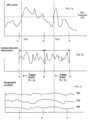
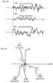
- FIGS. 7 a - 7 care related diagrams illustrating the use of sound pressure level as a trigger event for collecting acoustic information in accordance with the exemplary embodiment.
- FIGS. 7 a - 7 crelate to a trigger event for mobile device 600 of FIG. 6 .
- a mobile device 600is receiving audio information through the microphone 606 of the device.
- the acoustic informationis stored in buffer 616 of mobile device 600 for analysis.
- the analysiscan include looking for a trigger event such as sound pressure level.
- the trigger eventcould also comprise an AND function with one or more other trigger events to initiate collection of audio content or an OR function that initiates collection of audio content when any one of a variety of trigger events is detected.
- a trigger eventoccurs when the sound pressure level of the acoustic information exceeds sound pressure level threshold 706 .
- sound pressure level threshold 706For example, information on high noise areas is being collected.
- Setting sound pressure level threshold 706 at 70 dBwould collect information in areas having a sound pressure level that could produce hearing loss over a sustained period of time. Collecting a large number of data points would allow the mapping of acoustic information over a three dimensional region and over time. This information would have a variety of uses one of which is identifying when and where a person is exposed to potential harmful sound levels in the city.
- Trigger event 702occurs during a time period t.sub. 1 - t .sub. 2 as indicated by the dashed line.
- the acoustic informationis collected for sending to a database.
- the acoustic informationcan be immediately processed/sent or stored in memory of the communication device in its entirety or converted to a more compact form, modeled, characterized, and provided with metadata depending on the collection needs. Included in the metadata is the time information (t.sub. 1 - t .sub.
- Controller 420can calculate a sound pressure level measurement from the acoustic information (t.sub. 1 - t .sub. 2 ) based on the collection need. For example, average or peak sound pressure measurements could be calculated over the entire time period or portions of the time period.
- the position of the communication device indicated in x, y, and z coordinates versus timeis indicated in the graph provided by GPS receiver 612 .
- the GPS informationcould also be provided periodically. Interpolation (linear, other) could be used to estimate location versus time. A single geographic location could also be used for brevity depending on need.
- the position of the mobile device 600can be static or moving over time and this information is provided with the collected acoustic information.
- FIG. 7 aa second trigger event 704 is illustrated in FIG. 7 a .
- the acoustic signalis equal to or greater than sound pressure level 706 at trigger event 704 during time period t.sub. 2 - t .sub. 3 .
- the acoustic information, as shown in FIG. 7 bis similarly collected and sound pressure level calculated as disclosed hereinabove.
- a trigger eventoccurs anytime the sound pressure level threshold 706 is exceeded.
- the trigger eventcould be modified in other ways.
- the sound pressure level above threshold 706 for a predetermined time periodcould be a trigger event or a change in sound pressure level above a predetermined amount could also be a trigger event.
- the acoustic information collectedis not limited to the time period in which the trigger event occurs. The amount of acoustic information collected can be varied based on need. For example, collecting only acoustic information that exceeds sound pressure level threshold 706 .
- a trigger eventcould collect the acoustic information from the previous, current, and next time period depending on the size of buffer 616 .
- the sound pressure level, metadata, and other informationcould be sent immediately by mobile device 600 or later at a more opportune time to database 614 .
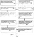
- an exemplary method 800 for sound monitoring and reporting over a network using mobile devicesis shown.
- the method 800can include more or less than the number of steps shown and is not limited to the order of the steps shown.
- the method 800can be implemented by the components of the mobile device shown in FIG. 4 .
- the mobile devicemonitors acoustic signals in the ambient environment.
- the mobile device microphonecan actively analyze acoustic signals in the environment and begin processing of the acoustic signals upon detection of a trigger event.
- mobile device 160begins buffering the acoustic signals in a step 804 when a trigger event occurs.
- the acoustic signalscan already be stored on a cyclical buffer.
- the processorcan monitor changes in the Sound Pressure Level, and upon detection of a significant change in SPL, begin to save the associated audio signals to memory.
- the eventcan also be user initiated, for instance, if the user hears a sound in the environment and then hits the record button on the user interface.
- the mobile devicecan prompt the user to begin recording if a sound signature is detected within the acoustic signal.
- the mobile devicecontinually monitors and analyzes the acoustic signal for salient information, such as a warning sound of a siren, in the user's environment.
- the trigger eventinitiates the mobile device 160 to proceed to open a communication channel with the server 130 in a step 806 .
- the connectioncan be a voice channel, a data channel, a packet data channel, a wi-fi channel, or any other communication link.
- the mobile device 160can send the captured audio signal directly over the voice channel.
- the datacan be sent in raw PCM format over the voice channel, or a non-lossy compression format to preserve the original signal characteristics.
- the mobile device 160can also send the code-plug information (see FIG. 4 ) identifying the parameter settings of the audio configuration path line-up.
- processor 230bypasses the audio processing circuitry and calculates the sound pressure level using the bypassed signal from the microphone.
- the calculationincludes compensation for aspects of mobile device 160 such as the microphone characteristics, microphone porting, foreign material coverings, amplifiers, and other audio processing circuitry.
- the microphone signalis coupled to a dedicated circuit for measuring sound pressure level and provided to processor 230 for further processing.
- Metadata or tag informationis generated and automatically attached with the features or acoustic signals. Included with the metadata are time information and geographic location information identifying when and where the acoustic signals were collected.
- the processcan also include manually attached tags related to the audio content.
- the tagcan include identifying information such as the type of sound (e.g., car horn, siren, whistle, bell, jack hammer, etc), more information related to the location of the capture (e.g., restaurant name, home address, etc.), a direction of the sound (e.g., moving closer, departing, stationary), and any associated description of the sound (e.g., faint sound, very loud, annoying, pleasant, etc.).
- the mobile devicereceives the tag information and associates it with the features of the acoustic signal, or alternatively the actual captured audio signal.
- the mobile devicetransmits the tags and features (or acoustic signals) to the server 130 over the open communication channel.
- the acoustic signals and tagscan be packaged together or sent separately over the network.
- the packetscan be sent over different hops and received at different times form the server.
- the server 130can then reorder the packets based on standard reconstruction techniques.
- the server 130analyzes the features and tags (acoustic signal) for sound pressure levels (SPLs) and sound signatures.
- the server 130also references the received code-plug information for determining the parameters of the audio modules. For instance, in assessing the SPL levels from the received audio signals or features, the server takes into account any compression or equalization performed during the sound acquisition. The SPL level can then be compensated for based on the front-end processing (e.g., compression, equalization, automatic gain control, filtering). Alternately, if the sound pressure level is calculated by mobile device 160 it can be received by server 130 and stored with the related metadata without further analysis (other than format and other checks to verify data quality). In this example, substantially less information would have to be transmitted.
- the server 130can also scan the audio signals —reconstructed acoustic signals or extracted features —for sound signatures.
- a sound signatureis a specific sound event such as a car horn, a siren, a whistle.
- Models of sound signaturescan be stored in the form of Gaussian Mixture Models (GMMs), Hidden Markov Models (HMMs), or any other statistical based pattern classifiers.
- the tagscan be parsed to determine if the audio signal contains previously learned sound signatures. For instance, the user may textually identify the uploaded acoustic signal as containing a whistle sound. Accordingly, the server 130 can update the sound signature model of the whistle sound with the new audio content.
- the server 130can train a new model to learn the characteristics of the unknown sound. For instance, if the user tags the sound as a ‘jackhammer sound’ and no models for that sound exist, the server 130 can generate a new model for jackhammers.
- the server 130 at step 816can generate and log a sound analysis report in view of the analysis.
- the sound analysis reportcan identify the sound signatures detected, their corresponding SPL levels, and other information such as whether the sound is a threat or the type of sound detected.
- the reportcan then be shared with service providers that are interested in data mining the audio content. For example, a restaurant can subscribe to receive audio content ratings for customers having dined in their restaurant.
- the audio content ratingscan include sound level analysis with associated time stamp and any customer related information. This permits the users and owners of the restaurant to assess the sound quality of the restaurant and allows the owners to monitor user feedback related to their experience at the restaurant.
- the servertransmits the report to the mobile device or subscriber by way of the open communication channel, or other means.
- the mobile devicepresents the details of the report to the user. Aspects of the report can be presented in a visual or audible format, or a combination thereof. For instance, upon automatically capturing a sound pressure level and transmitting the SPL/related information to the server for analysis, the user of the mobile device can then receive a text message warning that the SPL level could be harmful to the user if sustained over a long period of time or that the user should more accurately assess the sound levels of their ambient environment.
- the mobile devicecan also audibly present aspects of the report, for example, a threat level of a detected sound signature, and possible instructions for responding.
- the mobile devicecan audibly state a fire alarm was detected and visually present a map for exiting the restaurant, or facility. Understandably, other means of communicating the report can be contemplated in accordance with the teaching of this invention.
- FIG. 9illustrates a simplified GUI 900 that one can use to access sonic landscapes.
- the GUIcan be programmed (e.g., JAVA, C++) to provide options (e.g., map button 920 for map interaction, and address button 930 for address lookup interaction) for acoustic searching based on several parameters (e.g., location, time, topic (e.g., concerts, lectures, cars, boats, airplanes, war zones, historical), and any other identifying topic by which acoustic signals can be tagged and identified).
- GUI 900has a background panel 910 with two buttons, a map button 920 and an address search button 930 .
- a user interfaceis also illustrated (e.g., mouse 960 ), that facilitates selection by a user (e.g., movement of cursor 940 , over a button 920 or 930 , and the pressing ( 3 ) of selection button 970 ) of the available options.
- a usere.g., movement of cursor 940 , over a button 920 or 930 , and the pressing ( 3 ) of selection button 970
- the usercan move 955 , the mouse 960 from position ( 1 ) to position ( 2 ), which respectively moves 950 the cursor 940 from position ( 1 ′) to position ( 2 ′).
- the usercan then select (e.g., highlighted boundary ( 3 ′)) the map button 920 by pressing ( 3 ) on a button 970 built into the mouse 960 .
- button 920can have an “onClick” event (e.g., in C++, . . . void_fastcall TForm 1 ::BitBtnlClick(TObject*Sender) ⁇ ⁇ ) associated with opening up 1010 (e.g., C++ ChildForm ⁇ Show( )) a child form (i.e., a separate GUI, 1000 ), where a user can position the cursor and highlight and/or select a region of interest.
- an “onClick” evente.g., in C++, . . void_fastcall TForm 1 ::BitBtnlClick(TObject*Sender) ⁇ ⁇
- opening up 1010e.g., C++ ChildForm ⁇ Show( )
- a child formi.e., a separate GUI, 1000
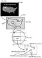
- FIG. 10illustrates a world map GUI 1000 in accordance with at least one exemplary embodiment. This is a non-limiting example of a world map that can be opened to provide a user the ability to position a cursor and select a region (e.g., country) of interest.
- a regione.g., country
- FIG. 11illustrates 1100 a user selecting a country using the world GUI 1000 in accordance with at least one exemplary embodiment.
- a usercan move ( 1155 ) the user interface 960 (e.g., a mouse) from position ( 4 ) to position ( 5 ) to move ( 1150 ) a cursor on the world map GUI 1000 from position ( 4 ′) to position ( 5 ′).
- the usercan then select a highlighted region ( 6 ′) by pressing ( 6 ) a selection button 970 on user interface 960 .
- a child formcan open 1210 displaying various information (e.g., the current SPL dosage across that region, a geographic map from which to further refine location selection).
- Illustrated in FIG. 12is the current SPL dosage of that region 1200 that one would experience in the standard dosage calculation time frame (e.g., 8 hours, 24 hours) at the present and/or projected SPL levels. Further location refinement is facilitated by specific location button 1220 .
- FIG. 12is a non-limiting example only.
- the SPL Dosagecan be calculated by associating pixels in the image with associated geographic extent in the region illustrated. Then the available SPL recordings can be used to calculate an associated SPL average value at the present time and fed into an SPL dosage calculation associated with the geographic regions.
- FIGS. 12 A- 12 Dillustrate the process of calculating an average SPL associated with a geographic region and combining average values to obtained a pixel related SPL average value and a pixel related SPL Dosage value that can be plotted as in FIG. 12 .
- FIG. 12 Acan be calculated by using the available SPL recorded values (e.g., 1340, 1350, 1360) of the geographic regions associated with the pixels.
- FIG. 12 Billustrates the various pixels 1310 (e.g., 1330 FIG. 12 C ) associated with the image.
- a geographic region of the image 1320can have many pixels (e.g., 1330 ).
- FIG. 12 Dillustrates SPL sources (SPL 1 , SPL 2 , and SPL 3 ) in pixel 1330 .
- FIG. 13illustrates a user selecting a location option according to at least one exemplary embodiment.
- a location button 1220associated with GUI 1200 , can be selected ( 7 ) with a user interface.
- a more specific location GUI map 1400can then be displayed FIG. 14 , where a user, can then move 1450 a cursor from location ( 8 ′) to ( 9 ′) above the location desired, where the move 1450 is associated with moving 1455 a user interface 1460 from location ( 8 ) to ( 9 ), where the user can select ( 10 ) the location associated with the cursor location on the GUI map 1400 .
- FIG. 15illustrates a GUI in accordance with at least one exemplary embodiment.
- FIG. 15illustrates a highlighted region ( 1510 e.g., Virginia) that has been selected ( 10 ) by a user.
- a closer map of the selected regioncan be displayed in an interactive GUI as illustrated in FIG. 16 .
- a usercenters a sub-regional extent 1620 about the cursor location indicating the next extent of any closer view selection.
- a usercan use the user interface 1460 to move 1650 a cursor from position ( 11 ′) to position ( 12 ′) corresponding to movement 1655 of a user interface from position ( 11 ) to position ( 12 ).
- a usercan then select ( 13 ) the closer view the region about the current position of the cursor, which for example can be indicated by a changing of the color of the surrounding region ( 13 ′). Note that other indications of selection can be used and the discussion herein is only for illustrative purposes.
- FIG. 17illustrates a GUI 1700 for selecting a location in a city in accordance with at least one exemplary embodiment.
- this embodimentillustrates a zoom bar 1730 that a user can use to increase or decrease resolution.
- an increase in resolutioncan be indicated by a rectangular 1710 extent of the view that would be displayed in a similar size image as the GUI's image.
- the image in 1710can be displayed (e.g., opening 1750 of a child form) such as illustrated in FIG. 18 .
- FIG. 18illustrates a GUI 1810 illustrating various available acoustic signals in accordance with at least one exemplary embodiment.
- various methodse.g., symbols, lights, shapes, colors
- type of sound recordinge.g., different shapes for different topics such as vehicles
- intensity of the sound signal of the sound recordinge.g., colors, shapes
- indication of whether the recording is real time or olde.g., symbols such as shown in shape legend 1840 ).
- the non-limiting example illustrated in FIG. 18indicates circles 1820 , 1850 for real time recordings and triangle 1830 for a recording, where real time can be set to be any recording that has an end time a Dt from eth present time.
- any recording within 30 minutes of the present timecan be considered a real time recording, note that the time can vary and be as short as fractions of a second to days.
- colorsare associated with the shape in this non-limiting example to illustrate the sound intensity of the sound recording at the recoding location.
- At least one exemplary embodimentplays the sound associated with a symbol by passing the cursor on the symbol, at which time the software (e.g., C++ OnEnter event) activates a media player and loads a sound recording associated with the pixel locations associated with the symbol and stop upon movement of the cursor off of the symbol (e.g., C++ OnExit event).
- the media playercan optionally be displayed.
- a usercan click on the symbol to play (e.g., C++ OnClick event).
- FIG. 19illustrates a media player set to play the selected sound recording.
- the sound recording 1910can be displayed mono or stereo.
- the usercan control the sound recording's play 1940 , reverse 1920 or pause 1930 .
- Note that other exemplary embodimentscan have other media players and exemplary embodiments are not restricted by the type of media player, nor whether the media player is visually displayed or not.
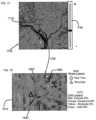
- FIG. 20illustrates the source signals from FIG. 18 and the associated source signals that generated the sound recordings ( 1820 and 1850 ) (as well as recording 1880 ).
- the sound recorded by microphones at 1820 and 1850can be from multiple sources (e.g., 2310 , 2320 , and 2330 ).
- the sound recordingsdo not necessarily indicate source locations.
- a recording at intensity I at x,y,zcan be due to a source of intensity 10 at a radius r.
- the source locationis not uniquely identified.
- Three recordings or moree.g., M 1 , M 2 , M 5 ), where the source intensity can be separated from microphone recordings can be used to uniquely identify the location of the source signal (e.g., s 12310 ).
- the source intensity and locationmay be needed, presenting four unknowns, for example Isource, xsource, ysource, and zsource.
- a source signalcan be identified in M 1 , M 2 , and M 5 by looking for frequency dependencies in the sound recordings (e.g., M 1 , M 2 , and M 5 ) that have similar coherence.
- High coherence frequency bandscan be used to identify and match frequency intensities due to similar signals.
- Matched frequency bandscan be used based upon intensity of the recordings in those bands and the location of the recordings to convolve the source location and approximate intensity for those bands.
- estimated source signalse.g., 2310 , 2320 , 2330
- the source signals 2310 , 2320 , and 2330can then be used to approximate the sound at a user selected location 2300 ( x,y,z ). Note that the methodology discussed herein is an example of one method of generating the acoustic source at a chosen location. There can be others within the scope of exemplary embodiments.
- FIG. 21illustrates source signals from the available sources in the listening area in accordance with at least one exemplary embodiment.
- sources 2010 , 2020 , and 2030have been located on GUI 1810 , and can be used to estimate the sound(s) that a user would hear at a selected position 2040 .
- FIG. 22illustrates source signals, s 1 , s 2 , and s 3 .
- a userthat has selected a location (x,y,z) and a time t 1 , can use the sources to compose a sound recording that is associated with x, y, z, and t 1 .
- the method for combinationmatches the various sources (s 1 , s 2 , and s 3 ) at start time t 1 , FIG. 23 .
- the source recording associated with the selected position (x,y,z)can be composed by calculating the radial distance (e.g., r 1 , r 2 , and r 3 ) (see FIG. 24 ), used to modify intensities of the sources at x, y, and z and modifying the time delay associated with the sources. For example, if source s 1 2310 is emitting a sound signal at t 1 , it will arrive at the selected position 2300 with a time delay based upon the speed of sound. Likewise other sources 2320 and 2330 will have a time delay from t 1 to location 2300 .
- the radial distancee.g., r 1 , r 2 , and r 3
- the source signals S 1 , S 2 , and S 3can also be identified in M 1 , M 2 , and M 3 by not only looking for high coherence but also time delays in the temporal recordings to help locate the location of the sources (e.g., via time delay between various microphone measurements).
- the radial distancecan be used to modify the expected intensity of the sound sources at 2300 ( FIG. 25 ).
- the modified signalscan be combined to create the estimated sound recording 2510 at 2300 ( FIG. 26 ).
- the present embodiments of the inventioncan be realized in hardware, software or a combination of hardware and software. Any kind of computer system or other apparatus adapted for carrying out the methods described herein are suitable.
- a typical combination of hardware and softwarecan be a mobile communications device with a computer program that, when being loaded and executed, can control the mobile communications device such that it carries out the methods described herein.
- Portions of the present method and systemmay also be embedded in a computer program product, which comprises all the features enabling the implementation of the methods described herein and which when loaded in a computer system, is able to carry out these methods.
Landscapes
- Engineering & Computer Science (AREA)
- Physics & Mathematics (AREA)
- Acoustics & Sound (AREA)
- Signal Processing (AREA)
- Health & Medical Sciences (AREA)
- Otolaryngology (AREA)
- General Health & Medical Sciences (AREA)
- Audiology, Speech & Language Pathology (AREA)
- Human Computer Interaction (AREA)
- Multimedia (AREA)
- Computational Linguistics (AREA)
- General Physics & Mathematics (AREA)
- Telephone Function (AREA)
- Telephonic Communication Services (AREA)
- Circuit For Audible Band Transducer (AREA)
Abstract
Description
(A1)D=100C/T
Claims (9)
Priority Applications (2)
| Application Number | Priority Date | Filing Date | Title |
|---|---|---|---|
| US17/244,202US12089011B2 (en) | 2008-09-11 | 2021-04-29 | Method and system for sound monitoring over a network |
| US18/425,025US20240267687A1 (en) | 2008-09-11 | 2024-01-29 | Method and system for sound monitoring over a network |
Applications Claiming Priority (5)
| Application Number | Priority Date | Filing Date | Title |
|---|---|---|---|
| US9612808P | 2008-09-11 | 2008-09-11 | |
| US12/555,570US8488799B2 (en) | 2008-09-11 | 2009-09-08 | Method and system for sound monitoring over a network |
| US13/917,079US10419863B2 (en) | 2008-09-11 | 2013-06-13 | Method and system for sound monitoring over a network |
| US16/571,973US11039259B2 (en) | 2008-09-11 | 2019-09-16 | Method and system for sound monitoring over a network |
| US17/244,202US12089011B2 (en) | 2008-09-11 | 2021-04-29 | Method and system for sound monitoring over a network |
Related Parent Applications (1)
| Application Number | Title | Priority Date | Filing Date |
|---|---|---|---|
| US16/571,973ContinuationUS11039259B2 (en) | 2008-09-11 | 2019-09-16 | Method and system for sound monitoring over a network |
Related Child Applications (1)
| Application Number | Title | Priority Date | Filing Date |
|---|---|---|---|
| US18/425,025ContinuationUS20240267687A1 (en) | 2008-09-11 | 2024-01-29 | Method and system for sound monitoring over a network |
Publications (2)
| Publication Number | Publication Date |
|---|---|
| US20210250713A1 US20210250713A1 (en) | 2021-08-12 |
| US12089011B2true US12089011B2 (en) | 2024-09-10 |
Family
ID=42005497
Family Applications (5)
| Application Number | Title | Priority Date | Filing Date |
|---|---|---|---|
| US12/555,570Active2032-04-05US8488799B2 (en) | 2008-09-11 | 2009-09-08 | Method and system for sound monitoring over a network |
| US13/917,079Active2031-04-04US10419863B2 (en) | 2008-09-11 | 2013-06-13 | Method and system for sound monitoring over a network |
| US16/571,973ActiveUS11039259B2 (en) | 2008-09-11 | 2019-09-16 | Method and system for sound monitoring over a network |
| US17/244,202Active2029-10-20US12089011B2 (en) | 2008-09-11 | 2021-04-29 | Method and system for sound monitoring over a network |
| US18/425,025PendingUS20240267687A1 (en) | 2008-09-11 | 2024-01-29 | Method and system for sound monitoring over a network |
Family Applications Before (3)
| Application Number | Title | Priority Date | Filing Date |
|---|---|---|---|
| US12/555,570Active2032-04-05US8488799B2 (en) | 2008-09-11 | 2009-09-08 | Method and system for sound monitoring over a network |
| US13/917,079Active2031-04-04US10419863B2 (en) | 2008-09-11 | 2013-06-13 | Method and system for sound monitoring over a network |
| US16/571,973ActiveUS11039259B2 (en) | 2008-09-11 | 2019-09-16 | Method and system for sound monitoring over a network |
Family Applications After (1)
| Application Number | Title | Priority Date | Filing Date |
|---|---|---|---|
| US18/425,025PendingUS20240267687A1 (en) | 2008-09-11 | 2024-01-29 | Method and system for sound monitoring over a network |
Country Status (4)
| Country | Link |
|---|---|
| US (5) | US8488799B2 (en) |
| EP (1) | EP2332345A4 (en) |
| JP (1) | JP2012502596A (en) |
| WO (1) | WO2010030889A1 (en) |
Families Citing this family (94)
| Publication number | Priority date | Publication date | Assignee | Title |
|---|---|---|---|---|
| US10009677B2 (en) | 2007-07-09 | 2018-06-26 | Staton Techiya, Llc | Methods and mechanisms for inflation |
| US9129291B2 (en) | 2008-09-22 | 2015-09-08 | Personics Holdings, Llc | Personalized sound management and method |
| DE102009037687A1 (en)* | 2009-08-18 | 2011-02-24 | Sennheiser Electronic Gmbh & Co. Kg | Microphone unit, bodypack transmitter and wireless audio system |
| US20110216905A1 (en)* | 2010-03-05 | 2011-09-08 | Nexidia Inc. | Channel compression |
| US9112989B2 (en)* | 2010-04-08 | 2015-08-18 | Qualcomm Incorporated | System and method of smart audio logging for mobile devices |
| US9736600B2 (en)* | 2010-05-17 | 2017-08-15 | Iii Holdings 4, Llc | Devices and methods for collecting acoustic data |
| US8550206B2 (en) | 2011-05-31 | 2013-10-08 | Virginia Tech Intellectual Properties, Inc. | Method and structure for achieving spectrum-tunable and uniform attenuation |
| WO2012027016A1 (en)* | 2010-08-23 | 2012-03-01 | Total Immersion Software, Inc. | Apparatus and methods for creation, collection, and dissemination of instructional content modules using mobile devices |
| CN103098493A (en)* | 2010-11-12 | 2013-05-08 | 松下电器产业株式会社 | Sound pressure evaluation system, and method and program therefor |
| US9135952B2 (en)* | 2010-12-17 | 2015-09-15 | Adobe Systems Incorporated | Systems and methods for semi-automatic audio problem detection and correction |
| US12349097B2 (en) | 2010-12-30 | 2025-07-01 | St Famtech, Llc | Information processing using a population of data acquisition devices |
| JP2013066307A (en)* | 2011-09-16 | 2013-04-11 | Sharp Corp | Wireless terminal, power transmission system, and power transmission method |
| EP2788978B1 (en) | 2011-12-07 | 2020-09-23 | QUALCOMM Incorporated | Low power integrated circuit to analyze a digitized audio stream |
| US9084058B2 (en) | 2011-12-29 | 2015-07-14 | Sonos, Inc. | Sound field calibration using listener localization |
| US9654821B2 (en) | 2011-12-30 | 2017-05-16 | Sonos, Inc. | Systems and methods for networked music playback |
| US10200751B2 (en)* | 2012-03-30 | 2019-02-05 | The Nielsen Company (Us), Llc | Methods, apparatus, and machine readable storage media to monitor a media presentation |
| US9674587B2 (en) | 2012-06-26 | 2017-06-06 | Sonos, Inc. | Systems and methods for networked music playback including remote add to queue |
| US9690539B2 (en) | 2012-06-28 | 2017-06-27 | Sonos, Inc. | Speaker calibration user interface |
| US9706323B2 (en) | 2014-09-09 | 2017-07-11 | Sonos, Inc. | Playback device calibration |
| US9219460B2 (en) | 2014-03-17 | 2015-12-22 | Sonos, Inc. | Audio settings based on environment |
| US9668049B2 (en) | 2012-06-28 | 2017-05-30 | Sonos, Inc. | Playback device calibration user interfaces |
| US9690271B2 (en) | 2012-06-28 | 2017-06-27 | Sonos, Inc. | Speaker calibration |
| US9106192B2 (en) | 2012-06-28 | 2015-08-11 | Sonos, Inc. | System and method for device playback calibration |
| US20150204965A1 (en)* | 2012-07-06 | 2015-07-23 | Toyota Jidosha Kabushiki Kaisha | Position specification system and method |
| GB201214573D0 (en)* | 2012-08-15 | 2012-09-26 | Britton Colin | Audio amplification apparatus |
| US8880495B2 (en)* | 2012-10-16 | 2014-11-04 | Michael J. Andri | Search query expansion and group search |
| US10194239B2 (en)* | 2012-11-06 | 2019-01-29 | Nokia Technologies Oy | Multi-resolution audio signals |
| US20140192990A1 (en)* | 2013-01-10 | 2014-07-10 | Wilson Cheng | Virtual Audio Map |
| CN103970793B (en)* | 2013-02-04 | 2020-03-03 | 腾讯科技(深圳)有限公司 | Information query method, client and server |
| US20160021512A1 (en)* | 2013-03-13 | 2016-01-21 | Retail Optimization International Inc. | Systems and methods for indoor location services |
| US10045133B2 (en) | 2013-03-15 | 2018-08-07 | Natan Bauman | Variable sound attenuator with hearing aid |
| US9521480B2 (en) | 2013-07-31 | 2016-12-13 | Natan Bauman | Variable noise attenuator with adjustable attenuation |
| US9333116B2 (en) | 2013-03-15 | 2016-05-10 | Natan Bauman | Variable sound attenuator |
| US9361371B2 (en) | 2013-04-16 | 2016-06-07 | Sonos, Inc. | Playlist update in a media playback system |
| US9501533B2 (en) | 2013-04-16 | 2016-11-22 | Sonos, Inc. | Private queue for a media playback system |
| US9247363B2 (en) | 2013-04-16 | 2016-01-26 | Sonos, Inc. | Playback queue transfer in a media playback system |
| US9684484B2 (en) | 2013-05-29 | 2017-06-20 | Sonos, Inc. | Playback zone silent connect |
| KR102109739B1 (en)* | 2013-07-09 | 2020-05-12 | 삼성전자 주식회사 | Method and apparatus for outputing sound based on location |
| US9167082B2 (en) | 2013-09-22 | 2015-10-20 | Steven Wayne Goldstein | Methods and systems for voice augmented caller ID / ring tone alias |
| WO2015061712A1 (en) | 2013-10-24 | 2015-04-30 | Tourmaline Labs, Inc. | Systems and methods for collecting and transmitting telematics data from a mobile device |
| US10659889B2 (en)* | 2013-11-08 | 2020-05-19 | Infineon Technologies Ag | Microphone package and method for generating a microphone signal |
| US9606713B1 (en)* | 2013-12-13 | 2017-03-28 | Amazon Technologies, Inc. | Utilizing dynamic granularity for application controls |
| US9729984B2 (en) | 2014-01-18 | 2017-08-08 | Microsoft Technology Licensing, Llc | Dynamic calibration of an audio system |
| US9264839B2 (en) | 2014-03-17 | 2016-02-16 | Sonos, Inc. | Playback device configuration based on proximity detection |
| US10325591B1 (en)* | 2014-09-05 | 2019-06-18 | Amazon Technologies, Inc. | Identifying and suppressing interfering audio content |
| US9952825B2 (en) | 2014-09-09 | 2018-04-24 | Sonos, Inc. | Audio processing algorithms |
| US9891881B2 (en) | 2014-09-09 | 2018-02-13 | Sonos, Inc. | Audio processing algorithm database |
| US9910634B2 (en) | 2014-09-09 | 2018-03-06 | Sonos, Inc. | Microphone calibration |
| US10127006B2 (en) | 2014-09-09 | 2018-11-13 | Sonos, Inc. | Facilitating calibration of an audio playback device |
| GB201509483D0 (en)* | 2014-12-23 | 2015-07-15 | Cirrus Logic Internat Uk Ltd | Feature extraction |
| GB2535167B (en)* | 2015-02-09 | 2017-03-29 | 24 Acoustics Ltd | Audio signal processing apparatus, client device, system and method |
| WO2016172593A1 (en) | 2015-04-24 | 2016-10-27 | Sonos, Inc. | Playback device calibration user interfaces |
| US10664224B2 (en) | 2015-04-24 | 2020-05-26 | Sonos, Inc. | Speaker calibration user interface |
| GB201510032D0 (en)* | 2015-06-09 | 2015-07-22 | Kp Acoustics Ltd | Integrated sensor system |
| US9538305B2 (en) | 2015-07-28 | 2017-01-03 | Sonos, Inc. | Calibration error conditions |
| US11477560B2 (en) | 2015-09-11 | 2022-10-18 | Hear Llc | Earplugs, earphones, and eartips |
| CN108028985B (en) | 2015-09-17 | 2020-03-13 | 搜诺思公司 | Method for computing device |
| US9693165B2 (en) | 2015-09-17 | 2017-06-27 | Sonos, Inc. | Validation of audio calibration using multi-dimensional motion check |
| WO2017058893A1 (en)* | 2015-09-29 | 2017-04-06 | Swineguard, Inc. | Warning system for animal farrowing operations |
| JP6657769B2 (en)* | 2015-10-23 | 2020-03-04 | 株式会社Jvcケンウッド | Transmission device, transmission method |
| KR102065522B1 (en)* | 2015-10-23 | 2020-02-11 | 삼성전자주식회사 | Electronic device and control method thereof |
| US9609449B1 (en) | 2015-10-26 | 2017-03-28 | Microsoft Technology Licensing, Llc | Continuous sound pressure level monitoring |
| US9743207B1 (en) | 2016-01-18 | 2017-08-22 | Sonos, Inc. | Calibration using multiple recording devices |
| US10003899B2 (en) | 2016-01-25 | 2018-06-19 | Sonos, Inc. | Calibration with particular locations |
| US11106423B2 (en) | 2016-01-25 | 2021-08-31 | Sonos, Inc. | Evaluating calibration of a playback device |
| CA3016877A1 (en)* | 2016-03-07 | 2017-09-14 | 3M Innovative Properties Company | Intelligent safety monitoring and analytics system for personal protective equipment |
| WO2017160170A1 (en)* | 2016-03-15 | 2017-09-21 | Motorola Solutions, Inc. | Method and apparatus for camera activation |
| US9864574B2 (en) | 2016-04-01 | 2018-01-09 | Sonos, Inc. | Playback device calibration based on representation spectral characteristics |
| US9860662B2 (en) | 2016-04-01 | 2018-01-02 | Sonos, Inc. | Updating playback device configuration information based on calibration data |
| US9763018B1 (en) | 2016-04-12 | 2017-09-12 | Sonos, Inc. | Calibration of audio playback devices |
| US9860670B1 (en) | 2016-07-15 | 2018-01-02 | Sonos, Inc. | Spectral correction using spatial calibration |
| US9794710B1 (en) | 2016-07-15 | 2017-10-17 | Sonos, Inc. | Spatial audio correction |
| US10372406B2 (en) | 2016-07-22 | 2019-08-06 | Sonos, Inc. | Calibration interface |
| US10459684B2 (en) | 2016-08-05 | 2019-10-29 | Sonos, Inc. | Calibration of a playback device based on an estimated frequency response |
| IT201600098080A1 (en)* | 2016-09-30 | 2018-03-30 | Lucas Srl | Indoor noise pollution meter |
| SG10202104872UA (en)* | 2016-11-10 | 2021-06-29 | Fiber Sense Pty Ltd | Acoustic method and system for providing digital data |
| GB2555843A (en)* | 2016-11-11 | 2018-05-16 | Eartex Ltd | Noise dosimeter |
| WO2018144367A1 (en)* | 2017-02-03 | 2018-08-09 | iZotope, Inc. | Audio control system and related methods |
| CN113865697B (en) | 2017-02-10 | 2024-11-12 | 霍尼韦尔国际公司 | Distributed network of communicatively coupled noise monitoring and mapping devices |
| US9870719B1 (en)* | 2017-04-17 | 2018-01-16 | Hz Innovations Inc. | Apparatus and method for wireless sound recognition to notify users of detected sounds |
| US10440463B2 (en) | 2017-06-09 | 2019-10-08 | Honeywell International Inc. | Dosimetry hearing protection device with time remaining warning |
| US10148241B1 (en)* | 2017-11-20 | 2018-12-04 | Dell Products, L.P. | Adaptive audio interface |
| US11094316B2 (en)* | 2018-05-04 | 2021-08-17 | Qualcomm Incorporated | Audio analytics for natural language processing |
| US11206484B2 (en) | 2018-08-28 | 2021-12-21 | Sonos, Inc. | Passive speaker authentication |
| US10299061B1 (en) | 2018-08-28 | 2019-05-21 | Sonos, Inc. | Playback device calibration |
| US11432086B2 (en) | 2019-04-16 | 2022-08-30 | Biamp Systems, LLC | Centrally controlling communication at a venue |
| US10796177B1 (en)* | 2019-05-15 | 2020-10-06 | Toyota Motor Engineering & Manufacturing North America, Inc. | Systems and methods for controlling the playback of video in a vehicle using timers |
| US10734965B1 (en) | 2019-08-12 | 2020-08-04 | Sonos, Inc. | Audio calibration of a portable playback device |
| US20220351114A1 (en)* | 2019-08-20 | 2022-11-03 | Nippon Telegraph And Telephone Corporation | Information collecting apparatus and method |
| CN110489076B (en)* | 2019-08-22 | 2024-03-01 | 百度在线网络技术(北京)有限公司 | Environment sound monitoring method and device and electronic equipment |
| US11129011B2 (en)* | 2019-12-26 | 2021-09-21 | Process Integration System Inc. | System and method to detect and report to the authorities high level sounds that infringe the law |
| FR3109458B1 (en)* | 2020-04-16 | 2022-08-26 | Intrapreneuriat Bouygues | Real-time sound source recognition and identification system |
| SE545604C2 (en)* | 2020-06-05 | 2023-11-07 | Saint Gobain Ecophon Ab | Determining an airborne and/or aerosol pathogen risk exposure |
| EP4564154A3 (en) | 2021-09-30 | 2025-07-23 | Sonos Inc. | Conflict management for wake-word detection processes |
Citations (91)
| Publication number | Priority date | Publication date | Assignee | Title |
|---|---|---|---|---|
| US3876843A (en) | 1973-01-02 | 1975-04-08 | Textron Inc | Directional hearing aid with variable directivity |
| US4054749A (en) | 1975-12-02 | 1977-10-18 | Fuji Xerox Co., Ltd. | Method for verifying identity or difference by voice |
| US4088849A (en) | 1975-09-30 | 1978-05-09 | Victor Company Of Japan, Limited | Headphone unit incorporating microphones for binaural recording |
| US4947440A (en) | 1988-10-27 | 1990-08-07 | The Grass Valley Group, Inc. | Shaping of automatic audio crossfade |
| US5208867A (en) | 1990-04-05 | 1993-05-04 | Intelex, Inc. | Voice transmission system and method for high ambient noise conditions |
| US5267321A (en) | 1991-11-19 | 1993-11-30 | Edwin Langberg | Active sound absorber |
| US5524056A (en) | 1993-04-13 | 1996-06-04 | Etymotic Research, Inc. | Hearing aid having plural microphones and a microphone switching system |
| US5903868A (en) | 1995-11-22 | 1999-05-11 | Yuen; Henry C. | Audio recorder with retroactive storage |
| US6021325A (en) | 1997-03-10 | 2000-02-01 | Ericsson Inc. | Mobile telephone having continuous recording capability |
| US6021207A (en) | 1997-04-03 | 2000-02-01 | Resound Corporation | Wireless open ear canal earpiece |
| US6163338A (en) | 1997-12-11 | 2000-12-19 | Johnson; Dan | Apparatus and method for recapture of realtime events |
| US6163508A (en) | 1999-05-13 | 2000-12-19 | Ericsson Inc. | Recording method having temporary buffering |
| US6226389B1 (en) | 1993-08-11 | 2001-05-01 | Jerome H. Lemelson | Motor vehicle warning and control system and method |
| US6298323B1 (en) | 1996-07-25 | 2001-10-02 | Siemens Aktiengesellschaft | Computer voice recognition method verifying speaker identity using speaker and non-speaker data |
| US20010046304A1 (en) | 2000-04-24 | 2001-11-29 | Rast Rodger H. | System and method for selective control of acoustic isolation in headsets |
| US6359993B2 (en) | 1999-01-15 | 2002-03-19 | Sonic Innovations | Conformal tip for a hearing aid with integrated vent and retrieval cord |
| US6400652B1 (en) | 1998-12-04 | 2002-06-04 | At&T Corp. | Recording system having pattern recognition |
| US6415034B1 (en) | 1996-08-13 | 2002-07-02 | Nokia Mobile Phones Ltd. | Earphone unit and a terminal device |
| US20020106091A1 (en) | 2001-02-02 | 2002-08-08 | Furst Claus Erdmann | Microphone unit with internal A/D converter |
| US20020118798A1 (en) | 2001-02-27 | 2002-08-29 | Christopher Langhart | System and method for recording telephone conversations |
| US20020181721A1 (en)* | 2000-10-02 | 2002-12-05 | Takeshi Sugiyama | Sound source probing system |
| US6567524B1 (en) | 2000-09-01 | 2003-05-20 | Nacre As | Noise protection verification device |
| US20030161097A1 (en) | 2002-02-28 | 2003-08-28 | Dana Le | Wearable computer system and modes of operating the system |
| US20030165246A1 (en) | 2002-02-28 | 2003-09-04 | Sintef | Voice detection and discrimination apparatus and method |
| US6661901B1 (en) | 2000-09-01 | 2003-12-09 | Nacre As | Ear terminal with microphone for natural voice rendition |
| USRE38351E1 (en) | 1992-05-08 | 2003-12-16 | Etymotic Research, Inc. | High fidelity insert earphones and methods of making same |
| US20040000194A1 (en)* | 2002-07-01 | 2004-01-01 | Yokio Sakai | System for watching and forecasting changes in natural phenomena and weather based on sounds from the earth |
| US20040042103A1 (en) | 2002-05-31 | 2004-03-04 | Yaron Mayer | System and method for improved retroactive recording and/or replay |
| US20040064319A1 (en) | 2002-09-27 | 2004-04-01 | Neuhauser Alan R. | Audio data receipt/exposure measurement with code monitoring and signature extraction |
| US6748238B1 (en) | 2000-09-25 | 2004-06-08 | Sharper Image Corporation | Hands-free digital recorder system for cellular telephones |
| US20040109668A1 (en) | 2002-12-05 | 2004-06-10 | Stuckman Bruce E. | DSL video service with memory manager |
| US6754359B1 (en) | 2000-09-01 | 2004-06-22 | Nacre As | Ear terminal with microphone for voice pickup |
| US20040125965A1 (en) | 2002-12-27 | 2004-07-01 | William Alberth | Method and apparatus for providing background audio during a communication session |
| US20040190737A1 (en) | 2003-03-25 | 2004-09-30 | Volker Kuhnel | Method for recording information in a hearing device as well as a hearing device |
| US20040196992A1 (en) | 2003-04-01 | 2004-10-07 | Ryan Jim G. | System and method for detecting the insertion or removal of a hearing instrument from the ear canal |
| US6804638B2 (en) | 1999-04-30 | 2004-10-12 | Recent Memory Incorporated | Device and method for selective recall and preservation of events prior to decision to record the events |
| US6804643B1 (en) | 1999-10-29 | 2004-10-12 | Nokia Mobile Phones Ltd. | Speech recognition |
| US20040203351A1 (en) | 2002-05-15 | 2004-10-14 | Koninklijke Philips Electronics N.V. | Bluetooth control device for mobile communication apparatus |
| US20050058313A1 (en) | 2003-09-11 | 2005-03-17 | Victorian Thomas A. | External ear canal voice detection |
| US20050078838A1 (en) | 2003-10-08 | 2005-04-14 | Henry Simon | Hearing ajustment appliance for electronic audio equipment |
| US6895378B1 (en)* | 2000-09-22 | 2005-05-17 | Meyer Sound Laboratories, Incorporated | System and method for producing acoustic response predictions via a communications network |
| US20050123146A1 (en) | 2003-12-05 | 2005-06-09 | Jeremie Voix | Method and apparatus for objective assessment of in-ear device acoustical performance |
| US20050288057A1 (en) | 2004-06-23 | 2005-12-29 | Inventec Appliances Corporation | Portable phone capable of being switched into hearing aid function |
| KR20060008100A (en) | 2004-07-23 | 2006-01-26 | 권용진 | Mobile based geographic information search and inquiry system |
| US20060067551A1 (en) | 2004-09-28 | 2006-03-30 | Cartwright Kristopher L | Conformable ear piece and method of using and making same |
| WO2006037156A1 (en) | 2004-10-01 | 2006-04-13 | Hear Works Pty Ltd | Acoustically transparent occlusion reduction system and method |
| US20060083395A1 (en) | 2004-10-15 | 2006-04-20 | Mimosa Acoustics, Inc. | System and method for automatically adjusting hearing aid based on acoustic reflectance |
| US20060092043A1 (en) | 2004-11-03 | 2006-05-04 | Lagassey Paul J | Advanced automobile accident detection, data recordation and reporting system |
| US7072482B2 (en) | 2002-09-06 | 2006-07-04 | Sonion Nederland B.V. | Microphone with improved sound inlet port |
| JP2006214740A (en)* | 2005-02-01 | 2006-08-17 | Ono Sokki Co Ltd | Acoustic measuring device |
| US20060195322A1 (en) | 2005-02-17 | 2006-08-31 | Broussard Scott J | System and method for detecting and storing important information |
| US7107109B1 (en) | 2000-02-16 | 2006-09-12 | Touchtunes Music Corporation | Process for adjusting the sound volume of a digital sound recording |
| US20060204014A1 (en) | 2000-03-02 | 2006-09-14 | Iseberg Steven J | Hearing test apparatus and method having automatic starting functionality |
| US20060235550A1 (en)* | 2003-04-24 | 2006-10-19 | Csicsatka Tibor G | Creation of playlists using audio identification |
| US20070032895A1 (en)* | 2005-07-29 | 2007-02-08 | Fawad Nackvi | Loudspeaker with demonstration mode |
| US20070043563A1 (en) | 2005-08-22 | 2007-02-22 | International Business Machines Corporation | Methods and apparatus for buffering data for use in accordance with a speech recognition system |
| US20070086600A1 (en) | 2005-10-14 | 2007-04-19 | Boesen Peter V | Dual ear voice communication device |
| US7209569B2 (en) | 1999-05-10 | 2007-04-24 | Sp Technologies, Llc | Earpiece with an inertial sensor |
| US20070189544A1 (en) | 2005-01-15 | 2007-08-16 | Outland Research, Llc | Ambient sound responsive media player |
| US20070291953A1 (en) | 2006-06-14 | 2007-12-20 | Think-A-Move, Ltd. | Ear sensor assembly for speech processing |
| US20080037801A1 (en) | 2006-08-10 | 2008-02-14 | Cambridge Silicon Radio, Ltd. | Dual microphone noise reduction for headset application |
| US7353114B1 (en) | 2005-06-27 | 2008-04-01 | Google Inc. | Markup language for an interactive geographic information system |
| US20080159547A1 (en)* | 2006-12-29 | 2008-07-03 | Motorola, Inc. | Method for autonomously monitoring and reporting sound pressure level (SPL) exposure for a user of a communication device |
| US20080165988A1 (en) | 2007-01-05 | 2008-07-10 | Terlizzi Jeffrey J | Audio blending |
| US7430299B2 (en) | 2003-04-10 | 2008-09-30 | Sound Design Technologies, Ltd. | System and method for transmitting audio via a serial data port in a hearing instrument |
| US7433714B2 (en) | 2003-06-30 | 2008-10-07 | Microsoft Corporation | Alert mechanism interface |
| US7450730B2 (en) | 2004-12-23 | 2008-11-11 | Phonak Ag | Personal monitoring system for a user and method for monitoring a user |
| US20090010456A1 (en) | 2007-04-13 | 2009-01-08 | Personics Holdings Inc. | Method and device for voice operated control |
| US7477756B2 (en) | 2006-03-02 | 2009-01-13 | Knowles Electronics, Llc | Isolating deep canal fitting earphone |
| US20090024234A1 (en) | 2007-07-19 | 2009-01-22 | Archibald Fitzgerald J | Apparatus and method for coupling two independent audio streams |
| US20090323914A1 (en) | 2008-04-29 | 2009-12-31 | Phal Jin Lee | Home appliance and home appliance system |
| US20100061564A1 (en) | 2007-02-07 | 2010-03-11 | Richard Clemow | Ambient noise reduction system |
| US7756285B2 (en) | 2006-01-30 | 2010-07-13 | Songbird Hearing, Inc. | Hearing aid with tuned microphone cavity |
| US7778434B2 (en) | 2004-05-28 | 2010-08-17 | General Hearing Instrument, Inc. | Self forming in-the-ear hearing aid with conical stent |
| US20100296668A1 (en) | 2009-04-23 | 2010-11-25 | Qualcomm Incorporated | Systems, methods, apparatus, and computer-readable media for automatic control of active noise cancellation |
| US7920557B2 (en) | 2007-02-15 | 2011-04-05 | Harris Corporation | Apparatus and method for soft media processing within a routing switcher |
| US7925982B2 (en) | 2006-09-01 | 2011-04-12 | Cheryl Parker | System and method of overlaying and integrating data with geographic mapping applications |
| US20110096939A1 (en) | 2009-10-28 | 2011-04-28 | Sony Corporation | Reproducing device, headphone and reproducing method |
| US8014553B2 (en) | 2006-11-07 | 2011-09-06 | Nokia Corporation | Ear-mounted transducer and ear-device |
| US20110264447A1 (en) | 2010-04-22 | 2011-10-27 | Qualcomm Incorporated | Systems, methods, and apparatus for speech feature detection |
| US20110293103A1 (en) | 2010-06-01 | 2011-12-01 | Qualcomm Incorporated | Systems, methods, devices, apparatus, and computer program products for audio equalization |
| US8493204B2 (en) | 2011-11-14 | 2013-07-23 | Google Inc. | Displaying sound indications on a wearable computing system |
| US8750295B2 (en) | 2006-12-20 | 2014-06-10 | Gvbb Holdings S.A.R.L. | Embedded audio routing switcher |
| US9037458B2 (en) | 2011-02-23 | 2015-05-19 | Qualcomm Incorporated | Systems, methods, apparatus, and computer-readable media for spatially selective audio augmentation |
| US9123343B2 (en) | 2006-04-27 | 2015-09-01 | Mobiter Dicta Oy | Method, and a device for converting speech by replacing inarticulate portions of the speech before the conversion |
| US9135797B2 (en) | 2006-12-28 | 2015-09-15 | International Business Machines Corporation | Audio detection using distributed mobile computing |
| US9146126B2 (en) | 2011-01-27 | 2015-09-29 | Here Global B.V. | Interactive geographic feature |
| US20160104452A1 (en) | 2013-05-24 | 2016-04-14 | Awe Company Limited | Systems and methods for a shared mixed reality experience |
| US20180349703A1 (en) | 2018-07-27 | 2018-12-06 | Yogesh Rathod | Display virtual objects in the event of receiving of augmented reality scanning or photo of real world object from particular location or within geofence and recognition of real world object |
| US20190155473A1 (en) | 2011-12-29 | 2019-05-23 | Apple Inc. | Device, method, and graphical user interface for navigation of information in a map-based interface |
| EP3627432A1 (en) | 2017-04-27 | 2020-03-25 | Snap Inc. | Map-based graphical user interface indicating geospatial activity metrics |
Family Cites Families (20)
| Publication number | Priority date | Publication date | Assignee | Title |
|---|---|---|---|---|
| US4484345A (en)* | 1983-02-28 | 1984-11-20 | Stearns William P | Prosthetic device for optimizing speech understanding through adjustable frequency spectrum responses |
| US5732143A (en)* | 1992-10-29 | 1998-03-24 | Andrea Electronics Corp. | Noise cancellation apparatus |
| US6639512B1 (en)* | 1998-07-15 | 2003-10-28 | Kyu-Woong Lee | Environmental warning system |
| US6507790B1 (en)* | 1998-07-15 | 2003-01-14 | Horton, Inc. | Acoustic monitor |
| EP1128693A1 (en)* | 2000-02-28 | 2001-08-29 | TELEFONAKTIEBOLAGET LM ERICSSON (publ) | Testing acoustic properties of a mobile terminal |
| US7340062B2 (en)* | 2000-03-14 | 2008-03-04 | Revit Lawrence J | Sound reproduction method and apparatus for assessing real-world performance of hearing and hearing aids |
| US7278734B2 (en)* | 2000-06-02 | 2007-10-09 | Oakley, Inc. | Wireless interactive headset |
| US6654652B1 (en)* | 2000-08-23 | 2003-11-25 | Beiersdorf Ag | Calibration and security device for PC auditory programs |
| US6601456B1 (en) | 2001-06-06 | 2003-08-05 | Southwest Research Institute | Fretting fixture for high-cycle fatigue test machines |
| US6677883B2 (en)* | 2002-05-09 | 2004-01-13 | Bae Systems Information And Electronic Systems Integration Inc. | Surveillance method and apparatus |
| JP2004133895A (en) | 2002-08-09 | 2004-04-30 | Matsushita Electric Ind Co Ltd | Communication terminal device of payback system and information processing device |
| JP2005084253A (en)* | 2003-09-05 | 2005-03-31 | Matsushita Electric Ind Co Ltd | Sound processing apparatus, method, program, and storage medium |
| JP4206876B2 (en)* | 2003-09-10 | 2009-01-14 | ヤマハ株式会社 | Communication device and program for transmitting state of remote place |
| US7076211B2 (en)* | 2003-10-14 | 2006-07-11 | Electronic Data Systems Corporation | Wireless sensor alerts |
| US20050244013A1 (en)* | 2004-04-29 | 2005-11-03 | Quest Technologies | Noise exposure monitoring device |
| US7914468B2 (en)* | 2004-09-22 | 2011-03-29 | Svip 4 Llc | Systems and methods for monitoring and modifying behavior |
| JP2006092381A (en)* | 2004-09-27 | 2006-04-06 | Hitachi Ltd | Media mining method |
| US20060198504A1 (en)* | 2005-01-21 | 2006-09-07 | Shemisa Yousef O | Call recording platform |
| WO2008064230A2 (en)* | 2006-11-20 | 2008-05-29 | Personics Holdings Inc. | Methods and devices for hearing damage notification and intervention ii |
| JP2008170415A (en)* | 2007-07-11 | 2008-07-24 | Earth Watch Corp | Environmental measuring system |
- 2009
- 2009-09-08USUS12/555,570patent/US8488799B2/enactiveActive
- 2009-09-11EPEP09813678.1Apatent/EP2332345A4/ennot_activeWithdrawn
- 2009-09-11JPJP2011526997Apatent/JP2012502596A/enactivePending
- 2009-09-11WOPCT/US2009/056673patent/WO2010030889A1/enactiveApplication Filing
- 2013
- 2013-06-13USUS13/917,079patent/US10419863B2/enactiveActive
- 2019
- 2019-09-16USUS16/571,973patent/US11039259B2/enactiveActive
- 2021
- 2021-04-29USUS17/244,202patent/US12089011B2/enactiveActive
- 2024
- 2024-01-29USUS18/425,025patent/US20240267687A1/enactivePending
Patent Citations (95)
| Publication number | Priority date | Publication date | Assignee | Title |
|---|---|---|---|---|
| US3876843A (en) | 1973-01-02 | 1975-04-08 | Textron Inc | Directional hearing aid with variable directivity |
| US4088849A (en) | 1975-09-30 | 1978-05-09 | Victor Company Of Japan, Limited | Headphone unit incorporating microphones for binaural recording |
| US4054749A (en) | 1975-12-02 | 1977-10-18 | Fuji Xerox Co., Ltd. | Method for verifying identity or difference by voice |
| US4947440A (en) | 1988-10-27 | 1990-08-07 | The Grass Valley Group, Inc. | Shaping of automatic audio crossfade |
| US5208867A (en) | 1990-04-05 | 1993-05-04 | Intelex, Inc. | Voice transmission system and method for high ambient noise conditions |
| US5267321A (en) | 1991-11-19 | 1993-11-30 | Edwin Langberg | Active sound absorber |
| USRE38351E1 (en) | 1992-05-08 | 2003-12-16 | Etymotic Research, Inc. | High fidelity insert earphones and methods of making same |
| US5524056A (en) | 1993-04-13 | 1996-06-04 | Etymotic Research, Inc. | Hearing aid having plural microphones and a microphone switching system |
| US6226389B1 (en) | 1993-08-11 | 2001-05-01 | Jerome H. Lemelson | Motor vehicle warning and control system and method |
| US5903868A (en) | 1995-11-22 | 1999-05-11 | Yuen; Henry C. | Audio recorder with retroactive storage |
| US6298323B1 (en) | 1996-07-25 | 2001-10-02 | Siemens Aktiengesellschaft | Computer voice recognition method verifying speaker identity using speaker and non-speaker data |
| US6415034B1 (en) | 1996-08-13 | 2002-07-02 | Nokia Mobile Phones Ltd. | Earphone unit and a terminal device |
| US6021325A (en) | 1997-03-10 | 2000-02-01 | Ericsson Inc. | Mobile telephone having continuous recording capability |
| US6021207A (en) | 1997-04-03 | 2000-02-01 | Resound Corporation | Wireless open ear canal earpiece |
| US6163338A (en) | 1997-12-11 | 2000-12-19 | Johnson; Dan | Apparatus and method for recapture of realtime events |
| US6400652B1 (en) | 1998-12-04 | 2002-06-04 | At&T Corp. | Recording system having pattern recognition |
| US6359993B2 (en) | 1999-01-15 | 2002-03-19 | Sonic Innovations | Conformal tip for a hearing aid with integrated vent and retrieval cord |
| US6804638B2 (en) | 1999-04-30 | 2004-10-12 | Recent Memory Incorporated | Device and method for selective recall and preservation of events prior to decision to record the events |
| US7209569B2 (en) | 1999-05-10 | 2007-04-24 | Sp Technologies, Llc | Earpiece with an inertial sensor |
| US6163508A (en) | 1999-05-13 | 2000-12-19 | Ericsson Inc. | Recording method having temporary buffering |
| US6804643B1 (en) | 1999-10-29 | 2004-10-12 | Nokia Mobile Phones Ltd. | Speech recognition |
| US7107109B1 (en) | 2000-02-16 | 2006-09-12 | Touchtunes Music Corporation | Process for adjusting the sound volume of a digital sound recording |
| US20060204014A1 (en) | 2000-03-02 | 2006-09-14 | Iseberg Steven J | Hearing test apparatus and method having automatic starting functionality |
| US20010046304A1 (en) | 2000-04-24 | 2001-11-29 | Rast Rodger H. | System and method for selective control of acoustic isolation in headsets |
| US6754359B1 (en) | 2000-09-01 | 2004-06-22 | Nacre As | Ear terminal with microphone for voice pickup |
| US6661901B1 (en) | 2000-09-01 | 2003-12-09 | Nacre As | Ear terminal with microphone for natural voice rendition |
| US6567524B1 (en) | 2000-09-01 | 2003-05-20 | Nacre As | Noise protection verification device |
| US6895378B1 (en)* | 2000-09-22 | 2005-05-17 | Meyer Sound Laboratories, Incorporated | System and method for producing acoustic response predictions via a communications network |
| US6748238B1 (en) | 2000-09-25 | 2004-06-08 | Sharper Image Corporation | Hands-free digital recorder system for cellular telephones |
| US20020181721A1 (en)* | 2000-10-02 | 2002-12-05 | Takeshi Sugiyama | Sound source probing system |
| US20020106091A1 (en) | 2001-02-02 | 2002-08-08 | Furst Claus Erdmann | Microphone unit with internal A/D converter |
| US20020118798A1 (en) | 2001-02-27 | 2002-08-29 | Christopher Langhart | System and method for recording telephone conversations |
| US7562020B2 (en) | 2002-02-28 | 2009-07-14 | Accenture Global Services Gmbh | Wearable computer system and modes of operating the system |
| US6728385B2 (en) | 2002-02-28 | 2004-04-27 | Nacre As | Voice detection and discrimination apparatus and method |
| US20030161097A1 (en) | 2002-02-28 | 2003-08-28 | Dana Le | Wearable computer system and modes of operating the system |
| US20030165246A1 (en) | 2002-02-28 | 2003-09-04 | Sintef | Voice detection and discrimination apparatus and method |
| US20040203351A1 (en) | 2002-05-15 | 2004-10-14 | Koninklijke Philips Electronics N.V. | Bluetooth control device for mobile communication apparatus |
| US20040042103A1 (en) | 2002-05-31 | 2004-03-04 | Yaron Mayer | System and method for improved retroactive recording and/or replay |
| US20040000194A1 (en)* | 2002-07-01 | 2004-01-01 | Yokio Sakai | System for watching and forecasting changes in natural phenomena and weather based on sounds from the earth |
| US7072482B2 (en) | 2002-09-06 | 2006-07-04 | Sonion Nederland B.V. | Microphone with improved sound inlet port |
| US20040064319A1 (en) | 2002-09-27 | 2004-04-01 | Neuhauser Alan R. | Audio data receipt/exposure measurement with code monitoring and signature extraction |
| US20040109668A1 (en) | 2002-12-05 | 2004-06-10 | Stuckman Bruce E. | DSL video service with memory manager |
| US20040125965A1 (en) | 2002-12-27 | 2004-07-01 | William Alberth | Method and apparatus for providing background audio during a communication session |
| US20040190737A1 (en) | 2003-03-25 | 2004-09-30 | Volker Kuhnel | Method for recording information in a hearing device as well as a hearing device |
| US20040196992A1 (en) | 2003-04-01 | 2004-10-07 | Ryan Jim G. | System and method for detecting the insertion or removal of a hearing instrument from the ear canal |
| US7430299B2 (en) | 2003-04-10 | 2008-09-30 | Sound Design Technologies, Ltd. | System and method for transmitting audio via a serial data port in a hearing instrument |
| US20060235550A1 (en)* | 2003-04-24 | 2006-10-19 | Csicsatka Tibor G | Creation of playlists using audio identification |
| US7433714B2 (en) | 2003-06-30 | 2008-10-07 | Microsoft Corporation | Alert mechanism interface |
| EP1519625A2 (en) | 2003-09-11 | 2005-03-30 | Starkey Laboratories, Inc. | External ear canal voice detection |
| US20050058313A1 (en) | 2003-09-11 | 2005-03-17 | Victorian Thomas A. | External ear canal voice detection |
| US20050078838A1 (en) | 2003-10-08 | 2005-04-14 | Henry Simon | Hearing ajustment appliance for electronic audio equipment |
| US20050123146A1 (en) | 2003-12-05 | 2005-06-09 | Jeremie Voix | Method and apparatus for objective assessment of in-ear device acoustical performance |
| US7778434B2 (en) | 2004-05-28 | 2010-08-17 | General Hearing Instrument, Inc. | Self forming in-the-ear hearing aid with conical stent |
| US20050288057A1 (en) | 2004-06-23 | 2005-12-29 | Inventec Appliances Corporation | Portable phone capable of being switched into hearing aid function |
| KR20060008100A (en) | 2004-07-23 | 2006-01-26 | 권용진 | Mobile based geographic information search and inquiry system |
| KR100625217B1 (en) | 2004-07-23 | 2006-09-20 | 권용진 | Mobile based geographic information search and inquiry system |
| US20060067551A1 (en) | 2004-09-28 | 2006-03-30 | Cartwright Kristopher L | Conformable ear piece and method of using and making same |
| WO2006037156A1 (en) | 2004-10-01 | 2006-04-13 | Hear Works Pty Ltd | Acoustically transparent occlusion reduction system and method |
| US20060083395A1 (en) | 2004-10-15 | 2006-04-20 | Mimosa Acoustics, Inc. | System and method for automatically adjusting hearing aid based on acoustic reflectance |
| US20060092043A1 (en) | 2004-11-03 | 2006-05-04 | Lagassey Paul J | Advanced automobile accident detection, data recordation and reporting system |
| US7450730B2 (en) | 2004-12-23 | 2008-11-11 | Phonak Ag | Personal monitoring system for a user and method for monitoring a user |
| US20070189544A1 (en) | 2005-01-15 | 2007-08-16 | Outland Research, Llc | Ambient sound responsive media player |
| JP2006214740A (en)* | 2005-02-01 | 2006-08-17 | Ono Sokki Co Ltd | Acoustic measuring device |
| US20060195322A1 (en) | 2005-02-17 | 2006-08-31 | Broussard Scott J | System and method for detecting and storing important information |
| US7353114B1 (en) | 2005-06-27 | 2008-04-01 | Google Inc. | Markup language for an interactive geographic information system |
| US20070032895A1 (en)* | 2005-07-29 | 2007-02-08 | Fawad Nackvi | Loudspeaker with demonstration mode |
| US20070043563A1 (en) | 2005-08-22 | 2007-02-22 | International Business Machines Corporation | Methods and apparatus for buffering data for use in accordance with a speech recognition system |
| US20070086600A1 (en) | 2005-10-14 | 2007-04-19 | Boesen Peter V | Dual ear voice communication device |
| US7756285B2 (en) | 2006-01-30 | 2010-07-13 | Songbird Hearing, Inc. | Hearing aid with tuned microphone cavity |
| US7477756B2 (en) | 2006-03-02 | 2009-01-13 | Knowles Electronics, Llc | Isolating deep canal fitting earphone |
| US9123343B2 (en) | 2006-04-27 | 2015-09-01 | Mobiter Dicta Oy | Method, and a device for converting speech by replacing inarticulate portions of the speech before the conversion |
| US20070291953A1 (en) | 2006-06-14 | 2007-12-20 | Think-A-Move, Ltd. | Ear sensor assembly for speech processing |
| US20080037801A1 (en) | 2006-08-10 | 2008-02-14 | Cambridge Silicon Radio, Ltd. | Dual microphone noise reduction for headset application |
| US7925982B2 (en) | 2006-09-01 | 2011-04-12 | Cheryl Parker | System and method of overlaying and integrating data with geographic mapping applications |
| US8014553B2 (en) | 2006-11-07 | 2011-09-06 | Nokia Corporation | Ear-mounted transducer and ear-device |
| US8750295B2 (en) | 2006-12-20 | 2014-06-10 | Gvbb Holdings S.A.R.L. | Embedded audio routing switcher |
| US9135797B2 (en) | 2006-12-28 | 2015-09-15 | International Business Machines Corporation | Audio detection using distributed mobile computing |
| US20080159547A1 (en)* | 2006-12-29 | 2008-07-03 | Motorola, Inc. | Method for autonomously monitoring and reporting sound pressure level (SPL) exposure for a user of a communication device |
| US20080165988A1 (en) | 2007-01-05 | 2008-07-10 | Terlizzi Jeffrey J | Audio blending |
| US20100061564A1 (en) | 2007-02-07 | 2010-03-11 | Richard Clemow | Ambient noise reduction system |
| US7920557B2 (en) | 2007-02-15 | 2011-04-05 | Harris Corporation | Apparatus and method for soft media processing within a routing switcher |
| US20090010456A1 (en) | 2007-04-13 | 2009-01-08 | Personics Holdings Inc. | Method and device for voice operated control |
| US20090024234A1 (en) | 2007-07-19 | 2009-01-22 | Archibald Fitzgerald J | Apparatus and method for coupling two independent audio streams |
| US20090323914A1 (en) | 2008-04-29 | 2009-12-31 | Phal Jin Lee | Home appliance and home appliance system |
| US20100296668A1 (en) | 2009-04-23 | 2010-11-25 | Qualcomm Incorporated | Systems, methods, apparatus, and computer-readable media for automatic control of active noise cancellation |
| US20110096939A1 (en) | 2009-10-28 | 2011-04-28 | Sony Corporation | Reproducing device, headphone and reproducing method |
| US20110264447A1 (en) | 2010-04-22 | 2011-10-27 | Qualcomm Incorporated | Systems, methods, and apparatus for speech feature detection |
| US20110293103A1 (en) | 2010-06-01 | 2011-12-01 | Qualcomm Incorporated | Systems, methods, devices, apparatus, and computer program products for audio equalization |
| US9146126B2 (en) | 2011-01-27 | 2015-09-29 | Here Global B.V. | Interactive geographic feature |
| US9037458B2 (en) | 2011-02-23 | 2015-05-19 | Qualcomm Incorporated | Systems, methods, apparatus, and computer-readable media for spatially selective audio augmentation |
| US8493204B2 (en) | 2011-11-14 | 2013-07-23 | Google Inc. | Displaying sound indications on a wearable computing system |
| US20190155473A1 (en) | 2011-12-29 | 2019-05-23 | Apple Inc. | Device, method, and graphical user interface for navigation of information in a map-based interface |
| US20160104452A1 (en) | 2013-05-24 | 2016-04-14 | Awe Company Limited | Systems and methods for a shared mixed reality experience |
| EP3627432A1 (en) | 2017-04-27 | 2020-03-25 | Snap Inc. | Map-based graphical user interface indicating geospatial activity metrics |
| US20180349703A1 (en) | 2018-07-27 | 2018-12-06 | Yogesh Rathod | Display virtual objects in the event of receiving of augmented reality scanning or photo of real world object from particular location or within geofence and recognition of real world object |
Non-Patent Citations (3)
| Title |
|---|
| Bernard Widrow, John R. Glover Jr., John M. McCool, John Kaunitz, Charles S. Williams, Robert H. Hearn, James R. Zeidler, Eugene Dong Jr, and Robert C. Goodlin, Adaptive Noise Cancelling: Principles and Applications, Proceedings of the IEEE, vol. 63, No. 12, Dec. 1975. |
| Mauro Dentino, John M. McCool, and Bernard Widrow, Adaptive Filtering in the Frequency Domain, Proceedings of the IEEE, vol. 66, No. 12, Dec. 1978. |
| Olwal, A. and Feiner S. Interaction Techniques Using Prosodic Features of Speech and Audio Localization. Proceedings of IUI 2005 (International Conference on Intelligent User Interfaces), San Diego, CA, Jan. 9-12, 2005, p. 284-286. |
Also Published As
| Publication number | Publication date |
|---|---|
| JP2012502596A (en) | 2012-01-26 |
| WO2010030889A1 (en) | 2010-03-18 |
| US8488799B2 (en) | 2013-07-16 |
| US11039259B2 (en) | 2021-06-15 |
| EP2332345A4 (en) | 2014-05-14 |
| US20240267687A1 (en) | 2024-08-08 |
| EP2332345A1 (en) | 2011-06-15 |
| US20200015025A1 (en) | 2020-01-09 |
| US20210250713A1 (en) | 2021-08-12 |
| US10419863B2 (en) | 2019-09-17 |
| US20130279703A1 (en) | 2013-10-24 |
| US20100142725A1 (en) | 2010-06-10 |
Similar Documents
| Publication | Publication Date | Title |
|---|---|---|
| US12089011B2 (en) | Method and system for sound monitoring over a network | |
| CN103688531B (en) | control device, control method and program | |
| CN101820474B (en) | Communication system | |
| US20110280422A1 (en) | Devices and Methods for Collecting Acoustic Data | |
| US10275210B2 (en) | Privacy protection in collective feedforward | |
| CN105580389B (en) | hearing aid with classifier | |
| US8614731B2 (en) | System and method for testing the reception and play of media on mobile devices | |
| WO2016017577A1 (en) | Terminal device, information provision system, information presentation method, and information provision method | |
| JP2004531103A6 (en) | Communications system | |
| CN107592339B (en) | Music recommendation method and music recommendation system based on intelligent terminal | |
| CN103155536A (en) | Image-processing device, method, and program | |
| CN113709291A (en) | Audio processing method and device, electronic equipment and readable storage medium | |
| JP7284570B2 (en) | Sound reproduction system and program | |
| JP7302559B2 (en) | TERMINAL DEVICE, OPERATING METHOD OF TERMINAL DEVICE, AND PROGRAM | |
| CN108919277B (en) | Indoor and outdoor environment identification method and system based on sub-ultrasonic waves and storage medium | |
| CN107209901A (en) | Information providing system, information providing method and managing device | |
| JP7087745B2 (en) | Terminal device, information provision system, operation method of terminal device and information provision method | |
| JP6881477B2 (en) | Information provision system, information provision method and program | |
| JP2011217052A (en) | Terminal, program specification system, program specification method and program | |
| JP4506141B2 (en) | Portable wireless terminal | |
| JP2018194601A (en) | Voice providing device and voice providing method | |
| JP2007180942A (en) | In-vehicle sound source search system | |
| GB2463682A (en) | System and Method for Collection and Analysis of Sound Outdoors | |
| EP3210169A1 (en) | Context-sensitive media classification |
Legal Events
| Date | Code | Title | Description |
|---|---|---|---|
| FEPP | Fee payment procedure | Free format text:ENTITY STATUS SET TO UNDISCOUNTED (ORIGINAL EVENT CODE: BIG.); ENTITY STATUS OF PATENT OWNER: SMALL ENTITY | |
| FEPP | Fee payment procedure | Free format text:ENTITY STATUS SET TO SMALL (ORIGINAL EVENT CODE: SMAL); ENTITY STATUS OF PATENT OWNER: SMALL ENTITY | |
| STPP | Information on status: patent application and granting procedure in general | Free format text:APPLICATION DISPATCHED FROM PREEXAM, NOT YET DOCKETED | |
| AS | Assignment | Owner name:STATON TECHIYA, LLC, FLORIDA Free format text:ASSIGNMENT OF ASSIGNORS INTEREST;ASSIGNOR:DM STATON FAMILY LIMITED PARTNERSHIP;REEL/FRAME:056216/0773 Effective date:20181008 Owner name:DM STATON FAMILY LIMITED PARTNERSHIP, FLORIDA Free format text:ASSIGNMENT OF ASSIGNORS INTEREST;ASSIGNORS:PERSONICS HOLDINGS, INC.;PERSONICS HOLDINGS, LLC;REEL/FRAME:056216/0722 Effective date:20181008 Owner name:PERSONICS HOLDINGS, LLC, FLORIDA Free format text:ASSIGNMENT OF ASSIGNORS INTEREST;ASSIGNOR:PERSONICS HOLDINGS, INC.;REEL/FRAME:056216/0658 Effective date:20131231 Owner name:PERSONICS HOLDINGS, LLC, FLORIDA Free format text:ASSIGNMENT OF ASSIGNORS INTEREST;ASSIGNOR:KEADY, JOHN P.;REEL/FRAME:056216/0593 Effective date:20180803 Owner name:PERSONICS HOLDINGS, INC., FLORIDA Free format text:ASSIGNMENT OF ASSIGNORS INTEREST;ASSIGNOR:KEADY, JOHN P.;REEL/FRAME:056216/0593 Effective date:20180803 Owner name:PERSONICS HOLDINGS, LLC, FLORIDA Free format text:ASSIGNMENT OF ASSIGNORS INTEREST;ASSIGNOR:MCINTOSH, JASON;REEL/FRAME:056216/0558 Effective date:20180817 Owner name:PERSONICS HOLDINGS, INC., FLORIDA Free format text:ASSIGNMENT OF ASSIGNORS INTEREST;ASSIGNOR:MCINTOSH, JASON;REEL/FRAME:056216/0558 Effective date:20180817 Owner name:PERSONICS HOLDINGS, INC., FLORIDA Free format text:ASSIGNMENT OF ASSIGNORS INTEREST;ASSIGNOR:BOILLOT, MARC;REEL/FRAME:056216/0542 Effective date:20100210 Owner name:PERSONICS HOLDINGS, LLC, FLORIDA Free format text:ASSIGNMENT OF ASSIGNORS INTEREST;ASSIGNOR:GOLDSTEIN, STEVEN WAYNE;REEL/FRAME:056216/0505 Effective date:20180811 Owner name:PERSONICS HOLDINGS, INC., FLORIDA Free format text:ASSIGNMENT OF ASSIGNORS INTEREST;ASSIGNOR:GOLDSTEIN, STEVEN WAYNE;REEL/FRAME:056216/0505 Effective date:20180811 | |
| STPP | Information on status: patent application and granting procedure in general | Free format text:DOCKETED NEW CASE - READY FOR EXAMINATION | |
| STPP | Information on status: patent application and granting procedure in general | Free format text:NON FINAL ACTION MAILED | |
| STPP | Information on status: patent application and granting procedure in general | Free format text:RESPONSE TO NON-FINAL OFFICE ACTION ENTERED AND FORWARDED TO EXAMINER | |
| STPP | Information on status: patent application and granting procedure in general | Free format text:FINAL REJECTION MAILED | |
| STPP | Information on status: patent application and granting procedure in general | Free format text:DOCKETED NEW CASE - READY FOR EXAMINATION | |
| STPP | Information on status: patent application and granting procedure in general | Free format text:NOTICE OF ALLOWANCE MAILED -- APPLICATION RECEIVED IN OFFICE OF PUBLICATIONS | |
| AS | Assignment | Owner name:ST FAMTECH, LLC, FLORIDA Free format text:ASSIGNMENT OF ASSIGNORS INTEREST;ASSIGNOR:ST PORTFOLIO HOLDINGS, LLC;REEL/FRAME:067803/0633 Effective date:20240612 Owner name:ST PORTFOLIO HOLDINGS, LLC, FLORIDA Free format text:ASSIGNMENT OF ASSIGNORS INTEREST;ASSIGNOR:STATON TECHIYA, LLC;REEL/FRAME:067803/0607 Effective date:20240612 | |
| STPP | Information on status: patent application and granting procedure in general | Free format text:PUBLICATIONS -- ISSUE FEE PAYMENT VERIFIED | |
| STCF | Information on status: patent grant | Free format text:PATENTED CASE |