US12085673B2 - Distributed LiDAR systems - Google Patents
Distributed LiDAR systemsDownload PDFInfo
- Publication number
- US12085673B2 US12085673B2US16/282,000US201916282000AUS12085673B2US 12085673 B2US12085673 B2US 12085673B2US 201916282000 AUS201916282000 AUS 201916282000AUS 12085673 B2US12085673 B2US 12085673B2
- Authority
- US
- United States
- Prior art keywords
- fiber
- pulse signal
- pulse
- steering system
- lidar
- Prior art date
- Legal status (The legal status is an assumption and is not a legal conclusion. Google has not performed a legal analysis and makes no representation as to the accuracy of the status listed.)
- Active, expires
Links
Images


Classifications
- G—PHYSICS
- G01—MEASURING; TESTING
- G01S—RADIO DIRECTION-FINDING; RADIO NAVIGATION; DETERMINING DISTANCE OR VELOCITY BY USE OF RADIO WAVES; LOCATING OR PRESENCE-DETECTING BY USE OF THE REFLECTION OR RERADIATION OF RADIO WAVES; ANALOGOUS ARRANGEMENTS USING OTHER WAVES
- G01S17/00—Systems using the reflection or reradiation of electromagnetic waves other than radio waves, e.g. lidar systems
- G01S17/02—Systems using the reflection of electromagnetic waves other than radio waves
- G01S17/06—Systems determining position data of a target
- G01S17/08—Systems determining position data of a target for measuring distance only
- G—PHYSICS
- G01—MEASURING; TESTING
- G01S—RADIO DIRECTION-FINDING; RADIO NAVIGATION; DETERMINING DISTANCE OR VELOCITY BY USE OF RADIO WAVES; LOCATING OR PRESENCE-DETECTING BY USE OF THE REFLECTION OR RERADIATION OF RADIO WAVES; ANALOGOUS ARRANGEMENTS USING OTHER WAVES
- G01S7/00—Details of systems according to groups G01S13/00, G01S15/00, G01S17/00
- G01S7/48—Details of systems according to groups G01S13/00, G01S15/00, G01S17/00 of systems according to group G01S17/00
- G01S7/481—Constructional features, e.g. arrangements of optical elements
- G01S7/4811—Constructional features, e.g. arrangements of optical elements common to transmitter and receiver
- G01S7/4813—Housing arrangements
- G—PHYSICS
- G01—MEASURING; TESTING
- G01S—RADIO DIRECTION-FINDING; RADIO NAVIGATION; DETERMINING DISTANCE OR VELOCITY BY USE OF RADIO WAVES; LOCATING OR PRESENCE-DETECTING BY USE OF THE REFLECTION OR RERADIATION OF RADIO WAVES; ANALOGOUS ARRANGEMENTS USING OTHER WAVES
- G01S7/00—Details of systems according to groups G01S13/00, G01S15/00, G01S17/00
- G01S7/48—Details of systems according to groups G01S13/00, G01S15/00, G01S17/00 of systems according to group G01S17/00
- G01S7/481—Constructional features, e.g. arrangements of optical elements
- G01S7/4814—Constructional features, e.g. arrangements of optical elements of transmitters alone
- G—PHYSICS
- G01—MEASURING; TESTING
- G01S—RADIO DIRECTION-FINDING; RADIO NAVIGATION; DETERMINING DISTANCE OR VELOCITY BY USE OF RADIO WAVES; LOCATING OR PRESENCE-DETECTING BY USE OF THE REFLECTION OR RERADIATION OF RADIO WAVES; ANALOGOUS ARRANGEMENTS USING OTHER WAVES
- G01S7/00—Details of systems according to groups G01S13/00, G01S15/00, G01S17/00
- G01S7/48—Details of systems according to groups G01S13/00, G01S15/00, G01S17/00 of systems according to group G01S17/00
- G01S7/481—Constructional features, e.g. arrangements of optical elements
- G01S7/4817—Constructional features, e.g. arrangements of optical elements relating to scanning
- G—PHYSICS
- G01—MEASURING; TESTING
- G01S—RADIO DIRECTION-FINDING; RADIO NAVIGATION; DETERMINING DISTANCE OR VELOCITY BY USE OF RADIO WAVES; LOCATING OR PRESENCE-DETECTING BY USE OF THE REFLECTION OR RERADIATION OF RADIO WAVES; ANALOGOUS ARRANGEMENTS USING OTHER WAVES
- G01S7/00—Details of systems according to groups G01S13/00, G01S15/00, G01S17/00
- G01S7/48—Details of systems according to groups G01S13/00, G01S15/00, G01S17/00 of systems according to group G01S17/00
- G01S7/481—Constructional features, e.g. arrangements of optical elements
- G01S7/4818—Constructional features, e.g. arrangements of optical elements using optical fibres
- H—ELECTRICITY
- H01—ELECTRIC ELEMENTS
- H01S—DEVICES USING THE PROCESS OF LIGHT AMPLIFICATION BY STIMULATED EMISSION OF RADIATION [LASER] TO AMPLIFY OR GENERATE LIGHT; DEVICES USING STIMULATED EMISSION OF ELECTROMAGNETIC RADIATION IN WAVE RANGES OTHER THAN OPTICAL
- H01S3/00—Lasers, i.e. devices using stimulated emission of electromagnetic radiation in the infrared, visible or ultraviolet wave range
- H01S3/05—Construction or shape of optical resonators; Accommodation of active medium therein; Shape of active medium
- H01S3/08—Construction or shape of optical resonators or components thereof
- H01S3/08013—Resonator comprising a fibre, e.g. for modifying dispersion or repetition rate
- H—ELECTRICITY
- H01—ELECTRIC ELEMENTS
- H01S—DEVICES USING THE PROCESS OF LIGHT AMPLIFICATION BY STIMULATED EMISSION OF RADIATION [LASER] TO AMPLIFY OR GENERATE LIGHT; DEVICES USING STIMULATED EMISSION OF ELECTROMAGNETIC RADIATION IN WAVE RANGES OTHER THAN OPTICAL
- H01S3/00—Lasers, i.e. devices using stimulated emission of electromagnetic radiation in the infrared, visible or ultraviolet wave range
- H01S3/10—Controlling the intensity, frequency, phase, polarisation or direction of the emitted radiation, e.g. switching, gating, modulating or demodulating
- H01S3/10007—Controlling the intensity, frequency, phase, polarisation or direction of the emitted radiation, e.g. switching, gating, modulating or demodulating in optical amplifiers
- H01S3/10023—Controlling the intensity, frequency, phase, polarisation or direction of the emitted radiation, e.g. switching, gating, modulating or demodulating in optical amplifiers by functional association of additional optical elements, e.g. filters, gratings, reflectors
- H—ELECTRICITY
- H01—ELECTRIC ELEMENTS
- H01S—DEVICES USING THE PROCESS OF LIGHT AMPLIFICATION BY STIMULATED EMISSION OF RADIATION [LASER] TO AMPLIFY OR GENERATE LIGHT; DEVICES USING STIMULATED EMISSION OF ELECTROMAGNETIC RADIATION IN WAVE RANGES OTHER THAN OPTICAL
- H01S3/00—Lasers, i.e. devices using stimulated emission of electromagnetic radiation in the infrared, visible or ultraviolet wave range
- H01S3/10—Controlling the intensity, frequency, phase, polarisation or direction of the emitted radiation, e.g. switching, gating, modulating or demodulating
- H01S3/102—Controlling the intensity, frequency, phase, polarisation or direction of the emitted radiation, e.g. switching, gating, modulating or demodulating by controlling the active medium, e.g. by controlling the processes or apparatus for excitation
- H01S3/1022—Controlling the intensity, frequency, phase, polarisation or direction of the emitted radiation, e.g. switching, gating, modulating or demodulating by controlling the active medium, e.g. by controlling the processes or apparatus for excitation by controlling the optical pumping
- H01S3/1024—Controlling the intensity, frequency, phase, polarisation or direction of the emitted radiation, e.g. switching, gating, modulating or demodulating by controlling the active medium, e.g. by controlling the processes or apparatus for excitation by controlling the optical pumping for pulse generation
- H—ELECTRICITY
- H01—ELECTRIC ELEMENTS
- H01S—DEVICES USING THE PROCESS OF LIGHT AMPLIFICATION BY STIMULATED EMISSION OF RADIATION [LASER] TO AMPLIFY OR GENERATE LIGHT; DEVICES USING STIMULATED EMISSION OF ELECTROMAGNETIC RADIATION IN WAVE RANGES OTHER THAN OPTICAL
- H01S3/00—Lasers, i.e. devices using stimulated emission of electromagnetic radiation in the infrared, visible or ultraviolet wave range
- H01S3/23—Arrangements of two or more lasers not provided for in groups H01S3/02 - H01S3/22, e.g. tandem arrangements of separate active media
- H01S3/2308—Amplifier arrangements, e.g. MOPA
- H01S3/2316—Cascaded amplifiers
- G—PHYSICS
- G01—MEASURING; TESTING
- G01S—RADIO DIRECTION-FINDING; RADIO NAVIGATION; DETERMINING DISTANCE OR VELOCITY BY USE OF RADIO WAVES; LOCATING OR PRESENCE-DETECTING BY USE OF THE REFLECTION OR RERADIATION OF RADIO WAVES; ANALOGOUS ARRANGEMENTS USING OTHER WAVES
- G01S17/00—Systems using the reflection or reradiation of electromagnetic waves other than radio waves, e.g. lidar systems
- G01S17/87—Combinations of systems using electromagnetic waves other than radio waves
- H—ELECTRICITY
- H01—ELECTRIC ELEMENTS
- H01S—DEVICES USING THE PROCESS OF LIGHT AMPLIFICATION BY STIMULATED EMISSION OF RADIATION [LASER] TO AMPLIFY OR GENERATE LIGHT; DEVICES USING STIMULATED EMISSION OF ELECTROMAGNETIC RADIATION IN WAVE RANGES OTHER THAN OPTICAL
- H01S3/00—Lasers, i.e. devices using stimulated emission of electromagnetic radiation in the infrared, visible or ultraviolet wave range
- H01S3/02—Constructional details
- H01S3/04—Arrangements for thermal management
Definitions
- This disclosurerelates generally to laser scanning systems and, more particularly, to connectors and architectures for distributed laser scanning systems.
- LiDARLight detection and ranging
- Some typical LiDAR systemsinclude a light source, a signal steering system, and light detector.
- the light sourcegenerates pulse signals (also referred to herein as light pulses or pulses), which are directed by the signal steering system in particular directions when being transmitted from the LiDAR system.
- pulse signalsalso referred to herein as light pulses or pulses
- the light detectordetects the returned pulse signal.
- the LiDAR systemcan determine the distance to the object along the path of the transmitted light pulse.
- the signal steering systemcan direct light pulses along different paths to allow the LiDAR system to scan the surrounding environment and produce a three-dimensional image or point cloud.
- LiDAR systemscan also use techniques other than time-of-flight and scanning to measure the surrounding environment.
- a light detection and ranging (LiDAR) systemcomprises: a light source housing; a light source mounted within the light source housing and configured to generate a pulse signal; a plurality of pre-amplifiers mounted within the light source housing and configured output an amplified pulse signal based on the pulse signal; a first laser pump configured to output a first pumping signal; a first fiber connector coupled to the light source housing and capable of outputting a first output pulse signal at a first power, wherein the first output pulse signal is based on the amplified pulse signal; a second fiber connector coupled to the light source housing and capable of outputting a second output signal based on the first pumping signal, wherein the second output signal is at a second power higher than the first power; a LiDAR head housing separate from the light source housing; a first fiber coupled to the LiDAR head housing and couplable to the first fiber connector; a second fiber to the LiDAR head housing and couplable to the second fiber connector; a combiner mounted in the Li
- a light detection and ranging (LiDAR) systemcomprises: a control system housing; a first LiDAR head housing separate and distinct from the control system housing; a light source within the control system housing, the light source configured to produce a first pulse signal; a light detector within the control system housing configured to detect a first return pulse signal associated with the pulse signal; a first pulse steering system within the first LiDAR housing, the first pulse steering system configured to direct the first pulse signal in a first direction; a first fiber coupled to the light source and the first pulse steering system, the first fiber configured to carry the first pulse signal from the light source to the first pulse steering system; and a second fiber coupled to the light detector and the first pulse steering system, the second fiber configured to carry a first returned pulse signal from the first LiDAR head housing to the light detector.
- LiDARlight detection and ranging
- a methodcomprises: producing, using a light source within a control system housing, a first pulse signal; transmitting, using a first fiber coupled to the light source and a first steering system, the first pulse signal from the light source to the first pulse steering system, wherein the first pulse steering system is within a first LiDAR head housing separate and distinct from the control system housing; directing, using the first pulse steering system, the first pulse signal in a first direction; transmitting, using a second fiber coupled to the light detector and the first pulse steering system, a first returned pulse signal associated with the pulse signal from the first LiDAR head housing to a light detector, wherein the light detector is within the control system housing; and detecting, using the light detector, the first return pulse signal associated with the pulse signal.
- FIG. 1illustrates an exemplary LiDAR system using pulse signal to measure distances to points in the outside environment.
- FIG. 2illustrates the exemplary LiDAR system using pulse signal to measure distances to points in the outside environment.
- FIG. 3illustrates the exemplary LiDAR system using pulse signal to measure distances to points in the outside environment.
- FIG. 4depicts a logical block diagram of the exemplary LiDAR system.
- FIG. 5depicts a light source of the exemplary LiDAR system.
- FIG. 6depicts a light detector of the exemplary LiDAR system.
- FIG. 7depicts an embodiment of a distributed LiDAR system.
- FIG. 8depicts an embodiment of a fiber connection system for easy connection and disconnection of a LiDAR head.
- a typical LiDAR systemhas a single light source for providing light signals to a LiDAR head and a single light detector for detecting returned pulses. Further, the light source, the LiDAR head, and the light detector are placed in the same housing.
- This type of integrated systemworks but has several disadvantages. For example, when multiple LiDAR heads are needed (e.g., to detect the environment on all sides of a vehicle), multiple integrated systems, each of which also includes a light source and a light detector, would be needed. Because components such as light sources may be expensive, adding LiDAR heads can become prohibitively expensive.
- the housingbecomes large and cumbersome, making the LiDAR system potentially difficult to be mounted on a support (e.g., a vehicle).
- replacing a LiDAR headwould also require replacing the entire LiDAR system.
- an integrated systemalso requires all components be located in the same environment.
- different types of componentsoften have different tolerances to the environment.
- the light sourcesuch as a laser may need a cooled environment while the signal steering system can handle a much warmer environment and may even produce enough heat to warm its surrounding environment, making the environment unsuited for operating the light source.
- the LiDAR headwhich includes a signal steering system among other things, is physically separated from the light source and the light detector.
- the LiDAR headis connected to the rest of the LiDAR system via a plurality of industry standard connectors.
- Thisprovides for several potential benefits.
- the configurationallows for use of connectors that are industry standard and/or cheaper.
- the connectorsalso allow for easier connection and disconnection of LiDAR heads from the rest of the system (as opposed to using a splicer). Any number of LiDAR heads can be added to the system without having to add additional light sources and/or light detectors (multiple LiDAR heads can share a light source and/or light detector).
- the LiDAR headscan be placed in an environment different from the light source and/or the light detector, which may make it easier to maintain the light source and/or the light detector in the appropriated environment (e.g., a cooler environment).
- the appropriated environmente.g., a cooler environment.
- Separating LiDAR heads from the rest of the LiDAR systemalso has the potential benefit of allowing for easier repair and/or replacement of the LiDAR heads.
- the benefitis provided by embodiments of the present technology that enable the use of industry standard fiber connectors connecting a LiDAR head to the rest of the LiDAR system.
- existing industry standard connectorscan be used.
- the pulse delivered on the lower power, single-mode fiber to the LiDAR headcan then be boosted in the LiDAR head based on the power provide via the high power, multimode fiber.
- an exemplary LiDAR system 100includes a laser light source (e.g., a fiber laser), a steering system (e.g., a system of one or more moving mirrors), and a light detector (e.g., a photon detector with one or more optics).
- a laser light sourcee.g., a fiber laser
- a steering systeme.g., a system of one or more moving mirrors
- a light detectore.g., a photon detector with one or more optics.
- LiDAR system 100transmits light pulse 102 along path 104 as determined by the steering system of LiDAR system 100 .
- light pulse 102which is generated by the laser light source, is a short pulse of laser light.
- the signal steering system of the LiDAR system 100is a pulse signal steering system.
- LiDAR systemscan operate by generating, transmitting, and detecting light signals that are not pulsed and/use derive ranges to object in the surrounding environment using techniques other than time-of-flight.
- some LiDAR systemsuse frequency modulated continuous waves (i.e., “FMCW”).
- FMCWfrequency modulated continuous waves
- any of the techniques described herein with respect to time-of-flight based systems that use pulsesalso may be applicable to LiDAR systems that do not use one or both of these techniques.
- LiDAR system 100scans the external environment (e.g., by directing light pulses 102 , 202 , 206 , 210 along paths 104 , 204 , 208 , 212 , respectively). As depicted in FIG. 3 , LiDAR system 100 receives returned light pulses 108 , 302 , 306 (which correspond to transmitted light pulses 102 , 202 , 210 , respectively) back after objects 106 and 214 scatter the transmitted light pulses and reflect pulses back along paths 110 , 304 , 308 , respectively.
- the surroundings within the detection rangee.g., the field of view between path 104 and 212 , inclusively
- the surroundings within the detection rangecan be precisely plotted (e.g., a point cloud or image can be created).
- a corresponding light pulseis not received for a particular transmitted light pulse, then it can be determined that there are no objects within a certain range of LiDAR system 100 (e.g., the max scanning distance of LiDAR system 100 ). For example, in FIG. 2 , light pulse 206 will not have a corresponding returned light pulse (as depicted in FIG. 3 ) because it did not produce a scattering event along its transmission path 208 within the predetermined detection range. LiDAR system 100 (or an external system communication with LiDAR system 100 ) can interpret this as no object being along path 208 within the detection range of LiDAR system 100 .
- transmitted light pulses 102 , 202 , 206 , 210can be transmitted in any order, serially, in parallel, or based on other timings with respect to each other.
- LiDAR system 100optionally also directs similar arrays of transmitted light pulses along other planes so that a 2-dimensional array of light pulses is transmitted.
- This 2-dimentional arraycan be transmitted point-by-point, line-by-line, all at once, or in some other manner.
- the point cloud or image from a 1-dimensional array(e.g., a single horizontal line) will produce 2-dimensional information (e.g., (1) the horizontal transmission direction and (2) the range to objects).
- the point cloud or image from a 2-dimensional arraywill have 3-dimensional information (e.g., (1) the horizontal transmission direction, (2) the vertical transmission direction, and (3) the range to objects).
- the density of points in point cloud or image from a LiDAR system 100is equal to the number of pulses divided by the field of view. Given that the field of view is fixed, to increase the density of points generated by one set of transmission-receiving optics, the LiDAR system should fire a pulse more frequently, in other words, a light source with a higher repetition rate is needed. However, by sending pulses more frequently the farthest distance that the LiDAR system can detect may be more limited. For example, if a returned signal from a far object is received after the system transmits the next pulse, the return signals may be detected in a different order than the order in which the corresponding signals are transmitted and get mixed up if the system cannot correctly correlate the returned signals with the transmitted signals.
- the farthest distance the LiDAR system can detectmay be 300 meters and 150 meters for 500 kHz and 1 Mhz, respectively.
- the density of points of a LiDAR system with 500 kHz repetition rateis half of that with 1 MHz.
- FIG. 4depicts a logical block diagram of LiDAR system 100 , which includes light source 402 , signal steering system 404 , pulse detector 406 , and controller 408 . These components are coupled together using communications paths 410 , 412 , 414 , 416 , and 418 . These communications paths represent communication (bidirectional or unidirectional) among the various LiDAR system components but need not be physical components themselves. While the communications paths can be implemented by one or more electrical wires, busses, or optical fibers, the communication paths can also be wireless channels or open-air optical paths so that no physical communication medium is present.
- communication path 410is one or more optical fibers
- communication path 412represents an optical path
- communication paths 414 , 416 , 418 , and 420are all one or more electrical wires that carry electrical signals.
- the communications pathscan also include more than one of the above types of communication mediums (e.g., they can include an optical fiber and an optical path or one or more optical fibers and one or more electrical wires).
- LiDAR system 100can also include other components not depicted in FIG. 4 , such as power buses, power supplies, LED indicators, switches, etc. Additionally, other connections among components may be present, such as a direct connection between light source 402 and light detector 406 so that light detector 406 can accurately measure the time from when light source 402 transmits a light pulse until light detector 406 detects a returned light pulse.
- FIG. 5depicts a logical block diagram of one example of light source 402 that is based on a laser fiber, although any number of light sources with varying architecture could be used as part of the LiDAR system.
- Light source 402uses seed 502 to generate initial light pulses of one or more wavelengths (e.g., 1550 nm), which are provided to wavelength-division multiplexor (WDM) 504 via fiber 503 .
- WDMwavelength-division multiplexor
- Pump 506also provides laser power (of a different wavelength, such as 980 nm) to WDM 504 via fiber 505 .
- the output of WDM 504is provided to pre-amplifiers 508 (which includes one or more amplifiers) which provides its output to combiner 510 via fiber 509 .
- Combiner 510also takes laser power from pump 512 via fiber 511 and provides pulses via fiber 513 to booster amplifier 514 , which produces output light pulses on fiber 410 . The outputted light pulses are then fed to steering system 404 .
- light source 402can produce pulses of different amplitudes based on the fiber gain profile of the fiber used in the source.
- Communication path 416couples light source 402 to controller 408 ( FIG. 4 ) so that components of light source 402 can be controlled by or otherwise communicate with controller 408 .
- light source 402may include its own controller. Instead of controller 408 communicating directly with components of light source 402 , a dedicated light source controller communicates with controller 408 and controls and/or communicates with the components of light source 402 .
- Light source 402also includes other components not shown, such as one or more power connectors, power supplies, and/or power lines.
- Some other light sourcesinclude one or more laser diodes, short-cavity fiber lasers, solid-state lasers, and/or tunable external cavity diode lasers, configured to generate one or more light signals at various wavelengths.
- light sources use amplifierse.g., pre-amps or booster amps
- amplifiersinclude a doped optical fiber amplifier, a solid-state bulk amplifier, and/or a semiconductor optical amplifier, configured to receive and amplify light signals.
- signal steering system 404includes any number of components for steering light signals generated by light source 402 .
- signal steering system 404may include one or more optical redirection elements (e.g., mirrors or lens) that steer light pulses (e.g., by rotating, vibrating, or directing) along a transmit path to scan the external environment.
- these optical redirection elementsmay include MEMS mirrors, rotating polyhedron mirrors, or stationary mirrors to steer the transmitted pulse signals to different directions.
- Signal steering system 404optionally also includes other optical components, such as dispersion optics (e.g., diffuser lenses, prisms, or gratings) to further expand the coverage of the transmitted signal in order to increase the LiDAR system 100 's transmission area (i.e., field of view).
- dispersion opticse.g., diffuser lenses, prisms, or gratings
- An example signal steering systemis described in U.S. patent application Ser. No. 15/721,127 filed on Sep. 29, 2017, entitled “2D Scanning High Precision LiDAR Using Combination of Rotating Concave Mirror and Beam Steering Devices,” the content of which is incorporated by reference in its entirety herein for all purposes.
- signal steering system 404does not contain any active optical components (e.g., it does not contain any amplifiers).
- one or more of the components from light source 402such as a booster amplifier, may be included in signal steering system 404 .
- signal steering system 404can be considered a LiD
- Some implementations of signal steering systemsinclude one or more optical redirection elements (e.g., mirrors or lens) that steers returned light signals (e.g., by rotating, vibrating, or directing) along a receive path to direct the returned light signals to the light detector.
- the optical redirection elements that direct light signals along the transmit and receive pathsmay be the same components (e.g., shared), separate components (e.g., dedicated), and/or a combination of shared and separate components. This means that in some cases the transmit and receive paths are different although they may partially overlap (or in some cases, substantially overlap).
- FIG. 6depicts a logical block diagram of one possible arrangement of components in light detector 404 of LiDAR system 100 ( FIG. 4 ).
- Light detector 404includes optics 604 (e.g., a system of one or more optical lenses) and detector 602 (e.g., a charge coupled device (CCD), a photodiode, an avalanche photodiode, a photomultiplier vacuum tube, an image sensor, etc.) that is connected to controller 408 ( FIG. 4 ) via communication path 418 .
- the optics 604may include one or more photo lenses to receive, focus, and direct the returned signals.
- Light detector 404can include filters to selectively pass light of certain wavelengths.
- Light detector 404can also include a timing circuit that measures the time from when a pulse is transmitted to when a corresponding returned pulse is detected. This data can then be transmitted to controller 408 ( FIG. 4 ) or to other devices via communication line 418 . Light detector 404 can also receive information about when light source 402 transmitted a light pulse via communication line 418 or other communications lines that are not shown (e.g., an optical fiber from light source 402 that samples transmitted light pulses). Alternatively, light detector 404 can provide signals via communication line 418 that indicate when returned light pulses are detected. Other pulse data, such as power, pulse shape, and/or wavelength, can also be communicated.
- controller 408contains components for the control of LiDAR system 100 and communication with external devices that use the system.
- controller 408optionally includes one or more processors, memories, communication interfaces, sensors, storage devices, clocks, ASICs, FPGAs, and/or other devices that control light source 402 , signal steering system 404 , and/or light detector 406 .
- controller 408controls the power, rate, timing, and/or other properties of light signals generated by light source 402 ; controls the speed, transmit direction, and/or other parameters of light steering system 404 ; and/or controls the sensitivity and/or other parameters of light detector 406 .
- Controller 408optionally is also configured to process data received from these components. In some examples, controller determines the time it takes from transmitting a light pulse until a corresponding returned light pulse is received; determines when a returned light pulse is not received for a transmitted light pulse; determines the transmitted direction (e.g., horizontal and/or vertical information) for a transmitted/returned light pulse; determines the estimated range in a particular direction; and/or determines any other type of data relevant to LiDAR system 100 .
- controllerdetermines the time it takes from transmitting a light pulse until a corresponding returned light pulse is received; determines when a returned light pulse is not received for a transmitted light pulse; determines the transmitted direction (e.g., horizontal and/or vertical information) for a transmitted/returned light pulse; determines the estimated range in a particular direction; and/or determines any other type of data relevant to LiDAR system 100 .
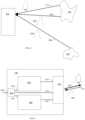
- FIG. 7depicts LiDAR system 700 according to some embodiments of the present technology for physically separating the one or more LiDAR heads from the rest of the LiDAR system (e.g., light sources and light detectors).
- LiDAR system 700includes a first LiDAR head 702 placed within housing 701 , and a second LiDAR head 752 placed within housing 751 .
- LiDAR head 702includes signal steering system 704 that uses motor drives 708 to move optical elements 706 so that pulses transmitted from LiDAR head 702 are directed in various directions to enable mapping of the environment around the system.
- LiDAR head 752includes pulse steering system 754 that uses motor drives 758 to move optical elements 756 so that pulses transmitted from LiDAR head 752 are directed in various directions to enable mapping of the environment around the system.
- LiDAR control system 712is housed in housing 711 that is separate and distinct from LiDAR head housings 701 and 751 .
- LiDAR control system 712includes light source 714 (such as the light source described with respect to FIG. 5 ), light detector 716 (such as the light detector described with respect to FIG. 6 ), and controller 718 (such as controller 408 described above).
- these three componentsare all placed within housing 711 . In other examples, the components could be placed in multiple housings separated from each other. Additionally, housing 711 and/or LiDAR control system 712 could include other components.
- LiDAR control system 712supplies light signals (e.g., light pulses) generated from light source 714 to LiDAR heads 702 and 752 via fibers 730 and 736 , respectively.
- Each of fibers 730 and 736may be a single fiber or multiple fibers (e.g., see description of multi-fiber connections with respect to FIG. 8 ).
- Returned pulses received at LiDAR heads 702 and 752are directed to light detector 716 via fibers 732 and 740 , respectively.
- Each of fibers 732 and 740may be a single fiber or multiple fibers.
- the returned pulsesare optionally directed or redirected by steering systems 704 or 754 . In some examples, however, returned pulses bypass the steering systems all together.
- Controller 718contains firmware and/or other software for controlling LiDAR heads 702 and 752 via communication lines 734 and 738 , respectively. Controller 718 optionally also receives information (e.g., registration data, status data, etc.) from LiDAR heads 702 and 752 via these communication lines. Controller 718 optionally also controls light source 714 and light detector 716 via communication lines that are not shown.
- LiDAR subsystem 722includes data processor 724 , control board 726 , and power supply 728 , which are all housed within housing 721 . While the housing 711 and housing 721 are depicted as separate and distinct housings, in other examples of the present technology, the components of LiDAR subsystem 722 and LiDAR control system 712 can be placed into one or more housings in any combination. LiDAR subsystem 722 provides power and control information via communication lines 742 and also receives data back from LiDAR control system 712 (e.g., estimated ranges, timing of transmitted and returned pulses, etc.).
- data back from LiDAR control system 712e.g., estimated ranges, timing of transmitted and returned pulses, etc.
- LiDAR heads 702 and 752do not contain any optically active elements (e.g., amplifiers, pumps, laser sources, etc.). In other embodiments (e.g., see FIG. 8 ) LiDAR heads 702 and 752 include some of these elements, such as the elements for amplifying a light pulse before it is transmitted by the steering system(s).
- optically active elementse.g., amplifiers, pumps, laser sources, etc.
- LiDAR heads 702 and 752include some of these elements, such as the elements for amplifying a light pulse before it is transmitted by the steering system(s).
- LiDAR heads 702 and 752from LiDAR control system 712 , LiDAR subsystem 722 , and particularly light source 714 and/or light detector 716 allows for any of LiDAR control system 712 's and/or LiDAR subsystem 722 's components to be held in a different environment than the LiDAR heads.
- light source 714 and light detector 716can be held in a controlled environment (e.g., a specific temperature or temperature range) while LiDAR heads 702 and 752 can be held in an uncontrolled environment (e.g., exposed to the outside so that the temperature fluctuates with the outside temperature).
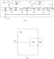
- FIG. 8depicts LiDAR system 800 implementing an embodiment of the present technology that allows for simplified connection of LiDAR heads to the rest of the LiDAR system. While LiDAR system 800 only has a single LiDAR head, the connection technique in LiDAR system 800 is extendable to any number of LiDAR heads by splitting the output of light source 802 to deliver pulses and CW power to multiple LiDAR heads. For example, the connection technology described with respect to LiDAR system 800 can be used to implement LiDAR system 700 of FIG. 7 .
- LiDAR system 800includes light source 802 and LiDAR head 804 .
- Light source 802includes many of the same components as light source 402 of FIG. 5 .
- housing 801 for light source 802does not include the final stages that are included in light source 402 (i.e., combiner 510 and booster amp 514 ).
- light source 802provides two fibers, fiber 511 and fiber 509 , that carry two outputs respectively.
- Fiber 511is a high power multimode fiber that can handle up to hundreds of watts output due to large fiber core size. Some implementations of fiber 511 are about 100 ⁇ or are 50 ⁇ -300 ⁇ in diameter.
- Fiber 509is a low power fiber.
- fiber 509is a single mode fiber.
- Some implementations of fiber 511are about 8 ⁇ or are 5 ⁇ -10 ⁇ in diameter.
- pre-amplifiers 508are configured to provide pulses of less than 300 mW on fiber 509 .
- the signals provided on fiber 509 and fiber 511are coupled to fiber 810 and fiber 812 , respectively, via connectors 808 and 806 , respectively.
- One benefit of separating the fiber sourcesis that the final laser power required by LiDAR system 100 may exceed maximum power limit of a single mode fiber connector.
- Connectorsenable easy system assembly and disassembly (e.g., for maintenance or replacement), especially for field engineers or customers. But many cost-efficient and low-loss single mode connectors cannot handle power higher than a few hundred milliwatts (300 mW). In some examples, the laser power needed by LiDAR system 100 may exceed this limit.
- a high power CW pump laser signalis delivered by multimode fiber 511 and connector 808 , which can handle up to hundreds of watts.
- a low power signale.g. less than 300 mW, is delivered by single mode fiber 509 and connector 806 .
- a pump signal on fiber 812(delivered from fiber 511 ) and a light signal on fiber 810 (delivered by fiber 509 ) are combined by combiner 510 and the signal is amplified by booster amp 514 to reach the required power level. This avoids the expense and complexity of having custom made connectors necessary to handle the higher power pulse signal that is eventually generated from booster amp 514 on fiber 818 .
- Steering system 704(as described with respect to FIG. 7 and more generally above with respect to pulse steering system 404 ) directs pulse 820 that was generated from booster amp 514 along optical path 822 .
- connectors 808 and 806are depicted as not being part of either light source 802 or LiDAR head 804 , in other examples, these connectors could be mounted on housing 801 or 803 , respectively (or are at least be an integrated part of light source 802 or LiDAR head 804 ). Additionally, more than one set of connectors may be present (e.g., one set that is a part of light source 802 and one set that is a part of LiDAR head 804 with a patch fiber cable connecting the two connectors).
- the use of connectors in LiDAR system 800allows for a design that avoids the need for a splicing tool when connecting LiDAR head 804 to light source 802 .
Landscapes
- Physics & Mathematics (AREA)
- Engineering & Computer Science (AREA)
- Electromagnetism (AREA)
- Computer Networks & Wireless Communication (AREA)
- General Physics & Mathematics (AREA)
- Radar, Positioning & Navigation (AREA)
- Remote Sensing (AREA)
- Plasma & Fusion (AREA)
- Optics & Photonics (AREA)
- Optical Radar Systems And Details Thereof (AREA)
Abstract
Description
Claims (24)
Priority Applications (1)
| Application Number | Priority Date | Filing Date | Title |
|---|---|---|---|
| US16/282,000US12085673B2 (en) | 2018-02-23 | 2019-02-21 | Distributed LiDAR systems |
Applications Claiming Priority (2)
| Application Number | Priority Date | Filing Date | Title |
|---|---|---|---|
| US201862634593P | 2018-02-23 | 2018-02-23 | |
| US16/282,000US12085673B2 (en) | 2018-02-23 | 2019-02-21 | Distributed LiDAR systems |
Publications (2)
| Publication Number | Publication Date |
|---|---|
| US20190265339A1 US20190265339A1 (en) | 2019-08-29 |
| US12085673B2true US12085673B2 (en) | 2024-09-10 |
Family
ID=67683939
Family Applications (2)
| Application Number | Title | Priority Date | Filing Date |
|---|---|---|---|
| US16/282,000Active2041-11-15US12085673B2 (en) | 2018-02-23 | 2019-02-21 | Distributed LiDAR systems |
| US16/281,993Active2041-02-17US11422234B2 (en) | 2018-02-23 | 2019-02-21 | Distributed lidar systems |
Family Applications After (1)
| Application Number | Title | Priority Date | Filing Date |
|---|---|---|---|
| US16/281,993Active2041-02-17US11422234B2 (en) | 2018-02-23 | 2019-02-21 | Distributed lidar systems |
Country Status (2)
| Country | Link |
|---|---|
| US (2) | US12085673B2 (en) |
| WO (1) | WO2019165095A1 (en) |
Families Citing this family (49)
| Publication number | Priority date | Publication date | Assignee | Title |
|---|---|---|---|---|
| US11609336B1 (en) | 2018-08-21 | 2023-03-21 | Innovusion, Inc. | Refraction compensation for use in LiDAR systems |
| WO2018182812A2 (en) | 2016-12-30 | 2018-10-04 | Innovusion Ireland Limited | Multiwavelength lidar design |
| US10942257B2 (en) | 2016-12-31 | 2021-03-09 | Innovusion Ireland Limited | 2D scanning high precision LiDAR using combination of rotating concave mirror and beam steering devices |
| US10969475B2 (en) | 2017-01-05 | 2021-04-06 | Innovusion Ireland Limited | Method and system for encoding and decoding LiDAR |
| US11009605B2 (en) | 2017-01-05 | 2021-05-18 | Innovusion Ireland Limited | MEMS beam steering and fisheye receiving lens for LiDAR system |
| US11054508B2 (en) | 2017-01-05 | 2021-07-06 | Innovusion Ireland Limited | High resolution LiDAR using high frequency pulse firing |
| CN111542765B (en) | 2017-10-19 | 2024-08-02 | 图达通智能美国有限公司 | LIDAR with large dynamic range |
| US11493601B2 (en) | 2017-12-22 | 2022-11-08 | Innovusion, Inc. | High density LIDAR scanning |
| US11977184B2 (en) | 2018-01-09 | 2024-05-07 | Seyond, Inc. | LiDAR detection systems and methods that use multi-plane mirrors |
| US11675050B2 (en) | 2018-01-09 | 2023-06-13 | Innovusion, Inc. | LiDAR detection systems and methods |
| WO2019164961A1 (en) | 2018-02-21 | 2019-08-29 | Innovusion Ireland Limited | Lidar systems with fiber optic coupling |
| US11391823B2 (en) | 2018-02-21 | 2022-07-19 | Innovusion, Inc. | LiDAR detection systems and methods with high repetition rate to observe far objects |
| WO2019165289A1 (en) | 2018-02-22 | 2019-08-29 | Innovusion Ireland Limited | Receive path for lidar system |
| WO2019165294A1 (en) | 2018-02-23 | 2019-08-29 | Innovusion Ireland Limited | 2-dimensional steering system for lidar systems |
| US11808888B2 (en) | 2018-02-23 | 2023-11-07 | Innovusion, Inc. | Multi-wavelength pulse steering in LiDAR systems |
| US12085673B2 (en) | 2018-02-23 | 2024-09-10 | Seyond, Inc. | Distributed LiDAR systems |
| WO2019245614A2 (en) | 2018-03-09 | 2019-12-26 | Innovusion Ireland Limited | Lidar safety systems and methods |
| WO2019199775A1 (en) | 2018-04-09 | 2019-10-17 | Innovusion Ireland Limited | Lidar systems and methods for exercising precise control of a fiber laser |
| US11789132B2 (en) | 2018-04-09 | 2023-10-17 | Innovusion, Inc. | Compensation circuitry for lidar receiver systems and method of use thereof |
| CN112585492B (en) | 2018-06-15 | 2024-10-25 | 图达通智能美国有限公司 | LIDAR system and method for focusing a range of interest |
| US11579300B1 (en) | 2018-08-21 | 2023-02-14 | Innovusion, Inc. | Dual lens receive path for LiDAR system |
| US11860316B1 (en) | 2018-08-21 | 2024-01-02 | Innovusion, Inc. | Systems and method for debris and water obfuscation compensation for use in LiDAR systems |
| US11614526B1 (en) | 2018-08-24 | 2023-03-28 | Innovusion, Inc. | Virtual windows for LIDAR safety systems and methods |
| US11796645B1 (en) | 2018-08-24 | 2023-10-24 | Innovusion, Inc. | Systems and methods for tuning filters for use in lidar systems |
| US11579258B1 (en) | 2018-08-30 | 2023-02-14 | Innovusion, Inc. | Solid state pulse steering in lidar systems |
| US12313788B1 (en) | 2018-10-09 | 2025-05-27 | Seyond, Inc. | Ultrashort pulses in LiDAR systems |
| WO2020102406A1 (en) | 2018-11-14 | 2020-05-22 | Innovusion Ireland Limited | Lidar systems and methods that use a multi-facet mirror |
| US11675055B2 (en) | 2019-01-10 | 2023-06-13 | Innovusion, Inc. | LiDAR systems and methods with beam steering and wide angle signal detection |
| US11486970B1 (en) | 2019-02-11 | 2022-11-01 | Innovusion, Inc. | Multiple beam generation from a single source beam for use with a LiDAR system |
| US11977185B1 (en) | 2019-04-04 | 2024-05-07 | Seyond, Inc. | Variable angle polygon for use with a LiDAR system |
| CN114008486A (en)* | 2019-05-21 | 2022-02-01 | 马卡鲁光学有限公司 | Scanning Lidar with Optical Switching |
| US12055630B2 (en) | 2020-10-15 | 2024-08-06 | Waymo Llc | Light detection and ranging device using combined pulse and continuous optical signals |
| US12360245B2 (en) | 2020-12-02 | 2025-07-15 | Waymo Llc | Dynamic sensing channel multiplexing for lidar applications |
| US12061289B2 (en) | 2021-02-16 | 2024-08-13 | Innovusion, Inc. | Attaching a glass mirror to a rotating metal motor frame |
| US11422267B1 (en) | 2021-02-18 | 2022-08-23 | Innovusion, Inc. | Dual shaft axial flux motor for optical scanners |
| US11789128B2 (en) | 2021-03-01 | 2023-10-17 | Innovusion, Inc. | Fiber-based transmitter and receiver channels of light detection and ranging systems |
| US11555895B2 (en) | 2021-04-20 | 2023-01-17 | Innovusion, Inc. | Dynamic compensation to polygon and motor tolerance using galvo control profile |
| US11614521B2 (en) | 2021-04-21 | 2023-03-28 | Innovusion, Inc. | LiDAR scanner with pivot prism and mirror |
| WO2022225859A1 (en) | 2021-04-22 | 2022-10-27 | Innovusion, Inc. | A compact lidar design with high resolution and ultra-wide field of view |
| CN117178199A (en) | 2021-04-22 | 2023-12-05 | 图达通智能美国有限公司 | Compact light detection and ranging design with high resolution and ultra wide field of view |
| EP4314885A1 (en) | 2021-05-12 | 2024-02-07 | Innovusion, Inc. | Systems and apparatuses for mitigating lidar noise, vibration, and harshness |
| EP4314884A1 (en) | 2021-05-21 | 2024-02-07 | Innovusion, Inc. | Movement profiles for smart scanning using galvonometer mirror inside lidar scanner |
| US12339371B2 (en) | 2021-07-06 | 2025-06-24 | Waymo Llc | Multimode lidar receiver for coherent distance and velocity measurements |
| US11768294B2 (en) | 2021-07-09 | 2023-09-26 | Innovusion, Inc. | Compact lidar systems for vehicle contour fitting |
| CN216356147U (en) | 2021-11-24 | 2022-04-19 | 图达通智能科技(苏州)有限公司 | Vehicle-mounted laser radar motor, vehicle-mounted laser radar and vehicle |
| CN114563793A (en)* | 2022-03-02 | 2022-05-31 | Nano科技(北京)有限公司 | Distributed frequency modulation continuous wave laser radar |
| US12204033B2 (en) | 2022-03-25 | 2025-01-21 | Seyond, Inc. | Multimodal detection with integrated sensors |
| US11871130B2 (en) | 2022-03-25 | 2024-01-09 | Innovusion, Inc. | Compact perception device |
| JP2024031215A (en)* | 2022-08-26 | 2024-03-07 | 株式会社小糸製作所 | Measuring device, control device and program |
Citations (267)
| Publication number | Priority date | Publication date | Assignee | Title |
|---|---|---|---|---|
| US3897150A (en) | 1972-04-03 | 1975-07-29 | Hughes Aircraft Co | Scanned laser imaging and ranging system |
| GB1427164A (en) | 1972-02-19 | 1976-03-10 | Nippon Electric Co | Interference eliminating system for radars |
| GB2000411A (en) | 1977-06-15 | 1979-01-04 | Impulsphysik Gmbh | Ceilometric method and apparatus |
| US4464048A (en) | 1981-03-25 | 1984-08-07 | Barr & Stroud Limited | Laser rangefinders |
| US4676586A (en) | 1982-12-20 | 1987-06-30 | General Electric Company | Apparatus and method for performing laser material processing through a fiber optic |
| US4923263A (en) | 1988-09-22 | 1990-05-08 | The United States Of America As Represented By The Secretary Of The Army | Rotating mirror optical scanning device |
| US5006721A (en) | 1990-03-23 | 1991-04-09 | Perceptron, Inc. | Lidar scanning system |
| US5012079A (en) | 1989-11-13 | 1991-04-30 | Lazerdata Corporation | Bar code scanner mirror assembly |
| US5157451A (en) | 1991-04-01 | 1992-10-20 | John Taboada | Laser imaging and ranging system using two cameras |
| US5173797A (en) | 1990-05-08 | 1992-12-22 | Xerox Corporation | Rotating mirror optical scanner with grooved grease bearings |
| US5185736A (en)* | 1989-05-12 | 1993-02-09 | Alcatel Na Network Systems Corp. | Synchronous optical transmission system |
| US5254893A (en) | 1992-01-30 | 1993-10-19 | Ide Russell D | Shaft support assembly for use in a polygon mirror drive motor |
| US5319434A (en) | 1992-12-30 | 1994-06-07 | Litton Systems, Inc. | Laser rangefinder apparatus with fiber optic interface |
| US5369661A (en) | 1991-02-07 | 1994-11-29 | Nippon Steel Corporation | Semiconductor laser-pumped solid state laser system and optical coupling system coupling semiconductor laser with optical fiber |
| US5442358A (en) | 1991-08-16 | 1995-08-15 | Kaman Aerospace Corporation | Imaging lidar transmitter downlink for command guidance of underwater vehicle |
| US5504731A (en) | 1992-03-06 | 1996-04-02 | Quantum Corporation | Remote fine positioning mechanism |
| US5546188A (en) | 1992-11-23 | 1996-08-13 | Schwartz Electro-Optics, Inc. | Intelligent vehicle highway system sensor and method |
| US5579153A (en) | 1992-04-27 | 1996-11-26 | Pirelli Cavi S.P.A. | Optical power limiting amplifier |
| EP0757257A2 (en) | 1995-07-31 | 1997-02-05 | HE HOLDINGS, INC. dba HUGHES ELECTRONICS | Laser range finder receiver |
| US5657077A (en) | 1993-02-18 | 1997-08-12 | Deangelis; Douglas J. | Event recording system with digital line camera |
| JPH09297014A (en) | 1996-05-08 | 1997-11-18 | Mitsubishi Heavy Ind Ltd | Laser radar 3-d form measurement device |
| US5793491A (en) | 1992-12-30 | 1998-08-11 | Schwartz Electro-Optics, Inc. | Intelligent vehicle highway system multi-lane sensor and method |
| US5838239A (en) | 1992-10-20 | 1998-11-17 | Robotic Vision Systems, Inc. | System for detecting ice or snow on surface which specularly reflects light |
| US5864391A (en) | 1996-04-04 | 1999-01-26 | Denso Corporation | Radar apparatus and a vehicle safe distance control system using this radar apparatus |
| US5920140A (en) | 1997-06-27 | 1999-07-06 | Asahi Kogaku Kogyo Kabushiki Kaisha | Galvano mirror unit |
| US5926259A (en) | 1995-05-04 | 1999-07-20 | Bushnell Corporation | Laser range finder with target quality display |
| US5936756A (en) | 1996-01-10 | 1999-08-10 | Ricoh Company Ltd. | Compact scanning optical system |
| US6163378A (en) | 1999-06-14 | 2000-12-19 | Khoury; Jehad | Spectroscopic time integrative correlation for rapid medical diagnostic and universal image analysis |
| US6317202B1 (en) | 1998-11-12 | 2001-11-13 | Denso Corporation | Automotive radar detecting lane mark and frontal obstacle |
| JP2002221574A (en) | 2001-01-25 | 2002-08-09 | Mitsubishi Heavy Ind Ltd | Method and system for identifying aerial position of flying object |
| EP1237305A2 (en) | 2001-02-28 | 2002-09-04 | KiloLambda IP Limited | Multi-wavelength light source |
| US20020136251A1 (en) | 2001-01-25 | 2002-09-26 | Science And Technology Corporation | Automatic gain control system for use with multiple wavelength signal detector |
| US20020149757A1 (en) | 2001-02-28 | 2002-10-17 | Optical Switch Corporation | Polarization vector alignment for interference lithography patterning |
| WO2002101408A1 (en) | 2001-06-12 | 2002-12-19 | Citech Sports Corporation Pty Ltd | System and method for monitoring and displaying athlete characteristics |
| US6593582B2 (en) | 2001-05-11 | 2003-07-15 | Science & Engineering Services, Inc. | Portable digital lidar system |
| US6650404B1 (en) | 2002-05-28 | 2003-11-18 | Analog Modules, Inc. | Laser rangefinder receiver |
| US20040135992A1 (en) | 2002-11-26 | 2004-07-15 | Munro James F. | Apparatus for high accuracy distance and velocity measurement and methods thereof |
| WO2004065984A1 (en) | 2003-01-15 | 2004-08-05 | ARETé ASSOCIATES | Ultraviolet, infrared, and near-infrared lidar system and method |
| JP2005009956A (en) | 2003-06-18 | 2005-01-13 | Mitsubishi Electric Corp | Laser equipment |
| US20050033497A1 (en) | 2003-08-06 | 2005-02-10 | Stopczynski Lawrence Gerard | Method of controlling an external object sensor for an automotive vehicle |
| US20050190424A1 (en) | 2004-02-27 | 2005-09-01 | Sick Ag | Method and device for optical scanning of objects |
| US20050195383A1 (en) | 1994-05-23 | 2005-09-08 | Breed David S. | Method for obtaining information about objects in a vehicular blind spot |
| CN1677050A (en) | 2004-03-31 | 2005-10-05 | 株式会社电装 | Object detector of vehicle |
| US20060071846A1 (en) | 2003-05-30 | 2006-04-06 | Yakayuki Yanagisawa | Coherent laser radar |
| US20060132752A1 (en) | 2004-12-16 | 2006-06-22 | Kane David M | Micromechanical and related lidar apparatus and method, and fast light-routing components |
| WO2006088822A2 (en) | 2005-02-14 | 2006-08-24 | Digital Signal Corporation | Laser radar system and system and method for providing chirped electromagnetic radiation |
| US7128267B2 (en) | 2003-07-11 | 2006-10-31 | Sick Ag | Device for optical scanning of objects, especially markings |
| US20070091948A1 (en) | 2005-07-29 | 2007-04-26 | Aculight Corporation | Multi-stage optical amplifier having photonic-crystal waveguides for generation of high-power pulsed radiation and associated method |
| JP2007144667A (en) | 2005-11-24 | 2007-06-14 | Fuji Xerox Co Ltd | Image forming apparatus and formed image correcting method |
| CA2629319A1 (en) | 2005-11-10 | 2007-07-26 | Optical Air Data Systems, Llc | Single aperture multiple optical waveguide transceiver |
| US20070188735A1 (en) | 2004-04-02 | 2007-08-16 | Leica Geosystems Ag | Electronic distance meter featuring spectral and spatial selectivety |
| US20070216995A1 (en) | 2006-03-16 | 2007-09-20 | Bollond Paul G | Optical fiber laser having improved efficiency |
| US20080037028A1 (en) | 2006-08-08 | 2008-02-14 | Northrop Grumman Corporation | Pulsed coherent fiber array and method |
| US7345271B2 (en) | 2002-09-25 | 2008-03-18 | Ibeo Automobile Sensor Gmbh | Optoelectric sensing device with common deflection device |
| US20080074640A1 (en) | 2006-09-22 | 2008-03-27 | Walsh Gregory C | Lidar system |
| EP1923721A1 (en) | 2005-08-15 | 2008-05-21 | Topcon Corporation | Measuring device |
| CN101201403A (en) | 2007-04-27 | 2008-06-18 | 北京航空航天大学 | 3D Polarization Imaging LiDAR Remote Sensor |
| US20080174762A1 (en) | 2006-08-29 | 2008-07-24 | Jony Jiang Liu | Micro-mirror optical tracking and ranging system |
| US20080193135A1 (en) | 2007-02-14 | 2008-08-14 | Finisar Corporation | Collimated ball lenses for optical triplexers |
| US20080192228A1 (en) | 2007-02-14 | 2008-08-14 | Eaton Robert B | High-speed laser ranging system including a fiber laser |
| US20090010644A1 (en) | 2002-02-01 | 2009-01-08 | Cubic Corporation | Integrated optical communication and range finding system and applications thereof |
| US20090028193A1 (en) | 2005-11-18 | 2009-01-29 | Omni Sciences, Inc. | Broadband or mid-infrared fiber light sources |
| US20090051926A1 (en) | 2007-04-13 | 2009-02-26 | United States Of America As Represented By The Administrator Of The National Aeronautics And Spac | Multiple frequency optical mixer and demultiplexer and apparatus for remote sensing |
| US20090059201A1 (en) | 2007-08-28 | 2009-03-05 | Science Applications International Corporation | Full-Field Light Detection and Ranging Imaging System |
| US20090067453A1 (en) | 2005-04-07 | 2009-03-12 | Matsushita Electric Industrial Co., Ltd. | Laser Light Source and Optical Device |
| US20090147239A1 (en) | 2005-09-02 | 2009-06-11 | Neptec | Apparatus and method for tracking an object |
| US20090262760A1 (en) | 2005-01-20 | 2009-10-22 | Vladimir Krupkin | Laser Obstacle Ranging and Display |
| US20090316134A1 (en) | 2004-07-08 | 2009-12-24 | Michael Christopher E | Fiber laser ladar |
| WO2010000751A1 (en) | 2008-07-04 | 2010-01-07 | Eads Deutschland Gmbh | Lidar method for measuring speeds and lidar device with time-controlled detection |
| US20100006760A1 (en) | 2004-04-13 | 2010-01-14 | Science & Engineering Services, Inc. | Ultraviolet lidar for detection of biological warfare agents |
| US20100020377A1 (en) | 2008-07-25 | 2010-01-28 | Spudnik, Inc. | Beam Scanning Based on Two-Dimensional Polygon Scanner for Display and Other Applications |
| US20100020306A1 (en) | 2006-07-13 | 2010-01-28 | Velodyne Acoustics, Inc. | High definition lidar system |
| US20100027602A1 (en) | 2008-07-31 | 2010-02-04 | United States Of America As Represented By The Administrator Of The National Aeronautics And Spac | Time delay and distance measurement |
| JP2010035385A (en) | 2008-07-31 | 2010-02-12 | Kyocera Mita Corp | Motor drive controller |
| EP2157445A2 (en) | 2008-08-19 | 2010-02-24 | Rosemount Aerospace Inc. | Lidar system using a pseudo-random pulse sequence |
| US20100053715A1 (en) | 2006-10-30 | 2010-03-04 | O'neill James | Scanning system for lidar |
| JP2010085316A (en) | 2008-10-01 | 2010-04-15 | Topcon Corp | Laser apparatus and distance measuring device |
| US20100128109A1 (en) | 2008-11-25 | 2010-05-27 | Banks Paul S | Systems And Methods Of High Resolution Three-Dimensional Imaging |
| KR20100096931A (en) | 2009-02-25 | 2010-09-02 | (주)하드램 | Laser direct imaging system having multi scanner unit |
| US20100271614A1 (en) | 2006-01-27 | 2010-10-28 | Vijay Albuquerque | LIDAR system utilizing SOI-based opto-electronic components |
| US7880865B2 (en) | 2007-02-28 | 2011-02-01 | Denso Wave Incorporated | Laser radar apparatus for three-dimensional detection of objects |
| US20110185935A1 (en) | 2008-08-08 | 2011-08-04 | Mbda Uk Limited | Optical proximity fuze |
| US20110216792A1 (en) | 2010-03-05 | 2011-09-08 | TeraDiode, Inc. | Scalable Wavelength Beam Combining System and Method |
| EP2395368A1 (en) | 2010-06-11 | 2011-12-14 | Sick AG | Distance-measuring laser scanner for detecting objects in a surveillance range |
| US20110306956A1 (en)* | 2010-01-07 | 2011-12-15 | Cheetah Omni, Llc | Laser-based method and system for selectively processing target tissue material in a patient and optical catheter assembly for use therein |
| JP2012026921A (en) | 2010-07-26 | 2012-02-09 | Sharp Corp | Optical distance measuring equipment and equipment loaded with the same |
| KR20120013515A (en) | 2010-08-05 | 2012-02-15 | (주)이오시스템 | Avalanche Photodiode Gain Compensation Device of Optical Measuring Equipment |
| US20120038903A1 (en) | 2010-08-16 | 2012-02-16 | Ball Aerospace & Technologies Corp. | Electronically steered flash lidar |
| JP2012083289A (en) | 2010-10-14 | 2012-04-26 | Toyota Motor Corp | Distance measuring device, distance measuring method and program |
| US20120124113A1 (en) | 2010-11-05 | 2012-05-17 | University of Maribor | LIGHT DETECTION AND RANGING (LiDAR)DATA COMPRESSION AND DECOMPRESSION METHODS AND APPARATUS |
| US20120162749A1 (en) | 2009-06-30 | 2012-06-28 | Trimble Ab | Optical pulse transmitter |
| US20120221142A1 (en) | 2011-02-24 | 2012-08-30 | Mss, Inc. | Sequential Scanning Of Multiple Wavelengths |
| US20130107016A1 (en) | 2010-05-17 | 2013-05-02 | Iee International Electronics & Engineering S.A. | Scanning 3d imager |
| US20130116971A1 (en) | 2010-06-28 | 2013-05-09 | Fraunhofer-Gesellschaft Zur Foerderung Der Angewandten Forschung E.V. | Method for generating a signal for a distance measurement and method and system for distance measurement between a transmitter and a receiver |
| KR20130068224A (en) | 2011-12-15 | 2013-06-26 | 여우순엽 | The apparatus and method of monitoring with terrestrial lidar and reflectless totalstation |
| DE102012202637A1 (en) | 2012-02-21 | 2013-08-22 | Ldt Laser Display Technology Gmbh | Projection head for a laser projector |
| US20130241761A1 (en) | 2012-03-16 | 2013-09-19 | Nikon Corporation | Beam steering for laser radar and other uses |
| US20130293946A1 (en) | 2012-05-01 | 2013-11-07 | Imra America, Inc. | Optical frequency ruler |
| US20130293867A1 (en) | 2009-09-23 | 2013-11-07 | Pixart Imaging Inc. | Distance-measuring device of measuring distance according to variation of imaging location and calibrating method thereof |
| US20130314694A1 (en) | 2010-04-20 | 2013-11-28 | Michigan Aerospace Corporation | Atmospheric measurement system and method |
| US20130329279A1 (en) | 2004-03-31 | 2013-12-12 | Imra America, Inc. | Method and apparatus for controlling and protecting pulsed high power fiber amplifier systems |
| US20130342822A1 (en) | 2011-03-02 | 2013-12-26 | Toyota Jidosha Kabushiki Kaisha | Laser radar device |
| US20140036252A1 (en) | 2012-08-03 | 2014-02-06 | U.S.A. As Represented By The Administrator Of The National Aeronautics And Space Administration | Coherent Doppler Lidar for Measuring Altitude, Ground Velocity, and Air Velocity of Aircraft and Spaceborne Vehicles |
| US20140078514A1 (en) | 2010-10-22 | 2014-03-20 | Neptec Design Group Ltd. | Wide angle bistatic scanning optical ranging sensor |
| US20140104594A1 (en) | 2009-07-28 | 2014-04-17 | Applied Concepts, Inc. | Lidar Measurement Device with Target Tracking and Method for Use of Same |
| CN103750814A (en) | 2013-12-31 | 2014-04-30 | 苏州微清医疗器械有限公司 | Fundus scanning imaging device |
| CN103792544A (en) | 2014-02-17 | 2014-05-14 | 北京师范大学 | Vibration-rotational Raman-Mie scattering multi-wavelength laser radar system and working method thereof |
| US20140226140A1 (en) | 2013-02-13 | 2014-08-14 | Kla-Tencor Corporation | 193nm Laser And Inspection System |
| US20140347650A1 (en) | 2011-12-23 | 2014-11-27 | Leica Geosystems Ag | Distance-measuring device alignment |
| US20140350836A1 (en) | 2013-05-24 | 2014-11-27 | Advance Scientific Concepts, Inc. | Automotive auxiliary ladar sensor |
| WO2014203654A1 (en) | 2013-06-17 | 2014-12-24 | 株式会社日立製作所 | Distance measurement device, shape measurement device, processing system, distance measurement method, shape measurement method, and processing method |
| CN204216401U (en) | 2014-11-11 | 2015-03-18 | 山东能源机械集团大族再制造有限公司 | A kind of semiconductor laser |
| US20150078123A1 (en) | 2013-09-16 | 2015-03-19 | Appareo Systems, Llc | Synthetic underwater visualization system |
| US20150084805A1 (en) | 2012-03-19 | 2015-03-26 | Qinetiq Limited | Detection Techniques |
| US20150109603A1 (en) | 2013-10-21 | 2015-04-23 | Electronics And Telecommunications Research Institute | Multi-wavelength image lidar sensor apparatus and signal processing method thereof |
| US20150116692A1 (en) | 2012-04-30 | 2015-04-30 | Michigan Aerospace Corporation | System and method for scan range gating |
| US20150139259A1 (en) | 2013-11-21 | 2015-05-21 | Christie Digital Systems Canada Inc. | Method, system and apparatus for automatically determining operating conditions of a periodically poled lithium niobate crystal in a laser system |
| US20150158489A1 (en) | 2013-12-09 | 2015-06-11 | Hyundai Motor Company | Method for object processing and vehicle supporting the same |
| JP2015111160A (en) | 2008-09-11 | 2015-06-18 | ニコン・メトロロジー・エヌヴェ | Compact fiber optic geometry for counter chirp fmcw coherent laser rader |
| US9065243B2 (en) | 2011-01-20 | 2015-06-23 | Nippon Telegraph And Telephone Corporation | Optical amplifier |
| EP2889642A1 (en) | 2013-12-16 | 2015-07-01 | Riegl Laser Measurement Systems GmbH | Method for distance measurement |
| US9086273B1 (en) | 2013-03-08 | 2015-07-21 | Google Inc. | Microrod compression of laser beam in combination with transmit lens |
| WO2015120118A1 (en)* | 2014-02-10 | 2015-08-13 | Soraa Laser Diode, Inc. | Manufacturable laser diode |
| CN204758260U (en) | 2015-07-21 | 2015-11-11 | 北京杏林睿光科技有限公司 | Semiconductor laser structure of multitube core characteristic monitoring |
| US20150338270A1 (en) | 2012-05-10 | 2015-11-26 | Voxtel, Inc. | Discriminating photo counts and dark counts in an avalanche photodiode |
| US20150355327A1 (en) | 2012-11-21 | 2015-12-10 | Nikon Metrology Nv | Scan mirrors for laser radar |
| CN204885804U (en) | 2015-07-21 | 2015-12-16 | 北京杏林睿光科技有限公司 | A narrow linewidth beam combining module and a multi-wavelength Raman laser with the module |
| US20160003946A1 (en) | 2014-07-03 | 2016-01-07 | Advanced Scientific Concepts, Inc. | Ladar sensor for a dense environment |
| US20160047896A1 (en) | 2014-08-15 | 2016-02-18 | US LADAR, Inc. | Method and System for Ladar Transmission with Spinning Polygon Mirror for Dynamic Scan Patterns |
| US20160061935A1 (en) | 2014-08-28 | 2016-03-03 | Google Inc. | Methods and Systems for Vehicle Radar Coordination and Interference Reduction |
| US20160061655A1 (en) | 2014-09-03 | 2016-03-03 | Panasonic Intellectual Property Management Co., Ltd. | Measurement system |
| US9279662B2 (en) | 2012-09-14 | 2016-03-08 | Faro Technologies, Inc. | Laser scanner |
| US9304316B2 (en) | 2004-11-15 | 2016-04-05 | Apple Inc. | Method and device for scanning light |
| US20160100521A1 (en) | 2014-10-10 | 2016-04-14 | Irobot Corporation | Autonomous Robot Localization |
| US9316724B2 (en) | 2012-12-18 | 2016-04-19 | Sick Ag | Optoelectronic sensor for the detection of objects |
| US20160117048A1 (en) | 2014-09-26 | 2016-04-28 | Cypress Semiconductor Corporation | Background Light Detection for Optical Navigation Systems |
| US20160139266A1 (en) | 2014-11-14 | 2016-05-19 | Juan C. Montoya | Methods and apparatus for phased array imaging |
| US20160172819A1 (en) | 2014-12-12 | 2016-06-16 | Omron Corporation | Light amplifying device and laser processing apparatus |
| US20160178736A1 (en) | 2014-12-19 | 2016-06-23 | Hanwha Techwin Co., Ltd. | Lidar system |
| US20160226210A1 (en) | 2015-01-29 | 2016-08-04 | John J. Zayhowski | Systems and methods for light amplification |
| US20160245902A1 (en) | 2015-02-25 | 2016-08-25 | Abbie T. Watnik | Real-time processing and adaptable illumination lidar camera using a spatial light modulator |
| US20160259038A1 (en) | 2015-03-05 | 2016-09-08 | Facet Technology Corp. | Methods and Apparatus for Increased Precision and Improved Range in a Multiple Detector LiDAR Array |
| US20160273034A1 (en) | 2015-03-16 | 2016-09-22 | Pacific Biosciences Of California, Inc. | Integrated devices and systems for free-space optical coupling |
| US20160291134A1 (en) | 2015-04-06 | 2016-10-06 | Google Inc. | Long Range Steerable LIDAR System |
| US9465175B2 (en) | 2014-07-23 | 2016-10-11 | Sifotonics Technologies Co., Ltd. | Integrated lens-array-on-substrate for optical coupling system and fabrication method thereof |
| CN205643711U (en) | 2016-05-13 | 2016-10-12 | 北醒(北京)光子科技有限公司 | Multi -thread rotational scanning detecting device |
| US20160313445A1 (en) | 2012-03-16 | 2016-10-27 | Advanced Scientific Concepts, Inc. | Personal ladar sensor |
| US20160327646A1 (en) | 2015-05-07 | 2016-11-10 | GM Global Technology Operations LLC | Pseudo random sequences in array lidar systems |
| US9529083B2 (en)* | 2009-11-20 | 2016-12-27 | Faro Technologies, Inc. | Three-dimensional scanner with enhanced spectroscopic energy detector |
| US20160377721A1 (en) | 2015-06-26 | 2016-12-29 | Mezmeriz Inc. | Beat signal bandwidth compression method, apparatus, and applications |
| JP2017003347A (en) | 2015-06-08 | 2017-01-05 | 日本信号株式会社 | Object detection device and object detection method |
| US20170003116A1 (en) | 2015-06-30 | 2017-01-05 | Korea Research Institute Of Standards And Science | Apparatus for real-time non-contact non-destructive thickness measurement using terahertz wave |
| CN106597471A (en) | 2016-11-08 | 2017-04-26 | 上海禾赛光电科技有限公司 | Vehicle with automatic detection function of transparent barrier and work method thereof |
| US20170153319A1 (en) | 2015-11-30 | 2017-06-01 | Luminar Technologies, Inc. | Lidar system with distributed laser and multiple sensor heads |
| WO2017110417A1 (en) | 2015-12-21 | 2017-06-29 | 株式会社小糸製作所 | Image acquisition device for vehicles, control device, vehicle provided with image acquisition device for vehicles and control device, and image acquisition method for vehicles |
| JP2017138301A (en) | 2016-01-28 | 2017-08-10 | 株式会社デンソー | Laser radar equipment |
| US20170242104A1 (en) | 2016-02-18 | 2017-08-24 | Aeye, Inc. | Ladar Transmitter with Induced Phase Drift for Improved Gaze on Scan Area Portions |
| US20170307738A1 (en) | 2013-11-22 | 2017-10-26 | Uber Technologies, Inc. | Lidar scanner calibration |
| US9810776B2 (en) | 2013-12-29 | 2017-11-07 | Irvine Senors Corp. | LIDAR scanner apparatus |
| US9810786B1 (en) | 2017-03-16 | 2017-11-07 | Luminar Technologies, Inc. | Optical parametric oscillator for lidar system |
| US20170365105A1 (en) | 2016-06-17 | 2017-12-21 | Ford Global Technologies, Llc | Method and apparatus for inter-vehicular safety awareness and alert |
| US9869754B1 (en) | 2017-03-22 | 2018-01-16 | Luminar Technologies, Inc. | Scan patterns for lidar systems |
| US9879990B2 (en) | 2013-03-22 | 2018-01-30 | Kongsberg Seatex As | Position reference system and method for positioning and tracking one or more objects |
| US9880278B2 (en) | 2013-08-01 | 2018-01-30 | Robert Bosch Gmbh | Object determination using a radar sensor |
| US20180031678A1 (en)* | 2016-07-28 | 2018-02-01 | Strobe, Inc. | Distributed Vehicle Lidar System |
| US20180040171A1 (en) | 2016-08-02 | 2018-02-08 | International Business Machines Corporation | Self-driving vehicle sensor fault remediation |
| US20180050704A1 (en) | 2016-08-16 | 2018-02-22 | Uber Technologies, Inc. | Autonomous vehicle diagnostic system |
| US9910139B2 (en) | 2015-03-27 | 2018-03-06 | Waymo Llc | Methods and systems for LIDAR optics alignment |
| CN108089201A (en) | 2017-12-08 | 2018-05-29 | 上海禾赛光电科技有限公司 | Obstacle information acquisition methods, the launching technique of laser pulse and device |
| US20180152691A1 (en) | 2015-09-24 | 2018-05-31 | Ouster, Inc. | Optical system for collecting distance information within a field |
| CN207457508U (en) | 2017-08-08 | 2018-06-05 | 上海禾赛光电科技有限公司 | Laser radar system based on two-dimensional scanning mirrors |
| US9989629B1 (en) | 2017-03-30 | 2018-06-05 | Luminar Technologies, Inc. | Cross-talk mitigation using wavelength switching |
| US20180158471A1 (en) | 2016-12-02 | 2018-06-07 | Breakaway Records, L.L.C. | Record Stabilizer for Multiple Vinyl Sizes |
| US20180156896A1 (en) | 2016-05-18 | 2018-06-07 | James Thomas O'Keeffe | Dynamically steered lidar adapted to vehicle shape |
| CN108132472A (en) | 2017-12-08 | 2018-06-08 | 上海禾赛光电科技有限公司 | Laser radar system |
| US20180164439A1 (en) | 2016-12-13 | 2018-06-14 | Waymo Llc | Power Modulation for a Rotary Light Detection and Ranging (LIDAR) Device |
| US10003168B1 (en) | 2017-10-18 | 2018-06-19 | Luminar Technologies, Inc. | Fiber laser with free-space components |
| US10007001B1 (en) | 2017-03-28 | 2018-06-26 | Luminar Technologies, Inc. | Active short-wave infrared four-dimensional camera |
| CN207557465U (en) | 2017-08-08 | 2018-06-29 | 上海禾赛光电科技有限公司 | Laser radar system based on tilting mirror |
| US20180188371A1 (en) | 2016-12-30 | 2018-07-05 | Innovusion Ireland Limited | Multiwavelength lidar design |
| US20180188358A1 (en) | 2017-01-05 | 2018-07-05 | Innovusion Ireland Limited | METHOD AND SYSTEM FOR ENCODING AND DECODING LiDAR |
| US20180188355A1 (en) | 2016-12-31 | 2018-07-05 | Innovusion Ireland Limited | 2D SCANNING HIGH PRECISION LiDAR USING COMBINATION OF ROTATING CONCAVE MIRROR AND BEAM STEERING DEVICES |
| WO2018126248A1 (en) | 2017-01-02 | 2018-07-05 | Okeeffe James | Micromirror array for feedback-based image resolution enhancement |
| US20180188357A1 (en) | 2017-01-05 | 2018-07-05 | Innovusion Ireland Limited | HIGH RESOLUTION LiDAR USING HIGH FREQUENCY PULSE FIRING |
| US20180188447A1 (en)* | 2015-06-25 | 2018-07-05 | Nkt Photonics A/S | A delivery fiber assembly and a broad band source |
| WO2018129410A1 (en) | 2017-01-05 | 2018-07-12 | Innovusion Ireland Limited | Mems beam steering and fisheye receiving lens for lidar system |
| US20180210084A1 (en) | 2017-01-26 | 2018-07-26 | Sick Ag | Optoelectronic sensor and method of determining the distance of an object in a monitored zone |
| US10042159B2 (en) | 2016-02-18 | 2018-08-07 | Aeye, Inc. | Ladar transmitter with optical field splitter/inverter |
| CN108445468A (en) | 2018-04-03 | 2018-08-24 | 上海禾赛光电科技有限公司 | A kind of distribution type laser radar |
| US10061019B1 (en) | 2017-03-28 | 2018-08-28 | Luminar Technologies, Inc. | Diffractive optical element in a lidar system to correct for backscan |
| WO2018162010A1 (en) | 2017-03-10 | 2018-09-13 | Ktp Kunststoff Palettentechnik Gmbh | Transport apparatus and method and device for producing the transport apparatus |
| US20180275274A1 (en) | 2017-03-23 | 2018-09-27 | Innovusion Ireland Limited | High resolution lidar using multi-stage multi-phase signal modulation, integration, sampling, and analysis |
| KR20180107673A (en) | 2017-03-22 | 2018-10-02 | (주) 위키옵틱스 | LIDAR light-emitting system improved pattern rotation |
| US20180284242A1 (en) | 2017-03-30 | 2018-10-04 | Luminar Technologies, Inc. | Protecting Detector in a Lidar System Using Off-Axis Illumination |
| US20180284241A1 (en) | 2017-03-29 | 2018-10-04 | Luminar Technologies, Inc. | Sizing the Field of View of a Detector to Improve Operation of a Lidar System |
| US20180284286A1 (en) | 2017-03-31 | 2018-10-04 | Luminar Technologies, Inc. | Multi-eye lidar system |
| US10094925B1 (en) | 2017-03-31 | 2018-10-09 | Luminar Technologies, Inc. | Multispectral lidar system |
| US20180329060A1 (en) | 2017-05-15 | 2018-11-15 | Ouster, Inc. | Lidar unit with an optical link between controller and photosensor layer |
| CN109116367A (en) | 2018-06-27 | 2019-01-01 | 上海禾赛光电科技有限公司 | A kind of laser radar |
| CN109116331A (en) | 2018-06-27 | 2019-01-01 | 上海禾赛光电科技有限公司 | A kind of coded laser light R-T unit, range unit and laser radar system |
| CN109116366A (en) | 2018-06-27 | 2019-01-01 | 上海禾赛光电科技有限公司 | A kind of multi-thread beam laser radar of non-homogeneous pulse energy |
| CN208314210U (en) | 2018-06-29 | 2019-01-01 | 上海禾赛光电科技有限公司 | laser radar system |
| CN109188397A (en) | 2018-08-29 | 2019-01-11 | 上海禾赛光电科技有限公司 | Laser transmitting-receiving device and laser radar |
| CN208421228U (en) | 2018-06-29 | 2019-01-22 | 上海禾赛光电科技有限公司 | laser radar system |
| US10191155B2 (en) | 2017-03-29 | 2019-01-29 | Luminar Technologies, Inc. | Optical resolution in front of a vehicle |
| CN208705506U (en) | 2018-08-28 | 2019-04-05 | 上海禾赛光电科技有限公司 | A kind of lens group for laser radar |
| US20190107607A1 (en) | 2017-10-09 | 2019-04-11 | Luminar Technologies, Inc. | Interlaced scan patterns for lidar system |
| WO2019079642A1 (en) | 2017-10-19 | 2019-04-25 | Innovusion Ireland Limited | Lidar with large dynamic range |
| US20190120962A1 (en) | 2017-10-20 | 2019-04-25 | Sick Ag | Transmission/reception module for an optoelectronic sensor and method of detecting objects |
| CN109690383A (en) | 2016-09-13 | 2019-04-26 | 三菱电机株式会社 | Galvano scanner and mirror unit |
| CN109725320A (en) | 2017-10-27 | 2019-05-07 | 上海禾赛光电科技有限公司 | A kind of laser radar |
| US10295656B1 (en) | 2018-06-13 | 2019-05-21 | Hesai Photonics Technology Co., Ltd. | Lidar systems and methods |
| US20190154804A1 (en) | 2017-11-22 | 2019-05-23 | Luminar Technologies, Inc. | Efficient orientation of a lidar system in a vehicle |
| US20190154807A1 (en) | 2017-11-21 | 2019-05-23 | Sick Ag | Polygon scanner and method of detecting objects in a monitored zone |
| CN109814086A (en) | 2019-01-07 | 2019-05-28 | 上海禾赛光电科技有限公司 | Laser radar |
| CN109814082A (en) | 2019-01-21 | 2019-05-28 | 上海禾赛光电科技有限公司 | Optical receiver module and laser radar system |
| US10324170B1 (en) | 2018-04-05 | 2019-06-18 | Luminar Technologies, Inc. | Multi-beam lidar system with polygon mirror |
| CN109917408A (en) | 2019-03-28 | 2019-06-21 | 上海禾赛光电科技有限公司 | Echo processing techniques, distance measuring method and the laser radar of laser radar |
| CN109917348A (en) | 2019-01-25 | 2019-06-21 | 上海禾赛光电科技有限公司 | A kind of laser radar system |
| CN109950784A (en) | 2019-04-10 | 2019-06-28 | 上海禾赛光电科技有限公司 | Laser and laser radar |
| US20190212416A1 (en) | 2018-01-09 | 2019-07-11 | Innovusion Ireland Limited | Lidar detection systems and methods |
| CN110031822A (en) | 2019-04-22 | 2019-07-19 | 上海禾赛光电科技有限公司 | Noise identification method and lidar system that can be used in lidar |
| CN110031823A (en) | 2019-04-22 | 2019-07-19 | 上海禾赛光电科技有限公司 | Noise point identification method for laser radar and laser radar system |
| CN209280923U (en) | 2018-10-16 | 2019-08-20 | 上海禾赛光电科技有限公司 | It is a kind of for the receiving terminal circuit of laser radar, reception device and laser radar |
| US20190257924A1 (en) | 2018-02-22 | 2019-08-22 | Innovusion Ireland Limited | Receive path for lidar system |
| US10393877B2 (en) | 2016-06-01 | 2019-08-27 | Velodyne Lidar, Inc. | Multiple pixel scanning LIDAR |
| US20190265334A1 (en) | 2018-02-23 | 2019-08-29 | Innovusion Ireland Limited | Distributed lidar systems |
| US20190265336A1 (en) | 2018-02-23 | 2019-08-29 | Innovusion Ireland Limited | 2-dimensional steering system for lidar systems |
| US20190265337A1 (en) | 2018-02-23 | 2019-08-29 | Innovusion Ireland Limited | Multi-wavelength pulse steering in lidar systems |
| US20190273365A1 (en) | 2014-08-27 | 2019-09-05 | Nuburu, Inc. | Multi kW Class Blue Laser System |
| US20190277952A1 (en) | 2018-03-08 | 2019-09-12 | Zf Friedrichshafen Ag | Receiver arrangement for the reception of light impulses, lidar module and method for receiving light impulses |
| US10429495B1 (en) | 2018-04-03 | 2019-10-01 | Hesai Photonics Technology Co., Ltd. | Lidar system and method |
| US20190310368A1 (en) | 2018-04-06 | 2019-10-10 | Luminar Technologies, Inc. | Lidar System with AlInAsSb Avalanche Photodiode |
| US10451716B2 (en) | 2017-11-22 | 2019-10-22 | Luminar Technologies, Inc. | Monitoring rotation of a mirror in a lidar system |
| US10466342B1 (en) | 2018-09-30 | 2019-11-05 | Hesai Photonics Technology Co., Ltd. | Adaptive coding for lidar systems |
| CN110492349A (en) | 2019-08-20 | 2019-11-22 | 上海禾赛光电科技有限公司 | Driving circuit, driving method and Optical Maser System |
| CN110492856A (en) | 2019-08-12 | 2019-11-22 | 上海禾赛光电科技有限公司 | Across resistance amplifying unit electronic feedback circuit, photodetection circuit and laser radar system |
| US10509112B1 (en) | 2019-04-02 | 2019-12-17 | Hesai Photonics Technology Co., Ltd. | Laser system for Lidar |
| CN110736975A (en) | 2019-11-07 | 2020-01-31 | 上海禾赛光电科技有限公司 | Receiver module and lidar including it |
| CN110784220A (en) | 2019-11-07 | 2020-02-11 | 上海禾赛光电科技有限公司 | Dynamic threshold timing circuit, laser radar and method for acquiring time information |
| CN110780283A (en) | 2019-11-22 | 2020-02-11 | 上海禾赛光电科技有限公司 | Receiving system, laser radar comprising same and echo receiving method |
| CN110780284A (en) | 2019-11-22 | 2020-02-11 | 上海禾赛光电科技有限公司 | Receiving system, laser radar including the same, and method of echo reception processing |
| US10627491B2 (en) | 2017-03-31 | 2020-04-21 | Velodyne Lidar, Inc. | Integrated LIDAR illumination power control |
| US10641872B2 (en) | 2016-02-18 | 2020-05-05 | Aeye, Inc. | Ladar receiver with advanced optics |
| US10663596B2 (en) | 2017-09-15 | 2020-05-26 | Aeye, Inc. | Ladar receiver with co-bore sited camera |
| US20200227882A1 (en) | 2018-04-09 | 2020-07-16 | Innovusion Ireland Limited | Lidar systems and methods for exercising precise control of a fiber laser |
| US10732281B2 (en) | 2017-03-28 | 2020-08-04 | Luminar Technologies, Inc. | Lidar detector system having range walk compensation |
| US20200319310A1 (en) | 2016-01-31 | 2020-10-08 | Velodyne Lidar, Inc. | Multiple pulse, lidar based 3-d imaging |
| CN211655309U (en) | 2019-12-23 | 2020-10-09 | 上海禾赛光电科技有限公司 | Laser and laser radar including the same |
| US20200341124A1 (en) | 2017-05-17 | 2020-10-29 | O-Net Communications (Shenzhen) Limited | Vehicle-mounted light detection and ranging (LIDAR) system |
| US20200400798A1 (en) | 2019-06-21 | 2020-12-24 | Aeva, Inc. | Lidar system with solid state spectral scanning |
| CN212623082U (en) | 2020-04-29 | 2021-02-26 | 上海禾赛光电科技有限公司 | Scanning device for laser radar and laser radar |
| US20210088630A9 (en) | 2017-04-19 | 2021-03-25 | Surestar Laser Technology (Suzhou) Co., Ltd. | Laser scanning device, radar device and scanning method thereof |
| CN112578396A (en) | 2019-09-30 | 2021-03-30 | 上海禾赛科技股份有限公司 | Method and device for coordinate transformation between radars and computer-readable storage medium |
| CN213182011U (en) | 2020-04-26 | 2021-05-11 | 上海禾赛光电科技有限公司 | Laser radar's transmitting unit, receiving element and laser radar |
| US11016192B2 (en) | 2017-07-05 | 2021-05-25 | Ouster, Inc. | Light ranging device with MEMS scanned emitter array and synchronized electronically scanned sensor array |
| US20210165169A1 (en) | 2017-01-30 | 2021-06-03 | Senko Adcanced Components, Inc. | Fiber optic system for narrow width fiber optic connectors, adapters and transceivers |
| CN213750313U (en) | 2020-11-27 | 2021-07-20 | 上海禾赛科技有限公司 | Optical window and laser radar |
| CN214151038U (en) | 2020-12-11 | 2021-09-07 | 上海禾赛科技有限公司 | Laser radar |
| CN214795200U (en) | 2021-04-30 | 2021-11-19 | 上海禾赛科技有限公司 | Window for laser radar and laser radar |
| CN214795206U (en) | 2021-04-07 | 2021-11-19 | 上海禾赛科技股份有限公司 | Laser radar |
| CN214895784U (en) | 2021-04-30 | 2021-11-26 | 上海禾赛科技有限公司 | Optical detection device and running vehicle |
| CN214895810U (en) | 2021-04-30 | 2021-11-26 | 上海禾赛科技有限公司 | Light splitting device and laser radar |
| US11194048B1 (en) | 2020-05-13 | 2021-12-07 | Luminar, Llc | Lidar system with high-resolution scan pattern |
| CN215641806U (en) | 2021-04-30 | 2022-01-25 | 上海禾赛科技有限公司 | Laser radar |
| US20220050187A1 (en)* | 2018-02-16 | 2022-02-17 | Xiaotian Steve Yao | Scan-less 3d optical sensing devices and associated lidar based on stacking of integrated photonic chips, wavelength division demultiplexing and position-to-angle conversion of a lens |
| CN215932142U (en) | 2021-09-15 | 2022-03-01 | 上海禾赛科技有限公司 | Laser radar |
- 2019
- 2019-02-21USUS16/282,000patent/US12085673B2/enactiveActive
- 2019-02-21WOPCT/US2019/018987patent/WO2019165095A1/ennot_activeCeased
- 2019-02-21USUS16/281,993patent/US11422234B2/enactiveActive
Patent Citations (385)
| Publication number | Priority date | Publication date | Assignee | Title |
|---|---|---|---|---|
| GB1427164A (en) | 1972-02-19 | 1976-03-10 | Nippon Electric Co | Interference eliminating system for radars |
| US3897150A (en) | 1972-04-03 | 1975-07-29 | Hughes Aircraft Co | Scanned laser imaging and ranging system |
| GB2000411A (en) | 1977-06-15 | 1979-01-04 | Impulsphysik Gmbh | Ceilometric method and apparatus |
| US4464048A (en) | 1981-03-25 | 1984-08-07 | Barr & Stroud Limited | Laser rangefinders |
| US4676586A (en) | 1982-12-20 | 1987-06-30 | General Electric Company | Apparatus and method for performing laser material processing through a fiber optic |
| US4923263A (en) | 1988-09-22 | 1990-05-08 | The United States Of America As Represented By The Secretary Of The Army | Rotating mirror optical scanning device |
| US5185736A (en)* | 1989-05-12 | 1993-02-09 | Alcatel Na Network Systems Corp. | Synchronous optical transmission system |
| US5012079A (en) | 1989-11-13 | 1991-04-30 | Lazerdata Corporation | Bar code scanner mirror assembly |
| US5006721A (en) | 1990-03-23 | 1991-04-09 | Perceptron, Inc. | Lidar scanning system |
| US5173797A (en) | 1990-05-08 | 1992-12-22 | Xerox Corporation | Rotating mirror optical scanner with grooved grease bearings |
| US5369661A (en) | 1991-02-07 | 1994-11-29 | Nippon Steel Corporation | Semiconductor laser-pumped solid state laser system and optical coupling system coupling semiconductor laser with optical fiber |
| US5157451A (en) | 1991-04-01 | 1992-10-20 | John Taboada | Laser imaging and ranging system using two cameras |
| US5442358A (en) | 1991-08-16 | 1995-08-15 | Kaman Aerospace Corporation | Imaging lidar transmitter downlink for command guidance of underwater vehicle |
| US5254893A (en) | 1992-01-30 | 1993-10-19 | Ide Russell D | Shaft support assembly for use in a polygon mirror drive motor |
| US5504731A (en) | 1992-03-06 | 1996-04-02 | Quantum Corporation | Remote fine positioning mechanism |
| US5579153A (en) | 1992-04-27 | 1996-11-26 | Pirelli Cavi S.P.A. | Optical power limiting amplifier |
| US5838239A (en) | 1992-10-20 | 1998-11-17 | Robotic Vision Systems, Inc. | System for detecting ice or snow on surface which specularly reflects light |
| US5546188A (en) | 1992-11-23 | 1996-08-13 | Schwartz Electro-Optics, Inc. | Intelligent vehicle highway system sensor and method |
| US5319434A (en) | 1992-12-30 | 1994-06-07 | Litton Systems, Inc. | Laser rangefinder apparatus with fiber optic interface |
| US5793491A (en) | 1992-12-30 | 1998-08-11 | Schwartz Electro-Optics, Inc. | Intelligent vehicle highway system multi-lane sensor and method |
| US5657077A (en) | 1993-02-18 | 1997-08-12 | Deangelis; Douglas J. | Event recording system with digital line camera |
| US20050195383A1 (en) | 1994-05-23 | 2005-09-08 | Breed David S. | Method for obtaining information about objects in a vehicular blind spot |
| US5926259A (en) | 1995-05-04 | 1999-07-20 | Bushnell Corporation | Laser range finder with target quality display |
| EP0757257A2 (en) | 1995-07-31 | 1997-02-05 | HE HOLDINGS, INC. dba HUGHES ELECTRONICS | Laser range finder receiver |
| US5936756A (en) | 1996-01-10 | 1999-08-10 | Ricoh Company Ltd. | Compact scanning optical system |
| US5864391A (en) | 1996-04-04 | 1999-01-26 | Denso Corporation | Radar apparatus and a vehicle safe distance control system using this radar apparatus |
| JPH09297014A (en) | 1996-05-08 | 1997-11-18 | Mitsubishi Heavy Ind Ltd | Laser radar 3-d form measurement device |
| US5920140A (en) | 1997-06-27 | 1999-07-06 | Asahi Kogaku Kogyo Kabushiki Kaisha | Galvano mirror unit |
| US6317202B1 (en) | 1998-11-12 | 2001-11-13 | Denso Corporation | Automotive radar detecting lane mark and frontal obstacle |
| US6163378A (en) | 1999-06-14 | 2000-12-19 | Khoury; Jehad | Spectroscopic time integrative correlation for rapid medical diagnostic and universal image analysis |
| US6594000B2 (en) | 2001-01-25 | 2003-07-15 | Science And Technology Corporation | Automatic gain control system for use with multiple wavelength signal detector |
| JP2002221574A (en) | 2001-01-25 | 2002-08-09 | Mitsubishi Heavy Ind Ltd | Method and system for identifying aerial position of flying object |
| US20020136251A1 (en) | 2001-01-25 | 2002-09-26 | Science And Technology Corporation | Automatic gain control system for use with multiple wavelength signal detector |
| EP1237305A2 (en) | 2001-02-28 | 2002-09-04 | KiloLambda IP Limited | Multi-wavelength light source |
| US20020149757A1 (en) | 2001-02-28 | 2002-10-17 | Optical Switch Corporation | Polarization vector alignment for interference lithography patterning |
| US6593582B2 (en) | 2001-05-11 | 2003-07-15 | Science & Engineering Services, Inc. | Portable digital lidar system |
| WO2002101408A1 (en) | 2001-06-12 | 2002-12-19 | Citech Sports Corporation Pty Ltd | System and method for monitoring and displaying athlete characteristics |
| US7489865B2 (en) | 2002-02-01 | 2009-02-10 | Cubic Corporation | Integrated optical communication and range finding system and applications thereof |
| US20090010644A1 (en) | 2002-02-01 | 2009-01-08 | Cubic Corporation | Integrated optical communication and range finding system and applications thereof |
| US6650404B1 (en) | 2002-05-28 | 2003-11-18 | Analog Modules, Inc. | Laser rangefinder receiver |
| US7345271B2 (en) | 2002-09-25 | 2008-03-18 | Ibeo Automobile Sensor Gmbh | Optoelectric sensing device with common deflection device |
| US7202941B2 (en) | 2002-11-26 | 2007-04-10 | Munro James F | Apparatus for high accuracy distance and velocity measurement and methods thereof |
| US20040135992A1 (en) | 2002-11-26 | 2004-07-15 | Munro James F. | Apparatus for high accuracy distance and velocity measurement and methods thereof |
| WO2004065984A1 (en) | 2003-01-15 | 2004-08-05 | ARETé ASSOCIATES | Ultraviolet, infrared, and near-infrared lidar system and method |
| US20060071846A1 (en) | 2003-05-30 | 2006-04-06 | Yakayuki Yanagisawa | Coherent laser radar |
| JP2005009956A (en) | 2003-06-18 | 2005-01-13 | Mitsubishi Electric Corp | Laser equipment |
| US7128267B2 (en) | 2003-07-11 | 2006-10-31 | Sick Ag | Device for optical scanning of objects, especially markings |
| US20050033497A1 (en) | 2003-08-06 | 2005-02-10 | Stopczynski Lawrence Gerard | Method of controlling an external object sensor for an automotive vehicle |
| US6950733B2 (en) | 2003-08-06 | 2005-09-27 | Ford Global Technologies, Llc | Method of controlling an external object sensor for an automotive vehicle |
| US20050190424A1 (en) | 2004-02-27 | 2005-09-01 | Sick Ag | Method and device for optical scanning of objects |
| US20130329279A1 (en) | 2004-03-31 | 2013-12-12 | Imra America, Inc. | Method and apparatus for controlling and protecting pulsed high power fiber amplifier systems |
| CN1677050A (en) | 2004-03-31 | 2005-10-05 | 株式会社电装 | Object detector of vehicle |
| US20070188735A1 (en) | 2004-04-02 | 2007-08-16 | Leica Geosystems Ag | Electronic distance meter featuring spectral and spatial selectivety |
| US20100006760A1 (en) | 2004-04-13 | 2010-01-14 | Science & Engineering Services, Inc. | Ultraviolet lidar for detection of biological warfare agents |
| US20090316134A1 (en) | 2004-07-08 | 2009-12-24 | Michael Christopher E | Fiber laser ladar |
| US9304316B2 (en) | 2004-11-15 | 2016-04-05 | Apple Inc. | Method and device for scanning light |
| US7440084B2 (en) | 2004-12-16 | 2008-10-21 | Arete' Associates | Micromechanical and related lidar apparatus and method, and fast light-routing components |
| US20060132752A1 (en) | 2004-12-16 | 2006-06-22 | Kane David M | Micromechanical and related lidar apparatus and method, and fast light-routing components |
| US20090262760A1 (en) | 2005-01-20 | 2009-10-22 | Vladimir Krupkin | Laser Obstacle Ranging and Display |
| US7847235B2 (en) | 2005-01-20 | 2010-12-07 | Elbit Systems Electro-Optics Elop Ltd. | Laser obstacle ranging and display |
| WO2006088822A2 (en) | 2005-02-14 | 2006-08-24 | Digital Signal Corporation | Laser radar system and system and method for providing chirped electromagnetic radiation |
| US20090067453A1 (en) | 2005-04-07 | 2009-03-12 | Matsushita Electric Industrial Co., Ltd. | Laser Light Source and Optical Device |
| US7835068B1 (en) | 2005-07-29 | 2010-11-16 | Lockheed Martin Corporation | Photonic-crystal-rod optical amplifier with sealed-hole endcap and associated method |
| US7440175B2 (en) | 2005-07-29 | 2008-10-21 | Aculight Corporation | Multi-stage optical amplifier having photonic-crystal waveguides for generation of high-power pulsed radiation and associated method |
| US20070091948A1 (en) | 2005-07-29 | 2007-04-26 | Aculight Corporation | Multi-stage optical amplifier having photonic-crystal waveguides for generation of high-power pulsed radiation and associated method |
| EP1923721A1 (en) | 2005-08-15 | 2008-05-21 | Topcon Corporation | Measuring device |
| US20090147239A1 (en) | 2005-09-02 | 2009-06-11 | Neptec | Apparatus and method for tracking an object |
| CA2629319A1 (en) | 2005-11-10 | 2007-07-26 | Optical Air Data Systems, Llc | Single aperture multiple optical waveguide transceiver |
| US20090142066A1 (en) | 2005-11-10 | 2009-06-04 | Lance Richard Leclair | Single Aperture Multiple Optical Waveguide Transceiver |
| US20090028193A1 (en) | 2005-11-18 | 2009-01-29 | Omni Sciences, Inc. | Broadband or mid-infrared fiber light sources |
| JP2007144667A (en) | 2005-11-24 | 2007-06-14 | Fuji Xerox Co Ltd | Image forming apparatus and formed image correcting method |
| US20100271614A1 (en) | 2006-01-27 | 2010-10-28 | Vijay Albuquerque | LIDAR system utilizing SOI-based opto-electronic components |
| US7936448B2 (en) | 2006-01-27 | 2011-05-03 | Lightwire Inc. | LIDAR system utilizing SOI-based opto-electronic components |
| US20070216995A1 (en) | 2006-03-16 | 2007-09-20 | Bollond Paul G | Optical fiber laser having improved efficiency |
| US7969558B2 (en) | 2006-07-13 | 2011-06-28 | Velodyne Acoustics Inc. | High definition lidar system |
| US20100020306A1 (en) | 2006-07-13 | 2010-01-28 | Velodyne Acoustics, Inc. | High definition lidar system |
| US20080037028A1 (en) | 2006-08-08 | 2008-02-14 | Northrop Grumman Corporation | Pulsed coherent fiber array and method |
| US20080174762A1 (en) | 2006-08-29 | 2008-07-24 | Jony Jiang Liu | Micro-mirror optical tracking and ranging system |
| US7576837B2 (en) | 2006-08-29 | 2009-08-18 | The United States Of America As Represented By The Secretary Of The Army | Micro-mirror optical tracking and ranging system |
| US20080074640A1 (en) | 2006-09-22 | 2008-03-27 | Walsh Gregory C | Lidar system |
| US20100053715A1 (en) | 2006-10-30 | 2010-03-04 | O'neill James | Scanning system for lidar |
| US20080192228A1 (en) | 2007-02-14 | 2008-08-14 | Eaton Robert B | High-speed laser ranging system including a fiber laser |
| US20080193135A1 (en) | 2007-02-14 | 2008-08-14 | Finisar Corporation | Collimated ball lenses for optical triplexers |
| US7880865B2 (en) | 2007-02-28 | 2011-02-01 | Denso Wave Incorporated | Laser radar apparatus for three-dimensional detection of objects |
| US20090051926A1 (en) | 2007-04-13 | 2009-02-26 | United States Of America As Represented By The Administrator Of The National Aeronautics And Spac | Multiple frequency optical mixer and demultiplexer and apparatus for remote sensing |
| US7830527B2 (en) | 2007-04-13 | 2010-11-09 | The United States Of America As Represented By The Administrator Of The National Aeronautics And Space Administration | Multiple frequency optical mixer and demultiplexer and apparatus for remote sensing |
| CN101201403A (en) | 2007-04-27 | 2008-06-18 | 北京航空航天大学 | 3D Polarization Imaging LiDAR Remote Sensor |
| US20090059201A1 (en) | 2007-08-28 | 2009-03-05 | Science Applications International Corporation | Full-Field Light Detection and Ranging Imaging System |
| US20110181864A1 (en) | 2008-07-04 | 2011-07-28 | Eads Deutschland Gmbh | Lidar method for measuring speeds and lidar device with time-controlled detection |
| WO2010000751A1 (en) | 2008-07-04 | 2010-01-07 | Eads Deutschland Gmbh | Lidar method for measuring speeds and lidar device with time-controlled detection |
| US20100020377A1 (en) | 2008-07-25 | 2010-01-28 | Spudnik, Inc. | Beam Scanning Based on Two-Dimensional Polygon Scanner for Display and Other Applications |
| JP2010035385A (en) | 2008-07-31 | 2010-02-12 | Kyocera Mita Corp | Motor drive controller |
| US7982861B2 (en) | 2008-07-31 | 2011-07-19 | The United States Of America As Represented By The Administrator Of The National Aeronautics And Space Administration | Time delay and distance measurement |
| US20100027602A1 (en) | 2008-07-31 | 2010-02-04 | United States Of America As Represented By The Administrator Of The National Aeronautics And Spac | Time delay and distance measurement |
| US20110185935A1 (en) | 2008-08-08 | 2011-08-04 | Mbda Uk Limited | Optical proximity fuze |
| US20100045965A1 (en) | 2008-08-19 | 2010-02-25 | Rosemount Aerospace Inc. | Lidar system using a pseudo-random pulse sequence |
| US8072582B2 (en) | 2008-08-19 | 2011-12-06 | Rosemount Aerospace Inc. | Lidar system using a pseudo-random pulse sequence |
| EP2157445A2 (en) | 2008-08-19 | 2010-02-24 | Rosemount Aerospace Inc. | Lidar system using a pseudo-random pulse sequence |
| JP2015111160A (en) | 2008-09-11 | 2015-06-18 | ニコン・メトロロジー・エヌヴェ | Compact fiber optic geometry for counter chirp fmcw coherent laser rader |
| JP2010085316A (en) | 2008-10-01 | 2010-04-15 | Topcon Corp | Laser apparatus and distance measuring device |
| US20100128109A1 (en) | 2008-11-25 | 2010-05-27 | Banks Paul S | Systems And Methods Of High Resolution Three-Dimensional Imaging |
| US8471895B2 (en) | 2008-11-25 | 2013-06-25 | Paul S. Banks | Systems and methods of high resolution three-dimensional imaging |
| KR20100096931A (en) | 2009-02-25 | 2010-09-02 | (주)하드램 | Laser direct imaging system having multi scanner unit |
| US20120162749A1 (en) | 2009-06-30 | 2012-06-28 | Trimble Ab | Optical pulse transmitter |
| US20140104594A1 (en) | 2009-07-28 | 2014-04-17 | Applied Concepts, Inc. | Lidar Measurement Device with Target Tracking and Method for Use of Same |
| US8749764B2 (en) | 2009-09-23 | 2014-06-10 | Pixart Imaging Inc. | Distance-measuring device of measuring distance according to variation of imaging location and calibrating method thereof |
| US20130293867A1 (en) | 2009-09-23 | 2013-11-07 | Pixart Imaging Inc. | Distance-measuring device of measuring distance according to variation of imaging location and calibrating method thereof |
| US9529083B2 (en)* | 2009-11-20 | 2016-12-27 | Faro Technologies, Inc. | Three-dimensional scanner with enhanced spectroscopic energy detector |
| US20110306956A1 (en)* | 2010-01-07 | 2011-12-15 | Cheetah Omni, Llc | Laser-based method and system for selectively processing target tissue material in a patient and optical catheter assembly for use therein |
| US20110216792A1 (en) | 2010-03-05 | 2011-09-08 | TeraDiode, Inc. | Scalable Wavelength Beam Combining System and Method |
| US20130314694A1 (en) | 2010-04-20 | 2013-11-28 | Michigan Aerospace Corporation | Atmospheric measurement system and method |
| US20130107016A1 (en) | 2010-05-17 | 2013-05-02 | Iee International Electronics & Engineering S.A. | Scanning 3d imager |
| US9621876B2 (en) | 2010-05-17 | 2017-04-11 | Iee International Electronics & Engineering S.A. | Scanning 3D imager |
| EP2395368A1 (en) | 2010-06-11 | 2011-12-14 | Sick AG | Distance-measuring laser scanner for detecting objects in a surveillance range |
| US20130116971A1 (en) | 2010-06-28 | 2013-05-09 | Fraunhofer-Gesellschaft Zur Foerderung Der Angewandten Forschung E.V. | Method for generating a signal for a distance measurement and method and system for distance measurement between a transmitter and a receiver |
| JP2012026921A (en) | 2010-07-26 | 2012-02-09 | Sharp Corp | Optical distance measuring equipment and equipment loaded with the same |
| KR20120013515A (en) | 2010-08-05 | 2012-02-15 | (주)이오시스템 | Avalanche Photodiode Gain Compensation Device of Optical Measuring Equipment |
| US20120038903A1 (en) | 2010-08-16 | 2012-02-16 | Ball Aerospace & Technologies Corp. | Electronically steered flash lidar |
| US8736818B2 (en) | 2010-08-16 | 2014-05-27 | Ball Aerospace & Technologies Corp. | Electronically steered flash LIDAR |
| JP2012083289A (en) | 2010-10-14 | 2012-04-26 | Toyota Motor Corp | Distance measuring device, distance measuring method and program |
| US20140078514A1 (en) | 2010-10-22 | 2014-03-20 | Neptec Design Group Ltd. | Wide angle bistatic scanning optical ranging sensor |
| US9255790B2 (en) | 2010-10-22 | 2016-02-09 | Neptec Design Group Ltd. | Wide angle bistatic scanning optical ranging sensor |
| US9300321B2 (en) | 2010-11-05 | 2016-03-29 | University of Maribor | Light detection and ranging (LiDAR)data compression and decompression methods and apparatus |
| US20120124113A1 (en) | 2010-11-05 | 2012-05-17 | University of Maribor | LIGHT DETECTION AND RANGING (LiDAR)DATA COMPRESSION AND DECOMPRESSION METHODS AND APPARATUS |
| US9065243B2 (en) | 2011-01-20 | 2015-06-23 | Nippon Telegraph And Telephone Corporation | Optical amplifier |
| US20120221142A1 (en) | 2011-02-24 | 2012-08-30 | Mss, Inc. | Sequential Scanning Of Multiple Wavelengths |
| US8812149B2 (en) | 2011-02-24 | 2014-08-19 | Mss, Inc. | Sequential scanning of multiple wavelengths |
| US20130342822A1 (en) | 2011-03-02 | 2013-12-26 | Toyota Jidosha Kabushiki Kaisha | Laser radar device |
| US8994928B2 (en) | 2011-03-02 | 2015-03-31 | Toyota Jidosha Kabushiki Kaisha | Laser radar device |
| KR20130068224A (en) | 2011-12-15 | 2013-06-26 | 여우순엽 | The apparatus and method of monitoring with terrestrial lidar and reflectless totalstation |
| US9194701B2 (en) | 2011-12-23 | 2015-11-24 | Leica Geosystems Ag | Distance-measuring device alignment |
| US20140347650A1 (en) | 2011-12-23 | 2014-11-27 | Leica Geosystems Ag | Distance-measuring device alignment |
| DE102012202637A1 (en) | 2012-02-21 | 2013-08-22 | Ldt Laser Display Technology Gmbh | Projection head for a laser projector |
| US20160313445A1 (en) | 2012-03-16 | 2016-10-27 | Advanced Scientific Concepts, Inc. | Personal ladar sensor |
| US9915726B2 (en) | 2012-03-16 | 2018-03-13 | Continental Advanced Lidar Solutions Us, Llc | Personal LADAR sensor |
| US20130241761A1 (en) | 2012-03-16 | 2013-09-19 | Nikon Corporation | Beam steering for laser radar and other uses |
| US20150084805A1 (en) | 2012-03-19 | 2015-03-26 | Qinetiq Limited | Detection Techniques |
| US9696426B2 (en) | 2012-04-30 | 2017-07-04 | Michigan Aerospace Corporation | System and method for scan range gating |
| US20150116692A1 (en) | 2012-04-30 | 2015-04-30 | Michigan Aerospace Corporation | System and method for scan range gating |
| US20130293946A1 (en) | 2012-05-01 | 2013-11-07 | Imra America, Inc. | Optical frequency ruler |
| US9354485B2 (en) | 2012-05-01 | 2016-05-31 | Imra America, Inc. | Optical frequency ruler |
| US20150338270A1 (en) | 2012-05-10 | 2015-11-26 | Voxtel, Inc. | Discriminating photo counts and dark counts in an avalanche photodiode |
| US20140036252A1 (en) | 2012-08-03 | 2014-02-06 | U.S.A. As Represented By The Administrator Of The National Aeronautics And Space Administration | Coherent Doppler Lidar for Measuring Altitude, Ground Velocity, and Air Velocity of Aircraft and Spaceborne Vehicles |
| US9279662B2 (en) | 2012-09-14 | 2016-03-08 | Faro Technologies, Inc. | Laser scanner |
| US20150355327A1 (en) | 2012-11-21 | 2015-12-10 | Nikon Metrology Nv | Scan mirrors for laser radar |
| US9638799B2 (en) | 2012-11-21 | 2017-05-02 | Nikon Corporation | Scan mirrors for laser radar |
| US9316724B2 (en) | 2012-12-18 | 2016-04-19 | Sick Ag | Optoelectronic sensor for the detection of objects |
| US20140226140A1 (en) | 2013-02-13 | 2014-08-14 | Kla-Tencor Corporation | 193nm Laser And Inspection System |
| US9086273B1 (en) | 2013-03-08 | 2015-07-21 | Google Inc. | Microrod compression of laser beam in combination with transmit lens |
| US9879990B2 (en) | 2013-03-22 | 2018-01-30 | Kongsberg Seatex As | Position reference system and method for positioning and tracking one or more objects |
| US20140350836A1 (en) | 2013-05-24 | 2014-11-27 | Advance Scientific Concepts, Inc. | Automotive auxiliary ladar sensor |
| WO2014203654A1 (en) | 2013-06-17 | 2014-12-24 | 株式会社日立製作所 | Distance measurement device, shape measurement device, processing system, distance measurement method, shape measurement method, and processing method |
| US9880278B2 (en) | 2013-08-01 | 2018-01-30 | Robert Bosch Gmbh | Object determination using a radar sensor |
| US20150078123A1 (en) | 2013-09-16 | 2015-03-19 | Appareo Systems, Llc | Synthetic underwater visualization system |
| US9702966B2 (en) | 2013-09-16 | 2017-07-11 | Appareo Systems, Llc | Synthetic underwater visualization system |
| US20150109603A1 (en) | 2013-10-21 | 2015-04-23 | Electronics And Telecommunications Research Institute | Multi-wavelength image lidar sensor apparatus and signal processing method thereof |
| US20150139259A1 (en) | 2013-11-21 | 2015-05-21 | Christie Digital Systems Canada Inc. | Method, system and apparatus for automatically determining operating conditions of a periodically poled lithium niobate crystal in a laser system |
| US9048616B1 (en) | 2013-11-21 | 2015-06-02 | Christie Digital Systems Usa, Inc. | Method, system and apparatus for automatically determining operating conditions of a periodically poled lithium niobate crystal in a laser system |
| US20170307738A1 (en) | 2013-11-22 | 2017-10-26 | Uber Technologies, Inc. | Lidar scanner calibration |
| US20150158489A1 (en) | 2013-12-09 | 2015-06-11 | Hyundai Motor Company | Method for object processing and vehicle supporting the same |
| EP2889642A1 (en) | 2013-12-16 | 2015-07-01 | Riegl Laser Measurement Systems GmbH | Method for distance measurement |
| US9810776B2 (en) | 2013-12-29 | 2017-11-07 | Irvine Senors Corp. | LIDAR scanner apparatus |
| CN103750814A (en) | 2013-12-31 | 2014-04-30 | 苏州微清医疗器械有限公司 | Fundus scanning imaging device |
| WO2015120118A1 (en)* | 2014-02-10 | 2015-08-13 | Soraa Laser Diode, Inc. | Manufacturable laser diode |
| CN103792544A (en) | 2014-02-17 | 2014-05-14 | 北京师范大学 | Vibration-rotational Raman-Mie scattering multi-wavelength laser radar system and working method thereof |
| US20160003946A1 (en) | 2014-07-03 | 2016-01-07 | Advanced Scientific Concepts, Inc. | Ladar sensor for a dense environment |
| JP2016014665A (en) | 2014-07-03 | 2016-01-28 | アドヴァンスド サイエンティフィック コンセプツ,イン | LADAR sensor in a dense environment |
| US9575184B2 (en) | 2014-07-03 | 2017-02-21 | Continental Advanced Lidar Solutions Us, Inc. | LADAR sensor for a dense environment |
| US9465175B2 (en) | 2014-07-23 | 2016-10-11 | Sifotonics Technologies Co., Ltd. | Integrated lens-array-on-substrate for optical coupling system and fabrication method thereof |
| US9897689B2 (en) | 2014-08-15 | 2018-02-20 | Aeye, Inc. | Method and system for ladar transmission with interline skipping for dynamic scan patterns |
| US10073166B2 (en) | 2014-08-15 | 2018-09-11 | Aeye, Inc. | Method and system for ladar transmission with spinning polygon mirror for dynamic scan patterns |
| US10908265B2 (en) | 2014-08-15 | 2021-02-02 | Aeye, Inc. | Ladar transmitter with feedback control of dynamic scan patterns |
| US20160047900A1 (en) | 2014-08-15 | 2016-02-18 | US LADAR, Inc. | Method and System for Scanning Ladar Transmission with Pulse Modulation |
| US10078133B2 (en) | 2014-08-15 | 2018-09-18 | Aeye, Inc. | Method and system for ladar transmission with closed loop feedback control of dynamic scan patterns |
| US20160047896A1 (en) | 2014-08-15 | 2016-02-18 | US LADAR, Inc. | Method and System for Ladar Transmission with Spinning Polygon Mirror for Dynamic Scan Patterns |
| US9885778B2 (en) | 2014-08-15 | 2018-02-06 | Aeye, Inc. | Method and system for scanning ladar transmission with pulse modulation |
| US20190273365A1 (en) | 2014-08-27 | 2019-09-05 | Nuburu, Inc. | Multi kW Class Blue Laser System |
| US20160061935A1 (en) | 2014-08-28 | 2016-03-03 | Google Inc. | Methods and Systems for Vehicle Radar Coordination and Interference Reduction |
| US9605998B2 (en) | 2014-09-03 | 2017-03-28 | Panasonic Intellectual Property Management Co., Ltd. | Measurement system |
| US20160061655A1 (en) | 2014-09-03 | 2016-03-03 | Panasonic Intellectual Property Management Co., Ltd. | Measurement system |
| US9927915B2 (en) | 2014-09-26 | 2018-03-27 | Cypress Semiconductor Corporation | Optical navigation systems and methods for background light detection and avoiding false detection and auto-movement |
| US20160117048A1 (en) | 2014-09-26 | 2016-04-28 | Cypress Semiconductor Corporation | Background Light Detection for Optical Navigation Systems |
| US20160100521A1 (en) | 2014-10-10 | 2016-04-14 | Irobot Corporation | Autonomous Robot Localization |
| US9510505B2 (en) | 2014-10-10 | 2016-12-06 | Irobot Corporation | Autonomous robot localization |
| CN204216401U (en) | 2014-11-11 | 2015-03-18 | 山东能源机械集团大族再制造有限公司 | A kind of semiconductor laser |
| US20160139266A1 (en) | 2014-11-14 | 2016-05-19 | Juan C. Montoya | Methods and apparatus for phased array imaging |
| US20160172819A1 (en) | 2014-12-12 | 2016-06-16 | Omron Corporation | Light amplifying device and laser processing apparatus |
| US20160178736A1 (en) | 2014-12-19 | 2016-06-23 | Hanwha Techwin Co., Ltd. | Lidar system |
| US20160226210A1 (en) | 2015-01-29 | 2016-08-04 | John J. Zayhowski | Systems and methods for light amplification |
| US10557923B2 (en) | 2015-02-25 | 2020-02-11 | The Government Of The United States Of America, As Represented By The Secretary Of The Navy | Real-time processing and adaptable illumination lidar camera using a spatial light modulator |
| US20160245902A1 (en) | 2015-02-25 | 2016-08-25 | Abbie T. Watnik | Real-time processing and adaptable illumination lidar camera using a spatial light modulator |
| US20160259038A1 (en) | 2015-03-05 | 2016-09-08 | Facet Technology Corp. | Methods and Apparatus for Increased Precision and Improved Range in a Multiple Detector LiDAR Array |
| US20160273034A1 (en) | 2015-03-16 | 2016-09-22 | Pacific Biosciences Of California, Inc. | Integrated devices and systems for free-space optical coupling |
| US9910139B2 (en) | 2015-03-27 | 2018-03-06 | Waymo Llc | Methods and systems for LIDAR optics alignment |
| US9880263B2 (en) | 2015-04-06 | 2018-01-30 | Waymo Llc | Long range steerable LIDAR system |
| US20160291134A1 (en) | 2015-04-06 | 2016-10-06 | Google Inc. | Long Range Steerable LIDAR System |
| US20160327646A1 (en) | 2015-05-07 | 2016-11-10 | GM Global Technology Operations LLC | Pseudo random sequences in array lidar systems |
| US10215847B2 (en) | 2015-05-07 | 2019-02-26 | GM Global Technology Operations LLC | Pseudo random sequences in array lidar systems |
| JP2017003347A (en) | 2015-06-08 | 2017-01-05 | 日本信号株式会社 | Object detection device and object detection method |
| US20180188447A1 (en)* | 2015-06-25 | 2018-07-05 | Nkt Photonics A/S | A delivery fiber assembly and a broad band source |
| US20160377721A1 (en) | 2015-06-26 | 2016-12-29 | Mezmeriz Inc. | Beat signal bandwidth compression method, apparatus, and applications |
| US20170003116A1 (en) | 2015-06-30 | 2017-01-05 | Korea Research Institute Of Standards And Science | Apparatus for real-time non-contact non-destructive thickness measurement using terahertz wave |
| CN204885804U (en) | 2015-07-21 | 2015-12-16 | 北京杏林睿光科技有限公司 | A narrow linewidth beam combining module and a multi-wavelength Raman laser with the module |
| CN204758260U (en) | 2015-07-21 | 2015-11-11 | 北京杏林睿光科技有限公司 | Semiconductor laser structure of multitube core characteristic monitoring |
| US20180359460A1 (en) | 2015-09-24 | 2018-12-13 | Ouster, Inc. | Optical imaging system with a plurality of sense channels |
| US20180152691A1 (en) | 2015-09-24 | 2018-05-31 | Ouster, Inc. | Optical system for collecting distance information within a field |
| US9958545B2 (en) | 2015-11-30 | 2018-05-01 | Luminar Technologies, Inc. | Lidar system |
| US9804264B2 (en) | 2015-11-30 | 2017-10-31 | Luminar Technologies, Inc. | Lidar system with distributed laser and multiple sensor heads |
| US20170299721A1 (en) | 2015-11-30 | 2017-10-19 | Luminar Technologies, Inc. | Lidar system |
| US10591600B2 (en) | 2015-11-30 | 2020-03-17 | Luminar Technologies, Inc. | Lidar system with distributed laser and multiple sensor heads |
| US9857468B1 (en) | 2015-11-30 | 2018-01-02 | Luminar Technologies, Inc. | Lidar system |
| US20180069367A1 (en) | 2015-11-30 | 2018-03-08 | Luminar Technologies, Inc. | Pulsed laser for lidar system |
| US10012732B2 (en) | 2015-11-30 | 2018-07-03 | Luminar Technologies, Inc. | Lidar system |
| US10520602B2 (en) | 2015-11-30 | 2019-12-31 | Luminar Technologies, Inc. | Pulsed laser for lidar system |
| US9823353B2 (en)* | 2015-11-30 | 2017-11-21 | Luminar Technologies, Inc. | Lidar system |
| US9812838B2 (en) | 2015-11-30 | 2017-11-07 | Luminar Technologies, Inc. | Pulsed laser for lidar system |
| US10557940B2 (en) | 2015-11-30 | 2020-02-11 | Luminar Technologies, Inc. | Lidar system |
| US20170153319A1 (en) | 2015-11-30 | 2017-06-01 | Luminar Technologies, Inc. | Lidar system with distributed laser and multiple sensor heads |
| WO2017110417A1 (en) | 2015-12-21 | 2017-06-29 | 株式会社小糸製作所 | Image acquisition device for vehicles, control device, vehicle provided with image acquisition device for vehicles and control device, and image acquisition method for vehicles |
| JP2017138301A (en) | 2016-01-28 | 2017-08-10 | 株式会社デンソー | Laser radar equipment |
| US20200319310A1 (en) | 2016-01-31 | 2020-10-08 | Velodyne Lidar, Inc. | Multiple pulse, lidar based 3-d imaging |
| US10641872B2 (en) | 2016-02-18 | 2020-05-05 | Aeye, Inc. | Ladar receiver with advanced optics |
| US20170242104A1 (en) | 2016-02-18 | 2017-08-24 | Aeye, Inc. | Ladar Transmitter with Induced Phase Drift for Improved Gaze on Scan Area Portions |
| US10042159B2 (en) | 2016-02-18 | 2018-08-07 | Aeye, Inc. | Ladar transmitter with optical field splitter/inverter |
| US10908262B2 (en) | 2016-02-18 | 2021-02-02 | Aeye, Inc. | Ladar transmitter with optical field splitter/inverter for improved gaze on scan area portions |
| CN205643711U (en) | 2016-05-13 | 2016-10-12 | 北醒(北京)光子科技有限公司 | Multi -thread rotational scanning detecting device |
| US20180156896A1 (en) | 2016-05-18 | 2018-06-07 | James Thomas O'Keeffe | Dynamically steered lidar adapted to vehicle shape |
| US10393877B2 (en) | 2016-06-01 | 2019-08-27 | Velodyne Lidar, Inc. | Multiple pixel scanning LIDAR |
| US20200142070A1 (en) | 2016-06-01 | 2020-05-07 | Velodyne Lidar, Inc. | Multiple Pixel Scanning LIDAR |
| US20190369258A1 (en) | 2016-06-01 | 2019-12-05 | Velodyne Lidar, Inc. | Multiple Pixel Scanning LIDAR |
| US10983218B2 (en) | 2016-06-01 | 2021-04-20 | Velodyne Lidar Usa, Inc. | Multiple pixel scanning LIDAR |
| US20170365105A1 (en) | 2016-06-17 | 2017-12-21 | Ford Global Technologies, Llc | Method and apparatus for inter-vehicular safety awareness and alert |
| US20180031678A1 (en)* | 2016-07-28 | 2018-02-01 | Strobe, Inc. | Distributed Vehicle Lidar System |
| US20180040171A1 (en) | 2016-08-02 | 2018-02-08 | International Business Machines Corporation | Self-driving vehicle sensor fault remediation |
| US20180050704A1 (en) | 2016-08-16 | 2018-02-22 | Uber Technologies, Inc. | Autonomous vehicle diagnostic system |
| CN109690383A (en) | 2016-09-13 | 2019-04-26 | 三菱电机株式会社 | Galvano scanner and mirror unit |
| CN106597471A (en) | 2016-11-08 | 2017-04-26 | 上海禾赛光电科技有限公司 | Vehicle with automatic detection function of transparent barrier and work method thereof |
| CN106597471B (en) | 2016-11-08 | 2019-05-24 | 上海禾赛光电科技有限公司 | Vehicle and method with transparent barriers object automatic detection function |
| US20180158471A1 (en) | 2016-12-02 | 2018-06-07 | Breakaway Records, L.L.C. | Record Stabilizer for Multiple Vinyl Sizes |
| US10157630B2 (en) | 2016-12-02 | 2018-12-18 | Breakaway Records, L.L.C. | Record stabilizer for multiple vinyl sizes |
| US20180164439A1 (en) | 2016-12-13 | 2018-06-14 | Waymo Llc | Power Modulation for a Rotary Light Detection and Ranging (LIDAR) Device |
| WO2018182812A2 (en) | 2016-12-30 | 2018-10-04 | Innovusion Ireland Limited | Multiwavelength lidar design |
| US20180188371A1 (en) | 2016-12-30 | 2018-07-05 | Innovusion Ireland Limited | Multiwavelength lidar design |
| US20180188355A1 (en) | 2016-12-31 | 2018-07-05 | Innovusion Ireland Limited | 2D SCANNING HIGH PRECISION LiDAR USING COMBINATION OF ROTATING CONCAVE MIRROR AND BEAM STEERING DEVICES |
| WO2018125725A1 (en) | 2016-12-31 | 2018-07-05 | Innovusion Ireland Limited | 2D SCANNING HIGH PRECISION LiDAR USING COMBINATION OR ROTATING CONCAVE MIRROR AND BEAM STEERING DEVICES |
| WO2018126248A1 (en) | 2017-01-02 | 2018-07-05 | Okeeffe James | Micromirror array for feedback-based image resolution enhancement |
| WO2018129409A1 (en) | 2017-01-05 | 2018-07-12 | Innovusion Ireland Limited | High resolution lidar using high frequency pulse firing |
| US20180188358A1 (en) | 2017-01-05 | 2018-07-05 | Innovusion Ireland Limited | METHOD AND SYSTEM FOR ENCODING AND DECODING LiDAR |
| US20180188357A1 (en) | 2017-01-05 | 2018-07-05 | Innovusion Ireland Limited | HIGH RESOLUTION LiDAR USING HIGH FREQUENCY PULSE FIRING |
| WO2018129410A1 (en) | 2017-01-05 | 2018-07-12 | Innovusion Ireland Limited | Mems beam steering and fisheye receiving lens for lidar system |
| US20190025428A1 (en) | 2017-01-05 | 2019-01-24 | Innovusion Ireland Limited | MEMS BEAM STEERING AND FISHEYE RECEIVING LENS FOR LiDAR SYSTEM |
| WO2018129408A1 (en) | 2017-01-05 | 2018-07-12 | Innovusion Ireland Limited | Method and system for encoding and decoding lidar |
| US20180210084A1 (en) | 2017-01-26 | 2018-07-26 | Sick Ag | Optoelectronic sensor and method of determining the distance of an object in a monitored zone |
| US20210165169A1 (en) | 2017-01-30 | 2021-06-03 | Senko Adcanced Components, Inc. | Fiber optic system for narrow width fiber optic connectors, adapters and transceivers |
| WO2018162010A1 (en) | 2017-03-10 | 2018-09-13 | Ktp Kunststoff Palettentechnik Gmbh | Transport apparatus and method and device for producing the transport apparatus |
| US9810786B1 (en) | 2017-03-16 | 2017-11-07 | Luminar Technologies, Inc. | Optical parametric oscillator for lidar system |
| US9869754B1 (en) | 2017-03-22 | 2018-01-16 | Luminar Technologies, Inc. | Scan patterns for lidar systems |
| US10267898B2 (en) | 2017-03-22 | 2019-04-23 | Luminar Technologies, Inc. | Scan patterns for lidar systems |
| US20190250254A1 (en) | 2017-03-22 | 2019-08-15 | Luminar Technologies, Inc. | Scan patterns for lidar systems |
| KR20180107673A (en) | 2017-03-22 | 2018-10-02 | (주) 위키옵틱스 | LIDAR light-emitting system improved pattern rotation |
| WO2018175990A1 (en) | 2017-03-23 | 2018-09-27 | Innovusion Ireland Limited | High resolution lidar using multi-stage multi-phase signal modulation, integration, sampling, and analysis |
| US20180275274A1 (en) | 2017-03-23 | 2018-09-27 | Innovusion Ireland Limited | High resolution lidar using multi-stage multi-phase signal modulation, integration, sampling, and analysis |
| US10732281B2 (en) | 2017-03-28 | 2020-08-04 | Luminar Technologies, Inc. | Lidar detector system having range walk compensation |
| US10007001B1 (en) | 2017-03-28 | 2018-06-26 | Luminar Technologies, Inc. | Active short-wave infrared four-dimensional camera |
| US10061019B1 (en) | 2017-03-28 | 2018-08-28 | Luminar Technologies, Inc. | Diffractive optical element in a lidar system to correct for backscan |
| US10191155B2 (en) | 2017-03-29 | 2019-01-29 | Luminar Technologies, Inc. | Optical resolution in front of a vehicle |
| US20200256964A1 (en) | 2017-03-29 | 2020-08-13 | Luminar Technologies, Inc. | Sizing the field of view of a detector to improve operation of a lidar system |
| US20180284241A1 (en) | 2017-03-29 | 2018-10-04 | Luminar Technologies, Inc. | Sizing the Field of View of a Detector to Improve Operation of a Lidar System |
| US9989629B1 (en) | 2017-03-30 | 2018-06-05 | Luminar Technologies, Inc. | Cross-talk mitigation using wavelength switching |
| US10684360B2 (en) | 2017-03-30 | 2020-06-16 | Luminar Technologies, Inc. | Protecting detector in a lidar system using off-axis illumination |
| US20180284242A1 (en) | 2017-03-30 | 2018-10-04 | Luminar Technologies, Inc. | Protecting Detector in a Lidar System Using Off-Axis Illumination |
| US10663564B2 (en) | 2017-03-30 | 2020-05-26 | Luminar Technologies, Inc. | Cross-talk mitigation using wavelength switching |
| US10627491B2 (en) | 2017-03-31 | 2020-04-21 | Velodyne Lidar, Inc. | Integrated LIDAR illumination power control |
| US20180284286A1 (en) | 2017-03-31 | 2018-10-04 | Luminar Technologies, Inc. | Multi-eye lidar system |
| US10094925B1 (en) | 2017-03-31 | 2018-10-09 | Luminar Technologies, Inc. | Multispectral lidar system |
| US20210088630A9 (en) | 2017-04-19 | 2021-03-25 | Surestar Laser Technology (Suzhou) Co., Ltd. | Laser scanning device, radar device and scanning method thereof |
| US20180329060A1 (en) | 2017-05-15 | 2018-11-15 | Ouster, Inc. | Lidar unit with an optical link between controller and photosensor layer |
| US10852398B2 (en)* | 2017-05-17 | 2020-12-01 | O-Net Communications (Shenzhen) Limited | Vehicle-mounted light detection and ranging (LIDAR) system |
| US20200341124A1 (en) | 2017-05-17 | 2020-10-29 | O-Net Communications (Shenzhen) Limited | Vehicle-mounted light detection and ranging (LIDAR) system |
| US11016192B2 (en) | 2017-07-05 | 2021-05-25 | Ouster, Inc. | Light ranging device with MEMS scanned emitter array and synchronized electronically scanned sensor array |
| CN207557465U (en) | 2017-08-08 | 2018-06-29 | 上海禾赛光电科技有限公司 | Laser radar system based on tilting mirror |
| CN207457508U (en) | 2017-08-08 | 2018-06-05 | 上海禾赛光电科技有限公司 | Laser radar system based on two-dimensional scanning mirrors |
| US10663596B2 (en) | 2017-09-15 | 2020-05-26 | Aeye, Inc. | Ladar receiver with co-bore sited camera |
| US20190107607A1 (en) | 2017-10-09 | 2019-04-11 | Luminar Technologies, Inc. | Interlaced scan patterns for lidar system |
| US20190107623A1 (en) | 2017-10-09 | 2019-04-11 | Luminar Technologies, Inc. | Adjustable scan patterns for lidar system |
| US10444356B2 (en) | 2017-10-16 | 2019-10-15 | Hesai Photonics Technology Co., Ltd. | Lidar system and method |
| US10003168B1 (en) | 2017-10-18 | 2018-06-19 | Luminar Technologies, Inc. | Fiber laser with free-space components |
| US20190120942A1 (en) | 2017-10-19 | 2019-04-25 | Innovusion Ireland Limited | Lidar with large dynamic range |
| WO2019079642A1 (en) | 2017-10-19 | 2019-04-25 | Innovusion Ireland Limited | Lidar with large dynamic range |
| US20190120962A1 (en) | 2017-10-20 | 2019-04-25 | Sick Ag | Transmission/reception module for an optoelectronic sensor and method of detecting objects |
| CN109725320B (en) | 2017-10-27 | 2020-12-29 | 上海禾赛光电科技有限公司 | Laser radar |
| CN109725320A (en) | 2017-10-27 | 2019-05-07 | 上海禾赛光电科技有限公司 | A kind of laser radar |
| US20190154807A1 (en) | 2017-11-21 | 2019-05-23 | Sick Ag | Polygon scanner and method of detecting objects in a monitored zone |
| US10663585B2 (en) | 2017-11-22 | 2020-05-26 | Luminar Technologies, Inc. | Manufacturing a balanced polygon mirror |
| US10451716B2 (en) | 2017-11-22 | 2019-10-22 | Luminar Technologies, Inc. | Monitoring rotation of a mirror in a lidar system |
| US20200284906A1 (en) | 2017-11-22 | 2020-09-10 | Luminar Technologies, Inc. | Lidar system with polygon mirror |
| US10502831B2 (en) | 2017-11-22 | 2019-12-10 | Luminar Technologies, Inc. | Scan sensors on the exterior surfaces of a vehicle |
| US10571567B2 (en) | 2017-11-22 | 2020-02-25 | Luminar Technologies, Inc. | Low profile lidar scanner with polygon mirror |
| US10310058B1 (en) | 2017-11-22 | 2019-06-04 | Luminar Technologies, Inc. | Concurrent scan of multiple pixels in a lidar system equipped with a polygon mirror |
| US10324185B2 (en) | 2017-11-22 | 2019-06-18 | Luminar Technologies, Inc. | Reducing audio noise in a lidar scanner with a polygon mirror |
| US20190154804A1 (en) | 2017-11-22 | 2019-05-23 | Luminar Technologies, Inc. | Efficient orientation of a lidar system in a vehicle |
| CN108132472A (en) | 2017-12-08 | 2018-06-08 | 上海禾赛光电科技有限公司 | Laser radar system |
| CN108089201B (en) | 2017-12-08 | 2020-04-24 | 上海禾赛光电科技有限公司 | Obstacle information acquisition method, laser pulse emission method and device |
| CN108089201A (en) | 2017-12-08 | 2018-05-29 | 上海禾赛光电科技有限公司 | Obstacle information acquisition methods, the launching technique of laser pulse and device |
| US20190212416A1 (en) | 2018-01-09 | 2019-07-11 | Innovusion Ireland Limited | Lidar detection systems and methods |
| US20220050187A1 (en)* | 2018-02-16 | 2022-02-17 | Xiaotian Steve Yao | Scan-less 3d optical sensing devices and associated lidar based on stacking of integrated photonic chips, wavelength division demultiplexing and position-to-angle conversion of a lens |
| US20190257924A1 (en) | 2018-02-22 | 2019-08-22 | Innovusion Ireland Limited | Receive path for lidar system |
| WO2019165289A1 (en) | 2018-02-22 | 2019-08-29 | Innovusion Ireland Limited | Receive path for lidar system |
| US20190265336A1 (en) | 2018-02-23 | 2019-08-29 | Innovusion Ireland Limited | 2-dimensional steering system for lidar systems |
| WO2019165294A1 (en) | 2018-02-23 | 2019-08-29 | Innovusion Ireland Limited | 2-dimensional steering system for lidar systems |
| WO2019165095A1 (en) | 2018-02-23 | 2019-08-29 | Innovusion Ireland Limited | Distributed lidar systems |
| US20190265334A1 (en) | 2018-02-23 | 2019-08-29 | Innovusion Ireland Limited | Distributed lidar systems |
| US20190265337A1 (en) | 2018-02-23 | 2019-08-29 | Innovusion Ireland Limited | Multi-wavelength pulse steering in lidar systems |
| WO2020013890A2 (en) | 2018-02-23 | 2020-01-16 | Innovusion Ireland Limited | Multi-wavelength pulse steering in lidar systems |
| US20190277952A1 (en) | 2018-03-08 | 2019-09-12 | Zf Friedrichshafen Ag | Receiver arrangement for the reception of light impulses, lidar module and method for receiving light impulses |
| US10429495B1 (en) | 2018-04-03 | 2019-10-01 | Hesai Photonics Technology Co., Ltd. | Lidar system and method |
| CN108445468B (en) | 2018-04-03 | 2019-11-05 | 上海禾赛光电科技有限公司 | A kind of distribution type laser radar |
| CN108445468A (en) | 2018-04-03 | 2018-08-24 | 上海禾赛光电科技有限公司 | A kind of distribution type laser radar |
| US11002835B2 (en) | 2018-04-03 | 2021-05-11 | Hesai Photonics Technology Co., Ltd. | Distributed laser radar |
| US20190369215A1 (en) | 2018-04-03 | 2019-12-05 | Hesai Photonics Technology Co., Ltd. | Lidar system and method |
| US10324170B1 (en) | 2018-04-05 | 2019-06-18 | Luminar Technologies, Inc. | Multi-beam lidar system with polygon mirror |
| US10578720B2 (en) | 2018-04-05 | 2020-03-03 | Luminar Technologies, Inc. | Lidar system with a polygon mirror and a noise-reducing feature |
| US20190310368A1 (en) | 2018-04-06 | 2019-10-10 | Luminar Technologies, Inc. | Lidar System with AlInAsSb Avalanche Photodiode |
| US20200227882A1 (en) | 2018-04-09 | 2020-07-16 | Innovusion Ireland Limited | Lidar systems and methods for exercising precise control of a fiber laser |
| US20190383915A1 (en) | 2018-06-13 | 2019-12-19 | Hesai Photonics Technology Co., Ltd. | Lidar systems and methods |
| US10295656B1 (en) | 2018-06-13 | 2019-05-21 | Hesai Photonics Technology Co., Ltd. | Lidar systems and methods |
| CN109116331A (en) | 2018-06-27 | 2019-01-01 | 上海禾赛光电科技有限公司 | A kind of coded laser light R-T unit, range unit and laser radar system |
| CN112639527A (en) | 2018-06-27 | 2021-04-09 | 上海禾赛科技股份有限公司 | Adaptive coding for lidar systems |
| CN112639527B (en) | 2018-06-27 | 2022-02-25 | 上海禾赛科技有限公司 | Adaptive Coding for LiDAR Systems |
| CN109116331B (en) | 2018-06-27 | 2020-04-24 | 上海禾赛光电科技有限公司 | Coding laser transceiver, distance measuring device and laser radar system |
| CN109116366A (en) | 2018-06-27 | 2019-01-01 | 上海禾赛光电科技有限公司 | A kind of multi-thread beam laser radar of non-homogeneous pulse energy |
| CN109116367A (en) | 2018-06-27 | 2019-01-01 | 上海禾赛光电科技有限公司 | A kind of laser radar |
| CN109116367B (en) | 2018-06-27 | 2020-05-19 | 上海禾赛光电科技有限公司 | Laser radar |
| CN109116366B (en) | 2018-06-27 | 2020-05-19 | 上海禾赛光电科技有限公司 | Multi-beam laser radar with non-uniform pulse energy |
| CN208314210U (en) | 2018-06-29 | 2019-01-01 | 上海禾赛光电科技有限公司 | laser radar system |
| CN208421228U (en) | 2018-06-29 | 2019-01-22 | 上海禾赛光电科技有限公司 | laser radar system |
| CN208705506U (en) | 2018-08-28 | 2019-04-05 | 上海禾赛光电科技有限公司 | A kind of lens group for laser radar |
| CN109188397B (en) | 2018-08-29 | 2020-11-24 | 上海禾赛科技股份有限公司 | Laser transmitter-receiver and laser radar |
| CN109188397A (en) | 2018-08-29 | 2019-01-11 | 上海禾赛光电科技有限公司 | Laser transmitting-receiving device and laser radar |
| US10466342B1 (en) | 2018-09-30 | 2019-11-05 | Hesai Photonics Technology Co., Ltd. | Adaptive coding for lidar systems |
| CN209280923U (en) | 2018-10-16 | 2019-08-20 | 上海禾赛光电科技有限公司 | It is a kind of for the receiving terminal circuit of laser radar, reception device and laser radar |
| CN109814086B (en) | 2019-01-07 | 2020-11-03 | 上海禾赛科技股份有限公司 | a lidar |
| CN109814086A (en) | 2019-01-07 | 2019-05-28 | 上海禾赛光电科技有限公司 | Laser radar |
| CN109814082A (en) | 2019-01-21 | 2019-05-28 | 上海禾赛光电科技有限公司 | Optical receiver module and laser radar system |
| CN109814082B (en) | 2019-01-21 | 2021-10-22 | 上海禾赛科技有限公司 | Light receiving module and laser radar system |
| CN109917348A (en) | 2019-01-25 | 2019-06-21 | 上海禾赛光电科技有限公司 | A kind of laser radar system |
| CN109917348B (en) | 2019-01-25 | 2020-11-03 | 上海禾赛科技股份有限公司 | Laser radar system |
| CN109917408A (en) | 2019-03-28 | 2019-06-21 | 上海禾赛光电科技有限公司 | Echo processing techniques, distance measuring method and the laser radar of laser radar |
| CN109917408B (en) | 2019-03-28 | 2020-04-24 | 上海禾赛光电科技有限公司 | Echo processing method and distance measuring method of laser radar and laser radar |
| US10509112B1 (en) | 2019-04-02 | 2019-12-17 | Hesai Photonics Technology Co., Ltd. | Laser system for Lidar |
| CN113491043A (en) | 2019-04-02 | 2021-10-08 | 上海禾赛科技有限公司 | Laser system for laser radar |
| CN109950784A (en) | 2019-04-10 | 2019-06-28 | 上海禾赛光电科技有限公司 | Laser and laser radar |
| CN109950784B (en) | 2019-04-10 | 2021-05-28 | 上海禾赛科技股份有限公司 | Laser and laser radar |
| CN110031822A (en) | 2019-04-22 | 2019-07-19 | 上海禾赛光电科技有限公司 | Noise identification method and lidar system that can be used in lidar |
| CN110031823A (en) | 2019-04-22 | 2019-07-19 | 上海禾赛光电科技有限公司 | Noise point identification method for laser radar and laser radar system |
| CN110031823B (en) | 2019-04-22 | 2020-03-24 | 上海禾赛光电科技有限公司 | Noise point identification method for laser radar and laser radar system |
| US10908268B2 (en) | 2019-04-22 | 2021-02-02 | Velodyne Lidar Usa, Inc. | Method for identification of a noise point used for LiDAR, and LiDAR system |
| CN110031822B (en) | 2019-04-22 | 2020-05-22 | 上海禾赛光电科技有限公司 | Noise identification method and lidar system that can be used in lidar |
| US20200400798A1 (en) | 2019-06-21 | 2020-12-24 | Aeva, Inc. | Lidar system with solid state spectral scanning |
| CN110492856A (en) | 2019-08-12 | 2019-11-22 | 上海禾赛光电科技有限公司 | Across resistance amplifying unit electronic feedback circuit, photodetection circuit and laser radar system |
| CN110492856B (en) | 2019-08-12 | 2020-11-13 | 上海禾赛光电科技有限公司 | Transimpedance amplification unit circuit feedback circuit, photoelectric detection circuit and laser radar system |
| CN110492349A (en) | 2019-08-20 | 2019-11-22 | 上海禾赛光电科技有限公司 | Driving circuit, driving method and Optical Maser System |
| CN110492349B (en) | 2019-08-20 | 2021-03-19 | 上海禾赛科技股份有限公司 | Driving circuit, driving method and laser system |
| CN112578396A (en) | 2019-09-30 | 2021-03-30 | 上海禾赛科技股份有限公司 | Method and device for coordinate transformation between radars and computer-readable storage medium |
| CN112578396B (en) | 2019-09-30 | 2022-04-19 | 上海禾赛科技有限公司 | Method and device for coordinate transformation between radars and computer-readable storage medium |
| CN110784220B (en) | 2019-11-07 | 2021-02-02 | 上海禾赛光电科技有限公司 | Dynamic threshold timing circuit, laser radar and method for acquiring time information |
| CN110784220A (en) | 2019-11-07 | 2020-02-11 | 上海禾赛光电科技有限公司 | Dynamic threshold timing circuit, laser radar and method for acquiring time information |
| CN110736975B (en) | 2019-11-07 | 2020-11-27 | 上海禾赛光电科技有限公司 | Receiver module and lidar including it |
| CN110736975A (en) | 2019-11-07 | 2020-01-31 | 上海禾赛光电科技有限公司 | Receiver module and lidar including it |
| CN110780283A (en) | 2019-11-22 | 2020-02-11 | 上海禾赛光电科技有限公司 | Receiving system, laser radar comprising same and echo receiving method |
| CN110780284A (en) | 2019-11-22 | 2020-02-11 | 上海禾赛光电科技有限公司 | Receiving system, laser radar including the same, and method of echo reception processing |
| CN110780283B (en) | 2019-11-22 | 2021-01-26 | 上海禾赛光电科技有限公司 | Receiving system, laser radar comprising same and echo receiving method |
| CN110780284B (en) | 2019-11-22 | 2020-12-29 | 上海禾赛光电科技有限公司 | Receiving system, laser radar including the same, and method of echo reception processing |
| CN211655309U (en) | 2019-12-23 | 2020-10-09 | 上海禾赛光电科技有限公司 | Laser and laser radar including the same |
| CN213182011U (en) | 2020-04-26 | 2021-05-11 | 上海禾赛光电科技有限公司 | Laser radar's transmitting unit, receiving element and laser radar |
| CN212623082U (en) | 2020-04-29 | 2021-02-26 | 上海禾赛光电科技有限公司 | Scanning device for laser radar and laser radar |
| US11194048B1 (en) | 2020-05-13 | 2021-12-07 | Luminar, Llc | Lidar system with high-resolution scan pattern |
| CN213750313U (en) | 2020-11-27 | 2021-07-20 | 上海禾赛科技有限公司 | Optical window and laser radar |
| CN214151038U (en) | 2020-12-11 | 2021-09-07 | 上海禾赛科技有限公司 | Laser radar |
| CN214795206U (en) | 2021-04-07 | 2021-11-19 | 上海禾赛科技股份有限公司 | Laser radar |
| CN214895784U (en) | 2021-04-30 | 2021-11-26 | 上海禾赛科技有限公司 | Optical detection device and running vehicle |
| CN214895810U (en) | 2021-04-30 | 2021-11-26 | 上海禾赛科技有限公司 | Light splitting device and laser radar |
| CN215641806U (en) | 2021-04-30 | 2022-01-25 | 上海禾赛科技有限公司 | Laser radar |
| CN214795200U (en) | 2021-04-30 | 2021-11-19 | 上海禾赛科技有限公司 | Window for laser radar and laser radar |
| CN215932142U (en) | 2021-09-15 | 2022-03-01 | 上海禾赛科技有限公司 | Laser radar |
Non-Patent Citations (51)
| Title |
|---|
| "Mirrors", Physics LibreTexts, https://phys.libretexts.org/Bookshelves/Optics/Supplemental_Modules_(Components)/Mirrors, (2021), 2 pages. |
| "Why Wavelengths Matter in Fiber Optics", FirstLight, https://www.firstlight.net/why-wavelengths-matter-in-fiber-optics/ (2021), 5 pages. |
| Chen, Li et al. "LiDAR technology and its application," Journal of Henan Polytechnic University (Natural Sciences), vol. 28, No. 5, Oct. 2009, pp. 583-586. |
| Chen, X, et al. (Feb. 2010). "Polarization Coupling of Light and Optoelectronics Devices Based on Periodically Poled Lithium Niobate," Shanghai Jiao Tong University, China, Frontiers in Guided Wave Optics and Optoelectronics, 24 pages. |
| EP2889642 Description translation, created Oct. 3, 2020 from application dated Nov. 11, 2014, 27 pp. (Year: 2020). |
| European Search Report, dated Jul. 17, 2020, for EP Application No. 18776977.3, twelve pages. |
| European Search Report, dated Jun. 17, 2021, for EP Application No. 18868896.4, 7 pages. |
| Extended European Search Report, dated Jul. 10, 2020, for EP Application No. 18736738.8, nine pages. |
| Extended European Search Report, dated Jul. 22, 2020, for EP Application No. 18736685.1, ten pages. |
| Fiber laser, Wikipedia, https://en.wikipedia.org/wiki/Fiber_laser, 6 pages. |
| Final Office Action mailed Oct. 8, 2020, for U.S. Appl. No. 15/857,563, filed Dec. 28, 2017, thirteen pages. |
| Goldstein, R. (Apr. 1986) "Electro-Optic Devices in Review, The Linear Electro-Optic (Pockels) Effect Forms the Basis for a Family of Active Devices," Laser & Applications, FastPulse Technology, Inc., six pages. |
| Gunzung, Kim, et al. (Mar. 2, 2016). "A hybrid 3D LIDAR imager based on pixel-by-pixel scanning and DS-OCDMA," Proceedings of SPIE; [Proceedings of SPIE ISSN 0277-786X vol. 10524], SPIE, US, vol. 9751, pp. 975119-1-975119-8. |
| Hariyama et al., "High accuracy distance measurement under high temperature environment using two-color method," Japan Society of Applied Physics, p. 606. |
| Helser, George., "Laser damage threshold—Galvo Mirror vs Polygon mirror", https://precisionlaserscanning.com/2016/03/laser-damage-threshold-galvo-mirror-vs-polygon-mirror/, Mar. 25, 2016, 4 pages. |
| International Preliminary Report on Patentability and Written Opinion of the International Searching Authority, mailed Sep. 18, 2018, for PCT Application No. PCT/US2018/12116, filed Jan. 2, 2018, 10 pages. |
| International Preliminary Report on Patentability mailed Apr. 30, 2020, for PCT Application No. PCT/US2018/056577, eight pages. |
| International Preliminary Report on Patentability, and Written Opinion dated Jul. 9, 2019, for PCT Application No. PCT/US2018/012703, filed Jan. 5, 2018, 10 pages. |
| International Preliminary Report on Patentability, dated Jul. 9, 2019, for PCT Application No. PCT/US2018/012704, filed Jan. 5, 2018, 7 pages. |
| International Preliminary Report on Patentability, dated Jul. 9, 2019, for PCT Application No. PCT/US2018/012705, filed Jan. 5, 2018, 7 pages. |
| International Search Report and Written Opinion issued in International Application No. PCT/US21/60660 dated Feb. 8, 2022, 9 pages. |
| International Search Report and Written Opinion, dated Jan. 17, 2020, for PCT Application No. PCT/US19/19276, 14 pages. |
| International Search Report and Written Opinion, dated Jul. 9, 2019, for PCT Application No. PCT/US2019/18987, 17 pages. |
| International Search Report and Written Opinion, dated May 3, 2019, for PCT Application No. PCT/US2019/19272, 16 pages. |
| International Search Report and Written Opinion, dated May 6, 2019, for PCT Application No. PCT/US2019/19264, 15 pages. |
| International Search Report and Written Opinion, mailed Jan. 3, 2019, for PCT Application No. PCT/US2018/056577, nine pages. |
| International Search Report, mailed Jun. 7, 2018, for PCT Application No. PCT/US2018/24185, filed Mar. 23, 2018, 2 pages. |
| International Search Report, mailed Mar. 19, 2018, for PCT Application No. PCT/US2018/012705, filed Jan. 5, 2018, 2 pages. |
| International Search Report, mailed Mar. 20, 2018, for PCT Application No. PCT/US2018/012703, filed Jan. 5, 2018, 2 pages. |
| International Search Report, mailed Mar. 23, 2018, for PCT Application No. PCT/US2018/012704, filed Jan. 5, 2018, 2 pages. |
| International Search Report, mailed Sep. 18, 2018, for PCT Application No. PCT/US2018/12116, filed Jan. 2, 2018, 2 pages. |
| J. Gluckman. (May 13, 2016). "Design of the processing chain for a high-altitude, airborne, single-photon lidar mapping instrument," Proceedings of SPIE; [Proceedings of SPIE ISSN 0277-786X vol. 10524], SPIE, US, vol. 9832, pp. 983203-983203. |
| Johnson, Lee., "Parabolic Mirror: How It Works & Types (w/ Examples)", https://sciencing.com/parabolic-mirror-how-it-works-types-w-examples-diagram-13722364.html, Dec. 28, 2020, 14 pages. |
| Lei, Ming, et al. "Laser Assisted Obstacle Detection Method for Intelligent Vehicles," Journal of Xi'an Technological University, vol. 35 No. 1, Jan. 2015, pp. 39-44. |
| Non-Final Office Action mailed Apr. 1, 2020, for U.S. Appl. No. 15/857,566, filed Dec. 28, 2017, twenty one pages. |
| Non-Final Office Action mailed Apr. 30, 2020, for U.S. Appl. No. 15/860,598, filed Jan. 2, 2018, thirteen pages. |
| Non-Final Office Action mailed Dec. 16, 2020, for U.S. Appl. No. 15/857,566, filed Dec. 28, 2017, eight pages. |
| Non-Final Office Action mailed Feb. 18, 2021, for U.S. Appl. No. 15/860,598, filed Jan. 2, 2018, thirteen pages. |
| Non-Final Office Action mailed Jun. 2, 2020, for U.S. Appl. No. 15/934,807, filed Mar. 23, 2018, thirteen bages. |
| Non-Final Office Action mailed Mar. 26, 2020, for U.S. Appl. No. 15/857,563, filed Dec. 28, 2017, twenty three pages. |
| Non-Final Office Action mailed Mar. 30, 2020, for U.S. Appl. No. 15/863,695, filed Jan. 5, 2018, eight pages. |
| Notice of Allowance mailed Mar. 26, 2021, for U.S. Appl. No. 15/857,566, filed Dec. 28, 2017, ten pages. |
| Notice of Allowance malled Dec. 2, 2020, for U.S. Appl. No. 15/863,695, filed Jan. 5, 2018, five pages. |
| Notice of Allowance, (corrected) mailed Jan. 8, 2021, for U.S. Appl. No. 15/863,695, filed Jan. 5, 2018, two pages. |
| Office Action Issued in Japanese Patent Application No. 2019-536019, dated Nov. 30, 2021, 6 pages. |
| U.S. Appl. No. 62/580,419, filed Nov. 1, 2017. |
| Wikipedia contributors. "Optical fiber connector." Wikipedia, The Free Encyclopedia. Wikipedia, The Free Encyclopedia, May 21, 2022. Web. Aug. 12, 2022. (Year: 2022).* |
| Written Opinion of the International Searching Authority, mailed Jun. 7, 2018, for PCT Application No. PCT/US2018/24185, filed Mar. 23, 2018, 5 pages. |
| Written Opinion of the International Searching Authority, mailed Mar. 19, 2018, for PCT Application No. PCT/US2018/012705, filed Jan. 5, 2018, 6 pages. |
| Written Opinion of the International Searching Authority, mailed Mar. 20, 2018, for PCT Application No. PCT/US2018/012703, filed Jan. 5, 2018, 2 pages. |
| Written Opinion of the International Searching Authority, mailed Mar. 23, 2018, for PCT Application No. PCT/US2018/012704, filed Jan. 5, 2018, 6 pages. |
Also Published As
| Publication number | Publication date |
|---|---|
| US20190265339A1 (en) | 2019-08-29 |
| US20190265334A1 (en) | 2019-08-29 |
| WO2019165095A1 (en) | 2019-08-29 |
| US11422234B2 (en) | 2022-08-23 |
Similar Documents
| Publication | Publication Date | Title |
|---|---|---|
| US12085673B2 (en) | Distributed LiDAR systems | |
| US11988773B2 (en) | 2-dimensional steering system for lidar systems | |
| US20240027588A1 (en) | Multi-wavelength pulse steering in lidar systems | |
| US12298399B2 (en) | Receive path for LiDAR system | |
| JP7303925B2 (en) | Multi-wavelength lidar design | |
| US11650296B2 (en) | Optical sensing based on wavelength division multiplexed (WDM) light at different wavelengths in light detection and ranging LiDAR systems | |
| US20220050187A1 (en) | Scan-less 3d optical sensing devices and associated lidar based on stacking of integrated photonic chips, wavelength division demultiplexing and position-to-angle conversion of a lens | |
| CN116710801A (en) | LiDAR system with transmit optical power monitor | |
| US9905987B2 (en) | Laser radar system | |
| US11644543B2 (en) | LiDAR systems and methods that use a multi-facet mirror | |
| US12050269B2 (en) | Dual lens receive path for LiDAR system | |
| US11914076B2 (en) | Solid state pulse steering in LiDAR systems | |
| KR102061040B1 (en) | Invisible LiDAR or Laser Scanning Apparatus | |
| KR102861083B1 (en) | Separated type receiving device for lidar, transmiting device for lidar and lidar system thereof | |
| CN113267777B (en) | A laser radar | |
| US12313788B1 (en) | Ultrashort pulses in LiDAR systems |
Legal Events
| Date | Code | Title | Description |
|---|---|---|---|
| FEPP | Fee payment procedure | Free format text:ENTITY STATUS SET TO UNDISCOUNTED (ORIGINAL EVENT CODE: BIG.); ENTITY STATUS OF PATENT OWNER: LARGE ENTITY | |
| FEPP | Fee payment procedure | Free format text:ENTITY STATUS SET TO SMALL (ORIGINAL EVENT CODE: SMAL); ENTITY STATUS OF PATENT OWNER: LARGE ENTITY | |
| STPP | Information on status: patent application and granting procedure in general | Free format text:DOCKETED NEW CASE - READY FOR EXAMINATION | |
| AS | Assignment | Owner name:INNOVUSION IRELAND LIMITED, CALIFORNIA Free format text:ASSIGNMENT OF ASSIGNORS INTEREST;ASSIGNORS:ZHANG, RUI;LI, JIM;LI, YUFENG;AND OTHERS;SIGNING DATES FROM 20190620 TO 20190701;REEL/FRAME:049911/0080 | |
| STPP | Information on status: patent application and granting procedure in general | Free format text:NON FINAL ACTION MAILED | |
| STPP | Information on status: patent application and granting procedure in general | Free format text:RESPONSE TO NON-FINAL OFFICE ACTION ENTERED AND FORWARDED TO EXAMINER | |
| AS | Assignment | Owner name:INNOVUSION, INC., CALIFORNIA Free format text:ASSIGNMENT OF ASSIGNORS INTEREST;ASSIGNOR:INNOVUSION IRELAND LIMITED;REEL/FRAME:060202/0550 Effective date:20220331 | |
| STPP | Information on status: patent application and granting procedure in general | Free format text:FINAL REJECTION MAILED | |
| FEPP | Fee payment procedure | Free format text:ENTITY STATUS SET TO UNDISCOUNTED (ORIGINAL EVENT CODE: BIG.); ENTITY STATUS OF PATENT OWNER: LARGE ENTITY | |
| STPP | Information on status: patent application and granting procedure in general | Free format text:RESPONSE AFTER FINAL ACTION FORWARDED TO EXAMINER | |
| STPP | Information on status: patent application and granting procedure in general | Free format text:NON FINAL ACTION MAILED | |
| STPP | Information on status: patent application and granting procedure in general | Free format text:RESPONSE TO NON-FINAL OFFICE ACTION ENTERED AND FORWARDED TO EXAMINER | |
| STPP | Information on status: patent application and granting procedure in general | Free format text:FINAL REJECTION MAILED | |
| STPP | Information on status: patent application and granting procedure in general | Free format text:DOCKETED NEW CASE - READY FOR EXAMINATION | |
| AS | Assignment | Owner name:SEYOND, INC., CALIFORNIA Free format text:CHANGE OF NAME;ASSIGNOR:INNOVUSION, INC.;REEL/FRAME:066660/0957 Effective date:20231031 | |
| STPP | Information on status: patent application and granting procedure in general | Free format text:NOTICE OF ALLOWANCE MAILED -- APPLICATION RECEIVED IN OFFICE OF PUBLICATIONS | |
| STPP | Information on status: patent application and granting procedure in general | Free format text:PUBLICATIONS -- ISSUE FEE PAYMENT VERIFIED | |
| STCF | Information on status: patent grant | Free format text:PATENTED CASE |