US12085094B2 - Pressure exchanger with flow divider in rotor duct - Google Patents
Pressure exchanger with flow divider in rotor ductDownload PDFInfo
- Publication number
- US12085094B2 US12085094B2US17/170,087US202117170087AUS12085094B2US 12085094 B2US12085094 B2US 12085094B2US 202117170087 AUS202117170087 AUS 202117170087AUS 12085094 B2US12085094 B2US 12085094B2
- Authority
- US
- United States
- Prior art keywords
- rotor
- flow
- flow divider
- duct
- pressure exchanger
- Prior art date
- Legal status (The legal status is an assumption and is not a legal conclusion. Google has not performed a legal analysis and makes no representation as to the accuracy of the status listed.)
- Active, expires
Links
- 239000012530fluidSubstances0.000claimsabstractdescription40
- 230000004323axial lengthEffects0.000claimsabstractdescription31
- 239000000919ceramicSubstances0.000claimsdescription10
- 239000000463materialSubstances0.000claimsdescription7
- 239000000853adhesiveSubstances0.000claimsdescription6
- 230000001070adhesive effectEffects0.000claimsdescription6
- 229920003023plasticPolymers0.000claimsdescription4
- 239000004033plasticSubstances0.000claimsdescription4
- 238000000638solvent extractionMethods0.000claims1
- 238000005192partitionMethods0.000abstractdescription3
- 238000000034methodMethods0.000description8
- 239000013535sea waterSubstances0.000description8
- 230000008569processEffects0.000description7
- 238000007789sealingMethods0.000description7
- 238000003780insertionMethods0.000description6
- 230000037431insertionEffects0.000description6
- 230000004888barrier functionEffects0.000description5
- 230000003247decreasing effectEffects0.000description5
- 238000004519manufacturing processMethods0.000description5
- XZPVPNZTYPUODG-UHFFFAOYSA-Msodium;chloride;dihydrateChemical compoundO.O.[Na+].[Cl-]XZPVPNZTYPUODG-UHFFFAOYSA-M0.000description5
- 239000002131composite materialSubstances0.000description4
- 238000006073displacement reactionMethods0.000description4
- 239000007788liquidSubstances0.000description4
- 239000012267brineSubstances0.000description3
- 230000007797corrosionEffects0.000description3
- 238000005260corrosionMethods0.000description3
- 239000011224oxide ceramicSubstances0.000description3
- 229910052574oxide ceramicInorganic materials0.000description3
- TWNQGVIAIRXVLR-UHFFFAOYSA-Noxo(oxoalumanyloxy)alumaneChemical compoundO=[Al]O[Al]=OTWNQGVIAIRXVLR-UHFFFAOYSA-N0.000description3
- HPALAKNZSZLMCH-UHFFFAOYSA-Msodium;chloride;hydrateChemical compoundO.[Na+].[Cl-]HPALAKNZSZLMCH-UHFFFAOYSA-M0.000description3
- PNEYBMLMFCGWSK-UHFFFAOYSA-NAluminaChemical compound[O-2].[O-2].[O-2].[Al+3].[Al+3]PNEYBMLMFCGWSK-UHFFFAOYSA-N0.000description2
- 238000013459approachMethods0.000description2
- 229910052751metalInorganic materials0.000description2
- 230000004075alterationEffects0.000description1
- 230000006378damageEffects0.000description1
- 230000000694effectsEffects0.000description1
- 229920006332epoxy adhesivePolymers0.000description1
- 239000003292glueSubstances0.000description1
- 230000006872improvementEffects0.000description1
- 238000003754machiningMethods0.000description1
- 230000007246mechanismEffects0.000description1
- 239000002184metalSubstances0.000description1
- 239000007769metal materialSubstances0.000description1
- 238000012986modificationMethods0.000description1
- 230000004048modificationEffects0.000description1
- 239000002245particleSubstances0.000description1
- 230000009467reductionEffects0.000description1
- 230000003252repetitive effectEffects0.000description1
- 150000003839saltsChemical class0.000description1
- 238000000926separation methodMethods0.000description1
- 239000007787solidSubstances0.000description1
- 238000006467substitution reactionMethods0.000description1
- 238000012546transferMethods0.000description1
Images


Classifications
- F—MECHANICAL ENGINEERING; LIGHTING; HEATING; WEAPONS; BLASTING
- F04—POSITIVE - DISPLACEMENT MACHINES FOR LIQUIDS; PUMPS FOR LIQUIDS OR ELASTIC FLUIDS
- F04F—PUMPING OF FLUID BY DIRECT CONTACT OF ANOTHER FLUID OR BY USING INERTIA OF FLUID TO BE PUMPED; SIPHONS
- F04F13/00—Pressure exchangers
Definitions
- the present disclosurerelates to a pressure exchanger, and more specifically, a pressure exchanger including one or more flow dividers in rotor ducts to reduce a dead volume in the rotor and increase flow capacity of the pressure exchanger.
- a pressure exchangeris a device that can exchange pressure energy between a high-pressure fluid stream and a low-pressure fluid stream.
- the pressure exchangercan exchange pressure energy between the high pressure fluid stream and the low pressure fluid stream while separating the two fluid streams by a liquid barrier or interface formed in a rotor of the pressure exchanger.
- the liquid barrier or interfacemay be defined by a fluid volume remaining in the duct of the rotor (i.e., dead volume) of one or both of the streams.
- the pressure exchangermay use the remaining dead volume in the rotor as the separating interface or barrier to avoid excessive mixing of the two fluid streams in the rotor.
- the dead volumemay result in partial displacement of the fluid streams with respect to an entire duct volume, and decrease a flow capacity, i.e., a net output of the pressure exchanger.
- a pressure exchanger having a 40% dead volume in the rotormay be able to use only 60% of the duct volume as a displacement volume for transmitting the streams.
- a pressure exchangerincludes a rotor having co-axial ducts in which each stream is displaced by direct contact.
- a significant portion of the duct volumemay be left as a separation barrier or dead volume.
- this barrier fluid volumemay occupy up to 50% of the duct volume, and the dead volume hence causes a substantial reduction of flow capacity per each rotor duct revolution and increases kinetic loss associated with the dead volume of liquid streams.
- the dead volume of the rotorgenerally relates to an aspect ratio (“AR”) of the rotor duct, for example, defined by a ratio of a diameter of the rotor duct with respect to a length of the rotor between end surfaces of the rotor.
- ARaspect ratio
- the aspect ratio of the rotor ductalso relates to mixing of fluid streams in the rotor.
- the dead volume and mixing in the rotor ductcan be reduced by decreasing the aspect ratio of the rotor duct.
- a greater number of rotor ducts with a reduced aspect ratiomay be defined in the rotor.
- this approachmay result in a limited improvement due to a substantial loss of flow cross-sectional areas.
- the aspect ratiocan be reduced by increasing the rotor length, but this approach may not be feasible in general due to manufacturing and bearing performance issues.
- the rotormay be machined from a single ceramic blank and positioned between end covers that introduce the fluid streams into the rotor ducts.
- the pressure exchangermay further include tubular elements to improve serviceability, flow pressure ripples, manufacturability, and flow capacity with reduced mixing.
- the pressure exchangermay include a bundle of tubes disposed between an outer and inner casings.
- the tubesmay be made of metal or composite materials and welded or glued together.
- the tubesmay have a length equal to a length of the rotor and face a sealing element in each end against the end covers.
- a ceramic sealing elementmay be used for the rotor made of ceramic.
- one componentis made of metal while the other component made of ceramic, there may be issues with seizure or galling that prevent reliable operation, as well as the unpredictable onset of corrosion.
- the tubesmay be made of alternative materials such as composite materials.
- the composite materialsmay wear rapidly by particles in the end clearance with the end covers.
- an epoxy adhesivemay be used to attach the tubes made of ceramic to the rotor, but the adhesive may be prone to wear at each end and lead to seal destruction from cavitation.
- the pressure exchangermay include rotor end plates that are glued to the tubes, but the rotor end plates may reduce an available flow cross-sectional area and be very costly to manufacture.
- a rotormay include a shell or body in the form of an outer tubular casing, and a plurality of walls that radially extend and divide an annular region into a plurality of pie-shaped ducts.
- each of the compartments or ductsmay include an about 30° segment of the circular cross-section of the rotor.
- the rotormay further include a plurality of individual tubes that have various sizes and that are spatially arranged in each of the pie-shaped compartments in a repetitive pattern about the rotor. The tubes have varying diameters and occupy a high percentage of the pie-shaped region.
- This arrangement of the tubesmay result in unequal flow resistance and uneven fluid displacement for each rotor duct because the flow velocity may be much higher in the larger tubes than in the smaller tubes. That is, the smaller tubes may be under-utilized, and the concept of having tubular elements may be counterproductive with respect to mixing.
- pressure exchangersmay employ a rotor of solid ceramic or other material, and the rotor may have open ducts of generally circular to pie-shaped cross sections extending longitudinally therethrough.
- the rotational speed of the rotor and the flow of the fluid streamsmay determine the relative size of the separating dead volume.
- the rotor having a plurality of parallel tubesmay suffer from wear, corrosion, and undesired consequences limiting commercial applicability.
- the present disclosuredescribes a pressure exchanger including one or more flow dividers that are located inside a rotor duct and that can reduce a dead volume and fluid mixing in the rotor duct.
- the present disclosurealso describes a method for improving the performance of a rotary pressure exchanger to transmit pressure from one fluid stream to another fluid stream.
- the present disclosurefurther describes a pressure exchanger that can improve commercial performance by adding an internal flow divider structure to the rotor ducts.
- the flow dividercan substantially reduce the aspect ratio of the rotor duct without incorporating any element of sealing or structural support function.
- the internal rotor duct flow dividercan split the rotor duct into multiple equal resistance flow elements (e.g., paths or spaces).
- the flow elementswhich have a smaller aspect ratio compared to the original duct without the flow divider, can reduce mixing in the rotor and increase the flow capacity of the pressure exchanger.
- the flow dividercan be press-fitted into the rotor duct. Alternatively or in addition, the flow divider can be glued to the rotor duct. In some examples, the flow divider can have a thin plate structure that may not provide structural support to the rotor. In some examples, the flow divider can be made of various materials that may be different from a material of the rotor. For instance, the flow divider can be made of plastics and provide minimum flow resistance by having thin walls. In some cases, a length of the flow divider can be shorter than a length of the rotor duct to avoid or reduce a mechanical drag and interference between the flow divider and an end cover of the pressure exchanger.
- a pressure exchangerincludes a rotor that is configured to rotate about an axis and that defines a plurality of rotor ducts extending parallel to the axis, where each rotor duct extending between a first side surface and a second side surface of the rotor that are spaced apart from each other in an axial direction.
- the rotoris configured to communicate a first fluid through the first side surface of the rotor and to communicate a second fluid through the second side surface of the rotor.
- the pressure exchangerfurther includes a flow divider that has a substantially flat shape and that is located in one or more of the plurality of rotor ducts, where the flow divider partitions an inner space of one of the plurality of rotor ducts into a plurality of flow paths that are configured to communicate at least one of the first fluid or the second fluid.
- the flow dividerdefines an aspect ratio of each of the plurality of flow paths, where the aspect ratio is a ratio of a width of one of the plurality of flow paths in a radial direction with respect to an axial length of the one of the plurality of flow paths in the axial direction.
- each of the plurality of flow pathscan have an equal aspect ratio.
- each of the plurality of flow pathscan have an equal cross-sectional area.
- each of the plurality of flow pathscan have the same width and the same axial length.
- an axial length of the flow divideris less than a rotor length of the rotor in the axial direction.
- the rotor lengthcan be greater than the axial length of each of the plurality of flow paths in the axial direction.
- the flow dividercan include a first axial end surface that is spaced apart from and recessed relative to the first side surface of the rotor in the axial direction, and a second axial end surface that is spaced apart from and recessed relative to the second side surface of the rotor in the axial direction.
- the pressure exchangercan further include a plurality of flow dividers including the flow divider, where the plurality of flow dividers are located inside the plurality of rotor ducts, respectively.
- the plurality of flow dividerscan include a first and second flow dividers that are located inside the one of the plurality of rotor ducts and that define three or more flow paths in the one of the plurality of rotor ducts.
- the first flow dividercan include a first plate
- the second flow dividercan include a second plate that intersects the first plate.
- a radial width of each of the first plate and the second plateis less than or equal to a diameter of the one of the plurality of rotor ducts, where an axial length of each of the first plate and the second plate can be equal to the axial length of the plurality of flow paths in the axial direction.
- the plurality of flow dividerscan further include a third flow divider located inside the one of the plurality of rotor ducts, the third flow divider including a third plate that intersects the first flow divider and the second flow divider.
- a radial width of the third plate and the radial width of each of the first plate and the second plateare equal to a radius of the one of the plurality of rotor ducts.
- the one of the plurality of rotor ductscan include a step portion defined in the one of the plurality of rotor ducts, a first rotor portion that extends from the first side surface of the rotor to the step portion, and a second rotor portion that extends from the second side surface of the rotor to the step portion, where the flow divider is one of a plurality of flow dividers that are located in the first rotor portion and the second rotor portion.
- the plurality of flow dividerscan include a first flow divider that is located in and extends along the first rotor portion, the first flow divider having a first inner end that faces the step portion, and a second flow divider that is located in and extends along the second rotor portion, the second flow divider having a second inner end that faces the first inner end and the step portion.
- the aspect ratiois defined by a width of the first flow divider or the second flow divider in the radial direction with respect to a sum of axial lengths of the first flow divider and the second flow divider.
- the width of the first flow dividercan be different from the width of the second flow divider, and the axial length of the first flow divider is different from the axial length of the second flow divider.
- the rotorcan be made of ceramic, and the flow divider can be made of a plastic material, where the flow diver can be in contact with the one of the plurality of rotor ducts.
- the flow dividercan be coupled to an inner surface of the one of the plurality of rotor ducts by friction without an adhesive.
- the flow divideris coupled to an inner surface of the one of the plurality of rotor ducts by friction and with an adhesive.
- the pressure exchangercan further include (i) a first end cover located at the first side surface of the rotor, where the first end cover defines a first pair of apertures configured to communicate the first fluid, and (ii) a second end cover located at the second side surface of the rotor, where the second end cover defines a second pair of apertures configured to communicate the second fluid having.
- the flow dividercan include a first end that faces the first end cover and is spaced apart from the first end cover in the axial direction, and a second end that faces the second end cover and is spaced apart from the second end cover in the axial direction.
- a duct length of each of the plurality of rotor ducts in the axial directioncan be greater than the axial length of the plurality of flow paths.
- FIG. 1is a circular cross-sectional view showing an example of a pressure exchanger in related art.
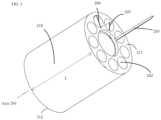
- FIG. 2is a perspective view showing an example of a pressure exchanger according to the present disclosure.
- FIG. 3is a perspective view showing an example of a rotor of the pressure exchanger and examples of flow dividers according to the present disclosure.
- FIGS. 4 A to 4 Care views showing examples of flow divider structures.
- FIG. 5is a cross-sectional view showing an example of a rotor duct including split flow dividers that accommodate duct manufacturing offsets.
- the described implementationsrelate generally to a rotary pressure exchanger including a plurality of rotor ducts defined in a rotor.
- the present disclosuredescribes one or more examples of flow dividers that are located inside the rotor duct to reduce a dead volume in the rotor of the pressure exchanger and to increase flow capacity of the pressure exchanger.
- FIG. 1is a circular cross-sectional view showing an example of operation of a pressure exchanger in related art.
- the pressure exchangerincludes a rotor 5 located between a pair of end covers 14 and 15 that face high-pressure streams and low-pressure streams.
- the end covers 14 and 15include sealing areas 8 and 9 that are disposed at central areas of the end covers, respectively.
- the rotor 5may include multiple rotor ducts that extend through an inside of the rotor 5 .
- the rotor 5may be located between the high-pressure and low-pressure streams and configured to rotate about an axis passing through the sealing areas 8 and 9 .
- the end cover 14may define a plurality of apertures connected to an inlet duct 12 and an outlet duct 13 .
- the end cover 14includes a first aperture connected to the inlet duct 12 and configured to receive a low pressure seawater feed 1 having C 1 salinity (i.e., concentration of salt), and a second aperture connected to the outlet duct 13 and configured to discharge a high pressure seawater output 3 having C 1 salinity.
- the end cover 15may define a plurality of apertures connected to an inlet duct 10 and an outlet duct 11 .
- the end cover 15includes a first aperture connected to the inlet duct 10 and configured to receive a high pressure brine feed 4 having C 0 salinity, and a second aperture connected to the outlet duct 11 and configured to discharge a low pressure brine water output 2 having C 0 salinity.
- the salinity (C 0 ) of the brine water feed 4may be greater than the salinity (C 1 ) of the seawater feed 1 .
- the seawater feed 1may, while moving in a direction from the sealing area 9 toward the end cover 15 , gradually move a dead volume 6 in the rotor 5 toward the end cover 15 .
- the dead volume 6may constitute about 40% of an overall duct volume of the rotor 5 and remain in the rotor 5 .
- the dead volume 6may, while moving toward the end cover 15 , displace the brine volume 7 in the rotor 5 through the low pressure outlet duct 11 .
- the displacement volumemay constitute about 60% of the overall duct volume.
- the dead volume 6may separate the different streams and remain in the rotor ducts, while oscillating back and forth along the axis of the rotor 5 for each revolution of the rotor 5 .
- the dead volumemay separate the seawater feed 1 and the brine water output 2 , and separate the brine water feed 4 and seawater output 3 .
- the dead volume 6may define a salinity gradient having salinity C 0 at the brine interface of the dead volume and salinity C 1 at the seawater interface of the dead volume.
- FIG. 1illustrates a plurality of portions of the dead volume 6 in the rotor ducts in gray scale.
- the dead volume 6may secure a low mixing transfer between brine water and seawater.
- FIG. 2is a perspective view showing an example of a pressure exchanger according to the present disclosure.
- a pressure exchanger 200can include a rotor 210 , a first end cover 220 , and a second end cover 230 .
- the first end cover 220comprises at least one high pressure inlet 240 configured to receive a first stream of high pressure liquid.
- the first streamcan have a first concentration.
- the first end cover 220can further include at least one low pressure outlet 250 through which the first stream flows out of the pressure exchanger 200 .
- the pressure exchanger 200can include a rod 270 that holds the rotor 210 and end covers 220 and 230 together.
- the rod 270may include or serve as a shaft that defines an axis 201 of rotation of the rotor 210 .
- the rotor 210can rotate about the axis 201 in one or both of a clockwise direction and a counterclockwise direction.
- the rotor 210 and the end covers 220 and 230can communicate first fluid and second fluid, which is similar to the operation of the rotor 5 and the end covers 14 and 15 described above with FIG. 1 .
- the rotor 210can rotate relative to the end covers 220 and 230 by various driving mechanisms.
- the rotor 210may mechanically rotate about a shaft (e.g., rod 270 ) that extends along the axis 201 .
- the shaftmay be rotated by a driving device such as a motor.
- the rotor 210(or the shaft of the rotor 210 ) can be configured to rotate by a flow entering to the rotor 210 .
- the pressure exchanger 200can further include a ramp structure that includes an inclined surface with respect to the axis 201 .
- the inclined surface of the ramp structurecan be configured to face and contact incoming flow streams. Based on pressure of the incoming flow streams applied to the inclined surface of the ramp structure, the rotor 210 can rotate about the shaft relative to the end covers 220 and 230 .
- a rotation speed of the rotor 210can be determined based on the arrangement of the incline surface of the ramp structure. For example, the rotation speed of the rotor 210 may be determined based on increasing or decreasing an inclined angle of the incline surface with respect to the axis 201 . In some examples, the rotation speed of the rotor 210 may be determined based on increasing or decreasing an area or a number of the incline surfaces arranged in the ramp structure. In some examples, the rotation speed of the rotor 210 may vary based on a pattern of the inclined surface of the ramp structure.
- the rotation speed of the rotor 210can be controlled by adjusting a flow rate or pressure of the incoming streams. For example, the rotation speed of the rotor 210 can be increased based on an increase of the flow rate of the incoming stream to the end cover 220 . The rotation speed of the rotor 210 can be decreased based on a decrease of the flow rate of the incoming stream to the end cover 220 . In this example, the rotation speed of the rotor 210 depends on the flow rate of the incoming stream to the end cover 220 .
- the rotation speed of the rotor 210can be controlled independent of the flow rate of the incoming stream.
- the rotor 210can be rotated by a separate driving device such as a motor.
- one or more components of the pressure exchanger 200may be replaced to adjust the rotation speed of the rotor 210 while keeping the same flow rate of the incoming stream.
- the end cover 220 , the end cover 230 , rotor 210 , or the ramp structure having the inclined surfacecan be replaced to adjust the rotation speed of the rotor 210 .
- the end cover 220 and the end cover 230may include the ramp structure having the inclined surface.
- the rotor 210 , the end covers 220 and 230 , and the rod 270 or another axlemay be made of a corrosion resistant material, such as ceramic.
- the end covers, rotor, and/or axlemay be made of Alumina ceramic (aluminum oxide ceramic), including 92% to 99.8% aluminum oxide ceramic, for example.
- the end covers, rotor, and/or axlemay be made of Alumina ceramic including 99.8% aluminum oxide ceramic.
- FIG. 3is a perspective view showing an example of a rotor of the pressure exchanger and examples of flow dividers.
- the rotor 210can includes multiple rotor ducts 202 that extend parallel to the axis 201 , where each rotor duct 202 extends between a first side surface 211 and a second side surface 212 of the rotor 210 .
- the first side surface 211 and the second side surface 212are spaced apart from each other in an axial direction of the axis 201 .
- the rotor 210can be configured to rotate about the axis 201 and communicate a first fluid through the first side surface 211 of the rotor 210 and a second fluid through the second side surface 212 of the rotor 210 .
- the pressure exchanger 200can include a plurality of flow dividers having a non-tubular shape.
- the flow dividerscan have a substantially flat shape (e.g., a plate shape).
- FIG. 3illustrates three flow dividers or plates 203 , 204 , and 205 , for example, but the pressure exchanger 200 can include more or less flow dividers in other implementations.
- each of the rotor ducts 202can include one or more flow dividers therein that extend through each rotor ducts 202 .
- the flow divider 203represents a first insertion position in which the flow divider 203 is partially inserted into one of the rotor ducts 202 .
- the flow divider 204represents a second insertion position in which the flow divider 204 is further pushed into one of the rotor ducts 202 and makes surface alignment or flush with the first side surface 211 .
- the second insertion positionmay be a final position of the flow divider 204 .
- the second insertion positionis not a final position of the flow divider 204 .
- the flow divider 205represents a third insertion position in which the flow divider 205 is further pushed into one of the rotor ducts 202 and its end positioned slightly below or recessed relative to the first side surface 211 . That is, the flow divider 205 has a first axial end surface that is spaced apart from and recessed relative to the first side surface 211 in the axial direction.
- the flow divider 205can further include a second axial end surface that is spaced apart from and recessed relative to the second side surface 212 of the rotor 210 in the axial direction.
- the third insertion position of the flow divider 205can be the final position of each of the flow dividers to avoid any mechanical contact or interference with the opposing end cover 220 or 230 (see FIG. 2 ).
- the rotor 210can rotate relative to the end covers 220 and 230 without interference with the flow dividers in their final positions inside the rotor ducts 202 .
- an axial length of the flow divider 205can be less than a rotor length (“L”) of the rotor 210 in the axial direction such that the axial ends of the flow divider 205 are recessed relative to the first side surface 211 and the second side surface 212 , respectively.
- the flow dividerscan be made of plastic or composite materials.
- the flow dividerscan be held in place by friction force against inner surfaces of the rotor ducts 202 , and, in some examples, aided with an adhesive or glue.
- the flow dividercan partition each rotor duct 202 into multiple equal resistance flow elements or paths without any sealing or structural support function.
- the flow dividers 203 , 204 , and 205can reduce an aspect ratio of the flow elements to thereby reduce mixing of the fluid streams inside the rotor duct 202 and increase a utilization of the rotor space without increasing a rotation speed of the rotor 210 .
- the flow divider 205can define an aspect ratio of two flow paths defined in the rotor duct 202 .
- the aspect ratiocan be a ratio of a width of one flow path in a radial direction with respect to an axial length of the flow path in the axial direction.
- the widthcan be less than or equal to a diameter of one rotor duct 202
- the lengthcan be less than or equal to the rotor length L.
- each of the plurality of flow pathscan have an equal width or define an equal cross-sectional area.
- each of the plurality of flow pathscan have an equal axial length to thereby define an equal aspect ratio for the plurality of flow paths.
- FIGS. 4 A to 4 Care views showing various examples of flow divider structures disposed in a rotor duct.
- FIG. 4 Aillustrates an example of a flow divider including a single wall or plate 41 that divides the rotor duct 202 into two equal resistance flow paths 42 .
- each flow path 42can have an equal cross-section area, for example, a half of a circle area defined by the rotor duct 202 .
- a radial width of each flow path 42can be between a radius and a diameter of the circle area defined by the rotor duct 202 .
- the aspect ratiocan be determined based on an effective diameter of a virtual circle that has the same area as the cross-section area of one flow path. For example, referring to FIG.
- the effective diameter of the virtual circlecan be 1/ ⁇ square root over (2) ⁇ of the diameter of the circle area defined by the rotor duct 202 .
- each of flow path 42can apply an equal flow resistance to the fluid streams such that the fluid streams flow with an equal flow velocity when an equal pressure difference is applied to axial ends of each flow path 42 . This is one of important conditions to maximize flow capacity without increasing mixing between the fluid streams in the rotor duct 202 .
- FIG. 4 Billustrates an example of a flow divider having a hub structure including three plates or walls 43 that define three equal resistance flow paths 44 .
- the flow divider structurecan be symmetrical with respect to a diameter of the circle area defined by the rotor duct 202 .
- the effective diameter of the virtual circlecan be 1/ ⁇ square root over (3) ⁇ of the diameter of the circle area defined by the rotor duct 202 because each of the pie-shaped areas has 1 ⁇ 3 of the circle area defined by the rotor duct 202 .
- the effective diameter of the virtual circlecan be used to determine the aspect ratio of the flow paths 44 .
- each of flow path 44can apply an equal flow resistance to the fluid streams such that the flow streams flow with an equal flow velocity when an equal pressure difference is applied to axial ends of each flow path 44 .
- the flow divider structuremay not be symmetrical but rather be adapted to the actual shape of the rotor duct 202 .
- the rotor duct 202can have a non-circular shape, and the flow dividers can be arranged to define a plurality of flow paths that have an equal cross-sectional area regardless of the shape or symmetricity of each of the plurality of flow paths.
- the flow divider structurecan include an increased number of flow dividers.
- one rotor duct 202can include a flow divider that includes three or more flow divider portions or walls therein (e.g., FIGS. 4 B and 4 C ).
- FIG. 4 Cillustrates an example of a flow divider including four plates or walls 45 that define four equal resistance flow paths 46 .
- the effective diametercan be 1 ⁇ 2 of the diameter of the circle area defined by the rotor duct 202 because each of the pie-shaped area has 1 ⁇ 4 of the circle area defined by the rotor duct 202 .
- the effective diameter of the virtual circlecan be used to determine the aspect ratio of the flow paths 46 .
- each flow path 46can apply an equal flow resistance to the fluid streams such that the fluid streams flow with an equal flow velocity when an equal pressure difference is applied to axial ends of each flow path 46 .
- FIG. 5is a cross-sectional view showing an example of a rotor duct including split flow dividers that accommodate duct manufacturing offsets.
- FIG. 5illustrates a cross-section area of a rotor duct 213 including a step portion 214 that can be generated from machining of the rotor duct 213 .
- the step portion 214can be generated at a position halfway from both ends of the rotor duct 213 .
- a misalignment of a boring process of the rotor duct 213may result in the step portion 214 .
- the boring processcan be performed from the first side surface 211 toward the second side surface 212 and then performed from the second side surface 212 toward the first side surface 211 .
- the boring processcan be simultaneously performed from the first side surface 211 and the second side surface 212 toward the opposing side surfaces.
- the step portion 214can be generated if the boring process from the side surfaces are performed along two axes that are slightly offset from each other.
- the misalignment of the boring processcan vary from one rotor duct to another.
- a location of the step portion 214 relative to the side surface 211 and 212can vary from one rotor duct to another.
- a step depth of the step portion 214can vary, as well, from one rotor duct to another.
- the flow dividercan include two or more separate flow dividers 52 and 54 inserted from each end of the rotor duct 213 to accommodate the misalignment or variation of the boring process.
- the rotor duct 213includes the step portion 214 , a first rotor portion that extends from the first side surface 211 to the step portion 214 , and a second rotor portion that extends from the second side surface 212 to the step portion 214 .
- the first flow divider 52can be located in and extend along the first rotor portion (e.g., the right part of the step portion 214 in FIG. 5 ), and the first flow divider 52 has a first inner end that faces the step portion 214 .
- the second flow divider 54can be located in and extend along the second rotor portion (e.g., the left part of the step portion 214 in FIG. 5 ), and the second flow divider 54 has a second inner end that faces the first inner end and the step portion 214 .
- an outer end of at least one of the first flow divider 52 or the second flow divider 54may be spaced apart from the corresponding side surface 211 or 212 .
- the outer end of each of the first flow divider 52 and the second flow divider 54can be recessed relative to the corresponding side surfaces 211 and 212 by a distance “d.”
- the aspect ratiocan be defined as D/k(L ⁇ 2d), where D denotes an inner diameter of the rotor duct 213 , and k denotes an adjustment coefficient according to an effect diameter.
- the aspect ratiocan be proportional to a width (“W”) of the first flow divider 52 or the second flow divider 54 in the radial direction, and the aspect ratio can be inversely proportional to a sum of axial lengths of the first flow divider and the second flow divider.
- Wwidth
- the sum of axial lengths of the first flow divider 52 and the second flow divider 54may be less than or equal to the distance L between the first side surface 211 and the second side surface 212 .
- the distance Lcan be defined as the rotor length L (see FIG. 3 ).
- the width W of the first flow divider 52can be equal to the width of the second flow divider 54
- the axial length of the first flow divider 52can be equal to the axial length of the second flow divider 54 .
- the axial length of the first flow divider 52 and the second flow divider 54can be a half of (L ⁇ 2d).
- the width (W 1 ) of the first flow divider 52can be different from the width (W 2 ) of the second flow divider 54
- the axial length (L 1 ) of the first flow divider 52can different from the axial length (L 2 ) of the second flow divider 54 to accommodate variation in the boring process of each rotor duct.
- the first flow divider 52can be recessed by d 1 from the side surface 211
- the second flow divider 54can be recessed by d 2 from the side surface 212 . That is, the separate flow dividers 52 and 54 can have structure for accommodating manufacturing offsets to thereby provide strong friction force to keep the structure from moving, and wearing of the flow dividers 52 and 54 and the rotor duct 213 can be reduced.
Landscapes
- Engineering & Computer Science (AREA)
- Mechanical Engineering (AREA)
- General Engineering & Computer Science (AREA)
- Centrifugal Separators (AREA)
- Heat-Exchange Devices With Radiators And Conduit Assemblies (AREA)
- Motor Or Generator Cooling System (AREA)
Abstract
Description
Claims (20)
Priority Applications (5)
| Application Number | Priority Date | Filing Date | Title |
|---|---|---|---|
| US17/170,087US12085094B2 (en) | 2020-02-12 | 2021-02-08 | Pressure exchanger with flow divider in rotor duct |
| PCT/US2021/018010WO2021163605A1 (en) | 2020-02-12 | 2021-02-12 | Pressure exchanger with flow divider in rotor duct |
| EP21710370.4AEP4103849A1 (en) | 2020-02-12 | 2021-02-12 | Pressure exchanger with flow divider in rotor duct |
| CN202180014461.2ACN115210476A (en) | 2020-02-12 | 2021-02-12 | Pressure exchanger with flow divider in rotor line |
| IL295527AIL295527A (en) | 2020-02-12 | 2021-02-12 | Pressure exchanger with flow divider in rotor duct |
Applications Claiming Priority (2)
| Application Number | Priority Date | Filing Date | Title |
|---|---|---|---|
| US202062975585P | 2020-02-12 | 2020-02-12 | |
| US17/170,087US12085094B2 (en) | 2020-02-12 | 2021-02-08 | Pressure exchanger with flow divider in rotor duct |
Publications (2)
| Publication Number | Publication Date |
|---|---|
| US20210246910A1 US20210246910A1 (en) | 2021-08-12 |
| US12085094B2true US12085094B2 (en) | 2024-09-10 |
Family
ID=77177437
Family Applications (1)
| Application Number | Title | Priority Date | Filing Date |
|---|---|---|---|
| US17/170,087Active2041-12-08US12085094B2 (en) | 2020-02-12 | 2021-02-08 | Pressure exchanger with flow divider in rotor duct |
Country Status (5)
| Country | Link |
|---|---|
| US (1) | US12085094B2 (en) |
| EP (1) | EP4103849A1 (en) |
| CN (1) | CN115210476A (en) |
| IL (1) | IL295527A (en) |
| WO (1) | WO2021163605A1 (en) |
Families Citing this family (6)
| Publication number | Priority date | Publication date | Assignee | Title |
|---|---|---|---|---|
| US12247588B2 (en) | 2020-02-12 | 2025-03-11 | Isobaric Strategies Inc. | Pressure exchanger for gas processing |
| US11572899B2 (en) | 2020-02-13 | 2023-02-07 | Isobaric Strategies Inc. | Pressure exchanger for hydraulic fracking |
| US12410821B2 (en) | 2022-03-24 | 2025-09-09 | Energy Recovery, Inc. | Reducing cavitation, noise, and vibration in a pressure exchanger |
| US20230323900A1 (en)* | 2022-03-24 | 2023-10-12 | Energy Recovery, Inc. | Minimizing mixing in a pressure exchanger |
| US20230375009A1 (en)* | 2022-05-20 | 2023-11-23 | Sulzer Management Ag | Rotary pressure exchanger |
| EP4332385A1 (en)* | 2022-09-05 | 2024-03-06 | Sulzer Management AG | Rotary pressure exchanger |
Citations (45)
| Publication number | Priority date | Publication date | Assignee | Title |
|---|---|---|---|---|
| US2675173A (en)* | 1948-02-28 | 1954-04-13 | Jendrasski George | Apparatus effecting pressure exchange |
| US2898866A (en) | 1956-04-06 | 1959-08-11 | Manton Gaulin Mfg Company Inc | Hydraulic pressure exchange pump |
| GB840408A (en) | 1958-02-28 | 1960-07-06 | Power Jets Res & Dev Ltd | Improvements in and relating to pressure exchangers |
| US3095704A (en) | 1960-12-09 | 1963-07-02 | Spalding Dudley Brian | Pressure exchanger apparatus |
| US3145909A (en) | 1957-04-26 | 1964-08-25 | Ite Circuit Breaker Ltd | Pressure transformer |
| US3234736A (en) | 1962-11-15 | 1966-02-15 | Spalding Dudley Brian | Pressure exchanger |
| US3874166A (en) | 1972-11-29 | 1975-04-01 | Hubert Kirchhofer | Method of and apparatus for reducing harmful emissions from internal combustion engines |
| US4352638A (en)* | 1979-11-05 | 1982-10-05 | Ford Motor Company | Rotor assembly for wave compression supercharger |
| SU1642096A1 (en) | 1989-04-11 | 1991-04-15 | Ворошиловградский машиностроительный институт | Rotor of wave pressure exchanger |
| US5338158A (en) | 1989-11-03 | 1994-08-16 | Hauge Leif J | Pressure exchanger having axially inclined rotor ducts |
| US5522217A (en) | 1993-09-06 | 1996-06-04 | Abb Management Ag | Pressure wave machine with integrated combustion and method for cooling the rotor of this pressure wave machine |
| US5988993A (en)* | 1994-11-28 | 1999-11-23 | Hauge; Leif J. | Pressure exchanger having a rotor with automatic axial alignment |
| EA002575B1 (en) | 1997-10-01 | 2002-06-27 | Энерджи Рикавери, Инк. | Pressure exchanger |
| US6460342B1 (en)* | 1999-04-26 | 2002-10-08 | Advanced Research & Technology Institute | Wave rotor detonation engine |
| US6544492B1 (en) | 1998-07-21 | 2003-04-08 | Crystatech, Inc. | Regeneration method for process which removes hydrogen sulfide from gas streams |
| US6725881B1 (en)* | 1999-02-26 | 2004-04-27 | Beswick Engineering, Inc. | Multi-port fluid valve and method |
| US20060037895A1 (en) | 2004-08-20 | 2006-02-23 | Scott Shumway | Pressure exchange apparatus with integral pump |
| US20090104046A1 (en) | 2006-06-29 | 2009-04-23 | Energy Recovery, Inc. | Rotary pressure transfer devices |
| CN101440828A (en) | 2008-12-18 | 2009-05-27 | 杭州帕尔水处理科技有限公司 | Pressure exchanger |
| CN101568733A (en) | 2006-10-04 | 2009-10-28 | 能量回收股份有限公司 | Rotary pressure transfer device |
| US20100196152A1 (en) | 2007-10-05 | 2010-08-05 | Energy Recovery, Inc. | Rotary pressure transfer device with improved flow |
| US7938627B2 (en)* | 2004-11-12 | 2011-05-10 | Board Of Trustees Of Michigan State University | Woven turbomachine impeller |
| JP2011231634A (en) | 2010-04-26 | 2011-11-17 | Kubota Corp | Pressure converter and method for adjusting performance of pressure converter |
| US8226376B2 (en)* | 2007-12-11 | 2012-07-24 | Grundfos Management A/S | Pressure exchanger for transmitting pressure energy from a first liquid stream to a second liquid stream |
| US20130037008A1 (en)* | 2010-04-20 | 2013-02-14 | Toyota Jidosha Kabushiki Kaisha | Pressure wave supercharger |
| US20130121850A1 (en) | 2009-12-23 | 2013-05-16 | Juan Miguel PINTO | Rotary Energy Recovery Device |
| US20140128656A1 (en) | 2012-11-08 | 2014-05-08 | Energy Recovery, Inc. | Isobaric pressure exchanger controls in amine gas processing |
| US20150096739A1 (en) | 2013-10-03 | 2015-04-09 | Energy Recovery, Inc. | Frac System with Hydraulic Energy Transfer System |
| US20160160890A1 (en) | 2014-12-05 | 2016-06-09 | Energy Recovery, Inc. | Systems and methods for rotor axial force balancing |
| US20160222985A1 (en) | 2015-02-03 | 2016-08-04 | Eli Oklejas, Jr. | Method and system for injecting a process fluid using a high pressure drive fluid |
| US9546671B2 (en) | 2011-09-30 | 2017-01-17 | Kubota Corporation | Pressure exchange device |
| US9604889B2 (en) | 2012-11-08 | 2017-03-28 | Energy Recovery, Inc. | Isobaric pressure exchanger in amine gas processing |
| US20170130743A1 (en) | 2015-11-10 | 2017-05-11 | Energy Recovery, Inc. | Pressure exchange system with hydraulic drive system |
| US20170335668A1 (en) | 2013-12-31 | 2017-11-23 | Energy Recovery, Inc. | Rotary isobaric pressure exchanger system with flush system |
| US20170350428A1 (en) | 2016-06-06 | 2017-12-07 | Energy Recovery, Inc. | Pressure exchanger as choke |
| RU2659646C1 (en) | 2014-08-06 | 2018-07-03 | Энерджи Рикавери, Инк. | System of improved pressure transmission in pipeline in pressure exchange system |
| US10125796B2 (en) | 2013-04-17 | 2018-11-13 | Leif J. Hauge | Rotor positioning system in a pressure exchange vessel |
| US10125594B2 (en) | 2016-05-03 | 2018-11-13 | Halliburton Energy Services, Inc. | Pressure exchanger having crosslinked fluid plugs |
| US20190055805A1 (en) | 2016-04-07 | 2019-02-21 | Halliburton Energy Services, Inc. | Pressure-exchanger to achieve rapid changes in proppant concentration |
| US20190278306A1 (en) | 2016-11-04 | 2019-09-12 | Schlumberger Technology Corporation | Pressure Exchanger Manifold Resonance Reduction |
| US20190390576A1 (en) | 2018-06-26 | 2019-12-26 | Energy Recovery, Inc. | Power Generation System With Rotary Liquid Piston Compressor for Transcritical and Supercritical Compression of Fluids |
| US20200149556A1 (en) | 2018-11-09 | 2020-05-14 | Flowserve Management Company | Fluid exchange devices and related controls, systems, and methods |
| US10961823B2 (en) | 2016-11-04 | 2021-03-30 | Schlumberger Technology Corporation | Pressure exchanger pressure oscillation source |
| US20210246912A1 (en) | 2020-02-12 | 2021-08-12 | Isobaric Strategies Inc. | Pressure exchanger for gas processing |
| US20210254636A1 (en) | 2020-02-13 | 2021-08-19 | Isobaric Strategies Inc. | Pressure exchanger for hydraulic fracking |
- 2021
- 2021-02-08USUS17/170,087patent/US12085094B2/enactiveActive
- 2021-02-12ILIL295527Apatent/IL295527A/enunknown
- 2021-02-12CNCN202180014461.2Apatent/CN115210476A/enactivePending
- 2021-02-12WOPCT/US2021/018010patent/WO2021163605A1/ennot_activeCeased
- 2021-02-12EPEP21710370.4Apatent/EP4103849A1/enactivePending
Patent Citations (52)
| Publication number | Priority date | Publication date | Assignee | Title |
|---|---|---|---|---|
| US2675173A (en)* | 1948-02-28 | 1954-04-13 | Jendrasski George | Apparatus effecting pressure exchange |
| US2898866A (en) | 1956-04-06 | 1959-08-11 | Manton Gaulin Mfg Company Inc | Hydraulic pressure exchange pump |
| US3145909A (en) | 1957-04-26 | 1964-08-25 | Ite Circuit Breaker Ltd | Pressure transformer |
| GB840408A (en) | 1958-02-28 | 1960-07-06 | Power Jets Res & Dev Ltd | Improvements in and relating to pressure exchangers |
| US3095704A (en) | 1960-12-09 | 1963-07-02 | Spalding Dudley Brian | Pressure exchanger apparatus |
| US3234736A (en) | 1962-11-15 | 1966-02-15 | Spalding Dudley Brian | Pressure exchanger |
| US3874166A (en) | 1972-11-29 | 1975-04-01 | Hubert Kirchhofer | Method of and apparatus for reducing harmful emissions from internal combustion engines |
| US4352638A (en)* | 1979-11-05 | 1982-10-05 | Ford Motor Company | Rotor assembly for wave compression supercharger |
| SU1642096A1 (en) | 1989-04-11 | 1991-04-15 | Ворошиловградский машиностроительный институт | Rotor of wave pressure exchanger |
| US5338158A (en) | 1989-11-03 | 1994-08-16 | Hauge Leif J | Pressure exchanger having axially inclined rotor ducts |
| US5522217A (en) | 1993-09-06 | 1996-06-04 | Abb Management Ag | Pressure wave machine with integrated combustion and method for cooling the rotor of this pressure wave machine |
| US5988993A (en)* | 1994-11-28 | 1999-11-23 | Hauge; Leif J. | Pressure exchanger having a rotor with automatic axial alignment |
| EA002575B1 (en) | 1997-10-01 | 2002-06-27 | Энерджи Рикавери, Инк. | Pressure exchanger |
| US6544492B1 (en) | 1998-07-21 | 2003-04-08 | Crystatech, Inc. | Regeneration method for process which removes hydrogen sulfide from gas streams |
| US6725881B1 (en)* | 1999-02-26 | 2004-04-27 | Beswick Engineering, Inc. | Multi-port fluid valve and method |
| US6460342B1 (en)* | 1999-04-26 | 2002-10-08 | Advanced Research & Technology Institute | Wave rotor detonation engine |
| US20060037895A1 (en) | 2004-08-20 | 2006-02-23 | Scott Shumway | Pressure exchange apparatus with integral pump |
| US7938627B2 (en)* | 2004-11-12 | 2011-05-10 | Board Of Trustees Of Michigan State University | Woven turbomachine impeller |
| US20090104046A1 (en) | 2006-06-29 | 2009-04-23 | Energy Recovery, Inc. | Rotary pressure transfer devices |
| CN101568733A (en) | 2006-10-04 | 2009-10-28 | 能量回收股份有限公司 | Rotary pressure transfer device |
| US20100196152A1 (en) | 2007-10-05 | 2010-08-05 | Energy Recovery, Inc. | Rotary pressure transfer device with improved flow |
| US7997853B2 (en) | 2007-10-05 | 2011-08-16 | Energy Recovery, Inc. | Rotary pressure transfer device with improved flow |
| US8226376B2 (en)* | 2007-12-11 | 2012-07-24 | Grundfos Management A/S | Pressure exchanger for transmitting pressure energy from a first liquid stream to a second liquid stream |
| CN101440828A (en) | 2008-12-18 | 2009-05-27 | 杭州帕尔水处理科技有限公司 | Pressure exchanger |
| US10138907B2 (en)* | 2009-12-23 | 2018-11-27 | Energy Recovery, Inc. | Rotary energy recovery device |
| US20130121850A1 (en) | 2009-12-23 | 2013-05-16 | Juan Miguel PINTO | Rotary Energy Recovery Device |
| US20130037008A1 (en)* | 2010-04-20 | 2013-02-14 | Toyota Jidosha Kabushiki Kaisha | Pressure wave supercharger |
| JP2011231634A (en) | 2010-04-26 | 2011-11-17 | Kubota Corp | Pressure converter and method for adjusting performance of pressure converter |
| US9546671B2 (en) | 2011-09-30 | 2017-01-17 | Kubota Corporation | Pressure exchange device |
| US20140128656A1 (en) | 2012-11-08 | 2014-05-08 | Energy Recovery, Inc. | Isobaric pressure exchanger controls in amine gas processing |
| US9604889B2 (en) | 2012-11-08 | 2017-03-28 | Energy Recovery, Inc. | Isobaric pressure exchanger in amine gas processing |
| US9440895B2 (en) | 2012-11-08 | 2016-09-13 | Energy Recovery, Inc. | Isobaric pressure exchanger controls in amine gas processing |
| US10125796B2 (en) | 2013-04-17 | 2018-11-13 | Leif J. Hauge | Rotor positioning system in a pressure exchange vessel |
| US20150096739A1 (en) | 2013-10-03 | 2015-04-09 | Energy Recovery, Inc. | Frac System with Hydraulic Energy Transfer System |
| US9945216B2 (en) | 2013-10-03 | 2018-04-17 | Energy Recovery, Inc. | Frac system with hydraulic energy transfer system |
| US20170335668A1 (en) | 2013-12-31 | 2017-11-23 | Energy Recovery, Inc. | Rotary isobaric pressure exchanger system with flush system |
| RU2659646C1 (en) | 2014-08-06 | 2018-07-03 | Энерджи Рикавери, Инк. | System of improved pressure transmission in pipeline in pressure exchange system |
| US20160160890A1 (en) | 2014-12-05 | 2016-06-09 | Energy Recovery, Inc. | Systems and methods for rotor axial force balancing |
| US20160222985A1 (en) | 2015-02-03 | 2016-08-04 | Eli Oklejas, Jr. | Method and system for injecting a process fluid using a high pressure drive fluid |
| US20170130743A1 (en) | 2015-11-10 | 2017-05-11 | Energy Recovery, Inc. | Pressure exchange system with hydraulic drive system |
| US10900318B2 (en) | 2016-04-07 | 2021-01-26 | Halliburton Energy Services, Inc. | Pressure-exchanger to achieve rapid changes in proppant concentration |
| US20190055805A1 (en) | 2016-04-07 | 2019-02-21 | Halliburton Energy Services, Inc. | Pressure-exchanger to achieve rapid changes in proppant concentration |
| US10125594B2 (en) | 2016-05-03 | 2018-11-13 | Halliburton Energy Services, Inc. | Pressure exchanger having crosslinked fluid plugs |
| US20170350428A1 (en) | 2016-06-06 | 2017-12-07 | Energy Recovery, Inc. | Pressure exchanger as choke |
| US20190278306A1 (en) | 2016-11-04 | 2019-09-12 | Schlumberger Technology Corporation | Pressure Exchanger Manifold Resonance Reduction |
| US10961823B2 (en) | 2016-11-04 | 2021-03-30 | Schlumberger Technology Corporation | Pressure exchanger pressure oscillation source |
| US11157025B2 (en) | 2016-11-04 | 2021-10-26 | Schlumberger Technology Corporation | Pressure exchanger manifold resonance reduction |
| US20190390576A1 (en) | 2018-06-26 | 2019-12-26 | Energy Recovery, Inc. | Power Generation System With Rotary Liquid Piston Compressor for Transcritical and Supercritical Compression of Fluids |
| US20200149556A1 (en) | 2018-11-09 | 2020-05-14 | Flowserve Management Company | Fluid exchange devices and related controls, systems, and methods |
| US20210246912A1 (en) | 2020-02-12 | 2021-08-12 | Isobaric Strategies Inc. | Pressure exchanger for gas processing |
| US20210254636A1 (en) | 2020-02-13 | 2021-08-19 | Isobaric Strategies Inc. | Pressure exchanger for hydraulic fracking |
| US11572899B2 (en) | 2020-02-13 | 2023-02-07 | Isobaric Strategies Inc. | Pressure exchanger for hydraulic fracking |
Non-Patent Citations (8)
| Title |
|---|
| CN Office Action in Chinese Appln. No. 202180014563.4, dated Sep. 29, 2023, 22 pages (with English translation). |
| International Preliminary Report on Patentability in International Appln. No. PCT/US2021/018003, dated Mar. 23, 2022, 5 pages. |
| International Preliminary Report on Patentability in International Appln. No. PCT/US2021/018010, dated Aug. 25, 2022, 10 pages. |
| International Preliminary Report on Patentability in International Appln. No. PCT/US2021/018012, dated Aug. 25, 2022, 9 pages. |
| International Search Report and Written Opinion in International Appln. No. PCT/US2021/018003, dated Apr. 28, 2021, 20 pages. |
| International Search Report and Written Opinion in International Appln. No. PCT/US2021/018010, dated May 7, 2021, 18 pages. |
| International Search Report and Written Opinion in International Appln. No. PCT/US2021/018012, dated Apr. 6, 2021, 14 pages. |
| RU Office Action in Russian Appln. No. 2022123957/12, dated Apr. 28, 2023, 15 pages (with English translation). |
Also Published As
| Publication number | Publication date |
|---|---|
| IL295527A (en) | 2022-10-01 |
| CN115210476A (en) | 2022-10-18 |
| WO2021163605A1 (en) | 2021-08-19 |
| US20210246910A1 (en) | 2021-08-12 |
| EP4103849A1 (en) | 2022-12-21 |
Similar Documents
| Publication | Publication Date | Title |
|---|---|---|
| US12085094B2 (en) | Pressure exchanger with flow divider in rotor duct | |
| US8556607B2 (en) | Screw rotor | |
| WO2014172576A1 (en) | Rotor positioning system in a pressure exchange vessel | |
| JPH01502208A (en) | Liquid pressure exchanger | |
| CN103328828A (en) | Pressure exchanger and performance adjustment method of pressure exchanger | |
| CN102884392A (en) | Rotary energy recovery device | |
| JPH10509783A (en) | Pressure transducer | |
| US20250160159A1 (en) | Manifold for a hydraulic vibration generating device or hydraulic motor | |
| CN102725538B (en) | Pressure exchanger | |
| JP2015232435A (en) | Heat exchanger and heat exchange unit | |
| US5267840A (en) | Power steering pump with balanced porting | |
| US8713926B2 (en) | Hydrodynamic machine, especially a hydrodynamic retarder | |
| US7500820B2 (en) | Impeller and fuel pump using the same | |
| CN114542555B (en) | Flow equalizing device and flow dividing device | |
| CN103582760B (en) | Hydraulic equipment | |
| US12228347B2 (en) | Heat exchanger core and heat exchanger | |
| WO2022246038A1 (en) | Refrigerant heat exchanger with integral multipass and flow distribution technology | |
| CN211573717U (en) | Rotor balancing block, motor rotor, motor and compressor | |
| JP6418386B2 (en) | Rotary compressor | |
| US12410821B2 (en) | Reducing cavitation, noise, and vibration in a pressure exchanger | |
| US20230323900A1 (en) | Minimizing mixing in a pressure exchanger | |
| FI95499C (en) | Apparatus for pumping a liquid medium | |
| JP2022006813A (en) | Heat exchanger | |
| US20070137844A1 (en) | Plate heat exchanger | |
| AU2010324526B2 (en) | Pressure exchanger |
Legal Events
| Date | Code | Title | Description |
|---|---|---|---|
| AS | Assignment | Owner name:ISOBARIC STRATEGIES INC., CALIFORNIA Free format text:ASSIGNMENT OF ASSIGNORS INTEREST;ASSIGNOR:HAUGE, LEIF J.;REEL/FRAME:055182/0850 Effective date:20210127 | |
| FEPP | Fee payment procedure | Free format text:ENTITY STATUS SET TO UNDISCOUNTED (ORIGINAL EVENT CODE: BIG.); ENTITY STATUS OF PATENT OWNER: LARGE ENTITY | |
| FEPP | Fee payment procedure | Free format text:ENTITY STATUS SET TO SMALL (ORIGINAL EVENT CODE: SMAL); ENTITY STATUS OF PATENT OWNER: LARGE ENTITY | |
| STPP | Information on status: patent application and granting procedure in general | Free format text:APPLICATION DISPATCHED FROM PREEXAM, NOT YET DOCKETED | |
| STPP | Information on status: patent application and granting procedure in general | Free format text:DOCKETED NEW CASE - READY FOR EXAMINATION | |
| STPP | Information on status: patent application and granting procedure in general | Free format text:RESPONSE TO NON-FINAL OFFICE ACTION ENTERED AND FORWARDED TO EXAMINER | |
| STPP | Information on status: patent application and granting procedure in general | Free format text:FINAL REJECTION MAILED | |
| STPP | Information on status: patent application and granting procedure in general | Free format text:RESPONSE AFTER FINAL ACTION FORWARDED TO EXAMINER | |
| STPP | Information on status: patent application and granting procedure in general | Free format text:ADVISORY ACTION MAILED | |
| STPP | Information on status: patent application and granting procedure in general | Free format text:DOCKETED NEW CASE - READY FOR EXAMINATION | |
| STPP | Information on status: patent application and granting procedure in general | Free format text:NOTICE OF ALLOWANCE MAILED -- APPLICATION RECEIVED IN OFFICE OF PUBLICATIONS | |
| STPP | Information on status: patent application and granting procedure in general | Free format text:PUBLICATIONS -- ISSUE FEE PAYMENT VERIFIED | |
| STCF | Information on status: patent grant | Free format text:PATENTED CASE | |
| FEPP | Fee payment procedure | Free format text:ENTITY STATUS SET TO UNDISCOUNTED (ORIGINAL EVENT CODE: BIG.); ENTITY STATUS OF PATENT OWNER: LARGE ENTITY |