US12082997B2 - Removable and replaceable dressing interface for a negative-pressure therapy system - Google Patents
Removable and replaceable dressing interface for a negative-pressure therapy systemDownload PDFInfo
- Publication number
- US12082997B2 US12082997B2US17/424,282US202017424282AUS12082997B2US 12082997 B2US12082997 B2US 12082997B2US 202017424282 AUS202017424282 AUS 202017424282AUS 12082997 B2US12082997 B2US 12082997B2
- Authority
- US
- United States
- Prior art keywords
- adhesive
- apertures
- negative
- pressure
- dressing interface
- Prior art date
- Legal status (The legal status is an assumption and is not a legal conclusion. Google has not performed a legal analysis and makes no representation as to the accuracy of the status listed.)
- Active, expires
Links
Images


Classifications
- A—HUMAN NECESSITIES
- A61—MEDICAL OR VETERINARY SCIENCE; HYGIENE
- A61F—FILTERS IMPLANTABLE INTO BLOOD VESSELS; PROSTHESES; DEVICES PROVIDING PATENCY TO, OR PREVENTING COLLAPSING OF, TUBULAR STRUCTURES OF THE BODY, e.g. STENTS; ORTHOPAEDIC, NURSING OR CONTRACEPTIVE DEVICES; FOMENTATION; TREATMENT OR PROTECTION OF EYES OR EARS; BANDAGES, DRESSINGS OR ABSORBENT PADS; FIRST-AID KITS
- A61F13/00—Bandages or dressings; Absorbent pads
- A61F13/02—Adhesive bandages or dressings
- A61F13/0246—Adhesive bandages or dressings characterised by the skin-adhering layer
- A61F13/0253—Adhesive bandages or dressings characterised by the skin-adhering layer characterized by the adhesive material
- A—HUMAN NECESSITIES
- A61—MEDICAL OR VETERINARY SCIENCE; HYGIENE
- A61F—FILTERS IMPLANTABLE INTO BLOOD VESSELS; PROSTHESES; DEVICES PROVIDING PATENCY TO, OR PREVENTING COLLAPSING OF, TUBULAR STRUCTURES OF THE BODY, e.g. STENTS; ORTHOPAEDIC, NURSING OR CONTRACEPTIVE DEVICES; FOMENTATION; TREATMENT OR PROTECTION OF EYES OR EARS; BANDAGES, DRESSINGS OR ABSORBENT PADS; FIRST-AID KITS
- A61F13/00—Bandages or dressings; Absorbent pads
- A61F13/02—Adhesive bandages or dressings
- A61F13/0259—Adhesive bandages or dressings characterised by the release liner covering the skin adhering layer
- A61F13/0263—Adhesive bandages or dressings characterised by the release liner covering the skin adhering layer especially adapted for island dressings
- A—HUMAN NECESSITIES
- A61—MEDICAL OR VETERINARY SCIENCE; HYGIENE
- A61F—FILTERS IMPLANTABLE INTO BLOOD VESSELS; PROSTHESES; DEVICES PROVIDING PATENCY TO, OR PREVENTING COLLAPSING OF, TUBULAR STRUCTURES OF THE BODY, e.g. STENTS; ORTHOPAEDIC, NURSING OR CONTRACEPTIVE DEVICES; FOMENTATION; TREATMENT OR PROTECTION OF EYES OR EARS; BANDAGES, DRESSINGS OR ABSORBENT PADS; FIRST-AID KITS
- A61F13/00—Bandages or dressings; Absorbent pads
- A61F13/05—Bandages or dressings; Absorbent pads specially adapted for use with sub-pressure or over-pressure therapy, wound drainage or wound irrigation, e.g. for use with negative-pressure wound therapy [NPWT]
- A—HUMAN NECESSITIES
- A61—MEDICAL OR VETERINARY SCIENCE; HYGIENE
- A61M—DEVICES FOR INTRODUCING MEDIA INTO, OR ONTO, THE BODY; DEVICES FOR TRANSDUCING BODY MEDIA OR FOR TAKING MEDIA FROM THE BODY; DEVICES FOR PRODUCING OR ENDING SLEEP OR STUPOR
- A61M1/00—Suction or pumping devices for medical purposes; Devices for carrying-off, for treatment of, or for carrying-over, body-liquids; Drainage systems
- A61M1/90—Negative pressure wound therapy devices, i.e. devices for applying suction to a wound to promote healing, e.g. including a vacuum dressing
- A61M1/91—Suction aspects of the dressing
- A61M1/912—Connectors between dressing and drainage tube
- A61M1/913—Connectors between dressing and drainage tube having a bridging element for transferring the reduced pressure from the connector to the dressing
- A—HUMAN NECESSITIES
- A61—MEDICAL OR VETERINARY SCIENCE; HYGIENE
- A61M—DEVICES FOR INTRODUCING MEDIA INTO, OR ONTO, THE BODY; DEVICES FOR TRANSDUCING BODY MEDIA OR FOR TAKING MEDIA FROM THE BODY; DEVICES FOR PRODUCING OR ENDING SLEEP OR STUPOR
- A61M1/00—Suction or pumping devices for medical purposes; Devices for carrying-off, for treatment of, or for carrying-over, body-liquids; Drainage systems
- A61M1/90—Negative pressure wound therapy devices, i.e. devices for applying suction to a wound to promote healing, e.g. including a vacuum dressing
- A61M1/91—Suction aspects of the dressing
- A61M1/915—Constructional details of the pressure distribution manifold
- A—HUMAN NECESSITIES
- A61—MEDICAL OR VETERINARY SCIENCE; HYGIENE
- A61M—DEVICES FOR INTRODUCING MEDIA INTO, OR ONTO, THE BODY; DEVICES FOR TRANSDUCING BODY MEDIA OR FOR TAKING MEDIA FROM THE BODY; DEVICES FOR PRODUCING OR ENDING SLEEP OR STUPOR
- A61M1/00—Suction or pumping devices for medical purposes; Devices for carrying-off, for treatment of, or for carrying-over, body-liquids; Drainage systems
- A61M1/71—Suction drainage systems
- A61M1/77—Suction-irrigation systems
- A61M1/772—Suction-irrigation systems operating alternately
Definitions
- the invention set forth in the appended claimsrelates generally to tissue treatment systems and more particularly, but without limitation, to dressings for tissue treatment with negative pressure and methods of using the dressings for tissue treatment with negative pressure.
- Negative-pressure therapymay provide a number of benefits, including migration of epithelial and subcutaneous tissues, improved blood flow, and micro-deformation of tissue at a wound site. Together, these benefits can increase development of granulation tissue and reduce healing times.
- cleansing a tissue sitecan be highly beneficial for new tissue growth.
- a wound or a cavitycan be washed out with a liquid solution for therapeutic purposes.
- These practicesare commonly referred to as “irrigation” and “lavage” respectively.
- “Instillation”is another practice that generally refers to a process of slowly introducing fluid to a tissue site and leaving the fluid for a prescribed period of time before removing the fluid.
- instillation of topical treatment solutions over a wound bedcan be combined with negative-pressure therapy to further promote wound healing by loosening soluble contaminants in a wound bed and removing infectious material. As a result, soluble bacterial burden can be decreased, contaminants removed, and the wound cleansed.
- a removable and replaceable dressing interface for connecting a negative-pressure source to a dressingmay comprise or consist essentially of a primary cover contact layer, a secondary cover contact layer, and a negative-pressure adapter.
- the primary cover contact layermay be a low-tack gel adhesive, such as, for example, a silicone adhesive with a peel strength of about 0.8 N.
- the primary cover contact layermay be formed of a hydrocolloid adhesive or low-tack polyurethane (PU) gel adhesive.
- the primary drape contact layermay be perforated to aid in sufficiently sealing the negative-pressure adapter to the cover when in normal use by a patient.
- the perforationsmay have two sizes which allow for protrusion of the secondary drape contact layer through the primary cover contact layer to the cover of the dressing.
- the secondary cover contact layermay be a high-tack, adhesive-coated polyurethane film.
- the two perforation sizes in the primary cover contact layermay allow for variation in the removal peel force when the dressing interface is adhered to the cover of the dressing.
- the portion of the dressing interface with the larger perforationsallows more of the high-tack secondary cover contact layer to adhere to the cover, and thus may act as an anchor to the dressing interface. This portion may require the greatest peel force to remove the dressing interface from the cover.
- the portion of the dressing interface with the smaller perforationsallows less of the high-tack secondary cover contact layer to adhere to the cover.
- This portionmay require a lesser peel force to remove the dressing interface from the cover. Accordingly, this portion with the smaller perforations may have a peel force that allows a user to remove and re-apply the dressing interface to the cover while still maintaining a sufficient seal to deliver negative-pressure therapy to a tissue site.
- the peel force of the portion of the dressing interface having the smaller perforationsmay be low enough to allow the dressing interface to be removed without damaging or destroying the cover.
- the negative-pressure portmay have a flat or straight portion which may allow the negative-pressure port to hinge when the dressing interface is removed or peeled up from the cover.
- some embodimentsmay comprise a dressing interface for connecting a negative-pressure source to a dressing, the dressing interface having a coupling member comprising an aperture, a first adhesive region having a first region peel strength, and a second adhesive region having a second region peel strength less than the first region peel strength.
- the dressing interfacemay further include a negative-pressure port for the delivery of negative pressure, wherein the negative-pressure port is coupled to the coupling member.
- the negative-pressure portincludes a flange and a conduit housing coupled to the flange and extending through the aperture in the contact layer.
- the coupling membermay further comprise a shell layer and a contact layer comprising a plurality of apertures, wherein the shell layer is configured to extend at least partially through the plurality of apertures in the contact layer.
- the plurality of aperturesfurther comprises a first plurality of apertures and a second plurality of apertures.
- the second adhesive regionis configured to be removable from a cover without destruction of the cover, while the first adhesive region is configured to remain adhered to the cover.
- other example embodimentsmay comprise a dressing interface for connecting a negative-pressure source to a dressing, the dressing interface having a base, a conduit housing attached to the base, a first layer coupled to the base, and a second layer.
- the first layerincludes an adhesive with a first peel strength and an aperture through which the conduit housing is configured to pass.
- the second layerhas an adhesive with a second peel strength less than the first peel strength of the first layer, a first plurality of apertures, and a second plurality of apertures.
- the first layeris configured to extend at least partially through the first and second plurality of apertures in the second layer.
- a first portion of the first layeris configured to extend through the first plurality of apertures and cooperate with the second layer to form a first adhesive region having a first region peel strength
- a second portion of the first layeris configured to extend through the second plurality of apertures and cooperate with the second layer to form a second adhesive region having a second region peel strength less than the first region peel strength
- a dressing interface for connecting a negative-pressure source to a dressingmay comprise a negative-pressure port coupled to at least one of a first layer and a second layer.
- the first layermay have a first side, a second side, and an adhesive on the first side having a first peel strength.
- the second layermay have a first side, a second side coupled to the first side of the first layer, the second layer comprising an adhesive having a second peel strength less than the first peel strength of the first layer, and a plurality of apertures.
- the first layeris configured to extend at least partially through the plurality of apertures in the second layer.
- a dressing interface for connecting a negative-pressure source to a dressingmay comprise a base, a conduit housing attached to the base, a shell layer having a first side, a second side, and an aperture through which the conduit housing is configured to pass, the shell layer coupled to the base, and a contact layer having a first side, a second side coupled to the first side of the shell layer, and an aperture in which the base is configured to reside.
- a dressing interface for connecting a negative-pressure source to a dressingmay comprise a stretch releasing adhesive layer having an adhesive portion, a tab, and an aperture, a flange coupled to the stretch releasing adhesive layer, and a conduit housing coupled to the flange and extending through the aperture in the stretch releasing adhesive layer.
- a dressing interface for connecting a negative-pressure source to a dressingmay comprise a coupling member comprising an aperture, a first adhesive region having a first region peel strength, a second adhesive region having a second region peel strength less than the first region peel strength, and a hinge line between the first adhesive region and the second adhesive region.
- the dressing interfacemay additionally include a fluid conductor comprising an applicator and a bridge, wherein the applicator is coupled to the coupling member.
- a system for treating a tissue siteis also described herein, wherein some example embodiments include a manifold for disposing proximate the tissue site, a cover for placement on a patient's epidermis and configured to form a fluid seal over the manifold, the dressing interface as described for coupling to the cover, and a negative-pressure source for coupling to the manifold via the dressing interface.
- a method of treating a tissue site with negative pressuremay comprise applying a manifold to the tissue site, applying a cover on the patient's epidermis to form a fluid seal over the manifold, applying the dressing interface as described to a first location on the cover, fluidly coupling the manifold to a negative-pressure source, and applying negative pressure from the negative-pressure source to the manifold and promoting healing and tissue granulation.
- FIG. 1is a functional block diagram of an example embodiment of a therapy system that can provide negative-pressure treatment and instillation treatment in accordance with this specification;
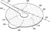
- FIG. 2is an isometric view of an example of a dressing interface, illustrating additional details that may be associated with some example embodiments of the therapy system of FIG. 1 ;
- FIG. 3is an exploded view of the dressing interface of FIG. 2 ;
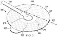
- FIG. 4is a top view of the dressing interface of FIG. 2 as assembled and coupled to an example of a cover that may be associated with some example embodiments of the therapy system of FIG. 1 ;
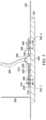
- FIG. 5is a cross-section view of the dressing interface and cover of FIG. 4 , and an example of a tissue interface that may be associated with some example embodiments of the therapy system of FIG. 1 ;
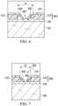
- FIG. 6 and FIG. 7are detail views of the dressing interface, cover, and tissue interface of FIG. 5 ;
- FIG. 8is a side view of the dressing interface and cover of FIG. 3 ;
- FIG. 9 and FIG. 10are top views of example configurations of hinge lines that may be associated with some embodiments of the dressing interface of FIG. 2 ;
- FIG. 11is an exploded view of another example of a dressing interface, illustrating additional details that may be associated with some example embodiments of the therapy system of FIG. 1 ;
- FIG. 12is a side view of the dressing interface of FIG. 11 and an example of a cover that may be associated with some example embodiments of the therapy system of FIG. 1 ;
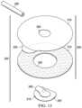
- FIG. 13is an exploded view of another example of a dressing interface, illustrating additional details that may be associated with some example embodiments of the therapy system of FIG. 1 ;
- FIG. 14 and FIG. 15are side views of another example of a dressing interface and a cover, illustrating additional details that may be associated with some example embodiments of the therapy system of FIG. 1 ;
- FIG. 16is an isometric view of another example of a dressing interface, illustrating additional details that may be associated with some example embodiments of the therapy system of FIG. 1 ;
- FIG. 17 and FIG. 18are top views of another example of a dressing interface and a cover, illustrating additional details that may be associated with some example embodiments of the therapy system of FIG. 1 ;
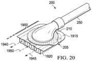
- FIG. 19is a bottom segmented isometric view of a dressing interface illustrating additional details that may be associated with some example embodiments of the therapy system of FIG. 1 ;
- FIG. 20is a segmented isometric view of the top of the dressing interface of FIG. 19 that may be associated with some example embodiments of the therapy system 100 of FIG. 1 .
- FIG. 1is a simplified functional block diagram of an example embodiment of a therapy system 100 that can provide negative-pressure therapy with instillation of topical treatment solutions to a tissue site in accordance with this specification.
- tissue sitein this context broadly refers to a wound, defect, or other treatment target located on or within tissue, including, but not limited to, bone tissue, adipose tissue, muscle tissue, neural tissue, dermal tissue, vascular tissue, connective tissue, cartilage, tendons, or ligaments.
- a woundmay include chronic, acute, traumatic, subacute, and dehisced wounds, partial-thickness burns, ulcers (such as diabetic, pressure, or venous insufficiency ulcers), flaps, and grafts, for example.
- tissue sitemay also refer to areas of any tissue that are not necessarily wounded or defective, but are instead areas in which it may be desirable to add or promote the growth of additional tissue. For example, negative pressure may be applied to a tissue site to grow additional tissue that may be harvested and transplanted.
- the therapy system 100may include a source or supply of negative pressure, such as a negative-pressure source 105 , and one or more distribution components.
- a distribution componentis preferably detachable and may be disposable, reusable, or recyclable.
- a dressing, such as a dressing 110 , and a fluid container, such as a container 115are examples of distribution components that may be associated with some examples of the therapy system 100 .
- the dressing 110may comprise or consist essentially of a tissue interface 120 , a cover 125 , or both in some embodiments.
- a fluid conductoris another illustrative example of a distribution component.
- a tubeis an elongated, cylindrical structure with some flexibility, but the geometry and rigidity may vary.
- some fluid conductorsmay be molded into or otherwise integrally combined with other components.
- Distribution componentsmay also include or comprise interfaces or fluid ports to facilitate coupling and de-coupling other components.
- a dressing interfacemay facilitate coupling a fluid conductor to the dressing 110 .
- the therapy system 100may also include a regulator or controller, such as a controller 130 . Additionally, the therapy system 100 may include sensors to measure operating parameters and provide feedback signals to the controller 130 indicative of the operating parameters. As illustrated in FIG. 1 , for example, the therapy system 100 may include a first sensor 135 and a second sensor 140 coupled to the controller 130 .
- the therapy system 100may also include a source of instillation solution.
- a solution source 145may be fluidly coupled to the dressing 110 , as illustrated in the example embodiment of FIG. 1 .
- the solution source 145may be fluidly coupled to a positive-pressure source such as a positive-pressure source 150 , a negative-pressure source such as the negative-pressure source 105 , or both in some embodiments.
- a regulatorsuch as an instillation regulator 155 , may also be fluidly coupled to the solution source 145 and the dressing 110 to ensure proper dosage of instillation solution (e.g. saline) to a tissue site.
- the instillation regulator 155may comprise a piston that can be pneumatically actuated by the negative-pressure source 105 to draw instillation solution from the solution source during a negative-pressure interval and to instill the solution to a dressing during a venting interval.
- the controller 130may be coupled to the negative-pressure source 105 , the positive-pressure source 150 , or both, to control dosage of instillation solution to a tissue site.
- the instillation regulator 155may also be fluidly coupled to the negative-pressure source 105 through the dressing 110 , as illustrated in the example of FIG. 1 .
- Some components of the therapy system 100may be housed within or used in conjunction with other components, such as sensors, processing units, alarm indicators, memory, databases, software, display devices, or user interfaces that further facilitate therapy.
- the negative-pressure source 105may be combined with the controller 130 , the solution source 145 , and other components into a therapy unit.
- components of the therapy system 100may be coupled directly or indirectly.
- the negative-pressure source 105may be directly coupled to the container 115 and may be indirectly coupled to the dressing 110 through the container 115 .
- Couplingmay include fluid, mechanical, thermal, electrical, or chemical coupling (such as a chemical bond), or some combination of coupling in some contexts.
- the negative-pressure source 105may be electrically coupled to the controller 130 and may be fluidly coupled to one or more distribution components to provide a fluid path to a tissue site.
- componentsmay also be coupled by virtue of physical proximity, being integral to a single structure, or being formed from the same piece of material.
- a negative-pressure supplysuch as the negative-pressure source 105
- Negative pressuregenerally refers to a pressure less than a local ambient pressure, such as the ambient pressure in a local environment external to a sealed therapeutic environment. In many cases, the local ambient pressure may also be the atmospheric pressure at which a tissue site is located. Alternatively, the pressure may be less than a hydrostatic pressure associated with tissue at the tissue site. Unless otherwise indicated, values of pressure stated herein are gauge pressures.
- references to increases in negative pressuretypically refer to a decrease in absolute pressure, while decreases in negative pressure typically refer to an increase in absolute pressure. While the amount and nature of negative pressure provided by the negative-pressure source 105 may vary according to therapeutic requirements, the pressure is generally a low vacuum, also commonly referred to as a rough vacuum, between ⁇ 5 mm Hg ( ⁇ 667 Pa) and ⁇ 500 mm Hg ( ⁇ 66.7 kPa). Common therapeutic ranges are between ⁇ 50 mm Hg ( ⁇ 6.7 kPa) and ⁇ 300 mm Hg ( ⁇ 39.9 kPa).
- the container 115is representative of a container, canister, pouch, or other storage component, which can be used to manage exudates and other fluids withdrawn from a tissue site.
- a rigid containermay be preferred or required for collecting, storing, and disposing of fluids.
- fluidsmay be properly disposed of without rigid container storage, and a re-usable container could reduce waste and costs associated with negative-pressure therapy.
- a controllersuch as the controller 130
- the controller 130may be a microcontroller, which generally comprises an integrated circuit containing a processor core and a memory programmed to directly or indirectly control one or more operating parameters of the therapy system 100 . Operating parameters may include the power applied to the negative-pressure source 105 , the pressure generated by the negative-pressure source 105 , or the pressure distributed to the tissue interface 120 , for example.
- the controller 130is also preferably configured to receive one or more input signals, such as a feedback signal, and programmed to modify one or more operating parameters based on the input signals.
- Sensorssuch as the first sensor 135 and the second sensor 140 , are generally known in the art as any apparatus operable to detect or measure a physical phenomenon or property, and generally provide a signal indicative of the phenomenon or property that is detected or measured.
- the first sensor 135 and the second sensor 140may be configured to measure one or more operating parameters of the therapy system 100 .
- the first sensor 135may be a transducer configured to measure pressure in a pneumatic pathway and convert the measurement to a signal indicative of the pressure measured.
- the first sensor 135may be a piezo-resistive strain gauge.
- the second sensor 140may optionally measure operating parameters of the negative-pressure source 105 , such as a voltage or current, in some embodiments.
- the signals from the first sensor 135 and the second sensor 140are suitable as an input signal to the controller 130 , but some signal conditioning may be appropriate in some embodiments.
- the signalmay need to be filtered or amplified before it can be processed by the controller 130 .
- the signalis an electrical signal, but may be represented in other forms, such as an optical signal.
- the tissue interface 120can be generally adapted to partially or fully contact a tissue site.
- the tissue interface 120may take many forms, and may have many sizes, shapes, or thicknesses, depending on a variety of factors, such as the type of treatment being implemented or the nature and size of a tissue site.
- the size and shape of the tissue interface 120may be adapted to the contours of deep and irregular shaped tissue sites. Any or all of the surfaces of the tissue interface 120 may have an uneven, coarse, or jagged profile.
- the tissue interface 120may comprise or consist essentially of a manifold.
- a manifold in this contextmay comprise or consist essentially of a means for collecting or distributing fluid across the tissue interface 120 under pressure.
- a manifoldmay be adapted to receive negative pressure from a source and distribute negative pressure through multiple apertures across the tissue interface 120 , which may have the effect of collecting fluid from across a tissue site and drawing the fluid toward the source.
- the fluid pathmay be reversed or a secondary fluid path may be provided to facilitate delivering fluid, such as fluid from a source of instillation solution, across a tissue site.
- a manifoldmay comprise a plurality of pathways, which can be interconnected to improve distribution or collection of fluids.
- a manifoldmay comprise or consist essentially of a porous material having interconnected fluid pathways.
- suitable porous material that can be adapted to form interconnected fluid pathwaysmay include cellular foam, including open-cell foam such as reticulated foam; porous tissue collections; and other porous material such as gauze or felted mat that generally include pores, edges, and/or walls.
- Liquids, gels, and other foamsmay also include or be cured to include apertures and fluid pathways.
- a manifoldmay additionally or alternatively comprise projections that form interconnected fluid pathways.
- a manifoldmay be molded to provide surface projections that define interconnected fluid pathways.
- the tissue interface 120may comprise or consist essentially of reticulated foam having pore sizes and free volume that may vary according to needs of a prescribed therapy.
- reticulated foam having a free volume of at least 90%may be suitable for many therapy applications, and foam having an average pore size in a range of 400-600 microns (40-50 pores per inch) may be particularly suitable for some types of therapy.
- the tensile strength of the tissue interface 120may also vary according to needs of a prescribed therapy. For example, the tensile strength of foam may be increased for instillation of topical treatment solutions.
- the 25% compression load deflection of the tissue interface 120may be at least 0.35 pounds per square inch, and the 65% compression load deflection may be at least 0.43 pounds per square inch.
- the tensile strength of the tissue interface 120may be at least 10 pounds per square inch.
- the tissue interface 120may have a tear strength of at least 2.5 pounds per inch.
- the tissue interfacemay be foam comprised of polyols such as polyester or polyether, isocyanate such as toluene diisocyanate, and polymerization modifiers such as amines and tin compounds.
- the tissue interface 120may be reticulated polyurethane foam such as found in GRANUFOAMTM dressing or V.A.C. VERAFLOTM dressing, both available from Kinetic Concepts, Inc. of San Antonio, Texas.
- the thickness of the tissue interface 120may also vary according to needs of a prescribed therapy. For example, the thickness of the tissue interface may be decreased to reduce tension on peripheral tissue. The thickness of the tissue interface 120 can also affect the conformability of the tissue interface 120 . In some embodiments, a thickness in a range of about 5 millimeters to 10 millimeters may be suitable.
- the tissue interface 120may be either hydrophobic or hydrophilic. In an example in which the tissue interface 120 may be hydrophilic, the tissue interface 120 may also wick fluid away from a tissue site, while continuing to distribute negative pressure to the tissue site. The wicking properties of the tissue interface 120 may draw fluid away from a tissue site by capillary flow or other wicking mechanisms.
- a hydrophilic materialthat may be suitable is a polyvinyl alcohol, open-cell foam such as V.A.C. WHITEFOAMTM dressing available from Kinetic Concepts, Inc. of San Antonio, Texas
- Other hydrophilic foamsmay include those made from polyether.
- Other foams that may exhibit hydrophilic characteristicsinclude hydrophobic foams that have been treated or coated to provide hydrophilicity.
- the tissue interface 120may be constructed from bioresorbable materials. Suitable bioresorbable materials may include, without limitation, a polymeric blend of polylactic acid (PLA) and polyglycolic acid (PGA). The polymeric blend may also include, without limitation, polycarbonates, polyfumarates, and capralactones.
- the tissue interface 120may further serve as a scaffold for new cell-growth, or a scaffold material may be used in conjunction with the tissue interface 120 to promote cell-growth.
- a scaffoldis generally a substance or structure used to enhance or promote the growth of cells or formation of tissue, such as a three-dimensional porous structure that provides a template for cell growth.
- Illustrative examples of scaffold materialsinclude calcium phosphate, collagen, PLA/PGA, coral hydroxy apatites, carbonates, or processed allograft materials.
- the cover 125may provide a bacterial barrier and protection from physical trauma.
- the cover 125may also be constructed from a material that can reduce evaporative losses and provide a fluid seal between two components or two environments, such as between a therapeutic environment and a local external environment.
- the cover 125may comprise or consist of, for example, an elastomeric film or membrane that can provide a seal adequate to maintain a negative pressure at a tissue site for a given negative-pressure source.
- the cover 125may have a high moisture-vapor transmission rate (MVTR) in some applications.
- MVTRmoisture-vapor transmission rate
- the MVTRmay be at least 250 grams per square meter per twenty-four hours (g/m 2 /24 hours) in some embodiments, measured using an upright cup technique according to ASTM E96/E96M Upright Cup Method at 38° C. and 10% relative humidity (RH). In some embodiments, an MVTR up to 5,000 g/m 2 /24 hours may provide effective breathability and mechanical properties.
- the cover 125may be a polymer drape, such as a polyurethane film, that is permeable to water vapor but impermeable to liquid.
- a polymer drapesuch as a polyurethane film
- Such drapestypically have a thickness in the range of 25-50 microns.
- the permeabilitygenerally should be low enough that a desired negative pressure may be maintained.
- the cover 125may comprise, for example, one or more of the following materials: polyurethane (PU), such as hydrophilic polyurethane; cellulosics; hydrophilic polyamides; polyvinyl alcohol; polyvinyl pyrrolidone; hydrophilic acrylics; silicones, such as hydrophilic silicone elastomers; natural rubbers; polyisoprene; styrene butadiene rubber; chloroprene rubber; polybutadiene; nitrile rubber; butyl rubber; ethylene propylene rubber; ethylene propylene diene monomer; chlorosulfonated polyethylene; polysulfide rubber; ethylene vinyl acetate (EVA); co-polyester; and polyether block polymide copolymers.
- PUpolyurethane
- PUpolyurethane
- hydrophilic polyurethanesuch as hydrophilic polyurethane
- cellulosicssuch as cellulosics; hydrophilic polyamides
- the cover 125may comprise INSPIRE 2301 having an MVTR (upright cup technique) of 2600 g/m 2 /24 hours and a thickness of about 30 microns.
- An attachment devicemay be used to attach the cover 125 to an attachment surface, such as undamaged epidermis, a gasket, or another cover.
- the attachment devicemay take many forms.
- an attachment devicemay be a medically-acceptable, pressure-sensitive adhesive configured to bond the cover 125 to epidermis around a tissue site.
- some or all of the cover 125may be coated with an adhesive, such as an acrylic adhesive, which may have a coating weight of about 25-65 grams per square meter (g.s.m.). Thicker adhesives, or combinations of adhesives, may be applied in some embodiments to improve the seal and reduce leaks.
- Other example embodiments of an attachment devicemay include a double-sided tape, paste, hydrocolloid, hydrogel, silicone gel, or organogel.
- the solution source 145may also be representative of a container, canister, pouch, bag, or other storage component, which can provide a solution for instillation therapy.
- Compositions of solutionsmay vary according to a prescribed therapy, but examples of solutions that may be suitable for some prescriptions include hypochlorite-based solutions, silver nitrate (0.5%), sulfur-based solutions, biguanides, cationic solutions, and isotonic solutions.
- the tissue interface 120may be placed within, over, on, or otherwise proximate to a tissue site. If the tissue site is a wound, for example, the tissue interface 120 may partially or completely fill the wound, or it may be placed over the wound.
- the cover 125may be placed over the tissue interface 120 and sealed to an attachment surface near a tissue site. For example, the cover 125 may be sealed to undamaged epidermis peripheral to a tissue site.
- the dressing 110can provide a sealed therapeutic environment proximate to a tissue site, substantially isolated from the external environment, and the negative-pressure source 105 can reduce pressure in the sealed therapeutic environment.
- the fluid mechanics of using a negative-pressure source to reduce pressure in another component or location, such as within a sealed therapeutic environment,can be mathematically complex.
- the basic principles of fluid mechanics applicable to negative-pressure therapy and instillationare generally well-known to those skilled in the art, and the process of reducing pressure may be described illustratively herein as “delivering,” “distributing,” or “generating” negative pressure, for example.
- downstreamtypically implies something in a fluid path relatively closer to a source of negative pressure or further away from a source of positive pressure.
- upstreamimplies something relatively further away from a source of negative pressure or closer to a source of positive pressure.
- fluid inletor “outlet” in such a frame of reference. This orientation is generally presumed for purposes of describing various features and components herein.
- the fluid pathmay also be reversed in some applications, such as by substituting a positive-pressure source for a negative-pressure source, and this descriptive convention should not be construed as a limiting convention.
- Negative pressure applied across the tissue site through the tissue interface 120 in the sealed therapeutic environmentcan induce macro-strain and micro-strain in the tissue site. Negative pressure can also remove exudate and other fluid from a tissue site, which can be collected in container 115 .
- the controller 130may receive and process data from one or more sensors, such as the first sensor 135 .
- the controller 130may also control the operation of one or more components of the therapy system 100 to manage the pressure delivered to the tissue interface 120 .
- controller 130may include an input for receiving a desired target pressure and may be programmed for processing data relating to the setting and inputting of the target pressure to be applied to the tissue interface 120 .
- the target pressuremay be a fixed pressure value set by an operator as the target negative pressure desired for therapy at a tissue site and then provided as input to the controller 130 .
- the target pressuremay vary from tissue site to tissue site based on the type of tissue forming a tissue site, the type of injury or wound (if any), the medical condition of the patient, and the preference of the attending physician.
- the controller 130can operate the negative-pressure source 105 in one or more control modes based on the target pressure and may receive feedback from one or more sensors to maintain the target pressure at the tissue interface 120 .
- the controller 130may have a continuous pressure mode, in which the negative-pressure source 105 is operated to provide a constant target negative pressure for the duration of treatment or until manually deactivated. Additionally or alternatively, the controller may have an intermittent pressure mode. For example, the controller 130 can operate the negative-pressure source 105 to cycle between a target pressure and atmospheric pressure. For example, the target pressure may be set at a value of ⁇ 135 mmHg for a specified period of time (e.g., 5 min), followed by a specified period of time (e.g., 2 min) of deactivation. The cycle can be repeated by activating the negative-pressure source 105 which can form a square wave pattern between the target pressure and atmospheric pressure.
- the increase in negative-pressure from ambient pressure to the target pressuremay not be instantaneous.
- the negative-pressure source 105 and the dressing 110may have an initial rise time.
- the initial rise timemay vary depending on the type of dressing and therapy equipment being used.
- the initial rise time for one therapy systemmay be in a range of about 20-30 mmHg/second and in a range of about 5-10 mmHg/second for another therapy system. If the therapy system 100 is operating in an intermittent mode, the repeating rise time may be a value substantially equal to the initial rise time.
- the target pressurecan vary with time.
- the target pressuremay vary in the form of a triangular waveform, varying between a negative pressure of 50 and 135 mmHg with a rise time set at a rate of +25 mmHg/min. and a descent time set at ⁇ 25 mmHg/min.
- the triangular waveformmay vary between negative pressure of 25 and 135 mmHg with a rise time set at a rate of +30 mmHg/min and a descent time set at ⁇ 30 mmHg/min.
- the controller 130may control or determine a variable target pressure in a dynamic pressure mode, and the variable target pressure may vary between a maximum and minimum pressure value that may be set as an input prescribed by an operator as the range of desired negative pressure.
- the variable target pressuremay also be processed and controlled by the controller 130 , which can vary the target pressure according to a predetermined waveform, such as a triangular waveform, a sine waveform, or a saw-tooth waveform.
- the waveformmay be set by an operator as the predetermined or time-varying negative pressure desired for therapy.
- the controller 130may receive and process data, such as data related to instillation solution provided to the tissue interface 120 .
- datamay include the type of instillation solution prescribed by a clinician, the volume of fluid or solution to be instilled to a tissue site (“fill volume”), and the amount of time prescribed for leaving solution at a tissue site (“dwell time”) before applying a negative pressure to the tissue site.
- the fill volumemay be, for example, between 10 and 500 mL, and the dwell time may be between one second to 30 minutes.
- the controller 130may also control the operation of one or more components of the therapy system 100 to instill solution. For example, the controller 130 may manage fluid distributed from the solution source 145 to the tissue interface 120 .
- fluidmay be instilled to a tissue site by applying a negative pressure from the negative-pressure source 105 to reduce the pressure at the tissue site, drawing solution into the tissue interface 120 .
- solutionmay be instilled to a tissue site by applying a positive pressure from the positive-pressure source 150 to move solution from the solution source 145 to the tissue interface 120 .
- the solution source 145may be elevated to a height sufficient to allow gravity to move solution into the tissue interface 120 .
- the controller 130may also control the fluid dynamics of instillation by providing a continuous flow of solution or an intermittent flow of solution. Negative pressure may be applied to provide either continuous flow or intermittent flow of solution.
- the application of negative pressuremay be implemented to provide a continuous pressure mode of operation to achieve a continuous flow rate of instillation solution through the tissue interface 120 , or it may be implemented to provide a dynamic pressure mode of operation to vary the flow rate of instillation solution through the tissue interface 120 .
- the application of negative pressuremay be implemented to provide an intermittent mode of operation to allow instillation solution to dwell at the tissue interface 120 . In an intermittent mode, a specific fill volume and dwell time may be provided depending, for example, on the type of tissue site being treated and the type of dressing being utilized. After or during instillation of solution, negative-pressure treatment may be applied.
- the controller 130may be utilized to select a mode of operation and the duration of the negative pressure treatment before commencing another instillation cycle by instilling more solution.
- FIG. 2is an isometric view illustrating a dressing interface 200 configured to connect the negative-pressure source 105 to the dressing 110 .
- the dressing interface 200may be easily removed, replaced, and/or repositioned on the cover 125 without damaging or destroying the cover 125 .
- the dressing interface 200comprises a coupling member 205 coupled to a negative-pressure port 210 .
- the coupling member 205includes an aperture 215 , a first adhesive region 220 , and a second adhesive region 225 .
- a hinge line 230may be formed between the first adhesive region 220 and the second adhesive region 225 .
- the first adhesive region 220has a first peel strength and the second adhesive region 225 has a second peel strength, wherein the second peel strength is less than the first peel strength.
- the dressing interface 200may further include a tab 235 coupled to the second adhesive region 225 .
- the negative-pressure port 210includes a base, such as a flange 240 , and a conduit housing 245 extending from the flange 240 .
- the conduit housing 245may be an elbow connector.
- the conduit housingmay extend through the aperture 215 in the coupling member 205 .
- a fluid conductor 250which may be a flexible tube, for example, may be fluidly coupled on one end to the conduit housing 245 .
- FIG. 3is an exploded view of the dressing interface 200 of FIG. 2 , illustrating additional details that may be associated with certain embodiments.
- the flange 240 of the negative-pressure port 210may have at least one straight edge and one rounded edge.
- the flange 240may have a rounded edge 300 corresponding to a major arc of a circle, and a straight edge 305 corresponding to a chord of the circle.
- the rounded edge 300 and the straight edge 305define a shape corresponding to a major segment of the circle. That is, the flange 240 may have straight section or flat spot.
- the straight edge 305may be parallel to the hinge line 230 .
- the straight edge 305may be offset from the hinge line 230 a distance into or toward the second adhesive region 225 . In other embodiments, the straight edge 305 may be collinear with the hinge line 230 . The straight edge 305 may lie along the hinge line 230 without any offset from the hinge line 230 . The straight edge 305 in the flange 240 can allow the negative-pressure port 210 to hinge about the hinge line 230 if the second adhesive region 225 is removed from the cover 125 as described herein.
- the flange 240 of the negative-pressure port 210may be flexible enough to permit folding and bending of the flange 240 such that a portion of the flange 240 may extend across the hinge line 230 and not impede or prohibit the hinging of the second adhesive region 225 .
- the flange 240may have any suitable shape, such as, for example, circles, triangles, squares, rectangles, pentagons, hexagons, octagons, stars, ovals, polygons, or rectilinear shapes.
- the flange 240has a shape with at least one straight edge (e.g., triangle, square, rectangle, pentagon, hexagon, octagon)
- the straight edgemay be parallel to or collinear with the hinge line 230 as described above with respect to the straight edge 305 .
- the coupling member 205may include a shell layer 310 and a contact layer 315 .
- the shell layer 310may be formed from any material that allows for a fluid seal.
- a fluid sealis a seal adequate to maintain negative pressure at a desired site given the particular negative-pressure source or system involved.
- the shell layer 310may comprise, for example, one or more of the following materials: hydrophilic polyurethane; cellulosics; hydrophilic polyamides; polyvinyl alcohol; polyvinyl pyrrolidone; hydrophilic acrylics; hydrophilic silicone elastomers; an INSPIRE 2301 or 2317 material from Expopack Advanced Coatings of Wrexham, United Kingdom having, for example, an MVTR (inverted cup technique) of 14400 g/m 2 /24 hours and a thickness of about 30 microns; a thin, uncoated polymer drape; natural rubbers; polyisoprene; styrene butadiene rubber; chloroprene rubber; polybutadiene; nitrile rubber; butyl rubber; ethylene propylene rubber; ethylene propylene diene monomer; chlorosulfonated polyethylene; polysulfide rubber; polyurethane (PU); EVA film; co-polyester; silicones; a silicone drape
- the shell layer 310may be vapor permeable and liquid impermeable.
- the shell layer 310may be a flexible, breathable film, membrane, or sheet having a high MVTR of, for example, at least about 300 g/m 2 per 24 hours. In other embodiments, a low or no vapor transfer film might be used.
- the shell layer 310may comprise a range of medically suitable films having a thickness between about 15 microns ( ⁇ m) to about 50 microns ( ⁇ m).
- the shell layer 310may be formed of the same material as the cover 125 .
- the shell layer 310may be clear, transparent, translucent, opaque and/or colored.
- the shell layer 310may have a first side and a second side.
- the first side of the shell layer 310may comprise an adhesive.
- the adhesivemay be coupled to the first side of the shell layer 310 .
- the adhesivemay be coated or deposited on the first side of the shell layer 310 .
- the adhesivemay be a medically-acceptable adhesive.
- the adhesivemay also be flowable.
- the adhesivemay comprise an acrylic adhesive, rubber adhesive, high-tack or tacky silicone adhesive, polyurethane, or other adhesive substance.
- the adhesive of the shell layer 310may be a pressure-sensitive adhesive, such as an acrylic adhesive with coating weight of 15 grams/m 2 (gsm) to 70 grams/m 2 (gsm).
- the adhesivemay have a peel strength or resistance to being peeled from a stainless steel material in a range of about 6.4N to about 8.8 N. In some embodiments, the adhesive may have a peel strength or resistance to being peeled from a stainless steel material of about 7.8 N.
- the peel strengthmay be measured by applying a 1 inch (2.54 cm) wide test strip of the adhesive to a stainless steel plate using a roller. The test strip is then peeled back over itself (at an angle of 180 degrees) and the force required to peel the test strip is measured. The test is conducted at on a stainless steel substrate at 23 degrees C. at 50% relative humidity based on ASTM D3330.
- the adhesive of the shell layer 310may be reduced or deactivated using ultraviolet light. Ultraviolet light may be shined upon the shell layer 310 and the ultraviolet light may reduce the peel strength of the adhesive a sufficient amount to allow removal of the dressing interface 200 from the cover 125 without damage to or destruction of the cover 125 .
- the shell layer 310further includes an aperture 320 .
- the aperture 320may be centrally located in the shell layer 310 .
- the aperture 320may be sized or dimensioned to receive the conduit housing 245 of the negative-pressure port 210 .
- the shape of the aperture 320may be coextensive or congruent with the shape of the conduit housing 245 where the conduit housing 245 meets the flange 240 .
- the size of the aperture 320 in the shell layer 310may be larger than the size of the conduit housing 245 where the conduit housing 245 meets the flange 240 .
- the shape of the aperture 320may be different from the shape of the conduit housing 245 where the conduit housing 245 meets the flange 240 .
- the top side of the flange 240 of the negative-pressure port 210may be coupled to the first side of the shell layer 310 by the adhesive on the first side of the shell layer 310 to create a fluid seal around the flange 240 .
- the shell layer 310may also include a tab 325 located on the periphery of the shell layer 310 on the second adhesive region 225 side of the hinge line 230 .
- the contact layer 315may have a first side and a second side.
- the second side of the contact layer 315may be coupled to the first side of the shell layer 310 .
- the contact layer 315may comprise an adhesive.
- the contact layer 315may be a soft, pliable material suitable for providing a fluid seal with the cover 125 as described herein.
- the contact layer 315may comprise a silicone gel, a soft silicone, hydrocolloid, hydrogel, polyurethane gel, polyolefin gel, hydrogenated styrenic copolymer gels, a foamed gel, a soft closed-cell foam such as polyurethanes and polyolefins coated with an adhesive, polyurethane, polyolefin, hydrogenated styrenic copolymers, or a film, membrane, or sheet coated with an adhesive.
- the contact layer 315may be comprised of hydrophobic or hydrophilic materials. In some embodiments, the contact layer 315 may be clear, transparent, translucent, opaque and/or colored.
- the contact layer 315may have a thickness between about 500 microns ( ⁇ m) and about 1000 microns ( ⁇ m). In some embodiments, the contact layer 315 has a stiffness between about 5 Shore 00 and about 80 Shore 00. In some embodiments, the contact layer 315 has a peel strength in a range of about 0.37 N to about 0.44 N. In some embodiments, for example, the contact layer 315 has a peel strength in a range of about 0.5 N to about 1.0 N. In some embodiments, for example, the contact layer 315 has a peel strength of about 0.4 N. In some embodiments, for example, the contact layer 315 has a peel strength of about 0.8 N.
- the contact layer 315has a peel strength of about 0.9 N. In some embodiments, for example, the contact layer 315 has a peel strength of about 2.8 N. The peel strength of the contact layer 315 may be less than the peel strength of the adhesive of the shell layer 310 .
- the ratio of the peel strength of the contact layer 315 to the peel strength of the adhesive of the shell layer 310may be about 1:2. In some embodiments, the ratio of the peel strength of the contact layer 315 to the peel strength of the adhesive of the shell layer 310 may be about 1:2.3. In some embodiments, the ratio of the peel strength of the contact layer 315 to the peel strength of the adhesive of the shell layer 310 may be about 1:3.1. In some embodiments, the ratio of the peel strength of the contact layer 315 to the peel strength of the adhesive of the shell layer 310 may be about 1:7.1. In some embodiments, the ratio of the peel strength of the contact layer 315 to the peel strength of the adhesive of the shell layer 310 may be about 1:8.
- the ratio of the peel strength of the contact layer 315 to the peel strength of the adhesive of the shell layer 310may be about 1:9.8. In some embodiments, the ratio of the peel strength of the contact layer 315 to the peel strength of the adhesive of the shell layer 310 may be about 1:11. In some embodiments, the ratio of the peel strength of the contact layer 315 to the peel strength of the adhesive of the shell layer 310 may be about 1:14.5. In some embodiments, the ratio of the peel strength of the contact layer 315 to the peel strength of the adhesive of the shell layer 310 may be about 1:17.3. In some embodiments, ratio of the peel strength of the contact layer 315 to the peel strength of the adhesive of the shell layer 310 may be about 1:19.5.
- the ratio of the peel strength of the contact layer 315 to the peel strength of the adhesive of the shell layer 310may be about 1:20. In some embodiments, the ratio of the peel strength of the contact layer 315 to the peel strength of the adhesive of the shell layer 310 may be about 1:23.8. In some embodiments, the ratio of the peel strength of the contact layer 315 to the peel strength of the adhesive of the shell layer 310 may range from about 1:2 to about 1:23.8. In some embodiments, the ratio of the peel strength of the contact layer 315 to the peel strength of the adhesive of the shell layer 310 may range from about 1:2 to about 1:25.
- the contact layer 315may further include an aperture 330 located in the second adhesive region 225 .
- the aperture 330may be sized or dimensioned to receive the flange 240 of the negative-pressure port 210 therein.
- the shape of the aperture 330may be coextensive or congruent with the shape of the flange 240 of the negative-pressure port 210 .
- the aperture 330may also have a truncated circle shape that corresponds to the shape of the flange 240 .
- the aperture 330may be located such that the straight edge 305 of the flange 240 may be parallel to the hinge line 230 in the coupling member 205 .
- the straight edge 305may be parallel to the hinge line 230 , but may be offset from the hinge line 230 a distance into or toward the second adhesive region 225 .
- the straight edge 305may be collinear with the hinge line 230 .
- the straight edge 305may lie along the hinge line 230 without any offset from the hinge line 230 .
- the flange 240 of the negative-pressure port 210has a thickness and the contact layer 315 has a thickness at least as thick as the thickness of the flange 240 . In other embodiments, the thickness of the contact layer 315 is less than the thickness of the flange 240 .
- the flange 240may be thicker than the contact layer 315 .
- the contact layer 315may further include a plurality of apertures 335 .
- the plurality of apertures 335may be formed by cutting, perforating, punching, or by other suitable techniques for forming an aperture, opening, perforation, or hole in the contact layer 315 , including but not limited to using a single- or multiple-blade cutter, a laser, a water jet, a hot knife, a computer numeric control (CNC) cutter, a hot wire, local RF or ultrasonic energy, and/or a single- or multiple-punch tool.
- CNCcomputer numeric control
- the plurality of apertures 335 in the contact layer 315may have many shapes including but not limited to, circles, triangles, rectangles, squares, pentagons, hexagons, octagons, ovals, ellipses, stars, polygons, slits, complex curves, and rectilinear shapes or may have some combination of shapes.
- the contact layer 315may further include a tab 340 located on the periphery of the contact layer 315 on the second adhesive region 225 side of the hinge line 230 .
- the tab 340 of the contact layer 315 and the tab 325 of the shell layer 310may cooperate to form tab 235 of coupling member 205 .
- FIG. 4illustrates a top view of the dressing interface 200 as assembled and coupled to a cover 125 .
- the plurality of apertures 335may include a first plurality of apertures 400 and a second plurality of apertures 405 .
- At least one of the first plurality of apertures 400is located on a first side of the hinge line 230 (e.g., in the first adhesive region 220 ) and at least one of the second plurality of apertures 405 is located on a second side of the hinge line 230 opposite the first side (e.g., in the second adhesive region 225 ).
- the first plurality of apertures 400 and the second plurality of apertures 405 in the contact layer 315may be substantially circular in shape.
- the width of each of the first plurality of apertures 400 and the second plurality of apertures 405may define the area of each of the first plurality of apertures 400 and the second plurality of apertures 405 .
- the diameter D 1and thus the open area, of each of the first plurality of apertures 400 is larger than the diameter D 2 and open area of each of the second plurality of apertures 405 .
- the diameter D 1 of the first plurality of apertures 400may be in a range of about 4 millimeters to about 15 millimeters.
- the diameter D 1 of the first plurality of apertures 400may be in a range of about 5 millimeters to about 10 millimeters. In some embodiments, the diameter D 1 of the first plurality of apertures 400 may be about 10 millimeters.
- the diameter D 2 of the second plurality of apertures 405may be in a range of about 1 millimeters to about 10 millimeters. In some embodiments, the diameter D 2 of the second plurality of apertures 405 may be in a range of about 2 millimeters to about 7 millimeters. In some embodiments, the diameter D 2 of the second plurality of apertures 405 may be about 5 millimeters.
- each aperture of the first plurality of apertures 400is shown as having the same diameter D 1 and each aperture of the second plurality of apertures 405 as having the same diameter D 2 , it will be understood that in other embodiments, the apertures of the first plurality of apertures 400 may have differing dimensions (and thus open areas) and the apertures of the second plurality of apertures 405 may have differing dimensions (and thus open areas).
- the first plurality of apertures 400may have apertures of two or more open areas which cooperate to form an overall open area of the first adhesive region 220 .
- the second plurality of apertures 405may have apertures of two or more open areas which cooperate to form an overall open area of the second adhesive region 225 . Therefore, much like the differing diameters of dimples on a golf ball, in some embodiments, the dimensions of the apertures in first plurality of apertures 400 may vary and the dimensions of the apertures in the second plurality of apertures 405 may vary.
- the first plurality of apertures 400are shown as having a circular shape; however, in other embodiments the first plurality of apertures 400 may have many shapes including but not limited to, triangles, rectangles, squares, pentagons, hexagons, octagons, ovals, ellipses, stars, polygons, slits, complex curves, rectilinear shapes or may have some combination of shapes.
- the second plurality of apertures 405are shown as having a circular shape; however, in other embodiments the second plurality of apertures 405 may have many shapes including but not limited to, triangles, rectangles, squares, pentagons, hexagons, octagons, ovals, ellipses, stars, polygons, slits, complex curves, rectilinear shapes or may have some combination of shapes.
- FIG. 5is a cross-section of the dressing interface 200 of FIG. 4 taken along section line 5 - 5 , illustration additional details that may be associated with some embodiments.
- the flange 240 of the negative-pressure port 210may be located below shell layer 310 and the conduit housing 245 may extend upward through the aperture 320 in shell layer 310 .
- the second side of the contact layer 315may be coupled to the first side of the shell layer 310 by the adhesive on the first side of the shell layer 310 .
- the flange 240 of the negative-pressure port 210may be located in the aperture 330 of the contact layer 315 .
- the aperture 320 in the shell layer 310 and the aperture 330 in the contact layer 315may cooperate to form the aperture 215 in coupling member 205 .
- the dressing interface 200may then be placed on top of the cover 125 so that the conduit housing 240 of the negative-pressure port 210 is located over an aperture 500 in the cover 125 and so that the fluid conductor 250 may be fluidly coupled with the tissue interface 120 through the aperture 500 .
- the flange 240 of the negative-pressure port 210may be located above shell layer 310 .
- the bottom side of the flange 240may be adhered to the second side or top side of shell layer 310 to create a fluid seal.
- FIG. 6 and FIG. 7are detail views of features in the example of FIG. 5 .
- the shell layer 310may extend or be pressed through the plurality of apertures 335 to contact the cover 125 for securing the dressing interface 200 to, for example, the cover 125 .
- the plurality of apertures 335may provide sufficient contact of the shell layer 310 to the cover 125 to secure the dressing interface 200 to the cover 125 .
- the plurality of apertures 335may be sized to control the amount of the shell layer 275 extending through the plurality of apertures 335 in the contact layer 315 to reach the cover 125 .
- the configuration of the plurality of apertures 335 , the shell layer 310 and the contact layer 315may permit release and repositioning of the dressing interface 200 on the cover 125 .
- At least a portion of the shell layer 310may be configured to extend at least partially through one or more of the plurality of apertures 335 in the contact layer 315 .
- at least a first portion of the shell layer 310may extend at least partially through the first plurality of apertures 400 in the contact layer 315 (see FIG. 6 ) and at least a second portion of the shell layer 310 may extend at least partially through the second plurality of apertures 405 in the contact layer 315 (see FIG. 7 ).
- the diameter D 1 of the first plurality of apertures 400is larger than the diameter D 2 of the second plurality of apertures 405 , allowing more of the shell layer 310 to come into contact with the cover 125 at each aperture in the first plurality of apertures 400 than is able to come into contact with the cover 125 at each aperture in the second plurality of apertures 405 .
- the first adhesive region 220may be formed by a first portion of the contact layer 315 proximate the first plurality of apertures 400 and a first portion of the shell layer 310 extending through the first plurality of apertures 400 .
- the second adhesive region 225may be formed by a second portion of the contact layer 315 proximate the second plurality of apertures 405 and a second portion of the shell layer 310 extending through the second plurality of apertures 405 .
- the combination of the peel strength of the shell layer 310 , the amount of the shell layer 310 extending through the first plurality of apertures 400 and contacting the cover 125 , and the peel strength of the contact layer 315 contacting the cover 125results in a first region peel strength.
- the combination of the peel strength of the shell layer 310 , the amount of the shell layer 310 extending through the second plurality of apertures 405 and contacting the cover 125 , and the peel strength of the contact layer 315 contacting the cover 125results in a second region peel strength.
- the first region peel strengthis higher than the second region peel strength. Therefore, the coupling member 205 may have a first region peel strength in the first adhesive region 220 and a second region peel strength in the second adhesive region 225 .
- the second region peel strength of the second adhesive region 225may be low enough to permit removal of the second adhesive region 225 from the cover 125 without damage to or destruction of the cover 125 . Additionally, in some examples, the first adhesive region 220 may remain attached to the cover 125 when the second adhesive region 225 is removed. The first adhesive region 220 may function as an anchor to hold the dressing interface 200 to the cover 125 .
- FIG. 8is a front view of the dressing interface 200 of FIG. 2 .
- the tab 235may be pulled to remove the second adhesive region 225 from the cover 125 .
- the tab 235may be pulled to completely remove the dressing interface 200 from the cover 125 .
- the tab 235is non-adhesive so that the tab 235 may be easily lifted up and pulled to remove part or all of the dressing interface 200 from the cover 125 .
- the tab 235may include a low-peel-force adhesive that is configured to keep the tab 235 attached to the cover 125 so that the tab 235 is not inadvertently pulled up by being snagged on clothing, medical equipment, other persons, or other objects.
- the negative-pressure port 210may also be located in the second adhesive region 225 and may also hinge or rotate about the hinge line 230 .
- the second plurality of apertures 405may also hinge or rotate about the hinge line 230 .
- the bottom side of the negative-pressure port 210 and the interior of the conduit housing 245can be inspected and/or accessed to remove exudate, clogs, and/or other material from, or otherwise clean, the negative-pressure port 210 and/or the interior of the conduit housing 245 .
- This cleaningcan be done without damaging or destroying the cover 125 , the tissue interface 120 , or the tissue site.
- the second adhesive region 225can be reattached to the cover 125 and negative-pressure therapy can resume.
- a number of factorsmay be utilized to control the first region peel strength and the second region peel strength of the dressing interface 200 , including, but not limited to, the area and number of the first plurality of apertures 400 and the second plurality of apertures 405 in the contact layer 315 , the thickness of the contact layer 315 , the thickness and amount of the adhesive on the shell layer 310 , the peel strength of the adhesive on the shell layer 310 , and the peel strength of the contact layer 315 .
- An increase in the amount of the adhesive of the shell layer 310 extending through the plurality of apertures 335generally corresponds to an increase in the peel strength of the dressing interface 200 .
- a decrease in the thickness of the contact layer 315generally corresponds to an increase in the amount of the adhesive of the shell layer 310 extending through the plurality of apertures 335 .
- the diameter and configuration of the first plurality of apertures 400 and the second plurality of apertures 405 , the amount and peel strength of the adhesive of the shell layer 310 , the thickness of the contact layer 315 , and the peel strength of the contact layer 315 utilizedmay be varied to provide a desired first region peel strength and second region peel strength for the dressing interface 200 .
- FIG. 9 and FIG. 10are top views of the dressing interface 200 , illustrating additional details that may be associated with certain embodiments.
- the hinge line 230 of various embodiments of the dressing interface 200is described and illustrated as being straight, in some embodiments the hinge line 230 may be non-linear (e.g., curved, an arc, wavy, sawtooth). In other embodiments, no part of the hinge line 230 intersects the flange 240 of the negative-pressure port 210 . In other embodiments, the hinge line 230 may be tangent to the flange 240 . In the example embodiment shown in FIG. 9 , the hinge line 230 is curved toward the negative-pressure port 210 .
- Coupling member 205comprises a perimeter 900 and the hinge line 230 has a first end point 905 on the perimeter 900 and a second end point 910 on the perimeter 900 .
- An imaginary line 915may be drawn from the first end point 905 to the second end point 910 , and no part of the imaginary line 915 intersects the flange 240 of the negative-pressure port 210 . Accordingly, in the example embodiment shown in FIG.
- hinge line 230is curved away from the negative-pressure port 210 , so long as the imaginary line 915 extending from the first end point 905 to the second end point 910 does not intersect the flange 240 , the second adhesive region 225 may rotate about the hinge line 230 and a user may be able to easily access the interior of the conduit housing 245 of the negative-pressure port 210 .
- FIG. 11is an exploded view of an example configuration of the plurality of apertures 335 , illustrating additional details that may be associated with some embodiments of the dressing interface 200 .
- the dressing interface 200includes coupling member 205 configured to be coupled to a negative-pressure port 210 .
- the coupling member 205may include a shell layer 310 , a contact layer 315 , and a tab 235 .
- the shell layer 310may further include an aperture 320 through which the conduit housing 245 of the negative-pressure port 210 is configured to extend.
- the contact layer 315has an aperture 330 for receiving the flange 240 of the negative-pressure port 210 , and a plurality of apertures 335 . As shown in FIG.
- the flange 240may be circular and may not include the chord 305 shown in FIGS. 2 - 5 . In some embodiments, flange 240 may include the chord 305 . Additionally, the example of the contact layer 315 shown in FIG. 11 only includes a single plurality of apertures 335 . In some embodiments, for example, the single plurality of apertures 335 may be the second plurality of apertures 405 . Consequently, in some embodiments, the dressing interface 200 may only have a single adhesive region with a single region peel strength. By including only the second plurality of apertures 405 , the entirety of the dressing interface 200 may be removed from the cover 125 without damage to or destruction of the cover 125 .
- FIG. 12is a front view of the dressing interface 200 shown in FIG. 11 illustrating the complete removal of the dressing interface 200 from the cover 125 along lines B without damaging or destroying the cover 125 or the tissue interface 120 . It will be understood however, that less than the entirety of dressing interface 200 may also be removed from cover 125 without damage to or destruction of the cover 125 .
- the dressing interface 200may be reattached by pressing down along lines B.
- FIG. 13is an exploded view of another example configuration of the dressing interface 200 , illustrating additional details that may be associated with some embodiments of the dressing interface 200 .
- the dressing interface 200includes coupling member 205 configured to be coupled to a negative-pressure port 210 .
- the coupling member 205may include a shell layer 310 , a contact layer 315 , and a tab 235 .
- the shell layer 310may further include an aperture 320 through which the conduit housing 245 of the negative-pressure port 210 is configured to extend.
- the contact layer 315includes an aperture 330 for receiving the flange 240 of the negative-pressure port 210 . As shown in FIG.
- the flange 240may be circular and may not include the chord 305 shown in FIGS. 2 - 5 . Moreover, unlike the examples of the contact layer 315 shown in FIGS. 2 - 8 and 11 having a plurality of apertures 335 , the example of the contact layer 315 shown in FIG. 13 lacks the plurality of apertures 335 .
- the dressing interface 200may only have a single adhesive region with a single region peel strength, wherein the single region peel strength is defined by the peel strength of the contact layer 315 . With the low peel strength of the contact layer 315 , the entirety of the dressing interface 200 may be removed from the cover 125 without damage to or destruction of the cover 125 .
- the contact layer 315has a peel strength in a range of about 0.44 N to about 3.1 N.
- the contact layer 315may comprise or consist essentially of a silicone adhesive having a peel strength of about 2.8 N.
- FIG. 14 and FIG. 15are front views of the dressing interface 200 and the cover 125 illustrating additional details that may be associated with some embodiments of the dressing interface 200 .
- the coupling layer 205 of the dressing interface 200may comprise a stretch-releasing adhesive.
- the stretch-releasing adhesivemay be COMMAND brand adhesives commercially available from 3M Company of Minneapolis, Minnesota.
- the tab 235 of the coupling layer 205may be pulled along line C in a direction substantially parallel to the coupling layer 205 to remove dressing interface 200 from cover 125 .
- the stretch-releasing adhesive of the coupling layer 305is stretched and thins which reduces the peel force of the stretch-releasing adhesive until such point that the coupling layer 305 lifts away from cover 125 as shown by lines D.
- the coupling layer 305may be perforated or cut along hinge line 230 such that when tab 235 is pulled, the perforations may be broken and the portion of the coupling layer 305 on the tab 235 side of the hinge line 230 may be removed, leaving the portion of the coupling layer 305 on the opposite side of the hinge line 230 intact and attached to cover 125 .
- a new stretch-releasing adhesive portionmay be provided and the dressing interface 200 may be reapplied to the cover 125 .
- the coupling layer 305may be perforated or cut along the hinge line 230 and may include a tab 235 on each side of the hinge line 230 such that each side of the coupling layer 305 may be independently removable.
- the contact layer 315may comprise a stretch-releasing adhesive which can be independently removed from shell layer 310 . After contact layer 315 is stretched to remove contact layer 315 from the cover 125 and the shell layer 310 , a new contact layer 315 may be applied to the shell layer 310 and the dressing interface 200 may be reapplied.
- FIG. 16is an isometric view of another example configuration of the dressing interface 200 , illustrating additional details that may be associated with some embodiments of the dressing interface 200 .
- the dressing interface 200includes a plurality of perforations 1600 in the shell layer 310 aligned with at least a portion of the first plurality of apertures 400 .
- the bond of the dressing interface 200 to the cover 125may increase, and thus the first adhesive region may offer higher resistance to removal. Additionally, the application of heat can increase the bond strength of the adhesive of the shell layer 310 .
- the perforations 1600may be configured to permit a liquid to be drawn through the plurality of perforations 1600 such that the liquid contacts the adhesive of the shell layer 310 .
- the liquidthen interacts with the adhesive of the shell layer 310 to reduce the peel strength of the adhesive of the shell layer 310 .
- the liquidmay be an alcohol, such as isopropyl alcohol.
- a usermay apply a small amount of isopropyl alcohol via a readily available alcohol wipe to the shell layer 310 .
- the isopropyl alcoholis then drawn through the plurality of perforations 1600 and will soften the adhesive of the shell layer 310 over about a 2 to 3 minute period, thus reducing the peel strength of the adhesive of the shell layer 310 .
- the dressing interface 200may then be removed from the cover 125 . After removal, the isopropyl alcohol will evaporate, and the peel strength of the adhesive of the shell layer 310 will return to only slightly less than its original level (about 80%), allowing the dressing interface 200 to be re-adhered to the cover 125 .
- the plurality of perforations 1600may comprise slits, slots, fenestrations, or other apertures which permit the flow of liquid from above the shell layer 310 to the adhesive of the shell layer 310 .
- the plurality of perforations 1600do not adversely affect the seal or integrity of the tissue site as the location of the plurality of perforations 1600 in the first adhesive region is a sufficient distance away from pneumatic or fluid connection with the tissue site.
- FIG. 17 and FIG. 18are top views of the dressing interface 200 and the cover 125 illustrating in greater detail the ability to move the dressing interface 200 .
- the dressing interface 200is at an initial position on the cover 125 . If the dressing interface 200 needs to be moved for a particular reason, the dressing interface 200 can be removed and placed in a second location as shown in FIG. 18 . This can be accomplished without removal of the cover 125 and underlying tissue interface 120 from the tissue site of the patient. A new aperture may be cut through the cover 125 and the dressing interface 200 may be sealed over the new aperture to fluidly couple fluid conductor 250 to the aperture.
- the aperture 500 in the cover 125may be sealed by a patch 1800 .
- the patch 1800may be the same material as the cover 125 .
- FIG. 19is a bottom segmented isometric view of another example configuration of the dressing interface 200 , illustrating additional details that may be associated with some embodiments.
- the dressing interface 200may include a bridge 1900 , which generally may have a low-profile structure.
- the bridge 1900may be configured to fluidly couple the negative-pressure source 105 to the therapeutic environment of the dressing 110 .
- the bridge 1900 of FIG. 19is substantially flat and flexible, and may also be compressible without occluding or blocking the fluid pathway between the fluid conductor 250 and the tissue interface 120 .
- the dressing interface 200may comprise an applicator 1905 , which can be adapted to be positioned in fluid communication with the tissue interface 120 .
- the bridge 1900can be fluidly coupled to the applicator 1905 and extend to the negative-pressure port 210 .
- the bridge 1900may have a substantially flat profile, and the negative-pressure port 210 may be configured to fluidly couple the bridge 1900 to a tube or other round fluid conductor, such as the fluid conductor 250 .
- the dressing interface 200 of FIG. 19may have a length that can range from about 15 cm to about 30 cm.
- the bridge 1900 and the applicator 1905may be formed as a single device as shown.
- the bridge 1900 and the applicator 1905may be separate components that are coupled together to form a single device.
- the bridge 1900 and the applicator 1905may be separate components that may be used independently of each other as a single component in the therapy system 100 .
- the applicator 1905may be bulbous, circular, or any shape suitable for applying therapy to the tissue interface 120 , depending on the size and nature of the tissue site.
- the bridge 1900 in the example of FIG. 19is generally long and narrow.
- the bridge 1900 and the applicator 1905may comprise a top layer, such as a first layer 1915 , and a base layer, such as a second layer 1920 .
- the second layer 1920may be coupled to the first layer 1915 around the periphery of the first layer 1915 to form an enclosed space within the dressing interface 200 .
- the enclosed spacemay be formed between the first layer 1915 and the second layer 1920 of both the bridge 1900 and the applicator 1905 .
- the enclosed spacemay be sealed along the periphery of the bridge 1900 , the applicator 1905 , or both.
- the first layer 1915 and the second layer 1920may both be formed from or include a polymeric film.
- the first layer 1915 and the second layer 1920may be coupled around the periphery of the dressing interface 200 to form the enclosed space by welding (RF or ultrasonic), heat sealing, or adhesive bonding such as, for example, acrylics or cured adhesives.
- the first layer 1915 and the second layer 1920may be welded together around the periphery of the dressing interface 200 and may form a flange 1925 around the periphery of the dressing interface 200 as a result of the weld.
- weldingRF or ultrasonic
- heat sealingRF or ultrasonic
- adhesive bondingsuch as, for example, acrylics or cured adhesives.
- the first layer 1915 and the second layer 1920may be welded together around the periphery of the dressing interface 200 and may form a flange 1925 around the periphery
- the bridge 1900 of FIG. 19may further comprise at least one barrier or wall, such as a first wall 1930 , between the first layer 1915 and the second layer 1920 .
- the first wall 1930may extend from the end of the bridge 1900 adjacent the negative-pressure port 210 into the applicator 1905 to form at least two enclosed spaces or fluid pathways between the first layer 1915 and the second layer 1920 within the dressing interface 200 .
- the dressing interface 200may further comprise a second barrier, such as a second wall 1935 , between the first layer 1915 and the second layer 1920 .
- the second wall 1935also may extend from the end of the bridge 1900 adjacent the negative-pressure port 210 into the applicator 1905 .
- the first wall 1930 and the second wall 1935may comprise a polymeric film coupled between the first layer 1915 and the second layer 1920 .
- the first wall 1930 and the second wall 1935may comprise a weld (RF or ultrasonic), a heat seal, an adhesive bond, or a combination of any of the foregoing.
- RF or ultrasonicRF or ultrasonic
- a heat seala heat seal
- an adhesive bondor a combination of any of the foregoing.
- such embodimentsmay form three enclosed spaces or fluid pathways within the enclosed space between the first layer 1915 and the second layer 1920 .
- two of the fluid pathwaysmay be dedicated to measuring pressure.
- a first pressure-sensing pathway 1940 and a second pressure-sensing pathway 1945 (as indicated by the dashed line arrows) in the example of FIG. 19may be configured as feedback pathways.
- a third fluid pathway, such as a negative-pressure pathway 1950 (as indicated by the dashed line arrows),may be utilized for providing negative pressure.
- the first pressure-sensing pathway 1940 , the negative-pressure pathway 1950 , and the second pressure-sensing pathway 1945may be fluidly coupled to the fluid conductor 250 by the negative-pressure port 210 .
- the negative-pressure pathway 1950may be fluidly coupled to the fluid conductor 250 so that the negative-pressure pathway 1950 functions to deliver negative pressure to the tissue interface 120 .
- the first pressure-sensing pathway 1940 and the second pressure-sensing pathway 1945may be fluidly coupled to the fluid conductor 250 .
- the first pressure-sensing pathway 1940 and the second pressure-sensing pathway 1945both may be fluidly coupled to a single space within the negative-pressure port 210 that is also fluidly coupled to the fluid conductor 250 .
- the other end of the first pressure-sensing pathway 1940 , the negative-pressure pathway 1950 , and the second pressure-sensing pathway 1945may terminate within the applicator 1905 and may be fluidly coupled to each other within the applicator 1905 for delivering and sensing the negative pressure associated with the tissue interface 120 .
- the applicator 1905may comprise an opening or aperture 1955 in the second layer 1920 , adapted to fluidly couple the enclosed space of the dressing interface 200 to the tissue interface 120 .
- the aperture 1955along with the first layer 1915 and the second layer 1920 portions of the applicator 1905 may define a recessed space 1960 within the enclosed space of the applicator 1905 , wherein the recessed space 1960 is adapted to be in fluid communication with the tissue interface 120 in use.
- the portion of the recessed space 1960 covered by the second layer 1920 of the applicator 1905may be referred to as a covered space.
- the first wall 1930 and the second wall 1935may extend only partially into the recessed space 1960 so that the end of the first wall 1930 and the second wall 1935 are exposed by the aperture 1955 .
- the first pressure-sensing pathway 1940 and the second pressure-sensing pathway 1945may be in fluid communication with the recessed space 1960 .
- the negative-pressure pathway 1950may also be in fluid communication with the recessed space 1960 and can be adapted to deliver negative pressure to the tissue interface 120 through the recessed space 1960 .
- the first wall 1930 and the second wall 1935may extend beyond the aperture 1955 so that less of the first pressure-sensing pathway 1940 and the second pressure-sensing pathway 1945 are being exposed to negative pressure being delivered to the tissue interface 120 by the negative-pressure pathway 1950 to avoid occlusions and/or blockages from the tissue site.
- the dressing interface 200may further comprise a means for supporting fluid paths under pressure.
- the means of supportmay comprise a plurality of support features, such as flexible projections, standoffs, nodes, cells porous textile, porous foam, or some combination of features disposed in a fluid path.
- the dressing interface 200 of FIG. 19comprises a plurality of supports 1965 .
- the supports 1965 in FIG. 19may be generally characterized as bubbles that have a bottom portion extending from the first layer 1915 and a top portion extending within the enclosed spaces toward the second layer 1920 outside the recessed space 1960 .
- the top portion of the supports 1965 extending from the first layer 1915may extend toward the tissue interface 120 and may be adapted to come in direct contact with the tissue interface 120 in use, or may be positioned above the tissue interface 120 .
- Features such as the supports 1965can provide a cushion to help prevent the enclosed spaces of the dressing interface 200 from collapsing as a result of external forces.
- the top portion of the supports 1965may come in contact with the second layer 1920 , and in some other example embodiments, the top portion of the supports 1965 may be coupled to the second layer 1920 .
- the dressing interface 200may further include the coupling member 205 for releasably coupling the applicator 1905 to the dressing 110 .
- the shell layer 310 of the coupling member 205may be coupled with the dressing interface 200 , such that the shell layer 310 is located between the contact layer 315 and the second layer 1920 of the dressing interface 200 .
- the coupling member 205may be located on the applicator 1905 with the aperture 330 of the coupling member 205 configured to be in fluid communication with the aperture 1955 .
- the aperture 330may be congruent with the aperture 1955 .
- the second side of the shell layer 310may also comprise an adhesive so that the shell layer 310 may be coupled to second layer 1920 of the dressing interface 200 .
- an adhesivemay be applied to the second layer 1920 of the dressing interface 200 to couple the shell layer 310 to the dressing interface 200 .
- the shell layer 310may be omitted from the coupling member 205 and an adhesive may be coated or deposited on the second layer 1920 of the dressing interface 200 .
- the second layer 1920 of the dressing interface 200may serve as the shell layer 310 .
- the adhesivemay be a medically-acceptable adhesive.
- the adhesivemay also be flowable.
- the adhesivemay comprise an acrylic adhesive, rubber adhesive, high-tack or tacky silicone adhesive, polyurethane, or other adhesive substance.
- the adhesive of the second layer 1920may be a pressure-sensitive adhesive, such as an acrylic adhesive with coating weight of 15 grams/m 2 (gsm) to 70 grams/m 2 (gsm).
- the adhesivemay have a peel strength or resistance to being peeled from a stainless steel material in a range of about 6.4N to about 8.8 N. In some embodiments, the adhesive may have a peel strength or resistance to being peeled from a stainless steel material of about 7.8 N.
- the adhesive of the second layer 1920may be reduced or deactivated using ultraviolet light. Ultraviolet light may be shined upon the dressing interface 200 and the ultraviolet light may reduce the peel strength of the adhesive a sufficient amount to allow removal of the dressing interface 200 from the cover 125 without damage to or destruction of the cover 125 .
- FIG. 20is a segmented isometric view of the top of the dressing interface 200 of FIG. 19 that may be associated with some example embodiments of the therapy system 100 of FIG. 1 .
- the coupling member 205may be configured for releasably coupling the negative-pressure port 210 to the bridge 1900 .
- the coupling member 205may be used to couple the negative-pressure port 210 to the first layer 1915 .
- the dressing interface 200includes a first coupling member 205 on the applicator 1905 and a second coupling member 205 on the bridge 1900 .
- the dressing interface 200includes the coupling member 205 on the applicator 1905 but not the bridge 1900 .
- the dressing interface 200includes the coupling member 205 on the bridge 1900 but not the applicator 1905 .
- the plurality of apertures 335may comprise elongated apertures, such as slots, partially located in the first adhesive region 220 and extending across the hinge line 230 into the second adhesive region 225 .
- the portion of the elongated aperture in the first adhesive region 220may have a greater open area than the portion of the elongated aperture in the second adhesive region 225 .
- the elongated aperturesmay have a wider open portion in the first adhesive region 220 and a narrower open portion in the second adhesive region 225 .
- a method of treating a tissue site with negative pressuremay be carried out utilizing the dressing interface 200 .
- the methodmay comprise applying the tissue interface 120 to the tissue site, applying a cover 125 on a patient's epidermis to form a fluid seal over the tissue interface 120 , coupling the dressing interface 200 to first location on the cover 125 , fluidly coupling the tissue interface 120 to a negative-pressure source 105 , and applying negative pressure from the negative-pressure source 105 to the tissue interface 120 and promoting healing and tissue granulation.
- the methodmay further include removing at least a portion of the dressing interface 200 from the cover 125 and then reapplying the dressing interface 200 to the cover 125 .
- the methodmay further include cleaning or removing a blockage from the dressing interface 200 after removing at least a portion of the dressing interface 200 from the cover 125 and before reapplying the dressing interface 200 to the cover 125 .
- the methodmay further include removing the entirety of the dressing interface 200 from the cover 125 and reapplying the dressing interface 200 to the cover 125 .
- the methodmay further include reapplying the dressing interface 200 to a second location on the cover 125 , wherein the second location is different from the first location.
- the methodmay further include cleaning or removing a blockage from the dressing interface 200 after removing the entirety of the dressing interface 200 from the cover 125 and before reapplying the dressing interface 200 to the cover 125 .
- the dressing interface 200can be removed, replaced, or relocated to resolve connection issues quickly and efficiently without damaging or destroying the cover 125 .
- the ability to reposition the negative-pressure port 210 on the cover 125 using the dressing interface 200can reduce troubleshooting time and may avoid an entire change of the dressing 110 .
- the dressing interface 200may also avoid a complete replacement of the negative-pressure port 210 , the tissue interface 120 , and/or the cover 125 , reducing the costs of an entirely new dressing 110 . As a result, therapy disruptions from removal of an entire dressing 110 may be reduced.
- the systems, apparatuses, and methods described hereinmay provide yet additional significant advantages. For example, if the negative-pressure port 210 becomes clogged, the dressing interface 200 may be easily peeled or lifted up and the negative-pressure port 210 may be cleaned. Additionally, topical medications may be easier to apply while the negative-pressure port 210 is peeled up. Following cleaning and/or the application of medication, the second adhesive region 225 of the dressing interface 200 can then be pressed back onto the cover 125 to reseal the negative-pressure port 210 to the cover and therapy can resume, all without damage to or destruction of the cover 125 . Additionally, in some embodiments, the entire dressing interface 200 may be removed and relocated without damage to or destruction of the cover 125 .
- Changing the position of the negative-pressure port 210 on the cover 125may be required under certain circumstances when, following the initial placement, there is a more appropriate location on the dressing 110 that may accommodate more fluid using positional gravity. Additionally, the dressing interface 200 and the negative-pressure port 210 can withstand some tugging or pulling force without damaging or destroying the cover 125 . The dressing interface 200 may also avoid the need to completely replace the negative-pressure port 210 if a leak occurs. Namely, if a leak occurs, the dressing interface 200 can be peeled or lifted up and placed back down onto the cover 125 to reseal the negative-pressure port 210 to the cover 125 .
Landscapes
- Health & Medical Sciences (AREA)
- Heart & Thoracic Surgery (AREA)
- Public Health (AREA)
- Vascular Medicine (AREA)
- Engineering & Computer Science (AREA)
- Biomedical Technology (AREA)
- Veterinary Medicine (AREA)
- Life Sciences & Earth Sciences (AREA)
- Animal Behavior & Ethology (AREA)
- General Health & Medical Sciences (AREA)
- Anesthesiology (AREA)
- Hematology (AREA)
- Dermatology (AREA)
- Media Introduction/Drainage Providing Device (AREA)
- Materials For Medical Uses (AREA)
- External Artificial Organs (AREA)
Abstract
Description
Claims (14)
Priority Applications (1)
| Application Number | Priority Date | Filing Date | Title |
|---|---|---|---|
| US17/424,282US12082997B2 (en) | 2019-01-29 | 2020-01-24 | Removable and replaceable dressing interface for a negative-pressure therapy system |
Applications Claiming Priority (3)
| Application Number | Priority Date | Filing Date | Title |
|---|---|---|---|
| US201962798275P | 2019-01-29 | 2019-01-29 | |
| PCT/US2020/014986WO2020159823A1 (en) | 2019-01-29 | 2020-01-24 | Removable and replaceable dressing interface for a negative-pressure therapy system |
| US17/424,282US12082997B2 (en) | 2019-01-29 | 2020-01-24 | Removable and replaceable dressing interface for a negative-pressure therapy system |
Publications (2)
| Publication Number | Publication Date |
|---|---|
| US20220088286A1 US20220088286A1 (en) | 2022-03-24 |
| US12082997B2true US12082997B2 (en) | 2024-09-10 |
Family
ID=69724115
Family Applications (1)
| Application Number | Title | Priority Date | Filing Date |
|---|---|---|---|
| US17/424,282Active2040-10-06US12082997B2 (en) | 2019-01-29 | 2020-01-24 | Removable and replaceable dressing interface for a negative-pressure therapy system |
Country Status (5)
| Country | Link |
|---|---|
| US (1) | US12082997B2 (en) |
| EP (2) | EP3917591B1 (en) |
| JP (2) | JP7487211B2 (en) |
| CN (1) | CN113365675A (en) |
| WO (1) | WO2020159823A1 (en) |
Families Citing this family (30)
| Publication number | Priority date | Publication date | Assignee | Title |
|---|---|---|---|---|
| ES2715605T3 (en)* | 2007-11-21 | 2019-06-05 | Smith & Nephew | Wound dressing |
| GB0808376D0 (en) | 2008-05-08 | 2008-06-18 | Bristol Myers Squibb Co | Wound dressing |
| GB201020236D0 (en) | 2010-11-30 | 2011-01-12 | Convatec Technologies Inc | A composition for detecting biofilms on viable tissues |
| ES2748519T3 (en) | 2010-12-08 | 2020-03-17 | Convatec Technologies Inc | Wound exudate system accessory |
| WO2012078724A1 (en) | 2010-12-08 | 2012-06-14 | Convatec Technologies Inc. | Apparatus and method for applying pressure to a wound site |
| JP2016507663A (en) | 2012-12-20 | 2016-03-10 | コンバテック・テクノロジーズ・インコーポレイテッドConvatec Technologies Inc | Processing of chemically modified cellulosic fibers |
| CN111836655A (en) | 2017-11-16 | 2020-10-27 | 康沃特克有限公司 | fluid collection equipment |
| EP4295869A3 (en) | 2019-06-03 | 2024-03-20 | Convatec Limited | Methods and devices to disrupt and contain pathogens |
| US11331221B2 (en) | 2019-12-27 | 2022-05-17 | Convatec Limited | Negative pressure wound dressing |
| US11771819B2 (en) | 2019-12-27 | 2023-10-03 | Convatec Limited | Low profile filter devices suitable for use in negative pressure wound therapy systems |
| US20220203014A1 (en)* | 2020-11-27 | 2022-06-30 | J&M Shuler Medical Inc. | Wound therapy systems |
| US11730215B1 (en) | 2022-06-30 | 2023-08-22 | CreateMe Technologies LLC | Thioester adhesives for apparel products |
| US11752234B1 (en) | 2022-06-30 | 2023-09-12 | CreateMe Technologies LLC | Shape memory adhesives for apparel products |
| US11530336B1 (en) | 2022-06-30 | 2022-12-20 | CreateMe Technologies LLC | Methods of assembling apparel products having cyclodextrin-azobenzene adhesives |
| US11632995B1 (en) | 2022-06-30 | 2023-04-25 | CreateMe Technologies LLC | Methods of assembling apparel products having disulfide adhesives |
| US11849791B1 (en) | 2022-06-30 | 2023-12-26 | Createme Technologies Inc. | Methods of assembling apparel products having imine adhesives |
| US11857013B1 (en) | 2022-06-30 | 2024-01-02 | Createme Technologies Inc. | Methods of assembling apparel products having shape memory adhesives |
| US11732159B1 (en) | 2022-06-30 | 2023-08-22 | CreateMe Technologies LLC | Methods of disassembling apparel products having boronate adhesives |
| US11905440B1 (en) | 2022-06-30 | 2024-02-20 | Createme Technologies Inc. | Disulfide adhesives for apparel products |
| US11730217B1 (en) | 2022-06-30 | 2023-08-22 | CreateMe Technologies LLC | Methods of disassembling apparel products having cycloalkene adhesives |
| US11655397B1 (en) | 2022-06-30 | 2023-05-23 | CreateMe Technologies LLC | Methods of assembling apparel products having cycloalkene adhesives |
| US11629272B1 (en) | 2022-06-30 | 2023-04-18 | CreateMe Technologies LLC | Methods of assembling apparel products having thioester adhesives |
| US11713405B1 (en) | 2022-06-30 | 2023-08-01 | CreateMe Technologies LLC | Methods of disassembling apparel products having thioester adhesives |
| US11653709B1 (en) | 2022-06-30 | 2023-05-23 | CreateMe Technologies LLC | Methods of disassembling apparel products having disulfide adhesives |
| US11530340B1 (en) | 2022-06-30 | 2022-12-20 | CreateMe Technologies LLC | Cyclodextrin-azobenzene adhesives for apparel products |
| US11712873B1 (en) | 2022-06-30 | 2023-08-01 | CreateMe Technologies LLC | Boronate adhesives for apparel products |
| US11542412B1 (en) | 2022-06-30 | 2023-01-03 | CreateMe Technologies LLC | Methods of disassembling apparel products having cyclodextrin-azobenzene adhesives |
| US11634616B1 (en) | 2022-06-30 | 2023-04-25 | CreateMe Technologies LLC | Methods of assembling apparel products having boronate adhesives |
| US11542413B1 (en) | 2022-06-30 | 2023-01-03 | CreateMe Technologies LLC | Methods of disassembling apparel products having imine adhesives |
| US11692111B1 (en) | 2022-06-30 | 2023-07-04 | CreateMe Technologies LLC | Methods of disassembling apparel products having shape memory adhesives |
Citations (145)
| Publication number | Priority date | Publication date | Assignee | Title |
|---|---|---|---|---|
| US1355846A (en) | 1920-02-06 | 1920-10-19 | David A Rannells | Medical appliance |
| US2547758A (en) | 1949-01-05 | 1951-04-03 | Wilmer B Keeling | Instrument for treating the male urethra |
| US2632443A (en) | 1949-04-18 | 1953-03-24 | Eleanor P Lesher | Surgical dressing |
| GB692578A (en) | 1949-09-13 | 1953-06-10 | Minnesota Mining & Mfg | Improvements in or relating to drape sheets for surgical use |
| US2682873A (en) | 1952-07-30 | 1954-07-06 | Johnson & Johnson | General purpose protective dressing |
| US2910763A (en) | 1955-08-17 | 1959-11-03 | Du Pont | Felt-like products |
| US2969057A (en) | 1957-11-04 | 1961-01-24 | Brady Co W H | Nematodic swab |
| US3066672A (en) | 1960-09-27 | 1962-12-04 | Jr William H Crosby | Method and apparatus for serial sampling of intestinal juice |
| US3367332A (en) | 1965-08-27 | 1968-02-06 | Gen Electric | Product and process for establishing a sterile area of skin |
| US3520300A (en) | 1967-03-15 | 1970-07-14 | Amp Inc | Surgical sponge and suction device |
| US3568675A (en) | 1968-08-30 | 1971-03-09 | Clyde B Harvey | Fistula and penetrating wound dressing |
| US3648692A (en) | 1970-12-07 | 1972-03-14 | Parke Davis & Co | Medical-surgical dressing for burns and the like |
| US3682180A (en) | 1970-06-08 | 1972-08-08 | Coilform Co Inc | Drain clip for surgical drain |
| US3826254A (en) | 1973-02-26 | 1974-07-30 | Verco Ind | Needle or catheter retaining appliance |
| DE2640413A1 (en) | 1976-09-08 | 1978-03-09 | Wolf Gmbh Richard | CATHETER MONITORING DEVICE |
| US4080970A (en) | 1976-11-17 | 1978-03-28 | Miller Thomas J | Post-operative combination dressing and internal drain tube with external shield and tube connector |
| US4096853A (en) | 1975-06-21 | 1978-06-27 | Hoechst Aktiengesellschaft | Device for the introduction of contrast medium into an anus praeter |
| US4139004A (en) | 1977-02-17 | 1979-02-13 | Gonzalez Jr Harry | Bandage apparatus for treating burns |
| US4165748A (en) | 1977-11-07 | 1979-08-28 | Johnson Melissa C | Catheter tube holder |
| US4184510A (en) | 1977-03-15 | 1980-01-22 | Fibra-Sonics, Inc. | Valued device for controlling vacuum in surgery |
| WO1980002182A1 (en) | 1979-04-06 | 1980-10-16 | J Moss | Portable suction device for collecting fluids from a closed wound |
| US4233969A (en) | 1976-11-11 | 1980-11-18 | Lock Peter M | Wound dressing materials |
| US4245630A (en) | 1976-10-08 | 1981-01-20 | T. J. Smith & Nephew, Ltd. | Tearable composite strip of materials |
| US4256109A (en) | 1978-07-10 | 1981-03-17 | Nichols Robert L | Shut off valve for medical suction apparatus |
| US4261363A (en) | 1979-11-09 | 1981-04-14 | C. R. Bard, Inc. | Retention clips for body fluid drains |
| US4275721A (en) | 1978-11-28 | 1981-06-30 | Landstingens Inkopscentral Lic, Ekonomisk Forening | Vein catheter bandage |
| US4284079A (en) | 1979-06-28 | 1981-08-18 | Adair Edwin Lloyd | Method for applying a male incontinence device |
| US4297995A (en) | 1980-06-03 | 1981-11-03 | Key Pharmaceuticals, Inc. | Bandage containing attachment post |
| US4333468A (en) | 1980-08-18 | 1982-06-08 | Geist Robert W | Mesentery tube holder apparatus |
| US4373519A (en) | 1981-06-26 | 1983-02-15 | Minnesota Mining And Manufacturing Company | Composite wound dressing |
| US4382441A (en) | 1978-12-06 | 1983-05-10 | Svedman Paul | Device for treating tissues, for example skin |
| US4392853A (en) | 1981-03-16 | 1983-07-12 | Rudolph Muto | Sterile assembly for protecting and fastening an indwelling device |
| US4392858A (en) | 1981-07-16 | 1983-07-12 | Sherwood Medical Company | Wound drainage device |
| US4419097A (en) | 1981-07-31 | 1983-12-06 | Rexar Industries, Inc. | Attachment for catheter tube |
| EP0100148A1 (en) | 1982-07-06 | 1984-02-08 | Dow Corning Limited | Medical-surgical dressing and a process for the production thereof |
| US4465485A (en) | 1981-03-06 | 1984-08-14 | Becton, Dickinson And Company | Suction canister with unitary shut-off valve and filter features |
| EP0117632A2 (en) | 1983-01-27 | 1984-09-05 | Johnson & Johnson Products Inc. | Adhesive film dressing |
| US4475909A (en) | 1982-05-06 | 1984-10-09 | Eisenberg Melvin I | Male urinary device and method for applying the device |
| US4480638A (en) | 1980-03-11 | 1984-11-06 | Eduard Schmid | Cushion for holding an element of grafted skin |
| US4525374A (en) | 1984-02-27 | 1985-06-25 | Manresa, Inc. | Treating hydrophobic filters to render them hydrophilic |
| US4525166A (en) | 1981-11-21 | 1985-06-25 | Intermedicat Gmbh | Rolled flexible medical suction drainage device |
| US4540412A (en) | 1983-07-14 | 1985-09-10 | The Kendall Company | Device for moist heat therapy |
| US4543100A (en) | 1983-11-01 | 1985-09-24 | Brodsky Stuart A | Catheter and drain tube retainer |
| US4548202A (en) | 1983-06-20 | 1985-10-22 | Ethicon, Inc. | Mesh tissue fasteners |
| US4551139A (en) | 1982-02-08 | 1985-11-05 | Marion Laboratories, Inc. | Method and apparatus for burn wound treatment |
| EP0161865A2 (en) | 1984-05-03 | 1985-11-21 | Smith and Nephew Associated Companies p.l.c. | Adhesive wound dressing |
| US4569348A (en) | 1980-02-22 | 1986-02-11 | Velcro Usa Inc. | Catheter tube holder strap |
| AU550575B2 (en) | 1981-08-07 | 1986-03-27 | Richard Christian Wright | Wound drainage device |
| US4605399A (en) | 1984-12-04 | 1986-08-12 | Complex, Inc. | Transdermal infusion device |
| US4608041A (en) | 1981-10-14 | 1986-08-26 | Frese Nielsen | Device for treatment of wounds in body tissue of patients by exposure to jets of gas |
| US4640688A (en) | 1985-08-23 | 1987-02-03 | Mentor Corporation | Urine collection catheter |
| US4655754A (en) | 1984-11-09 | 1987-04-07 | Stryker Corporation | Vacuum wound drainage system and lipids baffle therefor |
| US4664662A (en) | 1984-08-02 | 1987-05-12 | Smith And Nephew Associated Companies Plc | Wound dressing |
| WO1987004626A1 (en) | 1986-01-31 | 1987-08-13 | Osmond, Roger, L., W. | Suction system for wound and gastro-intestinal drainage |
| US4710165A (en) | 1985-09-16 | 1987-12-01 | Mcneil Charles B | Wearable, variable rate suction/collection device |
| US4733659A (en) | 1986-01-17 | 1988-03-29 | Seton Company | Foam bandage |
| GB2195255A (en) | 1986-09-30 | 1988-04-07 | Vacutec Uk Limited | Method and apparatus for vacuum treatment of an epidermal surface |
| US4743232A (en) | 1986-10-06 | 1988-05-10 | The Clinipad Corporation | Package assembly for plastic film bandage |
| GB2197789A (en) | 1986-11-28 | 1988-06-02 | Smiths Industries Plc | Anti-foaming disinfectants used in surgical suction apparatus |
| US4758220A (en) | 1985-09-26 | 1988-07-19 | Alcon Laboratories, Inc. | Surgical cassette proximity sensing and latching apparatus |
| US4787888A (en) | 1987-06-01 | 1988-11-29 | University Of Connecticut | Disposable piezoelectric polymer bandage for percutaneous delivery of drugs and method for such percutaneous delivery (a) |
| US4826494A (en) | 1984-11-09 | 1989-05-02 | Stryker Corporation | Vacuum wound drainage system |
| US4838883A (en) | 1986-03-07 | 1989-06-13 | Nissho Corporation | Urine-collecting device |
| US4840187A (en) | 1986-09-11 | 1989-06-20 | Bard Limited | Sheath applicator |
| US4863449A (en) | 1987-07-06 | 1989-09-05 | Hollister Incorporated | Adhesive-lined elastic condom cathether |
| US4872450A (en) | 1984-08-17 | 1989-10-10 | Austad Eric D | Wound dressing and method of forming same |
| US4878901A (en) | 1986-10-10 | 1989-11-07 | Sachse Hans Ernst | Condom catheter, a urethral catheter for the prevention of ascending infections |
| GB2220357A (en) | 1988-05-28 | 1990-01-10 | Smiths Industries Plc | Medico-surgical containers |
| US4897081A (en) | 1984-05-25 | 1990-01-30 | Thermedics Inc. | Percutaneous access device |
| US4906240A (en) | 1988-02-01 | 1990-03-06 | Matrix Medica, Inc. | Adhesive-faced porous absorbent sheet and method of making same |
| US4906233A (en) | 1986-05-29 | 1990-03-06 | Terumo Kabushiki Kaisha | Method of securing a catheter body to a human skin surface |
| US4919654A (en) | 1988-08-03 | 1990-04-24 | Kalt Medical Corporation | IV clamp with membrane |
| CA2005436A1 (en) | 1988-12-13 | 1990-06-13 | Glenda G. Kalt | Transparent tracheostomy tube dressing |
| US4941882A (en) | 1987-03-14 | 1990-07-17 | Smith And Nephew Associated Companies, P.L.C. | Adhesive dressing for retaining a cannula on the skin |
| US4953565A (en) | 1986-11-26 | 1990-09-04 | Shunro Tachibana | Endermic application kits for external medicines |
| US4969880A (en) | 1989-04-03 | 1990-11-13 | Zamierowski David S | Wound dressing and treatment method |
| US4985019A (en) | 1988-03-11 | 1991-01-15 | Michelson Gary K | X-ray marker |
| GB2235877A (en) | 1989-09-18 | 1991-03-20 | Antonio Talluri | Closed wound suction apparatus |
| US5037397A (en) | 1985-05-03 | 1991-08-06 | Medical Distributors, Inc. | Universal clamp |
| US5086170A (en) | 1989-01-16 | 1992-02-04 | Roussel Uclaf | Process for the preparation of azabicyclo compounds |
| US5092858A (en) | 1990-03-20 | 1992-03-03 | Becton, Dickinson And Company | Liquid gelling agent distributor device |
| US5100396A (en) | 1989-04-03 | 1992-03-31 | Zamierowski David S | Fluidic connection system and method |
| US5134994A (en) | 1990-02-12 | 1992-08-04 | Say Sam L | Field aspirator in a soft pack with externally mounted container |
| US5149331A (en) | 1991-05-03 | 1992-09-22 | Ariel Ferdman | Method and device for wound closure |
| US5167613A (en) | 1992-03-23 | 1992-12-01 | The Kendall Company | Composite vented wound dressing |
| US5176663A (en) | 1987-12-02 | 1993-01-05 | Pal Svedman | Dressing having pad with compressibility limiting elements |
| WO1993009727A1 (en) | 1991-11-14 | 1993-05-27 | Wake Forest University | Method and apparatus for treating tissue damage |
| US5215522A (en) | 1984-07-23 | 1993-06-01 | Ballard Medical Products | Single use medical aspirating device and method |
| US5232453A (en) | 1989-07-14 | 1993-08-03 | E. R. Squibb & Sons, Inc. | Catheter holder |
| US5261893A (en) | 1989-04-03 | 1993-11-16 | Zamierowski David S | Fastening system and method |
| US5278100A (en) | 1991-11-08 | 1994-01-11 | Micron Technology, Inc. | Chemical vapor deposition technique for depositing titanium silicide on semiconductor wafers |
| US5279550A (en) | 1991-12-19 | 1994-01-18 | Gish Biomedical, Inc. | Orthopedic autotransfusion system |
| US5298015A (en) | 1989-07-11 | 1994-03-29 | Nippon Zeon Co., Ltd. | Wound dressing having a porous structure |
| US5342376A (en) | 1993-05-03 | 1994-08-30 | Dermagraphics, Inc. | Inserting device for a barbed tissue connector |
| US5344415A (en) | 1993-06-15 | 1994-09-06 | Deroyal Industries, Inc. | Sterile system for dressing vascular access site |
| DE4306478A1 (en) | 1993-03-02 | 1994-09-08 | Wolfgang Dr Wagner | Drainage device, in particular pleural drainage device, and drainage method |
| WO1994020041A1 (en) | 1993-03-09 | 1994-09-15 | Wake Forest University | Wound treatment employing reduced pressure |
| US5358494A (en) | 1989-07-11 | 1994-10-25 | Svedman Paul | Irrigation dressing |
| US5437622A (en) | 1992-04-29 | 1995-08-01 | Laboratoire Hydrex (Sa) | Transparent adhesive dressing with reinforced starter cuts |
| US5437651A (en) | 1993-09-01 | 1995-08-01 | Research Medical, Inc. | Medical suction apparatus |
| DE29504378U1 (en) | 1995-03-15 | 1995-09-14 | MTG Medizinisch, technische Gerätebau GmbH, 66299 Friedrichsthal | Electronically controlled low-vacuum pump for chest and wound drainage |
| WO1996005873A1 (en) | 1994-08-22 | 1996-02-29 | Kinetic Concepts Inc. | Wound drainage equipment |
| US5527293A (en) | 1989-04-03 | 1996-06-18 | Kinetic Concepts, Inc. | Fastening system and method |
| US5549584A (en) | 1994-02-14 | 1996-08-27 | The Kendall Company | Apparatus for removing fluid from a wound |
| US5556375A (en) | 1994-06-16 | 1996-09-17 | Hercules Incorporated | Wound dressing having a fenestrated base layer |
| US5607388A (en) | 1994-06-16 | 1997-03-04 | Hercules Incorporated | Multi-purpose wound dressing |
| WO1997018007A1 (en) | 1995-11-14 | 1997-05-22 | Kci Medical Limited | Portable wound treatment apparatus |
| GB2329127A (en) | 1997-09-12 | 1999-03-17 | Kci Medical Ltd | Suction head and drape wound treatment assembly |
| US6071267A (en) | 1998-02-06 | 2000-06-06 | Kinetic Concepts, Inc. | Medical patient fluid management interface system and method |
| US6135116A (en) | 1997-07-28 | 2000-10-24 | Kci Licensing, Inc. | Therapeutic method for treating ulcers |
| US6241747B1 (en) | 1993-05-03 | 2001-06-05 | Quill Medical, Inc. | Barbed Bodily tissue connector |
| US6287316B1 (en) | 1999-03-26 | 2001-09-11 | Ethicon, Inc. | Knitted surgical mesh |
| US20020077661A1 (en) | 2000-12-20 | 2002-06-20 | Vahid Saadat | Multi-barbed device for retaining tissue in apposition and methods of use |
| US20020115951A1 (en) | 2001-02-22 | 2002-08-22 | Core Products International, Inc. | Ankle brace providing upper and lower ankle adjustment |
| US20020120185A1 (en) | 2000-05-26 | 2002-08-29 | Kci Licensing, Inc. | System for combined transcutaneous blood gas monitoring and vacuum assisted wound closure |
| US20020143286A1 (en) | 2001-03-05 | 2002-10-03 | Kci Licensing, Inc. | Vacuum assisted wound treatment apparatus and infection identification system and method |
| US6488643B1 (en) | 1998-10-08 | 2002-12-03 | Kci Licensing, Inc. | Wound healing foot wrap |
| US6493568B1 (en) | 1994-07-19 | 2002-12-10 | Kci Licensing, Inc. | Patient interface system |
| AU755496B2 (en) | 1997-09-12 | 2002-12-12 | Kci Licensing, Inc. | Surgical drape and suction head for wound treatment |
| US20040138602A1 (en)* | 2002-10-30 | 2004-07-15 | Rossen Joel S | Simplified one-handed preemptive medical procedure site dressing to prevent sharps injuries and exposure to bloodborne pathogens |
| JP4129536B2 (en) | 2000-02-24 | 2008-08-06 | ヴェネテック インターナショナル,インコーポレイテッド | Highly compatible catheter anchoring system |
| US20090227969A1 (en)* | 2008-03-05 | 2009-09-10 | Jonathan Paul Jaeb | Dressing and method for applying reduced pressure to and collecting and storing fluid from a tissue site |
| US20090234309A1 (en)* | 2008-03-13 | 2009-09-17 | Tyco Healthcare Group Lp | Shear Resistant Wound Dressing for Use in Vacuum Wound Therapy |
| US7846141B2 (en) | 2002-09-03 | 2010-12-07 | Bluesky Medical Group Incorporated | Reduced pressure treatment system |
| WO2011090986A2 (en) | 2010-01-20 | 2011-07-28 | Kci Licensing, Inc. | Wound-connection pads for fluid instillation and negative pressure wound therapy, and systems and methods |
| US8216198B2 (en) | 2009-01-09 | 2012-07-10 | Tyco Healthcare Group Lp | Canister for receiving wound exudate in a negative pressure therapy system |
| US8251979B2 (en) | 2009-05-11 | 2012-08-28 | Tyco Healthcare Group Lp | Orientation independent canister for a negative pressure wound therapy device |
| US8257327B2 (en) | 2003-10-28 | 2012-09-04 | Smith & Nephew Plc | Wound cleansing apparatus with actives |
| US8398614B2 (en) | 2002-10-28 | 2013-03-19 | Smith & Nephew Plc | Apparatus for aspirating, irrigating and cleansing wounds |
| US8449509B2 (en) | 2004-04-05 | 2013-05-28 | Bluesky Medical Group Incorporated | Flexible reduced pressure treatment appliance |
| US8529548B2 (en) | 2004-04-27 | 2013-09-10 | Smith & Nephew Plc | Wound treatment apparatus and method |
| US8551060B2 (en) | 2008-07-17 | 2013-10-08 | Smith & Nephew, Inc. | Subatmospheric pressure mechanism for wound therapy system and related methods therefor |
| US20140039426A1 (en)* | 2010-10-27 | 2014-02-06 | Kci Licensing, Inc. | Reduced-pressure systems, dressings, and methods employing a wireless pump |
| US20140046278A1 (en) | 2012-08-09 | 2014-02-13 | Paul Hartmann Ag | Connection device for use in the negative pressure treatment of wounds |
| US8926592B2 (en) | 2003-10-28 | 2015-01-06 | Smith & Nephew Plc | Wound cleansing apparatus with heat |
| US20150057625A1 (en) | 2012-03-28 | 2015-02-26 | Kci Licensing, Inc. | Reduced-pressure systems, dressings, and methods facilitating separation of electronic and clinical component parts |
| US9017302B2 (en) | 2008-07-21 | 2015-04-28 | Smith & Nephew, Inc. | Thin film wound dressing |
| WO2015065615A1 (en) | 2013-10-30 | 2015-05-07 | Kci Licensing, Inc. | Absorbent conduit and system |
| DE102014227042A1 (en) | 2014-12-30 | 2016-06-30 | Paul Hartmann Ag | Connection device for use in the negative pressure therapy of wounds |
| WO2017048866A1 (en) | 2015-09-17 | 2017-03-23 | Kci Licensing, Inc. | Hybrid silicone and acrylic adhesive cover for use with wound treatment |
| US20170189237A1 (en) | 2011-12-16 | 2017-07-06 | Kci Licensing, Inc. | Hybrid drape wound cover with programmable release of an adhesive |
| US20170189236A1 (en)* | 2015-11-20 | 2017-07-06 | Kci Licensing, Inc. | Medical system and dressing for use under compression |
| WO2018081217A1 (en) | 2016-10-26 | 2018-05-03 | Kci Licensing, Inc. | Hybrid drape and method of manufacturing a hybrid drape |
| WO2018226624A1 (en) | 2017-06-07 | 2018-12-13 | Kci Licensing, Inc. | Composite dressings for improved granulation and reduced maceration with negative-pressure treatment |
| US20190091072A1 (en) | 2008-11-25 | 2019-03-28 | Kci Licensing, Inc. | Pressure Indicator |
Family Cites Families (7)
| Publication number | Priority date | Publication date | Assignee | Title |
|---|---|---|---|---|
| WO1994024972A1 (en)* | 1993-05-04 | 1994-11-10 | Lisa Fernandez Geng | Wound dressing |
| US7485112B2 (en) | 2004-11-08 | 2009-02-03 | Boehringer Technologies, L.P. | Tube attachment device for wound treatment |
| CN103987348B (en) | 2011-12-16 | 2016-05-11 | 凯希特许有限公司 | Releasable Medical Drapes |
| CN103974679B (en) | 2011-12-16 | 2017-05-03 | 凯希特许有限公司 | Sealing system and method employing a switchable drape |
| JP6250571B2 (en) | 2012-03-12 | 2017-12-20 | スミス アンド ネフュー ピーエルシーSmith & Nephew Public Limited Company | Pressure reducing apparatus and method |
| US20200163803A1 (en) | 2017-05-22 | 2020-05-28 | Kci Usa, Inc. | Elastically deformable wound dressings |
| CN107569322A (en)* | 2017-10-18 | 2018-01-12 | 广州润虹医药科技股份有限公司 | A kind of negative-pressure wound therapeutic system |
- 2020
- 2020-01-24USUS17/424,282patent/US12082997B2/enactiveActive
- 2020-01-24EPEP20707946.8Apatent/EP3917591B1/enactiveActive
- 2020-01-24CNCN202080010380.0Apatent/CN113365675A/enactivePending
- 2020-01-24JPJP2021543172Apatent/JP7487211B2/enactiveActive
- 2020-01-24EPEP24173473.0Apatent/EP4385473A3/enactivePending
- 2020-01-24WOPCT/US2020/014986patent/WO2020159823A1/ennot_activeCeased
- 2024
- 2024-05-08JPJP2024075663Apatent/JP7721734B2/enactiveActive
Patent Citations (165)
| Publication number | Priority date | Publication date | Assignee | Title |
|---|---|---|---|---|
| US1355846A (en) | 1920-02-06 | 1920-10-19 | David A Rannells | Medical appliance |
| US2547758A (en) | 1949-01-05 | 1951-04-03 | Wilmer B Keeling | Instrument for treating the male urethra |
| US2632443A (en) | 1949-04-18 | 1953-03-24 | Eleanor P Lesher | Surgical dressing |
| GB692578A (en) | 1949-09-13 | 1953-06-10 | Minnesota Mining & Mfg | Improvements in or relating to drape sheets for surgical use |
| US2682873A (en) | 1952-07-30 | 1954-07-06 | Johnson & Johnson | General purpose protective dressing |
| US2910763A (en) | 1955-08-17 | 1959-11-03 | Du Pont | Felt-like products |
| US2969057A (en) | 1957-11-04 | 1961-01-24 | Brady Co W H | Nematodic swab |
| US3066672A (en) | 1960-09-27 | 1962-12-04 | Jr William H Crosby | Method and apparatus for serial sampling of intestinal juice |
| US3367332A (en) | 1965-08-27 | 1968-02-06 | Gen Electric | Product and process for establishing a sterile area of skin |
| US3520300A (en) | 1967-03-15 | 1970-07-14 | Amp Inc | Surgical sponge and suction device |
| US3568675A (en) | 1968-08-30 | 1971-03-09 | Clyde B Harvey | Fistula and penetrating wound dressing |
| US3682180A (en) | 1970-06-08 | 1972-08-08 | Coilform Co Inc | Drain clip for surgical drain |
| US3648692A (en) | 1970-12-07 | 1972-03-14 | Parke Davis & Co | Medical-surgical dressing for burns and the like |
| US3826254A (en) | 1973-02-26 | 1974-07-30 | Verco Ind | Needle or catheter retaining appliance |
| US4096853A (en) | 1975-06-21 | 1978-06-27 | Hoechst Aktiengesellschaft | Device for the introduction of contrast medium into an anus praeter |
| DE2640413A1 (en) | 1976-09-08 | 1978-03-09 | Wolf Gmbh Richard | CATHETER MONITORING DEVICE |
| US4245630A (en) | 1976-10-08 | 1981-01-20 | T. J. Smith & Nephew, Ltd. | Tearable composite strip of materials |
| US4233969A (en) | 1976-11-11 | 1980-11-18 | Lock Peter M | Wound dressing materials |
| US4080970A (en) | 1976-11-17 | 1978-03-28 | Miller Thomas J | Post-operative combination dressing and internal drain tube with external shield and tube connector |
| US4139004A (en) | 1977-02-17 | 1979-02-13 | Gonzalez Jr Harry | Bandage apparatus for treating burns |
| US4184510A (en) | 1977-03-15 | 1980-01-22 | Fibra-Sonics, Inc. | Valued device for controlling vacuum in surgery |
| US4165748A (en) | 1977-11-07 | 1979-08-28 | Johnson Melissa C | Catheter tube holder |
| US4256109A (en) | 1978-07-10 | 1981-03-17 | Nichols Robert L | Shut off valve for medical suction apparatus |
| US4275721A (en) | 1978-11-28 | 1981-06-30 | Landstingens Inkopscentral Lic, Ekonomisk Forening | Vein catheter bandage |
| US4382441A (en) | 1978-12-06 | 1983-05-10 | Svedman Paul | Device for treating tissues, for example skin |
| WO1980002182A1 (en) | 1979-04-06 | 1980-10-16 | J Moss | Portable suction device for collecting fluids from a closed wound |
| US4284079A (en) | 1979-06-28 | 1981-08-18 | Adair Edwin Lloyd | Method for applying a male incontinence device |
| US4261363A (en) | 1979-11-09 | 1981-04-14 | C. R. Bard, Inc. | Retention clips for body fluid drains |
| US4569348A (en) | 1980-02-22 | 1986-02-11 | Velcro Usa Inc. | Catheter tube holder strap |
| US4480638A (en) | 1980-03-11 | 1984-11-06 | Eduard Schmid | Cushion for holding an element of grafted skin |
| US4297995A (en) | 1980-06-03 | 1981-11-03 | Key Pharmaceuticals, Inc. | Bandage containing attachment post |
| US4333468A (en) | 1980-08-18 | 1982-06-08 | Geist Robert W | Mesentery tube holder apparatus |
| US4465485A (en) | 1981-03-06 | 1984-08-14 | Becton, Dickinson And Company | Suction canister with unitary shut-off valve and filter features |
| US4392853A (en) | 1981-03-16 | 1983-07-12 | Rudolph Muto | Sterile assembly for protecting and fastening an indwelling device |
| US4373519A (en) | 1981-06-26 | 1983-02-15 | Minnesota Mining And Manufacturing Company | Composite wound dressing |
| US4392858A (en) | 1981-07-16 | 1983-07-12 | Sherwood Medical Company | Wound drainage device |
| US4419097A (en) | 1981-07-31 | 1983-12-06 | Rexar Industries, Inc. | Attachment for catheter tube |
| AU550575B2 (en) | 1981-08-07 | 1986-03-27 | Richard Christian Wright | Wound drainage device |
| US4608041A (en) | 1981-10-14 | 1986-08-26 | Frese Nielsen | Device for treatment of wounds in body tissue of patients by exposure to jets of gas |
| US4525166A (en) | 1981-11-21 | 1985-06-25 | Intermedicat Gmbh | Rolled flexible medical suction drainage device |
| US4551139A (en) | 1982-02-08 | 1985-11-05 | Marion Laboratories, Inc. | Method and apparatus for burn wound treatment |
| US4475909A (en) | 1982-05-06 | 1984-10-09 | Eisenberg Melvin I | Male urinary device and method for applying the device |
| EP0100148A1 (en) | 1982-07-06 | 1984-02-08 | Dow Corning Limited | Medical-surgical dressing and a process for the production thereof |
| EP0117632A2 (en) | 1983-01-27 | 1984-09-05 | Johnson & Johnson Products Inc. | Adhesive film dressing |
| US4548202A (en) | 1983-06-20 | 1985-10-22 | Ethicon, Inc. | Mesh tissue fasteners |
| US4540412A (en) | 1983-07-14 | 1985-09-10 | The Kendall Company | Device for moist heat therapy |
| US4543100A (en) | 1983-11-01 | 1985-09-24 | Brodsky Stuart A | Catheter and drain tube retainer |
| US4525374A (en) | 1984-02-27 | 1985-06-25 | Manresa, Inc. | Treating hydrophobic filters to render them hydrophilic |
| EP0161865A2 (en) | 1984-05-03 | 1985-11-21 | Smith and Nephew Associated Companies p.l.c. | Adhesive wound dressing |
| US4897081A (en) | 1984-05-25 | 1990-01-30 | Thermedics Inc. | Percutaneous access device |
| US5215522A (en) | 1984-07-23 | 1993-06-01 | Ballard Medical Products | Single use medical aspirating device and method |
| US4664662A (en) | 1984-08-02 | 1987-05-12 | Smith And Nephew Associated Companies Plc | Wound dressing |
| US4872450A (en) | 1984-08-17 | 1989-10-10 | Austad Eric D | Wound dressing and method of forming same |
| US4826494A (en) | 1984-11-09 | 1989-05-02 | Stryker Corporation | Vacuum wound drainage system |
| US4655754A (en) | 1984-11-09 | 1987-04-07 | Stryker Corporation | Vacuum wound drainage system and lipids baffle therefor |
| US4605399A (en) | 1984-12-04 | 1986-08-12 | Complex, Inc. | Transdermal infusion device |
| US5037397A (en) | 1985-05-03 | 1991-08-06 | Medical Distributors, Inc. | Universal clamp |
| US4640688A (en) | 1985-08-23 | 1987-02-03 | Mentor Corporation | Urine collection catheter |
| US4710165A (en) | 1985-09-16 | 1987-12-01 | Mcneil Charles B | Wearable, variable rate suction/collection device |
| US4758220A (en) | 1985-09-26 | 1988-07-19 | Alcon Laboratories, Inc. | Surgical cassette proximity sensing and latching apparatus |
| US4733659A (en) | 1986-01-17 | 1988-03-29 | Seton Company | Foam bandage |
| WO1987004626A1 (en) | 1986-01-31 | 1987-08-13 | Osmond, Roger, L., W. | Suction system for wound and gastro-intestinal drainage |
| US4838883A (en) | 1986-03-07 | 1989-06-13 | Nissho Corporation | Urine-collecting device |
| US4906233A (en) | 1986-05-29 | 1990-03-06 | Terumo Kabushiki Kaisha | Method of securing a catheter body to a human skin surface |
| US4840187A (en) | 1986-09-11 | 1989-06-20 | Bard Limited | Sheath applicator |
| GB2195255A (en) | 1986-09-30 | 1988-04-07 | Vacutec Uk Limited | Method and apparatus for vacuum treatment of an epidermal surface |
| US4743232A (en) | 1986-10-06 | 1988-05-10 | The Clinipad Corporation | Package assembly for plastic film bandage |
| US4878901A (en) | 1986-10-10 | 1989-11-07 | Sachse Hans Ernst | Condom catheter, a urethral catheter for the prevention of ascending infections |
| US4953565A (en) | 1986-11-26 | 1990-09-04 | Shunro Tachibana | Endermic application kits for external medicines |
| GB2197789A (en) | 1986-11-28 | 1988-06-02 | Smiths Industries Plc | Anti-foaming disinfectants used in surgical suction apparatus |
| US4941882A (en) | 1987-03-14 | 1990-07-17 | Smith And Nephew Associated Companies, P.L.C. | Adhesive dressing for retaining a cannula on the skin |
| US4787888A (en) | 1987-06-01 | 1988-11-29 | University Of Connecticut | Disposable piezoelectric polymer bandage for percutaneous delivery of drugs and method for such percutaneous delivery (a) |
| US4863449A (en) | 1987-07-06 | 1989-09-05 | Hollister Incorporated | Adhesive-lined elastic condom cathether |
| US5176663A (en) | 1987-12-02 | 1993-01-05 | Pal Svedman | Dressing having pad with compressibility limiting elements |
| US4906240A (en) | 1988-02-01 | 1990-03-06 | Matrix Medica, Inc. | Adhesive-faced porous absorbent sheet and method of making same |
| US4985019A (en) | 1988-03-11 | 1991-01-15 | Michelson Gary K | X-ray marker |
| GB2220357A (en) | 1988-05-28 | 1990-01-10 | Smiths Industries Plc | Medico-surgical containers |
| EP0358302A2 (en) | 1988-05-28 | 1990-03-14 | Smiths Industries Public Limited Company | Medico-surgical suction container |
| US4919654A (en) | 1988-08-03 | 1990-04-24 | Kalt Medical Corporation | IV clamp with membrane |
| CA2005436A1 (en) | 1988-12-13 | 1990-06-13 | Glenda G. Kalt | Transparent tracheostomy tube dressing |
| US5086170A (en) | 1989-01-16 | 1992-02-04 | Roussel Uclaf | Process for the preparation of azabicyclo compounds |
| US4969880A (en) | 1989-04-03 | 1990-11-13 | Zamierowski David S | Wound dressing and treatment method |
| US5527293A (en) | 1989-04-03 | 1996-06-18 | Kinetic Concepts, Inc. | Fastening system and method |
| US5100396A (en) | 1989-04-03 | 1992-03-31 | Zamierowski David S | Fluidic connection system and method |
| US5261893A (en) | 1989-04-03 | 1993-11-16 | Zamierowski David S | Fastening system and method |
| US5358494A (en) | 1989-07-11 | 1994-10-25 | Svedman Paul | Irrigation dressing |
| US5298015A (en) | 1989-07-11 | 1994-03-29 | Nippon Zeon Co., Ltd. | Wound dressing having a porous structure |
| US5232453A (en) | 1989-07-14 | 1993-08-03 | E. R. Squibb & Sons, Inc. | Catheter holder |
| GB2235877A (en) | 1989-09-18 | 1991-03-20 | Antonio Talluri | Closed wound suction apparatus |
| US5134994A (en) | 1990-02-12 | 1992-08-04 | Say Sam L | Field aspirator in a soft pack with externally mounted container |
| US5092858A (en) | 1990-03-20 | 1992-03-03 | Becton, Dickinson And Company | Liquid gelling agent distributor device |
| US5149331A (en) | 1991-05-03 | 1992-09-22 | Ariel Ferdman | Method and device for wound closure |
| US5278100A (en) | 1991-11-08 | 1994-01-11 | Micron Technology, Inc. | Chemical vapor deposition technique for depositing titanium silicide on semiconductor wafers |
| US5645081A (en) | 1991-11-14 | 1997-07-08 | Wake Forest University | Method of treating tissue damage and apparatus for same |
| WO1993009727A1 (en) | 1991-11-14 | 1993-05-27 | Wake Forest University | Method and apparatus for treating tissue damage |
| US5636643A (en) | 1991-11-14 | 1997-06-10 | Wake Forest University | Wound treatment employing reduced pressure |
| US5279550A (en) | 1991-12-19 | 1994-01-18 | Gish Biomedical, Inc. | Orthopedic autotransfusion system |
| US5167613A (en) | 1992-03-23 | 1992-12-01 | The Kendall Company | Composite vented wound dressing |
| US5437622A (en) | 1992-04-29 | 1995-08-01 | Laboratoire Hydrex (Sa) | Transparent adhesive dressing with reinforced starter cuts |
| DE4306478A1 (en) | 1993-03-02 | 1994-09-08 | Wolfgang Dr Wagner | Drainage device, in particular pleural drainage device, and drainage method |
| WO1994020041A1 (en) | 1993-03-09 | 1994-09-15 | Wake Forest University | Wound treatment employing reduced pressure |
| US6241747B1 (en) | 1993-05-03 | 2001-06-05 | Quill Medical, Inc. | Barbed Bodily tissue connector |
| US5342376A (en) | 1993-05-03 | 1994-08-30 | Dermagraphics, Inc. | Inserting device for a barbed tissue connector |
| US5344415A (en) | 1993-06-15 | 1994-09-06 | Deroyal Industries, Inc. | Sterile system for dressing vascular access site |
| US5437651A (en) | 1993-09-01 | 1995-08-01 | Research Medical, Inc. | Medical suction apparatus |
| US5549584A (en) | 1994-02-14 | 1996-08-27 | The Kendall Company | Apparatus for removing fluid from a wound |
| US5556375A (en) | 1994-06-16 | 1996-09-17 | Hercules Incorporated | Wound dressing having a fenestrated base layer |
| US5607388A (en) | 1994-06-16 | 1997-03-04 | Hercules Incorporated | Multi-purpose wound dressing |
| US6493568B1 (en) | 1994-07-19 | 2002-12-10 | Kci Licensing, Inc. | Patient interface system |
| WO1996005873A1 (en) | 1994-08-22 | 1996-02-29 | Kinetic Concepts Inc. | Wound drainage equipment |
| DE29504378U1 (en) | 1995-03-15 | 1995-09-14 | MTG Medizinisch, technische Gerätebau GmbH, 66299 Friedrichsthal | Electronically controlled low-vacuum pump for chest and wound drainage |
| WO1997018007A1 (en) | 1995-11-14 | 1997-05-22 | Kci Medical Limited | Portable wound treatment apparatus |
| US6135116A (en) | 1997-07-28 | 2000-10-24 | Kci Licensing, Inc. | Therapeutic method for treating ulcers |
| AU755496B2 (en) | 1997-09-12 | 2002-12-12 | Kci Licensing, Inc. | Surgical drape and suction head for wound treatment |
| US6814079B2 (en) | 1997-09-12 | 2004-11-09 | Kci Licensing, Inc. | Surgical drape and suction head for wound treatment |
| EP1018967A1 (en) | 1997-09-12 | 2000-07-19 | KCI Medical Ltd. | Surgical drape and suction head for wound treatment |
| GB2333965A (en) | 1997-09-12 | 1999-08-11 | Kci Medical Ltd | Surgical drape |
| US6553998B2 (en) | 1997-09-12 | 2003-04-29 | Kci Licensing, Inc. | Surgical drape and suction head for wound treatment |
| US6345623B1 (en) | 1997-09-12 | 2002-02-12 | Keith Patrick Heaton | Surgical drape and suction head for wound treatment |
| AU745271B2 (en) | 1997-09-12 | 2002-03-14 | Kci Licensing, Inc. | Surgical drape and suction head for wound treatment |
| GB2329127A (en) | 1997-09-12 | 1999-03-17 | Kci Medical Ltd | Suction head and drape wound treatment assembly |
| WO1999013793A1 (en) | 1997-09-12 | 1999-03-25 | Kci Medical Limited | Surgical drape and suction head for wound treatment |
| US6071267A (en) | 1998-02-06 | 2000-06-06 | Kinetic Concepts, Inc. | Medical patient fluid management interface system and method |
| US6488643B1 (en) | 1998-10-08 | 2002-12-03 | Kci Licensing, Inc. | Wound healing foot wrap |
| US6287316B1 (en) | 1999-03-26 | 2001-09-11 | Ethicon, Inc. | Knitted surgical mesh |
| JP4129536B2 (en) | 2000-02-24 | 2008-08-06 | ヴェネテック インターナショナル,インコーポレイテッド | Highly compatible catheter anchoring system |
| US20020120185A1 (en) | 2000-05-26 | 2002-08-29 | Kci Licensing, Inc. | System for combined transcutaneous blood gas monitoring and vacuum assisted wound closure |
| US20020077661A1 (en) | 2000-12-20 | 2002-06-20 | Vahid Saadat | Multi-barbed device for retaining tissue in apposition and methods of use |
| US20020115951A1 (en) | 2001-02-22 | 2002-08-22 | Core Products International, Inc. | Ankle brace providing upper and lower ankle adjustment |
| US20020143286A1 (en) | 2001-03-05 | 2002-10-03 | Kci Licensing, Inc. | Vacuum assisted wound treatment apparatus and infection identification system and method |
| US9211365B2 (en) | 2002-09-03 | 2015-12-15 | Bluesky Medical Group, Inc. | Reduced pressure treatment system |
| US7846141B2 (en) | 2002-09-03 | 2010-12-07 | Bluesky Medical Group Incorporated | Reduced pressure treatment system |
| US8062273B2 (en) | 2002-09-03 | 2011-11-22 | Bluesky Medical Group Incorporated | Reduced pressure treatment system |
| US8834451B2 (en) | 2002-10-28 | 2014-09-16 | Smith & Nephew Plc | In-situ wound cleansing apparatus |
| US8535296B2 (en) | 2002-10-28 | 2013-09-17 | Smith & Nephew Plc | Apparatus for aspirating, irrigating and cleansing wounds |
| US8398614B2 (en) | 2002-10-28 | 2013-03-19 | Smith & Nephew Plc | Apparatus for aspirating, irrigating and cleansing wounds |
| US20040138602A1 (en)* | 2002-10-30 | 2004-07-15 | Rossen Joel S | Simplified one-handed preemptive medical procedure site dressing to prevent sharps injuries and exposure to bloodborne pathogens |
| US8257327B2 (en) | 2003-10-28 | 2012-09-04 | Smith & Nephew Plc | Wound cleansing apparatus with actives |
| US8926592B2 (en) | 2003-10-28 | 2015-01-06 | Smith & Nephew Plc | Wound cleansing apparatus with heat |
| US9289542B2 (en) | 2003-10-28 | 2016-03-22 | Smith & Nephew Plc | Wound cleansing apparatus |
| US8449509B2 (en) | 2004-04-05 | 2013-05-28 | Bluesky Medical Group Incorporated | Flexible reduced pressure treatment appliance |
| US9198801B2 (en) | 2004-04-05 | 2015-12-01 | Bluesky Medical Group, Inc. | Flexible reduced pressure treatment appliance |
| US8529548B2 (en) | 2004-04-27 | 2013-09-10 | Smith & Nephew Plc | Wound treatment apparatus and method |
| US20150080788A1 (en) | 2004-04-27 | 2015-03-19 | Smith & Nephew Plc | Wound treatment apparatus and method |
| US20090227969A1 (en)* | 2008-03-05 | 2009-09-10 | Jonathan Paul Jaeb | Dressing and method for applying reduced pressure to and collecting and storing fluid from a tissue site |
| US20090234309A1 (en)* | 2008-03-13 | 2009-09-17 | Tyco Healthcare Group Lp | Shear Resistant Wound Dressing for Use in Vacuum Wound Therapy |
| US20140163491A1 (en) | 2008-07-17 | 2014-06-12 | Smith & Nephew, Inc. | Subatmospheric pressure mechanism for wound therapy system and related methods therefor |
| US8551060B2 (en) | 2008-07-17 | 2013-10-08 | Smith & Nephew, Inc. | Subatmospheric pressure mechanism for wound therapy system and related methods therefor |
| US9017302B2 (en) | 2008-07-21 | 2015-04-28 | Smith & Nephew, Inc. | Thin film wound dressing |
| US20190091072A1 (en) | 2008-11-25 | 2019-03-28 | Kci Licensing, Inc. | Pressure Indicator |
| US8679081B2 (en) | 2009-01-09 | 2014-03-25 | Smith & Nephew, Inc. | Canister for receiving wound exudate in a negative pressure therapy system |
| US8216198B2 (en) | 2009-01-09 | 2012-07-10 | Tyco Healthcare Group Lp | Canister for receiving wound exudate in a negative pressure therapy system |
| US8251979B2 (en) | 2009-05-11 | 2012-08-28 | Tyco Healthcare Group Lp | Orientation independent canister for a negative pressure wound therapy device |
| US8568386B2 (en) | 2009-05-11 | 2013-10-29 | Smith & Nephew, Inc. | Orientation independent canister for a negative pressure wound therapy device |
| WO2011090986A2 (en) | 2010-01-20 | 2011-07-28 | Kci Licensing, Inc. | Wound-connection pads for fluid instillation and negative pressure wound therapy, and systems and methods |
| US20140039426A1 (en)* | 2010-10-27 | 2014-02-06 | Kci Licensing, Inc. | Reduced-pressure systems, dressings, and methods employing a wireless pump |
| US20170189237A1 (en) | 2011-12-16 | 2017-07-06 | Kci Licensing, Inc. | Hybrid drape wound cover with programmable release of an adhesive |
| US20150057625A1 (en) | 2012-03-28 | 2015-02-26 | Kci Licensing, Inc. | Reduced-pressure systems, dressings, and methods facilitating separation of electronic and clinical component parts |
| US20140046278A1 (en) | 2012-08-09 | 2014-02-13 | Paul Hartmann Ag | Connection device for use in the negative pressure treatment of wounds |
| WO2015065615A1 (en) | 2013-10-30 | 2015-05-07 | Kci Licensing, Inc. | Absorbent conduit and system |
| DE102014227042A1 (en) | 2014-12-30 | 2016-06-30 | Paul Hartmann Ag | Connection device for use in the negative pressure therapy of wounds |
| WO2017048866A1 (en) | 2015-09-17 | 2017-03-23 | Kci Licensing, Inc. | Hybrid silicone and acrylic adhesive cover for use with wound treatment |
| US20170189236A1 (en)* | 2015-11-20 | 2017-07-06 | Kci Licensing, Inc. | Medical system and dressing for use under compression |
| WO2018081217A1 (en) | 2016-10-26 | 2018-05-03 | Kci Licensing, Inc. | Hybrid drape and method of manufacturing a hybrid drape |
| WO2018226624A1 (en) | 2017-06-07 | 2018-12-13 | Kci Licensing, Inc. | Composite dressings for improved granulation and reduced maceration with negative-pressure treatment |
Non-Patent Citations (41)
| Title |
|---|
| A.A. Safronov, Dissertation Abstract, Vacuum Therapy of Trophic Ulcers of the Lower Leg with Simultaneous Autoplasty of the Skin (Central Scientific Research Institute of Traumatology and Orthopedics, Moscow, U.S.S.R. 1967) (copy and certified translation). |
| Arnljots, Björn et al.: "Irrigation Treatment in Split-Thickness Skin Grafting of Intractable Leg Ulcers", Scand J. Plast Reconstr. Surg., No. 19, 1985, pp. 211-213. |
| C.E. Tennants, "The Use of Hypermia in the Postoperative Treatment of Lesions of the Extremities and Thorax,"Journal of the American Medical Association 64 (1915), pp. 1548-1549. |
| Chariker, Mark E., M.D., et al; "Effective Management of incisional and cutaneous fistulae with closed suction wound drainage"; Contemporary Surgery, vol. 34, Jun. 1989, pp. 59-63. |
| Chinn, Steven D. et al.: "Closed Wound Suction Drainage", The Journal of Foot Surgery, vol. 24, No. 1, 1985, pp. 76-81. |
| D.E. Tribble, An Improved Sump Drain-Irrigation Device of Simple Construction, Archives of Surgery 105 (1972) pp. 511-513. |
| Dattilo, Philip P., Jr., et al; "Medical Textiles: Application of an Absorbable Barbed Bi-directional Surgical Suture"; Journal of Textile and Apparel, Technology and Management, vol. 2, Issue 2, Spring 2002, pp. 1-5. |
| Davydov, Yu. A., et al; "Vacuum Therapy in the Treatment of Purulent Lactation Mastitis"; Vestnik Khirurgi, May 14, 1986, pp. 66-70, and 9 page English translation thereof. |
| Davydov, Yu.A., et al; "Bacteriological and Cytological Assessment of Vacuum Therapy for Purulent Wounds"; Vestnik Khirugi, Oct. 1988, pp. 48-52, and 8 page English translation thereof. |
| Davydov, Yu.A., et al; "Concepts for the Clinical-Biological Management of the Wound Process in the Treatment of Purulent Wounds by Means of Vacuum Therapy"; Vestnik Khirurgi, Jul. 7, 1980, pp. 132-136, and 8 page English translation thereof. |
| Egnell Minor, Instruction Book, First Edition, 300 7502, Feb. 1975, pp. 24. |
| Egnell Minor: Addition to the Users Manual Concerning Overflow Protection—Concerns all Egnell Pumps, Feb. 3, 1983, p. 2. |
| F.E. Johnson, "An Improved Technique for Skin Graft Placement Using a Suction Drain," Surgery, Gynecology, and Obstetrics 159 (1984), pp. 584-585. |
| G. {hacek over (Z)}ivadinovi?, V. ?uki?, {hacek over (Z)}. Maksimovi?, ?. Radak, and P. Pe{hacek over (s)}ka, "Vacuum Therapy in the Treatment of Peripheral Blood Vessels," Timok Medical Journal 11 (1986), pp. 161-164 (copy and certified translation). |
| George V. Letsou, MD., et al; "Stimulation of Adenylate Cyclase Activity in Cultured Endothelial Cells Subjected to Cyclic Stretch"; Journal of Cardiovascular Surgery, 31, 1990, pp. 634-639. |
| International Search Report and Written Opinion for Corresponding Application No. PCT/US2020/014986, mailed Jul. 8, 2020. |
| International Search Report for PCT International Application PCT/GB95/01983; Nov. 23, 1995. |
| James H. Blackburn II, MD et al.: Negative-Pressure Dressings as a Bolster for Skin Grafts; Annals of Plastic Surgery, vol. 40, No. 5, May 1998, pp. 453-457; Lippincott Williams & Wilkins, Inc., Philidelphia, PA, USA. |
| John Masters; "Reliable, Inexpensive and Simple Suction Dressings"; Letter to the Editor, British Journal of Plastic Surgery, 1998, vol. 51 (3), p. 267; Elsevier Science/The British Association of Plastic Surgeons, UK. |
| K.F. Jeter, T.E. Tintle, and M. Chariker, "Managing Draining Wounds and Fistulae: New and Established Methods," Chronic Wound Care, edited by D. Krasner (Health Management Publications, Inc., King of Prussia, PA 1990), pp. 240-246. |
| Kostyuchenok, B.M., et al; "Vacuum Treatment in the Surgical Management of Purulent Wounds"; Vestnik Khirurgi, Sep. 1986, pp. 18-21 and 6 page English translation thereof. |
| Louis C. Argenta, MD and Michael J. Morykwas, PHD; Vacuum-Assisted Closure: A New Method for Wound Control and Treatment: Clinical Experience; Annals of Plastic Surgery; vol. 38, No. 6, Jun. 1997; pp. 563-576. |
| M. Schein, R. Saadia, J.R. Jamieson, and G.A.G. Decker, "The ‘Sandwich Technique’ in the Management of the Open Abdomen," British Journal of Surgery 73 (1986), pp. 369-370. |
| M.J. Morykwas, L.C. Argenta, E.I. Shelton-Brown, and W. McGuirt, "Vacuum-Assisted Closure: A New Method for Wound Control and Treatment: Animal Studies and Basic Foundation," Annals of Plastic Surgery 38 (1997), pp. 553-562 (Morykwas I). |
| N.A. Bagautdinov, "Variant of External Vacuum Aspiration in the Treatment of Purulent Diseases of Soft Tissues," Current Problems in Modern Clinical Surgery: Interdepartmental Collection, edited by V. Ye Volkov et al. (Chuvashia State University, Cheboksary, U.S.S.R. 1986); pp. 94-96 (copy and certified translation). |
| Orringer, Jay, et al; "Management of Wounds in Patients with Complex Enterocutaneous Fistulas"; Surgery, Gynecology & Obstetrics, Jul. 1987, vol. 165, pp. 79-80. |
| PCT International Examination and Search Report, PCT International Application PCT/GB96/02802; Jan. 15, 1998 & Apr. 29, 1997. |
| PCT International Search Report for PCT International Application PCT/GB98/02713; Jan. 8, 1999. |
| PCT Written Opinion, PCT International Application PCT/GB96/02802; Sep. 3, 1997. |
| PCT Written Opinion; PCT International Application PCT/GB98/02713; Jun. 8, 1999. |
| S.E. Greer, et al. "The Use of Subatmospheric Pressure Dressing Therapy to Close Lymphocutaneous Fistulas of the Groin" British Journal of Plastic Surgery (2000), 53, pp. 484-487. |
| Selections from W. Meyer and V. Schmieden, Bier's Hyperemic Treatment in Surgery, Medicine, and the Specialties: A Manual of its Practical Application, (W.B. Saunders Co., Philadelphia, PA 1909), pp. 17-25, 44-64, 90-96, 167-170, and 210-211. |
| Susan Mendez-Eatmen, RN; "When wounds Won't Heal" RN Jan. 1998, vol. 61 (1); Medical Economics Company, Inc., Montvale, NJ, USA; pp. 20-24. |
| Svedman, P. et al: "A Dressing System Providing Fluid Supply and Suction Drainage Used for Continuous of Intermittent Irrigation", Annals of Plastic Surgery, vol. 17, No. 2, Aug. 1986, pp. 125-133. |
| Svedman, P.: "A Dressing Allowing Continuous Treatment of a Biosurface", IRCS Medical Science: Biomedical Technology, Clinical Medicine, Surgery and Transplantation, vol. 7, 1979, p. 221. |
| Svedman, P.: "Irrigation Treatment of Leg Ulcers", The Lancet, Sep. 3, 1983, pp. 532-534. |
| V.A. Kuznetsov & N.a. Bagautdinov, "Vacuum and Vacuum-Sorption Treatment of Open Septic Wounds," in II All-Union Conference on Wounds and Wound Infections: Presentation Abstracts, edited by B.M. Kostyuchenok et al. (Moscow, U.S.S.R. Oct. 28-29, 1986) pp. 91-92 ("Bagautdinov II"). |
| V.A. Solovev et al., Guidelines, The Method of Treatment of Immature External Fistulas in the Upper Gastrointestinal Tract, editor-in-chief Prov. V.I. Parahonyak (S.M. Kirov Gorky State Medical Institute, Gorky, U.S.S.R. 1987) ("Solovev Guidelines"). |
| V.A. Solovev, Dissertation Abstract, Treatment and Prevention of Suture Failures after Gastric Resection (S.M. Kirov Gorky State Medical Institute, Gorky, U.S.S.R. 1988) ("Solovev Abstract"). |
| V.A.C.® Therapy Clinical Guidelines: A Reference Source for Clinicians; Jul. 2007. |
| Yusupov. Yu.N., et al; "Active Wound Drainage", Vestnki Khirurgi, vol. 138, Issue 4, 1987, and 7 page English translation thereof. |
Also Published As
| Publication number | Publication date |
|---|---|
| EP4385473A3 (en) | 2024-08-07 |
| JP2022518528A (en) | 2022-03-15 |
| CN113365675A (en) | 2021-09-07 |
| EP4385473A2 (en) | 2024-06-19 |
| US20220088286A1 (en) | 2022-03-24 |
| JP2024112826A (en) | 2024-08-21 |
| WO2020159823A1 (en) | 2020-08-06 |
| JP7487211B2 (en) | 2024-05-20 |
| EP3917591B1 (en) | 2024-05-08 |
| JP7721734B2 (en) | 2025-08-12 |
| EP3917591A1 (en) | 2021-12-08 |
Similar Documents
| Publication | Publication Date | Title |
|---|---|---|
| US12082997B2 (en) | Removable and replaceable dressing interface for a negative-pressure therapy system | |
| US11576821B2 (en) | Methods for manufacturing and assembling dual material tissue interface for negative-pressure therapy | |
| EP3634333B1 (en) | Peel and place dressing for thick exudate and instillation | |
| EP3813750B1 (en) | Release liner with edge protection | |
| CN110691573A (en) | Peel and Place Dressings for Negative Pressure Therapy | |
| EP3849483A1 (en) | Systems, apparatuses, and methods for negative-pressure treatment with reduced tissue in-growth | |
| US20200246190A1 (en) | Drape strip having selectable adhesive | |
| US20240131249A1 (en) | Systems, apparatuses, and methods for negative-pressure treatment with reduced tissue in-growth and extended wear time | |
| WO2023237972A1 (en) | Improved dressings, systems, and apparatus for sensing pressure at a tissue surface | |
| US12420007B2 (en) | Low profile off-loading fluid and pressure conduit | |
| WO2021148925A1 (en) | Customizable negative-pressure tissue interface with edge protection | |
| US20250186675A1 (en) | Improved dressings and systems for negative-pressure wound therapy and instillation therapy having low-volume manifolds and bypass instillation passages | |
| US20250161551A1 (en) | Negative pressure wound therapy dressings, apparatuses, and systems | |
| US20230301836A1 (en) | Dressings having selectable adhesive for use with instillation therapy and negative-pressure therapy |
Legal Events
| Date | Code | Title | Description |
|---|---|---|---|
| FEPP | Fee payment procedure | Free format text:ENTITY STATUS SET TO UNDISCOUNTED (ORIGINAL EVENT CODE: BIG.); ENTITY STATUS OF PATENT OWNER: LARGE ENTITY | |
| STPP | Information on status: patent application and granting procedure in general | Free format text:DOCKETED NEW CASE - READY FOR EXAMINATION | |
| STPP | Information on status: patent application and granting procedure in general | Free format text:NON FINAL ACTION MAILED | |
| STPP | Information on status: patent application and granting procedure in general | Free format text:RESPONSE TO NON-FINAL OFFICE ACTION ENTERED AND FORWARDED TO EXAMINER | |
| STPP | Information on status: patent application and granting procedure in general | Free format text:NOTICE OF ALLOWANCE MAILED -- APPLICATION RECEIVED IN OFFICE OF PUBLICATIONS | |
| STPP | Information on status: patent application and granting procedure in general | Free format text:AWAITING TC RESP., ISSUE FEE NOT PAID | |
| STPP | Information on status: patent application and granting procedure in general | Free format text:NOTICE OF ALLOWANCE MAILED -- APPLICATION RECEIVED IN OFFICE OF PUBLICATIONS | |
| AS | Assignment | Owner name:KCI LICENSING, INC., TEXAS Free format text:ASSIGNMENT OF ASSIGNORS INTEREST;ASSIGNORS:RICE, JUSTIN;LOCKE, CHRISTOPHER BRIAN;CARROLL, CHRISTOPHER ALLEN;AND OTHERS;SIGNING DATES FROM 20230709 TO 20231002;REEL/FRAME:068121/0204 | |
| STPP | Information on status: patent application and granting procedure in general | Free format text:PUBLICATIONS -- ISSUE FEE PAYMENT VERIFIED | |
| AS | Assignment | Owner name:KCI LICENSING, INC., TEXAS Free format text:ASSIGNMENT OF ASSIGNORS INTEREST;ASSIGNOR:CAVANAUGH, MATTHEW FRANCIS, II;REEL/FRAME:068329/0694 Effective date:20240817 | |
| STCF | Information on status: patent grant | Free format text:PATENTED CASE |