US12082760B2 - Cleaning article with irregularly spaced tow tufts - Google Patents
Cleaning article with irregularly spaced tow tuftsDownload PDFInfo
- Publication number
- US12082760B2 US12082760B2US15/943,740US201815943740AUS12082760B2US 12082760 B2US12082760 B2US 12082760B2US 201815943740 AUS201815943740 AUS 201815943740AUS 12082760 B2US12082760 B2US 12082760B2
- Authority
- US
- United States
- Prior art keywords
- tufts
- cleaning article
- cleaning
- bonds
- secondary bonds
- Prior art date
- Legal status (The legal status is an assumption and is not a legal conclusion. Google has not performed a legal analysis and makes no representation as to the accuracy of the status listed.)
- Active, expires
Links
Images


Classifications
- A—HUMAN NECESSITIES
- A47—FURNITURE; DOMESTIC ARTICLES OR APPLIANCES; COFFEE MILLS; SPICE MILLS; SUCTION CLEANERS IN GENERAL
- A47L—DOMESTIC WASHING OR CLEANING; SUCTION CLEANERS IN GENERAL
- A47L13/00—Implements for cleaning floors, carpets, furniture, walls, or wall coverings
- A47L13/10—Scrubbing; Scouring; Cleaning; Polishing
- A47L13/16—Cloths; Pads; Sponges
- A—HUMAN NECESSITIES
- A47—FURNITURE; DOMESTIC ARTICLES OR APPLIANCES; COFFEE MILLS; SPICE MILLS; SUCTION CLEANERS IN GENERAL
- A47L—DOMESTIC WASHING OR CLEANING; SUCTION CLEANERS IN GENERAL
- A47L13/00—Implements for cleaning floors, carpets, furniture, walls, or wall coverings
- A47L13/10—Scrubbing; Scouring; Cleaning; Polishing
- A47L13/20—Mops
- A—HUMAN NECESSITIES
- A47—FURNITURE; DOMESTIC ARTICLES OR APPLIANCES; COFFEE MILLS; SPICE MILLS; SUCTION CLEANERS IN GENERAL
- A47L—DOMESTIC WASHING OR CLEANING; SUCTION CLEANERS IN GENERAL
- A47L13/00—Implements for cleaning floors, carpets, furniture, walls, or wall coverings
- A47L13/10—Scrubbing; Scouring; Cleaning; Polishing
- A47L13/38—Other dusting implements
- A—HUMAN NECESSITIES
- A47—FURNITURE; DOMESTIC ARTICLES OR APPLIANCES; COFFEE MILLS; SPICE MILLS; SUCTION CLEANERS IN GENERAL
- A47L—DOMESTIC WASHING OR CLEANING; SUCTION CLEANERS IN GENERAL
- A47L13/00—Implements for cleaning floors, carpets, furniture, walls, or wall coverings
- A47L13/10—Scrubbing; Scouring; Cleaning; Polishing
- A47L13/42—Details
- A47L13/44—Securing scouring-cloths to the brush or like body of the implement
- B—PERFORMING OPERATIONS; TRANSPORTING
- B32—LAYERED PRODUCTS
- B32B—LAYERED PRODUCTS, i.e. PRODUCTS BUILT-UP OF STRATA OF FLAT OR NON-FLAT, e.g. CELLULAR OR HONEYCOMB, FORM
- B32B3/00—Layered products comprising a layer with external or internal discontinuities or unevennesses, or a layer of non-planar shape; Layered products comprising a layer having particular features of form
- B32B3/10—Layered products comprising a layer with external or internal discontinuities or unevennesses, or a layer of non-planar shape; Layered products comprising a layer having particular features of form characterised by a discontinuous layer, i.e. formed of separate pieces of material
- B—PERFORMING OPERATIONS; TRANSPORTING
- B32—LAYERED PRODUCTS
- B32B—LAYERED PRODUCTS, i.e. PRODUCTS BUILT-UP OF STRATA OF FLAT OR NON-FLAT, e.g. CELLULAR OR HONEYCOMB, FORM
- B32B3/00—Layered products comprising a layer with external or internal discontinuities or unevennesses, or a layer of non-planar shape; Layered products comprising a layer having particular features of form
- B32B3/26—Layered products comprising a layer with external or internal discontinuities or unevennesses, or a layer of non-planar shape; Layered products comprising a layer having particular features of form characterised by a particular shape of the outline of the cross-section of a continuous layer; characterised by a layer with cavities or internal voids ; characterised by an apertured layer
- B32B3/263—Layered products comprising a layer with external or internal discontinuities or unevennesses, or a layer of non-planar shape; Layered products comprising a layer having particular features of form characterised by a particular shape of the outline of the cross-section of a continuous layer; characterised by a layer with cavities or internal voids ; characterised by an apertured layer characterised by a layer having non-uniform thickness
- B—PERFORMING OPERATIONS; TRANSPORTING
- B32—LAYERED PRODUCTS
- B32B—LAYERED PRODUCTS, i.e. PRODUCTS BUILT-UP OF STRATA OF FLAT OR NON-FLAT, e.g. CELLULAR OR HONEYCOMB, FORM
- B32B5/00—Layered products characterised by the non- homogeneity or physical structure, i.e. comprising a fibrous, filamentary, particulate or foam layer; Layered products characterised by having a layer differing constitutionally or physically in different parts
- B32B5/02—Layered products characterised by the non- homogeneity or physical structure, i.e. comprising a fibrous, filamentary, particulate or foam layer; Layered products characterised by having a layer differing constitutionally or physically in different parts characterised by structural features of a fibrous or filamentary layer
- B32B5/022—Non-woven fabric
- B—PERFORMING OPERATIONS; TRANSPORTING
- B32—LAYERED PRODUCTS
- B32B—LAYERED PRODUCTS, i.e. PRODUCTS BUILT-UP OF STRATA OF FLAT OR NON-FLAT, e.g. CELLULAR OR HONEYCOMB, FORM
- B32B5/00—Layered products characterised by the non- homogeneity or physical structure, i.e. comprising a fibrous, filamentary, particulate or foam layer; Layered products characterised by having a layer differing constitutionally or physically in different parts
- B32B5/22—Layered products characterised by the non- homogeneity or physical structure, i.e. comprising a fibrous, filamentary, particulate or foam layer; Layered products characterised by having a layer differing constitutionally or physically in different parts characterised by the presence of two or more layers which are next to each other and are fibrous, filamentary, formed of particles or foamed
- B32B5/24—Layered products characterised by the non- homogeneity or physical structure, i.e. comprising a fibrous, filamentary, particulate or foam layer; Layered products characterised by having a layer differing constitutionally or physically in different parts characterised by the presence of two or more layers which are next to each other and are fibrous, filamentary, formed of particles or foamed one layer being a fibrous or filamentary layer
- B32B5/26—Layered products characterised by the non- homogeneity or physical structure, i.e. comprising a fibrous, filamentary, particulate or foam layer; Layered products characterised by having a layer differing constitutionally or physically in different parts characterised by the presence of two or more layers which are next to each other and are fibrous, filamentary, formed of particles or foamed one layer being a fibrous or filamentary layer another layer next to it also being fibrous or filamentary
- B32B5/265—Layered products characterised by the non- homogeneity or physical structure, i.e. comprising a fibrous, filamentary, particulate or foam layer; Layered products characterised by having a layer differing constitutionally or physically in different parts characterised by the presence of two or more layers which are next to each other and are fibrous, filamentary, formed of particles or foamed one layer being a fibrous or filamentary layer another layer next to it also being fibrous or filamentary characterised by one fibrous or filamentary layer being a non-woven fabric layer
- B32B5/266—Layered products characterised by the non- homogeneity or physical structure, i.e. comprising a fibrous, filamentary, particulate or foam layer; Layered products characterised by having a layer differing constitutionally or physically in different parts characterised by the presence of two or more layers which are next to each other and are fibrous, filamentary, formed of particles or foamed one layer being a fibrous or filamentary layer another layer next to it also being fibrous or filamentary characterised by one fibrous or filamentary layer being a non-woven fabric layer next to one or more non-woven fabric layers
- D—TEXTILES; PAPER
- D04—BRAIDING; LACE-MAKING; KNITTING; TRIMMINGS; NON-WOVEN FABRICS
- D04H—MAKING TEXTILE FABRICS, e.g. FROM FIBRES OR FILAMENTARY MATERIAL; FABRICS MADE BY SUCH PROCESSES OR APPARATUS, e.g. FELTS, NON-WOVEN FABRICS; COTTON-WOOL; WADDING ; NON-WOVEN FABRICS FROM STAPLE FIBRES, FILAMENTS OR YARNS, BONDED WITH AT LEAST ONE WEB-LIKE MATERIAL DURING THEIR CONSOLIDATION
- D04H11/00—Non-woven pile fabrics
- A—HUMAN NECESSITIES
- A47—FURNITURE; DOMESTIC ARTICLES OR APPLIANCES; COFFEE MILLS; SPICE MILLS; SUCTION CLEANERS IN GENERAL
- A47L—DOMESTIC WASHING OR CLEANING; SUCTION CLEANERS IN GENERAL
- A47L13/00—Implements for cleaning floors, carpets, furniture, walls, or wall coverings
- A47L13/10—Scrubbing; Scouring; Cleaning; Polishing
- A47L13/20—Mops
- A47L13/22—Mops with liquid-feeding devices
- B—PERFORMING OPERATIONS; TRANSPORTING
- B32—LAYERED PRODUCTS
- B32B—LAYERED PRODUCTS, i.e. PRODUCTS BUILT-UP OF STRATA OF FLAT OR NON-FLAT, e.g. CELLULAR OR HONEYCOMB, FORM
- B32B2432/00—Cleaning articles, e.g. mops or wipes
- B—PERFORMING OPERATIONS; TRANSPORTING
- B32—LAYERED PRODUCTS
- B32B—LAYERED PRODUCTS, i.e. PRODUCTS BUILT-UP OF STRATA OF FLAT OR NON-FLAT, e.g. CELLULAR OR HONEYCOMB, FORM
- B32B3/00—Layered products comprising a layer with external or internal discontinuities or unevennesses, or a layer of non-planar shape; Layered products comprising a layer having particular features of form
- B32B3/26—Layered products comprising a layer with external or internal discontinuities or unevennesses, or a layer of non-planar shape; Layered products comprising a layer having particular features of form characterised by a particular shape of the outline of the cross-section of a continuous layer; characterised by a layer with cavities or internal voids ; characterised by an apertured layer
- B32B3/266—Layered products comprising a layer with external or internal discontinuities or unevennesses, or a layer of non-planar shape; Layered products comprising a layer having particular features of form characterised by a particular shape of the outline of the cross-section of a continuous layer; characterised by a layer with cavities or internal voids ; characterised by an apertured layer characterised by an apertured layer, the apertures going through the whole thickness of the layer, e.g. expanded metal, perforated layer, slit layer regular cells B32B3/12
- B—PERFORMING OPERATIONS; TRANSPORTING
- B32—LAYERED PRODUCTS
- B32B—LAYERED PRODUCTS, i.e. PRODUCTS BUILT-UP OF STRATA OF FLAT OR NON-FLAT, e.g. CELLULAR OR HONEYCOMB, FORM
- B32B5/00—Layered products characterised by the non- homogeneity or physical structure, i.e. comprising a fibrous, filamentary, particulate or foam layer; Layered products characterised by having a layer differing constitutionally or physically in different parts
- B32B5/22—Layered products characterised by the non- homogeneity or physical structure, i.e. comprising a fibrous, filamentary, particulate or foam layer; Layered products characterised by having a layer differing constitutionally or physically in different parts characterised by the presence of two or more layers which are next to each other and are fibrous, filamentary, formed of particles or foamed
- B32B5/24—Layered products characterised by the non- homogeneity or physical structure, i.e. comprising a fibrous, filamentary, particulate or foam layer; Layered products characterised by having a layer differing constitutionally or physically in different parts characterised by the presence of two or more layers which are next to each other and are fibrous, filamentary, formed of particles or foamed one layer being a fibrous or filamentary layer
- B32B5/26—Layered products characterised by the non- homogeneity or physical structure, i.e. comprising a fibrous, filamentary, particulate or foam layer; Layered products characterised by having a layer differing constitutionally or physically in different parts characterised by the presence of two or more layers which are next to each other and are fibrous, filamentary, formed of particles or foamed one layer being a fibrous or filamentary layer another layer next to it also being fibrous or filamentary
Definitions
- the present inventionrelates to cleaning articles having differential height tufts of tow fibers for cleaning.
- Disposable dusters having tow fibersmay provide for wet cleaning as disclosed in U.S. Pat. No. 7,566,671 and in commonly assigned U.S. Pat. No. 7,803,726 and commonly assigned US Application 2008/0028560. But tow fibers may become matted when wet and not be suitable for cleaning a large or heavily wetted surface, such as a floor. Thus, dusters may not suitable for cleaning extremely large or heavily soiled surfaces.
- this inventionaddresses the problem of how to incorporate tow fibers into a hard surface cleaning article for capture and retention of the wide range of debris encountered in everyday cleaning by through the preferential treatment of tow tufts on a cleaning sheet.
- the inventioncomprises a cleaning article bounded by edges, having a longitudinal axis and comprising a carrier sheet, and a plurality of discretely spaced tufts of tow fibers joined to the carrier sheet.
- the tuftshave secondary bonds therethrough, creating channels for the accumulation of debris.
- the bond lines and the footprint of the cleaning articleare drawn to scale.
- the tufts of tow fibersare shown schematically.
- the top viewis the view of the cleaning article which faces towards and contacts the target surface.
- the bottom viewis opposed to the top view and faces towards the head of a cleaning device when the cleaning article is attached thereto.
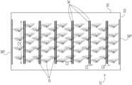
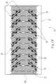
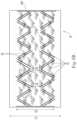
- FIG. 1 Ais a top view of a cleaning article according to the present invention and having discrete tufts represented as diamonds, with continuous paired secondary bonds oriented generally parallel to the transverse axis.
- FIG. 1 Bis a top view of the cleaning article of FIG. 1 A having discrete tufts represented with a common proximal end for each tuft.
- FIG. 1 Cis a bottom plan view of the cleaning article of FIGS. 1 A and 1 B .
- FIG. 2 Ais a top view of a cleaning article according to the present invention and having discrete tufts represented as diamonds, with aligned, paired, interrupted secondary bonds oriented generally parallel to the transverse axis.
- FIG. 2 Bis a top view of the cleaning article of FIG. 2 A having discrete tufts represented with a common proximal end for each tuft.
- FIG. 2 Cis a bottom plan view of the cleaning article of FIGS. 2 A and 2 B .
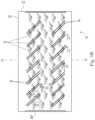
- FIG. 3 Ais a top view of a cleaning article according to the present invention and having discrete tufts represented as diamonds, with paired continuous secondary bonds oriented diagonal to the transverse axis.
- FIG. 3 Bis a top view of the cleaning article of FIG. 3 A having discrete tufts represented with a common proximal end for each tuft.
- FIG. 3 Cis a bottom plan view of the cleaning article of FIGS. 3 A and 3 B .
- FIG. 4 Ais a top view of a cleaning article according to the present invention and having discrete tufts represented as diamonds, with offset paired interrupted secondary bonds oriented diagonal to the transverse axis.
- FIG. 4 Bis a top view of the cleaning article of FIG. 4 A having discrete tufts represented with a common proximal end for each tuft.
- FIG. 4 Cis a bottom plan view of the cleaning article of FIGS. 4 A and 4 B .
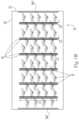
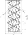
- FIG. 5 Ais a top view of a cleaning article according to the present invention and having discrete tufts represented as diamonds, with paired continuous chevron secondary bonds oriented in the longitudinal direction.
- FIG. 5 Bis a top view of the cleaning article of FIG. 5 A having discrete tufts represented with a common proximal end for each tuft.
- FIG. 5 Cis a bottom plan view of the cleaning article of FIGS. 5 A and 5 B .
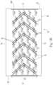
- FIG. 6 Ais a top view of a cleaning article according to the present invention and having discrete tufts represented as diamonds, with pared, interrupted, constant width chevron secondary bonds, forming herring bones oriented in the longitudinal direction.
- FIG. 6 Bis a top view of the cleaning article of FIG. 6 A having discrete tufts represented with a common proximal end for each tuft.
- FIG. 6 Cis a bottom plan view of the cleaning article of FIGS. 6 A and 6 B .
- FIG. 6 Dis a top view of a cleaning article according to the present invention and having discrete tufts represented as diamonds, with pared, interrupted variable width chevron secondary bonds, forming herring bones oriented in the longitudinal direction with offset zones for collection of debris.
- FIG. 6 Eis a top view of the cleaning article of FIG. 6 D having discrete tufts represented with a common proximal end for each tuft.
- FIG. 6 Fis a bottom plan view of the cleaning article of FIGS. 6 D and 6 E .
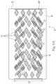
- FIG. 7 Ais a top view of a cleaning article according to the present invention and having discrete tufts represented as diamonds, with paired continuous secondary bonds forming diamond patterns.
- FIG. 7 Bis a top view of the cleaning article of FIG. 7 A having discrete tufts represented with a common proximal end for each tuft.
- FIG. 7 Cis a bottom plan view of the cleaning article of FIGS. 7 A and 7 B .
- FIG. 8 Ais a top view of a cleaning article according to the present invention and having discrete tufts represented as diamonds, with paired interrupted secondary bonds forming broken diamond patterns.
- FIG. 8 Bis a top view of the cleaning article of FIG. 8 A having discrete tufts represented with a common proximal end for each tuft.
- FIG. 8 Cis a bottom plan view of the cleaning article of FIGS. 8 A and 8 B .
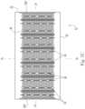
- FIG. 9 Ais a top view of a cleaning article according to the present invention and having discrete tufts represented as diamonds, with paired, variable spacing serpentine bonds.
- FIG. 9 Bis a top view of the cleaning article of FIG. 9 A having discrete tufts represented with a common proximal end for each tuft.
- FIG. 9 Cis a bottom plan view of the cleaning article of FIGS. 9 A and 9 B .
- FIG. 10is a schematic top plan view of a cleaning article according to the present invention and various combinations of the aforementioned secondary bonds, without an optional perimeter bond and having the tufts omitted for clarity.
- FIG. 11 Ais a perspective view of a floor cleaning implement suitable for use with the claimed invention and having a cleaning article attachable thereto.
- FIG. 11 Bis a perspective view of a floor cleaning implement suitable for use with the present invention and which sprays liquid cleanser on the floor.
- FIG. 11 Cis a perspective view of a handle suitable for use with a duster type cleaning article according to the claimed invention.
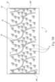
- the cleaning article 10may be generally elongate, and rectangular, although other shapes are contemplated and feasible.
- the cleaning article 10may comprise two or more components joined in a laminate form to provide cleaning article 10 suitable for floor cleaning.
- the cleaning article 10may have a carrier sheet, which forms a chassis for attachment of other components thereto.
- the cleaning article 10has a plurality of tufts 15 made of tow fibers.
- the tufts 15may be disposed in rows 30 forming a grid or field of tufts 15 .
- the tufts 15are joined to the carrier sheet by a first plurality of primary bonds 32 .
- a second plurality of secondary bonds 34forms channels or groves through the tufts 15 , to provide for accumulation of debris therein.
- the cleaning article 10may be disposable. By disposable it is meant that the cleaning article 10 may be used for one cleaning task, or generally for not more than several square meters, then discarded. In contrast, a reusable cleaning article 10 is laundered or otherwise restored after use.
- the cleaning article 10is macroscopically planar and defines an XY plane.
- the tufts 15extend outwardly in the Z direction perpendicular to the XY plane.
- the cleaning article 10may have a longitudinal axis LA defining a longitudinal direction and a transverse axis TA orthogonal thereto and defining a transverse direction, both axes LA, TA lying within the XY plane.
- the cleaning article 10and respective components thereof, may have two longitudinal edges 20 parallel to the longitudinal axis LA and two transverse edges 22 parallel to the transverse axis TA.
- the field of tufts 15may define a longitudinal edge 220 and transverse edge 222 disposed within the carrier sheet.
- the length of the cleaning article 10is taken in the longitudinal direction.
- the width of the cleaning article 10corresponds to the transverse direction perpendicular to the length direction and disposed within the plane of the sheet.
- the XY planeis defined as the plane defined by the cleaning article 10 .
- the Z-direction of the cleaning article 10is the direction perpendicular to the plane of the cleaning article 10 .
- the thicknessis defined as the dimension in the Z direction.
- the cleaning article 10may have a length from 20 to 50 cm and a width of 10 to 30 cm.
- the cleaning article 10may particularly be 30+/ ⁇ 2 cm long by 14+/ ⁇ 2 cm wide, as measured at the greatest dimensions, in order to fit the head 74 of a typical cleaning implement 70 , as discussed below.
- other shapesare feasible and within the scope of the present invention.
- the cleaning article 10may have an outwardly facing cleaning side and an attachment side opposed thereto.
- the cleaning article 10is intended to be used dry, although wet cleaning is contemplated and within the scope of the present invention.
- the cleaning article 10may also have an optional absorbent core for wet cleaning.
- An optional coremay particularly have a width of 6.5+/ ⁇ 2 cm and a length of 26+/ ⁇ 2 cm.
- the cleaning article 10may comprise a construction of at least one tow fiber tuft 15 and at least one carrier sheet.
- the tow fiber tuft 15 and carrierare joined in face-to-face relationship with at least one permanent bond to form a laminate.
- the tow fiber tuft(s) 15may be distended from and extend outwardly from the plane of the carrier sheet to provide a thickness in the z-direction.
- the tufts 15may be disposed directly on a carrier sheet.
- the tufts 15may be bonded to a precursor sheet, which, in turn, is joined to a carrier sheet.
- the carrier sheetmay particularly comprise a synthetic nonwoven.
- a carrier sheet having synthetic fibersprovides for convenient joining of the tow fibers thereto.
- Nonwovensinclude spun bonded, carded and airlaid materials, as are known in the art and made from synthetic fibers.
- a suitable nonwoven sheetmay be made according to commonly assigned U.S. Pat. No. 6,797,357.
- the carrier sheetmay optionally comprise a polyolefinic film, or a microfiber and be liquid pervious or impervious.
- the carrier sheetmay comprise cellulose, to provide absorptive capacity.
- a cellulosic sheetmay have permanent wet strength resin added thereto, as is known in the art.
- the carrier sheetmay preferably comprise a mixture of cellulosic and synthetic fibers, to provide both absorptive and barrier properties.
- the carrier sheetmay comprise a hydroentangled spunbond nonwoven with a basis weight of 20 to 80 gsm. A 45 gsm nonwoven from Avgol Nonwovens of Tel-Aviv, Israel has been found suitable.
- the carrier sheetmay comprise a laminate of two, three or more plies joined together using adhesive and/or thermal bonds as are known in the art. Optional attachment stripes of loop or similar material may be joined to the attachment side to removably join the cleaning article 10 to a handle 72 or implement 70 .
- One or more plies of the carrier sheetmay comprise a microfiber, particularly a nylon microfiber, as is known in the art.
- the cleaning article 10may have an optional cleaning strip element.
- the cleaning strip elementmay comprise a polyolefinic film, having integral protrusions as disclosed in commonly assigned U.S. Pat. No. 8,407,848 or may be a rope of tow fibers.
- the cleaning strip elementmay preferably comprise a mixture of wet laid fibers formed into a tissue which is bonded onto a synthetic nonwoven using a process such as spun lace or hydroentangling.
- the cleaning elementmay particularly comprise a 23 gsm tissue with a 17 gsm polypropylene spunbond as a composite, sold under the name Genesis tissue by Suominen of Helsinki, Finland.
- the cleaning strip element, precursor sheet and/or the carrier sheetmay alternatively or additionally comprise nylon microfiber.
- the tow fibers, and tufts 15 formed therewithmay be synthetic, comprising polymers including polyester, polypropylene, polyethylene, bio-derived polymers such as polylactic acid, bio-polyethylene, bio-polyester and the like.
- Tow fibersmay also include fibers from natural sources such as cellulose, cellulose acetate, flax, hemp, jute and mixtures thereof manufactured wherein the individual fibers are relatively long strands manufactured in bundles.
- Preferred tow fibersare bicomponent fibers having a PP or PE core with a polyethylene sheath.
- the tow fibersmay have a denier per filament of 1.5 to 8.0 and a total crimped denier of 15,000 to 95,000.
- Tow fibersare a component in Swiffer® DustersTM sold by the instant assignee.
- the tow fiber tuft(s) 15may be joined to the carrier sheet by a plurality of permanent primary bonds 32 .
- the primary bonds 32are intended to minimize or prevent stray or dislodged tow fibers from becoming loose from the carrier sheet.
- Such sheets 12 and tow fiber tuft(s) 15may typically be directly superimposed on one another, with or without intervening sheets, members or components therebetween.
- the primary bonds 32may be ultrasonic bonds, adhesive bonds, thermal bonds or a combination thereof, as are known in the art.
- the cleaning article 10also has a secondary plurality of secondary bonds 34 .
- the secondary bonds 34are typically formed after the tufts 15 are joined to the carrier sheet by the primary bonds 32 .
- the secondary bonds 34are generally linear, having an aspect ratio within the XY plane of at least 1, preferably at least 10 and more preferably at least 20.
- the secondary bonds 34reduce the thickness of the tufts 15 in the Z direction.
- the reduced thickness of the secondary bonds 34relative to the balance of the tufts 15 aligned with the edges of the secondary bonds 34 , creates channels to intercept debris.
- the secondary bonds 34may be of constant width, or may converge towards a distal end thereof.
- the secondary bonds 34may be of uniform size, orientation relative to the longitudinal axis, and spacing. Alternatively, the secondary bonds 34 may be of variable width, length, spacing, angular orientation and/or geometry, as desired.
- the channels formed by the secondary bonds 34allow large debris to enter in a direction approaching the longitudinal axis LA of the cleaning article 10 . Particularly, this arrangement provides the benefit during ordinary use that larger debris can be intercepted in the channel formed by the secondary bond, while smaller debris is intercepted by the tufts 15 .
- the secondary bonds 34may have adhesive disposed thereon.
- the adhesiveassists in retention of debris which enters the channels formed by the secondary bonds 34 .
- Suitable adhesiveincludes contact adhesive.
- the adhesivemay be applied to the secondary bonds 34 by spraying, rollers and other techniques known in the art for zone coating.
- the transverse edge 222 of the field of tufts 15may be juxtaposed with or coincident the transverse edge 22 of the carrier sheet.
- a perimeter bond 34 Pjoins the tow fibers of the field of tufts 15 at the respective transverse edges, 22 , 222 .
- This arrangementprevents loss of tow fibers from occurring when separating an individual cleaning article 10 from a continuous web or upon a slit 36 being near a transverse edge 22 without an intervening primary bond 32 .
- a slit 36is a cut through the two fibers and underlying carrier sheet, thereby forming a tuft 15 .
- the cleaning article 10may be made by providing a carrier sheet.
- Tow fibersare disposed on the carrier sheet.
- the tow fibersare generally aligned in the longitudinal direction, although the invention is not so limited.
- the tow fibersare joined to the carrier sheet with transversely offset primary bonds 32 .
- the primary bonds 32are oriented in the transverse direction.
- the primary bonds 32are shown as teardrops, although the invention is not so limited.
- the primary bonds 32may be linear or of any desired shape and size, so long as the tow fibers are permanently joined to the carrier sheet thereby.
- Tufts 15are created by cutting the carrier sheet and tow fibers between the bonds with a plurality of slits.
- the proximal ends of the tow fibers forming a tuft 15are defined by a respective primary bond 32 .
- Two continuous slits 36define and form the proximal ends of the tow fibers of a respective tuft 15 .
- the tufts 15may be optionally fluffed to increase the thickness of the tufts 15 in the Z direction.
- Optional fluffingmay be accomplished by blowing air, as is known in the art.
- the secondary bonds 34may be formed in the same manner as the primary bonds 32 , or may be formed by different methods.
- the secondary bonds 34may be ultrasonic bonds, adhesive bonds, thermal bonds or a combination thereof, as are known in the art. Any such method of forming the secondary bonds 34 is suitable, so long as visually discernable secondary bonds 34 are formed and provide a thickness difference in the Z direction between the secondary bond 34 and at least two or more adjacent tufts 15 of tow fibers.
- the secondary bonds 34preferably intercept the longitudinal edge 220 of the field of tufts 15 .
- This arrangementallows an opening for large debris to enter the field of tufts 15 in a direction towards the longitudinal axis and be retained by adhesive and/or tufts 15 adjacent to and which form the border of the secondary bond. Without the secondary bonds 34 , large debris may become entrapped on the longitudinal edge 220 of the field of tufts 15 and occlude the tufts 15 from intercepting additional debris.
- tufts 15 and secondary bonds 34may wrap the nose of the head 74 of the cleaning implement. Wrapping the nose of the head 74 of the cleaning implement 70 is believed to improve cleaning along walls and baseboards.
- the amount of tufts 15 on the nosecan be controlled by and is inversely proportional to the width of the secondary bonds 34 .
- the secondary bonds 34may be irregularly spaced.
- irregularly spacedit is meant that at least one secondary bond 34 is closely spaced relative to an adjacent secondary bond 34 and relatively further spaced from another adjacent secondary bond 34 . This arrangement provides two adjacent secondary bonds 34 which may appear to be a secondary bond 34 pair.
- the secondary bonds 34 of a pairmay be spaced from 2 to 15 mm, particularly 5 to 10 mm apart as measured at the closest points between secondary bonds 34 of that pair.
- the pair of secondary bonds 34may be spaced at least 30, 40 or 50 cm from a pair of adjacent secondary bond 34 pair, as measured at the closest points therebetween. Pairs of secondary bonds 34 may be visually discerned.
- This arrangementprovides the benefit of at least three different thickness of tufts 15 .
- the thickest portion of the cleaning article 10corresponds to where the tufts 15 are not intercepted by and are not functionally close to a secondary bond 34 .
- the thinnest portion of the cleaning article 10corresponds to where the tufts 15 are directly bonded by and subjacent the secondary bonds 34 .
- the intermediate thickness portion of the cleaning article 10corresponds to the channels between secondary bonds 34 of a pair. The differential thickness of the tufts 15 may be visually discerned.
- This arrangement of plural thickness tufts 15provides the benefit that the thickest portion of the cleaning article 10 can intercept and retain small debris and dust.
- the thinnest portion of the cleaning articlecan intercept and retain larger particles.
- the intermediate thickness portion of the cleaning article 10is believed suitable for intermediate sized debris.
- the cleaning article 10may have continuous secondary bonds 34 which are parallel to the transverse axis TA.
- This geometryprovides the benefit that the secondary bond 34 channels can allow debris to enter generally in the direction of forward and backward motion while, providing sufficient volume to accommodate large amounts of debris.
- the secondary bond 34 alignment being parallel to the transverse directionis generally oriented in the cross-machine direction and perpendicular to the machine direction. Thermal bonding and ultrasonic bonding typically occur in the cross-machine direction at any point in time. As the size of the secondary bond 34 increases in the cross-machine direction, the amount of amperage necessary to form the secondary bond 34 likewise increases. Increased amperage typically results in increased equipment cost and resulting increased manufacturing cost. Certain variant embodiments described below are stated to have the advantage of reduced amperage necessary to form the secondary bond 34 relative to the amperage required to form a comparable secondary bond 34 parallel to the transverse direction using thermal bonding and/or ultrasonic bonding.
- tufts 15While generally parallel and equally spaced rows of tufts 15 are shown, the invention is not so limited. Prophetically from two to 15 rows could be used, with equal or unequal spacing and equal or unequal variable widths and equal or unequal tuft 15 density.
- the rows of tufts 15may be mutually parallel to the transverse axis, mutually skewed thereto or be mutually skewed relative to other rows.
- adhesivemay be disposed in the spaces between the rows 30 .
- the rows 30may both extend throughout the transverse direction and be interrupted at the longitudinal axis.
- the tapered intra-tuft spaces between the tufts 15provide the benefit that no tufts 15 are interrupted by the spaces. Thus all tufts 15 can be selected to be of a size large enough for efficacious cleaning.
- the pitch, and thus tuft 15 densitymay be constant at any predetermined spacing from the longitudinal edge 20 .
- the tufts 15may be bilaterally staggered relative to the longitudinal axis and transverse axis. The tufts 15 may fully overlap the position of adjacent tufts 15 , in both directions, to provide adequate spacing therebetween and debris retention during back and for the sweeping.
- each tuft 15 having a maximum diameter, or other maximum dimension taken parallel to the longitudinal axis, and the pitch between adjacent tufts 15 in a particular rowmay be greater than that maximum diameter/dimension.
- the cleaning article accordingmay be tri-folded generally parallel to said longitudinal axis, as is common in the art.
- This arrangementprovides two outboard trisections, commonly used for attachment to the head 74 of a cleaning implement.
- tufts 15may be disposed in at least one of, and optionally both of, the outboard trisections, to provide for cleaning along walls and baseboards.
- the cleaning articlemay optionally be completely or partially coated with adhesive, wax, Newtonian oils and/or non-Newtonian oils or a combination thereof, in order to improve cleaning and increase retention of absorbed debris.
- the tow fiber tuft 15in any configuration, may be coated with a mineral oil coating.
- the coatingmay comprise a mixture of mineral oil and surfactant at a ratio of about 90% to 10% oil to surfactant.
- the surfactantprovides the benefit inducing the oil to wet the tow fibers by reducing the surface energy.
- the surfactantmay be a non-ionic surfactant.
- the cleaning article 10may have continuous paired secondary bonds 34 which are parallel to the transverse axis TA.
- paired secondary bonds 34it is meant two describe two secondary bonds 34 relatively closely and proximately spaced and which pair is spaced apart from another pair of secondary bonds 34 .
- Paired secondary bonds 34for each of the embodiments described herein having paired secondary bonds 34 , provides the benefit that a channel can be formed for collection of debris without requiring a relatively wide width for the secondary bond.
- the secondary bonds 34are typically formed in the cross-machine direction. As width of the secondary bond 34 increases (in the horizontal direction of FIGS. 3 A- 3 B ), the required amperage to accomplish bonding using heat sealing or ultrasonic bonding likewise increases. Using two, narrower, paired secondary bonds 34 requires less amperage spike than a single, wider secondary bond.
- Each of the paired secondary bonds 34may have a length C 1 of 11 to 20 cm, and a width C 2 of 0.1 to 1.5 cm.
- the secondary bond 34 pairsmay have a spacing C 3 therebetween of 1 to 10 cm.
- the channel between paired secondary bonds 34may range from 0.1 to 1 cm.
- This geometryprovides the benefit that the secondary bond 34 channels can allow debris to enter generally in the direction of forward and backward motion while having tufts 15 on and proximate to the longitudinal axis LA for retention of large debris.
- While six pairs of equally spaced secondary bonds 34are shown, the invention is not so limited. More or fewer secondary bonds 34 of similar or different size and/or spacing may be utilized.
- the secondary bonds 34may have differing thickness within a secondary bond 34 pair, or differing thickness between bond pairs as shown.
- the paired continuous secondary bonds 34may be interrupted proximate the longitudinal axis LA. This geometry provides the benefit that the paired secondary bond 34 channels can allow debris to enter generally in the direction of forward and backward motion while having tufts 15 on and proximate to the longitudinal axis LA for retention of large debris.
- the interruption between transversely opposed pairs of secondary bonds 34further provides for reduced amperage during heat sealing or ultrasonic bonding.
- the reduced amperagepotentially reduces manufacturing cost.
- Each of these paired secondary bonds 34may have a length C 1 of 2 to 8 cm, and a width C 2 of 0.05 to 0.5 cm.
- the secondary bond 34 pairsmay have a spacing C 3 therebetween of 1 to 10 cm.
- the channel C 4 between paired secondary bonds 34may range from 0.1 to 1 cm.
- the secondary bonds 34may have a spacing S 3 across the longitudinal axis LA in the transverse direction of 1 to 6 cm. These secondary bonds 34 may intercept both longitudinal edges 220 of the field of tufts 15 to allow convenient entry of debris.
- the secondary bonds 34may be continuous and diagonally oriented relative to the longitudinal axis LA.
- the diagonal orientationfor all such embodiments described and claimed herein, provides the benefit that during back and forth motion debris entering the channels formed by the secondary bonds 34 can intercept a tuft 15 bordering the channel and be retained thereby. Further, the channels can intercept debris during turns and lateral motions which occur during cleaning.
- the instantaneous amperage draw of the bonding step during manufactureis reduced compared to a secondary bond 34 oriented in the transverse direction during ultrasonic bonding or thermal bonding.
- the reduction in amperageoccurs due to less bond area being present at any point in time.
- the continuous diagonal secondary bond 34 linesmay be paired. This arrangement provides the benefit of reduced instantaneous amperage requirements at any point in time due to the advantageous combination of paired secondary bonds 34 and diagonal orientation.
- Each of the secondary bonds 34may have a length C 1 of 11 to 20 cm, and a width C 2 of 0.05 to 0.5 cm.
- the secondary bond 34 pairsmay have a spacing C 3 therebetween of 1 to 10 cm.
- the secondary bonds 34may have a spacing from a paired secondary bond 34 of 0.1 to 1 cm.
- the secondary bonds 34may form an angle A 1 with the longitudinal axis of 30 to 75 degrees. These secondary bonds 34 may intercept both longitudinal edges 220 of the field of tufts 15 to allow convenient entry of debris.
- the secondary bonds 34may be paired, diagonally oriented, interrupted and offset from the secondary bonds 34 disposed on the other side of the longitudinal axis LA. This arrangement advantageously further reduces the instantaneous amperage required for ultrasonically bonding or thermally bonding the secondary bonds 34 . Again, the tufts 15 proximate the longitudinal axis LA are retained, advantageously increasing capacity for debris.
- Each of the secondary bonds 34may have a length C 1 of 2 to 8 cm, and a width C 2 of 0.5 to 5 cm.
- the secondary bond 34 pairsmay have a spacing C 3 therebetween of 1 to 10 cm and a spacing C 4 between paired secondary bonds 34 of 01 to 1 cm.
- the secondary bonds 34may form an angle A 1 with the longitudinal axis of 30 to 75 degrees.
- the secondary bonds 34may have a spacing S 3 across the longitudinal axis LA in the transverse direction of 1 to 6 cm.
- the secondary bonds 34may be continuous chevrons, bridging across the longitudinal axis LA. Chevrons provide the benefit of reduced instantaneous amperage requirements for thermal bonding and ultrasonic bonding of the secondary bonds 34 .
- the diagonal legs of the chevroneach provide for retention of debris in the channels of the secondary bonds 34 .
- the chevronsadvantageously provide for diagonally oriented channels in two different directions. The two different orientations provide the benefit of intercepting dirt in different directions as the cleaning motion occurs in various directions.
- the secondary bonds 34may be in the form of paired continuous chevrons. This arrangement provides the benefit of retention at the vertices and more secondary bonds 34 to intercept debris.
- the secondary bonds 34may have a transverse span S 2 of 10 to 18 cm, each leg of the chevron secondary bond 34 having a length C 1 of 5 to 10 cm, a secondary bond 34 width C 2 of 0.1 to 1 cm, a spacing C 3 between pairs of secondary bonds 34 of 0.1 to 10 cm and a spacing C 4 between secondary bonds 34 within a pair of 0.1 to 1 cm.
- the secondary bonds 34may be formed on an angle A 1 relative to the longitudinal axis LA of 30 to 75 degrees.
- the interrupted chevron-shaped secondary bonds 34may be paired, to provide more channels to intercept debris.
- the secondary bonds 34may be spaced apart a distance S 3 across the longitudinal axis LA of 1 to 6 cm.
- any of the aforementioned embodimentsmay have secondary bonds 34 of variable width.
- This arrangementprovides the benefit of more surface area within the channel formed by a secondary bond.
- the increased surface areais believed to provide more entrapment of debris within the channel.
- the enlarged and relatively wider portion of the secondary bond 34is believed to increase the reservoir available for accumulation of debris.
- the enlarged portions of the secondary bonds 34may be offset in the longitudinal direction provide for accumulation as the user moves the cleaning article in various directions.
- the secondary bond 34may be diamond shaped. Of course it is to be recognized that similar shapes, having curvilinear sides and no vertices may be used for the secondary bonds 34 .
- the diamond shaped secondary bonds 34again provide the benefit of reduced amperage draw during the bonding step of the manufacturing process, due to less bond area being presented at any point in time.
- the diamond shapesprovide the benefit for the secondary bonds 34 of channels which are oriented in opposed directions relative to the longitudinal axis LA, providing more opportunity to entrap debris.
- Theis a symmetrical secondary bond 34 pattern for capturing debris during back and forth cleaning motion.
- the dimensions of the secondary bonds 34 cited aboveare believed suitable for this embodiment, with a spacing C 3 between vertices of adjacent bonds of 2 to 20 cm and a length C 1 of the secondary bond 34 of 11 to 20 cm.
- the continuous diamond shaped secondary bonds 34may be paired, to provide more channels to intercept debris. Again, the aforementioned symmetry is retained.
- the secondary bonds 34may be serpentine shaped. This geometry provides the benefit of matching the serpentine cleaning pattern many people utilize during a cleaning task, as they maneuver around furniture, etc.
- the secondary bond 34may span a diagonal length C 1 of 11 to 20 cm.
- the secondary bonds 34may be equally or unequally spaced from adjacent secondary bonds 34 .
- the secondary bonds 34may be of like geometry, size, angular orientation and shape or may be of mutually different geometry, size, angular orientation and/or shape.
- the cleaning article 10may optionally have strips 17 .
- the strips 17have an aspect ratio of length to width greater than 1.
- an elongate tow fiber rope oriented generally parallel to and optionally coincident the longitudinal axis LAmay be used.
- various pairs of secondary bonds 34may be utilized as shown. But the invention is not so limited. Three, four or more secondary bonds 34 may be closely spaced and disposed away from other closely spaced secondary bonds 34 . Paired secondary bonds 34 , or closely spaced secondary bonds 34 in general, provide the benefit that the thickness of the tufts 15 therebetween is greater than the thickness directly subjacent the secondary bond, and less than the thickness of a tuft 15 which is not bonded. This arrangement provides the benefit that regions of at least three different thicknesses in the z-direction of the cleaning article 10 are formed.
- the cleaning article 10may be removably attachable to a cleaning implement 70 for use with dry, wet and/or prewetted cleaning, depending upon the particular task.
- the cleaning implement 70may have a head 74 for receiving the cleaning article 10 and an elongate handle 72 joined thereto.
- a typical floor cleaning implement 70has a handle 72 for grasping by the user and a head 74 attached thereto, and preferably pivotally attached thereto. The head 74 moves against the floor, or other target surface.
- the cleaning article 10may be removably attached to the bottom of the head 74 .
- An attachment systemmay provide for removable attachment of the cleaning article 10 to a suitable and optional handle 72 .
- Removable attachment of the cleaning article 10 to the implement 70may be accomplished using adhesive 32 , hook and loop systems, elongate sleeves, grippers, etc.
- Grippers and a suitable cleaning implement 70are disclosed in commonly assigned 6 , 484 , 356 .
- the cleaning article 10may optionally be used with a cleaning solution or other solution usable for other purposes such as treating the surface for appearance or disinfectant, etc.
- a floor cleaning implement 70may allow for cleaning of the floor while the user is upright, and may also provide for spraying of cleaning solution or other liquid to the floor from a reservoir 75 through one or more nozzles 76 .
- Suitable spray implements 70are disclosed in commonly assigned U.S. Pat. Nos. 5,888,006; 5,988,920; 6,842,936; 7,182,537; 7,536,743; 7,676,877 and 8,186,898.
- the cleaning solutionmay be pre-applied to the cleaning article 10 , creating a pre-moistened cleaning article 10 or may be contained within a separate reservoir 75 for dosing onto the cleaning article 10 and/or target surface.
- the cleaning solutionmay comprise a majority water, and at least about 0.5, 2, 5 or 10 weight percent solids, or at least about 30 or 50 weight percent aqueous solvents, non-aqueous solutions or mixtures thereof.
- a suitable implement 70 having an optional vacuumis disclosed in 7 , 137 , 169 .
- the implement 70may have a handle 72 and head 74 used in fixed relationship and comprising one or more tines 73 .
- the tines 73may be inserted into sleeves in the cleaning article 10 .
- This arrangementallows the cleaning article 10 to be conveniently used as a duster for cleaning small object and tights spaces 31 .
- Suitable implements 70 for a duster type cleaning article 10are disclosed in commonly assigned U.S. Pat. No. 8,578,564 and D674,949 S.
- the cleaning article 10may be used with and removably attached to an autonomously moving robot or drone.
- robots and dronesfor use with the cleaning article of the present invention are found in commonly assigned U.S. Pat. Nos. 6,941,199; 6,810,305; 6,779,217; 6,481,515; 6,459,955 and Ser. No. 14/992,195, filed Jan. 11, 2016, P&G Case 14189.
- Examples of robots for use with wet and dry cleaningare found in U.S. Pat. Nos. 7,389,156; 8,774,966 and 8,855,813.
- a data control systemmay be utilized with the cleaning article 10 , as described in U.S. Pat. No. 7,431,524.
- the cleaning article 10may also be used manually, without a handle 72 or implement 70 . If desired, various cleaning articles 10 described herein may be packaged and sold in a kit. This arrangement provides the benefit that the user has a choice of different cleaning articles 10 for different tasks. For example, if desired, plural sizes of the cleaning articles 10 may be sold together as a single kit. This arrangement allows the user to select the particular cleaning article 10 best suited for the immediate task.
- the cleaning article 10may be made according to any of the following nonlimiting paragraphs in any combination thereof.
Landscapes
- Engineering & Computer Science (AREA)
- Textile Engineering (AREA)
- Cleaning Implements For Floors, Carpets, Furniture, Walls, And The Like (AREA)
Abstract
Description
- A. A cleaning
article 10 bounded byedges - a carrier sheet having a first side and a second side opposed thereto, and
- a plurality of discrete tow fibers joined to said first side of said carrier sheet by a plurality of
primary bonds 32 and extending outwardly therefrom in the Z-direction to have a tow thickness in the z-direction, and - at least one pair of elongate
secondary bonds 34 disposed on at least a portion of of tow fibers and joining said portion to said carrier sheet, each secondary bond having a secondary bond thickness in the Z-direction, said secondary bond thickness being less than said tow thickness in the Z-direction, said pair ofsecondary bonds 34 bridging at least two adjacent pluralities of tow fibers, - B. A
cleaning article 10 according to paragraph A characterized by said pair ofsecondary bonds 34 creating an intermediate thickness therebetween, said intermediate thickness being greater than said secondary bond thickness and less than said secondary bond thickness. - C. A
cleaning article 10 according to paragraph A characterized by creating intermediate thickness spaces therebetween, said channels having a thickness less at least partially through said plurality oftufts 15 in said XY plane. - D. A
cleaning article 10 according to paragraphs A, B and C comprising plural pairs ofsecondary bonds 34. - E.
A cleaning article 10 according to paragraphs A, B, C and D comprising four to 10 pairs ofsecondary bonds 34. - F. A
cleaning article 10 according to paragraphs A, B, C, D and E wherein saidtufts 15 comprise a field oftufts 15 intermediate two opposed tuft longitudinal edges. - G. A
cleaning article 10 according to paragraphs A, B, C, D, E and F wherein saidtufts 15 comprise a field oftufts 15 intermediate two opposed tuft longitudinal edges and at least one pair of saidsecondary bonds 34 intercepts both said tuft longitudinal edges. - H. A
cleaning article 10 according to paragraphs A, B, C, D, E, F and G wherein saidtufts 15 comprise a field oftufts 15 intermediate two opposed tuft longitudinal edges and at least one pair of saidsecondary bonds 34 intercepts both said tuft longitudinal edges without interruption therebetween. - I. A cleaning
article 10 according to paragraphs A, B, C, D, E, F and G wherein saidtufts 15 comprise a field oftufts 15 intermediate two opposed tuft longitudinal edges and at least one pair of saidsecondary bonds 34 does not continuously extend both said tuft longitudinal edges. - J. A cleaning
article 10 according to paragraphs A, B, C, D, E, F, G, H and I wherein each secondary bond of a said pair ofsecondary bonds 34 is mutually spaced apart 0.5 to 10 cm from the other secondary bond of said pair. - K. A
cleaning article 10 according to paragraphs A, B, C, D, E, F, G, H, I and J wherein each secondary bond of a said pair ofsecondary bonds 34 are mutually parallel. - L. A
cleaning article 10 according to paragraphs A, B, C, D, E, F, G, H, I, J and K whereintufts 15 disposed in a channel between a said pair ofsecondary bonds 34 visually have a thickness less than one half of a thickness of other saidtufts 15. - M. A
cleaning article 10 according to paragraphs A, B, C, D, E, F, G, H, I, J, K and L wherein at least one said pair of saidsecondary bonds 34 is generally parallel to said transverse axis. - N. A cleaning
article 10 according to paragraphs A, B, C, D, E, F, G, H, I, J, K and L wherein at least one said pair of saidsecondary bonds 34 is generally diagonal to said transverse axis. - O. A
cleaning article 10 according to paragraphs A, B, C, D, E, F and G comprising plural pairs ofsecondary bonds 34 disposed on each side of and not intercepting said longitudinal axis. - P. A
cleaning article 10 according to paragraphs A, B, C, D, E, F, G and0 comprising plural pairs ofsecondary bonds 34 disposed on each side of and not intercepting said longitudinal axis being arranged in a herring bone pattern. - Q. A cleaning
article 10 according to paragraphs A, B, C, D, E, F, G, H, I, J, K, L, M, N,0 and P wherein saidsecondary bonds 34 are tapered. - R. A
cleaning article 10 according to paragraphs A, B, C, D, E, F, G, H, I, J, K, L, M, N,0 and P wherein saidsecondary bonds 34 have a constant width of 2 to 12 mm - S. A cleaning
article 10 according to paragraphs A, B, C, D, E, F, G, H and I wherein said pairs of saidsecondary bonds 34 are arranged in a diamond pattern. - T. A
cleaning article 10 according to paragraphs A, B, C, D, E, F, G, H, I and S wherein said pairs of saidsecondary bonds 34 are arranged in a continuous diamond pattern which intercepts said longitudinal axis.
- A. A cleaning
Claims (4)
Priority Applications (6)
| Application Number | Priority Date | Filing Date | Title |
|---|---|---|---|
| US15/943,740US12082760B2 (en) | 2018-04-03 | 2018-04-03 | Cleaning article with irregularly spaced tow tufts |
| CA3092644ACA3092644A1 (en) | 2018-04-03 | 2019-03-22 | Cleaning article with irregularly spaced tow tufts |
| JP2020545474AJP2021515611A (en) | 2018-04-03 | 2019-03-22 | Cleaning supplies with irregularly spaced tow tufts |
| EP19715737.3AEP3773113B1 (en) | 2018-04-03 | 2019-03-22 | Cleaning article with irregularly spaced tow tufts |
| PCT/US2019/023574WO2019194990A1 (en) | 2018-04-03 | 2019-03-22 | Cleaning article with irregularly spaced tow tufts |
| JP2022167305AJP7553526B2 (en) | 2018-04-03 | 2022-10-19 | Cleaning product having irregularly spaced tow tufts |
Applications Claiming Priority (1)
| Application Number | Priority Date | Filing Date | Title |
|---|---|---|---|
| US15/943,740US12082760B2 (en) | 2018-04-03 | 2018-04-03 | Cleaning article with irregularly spaced tow tufts |
Publications (2)
| Publication Number | Publication Date |
|---|---|
| US20190298141A1 US20190298141A1 (en) | 2019-10-03 |
| US12082760B2true US12082760B2 (en) | 2024-09-10 |
Family
ID=66041761
Family Applications (1)
| Application Number | Title | Priority Date | Filing Date |
|---|---|---|---|
| US15/943,740Active2039-06-11US12082760B2 (en) | 2018-04-03 | 2018-04-03 | Cleaning article with irregularly spaced tow tufts |
Country Status (5)
| Country | Link |
|---|---|
| US (1) | US12082760B2 (en) |
| EP (1) | EP3773113B1 (en) |
| JP (2) | JP2021515611A (en) |
| CA (1) | CA3092644A1 (en) |
| WO (1) | WO2019194990A1 (en) |
Families Citing this family (2)
| Publication number | Priority date | Publication date | Assignee | Title |
|---|---|---|---|---|
| US11903542B2 (en)* | 2018-04-03 | 2024-02-20 | The Procter & Gamble Company | Cleaning article with double bonded tow tufts |
| US11375867B2 (en)* | 2018-04-03 | 2022-07-05 | The Procter & Gamble Company | Cleaning article with differential sized tow tufts |
Citations (66)
| Publication number | Priority date | Publication date | Assignee | Title |
|---|---|---|---|---|
| US823725A (en) | 1905-09-09 | 1906-06-19 | Henry A Hayden | Duster. |
| US4145787A (en) | 1977-07-29 | 1979-03-27 | Bastian Veit J B | Hand duster |
| US5691035A (en) | 1993-08-03 | 1997-11-25 | The Procter & Gamble Company | Web materials exhibiting elastic-like behavior |
| EP0923902A2 (en) | 1997-12-16 | 1999-06-23 | Uni-Charm Corporation | Cleaning product and production process therefor |
| US6143393A (en) | 1997-12-16 | 2000-11-07 | Uni-Charm Corporation | Cleaning product and production process therefor |
| JP2000316772A (en) | 1999-03-05 | 2000-11-21 | Uni Charm Corp | Composite sheet and its production |
| US6245413B1 (en) | 1998-09-24 | 2001-06-12 | Uni-Charm Corporation | Cleaning sheet |
| US6319593B1 (en)* | 1998-03-19 | 2001-11-20 | Uni-Charm Corporation | Disposable cleaning sheet |
| US6329308B1 (en)* | 1995-11-17 | 2001-12-11 | Uni-Charm Corporation | Disposable wipe-off article |
| US20020148061A1 (en) | 2000-07-10 | 2002-10-17 | Yoshinori Tanaka | Cleaning article |
| US6550092B1 (en) | 2000-04-26 | 2003-04-22 | S. C. Johnson & Son, Inc. | Cleaning sheet with particle retaining cavities |
| US6554937B1 (en) | 1999-04-13 | 2003-04-29 | Uni-Charm Co., Ltd. | Process for making disposable wipe-out sheet |
| US6774070B1 (en) | 1999-04-13 | 2004-08-10 | Uni-Charm Corporation | Disposable wipe-out sheet and process for making the same |
| US6777064B1 (en) | 1997-05-23 | 2004-08-17 | The Procter & Gamble Company | Cleaning sheets, implements, and articles useful for removing allergens from surfaces and methods of promoting the sale thereof |
| US6797357B2 (en) | 1997-05-23 | 2004-09-28 | The Procter & Gamble Company | Three dimensional structures useful as cleaning sheets |
| US6984615B2 (en) | 2000-12-27 | 2006-01-10 | Uni-Charm Corporation | Cleaning article |
| US7003856B2 (en) | 2000-09-01 | 2006-02-28 | Uni-Charm Corporation | Method and apparatus for opening continuous filaments |
| US20060171764A1 (en) | 2005-01-28 | 2006-08-03 | Hoadley David A | Cleaning pad for wet, damp or dry cleaning |
| US20060185108A1 (en)* | 2005-01-28 | 2006-08-24 | Hoadley David A | Cleaning or dusting pad cross-reference to related applications |
| US20070077403A1 (en)* | 2005-09-30 | 2007-04-05 | John Litvay | Cleaning pad laminate |
| US7291359B2 (en) | 2004-08-18 | 2007-11-06 | 3M Innovative Properties Company | Method and apparatus for making an adhesive cleaning sheet |
| US20080028560A1 (en) | 2006-08-07 | 2008-02-07 | Nicola John Policicchio | Duster system for damp and dry dusting |
| US7386907B2 (en) | 2002-12-27 | 2008-06-17 | Kao Corporation | Cleaning sheet |
| US20080235890A1 (en)* | 2007-03-30 | 2008-10-02 | Uni-Charm Corporation | Cleaning element and cleaning tool |
| WO2008146821A1 (en) | 2007-05-28 | 2008-12-04 | Kao Corporation | Cleaning sheet |
| US20090007355A1 (en)* | 2007-07-02 | 2009-01-08 | Nicola John Policicchio | Plural sided cleaning implement |
| WO2009084500A1 (en) | 2007-12-27 | 2009-07-09 | Kao Corporation | Cleaning sheet |
| US7560398B2 (en) | 2003-07-18 | 2009-07-14 | 3M Innovative Properties Company | Cleaning wipe and method of manufacture |
| US20100015383A1 (en)* | 2007-02-13 | 2010-01-21 | Daisaku Yamada | Cleaning sheet |
| US7682686B2 (en) | 2002-12-20 | 2010-03-23 | The Procter & Gamble Company | Tufted fibrous web |
| US20100088837A1 (en)* | 2007-04-27 | 2010-04-15 | Kao Corporation | Cleaning sheet |
| US7712178B2 (en) | 2004-04-01 | 2010-05-11 | Kikuo Yamada | Cleaning tool sheet and cleaning tool |
| US20100154156A1 (en)* | 2006-03-09 | 2010-06-24 | Keima Takabayashi | "Cleaning Article, Method of Fluffing Cleaning Article, and Method of Producing Cleaning Article" |
| US7779502B2 (en) | 2004-11-16 | 2010-08-24 | Uni-Charm Corporation | Cleaning item |
| US7786030B2 (en) | 2004-09-09 | 2010-08-31 | Uni-Charm Corporation | Cleaning tool |
| US7803726B2 (en) | 2006-08-07 | 2010-09-28 | The Procter & Gamble Company | Duster system for damp and dry dusting |
| US7838099B2 (en) | 2002-12-20 | 2010-11-23 | The Procter & Gamble Company | Looped nonwoven web |
| US7870635B2 (en) | 2004-04-01 | 2011-01-18 | Kikuo Yamada | Cleaning tool sheet and cleaning tool |
| US20110088189A1 (en) | 2008-04-16 | 2011-04-21 | Kao Corporation | Cleaning sheet and process for producing the same |
| US7937797B2 (en) | 2007-03-30 | 2011-05-10 | Uni-Charm Corporation | Cleaning element and cleaning tool |
| US20110277258A1 (en) | 2009-02-13 | 2011-11-17 | Hiroshi Otsuka | Cleaning sheet |
| US8075977B2 (en) | 2002-12-20 | 2011-12-13 | The Procter & Gamble Company | Tufted laminate web |
| US8146197B2 (en) | 2004-12-27 | 2012-04-03 | Kikuo Yamada | Cleaning device and process for producing the same |
| US8225453B2 (en) | 2007-12-28 | 2012-07-24 | Kikuo Yamada | Cleaning sheet |
| US8245349B2 (en) | 2006-09-12 | 2012-08-21 | Uni-Charm Corporation | Cleaning element and cleaning tool |
| US8528151B2 (en) | 2007-02-06 | 2013-09-10 | S.C. Johnson & Son, Inc. | Cleaning or dusting pad with attachment member holder |
| US8756746B2 (en) | 2012-03-09 | 2014-06-24 | The Procter & Gamble | Cleaning article with elastically contracted sheet |
| US8763197B2 (en) | 2009-12-04 | 2014-07-01 | The Procter & Gamble Company | Cleaning article with non-planar element in place of strips |
| US20140187406A1 (en)* | 2012-12-29 | 2014-07-03 | Unicharm Corporation | Method of producing cleaning member |
| US20140182767A1 (en)* | 2012-12-29 | 2014-07-03 | Unicharm Corporation | Method of producing cleaning member |
| US8793832B2 (en) | 2007-12-28 | 2014-08-05 | Kikuo Yamada | Cleaning sheet |
| US8851776B2 (en) | 2005-01-28 | 2014-10-07 | S. C. Johnson & Son, Inc. | Amphiphile surface treatment for a cleaning pad for improved dust adhesion |
| US9198553B2 (en) | 2012-03-09 | 2015-12-01 | The Procter & Gamble Company | Cleaning article with upstanding elastic panel |
| US9204775B2 (en) | 2011-04-26 | 2015-12-08 | The Procter & Gamble Company | Scrubbing strip for a cleaning sheet, cleaning sheet used therewith, and method of making |
| US20150374196A1 (en)* | 2013-02-07 | 2015-12-31 | Uni-Charm Corporation | Cleaning tool |
| US9296176B2 (en) | 2009-07-20 | 2016-03-29 | Suominen Corporation | High cellulose content, laminiferous nonwoven fabric |
| US9339165B2 (en) | 2013-03-26 | 2016-05-17 | The Procter & Gamble Company | Replaceable cleaning pads for cleaning device |
| US20170360271A1 (en)* | 2006-08-07 | 2017-12-21 | The Procter & Gamble Company | Floor cleaning article having strips with differential bond pattern |
| US20180042439A1 (en) | 2016-08-12 | 2018-02-15 | The Procter & Gamble Company | Cleaning sheets having coating thereon |
| US20190076886A1 (en) | 2017-09-11 | 2019-03-14 | The Procter & Gamble Company | Method of making a cleaning article having cutouts |
| US20190075993A1 (en)* | 2017-09-11 | 2019-03-14 | The Procter & Gamble Company | Cleaning article with differential pitch tow tufts |
| US20190075994A1 (en)* | 2017-09-11 | 2019-03-14 | The Procter & Gamble Company | Cleaning article with irregularly spaced tow tufts |
| US20190104909A1 (en) | 2017-10-06 | 2019-04-11 | The Procter & Gamble Company | Cleaning article with preferentially coated tow fibers |
| US20190298140A1 (en)* | 2018-04-03 | 2019-10-03 | The Procter & Gamble Company | Cleaning article with double bonded tow tufts |
| US20190298142A1 (en)* | 2018-04-03 | 2019-10-03 | The Procter & Gamble Company | Cleaning article with differential sized tow tufts |
| US11045061B2 (en) | 2017-09-11 | 2021-06-29 | The Procter & Gamble Company | Method of making a tufted laminated cleaning article |
Family Cites Families (25)
| Publication number | Priority date | Publication date | Assignee | Title |
|---|---|---|---|---|
| US5888006A (en) | 1996-11-26 | 1999-03-30 | The Procter & Gamble Company | Cleaning implement having a sprayer nozzle attached to a cleaning head member |
| US6941199B1 (en) | 1998-07-20 | 2005-09-06 | The Procter & Gamble Company | Robotic system |
| US5988920A (en) | 1998-11-30 | 1999-11-23 | The Procter & Gamble Company | Cleaning implement having a protected pathway for a fluid transfer tube |
| US7182537B2 (en) | 1998-12-01 | 2007-02-27 | The Procter & Gamble Company | Cleaning composition, pad, wipe, implement, and system and method of use thereof |
| US6842936B2 (en) | 1998-12-01 | 2005-01-18 | The Procter & Gamble Company | Adapter plates for cleaning implement |
| JP2000296084A (en) | 1999-04-13 | 2000-10-24 | Uni Charm Corp | Disposable wiping tool and its manufacture |
| AU1775401A (en) | 1999-11-18 | 2001-05-30 | Procter & Gamble Company, The | Home cleaning robot |
| US6481515B1 (en) | 2000-05-30 | 2002-11-19 | The Procter & Gamble Company | Autonomous mobile surface treating apparatus |
| DE10042671C5 (en) | 2000-08-31 | 2010-04-15 | Düpro AG | Vacuum cleaning tool with pear-shaped turbine chamber |
| US6810305B2 (en) | 2001-02-16 | 2004-10-26 | The Procter & Gamble Company | Obstruction management system for robots |
| US7137169B2 (en) | 2003-01-10 | 2006-11-21 | Royal Appliance Mfg. Co. | Vacuum cleaner with cleaning pad |
| JP2007503955A (en) | 2003-09-03 | 2007-03-01 | ザ プロクター アンド ギャンブル カンパニー | Multi-surface cleaning equipment |
| US8250700B2 (en) | 2003-10-08 | 2012-08-28 | The Procter & Gamble Company | Cleaning pad and cleaning implement |
| CA2555211A1 (en) | 2004-02-12 | 2005-09-01 | The Procter & Gamble Company | Cleaning implements and substrates for cleaning surfaces |
| US7431524B2 (en) | 2004-02-24 | 2008-10-07 | Avet-Usa, Inc. | Advanced data controlled cleaning system |
| KR101240732B1 (en) | 2005-02-18 | 2013-03-07 | 아이로보트 코퍼레이션 | Autonomous surface cleaning robot for wet and dry cleaning |
| US7389156B2 (en) | 2005-02-18 | 2008-06-17 | Irobot Corporation | Autonomous surface cleaning robot for wet and dry cleaning |
| JP4859490B2 (en)* | 2006-03-09 | 2012-01-25 | 花王株式会社 | Cleaning goods |
| JP5007218B2 (en)* | 2007-12-27 | 2012-08-22 | 花王株式会社 | Cleaning sheet |
| JP5231854B2 (en)* | 2008-04-16 | 2013-07-10 | 花王株式会社 | Cleaning sheet and manufacturing method thereof |
| US8186898B2 (en) | 2008-08-22 | 2012-05-29 | The Procter & Gamble Company | Plural nozzle cleaning implement |
| US8578564B2 (en) | 2009-11-05 | 2013-11-12 | The Procter & Gamble Company | Handle for removable cleaning implement |
| USD674949S1 (en) | 2011-11-03 | 2013-01-22 | Georgitsis Anthony C | Lighting system |
| JP6116589B2 (en)* | 2012-12-29 | 2017-04-19 | ユニ・チャーム株式会社 | Method for manufacturing cleaning member and system for manufacturing cleaning member |
| WO2018012333A1 (en)* | 2016-07-11 | 2018-01-18 | 山田菊夫 | Cleaning tool and method for producing same |
- 2018
- 2018-04-03USUS15/943,740patent/US12082760B2/enactiveActive
- 2019
- 2019-03-22JPJP2020545474Apatent/JP2021515611A/enactivePending
- 2019-03-22EPEP19715737.3Apatent/EP3773113B1/enactiveActive
- 2019-03-22WOPCT/US2019/023574patent/WO2019194990A1/ennot_activeCeased
- 2019-03-22CACA3092644Apatent/CA3092644A1/enactivePending
- 2022
- 2022-10-19JPJP2022167305Apatent/JP7553526B2/enactiveActive
Patent Citations (88)
| Publication number | Priority date | Publication date | Assignee | Title |
|---|---|---|---|---|
| US823725A (en) | 1905-09-09 | 1906-06-19 | Henry A Hayden | Duster. |
| US4145787A (en) | 1977-07-29 | 1979-03-27 | Bastian Veit J B | Hand duster |
| US5691035A (en) | 1993-08-03 | 1997-11-25 | The Procter & Gamble Company | Web materials exhibiting elastic-like behavior |
| US6329308B1 (en)* | 1995-11-17 | 2001-12-11 | Uni-Charm Corporation | Disposable wipe-off article |
| US6797357B2 (en) | 1997-05-23 | 2004-09-28 | The Procter & Gamble Company | Three dimensional structures useful as cleaning sheets |
| US6936330B2 (en) | 1997-05-23 | 2005-08-30 | The Procter & Gamble Company | Three dimensional structures useful as cleaning sheets |
| US6777064B1 (en) | 1997-05-23 | 2004-08-17 | The Procter & Gamble Company | Cleaning sheets, implements, and articles useful for removing allergens from surfaces and methods of promoting the sale thereof |
| US8536074B2 (en) | 1997-05-23 | 2013-09-17 | The Procter & Gamble Company | Three dimensional structures useful as cleaning sheets |
| EP0923902A2 (en) | 1997-12-16 | 1999-06-23 | Uni-Charm Corporation | Cleaning product and production process therefor |
| EP0923902A3 (en) | 1997-12-16 | 1999-11-03 | Uni-Charm Corporation | Cleaning product and production process therefor |
| US6143393A (en) | 1997-12-16 | 2000-11-07 | Uni-Charm Corporation | Cleaning product and production process therefor |
| US6241835B1 (en) | 1997-12-16 | 2001-06-05 | Uni-Charm Corporation | Cleaning product and production process therefor |
| US6319593B1 (en)* | 1998-03-19 | 2001-11-20 | Uni-Charm Corporation | Disposable cleaning sheet |
| US6245413B1 (en) | 1998-09-24 | 2001-06-12 | Uni-Charm Corporation | Cleaning sheet |
| JP2000316772A (en) | 1999-03-05 | 2000-11-21 | Uni Charm Corp | Composite sheet and its production |
| US6774070B1 (en) | 1999-04-13 | 2004-08-10 | Uni-Charm Corporation | Disposable wipe-out sheet and process for making the same |
| US6554937B1 (en) | 1999-04-13 | 2003-04-29 | Uni-Charm Co., Ltd. | Process for making disposable wipe-out sheet |
| US6550092B1 (en) | 2000-04-26 | 2003-04-22 | S. C. Johnson & Son, Inc. | Cleaning sheet with particle retaining cavities |
| US6813801B2 (en) | 2000-07-10 | 2004-11-09 | Uni-Charm Corporation | Cleaning article |
| US20020148061A1 (en) | 2000-07-10 | 2002-10-17 | Yoshinori Tanaka | Cleaning article |
| US7302729B2 (en) | 2000-07-10 | 2007-12-04 | Uni-Charm Corporation | Cleaning article |
| US7003856B2 (en) | 2000-09-01 | 2006-02-28 | Uni-Charm Corporation | Method and apparatus for opening continuous filaments |
| US6984615B2 (en) | 2000-12-27 | 2006-01-10 | Uni-Charm Corporation | Cleaning article |
| US8075977B2 (en) | 2002-12-20 | 2011-12-13 | The Procter & Gamble Company | Tufted laminate web |
| US7838099B2 (en) | 2002-12-20 | 2010-11-23 | The Procter & Gamble Company | Looped nonwoven web |
| US7682686B2 (en) | 2002-12-20 | 2010-03-23 | The Procter & Gamble Company | Tufted fibrous web |
| US7386907B2 (en) | 2002-12-27 | 2008-06-17 | Kao Corporation | Cleaning sheet |
| US7560398B2 (en) | 2003-07-18 | 2009-07-14 | 3M Innovative Properties Company | Cleaning wipe and method of manufacture |
| US7712178B2 (en) | 2004-04-01 | 2010-05-11 | Kikuo Yamada | Cleaning tool sheet and cleaning tool |
| US7870635B2 (en) | 2004-04-01 | 2011-01-18 | Kikuo Yamada | Cleaning tool sheet and cleaning tool |
| US7291359B2 (en) | 2004-08-18 | 2007-11-06 | 3M Innovative Properties Company | Method and apparatus for making an adhesive cleaning sheet |
| US7786030B2 (en) | 2004-09-09 | 2010-08-31 | Uni-Charm Corporation | Cleaning tool |
| US7779502B2 (en) | 2004-11-16 | 2010-08-24 | Uni-Charm Corporation | Cleaning item |
| US8146197B2 (en) | 2004-12-27 | 2012-04-03 | Kikuo Yamada | Cleaning device and process for producing the same |
| US8851776B2 (en) | 2005-01-28 | 2014-10-07 | S. C. Johnson & Son, Inc. | Amphiphile surface treatment for a cleaning pad for improved dust adhesion |
| US20060171764A1 (en) | 2005-01-28 | 2006-08-03 | Hoadley David A | Cleaning pad for wet, damp or dry cleaning |
| US7566671B2 (en) | 2005-01-28 | 2009-07-28 | S.C. Johnson & Son, Inc. | Cleaning or dusting pad |
| US20060185108A1 (en)* | 2005-01-28 | 2006-08-24 | Hoadley David A | Cleaning or dusting pad cross-reference to related applications |
| US20070077403A1 (en)* | 2005-09-30 | 2007-04-05 | John Litvay | Cleaning pad laminate |
| US20100154156A1 (en)* | 2006-03-09 | 2010-06-24 | Keima Takabayashi | "Cleaning Article, Method of Fluffing Cleaning Article, and Method of Producing Cleaning Article" |
| US8151402B2 (en) | 2006-03-09 | 2012-04-10 | Kao Corporation | Cleaning article, method of fluffing cleaning article, and method of producing cleaning article |
| US7803726B2 (en) | 2006-08-07 | 2010-09-28 | The Procter & Gamble Company | Duster system for damp and dry dusting |
| US20080028560A1 (en) | 2006-08-07 | 2008-02-07 | Nicola John Policicchio | Duster system for damp and dry dusting |
| US20170360271A1 (en)* | 2006-08-07 | 2017-12-21 | The Procter & Gamble Company | Floor cleaning article having strips with differential bond pattern |
| US8245349B2 (en) | 2006-09-12 | 2012-08-21 | Uni-Charm Corporation | Cleaning element and cleaning tool |
| US20190343365A1 (en)* | 2006-09-12 | 2019-11-14 | Unicharm Corporation | Cleaning element and cleaning tool |
| US8621704B2 (en)* | 2006-09-12 | 2014-01-07 | Uni-Charm Corporation | Cleaning element and cleaning tool |
| US20120297563A1 (en)* | 2006-09-12 | 2012-11-29 | Uni-Charm Corporation | Cleaning element and cleaning tool |
| US8528151B2 (en) | 2007-02-06 | 2013-09-10 | S.C. Johnson & Son, Inc. | Cleaning or dusting pad with attachment member holder |
| US8617685B2 (en) | 2007-02-13 | 2013-12-31 | Daisaku Yamada | Cleaning sheet |
| US20100015383A1 (en)* | 2007-02-13 | 2010-01-21 | Daisaku Yamada | Cleaning sheet |
| US7937797B2 (en) | 2007-03-30 | 2011-05-10 | Uni-Charm Corporation | Cleaning element and cleaning tool |
| US20080235890A1 (en)* | 2007-03-30 | 2008-10-02 | Uni-Charm Corporation | Cleaning element and cleaning tool |
| US8186001B2 (en) | 2007-03-30 | 2012-05-29 | Uni-Charm Corporation | Cleaning element and cleaning tool |
| US20100088837A1 (en)* | 2007-04-27 | 2010-04-15 | Kao Corporation | Cleaning sheet |
| US8646144B2 (en) | 2007-04-27 | 2014-02-11 | Kao Corporation | Cleaning sheet |
| WO2008146821A1 (en) | 2007-05-28 | 2008-12-04 | Kao Corporation | Cleaning sheet |
| US8161594B2 (en) | 2007-07-02 | 2012-04-24 | The Procter & Gamble Company | Plural sided cleaning implement |
| US20090007355A1 (en)* | 2007-07-02 | 2009-01-08 | Nicola John Policicchio | Plural sided cleaning implement |
| WO2009084500A1 (en) | 2007-12-27 | 2009-07-09 | Kao Corporation | Cleaning sheet |
| US8793832B2 (en) | 2007-12-28 | 2014-08-05 | Kikuo Yamada | Cleaning sheet |
| US8225453B2 (en) | 2007-12-28 | 2012-07-24 | Kikuo Yamada | Cleaning sheet |
| US20110088189A1 (en) | 2008-04-16 | 2011-04-21 | Kao Corporation | Cleaning sheet and process for producing the same |
| US9113768B2 (en) | 2008-04-16 | 2015-08-25 | Kao Corporation | Cleaning sheet and process for producing the same |
| US8752232B2 (en) | 2009-02-13 | 2014-06-17 | Kao Corporation | Cleaning sheet |
| US20110277258A1 (en) | 2009-02-13 | 2011-11-17 | Hiroshi Otsuka | Cleaning sheet |
| US9296176B2 (en) | 2009-07-20 | 2016-03-29 | Suominen Corporation | High cellulose content, laminiferous nonwoven fabric |
| US8763197B2 (en) | 2009-12-04 | 2014-07-01 | The Procter & Gamble Company | Cleaning article with non-planar element in place of strips |
| US9204775B2 (en) | 2011-04-26 | 2015-12-08 | The Procter & Gamble Company | Scrubbing strip for a cleaning sheet, cleaning sheet used therewith, and method of making |
| US8756746B2 (en) | 2012-03-09 | 2014-06-24 | The Procter & Gamble | Cleaning article with elastically contracted sheet |
| US9198553B2 (en) | 2012-03-09 | 2015-12-01 | The Procter & Gamble Company | Cleaning article with upstanding elastic panel |
| US20150351602A1 (en) | 2012-12-29 | 2015-12-10 | Unicharm Corporation | Method and system for manufacturing cleaning member |
| US20150336366A1 (en)* | 2012-12-29 | 2015-11-26 | Unicharm Corporation | Manufacturing method and manufacturing system for cleaning member |
| US20140182767A1 (en)* | 2012-12-29 | 2014-07-03 | Unicharm Corporation | Method of producing cleaning member |
| US20140187406A1 (en)* | 2012-12-29 | 2014-07-03 | Unicharm Corporation | Method of producing cleaning member |
| US20150374196A1 (en)* | 2013-02-07 | 2015-12-31 | Uni-Charm Corporation | Cleaning tool |
| US9339165B2 (en) | 2013-03-26 | 2016-05-17 | The Procter & Gamble Company | Replaceable cleaning pads for cleaning device |
| US20180042439A1 (en) | 2016-08-12 | 2018-02-15 | The Procter & Gamble Company | Cleaning sheets having coating thereon |
| US20190075993A1 (en)* | 2017-09-11 | 2019-03-14 | The Procter & Gamble Company | Cleaning article with differential pitch tow tufts |
| US20190075994A1 (en)* | 2017-09-11 | 2019-03-14 | The Procter & Gamble Company | Cleaning article with irregularly spaced tow tufts |
| US20190076886A1 (en) | 2017-09-11 | 2019-03-14 | The Procter & Gamble Company | Method of making a cleaning article having cutouts |
| US10730081B2 (en) | 2017-09-11 | 2020-08-04 | The Procter & Gamble Company | Method of making a cleaning article having cutouts |
| US11045061B2 (en) | 2017-09-11 | 2021-06-29 | The Procter & Gamble Company | Method of making a tufted laminated cleaning article |
| US11253128B2 (en) | 2017-09-11 | 2022-02-22 | The Procter & Gamble Company | Cleaning article with differential pitch tow tufts |
| US20190104909A1 (en) | 2017-10-06 | 2019-04-11 | The Procter & Gamble Company | Cleaning article with preferentially coated tow fibers |
| US10722091B2 (en) | 2017-10-06 | 2020-07-28 | The Procter & Gamble Company | Cleaning article with preferentially coated tow fibers |
| US20190298140A1 (en)* | 2018-04-03 | 2019-10-03 | The Procter & Gamble Company | Cleaning article with double bonded tow tufts |
| US20190298142A1 (en)* | 2018-04-03 | 2019-10-03 | The Procter & Gamble Company | Cleaning article with differential sized tow tufts |
Non-Patent Citations (11)
| Title |
|---|
| 15184 PCT Search Report for appl. no. PCT/U52019/023571, dated Jun. 4, 2019, 15 pages. |
| 15185 PCT Search Report for appl. no PCT/U52019/023574, dated Jun. 19, 2019, 16 pages. |
| 15186 PCT Search Report for appl. no. PCT/US2019/023578, dated Jun. 17, 2019, 18 pages. |
| All Office Actions, U.S. Appl. No. 15/943,739. |
| All Office Actions, U.S. Appl. No. 15/943,741. |
| All Office Actions; U.S. Appl. No. 17/743,918, filed on May 13, 2022. |
| All Office Actions; U.S. Appl. No. 18/407,859, filed on Jan. 9, 2024. |
| U.S. Appl. No. 15/943,739, filed Apr. 3, 2018, Policicchio. |
| U.S. Appl. No. 15/943,741, filed Apr. 3, 2018, Policicchio. |
| U.S. Appl. No. 17/743,918, filed on May 13, 2022, to Policicchio Nicola John (POLIC/NJ) et. al. |
| U.S. Appl. No. 18/407,859, filed on Jan. 9, 2024, to Nicola John Policicchio. |
Also Published As
| Publication number | Publication date |
|---|---|
| JP7553526B2 (en) | 2024-09-18 |
| CA3092644A1 (en) | 2019-10-10 |
| WO2019194990A1 (en) | 2019-10-10 |
| JP2021515611A (en) | 2021-06-24 |
| EP3773113A1 (en) | 2021-02-17 |
| JP2023012483A (en) | 2023-01-25 |
| EP3773113B1 (en) | 2024-02-07 |
| US20190298141A1 (en) | 2019-10-03 |
Similar Documents
| Publication | Publication Date | Title |
|---|---|---|
| US12390075B2 (en) | Cleaning article with double bonded tow tufts | |
| US12201253B2 (en) | Cleaning article with differential sized tow tufts | |
| US20220133118A1 (en) | Cleaning article with differential pitch tow tufts | |
| US10730081B2 (en) | Method of making a cleaning article having cutouts | |
| US11045061B2 (en) | Method of making a tufted laminated cleaning article | |
| CA3073076C (en) | Cleaning article with irregularly spaced tow tufts | |
| EP3773113B1 (en) | Cleaning article with irregularly spaced tow tufts | |
| CA3071720C (en) | Method of making a cleaning article having cutouts |
Legal Events
| Date | Code | Title | Description |
|---|---|---|---|
| FEPP | Fee payment procedure | Free format text:ENTITY STATUS SET TO UNDISCOUNTED (ORIGINAL EVENT CODE: BIG.); ENTITY STATUS OF PATENT OWNER: LARGE ENTITY | |
| AS | Assignment | Owner name:THE PROCTER & GAMBLE COMPANY, OHIO Free format text:ASSIGNMENT OF ASSIGNORS INTEREST;ASSIGNOR:POLICICCHIO, NICOLA JOHN;REEL/FRAME:045443/0790 Effective date:20180403 | |
| STPP | Information on status: patent application and granting procedure in general | Free format text:NON FINAL ACTION MAILED | |
| STPP | Information on status: patent application and granting procedure in general | Free format text:RESPONSE TO NON-FINAL OFFICE ACTION ENTERED AND FORWARDED TO EXAMINER | |
| STPP | Information on status: patent application and granting procedure in general | Free format text:FINAL REJECTION MAILED | |
| STPP | Information on status: patent application and granting procedure in general | Free format text:DOCKETED NEW CASE - READY FOR EXAMINATION | |
| STPP | Information on status: patent application and granting procedure in general | Free format text:RESPONSE TO NON-FINAL OFFICE ACTION ENTERED AND FORWARDED TO EXAMINER | |
| STPP | Information on status: patent application and granting procedure in general | Free format text:FINAL REJECTION MAILED | |
| STCV | Information on status: appeal procedure | Free format text:NOTICE OF APPEAL FILED | |
| STCV | Information on status: appeal procedure | Free format text:APPEAL BRIEF (OR SUPPLEMENTAL BRIEF) ENTERED AND FORWARDED TO EXAMINER | |
| STPP | Information on status: patent application and granting procedure in general | Free format text:NON FINAL ACTION MAILED | |
| STPP | Information on status: patent application and granting procedure in general | Free format text:RESPONSE TO NON-FINAL OFFICE ACTION ENTERED AND FORWARDED TO EXAMINER | |
| STPP | Information on status: patent application and granting procedure in general | Free format text:NOTICE OF ALLOWANCE MAILED -- APPLICATION RECEIVED IN OFFICE OF PUBLICATIONS | |
| ZAAB | Notice of allowance mailed | Free format text:ORIGINAL CODE: MN/=. | |
| STPP | Information on status: patent application and granting procedure in general | Free format text:PUBLICATIONS -- ISSUE FEE PAYMENT RECEIVED | |
| STPP | Information on status: patent application and granting procedure in general | Free format text:PUBLICATIONS -- ISSUE FEE PAYMENT VERIFIED | |
| STCF | Information on status: patent grant | Free format text:PATENTED CASE |