US12082618B2 - Cartridges for vaporizer devices - Google Patents
Cartridges for vaporizer devicesDownload PDFInfo
- Publication number
- US12082618B2 US12082618B2US17/347,993US202117347993AUS12082618B2US 12082618 B2US12082618 B2US 12082618B2US 202117347993 AUS202117347993 AUS 202117347993AUS 12082618 B2US12082618 B2US 12082618B2
- Authority
- US
- United States
- Prior art keywords
- orifice
- reservoir chamber
- cartridge
- vaporizer
- vaporizable material
- Prior art date
- Legal status (The legal status is an assumption and is not a legal conclusion. Google has not performed a legal analysis and makes no representation as to the accuracy of the status listed.)
- Active, expires
Links
Images


Classifications
- A—HUMAN NECESSITIES
- A61—MEDICAL OR VETERINARY SCIENCE; HYGIENE
- A61M—DEVICES FOR INTRODUCING MEDIA INTO, OR ONTO, THE BODY; DEVICES FOR TRANSDUCING BODY MEDIA OR FOR TAKING MEDIA FROM THE BODY; DEVICES FOR PRODUCING OR ENDING SLEEP OR STUPOR
- A61M11/00—Sprayers or atomisers specially adapted for therapeutic purposes
- A61M11/04—Sprayers or atomisers specially adapted for therapeutic purposes operated by the vapour pressure of the liquid to be sprayed or atomised
- A61M11/041—Sprayers or atomisers specially adapted for therapeutic purposes operated by the vapour pressure of the liquid to be sprayed or atomised using heaters
- A61M11/042—Sprayers or atomisers specially adapted for therapeutic purposes operated by the vapour pressure of the liquid to be sprayed or atomised using heaters electrical
- A—HUMAN NECESSITIES
- A24—TOBACCO; CIGARS; CIGARETTES; SIMULATED SMOKING DEVICES; SMOKERS' REQUISITES
- A24F—SMOKERS' REQUISITES; MATCH BOXES; SIMULATED SMOKING DEVICES
- A24F40/00—Electrically operated smoking devices; Component parts thereof; Manufacture thereof; Maintenance or testing thereof; Charging means specially adapted therefor
- A24F40/10—Devices using liquid inhalable precursors
- A—HUMAN NECESSITIES
- A24—TOBACCO; CIGARS; CIGARETTES; SIMULATED SMOKING DEVICES; SMOKERS' REQUISITES
- A24F—SMOKERS' REQUISITES; MATCH BOXES; SIMULATED SMOKING DEVICES
- A24F40/00—Electrically operated smoking devices; Component parts thereof; Manufacture thereof; Maintenance or testing thereof; Charging means specially adapted therefor
- A24F40/40—Constructional details, e.g. connection of cartridges and battery parts
- A24F40/42—Cartridges or containers for inhalable precursors
- A—HUMAN NECESSITIES
- A24—TOBACCO; CIGARS; CIGARETTES; SIMULATED SMOKING DEVICES; SMOKERS' REQUISITES
- A24F—SMOKERS' REQUISITES; MATCH BOXES; SIMULATED SMOKING DEVICES
- A24F40/00—Electrically operated smoking devices; Component parts thereof; Manufacture thereof; Maintenance or testing thereof; Charging means specially adapted therefor
- A24F40/40—Constructional details, e.g. connection of cartridges and battery parts
- A24F40/48—Fluid transfer means, e.g. pumps
- A24F40/485—Valves; Apertures
- A—HUMAN NECESSITIES
- A61—MEDICAL OR VETERINARY SCIENCE; HYGIENE
- A61M—DEVICES FOR INTRODUCING MEDIA INTO, OR ONTO, THE BODY; DEVICES FOR TRANSDUCING BODY MEDIA OR FOR TAKING MEDIA FROM THE BODY; DEVICES FOR PRODUCING OR ENDING SLEEP OR STUPOR
- A61M15/00—Inhalators
- A61M15/06—Inhaling appliances shaped like cigars, cigarettes or pipes
- A—HUMAN NECESSITIES
- A61—MEDICAL OR VETERINARY SCIENCE; HYGIENE
- A61M—DEVICES FOR INTRODUCING MEDIA INTO, OR ONTO, THE BODY; DEVICES FOR TRANSDUCING BODY MEDIA OR FOR TAKING MEDIA FROM THE BODY; DEVICES FOR PRODUCING OR ENDING SLEEP OR STUPOR
- A61M2205/00—General characteristics of the apparatus
- A61M2205/36—General characteristics of the apparatus related to heating or cooling
- A61M2205/3653—General characteristics of the apparatus related to heating or cooling by Joule effect, i.e. electric resistance
- A—HUMAN NECESSITIES
- A61—MEDICAL OR VETERINARY SCIENCE; HYGIENE
- A61M—DEVICES FOR INTRODUCING MEDIA INTO, OR ONTO, THE BODY; DEVICES FOR TRANSDUCING BODY MEDIA OR FOR TAKING MEDIA FROM THE BODY; DEVICES FOR PRODUCING OR ENDING SLEEP OR STUPOR
- A61M2205/00—General characteristics of the apparatus
- A61M2205/82—Internal energy supply devices
- A61M2205/8206—Internal energy supply devices battery-operated
Definitions
- the subject matter described hereinrelates to vaporizer devices, including a disposable vaporizer cartridge.
- Vaporizer deviceswhich can also be referred to as vaporizers, electronic vaporizer devices, or e-vaporizer devices, can be used for delivery of an aerosol (for example, a vapor-phase and/or condensed-phase material suspended in a stationary or moving mass of air or some other gas carrier) containing one or more active ingredients by inhalation of the aerosol by a user of the vaporizing device.
- an aerosolfor example, a vapor-phase and/or condensed-phase material suspended in a stationary or moving mass of air or some other gas carrier
- active ingredientsby inhalation of the aerosol by a user of the vaporizing device.
- electronic nicotine delivery systemsinclude a class of vaporizer devices that are battery powered and that can be used to simulate the experience of smoking, but without burning of tobacco or other substances.
- Vaporizer devicesare gaining increasing popularity both for prescriptive medical use, in delivering medicaments, and for consumption of tobacco, nicotine, and other plant-based materials. Vaporizer devices can be portable, self
- a vaporizer deviceIn use of a vaporizer device, the user inhales an aerosol, colloquially referred to as “vapor,” which can be generated by a heating element that vaporizes (e.g., causes a liquid or solid to at least partially transition to the gas phase) a vaporizable material, which can be liquid, a solution, a solid, a paste, a wax, and/or any other form compatible for use with a specific vaporizer device.
- the vaporizable material used with a vaporizer devicecan be provided within a vaporizer cartridge (for example, a separable part of the vaporizer device that contains vaporizable material) that includes an outlet (for example, a mouthpiece) for inhalation of the aerosol by a user.
- a usermay, in certain examples, activate the vaporizer device by taking a puff, by pressing a button, and/or by some other approach.
- a puff as used hereincan refer to inhalation by the user in a manner that causes a volume of air to be drawn into the vaporizer device such that the inhalable aerosol is generated by a combination of the vaporized vaporizable material with the volume of air.
- Vaporizer devicescan be controlled by one or more controllers, electronic circuits (for example, sensors, heating elements), and/or the like on the vaporizer device. Vaporizer devices can also wirelessly communicate with an external controller for example, a computing device such as a smartphone).
- a computing devicesuch as a smartphone
- a vaporizer devicegenerates an inhalable aerosol from a vaporizable material involves heating the vaporizable material in a vaporization chamber (e.g., a heater chamber) to cause the vaporizable material to be converted to the gas (or vapor) phase.
- a vaporization chambercan refer to an area or volume in the vaporizer device within which a heat source (for example, a conductive, convective, and/or radiative heat source) causes heating of a vaporizable material to produce a mixture of air and vaporized material to form a vapor for inhalation of the vaporizable material by a user of the vaporizer device.
- a heat sourcefor example, a conductive, convective, and/or radiative heat source
- the vaporizable materialcan be drawn out of a reservoir and into the vaporization chamber via a wicking element (e.g., a wick). Drawing of the vaporizable material into the vaporization chamber can be at least partially due to capillary action provided by the wicking element as the wicking element pulls the vaporizable material along the wicking element in the direction of the vaporization chamber.
- a wicking elemente.g., a wick
- Drawing of the vaporizable material into the vaporization chambercan be at least partially due to capillary action provided by the wicking element as the wicking element pulls the vaporizable material along the wicking element in the direction of the vaporization chamber.
- the pressure inside the reservoir chamberis reduced, thereby creating a vacuum and acting against the capillary action. This can reduce the effectiveness of the wick to draw the vaporizable material into the vaporization chamber.
- the wicking elementdegrades over time, which can adversely affect device performance, and ultimately renders the device unsafe to use. As a result, the wicking element, and in some instances the entire device, must be replaced.
- the vaporizable materialcan be drawn out of a reservoir chamber via an electric pump.
- the use of electric pumpstypically requires significant amounts of power to operate.
- vaporizer devices and/or vaporizer cartridgesthat address one or more of these issues are desired.
- aspects of the current subject matterrelate to cartridges, vaporizer devices, and methods for triggering flow of a vaporizable material from a reservoir chamber in response to a pressure differential that is created by an inhalation vacuum that exceeds a predetermined threshold. Accordingly, a user's puff can be used to control the flow of the vaporizable material from the reservoir chamber for vaporization.
- one or more of the following featuresmay optionally be included in any feasible combination.
- the second orificeis configured to allow a portion of ambient air that is outside the reservoir housing to enter the reservoir chamber in response to generation of a second pressure differential across the second orifice that exceeds a second predetermined threshold pressure differential during the withdrawal of the vaporizable material from the reservoir chamber.
- the vaporizable materialcan be maintained within the reservoir chamber until the first pressure differential exceeds the first predetermined threshold pressure differential.
- the first orificecan have a first diameter and the second orifice can have a second diameter that is greater than the first diameter.
- the first orificecan be configured to control a flow rate of the vaporizable material being withdrawn from the reservoir chamber along the first orifice.
- the second orificecan be configured to control a flow rate of the ambient air being drawn along the second orifice into the reservoir chamber.
- the first orificecan be configured to direct the vaporizable material being withdrawn from the reservoir chamber along the first orifice to a heating element for vaporization.
- the cartridgecan include a third orifice that extends through the first wall of the reservoir housing and in fluid communication with reservoir chamber.
- the third orificecan be configured to allow at least another portion of the vaporizable material to be withdrawn from the reservoir chamber in response to generation of a third pressure differential across the third orifice that exceeds a third predetermined threshold pressure differential.
- the cartridgecan include a third orifice that extends through the second wall of the reservoir housing and in fluid communication with reservoir chamber.
- the third orificecan be configured to allow at least another portion of ambient air outside of the reservoir housing to enter the reservoir chamber in response to generation of a third pressure differential across the third orifice that exceeds a third predetermined threshold pressure differential during the withdrawal of the vaporizable material from the reservoir chamber.
- the cartridgecan include a first tubular member that can extend through the first wall of the reservoir housing and into the reservoir chamber.
- the first tubular membercan define the first orifice.
- the cartridgecan include a second tubular member that can extend through the second wall of the reservoir housing and into the reservoir chamber.
- the second tubular membercan define the second orifice.
- a cartridgein another exemplary embodiment, can include a reservoir housing that includes a reservoir chamber configured to contain a vaporizable material, and first and second tubular members that are each in fluid communication with and at least partially extending into the reservoir chamber.
- the first tubular memberis configured to withdraw at least a portion of the vaporizable material from the reservoir chamber in response to being exposed to an inhalation vacuum that exceeds a predetermined threshold inhalation vacuum.
- the second tubular memberis configured to concurrently allow a portion of ambient air outside of the reservoir housing to pass therethrough and into the reservoir chamber while the inhalation vacuum is above the predetermined threshold inhalation vacuum.
- the first tubular membercan have a first inner diameter and the second tubular member can have a second inner diameter that is greater than the first inner diameter.
- the cartridgecan include a third tubular member that is in fluid communication with and at least partially extending into the reservoir chamber.
- the third tubular membercan be configured to withdraw at least another portion of the vaporizable material from the reservoir chamber in response to being exposed to the inhalation vacuum that exceeds the predetermined threshold inhalation vacuum.
- the third tubular membercan be configured to concurrently allow at least another portion of ambient air outside the reservoir housing to pass therethrough and into the reservoir chamber while the inhalation vacuum is above the predetermined threshold inhalation vacuum.
- a vaporizer deviceincludes a vaporizer body and a cartridge that is selectively coupled to and removable from the vaporizer body.
- the vaporizer bodyincludes a heating element disposed therein.
- the cartridgeincludes a reservoir housing that includes a reservoir chamber configured to contain a vaporizable material, a first orifice extending through a first wall of the reservoir housing and in fluid communication with the reservoir chamber, and a second orifice extending through a second wall of the reservoir housing and in fluid communication with the reservoir chamber.
- the first orificeis configured to allow at least a portion of the vaporizable material to be withdrawn from the reservoir chamber in response to generation of a first pressure differential across the first orifice that exceeds a first predetermined threshold pressure differential.
- the second orificeis configured to allow a portion of ambient air that is outside the reservoir housing to enter the reservoir chamber in response to generation of a second pressure differential across the second orifice that exceeds a second predetermined threshold pressure differential during the withdrawal of the vaporizable material from the reservoir chamber.
- the first orificeis in communication with the heating element for vaporization of the withdrawn vaporizable material into a vaporized material.
- the heating elementcan be in the form of a mesh structure. In other embodiments, the heating element can be in the form of a plate that includes at least one groove that is configured to receive the withdrawn vaporizable material. In yet other embodiments, the heating element can include at least one tine.
- the vaporizer bodycan include a first airflow path and the cartridge can include a second airflow path that is in fluid communication with the first airflow path.
- the vaporizer bodycan include at least one inlet that is configured to substantially allow airflow to pass into the vaporizer body.
- the at least one inletcan be in fluid communication with the first airflow path.
- the methodincludes generating a vacuum within a vaporizer device that exceeds a predetermined threshold vacuum, the vaporizer device including a vaporizer body, a cartridge coupled to the vaporizer body, and a vaporization chamber, the cartridge including a reservoir housing, a reservoir chamber residing within the reservoir housing and configured to hold a vaporizable material, and a plurality of orifices in fluid communication with the reservoir chamber, drawing, in response to the vacuum being applied to a first orifice of the plurality of orifices, a portion of the vaporizable material along the first orifice from the reservoir chamber and into the vaporization chamber thereby decreasing an internal pressure of the reservoir chamber, and drawing a portion of ambient air outside of the reservoir housing along a second orifice of the plurality of orifices into the reservoir chamber to increase the internal pressure of the reservoir chamber during the withdrawal of the vaporization material from the reservoir chamber.
- the first orificecan be defined by a first tubular member that extends from an exterior surface of a first wall of the reservoir housing and into the reservoir chamber
- the second orificecan be defined by a second tubular member that extends from an exterior surface of a second wall of the reservoir housing and into the reservoir chamber.
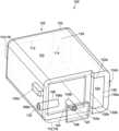
- FIG. 1is a partially transparent, bottom-up isometric view of an embodiment of a vaporizer cartridge in communication with a heating element:
- FIG. 2is a partially transparent, front view of an embodiment of a vaporizer device that includes a vaporizer cartridge and a vaporizer body having a heating element disposed therein, showing the vaporizer cartridge and the vaporizer body separated from each other:
- FIG. 3is a partially transparent, front view of the vaporizer device of FIG. 2 , showing the vaporizer cartridge inserted into a cartridge receptacle of the vaporizer body:
- FIG. 4is a partially transparent, front view of another embodiment of a vaporizer device that includes a vaporizer cartridge and a vaporizer body having a heating element disposed therein:
- FIG. 5is a partially transparent, front view of the vaporizer device of FIG. 4 , showing the vaporizer cartridge inserted into a cartridge receptacle of the vaporizer body:
- FIG. 5 Ais a magnified view of a portion of the vaporizer device of FIG. 5 .
- Implementations of the current subject matterinclude methods, apparatuses, articles of manufacture, and systems relating to vaporization of one or more materials for inhalation by a user.
- Example implementationsinclude vaporizer devices and systems including vaporizer devices.
- the term “vaporizer device” as used in the following description and claimsrefers to any of a self-contained apparatus, an apparatus that includes two or more separable parts (for example, a vaporizer body that includes a battery and other hardware, and a vaporizer cartridge that includes a vaporizable material), and/or the like.
- a “vaporizer system,” as used herein,can include one or more components, such as a vaporizer device.
- vaporizer devicesconsistent with implementations of the current subject matter include electronic vaporizers, electronic nicotine delivery systems (ENDS), and/or the like.
- electronic vaporizerselectronic vaporizers, electronic nicotine delivery systems (ENDS), and/or the like.
- vaporizer devicesare hand-held devices that heat (such as by convection, conduction, radiation, and/or some combination thereof) a vaporizable material to provide an inhalable dose of the material.
- the vaporizable material used with a vaporizer devicecan be provided within a vaporizer cartridge (for example, a part of the vaporizer device that contains the vaporizable material in a reservoir or other container) which can be refillable when empty, or disposable such that a new vaporizer cartridge containing additional vaporizable material of a same or different type can be used).
- a vaporizer devicecan be a cartridge-using vaporizer device, a cartridge-less vaporizer device, or a multi-use vaporizer device capable of use with or without a cartridge.
- a vaporizer devicecan include a heating chamber (for example, an oven or other region in which material is heated by a heating element) configured to receive a vaporizable material directly into the heating chamber, and/or a reservoir or the like for containing the vaporizable material.
- a heating chamberfor example, an oven or other region in which material is heated by a heating element
- a reservoir or the likefor containing the vaporizable material.
- a vaporizer devicecan be configured for use with a liquid vaporizable material.
- the liquid vaporizable materialmay include a carrier solution in which an active and/or inactive ingredient(s) are suspended or held in solution.
- the liquid vaporizable materialmay be a liquid form of the vaporizable material itself.
- the liquid vaporizable materialcan be capable of being completely vaporized. Alternatively, at least a portion of the liquid vaporizable material can remain after all of the material suitable for inhalation has been vaporized.
- the vaporizer cartridges described hereinallow for controlled delivery of vaporizable material from a reservoir chamber in response to the application of an inhalation vacuum that exceeds a predetermined threshold inhalation vacuum. That is, the vaporizer cartridges include a breath-modulated mechanism that controls delivery of the vaporizable material.
- the inhalation vacuumis generated in association with a suction force provided by a user puffing (e.g., drawing, inhaling, etc.) directly on the vaporizer cartridge itself, or alternatively, on a mouthpiece coupled thereto.
- a user puffinge.g., drawing, inhaling, etc.
- the breath-modulated mechanismis actuated to thereby cause vaporizable material to be withdrawn from the reservoir chamber for vaporization.
- the withdrawal of the at least a portion vaporizable material from, and the influx of the portion of ambient air into, the reservoir chamberoccurs when effective pressure differentials (e.g., pressure differentials that exceed respective predetermined threshold pressure differentials) are created across the first orifice and across the second orifice.
- pressure differentialsare generated by the application of an inhalation vacuum that exceeds a predetermined threshold inhalation vacuum.
- at least a portion of vaporizable materialmay be withdrawn from the reservoir chamber when the inhalation vacuum and the hydrostatic head pressure of the vaporizable material above the first orifice are sufficient to overcome the surface tension of the vaporizable material across the first orifice.
- the predetermined threshold inhalation vacuumcan vary, for example, due to a specific orientation of the vaporizer cartridge and/or environmental factors, such as any type of negative pressure event (e.g., pressure drop inside an airplane cabin).
- the first orificecan be configured to control a flow rate of the vaporizable material being withdrawn from the reservoir chamber along the first orifice.
- the second orificecan be configured to control a flow rate of the ambient air being drawn along the second orifice into the reservoir chamber.
- the first and second orificescan have a variety of configurations.
- the first and second orificescan each have a substantially circular shape, whereas in other embodiments, the first and second orifices can each have any other possible shape.
- the first and second orificeshave the same shape relative to each, whereas in another embodiment, the first and second orifices have a different shape relative to each other.
- the first and second orificeseach have a diameter.
- the first orificehas a diameter that is less than a diameter of the second orifice. It is contemplated herein that the first and second orifices can have any suitable cross-section.
- a liquid bubblePrior to the generation of pressure differentials across the first and second orifices in response to an inhalation vacuum, a liquid bubble can form outside of an end of the first orifice that is not in direct contact with vaporizable material disposed within the reservoir chamber. Further, an air bubble can form in the inside of an end of the second orifice that is in direct contact with vaporizable material disposed within the reservoir chamber. That is, the surface tension in the curved liquid-air interfaces allows the reservoir chamber to withstand a given threshold pressure drop.
- a userpuff's directly on the vaporizer cartridge itself, or alternatively, on a mouthpiece coupled thereto, thereby creating an inhalation vacuum.
- this inhalation vacuumexceeds a predetermined threshold inhalation vacuum
- effective pressure differentialsare concurrently created across each orifice.
- the vaporizable materialwill begin to travel along the first orifice from the reservoir chamber for vaporization and ambient air will concurrently travel along the second orifice and into the reservoir chamber. That is, once the pressure differentials across each orifice exceed their respective predetermined threshold pressure differentials, the vaporizable material can be withdrawn from, and ambient air can enter, the reservoir chamber. Further, as the inhalation vacuum increases past the predetermined threshold inhalation vacuum, the flow rate of the vaporizable material through the first orifice will increase linearly with pressure difference.
- a regulator valvecan be positioned upstream of the first orifice. Once the predetermined threshold inhalation vacuum is exceeded, the flow regulator valve can be configured to produce a substantially consistent pressure drop across the first orifice. Moreover, the flow regulator valve can maintain a consistent pressure drop even during variations in inhalation vacuum during puffing. In this way, the vaporizable material can flow through the first orifice at a substantially constant flow rate over a wide range of inhalation vacuum levels, including at the lowest possible level where flow of vaporization material through the first orifice is permitted.
- first and second orificescan be positioned at varying distances relative to each other, the distance therebetween can have an effect on hydrostatic head.
- the first and second orificescan be positioned at a distance relative to each other that minimizes hydrostatic head between them so as to prevent variation in performance relative to orientation of the vaporizer cartridge.
- greater distances between the first and second orificescan result in a hydrostatic head that decreases the predetermined threshold inhalation vacuum, and thus causes variations in performance, when the vaporizer cartridge is in certain orientations.
- the first and/or second orificesare each defined with a respective tubular member.
- the first orificecan be defined by a first tubular member that extends through the first wall of the reservoir housing and into the reservoir chamber.
- the second orificeis defined by a second tubular member that extends through the second wall of the reservoir housing and into the reservoir chamber.
- the first and second tubular memberseach extend from respective first and second ends and have a length extending therebetween.
- the first tubular membercan have a length that is less than a length of the second tubular member or vice versa.
- the vaporizer cartridgecan include additional orifices that function similar to the first or second orifices described above.
- a third orificecan extend through the first wall of the reservoir housing and be configured to allow at least another portion of the vaporizable material to be withdrawn from the reservoir chamber in response to generation of a third pressure differential across the third orifice that exceeds a predetermined threshold pressure differential.
- the third orificecan extend through the second wall of the reservoir housing configured to allow at least another portion of ambient air outside of the reservoir housing to enter the reservoir chamber in response to generation of a third pressure differential across the third orifice during the withdrawal of the vaporizable material from the reservoir chamber.
- the first orificecan be configured to direct the flow of vaporizable material from the reservoir chamber to a heating element disposed within a vaporizer body of a vaporizer device.
- the heating elementcan be configured to vaporize at least a portion of the vaporizable material into vaporized material when activated. Subsequently, at least a portion of the vaporized material can then enter into and travel along an airflow path of the vaporizer device, a portion of which passes adjacent to the heating element.
- the first orificecan be configured to direct the flow of vaporizable material from the reservoir chamber to other areas of the vaporizer cartridge or vaporizer device, such as a wicking element or a secondary reservoir chamber.
- the vaporizer devicecan also include a power source (for example, a battery, which can be a rechargeable battery), and a controller (for example, a processor, circuitry, etc. capable of executing logic) for controlling delivery of heat from the heating element to cause a vaporizable material to be converted from a condensed form (for example, a solid-phase material, such as wax or the like, a liquid, a solution, a suspension, etc.) to the gas phase.
- a power sourcefor example, a battery, which can be a rechargeable battery
- a controllerfor example, a processor, circuitry, etc. capable of executing logic
- the controllercan be part of one or more printed circuit boards (PCBs) consistent with certain implementations of the current subject matter.
- the vaporizable material in the gas phasecan condense to form particulate matter in at least a partial local equilibrium with a portion of the vaporizable material that remains in the gas phase.
- the vaporizable material in the gas phase as well as the condensed phaseare part of an aerosol, which can form some or all of an inhalable dose provided by the vaporizer device during a user's puff or draw on the vaporizer device.
- the interplay between the gas phase and condensed phase in an aerosol generated by a vaporizer devicecan be complex and dynamic, due to factors such as ambient temperature, relative humidity, chemistry, flow conditions in airflow paths (both inside the vaporizer device and in the airways of a human or other animal), and/or mixing of the vaporizable material in the gas phase or in the aerosol phase with other air streams, which can affect one or more physical parameters of an aerosol.
- the inhalable dosecan exist predominantly in the gas phase (for example, formation of condensed phase particles can be very limited).
- the heating elementcan have a variety of configurations.
- the heating elementcan extend from a first surface to a second surface.
- suitable heating elementsinclude a mesh, a plate, which in certain instances can include at least one groove, or a foil heater, which in certain instances can include at least one tine.
- the heating elementcan be configured to be heated using electrical, chemical, or mechanical energy.
- One type of heating elementis a resistive heating element, which can be constructed of, or at least include, a material (e.g., a metal or alloy, such as a nickel-chromium alloy, or a non-metallic resistor) configured to dissipate electrical power in the form of heat when electrical current is passed through one or more resistive segments of the heating element.
- a resistive heating elementmay be embedded on one side of a structure while an opposite side of the structure includes a non-porous ceramic having capillary grooves.
- the heating elementcan be, or include, one or more of a conductive heater, a radiative heater, and a convective heater.
- convective heatingmay be used to deliver heat to at least a portion of the vaporizable material held in an absorbent structure (e.g., a sponge and/or the like) that is disposed downstream (or upstream) from the heating element.
- absorbent structuree.g., a sponge and/or the like
- Other forms of heating elementsare also contemplated herein.
- the heating elementcan be coupled to a support structure.
- the support structurecan be configured to provide mechanical support to the heating element during and after manufacturing.
- the support structurecan be formed of any suitable material, e.g., one or more polymers, and the like, using any suitable manufacturing method, e.g., additive manufacturing, and the like.
- the support structurecan have a variety of configurations.
- the support structurecan be formed of one or more parts.
- the support structureis substantially u-shaped.
- the support structurecan be sized and shaped differently, including any other possible shape.
- the support structureincludes a base having two opposing legs extending therefrom.
- the base and the two opposing legscan have variety of configurations, for example, in some embodiments, the base is substantially rectangular shaped and the two opposing legs have a substantially t-shaped configuration. In other embodiments, the base and/or each of the two opposing legs can be sized and shaped differently, including any other possible shape.
- the support structurecan be coupled to the vaporizer body.
- the support structureis coupled to a chassis that is configured to house at least a portion of additional components of the vaporizer device such as, for example, a power source, input device(s), sensor(s), output, a controller, communication hardware, memory, and the like.
- the support structurecan be affixed to the vaporizer body.
- the heating elementcan be activated by a variety of mechanisms.
- the heating elementcan be activated (e.g., a controller, which is optionally part of the vaporizer body as discussed herein, may cause current to pass from a power source through a circuit including the heating element), in association with a user puffing (i.e., drawing, inhaling, etc.) directly on the vaporizer cartridge itself, or alternatively, on a mouthpiece coupled thereto, to cause air to flow from an air inlet, along a portion of an airflow path that passes adjacent to the heating element.
- a controllerwhich is optionally part of the vaporizer body as discussed herein, may cause current to pass from a power source through a circuit including the heating element
- a user puffingi.e., drawing, inhaling, etc.
- the entrained vaporizable material in the gas phasecan condense as it passes through the remainder of the airflow path, which also travels through the interior of the vaporizer cartridge (for example, through one or more internal channels therein), such that an inhalable dose of the vaporizable material in an aerosol form can be delivered from an outlet (for example, in the vaporizer cartridge itself and/or in a mouthpiece coupled thereto) for inhalation by a user.
- the vaporizer cartridgeincludes an internal channel extending through the vaporizer cartridge from an inlet to an outlet of the vaporizer cartridge.
- a sidewall of the reservoir chambercan at least partially define a sidewall of the internal channel.
- Activation of the heating elementcan be caused by automatic detection of a puff based on one or more signals generated by one or more sensors.
- the one or more sensors and the signals generated by the one or more sensorscan include one or more of: a pressure sensor or sensors disposed to detect pressure along the airflow path relative to ambient pressure (or optionally to measure changes in absolute pressure), a motion sensor or sensors (for example, an accelerometer) of the vaporizer device, a flow sensor or sensors of the vaporizer device, a capacitive lip sensor of the vaporizer device, detection of interaction of a user with the vaporizer device via one or more input devices (for example, buttons or other tactile control devices of the vaporizer device), receipt of signals from a computing device in communication with the vaporizer device, and/or via other approaches for determining that a puff is occurring or imminent.
- a pressure sensor or sensorsdisposed to detect pressure along the airflow path relative to ambient pressure (or optionally to measure changes in absolute pressure)
- a motion sensor or sensorsfor example, an accelerometer of the
- the vaporizer deviceconsistent with implementations of the current subject matter can be configured to connect (such as, for example, wirelessly or via a wired connection) to a computing device (or optionally two or more devices) in communication with the vaporizer device.
- the controllercan include communication hardware.
- the controllercan also include a memory.
- the communication hardwarecan include firmware and/or can be controlled by software for executing one or more cryptographic protocols for the communication.
- a computing devicecan be a component of a vaporizer system that also includes the vaporizer device, and can include its own hardware for communication, which can establish a wireless communication channel with the communication hardware of the vaporizer device.
- a computing device used as part of a vaporizer systemcan include a general-purpose computing device (such as a smartphone, a tablet, a personal computer, some other portable device such as a smartwatch, or the like) that executes software to produce a user interface for enabling a user to interact with the vaporizer device.
- such a device used as part of a vaporizer systemcan be a dedicated piece of hardware such as a remote control or other wireless or wired device having one or more physical or soft (i.e., configurable on a screen or other display device and selectable via user interaction with a touch-sensitive screen or some other input device like a mouse, pointer, trackball, cursor buttons, or the like) interface controls.
- a remote control or other wireless or wired devicehaving one or more physical or soft (i.e., configurable on a screen or other display device and selectable via user interaction with a touch-sensitive screen or some other input device like a mouse, pointer, trackball, cursor buttons, or the like) interface controls.
- the vaporizer devicecan also include one or more outputs or devices for providing information to the user.
- the outputscan include one or more light emitting diodes (LEDs) configured to provide feedback to a user based on a status and/or mode of operation of the vaporizer device.
- the one or more outputscan include a plurality of LEDs (i.e., two, three, four, five, or six LEDs).
- the one or more outputsi.e., each individual LED
- the one or more outputscan be configured to display different light patterns (for example, by illuminating specific LEDs, varying a light intensity of one or more of the LEDs over time, illuminating one or more LEDs with a different color, and/or the like) to indicate different statuses, modes of operation, and/or the like of the vaporizer device.
- the one or more outputscan be proximal to and/or at least partially disposed within a bottom end region of the vaporizer device.
- the vaporizer devicemay, additionally or alternatively, include externally accessible charging contacts, which can be proximate to and/or at least partially disposed within the bottom end region of the vaporizer device.
- a computing deviceprovides signals related to activation of a resistive heating element
- the computing deviceexecutes one or more computer instruction sets to provide a user interface and underlying data handling.
- detection by the computing device of user interaction with one or more user interface elementscan cause the computing device to signal the vaporizer device to activate the heating element to reach an operating temperature for creation of an inhalable dose of vapor/aerosol.
- Other functions of the vaporizer devicecan be controlled by interaction of a user with a user interface on a computing device in communication with the vaporizer device.
- the temperature of a resistive heating element of the vaporizer devicecan depend on a number of factors, including an amount of electrical power delivered to the resistive heating element and/or a duty cycle at which the electrical power is delivered, conductive heat transfer to other parts of the electronic vaporizer device and/or to the environment, latent heat losses due to vaporization of the vaporizable material from the wicking element, and convective heat losses due to airflow (i.e., air moving across the heating element when a user inhales on the vaporizer device).
- the vaporizer devicemay, in some implementations of the current subject matter, make use of signals from the sensor (for example, a pressure sensor) to determine when a user is inhaling.
- the sensorcan be positioned in the airflow path and/or can be connected (for example, by a passageway or other path) to an airflow path containing an inlet for air to enter the vaporizer device and an outlet via which the user inhales the resulting vapor and/or aerosol such that the sensor experiences changes (for example, pressure changes) concurrently with air passing through the vaporizer device from the air inlet to the air outlet.
- the heating elementcan be activated in association with a user's puff, for example by automatic detection of the puff, or by the sensor detecting a change (such as a pressure change) in the airflow path.
- the sensorcan be positioned on or coupled to (i.e., electrically or electronically connected, either physically or via a wireless connection) the controller (for example, a printed circuit board assembly or other type of circuit board).
- the controllerfor example, a printed circuit board assembly or other type of circuit board.
- the sealwhich can be a gasket, can be configured to at least partially surround the sensor such that connections of the sensor to the internal circuitry of the vaporizer device are separated from a part of the sensor exposed to the airflow path.
- the sealcan also separate parts of one or more electrical connections between the vaporizer body and the vaporizer cartridge.
- Such arrangements of the seal in the vaporizer devicecan be helpful in mitigating against potentially disruptive impacts on vaporizer components resulting from interactions with environmental factors such as water in the vapor or liquid phases, other fluids such as the vaporizable material, etc., and/or to reduce the escape of air from the designated airflow path in the vaporizer device.
- Unwanted air, liquid or other fluid passing and/or contacting circuitry of the vaporizer devicecan cause various unwanted effects, such as altered pressure readings, and/or can result in the buildup of unwanted material, such as moisture, excess vaporizable material, etc., in parts of the vaporizer device where they can result in poor pressure signal, degradation of the sensor or other components, and/or a shorter life of the vaporizer device.
- Leaks in the sealcan also result in a user inhaling air that has passed over parts of the vaporizer device containing, or constructed of, materials that may not be desirable to be inhaled.
- the vaporizer cartridgecan be selectively coupled to and removable from the vaporizer body using a coupling mechanism.
- the vaporizer body and the vaporizer cartridgecan each include corresponding coupling elements that are configured to releasably engage with each other. That is, in use, once a predetermined length of the vaporizer cartridge is inserted into the vaporizer body, the coupling elements can engage with each other, thereby securing the vaporizer cartridge to the vaporizer body. Likewise, once the vaporizer cartridge needs to be replaced, the coupling element can disengage allowing the vaporizer cartridge to be removed.
- a new vaporizer cartridge or the refilled vaporizer cartridgecan be selectively coupled or recoupled, respectively, to the vaporizer body.
- the position of the corresponding coupling elementscan be dependent at least upon the desired length of vaporizer cartridge to be inserted into the vaporizer body, for example, to avoid the heating element from damage caused by an insertion force.
- the vaporizer bodycan include one or more detents (for example, dimples, protrusions, etc.) protruding inwardly from an inner surface of the cartridge receptacle, additional material (such as metal, plastic, etc.) formed to include a portion protruding into the cartridge receptacle, and/or the like.
- detentsfor example, dimples, protrusions, etc.
- additional materialsuch as metal, plastic, etc.
- One or more exterior surfaces of the vaporizer cartridgecan include corresponding recesses that can fit and/or otherwise snap over such detents or protruding portions when the vaporizer cartridge is inserted into the cartridge receptacle on the vaporizer body.
- the detents or protrusions of the vaporizer bodycan fit within and/or otherwise be held within the recesses of the vaporizer cartridge, to hold the vaporizer cartridge in place when assembled.
- Such an assemblycan provide enough support to hold the vaporizer cartridge in place, while allowing release of the vaporizer cartridge from the vaporizer body when a user pulls with reasonable force on the vaporizer cartridge to disengage the vaporizer cartridge from the cartridge receptacle.
- the exterior surfaces of the vaporizer cartridgecan include the one or more detents and the cartridge receptacle can include the one or more recesses.
- the vaporizer cartridgeor at least an end the vaporizer cartridge configured for insertion in the cartridge receptacle, can have a non-circular cross section transverse to the axis along which the vaporizer cartridge is inserted into the cartridge receptacle.
- the non-circular cross sectioncan be approximately rectangular, approximately elliptical (i.e., have an approximately oval shape), non-rectangular but with two sets of parallel or approximately parallel opposing sides (i.e., having a parallelogram-like shape), or other shapes having rotational symmetry of at least order two.
- approximate shapeindicates that a basic likeness to the described shape is apparent, but that sides of the shape in question need not be completely linear and vertices need not be completely sharp. Rounding of both or either of the edges or the vertices of the cross-sectional shape is contemplated in the description of any non-circular cross section referred to herein.
- FIG. 1illustrates an exemplary vaporizer cartridge 100 for a vaporizer device. More specifically, the vaporizer cartridge 100 includes a reservoir housing 102 , a first tubular member 104 , and a second tubular member 106 . As shown, the vaporizer cartridge 100 is in communication with a heating element 108 of a vaporizer body, like vaporizer body 202 in FIGS. 2 - 3 . Further, the phantom lines shown in FIG. 1 are to illustrate selected portions of the internal structure of the vaporizer cartridge 100 . For purposes of simplicity only, certain components of the vaporizer cartridge 100 are not illustrated.
- the reservoir housing 102includes a reservoir chamber 110 that is configured to hold a vaporizable material (not shown). While the reservoir housing 102 can have a variety of sizes and shapes, the reservoir housing 102 , as shown in FIG. 1 , is substantially rectangular in shape.
- the reservoir housing 102includes at least two sets of opposing sidewalls 112 , 114 in which the first set of opposing sidewalls 112 extends substantially perpendicular to the second set of opposing sidewalls 114 . As shown, these sidewalls 112 , 114 define at least a portion of the reservoir chamber 110 .
- the first tubular member 104extends from a first end 104 a to a second end 104 b
- the second tubular member 106extends from a third end 106 a to fourth end 106 b
- the first tubular member 104extends inward from an exterior surface of a first wall 116 of the reservoir housing 102 and into the reservoir chamber 110 .
- the second end 104 b of the first tubular member 104is positioned within the reservoir chamber 110 .
- the second tubular member 106extends inward from an exterior surface of a second wall 118 of the reservoir housing 102 and into the reservoir chamber 110 .
- the fourth end 106 b of the second tubular member 106is positioned within the reservoir chamber 110 .
- the second end 104 b of the first tubular member 104 and the fourth end 106 b of the second tubular member 106are each immersed in vaporizable material disposed within the reservoir chamber 110 .
- the first end 104 a of the first tubular member 104may be flush (or substantially flush) against the first wall 116 of the reservoir chamber 110 .
- at least a portion of the first tubular member 104can extend outward from the exterior surface of the first wall 116 , thereby resulting in the first end 104 a of the first tubular member 104 being positioned at least partially outside of the reservoir housing 102 .
- the first end 104 a of the first tubular member 104may be recessed within the first wall 116 . Nevertheless, it should be appreciated that the length of the first tubular member 104 extending beyond the first wall 116 may be directly proportional to a hydrostatic head pressure within the first tubular member 104 .
- the length of the first tubular member 104 extending beyond the first wall 116may be proportional to a capillary force resisting the flow of the vaporizable material at the air-liquid interface such that the vaporizable material is not withdrawn from the reservoir chamber 110 unless an inhalation vacuum generates a sufficient pressure differential across the first orifice 120 .
- at least a portion of the second tubular member 106can extend outward from the exterior surface of the second wall 118 , thereby resulting in the third end 106 a of the second tubular member 106 being positioned completely outside of the reservoir housing 102 .
- the first tubular member 104includes the first orifice 120 , which extends therethrough such that at least a portion of vaporizable material can be received and directed through the first tubular member 104 to the heating element 108 . As discussed above, this occurs in response to an inhalation vacuum that generates a pressure differential across the first orifice 120 that exceeds a first predetermined threshold pressure differential. As such, the inner diameter of the first tubular member 104 , and thus, the diameter of the first orifice 120 , can control the flow rate of vaporizable material from the reservoir chamber 110 . Moreover, as noted, the length of the first tubular member 104 extending beyond the first wall 116 may also control the flow rate of the vaporizable material from the reservoir chamber 110 .
- the capillary force resisting the flow of the vaporizable material at the air-liquid interfacemay depend at least in part on the diameter of the first tubular member 104 . Meanwhile the length of the first tubular member 104 extending beyond the first wall 116 may impact the hydrostatic head pressure of the vaporizable material within the first tubular member 104 . Accordingly, the flow rate of the vaporizable material from the reservoir chamber 110 may be controlled by adjusting the diameter of the first tubular member 104 and/or the length of the first tubular member 104 extending beyond the first wall 116 . Further, as shown in FIG.
- the diameter of the first orifice 120is consistently sized, whereas in other embodiments, the first orifice 120 can have a diameter that exhibits a continuous or discrete variation in size (e.g., two or more sizes) along a length of the first tubular member 104 .
- the second tubular member 106includes a second orifice 122 that extends therethrough such that a portion of ambient air outside of the reservoir housing 102 can be received and directed through the second tubular member 106 and into the reservoir chamber 110 . As discussed above, this occurs in response to generation of a second pressure differential across the second orifice 122 that exceeds a second predetermined threshold pressure differential during the withdrawal of at least a portion of vaporizable material from the reservoir chamber 110 . As such, the inner diameter of the second tubular member 106 , and thus the diameter of the second orifice 122 , can control the flow rate of ambient air into the reservoir chamber 110 . Further, as shown in FIG.
- the diameter of the second orifice 122is consistently sized, whereas in other embodiments, the second orifice 122 can have a diameter that varies continuously or discretely in size (e.g., two or more sizes) along a length of the second tubular member 106 .
- the vaporizer cartridge 100also includes an internal channel 124 that extends from an inlet 126 to an outlet 128 of the vaporizer cartridge 100 .
- the internal channel 124is configured to direct air and vaporized material through the vaporizer cartridge 100 and exit the outlet 128 for inhalation by a user. While the internal channel 124 can have a variety of configurations, the internal channel 124 , as shown in FIG. 1 , is defined by two sets of opposing sidewalls 130 a , 130 b , 132 a , 132 b . In other embodiments, the internal channel 124 can be sized and shaped differently, including any other possible shape.
- a usercan puff on an end 103 of the vaporizer cartridge 100 such that the air and vaporized material within the vaporizer cartridge 100 can be delivered directly to the user from the outlet 128 for inhalation.
- a mouthpiece(not shown) can be coupled to the end 103 of the vaporizer cartridge 100 , in which case the user can puff on the mouthpiece rather than directly on the end 103 of the vaporizer cartridge 100 .
- the air and vaporized material within the vaporizer cartridge 100can travel from the outlet 128 into the mouthpiece for inhalation by the user.
- the vaporizer cartridge 100also includes a first set of coupling elements 134 a . 134 b that can be used to selectively couple the vaporizer cartridge 100 to a vaporizer body, such as vaporizer body 202 in FIGS. 2 - 3 .
- the first set of coupling elementscan have a variety of configurations
- the first set of coupling elements 134 a , 134 bas shown in FIG. 1 , include two protrusions extending outwardly from two opposing sidewalls of the vaporizer cartridge 100 .
- FIGS. 2 - 3illustrate an exemplary vaporizer device 200 that includes a vaporizer body 202 and a vaporizer cartridge 204 .
- the vaporizer body 202 and the vaporizer cartridge 204are illustrated in a decoupled configuration, whereas in FIG. 3 , the vaporizer body 202 and the vaporizer cartridge 204 are illustrated in a coupled configuration.
- the vaporizer cartridge 204is similar to vaporizer cartridge 100 in FIG. 1 and therefore similar components are not described in detail herein.
- the vaporizer body 202 and the vaporizer cartridge 204can be coupled to each other by way of corresponding coupling elements.
- the vaporizer body 202includes a first set of coupling elements 206 a , 206 b
- the vaporizer cartridge 204includes a second set of corresponding coupling elements 208 a , 208 b .
- first and second set of coupling elementscan have a variety of configurations
- the first set of coupling elements 206 a , 206 binclude two recess channels extending inward into the vaporizer body 202 and the second set of coupling elements 208 a , 208 b include two protrusions extending outwardly from two opposing sidewalls 209 a , 209 b of the vaporizer cartridge 204 .
- the vaporizer body 202can have a variety of configurations. As shown in FIGS. 2 - 3 , the vaporizer body 202 includes a sleeve 210 that extends from a distal end 210 a to a proximal end 210 b . The sleeve 210 defines a cartridge receptacle 212 within the vaporizer body 202 that is configured to receive at least a portion of the vaporizer cartridge 204 .
- the distal end 210 a of the sleeve 210is coupled to a chassis 214 that is configured to house at least a portion of additional components of the vaporizer device 200 , such as, for example, any of the components discussed above (e.g., a power source, input device(s), sensor(s), output, a controller, communication hardware, memory, and the like).
- the vaporizer device 200includes a power source 302 , input device(s) 304 , sensor(s) 306 , output 308 , a controller 310 , communication hardware 312 , memory 314 , which, as shown in FIGS. 2 - 3 , are disposed within the vaporizer body 202 .
- a vaporization chamber 216is created within the cartridge receptacle 212 between the chassis 214 and a distal surface 204 a of the vaporizer cartridge 204 .
- a first air inlet 218extends through a wall 211 of the sleeve 210 .
- This first air inlet 218is configured to allow at least a portion of ambient air outside of the vaporizer body 202 , and thus outside of the reservoir housing 205 of the vaporizer cartridge 204 , to enter the vaporizer device 200 .
- a userpuffs directly on an end 203 of the vaporizer cartridge 204 , at least a portion of ambient air enters the vaporizer body 202 and travels through a first airflow path 220 of the vaporization chamber 216 .
- a mouthpiece(not shown) can be coupled to the end 203 of the vaporizer cartridge 204 , in which case the user can puff on the mouthpiece rather than directly on the end 203 of the vaporizer cartridge 204 .
- vaporized materialjoins the first airflow path 220 and combines with at least a portion of the air within the vaporization chamber 216 to form a mixture.
- the mixturetravels through the remaining portion of the first airflow path 220 and then through a second airflow path 222 that extends through an internal channel 223 of the vaporizer cartridge 204 .
- the first and second airflow paths 220 , 222are in fluid communication with each other.
- a second air inlet 224extends through the wall 211 of the sleeve 210 . As shown in FIGS. 2 - 3 , this second air inlet 224 is in fluid communication with a second orifice (obscured), like second orifice 122 in FIG. 1 . The second orifice extends through a second tubular member 226 of the vaporizer cartridge 204 . As shown, the first and second air inlets 218 , 224 are in fluid communication with each other.
- the second orificeis in fluid communication with ambient air outside of the vaporizer device 200 , and thus outside of the reservoir housing 205 , such that a portion of the ambient air (illustrated as arrow 228 ) can be received within the second orifice.
- one end 226 a of the second tubular member 226and thus one end of the second orifice, is positioned within a reservoir chamber 230 of the reservoir housing 205 , and therefore, the second orifice is also in fluid communication with the reservoir chamber 230 .
- the second tubular member 226directs the ambient air 228 into a reservoir chamber 230 of the vaporizer cartridge 204 while at least a portion of vaporizable material (illustrated as arrow: 229 ) is being withdrawn through a first orifice (obscured), like first orifice 120 in FIG. 1 .
- the first orificeextends through a first tubular member 232 of the vaporizer cartridge 204 .
- one end 232 a of the first tubular member 232is positioned within the reservoir chamber 230 ).
- the first orificeis in fluid communication with reservoir chamber 230 .
- the first tubular member 232and thus the first orifice, directs the at least a portion of vaporizable material 229 towards a heating element 234 of the vaporizer body 202 .
- the heating element 234is disposed within the cartridge receptacle 212 . Further, as shown in FIG. 3 , the heating element 234 ultimately resides within the vaporization chamber 216 when the vaporizer body 202 and vaporizer cartridge 204 are coupled together. While the heating element 234 can have variety of configurations, the heating element, as shown in FIGS. 2 - 3 , includes a mesh that extends from a first surface 234 a to a second surface 234 b .
- the heating element 234may include a resistive heating element (coupled with a non-porous ceramic having capillary grooves) or a convective heating element configured to deliver heat upstream or downstream to at least a portion of the vaporizable material 229 held in an absorbent structure (e.g., a sponge and/or the like).
- an absorbent structuree.g., a sponge and/or the like.
- one or more electrical contactscan be attached to the mesh so as to operatively couple the mesh, and thus the heating element 234 , to at least the power source 302 disposed within the vaporizer body 202 .
- the one or more electrical contactscan have a variety of configurations.
- the one or more electrical contactscan be in the form of wires.
- the second surface 234 b of the meshis coupled to a support structure 236 .
- the support structure 236includes a base 238 and first and second opposing legs 240 a . 240 b extending outwardly from the base 238 and spaced apart relative to each other at a distance.
- the base 238can have a variety of configurations, the base 238 , as shown in FIGS. 2 - 3 , is substantially rectangular in shape. In other embodiments, the base 238 can be sized and shaped differently, including any other possible shape.
- first and second opposing legs 240 a , 240 bcan have a variety of configuration, each of the first and second opposing legs 240 a , 240 b can have a substantially t-shaped configuration. Further, as shown, the first and second opposing legs 240 a , 240 b are sized and shaped the same. In other embodiments, the first and second opposing legs 240 a . 240 b can be sized and shaped differently relative to each other, including any other possible shape. As shown, the base 238 and the first and second opposing legs 240 a , 240 b are integrally formed.
- a vacuume.g., an inhalation vacuum
- a predetermined threshold vacuume.g., a predetermined threshold inhalation vacuum
- the internal pressure of the reservoir chamber 230decreases. That is, as the vacuum exceeds the predetermined threshold vacuum, an effective pressure differential across the first orifice is created to allow the flow of at least a portion of vaporizable material 229 from the reservoir chamber 230 and through the first orifice for vaporization (e.g., into the vaporization chamber 216 ).
- a flow regulator valvecan be implemented within the vaporizer device 200 and positioned upstream of the first tubular member 232 .
- the flow regulator valvecan be formed of a resilient member that defines a portion of the wall 211 of the sleeve 210 .
- the flow regulator valvecan be configured to allow at least a portion of ambient air outside of the vaporizer body 202 to enter into the vaporizer device 200 over a first range of inhalation vacuums that are greater than predetermined threshold vacuum. Further, the flow regulator valve can be configured to prevent ambient air from entering the vaporizer device 200 over a second range of inhalation vacuums that is greater than the first range of inhalation vacuums.
- the internal pressure of the reservoir chamber 230can at least be partially equalized, for example, with an ambient pressure. Otherwise, without a mechanism to equalize the internal pressure of the reservoir chamber 230 , negative pressure (and potentially a vacuum) can develop within the reservoir chamber 230 due to the withdrawal of the vaporizable material. This negative pressure (or vacuum) can hinder withdraw of the vaporizable material from the reservoir chamber 230 including by increasing the threshold vacuum required to overcome the negative pressure in the reservoir chamber 230 ) and withdraw additional vaporizable material from the reservoir chamber 230 ).
- the heating element 234is also activated by the user puffing on the end 203 of the vaporizer cartridge 204 and at least a portion of vaporizable material 229 drawn along the first orifice and into the vaporization chamber 216 is vaporized into vaporized material.
- This puffingalso concurrently draws ambient air into the vaporization chamber 216 of the vaporizer body 202 through the first air inlet 218 of the sleeve 210 .
- at least a portion of the vaporized materialjoins the air traveling along the first airflow path 220 .
- the joined vaporized material and aircontinues to travel through the vaporizer body 202 and into the second airflow path 222 of the vaporizer cartridge 204 .
- the joined vaporized material and airtravel through at least the second airflow path 222 , and thus, the internal channel 223 of the vaporizer cartridge 204 , they at least partially condense into aerosol for subsequent inhalation by a user.
- FIGS. 4 and 5illustrate an exemplary vaporizer device 400 that includes a vaporizer body 402 and a vaporizer cartridge 404 .
- the vaporizer body 402 and the vaporizer cartridge 404are illustrated in a decoupled configuration
- the vaporizer body 402 and the vaporizer cartridge 404are illustrated in a coupled configuration.
- the vaporizer body 402 and the vaporizer cartridge 404are similar to vaporizer body 202 and vaporizer cartridge 204 in FIGS. 2 - 3 and therefore similar components thereof are not described in detail herein.
- a portion 433 of the first tubular member 432extends outward from the second wall 418 of the reservoir housing 405 .
- a first end 432 a of the first tubular member 432and thus one end of the first orifice (obscured), like first orifice 120 in FIG. 1 , extending through the first tubular member 432 , is positioned within the reservoir chamber 430 , and a second, opposing end 432 b of the first tubular member 432 , and thus another, opposing end of the first orifice, is positioned completely outside of the reservoir housing 405 .
- the second end 432 b of the first tubular member 432is positioned at a first distance (D 1 ) relative to the heating element 434 .
- This first distance (D 1 )is less than a second distance (D 2 ) between the first tubular member 232 and the heating element 234 of the vaporizer device 200 in FIGS. 2 - 3 .
- the vaporizable materialcan be directed in a more control manner to the heating element 434 .
- the term “substantially”is utilized herein to represent the inherent degree of uncertainty that may be attributed to any quantitative comparison, value, measurement, or other representation.
- the term “substantially”is also utilized herein to represent the degree by which a quantitative representation may vary from a stated reference without resulting in a change in the basic function of the subject matter at issue.
- references to a structure or feature that is disposed “adjacent” another featuremay have portions that overlap or underlie the adjacent feature.
- phrases such as “at least one of” or “one or more of”may occur followed by a conjunctive list of elements or features.
- the term “and/or”may also occur in a list of two or more elements or features. Unless otherwise implicitly or explicitly contradicted by the context in which it used, such a phrase is intended to mean any of the listed elements or features individually or any of the recited elements or features in combination with any of the other recited elements or features.
- the phrases “at least one of A and B:” “one or more of A and B:” and “A and/or B”are each intended to mean “A alone, B alone, or A and B together.”
- a similar interpretationis also intended for lists including three or more items.
- the phrases “at least one of A, B, and C:” “one or more of A, B, and C:” and “A, B, and/or C”are each intended to mean “A alone, B alone, C alone, A and B together, A and C together, B and C together, or A and B and C together.”
- Use of the term “based on,” above and in the claimsis intended to mean, “based at least in part on,” such that an unrecited feature or element is also permissible.
- spatially relative termssuch as “forward”, “rearward”, “under”, “below”, “lower”, “over”, “upper” and the like, may be used herein for ease of description to describe one element or feature's relationship to another element(s) or feature(s) as illustrated in the figures. It will be understood that the spatially relative terms are intended to encompass different orientations of the device in use or operation in addition to the orientation depicted in the figures. For example, if a device in the figures is inverted, elements described as “under” or “beneath” other elements or features would then be oriented “over” the other elements or features. Thus, the exemplary term “under” can encompass both an orientation of over and under.
- the devicemay be otherwise oriented (rotated 90 degrees or at other orientations) and the spatially relative descriptors used herein interpreted accordingly.
- the terms “upwardly”, “downwardly”, “vertical”, “horizontal” and the likeare used herein for the purpose of explanation only unless specifically indicated otherwise.
- first and secondmay be used herein to describe various features/elements (including steps), these features/elements should not be limited by these terms, unless the context indicates otherwise. These terms may be used to distinguish one feature/element from another feature/element. Thus, a first feature/element discussed below could be termed a second feature/element, and similarly, a second feature/element discussed below could be termed a first feature/element without departing from the teachings provided herein.
- a numeric valuemay have a value that is +/ ⁇ 0.1% of the stated value (or range of values), +/ ⁇ 1% of the stated value (or range of values), +/ ⁇ 2% of the stated value (or range of values), +/ ⁇ 5% of the stated value (or range of values), +/ ⁇ 10% of the stated value (or range of values), etc.
- Any numerical values given hereinshould also be understood to include about or approximately that value, unless the context indicates otherwise. For example, if the value “10” is disclosed, then “about 10” is also disclosed. Any numerical range recited herein is intended to include all sub-ranges subsumed therein.
- One or more aspects or features of the subject matter described hereincan be realized in digital electronic circuitry, integrated circuitry, specially designed application specific integrated circuits (ASICs), field programmable gate arrays (FPGAs) computer hardware, firmware, software, and/or combinations thereof.
- ASICsapplication specific integrated circuits
- FPGAsfield programmable gate arrays
- These various aspects or featurescan include implementation in one or more computer programs that are executable and/or interpretable on a programmable system including at least one programmable processor, which can be special or general purpose, coupled to receive data and instructions from, and to transmit data and instructions to, a storage system, at least one input device, and at least one output device.
- the programmable system or computing systemmay include clients and servers.
- a client and serverare generally remote from each other and typically interact through a communication network. The relationship of client and server arises by virtue of computer programs running on the respective computers and having a client-server relationship to each other.
- machine-readable signalrefers to any signal used to provide machine instructions and/or data to a programmable processor.
- the machine-readable mediumcan store such machine instructions non-transitorily, such as for example as would a non-transient solid-state memory or a magnetic hard drive or any equivalent storage medium.
- the machine-readable mediumcan alternatively or additionally store such machine instructions in a transient manner, such as for example as would a processor cache or other random access memory associated with one or more physical processor cores.
Landscapes
- Health & Medical Sciences (AREA)
- Engineering & Computer Science (AREA)
- Animal Behavior & Ethology (AREA)
- Anesthesiology (AREA)
- Biomedical Technology (AREA)
- Heart & Thoracic Surgery (AREA)
- Hematology (AREA)
- Life Sciences & Earth Sciences (AREA)
- General Health & Medical Sciences (AREA)
- Public Health (AREA)
- Veterinary Medicine (AREA)
- Pulmonology (AREA)
- Bioinformatics & Cheminformatics (AREA)
- Catching Or Destruction (AREA)
Abstract
Description
Claims (19)
Priority Applications (2)
| Application Number | Priority Date | Filing Date | Title |
|---|---|---|---|
| US17/347,993US12082618B2 (en) | 2018-12-31 | 2021-06-15 | Cartridges for vaporizer devices |
| US18/826,963US20240423280A1 (en) | 2018-12-31 | 2024-09-06 | Cartridges for Vaporizer Devices |
Applications Claiming Priority (4)
| Application Number | Priority Date | Filing Date | Title |
|---|---|---|---|
| US201862786876P | 2018-12-31 | 2018-12-31 | |
| US201962818977P | 2019-03-15 | 2019-03-15 | |
| PCT/US2019/069118WO2020142523A1 (en) | 2018-12-31 | 2019-12-31 | Cartridges for vaporizer devices |
| US17/347,993US12082618B2 (en) | 2018-12-31 | 2021-06-15 | Cartridges for vaporizer devices |
Related Parent Applications (1)
| Application Number | Title | Priority Date | Filing Date |
|---|---|---|---|
| PCT/US2019/069118ContinuationWO2020142523A1 (en) | 2018-12-31 | 2019-12-31 | Cartridges for vaporizer devices |
Related Child Applications (1)
| Application Number | Title | Priority Date | Filing Date |
|---|---|---|---|
| US18/826,963ContinuationUS20240423280A1 (en) | 2018-12-31 | 2024-09-06 | Cartridges for Vaporizer Devices |
Publications (2)
| Publication Number | Publication Date |
|---|---|
| US20210307401A1 US20210307401A1 (en) | 2021-10-07 |
| US12082618B2true US12082618B2 (en) | 2024-09-10 |
Family
ID=69467692
Family Applications (2)
| Application Number | Title | Priority Date | Filing Date |
|---|---|---|---|
| US17/347,993Active2041-09-14US12082618B2 (en) | 2018-12-31 | 2021-06-15 | Cartridges for vaporizer devices |
| US18/826,963PendingUS20240423280A1 (en) | 2018-12-31 | 2024-09-06 | Cartridges for Vaporizer Devices |
Family Applications After (1)
| Application Number | Title | Priority Date | Filing Date |
|---|---|---|---|
| US18/826,963PendingUS20240423280A1 (en) | 2018-12-31 | 2024-09-06 | Cartridges for Vaporizer Devices |
Country Status (4)
| Country | Link |
|---|---|
| US (2) | US12082618B2 (en) |
| EP (1) | EP3906074A1 (en) |
| CN (1) | CN113260399A (en) |
| WO (1) | WO2020142523A1 (en) |
Families Citing this family (2)
| Publication number | Priority date | Publication date | Assignee | Title |
|---|---|---|---|---|
| US20240237729A1 (en)* | 2021-03-12 | 2024-07-18 | Philip Morris Products S.A. | Aerosol-generating arrangement for generating an inhalable aerosol from an aerosol-forming liquid |
| WO2024240456A1 (en)* | 2023-05-25 | 2024-11-28 | Jt International Sa | Aerosol generating systems and methods for monitoring liquid volume in aerosol generating systems |
Citations (244)
| Publication number | Priority date | Publication date | Assignee | Title |
|---|---|---|---|---|
| US4735217A (en) | 1986-08-21 | 1988-04-05 | The Procter & Gamble Company | Dosing device to provide vaporized medicament to the lungs as a fine aerosol |
| EP0358002A2 (en) | 1988-09-08 | 1990-03-14 | R.J. Reynolds Tobacco Company | Smoking articles utilizing electrical energy |
| EP0358114A2 (en) | 1988-09-08 | 1990-03-14 | R.J. Reynolds Tobacco Company | Aerosol delivery articles utilizing electrical energy |
| US4947875A (en) | 1988-09-08 | 1990-08-14 | R. J. Reynolds Tobacco Company | Flavor delivery articles utilizing electrical energy |
| WO1995001137A1 (en) | 1993-06-29 | 1995-01-12 | Voges Innovation Pty. Ltd. | Dispenser |
| US5646666A (en) | 1992-04-24 | 1997-07-08 | Hewlett-Packard Company | Back pressure control in ink-jet printing |
| US5979548A (en) | 1996-12-23 | 1999-11-09 | Fafco, Inc. | Heat exchanger having heat exchange tubes with angled heat-exchange performance-improving indentations |
| US6155268A (en) | 1997-07-23 | 2000-12-05 | Japan Tobacco Inc. | Flavor-generating device |
| US6196218B1 (en) | 1999-02-24 | 2001-03-06 | Ponwell Enterprises Ltd | Piezo inhaler |
| US6234167B1 (en) | 1998-10-14 | 2001-05-22 | Chrysalis Technologies, Incorporated | Aerosol generator and methods of making and using an aerosol generator |
| US6314957B1 (en) | 1999-04-13 | 2001-11-13 | Air Liquide Sante (International) | Portable home oxygen therapy medical equipment |
| US6501052B2 (en) | 2000-12-22 | 2002-12-31 | Chrysalis Technologies Incorporated | Aerosol generator having multiple heating zones and methods of use thereof |
| US20030015045A1 (en) | 2001-07-23 | 2003-01-23 | Takehito Yoshida | Particle counting method and particle counter |
| US20030063901A1 (en) | 2001-07-16 | 2003-04-03 | Youfan Gu | Vapor delivery system |
| US6766220B2 (en) | 2001-07-31 | 2004-07-20 | Chrysalis Technologies Incorporated | Method and apparatus for generating a volatilized liquid |
| US20040182855A1 (en) | 2002-06-12 | 2004-09-23 | Steris Inc. | Heating apparatus for vaporizer |
| US20050034723A1 (en) | 2003-08-04 | 2005-02-17 | Bryson Bennett | Substrates for drug delivery device and methods of preparing and use |
| US20050268911A1 (en) | 2004-06-03 | 2005-12-08 | Alexza Molecular Delivery Corporation | Multiple dose condensation aerosol devices and methods of forming condensation aerosols |
| US20060196505A1 (en) | 2005-03-02 | 2006-09-07 | Izuchukwu John I | Portable field anesthesia machine and control therefore |
| US7167776B2 (en) | 2004-09-02 | 2007-01-23 | Philip Morris Usa Inc. | Method and system for controlling a vapor generator |
| KR100679751B1 (en) | 2005-07-29 | 2007-02-06 | 만 데베에 게엠베하 | Tubular reactor and method of operation of the reactor for carrying out the catalytic gas phase reaction |
| US20070169773A1 (en) | 2006-01-23 | 2007-07-26 | Lytesyde, Llc | Medical liquid processor apparatus and method |
| WO2008077271A1 (en) | 2006-12-25 | 2008-07-03 | Bernard Maas | A computerized healthy smoking device |
| US20080216828A1 (en) | 2007-03-09 | 2008-09-11 | Alexza Pharmaceuticals, Inc. | Heating unit for use in a drug delivery device |
| JP2009505649A (en) | 2005-08-27 | 2009-02-12 | セラニーズ アセテート リミテッド | Filter tow manufacturing method |
| JP2009131367A (en) | 2007-11-29 | 2009-06-18 | Japan Tobacco Inc | Aerosol suction device |
| US20090324206A1 (en) | 2002-02-19 | 2009-12-31 | Vapore, Inc. | Capillary Pumps for Vaporization of Liquids |
| KR100971178B1 (en) | 2003-04-29 | 2010-07-20 | 베스트 파트너스 월드와이드 리미티드 | Nonflammable Electronic Spray Cigarette |
| US20100181387A1 (en) | 2009-12-01 | 2010-07-22 | Zaffaroni Alejandro C | Aerosol delivery system and uses thereof |
| US7802569B2 (en) | 2005-12-22 | 2010-09-28 | Kaer Biotherapeutics Corporation | Aerosol processing and inhalation method and system for high dose rate aerosol drug delivery |
| WO2010145805A1 (en) | 2009-06-18 | 2010-12-23 | Zetzig Ab | Device for dispensing nicotine |
| US7913688B2 (en) | 2002-11-27 | 2011-03-29 | Alexza Pharmaceuticals, Inc. | Inhalation device for producing a drug aerosol |
| US7913686B2 (en) | 2002-12-19 | 2011-03-29 | Scadds Incorporated | Self contained aerosol dual delivery system (SCADDS) |
| US8079361B2 (en) | 2002-10-30 | 2011-12-20 | Novartis Ag | Increased dosage metered dose inhaler |
| WO2012026963A2 (en) | 2010-08-23 | 2012-03-01 | Darren Rubin | Systems and methods of aerosol delivery with airflow regulation |
| US8205622B2 (en)* | 2009-03-24 | 2012-06-26 | Guocheng Pan | Electronic cigarette |
| US20120199146A1 (en) | 2011-02-09 | 2012-08-09 | Bill Marangos | Electronic cigarette |
| US20130019862A1 (en) | 2010-03-29 | 2013-01-24 | Manabu Yamada | Liquid tank for aerosol inhalator |
| US8485180B2 (en) | 2008-06-13 | 2013-07-16 | Mannkind Corporation | Dry powder drug delivery system |
| US8528569B1 (en) | 2011-06-28 | 2013-09-10 | Kyle D. Newton | Electronic cigarette with liquid reservoir |
| US20130327327A1 (en) | 2012-06-06 | 2013-12-12 | Aerodesigns, Inc. | Aerosol dispenser with replaceable cartridge |
| CN103501847A (en) | 2011-04-22 | 2014-01-08 | 庄氏股份有限公司 | Medicant delivery system |
| US20140041658A1 (en) | 2011-03-09 | 2014-02-13 | Jack Goodman | Medicant Delivery System |
| US20140150810A1 (en) | 2011-08-04 | 2014-06-05 | Fontem Holdings 1 B.V. | Electronic cigarette with capacitor sensor |
| US20140158129A1 (en) | 2010-09-22 | 2014-06-12 | Clovershield, Inc. | Transversely-activated valve for a therapeutic vaporizer bag attachment system |
| US20140190496A1 (en) | 2012-11-28 | 2014-07-10 | E-Nicotine Technology, Inc. | Methods and devices for compound delivery |
| KR101430282B1 (en) | 2007-03-20 | 2014-08-14 | 필립모리스 프로덕츠 에스.에이. | Non-smoking tobacco products |
| US8833364B2 (en) | 2008-10-23 | 2014-09-16 | Batmark Limited | Inhaler |
| US8851083B2 (en)* | 2005-02-02 | 2014-10-07 | Oglesby & Butler Research & Development Limited | Device for vaporising vaporisable matter |
| US20150047661A1 (en) | 2011-09-14 | 2015-02-19 | Johnathan Seamus Blackley | Vapor delivery device |
| US20150053220A1 (en) | 2013-08-26 | 2015-02-26 | Sis Resources, Ltd. | Electronic cigarette with reduced energy consumption and environmental impact |
| CN104544565A (en) | 2013-10-12 | 2015-04-29 | 戴伟 | Suction liquid feeding electronic cigarette |
| US20150114504A1 (en) | 2005-05-18 | 2015-04-30 | Nektar Therapeutics | Valves, devices, and methods for endobronchial therapy |
| WO2015066136A1 (en) | 2013-10-31 | 2015-05-07 | R. J. Reynolds Tobacco Company | Aerosol delivery device including a pressure-based aerosol delivery mechanism |
| US20150208731A1 (en) | 2014-01-27 | 2015-07-30 | Sis Resources Ltd. | Wire communication in an e-vaping device |
| US20150216236A1 (en) | 2014-02-03 | 2015-08-06 | R.J. Reynolds Tobacco Company | Aerosol Delivery Device Comprising Multiple Outer Bodies and Related Assembly Method |
| US20150216237A1 (en) | 2014-01-22 | 2015-08-06 | E-Nicotine Technology, Inc. | Methods and devices for smoking urge relief |
| US20150216232A1 (en) | 2014-02-03 | 2015-08-06 | R.J. Reynolds Tobacco Company | Aerosol Delivery Device Comprising Multiple Outer Bodies and Related Assembly Method |
| US20150223522A1 (en) | 2014-02-13 | 2015-08-13 | R.J. Reynolds Tobacco Company | Method for Assembling a Cartridge for a Smoking Article |
| US20150245665A1 (en) | 2014-02-28 | 2015-09-03 | Beyond Twenty Ltd. | E-cigarette personal vaporizer |
| US20150257447A1 (en) | 2014-03-11 | 2015-09-17 | Voodoo Science Llc | Electronic Cigarette Assembly |
| WO2015148649A2 (en) | 2014-03-26 | 2015-10-01 | Basil Rigas | Systems and methods for ameliorating the effects of tobacco products |
| US20150282524A1 (en) | 2013-12-10 | 2015-10-08 | Wael Salim Elhalwani | Electronic Hookah |
| US20150289565A1 (en) | 2014-04-14 | 2015-10-15 | Edmond J. Cadieux | Method and system for the automated production of e-vapor devices |
| WO2016019550A1 (en) | 2014-08-07 | 2016-02-11 | 惠州市吉瑞科技有限公司 | Electronic cigarette |
| US20160058073A1 (en) | 2014-08-29 | 2016-03-03 | Shenzhen Smoore Technology Limited | Electronic Cigarette and Atomizer Assembly Thereof |
| US9302800B2 (en) | 2014-01-06 | 2016-04-05 | Cnjfw & Son, Llc | System and method for forming fluid mixtures |
| CN105476069A (en) | 2011-08-04 | 2016-04-13 | 如烟投资(控股)有限公司 | Capacitive sensor, device using capacitive sensor and method for using capacitive sensor |
| US20160129205A1 (en) | 2014-11-09 | 2016-05-12 | Sipnose Ltd. | Device and method for aerosolized delivering of substance to a natural orifice of the body |
| US20160128387A1 (en) | 2014-08-29 | 2016-05-12 | Shenzhen Smoore Technology Limited | Electronic cigarette and method for manufacturing electronic cigarette |
| WO2016079151A1 (en) | 2014-11-17 | 2016-05-26 | Mcneil Ab | Child-resistant container for nicotine-containing cartridges |
| WO2016079533A1 (en) | 2014-11-20 | 2016-05-26 | Nicoventures Holdings Limited | Apparatus and methods for monitoring aerosol delivery |
| US9351522B2 (en) | 2011-09-29 | 2016-05-31 | Robert Safari | Cartomizer e-cigarette |
| WO2016090602A1 (en) | 2014-12-11 | 2016-06-16 | 惠州市吉瑞科技有限公司 | Atomisation assembly, electronic cigarette, and method for preventing child from smoking electronic cigarette by accident |
| US20160166564A1 (en) | 2013-07-11 | 2016-06-16 | Alexza Pharmaceuticals, Inc. | Nicotine Salt with Meta-Salicylic Acid |
| US20160206000A1 (en) | 2013-08-30 | 2016-07-21 | Nicoventures Holidng Limited | Apparatus with battery power control |
| US9399110B2 (en) | 2011-03-09 | 2016-07-26 | Chong Corporation | Medicant delivery system |
| CN205390306U (en) | 2016-02-27 | 2016-07-27 | 卓尔悦(常州)电子科技有限公司 | Cigarette bullet and use its electron cigarette |
| WO2016119248A1 (en) | 2015-01-30 | 2016-08-04 | 惠州市吉瑞科技有限公司 | Ventilation performance testing device and method for atomizer of electronic cigarette |
| WO2016127361A1 (en) | 2015-02-12 | 2016-08-18 | 惠州市吉瑞科技有限公司 | Liquid injection device and method for atomisers of electronic cigarettes |
| CN105899094A (en) | 2014-01-26 | 2016-08-24 | 惠州市吉瑞科技有限公司深圳分公司 | Battery assembly of electronic cigarette, electronic cigarette and control method thereof |
| US9427022B2 (en) | 2012-03-12 | 2016-08-30 | UpToke, LLC | Electronic vaporizing device and methods for use |
| US20160262453A1 (en) | 2015-03-09 | 2016-09-15 | R.J. Reynolds Tobacco Company | Aerosol Delivery Device Including a Wave Guide and Related Method |
| US20160270446A1 (en) | 2014-11-03 | 2016-09-22 | Yuval Shenkal | E-Cigarette with Valve Allowing Exhale Filter |
| US9462832B2 (en) | 2012-10-19 | 2016-10-11 | Nicoventures Holdings Limited | Electronic inhalation device with suspension function |
| WO2016179376A1 (en) | 2015-05-06 | 2016-11-10 | Altria Client Services Llc | Non-combustible smoking device and elements thereof |
| US20160324217A1 (en) | 2015-05-08 | 2016-11-10 | Lunatech, Llc | Electronic Vapor Device With Power Obtained From An Electronic Device Audio Port |
| US20160325055A1 (en) | 2015-05-08 | 2016-11-10 | Lunatech, Llc | Device To Deliver Cannabidiol And Associated Compounds To Promote Health |
| US20160331913A1 (en) | 2014-01-31 | 2016-11-17 | Cannakorp, Inc. | Methods and apparatus for producing herbal vapor |
| US20160331027A1 (en) | 2015-05-15 | 2016-11-17 | Lunatech, Llc | Vaporizer with logic need based messaging platform |
| US20160331022A1 (en) | 2015-05-12 | 2016-11-17 | Lunatech, Llc | Customized Vaporization Based On Environmental Or Personal Wellness Factors |
| US20160334847A1 (en) | 2015-05-12 | 2016-11-17 | Lunatech, Llc | Electrical Power Supply For An Electronic Vapor Device |
| US20160331023A1 (en) | 2015-05-11 | 2016-11-17 | Lunatech, Llc | Electronic Vaporizing Card |
| US20160334119A1 (en) | 2015-05-15 | 2016-11-17 | Lunatech, Llc | Integration of vaporized or nebulized air in medical environments |
| US20160337141A1 (en) | 2015-05-14 | 2016-11-17 | Lunatech, Llc | Social networking with input from electronic vapor devices |
| US20160337362A1 (en) | 2015-05-15 | 2016-11-17 | Lunatech, Llc | Remote access authorization for use of vapor device |
| US20160337444A1 (en) | 2015-05-13 | 2016-11-17 | Lunatech, Llc | Social network for electronic vapor device users |
| US20160331024A1 (en) | 2015-05-12 | 2016-11-17 | Lunatech, Llc | Electronic vapor devices configured to dispense colored vapor |
| US20160331028A1 (en) | 2015-05-14 | 2016-11-17 | Westfield Limited (Ltd.) | System and method for vaporizing fluids by combustion |
| US20160331025A1 (en) | 2015-05-13 | 2016-11-17 | Lunatech, Llc | Integration Of Vapor Devices With Smart Devices |
| US20160331034A1 (en) | 2015-05-14 | 2016-11-17 | Lunatech, Llc | Vaporization method and apparatus |
| US20160331026A1 (en) | 2015-05-14 | 2016-11-17 | Lunatech, Llc | Multi-chambered vaporizer and blend control |
| US20160331859A1 (en) | 2015-05-15 | 2016-11-17 | Lunatech, Llc | Aerosol regulation and control using an electronic vaporizing and sensing device |
| WO2016187110A1 (en) | 2015-05-15 | 2016-11-24 | John Cameron | Electronic vapor device in cooperation with wireless communication device |
| US9510623B2 (en) | 2012-01-31 | 2016-12-06 | Altria Client Services Llc | Electronic cigarette |
| US20160356751A1 (en) | 2015-06-08 | 2016-12-08 | Lunatech, Llc | Respiration Simulating Analysis And Distribution Device |
| US20160363917A1 (en) | 2015-06-11 | 2016-12-15 | Lunatech, Llc | User Interface For An Analysis And Vapor Dispensing Apparatus |
| US20160363570A1 (en) | 2015-06-11 | 2016-12-15 | Lunatech, Llc | Calibrating Electronic Vapor Device |
| US20160367925A1 (en) | 2015-06-16 | 2016-12-22 | Lunatech, Llc | Air Analyzer, Treatment And Peer Networking Apparatus |
| US20160370335A1 (en) | 2015-06-16 | 2016-12-22 | Lunatech, Llc | Vapor Device For Security Screening |
| US20170018000A1 (en) | 2015-07-14 | 2017-01-19 | Lunatech, Llc | Electronic Vapor Recommendation System And Method |
| GB2522727B (en) | 2013-11-26 | 2017-01-25 | Purity Health Pharma Ltd | Pulmonary delivery devices |
| US20170020188A1 (en) | 2015-07-21 | 2017-01-26 | Lunatech, Llc | Skinning For Electronic Vapor Devices |
| US20170020195A1 (en) | 2015-07-20 | 2017-01-26 | Lunatech, Llc | Electronic Vaporizer Testing |
| US20170020196A1 (en) | 2015-07-22 | 2017-01-26 | Lunatech, Llc | Electronic Vapor Device With Integrated Audio |
| US20170020197A1 (en) | 2015-07-22 | 2017-01-26 | Lunatech, Llc | Electronic Vapor Device For Simulating A Traditional Smoking Implement |
| US20170027229A1 (en) | 2015-07-28 | 2017-02-02 | Lunatech, Llc | Inhalation puff counter gauge and display system |
| US20170046357A1 (en) | 2015-08-10 | 2017-02-16 | Lunatech, Llc | Collecting And Providing Data For Electronic Vaporizers |
| US20170045994A1 (en) | 2014-02-28 | 2017-02-16 | Beyond Twenty Ltd. | Electronic vaporiser system |
| US20170042247A1 (en) | 2014-04-30 | 2017-02-16 | Huizhou Kimree Technology Co., Ltd. Shenzhen Branch | Electronic cigarette and electronic cigarette operating method |
| US20170042231A1 (en) | 2015-08-11 | 2017-02-16 | Lunatech, Llc | Demonstrative interface for electronic vaporizing device |
| US20170046738A1 (en) | 2015-08-10 | 2017-02-16 | Lunatech, Llc | System And Method For Providing An E-Vapor Club |
| US20170042248A1 (en) | 2014-04-30 | 2017-02-16 | Huizhou Kimree Technology Co., Ltd. Shenzhen Branch | Electronic cigarette and method for preventing deterioration of electronic cigarette liquid |
| US20170042230A1 (en) | 2015-08-10 | 2017-02-16 | Lunatech, Llc | Intuitive Interface For Electronic Vaporizing Device |
| US20170055588A1 (en) | 2015-08-31 | 2017-03-02 | Lunatech, Llc | Methods And Systems For Vapor Cooling |
| WO2017036819A1 (en) | 2015-08-28 | 2017-03-09 | Fontem Holdings 1 B.V. | Electronic smoking device and additive reservoir for electronic smoking device |
| US20170071249A1 (en) | 2015-09-15 | 2017-03-16 | R.J. Reynolds Tobacco Company | Reservoir for Aerosol Delivery Devices |
| US20170093981A1 (en) | 2015-09-24 | 2017-03-30 | Lunatech, Llc | Monocle Communication Evapor Device |
| US20170086497A1 (en) | 2015-09-24 | 2017-03-30 | Lunatech, Llc | Methods And Systems For Vaping And Presenting Audio |
| US20170091853A1 (en) | 2015-09-24 | 2017-03-30 | Lunatech, Llc | Methods And Systems For Matching Products With Users |
| US20170086504A1 (en) | 2015-09-24 | 2017-03-30 | Lunatech, Llc | Evapor Mask Delivery System |
| US20170086496A1 (en) | 2015-09-24 | 2017-03-30 | Lunatech, Llc | Electronic Vapor Device Multitool |
| US20170093960A1 (en) | 2015-09-24 | 2017-03-30 | Lunatech, Llc | Vapor Device Ecosystem |
| US20170086503A1 (en) | 2015-09-24 | 2017-03-30 | Lunatech, Llc | Battery System For Electronic Vapor Communication Device |
| US20170092106A1 (en) | 2015-09-24 | 2017-03-30 | Lunatech, Llc | Methods And Systems For Locating Devices |
| WO2017054424A1 (en) | 2015-09-28 | 2017-04-06 | 深圳市新宜康科技有限公司 | Electronic cigarette |
| KR101724522B1 (en) | 2008-12-23 | 2017-04-07 | 카인드 컨슈머 리미티드 | A simulated cigarette device |
| WO2017064323A1 (en) | 2015-10-16 | 2017-04-20 | Fontem Holdings 1 B.V. | Electronic smoking device with two parallel flow paths having a constant total flow resistance |
| WO2017064051A1 (en) | 2015-10-15 | 2017-04-20 | Fontem Holdings 1 B.V. | Electronic cigarette with multicameral liquid reservoir |
| US20170119058A1 (en) | 2015-10-28 | 2017-05-04 | Lunatech, Llc | Methods and systems for a dual function vapor device |
| WO2017072277A1 (en) | 2015-10-28 | 2017-05-04 | Fontem Holdings 1 B.V. | Electronic smoking device with a variable-volume liquid reservoir |
| WO2017072239A1 (en) | 2015-10-28 | 2017-05-04 | Fontem Holdings 1 B.V. | Electronic smoking device |
| WO2017072284A1 (en) | 2015-10-28 | 2017-05-04 | Fontem Holdings 1 B.V. | Electronic smoking device, cartomizer and liquid reservoir |
| US9642397B2 (en) | 2014-03-31 | 2017-05-09 | Westfield Limited (Ltd.) | Personal vaporizer with liquid supply by suction |
| US9648908B1 (en) | 2014-12-16 | 2017-05-16 | Altria Client Services Llc | E-vaping device |
| US20170136301A1 (en) | 2015-11-17 | 2017-05-18 | Lunatech, Llc | Electronic vapor device enabled exercise system |
| US20170135408A1 (en) | 2015-11-17 | 2017-05-18 | Lunatech, Llc | Electronic vapor device warning system |
| US20170135399A1 (en) | 2015-11-13 | 2017-05-18 | Shmuel Gavrielov | E-vaping section and e-vaping device, and a method of manufacturing thereof |
| US20170135411A1 (en) | 2015-11-17 | 2017-05-18 | Lunatech, Llc | Computing device with enabled electronic vapor device |
| US20170135407A1 (en) | 2015-11-17 | 2017-05-18 | Lunatech, Llc | Voice responsive electronic vapor system |
| US20170135412A1 (en) | 2015-11-17 | 2017-05-18 | Lunatech, Llc | Advanced microprocessor for electronic vapor device |
| US20170136194A1 (en) | 2015-11-17 | 2017-05-18 | Lunatech, Llc | Electronic vapor device enabled aromatic distribution system |
| US20170136193A1 (en) | 2015-11-17 | 2017-05-18 | Lunatech, Llc | Next generation electronic vapor device |
| US20170136196A1 (en) | 2014-06-30 | 2017-05-18 | Syqe Medical Ltd. | Method and device for vaporization and inhalation of isolated substances |
| US20170135409A1 (en) | 2015-11-17 | 2017-05-18 | Lunatech, Llc | Methods and systems for smooth vapor delivery |
| WO2017085240A1 (en) | 2015-11-19 | 2017-05-26 | Fontem Holdings 1 B.V. | Electronic smoking device with non-simultaneously operated heating elements |
| US9675118B2 (en) | 2014-08-29 | 2017-06-13 | Shenzhen Smoore Technology Limited | Electronic cigarette and atomizer assembly mounting base thereof |
| US20170170439A1 (en) | 2015-10-02 | 2017-06-15 | Alcoa Inc. | Energy storage device and related methods |
| US9681688B1 (en) | 2014-12-16 | 2017-06-20 | Altria Client Services Llc | E-vaping device |
| US20170172210A1 (en) | 2015-12-22 | 2017-06-22 | Ben BRIGHT | Cartridge for pump-operated aerosol-generating system |
| US20170181474A1 (en) | 2015-12-28 | 2017-06-29 | Lunatech, Llc | Methods and Systems For Substance Reduction Via Electronic Vapor Device Delivery |
| US20170181475A1 (en) | 2015-12-28 | 2017-06-29 | Lunatech, Llc | Methods and Systems For Gradual Substance Reduction |
| US20170185364A1 (en) | 2015-12-28 | 2017-06-29 | Lunatech, Llc | Methods and Systems For a Dual Function Multimedia Device |
| US20170181471A1 (en) | 2015-12-28 | 2017-06-29 | R.J. Reynolds Tobacco Company | Aerosol delivery device including a housing and a coupler |
| WO2017108268A1 (en) | 2015-12-22 | 2017-06-29 | Philip Morris Products S.A. | An electrically operated aerosol-generating system with a liquid pump |
| CA2883143C (en) | 2012-08-28 | 2017-07-11 | Kind Consumer Limited | A breath operated inhaler with plume impiging air jets |
| US9714878B2 (en)* | 2013-09-12 | 2017-07-25 | Arrow Electronics, Inc. | Pressure sensitive device for flow detection |
| US20170208863A1 (en) | 2016-01-27 | 2017-07-27 | R. J. Reynolds Tobacco Company | One-way valve for refilling an aerosol delivery device |
| CN206390296U (en) | 2016-11-15 | 2017-08-11 | 卓尔悦欧洲控股有限公司 | Cigarette holder, atomizer and electronic cigarette with the cigarette holder |
| WO2017143865A1 (en) | 2016-02-27 | 2017-08-31 | 常州聚为智能科技有限公司 | Cigarette cartridge and electronic cigarette using same |
| US20170245547A1 (en) | 2016-02-25 | 2017-08-31 | Altria Client Services Llc | Method and devices for controlling electronic vaping devices |
| US20170259170A1 (en) | 2016-03-10 | 2017-09-14 | Pax Labs, Inc. | Vaporization device having integrated games |
| US20170258138A1 (en) | 2016-03-11 | 2017-09-14 | Altria Client Services Llc | Multiple dispersion generator e-vaping device |
| US20170258140A1 (en) | 2016-03-11 | 2017-09-14 | Altria Client Services Llc | Multiple dispersion generator e-vaping device |
| US9770055B2 (en) | 2015-05-15 | 2017-09-26 | Lunatech, Llc | Vaporizable material handling for electronic vapor device |
| EP3220987A1 (en) | 2014-11-17 | 2017-09-27 | McNeil AB | Electronic nicotine delivery system |
| WO2017163046A1 (en) | 2016-03-24 | 2017-09-28 | Nicoventures Holdings Limited | Vapour provision apparatus |
| WO2017163051A1 (en) | 2016-03-24 | 2017-09-28 | Nicoventures Holdings Limited | Vapour provision device |
| US20170303594A1 (en) | 2016-04-25 | 2017-10-26 | Lunatech, Llc | Electronic vaporizing device for vaporizing water-based compositions |
| US20170303590A1 (en) | 2016-04-25 | 2017-10-26 | Lunatech, Llc | Electronic vaporizing device with weather detection functionality |
| US20170309091A1 (en) | 2016-04-25 | 2017-10-26 | Lunatech, Llc | Electronic vaporizing device with vehicle monitoring functionality |
| US20170303593A1 (en) | 2016-04-25 | 2017-10-26 | Lunatech, Llc | Electronic vaporizing device with security monitoring functionality |
| US9802011B2 (en) | 2014-06-30 | 2017-10-31 | Syqe Medical Ltd. | Drug dose cartridge for an inhaler device |
| US20170332702A1 (en) | 2016-05-20 | 2017-11-23 | Lunatech, Llc | Electronic vaporizing device with messaging functionality |
| US9839238B2 (en)* | 2014-02-28 | 2017-12-12 | Rai Strategic Holdings, Inc. | Control body for an electronic smoking article |
| US20170354183A1 (en) | 2014-08-29 | 2017-12-14 | Qiuming Liu | Electronic cigarette, bluetooth assembly thereof, and smoking information acquisition system |
| US20170360093A1 (en) | 2014-12-15 | 2017-12-21 | Philip Morris Products S.A. | Aerosol-generating system using the venturi effect to deliver substrate to a heating element |
| US20170367407A1 (en) | 2014-11-17 | 2017-12-28 | Mcneil Ab | Disposable cartridge for use in an electronic nicotine delivery system |
| US9877519B2 (en) | 2014-08-07 | 2018-01-30 | Huizhou Kimree Technology Co., Ltd. Shenzhen Branch | Electronic cigarette |
| US20180027883A1 (en) | 2016-07-29 | 2018-02-01 | Altria Client Services Llc | Aerosol-generating system including a cartridge containing a gel |
| US9888723B2 (en) | 2015-05-15 | 2018-02-13 | Lunatech, Llc | Hybrid vapor delivery system utilizing nebulized and non-nebulized elements |
| CN107809918A (en) | 2015-04-02 | 2018-03-16 | 方特慕控股第私人有限公司 | Electronic smoking device with liquid reservoir including actuator |
| US20180093051A1 (en) | 2015-04-15 | 2018-04-05 | Alex Stenzler | Dual resistance dry powder inhaler |
| US20180116292A1 (en) | 2016-08-05 | 2018-05-03 | Juul Labs, Inc. | Anenometric-assisted control of a vaporizer |
| US20180146715A1 (en) | 2015-07-28 | 2018-05-31 | Japan Tobacco Inc. | Non-burning type flavor inhaler |
| US20180184722A1 (en) | 2015-09-01 | 2018-07-05 | Beyond Twenty Ltd. | Electronic vaporiser system |
| US20180199627A1 (en) | 2015-07-10 | 2018-07-19 | Juul Labs, Inc. | Wickless vaporizing devices and methods |
| US10034988B2 (en) | 2012-11-28 | 2018-07-31 | Fontem Holdings I B.V. | Methods and devices for compound delivery |
| US10058128B2 (en) | 2015-11-17 | 2018-08-28 | Lunatech, Llc | Portable wireless electronic vapor device |
| US10058129B2 (en) | 2013-12-23 | 2018-08-28 | Juul Labs, Inc. | Vaporization device systems and methods |
| CN108606366A (en) | 2018-06-20 | 2018-10-02 | 深圳市合元科技有限公司 | A kind of electronic cigarette and the method for controlling electronic cigarette |
| US10085486B2 (en) | 2015-09-24 | 2018-10-02 | Lunatech, Llc | Electronic vapor device with film assembly |
| US20180296777A1 (en) | 2010-05-15 | 2018-10-18 | Rai Strategic Holdings, Inc. | Vaporizer related systems, methods, and apparatus |
| CN108778006A (en) | 2016-03-31 | 2018-11-09 | 菲利普莫里斯生产公司 | System is generated with the aerosol of individual capsule and evaporation element |
| US10130123B2 (en)* | 2013-03-15 | 2018-11-20 | Juul Labs, Inc. | Vaporizer devices with blow discrimination |
| US10131532B2 (en) | 2014-02-28 | 2018-11-20 | Beyond Twenty Ltd. | Electronic vaporiser system |
| EP3423058A1 (en) | 2016-02-29 | 2019-01-09 | Nicogen Ltd. | Nicotine formulation and aerosols |
| US20190046745A1 (en) | 2016-03-24 | 2019-02-14 | Nicoventures Holdings Limited | Electronic vapor provision system |
| US20190104767A1 (en) | 2016-02-11 | 2019-04-11 | Juul Labs, Inc. | Vaporizer devices with blow discrimination |
| US10272170B2 (en)* | 2011-12-08 | 2019-04-30 | Philip Morris Products S.A. | Aerosol generating device with air flow nozzles |
| US10278421B2 (en) | 2012-07-16 | 2019-05-07 | Nicoventures Holdings Limited | Electronic vapor provision device |
| US10292427B2 (en) | 2016-04-25 | 2019-05-21 | Lunatech, Llc | Electronic vaporizing device having lighting control functionality |
| DE102017123869B4 (en) | 2017-10-13 | 2019-05-23 | Hauni Maschinenbau Gmbh | Liquid storage for an inhaler, in particular for an electronic cigarette product |
| US20190159519A1 (en) | 2017-11-24 | 2019-05-30 | Juul Labs, Inc. | Puff Sensing And Power Circuitry For Vaporizer Devices |
| US20190166913A1 (en) | 2017-12-02 | 2019-06-06 | Michael Alexander Trzecieski | Vaporizer device with removable cartridge and apparatus and method for filling removable cartridge |
| EP3261465B1 (en) | 2015-02-27 | 2019-06-26 | Philip Morris Products S.a.s. | Feedback controlled rtd adjustment for an aerosol-generating device |
| US10334884B2 (en)* | 2015-02-05 | 2019-07-02 | Jt International S.A. | Aerosol guiding device and aerosol generating system comprising said aerosol guiding device |
| US10357060B2 (en) | 2016-03-11 | 2019-07-23 | Altria Client Services Llc | E-vaping device cartridge holder |
| US10375990B2 (en) | 2012-10-19 | 2019-08-13 | Nicoventures Holdings Limited | Electronic inhalation device |
| US20190246693A1 (en) | 2016-03-24 | 2019-08-15 | Nicoventures Holdings Limited | Vapor provision device |
| US10405579B2 (en) | 2016-04-29 | 2019-09-10 | Rai Strategic Holdings, Inc. | Methods for assembling a cartridge for an aerosol delivery device, and associated systems and apparatuses |
| WO2019173923A1 (en) | 2018-03-14 | 2019-09-19 | Canopy Growth Corporation | Vape devices, including cartridges, tablets, sensors, and controls for vape devices, and methods for making and using the same |
| US10492528B2 (en)* | 2015-08-11 | 2019-12-03 | Altria Client Services Llc | Power supply section configuration for an electronic vaping device and electronic vaping device |
| WO2019232086A1 (en) | 2018-05-29 | 2019-12-05 | Pax Labs, Inc. | Vaporizer device with cartridge |
| US20190373953A1 (en) | 2018-06-07 | 2019-12-12 | Juul Labs, Inc. | Cartridges for Vaporizer Devices |
| WO2020006305A1 (en) | 2018-06-27 | 2020-01-02 | Juul Labs, Inc. | Vaporizer device |
| US20200000146A1 (en) | 2018-06-27 | 2020-01-02 | Juul Labs, Inc. | Vaporizer device |
| US20200022417A1 (en) | 2018-07-23 | 2020-01-23 | Juul Labs, Inc. | Airflow Management for Vaporizer Device |
| US20200077707A1 (en) | 2018-09-12 | 2020-03-12 | Juul Labs, Inc. | Vaporizer Including Positive Temperature Coefficient of Resistivity (PTCR) Heating Element |
| US20200113245A1 (en) | 2018-10-15 | 2020-04-16 | Juul Labs, Inc. | Cartridges for Vaporizer Devices |
| US20200114094A1 (en) | 2018-10-15 | 2020-04-16 | Juul Labs, Inc. | Heating element |
| US20200128874A1 (en) | 2018-10-17 | 2020-04-30 | Juul Labs, Inc. | Cartridge for a vaporizer device |
| US20200138113A1 (en) | 2018-11-05 | 2020-05-07 | Juul Labs, Inc. | Cartridges for Vaporizer Devices |
| US10772357B2 (en)* | 2015-08-21 | 2020-09-15 | Philip Morris Products S.A. | Cartridge assembly for an aerosol-generating system and an aerosol-generating system comprising a cartridge assembly |
| US20200329763A1 (en)* | 2019-04-18 | 2020-10-22 | Realizer Technologies, LLC | Method and apparatus for an aerosol generation device |
| US20210307392A1 (en)* | 2018-12-21 | 2021-10-07 | Juul Labs, Inc. | Vaporizer Devices |
| US20210352960A1 (en)* | 2020-05-15 | 2021-11-18 | Simrell Collection, Llc | Mouthpiece with adjustment |
| US20220046994A1 (en)* | 2018-12-21 | 2022-02-17 | Hexo Operations Inc. | Vaporization device with vapor cooling |
| US11273428B2 (en)* | 2017-04-10 | 2022-03-15 | Iconic Ventures, Inc. | Vaporizable substance storage device |
| US11278058B2 (en)* | 2017-08-28 | 2022-03-22 | Juul Labs, Inc. | Wick for vaporizer device |
| US11553734B2 (en)* | 2018-11-08 | 2023-01-17 | Juul Labs, Inc. | Cartridges for vaporizer devices |
| US11612186B2 (en)* | 2017-02-08 | 2023-03-28 | Japan Tobacco Inc. | Liquid supply method |
| US11647790B2 (en)* | 2019-04-17 | 2023-05-16 | Sv3, Llc | Vaporizer pod systems |
| US11771850B2 (en)* | 2019-06-18 | 2023-10-03 | Sv3, Llc | Vaporizer pod filtration systems |
- 2019
- 2019-12-31WOPCT/US2019/069118patent/WO2020142523A1/ennot_activeCeased
- 2019-12-31EPEP19848858.7Apatent/EP3906074A1/enactivePending
- 2019-12-31CNCN201980087297.0Apatent/CN113260399A/enactivePending
- 2021
- 2021-06-15USUS17/347,993patent/US12082618B2/enactiveActive
- 2024
- 2024-09-06USUS18/826,963patent/US20240423280A1/enactivePending
Patent Citations (264)
| Publication number | Priority date | Publication date | Assignee | Title |
|---|---|---|---|---|
| US4735217A (en) | 1986-08-21 | 1988-04-05 | The Procter & Gamble Company | Dosing device to provide vaporized medicament to the lungs as a fine aerosol |
| EP0358002A2 (en) | 1988-09-08 | 1990-03-14 | R.J. Reynolds Tobacco Company | Smoking articles utilizing electrical energy |
| EP0358114A2 (en) | 1988-09-08 | 1990-03-14 | R.J. Reynolds Tobacco Company | Aerosol delivery articles utilizing electrical energy |
| US4947875A (en) | 1988-09-08 | 1990-08-14 | R. J. Reynolds Tobacco Company | Flavor delivery articles utilizing electrical energy |
| US4947874A (en) | 1988-09-08 | 1990-08-14 | R. J. Reynolds Tobacco Company | Smoking articles utilizing electrical energy |
| US5646666A (en) | 1992-04-24 | 1997-07-08 | Hewlett-Packard Company | Back pressure control in ink-jet printing |
| WO1995001137A1 (en) | 1993-06-29 | 1995-01-12 | Voges Innovation Pty. Ltd. | Dispenser |
| US5979548A (en) | 1996-12-23 | 1999-11-09 | Fafco, Inc. | Heat exchanger having heat exchange tubes with angled heat-exchange performance-improving indentations |
| US6155268A (en) | 1997-07-23 | 2000-12-05 | Japan Tobacco Inc. | Flavor-generating device |
| US6234167B1 (en) | 1998-10-14 | 2001-05-22 | Chrysalis Technologies, Incorporated | Aerosol generator and methods of making and using an aerosol generator |
| US6196218B1 (en) | 1999-02-24 | 2001-03-06 | Ponwell Enterprises Ltd | Piezo inhaler |
| US6314957B1 (en) | 1999-04-13 | 2001-11-13 | Air Liquide Sante (International) | Portable home oxygen therapy medical equipment |
| US6501052B2 (en) | 2000-12-22 | 2002-12-31 | Chrysalis Technologies Incorporated | Aerosol generator having multiple heating zones and methods of use thereof |
| US20030063901A1 (en) | 2001-07-16 | 2003-04-03 | Youfan Gu | Vapor delivery system |
| US20030015045A1 (en) | 2001-07-23 | 2003-01-23 | Takehito Yoshida | Particle counting method and particle counter |
| US6766220B2 (en) | 2001-07-31 | 2004-07-20 | Chrysalis Technologies Incorporated | Method and apparatus for generating a volatilized liquid |
| US20090324206A1 (en) | 2002-02-19 | 2009-12-31 | Vapore, Inc. | Capillary Pumps for Vaporization of Liquids |
| US20040182855A1 (en) | 2002-06-12 | 2004-09-23 | Steris Inc. | Heating apparatus for vaporizer |
| US8079361B2 (en) | 2002-10-30 | 2011-12-20 | Novartis Ag | Increased dosage metered dose inhaler |
| US7913688B2 (en) | 2002-11-27 | 2011-03-29 | Alexza Pharmaceuticals, Inc. | Inhalation device for producing a drug aerosol |
| US7913686B2 (en) | 2002-12-19 | 2011-03-29 | Scadds Incorporated | Self contained aerosol dual delivery system (SCADDS) |
| KR100971178B1 (en) | 2003-04-29 | 2010-07-20 | 베스트 파트너스 월드와이드 리미티드 | Nonflammable Electronic Spray Cigarette |
| US20050034723A1 (en) | 2003-08-04 | 2005-02-17 | Bryson Bennett | Substrates for drug delivery device and methods of preparing and use |
| US20050268911A1 (en) | 2004-06-03 | 2005-12-08 | Alexza Molecular Delivery Corporation | Multiple dose condensation aerosol devices and methods of forming condensation aerosols |
| US7167776B2 (en) | 2004-09-02 | 2007-01-23 | Philip Morris Usa Inc. | Method and system for controlling a vapor generator |
| US8851083B2 (en)* | 2005-02-02 | 2014-10-07 | Oglesby & Butler Research & Development Limited | Device for vaporising vaporisable matter |
| US20060196505A1 (en) | 2005-03-02 | 2006-09-07 | Izuchukwu John I | Portable field anesthesia machine and control therefore |
| US20150114504A1 (en) | 2005-05-18 | 2015-04-30 | Nektar Therapeutics | Valves, devices, and methods for endobronchial therapy |
| KR100679751B1 (en) | 2005-07-29 | 2007-02-06 | 만 데베에 게엠베하 | Tubular reactor and method of operation of the reactor for carrying out the catalytic gas phase reaction |
| JP2009505649A (en) | 2005-08-27 | 2009-02-12 | セラニーズ アセテート リミテッド | Filter tow manufacturing method |
| US7802569B2 (en) | 2005-12-22 | 2010-09-28 | Kaer Biotherapeutics Corporation | Aerosol processing and inhalation method and system for high dose rate aerosol drug delivery |
| US20070169773A1 (en) | 2006-01-23 | 2007-07-26 | Lytesyde, Llc | Medical liquid processor apparatus and method |
| WO2008077271A1 (en) | 2006-12-25 | 2008-07-03 | Bernard Maas | A computerized healthy smoking device |
| US20080216828A1 (en) | 2007-03-09 | 2008-09-11 | Alexza Pharmaceuticals, Inc. | Heating unit for use in a drug delivery device |
| KR101430282B1 (en) | 2007-03-20 | 2014-08-14 | 필립모리스 프로덕츠 에스.에이. | Non-smoking tobacco products |
| JP2009131367A (en) | 2007-11-29 | 2009-06-18 | Japan Tobacco Inc | Aerosol suction device |
| US8485180B2 (en) | 2008-06-13 | 2013-07-16 | Mannkind Corporation | Dry powder drug delivery system |
| US8833364B2 (en) | 2008-10-23 | 2014-09-16 | Batmark Limited | Inhaler |
| KR101724522B1 (en) | 2008-12-23 | 2017-04-07 | 카인드 컨슈머 리미티드 | A simulated cigarette device |
| US8205622B2 (en)* | 2009-03-24 | 2012-06-26 | Guocheng Pan | Electronic cigarette |
| WO2010145805A1 (en) | 2009-06-18 | 2010-12-23 | Zetzig Ab | Device for dispensing nicotine |
| US20100181387A1 (en) | 2009-12-01 | 2010-07-22 | Zaffaroni Alejandro C | Aerosol delivery system and uses thereof |
| US20130019862A1 (en) | 2010-03-29 | 2013-01-24 | Manabu Yamada | Liquid tank for aerosol inhalator |
| CN102917744A (en) | 2010-03-29 | 2013-02-06 | 日本烟草产业株式会社 | Liquid tank for aerosol aspirator |
| US20180296777A1 (en) | 2010-05-15 | 2018-10-18 | Rai Strategic Holdings, Inc. | Vaporizer related systems, methods, and apparatus |
| WO2012026963A2 (en) | 2010-08-23 | 2012-03-01 | Darren Rubin | Systems and methods of aerosol delivery with airflow regulation |
| US20140158129A1 (en) | 2010-09-22 | 2014-06-12 | Clovershield, Inc. | Transversely-activated valve for a therapeutic vaporizer bag attachment system |
| US20120199146A1 (en) | 2011-02-09 | 2012-08-09 | Bill Marangos | Electronic cigarette |
| US20140041658A1 (en) | 2011-03-09 | 2014-02-13 | Jack Goodman | Medicant Delivery System |
| US9399110B2 (en) | 2011-03-09 | 2016-07-26 | Chong Corporation | Medicant delivery system |
| CN103501847A (en) | 2011-04-22 | 2014-01-08 | 庄氏股份有限公司 | Medicant delivery system |
| US8528569B1 (en) | 2011-06-28 | 2013-09-10 | Kyle D. Newton | Electronic cigarette with liquid reservoir |
| US20140150810A1 (en) | 2011-08-04 | 2014-06-05 | Fontem Holdings 1 B.V. | Electronic cigarette with capacitor sensor |
| CN105476069A (en) | 2011-08-04 | 2016-04-13 | 如烟投资(控股)有限公司 | Capacitive sensor, device using capacitive sensor and method for using capacitive sensor |
| CN105476069B (en) | 2011-08-04 | 2019-06-07 | 如烟投资(控股)有限公司 | Capacitance sensor, using the device and its application method of capacitance sensor |
| US20150047661A1 (en) | 2011-09-14 | 2015-02-19 | Johnathan Seamus Blackley | Vapor delivery device |
| US9351522B2 (en) | 2011-09-29 | 2016-05-31 | Robert Safari | Cartomizer e-cigarette |
| US10272170B2 (en)* | 2011-12-08 | 2019-04-30 | Philip Morris Products S.A. | Aerosol generating device with air flow nozzles |
| US9510623B2 (en) | 2012-01-31 | 2016-12-06 | Altria Client Services Llc | Electronic cigarette |
| US9427022B2 (en) | 2012-03-12 | 2016-08-30 | UpToke, LLC | Electronic vaporizing device and methods for use |
| US20130327327A1 (en) | 2012-06-06 | 2013-12-12 | Aerodesigns, Inc. | Aerosol dispenser with replaceable cartridge |
| US10278421B2 (en) | 2012-07-16 | 2019-05-07 | Nicoventures Holdings Limited | Electronic vapor provision device |
| CA2883143C (en) | 2012-08-28 | 2017-07-11 | Kind Consumer Limited | A breath operated inhaler with plume impiging air jets |
| US9462832B2 (en) | 2012-10-19 | 2016-10-11 | Nicoventures Holdings Limited | Electronic inhalation device with suspension function |
| US10375990B2 (en) | 2012-10-19 | 2019-08-13 | Nicoventures Holdings Limited | Electronic inhalation device |
| US20140190496A1 (en) | 2012-11-28 | 2014-07-10 | E-Nicotine Technology, Inc. | Methods and devices for compound delivery |
| US10034988B2 (en) | 2012-11-28 | 2018-07-31 | Fontem Holdings I B.V. | Methods and devices for compound delivery |
| US10130123B2 (en)* | 2013-03-15 | 2018-11-20 | Juul Labs, Inc. | Vaporizer devices with blow discrimination |
| US20160166564A1 (en) | 2013-07-11 | 2016-06-16 | Alexza Pharmaceuticals, Inc. | Nicotine Salt with Meta-Salicylic Acid |
| US20150053220A1 (en) | 2013-08-26 | 2015-02-26 | Sis Resources, Ltd. | Electronic cigarette with reduced energy consumption and environmental impact |
| US20160206000A1 (en) | 2013-08-30 | 2016-07-21 | Nicoventures Holidng Limited | Apparatus with battery power control |
| US9714878B2 (en)* | 2013-09-12 | 2017-07-25 | Arrow Electronics, Inc. | Pressure sensitive device for flow detection |
| CN104544565A (en) | 2013-10-12 | 2015-04-29 | 戴伟 | Suction liquid feeding electronic cigarette |
| WO2015066136A1 (en) | 2013-10-31 | 2015-05-07 | R. J. Reynolds Tobacco Company | Aerosol delivery device including a pressure-based aerosol delivery mechanism |
| GB2522727B (en) | 2013-11-26 | 2017-01-25 | Purity Health Pharma Ltd | Pulmonary delivery devices |
| US20150282524A1 (en) | 2013-12-10 | 2015-10-08 | Wael Salim Elhalwani | Electronic Hookah |
| US10058129B2 (en) | 2013-12-23 | 2018-08-28 | Juul Labs, Inc. | Vaporization device systems and methods |
| US9302800B2 (en) | 2014-01-06 | 2016-04-05 | Cnjfw & Son, Llc | System and method for forming fluid mixtures |
| US20150216237A1 (en) | 2014-01-22 | 2015-08-06 | E-Nicotine Technology, Inc. | Methods and devices for smoking urge relief |
| CN105899094B (en) | 2014-01-26 | 2019-05-14 | 惠州市吉瑞科技有限公司深圳分公司 | A battery assembly of an electronic cigarette, an electronic cigarette and a control method thereof |
| CN105899094A (en) | 2014-01-26 | 2016-08-24 | 惠州市吉瑞科技有限公司深圳分公司 | Battery assembly of electronic cigarette, electronic cigarette and control method thereof |
| US20150208731A1 (en) | 2014-01-27 | 2015-07-30 | Sis Resources Ltd. | Wire communication in an e-vaping device |
| US20160331913A1 (en) | 2014-01-31 | 2016-11-17 | Cannakorp, Inc. | Methods and apparatus for producing herbal vapor |
| US20150216236A1 (en) | 2014-02-03 | 2015-08-06 | R.J. Reynolds Tobacco Company | Aerosol Delivery Device Comprising Multiple Outer Bodies and Related Assembly Method |
| US20150216232A1 (en) | 2014-02-03 | 2015-08-06 | R.J. Reynolds Tobacco Company | Aerosol Delivery Device Comprising Multiple Outer Bodies and Related Assembly Method |
| US20150223522A1 (en) | 2014-02-13 | 2015-08-13 | R.J. Reynolds Tobacco Company | Method for Assembling a Cartridge for a Smoking Article |
| US9839238B2 (en)* | 2014-02-28 | 2017-12-12 | Rai Strategic Holdings, Inc. | Control body for an electronic smoking article |
| US9668522B2 (en) | 2014-02-28 | 2017-06-06 | Beyond Twenty Ltd. | E-cigarette personal vaporizer |
| US20160150824A1 (en) | 2014-02-28 | 2016-06-02 | Beyond Twenty Ltd. | E-cigarette personal vaporizer |
| US20150245665A1 (en) | 2014-02-28 | 2015-09-03 | Beyond Twenty Ltd. | E-cigarette personal vaporizer |
| US9247773B2 (en) | 2014-02-28 | 2016-02-02 | Beyond Twenty Ltd. | E-cigarette personal vaporizer |
| US20170045994A1 (en) | 2014-02-28 | 2017-02-16 | Beyond Twenty Ltd. | Electronic vaporiser system |
| US20150245666A1 (en) | 2014-02-28 | 2015-09-03 | Beyond Twenty Ltd. | E-cigarette personal vaporizer |
| US10131532B2 (en) | 2014-02-28 | 2018-11-20 | Beyond Twenty Ltd. | Electronic vaporiser system |
| US20150245667A1 (en) | 2014-02-28 | 2015-09-03 | Beyond Twenty Ltd. | E-cigarette personal vaporizer |
| US20150245654A1 (en) | 2014-02-28 | 2015-09-03 | Beyond Twenty Ltd. | E-cigarette personal vaporizer |
| US20150245657A1 (en) | 2014-02-28 | 2015-09-03 | Beyond Twenty Ltd. | E-cigarette personal vaporizer |
| US20150245662A1 (en) | 2014-02-28 | 2015-09-03 | Beyond Twenty Ltd. | E-cigarette personal vaporizer |
| US20150245655A1 (en) | 2014-02-28 | 2015-09-03 | Beyond Twenty Ltd. | E-cigarette personal vaporizer |
| US20150245668A1 (en) | 2014-02-28 | 2015-09-03 | Beyond Twenty Ltd. | E-cigarette personal vaporizer |
| US20150257447A1 (en) | 2014-03-11 | 2015-09-17 | Voodoo Science Llc | Electronic Cigarette Assembly |
| WO2015148649A2 (en) | 2014-03-26 | 2015-10-01 | Basil Rigas | Systems and methods for ameliorating the effects of tobacco products |
| US9642397B2 (en) | 2014-03-31 | 2017-05-09 | Westfield Limited (Ltd.) | Personal vaporizer with liquid supply by suction |
| US20150289565A1 (en) | 2014-04-14 | 2015-10-15 | Edmond J. Cadieux | Method and system for the automated production of e-vapor devices |
| US20170042248A1 (en) | 2014-04-30 | 2017-02-16 | Huizhou Kimree Technology Co., Ltd. Shenzhen Branch | Electronic cigarette and method for preventing deterioration of electronic cigarette liquid |
| US20170042247A1 (en) | 2014-04-30 | 2017-02-16 | Huizhou Kimree Technology Co., Ltd. Shenzhen Branch | Electronic cigarette and electronic cigarette operating method |
| US9802011B2 (en) | 2014-06-30 | 2017-10-31 | Syqe Medical Ltd. | Drug dose cartridge for an inhaler device |
| US20170136196A1 (en) | 2014-06-30 | 2017-05-18 | Syqe Medical Ltd. | Method and device for vaporization and inhalation of isolated substances |
| US9877519B2 (en) | 2014-08-07 | 2018-01-30 | Huizhou Kimree Technology Co., Ltd. Shenzhen Branch | Electronic cigarette |
| WO2016019550A1 (en) | 2014-08-07 | 2016-02-11 | 惠州市吉瑞科技有限公司 | Electronic cigarette |
| US20170354183A1 (en) | 2014-08-29 | 2017-12-14 | Qiuming Liu | Electronic cigarette, bluetooth assembly thereof, and smoking information acquisition system |
| US20160128387A1 (en) | 2014-08-29 | 2016-05-12 | Shenzhen Smoore Technology Limited | Electronic cigarette and method for manufacturing electronic cigarette |
| US9675118B2 (en) | 2014-08-29 | 2017-06-13 | Shenzhen Smoore Technology Limited | Electronic cigarette and atomizer assembly mounting base thereof |
| US20160058073A1 (en) | 2014-08-29 | 2016-03-03 | Shenzhen Smoore Technology Limited | Electronic Cigarette and Atomizer Assembly Thereof |
| US20160270446A1 (en) | 2014-11-03 | 2016-09-22 | Yuval Shenkal | E-Cigarette with Valve Allowing Exhale Filter |
| US20160129205A1 (en) | 2014-11-09 | 2016-05-12 | Sipnose Ltd. | Device and method for aerosolized delivering of substance to a natural orifice of the body |
| US20170367407A1 (en) | 2014-11-17 | 2017-12-28 | Mcneil Ab | Disposable cartridge for use in an electronic nicotine delivery system |
| EP3220987B1 (en) | 2014-11-17 | 2019-05-15 | McNeil AB | Electronic nicotine delivery system |
| WO2016079151A1 (en) | 2014-11-17 | 2016-05-26 | Mcneil Ab | Child-resistant container for nicotine-containing cartridges |
| EP3220987A1 (en) | 2014-11-17 | 2017-09-27 | McNeil AB | Electronic nicotine delivery system |
| US10188148B2 (en) | 2014-11-17 | 2019-01-29 | Mcneil Ab | Electronic nicotine delivery system |
| WO2016079533A1 (en) | 2014-11-20 | 2016-05-26 | Nicoventures Holdings Limited | Apparatus and methods for monitoring aerosol delivery |
| WO2016090602A1 (en) | 2014-12-11 | 2016-06-16 | 惠州市吉瑞科技有限公司 | Atomisation assembly, electronic cigarette, and method for preventing child from smoking electronic cigarette by accident |
| US20170360093A1 (en) | 2014-12-15 | 2017-12-21 | Philip Morris Products S.A. | Aerosol-generating system using the venturi effect to deliver substrate to a heating element |
| US9681688B1 (en) | 2014-12-16 | 2017-06-20 | Altria Client Services Llc | E-vaping device |
| US9648908B1 (en) | 2014-12-16 | 2017-05-16 | Altria Client Services Llc | E-vaping device |
| WO2016119248A1 (en) | 2015-01-30 | 2016-08-04 | 惠州市吉瑞科技有限公司 | Ventilation performance testing device and method for atomizer of electronic cigarette |
| US10334884B2 (en)* | 2015-02-05 | 2019-07-02 | Jt International S.A. | Aerosol guiding device and aerosol generating system comprising said aerosol guiding device |
| WO2016127361A1 (en) | 2015-02-12 | 2016-08-18 | 惠州市吉瑞科技有限公司 | Liquid injection device and method for atomisers of electronic cigarettes |
| EP3261465B1 (en) | 2015-02-27 | 2019-06-26 | Philip Morris Products S.a.s. | Feedback controlled rtd adjustment for an aerosol-generating device |
| US20160262453A1 (en) | 2015-03-09 | 2016-09-15 | R.J. Reynolds Tobacco Company | Aerosol Delivery Device Including a Wave Guide and Related Method |
| CN107809918A (en) | 2015-04-02 | 2018-03-16 | 方特慕控股第私人有限公司 | Electronic smoking device with liquid reservoir including actuator |
| US20180093051A1 (en) | 2015-04-15 | 2018-04-05 | Alex Stenzler | Dual resistance dry powder inhaler |
| WO2016179376A1 (en) | 2015-05-06 | 2016-11-10 | Altria Client Services Llc | Non-combustible smoking device and elements thereof |
| US20160325055A1 (en) | 2015-05-08 | 2016-11-10 | Lunatech, Llc | Device To Deliver Cannabidiol And Associated Compounds To Promote Health |
| US20160324217A1 (en) | 2015-05-08 | 2016-11-10 | Lunatech, Llc | Electronic Vapor Device With Power Obtained From An Electronic Device Audio Port |
| US20160331023A1 (en) | 2015-05-11 | 2016-11-17 | Lunatech, Llc | Electronic Vaporizing Card |
| US20160331024A1 (en) | 2015-05-12 | 2016-11-17 | Lunatech, Llc | Electronic vapor devices configured to dispense colored vapor |
| US20160331022A1 (en) | 2015-05-12 | 2016-11-17 | Lunatech, Llc | Customized Vaporization Based On Environmental Or Personal Wellness Factors |
| US20160334847A1 (en) | 2015-05-12 | 2016-11-17 | Lunatech, Llc | Electrical Power Supply For An Electronic Vapor Device |
| US20160337444A1 (en) | 2015-05-13 | 2016-11-17 | Lunatech, Llc | Social network for electronic vapor device users |
| US20160331025A1 (en) | 2015-05-13 | 2016-11-17 | Lunatech, Llc | Integration Of Vapor Devices With Smart Devices |
| US20160337141A1 (en) | 2015-05-14 | 2016-11-17 | Lunatech, Llc | Social networking with input from electronic vapor devices |
| US20160331034A1 (en) | 2015-05-14 | 2016-11-17 | Lunatech, Llc | Vaporization method and apparatus |
| US20160331028A1 (en) | 2015-05-14 | 2016-11-17 | Westfield Limited (Ltd.) | System and method for vaporizing fluids by combustion |
| US20160331026A1 (en) | 2015-05-14 | 2016-11-17 | Lunatech, Llc | Multi-chambered vaporizer and blend control |
| US9763478B2 (en) | 2015-05-15 | 2017-09-19 | Lunatech, Llc | Electronic vapor device in cooperation with wireless communication device |
| US9770055B2 (en) | 2015-05-15 | 2017-09-26 | Lunatech, Llc | Vaporizable material handling for electronic vapor device |
| US9888723B2 (en) | 2015-05-15 | 2018-02-13 | Lunatech, Llc | Hybrid vapor delivery system utilizing nebulized and non-nebulized elements |
| US20160331859A1 (en) | 2015-05-15 | 2016-11-17 | Lunatech, Llc | Aerosol regulation and control using an electronic vaporizing and sensing device |
| WO2016187110A1 (en) | 2015-05-15 | 2016-11-24 | John Cameron | Electronic vapor device in cooperation with wireless communication device |
| US20160337362A1 (en) | 2015-05-15 | 2016-11-17 | Lunatech, Llc | Remote access authorization for use of vapor device |
| US20160331027A1 (en) | 2015-05-15 | 2016-11-17 | Lunatech, Llc | Vaporizer with logic need based messaging platform |
| US20160334119A1 (en) | 2015-05-15 | 2016-11-17 | Lunatech, Llc | Integration of vaporized or nebulized air in medical environments |
| US20160356751A1 (en) | 2015-06-08 | 2016-12-08 | Lunatech, Llc | Respiration Simulating Analysis And Distribution Device |
| US20160363570A1 (en) | 2015-06-11 | 2016-12-15 | Lunatech, Llc | Calibrating Electronic Vapor Device |
| US20160363917A1 (en) | 2015-06-11 | 2016-12-15 | Lunatech, Llc | User Interface For An Analysis And Vapor Dispensing Apparatus |
| US20160370335A1 (en) | 2015-06-16 | 2016-12-22 | Lunatech, Llc | Vapor Device For Security Screening |
| US20160367925A1 (en) | 2015-06-16 | 2016-12-22 | Lunatech, Llc | Air Analyzer, Treatment And Peer Networking Apparatus |
| US20180199627A1 (en) | 2015-07-10 | 2018-07-19 | Juul Labs, Inc. | Wickless vaporizing devices and methods |
| US11154669B2 (en)* | 2015-07-10 | 2021-10-26 | Juul Labs, Inc. | Wickless vaporizing devices and methods |
| US20170018000A1 (en) | 2015-07-14 | 2017-01-19 | Lunatech, Llc | Electronic Vapor Recommendation System And Method |
| US20170020195A1 (en) | 2015-07-20 | 2017-01-26 | Lunatech, Llc | Electronic Vaporizer Testing |
| US20170020188A1 (en) | 2015-07-21 | 2017-01-26 | Lunatech, Llc | Skinning For Electronic Vapor Devices |
| US20170020197A1 (en) | 2015-07-22 | 2017-01-26 | Lunatech, Llc | Electronic Vapor Device For Simulating A Traditional Smoking Implement |
| US20170020196A1 (en) | 2015-07-22 | 2017-01-26 | Lunatech, Llc | Electronic Vapor Device With Integrated Audio |
| US20170027229A1 (en) | 2015-07-28 | 2017-02-02 | Lunatech, Llc | Inhalation puff counter gauge and display system |
| US20180146715A1 (en) | 2015-07-28 | 2018-05-31 | Japan Tobacco Inc. | Non-burning type flavor inhaler |
| US20170046357A1 (en) | 2015-08-10 | 2017-02-16 | Lunatech, Llc | Collecting And Providing Data For Electronic Vaporizers |
| US20170046738A1 (en) | 2015-08-10 | 2017-02-16 | Lunatech, Llc | System And Method For Providing An E-Vapor Club |
| US20170042230A1 (en) | 2015-08-10 | 2017-02-16 | Lunatech, Llc | Intuitive Interface For Electronic Vaporizing Device |
| US20170042231A1 (en) | 2015-08-11 | 2017-02-16 | Lunatech, Llc | Demonstrative interface for electronic vaporizing device |
| US10492528B2 (en)* | 2015-08-11 | 2019-12-03 | Altria Client Services Llc | Power supply section configuration for an electronic vaping device and electronic vaping device |
| US10772357B2 (en)* | 2015-08-21 | 2020-09-15 | Philip Morris Products S.A. | Cartridge assembly for an aerosol-generating system and an aerosol-generating system comprising a cartridge assembly |
| WO2017036819A1 (en) | 2015-08-28 | 2017-03-09 | Fontem Holdings 1 B.V. | Electronic smoking device and additive reservoir for electronic smoking device |
| US20170055588A1 (en) | 2015-08-31 | 2017-03-02 | Lunatech, Llc | Methods And Systems For Vapor Cooling |
| US20180184722A1 (en) | 2015-09-01 | 2018-07-05 | Beyond Twenty Ltd. | Electronic vaporiser system |
| US20170071249A1 (en) | 2015-09-15 | 2017-03-16 | R.J. Reynolds Tobacco Company | Reservoir for Aerosol Delivery Devices |
| US20170093960A1 (en) | 2015-09-24 | 2017-03-30 | Lunatech, Llc | Vapor Device Ecosystem |
| US20170086503A1 (en) | 2015-09-24 | 2017-03-30 | Lunatech, Llc | Battery System For Electronic Vapor Communication Device |
| US20170086496A1 (en) | 2015-09-24 | 2017-03-30 | Lunatech, Llc | Electronic Vapor Device Multitool |
| US20170092106A1 (en) | 2015-09-24 | 2017-03-30 | Lunatech, Llc | Methods And Systems For Locating Devices |
| US10085486B2 (en) | 2015-09-24 | 2018-10-02 | Lunatech, Llc | Electronic vapor device with film assembly |
| US20170091853A1 (en) | 2015-09-24 | 2017-03-30 | Lunatech, Llc | Methods And Systems For Matching Products With Users |
| US20170086497A1 (en) | 2015-09-24 | 2017-03-30 | Lunatech, Llc | Methods And Systems For Vaping And Presenting Audio |
| US20170086504A1 (en) | 2015-09-24 | 2017-03-30 | Lunatech, Llc | Evapor Mask Delivery System |
| US20170093981A1 (en) | 2015-09-24 | 2017-03-30 | Lunatech, Llc | Monocle Communication Evapor Device |
| WO2017054424A1 (en) | 2015-09-28 | 2017-04-06 | 深圳市新宜康科技有限公司 | Electronic cigarette |
| US20170170439A1 (en) | 2015-10-02 | 2017-06-15 | Alcoa Inc. | Energy storage device and related methods |
| WO2017064051A1 (en) | 2015-10-15 | 2017-04-20 | Fontem Holdings 1 B.V. | Electronic cigarette with multicameral liquid reservoir |
| WO2017064323A1 (en) | 2015-10-16 | 2017-04-20 | Fontem Holdings 1 B.V. | Electronic smoking device with two parallel flow paths having a constant total flow resistance |
| US20170119058A1 (en) | 2015-10-28 | 2017-05-04 | Lunatech, Llc | Methods and systems for a dual function vapor device |
| WO2017072239A1 (en) | 2015-10-28 | 2017-05-04 | Fontem Holdings 1 B.V. | Electronic smoking device |
| WO2017072277A1 (en) | 2015-10-28 | 2017-05-04 | Fontem Holdings 1 B.V. | Electronic smoking device with a variable-volume liquid reservoir |
| WO2017072284A1 (en) | 2015-10-28 | 2017-05-04 | Fontem Holdings 1 B.V. | Electronic smoking device, cartomizer and liquid reservoir |
| US20170135399A1 (en) | 2015-11-13 | 2017-05-18 | Shmuel Gavrielov | E-vaping section and e-vaping device, and a method of manufacturing thereof |
| US10058128B2 (en) | 2015-11-17 | 2018-08-28 | Lunatech, Llc | Portable wireless electronic vapor device |
| US20170136301A1 (en) | 2015-11-17 | 2017-05-18 | Lunatech, Llc | Electronic vapor device enabled exercise system |
| US20170135407A1 (en) | 2015-11-17 | 2017-05-18 | Lunatech, Llc | Voice responsive electronic vapor system |
| US20170135411A1 (en) | 2015-11-17 | 2017-05-18 | Lunatech, Llc | Computing device with enabled electronic vapor device |
| US20170135408A1 (en) | 2015-11-17 | 2017-05-18 | Lunatech, Llc | Electronic vapor device warning system |
| US20170136194A1 (en) | 2015-11-17 | 2017-05-18 | Lunatech, Llc | Electronic vapor device enabled aromatic distribution system |
| US20170136193A1 (en) | 2015-11-17 | 2017-05-18 | Lunatech, Llc | Next generation electronic vapor device |
| US20170135412A1 (en) | 2015-11-17 | 2017-05-18 | Lunatech, Llc | Advanced microprocessor for electronic vapor device |
| US20170135409A1 (en) | 2015-11-17 | 2017-05-18 | Lunatech, Llc | Methods and systems for smooth vapor delivery |
| WO2017085240A1 (en) | 2015-11-19 | 2017-05-26 | Fontem Holdings 1 B.V. | Electronic smoking device with non-simultaneously operated heating elements |
| US20170172210A1 (en) | 2015-12-22 | 2017-06-22 | Ben BRIGHT | Cartridge for pump-operated aerosol-generating system |
| US10412996B2 (en) | 2015-12-22 | 2019-09-17 | Altria Client Services Llc | Cartridge for pump-operated aerosol-generating system |
| WO2017108268A1 (en) | 2015-12-22 | 2017-06-29 | Philip Morris Products S.A. | An electrically operated aerosol-generating system with a liquid pump |
| CN108289510A (en) | 2015-12-22 | 2018-07-17 | 菲利普莫里斯生产公司 | Electrically operated aerosol with liquid pump generates system |
| US20170181474A1 (en) | 2015-12-28 | 2017-06-29 | Lunatech, Llc | Methods and Systems For Substance Reduction Via Electronic Vapor Device Delivery |
| US20170185364A1 (en) | 2015-12-28 | 2017-06-29 | Lunatech, Llc | Methods and Systems For a Dual Function Multimedia Device |
| US20170181471A1 (en) | 2015-12-28 | 2017-06-29 | R.J. Reynolds Tobacco Company | Aerosol delivery device including a housing and a coupler |
| US20170181475A1 (en) | 2015-12-28 | 2017-06-29 | Lunatech, Llc | Methods and Systems For Gradual Substance Reduction |
| US20170208863A1 (en) | 2016-01-27 | 2017-07-27 | R. J. Reynolds Tobacco Company | One-way valve for refilling an aerosol delivery device |
| US20190104767A1 (en) | 2016-02-11 | 2019-04-11 | Juul Labs, Inc. | Vaporizer devices with blow discrimination |
| US20170245547A1 (en) | 2016-02-25 | 2017-08-31 | Altria Client Services Llc | Method and devices for controlling electronic vaping devices |
| WO2017143865A1 (en) | 2016-02-27 | 2017-08-31 | 常州聚为智能科技有限公司 | Cigarette cartridge and electronic cigarette using same |
| CN205390306U (en) | 2016-02-27 | 2016-07-27 | 卓尔悦(常州)电子科技有限公司 | Cigarette bullet and use its electron cigarette |
| EP3423058A1 (en) | 2016-02-29 | 2019-01-09 | Nicogen Ltd. | Nicotine formulation and aerosols |
| US20170259170A1 (en) | 2016-03-10 | 2017-09-14 | Pax Labs, Inc. | Vaporization device having integrated games |
| US20170258140A1 (en) | 2016-03-11 | 2017-09-14 | Altria Client Services Llc | Multiple dispersion generator e-vaping device |
| US20170258138A1 (en) | 2016-03-11 | 2017-09-14 | Altria Client Services Llc | Multiple dispersion generator e-vaping device |
| US10357060B2 (en) | 2016-03-11 | 2019-07-23 | Altria Client Services Llc | E-vaping device cartridge holder |
| WO2017163046A1 (en) | 2016-03-24 | 2017-09-28 | Nicoventures Holdings Limited | Vapour provision apparatus |
| WO2017163051A1 (en) | 2016-03-24 | 2017-09-28 | Nicoventures Holdings Limited | Vapour provision device |
| US20190246693A1 (en) | 2016-03-24 | 2019-08-15 | Nicoventures Holdings Limited | Vapor provision device |
| US20190046745A1 (en) | 2016-03-24 | 2019-02-14 | Nicoventures Holdings Limited | Electronic vapor provision system |
| CN108778006A (en) | 2016-03-31 | 2018-11-09 | 菲利普莫里斯生产公司 | System is generated with the aerosol of individual capsule and evaporation element |
| US20170303593A1 (en) | 2016-04-25 | 2017-10-26 | Lunatech, Llc | Electronic vaporizing device with security monitoring functionality |
| US20170309091A1 (en) | 2016-04-25 | 2017-10-26 | Lunatech, Llc | Electronic vaporizing device with vehicle monitoring functionality |
| US20170303590A1 (en) | 2016-04-25 | 2017-10-26 | Lunatech, Llc | Electronic vaporizing device with weather detection functionality |
| US20170303594A1 (en) | 2016-04-25 | 2017-10-26 | Lunatech, Llc | Electronic vaporizing device for vaporizing water-based compositions |
| US10292427B2 (en) | 2016-04-25 | 2019-05-21 | Lunatech, Llc | Electronic vaporizing device having lighting control functionality |
| US10405579B2 (en) | 2016-04-29 | 2019-09-10 | Rai Strategic Holdings, Inc. | Methods for assembling a cartridge for an aerosol delivery device, and associated systems and apparatuses |
| US20170332702A1 (en) | 2016-05-20 | 2017-11-23 | Lunatech, Llc | Electronic vaporizing device with messaging functionality |
| US20180027883A1 (en) | 2016-07-29 | 2018-02-01 | Altria Client Services Llc | Aerosol-generating system including a cartridge containing a gel |
| US20180116292A1 (en) | 2016-08-05 | 2018-05-03 | Juul Labs, Inc. | Anenometric-assisted control of a vaporizer |
| CN206390296U (en) | 2016-11-15 | 2017-08-11 | 卓尔悦欧洲控股有限公司 | Cigarette holder, atomizer and electronic cigarette with the cigarette holder |
| US11612186B2 (en)* | 2017-02-08 | 2023-03-28 | Japan Tobacco Inc. | Liquid supply method |
| US11273428B2 (en)* | 2017-04-10 | 2022-03-15 | Iconic Ventures, Inc. | Vaporizable substance storage device |
| US11278058B2 (en)* | 2017-08-28 | 2022-03-22 | Juul Labs, Inc. | Wick for vaporizer device |
| DE102017123869B4 (en) | 2017-10-13 | 2019-05-23 | Hauni Maschinenbau Gmbh | Liquid storage for an inhaler, in particular for an electronic cigarette product |
| US20190159519A1 (en) | 2017-11-24 | 2019-05-30 | Juul Labs, Inc. | Puff Sensing And Power Circuitry For Vaporizer Devices |
| US20190166913A1 (en) | 2017-12-02 | 2019-06-06 | Michael Alexander Trzecieski | Vaporizer device with removable cartridge and apparatus and method for filling removable cartridge |
| WO2019173923A1 (en) | 2018-03-14 | 2019-09-19 | Canopy Growth Corporation | Vape devices, including cartridges, tablets, sensors, and controls for vape devices, and methods for making and using the same |
| WO2019232086A1 (en) | 2018-05-29 | 2019-12-05 | Pax Labs, Inc. | Vaporizer device with cartridge |
| US20190373953A1 (en) | 2018-06-07 | 2019-12-12 | Juul Labs, Inc. | Cartridges for Vaporizer Devices |
| CN108606366A (en) | 2018-06-20 | 2018-10-02 | 深圳市合元科技有限公司 | A kind of electronic cigarette and the method for controlling electronic cigarette |
| US20200000146A1 (en) | 2018-06-27 | 2020-01-02 | Juul Labs, Inc. | Vaporizer device |
| WO2020006305A1 (en) | 2018-06-27 | 2020-01-02 | Juul Labs, Inc. | Vaporizer device |
| US20200022417A1 (en) | 2018-07-23 | 2020-01-23 | Juul Labs, Inc. | Airflow Management for Vaporizer Device |
| US20200077707A1 (en) | 2018-09-12 | 2020-03-12 | Juul Labs, Inc. | Vaporizer Including Positive Temperature Coefficient of Resistivity (PTCR) Heating Element |
| US20200114094A1 (en) | 2018-10-15 | 2020-04-16 | Juul Labs, Inc. | Heating element |
| US20200113245A1 (en) | 2018-10-15 | 2020-04-16 | Juul Labs, Inc. | Cartridges for Vaporizer Devices |
| US20200128874A1 (en) | 2018-10-17 | 2020-04-30 | Juul Labs, Inc. | Cartridge for a vaporizer device |
| US20200138113A1 (en) | 2018-11-05 | 2020-05-07 | Juul Labs, Inc. | Cartridges for Vaporizer Devices |
| US11553734B2 (en)* | 2018-11-08 | 2023-01-17 | Juul Labs, Inc. | Cartridges for vaporizer devices |
| US20210307392A1 (en)* | 2018-12-21 | 2021-10-07 | Juul Labs, Inc. | Vaporizer Devices |
| US20220046994A1 (en)* | 2018-12-21 | 2022-02-17 | Hexo Operations Inc. | Vaporization device with vapor cooling |
| US11647790B2 (en)* | 2019-04-17 | 2023-05-16 | Sv3, Llc | Vaporizer pod systems |
| US20200329763A1 (en)* | 2019-04-18 | 2020-10-22 | Realizer Technologies, LLC | Method and apparatus for an aerosol generation device |
| US11771850B2 (en)* | 2019-06-18 | 2023-10-03 | Sv3, Llc | Vaporizer pod filtration systems |
| US20210352960A1 (en)* | 2020-05-15 | 2021-11-18 | Simrell Collection, Llc | Mouthpiece with adjustment |
Also Published As
| Publication number | Publication date |
|---|---|
| WO2020142523A1 (en) | 2020-07-09 |
| US20210307401A1 (en) | 2021-10-07 |
| CN113260399A (en) | 2021-08-13 |
| US20240423280A1 (en) | 2024-12-26 |
| EP3906074A1 (en) | 2021-11-10 |
Similar Documents
| Publication | Publication Date | Title |
|---|---|---|
| US20200113245A1 (en) | Cartridges for Vaporizer Devices | |
| US12070065B2 (en) | Vaporizer devices | |
| US12109355B2 (en) | Cartridges for vaporizer devices | |
| US12133951B2 (en) | Cartridges for vaporizer devices with combined wicking and heating element | |
| US20240423280A1 (en) | Cartridges for Vaporizer Devices | |
| US11553734B2 (en) | Cartridges for vaporizer devices | |
| US12233200B2 (en) | Cartridges for vaporizer devices | |
| US11980710B2 (en) | Cartridges with uninterrupted airflow and vapor paths for vaporizer devices | |
| US20250221453A1 (en) | Cartridges for Vaporizer Devices | |
| US20220304382A1 (en) | Vaporizer device including metallic bifunctional wick-heater assembly |
Legal Events
| Date | Code | Title | Description |
|---|---|---|---|
| FEPP | Fee payment procedure | Free format text:ENTITY STATUS SET TO UNDISCOUNTED (ORIGINAL EVENT CODE: BIG.); ENTITY STATUS OF PATENT OWNER: LARGE ENTITY | |
| STPP | Information on status: patent application and granting procedure in general | Free format text:DOCKETED NEW CASE - READY FOR EXAMINATION | |
| AS | Assignment | Owner name:JUUL LABS, INC., CALIFORNIA Free format text:ASSIGNMENT OF ASSIGNORS INTEREST;ASSIGNOR:CAMBRIDGE CONSULTANTS INC.;REEL/FRAME:057528/0644 Effective date:20210107 Owner name:JUUL LABS, INC., CALIFORNIA Free format text:ASSIGNMENT OF ASSIGNORS INTEREST;ASSIGNOR:DUQUE, ESTEBAN LEON;REEL/FRAME:057528/0615 Effective date:20201201 Owner name:CAMBRIDGE CONSULTANTS INC., MASSACHUSETTS Free format text:ASSIGNMENT OF ASSIGNORS INTEREST;ASSIGNOR:CAMBRIDGE CONSULTANTS LTD.;REEL/FRAME:057528/0563 Effective date:20210107 Owner name:CAMBRIDGE CONSULTANTS LTD., UNITED KINGDOM Free format text:ASSIGNMENT OF ASSIGNORS INTEREST;ASSIGNORS:DE GROMOBOY DABROWICKI, JOSHUA A.;ROSSER, CHRISTOPHER JAMES;STRATTON, ANDREW J.;SIGNING DATES FROM 20210105 TO 20210106;REEL/FRAME:057528/0490 | |
| AS | Assignment | Owner name:CORTLAND CAPITAL MARKET SERVICES LLC, ILLINOIS Free format text:SECURITY INTEREST;ASSIGNOR:JUUL LABS, INC.;REEL/FRAME:060376/0271 Effective date:20220429 | |
| AS | Assignment | Owner name:ALTER DOMUS (US) LLC, ILLINOIS Free format text:SECURITY INTEREST;ASSIGNOR:JUUL LABS, INC.;REEL/FRAME:061578/0865 Effective date:20220930 | |
| AS | Assignment | Owner name:JUUL LABS, INC., DISTRICT OF COLUMBIA Free format text:RELEASE BY SECURED PARTY;ASSIGNOR:CORTLAND CAPITAL MARKET SERVICES LLC;REEL/FRAME:061282/0887 Effective date:20220930 | |
| AS | Assignment | Owner name:JLI NATIONAL SETTLEMENT TRUST, CALIFORNIA Free format text:SECURITY INTEREST;ASSIGNOR:JUUL LABS, INC.;REEL/FRAME:062114/0195 Effective date:20221207 | |
| AS | Assignment | Owner name:JLI NATIONAL SETTLEMENT TRUST, CALIFORNIA Free format text:CORRECTIVE ASSIGNMENT TO CORRECT THE THE ASSIGNEE ADDRESS PREVIOUSLY RECORDED AT REEL: 062114 FRAME: 0196. ASSIGNOR(S) HEREBY CONFIRMS THE ASSIGNMENT;ASSIGNOR:JUUL LABS, INC.;REEL/FRAME:062214/0142 Effective date:20221207 | |
| AS | Assignment | Owner name:ALTER DOMUS (US) LLC, ILLINOIS Free format text:SECURITY INTEREST;ASSIGNORS:JUUL LABS, INC.;VMR PRODUCTS LLC;ENVENIO INC.;REEL/FRAME:064252/0225 Effective date:20230706 | |
| STPP | Information on status: patent application and granting procedure in general | Free format text:NON FINAL ACTION MAILED | |
| STPP | Information on status: patent application and granting procedure in general | Free format text:RESPONSE TO NON-FINAL OFFICE ACTION ENTERED AND FORWARDED TO EXAMINER | |
| STPP | Information on status: patent application and granting procedure in general | Free format text:NOTICE OF ALLOWANCE MAILED -- APPLICATION RECEIVED IN OFFICE OF PUBLICATIONS | |
| STPP | Information on status: patent application and granting procedure in general | Free format text:PUBLICATIONS -- ISSUE FEE PAYMENT VERIFIED | |
| STCF | Information on status: patent grant | Free format text:PATENTED CASE | |
| AS | Assignment | Owner name:ENVENIO INC., CANADA Free format text:RELEASE BY SECURED PARTY;ASSIGNOR:ALTER DOMUS (US) LLC;REEL/FRAME:069185/0228 Effective date:20240912 Owner name:VMR PRODUCTS LLC, FLORIDA Free format text:RELEASE BY SECURED PARTY;ASSIGNOR:ALTER DOMUS (US) LLC;REEL/FRAME:069185/0228 Effective date:20240912 Owner name:JUUL LABS, INC., DISTRICT OF COLUMBIA Free format text:RELEASE BY SECURED PARTY;ASSIGNOR:ALTER DOMUS (US) LLC;REEL/FRAME:069185/0228 Effective date:20240912 | |
| AS | Assignment | Owner name:JLI NATIONAL SETTLEMENT TRUST, CALIFORNIA Free format text:SECURITY INTEREST;ASSIGNOR:JUUL LABS, INC.;REEL/FRAME:071830/0883 Effective date:20241031 |