US12080158B2 - Lighting system - Google Patents
Lighting systemDownload PDFInfo
- Publication number
- US12080158B2 US12080158B2US17/191,539US202117191539AUS12080158B2US 12080158 B2US12080158 B2US 12080158B2US 202117191539 AUS202117191539 AUS 202117191539AUS 12080158 B2US12080158 B2US 12080158B2
- Authority
- US
- United States
- Prior art keywords
- light emitting
- emitting elements
- lighting system
- light
- appliance
- Prior art date
- Legal status (The legal status is an assumption and is not a legal conclusion. Google has not performed a legal analysis and makes no representation as to the accuracy of the status listed.)
- Active, expires
Links
Images


Classifications
- G—PHYSICS
- G08—SIGNALLING
- G08C—TRANSMISSION SYSTEMS FOR MEASURED VALUES, CONTROL OR SIMILAR SIGNALS
- G08C23/00—Non-electrical signal transmission systems, e.g. optical systems
- G08C23/04—Non-electrical signal transmission systems, e.g. optical systems using light waves, e.g. infrared
- F—MECHANICAL ENGINEERING; LIGHTING; HEATING; WEAPONS; BLASTING
- F21—LIGHTING
- F21K—NON-ELECTRIC LIGHT SOURCES USING LUMINESCENCE; LIGHT SOURCES USING ELECTROCHEMILUMINESCENCE; LIGHT SOURCES USING CHARGES OF COMBUSTIBLE MATERIAL; LIGHT SOURCES USING SEMICONDUCTOR DEVICES AS LIGHT-GENERATING ELEMENTS; LIGHT SOURCES NOT OTHERWISE PROVIDED FOR
- F21K9/00—Light sources using semiconductor devices as light-generating elements, e.g. using light-emitting diodes [LED] or lasers
- F21K9/20—Light sources comprising attachment means
- F21K9/23—Retrofit light sources for lighting devices with a single fitting for each light source, e.g. for substitution of incandescent lamps with bayonet or threaded fittings
- F21K9/232—Retrofit light sources for lighting devices with a single fitting for each light source, e.g. for substitution of incandescent lamps with bayonet or threaded fittings specially adapted for generating an essentially omnidirectional light distribution, e.g. with a glass bulb
- F—MECHANICAL ENGINEERING; LIGHTING; HEATING; WEAPONS; BLASTING
- F21—LIGHTING
- F21K—NON-ELECTRIC LIGHT SOURCES USING LUMINESCENCE; LIGHT SOURCES USING ELECTROCHEMILUMINESCENCE; LIGHT SOURCES USING CHARGES OF COMBUSTIBLE MATERIAL; LIGHT SOURCES USING SEMICONDUCTOR DEVICES AS LIGHT-GENERATING ELEMENTS; LIGHT SOURCES NOT OTHERWISE PROVIDED FOR
- F21K9/00—Light sources using semiconductor devices as light-generating elements, e.g. using light-emitting diodes [LED] or lasers
- F21K9/20—Light sources comprising attachment means
- F21K9/23—Retrofit light sources for lighting devices with a single fitting for each light source, e.g. for substitution of incandescent lamps with bayonet or threaded fittings
- F21K9/238—Arrangement or mounting of circuit elements integrated in the light source
- F—MECHANICAL ENGINEERING; LIGHTING; HEATING; WEAPONS; BLASTING
- F21—LIGHTING
- F21V—FUNCTIONAL FEATURES OR DETAILS OF LIGHTING DEVICES OR SYSTEMS THEREOF; STRUCTURAL COMBINATIONS OF LIGHTING DEVICES WITH OTHER ARTICLES, NOT OTHERWISE PROVIDED FOR
- F21V23/00—Arrangement of electric circuit elements in or on lighting devices
- F21V23/04—Arrangement of electric circuit elements in or on lighting devices the elements being switches
- F21V23/0435—Arrangement of electric circuit elements in or on lighting devices the elements being switches activated by remote control means
- H—ELECTRICITY
- H05—ELECTRIC TECHNIQUES NOT OTHERWISE PROVIDED FOR
- H05B—ELECTRIC HEATING; ELECTRIC LIGHT SOURCES NOT OTHERWISE PROVIDED FOR; CIRCUIT ARRANGEMENTS FOR ELECTRIC LIGHT SOURCES, IN GENERAL
- H05B45/00—Circuit arrangements for operating light-emitting diodes [LED]
- H—ELECTRICITY
- H05—ELECTRIC TECHNIQUES NOT OTHERWISE PROVIDED FOR
- H05B—ELECTRIC HEATING; ELECTRIC LIGHT SOURCES NOT OTHERWISE PROVIDED FOR; CIRCUIT ARRANGEMENTS FOR ELECTRIC LIGHT SOURCES, IN GENERAL
- H05B45/00—Circuit arrangements for operating light-emitting diodes [LED]
- H05B45/20—Controlling the colour of the light
- H—ELECTRICITY
- H05—ELECTRIC TECHNIQUES NOT OTHERWISE PROVIDED FOR
- H05B—ELECTRIC HEATING; ELECTRIC LIGHT SOURCES NOT OTHERWISE PROVIDED FOR; CIRCUIT ARRANGEMENTS FOR ELECTRIC LIGHT SOURCES, IN GENERAL
- H05B47/00—Circuit arrangements for operating light sources in general, i.e. where the type of light source is not relevant
- H05B47/10—Controlling the light source
- H05B47/105—Controlling the light source in response to determined parameters
- H—ELECTRICITY
- H05—ELECTRIC TECHNIQUES NOT OTHERWISE PROVIDED FOR
- H05B—ELECTRIC HEATING; ELECTRIC LIGHT SOURCES NOT OTHERWISE PROVIDED FOR; CIRCUIT ARRANGEMENTS FOR ELECTRIC LIGHT SOURCES, IN GENERAL
- H05B47/00—Circuit arrangements for operating light sources in general, i.e. where the type of light source is not relevant
- H05B47/10—Controlling the light source
- H05B47/175—Controlling the light source by remote control
- H05B47/19—Controlling the light source by remote control via wireless transmission
- F—MECHANICAL ENGINEERING; LIGHTING; HEATING; WEAPONS; BLASTING
- F21—LIGHTING
- F21S—NON-PORTABLE LIGHTING DEVICES; SYSTEMS THEREOF; VEHICLE LIGHTING DEVICES SPECIALLY ADAPTED FOR VEHICLE EXTERIORS
- F21S8/00—Lighting devices intended for fixed installation
- F21S8/04—Lighting devices intended for fixed installation intended only for mounting on a ceiling or the like overhead structures
- F—MECHANICAL ENGINEERING; LIGHTING; HEATING; WEAPONS; BLASTING
- F21—LIGHTING
- F21Y—INDEXING SCHEME ASSOCIATED WITH SUBCLASSES F21K, F21L, F21S and F21V, RELATING TO THE FORM OR THE KIND OF THE LIGHT SOURCES OR OF THE COLOUR OF THE LIGHT EMITTED
- F21Y2113/00—Combination of light sources
- F21Y2113/10—Combination of light sources of different colours
- F21Y2113/13—Combination of light sources of different colours comprising an assembly of point-like light sources
- F—MECHANICAL ENGINEERING; LIGHTING; HEATING; WEAPONS; BLASTING
- F21—LIGHTING
- F21Y—INDEXING SCHEME ASSOCIATED WITH SUBCLASSES F21K, F21L, F21S and F21V, RELATING TO THE FORM OR THE KIND OF THE LIGHT SOURCES OR OF THE COLOUR OF THE LIGHT EMITTED
- F21Y2113/00—Combination of light sources
- F21Y2113/30—Combination of light sources of visible and non-visible spectrum
- F—MECHANICAL ENGINEERING; LIGHTING; HEATING; WEAPONS; BLASTING
- F21—LIGHTING
- F21Y—INDEXING SCHEME ASSOCIATED WITH SUBCLASSES F21K, F21L, F21S and F21V, RELATING TO THE FORM OR THE KIND OF THE LIGHT SOURCES OR OF THE COLOUR OF THE LIGHT EMITTED
- F21Y2115/00—Light-generating elements of semiconductor light sources
- F21Y2115/10—Light-emitting diodes [LED]
- H—ELECTRICITY
- H05—ELECTRIC TECHNIQUES NOT OTHERWISE PROVIDED FOR
- H05B—ELECTRIC HEATING; ELECTRIC LIGHT SOURCES NOT OTHERWISE PROVIDED FOR; CIRCUIT ARRANGEMENTS FOR ELECTRIC LIGHT SOURCES, IN GENERAL
- H05B47/00—Circuit arrangements for operating light sources in general, i.e. where the type of light source is not relevant
- H05B47/10—Controlling the light source
- H05B47/105—Controlling the light source in response to determined parameters
- H05B47/115—Controlling the light source in response to determined parameters by determining the presence or movement of objects or living beings
- H—ELECTRICITY
- H05—ELECTRIC TECHNIQUES NOT OTHERWISE PROVIDED FOR
- H05B—ELECTRIC HEATING; ELECTRIC LIGHT SOURCES NOT OTHERWISE PROVIDED FOR; CIRCUIT ARRANGEMENTS FOR ELECTRIC LIGHT SOURCES, IN GENERAL
- H05B47/00—Circuit arrangements for operating light sources in general, i.e. where the type of light source is not relevant
- H05B47/10—Controlling the light source
- H05B47/175—Controlling the light source by remote control
- H05B47/196—Controlling the light source by remote control characterised by user interface arrangements
- H—ELECTRICITY
- H05—ELECTRIC TECHNIQUES NOT OTHERWISE PROVIDED FOR
- H05B—ELECTRIC HEATING; ELECTRIC LIGHT SOURCES NOT OTHERWISE PROVIDED FOR; CIRCUIT ARRANGEMENTS FOR ELECTRIC LIGHT SOURCES, IN GENERAL
- H05B47/00—Circuit arrangements for operating light sources in general, i.e. where the type of light source is not relevant
- H05B47/10—Controlling the light source
- H05B47/175—Controlling the light source by remote control
- H05B47/198—Grouping of control procedures or address assignation to light sources
- H05B47/1985—Creation of lighting zones or scenes
Definitions
- This inventionrelates generally to the lighting systems field, and more specifically to a new and useful low manufacturing cost, dynamically adjustable lighting system in the lighting systems field.
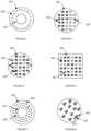
- FIG. 1is a schematic representation of the lighting system.
- FIG. 2is a schematic representation of a first variation of the lighting system, including a cover.
- FIGS. 3 , 4 , 5 , 6 , 7 , and 8are schematic representations of a first, second, third, fourth, fifth, and sixth variation of the arrangement of the EM signal emitting element sets on the substrate, respectively.
- FIGS. 9 and 10are schematic representations of a second and third configuration of the lighting system, respectively.
- FIG. 11is a schematic representation of a variation of the lighting system including a communication feature.
- FIGS. 12 and 13are schematic representations of lighting systems with individually indexed EM signal emitting elements and individually indexed EM signal emitting element sets, respectively.
- FIG. 14is a schematic representation of a lighting system variant including a power storage device.
- FIG. 15is a schematic representation of a method of lighting system operation.
- FIG. 16is a schematic representation of a method of mixing EM signals emitted by the lighting system to achieve a target EM signal emission parameter value.
- FIG. 17is a schematic representation of a method of using the lighting system to extend the range of device remote control.
- FIG. 18is a schematic representation of a variation of the method of lighting system operation.
- FIG. 19is a schematic representation of a variation of the method of remote control extension through an EM signal barrier.
- FIG. 20is a schematic representation of a variation of the method of remote control extension, using an intermediary remote computing system.
- FIG. 21is a schematic representation of a specific example of controlling the lighting system according to a lighting instruction.
- FIG. 22is a schematic representation of a specific example of controlling the lighting system according to a lighting instruction, through a remote or local communication network.
- FIG. 23is a schematic representation of a use case for multiple lighting systems including light emitting elements configured to emit light outside of the visible spectrum, wherein a first set of invisible light emitting elements is operated in a high mode, an external sensor records a measurement of interest (e.g., motion) using the invisible light, and the system automatically controls the visible light emitting elements in response to measurement of interest recordation.
- a measurement of intereste.g., motion
- FIG. 24is a schematic representation of a variation of the method of appliance control using the lighting system.
- FIG. 25is a schematic representation of a variation of the method of appliance control extension using the lighting system.
- FIG. 26is a schematic representation of a variation of the method, including concurrently displaying visible light based on a lighting instruction and emitting control signals based on an appliance instruction.
- FIG. 27is a schematic representation of associating the lighting system with the appliance.
- FIG. 28is a schematic representation of a variation of lighting system control based on a set of application instructions.
- FIG. 29is a schematic representation of lighting system control based on context.
- the lighting system 100includes multiple sets of electromagnetic signal emitting elements and a processor 300 configured to control operation of the multiple sets of EM signal emitting elements 200 .
- the lighting system 100functions to emit electromagnetic signals, such as light, having at least one, more preferably at least two, adjustable properties, wherein the adjustable properties can be color temperature, wavelength, intensity, or any other suitable electromagnetic property.
- the lighting system 100is preferably a light bulb, but can alternatively be incorporated into any other suitable component or utilized in any other suitable application.
- the lighting system 100confers several benefits over conventional lighting systems. First, by using multiple sets of light emitting elements that have substantially fixed emission properties that are substantially cheaper than light emitting elements having variable emission properties, the lighting system 100 enables dynamic adjustment of the properties of the resultant light emitted by the lighting system 100 as a whole. Second, by incorporating sets of light emitting elements having emission properties outside of the human-visible spectrum (e.g., outside of approximately 390 to 700 nm), the lighting system 100 can enable higher-resolution imaging at the respective wavelengths. For example, incorporating a set of infrared emitting elements into the lighting system 100 can enable better IR imaging resolution for security, low-light monitoring, or thermo-monitoring applications. Third, by incorporating EM signal emitting elements 200 having at least one or more variable parameters, the lighting system 100 enables dynamic aesthetic adjustment to substantially match or accommodate for the EM signal quality (e.g., light quality) emitted by previously installed systems in the space.
- the EM signal qualitye.g., light quality
- the electromagnetic signal emitting element 200 (EM signal emitting element) of the lighting system 100is configured to emit electromagnetic signals having a set of properties.
- the EM signal emitting element 200 (or combination thereof)can function to illuminate a physical area with light having a specified set of properties.
- the EM signal emitting element 200 (or combination thereof)can additionally or alternatively function communicate data to other systems (e.g., devices, appliance 20 s , other lighting system 100 s ) within a communication range.
- the EM signal emitting element 200can perform any other suitable functionality.
- the EM signal emitting element 200can emit light (e.g., visible light, invisible light, such as IR, UV, etc.), RF, microwave, or any other suitable electromagnetic signal.
- the lighting system 100can include a sound or pressure wave emitter configured to emit a sound or pressure wave signal, or include any other suitable emitter.
- the sound or pressure wave signalcan be an ultrasound signal, infrasound signal, or any other suitable sound or pressure wave signal.
- the EM signal emitting elements 200are preferably light emitting diodes (LEDs), but can alternatively be organic light emitting diodes (OLEDs), incandescent light bulbs, resistors, or any other suitable element configured to emit radiation.
- Each set of EM signal emitting elements 200preferably emits EM signals having at least one property that is different from the remaining sets of EM signal emitting elements 200 (e.g., different wavelength, frequency, propagation direction, etc.), but can alternatively have the same EM signal properties. All EM signal emitting elements 200 within a set can have substantially the same EM signal properties (e.g., within manufacturing error), share one or more EM signal property values (e.g., the same wavelength, phase, etc.), have entirely different electromagnetic property values, or have any other suitable set of EM signal property values.
- the parameter values associated with the different EM signal emitting element setsare preferably separated by a threshold value difference (e.g., opposing sides of a color spectrum, etc.), but can alternatively be differentiated in any other suitable manner.
- the multiple sets of EM signal emitting elements 200are preferably arranged in a pattern along a substrate 400 of the lighting system 100 , but can alternatively be randomly arranged.
- the EM signal emitting elements 200are preferably substantially evenly distributed across the substrate 400 , but can alternatively be unevenly distributed, such that the substrate 400 includes portions with high concentrations of EM signal emitting elements 200 , and other portions with low concentrations of EM signal emitting elements 200 .
- the EM signal emitting element setscan be substantially evenly distributed across the substrate 400 , be unevenly distributed across the substrate 400 , or be otherwise distributed across the substrate 400 .
- the EM signal emitting element setsare concentrically arranged, as shown in FIGS. 3 and 7 , wherein different EM signal emitting element sets can be arranged at different radial positions.
- the EM signal emitting element setsare arcuately arranged, wherein different EM signal emitting element sets can be arranged in different arcuate sections.
- the EM signal emitting elements 200 of the setsare randomly distributed (as shown in FIG. 5 and FIG. 6 ), and can be isotropically or non-isotropically distributed over the substrate 400 .
- different EM signal emitting element setsare arranged within different contiguous portions of the substrate 400 (as shown in FIG.
- an EM signal emitting element 200 from each of a plurality of EM signal emitting element setsis included in a group, wherein the lighting system 100 includes multiple groups and the groups are evenly distributed across the substrate 400 (dashed elements optional).
- one or more EM signal emitting element setscan be arranged in the central portion of the substrate 400 (e.g., the central portion of the substrate 400 mounting face), and different EM signal emitting element 200 set(s) can be arranged along the perimeter of the substrate 400 (e.g., evenly or unevenly distributed along the perimeter).
- the multiple sets of EM signal emitting elements 200can be otherwise arranged on the substrate 400 .
- the EM signal emitting elements 200 of a setare preferably connected in parallel, but can alternatively be connected in series. Different sets of EM signal emitting elements 200 are preferably connected in parallel to the power source by a set of switches, but can alternatively or additionally be connected to different power control circuits or connected in any other suitable manner.
- the EM signal emitting elements 200 of the subsetcan be related by physical arrangement on the substrate 400 (e.g., EM signal emitting elements 200 aligned along a vector, such as a radial vector, longitudinal vector, lateral vector, or other vector; EM signal emitting elements 200 arranged within a section of the substrate 400 , such as an arcuate section, etc.), be otherwise related, or be unrelated.
- EM signal emitting elements 200 aligned along a vectorsuch as a radial vector, longitudinal vector, lateral vector, or other vector
- EM signal emitting elements 200 arranged within a section of the substrate 400such as an arcuate section, etc.
- the EM signal emitting elements 200are preferably indexed during or after manufacturing, but can alternatively be indexed in response to installation (e.g., into an appliance 20 , a light fixture, or other power-connected component) or at any other suitable time.
- the indexis preferably used to identify the EM signal emitting element 200 , but can alternatively be used to determine parameters about the EM signal emitting element 200 , or be used in any other suitable manner.
- the indexcan be used to determine the EM signal emitting element 200 location relative to a reference point.
- the reference pointis preferably a lighting system 100 reference point on the lighting system 100 (e.g., an EM signal emitting element 200 , a center point, etc.), wherein the location of the EM signal emitting element 200 relative to the lighting system 100 reference point can be predetermined by the manufacturer or otherwise known.
- the position of the lighting system 100 reference point relative to an external reference pointcan be determined and used to select the EM signal emitting elements 200 that should be selectively powered.
- the reference pointcan be an external reference point, such as a point in a room, a geographic location, compass direction, or any other suitable external reference point.
- the lighting system 100can include a first set of light emitting elements configured to emit light having a first color temperature (e.g., above 5,000 K or any other suitable color temperature), and a second set of light emitting elements configured to emit light having a second color temperature (e.g., below 5,000 K, between 2,700-3,000 K, or any other suitable color temperature).
- the light emitting elementscan be configured to emit light having any other suitable color temperature.
- the lighting system 100can include a first set of light emitting elements configured to emit light at a first wavelength and a second set of light emitting elements configured to emit light at a second wavelength.
- the first and second wavelengthsare both within the visible spectrum (e.g., red and blue, respectively).
- the first wavelengthis in the visible spectrum and the second wavelength is outside of the visible spectrum (e.g., IR, UV, etc.).
- the light emitting elementscan be configured to emit light at any other suitable wavelength.
- the lighting system 100can include: a first set of light emitting elements configured to emit visible light having a first fixed wavelength of visible light (e.g., white light having a fixed color temperature above 5,000 K or any other suitable color temperature); a second set of light emitting elements configured to emit visible light having a second fixed wavelength of visible light (e.g., white light having a fixed color temperature below 5,000 K, between 2,700-3,000 K, or any other suitable color temperature); and a third set of light emitting elements 200 ′′ configured to emit a fixed wavelength of invisible light (e.g., IR light).
- a first fixed wavelength of visible lighte.g., white light having a fixed color temperature above 5,000 K or any other suitable color temperature
- a second set of light emitting elementsconfigured to emit visible light having a second fixed wavelength of visible light (e.g., white light having a fixed color temperature below 5,000 K, between 2,700-3,000 K, or any other suitable color temperature)
- a third set of light emitting elements 200 ′′configured to emit
- the first, second, and third sets of light emitting elementscan each be individually controlled (e.g., wherein the intensity of light emitted by the one set is independent from the intensity of light emitted by the other sets), or be controlled together (e.g., wherein the intensity of light emitted by the one set is dependent upon the intensity of light emitted by one or more of the other sets).
- Each element or sub-group of the first, second, and/or third setcan be independently indexed and controlled. Alternatively, all elements of a set are controlled together.
- the light emitting elementscan be configured to emit light having any other suitable property, and can be controlled in any suitable manner.
- the processor 300 of the lighting system 100functions to control EM signal emitting element 200 operation based on lighting instructions received from a device.
- the processor 300can individually control the relative intensities of EM signals emitted by different EM signal emitting element sets (e.g., by controlling power provision to the multiple EM signal emitting element sets).
- the processor 300can individually control a first and second set of light emitting elements to cooperatively emit light having a target color parameter value (e.g., wherein the light emitted by the first and second light emitting element are mixed by the diffuser to achieve the target light parameters).
- the processor 300can additionally or alternatively receive control instructions 30 for an external device (e.g., appliance 20 ), control an EM signal emitting element 200 or set thereof to communicate the control instructions 30 to a local external device, translate the control instructions 30 from one communication protocol to another communication protocol, or perform any other suitable functionality.
- an external devicee.g., appliance 20
- control an EM signal emitting element 200 or set thereofto communicate the control instructions 30 to a local external device
- translate the control instructions 30 from one communication protocol to another communication protocolor perform any other suitable functionality.
- the processor 300is preferably electrically connected to every EM signal emitting element 200 of the lighting system 100 , but can alternatively be electrically connected to a subset of the EM signal emitting elements 200 of a set; be electrically connected to some EM signal emitting element sets but not connected to other EM signal emitting element sets; or be electrically connected to any suitable set of EM signal emitting elements 200 .
- the processor 300can additionally or alternatively be connected to the communication module 700 , sensor(s), power storage system 800 , base, or any other suitable lighting system 100 component.
- the processor 300preferably controls power provision to the EM signal emitting elements 200 and/or communicates information to external devices using the EM signal emitting elements 200 by controlling the pulse rate of the EM signal emitting elements 200 (e.g., by controlling the PWM rate of the LED), but can alternatively control power provision and/or communicate information by controlling the current provided to the EM signal emitting element 200 or controlling any other suitable parameter of the power provided to the EM signal emitting element 200 .
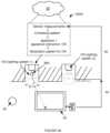
- the external devicecan be a remote device (e.g., outside of a communication range for the EM signal, protocol, etc., physically separated from the lighting system 100 by a wall or other EM barrier 90 , outside of a line of sight, etc.), a collocated device (e.g., connected to the lighting system 100 by a wire), or any other suitable device.
- the processor 300can additionally function to record lighting system 100 data and send the lighting system 100 data to a device.
- the processor 300is preferably a PCB, but can alternatively be any other suitable computing unit.
- the processor 300can additionally include a power conversion module that functions to convert power source power to power suitable for the EM signal emitting element 200 .
- the power conversion modulecan be a voltage converter, power conditioning circuit, or any other suitable circuit.
- the processor 300can additionally include digital memory that functions to store settings.
- the settingscan be for each EM signal emitting element 200 , each set of EM signal emitting elements 200 , the desired parameters of the cumulative light output, or any other suitable setting.
- the memoryis preferably volatile, but can alternatively be any other suitable memory.
- the substrate 400 of the lighting system 100functions to mechanically support and mount the EM signal emitting elements 200 .
- the substrate 400can additionally function to supply power and/or operation instructions to the EM signal emitting elements 200 from the processor 300 or power supply (e.g., lightbulb base or power storage system 800 ).
- the substrate 400is preferably mounted to an end of the housing 510 , and is preferably encapsulated between the housing 510 and the cover (e.g., the diffuser). However, the substrate 400 can be arranged in any other suitable position within the lighting system 100 .
- the substrate 400is preferably a PCB, but can alternatively be any other suitable surface.
- the substrate 400preferably defines a first broad face, and can additionally define a second broad face opposing the first broad face, sides, or define any other suitable surface.
- the EM signal emitting elements 200are preferably mounted to a single broad face (e.g., the first broad face), but can alternatively be mounted to the sides, the second broad face, or to any other suitable portion of the substrate 400 .
- the substrate profilee.g., cross section
- the substrate profilecan be circular, polygonal, irregular, or be any other suitable shape.
- the substrate 400can be substantially flat (planar), as shown in FIG.
- the substrate 400can be rigid, flexible, or have any other suitable material property.
- the substrate 400is preferably reflective or can additionally include a reflector, such that light directed toward the substrate 400 from the light emitting elements can be reflected away from the substrate 400 .
- the reflectorcan be substantially flat, curved, or have any other suitable configuration.
- the reflectorcan be textured, smooth, or have any other surface feature.
- the substrate 400can be matte, dark (e.g., such that the reflected light is absorbed), or have any other suitable property.
- the lighting system 100can additionally include a cover 500 that functions to cooperatively encapsulate the EM signal emitting elements 200 with the substrate 400 .
- the cover 500can function to mechanically protect the EM signal emitting elements 200 .
- the cover 500can function to change the properties of EM signals emitted by the elements.
- the cover 500is preferably arranged proximal the first broad face of the substrate 400 , but can alternatively be otherwise arranged.
- the cover 500 and substrate 400preferably cooperatively entirely encapsulate the EM signal emitting elements 200 , but can alternatively partially encapsulate the EM signal emitting elements 200 or encapsulate any other suitable portion of the light emitting elements.
- the cover 500can be transparent, opaque, translucent, or have any other suitable optical property.
- the cover 500can trace the substrate 400 profile or have a different profile.
- the cover 500can be cylindrical (e.g., with rounded corners), convex, or have any other suitable shape.
- the cover 500can be arranged with a broad face substantially perpendicular the active face(s) of the EM signal emitting elements 200 , the broad face of the substrate 400 , or arranged in any other suitable configuration.
- the cover 500can be made of plastic, metal, ceramic, or any other suitable material.
- the cover 500can additionally function as a diffuser, or the system can additionally include a diffuser.
- the diffuserfunctions to diffuse and blend the light emitted by the individual EM signal emitting elements 200 or different EM signal emitting element sets.
- the diffuseris preferably translucent and diffuses light, but can alternatively be a color filter or include any other suitable optical property.
- the diffusercan additionally include a communication feature 520 that permits data to be communicated through the diffuser (e.g., using visible light, invisible light, another EM signal, or any other suitable wireless communication mechanism).
- the communication feature 520can be an aperture through the diffuser thickness (e.g., a light pipe), a set of apertures or opaque features (e.g., printed dots) that selectively permit permeation of the communication wavelength but diffuses EM signals of other wavelengths, or be any other suitable feature that permits communication therethrough.
- the communication featurecan be arranged along the entirety of the diffuser side, along a portion of the diffuser side (e.g., portion proximal the housing 510 , portion distal the housing 510 ), along a broad face of the diffuser (e.g., along the flat surface of the diffuser), along a diffuser edge, extend along the entirety or portion of the diffuser arcuate face, or along any other suitable portion of the diffuser.
- the communication featureis preferably substantially aligned with a normal vector of the active surface of the EM signal emitting element 200 communicating the information (e.g., an IR LED), but can alternatively be at an angle to the normal vector, or be arranged in any other suitable configuration.
- the lighting system 100can additionally include a housing 510 that functions to encapsulate, protect, and support the lighting system components.
- the housing 510can additionally or alternatively be thermally coupled to and function as a heat sink for the lighting system 100 components.
- the housing 510is preferably mounted proximal the second broad face of the substrate 400 , but can alternatively be mounted to the first broad face or be otherwise arranged.
- the housing 510can be made of metal, ceramic, plastic, or any other suitable material.
- the housing 510can additionally include a base 512 that functions as a power supply.
- the basecan function to physically retain and electrically connect the lighting system 100 to a light fixture.
- the basecan be a standard light bulb base configured to connect to a standard light fixture (e.g., an Edison base, candelabra base, 2-pin base, 3-prong base, etc.), a custom base, or be any other suitable base.
- the baseis preferably mounted to an end of the housing 510 opposing the substrate 400 , but can alternatively be mounted to any other suitable portion of the housing 510 .
- the basecan be electrically connected to the processor 300 , power storage system 800 , EM signal emitting elements 200 , sensors 600 , communication modules 700 , and/or other lighting system components, but can alternatively be electrically connected to any other suitable component.
- the lighting system 100can additionally include a set of sensors 600 that function to measure ambient environment parameters, system parameters, or any other suitable parameter. These measurement values can be used to adjust EM signal emitting element 200 operation (e.g., adjust the intensity of emitted light, the color temperature of emitted light, turn the elements on or off, etc.), change communicated control information, interpret control information, or be used in any other suitable manner.
- EM signal emitting element 200 operatione.g., adjust the intensity of emitted light, the color temperature of emitted light, turn the elements on or off, etc.
- change communicated control informatione.g., interpret control information, or be used in any other suitable manner.
- Sensors 600can include position sensors 600 (e.g., accelerometer, gyroscope, etc.), location sensors 600 (e.g., GPS, cell tower triangulation sensors 600 , triangulation system, trilateration system, etc.), temperature sensors 600 , pressure sensors 600 , light sensors 600 (e.g., camera, CCD, IR sensor, etc.), current sensors 600 , proximity sensors 600 , clocks, touch sensors 600 , vibration sensors 600 , or any other suitable sensor.
- the sensors 600can be connected to and transmit data to the processor 300 and/or communication module 700 .
- the lighting system 100can additionally include a communication module 700 that functions to communicate data to and from the lighting system 100 (e.g., as a transceiver).
- the communication module 700preferably includes a receiver, and can additionally include a transmitter.
- the communication module 700is preferably a wireless communication module 700 , such as a Zigbee, Z-wave, or WiFi chip, but can alternatively be a short-range communication module 700 , such as Bluetooth, BLE beacon, RF, IR, or any other suitable short-range communication module 700 , a wired communication module 700 , such as Ethernet or powerline communication, or be any other suitable communication module 700 .
- the communication module 700can include an antenna 710 that functions to transmit or receive wireless data.
- the antenna 710can extend through the substrate 400 , extend along the housing 510 (e.g., along a longitudinal axis, about the housing perimeter, etc.), extend along the cover, or extend along any other suitable portion of the lighting system 100 .
- the antenna 710can extend through the thickness of the substrate 400 (e.g., from the second face to the first face), along or parallel a broad face of the substrate 400 , at an angle through the substrate 400 , or through any other suitable portion of the substrate 400 .
- the antenna 710can extend through a central portion of the substrate 400 (e.g., coaxially with the central axis, similar to that disclosed in U.S. application Ser. No. 14/512,669 filed 13 Oct. 2014, offset from the central axis, etc.), through a periphery of the substrate 400 , or along any other suitable portion of the substrate 400 .
- the lighting systemcan include one or more communication modules.
- each communication modulecan be substantially similar (e.g., run the same protocol), or be different.
- a first communication modulecan communicate with a remote router, while a second communication module functions as a border router for devices within a predetermined connection distance.
- the multiple communication modulescan operate independently and/or be incapable of communicating with other communication modules of the same lighting system, or can operate based on another communication module of the lighting system (e.g., based on the operation state of, information communicated by, or other operation-associated variable of a second communication module).
- the lighting systemcan include any suitable number of communication modules connected and/or associated in any other suitable manner.
- the lighting system 100can additionally or alternatively include a router (e.g., a WiFi router), an extender for one or more communication protocols, a communication protocol translator, or include any other suitable communication module 700 .
- a routere.g., a WiFi router
- an extender for one or more communication protocolse.g., a Wi-Fi router
- a communication protocol translatore.g., a Wi-Fi module
- the lighting system 100can additionally include a power storage system 800 that functions to store power, provide power, and/or receive power.
- the power storage system 800can be electrically connected to the processor 300 , power supply (e.g., base), and/or other lighting system 100 components.
- the power storage system 800can be arranged within the housing 510 , arranged external the housing 510 , or arranged in any other suitable position.
- the power storage system 800can be a battery (e.g., a rechargeable secondary battery, such as a lithium chemistry battery; a primary battery), piezoelectric device, or be any other suitable energy storage, generation, or conversion system.
- the systemincludes a first and second set of light emitting elements, wherein both sets are configured to emit visible light.
- a light parametere.g., color temperature, wavelength, etc.
- the first and second sets of light emitting elementsare preferably configured to emit light having a first and second fixed parameter value, respectively.
- the first and second sets of light emitting elementscooperatively form a lighting system 100 having a dynamically adjustable parameter, wherein the adjustable parameter is preferably the parameter that is fixed for each set of light emitting elements. As shown in FIGS.
- the processor 300in response to receipt of a target value for the fixed parameter from a device, the processor 300 preferably controls the relative pulse rate, intensity, or other operation parameter of the first and second sets of light emitting elements to meet the target value.
- the processor 300can control the light emitting elements in any other suitable manner.
- the parameter value of the subsequently emitted lightcan additionally be verified using a light sensor on the system or the device, or be verified in any other suitable manner.
- the first set of light emitting elementsare configured to emit light having a first color temperature
- the second set of light emitting elementsare configured to emit light having a second color temperature.
- the processor 300preferably controls the relative power provision to the first and second sets of light emitting elements such that the resultant color temperature emitted by the entirety of the lighting system 100 meets a target value, wherein the target value can be received from a device (e.g., a user device, remote server, secondary lighting system 100 , etc.).
- the first set of light emitting elementsare configured to emit white light having a 6,000 K color temperature
- the second set of light emitting elementsare configured to emit white light having a 2,700 K color temperature.
- the processor 300can control lighting system 100 operation to provide a first pulsing rate to the first set of light emitting elements and a second pulsing rate to the second set of light emitting elements, wherein the first pulsing rate can be 22% of the second pulsing rate.
- the pulse ratesare preferably determined based on a selected total light intensity, which can also be received from the device.
- the pulse ratecan be determined based on a maximum pulse rate or current as determined by a dimmer switch or any other suitable mechanism. However, the pulse rate can be otherwise determined.
- the processor 300can additionally accommodate for differences in the number, characteristics (e.g., quality), or any other parameter of light emitting elements between each set. For example, the processor 300 can provide more than 22% of the second current to the first set of light emitting elements when the first set includes less light emitting elements than the second set.
- the systemincludes a first set of light emitting elements configured to emit visible light and a second set of light emitting elements configured to emit light at a wavelength outside of the visible spectrum.
- the processor 300preferably controls operation of the first and second sets of light emitting elements independently, in response to independent operation instructions received from the device. More specifically, the processor 300 can supply power to the first set of light emitting elements in response to receipt of a target operation parameter for the first set of light emitting elements, and supply power to the second set of light emitting elements in response to receipt of a target operation parameter for the second set of light emitting elements.
- the systemcan include a first set of light emitting elements configured to emit white light and a second set of light emitting elements configured to emit infrared light.
- the systemcan additionally include a third set of light emitting elements configured to emit white light at a second color temperature, wherein the first set of light emitting elements are configured to emit white light at a first color temperature and the processor 300 can selectively control the first and second sets of light emitting elements to achieve a target parameter value.
- the systemcan include any other suitable sets of light emitting elements.
- the processor 300can provide power to the first set of light emitting elements.
- the processor 300can provide power to the second set of light emitting elements.
- the first and/or second sets of light emitting elementscan be automatically controlled, based on stored user settings (e.g., stored on-board or remotely), historical use of the set by a user, historical use of the set by a population, or controlled in any other suitable manner.
- the infrared lightcan function to provide better IR coverage for IR applications, such as security applications (e.g., for security camera illumination), monitoring applications (e.g., baby monitoring), night imaging applications, plant growth applications, data transfer applications, or any other suitable application, which can result in higher resolution images.
- security applicationse.g., for security camera illumination
- monitoring applicationse.g., baby monitoring
- night imaging applicationsplant growth applications
- data transfer applicationsor any other suitable application, which can result in higher resolution images.
- the infrared lightis preferably used with a secondary system that includes an infrared sensor, but the system can alternatively include an infrared sensor.
- a first lighting system 100can detect the light emitted by a second lighting system 100 .
- the infrared-containing light bulbis used to provide the infrared light for a security system.
- the light bulbis preferably distributed about a monitored space, wherein the light bulbs are preferably installed into the light fixtures of the monitored space.
- the infrared lightsare preferably powered in response to shutoff or a decrease in power provision to the set of visible-light emitting elements, but can alternatively be powered on in response to the instantaneous time meeting a predetermined time (e.g., turned on at 6:00 PM), powered on in response to the ambient light falling below a predetermined threshold, or powered in response to any other suitable event.
- a subset of the infrared-containing light bulbs in the monitored spaceare initially powered.
- the light bulbs forming the powered subsetare preferably substantially evenly distributed about the space, but can alternately be the light bulbs located over a space entry (e.g., window, door, etc.), or be any other suitable subset of light bulbs.
- a subset of the infrared elements on each powered light bulbcan be powered, while the remaining infrared elements can remain off.
- the powered subsetcan be powered with a low current or pulsed at a low rate, such that the infrared elements provide low-intensity infrared light.
- the set of powered lighting system 100 spreferably cooperatively illuminate the entire space, but can alternatively illuminate a subset of the space.
- the remaining infrared elements of ah light bulbs in the spacecan be powered, wherein the current provided to or pulse rate of the infrared elements is preferably high, but can alternatively be low or have any other suitable magnitude.
- the first set of visible-light emitting elementscan be powered in response to motion detection.
- An image of the roomcan additionally be recorded prior to turning the first set of lights on. The image can additionally be processed to determine whether the detected moving object is recognized, wherein the lighting system 100 is preferably operated in a first mode (e.g., a nightlight mode) in response to a recognized object and operated in a second mode (e.g., an full power mode) in response to a non-recognized object.
- a first modee.g., a nightlight mode
- a second modee.g., an full power mode
- current having a predetermined magnitude or power having a predetermined pulse ratecan be supplied to the visible lights of all or a subset of lighting system 100 s .
- currentcan be supplied to the lighting systems 100 proximal the moving object, wherein the location of the moving object can be determined based on the infrared light and sensor measurement analysis.
- the infrared light emitted by the lighting system 100 scan function to create a thermal map of a monitored space, wherein the thermal map can be used to adjust operation of an HVAC system (e.g., air conditioning system).
- a temperature control systemcan control the lighting system 100 s to emit infrared light in response to the temperature falling below a temperature threshold.
- the infrared lightcan be used to communicate information from the lighting system 100 to a peripheral device.
- the peripheral deviceis preferably within a line of sight of the lighting system 100 , independent of visible-light emitting element operation, but can alternatively be arranged in any other suitable location.
- the informationcan be communicated by pulsing or otherwise adjusting the intensity, saturation, or any other suitable light parameter of the emitted infrared light.
- the informationcan additionally or alternatively be communicated by changing which infrared light emitting element is emitting the infrared light, or communicated in any other suitable manner.
- the informationcan be data generated by the lighting system 100 , data received by the lighting system 100 from a remote or connected device, or be any other suitable information.
- the informationcan be received by a peripheral device, such as a television, mobile phone, or any other suitable device, and converted into a control signal or any other suitable device information for the peripheral device.
- control signalscan include operation instructions, media (e.g., audio/video transmission), device identification, device connection information, or any other suitable information.
- Different infrared light emitting elements of the same lighting system 100can simultaneously communicate information to two different peripheral devices, but can only communicate information to a single peripheral device, a predetermined set of peripheral devices, or any other suitable number of peripheral devices.
- the communicated informationcan be the same piece of information or be different pieces of information, wherein the different pieces of information can be simultaneously communicated by different infrared light emitting elements of the same lighting system 100 or by different lighting systems 100 .
- the lighting system 100can additionally function to receive data communicated by the peripheral device.
- the informationcan be communicated through a data channel (e.g., WiFi), EM signals emitted by the peripheral device (e.g., modulated IR light), or communicated in any other suitable manner.
- a data channele.g., WiFi
- EM signals emitted by the peripheral devicee.g., modulated IR light
- the light emitted by the light emitting elementscan be used to repel insects, arachnids, or other pests.
- This examplecan include determining the location of a user (e.g., using a secondary sensor, the location of a user device associated with the user, etc.) and directing the infrared light or other EM signal to repel pests away from the user location or any other suitable location (e.g., location of food).
- Directing the infrared light or other EM signal to repel pests away from the user locationcan include illuminating the area surrounding the user location with IR light, directing EM signals that attract insects at an area distal the user, or otherwise drawing insects away from the user location.
- the method of lighting system operationcan include: receiving control instructions at a lighting system S 100 and controlling a set of EM signal emitting elements based on the control instructions S 200 .
- the methodcan enable the lighting system to selectively emit light having a range of lighting parameters, even though the lighting system only includes light emitting elements having fixed lighting parameters.
- the methodcan additionally enable the lighting system to double as a remote control extender for appliances or other remote-controlled devices.
- the methodcan function in any other suitable manner.
- the methodis preferably performed with the system described above, but can alternatively be performed with any other suitable lighting system. More preferably, the method is performed with a plurality of lighting systems and devices (e.g., user devices, remote server systems, sensors, appliances, etc.), wherein the lighting systems and devices are preferably associated with a common user account. However, the method can be performed with any other suitable system.
- a plurality of lighting systems and devicese.g., user devices, remote server systems, sensors, appliances, etc.
- the methodcan be performed with any other suitable system.
- Receiving the control instruction at the lighting system S 100functions to provide instructions for lighting system operation.
- the control instructioncan be received at the lighting system by the communication module, but can alternatively be received in any other suitable manner by any other suitable component.
- the control instruction 30is preferably received from a sending device, wherein the sending device sends the control instruction or a derivatory instruction to the lighting system, but can alternatively be received from any other suitable source.
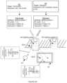
- the instructionscan be sent directly, through a secondary lighting system (e.g., as shown in FIG. 19 ), through a communication network (e.g., WiFi, example shown in FIG. 19 ), through a remote computing system (e.g., as shown in FIG. 20 ), or through any other suitable communication channel.
- the instructionscan be sent using the communication protocol in which the control instruction was received, a second communication protocol, or any other suitable protocol.
- the sending devicecan be a user device 60 (e.g., wherein the control instruction is entered by a user on a user interface, received by the user device at an input device, etc.), a second lighting system, a remote computing system 50 (e.g., remote server system), an external device (e.g., connected outlet, accessory, computing system, etc.), or any other suitable source.
- the sending devicecan receive the control instruction (or a precursor thereof) from a user (and therefore be the receiving device), receive the control instruction from a second sending device, automatically generate the control instruction (e.g., based on instantaneous and historical sensor measurements, etc.), or otherwise determine the control instructions.
- the sending devicecan additionally process the control instruction, such as by compressing the information, associating the control instruction with an endpoint (e.g., appliance identifier, lighting system identifier, EM signal emitting element, etc.), transforming the control instruction (e.g., into the modulation pattern or operation instructions), associating the control information with contextual information (e.g., sensor measurement values recorded within a threshold time period of control instruction receipt, timestamps, etc.), associating the control information with user account information (e.g., a user account identifier), associating the control information with any other suitable information, or otherwise processing the control information.
- an endpointe.g., appliance identifier, lighting system identifier, EM signal emitting element, etc.
- transforming the control instructione.g., into the modulation pattern or operation instructions
- contextual informatione.g., sensor measurement values recorded within a threshold time period of control instruction receipt, timestamps, etc.
- user account informatione.g., a user
- the sending deviceis preferably associated with the same user account as the lighting system, but can alternatively be associated with a different user account.
- the control instructioncan be automatically generated, manually entered (e.g., user-generated), or otherwise generated by the sending device.
- the control instructioncan include one or more lighting instructions 31 (e.g., target EM signal emission parameter values), appliance instructions 32 (e.g., for appliance control), context parameter values 40 (e.g., timestamps, weather information, sensor measurements, etc.), endpoint identifiers (e.g., a unique address for the lighting system, an appliance identifier, etc.), or include any other suitable information.
- the methodcan additionally or alternatively determine the type of control instruction. For example, the method can include determining whether the control instruction is an appliance instruction or a lighting instruction, wherein the type of control instruction can be determined based on the length of the control instruction, the communication protocol of the control instruction, an endpoint address included within the control instruction, the commands within the control instruction, or be determined in any other suitable manner.
- a first set of EM signal emitting elementsare preferably controlled when the control instructions include lighting instructions (e.g., according to the mixing variant below), and a second set of EM signal emitting elements (e.g., invisible light emitting elements, IR light emitting elements, etc.) are preferably controlled when the control instructions include appliance instructions (e.g., according to the external device control variant below).
- the EM signal emitting elements of one or more lighting systemscan be otherwise controlled.
- the control instructionscan include instructions for a single endpoint (e.g., a single appliance, a single lighting system, etc.), instructions for multiple endpoints (e.g., for both lighting systems and appliances, multiple lighting systems, multiple appliances, etc.), or instructions for any suitable set of endpoints.
- a single endpointe.g., a single appliance, a single lighting system, etc.
- instructions for multiple endpointse.g., for both lighting systems and appliances, multiple lighting systems, multiple appliances, etc.
- instructions for any suitable set of endpointse.g., a single appliance, a single lighting system, etc.
- the control instructioncan additionally include trigger events associated with the information, wherein the information is used when the trigger event is met.
- the control instructioncan include a trigger event, including a set of sensor measurement values, associated with the lighting instructions, wherein the lighting instructions are performed when the lighting system sensors record measurements substantially matching the set of sensor measurement values.
- the control informationcan additionally include associations between different pieces of the control information.
- a lighting instructioncan be associated with an appliance instruction, wherein the lighting instruction and appliance instruction are to be concurrently performed.
- the control instructioncan include any other suitable information.
- the methodcan additionally include determining secondary control instructions based on the control instruction.
- the secondary control instructionscan be for other devices (e.g., lighting systems adjacent the appliance when the control instruction is an appliance instruction; appliance instructions when the control instruction is a lighting instruction, etc.), for the target device, or for any other suitable device.
- the secondary control instructionscan be determined (e.g., generated, selected, calculated, etc.) based on the control instruction and instantaneous contextual parameter values, based on the control instruction alone, or be determined based on any other suitable information.
- control instructioncan be an appliance instruction for the thermostat to lower the temperature
- the secondary control instructionscan be to concurrently lower the color temperature of visible light emitted by the lighting systems proximal the user (e.g., proximal the user device, such as a smart phone).
- the secondary control instructioncan be to concurrently increase the color temperature of the emitted visible light.
- the control instructioncan be an appliance instruction for the television to change the channel, wherein the secondary control instructions can be to adjust the color temperature and/or hue of the emitted visible light based on the dominant color palette of the resultant channel.
- the secondary control instructioncan be otherwise determined.
- Individually controlling a set of EM signal emitting elements based on the control instructions S 200functions to concurrently emit EM signals having one or more properties from the lighting system.
- Independent EM signal emitting element set operationis preferably controlled by the processor, but can alternatively be controlled by any other suitable control system.
- individually controlling the elementsincludes operating a first set of light emitting elements at a first intensity and operating a second set of light emitting elements at a second intensity, wherein the light emitting elements cooperatively emit visible light having a target light parameter value.
- the first set of light emitting elementsincludes different light emitting elements from the second set of light emitting elements, and the first intensity is different from the second intensity.
- individually controlling the elementsincludes concurrently operating a set of visible light emitting elements according to a lighting instruction, and operating a set of communication EM signal emitting elements (communication elements) according to an appliance instruction.
- the set of visible light emitting elementscan be operated according to a lighting instruction as discussed in the first variation.
- the set of communication elementscan be operated according to the appliance instruction by determining a modulation pattern corresponding to the appliance instruction (e.g., that will communicate the appliance instruction to the appliance), and modulating the waveform of the power supplied to the communication elements according to the modulation pattern.
- Operating the set of communication elementscan additionally or alternatively include selecting the communication element most proximal the appliance, and controlling only the selected communication element according to the modulation pattern.
- the element setscan be otherwise individually controlled.
- the methodcan additionally include learning control instructions based on contextual patterns S 500 , which functions to automatically determine and control the appliances and lighting systems according to user preferences.
- the user preferencescan be individual user preferences, global user preferences, or user preferences for any other suitable set of users.
- the user preferencescan be stored in association with the user account, stored by the user device, stored by the lighting systems, or be stored in any other suitable manner.
- the control instructions and associated contextual patternsare preferably learned by the remote computing system, but can alternatively be learned by the user device, one or more lighting systems, or by any other suitable computing system.
- the control instructionsare preferably learned from historical control instructions and their associated contextual parameter values, but can alternatively be received from a user, or otherwise determined.
- learning control instructions based on contextual patternsincludes: receiving the control instruction; determining context parameter values associated with control instruction receipt; assigning the context parameter values with the control instructions to form a control record; and extracting a context parameter value pattern associated with the control instruction from a plurality of control records.
- the lighting systemis preferably automatically controlled according to the control instruction in response to the occurrence of an instantaneous set of context parameter values substantially matching the context parameter value pattern.
- the control instructions and associated contextual patterncan be otherwise determined.
- the context parameter valuesare preferably values measured within a predetermined time threshold of control instruction receipt (e.g., concurrent with control instruction receipt, within 10 seconds of receipt, etc.), but can alternatively be recorded at any other suitable time.
- the context parameter valuescan be a timestamp; a weather variable value (e.g., received from a remote server system); an appliance operation state; a lighting system operation state; a lighting plurality operation state; a sensor measurement value (e.g., ambient noise, temperature, light, etc.) from one or more lighting systems, connected outlets, connected switches, or other connected systems; a pattern or combination of device operation states; or be a value of any other suitable parameter indicative of context.
- Automatic system control based on satisfaction of the contextual parameterscan include: automatically generating and/or communicating appliance instructions to the appliances via the lighting systems; automatically generating and/or communicating lighting instructions to the lighting systems; or automatically controlling any other suitable device.
- the control instructionscan be generated and/or communicated by a control system, wherein the control system can be the remote computing system (e.g., server system), a user device, a lighting system or set thereof, or by any other suitable set of computing systems.
- the control systemcan receive sensor measurements, control instructions, or any other suitable information from the connected devices (e.g., lighting systems, user devices, connected outlets, etc.) at a predetermined frequency, as the measurements are recorded, or at any other suitable time.
- the methodcan include operating a first set of appliances according to a first set of control instructions in response to a first contextual pattern being met (example shown in FIG. 29 ), and operating a second set of appliances according to a second set of control instructions in response to a second contextual pattern being met.
- the first and second set of appliancescan be the same or different.
- the first and second set of control instructionscan be the same or different.
- the methodcan include: automatically turning on a first set of appliances when a user enters the house, and automatically shutting off a second set of appliances when a user leaves the house or goes to sleep.
- the first contextual patterncan be the user entering the house (e.g., determined based on the geographic location of the user device, proximity to beacons, based on power provision to one or more lighting systems within the house); and the second contextual pattern can be the user turning off the light (e.g., power provision cessation).
- the methodcan include: concurrently communicating a first set of control instructions associated with the first context parameter pattern to a plurality of appliances through a plurality of lighting systems (e.g., to turn on all the appliances that the user usually turns on).
- the methodcan additionally include storing power in power storage devices on-board each of the plurality of lighting systems in response to power receipt at the lighting system.
- the methodcan include concurrently communicating a second set of control instructions to the plurality of appliances through the plurality of lighting systems (e.g., to turn off all the appliances that the user usually turns off). Because no more power is being supplied to the lighting systems at this time, each lighting system can use the power stored by the respective power storage devices (e.g., batteries) to: determine that power provision has ceased; send a power cessation notification to the control system; receive control instructions from the control system, and send the control instructions to the respective appliances. However, the system can be otherwise controlled based on contextual patterns.
- the respective power storage devicese.g., batteries
- this methodincludes: receiving a target EM signal emission parameter value at the lighting system S 110 and individually controlling different sets of EM signal emitting elements to emit an EM signal having parameter values substantially matching the target EM signal emission parameter value S 210 .
- receiving the control instructionincludes: receiving a target EM signal emission parameter value at the lighting system; and individually controlling a set of EM signal emitting elements based on the control instructions includes: individually controlling different sets of EM signal emitting elements to emit an EM signal having parameter values substantially matching the target EM signal emission parameter value.
- This method variantfunctions to provide a lighting system, made from lighting elements having static lighting properties, with dynamically adjustable lighting capabilities.
- the methodincludes: receiving a target light parameter value (e.g., color temperature value), determining the relative intensities for a first and second light emitting element set to meet the target light parameter value, and operating the first and second light emitting element sets at the respective intensities to cooperatively emit light having substantially the target light parameter value.
- a target light parameter valuee.g., color temperature value
- the methoddetermines how bright the first plurality of light emitting elements should be operated, and how bright the second plurality of light emitting elements should be operated, such that the light emitted by the lighting system (i.e., the light cooperatively emitted by the first and second pluralities of light emitting elements and blended by the diffuser) has a color temperature substantially matching the target color temperature.
- the first plurality of light emitting elementsemits light having a first fixed hue (e.g., red) and the second plurality of light emitting elements light having a second fixed hue (e.g., red), each plurality without capability to emit light having another hue.
- the first and second plurality of light emitting elementscan be controlled to both emit the same intensity of light.
- the intensity of each pluralitycan substantially match that specified by the control instructions, be half that specified by the control instructions, or be any other suitable intensity.
- the first plurality of light emitting elementscan be operated at the specified intensity, while the second plurality of light emitting elements can be operated at a low intensity or shut off.
- the first and second pluralitiescan be otherwise operated to achieve a target parameter value.
- the operation parameters that can be determinedinclude the operation intensity (e.g., the amplitude or emission intensity for each set), the percentage of each set to be operated (e.g., in variants wherein individual subsets can be independently controlled), or include any other suitable operation parameter.
- the operation parameterscan calculated, empirically determined (e.g., by dynamically adjusting the relative operation parameters and measuring the emitted light with an external sensor), selected from a graph or chart, or otherwise determined.
- Determining the relative operation parameterscan include calculating an operation parameter ratio for the multiple sets, based on the respective fixed operation parameter for each set and the target operation parameter value. For example, if the first and second sets have a 1,700 K and 10,500 K color temperature, respectively, and the target color temperature is 5,00 K, then the operation ratio for the first set can be 62.5% more than the second set. The first set can be operated at an intensity that is 62.5% higher than the intensity of the second set, have 62.5% more elements in operation compared to the second set, or be controlled based on the calculated ratio in any other suitable manner.
- Determining the relative operation parameterscan additionally include accounting for a second target operation parameter value.
- the control instructioncan specify both a target color parameter (e.g., color temperature, hue, saturation) and a target intensity for the cooperatively emitted light, wherein the method can scale the respective intensities of each light emitting element set based on the target intensity (e.g., to substantially meet the target intensity).
- the second target operation parameter valuecan be accounted for by scaling the determined intensities, applying the determined ratio to the second target operation parameter value, using the second target operation parameter value as the maximum value for any light emitting element set, or be otherwise accounted for.
- Determining the relative operation parameterscan additionally include accommodating for differences in perceived intensities of the first and second sets. For example, when a first light having a warm color temperature (e.g., 1,700 K) and a second light having a cold color temperature (e.g., 10,5000 K) are emitted at the same intensity, the first light can be perceived as less intense by a user, wherein the method can accommodate for this discrepancy by increasing the intensity of the first light.
- Accommodating for the differencescan include weighting the respective fixed operation parameter value for the set when determining the ratio, correcting the ratio by a correction factor, or otherwise accommodating for the difference in perception.
- the relative operation parameterscan be otherwise determined.
- Controlling each set according to the respective operation parameterpreferably includes determining a pulse width modulation pattern (PWM pattern) corresponding to the relative operation parameter for the set and providing power to the light emitting element according to the PWM pattern (e.g., as described above).
- PWM patternpulse width modulation pattern
- each setcan be otherwise controlled based on the operation parameter.
- the methodincludes: receiving an appliance instruction for an appliance S 120 , identifying a lighting system proximal the appliance S 300 , determining a modulation pattern to communicate the control instruction to the appliance S 400 , and controlling an EM signal emitting element of the lighting system according to the modulation pattern S 220 .
- receiving the control instruction at the lighting systemincludes: receiving the appliance instruction or derivatory instructions, and individually controlling a set of EM signal emitting elements based on the control instructions includes: controlling an EM signal emitting element of the lighting system according to the modulation pattern.
- This methodfunctions to extend the communication range of a remote control.
- the methodcan additionally function to target communication to the appliance, such that other appliances adjacent the target appliance (e.g., within the same room as the target appliance) do not receive the control instruction and/or are not controlled by the control instruction. This can be useful when multiple appliances of similar type are closely arranged (e.g., when multiple televisions are closely arranged), but only one appliance is to be controlled.
- the methodcan additionally function to simultaneously send communications to multiple appliances, whether adjacent (e.g., in the same room) or remote (e.g., in different rooms, buildings, or other geographic locations).
- the methodcan additionally function to translate control instructions between communication protocols, which can expand the number of remote control devices that can be used to control the appliance.
- the second method variation or any portion thereofcan be performed in conjunction with, concurrently with, or independently from first method variation performance.
- the systemcan be used in any suitable manner and/or perform any other suitable functionality.
- Receiving an appliance instruction S 120functions to provide the appliance instruction to the system for subsequent processing and/or transmission.
- the appliance instructioncan be received by a user device, the lighting system, a secondary lighting system, a remote computing system, or by any other suitable system.
- the receiving systemis preferably associated with the same user identifier (e.g., user account, WiFi network, IP address, etc.) that the lighting system (and/or appliance) is associated with, but can alternatively be unassociated with any user identifier, associated with a different user identifier, or otherwise related to the lighting system.
- the appliance instructioncan be received from a sending device 80 (e.g., in the manner discussed above), received from the user (e.g., at a user input device, at a graphical interface, etc.), but can alternatively be received from any other suitable source.
- the appliance instructionis preferably a set of instructions meant for an appliance, and can include control instructions (e.g., on/off instructions, setting selection, setting control, etc.), display information (e.g., A/V information), or include any other suitable information.
- An applianceis preferably a home appliance (e.g., device designed for domestic or household functions, such as televisions, washing machines, stoves, ovens, etc.), but can alternatively be any remote-controlled device (e.g., toys, robots, etc.), device having a wireless communication module (e.g., secondary lighting systems, connected outlets, switches, user device, etc.), or be any other suitable device.
- the methodcan additionally include sending data indicative of the appliance instruction to the lighting system.
- the data indicative of the appliance instructioncan be the appliance instruction, as received by the receiving device; be a derivatory instruction, determined (e.g., computed, translated, selected, etc.) based on the appliance instruction (e.g., the modulation pattern); or be any other suitable data associated with the appliance instruction.
- the data indicative of the appliance instructionis preferably sent by the device receiving the appliance instruction (receiving device) via a wireless communication method, but can alternatively be sent by any other suitable computing system in any other suitable manner.
- the receiving deviceis preferably external the lighting system, but can be arranged in any other suitable position.
- the receiving devicecan be proximal the lighting system (e.g., within communication range for a short-range communication protocol, within communication range for a lighting system-hosted local network, within the same room as the lighting system, within a predetermined distance of the lighting system, etc.), remote from the lighting system (e.g., outside of the communication range for a short-range communication protocol, located in a different room or building from the lighting system, outside a predetermined distance of the lighting system, etc.), or be arranged in any suitable physical position relative to the lighting system.
- the data indicative of the appliance instructioncan be sent before the modulation pattern is determined (e.g., wherein the lighting system determines the modulation pattern), after the modulation pattern is determined (e.g., wherein the data is the modulation pattern or a precursor thereof), or at any other suitable time.
- the data indicative of the appliance instructionis preferably sent after the lighting system proximal the appliance is identified, but can alternatively be sent at any other suitable time.
- receiving the appliance instructionscan include: receiving the appliance instructions at a device from a user; and sending the appliance instructions to a first lighting system from the device in response to appliance instruction receipt.
- the methodcan additionally include forwarding the appliance instructions (or derivatory instructions) to a second lighting system, remote server system, or any other suitable endpoint.
- receiving the appliance instructionscan include: receiving the appliance instructions at a device from a user; sending the appliance instructions to a remote server system from the device in response to appliance instruction receipt; and sending the appliance instructions (or derivatory instructions) to the lighting system from the remote server system.
- receiving the appliance instructionscan include: generating the appliance instructions at a remote server system, user device, or lighting system; and sending the appliance instructions (or derivatory instructions) to the lighting system.
- the appliance instructionscan be otherwise received and/or generated.
- Identifying a lighting system proximal the appliance S 300functions to identify the lighting system with the highest probability of communicating the appliance instruction to the appliance, such that the appliance instruction or derivatory instruction can be sent only to the identified lighting systems (example shown in FIG. 26 ). This can function to reduce data traffic and reduce unintentional appliance control.
- the lighting system(s) proximal the appliancecan be uniquely identified, wherein the control instruction (or derivatory information) can be addressed to the lighting system and sent to the lighting system.
- the addressed lighting systemcan be sent through a common communication channel shared by all connected devices (e.g., associated with the user account), wherein the lighting system identified by the address selectively receives the information (e.g., pulls the information), and the other lighting systems ignore the information.
- the control instructionscan be sent only to the targeted lighting system by selectively connecting to a local network hosted by the lighting system based on the address, and communicating the control instruction through the local network.
- the informationcan be sent peer to peer (e.g., verified through a digital handshake).
- the informationcan be sent in a targeted direction (e.g., broadcast in a physical direction, such as in the direction of a room in which the lighting system is located).
- the informationcan be otherwise targeted at the lighting system.
- the lighting systemcan remain unidentified, and the appliance instructions can be broadcast to all lighting systems associated with the user account, ah lighting systems within a predetermined physical range, all lighting systems connected to a common wireless network, or to any other suitable set of lighting systems.
- the lighting systemcan be identified by the receiving device, by an intermediary device (e.g., a remote server system), or by any other suitable device.
- the lighting systemis preferably identified by a lighting system identifier, but can alternatively be otherwise identified.
- the lighting system identifiercan be globally unique, unique within the population of lighting systems associated with the user account, unique within the population of lighting systems within a geographic area or connected to a common wireless network, generic/shared, or be otherwise related to other lighting system identifiers.
- the lighting system identifiercan be automatically determined (e.g., assigned by the manufacturer, automatically assigned upon user setup based on other lighting systems already associated with the user account or the communication network 70 , etc.), manually determined (e.g., assigned by a user), or be otherwise determined.
- the identified lighting systemis preferably associated with the appliance identifier, but can alternatively be any other suitable lighting system.
- the methodincludes identifying the appliance identifier based on the control instructions, and identifying the lighting system based on the appliance identifier.
- the appliance identifiercan be definitively determined or probabilistically determined (e.g., wherein the target appliance is the one that has the highest probability of being the target, based on context, etc.).
- the appliance identifieris preferably associated with the user account, but can alternatively be unassociated with the user account.
- the appliance identifiercan be determined based on control instruction parameters (e.g., control instruction length, communication protocol, etc.); based on the content of the control instructions, wherein the instructions are compared against a database of instructions; based on an endpoint identifier included in the control instructions; or otherwise determined.
- control instruction parameterse.g., control instruction length, communication protocol, etc.
- a television identifieris identified in response to the control instructions being below a predetermined size or length
- an air conditioning unit identifieris identified in response to the control instructions being above a second size or length.
- the target appliance identifiercan be otherwise determined.
- identifying the lighting system proximal the appliancecan include: retrieving a lighting system identifier associated with the appliance from a database (example shown in FIG. 28 ).
- identifying the lighting system proximal the appliancecan additionally or alternatively include: sequentially sending and controlling the lighting system to emit the appliance instruction (or derivatory instruction) to different lighting systems associated with the user account until the appliance receives the appliance instruction, which can be determined based on a detected change in appliance operation (e.g., wherein a lighting system sensor or other sensor on another system, such as an outlet or light switch, records a measurement indicative of the change).
- the lighting system proximal the appliancecan be otherwise identified.
- the methodcan additionally include associating the lighting system with the appliance, which can be subsequently used in the first variation of identifying the lighting system proximal the appliance.
- Associating the lighting system with the appliancecan include: determining an association between the lighting system and the appliance, and storing the lighting system identifier in association with the appliance.
- the lighting system(s) within communication range of the appliancee.g., local lighting systems, proximal lighting systems, etc.
- any other suitable lighting systemcan be associated with the appliance.
- Storing the lighting system identifier in association with the appliancecan include: storing the identifier for the lighting system (lighting system identifier) in association with the identifier for the appliance (appliance identifier) in a remote computing system or other storage system; storing the appliance identifier in the lighting system memory; or otherwise associating the lighting system with the appliance.
- One or more lighting systemscan be associated with each appliance, and one or more appliances can be associated with each lighting system.
- the association between the lighting system and the appliancecan be determined: manually (e.g., received from a user, wherein the user enters or selects the lighting system identifier and the appliance identifier); pseudo-automatically; automatically; or otherwise determined.
- the user deviceis placed or held next to the appliance (e.g., in front of, adjacent the appliance sensor, between the appliance and the lighting system, etc.).
- Individual lighting systemsare then independently operated at different times (e.g., controlled by a user device, remote computing system, etc.).
- the user deviceor user notifies the system when light (visible or invisible) emitted by the lighting system is proximal or illuminates the appliance and/or the light sensor of the user device.
- the identifiers of the lighting system(s) in operation when the appliance and/or user device light sensor was illuminatedare then associated with the appliance.
- the associationcan be otherwise pseudo-automatically determined.
- the systemcan determine the relative position between a lighting system and an outlet, wherein the outlet is electrically connected to the appliance and identifies or is otherwise associated with the appliance.
- the position of the lighting system relative to the outletcan be automatically determined (e.g., based on trilateration using signals emitted and detected by the lighting system and/or outlet, determined from an image of the room, etc.), received from a user, or otherwise determined.
- the appliance connected to the outletcan be: manually identified; automatically identified based on data transfer from the appliance to the outlet; automatically identified based on the amount of power drawn, pattern of drawn power; or otherwise identified.
- the appliancecan be assumed to have a rear face facing the outlet, with the sensing face distal the outlet, but can be assumed to be in any other suitable position.
- the lighting system having light emitting elements directed toward the outletis preferably associated with the appliance, but any other suitable lighting system can be associated with the appliance. However, the lighting system can be otherwise associated with the outlet.
- Associating the lighting system with the appliancecan additionally or alternatively include associating one or more specific EM signal emitting element(s) of the lighting system with the appliance, wherein the EM signal emitting element identifier(s) are preferably subsequently identified and elements operated to communicate the control instruction to the appliance S 310 .
- the EM signal emitting elements of the lighting systemcan be individually indexed (e.g., as shown in FIG. 12 ) and controlled.
- the specific EM signal emitting elementcommunicates the control instruction to the appliance, while the other EM signal emitting elements of the lighting system can operate in a different mode (e.g., in a dim, off, or standby mode) (example shown in FIG. 28 ).
- Thisfunctions to target communication to the target appliance, which can limit inadvertent control instruction communication to other appliances.
- Thisalso functions to allow a single lighting system to concurrently control (or communicate control instructions to) multiple appliances.
- associating one or more EM signal emitting elements with the appliance S 320can include: determining an association between the EM signal emitting element(s) with the appliance and storing identifier(s) for the EM signal emitting element(s) with the appliance identifier (example shown in FIG. 27 ).
- the EM signal emitting elementscan be otherwise associated with the appliance.
- the associationcan be stored in a similar manner to lighting system association storage, or be stored differently.
- the associationcan be stored by the lighting system, by a second lighting system, by a remote server, by a user device, or by any other suitable system.
- the EM signal emitting element associated with the applianceis preferably a communication signal emitting element (e.g., an invisible signal emitting element, such as an IR light emitting element, RF emitting element, visible light emitting element, etc.), but can alternatively be a visible light emitting element or be any other suitable EM signal emitting element.
- the EM signal emitting element(s) within communication range of the appliancee.g., local lighting systems, proximal lighting systems, etc.
- any other suitable EM signal emitting elementcan be associated with the appliance.
- the association between the EM signal emitting element and the appliancecan be determined: manually (e.g., received from a user, wherein the user enters or selects the EM signal emitting element identifier and the appliance identifier); pseudo-automatically; automatically; or otherwise determined.
- the EM signal emitting elementcan be dynamically associated with the appliance (e.g., the control instruction is communicated by different EM signal emitting elements until the appliance operates according to the control instructions), or be otherwise associated with the appliance.
- the user deviceis placed or held next to the appliance (e.g., in front of, adjacent the appliance sensor, between the appliance and the lighting system, etc.).
- Individual EM signal emitting element sets of the lighting systemare sequentially operated (e.g., scrolled through) to project light from different EM signal emitting elements (e.g., different elements arranged in different arcuate or radial positions; projecting light radially outward, etc.) automatically, in response to an arcuate manual input, or operated in any other suitable manner.
- the EM signal emitting element setspreferably have fixed, known angular, radial, or other position relative to the lighting system.
- the EM signal emitting element setscan be operated in a manner similar to the method disclosed in U.S.
- the user devicenotifies the system when an EM signal emitted by the EM signal emitting element is proximal or illuminates the appliance and/or the light sensor of the user device.
- the identifiers of the EM signal emitting element(s) in operation when the appliance and/or user device light sensor was illuminatedare then associated with the appliance.
- individual visible light emitting element sets of the lighting systemare sequentially operated (e.g., scrolled through) to project light from different visible light emitting elements (e.g., different elements arranged in different arcuate or radial positions) automatically, in response to an arcuate manual input, or controlled in any other suitable manner.
- the light emitting element setspreferably have fixed, known angular, radial, or other position relative to the lighting system.
- the light emitting element setscan be operated in a manner similar to the method disclosed in U.S. application Ser. No. 14/720,180 filed 22 May 2015, incorporated herein in its entirety by this reference, but alternatively operated in any other suitable manner.
- the user devicenotifies the system when a visible light emitted by the visible light emitting element is proximal or illuminates the appliance and/or the light sensor of the user device.
- the identifiers of the visible light emitting element(s) in operation when the appliance and/or user device light sensor was illuminatedare then identified, and the EM signal emitting element(s) associated with the visible light emitting element(s) that were in operation are then associated with the appliance.
- the EM signal emitting element associated with the applianceis preferably the EM signal emitting element proximal the identified visible light emitting element (e.g., arcuately or radially adjacent the identified visible light emitting element, within the same group as the identified visible light emitting element, etc.), wherein the position of the EM signal emitting element relative to the identified visible light emitting element on the lighting system is known, but can alternatively be an EM signal emitting element configured to direct light in substantially the same direction as the identified visible light emitting element, or be any other suitable EM signal emitting element.
- the identified visible light emitting elemente.g., arcuately or radially adjacent the identified visible light emitting element, within the same group as the identified visible light emitting element, etc.
- associating the EM signal emitting elemente.g., invisible light emitting element, infrared light emitting element, etc.
- associating the EM signal emitting elementincludes: scrolling through a set of visual light emitting elements having predetermined angular positions on the lighting system, including, at each of a set of timestamps, concurrently operating a visual light emitting element in a high mode and operating a remainder of the set in a low mode; storing each of the set of timestamps with an identifier for the visual light emitting element concurrently operated in the high mode; receiving an association notification from a user device, the association notification including an association timestamp and an identifier for the appliance; determining a reference timestamp from the set of timestamps substantially matching the association timestamp; determining the visual light emitting element identifier, stored in association with the reference timestamp, as a reference visual light emitting element identifier; determining an identifier for an invisible light emitting element located adjacent the visual light emitting element identified
- the EM signal emitting element proximal the appliancecan be determined after the lighting system associated with the appliance is automatically identified (e.g., using the methods described above).
- the lighting systemcan determine its rotational orientation relative to the appliance, such that a lighting system reference point position relative to the appliance is known; retrieve a known position of the EM signal emitting elements relative to the reference point; and determine the EM signal emitting element(s) most proximal the appliance and/or the EM signal emitting element(s) configured to direct EM signals toward the appliance based on the lighting system rotational position and EM signal emitting element positions relative to the lighting system reference point.
- determining the position of the lighting system reference point relative to an external reference pointincludes determining the orientation of the lighting system using an onboard compass or other positioning system.
- determining the position of the lighting system reference point relative to an external reference pointincludes selectively powering a single or subset of EM signal emitting elements (indexing light emitting elements) and detecting the light on a mobile device including a light sensor (e.g., a camera or other light sensor). The location of the mobile device can be recorded in response to a detected light parameter (e.g., intensity) surpassing a predetermined threshold.
- a detected light parametere.g., intensity
- the orientation of the indexing EM signal emitting element and remainder EM signal emitting elementscan be determined once the recipient device geographic location is recorded.
- the position of one or more EM signal emitting elements relative to the appliancecan be otherwise determined and associated with the appliance.
- Determining a modulation pattern to communicate the control instruction to the appliance S 400functions to process the appliance instruction into instructions for EM signal emitting element operation.
- the modulation pattern(e.g., PWM modulation pattern) can be determined by the receiving device (e.g., the device initially receiving the control instruction), by the sending device (e.g., the device sending the control instruction), the lighting system operating its EM signal emitting elements according to the modulation pattern, or by any other suitable device.
- the modulation patternis preferably the pattern required to communicate an equivalent of the control instructions (or derivative thereof) using the EM signal emitting element(s), but can alternatively be any other suitable modulation pattern.
- the methodcan include generating operation instructions for a lighting system emitter (e.g., RF operation instructions, A/V instructions, etc.) to communicate the control instructions to the appliance.
- a lighting system emittere.g., RF operation instructions, A/V instructions, etc.
- the control instructioncan be otherwise communicated to the appliance via the lighting system.
- Determining a modulation patterncan additionally include selecting the communication protocol, which functions to translate control instructions in a first communication protocol to control instructions in a second communication protocol.
- the communication protocolis preferably selected based on the communication protocol(s) accepted by the appliance (wherein the accepted communication protocols can be retrieved from a database or otherwise determined), but can alternatively be otherwise determined.
- Different EM signal emitting element typescan be used when different communication protocols are selected, wherein the operated EM signal emitting element preferably corresponds to the selected communication protocol.
- different modulation patternscan be selected based on the selected communication protocol. However, the selected communication protocol can be otherwise used.
- Controlling an EM signal emitting element of a lighting system according to the modulation pattern S 220functions to communicate the control instruction (or derivatory instruction) to the appliance.
- thiscan include controlling one or more emitters of the lighting system (e.g., RF emitters, microwave emitters, BLE transceivers, etc.) according to the operation instructions, which were determined based on the control instructions.
- the control instructioncan be otherwise communicated to the appliance.
- the EM signal emitting element controlled according to the modulation patterncan be: all EM signal emitting elements of the lighting system; the EM signal emitting element associated with the appliance (e.g., as determined above); or be any other suitable EM signal emitting element or set thereof.
- controlling the EM signal emitting element according to the modulation patternincludes: operating the identified infrared light emitting element according to the modulation pattern; and operating a second infrared light emitting element of the plurality according to a second modulation pattern different from the modulation pattern.
- the EM signal emitting elementis preferably controlled by the processor of the lighting system according to the modulation pattern (e.g., by regulating power provision to the element), but can alternatively be controlled by the remote computing system (e.g., remote server system), a user device, or be controlled by any other suitable system.
- the remote computing systeme.g., remote server system
- the preferred embodimentsinclude every combination and permutation of the various system components and the various method processes.
Landscapes
- Engineering & Computer Science (AREA)
- General Engineering & Computer Science (AREA)
- Physics & Mathematics (AREA)
- Microelectronics & Electronic Packaging (AREA)
- Optics & Photonics (AREA)
- General Physics & Mathematics (AREA)
- Computer Networks & Wireless Communication (AREA)
- Circuit Arrangement For Electric Light Sources In General (AREA)
Abstract
Description
Claims (20)
Priority Applications (2)
| Application Number | Priority Date | Filing Date | Title |
|---|---|---|---|
| US17/191,539US12080158B2 (en) | 2014-09-02 | 2021-03-03 | Lighting system |
| US18/784,832US20240378991A1 (en) | 2014-09-02 | 2024-07-25 | Lighting system |
Applications Claiming Priority (3)
| Application Number | Priority Date | Filing Date | Title |
|---|---|---|---|
| US201462044789P | 2014-09-02 | 2014-09-02 | |
| US14/843,828US11455884B2 (en) | 2014-09-02 | 2015-09-02 | Lighting system |
| US17/191,539US12080158B2 (en) | 2014-09-02 | 2021-03-03 | Lighting system |
Related Parent Applications (1)
| Application Number | Title | Priority Date | Filing Date |
|---|---|---|---|
| US14/843,828ContinuationUS11455884B2 (en) | 2013-11-14 | 2015-09-02 | Lighting system |
Related Child Applications (1)
| Application Number | Title | Priority Date | Filing Date |
|---|---|---|---|
| US18/784,832ContinuationUS20240378991A1 (en) | 2014-09-02 | 2024-07-25 | Lighting system |
Publications (2)
| Publication Number | Publication Date |
|---|---|
| US20210192936A1 US20210192936A1 (en) | 2021-06-24 |
| US12080158B2true US12080158B2 (en) | 2024-09-03 |
Family
ID=55402017
Family Applications (3)
| Application Number | Title | Priority Date | Filing Date |
|---|---|---|---|
| US14/843,828Active2037-07-03US11455884B2 (en) | 2013-11-14 | 2015-09-02 | Lighting system |
| US17/191,539Active2035-11-13US12080158B2 (en) | 2014-09-02 | 2021-03-03 | Lighting system |
| US18/784,832PendingUS20240378991A1 (en) | 2014-09-02 | 2024-07-25 | Lighting system |
Family Applications Before (1)
| Application Number | Title | Priority Date | Filing Date |
|---|---|---|---|
| US14/843,828Active2037-07-03US11455884B2 (en) | 2013-11-14 | 2015-09-02 | Lighting system |
Family Applications After (1)
| Application Number | Title | Priority Date | Filing Date |
|---|---|---|---|
| US18/784,832PendingUS20240378991A1 (en) | 2014-09-02 | 2024-07-25 | Lighting system |
Country Status (1)
| Country | Link |
|---|---|
| US (3) | US11455884B2 (en) |
Families Citing this family (25)
| Publication number | Priority date | Publication date | Assignee | Title |
|---|---|---|---|---|
| US11455884B2 (en) | 2014-09-02 | 2022-09-27 | LIFI Labs, Inc. | Lighting system |
| US9210779B2 (en) | 2013-11-14 | 2015-12-08 | LIFI Labs, Inc. | Resettable lighting system and method |
| US9445482B2 (en) | 2014-05-23 | 2016-09-13 | Gecko Alliance Group Inc. | Light bulb and method and system for use in configuring same |
| US9641959B2 (en) | 2014-05-23 | 2017-05-02 | Gecko Alliance Group Inc. | Household for industrial device including programmable controller and method device and system for use in configuring same |
| US9749782B2 (en)* | 2014-07-31 | 2017-08-29 | Qualcomm Incorporated | Light fixture commissioning using encoded light signals |
| US9949348B2 (en) | 2014-11-10 | 2018-04-17 | LIFI Labs, Inc. | Lighting connectivity module |
| EP3395615A4 (en)* | 2015-12-22 | 2019-08-28 | Koito Manufacturing Co., Ltd. | VEHICLE LIGHTING DEVICE, AND LIGHTING CONTROL SYSTEM AND VEHICLE |
| US10118696B1 (en) | 2016-03-31 | 2018-11-06 | Steven M. Hoffberg | Steerable rotating projectile |
| JP6617882B2 (en)* | 2016-04-27 | 2019-12-11 | パナソニックIpマネジメント株式会社 | Lighting apparatus, lighting system, and lighting system setting method |
| EP3261061A1 (en)* | 2016-06-24 | 2017-12-27 | Skidata Ag | Access control method and system |
| US10676023B2 (en)* | 2016-07-29 | 2020-06-09 | Koito Manufacturing Co., Ltd. | Vehicle lighting system, vehicle system, and vehicle |
| US20190191535A1 (en)* | 2016-09-05 | 2019-06-20 | Signify Holding B.V. | Led-filament and lighting device comprising the led-filament |
| GB2564706B (en)* | 2017-07-21 | 2021-05-05 | Brandenburg Innovation Ltd | A method of repelling mosquitos |
| JP6871823B2 (en)* | 2017-08-10 | 2021-05-12 | ヤンマーパワーテクノロジー株式会社 | Fruit growth monitoring system and fruit growth monitoring method |
| US11712637B1 (en) | 2018-03-23 | 2023-08-01 | Steven M. Hoffberg | Steerable disk or ball |
| JP7186597B2 (en)* | 2018-12-12 | 2022-12-09 | 三菱電機株式会社 | LED module and lighting device |
| CN209926155U (en)* | 2019-04-30 | 2020-01-10 | 漳州立达信光电子科技有限公司 | Ceiling lamp |
| EP3964036B1 (en)* | 2019-05-01 | 2024-07-03 | Savant Systems, Inc. | Intelligent lighting control radar sensing system apparatuses and methods |
| WO2021154550A1 (en) | 2020-01-31 | 2021-08-05 | American Sterilizer Company | Proximity detection for a surgical light |
| EP4283188A4 (en)* | 2021-01-20 | 2024-10-23 | Boxyz, Inc. | LAMP AND SYSTEM |
| US20240107646A1 (en)* | 2021-01-28 | 2024-03-28 | Signify Holding B.V. | A controller for unlearning a learnt preference for a lighting system and a method thereof |
| US11578853B2 (en)* | 2021-05-20 | 2023-02-14 | Portal Infinity Mirrors, Inc. | Systems and methods for generating customizable mirrored effects with interchangeable and programmable infinity mirrors |
| US20230110571A1 (en)* | 2021-10-07 | 2023-04-13 | Andrew Walker, JR. | LED and AUDIO FRAGRANT OIL DIFFUSER |
| US20240162273A1 (en)* | 2022-06-15 | 2024-05-16 | Lumileds Llc | Non-visible light source having a low-density set of light-emitting elements |
| CN117042266B (en)* | 2023-10-10 | 2024-02-23 | 深圳市千岩科技有限公司 | Control method, control device, electronic equipment and computer readable storage medium |
Citations (247)
| Publication number | Priority date | Publication date | Assignee | Title |
|---|---|---|---|---|
| US433167A (en) | 1890-07-29 | James bolan glover | ||
| US463584A (en) | 1891-11-17 | Island | ||
| US590523A (en) | 1897-09-21 | Game-counter | ||
| US600368A (en) | 1898-03-08 | Knob attachment | ||
| US601278A (en) | 1898-03-29 | Cord-gutter | ||
| US605786A (en) | 1898-06-14 | Island | ||
| US616120A (en) | 1898-12-20 | leaycraft | ||
| US623774A (en) | 1899-04-25 | Bicycle saddle-post | ||
| US646809A (en) | 1899-11-07 | 1900-04-03 | Theodore Dickman | Clamp. |
| US688395A (en) | 1900-08-20 | 1901-12-10 | Homer C Davis | Nut-lock. |
| US4942386A (en) | 1988-12-16 | 1990-07-17 | Willis Billy R | Integrated impact detection and alarm system |
| US5420607A (en) | 1992-09-02 | 1995-05-30 | Miller; Robert F. | Electronic paintbrush and color palette |
| US5506946A (en) | 1991-10-01 | 1996-04-09 | Electronics For Imaging, Inc. | Selective color correction |
| US5710545A (en) | 1995-10-10 | 1998-01-20 | Motorola, Inc. | Display providing reversible contrasting indicia |
| US5769527A (en) | 1986-07-17 | 1998-06-23 | Vari-Lite, Inc. | Computer controlled lighting system with distributed control resources |
| US5790114A (en) | 1996-10-04 | 1998-08-04 | Microtouch Systems, Inc. | Electronic whiteboard with multi-functional user interface |
| US5841428A (en) | 1993-11-05 | 1998-11-24 | Intertactile Technologies Corporation | Rotary circuit control devices with changeable graphics |
| US5914669A (en) | 1997-03-06 | 1999-06-22 | Sony Corporation | Pager with rotating dial for inputting messages |
| US6003206A (en) | 1998-05-14 | 1999-12-21 | Illinois Tool Works Inc. | Control knob using LED for backlighting |
| US6121976A (en) | 1996-02-06 | 2000-09-19 | Ulead Systems, Inc. | Digital image-processing method for conducting color gradient |
| US6329990B1 (en) | 1997-07-15 | 2001-12-11 | Silverbrook Research Pty Ltd | Brush stroke palette feedback method for automatic digital “painting” effects |
| US6337629B1 (en) | 1999-09-14 | 2002-01-08 | Biosys Ab | Method and a system for monitoring a person |
| US20020047628A1 (en) | 1997-08-26 | 2002-04-25 | Frederick Morgan | Methods and apparatus for controlling devices in a networked lighting system |
| US20020111135A1 (en) | 1998-05-04 | 2002-08-15 | White Stanley A. | System and method for extending the range of a base unit |
| US20020145394A1 (en) | 2000-08-07 | 2002-10-10 | Frederick Morgan | Systems and methods for programming illumination devices |
| US20030019734A1 (en) | 2001-07-25 | 2003-01-30 | Teac Corporation | Switch device |
| CN2558026Y (en) | 2002-08-08 | 2003-06-25 | 无锡市汇捷科技有限公司 | Radio paging domestic electric appliances controller |
| US20030117408A1 (en) | 2001-12-21 | 2003-06-26 | Forsline Ladd B. | Computer painting system with passive paint brush stylus |
| US6726112B1 (en) | 2003-03-07 | 2004-04-27 | Joseph Ho | Illuminating thermostat |
| US6737801B2 (en)* | 2000-06-28 | 2004-05-18 | The Fox Group, Inc. | Integrated color LED chip |
| US20040105264A1 (en) | 2002-07-12 | 2004-06-03 | Yechezkal Spero | Multiple Light-Source Illuminating System |
| US6759966B1 (en) | 2000-09-01 | 2004-07-06 | Linsong Weng | Wireless remote control bulb device |
| US20040129946A1 (en) | 2002-10-17 | 2004-07-08 | Hideo Nagai | Light emission apparatus |
| US20040160198A1 (en) | 1997-05-12 | 2004-08-19 | Light And Sound Design, Ltd. A England Corporation | Electronically controlled stage lighting system |
| US20040212318A1 (en) | 2003-04-22 | 2004-10-28 | Matsushita Electric Works, Ltd. | Discharge lamp lighting device and lighting apparatus |
| US20050116667A1 (en) | 2001-09-17 | 2005-06-02 | Color Kinetics, Incorporated | Tile lighting methods and systems |
| US20050128751A1 (en) | 2003-05-05 | 2005-06-16 | Color Kinetics, Incorporated | Lighting methods and systems |
| US20050236263A1 (en) | 2004-01-12 | 2005-10-27 | Stanton Magnetics, Inc. | Control knob with multi-color indicator |
| US20050237341A1 (en) | 2003-02-25 | 2005-10-27 | Microsoft Corporation | Color gradient paths |
| US20050278778A1 (en) | 2004-05-28 | 2005-12-15 | D Agostino Anthony | Method and apparatus for credential management on a portable device |
| US20060002309A1 (en) | 2004-06-30 | 2006-01-05 | International Business Machines Corporation | Method and apparatus for self-configuring routing devices in a network |
| US20060044800A1 (en) | 2002-10-31 | 2006-03-02 | Gerd Reime | Device for controlling lighting, more especially inside the passenger compartments of vehicles and control , method therefor |
| US20060047132A1 (en) | 2004-09-02 | 2006-03-02 | Rohm And Haas Electronic Materials Llc | Method |
| US20060049935A1 (en) | 2002-12-19 | 2006-03-09 | Koninklijke Philips Electronics N.V. | Method of configuration a wireless-controlled lighting system |
| US20060139907A1 (en) | 2004-12-29 | 2006-06-29 | George Yen | All-color light control switch |
| US7103460B1 (en) | 1994-05-09 | 2006-09-05 | Automotive Technologies International, Inc. | System and method for vehicle diagnostics |
| US20060198157A1 (en) | 2005-03-01 | 2006-09-07 | Xiao-Dong Ruan | Erasing control circuit and method for erasing environment configuration memory in a computer system |
| US20060280660A1 (en)* | 2005-06-09 | 2006-12-14 | Weiss Robert M | Photocatalytic air purifier |
| US20070085863A1 (en) | 2005-10-13 | 2007-04-19 | Seiko Epson Corporation | Image display device, electronic apparatus, and pixel location determining method |
| US20070119484A1 (en) | 2005-05-23 | 2007-05-31 | Lg Electronics Inc. | Control panel of a laundry processing machine |
| US20070182367A1 (en) | 2006-01-31 | 2007-08-09 | Afshin Partovi | Inductive power source and charging system |
| US20070223219A1 (en)* | 2005-01-10 | 2007-09-27 | Cree, Inc. | Multi-chip light emitting device lamps for providing high-cri warm white light and light fixtures including the same |
| US20080006709A1 (en) | 2006-07-10 | 2008-01-10 | Ranco Inc. Of Delaware | Thermostat with adjustable color for aesthetics and readability |
| US20080049043A1 (en) | 2006-08-22 | 2008-02-28 | Geoff Titmuss | On-screen colour selection |
| US20080062192A1 (en) | 2006-09-13 | 2008-03-13 | Adobe Systems Incorporated | Color selection interface |
| US20080092800A1 (en) | 2006-10-20 | 2008-04-24 | Robert B. Smith | LED Light Bulb System |
| US20080106887A1 (en) | 2006-10-31 | 2008-05-08 | Tir Technology Lp | Light source comprising a light-excitable medium |
| US20080143273A1 (en) | 2006-12-13 | 2008-06-19 | Davidson David L | System and method for maintaining and controlling a plurality of wireless light fixtures |
| US20080198175A1 (en) | 2007-02-20 | 2008-08-21 | Microsoft Corporation | Drag-And-Drop Pasting For Seamless Image Composition |
| US7418392B1 (en) | 2003-09-25 | 2008-08-26 | Sensory, Inc. | System and method for controlling the operation of a device by voice commands |
| US20080218099A1 (en) | 2007-03-05 | 2008-09-11 | Lutron Electronics Co., Inc. | Method of programming a lighting preset from a radio-frequency remote control |
| US20080265799A1 (en) | 2007-04-20 | 2008-10-30 | Sibert W Olin | Illumination control network |
| CN101309237A (en) | 2008-06-30 | 2008-11-19 | 中兴通讯股份有限公司 | Home gateway , system and method for remote multimedia data sharing |
| US20090052182A1 (en) | 2005-03-18 | 2009-02-26 | Yoshiaki Matsuba | Illumination system |
| US20090059603A1 (en) | 2007-08-30 | 2009-03-05 | Wireless Environment, Llc | Wireless light bulb |
| US7502033B1 (en) | 2002-09-30 | 2009-03-10 | Dale Axelrod | Artists' color display system |
| US20090121651A1 (en) | 2005-09-16 | 2009-05-14 | Samir Gandhi | Color-Changing Light Array Device |
| US20090128059A1 (en) | 2006-03-13 | 2009-05-21 | Koninklijke Philips Electronics N V | Control device for controlling the color of light emitted from a light source |
| US20090146982A1 (en) | 2007-12-05 | 2009-06-11 | Jeff Thielman | Lighting Calibration System and Method |
| US20090147508A1 (en)* | 2007-12-07 | 2009-06-11 | Ralph Bertram | Lighting Unit and Lamp |
| US20090190338A1 (en) | 2008-01-25 | 2009-07-30 | Eveready Battery Company, Inc. | Lighting Device and Optics Package Therefor |
| US20090251127A1 (en) | 2008-04-03 | 2009-10-08 | Belkin International, Inc. | Power Management Connection Devices And Related Methods |
| US20090284169A1 (en) | 2008-05-16 | 2009-11-19 | Charles Bernard Valois | Systems and Methods for Communicating in a Lighting Network |
| US20090295310A1 (en) | 2008-05-28 | 2009-12-03 | John Duerr | Dual head inspection lamp |
| US20100068899A1 (en) | 2007-03-01 | 2010-03-18 | Asher Shvili | Lighting System |
| US20100070217A1 (en) | 2008-09-18 | 2010-03-18 | Adapta Strategy | System and method for monitoring and management of utility usage |
| US20100118527A1 (en) | 2008-11-07 | 2010-05-13 | Itramas International, Inc. | Methodology of providing white lighting with colour combination |
| US20100127638A1 (en) | 2008-11-24 | 2010-05-27 | Young Lighting Technology Corporation | Light source control device and method |
| US20100141153A1 (en) | 2006-03-28 | 2010-06-10 | Recker Michael V | Wireless lighting devices and applications |
| US20100172120A1 (en) | 2007-05-24 | 2010-07-08 | Koninklijke Philips Electronics N.V. | Color-tunable illumination system |
| US20100194687A1 (en) | 2005-05-27 | 2010-08-05 | Sony Computer Entertainment Inc. | Remote input device |
| US20100204841A1 (en)* | 2007-09-07 | 2010-08-12 | Koninklijke Philips Electronics N.V. | Methods and apparatus for providing led-based spotlight illumination in stage lighting applications |
| US20100207534A1 (en) | 2007-10-09 | 2010-08-19 | Philips Solid-State Lighting Solutions, Inc. | Integrated led-based luminare for general lighting |
| US20100277067A1 (en) | 2009-04-30 | 2010-11-04 | Lighting Science Group Corporation | Dimmable led luminaire |
| US20100289664A1 (en) | 2008-10-15 | 2010-11-18 | Panasonic Corporation | Light projection device |
| US20100296285A1 (en) | 2008-04-14 | 2010-11-25 | Digital Lumens, Inc. | Fixture with Rotatable Light Modules |
| CN201662712U (en) | 2009-12-30 | 2010-12-01 | 国网信息通信有限公司 | A smart home appliance control device |
| US20100301773A1 (en) | 2009-04-14 | 2010-12-02 | Digital Lumens, Inc. | Fixture with Individual Light Module Dimming |
| US7852322B2 (en) | 2007-01-24 | 2010-12-14 | Samsung Electronics Co., Ltd | Portable computer |
| US20100327766A1 (en) | 2006-03-28 | 2010-12-30 | Recker Michael V | Wireless emergency lighting system |
| US20110050120A1 (en) | 2009-09-01 | 2011-03-03 | Hong Kong Applied Science And Technology Research Institute Co. Ltd. | Lighting control system and led lamp |
| CN201758454U (en) | 2010-04-27 | 2011-03-09 | 山东大学 | Novel intelligent household system in the internet of things era |
| US20110074672A1 (en) | 2008-06-10 | 2011-03-31 | Koninklijke Philips Electronics N.V. | User interface device and method for controlling a connected consumer load, and light system using such user interface device |
| US20110089842A1 (en) | 2009-10-15 | 2011-04-21 | Massachusetts Institute Of Technology | Apparatus and Methods for Interactive Illumination |
| US20110089838A1 (en) | 2009-10-20 | 2011-04-21 | Cree Led Lighting Solutions, Inc. | Heat sinks and lamp incorporating same |
| US20110095687A1 (en) | 2009-10-25 | 2011-04-28 | Greenwave Reality, Inc. | Modular Networked Light Bulb |
| US20110109249A1 (en) | 2009-11-10 | 2011-05-12 | Green Mark Technology Inc. | Dimmable led lamp and dimmable led lighting apparatus |
| US20110109216A1 (en) | 2009-11-09 | 2011-05-12 | Seok Jin Kang | Lighting device |
| US20110133655A1 (en) | 2006-03-28 | 2011-06-09 | Recker Michael V | Autonomous grid shifting lighting device |
| US20110161865A1 (en) | 2002-03-08 | 2011-06-30 | Revelations In Design, Lp | Methods for controlling an electric device using a control apparatus |
| US20110163683A1 (en) | 2011-02-22 | 2011-07-07 | Quarkstar, Llc | Solid State Lamp Using Light Emitting Strips |
| US20110199004A1 (en) | 2010-02-18 | 2011-08-18 | Redwood Systems, Inc. | Commissioning lighting systems |
| US20110216085A1 (en) | 2006-03-13 | 2011-09-08 | Koninklijke Philips Electronics N.V. | Control device for controlling the hue of light emitted from a light source |
| US8024517B2 (en) | 2009-01-30 | 2011-09-20 | International Business Machines Corporation | Proactive technique for reducing occurrence of long write service time for a storage device with a write cache |
| CN201986217U (en) | 2010-12-28 | 2011-09-21 | 深圳市创荣发电子有限公司 | Light emitting diode (LED) lamp with wirelessly-adjusted luminance |
| US20110227495A1 (en) | 2008-02-06 | 2011-09-22 | C. Crane Company, Inc. | Light emitting diode lighting device |
| US20110227469A1 (en) | 2010-03-03 | 2011-09-22 | Cree, Inc. | Led lamp with remote phosphor and diffuser configuration utilizing red emitters |
| US20110234366A1 (en) | 2008-12-04 | 2011-09-29 | Koninklijke Philips Electronics N.V. | Methods for selecting and controlling devices |
| US20110260648A1 (en) | 2010-04-26 | 2011-10-27 | Panasonic Electric Works Co., Ltd. | Light source module, lighting apparatus, and illumination device using the same |
| US20110285515A1 (en) | 2010-05-24 | 2011-11-24 | Panasonic Electric Works Co., Ltd. | Lighting remote control system |
| US20110309769A1 (en) | 2010-04-08 | 2011-12-22 | Mitsumi Electric Co., Ltd. | Power control device for led lighting and lighting system |
| US20120026726A1 (en) | 2006-03-28 | 2012-02-02 | Wireless Environment, Llc | Power outage detector and transmitter |
| US20120025717A1 (en) | 2009-04-09 | 2012-02-02 | Koninklijke Philips Electronics N.V. | Intelligent lighting control system |
| US20120080944A1 (en) | 2006-03-28 | 2012-04-05 | Wireless Environment, Llc. | Grid Shifting System for a Lighting Circuit |
| US8160514B2 (en) | 2008-07-25 | 2012-04-17 | Qualcomm, Incorporated | Transmission noise cancellation |
| US20120120243A1 (en) | 2003-01-14 | 2012-05-17 | Tseng-Lu Chien | Device Having Built-In Digital Data Device Powered By Unlimited Power Source |
| US20120126699A1 (en) | 2010-11-18 | 2012-05-24 | Michael Zittel | LED Light Bulb with Battery Backup and Remote Operation |
| US20120130547A1 (en) | 2010-11-19 | 2012-05-24 | Nest Labs, Inc. | Thermostat user interface |
| US20120147604A1 (en) | 2010-12-14 | 2012-06-14 | Todd Farmer | Gimbaled LED Array Module |
| US20120146505A1 (en) | 2010-12-14 | 2012-06-14 | Greenwave Reality, Pte, Ltd. | Light with changeable color temperature |
| US20120153868A1 (en) | 2010-12-20 | 2012-06-21 | Redwood Systems, Inc. | Light timeout optimization |
| US20120188172A1 (en) | 2011-01-21 | 2012-07-26 | Peter Sui Lun Fong | Light emitting diode switch device and array |
| US20120195053A1 (en) | 2011-01-28 | 2012-08-02 | Wei Chung Wu | LED lamp |
| US20120206050A1 (en) | 2002-07-12 | 2012-08-16 | Yechezkal Evan Spero | Detector Controlled Illuminating System |
| US20120218421A1 (en) | 2004-07-06 | 2012-08-30 | Tseng-Lu Chien | Device having built-in digital data device powered by unlimited power source for led bulb |
| US20120224381A1 (en) | 2011-01-27 | 2012-09-06 | Naotaka Hashimoto | Light source device |
| US8282250B1 (en) | 2011-06-09 | 2012-10-09 | Elumigen Llc | Solid state lighting device using heat channels in a housing |
| US8299719B1 (en) | 2009-03-06 | 2012-10-30 | Masoud Moshirnoroozi | Individually selective intelligent lighting system |
| US20120281879A1 (en) | 2010-01-15 | 2012-11-08 | Koninklijke Philips Electronics N.V. | Method and System for 2D Detection of Localized Light Contributions |
| US20120287601A1 (en)* | 2011-05-09 | 2012-11-15 | Cree, Inc. | High efficiency led lamp |
| US20120287488A1 (en) | 2011-05-09 | 2012-11-15 | Canon Kabushiki Kaisha | Image processing apparatus, image processing method, and computer-readable medium |
| US20120293652A1 (en)* | 2011-05-17 | 2012-11-22 | Todd Farmer | LED Module with Integrated Thermal Spreader |
| US20120300441A1 (en) | 2006-06-30 | 2012-11-29 | Electraled, Inc. | Elongated led lighting fixture |
| US20120299476A1 (en) | 2011-05-23 | 2012-11-29 | General Electric Company | Configurable vehicle solid state lighting |
| US20120306377A1 (en) | 2011-04-22 | 2012-12-06 | Rohm Co., Ltd. | Led lamp |
| US8334777B2 (en) | 2010-02-19 | 2012-12-18 | Hill-Rom Services, Inc. | Patient room and bed management apparatus and system |
| US20130038230A1 (en) | 2011-03-11 | 2013-02-14 | Nularis Inc. | Method and apparatus to facilitate coupling an led-based lamp to a fluorescent light fixture |
| US20130049598A1 (en) | 2011-08-26 | 2013-02-28 | Rohm Co., Ltd. | Led lamp |
| US8390201B2 (en) | 2008-06-24 | 2013-03-05 | Advantest Corp. | Multi-column electron beam exposure apparatus and magnetic field generation device |
| US20130063042A1 (en) | 2011-03-11 | 2013-03-14 | Swapnil Bora | Wireless lighting control system |
| US8398264B2 (en)* | 2007-10-31 | 2013-03-19 | University Of Strathclyde | Lighting device |
| CN103067492A (en) | 2012-12-26 | 2013-04-24 | 上海无线通信研究中心 | Communication control device, electrical device based on network and network control method of electrical device |
| US20130099672A1 (en) | 2011-10-21 | 2013-04-25 | Chih-Hua Lin | Illumination system and control method of illumination system |
| US20130106283A1 (en) | 2011-10-26 | 2013-05-02 | Lee Gillio | Programmable lighting effect device and system |
| US20130113715A1 (en) | 2011-11-07 | 2013-05-09 | Immersion Corporation | Systems and Methods for Multi-Pressure Interaction on Touch-Sensitive Surfaces |
| US20130121569A1 (en) | 2009-09-14 | 2013-05-16 | Vikas Yadav | Methods and Apparatus for Blending Images |
| US20130148341A1 (en) | 2010-08-23 | 2013-06-13 | Litonics Limited | Heatsink for lighting device |
| US20130154985A1 (en) | 2010-08-25 | 2013-06-20 | Hitachi Solutions, Ltd. | Interactive whiteboards and programs |
| CN203099410U (en) | 2012-12-31 | 2013-07-31 | 东莞丰尚科技有限公司 | LED lamp with improved heat dissipation structure |
| US20130249435A1 (en) | 2011-06-29 | 2013-09-26 | Martin Edward Hellkamp | Level Light |
| US20130249392A1 (en) | 2012-03-20 | 2013-09-26 | Lg Innotek Co., Ltd. | Lighting apparatus and lighting control system |
| US20130257312A1 (en) | 2010-07-23 | 2013-10-03 | Lighting Science Group Corporation | System for generating non-homogenous biologically-adjusted light and associated methods |
| US20130278162A1 (en) | 2012-04-20 | 2013-10-24 | Calvin Hugh Watson | Led bulb for general and low intensity light |
| US20130278132A1 (en) | 2010-10-12 | 2013-10-24 | Zengguang Yuan | Led bulbs with adjustable light emitting direction |
| US20130278172A1 (en) | 2011-05-15 | 2013-10-24 | Lighting Science Group Corporation | System for generating non-homogenous light and associated methods |
| US8569968B2 (en) | 2010-04-23 | 2013-10-29 | Princeton Technology Corporation | Method for adjusting light brightness using a toggle switch and related illuminant system |
| US20130292106A1 (en) | 2012-05-02 | 2013-11-07 | Chen-Chun LIEN | Heat dissipation structure for light bulb assembly |
| US20130314680A1 (en) | 2012-05-28 | 2013-11-28 | Oki Data Corporation | Lens unit, exposure device, led head, image formation apparatus, and reading apparatus |
| US20130326381A1 (en) | 2012-05-29 | 2013-12-05 | Microsoft Corporation | Digital art program interaction and mechanisms |
| US20140021862A1 (en) | 2012-07-23 | 2014-01-23 | Lg Innotek Co., Ltd. | Lighting apparatus |
| US20140028199A1 (en) | 2012-03-19 | 2014-01-30 | Digital Lumens Incorporated | Methods, systems, and apparatus for providing variable illumination |
| US20140029749A1 (en) | 2011-03-16 | 2014-01-30 | Rammohan Malasani | Wi-fi router with integrated touch-screen and enhanced security features |
| US20140046152A1 (en) | 2012-05-03 | 2014-02-13 | Vioptix, Inc. | Wireless, Handheld, Tissue Oximetry Device |
| US20140043825A1 (en) | 2010-06-08 | 2014-02-13 | Cree, Inc. | Led light bulbs |
| US20140049983A1 (en) | 2010-11-18 | 2014-02-20 | Anthony John Nichol | Light emitting device comprising a lightguide film and aligned coupling lightguides |
| WO2014040118A1 (en) | 2012-09-06 | 2014-03-20 | Lifi Labs Inc | Controllable lighting devices |
| US20140084809A1 (en) | 2012-09-24 | 2014-03-27 | Anthony W. Catalano | Variable-beam light source and related methods |
| US20140097071A1 (en) | 2012-10-10 | 2014-04-10 | Lg Electronics Inc. | Mobile terminal |
| US20140118385A1 (en) | 2012-10-30 | 2014-05-01 | Pixtronix, Inc. | Display apparatus employing multiple composite contributing colors |
| US20140117859A1 (en) | 2012-10-26 | 2014-05-01 | Lutron Electronics Co., Inc. | Controllable light source |
| US8743923B2 (en) | 2012-01-31 | 2014-06-03 | Flir Systems Inc. | Multi-wavelength VCSEL array to reduce speckle |
| US8742594B2 (en) | 2012-09-14 | 2014-06-03 | International Business Machines Corporation | Structure and method of making an offset-trench crackstop that forms an air gap adjacent to a passivated metal crackstop |
| US20140159600A1 (en) | 2011-12-16 | 2014-06-12 | Marvell World Trade Ltd. | Led-based lamp with user-selectable color temperature |
| US20140184577A1 (en) | 2012-12-31 | 2014-07-03 | Lg Display Co., Ltd. | Transparent display apparatus and method for controlling the same |
| US8770771B2 (en) | 2007-03-15 | 2014-07-08 | Hans Christer Preta | Smart light with power backup |
| US20140239811A1 (en) | 2009-12-07 | 2014-08-28 | At&T Intellectual Property, I, L.P. | Mechanisms for light management |
| US20140265900A1 (en) | 2013-03-15 | 2014-09-18 | Laurence P. Sadwick | Fluorescent Lamp LED Replacement |
| US20140265864A1 (en) | 2013-03-15 | 2014-09-18 | Abl Ip Holding Llc | Systems and methods for providing a lighting effect |
| US20140273715A1 (en) | 2013-03-15 | 2014-09-18 | Crayola Llc | Panoramic Coloring Kit |
| US20140273892A1 (en) | 2013-03-14 | 2014-09-18 | Farhad Nourbakhsh | Integrated networking equipment and diversity antenna in light bulb |
| US20140285999A1 (en) | 2013-03-14 | 2014-09-25 | Aliphcom | Combination speaker and light source powered using light socket |
| US8854443B2 (en) | 2006-08-21 | 2014-10-07 | Chromaviso Ip Aps | Medical surgery room with coloured lighting |
| US20140300294A1 (en) | 2007-09-24 | 2014-10-09 | Integrated Illumination Systems, Inc. | Systems and methods for providing an oem level networked system |
| US20140300293A1 (en) | 2012-08-16 | 2014-10-09 | Zhejiang Shenghui Lighting Co., Ltd. | Led lighting device and an ledlighting network system |
| US20140321122A1 (en) | 2009-09-14 | 2014-10-30 | James L. Ecker | Led lighting devices |
| US20140354150A1 (en) | 2013-05-31 | 2014-12-04 | Smart Fos, Inc. | Systems and Methods for Providing a Self-Adjusting Light Source |
| US8928232B2 (en) | 2013-05-28 | 2015-01-06 | Abl Ip Holding Llc | Lighting network with autonomous commissioning |
| US20150015165A1 (en) | 2012-03-08 | 2015-01-15 | Koninklijke Philips N.V. | Methods and apparatus for configuration of control devices |
| US8941013B2 (en) | 2012-05-30 | 2015-01-27 | Shawn X. ARNOLD | Multilayer laminated structure for plug and connector with spring finger interconnecting feature |
| US20150038246A1 (en) | 2013-08-05 | 2015-02-05 | Do It Yourself Toys, LLC | Repeatedly Collapsible Retail Stand Toy |
| US20150048760A1 (en) | 2013-08-13 | 2015-02-19 | Samsung Electronics Co., Ltd. | Lighting apparatus, lighting control system, and method of controlling the lighting apparatus |
| US20150062892A1 (en) | 2013-08-29 | 2015-03-05 | Soraa, Inc. | Circadian friendly led light source |
| US20150084513A1 (en) | 2013-09-20 | 2015-03-26 | Osram Sylvania Inc. | Techniques and graphical user interface for controlling solid-state luminaire with electronically adjustable light beam distribution |
| US20150084515A1 (en) | 2013-09-23 | 2015-03-26 | Seasonal Specialties, Llc | Ornamental Lighting |
| US20150103520A1 (en) | 2013-10-16 | 2015-04-16 | Winvic Sales Inc. | Battery powered electronic candle with speaker |
| US20150103515A1 (en) | 2013-10-15 | 2015-04-16 | LIFI Labs, Inc. | Lighting assembly |
| US20150108904A1 (en) | 2013-03-09 | 2015-04-23 | Chia-Teh Chen | Microcontroller-based multifunctional electronic switch and lighting apparatus having the same |
| US20150130359A1 (en) | 2013-11-14 | 2015-05-14 | LIFI Labs, Inc. | Resettable lighting system and method |
| US20150141755A1 (en) | 2013-09-20 | 2015-05-21 | Camplex, Inc. | Surgical visualization systems |
| US9055055B1 (en) | 2013-06-21 | 2015-06-09 | Amazon Technologies, Inc. | Provisioning account credentials via a trusted channel |
| US20150189721A1 (en) | 2013-12-26 | 2015-07-02 | Lutron Electronics Co., Inc. | Control device for use with a three-way lamp socket |
| US20150208900A1 (en) | 2010-09-20 | 2015-07-30 | Endochoice, Inc. | Interface Unit In A Multiple Viewing Elements Endoscope System |
| US20150236225A1 (en) | 2009-09-18 | 2015-08-20 | Soraa, Inc. | Led lamps with improved quality of light |
| US9172917B1 (en) | 2012-08-17 | 2015-10-27 | Kuna Systems Corporation | Internet protocol security camera connected light bulb/system |
| US20150325163A1 (en) | 2012-07-24 | 2015-11-12 | Sharp Kabushiki Kaisha | Image display device and driving method therefor |
| US20150325157A1 (en) | 2010-06-25 | 2015-11-12 | Jumbie, Llc | Color changing display systems |
| US9198262B1 (en) | 2014-05-22 | 2015-11-24 | LIFI Labs, Inc. | Directional lighting system and method |
| US20150345764A1 (en) | 2014-05-28 | 2015-12-03 | Technical Consumer Products, Inc. | Radio frequency (rf) signal pathway for a lamp antenna |
| US20150359061A1 (en) | 2014-06-05 | 2015-12-10 | Osram Sylvania Inc. | Lighting control technology and systems and methods using the same |
| US20150382463A1 (en) | 2014-06-30 | 2015-12-31 | Lg Innotek Co., Ltd. | Printed circuit board, package substrate, and method of fabricating the same |
| US20160007431A1 (en) | 2014-07-07 | 2016-01-07 | LIFI Labs, Inc. | Switch and method of operation |
| US20160030610A1 (en)* | 2014-07-31 | 2016-02-04 | Vital Vio, Inc. | Disinfecting light fixture |
| US20160066393A1 (en) | 2014-09-02 | 2016-03-03 | LIFI Labs, Inc. | Lighting system operation management method |
| US20160061396A1 (en) | 2014-09-02 | 2016-03-03 | LIFI Labs, Inc. | Lighting system |
| US20160066387A1 (en) | 2013-03-22 | 2016-03-03 | Lifi Labs Inc | Color selection |
| US20160073474A1 (en) | 2013-04-05 | 2016-03-10 | Koninklijke Philips N.V. | Apparatus and methods for activatable lighting devices |
| US20160073479A1 (en)* | 2013-05-01 | 2016-03-10 | BeON HOME INC. | Modular illumination device and associated systems and methods |
| US20160100086A1 (en) | 2011-11-14 | 2016-04-07 | Tseng-Lu Chien | Light Device has Built-in Camera and Related Digital Data Device's Functions |
| US9408282B1 (en) | 2014-07-21 | 2016-08-02 | Astro, Inc. | Multi-purpose lightbulb |
| US9404624B2 (en) | 2012-07-23 | 2016-08-02 | Lg Innotek Co., Ltd. | Lighting apparatus |
| US20160264054A1 (en) | 2009-10-07 | 2016-09-15 | Magna Mirrors Of America, Inc. | Exterior rearview mirror assembly |
| US20160286627A1 (en)* | 2013-03-18 | 2016-09-29 | Koninklijke Philips N.V. | Methods and apparatus for information management and control of outdoor lighting networks |
| US9497819B2 (en) | 2013-05-08 | 2016-11-15 | Koninklijke Philips N.V. | Methods and apparatus for controlling lighting based on user manipulation of a mobile computing device |
| US9510426B2 (en) | 2011-11-03 | 2016-11-29 | Digital Lumens, Inc. | Methods, systems, and apparatus for intelligent lighting |
| US20160364854A1 (en) | 2015-06-12 | 2016-12-15 | WiTrins s.r.o | Inspection system and method for defect analysis of wire connections |
| US9534773B1 (en) | 2014-09-04 | 2017-01-03 | Andy Turudic | 2-D lamp with integrated thermal management and near-ideal light pattern |
| US9644799B2 (en) | 2013-03-13 | 2017-05-09 | Smartbotics Inc. | LED light bulb construction and manufacture |
| US20170163439A1 (en) | 2013-11-14 | 2017-06-08 | LIFI Labs, Inc. | Lighting system |
| US9677755B1 (en) | 2014-03-14 | 2017-06-13 | Autofuss | Controlling three-dimensional lighting arrangements |
| US9699871B2 (en) | 2013-03-14 | 2017-07-04 | Lutron Electronics Co., Inc. | State change devices for switched electrical receptacles |
| US9696200B2 (en) | 2014-05-23 | 2017-07-04 | Abl Ip Holding Llc | Combinatorial light device for general lighting and lighting for machine vision |
| US20170309215A1 (en) | 2014-02-07 | 2017-10-26 | Samsung Electronics Co., Ltd. | Multi-layer display with color and contrast enhancement |
| US20170310956A1 (en) | 2014-02-07 | 2017-10-26 | Samsung Electronics Co., Ltd. | Multi-layer high transparency display for light field generation |
| US20170310940A1 (en) | 2014-02-07 | 2017-10-26 | Samsung Electronics Co., Ltd. | Projection system with enhanced color and contrast |
| US20170347422A1 (en) | 2015-06-08 | 2017-11-30 | Opple Lighting Co., Ltd. | Smart lighting system and control method thereof |
| US20180005590A1 (en) | 2016-06-30 | 2018-01-04 | Abl Ip Holding Llc | Enhancements of a transparent display to form a software configurable luminaire |
| US20180022274A1 (en) | 2016-07-21 | 2018-01-25 | Sharpline Converting, Inc. | Illuminating emblem device and methods of manufacture and use |
| US20180240418A1 (en) | 2015-11-02 | 2018-08-23 | Sharp Kabushiki Kaisha | Color image display device and color image display method |
| US10129937B1 (en) | 2018-01-10 | 2018-11-13 | Abl Ip Holding Llc | Controlling flicker caused by multiple light sources |
| US10129955B2 (en) | 2015-12-03 | 2018-11-13 | Sony Interactive Entertainment Inc. | Light source identification apparatus and method |
| US10136292B2 (en) | 2014-09-02 | 2018-11-20 | LIFI Labs, Inc. | Power outlet and method for use |
| US20190034106A1 (en) | 2017-07-27 | 2019-01-31 | Qualcomm Incorporated | Power down mode for universal flash storage (ufs) |
| US10274160B2 (en) | 2014-11-07 | 2019-04-30 | Axis Lighting Inc. | Luminaire for emitting directional and non-directional light |
| US10304901B1 (en) | 2017-11-27 | 2019-05-28 | Wuhan China Star Optoelectronics Technology Co., Ltd. | Micro light-emitting diode display device and manufacturing method thereof |
| US10375789B2 (en) | 2014-05-22 | 2019-08-06 | LIFI Labs, Inc. | Directional lighting system and method |
| US20190254137A1 (en) | 2016-09-01 | 2019-08-15 | Signify Holding B.V. | Spatial dimming |
| US10440794B2 (en) | 2016-11-02 | 2019-10-08 | LIFI Labs, Inc. | Lighting system and method |
- 2015
- 2015-09-02USUS14/843,828patent/US11455884B2/enactiveActive
- 2021
- 2021-03-03USUS17/191,539patent/US12080158B2/enactiveActive
- 2024
- 2024-07-25USUS18/784,832patent/US20240378991A1/enactivePending
Patent Citations (356)
| Publication number | Priority date | Publication date | Assignee | Title |
|---|---|---|---|---|
| US433167A (en) | 1890-07-29 | James bolan glover | ||
| US463584A (en) | 1891-11-17 | Island | ||
| US590523A (en) | 1897-09-21 | Game-counter | ||
| US600368A (en) | 1898-03-08 | Knob attachment | ||
| US601278A (en) | 1898-03-29 | Cord-gutter | ||
| US605786A (en) | 1898-06-14 | Island | ||
| US616120A (en) | 1898-12-20 | leaycraft | ||
| US623774A (en) | 1899-04-25 | Bicycle saddle-post | ||
| US646809A (en) | 1899-11-07 | 1900-04-03 | Theodore Dickman | Clamp. |
| US688395A (en) | 1900-08-20 | 1901-12-10 | Homer C Davis | Nut-lock. |
| US5769527A (en) | 1986-07-17 | 1998-06-23 | Vari-Lite, Inc. | Computer controlled lighting system with distributed control resources |
| US4942386A (en) | 1988-12-16 | 1990-07-17 | Willis Billy R | Integrated impact detection and alarm system |
| US5506946A (en) | 1991-10-01 | 1996-04-09 | Electronics For Imaging, Inc. | Selective color correction |
| US5420607A (en) | 1992-09-02 | 1995-05-30 | Miller; Robert F. | Electronic paintbrush and color palette |
| US5841428A (en) | 1993-11-05 | 1998-11-24 | Intertactile Technologies Corporation | Rotary circuit control devices with changeable graphics |
| US7103460B1 (en) | 1994-05-09 | 2006-09-05 | Automotive Technologies International, Inc. | System and method for vehicle diagnostics |
| US5710545A (en) | 1995-10-10 | 1998-01-20 | Motorola, Inc. | Display providing reversible contrasting indicia |
| US6121976A (en) | 1996-02-06 | 2000-09-19 | Ulead Systems, Inc. | Digital image-processing method for conducting color gradient |
| US5790114A (en) | 1996-10-04 | 1998-08-04 | Microtouch Systems, Inc. | Electronic whiteboard with multi-functional user interface |
| US5914669A (en) | 1997-03-06 | 1999-06-22 | Sony Corporation | Pager with rotating dial for inputting messages |
| US20040160198A1 (en) | 1997-05-12 | 2004-08-19 | Light And Sound Design, Ltd. A England Corporation | Electronically controlled stage lighting system |
| US6329990B1 (en) | 1997-07-15 | 2001-12-11 | Silverbrook Research Pty Ltd | Brush stroke palette feedback method for automatic digital “painting” effects |
| US20020047628A1 (en) | 1997-08-26 | 2002-04-25 | Frederick Morgan | Methods and apparatus for controlling devices in a networked lighting system |
| US20020111135A1 (en) | 1998-05-04 | 2002-08-15 | White Stanley A. | System and method for extending the range of a base unit |
| US6694125B2 (en) | 1998-05-04 | 2004-02-17 | Skyworks Solutions, Inc. | System and method for extending the range of a base unit |
| US6003206A (en) | 1998-05-14 | 1999-12-21 | Illinois Tool Works Inc. | Control knob using LED for backlighting |
| US6337629B1 (en) | 1999-09-14 | 2002-01-08 | Biosys Ab | Method and a system for monitoring a person |
| US6737801B2 (en)* | 2000-06-28 | 2004-05-18 | The Fox Group, Inc. | Integrated color LED chip |
| US20020145394A1 (en) | 2000-08-07 | 2002-10-10 | Frederick Morgan | Systems and methods for programming illumination devices |
| US6759966B1 (en) | 2000-09-01 | 2004-07-06 | Linsong Weng | Wireless remote control bulb device |
| US6624368B2 (en) | 2001-07-25 | 2003-09-23 | Teac Corporation | Switch device |
| US20030019734A1 (en) | 2001-07-25 | 2003-01-30 | Teac Corporation | Switch device |
| US20050116667A1 (en) | 2001-09-17 | 2005-06-02 | Color Kinetics, Incorporated | Tile lighting methods and systems |
| US20030117408A1 (en) | 2001-12-21 | 2003-06-26 | Forsline Ladd B. | Computer painting system with passive paint brush stylus |
| US8788966B2 (en) | 2002-03-08 | 2014-07-22 | Quantum Interface Llc | Methods for controlling an electric device using a control apparatus |
| US20110161865A1 (en) | 2002-03-08 | 2011-06-30 | Revelations In Design, Lp | Methods for controlling an electric device using a control apparatus |
| US8100552B2 (en) | 2002-07-12 | 2012-01-24 | Yechezkal Evan Spero | Multiple light-source illuminating system |
| US20040105264A1 (en) | 2002-07-12 | 2004-06-03 | Yechezkal Spero | Multiple Light-Source Illuminating System |
| US20120206050A1 (en) | 2002-07-12 | 2012-08-16 | Yechezkal Evan Spero | Detector Controlled Illuminating System |
| CN2558026Y (en) | 2002-08-08 | 2003-06-25 | 无锡市汇捷科技有限公司 | Radio paging domestic electric appliances controller |
| US7502033B1 (en) | 2002-09-30 | 2009-03-10 | Dale Axelrod | Artists' color display system |
| US20040129946A1 (en) | 2002-10-17 | 2004-07-08 | Hideo Nagai | Light emission apparatus |
| US7221271B2 (en) | 2002-10-31 | 2007-05-22 | Gerd Reime | Device for controlling lighting for the interiors of automotive vehicles and method for controlling said device |
| US20060044800A1 (en) | 2002-10-31 | 2006-03-02 | Gerd Reime | Device for controlling lighting, more especially inside the passenger compartments of vehicles and control , method therefor |
| US20060049935A1 (en) | 2002-12-19 | 2006-03-09 | Koninklijke Philips Electronics N.V. | Method of configuration a wireless-controlled lighting system |
| US7446671B2 (en) | 2002-12-19 | 2008-11-04 | Koninklijke Philips Electronics N.V. | Method of configuration a wireless-controlled lighting system |
| US20120218407A1 (en) | 2003-01-14 | 2012-08-30 | Tseng-Lu Chien | Device having built-in digital data device powered by unlimited power source for lamp holder |
| US8760514B2 (en) | 2003-01-14 | 2014-06-24 | Tseng-Lu Chien | Device having built-in digital data device powered by unlimited power source |
| US20120120243A1 (en) | 2003-01-14 | 2012-05-17 | Tseng-Lu Chien | Device Having Built-In Digital Data Device Powered By Unlimited Power Source |
| US20050237341A1 (en) | 2003-02-25 | 2005-10-27 | Microsoft Corporation | Color gradient paths |
| US6726112B1 (en) | 2003-03-07 | 2004-04-27 | Joseph Ho | Illuminating thermostat |
| US6949885B2 (en) | 2003-04-22 | 2005-09-27 | Matsushita Electric Works, Ltd. | Discharge lamp lighting device and lighting apparatus |
| US20040212318A1 (en) | 2003-04-22 | 2004-10-28 | Matsushita Electric Works, Ltd. | Discharge lamp lighting device and lighting apparatus |
| US8207821B2 (en) | 2003-05-05 | 2012-06-26 | Philips Solid-State Lighting Solutions, Inc. | Lighting methods and systems |
| US20070145915A1 (en) | 2003-05-05 | 2007-06-28 | Color Kinetics Incorporated | Lighting methods and systems |
| US20050128751A1 (en) | 2003-05-05 | 2005-06-16 | Color Kinetics, Incorporated | Lighting methods and systems |
| US7418392B1 (en) | 2003-09-25 | 2008-08-26 | Sensory, Inc. | System and method for controlling the operation of a device by voice commands |
| US20050236263A1 (en) | 2004-01-12 | 2005-10-27 | Stanton Magnetics, Inc. | Control knob with multi-color indicator |
| US7205495B2 (en) | 2004-01-12 | 2007-04-17 | Stanton Magnets, Inc. | Control knob with multi-color indicator |
| US20050278778A1 (en) | 2004-05-28 | 2005-12-15 | D Agostino Anthony | Method and apparatus for credential management on a portable device |
| US20060002309A1 (en) | 2004-06-30 | 2006-01-05 | International Business Machines Corporation | Method and apparatus for self-configuring routing devices in a network |
| US7474632B2 (en) | 2004-06-30 | 2009-01-06 | International Business Machines Corporation | Method for self-configuring routing devices in a network |
| US8834009B2 (en) | 2004-07-06 | 2014-09-16 | Tseng-Lu Chien | LED bulb has multiple features |
| US20130021795A1 (en) | 2004-07-06 | 2013-01-24 | Tseng-Lu Chien | Led bulb has multiple features |
| US20120218421A1 (en) | 2004-07-06 | 2012-08-30 | Tseng-Lu Chien | Device having built-in digital data device powered by unlimited power source for led bulb |
| US8562158B2 (en) | 2004-07-06 | 2013-10-22 | Tseng-Lu Chien | Device having built-in digital data device for LED bulb |
| US20060047132A1 (en) | 2004-09-02 | 2006-03-02 | Rohm And Haas Electronic Materials Llc | Method |
| US20060139907A1 (en) | 2004-12-29 | 2006-06-29 | George Yen | All-color light control switch |
| US7339128B2 (en) | 2004-12-29 | 2008-03-04 | George Yen | All-color light control switch |
| US20070223219A1 (en)* | 2005-01-10 | 2007-09-27 | Cree, Inc. | Multi-chip light emitting device lamps for providing high-cri warm white light and light fixtures including the same |
| US20060198157A1 (en) | 2005-03-01 | 2006-09-07 | Xiao-Dong Ruan | Erasing control circuit and method for erasing environment configuration memory in a computer system |
| US20090052182A1 (en) | 2005-03-18 | 2009-02-26 | Yoshiaki Matsuba | Illumination system |
| US7598885B2 (en) | 2005-05-23 | 2009-10-06 | Lg Electronics, Inc. | Control panel of a laundry processing machine |
| US20070119484A1 (en) | 2005-05-23 | 2007-05-31 | Lg Electronics Inc. | Control panel of a laundry processing machine |
| US8723794B2 (en) | 2005-05-27 | 2014-05-13 | Sony Computer Entertainment Inc. | Remote input device |
| US20100194687A1 (en) | 2005-05-27 | 2010-08-05 | Sony Computer Entertainment Inc. | Remote input device |
| US20060280660A1 (en)* | 2005-06-09 | 2006-12-14 | Weiss Robert M | Photocatalytic air purifier |
| US7884556B2 (en) | 2005-09-16 | 2011-02-08 | Advanced Color Lighting, Inc. | Color-changing light array device |
| US20090121651A1 (en) | 2005-09-16 | 2009-05-14 | Samir Gandhi | Color-Changing Light Array Device |
| US20070085863A1 (en) | 2005-10-13 | 2007-04-19 | Seiko Epson Corporation | Image display device, electronic apparatus, and pixel location determining method |
| US7952322B2 (en) | 2006-01-31 | 2011-05-31 | Mojo Mobility, Inc. | Inductive power source and charging system |
| US20070182367A1 (en) | 2006-01-31 | 2007-08-09 | Afshin Partovi | Inductive power source and charging system |
| US20090128059A1 (en) | 2006-03-13 | 2009-05-21 | Koninklijke Philips Electronics N V | Control device for controlling the color of light emitted from a light source |
| US7980726B2 (en) | 2006-03-13 | 2011-07-19 | Koninklijke Philips Electronics N.V. | Control device for controlling the color of light emitted from a light source |
| US20110216085A1 (en) | 2006-03-13 | 2011-09-08 | Koninklijke Philips Electronics N.V. | Control device for controlling the hue of light emitted from a light source |
| US8829799B2 (en) | 2006-03-28 | 2014-09-09 | Wireless Environment, Llc | Autonomous grid shifting lighting device |
| US8994276B2 (en) | 2006-03-28 | 2015-03-31 | Wireless Environment, Llc | Grid shifting system for a lighting circuit |
| US20120080944A1 (en) | 2006-03-28 | 2012-04-05 | Wireless Environment, Llc. | Grid Shifting System for a Lighting Circuit |
| US20120026726A1 (en) | 2006-03-28 | 2012-02-02 | Wireless Environment, Llc | Power outage detector and transmitter |
| US9074736B2 (en) | 2006-03-28 | 2015-07-07 | Wireless Environment, Llc | Power outage detector and transmitter |
| US8033686B2 (en) | 2006-03-28 | 2011-10-11 | Wireless Environment, Llc | Wireless lighting devices and applications |
| US20100141153A1 (en) | 2006-03-28 | 2010-06-10 | Recker Michael V | Wireless lighting devices and applications |
| US9247625B2 (en) | 2006-03-28 | 2016-01-26 | Wireless Environment, Llc | Detection and wireless control for auxiliary emergency lighting |
| US8491159B2 (en) | 2006-03-28 | 2013-07-23 | Wireless Environment, Llc | Wireless emergency lighting system |
| US20130193847A1 (en) | 2006-03-28 | 2013-08-01 | Wireless Environment, Llc | Detection and wireless control for auxiliary emergency lighting |
| US20100327766A1 (en) | 2006-03-28 | 2010-12-30 | Recker Michael V | Wireless emergency lighting system |
| US20110133655A1 (en) | 2006-03-28 | 2011-06-09 | Recker Michael V | Autonomous grid shifting lighting device |
| US20120300441A1 (en) | 2006-06-30 | 2012-11-29 | Electraled, Inc. | Elongated led lighting fixture |
| US8888306B2 (en) | 2006-06-30 | 2014-11-18 | ElectraLED Inc. | Elongated LED lighting fixture |
| US20080006709A1 (en) | 2006-07-10 | 2008-01-10 | Ranco Inc. Of Delaware | Thermostat with adjustable color for aesthetics and readability |
| US7667163B2 (en) | 2006-07-10 | 2010-02-23 | Ranco Incorporated Of Delaware | Thermostat with adjustable color for aesthetics and readability |
| US8854443B2 (en) | 2006-08-21 | 2014-10-07 | Chromaviso Ip Aps | Medical surgery room with coloured lighting |
| US20080049043A1 (en) | 2006-08-22 | 2008-02-28 | Geoff Titmuss | On-screen colour selection |
| US20080062192A1 (en) | 2006-09-13 | 2008-03-13 | Adobe Systems Incorporated | Color selection interface |
| US7597455B2 (en) | 2006-10-20 | 2009-10-06 | Robert B. Smith | LED light bulb system |
| US20080092800A1 (en) | 2006-10-20 | 2008-04-24 | Robert B. Smith | LED Light Bulb System |
| US20080106887A1 (en) | 2006-10-31 | 2008-05-08 | Tir Technology Lp | Light source comprising a light-excitable medium |
| US7859398B2 (en) | 2006-12-13 | 2010-12-28 | Eaton Corporation | System and method for maintaining and controlling a plurality of wireless light fixtures |
| US20080143273A1 (en) | 2006-12-13 | 2008-06-19 | Davidson David L | System and method for maintaining and controlling a plurality of wireless light fixtures |
| US7852322B2 (en) | 2007-01-24 | 2010-12-14 | Samsung Electronics Co., Ltd | Portable computer |
| US20080198175A1 (en) | 2007-02-20 | 2008-08-21 | Microsoft Corporation | Drag-And-Drop Pasting For Seamless Image Composition |
| US20100068899A1 (en) | 2007-03-01 | 2010-03-18 | Asher Shvili | Lighting System |
| US20080218099A1 (en) | 2007-03-05 | 2008-09-11 | Lutron Electronics Co., Inc. | Method of programming a lighting preset from a radio-frequency remote control |
| US7573208B2 (en) | 2007-03-05 | 2009-08-11 | Lutron Electronics Co., Inc. | Method of programming a lighting preset from a radio-frequency remote control |
| US8770771B2 (en) | 2007-03-15 | 2014-07-08 | Hans Christer Preta | Smart light with power backup |
| US8035320B2 (en) | 2007-04-20 | 2011-10-11 | Sibert W Olin | Illumination control network |
| US20080265799A1 (en) | 2007-04-20 | 2008-10-30 | Sibert W Olin | Illumination control network |
| US20100172120A1 (en) | 2007-05-24 | 2010-07-08 | Koninklijke Philips Electronics N.V. | Color-tunable illumination system |
| CN101897236A (en) | 2007-08-30 | 2010-11-24 | 无线环境有限责任公司 | Wireless light bulb |
| US20090059603A1 (en) | 2007-08-30 | 2009-03-05 | Wireless Environment, Llc | Wireless light bulb |
| US8669716B2 (en) | 2007-08-30 | 2014-03-11 | Wireless Environment, Llc | Wireless light bulb |
| US20100204841A1 (en)* | 2007-09-07 | 2010-08-12 | Koninklijke Philips Electronics N.V. | Methods and apparatus for providing led-based spotlight illumination in stage lighting applications |
| US20140300294A1 (en) | 2007-09-24 | 2014-10-09 | Integrated Illumination Systems, Inc. | Systems and methods for providing an oem level networked system |
| US8390207B2 (en) | 2007-10-09 | 2013-03-05 | Koninklijke Philipe Electronics N.V. | Integrated LED-based luminare for general lighting |
| US20100207534A1 (en) | 2007-10-09 | 2010-08-19 | Philips Solid-State Lighting Solutions, Inc. | Integrated led-based luminare for general lighting |
| US8398264B2 (en)* | 2007-10-31 | 2013-03-19 | University Of Strathclyde | Lighting device |
| US20090146982A1 (en) | 2007-12-05 | 2009-06-11 | Jeff Thielman | Lighting Calibration System and Method |
| US20090147508A1 (en)* | 2007-12-07 | 2009-06-11 | Ralph Bertram | Lighting Unit and Lamp |
| US20090190338A1 (en) | 2008-01-25 | 2009-07-30 | Eveready Battery Company, Inc. | Lighting Device and Optics Package Therefor |
| US20110227495A1 (en) | 2008-02-06 | 2011-09-22 | C. Crane Company, Inc. | Light emitting diode lighting device |
| US8253344B2 (en) | 2008-02-06 | 2012-08-28 | C. Crane Company, Inc. | Light emitting diode lighting device |
| US20090251127A1 (en) | 2008-04-03 | 2009-10-08 | Belkin International, Inc. | Power Management Connection Devices And Related Methods |
| US20100296285A1 (en) | 2008-04-14 | 2010-11-25 | Digital Lumens, Inc. | Fixture with Rotatable Light Modules |
| US20090284169A1 (en) | 2008-05-16 | 2009-11-19 | Charles Bernard Valois | Systems and Methods for Communicating in a Lighting Network |
| US20090295310A1 (en) | 2008-05-28 | 2009-12-03 | John Duerr | Dual head inspection lamp |
| US20110074672A1 (en) | 2008-06-10 | 2011-03-31 | Koninklijke Philips Electronics N.V. | User interface device and method for controlling a connected consumer load, and light system using such user interface device |
| US8390201B2 (en) | 2008-06-24 | 2013-03-05 | Advantest Corp. | Multi-column electron beam exposure apparatus and magnetic field generation device |
| CN101309237A (en) | 2008-06-30 | 2008-11-19 | 中兴通讯股份有限公司 | Home gateway , system and method for remote multimedia data sharing |
| US8160514B2 (en) | 2008-07-25 | 2012-04-17 | Qualcomm, Incorporated | Transmission noise cancellation |
| US8433530B2 (en) | 2008-09-18 | 2013-04-30 | ThinkEco, Inc. | System and method for monitoring and management of utility usage |
| US20100070217A1 (en) | 2008-09-18 | 2010-03-18 | Adapta Strategy | System and method for monitoring and management of utility usage |
| US8446288B2 (en) | 2008-10-15 | 2013-05-21 | Panasonic Corporation | Light projection device |
| US20100289664A1 (en) | 2008-10-15 | 2010-11-18 | Panasonic Corporation | Light projection device |
| US20100118527A1 (en) | 2008-11-07 | 2010-05-13 | Itramas International, Inc. | Methodology of providing white lighting with colour combination |
| US20100127638A1 (en) | 2008-11-24 | 2010-05-27 | Young Lighting Technology Corporation | Light source control device and method |
| US20110234366A1 (en) | 2008-12-04 | 2011-09-29 | Koninklijke Philips Electronics N.V. | Methods for selecting and controlling devices |
| US9578722B2 (en) | 2008-12-04 | 2017-02-21 | Philips Lighting Holding B.V. | Methods for selecting and controlling devices |
| US8024517B2 (en) | 2009-01-30 | 2011-09-20 | International Business Machines Corporation | Proactive technique for reducing occurrence of long write service time for a storage device with a write cache |
| US8299719B1 (en) | 2009-03-06 | 2012-10-30 | Masoud Moshirnoroozi | Individually selective intelligent lighting system |
| US9049756B2 (en) | 2009-04-09 | 2015-06-02 | Koninklijke Philips N.V. | Intelligent lighting control system and network comprising multiple-channel photo sensor |
| US20120025717A1 (en) | 2009-04-09 | 2012-02-02 | Koninklijke Philips Electronics N.V. | Intelligent lighting control system |
| US20100301773A1 (en) | 2009-04-14 | 2010-12-02 | Digital Lumens, Inc. | Fixture with Individual Light Module Dimming |
| US20100277067A1 (en) | 2009-04-30 | 2010-11-04 | Lighting Science Group Corporation | Dimmable led luminaire |
| US8373360B2 (en) | 2009-09-01 | 2013-02-12 | Hong Kong Applied Science And Technology Research Institute Co. Ltd. | Lighting control system and LED lamp |
| US20110050120A1 (en) | 2009-09-01 | 2011-03-03 | Hong Kong Applied Science And Technology Research Institute Co. Ltd. | Lighting control system and led lamp |
| US20140321122A1 (en) | 2009-09-14 | 2014-10-30 | James L. Ecker | Led lighting devices |
| US20130121569A1 (en) | 2009-09-14 | 2013-05-16 | Vikas Yadav | Methods and Apparatus for Blending Images |
| US9368695B2 (en) | 2009-09-18 | 2016-06-14 | Soraa, Inc. | LED lamps with improved quality of light |
| US20150236225A1 (en) | 2009-09-18 | 2015-08-20 | Soraa, Inc. | Led lamps with improved quality of light |
| US20160264054A1 (en) | 2009-10-07 | 2016-09-15 | Magna Mirrors Of America, Inc. | Exterior rearview mirror assembly |
| US20110089842A1 (en) | 2009-10-15 | 2011-04-21 | Massachusetts Institute Of Technology | Apparatus and Methods for Interactive Illumination |
| US8593073B2 (en) | 2009-10-15 | 2013-11-26 | Massachusetts Institute Of Technology | Apparatus and methods for interactive illumination |
| US9030120B2 (en) | 2009-10-20 | 2015-05-12 | Cree, Inc. | Heat sinks and lamp incorporating same |
| US20110089838A1 (en) | 2009-10-20 | 2011-04-21 | Cree Led Lighting Solutions, Inc. | Heat sinks and lamp incorporating same |
| US20110095687A1 (en) | 2009-10-25 | 2011-04-28 | Greenwave Reality, Inc. | Modular Networked Light Bulb |
| US8013545B2 (en) | 2009-10-25 | 2011-09-06 | Greenwave Reality, Pte, Ltd. | Modular networked light bulb |
| US8115369B2 (en) | 2009-11-09 | 2012-02-14 | Lg Innotek Co., Ltd. | Lighting device |
| US20110109216A1 (en) | 2009-11-09 | 2011-05-12 | Seok Jin Kang | Lighting device |
| US8294379B2 (en) | 2009-11-10 | 2012-10-23 | Green Mark Technology Inc. | Dimmable LED lamp and dimmable LED lighting apparatus |
| US20110109249A1 (en) | 2009-11-10 | 2011-05-12 | Green Mark Technology Inc. | Dimmable led lamp and dimmable led lighting apparatus |
| US9526151B2 (en) | 2009-12-07 | 2016-12-20 | At&T Intellectual Property I, L.P. | Mechanisms for light management |
| US20140239811A1 (en) | 2009-12-07 | 2014-08-28 | At&T Intellectual Property, I, L.P. | Mechanisms for light management |
| CN201662712U (en) | 2009-12-30 | 2010-12-01 | 国网信息通信有限公司 | A smart home appliance control device |
| US8755561B2 (en) | 2010-01-15 | 2014-06-17 | Koninklijke Philips N.V. | Method and system for 2D detection of localized light contributions |
| US20120281879A1 (en) | 2010-01-15 | 2012-11-08 | Koninklijke Philips Electronics N.V. | Method and System for 2D Detection of Localized Light Contributions |
| US8981913B2 (en) | 2010-02-18 | 2015-03-17 | Redwood Systems, Inc. | Commissioning lighting systems |
| US20110199004A1 (en) | 2010-02-18 | 2011-08-18 | Redwood Systems, Inc. | Commissioning lighting systems |
| US8334777B2 (en) | 2010-02-19 | 2012-12-18 | Hill-Rom Services, Inc. | Patient room and bed management apparatus and system |
| US20110227469A1 (en) | 2010-03-03 | 2011-09-22 | Cree, Inc. | Led lamp with remote phosphor and diffuser configuration utilizing red emitters |
| US9024517B2 (en) | 2010-03-03 | 2015-05-05 | Cree, Inc. | LED lamp with remote phosphor and diffuser configuration utilizing red emitters |
| US20110309769A1 (en) | 2010-04-08 | 2011-12-22 | Mitsumi Electric Co., Ltd. | Power control device for led lighting and lighting system |
| US8569968B2 (en) | 2010-04-23 | 2013-10-29 | Princeton Technology Corporation | Method for adjusting light brightness using a toggle switch and related illuminant system |
| US20110260648A1 (en) | 2010-04-26 | 2011-10-27 | Panasonic Electric Works Co., Ltd. | Light source module, lighting apparatus, and illumination device using the same |
| US8581512B2 (en) | 2010-04-26 | 2013-11-12 | Panasonic Corporation | Light source module, lighting apparatus, and illumination device using the same |
| CN201758454U (en) | 2010-04-27 | 2011-03-09 | 山东大学 | Novel intelligent household system in the internet of things era |
| US20110285515A1 (en) | 2010-05-24 | 2011-11-24 | Panasonic Electric Works Co., Ltd. | Lighting remote control system |
| US8902049B2 (en) | 2010-05-24 | 2014-12-02 | Panasonic Corporation | Lighting remote control system |
| US20140043825A1 (en) | 2010-06-08 | 2014-02-13 | Cree, Inc. | Led light bulbs |
| US8858029B2 (en) | 2010-06-08 | 2014-10-14 | Cree, Inc. | LED light bulbs |
| US20150325157A1 (en) | 2010-06-25 | 2015-11-12 | Jumbie, Llc | Color changing display systems |
| US20130257312A1 (en) | 2010-07-23 | 2013-10-03 | Lighting Science Group Corporation | System for generating non-homogenous biologically-adjusted light and associated methods |
| US8743023B2 (en) | 2010-07-23 | 2014-06-03 | Biological Illumination, Llc | System for generating non-homogenous biologically-adjusted light and associated methods |
| US20130148341A1 (en) | 2010-08-23 | 2013-06-13 | Litonics Limited | Heatsink for lighting device |
| US20130154985A1 (en) | 2010-08-25 | 2013-06-20 | Hitachi Solutions, Ltd. | Interactive whiteboards and programs |
| US20150208900A1 (en) | 2010-09-20 | 2015-07-30 | Endochoice, Inc. | Interface Unit In A Multiple Viewing Elements Endoscope System |
| US20130278132A1 (en) | 2010-10-12 | 2013-10-24 | Zengguang Yuan | Led bulbs with adjustable light emitting direction |
| US20140049983A1 (en) | 2010-11-18 | 2014-02-20 | Anthony John Nichol | Light emitting device comprising a lightguide film and aligned coupling lightguides |
| US20120126699A1 (en) | 2010-11-18 | 2012-05-24 | Michael Zittel | LED Light Bulb with Battery Backup and Remote Operation |
| US20120130547A1 (en) | 2010-11-19 | 2012-05-24 | Nest Labs, Inc. | Thermostat user interface |
| US8195313B1 (en) | 2010-11-19 | 2012-06-05 | Nest Labs, Inc. | Thermostat user interface |
| US20120147604A1 (en) | 2010-12-14 | 2012-06-14 | Todd Farmer | Gimbaled LED Array Module |
| US8641241B2 (en) | 2010-12-14 | 2014-02-04 | Bridgelux, Inc. | Gimbaled LED array module |
| US20120146505A1 (en) | 2010-12-14 | 2012-06-14 | Greenwave Reality, Pte, Ltd. | Light with changeable color temperature |
| CN102573220A (en) | 2010-12-20 | 2012-07-11 | 红杉系统公司 | Light timeout optimization |
| US20120153868A1 (en) | 2010-12-20 | 2012-06-21 | Redwood Systems, Inc. | Light timeout optimization |
| CN201986217U (en) | 2010-12-28 | 2011-09-21 | 深圳市创荣发电子有限公司 | Light emitting diode (LED) lamp with wirelessly-adjusted luminance |
| US20120188172A1 (en) | 2011-01-21 | 2012-07-26 | Peter Sui Lun Fong | Light emitting diode switch device and array |
| US8523410B2 (en) | 2011-01-27 | 2013-09-03 | Panasonic Corporation | Light source device with thermal dissipating members |
| US20120224381A1 (en) | 2011-01-27 | 2012-09-06 | Naotaka Hashimoto | Light source device |
| US20120195053A1 (en) | 2011-01-28 | 2012-08-02 | Wei Chung Wu | LED lamp |
| US8314566B2 (en) | 2011-02-22 | 2012-11-20 | Quarkstar Llc | Solid state lamp using light emitting strips |
| US20110163683A1 (en) | 2011-02-22 | 2011-07-07 | Quarkstar, Llc | Solid State Lamp Using Light Emitting Strips |
| US9113528B2 (en) | 2011-03-11 | 2015-08-18 | Ilumi Solutions, Inc. | Wireless lighting control methods |
| US20130264943A1 (en) | 2011-03-11 | 2013-10-10 | Ilumi Solutions, Inc. | Wireless Lighting Control System |
| US20130063042A1 (en) | 2011-03-11 | 2013-03-14 | Swapnil Bora | Wireless lighting control system |
| US20130038230A1 (en) | 2011-03-11 | 2013-02-14 | Nularis Inc. | Method and apparatus to facilitate coupling an led-based lamp to a fluorescent light fixture |
| US8742694B2 (en) | 2011-03-11 | 2014-06-03 | Ilumi Solutions, Inc. | Wireless lighting control system |
| US8890435B2 (en) | 2011-03-11 | 2014-11-18 | Ilumi Solutions, Inc. | Wireless lighting control system |
| US20140152188A1 (en) | 2011-03-11 | 2014-06-05 | Ilumi Solutions, Inc. | Wireless lighting control methods |
| US20140029749A1 (en) | 2011-03-16 | 2014-01-30 | Rammohan Malasani | Wi-fi router with integrated touch-screen and enhanced security features |
| US8812827B2 (en) | 2011-03-16 | 2014-08-19 | Rammohan Malasani | Wi-Fi router with integrated touch-screen and enhanced security features |
| US9080758B2 (en) | 2011-04-22 | 2015-07-14 | Rohm Co., Ltd. | LED lamp |
| US20120306377A1 (en) | 2011-04-22 | 2012-12-06 | Rohm Co., Ltd. | Led lamp |
| US20120287488A1 (en) | 2011-05-09 | 2012-11-15 | Canon Kabushiki Kaisha | Image processing apparatus, image processing method, and computer-readable medium |
| US20120287601A1 (en)* | 2011-05-09 | 2012-11-15 | Cree, Inc. | High efficiency led lamp |
| US20130278172A1 (en) | 2011-05-15 | 2013-10-24 | Lighting Science Group Corporation | System for generating non-homogenous light and associated methods |
| US8760370B2 (en) | 2011-05-15 | 2014-06-24 | Lighting Science Group Corporation | System for generating non-homogenous light and associated methods |
| US20120293652A1 (en)* | 2011-05-17 | 2012-11-22 | Todd Farmer | LED Module with Integrated Thermal Spreader |
| US20120299476A1 (en) | 2011-05-23 | 2012-11-29 | General Electric Company | Configurable vehicle solid state lighting |
| US8282250B1 (en) | 2011-06-09 | 2012-10-09 | Elumigen Llc | Solid state lighting device using heat channels in a housing |
| US20130249435A1 (en) | 2011-06-29 | 2013-09-26 | Martin Edward Hellkamp | Level Light |
| US8960940B2 (en) | 2011-06-29 | 2015-02-24 | Martin Edward Hellkamp | Level light |
| US20130049598A1 (en) | 2011-08-26 | 2013-02-28 | Rohm Co., Ltd. | Led lamp |
| US20130099672A1 (en) | 2011-10-21 | 2013-04-25 | Chih-Hua Lin | Illumination system and control method of illumination system |
| US20130106283A1 (en) | 2011-10-26 | 2013-05-02 | Lee Gillio | Programmable lighting effect device and system |
| US8820984B2 (en) | 2011-10-26 | 2014-09-02 | Lee Gillio | Programmable lighting effect device and system |
| US9510426B2 (en) | 2011-11-03 | 2016-11-29 | Digital Lumens, Inc. | Methods, systems, and apparatus for intelligent lighting |
| US20130113715A1 (en) | 2011-11-07 | 2013-05-09 | Immersion Corporation | Systems and Methods for Multi-Pressure Interaction on Touch-Sensitive Surfaces |
| US20160100086A1 (en) | 2011-11-14 | 2016-04-07 | Tseng-Lu Chien | Light Device has Built-in Camera and Related Digital Data Device's Functions |
| US8947013B2 (en) | 2011-12-16 | 2015-02-03 | Marvell World Trade Ltd. | LED-based lamp with user-selectable color temperature |
| US20140159600A1 (en) | 2011-12-16 | 2014-06-12 | Marvell World Trade Ltd. | Led-based lamp with user-selectable color temperature |
| US8743923B2 (en) | 2012-01-31 | 2014-06-03 | Flir Systems Inc. | Multi-wavelength VCSEL array to reduce speckle |
| US20150015165A1 (en) | 2012-03-08 | 2015-01-15 | Koninklijke Philips N.V. | Methods and apparatus for configuration of control devices |
| US20140028199A1 (en) | 2012-03-19 | 2014-01-30 | Digital Lumens Incorporated | Methods, systems, and apparatus for providing variable illumination |
| US20130249392A1 (en) | 2012-03-20 | 2013-09-26 | Lg Innotek Co., Ltd. | Lighting apparatus and lighting control system |
| US20130278162A1 (en) | 2012-04-20 | 2013-10-24 | Calvin Hugh Watson | Led bulb for general and low intensity light |
| US8723434B2 (en) | 2012-04-20 | 2014-05-13 | Calvin Hugh Watson | LED bulb for general and low intensity light |
| US20130292106A1 (en) | 2012-05-02 | 2013-11-07 | Chen-Chun LIEN | Heat dissipation structure for light bulb assembly |
| US8764251B2 (en) | 2012-05-02 | 2014-07-01 | Everspring Industry Co., Ltd. | Heat dissipation structure for light bulb assembly |
| US20140046152A1 (en) | 2012-05-03 | 2014-02-13 | Vioptix, Inc. | Wireless, Handheld, Tissue Oximetry Device |
| US20130314680A1 (en) | 2012-05-28 | 2013-11-28 | Oki Data Corporation | Lens unit, exposure device, led head, image formation apparatus, and reading apparatus |
| US20130326381A1 (en) | 2012-05-29 | 2013-12-05 | Microsoft Corporation | Digital art program interaction and mechanisms |
| US8941013B2 (en) | 2012-05-30 | 2015-01-27 | Shawn X. ARNOLD | Multilayer laminated structure for plug and connector with spring finger interconnecting feature |
| US20140021862A1 (en) | 2012-07-23 | 2014-01-23 | Lg Innotek Co., Ltd. | Lighting apparatus |
| US9404624B2 (en) | 2012-07-23 | 2016-08-02 | Lg Innotek Co., Ltd. | Lighting apparatus |
| US9253859B2 (en) | 2012-07-23 | 2016-02-02 | Lg Innotek Co., Ltd. | Lighting apparatus |
| US20150325163A1 (en) | 2012-07-24 | 2015-11-12 | Sharp Kabushiki Kaisha | Image display device and driving method therefor |
| US20140300293A1 (en) | 2012-08-16 | 2014-10-09 | Zhejiang Shenghui Lighting Co., Ltd. | Led lighting device and an ledlighting network system |
| US9172917B1 (en) | 2012-08-17 | 2015-10-27 | Kuna Systems Corporation | Internet protocol security camera connected light bulb/system |
| WO2014040118A1 (en) | 2012-09-06 | 2014-03-20 | Lifi Labs Inc | Controllable lighting devices |
| US8742594B2 (en) | 2012-09-14 | 2014-06-03 | International Business Machines Corporation | Structure and method of making an offset-trench crackstop that forms an air gap adjacent to a passivated metal crackstop |
| US20140084809A1 (en) | 2012-09-24 | 2014-03-27 | Anthony W. Catalano | Variable-beam light source and related methods |
| US20140097071A1 (en) | 2012-10-10 | 2014-04-10 | Lg Electronics Inc. | Mobile terminal |
| US20140117859A1 (en) | 2012-10-26 | 2014-05-01 | Lutron Electronics Co., Inc. | Controllable light source |
| US9538619B2 (en) | 2012-10-26 | 2017-01-03 | Lutron Electronics Co., Inc. | Controllable light source |
| US20140118385A1 (en) | 2012-10-30 | 2014-05-01 | Pixtronix, Inc. | Display apparatus employing multiple composite contributing colors |
| CN103067492A (en) | 2012-12-26 | 2013-04-24 | 上海无线通信研究中心 | Communication control device, electrical device based on network and network control method of electrical device |
| US20140184577A1 (en) | 2012-12-31 | 2014-07-03 | Lg Display Co., Ltd. | Transparent display apparatus and method for controlling the same |
| CN203099410U (en) | 2012-12-31 | 2013-07-31 | 东莞丰尚科技有限公司 | LED lamp with improved heat dissipation structure |
| US20150108904A1 (en) | 2013-03-09 | 2015-04-23 | Chia-Teh Chen | Microcontroller-based multifunctional electronic switch and lighting apparatus having the same |
| US9644799B2 (en) | 2013-03-13 | 2017-05-09 | Smartbotics Inc. | LED light bulb construction and manufacture |
| US20140273892A1 (en) | 2013-03-14 | 2014-09-18 | Farhad Nourbakhsh | Integrated networking equipment and diversity antenna in light bulb |
| US20140285999A1 (en) | 2013-03-14 | 2014-09-25 | Aliphcom | Combination speaker and light source powered using light socket |
| US9699871B2 (en) | 2013-03-14 | 2017-07-04 | Lutron Electronics Co., Inc. | State change devices for switched electrical receptacles |
| US20140273715A1 (en) | 2013-03-15 | 2014-09-18 | Crayola Llc | Panoramic Coloring Kit |
| US20140265900A1 (en) | 2013-03-15 | 2014-09-18 | Laurence P. Sadwick | Fluorescent Lamp LED Replacement |
| US20140265864A1 (en) | 2013-03-15 | 2014-09-18 | Abl Ip Holding Llc | Systems and methods for providing a lighting effect |
| US20160286627A1 (en)* | 2013-03-18 | 2016-09-29 | Koninklijke Philips N.V. | Methods and apparatus for information management and control of outdoor lighting networks |
| US20160066387A1 (en) | 2013-03-22 | 2016-03-03 | Lifi Labs Inc | Color selection |
| US20160073474A1 (en) | 2013-04-05 | 2016-03-10 | Koninklijke Philips N.V. | Apparatus and methods for activatable lighting devices |
| US20160073479A1 (en)* | 2013-05-01 | 2016-03-10 | BeON HOME INC. | Modular illumination device and associated systems and methods |
| US9497819B2 (en) | 2013-05-08 | 2016-11-15 | Koninklijke Philips N.V. | Methods and apparatus for controlling lighting based on user manipulation of a mobile computing device |
| US8928232B2 (en) | 2013-05-28 | 2015-01-06 | Abl Ip Holding Llc | Lighting network with autonomous commissioning |
| US9351378B2 (en) | 2013-05-28 | 2016-05-24 | Abl Ip Holding Llc | Lighting network with autonomous commissioning |
| US20150250042A1 (en) | 2013-05-28 | 2015-09-03 | Abl Ip Holding Llc | Lighting network with autonomous commissioning |
| US20140354150A1 (en) | 2013-05-31 | 2014-12-04 | Smart Fos, Inc. | Systems and Methods for Providing a Self-Adjusting Light Source |
| US9345098B2 (en) | 2013-05-31 | 2016-05-17 | Stack Labs, Inc. | Systems and methods for providing a self-adjusting light source |
| US9055055B1 (en) | 2013-06-21 | 2015-06-09 | Amazon Technologies, Inc. | Provisioning account credentials via a trusted channel |
| US20150038246A1 (en) | 2013-08-05 | 2015-02-05 | Do It Yourself Toys, LLC | Repeatedly Collapsible Retail Stand Toy |
| US9192032B2 (en) | 2013-08-13 | 2015-11-17 | Samsung Electronics Co., Ltd. | Lighting apparatus, lighting control system, and method of controlling the lighting apparatus |
| US20150048760A1 (en) | 2013-08-13 | 2015-02-19 | Samsung Electronics Co., Ltd. | Lighting apparatus, lighting control system, and method of controlling the lighting apparatus |
| US9410664B2 (en) | 2013-08-29 | 2016-08-09 | Soraa, Inc. | Circadian friendly LED light source |
| US20150062892A1 (en) | 2013-08-29 | 2015-03-05 | Soraa, Inc. | Circadian friendly led light source |
| US20150141755A1 (en) | 2013-09-20 | 2015-05-21 | Camplex, Inc. | Surgical visualization systems |
| US20150084513A1 (en) | 2013-09-20 | 2015-03-26 | Osram Sylvania Inc. | Techniques and graphical user interface for controlling solid-state luminaire with electronically adjustable light beam distribution |
| US9801260B2 (en) | 2013-09-20 | 2017-10-24 | Osram Sylvania Inc. | Techniques and graphical user interface for controlling solid-state luminaire with electronically adjustable light beam distribution |
| US20150084515A1 (en) | 2013-09-23 | 2015-03-26 | Seasonal Specialties, Llc | Ornamental Lighting |
| US20170118815A1 (en) | 2013-09-23 | 2017-04-27 | Seasonal Specialties, Llc | Ornamental Lighting |
| US10047912B2 (en) | 2013-10-15 | 2018-08-14 | LIFI Labs, Inc. | Lighting assembly |
| US20150103515A1 (en) | 2013-10-15 | 2015-04-16 | LIFI Labs, Inc. | Lighting assembly |
| US20150103520A1 (en) | 2013-10-16 | 2015-04-16 | Winvic Sales Inc. | Battery powered electronic candle with speaker |
| US9039233B2 (en) | 2013-10-16 | 2015-05-26 | Winvic Sales Inc. | Battery powered electronic candle with speaker |
| US9210779B2 (en) | 2013-11-14 | 2015-12-08 | LIFI Labs, Inc. | Resettable lighting system and method |
| US20160066397A1 (en) | 2013-11-14 | 2016-03-03 | LIFI Labs, Inc. | Resettable lighting system and method |
| US20170163439A1 (en) | 2013-11-14 | 2017-06-08 | LIFI Labs, Inc. | Lighting system |
| US20180177033A1 (en) | 2013-11-14 | 2018-06-21 | LIFI Labs, Inc. | Resettable lighting system and method |
| US9936566B2 (en) | 2013-11-14 | 2018-04-03 | LIFI Labs, Inc. | Resettable lighting system and method |
| US11632846B2 (en) | 2013-11-14 | 2023-04-18 | Feit Electric Company, Inc. | Resettable lighting system and method |
| US20190008025A1 (en) | 2013-11-14 | 2019-01-03 | LIFI Labs, Inc. | Resettable lighting system and method |
| US10085331B2 (en) | 2013-11-14 | 2018-09-25 | LIFI Labs, Inc. | Resettable lighting system and method |
| US20150130359A1 (en) | 2013-11-14 | 2015-05-14 | LIFI Labs, Inc. | Resettable lighting system and method |
| US20190200438A1 (en) | 2013-11-14 | 2019-06-27 | LIFI Labs, Inc. | Resettable lighting system and method |
| US10588206B2 (en) | 2013-11-14 | 2020-03-10 | LIFI Labs, Inc. | Resettable lighting system and method |
| US20200163192A1 (en) | 2013-11-14 | 2020-05-21 | LIFI Labs, Inc. | Resettable lighting system and method |
| US10779385B2 (en) | 2013-11-14 | 2020-09-15 | LIFI Labs, Inc. | Resettable lighting system and method |
| US20200375014A1 (en) | 2013-11-14 | 2020-11-26 | LIFI Labs, Inc. | Resettable lighting system and method |
| US20150189721A1 (en) | 2013-12-26 | 2015-07-02 | Lutron Electronics Co., Inc. | Control device for use with a three-way lamp socket |
| US20170309215A1 (en) | 2014-02-07 | 2017-10-26 | Samsung Electronics Co., Ltd. | Multi-layer display with color and contrast enhancement |
| US20170310956A1 (en) | 2014-02-07 | 2017-10-26 | Samsung Electronics Co., Ltd. | Multi-layer high transparency display for light field generation |
| US20170310940A1 (en) | 2014-02-07 | 2017-10-26 | Samsung Electronics Co., Ltd. | Projection system with enhanced color and contrast |
| US9677755B1 (en) | 2014-03-14 | 2017-06-13 | Autofuss | Controlling three-dimensional lighting arrangements |
| US20200389951A1 (en) | 2014-05-22 | 2020-12-10 | LIFI Labs, Inc. | Directional lighting system and method |
| US9635737B2 (en) | 2014-05-22 | 2017-04-25 | LIFI Labs, Inc. | Directional lighting system and method |
| US9198262B1 (en) | 2014-05-22 | 2015-11-24 | LIFI Labs, Inc. | Directional lighting system and method |
| US10772171B2 (en) | 2014-05-22 | 2020-09-08 | LIFI Labs, Inc. | Directional lighting system and method |
| US9883563B2 (en) | 2014-05-22 | 2018-01-30 | LIFI Labs, Inc. | Directional lighting system and method |
| US10375789B2 (en) | 2014-05-22 | 2019-08-06 | LIFI Labs, Inc. | Directional lighting system and method |
| US9696200B2 (en) | 2014-05-23 | 2017-07-04 | Abl Ip Holding Llc | Combinatorial light device for general lighting and lighting for machine vision |
| US20150345764A1 (en) | 2014-05-28 | 2015-12-03 | Technical Consumer Products, Inc. | Radio frequency (rf) signal pathway for a lamp antenna |
| US20150359061A1 (en) | 2014-06-05 | 2015-12-10 | Osram Sylvania Inc. | Lighting control technology and systems and methods using the same |
| US20150382463A1 (en) | 2014-06-30 | 2015-12-31 | Lg Innotek Co., Ltd. | Printed circuit board, package substrate, and method of fabricating the same |
| US20160007431A1 (en) | 2014-07-07 | 2016-01-07 | LIFI Labs, Inc. | Switch and method of operation |
| US9338864B2 (en) | 2014-07-07 | 2016-05-10 | LIFI Labs, Inc. | Switch and method of operation |
| US10129965B2 (en) | 2014-07-07 | 2018-11-13 | LIFI Labs, Inc. | Controller with light emitting elements and method of operation |
| US20170231072A1 (en) | 2014-07-07 | 2017-08-10 | LIFI Labs, Inc. | Switch and method of operation |
| US9651243B1 (en) | 2014-07-21 | 2017-05-16 | Astro, Inc. | Multi-purpose lightbulb |
| US9408282B1 (en) | 2014-07-21 | 2016-08-02 | Astro, Inc. | Multi-purpose lightbulb |
| US20160030610A1 (en)* | 2014-07-31 | 2016-02-04 | Vital Vio, Inc. | Disinfecting light fixture |
| US20160061396A1 (en) | 2014-09-02 | 2016-03-03 | LIFI Labs, Inc. | Lighting system |
| US10136292B2 (en) | 2014-09-02 | 2018-11-20 | LIFI Labs, Inc. | Power outlet and method for use |
| US9326359B2 (en) | 2014-09-02 | 2016-04-26 | LIFI Labs, Inc. | Lighting system operation management method |
| US20160066393A1 (en) | 2014-09-02 | 2016-03-03 | LIFI Labs, Inc. | Lighting system operation management method |
| US11455884B2 (en) | 2014-09-02 | 2022-09-27 | LIFI Labs, Inc. | Lighting system |
| US9534773B1 (en) | 2014-09-04 | 2017-01-03 | Andy Turudic | 2-D lamp with integrated thermal management and near-ideal light pattern |
| US10274160B2 (en) | 2014-11-07 | 2019-04-30 | Axis Lighting Inc. | Luminaire for emitting directional and non-directional light |
| US20170347422A1 (en) | 2015-06-08 | 2017-11-30 | Opple Lighting Co., Ltd. | Smart lighting system and control method thereof |
| US20160364854A1 (en) | 2015-06-12 | 2016-12-15 | WiTrins s.r.o | Inspection system and method for defect analysis of wire connections |
| US20180240418A1 (en) | 2015-11-02 | 2018-08-23 | Sharp Kabushiki Kaisha | Color image display device and color image display method |
| US10129955B2 (en) | 2015-12-03 | 2018-11-13 | Sony Interactive Entertainment Inc. | Light source identification apparatus and method |
| US20180005590A1 (en) | 2016-06-30 | 2018-01-04 | Abl Ip Holding Llc | Enhancements of a transparent display to form a software configurable luminaire |
| US20180022274A1 (en) | 2016-07-21 | 2018-01-25 | Sharpline Converting, Inc. | Illuminating emblem device and methods of manufacture and use |
| US20190254137A1 (en) | 2016-09-01 | 2019-08-15 | Signify Holding B.V. | Spatial dimming |
| US10440794B2 (en) | 2016-11-02 | 2019-10-08 | LIFI Labs, Inc. | Lighting system and method |
| US20190034106A1 (en) | 2017-07-27 | 2019-01-31 | Qualcomm Incorporated | Power down mode for universal flash storage (ufs) |
| US10304901B1 (en) | 2017-11-27 | 2019-05-28 | Wuhan China Star Optoelectronics Technology Co., Ltd. | Micro light-emitting diode display device and manufacturing method thereof |
| US10129937B1 (en) | 2018-01-10 | 2018-11-13 | Abl Ip Holding Llc | Controlling flicker caused by multiple light sources |
Non-Patent Citations (7)
| Title |
|---|
| "A New Kind of Clean, Vyv Antimicrobial Light works around the clock to create cleaner environments in the places we live, work, and play", viv, https://vyv.tech, downloaded Sep. 24, 2020. |
| "Boost Your Sales Immediately. Add an LED Display From Cirrus, https://cirrusled.com/.", Jan. 26, 2018 00:00:00.0. |
| "The Light with the Power to Boost your Defense Against Bacteria", Ellumi Lighting, LED Germ Killing Disinfection Lighting, https://www.ellumilighting.com, downloaded Sep. 25, 2020. |
| Clover Juli, https: Review: Nanoleaf's ‘Aurora Smarter Kit’ Offers Awesome HomeKit-Enabled Mood Lighting for $200, Jan. 27, 2017, //www.macrumors.com/review/nanoleaf-aurora-smarter-kit/, Jan. 26, 2018 00:00:00.0. |
| International Preliminary Report on Patentability for International Application No. PCT/US2014/065799, dated May 26, 2016, (9 pages), The International Bureau of WIPO, Geneva, Switzerland. |
| International Search Report and Written Opinion for International Application No. PCT/US2014/065799, dated Feb. 20, 2015, (11 pages), United States Patent and Trademark Office, US. |
| Reyes Kimberly, User Story: Grain Lighting, Oct. 21, 2013, https://www.typeamachines.com/additive-manufacturing/user-story-grain-lighting, Jan. 26, 2018 00:00:00.0. |
Also Published As
| Publication number | Publication date |
|---|---|
| US11455884B2 (en) | 2022-09-27 |
| US20240378991A1 (en) | 2024-11-14 |
| US20210192936A1 (en) | 2021-06-24 |
| US20160061396A1 (en) | 2016-03-03 |
Similar Documents
| Publication | Publication Date | Title |
|---|---|---|
| US12080158B2 (en) | Lighting system | |
| US20170163439A1 (en) | Lighting system | |
| US11503682B2 (en) | Systems and methods for controlling color temperature | |
| US11729873B2 (en) | Control device having buttons with automatically adjustable backlighting | |
| US10111308B2 (en) | System for and method of commissioning lighting devices within a wireless network | |
| US8787765B2 (en) | Methods for communication between a lighting node and a controller | |
| US10772171B2 (en) | Directional lighting system and method | |
| US9894735B2 (en) | Systems and methods of determining a type and feature set of a light source, and the control thereof | |
| US9936556B2 (en) | Apparatus for controlling lighting parameters based on time of day and/or ambient light conditions and related methods | |
| US9049756B2 (en) | Intelligent lighting control system and network comprising multiple-channel photo sensor | |
| US20230019044A1 (en) | Electronic Control Device | |
| EP3366083B1 (en) | Notification lighting control | |
| KR20190074870A (en) | Lighting system, lighting device and lighting control method using ultra wide band sensor | |
| US12185437B2 (en) | System and method of commissioning a building control system | |
| CN109644540A (en) | Energy harvester as user interface |
Legal Events
| Date | Code | Title | Description |
|---|---|---|---|
| AS | Assignment | Owner name:LIFI LABS, INC., CALIFORNIA Free format text:ASSIGNMENT OF ASSIGNORS INTEREST;ASSIGNORS:BOSUA, PHILLIP;ALEXANDER, MARC;SIGNING DATES FROM 20150909 TO 20160121;REEL/FRAME:055484/0726 | |
| FEPP | Fee payment procedure | Free format text:ENTITY STATUS SET TO UNDISCOUNTED (ORIGINAL EVENT CODE: BIG.); ENTITY STATUS OF PATENT OWNER: SMALL ENTITY | |
| FEPP | Fee payment procedure | Free format text:ENTITY STATUS SET TO SMALL (ORIGINAL EVENT CODE: SMAL); ENTITY STATUS OF PATENT OWNER: SMALL ENTITY | |
| STPP | Information on status: patent application and granting procedure in general | Free format text:DOCKETED NEW CASE - READY FOR EXAMINATION | |
| STPP | Information on status: patent application and granting procedure in general | Free format text:NON FINAL ACTION MAILED | |
| AS | Assignment | Owner name:FEIT ELECTRIC COMPANY, INC., CALIFORNIA Free format text:ASSIGNMENT OF ASSIGNORS INTEREST;ASSIGNOR:LIFI LABS, INC.;REEL/FRAME:060886/0049 Effective date:20220731 | |
| STPP | Information on status: patent application and granting procedure in general | Free format text:FINAL REJECTION MAILED | |
| STPP | Information on status: patent application and granting procedure in general | Free format text:RESPONSE AFTER FINAL ACTION FORWARDED TO EXAMINER | |
| STPP | Information on status: patent application and granting procedure in general | Free format text:RESPONSE TO NON-FINAL OFFICE ACTION ENTERED AND FORWARDED TO EXAMINER | |
| STPP | Information on status: patent application and granting procedure in general | Free format text:FINAL REJECTION MAILED | |
| STPP | Information on status: patent application and granting procedure in general | Free format text:RESPONSE AFTER FINAL ACTION FORWARDED TO EXAMINER | |
| STPP | Information on status: patent application and granting procedure in general | Free format text:ADVISORY ACTION MAILED | |
| STPP | Information on status: patent application and granting procedure in general | Free format text:DOCKETED NEW CASE - READY FOR EXAMINATION | |
| STPP | Information on status: patent application and granting procedure in general | Free format text:NON FINAL ACTION MAILED | |
| STPP | Information on status: patent application and granting procedure in general | Free format text:FINAL REJECTION MAILED | |
| STPP | Information on status: patent application and granting procedure in general | Free format text:RESPONSE AFTER FINAL ACTION FORWARDED TO EXAMINER | |
| STPP | Information on status: patent application and granting procedure in general | Free format text:ADVISORY ACTION MAILED | |
| STPP | Information on status: patent application and granting procedure in general | Free format text:DOCKETED NEW CASE - READY FOR EXAMINATION | |
| STPP | Information on status: patent application and granting procedure in general | Free format text:NOTICE OF ALLOWANCE MAILED -- APPLICATION RECEIVED IN OFFICE OF PUBLICATIONS | |
| STPP | Information on status: patent application and granting procedure in general | Free format text:AWAITING TC RESP., ISSUE FEE NOT PAID | |
| STPP | Information on status: patent application and granting procedure in general | Free format text:NOTICE OF ALLOWANCE MAILED -- APPLICATION RECEIVED IN OFFICE OF PUBLICATIONS | |
| STPP | Information on status: patent application and granting procedure in general | Free format text:PUBLICATIONS -- ISSUE FEE PAYMENT VERIFIED | |
| STCF | Information on status: patent grant | Free format text:PATENTED CASE | |
| CC | Certificate of correction |