US12077337B2 - Systems and methods for sealing a container - Google Patents
Systems and methods for sealing a containerDownload PDFInfo
- Publication number
- US12077337B2 US12077337B2US17/329,490US202117329490AUS12077337B2US 12077337 B2US12077337 B2US 12077337B2US 202117329490 AUS202117329490 AUS 202117329490AUS 12077337 B2US12077337 B2US 12077337B2
- Authority
- US
- United States
- Prior art keywords
- film
- container
- nir leds
- sealing
- top portion
- Prior art date
- Legal status (The legal status is an assumption and is not a legal conclusion. Google has not performed a legal analysis and makes no representation as to the accuracy of the status listed.)
- Active, expires
Links
Images


Classifications
- B—PERFORMING OPERATIONS; TRANSPORTING
- B29—WORKING OF PLASTICS; WORKING OF SUBSTANCES IN A PLASTIC STATE IN GENERAL
- B29C—SHAPING OR JOINING OF PLASTICS; SHAPING OF MATERIAL IN A PLASTIC STATE, NOT OTHERWISE PROVIDED FOR; AFTER-TREATMENT OF THE SHAPED PRODUCTS, e.g. REPAIRING
- B29C65/00—Joining or sealing of preformed parts, e.g. welding of plastics materials; Apparatus therefor
- B29C65/02—Joining or sealing of preformed parts, e.g. welding of plastics materials; Apparatus therefor by heating, with or without pressure
- B29C65/14—Joining or sealing of preformed parts, e.g. welding of plastics materials; Apparatus therefor by heating, with or without pressure using wave energy, i.e. electromagnetic radiation, or particle radiation
- B29C65/1429—Joining or sealing of preformed parts, e.g. welding of plastics materials; Apparatus therefor by heating, with or without pressure using wave energy, i.e. electromagnetic radiation, or particle radiation characterised by the way of heating the interface
- B29C65/1464—Joining or sealing of preformed parts, e.g. welding of plastics materials; Apparatus therefor by heating, with or without pressure using wave energy, i.e. electromagnetic radiation, or particle radiation characterised by the way of heating the interface making use of several radiators
- B29C65/1467—Joining or sealing of preformed parts, e.g. welding of plastics materials; Apparatus therefor by heating, with or without pressure using wave energy, i.e. electromagnetic radiation, or particle radiation characterised by the way of heating the interface making use of several radiators at the same time, i.e. simultaneous welding
- B—PERFORMING OPERATIONS; TRANSPORTING
- B29—WORKING OF PLASTICS; WORKING OF SUBSTANCES IN A PLASTIC STATE IN GENERAL
- B29C—SHAPING OR JOINING OF PLASTICS; SHAPING OF MATERIAL IN A PLASTIC STATE, NOT OTHERWISE PROVIDED FOR; AFTER-TREATMENT OF THE SHAPED PRODUCTS, e.g. REPAIRING
- B29C65/00—Joining or sealing of preformed parts, e.g. welding of plastics materials; Apparatus therefor
- B29C65/02—Joining or sealing of preformed parts, e.g. welding of plastics materials; Apparatus therefor by heating, with or without pressure
- B29C65/14—Joining or sealing of preformed parts, e.g. welding of plastics materials; Apparatus therefor by heating, with or without pressure using wave energy, i.e. electromagnetic radiation, or particle radiation
- B29C65/1403—Joining or sealing of preformed parts, e.g. welding of plastics materials; Apparatus therefor by heating, with or without pressure using wave energy, i.e. electromagnetic radiation, or particle radiation characterised by the type of electromagnetic or particle radiation
- B29C65/1412—Infrared [IR] radiation
- B29C65/1416—Near-infrared radiation [NIR]
- B—PERFORMING OPERATIONS; TRANSPORTING
- B29—WORKING OF PLASTICS; WORKING OF SUBSTANCES IN A PLASTIC STATE IN GENERAL
- B29C—SHAPING OR JOINING OF PLASTICS; SHAPING OF MATERIAL IN A PLASTIC STATE, NOT OTHERWISE PROVIDED FOR; AFTER-TREATMENT OF THE SHAPED PRODUCTS, e.g. REPAIRING
- B29C65/00—Joining or sealing of preformed parts, e.g. welding of plastics materials; Apparatus therefor
- B29C65/02—Joining or sealing of preformed parts, e.g. welding of plastics materials; Apparatus therefor by heating, with or without pressure
- B29C65/14—Joining or sealing of preformed parts, e.g. welding of plastics materials; Apparatus therefor by heating, with or without pressure using wave energy, i.e. electromagnetic radiation, or particle radiation
- B29C65/1477—Joining or sealing of preformed parts, e.g. welding of plastics materials; Apparatus therefor by heating, with or without pressure using wave energy, i.e. electromagnetic radiation, or particle radiation making use of an absorber or impact modifier
- B29C65/1483—Joining or sealing of preformed parts, e.g. welding of plastics materials; Apparatus therefor by heating, with or without pressure using wave energy, i.e. electromagnetic radiation, or particle radiation making use of an absorber or impact modifier coated on the article
- B—PERFORMING OPERATIONS; TRANSPORTING
- B29—WORKING OF PLASTICS; WORKING OF SUBSTANCES IN A PLASTIC STATE IN GENERAL
- B29C—SHAPING OR JOINING OF PLASTICS; SHAPING OF MATERIAL IN A PLASTIC STATE, NOT OTHERWISE PROVIDED FOR; AFTER-TREATMENT OF THE SHAPED PRODUCTS, e.g. REPAIRING
- B29C65/00—Joining or sealing of preformed parts, e.g. welding of plastics materials; Apparatus therefor
- B29C65/02—Joining or sealing of preformed parts, e.g. welding of plastics materials; Apparatus therefor by heating, with or without pressure
- B29C65/14—Joining or sealing of preformed parts, e.g. welding of plastics materials; Apparatus therefor by heating, with or without pressure using wave energy, i.e. electromagnetic radiation, or particle radiation
- B29C65/1496—Joining or sealing of preformed parts, e.g. welding of plastics materials; Apparatus therefor by heating, with or without pressure using wave energy, i.e. electromagnetic radiation, or particle radiation making use of masks
- B—PERFORMING OPERATIONS; TRANSPORTING
- B29—WORKING OF PLASTICS; WORKING OF SUBSTANCES IN A PLASTIC STATE IN GENERAL
- B29C—SHAPING OR JOINING OF PLASTICS; SHAPING OF MATERIAL IN A PLASTIC STATE, NOT OTHERWISE PROVIDED FOR; AFTER-TREATMENT OF THE SHAPED PRODUCTS, e.g. REPAIRING
- B29C65/00—Joining or sealing of preformed parts, e.g. welding of plastics materials; Apparatus therefor
- B29C65/78—Means for handling the parts to be joined, e.g. for making containers or hollow articles, e.g. means for handling sheets, plates, web-like materials, tubular articles, hollow articles or elements to be joined therewith; Means for discharging the joined articles from the joining apparatus
- B29C65/7802—Positioning the parts to be joined, e.g. aligning, indexing or centring
- B29C65/7805—Positioning the parts to be joined, e.g. aligning, indexing or centring the parts to be joined comprising positioning features
- B29C65/7817—Positioning the parts to be joined, e.g. aligning, indexing or centring the parts to be joined comprising positioning features in the form of positioning marks
- B—PERFORMING OPERATIONS; TRANSPORTING
- B29—WORKING OF PLASTICS; WORKING OF SUBSTANCES IN A PLASTIC STATE IN GENERAL
- B29C—SHAPING OR JOINING OF PLASTICS; SHAPING OF MATERIAL IN A PLASTIC STATE, NOT OTHERWISE PROVIDED FOR; AFTER-TREATMENT OF THE SHAPED PRODUCTS, e.g. REPAIRING
- B29C65/00—Joining or sealing of preformed parts, e.g. welding of plastics materials; Apparatus therefor
- B29C65/78—Means for handling the parts to be joined, e.g. for making containers or hollow articles, e.g. means for handling sheets, plates, web-like materials, tubular articles, hollow articles or elements to be joined therewith; Means for discharging the joined articles from the joining apparatus
- B29C65/7858—Means for handling the parts to be joined, e.g. for making containers or hollow articles, e.g. means for handling sheets, plates, web-like materials, tubular articles, hollow articles or elements to be joined therewith; Means for discharging the joined articles from the joining apparatus characterised by the feeding movement of the parts to be joined
- B29C65/7888—Means for handling of moving sheets or webs
- B29C65/7891—Means for handling of moving sheets or webs of discontinuously moving sheets or webs
- B—PERFORMING OPERATIONS; TRANSPORTING
- B29—WORKING OF PLASTICS; WORKING OF SUBSTANCES IN A PLASTIC STATE IN GENERAL
- B29C—SHAPING OR JOINING OF PLASTICS; SHAPING OF MATERIAL IN A PLASTIC STATE, NOT OTHERWISE PROVIDED FOR; AFTER-TREATMENT OF THE SHAPED PRODUCTS, e.g. REPAIRING
- B29C66/00—General aspects of processes or apparatus for joining preformed parts
- B29C66/01—General aspects dealing with the joint area or with the area to be joined
- B29C66/05—Particular design of joint configurations
- B29C66/10—Particular design of joint configurations particular design of the joint cross-sections
- B29C66/13—Single flanged joints; Fin-type joints; Single hem joints; Edge joints; Interpenetrating fingered joints; Other specific particular designs of joint cross-sections not provided for in groups B29C66/11 - B29C66/12
- B29C66/131—Single flanged joints, i.e. one of the parts to be joined being rigid and flanged in the joint area
- B—PERFORMING OPERATIONS; TRANSPORTING
- B29—WORKING OF PLASTICS; WORKING OF SUBSTANCES IN A PLASTIC STATE IN GENERAL
- B29C—SHAPING OR JOINING OF PLASTICS; SHAPING OF MATERIAL IN A PLASTIC STATE, NOT OTHERWISE PROVIDED FOR; AFTER-TREATMENT OF THE SHAPED PRODUCTS, e.g. REPAIRING
- B29C66/00—General aspects of processes or apparatus for joining preformed parts
- B29C66/50—General aspects of joining tubular articles; General aspects of joining long products, i.e. bars or profiled elements; General aspects of joining single elements to tubular articles, hollow articles or bars; General aspects of joining several hollow-preforms to form hollow or tubular articles
- B29C66/51—Joining tubular articles, profiled elements or bars; Joining single elements to tubular articles, hollow articles or bars; Joining several hollow-preforms to form hollow or tubular articles
- B29C66/53—Joining single elements to tubular articles, hollow articles or bars
- B29C66/534—Joining single elements to open ends of tubular or hollow articles or to the ends of bars
- B29C66/5346—Joining single elements to open ends of tubular or hollow articles or to the ends of bars said single elements being substantially flat
- B29C66/53461—Joining single elements to open ends of tubular or hollow articles or to the ends of bars said single elements being substantially flat joining substantially flat covers and/or substantially flat bottoms to open ends of container bodies
- B—PERFORMING OPERATIONS; TRANSPORTING
- B29—WORKING OF PLASTICS; WORKING OF SUBSTANCES IN A PLASTIC STATE IN GENERAL
- B29C—SHAPING OR JOINING OF PLASTICS; SHAPING OF MATERIAL IN A PLASTIC STATE, NOT OTHERWISE PROVIDED FOR; AFTER-TREATMENT OF THE SHAPED PRODUCTS, e.g. REPAIRING
- B29C66/00—General aspects of processes or apparatus for joining preformed parts
- B29C66/70—General aspects of processes or apparatus for joining preformed parts characterised by the composition, physical properties or the structure of the material of the parts to be joined; Joining with non-plastics material
- B29C66/73—General aspects of processes or apparatus for joining preformed parts characterised by the composition, physical properties or the structure of the material of the parts to be joined; Joining with non-plastics material characterised by the intensive physical properties of the material of the parts to be joined, by the optical properties of the material of the parts to be joined, by the extensive physical properties of the parts to be joined, by the state of the material of the parts to be joined or by the material of the parts to be joined being a thermoplastic or a thermoset
- B29C66/737—General aspects of processes or apparatus for joining preformed parts characterised by the composition, physical properties or the structure of the material of the parts to be joined; Joining with non-plastics material characterised by the intensive physical properties of the material of the parts to be joined, by the optical properties of the material of the parts to be joined, by the extensive physical properties of the parts to be joined, by the state of the material of the parts to be joined or by the material of the parts to be joined being a thermoplastic or a thermoset characterised by the state of the material of the parts to be joined
- B29C66/7371—General aspects of processes or apparatus for joining preformed parts characterised by the composition, physical properties or the structure of the material of the parts to be joined; Joining with non-plastics material characterised by the intensive physical properties of the material of the parts to be joined, by the optical properties of the material of the parts to be joined, by the extensive physical properties of the parts to be joined, by the state of the material of the parts to be joined or by the material of the parts to be joined being a thermoplastic or a thermoset characterised by the state of the material of the parts to be joined oriented or heat-shrinkable
- B29C66/73715—General aspects of processes or apparatus for joining preformed parts characterised by the composition, physical properties or the structure of the material of the parts to be joined; Joining with non-plastics material characterised by the intensive physical properties of the material of the parts to be joined, by the optical properties of the material of the parts to be joined, by the extensive physical properties of the parts to be joined, by the state of the material of the parts to be joined or by the material of the parts to be joined being a thermoplastic or a thermoset characterised by the state of the material of the parts to be joined oriented or heat-shrinkable heat-shrinkable
- B—PERFORMING OPERATIONS; TRANSPORTING
- B29—WORKING OF PLASTICS; WORKING OF SUBSTANCES IN A PLASTIC STATE IN GENERAL
- B29C—SHAPING OR JOINING OF PLASTICS; SHAPING OF MATERIAL IN A PLASTIC STATE, NOT OTHERWISE PROVIDED FOR; AFTER-TREATMENT OF THE SHAPED PRODUCTS, e.g. REPAIRING
- B29C66/00—General aspects of processes or apparatus for joining preformed parts
- B29C66/80—General aspects of machine operations or constructions and parts thereof
- B29C66/83—General aspects of machine operations or constructions and parts thereof characterised by the movement of the joining or pressing tools
- B29C66/832—Reciprocating joining or pressing tools
- B29C66/8322—Joining or pressing tools reciprocating along one axis
- B—PERFORMING OPERATIONS; TRANSPORTING
- B29—WORKING OF PLASTICS; WORKING OF SUBSTANCES IN A PLASTIC STATE IN GENERAL
- B29C—SHAPING OR JOINING OF PLASTICS; SHAPING OF MATERIAL IN A PLASTIC STATE, NOT OTHERWISE PROVIDED FOR; AFTER-TREATMENT OF THE SHAPED PRODUCTS, e.g. REPAIRING
- B29C66/00—General aspects of processes or apparatus for joining preformed parts
- B29C66/80—General aspects of machine operations or constructions and parts thereof
- B29C66/84—Specific machine types or machines suitable for specific applications
- B29C66/841—Machines or tools adaptable for making articles of different dimensions or shapes or for making joints of different dimensions
- B—PERFORMING OPERATIONS; TRANSPORTING
- B29—WORKING OF PLASTICS; WORKING OF SUBSTANCES IN A PLASTIC STATE IN GENERAL
- B29C—SHAPING OR JOINING OF PLASTICS; SHAPING OF MATERIAL IN A PLASTIC STATE, NOT OTHERWISE PROVIDED FOR; AFTER-TREATMENT OF THE SHAPED PRODUCTS, e.g. REPAIRING
- B29C66/00—General aspects of processes or apparatus for joining preformed parts
- B29C66/80—General aspects of machine operations or constructions and parts thereof
- B29C66/84—Specific machine types or machines suitable for specific applications
- B29C66/849—Packaging machines
- B—PERFORMING OPERATIONS; TRANSPORTING
- B29—WORKING OF PLASTICS; WORKING OF SUBSTANCES IN A PLASTIC STATE IN GENERAL
- B29C—SHAPING OR JOINING OF PLASTICS; SHAPING OF MATERIAL IN A PLASTIC STATE, NOT OTHERWISE PROVIDED FOR; AFTER-TREATMENT OF THE SHAPED PRODUCTS, e.g. REPAIRING
- B29C66/00—General aspects of processes or apparatus for joining preformed parts
- B29C66/80—General aspects of machine operations or constructions and parts thereof
- B29C66/87—Auxiliary operations or devices
- B29C66/872—Starting or stopping procedures
- B—PERFORMING OPERATIONS; TRANSPORTING
- B29—WORKING OF PLASTICS; WORKING OF SUBSTANCES IN A PLASTIC STATE IN GENERAL
- B29C—SHAPING OR JOINING OF PLASTICS; SHAPING OF MATERIAL IN A PLASTIC STATE, NOT OTHERWISE PROVIDED FOR; AFTER-TREATMENT OF THE SHAPED PRODUCTS, e.g. REPAIRING
- B29C66/00—General aspects of processes or apparatus for joining preformed parts
- B29C66/80—General aspects of machine operations or constructions and parts thereof
- B29C66/87—Auxiliary operations or devices
- B29C66/874—Safety measures or devices
- B29C66/8746—Detecting the absence of the articles to be joined
- B—PERFORMING OPERATIONS; TRANSPORTING
- B29—WORKING OF PLASTICS; WORKING OF SUBSTANCES IN A PLASTIC STATE IN GENERAL
- B29C—SHAPING OR JOINING OF PLASTICS; SHAPING OF MATERIAL IN A PLASTIC STATE, NOT OTHERWISE PROVIDED FOR; AFTER-TREATMENT OF THE SHAPED PRODUCTS, e.g. REPAIRING
- B29C66/00—General aspects of processes or apparatus for joining preformed parts
- B29C66/90—Measuring or controlling the joining process
- B29C66/91—Measuring or controlling the joining process by measuring or controlling the temperature, the heat or the thermal flux
- B29C66/912—Measuring or controlling the joining process by measuring or controlling the temperature, the heat or the thermal flux by measuring the temperature, the heat or the thermal flux
- B29C66/9121—Measuring or controlling the joining process by measuring or controlling the temperature, the heat or the thermal flux by measuring the temperature, the heat or the thermal flux by measuring the temperature
- B29C66/91231—Measuring or controlling the joining process by measuring or controlling the temperature, the heat or the thermal flux by measuring the temperature, the heat or the thermal flux by measuring the temperature of the joining tool
- B—PERFORMING OPERATIONS; TRANSPORTING
- B29—WORKING OF PLASTICS; WORKING OF SUBSTANCES IN A PLASTIC STATE IN GENERAL
- B29C—SHAPING OR JOINING OF PLASTICS; SHAPING OF MATERIAL IN A PLASTIC STATE, NOT OTHERWISE PROVIDED FOR; AFTER-TREATMENT OF THE SHAPED PRODUCTS, e.g. REPAIRING
- B29C66/00—General aspects of processes or apparatus for joining preformed parts
- B29C66/90—Measuring or controlling the joining process
- B29C66/91—Measuring or controlling the joining process by measuring or controlling the temperature, the heat or the thermal flux
- B29C66/914—Measuring or controlling the joining process by measuring or controlling the temperature, the heat or the thermal flux by controlling or regulating the temperature, the heat or the thermal flux
- B29C66/9161—Measuring or controlling the joining process by measuring or controlling the temperature, the heat or the thermal flux by controlling or regulating the temperature, the heat or the thermal flux by controlling or regulating the heat or the thermal flux, i.e. the heat flux
- B—PERFORMING OPERATIONS; TRANSPORTING
- B29—WORKING OF PLASTICS; WORKING OF SUBSTANCES IN A PLASTIC STATE IN GENERAL
- B29C—SHAPING OR JOINING OF PLASTICS; SHAPING OF MATERIAL IN A PLASTIC STATE, NOT OTHERWISE PROVIDED FOR; AFTER-TREATMENT OF THE SHAPED PRODUCTS, e.g. REPAIRING
- B29C66/00—General aspects of processes or apparatus for joining preformed parts
- B29C66/90—Measuring or controlling the joining process
- B29C66/96—Measuring or controlling the joining process characterised by the method for implementing the controlling of the joining process
- B29C66/962—Measuring or controlling the joining process characterised by the method for implementing the controlling of the joining process using proportional controllers, e.g. PID controllers [proportional–integral–derivative controllers]
- B—PERFORMING OPERATIONS; TRANSPORTING
- B29—WORKING OF PLASTICS; WORKING OF SUBSTANCES IN A PLASTIC STATE IN GENERAL
- B29C—SHAPING OR JOINING OF PLASTICS; SHAPING OF MATERIAL IN A PLASTIC STATE, NOT OTHERWISE PROVIDED FOR; AFTER-TREATMENT OF THE SHAPED PRODUCTS, e.g. REPAIRING
- B29C66/00—General aspects of processes or apparatus for joining preformed parts
- B29C66/90—Measuring or controlling the joining process
- B29C66/96—Measuring or controlling the joining process characterised by the method for implementing the controlling of the joining process
- B29C66/967—Measuring or controlling the joining process characterised by the method for implementing the controlling of the joining process involving special data inputs or special data outputs, e.g. for monitoring purposes
- B29C66/9672—Measuring or controlling the joining process characterised by the method for implementing the controlling of the joining process involving special data inputs or special data outputs, e.g. for monitoring purposes involving special data inputs, e.g. involving barcodes, RFID tags
- B—PERFORMING OPERATIONS; TRANSPORTING
- B29—WORKING OF PLASTICS; WORKING OF SUBSTANCES IN A PLASTIC STATE IN GENERAL
- B29C—SHAPING OR JOINING OF PLASTICS; SHAPING OF MATERIAL IN A PLASTIC STATE, NOT OTHERWISE PROVIDED FOR; AFTER-TREATMENT OF THE SHAPED PRODUCTS, e.g. REPAIRING
- B29C66/00—General aspects of processes or apparatus for joining preformed parts
- B29C66/90—Measuring or controlling the joining process
- B29C66/96—Measuring or controlling the joining process characterised by the method for implementing the controlling of the joining process
- B29C66/967—Measuring or controlling the joining process characterised by the method for implementing the controlling of the joining process involving special data inputs or special data outputs, e.g. for monitoring purposes
- B29C66/9674—Measuring or controlling the joining process characterised by the method for implementing the controlling of the joining process involving special data inputs or special data outputs, e.g. for monitoring purposes involving special data outputs, e.g. special data display means
- B—PERFORMING OPERATIONS; TRANSPORTING
- B29—WORKING OF PLASTICS; WORKING OF SUBSTANCES IN A PLASTIC STATE IN GENERAL
- B29C—SHAPING OR JOINING OF PLASTICS; SHAPING OF MATERIAL IN A PLASTIC STATE, NOT OTHERWISE PROVIDED FOR; AFTER-TREATMENT OF THE SHAPED PRODUCTS, e.g. REPAIRING
- B29C66/00—General aspects of processes or apparatus for joining preformed parts
- B29C66/90—Measuring or controlling the joining process
- B29C66/98—Determining the joining area by using markings on at least one of the parts to be joined
- B—PERFORMING OPERATIONS; TRANSPORTING
- B65—CONVEYING; PACKING; STORING; HANDLING THIN OR FILAMENTARY MATERIAL
- B65B—MACHINES, APPARATUS OR DEVICES FOR, OR METHODS OF, PACKAGING ARTICLES OR MATERIALS; UNPACKING
- B65B41/00—Supplying or feeding container-forming sheets or wrapping material
- B65B41/18—Registering sheets, blanks, or webs
- B—PERFORMING OPERATIONS; TRANSPORTING
- B65—CONVEYING; PACKING; STORING; HANDLING THIN OR FILAMENTARY MATERIAL
- B65B—MACHINES, APPARATUS OR DEVICES FOR, OR METHODS OF, PACKAGING ARTICLES OR MATERIALS; UNPACKING
- B65B51/00—Devices for, or methods of, sealing or securing package folds or closures; Devices for gathering or twisting wrappers, or necks of bags
- B65B51/10—Applying or generating heat or pressure or combinations thereof
- B—PERFORMING OPERATIONS; TRANSPORTING
- B65—CONVEYING; PACKING; STORING; HANDLING THIN OR FILAMENTARY MATERIAL
- B65B—MACHINES, APPARATUS OR DEVICES FOR, OR METHODS OF, PACKAGING ARTICLES OR MATERIALS; UNPACKING
- B65B57/00—Automatic control, checking, warning, or safety devices
- B65B57/02—Automatic control, checking, warning, or safety devices responsive to absence, presence, abnormal feed, or misplacement of binding or wrapping material, containers, or packages
- B—PERFORMING OPERATIONS; TRANSPORTING
- B65—CONVEYING; PACKING; STORING; HANDLING THIN OR FILAMENTARY MATERIAL
- B65B—MACHINES, APPARATUS OR DEVICES FOR, OR METHODS OF, PACKAGING ARTICLES OR MATERIALS; UNPACKING
- B65B61/00—Auxiliary devices, not otherwise provided for, for operating on sheets, blanks, webs, binding material, containers or packages
- B65B61/26—Auxiliary devices, not otherwise provided for, for operating on sheets, blanks, webs, binding material, containers or packages for marking or coding completed packages
- B—PERFORMING OPERATIONS; TRANSPORTING
- B65—CONVEYING; PACKING; STORING; HANDLING THIN OR FILAMENTARY MATERIAL
- B65B—MACHINES, APPARATUS OR DEVICES FOR, OR METHODS OF, PACKAGING ARTICLES OR MATERIALS; UNPACKING
- B65B7/00—Closing containers or receptacles after filling
- B65B7/16—Closing semi-rigid or rigid containers or receptacles not deformed by, or not taking-up shape of, contents, e.g. boxes or cartons
- B65B7/162—Closing semi-rigid or rigid containers or receptacles not deformed by, or not taking-up shape of, contents, e.g. boxes or cartons by feeding web material to securing means
- B65B7/164—Securing by heat-sealing
- B—PERFORMING OPERATIONS; TRANSPORTING
- B65—CONVEYING; PACKING; STORING; HANDLING THIN OR FILAMENTARY MATERIAL
- B65B—MACHINES, APPARATUS OR DEVICES FOR, OR METHODS OF, PACKAGING ARTICLES OR MATERIALS; UNPACKING
- B65B7/00—Closing containers or receptacles after filling
- B65B7/16—Closing semi-rigid or rigid containers or receptacles not deformed by, or not taking-up shape of, contents, e.g. boxes or cartons
- B65B7/162—Closing semi-rigid or rigid containers or receptacles not deformed by, or not taking-up shape of, contents, e.g. boxes or cartons by feeding web material to securing means
- B65B7/167—Securing by heat-shrinking
- B—PERFORMING OPERATIONS; TRANSPORTING
- B29—WORKING OF PLASTICS; WORKING OF SUBSTANCES IN A PLASTIC STATE IN GENERAL
- B29C—SHAPING OR JOINING OF PLASTICS; SHAPING OF MATERIAL IN A PLASTIC STATE, NOT OTHERWISE PROVIDED FOR; AFTER-TREATMENT OF THE SHAPED PRODUCTS, e.g. REPAIRING
- B29C2793/00—Shaping techniques involving a cutting or machining operation
- B29C2793/0081—Shaping techniques involving a cutting or machining operation before shaping
- B—PERFORMING OPERATIONS; TRANSPORTING
- B29—WORKING OF PLASTICS; WORKING OF SUBSTANCES IN A PLASTIC STATE IN GENERAL
- B29C—SHAPING OR JOINING OF PLASTICS; SHAPING OF MATERIAL IN A PLASTIC STATE, NOT OTHERWISE PROVIDED FOR; AFTER-TREATMENT OF THE SHAPED PRODUCTS, e.g. REPAIRING
- B29C2795/00—Printing on articles made from plastics or substances in a plastic state
- B29C2795/002—Printing on articles made from plastics or substances in a plastic state before shaping
- B—PERFORMING OPERATIONS; TRANSPORTING
- B29—WORKING OF PLASTICS; WORKING OF SUBSTANCES IN A PLASTIC STATE IN GENERAL
- B29C—SHAPING OR JOINING OF PLASTICS; SHAPING OF MATERIAL IN A PLASTIC STATE, NOT OTHERWISE PROVIDED FOR; AFTER-TREATMENT OF THE SHAPED PRODUCTS, e.g. REPAIRING
- B29C66/00—General aspects of processes or apparatus for joining preformed parts
- B29C66/70—General aspects of processes or apparatus for joining preformed parts characterised by the composition, physical properties or the structure of the material of the parts to be joined; Joining with non-plastics material
- B29C66/71—General aspects of processes or apparatus for joining preformed parts characterised by the composition, physical properties or the structure of the material of the parts to be joined; Joining with non-plastics material characterised by the composition of the plastics material of the parts to be joined
- B—PERFORMING OPERATIONS; TRANSPORTING
- B29—WORKING OF PLASTICS; WORKING OF SUBSTANCES IN A PLASTIC STATE IN GENERAL
- B29C—SHAPING OR JOINING OF PLASTICS; SHAPING OF MATERIAL IN A PLASTIC STATE, NOT OTHERWISE PROVIDED FOR; AFTER-TREATMENT OF THE SHAPED PRODUCTS, e.g. REPAIRING
- B29C66/00—General aspects of processes or apparatus for joining preformed parts
- B29C66/70—General aspects of processes or apparatus for joining preformed parts characterised by the composition, physical properties or the structure of the material of the parts to be joined; Joining with non-plastics material
- B29C66/73—General aspects of processes or apparatus for joining preformed parts characterised by the composition, physical properties or the structure of the material of the parts to be joined; Joining with non-plastics material characterised by the intensive physical properties of the material of the parts to be joined, by the optical properties of the material of the parts to be joined, by the extensive physical properties of the parts to be joined, by the state of the material of the parts to be joined or by the material of the parts to be joined being a thermoplastic or a thermoset
- B29C66/735—General aspects of processes or apparatus for joining preformed parts characterised by the composition, physical properties or the structure of the material of the parts to be joined; Joining with non-plastics material characterised by the intensive physical properties of the material of the parts to be joined, by the optical properties of the material of the parts to be joined, by the extensive physical properties of the parts to be joined, by the state of the material of the parts to be joined or by the material of the parts to be joined being a thermoplastic or a thermoset characterised by the extensive physical properties of the parts to be joined
- B29C66/7352—Thickness, e.g. very thin
- B—PERFORMING OPERATIONS; TRANSPORTING
- B29—WORKING OF PLASTICS; WORKING OF SUBSTANCES IN A PLASTIC STATE IN GENERAL
- B29C—SHAPING OR JOINING OF PLASTICS; SHAPING OF MATERIAL IN A PLASTIC STATE, NOT OTHERWISE PROVIDED FOR; AFTER-TREATMENT OF THE SHAPED PRODUCTS, e.g. REPAIRING
- B29C66/00—General aspects of processes or apparatus for joining preformed parts
- B29C66/70—General aspects of processes or apparatus for joining preformed parts characterised by the composition, physical properties or the structure of the material of the parts to be joined; Joining with non-plastics material
- B29C66/73—General aspects of processes or apparatus for joining preformed parts characterised by the composition, physical properties or the structure of the material of the parts to be joined; Joining with non-plastics material characterised by the intensive physical properties of the material of the parts to be joined, by the optical properties of the material of the parts to be joined, by the extensive physical properties of the parts to be joined, by the state of the material of the parts to be joined or by the material of the parts to be joined being a thermoplastic or a thermoset
- B29C66/737—General aspects of processes or apparatus for joining preformed parts characterised by the composition, physical properties or the structure of the material of the parts to be joined; Joining with non-plastics material characterised by the intensive physical properties of the material of the parts to be joined, by the optical properties of the material of the parts to be joined, by the extensive physical properties of the parts to be joined, by the state of the material of the parts to be joined or by the material of the parts to be joined being a thermoplastic or a thermoset characterised by the state of the material of the parts to be joined
- B29C66/7371—General aspects of processes or apparatus for joining preformed parts characterised by the composition, physical properties or the structure of the material of the parts to be joined; Joining with non-plastics material characterised by the intensive physical properties of the material of the parts to be joined, by the optical properties of the material of the parts to be joined, by the extensive physical properties of the parts to be joined, by the state of the material of the parts to be joined or by the material of the parts to be joined being a thermoplastic or a thermoset characterised by the state of the material of the parts to be joined oriented or heat-shrinkable
- B29C66/73711—General aspects of processes or apparatus for joining preformed parts characterised by the composition, physical properties or the structure of the material of the parts to be joined; Joining with non-plastics material characterised by the intensive physical properties of the material of the parts to be joined, by the optical properties of the material of the parts to be joined, by the extensive physical properties of the parts to be joined, by the state of the material of the parts to be joined or by the material of the parts to be joined being a thermoplastic or a thermoset characterised by the state of the material of the parts to be joined oriented or heat-shrinkable oriented
- B29C66/73713—General aspects of processes or apparatus for joining preformed parts characterised by the composition, physical properties or the structure of the material of the parts to be joined; Joining with non-plastics material characterised by the intensive physical properties of the material of the parts to be joined, by the optical properties of the material of the parts to be joined, by the extensive physical properties of the parts to be joined, by the state of the material of the parts to be joined or by the material of the parts to be joined being a thermoplastic or a thermoset characterised by the state of the material of the parts to be joined oriented or heat-shrinkable oriented bi-axially or multi-axially
- B—PERFORMING OPERATIONS; TRANSPORTING
- B29—WORKING OF PLASTICS; WORKING OF SUBSTANCES IN A PLASTIC STATE IN GENERAL
- B29C—SHAPING OR JOINING OF PLASTICS; SHAPING OF MATERIAL IN A PLASTIC STATE, NOT OTHERWISE PROVIDED FOR; AFTER-TREATMENT OF THE SHAPED PRODUCTS, e.g. REPAIRING
- B29C66/00—General aspects of processes or apparatus for joining preformed parts
- B29C66/70—General aspects of processes or apparatus for joining preformed parts characterised by the composition, physical properties or the structure of the material of the parts to be joined; Joining with non-plastics material
- B29C66/73—General aspects of processes or apparatus for joining preformed parts characterised by the composition, physical properties or the structure of the material of the parts to be joined; Joining with non-plastics material characterised by the intensive physical properties of the material of the parts to be joined, by the optical properties of the material of the parts to be joined, by the extensive physical properties of the parts to be joined, by the state of the material of the parts to be joined or by the material of the parts to be joined being a thermoplastic or a thermoset
- B29C66/737—General aspects of processes or apparatus for joining preformed parts characterised by the composition, physical properties or the structure of the material of the parts to be joined; Joining with non-plastics material characterised by the intensive physical properties of the material of the parts to be joined, by the optical properties of the material of the parts to be joined, by the extensive physical properties of the parts to be joined, by the state of the material of the parts to be joined or by the material of the parts to be joined being a thermoplastic or a thermoset characterised by the state of the material of the parts to be joined
- B29C66/7379—General aspects of processes or apparatus for joining preformed parts characterised by the composition, physical properties or the structure of the material of the parts to be joined; Joining with non-plastics material characterised by the intensive physical properties of the material of the parts to be joined, by the optical properties of the material of the parts to be joined, by the extensive physical properties of the parts to be joined, by the state of the material of the parts to be joined or by the material of the parts to be joined being a thermoplastic or a thermoset characterised by the state of the material of the parts to be joined degradable
- B29C66/73791—General aspects of processes or apparatus for joining preformed parts characterised by the composition, physical properties or the structure of the material of the parts to be joined; Joining with non-plastics material characterised by the intensive physical properties of the material of the parts to be joined, by the optical properties of the material of the parts to be joined, by the extensive physical properties of the parts to be joined, by the state of the material of the parts to be joined or by the material of the parts to be joined being a thermoplastic or a thermoset characterised by the state of the material of the parts to be joined degradable biodegradable
- B—PERFORMING OPERATIONS; TRANSPORTING
- B29—WORKING OF PLASTICS; WORKING OF SUBSTANCES IN A PLASTIC STATE IN GENERAL
- B29C—SHAPING OR JOINING OF PLASTICS; SHAPING OF MATERIAL IN A PLASTIC STATE, NOT OTHERWISE PROVIDED FOR; AFTER-TREATMENT OF THE SHAPED PRODUCTS, e.g. REPAIRING
- B29C66/00—General aspects of processes or apparatus for joining preformed parts
- B29C66/70—General aspects of processes or apparatus for joining preformed parts characterised by the composition, physical properties or the structure of the material of the parts to be joined; Joining with non-plastics material
- B29C66/74—Joining plastics material to non-plastics material
- B29C66/742—Joining plastics material to non-plastics material to metals or their alloys
- B—PERFORMING OPERATIONS; TRANSPORTING
- B29—WORKING OF PLASTICS; WORKING OF SUBSTANCES IN A PLASTIC STATE IN GENERAL
- B29C—SHAPING OR JOINING OF PLASTICS; SHAPING OF MATERIAL IN A PLASTIC STATE, NOT OTHERWISE PROVIDED FOR; AFTER-TREATMENT OF THE SHAPED PRODUCTS, e.g. REPAIRING
- B29C66/00—General aspects of processes or apparatus for joining preformed parts
- B29C66/80—General aspects of machine operations or constructions and parts thereof
- B29C66/87—Auxiliary operations or devices
- B29C66/874—Safety measures or devices
- B29C66/8748—Safety measures or devices involving the use of warnings
- B—PERFORMING OPERATIONS; TRANSPORTING
- B29—WORKING OF PLASTICS; WORKING OF SUBSTANCES IN A PLASTIC STATE IN GENERAL
- B29C—SHAPING OR JOINING OF PLASTICS; SHAPING OF MATERIAL IN A PLASTIC STATE, NOT OTHERWISE PROVIDED FOR; AFTER-TREATMENT OF THE SHAPED PRODUCTS, e.g. REPAIRING
- B29C66/00—General aspects of processes or apparatus for joining preformed parts
- B29C66/90—Measuring or controlling the joining process
- B29C66/91—Measuring or controlling the joining process by measuring or controlling the temperature, the heat or the thermal flux
- B29C66/919—Measuring or controlling the joining process by measuring or controlling the temperature, the heat or the thermal flux characterised by specific temperature, heat or thermal flux values or ranges
- B—PERFORMING OPERATIONS; TRANSPORTING
- B29—WORKING OF PLASTICS; WORKING OF SUBSTANCES IN A PLASTIC STATE IN GENERAL
- B29C—SHAPING OR JOINING OF PLASTICS; SHAPING OF MATERIAL IN A PLASTIC STATE, NOT OTHERWISE PROVIDED FOR; AFTER-TREATMENT OF THE SHAPED PRODUCTS, e.g. REPAIRING
- B29C66/00—General aspects of processes or apparatus for joining preformed parts
- B29C66/90—Measuring or controlling the joining process
- B29C66/94—Measuring or controlling the joining process by measuring or controlling the time
- B29C66/949—Measuring or controlling the joining process by measuring or controlling the time characterised by specific time values or ranges
- B—PERFORMING OPERATIONS; TRANSPORTING
- B29—WORKING OF PLASTICS; WORKING OF SUBSTANCES IN A PLASTIC STATE IN GENERAL
- B29L—INDEXING SCHEME ASSOCIATED WITH SUBCLASS B29C, RELATING TO PARTICULAR ARTICLES
- B29L2031/00—Other particular articles
- B29L2031/712—Containers; Packaging elements or accessories, Packages
- B29L2031/7132—Bowls, Cups, Glasses
- B—PERFORMING OPERATIONS; TRANSPORTING
- B65—CONVEYING; PACKING; STORING; HANDLING THIN OR FILAMENTARY MATERIAL
- B65B—MACHINES, APPARATUS OR DEVICES FOR, OR METHODS OF, PACKAGING ARTICLES OR MATERIALS; UNPACKING
- B65B41/00—Supplying or feeding container-forming sheets or wrapping material
- B65B41/12—Feeding webs from rolls
- B65B41/16—Feeding webs from rolls by rollers
- B—PERFORMING OPERATIONS; TRANSPORTING
- B65—CONVEYING; PACKING; STORING; HANDLING THIN OR FILAMENTARY MATERIAL
- B65B—MACHINES, APPARATUS OR DEVICES FOR, OR METHODS OF, PACKAGING ARTICLES OR MATERIALS; UNPACKING
- B65B57/00—Automatic control, checking, warning, or safety devices
- B65B57/02—Automatic control, checking, warning, or safety devices responsive to absence, presence, abnormal feed, or misplacement of binding or wrapping material, containers, or packages
- B65B57/08—Automatic control, checking, warning, or safety devices responsive to absence, presence, abnormal feed, or misplacement of binding or wrapping material, containers, or packages and operating to stop, or to control the speed of, the machine as a whole
Definitions
- Example embodiments of the present inventiongenerally relate to systems and methods for utilizing film to form a seal for a container.
- lid sealing devicesAnother shortcoming associated with existing lid sealing devices relates to the limited ability of such systems to accommodate containers of alternate shapes, sizes, and materials.
- known lid securing devicesare commonly tailored to operate with containers having only a single size and shape or a very limited deviation associated with the size and shape of the container.
- many lid securing devicesrequire containers of a particular material or the use of an adhesive to ensure proper securement of a lid to the container.
- the disclosed subject matterincludes systems, apparatuses, and methods related to example sealing apparatuses described herein.
- Some example embodiments of the present inventionprovide a film sealing apparatus and corresponding systems and methods that secure film from a supply of film (e.g., a roll of film) over the top of a container.
- the containermay vary in size and shape, but may still be utilized with example sealing apparatuses.
- the sealing apparatusmay be automated and may simply require a user to position a top portion of a container (e.g., cup, bowl, soup container, tray, etc.) into a sealing portion of the apparatus through an aperture.
- the sealing apparatusmay sense the presence of the container and automatically secure a portion of film over the container—thereby providing an automatic seal.
- Some such example sealing apparatusesprovide a beneficial individual container sealer that can be quickly and easily employed by a user.
- a portion of filmmay be cut and positioned within a loading zone in the sealing portion.
- a usermay push the top of the container upwardly into the portion of the film and through the aperture to a sealing volume of the sealing portion.
- one or more energy-emitting element(s)may activate and cause the film to secure around the opening of the container, such as through heat shrinkage—thereby forming a sealed lid.
- the energy-emitting elementsmay be a plurality of near-infrared light emitting diodes (NIR LEDs).
- NIR LEDsmay be placed on printed circuit boards, such as in rows, and operated to cause formation of the seal.
- the use of NIR LEDs as the energy-emitting elementshas shown to provide increased sealing efficiency over halogen light bulbs. This may lead to decreased cycle time—thereby enabling more seals to be created (such as per minute).
- Another potential benefitis the increased ability to control operation of the power output and/or the specific ones of the NIR LEDs, which may allow variations and unique positioning/placement of the NIR LEDs to further increase efficiency when the seal is formed.
- a support roller for supporting the roll of film supplying the film to the apparatusmay be employed, where the support roller is designed to automatically cause alignment of the film laterally as it is pulled off the roll of film and translated along the film path within the sealing apparatus.
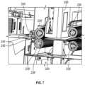
- the rolls of filmmay not be perfectly straight on their side edge and, thus, as the roll of film rotates on the support roller, the film may come off at different lateral angles leading to a nip (e.g., defined by a drive roller and a pinch roller).
- various components of the sealing apparatusmay be positioned and/or designed to operate at a specific lateral position on the film path.
- a piercermay be positioned to pierce the film at a desired lateral position.
- a printermay be configured to print onto the film at a desired lateral position. If the film comes off the roll of film at an undesirable angle, it could be out of alignment with such components—providing for various inconsistencies (e.g., the film being printed and/or pierced in the wrong place).
- the support rollermay include an edge shuttle that translates laterally along the axis of the support roller. The edge shuttle may have an engagement feature that interacts with one or more edges of the roll of film.
- a biasing elementmay bias the edge shuttle toward the center of the support roller to cause repositioning of the roll of film on the support roller as it rotates—thereby maintaining lateral alignment of the film as it is pulled from the roll of film.
- the roll of film installed in the sealing apparatusmay have a radio frequency identification (RFID) tag associated therewith (such as attached to a core of the roll of film).
- RFIDradio frequency identification
- the sealing apparatusmay include an RFID read/write system that is configured to read from and write to the RFID tag of the installed roll of film.
- the sealing apparatusmay write to the RFID tag the current estimated amount of film remaining on the roll of film—thereby keeping an updated amount of film remaining with the roll. In that way, if the roll of film is moved to a new sealing apparatus or re-installed (such as after swapping it out with a different roll of film—perhaps for a different product), then the sealing apparatus could read the amount of film remaining for the roll and could keep track accordingly.
- the RFID tag of the installed roll of filmmay include identification data that enables identification of the film by the sealing apparatus.
- Such example embodimentsmay be used to control operation of the sealing apparatus, such as by enabling and/or disabling various features/components of the sealing apparatus. Such functionality may help ensure that proper sealing of the containers is occurring.
- a container presence sensormay be employed proximate the aperture that receives the top portion of the container being sealed.
- the container presence sensormay be configured to sense the presence of the container and stop or prevent advancement of the film into a loading zone.
- the filmmay jam or bunch, thereby creating a maintenance issue and wasting film—and likely frustrating the user.
- less than the planned amount of filmmay be brought into the sealing volume and, thus, an improper seal may be formed—which may waste the film and/or create an undesirable situation for a user that is planning on having a proper seal for the container.
- the advancement of filmcan be stopped or prevented and a corresponding error message may be presented to the user so that they can remove the container from the aperture to allow complete advancement of the film into the loading zone—thereby enabling a proper seal to be formed when the user subsequently moves the container into the sealing volume through the aperture.
- an apparatus for securing a film to a containercomprises a body portion to house film and a sealing portion comprising a sealing volume for receiving a top portion of the container and a plurality of near-infrared light emitting diodes (NIR LEDs) positioned within the sealing volume so as to at least partially surround the top portion of the container when the top portion of the container is positioned within the sealing volume.
- the sealing portionfurther comprises a sensor configured to sense when the top portion of the container is at least partially positioned within the sealing volume.
- the sealing portionfurther comprises a loading zone sized to receive a portion of film from the body portion and position the portion of the film for insertion into the sealing volume with the top portion of the container.
- the apparatusincludes a controller configured to receive sensor input from the sensor indicating that the top portion of the container is at least partially positioned within the sealing volume; and cause, in response thereto, activation of at least one of the plurality of NIR LEDs to secure the portion of the film to the top portion of the container.
- the second set of corner NIR LEDsis positioned within the sealing volume proximate at least one corner of the portion of the film.
- the controlleris configured to operate the at least one of the plurality of NIR LEDs for a sealing cycle to secure the portion of film to the top portion of the container.
- the controlleris configured to operate the first set of edge NIR LEDs differently than the second set of corner NIR LEDs.
- the controlleris configured to operate the second set of corner NIR LEDs to provide a greater amount of energy to the portion of the film than the first set of edge NIR LEDs so as to provide increased energy to the corners of the portion of the film to encourage increased film shrinking at the corners of the portion of the film.
- the top portion of the containerdefines a plane corresponding to a container lip.
- the at least one of the plurality of NIR LEDscomprise at least a first set of NIR LEDs and a second set of NIR LEDs.
- the first set of NIR LEDsis positioned within the sealing volume at a first vertical position corresponding to the plane corresponding to the container lip when the top portion of the container is positioned within the sealing volume.
- the second set of NIR LEDsis positioned within the sealing volume at a second vertical position. The second vertical position is below the first vertical position.
- the controlleris configured to operate the plurality of NIR LEDs for a sealing cycle to secure the portion of film to the top portion of the container.
- the controlleris configured to operate the first set of NIR LEDs differently than the second set of NIR LEDs. In some embodiments, during the sealing cycle, the controller is configured to operate the second set of NIR LEDs to provide a greater amount of energy to the portion of the film than the first set of NIR LEDs so as to provide increased energy below the container lip to encourage increased film shrinking below the container lip. In some embodiments, the controller is configured to operate the second set of NIR LEDs for a greater amount of time of operation or at a greater power output than the first set of NIR LEDS.
- the controlleris configured to operate the at least one of the plurality of NIR LEDs according to one of a plurality of operation profiles during a sealing cycle to secure the portion of film to the top portion of the container.
- the plurality of operation profilesinclude at least a first operation profile and a second operation profile.
- An operation characteristic of the first operation profileis different than the second operation profile.
- the operation characteristicis at least one of an amount of time of operation of one or more of the plurality of NIR LEDs or a power output of the one or more of the plurality of NIR LEDs.
- an identification sensoris configured to sense identification data associated with the film housed in the body portion.
- the controlleris configured to determine, based on the identification data, to operate the at least one of the plurality of NIR LEDs according to the first operation profile during the sealing cycle.
- a user interfaceis configured to receive user input.
- the controlleris configured to determine, based on the user input, to operate the at least one of the plurality of NIR LEDs according to the first operation profile during the sealing cycle.
- the at least one of the plurality of NIR LEDscomprise at least a first set of NIR LEDs and a second set of NIR LEDs.
- the first set of NIR LEDsis mounted to a first printed circuit board.
- the second set of NIR LEDsis mounted to a second printed circuit board.
- the first printed circuit boardincludes a first thermistor configured to measure temperature corresponding to operation of the first set of NIR LEDs.
- the second printed circuit boardincludes a second thermistor configured to measure temperature corresponding to operation of the second set of NIR LEDs.
- each of the plurality of NIR LEDsoperates at a wavelength ranging from 0.75 ⁇ m-1.4 ⁇ m.
- the body portioncomprises a support roller configured to hold a roll of film thereon.
- the support rollercomprises a spindle configured to rotate about an axis.
- the spindlecomprises a contact portion that is configured to contact an outer circumferential surface of the roll of film.
- the support rollerfurther comprises an edge shuttle configured to translate along the axis between a first position and a second position.
- the edge shuttledefines an engagement feature configured to interact with an edge of the roll of film.
- a biasing elementis configured to bias the edge shuttle toward a center of the support roller.
- a sealing portionsecuring a film to a container.
- the sealing portioncomprises a sealing volume for receiving a top portion of the container and a plurality of near-infrared light emitting diodes (NIR LEDs) positioned within the sealing volume so as at least partially surround the top portion of the container when the top portion of the container is positioned within the sealing volume.
- the sealing portionfurther includes a sensor configured to sense when the top portion of the container is at least partially positioned within the sealing volume and a loading zone sized to receive a portion of film from the body portion and position the portion of the film for insertion into the sealing volume with the top portion of the container.
- NIR LEDsnear-infrared light emitting diodes
- a method for securing a film to a containercomprises providing an apparatus comprising a body portion to house film and a sealing portion.
- the sealing portioncomprises a sealing volume for receiving a top portion of the container and a plurality of near-infrared light emitting diodes (NIR LEDs) positioned within the sealing volume so as to at least partially surround the top portion of the container when the top portion of the container is positioned within the sealing volume.
- the sealing portionfurther includes a sensor configured to sense when the top portion of the container is at least partially positioned within the sealing volume and a loading zone sized to receive a portion of film from the body portion and position the portion of the film for insertion into the sealing volume with the top portion of the container.
- the apparatusfurther includes a controller.
- the methodfurther includes receiving sensor input indicating that the top portion of the container is at least partially positioned within the sealing volume; and causing, in response thereto, activation of at least one of the plurality of NIR LEDs to secure the portion of the film to the top portion of the container.
- an apparatus for securing a film to a containercomprises a body portion to house a roll of film.
- the body portioncomprises a support roller configured to support the roll of film thereon.
- the support rollercomprises a spindle configured to rotate about an axis.
- the spindlecomprises a contact portion that is configured to contact an outer circumferential surface of the roll of film.
- the support rollerfurther includes an edge shuttle configured to translate along the axis between a first position and a second position.
- the edge shuttledefines an engagement feature configured to interact with an edge of the roll of film.
- the support rollerfurther includes a biasing element configured to bias the edge shuttle along the axis toward a center of the support roller.
- the apparatusfurther includes a drive roller and a pinch roller, wherein the drive roller and the pinch roller define a nip that is configured to receive the film from the roll of film therethrough.
- the apparatusfurther includes a motor configured to, when operated, drive the drive roller to cause translation of the film along a film path toward a loading zone.
- the apparatusfurther includes a sealing portion comprising a sealing volume for receiving a top portion of the container, one or more energy emitting elements, a sensor configured to sense when the top portion of the container is at least partially positioned within the sealing volume, and the loading zone sized to receive a portion of the film from the body portion and position the portion of the film for insertion into the sealing volume with the top portion of the container.
- the apparatusfurther includes a controller configured to receive sensor input from the sensor indicating that the top portion of the container is at least partially positioned within the sealing volume and cause, in response thereto, activation of the one or more energy emitting elements to secure the portion of the film to the top portion of the container.
- the filmwhen the motor is operated and the film is positioned within the nip, the film is pulled off the roll of film supported by the support roller and the roll of film rotates such that a different portion of the outer circumferential surface of the roll of film contacts the contact surface of the spindle.
- the edge shuttleis configured to redirect the edge of the roll of film as the roll of film rotates to align the film with the film path.
- a pierceris configured to pierce a hole into the film as the film is positioned along the film path. The piercer is in a fixed lateral position with respect to the film path.
- the edge shuttleis configured to align the film with the film path to ensure that the hole is formed in a desired hole position on the portion of the film that forms a seal with the top portion of the container.
- a printeris configured to print onto the film as the film is positioned along the film path.
- the edge shuttleis configured to align the film with the film path to ensure that printed information is printed in a desired printed position on the portion of the film that forms a seal with the top portion of the container.
- the edge shuttleis configured to align the film with the film path to ensure that the film is aligned with a piercer for piercing a hole into the film, a printer for printing onto the film, a cutter for cutting the portion of the film, and the loading zone for receiving the portion of the film.
- the engagement featuredefines a flange that extends radially away from the axis.
- the engagement featuredefines a tapered surface, wherein a slope of the tapered surface leads toward the center of the roll of film to utilize gravity to aid in redirecting the edge of the roll of film.
- the edge shuttledefines a first edge shuttle and the edge of the roll of film defines a first edge of the roll of film, wherein the biasing element defines a first biasing element.
- the support rollerfurther comprises a second edge shuttle configured to translate along the axis, wherein the second edge shuttle defines a second engagement feature configured to interact with a second edge of the roll of film. The second edge is opposite the first edge of the roll of film.
- the support rollerfurther includes a second biasing element configured to bias the second edge shuttle along the axis toward the center of the roll of film.
- the edge shuttleis configured to freely rotate with respect to the spindle.
- the motorcomprises at least one motor that is configured to operate to drive rotation of the drive roller and the support roller.
- the drive rollerdefines a smaller diameter than the support roller such that the drive roller operates with a faster rate of turn than the support roller so as to cause tension in the film being pulled along the film path.
- the motoris further configured to operate to drive rotation of the spindle.
- the pinch rolleris configured to move between an engaged position with the drive roller to form the nip and an unengaged position spaced therefrom.
- the body portioncomprises a cover that is configured to move between an open position and a closed position. When the cover moves to the open position, the pinch roller is configured to automatically move to the unengaged position so as to enable loading of film onto the drive roller.
- a support rollerconfigured to support a roll of film thereon for use in securing film from the roll of film to a container.
- the support rollercomprises a spindle configured to rotate about an axis, wherein the spindle comprises a contact portion that is configured to contact an outer circumferential surface of the roll of film.
- the support rollerfurther comprises an edge shuttle configured to translate along the axis between a first position and a second position.
- the edge shuttledefines an engagement feature configured to interact with an edge of the roll of film.
- the support rollerfurther includes a biasing element configured to bias the edge shuttle along the axis toward a center of the support roller.
- the engagement featuredefines a flange that extends radially away from the axis.
- the engagement featuredefines a tapered surface, wherein a slope of the tapered surface leads toward the center of the support roller to utilize gravity to aid in redirecting the edge of the roll of film.
- the edge shuttledefines a first edge shuttle and the edge of the roll of film defines a first edge of the roll of film.
- the biasing elementdefines a first biasing element.
- the support rollerfurther comprises a second edge shuttle configured to translate along the axis.
- the second edge shuttledefines a second engagement feature configured to interact with a second edge of the roll of film.
- the second edgeis opposite the first edge of the roll of film.
- the support rollerfurther includes a second biasing element configured to bias the second edge shuttle along the axis toward the center of the support roller.
- an apparatus for securing a film to a containercomprises a body portion to house a roll of film, wherein the roll of film comprises a radio frequency identification (RFID) tag.
- RFID tagincludes supply data comprising a remaining amount of supply of the roll of film.
- the apparatusfurther includes a drive roller and a pinch roller, wherein the drive roller and the pinch roller define a nip that is configured to receive the film from the roll of film therethrough.
- the apparatusfurther includes a motor configured to, when operated, drive the drive roller to cause translation of the film along a film path toward a loading zone.
- the apparatusfurther includes an RFID read/write system configured to read the supply data from the RFID tag when the roll of film is housed in the body portion.
- the apparatusfurther includes a sealing portion comprising a sealing volume for receiving a top portion of the container, one or more energy emitting elements, a sensor configured to sense when the top portion of the container is at least partially positioned within the sealing volume, and the loading zone sized to receive a portion of the film from the body portion and position the portion of the film for insertion into the sealing volume with the top portion of the container.
- the apparatusfurther includes a controller configured to: operate the motor to cause advancement of the portion of the film into the loading zone; determine an updated remaining amount of supply on the roll of film; and cause the RFID read/write system to update the supply data on the RFID tag of the roll of film with the updated remaining amount of supply on the roll of film.
- the RFID tagincludes film identification data.
- the controlleris further configured to receive, via the RFID read/write system, the identification data corresponding to an installed roll of film; and cause, based on the identification data, at least one of enabling operation of one or more components of the apparatus, disabling operation of the one or more components of the apparatus, or revised operation of the one or more components of the apparatus.
- an apparatus for securing a film to a containercomprises a body portion to house a roll of film, a drive roller, and a pinch roller.
- the drive roller and the pinch rollerdefine a nip that is configured to receive the film from the roll of film therethrough.
- the apparatusfurther includes a motor configured to, when operated, drive the drive roller to cause translation of the film along a film path toward a loading zone.
- the apparatusfurther includes a sealing portion comprising a sealing volume for receiving a top portion of the container, one or more energy emitting elements, and the loading zone sized to receive a portion of the film from the body portion and position the portion of the film for insertion into the sealing volume with the top portion of the container.
- the apparatusfurther includes a container presence sensor positioned within or below the aperture or the sealing volume and configured to sense presence of the container.
- the apparatusfurther includes a controller configured to receive sensor input from the container presence sensor indicating the presence of the container proximate the aperture; and cause, in response thereto, at least one of cessation or prevention of operation of the motor to prevent further advancement of the film into the loading zone while the container is proximate the aperture.
- the container presence sensoris a first sensor.
- the sealing portioncomprises a second sensor configured to sense when the top portion of the container is at least partially positioned within the sealing volume.
- the controlleris further configured to receive sensor input from the second sensor indicating that the top portion of the container is at least partially positioned within the sealing volume; and cause, in response thereto, activation of the one or more energy emitting elements to secure the portion of the film to the top portion of the container.
- the container presence sensorcomprises a break beam sensor.
- the container presence sensorcomprises a reflection sensor.
- the container presence sensorcomprises a light curtain sensor.
- Some additional embodimentsinclude apparatuses, systems, and methods including various example embodiments, such as described herein.
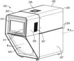
- FIG. 1is a top perspective view of an example sealing apparatus, in accordance with some embodiments described herein.
- FIG. 2is a bottom perspective view of the example sealing apparatus shown in FIG. 1 , in accordance with some embodiments described herein.
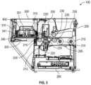
- FIG. 3is a cross-sectional side view of the example sealing apparatus shown in FIG. 1 taken along line A-A, in accordance with some embodiments described herein.
- FIG. 4is a cross-sectional side view of the example sealing apparatus shown in FIG. 1 taken along line A-A, wherein a roll of film is installed within the sealing apparatus and a portion of the film is ready for sealing, in accordance with some embodiments described herein.
- FIG. 5is a side view of the example sealing apparatus shown in FIG. 1 with a body cover in an opened position, wherein an arm is also in the opened position, in accordance with some embodiments described herein.
- FIG. 6is a close-up view of a roll of film loaded into the example sealing apparatus of FIG. 1 , in accordance with some embodiments described herein.
- FIG. 7is a close-up view of a portion of the example sealing apparatus shown in FIG. 1 , wherein example nips are shown, in accordance with some embodiments described herein.
- FIG. 8is a top view of an example sealed container with a customized message printed on the lid, in accordance with some embodiments described herein
- FIG. 9is a top view of a portion of an example film usable with the example sealing apparatus shown in FIG. 1 , in accordance with some embodiments described herein.
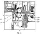
- FIG. 10is a close-up view of another portion of the example sealing apparatus shown in FIG. 1 , wherein a cutter is shown, in accordance with some embodiments described herein.
- FIG. 11is a close-up of a cross-sectional view of the example sealing apparatus shown in FIG. 1 , where the sealing volume and a plurality of near-infrared light emitting diodes (NIR LEDs) are shown, in accordance with some embodiments described herein.
- NIR LEDsnear-infrared light emitting diodes
- FIG. 11 Ais a close-up of a cross-sectional view of another example sealing apparatus, where the plurality of NIR LEDs are positioned to face downwardly into the sealing volume to cause securing of the film to the top portion of a container placed into the sealing volume, in accordance with some embodiments described herein.
- FIG. 12 Ais a cross-sectional side view of the example sealing apparatus, wherein a container is positioned below an aperture and ready for sealing, in accordance with some embodiments described herein.
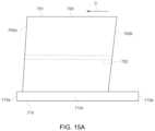
- FIG. 15 Billustrates the schematic of FIG. 14 B , where the lopsided roll of film has now rotated on the support roller and film therefrom is being fed along the film path within the example sealing apparatus, in accordance with some embodiments described herein.
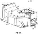
- FIG. 19 Ashows a front, right side perspective view of an example securing assembly, in accordance with some embodiments described herein.
- FIG. 19 Bshows a rear, left side perspective view of the example securing assembly, in accordance with some embodiments described herein.
- FIG. 20 Bis a top view of the portion of the securing assembly shown in FIG. 19 A , illustrating an example circular shape of the sealing volume, in accordance with some embodiments described herein.
- FIG. 21 Aillustrates the portion of the securing assembly shown in FIG. 20 B along with a portion of the film and a circular shape corresponding to the shape of a top portion of a container to be sealed, all separated for explanatory purposes, in accordance with some embodiments described herein.
- FIG. 21 Billustrates the portion of the securing assembly shown in FIG. 20 B along with a portion of the film and a circular shape corresponding to the shape of a top portion of a container to be sealed, all stacked together for explanatory purposes, in accordance with some embodiments described herein.
- FIG. 22is a bottom perspective view of a portion of the securing assembly illustrating different rows of NIR LEDs, in accordance with some embodiments described herein.
- FIG. 22 Ashows two sets of corner NIR LEDs and a set of edge NIR LEDs for a sealing volume, in accordance with some embodiments described herein.
- FIG. 23shows a block diagram of an example system utilizing an example sealing apparatus, in accordance with some embodiments described herein.
- FIG. 25illustrates a flowchart of an example method for preventing a feeding error within an example sealing apparatus, in accordance with some embodiments described herein.
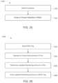
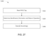
- FIG. 27illustrates a flowchart of an example method for operating an example sealing apparatus utilizing an RFID tag associated with an installed roll of film, in accordance with some embodiments described herein.
- an example sealing apparatus 100may include a body portion 200 and a sealing portion 300 .
- the body portion 200may include a body housing 204 that includes a body base 207 and a body cover 205 , and any other suitable structure to contain the various components therein.
- the body cover 205may be coupled to the body base 207 , for example pivotably coupled by a hinge, screws, positioning, or other coupling devices, and additionally or alternatively, by friction and/or gravity alone.
- the body housing 204may improve the usability, safety, aesthetics, and other properties of the apparatus 100 .
- the body housing 204can improve usability by reducing the amount of debris that enters the body portion 200 .
- the body housing 204can contribute to the safe operation of the apparatus, such as by reducing the likelihood of bodily contact with internal components.
- the body housing 204can be sized and/or shaped to accommodate a roll of film to be used for securement to containers.
- the body portion 200may contain one or more components of the sealing apparatus 100 , such as described herein.
- a plug 209 and corresponding electrical cordmay extend out from the body portion 200 and may enable obtaining access to an external power supply (e.g., plug into an external power outlet).
- the sealing portion 300may also contain one or more components of the apparatus 100 , such as described herein.
- the sealing portion 300may define a shaped housing 305 that may, for example, define a container receiving volume 329 .
- the container receiving volume 329may be sized to encourage positioning of a container, such as for insertion into an aperture 325 defined into the sealing portion 300 (shown in FIG. 2 ).
- one or more indicators 327may be utilized to provide instructions or indications of where to position the container or maneuver the container to cause initiate of forming a seal thereto.
- the sealing portion 300may also comprise a container presence sensor 390 , such as formed by a transmitter 391 and receiver 392 .
- the container presence sensor 390may be configured to sense the presence or absence of a container and may be positioned proximate (e.g., just below or within) the aperture 325 .
- the apparatus 100may be configured to receive inputs and commands. Such inputs and commands can be effectuated by way of a user interface operatively coupled with the apparatus. Alternatively or additionally thereto, the apparatus can be configured to receive inputs and commands remotely or wirelessly from a user and/or remote electronic devices.
- the sealing portion 300includes a user interface 310 to receive inputs and commands from a user and/or provide information to the user.
- the user interface 310can include a display 311 that may, for example, be a touchscreen display that enables receipt of user input.
- the user interface 310may be formed by one or more other interfaces, such as one or more light emitting diodes, a light, a rotating indicator, sound device, an actuating indicator, a smart device, push button, a lever, a dial, a virtual input on a graphical user interface, or the like.
- the user interface 310may provide various information to a user.
- the user interface 310can indicate the status or mode of the apparatus 100 .
- the user interface 310can indicate that the apparatus 100 is in a ready state, a securing state, a preparing state, or another state.
- the user interface 310can indicate how many cycles the apparatus has performed since reset, the status of adjustable settings, repair information, a warning such as to replace a roll of film therein, ink levels, an error message, and/or other information about the apparatus, as desired.
- the user interface 310can indicate completion of a sealing cycle.
- the user interface 310may be configured to display and receive user input, such as one or more user selections.
- a usermay be able to select and/or provide instructions for the apparatus 100 .
- the user interfacemay display printing options for a user to select from for printing on the film (such as with a printer—such as described herein).
- the usermay enter a desired message for printing on the film.
- the resulting sealed lidthen includes the user selected message and/or image.
- the usermay select a desired product that is within the container being sealed. Such a selection may lead to certain operation parameters being applied to the next sealing cycle—such as for use in sealing the corresponding container.
- a pierced hole in the seale.g., for a straw
- the apparatus 100may utilize a piercer to pierce such a hole in the film for use in sealing the container with the cold beverage contained therein.
- Such instructioncould be provided through the user interface 310 and/or could be automatically applied (e.g., based on identification of the film, based on selection of a beverage profile, based on the last sealing cycle, etc.).
- the apparatus 100further includes at least one controller 30 (shown in FIG. 23 ) that may be positioned therein and/or be configured to cooperate with an external computer or device.
- the controller 30can be configured to control operation of the apparatus 100 and/or various components thereof.
- the controller 30may communicate with the user interface 310 such as to receive user input and/or cause presentation of information to the user.
- the apparatus 100may include a heat management system, such as within the sealing portion 300 and/or body portion 200 .
- the housing 305 of the sealing portion 300may include one or more vents 307 for enabling air flow between the inside of the housing 305 and the external environment—such as for managing heat within the housing 305 .
- the body housing 204 of the body portion 200may include one or more vents.
- FIG. 3is a cross-sectional side view of the apparatus 100 , in accordance with the disclosed subject matter.
- the sealing portion 300can be positioned at a front of the apparatus 100 and adjacent to the body portion 200 .
- the body portion 200can be positioned at the back of the apparatus.
- the body portion 200can house a supply of film therein, such as a roll of film 500 , that can feed into the sealing portion 300 (e.g., along the film path 211 ).
- the body cover 205may be opened (e.g., with respect to the body base 207 ) to enable removal and/or installation of a roll of film 500 .
- the roll of film 500can be positioned on one or more support rollers 210 , 215 .
- An arm 255 that includes a pinch roller 230may be lifted to cause the pinch roller 230 to move from an engaged position (forming a nip 236 with the drive roller 235 ) to an unengaged position spaced therefrom—enabling feeding of a leading edge of film from the roll of film 500 along the film path 211 .
- a usermay pull the film off the roll of film 500 and position it at least over a drive roller 235 .
- closing of the arm 255will cause the pinch roller 230 to sandwich the film between itself and the drive roller 235 —which together form the nip 236 (shown in FIG. 4 ).
- a motor 213may operate to cause the roll of film to rotate and/or the film to be pulled off the roll of film 500 and translated along the film path 211 .
- the arm 255may be attached (e.g., through an attachment feature 256 ) to the body cover 204 such that moving the body cover 204 to the open position will cause the arm 255 to also move to the open position.
- the body portion 200may comprise various components, including for example a first support roller 210 and a second support roller 215 , a first pinch roller 230 and a first drive roller 235 (defining a first nip 236 when contacting each other), a piercer 220 with a piercing tip 225 , a printer 250 , a second pinch roller 230 ′ and a second drive roller 235 ′ (defining a second nip 236 ′), a motor 213 (such as for operating the first drive roller 235 , the second drive roller 235 ′, and/or the first support roller 210 ), a cutter 214 , one or more film sensors 240 , an RFID read/write system 595 , and one or more controllers 260 .
- a first support roller 210 and a second support roller 215defining a first nip 236 when contacting each other
- a piercer 220 with a piercing tip 225defining a first nip
- any of the featurescan be located in any other suitable location.
- at least one of the piercer 220 , the printer 250 , the second nip 236 ′, and the film sensor 240can be located in the sealing portion 300 .
- an installed roll of film 500may rest on a first support roller 210 and second support roller 215 . That is, the roll of film 500 can rest between the first support roller 210 and the second support roller 215 and be capable of rotation with respect thereto (although other forms of holding the roll of film are contemplated herein, such as with a roll holder). As shown in FIG. 6 , the first and second support rollers 210 , 215 can support the roll from underneath.
- one or both of the film support rollers 210 , 215is rotated, such as via operation of the motor 213 (e.g., through a belt connection or other drive means, such as a gear). As such, the rotation of one or both of the support rollers 210 , 215 may impart rotation to the supported roll of film. Additionally or alternatively, force applied to the leading portion of the film 501 by the first nip 236 and/or second nip 236 ′ may cause the film to be pulled off the roll of film 500 —which may impart rotation of the roll of film 500 .
- one or more of the nips 236 , 236 ′may be configured to impart a translating film speed faster than a speed of rotation of the roll of film so as to cause tension in the film being translated through the film path 211 .
- the motor 213may be configured to cause rotation of the first drive roller 235 , the second drive roller 235 ′, and the first support roller 210 . In some such embodiments, the motor 213 may impart the same speed of rotation on each the rollers.
- first drive roller 235 and/or the second drive roller 236may have a smaller diameter than the first support roller 210 such that the there is tension created along the film path 211 —such as because the first drive roller 235 and/or the second drive roller 235 ′ are operating with a faster rate of turn to pull on the film at a faster rate than the support roller 210 forces rotation of the roll of film 500 positioned thereon.
- one or both of the film support rollers 210 , 215is capable of passively rotating, such as with non-negligible resistance. In those embodiments, rotation of the roll of film imparts a rotational force on those such support rollers 210 , 215 . In still other embodiments, one or both of the support rollers 210 , 215 can be prevented from rotating. In such embodiments, lack of rotation causes slippage to occur between one or both of the support rollers 210 , 215 and the roll of film 500 , imparting rotational resistance to the roll of film, thereby imparting tension in the film between the roll of film and the drive rollers 235 , 235 ′.
- the controlleris configured to operate the motor to cause a different rotation speed to one or more of the drive rollers 235 , 235 ′ in comparison to one or more support rollers 210 , 215 for the supply of film so as to form tension in the film (which may aid with piercing and/or printing of the film).
- the one or more support rollersare depicted upstream from the sealing portion 300 , the one or more support rollers can be positioned at any suitable location along the film path 211 .
- At least one of the first drive roller 235 , the second drive roller 235 ′, and the first support roller 210can be mechanically rotated (e.g., via a crank mechanism, a rotational driver, a drive shaft, a drive belt, a drive chain, or any other means of imparting rotational force).
- the first drive roller 235 , the second drive roller 235 ′, and the first support roller 210can be driven together by the motor 213 , such as via one or more gears or one or more drive belts.
- the first pinch roller 230 and the second pinch roller 230 ′can freely rotate in response to a torque (although in some embodiments, one or more pinch rollers may be driven, such as by one or more motors). For example, torque could be applied by friction between the pinch rollers 230 , 230 ′ and the respective rotating drive rollers 235 , 235 ′, or by friction between the pinch rollers 230 , 230 ′ and the film 501 .
- torquecould be applied by friction between the pinch rollers 230 , 230 ′ and the respective rotating drive rollers 235 , 235 ′, or by friction between the pinch rollers 230 , 230 ′ and the film 501 .
- some of the depicted embodimentsshow a gap between the first pinch roller 230 and the first drive roller 235 , some embodiments may enable contact between the first pinch roller 230 and the first drive roller 235 .
- one or more drive or pinch rollersmay be replaced with other drive means, such as a conveyor belt, pull drives, tracks, among
- the apparatus 100may also include a printer 250 .
- the printer 250may be configured to print any suitable information (e.g., messages or images) on the film 501 , such as the type of drink or product (or symbol or emoji thereof) disposed within the container (e.g., an example image (e.g., COLA 459 ) is shown printed on the sealed lid 460 in FIG. 8 ).
- the printer 250can be any suitable type of printer to provide information on film 501 .
- the printercan utilize laser printing, ink jet printing, laser etching, or any other type of printing suitable for film 501 .
- the printer 250can be used to print the same message on film 501 during multiple sealing cycles. Additionally or alternatively, printer 250 can be used to print a message on film 501 depending on an input.
- the apparatus 100can further comprise a controller 30 to receive at least one command.
- the controller 30can be operatively coupled with the apparatus (e.g., controller 260 ). Accordingly, the controller 30 can send a signal to the printer 250 to print a determined message on film 501 associated with the at least one command when the at least one command is received.
- the messagecan indicate at least one of the type of contents secured within the container, a trademark, a safety message, or any other suitable message.
- the printercan be configured to receive commands through a network and wirelessly.
- the printer 250can be positioned at any suitable location within the apparatus and is not limited to placement within the body portion 200 .
- the printer 250may be positioned at a specific lateral position along the film path.
- the printer 250may be configured to print generally on a right half of the film as it passes along the film path 211 (although any lateral position is contemplated and, in some embodiments, the printer 250 may be movable laterally (or longitudinally) along the film path to enable printing anywhere on the film 501 ).
- the printer 250can be positioned in the sealing portion 300 .
- the printer 250can be positioned above the sealing volume 301 .
- the printercan be configured to print on film 501 shortly before securement, during securement, or shortly after securement.
- a shield plate of the sealing portionmay include a printing window through which printer 250 can print a message on film 501 .
- the controllermay be configured to print one or more messages or icons on the film based on input from an external device/network.
- the controllermay be in communication with a remote device/server and receive instructions or other data that may cause the controller to cause printing on the film, such as using the printer 250 .
- the sealing apparatus 100may be in communication with a point-of-sale (POS) system (e.g., the POS system 13 shown in FIG. 23 ).
- POS systemmay receive an order that may include one or more drink orders.
- the controller 30 of the sealing apparatus 10may be configured to receive data corresponding to the order and control its operations accordingly, such as by printing a label on the film to indicate the drink order (e.g., “Cola” or “Diet Cola”).
- the printed message or imagemay be customized, such as indicating the customer (e.g., “JOHN'S COLA” 459 in FIG. 8 ).
- the corresponding sealed lidmay include the appropriately printed data that can be used with fulfilling the order.
- the determination as to what to printmay occur remotely from the sealing apparatus 10 and communicated thereto, such as at the POS system 13 or some other remote system.
- FIG. 8An example customized lid 460 with a logo 458 and a printed customized message (“JOHN'S COLA”) 459 is shown in FIG. 8 .
- Example systems for use with a point-of-sale systemincluding example print determinations and data management, may be found in U.S. patent application Ser. No. 16/212,047, entitled “Personalized Food Service Material Printing Systems”, which published as U.S. Publication No. 2019/0180392, and which is owned by the Assignee of the present invention and incorporated by reference herein in its entirety.
- the sealing apparatus and/or the components thereofmay form part of a beverage forming apparatus or system.
- the beverage forming apparatus/systemmay create (e.g., mix, satisfy, dispense, form, etc.) a beverage order, such as pour a cup of soda, water, coffee, or juice, from one or more supplies.
- the beverage forming apparatus/systemmay employ various components/systems described herein (e.g., a sealing apparatus) in conjunction with creating the beverage such that the beverage is produced to a customer with a sealed lid.
- the sealed lidmay include one or more identifying messages or images appropriate for the created beverage.
- the controllermay be configured, such as in response to certain operation conditions, to have the printer print a specific code on the film to provide one or more indications to an operator, such as the position of a splice, an amount of film remaining in the supply, or other indication.
- the sealing devicemay alert the operator that a certain film and/or components within the sealing device may be non-functional (e.g., due to presence of splice).
- the operatormay be alerted that the sealing apparatus may need a replacement supply of film (e.g., due to an indication of a low amount of film supply remaining).
- the apparatus 100may also include a piercer 220 configured to pierce one or more holes in the film 501 —such as to create a ventilation hole and/or straw hole for the sealed lid.
- Example holes 457 formed in a sealed lid 460are shown in FIG. 8 .
- the apparatus 100may include a piercer 220 having one or more protrusions 225 (e.g., tips, blades, etc.).
- the piercer and the protrusionsare monolithic such that the piercer is actuatable.
- Piercers without protrusionscan include, for example, air jets, lasers, blast heaters, or any other suitable piercer.
- the piercer 220may be configured with two or more spaced apart protrusions (e.g., tips, blades, etc.).
- the piercer 220can be positioned at any suitable location in the apparatus including being positioned in the sealing portion 300 .
- the piercer 220may be positioned at a specific lateral position along the film path.
- the piercer 220may be configured to pierce the film generally in the center (laterally) of the film as it passes along the film path 211 (although any lateral position is contemplated).
- the piercer 220can be positioned in the sealing portion 300 .
- the piercercan be configured to pierce film 501 shortly before securement, during securement, or shortly after securement.
- the piercer 220includes a piercing rod coupled to the piercing tip 225 , wherein the piercing rod is coaxial with and movable with respect to the guide rod of the securing assembly 400 .
- a controllermay be configured to cause actuation of the piercer 220 to cause the perforations or slits to be created in the film, such as it travels along the film path 211 .
- the controllermay be configured to control the relative position of the perforations or slits on the lid, such as based on a desired operational parameter for the anticipated product or the utilized film.
- the controller 30may be configured to determine whether to apply the piercer to the film or not based on user input provided. For example, if a user indicates that the contents of the container are hot, then the controller 30 may operate the piercer to provide the corresponding ventilation holes.
- the apparatus 100may also include one or more film sensors 240 configured to detect one or more indicators on the film 501 , such as to determine a distance of travel of the film on the film path 211 .
- the film sensor 240can comprise a film signal emitter 241 and a film signal sensor 242 to detect a film sensor window 510 passing therebetween (although other types of sensors are contemplated).
- An example sensor window 510is shown in FIG. 9 .
- the film sensor window 510 positioningcan directly correspond to the position of the film as moved past the second nip 236 ′.
- the film signal emitter 241can continuously emit a light signal capable of being detected by the film signal sensor 242 .
- Film 501can be positioned between the film signal emitter 241 and the film signal sensor 242 , such that opaque portions of the film 501 block the light signal where opaque.
- the film sensor 240detects a change of the film, such as when detecting a transparent portion/window of the film or a film sensor window 510 , the film sensor 240 can send a signal input indicating that the continuous emission of the signal emitter has been disrupted. Accordingly, as the film 501 moves between the film signal emitter 241 and film signal sensor 242 , the film sensor window 510 can allow transmission of the light signal to the film signal sensor.
- the film signal sensorupon detecting the light signal or a change in the intensity of the light signal, can register that the film 501 has progressed upstream and generate a film sensor input.
- a reverse set upcan be provided. That is, the film can allow transmission of the light signal to the film signal sensor 242 until it is blocked or partially blocked by the film once the film has progressed.
- the film signal sensorupon detecting the reduction of the light signal, can register that the film has progressed and generate a film sensor input to deactivate the drive nip.
- the film sensor 240can be any sensor suitable for detecting the progression.
- the film sensor 240can include at least one of a light sensor as described, a mechanical sensor, a motion sensor, among others.
- a mechanical sensorcan include a rotational sensor that rotates by progression of the film and registers that the film has progressed upon such rotation.
- a mechanical sensorcan register a degree of progression by the amount of rotation.
- a rotational sensorcan be coupled to the pinch roller 230 to detect rotation thereof.
- the motor 213can be operated according to input from the film sensor 240 . That is, in response to film sensor inputs by the film sensor 240 , the drive rollers 235 , 235 ′ may have their rotation initiated, continued, or ceased. For example, after a sealing cycle, rotation of drive rollers 235 , 235 ′ can be initiated, film sensor 240 can detect progression of film 501 , and film sensor 240 can provide a film sensor input. In response to the film sensor input, rotation of drive rollers 235 , 235 ′ can be ceased.
- the apparatus 100may also include one or more cutters 214 (e.g., film cutters) configured to separate the film 501 (e.g., via one or more cuts), such as to a predetermined length of film (e.g., a portion of the film sized to fit within a loading zone 326 of the sealing portion 300 and designed to be sealed around the top portion of a container).
- a predetermined length of filme.g., a portion of the film sized to fit within a loading zone 326 of the sealing portion 300 and designed to be sealed around the top portion of a container.
- FIG. 10illustrates an example cutter 214 that includes driving mechanism 216 .
- the predetermined length of filmcan be sized to cover the top opening of a container to allow the film to be secured to the container for a suitable seal thereon.
- the film cutteris positioned along the film path 211 between the loading zone 326 and the second nip 236 ′ comprised of the second drive roller 235 ′ and the second pinch roller 230 ′.
- the film cuttercomprises at least one of a guillotine cutter and a shear cutter.
- the film cuttercan comprise any film separator suitable for separating portions of the film 501 or at least perforating the film to create segments of film.
- the film cuttercan include a rotary cutter, an air jet cutter, a laser cutter, a blast heater cutter, or any other suitable cutter, tear mechanism, or separator.
- a controllere.g., the controller 30
- controlmay be based on, for example, a measured distance of travel of the film along a film path 211 and may be based on data conveyed from the one or more film sensors 240 .
- the apparatus 100can be used in conjunction with any suitable type of film.
- the free ends of the filmchange shape and heat shrink about the top portion of the container, such as about a top portion 602 (e.g., a lip) of the container 600 , as shown in FIG. 12 A and further discussed herein.
- Suitable filmsinclude those that will shrink in the presence of heat or radiant energy.
- the filmcan be a plastic wrapping film which has the capability of shrinking when it is heated, and in some cases to near the melting point of the film.
- plastic resinssuch as polyvinyl chloride (PVC); polypropylene (PP); linear-low density polyethylene (LLDPE); low density polyethylene (LDPE); high density polyethylene (HDPE); copolymers of ethylene and vinyl acetate (EVA); copolymers of ethylene and vinyl alcohols (EVOH); ionomers (e.g., SURLYNTM, by E.I.
- the filmcan be a bi-axially oriented thin shrink film having a thickness of between 40 to 120 gauge (1.02 mm to 3.05 mm). In another embodiment, the film can be a bi-axially oriented thin shrink film having a thickness of between 60 to 100 gauge (1.52 mm to 2.54 mm).
- the filmcan further include at least one energy absorbing substance (e.g., a radiation-absorbing layer of ink) on at least part of the film.
- the one or more energy absorbing substancescan be pre-applied to the film, such as by printing, brushing, spray coating, electrostatic coating, electrodeposition coating, flow coating, roller coating, dip coating, among others. Additionally or alternatively, the substances can be incorporated into the film during formation or manufacture thereof. In other embodiments, the one or more substances can be printed onto the film during operation of the disclosed apparatus. Such substances can allow or enable shrinking of the film at the desired locations to create a suitable seal.
- a reduced amount or a lack of such substance in certain sections/positions of the portion of the filmmay lead to formation of a partial seal at such sections/position, which may, for example, be useful for enabling peeling back of the seal (e.g., for drinking and/or pouring).
- a pull-tabcould be designed into the seal for enabling easy lifting of that portion of the seal.
- corresponding instructions for lifting the pull-tabcould be provided on the film (and, thus, the seal).
- the filmcan be dimensioned to operate within the confines of the apparatus.
- the filmcan have a width dimension of between approximately 8 and approximately 30 cm.
- the filmcan be cut to a predetermined length dimension of between approximately 8 to approximately 30 cm.
- the width and lengths dimensions of the predetermined dimensioned filmcan be the same.
- the predetermined dimensioned filmcan be square, although other shapes are contemplated herein.
- the filmcan have a degree of elasticity. As such, when the film is secured to a top of the container and thereafter removed from the container, the removed film generally maintains its shape with respect to the heat shrunk edges, and the film can be reapplied to the top of the container for securement. In some embodiments, the film may be pre-printed prior to installation into the sealing apparatus.
- the sealing portion 300can be configured to enable securing of a portion of the film to a container to form a seal of the container.
- the sealing portion 300may comprise various components, including, for example, a loading zone 326 , a sealing volume 301 , and an aperture 325 .
- the sealing volume 301may be contained within a securing assembly 400 .
- the user interface 310(or portions thereof) may be housed in the sealing portion 300 . Although depicted and described as being in the sealing portion 300 , any of the features can be located in any other suitable location, such as within the body portion 200 .
- the loading zone 326may be sized to receive and hold a portion of the film that is prepared for use during the sealing process.
- FIG. 4illustrates an example portion of film 501 a that has been separated from the film using the cutter 214 and is waiting in the loading zone 326 for engagement with a top portion of a container (such as described herein).
- the sealing portion 300may include various features/structures to enable or encourage proper positioning of a portion of film 501 a within the loading zone 326 .
- the sealing portion 300may include an entry structure 270 positioned proximate the cutter 214 to aid in holding a side of the portion of the film 501 a to prevent it from falling through the aperture 325 .
- the other side of the portion of the film 501 amay be held up by one or more ribs 447 a - 447 d that are spaced apart from each other and positioned on the opposite side of the aperture 325 from the entry structure 270 .
- two or more of the ribs 447 a - 447 dmay define varying heights in order to promote stiffness of the portion of the film 501 a in the loading zone 326 so that the portion of the film 501 a is spread across the aperture 325 and ready for engagement with a top portion of the container so as to form a complete seal around the top portion of the container.
- the ribs 447 a - 447 dmay be designed to cause the portion of the film 501 a to maintain a profile that retains it within the loading zone 326 so that it doesn't fall through the aperture 325 and so that edges of the portion of the film 501 a extend over the top portion of the container so that the excess film over the edges of the top portion of the container can be secured around the top portion of the container to form the seal (e.g., when heated within the sealing volume 301 ).
- the one or more ribs 447 a - 447 dmay increase in height toward a lateral edge of the portion of the film 501 a , such as corresponding to the illustrated embodiment of FIG. 11 .
- the ribs 447 a - 447 dmay impart a desired curvature to the portion of the film 501 a that may promote stiffness.
- FIGS. 12 A- 12 Cshow the operation of the apparatus 100 with respect to a representative container 600 , such as a disposable beverage cup.
- FIG. 12 Adepicts a portion of film 501 a in the loading zone 326 in the sealing portion 300 in a position ready to be secured to a container 600 .
- a usermoves the container 600 up into the aperture 325 .
- the top portion 602 of the container 600pushes against (e.g., engages with) the portion of the film 501 a in the loading zone 326 as the top portion 602 of the container 600 moves upwardly and into contact with a shield plate 315 of the securing assembly 400 .
- the usercontinues to push the top portion 602 of the container 600 along with the portion of the film 501 a upwardly into the sealing volume 301 of the securing assembly 400 .
- the shield plate 315moves with the top portion 602 of the container into the sealing volume 301 .
- a sensor 421senses the presence of at least a portion of the container 600 within the sealing volume 301 and a sealing cycle is activated.
- the shield plate 315moves upwardly along with a shaft 429 , and once the shaft 429 and a corresponding sensor trigger 415 reaches a certain position, the sensor 421 senses the sensor trigger 415 as an indication that the at least a portion of the container 600 is within the sealing volume 301 .
- one or more energy-emitting (e.g., heating) elements 340are activated to cause the portion of the film 501 a to seal the top portion 602 of the container 600 .
- extra film from the portion of the film 501 amay hang over the top portion 602 (e.g., a lip) of the container 600 .
- the energy-emitting elements 340when activated, may cause the extra film to shrink around the top portion 602 of the container 600 to form the seal—such as shown in FIG. 12 B .
- the energy-emitting elementsmay be near-infrared light emitting diodes (NIR LEDs), although other energy-emitting elements may be utilized.
- NIR LEDsnear-infrared light emitting diodes
- FIG. 12 Cdepicts the film 501 a secured to the container 600 prior to the apparatus 100 feeding a next portion of film (from along the film path 211 ) into the loading zone 326 . That next portion of film may have been pierced, printed, and then may be cut—similar to or according to different operations—in conjunction with being fed into the loading zone 326 for the next sealing cycle.
- FIG. 11 Aillustrates another example securing assembly 400 ′ where the energy-emitting elements 340 ′ comprise a plurality of NIR LEDs that are mounted on a PCB 343 ′ that is positioned above the shield plate 315 at the top of the sealing volume 301 .
- the plurality of NIR LEDs 340 ′face downwardly and are positioned on the PCB 343 ′ in a circle so as to surround the top portion of the container when it is positioned within the sealing volume 301 (although other configurations are contemplated).
- One or more reflective elements 487may be positioned within the sealing volume 301 and configured to redirect energy emitted from the plurality of NIR LEDs toward the top portion of the container when it is placed therein. As shown, the reflective elements 487 may define an angled surface that reflects and redirects the energy (e.g., via a mirror, a polished surface, etc.). In this regard, any angle or varying angle of slope is contemplated.
- a barrier 488such as a glass barrier, may be positioned within the sealing volume 301 and above the aperture 325 , and configured to receive the shield plate 315 and/or top portion of the container therein.
- the barrier 488may provide protection to the sealing volume 301 and various components therein, such as from contents of the container that may splash or spill out.
- the barrier 488is stationary, whereas in other embodiments, the barrier may move, such as with the shield plate 315 .
- a similar barriermay be used in other embodiments described herein.
- a single large heat sink 341 ′can be provided opposite the plurality of NIR LEDs 340 ′ to gather heat generated by the apparatus and dissipate the heat based on air flow over the heat sink 341 ′.
- Such a single heat sink 341 ′allows for efficient heat management such as through size of the heat sink and the ability to direct air thereover.
- Some potential benefits of example embodiments like that shown in FIG. 11 Ainclude enabling increased air flow over the heat sink 341 ′, providing for more space for other components (e.g., the cutter), providing for ease of assembly and/or reduced part count. Further, utilizing reflective elements enables increased optimization for directing energy emitted from the NIR LEDs.
- a lens or collimating reflectormay be positioned between the NIR LEDs and the reflective element(s) to further direct the energy emitted from the NIR LEDs, such as prior to be redirected by the reflective element(s).
- the sealing volumemay be brought down around the top portion of the container.
- a usermay place the container on a surface and one or more components of the sealing volume may be brought down around the top portion of the container to begin the sealing cycle.
- one or more components of the apparatusmay be movable, such as with respect to other components and/or the container.
- the apparatus 100may be configured to automatically present the next portion of film within the loading zone 326 after completion of a sealing cycle.
- the apparatus 100may be configured to advance the film and perform various operations (e.g., piercing, printing, etc.) based on instructions provided and, in some such embodiments, may wait for such instructions to be provided (e.g., via the user interface 310 , controller 30 , and/or remotely) prior to performing the operations and advancing a portion of film into the loading zone 326 for use in a sealing cycle.
- the apparatus 100automatically advances the film and provides a next portion of film in the loading zone 326 for a next sealing cycle, there is a chance that a user may prematurely try to insert a container into the aperture 325 .
- the advancement of the film into the loading zone 326may be disrupted.
- the filmmay jam or bunch, thereby creating a maintenance issue and wasting film—and likely frustrating the user.
- the usermay cause some amount of the film to be brought into the sealing volume. This may cause the film to become wrinkled or bent.
- the sealing cyclemay be inadvertently triggered, causing a partial seal to be formed—which may waste the film and/or create an undesirable situation for a user that is planning on having a proper seal for the container.
- the apparatus 100may include a container presence sensor that is configured to sense the presence of the container and stop or prevent advancement of the film into a loading zone.
- the container presence sensormay be positioned proximate to the aperture 325 and sense the container as it is brought near or within the aperture 325 .
- the container presence sensormay be configured to transmit an indication to the controller 30 to indicate when the container presence sensor senses the container. Accordingly, the controller may receive the indication (e.g., sensor input) from the container presence sensor and cease or prevent advancement of the film into the loading zone—thereby avoiding or limiting the above indicated undesirable scenarios.
- container presence sensor 390is a break beam sensor
- other forms of sensorsare contemplated, such as a reflection sensor, a light curtain sensor, an infrared sensor, a mechanical switch sensor, etc.
- FIG. 14 Billustrates a schematic view of the roll of film 700 (broken line 700 d illustrates the front edge of the roll of film 700 ) installed on two support rollers 710 , 715 and a top layer of film 701 being pulled off (e.g., by force from two drive rollers 735 , 735 ′), such as similar to various embodiments described herein.
- the roll of film 700is generally positioned in the center of the support roller 710 between a first end 710 a and a second end 710 b .
- the film 701travels along a film path 711 (the bounds of a desired film path are illustrated by two bold dashed lines).
- such a scenariomay have a negative downstream effect on operation of the sealing apparatus.
- the film 701now has come at an angle into the first drive roller 735 and is generally skewed along the lateral axis LA as it travels through the sealing apparatus along the machine direction MD.
- a center 701 c ′ of the film 701is offset from the center 711 c of the desired film path 711 (as highlighted in 799 a ).
- the center 701 c of that film 701was aligned with the center 711 c of the desired film path 711 .
- a support roller for supporting the roll of film supplying the film to the apparatusmay be employed, where the support roller is designed to automatically cause alignment of the film laterally as it is pulled off the roll of film and translated along the film path within the file sealing apparatus.
- FIG. 16illustrates an example support roller 210 configured along these lines.
- the illustrated support roller 210is positioned to support a front portion of the roll of film 500 thereon, however, in some embodiments, the support roller 210 may be positioned to support another portion of the roll of film 500 .
- multiple support rollers 210can be employed, such as corresponding to the front and back portions of the roll of film 500 .
- the support roller 210may be driven by the motor 213 to aid in translating the film from the roll of film 500 along the film path 211 .
- the edge shuttles 280 a , 280 beach include a corresponding engagement feature 281 a , 281 b protruding radially and configured to interact with a corresponding edge of an installed roll of film.
- the engagement feature 281 ais a flange extending radially from the axis of rotation of the support roller (ASR).
- ASRaxis of rotation of the support roller
- the engagement feature 281 aincludes a tapered surface 283 leading from a top end 283 a downwardly to a bottom edge 283 b —where the slope of that tapered surface 283 generally leads toward a center 217 of the support roller 210 .
- that tapered surface 283may utilize gravity to aid in redirecting the side edge of the roll of film.
- the edge shuttle 280 a , 280 bmay be configured to not contact the outer circumferential surface of the roll of film.
- the contact surface 218 of the spindle 217may extend radially further away from the axis of rotation of the support roller ASR than a corresponding surface 288 of the edge shuttle 280 a (e.g., illustrated in FIG. 17 A ).
- the support roller 210further includes at least one biasing element (e.g., springs 285 a , 285 b , although other biasing elements are contemplated, such as an elastic band, magnets, etc.) corresponding to each edge shuttle 280 a , 280 b .
- the first spring 285 ais configured to provide a bias to the first edge shuttle 280 a to bias translation of the first edge shuttle 280 a toward the center 210 c of the support roller 210 .
- the edge shuttles 280 a , 280 bare configured to translate laterally along the spindle 217 (e.g., as illustrated by double arrow D).
- the spindle 217includes a stop feature 218 a that is configured to prevent translation of the first edge shuttle 280 a further toward the center 210 c of the support roller 210 (such as though interaction with a corresponding stop feature 284 a of the edge shuttle 280 a ).
- a misaligned roll of film 700may be installed on the support roller 210 .
- the support roller 210is configured to maintain alignment of the roll of film and the corresponding film pulled off the roll of film during operation of the motor (and the sealing apparatus 100 ).
- the support roller 210is configured to passively maintain such alignment (such as without utilizing control signals, etc.). Accordingly, as the roll of film rotates, the edge 700 a would come into contact with the engagement feature 281 a .
- the engagement feature 281 awill redirect the edge 700 a (e.g., along arrow E) into alignment so that the center of the roll of film 700 c is aligned with the center 210 c of the support roller 210 . Accordingly, even after 100-180 degrees of rotation (now with a new portion of the outer circumference of the roll of film 700 contacting the contact surface 218 of the support roller 210 ), the center 700 c of the roll of film 700 will be generally aligned with the center 210 c of the support roller 210 —thereby generally maintaining downstream alignment of the film 701 along the film path 211 .
- the piercer(which may be in a fixed lateral position) may form the pierced hole in a desired hole position on the film and the printer may print the printed information in a desired printed position on the film (ensuring that a resulting seal has the pierced hole and the printed information in the desired position).
- the cuttermay cut the film at a desired orientation/position.
- the floating nature of the edge shuttle 280 aenables passive alignment as it compensates for the variances in the relative position of the edge of the roll of film.
- the apparatus 100may include a securing assembly 400 , such as positioned within the sealing portion 300 (e.g., shown in FIGS. 3 - 4 ).
- a securing assembly 400is shown in FIGS. 19 A and 19 B .
- any such features/componentsmay be positioned separately and/or not form part of a securing assembly.
- the securing assembly 400includes a housing 425 .
- the housing 425may be shaped to contain (at least partially) one or more features/components of the securing assembly 400 . Further, the housing 425 may be shaped to provide one or more flow paths for air.
- the securing assembly 400may include an outlet 426 that includes fan 304 that may be configured to pull in air from inside the housing 425 (e.g., around the various heat sinks 341 and PCBs) for expulsion of the now heated air to an external environment (such as through a vent 307 shown in FIG. 1 ).
- the housing 425may include an inlet 427 that enables air from the external environment to enter into the housing 425 . In some embodiments, the direction of air flow may be switched.
- the securing assembly 400also includes a shield plate 315 that can move up and down within the housing 425 . As described herein, as the shield plate 315 moves upwardly, so does a shaft 429 and corresponding sensor trigger 415 . While some embodiments described herein detail that the shield plate 315 moves with the top portion of the container, in some embodiments, the shield plate 315 may be stationary. For example, the shield plate 315 may be positioned above the sealing volume 301 .
- the aperture 325may be sized to deflect corners of the portion of the film as the top portion of the container is pushed therethrough, such as to position the excess film around a top portion of the container for securement around the top portion (e.g., due to heat shrinking).
- the sensor trigger 415is operatively coupled to the shield plate 315 when the shield plate is embodied as a movable part.
- the sensor trigger 415can be sensed by the sensor 421 when the top portion of the container (and the shield plate) move to a certain position within the sealing volume—thereby indicating that it is appropriate to begin a sealing cycle.
- the sensor 421can be positioned within the apparatus to sense the presence of the container in the sealing volume 301 , such as beyond the aperture 325 .
- the illustrated sensor 421includes a signal emitter 423 and a signal sensor 422 .
- the sensor 421 positioningcan directly correspond to the position of the shield plate as moved by the container.
- the signal emitter 423can continuously emit a signal capable of being detected by the signal sensor 422 .
- the sensor trigger 415can be positioned between the signal emitter 423 and the signal sensor 422 , such that sensor trigger 415 blocks the signal where opaque.
- the sensor trigger 415can further define a window 415 a therein at a predetermined location in order to allow the signal to trigger the signal sensor 422 . Accordingly, as the signal trigger 415 moves between the signal emitter 423 and signal sensor 422 , the window 415 a can allow transmission of the signal to the signal sensor 422 .
- the signal sensor 422upon detecting the signal, can register that the shield plate 315 has moved to a certain position within the sealing volume 301 and, thus, generate a corresponding sensor input to the controller 30 to indicate that the container is appropriately positioned within the sealing volume 301 .
- the senor 421can be any sensor suitable for detecting the presence of the container within the sealing volume 301 .
- the sensorcan include at least one of a signal sensor as described, a mechanical sensor, a motion sensor, amongst others.
- the controller 30may be configured to activate one or more energy-emitting elements 340 to transmit energy to the portion of the film 501 a to cause securement of the film to the container 600 (e.g., radiation-absorbing layers of ink on the film may absorb the energy and shrink around the top portion of the container to form a seal over the top portion of the container).
- the one or more energy-emitting elementsmay be any suitable device that can be configured to emanate a suitable amount of energy to cause the film to secure to a container to form a seal thereon.
- the at least one energy-emitting elementcomprises a near-infrared light emitting diode (NIR LED), although in some embodiments a plurality of NIR LEDs are utilized.
- NIR LEDnear-infrared light emitting diode
- energy-emitting elementsinclude, but are not limited to, a light bulb (e.g., a tungsten-halogen light bulb), a resistor, a cathode ray tube, a light emitting diode, a carbon filament bulb, a ceramic heater, amongst others.
- the energy-emitting element(s)may be chosen/tailored to the specific component of the film which absorbs the radiant heat (e.g., carbon black pigment or other near infrared absorbing pigment/dye which could be a component of the applied coatings/inks).
- an appropriate energy-emitting elementmay be chosen that radiates a type of heat that maximizes efficient absorption from the type of film and/or ink/coating thereon for sealing purposes.
- two or more different types of energy-emitting elementsmay be installed in the sealing device and the most efficient/effective type of energy-emitting element may be chosen to operate based on the film that is currently being utilized (such as described with respect to various embodiments herein).
- the at least one energy-emitting element 340can be activated, such as via a controller (e.g., controller 30 ) to emanate energy.
- the term “emanate”may encompass any type of heat transfer to the film (e.g., conduction, convection, radiation, transfer, etc.).
- the emanated energy from the at least one energy-emitting element 340can contact and heat the film, causing it to shrink.
- energy from the at least one energy-emitting elementcan contact the film.
- the shrinkage of the filmthen causes the film to secure or tightly secure to or around a top portion (e.g., lip, rim, or edge) of a container.
- the filmis not adhered or heat glued to the container, but rather is heat-shrinked around the container.
- the filmcan cooperate with the container to melt and fuse together.
- the containercan include a coating that interacts with the film upon the activation of energy thereto.
- the apparatus 100is configured to utilize a plurality of NIR LEDs as the energy-emitting elements for causing securement of the portion of the film to the container within the sealing volume.
- the NIR LEDsmay be configured to operate at a wavelength ranging from 0.75 ⁇ m—1.4 ⁇ m.
- the film being utilizedabsorbs radiated energy at 0.94 ⁇ m (which falls within the wavelength range of operation of the NIR LEDs).
- FIG. 20illustrates an example arrangement of a plurality of NIR LEDs 340 .
- the sealing volume 301is defined by a plurality of NIR LEDs 340 that face toward and at least partially surround the sealing volume 301 so as to face toward and at least partially surround the top portion of the container when present inside the sealing volume 301 .
- NIR LEDsAs the energy-emitting elements has shown to provide increased sealing efficiency over light bulbs and other energy-emitting elements. For example, testing has shown an increase in overall efficiency to 37.8% when using NIR LEDs versus an overall efficiency of 12.5% when using halogen light bulbs. To explain, and without being bound by theory, some notable differences that may lead to such increased efficiency include, for example, the fact that NIR LEDs provide focused energy whereas light bulbs spread out the energy in 360 degrees. Additional notable benefits include having an increased lifespan versus halogen light bulbs, thereby leading to less maintenance. Further, the NIR LEDs do not flash visible light, as the wavelength of operation is imperceptible to the human eye. Thus, there is no irritation to the user due to a flash of light. A further benefit is that NIR LEDs are mounted to printed circuit boards (PCBs), which allows mounting of heat sinks and thermistors in close proximity to increase effective thermal management options.
- PCBsprinted circuit boards
- the NIR LEDs 340may be mounted on printed circuit boards (PCBs) 343 , such as in rows, and operated to cause formation of the seal. Further, in some embodiments, heat sinks 341 may be mounted opposite the NIR LEDs 340 to draw heat away form the NIR LEDs 340 . Referring to FIGS. 20 A-B , in some embodiments, there may be a heat sink 341 a - h for each PCB. With reference to FIGS. 19 A-B , air flow around the heat sinks 341 draws that heat away from the heat sinks 341 and out of the apparatus 100 —thereby further enabling heat management and decreasing off time needed for cooling of the NIR LEDs 340 .
- PCBsprinted circuit boards
- one or more temperature sensorsmay be mounted proximate the NIR LEDs 340 , such as on a PCB (and even, in some embodiments, the same PCB).
- the temperature sensorsmay provide temperature information to the controller to help know the temperature of the NIR LEDs, which may be used for heat management and to control operation of the NIR LEDs and other components of the apparatus 100 .
- itmay be desirable to only operate the NIR LEDs below a certain first (e.g., critical) temperature threshold (e.g., 100° C., 85° C., or another selected temperature).
- Knowing the temperature of the NIR LEDsmay enable the controller 30 to know whether to operate the NIR LEDs or let them cool (such as may occur when the NIR LEDs are not operating). For example, if the temperature of one or more NIR LEDs reaches the first temperature threshold, the controller 30 may cease or prevent operation of the NIR LED(s)—e.g., the specific set of NIR LEDs corresponding to the temperature reading and/or any or all of the NIR LEDs.
- a second (e.g., restart) temperature thresholdmay be applied, such that the NIR LEDs may not begin operation again until the temperature has dropped below the second temperature threshold (e.g., 75° C., 60° C., or another selected temperature).
- the second temperature thresholdmay be below the first temperature threshold to enable room in the temperature range for additional operations before the first temperature threshold is reached.
- roomwould allow for variances (e.g., time between uses) or other features (e.g., operation of the fan) to aid in maintaining a cooler temperature.
- a third (e.g., fan start) temperature thresholdmay be applied, such that the controller 30 is configured to start operation of the fan once the third temperature threshold is reached.
- the third temperature thresholdmay be any temperature and may correspond, for example, to the second (e.g., restart) temperature threshold (although it need not in some embodiments).
- temperature thresholdsare just some example features and controls that can be applied to aid in heat management of the NIR LEDs in order to maintain operation ability and provide for completion of a desirable number of sealing cycles, such as per minute.
- a desirable number of sealing cycles per minuteis 8-10, such that the sealing cycle should take no longer than 6 seconds.
- the controller 30may be configured to operate the NIR LEDs for less than 2 seconds and allow for 4 seconds of other operations of the apparatus 100 to be performed (e.g., advancing a new portion of film into the loading zone and separating of the portion of film). This would enable initiation of the next sealing cycle.
- the apparatus and the NIR LEDSmay also benefit from cooling during that time.
- the NIR LEDsmay be arranged in a particular manner, such as to provide for efficiency sealing during a sealing cycle.
- the NIR LEDsmay be arranged in rows and two or three rows of NIR LEDs may be mounted on a single PCB.
- the four PCBs 344 a - 344 d arranged to face the corners of the portion of the filmmay each include three rows 348 a - 348 c of NIR LEDs totaling 19 NIR LEDs (though any number of NIR LEDs and rows can be used).
- Such NIR LEDs of a corner facing PCB 344 a - 344 dmay be referred to herein as the corner NIR LEDs 345 a - d .
- the corner NIR LEDs(on the corner PCBs 344 a - 344 d ) face the corners 511 a - d of the portion of the film 501 a (which is, in the illustrated example, a rectangular shape (such as including a square shape)) when it is brought into the sealing volume 301 to cause securing of the film that overhangs the perimeter of the top portion 602 of the container near the corners 511 a - d . While the above example illustrates a rectangular shape, other shapes of the portion of film are contemplated and may be formed, such as utilizing one or more film separators described herein.
- the four PCBs 346 a - 346 d arranged to face the edges of the portion of the filmmay each include two rows 349 a - 349 b of NIR LEDs totaling 13 NIR LEDs (though any number of NIR LEDs and rows can be used).
- Such NIR LEDs of an edge facing PCB 346 a - 346 dmay be referred to herein as the edge NIR LEDs 347 a - d .
- edge NIR LEDson the edge PCBs 346 a - 346 d ) face the edges 513 a - d of the portion of the film 501 a (e.g., proximate a center point along each edge 513 a - d ) when it is brought into the sealing volume 301 to cause securing of the film that overhangs the perimeter of the top portion 602 of the container near the edges 513 a - d.
- additional NIR LEDsare positioned on the corner PCBs 344 a - 344 d (e.g., there are three rows 348 a - 348 c with 19 total NIR LEDs as compared to two rows 349 a - 349 b and 13 total NIR LEDs on the edge PCBs 346 a - 346 d ).
- the controller 30may be configured to operate the corner NIR LEDs 345 a - d according to different operation characteristics (e.g., different power output and/or different time of operation (amount and/or position of time in the sealing cycle)) than the edge NIR LEDs 347 a - d in order to, for example, account for the additional extra film near the corners 511 a - d of the portion of the film 501 a .
- the controller 30may operate the corner NIR LEDs 345 a - d to provide more energy than the edge NIR LEDs 347 a - d during a sealing cycle.
- an example benefit of utilizing NIR LEDsis the ability to vary operation to adjust energy output, such as by varying an operation characteristic of one or more of the NIR LEDs (e.g., utilize different power output and/or different time of operation (amount and/or position of time in the sealing cycle)).
- an operation characteristic of one or more of the NIR LEDse.g., utilize different power output and/or different time of operation (amount and/or position of time in the sealing cycle)
- the operation of the NIR LEDscan be customized and/or adapted. For example, only some of the NIR LEDs may be operated.
- the power outputmay vary for one or more of the NIR LEDs during the sealing cycle (e.g., full power for 1 second and half power for 1 second, although any suitable variation is contemplated).
- the controller 30may be configured to operate the NIR LEDs according to different operation profiles that may correspond to, for example, specific film that is installed (which may be determined from identification information via, for example, the RFID read/write system described herein or through user input, such as provided by the user interface).
- the NIR LEDsmay be arranged to provide for increased efficiency of securing of the film to the container.
- the NIR LEDsmay be positioned in two or more rows on a PCB.
- the edge PCB 346 cmay include a top row 349 a of NIR LEDs and a bottom row 349 b of NIR LEDs (e.g., at different vertical positions).
- the corner PCB 344 cmay include a top row 348 a of NIR LEDs, a middle row 348 b of NIR LEDs, and a bottom row 348 c of NIR LEDs (e.g., at different vertical positions).
- one or more of the rowsmay be aligned with the anticipated plane corresponding to the top portion of the container.
- that planemay be designed to align with (e.g., match, fall just above, or fall just below) the top row 349 a of NIR LEDs and the top row 348 a of NIR LEDs. This would leave the bottom row 349 b , the middle row 348 b , and the bottom row 348 c of NIR LEDs below the top portion of the container—which may correspond to where the film will heat shrink to itself to secure around the top portion of the container.
- the controller 30may be configured to operate the rows differently to achieve securement.
- the rows falling below the top portion of the containermay be operated according to a higher power output than the rows at or above the top portion of the container.
- the amount of time of the operation of the rows falling below the top portion of the containermay be greater than the amount of time of the operation of the rows at or above the top portion of the container.
- certain portions of the filmmay receive additional energy.
- the apparatus 100may include a film identification system that is configured to determine (e.g., sense, read, compare, etc.) identification information and/or supply information regarding an installed roll of film.
- the filmmay include one or more identification indicia associate therewith.
- the filmmay include a radio frequency identification (RFID) tag suitably positioned or attached to the roll of the film (e.g., at an end of the film, on the core of the film, etc.) that includes identification information and/or supply information that can be read therefrom.
- RFID tagcan be configured to enable writing of information thereto, such as from a corresponding RFID read/write system.
- the filmmay include one or more markings that can be read (e.g., along the film, such as near an edge).
- the markingsmay be unique to the film or type of film and may correlate to identification information and/or supply information.
- Some example markingsinclude unique marking patterns, bar codes, quick response (QR) codes, among others.
- the identification informationmay enable identification of the type of film and/or desired products to be produced from the film. Accordingly, the controller 30 of the apparatus 100 may be configured to determine corresponding desired operation of various features/components of the apparatus 100 when such film is installed in the apparatus 100 .
- the supply informationmay include, for example, the amount of film remaining on the roll.
- the apparatus 100may include an RFID read/write system 595 positioned proximate the installed roll of film 500 .
- the RFID read/write system 595may be configured to read from and write to an RFID tag 598 of the installed roll of film 501 (e.g., the RFID tag 598 ) is positioned on the core 502 of the roll of film. Accordingly, the RFID read/write system 595 may read identification data (e.g., corresponding to an unique or semi-unique identification of the film or roll) and/or supply data (e.g., corresponding to supply information, such as the amount of film remaining on the roll) from the RFID tag 598 and provide it to the controller 30 .
- identification datae.g., corresponding to an unique or semi-unique identification of the film or roll
- supply datae.g., corresponding to supply information, such as the amount of film remaining on the roll
- the apparatus 100may write to the RFID tag 595 to update the information stored therein.
- the controller 30may determine the amount of film remaining on an installed roll of film 500 . This can be accomplished in many different ways. For example, the controller 30 may keep track of a count of the number of times the controller 30 has advanced film into the loading zone 325 and cut the film. With a known or estimated starting amount of film on the installed roll of film, the controller 30 may be able to estimate the amount of film remaining (e.g., the number of portion of film remaining—which may also correspond to a distance).
- the starting amount of film on a roll of filmmay, for example, be read from an RFID tag associated with the roll of film.
- one or more film amount sensorsmay be utilized, such as a weight sensor, roll radius sensor (e.g., mechanical paddle, line-of-sight sensor, infrared sensor, etc.), or other sensor used to determine a size of the roll or an amount of film remaining on the roll (e.g., the size of the roll of film decreases as film is removed therefrom).
- the controller 30may be configured to utilize the RFID read/write system 595 to update the supply data of the RFID tag 598 with the current estimated amount of film remaining on the roll of film—thereby keeping an updated amount of film remaining with the roll.
- the apparatus 100could read the amount of film remaining for the roll and could keep track accordingly.
- Such informationcould be used to help inform a maintainer of the current amount of film on the roll (e.g., the controller could continue to keep track from that point or determine the amount of film remaining as indicated above).
- various thresholds of film remainingcould be used to inform the maintainer of the amount of film remaining on the roll. For example, when 10% of the roll is remaining, the user interface 310 may provide a corresponding message or indication and/or a message or indication could be provided in other ways (e.g., remotely, audibly, etc.). In some embodiments, additional or different thresholds are contemplated. In some embodiments, automatic or semi-automatic re-order functionality can be employed to automatically order new rolls of film and/or set-up such orders for approval by the maintainer.
- the RFID read/write system 595may be configured to read identification information from the RFID tag 598 of the installed roll of film 500 .
- the identification informationmay be used to control operation of the apparatus 100 , such as by enabling and/or disabling various features/components of the sealing apparatus. Such functionality may help ensure that proper sealing of the containers is occurring.
- the controller 30may be configured to access a database (such as in memory) of approved identification data (e.g., corresponding to the identification data read from the RFID tag 598 ) and determine if the detected identification data is approved. Then, if approved, the apparatus 100 and/or various functions/components (e.g., such as described herein) of the apparatus 100 may be enabled for use. If unapproved, the apparatus 100 and/or various functions/components (e.g., such as described herein) of the apparatus 100 may be disabled or altered. Additionally, reports of the approved or unapproved film usage may be provided to a remote server for data generation and use (e.g., re-ordering, maintenance, etc.).
- a remote serverfor data generation and use (e.g., re-ordering, maintenance, etc.).
- the controller 30may affect operation by enabling operation, disabling operation, or changing (e.g., revise) operation of the apparatus 100 and/or one or more components of the apparatus 100 .
- the controller 30may enable/disable/change power transfer to the apparatus 100 (or its components); enable/disable/change operation of the motor 213 , enable/disable/change operation of the energy-emitting element(s) 340 , enable/disable/change operation of the printer 250 , enable/disable/change operation of the piercer 220 , and/or enable/disable/change operation of other various components.
- the current or future sealing cycle of the apparatusmay be affected.
- the controller 30may cause one or more components to operate in a reduced or hindered capacity to discourage further use of the unauthorized film. For example, the controller 30 may decrease a speed of operation of the motor 213 , cause the film to misalign with the top portion of the container, decrease a power output or amount of time of operation of the at least one energy-emitting element 340 , cause the printer 250 to print one or more messages or images in an offset position on the film, cause the printer 250 to print one or more messages indicating that an unapproved film is being utilized, increase a delay time between sealing cycles performed by the apparatus 100 , or cause the piercer 220 to pierce the film in a undesired location. As more examples, the controller may cause an increased or over anticipated amount of film to be used to cause faster depletion of the unauthorized supply of film and/or misalignment of features to provide a less desirable end product.
- the identification informationmay be read and used to provide information (e.g., characteristics) relevant to the installed film.
- various characteristics of the filme.g., thickness, pre-printed information, etc.
- various desired operational parameters of the apparatus during use with the filme.g., how long to activate the energy-emitting element(s), what to print on the film, whether or not to pierce the film, etc.
- an installed roll of filmmay have a thickness that would require a longer than normal time of operation for the energy-emitting element(s) to remain active for providing a sealed lid.
- the planned sealmay be printed with a lighter ink that may require a different than normal amount of time of operation for the energy-emitting element(s) to remain active for providing a sealed lid.
- the controller 30may further determine and cause a desired operation of one or more components of the apparatus.
- the controllermay cause the at least one energy-emitting element 430 to operate according to at least one of a specific amount of time or a specific power output based on the determined one or more characteristics (e.g., the specific film may require a certain heat for proper shrinkage and sealing).
- the controllermay cause the motor 213 to operate according to at least one of a specific amount of time or according to a specific number of detected markings based on the determined one or more characteristics (e.g., the film may correspond to a specific product and/or may be designed for use with a specifically-sized container—which may lead to a desire to provide a portion of film of a specific length.
- the controllermay cause the piercer 220 to operate based on the determined one or more characteristics (e.g., the associated product may not require the piercer to operate or it may be desirable to utilize the piercer to provide a slit/perforation in a specific location or of a specified dimension).
- the controllermay cause the printer 250 to operate based on the determined one or more characteristics, such as by printing one or more messages or images on the film based on the determined one or more characteristics (e.g., the associated product that is utilized with the film may be associated with a certain logo to be printed on the film).
- the controllermay cause the printer 250 to operate based on the determined one or more characteristics, such as by printing one or more messages or images on the film based on the determined one or more characteristics (e.g., the associated product that is utilized with the film may be associated with a certain logo to be printed on the film).
- other example operations/featuresthat would be controllable are contemplated, such as providing a delay between sealing cycles, controlling the fan air flow, controlling the motor operation speed, controlling which ones and how many energy-emitting elements to activate, controlling the user interface, among many others.
- FIG. 23illustrates an example system/environment in which some example embodiments of the present invention may be employed.
- the system 1may include an example sealing apparatus 10 (such as described herein).
- the sealing apparatus 10may comprise hardware and/or software capable of performing functions described herein.
- the apparatus 10may include a roll of film 9 (although the film may be in stacks in some embodiments) that includes a leading edge that extends through the sealing apparatus along a film path 7 .
- the apparatus 10may include a controller 30 (e.g., controller 260 ), a motor 22 , a memory 32 , a communication interface 34 , a user interface 36 , an identification (ID) system 37 , a fan 33 , a container sensor 26 , and a power source 39 .
- IDidentification
- the apparatus 10may include a printer 50 , a piercer 20 , a nip 23 , one or more film sensors 25 , a cutter 27 , and a sealing portion 11 that are positioned along the film path 7 .
- the sealing portion 11may include a shield plate 15 , a sensor 42 , one or more energy-emitting elements 40 , and one or more temperature sensors 31 .
- a usermay position a container 6 within the sealing portion 11 to cause sealing thereof.
- various described components and features of the example system 1may correspond to components and features described herein, such as with respect to apparatus 100 (among the other described embodiments). Notably, while some components/features are described within certain parts of the apparatus 100 and not others, it is contemplated that any components or features can be positioned anywhere in the system 1 .
- the controller 30may be any suitable means configured to execute various programmed operations or instructions stored in a memory device such as a device or circuitry operating in accordance with software or otherwise embodied in hardware or a combination of hardware and software, thereby configuring the device or circuitry to perform the corresponding functions of the controller 30 as described herein.
- the controller 30may be configured to receive (such as via the communication interface 34 or user interface 34 ) and/or determine (such as based on sensor data) one or more instructions for operating one or more components of the apparatus 10 .
- the controller 30may be connected to and control or cause operation of the user interface 36 , memory 32 , communication interface 34 , motor 22 , printer 50 , piercer 20 , film sensor(s) 25 , cutter 27 , shield plate 15 , a sensor 42 , energy-emitting element(s) 40 , temperature sensor(s) 31 , a fan, a container sensor 26 , and an ID system 37 .
- various separate controllersmay perform functions described herein.
- the one or more motors 22may be used to drive (e.g., through rotation or otherwise) the nip(s) 23 (e.g., the drive roller) to cause advancement of the film from the roll of film 9 along the film path 7 .
- the controller 30may be configured to operate the motor 22 accordingly.
- the printer 50may be configured to print on the film.
- the printer 50includes ink that enables the printing, such as provided from one or more ink cartridges, tanks, reservoirs, etc.
- the controller 30may be configured to instruct the printer 50 to cause printing of various messages and/or images.
- the piercer 20may be configured to pierce one or more holes into the film along the film path 7 .
- the controller 30may operate the piercer 20 to cause the piercer 20 to move toward and puncture the film and/or the film to move toward the piercer 20 accordingly.
- the nip(s) 23may be formed of a drive roller and a pinch roller, such as described herein.
- the film path 7may include multiple nips, which can be used to create tension in the film and drive translation of the film along the film path 7 .
- other film transportation means and/or variations of drive and pinch rollersmay be utilized.
- the film sensor(s) 25may be configured to detect one or more markings on the film, such as described herein.
- the film sensor(s) 25may be configured to provide the sensor data to the controller 30 , such as described herein.
- the cutter 27may be configured to operate to separate one or more portions of the film from a remainder of the film, such as in response to instruction from the controller 30 .
- the container sensor 26may be configured to sense the presence of the container, such as proximate an aperture leading to the sealing portion 11 , such as described herein.
- the container sensor 26may be configured to provide sensor data to the controller 30 .
- the shield plate 15may be configured to provide a shielded surface for positioning of the container 6 within the sealing portion 11 .
- the shield plate 15may provide physical resistance and/or heat dispersion or other characteristic to aid in sealing of the container 6 .
- the shield plate 15may connect with or interact with the sensor 42 to indicate that the container 6 is properly positioned in the sealing volume so that the sealing cycle can begin.
- the energy-emitting element(s) 40may be configured to operate, such as based on instructions from the controller 30 or other sensor assembly, such as described herein.
- the energy-emitting element(s) 40may be configured to emanate energy to cause shrinkage of the film to or around the top portion of the container 6 to form a sealed lid thereon.
- the formed sealmay be configured to be absolute.
- the formed sealmay be configured to be partial such that a portion of the top container is unsealed or lightly sealed. In such an example embodiment, a user may be able to drink from the unsealed portion and/or peel back the unsealed or lightly sealed portion (e.g., to facilitate drinking therefrom and/or pouring therethrough).
- the sensor 42may be configured to sense the presence of the container inside the sealing volume and provide corresponding sensor data to the controller 30 , such as to initiate the sealing cycle.
- One or more temperature sensor(s) 31may be utilized to determine the temperature within the sealing volume and/or for one or more of the energy-emitting elements 40 , such as described herein.
- the temperature sensor(s) 31may provide the sensor data to the controller 30 .
- the fan 33may be configured to pull in air from an external environment to aid in heat management within the apparatus 10 .
- the controller 30may control operation of the fan 33 , such as described herein.
- the ID system 37may be configured to read information from the roll of film, such as from the film directly or an associated tag.
- an RFID tagis associated with the roll of film 9 and can be read from and written to by the ID system 37 , such as described herein.
- the memory 32may be configured to store instructions, computer program code, approved marking schemes and/or characteristics, and other data/information associated with the apparatus 10 in a non-transitory computer readable medium for use, such as by the controller 30 .
- the communication interface 34may be configured to enable connection to external systems (e.g., an external network 12 and/or one or more other system(s)/device(s), such as another apparatus 10 ).
- the communication interface 34may comprise one or more transmitters configured to transmit, for example, one or more signals according to example embodiments described herein.
- the communication interface 34may include at least one receiver configured to, for example, receive data according to example embodiments described herein.
- the transmitter and receivermay be combined as a transceiver.
- the apparatus 10may be configured for wired and/or wireless communication.
- the communication interface 34may comprise wireless capabilities for WiFi, Bluetooth, or other wireless protocols.
- the apparatus 10may be connected to one or more point-of-sale (POS) system(s) 13 to aid in performance of food orders (such as by forming sealing lids for use with an order).
- POSpoint-of-sale
- the user interface 36may be configured to receive input from a user and/or provide output to a user.
- the user interface 36may include, for example, a display, a keyboard, keypad, function keys, mouse, scrolling device, input/output ports, touch screen, or any other mechanism by which a user may interface with the system.
- the user interface 36is shown as being directly connected to the controller 30 and within the apparatus 10 , the user interface 36 could alternatively be remote from the controller 30 and/or apparatus 10 . Likewise, in some embodiments, other components of the apparatus 10 could be remotely located.
- the power source 39may be any suitable type of power source, such as a battery (or batteries) and/or an external power source (e.g., a plug 209 may be used to receive power from an outlet). Power from the power source 39 may be used to provide power to any of the components/devices utilized in the apparatus 10 .
- Embodiments of the present inventionprovide methods, apparatuses and computer program products for operating example sealing apparatuses according to various embodiments described herein. Various examples of the operations performed in accordance with embodiments of the present invention will now be provided with reference to FIGS. 24 - 27 .
- FIG. 24illustrates a flowchart according to an example method for operating an example sealing apparatus according to an example embodiment.
- FIG. 24provides a flow of various operations, the order of occurrence of the operations is not meant to be limited to that illustrated in FIG. 24 and may vary within embodiments of the present invention. In some embodiments, however, the order of operations and/or certain operations may be necessary, where others may be optional—such as corresponding to described embodiments herein.
- the operations illustrated in and described with respect to FIG. 24may, for example, be performed by, with the assistance of, and/or under the control of one or more of the components of example systems/device described herein, such as apparatus 10 , 100 among other things.
- the method 1000may include sensing a top portion of a container (e.g., via a shield plate) within the sealing portion at operation 1002 .
- the methodmay include activating one or more energy-emitting element(s) to cause sealing of the film to a container.
- the methodmay include printing on the film, such as including one or more messages or images. Then, the method may include piercing the film with a piercer at operation 1008 . The method may further include operating the motor to cause advancement of the film along the film path at operation 1010 .
- the methodmay include sensing one or more markings on the film. Then, at operation 1014 , the method may cause ceasing operation of the motor to position portion of the film in the sealing portion.
- the methodmay include cutting the film, thereby putting the sealing device back into a ready status.
- different orders of operations of FIG. 24may occur in various embodiments described herein.
- the printing and/or piercingmay occur before the energy-emitting elements are activated.
- the printing and/or piercingmay occur after the motor has operated to advance the film.
- the operationsmay occur at the same time (e.g., the piercing may occur while the motor is operating to advance the film, the sensing may occur while the motor is operating to advance the film, etc.).
- FIG. 25illustrates a flowchart according to an example method for preventing a feeding error within an example sealing apparatus according to an example embodiment.
- FIG. 25provides a flow of various operations, the order of occurrence of the operations is not meant to be limited to that illustrated in FIG. 25 and may vary within embodiments of the present invention. In some embodiments, however, the order of operations and/or certain operations may be necessary, where others may be optional—such as corresponding to described embodiments herein.
- the operations illustrated in and described with respect to FIG. 25may, for example, be performed by, with the assistance of, and/or under the control of one or more of the components of example systems/device described herein, such as apparatus 10 , 100 among other things.
- the method 1100may include sensing the presence of the container, such as proximate an aperture leading to a sealing volume, at operation 1102 . Then, at operation 1104 , the method may include ceasing or preventing operation of the motor to cease or prevent advancement of the film—such as into the loading zone. In some embodiments, when the presence of the container is no longer sensed, the operation of the motor may resume or be enabled.
- FIG. 26illustrates a flowchart according to an example method for reading from and writing to an RFID tag of a roll of film installed in an example sealing apparatus according to an example embodiment.
- FIG. 26provides a flow of various operations, the order of occurrence of the operations is not meant to be limited to that illustrated in FIG. 26 and may vary within embodiments of the present invention. In some embodiments, however, the order of operations and/or certain operations may be necessary, where others may be optional—such as corresponding to described embodiments herein.
- the operations illustrated in and described with respect to FIG. 26may, for example, be performed by, with the assistance of, and/or under the control of one or more of the components of example systems/device described herein, such as apparatus 10 , 100 among other things.
- the method 1200may include reading an RFID tag, such as to gather supply data therefrom, at operation 1202 .
- the methodmay include operating the motor to cause advancement of the film, such as into the loading zone.
- the methodmay include determining an updated remaining amount of film on the installed roll of film, such as by accounting for a count of uses by the controller. Then, the method may include writing the updated remaining amount of film onto the RFID tag at operation 1208 .
- FIG. 27illustrates a flowchart according to an example method for operating an example sealing apparatus utilizing an RFID tag associated with an installed roll of film according to an example embodiment.
- FIG. 27provides a flow of various operations, the order of occurrence of the operations is not meant to be limited to that illustrated in FIG. 27 and may vary within embodiments of the present invention. In some embodiments, however, the order of operations and/or certain operations may be necessary, where others may be optional—such as corresponding to described embodiments herein.
- the operations illustrated in and described with respect to FIG. 27may, for example, be performed by, with the assistance of, and/or under the control of one or more of the components of example systems/device described herein, such as apparatus 10 , 100 among other things.
- the method 1300may include reading an RFID tag, such as to gather identification data therefrom, at operation 1302 .
- the methodmay include determining the identification information and a corresponding mode of operation of the one or more features/components of the apparatus 100 . For example, various operation of various features/components may be disabled, enabled, and/or changed/revised.
- the methodincludes operating according to the determined identification information, such as in accordance with the corresponding mode of operation.
- FIGS. 24 - 27illustrates an example flowchart of a system, method, and computer program product according to various example embodiments described herein. It will be understood that each block of the flowcharts, and combinations of blocks in the flowcharts, may be implemented by various means, such as hardware and/or a computer program product comprising one or more computer-readable mediums having computer readable program instructions stored thereon. For example, one or more of the procedures described herein may be embodied by computer program instructions of a computer program product. In this regard, the computer program product(s) which embody the procedures described herein may be stored by, for example, the memory and executed by, for example, the controller 30 .
- any such computer program productmay be loaded onto a computer or other programmable apparatus to produce a machine, such that the computer program product including the instructions which execute on the computer or other programmable apparatus creates means for implementing the functions specified in the flowchart block(s).
- the computer program productmay comprise one or more non-transitory computer-readable mediums on which the computer program instructions may be stored such that the one or more computer-readable memories can direct a computer or other programmable device to cause a series of operations to be performed on the computer or other programmable apparatus to produce a computer-implemented process such that the instructions which execute on the computer or other programmable apparatus implement the functions specified in the flowchart block(s).
Landscapes
- Engineering & Computer Science (AREA)
- Mechanical Engineering (AREA)
- Physics & Mathematics (AREA)
- Electromagnetism (AREA)
- Health & Medical Sciences (AREA)
- Toxicology (AREA)
- Thermal Sciences (AREA)
- Closing Of Containers (AREA)
Abstract
Description
Claims (33)
Priority Applications (6)
| Application Number | Priority Date | Filing Date | Title |
|---|---|---|---|
| US17/329,490US12077337B2 (en) | 2018-12-04 | 2021-05-25 | Systems and methods for sealing a container |
| AU2022203134AAU2022203134A1 (en) | 2021-05-25 | 2022-05-11 | Systems and methods for sealing a container |
| JP2022083636AJP2022181190A (en) | 2021-05-25 | 2022-05-23 | Systems and methods for sealing containers |
| CN202210572950.6ACN115384830A (en) | 2021-05-25 | 2022-05-24 | System and method for sealing containers |
| EP22175058.1AEP4095048A1 (en) | 2021-05-25 | 2022-05-24 | Systems and methods for sealing a container |
| US18/789,356US20240391620A1 (en) | 2018-12-04 | 2024-07-30 | Systems and methods for sealing a container |
Applications Claiming Priority (4)
| Application Number | Priority Date | Filing Date | Title |
|---|---|---|---|
| US201862775227P | 2018-12-04 | 2018-12-04 | |
| US201962848735P | 2019-05-16 | 2019-05-16 | |
| US16/700,164US11472579B2 (en) | 2018-12-04 | 2019-12-02 | Film securing apparatus and method |
| US17/329,490US12077337B2 (en) | 2018-12-04 | 2021-05-25 | Systems and methods for sealing a container |
Related Parent Applications (1)
| Application Number | Title | Priority Date | Filing Date |
|---|---|---|---|
| US16/700,164Continuation-In-PartUS11472579B2 (en) | 2017-12-12 | 2019-12-02 | Film securing apparatus and method |
Related Child Applications (1)
| Application Number | Title | Priority Date | Filing Date |
|---|---|---|---|
| US18/789,356ContinuationUS20240391620A1 (en) | 2018-12-04 | 2024-07-30 | Systems and methods for sealing a container |
Publications (2)
| Publication Number | Publication Date |
|---|---|
| US20210292016A1 US20210292016A1 (en) | 2021-09-23 |
| US12077337B2true US12077337B2 (en) | 2024-09-03 |
Family
ID=77746529
Family Applications (2)
| Application Number | Title | Priority Date | Filing Date |
|---|---|---|---|
| US17/329,490Active2041-03-27US12077337B2 (en) | 2018-12-04 | 2021-05-25 | Systems and methods for sealing a container |
| US18/789,356PendingUS20240391620A1 (en) | 2018-12-04 | 2024-07-30 | Systems and methods for sealing a container |
Family Applications After (1)
| Application Number | Title | Priority Date | Filing Date |
|---|---|---|---|
| US18/789,356PendingUS20240391620A1 (en) | 2018-12-04 | 2024-07-30 | Systems and methods for sealing a container |
Country Status (1)
| Country | Link |
|---|---|
| US (2) | US12077337B2 (en) |
Families Citing this family (6)
| Publication number | Priority date | Publication date | Assignee | Title |
|---|---|---|---|---|
| US11472579B2 (en) | 2018-12-04 | 2022-10-18 | Gpcp Ip Holdings Llc | Film securing apparatus and method |
| US12077337B2 (en) | 2018-12-04 | 2024-09-03 | Yum Connect, LLC | Systems and methods for sealing a container |
| CA3209605A1 (en) | 2021-02-24 | 2022-09-01 | Yum Connect, LLC | Automated beverage dispenser system and method |
| US12297093B2 (en) | 2021-09-24 | 2025-05-13 | Miso Robotics, Inc. | Automated beverage dispensing system |
| US12338022B2 (en) | 2023-02-10 | 2025-06-24 | Yum Connect, LLC | Automated beverage dispenser system and method |
| US12415716B2 (en) | 2023-04-25 | 2025-09-16 | Yum Connect, LLC | Automated beverage dispenser system and method |
Citations (435)
| Publication number | Priority date | Publication date | Assignee | Title |
|---|---|---|---|---|
| US370615A (en) | 1887-09-27 | Meat-spreader | ||
| US3279652A (en) | 1965-01-27 | 1966-10-18 | Willvonseder Ernest | Cup dispenser having a plurality of simultaneously acting circumposed oscillating cup ejectors |
| US3286437A (en) | 1963-04-10 | 1966-11-22 | Cole Richard Melvin | Apparatus for applying covers to cups |
| US3652363A (en) | 1969-10-23 | 1972-03-28 | Phillips Petroleum Co | Film positioning apparatus |
| US3672113A (en) | 1969-05-08 | 1972-06-27 | Hoefliger & Karg | Process and apparatus for securing covering material in proper alignment to a series of containers |
| US3706175A (en) | 1969-10-31 | 1972-12-19 | Ralph F Anderson | Method and apparatus for closing containers |
| US3716963A (en) | 1970-11-25 | 1973-02-20 | Owens Illinois Inc | Shrink-film capping machine |
| US3726453A (en) | 1971-03-11 | 1973-04-10 | Ppg Industries Inc | Edge-vent detector |
| US3838805A (en)* | 1970-11-25 | 1974-10-01 | Owens Illinois Inc | Shrink-film capping machine |
| US3844444A (en) | 1968-12-26 | 1974-10-29 | M Carroll | Cup dispenser |
| US3861983A (en) | 1973-02-12 | 1975-01-21 | Phillips Petroleum Co | Film positioning apparatus |
| US3979877A (en) | 1974-08-01 | 1976-09-14 | Multivac Sepp Haggenmueller Kg | Vacuum packaging machine with web registration means |
| US4007577A (en) | 1974-05-29 | 1977-02-15 | Matthews Machine Company, Inc. | Apparatus for packaging fluid materials in packets |
| US4035987A (en) | 1975-01-30 | 1977-07-19 | Sumitomo Bakelite Company, Limited | Apparatus for sealing the heads of containers |
| US4050971A (en) | 1976-02-19 | 1977-09-27 | Minnesota Mining And Manufacturing Company | Device for fusing lengths of film over the open ends of cups |
| US4092817A (en)* | 1977-01-31 | 1978-06-06 | Minnesota Mining And Manufacturing Company | Film applying device with a straw-hole perforator |
| US4134248A (en)* | 1976-05-10 | 1979-01-16 | Kup Kap, Inc. | Container capping apparatus and method therefor |
| US4184310A (en) | 1978-04-05 | 1980-01-22 | Shelby Richard K | Sealed container and method of making the same |
| US4345412A (en) | 1980-06-13 | 1982-08-24 | Balzer Winton E | Cup lidding apparatus and leakproof cup |
| US4354408A (en) | 1980-09-12 | 1982-10-19 | Valcour Imprinted Papers, Inc. | Place mat producing and dispensing apparatus |
| JPS5854474A (en) | 1981-09-26 | 1983-03-31 | Omron Tateisi Electronics Co | Restaurant system |
| US4492345A (en) | 1981-08-07 | 1985-01-08 | Bakker William J | Paper roll rewinder |
| US4566250A (en) | 1982-10-18 | 1986-01-28 | Unitika Ltd. | Method and apparatus for producing bag-shaped packages with cap body and content |
| US4590975A (en) | 1984-06-13 | 1986-05-27 | The Coca-Cola Company | Automatic beverage dispensing system |
| US4618073A (en) | 1985-04-29 | 1986-10-21 | William Bartfield | Cup dispensing apparatus |
| US4625498A (en) | 1985-03-25 | 1986-12-02 | Sealright Co., Inc. | Apparatus for applying recessed membrane seals to containers |
| US4936100A (en) | 1987-05-12 | 1990-06-26 | Havi Corporation | Refrigerated transportation container and refrigerated distribution method |
| US4944337A (en) | 1988-03-29 | 1990-07-31 | Credle Jr William S | Automatic beverage dispensing system with plural conveyors |
| US5041070A (en) | 1988-07-29 | 1991-08-20 | Amplas, Inc. | Intermittent web feed apparatus |
| US5042351A (en) | 1989-05-30 | 1991-08-27 | Rosenthal Manufacturing Company, Inc. | Feeding apparatus for a machine for feeding and cutting sheet materials |
| US5205476A (en) | 1992-06-12 | 1993-04-27 | Perseco Division Of The Havi Group Lp | Clamshell carton having an improved latching mechanism |
| KR930007681A (en) | 1991-10-26 | 1993-05-20 | 박윤우 | Surface printing method of cylindrical synthetic resin container and device therefor |
| US5221040A (en) | 1992-06-12 | 1993-06-22 | Perseco Division Of The Havi Group Lp | Buckle-proof clamshell carton |
| US5249410A (en)* | 1992-04-27 | 1993-10-05 | Bakker William J | Device for heat shrinking film onto an open-topped container |
| US5277646A (en) | 1991-12-10 | 1994-01-11 | M-B Sales, Division Of The Havi Group Limited Partnership | Animated toy |
| USD343432S (en) | 1992-06-02 | 1994-01-18 | M-B Sales, a division of the Havi Group L.P. | Toy french fry package |
| USD345400S (en) | 1992-06-02 | 1994-03-22 | M-B Sales, a division of the Havi Group L.P. | Toy hamburger sandwich |
| USD345399S (en) | 1992-06-02 | 1994-03-22 | M-B Sales, a division of the Havi Group L.P. | Toy fish sandwich |
| JPH06103285A (en) | 1992-09-21 | 1994-04-15 | Nitsuko Corp | Order entry system for ticket issuing machine |
| US5332147A (en) | 1992-06-12 | 1994-07-26 | Perseco Division Of The Havi Group Lp | Buckle-proof clamshell carton |
| USD349136S (en) | 1992-06-02 | 1994-07-26 | M-B Sales, a division of the Havi Group L.P. | Toy milkshake cup |
| US5390711A (en) | 1992-09-02 | 1995-02-21 | Murphey; James D. | Method and apparatus for making snow cones |
| US5507579A (en) | 1993-12-13 | 1996-04-16 | Perseco Division Of The Havi Group Lp | Sandwich bag |
| US5577370A (en) | 1994-03-07 | 1996-11-26 | The Pillsbury Company | Apparatus for sealing a container |
| US5727609A (en) | 1995-03-15 | 1998-03-17 | Gem Vending Limited | Transport apparatus |
| KR19990011615U (en) | 1997-08-31 | 1999-03-25 | 윤종용 | Cash register with braille receipt |
| WO1999029508A1 (en) | 1997-12-11 | 1999-06-17 | Teich Aktiengesellschaft | Method for producing partially embossed cover members for containers |
| US5993942A (en) | 1992-04-27 | 1999-11-30 | Bakker; William J. | Packaging film for forming packages |
| US6021629A (en) | 1998-10-12 | 2000-02-08 | Sks Equipment Co, Inc. | Registration system for sealed tray packaging machine |
| US6112539A (en) | 1999-01-23 | 2000-09-05 | Colberg; Francisco J. | Ice making and bagging vending machine |
| USRE36876E (en) | 1996-11-05 | 2000-09-19 | Daniels; Mark E. | Plastic bag with promotional strip |
| US6219996B1 (en) | 1999-05-17 | 2001-04-24 | Sweetheart Cup Company, Inc. | Systems for filling non-round containers, especially frozen dessert containers |
| US6282869B1 (en) | 1997-07-21 | 2001-09-04 | Cryovac, Inc. | Method of cutting and sealing film |
| JP2001306666A (en) | 2000-04-27 | 2001-11-02 | Seiko Epson Corp | Cooking order support system |
| US20010052219A1 (en) | 2000-03-17 | 2001-12-20 | Fan Jui Chuan | Cup ejecting device for a cup sealing machine |
| US6334109B1 (en) | 1998-10-30 | 2001-12-25 | International Business Machines Corporation | Distributed personalized advertisement system and method |
| US20020004749A1 (en) | 2000-02-09 | 2002-01-10 | Froseth Barrie R. | Customized food selection, ordering and distribution system and method |
| US6351928B2 (en) | 1996-12-17 | 2002-03-05 | Minipack Torre S.P.A. | Device for packaging products in containers sealed with stretchable plastic film |
| US6355290B1 (en) | 1998-07-17 | 2002-03-12 | Creative Edge Design Group, Ltd. | Ice cream manufacturing and packaging process and a package for this process |
| US20020029855A1 (en) | 1999-06-11 | 2002-03-14 | 3M Innovative Properties Company | System for printing and applying tape onto surfaces |
| US20020032582A1 (en) | 2000-09-14 | 2002-03-14 | Feeney Robert J. | System for medication dispensing and integrated data management |
| JP2002190068A (en) | 2000-12-20 | 2002-07-05 | Fujitsu General Ltd | POS system |
| KR20020074952A (en) | 2001-03-23 | 2002-10-04 | 모디테크주식회사 | Bluetooth using the order System with wireless |
| US20020174025A1 (en) | 2001-05-17 | 2002-11-21 | Hind John R. | Method and system for providing targeted advertising and personalized customer services |
| KR200296194Y1 (en) | 2002-07-08 | 2002-11-23 | 최경승 | CAN omitted |
| US20030014305A1 (en) | 2001-07-12 | 2003-01-16 | Jeffrey Harden | Method of encouraging re-patronage by offering souvenir adornments at different associated business locations |
| JP2003016529A (en) | 2001-06-28 | 2003-01-17 | Toshiba Tec Corp | Label and electronic fee scale with printer that issues the label |
| US20030015274A1 (en) | 2001-06-29 | 2003-01-23 | Mallman A. James | Reflective hood for heat-shrinking film onto an open-topped container and method of using same |
| US20030019188A1 (en) | 2001-06-29 | 2003-01-30 | Biba Scott I. | Method and apparatus for marking shrink wrap lid for beverage container |
| US20030021969A1 (en) | 2001-06-29 | 2003-01-30 | Aloisi Robert J. | Reflective heat-shrinking film |
| US20030033915A1 (en) | 2001-07-30 | 2003-02-20 | Gerhard Glemser | Apparatus and process for cutting sheet-shaped print materials |
| US20030061922A1 (en)* | 2001-06-29 | 2003-04-03 | Biba Scott I. | Method and apparatus for cutting film for heat-shrinking |
| US20030065565A1 (en) | 2000-01-26 | 2003-04-03 | Wagner Peter J. | Method and system for routing food orders over a computer network |
| US20030074254A1 (en) | 2001-10-11 | 2003-04-17 | Fujitsu Limited | Data collecting method |
| US20030080005A1 (en) | 2001-10-26 | 2003-05-01 | The Procter & Gamble Company | Flexible wrap kit and methods |
| US6564846B1 (en) | 1997-01-27 | 2003-05-20 | World Wide Sealing Corporation | Tape for mass-sealing bottles and similar containers, and apparati for its application and removal |
| US6577407B1 (en) | 1999-03-04 | 2003-06-10 | Oki Data Americas, Inc. | Secondary printer system |
| US20030110083A1 (en) | 2001-12-10 | 2003-06-12 | Taylor Jason W. | Automated point-of-sale terminal for use in a post office |
| US6578475B1 (en) | 1998-09-11 | 2003-06-17 | Udo Siedlaczek | Method and device for labeling or printing stackable flowerpots |
| US6597969B2 (en) | 2001-06-22 | 2003-07-22 | Shlomo Greenwald | Hospital drug distribution system |
| US6601760B1 (en) | 2002-06-11 | 2003-08-05 | Eastman Kodak Company | System and method for delivering photographic-based products to a customer |
| US20030182154A1 (en) | 2002-03-20 | 2003-09-25 | Myers Gregory K. | Method and apparatus for handling mail pieces that require special handling |
| US20030200725A1 (en) | 2001-06-29 | 2003-10-30 | Aloisi Robert J. | Packaging material and products comprising indicia-former which changes from a first visual condition to a second visual condition and indicates a characteristic of the package contents |
| US6646659B1 (en) | 1999-12-17 | 2003-11-11 | International Business Machines Corporation | Method, system and program for specifying an electronic food menu with food preferences from a universally accessible database |
| US20030228964A1 (en)* | 2002-06-10 | 2003-12-11 | Biba Scott I. | Apparatus and method for braking and controlling tension in a web |
| WO2003103930A2 (en) | 2002-06-01 | 2003-12-18 | Fort James Corporation | Apparatus for heat-shrinking film onto an open-topped container and method of using same |
| US20040020171A1 (en)* | 2002-06-10 | 2004-02-05 | Biba Scott I. | Web cutter |
| US20040031242A1 (en) | 2002-08-16 | 2004-02-19 | Alain Cerf | Apparatus and process for wrapping articles on a conveyor |
| US20040031243A1 (en) | 2001-06-29 | 2004-02-19 | Aloisi Robert J. | Packaging material and products comprising indicia-former which changes from a first visual condition to a second visual condition and indicates a characteristic of the package contents |
| US20040035088A1 (en) | 2002-06-10 | 2004-02-26 | Loeffler Herbert H. | Container positioning device |
| US20040045257A1 (en) | 2002-09-05 | 2004-03-11 | Bakker William J. | Container centering device |
| US20040068968A1 (en) | 2002-06-10 | 2004-04-15 | Biba Scott I. | Modular rotational assembly |
| US20040093250A1 (en) | 2002-11-07 | 2004-05-13 | Nec Infrontia Corporation | Kitchen order system |
| US6739109B1 (en)* | 2002-12-20 | 2004-05-25 | Jui Chuan Fan | Sealing device for a disposable cup |
| US6739773B2 (en) | 2000-12-26 | 2004-05-25 | Axiohm Transaction Solutions, Inc. | Thermal printing a two-color sales receipt |
| US20040105126A1 (en) | 2002-09-05 | 2004-06-03 | Masahiro Minowa | Method of printing, program for realizing the same, recording medium, apparatus for printing, printer driver, merchandise sales data processing device, and point-of-sale system |
| US6775472B2 (en) | 2001-06-26 | 2004-08-10 | Green-Line Products Inc. | Radiant energy device for shrinking a thin film |
| US20040158499A1 (en) | 2002-07-16 | 2004-08-12 | Dev Roger H. | System and method for providing self-service restaurant ordering and payment |
| US6793755B2 (en) | 2001-06-01 | 2004-09-21 | Interactive Packaging Group, Ltd. | Method and machine for placement of multiple labels |
| US20040182503A1 (en) | 2003-03-21 | 2004-09-23 | Bhs Corrugated Maschinen-Und Anlagenbau Gmbh | Corrugating machine and method for the manufacture of sheets of corrugated board |
| US6802919B2 (en) | 2000-08-03 | 2004-10-12 | Creative Foods, Llc | Container lid sealing method |
| US20040210488A1 (en) | 2003-04-17 | 2004-10-21 | Doherty James M. | Internet Pharmacy Dispenser |
| US6811080B1 (en) | 1999-03-24 | 2004-11-02 | Hewlett-Packard Development Company, L.P. | Intelligent media reader and label printer |
| US20040238555A1 (en) | 2003-05-27 | 2004-12-02 | Parks Charley M. | Vending machine that delivers made-to-order food items |
| US20040267544A1 (en) | 2000-09-08 | 2004-12-30 | Michelson Sharon G | Systems, apparatus, and methods for handling customer requests related to the delivery of items |
| US20050006449A1 (en) | 2003-07-10 | 2005-01-13 | D'amato Gianfranco | Container |
| US20050015256A1 (en) | 2003-05-29 | 2005-01-20 | Kargman James B. | Method and apparatus for ordering food items, and in particular, pizza |
| US20050021407A1 (en) | 2003-06-20 | 2005-01-27 | Kargman James B. | Enhanced user display for use in a restaurant kitchen |
| US6859215B1 (en) | 1999-12-17 | 2005-02-22 | International Business Machines Corporation | Method, system and program for specifying an electronic food menu on a data processing system |
| US20050075934A1 (en) | 2003-08-04 | 2005-04-07 | Paul Knight | Nutritional assistant for kiosk |
| US6881380B1 (en) | 1998-06-18 | 2005-04-19 | Bayer Corporation | Cup handling subsystem for an automated clinical chemistry analyzer system |
| US20050102179A1 (en) | 2003-11-12 | 2005-05-12 | Caplinger Gary L. | Method for producing targeted promotional information on retail shopping bags |
| US6910313B2 (en) | 1999-09-13 | 2005-06-28 | Gilbert L. De Cardenas | System and apparatus for an automated container filling production line |
| JP2005231716A (en) | 2004-02-23 | 2005-09-02 | Sanyo Electric Co Ltd | Beverage dispenser |
| US6941980B2 (en) | 2002-06-27 | 2005-09-13 | Nektar Therapeutics | Apparatus and method for filling a receptacle with powder |
| US20050237556A1 (en) | 2004-04-06 | 2005-10-27 | Watkins Rex D | Printer input device having intelligent and non-intelligent modes |
| US6961710B1 (en) | 1999-03-10 | 2005-11-01 | Seiko Epson Corporation | Method for billing for advertisements printed on check-out receipts |
| US20050242178A1 (en) | 2004-04-08 | 2005-11-03 | Masahiro Minowa | Printing system, POS system, connection device, and control method and control program for printing system |
| US20050247173A1 (en) | 2004-05-05 | 2005-11-10 | Peter Alsten | Automated method and apparatus for vision registration of graphics areas operating from the unprinted side |
| US20050274092A1 (en) | 2004-06-10 | 2005-12-15 | Packaging Technologies, Inc. | Continuous motion sealer |
| US20050275894A1 (en) | 2002-10-11 | 2005-12-15 | Masahiro Minowa | Method of controlling printing apparatus, method of generating receipt print data, program, printer driver, printing apparatus, merchandise sales data processing apparatus and POS system |
| US20060010137A1 (en) | 2002-07-01 | 2006-01-12 | Terry Johnson | Intelligent interface for managing data content and presentation |
| US20060081653A1 (en) | 2004-10-01 | 2006-04-20 | Boland Michael J | Customised nutritional food and beverage dispensing system |
| US20060089881A1 (en) | 2004-10-26 | 2006-04-27 | Landry Michael W | Retail restaurant business |
| US7040566B1 (en) | 2003-04-08 | 2006-05-09 | Alwin Manufacturing Co., Inc. | Dispenser with material-recognition apparatus and material-recognition method |
| US7050938B1 (en) | 2004-04-19 | 2006-05-23 | Amazon Technologies, Inc. | Package handling system |
| US7061379B2 (en) | 2002-11-21 | 2006-06-13 | Kimberly-Clark Worldwide, Inc. | RFID system and method for ensuring safety of hazardous or dangerous substances |
| US7070250B2 (en) | 2003-11-12 | 2006-07-04 | Hewlett-Packard Development Company, L.P. | Modular printing system |
| US20060155600A1 (en) | 2004-09-24 | 2006-07-13 | Mays Steven G | Method of mass marketing for quick service food restaurants through print advertising upon sanitizing wipes packaging |
| US20060162284A1 (en) | 2005-01-24 | 2006-07-27 | Ishida Co., Ltd. | Packaging apparatus and packaging system including the same |
| US20060178986A1 (en) | 2000-02-17 | 2006-08-10 | Giordano Joseph A | System and method for processing financial transactions using multi-payment preferences |
| US7110964B2 (en) | 2003-08-29 | 2006-09-19 | Exit41, Inc. | Order processing |
| US20060222429A1 (en) | 2005-03-29 | 2006-10-05 | Seiko Epson Corporation | Printing/processing system, printing device, processing device, printing/processing apparatus, method for controlling printing/processing system, program, and storage medium |
| US7124098B2 (en) | 2002-10-07 | 2006-10-17 | The Kroger Company | Online shopping system |
| US7123375B2 (en) | 2001-04-10 | 2006-10-17 | Seiko Epson Corporation | Printer, POS system, wireless communication control method, and data storage medium |
| US7126716B1 (en) | 1999-08-20 | 2006-10-24 | Zih Corp. | Printer for printing labels, tags or the like |
| US20060244989A1 (en) | 2005-04-13 | 2006-11-02 | Charles Evans | Systems for and methods of presenting digital images |
| US7133939B1 (en) | 2000-11-20 | 2006-11-07 | Symbol Technologies, Inc. | Distributed-service architecture at the point of sale or service |
| JP2006346869A (en) | 2005-06-13 | 2006-12-28 | Seiko Epson Corp | Printer and printing system |
| US7182007B2 (en) | 2004-01-29 | 2007-02-27 | Esko-Graphics A/S | Method for dynamically aligning substrates bearing printed reference marks and codes for automated cutting or scoring, and substrates so cut or scored |
| CN1924787A (en) | 2005-08-29 | 2007-03-07 | 海信集团有限公司 | Method for generating fakeproof fiscal code in printing data outputted from POS |
| US20070056871A1 (en) | 2005-09-09 | 2007-03-15 | Medrad, Inc. | Devices, methods and applications for intelligent medical packaging |
| US7204069B2 (en) | 2005-05-09 | 2007-04-17 | Yu Chi Liao | Container sealing device |
| US20070094087A1 (en) | 2003-05-06 | 2007-04-26 | International Business Machines Corporation | System and method of handling product returns |
| US7222470B2 (en) | 2001-06-13 | 2007-05-29 | Ribi Pack S.P.A. | Processes for causing an extensible polymer film to adhere to the edge of the opening of a bottle or similar container made of plastic (pet or the like) or metal and various devices for implementing said processes |
| JP2007161336A (en) | 2005-12-16 | 2007-06-28 | Fp Corp | Heat seal device for containers |
| US20070150371A1 (en) | 2005-12-08 | 2007-06-28 | Arif Gangji | Online menu and food preparation systems and methods |
| US20070150996A1 (en) | 2006-01-05 | 2007-07-05 | Havi Global Solutions Llc | Disposable gloves |
| US20070157559A1 (en) | 2006-01-10 | 2007-07-12 | Volker Till | Beverage bottling plant for filling beverage bottles with a liquid beverage, with an information adding arrangement for adding information relating to the beverage bottles, and a method of operating the beverage bottling plant |
| US20070221728A1 (en) | 2006-03-26 | 2007-09-27 | Nutricate Corporation | POS Receipt Bearing Real-Time Time/Geographic Advertisement |
| US7297969B1 (en) | 2003-06-09 | 2007-11-20 | Cognex Technology And Investment Corporation | Web marking and inspection system |
| US7308916B2 (en) | 2004-12-20 | 2007-12-18 | Sanden Corporation | Beverage dispenser |
| US20080048012A1 (en) | 2006-08-28 | 2008-02-28 | Mei-Lin Liou | Food container with obverse form and reverse form of information |
| US20080052158A1 (en) | 2006-03-26 | 2008-02-28 | Nutricate Corporation | POS Advertising System, Method, and Computer Program Product |
| US20080052173A1 (en) | 2006-08-28 | 2008-02-28 | Mei-Lin Liou | Fast food wrapping and delivery system and method for the same |
| US7344070B2 (en) | 2004-03-25 | 2008-03-18 | Seiko Epson Corporation | POS system, input/output control apparatus for use in a POS system, and method |
| US7370455B2 (en) | 2004-08-19 | 2008-05-13 | Oliver Products Company | Food container sealing apparatus |
| US20080140500A1 (en) | 2005-02-19 | 2008-06-12 | Uday Kurkure | System and method of targeting and personalizing advertisements and generating advertising revenue |
| US20080164274A1 (en) | 2007-01-10 | 2008-07-10 | Stettes Gregory G | Automatic cup detection and associated customer interface for vending apparatus and method therefor |
| US7401445B2 (en) | 2005-04-21 | 2008-07-22 | Hamba Filltec Gmbh & Co. Kg | Vessel-filling apparatus |
| US7404349B1 (en) | 2004-11-22 | 2008-07-29 | Roll Systems, Inc. | System and method for cutting continuous web |
| MX2008011202A (en) | 2006-03-06 | 2008-09-11 | Coca Cola Co | Beverage dispensing system. |
| CA2681759A1 (en) | 2007-03-27 | 2008-10-02 | Stora Enso Oyj | Method and a printing machine for manufacturing printed board containers |
| US20080278750A1 (en) | 2007-05-11 | 2008-11-13 | Daniel Adolf Lehotsky | System And Method For Intelligent Label Printer Control |
| US7460252B2 (en) | 2003-01-13 | 2008-12-02 | Axiohm Transaction Solutions, Inc. | Graphical printing system and method using text triggers |
| US20080295659A1 (en) | 2006-01-16 | 2008-12-04 | Patrick Joseph Tobin | Method of Aligning and Cutting Web of Lidstock |
| US7484345B2 (en) | 2005-11-28 | 2009-02-03 | Pdc Facilities, Inc. | Filling machine |
| JP2009037341A (en) | 2007-07-31 | 2009-02-19 | Apex:Kk | Food and beverage vending machine and advertising method using the same |
| US20090049804A1 (en) | 2006-03-14 | 2009-02-26 | Ki Seok Choi | Portable Aluminum Foil Sealing Apparatus |
| US20090066996A1 (en) | 2005-05-17 | 2009-03-12 | Seiko Epson Corporation | Printing System, POS System, Connection Device, Control Method of Printing System, and Program Therefor |
| US7533604B2 (en) | 2003-01-24 | 2009-05-19 | Kraft Foods R & D, Inc. | Cartridge system for the preparation of beverages and method of manufacturing said system |
| US7563339B2 (en) | 2002-04-24 | 2009-07-21 | Relco U.K. Limited | Cutting device |
| US20090204883A1 (en) | 2004-07-30 | 2009-08-13 | Thomas Talanis | Method, Program and System for the Dynamic, Template-Based Generation of Internet Pages |
| US7580146B2 (en) | 2005-03-22 | 2009-08-25 | Xerox Corporation | Hierarchical architecture for a distributed and scalable network printing system |
| CN201296476Y (en) | 2008-11-26 | 2009-08-26 | 初东 | Drinking machine bucket coating with advertisement |
| CN201301001Y (en) | 2008-09-08 | 2009-09-02 | 益芳封口机有限公司 | Safety device of sealing machine |
| US7603827B2 (en) | 2006-12-08 | 2009-10-20 | Boyer Jr Ronald S | Apparatus for packaging of foodstuffs in containers of various dimensions |
| US7610736B2 (en) | 2006-12-22 | 2009-11-03 | Jörg von Seggern Maschinenbau GmbH | Method and system for the gas-tight packing of objects |
| US20090287568A1 (en) | 2008-05-16 | 2009-11-19 | Eftim Cesmedziev | Method for providing daily dynamic visual information on beverage sleeves and/or cups |
| US7644744B2 (en) | 2006-04-13 | 2010-01-12 | Jyh Huei Fan | Lid sealing machine |
| US7647249B2 (en) | 2005-02-25 | 2010-01-12 | United Parcel Service Of America, Inc. | Method for providing a shipping label via an intermediary's website |
| CN201424140Y (en) | 2009-06-24 | 2010-03-17 | 益芳封口机有限公司 | Manual Sealer |
| US7689461B2 (en) | 2004-05-25 | 2010-03-30 | Seiko Epson Corporation | Printing apparatus, POS system and printing apparatus control method |
| US7726599B2 (en) | 2003-12-31 | 2010-06-01 | Kimberly-Clark Worldwide, Inc. | Apparatus and method for dispensing sheet material |
| US20100161521A1 (en) | 2008-12-08 | 2010-06-24 | Friend Andrew L | Fund raising business method employing brand creation and food packaging advertising |
| US7752146B2 (en) | 2005-12-02 | 2010-07-06 | Modiv Media, Inc. | Service-queue-management and production-management system and method |
| US7774096B2 (en) | 2003-12-31 | 2010-08-10 | Kimberly-Clark Worldwide, Inc. | Apparatus for dispensing and identifying product in washrooms |
| US20100223888A1 (en)* | 2009-03-05 | 2010-09-09 | Duoseal Automatics B.V. | Apparatus And Method For Sealing Bags |
| US20100237091A1 (en) | 2009-03-18 | 2010-09-23 | Garson Brent D | Method and apparatus for use in a vending machine |
| MX2010008550A (en) | 2008-02-04 | 2010-09-24 | Coca Cola Co | Methods of creating customized beverage products. |
| US20100250234A1 (en) | 2009-03-30 | 2010-09-30 | Lsi Corporation | Receipt Translation for Vouchering |
| US7819489B2 (en) | 2007-03-20 | 2010-10-26 | Kellogg Company | Concurrently printing an image on a food product and a corresponding image on packaging for the food product |
| US20100325000A1 (en) | 2009-06-18 | 2010-12-23 | Teraoka Seiko Co., Ltd. | Ordering method and order management system |
| US20110006074A1 (en) | 2009-07-07 | 2011-01-13 | Machers Christian | Dispenser |
| US20110041464A1 (en)* | 2008-06-06 | 2011-02-24 | Ranpak Corp. | System and method for sealing packing containers |
| US20110049180A1 (en) | 2006-03-09 | 2011-03-03 | The Coca-Cola Company | Micro-Ingredient Based Dispenser with User Data Storage Mediums |
| US7908778B1 (en) | 2007-07-09 | 2011-03-22 | Steven Dushane | Customer order and billables confirmation method |
| US7913879B2 (en) | 2006-03-06 | 2011-03-29 | The Coca-Cola Company | Beverage dispensing system |
| US20110072764A1 (en) | 2009-09-30 | 2011-03-31 | Ross Industries, Inc. | Method and apparatus for sealing containers |
| US8033452B2 (en) | 2008-01-24 | 2011-10-11 | Seiko Epson Corporation | Receipt printing processing method, receipt printing processing system, and printer |
| US20110264284A1 (en) | 2010-04-26 | 2011-10-27 | The Coca-Cola Company | Vessel Activated Beverage Dispenser |
| US8075726B2 (en) | 2005-08-05 | 2011-12-13 | Kirin Beer Kabushiki Kaisha | Method for producing hermetically sealed container for beverage or food |
| WO2011153610A2 (en) | 2010-06-07 | 2011-12-15 | Bakker William J | Apparatus and method for thermoplastic fusion |
| US20110315706A1 (en) | 2009-09-25 | 2011-12-29 | Lockwood Thomas A | Secure Merchandising Display With Blocker Mechanisms |
| US8098408B2 (en) | 2006-09-27 | 2012-01-17 | Brother Kogyo Kabushiki Kaisha | Two-dimentional code printing apparatus and method and tangible medium |
| US20120012604A1 (en) | 2007-04-06 | 2012-01-19 | The Coca-Cola Company | Vending Dispenser Assemblies for Beverage Dispensers |
| US20120084154A1 (en) | 2010-09-30 | 2012-04-05 | David Andrew Dresner | Apparatus, system and method for real-time content management for printing on media |
| US8164785B2 (en) | 2004-06-15 | 2012-04-24 | Sharp Laboratories Of America, Inc. | Method and apparatus for selecting printing devices according to resource availability |
| US8175739B2 (en) | 2007-07-26 | 2012-05-08 | 3M Innovative Properties Company | Multi-unit process spatial synchronization |
| US8224700B2 (en) | 2002-08-19 | 2012-07-17 | Andrew Silver | System and method for managing restaurant customer data elements |
| US20120207887A1 (en) | 2009-08-26 | 2012-08-16 | Mantrose-Haeuser Company, Inc. | Printed flexible film for food packaging |
| WO2012116823A1 (en) | 2011-03-03 | 2012-09-07 | Gea Cfs Germany Gmbh | Packaging machine for producing packagings from printed material webs |
| US8264725B1 (en) | 2011-06-17 | 2012-09-11 | Hewlett-Packard Development Company, L.P. | Providing printable content |
| US8266869B1 (en) | 2010-05-04 | 2012-09-18 | Ssu-Liu Liu | Manual cup sealer |
| US20120239683A1 (en) | 2011-02-22 | 2012-09-20 | Foodsies.Com, Llc | Food Related Social Networking Website |
| US8297471B2 (en) | 2008-10-27 | 2012-10-30 | Gwen Nielsen, legal representative | Interactive manual cup dispenser |
| US20120285986A1 (en) | 2011-01-26 | 2012-11-15 | Jason Bradley Irvin | System and method for customized beverages |
| US20120290412A1 (en) | 2011-03-15 | 2012-11-15 | Marovets Jack L | System, method, and apparatus for integrating real world and virtual world advertising and marketing, which may optionally include a coupon exchange system |
| US20120306987A1 (en) | 2011-05-30 | 2012-12-06 | Myeong Ju KIM | Printing apparatus and method for paper cup |
| US8327608B2 (en) | 2010-09-30 | 2012-12-11 | Robert Ebitz | Method of covering, preventing debris and insects from entering, minimizing heat transfer, and stabilizing a cup or can filled with a liquid beverage material, and device therefor |
| MX2012012504A (en) | 2010-04-26 | 2013-01-18 | Coca Cola Co | Method for managing orders and dispensing beverages. |
| CN102915601A (en) | 2012-09-24 | 2013-02-06 | 守望者科技(北京)有限公司 | Receipt information forwarder, forwarding method and receipt printer |
| US8381497B2 (en) | 2009-10-13 | 2013-02-26 | Multivac Sepp Haggenmuller Gmbh & Co. Kg | Method and packaging machine for packaging products |
| US20130054695A1 (en) | 2011-08-26 | 2013-02-28 | Elwha LLC, a limited liability company of the State of Delaware | Social network reporting system and method for ingestible material preparation system and method |
| US20130054016A1 (en) | 2011-08-29 | 2013-02-28 | Crane Merchandising Systems, Inc. | Using consumer profile information in vending and other unattended retail |
| US8445104B2 (en) | 2006-05-18 | 2013-05-21 | MAXStick Products Ltd. | Thermally printable adhesive label |
| AU2012254875A1 (en) | 2011-11-17 | 2013-06-06 | Cryovac, Inc. | Cutter, packaging apparatus and method of cutting a film |
| USD686915S1 (en) | 2012-02-07 | 2013-07-30 | Pactiv LLC | Food container base |
| US8498899B2 (en) | 2008-09-24 | 2013-07-30 | Incentient LLC | Method for providing room service |
| USD686914S1 (en) | 2012-02-07 | 2013-07-30 | Pactiv LLC | Food container with lid |
| US8505593B1 (en) | 2009-01-06 | 2013-08-13 | Jason Adam Denise | Refrigerator and dispenser |
| US20130215055A1 (en) | 2012-02-20 | 2013-08-22 | Toshiba Tec Kabushiki Kaisha | Order reception apparatus |
| CA2865589A1 (en) | 2012-02-27 | 2013-09-06 | The Coca-Cola Company | Automated beverage dispensing system with ice and beverage dispensing |
| CA2865590A1 (en) | 2012-02-27 | 2013-09-06 | The Coca-Cola Company | Automated beverage dispensing system with cup lidding and beverage identification |
| US8537399B2 (en) | 2011-06-17 | 2013-09-17 | Hewlett-Packard Development Company, L.P. | Sharing content in a content database among printers via a request from a first printer |
| US8544245B2 (en) | 2009-05-13 | 2013-10-01 | Multivac Sepp Haggenmueller Gmbh & Co. Kg | Packaging machine for multilayer lid foil |
| US8565916B2 (en) | 2010-04-26 | 2013-10-22 | The Coca-Cola Company | Method of printing indicia on vessels to control a beverage dispenser |
| US8607534B2 (en) | 2008-03-14 | 2013-12-17 | Rm Beteiligungs Ag | Method for filling a plastic container having a container neck and applying a capsule thereon |
| US20140012706A1 (en) | 2011-12-22 | 2014-01-09 | Zuora, Inc. | Methods and systems for processing orders in a subscription based billing system |
| EP2605909B1 (en) | 2010-08-18 | 2014-01-15 | Till GmbH | Apparatus and process to print containers |
| US20140022576A1 (en) | 2012-07-19 | 2014-01-23 | Seiko Epson Corporation | Printing Device, Printing System, and Printing Method |
| US20140041748A1 (en) | 2012-08-07 | 2014-02-13 | The Coca-Cola Company | Automated Beverage Dispensing System with Vertical Staging |
| US20140080102A1 (en) | 2011-05-11 | 2014-03-20 | Srikanth Krishna | System and method for a personal diet management |
| CN103679362A (en) | 2013-12-02 | 2014-03-26 | 郑惠娣 | Wireless restaurant management system |
| US20140092422A1 (en) | 2012-10-01 | 2014-04-03 | Seiko Epson Corporation | Printing System and Printing Device |
| US20140149937A1 (en) | 2012-11-26 | 2014-05-29 | University Of Birmingham | Visual meal creator |
| US20140156361A1 (en) | 2012-11-30 | 2014-06-05 | Sean P. Hughes | System and method for coupling receipt information with packaging |
| US20140165502A1 (en) | 2011-07-01 | 2014-06-19 | Leung Chi Wah | Sealing Apparatus |
| US8757479B2 (en) | 2012-07-31 | 2014-06-24 | Xerox Corporation | Method and system for creating personalized packaging |
| US20140183084A1 (en) | 2010-08-23 | 2014-07-03 | Herve M Brebion | Ovenable Heat-Sealed Package |
| US8770428B2 (en) | 2009-05-19 | 2014-07-08 | Weener Plastik Gmbh | Lid for closing an opening of a container, packaging including a container with such a lid and process for sealing a container with such a lid |
| US20140201094A1 (en) | 2013-01-16 | 2014-07-17 | Amazon Technologies, Inc. | Unauthorized product detection techniques |
| US20140214561A1 (en) | 2013-01-31 | 2014-07-31 | Ncr Corporation | Combined label for food preparers and food servers in table service restaurants and method of using same |
| US8800252B2 (en) | 2010-03-22 | 2014-08-12 | Conopco, Inc. | Method for securely seating a curvilinear surfaced closure onto a container |
| US8814042B2 (en) | 2010-09-02 | 2014-08-26 | Diebold Self-Service Systems Division Of Diebold, Incorporated | Printing system with multiple paper supplies |
| US20140244526A1 (en) | 2013-02-28 | 2014-08-28 | Ncr Corporation | Methods of printing food labels for restaurant food items |
| US20140272020A1 (en) | 2013-03-15 | 2014-09-18 | Mccormick & Company, Incorporated | Flavor shot container system |
| US8839910B2 (en) | 2008-05-27 | 2014-09-23 | Kura Corporation Ltd. | Food and drink conveyance device |
| US8844250B2 (en) | 2006-05-29 | 2014-09-30 | Tetra Laval Holdings & Finance S.A. | Sealing device and method for producing sealed packages of a pourable food product |
| US20140293297A1 (en) | 2013-03-28 | 2014-10-02 | Seiko Epson Corporation | Label production apparatus and label production method |
| US20140290181A1 (en) | 2013-04-01 | 2014-10-02 | Bottle Tree Water Corporation | System and Method for Eco-Friendly Beverage Dispensing Kiosk |
| US8861016B2 (en) | 2010-09-22 | 2014-10-14 | Seiko Epson Corporation | Method of adding value to print data, a value-adding device, and a recording medium |
| US8867087B2 (en) | 2004-06-24 | 2014-10-21 | Seiko Epson Corporation | Printing apparatus, printing system, and printing control method for printing a watermark on a receipt along with print data sent from a host apparatus |
| US20140312104A1 (en) | 2014-05-27 | 2014-10-23 | Chun Pil Kim | Food Isolator With Quick-Release Perforation |
| US8869496B2 (en) | 2008-04-12 | 2014-10-28 | Krones Ag | Device for filling containers |
| US8873096B2 (en) | 2012-05-22 | 2014-10-28 | Seiko Epson Corporation | Media processing device and POS system |
| US8888492B2 (en) | 2011-11-21 | 2014-11-18 | Daniel Riscalla | Systems and methods for ordering prepared food products |
| JP2014219855A (en) | 2013-05-09 | 2014-11-20 | 大日本印刷株式会社 | Automatic dispenser |
| US8897820B2 (en) | 2010-11-16 | 2014-11-25 | Jack L. Marovets | System, method, and apparatus for storing, transmitting, receiving, and using structured data using un-structured text message bodies |
| US8913284B2 (en) | 2012-05-22 | 2014-12-16 | Seiko Epson Corporation | Media processing device and systems with multiple processing units |
| US8919233B2 (en) | 2010-12-30 | 2014-12-30 | Kimberly-Clark Worldwide, Inc. | Electronic pre-cut sheet dispenser with dispensing adjustments |
| US8928925B2 (en) | 2011-09-28 | 2015-01-06 | Seiko Epson Corporation | Multifunction device and method for printing and reading data on a medium |
| US8944583B2 (en) | 2011-10-19 | 2015-02-03 | Durst Phototechnik Digital Technology Gmbh | Ink jet printer and printing method for printing an image having matt and glossy image areas |
| US8943784B2 (en) | 2009-05-13 | 2015-02-03 | Kabushiki Kaisha Yakult Honsha | Method for producing food filled and sealed container |
| CN104326122A (en) | 2014-10-31 | 2015-02-04 | 北京汇金英和科技有限公司 | Sealing device |
| CN104326121A (en) | 2014-10-24 | 2015-02-04 | 厦门冠吉自动化设备有限公司 | Opening sealing machine |
| US20150034661A1 (en) | 2012-01-31 | 2015-02-05 | Team Grasshopper Ltd. | Packaging containing a consumable |
| CN204197427U (en) | 2014-10-31 | 2015-03-11 | 北京汇金英和科技有限公司 | Closing device |
| CN104443487A (en) | 2014-12-09 | 2015-03-25 | 长沙世通纸塑箸业有限公司 | Film sealing machine for disposable paper plastic container |
| US20150083727A1 (en) | 2013-09-25 | 2015-03-26 | Daniel D. Smolko | Sealable containers |
| US20150114923A1 (en) | 2012-01-20 | 2015-04-30 | Ardagh Mp Group Netherlands B.V. | Cover unit with adapter, cover, and sealing film for a container |
| US9030685B2 (en) | 2012-07-20 | 2015-05-12 | Seiko Epson Corporation | Printing device, printing system, and printing method |
| US9056704B2 (en) | 2009-03-16 | 2015-06-16 | 1/4 Vin | Wine glass, method for packaging wine, and wine container |
| JP2015111390A (en) | 2013-10-27 | 2015-06-18 | 株式会社寺岡精工 | Vending machine, sales system, and commodity sales data processor |
| US20150185974A1 (en) | 2013-12-30 | 2015-07-02 | Elwha Llc | Automated generation of one or more customized food items in response to a generic food request |
| US20150186966A1 (en) | 2013-12-30 | 2015-07-02 | Elwha Llc | Systems and methods for providing customized packagings for customized food items that were customized based, at least in part, on customized food item integrity preference |
| US20150186968A1 (en) | 2013-12-30 | 2015-07-02 | Elwha Llc | Systems and methods for providing customized food items that are customized based, at least in part, on customized food item integrity preference |
| US20150187026A1 (en) | 2013-12-30 | 2015-07-02 | Elwha Llc | Directing one or more users to one or more automated customized food generation machines |
| US20150186981A1 (en) | 2013-12-30 | 2015-07-02 | Elwha Llc | Identifying one or more substitute automated customized food generation machines for generating one or more substitute customized food items |
| US9073681B2 (en) | 2010-04-01 | 2015-07-07 | Silgan Plastic Food Containers Corporation | Heat sealing thru food contaminants |
| US9096337B2 (en) | 2008-10-30 | 2015-08-04 | Tetra Laval Holdings & Finance S.A. | Gluing unit for applying adhesive to a succession of opening devices for gluing to sealed packages of food products pourable into a tube of packaging material |
| US9117326B2 (en) | 2009-04-25 | 2015-08-25 | Nestec S.A. | Apparatus for packaging drinking water |
| US9129206B2 (en) | 2012-07-20 | 2015-09-08 | Seiko Epson Corporation | Printing device and printing system |
| US9132929B2 (en) | 2009-04-14 | 2015-09-15 | James Nash | Filling and sealing of beverage containers |
| US9156279B2 (en) | 2012-09-27 | 2015-10-13 | Seiko Epson Corporation | Printing system, printing device, and printing method |
| US9159094B2 (en) | 2013-03-15 | 2015-10-13 | Panera, Llc | Methods and apparatus for facilitation of orders of food items |
| US9180987B2 (en) | 2010-10-20 | 2015-11-10 | Multivac Sepp Haggenmueller Gmbh & Co. Kg | Thermoform packaging machine and method for stretching a film web |
| CN105046339A (en) | 2015-08-24 | 2015-11-11 | 马保真 | Reservation and food ordering intelligent food and beverage management system and reservation and food ordering intelligent food and beverage management method |
| CN105163927A (en) | 2013-04-09 | 2015-12-16 | 克里奥瓦克公司 | Apparatus and method for packaging products |
| US9221565B2 (en) | 2012-03-07 | 2015-12-29 | Intercontinental Great Brands Llc | Systems and methods for sealing containers having a non-planar flange |
| US9226513B2 (en) | 2006-03-29 | 2016-01-05 | Wm. Wrigley Jr. Company | Non-contact printed comestible products and apparatus and method for producing same |
| US9242754B2 (en) | 2010-02-16 | 2016-01-26 | Kabushiki Kaisha Yakult Honsha | Continuous rotary filling and packaging machine |
| US20160023471A1 (en) | 2014-07-24 | 2016-01-28 | James M. Jeter | Digital printing system for cylindrical containers |
| US9248947B2 (en) | 2009-08-28 | 2016-02-02 | Clear Lam Packaging, Inc. | Film for thermal adhesion to a rigid biopolymer structure |
| JP5860841B2 (en) | 2013-06-21 | 2016-02-16 | 東芝テック株式会社 | Label printer and program |
| JP5867563B2 (en) | 2014-10-06 | 2016-02-24 | セイコーエプソン株式会社 | Function expansion program, function expansion device, and function expansion method using print data |
| JP5867565B2 (en) | 2014-10-06 | 2016-02-24 | セイコーエプソン株式会社 | Print data value addition program, value addition apparatus, and value addition method |
| JP5867564B2 (en) | 2014-10-06 | 2016-02-24 | セイコーエプソン株式会社 | Print data processing program for distributing output destinations, print data processing apparatus, and print data processing method |
| US9272534B2 (en) | 2013-03-25 | 2016-03-01 | Krones Ag | Printing device for printing on containers |
| US9280305B2 (en) | 2013-01-02 | 2016-03-08 | Seiko Epson Corporation | Client device using a markup language to control a periphery device via a printer |
| US9280690B2 (en) | 2013-02-25 | 2016-03-08 | Ricoh Company, Limited | Writing apparatus, writing system, and writing method |
| US9302463B2 (en) | 2013-09-04 | 2016-04-05 | Krones Ag | Container treatment machine for printing on containers |
| WO2016055599A1 (en) | 2014-10-10 | 2016-04-14 | Cryovac, Inc. | Apparatus and process for packaging a product |
| WO2016055598A1 (en) | 2014-10-10 | 2016-04-14 | Cryovac, Inc. | Apparatus and process for packaging a product |
| US9320373B2 (en) | 2006-03-27 | 2016-04-26 | Graphic Packaging International, Inc. | Blank and methods of constructing a food holder from the blank |
| CA3047440A1 (en) | 2014-10-21 | 2016-04-28 | Rolf Silbert | Method and apparatus for printing on an object having a curved surface |
| CA2964046A1 (en) | 2014-11-10 | 2016-05-19 | Rexam Beverage Can South America S.A. | Method and apparatus for printing metallic beverage container bodies |
| US9361550B2 (en) | 2012-08-06 | 2016-06-07 | Tetra Laval Holdings & Finance S.A. | Processing webs using printed graphic code symbol relating to web features |
| US9372644B2 (en) | 2012-05-29 | 2016-06-21 | Hewlett-Packard Development Company, L.P. | Sending a job processing notice to a social network contact |
| US9375927B1 (en) | 2015-05-27 | 2016-06-28 | Tapematic S.P.A. | Apparatus and process for digital printing on articles |
| US20160201347A1 (en) | 2015-01-13 | 2016-07-14 | Fauzia Lala | Self-Serve Food and Beverage Service |
| US9406084B2 (en) | 2012-05-23 | 2016-08-02 | Specialty's Café & Bakery, Inc. | Methods for submitting a food order remotely |
| CN205418267U (en) | 2016-03-18 | 2016-08-03 | 广州市伊东机电有限公司 | Seal cup machine |
| US9428329B2 (en) | 2013-08-20 | 2016-08-30 | 2266170 Ontario Inc. | System for making capsule containing a dosing agent |
| WO2016140197A1 (en) | 2015-03-02 | 2016-09-09 | 大日本印刷株式会社 | Container sealing device and container sealing method |
| US20160267567A1 (en) | 2015-03-11 | 2016-09-15 | II Robert Shinkle | Systems and methods for customized order processing |
| US20160267816A1 (en) | 2015-03-11 | 2016-09-15 | Austin Daniel Anderson | Two sided printed label with adhesive |
| US20160264348A1 (en) | 2015-03-11 | 2016-09-15 | Starbucks Corporation D/B/A Starbucks Coffee Company | Beverage cartridges and methods |
| US9457378B2 (en) | 2005-12-19 | 2016-10-04 | Tetra Laval Holdings & Finance S.A | Method of applying adhesive to opening devices for gluing to sealed packages of pourable food products |
| US9463616B2 (en) | 2013-09-04 | 2016-10-11 | Krones Ag | Device and method for printing on containers |
| US20160304226A1 (en) | 2013-12-13 | 2016-10-20 | Mauro Scolaro | Packaging device |
| US20160355282A1 (en) | 2013-12-20 | 2016-12-08 | Rivac S.R.L. | Thermo-sealing apparatus for filling and sealing liquid containers |
| US20160355291A1 (en) | 2013-08-06 | 2016-12-08 | Humana Inc. | Integrated capper system |
| US20160361886A1 (en) | 2015-06-09 | 2016-12-15 | Kabushiki Kaisha Isowa | Corrugated paperboard sheet manufacturing apparatus |
| US9538877B2 (en) | 2015-03-20 | 2017-01-10 | Meltz, LLC | Processes for creating a consumable liquid food or beverage product from frozen contents |
| US20170011319A1 (en) | 2014-02-11 | 2017-01-12 | Queuefx Technologies Pty Ltd | System of real-time multi factor queue management |
| US9550596B2 (en) | 2012-03-29 | 2017-01-24 | Toyo Seikan Group Holdings, Ltd. | Method of sealing containers and lids by melt adhesion by laser |
| US20170032448A1 (en) | 2014-05-28 | 2017-02-02 | Fujitsu Limited | Ordering program, ordering device, and ordering method |
| US20170029145A1 (en) | 2015-07-31 | 2017-02-02 | Belco Packaging Systems, Inc. | Ejector for seal fixture machine |
| US20170035183A1 (en) | 2014-03-06 | 2017-02-09 | Patent Lab Sa. | Method for manufacturing cosmetic product capsules, specifically lipsticks, and relating manufacturing machine |
| US20170043943A1 (en) | 2015-08-11 | 2017-02-16 | Pneutools, Inc. | Container for preparation of a beverage and machine for automated filling of the container |
| US20170043305A1 (en) | 2014-04-28 | 2017-02-16 | Shefco Co., Ltd. | Method and device for producing hydrogen-containing drinking water |
| US9585719B2 (en) | 2011-08-26 | 2017-03-07 | Stericycle, Inc. | Waste container assembly |
| US9591078B2 (en) | 2012-05-22 | 2017-03-07 | Seiko Epson Corporation | Media processing device and POS system |
| CN205998190U (en) | 2016-08-11 | 2017-03-08 | 广州市伊东机电有限公司 | Overturning-preventing capper |
| US20170087793A1 (en) | 2015-09-24 | 2017-03-30 | Bhs Corrugated Maschinen-Und Anlagenbau Gmbh | Corrugator machine |
| US20170121044A1 (en) | 2014-05-22 | 2017-05-04 | Gima S.P.A. | Unit for feeding closing elements designed to close cup-shaped containers, station and method for closing the cup-shaped containers |
| US9676207B2 (en) | 2012-08-08 | 2017-06-13 | Tabletop Media, LLC | Printer control mechanism for a device having a mobile operating system |
| US9676504B2 (en) | 2011-07-07 | 2017-06-13 | Berry Plastics Corporation | Lid sealing process |
| US9689601B2 (en) | 2010-11-10 | 2017-06-27 | Dongguan Jia Feng Mechanical Equipment Co., Ltd. | Bag sealer and ice vending machine using the same |
| US20170190474A1 (en) | 2015-12-30 | 2017-07-06 | Bizerba USA Inc. | Printable plastic food bag |
| US9701530B2 (en) | 2013-11-22 | 2017-07-11 | Michael J. Kline | System, method, and apparatus for purchasing, dispensing, or sampling of products |
| US20170197741A1 (en) | 2014-06-17 | 2017-07-13 | 1/4 Vin | Method and device for heat-sealing a lid onto the rim of a glass |
| US20170210553A1 (en) | 2016-01-25 | 2017-07-27 | Edward Francis Burress | Coffee Pod for Point of Sale Device |
| US20170210498A1 (en) | 2016-01-25 | 2017-07-27 | Kurt Allen Jenkins | Method of Fabricating Coffee Pods at Point of Sale |
| WO2017136771A1 (en) | 2016-02-05 | 2017-08-10 | Havi Global Solutions, Llc | Micro-structured surface with improved insulation and condensation resistance |
| WO2017134431A1 (en) | 2016-02-01 | 2017-08-10 | Four04 Flexibles Limited | Lidding film, sealed container, processes for producing a lidding film and for sealing a container and manufacturing system for a sealed container |
| US9731514B2 (en) | 2015-06-23 | 2017-08-15 | Steam Cc Ltd. | Method and apparatus for printing on a drink |
| WO2017144314A1 (en) | 2016-02-26 | 2017-08-31 | Cryovac, Inc. | Heating head for packaging assembly, packaging apparatus and process, manufacturing process for making a heating head |
| US20170283101A1 (en)* | 2016-03-31 | 2017-10-05 | Gorby LLC | Apparatus and system to fill single-serve biodegradable coffee pods |
| US20170283102A1 (en) | 2016-03-30 | 2017-10-05 | Hamba Filltec Gmbh & Co. Kg | Device For Filling Food Products |
| WO2017177058A1 (en) | 2016-04-07 | 2017-10-12 | Havi Global Solutions, Llc | Fluid pouch with inner microstructure |
| WO2017178228A1 (en) | 2016-04-12 | 2017-10-19 | Bhs Corrugated Maschinen- Und Anlagenbau Gmbh | Corrugator |
| US20170310848A1 (en) | 2014-12-04 | 2017-10-26 | Seiko Epson Corporation | Printing device, control method of a printing device, and storage medium |
| US9815579B2 (en) | 2012-01-20 | 2017-11-14 | A&R Carton Lund AB | Apparatus and method for application of lids to containers |
| US20170325482A1 (en) | 2014-12-19 | 2017-11-16 | Jun Deng | Vending machine having integrated fresh orange juice squeezing, filling, bottling and media |
| US9821922B2 (en) | 2014-03-23 | 2017-11-21 | Vp Sheets Ltd. | Device and method for atmosphere modification in a container during the sealing process |
| US9830764B1 (en) | 2014-04-09 | 2017-11-28 | Gpcp Ip Holdings Llc | Universal dispenser interface |
| WO2017207131A1 (en) | 2016-06-03 | 2017-12-07 | Khs Gmbh | Apparatus and method for printing on containers |
| CA2871876C (en) | 2014-11-19 | 2017-12-12 | Beaver Machine Corporation | Printing system for a vending machine |
| US9845574B2 (en) | 2014-04-15 | 2017-12-19 | Gpcp Ip Holdings Llc | Method of marking a paper web for controlling a manufacturing line used to convert the paper web into paper products by reading marks on the paper web |
| US20170365017A1 (en) | 2016-06-17 | 2017-12-21 | Chipotle Mexican Grill, Inc. | Make line optimization |
| US9850015B2 (en) | 2010-02-16 | 2017-12-26 | Kabushiki Kaisha Yakult Honsha | Continuous rotary type filling and packing machine provided with printing mechanism |
| WO2017221077A2 (en) | 2016-06-23 | 2017-12-28 | Steam Cc Ltd. | Method and apparatus for printing on a drink |
| WO2018005294A1 (en) | 2016-06-27 | 2018-01-04 | Havi Global Solutions, Llc | Microstructured packaging surfaces for enhanced grip |
| US20180000266A1 (en) | 2016-02-05 | 2018-01-04 | Havi Global Solutions, Llc | Microstructured packaging surfaces for enhanced grip |
| US20180016047A1 (en)* | 2015-01-15 | 2018-01-18 | Ishida Co., Ltd. | Bag making and packaging machine |
| US20180016038A1 (en) | 2015-02-05 | 2018-01-18 | Å&R Carton Lund Aktiebolag | Method of producing and filling a packaging container |
| JP6273815B2 (en) | 2013-12-12 | 2018-02-07 | 株式会社寺岡精工 | Ordering system and its program |
| CN107804499A (en) | 2017-11-24 | 2018-03-16 | 无锡鼎茂机械制造有限公司 | A kind of seal device of packer |
| US9919819B2 (en) | 2010-12-13 | 2018-03-20 | Extru Sa | Device for vacuum packaging, particularly of food products |
| US20180099806A1 (en) | 2016-10-12 | 2018-04-12 | Guizhou Green Tea Technology Development Co. Ltd. | Bottle for cold-brewed tea |
| WO2018068869A1 (en) | 2016-10-14 | 2018-04-19 | Havi Global Solution Europe | Double-wall container |
| US9957081B2 (en) | 2012-07-11 | 2018-05-01 | Mark Gayer | Multi-portion removable cover apparatus and related methods |
| US9963291B2 (en) | 2016-04-06 | 2018-05-08 | Altria Client Services Llc | Multicompartment capsules of a beverage forming apparatus and methods of making thereof |
| CN108021995A (en) | 2016-11-03 | 2018-05-11 | 赵建军 | A kind of booking method for meal and system for possessing foodstuff traceability data |
| WO2018108361A1 (en) | 2016-12-16 | 2018-06-21 | Krones Ag | Method and direct printing machine for printing round containers by means of direct printing |
| US10010926B2 (en) | 2013-10-28 | 2018-07-03 | Ball Corporation | Method for filling, seaming, distributing and selling a beverage in a metallic container at a single location |
| US10019864B2 (en) | 2012-01-30 | 2018-07-10 | Pepsico, Inc. | Merchandise dispensing system |
| US20180197163A1 (en) | 2016-10-31 | 2018-07-12 | Kevin Kelly | Drive-thru / point-of-sale automated transaction technologies and apparatus |
| US10021874B2 (en) | 2010-07-02 | 2018-07-17 | Senoret Chemical Company | Mole trap and method of operation therefor |
| US20180200906A1 (en) | 2015-08-10 | 2018-07-19 | Mitsubishi Heavy Industries Machinery Systems,Ltd. | Cardboard sheet-cutting device, cutting control unit therefor, and cardboard sheet-manufacturing apparatus |
| US10029836B2 (en) | 2015-07-31 | 2018-07-24 | Purina Animal Nutrition Llc | Animal feed covers and systems and methods for their production and use |
| US20180218562A1 (en) | 2017-02-02 | 2018-08-02 | David Conway | Bulk food integrated scale system |
| US20180215488A1 (en) | 2017-02-02 | 2018-08-02 | Rai Strategic Holdings, Inc. | Dispenser unit for aerosol precursor |
| US10045668B2 (en) | 2015-02-25 | 2018-08-14 | Kimberly-Clark Worldwide, Inc. | Method and system for authentication of a paper product in a dispenser |
| US10051874B2 (en) | 2015-05-06 | 2018-08-21 | La Colombe Torrefaction, Inc. | Foaming pressurized beverage |
| US10059498B2 (en) | 2015-10-02 | 2018-08-28 | Barton Group, Inc. | Thermoformed flexible dispensing container with integrally formed flat bottom for a stand-up configuration |
| WO2018154378A1 (en) | 2017-02-24 | 2018-08-30 | Green-Line Products, Inc. | Apparatus and methods for sealing open-topped containers with heat-shrinking film material |
| US20180253263A1 (en) | 2016-01-28 | 2018-09-06 | Hewlett-Packard Development Company, L.P. | Corrugator control information on a box liner |
| JP6390250B2 (en) | 2014-08-04 | 2018-09-19 | 株式会社寺岡精工 | Product sales data processing system, product data processing device and program |
| EP3377325A1 (en) | 2015-11-20 | 2018-09-26 | Krones AG | Direct printing machine and method for printing containers with a direct print |
| US10086964B2 (en) | 2014-10-23 | 2018-10-02 | H G Molenaar And Company Proprietary Limited | Feed control system for a lidding web |
| WO2018182114A1 (en) | 2017-03-30 | 2018-10-04 | 주식회사 클래스액트 | Near-field wireless communication-based coffee printing service system using smart device |
| US10106282B2 (en) | 2016-03-30 | 2018-10-23 | Hamba Filltec Gmbh & Co. Kg | Device for filling liquid food products |
| US20180312288A1 (en) | 2017-04-28 | 2018-11-01 | Multivac Sepp Haggenmüller Se & Co. Kg | Sealing device |
| US10124614B1 (en) | 2017-05-10 | 2018-11-13 | Xerox Corporation | System for conveying objects from a nested stack of objects to a printer for printing |
| US20180334275A1 (en) | 2017-05-19 | 2018-11-22 | Vernon M. Haupt | Single Serving Beverage Container Filling and Sealing System and Method |
| US20180338509A1 (en) | 2017-05-26 | 2018-11-29 | La Colombe Torrefaction, Inc. | Filling system for a textured beverage |
| US10144541B2 (en) | 2013-03-06 | 2018-12-04 | Gima, S.P.A. | Beverage capsule machine for making single use beverage capsules |
| US10144225B2 (en) | 2015-01-12 | 2018-12-04 | Khs Gmbh | Detection segment as well as device and method for printing containers |
| US20180345619A1 (en) | 2015-09-22 | 2018-12-06 | Ds Smith Packaging Ltd | Corrugated sheet processing apparatus |
| US10196184B2 (en) | 2014-11-12 | 2019-02-05 | A-American Machine & Assembly Co. | Manual container sealer and methods |
| WO2019042686A1 (en) | 2017-09-04 | 2019-03-07 | Krones Ag | DEVICE FOR PRINTING CONTAINERS; PRINTING MACHINE AND METHOD FOR SWIVELING A PRESSURE MODULE WITH A PRINTHEK BUILT IN IT |
| WO2019042600A1 (en) | 2017-09-04 | 2019-03-07 | Krones Ag | DIRECT PRINTING MACHINE FOR APPLYING A PRINTING LAYER ON CONTAINER |
| US10226058B2 (en) | 2015-09-24 | 2019-03-12 | Jared L. Ingold | Cold brew coffee maker |
| EP2762317B1 (en) | 2013-01-31 | 2019-03-13 | Krones AG | Device for printing containers, and method for same |
| US20190100339A1 (en)* | 2017-10-03 | 2019-04-04 | Kabushiki Kaisha Yaskawa Denki | Lidding system and lidding method |
| KR20190036782A (en) | 2017-09-28 | 2019-04-05 | 유동훈 | System for providing additional information using paper cup and method of the same |
| WO2019077524A1 (en) | 2017-10-20 | 2019-04-25 | Nuova Ompi S.R.L. | System for providing marked containers and method thereof |
| US10279600B2 (en) | 2015-08-21 | 2019-05-07 | Krones Ag | Direct printing machine and method for printing containers using direct printing |
| US10287039B2 (en) | 2014-07-19 | 2019-05-14 | William M. Heyn | Induction heat sealed container closures |
| US10286684B2 (en) | 2014-11-10 | 2019-05-14 | Khs Gmbh | Printing device and method for printing containers |
| US10315809B2 (en) | 2013-12-18 | 2019-06-11 | Toyo Seikan Co., Ltd. | Formed lid, method for fitting the lid to container, and sealing method |
| US20190182390A1 (en) | 2017-12-12 | 2019-06-13 | Gpcp Ip Holdings Llc | Food service material dispensers, systems, and methods |
| US20190193891A1 (en) | 2016-03-10 | 2019-06-27 | Ripshot Enterprises Corporation | Disposable shot glass with peel-off lid |
| US10354258B2 (en) | 2011-09-08 | 2019-07-16 | Jack L. Marovets | System, method, and apparatus for integrating real world and virtual world advertising and marketing, which includes a coupon exchange option |
| US10414529B1 (en) | 2018-04-17 | 2019-09-17 | William S. Bayer | Machines and components for generating beverage pods for use in single serve beverage brewing machines |
| US20190291407A1 (en)* | 2018-02-28 | 2019-09-26 | Jet Printers L.L.C. | Custom printing of cups, glasses, and other vessels |
| WO2019180320A1 (en) | 2018-03-19 | 2019-09-26 | Upm Raflatac Oy | Label arrangement for a food package |
| US10496961B2 (en) | 2016-05-26 | 2019-12-03 | Op Hygiene Ip Gmbh | Dispenser servicing in a multiple washroom facility |
| WO2020014183A1 (en) | 2018-07-09 | 2020-01-16 | Heat Seal Llc | Packaging for food and beverage |
| WO2020030932A1 (en) | 2018-08-09 | 2020-02-13 | Datalase Limited | Laser marking apparatus |
| US20200171760A1 (en) | 2018-12-04 | 2020-06-04 | Gpcp Ip Holdings Llc | Film securing apparatus and method |
| US20210292016A1 (en) | 2018-12-04 | 2021-09-23 | Gpcp Ip Holdings Llc | Systems and methods for sealing a container |
- 2021
- 2021-05-25USUS17/329,490patent/US12077337B2/enactiveActive
- 2024
- 2024-07-30USUS18/789,356patent/US20240391620A1/enactivePending
Patent Citations (538)
| Publication number | Priority date | Publication date | Assignee | Title |
|---|---|---|---|---|
| US370615A (en) | 1887-09-27 | Meat-spreader | ||
| US3286437A (en) | 1963-04-10 | 1966-11-22 | Cole Richard Melvin | Apparatus for applying covers to cups |
| US3279652A (en) | 1965-01-27 | 1966-10-18 | Willvonseder Ernest | Cup dispenser having a plurality of simultaneously acting circumposed oscillating cup ejectors |
| US3844444A (en) | 1968-12-26 | 1974-10-29 | M Carroll | Cup dispenser |
| US3672113A (en) | 1969-05-08 | 1972-06-27 | Hoefliger & Karg | Process and apparatus for securing covering material in proper alignment to a series of containers |
| US3652363A (en) | 1969-10-23 | 1972-03-28 | Phillips Petroleum Co | Film positioning apparatus |
| US3706175A (en) | 1969-10-31 | 1972-12-19 | Ralph F Anderson | Method and apparatus for closing containers |
| US3716963A (en) | 1970-11-25 | 1973-02-20 | Owens Illinois Inc | Shrink-film capping machine |
| US3838805A (en)* | 1970-11-25 | 1974-10-01 | Owens Illinois Inc | Shrink-film capping machine |
| US3726453A (en) | 1971-03-11 | 1973-04-10 | Ppg Industries Inc | Edge-vent detector |
| US3861983A (en) | 1973-02-12 | 1975-01-21 | Phillips Petroleum Co | Film positioning apparatus |
| US4007577A (en) | 1974-05-29 | 1977-02-15 | Matthews Machine Company, Inc. | Apparatus for packaging fluid materials in packets |
| US3979877A (en) | 1974-08-01 | 1976-09-14 | Multivac Sepp Haggenmueller Kg | Vacuum packaging machine with web registration means |
| US4035987A (en) | 1975-01-30 | 1977-07-19 | Sumitomo Bakelite Company, Limited | Apparatus for sealing the heads of containers |
| US4050971A (en) | 1976-02-19 | 1977-09-27 | Minnesota Mining And Manufacturing Company | Device for fusing lengths of film over the open ends of cups |
| US4134248A (en)* | 1976-05-10 | 1979-01-16 | Kup Kap, Inc. | Container capping apparatus and method therefor |
| US4092817A (en)* | 1977-01-31 | 1978-06-06 | Minnesota Mining And Manufacturing Company | Film applying device with a straw-hole perforator |
| US4184310A (en) | 1978-04-05 | 1980-01-22 | Shelby Richard K | Sealed container and method of making the same |
| US4345412A (en) | 1980-06-13 | 1982-08-24 | Balzer Winton E | Cup lidding apparatus and leakproof cup |
| US4354408A (en) | 1980-09-12 | 1982-10-19 | Valcour Imprinted Papers, Inc. | Place mat producing and dispensing apparatus |
| US4492345A (en) | 1981-08-07 | 1985-01-08 | Bakker William J | Paper roll rewinder |
| JPS5854474A (en) | 1981-09-26 | 1983-03-31 | Omron Tateisi Electronics Co | Restaurant system |
| US4566250A (en) | 1982-10-18 | 1986-01-28 | Unitika Ltd. | Method and apparatus for producing bag-shaped packages with cap body and content |
| US4590975A (en) | 1984-06-13 | 1986-05-27 | The Coca-Cola Company | Automatic beverage dispensing system |
| US4625498A (en) | 1985-03-25 | 1986-12-02 | Sealright Co., Inc. | Apparatus for applying recessed membrane seals to containers |
| US4618073A (en) | 1985-04-29 | 1986-10-21 | William Bartfield | Cup dispensing apparatus |
| US4936100A (en) | 1987-05-12 | 1990-06-26 | Havi Corporation | Refrigerated transportation container and refrigerated distribution method |
| US4944337A (en) | 1988-03-29 | 1990-07-31 | Credle Jr William S | Automatic beverage dispensing system with plural conveyors |
| US5041070A (en) | 1988-07-29 | 1991-08-20 | Amplas, Inc. | Intermittent web feed apparatus |
| US5042351A (en) | 1989-05-30 | 1991-08-27 | Rosenthal Manufacturing Company, Inc. | Feeding apparatus for a machine for feeding and cutting sheet materials |
| KR930007681A (en) | 1991-10-26 | 1993-05-20 | 박윤우 | Surface printing method of cylindrical synthetic resin container and device therefor |
| KR950005668B1 (en) | 1991-10-26 | 1995-05-29 | 박윤우 | Surface printing method and apparatus of cylindrical synthetic resin container |
| US5277646A (en) | 1991-12-10 | 1994-01-11 | M-B Sales, Division Of The Havi Group Limited Partnership | Animated toy |
| WO1995009766A1 (en) | 1992-04-27 | 1995-04-13 | Bakker William J | Method and apparatus for sealing open-topped containers |
| US6291037B1 (en) | 1992-04-27 | 2001-09-18 | William J. Bakker | Packaging film for forming packages |
| US5249410A (en)* | 1992-04-27 | 1993-10-05 | Bakker William J | Device for heat shrinking film onto an open-topped container |
| EP0719227B1 (en) | 1992-04-27 | 1999-01-13 | William J. Bakker | Method and apparatus for sealing open-topped containers |
| US5993942A (en) | 1992-04-27 | 1999-11-30 | Bakker; William J. | Packaging film for forming packages |
| US20030012920A1 (en) | 1992-04-27 | 2003-01-16 | William J. Bakker | Device for heat shrinking film onto an open-topped container |
| US5511360A (en) | 1992-04-27 | 1996-04-30 | William J. Bakker | Container for receiving head shrinking film and method for forming a spill-resistant cover therefor |
| AU4813793A (en) | 1992-04-27 | 1995-05-01 | William J. Bakker | Method and apparatus for sealing open-topped containers |
| USD345400S (en) | 1992-06-02 | 1994-03-22 | M-B Sales, a division of the Havi Group L.P. | Toy hamburger sandwich |
| USD349136S (en) | 1992-06-02 | 1994-07-26 | M-B Sales, a division of the Havi Group L.P. | Toy milkshake cup |
| USD345399S (en) | 1992-06-02 | 1994-03-22 | M-B Sales, a division of the Havi Group L.P. | Toy fish sandwich |
| USD343432S (en) | 1992-06-02 | 1994-01-18 | M-B Sales, a division of the Havi Group L.P. | Toy french fry package |
| US5332147A (en) | 1992-06-12 | 1994-07-26 | Perseco Division Of The Havi Group Lp | Buckle-proof clamshell carton |
| US5205476A (en) | 1992-06-12 | 1993-04-27 | Perseco Division Of The Havi Group Lp | Clamshell carton having an improved latching mechanism |
| US5221040A (en) | 1992-06-12 | 1993-06-22 | Perseco Division Of The Havi Group Lp | Buckle-proof clamshell carton |
| US5390711A (en) | 1992-09-02 | 1995-02-21 | Murphey; James D. | Method and apparatus for making snow cones |
| JPH06103285A (en) | 1992-09-21 | 1994-04-15 | Nitsuko Corp | Order entry system for ticket issuing machine |
| US5507579A (en) | 1993-12-13 | 1996-04-16 | Perseco Division Of The Havi Group Lp | Sandwich bag |
| US5577370A (en) | 1994-03-07 | 1996-11-26 | The Pillsbury Company | Apparatus for sealing a container |
| US5727609A (en) | 1995-03-15 | 1998-03-17 | Gem Vending Limited | Transport apparatus |
| USRE36876E (en) | 1996-11-05 | 2000-09-19 | Daniels; Mark E. | Plastic bag with promotional strip |
| US6351928B2 (en) | 1996-12-17 | 2002-03-05 | Minipack Torre S.P.A. | Device for packaging products in containers sealed with stretchable plastic film |
| US7510756B2 (en) | 1997-01-27 | 2009-03-31 | Ribi Pack S.P.A. | Tape for mass sealing bottles and similar containers, and apparati for its application and removal |
| US7934532B2 (en) | 1997-01-27 | 2011-05-03 | Ribi Pack S.P.A. | Tape for mass-sealing bottles and similar containers, and apparati for its application and removal |
| US8616258B2 (en) | 1997-01-27 | 2013-12-31 | Ribi Pack S.P.A. | Tape for mass-sealing bottles and similar containers, and apparati for its application and removal |
| US6564846B1 (en) | 1997-01-27 | 2003-05-20 | World Wide Sealing Corporation | Tape for mass-sealing bottles and similar containers, and apparati for its application and removal |
| US6282869B1 (en) | 1997-07-21 | 2001-09-04 | Cryovac, Inc. | Method of cutting and sealing film |
| KR19990011615U (en) | 1997-08-31 | 1999-03-25 | 윤종용 | Cash register with braille receipt |
| WO1999029508A1 (en) | 1997-12-11 | 1999-06-17 | Teich Aktiengesellschaft | Method for producing partially embossed cover members for containers |
| US6881380B1 (en) | 1998-06-18 | 2005-04-19 | Bayer Corporation | Cup handling subsystem for an automated clinical chemistry analyzer system |
| US6355290B1 (en) | 1998-07-17 | 2002-03-12 | Creative Edge Design Group, Ltd. | Ice cream manufacturing and packaging process and a package for this process |
| US6578475B1 (en) | 1998-09-11 | 2003-06-17 | Udo Siedlaczek | Method and device for labeling or printing stackable flowerpots |
| US6021629A (en) | 1998-10-12 | 2000-02-08 | Sks Equipment Co, Inc. | Registration system for sealed tray packaging machine |
| US6334109B1 (en) | 1998-10-30 | 2001-12-25 | International Business Machines Corporation | Distributed personalized advertisement system and method |
| US6112539A (en) | 1999-01-23 | 2000-09-05 | Colberg; Francisco J. | Ice making and bagging vending machine |
| US6577407B1 (en) | 1999-03-04 | 2003-06-10 | Oki Data Americas, Inc. | Secondary printer system |
| US6961710B1 (en) | 1999-03-10 | 2005-11-01 | Seiko Epson Corporation | Method for billing for advertisements printed on check-out receipts |
| US7424443B2 (en) | 1999-03-10 | 2008-09-09 | Seiko Epson Corporation | POS system for advertisements printed on receipts |
| US6811080B1 (en) | 1999-03-24 | 2004-11-02 | Hewlett-Packard Development Company, L.P. | Intelligent media reader and label printer |
| US6219996B1 (en) | 1999-05-17 | 2001-04-24 | Sweetheart Cup Company, Inc. | Systems for filling non-round containers, especially frozen dessert containers |
| US20020029855A1 (en) | 1999-06-11 | 2002-03-14 | 3M Innovative Properties Company | System for printing and applying tape onto surfaces |
| US7126716B1 (en) | 1999-08-20 | 2006-10-24 | Zih Corp. | Printer for printing labels, tags or the like |
| US6910313B2 (en) | 1999-09-13 | 2005-06-28 | Gilbert L. De Cardenas | System and apparatus for an automated container filling production line |
| US6859215B1 (en) | 1999-12-17 | 2005-02-22 | International Business Machines Corporation | Method, system and program for specifying an electronic food menu on a data processing system |
| US6646659B1 (en) | 1999-12-17 | 2003-11-11 | International Business Machines Corporation | Method, system and program for specifying an electronic food menu with food preferences from a universally accessible database |
| US20030065565A1 (en) | 2000-01-26 | 2003-04-03 | Wagner Peter J. | Method and system for routing food orders over a computer network |
| US20020004749A1 (en) | 2000-02-09 | 2002-01-10 | Froseth Barrie R. | Customized food selection, ordering and distribution system and method |
| US8249946B2 (en) | 2000-02-09 | 2012-08-21 | General Mills, Inc. | Customized food selection, ordering and distribution system and method |
| US20060178986A1 (en) | 2000-02-17 | 2006-08-10 | Giordano Joseph A | System and method for processing financial transactions using multi-payment preferences |
| US20010052219A1 (en) | 2000-03-17 | 2001-12-20 | Fan Jui Chuan | Cup ejecting device for a cup sealing machine |
| JP2001306666A (en) | 2000-04-27 | 2001-11-02 | Seiko Epson Corp | Cooking order support system |
| US6802919B2 (en) | 2000-08-03 | 2004-10-12 | Creative Foods, Llc | Container lid sealing method |
| US20040267544A1 (en) | 2000-09-08 | 2004-12-30 | Michelson Sharon G | Systems, apparatus, and methods for handling customer requests related to the delivery of items |
| US20020032582A1 (en) | 2000-09-14 | 2002-03-14 | Feeney Robert J. | System for medication dispensing and integrated data management |
| US7133939B1 (en) | 2000-11-20 | 2006-11-07 | Symbol Technologies, Inc. | Distributed-service architecture at the point of sale or service |
| JP2002190068A (en) | 2000-12-20 | 2002-07-05 | Fujitsu General Ltd | POS system |
| US6739773B2 (en) | 2000-12-26 | 2004-05-25 | Axiohm Transaction Solutions, Inc. | Thermal printing a two-color sales receipt |
| KR20020074952A (en) | 2001-03-23 | 2002-10-04 | 모디테크주식회사 | Bluetooth using the order System with wireless |
| US7123375B2 (en) | 2001-04-10 | 2006-10-17 | Seiko Epson Corporation | Printer, POS system, wireless communication control method, and data storage medium |
| US20020174025A1 (en) | 2001-05-17 | 2002-11-21 | Hind John R. | Method and system for providing targeted advertising and personalized customer services |
| US6793755B2 (en) | 2001-06-01 | 2004-09-21 | Interactive Packaging Group, Ltd. | Method and machine for placement of multiple labels |
| US7222470B2 (en) | 2001-06-13 | 2007-05-29 | Ribi Pack S.P.A. | Processes for causing an extensible polymer film to adhere to the edge of the opening of a bottle or similar container made of plastic (pet or the like) or metal and various devices for implementing said processes |
| US6597969B2 (en) | 2001-06-22 | 2003-07-22 | Shlomo Greenwald | Hospital drug distribution system |
| US6775472B2 (en) | 2001-06-26 | 2004-08-10 | Green-Line Products Inc. | Radiant energy device for shrinking a thin film |
| JP2003016529A (en) | 2001-06-28 | 2003-01-17 | Toshiba Tec Corp | Label and electronic fee scale with printer that issues the label |
| US20030200725A1 (en) | 2001-06-29 | 2003-10-30 | Aloisi Robert J. | Packaging material and products comprising indicia-former which changes from a first visual condition to a second visual condition and indicates a characteristic of the package contents |
| US20040031243A1 (en) | 2001-06-29 | 2004-02-19 | Aloisi Robert J. | Packaging material and products comprising indicia-former which changes from a first visual condition to a second visual condition and indicates a characteristic of the package contents |
| US20030019188A1 (en) | 2001-06-29 | 2003-01-30 | Biba Scott I. | Method and apparatus for marking shrink wrap lid for beverage container |
| US20030015274A1 (en) | 2001-06-29 | 2003-01-23 | Mallman A. James | Reflective hood for heat-shrinking film onto an open-topped container and method of using same |
| US20030061922A1 (en)* | 2001-06-29 | 2003-04-03 | Biba Scott I. | Method and apparatus for cutting film for heat-shrinking |
| US20030021969A1 (en) | 2001-06-29 | 2003-01-30 | Aloisi Robert J. | Reflective heat-shrinking film |
| US20030014305A1 (en) | 2001-07-12 | 2003-01-16 | Jeffrey Harden | Method of encouraging re-patronage by offering souvenir adornments at different associated business locations |
| US20030033915A1 (en) | 2001-07-30 | 2003-02-20 | Gerhard Glemser | Apparatus and process for cutting sheet-shaped print materials |
| US20030074254A1 (en) | 2001-10-11 | 2003-04-17 | Fujitsu Limited | Data collecting method |
| US20030080005A1 (en) | 2001-10-26 | 2003-05-01 | The Procter & Gamble Company | Flexible wrap kit and methods |
| US20030110083A1 (en) | 2001-12-10 | 2003-06-12 | Taylor Jason W. | Automated point-of-sale terminal for use in a post office |
| US20030182154A1 (en) | 2002-03-20 | 2003-09-25 | Myers Gregory K. | Method and apparatus for handling mail pieces that require special handling |
| US7563339B2 (en) | 2002-04-24 | 2009-07-21 | Relco U.K. Limited | Cutting device |
| WO2003103930A2 (en) | 2002-06-01 | 2003-12-18 | Fort James Corporation | Apparatus for heat-shrinking film onto an open-topped container and method of using same |
| US7395645B2 (en) | 2002-06-10 | 2008-07-08 | Green-Line Products, Inc. | Apparatus for heat-shrinking film onto an open-topped container |
| US20030228964A1 (en)* | 2002-06-10 | 2003-12-11 | Biba Scott I. | Apparatus and method for braking and controlling tension in a web |
| US7089718B2 (en) | 2002-06-10 | 2006-08-15 | Green-Line Products, Inc. | Apparatus for heat-shrinking film onto an open-topped container and method of using same |
| US20040020171A1 (en)* | 2002-06-10 | 2004-02-05 | Biba Scott I. | Web cutter |
| US20040020172A1 (en)* | 2002-06-10 | 2004-02-05 | Biba Scott I. | Apparatus for heat-shrinking film onto an open-topped container and method of using same |
| US20040068968A1 (en) | 2002-06-10 | 2004-04-15 | Biba Scott I. | Modular rotational assembly |
| US20040035088A1 (en) | 2002-06-10 | 2004-02-26 | Loeffler Herbert H. | Container positioning device |
| US6601760B1 (en) | 2002-06-11 | 2003-08-05 | Eastman Kodak Company | System and method for delivering photographic-based products to a customer |
| US6941980B2 (en) | 2002-06-27 | 2005-09-13 | Nektar Therapeutics | Apparatus and method for filling a receptacle with powder |
| US20060010137A1 (en) | 2002-07-01 | 2006-01-12 | Terry Johnson | Intelligent interface for managing data content and presentation |
| KR200296194Y1 (en) | 2002-07-08 | 2002-11-23 | 최경승 | CAN omitted |
| US20040158499A1 (en) | 2002-07-16 | 2004-08-12 | Dev Roger H. | System and method for providing self-service restaurant ordering and payment |
| US20040031242A1 (en) | 2002-08-16 | 2004-02-19 | Alain Cerf | Apparatus and process for wrapping articles on a conveyor |
| US8224700B2 (en) | 2002-08-19 | 2012-07-17 | Andrew Silver | System and method for managing restaurant customer data elements |
| US20040045257A1 (en) | 2002-09-05 | 2004-03-11 | Bakker William J. | Container centering device |
| US20040105126A1 (en) | 2002-09-05 | 2004-06-03 | Masahiro Minowa | Method of printing, program for realizing the same, recording medium, apparatus for printing, printer driver, merchandise sales data processing device, and point-of-sale system |
| US7124098B2 (en) | 2002-10-07 | 2006-10-17 | The Kroger Company | Online shopping system |
| US20050275894A1 (en) | 2002-10-11 | 2005-12-15 | Masahiro Minowa | Method of controlling printing apparatus, method of generating receipt print data, program, printer driver, printing apparatus, merchandise sales data processing apparatus and POS system |
| US20040093250A1 (en) | 2002-11-07 | 2004-05-13 | Nec Infrontia Corporation | Kitchen order system |
| US7061379B2 (en) | 2002-11-21 | 2006-06-13 | Kimberly-Clark Worldwide, Inc. | RFID system and method for ensuring safety of hazardous or dangerous substances |
| US6739109B1 (en)* | 2002-12-20 | 2004-05-25 | Jui Chuan Fan | Sealing device for a disposable cup |
| US7460252B2 (en) | 2003-01-13 | 2008-12-02 | Axiohm Transaction Solutions, Inc. | Graphical printing system and method using text triggers |
| US7533604B2 (en) | 2003-01-24 | 2009-05-19 | Kraft Foods R & D, Inc. | Cartridge system for the preparation of beverages and method of manufacturing said system |
| US20040182503A1 (en) | 2003-03-21 | 2004-09-23 | Bhs Corrugated Maschinen-Und Anlagenbau Gmbh | Corrugating machine and method for the manufacture of sheets of corrugated board |
| US7040566B1 (en) | 2003-04-08 | 2006-05-09 | Alwin Manufacturing Co., Inc. | Dispenser with material-recognition apparatus and material-recognition method |
| US20040210488A1 (en) | 2003-04-17 | 2004-10-21 | Doherty James M. | Internet Pharmacy Dispenser |
| US20070094087A1 (en) | 2003-05-06 | 2007-04-26 | International Business Machines Corporation | System and method of handling product returns |
| US20040238555A1 (en) | 2003-05-27 | 2004-12-02 | Parks Charley M. | Vending machine that delivers made-to-order food items |
| US20050015256A1 (en) | 2003-05-29 | 2005-01-20 | Kargman James B. | Method and apparatus for ordering food items, and in particular, pizza |
| US7297969B1 (en) | 2003-06-09 | 2007-11-20 | Cognex Technology And Investment Corporation | Web marking and inspection system |
| US20050021407A1 (en) | 2003-06-20 | 2005-01-27 | Kargman James B. | Enhanced user display for use in a restaurant kitchen |
| US20050006449A1 (en) | 2003-07-10 | 2005-01-13 | D'amato Gianfranco | Container |
| US20050075934A1 (en) | 2003-08-04 | 2005-04-07 | Paul Knight | Nutritional assistant for kiosk |
| US7110964B2 (en) | 2003-08-29 | 2006-09-19 | Exit41, Inc. | Order processing |
| US7070250B2 (en) | 2003-11-12 | 2006-07-04 | Hewlett-Packard Development Company, L.P. | Modular printing system |
| US20050102179A1 (en) | 2003-11-12 | 2005-05-12 | Caplinger Gary L. | Method for producing targeted promotional information on retail shopping bags |
| US7774096B2 (en) | 2003-12-31 | 2010-08-10 | Kimberly-Clark Worldwide, Inc. | Apparatus for dispensing and identifying product in washrooms |
| US7726599B2 (en) | 2003-12-31 | 2010-06-01 | Kimberly-Clark Worldwide, Inc. | Apparatus and method for dispensing sheet material |
| US7182007B2 (en) | 2004-01-29 | 2007-02-27 | Esko-Graphics A/S | Method for dynamically aligning substrates bearing printed reference marks and codes for automated cutting or scoring, and substrates so cut or scored |
| JP2005231716A (en) | 2004-02-23 | 2005-09-02 | Sanyo Electric Co Ltd | Beverage dispenser |
| US7344070B2 (en) | 2004-03-25 | 2008-03-18 | Seiko Epson Corporation | POS system, input/output control apparatus for use in a POS system, and method |
| US7648067B2 (en) | 2004-03-25 | 2010-01-19 | Seiko Epson Corporation | POS system, input/output control apparatus for use in a POS system, and method |
| US20050237556A1 (en) | 2004-04-06 | 2005-10-27 | Watkins Rex D | Printer input device having intelligent and non-intelligent modes |
| US20050242178A1 (en) | 2004-04-08 | 2005-11-03 | Masahiro Minowa | Printing system, POS system, connection device, and control method and control program for printing system |
| US7050938B1 (en) | 2004-04-19 | 2006-05-23 | Amazon Technologies, Inc. | Package handling system |
| US20050247173A1 (en) | 2004-05-05 | 2005-11-10 | Peter Alsten | Automated method and apparatus for vision registration of graphics areas operating from the unprinted side |
| US7689461B2 (en) | 2004-05-25 | 2010-03-30 | Seiko Epson Corporation | Printing apparatus, POS system and printing apparatus control method |
| US20050274092A1 (en) | 2004-06-10 | 2005-12-15 | Packaging Technologies, Inc. | Continuous motion sealer |
| US8164785B2 (en) | 2004-06-15 | 2012-04-24 | Sharp Laboratories Of America, Inc. | Method and apparatus for selecting printing devices according to resource availability |
| US8867087B2 (en) | 2004-06-24 | 2014-10-21 | Seiko Epson Corporation | Printing apparatus, printing system, and printing control method for printing a watermark on a receipt along with print data sent from a host apparatus |
| US20090204883A1 (en) | 2004-07-30 | 2009-08-13 | Thomas Talanis | Method, Program and System for the Dynamic, Template-Based Generation of Internet Pages |
| US7370455B2 (en) | 2004-08-19 | 2008-05-13 | Oliver Products Company | Food container sealing apparatus |
| US20060155600A1 (en) | 2004-09-24 | 2006-07-13 | Mays Steven G | Method of mass marketing for quick service food restaurants through print advertising upon sanitizing wipes packaging |
| US20060081653A1 (en) | 2004-10-01 | 2006-04-20 | Boland Michael J | Customised nutritional food and beverage dispensing system |
| US7762181B2 (en) | 2004-10-01 | 2010-07-27 | Fonterra Co-Operative Group Limited | Customised nutritional food and beverage dispensing system |
| US20060089881A1 (en) | 2004-10-26 | 2006-04-27 | Landry Michael W | Retail restaurant business |
| US7404349B1 (en) | 2004-11-22 | 2008-07-29 | Roll Systems, Inc. | System and method for cutting continuous web |
| US7308916B2 (en) | 2004-12-20 | 2007-12-18 | Sanden Corporation | Beverage dispenser |
| US20060162284A1 (en) | 2005-01-24 | 2006-07-27 | Ishida Co., Ltd. | Packaging apparatus and packaging system including the same |
| US20080140500A1 (en) | 2005-02-19 | 2008-06-12 | Uday Kurkure | System and method of targeting and personalizing advertisements and generating advertising revenue |
| US7647249B2 (en) | 2005-02-25 | 2010-01-12 | United Parcel Service Of America, Inc. | Method for providing a shipping label via an intermediary's website |
| US7580146B2 (en) | 2005-03-22 | 2009-08-25 | Xerox Corporation | Hierarchical architecture for a distributed and scalable network printing system |
| US20060222429A1 (en) | 2005-03-29 | 2006-10-05 | Seiko Epson Corporation | Printing/processing system, printing device, processing device, printing/processing apparatus, method for controlling printing/processing system, program, and storage medium |
| US20060244989A1 (en) | 2005-04-13 | 2006-11-02 | Charles Evans | Systems for and methods of presenting digital images |
| US7401445B2 (en) | 2005-04-21 | 2008-07-22 | Hamba Filltec Gmbh & Co. Kg | Vessel-filling apparatus |
| US7204069B2 (en) | 2005-05-09 | 2007-04-17 | Yu Chi Liao | Container sealing device |
| US20090066996A1 (en) | 2005-05-17 | 2009-03-12 | Seiko Epson Corporation | Printing System, POS System, Connection Device, Control Method of Printing System, and Program Therefor |
| JP2006346869A (en) | 2005-06-13 | 2006-12-28 | Seiko Epson Corp | Printer and printing system |
| US8075726B2 (en) | 2005-08-05 | 2011-12-13 | Kirin Beer Kabushiki Kaisha | Method for producing hermetically sealed container for beverage or food |
| CN1924787A (en) | 2005-08-29 | 2007-03-07 | 海信集团有限公司 | Method for generating fakeproof fiscal code in printing data outputted from POS |
| US20070056871A1 (en) | 2005-09-09 | 2007-03-15 | Medrad, Inc. | Devices, methods and applications for intelligent medical packaging |
| US7484345B2 (en) | 2005-11-28 | 2009-02-03 | Pdc Facilities, Inc. | Filling machine |
| US7752146B2 (en) | 2005-12-02 | 2010-07-06 | Modiv Media, Inc. | Service-queue-management and production-management system and method |
| US20070150371A1 (en) | 2005-12-08 | 2007-06-28 | Arif Gangji | Online menu and food preparation systems and methods |
| JP2007161336A (en) | 2005-12-16 | 2007-06-28 | Fp Corp | Heat seal device for containers |
| US9457378B2 (en) | 2005-12-19 | 2016-10-04 | Tetra Laval Holdings & Finance S.A | Method of applying adhesive to opening devices for gluing to sealed packages of pourable food products |
| US20070150996A1 (en) | 2006-01-05 | 2007-07-05 | Havi Global Solutions Llc | Disposable gloves |
| US9221275B2 (en) | 2006-01-10 | 2015-12-29 | Khs Gmbh | Method of printing a pictorial image onto the circumferential outer surface of beverage bottles and filling beverage bottles in a bottling plant for filling bottles with a liquid beverage filling material in rotary filling machinery and apparatus therefor |
| US20070157559A1 (en) | 2006-01-10 | 2007-07-12 | Volker Till | Beverage bottling plant for filling beverage bottles with a liquid beverage, with an information adding arrangement for adding information relating to the beverage bottles, and a method of operating the beverage bottling plant |
| US20080295659A1 (en) | 2006-01-16 | 2008-12-04 | Patrick Joseph Tobin | Method of Aligning and Cutting Web of Lidstock |
| US8453879B2 (en) | 2006-03-06 | 2013-06-04 | The Coca-Cola Company | Beverage dispensing system |
| MX347029B (en) | 2006-03-06 | 2017-04-10 | The Coca-Cola Company * | Beverage dispensing system. |
| MX348413B (en) | 2006-03-06 | 2017-06-12 | Coca Cola Co | Beverage dispensing system. |
| US8807393B2 (en) | 2006-03-06 | 2014-08-19 | The Coca-Cola Company | Beverage dispensing system |
| US8162181B2 (en) | 2006-03-06 | 2012-04-24 | The Coca-Cola Company | Beverage dispensing system |
| US10029904B2 (en) | 2006-03-06 | 2018-07-24 | The Coca-Cola Company | Beverage dispensing system |
| MX2008011202A (en) | 2006-03-06 | 2008-09-11 | Coca Cola Co | Beverage dispensing system. |
| US7757896B2 (en) | 2006-03-06 | 2010-07-20 | The Coca-Cola Company | Beverage dispensing system |
| US7913879B2 (en) | 2006-03-06 | 2011-03-29 | The Coca-Cola Company | Beverage dispensing system |
| US10384922B2 (en) | 2006-03-06 | 2019-08-20 | The Coca-Cola Company | Beverage dispensing system |
| US9434596B2 (en) | 2006-03-06 | 2016-09-06 | The Coca-Cola Company | Beverage dispensing system |
| US20110049180A1 (en) | 2006-03-09 | 2011-03-03 | The Coca-Cola Company | Micro-Ingredient Based Dispenser with User Data Storage Mediums |
| US20090049804A1 (en) | 2006-03-14 | 2009-02-26 | Ki Seok Choi | Portable Aluminum Foil Sealing Apparatus |
| US20080052158A1 (en) | 2006-03-26 | 2008-02-28 | Nutricate Corporation | POS Advertising System, Method, and Computer Program Product |
| US20070221728A1 (en) | 2006-03-26 | 2007-09-27 | Nutricate Corporation | POS Receipt Bearing Real-Time Time/Geographic Advertisement |
| US9320373B2 (en) | 2006-03-27 | 2016-04-26 | Graphic Packaging International, Inc. | Blank and methods of constructing a food holder from the blank |
| US9226513B2 (en) | 2006-03-29 | 2016-01-05 | Wm. Wrigley Jr. Company | Non-contact printed comestible products and apparatus and method for producing same |
| US7644744B2 (en) | 2006-04-13 | 2010-01-12 | Jyh Huei Fan | Lid sealing machine |
| US8445104B2 (en) | 2006-05-18 | 2013-05-21 | MAXStick Products Ltd. | Thermally printable adhesive label |
| US8844250B2 (en) | 2006-05-29 | 2014-09-30 | Tetra Laval Holdings & Finance S.A. | Sealing device and method for producing sealed packages of a pourable food product |
| US20080048012A1 (en) | 2006-08-28 | 2008-02-28 | Mei-Lin Liou | Food container with obverse form and reverse form of information |
| US20080052173A1 (en) | 2006-08-28 | 2008-02-28 | Mei-Lin Liou | Fast food wrapping and delivery system and method for the same |
| US8098408B2 (en) | 2006-09-27 | 2012-01-17 | Brother Kogyo Kabushiki Kaisha | Two-dimentional code printing apparatus and method and tangible medium |
| US7603827B2 (en) | 2006-12-08 | 2009-10-20 | Boyer Jr Ronald S | Apparatus for packaging of foodstuffs in containers of various dimensions |
| US7610736B2 (en) | 2006-12-22 | 2009-11-03 | Jörg von Seggern Maschinenbau GmbH | Method and system for the gas-tight packing of objects |
| US20080164274A1 (en) | 2007-01-10 | 2008-07-10 | Stettes Gregory G | Automatic cup detection and associated customer interface for vending apparatus and method therefor |
| US7819489B2 (en) | 2007-03-20 | 2010-10-26 | Kellogg Company | Concurrently printing an image on a food product and a corresponding image on packaging for the food product |
| US8201904B2 (en) | 2007-03-27 | 2012-06-19 | Stora Enso Oyj | Method and a printing machine for manufacturing printed board containers |
| CA2681759A1 (en) | 2007-03-27 | 2008-10-02 | Stora Enso Oyj | Method and a printing machine for manufacturing printed board containers |
| US20120012604A1 (en) | 2007-04-06 | 2012-01-19 | The Coca-Cola Company | Vending Dispenser Assemblies for Beverage Dispensers |
| US20080278750A1 (en) | 2007-05-11 | 2008-11-13 | Daniel Adolf Lehotsky | System And Method For Intelligent Label Printer Control |
| US7908778B1 (en) | 2007-07-09 | 2011-03-22 | Steven Dushane | Customer order and billables confirmation method |
| US8175739B2 (en) | 2007-07-26 | 2012-05-08 | 3M Innovative Properties Company | Multi-unit process spatial synchronization |
| JP2009037341A (en) | 2007-07-31 | 2009-02-19 | Apex:Kk | Food and beverage vending machine and advertising method using the same |
| US8033452B2 (en) | 2008-01-24 | 2011-10-11 | Seiko Epson Corporation | Receipt printing processing method, receipt printing processing system, and printer |
| US8459542B2 (en) | 2008-01-24 | 2013-06-11 | Seiko Epson Corporation | Receipt printing processing method and receipt printing processing system |
| US20130146652A1 (en) | 2008-01-24 | 2013-06-13 | Seiko Epson Corporation | Receipt Printing Processing Method and Receipt Printing Processing System |
| US8215544B2 (en) | 2008-01-24 | 2012-07-10 | Seiko Epson Corporation | Receipt printing processing method and receipt printing processing system |
| US8887992B2 (en) | 2008-01-24 | 2014-11-18 | Seiko Epson Corporation | Receipt printing processing method and receipt printing processing system |
| US20180108096A1 (en) | 2008-02-04 | 2018-04-19 | The Coca-Cola Company | Methods of creating customized beverage products |
| MX2010008550A (en) | 2008-02-04 | 2010-09-24 | Coca Cola Co | Methods of creating customized beverage products. |
| US9865023B2 (en) | 2008-02-04 | 2018-01-09 | The Coca-Cola Company | Methods of creating customized beverage products |
| US8607534B2 (en) | 2008-03-14 | 2013-12-17 | Rm Beteiligungs Ag | Method for filling a plastic container having a container neck and applying a capsule thereon |
| US8869496B2 (en) | 2008-04-12 | 2014-10-28 | Krones Ag | Device for filling containers |
| US20090287568A1 (en) | 2008-05-16 | 2009-11-19 | Eftim Cesmedziev | Method for providing daily dynamic visual information on beverage sleeves and/or cups |
| US8839910B2 (en) | 2008-05-27 | 2014-09-23 | Kura Corporation Ltd. | Food and drink conveyance device |
| US20110041464A1 (en)* | 2008-06-06 | 2011-02-24 | Ranpak Corp. | System and method for sealing packing containers |
| CN201301001Y (en) | 2008-09-08 | 2009-09-02 | 益芳封口机有限公司 | Safety device of sealing machine |
| US8498899B2 (en) | 2008-09-24 | 2013-07-30 | Incentient LLC | Method for providing room service |
| US8297471B2 (en) | 2008-10-27 | 2012-10-30 | Gwen Nielsen, legal representative | Interactive manual cup dispenser |
| US9096337B2 (en) | 2008-10-30 | 2015-08-04 | Tetra Laval Holdings & Finance S.A. | Gluing unit for applying adhesive to a succession of opening devices for gluing to sealed packages of food products pourable into a tube of packaging material |
| CN201296476Y (en) | 2008-11-26 | 2009-08-26 | 初东 | Drinking machine bucket coating with advertisement |
| US20100161521A1 (en) | 2008-12-08 | 2010-06-24 | Friend Andrew L | Fund raising business method employing brand creation and food packaging advertising |
| US8505593B1 (en) | 2009-01-06 | 2013-08-13 | Jason Adam Denise | Refrigerator and dispenser |
| US20100223888A1 (en)* | 2009-03-05 | 2010-09-09 | Duoseal Automatics B.V. | Apparatus And Method For Sealing Bags |
| US9056704B2 (en) | 2009-03-16 | 2015-06-16 | 1/4 Vin | Wine glass, method for packaging wine, and wine container |
| US20100237091A1 (en) | 2009-03-18 | 2010-09-23 | Garson Brent D | Method and apparatus for use in a vending machine |
| US20100250234A1 (en) | 2009-03-30 | 2010-09-30 | Lsi Corporation | Receipt Translation for Vouchering |
| US9132929B2 (en) | 2009-04-14 | 2015-09-15 | James Nash | Filling and sealing of beverage containers |
| US9117326B2 (en) | 2009-04-25 | 2015-08-25 | Nestec S.A. | Apparatus for packaging drinking water |
| US8943784B2 (en) | 2009-05-13 | 2015-02-03 | Kabushiki Kaisha Yakult Honsha | Method for producing food filled and sealed container |
| US8544245B2 (en) | 2009-05-13 | 2013-10-01 | Multivac Sepp Haggenmueller Gmbh & Co. Kg | Packaging machine for multilayer lid foil |
| US8770428B2 (en) | 2009-05-19 | 2014-07-08 | Weener Plastik Gmbh | Lid for closing an opening of a container, packaging including a container with such a lid and process for sealing a container with such a lid |
| US20100325000A1 (en) | 2009-06-18 | 2010-12-23 | Teraoka Seiko Co., Ltd. | Ordering method and order management system |
| CN201424140Y (en) | 2009-06-24 | 2010-03-17 | 益芳封口机有限公司 | Manual Sealer |
| US20110006074A1 (en) | 2009-07-07 | 2011-01-13 | Machers Christian | Dispenser |
| US20120207887A1 (en) | 2009-08-26 | 2012-08-16 | Mantrose-Haeuser Company, Inc. | Printed flexible film for food packaging |
| US9248947B2 (en) | 2009-08-28 | 2016-02-02 | Clear Lam Packaging, Inc. | Film for thermal adhesion to a rigid biopolymer structure |
| US20110315706A1 (en) | 2009-09-25 | 2011-12-29 | Lockwood Thomas A | Secure Merchandising Display With Blocker Mechanisms |
| US20110072764A1 (en) | 2009-09-30 | 2011-03-31 | Ross Industries, Inc. | Method and apparatus for sealing containers |
| US8381497B2 (en) | 2009-10-13 | 2013-02-26 | Multivac Sepp Haggenmuller Gmbh & Co. Kg | Method and packaging machine for packaging products |
| US9850015B2 (en) | 2010-02-16 | 2017-12-26 | Kabushiki Kaisha Yakult Honsha | Continuous rotary type filling and packing machine provided with printing mechanism |
| US9242754B2 (en) | 2010-02-16 | 2016-01-26 | Kabushiki Kaisha Yakult Honsha | Continuous rotary filling and packaging machine |
| US8800252B2 (en) | 2010-03-22 | 2014-08-12 | Conopco, Inc. | Method for securely seating a curvilinear surfaced closure onto a container |
| US9764863B2 (en) | 2010-04-01 | 2017-09-19 | Silgan Plastic Food Containers Corporation | Heat sealing thru food contaminants |
| US9073681B2 (en) | 2010-04-01 | 2015-07-07 | Silgan Plastic Food Containers Corporation | Heat sealing thru food contaminants |
| US20140261858A1 (en) | 2010-04-26 | 2014-09-18 | The Coca-Cola Company | Method for Managing Orders and Dispensing Beverages |
| US8565916B2 (en) | 2010-04-26 | 2013-10-22 | The Coca-Cola Company | Method of printing indicia on vessels to control a beverage dispenser |
| US9067775B2 (en) | 2010-04-26 | 2015-06-30 | The Coca-Cola Company | Method for managing orders and dispensing beverages |
| US8739840B2 (en) | 2010-04-26 | 2014-06-03 | The Coca-Cola Company | Method for managing orders and dispensing beverages |
| US20110264284A1 (en) | 2010-04-26 | 2011-10-27 | The Coca-Cola Company | Vessel Activated Beverage Dispenser |
| MX2012012505A (en) | 2010-04-26 | 2013-01-25 | Coca Cola Co | Vessel activated beverage dispenser. |
| MX2012012504A (en) | 2010-04-26 | 2013-01-18 | Coca Cola Co | Method for managing orders and dispensing beverages. |
| US8757222B2 (en) | 2010-04-26 | 2014-06-24 | The Coca-Cola Company | Vessel activated beverage dispenser |
| US8266869B1 (en) | 2010-05-04 | 2012-09-18 | Ssu-Liu Liu | Manual cup sealer |
| WO2011153610A2 (en) | 2010-06-07 | 2011-12-15 | Bakker William J | Apparatus and method for thermoplastic fusion |
| US10021874B2 (en) | 2010-07-02 | 2018-07-17 | Senoret Chemical Company | Mole trap and method of operation therefor |
| EP2605909B1 (en) | 2010-08-18 | 2014-01-15 | Till GmbH | Apparatus and process to print containers |
| US20140183084A1 (en) | 2010-08-23 | 2014-07-03 | Herve M Brebion | Ovenable Heat-Sealed Package |
| US8814042B2 (en) | 2010-09-02 | 2014-08-26 | Diebold Self-Service Systems Division Of Diebold, Incorporated | Printing system with multiple paper supplies |
| US8861016B2 (en) | 2010-09-22 | 2014-10-14 | Seiko Epson Corporation | Method of adding value to print data, a value-adding device, and a recording medium |
| US8327608B2 (en) | 2010-09-30 | 2012-12-11 | Robert Ebitz | Method of covering, preventing debris and insects from entering, minimizing heat transfer, and stabilizing a cup or can filled with a liquid beverage material, and device therefor |
| US20120084154A1 (en) | 2010-09-30 | 2012-04-05 | David Andrew Dresner | Apparatus, system and method for real-time content management for printing on media |
| US9180987B2 (en) | 2010-10-20 | 2015-11-10 | Multivac Sepp Haggenmueller Gmbh & Co. Kg | Thermoform packaging machine and method for stretching a film web |
| US9689601B2 (en) | 2010-11-10 | 2017-06-27 | Dongguan Jia Feng Mechanical Equipment Co., Ltd. | Bag sealer and ice vending machine using the same |
| US9680779B2 (en) | 2010-11-16 | 2017-06-13 | Jack L. Marovets | System, method, and apparatus for storing, transmitting, receiving, and using structured data using un-structured text message bodies |
| US8897820B2 (en) | 2010-11-16 | 2014-11-25 | Jack L. Marovets | System, method, and apparatus for storing, transmitting, receiving, and using structured data using un-structured text message bodies |
| US9919819B2 (en) | 2010-12-13 | 2018-03-20 | Extru Sa | Device for vacuum packaging, particularly of food products |
| US8919233B2 (en) | 2010-12-30 | 2014-12-30 | Kimberly-Clark Worldwide, Inc. | Electronic pre-cut sheet dispenser with dispensing adjustments |
| US20120285986A1 (en) | 2011-01-26 | 2012-11-15 | Jason Bradley Irvin | System and method for customized beverages |
| US20120239683A1 (en) | 2011-02-22 | 2012-09-20 | Foodsies.Com, Llc | Food Related Social Networking Website |
| WO2012116823A1 (en) | 2011-03-03 | 2012-09-07 | Gea Cfs Germany Gmbh | Packaging machine for producing packagings from printed material webs |
| US20120290412A1 (en) | 2011-03-15 | 2012-11-15 | Marovets Jack L | System, method, and apparatus for integrating real world and virtual world advertising and marketing, which may optionally include a coupon exchange system |
| US20140080102A1 (en) | 2011-05-11 | 2014-03-20 | Srikanth Krishna | System and method for a personal diet management |
| US20120306987A1 (en) | 2011-05-30 | 2012-12-06 | Myeong Ju KIM | Printing apparatus and method for paper cup |
| US8537399B2 (en) | 2011-06-17 | 2013-09-17 | Hewlett-Packard Development Company, L.P. | Sharing content in a content database among printers via a request from a first printer |
| US8264725B1 (en) | 2011-06-17 | 2012-09-11 | Hewlett-Packard Development Company, L.P. | Providing printable content |
| US20140165502A1 (en) | 2011-07-01 | 2014-06-19 | Leung Chi Wah | Sealing Apparatus |
| US9676504B2 (en) | 2011-07-07 | 2017-06-13 | Berry Plastics Corporation | Lid sealing process |
| US20130054695A1 (en) | 2011-08-26 | 2013-02-28 | Elwha LLC, a limited liability company of the State of Delaware | Social network reporting system and method for ingestible material preparation system and method |
| US9585719B2 (en) | 2011-08-26 | 2017-03-07 | Stericycle, Inc. | Waste container assembly |
| US20130054016A1 (en) | 2011-08-29 | 2013-02-28 | Crane Merchandising Systems, Inc. | Using consumer profile information in vending and other unattended retail |
| US10354258B2 (en) | 2011-09-08 | 2019-07-16 | Jack L. Marovets | System, method, and apparatus for integrating real world and virtual world advertising and marketing, which includes a coupon exchange option |
| US8928925B2 (en) | 2011-09-28 | 2015-01-06 | Seiko Epson Corporation | Multifunction device and method for printing and reading data on a medium |
| US8944583B2 (en) | 2011-10-19 | 2015-02-03 | Durst Phototechnik Digital Technology Gmbh | Ink jet printer and printing method for printing an image having matt and glossy image areas |
| US20140000217A1 (en) | 2011-11-17 | 2014-01-02 | Cryovac, Inc. | Cutter, Packaging Apparatus and Method of Cutting a Film |
| AU2012254875A1 (en) | 2011-11-17 | 2013-06-06 | Cryovac, Inc. | Cutter, packaging apparatus and method of cutting a film |
| US8888492B2 (en) | 2011-11-21 | 2014-11-18 | Daniel Riscalla | Systems and methods for ordering prepared food products |
| US20140012706A1 (en) | 2011-12-22 | 2014-01-09 | Zuora, Inc. | Methods and systems for processing orders in a subscription based billing system |
| US9815579B2 (en) | 2012-01-20 | 2017-11-14 | A&R Carton Lund AB | Apparatus and method for application of lids to containers |
| US20150114923A1 (en) | 2012-01-20 | 2015-04-30 | Ardagh Mp Group Netherlands B.V. | Cover unit with adapter, cover, and sealing film for a container |
| US10019864B2 (en) | 2012-01-30 | 2018-07-10 | Pepsico, Inc. | Merchandise dispensing system |
| US20150034661A1 (en) | 2012-01-31 | 2015-02-05 | Team Grasshopper Ltd. | Packaging containing a consumable |
| USD686915S1 (en) | 2012-02-07 | 2013-07-30 | Pactiv LLC | Food container base |
| USD686914S1 (en) | 2012-02-07 | 2013-07-30 | Pactiv LLC | Food container with lid |
| US20130215055A1 (en) | 2012-02-20 | 2013-08-22 | Toshiba Tec Kabushiki Kaisha | Order reception apparatus |
| US9994340B2 (en) | 2012-02-27 | 2018-06-12 | The Coca-Cola Company | Automated beverage dispensing system with ice and beverage dispensing |
| CA2865590A1 (en) | 2012-02-27 | 2013-09-06 | The Coca-Cola Company | Automated beverage dispensing system with cup lidding and beverage identification |
| MX2014010242A (en) | 2012-02-27 | 2014-12-04 | Coca Cola Co | Automated beverage dispensing system with ice and beverage dispensing. |
| CA2865589A1 (en) | 2012-02-27 | 2013-09-06 | The Coca-Cola Company | Automated beverage dispensing system with ice and beverage dispensing |
| US9141562B2 (en) | 2012-02-27 | 2015-09-22 | The Coca-Cola Company | Automated beverage dispensing system with cup lidding and beverage identification |
| MX2014010241A (en) | 2012-02-27 | 2014-12-04 | Coca Cola Co | Automated beverage dispensing system with cup lidding and beverage identification. |
| US9227830B2 (en) | 2012-02-27 | 2016-01-05 | The Coca-Cola Company | Automated beverage dispensing system with ice and beverage dispensing |
| US9221565B2 (en) | 2012-03-07 | 2015-12-29 | Intercontinental Great Brands Llc | Systems and methods for sealing containers having a non-planar flange |
| US9550596B2 (en) | 2012-03-29 | 2017-01-24 | Toyo Seikan Group Holdings, Ltd. | Method of sealing containers and lids by melt adhesion by laser |
| US9591078B2 (en) | 2012-05-22 | 2017-03-07 | Seiko Epson Corporation | Media processing device and POS system |
| US8873096B2 (en) | 2012-05-22 | 2014-10-28 | Seiko Epson Corporation | Media processing device and POS system |
| US9224275B2 (en) | 2012-05-22 | 2015-12-29 | Seiko Epson Corporation | Media processing method using multiple processing units for performing multiple processes |
| US8913284B2 (en) | 2012-05-22 | 2014-12-16 | Seiko Epson Corporation | Media processing device and systems with multiple processing units |
| US9406084B2 (en) | 2012-05-23 | 2016-08-02 | Specialty's Café & Bakery, Inc. | Methods for submitting a food order remotely |
| US9372644B2 (en) | 2012-05-29 | 2016-06-21 | Hewlett-Packard Development Company, L.P. | Sending a job processing notice to a social network contact |
| US9957081B2 (en) | 2012-07-11 | 2018-05-01 | Mark Gayer | Multi-portion removable cover apparatus and related methods |
| US20140022576A1 (en) | 2012-07-19 | 2014-01-23 | Seiko Epson Corporation | Printing Device, Printing System, and Printing Method |
| US9129206B2 (en) | 2012-07-20 | 2015-09-08 | Seiko Epson Corporation | Printing device and printing system |
| US9030685B2 (en) | 2012-07-20 | 2015-05-12 | Seiko Epson Corporation | Printing device, printing system, and printing method |
| US8757479B2 (en) | 2012-07-31 | 2014-06-24 | Xerox Corporation | Method and system for creating personalized packaging |
| US9361550B2 (en) | 2012-08-06 | 2016-06-07 | Tetra Laval Holdings & Finance S.A. | Processing webs using printed graphic code symbol relating to web features |
| US20140041748A1 (en) | 2012-08-07 | 2014-02-13 | The Coca-Cola Company | Automated Beverage Dispensing System with Vertical Staging |
| US9676207B2 (en) | 2012-08-08 | 2017-06-13 | Tabletop Media, LLC | Printer control mechanism for a device having a mobile operating system |
| CN102915601A (en) | 2012-09-24 | 2013-02-06 | 守望者科技(北京)有限公司 | Receipt information forwarder, forwarding method and receipt printer |
| US9156279B2 (en) | 2012-09-27 | 2015-10-13 | Seiko Epson Corporation | Printing system, printing device, and printing method |
| US20140092422A1 (en) | 2012-10-01 | 2014-04-03 | Seiko Epson Corporation | Printing System and Printing Device |
| US9766848B2 (en) | 2012-10-01 | 2017-09-19 | Seiko Epson Corporation | Printing system and printing device |
| US20140149937A1 (en) | 2012-11-26 | 2014-05-29 | University Of Birmingham | Visual meal creator |
| US20140156361A1 (en) | 2012-11-30 | 2014-06-05 | Sean P. Hughes | System and method for coupling receipt information with packaging |
| US9280305B2 (en) | 2013-01-02 | 2016-03-08 | Seiko Epson Corporation | Client device using a markup language to control a periphery device via a printer |
| US20140201094A1 (en) | 2013-01-16 | 2014-07-17 | Amazon Technologies, Inc. | Unauthorized product detection techniques |
| US20140214561A1 (en) | 2013-01-31 | 2014-07-31 | Ncr Corporation | Combined label for food preparers and food servers in table service restaurants and method of using same |
| EP2762317B1 (en) | 2013-01-31 | 2019-03-13 | Krones AG | Device for printing containers, and method for same |
| US9280690B2 (en) | 2013-02-25 | 2016-03-08 | Ricoh Company, Limited | Writing apparatus, writing system, and writing method |
| US20140244526A1 (en) | 2013-02-28 | 2014-08-28 | Ncr Corporation | Methods of printing food labels for restaurant food items |
| US10144541B2 (en) | 2013-03-06 | 2018-12-04 | Gima, S.P.A. | Beverage capsule machine for making single use beverage capsules |
| US10032201B2 (en) | 2013-03-15 | 2018-07-24 | Panera, Llc | Methods and apparatus for facilitation of orders of food items |
| US10089669B2 (en) | 2013-03-15 | 2018-10-02 | Panera, Llc | Methods and apparatus for facilitation of orders of food items |
| US20140272020A1 (en) | 2013-03-15 | 2014-09-18 | Mccormick & Company, Incorporated | Flavor shot container system |
| US9159094B2 (en) | 2013-03-15 | 2015-10-13 | Panera, Llc | Methods and apparatus for facilitation of orders of food items |
| US20180300785A1 (en) | 2013-03-15 | 2018-10-18 | Panera, Llc | Methods and apparatus for facilitation of orders of food items |
| US9272534B2 (en) | 2013-03-25 | 2016-03-01 | Krones Ag | Printing device for printing on containers |
| US20140293297A1 (en) | 2013-03-28 | 2014-10-02 | Seiko Epson Corporation | Label production apparatus and label production method |
| US20140290181A1 (en) | 2013-04-01 | 2014-10-02 | Bottle Tree Water Corporation | System and Method for Eco-Friendly Beverage Dispensing Kiosk |
| US20180068515A1 (en) | 2013-04-01 | 2018-03-08 | Drop Water Corporation | Automated electromechanical system for dispensing liquid in a sealed container |
| CN105163927A (en) | 2013-04-09 | 2015-12-16 | 克里奥瓦克公司 | Apparatus and method for packaging products |
| JP2014219855A (en) | 2013-05-09 | 2014-11-20 | 大日本印刷株式会社 | Automatic dispenser |
| JP5860841B2 (en) | 2013-06-21 | 2016-02-16 | 東芝テック株式会社 | Label printer and program |
| US20160355291A1 (en) | 2013-08-06 | 2016-12-08 | Humana Inc. | Integrated capper system |
| US9428329B2 (en) | 2013-08-20 | 2016-08-30 | 2266170 Ontario Inc. | System for making capsule containing a dosing agent |
| US9302463B2 (en) | 2013-09-04 | 2016-04-05 | Krones Ag | Container treatment machine for printing on containers |
| US9463616B2 (en) | 2013-09-04 | 2016-10-11 | Krones Ag | Device and method for printing on containers |
| US20150083727A1 (en) | 2013-09-25 | 2015-03-26 | Daniel D. Smolko | Sealable containers |
| JP2015111390A (en) | 2013-10-27 | 2015-06-18 | 株式会社寺岡精工 | Vending machine, sales system, and commodity sales data processor |
| US10010926B2 (en) | 2013-10-28 | 2018-07-03 | Ball Corporation | Method for filling, seaming, distributing and selling a beverage in a metallic container at a single location |
| US9701530B2 (en) | 2013-11-22 | 2017-07-11 | Michael J. Kline | System, method, and apparatus for purchasing, dispensing, or sampling of products |
| CN103679362A (en) | 2013-12-02 | 2014-03-26 | 郑惠娣 | Wireless restaurant management system |
| JP6273815B2 (en) | 2013-12-12 | 2018-02-07 | 株式会社寺岡精工 | Ordering system and its program |
| US20160304226A1 (en) | 2013-12-13 | 2016-10-20 | Mauro Scolaro | Packaging device |
| US10315809B2 (en) | 2013-12-18 | 2019-06-11 | Toyo Seikan Co., Ltd. | Formed lid, method for fitting the lid to container, and sealing method |
| US20160355282A1 (en) | 2013-12-20 | 2016-12-08 | Rivac S.R.L. | Thermo-sealing apparatus for filling and sealing liquid containers |
| US10176505B2 (en) | 2013-12-30 | 2019-01-08 | Elwha Llc | Systems and methods for providing customized food items that are customized based, at least in part, on customized food item integrity preference |
| US20150186970A1 (en) | 2013-12-30 | 2015-07-02 | Elwha Llc | Directing one or more users to one or more automated customized food generation machines |
| US10035643B2 (en) | 2013-12-30 | 2018-07-31 | Elwha Llc | Systems and methods for providing customized packagings for customized food items that were customized based, at least in part, on customized food item integrity preference |
| US20150185974A1 (en) | 2013-12-30 | 2015-07-02 | Elwha Llc | Automated generation of one or more customized food items in response to a generic food request |
| US10346899B2 (en) | 2013-12-30 | 2019-07-09 | Elwha Llc | Identifying one or more substitute automated customized food generation machines for generating one or more substitute customized food items |
| US20150186966A1 (en) | 2013-12-30 | 2015-07-02 | Elwha Llc | Systems and methods for providing customized packagings for customized food items that were customized based, at least in part, on customized food item integrity preference |
| US10262352B2 (en) | 2013-12-30 | 2019-04-16 | Elwha Llc | Directing one or more users to one or more automated customized food generation machines |
| US20150186968A1 (en) | 2013-12-30 | 2015-07-02 | Elwha Llc | Systems and methods for providing customized food items that are customized based, at least in part, on customized food item integrity preference |
| US20150186971A1 (en) | 2013-12-30 | 2015-07-02 | Elwha Llc | Automated generation of one or more customized food items in response to a generic food request |
| US9824382B2 (en) | 2013-12-30 | 2017-11-21 | Elwha, Llc | Systems and methods for providing customized food items that are customized based, at least in part, on customized food item integrity preference |
| US20150187026A1 (en) | 2013-12-30 | 2015-07-02 | Elwha Llc | Directing one or more users to one or more automated customized food generation machines |
| US20150186981A1 (en) | 2013-12-30 | 2015-07-02 | Elwha Llc | Identifying one or more substitute automated customized food generation machines for generating one or more substitute customized food items |
| US20150181923A1 (en) | 2013-12-30 | 2015-07-02 | Elwha Llc | Identifying one or more substitute automated customized food generation machines for generating one or more substitute customized food items |
| US20150183534A1 (en) | 2013-12-30 | 2015-07-02 | Elwha LLC, a limited liability company of the State of Delaware | Systems and methods for providing customized packagings for customized food items that were customized based, at least in part, on customized food item integrity preference |
| US20150186969A1 (en) | 2013-12-30 | 2015-07-02 | Elwha Llc | Systems and methods for providing customized food items that are customized based, at least in part, on customized food item integrity preference |
| US10115142B2 (en) | 2013-12-30 | 2018-10-30 | Elwha Llc | Directing one or more users to one or more automated customized food generation machines |
| US10053280B2 (en) | 2013-12-30 | 2018-08-21 | Elwha Llc | Systems and methods for providing customized packagings for customized food items that were customized based, at least in part, on customized food item integrity preference |
| US20170011319A1 (en) | 2014-02-11 | 2017-01-12 | Queuefx Technologies Pty Ltd | System of real-time multi factor queue management |
| US20170035183A1 (en) | 2014-03-06 | 2017-02-09 | Patent Lab Sa. | Method for manufacturing cosmetic product capsules, specifically lipsticks, and relating manufacturing machine |
| US9821922B2 (en) | 2014-03-23 | 2017-11-21 | Vp Sheets Ltd. | Device and method for atmosphere modification in a container during the sealing process |
| US9830764B1 (en) | 2014-04-09 | 2017-11-28 | Gpcp Ip Holdings Llc | Universal dispenser interface |
| US9845574B2 (en) | 2014-04-15 | 2017-12-19 | Gpcp Ip Holdings Llc | Method of marking a paper web for controlling a manufacturing line used to convert the paper web into paper products by reading marks on the paper web |
| US20170043305A1 (en) | 2014-04-28 | 2017-02-16 | Shefco Co., Ltd. | Method and device for producing hydrogen-containing drinking water |
| US20170121044A1 (en) | 2014-05-22 | 2017-05-04 | Gima S.P.A. | Unit for feeding closing elements designed to close cup-shaped containers, station and method for closing the cup-shaped containers |
| US20140312104A1 (en) | 2014-05-27 | 2014-10-23 | Chun Pil Kim | Food Isolator With Quick-Release Perforation |
| US20170032448A1 (en) | 2014-05-28 | 2017-02-02 | Fujitsu Limited | Ordering program, ordering device, and ordering method |
| US20170197741A1 (en) | 2014-06-17 | 2017-07-13 | 1/4 Vin | Method and device for heat-sealing a lid onto the rim of a glass |
| US10287039B2 (en) | 2014-07-19 | 2019-05-14 | William M. Heyn | Induction heat sealed container closures |
| US20160023471A1 (en) | 2014-07-24 | 2016-01-28 | James M. Jeter | Digital printing system for cylindrical containers |
| JP6390250B2 (en) | 2014-08-04 | 2018-09-19 | 株式会社寺岡精工 | Product sales data processing system, product data processing device and program |
| JP5867564B2 (en) | 2014-10-06 | 2016-02-24 | セイコーエプソン株式会社 | Print data processing program for distributing output destinations, print data processing apparatus, and print data processing method |
| JP5867565B2 (en) | 2014-10-06 | 2016-02-24 | セイコーエプソン株式会社 | Print data value addition program, value addition apparatus, and value addition method |
| JP5867563B2 (en) | 2014-10-06 | 2016-02-24 | セイコーエプソン株式会社 | Function expansion program, function expansion device, and function expansion method using print data |
| US20170305585A1 (en) | 2014-10-10 | 2017-10-26 | Cryovac, Inc. | Apparatus and process for packaging a product |
| WO2016055599A1 (en) | 2014-10-10 | 2016-04-14 | Cryovac, Inc. | Apparatus and process for packaging a product |
| EP3204211A1 (en) | 2014-10-10 | 2017-08-16 | Cryovac, Inc. | Apparatus and process for packaging a product |
| EP3204210A1 (en) | 2014-10-10 | 2017-08-16 | Cryovac, Inc. | Apparatus and process for packaging a product |
| WO2016055598A1 (en) | 2014-10-10 | 2016-04-14 | Cryovac, Inc. | Apparatus and process for packaging a product |
| AU2015329971A1 (en) | 2014-10-10 | 2017-04-27 | Cryovac, Llc | Apparatus and process for packaging a product |
| US20170305586A1 (en) | 2014-10-10 | 2017-10-26 | Cryovac, Inc. | Apparatus and process for packaging a product |
| AU2015329972A1 (en) | 2014-10-10 | 2017-04-27 | Cryovac, Llc | Apparatus and process for packaging a product |
| CA3006133C (en) | 2014-10-21 | 2019-10-01 | Gen-Probe Incorporated | Method and apparatus for printing on an object having a curved surface |
| US20180250970A1 (en) | 2014-10-21 | 2018-09-06 | Gen-Probe Incorporated | Apparatus for printing on an object having a curved surface |
| US10464360B2 (en) | 2014-10-21 | 2019-11-05 | Gen-Probe Incorporated | Method and apparatus for printing on an object having a curved surface |
| US9724948B2 (en) | 2014-10-21 | 2017-08-08 | Gen-Probe Incorporated | Method and apparatus for printing on an object having a curved surface |
| CA3047441A1 (en) | 2014-10-21 | 2016-04-28 | Gen-Probe Incorporated | Method and apparatus for printing on an object having a curved surface |
| CA2964930C (en) | 2014-10-21 | 2018-07-10 | Rolf Silbert | Method and apparatus for printing on an object having a curved surface |
| CA3047440A1 (en) | 2014-10-21 | 2016-04-28 | Rolf Silbert | Method and apparatus for printing on an object having a curved surface |
| US10086964B2 (en) | 2014-10-23 | 2018-10-02 | H G Molenaar And Company Proprietary Limited | Feed control system for a lidding web |
| CN104326121A (en) | 2014-10-24 | 2015-02-04 | 厦门冠吉自动化设备有限公司 | Opening sealing machine |
| CN104326121B (en) | 2014-10-24 | 2016-08-31 | 厦门冠吉自动化设备有限公司 | A kind of sealing machine |
| CN104326122B (en) | 2014-10-31 | 2017-02-01 | 北京汇金英和科技有限公司 | Sealing device |
| CN104326122A (en) | 2014-10-31 | 2015-02-04 | 北京汇金英和科技有限公司 | Sealing device |
| CN204197427U (en) | 2014-10-31 | 2015-03-11 | 北京汇金英和科技有限公司 | Closing device |
| MX2017005041A (en) | 2014-11-10 | 2017-07-19 | Rexam Beverage Can South America S A | METHOD AND APPARATUS FOR PRINTING BODIES OF METAL DRINKS. |
| US10086602B2 (en) | 2014-11-10 | 2018-10-02 | Rexam Beverage Can South America | Method and apparatus for printing metallic beverage container bodies |
| CA2964046A1 (en) | 2014-11-10 | 2016-05-19 | Rexam Beverage Can South America S.A. | Method and apparatus for printing metallic beverage container bodies |
| US10286684B2 (en) | 2014-11-10 | 2019-05-14 | Khs Gmbh | Printing device and method for printing containers |
| US10196184B2 (en) | 2014-11-12 | 2019-02-05 | A-American Machine & Assembly Co. | Manual container sealer and methods |
| CA2871876C (en) | 2014-11-19 | 2017-12-12 | Beaver Machine Corporation | Printing system for a vending machine |
| CA2983472C (en) | 2014-11-19 | 2018-06-26 | Beaver Machine Corporation | Printing system for a vending machine |
| US10152841B2 (en) | 2014-11-19 | 2018-12-11 | Beaver Machine Corporation | Printing system for a vending machine |
| US20190108708A1 (en) | 2014-11-19 | 2019-04-11 | Beaver Machine Corporation | Printing system for a vending machine |
| US20170310848A1 (en) | 2014-12-04 | 2017-10-26 | Seiko Epson Corporation | Printing device, control method of a printing device, and storage medium |
| CN104443487B (en) | 2014-12-09 | 2016-04-27 | 长沙世通纸塑箸业有限公司 | Disposable paper-plastic container film sealing machine |
| CN104443487A (en) | 2014-12-09 | 2015-03-25 | 长沙世通纸塑箸业有限公司 | Film sealing machine for disposable paper plastic container |
| US20170325482A1 (en) | 2014-12-19 | 2017-11-16 | Jun Deng | Vending machine having integrated fresh orange juice squeezing, filling, bottling and media |
| US10144225B2 (en) | 2015-01-12 | 2018-12-04 | Khs Gmbh | Detection segment as well as device and method for printing containers |
| US20160201347A1 (en) | 2015-01-13 | 2016-07-14 | Fauzia Lala | Self-Serve Food and Beverage Service |
| US20180016047A1 (en)* | 2015-01-15 | 2018-01-18 | Ishida Co., Ltd. | Bag making and packaging machine |
| US20180016038A1 (en) | 2015-02-05 | 2018-01-18 | Å&R Carton Lund Aktiebolag | Method of producing and filling a packaging container |
| US10045668B2 (en) | 2015-02-25 | 2018-08-14 | Kimberly-Clark Worldwide, Inc. | Method and system for authentication of a paper product in a dispenser |
| WO2016140197A1 (en) | 2015-03-02 | 2016-09-09 | 大日本印刷株式会社 | Container sealing device and container sealing method |
| US20160267567A1 (en) | 2015-03-11 | 2016-09-15 | II Robert Shinkle | Systems and methods for customized order processing |
| US20160267816A1 (en) | 2015-03-11 | 2016-09-15 | Austin Daniel Anderson | Two sided printed label with adhesive |
| US20160264348A1 (en) | 2015-03-11 | 2016-09-15 | Starbucks Corporation D/B/A Starbucks Coffee Company | Beverage cartridges and methods |
| US10269052B2 (en) | 2015-03-11 | 2019-04-23 | Iconex Llc | Systems and methods for customized order processing |
| US9538877B2 (en) | 2015-03-20 | 2017-01-10 | Meltz, LLC | Processes for creating a consumable liquid food or beverage product from frozen contents |
| US10051874B2 (en) | 2015-05-06 | 2018-08-21 | La Colombe Torrefaction, Inc. | Foaming pressurized beverage |
| US9375927B1 (en) | 2015-05-27 | 2016-06-28 | Tapematic S.P.A. | Apparatus and process for digital printing on articles |
| US20160361886A1 (en) | 2015-06-09 | 2016-12-15 | Kabushiki Kaisha Isowa | Corrugated paperboard sheet manufacturing apparatus |
| US20190200799A1 (en) | 2015-06-23 | 2019-07-04 | Ripples Ltd. | Method and apparatus for printing on a drink |
| US9731514B2 (en) | 2015-06-23 | 2017-08-15 | Steam Cc Ltd. | Method and apparatus for printing on a drink |
| US10029836B2 (en) | 2015-07-31 | 2018-07-24 | Purina Animal Nutrition Llc | Animal feed covers and systems and methods for their production and use |
| US20170029145A1 (en) | 2015-07-31 | 2017-02-02 | Belco Packaging Systems, Inc. | Ejector for seal fixture machine |
| US10059473B2 (en) | 2015-07-31 | 2018-08-28 | Belco Packaging Systems, Inc. | Ejector for seal fixture machine |
| US20180200906A1 (en) | 2015-08-10 | 2018-07-19 | Mitsubishi Heavy Industries Machinery Systems,Ltd. | Cardboard sheet-cutting device, cutting control unit therefor, and cardboard sheet-manufacturing apparatus |
| US20170043943A1 (en) | 2015-08-11 | 2017-02-16 | Pneutools, Inc. | Container for preparation of a beverage and machine for automated filling of the container |
| US10279600B2 (en) | 2015-08-21 | 2019-05-07 | Krones Ag | Direct printing machine and method for printing containers using direct printing |
| CN105046339A (en) | 2015-08-24 | 2015-11-11 | 马保真 | Reservation and food ordering intelligent food and beverage management system and reservation and food ordering intelligent food and beverage management method |
| US20180345619A1 (en) | 2015-09-22 | 2018-12-06 | Ds Smith Packaging Ltd | Corrugated sheet processing apparatus |
| US20170087793A1 (en) | 2015-09-24 | 2017-03-30 | Bhs Corrugated Maschinen-Und Anlagenbau Gmbh | Corrugator machine |
| US10226058B2 (en) | 2015-09-24 | 2019-03-12 | Jared L. Ingold | Cold brew coffee maker |
| US10059498B2 (en) | 2015-10-02 | 2018-08-28 | Barton Group, Inc. | Thermoformed flexible dispensing container with integrally formed flat bottom for a stand-up configuration |
| EP3377325A1 (en) | 2015-11-20 | 2018-09-26 | Krones AG | Direct printing machine and method for printing containers with a direct print |
| US20170190474A1 (en) | 2015-12-30 | 2017-07-06 | Bizerba USA Inc. | Printable plastic food bag |
| US10308398B2 (en) | 2015-12-30 | 2019-06-04 | Bizerba USA Inc. | Printing apparatus for printing plastic food bags |
| US20170210553A1 (en) | 2016-01-25 | 2017-07-27 | Edward Francis Burress | Coffee Pod for Point of Sale Device |
| US20170210498A1 (en) | 2016-01-25 | 2017-07-27 | Kurt Allen Jenkins | Method of Fabricating Coffee Pods at Point of Sale |
| US20180253263A1 (en) | 2016-01-28 | 2018-09-06 | Hewlett-Packard Development Company, L.P. | Corrugator control information on a box liner |
| WO2017134431A1 (en) | 2016-02-01 | 2017-08-10 | Four04 Flexibles Limited | Lidding film, sealed container, processes for producing a lidding film and for sealing a container and manufacturing system for a sealed container |
| US20180000266A1 (en) | 2016-02-05 | 2018-01-04 | Havi Global Solutions, Llc | Microstructured packaging surfaces for enhanced grip |
| US9988201B2 (en) | 2016-02-05 | 2018-06-05 | Havi Global Solutions, Llc | Micro-structured surface with improved insulation and condensation resistance |
| WO2017136771A1 (en) | 2016-02-05 | 2017-08-10 | Havi Global Solutions, Llc | Micro-structured surface with improved insulation and condensation resistance |
| US20170224142A1 (en) | 2016-02-05 | 2017-08-10 | Havi Global Solutions, Llc | Micro-structured surface with improved insulation and condensation resistance |
| AU2017224048A1 (en) | 2016-02-26 | 2018-08-23 | Cryovac, Llc | Heating head for packaging assembly, packaging apparatus and process, manufacturing process for making a heating head |
| WO2017144314A1 (en) | 2016-02-26 | 2017-08-31 | Cryovac, Inc. | Heating head for packaging assembly, packaging apparatus and process, manufacturing process for making a heating head |
| US20190193891A1 (en) | 2016-03-10 | 2019-06-27 | Ripshot Enterprises Corporation | Disposable shot glass with peel-off lid |
| CN205418267U (en) | 2016-03-18 | 2016-08-03 | 广州市伊东机电有限公司 | Seal cup machine |
| US20170283102A1 (en) | 2016-03-30 | 2017-10-05 | Hamba Filltec Gmbh & Co. Kg | Device For Filling Food Products |
| US10106282B2 (en) | 2016-03-30 | 2018-10-23 | Hamba Filltec Gmbh & Co. Kg | Device for filling liquid food products |
| US20170283101A1 (en)* | 2016-03-31 | 2017-10-05 | Gorby LLC | Apparatus and system to fill single-serve biodegradable coffee pods |
| US9963291B2 (en) | 2016-04-06 | 2018-05-08 | Altria Client Services Llc | Multicompartment capsules of a beverage forming apparatus and methods of making thereof |
| US20170291746A1 (en) | 2016-04-07 | 2017-10-12 | Havi Global Solutions, Llc | Fluid pouch with inner microstructure |
| WO2017177058A4 (en) | 2016-04-07 | 2017-11-30 | Havi Global Solutions, Llc | Fluid pouch with inner microstructure |
| WO2017177058A1 (en) | 2016-04-07 | 2017-10-12 | Havi Global Solutions, Llc | Fluid pouch with inner microstructure |
| US20190084266A1 (en) | 2016-04-12 | 2019-03-21 | Bhs Corrugated Maschinen- Und Anlagenbau Gmbh | Corrugated cardboard plant |
| WO2017178228A1 (en) | 2016-04-12 | 2017-10-19 | Bhs Corrugated Maschinen- Und Anlagenbau Gmbh | Corrugator |
| US10496961B2 (en) | 2016-05-26 | 2019-12-03 | Op Hygiene Ip Gmbh | Dispenser servicing in a multiple washroom facility |
| WO2017207131A1 (en) | 2016-06-03 | 2017-12-07 | Khs Gmbh | Apparatus and method for printing on containers |
| US10252545B2 (en) | 2016-06-03 | 2019-04-09 | Khs Gmbh | Apparatus and method for printing on containers |
| US20170365017A1 (en) | 2016-06-17 | 2017-12-21 | Chipotle Mexican Grill, Inc. | Make line optimization |
| WO2017221077A2 (en) | 2016-06-23 | 2017-12-28 | Steam Cc Ltd. | Method and apparatus for printing on a drink |
| WO2017221077A3 (en) | 2016-06-23 | 2018-02-08 | Steam Cc Ltd. | Method and apparatus for printing on a drink |
| WO2018005294A1 (en) | 2016-06-27 | 2018-01-04 | Havi Global Solutions, Llc | Microstructured packaging surfaces for enhanced grip |
| CN205998190U (en) | 2016-08-11 | 2017-03-08 | 广州市伊东机电有限公司 | Overturning-preventing capper |
| US20180099806A1 (en) | 2016-10-12 | 2018-04-12 | Guizhou Green Tea Technology Development Co. Ltd. | Bottle for cold-brewed tea |
| WO2018068869A1 (en) | 2016-10-14 | 2018-04-19 | Havi Global Solution Europe | Double-wall container |
| US20180197163A1 (en) | 2016-10-31 | 2018-07-12 | Kevin Kelly | Drive-thru / point-of-sale automated transaction technologies and apparatus |
| CN108021995A (en) | 2016-11-03 | 2018-05-11 | 赵建军 | A kind of booking method for meal and system for possessing foodstuff traceability data |
| WO2018108361A1 (en) | 2016-12-16 | 2018-06-21 | Krones Ag | Method and direct printing machine for printing round containers by means of direct printing |
| US20180215488A1 (en) | 2017-02-02 | 2018-08-02 | Rai Strategic Holdings, Inc. | Dispenser unit for aerosol precursor |
| US20180218562A1 (en) | 2017-02-02 | 2018-08-02 | David Conway | Bulk food integrated scale system |
| WO2018154378A1 (en) | 2017-02-24 | 2018-08-30 | Green-Line Products, Inc. | Apparatus and methods for sealing open-topped containers with heat-shrinking film material |
| WO2018182114A1 (en) | 2017-03-30 | 2018-10-04 | 주식회사 클래스액트 | Near-field wireless communication-based coffee printing service system using smart device |
| US20180312288A1 (en) | 2017-04-28 | 2018-11-01 | Multivac Sepp Haggenmüller Se & Co. Kg | Sealing device |
| US10124614B1 (en) | 2017-05-10 | 2018-11-13 | Xerox Corporation | System for conveying objects from a nested stack of objects to a printer for printing |
| US20180334275A1 (en) | 2017-05-19 | 2018-11-22 | Vernon M. Haupt | Single Serving Beverage Container Filling and Sealing System and Method |
| US20180338509A1 (en) | 2017-05-26 | 2018-11-29 | La Colombe Torrefaction, Inc. | Filling system for a textured beverage |
| WO2019042600A1 (en) | 2017-09-04 | 2019-03-07 | Krones Ag | DIRECT PRINTING MACHINE FOR APPLYING A PRINTING LAYER ON CONTAINER |
| WO2019042686A1 (en) | 2017-09-04 | 2019-03-07 | Krones Ag | DEVICE FOR PRINTING CONTAINERS; PRINTING MACHINE AND METHOD FOR SWIVELING A PRESSURE MODULE WITH A PRINTHEK BUILT IN IT |
| KR20190036782A (en) | 2017-09-28 | 2019-04-05 | 유동훈 | System for providing additional information using paper cup and method of the same |
| US20190100339A1 (en)* | 2017-10-03 | 2019-04-04 | Kabushiki Kaisha Yaskawa Denki | Lidding system and lidding method |
| WO2019077524A1 (en) | 2017-10-20 | 2019-04-25 | Nuova Ompi S.R.L. | System for providing marked containers and method thereof |
| CN107804499A (en) | 2017-11-24 | 2018-03-16 | 无锡鼎茂机械制造有限公司 | A kind of seal device of packer |
| US20190182390A1 (en) | 2017-12-12 | 2019-06-13 | Gpcp Ip Holdings Llc | Food service material dispensers, systems, and methods |
| US20200268173A1 (en) | 2017-12-12 | 2020-08-27 | Gpcp Ip Holdings Llc | Food service material dispensers, systems, and methods |
| WO2019118479A1 (en) | 2017-12-12 | 2019-06-20 | Gpcp Ip Holdings Llc | Personalized food service material printing systems |
| US20190174933A1 (en) | 2017-12-12 | 2019-06-13 | Gpcp Ip Holdings Llc | Food service cup dispensers, systems, and methods |
| US20190180392A1 (en) | 2017-12-12 | 2019-06-13 | Gpcp Ip Holdings Llc | Personalized food service material printing systems |
| US10492626B2 (en) | 2017-12-12 | 2019-12-03 | Gpcp Ip Holdings Llc | Food service material dispensers, systems, and methods |
| US20190291407A1 (en)* | 2018-02-28 | 2019-09-26 | Jet Printers L.L.C. | Custom printing of cups, glasses, and other vessels |
| WO2019180320A1 (en) | 2018-03-19 | 2019-09-26 | Upm Raflatac Oy | Label arrangement for a food package |
| US10414529B1 (en) | 2018-04-17 | 2019-09-17 | William S. Bayer | Machines and components for generating beverage pods for use in single serve beverage brewing machines |
| WO2020014183A1 (en) | 2018-07-09 | 2020-01-16 | Heat Seal Llc | Packaging for food and beverage |
| WO2020030932A1 (en) | 2018-08-09 | 2020-02-13 | Datalase Limited | Laser marking apparatus |
| US20200171760A1 (en) | 2018-12-04 | 2020-06-04 | Gpcp Ip Holdings Llc | Film securing apparatus and method |
| US20200172272A1 (en)* | 2018-12-04 | 2020-06-04 | Gpcp Ip Holdings Llc | Film securing apparatus and method |
| US20210292016A1 (en) | 2018-12-04 | 2021-09-23 | Gpcp Ip Holdings Llc | Systems and methods for sealing a container |
Non-Patent Citations (25)
| Title |
|---|
| "Arby's medias on Instagram;" Picgra.; retrieved Mar. 8, 2019 from https://picgra.com/location/arby-s/5760301. |
| "Fast Food Review: Roast Ham and Swiss Market Fresh Sandwich from Arby's;" posted Jun. 22, 2009; retrieved Mar. 8, 2019 from https://www.grubgrade.com/reviews/fast-food-review-roast-ham-and-swiss-market-fresh-sandwich-from-arbys/. |
| 19Crimes; Living Wine Labels; retrieved Mar. 4, 2019 from https://www.9crimes.com. |
| Arby's Wrapper obtained at least as early as Dec. 4, 2017; 3 pp. |
| Clean Step XTC Product website accessed at http://www.cleanstep.pl/technologia on Mar. 24, 2021, 4 pages. |
| Cornelius A.B.S. Unit Operator's Manual, Retrieved from the Internet URL: https://www.manualslib.com/manual/1485020/Cornelius-A-B-S-Unit.html, 2 pages. |
| Final office action for U.S. Appl. No. 17/110,955 mailed on Feb. 3, 2023, 14 pages. |
| Final office action received for U.S. Appl. No. 17/110,987, mailed on Feb. 3, 2023, 16 pages. |
| https://dailynews-india.com/environment-first-kfc-turns-printed-food-receipts-into-eco-friendly-napkins/, retrieved Mar. 5, 2020. |
| International Preliminary Report on Patentability received for PCT Application No. PCT/US2019/064122, mailed on Jun. 17, 2021, 19 pages. |
| International Search Report and Written opinion for PCT application No. PCT/US2019/064122, mailed on Sep. 8, 2020, 24 pages. |
| International Search Report and Written opinion for PCT application No. PCT/US2019/064122, mailed on Sep. 9, 2020, 24 pages. |
| International Search Report and Written Opinion received for PCT Application No. PCT/IB2020/061544, mailed on Feb. 8, 2021, 13 Pages. |
| International Search Report and Written Opinion received for PCT Application No. PCT/US2018/064977, mailed on May 7, 2019, 33 pages. |
| Introducing Nforme; retrieved Mar. 4, 2019 from https://vimeo.com/305768354/a0a3a40a32?utm_campaign=nForme&utm_source=hs_email&utm_medium=email&utm_content=2&_hsenc=p2ANqtz-_WjXQoyWJwbD7Uo1G3aTzDRWPMz_u5qthtjbyF7QIvSirS2RppnS2JDzW4IsLcvcMO7Dyz9FexkR_jZVYproCT5aoP4w&_hsmi=2. |
| Invitation to Pay Additional Fee received for PCT Patent application No. PCT/US2019/064122, mailed on Mar. 12, 2020, 15 pages. |
| James, A.J., "Useful for places where you can't take your shoes off", accessed at https://www.linkedin.com/posts/sayed-saif-pmp%C2%AE-837a063b_useful-for-places-where-you-cant-take-your-ugcPost-6770449686890332161-HHwD, retrieved on Mar. 10, 2021, pp. 2. |
| James, A.J., "Useful for places where you can't take your shoes off", accessed at https://www.linkedin.com/posts/sayed-saif-prnp%C2%AE-837a063b_useful-for-places-where-you-cant-take-your-ugcPost-6770449686890332161-HHwD, retrieved on Mar. 10, 2021, pp. 2. |
| McDonalds New Equipment Evaluation—All Day Breakfast; retreived Mar. 4, 2019 from https://www.youtube.com/watch?v=CYKgiH9jeCY&feature=youtu.be. |
| Non-Final office action for U.S. Appl. No. 17/110,955 mailed on Jul. 25, 2022, 11 pages. |
| Non-Final office action received for U.S. Appl. No. 16/701,453 mailed on Nov. 23, 2021, 16 pages. |
| Non-final office action received for U.S. Appl. No. 17/110,987, mailed on Aug. 5, 2022, 13 pages. |
| Non-Final Rejection received for U.S. Appl. No. 17/976,884 mailed on Jun. 30, 2023, 9 pages. |
| Quick Serve Restaurants (QSR); Star Micronics; retrieved Apr. 18, 2019 from https://www.starmicronics.com/pages/QuickServiceRestaurantsQSR. |
| U.S. Appl. No. 62/463,101, filed Feb. 24, 2017 entitled "Apparatus and Methods for Sealing Open-Topped Containers with Heat-Shrinking Film Material". |
Also Published As
| Publication number | Publication date |
|---|---|
| US20240391620A1 (en) | 2024-11-28 |
| US20210292016A1 (en) | 2021-09-23 |
Similar Documents
| Publication | Publication Date | Title |
|---|---|---|
| US12077337B2 (en) | Systems and methods for sealing a container | |
| US12409962B2 (en) | Film securing apparatus and method | |
| US20230373778A1 (en) | Integrated food service cup dispensers, systems, and methods | |
| JP5962919B2 (en) | Printing device | |
| EP4095048A1 (en) | Systems and methods for sealing a container | |
| AU2003298255B2 (en) | Identifying compatible combination for a thermal printer | |
| JP6403191B2 (en) | Label printer | |
| JP2013071310A (en) | Printing apparatus | |
| JP2011245758A (en) | Tape cartridge, label forming device, and label forming device unit | |
| JP2014218044A (en) | Printer | |
| JP4983675B2 (en) | Magnetic sheet creation device | |
| JP4867933B2 (en) | Tape cassette | |
| US9242485B2 (en) | Recording device | |
| JP2010167613A (en) | Information recording device | |
| JP2016209834A (en) | Shredda | |
| JP6208096B2 (en) | Label printer | |
| JP4327623B2 (en) | Thermal activation apparatus for heat-sensitive adhesive sheet and printer apparatus using the thermal activation apparatus | |
| JP5533500B2 (en) | Label making device | |
| JP2010042636A (en) | Label making device | |
| JP2013184351A (en) | Thermal printer, printing paper setting device thereof, and printing paper setting method thereof | |
| JP2004292156A (en) | Printer near-end detection mechanism | |
| JP2014024298A (en) | Printer |
Legal Events
| Date | Code | Title | Description |
|---|---|---|---|
| FEPP | Fee payment procedure | Free format text:ENTITY STATUS SET TO UNDISCOUNTED (ORIGINAL EVENT CODE: BIG.); ENTITY STATUS OF PATENT OWNER: LARGE ENTITY | |
| STPP | Information on status: patent application and granting procedure in general | Free format text:DOCKETED NEW CASE - READY FOR EXAMINATION | |
| AS | Assignment | Owner name:GPCP IP HOLDINGS LLC, GEORGIA Free format text:ASSIGNMENT OF ASSIGNORS INTEREST;ASSIGNOR:SIGMA DESIGN, INC.;REEL/FRAME:058041/0454 Effective date:20210827 Owner name:SIGMA DESIGN, INC., WASHINGTON Free format text:ASSIGNMENT OF ASSIGNORS INTEREST;ASSIGNORS:MYERS, DANIEL E;BARGER, MICHAEL AARON;DE LA O, ROBERT A;SIGNING DATES FROM 20210804 TO 20210826;REEL/FRAME:058041/0449 Owner name:GPCP IP HOLDINGS LLC, GEORGIA Free format text:ASSIGNMENT OF ASSIGNORS INTEREST;ASSIGNORS:PETERS, MARK EDWIN;SWANSON, KEVIN MICHAEL;SCHUH, RYAN JOSEPH;AND OTHERS;SIGNING DATES FROM 20210804 TO 20211020;REEL/FRAME:058041/0444 | |
| STPP | Information on status: patent application and granting procedure in general | Free format text:NON FINAL ACTION MAILED | |
| STPP | Information on status: patent application and granting procedure in general | Free format text:RESPONSE TO NON-FINAL OFFICE ACTION ENTERED AND FORWARDED TO EXAMINER | |
| STPP | Information on status: patent application and granting procedure in general | Free format text:NOTICE OF ALLOWANCE MAILED -- APPLICATION RECEIVED IN OFFICE OF PUBLICATIONS | |
| AS | Assignment | Owner name:YUM CONNECT, LLC, KENTUCKY Free format text:ASSIGNMENT OF ASSIGNORS INTEREST;ASSIGNOR:GPCP IP HOLDINGS LLC;REEL/FRAME:067776/0732 Effective date:20240415 | |
| STPP | Information on status: patent application and granting procedure in general | Free format text:PUBLICATIONS -- ISSUE FEE PAYMENT VERIFIED | |
| STCF | Information on status: patent grant | Free format text:PATENTED CASE |