US12076281B2 - Modular multi-articulated patient support system - Google Patents
Modular multi-articulated patient support systemDownload PDFInfo
- Publication number
- US12076281B2 US12076281B2US16/910,489US202016910489AUS12076281B2US 12076281 B2US12076281 B2US 12076281B2US 202016910489 AUS202016910489 AUS 202016910489AUS 12076281 B2US12076281 B2US 12076281B2
- Authority
- US
- United States
- Prior art keywords
- block
- column
- support structure
- patient support
- shaft
- Prior art date
- Legal status (The legal status is an assumption and is not a legal conclusion. Google has not performed a legal analysis and makes no representation as to the accuracy of the status listed.)
- Active, expires
Links
Images


Classifications
- A—HUMAN NECESSITIES
- A61—MEDICAL OR VETERINARY SCIENCE; HYGIENE
- A61G—TRANSPORT, PERSONAL CONVEYANCES, OR ACCOMMODATION SPECIALLY ADAPTED FOR PATIENTS OR DISABLED PERSONS; OPERATING TABLES OR CHAIRS; CHAIRS FOR DENTISTRY; FUNERAL DEVICES
- A61G13/00—Operating tables; Auxiliary appliances therefor
- A61G13/02—Adjustable operating tables; Controls therefor
- A61G13/08—Adjustable operating tables; Controls therefor the table being divided into different adjustable sections
- A—HUMAN NECESSITIES
- A61—MEDICAL OR VETERINARY SCIENCE; HYGIENE
- A61G—TRANSPORT, PERSONAL CONVEYANCES, OR ACCOMMODATION SPECIALLY ADAPTED FOR PATIENTS OR DISABLED PERSONS; OPERATING TABLES OR CHAIRS; CHAIRS FOR DENTISTRY; FUNERAL DEVICES
- A61G7/00—Beds specially adapted for nursing; Devices for lifting patients or disabled persons
- A61G7/002—Beds specially adapted for nursing; Devices for lifting patients or disabled persons having adjustable mattress frame
- A61G7/012—Beds specially adapted for nursing; Devices for lifting patients or disabled persons having adjustable mattress frame raising or lowering of the whole mattress frame
- A—HUMAN NECESSITIES
- A61—MEDICAL OR VETERINARY SCIENCE; HYGIENE
- A61B—DIAGNOSIS; SURGERY; IDENTIFICATION
- A61B6/00—Apparatus or devices for radiation diagnosis; Apparatus or devices for radiation diagnosis combined with radiation therapy equipment
- A61B6/04—Positioning of patients; Tiltable beds or the like
- A61B6/0407—Supports, e.g. tables or beds, for the body or parts of the body
- A61B6/0421—Supports, e.g. tables or beds, for the body or parts of the body with immobilising means
- A—HUMAN NECESSITIES
- A61—MEDICAL OR VETERINARY SCIENCE; HYGIENE
- A61B—DIAGNOSIS; SURGERY; IDENTIFICATION
- A61B6/00—Apparatus or devices for radiation diagnosis; Apparatus or devices for radiation diagnosis combined with radiation therapy equipment
- A61B6/04—Positioning of patients; Tiltable beds or the like
- A61B6/0487—Motor-assisted positioning
- A—HUMAN NECESSITIES
- A61—MEDICAL OR VETERINARY SCIENCE; HYGIENE
- A61G—TRANSPORT, PERSONAL CONVEYANCES, OR ACCOMMODATION SPECIALLY ADAPTED FOR PATIENTS OR DISABLED PERSONS; OPERATING TABLES OR CHAIRS; CHAIRS FOR DENTISTRY; FUNERAL DEVICES
- A61G13/00—Operating tables; Auxiliary appliances therefor
- A61G13/0018—Physician's examining tables
- A—HUMAN NECESSITIES
- A61—MEDICAL OR VETERINARY SCIENCE; HYGIENE
- A61G—TRANSPORT, PERSONAL CONVEYANCES, OR ACCOMMODATION SPECIALLY ADAPTED FOR PATIENTS OR DISABLED PERSONS; OPERATING TABLES OR CHAIRS; CHAIRS FOR DENTISTRY; FUNERAL DEVICES
- A61G13/00—Operating tables; Auxiliary appliances therefor
- A61G13/0036—Orthopaedic operating tables
- A61G13/0054—Orthopaedic operating tables specially adapted for back or spinal surgeries
- A—HUMAN NECESSITIES
- A61—MEDICAL OR VETERINARY SCIENCE; HYGIENE
- A61G—TRANSPORT, PERSONAL CONVEYANCES, OR ACCOMMODATION SPECIALLY ADAPTED FOR PATIENTS OR DISABLED PERSONS; OPERATING TABLES OR CHAIRS; CHAIRS FOR DENTISTRY; FUNERAL DEVICES
- A61G13/00—Operating tables; Auxiliary appliances therefor
- A61G13/02—Adjustable operating tables; Controls therefor
- A61G13/04—Adjustable operating tables; Controls therefor tiltable around transverse or longitudinal axis
- A—HUMAN NECESSITIES
- A61—MEDICAL OR VETERINARY SCIENCE; HYGIENE
- A61G—TRANSPORT, PERSONAL CONVEYANCES, OR ACCOMMODATION SPECIALLY ADAPTED FOR PATIENTS OR DISABLED PERSONS; OPERATING TABLES OR CHAIRS; CHAIRS FOR DENTISTRY; FUNERAL DEVICES
- A61G13/00—Operating tables; Auxiliary appliances therefor
- A61G13/02—Adjustable operating tables; Controls therefor
- A61G13/06—Adjustable operating tables; Controls therefor raising or lowering of the whole table surface
- A—HUMAN NECESSITIES
- A61—MEDICAL OR VETERINARY SCIENCE; HYGIENE
- A61G—TRANSPORT, PERSONAL CONVEYANCES, OR ACCOMMODATION SPECIALLY ADAPTED FOR PATIENTS OR DISABLED PERSONS; OPERATING TABLES OR CHAIRS; CHAIRS FOR DENTISTRY; FUNERAL DEVICES
- A61G7/00—Beds specially adapted for nursing; Devices for lifting patients or disabled persons
- A61G7/001—Beds specially adapted for nursing; Devices for lifting patients or disabled persons with means for turning-over the patient
- A—HUMAN NECESSITIES
- A61—MEDICAL OR VETERINARY SCIENCE; HYGIENE
- A61G—TRANSPORT, PERSONAL CONVEYANCES, OR ACCOMMODATION SPECIALLY ADAPTED FOR PATIENTS OR DISABLED PERSONS; OPERATING TABLES OR CHAIRS; CHAIRS FOR DENTISTRY; FUNERAL DEVICES
- A61G7/00—Beds specially adapted for nursing; Devices for lifting patients or disabled persons
- A61G7/002—Beds specially adapted for nursing; Devices for lifting patients or disabled persons having adjustable mattress frame
- A61G7/008—Beds specially adapted for nursing; Devices for lifting patients or disabled persons having adjustable mattress frame tiltable around longitudinal axis, e.g. for rolling
Definitions
- the present inventionis broadly concerned with a system for positioning and supporting a patient during examination and treatment, including medical procedures such as imaging, surgery and the like. More particularly, it is concerned with a system having patient support modules that can be independently adjusted for selective positioning of portions of the patient's body by movement up and down, tilting, pivoting, angulating or bending of the trunk in a supine, prone or lateral position, multi-axial motion of joints, rotation of the patient about an axis from a prone to a lateral to a supine position, and that is suitable for integrated computer software actuation.
- Modern surgical practiceincorporates imaging techniques and technologies throughout the course of patient examination, diagnosis and treatment.
- minimally invasive surgical techniquessuch as percutaneous insertion of spinal implants
- These imagescan be processed using computer software programs that produce three dimensional images for reference by the surgeon during the course of the procedure.
- the patient support surfaceis not radiolucent or compatible with the imaging technologies, it may be necessary to interrupt the surgery periodically in order to remove the patient to a separate surface for imaging followed by transfer back to the operating support surface for resumption of the surgical procedure.
- Such patient transfers for imaging purposesmay be avoided by employing radiolucent and other imaging compatible systems.
- the patient support systemshould also be constructed to permit unobstructed movement of the imaging equipment and other surgical equipment around, over and under the patient throughout the course of the surgical procedure without contamination of the sterile field.
- the patient support systembe constructed to provide optimum access to the surgical field by the surgery team.
- Some proceduresrequire positioning of portions of the patient's body in different ways at different times during the procedure.
- Some procedures, for example, spinal surgeryinvolve access through more than one surgical site or field.
- the patient support surfacesshould be adjustable and capable of providing support in different planes for different parts of the patient's body as well as different positions or alignments for a given part of the body.
- the support surfaceshould be adjustable to provide support in separate planes and in different alignments for the head and upper trunk portion of the patient's body, the lower trunk and pelvic portion of the body as well as each of the limbs independently.
- Certain types of surgerymay require that the patient or a part of the patient be repositioned during the procedure while in some cases maintaining the sterile field.
- surgeryis directed toward motion preservation procedures, such as by installation of artificial joints, spinal ligaments and total disc prostheses, for example, the surgeon must be able to manipulate certain joints while supporting selected portions of the patient's body during surgery in order to facilitate the procedure. It is also desirable to be able to test the range of motion of the surgically repaired or stabilized joint and to observe the gliding movement of the reconstructed articulating prosthetic surfaces or the tension of artificial ligaments before the wound is closed. Such manipulation can be used, for example, to verify the correct positioning and function of an implanted prosthetic disc or joint replacement during a surgical procedure.
- a patient support surfacethat can be rotated, articulated and angulated so that the patient can be moved from a prone to a supine position or from a prone to a 90° position and whereby intraoperative extension and flexion of at least a portion of the spinal column can be achieved.
- the patient support surfacemust also be capable of easy, selective adjustment without necessitating removal of the patient or causing substantial interruption of the procedure.
- the patient support surfaceshould also be capable of rotation about an axis in order to provide correct positioning of the patient and optimum accessibility for the surgeon as well as imaging equipment during such sequential procedures.
- Orthopedic proceduresmay also require the use of traction equipment such as cables, tongs, pulleys and weights.
- the patient support systemmust include structure for anchoring such equipment and it must provide adequate support to withstand unequal forces generated by traction against such equipment.
- Articulated robotic armsare increasingly employed to perform surgical techniques. These units are generally designed to move short distances and to perform very precise work. Reliance on the patient support structure to perform any necessary gross movement of the patient can be beneficial, especially if the movements are synchronized or coordinated. Such units require a surgical support surface capable of smoothly performing the multi-directional movements which would otherwise be performed by trained medical personnel. There is thus a need in this application as well for integration between the robotics technology and the patient positioning technology.
- While conventional operating tablesgenerally include structure that permits tilting or rotation of a patient support surface about a longitudinal axis, previous surgical support devices have attempted to address the need for access by providing a cantilevered patient support surface on one end.
- Such designstypically employ either a massive base to counterbalance the extended support member or a large overhead frame structure to provide support from above.
- the enlarged base members associated with such cantilever designsare problematic in that they may obstruct the movement of C-arm mobile fluoroscopic imaging devices.
- Surgical tables with overhead frame structuresare bulky and may require the use of dedicated operating rooms, since in some cases they cannot be moved easily out of the way. Neither of these designs is easily portable or storable.
- the system of the inventionincludes a pair of independently height-adjustable upright end support columns connected to a horizontally length-adjustable base.
- the support columnsare coupled with respective horizontal support assemblies, which include rotation, angulation and separation adjustment structure.
- the horizontal support assembliesare pivotally connected to a patient support structure which may be raised, lowered and rotated about a longitudinal axis in either horizontal or tilted orientation.
- the patient support structureis articulated and includes a body board rotatably coupled with a pair of leg boards.
- the leg boardsare each disengageable at the outboard ends, and have multi-directional movement which can be locked in place.
- a drop down center supportis shiftable to engage the base when the outboard ends of the leg boards are disengaged from the support column.
- the patient support structuremay also be configured to include two pairs of opposed patient supports which can be constructed as frames or boards that are, attached in spaced relation at the outboard ends to a corresponding upright end support column.
- a coordinated drive systemraises, lowers, tilts and rotates the supports, which may be positioned in overlapping relation when the base is adjusted to a shortened, retracted position.
- the pairs of patient supportsWhen in an aligned position, the pairs of patient supports may be rotated in unison about a longitudinal axis to achieve 180° repositioning of a patient, from a prone to a supine position.
- the surgical tableincludes a patient support structure, a first support structure, and a second support structure.
- the patient support structuremay be configured to support the patient during the surgical procedure and may be operably coupled at a first end to the first support structure and at a second end to the second support structure.
- the first support structureincludes a first column and a first displacement apparatus operably coupling the first column to the first end of the patient support structure.
- the first displacement apparatusmay include a first rotation assembly operably coupled between the first column and the first end of the patient support structure.
- the first rotation assemblymay be configured to rotate the patient support structure relative to the first column and relative to a rotation axis that is parallel to and positioned above a longitudinal axis of the patient support structure.
- the second support structuremay include a second column operably coupled to the second end of the patient support structure and a second displacement apparatus operably coupling the second column to the second end of the patient support structure.
- the second displacement apparatusmay include a second rotation assembly operably coupled between the second column and the second end of the patient support structure.
- the second rotation assemblymay be configured to rotate the patient support structure relative to second vertical column and relative to the rotation axis.
- the patient support structureincludes a first segment including the first end, a second segment including the second end and opposite the first segment, and an inward articulation between inner ends of the first and second segments about which the first and second segments articulate relative to each other.
- the first displacement apparatusfurther includes a first angulation assembly operably coupled between the first column and the first end of the patient support, the first angulation assembly configured to angle the first segment of the patient support structure relative to the first column.
- the first angulation assemblymay include a first member and a second member. The second member may be operably coupled to the first column via a first pivot; and the second member may be operably coupled to the first end of the first segment of the patient support structure and pivotally coupled to the first member via a second pivot.
- the first angulation assemblyfurther includes a third pivot near an intersection between the first end of the first segment of the patient support and the second member.
- the second displacement apparatusfurther includes a second angulation assembly operably coupled between the second column and the second end of the second segment of the patient support structure, the second angulation assembly configured to angle the second segment of the patient support structure relative to the second column.
- the second angulation assemblymay include a third member operably coupled to the second column via a third pivot and a fourth member operably coupled to the second end of the second segment of the patient support structure and pivotally coupled to the third member via a fourth pivot.
- the rotation axisis parallel to and positioned above the longitudinal axis of the patient support structure when the patient support structure supports the patient from below.
- the inward articulationcomprises a joint about which the inner ends of the first and second segments are coupled.
- the jointis a ball and socket joint assembly.
- FIG. 1is a side perspective view of a modular multi-articulated patient support system in accordance with the present invention.
- FIG. 2is a top plan view of the system with parts of the motor housing broken away to show the motor and drive shaft.
- FIG. 3is a side elevational view of the system.
- FIG. 4is a side elevational view similar to that shown in FIG. 3 , with the pillow support structure disengaged from the bracket and pivoted 90° to form an upright brace.
- FIG. 5is a side perspective view of the system showing a patient positioned on the support surfaces in a generally supine position with the leg supports disengaged at the foot end and equipped with traction boots, and showing one of the leg supports pivoted and lowered for abduction of the patient's right leg and to achieve hyperextension of the hip.
- FIG. 6is a side elevational view of the system similar to that shown in FIG. 5 , with the second support column and associated base rail removed, and the patient's head and feet lowered to leave the hip area elevated for disarticulation, such as is needed for minimally invasive total hip replacement.
- FIG. 7is a perspective end view of the system with an optional upper patient support structure installed and with the motor and drive shaft shown in phantom.
- FIG. 8is an enlarged detail of the rotation and angulation subassemblies, with parts of the housing omitted to show details of the gears.
- FIG. 9is a side elevational view of one end of the system, with parts of the rotation and angulation subassemblies shown in section.
- FIG. 10is a greatly enlarged detail of the structures shown in FIG. 9 .
- FIG. 11is a greatly enlarged detail similar to that shown in FIG. 10 , with the patient support structure angled upwardly.
- FIG. 12is a greatly enlarged detail similar to that shown in FIG. 10 , with the patient support structure angled downwardly.
- FIG. 13is a view of a ball joint housing as viewed from the foot end, and showing a pair of set screws, with a portion of the housing broken away to show engagement of a set screw with the ball.
- FIG. 14is an exemplary perspective view of a ball joint engaged by one of the set screws.
- FIG. 15is an enlarged side perspective detail view of the ball and socket assembly shown in FIGS. 1 and 3 , with the ball shown in phantom.
- FIG. 16is an enlarged perspective detail view of the ball and socket assembly depicted in FIGS. 1 and 3 .
- FIG. 17is an exploded perspective view of the ball and socket assembly shown in FIG. 16 .
- FIG. 18is a side perspective view of an alternate modular multi-articulated patient support system having a first pair of patient support structures, with a second pair of support structures shown in phantom.
- FIG. 19is a side perspective view of the system shown in FIG. 18 showing the patient support structures rotated 180° and with the first set of patient support structures in a raised position, a patient shown in phantom in a supine position and secured to the second set of patient support structures.
- FIG. 20is a side perspective view similar to that of FIG. 19 with the first set of patient support structures in a lowered, position approaching contact with a patient.
- FIG. 21is a side perspective view similar to FIG. 20 , with the first set of patient support structures fully lowered to a patient-contacting position, and the structures and patient rotated approximately 30°.
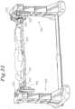
- FIG. 22is a side perspective view of the system following 180° rotation, with the patient in a prone position and the second set of patient support structures removed.
- FIG. 23is a side perspective view similar to FIG. 22 , with first column lowered to place the patient in Trendelenburg's position.
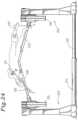
- FIG. 24is a side perspective view of the system showing a patient in a lateral position on two centrally raised support surfaces, with an optional leg spar and patient arm transfer board shown in phantom.
- FIG. 25is a side elevation of the system with both first and second pairs of support structures in place and showing in phantom the foot end column and associated patient support structures shifted toward the head end.
- FIG. 26is a side elevation of the system with the head end patient support structures in an elevated position and the foot end patient support structures in a lowered position supporting a patient in a 90°/90° kneeling prone position.
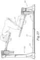
- FIG. 27is a side elevation similar to FIG. 26 , with the first column raised, the second column lowered and the associated head and foot end patient support structures pivoted and supporting a patient in a 90°/90° kneeling prone position approximately 30° from horizontal.
- FIG. 28is an enlarged detail perspective view of an alternate elevation assembly and a transverse travel subassembly, with parts of the housing cut away to show details of the gears.
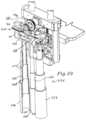
- FIG. 29is an enlarged view similar to that shown in FIG. 28 , with the upper patient support structure and travel subassembly housing removed and showing one of the telescoping members in a shortened, retracted position.
- FIG. 30is a side sectional view of the structures shown in FIG. 29 .
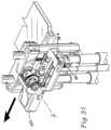
- FIG. 31is a greatly enlarged detail similar to that shown in FIG. 29 , with the upper portions of the lateral travel assembly shifted rearwardly.
- FIG. 32is a partial top plan view of the system showing a pair of patient support structure shifted rearwardly.
- FIG. 33is a partial top plan view similar to that shown in FIG. 32 , with one patient support structure shifted rearwardly and one patient support structure shifted forwardly.
- FIGS. 1 - 17a modular patient support system in accordance with the invention is generally designated by the reference numeral 1 and is depicted in FIGS. 1 - 17 .
- the system 1broadly includes an elongate length-adjustable base 2 surmounted at either end by respective first and second upright support piers or columns 3 and 4 which are connected to respective first and second horizontal support assemblies 5 and 6 . Between them, the support assemblies 5 and 6 uphold an elongated patient support structure 10 and optionally, a removable second patient support structure 10 a ( FIG. 8 ).
- the base 2When viewed from above, the base 2 , has an approximately I-shaped configuration, including first and second low stabilizing plinths or feet 11 and 12 adjustably interconnected by a base rail or crossbar 13 .
- the crossbar 13includes an expansion mechanism of first and second telescoping rail sections 14 and 15 .
- the first rail section 14is substantially hollow and sized for reception of the retracting second rail section 15 .
- the crossbar 13may be selectively elongated and shortened as needed when a portion of the length of the second rail 15 is slidingly and telescopically received within the first rail 14 .
- the crossbar 13also includes a locking assembly 20 ( FIG.
- the horizontal telescoping action of the crossbar 13 and engagement/disengagement of the locking assembly 20may be actuated by a motor 23 housed within the foot 11 or 12 .
- the systemis optionally equipped with a carriage assembly consisting of a series of spaced apart casters or wheels 24 extending below the feet 11 and 12 and center portion of the first rail 14 .
- the wheels 24 associated with the feet 11 and 12are each equipped with a floorlock foot lever 25 that operates to disengage the wheels and lower the foot 11 or 12 into a floor-engaging position. In this lowered position the combined weight of the base 2 and respective upright support column 3 or 4 serves as a brake against inadvertent shifting of the system 2 .
- the first and second feet 11 and 12are surmounted by respective first and second upright end supports or columns 3 and 4 .
- These columnseach include a plurality of telescoping lift arm segments 3 a , 3 b and 3 c or 4 a , 4 b and 4 c which permit the height of each of the columns 3 and 4 to be selectively increased and decreased in order to raise and lower the attached patient support structure 10 .
- the base 2 and vertical supports 3 and 4may be constructed so that the first foot 11 and support column 3 have substantially greater mass than the second foot 12 and support column 4 or vice versa in order to accommodate the uneven weight distribution of the human body.
- Such reduction in size at the foot end of the system 1may be employed in some embodiments to facilitate the approach of personnel and equipment, for example, when a patient is positioned in a lithotomy position.
- Each of the horizontal support assemblies 5 and 6includes a rotation subassembly 26 and angulation subassembly 27 which are interconnected by a separation subassembly 28 and associated circuitry linked to a controller 29 ( FIG. 1 ) for cooperative and integrated actuation and operation.
- the rotational subassembly 26enables coordinated rotation of the patient support structure 10 about a longitudinal axis.
- the angulation subassembly 27enables independent angular adjustment of each end of the patient support structure 10 and selective tilting of the longitudinal axis.
- the separation subassembly 28enables each end of the patient support structure 10 to be raised and lowered with respect to an optional second patient support structure 10 a mounted in spaced relation to the rotation subassembly.
- the rotation subassembly or mechanism 26is shown in FIGS. 2 and 7 - 10 to include first and second motor housings 30 and 31 surmounting respective support columns 3 and 4 .
- a main rotational shaft 32extends from each motor housing 30 and 31 and turns one of a pair of corresponding rotatable blocks 33 , each of which is connected to an angulation subassembly 27 by means of a separation subassembly 28 .
- Each housing 30 or 31contains a rotary electric motor or other actuator 34 drivingly engaged with a transverse drive shaft 35 supported at the forward end by an apertured bearing wall 40 ( FIGS. 2 and 7 ).
- the drive shaft 35includes a drive gear 41 that in turn engages a gear 36 at the end of the main rotational shaft 32 .
- the main shaft 32is tapered or stepped down toward the gear 36 and includes a radially expanded mounting flange or collar 42 in spaced relation to the inboard end ( FIGS. 8 - 12 ).
- the shaft 32is fitted with a pair of tapered roller bearings 43 that engage the inner surface of the motor housing 30 or 31 .
- An inboard end portion of each main shaft 32projects outside the motor housing 30 or 31 for connection with the rotatable block 33 .
- the rotatable block 33is apertured to receive the inboard end of the main shaft 32 , which is fastened in place with bolts or the like through the apertured collar 42 and onto the rear surface of the block 33 .
- the main shaft 32is bored through to include a horizontal bore or channel 44 that extends along its length and the rotatable block 33 includes a corresponding bore or channel 45 .
- the channelsare located so that, when the shaft 32 is installed in the rotatable block 33 , the channels 44 and 45 are collinear.
- the housing 30includes a corresponding aperture that is normally covered by an escutcheon, cover or cap 46 .
- the cap 46may be removed to open a continuous passageway from the outboard surface of the housing 30 to the inboard surface of the rotatable block 33 . Cables may be passed or threaded through this passageway for use in conjunction with for example, a traction harness or other skeletal traction apparatus (not shown).
- each rotatable block 33includes a pair of spaced apertures or slide channels 47 that are sized for receiving a pair of removable elongate riser posts 48 ( FIG. 8 ) for supporting an optional second patient support structure 10 a .
- the riser posts 48are depicted as having a generally tubular configuration, and each includes a series of vertically spaced apertures 49 for receiving pins 49 a for securing the second patient support structure 10 a in place at a preselected height in spaced relation to the first patient support structure 10 .
- the rotation mechanism 26is operated by actuating the motor 34 using a switch or other similar means.
- the motor 34operates to turn or rotate the transverse drive shaft 35 and associated drive gear 41 , which engages the gear 36 on the main shaft 32 , causing the main shaft 32 to turn or rotate about a longitudinal axis A of the system 10 ( FIGS. 1 , 2 , 7 and 10 ).
- the collar 42 of the rotating main shaft 32is in fixed engagement with and serves to turn or rotate the rotatable block 33 .
- the rotatable block 33is remotely coupled with and turns or rotates the associated patient support structure 10 via the angulation and separation subassemblies 27 and 28 and the patient support structure 10 a via the riser posts 48 , to be more fully described hereinafter.
- each angulation subassembly 27is coupled with the patient support structure 10 for enabling selective angular adjustment of the support structure 10 .
- each angulation subassembly 27includes a gear box 50 that houses a pivotable nut pivot block 51 that is intercoupled with a pivotable bracket arm 52 that supports a table top or other patient support structure 10 in accordance with a preselected, adjustable angular orientation or pitch.
- the inboard wall of the gear box 50is apertured to receive the bracket arm 52 , and the outboard aspect is substantially open to permit easy access for maintenance.
- the floor of the gear box 50is apertured or punched out to accommodate upwardly projecting attachments to a generally rectangular mounting plate or motor housing mount 53 that is pivotally mounted below the floor of the gear box 50 as well as a drive mechanism for the separation subassembly 28 to be more fully described.
- Pivot pins or trunnionsproject from the opposite ends of the motor housing mount 53 and are aligned to define a pivot axis that is orthogonal to a longitudinal axis of the system 1 .
- Each trunnion, along with a corresponding bushing,is received in a respective flanged pillow block bearing 54 ( FIG. 8 ) that is fastened to the under surface of the gear box 50 .
- the trunnionsenable the motor housing mount 53 to tip or rock slightly to and fro about the pivot axis in response to stresses on the attachments it supports.
- the motor housing mount 53has a pair of spaced, side-by-side apertures through the planar surface thereof to respectively receive a DC motor or other suitable actuator 55 within a housing, and a jack or lead screw 56 .
- the motor 55includes a drive shaft that extends downwardly to engage a motor pulley (not shown).
- a stepped down lower portion of the lead screw 56is received within a bearing housing 60 that is fastened to the lower surface of the motor housing mount 53 from below ( FIGS. 11 - 12 ).
- the bearing housing 60contains a pair of angular contact bearings 61 for engagement with the lead screw 56 .
- a further stepped down portion of the lead screwextends downwardly below the bearing housing 60 to engage a pulley 62 driven by a belt 63 that is reeved about the motor pulley.
- the parts extending below the motor housing mount 53are covered by a generally rectangular pan or belt housing 64 and the open outboard wall of the gear box 50 is covered by a gear box cover plate 65 ( FIG. 10 ), each held in place by a plurality of fasteners such as panhead screws.
- the upper end of the lead screw 56extends through a clearance slot or aperture in the bracket arm 52 and then through the nut pivot block 51 which is fixedly secured to a lead nut 70 .
- the lead screw 56is threaded into the lead nut 70 .
- the nut pivot block 51includes a pair of projecting pivot pins or trunnions (not shown), which are aligned to define a pivot axis orthogonal to a longitudinal axis of the system 1 .
- Each trunnionis received along with a corresponding bushing in a respective flanged pillow block bearing 71 that is fastened by bolts or the like into the upper rearward surface of the bracket arm 52 ( FIG. 8 ).
- This structureenables the nut pivot block 51 and attached lead nut 70 to tip or rock to and fro to accommodate slight changes in the angular orientation or pitch of the lead screw 56 .
- the bracket arm 52has a generally dog-leg configuration and includes an elongate clearance slot 72 positioned lengthwise adjacent the outboard end for receiving the upper portion of the lead screw 56 .
- the lateral surface of the shank of the bracket arm 52 adjacent its inboard endincludes a pair of opposed projecting pivot pins or trunnions 73 aligned to define a pivot axis orthogonal to a longitudinal axis of the system 1 .
- Each trunnion 73is received along with a corresponding bushing in a respective flanged block bearing 74 .
- the bearingsare mounted by means of fasteners in partially inset or recessed fashion in corresponding grooves or depressions formed on the inboard surface of the gear box 50 .
- the distance between the pivot axis defined by the bracket arm trunnions 73 and the pivot axis defined by the trunnions of the motor housing mount 53is fixed.
- the distance between the pivot axis of the nut pivot block 51 and the bracket arm pivot axis 73is also fixed.
- alteration of the distance between the nut pivot block 51 and the motor housing mount 53causes the bracket arm 52 to ride up or down on the lead screw 56 .
- the clearance slot 72 in combination with the pivoting action of the nut block 51 and the motor housing mount 53accommodates the tilted aspect of the lead screw 56 and permits the outboard end of the bracket arm to ride freely up and down on the screw 56 , thus commensurately varying the angular pitch of the patient support structure 10 .
- the inboard end of the bracket arm 52extends through the apertured gear box 50 and is configured to form a clamp-like slot or channel 75 for receiving an end of a patient support structure 10 .
- the channel 75has a generally U-shaped configuration overall when viewed in cross section, however the vertical end wall portion includes a dovetail mortise 80 for mating engagement with a corresponding tenon on the end of the support structure 10 . It is foreseen that the inboard end of the bracket arm 52 and the mating outboard end of the support structure 10 may include corresponding vertically oriented apertures for receiving retainer pins or the like.
- bracket arm 52is depicted and described as having a dog-leg configuration and being of unitary construction, it is foreseen that other shapes may be employed and that the arm 52 may be constructed in two or more sections, with the inner surface of the outboard portion including an outstanding flange for connecting with fasteners to the inboard portion that includes the channel 75 .
- the angulation subassembly 27is operated by actuating the DC motor 55 to engage the motor pulley (not shown) which in turn rotates the pulley belt 63 that is reeved about the pulley 62 that engages and rotates the lower end of the lead screw 56 . It is also foreseen that any of a number of known systems of gears could be employed to rotate the lead screw 56 . Rotation of the lead screw 56 pulls the lead nut 70 downwardly on its shaft along with the attached nut pivot block 51 , closing the gap between the nut pivot block 51 and the motor housing mount 53 .
- Reversal of the motor 55serves to reverse the direction of rotation of the lead screw 56 , which pushes the lead nut 70 upwardly on the screw 56 .
- the attached nut pivot block 51follows the lead nut and urges the attached outboard end of the bracket arm 52 upwardly along the screw 56 through the clearance slot 72 , increasing the gap between the nut pivot block 51 and the motor housing mount 53 .
- the bracket arm 52pivots, the inboard end of the arm containing the channel 75 tips downwardly, commensurately varying the angular pitch of the patient support structure 10 to a lowered position. Continued actuation of the motor will tip the table top 10 downwardly as shown in FIG. 12 .
- each end of the patient support structure 10may be positioned to subtend an angle of from about 0° (horizontal) to about +25° upward or ⁇ 25° downward from horizontal.
- the support structuremay be positioned to subtend an angle of up to about +90° upwardly or ⁇ 90° downwardly from horizontal, that is to say, from an approximately perpendicular upstanding or approximately perpendicular dependent position, with a full range of motion of the table top 10 of up to about 180°.
- the second patient support structure 10 ais supported by a bracket arm 52 a having a pair of sockets 58 on the outboard end thereof for receiving the respective riser posts 48 . Because the riser posts 48 are received in the slide channels 47 of the rotatable block 33 , both the patient support structure 10 and the second patient support structure 10 a are rotated by the action of the rotation subassembly 26 . However, the angular pitch of the second patient support structure 10 a is fixed by the registry of the riser posts 48 within the sockets 58 , and will not be varied by the operation of the angulation subassembly 27 .
- the distance between the patient support structure 10 and second patient support structure 10 amay be selectively increased or decreased by the operation of the separation subassembly 28 in order to provide support for a patient during 180° rotation of the structures 10 and 10 a by the rotation subassembly 26 .
- the separation subassembly 28is depicted in FIGS. 1 - 3 and 8 - 10 to include first and second pairs of elongate guide bars or rails 81 that adjustably interconnect the rotatable block 33 and gear box 50 at each end of the system 1 .
- the guide rails 81have a generally triangular configuration in cross section and are installed with the base of the triangle oriented toward the shorter side walls of the rotatable block 33 and gear box 50 .
- the guide rails 81are connected to the shorter side walls of each rotatable block 33 by guide end brackets 82 , that are shaped to receive the guide rails 81 .
- the shorter side walls of the gear box 50each include a channel or bracket 83 that may be undercut, so that the side walls partially overlap and retain the angular sides of the guide rails 81 in sliding relation within the bracket ( FIG. 8 ).
- the center portion of the gear box bracket 83includes a slot for mounting linear bearings (not shown).
- the inner facing surface of each guide rail 81includes a normally vertical slot 84 for mounting a linear bearing rail 86 ( FIGS. 9 , 10 ), upon which the linear bearings ride.
- the floor of the gear box 50is apertured to receive a housing 85 containing a lead screw 90 .
- the lead screwis connected to a DC motor or other suitable actuator 91 within a motor housing.
- the motor 91is fixedly attached to the inside surface of the upper wall of the gear box 50 .
- the lead screw 90is threaded into a lead nut (not shown) that is fixedly attached to the floor of the gear box 50 .
- the separation subassembly 28is operated by actuating the motor by a switch or similar device.
- the motor 91rotates the lead screw 90 to pull the lead nut and attached gear box 50 upwardly or downwardly on its shaft, depending on the driving direction of the motor 91 .
- the gear box 50travels upwardly or downwardly on the bearing rails 86 attached to the guide rails 81 , thus raising and lowering the attached patient support structure 10 with respect to the rotatable block 33 .
- the upward and downward travel of the gear box 50serves to shorten and lengthen the distance between the two patient support structures 10 and 10 a.
- the horizontal support assemblies 5 and 6support a table top 10 and optional top 10 a or other suitable patient support structure such as, for example, open frames, slings or bolsters or combinations thereof.
- a top 10 suitable for surgeryis depicted in FIG. 14 to include a patient body support board 92 coupled with first and second patient leg support boards 93 and 94 by a pair of lockable universal or polyaxial joint assemblies 95 and a dependent pillow support structure 96 .
- FIGS. 8 and 9depict an optional second support board 92 a of open frame construction.
- the body board 92is of unitary construction and is sized to support the head and body of a patient except for the legs.
- the body board 92includes an elongate rectangular outboard bracket-engaging section 100 having a dovetail tenon 101 sized for snug sliding reception within the dovetail mortise 80 in the bracket arm channel 75 ( FIG. 12 ).
- the bracket-engaging section 100is joined to a generally rectangular center section 102 having four slightly relieved corners ( FIG. 1 ).
- An elongate perineal section or leg 103projects from the inboard end of the center section 102 and an upright perineal post 104 is removably mounted adjacent the inboard end of the perineal leg 103 .
- the perineal post 104is preferably constructed of a radiolucent material to permit imaging.
- the post 104may have a generally cylindrical configuration as depicted, or it may be constructed in any other suitable shape for supporting engagement with the perineal region of a patient.
- the body board center section 102may serve as a stage for attachment of certain optional and removable accessories.
- a pivoting padded arm board having strap-type restraints 106may be employed for lateral positioning of the patient's arm.
- a cross arm support structure 110 including an elevated arm board 111may be employed for raised, spaced positioning of the patient's arm with respect to the body.
- the first and second patient leg boards 93 and 94are rotatably attached to the body board center section 102 in spaced relation to the perineal leg 103 by first and second polyaxial joint assemblies 95 .
- the leg boards 93 and 94each have a generally elongate rectangular configuration with relieved corners.
- the outboard endseach include a bracket-engaging section 112 having a dovetail tenon 113 for reception within the dovetail mortise 80 in the bracket arm channel 75 .
- the inboard end of the foot end bracket arm 52 and each of the bracket-engaging sections 112are vertically apertured to receive a pair of spaced removable pins 114 for securing the leg boards 93 and 94 in place ( FIG. 1 ).
- the body board 92 and leg boards 93 and 94are constructed of a radiolucent material to permit patient imaging during use. Although depicted in FIGS. 1 - 5 as being of equal length, those skilled in the art will appreciate that the body board 92 may be constructed to have greater length than the leg boards 93 and 94 or vice versa to enable positioning of a patient so that articulation of the leg boards 93 and 94 will occur adjacent the superior aspect of the iliac crest in order to facilitate disarticulation of the hip and hyperextension of the lumbar spine as shown in FIG. 6 .
- the board modules 92 , 93 and 94may be selectively replaced with other modules having different lengths or construction details, such as open frames, slings or bolsters.
- FIGS. 13 - 17show details of the polyaxial joint assemblies 95 that interconnect the body board 92 with the leg boards 93 and 94 to enable adjustment of the angular pitch in nearly all directions.
- the joint 95includes a housing 115 having a generally spherical interior socket 116 that receives a generally spherical ball member 120 .
- the outer rear wall of each housing 115includes an orthogonally projecting shaft 121 that is installed within a corresponding bore in the inboard margin of the body board 92 .
- the ball 120is mounted on a shaft 122 that is installed within a corresponding bore in the inboard margin of a leg board 93 or 94 .
- the housing 115which may be constructed of radiolucent carbon fiber or other suitable material, includes a pair of spaced threaded apertures 123 for receiving a pair of pads or set screws 124 , each of which has a correspondingly threaded stem and is equipped on the outboard end with a handle or finger knob 125 .
- the apertures 123are positioned so that the installed set screws 124 will subtend an angle of about 45° from an axis B defined by the housing shaft 121 as shown in FIG. 17 .
- each set screw 124terminates in an engagement tip 130 that is arcuately configured in a generally concave conical shape for mating engagement with the spherical surface of the ball 120 for cooperatively securing the ball against the inner surface of the socket 116 ( FIGS. 13 and 14 ). While a ball and socket type joint assembly has been depicted and described herein, those skilled in the art will appreciate that any lockable universal joint, such as, for example, a lockable gimbal joint may also be employed to enable polyaxial rotation of the leg boards 93 and 94 .
- the structure 96is designed to convert from a pillow support to a brace when it is positioned as shown in FIGS. 4 and 5 .
- the structure 96includes a pivotable first support element 131 , telescoping second and third support elements 132 and 133 and a pair of dependent spaced wire supports 134 .
- the elements 131 , 132 , 133 and wire supports 134depend from the patient support top 10 in end-to-end relation to form a shelf which may be used for supporting an optional pillow (not shown) that is configured to extend upwardly to fill the space between the leg boards 93 and 94 .
- the first element 131is generally rectangular and planar, and is equipped at each end with a hinge 135 or 135 a ( FIG. 3 ).
- Hinge 135pivotally connects one end to the lower surface of the body board 92 .
- Hinge 135 apivotally connects the opposite end to the second support element 132 .
- the hinges 135 and 135 aenable pivotal movement of the element 131 from the dependent position shown in FIG. 1 to a position parallel and adjacent the lower surface of the body board 92 shown in FIG. 4 .
- the generally planar rectangular second element 132is joined at one end to the first element 131 in a generally perpendicular orientation.
- the opposite end of the second support element 132is slidingly and telescopically received within a hollow end of the third support element 133 .
- the hollow end of the third element 133also includes conventional rack and pinion gear structure (not shown) similar to that within the crossbar 13 to permit locking telescoping adjustment of the length of the two coupled elements when in the upright positions shown in FIGS. 4 - 6 .
- the third support element 133is generally planar and rectangular except for a notch 140 at the outboard end ( FIG. 1 ).
- the notch 140is sized to receive the first rail 14 of the crossbar 13 when the third support element 133 is in an upright position shown in FIGS. 4 - 6 .
- the wire supports 134comprise two spaced sets of articulated wire sections 134 a , 134 b , and 134 c , each of which sets depends from a respective foot board 93 or 94 . It is foreseen that a stabilizing crossbar may also be included at the junction of the first and second sections 134 a and 134 b or other suitable location.
- the lower sections 134 b and 134 care pivotable upwardly from the position shown in FIG. 4 to form a generally triangular releasable loop foot ( FIG. 3 ) that is sized to receive an outboard end corner of each of the leg boards 93 and 94 .
- the leg boards 93 and 94can be disengaged from the angulation subassembly 27 and raised, dropped down or rotated nearly 360° in all directions ( FIGS. 5 and 6 ).
- the first support element 131is rotated about the hinge 135 to the position shown in FIG. 4 .
- the second and third support elementsrotate downwardly and about the hinge 135 a .
- the rack and pinion gear systemis actuated by the motor 141 to urge the second support element 132 outwardly from its telescoped position within the third support element 33 , thereby elongating the support until the slot 140 engages the crossbar rail 14 in straddling relation.
- an elastomeric gasket 139may be provided between the now upstanding end of the second support element and the lower surface of the body board 92 to cushion against any flexing or tilting of the body board 92 which may occur when the foot boards are released from the angulation subassembly 27 .
- the floor engaging corners of the support element 133may also be equipped with elastomeric feet to facilitate snugging of the brace 96 against the body board 92 and to prevent any slippage of the support element 133 along the surface of the floor.
- one or more of the leg boards 93 and 94may be released from the bracket arm channel 75 .
- One or more of the pins 114is released and the bracket engaging leg board tenon 113 is slidingly disengaged from the bracket mortise 80 ( FIGS. 1 and 5 ).
- the floorlock foot lever 25 and the telescoping cross bar rails 14 and 15may be completely disengaged, leaving the inboard end of the rail 14 supported by the wheel 24 ( FIG. 6 ). This frees the disengaged second horizontal support assembly 6 and its attached upright support column 4 , which may be wheeled out of the way. In this manner, access by the surgical team and its equipment to the midsection and lower limbs of the patient is greatly enhanced.
- an optional leg spar assembly 142may be attached to the free end of each leg board 92 and 93 for mounting a traction boot 143 or cable (not shown).
- the leg boards 93 and 94may each be rotated about one of the ball joints 95 , by rotating the finger knob 125 counter clockwise to release the ball 120 within the socket 116 .
- the right leg board 94may be dropped down and tilted laterally or medially with respect to a longitudinal axis to disarticulate the hip of the patient.
- the respective finger knob 125is rotated clockwise to engage the ball against the surface of the socket 116 and secure the leg board 92 or 93 in place.
- the system 1 of the inventionhas been described as actuated by a series of electric motors 23 (vertical translation of support columns 3 and 4 and lateral translation of rack and pinion 21 and 22 ), 34 (rotation subassembly 26 ), 55 (angulation subassembly 27 ), 91 (vertical translation of linear guide rail subassembly), and 141 (intermediate support structure 96 ). Cooperatively these motors form a coordinated drive system to raise, lower, tilt and rotate the patient support structures and to disengage the second support column 4 from the system 1 .
- Actuation of the motorsis coordinated by the controller 29 , including computer software which may be part of an integrated guidance system that coordinates and controls other devices such as a robotic surgical arm, imaging, monitoring and/or heated or cooled gas and fluid delivery, as well as temperature and/or pressure point management devices.
- the softwaremay include preset routines for positioning components in preselected positions.
- the softwaremay include the capability of fine tuning any aspect of the configuration of the system 1 .
- the motor 91may also be selectively actuated to lower the body board 92 with respect to the rotatable block 33 while each of the motors 55 are also actuated to tip the body board 92 upwardly and the opposed leg boards 93 and 94 downwardly in accordance with the new angle subtended by the support columns 3 and 4 to a position in which the hips of the patient are above both the head and the feet.
- a hydraulic or pneumatic systemcould be employed.
- the horizontal support assemblies 5 and 6may be positioned in a horizontal orientation and at a convenient height to facilitate transfer of a patient onto the support surface 10 .
- the patientis positioned in a generally supine position with the head, torso and lower body except for the legs on the body board 92 outboard of the perineal post 104 , and with one leg on each of the leg boards 93 and 94 .
- Arm boards 105 and 111may be attached to the body board 92 as necessary, and the patient's arms arranged thereon and restrained using the straps 106 .
- the patientmay be tilted to a Trendelenburg position (as shown in FIG. 23 ), or a reverse Trendelenburg position in which the head is raised above the feet, by actuating the motors 23 and 55 to selectively lower a selected support column 3 or 4 and adjust the angulation of the body board 92 and leg boards 93 and 94 .
- the patientmay be rotated or rolled from the supine position to a clockwise or counter clockwise laterally tilted position by actuating the motors 34 to rotate the blocks 33 .
- One or more of the leg boards 92 and 93may be disengaged and the patient's legs positioned for example, for hip surgery, by converting the intermediate support structure 96 from its pillow-supporting configuration to a central support column as shown in FIG. 4 by disengaging the wire supports 134 , rotating the first support element 131 about the hinges 135 to its horizontal position and actuating the motor 141 to extend the support elements 132 and 133 to engage the rail 14 .
- the wire supports 134are removed and the pins 114 are removed from the bracket arm 52 .
- the bracket engaging section 112 of each of the leg boards 93 and 94is slid out of the channel 75 by laterally rolling or rotating the respective leg board about the respective polyaxial ball joint 95 . This is accomplished by manually turning the finger knob 125 through the sterile drapes to disengage the set screw 124 from the ball 120 and permit free rotation of the ball within the socket 116 .
- the foot end separation assembly motor 91may be actuated to raise the gear box 50 to its highest position on the guide rails 81 and the motor 23 may be actuated to lower the foot end support column 4 to its lowest position.
- the foot end floorlock foot lever 25is next disengaged to free the foot end support column 4 , while the head end support column 4 remains locked down.
- the motor 23is actuated to urge the rack and pinion 21 and 22 to commence withdrawal of the rail 15 from its telescoped position within the rail 14 and thereby lengthen the crossbar 13 to its fully extended position.
- the rack and pinion locking assembly 20is then released either manually or by means of a switch so that the entire second upright support column 4 with its horizontal support assembly 6 and attached rail 15 may be wheeled out of the way to provide the surgical team and equipment with free access to the pelvis as well as to the hip joints and legs of the patient from both a medial and lateral approach.
- leg boards 93 and 94may be positioned as shown in FIG. 6 , with the outboard ends tilted upwardly or downwardly and angled laterally or medially.
- the leg boards 93 and 94are secured in place in the selected angular orientation by manually tightening each of the finger knobs 125 through the sterile drapes until the engagement tips 130 lock the ball 120 against the inner surface of its socket 116 .
- Leg spar assemblies 142may be installed on the leg boards 93 and/or 94 and the patient's feet may be fitted with traction boots 143 .
- a second embodiment of the patient support system of the inventionis generally designated by the reference numeral 201 and is depicted in FIGS. 18 - 27 to include a base 202 , support columns 203 and 204 and horizontal support assemblies 205 and 206 including rotation subassemblies 226 , angulation subassemblies 227 and linear guide rail or separation subassemblies 228 substantially as previously described.
- the patient support structure 210includes a pair of body boards 292 and 293 , depicted as surgical tops and open frames ( FIG. 18 ), although as previously discussed, other suitable structures such as slings, bolsters or a combination thereof may be employed.
- the boards 292 and 293each include bracket engaging sections 300 that are received within channels 275 in brackets 283 attached to gear boxes 250 .
- the inboard ends of the body boards 292 and 293are free so that they may be independently raised and lowered by the support columns 203 and 204 ( FIG. 26 ).
- the distance between the inboard endsmay be increased or decreased by actuation of a rack and pinion in the crossbar first section 214 to telescopically receive a portion of the second crossbar section 215 , shortening the horizontal length of the crossbar 213 to achieve the overlapping positioning of the body boards 292 and 293 depicted in FIG. 25 .
- the body boards 292 and 293need not be uniform in size and may vary in length and thickness (in which case correspondingly sized brackets 252 are employed).
- the foot end boardmay be longer than the head or torso board, in which case the angulation of the boards when the ends are proximate would occur at approximately the waist of the patient.
- a frame type patient support 210may be employed in conjunction with a body board type of support to support a patient, or a pair of frame type patient supports may be employed in lieu of body boards.
- the free ends of the body boards 292 and 293may be spaced substantially apart and a third body board (not shown) may be interconnected by means of additional brackets 252 on the free ends of the boards 292 and 293 in order to provide a substantially elongated patient support surface 210 . It is also foreseen that the boards 292 and 293 may be brought into contact with each other in stacked relation, for example for use with children or in small rooms in order to reduce the overall length of the system 201 . Since such an arrangement necessarily provides a double thickness patient support structure, the resultant structure has a greater load bearing capacity.
- each of the body boards 292 and 293may also be individually adjusted by the angulation subassembly 227 as shown in FIGS. 23 , 24 and 27 and the adjustment may be coordinated to achieve complementary angulation for positioning of a patient, for example with the inboard ends of the body boards 292 and 293 upraised as shown in FIG. 24 .
- the system 201is designed to include an optional and removable second pair of patient support structures 210 a attached by brackets 252 coupled with riser posts 248 .
- the support structures 210 aare depicted in FIGS. 8 and 18 as first and second generally rectangular open frames 292 a and 293 a and as surgical tops in FIGS. 19 - 21 and 25 .
- the patient support structures 210 and 210 amay comprise conventional surgical table tops and open frames as described or any other structure capable of supporting a patient, whether directly or in association with pads, slings, cables, brackets, pins or in any other suitable manner.
- any of the board modules 292 , 292 a , 293 and 293 amay also be removed and replaced by modules of alternate construction during the course of a medical procedure as may be desirable.
- the body boards/frames 292 a and 293 ainclude bracket engaging sections 300 a that are received within channels 275 in corresponding brackets 283 a .
- the outboard portion of each bracket 283 aincludes a pair of sockets 258 for receiving a pair of riser posts 248 .
- the riser posts 248include a series of vertical apertures 249 for receiving pins 249 a for holding the riser posts 248 in place at a preselected height or distance above the rotatable blocks 233 .
- the body boards and/or frames 292 and 292 aalso be equipped with optional and removable accessories such as a cross arm support 310 and arm board 311 and the body boards and/or frames 293 and 293 a may also be equipped with accessories such as leg spar assemblies 342 as shown in FIG. 24 or other support assemblies such as the kneeler assembly 317 shown in FIG. 27
- the second pair of support structures 210 aare installed by sliding the sockets 258 over the corresponding riser posts 248 and fastening in place with pins 249 a through the apertures 249 as shown in FIG. 18 .
- the rotation subassembly 226is actuated to operate as previously described for rotating the blocks 233 along with the attached frames 292 a and 293 a and the gear boxes 250 along with the attached body boards 292 and 293 about the longitudinal axis of the system 201 into the 180° position shown in FIG. 19 .
- the separation subassembly 228is actuated to operate in the manner previously described to urge the gear boxes 250 along with the attached body boards 292 and 293 along the guide bars 281 and into the upraised position shown in FIG. 19 to provide ample space for transfer and positioning of a patient.
- the overall height of the system 201may be adjusted for convenient patient transfer by actuating the telescoping action of the support columns 203 and 204 .
- the upright support columns 203 and 204raise and lower the patient support structures 210 and 210 a in tandem, and cooperate with the separation subassembly 228 to set the patient support structures 210 and 210 a at a preselected height with respect to the floor and a preselected separating distance with respect to each other.
- a patientis next transferred onto the support boards 292 a and 293 a and a protective guard 294 is positioned over the face and restraint straps 295 positioned at strategic points along the patient's body and snugged against the body boards 292 a and 293 a .
- the separation subassembly 228is actuated to urge the gear boxes 250 closer to the rotatable blocks 233 , decreasing the distance or separation between the patient support boards in the position shown in FIG. 20 .
- the rotation subassembly 226is next actuated to rotate the blocks 233 along with the body boards 292 a and 293 a and the attached gear boxes 250 and attached body boards 292 and 293 with the patient in the generally supine position shown in FIG. 21 to the generally prone position shown in FIG. 22 .
- the rotation subassembly 226cooperates with the angulation subassembly 227 , the support columns 203 and 204 and the separation subassembly 228 to enable rotation of the patient support structures 210 and 210 a about a longitudinal axis, that is preselected according to the respective selected heights of the support columns 203 and 204 and the respective selected separation spacing of the patient supports 292 and 293 and 292 a and 293 a by the guide rails 281 .
- the system 201may be rotated 360° in either clockwise or counterclockwise direction.
- the second patient support structure 210 aincluding the boards 292 a and 293 a and associated brackets 252 and riser posts 248 may be removed to provide full access to the surgical field.
- the linear guide rail subassemblies 228may be actuated to raise the gear boxes 250 and connected body boards 292 and 293 up to a position adjacent the blocks 233 .
- the angulation subassemblies 227cooperate with the support columns 203 and 204 to permit independent adjustment of the height of the support columns, so that the body boards 292 and 293 may be set at an angle, with the patient's head above or below the feet.
- Cooperation of the angulation subassemblies 227 with the support columns 203 and 204 and with the telescoping crossbar 213enables positioning of the patient with the head and torso horizontal in an upper plane and with the lower legs horizontal in a lower plane as shown in FIG. 26 and coordinated upward tipping of the patient with the head and torso and lower legs maintained in parallel angled planes as shown in FIG. 27 .
- a third embodiment of the patient support system of the inventionis generally designated by the reference numeral 401 and is depicted in FIGS. 28 to 33 to include a base, support columns 403 and horizontal support assemblies 405 including rotation subassemblies 426 , angulation subassemblies 427 and separation subassemblies 428 substantially as previously described.
- the horizontal support assemblies 405 and 406support a patient support structure 410 that includes patient head and foot boards or supports 492 , 492 a , 493 , 493 a ( FIGS. 28 , 32 , 33 ), substantially as previously described with respect to FIGS. 18 - 27 .
- the patient support structure 410may also be configured as a single support, which may be articulated as previously described with respect to FIGS. 1 - 6 .
- the columns 403include an elevation assembly 544 and the horizontal support assemblies 405 each further include a transverse or lateral shift subassembly 545 , which subassemblies are interconnected by associated circuitry linked to a controller such as controller 29 depicted in FIG. 1 .
- the lateral shift subassembly 545enables lateral translational movement of the patient support structures 410 with respect to the longitudinal axis A ( FIGS. 32 , 33 ).
- An elevation assembly 544enables the patient support structures 410 to be maintained at a preselected elevation and angular orientation that is laterally displaced from the longitudinal axis A, despite multi-directional bending forces and torque on the patient support structures 410 .
- the support columns 403( FIGS. 29 , 33 ), each include a pair of upright, elongated and generally cylindrical telescoping supports 546 and 547 .
- the supports 546 and 547are operated by a hydraulic lift mechanism 551 located in spaced relation between the supports.
- Each of the telescoping members 546 and 547includes a series of shorter hollow cylindrical tubes 552 .
- the lowermost or base tubesare joined to the column feet or base (previously described and shown).
- Each tubeis equipped on its outer surface with an upper bushing 553 and a lower bushing 554 .
- the tubes and bushingsare sized for fixed attachment of the lower bushing to the outer surface of a tube and fixed attachment of the corresponding upper bushing to the inner surface of the next lower tube, so that the upper bushing serves to limit or stop the vertical travel of the tubes 552 .
- the snug fit of the bushings in the tubesalso serves to provide lateral support for the tubes 552 .
- the hydraulic lift mechanism 551is of conventional construction and includes a cylinder 555 and a multistage telescoping lift arm 556 .
- the lower end of the cylinder 555may be supported by a block (not shown) or other suitable support.
- the lift mechanism 551also includes associated circuitry (not shown) linked to the controller 29 .
- the columns 403 and the lift arm 556may be enclosed within suitable telescoping housing members (not shown).
- One or both of such housing membersmay also be configured to provide additional interior space.
- This additional spacemay be employed to house a plurality of counterweights, such as concrete or metal blocks or the like.
- the counterweightsmay be employed at one or both ends of the system 401 .
- the elevation assembly 544is operated by actuating the hydraulic cylinder 560 of the lift mechanism 551 via the controller 29 .
- the cylinder 555operates to raise the lift arm 556 , which engages a bearing plate, to be described hereinafter, which in turn is remotely coupled with the horizontal support assembly 405 .
- the lateral shift subassembly 545is shown in FIGS. 28 - 31 to include a mounting plate 560 that supports an upper mounting block 561 , which is shiftably coupled with a support housing 562 .
- the mounting block 561houses a lead screw 563 that supports a shiftable worm mount 564 , which in turn supports a worm-type drive gear 441 , for driving the main gear 436 .
- the mounting plate 560has a generally planar rectangular configuration and is apertured for reception of a plurality of fasteners such as bolts or the like. Two of these fasteners serve to connect a pair of spaced support bosses (not shown) in dependent relation to the lower surface of the plate 560 . The bosses are positioned for reception within the open upper ends of the telescoping support guides 546 and 547 .
- the lower surface of the plate 560also includes a cylinder clevis 570 ( FIG. 30 ) for connection with an eye atop the lift arm 556 . The remainder of the apertures receive bolts for connecting the lower surface of the mounting block 561 with the upper surface of the plate 560 .
- the mounting block 561has an overall rectangular shape generally corresponding to the footprint of the mounting plate 560 .
- the block 561is configured to include large and small gear box areas on the underside and one short end, respectively.
- the block 561is apertured through at the short ends and at the perimeter for fastening to the support housing 562 .
- a worm mount 564includes a generally U-shaped upper portion having a pair of upstanding arms 571 .
- the mount 564includes a dependent leg 572 , which is apertured through to receive the lead screw 563 .
- a lead nut 573is threaded onto the lead screw 563 and is fixedly attached to the leg 572 .
- the inner wall of the small gear box at the short end of the block 561is equipped with a plate 574 ( FIG. 29 ).
- the plateincludes corresponding apertures for reception of the drive end of the lead screw 563 , the drive shaft of the lateral shift motor 575 and the shaft of an idler gear 580 .
- the motor drive shaft and the drive end of the lead screware connected to respective spur gears 581 and 582 which engage the idler gear 580 between them.
- the roof of the block 561includes a slot to enable lateral travel of the dependent leg 572 of the worm mount 564 .
- the upstanding arms 571 of the worm mountinclude apertures for securing to corresponding apertures in the support housing 562 by means of fasteners such as bolts or the like.
- the upstanding worm mount arms 571are apertured through to receive a pair of motors 583 , the inboard end of each of which is fastened in place by bolts or the like through an apertured collar 584 and onto the outboard surface of a respective arm 571 .
- the outboard end of each motoris remotely coupled with a power source, which interfaces with the controller 26 .
- Each of the motors 583is drivingly engaged with a drive shaft which engages the worm gear 441 .
- the worm gear 441in turn engages the gear 436 on the main rotational shaft 432 , substantially as previously described.
- a pair of linear bearing rails 585 having a U-shaped cross sectional aspectis mounted along the unapertured perimeter of the roof of the block 561 in a generally parallel longitudinal orientation.
- a corresponding pair of elongated linear bearings 586is mounted to the lowermost surface of the support housing 562 for reception in the bearing rails 585 .
- the support housing 562has a rectangular overall footprint sized somewhat wider than the mounting block 561 to provide coverage for the block 561 during lateral travel of the housing 562 . While the elevation of the housing 562 is depicted as approximately clock-shaped, any configuration may be employed which will house the main rotational shaft 432 , drive gear 436 , worm gear 441 and drive motors 583 .
- the lateral shift subassembly 545is operated by actuating the motor 575 using a switch or other similar means, which in turn may be interfaced with a controller 26 ( FIG. 1 ).
- the motor 575operates to turn or rotate a drive shaft connected to a spur gear 581 , which engages the idler gear 580 , which in turn engages a spur gear 582 connected to the lead screw 563 .
- rotation of the lead screw 563causes the lead nut 573 to travel along the screw 563 , pushing or pulling the attached worm mount leg 572 .
- the worm mount 564is driven along the lead screw 563 .
- the worm mount 564is fixedly attached to the support housing 562 .
- the linear bearings 586 on the lower surface of the support housingtravel in sliding manner along the linear bearing rails 585 on the surface of the mounting block 561 .
- the lateral shift subassembly 545is actuated as previously described to shift a patient on a patient support structure 410 (which may comprise a single articulated structure, a pair of support structures 492 and 493 or two pairs of support structures 492 , 493 and 492 a and 493 a ) laterally toward or away form the longitudinal axis A of the system 401 in either direction as shown in FIG. 32 .
- the patientmay be shifted up to about five inches away from axis A in either direction, enabling total shifting travel of up to about ten inches.
- the lateral shift subassembly 545may be actuated either alone or in combination with the elevation assembly 544 , the rotation subassembly 426 , angulation subassembly 427 or the separation subassembly 428 .
- the patient support 410may be rotated, tilted and raised or lowered and shifted laterally away from the longitudinal axis in a rightward direction with respect to the patient.
- one set of structuresmay be shifted up to five inches in a leftward direction away from the longitudinal axis A and the other structure or set of structures may be shifted up to five inches in a rightward direction away from the axis A.
- the support structuresmay then be shifted back to the axis A, and then shifted to the reverse position.
- the lateral shift subassemblies 545may be actuated either singly or in a coordinated fashion in cooperation with the elevation assembly 544 , rotation subassembly 426 , angulation subassembly 427 and/or the separation subassembly 428 to achieve multiaxial movement of the system 401 .
Landscapes
- Health & Medical Sciences (AREA)
- Life Sciences & Earth Sciences (AREA)
- Engineering & Computer Science (AREA)
- Animal Behavior & Ethology (AREA)
- General Health & Medical Sciences (AREA)
- Public Health (AREA)
- Veterinary Medicine (AREA)
- Biomedical Technology (AREA)
- Medical Informatics (AREA)
- Orthopedic Medicine & Surgery (AREA)
- Nursing (AREA)
- Pathology (AREA)
- High Energy & Nuclear Physics (AREA)
- Nuclear Medicine, Radiotherapy & Molecular Imaging (AREA)
- Optics & Photonics (AREA)
- Physics & Mathematics (AREA)
- Radiology & Medical Imaging (AREA)
- Heart & Thoracic Surgery (AREA)
- Molecular Biology (AREA)
- Surgery (AREA)
- Biophysics (AREA)
- Neurology (AREA)
- Neurosurgery (AREA)
- Accommodation For Nursing Or Treatment Tables (AREA)
Abstract
Description
Claims (24)
Priority Applications (2)
| Application Number | Priority Date | Filing Date | Title |
|---|---|---|---|
| US16/910,489US12076281B2 (en) | 2005-02-22 | 2020-06-24 | Modular multi-articulated patient support system |
| US18/822,883US20240423856A1 (en) | 2005-02-22 | 2024-09-03 | Modular multi-articulated patient support system |
Applications Claiming Priority (10)
| Application Number | Priority Date | Filing Date | Title |
|---|---|---|---|
| US11/062,775US7152261B2 (en) | 2005-02-22 | 2005-02-22 | Modular multi-articulated patient support system |
| US11/159,494US7343635B2 (en) | 2005-02-22 | 2005-06-23 | Modular multi-articulated patient support system |
| US79828806P | 2006-05-05 | 2006-05-05 | |
| US11/788,513US7565708B2 (en) | 2005-02-22 | 2007-04-20 | Patient positioning support structure |
| US12/460,702US8060960B2 (en) | 2005-02-22 | 2009-07-23 | Patient positioning support structure |
| US13/317,012US8719979B2 (en) | 2005-02-22 | 2011-10-06 | Patient positioning support structure |
| US13/902,536US8978180B2 (en) | 2005-02-22 | 2013-05-24 | Modular multi-articulated patient support system |
| US14/616,500US20150150743A1 (en) | 2005-02-22 | 2015-02-06 | Modular multi-articulated patient support system |
| US15/431,439US10835438B2 (en) | 2005-02-22 | 2017-02-13 | Modular multi-articulated patient support system |
| US16/910,489US12076281B2 (en) | 2005-02-22 | 2020-06-24 | Modular multi-articulated patient support system |
Related Parent Applications (1)
| Application Number | Title | Priority Date | Filing Date |
|---|---|---|---|
| US15/431,439ContinuationUS10835438B2 (en) | 2005-02-22 | 2017-02-13 | Modular multi-articulated patient support system |
Related Child Applications (1)
| Application Number | Title | Priority Date | Filing Date |
|---|---|---|---|
| US18/822,883ContinuationUS20240423856A1 (en) | 2005-02-22 | 2024-09-03 | Modular multi-articulated patient support system |
Publications (2)
| Publication Number | Publication Date |
|---|---|
| US20200315892A1 US20200315892A1 (en) | 2020-10-08 |
| US12076281B2true US12076281B2 (en) | 2024-09-03 |
Family
ID=38668395
Family Applications (26)
| Application Number | Title | Priority Date | Filing Date |
|---|---|---|---|
| US11/788,513Expired - Fee RelatedUS7565708B2 (en) | 2005-02-22 | 2007-04-20 | Patient positioning support structure |
| US12/460,702Expired - LifetimeUS8060960B2 (en) | 2005-02-22 | 2009-07-23 | Patient positioning support structure |
| US13/317,012Expired - LifetimeUS8719979B2 (en) | 2005-02-22 | 2011-10-06 | Patient positioning support structure |
| US13/815,982Expired - LifetimeUS9211223B2 (en) | 2005-02-22 | 2013-03-20 | Patient positioning support structure |
| US13/902,487Expired - LifetimeUS8856986B2 (en) | 2005-02-22 | 2013-05-24 | Patient positioning support structure |
| US13/902,466Expired - LifetimeUS9205013B2 (en) | 2005-02-22 | 2013-05-24 | Patient positioning support structure |
| US13/902,525Expired - LifetimeUS8826474B2 (en) | 2005-02-22 | 2013-05-24 | Modular multi-articulated patient support system |
| US13/902,565Expired - LifetimeUS9198817B2 (en) | 2005-02-22 | 2013-05-24 | Patient positioning support structure |
| US13/902,479Expired - LifetimeUS8839471B2 (en) | 2005-02-22 | 2013-05-24 | Patient positioning support structure |
| US13/902,510Expired - LifetimeUS8826475B2 (en) | 2005-02-22 | 2013-05-24 | Modular multi-articulated patient support system |
| US13/902,536Expired - LifetimeUS8978180B2 (en) | 2005-02-22 | 2013-05-24 | Modular multi-articulated patient support system |
| US13/902,550Expired - LifetimeUS9289342B2 (en) | 2005-02-22 | 2013-05-24 | Patient positioning support structure |
| US13/902,577Expired - LifetimeUS9180062B2 (en) | 2005-02-22 | 2013-05-24 | Patient positioning support structure |
| US13/902,455Expired - LifetimeUS8938826B2 (en) | 2005-02-22 | 2013-05-24 | Patient positioning support structure |
| US14/096,875Expired - LifetimeUS9364380B2 (en) | 2005-02-22 | 2013-12-04 | Patient positioning support structure |
| US14/218,599Expired - LifetimeUS9610206B2 (en) | 2005-02-22 | 2014-03-18 | Patient positioning support structure |
| US14/218,667AbandonedUS20140201914A1 (en) | 2005-02-22 | 2014-03-18 | Patient positioning support structure |
| US14/218,431Expired - LifetimeUS9456945B2 (en) | 2005-02-22 | 2014-03-18 | Patient positioning support structure |
| US14/230,432Expired - LifetimeUS9757300B2 (en) | 2005-02-22 | 2014-03-31 | Patient positioning support structure |
| US14/328,058AbandonedUS20140317847A1 (en) | 2005-02-22 | 2014-07-10 | Patient positioning support structure |
| US14/616,500AbandonedUS20150150743A1 (en) | 2005-02-22 | 2015-02-06 | Modular multi-articulated patient support system |
| US14/923,044AbandonedUS20160038364A1 (en) | 2005-02-22 | 2015-10-26 | Patient Positioning Support Structure |
| US15/431,439Active2026-02-17US10835438B2 (en) | 2005-02-22 | 2017-02-13 | Modular multi-articulated patient support system |
| US15/631,911Active2026-09-04US10695252B2 (en) | 2005-02-22 | 2017-06-23 | Patient positioning support structure |
| US16/884,947Active2026-06-10US11679051B2 (en) | 2005-02-22 | 2020-05-27 | Patient positioning support structure |
| US16/910,489Active2026-12-24US12076281B2 (en) | 2005-02-22 | 2020-06-24 | Modular multi-articulated patient support system |
Family Applications Before (25)
| Application Number | Title | Priority Date | Filing Date |
|---|---|---|---|
| US11/788,513Expired - Fee RelatedUS7565708B2 (en) | 2005-02-22 | 2007-04-20 | Patient positioning support structure |
| US12/460,702Expired - LifetimeUS8060960B2 (en) | 2005-02-22 | 2009-07-23 | Patient positioning support structure |
| US13/317,012Expired - LifetimeUS8719979B2 (en) | 2005-02-22 | 2011-10-06 | Patient positioning support structure |
| US13/815,982Expired - LifetimeUS9211223B2 (en) | 2005-02-22 | 2013-03-20 | Patient positioning support structure |
| US13/902,487Expired - LifetimeUS8856986B2 (en) | 2005-02-22 | 2013-05-24 | Patient positioning support structure |
| US13/902,466Expired - LifetimeUS9205013B2 (en) | 2005-02-22 | 2013-05-24 | Patient positioning support structure |
| US13/902,525Expired - LifetimeUS8826474B2 (en) | 2005-02-22 | 2013-05-24 | Modular multi-articulated patient support system |
| US13/902,565Expired - LifetimeUS9198817B2 (en) | 2005-02-22 | 2013-05-24 | Patient positioning support structure |
| US13/902,479Expired - LifetimeUS8839471B2 (en) | 2005-02-22 | 2013-05-24 | Patient positioning support structure |
| US13/902,510Expired - LifetimeUS8826475B2 (en) | 2005-02-22 | 2013-05-24 | Modular multi-articulated patient support system |
| US13/902,536Expired - LifetimeUS8978180B2 (en) | 2005-02-22 | 2013-05-24 | Modular multi-articulated patient support system |
| US13/902,550Expired - LifetimeUS9289342B2 (en) | 2005-02-22 | 2013-05-24 | Patient positioning support structure |
| US13/902,577Expired - LifetimeUS9180062B2 (en) | 2005-02-22 | 2013-05-24 | Patient positioning support structure |
| US13/902,455Expired - LifetimeUS8938826B2 (en) | 2005-02-22 | 2013-05-24 | Patient positioning support structure |
| US14/096,875Expired - LifetimeUS9364380B2 (en) | 2005-02-22 | 2013-12-04 | Patient positioning support structure |
| US14/218,599Expired - LifetimeUS9610206B2 (en) | 2005-02-22 | 2014-03-18 | Patient positioning support structure |
| US14/218,667AbandonedUS20140201914A1 (en) | 2005-02-22 | 2014-03-18 | Patient positioning support structure |
| US14/218,431Expired - LifetimeUS9456945B2 (en) | 2005-02-22 | 2014-03-18 | Patient positioning support structure |
| US14/230,432Expired - LifetimeUS9757300B2 (en) | 2005-02-22 | 2014-03-31 | Patient positioning support structure |
| US14/328,058AbandonedUS20140317847A1 (en) | 2005-02-22 | 2014-07-10 | Patient positioning support structure |
| US14/616,500AbandonedUS20150150743A1 (en) | 2005-02-22 | 2015-02-06 | Modular multi-articulated patient support system |
| US14/923,044AbandonedUS20160038364A1 (en) | 2005-02-22 | 2015-10-26 | Patient Positioning Support Structure |
| US15/431,439Active2026-02-17US10835438B2 (en) | 2005-02-22 | 2017-02-13 | Modular multi-articulated patient support system |
| US15/631,911Active2026-09-04US10695252B2 (en) | 2005-02-22 | 2017-06-23 | Patient positioning support structure |
| US16/884,947Active2026-06-10US11679051B2 (en) | 2005-02-22 | 2020-05-27 | Patient positioning support structure |
Country Status (7)
| Country | Link |
|---|---|
| US (26) | US7565708B2 (en) |
| EP (1) | EP2015725A4 (en) |
| JP (5) | JP2009534159A (en) |
| KR (1) | KR101279010B1 (en) |
| AU (3) | AU2007248426B2 (en) |
| CA (1) | CA2649350C (en) |
| WO (1) | WO2007130679A2 (en) |
Families Citing this family (155)
| Publication number | Priority date | Publication date | Assignee | Title |
|---|---|---|---|---|
| US20150059094A1 (en) | 2005-02-22 | 2015-03-05 | Roger P. Jackson | Patient positioning support structure |
| US7739762B2 (en) | 2007-10-22 | 2010-06-22 | Mizuho Orthopedic Systems, Inc. | Surgery table apparatus |
| US20130133137A1 (en)* | 2011-11-28 | 2013-05-30 | Roger P. Jackson | Patient positioning support structure with coordinated continuous nonsegmented articulation, rotation and lift, and locking fail-safe device |
| US9468576B2 (en) | 2005-02-22 | 2016-10-18 | Roger P. Jackson | Patient support apparatus with body slide position digitally coordinated with hinge angle |
| US9186291B2 (en)* | 2005-02-22 | 2015-11-17 | Roger P. Jackson | Patient positioning support structure with trunk translator |
| US9265679B2 (en) | 2005-02-22 | 2016-02-23 | Roger P Jackson | Cantilevered patient positioning support structure |
| US9295433B2 (en) | 2005-02-22 | 2016-03-29 | Roger P. Jackson | Synchronized patient elevation and positioning apparatus for use with patient positioning support systems |
| US9301897B2 (en) | 2005-02-22 | 2016-04-05 | Roger P. Jackson | Patient positioning support structure |
| US8844077B2 (en) | 2005-02-22 | 2014-09-30 | Roger P. Jackson | Syncronized patient elevation and positioning apparatus positioning support systems |
| US9744087B2 (en) | 2005-02-22 | 2017-08-29 | Roger P. Jackson | Patient support apparatus with body slide position digitally coordinated with hinge angle |
| US7565708B2 (en) | 2005-02-22 | 2009-07-28 | Jackson Roger P | Patient positioning support structure |
| US9308145B2 (en) | 2005-02-22 | 2016-04-12 | Roger P. Jackson | Patient positioning support structure |
| US8707484B2 (en)* | 2005-02-22 | 2014-04-29 | Roger P. Jackson | Patient positioning support structure |
| AU2006283126A1 (en)* | 2005-08-24 | 2007-03-01 | Thomson Licensing | Method for graphical scaling of LCDs in mobile television devices |
| US9642760B2 (en) | 2006-05-05 | 2017-05-09 | Roger P. Jackson | Patient positioning support apparatus with virtual pivot-shift pelvic pads, upper body stabilization and fail-safe table attachment mechanism |
| US10869798B2 (en)* | 2006-05-05 | 2020-12-22 | Warsaw Orthopedic, Inc. | Patient positioning support apparatus with virtual pivot-shift pelvic pads, upper body stabilization and fail-safe table attachment mechanism |
| US9339430B2 (en) | 2006-05-05 | 2016-05-17 | Roger P. Jackson | Patient positioning support apparatus with virtual pivot-shift pelvic pads, upper body stabilization and fail-safe table attachment mechanism |
| US8864205B2 (en) | 2006-06-28 | 2014-10-21 | Stryker Corporation | Patient support with wireless data and/or energy transfer |
| EP2046259B1 (en)* | 2006-06-28 | 2014-07-02 | Stryker Corporation | Patient support |
| CZ18426U1 (en)* | 2008-02-15 | 2008-04-07 | Linet, Spol. S R.O. | Bed positioning mechanism |
| KR100950162B1 (en)* | 2008-03-05 | 2010-03-30 | 유영선 | Body stretching bed |
| US8635725B2 (en)* | 2008-10-28 | 2014-01-28 | Tony Y. Tannoury | Prone and laterally angled surgical device and method |
| FR2940130B1 (en)* | 2008-12-19 | 2012-04-13 | Roussy Inst Gustave | PATIENT ORIENTATION AND CONTENT DEVICE FOR HADRONTHERAPY TREATMENT |
| US20100234771A1 (en)* | 2009-03-11 | 2010-09-16 | Patrick Ingrassia | Massage bench |
| US8707476B2 (en) | 2009-04-01 | 2014-04-29 | Operating Room Safety Enterprises, LLC | Apparatuses for posterior surgery |
| US8381331B2 (en) | 2009-04-01 | 2013-02-26 | Operating Room Safety Enterprises, LLC | Patient-rotation system with center-of-gravity assembly |
| US9211074B2 (en)* | 2009-06-09 | 2015-12-15 | Safeop Surgical, Inc. | System, method, apparatus, device and computer program product for automatically detecting positioning effect |
| IT1395114B1 (en)* | 2009-07-28 | 2012-09-05 | Itel Telecomunicazioni S R L | ROBOTIC SYSTEM FOR THE POSITIONING OF A PATIENT COMPARED TO AT LEAST ONE PARTICLE SOURCE |
| US8763178B1 (en)* | 2009-08-19 | 2014-07-01 | Martin Manufacturing Co., Llc | Low profile patient examination table |
| US9676497B2 (en)* | 2010-01-21 | 2017-06-13 | The Boeing Company | High rate pulsing wing assembly line |
| AU2015201454B2 (en)* | 2010-06-21 | 2018-03-29 | Warsaw Orthopedic, Inc. | Patient positioning support structure with trunk translator |
| USD663427S1 (en) | 2010-10-14 | 2012-07-10 | Operating Room Safety Enterprises, LLC | Torso-support apparatus |
| USD645967S1 (en)* | 2010-10-14 | 2011-09-27 | Patient Safety Transport Systems, Llc | Patient-support frame |
| WO2012061802A1 (en)* | 2010-11-05 | 2012-05-10 | Contour Fabricators, Inc. | Patient support system and support surface therefor and method of installation thereof |
| US9072646B2 (en)* | 2010-12-14 | 2015-07-07 | Allen Medical Systems, Inc. | Lateral surgical platform with rotation |
| US8584281B2 (en) | 2011-04-07 | 2013-11-19 | Mizuho Orthopedic Systems, Inc | Surgery table having coordinated motion |
| CN102853734A (en)* | 2011-06-30 | 2013-01-02 | 深圳富泰宏精密工业有限公司 | Support structure |
| GB201115391D0 (en)* | 2011-09-06 | 2011-10-19 | Wootton Malcolm | Operating tables and accessories |
| WO2013058806A1 (en) | 2011-10-17 | 2013-04-25 | Jackson Roger P | Patient positioning support structure |
| US9233043B2 (en)* | 2012-01-26 | 2016-01-12 | American Sterilizer Company | Femur support for a medical table |
| US9561145B2 (en)* | 2012-02-07 | 2017-02-07 | Roger P. Jackson | Fail-safe release mechanism for use with patient positioning support apparati |
| US9265680B2 (en)* | 2012-03-06 | 2016-02-23 | Operating Room Safety Enterprises, LLC | Surgical table |
| US9474671B2 (en)* | 2012-03-06 | 2016-10-25 | Operating Room Safety Enterprises, LLC | Surgical table |
| US9498397B2 (en) | 2012-04-16 | 2016-11-22 | Allen Medical Systems, Inc. | Dual column surgical support system |
| DE202012003941U1 (en)* | 2012-04-20 | 2012-07-23 | Igus Gmbh | Caddy for cable drag chains |
| JP6426083B2 (en) | 2012-05-02 | 2018-11-21 | セーフオプ サージカル インコーポレイテッド | Systems, methods, and computer algorithms for characterizing and classifying electrophysiological evoked potentials |
| US9597043B1 (en) | 2012-05-31 | 2017-03-21 | Dartmouth-Hitchcock Clinic | System and method for supporting a patient for imagery during surgery |
| CN104582661B (en) | 2012-08-18 | 2017-11-28 | 有限会社知财经营社 | Sleep Position Control Bed System |
| US20140081659A1 (en) | 2012-09-17 | 2014-03-20 | Depuy Orthopaedics, Inc. | Systems and methods for surgical and interventional planning, support, post-operative follow-up, and functional recovery tracking |
| ITMI20121548A1 (en) | 2012-09-18 | 2014-03-19 | Medacta Int Sa | APPARATUS FOR POSITIONING THE LOWER ARTH OF A PATIENT IN OPERATIVE OFFICE, IN PARTICULAR FOR REPLACEMENT OPERATIONS OF THE ANCHOR WITH A FRONT APPROACH, AND A SURGICAL POSITIONING SYSTEM INCLUDING THE APPLIANCE |
| ITMI20121546A1 (en) | 2012-09-18 | 2014-03-19 | Medacta Int Sa | ADAPTER FLOOR FOR SURGICAL TABLE, IN PARTICULAR FOR REPLACEMENT OPERATIONS OF THE HOOK WITH FRONT APPROACH |
| USD745971S1 (en) | 2013-03-06 | 2015-12-22 | Operating Room Safety Enterprises, LLC | Surgical table |
| USD720076S1 (en) | 2013-03-06 | 2014-12-23 | Operating Room Safety Enterprises, LLC | Surgical table |
| JP6345485B2 (en)* | 2013-05-29 | 2018-06-20 | キヤノンメディカルシステムズ株式会社 | Bed apparatus, X-ray CT apparatus, and medical image diagnostic apparatus |
| US12011399B2 (en)* | 2013-08-28 | 2024-06-18 | Warsaw Orthopedic, Inc. | Patient positioning support apparatus with fail-safe connector attachment mechanism |
| GB2518394A (en)* | 2013-09-20 | 2015-03-25 | Sherborne Upholstery Ltd | Adjustable bed |
| EP3065687B1 (en)* | 2013-11-06 | 2018-12-26 | IDEAssociates (IOM) Limited | A bed |
| US11083387B2 (en) | 2013-11-07 | 2021-08-10 | Safeop Surgical, Inc. | Systems and methods for detecting nerve function |
| EP2873405B1 (en)* | 2013-11-18 | 2016-05-18 | Schaerer Medical Management AG | Modular operating table |
| US10406068B2 (en) | 2014-02-19 | 2019-09-10 | Keith G. Lurie | Lockable head up cardiopulmonary resuscitation support device |
| US11844742B2 (en) | 2014-02-19 | 2023-12-19 | Keith G. Lurie | Methods and systems to reduce brain damage |
| US10667987B2 (en) | 2014-02-19 | 2020-06-02 | Keith G. Lurie | Uniform chest compression CPR |
| US9801782B2 (en) | 2014-02-19 | 2017-10-31 | Keith G. Lurie | Support devices for head up cardiopulmonary resuscitation |
| US10406069B2 (en) | 2014-02-19 | 2019-09-10 | Keith G. Lurie | Device for elevating the head and chest for treating low blood flow states |
| US9707152B2 (en) | 2014-02-19 | 2017-07-18 | Keith G. Lurie | Systems and methods for head up cardiopulmonary resuscitation |
| US11246794B2 (en) | 2014-02-19 | 2022-02-15 | Keith G. Lurie | Systems and methods for improved post-resuscitation recovery |
| US10350137B2 (en) | 2014-02-19 | 2019-07-16 | Keith G. Lurie | Elevation timing systems and methods for head up CPR |
| US10245209B2 (en) | 2014-02-19 | 2019-04-02 | Keith G. Lurie | Systems and methods for gravity-assisted cardiopulmonary resuscitation |
| US11020314B2 (en) | 2014-02-19 | 2021-06-01 | Keith G. Lurie | Methods and systems to reduce brain damage |
| US11259988B2 (en) | 2014-02-19 | 2022-03-01 | Keith G. Lurie | Active compression decompression and upper body elevation system |
| US12144777B2 (en) | 2014-02-19 | 2024-11-19 | Resuscitation Innovations Llc | Methods and systems to reduce brain damage |
| US9750661B2 (en) | 2014-02-19 | 2017-09-05 | Keith G. Lurie | Systems and methods for head up cardiopulmonary resuscitation |
| US11096861B2 (en) | 2014-02-19 | 2021-08-24 | Keith G. Lurie | Systems and methods for gravity-assisted cardiopulmonary resuscitation and defibrillation |
| EP2944259A1 (en)* | 2014-05-15 | 2015-11-18 | Buck Engineering & Consulting GmbH | Patient positioning device |
| US9549863B2 (en)* | 2014-07-07 | 2017-01-24 | Roger P. Jackson | Surgical table with pivoting and translating hinge |
| US9402775B2 (en)* | 2014-07-07 | 2016-08-02 | Roger P. Jackson | Single and dual column patient positioning and support structure |
| CN104546361B (en)* | 2014-12-29 | 2016-09-14 | 奚健 | Operating table for microspinal surgery |
| US10492973B2 (en) | 2015-01-05 | 2019-12-03 | Allen Medical Systems, Inc. | Dual modality prone spine patient support apparatuses |
| US10149793B2 (en)* | 2015-02-04 | 2018-12-11 | Stephen Hoel | Adjustable support apparatus for a surgery table |
| US9713562B2 (en)* | 2015-02-06 | 2017-07-25 | Mizuho Orthopedic Systems, Inc. | Surgery table attachment apparatus |
| US9700476B2 (en)* | 2015-02-06 | 2017-07-11 | Mizuho Orthopedic Systems, Inc. | Patient platform connection device |
| DE202015101357U1 (en)* | 2015-03-17 | 2016-06-22 | Hermann Bock Gmbh | Height adjustable bed |
| US9655793B2 (en) | 2015-04-09 | 2017-05-23 | Allen Medical Systems, Inc. | Brake release mechanism for surgical table |
| US11197640B2 (en) | 2015-05-04 | 2021-12-14 | Safeop Surgical, Inc. | System, method, and computer algorithm for measuring, displaying, and accurately detecting changes in electrophysiological evoked potentials |
| TWM507268U (en)* | 2015-05-20 | 2015-08-21 | Chun-Yen Li | Turnover device bracket |
| US11382816B2 (en) | 2015-06-05 | 2022-07-12 | Stryker Corporation | Surgical table and accessories to facilitate hip arthroscopy |
| JP6170522B2 (en)* | 2015-06-09 | 2017-07-26 | 矢島工業株式会社 | Position control device |
| US10426684B2 (en) | 2015-06-11 | 2019-10-01 | Allen Medical Systems, Inc. | Person support apparatuses including person repositioning assemblies |
| US10548796B2 (en) | 2015-08-17 | 2020-02-04 | Warsaw Orthopedic, Inc. | Surgical frame and method for use thereof facilitating articulatable support for a patient during surgery |
| AU2016308175B2 (en) | 2015-08-17 | 2021-04-01 | Warsaw Orthopedic, Inc. | Surgical frame facilitating articulatable support for a patient during surgery |
| US10561559B2 (en) | 2015-10-23 | 2020-02-18 | Allen Medical Systems, Inc. | Surgical patient support system and method for lateral-to-prone support of a patient during spine surgery |
| US10363189B2 (en) | 2015-10-23 | 2019-07-30 | Allen Medical Systems, Inc. | Surgical patient support for accommodating lateral-to-prone patient positioning |
| US10857054B2 (en) | 2015-11-13 | 2020-12-08 | Allen Medical Systems, Inc. | Person support apparatuses for subject repositioning |
| ES2572633B1 (en)* | 2016-01-16 | 2017-03-17 | Gerinet, S.L.U. | Bed with mobile frame |
| US10582981B2 (en) | 2016-02-02 | 2020-03-10 | Stryker Corporation | Accessory support and coupling systems for an accessory support |
| US10893988B2 (en) | 2016-05-26 | 2021-01-19 | Stryker Corporation | Patient support systems and methods for docking, transporting, sterilizing, and storing patient support decks |
| US11160709B2 (en) | 2016-06-14 | 2021-11-02 | Warsaw Orthopedic, Inc. | Surgical table with movement capabilities of lower body support structures |
| US10548793B2 (en)* | 2016-06-14 | 2020-02-04 | Allen Medical Systems, Inc. | Pinless loading for spine table |
| CN106361528B (en)* | 2016-08-25 | 2017-10-20 | 申桂广 | Neurosurgery spinal operation bracket system |
| US11986321B2 (en) | 2016-09-22 | 2024-05-21 | Safeop Surgical, Inc. | System and method for detecting and removing periodic non-physiological artifact from evoked potentials |
| US10881567B2 (en)* | 2016-10-28 | 2021-01-05 | Stryker Corporation | Patient support apparatus |
| US10188566B2 (en)* | 2016-10-31 | 2019-01-29 | Accora Limited | Lifting mechanism |
| US10744053B2 (en) | 2016-12-07 | 2020-08-18 | Stryker Corporation | Haptic systems and methods for a user interface of a patient support apparatus |
| US10342722B2 (en) | 2016-12-22 | 2019-07-09 | Benito J. GARRIDO | Surgical tables for spinal surgeries employing lordosis adjustment subassemblies rotatably connected to rigid frames, and related systems and methods |
| DE102016125800A1 (en)* | 2016-12-28 | 2018-06-28 | MAQUET GmbH | Operating table column with stabilization guide |
| US10849808B2 (en) | 2017-01-05 | 2020-12-01 | Allen Medical Systems, Inc. | Reconfigurable patient support device and patient support system |
| CA3052793A1 (en) | 2017-02-06 | 2018-08-09 | Stryker Corp. | Distraction frame for effecting hip distraction |
| EP3576687B1 (en) | 2017-02-06 | 2025-07-02 | Stryker Corporation | Method and apparatus for supporting and stabilizing a patient during hip distraction |
| US11510805B2 (en) | 2017-02-06 | 2022-11-29 | Stryker Corp. | Anatomical gripping system for gripping the leg and foot of a patient when effecting hip distraction and/or when effecting leg positioning |
| US10900448B2 (en) | 2017-03-10 | 2021-01-26 | Warsaw Orthopedic, Inc. | Reconfigurable surgical frame and method for use thereof |
| US11963775B2 (en) | 2017-03-22 | 2024-04-23 | Safeop Surgical, Inc. | Medical systems and methods for detecting changes in electrophysiological evoked potentials |
| CN106901935B (en)* | 2017-04-23 | 2018-12-18 | 诸暨市领跑管理咨询事务所 | A kind of hospital's shaping device easy to use |
| US10874570B2 (en)* | 2017-06-30 | 2020-12-29 | Warsaw Orthopedic, Inc. | Surgical frame and method for use thereof facilitating patient transfer |
| US10576006B2 (en) | 2017-06-30 | 2020-03-03 | Warsaw Orthopedic, Inc. | Surgical frame having translating lower beam and method for use thereof |
| US11213448B2 (en) | 2017-07-31 | 2022-01-04 | Allen Medical Systems, Inc. | Rotation lockout for surgical support |
| US11020304B2 (en) | 2017-08-08 | 2021-06-01 | Warsaw Orthopedic, Inc. | Surgical frame including main beam for facilitating patient access |
| USD878836S1 (en) | 2017-08-17 | 2020-03-24 | Stryker Corp. | Table extender |
| US11007102B2 (en) | 2017-08-22 | 2021-05-18 | Stryker Corporation | Patient transport system |
| DK179748B1 (en) | 2017-09-15 | 2019-05-01 | Bergmann Jean-Paul | Hospital bed with an enclosed housing, easy to clean and maintain |
| US11116680B2 (en) | 2017-09-19 | 2021-09-14 | Stryker Corporation | Patient support apparatus for controlling patient ingress and egress |
| US11052005B2 (en) | 2017-09-19 | 2021-07-06 | Stryker Corporation | Patient support apparatus with handles for patient ambulation |
| US11160705B2 (en) | 2017-10-20 | 2021-11-02 | Stryker Corporation | Adjustable patient support apparatus for assisted egress and ingress |
| US11039892B2 (en)* | 2017-12-22 | 2021-06-22 | Zimmer, Inc. | Robotically-assisted knee arthroplasty support systems and methods |
| US11202731B2 (en) | 2018-02-28 | 2021-12-21 | Allen Medical Systems, Inc. | Surgical patient support and methods thereof |
| US11510833B2 (en) | 2018-04-05 | 2022-11-29 | Taylor C. Kirkpatrick | Human body positioning system |
| CN108542678B (en)* | 2018-05-11 | 2024-02-23 | 石家庄高新区亿成科技有限公司 | Compensation device for operation bed board |
| CN108836721B (en)* | 2018-07-12 | 2020-04-07 | 王君 | Movable support for obstetrics and gynecology department |
| US10835439B2 (en)* | 2018-08-21 | 2020-11-17 | Warsaw Orthopedic, Inc. | Surgical frame having translating lower beam and moveable linkage or surgical equipment attached thereto and method for use thereof |
| US10893996B2 (en)* | 2018-08-22 | 2021-01-19 | Warsaw Orthopedic, Inc. | Surgical frame having translating lower beam and moveable linkage or surgical equipment attached thereto and method for use thereof |
| US11471354B2 (en) | 2018-08-30 | 2022-10-18 | Allen Medical Systems, Inc. | Patient support with selectable pivot |
| CN211797334U (en) | 2018-08-31 | 2020-10-30 | 希尔-罗姆服务公司 | Patient rotation system |
| CN109363876A (en)* | 2018-12-04 | 2019-02-22 | 王玉 | Gastroenterology inspection auxiliary frame |
| CN109330809A (en)* | 2018-12-13 | 2019-02-15 | 安方敬 | A kind of medical imaging auxiliary support apparatus |
| EP3705048B1 (en)* | 2019-03-04 | 2021-04-21 | Boscherini, Duccio | A surgical table with an integrated imaging device |
| DE102019203882B3 (en)* | 2019-03-21 | 2020-07-02 | Siemens Healthcare Gmbh | Patient positioning device and medical imaging device |
| US10881570B2 (en) | 2019-04-26 | 2021-01-05 | Warsaw Orthopedic, Inc | Reconfigurable pelvic support for a surgical frame and method for use thereof |
| US11497669B2 (en) | 2019-04-27 | 2022-11-15 | Ethicon, Inc. | Systems, devices, and methods for testing suture performance under static and dynamic conditions |
| US11234886B2 (en) | 2019-09-25 | 2022-02-01 | Warsaw Orthopedic, Inc. | Reconfigurable upper leg support for a surgical frame |
| CN110916924A (en)* | 2019-11-21 | 2020-03-27 | 中国人民解放军陆军军医大学第一附属医院 | Surgical nursing support device |
| CN111000635B (en)* | 2019-12-06 | 2020-09-18 | 河南省肿瘤医院 | Mechanical arm mechanism for tumor resection |
| EP4099971B1 (en) | 2020-02-03 | 2025-09-17 | Alphatec Spine, Inc. | Patient positioning system |
| US11304867B2 (en) | 2020-04-22 | 2022-04-19 | Warsaw Orthopedic, Inc. | Lift and method for use of a lift for positioning a patient relative to a surgical frame |
| US11813217B2 (en) | 2020-04-22 | 2023-11-14 | Warsaw Orthopedic, Inc | Lift and method for use of a lift for positioning a patient relative to a surgical frame |
| US11564855B2 (en) | 2020-09-28 | 2023-01-31 | Stryker Corporation | Systems and methods for supporting and stabilizing a patient during hip distraction |
| CN112353586B (en)* | 2020-09-30 | 2022-04-15 | 重庆顺美吉医疗器械有限公司 | Medical electric bed |
| CN113995615A (en)* | 2021-12-07 | 2022-02-01 | 中国人民解放军总医院第八医学中心 | Obstetric table for obstetrics and gynecology department |
| US20230190255A1 (en)* | 2021-12-22 | 2023-06-22 | Globus Medical, Inc. | Patient positioner |
| US11925586B2 (en) | 2022-03-25 | 2024-03-12 | Mazor Robotics Ltd. | Surgical platform and trolley assembly |
| US12207946B2 (en) | 2022-05-10 | 2025-01-28 | Warsaw Orthopedic, Inc. | Surgical platform system |
| US12150902B2 (en) | 2022-05-10 | 2024-11-26 | Warsaw Orthopedic, Inc. | Surgical table |
| US12213905B2 (en) | 2022-05-10 | 2025-02-04 | Warsaw Orthopedic, Inc. | Surgical platform system |
| US12239584B2 (en) | 2022-06-22 | 2025-03-04 | Warsaw Orthopedic, Inc. | Interface moveably interconnecting surgical table and gantry |
| US12011397B2 (en) | 2022-08-26 | 2024-06-18 | EMPLASE Medical Technologies, LLC | Patient-positioning system, computer-control and data-integration system, surgical componentry, and surgical methods of using same |
| US12396909B2 (en) | 2022-08-29 | 2025-08-26 | Warsaw Orthopedic, Inc. | Surgical platform system |
| KR20240156840A (en) | 2023-04-24 | 2024-10-31 | 서울대학교병원 | Joint Angle adjustment device for imaging |
Citations (246)
| Publication number | Priority date | Publication date | Assignee | Title |
|---|---|---|---|---|
| US377377A (en) | 1888-02-07 | Spring-bed | ||
| US392743A (en) | 1888-11-13 | millen | ||
| US430635A (en) | 1890-06-24 | Invalid-bed | ||
| US769415A (en) | 1903-09-12 | 1904-09-06 | Jasper D Smock | Attachment for head-rests. |
| US987423A (en) | 1910-04-01 | 1911-03-21 | Universal Bed And Hospital Supply Company | Adjustable reclining spring-frame. |
| US1032743A (en) | 1909-11-15 | 1912-07-16 | Minneapolis Bedding Company | Hospital-bed. |
| US1046430A (en) | 1911-08-25 | 1912-12-10 | Henry C Beitz | Back-rest attachment for beds. |
| US1098209A (en) | 1914-02-19 | 1914-05-26 | David B Allen | Adjustable head and back rest for beds. |
| US1098477A (en) | 1913-04-11 | 1914-06-02 | Patrick Cashman | Apparatus for elevating and conveying invalids. |
| US1143618A (en) | 1914-09-12 | 1915-06-22 | Martin R Ewald | Bed attachment. |
| US1160451A (en) | 1914-04-06 | 1915-11-16 | Charles H Sanford | Combined fracture and orthopedic operating-table. |
| US1171713A (en) | 1914-02-16 | 1916-02-15 | John K Gilkerson | Chiropractic table. |
| US1356467A (en) | 1919-02-04 | 1920-10-19 | Frederick R Payne | Invalid's bed |
| US1404482A (en) | 1920-05-11 | 1922-01-24 | Walter H Sawyer | Invalid bed |
| US1482439A (en) | 1922-02-17 | 1924-02-05 | William A Mccollough | Invalid's bed |
| US1524399A (en) | 1921-01-07 | 1925-01-27 | Theodore H Krueger | Carrier for packages and the like |
| US1528835A (en) | 1922-09-23 | 1925-03-10 | William A Mccollough | Invalid's bed |
| US1667982A (en) | 1925-06-04 | 1928-05-01 | Pearson Royal Washington | Revolving bed |
| US1780399A (en) | 1928-04-12 | 1930-11-04 | Edmund L Munson | Hospital bed |
| US1799692A (en) | 1925-08-08 | 1931-04-07 | St Louis Union Trust C Incorpo | Operating stand |
| US1938006A (en) | 1932-05-11 | 1933-12-05 | Edward P Blanchard | Manipulative table for spinal correction |
| US1990357A (en) | 1933-04-17 | 1935-02-05 | John W Speck | Invalid bed construction |
| US2188592A (en)* | 1936-12-21 | 1940-01-30 | Damon R Hosken | Invalid bed |
| US2261297A (en) | 1941-03-03 | 1941-11-04 | Seib Frederick Anthony | Hospital bed crane |
| GB569758A (en) | 1943-09-14 | 1945-06-07 | Hoskins & Sewell Ltd | Improvements relating to hospital beds |
| US2411768A (en) | 1944-09-02 | 1946-11-26 | Henry M Welch | Boxcar brace |
| US2475003A (en) | 1945-01-02 | 1949-07-05 | Lewis M Black | Body manipulation apparatus |
| US2636793A (en) | 1950-07-21 | 1953-04-28 | Meyer Walter | Operating table with adjustable top sections |
| US2688410A (en) | 1949-08-27 | 1954-09-07 | George B Nelson | Device for transporting bedridden patients |
| US2792945A (en) | 1952-10-13 | 1957-05-21 | Stanley J Brenny | Corpse handling device |
| GB810956A (en) | 1956-04-13 | 1959-03-25 | Allen & Hanburys Ltd | Improvements relating to surgical operation tables |
| US3046071A (en) | 1958-07-24 | 1962-07-24 | Shampaine | Head-end control surgical operating table |
| US3049726A (en) | 1960-03-15 | 1962-08-21 | Clarence A Getz | Mobile body lift |
| US3281141A (en) | 1963-01-15 | 1966-10-25 | American Sterilizer Co | Surgical table |
| US3302218A (en) | 1965-05-28 | 1967-02-07 | Stryker Corp | Turning frame |
| US3584321A (en) | 1969-09-12 | 1971-06-15 | Donald L Buchanan | Hydraulic positioning bed for radioisotope scanning |
| US3599964A (en) | 1968-07-17 | 1971-08-17 | Jaernhs Elektriska Ab | Operating table |
| US3640416A (en) | 1970-10-16 | 1972-02-08 | John J Temple | Reverse angle thread system for containers |
| US3766384A (en) | 1971-04-28 | 1973-10-16 | Tower Co Inc | Surgical table |
| US3814414A (en) | 1972-07-24 | 1974-06-04 | H Chapa | Medical examination table |
| US3827089A (en) | 1971-09-16 | 1974-08-06 | W Grow | Turnover bed assembly |
| US3832742A (en) | 1972-06-07 | 1974-09-03 | Stryker Corp | End support for anterior bed frame |
| US3868103A (en) | 1973-04-24 | 1975-02-25 | Millet Roux & Cie Ltee | Surgical and examination table structure |
| US3937054A (en) | 1974-09-10 | 1976-02-10 | Armco Steel Corporation | Heavy duty pipe spreader |
| US3988790A (en) | 1973-11-29 | 1976-11-02 | Mracek Milo F | Portable support for a bed patient |
| JPS53763A (en) | 1976-06-22 | 1978-01-06 | Riyouichi Enohayashi | Bed functioning as chair |
| US4101120A (en) | 1976-08-10 | 1978-07-18 | Mizuho Ika Kogyo Kabushiki Kaisha | Electrically driven, separate type, surgical operation table |
| US4131802A (en) | 1976-06-28 | 1978-12-26 | Ohio-Nuclear, Inc. | Automatic patient table having means for transporting patient along a table |
| US4144880A (en) | 1977-03-11 | 1979-03-20 | Daniels E Robert | Orthopedic table |
| US4148472A (en) | 1977-05-27 | 1979-04-10 | M. Schaerer A.G. | Operating table for medical purposes |
| US4175550A (en) | 1978-03-27 | 1979-11-27 | Leininger James R | Therapeutic bed |
| US4186917A (en) | 1977-05-27 | 1980-02-05 | M. Schaerer A.G. | Operating table for medical purposes |
| US4195829A (en) | 1978-04-21 | 1980-04-01 | Sybron Corporation | Surgical table hydraulic system |
| US4227269A (en) | 1978-09-01 | 1980-10-14 | Burke, Inc. | Adjustable bed |
| US4230100A (en) | 1978-07-26 | 1980-10-28 | Moon Derryl E | Chiropractic table |
| US4244358A (en) | 1979-09-10 | 1981-01-13 | Noel Pyers | Rollover bed having pallet with flex points and constant traction maintaining apparatus |
| US4292962A (en) | 1979-04-19 | 1981-10-06 | Krause Nicolaas J P R | Apparatus for postural treatment of humans |
| US4384378A (en)* | 1980-10-17 | 1983-05-24 | Tri W-G, Inc. | Mobile body lift |
| US4391438A (en) | 1981-06-12 | 1983-07-05 | Heffington Jr Charles A | Patient support attachment for surgical tables |
| US4435861A (en) | 1982-02-25 | 1984-03-13 | Lindley William L | Ledge bed |
| US4474364A (en) | 1982-11-29 | 1984-10-02 | American Sterilizer Company | Surgical table |
| US4503844A (en) | 1983-01-13 | 1985-03-12 | Fischer Imaging Corporation | Surgical table |
| US4534076A (en)* | 1982-05-05 | 1985-08-13 | Barge Fred H | Reclining radiographic wall table |
| US4552346A (en) | 1982-05-14 | 1985-11-12 | Stierlen-Maquet Ag | Operating table |
| US4712781A (en) | 1986-05-12 | 1987-12-15 | Watanabe Orthopedic Systems, Inc. | Operating table for microscopic lumbar laminectomy surgery |
| US4715073A (en) | 1986-08-22 | 1987-12-29 | Butler Wilbur T | Tiltable bed frame assembly |
| US4718077A (en) | 1985-03-14 | 1988-01-05 | Moore Robert R | Radiolucent table for medical radiography |
| US4763643A (en) | 1981-01-19 | 1988-08-16 | Kinetic Concepts, Inc. | Arc changing apparatus for a therapeutic oscillating bed |
| US4771785A (en) | 1986-07-25 | 1988-09-20 | Resonex, Inc. | Magnetic resonance imaging apparatus and three-axis patient positioning assembly for use therewith |
| US4830337A (en) | 1984-02-17 | 1989-05-16 | Aioi Seiki Kabushiki Kaisha | Device for pushing and pulling an accessory instrument of manufacturing plant |
| US4850775A (en) | 1988-04-26 | 1989-07-25 | Lee Jae B | Screw-type fastening device |
| US4862529A (en) | 1988-07-13 | 1989-09-05 | Hill-Rom Company, Inc. | Hospital bed convertible to chair |
| US4868937A (en)* | 1986-05-02 | 1989-09-26 | Ethos Medical Research Limited | Therapeutic bed |
| US4872657A (en) | 1986-10-17 | 1989-10-10 | M. Schaerer Ag | Operating table with a patient support surface tiltable around the longitudinal and transverse axes |
| US4872656A (en) | 1981-12-21 | 1989-10-10 | American Sterilizer Company | Orthopedic table with movable upper body and sacrum supports |
| US4887325A (en) | 1989-07-13 | 1989-12-19 | Tesch Charles V | Patient positioning apparatus |
| US4937901A (en) | 1988-11-04 | 1990-07-03 | Brennan Louis G | Apparatus for turning a patient from a supine to a prone position and vice-versa |
| US4940218A (en)* | 1987-10-05 | 1990-07-10 | Societe Anonyme Dite: Etablissements Tasserit | Orthopedic operating table for limbs, and in particular for the lower limbs |
| US4939801A (en) | 1988-12-22 | 1990-07-10 | Schaal Gary A | Patient transporting and turning gurney |
| US4944500A (en) | 1987-04-07 | 1990-07-31 | American Sterilizer Company | Translation lock for surgical table with displaceable tabletop |
| US4953245A (en) | 1989-01-25 | 1990-09-04 | Hans Jung | Device for moving patients who are confined to bed |
| US4970737A (en) | 1989-02-10 | 1990-11-20 | Vauth-Sagel Gmbh & Co. | Adjustable hospital and nursing home bed |
| US4989848A (en) | 1981-12-21 | 1991-02-05 | American Sterilizer Company | Apparatus for adjusting the position of the upper body support of an orthopedic table |
| US5013018A (en) | 1989-06-22 | 1991-05-07 | Sicek Bernard W | Table positioning for X-ray examinations in plurality of positions |
| US5088706A (en)* | 1990-08-30 | 1992-02-18 | Jackson Roger P | Spinal surgery table |
| US5131105A (en) | 1990-11-21 | 1992-07-21 | Diasonics, Inc. | Patient support table |
| US5131106A (en) | 1990-08-30 | 1992-07-21 | Jackson Roger P | Spinal surgery table |
| US5131103A (en) | 1990-12-18 | 1992-07-21 | Thomas Jimmy W | Integrated back support and bed apparatus and method |
| US5161267A (en) | 1991-06-21 | 1992-11-10 | Smith Gene A | Method for lifting and turning a patient confined to a bed |
| US5163890A (en) | 1991-06-03 | 1992-11-17 | Perry Jr Leroy R | Adductor contraction exercise apparatus and method |
| US5181289A (en) | 1991-03-15 | 1993-01-26 | Kenzou Kassai | Bed apparatus and rehabilitation attachment |
| US5208928A (en) | 1991-09-20 | 1993-05-11 | Midmark Corporation | Plastic surgery table |
| US5210887A (en) | 1991-08-26 | 1993-05-18 | Juanita Kershaw | Methods of turning a bedridden invalid |
| US5210888A (en) | 1992-06-25 | 1993-05-18 | Canfield Michael A | Portable tent--cot |
| US5230112A (en)* | 1990-11-21 | 1993-07-27 | Diasonics, Inc. | Patient support table |
| US5231741A (en) | 1991-11-12 | 1993-08-03 | Batesville Casket Company, Inc. | Articulated bed for positioning human bodies in caskets |
| US5239716A (en) | 1992-04-03 | 1993-08-31 | Fisk Albert W | Surgical spinal positioning frame |
| US5274862A (en) | 1992-05-18 | 1994-01-04 | Palmer Jr John M | Patient turning device and method for lateral traveling transfer system |
| US5294179A (en) | 1992-05-11 | 1994-03-15 | Hand Machine Company, Inc. | Retrofittable chair lifting and tilting device |
| US5333334A (en) | 1992-06-15 | 1994-08-02 | Kenzou Kassai | Human body moving apparatus |
| US5393018A (en) | 1992-11-10 | 1995-02-28 | Deutsche Aerospace Ag | Unfolding and locking joint for space elements |
| US5444882A (en) | 1990-09-17 | 1995-08-29 | Orthopedic Systems, Inc. | Spinal surgery table |
| US5461740A (en) | 1991-07-23 | 1995-10-31 | Theraposture Limited | Multi-positional bed |
| US5468216A (en) | 1994-10-12 | 1995-11-21 | Physicians Consulting Incorporated | Kinetic rehabilitation device employing controlled passive motion |
| US5487195A (en) | 1993-02-22 | 1996-01-30 | Ray; Donald A. | Patient lifting and transporting apparatus |
| US5499408A (en) | 1994-09-09 | 1996-03-19 | Nix; John W. | Apparatus for lifting invalids |
| US5524304A (en) | 1994-10-19 | 1996-06-11 | Shutes; Robert S. | Bed rail mounted drive unit for patient positioner |
| US5544371A (en) | 1993-04-13 | 1996-08-13 | Fuller; Carmel U. | Bed patient turning, lifting and transporting apparatus with mobile, folding and knockdown frame |
| US5579550A (en) | 1994-09-19 | 1996-12-03 | C.E.B. Enterprises, Inc. | Articulated bed with collapsible frame |
| US5588705A (en) | 1993-10-06 | 1996-12-31 | Chang; Chung L. | Seatback recliner mechanism |
| US5613254A (en) | 1994-12-02 | 1997-03-25 | Clayman; Ralph V. | Radiolucent table for supporting patients during medical procedures |
| US5640730A (en) | 1995-05-11 | 1997-06-24 | Maxwell Products, Inc. | Adjustable articulated bed with tiltable head portion |
| US5645079A (en) | 1994-12-02 | 1997-07-08 | Zahiri; Hormoz | Apparatus for mechanically holding, maneuvering and maintaining a body part of a patient during orthopedic surgery |
| US5658315A (en)* | 1994-02-23 | 1997-08-19 | Orthopedic Systems, Inc. | Apparatus and method for lower limb traction |
| US5659909A (en) | 1994-07-04 | 1997-08-26 | Maquet Ag | Operating table patient support means |
| US5673443A (en) | 1996-08-30 | 1997-10-07 | Marmor; Maxine S. | Apparatus for turning a patient in bed |
| US5737781A (en) | 1995-09-13 | 1998-04-14 | Ergodyne Corporation | Patient transfer system |
| US5754997A (en) | 1994-08-15 | 1998-05-26 | Midmark Corporation | Support cushion for surgery table |
| US5774914A (en) | 1996-01-05 | 1998-07-07 | Stryker Corporation | Maternity bed |
| US5794286A (en) | 1995-09-13 | 1998-08-18 | Standex International | Patient treatment apparatus |
| US5829077A (en) | 1994-10-25 | 1998-11-03 | Neige; Jean-Francois | Device for tilting the top end and/or bottom end of a bed |
| US5862549A (en) | 1996-01-05 | 1999-01-26 | Stryker Corporation | Maternity bed |
| US5870784A (en) | 1994-03-15 | 1999-02-16 | Maxwell Products, Inc. | Adjustable articulated bed |
| WO1999007320A2 (en) | 1997-08-08 | 1999-02-18 | Hill-Rom, Inc. | Proning bed |
| US5890238A (en) | 1995-09-13 | 1999-04-06 | Ergodyne Corporation | Patient transfer systems |
| US5901388A (en) | 1998-03-26 | 1999-05-11 | Cowan; William Thomas | Mono-pull drawsheet |
| US5937456A (en) | 1997-08-29 | 1999-08-17 | Norris; John F. | Device for transferring a patient to and from a hospital bed |
| US5940911A (en) | 1997-11-10 | 1999-08-24 | Wang; Yi-Lung | Multi-functional bed structure |
| US5996151A (en) | 1997-01-10 | 1999-12-07 | Stryker Corporation | Balanced fowler design |
| US6000076A (en) | 1996-10-23 | 1999-12-14 | Hill-Rom, Inc. | Procedural stretcher recline controls |
| WO2000007537A2 (en) | 1998-08-07 | 2000-02-17 | Hill-Rom, Inc. | Stretcher for obstetrics or gynecology |
| JP2000060995A (en) | 1998-08-18 | 2000-02-29 | Toshiba Tec Corp | Chair with stretch function |
| US6035465A (en) | 1994-11-14 | 2000-03-14 | Elliot Kelman | Patient lifting and support system |
| US6049923A (en)* | 1997-10-03 | 2000-04-18 | Ochiai; Shigeyoshi | Lift for lifting and lowering body |
| JP2000116733A (en) | 1998-10-09 | 2000-04-25 | Maquet Ag | Surgical operation table system |
| US6058532A (en) | 1998-03-30 | 2000-05-09 | Allen; Newton P. | Apparatus for elevating one end portion of a bed frame |
| US6106065A (en)* | 1997-10-24 | 2000-08-22 | Reliance Medical Products, Inc. | Examination chair with lifting and tilting mechanism |
| US6108838A (en)* | 1995-03-08 | 2000-08-29 | Alliance Investments Limited | Therapeutic bed |
| US6109424A (en) | 1997-03-20 | 2000-08-29 | Fori Automation, Inc. | Chassis/body marriage lift machine |
| WO2000062731A1 (en) | 1999-04-21 | 2000-10-26 | Hill-Rom, Inc. | Proning bed |
| US6212713B1 (en) | 1999-08-09 | 2001-04-10 | Midmark Corporation | Examination table with sliding back section |
| US6224037B1 (en) | 1998-11-30 | 2001-05-01 | Serapid France | Column for lifting loads |
| US6240582B1 (en) | 1999-07-30 | 2001-06-05 | Hill-Rom, Inc. | Apparatus for positioning a patient-support deck |
| US6260220B1 (en)* | 1997-02-13 | 2001-07-17 | Orthopedic Systems, Inc. | Surgical table for lateral procedures |
| WO2001060308A2 (en) | 2000-02-18 | 2001-08-23 | Hill-Rom Services, Inc. | Imaging stretcher |
| US6287241B1 (en) | 2000-01-20 | 2001-09-11 | Metal Resources, Inc. | Leg press with composite motion |
| US6286164B1 (en)* | 1998-03-19 | 2001-09-11 | Orthopedic Systems, Inc. | Medical table having controlled movement and method of use |
| US6295671B1 (en) | 1998-03-06 | 2001-10-02 | Ohio Medical Instrument Company, Inc. | Medical surgical table including interchangeable orthopedic attachment and scanning table |
| US6295666B1 (en) | 1998-11-06 | 2001-10-02 | Kiyoshi Takaura | Method of changing the posture of a patient on a nursing bed |
| US20010037524A1 (en) | 2000-05-05 | 2001-11-08 | Regents Of The University Of Minnesota | Interventional MR surgical table |
| US6315564B1 (en) | 2000-03-21 | 2001-11-13 | Ricardo Levisman | Bone implant |
| CN2467091Y (en) | 2001-02-20 | 2001-12-26 | 三丰医疗器材股份有限公司 | stable lifting device |
| US6438777B1 (en) | 2000-01-27 | 2002-08-27 | Tri-Medics, Inc. | Surgical supporting device |
| WO2002078589A1 (en) | 2001-03-29 | 2002-10-10 | Kci Licensing, Inc. | Prone positioning therapeutic bed |
| US20020170116A1 (en) | 1997-11-07 | 2002-11-21 | Borders Richard L. | Head section support for a surgical table apparatus |
| US6496991B1 (en) | 1995-09-13 | 2002-12-24 | Ergodyne Corporation | Device for patient pullup, rollover, and transfer and methods therefor |
| US6499162B1 (en) | 2000-10-04 | 2002-12-31 | Kuo-Heey Chang | Power-driven bed |
| US6505365B1 (en)* | 1998-12-11 | 2003-01-14 | Hill-Rom Services, Inc. | Hospital bed mechanisms |
| US6526610B1 (en) | 1998-06-26 | 2003-03-04 | Hill-Rom Services, Inc. | Proning bed |
| US20030074735A1 (en) | 2000-03-29 | 2003-04-24 | Bjorn Zachrisson | Surgical table with displacement arrangement |
| US20030145383A1 (en) | 2002-02-05 | 2003-08-07 | Reliance Medical Products, Inc. | Surgical table |
| WO2003070145A1 (en) | 2002-02-25 | 2003-08-28 | Protean Global Pty Ltd | Lifting mechanism and health care equipment that incorporates the lifting mechanism |
| US6638299B2 (en) | 2001-09-14 | 2003-10-28 | James M. Cox | Chiropractic treatment table and method for spinal distraction |
| US6662388B2 (en) | 2001-12-18 | 2003-12-16 | Evelyn M. Friel | Patient adjustment device |
| US6668396B2 (en) | 2001-12-28 | 2003-12-30 | Ching-Hua Wei | Turning mechanism for a patient confined to a bed |
| US20040098804A1 (en) | 2002-11-26 | 2004-05-27 | Muthuvelan Varadharajulu | Grouted tilting patient positioning table for vascular applications |
| US20040133983A1 (en) | 2003-01-13 | 2004-07-15 | Newkirk David C. | Surgical table |
| US20040133979A1 (en)* | 2003-01-13 | 2004-07-15 | Newkirk David C. | Orthopedic table apparatus |
| US6779210B1 (en) | 2003-03-18 | 2004-08-24 | Hugh Kelly | Elevating bed |
| US6791997B2 (en) | 2001-08-25 | 2004-09-14 | Nokia Corporation | System and method for collision-free transmission scheduling using neighborhood information and advertised transmission times |
| US6794286B2 (en) | 1993-10-29 | 2004-09-21 | Kabushiki Kaisha Toshiba | Process for fabricating a metal wiring and metal contact in a semicondutor device |
| US20040219002A1 (en) | 2003-05-01 | 2004-11-04 | Sonny Lenaers | Transportable manufacturing system |
| US6817363B2 (en) | 2000-07-14 | 2004-11-16 | Hill-Rom Services, Inc. | Pulmonary therapy apparatus |
| US6854137B2 (en) | 2002-02-18 | 2005-02-15 | Daniel T. Johnson | Patient transfer and transport bed |
| US6857144B1 (en) | 2003-08-12 | 2005-02-22 | Chi-Tzung Huang | Foldable lift and transfer apparatus for patient |
| US6885165B2 (en) | 2001-05-31 | 2005-04-26 | Cti Pet Systems, Inc. | Patient bed for multiple position emission scans |
| US6971131B2 (en) | 2001-01-13 | 2005-12-06 | Eschmann Holdings Limited | Surgical tables |
| US6971997B1 (en) | 2002-01-22 | 2005-12-06 | The Saunders Group, Inc. | Multi-axis cervical and lumber traction table |
| US7003828B2 (en) | 2004-06-25 | 2006-02-28 | Carroll Hospital, Inc. | Leveling system for a height adjustment patient bed |
| US7055195B2 (en) | 2004-06-25 | 2006-06-06 | Carroll Hospital Group, Inc. | Patient bed with CPR system |
| US7089612B2 (en) | 2001-01-09 | 2006-08-15 | Fhsurgical | Motorized operating table with multiple sections |
| US7103931B2 (en) | 2004-08-28 | 2006-09-12 | General Electric Company | Table drive system for medical imaging apparatus |
| US20060248650A1 (en) | 2004-11-10 | 2006-11-09 | Skripps Thomas K | Body support apparatus for spinal surgery |
| US7152261B2 (en) | 2005-02-22 | 2006-12-26 | Jackson Roger P | Modular multi-articulated patient support system |
| US7171709B2 (en) | 1999-12-13 | 2007-02-06 | Hill-Rom Services, Inc. | Accessories for a patient support apparatus |
| US20070056105A1 (en) | 2005-09-13 | 2007-03-15 | Midmark Corporation | Conjoined electrical cords for an examination table |
| US7197778B2 (en) | 2004-06-14 | 2007-04-03 | Patient Safety Transport Systems Gp, Llc | Patient transfer system |
| US7213279B2 (en) | 1995-08-04 | 2007-05-08 | Weismiller Matthew W | Hospital bed and mattress having extendable foot section |
| US20070107126A1 (en) | 2005-11-14 | 2007-05-17 | Maquet Gmbh & Co. Kg | Device for adjusting an operating table |
| US20070113336A1 (en)* | 2005-11-19 | 2007-05-24 | Patient Safety Transport Systems Gp, Llc | Back surgery platform |
| US7234180B2 (en) | 2004-12-10 | 2007-06-26 | Warsaw Orthopedic, Inc. | Dynamic surgical table system |
| US20070157385A1 (en) | 2005-12-19 | 2007-07-12 | Stryker Corporation | Hospital bed |
| US20070174965A1 (en) | 2005-12-19 | 2007-08-02 | Stryker Corporation | Hospital bed |
| WO2007130679A2 (en) | 2006-05-05 | 2007-11-15 | Jackson Roger P | Patient postioning support structure |
| US20070266516A1 (en) | 2005-05-23 | 2007-11-22 | Ertan Cakmak | Snow removal and deicing device for windshield wiper |
| US7331557B2 (en) | 2000-09-21 | 2008-02-19 | Linak A/S | Furniture drive embodied as a double drive |
| US20080216241A1 (en) | 2005-07-20 | 2008-09-11 | Mangiardi John R | Re-Design of Operating Room Tables |
| US7437785B2 (en) | 2006-03-31 | 2008-10-21 | General Electric Company | Drive system for imaging device |
| WO2009054969A1 (en) | 2007-10-22 | 2009-04-30 | Mizuho Orthopedic Systems, Inc. | Surgery table appratus |
| US7552490B2 (en) | 2006-01-24 | 2009-06-30 | Accuray Incorporated | Method and apparatus for patient loading and unloading |
| WO2009100692A1 (en) | 2008-02-15 | 2009-08-20 | Linet Spol. S R.O. | Positioning mechanism of a bed |
| US20090235456A1 (en) | 2006-05-26 | 2009-09-24 | Klaus Bock | Pivoting Device |
| US7596820B2 (en) | 2004-06-21 | 2009-10-06 | Linak A/S | Linear actuator for beds, slatted beds or chairs |
| US7653953B2 (en) | 2004-02-17 | 2010-02-02 | Ciateq, A.C. | Rotating therapeutic bed |
| US20100037397A1 (en) | 2008-08-14 | 2010-02-18 | RemGenic LLC | Bed |
| US7669262B2 (en) | 2004-11-10 | 2010-03-02 | Allen Medical Systems, Inc. | Accessory frame for spinal surgery |
| US20100107790A1 (en) | 2007-03-30 | 2010-05-06 | Zentaro Yamaguchi | Linear actuator |
| WO2010051303A1 (en) | 2008-10-28 | 2010-05-06 | Allen Medical Systems, Inc. | Prone and laterally angled surgical device and method |
| US20100223728A1 (en) | 2009-03-04 | 2010-09-09 | Hutchison Stephen E | Height Adjustable Bed with a Lift Chain Assembly and Components Thereof |
| US7874030B2 (en) | 2006-08-18 | 2011-01-25 | Gachon University of Medicine & Science Industry—Academic Cooperation Foundation | Device for transferring a cradle for use with a medical imaging equipment |
| US7874695B2 (en) | 2006-11-15 | 2011-01-25 | Linak A/S | Electrical actuator system for articles of furniture |
| US7882583B2 (en) | 2004-11-10 | 2011-02-08 | Allen Medical Systems, Inc. | Head support apparatus for spinal surgery |
| US20110107516A1 (en)* | 2005-02-22 | 2011-05-12 | Jackson Roger P | Patient positioning support structure with trunk translator |
| US20110197361A1 (en) | 2010-02-18 | 2011-08-18 | Hornbach David W | Height Adjustable Bed with a Push Chain Assembly |
| US8056163B2 (en) | 2006-06-28 | 2011-11-15 | Stryker Corporation | Patient support |
| US20120005832A1 (en) | 2010-07-09 | 2012-01-12 | Turner Jonathan D | Bed Structure with a Deck Section Motion Converter |
| US20120144589A1 (en) | 2010-12-14 | 2012-06-14 | Skripps Thomas K | Lateral surgical platform with rotation |
| US20120174319A1 (en) | 1999-12-29 | 2012-07-12 | Menkedick Douglas J | Hospital Bed |
| US20120198625A1 (en) | 2005-02-22 | 2012-08-09 | Jackson Roger P | Patient positioning support structure |
| US20120246830A1 (en) | 2011-03-31 | 2012-10-04 | Hornbach David W | Footboard egress design |
| US8381331B2 (en)* | 2009-04-01 | 2013-02-26 | Operating Room Safety Enterprises, LLC | Patient-rotation system with center-of-gravity assembly |
| US20130111666A1 (en) | 2005-02-22 | 2013-05-09 | Roger P. Jackson | Patient positioning support structure |
| US20130133137A1 (en) | 2011-11-28 | 2013-05-30 | Roger P. Jackson | Patient positioning support structure with coordinated continuous nonsegmented articulation, rotation and lift, and locking fail-safe device |
| US20130198958A1 (en) | 2012-02-07 | 2013-08-08 | Roger P. Jackson | Fail-safe release mechanism for use with patient positioning support apparati |
| US20130219623A1 (en) | 2005-02-22 | 2013-08-29 | Roger P. Jackson | Patient positioning support structure |
| US20130269710A1 (en) | 2012-04-16 | 2013-10-17 | Allen Medical Systems, Inc. | Dual column surgical support system |
| US20130282234A1 (en) | 2012-04-23 | 2013-10-24 | Timothy J. Roberts | High centering bases for hospital gurneys |
| US8584281B2 (en) | 2011-04-07 | 2013-11-19 | Mizuho Orthopedic Systems, Inc | Surgery table having coordinated motion |
| US20130312187A1 (en) | 2005-02-22 | 2013-11-28 | Roger P. Jackson | Patient support apparatus with body slide position digitally coordinated with hinge angle |
| US20130312188A1 (en) | 2005-02-22 | 2013-11-28 | Roger P. Jackson | Patient support apparatus with body slide position digitally coordinated with hinge angle |
| US20140007349A1 (en) | 2005-02-22 | 2014-01-09 | Roger P. Jackson | Patient positioning support structure |
| US20140033436A1 (en) | 2005-02-22 | 2014-02-06 | Roger P Jackson | Cantilevered patient positioning support structure |
| US20140068861A1 (en) | 2006-05-05 | 2014-03-13 | Roger P Jackson | Patient positioning support apparatus with virtual pivot-shift pelvic pads, upper body stabilization and fail-safe table attachment mechanism |
| US20140109316A1 (en) | 2006-05-05 | 2014-04-24 | Roger P. Jackson | Patient positioning support apparatus with virtual pivot-shift pelvic pads, upper body stabilization and fail-safe table attachment mechanism |
| US8707476B2 (en) | 2009-04-01 | 2014-04-29 | Operating Room Safety Enterprises, LLC | Apparatuses for posterior surgery |
| EP2226010B1 (en) | 2009-03-04 | 2014-06-18 | Roesys GmbH | Patient table for radiology |
| US8844077B2 (en) | 2005-02-22 | 2014-09-30 | Roger P. Jackson | Syncronized patient elevation and positioning apparatus positioning support systems |
| USD720076S1 (en) | 2013-03-06 | 2014-12-23 | Operating Room Safety Enterprises, LLC | Surgical table |
| US20150007391A1 (en) | 2013-07-05 | 2015-01-08 | Jiaxing Shufude Electric Bed Co., Ltd | Sliding block linkage folding bed |
| US20150059094A1 (en) | 2005-02-22 | 2015-03-05 | Roger P. Jackson | Patient positioning support structure |
| US20150113733A1 (en) | 2011-04-07 | 2015-04-30 | Mark Diel | Surgery table having coordinated motion |
| US20160000627A1 (en) | 2014-07-07 | 2016-01-07 | Roger P. Jackson | Single and dual column patient positioning and support structure |
| US20160000626A1 (en) | 2014-07-07 | 2016-01-07 | Roger P. Jackson | Surgical Table with Patient Support Having Flexible Inner Frame Supported on Rigid Outer Frame |
| US20160000620A1 (en) | 2014-07-04 | 2016-01-07 | MAQUET GmbH | Operating table column for an operating table |
| US9265680B2 (en) | 2012-03-06 | 2016-02-23 | Operating Room Safety Enterprises, LLC | Surgical table |
| US9295433B2 (en)* | 2005-02-22 | 2016-03-29 | Roger P. Jackson | Synchronized patient elevation and positioning apparatus for use with patient positioning support systems |
Family Cites Families (9)
| Publication number | Priority date | Publication date | Assignee | Title |
|---|---|---|---|---|
| SU371359A1 (en) | 1971-06-15 | 1973-02-22 | В. И. Соколовский, В. П. Банков , В. С. Паршин Уральский политехнический институт С. М. Кирова | SCREW PAIR |
| JPS53763Y2 (en) | 1973-07-19 | 1978-01-11 | ||
| JP3756255B2 (en)* | 1996-07-09 | 2006-03-15 | 瑞穂医科工業株式会社 | Orthopedic operating table |
| DE29710484U1 (en) | 1997-06-16 | 1998-10-15 | Howmedica GmbH, 24232 Schönkirchen | Receiving part for a holding component of a spinal implant |
| US6202230B1 (en)* | 1997-11-07 | 2001-03-20 | Hill-Rom, Inc. | Surgical table apparatus |
| DE29810798U1 (en) | 1998-06-17 | 1999-10-28 | SCHÄFER micomed GmbH, 73035 Göppingen | Osteosynthesis device |
| US7328469B2 (en)* | 2004-06-16 | 2008-02-12 | Kci Licensing, Inc. | Patient support apparatus |
| JP6040522B2 (en) | 2011-11-15 | 2016-12-07 | セイコーエプソン株式会社 | Printing apparatus, printing method and program thereof |
| JP6057752B2 (en) | 2013-02-07 | 2017-01-11 | オリンパス株式会社 | Imaging apparatus, imaging method, and program |
- 2007
- 2007-04-20USUS11/788,513patent/US7565708B2/ennot_activeExpired - Fee Related
- 2007-05-07EPEP07776853Apatent/EP2015725A4/ennot_activeWithdrawn
- 2007-05-07JPJP2009507857Apatent/JP2009534159A/enactivePending
- 2007-05-07KRKR1020087029815Apatent/KR101279010B1/ennot_activeExpired - Fee Related
- 2007-05-07WOPCT/US2007/011056patent/WO2007130679A2/enactiveApplication Filing
- 2007-05-07CACA2649350Apatent/CA2649350C/enactiveActive
- 2007-05-07AUAU2007248426Apatent/AU2007248426B2/enactiveActive
- 2009
- 2009-07-23USUS12/460,702patent/US8060960B2/ennot_activeExpired - Lifetime
- 2011
- 2011-01-10AUAU2011200082Apatent/AU2011200082B2/enactiveActive
- 2011-10-06USUS13/317,012patent/US8719979B2/ennot_activeExpired - Lifetime
- 2012
- 2012-06-07AUAU2012203355Apatent/AU2012203355B2/enactiveActive
- 2012-08-02JPJP2012171886Apatent/JP2012236054A/enactivePending
- 2013
- 2013-03-20USUS13/815,982patent/US9211223B2/ennot_activeExpired - Lifetime
- 2013-05-24USUS13/902,487patent/US8856986B2/ennot_activeExpired - Lifetime
- 2013-05-24USUS13/902,466patent/US9205013B2/ennot_activeExpired - Lifetime
- 2013-05-24USUS13/902,525patent/US8826474B2/ennot_activeExpired - Lifetime
- 2013-05-24USUS13/902,565patent/US9198817B2/ennot_activeExpired - Lifetime
- 2013-05-24USUS13/902,479patent/US8839471B2/ennot_activeExpired - Lifetime
- 2013-05-24USUS13/902,510patent/US8826475B2/ennot_activeExpired - Lifetime
- 2013-05-24USUS13/902,536patent/US8978180B2/ennot_activeExpired - Lifetime
- 2013-05-24USUS13/902,550patent/US9289342B2/ennot_activeExpired - Lifetime
- 2013-05-24USUS13/902,577patent/US9180062B2/ennot_activeExpired - Lifetime
- 2013-05-24USUS13/902,455patent/US8938826B2/ennot_activeExpired - Lifetime
- 2013-12-04USUS14/096,875patent/US9364380B2/ennot_activeExpired - Lifetime
- 2014
- 2014-03-18USUS14/218,599patent/US9610206B2/ennot_activeExpired - Lifetime
- 2014-03-18USUS14/218,667patent/US20140201914A1/ennot_activeAbandoned
- 2014-03-18USUS14/218,431patent/US9456945B2/ennot_activeExpired - Lifetime
- 2014-03-31USUS14/230,432patent/US9757300B2/ennot_activeExpired - Lifetime
- 2014-07-10JPJP2014142074Apatent/JP2014221400A/enactivePending
- 2014-07-10USUS14/328,058patent/US20140317847A1/ennot_activeAbandoned
- 2015
- 2015-02-06USUS14/616,500patent/US20150150743A1/ennot_activeAbandoned
- 2015-10-26USUS14/923,044patent/US20160038364A1/ennot_activeAbandoned
- 2016
- 2016-03-03JPJP2016041088Apatent/JP2016152923A/enactivePending
- 2017
- 2017-01-25JPJP2017011315Apatent/JP6327731B2/enactiveActive
- 2017-02-13USUS15/431,439patent/US10835438B2/enactiveActive
- 2017-06-23USUS15/631,911patent/US10695252B2/enactiveActive
- 2020
- 2020-05-27USUS16/884,947patent/US11679051B2/enactiveActive
- 2020-06-24USUS16/910,489patent/US12076281B2/enactiveActive
Patent Citations (305)
| Publication number | Priority date | Publication date | Assignee | Title |
|---|---|---|---|---|
| US377377A (en) | 1888-02-07 | Spring-bed | ||
| US392743A (en) | 1888-11-13 | millen | ||
| US430635A (en) | 1890-06-24 | Invalid-bed | ||
| US769415A (en) | 1903-09-12 | 1904-09-06 | Jasper D Smock | Attachment for head-rests. |
| US1032743A (en) | 1909-11-15 | 1912-07-16 | Minneapolis Bedding Company | Hospital-bed. |
| US987423A (en) | 1910-04-01 | 1911-03-21 | Universal Bed And Hospital Supply Company | Adjustable reclining spring-frame. |
| US1046430A (en) | 1911-08-25 | 1912-12-10 | Henry C Beitz | Back-rest attachment for beds. |
| US1098477A (en) | 1913-04-11 | 1914-06-02 | Patrick Cashman | Apparatus for elevating and conveying invalids. |
| US1171713A (en) | 1914-02-16 | 1916-02-15 | John K Gilkerson | Chiropractic table. |
| US1098209A (en) | 1914-02-19 | 1914-05-26 | David B Allen | Adjustable head and back rest for beds. |
| US1160451A (en) | 1914-04-06 | 1915-11-16 | Charles H Sanford | Combined fracture and orthopedic operating-table. |
| US1143618A (en) | 1914-09-12 | 1915-06-22 | Martin R Ewald | Bed attachment. |
| US1356467A (en) | 1919-02-04 | 1920-10-19 | Frederick R Payne | Invalid's bed |
| US1404482A (en) | 1920-05-11 | 1922-01-24 | Walter H Sawyer | Invalid bed |
| US1524399A (en) | 1921-01-07 | 1925-01-27 | Theodore H Krueger | Carrier for packages and the like |
| US1482439A (en) | 1922-02-17 | 1924-02-05 | William A Mccollough | Invalid's bed |
| US1528835A (en) | 1922-09-23 | 1925-03-10 | William A Mccollough | Invalid's bed |
| US1667982A (en) | 1925-06-04 | 1928-05-01 | Pearson Royal Washington | Revolving bed |
| US1799692A (en) | 1925-08-08 | 1931-04-07 | St Louis Union Trust C Incorpo | Operating stand |
| US1780399A (en) | 1928-04-12 | 1930-11-04 | Edmund L Munson | Hospital bed |
| US1938006A (en) | 1932-05-11 | 1933-12-05 | Edward P Blanchard | Manipulative table for spinal correction |
| US1990357A (en) | 1933-04-17 | 1935-02-05 | John W Speck | Invalid bed construction |
| US2188592A (en)* | 1936-12-21 | 1940-01-30 | Damon R Hosken | Invalid bed |
| US2261297A (en) | 1941-03-03 | 1941-11-04 | Seib Frederick Anthony | Hospital bed crane |
| GB569758A (en) | 1943-09-14 | 1945-06-07 | Hoskins & Sewell Ltd | Improvements relating to hospital beds |
| US2411768A (en) | 1944-09-02 | 1946-11-26 | Henry M Welch | Boxcar brace |
| US2475003A (en) | 1945-01-02 | 1949-07-05 | Lewis M Black | Body manipulation apparatus |
| US2688410A (en) | 1949-08-27 | 1954-09-07 | George B Nelson | Device for transporting bedridden patients |
| US2636793A (en) | 1950-07-21 | 1953-04-28 | Meyer Walter | Operating table with adjustable top sections |
| US2792945A (en) | 1952-10-13 | 1957-05-21 | Stanley J Brenny | Corpse handling device |
| GB810956A (en) | 1956-04-13 | 1959-03-25 | Allen & Hanburys Ltd | Improvements relating to surgical operation tables |
| US3046071A (en) | 1958-07-24 | 1962-07-24 | Shampaine | Head-end control surgical operating table |
| US3049726A (en) | 1960-03-15 | 1962-08-21 | Clarence A Getz | Mobile body lift |
| US3281141A (en) | 1963-01-15 | 1966-10-25 | American Sterilizer Co | Surgical table |
| US3302218A (en) | 1965-05-28 | 1967-02-07 | Stryker Corp | Turning frame |
| US3599964A (en) | 1968-07-17 | 1971-08-17 | Jaernhs Elektriska Ab | Operating table |
| US3584321A (en) | 1969-09-12 | 1971-06-15 | Donald L Buchanan | Hydraulic positioning bed for radioisotope scanning |
| US3640416A (en) | 1970-10-16 | 1972-02-08 | John J Temple | Reverse angle thread system for containers |
| US3766384A (en) | 1971-04-28 | 1973-10-16 | Tower Co Inc | Surgical table |
| US3827089A (en) | 1971-09-16 | 1974-08-06 | W Grow | Turnover bed assembly |
| US3832742A (en) | 1972-06-07 | 1974-09-03 | Stryker Corp | End support for anterior bed frame |
| US3814414A (en) | 1972-07-24 | 1974-06-04 | H Chapa | Medical examination table |
| US3868103A (en) | 1973-04-24 | 1975-02-25 | Millet Roux & Cie Ltee | Surgical and examination table structure |
| US3988790A (en) | 1973-11-29 | 1976-11-02 | Mracek Milo F | Portable support for a bed patient |
| US3937054A (en) | 1974-09-10 | 1976-02-10 | Armco Steel Corporation | Heavy duty pipe spreader |
| JPS53763A (en) | 1976-06-22 | 1978-01-06 | Riyouichi Enohayashi | Bed functioning as chair |
| US4131802A (en) | 1976-06-28 | 1978-12-26 | Ohio-Nuclear, Inc. | Automatic patient table having means for transporting patient along a table |
| US4101120A (en) | 1976-08-10 | 1978-07-18 | Mizuho Ika Kogyo Kabushiki Kaisha | Electrically driven, separate type, surgical operation table |
| US4144880A (en) | 1977-03-11 | 1979-03-20 | Daniels E Robert | Orthopedic table |
| US4148472A (en) | 1977-05-27 | 1979-04-10 | M. Schaerer A.G. | Operating table for medical purposes |
| US4186917A (en) | 1977-05-27 | 1980-02-05 | M. Schaerer A.G. | Operating table for medical purposes |
| US4175550A (en) | 1978-03-27 | 1979-11-27 | Leininger James R | Therapeutic bed |
| US4195829A (en) | 1978-04-21 | 1980-04-01 | Sybron Corporation | Surgical table hydraulic system |
| US4230100A (en) | 1978-07-26 | 1980-10-28 | Moon Derryl E | Chiropractic table |
| US4227269A (en) | 1978-09-01 | 1980-10-14 | Burke, Inc. | Adjustable bed |
| US4292962A (en) | 1979-04-19 | 1981-10-06 | Krause Nicolaas J P R | Apparatus for postural treatment of humans |
| US4244358A (en) | 1979-09-10 | 1981-01-13 | Noel Pyers | Rollover bed having pallet with flex points and constant traction maintaining apparatus |
| US4384378A (en)* | 1980-10-17 | 1983-05-24 | Tri W-G, Inc. | Mobile body lift |
| US4763643A (en) | 1981-01-19 | 1988-08-16 | Kinetic Concepts, Inc. | Arc changing apparatus for a therapeutic oscillating bed |
| US4391438A (en) | 1981-06-12 | 1983-07-05 | Heffington Jr Charles A | Patient support attachment for surgical tables |
| US4989848A (en) | 1981-12-21 | 1991-02-05 | American Sterilizer Company | Apparatus for adjusting the position of the upper body support of an orthopedic table |
| US4872656A (en) | 1981-12-21 | 1989-10-10 | American Sterilizer Company | Orthopedic table with movable upper body and sacrum supports |
| US4435861A (en) | 1982-02-25 | 1984-03-13 | Lindley William L | Ledge bed |
| US4534076A (en)* | 1982-05-05 | 1985-08-13 | Barge Fred H | Reclining radiographic wall table |
| US4552346A (en) | 1982-05-14 | 1985-11-12 | Stierlen-Maquet Ag | Operating table |
| US4474364A (en) | 1982-11-29 | 1984-10-02 | American Sterilizer Company | Surgical table |
| US4503844A (en) | 1983-01-13 | 1985-03-12 | Fischer Imaging Corporation | Surgical table |
| US4830337A (en) | 1984-02-17 | 1989-05-16 | Aioi Seiki Kabushiki Kaisha | Device for pushing and pulling an accessory instrument of manufacturing plant |
| US4718077A (en) | 1985-03-14 | 1988-01-05 | Moore Robert R | Radiolucent table for medical radiography |
| US4868937A (en)* | 1986-05-02 | 1989-09-26 | Ethos Medical Research Limited | Therapeutic bed |
| US4712781A (en) | 1986-05-12 | 1987-12-15 | Watanabe Orthopedic Systems, Inc. | Operating table for microscopic lumbar laminectomy surgery |
| US4771785A (en) | 1986-07-25 | 1988-09-20 | Resonex, Inc. | Magnetic resonance imaging apparatus and three-axis patient positioning assembly for use therewith |
| US4715073A (en) | 1986-08-22 | 1987-12-29 | Butler Wilbur T | Tiltable bed frame assembly |
| US4872657A (en) | 1986-10-17 | 1989-10-10 | M. Schaerer Ag | Operating table with a patient support surface tiltable around the longitudinal and transverse axes |
| US4944500A (en) | 1987-04-07 | 1990-07-31 | American Sterilizer Company | Translation lock for surgical table with displaceable tabletop |
| US4940218A (en)* | 1987-10-05 | 1990-07-10 | Societe Anonyme Dite: Etablissements Tasserit | Orthopedic operating table for limbs, and in particular for the lower limbs |
| US4850775A (en) | 1988-04-26 | 1989-07-25 | Lee Jae B | Screw-type fastening device |
| US4862529A (en) | 1988-07-13 | 1989-09-05 | Hill-Rom Company, Inc. | Hospital bed convertible to chair |
| US4937901A (en) | 1988-11-04 | 1990-07-03 | Brennan Louis G | Apparatus for turning a patient from a supine to a prone position and vice-versa |
| US4939801A (en) | 1988-12-22 | 1990-07-10 | Schaal Gary A | Patient transporting and turning gurney |
| US4953245A (en) | 1989-01-25 | 1990-09-04 | Hans Jung | Device for moving patients who are confined to bed |
| US4970737A (en) | 1989-02-10 | 1990-11-20 | Vauth-Sagel Gmbh & Co. | Adjustable hospital and nursing home bed |
| US5013018A (en) | 1989-06-22 | 1991-05-07 | Sicek Bernard W | Table positioning for X-ray examinations in plurality of positions |
| US4887325A (en) | 1989-07-13 | 1989-12-19 | Tesch Charles V | Patient positioning apparatus |
| US5088706A (en)* | 1990-08-30 | 1992-02-18 | Jackson Roger P | Spinal surgery table |
| US5131106A (en) | 1990-08-30 | 1992-07-21 | Jackson Roger P | Spinal surgery table |
| US5444882A (en) | 1990-09-17 | 1995-08-29 | Orthopedic Systems, Inc. | Spinal surgery table |
| US5230112A (en)* | 1990-11-21 | 1993-07-27 | Diasonics, Inc. | Patient support table |
| US5131105A (en) | 1990-11-21 | 1992-07-21 | Diasonics, Inc. | Patient support table |
| US5131103A (en) | 1990-12-18 | 1992-07-21 | Thomas Jimmy W | Integrated back support and bed apparatus and method |
| US5181289A (en) | 1991-03-15 | 1993-01-26 | Kenzou Kassai | Bed apparatus and rehabilitation attachment |
| US5163890A (en) | 1991-06-03 | 1992-11-17 | Perry Jr Leroy R | Adductor contraction exercise apparatus and method |
| US5161267A (en) | 1991-06-21 | 1992-11-10 | Smith Gene A | Method for lifting and turning a patient confined to a bed |
| US5461740A (en) | 1991-07-23 | 1995-10-31 | Theraposture Limited | Multi-positional bed |
| US5210887A (en) | 1991-08-26 | 1993-05-18 | Juanita Kershaw | Methods of turning a bedridden invalid |
| US5208928A (en) | 1991-09-20 | 1993-05-11 | Midmark Corporation | Plastic surgery table |
| US5231741A (en) | 1991-11-12 | 1993-08-03 | Batesville Casket Company, Inc. | Articulated bed for positioning human bodies in caskets |
| US5239716A (en) | 1992-04-03 | 1993-08-31 | Fisk Albert W | Surgical spinal positioning frame |
| US5294179A (en) | 1992-05-11 | 1994-03-15 | Hand Machine Company, Inc. | Retrofittable chair lifting and tilting device |
| US5274862A (en) | 1992-05-18 | 1994-01-04 | Palmer Jr John M | Patient turning device and method for lateral traveling transfer system |
| US5333334A (en) | 1992-06-15 | 1994-08-02 | Kenzou Kassai | Human body moving apparatus |
| US5210888A (en) | 1992-06-25 | 1993-05-18 | Canfield Michael A | Portable tent--cot |
| US5393018A (en) | 1992-11-10 | 1995-02-28 | Deutsche Aerospace Ag | Unfolding and locking joint for space elements |
| US5487195A (en) | 1993-02-22 | 1996-01-30 | Ray; Donald A. | Patient lifting and transporting apparatus |
| US5544371A (en) | 1993-04-13 | 1996-08-13 | Fuller; Carmel U. | Bed patient turning, lifting and transporting apparatus with mobile, folding and knockdown frame |
| US5588705A (en) | 1993-10-06 | 1996-12-31 | Chang; Chung L. | Seatback recliner mechanism |
| US6794286B2 (en) | 1993-10-29 | 2004-09-21 | Kabushiki Kaisha Toshiba | Process for fabricating a metal wiring and metal contact in a semicondutor device |
| US5658315A (en)* | 1994-02-23 | 1997-08-19 | Orthopedic Systems, Inc. | Apparatus and method for lower limb traction |
| US5870784A (en) | 1994-03-15 | 1999-02-16 | Maxwell Products, Inc. | Adjustable articulated bed |
| US5659909A (en) | 1994-07-04 | 1997-08-26 | Maquet Ag | Operating table patient support means |
| US5754997A (en) | 1994-08-15 | 1998-05-26 | Midmark Corporation | Support cushion for surgery table |
| US5499408A (en) | 1994-09-09 | 1996-03-19 | Nix; John W. | Apparatus for lifting invalids |
| US5579550A (en) | 1994-09-19 | 1996-12-03 | C.E.B. Enterprises, Inc. | Articulated bed with collapsible frame |
| US5468216A (en) | 1994-10-12 | 1995-11-21 | Physicians Consulting Incorporated | Kinetic rehabilitation device employing controlled passive motion |
| US5524304A (en) | 1994-10-19 | 1996-06-11 | Shutes; Robert S. | Bed rail mounted drive unit for patient positioner |
| US5829077A (en) | 1994-10-25 | 1998-11-03 | Neige; Jean-Francois | Device for tilting the top end and/or bottom end of a bed |
| US6035465A (en) | 1994-11-14 | 2000-03-14 | Elliot Kelman | Patient lifting and support system |
| US5645079A (en) | 1994-12-02 | 1997-07-08 | Zahiri; Hormoz | Apparatus for mechanically holding, maneuvering and maintaining a body part of a patient during orthopedic surgery |
| US5613254A (en) | 1994-12-02 | 1997-03-25 | Clayman; Ralph V. | Radiolucent table for supporting patients during medical procedures |
| US6108838A (en)* | 1995-03-08 | 2000-08-29 | Alliance Investments Limited | Therapeutic bed |
| US5640730A (en) | 1995-05-11 | 1997-06-24 | Maxwell Products, Inc. | Adjustable articulated bed with tiltable head portion |
| US7213279B2 (en) | 1995-08-04 | 2007-05-08 | Weismiller Matthew W | Hospital bed and mattress having extendable foot section |
| US5794286A (en) | 1995-09-13 | 1998-08-18 | Standex International | Patient treatment apparatus |
| US6496991B1 (en) | 1995-09-13 | 2002-12-24 | Ergodyne Corporation | Device for patient pullup, rollover, and transfer and methods therefor |
| US5890238A (en) | 1995-09-13 | 1999-04-06 | Ergodyne Corporation | Patient transfer systems |
| US5737781A (en) | 1995-09-13 | 1998-04-14 | Ergodyne Corporation | Patient transfer system |
| US5774914A (en) | 1996-01-05 | 1998-07-07 | Stryker Corporation | Maternity bed |
| US5862549A (en) | 1996-01-05 | 1999-01-26 | Stryker Corporation | Maternity bed |
| US5673443A (en) | 1996-08-30 | 1997-10-07 | Marmor; Maxine S. | Apparatus for turning a patient in bed |
| US6000076A (en) | 1996-10-23 | 1999-12-14 | Hill-Rom, Inc. | Procedural stretcher recline controls |
| US5996151A (en) | 1997-01-10 | 1999-12-07 | Stryker Corporation | Balanced fowler design |
| US6260220B1 (en)* | 1997-02-13 | 2001-07-17 | Orthopedic Systems, Inc. | Surgical table for lateral procedures |
| US6109424A (en) | 1997-03-20 | 2000-08-29 | Fori Automation, Inc. | Chassis/body marriage lift machine |
| WO1999007320A2 (en) | 1997-08-08 | 1999-02-18 | Hill-Rom, Inc. | Proning bed |
| US6282736B1 (en) | 1997-08-08 | 2001-09-04 | Hill-Rom Services, Inc. | Proning bed |
| US5937456A (en) | 1997-08-29 | 1999-08-17 | Norris; John F. | Device for transferring a patient to and from a hospital bed |
| US6049923A (en)* | 1997-10-03 | 2000-04-18 | Ochiai; Shigeyoshi | Lift for lifting and lowering body |
| US6106065A (en)* | 1997-10-24 | 2000-08-22 | Reliance Medical Products, Inc. | Examination chair with lifting and tilting mechanism |
| US20020170116A1 (en) | 1997-11-07 | 2002-11-21 | Borders Richard L. | Head section support for a surgical table apparatus |
| US5940911A (en) | 1997-11-10 | 1999-08-24 | Wang; Yi-Lung | Multi-functional bed structure |
| US6295671B1 (en) | 1998-03-06 | 2001-10-02 | Ohio Medical Instrument Company, Inc. | Medical surgical table including interchangeable orthopedic attachment and scanning table |
| US6286164B1 (en)* | 1998-03-19 | 2001-09-11 | Orthopedic Systems, Inc. | Medical table having controlled movement and method of use |
| US6634043B2 (en) | 1998-03-19 | 2003-10-21 | Orthopedic Systems, Inc. | Medical table having controlled movement and method of use |
| US5901388A (en) | 1998-03-26 | 1999-05-11 | Cowan; William Thomas | Mono-pull drawsheet |
| US6058532A (en) | 1998-03-30 | 2000-05-09 | Allen; Newton P. | Apparatus for elevating one end portion of a bed frame |
| US6526610B1 (en) | 1998-06-26 | 2003-03-04 | Hill-Rom Services, Inc. | Proning bed |
| US6862759B2 (en) | 1998-06-26 | 2005-03-08 | Hill-Rom Services, Inc. | Hospital bed |
| WO2000007537A2 (en) | 1998-08-07 | 2000-02-17 | Hill-Rom, Inc. | Stretcher for obstetrics or gynecology |
| US6282738B1 (en) | 1998-08-07 | 2001-09-04 | Hill-Rom, Inc. | Ob/Gyn stretcher |
| JP2000060995A (en) | 1998-08-18 | 2000-02-29 | Toshiba Tec Corp | Chair with stretch function |
| JP2000116733A (en) | 1998-10-09 | 2000-04-25 | Maquet Ag | Surgical operation table system |
| US6322251B1 (en) | 1998-10-09 | 2001-11-27 | Maquet Ag | Operating table system |
| US6295666B1 (en) | 1998-11-06 | 2001-10-02 | Kiyoshi Takaura | Method of changing the posture of a patient on a nursing bed |
| US6224037B1 (en) | 1998-11-30 | 2001-05-01 | Serapid France | Column for lifting loads |
| US6505365B1 (en)* | 1998-12-11 | 2003-01-14 | Hill-Rom Services, Inc. | Hospital bed mechanisms |
| WO2000062731A1 (en) | 1999-04-21 | 2000-10-26 | Hill-Rom, Inc. | Proning bed |
| US20040168253A1 (en) | 1999-04-21 | 2004-09-02 | Hill-Rom Services, Inc. | Proning bed |
| US6701553B1 (en)* | 1999-04-21 | 2004-03-09 | Hill-Rom Services, Inc. | Proning bed |
| US7137160B2 (en) | 1999-04-21 | 2006-11-21 | Hill-Rom Services, Inc. | Proning bed |
| US6240582B1 (en) | 1999-07-30 | 2001-06-05 | Hill-Rom, Inc. | Apparatus for positioning a patient-support deck |
| US6212713B1 (en) | 1999-08-09 | 2001-04-10 | Midmark Corporation | Examination table with sliding back section |
| US7171709B2 (en) | 1999-12-13 | 2007-02-06 | Hill-Rom Services, Inc. | Accessories for a patient support apparatus |
| US20120174319A1 (en) | 1999-12-29 | 2012-07-12 | Menkedick Douglas J | Hospital Bed |
| US6287241B1 (en) | 2000-01-20 | 2001-09-11 | Metal Resources, Inc. | Leg press with composite motion |
| US6438777B1 (en) | 2000-01-27 | 2002-08-27 | Tri-Medics, Inc. | Surgical supporting device |
| WO2001060308A2 (en) | 2000-02-18 | 2001-08-23 | Hill-Rom Services, Inc. | Imaging stretcher |
| US6315564B1 (en) | 2000-03-21 | 2001-11-13 | Ricardo Levisman | Bone implant |
| US6681423B2 (en) | 2000-03-29 | 2004-01-27 | Stille Surgical Ab | Surgical table with displacement arrangement |
| US20030074735A1 (en) | 2000-03-29 | 2003-04-24 | Bjorn Zachrisson | Surgical table with displacement arrangement |
| US20010037524A1 (en) | 2000-05-05 | 2001-11-08 | Regents Of The University Of Minnesota | Interventional MR surgical table |
| US6817363B2 (en) | 2000-07-14 | 2004-11-16 | Hill-Rom Services, Inc. | Pulmonary therapy apparatus |
| US7331557B2 (en) | 2000-09-21 | 2008-02-19 | Linak A/S | Furniture drive embodied as a double drive |
| US6499162B1 (en) | 2000-10-04 | 2002-12-31 | Kuo-Heey Chang | Power-driven bed |
| US7089612B2 (en) | 2001-01-09 | 2006-08-15 | Fhsurgical | Motorized operating table with multiple sections |
| US6971131B2 (en) | 2001-01-13 | 2005-12-06 | Eschmann Holdings Limited | Surgical tables |
| CN2467091Y (en) | 2001-02-20 | 2001-12-26 | 三丰医疗器材股份有限公司 | stable lifting device |
| WO2002078589A1 (en) | 2001-03-29 | 2002-10-10 | Kci Licensing, Inc. | Prone positioning therapeutic bed |
| US6885165B2 (en) | 2001-05-31 | 2005-04-26 | Cti Pet Systems, Inc. | Patient bed for multiple position emission scans |
| US6791997B2 (en) | 2001-08-25 | 2004-09-14 | Nokia Corporation | System and method for collision-free transmission scheduling using neighborhood information and advertised transmission times |
| US6638299B2 (en) | 2001-09-14 | 2003-10-28 | James M. Cox | Chiropractic treatment table and method for spinal distraction |
| US6662388B2 (en) | 2001-12-18 | 2003-12-16 | Evelyn M. Friel | Patient adjustment device |
| US6668396B2 (en) | 2001-12-28 | 2003-12-30 | Ching-Hua Wei | Turning mechanism for a patient confined to a bed |
| US6971997B1 (en) | 2002-01-22 | 2005-12-06 | The Saunders Group, Inc. | Multi-axis cervical and lumber traction table |
| US7189214B1 (en) | 2002-01-22 | 2007-03-13 | The Saunders Group, Inc. | Multi-axis cervical and lumbar traction table |
| US6721976B2 (en)* | 2002-02-05 | 2004-04-20 | Reliance Medical Products, Inc. | Surgical table |
| US20030145383A1 (en) | 2002-02-05 | 2003-08-07 | Reliance Medical Products, Inc. | Surgical table |
| US6854137B2 (en) | 2002-02-18 | 2005-02-15 | Daniel T. Johnson | Patient transfer and transport bed |
| US7428760B2 (en) | 2002-02-25 | 2008-09-30 | Protean Global Pty Ltd | Lifting mechanism and health care equipment that incorporates the lifting mechanism |
| WO2003070145A1 (en) | 2002-02-25 | 2003-08-28 | Protean Global Pty Ltd | Lifting mechanism and health care equipment that incorporates the lifting mechanism |
| US20040098804A1 (en) | 2002-11-26 | 2004-05-27 | Muthuvelan Varadharajulu | Grouted tilting patient positioning table for vascular applications |
| US20040133979A1 (en)* | 2003-01-13 | 2004-07-15 | Newkirk David C. | Orthopedic table apparatus |
| US20040133983A1 (en) | 2003-01-13 | 2004-07-15 | Newkirk David C. | Surgical table |
| US6779210B1 (en) | 2003-03-18 | 2004-08-24 | Hugh Kelly | Elevating bed |
| US20040219002A1 (en) | 2003-05-01 | 2004-11-04 | Sonny Lenaers | Transportable manufacturing system |
| US6857144B1 (en) | 2003-08-12 | 2005-02-22 | Chi-Tzung Huang | Foldable lift and transfer apparatus for patient |
| US7653953B2 (en) | 2004-02-17 | 2010-02-02 | Ciateq, A.C. | Rotating therapeutic bed |
| US7197778B2 (en) | 2004-06-14 | 2007-04-03 | Patient Safety Transport Systems Gp, Llc | Patient transfer system |
| US7596820B2 (en) | 2004-06-21 | 2009-10-06 | Linak A/S | Linear actuator for beds, slatted beds or chairs |
| US7055195B2 (en) | 2004-06-25 | 2006-06-06 | Carroll Hospital Group, Inc. | Patient bed with CPR system |
| US7003828B2 (en) | 2004-06-25 | 2006-02-28 | Carroll Hospital, Inc. | Leveling system for a height adjustment patient bed |
| US7103931B2 (en) | 2004-08-28 | 2006-09-12 | General Electric Company | Table drive system for medical imaging apparatus |
| US7882583B2 (en) | 2004-11-10 | 2011-02-08 | Allen Medical Systems, Inc. | Head support apparatus for spinal surgery |
| US20060248650A1 (en) | 2004-11-10 | 2006-11-09 | Skripps Thomas K | Body support apparatus for spinal surgery |
| US7669262B2 (en) | 2004-11-10 | 2010-03-02 | Allen Medical Systems, Inc. | Accessory frame for spinal surgery |
| US7234180B2 (en) | 2004-12-10 | 2007-06-26 | Warsaw Orthopedic, Inc. | Dynamic surgical table system |
| US7343635B2 (en) | 2005-02-22 | 2008-03-18 | Jackson Roger P | Modular multi-articulated patient support system |
| US8844077B2 (en) | 2005-02-22 | 2014-09-30 | Roger P. Jackson | Syncronized patient elevation and positioning apparatus positioning support systems |
| US20160008201A1 (en) | 2005-02-22 | 2016-01-14 | Roger P. Jackson | Patient Positioning Support Structure with Trunk Translator |
| US20130312187A1 (en) | 2005-02-22 | 2013-11-28 | Roger P. Jackson | Patient support apparatus with body slide position digitally coordinated with hinge angle |
| US20130312188A1 (en) | 2005-02-22 | 2013-11-28 | Roger P. Jackson | Patient support apparatus with body slide position digitally coordinated with hinge angle |
| US20160038364A1 (en) | 2005-02-22 | 2016-02-11 | Roger P. Jackson | Patient Positioning Support Structure |
| US9211223B2 (en) | 2005-02-22 | 2015-12-15 | Roger P. Jackson | Patient positioning support structure |
| US9205013B2 (en) | 2005-02-22 | 2015-12-08 | Roger P. Jackson | Patient positioning support structure |
| US9198817B2 (en) | 2005-02-22 | 2015-12-01 | Roger P. Jackson | Patient positioning support structure |
| US9186291B2 (en) | 2005-02-22 | 2015-11-17 | Roger P. Jackson | Patient positioning support structure with trunk translator |
| US7565708B2 (en) | 2005-02-22 | 2009-07-28 | Jackson Roger P | Patient positioning support structure |
| US9180062B2 (en) | 2005-02-22 | 2015-11-10 | Roger P. Jackson | Patient positioning support structure |
| US20150150743A1 (en) | 2005-02-22 | 2015-06-04 | Roger P. Jackson | Modular multi-articulated patient support system |
| US9295433B2 (en)* | 2005-02-22 | 2016-03-29 | Roger P. Jackson | Synchronized patient elevation and positioning apparatus for use with patient positioning support systems |
| US20160166452A1 (en) | 2005-02-22 | 2016-06-16 | Roger P. Jackson | Synchronized patient elevation and positioning apparatus for use with patient positioning support systems |
| US8978180B2 (en) | 2005-02-22 | 2015-03-17 | Roger P. Jackson | Modular multi-articulated patient support system |
| US20140007349A1 (en) | 2005-02-22 | 2014-01-09 | Roger P. Jackson | Patient positioning support structure |
| US20150059094A1 (en) | 2005-02-22 | 2015-03-05 | Roger P. Jackson | Patient positioning support structure |
| US8938826B2 (en) | 2005-02-22 | 2015-01-27 | Roger P. Jackson | Patient positioning support structure |
| US20140317847A1 (en) | 2005-02-22 | 2014-10-30 | Roger P. Jackson | Patient positioning support structure |
| US8856986B2 (en) | 2005-02-22 | 2014-10-14 | Roger P. Jackson | Patient positioning support structure |
| US20130254995A1 (en) | 2005-02-22 | 2013-10-03 | Roger P. Jackson | Patient positioning support structure |
| US8839471B2 (en) | 2005-02-22 | 2014-09-23 | Roger P. Jackson | Patient positioning support structure |
| US8826474B2 (en) | 2005-02-22 | 2014-09-09 | Roger P. Jackson | Modular multi-articulated patient support system |
| US20130219623A1 (en) | 2005-02-22 | 2013-08-29 | Roger P. Jackson | Patient positioning support structure |
| US20110107516A1 (en)* | 2005-02-22 | 2011-05-12 | Jackson Roger P | Patient positioning support structure with trunk translator |
| US8826475B2 (en) | 2005-02-22 | 2014-09-09 | Roger P. Jackson | Modular multi-articulated patient support system |
| US20140208512A1 (en) | 2005-02-22 | 2014-07-31 | Roger P Jackson | Patient positioning support structure |
| US20140201913A1 (en) | 2005-02-22 | 2014-07-24 | Roger P. Jackson | Patient positioning support structure |
| US8060960B2 (en) | 2005-02-22 | 2011-11-22 | Jackson Roger P | Patient positioning support structure |
| US20140201914A1 (en) | 2005-02-22 | 2014-07-24 | Roger P. Jackson | Patient positioning support structure |
| US20140196212A1 (en) | 2005-02-22 | 2014-07-17 | Roger P. Jackson | Patient positioning support structure |
| US7152261B2 (en) | 2005-02-22 | 2006-12-26 | Jackson Roger P | Modular multi-articulated patient support system |
| US20120198625A1 (en) | 2005-02-22 | 2012-08-09 | Jackson Roger P | Patient positioning support structure |
| US8719979B2 (en) | 2005-02-22 | 2014-05-13 | Roger P. Jackson | Patient positioning support structure |
| US8707484B2 (en) | 2005-02-22 | 2014-04-29 | Roger P. Jackson | Patient positioning support structure |
| US20140082842A1 (en) | 2005-02-22 | 2014-03-27 | Roger P Jackson | Patient positioning support structure |
| US20130111666A1 (en) | 2005-02-22 | 2013-05-09 | Roger P. Jackson | Patient positioning support structure |
| US20140033436A1 (en) | 2005-02-22 | 2014-02-06 | Roger P Jackson | Cantilevered patient positioning support structure |
| US20140020181A1 (en) | 2005-02-22 | 2014-01-23 | Roger P. Jackson | Patient positioning support structure with trunk translator |
| US20070266516A1 (en) | 2005-05-23 | 2007-11-22 | Ertan Cakmak | Snow removal and deicing device for windshield wiper |
| US20080216241A1 (en) | 2005-07-20 | 2008-09-11 | Mangiardi John R | Re-Design of Operating Room Tables |
| US20070056105A1 (en) | 2005-09-13 | 2007-03-15 | Midmark Corporation | Conjoined electrical cords for an examination table |
| US20070107126A1 (en) | 2005-11-14 | 2007-05-17 | Maquet Gmbh & Co. Kg | Device for adjusting an operating table |
| US20070113336A1 (en)* | 2005-11-19 | 2007-05-24 | Patient Safety Transport Systems Gp, Llc | Back surgery platform |
| US7290302B2 (en) | 2005-11-19 | 2007-11-06 | Patient Safety Transport Systems Gp, Llc | Back surgery platform |
| US20070157385A1 (en) | 2005-12-19 | 2007-07-12 | Stryker Corporation | Hospital bed |
| US20070174965A1 (en) | 2005-12-19 | 2007-08-02 | Stryker Corporation | Hospital bed |
| US7552490B2 (en) | 2006-01-24 | 2009-06-30 | Accuray Incorporated | Method and apparatus for patient loading and unloading |
| US7437785B2 (en) | 2006-03-31 | 2008-10-21 | General Electric Company | Drive system for imaging device |
| US20140109316A1 (en) | 2006-05-05 | 2014-04-24 | Roger P. Jackson | Patient positioning support apparatus with virtual pivot-shift pelvic pads, upper body stabilization and fail-safe table attachment mechanism |
| WO2007130679A2 (en) | 2006-05-05 | 2007-11-15 | Jackson Roger P | Patient postioning support structure |
| US20140068861A1 (en) | 2006-05-05 | 2014-03-13 | Roger P Jackson | Patient positioning support apparatus with virtual pivot-shift pelvic pads, upper body stabilization and fail-safe table attachment mechanism |
| US20090235456A1 (en) | 2006-05-26 | 2009-09-24 | Klaus Bock | Pivoting Device |
| US8056163B2 (en) | 2006-06-28 | 2011-11-15 | Stryker Corporation | Patient support |
| US7874030B2 (en) | 2006-08-18 | 2011-01-25 | Gachon University of Medicine & Science Industry—Academic Cooperation Foundation | Device for transferring a cradle for use with a medical imaging equipment |
| US7874695B2 (en) | 2006-11-15 | 2011-01-25 | Linak A/S | Electrical actuator system for articles of furniture |
| US20100107790A1 (en) | 2007-03-30 | 2010-05-06 | Zentaro Yamaguchi | Linear actuator |
| US20140173826A1 (en) | 2007-10-22 | 2014-06-26 | Roger P. Jackson | Surgery table apparatus |
| US7739762B2 (en)* | 2007-10-22 | 2010-06-22 | Mizuho Orthopedic Systems, Inc. | Surgery table apparatus |
| US20090126116A1 (en)* | 2007-10-22 | 2009-05-21 | Mizuho Orthopedic Systems | Surgery table apparatus |
| US20120246829A1 (en) | 2007-10-22 | 2012-10-04 | Steve Lamb | Surgery table apparatus |
| US8677529B2 (en) | 2007-10-22 | 2014-03-25 | Roger P Jackson | Surgery table apparatus |
| US20110107517A1 (en) | 2007-10-22 | 2011-05-12 | Steve Lamb | Surgery table apparatus |
| WO2009054969A1 (en) | 2007-10-22 | 2009-04-30 | Mizuho Orthopedic Systems, Inc. | Surgery table appratus |
| US20160317372A1 (en) | 2007-10-22 | 2016-11-03 | Roger P. Jackson | Surgery table apparatus |
| US20160136027A1 (en) | 2007-10-22 | 2016-05-19 | Roger P. Jackson | Surgery table apparatus |
| WO2009100692A1 (en) | 2008-02-15 | 2009-08-20 | Linet Spol. S R.O. | Positioning mechanism of a bed |
| US20100037397A1 (en) | 2008-08-14 | 2010-02-18 | RemGenic LLC | Bed |
| US8635725B2 (en) | 2008-10-28 | 2014-01-28 | Tony Y. Tannoury | Prone and laterally angled surgical device and method |
| US20100192300A1 (en) | 2008-10-28 | 2010-08-05 | Tannoury Tony Y | Prone and laterally angled surgical device and method |
| WO2010051303A1 (en) | 2008-10-28 | 2010-05-06 | Allen Medical Systems, Inc. | Prone and laterally angled surgical device and method |
| US20100223728A1 (en) | 2009-03-04 | 2010-09-09 | Hutchison Stephen E | Height Adjustable Bed with a Lift Chain Assembly and Components Thereof |
| EP2226010B1 (en) | 2009-03-04 | 2014-06-18 | Roesys GmbH | Patient table for radiology |
| US8381331B2 (en)* | 2009-04-01 | 2013-02-26 | Operating Room Safety Enterprises, LLC | Patient-rotation system with center-of-gravity assembly |
| US8707476B2 (en) | 2009-04-01 | 2014-04-29 | Operating Room Safety Enterprises, LLC | Apparatuses for posterior surgery |
| US20110197361A1 (en) | 2010-02-18 | 2011-08-18 | Hornbach David W | Height Adjustable Bed with a Push Chain Assembly |
| US20120005832A1 (en) | 2010-07-09 | 2012-01-12 | Turner Jonathan D | Bed Structure with a Deck Section Motion Converter |
| US20160213542A1 (en) | 2010-12-09 | 2016-07-28 | Roger P. Jackson | Patient positioning support structure |
| US20120144589A1 (en) | 2010-12-14 | 2012-06-14 | Skripps Thomas K | Lateral surgical platform with rotation |
| US20120246830A1 (en) | 2011-03-31 | 2012-10-04 | Hornbach David W | Footboard egress design |
| US8584281B2 (en) | 2011-04-07 | 2013-11-19 | Mizuho Orthopedic Systems, Inc | Surgery table having coordinated motion |
| US20150113733A1 (en) | 2011-04-07 | 2015-04-30 | Mark Diel | Surgery table having coordinated motion |
| US20130133137A1 (en) | 2011-11-28 | 2013-05-30 | Roger P. Jackson | Patient positioning support structure with coordinated continuous nonsegmented articulation, rotation and lift, and locking fail-safe device |
| US20160296393A1 (en) | 2012-02-07 | 2016-10-13 | Roger P. Jackson | Fail-safe release mechanism for use with patient positioning support apparati |
| US20160296395A1 (en) | 2012-02-07 | 2016-10-13 | Roger P. Jackson | Fail-safe release mechanism for use with patient positioning support apparati |
| US20160346148A1 (en) | 2012-02-07 | 2016-12-01 | Roger P. Jackson | Fail-safe release mechanism for use with patient positioning support apparati |
| US20160346149A1 (en) | 2012-02-07 | 2016-12-01 | Roger P. Jackson | Fail-safe release mechanism for use with patient positioning support apparati |
| US20130198958A1 (en) | 2012-02-07 | 2013-08-08 | Roger P. Jackson | Fail-safe release mechanism for use with patient positioning support apparati |
| US9265680B2 (en) | 2012-03-06 | 2016-02-23 | Operating Room Safety Enterprises, LLC | Surgical table |
| US20130269710A1 (en) | 2012-04-16 | 2013-10-17 | Allen Medical Systems, Inc. | Dual column surgical support system |
| US20130282234A1 (en) | 2012-04-23 | 2013-10-24 | Timothy J. Roberts | High centering bases for hospital gurneys |
| USD720076S1 (en) | 2013-03-06 | 2014-12-23 | Operating Room Safety Enterprises, LLC | Surgical table |
| US20150007391A1 (en) | 2013-07-05 | 2015-01-08 | Jiaxing Shufude Electric Bed Co., Ltd | Sliding block linkage folding bed |
| US20160000620A1 (en) | 2014-07-04 | 2016-01-07 | MAQUET GmbH | Operating table column for an operating table |
| US20160000629A1 (en) | 2014-07-07 | 2016-01-07 | Roger P. Jackson | Radiolucent Hinge for a Surgical Table |
| US20160000621A1 (en) | 2014-07-07 | 2016-01-07 | Roger P. Jackson | Surgical Table with Pivoting and Translating Hinge |
| US20160317373A1 (en) | 2014-07-07 | 2016-11-03 | Roger P. Jackson | Single and dual column patient positioning support structure |
| US20160000626A1 (en) | 2014-07-07 | 2016-01-07 | Roger P. Jackson | Surgical Table with Patient Support Having Flexible Inner Frame Supported on Rigid Outer Frame |
| US20160000627A1 (en) | 2014-07-07 | 2016-01-07 | Roger P. Jackson | Single and dual column patient positioning and support structure |
Non-Patent Citations (46)
| Title |
|---|
| Appendix A Amended Infringement Contentions Claim Chart For Mizuho's Axis System Compared To U.S. Pat. No. 7,565,708, Jackson v. Mizuho Orthopedic Sys., Inc., No. 4:12-CV-01031 (W.D. Mo. Aug. 12, 2013). |
| Appendix B Amended Infringement Contentions Claim Chart For Mizuho's Axis System Compared To U.S. Pat. No. 8,060,960, Jackson v. Mizuho Orthopedic Sys., Inc., No. 4:12-CV-01031 (W.D. Mo. Aug. 12, 2013). |
| Appendix C Amended Infringement Contentions Claim Chart For Mizuho's Proaxis System Compared To U.S. Pat. No. 7,565,708, Jackson v. Mizuho Orthopedic Sys., Inc., No. 4:12-CV-01031 (W.D. Mo. Aug. 12, 2013). |
| Appendix D Amended Infringement Contentions Claim Chart For Mizuho's Proaxis System Compared To U.S. Pat. No. 8,060,960, Jackson v. Mizuho Orthopedic Sys., Inc., No. 4:12-CV-01031 (W.D. Mo. Aug. 12, 2013). |
| Australian Patent Examination Report No. 2, AU2014200274, dated Oct. 9, 2015. |
| Brochure of OSI on Modular Table System 90D, pp. 1-15, date of first publication: Unknown. |
| Brochure of Smith & Nephew on Spinal Positioning System, 2003, 2004. |
| Canadian Office Action, CA2803110, dated Mar. 5, 2015. |
| Chinese Office Action, CN 201180039162.0, dated Jan. 19, 2015. |
| Complaint for Patent Infringement, Jackson v. Mizuho Orthopedic Sys., Inc., No. 4:12-CV-01031 (W.D. Mo. Aug. 7, 2012). |
| Defendant Mizuho Orthopedic Systems, Inc.'s Answer To First Amended Complaint And Counterclaims, Jackson v. Mizuho Orthopedic Sys., Inc., No. 4:12-CV-01031 (W.D. Mo. Nov. 1, 2012). |
| Defendant Mizuho Orthopedic Systems, Inc.'s Answer To Second Amended Complaint And Counterclaims, Jackson v. Mizuho Orthopedic Sys., Inc., No. 4:12-CV-01031 (W.D. Mo. Feb. 19, 2013). |
| Defendant Mizuho Orthopedic Systems, Inc.'s Disclosure of Proposed Terms and Claim Elements for Construction, Jackson v. Mizuho Orthopedic Sys., Inc., No. 4:12-CV-01031 (W.D. Mo. Apr. 5, 2013). |
| Defendant Mizuho Orthopedic Systems, Inc.'s Objections And Responses To Plaintiff's First Set Of Interrogatories, Jackson v. Mizuho Orthopedic Sys., Inc., No. 4:12-CV-01031 (W.D. Mo. Jun. 24, 2013). |
| Defendant Mizuho Orthopedic Systems, Inc.'s Opening Claim Construction Brief, Jackson v. Mizuho Orthopedic Sys., Inc., No. 4:12-CV-01031 (W.D. Mo. Jul. 31, 2013). |
| Defendant Mizuho Orthopedic Systems, Inc.'s Opposition To Plaintiff's Motion To Strike, Jackson v. Mizuho Orthopedic Sys., Inc., No. 4:12-CV-01031 (W.D. Mo. Sep. 3, 2013). |
| Defendant Mizuho Orthopedic Systems, Inc's Brief In Response To Plaintiff's Opening Claim Construction Brief, Jackson v. Mizuho Orthopedic Sys., Inc., No. 4:12-CV-01031 (W.D. Mo. Aug. 16, 2013). |
| Defendant Mizuho Osi's Amended Invalidity Contentions Pursuant To The Parties' Joint Scheduling Order, Jackson v. Mizuho Orthopedic Sys., Inc., No. 4:12-CV-01031 (W.D. Mo. May 15, 2013). |
| Defendant Mizuho Osi's Invalidity Contentions Pursuant To The Parties' Joint Scheduling Order, Jackson v. Mizuho Orthopedic Sys., Inc., No. 4:12-CV-01031 (W.D. Mo. Feb. 22, 2013). |
| European Examination Report, EP11798501.0, dated Nov. 12, 2015. |
| European Search Report, EP11798501.0, dated Mar. 30, 2015. |
| First Amended Complaint For Patent Infringement And Correction Of Inventorship, Jackson v. Mizuho Orthopedic Sys., Inc., No. 4:12-CV-01031 (W.D. Mo. Sep. 21, 2012). |
| International Search Report and Written Opinion of the International Searching Authority, PCT/US2015/039400, dated Dec. 7, 2015, 13 pages. |
| Japanese Final Rejection (English version), JP 2014-142074, dated Dec. 6, 2015. |
| Japanese Office Action, JP 2014-132463, dated Jun. 18, 2015. |
| Japanese Office Action, JP 2014-142074, dated Jun. 18, 2015. |
| Japanese Office Action, JP 2016-041088, dated Apr. 12, 2016. |
| Joint Claim Construction Chart And Joint Prehearing Statement, Jackson v. Mizuho Orthopedic Sys., Inc., No. 4:12-CV-01031 (W.D. Mo. Jun. 7, 2013). |
| Mizuho Orthopedic Systems, Inc.'s Disclosure Of Proposed Claim Constructions And Extrinsic Evidence, Jackson v. Mizuho Orthopedic Sys., Inc., No. 4:12-CV-01031 (W.D. Mo. May 13, 2013). |
| Mizuho's Claim Construction Argument, Jackson v. Mizuho Orthopedic Sys., Inc., No. 4:12-CV-01031 (W.D. Mo. Oct. 11, 2013). |
| Order, Jackson v. Mizuho Orthopedic Sys., Inc., No. 4:12-CV-01031 (W.D. Mo. Apr. 4, 2014). |
| Pages from website http://www.schaerermayfieldusa.com, pp. 1-5, date of first publication: Unknown. |
| Plaintiff Roger P. Jackson, MD's Claim Construction Presentation for U.S. District Judge Nanette K. Laughrey, Jackson v. Mizuho Orthopedic Sys., Inc., No. 4:12-CV-01031 (W.D. Mo. Oct. 11, 2013). |
| Plaintiff Roger P. Jackson, MD's Disclosure Of Preliminary Proposed Claim Constructions, Jackson v. Mizuho Orthopedic Sys., Inc., No. 4:12-CV-01031 (W.D. Mo. May 13, 2013). |
| Plaintiff Roger P. Jackson, MD's Opening Claim Construction Brief, Jackson v. Mizuho Orthopedic Sys., Inc., No. 4:12-CV-01031 (W.D. Mo. Jul. 31, 2013). |
| Plaintiff Roger P. Jackson, MD's Responsive Claim Construction Brief, Jackson v. Mizuho Orthopedic Sys., Inc., No. 4:12-CV-01031 (W.D. Mo. Aug. 16, 2013). |
| Plaintiff Roger P. Jackson, Md's Suggestions In Support Of His Motion To Strike Exhibit A Of Mizuho's Opening Claim Construction Brief, Jackson v. Mizuho Orthopedic Sys., Inc., No. 4:12-CV-01031 (W.D. Mo. Aug. 16, 2013). |
| Plaintiff Roger P. Jackson, MD's, Reply To Counterclaims, Jackson v. Mizuho Orthopedic Sys., Inc., No. 4:12-CV-01031 (W.D. Mo. Nov. 26, 2012). |
| Plaintiff Roger P. Jackson, MD's, Reply To Second Counterclaims, Jackson v. Mizuho Orthopedic Sys., Inc., No. 4:12-CV-01031 (W.D. Mo. Mar. 12, 2013). |
| Quayle Action, U.S. Appl. No. 14/792,216, dated Sep. 9, 2015. |
| Roger P. Jackson, MD's Disclosure Of Proposed Terms To Be Construed, Jackson v. Mizuho Orthopedic Sys., Inc., No. 4:12-CV-01031 (W.D. Mo. Apr. 5, 2013). |
| Roger P. Jackson's Disclosure Of Asserted Claims And Preliminary Infringement Contentions, Jackson v. Mizuho Orthopedic Sys., Inc., No. 4:12-CV-01031 (W.D. Mo. Jan. 4, 2013). |
| Second Amended Complaint For Patent Infringement, For Correction Of Inventorship, For Breach Of A Non-Disclosure And Confidentiality Agreement, And For Misappropriation Of Dr. Jackson's Right Of Publicity, Jackson v. Mizuho Orthopedic Sys., Inc., No. 4:12-CV-01031 (W.D. Mo. Jan. 28, 2013). |
| Transcript of Claim Construction Hearing, Jackson v. Mizuho Orthopedic Sys., Inc., No. 4:12-CV-01031 (W.D. Mo. Oct. 11, 2013). |
| U.S. Appl. No. 15/341,167, filed Nov. 2, 2016, Jackson et al. |
| U.S. Appl. No. 15/421,994, filed Feb. 1, 2017, Jackson et al. |
Also Published As
Similar Documents
| Publication | Publication Date | Title |
|---|---|---|
| US12076281B2 (en) | Modular multi-articulated patient support system | |
| US20240423856A1 (en) | Modular multi-articulated patient support system | |
| US7343635B2 (en) | Modular multi-articulated patient support system | |
| US11110022B2 (en) | Patient positioning support structure with trunk translator | |
| US11918518B2 (en) | Patient positioning support apparatus with fail-safe connector attachment mechanism | |
| US8707484B2 (en) | Patient positioning support structure | |
| US9301897B2 (en) | Patient positioning support structure | |
| US12011399B2 (en) | Patient positioning support apparatus with fail-safe connector attachment mechanism |
Legal Events
| Date | Code | Title | Description |
|---|---|---|---|
| FEPP | Fee payment procedure | Free format text:ENTITY STATUS SET TO UNDISCOUNTED (ORIGINAL EVENT CODE: BIG.); ENTITY STATUS OF PATENT OWNER: LARGE ENTITY | |
| STPP | Information on status: patent application and granting procedure in general | Free format text:DOCKETED NEW CASE - READY FOR EXAMINATION | |
| AS | Assignment | Owner name:WARSAW ORTHOPEDIC, INC., INDIANA Free format text:ASSIGNMENT OF ASSIGNORS INTEREST;ASSIGNOR:JACKSON, ROGER P.;REEL/FRAME:059142/0235 Effective date:20220301 | |
| STPP | Information on status: patent application and granting procedure in general | Free format text:NON FINAL ACTION MAILED | |
| STPP | Information on status: patent application and granting procedure in general | Free format text:FINAL REJECTION MAILED | |
| STPP | Information on status: patent application and granting procedure in general | Free format text:RESPONSE AFTER FINAL ACTION FORWARDED TO EXAMINER | |
| STPP | Information on status: patent application and granting procedure in general | Free format text:DOCKETED NEW CASE - READY FOR EXAMINATION | |
| STPP | Information on status: patent application and granting procedure in general | Free format text:NON FINAL ACTION MAILED | |
| STPP | Information on status: patent application and granting procedure in general | Free format text:RESPONSE TO NON-FINAL OFFICE ACTION ENTERED AND FORWARDED TO EXAMINER | |
| STPP | Information on status: patent application and granting procedure in general | Free format text:NOTICE OF ALLOWANCE MAILED -- APPLICATION RECEIVED IN OFFICE OF PUBLICATIONS | |
| ZAAB | Notice of allowance mailed | Free format text:ORIGINAL CODE: MN/=. | |
| STPP | Information on status: patent application and granting procedure in general | Free format text:PUBLICATIONS -- ISSUE FEE PAYMENT VERIFIED | |
| STCF | Information on status: patent grant | Free format text:PATENTED CASE |