US12076241B2 - Adjustable implant system - Google Patents
Adjustable implant systemDownload PDFInfo
- Publication number
- US12076241B2 US12076241B2US17/524,133US202117524133AUS12076241B2US 12076241 B2US12076241 B2US 12076241B2US 202117524133 AUS202117524133 AUS 202117524133AUS 12076241 B2US12076241 B2US 12076241B2
- Authority
- US
- United States
- Prior art keywords
- magnet
- adjustable
- annuloplasty ring
- dimension
- lead screw
- Prior art date
- Legal status (The legal status is an assumption and is not a legal conclusion. Google has not performed a legal analysis and makes no representation as to the accuracy of the status listed.)
- Active, expires
Links
Images


Classifications
- A—HUMAN NECESSITIES
- A61—MEDICAL OR VETERINARY SCIENCE; HYGIENE
- A61F—FILTERS IMPLANTABLE INTO BLOOD VESSELS; PROSTHESES; DEVICES PROVIDING PATENCY TO, OR PREVENTING COLLAPSING OF, TUBULAR STRUCTURES OF THE BODY, e.g. STENTS; ORTHOPAEDIC, NURSING OR CONTRACEPTIVE DEVICES; FOMENTATION; TREATMENT OR PROTECTION OF EYES OR EARS; BANDAGES, DRESSINGS OR ABSORBENT PADS; FIRST-AID KITS
- A61F2/00—Filters implantable into blood vessels; Prostheses, i.e. artificial substitutes or replacements for parts of the body; Appliances for connecting them with the body; Devices providing patency to, or preventing collapsing of, tubular structures of the body, e.g. stents
- A61F2/02—Prostheses implantable into the body
- A61F2/24—Heart valves ; Vascular valves, e.g. venous valves; Heart implants, e.g. passive devices for improving the function of the native valve or the heart muscle; Transmyocardial revascularisation [TMR] devices; Valves implantable in the body
- A61F2/2442—Annuloplasty rings or inserts for correcting the valve shape; Implants for improving the function of a native heart valve
- A61F2/2445—Annuloplasty rings in direct contact with the valve annulus
- A61F2/2448—D-shaped rings
- A—HUMAN NECESSITIES
- A61—MEDICAL OR VETERINARY SCIENCE; HYGIENE
- A61F—FILTERS IMPLANTABLE INTO BLOOD VESSELS; PROSTHESES; DEVICES PROVIDING PATENCY TO, OR PREVENTING COLLAPSING OF, TUBULAR STRUCTURES OF THE BODY, e.g. STENTS; ORTHOPAEDIC, NURSING OR CONTRACEPTIVE DEVICES; FOMENTATION; TREATMENT OR PROTECTION OF EYES OR EARS; BANDAGES, DRESSINGS OR ABSORBENT PADS; FIRST-AID KITS
- A61F2/00—Filters implantable into blood vessels; Prostheses, i.e. artificial substitutes or replacements for parts of the body; Appliances for connecting them with the body; Devices providing patency to, or preventing collapsing of, tubular structures of the body, e.g. stents
- A61F2/02—Prostheses implantable into the body
- A61F2/24—Heart valves ; Vascular valves, e.g. venous valves; Heart implants, e.g. passive devices for improving the function of the native valve or the heart muscle; Transmyocardial revascularisation [TMR] devices; Valves implantable in the body
- A61F2/2442—Annuloplasty rings or inserts for correcting the valve shape; Implants for improving the function of a native heart valve
- A61F2/2445—Annuloplasty rings in direct contact with the valve annulus
- A—HUMAN NECESSITIES
- A61—MEDICAL OR VETERINARY SCIENCE; HYGIENE
- A61F—FILTERS IMPLANTABLE INTO BLOOD VESSELS; PROSTHESES; DEVICES PROVIDING PATENCY TO, OR PREVENTING COLLAPSING OF, TUBULAR STRUCTURES OF THE BODY, e.g. STENTS; ORTHOPAEDIC, NURSING OR CONTRACEPTIVE DEVICES; FOMENTATION; TREATMENT OR PROTECTION OF EYES OR EARS; BANDAGES, DRESSINGS OR ABSORBENT PADS; FIRST-AID KITS
- A61F2210/00—Particular material properties of prostheses classified in groups A61F2/00 - A61F2/26 or A61F2/82 or A61F9/00 or A61F11/00 or subgroups thereof
- A61F2210/009—Particular material properties of prostheses classified in groups A61F2/00 - A61F2/26 or A61F2/82 or A61F9/00 or A61F11/00 or subgroups thereof magnetic
- A—HUMAN NECESSITIES
- A61—MEDICAL OR VETERINARY SCIENCE; HYGIENE
- A61F—FILTERS IMPLANTABLE INTO BLOOD VESSELS; PROSTHESES; DEVICES PROVIDING PATENCY TO, OR PREVENTING COLLAPSING OF, TUBULAR STRUCTURES OF THE BODY, e.g. STENTS; ORTHOPAEDIC, NURSING OR CONTRACEPTIVE DEVICES; FOMENTATION; TREATMENT OR PROTECTION OF EYES OR EARS; BANDAGES, DRESSINGS OR ABSORBENT PADS; FIRST-AID KITS
- A61F2250/00—Special features of prostheses classified in groups A61F2/00 - A61F2/26 or A61F2/82 or A61F9/00 or A61F11/00 or subgroups thereof
- A61F2250/0001—Means for transferring electromagnetic energy to implants
- A—HUMAN NECESSITIES
- A61—MEDICAL OR VETERINARY SCIENCE; HYGIENE
- A61F—FILTERS IMPLANTABLE INTO BLOOD VESSELS; PROSTHESES; DEVICES PROVIDING PATENCY TO, OR PREVENTING COLLAPSING OF, TUBULAR STRUCTURES OF THE BODY, e.g. STENTS; ORTHOPAEDIC, NURSING OR CONTRACEPTIVE DEVICES; FOMENTATION; TREATMENT OR PROTECTION OF EYES OR EARS; BANDAGES, DRESSINGS OR ABSORBENT PADS; FIRST-AID KITS
- A61F2250/00—Special features of prostheses classified in groups A61F2/00 - A61F2/26 or A61F2/82 or A61F9/00 or A61F11/00 or subgroups thereof
- A61F2250/0004—Special features of prostheses classified in groups A61F2/00 - A61F2/26 or A61F2/82 or A61F9/00 or A61F11/00 or subgroups thereof adjustable
Definitions
- This applicationis related to annuloplasty rings. More specifically, this application is related to reversibly adjustable annuloplasty rings.
- Mitral valve defectssuch as regurgitation are often caused by a dilation of the tissue surrounding the valve. This causes the mitral opening to enlarge, which prevents the valve leaflets from sealing properly.
- This heart conditionis commonly treated by sewing a ridged ring around the valve. Cinching the tissue around the ring restores the valve opening to its approximate original size and operating efficiency.
- a system for treating a heart valveincludes an adjustable annuloplasty ring configured to be attached to or near a cardiac valve annulus.
- the adjustable annuloplasty ringincludes a tubular body member and one or more adjustable members.
- the tubular body member and the one or more adjustable membersform a ring shape.
- the adjustable annuloplasty ringalso includes an internal magnet within the tubular body member.
- the internal magnetis configured to rotate in response to a rotating external magnetic field.
- the internal magnetis coupled to the one or more adjustable members to change a dimension of the ring shape as the internal magnet rotates.
- the internal magnetincludes a cylindrical magnet having magnetic poles divided along a plane running the length of the cylinder. Similar external magnets may be used in an external adjustment device that generates the external magnetic field.
- the internal and external magnetsmay be permanent magnets.
- one or more electromagnetsmay be used. Numerous example embodiments are provided for the adjustable annuloplasty ring and the external adjustment device.
- a magnetic brakeis implanted near a patient's heart. In the absence of the external magnetic field, the magnetic brake prevents the internal magnet from rotating. In the presence the external magnetic field, the magnetic brake allows the internal magnet to rotate.
- FIG. 1 Ais a block diagram of a system for adjusting the size of a heart valve according to one embodiment that includes an annuloplasty ring and an external magnetic driver or adjustment device.
- FIG. 1 Bis an enlarged, cross-sectional view of the annuloplasty ring and the external magnetic adjustment device shown in FIG. 1 A according to one embodiment.
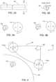
- FIGS. 2 A and 2 Bschematically illustrate a magnet that is usable in the annuloplasty ring shown in FIG. 1 A according to one embodiment.
- FIGS. 3 A and 3 Bschematically illustrate an end view of the magnet of the external magnetic adjustment device placed in parallel with the magnet of the annuloplasty ring according to certain embodiments.
- FIG. 4is a schematic diagram of an external magnet adjustment device including two magnets arranged outside of a patient's body according to one embodiment.
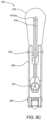
- FIGS. 5 A and 5 Bschematically illustrate a catheter system used to insert an adjustment device into a patient's heart according to certain embodiments.
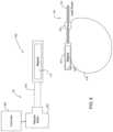
- FIG. 6is a simplified block diagram of a system for adjusting the size of a heart valve according to one embodiment.
- FIG. 7is a schematic diagram of an adjustable annuloplasty ring according to one embodiment.
- FIGS. 8 A 8 B, 8 C 8 D, and 8 Eschematically illustrate an annuloplasty ring according to one embodiment.
- FIG. 9is a schematic diagram illustrating a partially transparent top view of an annuloplasty ring according to another embodiment.
- FIG. 10is a schematic diagram illustrating a cross-sectional top view illustrating an annuloplasty ring according to another embodiment.
- FIGS. 11 A, 11 B, and 11 Care schematic diagrams of an adjustable annuloplasty ring according to another embodiment.
- FIGS. 12 A and 12 Bpartially illustrate the annuloplasty ring shown in FIG. 11 A in a retracted position ( FIG. 12 A ) and in an expanded position ( FIG. 12 B ) according to certain embodiments.
- FIGS. 13 A, 13 B, and 13 Care schematic diagrams of an adjustable annuloplasty ring according to another embodiment.
- FIGS. 14 A and 14 Bschematically illustrate one embodiment in which the superelasticity of a wire may be compressed so as to allow an annuloplasty ring to be inserted through a trocar.
- FIGS. 15 A and 15 Bschematically illustrate an annuloplasty ring having a hinged arm according to one embodiment.
- FIGS. 16 A, 16 B, 16 C, 16 D, and 16 Eschematically illustrate alternative latch embodiments that may be used with the annuloplasty ring shown in FIGS. 15 A and 15 B according to certain embodiments.
- FIGS. 17 A, 17 B, 17 C, 17 D, 17 E, and 17 Fare schematic diagrams of an adjustable annuloplasty ring according to another embodiment.
- FIG. 18is a schematic diagram of an adjustable annuloplasty ring according to another embodiment.
- FIG. 19is a simplified schematic illustrating an end view of a gear attached to a magnetic motor shown in FIG. 18 according to one embodiment.
- FIGS. 20 A and 20 Bschematically illustrate an annuloplasty ring according to another embodiment.
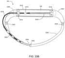
- FIG. 21schematically illustrates an annuloplasty ring according to another embodiment.
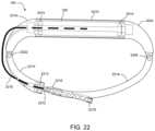
- FIG. 22schematically illustrates an annuloplasty ring according to another embodiment.
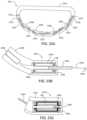
- FIGS. 23 A, 23 B, and 23 Cschematically illustrate a multi-segment annuloplasty ring according to one embodiment.
- FIG. 24is a schematic diagram of an annuloplasty ring that includes a bidirectional torsion drive cable according to one embodiment.
- FIG. 25is a schematic diagram of an annuloplasty ring that includes an elastic tube according to one embodiment.
- FIG. 26is a schematic diagram of an annuloplasty ring that includes a rotatable magnet within a pivot arm according to one embodiment.
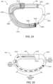
- FIG. 27is a schematic diagram of an annuloplasty ring according to another embodiment.
- FIG. 28is a perspective view of an external magnetic adjustment device according to one embodiment.
- FIGS. 29 A, 29 B, 29 C, and 29 Dschematically illustrate end views of the magnets of the external magnetic adjustment device shown in FIG. 28 according to certain embodiments.
- FIGS. 30 A and 30 Bgraphically represent example magnetic field measurements as the magnets of the external magnetic adjustment device are rotated according to certain embodiments.
- FIG. 31is a schematic diagram of an external magnetic adjustment device that includes two electromagnets according to one embodiment.
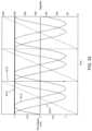
- FIG. 32graphically illustrates various parameters of the magnetic fields generated by the external magnetic adjustment device shown in FIG. 31 according to one embodiment.
- FIG. 33 Ais a schematic diagram of a superior section view of a heart rating an annuloplasty ring implanted in the heart and a magnetic brake assembly implanted outside of the heart according to one embodiment.
- FIG. 33 Bis a schematic diagram illustrating an end view of a brake magnet and an internal magnet in the annuloplasty ring shown in FIG. 33 A according to one embodiment.
- FIGS. 34 A and 34 Bschematically illustrate end views of the brake magnet and the internal magnet of the annuloplasty device according to one embodiment.
- An adjustable annuloplasty ringallows for the proper degree of cinching both during open heart surgery and over the patient's lifetime.
- an annuloplasty ringmay be adjusted less-invasively or non-invasively with the patient alert and postoperatively healed.
- the annuloplasty ringincorporates the ability to both open and close with fine position control.
- adjustable annuloplasty ringsfor mitral valve repair.
- this disclosureis not limited to the mitral valve and an artisan will recognize from the disclosure herein that the adjustable rings may be adapted for other heart valves (e.g., tricuspid valve, aortic value, and/or pulmonary valve) and other vascular structures.
- FIG. 1 Ais a block diagram of a system for adjusting the size of a heart valve according to one embodiment that includes an annuloplasty ring 100 and an external magnetic driver or adjustment device 102 .
- FIG. 1 Bis an enlarged, cross-sectional view of the annuloplasty ring 100 and the external magnetic adjustment device 102 shown in FIG. 1 A .
- the adjustable annuloplasty ring 100may be implanted in a heart 104 of a patient 106 in the same manner as current rigid annuloplasty rings.
- the heart 104 discussed hereinis described in terms of a human heart, an artisan will understand from the disclosure herein that the patient 106 may include any type of mammal or other animal.
- the annuloplasty ring 100 in this exampleis “D” shaped and may be attached, for example, to the mitral valve 107 .
- Other shapese.g., circular or “C” shaped rings
- other openingse.g., for the tricuspid valve.
- the annuloplasty ring 100includes a permanent magnet 108 that may be rotated remotely by one or more magnets 110 in the external magnetic adjustment device 102 .
- Rotating the one or more magnets 110 in the external magnetic adjustment device 102 in one directioncauses the annuloplasty ring 100 to close while turning the one or more magnets 110 in the opposite direction causes the annuloplasty ring 100 to open.
- the external magnetic adjustment device 102 shown in FIGS. 1 A and 1 Bmay include an external handpiece that controls the annuloplasty ring 100 from outside of the patient's body at a distance d from the annuloplasty ring 100 .
- other adjustment devicesincluding percutaneous adjustment devices
- the annuloplasty ring 100 and adjustment deviceincludes one or more of the magnetic adjustment elements disclosed in U.S. Patent Application Publication No. 2008/0097487, titled “Method and Apparatus for Adjusting a Gastrointestinal Restriction Device,” filed Jun. 8, 2007, which is assigned to the Assignee of the present application, and which is hereby incorporated by reference herein for all purposes.
- U.S. Patent Application Publication No. 2008/0097487discloses a gastrointestinal implant system that includes a magnetically adjustable restriction device having a contact surface configured for at least partially engaging a surface of a gastrointestinal tract of a mammal.
- the gastrointestinal implant systemincludes an implantable interface including a driving element, the driving element being moveable and operatively coupled to the adjustable restriction device by an actuator configured to change the dimension or configuration of the contact surface in response to movement of the driving element. Movement of the driving element is effected by application of a moving magnetic field originating external to the patient.
- FIGS. 2 A and 2 Bschematically illustrate a magnet 108 that is usable in the annuloplasty ring 100 shown in FIG. 1 A according to one embodiment.
- a similarly configured magnetmay also be used for the magnet 110 in the external magnetic adjustment device 102 .
- the magnet 108 in this example embodimentis cylindrical and has magnetic poles (e.g., north “N” and south “S”) divided along a plane 200 that runs the length of the cylinder.
- a rotating magnetic fieldcauses the magnet 108 to rotate around an axis 202 of the cylinder that passes through the respective centers of the cylinder's bases (the “cylindrical axis”).
- FIGS. 3 A and 3 Bschematically illustrate an end view of the magnet 110 of the external magnetic adjustment device 102 placed in parallel with the magnet 108 of the annuloplasty ring 100 according to certain embodiments.
- FIG. 3 Aillustrates the magnets 108 , 110 aligned for maximum (peak) torque transmission
- FIG. 3 Billustrates the south pole of the magnet 110 of the external magnetic adjustment device 102 aligned with the north pole of the magnet 108 of the annuloplasty ring 100 .
- the magnetic fields of the respective magnets 108 , 110interact with each other such that mechanically rotating the magnet 110 (e.g., using a stepper motor) in the external magnetic adjustment device 102 causes the magnet 108 in the annuloplasty ring 100 to rotate.
- rotating the magnet 110 in a clockwise direction around its cylindrical axiscauses the magnet 108 to rotate in a counterclockwise direction around its cylindrical axis.
- rotating the magnet 110 in a counterclockwise direction around its cylindrical axiscauses the ma net 108 to rotate in a clockwise direction around its cylindrical axis.
- the magnet 110 in the external magnetic adjustment device 102provides accurate one-to-one control of the magnet 108 in the annuloplasty ring 100 , assuming sufficient magnetic interaction between the magnets 108 , 110 . In other words, one complete rotation of the magnet 110 in the external magnetic adjustment device 102 will cause one complete rotation of the magnet 108 in the annuloplasty ring 100 . If the relationship between the number of rotations of the magnet 108 and the size of the ring is linear, the size of the annuloplasty ring 108 may be determined directly from the number of revolutions since the ring was at its last known size.
- the annuloplasty ring 100may include circuitry for counting the number of revolutions or determining its own size, and for communicating this data to a user.
- the annuloplasty ring 100may include a radio frequency identification (RF ID) tag technology to power and receive data from the annuloplasty ring 100 .
- RF IDradio frequency identification
- FIG. 1 Billustrates that the cylindrical axis of the magnet 110 in the external magnetic adjustment device 102 may be located at an angle ⁇ with respect to the cylindrical axis of the magnet 108 in the annuloplasty ring 100 .
- the rotational torque on the magnet 108 provided by rotating the magnet 110increases as the angle ⁇ approaches zero degrees, and decreases as the angle ⁇ approaches 90 degrees (assuming both magnets 108 , 110 are in the same geometric plane or in parallel planes).
- FIG. 4is a schematic diagram of an external magnetic adjustment device including two magnets 110 ( a ), 110 ( b ) arranged outside of a patient's body 106 according to one embodiment.
- the external magnetic adjustment device 102is not limited to one or two magnets, but may include any number of magnets. For example, an example embodiment that includes four magnets is described below with respect to FIG. 28 .
- the magnets 110 ( a ), 110 ( b )are oriented and rotated relative to each other such that their magnetic fields add together at the ring magnet 108 to increase rotational torque.
- a computer controlled motor 402synchronously rotates the external magnets 110 ( a ), 110 ( b ) through a mechanical linkage 404 to magnetically rotate the internal magnet 108 and adjust the size of the annuloplasty ring 100 .
- One revolution of the motor 402causes one revolution of the external magnets 110 ( a ), 110 ( b ), which in turn causes one revolution of the ring magnet 108 .
- the size of the annuloplasty ring 100may be calculated.
- the motor 402includes a gearbox with a known gear ratio such that multiple motor revolutions may be counted for one magnet revolution.
- a strong electro-magnetic fieldlike that used in Magnetic Resonance Imaging (MRI) is used to adjust the annuloplasty ring 100 .
- the magnetic fieldmay be rotated either mechanically or electronically to cause the magnet 108 in the annuloplasty ring 100 to rotate.
- the patient's bodymay also be rotated about the axis 202 of the magnet 108 in the presence of a strong magnetic field, like that of an MRI.
- the strong magnetic fieldwill hold the magnet 108 stationary while the ring 100 and patient 106 are rotated around the fixed magnet 108 to cause adjustment.
- the ring sizemay be determined by counting the number of revolutions of the magnetic field, or the patient's body, similar to counting revolutions of the permanent magnets 110 discussed above.
- the annuloplasty ring 100may be adjusted during open heart surgery. For example, after implanting the annuloplasty ring 100 in the heart 104 , the heart 104 and pericardium may be closed, and the regurgitation monitored (e.g., using ultrasound color Doppler). Then, a user (e.g., surgeon) may use a handheld adjustment device 102 to resize the annuloplasty ring based on the detected regurgitation. Additional regurgitation monitoring and ring adjustment may be performed before completing the surgery.
- the regurgitation monitorede.g., using ultrasound color Doppler
- FIGS. 5 A and 5 Bschematically illustrate a catheter system 502 used to insert an adjustment device 501 into a patient's heart 104 according to certain embodiments.
- the annuloplasty ring 100may be implanted in the left atrium 504 of the heart 104 on the upper side 506 of the leaflets 508 of the mitral valve 510 .
- the annuloplasty ring 100may be positioned on the lower side of the leaflets 508 .
- the annuloplasty ring 100may be positioned in the left ventricle 512 .
- the annuloplasty ring 100is snaked through the chordae tendineae and then placed against the lower surfaces of the leaflets 508 .
- the chordae tendineaemay be cut to provide a delivery path for implantation of the annuloplasty ring 100 .
- the annuloplasty ring 100may be implanted at other locations in the vasculature system, or at any other position within a patient's body 106 .
- the annuloplasty ring 100may be implanted at a location proximate to the tricuspid valve 514 .
- the annuloplasty ring 100may be positioned on the upper side (e.g., in the right atrium 516 ) or lower side (e.g., in the right ventricle 518 ) of the tricuspid valve 514 to improve the efficacy of the tricuspid valve 514 .
- the catheter system 502enters the heart 104 through the inferior vena cava 520 into the right atrium 516 so as to position the adjustment device 501 proximate the interatrial septum 522 .
- the catheter system 502may alternatively enter from the superior vena cava.
- the adjustment device 501includes one or more magnets configured to interact with a magnetic field of a magnet in the annuloplasty ring 100 .
- the catheter system 502is configured to adjust the size of the annuloplasty ring 100 through the interatrial septum 522 by rotating the one or more magnets in the adjustment device 501 using a flexible drive shaft connected to an external hand crank operated by a user (e.g., physician) or a processor-controlled motor.
- the catheter system 502in another embodiment may enter the heart 104 through the inferior vena cava 520 into the right atrium 516 , and through a hole (e.g., through the fossa ovalis) in the interatrial septum 522 into the left atrium 504 .
- the catheter system 502may alternatively enter from the superior vera cava.
- the catheter system 502may locate the adjustment device 501 proximate the magnet in the annuloplasty ring 100 .
- the adjustment device 501includes one or more magnets configured to interact with a magnetic field of the magnet in the annuloplasty ring 100 .
- the catheter system 502is configured to adjust the size of the annuloplasty ring 100 by rotating the one or more magnets in the adjustment device 501 using a flexible drive shaft connected to an external hand crank operated by a user (e.g., physician) or a processor controlled motor.
- FIG. 6is a simplified block diagram of a system 600 for adjusting the size of a heart valve according to one embodiment.
- the simplified embodiment shown in FIG. 6is provided to illustrate the basic operation of the annuloplasty ring 100 .
- more detailed embodimentsare provided below.
- the system 600includes an adjustable annuloplasty ring 100 and an external magnetic adjustment device 102 .
- the annuloplasty ring 100includes a magnet 108 in a magnet housing 610 .
- the magnet 108is cylindrical and is configured to rotate around its cylindrical axis when exposed to a rotating magnetic field.
- the magnet 108is coupled to a proximal end of a lead screw 612 .
- a spindle nut 614is threaded onto the lead screw 612 .
- a wire 616is coupled to the magnet housing 610 and the spindle nut 614 to form a loop.
- the wire 616may include, for example, stainless steel or superelastic nitinol.
- the external magnetic adjustment device 102includes a magnet 110 in a magnet housing 618 coupled to a drive shaft 620 .
- the drive shaft 620may be connected to a stepper motor 622 coupled to a motor controller/drive 624 .
- the controller/drive 624may include, for example, a microprocessor or personal computer.
- the controller/drive 624is configured to control the position, rotation direction, rotation speed, speed ramp up/down, and other parameters of the stepper motor 622 .
- the stepper motor 622rotates the shaft 620 , which in turn rotates the magnet 110 .
- the shaft 620 and the magnet 110may be covered with a protective material (e.g., plating) and inserted into the heart 104 through a catheter.
- the rotating magnet 110 in the external magnetic adjustment device 102causes the magnet 108 in the annuloplasty ring 100 to rotate.
- the notating magnet 108causes the lead screw 612 to rotate, which in turn causes the spindle nut 614 to move along the threads of the lead screw 612 to either increase or decrease the size of the loop formed by the wire 616 .
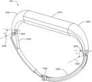
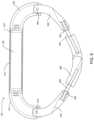
- FIG. 7is a schematic diagram of an adjustable annuloplasty ring according to one embodiment.
- the annuloplasty ring 100is “D” shaped having an AP dimension along the curved portion of the “D” and a commissure to commissure or “CC” dimension along the straight portion of the “D.” Adjusting the annuloplasty ring 100 from an open to a closed position, or vice versa, changes the AP dimension without substantially changing the CC dimension. Further, the AP dimension changes symmetrically in that both the left and right sides of the annuloplasty ring 100 change by substantially the same amount. Certain of the following embodiments include these features.
- the materials of the annuloplasty ring 100are selected for compatibility with long-term contact with human tissue.
- these materialsmay include nitinol, stainless steel, titanium alloys, cobalt alloys, bio-compatible plastics, and other bio-compatible materials.
- the annuloplasty ring 100may be covered with a polyester or Dacron® fabric or other suturable material.
- the annuloplasty ring 100may also include eyelets used for suturing.
- the magnet 108 discussed in certain embodiments hereinmay include a rare-earth magnet and may be plated (e.g., with nickel or gold) or encapsulated in a suitable bio-compatible material, such as the materials discussed above, to reduce or prevent harm to the patient and damage to the magnet.
- Bearingsare included in certain embodiments. These bearings may be of any suitable type including, for example, ball bearings or jewel bearings.
- FIGS. 8 A, 8 B, 8 C, 8 D, and 8 Eschematically illustrate an annuloplasty ring 100 according to one embodiment.
- FIG. 8 Ais a partially transparent top view of the annuloplasty ring 100 in an AP extended or plus position.
- FIG. 8 Bis a partially transparent top view of the annuloplasty ring 100 in an AP retracted or minus position.
- FIG. 8 Cschematically illustrates a side view of the annuloplasty ring 100 .
- FIG. 8 Dis a partially transparent perspective view of the annuloplasty ring 100 .
- FIG. 8 Eis another partially transparent top view of the annuloplasty ring 100 .
- the annuloplasty ring 100includes a body tube 810 for enclosing a magnet housing 812 (including a first end 812 ( a ) and a second end 812 ( b )) that encases a magnet 108 ( FIG. 8 E ).
- a first end of the body tube 810is connected to a first fixed arm 816 and a first end of the magnet housing 812 ( a ) crimps to a first end of a drive cable 818 .
- the first fixed arm 816is connected to a first swivel arm 820 at a first pin joint 822 (e.g., pivot point).
- a second end of the body tube 810is connected to a second fixed arm 824 that is connected to a second swivel arm 826 at a second pin joint 828 .
- the annuloplasty ring 100also includes a lead screw 830 having a first end threaded into a drive nut 832 that is connected to the second swivel arm 826 at a third pin joint 834 .
- a second end of the lead screwis connected to a drive spindle 836 that is connected to a second end of the drive cable 818 .
- a spindle nut 838is threaded onto the lead screw 830 . The spindle nut 838 retains the drive spindle 836 into the first swivel arm 820 .
- the magnet housing 812is engaged with the first fixed arm 816 and the second fixed arm 824 such that rotating the magnet 108 (e.g., using the external magnetic adjustment device 102 ) causes the magnet housing 812 to rotate.
- the rotating magnet housing 812turns the drive cable 818 , which turns the drive spindle 836 .
- the drive spindle 836rotates the lead screw 830 such that it screws into or out of the drive nut 832 .
- the swivel arms 820 , 826pivot at their respective pin joints 822 , 828 , 834 to reduce or enlarge the size of the ring opening in the AP dimension.
- FIG. 9is a schematic diagram illustrating a partially transparent top view of an annuloplasty ring 100 according to another embodiment.
- the annuloplasty ring 100 shown in FIG. 9includes a body tube 910 for enclosing a magnet housing 912 that encases a magnet 108 .
- a first end of the body tube 910is connected to a first fixed arm 914 and a first end of the magnet housing 912 crimps to a first end of a first drive cable (not shown).
- the first fixed arm 914is connected to a first swivel arm 916 at a first pin joint 918 .
- a second end of the body tube 910is connected to a second fixed arm 920 and a second end of the magnet housing 912 crimps to a first end of a second drive cable (not shown).
- the second fixed arm 920is connected to a second swivel arm 922 at a second pin joint 924 .
- the annuloplasty ring 100also includes an extension 926 that symmetrically moves in and out in the AP dimension as the magnet 108 turns.
- a first end of a first lead screw 928is connected to the first swivel arm 916 through a first drive spindle 930 that is connected to the second end of the first drive cable.
- a second end of the first lead screw 928is threaded into a first end of the extension 926 .
- a first end of a second lead screw 932is connected to the second swivel arm 922 through a second drive spindle 934 that is connected to the second end of the second drive cable.
- a second end of the second lead screw 932is threaded into a second end of the extension 926 .
- the extension 926acts as a drive nut for a first lead screw 928 and the second lead screw 932 .
- the first lead screw 928 and the second lead screw 932both screw into or out of the extension 926 at the same time, causing the swivel arms 916 , 922 to pivot about their respective pin joints 918 , 924 .
- one of the lead screws 928 , 932has “right handed” threads and the other has “left-handed” threads such that both lead screws 928 , 932 tighten or loosen together.
- FIG. 10is a schematic diagram illustrating a cross-sectional top view illustrating an annuloplasty ring 100 according to another embodiment.
- the annuloplasty ring 100 shown in FIG. 10includes a magnet 108 , a flexible lead screw 1010 , an elastic covering 1012 , and a wire (not shown) extending from a first end of the flexible lead screw 1010 to a fixed point.
- the elastic covering 1012may include, for example, a biocompatible polymer such as, for instance, polyurethane silicone or a silicone-urethane copolymer.
- the magnet 108includes a hollow passage 1014 and a threaded nut section 1015 or bearings through which the flexible lead screw 1010 passes (e.g., either to the right or to the left) as the magnet 108 turns.
- FIG. 11 Ais a schematic diagram of an adjustable annuloplasty ring 100 according to another embodiment.
- the annuloplasty ring 100includes a permanent magnet 1102 configured to rotate within a magnet housing 1104 .
- the magnet 1102is cylindrical and is configured to rotate around its cylindrical axis when exposed to a rotating magnetic field.
- FIG. 11 Bis a schematic diagram of a front view of the magnet 1102 shown in FIG. 11 A according to one embodiment.
- FIG. 11 Cis a schematic diagram of a side view of the magnet 1102 shown in FIG. 11 A according to one embodiment.
- the magnet 1102has magnetic poles (e.g., north “N” and south “S”) divided along the plane 200 that runs the length of the cylinder.
- the magnet 1102may include a rare earth magnet and may be plated (e.g., with nickel or gold) and/or suitably encapsulated to prevent harm to the patient and damage to the magnet 1102 .
- the magnet 1102includes a hollow region 1106 running along the length of the cylinder between the N and S pores.
- the hollow region 1106may be threaded or may contain a threaded insert 1108 through which a lead screw 1110 is pulled into and out of the magnet 1102 .
- a wire 1112is coupled between the magnet housing 1104 (e.g., by a weld 1114 ) and an end of the lead, screw 1110 .
- a separate lead screw 1110is not used. Rather, threads are formed or cut into the end of the wire 1112 such that the wire 1112 interfaces directly with the threads in the magnet 1102 (e.g., the threaded insert 1108 ).
- the wire 1112may include, for example, superelastic.
- the annuloplasty ring 100includes bearings 1116 to anchor the spinning magnet 1102 .
- the magnet 1102pulls the lead screw 1110 and/or threaded wire 1112 into the magnet 1102 , which in turn reduces the size of the loop formed by the wire 1112 .
- the magnet 1102pushes the lead screw 1110 and/or the threaded wire 1112 out of the magnet 1102 , which in turn increases the size of the loop formed by the wire 1112 .
- FIGS. 12 A and 12 Bpartially illustrate the annuloplasty ring 100 shown in FIG. 11 A in a retracted position ( FIG. 12 A ) and in an expanded position ( FIG. 12 B ) according to certain embodiments.
- the rotation of the magnet 1102e.g., clockwise
- the rotation of the magnet 1102e.g., counter-clockwise
- a portion of the lead screw 1110 and/or the threads in the wire 1112may extend beyond the magnet housing 1104 when the annuloplasty ring 100 is in the extended position. In another embodiment, the lead screw 1110 and/or the threads in the wire 1112 remain within the magnet housing 1104 in both the extended and retracted positions. Moving the lead screw 1110 and or the threaded portion of the threads in the wire 1112 into and out of the magnet 1110 allows improved control for symmetrically adjusting the annuloplasty ring 100 in the AP direction, as discussed above in relation to FIG. 7 .
- FIGS. 13 A, 13 B, and 13 Care schematic diagrams of an adjustable annuloplasty ring 100 according to another embodiment.
- the annuloplasty ring 100includes arm extensions or “horns” 1310 , 1312 attached to each end of the magnet housing 1104 .
- the horns 1310 , 1312may include a suitable rigid or semi-rigid material such as metal or plastic.
- the horns 1310 , 1312redirect or angle a wire 1314 forming the loop of the annuloplasty ring 100 .
- the horns 1310 , 1312may redirect the wire 1314 approximately 90° from the cylindrical axis of the magnet 1102 within the housing 1104 .
- the horns 1310 , 1312further maintain the “D” shape of the annuloplasty ring 100 such that it is substantially only adjusted in the AP direction (e.g., expansion/contraction of the loop is perpendicular to the rotation of the magnet 1102 ).
- the annuloplasty ring 100includes silicone tubing 1317 sealed to each horn 1310 , 1312 .
- the wire 1314extends through the silicone tubing 1317 .
- the silicone tubing 1317stretches and contracts to accommodate circumferential changes to the loop in the annuloplasty ring 100 .
- FIG. 13 Bis a cross-sectional view of the housing 1104 shown in FIG. 13 A according to one embodiment.
- the magnet 1102includes a first threaded insert 1318 and a second threaded insert 1320 .
- the two inserts 1318 , 1320have opposite threaded orientations.
- the first threaded insert 1318may have a right-hand thread orientation and the second threaded insert 1320 may have a left-hand thread orientation.
- Both ends of the magnet 1102may be coupled to bearings 1116 to support the spinning magnet 1102 .
- Each end of the wire 1314is threaded to interface with its respective threaded insert 1318 , 1320 such that rotating the magnet 1102 in one direction pulls the ends of the wire 1314 toward each other and the center of the magnet, and rotating the magnet in the opposite direction pushes the ends of the wire 1314 away from each other and the center of the magnet 1102 .
- the housing 1104 and horns 1310 , 1312are sealed from the outside environment.
- the housing 1104may include two portions that are welded together along a weld line 1321 . Further, the horns 1310 , 1312 are bonded to the housing 1104 to create a hermetic seal 1322 .
- Lubricant 1324may also be sealed within portions of the housing 1104 to provide for proper operation of the bearings 1116 .
- FIG. 13 Cis a cross-sectional view of the interface between the horn 1310 and the silicone tubing 1317 according to one embodiment.
- the annuloplasty ring 100may include a Dacron® covering 1326 (or other polyester covering) or a covering of other suitable material.
- the inner pathway of the horn 1310may include a lubricant such as polytetrafluoroethylene (as known as PTFE Teflon®), silicone oil, grease, etc. to reduce friction between the wire 1314 and the horn 1310 during adjustment of the annuloplasty ring 100 .
- the silicone tubing 1317attaches to the horn 1310 and may provide an area into which sutures may be placed to secure the annuloplasty ring 100 to heart tissue. As discussed above, the silicone tubing 1317 also provides elasticity to accommodate expansion and contraction of the annuloplasty ring 100 .
- the annuloplasty ring 100is configured for implantation into a heart through a narrow trocar or similar device.
- FIGS. 14 A and 14 Bschematically illustrate one embodiment in which the superelasticity of the wire 1314 (e.g., including a material such as nitinol), may be compressed so as to allow the annuloplasty ring 100 to be inserted through a trocar.
- the size of the annuloplasty ring 100 in the AP dimensionis approximately 20 mm or more according to some embodiments. This size may correspond to the dimensions of the annuloplasty ring 100 both before and after being inserted through the trocar.
- FIG. 14 Bthe annuloplasty ring 100 is compressed so as to pass through the trocar. In this configuration, the size of the annuloplasty ring 100 in the AP dimension is approximately 10 mm or less according to some embodiments.
- the superelasticity of the wire 1314allows for extreme flexibility, yet still provides the necessary strength after implantation for annuloplasty.
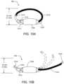
- FIGS. 15 A and 15 Bschematically illustrate an annuloplasty ring 100 having a hinged arm 1510 according to one embodiment.
- the hinged arm 1510is connected to the housing 1104 through a pin joint 1513 .
- the other end of the hinged arm 1510includes a latch 1514 for engaging the superelastic wire 1314 after implantation through the trocar.
- the latch 1514may include a socket configured to receive a “snap-in” lock pin 1516 attached to the free end of the wire 314 curing implantation.
- the annuloplasty ring 100may be inserted into a very small orifice without worry of damaging the wire 1314 .
- FIGS. 16 A, 16 B, 16 C, 16 D , and 16 EAlternative latch embodiments that may be used with the annuloplasty ring 100 shown in FIGS. 15 A and 15 B are schematically illustrated in FIGS. 16 A, 16 B, 16 C, 16 D , and 16 E.
- FIG. 16 Aillustrates an embodiment wherein the socket latch 1514 and the lock pin 1516 are located anywhere along the wire 1314 . In other words, the socket latch 1514 is not directly connected to the hinged arm 1510 , as shown in FIGS. 15 A and 15 B .
- FIG. 16 Aillustrates an embodiment wherein the socket latch 1514 and the lock pin 1516 are located anywhere along the wire 1314 . In other words, the socket latch 1514 is not directly connected to the hinged arm 1510 , as shown in FIGS. 15 A and 15 B .
- FIG. 16 Aillustrates an embodiment wherein the socket latch 1514 and the lock pin 1516 are located anywhere along the wire 1314 . In other words, the socket latch 1514 is not directly connected to the hinge
- the latching mechanismincludes a “ramp and pawl” device in which a pin 1610 having a ramped surface 1612 and a vertical surface 1614 is inserted into a receptacle 1616 having a slanting protrusion 1618 .
- the slanting protrusion 1618is angled and sufficiently flexible so as to allow the slanted surface 1612 to proceed into the receptacle 1616 .
- the slanting protrusion 1618interfaces with the vertical surface 1614 of the pin 1610 so as to prevent the pin 1610 from exiting the receptacle 1616 , at least under normal operating conditions.
- a “knuckle” style latch 1621provides coupling simile to that used in trains.
- the latchincludes a threaded end 1620 configured to be screwed into a threaded nut 1622 .
- the latchincludes a “T-bar” 1624 configured to be received by an appropriately shaped receptacle 1626 .
- FIGS. 17 A, 17 B, 17 C, 17 D, 17 E, and 17 Fare schematic diagrams of adjustable annuloplasty ring 100 according to another embodiment.
- the annuloplasty ring 100includes a first arm 1710 attached to the housing 1104 , a second arm 1712 attached to the housing 1104 , and a third arm 1714 extending between the first arm 1710 and the second arm 1712 .
- the first arm 1710 and the second arm 1712may be pushed into or out of the housing 1104 in response to the rotation of the internal magnet 108 discussed above.
- the third arm 1714is connected to at least one of the first arm 1710 and the second arm 1712 with a folding hinge 1716 that allows the loop portion of the annuloplasty ring 100 to be folded for insertion through a trocar.
- FIG. 17 Aillustrates a front view of the “open” or unfolded annuloplasty ring 100 .
- FIG. 17 Billustrates a front view of the “folded” annuloplasty ring 100 for insertion through the trocar.
- FIGS. 17 C and 17 Dprovide respective close-up views of the hinge 1716 .
- the hingesare opened and may be locked in the open position for implantation around a heart valve (e.g., the mitral valve).
- a heart valvee.g., the mitral valve
- FIG. 17 E and 17 Fillustrate a locking mechanism that includes a locking sleeve 1720 , a bias element 1722 (e.g., spring), and a mechanical stop 1724 .
- the locking sleeve 1720is located above the hinge 1716 .
- the bias element 1722pushes the locking sleeve 1720 over the hinge 1716 until it makes contact with the stop 1724 , as shown in FIG. 17 F .
- the bias element 1722 and the stop 1724hold the locking sleeve 1720 in place such that the hinge 1716 cannot be opened, at least not without user intervention.
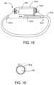
- FIG. 18is a schematic diagram of an adjustable annuloplasty ring 100 according to another embodiment.
- the annuloplasty ring 100includes a housing 1810 , a magnetic motor 108 , and a wire 616 , such as the magnetic motor 108 and wire 616 discussed above in relation to FIGS. 1 B, 2 A, 2 B, 3 , 4 , and 6 .
- the wire 616includes a fixed end 1812 attached to the housing 1810 and a moving end 1814 attached to a rack 1816 located within the housing 1810 .
- the rack 1816is cut or formed within the wire 616 itself.
- the magnetic motor 108rotates in the presence of a rotating magnetic field so as to turn a gear 1818 .
- FIG. 19is a simplified schematic illustrating an end view of the gear 1818 attached to the magnetic motor 108 according to one embodiment.
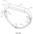
- FIGS. 20 A and 20 Bschematically illustrate an annuloplasty ring 100 according to another embodiment.
- FIG. 20 Ais a perspective view of the annuloplasty ring 100 .
- FIG. 20 Bis a partially transparent top view of the annuloplasty ring 100 .
- the annuloplasty ring 100includes a body tube 2010 for enclosing a magnet 108 .
- the magnet 108is cylindrical and both ends thereof are coupled to bearings 2014 to allow the magnet 108 to rotate when exposed to a rotating magnetic field.
- the magnet 108has magnetic poles divided along a plane that runs along the length of the cylinder.
- the magnet 108includes a hollow region 2015 running along the length of the cylinder between the magnetic poles.
- the hollow region 2015may be threaded or may include a threaded insert through which a lead screw 2030 is pulled (e.g., right and left as shown in FIG. 20 B ) through the magnet 108 .
- a first end of the body tube 2010is connected to a first fixed arm 2016 and a first end of the lead screw 2030 crimps or otherwise attaches to a first end of a drive cable 2018 .
- the first fixed arm 2016is connected to a first swivel arm 2020 at a first pin joint 2022 .
- a second end of the body tube 2010is connected to a second fixed arm 2024 that is connected to a second swivel arm 2026 at a second pin joint 2028 .
- a second end of the drive cable 2018crimps or otherwise attaches to a push rod 2032 .
- a second end of the push rod 2032is connected to the second swivel arm 2026 at a third pin joint 2034 .
- the magnet 108When the magnet 108 is exposed to a rotating magnetic field (e.g., using the external magnetic adjustment device 102 ), the magnet 108 rotates.
- the connection of the drive cable 2018 between the lead screw 2030 and the push rod 2032prevents the lead screw 2030 from rotating along with the magnet 108 .
- the rotating magnetcauses the lead screw 2030 to push and pull the drive cable 2018 into and out of the magnet 108 , which causes the swivel arms 2020 , 2026 to pivot at their respective pin joints 2022 , 2028 , 2034 to reduce or enlarge the size of the ring opening in the AP dimension.
- first pin joint 2022may rotate around a first axis 2036 and the second pin joint 2028 may rotate around a second axis 2038 (which is parallel to the first axis 2036 ) such that the swivel arms 2020 , 2026 move in a first plane.
- the annuloplasty ring 100is configured to change shape in a second plane.
- one or more of the pin joints 2022 , 2028 , 2034 shown in FIG. 20 Bmay be replaced by ball joints (or pin joints that rotate in a diff rent direction).
- the ball jointsmay be configured to rotate out of the first plane when the rotating magnet 108 pushes or pulls the drive cable 2018 .
- first joint 2022 and/or the second joint 2028may rotate at an angle ⁇ with respect to the second axis 2038 .
- the annuloplasty ring 100is configured to form a saddle shape when the rotating magnet 108 pushes or pulls the drive cable 2018 .
- FIG. 21schematically illustrates an annuloplasty ring 100 according to another embodiment.
- the embodiment illustrated in FIG. 21is similar to the embodiment shown in FIGS. 20 A and 20 B , except that the push rod 2032 is hollow to allow the drive cable 2018 to be inserted and secured therein.
- the annuloplasty ring 100 in FIG. 21also includes a coupler 2110 to attach the push rod 2032 and/or the drive cable 2018 to the second swivel arm 2026 at the third pin joint 2034 .
- the drive cable 2018pushes and pulls the push rod 2032 through the first swivel arm 2020 , which causes the swivel arms 2020 , 2026 to pivot at their respective pin joints 2022 , 2028 , 2034 to reduce or enlarge the size of the ring opening in the AP dimension.
- the first swivel arm 2020includes one or more divots or crimps 2112 configured to engage the sliding end of the push rod 2032 to prevent it from exiting the second swivel arm 2020 .
- FIG. 22schematically illustrates an annuloplasty ring 100 according to another embodiment.
- the annuloplasty ring 100includes the body tube 2010 , magnet 108 , bearings 2014 , first fixed arm 2016 , second fixed arm 2024 , drive cable 2018 , first pin joint 2022 , and second pin joint 2028 discussed above in relation to FIGS. 20 A and 20 B .
- the magnet 108need not be threaded, though it may or may not be hollow to facilitate attachment of the drive cable 2018 .
- a first end of the drive cable 2018is attached to either the magnet 108 such that rotating the magnet 108 causes the drive cable 2018 to rotate.
- the annuloplasty ring 100 shown in FIG. 22includes a first swivel arm 2210 attached to the first fixed arm 2016 at the first pin joint 2022 .
- the first swivel arm 2210is coupled to a lead screw 2212 using a bearing 2213 .
- a second end of the drive cable 2018is attached to a first end of the lead screw 2213 such that rotating the drive cable 2018 causes the lead screw 2212 to rotate about the bearing 2213 .
- the bearing 2213allows the lead screw to rotate freely without detaching from the first swivel arm 2210 .
- a second swivel arm 2214is attached to the second fixed arm 2024 at the second pin joint 2028 .
- the second swivel arm 2214includes a threaded drive nut 2216 that engages the threads of the threads of the lead screw 2212 .
- the swivel arms 2210 , 2214pivot at their respective pin joints 2022 , 2028 to reduce or enlarge the size of the ring opening in AP dimension.
- the lead screw 2212may include an end stop 2218 to prevent the lead screw 2212 from being removed (e.g., unscrewed) from the drive nut 2216 .
- FIGS. 23 A, 23 B, and 23 Cillustrate a multi-segment annuloplasty ring 100 according to one embodiment.
- the annuloplasty ring 100includes a body tube 2310 attached to a first magnetic drive segment 2312 at a first pin joint 2314 and a second magnetic drive segment 2316 at a second pin joint 2318 .
- the annuloplasty ring 100may include one or more additional magnetic drive segments 2320 (four shown in the example of FIG. 23 A ) coupled between the first magnetic drive segment 2312 and the second magnetic drive segment 2316 .
- the magnetic drive segments 2312 , 2316 , 2320are coupled to one another with respective lead screws 2322 (five shown in the example of FIG.
- Each magnetic drive segment 2312 , 316 , 2320includes a magnet 108 ( FIGS. 23 B and 23 C ) that may be rotated using a changing magnetic field to drive the respective lead screws 2322 .
- the distance between adjacent magnetic drive segments 2312 , 2316 , 2320may be selectively adjusted.
- the position of each magnetic drive segment 2312 , 2316 , 2320may be individually adjusted.
- FIG. 23 Bschematically illustrates an example magnetic drive segment 2320 according to one embodiment.
- the magnetic drive segment 2320include a link housing 2326 having a first end with a threaded drive nut 2328 for receiving a first lead screw 2322 (not shown in FIG. 23 B ).
- a second end of the link housing 2326includes a hollow magnet 108 within a magnet housing 2330 .
- the magnet 108 and magnet housing 2332are attached to bearings 2332 that allow them to rotate in the presence of a rotating magnetic field.
- a second lead screw 2322is connected to and rotates with the magnet 108 , and is attached to a first end of a safety wire 2324 .
- a second end of the safety wire 2324is attached to a safety stop 2336 configured to attach to one of the other magnetic drive segments 2312 , 2316 , 2320 shown in FIG. 23 A .
- FIG. 23 Cschematically illustrates an example magnetic drive segment 2320 according to another embodiment.
- the magnetic drive segment 2320 shown in FIG. 23 Cincludes a link housing 2338 having a first end fixed to a threaded stud 2340 .
- the threaded stud 2340is configured to be received by one of the other magnetic drive segments 2312 , 2316 , 2320 shown in FIG. 23 A .
- a second end of the link housing 2338includes a hollow magnet 108 within a magnet housing 2342 .
- the magnet 108 and magnet housing 2342are attached to bearings 2344 that allow them to rotate in the presence of a rotating magnetic field.
- An inner magnet housing 2346is threaded to receive a lead screw 2322 or a threaded stud fixed to one of the other magnetic drive segments 2312 , 2316 , 2320 shown in FIG. 23 A .
- FIG. 24is a schematic diagram of an annuloplasty ring 100 that includes a bidirectional torsion drive cable 2410 according to one embodiment.
- the annuloplasty ring 100includes a C-shaped base 2412 that passes through a hollow magnet 108 . In the presence of a rotating magnetic field, the hollow magnet 108 rotates on bearings 2414 attached to the base 2412 .
- a first end of the base 2412is attached to a first swivel arm 2416 at a first pin joint 2418 .
- the first swivel arm 2416includes a threaded section 2420 .
- a first end of the bidirectional torsion drive cable 2410is attached to a first end of the magnet 108 .
- a second end of the bidirectional torsion cable 2410includes a drive nut 2422 that engages the threaded section 2420 of the first swivel arm 2416 .
- the first swivel arm 2416includes a curved lead-in section 2426 to assist in controlling the shape of the bidirectional torsion drive cable 2410 .
- the annuloplasty ring 100may also include a second swivel arm 2428 connected to a second end of the base 2412 at a second pin joint 2430 . The second swivel arm 2428 also assists in controlling the shape of the bidirectional torsion drive cable 2410 .
- the bidirectional torsion drive cable 2410may include, for example, a flexible shaft available from S.S. White Technologies, Inc., of Piscataway, N.J.
- FIG. 25is a schematic diagram of an annuloplasty ring 100 that includes an elastic tube 2510 according to one embodiment.
- the elastic tube 2510extends between the ends of a rigid base 2512 to form a D-shaped ring.
- a magnet 108 with internal threads(as discussed above) is configured to rotate within the base 2512 in the presence of a rotating magnetic field.
- a first end of a drive cable 2514may be threaded so as to engage the internal threads of the magnet 108 .
- the first end of the drive cable 2514is attached to a threaded drive screw 2513 configured to engage the internal threads of the magnet 108 .
- a second end of the drive cable 2514is attached to an anchor point 2516 within the elastic tube 2510 .
- the elastic tube 2510includes bending regions 2518 and an expandable region 2520 .
- the drive cable 2514acts as a draw string to control the circumference of the expandable section 2520 of the elastic tube 2510 .
- the elastic tube 2510comprises superelastic nitinol.
- FIG. 26is a schematic diagram of an annuloplasty ring 100 that includes a rotatable magnet 108 within a pivot arm 2610 according to one embodiment.
- the annuloplasty ring 100includes a C-shaped base 2612 attached to a first end to the pivot arm 2610 at a first pin joint 2614 .
- a second end of the base 2612is attached to a first end of a second pivot arm 2616 at a second pin joint 2618 .
- a second end of the second pivot arm 2616is attached to a drive nut 2620 at a third pin joint 2622 .
- the magnet 108(or an attached magnet housing) may be coupled to bearings 2624 that allow the magnet 108 to rotate within the pivot arm 2610 .
- the magnet 108(or a magnet housing) is attached to a first end of a lead screw 2626 .
- a second end of the lead screw 2626interfaces with the drive nut 2620 .
- the lead screw 2626is drawn into and out of the drive nut 2020 in the direction of the illustrated arrow 2628 to adjust the size of the annuloplasty ring 100 .
- FIG. 27is a schematic diagram of an annuloplasty ring 100 according to another embodiment.
- the annuloplasty ring 100includes a C-shaped base 2712 having a first end attached to a first end of a first pivot arm 2714 at a first pin joint 2716 .
- a second end of the base 2712is attached to a first end of a second pivot arm 2718 at a second pin joint 2720 .
- a second end of the first pivot arm 2714is attached to a first coupler 2721 at a third pin joint 2724 .
- a second end of the second pivot arm 2718is attached to a second coupler 2723 at a fourth pin joint 2726 .
- a magnet 108is configured to rotate on bearings 2728 within a drive housing 2722 .
- the first coupler 2721is attached to a first lead screw 2730 and the second coupler 2723 is attached to a second lead screw 2732 .
- Each lead screw 2730 , 2732is configured to interface with respective internal threads of the magnet 108 .
- the first lead screw 2730 and the second lead screw 2732are threaded in opposite directions.
- the first lead screw 2730may have left-hand threads and the second lead screw 2732 may have right-hand threads.
- both lead screws 2730 , 2732are either drawn into the magnet 108 , or both lead screws 2730 , 2732 are drawn out of the magnet 108 in the direction of the illustrated arrows 2734 to adjust the size of the annuloplasty ring 100 .
- FIG. 28is a perspective view of an external magnetic adjustment device 102 according to one embodiment.
- the external magnetic adjustment device 102includes a first cylindrical magnet 110 ( a ), a second cylindrical magnet 110 ( b ), a third cylindrical magnet 110 ( c ), and a fourth cylindrical magnet 110 ( d ) (referred to collectively as magnets 110 ).
- the magnets 110are permanent magnets.
- the magnets 110are electromagnets configured in be selectively activated.
- the first magnet 110 ( a ) and the second magnet 110 ( b )are attached to a first arm 2810 .
- the third magnet 110 ( c ) and the fourth magnet 110 ( d )are attached to a second arm.
- the first arm 2810 and the second arm 2812are configured to slide relative to each other in opposite directions along a first rail 2814 and a second rail 2816 .
- a patient's chestmay be placed between the magnets 110 of the first arm 2810 and the second arm 2812 during adjustment of a magnetic annuloplasty ring (such as the annuloplasty rings 100 discussed above) implanted within the patient's heart.
- a magnetic annuloplasty ringsuch as the annuloplasty rings 100 discussed above
- the first arm 2810may be connected to a first screw 2818 threaded in a first direction (e.g., right-hand threads) and the second arm 2812 may be connected to a second screw 2820 threaded in a second direction (e.g., left-hand threads).
- the first screw 2818is connected to the second screw 2820 by a coupler 2830 such that both screws 2818 , 2820 turn at the same time.
- a usermay turn the screws 2818 , 2820 using, for example, a hand crank 2832 to adjust the relative positions of the arms 2810 , 2812 .
- a motor(not shown) under the control of a controller (such as the controller 624 shown in FIG. 6 ) may be used to turn the screws 2818 , 2820 .
- the first arm 2810includes a first stepper motor 2834 configured to rotate the first magnet 110 ( a ) and the second magnet 110 ( b ).
- a first stepper motor 2834configured to rotate the first magnet 110 ( a ) and the second magnet 110 ( b ).
- an axle(not shown) may be connected to the first magnet 110 ( a ) and a coupling such as a drive chain (not shown may couple the first magnet 110 ( a ) to the second magnet 110 ( b ) such that the magnets 110 ( a ), 110 ( b ) rotate together in the same direction.
- the second arm 2812includes a second stepper motor 2834 configured to rotate the third magnet 110 ( c ) and the fourth magnet 110 ( d ).
- additional stepper motorsmay be used to independently rotate each magnet.
- ail of the magnets 110are coupled to a single stepper motor (not shown).
- the stepper motors 2834 , 2836may be controlled by a host computer or controller (such as the controller 624 shown in FIG. 6 ) to coordinate the rotation of the magnets 110 at a desired frequency to generate a changing magnetic field suitable for adjusting the annuloplasty ring 100 .
- FIGS. 29 A, 29 B, 29 C, and 29 Dschematically illustrate end views of the magnets 110 of the external magnetic adjustment device 102 shown in FIG. 28 according to certain embodiments.
- a first magnetic polee.g., north
- a second magnetic polee.g. south
- the illustrated examplesalso graphically illustrate the resulting magnetic field lines resulting from each polar alignment configuration.
- FIG. 29 Billustrates the magnets 110 rotated 45° in a clockwise direction as compared to the arrangement of FIG. 29 A . Accordingly, the total magnetic field in the central area of the magnet array (as illustrated by the arrow 2912 ) is also rotated 45°, but in the counterclockwise direction.
- the magnets 110are in an aligned arrangement such that the magnetic poles are all facing the same direction. Further, the line separating the magnetic poles in each magnet 110 set at a 0° offset from a horizontal direction. In this arrangement, the magnetic fields from each magnet 110 also combine so as to augment the total magnetic field (as illustrated by the arrow 2914 ) in the central area of the magnet array. However, in some embodiments (see FIG. 30 A ), the total magnetic field generated in the central region by the aligned arrangement shown in FIG. 29 C may not be as great as that of the Halbach arrangement shown in FIG. 29 A . Further, the total magnetic field in central region of the magnet array may decrease as the magnets 110 are rotated. For example, FIG.
- 29 Dillustrates the magnets 110 rotated 45° in a clockwise direction as compared to the arrangement of FIG. 29 C . Accordingly, the total magnetic field in the central area of the magnet array (as illustrated by the arrow 2916 ) is also rotated 45° in the clockwise direction. However, the magnitude of the total magnetic field in the central region of the magnet array is reduced due to counteracting magnetic fields generated by the first magnet 110 ( a ) and the fourth magnet 110 ( d ).
- FIGS. 30 A and 30 Bgraphically represent example magnetic field measurements as the magnets 110 of the external magnetic adjustment device 102 are rotated according to certain embodiments.
- FIG. 30 Arepresents data corresponding to aligning 3 inch magnets 110 in a square arrangement that is approximately 8.5 inches ⁇ 8.5 inches.
- a first graph 3010(with data points represented by triangles) corresponds to a Halbach arrangement (see FIGS. 29 A and 29 B ) with a gauss meter aligned at 0° with respect to the horizontal direction.
- a second graph 3012(with data points represented by squares) corresponds to the Halbach arrangement (see FIGS. 29 A and 29 B ) with the gauss meter aligned at 45° with respect to the horizontal direction.
- a third graph 3014corresponds to an aligned arrangement (see FIGS. 29 C and 29 D ) with the gauss meter aligned at 0° with respect to the horizontal direction.
- a fourth graph 3016corresponds to the aligned arrangement (see FIGS. 29 C and 29 D ) with the gauss meter aligned at 45° with respect to the horizontal direction.
- the Halbach arrangementprovides stronger magnetic fields in the central region of the magnet array, as compared to that of the aligned arrangement.
- FIG. 30 Brepresents data corresponding to aligning 3 inch magnets 110 in a rectangular arrangement tats approximately 8.5 inches ⁇ 17 inches.
- a first graph 3018(with data points represented by triangles) corresponds to a Halbach arrangement (see FIGS. 29 A and 29 B ) with a gauss meter aligned at 0° with respect to the horizontal direction.
- a second graph 3020(with data points represented by squares) corresponds to the Halbach arrangement (see FIGS. 29 A and 29 B ) with the gauss meter aligned at 90° with respect to the horizontal direction.
- a third graph 3022(with data points represented by circles) corresponds to an aligned arrangement (see FIGS.
- a fourth graph 3024(with data points represented by diamonds) corresponds to the aligned arrangement (see FIGS. 29 C and 29 D ) with the gauss meter aligned at 90° with respect to the horizontal direction.
- FIG. 30 Bthe differences between the third graph 3022 and the fourth graph 3024 illustrate that the aligned arrangement does not produce a consistent magnetic field in the central region of the magnet array as the magnets 110 are rotated.
- FIG. 31is a schematic diagram of an external magnetic adjustment device 102 that includes two electromagnets 3110 ( a ), 3110 ( b ) according to one embodiment.
- electromagnets 3110 ( a ), 3110 ( b )allows the magnetic field generated by the external magnetic adjustment device 102 to be turned off when not in use.
- the electromagnets 3110 ( a ), 3110 ( b )are driven to provide a constant absolute value for the total magnetic field (as discussed below) as the direction of the total magnetic field is rotated at a selected frequency.
- the electromagnets 3110 ( a ), 3110 ( b )may be electronically driven so as to selectively adjust the magnitude of the total magnetic field.
- the electromagnets 3110 ( a ), 3110 ( b )are C-shaped.
- the C-shapereduces or eliminates the magnitude of the magnetic field outside an area where a patient 106 is being treated.
- the magnetic field generated by each electromagnet 3110 ( a ), 3110 ( b )is fairly well maintained between the opposite ends (e.g., a north “N” end and south “S” end) of the respective electromagnet 3110 ( a ), 3110 ( b ).
- each electromagnet 3110 ( a ), 311 ( b )may include, for example, a ferromagnetic core (such as iron) wrapped with an electrically conductive wire.
- the gap between the ends of each C-shaped electromagnet 3110 ( a ), 3110 ( b )is adjustable.
- the respective backbones 3112 ( a ), 3112 ( b )may each include a pivot or slide point.
- a first electromagnet 3110 ( a )is positioned in a horizontal plane and a second electromagnet 3110 ( b ) is positioned in a vertical plane.
- the “backbone” of the first electromagnet 3110 ( a )may be in the horizontal plane with a patient table (not shown) and the “backbone” 3112 of the second electromagnet 3112 may pass beneath the patient table. All four magnet ends (two for each magnet 3110 ( a ), 3110 ( b )) are positioned in the horizontal plane.
- a patient 106may be placed on the table in an approximately 30° right-decubitus (right side downward) supine position on the table. In this position, the axis of the magnet 108 in the annuloplasty ring 100 (not shown in FIG. 31 ) is approximately vertical, and the combined magnetic field is approximately centered around the patient's heart.
- FIG. 32graphically illustrates various parameters of the magnetic fields generated by the external magnetic adjustment device 102 shown in FIG. 31 according to one embodiment.
- a first graph 3210illustrates an X-direction component (e.g., that contributed by the magnet 3110 ( a )) of the combined magnetic field in arbitrary (normalized) units.
- a second graph 3212illustrates a Y-direction component (e.g., that contributed by the magnet 3110 ( b )) of the combined magnetic field in arbitrary (normalized) units. As shown, the first graph 3210 and the second graph 3212 are 90° out of phase from one another.
- a fourth graph 3216(shown as a dashed line) illustrates the direction of the total field in degrees. As time progresses, the direction of the total field cycles between 0° and 360° to turn the magnet 108 in the annuloplasty ring 100 implanted within the patient 106 .
- FIG. 33 Ais a schematic diagram of a superior section view of a heart 104 illustrating an annuloplasty ring 100 implanted in the heart 104 and a magnetic brake assembly 3310 implanted outside of the heart 104 according to one embodiment.
- the annuloplasty ring 100is attached to or near the mitral valve 107 annulus.
- the magnetic brake assembly 3310includes a housing 3312 and a brake magnet 3316 coupled to bearings 3316 in the housing such that the brake magnet 3314 may rotate therein.
- the brake magnet 3314may include a cylindrical magnet having magnetic poles divided along a plane running the length of the cylinder.
- FIG. 33 Bwhich is a schematic diagram illustrating an end view of the brake magnet 3314 and the internal magnet 108 in the annuloplasty ring 100 shown in FIG.
- the magnetic field of the brake magnet 3314interacts with the magnetic field of the internal magnet 108 of the annuloplasty ring 100 to prevent rotation of either magnet 3314 , 108 .
- the internal magnet 108 and the brake magnet 3314are in “phase lock.”
- the annuloplasty ring 100may still be adjusted when desired, however, because the external adjustment device 102 generates a sufficiently large rotating magnetic field to overcome the coupling between the internal magnet 108 and the brake magnet 3314 .
- FIGS. 34 A and 34 Bschematically illustrate end views of the brake magnet 3314 and the interne magnet 108 of the annuloplasty device 100 according to one embodiment.
- a first magnetic polee.g., north
- a second magnetic polee.g., south
- field lines 3410 corresponding to an external magnetic fieldare represented as having a lower density than field lines 3412 shown in FIG. 34 B .
- the external magnetic fieldis relatively weak such that the magnetic poles of the magnets 3314 , 108 may overcome the magnetic field to align with each other.
- FIG. 34 Athe external magnetic field is relatively weak such that the magnetic poles of the magnets 3314 , 108 may overcome the magnetic field to align with each other.
- the external adjustment device 102may be activated to produce a relatively stronger external magnetic field that overcomes the attraction between the magnets 3314 , 108 . Accordingly, both magnets 3314 , 108 align their respective poles with the strong external magnetic field. In other words, both the internal magnet 108 of the annuloplasty ring 100 and the brake magnet 3314 are rotated during selective adjustment of the annuloplasty ring's size.
Landscapes
- Health & Medical Sciences (AREA)
- Cardiology (AREA)
- Oral & Maxillofacial Surgery (AREA)
- Transplantation (AREA)
- Engineering & Computer Science (AREA)
- Biomedical Technology (AREA)
- Heart & Thoracic Surgery (AREA)
- Vascular Medicine (AREA)
- Life Sciences & Earth Sciences (AREA)
- Animal Behavior & Ethology (AREA)
- General Health & Medical Sciences (AREA)
- Public Health (AREA)
- Veterinary Medicine (AREA)
- Prostheses (AREA)
Abstract
Description
Claims (15)
Priority Applications (2)
| Application Number | Priority Date | Filing Date | Title |
|---|---|---|---|
| US17/524,133US12076241B2 (en) | 2008-03-25 | 2021-11-11 | Adjustable implant system |
| US18/800,520US20240398565A1 (en) | 2008-03-25 | 2024-08-12 | Adjustable implant system |
Applications Claiming Priority (6)
| Application Number | Priority Date | Filing Date | Title |
|---|---|---|---|
| US3934908P | 2008-03-25 | 2008-03-25 | |
| US12/411,107US20090248148A1 (en) | 2008-03-25 | 2009-03-25 | Systems and methods for adjusting an annuloplasty ring with an integrated magnetic drive |
| US13/625,725US9198755B2 (en) | 2008-03-25 | 2012-09-24 | Adjustable implant system |
| US14/885,749US10076413B2 (en) | 2008-03-25 | 2015-10-16 | Adjustable implant system |
| US16/103,710US11202707B2 (en) | 2008-03-25 | 2018-08-14 | Adjustable implant system |
| US17/524,133US12076241B2 (en) | 2008-03-25 | 2021-11-11 | Adjustable implant system |
Related Parent Applications (1)
| Application Number | Title | Priority Date | Filing Date |
|---|---|---|---|
| US16/103,710ContinuationUS11202707B2 (en) | 2008-03-25 | 2018-08-14 | Adjustable implant system |
Related Child Applications (1)
| Application Number | Title | Priority Date | Filing Date |
|---|---|---|---|
| US18/800,520ContinuationUS20240398565A1 (en) | 2008-03-25 | 2024-08-12 | Adjustable implant system |
Publications (2)
| Publication Number | Publication Date |
|---|---|
| US20220061989A1 US20220061989A1 (en) | 2022-03-03 |
| US12076241B2true US12076241B2 (en) | 2024-09-03 |
Family
ID=78829262
Family Applications (3)
| Application Number | Title | Priority Date | Filing Date |
|---|---|---|---|
| US16/103,710Active2029-12-18US11202707B2 (en) | 2008-03-25 | 2018-08-14 | Adjustable implant system |
| US17/524,133Active2029-06-11US12076241B2 (en) | 2008-03-25 | 2021-11-11 | Adjustable implant system |
| US18/800,520PendingUS20240398565A1 (en) | 2008-03-25 | 2024-08-12 | Adjustable implant system |
Family Applications Before (1)
| Application Number | Title | Priority Date | Filing Date |
|---|---|---|---|
| US16/103,710Active2029-12-18US11202707B2 (en) | 2008-03-25 | 2018-08-14 | Adjustable implant system |
Family Applications After (1)
| Application Number | Title | Priority Date | Filing Date |
|---|---|---|---|
| US18/800,520PendingUS20240398565A1 (en) | 2008-03-25 | 2024-08-12 | Adjustable implant system |
Country Status (1)
| Country | Link |
|---|---|
| US (3) | US11202707B2 (en) |
Families Citing this family (4)
| Publication number | Priority date | Publication date | Assignee | Title |
|---|---|---|---|---|
| US11202707B2 (en)* | 2008-03-25 | 2021-12-21 | Nuvasive Specialized Orthopedics, Inc. | Adjustable implant system |
| US11589901B2 (en)* | 2019-02-08 | 2023-02-28 | Nuvasive Specialized Orthopedics, Inc. | External adjustment device |
| US11678985B2 (en) | 2019-11-07 | 2023-06-20 | Primo Medical Group, Inc. | Systems, apparatus and methods to repair operation of a heart valve |
| WO2023235518A1 (en)* | 2022-06-02 | 2023-12-07 | Edwards Lifesciences Corporation | Adjustable annuloplasty ring |
Citations (586)
| Publication number | Priority date | Publication date | Assignee | Title |
|---|---|---|---|---|
| US2702031A (en) | 1953-09-25 | 1955-02-15 | Wenger Herman Leslie | Method and apparatus for treatment of scoliosis |
| US3111945A (en) | 1961-01-05 | 1963-11-26 | Solbrig Charles R Von | Bone band and process of applying the same |
| US3372476A (en) | 1967-04-05 | 1968-03-12 | Amp Inc | Method of making permanent connections between interfitting parts |
| US3377576A (en) | 1965-05-03 | 1968-04-09 | Metcom Inc | Gallium-wetted movable electrode switch |
| DE1541262A1 (en) | 1966-06-23 | 1969-06-19 | Gruenert Dr Med Rolf Dieter | Device for closing and opening a natural or artificially created passage way in human or animal bodies |
| US3512901A (en) | 1967-07-28 | 1970-05-19 | Carrier Corp | Magnetically coupled pump with slip detection means |
| US3597781A (en) | 1967-06-05 | 1971-08-10 | Christian Eibes | Self-tapping threaded bushings |
| US3900025A (en) | 1974-04-24 | 1975-08-19 | Jr Walter P Barnes | Apparatus for distracting or compressing longitudinal bone segments |
| US3915151A (en) | 1973-03-23 | 1975-10-28 | Werner Kraus | Apparatus for promoting healing processes |
| USRE28907E (en) | 1967-06-05 | 1976-07-20 | Self-tapping threaded bushings | |
| US3976060A (en) | 1974-04-09 | 1976-08-24 | Messerschmitt-Bolkow-Blohm Gmbh | Extension apparatus, especially for osteotomic surgery |
| US4010758A (en) | 1975-09-03 | 1977-03-08 | Medtronic, Inc. | Bipolar body tissue electrode |
| US4056743A (en) | 1973-07-30 | 1977-11-01 | Horstmann Clifford Magnetics Ltd. | Oscillating reed electric motors |
| US4068821A (en) | 1976-09-13 | 1978-01-17 | Acf Industries, Incorporated | Valve seat ring having a corner groove to receive an elastic seal ring |
| US4078559A (en) | 1975-05-30 | 1978-03-14 | Erkki Einari Nissinen | Straightening and supporting device for the spinal column in the surgical treatment of scoliotic diseases |
| US4204541A (en) | 1977-01-24 | 1980-05-27 | Kapitanov Nikolai N | Surgical instrument for stitching up soft tissues with lengths of spiked suture material |
| US4357946A (en) | 1980-03-24 | 1982-11-09 | Medtronic, Inc. | Epicardial pacing lead with stylet controlled helical fixation screw |
| US4386603A (en) | 1981-03-23 | 1983-06-07 | Mayfield Jack K | Distraction device for spinal distraction systems |
| US4448191A (en) | 1981-07-07 | 1984-05-15 | Rodnyansky Lazar I | Implantable correctant of a spinal curvature and a method for treatment of a spinal curvature |
| US4486176A (en) | 1981-10-08 | 1984-12-04 | Kollmorgen Technologies Corporation | Hand held device with built-in motor |
| US4501266A (en) | 1983-03-04 | 1985-02-26 | Biomet, Inc. | Knee distraction device |
| US4522501A (en) | 1984-04-06 | 1985-06-11 | Northern Telecom Limited | Monitoring magnetically permeable particles in admixture with a fluid carrier |
| US4537520A (en) | 1982-11-16 | 1985-08-27 | Tokyo Electric Co., Ltd. | Dot printer head with reduced magnetic interference |
| DE8515687U1 (en) | 1985-05-29 | 1985-10-24 | Aesculap-Werke Ag Vormals Jetter & Scheerer, 7200 Tuttlingen | Distraction device for extension osteotomy |
| US4550279A (en) | 1982-09-10 | 1985-10-29 | Fabriques D'horlogerie De Fontainemelon S.A. | Step-by-step motor unit |
| US4561798A (en) | 1982-03-09 | 1985-12-31 | Thomson Csf | Telescopic cylindrical tube column |
| US4573454A (en) | 1984-05-17 | 1986-03-04 | Hoffman Gregory A | Spinal fixation apparatus |
| US4592355A (en) | 1983-01-28 | 1986-06-03 | Eliahu Antebi | Process for tying live tissue and an instrument for performing the tying operation |
| US4595007A (en) | 1983-03-14 | 1986-06-17 | Ethicon, Inc. | Split ring type tissue fastener |
| US4642257A (en) | 1985-06-13 | 1987-02-10 | Michael Chase | Magnetic occluding device |
| US4658809A (en) | 1983-02-25 | 1987-04-21 | Firma Heinrich C. Ulrich | Implantable spinal distraction splint |
| US4700091A (en) | 1986-08-22 | 1987-10-13 | Timex Corporation | Bipolar stepping motor rotor with drive pinion and method of manufacture |
| US4747832A (en) | 1983-09-02 | 1988-05-31 | Jacques Buffet | Device for the injection of fluid, suitable for implantation |
| US4854304A (en) | 1987-03-19 | 1989-08-08 | Oscobal Ag | Implant for the operative correction of spinal deformity |
| US4904861A (en) | 1988-12-27 | 1990-02-27 | Hewlett-Packard Company | Optical encoder using sufficient inactive photodetectors to make leakage current equal throughout |
| US4931055A (en) | 1986-05-30 | 1990-06-05 | John Bumpus | Distraction rods |
| US4940467A (en) | 1988-02-03 | 1990-07-10 | Tronzo Raymond G | Variable length fixation device |
| US4957495A (en) | 1987-04-01 | 1990-09-18 | Patrick Kluger | Device for setting the spinal column |
| US4973331A (en) | 1989-03-08 | 1990-11-27 | Autogenesis Corporation | Automatic compression-distraction-torsion method and apparatus |
| US5010879A (en) | 1989-03-31 | 1991-04-30 | Tanaka Medical Instrument Manufacturing Co. | Device for correcting spinal deformities |
| US5030235A (en) | 1990-04-20 | 1991-07-09 | Campbell Robert M Jr | Prosthetic first rib |
| US5041112A (en) | 1989-11-30 | 1991-08-20 | Citieffe S.R.L. | External splint for the treatment of fractures of the long bones of limbs |
| US5064004A (en) | 1986-10-15 | 1991-11-12 | Sandvik Ab | Drill rod for percussion drilling |
| US5074882A (en) | 1988-06-09 | 1991-12-24 | Medinov Sarl | Progressive elongation centro-medullar nail |
| US5092889A (en) | 1989-04-14 | 1992-03-03 | Campbell Robert M Jr | Expandable vertical prosthetic rib |
| US5133716A (en) | 1990-11-07 | 1992-07-28 | Codespi Corporation | Device for correction of spinal deformities |
| US5142407A (en) | 1989-12-22 | 1992-08-25 | Donnelly Corporation | Method of reducing leakage current in electrochemichromic solutions and solutions based thereon |
| US5156605A (en) | 1990-07-06 | 1992-10-20 | Autogenesis Corporation | Automatic internal compression-distraction-method and apparatus |
| US5263955A (en) | 1989-07-04 | 1993-11-23 | Rainer Baumgart | Medullary nail |
| US5290289A (en) | 1990-05-22 | 1994-03-01 | Sanders Albert E | Nitinol spinal instrumentation and method for surgically treating scoliosis |
| US5306275A (en) | 1992-12-31 | 1994-04-26 | Bryan Donald W | Lumbar spine fixation apparatus and method |
| US5330503A (en) | 1989-05-16 | 1994-07-19 | Inbae Yoon | Spiral suture needle for joining tissue |
| US5334202A (en) | 1993-04-06 | 1994-08-02 | Carter Michael A | Portable bone distraction apparatus |
| US5336223A (en) | 1993-02-04 | 1994-08-09 | Rogers Charles L | Telescoping spinal fixator |
| US5356424A (en) | 1993-02-05 | 1994-10-18 | American Cyanamid Co. | Laparoscopic suturing device |
| US5356411A (en) | 1993-02-18 | 1994-10-18 | Spievack Alan R | Bone transporter |
| US5364396A (en) | 1993-03-29 | 1994-11-15 | Robinson Randolph C | Distraction method and apparatus |
| US5403322A (en) | 1993-07-08 | 1995-04-04 | Smith & Nephew Richards Inc. | Drill guide and method for avoiding intramedullary nails in the placement of bone pins |
| US5429638A (en) | 1993-02-12 | 1995-07-04 | The Cleveland Clinic Foundation | Bone transport and lengthening system |
| EP0663184A1 (en) | 1994-01-13 | 1995-07-19 | Ethicon Inc. | Spiral surgical tack |
| US5437266A (en) | 1992-07-02 | 1995-08-01 | Mcpherson; William | Coil screw surgical retractor |
| US5466261A (en) | 1992-11-19 | 1995-11-14 | Wright Medical Technology, Inc. | Non-invasive expandable prosthesis for growing children |
| US5468030A (en) | 1994-01-04 | 1995-11-21 | Caterpillar Inc. | Tube clamp and coupling |
| US5480437A (en) | 1987-08-27 | 1996-01-02 | Draenert; Klaus | Prestressed surgical network |
| US5509888A (en) | 1994-07-26 | 1996-04-23 | Conceptek Corporation | Controller valve device and method |
| US5516335A (en) | 1993-03-24 | 1996-05-14 | Hospital For Joint Diseases Orthopaedic Institute | Intramedullary nail for femoral lengthening |
| US5527309A (en) | 1993-04-21 | 1996-06-18 | The Trustees Of Columbia University In The City Of New York | Pelvo-femoral fixator |
| US5536269A (en) | 1993-02-18 | 1996-07-16 | Genesis Orthopedics | Bone and tissue lengthening device |
| US5549610A (en) | 1994-10-31 | 1996-08-27 | Smith & Nephew Richards Inc. | Femoral intramedullary nail |
| US5573012A (en) | 1994-08-09 | 1996-11-12 | The Regents Of The University Of California | Body monitoring and imaging apparatus and method |
| US5575790A (en) | 1995-03-28 | 1996-11-19 | Rensselaer Polytechnic Institute | Shape memory alloy internal linear actuator for use in orthopedic correction |
| US5582616A (en) | 1994-08-05 | 1996-12-10 | Origin Medsystems, Inc. | Surgical helical fastener with applicator |
| JPH0956736A (en) | 1995-08-25 | 1997-03-04 | Tanaka Ika Kikai Seisakusho:Kk | Device for straightening spinal curvature |
| US5620445A (en) | 1994-07-15 | 1997-04-15 | Brosnahan; Robert | Modular intramedullary nail |
| US5620449A (en) | 1994-07-28 | 1997-04-15 | Orthofix, S.R.L. | Mechanical system for blind nail-hole alignment of bone screws |
| US5626579A (en) | 1993-02-12 | 1997-05-06 | The Cleveland Clinic Foundation | Bone transport and lengthening system |
| US5626613A (en) | 1995-05-04 | 1997-05-06 | Arthrex, Inc. | Corkscrew suture anchor and driver |
| US5632744A (en) | 1992-06-08 | 1997-05-27 | Campbell, Jr.; Robert M. | Segmental rib carriage instrumentation and associated methods |
| US5659217A (en) | 1995-02-10 | 1997-08-19 | Petersen; Christian C. | Permanent magnet d.c. motor having a radially-disposed working flux gap |
| US5662683A (en) | 1995-08-22 | 1997-09-02 | Ortho Helix Limited | Open helical organic tissue anchor and method of facilitating healing |
| US5672175A (en) | 1993-08-27 | 1997-09-30 | Martin; Jean Raymond | Dynamic implanted spinal orthosis and operative procedure for fitting |
| US5672177A (en) | 1996-01-31 | 1997-09-30 | The General Hospital Corporation | Implantable bone distraction device |
| US5700263A (en) | 1996-06-17 | 1997-12-23 | Schendel; Stephen A. | Bone distraction apparatus |
| DE19626230A1 (en) | 1996-06-29 | 1998-01-02 | Inst Physikalische Hochtech Ev | Device for determining the position of magnetic marker through Magen-Darm tract |
| US5704939A (en) | 1996-04-09 | 1998-01-06 | Justin; Daniel F. | Intramedullary skeletal distractor and method |
| US5704938A (en) | 1996-03-27 | 1998-01-06 | Volunteers For Medical Engineering | Implantable bone lengthening apparatus using a drive gear mechanism |
| US5720746A (en) | 1994-11-16 | 1998-02-24 | Soubeiran; Arnaud Andre | Device for displacing two bodies relative to each other |
| US5743910A (en) | 1996-11-14 | 1998-04-28 | Xomed Surgical Products, Inc. | Orthopedic prosthesis removal instrument |
| US5762599A (en) | 1994-05-02 | 1998-06-09 | Influence Medical Technologies, Ltd. | Magnetically-coupled implantable medical devices |
| US5771903A (en) | 1995-09-22 | 1998-06-30 | Kirk Promotions Limited | Surgical method for reducing the food intake of a patient |
| US5810815A (en) | 1996-09-20 | 1998-09-22 | Morales; Jose A. | Surgical apparatus for use in the treatment of spinal deformities |
| WO1998044858A1 (en) | 1997-04-09 | 1998-10-15 | Societe De Fabrication De Materiel Orthopedique - Sofamor | Apparatus for lumbar osteosynthesis to correct spondylolisthesis by posterior route |
| US5827286A (en) | 1997-02-14 | 1998-10-27 | Incavo; Stephen J. | Incrementally adjustable tibial osteotomy fixation device and method |
| US5830221A (en) | 1996-09-20 | 1998-11-03 | United States Surgical Corporation | Coil fastener applier |
| US5879375A (en) | 1992-08-06 | 1999-03-09 | Electric Boat Corporation | Implantable device monitoring arrangement and method |
| DE19745654A1 (en) | 1997-10-16 | 1999-04-22 | Hans Peter Prof Dr Med Zenner | Port for subcutaneous infusion |
| US5902304A (en) | 1995-12-01 | 1999-05-11 | Walker; David A. | Telescopic bone plate for use in bone lengthening by distraction osteogenesis |
| US5935127A (en) | 1997-12-17 | 1999-08-10 | Biomet, Inc. | Apparatus and method for treatment of a fracture in a long bone |
| US5945762A (en) | 1998-02-10 | 1999-08-31 | Light Sciences Limited Partnership | Movable magnet transmitter for inducing electrical current in an implanted coil |
| US5961553A (en) | 1995-02-13 | 1999-10-05 | Medinov-Amp | Long bone elongation device |
| WO1999051160A1 (en) | 1998-04-02 | 1999-10-14 | The University Of Birmingham | Distraction device |
| US5976138A (en) | 1997-02-28 | 1999-11-02 | Baumgart; Rainer | Distraction system for long bones |
| US5979456A (en) | 1996-04-22 | 1999-11-09 | Magovern; George J. | Apparatus and method for reversibly reshaping a body part |
| US6022349A (en) | 1997-02-12 | 2000-02-08 | Exogen, Inc. | Method and system for therapeutically treating bone fractures and osteoporosis |
| US6033412A (en) | 1997-04-03 | 2000-03-07 | Losken; H. Wolfgang | Automated implantable bone distractor for incremental bone adjustment |
| US6034296A (en) | 1997-03-11 | 2000-03-07 | Elvin; Niell | Implantable bone strain telemetry sensing system and method |
| US6102922A (en) | 1995-09-22 | 2000-08-15 | Kirk Promotions Limited | Surgical method and device for reducing the food intake of patient |
| US6106525A (en) | 1997-09-22 | 2000-08-22 | Sachse; Hans | Fully implantable bone expansion device |
| US6126661A (en) | 1997-01-20 | 2000-10-03 | Orthofix S.R.L. | Intramedullary cavity nail and kit for the treatment of fractures of the hip |
| US6126660A (en) | 1998-07-29 | 2000-10-03 | Sofamor Danek Holdings, Inc. | Spinal compression and distraction devices and surgical methods |
| US6139316A (en) | 1999-01-26 | 2000-10-31 | Sachdeva; Rohit C. L. | Device for bone distraction and tooth movement |
| US6138681A (en) | 1997-10-13 | 2000-10-31 | Light Sciences Limited Partnership | Alignment of external medical device relative to implanted medical device |
| US6162223A (en) | 1999-04-09 | 2000-12-19 | Smith & Nephew, Inc. | Dynamic wrist fixation apparatus for early joint motion in distal radius fractures |
| US6183476B1 (en) | 1998-06-26 | 2001-02-06 | Orto Maquet Gmbh & Co. Kg | Plate arrangement for osteosynthesis |
| US6200317B1 (en) | 1996-12-23 | 2001-03-13 | Universiteit Twente And Technologiestichting Stw | Device for moving two objects relative to each other |
| WO2001024697A1 (en) | 1999-10-06 | 2001-04-12 | Orthodyne, Inc. | Device and method for measuring skeletal distraction |
| US6234956B1 (en) | 1999-08-11 | 2001-05-22 | Hongping He | Magnetic actuation urethral valve |
| US6241730B1 (en) | 1997-11-26 | 2001-06-05 | Scient'x (Societe A Responsabilite Limitee) | Intervertebral link device capable of axial and angular displacement |
| US6245075B1 (en) | 1997-01-07 | 2001-06-12 | Wittenstein Motion Control Gmbh | Distraction device for moving apart two bone sections |
| WO2001045485A2 (en) | 2000-02-10 | 2001-06-28 | Obtech Medical Ag | Controlled heartburn and reflux disease treatment apparatus |
| WO2001045487A2 (en) | 2000-02-10 | 2001-06-28 | Potencia Medical Ag | Anal incontinence treatment apparatus with wireless energy supply |
| WO2001067973A2 (en) | 2000-03-15 | 2001-09-20 | Sdgi Holdings, Inc. | Multidirectional pivoting bone screw and fixation system |
| WO2001078614A1 (en) | 2000-04-13 | 2001-10-25 | University College London | Surgical distraction device |
| US6315784B1 (en) | 1999-02-03 | 2001-11-13 | Zarija Djurovic | Surgical suturing unit |
| US6319255B1 (en) | 1996-12-18 | 2001-11-20 | Eska Implants Gmbh & Co. | Prophylactic implant against fracture of osteoporosis-affected bone segments |
| US6331744B1 (en) | 1998-02-10 | 2001-12-18 | Light Sciences Corporation | Contactless energy transfer apparatus |
| US6336929B1 (en) | 1998-01-05 | 2002-01-08 | Orthodyne, Inc. | Intramedullary skeletal distractor and method |
| JP2002500063A (en) | 1998-01-05 | 2002-01-08 | オーソダイン・インコーポレーテッド | Intramedullary skeletal distractor and distraction method |
| US6343568B1 (en) | 1998-03-25 | 2002-02-05 | Mcclasky David R. | Non-rotating telescoping pole |
| US6358283B1 (en) | 1999-06-21 | 2002-03-19 | Hoegfors Christian | Implantable device for lengthening and correcting malpositions of skeletal bones |
| US6375682B1 (en) | 2001-08-06 | 2002-04-23 | Lewis W. Fleischmann | Collapsible, rotatable and expandable spinal hydraulic prosthetic device |
| US20020050112A1 (en) | 2000-11-02 | 2002-05-02 | Okin Gesselschaft Fur Antriebstechnik Mbh & Co. Kg | Telescopic column |
| US6389187B1 (en) | 1997-06-20 | 2002-05-14 | Qinetiq Limited | Optical fiber bend sensor |
| US6400980B1 (en) | 1996-11-05 | 2002-06-04 | Jerome Lemelson | System and method for treating select tissue in a living being |
| US6402753B1 (en) | 1999-06-10 | 2002-06-11 | Orthodyne, Inc. | Femoral intramedullary rod system |
| US20020072758A1 (en) | 2000-12-13 | 2002-06-13 | Reo Michael L. | Processes for producing anastomotic components having magnetic properties |
| US6409175B1 (en) | 1999-07-13 | 2002-06-25 | Grant Prideco, Inc. | Expandable joint connector |
| US6416516B1 (en) | 1999-02-16 | 2002-07-09 | Wittenstein Gmbh & Co. Kg | Active intramedullary nail for the distraction of bone parts |
| US20020164905A1 (en) | 2000-03-14 | 2002-11-07 | Amei Technologies Inc., A Delaware Corporation | Osteotomy guide and method |
| US6499907B1 (en) | 1998-02-24 | 2002-12-31 | Franz Baur | Connecting means for the releasable connection and method for releasing a connection between a first component and a second component |
| US6500110B1 (en) | 1996-08-15 | 2002-12-31 | Neotonus, Inc. | Magnetic nerve stimulation seat device |
| US6508820B2 (en) | 2000-02-03 | 2003-01-21 | Joel Patrick Bales | Intramedullary interlock screw |
| US6510345B1 (en) | 2000-04-24 | 2003-01-21 | Medtronic, Inc. | System and method of bridging a transreceiver coil of an implantable medical device during non-communication periods |
| US20030040671A1 (en) | 1996-06-17 | 2003-02-27 | Somogyi Christopher P. | Medical tube for insertion and detection within the body of a patient |
| US6537196B1 (en) | 2000-10-24 | 2003-03-25 | Stereotaxis, Inc. | Magnet assembly with variable field directions and methods of magnetically navigating medical objects |
| US6554831B1 (en) | 2000-09-01 | 2003-04-29 | Hopital Sainte-Justine | Mobile dynamic system for treating spinal disorder |
| US6565573B1 (en) | 2001-04-16 | 2003-05-20 | Smith & Nephew, Inc. | Orthopedic screw and method of use |
| US6565576B1 (en) | 1998-12-04 | 2003-05-20 | Wittenstein Gmbh & Co. Kg | Distraction assembly |
| US6582313B2 (en) | 2000-12-22 | 2003-06-24 | Delphi Technologies, Inc. | Constant velocity stroking joint having recirculating spline balls |
| US6583630B2 (en) | 1999-11-18 | 2003-06-24 | Intellijoint Systems Ltd. | Systems and methods for monitoring wear and/or displacement of artificial joint members, vertebrae, segments of fractured bones and dental implants |
| US20030144669A1 (en) | 2001-12-05 | 2003-07-31 | Robinson Randolph C. | Limb lengthener |
| US6616669B2 (en) | 1999-04-23 | 2003-09-09 | Sdgi Holdings, Inc. | Method for the correction of spinal deformities through vertebral body tethering without fusion |
| US6626917B1 (en) | 1999-10-26 | 2003-09-30 | H. Randall Craig | Helical suture instrument |
| US20030220643A1 (en) | 2002-05-24 | 2003-11-27 | Ferree Bret A. | Devices to prevent spinal extension |
| US20030220644A1 (en) | 2002-05-23 | 2003-11-27 | Thelen Sarah L. | Method and apparatus for reducing femoral fractures |
| US6656135B2 (en) | 2000-05-01 | 2003-12-02 | Southwest Research Institute | Passive and wireless displacement measuring device |
| US6656194B1 (en) | 2002-11-05 | 2003-12-02 | Satiety, Inc. | Magnetic anchoring devices |
| US6667725B1 (en) | 2002-08-20 | 2003-12-23 | The United States Of America As Represented By The Administrator Of The National Aeronautics And Space Administration | Radio frequency telemetry system for sensors and actuators |
| US6673079B1 (en) | 1999-08-16 | 2004-01-06 | Washington University | Device for lengthening and reshaping bone by distraction osteogenesis |
| US20040011137A1 (en) | 2002-07-10 | 2004-01-22 | Hnat William P. | Strain sensing system |
| US20040011365A1 (en) | 2002-07-18 | 2004-01-22 | Assaf Govari | Medical sensor having power coil, sensing coil and control chip |
| US20040019353A1 (en) | 2002-02-01 | 2004-01-29 | Freid James M. | Spinal plate system for stabilizing a portion of a spine |
| US20040023623A1 (en) | 2000-11-09 | 2004-02-05 | Roman Stauch | Device for controlling, regulating and/or putting an active implant into operation |
| US6702816B2 (en) | 2001-05-25 | 2004-03-09 | Sulzer Orthopedics Ltd. | Femur marrow nail for insertion at the knee joint |
| US6706042B2 (en) | 2001-03-16 | 2004-03-16 | Finsbury (Development) Limited | Tissue distractor |
| US6709293B2 (en) | 2001-08-09 | 2004-03-23 | Kabushiki Kaisha Tokai Rika Denki Seisakusho | Printed-circuit board connector |
| US20040055610A1 (en) | 2002-09-25 | 2004-03-25 | Peter Forsell | Detection of implanted wireless energy receiving device |
| US6730087B1 (en) | 1998-07-02 | 2004-05-04 | Michael Butsch | Bone distraction device |
| US20040133219A1 (en) | 2002-07-29 | 2004-07-08 | Peter Forsell | Multi-material constriction device for forming stoma opening |
| US6761503B2 (en) | 2002-04-24 | 2004-07-13 | Torque-Traction Technologies, Inc. | Splined member for use in a slip joint and method of manufacturing the same |
| US20040138725A1 (en) | 2002-09-20 | 2004-07-15 | Peter Forsell | Harmless wireless energy transmission to implant |
| US6769499B2 (en) | 2001-06-28 | 2004-08-03 | Halliburton Energy Services, Inc. | Drilling direction control device |
| US6789442B2 (en) | 2000-09-15 | 2004-09-14 | Heidelberger Druckmaschinen Ag | Gear stage assembly with preload torque |
| US6796984B2 (en) | 2000-02-29 | 2004-09-28 | Soubeiran Andre Arnaud | Device for relative displacement of two bodies |
| US20040193266A1 (en) | 2003-03-31 | 2004-09-30 | Meyer Rudolf Xaver | Expansible prosthesis and magnetic apparatus |
| US6802844B2 (en) | 2001-03-26 | 2004-10-12 | Nuvasive, Inc | Spinal alignment apparatus and methods |
| US6809434B1 (en) | 1999-06-21 | 2004-10-26 | Fisher & Paykel Limited | Linear motor |
| US6835207B2 (en) | 1996-07-22 | 2004-12-28 | Fred Zacouto | Skeletal implant |
| US6852113B2 (en) | 2001-12-14 | 2005-02-08 | Orthopaedic Designs, Llc | Internal osteotomy fixation device |
| US20050034705A1 (en) | 2003-08-12 | 2005-02-17 | Cooper Cameron Corporation | Seal assembly for a pressurized fuel feed system for an internal combustion engine |
| US20050049617A1 (en) | 2003-08-25 | 2005-03-03 | Ethicon, Inc. | Deployment apparatus for suture anchoring device |
| US20050060030A1 (en) | 2000-01-31 | 2005-03-17 | Lashinski Randall T. | Remotely activated mitral annuloplasty system and methods |
| US20050065529A1 (en) | 2003-09-11 | 2005-03-24 | Mingyan Liu | Impulsive percussion instruments for endplate preparation |
| US20050090823A1 (en) | 2003-10-28 | 2005-04-28 | Bartimus Christopher S. | Posterior fixation system |
| US6918910B2 (en) | 2002-12-16 | 2005-07-19 | John T. Smith | Implantable distraction device |
| US6918838B2 (en) | 2001-11-29 | 2005-07-19 | Gkn Lobro Gmbh | Longitudinal plunging unit with a hollow profiled journal |
| US20050159754A1 (en) | 2004-01-21 | 2005-07-21 | Odrich Ronald B. | Periosteal distraction bone growth |
| US6921400B2 (en) | 1999-10-21 | 2005-07-26 | Gary W. Sohngen | Modular intramedullary nail |
| US6923951B2 (en) | 1994-07-01 | 2005-08-02 | Board Of Trustees Of The Leland Stanford University | Non-invasive localization of a light-emitting conjugate in a mammal |
| US20050234462A1 (en) | 2004-01-05 | 2005-10-20 | Hershberger Troy W | Method and instrumentation for performing minimally invasive hip arthroplasty |
| US20050234448A1 (en) | 2004-03-19 | 2005-10-20 | Mccarthy James | Implantable bone-lengthening device |
| US20050246034A1 (en) | 2002-08-30 | 2005-11-03 | Arnaud Soubeiran | Implantable mechanical device with adjustable geometry |
| CN1697630A (en) | 2002-08-25 | 2005-11-16 | 香港大学 | Devices for correcting spinal deformities |
| US20050261779A1 (en) | 2003-11-17 | 2005-11-24 | Meyer Rudolf X | Expansible rod-type prosthesis and external magnetic apparatus |
| US6971143B2 (en) | 2002-02-20 | 2005-12-06 | Terumo Cardiovascular Systems Corporation | Magnetic detent for rotatable knob |
| US20050272976A1 (en) | 2004-03-15 | 2005-12-08 | Olympus Corporation | Endoscope insertion aiding device |
| US20060004459A1 (en) | 2004-06-30 | 2006-01-05 | Hazebrouck Stephen A | Adjustable orthopaedic prosthesis and associated method |
| US20060009767A1 (en) | 2004-07-02 | 2006-01-12 | Kiester P D | Expandable rod system to treat scoliosis and method of using the same |
| US20060036324A1 (en) | 2004-08-03 | 2006-02-16 | Dan Sachs | Adjustable spinal implant device and method |
| US20060036323A1 (en) | 2004-08-03 | 2006-02-16 | Carl Alan L | Facet device and method |
| US20060036259A1 (en) | 2004-08-03 | 2006-02-16 | Carl Allen L | Spine treatment devices and methods |
| US7001346B2 (en) | 2001-11-14 | 2006-02-21 | Michael R. White | Apparatus and methods for making intraoperative orthopedic measurements |
| US20060047282A1 (en) | 2004-08-30 | 2006-03-02 | Vermillion Technologies, Llc | Implant for correction of spinal deformity |
| US7008425B2 (en) | 1999-05-27 | 2006-03-07 | Jonathan Phillips | Pediatric intramedullary nail and method |
| US7011658B2 (en) | 2002-03-04 | 2006-03-14 | Sdgi Holdings, Inc. | Devices and methods for spinal compression and distraction |
| US20060058792A1 (en) | 2004-09-16 | 2006-03-16 | Hynes Richard A | Intervertebral support device with bias adjustment and related methods |
| US20060069447A1 (en) | 2004-09-30 | 2006-03-30 | Disilvestro Mark R | Adjustable, remote-controllable orthopaedic prosthesis and associated method |
| US20060074448A1 (en) | 2004-09-29 | 2006-04-06 | The Regents Of The University Of California | Apparatus and methods for magnetic alteration of deformities |
| US20060079897A1 (en) | 2004-09-29 | 2006-04-13 | Harrison Michael R | Apparatus and methods for magnetic alteration of anatomical features |
| US7029475B2 (en) | 2003-05-02 | 2006-04-18 | Yale University | Spinal stabilization method |
| US7029472B1 (en) | 1999-06-01 | 2006-04-18 | Fortin Frederic | Distraction device for the bones of children |
| US7041105B2 (en) | 2001-06-06 | 2006-05-09 | Sdgi Holdings, Inc. | Dynamic, modular, multilock anterior cervical plate system having detachably fastened assembleable and moveable segments |
| US7060080B2 (en) | 2002-09-04 | 2006-06-13 | Endoart S.A. | Closure system for surgical ring |
| US7063706B2 (en) | 2001-11-19 | 2006-06-20 | Wittenstein Ag | Distraction device |
| US20060136062A1 (en) | 2004-12-17 | 2006-06-22 | Dinello Alexandre | Height-and angle-adjustable motion disc implant |
| US20060142767A1 (en) | 2004-12-27 | 2006-06-29 | Green Daniel W | Orthopedic device and method for correcting angular bone deformity |
| US20060155279A1 (en) | 2004-10-28 | 2006-07-13 | Axial Biotech, Inc. | Apparatus and method for concave scoliosis expansion |
| US20060195088A1 (en) | 2005-02-02 | 2006-08-31 | Ronald Sacher | Adjustable length implant |
| US20060195087A1 (en) | 2005-02-02 | 2006-08-31 | Ronald Sacher | Adjustable length implant |
| US20060200134A1 (en) | 2002-02-01 | 2006-09-07 | James Freid | Spinal plate system for stabilizing a portion of a spine |
| US7105029B2 (en) | 2002-02-04 | 2006-09-12 | Zimmer Spine, Inc. | Skeletal fixation device with linear connection |
| US7105968B2 (en) | 2004-12-03 | 2006-09-12 | Edward William Nissen | Magnetic transmission |
| US20060204156A1 (en) | 2005-03-08 | 2006-09-14 | Nsk Ltd. | Wheel supporting bearing assembly and method for producing the same |
| US7115129B2 (en) | 2001-10-19 | 2006-10-03 | Baylor College Of Medicine | Bone compression devices and systems and methods of contouring and using same |
| US7114501B2 (en) | 2000-08-14 | 2006-10-03 | Spine Wave, Inc. | Transverse cavity device and method |
| US20060235299A1 (en) | 2005-04-13 | 2006-10-19 | Martinelli Michael A | Apparatus and method for intravascular imaging |
| US20060235424A1 (en) | 2005-04-01 | 2006-10-19 | Foster-Miller, Inc. | Implantable bone distraction device and method |
| US20060241767A1 (en) | 2005-04-22 | 2006-10-26 | Doty Keith L | Spinal disc prosthesis and methods of use |
| US20060241746A1 (en) | 2005-04-21 | 2006-10-26 | Emanuel Shaoulian | Magnetic implants and methods for reshaping tissue |
| US20060241748A1 (en) | 2005-03-25 | 2006-10-26 | Lee Leonard Y | Methods and apparatus for controlling the internal circumference of an anatomic orifice or lumen |
| US20060252982A1 (en) | 2005-05-04 | 2006-11-09 | Hassler William L Jr | Magnetic resonance imaging (MRI) safe remotely adjustable artificial sphincter |
| US20060249914A1 (en) | 2005-05-06 | 2006-11-09 | Dulin Robert D | Enhanced reliability sealing system |
| US7135022B2 (en) | 2001-05-23 | 2006-11-14 | Orthogon 2003 Ltd. | Magnetically-actuable intramedullary device |
| US20060271107A1 (en) | 2004-09-29 | 2006-11-30 | Harrison Michael R | Apparatus and methods for magnetic alteration of anatomical features |
| US20060282073A1 (en) | 2003-04-03 | 2006-12-14 | Naum Simanovsky | Implant for treating idiopathic scoliosis and a method for using the same |
| US20060293683A1 (en) | 2003-04-16 | 2006-12-28 | Roman Stauch | Device for lengthening bones or bone parts |
| US20070004999A1 (en) | 2002-12-11 | 2007-01-04 | Christoph Miethke | Method of treating a patient with hydrocephalus and apparatus therefor |
| US7160312B2 (en) | 1999-06-25 | 2007-01-09 | Usgi Medical, Inc. | Implantable artificial partition and methods of use |
| US20070010887A1 (en) | 2002-03-30 | 2007-01-11 | Williams Lytton A | Intervertebral Device and Method of Use |
| US20070010814A1 (en) | 2003-08-28 | 2007-01-11 | Roman Stauch | Device for extending bones |
| US7163538B2 (en) | 2002-02-13 | 2007-01-16 | Cross Medical Products, Inc. | Posterior rod system |
| US20070021644A1 (en) | 2005-03-02 | 2007-01-25 | Woolson Steven T | Noninvasive methods, apparatus, kits, and systems for intraoperative position and length determination |
| WO2007013059A2 (en) | 2005-07-26 | 2007-02-01 | Ram Weiss | Extending intrabody capsule |
| US20070027356A1 (en) | 2005-07-28 | 2007-02-01 | Ethicon Endo-Surgery, Inc. | Electroactive polymer actuated gastric band |
| US20070031131A1 (en) | 2005-08-04 | 2007-02-08 | Mountain Engineering Ii, Inc. | System for measuring the position of an electric motor |
| WO2007015239A2 (en) | 2005-08-01 | 2007-02-08 | Orthogon Technologies 2003 Ltd. | An implantable magnetically activated actuator |
| US20070043376A1 (en) | 2003-02-21 | 2007-02-22 | Osteobiologics, Inc. | Bone and cartilage implant delivery device |
| US20070050030A1 (en) | 2005-08-23 | 2007-03-01 | Kim Richard C | Expandable implant device with interchangeable spacer |
| US7189005B2 (en) | 2005-03-14 | 2007-03-13 | Borgwarner Inc. | Bearing system for a turbocharger |
| US7191007B2 (en) | 2004-06-24 | 2007-03-13 | Ethicon Endo-Surgery, Inc | Spatially decoupled twin secondary coils for optimizing transcutaneous energy transfer (TET) power transfer characteristics |
| DE102005045070A1 (en) | 2005-09-21 | 2007-04-05 | Siemens Ag | Bone implant, in particular femoral neck prosthesis |
| US7218232B2 (en) | 2003-07-11 | 2007-05-15 | Depuy Products, Inc. | Orthopaedic components with data storage element |
| US20070118215A1 (en) | 2005-11-16 | 2007-05-24 | Micardia Corporation | Magnetic engagement of catheter to implantable device |
| US7238191B2 (en) | 2002-09-04 | 2007-07-03 | Endoart S.A. | Surgical ring featuring a reversible diameter remote control system |
| US7241300B2 (en) | 2000-04-29 | 2007-07-10 | Medtronic, Inc, | Components, systems and methods for forming anastomoses using magnetism or other coupling means |
| US20070161984A1 (en) | 2005-12-08 | 2007-07-12 | Ebi, L.P. | Foot plate fixation |
| US7243719B2 (en) | 2004-06-07 | 2007-07-17 | Pathfinder Energy Services, Inc. | Control method for downhole steering tool |
| US20070173837A1 (en) | 2005-11-18 | 2007-07-26 | William Marsh Rice University | Bone fixation and dynamization devices and methods |
| US20070179493A1 (en) | 2006-01-13 | 2007-08-02 | Kim Richard C | Magnetic spinal implant device |
| US20070185374A1 (en) | 2006-01-17 | 2007-08-09 | Ellipse Technologies, Inc. | Two-way adjustable implant |
| US7255682B1 (en) | 2004-09-09 | 2007-08-14 | Bartol Jr Robert J | Spot locator device |
| US20070213751A1 (en) | 2006-03-13 | 2007-09-13 | Scirica Paul A | Transdermal magnetic coupling gastric banding |
| CN101040807A (en) | 2002-09-06 | 2007-09-26 | 爱普能公司 | Implanted system |
| US20070233239A1 (en)* | 2005-07-15 | 2007-10-04 | The Cleveland Clinic Foundation | Apparatus and method for reducing cardiac valve regurgitation |
| US20070233098A1 (en) | 2004-06-30 | 2007-10-04 | Brooke Mastrorio | Adjustable Posterior Spinal Column Positioner |
| US20070239159A1 (en) | 2005-07-22 | 2007-10-11 | Vertiflex, Inc. | Systems and methods for stabilization of bone structures |
| US20070239161A1 (en) | 2006-04-06 | 2007-10-11 | Lukas Giger | Remotely Adjustable Tissue Displacement Device |
| US7282023B2 (en) | 2000-09-11 | 2007-10-16 | Magnetic Developpement Medical | Method and device for controlling the inflation of an inflatable prosthetic envelope |
| WO2007118179A2 (en)* | 2006-04-06 | 2007-10-18 | Synthes (U.S.A.) | Remotely adjustable tissue displacement device |
| US7285087B2 (en) | 2004-07-15 | 2007-10-23 | Micardia Corporation | Shape memory devices and methods for reshaping heart anatomy |
| US20070255088A1 (en) | 2006-04-11 | 2007-11-01 | Jacobson Andrew D | Implantable, magnetic actuator |
| US7302015B2 (en) | 2003-01-02 | 2007-11-27 | Samsung Electronics Co., Ltd. | Motion estimation method for moving picture compression coding |
| US20070276378A1 (en) | 2004-09-29 | 2007-11-29 | The Regents Of The University Of California | Apparatus and methods for magnetic alteration of anatomical features |
| US20070276493A1 (en) | 2005-02-17 | 2007-11-29 | Malandain Hugues F | Percutaneous spinal implants and methods |
| US20070276369A1 (en) | 2006-05-26 | 2007-11-29 | Sdgi Holdings, Inc. | In vivo-customizable implant |
| US20070276368A1 (en) | 2006-05-23 | 2007-11-29 | Sdgi Holdings, Inc. | Systems and methods for adjusting properties of a spinal implant |
| US20070276373A1 (en) | 2005-02-17 | 2007-11-29 | Malandain Hugues F | Percutaneous Spinal Implants and Methods |
| US7302858B2 (en) | 2004-09-24 | 2007-12-04 | Kevin Walsh | MEMS capacitive cantilever strain sensor, devices, and formation methods |
| US20070288024A1 (en) | 2006-06-06 | 2007-12-13 | Sohrab Gollogly | Bone fixation |
| US20070288183A1 (en) | 2006-06-07 | 2007-12-13 | Cherik Bulkes | Analog signal transition detector |
| FR2901991A1 (en) | 2006-06-13 | 2007-12-14 | Arnaud Andre Soubeiran | INTRACORPOREAL LENGTH DEVICE WITH TENSIONED SCREW |
| US7314443B2 (en) | 2002-03-08 | 2008-01-01 | Allergan Medical S.A. | Implantable device |
| US20080009792A1 (en) | 2006-01-27 | 2008-01-10 | Bruce Henniges | System and method for deliverying an agglomeration of solid beads and cement to the interior of a bone in order to form an implant within the bone |
| US20080015577A1 (en) | 2006-07-11 | 2008-01-17 | Alexander Loeb | Spinal Correction Device |
| US20080021454A1 (en) | 2006-07-21 | 2008-01-24 | Depuy Spine, Inc. | Sacral or iliac connector |
| US20080021456A1 (en) | 2006-07-21 | 2008-01-24 | Depuy Spine, Inc. | Sacral or iliac cross connector |
| US20080021455A1 (en) | 2006-07-21 | 2008-01-24 | Depuy Spine, Inc. | Articulating Sacral or Iliac Connector |
| US20080027436A1 (en) | 2006-07-14 | 2008-01-31 | John Cournoyer | Rod to Rod Connectors and Methods of Adjusting The Length Of A Spinal Rod Construct |
| US20080033431A1 (en) | 2006-06-29 | 2008-02-07 | Searete Llc, A Limited Liability Corporation Of The State Of Delaware | Position augmenting mechanism |
| US20080033436A1 (en) | 2004-08-30 | 2008-02-07 | Vermillion Technologies, Llc | Device and method for treatment of spinal deformity |
| US7333013B2 (en) | 2004-05-07 | 2008-02-19 | Berger J Lee | Medical implant device with RFID tag and method of identification of device |
| US20080051784A1 (en) | 2006-08-03 | 2008-02-28 | Sohrab Gollogly | Bone repositioning apparatus and methodology |
| EP1905388A1 (en) | 2006-09-29 | 2008-04-02 | DePuy Products, Inc. | Monitoring orthopaedic implant data over a cellular network |
| US20080082118A1 (en) | 2005-02-17 | 2008-04-03 | Edidin Avram A | Percutaneous spinal implants and methods |
| US20080086128A1 (en) | 2006-09-07 | 2008-04-10 | David Warren Lewis | Method and apparatus for treatment of scoliosis |
| US7357037B2 (en) | 2002-07-10 | 2008-04-15 | Orthodata Technologies Llc | Strain sensing system |
| US7357635B2 (en) | 2004-05-19 | 2008-04-15 | Orthovisage Inc. | System and method to bioengineer facial form in adults |
| US20080091264A1 (en) | 2002-11-26 | 2008-04-17 | Ample Medical, Inc. | Devices, systems, and methods for reshaping a heart valve annulus, including the use of magnetic tools |
| US7360542B2 (en) | 2002-09-06 | 2008-04-22 | Apneon, Inc. | Devices, systems, and methods to fixate tissue within the regions of body, such as the pharyngeal conduit |
| US20080097487A1 (en) | 2006-10-20 | 2008-04-24 | Scott Pool | Method and apparatus for adjusting a gastrointestinal restriction device |
| US20080097496A1 (en) | 2006-10-20 | 2008-04-24 | Arvin Chang | System and method for securing an implantable interface to a mammal |
| US20080109076A1 (en) | 2002-08-29 | 2008-05-08 | Mitralsolutions, Inc. | Methods for controlling the internal circumference of an anatomic orifice or lumen |
| US20080108995A1 (en) | 2006-11-06 | 2008-05-08 | Janet Conway | Internal bone transport |
| US7390294B2 (en) | 2004-05-28 | 2008-06-24 | Ethicon Endo-Surgery, Inc. | Piezo electrically driven bellows infuser for hydraulically controlling an adjustable gastric band |
| US7390007B2 (en) | 2005-06-06 | 2008-06-24 | Ibis Tek, Llc | Towbar system |
| US20080161933A1 (en) | 2005-09-26 | 2008-07-03 | Innvotec Surgical, Inc. | Selectively expanding spine cage, hydraulically controllable in three dimensions for vertebral body replacement |
| US20080167685A1 (en) | 2007-01-05 | 2008-07-10 | Warsaw Orthopedic, Inc. | System and Method For Percutanously Curing An Implantable Device |
| US20080172063A1 (en) | 2004-07-29 | 2008-07-17 | Andrew Clive Taylor | Auto-Extensible Device |
| US7402176B2 (en) | 2003-09-30 | 2008-07-22 | Malek Michel H | Intervertebral disc prosthesis |
| US7402134B2 (en) | 2004-07-15 | 2008-07-22 | Micardia Corporation | Magnetic devices and methods for reshaping heart anatomy |
| US20080177326A1 (en) | 2007-01-19 | 2008-07-24 | Matthew Thompson | Orthosis to correct spinal deformities |
| US20080177319A1 (en) | 2006-12-09 | 2008-07-24 | Helmut Schwab | Expansion Rod, Self-Adjusting |
| US20080183285A1 (en) | 2004-06-29 | 2008-07-31 | Micardia Corporation | Adjustable cardiac valve implant with selective dimensional adjustment |
| FR2900563B1 (en) | 2006-05-05 | 2008-08-08 | Frederic Fortin | ADJUSTABLE SCOLIOSIS RECTIFIER DEVICE |
| US20080190237A1 (en) | 2006-12-06 | 2008-08-14 | Schaeffler Kg | Mechanical tappet in particular for a fuel pump of an internal combustion engine |
| US20080228186A1 (en) | 2005-04-01 | 2008-09-18 | The Regents Of The University Of Colorado | Graft Fixation Device |
| FR2892617B1 (en) | 2005-11-02 | 2008-09-26 | Frederic Fortin | DAMPING DISPLACEMENT DEVICE AND CORRECTION ADJUSTABLE TO THE GROWTH OF THE RACHIS |
| US7429259B2 (en) | 2003-12-02 | 2008-09-30 | Cadeddu Jeffrey A | Surgical anchor and system |
| US20080243150A1 (en) | 2003-09-04 | 2008-10-02 | Guided Delivery Systems, Inc. | Delivery devices and methods for heart valve repair |
| US20080255615A1 (en) | 2007-03-27 | 2008-10-16 | Warsaw Orthopedic, Inc. | Treatments for Correcting Spinal Deformities |
| US7445010B2 (en) | 2003-01-29 | 2008-11-04 | Torax Medical, Inc. | Use of magnetic implants to treat issue structures |
| US20080275557A1 (en) | 2007-05-01 | 2008-11-06 | Exploramed Nc4, Inc. | Adjustable absorber designs for implantable device |
| US20080272928A1 (en) | 2007-05-03 | 2008-11-06 | Shuster Gary S | Signaling light with motion-sensing light control circuit |
| US7458981B2 (en) | 2004-03-09 | 2008-12-02 | The Board Of Trustees Of The Leland Stanford Junior University | Spinal implant and method for restricting spinal flexion |
| US20090030462A1 (en) | 2007-07-26 | 2009-01-29 | Glenn R. Buttermann, M.D. | Segmental Orthopaedic device for spinal elongation and for treatment of Scoliosis |
| US7485143B2 (en) | 2002-11-15 | 2009-02-03 | Abbott Cardiovascular Systems Inc. | Apparatuses and methods for heart valve repair |
| US7485149B1 (en) | 2003-10-06 | 2009-02-03 | Biomet Manufacturing Corporation | Method and apparatus for use of a non-invasive expandable implant |
| US7489495B2 (en) | 2004-04-15 | 2009-02-10 | Greatbatch-Sierra, Inc. | Apparatus and process for reducing the susceptibility of active implantable medical devices to medical procedures such as magnetic resonance imaging |
| US20090076597A1 (en) | 2007-09-19 | 2009-03-19 | Jonathan Micheal Dahlgren | System for mechanical adjustment of medical implants |
| US20090082815A1 (en) | 2007-09-20 | 2009-03-26 | Zimmer Gmbh | Spinal stabilization system with transition member |
| US20090088803A1 (en) | 2007-10-01 | 2009-04-02 | Warsaw Orthopedic, Inc. | Flexible members for correcting spinal deformities |
| US20090093890A1 (en) | 2007-10-04 | 2009-04-09 | Daniel Gelbart | Precise control of orthopedic actuators |
| US20090093820A1 (en) | 2007-10-09 | 2009-04-09 | Warsaw Orthopedic, Inc. | Adjustable spinal stabilization systems |
| US20090112263A1 (en) | 2007-10-30 | 2009-04-30 | Scott Pool | Skeletal manipulation system |
| US7531002B2 (en) | 2004-04-16 | 2009-05-12 | Depuy Spine, Inc. | Intervertebral disc with monitoring and adjusting capabilities |
| US7530981B2 (en) | 2002-02-18 | 2009-05-12 | Crimean Traumatology and Orthopedics Centre Named After A. I. Bliskunov “Abas” | Bliskunov device for elongating long bones |
| US20090163780A1 (en) | 2007-12-21 | 2009-06-25 | Microvention, Inc. | System And Method For Locating Detachment Zone Of A Detachable Implant |
| US7553298B2 (en) | 2003-12-19 | 2009-06-30 | Ethicon Endo-Surgery, Inc. | Implantable medical device with cover and method |
| US20090171356A1 (en) | 2008-01-02 | 2009-07-02 | International Business Machines Corporation | Bone Repositioning Apparatus and System |
| US7561916B2 (en) | 2005-06-24 | 2009-07-14 | Ethicon Endo-Surgery, Inc. | Implantable medical device with indicator |
| US20090192514A1 (en) | 2007-10-09 | 2009-07-30 | Feinberg Stephen E | Implantable distraction osteogenesis device and methods of using same |
| US20090198144A1 (en) | 2007-09-25 | 2009-08-06 | Neosync, Inc. | Systems and Methods for Anxiety Treatment Using Neuro-EEG Synchronization Therapy |
| US20090216113A1 (en) | 2005-11-17 | 2009-08-27 | Eric Meier | Apparatus and Methods for Using an Electromagnetic Transponder in Orthopedic Procedures |
| FR2916622B1 (en) | 2007-05-28 | 2009-09-04 | Arnaud Andre Soubeiran | IMPLANTABLE DISTRACTOR WITH MODIFIABLE LENGTH WITHOUT REOPERATION IN J-SHAPE |
| US7611526B2 (en) | 2004-08-03 | 2009-11-03 | K Spine, Inc. | Spinous process reinforcement device and method |
| US20090275984A1 (en) | 2008-05-02 | 2009-11-05 | Gabriel Min Kim | Reforming device |
| US7618435B2 (en) | 2003-03-04 | 2009-11-17 | Nmt Medical, Inc. | Magnetic attachment systems |
| US20100004654A1 (en) | 2008-07-01 | 2010-01-07 | Schmitz Gregory P | Access and tissue modification systems and methods |
| US7658754B2 (en) | 2003-09-04 | 2010-02-09 | Warsaw Orthopedic, Inc. | Method for the correction of spinal deformities using a rod-plate anterior system |
| US7666210B2 (en) | 2002-02-11 | 2010-02-23 | Scient'x Sa | Connection system between a spinal rod and a transverse bar |
| US7666184B2 (en) | 2003-08-28 | 2010-02-23 | Wittenstein Ag | Planetary roll system, in particular for a device for extending bones |
| US20100057127A1 (en) | 2008-08-26 | 2010-03-04 | Mcguire Brian | Expandable Laminoplasty Fixation System |
| US7678136B2 (en) | 2002-02-04 | 2010-03-16 | Spinal, Llc | Spinal fixation assembly |
| US7678139B2 (en) | 2004-04-20 | 2010-03-16 | Allez Spine, Llc | Pedicle screw assembly |
| US20100094306A1 (en) | 2008-10-13 | 2010-04-15 | Arvin Chang | Spinal distraction system |
| US20100100185A1 (en) | 2008-10-22 | 2010-04-22 | Warsaw Orthopedic, Inc. | Intervertebral Disc Prosthesis Having Viscoelastic Properties |
| US20100106192A1 (en) | 2008-10-27 | 2010-04-29 | Barry Mark A | System and method for aligning vertebrae in the amelioration of aberrant spinal column deviation condition in patients requiring the accomodation of spinal column growth or elongation |
| US7708737B2 (en) | 2005-07-12 | 2010-05-04 | Intramed Systems Ltd | Intramedullar distraction device with user actuated distraction |
| US7708762B2 (en) | 2005-04-08 | 2010-05-04 | Warsaw Orthopedic, Inc. | Systems, devices and methods for stabilization of the spinal column |
| US20100114322A1 (en) | 2007-05-01 | 2010-05-06 | Moximed, Inc. | Extra-Articular Implantable Mechanical Energy Absorbing Systems and Implantation Method |
| US20100130941A1 (en) | 2003-06-16 | 2010-05-27 | Conlon Sean P | Audible And Tactile Feedback |
| US7727143B2 (en) | 2006-05-31 | 2010-06-01 | Allergan, Inc. | Locator system for implanted access port with RFID tag |
| US20100137872A1 (en) | 2008-12-03 | 2010-06-03 | Linvatec Corporation | Drill guide for cruciate ligament repair |
| US20100145462A1 (en) | 2006-10-24 | 2010-06-10 | Trans1 Inc. | Preformed membranes for use in intervertebral disc spaces |
| US20100145449A1 (en) | 2007-05-01 | 2010-06-10 | Moximed, Inc. | Adjustable absorber designs for implantable device |
| US20100168751A1 (en) | 2002-03-19 | 2010-07-01 | Anderson D Greg | Method, Implant & Instruments for Percutaneous Expansion of the Spinal Canal |
| US7753915B1 (en) | 2007-06-14 | 2010-07-13 | August Eksler | Bi-directional bone length adjustment system |
| US7753913B2 (en) | 2002-10-03 | 2010-07-13 | Virginia Polytechnic Institute And State University | Magnetic targeting device |
| US7763080B2 (en) | 2004-04-30 | 2010-07-27 | Depuy Products, Inc. | Implant system with migration measurement capacity |
| US7762998B2 (en) | 2003-09-15 | 2010-07-27 | Allergan, Inc. | Implantable device fastening system and methods of use |
| US7766855B2 (en) | 2004-03-27 | 2010-08-03 | Christoph Miethke Gmbh & Co. Kg | Adjustable hydrocephalus valve |
| US7775215B2 (en) | 2005-02-24 | 2010-08-17 | Ethicon Endo-Surgery, Inc. | System and method for determining implanted device positioning and obtaining pressure data |
| US7776075B2 (en) | 2006-01-31 | 2010-08-17 | Warsaw Orthopedic, Inc. | Expandable spinal rods and methods of use |
| US7776068B2 (en) | 2003-10-23 | 2010-08-17 | Trans1 Inc. | Spinal motion preservation assemblies |
| US7787958B2 (en) | 2001-04-13 | 2010-08-31 | Greatbatch Ltd. | RFID detection and identification system for implantable medical lead systems |
| US7794476B2 (en) | 2003-08-08 | 2010-09-14 | Warsaw Orthopedic, Inc. | Implants formed of shape memory polymeric material for spinal fixation |
| US20100249782A1 (en) | 2002-10-03 | 2010-09-30 | Durham Alfred A | Intramedullary nail targeting device |
| US20100256626A1 (en) | 2009-04-02 | 2010-10-07 | Avedro, Inc. | Eye therapy system |
| US7811328B2 (en) | 2005-04-29 | 2010-10-12 | Warsaw Orthopedic, Inc. | System, device and methods for replacing the intervertebral disc with a magnetic or electromagnetic prosthesis |
| US20100262239A1 (en) | 2009-04-14 | 2010-10-14 | Searete Llc, A Limited Liability Corporation Of The State Delaware | Adjustable orthopedic implant and method for treating an orthopedic condition in a subject |
| US7835779B2 (en) | 2002-03-27 | 2010-11-16 | Ge Medical Systems Global Technology Company Llc | Magnetic tracking system |
| US7837691B2 (en) | 2004-02-06 | 2010-11-23 | Synvasive Technology, Inc. | Dynamic knee balancer with opposing adjustment mechanism |
| US20100318129A1 (en) | 2009-06-16 | 2010-12-16 | Kspine, Inc. | Deformity alignment system with reactive force balancing |
| US20100331883A1 (en) | 2004-10-15 | 2010-12-30 | Schmitz Gregory P | Access and tissue modification systems and methods |
| US7862586B2 (en) | 2003-11-25 | 2011-01-04 | Life Spine, Inc. | Spinal stabilization systems |
| US20110004076A1 (en) | 2008-02-01 | 2011-01-06 | Smith & Nephew, Inc. | System and method for communicating with an implant |
| US7867235B2 (en) | 2005-06-14 | 2011-01-11 | Fell Barry M | System and method for joint restoration by extracapsular means |
| US20110009956A1 (en) | 2002-08-29 | 2011-01-13 | Cartledge Richard G | Magnetic docking system and method for the long term adjustment of an implantable device |
| US7875033B2 (en) | 2004-07-19 | 2011-01-25 | Synthes Usa, Llc | Bone distraction apparatus |
| US20110022169A1 (en) | 2007-01-26 | 2011-01-27 | Ryan Timothy R | Annuloplasty Device for Tricuspid Valve Repair |
| US7901381B2 (en) | 2003-09-15 | 2011-03-08 | Allergan, Inc. | Implantable device fastening system and methods of use |
| US20110060407A1 (en)* | 2005-02-07 | 2011-03-10 | Ted Ketai | Methods, systems and devices for cardiac valve repair |
| US20110057756A1 (en) | 2009-09-04 | 2011-03-10 | Electron Energy Corporation | Rare Earth Composite Magnets with Increased Resistivity |
| US20110066188A1 (en) | 2009-09-15 | 2011-03-17 | Kspine, Inc. | Growth modulation system |
| US7909852B2 (en) | 2004-03-31 | 2011-03-22 | Depuy Spine Sarl | Adjustable-angle spinal fixation element |
| US7918844B2 (en) | 2005-06-24 | 2011-04-05 | Ethicon Endo-Surgery, Inc. | Applier for implantable medical device |
| US20110098748A1 (en) | 2009-10-26 | 2011-04-28 | Warsaw Orthopedic, Inc. | Adjustable vertebral rod system and methods of use |
| US7938841B2 (en) | 2000-04-29 | 2011-05-10 | Medtronic, Inc. | Components, systems and methods for forming anastomoses using magnetism or other coupling means |
| US20110152725A1 (en) | 2008-09-02 | 2011-06-23 | Christian M. Puttlitz Consulting, Llc | Biomems sensor and apparatuses and methods therefor |
| US7985256B2 (en) | 2005-09-26 | 2011-07-26 | Coalign Innovations, Inc. | Selectively expanding spine cage, hydraulically controllable in three dimensions for enhanced spinal fusion |
| US7988709B2 (en) | 2005-02-17 | 2011-08-02 | Kyphon Sarl | Percutaneous spinal implants and methods |
| US20110190879A1 (en)* | 2010-02-03 | 2011-08-04 | Edwards Lifesciences Corporation | Devices and Methods for Treating a Heart |
| US20110196435A1 (en) | 2008-10-31 | 2011-08-11 | Milux Holding Sa | Device and method for bone adjustment operating with wireless transmission energy |
| US20110202138A1 (en) | 2009-08-27 | 2011-08-18 | The Foundry Llc | Method and Apparatus for Force Redistribution in Articular Joints |
| US8002809B2 (en) | 2004-02-10 | 2011-08-23 | Atlas Spine, Inc. | Dynamic cervical plate |
| US8011308B2 (en) | 2006-11-14 | 2011-09-06 | Unifor S.P.A. | Telescopic table support |
| US20110230961A1 (en)* | 2010-01-05 | 2011-09-22 | Micardia Corporation | Dynamically adjustable annuloplasty ring and papillary muscle repositioning suture |
| WO2011116158A2 (en) | 2010-03-19 | 2011-09-22 | Zahrly Daniel C | Telescoping im nail and actuating mechanism |
| US20110238126A1 (en) | 2010-03-23 | 2011-09-29 | Arnaud Soubeiran | Device for the displacement of tissues, especially bone tissues |
| US20110238171A1 (en)* | 2007-02-09 | 2011-09-29 | Carpentier Alain F | Mitral annuloplasty rings with sewing cuff |
| US8034080B2 (en) | 2005-02-17 | 2011-10-11 | Kyphon Sarl | Percutaneous spinal implants and methods |
| US20110257655A1 (en) | 2008-10-02 | 2011-10-20 | Copf Jr Franz | Instrument for measuring the distraction pressure between vertebral bodies |
| US8043338B2 (en) | 2008-12-03 | 2011-10-25 | Zimmer Spine, Inc. | Adjustable assembly for correcting spinal abnormalities |
| US8043299B2 (en) | 2006-11-06 | 2011-10-25 | Janet Conway | Internal bone transport |
| US8057473B2 (en) | 2007-10-31 | 2011-11-15 | Wright Medical Technology, Inc. | Orthopedic device |
| US8057513B2 (en) | 2005-02-17 | 2011-11-15 | Kyphon Sarl | Percutaneous spinal implants and methods |
| US20110284014A1 (en) | 2010-05-19 | 2011-11-24 | The Board Of Regents Of The University Of Texas System | Medical Devices That Include Removable Magnet Units and Related Methods |
| US20110313516A1 (en)* | 2009-02-12 | 2011-12-22 | Micardia Corporation | Percutaneous magnetic catheter |
| US8083741B2 (en) | 2004-06-07 | 2011-12-27 | Synthes Usa, Llc | Orthopaedic implant with sensors |
| US8092499B1 (en) | 2008-01-11 | 2012-01-10 | Roth Herbert J | Skeletal flexible/rigid rod for treating skeletal curvature |
| US8095317B2 (en) | 2008-10-22 | 2012-01-10 | Gyrodata, Incorporated | Downhole surveying utilizing multiple measurements |
| US20120019341A1 (en) | 2010-07-21 | 2012-01-26 | Alexandr Gabay | Composite permanent magnets made from nanoflakes and powders |
| US20120019342A1 (en) | 2010-07-21 | 2012-01-26 | Alexander Gabay | Magnets made from nanoflake precursors |
| US8105360B1 (en) | 2009-07-16 | 2012-01-31 | Orthonex LLC | Device for dynamic stabilization of the spine |
| US8114158B2 (en) | 2004-08-03 | 2012-02-14 | Kspine, Inc. | Facet device and method |
| US8123805B2 (en) | 2007-05-01 | 2012-02-28 | Moximed, Inc. | Adjustable absorber designs for implantable device |
| US20120053687A1 (en)* | 2010-08-24 | 2012-03-01 | Edwards Lifesciences Corporation | Flexible Annuloplasty Ring With Select Control Points |
| US20120053633A1 (en) | 2010-08-26 | 2012-03-01 | Wittenstein Ag | Actuator for correcting scoliosis |
| US8133280B2 (en) | 2008-12-19 | 2012-03-13 | Depuy Spine, Inc. | Methods and devices for expanding a spinal canal |
| US8147549B2 (en) | 2008-11-24 | 2012-04-03 | Warsaw Orthopedic, Inc. | Orthopedic implant with sensor communications antenna and associated diagnostics measuring, monitoring, and response system |
| US20120088953A1 (en) | 2010-10-08 | 2012-04-12 | Jerry King | Fractured Bone Treatment Methods And Fractured Bone Treatment Assemblies |
| US8162979B2 (en) | 2007-06-06 | 2012-04-24 | K Spine, Inc. | Medical device and method to correct deformity |
| US8162897B2 (en) | 2003-12-19 | 2012-04-24 | Ethicon Endo-Surgery, Inc. | Audible and tactile feedback |
| US20120109207A1 (en) | 2010-10-29 | 2012-05-03 | Warsaw Orthopedic, Inc. | Enhanced Interfacial Conformance for a Composite Rod for Spinal Implant Systems with Higher Modulus Core and Lower Modulus Polymeric Sleeve |
| US20120116535A1 (en) | 2010-06-07 | 2012-05-10 | Yves-Alain Ratron | Telescopic prosthesis |
| US8177789B2 (en) | 2007-10-01 | 2012-05-15 | The General Hospital Corporation | Distraction osteogenesis methods and devices |
| US20120136436A1 (en) | 2008-12-22 | 2012-05-31 | Valtech Cardio, Ltd. | Adjustable annuloplasty devices and adjustment mechanisms therefor |
| US8197490B2 (en) | 2009-02-23 | 2012-06-12 | Ellipse Technologies, Inc. | Non-invasive adjustable distraction system |
| US20120158061A1 (en) | 2010-12-17 | 2012-06-21 | David Koch | Methods and systems for minimally invasive posterior arch expansion |
| US8211149B2 (en) | 2008-05-12 | 2012-07-03 | Warsaw Orthopedic | Elongated members with expansion chambers for treating bony members |
| US8211151B2 (en) | 2009-10-30 | 2012-07-03 | Warsaw Orthopedic | Devices and methods for dynamic spinal stabilization and correction of spinal deformities |
| US20120172883A1 (en) | 2009-10-05 | 2012-07-05 | Sayago Ruben Fernando | Remote-controlled internal hydraulic osseous distractor |
| US20120179215A1 (en) | 2009-09-09 | 2012-07-12 | Arnaud Soubeiran | Intracorporeal device for moving tissue |
| US8221420B2 (en) | 2009-02-16 | 2012-07-17 | Aoi Medical, Inc. | Trauma nail accumulator |
| US8226690B2 (en) | 2005-07-22 | 2012-07-24 | The Board Of Trustees Of The Leland Stanford Junior University | Systems and methods for stabilization of bone structures |
| FR2961386B1 (en) | 2010-06-21 | 2012-07-27 | Arnaud Soubeiran | INTRA-MEDALLIC DEVICE FOR THE RELATIVE MOVEMENT OF TWO LOCKED BONE PORTIONS BY THE MEDULLARY CHANNEL. |
| US20120197392A1 (en) | 2009-07-20 | 2012-08-02 | Micardia Corporation | Adjustable annuloplasty ring with subcutaneous activation port |
| US8236002B2 (en) | 2002-08-13 | 2012-08-07 | Siguler Guff Distressed Oppurtunities Fund III, LP | Distraction and damping system which can be adjusted as the vertebral column grows |
| US8241331B2 (en) | 2007-11-08 | 2012-08-14 | Spine21 Ltd. | Spinal implant having a post-operative adjustable dimension |
| US8246630B2 (en) | 2004-01-08 | 2012-08-21 | Spine Wave, Inc. | Apparatus and method for injecting fluent material at a distracted tissue site |
| US8252063B2 (en) | 2009-03-04 | 2012-08-28 | Wittenstein Ag | Growing prosthesis |
| US20120221101A1 (en)* | 2004-06-29 | 2012-08-30 | Micardia Corporation | Adjustable annuloplasty ring activation system |
| US20120221106A1 (en) | 2007-05-01 | 2012-08-30 | Moximed, Inc. | Extra-Articular Implantable Load Sharing Systems |
| US8267969B2 (en) | 2004-10-20 | 2012-09-18 | Exactech, Inc. | Screw systems and methods for use in stabilization of bone structures |
| US20120245678A1 (en)* | 2010-03-25 | 2012-09-27 | Jan Otto Solem | Device And A Method For Augmenting Heart Function |
| US8278941B2 (en) | 2003-09-16 | 2012-10-02 | Cardiomems, Inc. | Strain monitoring system and apparatus |
| US8282671B2 (en) | 2010-10-25 | 2012-10-09 | Orthonex | Smart device for non-invasive skeletal adjustment |
| US20120271353A1 (en) | 2010-08-16 | 2012-10-25 | Mark Barry | System and method for aligning vertebrae in the amelioration of aberrant spinal column deviation conditions in patients requiring the accomodation of spinal column growth or elongation |
| US20120296234A1 (en) | 2011-05-16 | 2012-11-22 | Smith & Nephew, Inc. | Measuring skeletal distraction |
| US8323290B2 (en) | 2006-03-03 | 2012-12-04 | Biomet Manufacturing Corp. | Tensor for use in surgical navigation |
| US20120329882A1 (en) | 2011-05-19 | 2012-12-27 | Northwestern University | pH Responsive Self-Heating Hydrogels Formed By Boronate-Catechol Complexation |
| US20130013066A1 (en) | 2011-07-06 | 2013-01-10 | Moximed, Inc. | Methods and Devices for Joint Load Control During Healing of Joint Tissue |
| US20130013059A1 (en) | 2010-12-22 | 2013-01-10 | Centre Hospitalier Universitaire Vaudois | Annuloplasty ring system |
| US8357182B2 (en) | 2009-03-26 | 2013-01-22 | Kspine, Inc. | Alignment system with longitudinal support features |
| US8366628B2 (en) | 2007-06-07 | 2013-02-05 | Kenergy, Inc. | Signal sensing in an implanted apparatus with an internal reference |
| US8372078B2 (en) | 2006-06-30 | 2013-02-12 | Howmedica Osteonics Corp. | Method for performing a high tibial osteotomy |
| US8386018B2 (en) | 2006-12-13 | 2013-02-26 | Wittenstein Ag | Medical device for determining the position of intracorporeal implants |
| US8394124B2 (en) | 2009-06-18 | 2013-03-12 | The University Of Toledo | Unidirectional rotatory pedicle screw and spinal deformity correction device for correction of spinal deformity in growing children |
| US20130072932A1 (en) | 2011-09-15 | 2013-03-21 | Wittenstein Ag | Intramedullary nail |
| US8403958B2 (en) | 2006-08-21 | 2013-03-26 | Warsaw Orthopedic, Inc. | System and method for correcting spinal deformity |
| US8414584B2 (en) | 2008-07-09 | 2013-04-09 | Icon Orthopaedic Concepts, Llc | Ankle arthrodesis nail and outrigger assembly |
| US8425608B2 (en) | 2008-01-18 | 2013-04-23 | Warsaw Orthopedic, Inc. | Lordotic expanding vertebral body spacer |
| US8435268B2 (en) | 2007-01-19 | 2013-05-07 | Reduction Technologies, Inc. | Systems, devices and methods for the correction of spinal deformities |
| US8439926B2 (en) | 2001-05-25 | 2013-05-14 | Conformis, Inc. | Patient selectable joint arthroplasty devices and surgical tools |
| US20130123847A1 (en) | 2011-10-21 | 2013-05-16 | Innovative Surgical Designs, Inc. | Surgical Implants For Percutaneous Lengthening Of Spinal Pedicles To Correct Spinal Stenosis |
| US8444693B2 (en) | 2004-08-09 | 2013-05-21 | Si-Bone Inc. | Apparatus, systems, and methods for achieving lumbar facet fusion |
| US20130138154A1 (en) | 2008-01-04 | 2013-05-30 | Inbone Medical Technologies, Inc. | Devices, systems and methods for re-alignment of bone |
| US20130138017A1 (en) | 2010-03-24 | 2013-05-30 | Jonathon Jundt | Ultrasound guided automated wireless distraction osteogenesis |
| US20130150889A1 (en) | 2011-12-12 | 2013-06-13 | Stephen D. Fening | Noninvasive device for adjusting fastener |
| US20130150863A1 (en) | 2011-06-22 | 2013-06-13 | Adrian Baumgartner | Ultrasound ct registration for positioning |
| US8469908B2 (en) | 2007-04-06 | 2013-06-25 | Wilson T. Asfora | Analgesic implant device and system |
| US8470004B2 (en) | 2004-08-09 | 2013-06-25 | Si-Bone Inc. | Apparatus, systems, and methods for stabilizing a spondylolisthesis |
| US20130178903A1 (en) | 2011-07-07 | 2013-07-11 | Samy Abdou | Devices and methods to prevent or limit spondlylolisthesis and other aberrant movements of the vertebral bones |
| US8486070B2 (en) | 2005-08-23 | 2013-07-16 | Smith & Nephew, Inc. | Telemetric orthopaedic implant |
| US8486147B2 (en) | 2006-04-12 | 2013-07-16 | Spinalmotion, Inc. | Posterior spinal device and method |
| US8486076B2 (en) | 2011-01-28 | 2013-07-16 | DePuy Synthes Products, LLC | Oscillating rasp for use in an orthopaedic surgical procedure |
| US8494805B2 (en) | 2005-11-28 | 2013-07-23 | Orthosensor | Method and system for assessing orthopedic alignment using tracking sensors |
| US8496662B2 (en) | 2005-01-31 | 2013-07-30 | Arthrex, Inc. | Method and apparatus for forming a wedge-like opening in a bone for an open wedge osteotomy |
| WO2013119528A1 (en) | 2012-02-07 | 2013-08-15 | Io Surgical, Llc | Sensor system, implantable sensor and method for remote sensing of a stimulus in vivo |
| US20130211521A1 (en) | 2009-08-27 | 2013-08-15 | Cotera, Inc. | Method and Apparatus for Altering Biomechanics of the Articular Joints |
| US8518062B2 (en) | 2000-04-29 | 2013-08-27 | Medtronic, Inc. | Devices and methods for forming magnetic anastomoses between vessels |
| US8523866B2 (en) | 2007-02-09 | 2013-09-03 | Christopher G. Sidebotham | Modular tapered hollow reamer for medical applications |
| US8529474B2 (en) | 2004-07-08 | 2013-09-10 | Deborah Schenberger | Strain monitoring system and apparatus |
| US8529607B2 (en) | 2009-02-02 | 2013-09-10 | Simpirica Spine, Inc. | Sacral tether anchor and methods of use |
| US8529606B2 (en) | 2009-03-10 | 2013-09-10 | Simpirica Spine, Inc. | Surgical tether apparatus and methods of use |
| US20130245692A1 (en) | 2012-03-19 | 2013-09-19 | Kyle Hayes | Spondylolisthesis reduction system |
| US20130253344A1 (en) | 2012-03-26 | 2013-09-26 | Medtronic, Inc. | Intravascular implantable medical device introduction |
| US20130253587A1 (en) | 2012-03-20 | 2013-09-26 | Warsaw Orthopedic, Inc. | Spinal systems and methods for correction of spinal disorders |
| US20130261672A1 (en) | 2010-12-10 | 2013-10-03 | Celgen Ag | Universal distraction device for bone regeneration |
| US8556901B2 (en) | 2009-12-31 | 2013-10-15 | DePuy Synthes Products, LLC | Reciprocating rasps for use in an orthopaedic surgical procedure |
| US8556975B2 (en) | 2009-09-28 | 2013-10-15 | Lfc Sp. Z.O.O. | Device for surgical displacement of vertebrae |
| US8556911B2 (en) | 2009-01-27 | 2013-10-15 | Vishal M. Mehta | Arthroscopic tunnel guide for rotator cuff repair |
| US8562653B2 (en) | 2009-03-10 | 2013-10-22 | Simpirica Spine, Inc. | Surgical tether apparatus and methods of use |
| US8568457B2 (en) | 2009-12-01 | 2013-10-29 | DePuy Synthes Products, LLC | Non-fusion scoliosis expandable spinal rod |
| US20130296940A1 (en) | 2012-04-17 | 2013-11-07 | Aurora Spine, Llc | Dynamic and non-dynamic interspinous fusion implant and bone growth stimulation system |
| US20130296864A1 (en) | 2012-01-05 | 2013-11-07 | Pivot Medical, Inc. | Flexible drill bit and angled drill guide for use with the same |
| US20130296863A1 (en) | 2010-06-07 | 2013-11-07 | Carbofix Orthopedics Ltd. | Plate with contour |
| US8579979B2 (en) | 2006-05-01 | 2013-11-12 | Warsaw Orthopedic, Inc. | Expandable intervertebral spacers and methods of use |
| US8585595B2 (en) | 2011-01-27 | 2013-11-19 | Biomet Manufacturing, Llc | Method and apparatus for aligning bone screw holes |
| US8585740B1 (en) | 2010-01-12 | 2013-11-19 | AMB Surgical, LLC | Automated growing rod device |
| US8591549B2 (en) | 2011-04-08 | 2013-11-26 | Warsaw Orthopedic, Inc. | Variable durometer lumbar-sacral implant |
| US8591553B2 (en) | 2003-02-12 | 2013-11-26 | Warsaw Orthopedic, Inc. | Spinal disc prosthesis and associated methods |
| US20130325071A1 (en) | 2012-05-30 | 2013-12-05 | Marcin Niemiec | Aligning Vertebral Bodies |
| US20130325006A1 (en) | 2012-05-30 | 2013-12-05 | Acumed Llc | Articulated intramedullary nail |
| US20130338467A1 (en)* | 2010-11-19 | 2013-12-19 | St. Jude Medical, Atrial Fibrillation Division, Inc. | Electrode catheter device with indifferent electrode for direct current tissue therapies |
| US8613758B2 (en) | 2008-10-23 | 2013-12-24 | Linares Medical Devices, Llc | Two piece spinal jack incorporating varying mechanical and fluidic lift mechanisms for establishing a desired spacing between succeeding vertebrae |
| US8617220B2 (en) | 2012-01-04 | 2013-12-31 | Warsaw Orthopedic, Inc. | System and method for correction of a spinal disorder |
| US20140005788A1 (en) | 2010-05-24 | 2014-01-02 | Aalto University Foundation | Implantable treatment device fixed or interlinked to bone |
| US8623036B2 (en)* | 2004-09-29 | 2014-01-07 | The Regents Of The University Of California | Magnamosis |
| US8632544B2 (en) | 2008-03-19 | 2014-01-21 | Synoste Oy | Internal osteodistraction device |
| US8632548B2 (en) | 2006-10-03 | 2014-01-21 | Arnaud Soubeiran | Intracorporeal elongation device with a permanent magnet |
| US8632563B2 (en) | 2003-05-08 | 2014-01-21 | Olympus Corporation | Surgical instrument |
| US20140025172A1 (en) | 2012-07-17 | 2014-01-23 | Kim John Chillag | Lockable implants and related methods |
| US8636771B2 (en) | 2010-11-29 | 2014-01-28 | Life Spine, Inc. | Spinal implants for lumbar vertebra to sacrum fixation |
| US8636802B2 (en) | 2004-03-06 | 2014-01-28 | DePuy Synthes Products, LLC | Dynamized interspinal implant |
| US8641719B2 (en) | 2005-02-23 | 2014-02-04 | Pioneer Surgical Technology, Inc. | Minimally invasive surgical system |
| US8641723B2 (en)* | 2010-06-03 | 2014-02-04 | Orthonex LLC | Skeletal adjustment device |
| US20140052134A1 (en) | 2012-02-08 | 2014-02-20 | Bruce Orisek | Limb lengthening apparatus and methods |
| US8657856B2 (en) | 2009-08-28 | 2014-02-25 | Pioneer Surgical Technology, Inc. | Size transition spinal rod |
| US20140058450A1 (en) | 2012-08-22 | 2014-02-27 | Warsaw Orthopedic, Inc. | Spinal correction system and method |
| US20140058392A1 (en) | 2011-02-08 | 2014-02-27 | Stryker Trauma Gmbh | Implant system for bone fixation |
| US8663287B2 (en) | 2006-01-10 | 2014-03-04 | Life Spine, Inc. | Pedicle screw constructs and spinal rod attachment assemblies |
| US8663285B2 (en) | 2009-09-03 | 2014-03-04 | Dalmatic Lystrup A/S | Expansion devices |
| US20140066987A1 (en) | 2011-08-08 | 2014-03-06 | Zimmer Spine, Inc. | Bone anchoring device |
| US8668719B2 (en) | 2009-03-30 | 2014-03-11 | Simpirica Spine, Inc. | Methods and apparatus for improving shear loading capacity of a spinal segment |
| WO2014040013A1 (en) | 2012-09-10 | 2014-03-13 | Cotera, Inc. | Method and apparatus for treating canine cruciate ligament disease |
| US20140088715A1 (en) | 2011-05-12 | 2014-03-27 | Lfc Spolka Zo.O. | Intervertebral implant for mutual situating of adjacent vertebrae |
| US8709090B2 (en) | 2007-05-01 | 2014-04-29 | Moximed, Inc. | Adjustable absorber designs for implantable device |
| US20140128920A1 (en) | 2012-11-05 | 2014-05-08 | Sven Kantelhardt | Dynamic Stabilizing Device for Bones |
| US8721718B2 (en)* | 2007-01-23 | 2014-05-13 | Cvdevices, Llc | Systems and methods for valve annulus remodeling |
| US20140163664A1 (en) | 2006-11-21 | 2014-06-12 | David S. Goldsmith | Integrated system for the ballistic and nonballistic infixion and retrieval of implants with or without drug targeting |
| US8758355B2 (en) | 2004-02-06 | 2014-06-24 | Synvasive Technology, Inc. | Dynamic knee balancer with pressure sensing |
| US8758347B2 (en) | 2010-03-19 | 2014-06-24 | Nextremity Solutions, Inc. | Dynamic bone plate |
| US8771272B2 (en) | 2010-06-18 | 2014-07-08 | Kettering University | Easily implantable and stable nail-fastener for skeletal fixation and method |
| US8777995B2 (en) | 2008-02-07 | 2014-07-15 | K2M, Inc. | Automatic lengthening bone fixation device |
| US8777947B2 (en) | 2010-03-19 | 2014-07-15 | Smith & Nephew, Inc. | Telescoping IM nail and actuating mechanism |
| US8790343B2 (en) | 2008-10-11 | 2014-07-29 | Epix Orthopaedics, Inc. | Intramedullary rod with pivotable and fixed fasteners and method for using same |
| US8790409B2 (en) | 2012-12-07 | 2014-07-29 | Cochlear Limited | Securable implantable component |
| US20140236311A1 (en) | 2011-06-27 | 2014-08-21 | University Of Cape Town | Endoprosthesis |
| US20140236234A1 (en) | 2011-06-03 | 2014-08-21 | Kspine, Inc. | Spinal correction system actuators |
| US8828058B2 (en) | 2008-11-11 | 2014-09-09 | Kspine, Inc. | Growth directed vertebral fixation system with distractible connector(s) and apical control |
| US8828087B2 (en) | 2006-02-27 | 2014-09-09 | Biomet Manufacturing, Llc | Patient-specific high tibia osteotomy |
| US20140257412A1 (en) | 2011-01-25 | 2014-09-11 | Bridging Medical, Inc. | Bone compression screw |
| US20140277446A1 (en) | 2013-03-15 | 2014-09-18 | Moximed, Inc. | Implantation Approach and Instrumentality for an Energy Absorbing System |
| US20140277420A1 (en)* | 2013-03-14 | 2014-09-18 | Edwards Lifesciences Corporation | Multi-stranded heat set annuloplasty rings |
| US8840651B2 (en) | 2004-08-09 | 2014-09-23 | Si-Bone Inc. | Systems and methods for the fixation or fusion of bone |
| US20140296918A1 (en) | 2011-12-12 | 2014-10-02 | Stephen D. Fening | Noninvasive device for adjusting fastener |
| US20140303539A1 (en) | 2013-04-08 | 2014-10-09 | Elwha Llc | Apparatus, System, and Method for Controlling Movement of an Orthopedic Joint Prosthesis in a Mammalian Subject |
| US20140303538A1 (en) | 2013-04-08 | 2014-10-09 | Elwha Llc | Apparatus, System, and Method for Controlling Movement of an Orthopedic Joint Prosthesis in a Mammalian Subject |
| US8870959B2 (en) | 2009-11-24 | 2014-10-28 | Spine21 Ltd. | Spinal fusion cage having post-operative adjustable dimensions |
| US8870881B2 (en) | 2012-04-06 | 2014-10-28 | Warsaw Orthopedic, Inc. | Spinal correction system and method |
| US20140358150A1 (en) | 2013-05-29 | 2014-12-04 | Children's National Medical Center | Surgical distraction device with external activation |
| US8915915B2 (en) | 2004-09-29 | 2014-12-23 | The Regents Of The University Of California | Apparatus and methods for magnetic alteration of anatomical features |
| US8915917B2 (en) | 2009-08-13 | 2014-12-23 | Cork Institute Of Technology | Intramedullary nails for long bone fracture setting |
| US8920422B2 (en) | 2011-09-16 | 2014-12-30 | Stryker Trauma Gmbh | Method for tibial nail insertion |
| US8945188B2 (en) | 2012-04-06 | 2015-02-03 | William Alan Rezach | Spinal correction system and method |
| US8961567B2 (en) | 2010-11-22 | 2015-02-24 | DePuy Synthes Products, LLC | Non-fusion scoliosis expandable spinal rod |
| US8961521B2 (en) | 2009-12-31 | 2015-02-24 | DePuy Synthes Products, LLC | Reciprocating rasps for use in an orthopaedic surgical procedure |
| US8968402B2 (en) | 2011-10-18 | 2015-03-03 | Arthrocare Corporation | ACL implants, instruments, and methods |
| US8992527B2 (en) | 2009-06-24 | 2015-03-31 | Jean-Marc Guichet | Elongation nail for long bone or similar |
| US20150105782A1 (en) | 2013-10-15 | 2015-04-16 | XpandOrtho, Inc. | Actuated positioning device for arthroplasty and methods of use |
| US20150105824A1 (en) | 2005-04-12 | 2015-04-16 | Nathan C. Moskowitz | Bi-directional fixating transvertebral body screws, zero-profile horizontal intervertebral miniplates, total intervertebral body fusion devices, and posterior motion-calibrating interarticulating joint stapling device for spinal fusion |
| US20150112432A1 (en) | 2011-06-23 | 2015-04-23 | Valtech Cardio, Ltd. | Closed band for percutaneous annuloplasty |
| US9022917B2 (en) | 2012-07-16 | 2015-05-05 | Sophono, Inc. | Magnetic spacer systems, devices, components and methods for bone conduction hearing aids |
| US9044218B2 (en) | 2010-04-14 | 2015-06-02 | Depuy (Ireland) | Distractor |
| US9060810B2 (en) | 2008-05-28 | 2015-06-23 | Kerflin Orthopedic Innovations, Llc | Fluid-powered elongation instrumentation for correcting orthopedic deformities |
| US9078703B2 (en) | 2009-11-25 | 2015-07-14 | Spine21 Ltd. | Spinal rod having a post-operative adjustable dimension |
| US20150223820A1 (en) | 2014-02-07 | 2015-08-13 | St. Jude Medical, Cardiology Division, Inc. | Mitral valve treatment device having left atrial appendage closure |
| US20160135953A1 (en) | 2011-12-12 | 2016-05-19 | Cardiac Implants Llc | Magnetically Coupled Cinching of a Loop Installed in a Valve Annulus |
| US20170216031A1 (en)* | 2005-03-25 | 2017-08-03 | Mvrx, Inc. | Devices, systems, and methods for reshaping a heart valve anulus, including the use of a bridge implant having an adjustable bridge stop |
| US10076413B2 (en)* | 2008-03-25 | 2018-09-18 | Nuvasive Specialized Orthopedics, Inc. | Adjustable implant system |
| US20190000620A1 (en)* | 2008-03-25 | 2019-01-03 | Nuvasive Specialized Orthopedics Inc. | Adjustable implant system |
| US20220163764A1 (en)* | 2019-08-12 | 2022-05-26 | Huawei Technologies Co., Ltd. | Optical Lens, Camera Module, And Terminal |
| US20220233316A1 (en)* | 2019-07-23 | 2022-07-28 | Valtech Cardio Ltd. | Fluoroscopic visualization of heart valve anatomy |
| US20230017801A1 (en)* | 2021-07-13 | 2023-01-19 | Boston Scientific Scimed, Inc. | Systems and methods for deploying an implantable medical device |
| US20240138987A1 (en)* | 2017-08-04 | 2024-05-02 | Mvrx, Inc. | Delivery system and methods for reshaping a heart valve annulus, including the use of magnetic tools |
Family Cites Families (242)
| Publication number | Priority date | Publication date | Assignee | Title |
|---|---|---|---|---|
| US1599538A (en) | 1919-12-06 | 1926-09-14 | Mintrop Ludger | Geological testing method |
| US3397928A (en) | 1965-11-08 | 1968-08-20 | Edward M. Galle | Seal means for drill bit bearings |
| US3866510A (en) | 1967-06-05 | 1975-02-18 | Carl B H Eibes | Self-tapping threaded bushings |
| US3527220A (en) | 1968-06-28 | 1970-09-08 | Fairchild Hiller Corp | Implantable drug administrator |
| FR2086747A5 (en) | 1970-04-07 | 1971-12-31 | Cotton De Bennetot M | |
| US3726279A (en) | 1970-10-08 | 1973-04-10 | Carolina Medical Electronics I | Hemostatic vascular cuff |
| US3810259A (en) | 1971-01-25 | 1974-05-14 | Fairchild Industries | Implantable urinary control apparatus |
| US3750194A (en) | 1971-03-16 | 1973-08-07 | Fairchild Industries | Apparatus and method for reversibly closing a natural or implanted body passage |
| US3840018A (en) | 1973-01-31 | 1974-10-08 | M Heifetz | Clamp for occluding tubular conduits in the human body |
| US4118805A (en) | 1977-02-28 | 1978-10-10 | Codman & Shurtleff, Inc. | Artificial sphincter |
| CH625384B (en) | 1977-12-20 | Ebauches Electroniques Sa | STEP MOTOR NON-ROTATION DETECTION DEVICE FOR CLOCKWORK PART AND LOST STEPS CATCHING UP. | |
| US4222374A (en) | 1978-06-16 | 1980-09-16 | Metal Bellows Corporation | Septum locating apparatus |
| US4286584A (en) | 1978-06-16 | 1981-09-01 | Infusaid Corporation | Septum locating apparatus |
| US4235246A (en) | 1979-02-05 | 1980-11-25 | Arco Medical Products Company | Epicardial heart lead and assembly and method for optimal fixation of same for cardiac pacing |
| US4256094A (en) | 1979-06-18 | 1981-03-17 | Kapp John P | Arterial pressure control system |
| DE3035670A1 (en) | 1980-09-22 | 1982-04-29 | Siemens AG, 1000 Berlin und 8000 München | DEVICE FOR INFUSING LIQUIDS IN HUMAN OR ANIMAL BODIES |
| SE448812B (en) | 1985-02-01 | 1987-03-23 | Astra Meditec Ab | SURGICAL DEVICE FOR CONNECTING THE TAGS OF A PATIENT |
| US4592339A (en) | 1985-06-12 | 1986-06-03 | Mentor Corporation | Gastric banding device |
| US4696288A (en) | 1985-08-14 | 1987-09-29 | Kuzmak Lubomyr I | Calibrating apparatus and method of using same for gastric banding surgery |
| US4760837A (en) | 1987-02-19 | 1988-08-02 | Inamed Development Company | Apparatus for verifying the position of needle tip within the injection reservoir of an implantable medical device |
| US4998013A (en) | 1988-12-27 | 1991-03-05 | Hewlett-Packard Company | Optical encoder with inactive photodetectors |
| US5180380A (en) | 1989-03-08 | 1993-01-19 | Autogenesis Corporation | Automatic compression-distraction-torsion method and apparatus |
| US5222976A (en) | 1989-05-16 | 1993-06-29 | Inbae Yoon | Suture devices particularly useful in endoscopic surgery |
| US4978323A (en) | 1989-08-10 | 1990-12-18 | George Freedman | System and method for preventing closure of passageways |
| US5176618A (en) | 1989-08-10 | 1993-01-05 | George Freedman | System for preventing closure of passageways |
| SE464558B (en) | 1990-03-22 | 1991-05-13 | Hepar Ab | IMPLANTABLE DEVICE FOR SUSPENSION OF A CHANNEL IN THE BODY OF A LIVE BEING |
| US5074868A (en) | 1990-08-03 | 1991-12-24 | Inamed Development Company | Reversible stoma-adjustable gastric band |
| US5226429A (en) | 1991-06-20 | 1993-07-13 | Inamed Development Co. | Laparoscopic gastric band and method |
| US5399168A (en) | 1991-08-29 | 1995-03-21 | C. R. Bard, Inc. | Implantable plural fluid cavity port |
| US5360407A (en) | 1991-08-29 | 1994-11-01 | C. R. Bard, Inc. | Implantable dual access port with tactile ridge for position sensing |
| US5433721A (en) | 1992-01-17 | 1995-07-18 | Ethicon, Inc. | Endoscopic instrument having a torsionally stiff drive shaft for applying fasteners to tissue |
| DE4221692A1 (en) | 1992-07-02 | 1994-01-05 | Siemens Ag | Method and device for determining a mixture proportion of a gas mixture |
| US5601224A (en) | 1992-10-09 | 1997-02-11 | Ethicon, Inc. | Surgical instrument |
| US5381943A (en) | 1992-10-09 | 1995-01-17 | Ethicon, Inc. | Endoscopic surgical stapling instrument with pivotable and rotatable staple cartridge |
| US5498262A (en) | 1992-12-31 | 1996-03-12 | Bryan; Donald W. | Spinal fixation apparatus and method |
| US5449368A (en) | 1993-02-18 | 1995-09-12 | Kuzmak; Lubomyr I. | Laparoscopic adjustable gastric banding device and method for implantation and removal thereof |
| US7255851B2 (en) | 1994-07-01 | 2007-08-14 | The Board Of Trustees Of The Leland Stanford Junior University | Non-invasive localization of a light-emitting conjugate in a mammal |
| EP0769928B1 (en) | 1994-07-11 | 1999-02-24 | Dacomed Corporation | Vessel occlusive apparatus |
| US5874796A (en) | 1995-02-10 | 1999-02-23 | Petersen; Christian C. | Permanent magnet D.C. motor having a radially-disposed working flux gap |
| US5536296A (en) | 1995-05-03 | 1996-07-16 | Alumax Inc. | Process for treating molten aluminum with chlorine gas and sulfur hexafluoride to remove impurities |
| US5628888A (en) | 1996-03-28 | 1997-05-13 | Rscecat, Usa, Inc. | Apparatus for electrochemical treatment of water and/or water solutions |
| WO1998050309A1 (en) | 1996-03-27 | 1998-11-12 | Bakhir Vitold M | Apparatus for electrochemical treatment of water and/or water solutions |
| US5985110A (en) | 1996-03-28 | 1999-11-16 | Bakhir; Vitold M. | Apparatus for electrochemical treatment of water and/or water solutions |
| US5954915A (en) | 1996-05-24 | 1999-09-21 | Voorwood Company | Surface finishing apparatus |
| US5938669A (en) | 1997-05-07 | 1999-08-17 | Klasamed S.A. | Adjustable gastric banding device for contracting a patient's stomach |
| GB9723194D0 (en) | 1997-11-03 | 1998-01-07 | Isis Innovation | Electromechanical transducer |
| US7468060B2 (en) | 1998-02-19 | 2008-12-23 | Respiratory Diagnostic, Inc. | Systems and methods for treating obesity and other gastrointestinal conditions |
| US6009837A (en) | 1998-03-25 | 2000-01-04 | Mcclasky; David R. | Purple martin birdhouse and telescoping pole |
| US6074341A (en) | 1998-06-09 | 2000-06-13 | Timm Medical Technologies, Inc. | Vessel occlusive apparatus and method |
| US6283156B1 (en) | 1998-06-17 | 2001-09-04 | Halliburton Energy Services, Inc. | Expandable O-ring seal, method of sealing and apparatus having such seals |
| US6210347B1 (en) | 1998-08-13 | 2001-04-03 | Peter Forsell | Remote control food intake restriction device |
| US6067991A (en) | 1998-08-13 | 2000-05-30 | Forsell; Peter | Mechanical food intake restriction device |
| US6460543B1 (en) | 1998-08-13 | 2002-10-08 | Obtech Medical Ag | Non-injection port food intake restriction device |
| FR2783153B1 (en) | 1998-09-14 | 2000-12-01 | Jerome Dargent | GASTRIC CONSTRICTION DEVICE |
| US6494879B2 (en) | 1998-10-15 | 2002-12-17 | Scimed Life Systems, Inc. | Treating urinary retention |
| IL129032A (en) | 1999-03-17 | 2006-12-31 | Moshe Dudai | Gastric band |
| US6325805B1 (en) | 1999-04-23 | 2001-12-04 | Sdgi Holdings, Inc. | Shape memory alloy staple |
| US6296643B1 (en) | 1999-04-23 | 2001-10-02 | Sdgi Holdings, Inc. | Device for the correction of spinal deformities through vertebral body tethering without fusion |
| US7018380B2 (en) | 1999-06-10 | 2006-03-28 | Cole J Dean | Femoral intramedullary rod system |
| AU5884400A (en) | 1999-06-25 | 2001-01-31 | Vahid Saadat | Apparatus and methods for treating tissue |
| US6626899B2 (en) | 1999-06-25 | 2003-09-30 | Nidus Medical, Llc | Apparatus and methods for treating tissue |
| US20050192629A1 (en) | 1999-06-25 | 2005-09-01 | Usgi Medical Inc. | Methods and apparatus for creating and regulating a gastric stoma |
| US6587719B1 (en) | 1999-07-01 | 2003-07-01 | Cyberonics, Inc. | Treatment of obesity by bilateral vagus nerve stimulation |
| EP1072282A1 (en) | 1999-07-19 | 2001-01-31 | EndoArt S.A. | Flow control device |
| AUPQ202699A0 (en) | 1999-08-04 | 1999-08-26 | University Of Melbourne, The | Prosthetic device for incontinence |
| US6450173B1 (en) | 1999-08-12 | 2002-09-17 | Obtech Medical Ag | Heartburn and reflux disease treatment with controlled wireless energy supply |
| EP1211988B1 (en) | 1999-08-12 | 2010-02-17 | Potencia Medical AG | Stoma opening forming apparatus |
| US6454701B1 (en) | 1999-08-12 | 2002-09-24 | Obtech Medical Ag | Heartburn and reflux disease treatment apparatus with energy transfer device |
| US6454699B1 (en) | 2000-02-11 | 2002-09-24 | Obtech Medical Ag | Food intake restriction with controlled wireless energy supply |
| US6482145B1 (en) | 2000-02-14 | 2002-11-19 | Obtech Medical Ag | Hydraulic anal incontinence treatment |
| US6453907B1 (en) | 1999-08-12 | 2002-09-24 | Obtech Medical Ag | Food intake restriction with energy transfer device |
| US6464628B1 (en) | 1999-08-12 | 2002-10-15 | Obtech Medical Ag | Mechanical anal incontinence |
| US6471635B1 (en) | 2000-02-10 | 2002-10-29 | Obtech Medical Ag | Anal incontinence disease treatment with controlled wireless energy supply |
| US6454698B1 (en) | 1999-08-12 | 2002-09-24 | Obtech Medical Ag | Anal incontinence treatment with energy transfer device |
| US20030208212A1 (en) | 1999-12-07 | 2003-11-06 | Valerio Cigaina | Removable gastric band |
| US6702732B1 (en) | 1999-12-22 | 2004-03-09 | Paracor Surgical, Inc. | Expandable cardiac harness for treating congestive heart failure |
| US6386083B1 (en) | 1999-12-23 | 2002-05-14 | Ber-Fong Hwang | Vertically movable foam sponge cutting apparatus |
| US7296577B2 (en) | 2000-01-31 | 2007-11-20 | Edwards Lifescience Ag | Transluminal mitral annuloplasty with active anchoring |
| US6527702B2 (en) | 2000-02-01 | 2003-03-04 | Abbeymoor Medical, Inc. | Urinary flow control device and method |
| US6454700B1 (en) | 2000-02-09 | 2002-09-24 | Obtech Medical Ag | Heartburn and reflux disease treatment apparatus with wireless energy supply |
| EP1253881B1 (en) | 2000-02-10 | 2005-09-14 | Potencia Medical AG | Anal incontinence treatment with controlled wireless energy supply |
| US6470892B1 (en) | 2000-02-10 | 2002-10-29 | Obtech Medical Ag | Mechanical heartburn and reflux treatment |
| ATE391468T1 (en) | 2000-02-10 | 2008-04-15 | Potencia Medical Ag | MECHANICAL DEVICE FOR IMPOTENCY TREATMENT |
| US6463935B1 (en) | 2000-02-10 | 2002-10-15 | Obtech Medical Ag | Controlled heartburn and reflux disease treatment |
| EP1284691B1 (en) | 2000-02-11 | 2006-12-20 | Potencia Medical AG | Urinary incontinence treatment apparatus |
| US6450946B1 (en) | 2000-02-11 | 2002-09-17 | Obtech Medical Ag | Food intake restriction with wireless energy transfer |
| ATE293941T1 (en) | 2000-02-14 | 2005-05-15 | Potencia Medical Ag | HYDRAULIC DEVICE FOR TREATING URINARY INCONTINENCE |
| US6475136B1 (en) | 2000-02-14 | 2002-11-05 | Obtech Medical Ag | Hydraulic heartburn and reflux treatment |
| US7938836B2 (en) | 2003-10-23 | 2011-05-10 | Trans1, Inc. | Driver assembly for simultaneous axial delivery of spinal implants |
| US20070260270A1 (en) | 2000-02-16 | 2007-11-08 | Trans1 Inc. | Cutter for preparing intervertebral disc space |
| US7601171B2 (en) | 2003-10-23 | 2009-10-13 | Trans1 Inc. | Spinal motion preservation assemblies |
| WO2001067985A1 (en) | 2000-03-10 | 2001-09-20 | Paracor Surgical, Inc. | Expandable cardiac harness for treating congestive heart failure |
| US6802847B1 (en) | 2000-04-29 | 2004-10-12 | Ventrica, Inc. | Devices and methods for forming magnetic anastomoses and ports in vessels |
| US20050080439A1 (en) | 2000-04-29 | 2005-04-14 | Carson Dean F. | Devices and methods for forming magnetic anastomoses and ports in vessels |
| US6432040B1 (en) | 2000-09-14 | 2002-08-13 | Nizam N. Meah | Implantable esophageal sphincter apparatus for gastroesophageal reflux disease and method |
| US20090287179A1 (en) | 2003-10-01 | 2009-11-19 | Ample Medical, Inc. | Devices, systems, and methods for reshaping a heart valve annulus, including the use of magnetic tools |
| US7691144B2 (en) | 2003-10-01 | 2010-04-06 | Mvrx, Inc. | Devices, systems, and methods for reshaping a heart valve annulus |
| US8956407B2 (en) | 2000-09-20 | 2015-02-17 | Mvrx, Inc. | Methods for reshaping a heart valve annulus using a tensioning implant |
| US8784482B2 (en) | 2000-09-20 | 2014-07-22 | Mvrx, Inc. | Method of reshaping a heart valve annulus using an intravascular device |
| US7381220B2 (en) | 2000-09-20 | 2008-06-03 | Ample Medical, Inc. | Devices, systems, and methods for supplementing, repairing, or replacing a native heart valve leaflet |
| US6527701B1 (en) | 2000-09-29 | 2003-03-04 | Precision Medical Devices, Inc. | Body fluid flow control device |
| US7011621B2 (en) | 2000-09-29 | 2006-03-14 | Precision Medical Devices, Inc. | Body fluid flow control method and device |
| US6609025B2 (en) | 2001-01-02 | 2003-08-19 | Cyberonics, Inc. | Treatment of obesity by bilateral sub-diaphragmatic nerve stimulation |
| JP3910020B2 (en) | 2001-03-08 | 2007-04-25 | 敏行 ▲高▼木 | Artificial sphincter |
| SE523852C2 (en) | 2001-04-10 | 2004-05-25 | Azad Al-Najjar | Heart prosthesis |
| US20040173222A1 (en) | 2001-04-24 | 2004-09-09 | Kim Young D. | Magnetic pellets and external electromagnetic device for assisting left ventricular contraction, method of pellet insertion, and method of ventricular electromagnetic assistance |
| US7083629B2 (en) | 2001-05-30 | 2006-08-01 | Satiety, Inc. | Overtube apparatus for insertion into a body |
| US6558400B2 (en) | 2001-05-30 | 2003-05-06 | Satiety, Inc. | Obesity treatment tools and methods |
| FR2825264B1 (en) | 2001-06-01 | 2004-04-02 | Surgical Diffusion | GASTROPLASTY RING |
| US6511490B2 (en) | 2001-06-22 | 2003-01-28 | Antoine Jean Henri Robert | Gastric banding device and method |
| SE0102313D0 (en) | 2001-06-28 | 2001-06-28 | Obtech Medical Ag | Intestine dysfunction treatment apparatus |
| US6627206B2 (en) | 2001-07-25 | 2003-09-30 | Greg A. Lloyd | Method and apparatus for treating obesity and for delivering time-released medicaments |
| US20040172040A1 (en) | 2001-10-19 | 2004-09-02 | Heggeness Michael H. | Bone compression devices and systems and methods of contouring and using same |
| US7194297B2 (en) | 2001-11-13 | 2007-03-20 | Boston Scientific Scimed, Inc. | Impedance-matching apparatus and construction for intravascular device |
| US20030114731A1 (en) | 2001-12-14 | 2003-06-19 | Cadeddu Jeffrey A. | Magnetic positioning system for trocarless laparoscopic instruments |
| US20040006342A1 (en) | 2002-02-13 | 2004-01-08 | Moti Altarac | Posterior polyaxial plate system for the spine |
| US7311690B2 (en) | 2002-02-25 | 2007-12-25 | Novashunt Ag | Implantable fluid management system for the removal of excess fluid |
| US6749556B2 (en) | 2002-05-10 | 2004-06-15 | Scimed Life Systems, Inc. | Electroactive polymer based artificial sphincters and artificial muscle patches |
| FR2840193B1 (en) | 2002-05-31 | 2005-02-11 | Textile Hi Tec | GASTRIC BAND |
| US20050165440A1 (en) | 2002-06-13 | 2005-07-28 | Richard Cancel | System for treating obesity and implant for a system of this type |
| US7175589B2 (en) | 2002-07-02 | 2007-02-13 | The Foundry Inc. | Methods and devices for luminal and sphincter augmentation |
| US7338433B2 (en) | 2002-08-13 | 2008-03-04 | Allergan, Inc. | Remotely adjustable gastric banding method |
| EP1389453B1 (en) | 2002-08-16 | 2007-03-07 | AMI Agency for Medical Innovations GmbH | Band to produce an artificial reduction in the gastrointestinal tract |
| DK1553878T3 (en) | 2002-08-28 | 2010-05-31 | Allergan Inc | Fatigue resistant gastric banding device |
| US8758372B2 (en) | 2002-08-29 | 2014-06-24 | St. Jude Medical, Cardiology Division, Inc. | Implantable devices for controlling the size and shape of an anatomical structure or lumen |
| US7901419B2 (en) | 2002-09-04 | 2011-03-08 | Allergan, Inc. | Telemetrically controlled band for regulating functioning of a body organ or duct, and methods of making, implantation and use |
| US7972346B2 (en) | 2002-09-04 | 2011-07-05 | Allergan Medical S.A. | Telemetrically controlled band for regulating functioning of a body organ or duct, and methods of making, implantation and use |
| US7845356B2 (en) | 2002-09-06 | 2010-12-07 | Koninklijke Philips Electronics N.V. | Implantable devices, systems, and methods for maintaining desired orientations in targeted tissue regions |
| US7188627B2 (en) | 2002-09-06 | 2007-03-13 | Apneon, Inc. | Magnetic force devices, systems, and methods for resisting tissue collapse within the pharyngeal conduit |
| US7441559B2 (en) | 2002-09-06 | 2008-10-28 | Koninklijke Philips Electronics N.V. | Devices, systems, and methods to fixate tissue within the regions of body, such as the pharyngeal conduit |
| US20080066764A1 (en) | 2002-09-06 | 2008-03-20 | Apneon, Inc. | Implantable devices, systems, and methods for maintaining desired orientations in targeted tissue regions |
| US20070256693A1 (en) | 2002-09-06 | 2007-11-08 | Apneon, Inc. | Devices, systems, and methods using magnetic force systems in or on soft palate tissue |
| US8074654B2 (en) | 2002-09-06 | 2011-12-13 | Koninklijke Philips Electronics N.V. | Implantable devices, systems, and methods for maintaining desired orientations in targeted tissue regions |
| US8707959B2 (en) | 2002-09-06 | 2014-04-29 | Koninklijke Philips N.V. | Implantable devices, systems, and methods for maintaining desired orientations in targeted tissue regions |
| US20060289014A1 (en) | 2002-09-06 | 2006-12-28 | Apneon, Inc. | Devices, systems, and methods using magnetic force systems in or on tissue in an airway |
| US20120312307A1 (en) | 2002-09-06 | 2012-12-13 | Koninklijke Philips Electronics N.V. | Implantable devices, systems, and methods for maintaining desired orientations in targeted tissue regions |
| US8522790B2 (en) | 2002-09-06 | 2013-09-03 | Koninklijke Philips N.V. | Stabilized magnetic force devices, systems and methods |
| US20040064030A1 (en) | 2002-10-01 | 2004-04-01 | Peter Forsell | Detection of implanted injection port |
| AU2003277118A1 (en) | 2002-10-01 | 2004-04-23 | Ample Medical, Inc. | Devices for retaining native heart valve leaflet |
| US7794447B2 (en) | 2002-11-01 | 2010-09-14 | Valentx, Inc. | Gastrointestinal sleeve device and methods for treatment of morbid obesity |
| US7837669B2 (en) | 2002-11-01 | 2010-11-23 | Valentx, Inc. | Devices and methods for endolumenal gastrointestinal bypass |
| US9060844B2 (en) | 2002-11-01 | 2015-06-23 | Valentx, Inc. | Apparatus and methods for treatment of morbid obesity |
| EP1560525B1 (en) | 2002-11-07 | 2009-01-14 | NMT Medical, Inc. | Patent foramen ovale (pfo) closure with magnetic force |
| US8187324B2 (en) | 2002-11-15 | 2012-05-29 | Advanced Cardiovascular Systems, Inc. | Telescoping apparatus for delivering and adjusting a medical device in a vessel |
| US7481224B2 (en) | 2003-01-22 | 2009-01-27 | Koninklijke Philips Electronics N.V. | Magnetic force device, systems, and methods for resisting tissue collapse within the pharyngeal conduit |
| US6752754B1 (en) | 2003-02-04 | 2004-06-22 | Imagine Enterprise, Inc. | Artificial rectum and related method |
| US6961553B2 (en) | 2003-04-11 | 2005-11-01 | Motorola, Inc. | Bidirectional distributed amplifier |
| US20050182401A1 (en) | 2003-05-02 | 2005-08-18 | Timm Jens P. | Systems and methods for spine stabilization including a dynamic junction |
| US20050171543A1 (en) | 2003-05-02 | 2005-08-04 | Timm Jens P. | Spine stabilization systems and associated devices, assemblies and methods |
| US7615068B2 (en) | 2003-05-02 | 2009-11-10 | Applied Spine Technologies, Inc. | Mounting mechanisms for pedicle screws and related assemblies |
| US7635379B2 (en) | 2003-05-02 | 2009-12-22 | Applied Spine Technologies, Inc. | Pedicle screw assembly with bearing surfaces |
| US20050177164A1 (en) | 2003-05-02 | 2005-08-11 | Carmen Walters | Pedicle screw devices, systems and methods having a preloaded set screw |
| US8652175B2 (en) | 2003-05-02 | 2014-02-18 | Rachiotek, Llc | Surgical implant devices and systems including a sheath member |
| US7713287B2 (en) | 2003-05-02 | 2010-05-11 | Applied Spine Technologies, Inc. | Dynamic spine stabilizer |
| AT413475B (en) | 2003-06-04 | 2006-03-15 | Ami Gmbh | DEVICE FOR GENERATING ARTIFICIAL FENCING IN THE GASTRO-INTESTINAL TRACT |
| US7374557B2 (en) | 2003-06-16 | 2008-05-20 | Ethicon Endo-Surgery, Inc. | Subcutaneous self attaching injection port with integral fasteners |
| US8715243B2 (en) | 2003-06-16 | 2014-05-06 | Ethicon Endo-Surgery, Inc. | Injection port applier with downward force actuation |
| US20050131352A1 (en) | 2003-06-16 | 2005-06-16 | Conlon Sean P. | Subcutaneous injection port for applied fasteners |
| US20060184240A1 (en) | 2003-06-25 | 2006-08-17 | Georgia Tech Research Corporation | Annuloplasty chain |
| US7494459B2 (en) | 2003-06-26 | 2009-02-24 | Biophan Technologies, Inc. | Sensor-equipped and algorithm-controlled direct mechanical ventricular assist device |
| US20050002984A1 (en) | 2003-06-27 | 2005-01-06 | Byrum Randal T. | Implantable band with attachment mechanism having dissimilar material properties |
| US7951067B2 (en) | 2003-06-27 | 2011-05-31 | Ethicon Endo-Surgery, Inc. | Implantable band having improved attachment mechanism |
| US8048169B2 (en) | 2003-07-28 | 2011-11-01 | Baronova, Inc. | Pyloric valve obstructing devices and methods |
| US9700450B2 (en) | 2003-07-28 | 2017-07-11 | Baronova, Inc. | Devices and methods for gastrointestinal stimulation |
| US20090259236A2 (en) | 2003-07-28 | 2009-10-15 | Baronova, Inc. | Gastric retaining devices and methods |
| US9498366B2 (en) | 2003-07-28 | 2016-11-22 | Baronova, Inc. | Devices and methods for pyloric anchoring |
| US8026729B2 (en) | 2003-09-16 | 2011-09-27 | Cardiomems, Inc. | System and apparatus for in-vivo assessment of relative position of an implant |
| US20050070937A1 (en) | 2003-09-30 | 2005-03-31 | Jambor Kristin L. | Segmented gastric band |
| WO2005051292A2 (en) | 2003-11-20 | 2005-06-09 | Apneon, Inc. | Devices systems, and methods to fixate tissue within the regions of the body, such as the pharyngeal conduit |
| US7775099B2 (en) | 2003-11-20 | 2010-08-17 | Schlumberger Technology Corporation | Downhole tool sensor system and method |
| US20050159755A1 (en) | 2004-01-21 | 2005-07-21 | Odrich Ronald B. | Bone growth via periosteal distraction |
| US8328854B2 (en) | 2004-02-10 | 2012-12-11 | Atlas Spine, Inc. | Cervical plate ratchet pedicle screws |
| US7993397B2 (en) | 2004-04-05 | 2011-08-09 | Edwards Lifesciences Ag | Remotely adjustable coronary sinus implant |
| US20080091059A1 (en) | 2004-05-14 | 2008-04-17 | Ample Medical, Inc. | Devices, systems, and methods for reshaping a heart valve annulus, including the use of a bridge implant having an adjustable bridge stop |
| US7909839B2 (en) | 2004-05-26 | 2011-03-22 | Bariatec Corporation | Gastric bypass band and surgical method |
| US7481763B2 (en) | 2004-05-28 | 2009-01-27 | Ethicon Endo-Surgery, Inc. | Metal bellows position feedback for hydraulic control of an adjustable gastric band |
| US7351240B2 (en) | 2004-05-28 | 2008-04-01 | Ethicon Endo—Srugery, Inc. | Thermodynamically driven reversible infuser pump for use as a remotely controlled gastric band |
| US7351198B2 (en) | 2004-06-02 | 2008-04-01 | Ethicon Endo-Surgery, Inc. | Implantable adjustable sphincter system |
| US8388667B2 (en) | 2004-08-09 | 2013-03-05 | Si-Bone, Inc. | Systems and methods for the fixation or fusion of bone using compressive implants |
| US8425570B2 (en) | 2004-08-09 | 2013-04-23 | Si-Bone Inc. | Apparatus, systems, and methods for achieving anterior lumbar interbody fusion |
| US8414648B2 (en) | 2004-08-09 | 2013-04-09 | Si-Bone Inc. | Apparatus, systems, and methods for achieving trans-iliac lumbar fusion |
| US7776061B2 (en) | 2004-09-28 | 2010-08-17 | Garner Dean L | Fluid adjustable band |
| US8142454B2 (en) | 2004-09-29 | 2012-03-27 | The Regents Of The University Of California, San Francisco | Apparatus and method for magnetic alteration of anatomical features |
| US7601162B2 (en) | 2005-01-14 | 2009-10-13 | Ethicon Endo-Surgery, Inc. | Actuator for an implantable band |
| WO2006086627A2 (en) | 2005-02-11 | 2006-08-17 | Micardia Corporation | Dynamically adjustable gastric implants and methods of treating obesity using dynamically adjustable gastric implants |
| US8092459B2 (en) | 2005-02-17 | 2012-01-10 | Kyphon Sarl | Percutaneous spinal implants and methods |
| US20070276372A1 (en) | 2005-02-17 | 2007-11-29 | Malandain Hugues F | Percutaneous Spinal Implants and Methods |
| US8157841B2 (en) | 2005-02-17 | 2012-04-17 | Kyphon Sarl | Percutaneous spinal implants and methods |
| US8097018B2 (en) | 2005-02-17 | 2012-01-17 | Kyphon Sarl | Percutaneous spinal implants and methods |
| US8096995B2 (en) | 2005-02-17 | 2012-01-17 | Kyphon Sarl | Percutaneous spinal implants and methods |
| US20070055237A1 (en) | 2005-02-17 | 2007-03-08 | Edidin Avram A | Percutaneous spinal implants and methods |
| US7998208B2 (en) | 2005-02-17 | 2011-08-16 | Kyphon Sarl | Percutaneous spinal implants and methods |
| US7927354B2 (en) | 2005-02-17 | 2011-04-19 | Kyphon Sarl | Percutaneous spinal implants and methods |
| US8100943B2 (en) | 2005-02-17 | 2012-01-24 | Kyphon Sarl | Percutaneous spinal implants and methods |
| US8038698B2 (en) | 2005-02-17 | 2011-10-18 | Kphon Sarl | Percutaneous spinal implants and methods |
| US7998174B2 (en) | 2005-02-17 | 2011-08-16 | Kyphon Sarl | Percutaneous spinal implants and methods |
| US7993342B2 (en) | 2005-02-17 | 2011-08-09 | Kyphon Sarl | Percutaneous spinal implants and methods |
| US20060195102A1 (en) | 2005-02-17 | 2006-08-31 | Malandain Hugues F | Apparatus and method for treatment of spinal conditions |
| US8029567B2 (en) | 2005-02-17 | 2011-10-04 | Kyphon Sarl | Percutaneous spinal implants and methods |
| US7699770B2 (en) | 2005-02-24 | 2010-04-20 | Ethicon Endo-Surgery, Inc. | Device for non-invasive measurement of fluid pressure in an adjustable restriction device |
| US8864823B2 (en) | 2005-03-25 | 2014-10-21 | StJude Medical, Cardiology Division, Inc. | Methods and apparatus for controlling the internal circumference of an anatomic orifice or lumen |
| US20060276812A1 (en) | 2005-04-04 | 2006-12-07 | Hill James W | Dynamic reinforcement of the lower esophageal sphincter |
| US7942903B2 (en) | 2005-04-12 | 2011-05-17 | Moskowitz Ahmnon D | Bi-directional fixating transvertebral body screws and posterior cervical and lumbar interarticulating joint calibrated stapling devices for spinal fusion |
| US7704279B2 (en) | 2005-04-12 | 2010-04-27 | Moskowitz Mosheh T | Bi-directional fixating transvertebral body screws, zero-profile horizontal intervertebral miniplates, expansile intervertebral body fusion devices, and posterior motion-calibrating interarticulating joint stapling device for spinal fusion |
| US8257370B2 (en) | 2005-04-12 | 2012-09-04 | Moskowitz Ahmnon D | Posterior cervical and lumbar interarticulating joint staples, stapling guns, and devices for spinal fusion |
| US7972363B2 (en) | 2005-04-12 | 2011-07-05 | Moskowitz Ahmnon D | Bi-directional fixating/locking transvertebral body screw/intervertebral cage stand-alone constructs and posterior cervical and lumbar interarticulating joint stapling guns and devices for spinal fusion |
| US9848993B2 (en) | 2005-04-12 | 2017-12-26 | Nathan C. Moskowitz | Zero-profile expandable intervertebral spacer devices for distraction and spinal fusion and a universal tool for their placement and expansion |
| US8251888B2 (en) | 2005-04-13 | 2012-08-28 | Mitchell Steven Roslin | Artificial gastric valve |
| US7799080B2 (en) | 2005-04-22 | 2010-09-21 | Doty Keith L | Spinal disc prosthesis and methods of use |
| US20070264605A1 (en) | 2005-05-19 | 2007-11-15 | Theodore Belfor | System and method to bioengineer facial form in adults |
| US7651483B2 (en) | 2005-06-24 | 2010-01-26 | Ethicon Endo-Surgery, Inc. | Injection port |
| US7367937B2 (en) | 2005-07-15 | 2008-05-06 | Ethicon Endo-Surgey, Inc. | Gastric band |
| US7416528B2 (en) | 2005-07-15 | 2008-08-26 | Ethicon Endo-Surgery, Inc. | Latching device for gastric band |
| US7615001B2 (en) | 2005-07-15 | 2009-11-10 | Ethicon Endo-Surgery, Inc. | Precurved gastric band |
| US8298133B2 (en) | 2005-07-15 | 2012-10-30 | Ethicon Endo-Surgery, Inc. | Gastric band composed of different hardness materials |
| US8182411B2 (en) | 2005-07-15 | 2012-05-22 | Ethicon Endo-Surgery, Inc. | Gastric band with mating end profiles |
| US7364542B2 (en) | 2005-07-15 | 2008-04-29 | Ethicon Endo-Surgery, Inc. | Gastric band suture tab extender |
| US20070015955A1 (en) | 2005-07-15 | 2007-01-18 | Mark Tsonton | Accordion-like gastric band |
| US8523865B2 (en) | 2005-07-22 | 2013-09-03 | Exactech, Inc. | Tissue splitter |
| US7353747B2 (en) | 2005-07-28 | 2008-04-08 | Ethicon Endo-Surgery, Inc. | Electroactive polymer-based pump |
| US20070055368A1 (en) | 2005-09-07 | 2007-03-08 | Richard Rhee | Slotted annuloplasty ring |
| US9028550B2 (en) | 2005-09-26 | 2015-05-12 | Coalign Innovations, Inc. | Selectively expanding spine cage with enhanced bone graft infusion |
| US7798954B2 (en) | 2006-01-04 | 2010-09-21 | Allergan, Inc. | Hydraulic gastric band with collapsible reservoir |
| US8043206B2 (en) | 2006-01-04 | 2011-10-25 | Allergan, Inc. | Self-regulating gastric band with pressure data processing |
| US7431692B2 (en) | 2006-03-09 | 2008-10-07 | Edwards Lifesciences Corporation | Apparatus, system, and method for applying and adjusting a tensioning element to a hollow body organ |
| JP2009535161A (en) | 2006-04-29 | 2009-10-01 | ボード・オブ・リージエンツ,ザ・ユニバーシテイ・オブ・テキサス・システム | Device for use in transmural and intraluminal surgery |
| US7780590B2 (en) | 2006-05-31 | 2010-08-24 | Allergan, Inc. | Method for locating an implanted fluid access port |
| US20100179601A1 (en) | 2006-06-29 | 2010-07-15 | Jung Edward K Y | Threadless position augmenting mechanism |
| US20100286791A1 (en) | 2006-11-21 | 2010-11-11 | Goldsmith David S | Integrated system for the ballistic and nonballistic infixion and retrieval of implants |
| US9204908B2 (en) | 2007-07-26 | 2015-12-08 | Dynamic Spine, Llc | Segmental orthopedic device for spinal elongation and for treatment of scoliosis |
| US7983763B2 (en) | 2007-11-20 | 2011-07-19 | Greatbatch Ltd. | Implanted lead sleeve having RFID tag |
| EP2339976B1 (en) | 2008-07-09 | 2016-03-16 | Icon Orthopaedic Concepts, LLC | Ankle arthrodesis nail and outrigger assembly |
| EP2304445B1 (en) | 2008-07-09 | 2020-06-10 | Micropoint Bioscience Inc | Analytical cartridge with fluid flow control |
| US7987241B2 (en) | 2008-10-15 | 2011-07-26 | Xerox Corporation | Sharing EIP service applications across a fleet of multi-function document reproduction devices in a peer-aware network |
| US20100106193A1 (en) | 2008-10-27 | 2010-04-29 | Barry Mark A | System and method for aligning vertebrae in the amelioration of aberrant spinal column deviation conditions in patients requiring the accomodation of spinal column growth or elongation |
| US20100114103A1 (en) | 2008-11-06 | 2010-05-06 | The Regents Of The University Of California | Apparatus and methods for alteration of anatomical features |
| EP2405840B1 (en) | 2009-03-10 | 2024-02-21 | Empirical Spine, Inc. | Surgical tether apparatus |
| WO2010117572A2 (en) | 2009-04-08 | 2010-10-14 | Virginia Commonwealth University | Combining predictive capabilities of transcranial doppler (tcd) with electrocardiogram (ecg) to predict hemorrhagic shock |
| US9668868B2 (en) | 2009-08-27 | 2017-06-06 | Cotera, Inc. | Apparatus and methods for treatment of patellofemoral conditions |
| US8470003B2 (en) | 2009-10-30 | 2013-06-25 | DePuy Synthes Products, LLC | Laminoplasty plates and methods of expanding the spinal canal |
| US8632547B2 (en) | 2010-02-26 | 2014-01-21 | Biomet Sports Medicine, Llc | Patient-specific osteotomy devices and methods |
| US8287540B2 (en) | 2010-06-18 | 2012-10-16 | Kettering University | Easily implantable and stable nail-fastener for skeletal fixation and method |
- 2018
- 2018-08-14USUS16/103,710patent/US11202707B2/enactiveActive
- 2021
- 2021-11-11USUS17/524,133patent/US12076241B2/enactiveActive
- 2024
- 2024-08-12USUS18/800,520patent/US20240398565A1/enactivePending
Patent Citations (592)
| Publication number | Priority date | Publication date | Assignee | Title |
|---|---|---|---|---|
| US2702031A (en) | 1953-09-25 | 1955-02-15 | Wenger Herman Leslie | Method and apparatus for treatment of scoliosis |
| US3111945A (en) | 1961-01-05 | 1963-11-26 | Solbrig Charles R Von | Bone band and process of applying the same |
| US3377576A (en) | 1965-05-03 | 1968-04-09 | Metcom Inc | Gallium-wetted movable electrode switch |
| DE1541262A1 (en) | 1966-06-23 | 1969-06-19 | Gruenert Dr Med Rolf Dieter | Device for closing and opening a natural or artificially created passage way in human or animal bodies |
| US3372476A (en) | 1967-04-05 | 1968-03-12 | Amp Inc | Method of making permanent connections between interfitting parts |
| USRE28907E (en) | 1967-06-05 | 1976-07-20 | Self-tapping threaded bushings | |
| US3597781A (en) | 1967-06-05 | 1971-08-10 | Christian Eibes | Self-tapping threaded bushings |
| US3512901A (en) | 1967-07-28 | 1970-05-19 | Carrier Corp | Magnetically coupled pump with slip detection means |
| US3915151A (en) | 1973-03-23 | 1975-10-28 | Werner Kraus | Apparatus for promoting healing processes |
| US4056743A (en) | 1973-07-30 | 1977-11-01 | Horstmann Clifford Magnetics Ltd. | Oscillating reed electric motors |
| US3976060A (en) | 1974-04-09 | 1976-08-24 | Messerschmitt-Bolkow-Blohm Gmbh | Extension apparatus, especially for osteotomic surgery |
| US3900025A (en) | 1974-04-24 | 1975-08-19 | Jr Walter P Barnes | Apparatus for distracting or compressing longitudinal bone segments |
| US4078559A (en) | 1975-05-30 | 1978-03-14 | Erkki Einari Nissinen | Straightening and supporting device for the spinal column in the surgical treatment of scoliotic diseases |
| US4010758A (en) | 1975-09-03 | 1977-03-08 | Medtronic, Inc. | Bipolar body tissue electrode |
| US4068821A (en) | 1976-09-13 | 1978-01-17 | Acf Industries, Incorporated | Valve seat ring having a corner groove to receive an elastic seal ring |
| US4204541A (en) | 1977-01-24 | 1980-05-27 | Kapitanov Nikolai N | Surgical instrument for stitching up soft tissues with lengths of spiked suture material |
| US4357946A (en) | 1980-03-24 | 1982-11-09 | Medtronic, Inc. | Epicardial pacing lead with stylet controlled helical fixation screw |
| US4386603A (en) | 1981-03-23 | 1983-06-07 | Mayfield Jack K | Distraction device for spinal distraction systems |
| US4448191A (en) | 1981-07-07 | 1984-05-15 | Rodnyansky Lazar I | Implantable correctant of a spinal curvature and a method for treatment of a spinal curvature |
| US4486176A (en) | 1981-10-08 | 1984-12-04 | Kollmorgen Technologies Corporation | Hand held device with built-in motor |
| US4561798A (en) | 1982-03-09 | 1985-12-31 | Thomson Csf | Telescopic cylindrical tube column |
| US4550279A (en) | 1982-09-10 | 1985-10-29 | Fabriques D'horlogerie De Fontainemelon S.A. | Step-by-step motor unit |
| US4537520A (en) | 1982-11-16 | 1985-08-27 | Tokyo Electric Co., Ltd. | Dot printer head with reduced magnetic interference |
| US4592355A (en) | 1983-01-28 | 1986-06-03 | Eliahu Antebi | Process for tying live tissue and an instrument for performing the tying operation |
| US4658809A (en) | 1983-02-25 | 1987-04-21 | Firma Heinrich C. Ulrich | Implantable spinal distraction splint |
| US4501266A (en) | 1983-03-04 | 1985-02-26 | Biomet, Inc. | Knee distraction device |
| US4595007A (en) | 1983-03-14 | 1986-06-17 | Ethicon, Inc. | Split ring type tissue fastener |
| US4747832A (en) | 1983-09-02 | 1988-05-31 | Jacques Buffet | Device for the injection of fluid, suitable for implantation |
| US4522501A (en) | 1984-04-06 | 1985-06-11 | Northern Telecom Limited | Monitoring magnetically permeable particles in admixture with a fluid carrier |
| US4573454A (en) | 1984-05-17 | 1986-03-04 | Hoffman Gregory A | Spinal fixation apparatus |
| DE8515687U1 (en) | 1985-05-29 | 1985-10-24 | Aesculap-Werke Ag Vormals Jetter & Scheerer, 7200 Tuttlingen | Distraction device for extension osteotomy |
| US4642257A (en) | 1985-06-13 | 1987-02-10 | Michael Chase | Magnetic occluding device |
| US4931055A (en) | 1986-05-30 | 1990-06-05 | John Bumpus | Distraction rods |
| US4700091A (en) | 1986-08-22 | 1987-10-13 | Timex Corporation | Bipolar stepping motor rotor with drive pinion and method of manufacture |
| US5064004A (en) | 1986-10-15 | 1991-11-12 | Sandvik Ab | Drill rod for percussion drilling |
| US4854304A (en) | 1987-03-19 | 1989-08-08 | Oscobal Ag | Implant for the operative correction of spinal deformity |
| US4957495A (en) | 1987-04-01 | 1990-09-18 | Patrick Kluger | Device for setting the spinal column |
| US5480437A (en) | 1987-08-27 | 1996-01-02 | Draenert; Klaus | Prestressed surgical network |
| US4940467A (en) | 1988-02-03 | 1990-07-10 | Tronzo Raymond G | Variable length fixation device |
| US5074882A (en) | 1988-06-09 | 1991-12-24 | Medinov Sarl | Progressive elongation centro-medullar nail |
| US4904861A (en) | 1988-12-27 | 1990-02-27 | Hewlett-Packard Company | Optical encoder using sufficient inactive photodetectors to make leakage current equal throughout |
| US4973331A (en) | 1989-03-08 | 1990-11-27 | Autogenesis Corporation | Automatic compression-distraction-torsion method and apparatus |
| US5010879A (en) | 1989-03-31 | 1991-04-30 | Tanaka Medical Instrument Manufacturing Co. | Device for correcting spinal deformities |
| US5092889A (en) | 1989-04-14 | 1992-03-03 | Campbell Robert M Jr | Expandable vertical prosthetic rib |
| US5330503A (en) | 1989-05-16 | 1994-07-19 | Inbae Yoon | Spiral suture needle for joining tissue |
| US5263955A (en) | 1989-07-04 | 1993-11-23 | Rainer Baumgart | Medullary nail |
| US5041112A (en) | 1989-11-30 | 1991-08-20 | Citieffe S.R.L. | External splint for the treatment of fractures of the long bones of limbs |
| US5142407A (en) | 1989-12-22 | 1992-08-25 | Donnelly Corporation | Method of reducing leakage current in electrochemichromic solutions and solutions based thereon |
| US5030235A (en) | 1990-04-20 | 1991-07-09 | Campbell Robert M Jr | Prosthetic first rib |
| US5290289A (en) | 1990-05-22 | 1994-03-01 | Sanders Albert E | Nitinol spinal instrumentation and method for surgically treating scoliosis |
| US5156605A (en) | 1990-07-06 | 1992-10-20 | Autogenesis Corporation | Automatic internal compression-distraction-method and apparatus |
| US5133716A (en) | 1990-11-07 | 1992-07-28 | Codespi Corporation | Device for correction of spinal deformities |
| US5632744A (en) | 1992-06-08 | 1997-05-27 | Campbell, Jr.; Robert M. | Segmental rib carriage instrumentation and associated methods |
| US5437266A (en) | 1992-07-02 | 1995-08-01 | Mcpherson; William | Coil screw surgical retractor |
| US5879375A (en) | 1992-08-06 | 1999-03-09 | Electric Boat Corporation | Implantable device monitoring arrangement and method |
| US5466261A (en) | 1992-11-19 | 1995-11-14 | Wright Medical Technology, Inc. | Non-invasive expandable prosthesis for growing children |
| US5306275A (en) | 1992-12-31 | 1994-04-26 | Bryan Donald W | Lumbar spine fixation apparatus and method |
| US5336223A (en) | 1993-02-04 | 1994-08-09 | Rogers Charles L | Telescoping spinal fixator |
| US5356424A (en) | 1993-02-05 | 1994-10-18 | American Cyanamid Co. | Laparoscopic suturing device |
| US5429638A (en) | 1993-02-12 | 1995-07-04 | The Cleveland Clinic Foundation | Bone transport and lengthening system |
| US5626579A (en) | 1993-02-12 | 1997-05-06 | The Cleveland Clinic Foundation | Bone transport and lengthening system |
| US5536269A (en) | 1993-02-18 | 1996-07-16 | Genesis Orthopedics | Bone and tissue lengthening device |
| US5356411A (en) | 1993-02-18 | 1994-10-18 | Spievack Alan R | Bone transporter |
| US5516335A (en) | 1993-03-24 | 1996-05-14 | Hospital For Joint Diseases Orthopaedic Institute | Intramedullary nail for femoral lengthening |
| US5364396A (en) | 1993-03-29 | 1994-11-15 | Robinson Randolph C | Distraction method and apparatus |
| US5334202A (en) | 1993-04-06 | 1994-08-02 | Carter Michael A | Portable bone distraction apparatus |
| US5527309A (en) | 1993-04-21 | 1996-06-18 | The Trustees Of Columbia University In The City Of New York | Pelvo-femoral fixator |
| US5403322A (en) | 1993-07-08 | 1995-04-04 | Smith & Nephew Richards Inc. | Drill guide and method for avoiding intramedullary nails in the placement of bone pins |
| US5672175A (en) | 1993-08-27 | 1997-09-30 | Martin; Jean Raymond | Dynamic implanted spinal orthosis and operative procedure for fitting |
| US5468030A (en) | 1994-01-04 | 1995-11-21 | Caterpillar Inc. | Tube clamp and coupling |
| EP0663184A1 (en) | 1994-01-13 | 1995-07-19 | Ethicon Inc. | Spiral surgical tack |
| US5762599A (en) | 1994-05-02 | 1998-06-09 | Influence Medical Technologies, Ltd. | Magnetically-coupled implantable medical devices |
| US6923951B2 (en) | 1994-07-01 | 2005-08-02 | Board Of Trustees Of The Leland Stanford University | Non-invasive localization of a light-emitting conjugate in a mammal |
| US5620445A (en) | 1994-07-15 | 1997-04-15 | Brosnahan; Robert | Modular intramedullary nail |
| US5509888A (en) | 1994-07-26 | 1996-04-23 | Conceptek Corporation | Controller valve device and method |
| US5620449A (en) | 1994-07-28 | 1997-04-15 | Orthofix, S.R.L. | Mechanical system for blind nail-hole alignment of bone screws |
| US5582616A (en) | 1994-08-05 | 1996-12-10 | Origin Medsystems, Inc. | Surgical helical fastener with applicator |
| US5573012A (en) | 1994-08-09 | 1996-11-12 | The Regents Of The University Of California | Body monitoring and imaging apparatus and method |
| US5549610A (en) | 1994-10-31 | 1996-08-27 | Smith & Nephew Richards Inc. | Femoral intramedullary nail |
| US5720746A (en) | 1994-11-16 | 1998-02-24 | Soubeiran; Arnaud Andre | Device for displacing two bodies relative to each other |
| US5659217A (en) | 1995-02-10 | 1997-08-19 | Petersen; Christian C. | Permanent magnet d.c. motor having a radially-disposed working flux gap |
| US5961553A (en) | 1995-02-13 | 1999-10-05 | Medinov-Amp | Long bone elongation device |
| US5575790A (en) | 1995-03-28 | 1996-11-19 | Rensselaer Polytechnic Institute | Shape memory alloy internal linear actuator for use in orthopedic correction |
| US5626613A (en) | 1995-05-04 | 1997-05-06 | Arthrex, Inc. | Corkscrew suture anchor and driver |
| US5662683A (en) | 1995-08-22 | 1997-09-02 | Ortho Helix Limited | Open helical organic tissue anchor and method of facilitating healing |
| JPH0956736A (en) | 1995-08-25 | 1997-03-04 | Tanaka Ika Kikai Seisakusho:Kk | Device for straightening spinal curvature |
| US6102922A (en) | 1995-09-22 | 2000-08-15 | Kirk Promotions Limited | Surgical method and device for reducing the food intake of patient |
| US5771903A (en) | 1995-09-22 | 1998-06-30 | Kirk Promotions Limited | Surgical method for reducing the food intake of a patient |
| US5902304A (en) | 1995-12-01 | 1999-05-11 | Walker; David A. | Telescopic bone plate for use in bone lengthening by distraction osteogenesis |
| US5672177A (en) | 1996-01-31 | 1997-09-30 | The General Hospital Corporation | Implantable bone distraction device |
| US5704938A (en) | 1996-03-27 | 1998-01-06 | Volunteers For Medical Engineering | Implantable bone lengthening apparatus using a drive gear mechanism |
| US5704939A (en) | 1996-04-09 | 1998-01-06 | Justin; Daniel F. | Intramedullary skeletal distractor and method |
| US5979456A (en) | 1996-04-22 | 1999-11-09 | Magovern; George J. | Apparatus and method for reversibly reshaping a body part |
| US5700263A (en) | 1996-06-17 | 1997-12-23 | Schendel; Stephen A. | Bone distraction apparatus |
| US20030040671A1 (en) | 1996-06-17 | 2003-02-27 | Somogyi Christopher P. | Medical tube for insertion and detection within the body of a patient |
| DE19626230A1 (en) | 1996-06-29 | 1998-01-02 | Inst Physikalische Hochtech Ev | Device for determining the position of magnetic marker through Magen-Darm tract |
| US6835207B2 (en) | 1996-07-22 | 2004-12-28 | Fred Zacouto | Skeletal implant |
| US6500110B1 (en) | 1996-08-15 | 2002-12-31 | Neotonus, Inc. | Magnetic nerve stimulation seat device |
| US5830221A (en) | 1996-09-20 | 1998-11-03 | United States Surgical Corporation | Coil fastener applier |
| US5810815A (en) | 1996-09-20 | 1998-09-22 | Morales; Jose A. | Surgical apparatus for use in the treatment of spinal deformities |
| US6400980B1 (en) | 1996-11-05 | 2002-06-04 | Jerome Lemelson | System and method for treating select tissue in a living being |
| US5743910A (en) | 1996-11-14 | 1998-04-28 | Xomed Surgical Products, Inc. | Orthopedic prosthesis removal instrument |
| US6319255B1 (en) | 1996-12-18 | 2001-11-20 | Eska Implants Gmbh & Co. | Prophylactic implant against fracture of osteoporosis-affected bone segments |
| US6200317B1 (en) | 1996-12-23 | 2001-03-13 | Universiteit Twente And Technologiestichting Stw | Device for moving two objects relative to each other |
| US6245075B1 (en) | 1997-01-07 | 2001-06-12 | Wittenstein Motion Control Gmbh | Distraction device for moving apart two bone sections |
| US6126661A (en) | 1997-01-20 | 2000-10-03 | Orthofix S.R.L. | Intramedullary cavity nail and kit for the treatment of fractures of the hip |
| US6022349A (en) | 1997-02-12 | 2000-02-08 | Exogen, Inc. | Method and system for therapeutically treating bone fractures and osteoporosis |
| US5827286A (en) | 1997-02-14 | 1998-10-27 | Incavo; Stephen J. | Incrementally adjustable tibial osteotomy fixation device and method |
| US5976138A (en) | 1997-02-28 | 1999-11-02 | Baumgart; Rainer | Distraction system for long bones |
| US6034296A (en) | 1997-03-11 | 2000-03-07 | Elvin; Niell | Implantable bone strain telemetry sensing system and method |
| US6033412A (en) | 1997-04-03 | 2000-03-07 | Losken; H. Wolfgang | Automated implantable bone distractor for incremental bone adjustment |
| WO1998044858A1 (en) | 1997-04-09 | 1998-10-15 | Societe De Fabrication De Materiel Orthopedique - Sofamor | Apparatus for lumbar osteosynthesis to correct spondylolisthesis by posterior route |
| US6389187B1 (en) | 1997-06-20 | 2002-05-14 | Qinetiq Limited | Optical fiber bend sensor |
| US6106525A (en) | 1997-09-22 | 2000-08-22 | Sachse; Hans | Fully implantable bone expansion device |
| US6138681A (en) | 1997-10-13 | 2000-10-31 | Light Sciences Limited Partnership | Alignment of external medical device relative to implanted medical device |
| DE19745654A1 (en) | 1997-10-16 | 1999-04-22 | Hans Peter Prof Dr Med Zenner | Port for subcutaneous infusion |
| US6241730B1 (en) | 1997-11-26 | 2001-06-05 | Scient'x (Societe A Responsabilite Limitee) | Intervertebral link device capable of axial and angular displacement |
| US5935127A (en) | 1997-12-17 | 1999-08-10 | Biomet, Inc. | Apparatus and method for treatment of a fracture in a long bone |
| JP2002500063A (en) | 1998-01-05 | 2002-01-08 | オーソダイン・インコーポレーテッド | Intramedullary skeletal distractor and distraction method |
| US6336929B1 (en) | 1998-01-05 | 2002-01-08 | Orthodyne, Inc. | Intramedullary skeletal distractor and method |
| US6331744B1 (en) | 1998-02-10 | 2001-12-18 | Light Sciences Corporation | Contactless energy transfer apparatus |
| US5945762A (en) | 1998-02-10 | 1999-08-31 | Light Sciences Limited Partnership | Movable magnet transmitter for inducing electrical current in an implanted coil |
| US6499907B1 (en) | 1998-02-24 | 2002-12-31 | Franz Baur | Connecting means for the releasable connection and method for releasing a connection between a first component and a second component |
| US6343568B1 (en) | 1998-03-25 | 2002-02-05 | Mcclasky David R. | Non-rotating telescoping pole |
| WO1999051160A1 (en) | 1998-04-02 | 1999-10-14 | The University Of Birmingham | Distraction device |
| US6183476B1 (en) | 1998-06-26 | 2001-02-06 | Orto Maquet Gmbh & Co. Kg | Plate arrangement for osteosynthesis |
| US6730087B1 (en) | 1998-07-02 | 2004-05-04 | Michael Butsch | Bone distraction device |
| US6126660A (en) | 1998-07-29 | 2000-10-03 | Sofamor Danek Holdings, Inc. | Spinal compression and distraction devices and surgical methods |
| US6565576B1 (en) | 1998-12-04 | 2003-05-20 | Wittenstein Gmbh & Co. Kg | Distraction assembly |
| US6139316A (en) | 1999-01-26 | 2000-10-31 | Sachdeva; Rohit C. L. | Device for bone distraction and tooth movement |
| US6315784B1 (en) | 1999-02-03 | 2001-11-13 | Zarija Djurovic | Surgical suturing unit |
| US6416516B1 (en) | 1999-02-16 | 2002-07-09 | Wittenstein Gmbh & Co. Kg | Active intramedullary nail for the distraction of bone parts |
| US6162223A (en) | 1999-04-09 | 2000-12-19 | Smith & Nephew, Inc. | Dynamic wrist fixation apparatus for early joint motion in distal radius fractures |
| US6616669B2 (en) | 1999-04-23 | 2003-09-09 | Sdgi Holdings, Inc. | Method for the correction of spinal deformities through vertebral body tethering without fusion |
| US7008425B2 (en) | 1999-05-27 | 2006-03-07 | Jonathan Phillips | Pediatric intramedullary nail and method |
| US7029472B1 (en) | 1999-06-01 | 2006-04-18 | Fortin Frederic | Distraction device for the bones of children |
| US6402753B1 (en) | 1999-06-10 | 2002-06-11 | Orthodyne, Inc. | Femoral intramedullary rod system |
| US6358283B1 (en) | 1999-06-21 | 2002-03-19 | Hoegfors Christian | Implantable device for lengthening and correcting malpositions of skeletal bones |
| US6809434B1 (en) | 1999-06-21 | 2004-10-26 | Fisher & Paykel Limited | Linear motor |
| US7160312B2 (en) | 1999-06-25 | 2007-01-09 | Usgi Medical, Inc. | Implantable artificial partition and methods of use |
| US6409175B1 (en) | 1999-07-13 | 2002-06-25 | Grant Prideco, Inc. | Expandable joint connector |
| US6234956B1 (en) | 1999-08-11 | 2001-05-22 | Hongping He | Magnetic actuation urethral valve |
| US6673079B1 (en) | 1999-08-16 | 2004-01-06 | Washington University | Device for lengthening and reshaping bone by distraction osteogenesis |
| WO2001024697A1 (en) | 1999-10-06 | 2001-04-12 | Orthodyne, Inc. | Device and method for measuring skeletal distraction |
| US6921400B2 (en) | 1999-10-21 | 2005-07-26 | Gary W. Sohngen | Modular intramedullary nail |
| US6626917B1 (en) | 1999-10-26 | 2003-09-30 | H. Randall Craig | Helical suture instrument |
| US6583630B2 (en) | 1999-11-18 | 2003-06-24 | Intellijoint Systems Ltd. | Systems and methods for monitoring wear and/or displacement of artificial joint members, vertebrae, segments of fractured bones and dental implants |
| US20050060030A1 (en) | 2000-01-31 | 2005-03-17 | Lashinski Randall T. | Remotely activated mitral annuloplasty system and methods |
| US6508820B2 (en) | 2000-02-03 | 2003-01-21 | Joel Patrick Bales | Intramedullary interlock screw |
| WO2001045487A2 (en) | 2000-02-10 | 2001-06-28 | Potencia Medical Ag | Anal incontinence treatment apparatus with wireless energy supply |
| WO2001045485A2 (en) | 2000-02-10 | 2001-06-28 | Obtech Medical Ag | Controlled heartburn and reflux disease treatment apparatus |
| WO2001045485A3 (en) | 2000-02-10 | 2002-01-24 | It Medical Ag | Controlled heartburn and reflux disease treatment apparatus |
| US6796984B2 (en) | 2000-02-29 | 2004-09-28 | Soubeiran Andre Arnaud | Device for relative displacement of two bodies |
| US20020164905A1 (en) | 2000-03-14 | 2002-11-07 | Amei Technologies Inc., A Delaware Corporation | Osteotomy guide and method |
| WO2001067973A2 (en) | 2000-03-15 | 2001-09-20 | Sdgi Holdings, Inc. | Multidirectional pivoting bone screw and fixation system |
| WO2001078614A1 (en) | 2000-04-13 | 2001-10-25 | University College London | Surgical distraction device |
| US6510345B1 (en) | 2000-04-24 | 2003-01-21 | Medtronic, Inc. | System and method of bridging a transreceiver coil of an implantable medical device during non-communication periods |
| US7241300B2 (en) | 2000-04-29 | 2007-07-10 | Medtronic, Inc, | Components, systems and methods for forming anastomoses using magnetism or other coupling means |
| US7938841B2 (en) | 2000-04-29 | 2011-05-10 | Medtronic, Inc. | Components, systems and methods for forming anastomoses using magnetism or other coupling means |
| US8518062B2 (en) | 2000-04-29 | 2013-08-27 | Medtronic, Inc. | Devices and methods for forming magnetic anastomoses between vessels |
| US6656135B2 (en) | 2000-05-01 | 2003-12-02 | Southwest Research Institute | Passive and wireless displacement measuring device |
| US7114501B2 (en) | 2000-08-14 | 2006-10-03 | Spine Wave, Inc. | Transverse cavity device and method |
| US6554831B1 (en) | 2000-09-01 | 2003-04-29 | Hopital Sainte-Justine | Mobile dynamic system for treating spinal disorder |
| US7282023B2 (en) | 2000-09-11 | 2007-10-16 | Magnetic Developpement Medical | Method and device for controlling the inflation of an inflatable prosthetic envelope |
| US6789442B2 (en) | 2000-09-15 | 2004-09-14 | Heidelberger Druckmaschinen Ag | Gear stage assembly with preload torque |
| US6537196B1 (en) | 2000-10-24 | 2003-03-25 | Stereotaxis, Inc. | Magnet assembly with variable field directions and methods of magnetically navigating medical objects |
| US20020050112A1 (en) | 2000-11-02 | 2002-05-02 | Okin Gesselschaft Fur Antriebstechnik Mbh & Co. Kg | Telescopic column |
| US20040023623A1 (en) | 2000-11-09 | 2004-02-05 | Roman Stauch | Device for controlling, regulating and/or putting an active implant into operation |
| US20020072758A1 (en) | 2000-12-13 | 2002-06-13 | Reo Michael L. | Processes for producing anastomotic components having magnetic properties |
| US6582313B2 (en) | 2000-12-22 | 2003-06-24 | Delphi Technologies, Inc. | Constant velocity stroking joint having recirculating spline balls |
| US6706042B2 (en) | 2001-03-16 | 2004-03-16 | Finsbury (Development) Limited | Tissue distractor |
| US6802844B2 (en) | 2001-03-26 | 2004-10-12 | Nuvasive, Inc | Spinal alignment apparatus and methods |
| US7787958B2 (en) | 2001-04-13 | 2010-08-31 | Greatbatch Ltd. | RFID detection and identification system for implantable medical lead systems |
| US6565573B1 (en) | 2001-04-16 | 2003-05-20 | Smith & Nephew, Inc. | Orthopedic screw and method of use |
| US7135022B2 (en) | 2001-05-23 | 2006-11-14 | Orthogon 2003 Ltd. | Magnetically-actuable intramedullary device |
| US8439926B2 (en) | 2001-05-25 | 2013-05-14 | Conformis, Inc. | Patient selectable joint arthroplasty devices and surgical tools |
| US6702816B2 (en) | 2001-05-25 | 2004-03-09 | Sulzer Orthopedics Ltd. | Femur marrow nail for insertion at the knee joint |
| US7041105B2 (en) | 2001-06-06 | 2006-05-09 | Sdgi Holdings, Inc. | Dynamic, modular, multilock anterior cervical plate system having detachably fastened assembleable and moveable segments |
| US6769499B2 (en) | 2001-06-28 | 2004-08-03 | Halliburton Energy Services, Inc. | Drilling direction control device |
| US6375682B1 (en) | 2001-08-06 | 2002-04-23 | Lewis W. Fleischmann | Collapsible, rotatable and expandable spinal hydraulic prosthetic device |
| US6709293B2 (en) | 2001-08-09 | 2004-03-23 | Kabushiki Kaisha Tokai Rika Denki Seisakusho | Printed-circuit board connector |
| US7115129B2 (en) | 2001-10-19 | 2006-10-03 | Baylor College Of Medicine | Bone compression devices and systems and methods of contouring and using same |
| US7001346B2 (en) | 2001-11-14 | 2006-02-21 | Michael R. White | Apparatus and methods for making intraoperative orthopedic measurements |
| US7063706B2 (en) | 2001-11-19 | 2006-06-20 | Wittenstein Ag | Distraction device |
| US6918838B2 (en) | 2001-11-29 | 2005-07-19 | Gkn Lobro Gmbh | Longitudinal plunging unit with a hollow profiled journal |
| US20030144669A1 (en) | 2001-12-05 | 2003-07-31 | Robinson Randolph C. | Limb lengthener |
| US6852113B2 (en) | 2001-12-14 | 2005-02-08 | Orthopaedic Designs, Llc | Internal osteotomy fixation device |
| US20060200134A1 (en) | 2002-02-01 | 2006-09-07 | James Freid | Spinal plate system for stabilizing a portion of a spine |
| US20040019353A1 (en) | 2002-02-01 | 2004-01-29 | Freid James M. | Spinal plate system for stabilizing a portion of a spine |
| US7678136B2 (en) | 2002-02-04 | 2010-03-16 | Spinal, Llc | Spinal fixation assembly |
| US7105029B2 (en) | 2002-02-04 | 2006-09-12 | Zimmer Spine, Inc. | Skeletal fixation device with linear connection |
| US7666210B2 (en) | 2002-02-11 | 2010-02-23 | Scient'x Sa | Connection system between a spinal rod and a transverse bar |
| US7163538B2 (en) | 2002-02-13 | 2007-01-16 | Cross Medical Products, Inc. | Posterior rod system |
| US7530981B2 (en) | 2002-02-18 | 2009-05-12 | Crimean Traumatology and Orthopedics Centre Named After A. I. Bliskunov “Abas” | Bliskunov device for elongating long bones |
| US6971143B2 (en) | 2002-02-20 | 2005-12-06 | Terumo Cardiovascular Systems Corporation | Magnetic detent for rotatable knob |
| US7011658B2 (en) | 2002-03-04 | 2006-03-14 | Sdgi Holdings, Inc. | Devices and methods for spinal compression and distraction |
| US7314443B2 (en) | 2002-03-08 | 2008-01-01 | Allergan Medical S.A. | Implantable device |
| US20100168751A1 (en) | 2002-03-19 | 2010-07-01 | Anderson D Greg | Method, Implant & Instruments for Percutaneous Expansion of the Spinal Canal |
| US7835779B2 (en) | 2002-03-27 | 2010-11-16 | Ge Medical Systems Global Technology Company Llc | Magnetic tracking system |
| US20070010887A1 (en) | 2002-03-30 | 2007-01-11 | Williams Lytton A | Intervertebral Device and Method of Use |
| US6761503B2 (en) | 2002-04-24 | 2004-07-13 | Torque-Traction Technologies, Inc. | Splined member for use in a slip joint and method of manufacturing the same |
| US20030220644A1 (en) | 2002-05-23 | 2003-11-27 | Thelen Sarah L. | Method and apparatus for reducing femoral fractures |
| US20030220643A1 (en) | 2002-05-24 | 2003-11-27 | Ferree Bret A. | Devices to prevent spinal extension |
| US7357037B2 (en) | 2002-07-10 | 2008-04-15 | Orthodata Technologies Llc | Strain sensing system |
| US20040011137A1 (en) | 2002-07-10 | 2004-01-22 | Hnat William P. | Strain sensing system |
| US20040011365A1 (en) | 2002-07-18 | 2004-01-22 | Assaf Govari | Medical sensor having power coil, sensing coil and control chip |
| US20040133219A1 (en) | 2002-07-29 | 2004-07-08 | Peter Forsell | Multi-material constriction device for forming stoma opening |
| US8236002B2 (en) | 2002-08-13 | 2012-08-07 | Siguler Guff Distressed Oppurtunities Fund III, LP | Distraction and damping system which can be adjusted as the vertebral column grows |
| US6667725B1 (en) | 2002-08-20 | 2003-12-23 | The United States Of America As Represented By The Administrator Of The National Aeronautics And Space Administration | Radio frequency telemetry system for sensors and actuators |
| CN1697630A (en) | 2002-08-25 | 2005-11-16 | 香港大学 | Devices for correcting spinal deformities |
| US20080109076A1 (en) | 2002-08-29 | 2008-05-08 | Mitralsolutions, Inc. | Methods for controlling the internal circumference of an anatomic orifice or lumen |
| US20110009956A1 (en) | 2002-08-29 | 2011-01-13 | Cartledge Richard G | Magnetic docking system and method for the long term adjustment of an implantable device |
| US20050246034A1 (en) | 2002-08-30 | 2005-11-03 | Arnaud Soubeiran | Implantable mechanical device with adjustable geometry |
| US7238191B2 (en) | 2002-09-04 | 2007-07-03 | Endoart S.A. | Surgical ring featuring a reversible diameter remote control system |
| US7060080B2 (en) | 2002-09-04 | 2006-06-13 | Endoart S.A. | Closure system for surgical ring |
| CN101040807A (en) | 2002-09-06 | 2007-09-26 | 爱普能公司 | Implanted system |
| US7360542B2 (en) | 2002-09-06 | 2008-04-22 | Apneon, Inc. | Devices, systems, and methods to fixate tissue within the regions of body, such as the pharyngeal conduit |
| US20040138725A1 (en) | 2002-09-20 | 2004-07-15 | Peter Forsell | Harmless wireless energy transmission to implant |
| US20040055610A1 (en) | 2002-09-25 | 2004-03-25 | Peter Forsell | Detection of implanted wireless energy receiving device |
| US7753913B2 (en) | 2002-10-03 | 2010-07-13 | Virginia Polytechnic Institute And State University | Magnetic targeting device |
| US20100249782A1 (en) | 2002-10-03 | 2010-09-30 | Durham Alfred A | Intramedullary nail targeting device |
| US6656194B1 (en) | 2002-11-05 | 2003-12-02 | Satiety, Inc. | Magnetic anchoring devices |
| US7485143B2 (en) | 2002-11-15 | 2009-02-03 | Abbott Cardiovascular Systems Inc. | Apparatuses and methods for heart valve repair |
| US20080091264A1 (en) | 2002-11-26 | 2008-04-17 | Ample Medical, Inc. | Devices, systems, and methods for reshaping a heart valve annulus, including the use of magnetic tools |
| US20070004999A1 (en) | 2002-12-11 | 2007-01-04 | Christoph Miethke | Method of treating a patient with hydrocephalus and apparatus therefor |
| US6918910B2 (en) | 2002-12-16 | 2005-07-19 | John T. Smith | Implantable distraction device |
| US7302015B2 (en) | 2003-01-02 | 2007-11-27 | Samsung Electronics Co., Ltd. | Motion estimation method for moving picture compression coding |
| US7445010B2 (en) | 2003-01-29 | 2008-11-04 | Torax Medical, Inc. | Use of magnetic implants to treat issue structures |
| US8591553B2 (en) | 2003-02-12 | 2013-11-26 | Warsaw Orthopedic, Inc. | Spinal disc prosthesis and associated methods |
| US20070043376A1 (en) | 2003-02-21 | 2007-02-22 | Osteobiologics, Inc. | Bone and cartilage implant delivery device |
| US7618435B2 (en) | 2003-03-04 | 2009-11-17 | Nmt Medical, Inc. | Magnetic attachment systems |
| US20040193266A1 (en) | 2003-03-31 | 2004-09-30 | Meyer Rudolf Xaver | Expansible prosthesis and magnetic apparatus |
| US20060282073A1 (en) | 2003-04-03 | 2006-12-14 | Naum Simanovsky | Implant for treating idiopathic scoliosis and a method for using the same |
| US20060293683A1 (en) | 2003-04-16 | 2006-12-28 | Roman Stauch | Device for lengthening bones or bone parts |
| US7029475B2 (en) | 2003-05-02 | 2006-04-18 | Yale University | Spinal stabilization method |
| US8632563B2 (en) | 2003-05-08 | 2014-01-21 | Olympus Corporation | Surgical instrument |
| US20100130941A1 (en) | 2003-06-16 | 2010-05-27 | Conlon Sean P | Audible And Tactile Feedback |
| US7218232B2 (en) | 2003-07-11 | 2007-05-15 | Depuy Products, Inc. | Orthopaedic components with data storage element |
| US7794476B2 (en) | 2003-08-08 | 2010-09-14 | Warsaw Orthopedic, Inc. | Implants formed of shape memory polymeric material for spinal fixation |
| US20050034705A1 (en) | 2003-08-12 | 2005-02-17 | Cooper Cameron Corporation | Seal assembly for a pressurized fuel feed system for an internal combustion engine |
| US20050049617A1 (en) | 2003-08-25 | 2005-03-03 | Ethicon, Inc. | Deployment apparatus for suture anchoring device |
| US20070010814A1 (en) | 2003-08-28 | 2007-01-11 | Roman Stauch | Device for extending bones |
| US7666184B2 (en) | 2003-08-28 | 2010-02-23 | Wittenstein Ag | Planetary roll system, in particular for a device for extending bones |
| US7658754B2 (en) | 2003-09-04 | 2010-02-09 | Warsaw Orthopedic, Inc. | Method for the correction of spinal deformities using a rod-plate anterior system |
| US20080243150A1 (en) | 2003-09-04 | 2008-10-02 | Guided Delivery Systems, Inc. | Delivery devices and methods for heart valve repair |
| US20050065529A1 (en) | 2003-09-11 | 2005-03-24 | Mingyan Liu | Impulsive percussion instruments for endplate preparation |
| US7901381B2 (en) | 2003-09-15 | 2011-03-08 | Allergan, Inc. | Implantable device fastening system and methods of use |
| US7762998B2 (en) | 2003-09-15 | 2010-07-27 | Allergan, Inc. | Implantable device fastening system and methods of use |
| US8278941B2 (en) | 2003-09-16 | 2012-10-02 | Cardiomems, Inc. | Strain monitoring system and apparatus |
| US7402176B2 (en) | 2003-09-30 | 2008-07-22 | Malek Michel H | Intervertebral disc prosthesis |
| US7485149B1 (en) | 2003-10-06 | 2009-02-03 | Biomet Manufacturing Corporation | Method and apparatus for use of a non-invasive expandable implant |
| US7776068B2 (en) | 2003-10-23 | 2010-08-17 | Trans1 Inc. | Spinal motion preservation assemblies |
| US20050090823A1 (en) | 2003-10-28 | 2005-04-28 | Bartimus Christopher S. | Posterior fixation system |
| US20050261779A1 (en) | 2003-11-17 | 2005-11-24 | Meyer Rudolf X | Expansible rod-type prosthesis and external magnetic apparatus |
| US7862586B2 (en) | 2003-11-25 | 2011-01-04 | Life Spine, Inc. | Spinal stabilization systems |
| US7429259B2 (en) | 2003-12-02 | 2008-09-30 | Cadeddu Jeffrey A | Surgical anchor and system |
| US7553298B2 (en) | 2003-12-19 | 2009-06-30 | Ethicon Endo-Surgery, Inc. | Implantable medical device with cover and method |
| US8162897B2 (en) | 2003-12-19 | 2012-04-24 | Ethicon Endo-Surgery, Inc. | Audible and tactile feedback |
| US20050234462A1 (en) | 2004-01-05 | 2005-10-20 | Hershberger Troy W | Method and instrumentation for performing minimally invasive hip arthroplasty |
| US8246630B2 (en) | 2004-01-08 | 2012-08-21 | Spine Wave, Inc. | Apparatus and method for injecting fluent material at a distracted tissue site |
| US20050159754A1 (en) | 2004-01-21 | 2005-07-21 | Odrich Ronald B. | Periosteal distraction bone growth |
| US8758355B2 (en) | 2004-02-06 | 2014-06-24 | Synvasive Technology, Inc. | Dynamic knee balancer with pressure sensing |
| US7837691B2 (en) | 2004-02-06 | 2010-11-23 | Synvasive Technology, Inc. | Dynamic knee balancer with opposing adjustment mechanism |
| US8002809B2 (en) | 2004-02-10 | 2011-08-23 | Atlas Spine, Inc. | Dynamic cervical plate |
| US8636802B2 (en) | 2004-03-06 | 2014-01-28 | DePuy Synthes Products, LLC | Dynamized interspinal implant |
| US7458981B2 (en) | 2004-03-09 | 2008-12-02 | The Board Of Trustees Of The Leland Stanford Junior University | Spinal implant and method for restricting spinal flexion |
| US20050272976A1 (en) | 2004-03-15 | 2005-12-08 | Olympus Corporation | Endoscope insertion aiding device |
| US20050234448A1 (en) | 2004-03-19 | 2005-10-20 | Mccarthy James | Implantable bone-lengthening device |
| US7766855B2 (en) | 2004-03-27 | 2010-08-03 | Christoph Miethke Gmbh & Co. Kg | Adjustable hydrocephalus valve |
| US7909852B2 (en) | 2004-03-31 | 2011-03-22 | Depuy Spine Sarl | Adjustable-angle spinal fixation element |
| US7489495B2 (en) | 2004-04-15 | 2009-02-10 | Greatbatch-Sierra, Inc. | Apparatus and process for reducing the susceptibility of active implantable medical devices to medical procedures such as magnetic resonance imaging |
| US7531002B2 (en) | 2004-04-16 | 2009-05-12 | Depuy Spine, Inc. | Intervertebral disc with monitoring and adjusting capabilities |
| US7678139B2 (en) | 2004-04-20 | 2010-03-16 | Allez Spine, Llc | Pedicle screw assembly |
| US7763080B2 (en) | 2004-04-30 | 2010-07-27 | Depuy Products, Inc. | Implant system with migration measurement capacity |
| US7333013B2 (en) | 2004-05-07 | 2008-02-19 | Berger J Lee | Medical implant device with RFID tag and method of identification of device |
| US7357635B2 (en) | 2004-05-19 | 2008-04-15 | Orthovisage Inc. | System and method to bioengineer facial form in adults |
| US7390294B2 (en) | 2004-05-28 | 2008-06-24 | Ethicon Endo-Surgery, Inc. | Piezo electrically driven bellows infuser for hydraulically controlling an adjustable gastric band |
| US8083741B2 (en) | 2004-06-07 | 2011-12-27 | Synthes Usa, Llc | Orthopaedic implant with sensors |
| US7243719B2 (en) | 2004-06-07 | 2007-07-17 | Pathfinder Energy Services, Inc. | Control method for downhole steering tool |
| US7191007B2 (en) | 2004-06-24 | 2007-03-13 | Ethicon Endo-Surgery, Inc | Spatially decoupled twin secondary coils for optimizing transcutaneous energy transfer (TET) power transfer characteristics |
| US20120221101A1 (en)* | 2004-06-29 | 2012-08-30 | Micardia Corporation | Adjustable annuloplasty ring activation system |
| US20080183285A1 (en) | 2004-06-29 | 2008-07-31 | Micardia Corporation | Adjustable cardiac valve implant with selective dimensional adjustment |
| US20070233098A1 (en) | 2004-06-30 | 2007-10-04 | Brooke Mastrorio | Adjustable Posterior Spinal Column Positioner |
| US20060004459A1 (en) | 2004-06-30 | 2006-01-05 | Hazebrouck Stephen A | Adjustable orthopaedic prosthesis and associated method |
| US20060009767A1 (en) | 2004-07-02 | 2006-01-12 | Kiester P D | Expandable rod system to treat scoliosis and method of using the same |
| US8529474B2 (en) | 2004-07-08 | 2013-09-10 | Deborah Schenberger | Strain monitoring system and apparatus |
| US7285087B2 (en) | 2004-07-15 | 2007-10-23 | Micardia Corporation | Shape memory devices and methods for reshaping heart anatomy |
| US7402134B2 (en) | 2004-07-15 | 2008-07-22 | Micardia Corporation | Magnetic devices and methods for reshaping heart anatomy |
| US7875033B2 (en) | 2004-07-19 | 2011-01-25 | Synthes Usa, Llc | Bone distraction apparatus |
| US20080172063A1 (en) | 2004-07-29 | 2008-07-17 | Andrew Clive Taylor | Auto-Extensible Device |
| US20060036324A1 (en) | 2004-08-03 | 2006-02-16 | Dan Sachs | Adjustable spinal implant device and method |
| US8114158B2 (en) | 2004-08-03 | 2012-02-14 | Kspine, Inc. | Facet device and method |
| US20060036323A1 (en) | 2004-08-03 | 2006-02-16 | Carl Alan L | Facet device and method |
| US20060036259A1 (en) | 2004-08-03 | 2006-02-16 | Carl Allen L | Spine treatment devices and methods |
| US7611526B2 (en) | 2004-08-03 | 2009-11-03 | K Spine, Inc. | Spinous process reinforcement device and method |
| US8444693B2 (en) | 2004-08-09 | 2013-05-21 | Si-Bone Inc. | Apparatus, systems, and methods for achieving lumbar facet fusion |
| US8470004B2 (en) | 2004-08-09 | 2013-06-25 | Si-Bone Inc. | Apparatus, systems, and methods for stabilizing a spondylolisthesis |
| US8840651B2 (en) | 2004-08-09 | 2014-09-23 | Si-Bone Inc. | Systems and methods for the fixation or fusion of bone |
| US20080033436A1 (en) | 2004-08-30 | 2008-02-07 | Vermillion Technologies, Llc | Device and method for treatment of spinal deformity |
| US20060047282A1 (en) | 2004-08-30 | 2006-03-02 | Vermillion Technologies, Llc | Implant for correction of spinal deformity |
| US7255682B1 (en) | 2004-09-09 | 2007-08-14 | Bartol Jr Robert J | Spot locator device |
| US20060058792A1 (en) | 2004-09-16 | 2006-03-16 | Hynes Richard A | Intervertebral support device with bias adjustment and related methods |
| US7302858B2 (en) | 2004-09-24 | 2007-12-04 | Kevin Walsh | MEMS capacitive cantilever strain sensor, devices, and formation methods |
| US8915915B2 (en) | 2004-09-29 | 2014-12-23 | The Regents Of The University Of California | Apparatus and methods for magnetic alteration of anatomical features |
| US20060079897A1 (en) | 2004-09-29 | 2006-04-13 | Harrison Michael R | Apparatus and methods for magnetic alteration of anatomical features |
| US20060074448A1 (en) | 2004-09-29 | 2006-04-06 | The Regents Of The University Of California | Apparatus and methods for magnetic alteration of deformities |
| US20060271107A1 (en) | 2004-09-29 | 2006-11-30 | Harrison Michael R | Apparatus and methods for magnetic alteration of anatomical features |
| US20070276378A1 (en) | 2004-09-29 | 2007-11-29 | The Regents Of The University Of California | Apparatus and methods for magnetic alteration of anatomical features |
| US8623036B2 (en)* | 2004-09-29 | 2014-01-07 | The Regents Of The University Of California | Magnamosis |
| US20060069447A1 (en) | 2004-09-30 | 2006-03-30 | Disilvestro Mark R | Adjustable, remote-controllable orthopaedic prosthesis and associated method |
| US20100331883A1 (en) | 2004-10-15 | 2010-12-30 | Schmitz Gregory P | Access and tissue modification systems and methods |
| US8267969B2 (en) | 2004-10-20 | 2012-09-18 | Exactech, Inc. | Screw systems and methods for use in stabilization of bone structures |
| US20060155279A1 (en) | 2004-10-28 | 2006-07-13 | Axial Biotech, Inc. | Apparatus and method for concave scoliosis expansion |
| US7105968B2 (en) | 2004-12-03 | 2006-09-12 | Edward William Nissen | Magnetic transmission |
| US20060136062A1 (en) | 2004-12-17 | 2006-06-22 | Dinello Alexandre | Height-and angle-adjustable motion disc implant |
| US20060142767A1 (en) | 2004-12-27 | 2006-06-29 | Green Daniel W | Orthopedic device and method for correcting angular bone deformity |
| US8496662B2 (en) | 2005-01-31 | 2013-07-30 | Arthrex, Inc. | Method and apparatus for forming a wedge-like opening in a bone for an open wedge osteotomy |
| US20060195088A1 (en) | 2005-02-02 | 2006-08-31 | Ronald Sacher | Adjustable length implant |
| US20060195087A1 (en) | 2005-02-02 | 2006-08-31 | Ronald Sacher | Adjustable length implant |
| US20110060407A1 (en)* | 2005-02-07 | 2011-03-10 | Ted Ketai | Methods, systems and devices for cardiac valve repair |
| US20080082118A1 (en) | 2005-02-17 | 2008-04-03 | Edidin Avram A | Percutaneous spinal implants and methods |
| US8057513B2 (en) | 2005-02-17 | 2011-11-15 | Kyphon Sarl | Percutaneous spinal implants and methods |
| US8034080B2 (en) | 2005-02-17 | 2011-10-11 | Kyphon Sarl | Percutaneous spinal implants and methods |
| US20070276373A1 (en) | 2005-02-17 | 2007-11-29 | Malandain Hugues F | Percutaneous Spinal Implants and Methods |
| US20070276493A1 (en) | 2005-02-17 | 2007-11-29 | Malandain Hugues F | Percutaneous spinal implants and methods |
| US7988709B2 (en) | 2005-02-17 | 2011-08-02 | Kyphon Sarl | Percutaneous spinal implants and methods |
| US8641719B2 (en) | 2005-02-23 | 2014-02-04 | Pioneer Surgical Technology, Inc. | Minimally invasive surgical system |
| US7775215B2 (en) | 2005-02-24 | 2010-08-17 | Ethicon Endo-Surgery, Inc. | System and method for determining implanted device positioning and obtaining pressure data |
| US20070021644A1 (en) | 2005-03-02 | 2007-01-25 | Woolson Steven T | Noninvasive methods, apparatus, kits, and systems for intraoperative position and length determination |
| US20060204156A1 (en) | 2005-03-08 | 2006-09-14 | Nsk Ltd. | Wheel supporting bearing assembly and method for producing the same |
| US7189005B2 (en) | 2005-03-14 | 2007-03-13 | Borgwarner Inc. | Bearing system for a turbocharger |
| US20060241748A1 (en) | 2005-03-25 | 2006-10-26 | Lee Leonard Y | Methods and apparatus for controlling the internal circumference of an anatomic orifice or lumen |
| US20170216031A1 (en)* | 2005-03-25 | 2017-08-03 | Mvrx, Inc. | Devices, systems, and methods for reshaping a heart valve anulus, including the use of a bridge implant having an adjustable bridge stop |
| US20080228186A1 (en) | 2005-04-01 | 2008-09-18 | The Regents Of The University Of Colorado | Graft Fixation Device |
| US20060235424A1 (en) | 2005-04-01 | 2006-10-19 | Foster-Miller, Inc. | Implantable bone distraction device and method |
| US7708762B2 (en) | 2005-04-08 | 2010-05-04 | Warsaw Orthopedic, Inc. | Systems, devices and methods for stabilization of the spinal column |
| US20150105824A1 (en) | 2005-04-12 | 2015-04-16 | Nathan C. Moskowitz | Bi-directional fixating transvertebral body screws, zero-profile horizontal intervertebral miniplates, total intervertebral body fusion devices, and posterior motion-calibrating interarticulating joint stapling device for spinal fusion |
| US20060235299A1 (en) | 2005-04-13 | 2006-10-19 | Martinelli Michael A | Apparatus and method for intravascular imaging |
| US20060241746A1 (en) | 2005-04-21 | 2006-10-26 | Emanuel Shaoulian | Magnetic implants and methods for reshaping tissue |
| US20060241767A1 (en) | 2005-04-22 | 2006-10-26 | Doty Keith L | Spinal disc prosthesis and methods of use |
| US7811328B2 (en) | 2005-04-29 | 2010-10-12 | Warsaw Orthopedic, Inc. | System, device and methods for replacing the intervertebral disc with a magnetic or electromagnetic prosthesis |
| US20060252982A1 (en) | 2005-05-04 | 2006-11-09 | Hassler William L Jr | Magnetic resonance imaging (MRI) safe remotely adjustable artificial sphincter |
| US20060249914A1 (en) | 2005-05-06 | 2006-11-09 | Dulin Robert D | Enhanced reliability sealing system |
| US7390007B2 (en) | 2005-06-06 | 2008-06-24 | Ibis Tek, Llc | Towbar system |
| US7867235B2 (en) | 2005-06-14 | 2011-01-11 | Fell Barry M | System and method for joint restoration by extracapsular means |
| US7561916B2 (en) | 2005-06-24 | 2009-07-14 | Ethicon Endo-Surgery, Inc. | Implantable medical device with indicator |
| US7918844B2 (en) | 2005-06-24 | 2011-04-05 | Ethicon Endo-Surgery, Inc. | Applier for implantable medical device |
| US7708737B2 (en) | 2005-07-12 | 2010-05-04 | Intramed Systems Ltd | Intramedullar distraction device with user actuated distraction |
| US20070233239A1 (en)* | 2005-07-15 | 2007-10-04 | The Cleveland Clinic Foundation | Apparatus and method for reducing cardiac valve regurgitation |
| US20070239159A1 (en) | 2005-07-22 | 2007-10-11 | Vertiflex, Inc. | Systems and methods for stabilization of bone structures |
| US8226690B2 (en) | 2005-07-22 | 2012-07-24 | The Board Of Trustees Of The Leland Stanford Junior University | Systems and methods for stabilization of bone structures |
| WO2007013059A2 (en) | 2005-07-26 | 2007-02-01 | Ram Weiss | Extending intrabody capsule |
| WO2007013059A3 (en) | 2005-07-26 | 2009-04-30 | Ram Weiss | Extending intrabody capsule |
| US20070027356A1 (en) | 2005-07-28 | 2007-02-01 | Ethicon Endo-Surgery, Inc. | Electroactive polymer actuated gastric band |
| WO2007015239A2 (en) | 2005-08-01 | 2007-02-08 | Orthogon Technologies 2003 Ltd. | An implantable magnetically activated actuator |
| WO2007015239A3 (en) | 2005-08-01 | 2008-01-24 | Orthogon Technologies 2003 Ltd | An implantable magnetically activated actuator |
| US20070031131A1 (en) | 2005-08-04 | 2007-02-08 | Mountain Engineering Ii, Inc. | System for measuring the position of an electric motor |
| US20070050030A1 (en) | 2005-08-23 | 2007-03-01 | Kim Richard C | Expandable implant device with interchangeable spacer |
| US8486070B2 (en) | 2005-08-23 | 2013-07-16 | Smith & Nephew, Inc. | Telemetric orthopaedic implant |
| DE102005045070A1 (en) | 2005-09-21 | 2007-04-05 | Siemens Ag | Bone implant, in particular femoral neck prosthesis |
| US7985256B2 (en) | 2005-09-26 | 2011-07-26 | Coalign Innovations, Inc. | Selectively expanding spine cage, hydraulically controllable in three dimensions for enhanced spinal fusion |
| US20080161933A1 (en) | 2005-09-26 | 2008-07-03 | Innvotec Surgical, Inc. | Selectively expanding spine cage, hydraulically controllable in three dimensions for vertebral body replacement |
| FR2892617B1 (en) | 2005-11-02 | 2008-09-26 | Frederic Fortin | DAMPING DISPLACEMENT DEVICE AND CORRECTION ADJUSTABLE TO THE GROWTH OF THE RACHIS |
| US20070118215A1 (en) | 2005-11-16 | 2007-05-24 | Micardia Corporation | Magnetic engagement of catheter to implantable device |
| US20090216113A1 (en) | 2005-11-17 | 2009-08-27 | Eric Meier | Apparatus and Methods for Using an Electromagnetic Transponder in Orthopedic Procedures |
| US20070173837A1 (en) | 2005-11-18 | 2007-07-26 | William Marsh Rice University | Bone fixation and dynamization devices and methods |
| US8494805B2 (en) | 2005-11-28 | 2013-07-23 | Orthosensor | Method and system for assessing orthopedic alignment using tracking sensors |
| US20070161984A1 (en) | 2005-12-08 | 2007-07-12 | Ebi, L.P. | Foot plate fixation |
| US8663287B2 (en) | 2006-01-10 | 2014-03-04 | Life Spine, Inc. | Pedicle screw constructs and spinal rod attachment assemblies |
| US20070179493A1 (en) | 2006-01-13 | 2007-08-02 | Kim Richard C | Magnetic spinal implant device |
| US20070185374A1 (en) | 2006-01-17 | 2007-08-09 | Ellipse Technologies, Inc. | Two-way adjustable implant |
| US20080009792A1 (en) | 2006-01-27 | 2008-01-10 | Bruce Henniges | System and method for deliverying an agglomeration of solid beads and cement to the interior of a bone in order to form an implant within the bone |
| US7776075B2 (en) | 2006-01-31 | 2010-08-17 | Warsaw Orthopedic, Inc. | Expandable spinal rods and methods of use |
| US8828087B2 (en) | 2006-02-27 | 2014-09-09 | Biomet Manufacturing, Llc | Patient-specific high tibia osteotomy |
| US8323290B2 (en) | 2006-03-03 | 2012-12-04 | Biomet Manufacturing Corp. | Tensor for use in surgical navigation |
| US20070213751A1 (en) | 2006-03-13 | 2007-09-13 | Scirica Paul A | Transdermal magnetic coupling gastric banding |
| US20070239161A1 (en) | 2006-04-06 | 2007-10-11 | Lukas Giger | Remotely Adjustable Tissue Displacement Device |
| WO2007118179A2 (en)* | 2006-04-06 | 2007-10-18 | Synthes (U.S.A.) | Remotely adjustable tissue displacement device |
| US20070270803A1 (en) | 2006-04-06 | 2007-11-22 | Lukas Giger | Remotely Adjustable Tissue Displacement Device |
| US20070255088A1 (en) | 2006-04-11 | 2007-11-01 | Jacobson Andrew D | Implantable, magnetic actuator |
| US8486147B2 (en) | 2006-04-12 | 2013-07-16 | Spinalmotion, Inc. | Posterior spinal device and method |
| US8579979B2 (en) | 2006-05-01 | 2013-11-12 | Warsaw Orthopedic, Inc. | Expandable intervertebral spacers and methods of use |
| FR2900563B1 (en) | 2006-05-05 | 2008-08-08 | Frederic Fortin | ADJUSTABLE SCOLIOSIS RECTIFIER DEVICE |
| US20070276368A1 (en) | 2006-05-23 | 2007-11-29 | Sdgi Holdings, Inc. | Systems and methods for adjusting properties of a spinal implant |
| US20070276369A1 (en) | 2006-05-26 | 2007-11-29 | Sdgi Holdings, Inc. | In vivo-customizable implant |
| US7727143B2 (en) | 2006-05-31 | 2010-06-01 | Allergan, Inc. | Locator system for implanted access port with RFID tag |
| US20070288024A1 (en) | 2006-06-06 | 2007-12-13 | Sohrab Gollogly | Bone fixation |
| US20070288183A1 (en) | 2006-06-07 | 2007-12-13 | Cherik Bulkes | Analog signal transition detector |
| FR2901991A1 (en) | 2006-06-13 | 2007-12-14 | Arnaud Andre Soubeiran | INTRACORPOREAL LENGTH DEVICE WITH TENSIONED SCREW |
| US20080033431A1 (en) | 2006-06-29 | 2008-02-07 | Searete Llc, A Limited Liability Corporation Of The State Of Delaware | Position augmenting mechanism |
| US8372078B2 (en) | 2006-06-30 | 2013-02-12 | Howmedica Osteonics Corp. | Method for performing a high tibial osteotomy |
| US20080015577A1 (en) | 2006-07-11 | 2008-01-17 | Alexander Loeb | Spinal Correction Device |
| US20080027436A1 (en) | 2006-07-14 | 2008-01-31 | John Cournoyer | Rod to Rod Connectors and Methods of Adjusting The Length Of A Spinal Rod Construct |
| US20080021455A1 (en) | 2006-07-21 | 2008-01-24 | Depuy Spine, Inc. | Articulating Sacral or Iliac Connector |
| US20080021456A1 (en) | 2006-07-21 | 2008-01-24 | Depuy Spine, Inc. | Sacral or iliac cross connector |
| US20080021454A1 (en) | 2006-07-21 | 2008-01-24 | Depuy Spine, Inc. | Sacral or iliac connector |
| US20080051784A1 (en) | 2006-08-03 | 2008-02-28 | Sohrab Gollogly | Bone repositioning apparatus and methodology |
| US8403958B2 (en) | 2006-08-21 | 2013-03-26 | Warsaw Orthopedic, Inc. | System and method for correcting spinal deformity |
| US20080086128A1 (en) | 2006-09-07 | 2008-04-10 | David Warren Lewis | Method and apparatus for treatment of scoliosis |
| EP1905388A1 (en) | 2006-09-29 | 2008-04-02 | DePuy Products, Inc. | Monitoring orthopaedic implant data over a cellular network |
| US8632548B2 (en) | 2006-10-03 | 2014-01-21 | Arnaud Soubeiran | Intracorporeal elongation device with a permanent magnet |
| US20080097487A1 (en) | 2006-10-20 | 2008-04-24 | Scott Pool | Method and apparatus for adjusting a gastrointestinal restriction device |
| US20080097496A1 (en) | 2006-10-20 | 2008-04-24 | Arvin Chang | System and method for securing an implantable interface to a mammal |
| US20100145462A1 (en) | 2006-10-24 | 2010-06-10 | Trans1 Inc. | Preformed membranes for use in intervertebral disc spaces |
| US8043299B2 (en) | 2006-11-06 | 2011-10-25 | Janet Conway | Internal bone transport |
| US20080108995A1 (en) | 2006-11-06 | 2008-05-08 | Janet Conway | Internal bone transport |
| US8011308B2 (en) | 2006-11-14 | 2011-09-06 | Unifor S.P.A. | Telescopic table support |
| US20140163664A1 (en) | 2006-11-21 | 2014-06-12 | David S. Goldsmith | Integrated system for the ballistic and nonballistic infixion and retrieval of implants with or without drug targeting |
| US20080190237A1 (en) | 2006-12-06 | 2008-08-14 | Schaeffler Kg | Mechanical tappet in particular for a fuel pump of an internal combustion engine |
| US20080177319A1 (en) | 2006-12-09 | 2008-07-24 | Helmut Schwab | Expansion Rod, Self-Adjusting |
| US8386018B2 (en) | 2006-12-13 | 2013-02-26 | Wittenstein Ag | Medical device for determining the position of intracorporeal implants |
| US20080167685A1 (en) | 2007-01-05 | 2008-07-10 | Warsaw Orthopedic, Inc. | System and Method For Percutanously Curing An Implantable Device |
| US8435268B2 (en) | 2007-01-19 | 2013-05-07 | Reduction Technologies, Inc. | Systems, devices and methods for the correction of spinal deformities |
| US20080177326A1 (en) | 2007-01-19 | 2008-07-24 | Matthew Thompson | Orthosis to correct spinal deformities |
| US8721718B2 (en)* | 2007-01-23 | 2014-05-13 | Cvdevices, Llc | Systems and methods for valve annulus remodeling |
| US20110022169A1 (en) | 2007-01-26 | 2011-01-27 | Ryan Timothy R | Annuloplasty Device for Tricuspid Valve Repair |
| US8523866B2 (en) | 2007-02-09 | 2013-09-03 | Christopher G. Sidebotham | Modular tapered hollow reamer for medical applications |
| US20110238171A1 (en)* | 2007-02-09 | 2011-09-29 | Carpentier Alain F | Mitral annuloplasty rings with sewing cuff |
| US20080255615A1 (en) | 2007-03-27 | 2008-10-16 | Warsaw Orthopedic, Inc. | Treatments for Correcting Spinal Deformities |
| US8469908B2 (en) | 2007-04-06 | 2013-06-25 | Wilson T. Asfora | Analgesic implant device and system |
| US8709090B2 (en) | 2007-05-01 | 2014-04-29 | Moximed, Inc. | Adjustable absorber designs for implantable device |
| US20100114322A1 (en) | 2007-05-01 | 2010-05-06 | Moximed, Inc. | Extra-Articular Implantable Mechanical Energy Absorbing Systems and Implantation Method |
| US20080275557A1 (en) | 2007-05-01 | 2008-11-06 | Exploramed Nc4, Inc. | Adjustable absorber designs for implantable device |
| US20100145449A1 (en) | 2007-05-01 | 2010-06-10 | Moximed, Inc. | Adjustable absorber designs for implantable device |
| US8123805B2 (en) | 2007-05-01 | 2012-02-28 | Moximed, Inc. | Adjustable absorber designs for implantable device |
| US20120221106A1 (en) | 2007-05-01 | 2012-08-30 | Moximed, Inc. | Extra-Articular Implantable Load Sharing Systems |
| US20080272928A1 (en) | 2007-05-03 | 2008-11-06 | Shuster Gary S | Signaling light with motion-sensing light control circuit |
| FR2916622B1 (en) | 2007-05-28 | 2009-09-04 | Arnaud Andre Soubeiran | IMPLANTABLE DISTRACTOR WITH MODIFIABLE LENGTH WITHOUT REOPERATION IN J-SHAPE |
| US8162979B2 (en) | 2007-06-06 | 2012-04-24 | K Spine, Inc. | Medical device and method to correct deformity |
| US8366628B2 (en) | 2007-06-07 | 2013-02-05 | Kenergy, Inc. | Signal sensing in an implanted apparatus with an internal reference |
| US7753915B1 (en) | 2007-06-14 | 2010-07-13 | August Eksler | Bi-directional bone length adjustment system |
| US20090030462A1 (en) | 2007-07-26 | 2009-01-29 | Glenn R. Buttermann, M.D. | Segmental Orthopaedic device for spinal elongation and for treatment of Scoliosis |
| US20090076597A1 (en) | 2007-09-19 | 2009-03-19 | Jonathan Micheal Dahlgren | System for mechanical adjustment of medical implants |
| US20090082815A1 (en) | 2007-09-20 | 2009-03-26 | Zimmer Gmbh | Spinal stabilization system with transition member |
| US20090198144A1 (en) | 2007-09-25 | 2009-08-06 | Neosync, Inc. | Systems and Methods for Anxiety Treatment Using Neuro-EEG Synchronization Therapy |
| US20090088803A1 (en) | 2007-10-01 | 2009-04-02 | Warsaw Orthopedic, Inc. | Flexible members for correcting spinal deformities |
| US8177789B2 (en) | 2007-10-01 | 2012-05-15 | The General Hospital Corporation | Distraction osteogenesis methods and devices |
| US20090093890A1 (en) | 2007-10-04 | 2009-04-09 | Daniel Gelbart | Precise control of orthopedic actuators |
| US20090192514A1 (en) | 2007-10-09 | 2009-07-30 | Feinberg Stephen E | Implantable distraction osteogenesis device and methods of using same |
| US20090093820A1 (en) | 2007-10-09 | 2009-04-09 | Warsaw Orthopedic, Inc. | Adjustable spinal stabilization systems |
| US20090112263A1 (en) | 2007-10-30 | 2009-04-30 | Scott Pool | Skeletal manipulation system |
| US8057473B2 (en) | 2007-10-31 | 2011-11-15 | Wright Medical Technology, Inc. | Orthopedic device |
| US8241331B2 (en) | 2007-11-08 | 2012-08-14 | Spine21 Ltd. | Spinal implant having a post-operative adjustable dimension |
| US20090163780A1 (en) | 2007-12-21 | 2009-06-25 | Microvention, Inc. | System And Method For Locating Detachment Zone Of A Detachable Implant |
| US20090171356A1 (en) | 2008-01-02 | 2009-07-02 | International Business Machines Corporation | Bone Repositioning Apparatus and System |
| US20130138154A1 (en) | 2008-01-04 | 2013-05-30 | Inbone Medical Technologies, Inc. | Devices, systems and methods for re-alignment of bone |
| US8092499B1 (en) | 2008-01-11 | 2012-01-10 | Roth Herbert J | Skeletal flexible/rigid rod for treating skeletal curvature |
| US8425608B2 (en) | 2008-01-18 | 2013-04-23 | Warsaw Orthopedic, Inc. | Lordotic expanding vertebral body spacer |
| US20110004076A1 (en) | 2008-02-01 | 2011-01-06 | Smith & Nephew, Inc. | System and method for communicating with an implant |
| US8777995B2 (en) | 2008-02-07 | 2014-07-15 | K2M, Inc. | Automatic lengthening bone fixation device |
| US8632544B2 (en) | 2008-03-19 | 2014-01-21 | Synoste Oy | Internal osteodistraction device |
| US20190000620A1 (en)* | 2008-03-25 | 2019-01-03 | Nuvasive Specialized Orthopedics Inc. | Adjustable implant system |
| US10076413B2 (en)* | 2008-03-25 | 2018-09-18 | Nuvasive Specialized Orthopedics, Inc. | Adjustable implant system |
| US20090275984A1 (en) | 2008-05-02 | 2009-11-05 | Gabriel Min Kim | Reforming device |
| US8211149B2 (en) | 2008-05-12 | 2012-07-03 | Warsaw Orthopedic | Elongated members with expansion chambers for treating bony members |
| US9060810B2 (en) | 2008-05-28 | 2015-06-23 | Kerflin Orthopedic Innovations, Llc | Fluid-powered elongation instrumentation for correcting orthopedic deformities |
| US20100004654A1 (en) | 2008-07-01 | 2010-01-07 | Schmitz Gregory P | Access and tissue modification systems and methods |
| US8414584B2 (en) | 2008-07-09 | 2013-04-09 | Icon Orthopaedic Concepts, Llc | Ankle arthrodesis nail and outrigger assembly |
| US20100057127A1 (en) | 2008-08-26 | 2010-03-04 | Mcguire Brian | Expandable Laminoplasty Fixation System |
| US20110152725A1 (en) | 2008-09-02 | 2011-06-23 | Christian M. Puttlitz Consulting, Llc | Biomems sensor and apparatuses and methods therefor |
| US20110257655A1 (en) | 2008-10-02 | 2011-10-20 | Copf Jr Franz | Instrument for measuring the distraction pressure between vertebral bodies |
| US8790343B2 (en) | 2008-10-11 | 2014-07-29 | Epix Orthopaedics, Inc. | Intramedullary rod with pivotable and fixed fasteners and method for using same |
| US20100094306A1 (en) | 2008-10-13 | 2010-04-15 | Arvin Chang | Spinal distraction system |
| US20100100185A1 (en) | 2008-10-22 | 2010-04-22 | Warsaw Orthopedic, Inc. | Intervertebral Disc Prosthesis Having Viscoelastic Properties |
| US8095317B2 (en) | 2008-10-22 | 2012-01-10 | Gyrodata, Incorporated | Downhole surveying utilizing multiple measurements |
| US8613758B2 (en) | 2008-10-23 | 2013-12-24 | Linares Medical Devices, Llc | Two piece spinal jack incorporating varying mechanical and fluidic lift mechanisms for establishing a desired spacing between succeeding vertebrae |
| US20100106192A1 (en) | 2008-10-27 | 2010-04-29 | Barry Mark A | System and method for aligning vertebrae in the amelioration of aberrant spinal column deviation condition in patients requiring the accomodation of spinal column growth or elongation |
| US20110196435A1 (en) | 2008-10-31 | 2011-08-11 | Milux Holding Sa | Device and method for bone adjustment operating with wireless transmission energy |
| US8828058B2 (en) | 2008-11-11 | 2014-09-09 | Kspine, Inc. | Growth directed vertebral fixation system with distractible connector(s) and apical control |
| US8147549B2 (en) | 2008-11-24 | 2012-04-03 | Warsaw Orthopedic, Inc. | Orthopedic implant with sensor communications antenna and associated diagnostics measuring, monitoring, and response system |
| US20100137872A1 (en) | 2008-12-03 | 2010-06-03 | Linvatec Corporation | Drill guide for cruciate ligament repair |
| US8043338B2 (en) | 2008-12-03 | 2011-10-25 | Zimmer Spine, Inc. | Adjustable assembly for correcting spinal abnormalities |
| US8133280B2 (en) | 2008-12-19 | 2012-03-13 | Depuy Spine, Inc. | Methods and devices for expanding a spinal canal |
| US20120136436A1 (en) | 2008-12-22 | 2012-05-31 | Valtech Cardio, Ltd. | Adjustable annuloplasty devices and adjustment mechanisms therefor |
| US20170367825A1 (en) | 2008-12-22 | 2017-12-28 | Valtech Cardio, Ltd. | Adjustable annuloplasty devices and adjustment mechanisms therefor |
| US8556911B2 (en) | 2009-01-27 | 2013-10-15 | Vishal M. Mehta | Arthroscopic tunnel guide for rotator cuff repair |
| US8529607B2 (en) | 2009-02-02 | 2013-09-10 | Simpirica Spine, Inc. | Sacral tether anchor and methods of use |
| US20110313516A1 (en)* | 2009-02-12 | 2011-12-22 | Micardia Corporation | Percutaneous magnetic catheter |
| US8221420B2 (en) | 2009-02-16 | 2012-07-17 | Aoi Medical, Inc. | Trauma nail accumulator |
| US8197490B2 (en) | 2009-02-23 | 2012-06-12 | Ellipse Technologies, Inc. | Non-invasive adjustable distraction system |
| US8252063B2 (en) | 2009-03-04 | 2012-08-28 | Wittenstein Ag | Growing prosthesis |
| US8562653B2 (en) | 2009-03-10 | 2013-10-22 | Simpirica Spine, Inc. | Surgical tether apparatus and methods of use |
| US8529606B2 (en) | 2009-03-10 | 2013-09-10 | Simpirica Spine, Inc. | Surgical tether apparatus and methods of use |
| US8357182B2 (en) | 2009-03-26 | 2013-01-22 | Kspine, Inc. | Alignment system with longitudinal support features |
| US8668719B2 (en) | 2009-03-30 | 2014-03-11 | Simpirica Spine, Inc. | Methods and apparatus for improving shear loading capacity of a spinal segment |
| US20100256626A1 (en) | 2009-04-02 | 2010-10-07 | Avedro, Inc. | Eye therapy system |
| US20100262239A1 (en) | 2009-04-14 | 2010-10-14 | Searete Llc, A Limited Liability Corporation Of The State Delaware | Adjustable orthopedic implant and method for treating an orthopedic condition in a subject |
| US20100318129A1 (en) | 2009-06-16 | 2010-12-16 | Kspine, Inc. | Deformity alignment system with reactive force balancing |
| US8394124B2 (en) | 2009-06-18 | 2013-03-12 | The University Of Toledo | Unidirectional rotatory pedicle screw and spinal deformity correction device for correction of spinal deformity in growing children |
| US8992527B2 (en) | 2009-06-24 | 2015-03-31 | Jean-Marc Guichet | Elongation nail for long bone or similar |
| US8105360B1 (en) | 2009-07-16 | 2012-01-31 | Orthonex LLC | Device for dynamic stabilization of the spine |
| US20120197392A1 (en) | 2009-07-20 | 2012-08-02 | Micardia Corporation | Adjustable annuloplasty ring with subcutaneous activation port |
| US8915917B2 (en) | 2009-08-13 | 2014-12-23 | Cork Institute Of Technology | Intramedullary nails for long bone fracture setting |
| US20110202138A1 (en) | 2009-08-27 | 2011-08-18 | The Foundry Llc | Method and Apparatus for Force Redistribution in Articular Joints |
| US20130211521A1 (en) | 2009-08-27 | 2013-08-15 | Cotera, Inc. | Method and Apparatus for Altering Biomechanics of the Articular Joints |
| US8657856B2 (en) | 2009-08-28 | 2014-02-25 | Pioneer Surgical Technology, Inc. | Size transition spinal rod |
| US8663285B2 (en) | 2009-09-03 | 2014-03-04 | Dalmatic Lystrup A/S | Expansion devices |
| US20110057756A1 (en) | 2009-09-04 | 2011-03-10 | Electron Energy Corporation | Rare Earth Composite Magnets with Increased Resistivity |
| US20120179215A1 (en) | 2009-09-09 | 2012-07-12 | Arnaud Soubeiran | Intracorporeal device for moving tissue |
| US20110066188A1 (en) | 2009-09-15 | 2011-03-17 | Kspine, Inc. | Growth modulation system |
| US8556975B2 (en) | 2009-09-28 | 2013-10-15 | Lfc Sp. Z.O.O. | Device for surgical displacement of vertebrae |
| US20120172883A1 (en) | 2009-10-05 | 2012-07-05 | Sayago Ruben Fernando | Remote-controlled internal hydraulic osseous distractor |
| US20110098748A1 (en) | 2009-10-26 | 2011-04-28 | Warsaw Orthopedic, Inc. | Adjustable vertebral rod system and methods of use |
| US8211151B2 (en) | 2009-10-30 | 2012-07-03 | Warsaw Orthopedic | Devices and methods for dynamic spinal stabilization and correction of spinal deformities |
| US8870959B2 (en) | 2009-11-24 | 2014-10-28 | Spine21 Ltd. | Spinal fusion cage having post-operative adjustable dimensions |
| US9078703B2 (en) | 2009-11-25 | 2015-07-14 | Spine21 Ltd. | Spinal rod having a post-operative adjustable dimension |
| US8568457B2 (en) | 2009-12-01 | 2013-10-29 | DePuy Synthes Products, LLC | Non-fusion scoliosis expandable spinal rod |
| US8961521B2 (en) | 2009-12-31 | 2015-02-24 | DePuy Synthes Products, LLC | Reciprocating rasps for use in an orthopaedic surgical procedure |
| US8556901B2 (en) | 2009-12-31 | 2013-10-15 | DePuy Synthes Products, LLC | Reciprocating rasps for use in an orthopaedic surgical procedure |
| US20110230961A1 (en)* | 2010-01-05 | 2011-09-22 | Micardia Corporation | Dynamically adjustable annuloplasty ring and papillary muscle repositioning suture |
| US8585740B1 (en) | 2010-01-12 | 2013-11-19 | AMB Surgical, LLC | Automated growing rod device |
| US20110190879A1 (en)* | 2010-02-03 | 2011-08-04 | Edwards Lifesciences Corporation | Devices and Methods for Treating a Heart |
| WO2011116158A3 (en) | 2010-03-19 | 2012-01-12 | Zahrly Daniel C | Telescoping im nail and actuating mechanism |
| US8777947B2 (en) | 2010-03-19 | 2014-07-15 | Smith & Nephew, Inc. | Telescoping IM nail and actuating mechanism |
| WO2011116158A2 (en) | 2010-03-19 | 2011-09-22 | Zahrly Daniel C | Telescoping im nail and actuating mechanism |
| US8758347B2 (en) | 2010-03-19 | 2014-06-24 | Nextremity Solutions, Inc. | Dynamic bone plate |
| US20110238126A1 (en) | 2010-03-23 | 2011-09-29 | Arnaud Soubeiran | Device for the displacement of tissues, especially bone tissues |
| US20130138017A1 (en) | 2010-03-24 | 2013-05-30 | Jonathon Jundt | Ultrasound guided automated wireless distraction osteogenesis |
| US20120245678A1 (en)* | 2010-03-25 | 2012-09-27 | Jan Otto Solem | Device And A Method For Augmenting Heart Function |
| US9044218B2 (en) | 2010-04-14 | 2015-06-02 | Depuy (Ireland) | Distractor |
| US20110284014A1 (en) | 2010-05-19 | 2011-11-24 | The Board Of Regents Of The University Of Texas System | Medical Devices That Include Removable Magnet Units and Related Methods |
| US20140005788A1 (en) | 2010-05-24 | 2014-01-02 | Aalto University Foundation | Implantable treatment device fixed or interlinked to bone |
| US8641723B2 (en)* | 2010-06-03 | 2014-02-04 | Orthonex LLC | Skeletal adjustment device |
| US20130296863A1 (en) | 2010-06-07 | 2013-11-07 | Carbofix Orthopedics Ltd. | Plate with contour |
| US20120116535A1 (en) | 2010-06-07 | 2012-05-10 | Yves-Alain Ratron | Telescopic prosthesis |
| US8771272B2 (en) | 2010-06-18 | 2014-07-08 | Kettering University | Easily implantable and stable nail-fastener for skeletal fixation and method |
| FR2961386B1 (en) | 2010-06-21 | 2012-07-27 | Arnaud Soubeiran | INTRA-MEDALLIC DEVICE FOR THE RELATIVE MOVEMENT OF TWO LOCKED BONE PORTIONS BY THE MEDULLARY CHANNEL. |
| US20120019342A1 (en) | 2010-07-21 | 2012-01-26 | Alexander Gabay | Magnets made from nanoflake precursors |
| US20120019341A1 (en) | 2010-07-21 | 2012-01-26 | Alexandr Gabay | Composite permanent magnets made from nanoflakes and powders |
| US20120271353A1 (en) | 2010-08-16 | 2012-10-25 | Mark Barry | System and method for aligning vertebrae in the amelioration of aberrant spinal column deviation conditions in patients requiring the accomodation of spinal column growth or elongation |
| US20120053687A1 (en)* | 2010-08-24 | 2012-03-01 | Edwards Lifesciences Corporation | Flexible Annuloplasty Ring With Select Control Points |
| US20120053633A1 (en) | 2010-08-26 | 2012-03-01 | Wittenstein Ag | Actuator for correcting scoliosis |
| US20120088953A1 (en) | 2010-10-08 | 2012-04-12 | Jerry King | Fractured Bone Treatment Methods And Fractured Bone Treatment Assemblies |
| US8282671B2 (en) | 2010-10-25 | 2012-10-09 | Orthonex | Smart device for non-invasive skeletal adjustment |
| US20120109207A1 (en) | 2010-10-29 | 2012-05-03 | Warsaw Orthopedic, Inc. | Enhanced Interfacial Conformance for a Composite Rod for Spinal Implant Systems with Higher Modulus Core and Lower Modulus Polymeric Sleeve |
| US20130338467A1 (en)* | 2010-11-19 | 2013-12-19 | St. Jude Medical, Atrial Fibrillation Division, Inc. | Electrode catheter device with indifferent electrode for direct current tissue therapies |
| US8961567B2 (en) | 2010-11-22 | 2015-02-24 | DePuy Synthes Products, LLC | Non-fusion scoliosis expandable spinal rod |
| US8636771B2 (en) | 2010-11-29 | 2014-01-28 | Life Spine, Inc. | Spinal implants for lumbar vertebra to sacrum fixation |
| US20130261672A1 (en) | 2010-12-10 | 2013-10-03 | Celgen Ag | Universal distraction device for bone regeneration |
| US20120158061A1 (en) | 2010-12-17 | 2012-06-21 | David Koch | Methods and systems for minimally invasive posterior arch expansion |
| US20130013059A1 (en) | 2010-12-22 | 2013-01-10 | Centre Hospitalier Universitaire Vaudois | Annuloplasty ring system |
| US20140257412A1 (en) | 2011-01-25 | 2014-09-11 | Bridging Medical, Inc. | Bone compression screw |
| US8585595B2 (en) | 2011-01-27 | 2013-11-19 | Biomet Manufacturing, Llc | Method and apparatus for aligning bone screw holes |
| US8486076B2 (en) | 2011-01-28 | 2013-07-16 | DePuy Synthes Products, LLC | Oscillating rasp for use in an orthopaedic surgical procedure |
| US20140058392A1 (en) | 2011-02-08 | 2014-02-27 | Stryker Trauma Gmbh | Implant system for bone fixation |
| US8591549B2 (en) | 2011-04-08 | 2013-11-26 | Warsaw Orthopedic, Inc. | Variable durometer lumbar-sacral implant |
| US20140088715A1 (en) | 2011-05-12 | 2014-03-27 | Lfc Spolka Zo.O. | Intervertebral implant for mutual situating of adjacent vertebrae |
| US20120296234A1 (en) | 2011-05-16 | 2012-11-22 | Smith & Nephew, Inc. | Measuring skeletal distraction |
| US20120329882A1 (en) | 2011-05-19 | 2012-12-27 | Northwestern University | pH Responsive Self-Heating Hydrogels Formed By Boronate-Catechol Complexation |
| US20140236234A1 (en) | 2011-06-03 | 2014-08-21 | Kspine, Inc. | Spinal correction system actuators |
| US20130150863A1 (en) | 2011-06-22 | 2013-06-13 | Adrian Baumgartner | Ultrasound ct registration for positioning |
| US20150112432A1 (en) | 2011-06-23 | 2015-04-23 | Valtech Cardio, Ltd. | Closed band for percutaneous annuloplasty |
| US20140236311A1 (en) | 2011-06-27 | 2014-08-21 | University Of Cape Town | Endoprosthesis |
| US20130013066A1 (en) | 2011-07-06 | 2013-01-10 | Moximed, Inc. | Methods and Devices for Joint Load Control During Healing of Joint Tissue |
| US20130178903A1 (en) | 2011-07-07 | 2013-07-11 | Samy Abdou | Devices and methods to prevent or limit spondlylolisthesis and other aberrant movements of the vertebral bones |
| US20140066987A1 (en) | 2011-08-08 | 2014-03-06 | Zimmer Spine, Inc. | Bone anchoring device |
| US20130072932A1 (en) | 2011-09-15 | 2013-03-21 | Wittenstein Ag | Intramedullary nail |
| US8920422B2 (en) | 2011-09-16 | 2014-12-30 | Stryker Trauma Gmbh | Method for tibial nail insertion |
| US8968402B2 (en) | 2011-10-18 | 2015-03-03 | Arthrocare Corporation | ACL implants, instruments, and methods |
| US20130123847A1 (en) | 2011-10-21 | 2013-05-16 | Innovative Surgical Designs, Inc. | Surgical Implants For Percutaneous Lengthening Of Spinal Pedicles To Correct Spinal Stenosis |
| US20140296918A1 (en) | 2011-12-12 | 2014-10-02 | Stephen D. Fening | Noninvasive device for adjusting fastener |
| US20130150889A1 (en) | 2011-12-12 | 2013-06-13 | Stephen D. Fening | Noninvasive device for adjusting fastener |
| US20160135953A1 (en) | 2011-12-12 | 2016-05-19 | Cardiac Implants Llc | Magnetically Coupled Cinching of a Loop Installed in a Valve Annulus |
| US8617220B2 (en) | 2012-01-04 | 2013-12-31 | Warsaw Orthopedic, Inc. | System and method for correction of a spinal disorder |
| US20130296864A1 (en) | 2012-01-05 | 2013-11-07 | Pivot Medical, Inc. | Flexible drill bit and angled drill guide for use with the same |
| WO2013119528A1 (en) | 2012-02-07 | 2013-08-15 | Io Surgical, Llc | Sensor system, implantable sensor and method for remote sensing of a stimulus in vivo |
| US20140052134A1 (en) | 2012-02-08 | 2014-02-20 | Bruce Orisek | Limb lengthening apparatus and methods |
| US20130245692A1 (en) | 2012-03-19 | 2013-09-19 | Kyle Hayes | Spondylolisthesis reduction system |
| US20130253587A1 (en) | 2012-03-20 | 2013-09-26 | Warsaw Orthopedic, Inc. | Spinal systems and methods for correction of spinal disorders |
| US20130253344A1 (en) | 2012-03-26 | 2013-09-26 | Medtronic, Inc. | Intravascular implantable medical device introduction |
| US8945188B2 (en) | 2012-04-06 | 2015-02-03 | William Alan Rezach | Spinal correction system and method |
| US8870881B2 (en) | 2012-04-06 | 2014-10-28 | Warsaw Orthopedic, Inc. | Spinal correction system and method |
| US20130296940A1 (en) | 2012-04-17 | 2013-11-07 | Aurora Spine, Llc | Dynamic and non-dynamic interspinous fusion implant and bone growth stimulation system |
| US20130325071A1 (en) | 2012-05-30 | 2013-12-05 | Marcin Niemiec | Aligning Vertebral Bodies |
| US20130325006A1 (en) | 2012-05-30 | 2013-12-05 | Acumed Llc | Articulated intramedullary nail |
| US9022917B2 (en) | 2012-07-16 | 2015-05-05 | Sophono, Inc. | Magnetic spacer systems, devices, components and methods for bone conduction hearing aids |
| US20140025172A1 (en) | 2012-07-17 | 2014-01-23 | Kim John Chillag | Lockable implants and related methods |
| US20140058450A1 (en) | 2012-08-22 | 2014-02-27 | Warsaw Orthopedic, Inc. | Spinal correction system and method |
| WO2014040013A1 (en) | 2012-09-10 | 2014-03-13 | Cotera, Inc. | Method and apparatus for treating canine cruciate ligament disease |
| US20140128920A1 (en) | 2012-11-05 | 2014-05-08 | Sven Kantelhardt | Dynamic Stabilizing Device for Bones |
| US8790409B2 (en) | 2012-12-07 | 2014-07-29 | Cochlear Limited | Securable implantable component |
| US20140277420A1 (en)* | 2013-03-14 | 2014-09-18 | Edwards Lifesciences Corporation | Multi-stranded heat set annuloplasty rings |
| US20140277446A1 (en) | 2013-03-15 | 2014-09-18 | Moximed, Inc. | Implantation Approach and Instrumentality for an Energy Absorbing System |
| US20140303539A1 (en) | 2013-04-08 | 2014-10-09 | Elwha Llc | Apparatus, System, and Method for Controlling Movement of an Orthopedic Joint Prosthesis in a Mammalian Subject |
| US20140303538A1 (en) | 2013-04-08 | 2014-10-09 | Elwha Llc | Apparatus, System, and Method for Controlling Movement of an Orthopedic Joint Prosthesis in a Mammalian Subject |
| US20140358150A1 (en) | 2013-05-29 | 2014-12-04 | Children's National Medical Center | Surgical distraction device with external activation |
| US20150105782A1 (en) | 2013-10-15 | 2015-04-16 | XpandOrtho, Inc. | Actuated positioning device for arthroplasty and methods of use |
| US20150223820A1 (en) | 2014-02-07 | 2015-08-13 | St. Jude Medical, Cardiology Division, Inc. | Mitral valve treatment device having left atrial appendage closure |
| US20240138987A1 (en)* | 2017-08-04 | 2024-05-02 | Mvrx, Inc. | Delivery system and methods for reshaping a heart valve annulus, including the use of magnetic tools |
| US20220233316A1 (en)* | 2019-07-23 | 2022-07-28 | Valtech Cardio Ltd. | Fluoroscopic visualization of heart valve anatomy |
| US20220163764A1 (en)* | 2019-08-12 | 2022-05-26 | Huawei Technologies Co., Ltd. | Optical Lens, Camera Module, And Terminal |
| US20230017801A1 (en)* | 2021-07-13 | 2023-01-19 | Boston Scientific Scimed, Inc. | Systems and methods for deploying an implantable medical device |
Non-Patent Citations (102)
Also Published As
| Publication number | Publication date |
|---|---|
| US20240398565A1 (en) | 2024-12-05 |
| US11202707B2 (en) | 2021-12-21 |
| US20190000620A1 (en) | 2019-01-03 |
| US20220061989A1 (en) | 2022-03-03 |
Similar Documents
| Publication | Publication Date | Title |
|---|---|---|
| US10076413B2 (en) | Adjustable implant system | |
| US12076241B2 (en) | Adjustable implant system | |
| US20220287843A1 (en) | Artificial chordae tendineae repair devices and delivery thereof | |
| US10105225B2 (en) | Devices, systems and methods for tissue approximation, including approximating mitral valve leaflets | |
| US20110230961A1 (en) | Dynamically adjustable annuloplasty ring and papillary muscle repositioning suture | |
| US7927371B2 (en) | Apparatus and method for reducing cardiac valve regurgitation | |
| JP5371440B2 (en) | Papillary muscle position control device, system and method | |
| US9433503B2 (en) | Percutaneous transcatheter repair of heart valves | |
| JP5530455B2 (en) | Device for minimally invasive heart valve treatment | |
| EP1432369B1 (en) | Apparatus for valve repair | |
| US20060247763A1 (en) | Coronary sinus approach for repair of mitral valve regurgitation | |
| CN113413245B (en) | Tissue clamping device and tissue repair equipment | |
| KR20220060538A (en) | Methods and devices for delivering implantable prostheses | |
| US20240138986A1 (en) | Heart valve clip | |
| CN112292101A (en) | Implantable heart valve improving devices, systems, and procedures |
Legal Events
| Date | Code | Title | Description |
|---|---|---|---|
| FEPP | Fee payment procedure | Free format text:ENTITY STATUS SET TO UNDISCOUNTED (ORIGINAL EVENT CODE: BIG.); ENTITY STATUS OF PATENT OWNER: LARGE ENTITY | |
| STPP | Information on status: patent application and granting procedure in general | Free format text:DOCKETED NEW CASE - READY FOR EXAMINATION | |
| AS | Assignment | Owner name:ELLIPSE TECHNOLOGIES, INC., CALIFORNIA Free format text:ASSIGNMENT OF ASSIGNORS INTEREST;ASSIGNORS:SHAOLIAN, SAMUEL M.;POOL, SCOTT L.;TSUKASHIMA, ROSS;AND OTHERS;REEL/FRAME:058400/0661 Effective date:20090507 Owner name:NUVASIVE SPECIALIZED ORTHOPEDICS, INC., CALIFORNIA Free format text:MERGER AND CHANGE OF NAME;ASSIGNORS:ELLIPSE TECHNOLOGIES, INC.;NUVASIVE SPECIALIZED ORTHOPEDICS, INC.;REEL/FRAME:058400/0680 Effective date:20160211 | |
| STPP | Information on status: patent application and granting procedure in general | Free format text:RESPONSE TO NON-FINAL OFFICE ACTION ENTERED AND FORWARDED TO EXAMINER | |
| STPP | Information on status: patent application and granting procedure in general | Free format text:FINAL REJECTION MAILED | |
| STPP | Information on status: patent application and granting procedure in general | Free format text:DOCKETED NEW CASE - READY FOR EXAMINATION | |
| STPP | Information on status: patent application and granting procedure in general | Free format text:NON FINAL ACTION MAILED | |
| STPP | Information on status: patent application and granting procedure in general | Free format text:RESPONSE TO NON-FINAL OFFICE ACTION ENTERED AND FORWARDED TO EXAMINER | |
| STPP | Information on status: patent application and granting procedure in general | Free format text:NOTICE OF ALLOWANCE MAILED -- APPLICATION RECEIVED IN OFFICE OF PUBLICATIONS | |
| STPP | Information on status: patent application and granting procedure in general | Free format text:PUBLICATIONS -- ISSUE FEE PAYMENT RECEIVED | |
| STPP | Information on status: patent application and granting procedure in general | Free format text:PUBLICATIONS -- ISSUE FEE PAYMENT VERIFIED | |
| STCF | Information on status: patent grant | Free format text:PATENTED CASE |