US12076102B2 - Connector device for a controllable instrument - Google Patents
Connector device for a controllable instrumentDownload PDFInfo
- Publication number
- US12076102B2 US12076102B2US16/928,173US202016928173AUS12076102B2US 12076102 B2US12076102 B2US 12076102B2US 202016928173 AUS202016928173 AUS 202016928173AUS 12076102 B2US12076102 B2US 12076102B2
- Authority
- US
- United States
- Prior art keywords
- force transmission
- transmission element
- engagement feature
- actuator
- force
- Prior art date
- Legal status (The legal status is an assumption and is not a legal conclusion. Google has not performed a legal analysis and makes no representation as to the accuracy of the status listed.)
- Active, expires
Links
Images


Classifications
- A—HUMAN NECESSITIES
- A61—MEDICAL OR VETERINARY SCIENCE; HYGIENE
- A61B—DIAGNOSIS; SURGERY; IDENTIFICATION
- A61B34/00—Computer-aided surgery; Manipulators or robots specially adapted for use in surgery
- A61B34/70—Manipulators specially adapted for use in surgery
- A61B34/71—Manipulators operated by drive cable mechanisms
- A—HUMAN NECESSITIES
- A61—MEDICAL OR VETERINARY SCIENCE; HYGIENE
- A61B—DIAGNOSIS; SURGERY; IDENTIFICATION
- A61B1/00—Instruments for performing medical examinations of the interior of cavities or tubes of the body by visual or photographical inspection, e.g. endoscopes; Illuminating arrangements therefor
- A61B1/00112—Connection or coupling means
- A61B1/00121—Connectors, fasteners and adapters, e.g. on the endoscope handle
- A61B1/00128—Connectors, fasteners and adapters, e.g. on the endoscope handle mechanical, e.g. for tubes or pipes
- A—HUMAN NECESSITIES
- A61—MEDICAL OR VETERINARY SCIENCE; HYGIENE
- A61B—DIAGNOSIS; SURGERY; IDENTIFICATION
- A61B1/00—Instruments for performing medical examinations of the interior of cavities or tubes of the body by visual or photographical inspection, e.g. endoscopes; Illuminating arrangements therefor
- A61B1/00147—Holding or positioning arrangements
- A61B1/0016—Holding or positioning arrangements using motor drive units
- A—HUMAN NECESSITIES
- A61—MEDICAL OR VETERINARY SCIENCE; HYGIENE
- A61B—DIAGNOSIS; SURGERY; IDENTIFICATION
- A61B1/00—Instruments for performing medical examinations of the interior of cavities or tubes of the body by visual or photographical inspection, e.g. endoscopes; Illuminating arrangements therefor
- A61B1/005—Flexible endoscopes
- A61B1/0051—Flexible endoscopes with controlled bending of insertion part
- A61B1/0052—Constructional details of control elements, e.g. handles
- A61B1/0053—Constructional details of control elements, e.g. handles using distributed actuators, e.g. artificial muscles
- A—HUMAN NECESSITIES
- A61—MEDICAL OR VETERINARY SCIENCE; HYGIENE
- A61B—DIAGNOSIS; SURGERY; IDENTIFICATION
- A61B1/00—Instruments for performing medical examinations of the interior of cavities or tubes of the body by visual or photographical inspection, e.g. endoscopes; Illuminating arrangements therefor
- A61B1/005—Flexible endoscopes
- A61B1/0051—Flexible endoscopes with controlled bending of insertion part
- A61B1/0055—Constructional details of insertion parts, e.g. vertebral elements
- A—HUMAN NECESSITIES
- A61—MEDICAL OR VETERINARY SCIENCE; HYGIENE
- A61B—DIAGNOSIS; SURGERY; IDENTIFICATION
- A61B1/00—Instruments for performing medical examinations of the interior of cavities or tubes of the body by visual or photographical inspection, e.g. endoscopes; Illuminating arrangements therefor
- A61B1/005—Flexible endoscopes
- A61B1/0051—Flexible endoscopes with controlled bending of insertion part
- A61B1/0057—Constructional details of force transmission elements, e.g. control wires
- A—HUMAN NECESSITIES
- A61—MEDICAL OR VETERINARY SCIENCE; HYGIENE
- A61B—DIAGNOSIS; SURGERY; IDENTIFICATION
- A61B1/00—Instruments for performing medical examinations of the interior of cavities or tubes of the body by visual or photographical inspection, e.g. endoscopes; Illuminating arrangements therefor
- A61B1/005—Flexible endoscopes
- A61B1/008—Articulations
- A—HUMAN NECESSITIES
- A61—MEDICAL OR VETERINARY SCIENCE; HYGIENE
- A61B—DIAGNOSIS; SURGERY; IDENTIFICATION
- A61B1/00—Instruments for performing medical examinations of the interior of cavities or tubes of the body by visual or photographical inspection, e.g. endoscopes; Illuminating arrangements therefor
- A61B1/31—Instruments for performing medical examinations of the interior of cavities or tubes of the body by visual or photographical inspection, e.g. endoscopes; Illuminating arrangements therefor for the rectum, e.g. proctoscopes, sigmoidoscopes, colonoscopes
- A—HUMAN NECESSITIES
- A61—MEDICAL OR VETERINARY SCIENCE; HYGIENE
- A61B—DIAGNOSIS; SURGERY; IDENTIFICATION
- A61B17/00—Surgical instruments, devices or methods
- A61B17/00234—Surgical instruments, devices or methods for minimally invasive surgery
- A61B2017/00292—Surgical instruments, devices or methods for minimally invasive surgery mounted on or guided by flexible, e.g. catheter-like, means
- A61B2017/003—Steerable
- A—HUMAN NECESSITIES
- A61—MEDICAL OR VETERINARY SCIENCE; HYGIENE
- A61B—DIAGNOSIS; SURGERY; IDENTIFICATION
- A61B17/00—Surgical instruments, devices or methods
- A61B2017/00477—Coupling
Definitions
- the present inventionrelates generally to connector assemblies for use with articulating instruments. More particularly, it relates to connectors and systems for transmitting force to an articulating instrument to move that instrument.
- One challenge confronting the use of articulating instrumentsis the efficient and reliable coupling of the force generated for moving the articulating components of the instrument to the articulating components themselves. It may be desirable to have a single force generator that may be used with a number of individual articulating instruments. In this case, the ability to switch, with ease, between the different individual articulating instruments is desirable. For example, while one articulating instrument is being cleaned or maintained, the force generator could be coupled to another articulating instrument thereby increasing the utilization factor of the force generator.
- Articulating instrumentsare used in a wide variety of commercial settings including, for example, industrial robotic applications and medical applications.
- An articulating medical instrumentis an endoscope.
- An endoscopeis a medical instrument for visualizing the interior of a patient's body. Endoscopes are used for a variety of different diagnostic and interventional procedures, including colonoscopy, bronchoscopy, thoracoscopy, laparoscopy and video endoscopy.
- colonoscopyincluding colonoscopy, bronchoscopy, thoracoscopy, laparoscopy and video endoscopy.
- the desire to access remote portions of the body more efficiently or access one area of the body while avoiding other areas along the wayincreases the complexity of articulating endoscopes and articulating surgical instruments generally.
- Insertion of an articulating colonoscopeis further complicated by the fact that the colon represents a tortuous and convoluted path.
- Considerable manipulation of the colonoscope by manipulation of articulating componentsis often necessary to advance the colonoscope through the colon.
- the colonoscoperubs against the mucosal surface of the colon and friction and slack in the articulating components of the colonoscope changes.
- connector assembliesthat will organize and simplify the process of connecting the plurality of elements needed to move and control an articulating instrument with the force generator or actuators that generate the forces to move the articulating instrument.
- a system for moving a controllable articleincludes a force generator; a first force transmission element having a first end connected to the force generator and a second end having a first connecting element; a second force transmission element having a first end connected to the controllable article and a second end having a second connecting element; and a connector for releasably engaging the first connecting element and the second connecting element.
- the connectorreleasably engages the first connecting element and the second connecting element using a mechanical coupler.
- the force generatorgenerates a mechanical force. In another aspect of the present invention, the force generator generates a hydraulic force. In another aspect of the present invention, the force generator generates a rotational force. In another aspect of the present invention, the rotational force from the force generator is translated into longitudinal motion within the connector. In another aspect of the present invention, the force generator generates a pneumatic force.
- a connectorhaving a first portion releasably coupled to a second portion.
- the first portionhas a plurality of guideways.
- Each of the guidewayshas a carriage assembly and each of the carriage assemblies is coupled to a force generator.
- the second portionalso has a plurality of guideways where each of the guideways has a carriage assembly.
- Each of the carriage assemblies in the second portionis coupled to an article articulated by moving one or more of the second portion carriage assemblies.
- the plurality of guideways in the first and/or second portionare parallel.
- each of the plurality of guideways in the first portionare parallel to each of the plurality of guideways in the second portion.
- at least one of the plurality of guideways in the first portionis aligned with at least one of the plurality of guideways in the second portion.
- the force generated by the force generatoris coupled to the article.
- At least one carriage assembly in the first portionis engaged with at least one carriage assembly in the second portion.
- the engaging feature and the complementary engaging featureare engaged by relative movement between the first connector portion and the second connector portion.
- a carriage assembly of the first portionhas an engaging feature and a carriage assembly of the second portion has an engaging feature complementary to the engaging feature of the carriage assembly of the first portion.
- the engaging feature and the complementary engaging featureinclude teeth.
- the engaging feature and the complementary engaging featureinclude gear teeth.
- the engaging feature and the complementary engaging featureinclude a spur gear.
- the engaging feature and the complementary engaging featureinclude a shape memory alloy element.
- the engaging feature and the complementary engaging featureinclude hooks.
- the engaging feature and the complementary engaging featureare threaded members.
- the engaging feature and the complementary engaging featurecomprise a slot and pin.
- the engaging feature and the complementary engaging featurecomprise a spline and a rack.
- a force generated by the force generatoris transmitted to the article when the first portion is coupled to the second portion.
- the first portionis coupled to the second portion using a lever.
- the first portionis coupled to the second portion by hydraulically moving one or both of the first portion or the second portion.
- the first portionis coupled to the second portion by pneumatically moving one or both of the first portion or the second portion.
- the first portionis coupled to the second portion by moving one or both of the first portion and the second portion utilizing a lead screw, a motor driven lead screw and combinations thereof.
- the force generatoris a motor.
- the motoris coupled to a leadscrew assembly, so that when the motor rotates, it transmits torque to the leadscrew.
- a modified nut on the leadscrewis constrained to prevent rotational motion, so that when the leadscrew is rotated, the nut is translated along the axis of the leadscrew. The torque from the motor is thereby translated into linear motion.
- a force transmission elementis a cable that is connected to the nut on one end and a carriage assembly on the other end. The linear motion of the nut translates into force on the cable.
- 64 of the leadscrew assembliesare arranged in modules for easy organization and maintenance. The modules are supported in a chassis that also houses the first portion of the connector as described herein.
- the articleis an endoscope. In another aspect, the article is a control surface. In another aspect, the article is a robot. In another aspect, the article is a surgical instrument.
- the carriage assembliesare biased to an initial condition.
- a biasing elementis coupled to each one of the plurality of carriage assemblies.
- the carriage assembliesare aligned before engaging the first connector portion and the second connector portion.
- a biasing elementaligns the carriage assemblies before engaging the first connector portion and the second connector portion.
- a connector for coupling a force to move an articlehas a first connector housing having a plurality of guideways and a carriage assembly disposed in each guideway. A force transmission element attached to each carriage assembly. The force transmission elements are adapted for connection to a force generator. A second connector housing having a plurality of guideways and a carriage assembly disposed in each guideway. A force transmission element attached to each carriage assembly. The force transmission elements are adapted for connection to an article.
- the articleis a surgical instrument.
- the articleis an endoscope
- At least one of the first connector housing and the second connector housingcomprising a slack area.
- the slack areacontains the force transmission elements of the first connector housing arranged in an angular relationship to the guideways in the first connector housing.
- the slack areacontains the force transmission elements of the second connector housing arranged in an angular relationship to the guideways in the second connector housing.
- the connectorincludes a sensor to detect an operational characteristic of the connector.
- the operational characteristic of the connectoris the engagement of a carriage assembly in the first connector housing to a carriage assembly in the second connector housing.
- the operational characteristic of the connectoris the disengagement of a carriage assembly in the first connector housing to a carriage assembly in the second connector housing.
- the operational characteristic of the connectoris the tension in a force transmission element or a position of each or any of the carriage assemblies.
- the operational characteristic of the connectoris the torque exerted on a force transmission element.
- the operational characteristic of the connectoris a force acting on a force transmission element.
- the operational characteristic of the connectoris the time in service of a particular article.
- the operational characteristic of the connectoris the range of travel of a carriage assembly.
- the operational characteristic of the connectoris the engagement of a carriage assembly in the first connector housing to a carriage assembly in the second connector housing.
- connection assemblyfor connecting an articulating instrument to a force generator.
- the connection assemblyhas a first portion releasably coupled to a second portion.
- the first portionincludes at least one guideway, a carriage assembly moveable relative to the at least one guideway.
- a force transmission elementis attached to the carriage assembly and coupled to the force generator.
- the second portionincludes at least one guideway, a carriage assembly moveable relative to the at least one guideway.
- a force transmission elementis attached to the carriage assembly and coupled to the articulating instrument.
- the carriage assembly of the first portionengages the carriage assembly of the second portion when the first portion is coupled to the second portion.
- first portionis coupled to the second portion using a first motion and the carriage assembly of the first portion engages the carriage assembly of the second portion using a second motion.
- movement of a carriage assembly in the first portion relative to the at least one guideway in the first portionmoves the articulating instrument when the first portion is coupled to the second portion.
- a carriage assembly of the first portionis engaged to a carriage assembly of the second portion using hooks. In yet another aspect, a carriage assembly of the first portion is engaged to a carriage assembly of the second portion using gears. In yet another aspect, a carriage assembly of the first portion is engaged to a carriage assembly of the second portion using an engaging surface and a complementary engaging surface. In yet another aspect, a carriage assembly of the first portion is engaged to a carriage assembly of the second portion when a shape memory alloy element is activated. In yet another aspect, a carriage assembly of the first portion is engaged to a carriage assembly of the second portion using a pin and a slot. In yet another aspect, a carriage assembly of the first portion is engaged to a carriage assembly of the second portion using a mechanical connector. In yet another aspect, a carriage assembly of the first portion is engaged to a carriage assembly of the second portion using a magnetic field.
- the force generatorproduces rotational energy.
- the force generatorcomprises a motor.
- force generatorcomprises a pump.
- the application of force to the force transmission element in the first portionmoves the carriage assembly in the first portion relative to the at least one guideway in the first portion.
- the application of force to the force transmission element in the first portionmoves the articulating instrument.
- the articulating instrumentis a medical instrument.
- the medical instrumentis a segmented endoscope.
- the force transmission element of the second portionis connected to at least one segment of a segmented endoscope.
- connection assemblyincludes a sensor that indicates an operational condition of the connection assembly.
- the connection assemblycomprises a quick release mechanism.
- the connection assemblycomprises a mechanical interface adapted to transfer force from the first portion to the second portion.
- a guidewaydefines a limited range of travel for a carriage assembly.
- a guidewaycomprises a stop to limit carriage assembly movement.
- a guidewaycomprises a protrusion.
- the protrusionis adapted to retain a carriage assembly.
- guidewaycomprises a recess.
- the recessis adapted to retain a carriage assembly.
- a system for controlling the movement of an articulating instrumentincludes a connection assembly having a first portion removably coupled to a second portion.
- the first portioncomprising a carriage assembly connected to a first force transmission element.
- the second portioncomprising a carriage assembly connected to a second force transmission element.
- An actuatoris coupled to the first force transmission element.
- An articulating instrumentis coupled to the second force transmission element.
- a control systemresponsive to inputs for controlling movement of the articulating instrument.
- control systemcontrols the articulating instrument movement by regulating the operation of the actuator.
- first portion carriage assemblyis engaged with the second portion carriage assembly when the first portion is coupled to the second portion.
- first portion carriage assemblyis mechanically engaged with the second portion carriage assembly.
- first portion carriage assemblyis magnetically engaged with the second portion carriage assembly.
- first portion carriage assemblyis pneumatically engaged with the second portion carriage assembly.
- first portion carriage assemblyengaged with the second portion carriage assembly using suction or vacuum.
- the first portion carriage assemblyis hydraulically engaged with the second portion carriage assembly.
- the first portion carriage assemblyis engaged with the second portion carriage assembly using a set of engaging teeth. In another aspect of the invention, the first portion carriage assembly is engaged with the second portion carriage assembly using a set of engaging gear teeth. In another aspect of the invention, the first portion carriage assembly is engaged with the second portion carriage assembly using a spur gear. In another aspect of the invention, the first portion carriage assembly is engaged with the second portion carriage assembly by activating a shape memory alloy element. In another aspect of the invention, the first portion carriage assembly is engaged with the second portion carriage assembly using at least one hook. In another aspect of the invention, the first portion carriage assembly is engaged with the second portion carriage assembly using a threaded member.
- the first portion carriage assemblyis engaged with the second portion carriage assembly by engaging a slot and a pin. In another aspect of the invention, the first portion carriage assembly is engaged with the second portion carriage assembly using a spline and a rack. In another aspect, the first portion carriage assembly is engaged with the second portion carriage assembly using a rack; a pinion; a spur gear; a worm gear, or combinations thereof. In another aspect, the first portion carriage assembly is engaged with the second portion carriage assembly using an electromagnet and/or permanent magnet or other magnetic forces.
- the first force transmission element or the second force transmission elementis a cable. In another aspect of the invention, the first force transmission element or the second force transmission element is a piston. In one aspect of the invention, the first force transmission element or the second force transmission element is a Bowden cable.
- the actuatoris a motor. In one aspect of the invention, the actuator is a pump. In another aspect of the invention, the actuator is a vacuum pump. In one aspect of the invention; the actuator is a pneumatic pump.
- the first portion carriage assemblyis disengaged with the second portion carriage assembly when the first portion is disengaged from the second portion.
- a system for controlling the movement of an articulating instrument and the articulating instrumentis a medical instrument.
- the medical instrumentis a segmented endoscope.
- the first portionis coupled to the second portion and movement of the first force transmission element moves a segment of the segmented endoscope.
- a control systemgenerates a command to operate the actuator and thereby move a segment of the segmented endoscope in response to an input.
- the inputis provided by a user. In another aspect of the invention, the input is provided by a surgical planning program. In another aspect of the invention, the input is provided by an image of the desired path of travel for the segmented endoscope.
- a connector for coupling a force to move a segmented medical instrumenthaving a connector having a first connector housing releaseably coupled to a second connector housing.
- the first connector housinghaving a plurality of guideways and a carriage assembly disposed in each guideway.
- the carriage assemblyis adapted to be coupled to a force generator.
- a second connector housinghaving a plurality of guideways and a carriage assembly disposed in each guideway.
- a force transmission elementattached to each carriage assembly and adapted for connection to a segmented medical instrument.
- a carriage assembly in the first connector housingis adapted to be coupled to the force generator using a force transmission element.
- a force transmission element attached to a carriage assembly in the second connector housingpasses through a proximal segment of the segmented medical instrument and is attached to a distal segment of the segmented medical instrument.
- application of a force to a carriage assembly in the first connector housingmoves a carriage assembly in the second connector housing.
- application of a force to a carriage assembly in the first connector housingmoves a segment of the segmented medical instrument.
- the carriage assembly in the second connector housingmoves along a guideway.
- at least one of the first connector housing and the second connector housingcomprising a slack area.
- the slack areais in the first connector housing and a portion of the slack area is in a non-linear orientation to the guideways in the first connector housing. In another aspect, the slack area is in the second connector housing and a portion of the slack area is in a non-linear orientation to the guideways in the second connector housing. In yet another aspect, the slack area contains the force transmission element coupled to the first connector housing arranged in an angular relationship to the guideways in the first connector housing. In yet another aspect, the slack area contains the force transmission elements of the second connector housing arranged in an angular relationship to the guideways in the second connector housing.
- a connectorhaving a sensor to detect an operational characteristic of the connector.
- the operational characteristic of the connectoris the engagement of a carriage assembly in the first connector housing to a carriage assembly in the second connector housing.
- the operational characteristic of the connectoris the disengagement of a carriage assembly in the first connector housing to a carriage assembly in the second connector housing.
- the operational characteristic of the connectorrelates to the operational condition or performance of the connector such as friction losses, wear, component-degradation and the like.
- the operational characteristic of the connectoris the tension in a force transmission element.
- the operational characteristic of the connectoris the torque exerted on a force transmission element.
- the operational characteristic of the connectoris a force acting on a force transmission element. In another aspect, the operational characteristic of the connector is a force acting on a carriage assembly. In another aspect, the characteristic of the connector is the range of travel of a carriage assembly.
- the connectorincludes an indicator that provides information about the segmented medical instrument coupled to the connector. In one aspect, the information is related to the time since maintenance was performed on the segmented medical instrument. In another aspect, the information is related to the physical parameters of the segmented medical instrument. In another aspect, the information provided by the indicator alters the manner in which the segmented medical instrument is actuated. In another aspect, the segmented medical instrument is an endoscope.
- FIG. 1shows a schematic view of a system for articulating a controllable article.
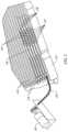
- FIG. 2is a perspective view of one embodiment of the connector assembly.
- FIG. 3shows a detailed perspective view of one variation for a carriage assembly.
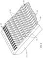
- FIG. 4shows a variation of a connector portion having a slack area.
- FIGS. 5 A and 5 Billustrate a manner of engagement between the first and second connector portions.
- FIG. 6illustrates carriage assemblies having positioning elements.
- FIGS. 7 A and 7 Billustrate alternative carriage assembly embodiments.
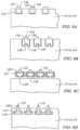
- FIGS. 8 A, 8 B, 8 C and 8 Dillustrate various exemplary embodiments of carriage assemblies and guideways.
- FIG. 9 Ashows a variation of a quick-release mechanism for attaching and detaching the tendon driven endoscope from the actuators that relies on pins to actuate the tendons.
- FIGS. 9 B and 9 Cshows a second variation of a quick-release mechanism for attaching and detaching the tendon driven endoscope from the actuators that relies on a nail-head configuration to actuate the tendons.
- FIG. 10illustrates an exemplary embodiment of complementary barbed connection features for force transmission elements.
- FIG. 11illustrates an exemplary embodiment of complementary male and female connection features for force transmission elements.
- FIG. 12illustrates an exemplary embodiment of complementary engagement element connection features for force transmission elements.
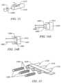
- FIG. 13illustrates an exemplary embodiment of a slotted engagement pair connection feature for force transmission elements.
- FIGS. 14 A and 14 Billustrate an exemplary embodiment of male and slotted engagement element connection features for force transmission elements.
- FIG. 15illustrates an exemplary embodiment of a complementary engagement pair including threaded male and female connection members for force transmission elements.
- FIG. 16illustrates an exemplary embodiment of an engagement and force transmission coupling for force transmission elements.
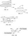
- FIG. 17illustrates an exemplary embodiment of a gear drive or half spur drive coupling for force transmission elements.
- FIGS. 18 A and 18 Billustrate an exemplary embodiment of a gear drive engagement and force transmission coupling.
- FIG. 19illustrates an exemplary embodiment of an actuator engaged with a force transmission element.
- FIGS. 20 A and 20 Billustrate another exemplary embodiment of an engagement system to engage a connector portion.
- FIG. 21illustrates an exemplary embodiment of a pair of force transmission elements.
- FIGS. 22 A and 22 Billustrates an exemplary embodiment of a connection and force transmission arrangement.
- FIG. 23illustrates an exemplary embodiment of a connector assembly utilizing a pressure source.
- FIG. 24illustrates an exemplary embodiment of a roller actuator to couple and drive a force transmission element.
- FIG. 25illustrates an embodiment where the controllable article is a segmented endoscope.
- FIG. 26shows a partial schematic representation of a single tendon bending a segment.
- FIGS. 27 A, 27 B and 27 Cillustrate an endoscope traversing a pathway.
- FIGS. 28 and 29illustrate alternative endoscope embodiments.
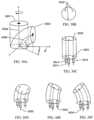
- FIGS. 30 A, 30 B, 30 C, 30 D, 30 E, and 30 Fshow the use of three tendons to actuate a controllable segment used in the endoscope of the present invention.
- FIGS. 31 A, 31 B and 31 Cillustrate an exemplary embodiment of a complementary engagement pair including a saw tooth male member and correspondingly shaped saw tooth female receiver.
- FIG. 1illustrates a schematic view of a system 1000 for moving a controllable article 1100 .
- a force generatorunder control of one or both of a user input device 1140 and a system controller 1145 generates forces that are used to move the controllable article 1100 .
- the forces generated by the force generatorare transmitted to the controllable article using force connecting elements 1135 and a connector assembly 1120 .
- the controllable articlemay also be an articulating instrument.
- a connector assembly 1120completes the transmission of power generated by the force generator 1110 and applied to the controllable article 1100 .
- the two portions 1125 , 1130 of the connector assembly 1120are disengagably coupled.
- the connector portion 1125is the first connector portion or the force generation side connector.
- the connector 1130is the second connector portion or the controllable article side connector portion.
- the connector portion 1130 , force transmission elements 1135 and the controllable article 1100may be removed, in some embodiments as a single integrated unit, from the connector portion 1125 , force transmission elements 1135 and the force generator 1110 or actuators 1115 .
- the connector assembly 1120represents one advantage of the present invention.
- the ability to quickly connect and disconnect the two portions 1125 , 1130allow a single force transmission portion to be used with multiple controllable articles.
- articulating instrumentssuch as, for example, endoscopes typically have only 4 cables to provide limited control at the tip of the endoscope.
- the present inventionmay be advantageously utilized by existing articulating instruments to allow endoscopes with only a few force transmission elements to be quickly and more readily connected to a force generator.
- connector embodiments of the present inventionprovide compact organization and efficient coupling of numerous force transmission elements used by highly maneuverable controllable articles. As the degree of control exerted over controllable articles increases, the number of force transmission elements needed to exert that control also increases. Increasing numbers of force transmission elements drive the need for connector solutions such as those presented by embodiments of the present invention that afford a highly compact and organized coupling arrangement of the force transmission elements.
- connection/disconnection aspect of the present inventionis that in many instances it may be desirable to have the controllable article easily separable from the actuators, force generators or controllers for cleaning, disinfecting or maintenance.
- the quick-release characteristic of the connectors of the present inventionenable an efficient way to achieve a controllable article that is easily removable, replaceable or interchangeable. In this manner, a single controller and actuator system may be used to articulate multiple controllable instruments. After one instrument is released, another is quickly and easily connected and ready for service.
- the proximal ends of the force transmission elements attached to the controllable articlecan be organized to allow predictable attachment point to the corresponding force transmission elements coupled to the actuators.
- the plurality of force transmission elementsmay be organized into a bundle, array, or rack.
- Such organizationprovides a known attachment point between the force transmission elements of the actuators to the force transmission elements of the articulating instrument.
- dozens of force transmission elementswill be utilized in advanced articulating instruments.
- Embodiments of the connectors of the present inventionprovide a scaleable solutions that allows a user, in a single motion, to connect all the force transmission elements coupled to the actuators to those coupled to the controllable article.
- the single action connection feature of some embodiments of the present inventionalso provides an important safely feature if an unsafe condition arises, the actuators or force generators may be quickly disconnected from the articulating instrument.
- each tendoncan be modified to allow attachment and manipulation, e.g., the ends of the tendons may be held in a specially configured sheath or casing.
- the connector 1120may include sensors and/or safety features to help ensure proper operation and articulation of the controllable article.
- the connectorrefers to embodiments of the connector 1120 as well as embodiments of the first and second connector portions 1125 , 1130 .
- One sensor or featuremay indicate or detect translation or movement of the engaging elements (i.e., carriage assemblies 120 described below) or the force transmission elements 1135 themselves.
- Another sensor or featuremay also detect and measure or otherwise quantify the amount of translation or movement of the engaging elements (i.e., carriage assemblies 120 described below) or the force transmission elements 1135 themselves.
- Another sensormay be utilized to indicate proper engagement of either the connector portions 1125 , 1130 or each of the individual engaging elements (i.e., carriage assemblies 120 ).
- Another sensor or indicatormay be used to generate a signal based on contacting a limit stop or the length of travel of a particular component.
- Another sensormay be used to detect component failure within the connector 1120 .
- the systemincludes a force generator 1110 .
- the force generatormay be any conventional generator used to provide or generate sufficient force to the movement of the controllable article 1100 .
- the force generatormay provide, for example, mechanical force, hydraulic force, rotational force, or pneumatic force. Force generators may also utilize shape memory alloys (SMA) and/or electroactive polymers (EAP).
- SMAshape memory alloys
- EAPelectroactive polymers
- the force generator 1110may itself be an actuator or include a plurality of individual actuators 1115 acting as individually controllable force generators for each force transmission element 1135 . Alternatively, an individual actuator 1115 may be connected to drive and control a subset of the total number of elements 1135 but more than one element.
- an individual actuatormay be connected to drive two, three, four or more individual force transmission elements.
- a plurality of first force transmission elements 1135are illustrated having a first end connected to a force generator 1110 ; 1115 and a second end having a first connecting element within the connector portion 1125 . Details of several illustrative connecting element embodiments are described in detail below.
- the controllable article 1100is connected to the connector portion 1130 by a plurality of force transmission elements 1135 .
- the controllable articlemay be any of a number of commercial, industrial or medical devices. These force transmission elements have a first end connected to the controllable elements, modules or components within the controllable article.
- the controllable articlemay be, for example, a robotic handler having a number of articulating linkages.
- the force transmission elements 1135 attached to the connector 1130are connected to transmit force to the articulating linkages.
- the controllable articlemay be a segmented, articulating instrument. In this case, the force transmission elements 1135 attached to the connector 1130 will also be connected so as to transmit force to the individual segments to articulate the instrument.
- the ends of the force transmission elements 1135 within the connector 1120are adapted to engage one another when the connector portions 1125 , 1130 are coupled.
- the first and the second elementsare mechanically coupled. Other types of coupling configurations are possible and are described in greater detail below.
- a controllable article 1100includes at least one segment or module, and preferably several segments or modules, which are controllable via a computer and/or electronic controller (controller) 1140 located at a distance from the controllable article 1100 .
- Each of the segmentshas force transmission elements 1135 , tendons, mechanical linkages or elements connected to a force generator 1110 or an actuator 1115 to allow for the controlled motion of the segments or modules.
- the actuators driving the tendonsmay include a variety of different types of mechanisms capable of applying a force to a tendon, e.g., electromechanical motors, pneumatic and hydraulic cylinders, pneumatic and hydraulic motors, solenoids, shape memory alloy wires, electroactive polymer actuated devices, electronic rotary actuators or other devices or methods as known in the art. If shape memory alloy wires are used, they are preferably configured into several wire bundles attached at a proximal end of each of the tendons within the controller.
- Segment articulationmay be accomplished by applying energy, e.g., electrical current, heat, etc., to each of the bundles to actuate a linear motion in the wire bundles which in turn actuate the tendon movement.
- energye.g., electrical current, heat, etc.
- the linear translation of the actuators within the controlleris configured and scaled in conformity with the desired movement of the controllable article and may vary depending upon application of the controllable article. Some commercial applications may include controllable articles articulating in large movements measured in feet.
- controllable articleis configured for tighter control to enable more precise movement over a relatively short distance, e.g., within a few inches or less such as ⁇ 1 inch, to accomplish effective articulation depending upon the desired degree of segment movement and articulation.
- the force generatoris a motor.
- the motoris coupled to a leadscrew assembly, so that when the motor rotates, it transmits torque to the leadscrew.
- a modified nut on the leadscrewis constrained to prevent rotational motion, so that when the leadscrew is rotated, the nut is translated along the axis of the leadscrew.
- the torque from the motoris thereby translated into linear motion.
- the force transmission elementis a cable that is connected to the nut on one end and a carriage assembly 120 on the other end.
- the linear motion of the nuttranslates into force on the cable.
- the leadscrew movementis translated into linear movement of a carriage assembly in one connector hence to another carriage assembly in another connector assembly connected to the controllable article.
- 64 of the leadscrew assembliesare arranged in modules for easy organization and maintenance. The modules are supported in a chassis that also houses the first portion of the connector described above. More or fewer leadscrew assemblies may be used depending upon application.
- FIG. 2illustrates a perspective view of a connector assembly 110 according to one embodiment of the present invention.
- the connector assembly 110includes a first connector portion 112 (not shown but within housing 109 ) and a second connector portion 114 .
- the first connector portion 112is within the housing 109 .
- the second connector assembly 114includes a plurality of guideways 118 each containing a carriage assembly 120 .
- Each carriage assemblycontains one or more than one engaging feature 122 .
- Engaging features 122 on carriage assemblies 120 in the second connector portion 114are adapted to engage with the engaging features 122 on carriage assemblies 120 of the first connector portion 112 (see FIG. 3 ).
- One end of the carriage assembliesare connected to force transmission elements or cables 130 .
- the cablesare Bowden cables.
- the cablesrun through a slack area 116 .
- the slack area 116allows added space for cable slack that may build up during controllable article movement. Thereafter, the cables are connected as desired to the controll
- the housing 109provides a structural base for supporting the connector assembly 110 .
- the first connector portion 112(not shown) is secured within the housing 109 .
- the first connector portion and its carriage assembliesare connected via force transmission elements 130 to actuators 105 . While four actuators 105 are illustrated, it is to be appreciated that more actuators may be used to drive a corresponding number of carriage assemblies.
- the housing 109also provides a opening 107 configured to receive the second connector portion 114 .
- either one or both of the opening 107 or a portion of the second connector portion 114may be keyed to ensure correct orientation prior to connection.
- first and second connector portions 112 , 114are brought into engagement using an appropriate quick release mechanism, such as for example a cam actuated lever or other engagement device as known to those of ordinary skill in the art.
- an appropriate quick release mechanismsuch as for example a cam actuated lever or other engagement device as known to those of ordinary skill in the art.
- forces generated by actuators 105are transmitted to the controllable article.
- relative movement between the first connector portion and the second connector portionis used to couple the first connector portion to the second connector portion.
- nearly vertical movement between the first connector portion and the second connector portionis used to engage the first and second connector portions.
- the coupling force between the first and second connection portionsacts nearly orthogonal to the direction of movement of the individual connection elements (i.e., carriage assemblies 120 ) within the first and second connection portions.
- the connector 110 embodiment of FIG. 2 and other embodiments of the present inventionmay also provide a number of safety features.
- the forces used to bring together and hold the carriage assemblies of the first and second connector portions in locking cooperationmay be set to such a level that ensures these is positive engagement and no slip.
- the force holding the connector portionscould be set to separate at a force below a threshold force that could damage a component in the force transmission pathway, such as for example, a force transmission element.
- carriage assembliescould be attached to their force transmission elements at some margin of safety whereby in the event an actuator loses control, the respective carriage assembly would separate from its force transmission element.
- FIG. 3shows an embodiment of the first connection portion 112 coupled to an actuator 105 .
- the first connector portion 112is constructed similar to the second connector portion 114 described above. As such, the first connector portion 112 includes a plurality of guideways 118 and carriage assemblies 120 . Instead of connecting to the controllable article, the carriage assemblies 120 of the first connector portion 112 are appropriately connected to actuators 105 .
- FIG. 4shows a perspective view of one embodiment of the second connector portion 114 .
- the second connector portion 114organizes and houses the carriage assemblies 120 within guideways 118 . By connecting the force transmission elements to the carriage assemblies, this organization is provided to the plurality of force transmission elements needed in highly controlled articulating instruments and controllable articles.
- the second connector portionprovides 64 guideways with 32 guideways in the upper face 114 A and 32 guideways in the lower face 114 B (the edge of the guideways 118 of the lower face 114 E are visible).
- the embodiment of FIG. 4illustrates the compact nature of connectors according to the present invention.
- a connector of the present inventionmay provide articulation force to 64 separate cables in a space only slightly larger than the width of 32 cables or one-half the total number of cables.
- the width of the connectoris only slightly larger than the width of a single carriage assembly multiplied by one-half the number of force transmission elements.
- the double-sided second connector portionmay be coupled to two single sided first connector portions (i.e., one single sided first connector engages with the second connector upper face and the other engages with the lower face, for example FIG. 203 .)
- two double-sided second connectors 114may be engaged by one double sided first connector portion 112 between the double sided second connectors 114 and a first single sided first connector above one and a second single sided first connector below the other second connector portion 114 .
- the mechanical workings within the housing 109provide proper alignment and quick disconnect between the various connector portions regardless of the numbers used.
- the connectors and housing 109may be formed from any suitable material having sufficient strength to transmit the forces or energy used. Suitable materials include metals, plastics, extrusions, injection molded parts, forged, and/or metal injection molded parts,
- the bearing surfacesmay be coated with suitable low friction coatings to reduce friction losses within the connectors such as between the carriage assemblies and the guideways. One or more surfaces within the connector assembly may be coated as desired. Suitable coatings include, for example, Teflon, PTFE, and other low friction coatings.
- the bearing surfacesmay include a viscous coating or include other bearing structure or surfaces such as, for example, ball bearings, linear bearings, or air bearings and the like.
- Connector assembly portion 114has a plurality of guideways 118 for organizing the array of tensioning members and/or cables 121 used to control a controllable article
- Guideway 118may be a U-shaped channel formed integrally within housing 114 as illustrated or it may be manufactured separately and attached onto housing 114 .
- embodiments of the guideway 118may comprise tracks or rails aligned adjacent to each other.
- each of the railsmay form a protrusion extending along the length of guideway 118 such that a rectangularly shaped-rail is formed.
- the rail or trackmay be of any shape such as, for example, rectangular, concave, convex, rounded or curvilinear.
- a complementary shapeis formed in the engaging face of the carriage assembly for that guideway.
- the number of railsmay correspond to the number of tensioning members utilized for a controllable device or more rails may be provided to accommodate for additional tensioning members.
- the railsalign parallel to one another although in other variations, the shape and alignment of the rails may be varied.
- each carriage assembly 120may be secured to a cable 121 extending from a tensioning member or force transmission element.
- the cable 121passes through the cable stop 117 , the coil tube 111 and is suitably coupled to the actuator 105 .
- the cable 121is wrapped about the end of the actuator 105 .
- the cable stop 117is anchored in the gap between the frame stop 119 and the end of the guideway 118 .
- the ends of the coil tube 111are anchored between the actuator frame or a support 115 and the cable stop 117 . Similar to a conventional Bowden cable arrangement, the above described anchoring configuration retains the coil tube 111 in compression while the cable 121 remains in tension and transmits force from the actuator 105 . As best illustrated in FIG. 4 , the carriage assembly 120 is moved within the guideway 118 as indicated by the direction of travel 126 . A force transmission element (i.e., 130 , 130 . 1 , 130 . 2 ) attached to a carriage assembly 120 and the controllable article 1100 transfers that motion 126 to move the controllable article 1100 accordingly. The number of carriage assemblies 120 utilized will vary depending upon the number of tensioning members utilized for articulation of the controllable article.
- Guideway 118may be configured to provide a limited range of travel for the translational movement of cable carriage assemblies 120 .
- guideway 118may have a frame stop 119 defined at one end of the guideway 118 so that carriage assemblies 120 may be securely seated and aligned with each rail.
- Frame stop 119may define a portion of the guideway that is discontinuous such that a carriage assembly 120 may be seated within the discontinuity.
- the discontinuityis shown in FIG. 4 at one end of the guideway 118 , it may alternatively be positioned at the other end of in another location along the guideway 118 .
- frame stop 119may define a crimp, clamp, adhesive, mechanical fastener, or some other method as known in the art for securing to prevent the excess movement of carriage assembly 120 .
- the second connector portion 114includes a cable passageway or slack area 116 .
- Slack area 116is an area sufficiently spacious to allow for the inclusion of slack in the tendons and/or cables which may be routed through and/or bend within the passageway 116 , as described in further detail below.
- the passageway 116may be curved such that controllable article interface 113 and guideway 118 are angled relative to one another, such as the illustrated angle of about 90° but may range between 0° to 180°.
- the slack area angleis measured between a line representing the direction of movement of the carriage assembles—i.e., direction of travel 126 —and a line directed towards the articulating instrument through interface 113 .
- the size and exact configuration of the slack area, if included,will depend upon the number size, shape and flexibility of the force transmission elements used in a particular application. As such, the slack area may have any of a wide variety of shapes or curvature to provide an accommodation for the excess or slack cable length temporarily created during movement or manipulation of the controllable article.
- the force transmission elements 130 , 130 . 1 and 130 . 2are Bowden cables (i.e., cable 121 within a flexible housing or coil tube 111 ). As the controllable article is manipulated by movement of the cables, the cable housings for the cables may be moved longitudinally proximally and/or distally as well.
- the slack area 116is shaped and sized to accommodate a number of tensioning elements in the connector assembly. The slack area 116 may simply be a compartment sufficiently large enough to provide space for the cables 130 , 130 . 1 , and 130 . 2 , for example, to extend in an expanded configuration, to allow for cable slack in the connector 110 .
- FIG. 1 , and 130 . 2illustrate the relative amount of space required for coil tube and cable extension. Illustrated are various degrees of extension from low extension in force transmission element 130 to moderate and high degrees of extension in force transmission elements 130 . 1 and 130 . 2 respectively. Where a slack area 116 is utilized, the relationship between the connector assembly portion and the slack area need not be angled, as illustrated, but may instead provide for a collinear arrangement.
- FIGS. 5 A and 5 Billustrate one manner of engagement between the carriage assemblies 120 of the connector portions 114 , 112 .
- the carriage assemblies 120 arranged on one side of a double sided first connector portion 112align with and engage the carriage assemblies 120 arranged on one side of a double sided second connector portion 114 ( FIG. 5 A ).
- One possible engagement between the features 122 of the carriage assemblies 120is illustrated in FIG. 5 B as the carriage assemblies are moved in the direction of the arrows. While FIG.
- FIGS. 20 A and 20 Billustrates both connectors 112 , 114 moving together to join one face
- the connectorsmay engage through relative movement in another direction (i.e., lateral or circular movement, for example) and that one connector may remain fixed while the other moves to engage and that, when engaged, the connectors engage on more than one face (i.e., FIGS. 20 A and 20 B ).
- FIG. 6illustrates one embodiment where carriage assembly alignment is provided by placing an alignment element 123 adjacent a carriage assembly. In this manner, each carriage assembly is urged into a similar position within a guideway 118 .
- the alignment elementmay be a bias element such as spring.
- a small alignment featuremay be provided in each guideway to temporarily engage a carriage assembly. The initial application of force applied to the connector after engagement is used to move the carriage assemblies off the alignment feature in preparation for articulating the controllable article.
- each connector portion 112 , 114includes an alignment feature that urges the carriage assembly into an alignment position.
- An alignment positionis a position of a carriage assembly in a guideway of one connector portion to further the engagement of that carriage assembly to a similarly positioned carriage assembly on the other connector portion.
- FIGS. 7 A and 7 Bshow detailed perspective views of two alternative carriage assembly embodiments 120 ′ and 120 ′′.
- Carriage assemblies 120 ′, 120 ′′provide a rack 130 configured to correspondingly fit and slide along a rail disposed within or other feature configured within a guideway 118 .
- rack 130defines a U-shaped or generally rectangular channel 132 .
- FIG. 7 Aillustrates an embodiment of a rack 130 having a channel 132 .
- a force transmission cable 144is crimped 138 or otherwise fastened with adhesive, soldered, etc. to the rack 130 .
- the cable 144extends through stop 146 and through coil tube 142 .
- Cable 144may extend beyond stop 146 and the other end connected, for example, to a force generator or to an articulating segment of an articulating instrument.
- a coil tube 142may optionally extend beyond assembly stop 146 to provide support between the cable 144 and stop 146 interface to aid in preventing cable 144 from kinking.
- FIG. 7 Billustrates an embodiment utilizing a telescoping tube 140 , 136 .
- Inner tube 136extends within the interior of telescoping tube 140 in a slideable arrangement.
- Inner tube 136may be attached within channel 132 at crimps 138 or, alternatively, to the rack 130 with adhesive, solder or other fastening techniques known in the art.
- One end of telescoping tube 140may terminate in stop 146 , which may be positioned within or adjacent to frame stop 119 .
- Extending from assembly stop 146is cable 144 , which may further extend and be connected to a force generator or a portion of an articulating instrument. Alternatively, cable 144 may further extend from assembly stop 146 directly into a segment of an articulating endoscope.
- a coil tube 142may extend partially beyond assembly stop 146 to provide support between the cable 144 and stop 146 interface to aid in preventing cable 144 from kinking or to conventionally assist in the transmission of force.
- one end of cable 144may be secured to the distal end of inner tubing 136 or cable 144 may be disposed through inner tubing 136 and extend towards the proximal end of inner tubing 136 for direct attachment to rack 130 using a crimp 138 .
- rack 130rides along a rail in guideway 118 while inner tubing 136 slides through telescoping tube 140 relative to the stationary assembly stop 146 .
- the distal and/or proximal movement of rack 130will likewise urge cable 144 to move in accordance with rack 130 , thereby transferring the longitudinal motion either directly or indirectly to the articulating instrument segment or portion attached to the cable 144 .
- interface portion 134upon at least one of the outer surfaces of rack 130 to provide for a secure engagement interface with an actuator, e.g., electric motor, shape-memory alloy actuator, hydraulic or pneumatic actuator, etc.
- Interface portion 134may be formed into a series of gear-shaped ridges, as shown, to provide engagement surfaces against a corresponding member attached to the actuator; alternatively, interface portion 134 may be configured to have a receiving clamp or slotted interface to provide for engagement or any other type of engagement interface as known in the art.
- FIGS. 7 A and 7 Billustrate a rectangular or generally U-shaped channel 132
- the sliding channel 132may also be formed in a variety of open shapes, such as semi-spherical, semi-elliptical, etc., provided the rail upon which rack 130 moves upon is formed in a corresponding shape. Examples of alternative rail and channel configurations are illustrated in FIGS. 8 A- 8 D .
- FIGS. 8 A- 8 Dillustrate alternative guideway and carriage assembly arrangements. Note that the carriage assembly/guideway arrangements described are applicable to either or both of the full and second connector assemblies 112 , 114 .
- FIG. 8 Aillustrates the carriage assembly 120 guideway 118 arrangement of FIGS. 3 , 4 and 5 A .
- the carriage assembly 120 shapeis accommodated by the shape of guideway 118 .
- FIG. 8 Billustrates one embodiment of a guideway 118 configured to accept a carriage assembly 120 ′ or 120 ′′ as described above in FIGS. 7 A and 7 B .
- the guideway 118includes a feature or rail 118 ′ configured to cooperate in a sliding arrangement with the channel 132 .
- FIG. 8 Cillustrates an alternative embodiment where the guideway is a raised feature 118 ′′ adapted to engage with a complementary shaped channel 132 ′ in carriage assembly 120 . 1 .
- FIG. 8 Dillustrates another alternative embodiment where the carriage assembly 120 . 2 includes a shaped feature 132 ′′ adapted to slide along within the recessed, shaped guideway 118 ′′′.
- the arrangement and shape of the complementary surfaces of the carriage assembly embodiment and the guideway embodimentare illustrative and are not intended to be limited to the examples described herein. Rather, the specific shapes used to interface the carriage assembly to the guideway may be varied accordingly as understood by one of skill in the art.
- FIGS. 9 A and 9 Bshow two variations on quick-release mechanisms for attaching and detaching an articulating instrument from a set of actuators or force generators.
- FIG. 9 Ashows one variation of this quick-release mechanism.
- the proximal end of the force transmission elementsmay be bundled in an umbilicus 90 , and the individual elements may terminate in dimpled connectors 102 that are held in an organized array in a connector interface 92 .
- a single force transmission element 93is shown (in phantom) within a connector 102 . It is appreciated that each connector 102 could have a force transmission element 93 to mate with a corresponding pin 100 .
- the connector interface 92mates to a complementary receiving interface 96 on the structure that houses the actuators 104 , e.g. as part of the controller box.
- the actuatorsmay project “pins” 100 which can mate with the dimpled connectors and convey force from the actuators to the tendons.
- an actuatormay cause a pin 100 to apply pressure to a corresponding dimpled receiver 102 .
- the dimpled receivertranslates the pushing of the pin into a tensile or compressive force applied to the affiliated force transmission element. This could be achieved using levers to reverse the direction of the force, for example. Since every pin preferably mates to a corresponding receiver, it is desirable to maintain the register of the connectors from the endoscope and the actuators.
- An orientation notch 94 on the connector that fits into a receiving orientation mate 98 on the actuatorcould be used to align both interfaces.
- the arrangement of the pins and receptaclescould be orientation specific.
- FIG. 9 Bshows another variation of a quick-release mechanism for attaching and detaching an articulating instrument from the actuators that relies on a nail-head configuration to actuate the force transmission elements.
- the force transmission elementsmay terminate in a flattened out protrusion resembling a nail-head 106 .
- the array of nail-heads 106project from the connector interface 92 at the end of the umbilicus 90 , and can mate with slotted holes 108 on the interface 96 of actuator mechanism 104 ( FIG. 9 C ).
- the slotted holes 108 of the actuatorscan be individually retracted by the actuators to apply tension to individual force transmission elements.
- the quick-release mechanismcould also be designed to allow the use of different controllable instruments, even of different configurations, from the same actuator set and/or controller unit.
- FIG. 10illustrates an embodiment of complementary barbed connection features 1005 , 1010 .
- barbed connections 1005 , 1010engage and provide a force transmission pathway.
- These featuresmay be used, for example, as connection points similar to nail heads 106 ( FIG. 9 B, 9 C ).
- These featurescould be configured to easily connect a force transmission element connected to an actuator to a force transmission element connected to a controllable article.
- barb 1010could be attached to a force transmission element connected to an actuator.
- Barb 1005could be attached to a force transmission element connected to a controllable article.
- the complementary shaped sloped portions 1015slide relative to each other until the barbs fall into engagement.
- these featurescould also be incorporated into the design of a carriage assembly or guideway.
- FIG. 11illustrates an embodiment of a complementary male and female engagement pair 1175 , 1180 .
- Cavity 1182 in female receiver 1180is configured to receive the arrowhead feature 1176 .
- the engagement tabs 1184deflect allowing the arrowhead feature 1176 to pass into the cavity 1182 .
- the engagement tabs 1184close behind the arrowhead 1176 securing it within the cavity 1182 .
- the male/female connection featurescould be configured to easily connect a force transmission element connected to an actuator to a force transmission element connected to a controllable article.
- male feature 1175could be attached to a force transmission element connected to an actuator.
- Female feature 1180could be attached to a force transmission element connected to a controllable article. Thereafter, the force transmission elements are connected by relative movement to engage the arrowhead feature 1176 . In additional alternative embodiments, these features could also be incorporated into the design of a carriage assembly or guideway or as part of the embodiments of FIGS. 9 A- 9 C .
- FIG. 12illustrates an embodiment of a complementary engagement elements 1205 and 1220 .
- SMA engagement element 1205is formed from a shape memory alloy (SMA) or memory metal that changes configuration (martinsite to austenite and vice versa) when energy is applied to it.
- the unenergized state 1210is illustrated in dashed lines. Once energized, the element curves forming hook 1215 . As the SMA engagement element 1205 forms into hook 1215 it engages with the hook shaped engagement element 1220 completing the connection between the two engagement elements.
- the complementary engagement elements 1205 and 1220could be configured to easily connect a force transmission element connected to an actuator to a force transmission element connected to a controllable article.
- SMA engagement element 1205could be attached to a force transmission element connected to an actuator.
- Hook 1215could be attached to a force transmission element connected to a controllable article. Thereafter, the force transmission elements are connected by energizing the SMA element 1205 to engage the hook 1220 .
- the complementary features 1205 , 1220could also be incorporated into the design of a carriage assembly, guideway or as part of the embodiments of FIGS. 9 A- 9 C .
- FIG. 13illustrates an embodiment of a slotted engagement pair.
- Male element 1300has a feature or protrusion 1305 .
- the slotted element 1310includes a slot 1315 sized to receive the feature or protrusion 1305 .
- the feature or protrusion 1305seats into and is held within the slot 1315 .
- the male element 1300is coupled to the slotted element 1310 .
- the complementary engagement elements 1300 and 1310could be configured to easily connect a force transmission element connected to an actuator to a force transmission element connected to a controllable article.
- male element 1300could be attached to a force transmission element connected to an actuator.
- Slotted element 1310could be attached to a force transmission element connected to a controllable article. Thereafter, the force transmission elements are connected by engaging feature 1305 into slot 1315 .
- the male element 1300 and the slotted element 1310could also be incorporated into the design of a carriage assembly, guideway or as part of the embodiments of FIGS. 9 A- 9 C .
- a window latch type connectorcould also be used to connect the force transmission elements. An arcuate male member could be rotated into engagement with an arcuate female member in a motion similar to the operation of a window latch.
- FIGS. 14 A and 14 Billustrate another embodiment of male 1400 and slotted 1410 engagement elements.
- Male engagement element 1400includes a number of features 1405 moveable between a retracted position ( FIG. 14 A ) and an extended or engaged position ( FIG. 14 B ).
- the slotted element 1410includes a cavity 1415 sized and shaped to retain the features 1405 when the features 1405 are in the extended position ( FIG. 14 B ). Returning the features 1405 to a retracted position allows the male element 1400 to withdraw from the cavity 1415 .
- the male 1400 and slotted 1410 engagement elementscould be configured to easily connect a force transmission element connected to an actuator to a force transmission element connected to a controllable article.
- male element 1400could be attached to a force transmission element connected to an actuator.
- Slotted element 1410could be attached to a force transmission element connected to a controllable article. Thereafter, the force transmission elements are connected by engaging features 1405 into cavity 1415 .
- the male element 1400 and the slotted element 1410could also be incorporated into the design of a carriage assembly, guideway or as part of the embodiments of FIGS. 9 A- 9 C .
- FIG. 15illustrates a complementary engagement pair including threaded male members 1500 and correspondingly threaded female receivers 1510 .
- Threaded male members 1500include threads 1505 .
- Correspondingly threaded female receivers 1510have internal threaded surfaces (not shown) to engage the threads 1505 on male members 1500 .
- a driver 1520that is wrapped about or otherwise coupled to the female receivers 1510 . In operation, the driver 1520 rotates the female receivers 1510 to engage threads 1505 and secure together the male member 1500 into the female receiver 1510 . While illustrated as the female receiver 1510 rotating about a stationary male member 1500 , the driver 1520 may also be configured to rotate the male members 1500 to drive threads 1505 into stationary female receivers 1510 .
- pairs 1500 , 1510are illustrated for discussion purposes only.
- the principal of engagement represented by the pairs 1500 , 1510may be applied to any number of pairs.
- the male threaded 1500 and female threaded 1510 engagement elementscould be configured to easily connect a force transmission element connected to an actuator to a force transmission element connected to a controllable article.
- male threaded element 1500could be attached to a force transmission element connected to an actuator.
- Female threaded element 1510could be attached to a force transmission element connected to a controllable article.
- the force transmission elementsare connected by engaging threads 1505 into threaded interior features of female threaded element 1510 through, in one embodiment, rotation via driver 1520 of the female threaded elements 1520 .
- the threaded male element 1500 and the threaded female element 1510could also be incorporated into the design of a carriage assembly, guideway or as part of the embodiments of FIGS. 9 A- 9 C .
- FIG. 16illustrates an alternative engagement and force transmission coupling that utilizes a carriage assembly 1620 and a threaded driver 1600 in a worm gear configuration.
- the carriage assembly 1620is similar in design and function as the above described carriage assemblies 120 .
- Carriage assembly 1620differs in at least that the engagement features 1622 are shaped and sized to engage and transfer force from the threads 1605 as the drive member 1600 rotates.
- Guideways 118may be modified to accommodate and ensure engagement of the drive member 1600 and carriage assembly 1620 when the first and second connector portions 112 , 114 engage.
- an actuator or force generatorcauses the driver 1600 to rotate.
- the threads 1605are engaged with the features 1622 such that as the driver 1600 rotates the carriage assembly 1620 translates relative to the driver 1600 .
- FIG. 17illustrates another alternative gear drive or half spur drive configuration.
- This alternative engagement and force transmission couplingutilizes a carriage assembly 1720 and a spur driver 1700 .
- the carriage assembly 1720is similar in design and function as the above described carriage assemblies 120 .
- Carriage assembly 1720differs in at least that the engagement features 1722 are shaped and sized to engage and transfer force from the spur engagement elements 1705 as the spur drive 1700 rotates.
- the spur drive 1700is coupled to an actuator and the carriage assembly 1720 is coupled to a controllable article.
- the spur drive 1700may be used simply to engage with the carriage assembly 1720 by rotating in the direction indicated.
- the spur driver 1700coupled to the carriage assembly 1720 , translates along a guideway as described above and thereby articulates the controllable article.
- the spur driver 1700is larger, perhaps, even a complete gear, that instead of coupling to and translating with the carriage assembly 1720 , the gear drive 1700 would be engaged with and rotate relative to the carriage assembly 1720 . Rotation of the gear drive 1700 in this alternative embodiment would result in translation of the carriage assembly 1720 and articulation of the controllable article.
- guideways 118may be modified to accommodate and ensure engagement of the gear drive 1700 and carriage assembly 1720 when the first and second connector portions 112 , 114 engage.
- an actuator or force generatorcauses the gear driver 1700 to rotate.
- the engagement elements 1705are engaged with the features 1722 such that as the gear driver 1700 rotates the carriage assembly 1620 translates relative to the gear driver 1700 .
- FIG. 18 Aillustrates another alternative gear drive configuration.
- This alternative engagement and force transmission couplingutilizes carriage assemblies 1820 and a gear driver 1800 .
- the transmission of forcefollows similar to the manner in which pushing on one end of a bar 1850 hinged to a fulcrum 1860 by a pivot point 1870 results in movement of the other end of the bar ( FIG. 18 B ).
- the carriage assemblies 1820is similar in design and function as the above described carriage assemblies 120 .
- a carriage assembly 1820differs in at least that the engagement features 1822 are shaped and sized to engage with the gear teeth 1805 as the gear drive 1800 rotates.
- one carriage assembly 1820is coupled to an actuator and the other carriage assembly 1820 is coupled to a controllable article.
- An actuator or force generatormoves its carriage assembly that in turn engages teeth 1805 to rotate gear 1800 .
- Rotation of gear 1800engages teeth 1805 with the other carriage assembly 1820 resulting in translation of that carriage assembly and movement of the controllable article.
- the gear driver 1800would instead be used as a driver to cause translation of both carriage assemblies 1820 .
- Rotation of the gear drive 1800 in this alternative embodimentwould result in translation of both carriage assemblies 1820 and articulation of the controllable article.
- the first and second connector portions 112 , 114 and the guideways 118may be modified to accommodate and ensure engagement of the gear drive 1800 and carriage assemblies 1820 when the first and second connector portions 112 , 114 engage.
- FIG. 19illustrates an alternative method of engaging the actuator to a force transmission element.
- a force transmission element 1915has a catch 1910 .
- the actuator 1900is connected to and maneuverable by a linkage 1905 .
- the linkage 1905moves the actuator 1900 as indicated into engagement with the catch 1910 .
- forces generated by the actuator 1900result in translation of the force transmission element 1915 .
- the linkage 1905 , actuator 1900 and catch 1910 elementscould also be incorporated into the design of a carriage assembly, guideway or as part of the embodiments of FIGS. 9 A- 9 C .
- FIGS. 20 A and 20 Billustrate one embodiment of an engagement system to engage a connector embodiment of the present invention.
- An L-shaped frame 2010includes a guide 2015 for an upper plate 2020 .
- An actuator 2000is coupled to the upper plate 2020 to move the upper plate up and down the guide 2015 .
- the motion of the upper plate 2020is the motion that engages the first and second connector portions 112 , 114 .
- the upper plate 2020has a lower surface 2025 including a first connector portion 118 .
- the L-shaped frame upper surface 2030also includes a first connector portion 118 .
- a double sided connector portion 114is placed between the plates ( FIG. 20 B ). With the double sided second connector portion 114 disposed between the plates ( FIG.
- the actuator 2000moves the upper plate 2020 to engage the carriage assemblies of each of the connector assemblies in the connection portions an complete the connection from the force generator to the controllable article. While illustrated as engaging one double sided second connector portion 114 , it is to be appreciated that this embodiment could be modified to connect one or more single sided second connectors 114 or two or more double sided second connector portions 114 by including single or double sided first connector portions 112 as needed.
- FIG. 21illustrates a pair of force transmission elements 2110 .
- Force transmission elements 2110are similar in many ways to the earlier described force transmission elements. Force transmission elements 2110 differ from the earlier described elements in that the ends 2115 are shaped and configured to attach the elements 2110 together using vacuum or suction forces. In additional alternative embodiments, the vacuum or suction end 2115 could also be incorporated into the design of a carriage assembly, guideway or as part of the embodiments of FIGS. 9 A- 9 C .
- FIGS. 22 A and 22 Billustrate an alternative connection and force transmission arrangement.
- An actuator 2200has a recess 2205 adapted to receive and secure an end 2215 of a force transmission element 2210 . Another part of the force transmission element 2210 is connected to a controllable article. When the end 2215 is seated in recess 2205 , the force transmission element is also secured against a fixed roller 2220 . Movement of the force translation element is accomplished by rotation of the actuator 2200 resulting in deflection of the force transmission element 2210 about the actuator 2200 and against the roller 2220 .
- the guideways of a connector portioncould each contain an actuator 2200 .
- the other connector portioncould contain force transmission elements 2210 having ends 2215 .
- coupling together the connector portionswould urge the end 2215 into engagement with the recess 2205 thereby providing a force transmission pathway.
- the actuator 2200 , recess 2205 and end 2215could also be incorporated into additional alternative designs of a carriage assembly, guideway or as part of the embodiments of FIGS. 9 A- 9 C .
- FIG. 23illustrates an embodiment of a connector assembly modified to utilize a pressure source 2300 as a force generator.
- a pressure source capable of generating positive and negative pressureis connected to a modified pressure tight guideway 2318 containing a piston 2205 .
- Piston 2205is in a sealed and slideable relation to the interior of the guideway 2318 .
- the piston 2205is also connected to a bias element 2210 and force transmission element 2215 .
- the force transmission elementis also connected to a controllable article.
- pressure changes generated by the pressure source 2200result in the translation of the piston 2205 .
- Translation of the piston 2205results in the translation of the force transmission element 2215 and the movement of the controllable article.
- FIG. 24illustrates another embodiment of a roller actuator operation set used to couple to and drive a force transmission element.
- a roller actuator setincludes a roller actuator 2400 and a pair of fixed rollers 2405 , 2410 .
- the roller actuator 2400may move in the indicated directions. Movement towards the force transmission element 2415 will engage the element 2415 . Since the element is secured against block 2420 , further moving actuator 2400 deflects the element between the rollers 2405 , 2410 resulting in movement of element 2415 .
- another operating set of a roller actuator 2400 and roller pair 2405 , 2410may be utilized in opposition to the described actuator and roller. In this embodiment, one actuator and roller pair moves the force transmission element in a first direction while the other actuator is idle.
- the other actuatoris activated to deflect the element while the one actuator idles.
- the actuator 2400 , and rollers 2405 , 2410in one or more operating sets could also be incorporated into additional alternative designs of a carriage assembly, guideway or as part of the embodiments of FIGS. 9 A- 9 C .
- FIGS. 31 A, 31 B and 31 Cillustrate a complementary engagement pair including saw tooth male member 3100 and correspondingly shaped saw tooth female receiver 3120 .
- Saw tooth male member 3100includes individual saw teeth 3105 .
- Correspondingly shaped female saw tooth receivers 3122are shaped to engage the saw teeth 3105 on male member 3100 .
- FIG. 31 Aillustrates the members 3100 , 3120 in a disengaged configuration. Longitudinal movement between the members 3100 , 3120 places the members in an engaged position ( FIG. 31 B ). In this configuration, force, position and lateral translation may all be conveyed between the members 3100 , 3120 . Disengagement of the members is illustrated in FIG. 31 C . Rotation of one member relative to the other is used to disengage the members.
- the female member 3120is rotated in the direction indicated to move the female teeth 3122 out of engagement with the male saw teeth 3105 .
- different saw tooth shapesmay be used or other shapes suited to longitudinal engagement and rotational disengagement may be used.
- the male member 3100may be rotated to disengage engaged members 3100 , 3120 .
- connection embodimentsmay be modified to include sensors to provide added functionality to embodiments of the connector of the present invention.
- Sensorsmay be located in either or both of the connector portions 112 , 114 or in any of the connection and release mechanisms described herein. Any of a wide variety of commonly available sensors may be used to accomplish the functionalities described below such as, for example, reed switches, electro-optical switches, resistive switches, contact switches, optical indicators, strain gauges, stress gauges, measurement indicators and the like. Examples of added functionality, include without limitation, detection of cable or carriage assembly translation, position, or engagement With regard to engagement, sensors may be used to indicate proper or improper engagement between carriage assemblies or connectors or whether components have become or are about to become disengaged. Sensors may be used to measure component performance or failure.
- a sensordetects when a cable becomes slack when it should be under tension as an indication of cable failure or, if a carriage assembly suddenly locks into a position, a sensor may indicate an obstruction of the controllable article and/or obstruction or abnormal occurrence elsewhere in the force transmission pathway.
- the output or signal from a sensormay be integrated into the control system.
- sensors within the connectorcould be used to measure carriage assembly movement as the indication for position of the controllable article.
- the sensorcould be coupled to or in communication with a portion of the connector assembly and have an output that indicates the position of the instrument.
- the control systemcould be adapted to use the output of the sensor, in place of or in addition to encoders on the instrument to control and/or monitor the position, shape, movement etc. of the instrument.
- the tip of the endoscope and different segments or positions of the endoscopecould be controlled using the position of the carriage assembly/assemblies and cables used to control those segments.
- a sensormay be used as limit switch for the length of travel of a carriage assembly.
- the carriage assembly length of travelcorresponds to a physical or operational limitation of the system or of the controllable article.
- the control systemmay respond appropriately by, for example, shutting off power, sounding an alarm or otherwise providing an indication that the limit switch sensor had been activated.
- sensorsmay be used to identify a particular controllable article being provided to the connector.
- the identifying informationcould be used to recall stored maintenance or performance information about the particular controllable article. If for example, a particular component was beginning to wear or if a particular cable required additional force for proper movement such unique variability for the article could be provided to and accounted for by the control signals generated by the control system.
- the control systemmay have recording capabilities to record the amount of time the device was used and performance criteria met or not met by the article.
- a connector portion attached to a controllable articlemay include a sensor, other readable feature, mark or other identifying characteristic or a user may enter a serial number or the connector may have a bar code identifier read by a bar code reader associated with the system. The system could automatically read the identifying feature of the connector and adjust control signals according to the stored maintenance, performance and/or service information related to that article.
- Embodiments of the connector of the present inventionallow for determination of position and provide control of the various segments or modules of a controllable article using the position and/or movement of the cables or carriage assemblies or other components within the connector.
- the position, shape, and/or movement of the tip of a steerable endoscope or portion thereofcould be controlled using the position of the cables, carriage assemblies or other components used to control the tip.
- the amount of within connector movement of the more or more cables, carriage assemblies or componentsis correlated to an amount, degree or type of tip movement. A such, by monitoring and controlling within connector movements, the tip and other sections or modules of a controllable article may be controlled.
- linear motion of the cable within the connectormay be used to indicate segment position including the position and movement of the instrument tip. Sensors to detect movement may be placed in one or both connector portions 112 , 114 (or in other connector assemblies such as FIG. 20 B or as described herein)
- sensors incorporated into the connectormay be used to measure or indicate the operational condition of the cables, cable wear or changes in friction loads in the instrument.
- sensors in the connectormay be used to detect, for example, increases in cable wear or friction within the instrument, in specific cables and sections of the instrument.
- Information regarding the operating condition of the cables and instrumentmay be used in a number of ways to improve overall system performance. For example, measurements indicating increasing friction losses over a period of time may be used as an indication that maintenance or service of the instrument is advisable.
- measurements indicating an immediate friction increasemay be an indication of mechanical binding in the force transmission pathway, instrument failure or that the instrument has encountered an obstruction.
- the signal indicationscould be used by the system in a number of ways, such as for example, a warning indication, a safety shut-offs, or a “service needed” indicator.
- FIG. 25shows an embodiment where the controllable article is a tendon driven endoscope 2510 .
- the endoscope 2510has an elongate body 2512 with a manually or selectively steerable distal portion 2516 , an automatically controlled portion 2520 , and a flexible and passively manipulated proximal portion 2514 , which may be optionally omitted from the device.
- the steerable distal portion 2516can be articulated by hand (i.e., using mechanical force of a conventional endoscope manual controls adapted to articulate segments) or with mechanical assistance from actuators.
- some embodimentsallow a user to input steering commands (i.e., via a joystick 2544 or other input device) into a controller that translates the steering commands into endoscope segment movement.
- the automatically controlled portion 2520is segmented, and each segment is capable of bending through a full range of steerable motion.
- the distal portion 2516is also a controllable segment.
- the selectively steerable distal portion 2516can be selectively steered or bent up to, e.g., a full 180° bend in any direction 2518 , as shown.
- a fiber optic imaging bundle 2534 and one or more illumination fibers 2532may extend through the body 2512 from the proximal portion 2514 to the distal portion 2516 .
- the endoscope 2510may be configured as a video endoscope with a miniaturized video camera, such as a CCD or CMOS camera, positioned at the distal portion 2516 of the endoscope body 2512 .
- the images from the video cameracan be transmitted to a video monitor by a transmission cable or by wireless transmission where images may be viewed in real-time and/or recorded by a recording device onto analog recording medium, e.g., magnetic tape, or digital recording medium, e.g., compact disc, digital tape, etc. LEDs or other light sources could also be used for illumination at the distal tip of the endoscope.
- analog recording mediume.g., magnetic tape, or digital recording medium, e.g., compact disc, digital tape, etc.
- LEDs or other light sourcescould also be used for illumination at the distal tip of the endoscope.
- the body 2512 of the endoscope 2510may also include one or more access lumens 2528 that may optionally be used for illumination, fibers for providing a light source, insufflation or irrigation, air and water channels, and vacuum channels.
- the body 2512 of the endoscope 2510is highly flexible so that it is able to bend around small diameter curves without buckling or kinking while maintaining the various channels intact.
- the body 2512 of the endoscope 2510may range typically from 135 to 185 cm in length and about 13-19 mm in diameter.
- the endoscope 2510can be made in a variety of other sizes and configurations for other medical and industrial applications.
- the controllable portion 2520is composed of at least one segment 2522 , and preferably several segments 2522 , which are controllable via a computer and/or electronic controller 2540 located at a distance from the endoscope 2510 .
- Each, or at least a majority, of the segments 2522may have forces transmission elements or tendons mechanically connected to force generators or actuators to allow for the controlled motion of the segments 2522 in space.
- the actuators driving the tendonsmay include a variety of different types of mechanisms capable of applying a force to a tendon, e.g., electromechanical motors, pneumatic and hydraulic cylinders, pneumatic and hydraulic motors, solenoids, shape memory alloy wires, electronic rotary actuators or other devices or methods as known in the art.
- shape memory alloy wiresare used, they are preferably configured into several wire bundles attached at a proximal end of each of the tendons within the controller. Segment articulation may be accomplished by applying energy, e.g., electrical current, heat, etc., to each of the bundles to actuate a linear motion in the wire bundles which in turn actuate the tendon movement.
- the linear translation of the actuators within the controllermay be configured to move over a relatively short distance, e.g., within a few inches or less such as ⁇ 1 inch, to accomplish effective articulation depending upon the desired degree of segment movement and articulation.
- the length of the insertable portion of the endoscopecomprises controllable segments 2522 , although a passive proximal portion 2514 can also be optionally used.
- This proximal portion 2514is preferably a flexible tubing member that may conform to an infinite variety of shapes, and may be made from a variety of materials such as thermoset and thermoplastic polymers which are used for fabricating the tubing of conventional endoscopes.
- Each segment 2522preferably defines at least one lumen running throughout to provide an access channel through which wires, optical fibers, air and/or water channels, various endoscopic tools, or any variety of devices and wires may be routed.
- a polymeric covering, or sheath, 2530may also extend over the body of the endoscope 2512 including the controllable portion 2520 and steerable distal portion 2516 . This sheath 2530 can preferably provide a smooth transition between the controllable segments 2522 , the steerable distal portion 2516 , and the flexible tubing of proximal portion 2514 .
- a handle 2524may be attached to the proximal end of the endoscope.
- the handle 2524may include an ocular connected to the fiber optic imaging bundle 2534 for direct viewing.
- the handle 2524may otherwise have a cable 2552 for connection to a video monitor; camera, e.g., a CCD or CMOS camera, or a recording device 2550 .
- the handle 2524may be connected to an illumination source 2536 by an illumination cable 2538 that is connected to or continuous with the illumination fibers 2534 . Alternatively, some or all of these connections could be made at the controller 2540 .
- Luer lock fittings 2526may be located on the handle 2524 and connected to the various instrument channels.
- the handle 2524may be connected to a motion controller 2540 by way of a controller cable 2542 .
- a steering controller 2544may be connected to the motion controller 2540 by way of a second cable 2546 or it may optionally be connected directly to the handle 2524 .
- the handlemay have the steering control mechanism integrated directly into the handle, e.g., in the form of a joystick, conventional disk controllers such as dials, pulleys or wheels, etc.
- the steering controller 2544allows the user to selectively steer or bend the selectively steerable distal portion 2516 of the body 2512 in the desired direction 2518 .
- the steering controller 2544may be a joystick controller as shown, or other steering control mechanism, e.g., dual dials or rotary knobs as in conventional endoscopes, track balls, touchpads, mouse, or sensory gloves.
- the motion controller 2540controls the movement of the segmented automatically controlled proximal portion 2520 of the body 2512 .
- This controller 2540may be implemented using a motion control program running on a microcomputer or using an application-specific motion controller. Alternatively, the controller 2540 may be implemented using, e.g., a neural network controller.
- the actuators applying force, to the tendonsmay be included in the motion controller unit 2540 , as shown, or may be located separately and connected by a control cable.
- the tendons controlling the steerable distal portion 2516 and the controllable segments 2522extend down the length of the endoscope body 2512 and connect to the actuators.
- FIG. 25shows a variation in which the tendons may pass through the handle 2524 and connect directly to the motion controller 2540 via a quick-release connector 2554 .
- quick release connector 2254could be any of the above described connector or engagement assemblies.
- the tendonsmay be part of the control cable 2542 , although they could independently connect to the actuators, so long as the actuators are in communication with the controller 2540 .
- An axial, motion transducer (also called a depth referencing device or datum) 2548may be provided for measuring the axial motion, i.e., the depth change, of the endoscope body 2512 as it is advanced and withdrawn.
- the depth referencing device 2548can be made in many possible configurations.
- the axial motion transducer 2548 in FIG. 25is configured as a ring 2548 that may surround the body 2512 of the endoscope 2510 .
- the axial motion transducer 2548is preferably attached to a fixed point of reference, such as the surgical table or the insertion point for the endoscope 2510 on the patient's body.
- Depth referencing device 2548and different examples thereof, as well as segment articulation and cable operation are described in further detail in U.S. patent application Ser. No. 10/229,577 filed Aug. 27, 2002, which is incorporated herein by reference in its entirety.
- FIG. 26shows a partial schematic representation of a single tendon bending a segment.
- the Bowden cable 2610has a sleeve 2614 attached to the base 2622 of the segment 2601 and also fixed at the proximal actuator end 2603 .
- the tendon cable 2612is connected to the actuator 2605 and the distal segment end 2630 . By applying tension to the tendon 2612 , only the intended segment 2601 is bent, and more proximal segments are unaffected.
- the tendon 2612is placed in tension by the actuator 2605 , which is shown, in this variation, as a motor pulling on the tendon cable 2612 .
- FIGS. 27 A to 27 Cillustrate a variation of the tendon driven endoscope navigating a tortuous path.
- the path 701is shown in FIG. 27 A .
- This pathwaymay represent a portion of colon, for example.
- the distal tip of the device 704approaches the designated bend.
- FIG. 27 Bshows the distal tip being steered 705 (i.e., from the phantom position to the solid position) to assume the appropriate curve or bend 706 .
- This steeringcould be performed manually by the user, e.g. a doctor, or automatically using an automatic detection method that could determine the proximity of the walls of the pathway or using images of the pathway generated by the instrument alone or in combination with images generated by an imaging modality outside of the instrument.
- the bending of the steerable tipis performed by placing tension on the tendon, or combination of tendons that results in the appropriate bending.
- the deviceis then advanced again in FIG. 27 C ; as it is advanced, the selected curve is propagated down the proximal length of the endoscope, so that the bend 706 of the endoscope remains in relatively the same position with respect to the pathway 701 . This prevents excessive contact with the walls, and allows the endoscope to move more easily along the tortuous pathway 701 .
- the endoscopeis in continuous communication with the motion controller, and the motion controller can monitor the location of the endoscope within the pathway, e.g., depth of insertion, as well as the selected bends or curves that define the pathway of the endoscope. Depth can be determined by, e.g., the axial motion transducer 2548 previously described, or by more direct measurement techniques.
- each segmentcould be determined by the tension applied to the tendons, or by direct measurement, such as direct measurement of displacement of the tendon cables.
- the motion controllercan propagate the selected shape of a segment at a specified location, or depth, within the body, e.g., by setting the lengths of the sides of more proximal segments equal to the corresponding lengths of the sides of more distal segments as the device is moved distally.
- the controllercan also use this information to automatically steer the body of the endoscope, or for other purposes, e.g. creating a virtual map of the endoscope pathway for analytic use.
- the motion controllercan also adjust for tendon stretch or compression.
- the motion controllercan control the “slack” in the tendons, particularly in tendons that are not actively under tension or compression. Allowing slack in inactive tendons reduces the amount of force that is required to articulate more proximal segments.
- the umbilicus at the distal end of the endoscopemay contain space to allow slack in individual tendons.
- the bending and advancing processcan be done in a stepwise or continuous manner. If stepwise, e.g., as the tendon is advanced by a segment length, the next proximal segment 706 is bent to the same shape as the previous segment or distal steerable portion. A more continuous process could also result by bending the segment incrementally as the tendon is advanced. This could be accomplished by the computer control; for example when the segments are smaller than the navigated curve.
- Controllable segmentsincluding the steerable distal portion, can be selected to have different dimensions, e.g., different diameters or lengths, even within the same endoscope. Segments of different dimensions may be desirable because of considerations of space, flexibility and method of bending. For example, the more segments in an endoscope, the further it can be steered within a body cavity; however, more segments require more tendons to control the segments.
- FIGS. 28 and 29illustrate two variations on tendon driven endoscopes.
- FIG. 28shows a tendon driven endoscope variation that has segments 800 of differing diameters. More distal segments may have a smaller diameter 803 than more proximal segments, e.g., 802 , 801 .
- the diameter of a typical endoscopecould decrease from, e.g., 20 mm, down to, e.g., 12.5 mm.
- the endoscope shown in FIG. 28appears telescoped, as the diameter decreases distally in a stepwise manner.
- This designwould be responsive, e.g., to internal body structures that become increasingly narrow. This design would also help accommodate bypassing tendons from more distal segments as they proceed towards the proximal actuators because of the larger diameter of the more proximal segments.
- FIG. 28shows four differently sized segments; however, virtually any number of differently sized segments could be used.
- the outer surfacemay be gently tapered to present a smooth outer surface decreasing in diameter towards the distal end.
- FIG. 29shows another variation of the tendon driven endoscope that has segments of different lengths. Using segments of different lengths may require fewer overall segments 900 to construct an equivalent length of articulatable endo scope. As shown in FIG. 29 , more proximal segments 901 are increasingly longer than more distal, e.g., 902 , 903 , segments. For example, segment length could be decreased from 20 cm at a proximal segment down to 6 cm at a distal most segment. The lengths may be decreased incrementally segment to segment by a constant factor; alternatively, lengths may be decreased geometrically, exponentially, or arbitrarily depending upon the desired articulation.
- the motion controllermay be configured to accommodate the differently sized segments accordingly.
- endoscopescould be comprised of a combination of segments of different length and thickness, depending upon the application.
- the tendons that articulate the segmentsare in mechanical communication with the actuators.
- the insertable distal portion of the endoscopebe removable from the actuators and controller, e.g., for cleaning or disinfecting.
- a quick-release mechanismsuch as a connector embodiment described in this application, between the proximal end of the endoscope and the actuators is an efficient way to achieve an endoscope that is easily removable, replaceable or interchangeable.
- the proximal ends of the tendonscan be organized to allow predictable attachment to corresponding actuators, such as for example, through the utilization of embodiments of connector portions 112 , 114 or the connectors described with regard to FIGS. 9 A and 9 B .
- the connectorprovides ways for the tendons to be organized into a bundle, array, or rack. This organization could also provide other advantages to the endoscope, such as allowing active or passive control of the tendon slack.
- the proximal ends of each tendoncan be modified to allow attachment and manipulation, e.g., the ends of the tendons may be held in a specially configured sheath or casing such as through the use of any of the above described connector and engagement embodiments.
- FIG. 30 Ashows an example of the resulting segment articulation which may be possible through the use of two or three tendons to articulate the controllable segments, including the steerable distal section.
- FIG. 30 Ashows one example of a possible range of motion of controllable segment of the present disclosure actuated, in this example, by three tendons.
- a segment in the relaxed, upright position 3001can be bent in virtually any direction relative to the x-y plane.
- FIG. 30 Ashows a segment 3002 that has been bent down and at an angle relative to its original position 3001 .
- the angles ⁇ and ⁇describe the bend assumed by the segment.
- Angle ⁇gives the angle in the x-y plane, while ⁇ is the angle describing the motion in the x-z plane.
- controllable segments of the endoscopecan bend through all 360 degrees in the ⁇ angle and up to 90 degrees in the ⁇ angle.
- An angle ⁇ greater than 90 degreeswould result in looping of the endoscope.
- the segment 3002is shown bent approximately 45 degrees along angle ⁇ .
- the freedom of movement of a segmentis, in part, determined by the articulation method, the size of the segment, the materials from which it is constructed, and the manner in which it is constructed; among others. Some of these factors are discussed herein.
- the steerable distal portion, as well as the endoscope and the controllable segmentsare bendable but preferably not compressible or expansible.
- the centerline 3004 of the relaxed segment 3001is approximately the same length as the centerline 3006 of the segment after bending 3002 .
- FIGS. 30 B to 30 Fshow the use of three tendons to actuate a controllable segment used in an endoscope of the present disclosure.
- the tendons shown in this exampleare all Bowden type cables 3010 that have an internal cable 3012 coaxially surrounded by a housing or sleeve 3014 in which the cable is free to move.
- Bowden cablescan be used to apply either tensile or compressive forces, i.e., they may be pushed or pulled, to articulate the endoscope and can be actuated remotely to deliver forces as desired at locations along the endoscope.
- FIG. 30 Bshows a view of the top of the segment with three attachment sites for the tendon cables indicated 3020 .
- three tendonsare used to actuate each segment, including the steerable distal portion, although four or more tendons could be used.
- Three tendonscan reliably articulate a segment in any direction without having to rotate the segment or endoscope about its longitudinal axis.
- the three cable tendons 3012are preferably attached at the distal end of the segment 3020 close to the segment's edge, spaced equally apart.
- tendonsare attached at the two o'clock, six o'clock and 10 o'clock positions. It is desirable to use fewer tendons, because of space concerns, since the tendons controlling each segment project proximally to the actuators. Thus, two tendons could be used to control a segment.
- biasing elemente.g., a spring
- two tendonsmay be used to articulate a segment in three dimensional space by controlling motion in two directions while rotating the segment about its longitudinal axis.
- FIG. 30 Cshows a relaxed segment with three tendons attached.
- the tendon sleeves 3014are shown attached to the proximal end of the segment 3022 directly below the corresponding cable attachment sites.
- FIGS. 30 D, 30 E and 30 Fshow this segment bent by each of the controlling tendons 3010 separately.
- FIG. 30 Dapplying tension by pulling on the first tendon 3030 results in a bending in the direction of the first tendon 3030 . That is, looking down on the top of the unbent segment (as in FIG. 30 A ), if the first tendon is attached at the six o'clock position, then pulling on just this tendon results in bending the segment towards the six o'clock position.
- FIG. 30 Eputting tension only on a second tendon 3032 attached at the two o'clock position results in bending the segment towards the two o'clock direction.
- pulling on the tendon in the ten o'clock position 3034bends the segment towards the ten o'clock direction, as depicted in FIG. 30 F .
- first tendon 3030 in the six o'clock positionmay be pushed either alone or in combination with second 3032 and third tendons 3034 being pulled to result in the same configuration.
- circumferential locations of the tendons and/or biasing elementsare illustrative and are not intended to be limited to the examples described herein. Rather, they may be varied according to the desired effects as understood by one of skill in the art.
- Steerable endoscopes and colonoscopesmay utilize a plurality of individual tensioning or control members, as described in greater detail in U.S. patent application Ser. No. 10/229,577 filed Aug. 27, 2002, which is incorporated herein by reference in its entirety.
- the organization and management for each of these tensioning membersmay be optimized according to embodiments of the methods and apparatus described herein.
- the connector and engagement assemblies of the present inventionmay be configured for the efficient control of a wide variety of controllable articles in, the a number of other medical and industrial applications.
- theycan also be configured for use with catheters, cannulas, surgical instruments, interluminal instruments, and/or introducer sheaths that use the principles described above for navigating through body channels or within the body. They may also be used for industrial applications such as inspection and exploratory applications within tortuous regions, e.g., machinery, pipes, difficult to access enclosures and the like.
- the motion controller assembliescan be used to control the automatically controlled proximal portion to follow the selected path and, if necessary, to return to a desired location using the three-dimensional model in the electronic memory of the controller. While the above illustrative embodiments have described mechanical connections and force transmissions of the first and second connector portions, it is to be appreciated that alternative embodiments of the connector of the present invention may be modified and adapted to accommodate other forms of energy, position, or force transfer including but not limited to, electrical, pneumatic, hydraulic and the like. Modification of the above-described assemblies and methods for carrying out the invention, and variations of aspects of the invention that are obvious to those of skill in the art are intended to be within the scope of the claims.
Landscapes
- Health & Medical Sciences (AREA)
- Life Sciences & Earth Sciences (AREA)
- Surgery (AREA)
- Engineering & Computer Science (AREA)
- Veterinary Medicine (AREA)
- Public Health (AREA)
- General Health & Medical Sciences (AREA)
- Animal Behavior & Ethology (AREA)
- Nuclear Medicine, Radiotherapy & Molecular Imaging (AREA)
- Molecular Biology (AREA)
- Biomedical Technology (AREA)
- Heart & Thoracic Surgery (AREA)
- Medical Informatics (AREA)
- Pathology (AREA)
- Radiology & Medical Imaging (AREA)
- Physics & Mathematics (AREA)
- Optics & Photonics (AREA)
- Biophysics (AREA)
- Mechanical Engineering (AREA)
- Rehabilitation Therapy (AREA)
- Robotics (AREA)
- Endoscopes (AREA)
- Instruments For Viewing The Inside Of Hollow Bodies (AREA)
- Details Of Connecting Devices For Male And Female Coupling (AREA)
Abstract
Description
Claims (20)
Priority Applications (1)
| Application Number | Priority Date | Filing Date | Title |
|---|---|---|---|
| US16/928,173US12076102B2 (en) | 2000-04-03 | 2020-07-14 | Connector device for a controllable instrument |
Applications Claiming Priority (7)
| Application Number | Priority Date | Filing Date | Title |
|---|---|---|---|
| US19414000P | 2000-04-03 | 2000-04-03 | |
| US09/790,204US6468203B2 (en) | 2000-04-03 | 2001-02-20 | Steerable endoscope and improved method of insertion |
| US10/229,577US6858005B2 (en) | 2000-04-03 | 2002-08-27 | Tendon-driven endoscope and methods of insertion |
| US10/988,212US8888688B2 (en) | 2000-04-03 | 2004-11-12 | Connector device for a controllable instrument |
| US14/537,127US10105036B2 (en) | 2000-04-03 | 2014-11-10 | Connector device for a controllable instrument |
| US16/123,309US10736490B2 (en) | 2000-04-03 | 2018-09-06 | Connector device for a controllable instrument |
| US16/928,173US12076102B2 (en) | 2000-04-03 | 2020-07-14 | Connector device for a controllable instrument |
Related Parent Applications (1)
| Application Number | Title | Priority Date | Filing Date |
|---|---|---|---|
| US16/123,309ContinuationUS10736490B2 (en) | 2000-04-03 | 2018-09-06 | Connector device for a controllable instrument |
Publications (2)
| Publication Number | Publication Date |
|---|---|
| US20210030260A1 US20210030260A1 (en) | 2021-02-04 |
| US12076102B2true US12076102B2 (en) | 2024-09-03 |
Family
ID=36337249
Family Applications (4)
| Application Number | Title | Priority Date | Filing Date |
|---|---|---|---|
| US10/988,212Active2027-08-26US8888688B2 (en) | 2000-04-03 | 2004-11-12 | Connector device for a controllable instrument |
| US14/537,127Expired - Fee RelatedUS10105036B2 (en) | 2000-04-03 | 2014-11-10 | Connector device for a controllable instrument |
| US16/123,309Expired - Fee RelatedUS10736490B2 (en) | 2000-04-03 | 2018-09-06 | Connector device for a controllable instrument |
| US16/928,173Active2027-10-05US12076102B2 (en) | 2000-04-03 | 2020-07-14 | Connector device for a controllable instrument |
Family Applications Before (3)
| Application Number | Title | Priority Date | Filing Date |
|---|---|---|---|
| US10/988,212Active2027-08-26US8888688B2 (en) | 2000-04-03 | 2004-11-12 | Connector device for a controllable instrument |
| US14/537,127Expired - Fee RelatedUS10105036B2 (en) | 2000-04-03 | 2014-11-10 | Connector device for a controllable instrument |
| US16/123,309Expired - Fee RelatedUS10736490B2 (en) | 2000-04-03 | 2018-09-06 | Connector device for a controllable instrument |
Country Status (4)
| Country | Link |
|---|---|
| US (4) | US8888688B2 (en) |
| EP (1) | EP1814433B1 (en) |
| JP (1) | JP5207119B2 (en) |
| WO (1) | WO2006053198A2 (en) |
Families Citing this family (572)
| Publication number | Priority date | Publication date | Assignee | Title |
|---|---|---|---|---|
| US6468203B2 (en) | 2000-04-03 | 2002-10-22 | Neoguide Systems, Inc. | Steerable endoscope and improved method of insertion |
| US8888688B2 (en) | 2000-04-03 | 2014-11-18 | Intuitive Surgical Operations, Inc. | Connector device for a controllable instrument |
| US8517923B2 (en)* | 2000-04-03 | 2013-08-27 | Intuitive Surgical Operations, Inc. | Apparatus and methods for facilitating treatment of tissue via improved delivery of energy based and non-energy based modalities |
| US6610007B2 (en) | 2000-04-03 | 2003-08-26 | Neoguide Systems, Inc. | Steerable segmented endoscope and method of insertion |
| US6858005B2 (en) | 2000-04-03 | 2005-02-22 | Neo Guide Systems, Inc. | Tendon-driven endoscope and methods of insertion |
| CA2472207A1 (en) | 2002-01-09 | 2003-07-24 | Neoguide Systems, Inc. | Apparatus and method for endoscopic colectomy |
| DE10253634A1 (en)* | 2002-11-13 | 2004-05-27 | Biotronik Meß- und Therapiegeräte GmbH & Co. Ingenieurbüro Berlin | endoprosthesis |
| US8882657B2 (en)* | 2003-03-07 | 2014-11-11 | Intuitive Surgical Operations, Inc. | Instrument having radio frequency identification systems and methods for use |
| US20070084897A1 (en) | 2003-05-20 | 2007-04-19 | Shelton Frederick E Iv | Articulating surgical stapling instrument incorporating a two-piece e-beam firing mechanism |
| US9060770B2 (en) | 2003-05-20 | 2015-06-23 | Ethicon Endo-Surgery, Inc. | Robotically-driven surgical instrument with E-beam driver |
| EP1797812B1 (en)* | 2003-08-22 | 2011-04-13 | Olympus Corporation | Device for detecting shape of endoscope |
| US11998198B2 (en) | 2004-07-28 | 2024-06-04 | Cilag Gmbh International | Surgical stapling instrument incorporating a two-piece E-beam firing mechanism |
| US11890012B2 (en) | 2004-07-28 | 2024-02-06 | Cilag Gmbh International | Staple cartridge comprising cartridge body and attached support |
| US9072535B2 (en) | 2011-05-27 | 2015-07-07 | Ethicon Endo-Surgery, Inc. | Surgical stapling instruments with rotatable staple deployment arrangements |
| US8215531B2 (en) | 2004-07-28 | 2012-07-10 | Ethicon Endo-Surgery, Inc. | Surgical stapling instrument having a medical substance dispenser |
| US7216831B2 (en)* | 2004-11-12 | 2007-05-15 | The Boeing Company | Shape changing structure |
| US8052609B2 (en)* | 2005-04-15 | 2011-11-08 | Imacor Inc. | Connectorized probe with serial engagement mechanism |
| US20060235457A1 (en)* | 2005-04-15 | 2006-10-19 | Amir Belson | Instruments having a rigidizable external working channel |
| US8070685B2 (en)* | 2005-04-15 | 2011-12-06 | Imacor Inc. | Connectorized probe for transesophageal echocardiography |
| US7934630B2 (en) | 2005-08-31 | 2011-05-03 | Ethicon Endo-Surgery, Inc. | Staple cartridges for forming staples having differing formed staple heights |
| US9237891B2 (en) | 2005-08-31 | 2016-01-19 | Ethicon Endo-Surgery, Inc. | Robotically-controlled surgical stapling devices that produce formed staples having different lengths |
| US11246590B2 (en) | 2005-08-31 | 2022-02-15 | Cilag Gmbh International | Staple cartridge including staple drivers having different unfired heights |
| US7669746B2 (en) | 2005-08-31 | 2010-03-02 | Ethicon Endo-Surgery, Inc. | Staple cartridges for forming staples having differing formed staple heights |
| US10159482B2 (en) | 2005-08-31 | 2018-12-25 | Ethicon Llc | Fastener cartridge assembly comprising a fixed anvil and different staple heights |
| US11484312B2 (en) | 2005-08-31 | 2022-11-01 | Cilag Gmbh International | Staple cartridge comprising a staple driver arrangement |
| JP2009507617A (en)* | 2005-09-14 | 2009-02-26 | ネオガイド システムズ, インコーポレイテッド | Method and apparatus for performing transluminal and other operations |
| US7935077B2 (en) | 2005-09-28 | 2011-05-03 | Medrad, Inc. | Thrombectomy catheter deployment system |
| US20070106317A1 (en) | 2005-11-09 | 2007-05-10 | Shelton Frederick E Iv | Hydraulically and electrically actuated articulation joints for surgical instruments |
| US20070161857A1 (en) | 2005-11-22 | 2007-07-12 | Neoguide Systems, Inc. | Method of determining the shape of a bendable instrument |
| US8083879B2 (en)* | 2005-11-23 | 2011-12-27 | Intuitive Surgical Operations, Inc. | Non-metallic, multi-strand control cable for steerable instruments |
| US8523764B2 (en)* | 2005-12-07 | 2013-09-03 | Siemens Energy, Inc. | Remote viewing apparatus |
| US11278279B2 (en) | 2006-01-31 | 2022-03-22 | Cilag Gmbh International | Surgical instrument assembly |
| US8186555B2 (en) | 2006-01-31 | 2012-05-29 | Ethicon Endo-Surgery, Inc. | Motor-driven surgical cutting and fastening instrument with mechanical closure system |
| US7845537B2 (en) | 2006-01-31 | 2010-12-07 | Ethicon Endo-Surgery, Inc. | Surgical instrument having recording capabilities |
| US11793518B2 (en) | 2006-01-31 | 2023-10-24 | Cilag Gmbh International | Powered surgical instruments with firing system lockout arrangements |
| US8820603B2 (en) | 2006-01-31 | 2014-09-02 | Ethicon Endo-Surgery, Inc. | Accessing data stored in a memory of a surgical instrument |
| US20110024477A1 (en) | 2009-02-06 | 2011-02-03 | Hall Steven G | Driven Surgical Stapler Improvements |
| US20120292367A1 (en) | 2006-01-31 | 2012-11-22 | Ethicon Endo-Surgery, Inc. | Robotically-controlled end effector |
| US11224427B2 (en) | 2006-01-31 | 2022-01-18 | Cilag Gmbh International | Surgical stapling system including a console and retraction assembly |
| US20110295295A1 (en) | 2006-01-31 | 2011-12-01 | Ethicon Endo-Surgery, Inc. | Robotically-controlled surgical instrument having recording capabilities |
| US7753904B2 (en) | 2006-01-31 | 2010-07-13 | Ethicon Endo-Surgery, Inc. | Endoscopic surgical instrument with a handle that can articulate with respect to the shaft |
| US8708213B2 (en) | 2006-01-31 | 2014-04-29 | Ethicon Endo-Surgery, Inc. | Surgical instrument having a feedback system |
| US8236010B2 (en) | 2006-03-23 | 2012-08-07 | Ethicon Endo-Surgery, Inc. | Surgical fastener and cutter with mimicking end effector |
| US8992422B2 (en) | 2006-03-23 | 2015-03-31 | Ethicon Endo-Surgery, Inc. | Robotically-controlled endoscopic accessory channel |
| US8568299B2 (en) | 2006-05-19 | 2013-10-29 | Intuitive Surgical Operations, Inc. | Methods and apparatus for displaying three-dimensional orientation of a steerable distal tip of an endoscope |
| US8322455B2 (en) | 2006-06-27 | 2012-12-04 | Ethicon Endo-Surgery, Inc. | Manually driven surgical cutting and fastening instrument |
| US7506791B2 (en) | 2006-09-29 | 2009-03-24 | Ethicon Endo-Surgery, Inc. | Surgical stapling instrument with mechanical mechanism for limiting maximum tissue compression |
| US10568652B2 (en) | 2006-09-29 | 2020-02-25 | Ethicon Llc | Surgical staples having attached drivers of different heights and stapling instruments for deploying the same |
| US11980366B2 (en) | 2006-10-03 | 2024-05-14 | Cilag Gmbh International | Surgical instrument |
| JP2008093113A (en)* | 2006-10-10 | 2008-04-24 | Fujinon Corp | Endoscope apparatus |
| US11291441B2 (en) | 2007-01-10 | 2022-04-05 | Cilag Gmbh International | Surgical instrument with wireless communication between control unit and remote sensor |
| US8684253B2 (en) | 2007-01-10 | 2014-04-01 | Ethicon Endo-Surgery, Inc. | Surgical instrument with wireless communication between a control unit of a robotic system and remote sensor |
| US8652120B2 (en) | 2007-01-10 | 2014-02-18 | Ethicon Endo-Surgery, Inc. | Surgical instrument with wireless communication between control unit and sensor transponders |
| US8632535B2 (en) | 2007-01-10 | 2014-01-21 | Ethicon Endo-Surgery, Inc. | Interlock and surgical instrument including same |
| US20080169333A1 (en) | 2007-01-11 | 2008-07-17 | Shelton Frederick E | Surgical stapler end effector with tapered distal end |
| US11039836B2 (en) | 2007-01-11 | 2021-06-22 | Cilag Gmbh International | Staple cartridge for use with a surgical stapling instrument |
| US20090036900A1 (en) | 2007-02-02 | 2009-02-05 | Hansen Medical, Inc. | Surgery methods using a robotic instrument system |
| ES2432083T3 (en) | 2007-02-27 | 2013-11-29 | Carnegie Mellon University | A multi-rod device that has a reinforcing member |
| US7673782B2 (en) | 2007-03-15 | 2010-03-09 | Ethicon Endo-Surgery, Inc. | Surgical stapling instrument having a releasable buttress material |
| US8893946B2 (en) | 2007-03-28 | 2014-11-25 | Ethicon Endo-Surgery, Inc. | Laparoscopic tissue thickness and clamp load measuring devices |
| US11564682B2 (en) | 2007-06-04 | 2023-01-31 | Cilag Gmbh International | Surgical stapler device |
| US8931682B2 (en) | 2007-06-04 | 2015-01-13 | Ethicon Endo-Surgery, Inc. | Robotically-controlled shaft based rotary drive systems for surgical instruments |
| US7753245B2 (en) | 2007-06-22 | 2010-07-13 | Ethicon Endo-Surgery, Inc. | Surgical stapling instruments |
| US11849941B2 (en) | 2007-06-29 | 2023-12-26 | Cilag Gmbh International | Staple cartridge having staple cavities extending at a transverse angle relative to a longitudinal cartridge axis |
| JP5160549B2 (en)* | 2007-09-11 | 2013-03-13 | オリンパス株式会社 | Endoscope device |
| US9220398B2 (en) | 2007-10-11 | 2015-12-29 | Intuitive Surgical Operations, Inc. | System for managing Bowden cables in articulating instruments |
| FR2924616B1 (en)* | 2007-12-11 | 2010-02-12 | Axess Vision Technology | MEDICAL APPARATUS WITH CONNECTION AND DISCONNECT SYSTEM FOR SEPARABLE MEDICAL INSTRUMENT. |
| TW200928678A (en)* | 2007-12-27 | 2009-07-01 | Asustek Comp Inc | Foldable electronic device |
| JP5409655B2 (en)* | 2008-02-05 | 2014-02-05 | スティーラブル・インスツルメンツ・ベー.フェー.ベー.アー. | Steerable tube |
| KR101583246B1 (en) | 2008-02-06 | 2016-01-12 | 인튜어티브 서지컬 오퍼레이션즈 인코포레이티드 | A segmented instrument having braking capabilities |
| EP2247229B1 (en)* | 2008-02-07 | 2016-02-03 | The Trustees Of Columbia University In The City Of New York | Remote endoscope handle manipulation |
| US9706907B2 (en) | 2008-02-07 | 2017-07-18 | Institute For Cancer Research | Remote endoscope handle manipulation |
| US8636736B2 (en) | 2008-02-14 | 2014-01-28 | Ethicon Endo-Surgery, Inc. | Motorized surgical cutting and fastening instrument |
| US7866527B2 (en) | 2008-02-14 | 2011-01-11 | Ethicon Endo-Surgery, Inc. | Surgical stapling apparatus with interlockable firing system |
| US11986183B2 (en) | 2008-02-14 | 2024-05-21 | Cilag Gmbh International | Surgical cutting and fastening instrument comprising a plurality of sensors to measure an electrical parameter |
| US8758391B2 (en) | 2008-02-14 | 2014-06-24 | Ethicon Endo-Surgery, Inc. | Interchangeable tools for surgical instruments |
| US8573465B2 (en) | 2008-02-14 | 2013-11-05 | Ethicon Endo-Surgery, Inc. | Robotically-controlled surgical end effector system with rotary actuated closure systems |
| US9179912B2 (en) | 2008-02-14 | 2015-11-10 | Ethicon Endo-Surgery, Inc. | Robotically-controlled motorized surgical cutting and fastening instrument |
| JP5410110B2 (en) | 2008-02-14 | 2014-02-05 | エシコン・エンド−サージェリィ・インコーポレイテッド | Surgical cutting / fixing instrument with RF electrode |
| US7819298B2 (en) | 2008-02-14 | 2010-10-26 | Ethicon Endo-Surgery, Inc. | Surgical stapling apparatus with control features operable with one hand |
| US11272927B2 (en) | 2008-02-15 | 2022-03-15 | Cilag Gmbh International | Layer arrangements for surgical staple cartridges |
| US9585657B2 (en) | 2008-02-15 | 2017-03-07 | Ethicon Endo-Surgery, Llc | Actuator for releasing a layer of material from a surgical end effector |
| US8182418B2 (en) | 2008-02-25 | 2012-05-22 | Intuitive Surgical Operations, Inc. | Systems and methods for articulating an elongate body |
| US8641663B2 (en)* | 2008-03-27 | 2014-02-04 | St. Jude Medical, Atrial Fibrillation Division, Inc. | Robotic catheter system input device |
| US8317744B2 (en) | 2008-03-27 | 2012-11-27 | St. Jude Medical, Atrial Fibrillation Division, Inc. | Robotic catheter manipulator assembly |
| US8684962B2 (en)* | 2008-03-27 | 2014-04-01 | St. Jude Medical, Atrial Fibrillation Division, Inc. | Robotic catheter device cartridge |
| US9241768B2 (en)* | 2008-03-27 | 2016-01-26 | St. Jude Medical, Atrial Fibrillation Division, Inc. | Intelligent input device controller for a robotic catheter system |
| US9161817B2 (en)* | 2008-03-27 | 2015-10-20 | St. Jude Medical, Atrial Fibrillation Division, Inc. | Robotic catheter system |
| US8317745B2 (en) | 2008-03-27 | 2012-11-27 | St. Jude Medical, Atrial Fibrillation Division, Inc. | Robotic catheter rotatable device cartridge |
| US8641664B2 (en)* | 2008-03-27 | 2014-02-04 | St. Jude Medical, Atrial Fibrillation Division, Inc. | Robotic catheter system with dynamic response |
| US8343096B2 (en) | 2008-03-27 | 2013-01-01 | St. Jude Medical, Atrial Fibrillation Division, Inc. | Robotic catheter system |
| CN104887170B (en) | 2008-09-05 | 2017-06-09 | 卡内基梅隆大学 | More piece endoscopic apparatus with spherical distal ends component |
| US9386983B2 (en) | 2008-09-23 | 2016-07-12 | Ethicon Endo-Surgery, Llc | Robotically-controlled motorized surgical instrument |
| US8210411B2 (en) | 2008-09-23 | 2012-07-03 | Ethicon Endo-Surgery, Inc. | Motor-driven surgical cutting instrument |
| US11648005B2 (en) | 2008-09-23 | 2023-05-16 | Cilag Gmbh International | Robotically-controlled motorized surgical instrument with an end effector |
| US9005230B2 (en) | 2008-09-23 | 2015-04-14 | Ethicon Endo-Surgery, Inc. | Motorized surgical instrument |
| US8608045B2 (en) | 2008-10-10 | 2013-12-17 | Ethicon Endo-Sugery, Inc. | Powered surgical cutting and stapling apparatus with manually retractable firing system |
| US20110238010A1 (en)* | 2008-12-31 | 2011-09-29 | Kirschenman Mark B | Robotic catheter system input device |
| US8517239B2 (en) | 2009-02-05 | 2013-08-27 | Ethicon Endo-Surgery, Inc. | Surgical stapling instrument comprising a magnetic element driver |
| RU2525225C2 (en) | 2009-02-06 | 2014-08-10 | Этикон Эндо-Серджери, Инк. | Improvement of drive surgical suturing instrument |
| US8444036B2 (en) | 2009-02-06 | 2013-05-21 | Ethicon Endo-Surgery, Inc. | Motor driven surgical fastener device with mechanisms for adjusting a tissue gap within the end effector |
| WO2010126669A2 (en)* | 2009-03-25 | 2010-11-04 | Massachusetts Institute Of Technology | Cellular automotion digital material |
| US9330497B2 (en) | 2011-08-12 | 2016-05-03 | St. Jude Medical, Atrial Fibrillation Division, Inc. | User interface devices for electrophysiology lab diagnostic and therapeutic equipment |
| US9439736B2 (en) | 2009-07-22 | 2016-09-13 | St. Jude Medical, Atrial Fibrillation Division, Inc. | System and method for controlling a remote medical device guidance system in three-dimensions using gestures |
| US8220688B2 (en) | 2009-12-24 | 2012-07-17 | Ethicon Endo-Surgery, Inc. | Motor-driven surgical cutting instrument with electric actuator directional control assembly |
| US8851354B2 (en) | 2009-12-24 | 2014-10-07 | Ethicon Endo-Surgery, Inc. | Surgical cutting instrument that analyzes tissue thickness |
| US9888973B2 (en) | 2010-03-31 | 2018-02-13 | St. Jude Medical, Atrial Fibrillation Division, Inc. | Intuitive user interface control for remote catheter navigation and 3D mapping and visualization systems |
| EP2598075A4 (en) | 2010-07-28 | 2016-11-30 | Medrobotics Corp | SURGICAL POSITIONING AND SUPPORT SYSTEM |
| US8783543B2 (en) | 2010-07-30 | 2014-07-22 | Ethicon Endo-Surgery, Inc. | Tissue acquisition arrangements and methods for surgical stapling devices |
| JP5608486B2 (en)* | 2010-09-06 | 2014-10-15 | オリンパス株式会社 | Surgical power transmission adapter and medical manipulator system |
| US10945731B2 (en) | 2010-09-30 | 2021-03-16 | Ethicon Llc | Tissue thickness compensator comprising controlled release and expansion |
| US9629814B2 (en) | 2010-09-30 | 2017-04-25 | Ethicon Endo-Surgery, Llc | Tissue thickness compensator configured to redistribute compressive forces |
| US9301753B2 (en) | 2010-09-30 | 2016-04-05 | Ethicon Endo-Surgery, Llc | Expandable tissue thickness compensator |
| US11925354B2 (en) | 2010-09-30 | 2024-03-12 | Cilag Gmbh International | Staple cartridge comprising staples positioned within a compressible portion thereof |
| US9351730B2 (en) | 2011-04-29 | 2016-05-31 | Ethicon Endo-Surgery, Llc | Tissue thickness compensator comprising channels |
| US11812965B2 (en) | 2010-09-30 | 2023-11-14 | Cilag Gmbh International | Layer of material for a surgical end effector |
| US9016542B2 (en) | 2010-09-30 | 2015-04-28 | Ethicon Endo-Surgery, Inc. | Staple cartridge comprising compressible distortion resistant components |
| US9232941B2 (en) | 2010-09-30 | 2016-01-12 | Ethicon Endo-Surgery, Inc. | Tissue thickness compensator comprising a reservoir |
| US12213666B2 (en) | 2010-09-30 | 2025-02-04 | Cilag Gmbh International | Tissue thickness compensator comprising layers |
| US9386988B2 (en) | 2010-09-30 | 2016-07-12 | Ethicon End-Surgery, LLC | Retainer assembly including a tissue thickness compensator |
| US9788834B2 (en) | 2010-09-30 | 2017-10-17 | Ethicon Llc | Layer comprising deployable attachment members |
| US9220501B2 (en) | 2010-09-30 | 2015-12-29 | Ethicon Endo-Surgery, Inc. | Tissue thickness compensators |
| US11298125B2 (en) | 2010-09-30 | 2022-04-12 | Cilag Gmbh International | Tissue stapler having a thickness compensator |
| US9364233B2 (en) | 2010-09-30 | 2016-06-14 | Ethicon Endo-Surgery, Llc | Tissue thickness compensators for circular surgical staplers |
| US8695866B2 (en) | 2010-10-01 | 2014-04-15 | Ethicon Endo-Surgery, Inc. | Surgical instrument having a power control circuit |
| US8702594B2 (en)* | 2010-10-21 | 2014-04-22 | Avram Allan Edidin | Imaging system having a quick connect coupling interface |
| JP5711380B2 (en) | 2010-10-22 | 2015-04-30 | メドロボティクス コーポレイション | Articulated robotic probe |
| JP6167041B2 (en) | 2010-11-11 | 2017-07-19 | メドロボティクス コーポレイション | Introduction assembly for articulated robotic probes |
| US9198729B2 (en)* | 2010-11-15 | 2015-12-01 | Intuitive Surgical Operations, Inc. | Actuation cable having multiple friction characteristics |
| EP3964146B1 (en) | 2011-01-31 | 2023-10-18 | Boston Scientific Scimed Inc. | Medical devices having releasable coupling |
| US8578810B2 (en) | 2011-02-14 | 2013-11-12 | Intuitive Surgical Operations, Inc. | Jointed link structures exhibiting preferential bending, and related methods |
| AU2012250197B2 (en) | 2011-04-29 | 2017-08-10 | Ethicon Endo-Surgery, Inc. | Staple cartridge comprising staples positioned within a compressible portion thereof |
| US9259277B2 (en) | 2011-05-13 | 2016-02-16 | Intuitive Surgical Operations, Inc. | Instrument actuation interface |
| US11207064B2 (en) | 2011-05-27 | 2021-12-28 | Cilag Gmbh International | Automated end effector component reloading system for use with a robotic system |
| WO2013018861A1 (en) | 2011-08-04 | 2013-02-07 | オリンパス株式会社 | Medical manipulator and method for controlling same |
| JP6005950B2 (en) | 2011-08-04 | 2016-10-12 | オリンパス株式会社 | Surgery support apparatus and control method thereof |
| JP5953058B2 (en) | 2011-08-04 | 2016-07-13 | オリンパス株式会社 | Surgery support device and method for attaching and detaching the same |
| JP6081061B2 (en) | 2011-08-04 | 2017-02-15 | オリンパス株式会社 | Surgery support device |
| US9161772B2 (en) | 2011-08-04 | 2015-10-20 | Olympus Corporation | Surgical instrument and medical manipulator |
| JP6009840B2 (en) | 2011-08-04 | 2016-10-19 | オリンパス株式会社 | Medical equipment |
| JP5841451B2 (en) | 2011-08-04 | 2016-01-13 | オリンパス株式会社 | Surgical instrument and control method thereof |
| JP6021484B2 (en) | 2011-08-04 | 2016-11-09 | オリンパス株式会社 | Medical manipulator |
| JP6021353B2 (en) | 2011-08-04 | 2016-11-09 | オリンパス株式会社 | Surgery support device |
| WO2013018908A1 (en) | 2011-08-04 | 2013-02-07 | オリンパス株式会社 | Manipulator for medical use and surgery support device |
| JP5931497B2 (en) | 2011-08-04 | 2016-06-08 | オリンパス株式会社 | Surgery support apparatus and assembly method thereof |
| JP6000641B2 (en) | 2011-08-04 | 2016-10-05 | オリンパス株式会社 | Manipulator system |
| JP5936914B2 (en) | 2011-08-04 | 2016-06-22 | オリンパス株式会社 | Operation input device and manipulator system including the same |
| JP2013045047A (en)* | 2011-08-26 | 2013-03-04 | Olympus Corp | Light source device |
| CN104010773B (en) | 2011-09-13 | 2017-01-18 | 美的洛博迪克斯公司 | Highly Articulated Probes With Anti-Twist Link Arrangement, Methods Of Formation Thereof, And Methods Of Performing Medical Procedures |
| JP5800676B2 (en)* | 2011-10-25 | 2015-10-28 | オリンパス株式会社 | Medical manipulator |
| EP2771969A4 (en)* | 2011-10-26 | 2015-09-16 | Autosplice Inc | Shape memory alloy powered apparatus and method for making and constructing the apparatus |
| WO2013096610A1 (en) | 2011-12-21 | 2013-06-27 | Oyola Arnold E | Stabilizing apparatus for highly articulated probes with link arrangement, methods of formation thereof, and methods of use thereof |
| US9044230B2 (en) | 2012-02-13 | 2015-06-02 | Ethicon Endo-Surgery, Inc. | Surgical cutting and fastening instrument with apparatus for determining cartridge and firing motion status |
| MX358135B (en) | 2012-03-28 | 2018-08-06 | Ethicon Endo Surgery Inc | Tissue thickness compensator comprising a plurality of layers. |
| JP6224070B2 (en) | 2012-03-28 | 2017-11-01 | エシコン・エンド−サージェリィ・インコーポレイテッドEthicon Endo−Surgery,Inc. | Retainer assembly including tissue thickness compensator |
| BR112014024098B1 (en) | 2012-03-28 | 2021-05-25 | Ethicon Endo-Surgery, Inc. | staple cartridge |
| US9101358B2 (en) | 2012-06-15 | 2015-08-11 | Ethicon Endo-Surgery, Inc. | Articulatable surgical instrument comprising a firing drive |
| US9408606B2 (en) | 2012-06-28 | 2016-08-09 | Ethicon Endo-Surgery, Llc | Robotically powered surgical device with manually-actuatable reversing system |
| US9282974B2 (en) | 2012-06-28 | 2016-03-15 | Ethicon Endo-Surgery, Llc | Empty clip cartridge lockout |
| US9289256B2 (en) | 2012-06-28 | 2016-03-22 | Ethicon Endo-Surgery, Llc | Surgical end effectors having angled tissue-contacting surfaces |
| US20140005718A1 (en) | 2012-06-28 | 2014-01-02 | Ethicon Endo-Surgery, Inc. | Multi-functional powered surgical device with external dissection features |
| BR112014032776B1 (en) | 2012-06-28 | 2021-09-08 | Ethicon Endo-Surgery, Inc | SURGICAL INSTRUMENT SYSTEM AND SURGICAL KIT FOR USE WITH A SURGICAL INSTRUMENT SYSTEM |
| US20140001231A1 (en) | 2012-06-28 | 2014-01-02 | Ethicon Endo-Surgery, Inc. | Firing system lockout arrangements for surgical instruments |
| US12383267B2 (en) | 2012-06-28 | 2025-08-12 | Cilag Gmbh International | Robotically powered surgical device with manually-actuatable reversing system |
| JP6290201B2 (en) | 2012-06-28 | 2018-03-07 | エシコン・エンド−サージェリィ・インコーポレイテッドEthicon Endo−Surgery,Inc. | Lockout for empty clip cartridge |
| US11278284B2 (en) | 2012-06-28 | 2022-03-22 | Cilag Gmbh International | Rotary drive arrangements for surgical instruments |
| EP2883511B1 (en) | 2012-07-03 | 2018-08-22 | KUKA Deutschland GmbH | Surgical instrument arrangement |
| DE102012013242A1 (en)* | 2012-07-03 | 2014-01-09 | Kuka Laboratories Gmbh | Surgical instrument arrangement for manipulator surgery system, has modular motor drive unit which has drive arrangement with output element and instrument shaft which is detachably connected to drive unit |
| US20140018620A1 (en)* | 2012-07-13 | 2014-01-16 | Fortimedix B.V. | Steerable tube for endoscopic applications |
| CN105246428B (en)* | 2013-01-11 | 2019-09-27 | 美的洛博迪克斯公司 | Radial type surgical instruments and its configuration method |
| RU2672520C2 (en) | 2013-03-01 | 2018-11-15 | Этикон Эндо-Серджери, Инк. | Hingedly turnable surgical instruments with conducting ways for signal transfer |
| BR112015021082B1 (en) | 2013-03-01 | 2022-05-10 | Ethicon Endo-Surgery, Inc | surgical instrument |
| US9839481B2 (en)* | 2013-03-07 | 2017-12-12 | Intuitive Surgical Operations, Inc. | Hybrid manual and robotic interventional instruments and methods of use |
| EP2969765B1 (en)* | 2013-03-13 | 2018-01-10 | United Technologies Corporation | Hydraulically operated latch for a gas turbine engine nacelle and method of operation |
| US20140277334A1 (en) | 2013-03-14 | 2014-09-18 | Hansen Medical, Inc. | Active drives for robotic catheter manipulators |
| US9629629B2 (en) | 2013-03-14 | 2017-04-25 | Ethicon Endo-Surgey, LLC | Control systems for surgical instruments |
| US9808244B2 (en) | 2013-03-14 | 2017-11-07 | Ethicon Llc | Sensor arrangements for absolute positioning system for surgical instruments |
| US9326822B2 (en) | 2013-03-14 | 2016-05-03 | Hansen Medical, Inc. | Active drives for robotic catheter manipulators |
| US20140276647A1 (en) | 2013-03-15 | 2014-09-18 | Hansen Medical, Inc. | Vascular remote catheter manipulator |
| US20140276936A1 (en) | 2013-03-15 | 2014-09-18 | Hansen Medical, Inc. | Active drive mechanism for simultaneous rotation and translation |
| US10376672B2 (en) | 2013-03-15 | 2019-08-13 | Auris Health, Inc. | Catheter insertion system and method of fabrication |
| US9408669B2 (en) | 2013-03-15 | 2016-08-09 | Hansen Medical, Inc. | Active drive mechanism with finite range of motion |
| US10307043B2 (en)* | 2013-03-15 | 2019-06-04 | Richard Rutgers | Endotracheal intubation devices |
| BR112015026109B1 (en) | 2013-04-16 | 2022-02-22 | Ethicon Endo-Surgery, Inc | surgical instrument |
| US9826976B2 (en) | 2013-04-16 | 2017-11-28 | Ethicon Llc | Motor driven surgical instruments with lockable dual drive shafts |
| US9775609B2 (en) | 2013-08-23 | 2017-10-03 | Ethicon Llc | Tamper proof circuit for surgical instrument battery pack |
| MX369362B (en) | 2013-08-23 | 2019-11-06 | Ethicon Endo Surgery Llc | Firing member retraction devices for powered surgical instruments. |
| US9962161B2 (en) | 2014-02-12 | 2018-05-08 | Ethicon Llc | Deliverable surgical instrument |
| JP6462004B2 (en) | 2014-02-24 | 2019-01-30 | エシコン エルエルシー | Fastening system with launcher lockout |
| US20140166724A1 (en) | 2014-02-24 | 2014-06-19 | Ethicon Endo-Surgery, Inc. | Staple cartridge including a barbed staple |
| BR112016021960B1 (en)* | 2014-03-26 | 2022-12-06 | Ethicon Endo-Surgery, Llc | METHOD AND SURGICAL SYSTEM |
| US20150272580A1 (en) | 2014-03-26 | 2015-10-01 | Ethicon Endo-Surgery, Inc. | Verification of number of battery exchanges/procedure count |
| US12232723B2 (en) | 2014-03-26 | 2025-02-25 | Cilag Gmbh International | Systems and methods for controlling a segmented circuit |
| BR112016021943B1 (en) | 2014-03-26 | 2022-06-14 | Ethicon Endo-Surgery, Llc | SURGICAL INSTRUMENT FOR USE BY AN OPERATOR IN A SURGICAL PROCEDURE |
| US10013049B2 (en) | 2014-03-26 | 2018-07-03 | Ethicon Llc | Power management through sleep options of segmented circuit and wake up control |
| US10004497B2 (en)* | 2014-03-26 | 2018-06-26 | Ethicon Llc | Interface systems for use with surgical instruments |
| US20150297225A1 (en) | 2014-04-16 | 2015-10-22 | Ethicon Endo-Surgery, Inc. | Fastener cartridges including extensions having different configurations |
| CN106456159B (en) | 2014-04-16 | 2019-03-08 | 伊西康内外科有限责任公司 | Fastener Cartridge Assembly and Nail Retainer Cover Arrangement |
| CN106456176B (en) | 2014-04-16 | 2019-06-28 | 伊西康内外科有限责任公司 | Fastener Cartridge Including Extensions With Different Configurations |
| US10327764B2 (en) | 2014-09-26 | 2019-06-25 | Ethicon Llc | Method for creating a flexible staple line |
| US10470768B2 (en) | 2014-04-16 | 2019-11-12 | Ethicon Llc | Fastener cartridge including a layer attached thereto |
| BR112016023825B1 (en) | 2014-04-16 | 2022-08-02 | Ethicon Endo-Surgery, Llc | STAPLE CARTRIDGE FOR USE WITH A SURGICAL STAPLER AND STAPLE CARTRIDGE FOR USE WITH A SURGICAL INSTRUMENT |
| US10046140B2 (en) | 2014-04-21 | 2018-08-14 | Hansen Medical, Inc. | Devices, systems, and methods for controlling active drive systems |
| CA2946324C (en)* | 2014-05-02 | 2023-03-21 | Intellimedical Technologies Pty Ltd | Elongate steerable devices for insertion into a subject's body |
| US10045781B2 (en) | 2014-06-13 | 2018-08-14 | Ethicon Llc | Closure lockout systems for surgical instruments |
| US11311294B2 (en) | 2014-09-05 | 2022-04-26 | Cilag Gmbh International | Powered medical device including measurement of closure state of jaws |
| US10135242B2 (en) | 2014-09-05 | 2018-11-20 | Ethicon Llc | Smart cartridge wake up operation and data retention |
| BR112017004361B1 (en) | 2014-09-05 | 2023-04-11 | Ethicon Llc | ELECTRONIC SYSTEM FOR A SURGICAL INSTRUMENT |
| US10105142B2 (en) | 2014-09-18 | 2018-10-23 | Ethicon Llc | Surgical stapler with plurality of cutting elements |
| CN107427300B (en) | 2014-09-26 | 2020-12-04 | 伊西康有限责任公司 | Surgical suture buttresses and auxiliary materials |
| US11523821B2 (en) | 2014-09-26 | 2022-12-13 | Cilag Gmbh International | Method for creating a flexible staple line |
| GB2552920A (en)* | 2014-09-29 | 2018-02-21 | Dong Tao | Disposable endoscope and system |
| US10076325B2 (en) | 2014-10-13 | 2018-09-18 | Ethicon Llc | Surgical stapling apparatus comprising a tissue stop |
| US9924944B2 (en) | 2014-10-16 | 2018-03-27 | Ethicon Llc | Staple cartridge comprising an adjunct material |
| US11141153B2 (en) | 2014-10-29 | 2021-10-12 | Cilag Gmbh International | Staple cartridges comprising driver arrangements |
| US10517594B2 (en) | 2014-10-29 | 2019-12-31 | Ethicon Llc | Cartridge assemblies for surgical staplers |
| US9844376B2 (en) | 2014-11-06 | 2017-12-19 | Ethicon Llc | Staple cartridge comprising a releasable adjunct material |
| US10736636B2 (en) | 2014-12-10 | 2020-08-11 | Ethicon Llc | Articulatable surgical instrument system |
| US9844374B2 (en) | 2014-12-18 | 2017-12-19 | Ethicon Llc | Surgical instrument systems comprising an articulatable end effector and means for adjusting the firing stroke of a firing member |
| US10117649B2 (en) | 2014-12-18 | 2018-11-06 | Ethicon Llc | Surgical instrument assembly comprising a lockable articulation system |
| US9987000B2 (en) | 2014-12-18 | 2018-06-05 | Ethicon Llc | Surgical instrument assembly comprising a flexible articulation system |
| MX389118B (en) | 2014-12-18 | 2025-03-20 | Ethicon Llc | SURGICAL INSTRUMENT WITH AN ANVIL THAT CAN BE SELECTIVELY MOVED ON A DISCRETE, NON-MOBILE AXIS RELATIVE TO A STAPLE CARTRIDGE. |
| US10085748B2 (en) | 2014-12-18 | 2018-10-02 | Ethicon Llc | Locking arrangements for detachable shaft assemblies with articulatable surgical end effectors |
| US9844375B2 (en) | 2014-12-18 | 2017-12-19 | Ethicon Llc | Drive arrangements for articulatable surgical instruments |
| US9943309B2 (en) | 2014-12-18 | 2018-04-17 | Ethicon Llc | Surgical instruments with articulatable end effectors and movable firing beam support arrangements |
| US10188385B2 (en) | 2014-12-18 | 2019-01-29 | Ethicon Llc | Surgical instrument system comprising lockable systems |
| EP3653145B1 (en) | 2014-12-19 | 2024-01-24 | DistalMotion SA | Reusable surgical instrument for minimally invasive procedures |
| WO2016097861A1 (en) | 2014-12-19 | 2016-06-23 | Distalmotion Sa | Sterile interface for articulated surgical instruments |
| US11154301B2 (en) | 2015-02-27 | 2021-10-26 | Cilag Gmbh International | Modular stapling assembly |
| US9993258B2 (en) | 2015-02-27 | 2018-06-12 | Ethicon Llc | Adaptable surgical instrument handle |
| US10180463B2 (en) | 2015-02-27 | 2019-01-15 | Ethicon Llc | Surgical apparatus configured to assess whether a performance parameter of the surgical apparatus is within an acceptable performance band |
| US10159483B2 (en) | 2015-02-27 | 2018-12-25 | Ethicon Llc | Surgical apparatus configured to track an end-of-life parameter |
| US9901342B2 (en) | 2015-03-06 | 2018-02-27 | Ethicon Endo-Surgery, Llc | Signal and power communication system positioned on a rotatable shaft |
| JP2020121162A (en) | 2015-03-06 | 2020-08-13 | エシコン エルエルシーEthicon LLC | Time dependent evaluation of sensor data to determine stability element, creep element and viscoelastic element of measurement |
| US10617412B2 (en) | 2015-03-06 | 2020-04-14 | Ethicon Llc | System for detecting the mis-insertion of a staple cartridge into a surgical stapler |
| US9993248B2 (en) | 2015-03-06 | 2018-06-12 | Ethicon Endo-Surgery, Llc | Smart sensors with local signal processing |
| US10045776B2 (en) | 2015-03-06 | 2018-08-14 | Ethicon Llc | Control techniques and sub-processor contained within modular shaft with select control processing from handle |
| US9924961B2 (en) | 2015-03-06 | 2018-03-27 | Ethicon Endo-Surgery, Llc | Interactive feedback system for powered surgical instruments |
| US10687806B2 (en) | 2015-03-06 | 2020-06-23 | Ethicon Llc | Adaptive tissue compression techniques to adjust closure rates for multiple tissue types |
| US10245033B2 (en) | 2015-03-06 | 2019-04-02 | Ethicon Llc | Surgical instrument comprising a lockable battery housing |
| US9808246B2 (en) | 2015-03-06 | 2017-11-07 | Ethicon Endo-Surgery, Llc | Method of operating a powered surgical instrument |
| US10441279B2 (en) | 2015-03-06 | 2019-10-15 | Ethicon Llc | Multiple level thresholds to modify operation of powered surgical instruments |
| US10548504B2 (en) | 2015-03-06 | 2020-02-04 | Ethicon Llc | Overlaid multi sensor radio frequency (RF) electrode system to measure tissue compression |
| US10433844B2 (en) | 2015-03-31 | 2019-10-08 | Ethicon Llc | Surgical instrument with selectively disengageable threaded drive systems |
| US10405733B2 (en)* | 2015-04-30 | 2019-09-10 | Sony Olympus Medical Solutions Inc. | Medical signal processing device and medical observation system |
| US10313629B2 (en)* | 2015-04-30 | 2019-06-04 | Sony Olympus Medical Solutions Inc. | Medical observation device |
| CN107735044B (en)* | 2015-05-11 | 2021-02-05 | 柯惠Lp公司 | Coupling instrument drive unit and robotic surgical instrument |
| US10154841B2 (en) | 2015-06-18 | 2018-12-18 | Ethicon Llc | Surgical stapling instruments with lockout arrangements for preventing firing system actuation when a cartridge is spent or missing |
| CA2992948A1 (en)* | 2015-07-17 | 2017-01-26 | Deka Products Limited Partnership | Robotic surgery system, method, and apparatus |
| US10835249B2 (en) | 2015-08-17 | 2020-11-17 | Ethicon Llc | Implantable layers for a surgical instrument |
| US10980538B2 (en) | 2015-08-26 | 2021-04-20 | Ethicon Llc | Surgical stapling configurations for curved and circular stapling instruments |
| WO2017037532A1 (en) | 2015-08-28 | 2017-03-09 | Distalmotion Sa | Surgical instrument with increased actuation force |
| JP7082052B2 (en) | 2015-09-03 | 2022-06-07 | ネプチューン メディカル インク. | A device for advancing the endoscope in the small intestine |
| US10076326B2 (en) | 2015-09-23 | 2018-09-18 | Ethicon Llc | Surgical stapler having current mirror-based motor control |
| US10085751B2 (en) | 2015-09-23 | 2018-10-02 | Ethicon Llc | Surgical stapler having temperature-based motor control |
| US10363036B2 (en) | 2015-09-23 | 2019-07-30 | Ethicon Llc | Surgical stapler having force-based motor control |
| US10327769B2 (en) | 2015-09-23 | 2019-06-25 | Ethicon Llc | Surgical stapler having motor control based on a drive system component |
| US10238386B2 (en) | 2015-09-23 | 2019-03-26 | Ethicon Llc | Surgical stapler having motor control based on an electrical parameter related to a motor current |
| US10105139B2 (en) | 2015-09-23 | 2018-10-23 | Ethicon Llc | Surgical stapler having downstream current-based motor control |
| US10299878B2 (en) | 2015-09-25 | 2019-05-28 | Ethicon Llc | Implantable adjunct systems for determining adjunct skew |
| US10478188B2 (en) | 2015-09-30 | 2019-11-19 | Ethicon Llc | Implantable layer comprising a constricted configuration |
| US10980539B2 (en) | 2015-09-30 | 2021-04-20 | Ethicon Llc | Implantable adjunct comprising bonded layers |
| US10433846B2 (en) | 2015-09-30 | 2019-10-08 | Ethicon Llc | Compressible adjunct with crossing spacer fibers |
| US11890015B2 (en) | 2015-09-30 | 2024-02-06 | Cilag Gmbh International | Compressible adjunct with crossing spacer fibers |
| US10265068B2 (en) | 2015-12-30 | 2019-04-23 | Ethicon Llc | Surgical instruments with separable motors and motor control circuits |
| US10368865B2 (en) | 2015-12-30 | 2019-08-06 | Ethicon Llc | Mechanisms for compensating for drivetrain failure in powered surgical instruments |
| US10292704B2 (en) | 2015-12-30 | 2019-05-21 | Ethicon Llc | Mechanisms for compensating for battery pack failure in powered surgical instruments |
| US9660380B1 (en) | 2016-01-22 | 2017-05-23 | Microsoft Technology Licensing, Llc | Alignment tolerant electronic connector |
| BR112018009251A2 (en) | 2016-02-05 | 2019-04-09 | Board Of Regents Of The University Of Texas System | surgical apparatus and customized main controller for a surgical apparatus |
| BR112018016098B1 (en) | 2016-02-09 | 2023-02-23 | Ethicon Llc | SURGICAL INSTRUMENT |
| US10413291B2 (en) | 2016-02-09 | 2019-09-17 | Ethicon Llc | Surgical instrument articulation mechanism with slotted secondary constraint |
| US11213293B2 (en) | 2016-02-09 | 2022-01-04 | Cilag Gmbh International | Articulatable surgical instruments with single articulation link arrangements |
| US10258331B2 (en) | 2016-02-12 | 2019-04-16 | Ethicon Llc | Mechanisms for compensating for drivetrain failure in powered surgical instruments |
| US11224426B2 (en) | 2016-02-12 | 2022-01-18 | Cilag Gmbh International | Mechanisms for compensating for drivetrain failure in powered surgical instruments |
| US10448948B2 (en) | 2016-02-12 | 2019-10-22 | Ethicon Llc | Mechanisms for compensating for drivetrain failure in powered surgical instruments |
| US10413297B2 (en) | 2016-04-01 | 2019-09-17 | Ethicon Llc | Surgical stapling system configured to apply annular rows of staples having different heights |
| US10617413B2 (en) | 2016-04-01 | 2020-04-14 | Ethicon Llc | Closure system arrangements for surgical cutting and stapling devices with separate and distinct firing shafts |
| US10357247B2 (en) | 2016-04-15 | 2019-07-23 | Ethicon Llc | Surgical instrument with multiple program responses during a firing motion |
| US10405859B2 (en) | 2016-04-15 | 2019-09-10 | Ethicon Llc | Surgical instrument with adjustable stop/start control during a firing motion |
| US10335145B2 (en) | 2016-04-15 | 2019-07-02 | Ethicon Llc | Modular surgical instrument with configurable operating mode |
| US10426467B2 (en) | 2016-04-15 | 2019-10-01 | Ethicon Llc | Surgical instrument with detection sensors |
| US11607239B2 (en) | 2016-04-15 | 2023-03-21 | Cilag Gmbh International | Systems and methods for controlling a surgical stapling and cutting instrument |
| US10828028B2 (en) | 2016-04-15 | 2020-11-10 | Ethicon Llc | Surgical instrument with multiple program responses during a firing motion |
| US10492783B2 (en) | 2016-04-15 | 2019-12-03 | Ethicon, Llc | Surgical instrument with improved stop/start control during a firing motion |
| US10456137B2 (en) | 2016-04-15 | 2019-10-29 | Ethicon Llc | Staple formation detection mechanisms |
| US11179150B2 (en) | 2016-04-15 | 2021-11-23 | Cilag Gmbh International | Systems and methods for controlling a surgical stapling and cutting instrument |
| US10363037B2 (en) | 2016-04-18 | 2019-07-30 | Ethicon Llc | Surgical instrument system comprising a magnetic lockout |
| US20170296173A1 (en) | 2016-04-18 | 2017-10-19 | Ethicon Endo-Surgery, Llc | Method for operating a surgical instrument |
| US11317917B2 (en) | 2016-04-18 | 2022-05-03 | Cilag Gmbh International | Surgical stapling system comprising a lockable firing assembly |
| US11925431B2 (en)* | 2016-07-29 | 2024-03-12 | Cmr Surgical Limited | Motion feedthrough |
| GB2552541A (en) | 2016-07-29 | 2018-01-31 | Cambridge Medical Robotics Ltd | Drive transfer |
| GB2552553B (en) | 2016-07-29 | 2022-03-16 | Cmr Surgical Ltd | Motion feedthrough |
| GB2552540B (en)* | 2016-07-29 | 2021-11-24 | Cmr Surgical Ltd | Interface structure |
| US10500000B2 (en) | 2016-08-16 | 2019-12-10 | Ethicon Llc | Surgical tool with manual control of end effector jaws |
| EP3500151A4 (en) | 2016-08-18 | 2020-03-25 | Neptune Medical Inc. | DEVICE AND METHOD FOR IMPROVED VISUALIZATION OF THE SMALL BOWEL |
| US11241559B2 (en) | 2016-08-29 | 2022-02-08 | Auris Health, Inc. | Active drive for guidewire manipulation |
| JP2020501815A (en) | 2016-12-21 | 2020-01-23 | エシコン エルエルシーEthicon LLC | Surgical stapling system |
| CN110087565A (en) | 2016-12-21 | 2019-08-02 | 爱惜康有限责任公司 | Surgical stapling system |
| US10813638B2 (en) | 2016-12-21 | 2020-10-27 | Ethicon Llc | Surgical end effectors with expandable tissue stop arrangements |
| JP6983893B2 (en) | 2016-12-21 | 2021-12-17 | エシコン エルエルシーEthicon LLC | Lockout configuration for surgical end effectors and replaceable tool assemblies |
| US10973516B2 (en) | 2016-12-21 | 2021-04-13 | Ethicon Llc | Surgical end effectors and adaptable firing members therefor |
| US10542982B2 (en) | 2016-12-21 | 2020-01-28 | Ethicon Llc | Shaft assembly comprising first and second articulation lockouts |
| US11090048B2 (en) | 2016-12-21 | 2021-08-17 | Cilag Gmbh International | Method for resetting a fuse of a surgical instrument shaft |
| MX2019007295A (en) | 2016-12-21 | 2019-10-15 | Ethicon Llc | Surgical instrument system comprising an end effector lockout and a firing assembly lockout. |
| US11134942B2 (en) | 2016-12-21 | 2021-10-05 | Cilag Gmbh International | Surgical stapling instruments and staple-forming anvils |
| JP7010957B2 (en) | 2016-12-21 | 2022-01-26 | エシコン エルエルシー | Shaft assembly with lockout |
| US10426471B2 (en) | 2016-12-21 | 2019-10-01 | Ethicon Llc | Surgical instrument with multiple failure response modes |
| US10582928B2 (en) | 2016-12-21 | 2020-03-10 | Ethicon Llc | Articulation lock arrangements for locking an end effector in an articulated position in response to actuation of a jaw closure system |
| US10758229B2 (en) | 2016-12-21 | 2020-09-01 | Ethicon Llc | Surgical instrument comprising improved jaw control |
| US10568625B2 (en) | 2016-12-21 | 2020-02-25 | Ethicon Llc | Staple cartridges and arrangements of staples and staple cavities therein |
| US11419606B2 (en) | 2016-12-21 | 2022-08-23 | Cilag Gmbh International | Shaft assembly comprising a clutch configured to adapt the output of a rotary firing member to two different systems |
| US20180168615A1 (en) | 2016-12-21 | 2018-06-21 | Ethicon Endo-Surgery, Llc | Method of deforming staples from two different types of staple cartridges with the same surgical stapling instrument |
| US10485543B2 (en) | 2016-12-21 | 2019-11-26 | Ethicon Llc | Anvil having a knife slot width |
| US10695055B2 (en) | 2016-12-21 | 2020-06-30 | Ethicon Llc | Firing assembly comprising a lockout |
| JP7010956B2 (en) | 2016-12-21 | 2022-01-26 | エシコン エルエルシー | How to staple tissue |
| US10980536B2 (en) | 2016-12-21 | 2021-04-20 | Ethicon Llc | No-cartridge and spent cartridge lockout arrangements for surgical staplers |
| US20180168625A1 (en) | 2016-12-21 | 2018-06-21 | Ethicon Endo-Surgery, Llc | Surgical stapling instruments with smart staple cartridges |
| US10898186B2 (en) | 2016-12-21 | 2021-01-26 | Ethicon Llc | Staple forming pocket arrangements comprising primary sidewalls and pocket sidewalls |
| US11058503B2 (en) | 2017-05-11 | 2021-07-13 | Distalmotion Sa | Translational instrument interface for surgical robot and surgical robot systems comprising the same |
| JP6631974B2 (en) | 2017-05-16 | 2020-01-15 | リバーフィールド株式会社 | Power transmission adapter and medical manipulator system |
| CN107080513B (en)* | 2017-05-17 | 2018-10-16 | 武汉佑康科技有限公司 | A kind of modularization endoscope |
| USD879808S1 (en) | 2017-06-20 | 2020-03-31 | Ethicon Llc | Display panel with graphical user interface |
| US10980537B2 (en) | 2017-06-20 | 2021-04-20 | Ethicon Llc | Closed loop feedback control of motor velocity of a surgical stapling and cutting instrument based on measured time over a specified number of shaft rotations |
| US11071554B2 (en) | 2017-06-20 | 2021-07-27 | Cilag Gmbh International | Closed loop feedback control of motor velocity of a surgical stapling and cutting instrument based on magnitude of velocity error measurements |
| US10307170B2 (en) | 2017-06-20 | 2019-06-04 | Ethicon Llc | Method for closed loop control of motor velocity of a surgical stapling and cutting instrument |
| US11653914B2 (en) | 2017-06-20 | 2023-05-23 | Cilag Gmbh International | Systems and methods for controlling motor velocity of a surgical stapling and cutting instrument according to articulation angle of end effector |
| US10881399B2 (en) | 2017-06-20 | 2021-01-05 | Ethicon Llc | Techniques for adaptive control of motor velocity of a surgical stapling and cutting instrument |
| US10881396B2 (en) | 2017-06-20 | 2021-01-05 | Ethicon Llc | Surgical instrument with variable duration trigger arrangement |
| US10327767B2 (en) | 2017-06-20 | 2019-06-25 | Ethicon Llc | Control of motor velocity of a surgical stapling and cutting instrument based on angle of articulation |
| US10390841B2 (en) | 2017-06-20 | 2019-08-27 | Ethicon Llc | Control of motor velocity of a surgical stapling and cutting instrument based on angle of articulation |
| US10624633B2 (en) | 2017-06-20 | 2020-04-21 | Ethicon Llc | Systems and methods for controlling motor velocity of a surgical stapling and cutting instrument |
| US11517325B2 (en) | 2017-06-20 | 2022-12-06 | Cilag Gmbh International | Closed loop feedback control of motor velocity of a surgical stapling and cutting instrument based on measured displacement distance traveled over a specified time interval |
| US10646220B2 (en) | 2017-06-20 | 2020-05-12 | Ethicon Llc | Systems and methods for controlling displacement member velocity for a surgical instrument |
| USD879809S1 (en) | 2017-06-20 | 2020-03-31 | Ethicon Llc | Display panel with changeable graphical user interface |
| US11382638B2 (en) | 2017-06-20 | 2022-07-12 | Cilag Gmbh International | Closed loop feedback control of motor velocity of a surgical stapling and cutting instrument based on measured time over a specified displacement distance |
| US11090046B2 (en) | 2017-06-20 | 2021-08-17 | Cilag Gmbh International | Systems and methods for controlling displacement member motion of a surgical stapling and cutting instrument |
| US10813639B2 (en) | 2017-06-20 | 2020-10-27 | Ethicon Llc | Closed loop feedback control of motor velocity of a surgical stapling and cutting instrument based on system conditions |
| USD890784S1 (en) | 2017-06-20 | 2020-07-21 | Ethicon Llc | Display panel with changeable graphical user interface |
| US10368864B2 (en) | 2017-06-20 | 2019-08-06 | Ethicon Llc | Systems and methods for controlling displaying motor velocity for a surgical instrument |
| US10779820B2 (en) | 2017-06-20 | 2020-09-22 | Ethicon Llc | Systems and methods for controlling motor speed according to user input for a surgical instrument |
| US10888321B2 (en) | 2017-06-20 | 2021-01-12 | Ethicon Llc | Systems and methods for controlling velocity of a displacement member of a surgical stapling and cutting instrument |
| US11266405B2 (en) | 2017-06-27 | 2022-03-08 | Cilag Gmbh International | Surgical anvil manufacturing methods |
| US10772629B2 (en) | 2017-06-27 | 2020-09-15 | Ethicon Llc | Surgical anvil arrangements |
| US10856869B2 (en) | 2017-06-27 | 2020-12-08 | Ethicon Llc | Surgical anvil arrangements |
| US11090049B2 (en) | 2017-06-27 | 2021-08-17 | Cilag Gmbh International | Staple forming pocket arrangements |
| US11324503B2 (en) | 2017-06-27 | 2022-05-10 | Cilag Gmbh International | Surgical firing member arrangements |
| US10993716B2 (en) | 2017-06-27 | 2021-05-04 | Ethicon Llc | Surgical anvil arrangements |
| US10716614B2 (en) | 2017-06-28 | 2020-07-21 | Ethicon Llc | Surgical shaft assemblies with slip ring assemblies with increased contact pressure |
| US11564686B2 (en) | 2017-06-28 | 2023-01-31 | Cilag Gmbh International | Surgical shaft assemblies with flexible interfaces |
| USD906355S1 (en) | 2017-06-28 | 2020-12-29 | Ethicon Llc | Display screen or portion thereof with a graphical user interface for a surgical instrument |
| US10211586B2 (en) | 2017-06-28 | 2019-02-19 | Ethicon Llc | Surgical shaft assemblies with watertight housings |
| EP3420884A1 (en)* | 2017-06-28 | 2019-01-02 | Koninklijke Philips N.V. | Invasive medical device with flexible tip |
| USD851762S1 (en) | 2017-06-28 | 2019-06-18 | Ethicon Llc | Anvil |
| US10765427B2 (en) | 2017-06-28 | 2020-09-08 | Ethicon Llc | Method for articulating a surgical instrument |
| US11484310B2 (en) | 2017-06-28 | 2022-11-01 | Cilag Gmbh International | Surgical instrument comprising a shaft including a closure tube profile |
| USD854151S1 (en) | 2017-06-28 | 2019-07-16 | Ethicon Llc | Surgical instrument shaft |
| US11259805B2 (en) | 2017-06-28 | 2022-03-01 | Cilag Gmbh International | Surgical instrument comprising firing member supports |
| US11246592B2 (en) | 2017-06-28 | 2022-02-15 | Cilag Gmbh International | Surgical instrument comprising an articulation system lockable to a frame |
| USD869655S1 (en) | 2017-06-28 | 2019-12-10 | Ethicon Llc | Surgical fastener cartridge |
| EP3420947B1 (en) | 2017-06-28 | 2022-05-25 | Cilag GmbH International | Surgical instrument comprising selectively actuatable rotatable couplers |
| US10903685B2 (en) | 2017-06-28 | 2021-01-26 | Ethicon Llc | Surgical shaft assemblies with slip ring assemblies forming capacitive channels |
| US10758232B2 (en) | 2017-06-28 | 2020-09-01 | Ethicon Llc | Surgical instrument with positive jaw opening features |
| US10258418B2 (en) | 2017-06-29 | 2019-04-16 | Ethicon Llc | System for controlling articulation forces |
| US10898183B2 (en) | 2017-06-29 | 2021-01-26 | Ethicon Llc | Robotic surgical instrument with closed loop feedback techniques for advancement of closure member during firing |
| US10398434B2 (en) | 2017-06-29 | 2019-09-03 | Ethicon Llc | Closed loop velocity control of closure member for robotic surgical instrument |
| US10932772B2 (en) | 2017-06-29 | 2021-03-02 | Ethicon Llc | Methods for closed loop velocity control for robotic surgical instrument |
| US11007022B2 (en) | 2017-06-29 | 2021-05-18 | Ethicon Llc | Closed loop velocity control techniques based on sensed tissue parameters for robotic surgical instrument |
| JP7379321B2 (en) | 2017-07-20 | 2023-11-14 | ネプチューン メディカル インク. | Dynamically rigid overtube |
| US11974742B2 (en) | 2017-08-03 | 2024-05-07 | Cilag Gmbh International | Surgical system comprising an articulation bailout |
| US11304695B2 (en) | 2017-08-03 | 2022-04-19 | Cilag Gmbh International | Surgical system shaft interconnection |
| US11944300B2 (en) | 2017-08-03 | 2024-04-02 | Cilag Gmbh International | Method for operating a surgical system bailout |
| US11471155B2 (en) | 2017-08-03 | 2022-10-18 | Cilag Gmbh International | Surgical system bailout |
| US10765429B2 (en) | 2017-09-29 | 2020-09-08 | Ethicon Llc | Systems and methods for providing alerts according to the operational state of a surgical instrument |
| US10796471B2 (en) | 2017-09-29 | 2020-10-06 | Ethicon Llc | Systems and methods of displaying a knife position for a surgical instrument |
| USD917500S1 (en) | 2017-09-29 | 2021-04-27 | Ethicon Llc | Display screen or portion thereof with graphical user interface |
| USD907647S1 (en) | 2017-09-29 | 2021-01-12 | Ethicon Llc | Display screen or portion thereof with animated graphical user interface |
| US10729501B2 (en) | 2017-09-29 | 2020-08-04 | Ethicon Llc | Systems and methods for language selection of a surgical instrument |
| US10743872B2 (en) | 2017-09-29 | 2020-08-18 | Ethicon Llc | System and methods for controlling a display of a surgical instrument |
| USD907648S1 (en) | 2017-09-29 | 2021-01-12 | Ethicon Llc | Display screen or portion thereof with animated graphical user interface |
| US11399829B2 (en) | 2017-09-29 | 2022-08-02 | Cilag Gmbh International | Systems and methods of initiating a power shutdown mode for a surgical instrument |
| US10639116B2 (en) | 2017-10-23 | 2020-05-05 | Ethicon Llc | Distally replaceable cable systems in surgical tools |
| US11134944B2 (en) | 2017-10-30 | 2021-10-05 | Cilag Gmbh International | Surgical stapler knife motion controls |
| US11090075B2 (en) | 2017-10-30 | 2021-08-17 | Cilag Gmbh International | Articulation features for surgical end effector |
| US10842490B2 (en) | 2017-10-31 | 2020-11-24 | Ethicon Llc | Cartridge body design with force reduction based on firing completion |
| US10779903B2 (en) | 2017-10-31 | 2020-09-22 | Ethicon Llc | Positive shaft rotation lock activated by jaw closure |
| US11197670B2 (en) | 2017-12-15 | 2021-12-14 | Cilag Gmbh International | Surgical end effectors with pivotal jaws configured to touch at their respective distal ends when fully closed |
| US10743874B2 (en) | 2017-12-15 | 2020-08-18 | Ethicon Llc | Sealed adapters for use with electromechanical surgical instruments |
| US11071543B2 (en) | 2017-12-15 | 2021-07-27 | Cilag Gmbh International | Surgical end effectors with clamping assemblies configured to increase jaw aperture ranges |
| US10743875B2 (en) | 2017-12-15 | 2020-08-18 | Ethicon Llc | Surgical end effectors with jaw stiffener arrangements configured to permit monitoring of firing member |
| US10869666B2 (en) | 2017-12-15 | 2020-12-22 | Ethicon Llc | Adapters with control systems for controlling multiple motors of an electromechanical surgical instrument |
| US10966718B2 (en) | 2017-12-15 | 2021-04-06 | Ethicon Llc | Dynamic clamping assemblies with improved wear characteristics for use in connection with electromechanical surgical instruments |
| US11006955B2 (en) | 2017-12-15 | 2021-05-18 | Ethicon Llc | End effectors with positive jaw opening features for use with adapters for electromechanical surgical instruments |
| US11033267B2 (en) | 2017-12-15 | 2021-06-15 | Ethicon Llc | Systems and methods of controlling a clamping member firing rate of a surgical instrument |
| US10828033B2 (en) | 2017-12-15 | 2020-11-10 | Ethicon Llc | Handheld electromechanical surgical instruments with improved motor control arrangements for positioning components of an adapter coupled thereto |
| US10687813B2 (en) | 2017-12-15 | 2020-06-23 | Ethicon Llc | Adapters with firing stroke sensing arrangements for use in connection with electromechanical surgical instruments |
| US10779826B2 (en) | 2017-12-15 | 2020-09-22 | Ethicon Llc | Methods of operating surgical end effectors |
| US10779825B2 (en) | 2017-12-15 | 2020-09-22 | Ethicon Llc | Adapters with end effector position sensing and control arrangements for use in connection with electromechanical surgical instruments |
| US11045270B2 (en) | 2017-12-19 | 2021-06-29 | Cilag Gmbh International | Robotic attachment comprising exterior drive actuator |
| US10835330B2 (en) | 2017-12-19 | 2020-11-17 | Ethicon Llc | Method for determining the position of a rotatable jaw of a surgical instrument attachment assembly |
| USD910847S1 (en) | 2017-12-19 | 2021-02-16 | Ethicon Llc | Surgical instrument assembly |
| US10716565B2 (en) | 2017-12-19 | 2020-07-21 | Ethicon Llc | Surgical instruments with dual articulation drivers |
| US10729509B2 (en) | 2017-12-19 | 2020-08-04 | Ethicon Llc | Surgical instrument comprising closure and firing locking mechanism |
| US11020112B2 (en) | 2017-12-19 | 2021-06-01 | Ethicon Llc | Surgical tools configured for interchangeable use with different controller interfaces |
| US12336705B2 (en) | 2017-12-21 | 2025-06-24 | Cilag Gmbh International | Continuous use self-propelled stapling instrument |
| US11076853B2 (en) | 2017-12-21 | 2021-08-03 | Cilag Gmbh International | Systems and methods of displaying a knife position during transection for a surgical instrument |
| US11179151B2 (en) | 2017-12-21 | 2021-11-23 | Cilag Gmbh International | Surgical instrument comprising a display |
| US11311290B2 (en) | 2017-12-21 | 2022-04-26 | Cilag Gmbh International | Surgical instrument comprising an end effector dampener |
| US11129680B2 (en) | 2017-12-21 | 2021-09-28 | Cilag Gmbh International | Surgical instrument comprising a projector |
| US10773051B2 (en)* | 2018-01-24 | 2020-09-15 | Covidien Lp | Methods of manufacturing a catheter having a sensor |
| US10773053B2 (en)* | 2018-01-24 | 2020-09-15 | Covidien Lp | Methods of manufacturing a catheter having a sensor |
| US11980434B2 (en)* | 2018-02-20 | 2024-05-14 | Intuitive Surgical Operations, Inc. | Systems and methods for control of end effectors |
| US12059128B2 (en) | 2018-05-31 | 2024-08-13 | Neptune Medical Inc. | Device and method for enhanced visualization of the small intestine |
| CN112714658A (en) | 2018-07-19 | 2021-04-27 | 海王星医疗公司 | Dynamic rigidized composite medical structure |
| US11045192B2 (en) | 2018-08-20 | 2021-06-29 | Cilag Gmbh International | Fabricating techniques for surgical stapler anvils |
| US10856870B2 (en) | 2018-08-20 | 2020-12-08 | Ethicon Llc | Switching arrangements for motor powered articulatable surgical instruments |
| US11253256B2 (en) | 2018-08-20 | 2022-02-22 | Cilag Gmbh International | Articulatable motor powered surgical instruments with dedicated articulation motor arrangements |
| US10912559B2 (en) | 2018-08-20 | 2021-02-09 | Ethicon Llc | Reinforced deformable anvil tip for surgical stapler anvil |
| US11039834B2 (en) | 2018-08-20 | 2021-06-22 | Cilag Gmbh International | Surgical stapler anvils with staple directing protrusions and tissue stability features |
| US11324501B2 (en) | 2018-08-20 | 2022-05-10 | Cilag Gmbh International | Surgical stapling devices with improved closure members |
| US10842492B2 (en) | 2018-08-20 | 2020-11-24 | Ethicon Llc | Powered articulatable surgical instruments with clutching and locking arrangements for linking an articulation drive system to a firing drive system |
| US11083458B2 (en) | 2018-08-20 | 2021-08-10 | Cilag Gmbh International | Powered surgical instruments with clutching arrangements to convert linear drive motions to rotary drive motions |
| US11207065B2 (en) | 2018-08-20 | 2021-12-28 | Cilag Gmbh International | Method for fabricating surgical stapler anvils |
| US20200054321A1 (en) | 2018-08-20 | 2020-02-20 | Ethicon Llc | Surgical instruments with progressive jaw closure arrangements |
| USD914878S1 (en) | 2018-08-20 | 2021-03-30 | Ethicon Llc | Surgical instrument anvil |
| US10779821B2 (en) | 2018-08-20 | 2020-09-22 | Ethicon Llc | Surgical stapler anvils with tissue stop features configured to avoid tissue pinch |
| US11291440B2 (en) | 2018-08-20 | 2022-04-05 | Cilag Gmbh International | Method for operating a powered articulatable surgical instrument |
| US11529038B2 (en) | 2018-10-02 | 2022-12-20 | Elements Endoscopy, Inc. | Endoscope with inertial measurement units and / or haptic input controls |
| US11420775B2 (en)* | 2018-10-04 | 2022-08-23 | The Aerospace Corporation | Systems and methods for deploying a deorbiting device |
| FR3090222B1 (en) | 2018-12-12 | 2021-01-08 | Univ Grenoble Alpes | Cable connector |
| US11147553B2 (en) | 2019-03-25 | 2021-10-19 | Cilag Gmbh International | Firing drive arrangements for surgical systems |
| US11696761B2 (en) | 2019-03-25 | 2023-07-11 | Cilag Gmbh International | Firing drive arrangements for surgical systems |
| US11147551B2 (en) | 2019-03-25 | 2021-10-19 | Cilag Gmbh International | Firing drive arrangements for surgical systems |
| US11172929B2 (en) | 2019-03-25 | 2021-11-16 | Cilag Gmbh International | Articulation drive arrangements for surgical systems |
| WO2020214221A1 (en) | 2019-04-17 | 2020-10-22 | Neptune Medical Inc. | Dynamically rigidizing composite medical structures |
| US11793392B2 (en) | 2019-04-17 | 2023-10-24 | Neptune Medical Inc. | External working channels |
| US11426251B2 (en) | 2019-04-30 | 2022-08-30 | Cilag Gmbh International | Articulation directional lights on a surgical instrument |
| US11253254B2 (en) | 2019-04-30 | 2022-02-22 | Cilag Gmbh International | Shaft rotation actuator on a surgical instrument |
| US11648009B2 (en) | 2019-04-30 | 2023-05-16 | Cilag Gmbh International | Rotatable jaw tip for a surgical instrument |
| US11432816B2 (en) | 2019-04-30 | 2022-09-06 | Cilag Gmbh International | Articulation pin for a surgical instrument |
| US11452528B2 (en) | 2019-04-30 | 2022-09-27 | Cilag Gmbh International | Articulation actuators for a surgical instrument |
| US11903581B2 (en) | 2019-04-30 | 2024-02-20 | Cilag Gmbh International | Methods for stapling tissue using a surgical instrument |
| US11471157B2 (en) | 2019-04-30 | 2022-10-18 | Cilag Gmbh International | Articulation control mapping for a surgical instrument |
| US11259803B2 (en) | 2019-06-28 | 2022-03-01 | Cilag Gmbh International | Surgical stapling system having an information encryption protocol |
| US11497492B2 (en) | 2019-06-28 | 2022-11-15 | Cilag Gmbh International | Surgical instrument including an articulation lock |
| US11426167B2 (en) | 2019-06-28 | 2022-08-30 | Cilag Gmbh International | Mechanisms for proper anvil attachment surgical stapling head assembly |
| US11638587B2 (en) | 2019-06-28 | 2023-05-02 | Cilag Gmbh International | RFID identification systems for surgical instruments |
| US11523822B2 (en) | 2019-06-28 | 2022-12-13 | Cilag Gmbh International | Battery pack including a circuit interrupter |
| US11627959B2 (en) | 2019-06-28 | 2023-04-18 | Cilag Gmbh International | Surgical instruments including manual and powered system lockouts |
| US11376098B2 (en) | 2019-06-28 | 2022-07-05 | Cilag Gmbh International | Surgical instrument system comprising an RFID system |
| US11298132B2 (en) | 2019-06-28 | 2022-04-12 | Cilag GmbH Inlernational | Staple cartridge including a honeycomb extension |
| US11224497B2 (en) | 2019-06-28 | 2022-01-18 | Cilag Gmbh International | Surgical systems with multiple RFID tags |
| US11771419B2 (en) | 2019-06-28 | 2023-10-03 | Cilag Gmbh International | Packaging for a replaceable component of a surgical stapling system |
| US11241235B2 (en) | 2019-06-28 | 2022-02-08 | Cilag Gmbh International | Method of using multiple RFID chips with a surgical assembly |
| US11553971B2 (en) | 2019-06-28 | 2023-01-17 | Cilag Gmbh International | Surgical RFID assemblies for display and communication |
| US11291451B2 (en) | 2019-06-28 | 2022-04-05 | Cilag Gmbh International | Surgical instrument with battery compatibility verification functionality |
| US11246678B2 (en) | 2019-06-28 | 2022-02-15 | Cilag Gmbh International | Surgical stapling system having a frangible RFID tag |
| US11660163B2 (en) | 2019-06-28 | 2023-05-30 | Cilag Gmbh International | Surgical system with RFID tags for updating motor assembly parameters |
| US11051807B2 (en) | 2019-06-28 | 2021-07-06 | Cilag Gmbh International | Packaging assembly including a particulate trap |
| US12004740B2 (en) | 2019-06-28 | 2024-06-11 | Cilag Gmbh International | Surgical stapling system having an information decryption protocol |
| US11298127B2 (en) | 2019-06-28 | 2022-04-12 | Cilag GmbH Interational | Surgical stapling system having a lockout mechanism for an incompatible cartridge |
| US11399837B2 (en) | 2019-06-28 | 2022-08-02 | Cilag Gmbh International | Mechanisms for motor control adjustments of a motorized surgical instrument |
| US11684434B2 (en) | 2019-06-28 | 2023-06-27 | Cilag Gmbh International | Surgical RFID assemblies for instrument operational setting control |
| US11219455B2 (en) | 2019-06-28 | 2022-01-11 | Cilag Gmbh International | Surgical instrument including a lockout key |
| US11478241B2 (en) | 2019-06-28 | 2022-10-25 | Cilag Gmbh International | Staple cartridge including projections |
| US11464601B2 (en) | 2019-06-28 | 2022-10-11 | Cilag Gmbh International | Surgical instrument comprising an RFID system for tracking a movable component |
| US11730349B2 (en) | 2019-10-25 | 2023-08-22 | Canon U.S.A., Inc. | Steerable medical device with bending sections and improved connector therefor |
| US12035913B2 (en) | 2019-12-19 | 2024-07-16 | Cilag Gmbh International | Staple cartridge comprising a deployable knife |
| US11844520B2 (en) | 2019-12-19 | 2023-12-19 | Cilag Gmbh International | Staple cartridge comprising driver retention members |
| US11446029B2 (en) | 2019-12-19 | 2022-09-20 | Cilag Gmbh International | Staple cartridge comprising projections extending from a curved deck surface |
| US11931033B2 (en) | 2019-12-19 | 2024-03-19 | Cilag Gmbh International | Staple cartridge comprising a latch lockout |
| US11291447B2 (en) | 2019-12-19 | 2022-04-05 | Cilag Gmbh International | Stapling instrument comprising independent jaw closing and staple firing systems |
| US11529137B2 (en) | 2019-12-19 | 2022-12-20 | Cilag Gmbh International | Staple cartridge comprising driver retention members |
| US11559304B2 (en) | 2019-12-19 | 2023-01-24 | Cilag Gmbh International | Surgical instrument comprising a rapid closure mechanism |
| US11701111B2 (en) | 2019-12-19 | 2023-07-18 | Cilag Gmbh International | Method for operating a surgical stapling instrument |
| US11504122B2 (en) | 2019-12-19 | 2022-11-22 | Cilag Gmbh International | Surgical instrument comprising a nested firing member |
| US11576672B2 (en) | 2019-12-19 | 2023-02-14 | Cilag Gmbh International | Surgical instrument comprising a closure system including a closure member and an opening member driven by a drive screw |
| US11529139B2 (en) | 2019-12-19 | 2022-12-20 | Cilag Gmbh International | Motor driven surgical instrument |
| US11911032B2 (en) | 2019-12-19 | 2024-02-27 | Cilag Gmbh International | Staple cartridge comprising a seating cam |
| US11234698B2 (en) | 2019-12-19 | 2022-02-01 | Cilag Gmbh International | Stapling system comprising a clamp lockout and a firing lockout |
| US11464512B2 (en) | 2019-12-19 | 2022-10-11 | Cilag Gmbh International | Staple cartridge comprising a curved deck surface |
| US11304696B2 (en) | 2019-12-19 | 2022-04-19 | Cilag Gmbh International | Surgical instrument comprising a powered articulation system |
| US11607219B2 (en) | 2019-12-19 | 2023-03-21 | Cilag Gmbh International | Staple cartridge comprising a detachable tissue cutting knife |
| USD975851S1 (en) | 2020-06-02 | 2023-01-17 | Cilag Gmbh International | Staple cartridge |
| USD967421S1 (en) | 2020-06-02 | 2022-10-18 | Cilag Gmbh International | Staple cartridge |
| USD975278S1 (en) | 2020-06-02 | 2023-01-10 | Cilag Gmbh International | Staple cartridge |
| USD976401S1 (en) | 2020-06-02 | 2023-01-24 | Cilag Gmbh International | Staple cartridge |
| USD966512S1 (en) | 2020-06-02 | 2022-10-11 | Cilag Gmbh International | Staple cartridge |
| USD975850S1 (en) | 2020-06-02 | 2023-01-17 | Cilag Gmbh International | Staple cartridge |
| USD974560S1 (en) | 2020-06-02 | 2023-01-03 | Cilag Gmbh International | Staple cartridge |
| US11871925B2 (en) | 2020-07-28 | 2024-01-16 | Cilag Gmbh International | Surgical instruments with dual spherical articulation joint arrangements |
| US12076505B2 (en) | 2020-08-06 | 2024-09-03 | Canon U.S.A., Inc. | Magnetic connector for steerable medical device |
| US11779330B2 (en) | 2020-10-29 | 2023-10-10 | Cilag Gmbh International | Surgical instrument comprising a jaw alignment system |
| US11931025B2 (en) | 2020-10-29 | 2024-03-19 | Cilag Gmbh International | Surgical instrument comprising a releasable closure drive lock |
| US12053175B2 (en) | 2020-10-29 | 2024-08-06 | Cilag Gmbh International | Surgical instrument comprising a stowed closure actuator stop |
| US11896217B2 (en) | 2020-10-29 | 2024-02-13 | Cilag Gmbh International | Surgical instrument comprising an articulation lock |
| US11517390B2 (en) | 2020-10-29 | 2022-12-06 | Cilag Gmbh International | Surgical instrument comprising a limited travel switch |
| US11717289B2 (en) | 2020-10-29 | 2023-08-08 | Cilag Gmbh International | Surgical instrument comprising an indicator which indicates that an articulation drive is actuatable |
| US11452526B2 (en) | 2020-10-29 | 2022-09-27 | Cilag Gmbh International | Surgical instrument comprising a staged voltage regulation start-up system |
| US11534259B2 (en) | 2020-10-29 | 2022-12-27 | Cilag Gmbh International | Surgical instrument comprising an articulation indicator |
| US11844518B2 (en) | 2020-10-29 | 2023-12-19 | Cilag Gmbh International | Method for operating a surgical instrument |
| USD980425S1 (en) | 2020-10-29 | 2023-03-07 | Cilag Gmbh International | Surgical instrument assembly |
| US11617577B2 (en) | 2020-10-29 | 2023-04-04 | Cilag Gmbh International | Surgical instrument comprising a sensor configured to sense whether an articulation drive of the surgical instrument is actuatable |
| USD1013170S1 (en) | 2020-10-29 | 2024-01-30 | Cilag Gmbh International | Surgical instrument assembly |
| US11678882B2 (en) | 2020-12-02 | 2023-06-20 | Cilag Gmbh International | Surgical instruments with interactive features to remedy incidental sled movements |
| US11653915B2 (en) | 2020-12-02 | 2023-05-23 | Cilag Gmbh International | Surgical instruments with sled location detection and adjustment features |
| US11627960B2 (en) | 2020-12-02 | 2023-04-18 | Cilag Gmbh International | Powered surgical instruments with smart reload with separately attachable exteriorly mounted wiring connections |
| US11744581B2 (en) | 2020-12-02 | 2023-09-05 | Cilag Gmbh International | Powered surgical instruments with multi-phase tissue treatment |
| US11890010B2 (en) | 2020-12-02 | 2024-02-06 | Cllag GmbH International | Dual-sided reinforced reload for surgical instruments |
| US11737751B2 (en) | 2020-12-02 | 2023-08-29 | Cilag Gmbh International | Devices and methods of managing energy dissipated within sterile barriers of surgical instrument housings |
| US11944296B2 (en) | 2020-12-02 | 2024-04-02 | Cilag Gmbh International | Powered surgical instruments with external connectors |
| US11653920B2 (en) | 2020-12-02 | 2023-05-23 | Cilag Gmbh International | Powered surgical instruments with communication interfaces through sterile barrier |
| US11849943B2 (en) | 2020-12-02 | 2023-12-26 | Cilag Gmbh International | Surgical instrument with cartridge release mechanisms |
| CN114391789B (en)* | 2021-01-12 | 2025-01-03 | 常州朗合医疗器械有限公司 | Endoscope handle and drive device |
| KR20230133374A (en) | 2021-01-29 | 2023-09-19 | 넵튠 메디컬 인코포레이티드 | Device and method for preventing inadvertent movement of a dynamic stiffening device |
| US11696757B2 (en) | 2021-02-26 | 2023-07-11 | Cilag Gmbh International | Monitoring of internal systems to detect and track cartridge motion status |
| US11749877B2 (en) | 2021-02-26 | 2023-09-05 | Cilag Gmbh International | Stapling instrument comprising a signal antenna |
| US11950779B2 (en) | 2021-02-26 | 2024-04-09 | Cilag Gmbh International | Method of powering and communicating with a staple cartridge |
| US11701113B2 (en) | 2021-02-26 | 2023-07-18 | Cilag Gmbh International | Stapling instrument comprising a separate power antenna and a data transfer antenna |
| US12108951B2 (en) | 2021-02-26 | 2024-10-08 | Cilag Gmbh International | Staple cartridge comprising a sensing array and a temperature control system |
| US11793514B2 (en) | 2021-02-26 | 2023-10-24 | Cilag Gmbh International | Staple cartridge comprising sensor array which may be embedded in cartridge body |
| US11925349B2 (en) | 2021-02-26 | 2024-03-12 | Cilag Gmbh International | Adjustment to transfer parameters to improve available power |
| US11980362B2 (en) | 2021-02-26 | 2024-05-14 | Cilag Gmbh International | Surgical instrument system comprising a power transfer coil |
| US11723657B2 (en) | 2021-02-26 | 2023-08-15 | Cilag Gmbh International | Adjustable communication based on available bandwidth and power capacity |
| US12324580B2 (en) | 2021-02-26 | 2025-06-10 | Cilag Gmbh International | Method of powering and communicating with a staple cartridge |
| US11950777B2 (en) | 2021-02-26 | 2024-04-09 | Cilag Gmbh International | Staple cartridge comprising an information access control system |
| US11812964B2 (en) | 2021-02-26 | 2023-11-14 | Cilag Gmbh International | Staple cartridge comprising a power management circuit |
| US11730473B2 (en) | 2021-02-26 | 2023-08-22 | Cilag Gmbh International | Monitoring of manufacturing life-cycle |
| US11744583B2 (en) | 2021-02-26 | 2023-09-05 | Cilag Gmbh International | Distal communication array to tune frequency of RF systems |
| US11751869B2 (en) | 2021-02-26 | 2023-09-12 | Cilag Gmbh International | Monitoring of multiple sensors over time to detect moving characteristics of tissue |
| US11759202B2 (en) | 2021-03-22 | 2023-09-19 | Cilag Gmbh International | Staple cartridge comprising an implantable layer |
| US11717291B2 (en) | 2021-03-22 | 2023-08-08 | Cilag Gmbh International | Staple cartridge comprising staples configured to apply different tissue compression |
| US11826012B2 (en) | 2021-03-22 | 2023-11-28 | Cilag Gmbh International | Stapling instrument comprising a pulsed motor-driven firing rack |
| US11723658B2 (en) | 2021-03-22 | 2023-08-15 | Cilag Gmbh International | Staple cartridge comprising a firing lockout |
| US11737749B2 (en) | 2021-03-22 | 2023-08-29 | Cilag Gmbh International | Surgical stapling instrument comprising a retraction system |
| US11826042B2 (en) | 2021-03-22 | 2023-11-28 | Cilag Gmbh International | Surgical instrument comprising a firing drive including a selectable leverage mechanism |
| US11806011B2 (en) | 2021-03-22 | 2023-11-07 | Cilag Gmbh International | Stapling instrument comprising tissue compression systems |
| US11832816B2 (en) | 2021-03-24 | 2023-12-05 | Cilag Gmbh International | Surgical stapling assembly comprising nonplanar staples and planar staples |
| US11896218B2 (en) | 2021-03-24 | 2024-02-13 | Cilag Gmbh International | Method of using a powered stapling device |
| US11849945B2 (en) | 2021-03-24 | 2023-12-26 | Cilag Gmbh International | Rotary-driven surgical stapling assembly comprising eccentrically driven firing member |
| US11786243B2 (en) | 2021-03-24 | 2023-10-17 | Cilag Gmbh International | Firing members having flexible portions for adapting to a load during a surgical firing stroke |
| US12102323B2 (en) | 2021-03-24 | 2024-10-01 | Cilag Gmbh International | Rotary-driven surgical stapling assembly comprising a floatable component |
| US11849944B2 (en) | 2021-03-24 | 2023-12-26 | Cilag Gmbh International | Drivers for fastener cartridge assemblies having rotary drive screws |
| US11944336B2 (en) | 2021-03-24 | 2024-04-02 | Cilag Gmbh International | Joint arrangements for multi-planar alignment and support of operational drive shafts in articulatable surgical instruments |
| US11744603B2 (en) | 2021-03-24 | 2023-09-05 | Cilag Gmbh International | Multi-axis pivot joints for surgical instruments and methods for manufacturing same |
| US11896219B2 (en) | 2021-03-24 | 2024-02-13 | Cilag Gmbh International | Mating features between drivers and underside of a cartridge deck |
| US11903582B2 (en) | 2021-03-24 | 2024-02-20 | Cilag Gmbh International | Leveraging surfaces for cartridge installation |
| US11857183B2 (en) | 2021-03-24 | 2024-01-02 | Cilag Gmbh International | Stapling assembly components having metal substrates and plastic bodies |
| US11786239B2 (en) | 2021-03-24 | 2023-10-17 | Cilag Gmbh International | Surgical instrument articulation joint arrangements comprising multiple moving linkage features |
| US11793516B2 (en) | 2021-03-24 | 2023-10-24 | Cilag Gmbh International | Surgical staple cartridge comprising longitudinal support beam |
| GB2606727B (en)* | 2021-05-18 | 2023-11-08 | Rolls Royce Plc | Actuator |
| GB2606728A (en) | 2021-05-18 | 2022-11-23 | Rolls Royce Plc | A mechanism |
| US11826047B2 (en) | 2021-05-28 | 2023-11-28 | Cilag Gmbh International | Stapling instrument comprising jaw mounts |
| JP7731733B2 (en)* | 2021-08-31 | 2025-09-01 | キヤノン株式会社 | medical devices |
| WO2023037273A1 (en) | 2021-09-13 | 2023-03-16 | Distalmotion Sa | Instruments for surgical robotic system and interfaces for the same |
| US11877745B2 (en) | 2021-10-18 | 2024-01-23 | Cilag Gmbh International | Surgical stapling assembly having longitudinally-repeating staple leg clusters |
| US11957337B2 (en) | 2021-10-18 | 2024-04-16 | Cilag Gmbh International | Surgical stapling assembly with offset ramped drive surfaces |
| US12239317B2 (en) | 2021-10-18 | 2025-03-04 | Cilag Gmbh International | Anvil comprising an arrangement of forming pockets proximal to tissue stop |
| US11980363B2 (en) | 2021-10-18 | 2024-05-14 | Cilag Gmbh International | Row-to-row staple array variations |
| US11937816B2 (en) | 2021-10-28 | 2024-03-26 | Cilag Gmbh International | Electrical lead arrangements for surgical instruments |
| US12089841B2 (en) | 2021-10-28 | 2024-09-17 | Cilag CmbH International | Staple cartridge identification systems |
| US12432790B2 (en) | 2021-10-28 | 2025-09-30 | Cilag Gmbh International | Method and device for transmitting UART communications over a security short range wireless communication |
| JP7748267B2 (en)* | 2021-12-03 | 2025-10-02 | 住友重機械工業株式会社 | Actuator device and robot |
| KR102459056B1 (en)* | 2021-12-08 | 2022-10-27 | 주식회사 메디인테크 | Power Provider for Medical Device having Response Accuracy |
| KR102427943B1 (en)* | 2021-12-08 | 2022-08-03 | 주식회사 메디인테크 | Power Provider for Medical Device |
| KR20240124993A (en)* | 2021-12-22 | 2024-08-19 | 넵튠 메디컬 인코포레이티드 | Method and device for conquering curvature of the colon |
| JP2023103866A (en)* | 2022-01-14 | 2023-07-27 | キヤノン株式会社 | medical system |
| KR20250003955A (en) | 2022-04-27 | 2025-01-07 | 넵튠 메디컬 인코포레이티드 | Sanitary outer covering for endoscope |
| IT202200015654A1 (en)* | 2022-07-26 | 2024-01-26 | Cisa Production S R L | Endoscope processing equipment. |
| EP4424228A1 (en)* | 2023-03-03 | 2024-09-04 | Cook Medical Technologies LLC | Endoscope handle steering controls |
| WO2025043077A1 (en)* | 2023-08-23 | 2025-02-27 | Canon U.S.A., Inc. | Medical robot with insertion arm |
| US12330292B2 (en) | 2023-09-28 | 2025-06-17 | Neptune Medical Inc. | Telescoping robot |
| WO2025184725A1 (en)* | 2024-02-28 | 2025-09-12 | Halo Dental Technologies, Inc. | Dental instrument with integrated power source |
Citations (565)
| Publication number | Priority date | Publication date | Assignee | Title |
|---|---|---|---|---|
| US616672A (en) | 1898-12-27 | kelling | ||
| US1590919A (en) | 1926-06-29 | of brooklyn | ||
| US2241576A (en) | 1940-03-20 | 1941-05-13 | Charles L Barton | Figure toy |
| US2510198A (en) | 1947-10-17 | 1950-06-06 | Earl B Tesmer | Flexible positioner |
| US2533494A (en) | 1949-02-18 | 1950-12-12 | Jr Iverson O Mitchell | Adjustable article support |
| US2767705A (en) | 1954-10-08 | 1956-10-23 | Technical Oil Tool Corp | Sigmoidoscope with suction attachment for immobilizing adjacent tissue |
| US3060972A (en) | 1957-08-22 | 1962-10-30 | Bausch & Lomb | Flexible tube structures |
| US3071161A (en) | 1960-05-16 | 1963-01-01 | Bausch & Lomb | Bidirectionally flexible segmented tube |
| US3096962A (en) | 1960-02-04 | 1963-07-09 | Meijs Pieter Johannes | Locking device for a measuring apparatus or the like |
| US3162214A (en) | 1963-01-16 | 1964-12-22 | American Optical Corp | Flexible tubular structures |
| US3168274A (en) | 1962-09-18 | 1965-02-02 | Polymathic Engineering Company | Supporting stand for instruments, tools and the like |
| US3190286A (en) | 1961-10-31 | 1965-06-22 | Bausch & Lomb | Flexible viewing probe for endoscopic use |
| US3266059A (en) | 1963-06-19 | 1966-08-16 | North American Aviation Inc | Prestressed flexible joint for mechanical arms and the like |
| US3430662A (en) | 1964-09-21 | 1969-03-04 | Stephen Guarnaschelli | Flexible segmented tube |
| US3497083A (en) | 1968-05-10 | 1970-02-24 | Us Navy | Tensor arm manipulator |
| US3546961A (en) | 1967-12-22 | 1970-12-15 | Gen Electric | Variable flexibility tether |
| US3610231A (en) | 1967-07-21 | 1971-10-05 | Olympus Optical Co | Endoscope |
| US3625084A (en) | 1970-09-21 | 1971-12-07 | Nasa | Flexible/rigidifiable cable assembly |
| US3643653A (en) | 1968-12-24 | 1972-02-22 | Olympus Optical Co | Endoscopic apparatus |
| JPS4712705U (en) | 1971-03-12 | 1972-10-14 | ||
| US3739770A (en) | 1970-10-09 | 1973-06-19 | Olympus Optical Co | Bendable tube of an endoscope |
| US3773034A (en) | 1971-11-24 | 1973-11-20 | Itt Research Institute | Steerable catheter |
| US3780740A (en) | 1972-11-01 | 1973-12-25 | J Rhea | Intubation device and method of advancing a tube past the pylorus |
| US3858578A (en) | 1974-01-21 | 1975-01-07 | Pravel Wilson & Matthews | Surgical retaining device |
| JPS501999A (en) | 1973-04-19 | 1975-01-10 | Noranda Mines Ltd | |
| JPS5011196A (en) | 1973-05-29 | 1975-02-05 | ||
| US3871358A (en) | 1972-08-04 | 1975-03-18 | Olympus Optical Co | Guiding tube for the insertion of an admissible medical implement into a human body |
| US3897775A (en) | 1973-09-07 | 1975-08-05 | Olympus Optical Co | Endoscope with facile bending operation |
| US3913565A (en) | 1973-05-18 | 1975-10-21 | Olympus Optical Co | Guide tube for a treating instrument to be inserted into body cavity |
| JPS5111458A (en) | 1974-07-18 | 1976-01-29 | Matsushita Electric Industrial Co Ltd | Choonpahikarihenkososhi |
| US3946727A (en) | 1971-06-15 | 1976-03-30 | Olympus Optical Co., Ltd. | Flexible tube assembly for an endoscope |
| JPS5177002A (en) | 1974-11-27 | 1976-07-03 | Philips Nv | 2 shinparusushingodensosochinimochiiru jushinki |
| JPS5184531A (en) | 1975-01-21 | 1976-07-23 | Nippon Electric Co | |
| US3990434A (en) | 1975-02-18 | 1976-11-09 | The United States Of America As Represented By The Department Of Health, Education And Welfare | Reversible intravasal occlusive device |
| US4054128A (en) | 1976-09-28 | 1977-10-18 | Universite De Sherbrooke | Device for carrying observation and/or manipulation instruments |
| JPS535073A (en) | 1976-07-06 | 1978-01-18 | Mitsubishi Heavy Ind Ltd | Solid-gas contact reaction apparatus |
| US4176662A (en) | 1977-06-17 | 1979-12-04 | The United States Of America As Represented By The Administrator Of The National Aeronautics And Space Administration | Apparatus for endoscopic examination |
| US4233981A (en) | 1976-12-17 | 1980-11-18 | Schomacher Paul H | Device for closing severed body vessels |
| US4236509A (en) | 1976-12-28 | 1980-12-02 | Nagashige Takahashi | Curving device in an endoscope |
| US4240435A (en) | 1978-10-03 | 1980-12-23 | Fumi Yazawa | Hair tweezers |
| US4273111A (en) | 1978-12-22 | 1981-06-16 | Olympus Optical Co., Ltd. | Endoscope with bend angle control |
| US4272873A (en) | 1978-04-27 | 1981-06-16 | J. M. Voith Gmbh | Stone roller |
| US4286585A (en) | 1978-12-22 | 1981-09-01 | Olympus Optical Co., Ltd. | Bend angle control for endoscope |
| SU871786A1 (en) | 1978-12-04 | 1981-10-15 | Сктб Средств Неразрушающего Контроля | Pipe for endoscopy |
| US4327711A (en) | 1979-11-16 | 1982-05-04 | Olympus Optical Co., Ltd. | Flexible tube for an endoscope |
| US4366810A (en) | 1980-08-28 | 1983-01-04 | Slanetz Jr Charles A | Tactile control device for a remote sensing device |
| US4393728A (en) | 1979-03-16 | 1983-07-19 | Robotgruppen Hb | Flexible arm, particularly a robot arm |
| US4418688A (en) | 1981-07-06 | 1983-12-06 | Laserscope, Inc. | Microcatheter having directable laser and expandable walls |
| US4432349A (en) | 1979-04-03 | 1984-02-21 | Fuji Photo Optical Co., Ltd. | Articulated tube structure for use in an endoscope |
| US4483326A (en) | 1981-04-21 | 1984-11-20 | Kabushiki Kaisha Medos Kenkyusho | Curvature control mechanism in endoscopes |
| US4489826A (en) | 1982-02-05 | 1984-12-25 | Philip Dubson | Adjustable apparatus |
| JPS607287A (en) | 1983-06-27 | 1985-01-16 | Sony Corp | Y/c separating circuit |
| US4494417A (en) | 1979-03-16 | 1985-01-22 | Robotgruppen Hb | Flexible arm, particularly a robot arm |
| US4499895A (en) | 1981-10-15 | 1985-02-19 | Olympus Optical Co., Ltd. | Endoscope system with an electric bending mechanism |
| US4503842A (en) | 1981-11-04 | 1985-03-12 | Olympus Optical Co., Ltd. | Endoscope apparatus with electric deflection mechanism |
| US4517652A (en) | 1982-03-05 | 1985-05-14 | Texas Instruments Incorporated | Hand-held manipulator application module |
| US4534339A (en) | 1983-10-17 | 1985-08-13 | Warner-Lambert Technologies, Inc. | Endoscope |
| US4543090A (en) | 1983-10-31 | 1985-09-24 | Mccoy William C | Steerable and aimable catheter |
| US4551061A (en) | 1983-04-18 | 1985-11-05 | Olenick Ralph W | Flexible, extensible robot arm |
| US4559928A (en) | 1981-10-22 | 1985-12-24 | Olympus Optical Co., Ltd. | Endoscope apparatus with motor-driven bending mechanism |
| EP0165718A2 (en) | 1984-05-22 | 1985-12-27 | Pilkington Medical Systems Limited (formely Minvade Limited) | Endoscopes |
| US4566843A (en) | 1982-09-22 | 1986-01-28 | Hitachi, Ltd. | Multiarticulated manipulator |
| DE2823025C2 (en) | 1978-05-26 | 1986-02-06 | Rolf 2300 Quarnbek Emeis | Device for transporting an instrument (colonoscope) for colon diagnostics and / or therapy |
| US4577621A (en) | 1984-12-03 | 1986-03-25 | Patel Jayendrakumar I | Endoscope having novel proximate and distal portions |
| US4592341A (en) | 1984-05-23 | 1986-06-03 | Olympus Optical Co., Ltd. | Method and apparatus for guiding prosthesis |
| US4601705A (en) | 1983-10-31 | 1986-07-22 | Mccoy William C | Steerable and aimable catheter |
| US4601283A (en) | 1981-12-07 | 1986-07-22 | Machida Endoscope Co., Ltd. | Endoscope with a memory shape alloy to control tube bending |
| US4601713A (en) | 1985-06-11 | 1986-07-22 | Genus Catheter Technologies, Inc. | Variable diameter catheter |
| JPS61205912A (en) | 1985-03-08 | 1986-09-12 | Olympus Optical Co Ltd | Endoscope device |
| SU1256955A1 (en) | 1985-01-17 | 1986-09-15 | Всесоюзный Проектно-Технологический Институт Тяжелого Машиностроения | Manipulator |
| US4621618A (en) | 1984-02-28 | 1986-11-11 | Olympus Optical Company, Ltd. | Dual viewing and control apparatus for endoscope |
| US4624243A (en) | 1985-04-08 | 1986-11-25 | American Hospital Supply Corp. | Endoscope having a reusable eyepiece and a disposable distal section |
| US4630649A (en) | 1984-05-02 | 1986-12-23 | Kabushiki Kaisha Machida Seisakusho | Guide tube for industrial endoscope |
| US4643184A (en) | 1982-09-29 | 1987-02-17 | Mobin Uddin Kazi | Embolus trap |
| US4646722A (en) | 1984-12-10 | 1987-03-03 | Opielab, Inc. | Protective endoscope sheath and method of installing same |
| US4648733A (en) | 1984-07-14 | 1987-03-10 | Robert Merkt | Device for producing an installation template for conduits, especially conduits for hydraulic or pneumatic control or process circuits |
| US4651718A (en) | 1984-06-29 | 1987-03-24 | Warner-Lambert Technologies Inc. | Vertebra for articulatable shaft |
| US4655257A (en) | 1985-03-25 | 1987-04-07 | Kabushiki Kaisha Machida Seisakusho | Guide tube assembly for industrial endoscope |
| SU1301701A1 (en) | 1985-11-04 | 1987-04-07 | Государственный Научно-Исследовательский Институт Машиноведения Им.А.А.Благонравова | Industrial robot actuating device |
| US4683773A (en) | 1985-06-27 | 1987-08-04 | Gary Diamond | Robotic device |
| US4686963A (en) | 1986-03-05 | 1987-08-18 | Circon Corporation | Torsion resistant vertebrated probe of simple construction |
| US4696544A (en) | 1985-11-18 | 1987-09-29 | Olympus Corporation | Fiberscopic device for inspection of internal sections of construction, and method for using same |
| US4712969A (en) | 1983-08-29 | 1987-12-15 | Kabushiki Kaisha Toshiba | Expandable and contractable arms |
| US4726355A (en) | 1986-02-17 | 1988-02-23 | Olympus Optical Co., Ltd. | Curvable part device for endoscope devices |
| JPS63136014A (en) | 1986-11-28 | 1988-06-08 | Res Dev Corp Of Japan | Active bending device for flexible tube |
| US4753223A (en) | 1986-11-07 | 1988-06-28 | Bremer Paul W | System for controlling shape and direction of a catheter, cannula, electrode, endoscope or similar article |
| US4753222A (en) | 1985-12-13 | 1988-06-28 | Olympus Optical Co., Ltd. | Endoscopic flexible tube |
| US4754909A (en) | 1984-08-09 | 1988-07-05 | Barker John M | Flexible stapler |
| DE3707787A1 (en) | 1987-03-11 | 1988-09-22 | Patrik Dr Med Gruendler | Endoscope |
| JPS63272322A (en) | 1987-05-01 | 1988-11-09 | Olympus Optical Co Ltd | Apparatus for detecting curvature of leading end part of endoscope |
| US4784117A (en) | 1986-02-14 | 1988-11-15 | Olympus Optical Co., Ltd. | Endoscope insertion assisting device |
| US4787369A (en) | 1987-08-14 | 1988-11-29 | Welch Allyn, Inc. | Force relieving, force limiting self-adjusting steering for borescope or endoscope |
| US4788967A (en) | 1985-11-13 | 1988-12-06 | Olympus Optical Co., Ltd. | Endoscope |
| JPS63503365A (en) | 1986-05-19 | 1988-12-08 | デービーズ,デービッド・ハイウェル | Retrofacing laser catheter and method |
| US4790624A (en) | 1986-10-31 | 1988-12-13 | Identechs Corporation | Method and apparatus for spatially orienting movable members using shape memory effect alloy actuator |
| US4793326A (en) | 1986-12-08 | 1988-12-27 | Olympus Optical Co., Ltd. | Endoscope having insertion end guide means |
| US4796607A (en) | 1987-07-28 | 1989-01-10 | Welch Allyn, Inc. | Endoscope steering section |
| US4799474A (en) | 1986-03-13 | 1989-01-24 | Olympus Optical Co., Ltd. | Medical tube to be inserted in body cavity |
| US4800890A (en) | 1984-12-28 | 1989-01-31 | Cramer Bernhard M | Steerable guide wire for catheters |
| US4807593A (en) | 1987-05-08 | 1989-02-28 | Olympus Optical Co. Ltd. | Endoscope guide tube |
| US4815450A (en) | 1988-02-01 | 1989-03-28 | Patel Jayendra I | Endoscope having variable flexibility |
| US4832473A (en) | 1987-02-06 | 1989-05-23 | Olympus Optical Co., Ltd. | Endoscope with elastic actuator comprising a synthetic rubber tube with only radial expansion controlled by a mesh-like tube |
| US4834068A (en) | 1988-03-18 | 1989-05-30 | Gottesman James E | Barrier shield method and apparatus for optical-medical devices |
| JPH01153292A (en) | 1987-12-10 | 1989-06-15 | Komatsu Ltd | Overrun detector for flexible arm robot |
| US4846573A (en) | 1987-04-10 | 1989-07-11 | Identechs Corporation | Shape memory effect alloy pull wire articulator for borescopes |
| JPH01229220A (en) | 1988-03-09 | 1989-09-12 | Olympus Optical Co Ltd | Guide tube for endoscope |
| US4873990A (en) | 1988-09-23 | 1989-10-17 | The United States Of America As Represented By The Administrator Of The National Aeronautics And Space Administration | Circumferential pressure probe |
| US4873965A (en) | 1987-07-31 | 1989-10-17 | Guido Danieli | Flexible endoscope |
| JPH01262372A (en) | 1988-04-13 | 1989-10-19 | Olympus Optical Co Ltd | Shape memory actuator |
| US4879991A (en) | 1986-11-12 | 1989-11-14 | Olympus Optical Co., Ltd. | Endoscope |
| US4884557A (en) | 1987-05-15 | 1989-12-05 | Olympus Optical Co., Ltd. | Endoscope for automatically adjusting an angle with a shape memory alloy |
| US4890602A (en) | 1987-11-25 | 1990-01-02 | Hake Lawrence W | Endoscope construction with means for controlling rigidity and curvature of flexible endoscope tube |
| US4895431A (en) | 1986-11-13 | 1990-01-23 | Olympus Optical Co., Ltd. | Method of processing endoscopic images |
| US4899731A (en) | 1986-10-16 | 1990-02-13 | Olympus Optical Co., Ltd. | Endoscope |
| US4904048A (en) | 1987-02-09 | 1990-02-27 | Sumitomo Electric Industries, Ltd. | Mechanism for bending elongated body |
| US4917114A (en) | 1986-10-17 | 1990-04-17 | United States Surgical Corporation | Surgical fastener and surgical stapling apparatus |
| US4919112A (en) | 1989-04-07 | 1990-04-24 | Schott Fiber Optics | Low-cost semi-disposable endoscope |
| US4930494A (en) | 1988-03-09 | 1990-06-05 | Olympus Optical Co., Ltd. | Apparatus for bending an insertion section of an endoscope using a shape memory alloy |
| US4949927A (en) | 1989-10-17 | 1990-08-21 | John Madocks | Articulable column |
| EP0382974A1 (en) | 1989-01-23 | 1990-08-22 | C.R. Bard, Inc. | Braided guide wire and method for the use thereof |
| US4957486A (en) | 1989-10-02 | 1990-09-18 | Davis Emsley A | Rectal-stomal insert apparatus and method |
| JPH02246986A (en) | 1989-03-20 | 1990-10-02 | Olympus Optical Co Ltd | In-vivo guiding tool |
| US4971035A (en) | 1989-02-28 | 1990-11-20 | Asahi Kogaku Kogyo Kabushiki Kaisha | Insert part of endoscope |
| JPH02296209A (en) | 1989-05-10 | 1990-12-06 | Olympus Optical Co Ltd | Endoscope device for measuring |
| US4977886A (en) | 1989-02-08 | 1990-12-18 | Olympus Optical Co., Ltd. | Position controlling apparatus |
| US4977887A (en) | 1989-05-02 | 1990-12-18 | Kabushiki Kaisha Toshiba | Endoscope with scope section of adjustable rigidity |
| JPH034830A (en) | 1989-05-31 | 1991-01-10 | Olympus Optical Co Ltd | Endoscope |
| US4987314A (en) | 1988-04-21 | 1991-01-22 | Olympus Optical Co., Ltd. | Actuator apparatus utilizing a shape-memory alloy |
| US5005559A (en) | 1989-07-27 | 1991-04-09 | Massachusetts Institute Of Technology | Video-graphic arthroscopy system |
| US5005558A (en) | 1988-05-16 | 1991-04-09 | Kabushiki Kaisha Toshiba | Endoscope |
| JPH03109021A (en) | 1989-05-19 | 1991-05-09 | Olympus Optical Co Ltd | Bending apparatus |
| US5014709A (en) | 1989-06-13 | 1991-05-14 | Biologic Systems Corp. | Method and apparatus for high resolution holographic imaging of biological tissue |
| US5018509A (en) | 1989-02-21 | 1991-05-28 | Olympus Optical Co., Ltd. | Endoscope insertion controlling apparatus |
| JPH03136630A (en) | 1989-10-24 | 1991-06-11 | Olympus Optical Co Ltd | Endoscope guide tube |
| JPH03139325A (en) | 1989-10-24 | 1991-06-13 | Olympus Optical Co Ltd | Bending-active body for endoscope |
| US5025778A (en) | 1990-03-26 | 1991-06-25 | Opielab, Inc. | Endoscope with potential channels and method of using the same |
| US5025804A (en) | 1989-07-12 | 1991-06-25 | Fuji Photo Optical Co., Ltd. | Endoscope angling mechanism |
| JPH03170125A (en) | 1990-11-02 | 1991-07-23 | Olympus Optical Co Ltd | Endoscope |
| DE4102211A1 (en) | 1990-01-26 | 1991-08-01 | Asahi Optical Co Ltd | BENDING DEVICE FOR AN ENDOSCOPE |
| US5050585A (en) | 1988-03-28 | 1991-09-24 | Asahi Kogaku Kogyo Kabushiki Kaisha | Sheathed endoscope |
| US5059158A (en) | 1990-05-08 | 1991-10-22 | E.B.T., Inc. | Electronic transmission control system for a bicycle |
| US5060632A (en) | 1989-09-05 | 1991-10-29 | Olympus Optical Co., Ltd. | Endoscope apparatus |
| JPH042322A (en) | 1990-04-20 | 1992-01-07 | Olympus Optical Co Ltd | Endoscope apparatus |
| US5083549A (en) | 1989-02-06 | 1992-01-28 | Candela Laser Corporation | Endoscope with tapered shaft |
| JPH0454970A (en) | 1990-06-25 | 1992-02-21 | Olympus Optical Co Ltd | Medical treatment device |
| US5090956A (en) | 1983-10-31 | 1992-02-25 | Catheter Research, Inc. | Catheter with memory element-controlled steering |
| US5092901A (en) | 1990-06-06 | 1992-03-03 | The Royal Institution For The Advancement Of Learning (Mcgill University) | Shape memory alloy fibers having rapid twitch response |
| US5103403A (en) | 1987-02-04 | 1992-04-07 | Logabex S.A.R.L. | Redundant modular robot |
| US5125395A (en) | 1990-09-12 | 1992-06-30 | Adair Edwin Lloyd | Deflectable sheath for optical catheter |
| US5127393A (en) | 1991-05-28 | 1992-07-07 | Medilase, Inc. | Flexible endoscope with rigid introducer |
| US5158086A (en)* | 1990-07-20 | 1992-10-27 | W. L. Gore & Associates, Inc. | Invasive probe system |
| US5159446A (en) | 1991-06-21 | 1992-10-27 | Olympus Optical Co., Ltd. | Electronic endoscope system provided with a separate camera controlling unit and motor controlling unit |
| WO1992019147A1 (en) | 1991-05-07 | 1992-11-12 | Zehel Wendell E | Method and apparatus for conducting exploratory procedures |
| US5166787A (en) | 1989-06-28 | 1992-11-24 | Karl Storz Gmbh & Co. | Endoscope having provision for repositioning a video sensor to a location which does not provide the same cross-sectionally viewed relationship with the distal end |
| US5174276A (en) | 1988-11-18 | 1992-12-29 | Hillway Surgical Limited | Endoscope device for applying an aneurysm clip |
| US5174277A (en) | 1990-01-24 | 1992-12-29 | Kabushiki Kaisha Toshiba | Endoscope |
| US5179935A (en) | 1990-05-17 | 1993-01-19 | Olympus Optical Co., Ltd. | Endoscope provided in the insertable section with a flexible part which can be made linear |
| US5184601A (en)* | 1991-08-05 | 1993-02-09 | Putman John M | Endoscope stabilizer |
| US5188111A (en) | 1991-01-18 | 1993-02-23 | Catheter Research, Inc. | Device for seeking an area of interest within a body |
| US5203319A (en) | 1990-06-18 | 1993-04-20 | Welch Allyn, Inc. | Fluid controlled biased bending neck |
| US5207695A (en) | 1989-06-19 | 1993-05-04 | Trout Iii Hugh H | Aortic graft, implantation device, and method for repairing aortic aneurysm |
| US5217001A (en) | 1991-12-09 | 1993-06-08 | Nakao Naomi L | Endoscope sheath and related method |
| US5218280A (en) | 1988-05-19 | 1993-06-08 | Edwards Eric F R | Movement actuators |
| US5220911A (en) | 1990-09-11 | 1993-06-22 | Kabushiki Kaisha Toshiba | Articulated pipe with shape memory joint pin |
| US5228429A (en) | 1991-01-14 | 1993-07-20 | Tadashi Hatano | Position measuring device for endoscope |
| US5234448A (en) | 1992-02-28 | 1993-08-10 | Shadyside Hospital | Method and apparatus for connecting and closing severed blood vessels |
| WO1993015648A1 (en) | 1992-02-07 | 1993-08-19 | Wilk Peter J | Endoscope with disposable insertion member |
| US5239982A (en) | 1991-06-07 | 1993-08-31 | Baxter International Inc. | Catheter depth gauge and method of use |
| US5243967A (en) | 1991-03-26 | 1993-09-14 | Olympus Optical Co., Ltd. | Endoscope system providing mutual operative communication between the drive control means and the video signal control means |
| WO1993017751A1 (en) | 1992-03-06 | 1993-09-16 | Aai Corporation | Remote steering system for medical catheter |
| US5250167A (en) | 1992-06-22 | 1993-10-05 | The United States Of America As Represented By The United States Department Of Energy | Electrically controlled polymeric gel actuators |
| US5250058A (en) | 1991-01-17 | 1993-10-05 | Ethicon, Inc. | Absorbable anastomosic fastener means |
| US5253647A (en) | 1990-04-13 | 1993-10-19 | Olympus Optical Co., Ltd. | Insertion position and orientation state pickup for endoscope |
| US5254809A (en) | 1990-10-26 | 1993-10-19 | W. L. Gore & Associates, Inc. | Segmented flexible housing |
| US5257617A (en) | 1989-12-25 | 1993-11-02 | Asahi Kogaku Kogyo Kabushiki Kaisha | Sheathed endoscope and sheath therefor |
| US5259364A (en) | 1989-08-01 | 1993-11-09 | Stm Medizintechnik Starnberg Gmbh | Endoscope device |
| US5268082A (en) | 1991-02-28 | 1993-12-07 | Agency Of Industrial Science And Technology | Actuator element |
| US5269289A (en) | 1990-12-25 | 1993-12-14 | Olympus Optical Co., Ltd. | Cavity insert device using fuzzy theory |
| US5271382A (en) | 1991-07-24 | 1993-12-21 | Kabushiki Kaisha Machida Seisakusho | Bending device |
| US5271381A (en) | 1991-11-18 | 1993-12-21 | Vision Sciences, Inc. | Vertebrae for a bending section of an endoscope |
| EP0497781B1 (en) | 1989-10-23 | 1994-01-12 | BAUERFEIND, Peter | Device for inserting tubular optical fibre instruments, especially colonoscopes |
| US5279610A (en) | 1992-11-06 | 1994-01-18 | Cook Incorporated | Oroesophageal, instrument introducer assembly and method of use |
| ES2048086A1 (en) | 1992-01-17 | 1994-03-01 | Univ Pais Vasco | Laminate devices that employ conductor polymers capable of triggering mechanical movements |
| JPH0670940A (en) | 1992-08-27 | 1994-03-15 | Olympus Optical Co Ltd | Arrhythmia treatment device |
| US5297443A (en) | 1992-07-07 | 1994-03-29 | Wentz John D | Flexible positioning appendage |
| US5299143A (en) | 1990-09-28 | 1994-03-29 | Kayaba Kogyo Kabushiki Kaisha | Displacement detecting apparatus |
| JPH06142106A (en) | 1992-06-05 | 1994-05-24 | Cardiac Pathways Corp | Intracardiac mapping and ablation device and method utilizing separately controlled ablation catheters |
| US5325845A (en) | 1992-06-08 | 1994-07-05 | Adair Edwin Lloyd | Steerable sheath for use with selected removable optical catheter |
| US5337732A (en) | 1992-09-16 | 1994-08-16 | Cedars-Sinai Medical Center | Robotic endoscopy |
| WO1994019051A1 (en) | 1993-02-24 | 1994-09-01 | The Board Of Trustees Of The Leland Stanford Junior University | A spatially distributed sma actuator film |
| US5343874A (en) | 1991-09-27 | 1994-09-06 | Applied Medical Technology, Inc. | Tract measuring device |
| US5347987A (en) | 1991-04-08 | 1994-09-20 | Feldstein David A | Self-centering endoscope system |
| US5348259A (en) | 1992-02-10 | 1994-09-20 | Massachusetts Institute Of Technology | Flexible, articulable column |
| JPH06285043A (en) | 1993-04-07 | 1994-10-11 | Olympus Optical Co Ltd | In-celom position detecting system |
| JPH06285009A (en) | 1993-04-02 | 1994-10-11 | Olympus Optical Co Ltd | Curving device for flexible tube-like inserting implement |
| JPH06510439A (en) | 1991-03-21 | 1994-11-24 | ウィンストン,トーマス・アール | Catheters for laser treatment of atherosclerotic plaques and other tissue abnormalities |
| US5368015A (en) | 1991-03-18 | 1994-11-29 | Wilk; Peter J. | Automated surgical system and apparatus |
| US5370108A (en) | 1991-10-02 | 1994-12-06 | Asahi Kogaku Kogyo Kabushiki Kaisha | Endoscope |
| ES2062930A1 (en) | 1992-12-28 | 1994-12-16 | Univ Pais Vasco | Artificial muscles formed from conductive polymer - non- conductive polymer multilayer structures |
| US5377678A (en) | 1991-09-03 | 1995-01-03 | General Electric Company | Tracking system to follow the position and orientation of a device with radiofrequency fields |
| US5383852A (en) | 1992-12-04 | 1995-01-24 | C. R. Bard, Inc. | Catheter with independent proximal and distal control |
| US5383467A (en) | 1992-11-18 | 1995-01-24 | Spectrascience, Inc. | Guidewire catheter and apparatus for diagnostic imaging |
| US5389222A (en) | 1993-09-21 | 1995-02-14 | The United States Of America As Represented By The United States Department Of Energy | Spring-loaded polymeric gel actuators |
| WO1995004556A2 (en) | 1993-07-28 | 1995-02-16 | Active Control Experts, Inc. | Remotely steered catheterization device |
| US5394864A (en) | 1991-10-15 | 1995-03-07 | Asahi Kogaku Kogyo Kabushiki Kaisha | Bendable portion of endoscope |
| US5396879A (en) | 1992-04-09 | 1995-03-14 | Wilk; Peter J. | Elongate medical instrument with distal end orientation control |
| US5400769A (en) | 1991-02-18 | 1995-03-28 | Olympus Optical Co., Ltd. | Electrically bendable endoscope apparatus having controlled fixed bending speed |
| JPH0788788A (en) | 1993-09-20 | 1995-04-04 | Olympus Optical Co Ltd | Active bending type pipe-shaped manipulator |
| US5402768A (en) | 1992-09-01 | 1995-04-04 | Adair; Edwin L. | Endoscope with reusable core and disposable sheath with passageways |
| WO1995009562A1 (en) | 1993-10-06 | 1995-04-13 | Biosense, Inc. | Magnetic determination of position and orientation |
| US5411508A (en) | 1991-10-29 | 1995-05-02 | The Trustees Of Columbia University In The City Of New York | Gastrointestinal approximating and tissue attaching device |
| US5413108A (en) | 1993-04-21 | 1995-05-09 | The Research Foundation Of City College Of New York | Method and apparatus for mapping a tissue sample for and distinguishing different regions thereof based on luminescence measurements of cancer-indicative native fluorophor |
| US5421337A (en) | 1989-04-14 | 1995-06-06 | Massachusetts Institute Of Technology | Spectral diagnosis of diseased tissue |
| US5421338A (en) | 1988-03-21 | 1995-06-06 | Boston Scientific Corporation | Acoustic imaging catheter and the like |
| US5425738A (en) | 1992-04-08 | 1995-06-20 | American Cyanamid Company | Endoscopic anastomosis ring insertion device and method of use thereof |
| US5429118A (en) | 1994-04-07 | 1995-07-04 | Cook (Canada) Incorporated | Disposable medical scope sheath |
| US5431645A (en) | 1990-05-10 | 1995-07-11 | Symbiosis Corporation | Remotely activated endoscopic tools such as endoscopic biopsy forceps |
| US5439000A (en) | 1992-11-18 | 1995-08-08 | Spectrascience, Inc. | Method of diagnosing tissue with guidewire |
| US5451221A (en) | 1993-12-27 | 1995-09-19 | Cynosure, Inc. | Endoscopic light delivery system |
| US5456714A (en) | 1991-07-04 | 1995-10-10 | Owen; Earl R. | Tubular surgical implant having a locking ring and flange |
| US5460166A (en) | 1993-03-11 | 1995-10-24 | Olympus Optical, Ltd. | Endoscope of an endoscope cover system wherein, at the time of the maximum curvature, a fluid tube path will be curved as twisted so as to move to the side on which the radius of curvature will become larger |
| US5460168A (en) | 1992-12-25 | 1995-10-24 | Olympus Optical Co., Ltd. | Endoscope cover assembly and cover-system endoscope |
| US5469840A (en) | 1991-12-10 | 1995-11-28 | Olympus Optical, Ltd. | Electromotive warping type endoscope with velocity control |
| US5479930A (en) | 1993-11-19 | 1996-01-02 | Advanced Technology Laboratories, Inc. | Ultrasonic transesophageal probe with articulation control for the imaging and diagnosis of multiple scan planes |
| US5482029A (en) | 1992-06-26 | 1996-01-09 | Kabushiki Kaisha Toshiba | Variable flexibility endoscope system |
| JPH0810336A (en) | 1994-06-30 | 1996-01-16 | Agency Of Ind Science & Technol | Medical tube |
| JPH0816104A (en) | 1994-06-28 | 1996-01-19 | Internatl Business Mach Corp <Ibm> | Method and device for verifying information security with dispersed collator |
| JPH0820684A (en) | 1994-07-07 | 1996-01-23 | Toyota Motor Corp | Polypropylene resin composition for automobile interior |
| US5486182A (en) | 1991-11-05 | 1996-01-23 | Wilk & Nakao Medical Technology Inc. | Polyp retrieval assembly with separable web member |
| US5487385A (en) | 1993-12-03 | 1996-01-30 | Avitall; Boaz | Atrial mapping and ablation catheter system |
| US5487757A (en) | 1993-07-20 | 1996-01-30 | Medtronic Cardiorhythm | Multicurve deflectable catheter |
| US5489256A (en) | 1992-09-01 | 1996-02-06 | Adair; Edwin L. | Sterilizable endoscope with separable disposable tube assembly |
| US5492131A (en) | 1994-09-06 | 1996-02-20 | Guided Medical Systems, Inc. | Servo-catheter |
| WO1996005768A1 (en) | 1994-08-19 | 1996-02-29 | Biosense, Inc. | Medical diagnosis, treatment and imaging systems |
| JPH0866351A (en) | 1994-06-21 | 1996-03-12 | Gunji Haga | Robot endoscope |
| US5503616A (en) | 1991-06-10 | 1996-04-02 | Endomedical Technologies, Inc. | Collapsible access channel system |
| US5507287A (en) | 1991-05-08 | 1996-04-16 | Xillix Technologies Corporation | Endoscopic imaging system for diseased tissue |
| US5507717A (en) | 1993-05-24 | 1996-04-16 | Olympus Optical Co., Ltd. | Device for bending the insertion section of an endoscope |
| US5522788A (en) | 1994-10-26 | 1996-06-04 | Kuzmak; Lubomyr I. | Finger-like laparoscopic blunt dissector device |
| US5531664A (en) | 1990-12-26 | 1996-07-02 | Olympus Optical Co., Ltd. | Bending actuator having a coil sheath with a fixed distal end and a free proximal end |
| US5535759A (en) | 1994-11-02 | 1996-07-16 | Wilk; Peter J. | Endoscopic method of cleaning and operating on a site within a patient |
| US5551945A (en) | 1993-03-16 | 1996-09-03 | Olympus Optical Co., Ltd. | Endoscope system including endoscope and protection cover |
| US5556700A (en) | 1994-03-25 | 1996-09-17 | Trustees Of The University Of Pennsylvania | Conductive polyaniline laminates |
| US5556370A (en) | 1993-07-28 | 1996-09-17 | The Board Of Trustees Of The Leland Stanford Junior University | Electrically activated multi-jointed manipulator |
| US5558619A (en) | 1991-04-23 | 1996-09-24 | Olympus Optical Co., Ltd. | Endoscope system with automatic control according to movement of an operator |
| US5558665A (en) | 1994-06-24 | 1996-09-24 | Archimedes Surgical, Inc. | Surgical instrument and method for intraluminal retraction of an anatomic structure |
| FR2732225A1 (en) | 1995-03-27 | 1996-10-04 | Mazars Paul | Catheter with externally controlled deformation |
| US5577992A (en) | 1993-10-05 | 1996-11-26 | Asahi Kogaku Kogyo Kabushiki Kaisha | Bendable portion of endoscope |
| JPH08322786A (en) | 1995-05-30 | 1996-12-10 | Toshiba Medical Eng Co Ltd | In-vivo diagnostic treatment device |
| JPH08322783A (en) | 1995-03-30 | 1996-12-10 | Gunji Haga | Robot endoscope for large intestine |
| WO1996039963A1 (en) | 1995-06-07 | 1996-12-19 | Abela Laser Systems, Inc. | Optical fiber catheter and method |
| US5586968A (en) | 1992-12-15 | 1996-12-24 | Gruendl; Andreas | Method and apparatus for moving an endoscope along a canal-shaped cavity |
| US5590660A (en) | 1994-03-28 | 1997-01-07 | Xillix Technologies Corp. | Apparatus and method for imaging diseased tissue using integrated autofluorescence |
| JPH0928662A (en) | 1995-07-17 | 1997-02-04 | Olympus Optical Co Ltd | Endscope shape sensing system |
| US5602449A (en) | 1992-04-13 | 1997-02-11 | Smith & Nephew Endoscopy, Inc. | Motor controlled surgical system and method having positional control |
| WO1997010746A1 (en) | 1995-09-20 | 1997-03-27 | University Of Wales College Of Medicine | Anorectal angle measurement |
| US5620408A (en) | 1995-04-14 | 1997-04-15 | Vennes; Jack A. | Endoscopic over-tube |
| US5624381A (en) | 1994-08-09 | 1997-04-29 | Kieturakis; Maciej J. | Surgical instrument and method for retraction of an anatomic structure defining an interior lumen |
| US5624380A (en) | 1992-03-12 | 1997-04-29 | Olympus Optical Co., Ltd. | Multi-degree of freedom manipulator |
| US5626553A (en) | 1995-06-05 | 1997-05-06 | Vision-Sciences, Inc. | Endoscope articulation system to reduce effort during articulation of an endoscope |
| US5631040A (en) | 1989-07-11 | 1997-05-20 | Ngk Insulators, Ltd. | Method of fabricating a piezoelectric/electrostrictive actuator |
| US5645520A (en) | 1994-10-12 | 1997-07-08 | Computer Motion, Inc. | Shape memory alloy actuated rod for endoscopic instruments |
| US5645064A (en) | 1992-01-29 | 1997-07-08 | Cardima, Inc. | High resolution intravascular signal detection |
| US5647368A (en) | 1996-02-28 | 1997-07-15 | Xillix Technologies Corp. | Imaging system for detecting diseased tissue using native fluorsecence in the gastrointestinal and respiratory tract |
| US5647840A (en) | 1994-09-14 | 1997-07-15 | Circon Corporation | Endoscope having a distally heated distal lens |
| WO1997025101A2 (en) | 1996-01-08 | 1997-07-17 | Biosense Inc. | Methods and apparatus for myocardial revascularization |
| US5651769A (en) | 1995-10-16 | 1997-07-29 | The Beth Israel Hospital Association | Method for retrieving pancreatic juice utilizing and endoscopically wire-guided catheter |
| US5651366A (en) | 1994-09-19 | 1997-07-29 | Board Of Trustees Of The Leland Stanford Junior University | Forward viewing ultrasonic imaging catheter |
| US5653690A (en) | 1992-12-30 | 1997-08-05 | Medtronic, Inc. | Catheter having a balloon with retention enhancement |
| US5658238A (en) | 1992-02-25 | 1997-08-19 | Olympus Optical Co., Ltd. | Endoscope apparatus capable of being switched to a mode in which a curvature operating lever is returned and to a mode in which the curvature operating lever is not returned |
| WO1997029701A1 (en) | 1996-02-15 | 1997-08-21 | Biosense Inc. | Catheter based surgery |
| WO1997029710A1 (en) | 1996-02-15 | 1997-08-21 | Biosense, Inc. | Medical probes with field transducers |
| US5662585A (en) | 1994-05-05 | 1997-09-02 | Imagyn Medical, Inc. | Endoscope with protruding member and method of utilizing the same |
| US5662587A (en) | 1992-09-16 | 1997-09-02 | Cedars Sinai Medical Center | Robotic endoscopy |
| US5662621A (en) | 1995-07-06 | 1997-09-02 | Scimed Life Systems, Inc. | Guide catheter with shape memory retention |
| US5665050A (en) | 1995-03-25 | 1997-09-09 | Olympus Winter & Ibe Gmbh | Apparatus for medical endoscopy with a superelastic element and method of making the same |
| US5681260A (en) | 1989-09-22 | 1997-10-28 | Olympus Optical Co., Ltd. | Guiding apparatus for guiding an insertable body within an inspected object |
| US5704898A (en)* | 1995-11-17 | 1998-01-06 | Circon Corporation | Articulation mechanism for an endoscope |
| DE19626433A1 (en) | 1996-06-19 | 1998-01-15 | Jan Henrik Dr Wilkens | Endoscope head arrangement with integrated image production arrangement |
| JPH1014863A (en) | 1991-11-05 | 1998-01-20 | Seiko Epson Corp | Micro robot |
| JPH1046318A (en) | 1996-07-26 | 1998-02-17 | Ntn Corp | Shell type needle roller bearing |
| US5720718A (en) | 1992-08-12 | 1998-02-24 | Vidamed, Inc. | Medical probe apparatus with enhanced RF, resistance heating, and microwave ablation capabilities |
| US5725475A (en) | 1994-03-15 | 1998-03-10 | Asahi Kogaku Kogyo Kabushiki Kaisha | Front end structure of endoscope |
| US5728044A (en) | 1995-03-10 | 1998-03-17 | Shan; Yansong | Sensor device for spacial imaging of endoscopes |
| WO1998011816A1 (en) | 1996-09-18 | 1998-03-26 | University College London | Imaging apparatus |
| US5733245A (en) | 1995-12-19 | 1998-03-31 | Fuji Photo Optical Co., Ltd. | Endoscope provided with curved portion protecting mechanism |
| JPH1096478A (en) | 1996-09-24 | 1998-04-14 | Aisin Aw Co Ltd | Union with check ball |
| US5746694A (en) | 1996-05-16 | 1998-05-05 | Wilk; Peter J. | Endoscope biopsy channel liner and associated method |
| US5749828A (en) | 1995-12-22 | 1998-05-12 | Hewlett-Packard Company | Bending neck for use with invasive medical devices |
| US5752912A (en) | 1995-06-26 | 1998-05-19 | Asahi Kogaku Kogyo Kabushiki Kaisha | Manipulator for flexible portion of an endoscope |
| US5759151A (en) | 1995-06-07 | 1998-06-02 | Carnegie Mellon University | Flexible steerable device for conducting exploratory procedures |
| WO1998024017A2 (en) | 1996-11-26 | 1998-06-04 | University Of Bristol | Control means |
| US5762613A (en) | 1996-05-07 | 1998-06-09 | Spectrascience, Inc. | Optical biopsy forceps |
| US5765561A (en) | 1994-10-07 | 1998-06-16 | Medical Media Systems | Video-based surgical targeting system |
| US5769792A (en) | 1991-07-03 | 1998-06-23 | Xillix Technologies Corp. | Endoscopic imaging system for diseased tissue |
| US5771902A (en) | 1995-09-25 | 1998-06-30 | Regents Of The University Of California | Micromachined actuators/sensors for intratubular positioning/steering |
| US5772597A (en) | 1992-09-14 | 1998-06-30 | Sextant Medical Corporation | Surgical tool end effector |
| US5773835A (en) | 1996-06-07 | 1998-06-30 | Rare Earth Medical, Inc. | Fiber optic spectroscopy |
| US5779624A (en) | 1996-12-05 | 1998-07-14 | Boston Scientific Corporation | Sigmoid splint device for endoscopy |
| US5807241A (en) | 1995-09-22 | 1998-09-15 | Richard Wolf Gmbh | Bendable tube and method for its manufacture |
| US5810776A (en) | 1996-02-13 | 1998-09-22 | Imagyn Medical, Inc. | Method and apparatus for performing laparoscopy |
| US5810717A (en) | 1995-09-22 | 1998-09-22 | Mitsubishi Cable Industries, Ltd. | Bending mechanism and stereoscope using same |
| US5810716A (en) | 1996-11-15 | 1998-09-22 | The United States Of America As Represented By The Secretary Of The Navy | Articulated manipulator for minimally invasive surgery (AMMIS) |
| US5810715A (en) | 1995-09-29 | 1998-09-22 | Olympus Optical Co., Ltd. | Endoscope provided with function of being locked to flexibility of insertion part which is set by flexibility modifying operation member |
| US5813976A (en) | 1996-04-02 | 1998-09-29 | Filipi; Charles J. | Stabilizing instrumentation for the performing of endoscopic surgical procedures |
| US5827265A (en) | 1996-02-07 | 1998-10-27 | Regents Of The University Of California | Intraluminal tissue welding for anastomosis |
| WO1998049938A1 (en) | 1997-05-08 | 1998-11-12 | Lucent Medical Systems, Inc. | System and method to determine the location and orientation of an indwelling medical device |
| US5842973A (en) | 1994-05-17 | 1998-12-01 | Bullard; James Roger | Nasal intubation apparatus |
| US5848972A (en) | 1995-09-15 | 1998-12-15 | Children's Medical Center Corporation | Method for endocardial activation mapping using a multi-electrode catheter |
| JPH10337274A (en) | 1997-04-09 | 1998-12-22 | Olympus Optical Co Ltd | Endoscopic spectrometry device |
| US5855565A (en) | 1997-02-21 | 1999-01-05 | Bar-Cohen; Yaniv | Cardiovascular mechanically expanding catheter |
| US5857962A (en) | 1997-03-13 | 1999-01-12 | Circon Corporation | Resectoscope with curved electrode channel and resiliently deflectable electrode section |
| DE19729499A1 (en) | 1997-07-10 | 1999-01-14 | Friedrich Schiller Uni Jena Bu | Guide for flexible endoscope, with reinforcements |
| US5860581A (en) | 1994-03-24 | 1999-01-19 | United States Surgical Corporation | Anvil for circular stapler |
| US5868760A (en) | 1994-12-07 | 1999-02-09 | Mcguckin, Jr.; James F. | Method and apparatus for endolumenally resectioning tissue |
| JPH1142258A (en) | 1997-07-25 | 1999-02-16 | Tabuchi Kazuhisa | Treating table concurrently serving for endoscopy and endoscopy and its use |
| US5873817A (en) | 1997-05-12 | 1999-02-23 | Circon Corporation | Endoscope with resilient deflectable section |
| JPH1148171A (en) | 1997-06-02 | 1999-02-23 | Masaki Esashi | Active conduit and manufacture thereof |
| JPH1152413A (en) | 1997-07-30 | 1999-02-26 | Matsushita Electric Ind Co Ltd | Liquid crystal display device and method of manufacturing the same |
| US5876373A (en) | 1997-04-04 | 1999-03-02 | Eclipse Surgical Technologies, Inc. | Steerable catheter |
| US5876329A (en) | 1996-08-08 | 1999-03-02 | Vision-Sciences, Inc. | Endoscope with sheath retaining device |
| US5885208A (en) | 1996-12-24 | 1999-03-23 | Olympus Optical Co., Ltd. | Endoscope system |
| WO1999016359A1 (en) | 1997-09-26 | 1999-04-08 | Cryolife, Inc. | Sutureless anastomotic technique using a bioadhesive and device therefor |
| US5893369A (en) | 1997-02-24 | 1999-04-13 | Lemole; Gerald M. | Procedure for bypassing an occlusion in a blood vessel |
| US5897488A (en) | 1991-09-17 | 1999-04-27 | Olympus Optical Co., Ltd. | Bending insertion instrument to be inserted into a body cavity through an endoscope |
| US5897417A (en) | 1995-12-11 | 1999-04-27 | Primordial, Llc | Construction system |
| US5902254A (en) | 1996-07-29 | 1999-05-11 | The Nemours Foundation | Cathether guidewire |
| US5906591A (en) | 1996-10-22 | 1999-05-25 | Scuola Superiore Di Studi Universitari E Di Perfezionamento S. Anna | Endoscopic robot |
| US5908381A (en) | 1997-04-30 | 1999-06-01 | C. R. Bard Inc. | Directional surgical device for use with endoscope, gastroscope, colonoscope or the like |
| US5911715A (en) | 1994-02-14 | 1999-06-15 | Scimed Life Systems, Inc. | Guide catheter having selected flexural modulus segments |
| US5916147A (en) | 1997-09-22 | 1999-06-29 | Boury; Harb N. | Selectively manipulable catheter |
| US5916146A (en) | 1995-12-22 | 1999-06-29 | Bieffe Medital S.P.A. | System for support and actuation with vertebrae in particular for surgical and diagnostic instruments |
| WO1999033392A1 (en) | 1997-12-29 | 1999-07-08 | Falko Skrabal | Deformable probe with automatic detection of the position of the probe |
| US5921915A (en) | 1997-04-30 | 1999-07-13 | C.R. Bard, Inc. | Directional surgical device for use with endoscope, gastroscope, colonoscope or the like |
| US5928136A (en) | 1997-02-13 | 1999-07-27 | Karl Storz Gmbh & Co. | Articulated vertebra for endoscopes and method to make it |
| US5941908A (en) | 1997-04-23 | 1999-08-24 | Vascular Science, Inc. | Artificial medical graft with a releasable retainer |
| US5957969A (en) | 1993-05-14 | 1999-09-28 | Fidus Medical Technology Corporation | Tunable microwave ablation catheter system and method |
| WO1999051283A2 (en) | 1998-04-07 | 1999-10-14 | Stm Medizintechnik Starnberg Gmbh | Flexible trocar with an upturning tube system |
| US5968052A (en) | 1996-11-27 | 1999-10-19 | Scimed Life Systems Inc. | Pull back stent delivery system with pistol grip retraction handle |
| US5971767A (en) | 1996-09-16 | 1999-10-26 | The Research Foundation Of State University Of New York | System and method for performing a three-dimensional virtual examination |
| JPH11313827A (en) | 1998-02-27 | 1999-11-16 | Eclipse Surgical Technol Inc | Surgical scope for observation used for minimum invasive method |
| US5989182A (en) | 1997-12-19 | 1999-11-23 | Vista Medical Technologies, Inc. | Device-steering shaft assembly and endoscope |
| US5989230A (en) | 1996-01-11 | 1999-11-23 | Essex Technology, Inc. | Rotate to advance catheterization system |
| WO1999059664A1 (en) | 1998-05-18 | 1999-11-25 | Boston Scientific Limited | Guidewire and catheter locking device and method |
| US5993447A (en) | 1996-08-16 | 1999-11-30 | United States Surgical | Apparatus for thermal treatment of tissue |
| US5993381A (en) | 1997-08-18 | 1999-11-30 | Asahi Kogaku Kogyo Kabushiki Kaisha | Operating unit for an endoscope |
| US5993462A (en) | 1996-07-15 | 1999-11-30 | Cardiac Pathways Corporation | Shapable catheter using exchangeable core and method of use |
| US6016440A (en) | 1996-07-29 | 2000-01-18 | Bruker Analytik Gmbh | Device for infrared (IR) spectroscopic investigations of internal surfaces of a body |
| WO2000010456A1 (en) | 1998-08-02 | 2000-03-02 | Super Dimension Ltd. | Intrabody navigation system for medical applications |
| WO2000010466A1 (en) | 1998-08-17 | 2000-03-02 | Coroneo Inc. | Pericardium retraction device for positioning a beating heart |
| US6033359A (en) | 1997-10-28 | 2000-03-07 | Asahi Kogaku Kogyo Kabushiki Kaisha | Endoscopic length-measuring tool |
| US6036636A (en) | 1996-11-18 | 2000-03-14 | Olympus Optical Co., Ltd. | Endoscope with tip portion disposed on distal side of insertion portion |
| US6036702A (en) | 1997-04-23 | 2000-03-14 | Vascular Science Inc. | Medical grafting connectors and fasteners |
| US6042155A (en) | 1994-01-04 | 2000-03-28 | Lockwood Products, Inc. | Ball and socket joint with internal stop |
| US6048307A (en) | 1993-08-30 | 2000-04-11 | Stm Medizintechnik Starnberg Gmbh | Endoscope with a movable frontal end area |
| EP0993804A1 (en) | 1998-10-15 | 2000-04-19 | Biosense, Inc. | Method and system for tracking an object |
| US6059718A (en) | 1993-10-18 | 2000-05-09 | Olympus Optical Co., Ltd. | Endoscope form detecting apparatus in which coil is fixedly mounted by insulating member so that form is not deformed within endoscope |
| US6063022A (en) | 1997-01-03 | 2000-05-16 | Biosense, Inc. | Conformal catheter |
| WO2000027462A1 (en) | 1998-11-06 | 2000-05-18 | The Furukawa Electric Co., Ltd. | NiTi-TYPE MEDICAL GUIDE WIRE AND METHOD OF PRODUCING THE SAME |
| US6066132A (en) | 1998-06-30 | 2000-05-23 | Ethicon, Inc. | Articulating endometrial ablation device |
| US6066102A (en) | 1998-03-09 | 2000-05-23 | Spectrascience, Inc. | Optical biopsy forceps system and method of diagnosing tissue |
| US6068638A (en) | 1995-10-13 | 2000-05-30 | Transvascular, Inc. | Device, system and method for interstitial transvascular intervention |
| US6068629A (en) | 1997-02-04 | 2000-05-30 | Medtronic, Inc. | System and methods for tissue mapping and ablation |
| US6071234A (en) | 1998-06-03 | 2000-06-06 | Takada; Masazumi | Self-propelled colonoscope |
| US6096023A (en) | 1996-06-12 | 2000-08-01 | Lemelson; Jerome H. | Medical devices using electrosensitive gels |
| US6096289A (en) | 1992-05-06 | 2000-08-01 | Immunomedics, Inc. | Intraoperative, intravascular, and endoscopic tumor and lesion detection, biopsy and therapy |
| US6099464A (en) | 1995-04-10 | 2000-08-08 | Olympus Optical Co., Ltd. | Bending sheath for probe |
| US6099524A (en) | 1994-01-28 | 2000-08-08 | Cardiac Pacemakers, Inc. | Electrophysiological mapping and ablation catheter and method |
| US6099485A (en) | 1996-08-27 | 2000-08-08 | C. R. Bard, Inc. | Torquable, low mass medical guidewire |
| US6099465A (en) | 1996-12-04 | 2000-08-08 | Fuji Photo Optical Co., Ltd. | Electromagnetically coupled electronic endoscope system |
| US6106510A (en) | 1998-05-28 | 2000-08-22 | Medtronic, Inc. | Extruded guide catheter shaft with bump extrusion soft distal segment |
| US6109852A (en) | 1996-01-18 | 2000-08-29 | University Of New Mexico | Soft actuators and artificial muscles |
| US6117296A (en) | 1998-07-21 | 2000-09-12 | Thomson; Timothy | Electrically controlled contractile polymer composite |
| US6119913A (en) | 1996-06-14 | 2000-09-19 | Boston Scientific Corporation | Endoscopic stapler |
| WO2000054653A1 (en) | 1999-03-12 | 2000-09-21 | Boston Scientific Limited | Controllable endoscopic sheath |
| US6129667A (en) | 1998-02-02 | 2000-10-10 | General Electric Company | Luminal diagnostics employing spectral analysis |
| JP2000279367A (en) | 1999-03-31 | 2000-10-10 | Olympus Optical Co Ltd | Endoscope device |
| US6141577A (en) | 1997-07-28 | 2000-10-31 | University Of Central Florida | Three dimensional optical imaging colposcopy |
| US6149581A (en) | 1997-06-12 | 2000-11-21 | Klingenstein; Ralph James | Device and method for access to the colon and small bowel of a patient |
| WO2000074565A1 (en) | 1999-06-05 | 2000-12-14 | Wilson-Cook Medical Inc. | Indicia for an endoscopic medical device |
| US6162171A (en) | 1998-12-07 | 2000-12-19 | Wan Sing Ng | Robotic endoscope and an autonomous pipe robot for performing endoscopic procedures |
| US6174280B1 (en) | 1998-11-19 | 2001-01-16 | Vision Sciences, Inc. | Sheath for protecting and altering the bending characteristics of a flexible endoscope |
| US6174291B1 (en) | 1998-03-09 | 2001-01-16 | Spectrascience, Inc. | Optical biopsy system and methods for tissue diagnosis |
| US6178346B1 (en) | 1998-10-23 | 2001-01-23 | David C. Amundson | Infrared endoscopic imaging in a liquid with suspended particles: method and apparatus |
| US6185448B1 (en) | 1998-09-29 | 2001-02-06 | Simcha Borovsky | Apparatus and method for locating and mapping a catheter in intracardiac operations |
| US6201989B1 (en) | 1997-03-13 | 2001-03-13 | Biomax Technologies Inc. | Methods and apparatus for detecting the rejection of transplanted tissue |
| US6203493B1 (en) | 1996-02-15 | 2001-03-20 | Biosense, Inc. | Attachment with one or more sensors for precise position determination of endoscopes |
| US6203494B1 (en) | 1999-03-02 | 2001-03-20 | Olympus Optical Co., Ltd. | Endoscope capable of varying hardness of flexible part of insertion unit thereof |
| US6210337B1 (en) | 1995-06-07 | 2001-04-03 | Atl Ultrasound Inc. | Ultrasonic endoscopic probe |
| US6221006B1 (en) | 1998-02-10 | 2001-04-24 | Artemis Medical Inc. | Entrapping apparatus and method for use |
| US6226547B1 (en) | 1997-11-15 | 2001-05-01 | Roke Manor Research Limited | Catheter tracking system |
| US6233476B1 (en) | 1999-05-18 | 2001-05-15 | Mediguide Ltd. | Medical positioning system |
| EP1101442A2 (en) | 1999-11-19 | 2001-05-23 | Marconi Caswell Limited | Endoscope suitable for magnetic resonance imaging |
| US6241657B1 (en) | 1995-07-24 | 2001-06-05 | Medical Media Systems | Anatomical visualization system |
| US6249076B1 (en) | 1998-04-14 | 2001-06-19 | Massachusetts Institute Of Technology | Conducting polymer actuator |
| WO2001049353A2 (en) | 2000-01-05 | 2001-07-12 | Thomas Waram | Variable shape guide apparatus |
| US6270453B1 (en) | 1998-12-28 | 2001-08-07 | Suzuki Motor Corporation | Bending device for examining insertion tube |
| WO2001058973A2 (en) | 2000-02-09 | 2001-08-16 | Sri International | Energy efficient electroactive polymers and electroactive polymer devices |
| WO2001067964A2 (en) | 2000-03-16 | 2001-09-20 | Medigus Ltd. | Fundoplication apparatus and method |
| US6293907B1 (en) | 1996-05-23 | 2001-09-25 | Anthony Thomas Roger Axon | Endoscope cover having protrusions |
| WO2001070096A1 (en) | 2000-03-23 | 2001-09-27 | Atropos Limited | An insertion device for an endoscope |
| WO2001074235A1 (en) | 2000-04-03 | 2001-10-11 | Neoguide Systems, Inc. | Steerable endoscope and improved method of insertion |
| US20010031983A1 (en)* | 1999-05-10 | 2001-10-18 | Brock David L. | Surgical instrument |
| JP2001519199A (en) | 1997-10-10 | 2001-10-23 | サイメッド ライフ システムズ, インコーポレイテッド | Soft tissue coagulation probe |
| US6306081B1 (en) | 1998-04-21 | 2001-10-23 | Olympus Optical Co., Ltd. | Hood for an endoscope |
| FR2807960A1 (en) | 2000-04-21 | 2001-10-26 | Univ Paris Curie | Device for positioning, exploring and operating in endoscopy and minimal invasive surgery comprises two mounts and two bellows whose fluid pressures are independently modified by supply tubes |
| US6309346B1 (en) | 2000-06-29 | 2001-10-30 | Ashkan Farhadi | Creeping colonoscope |
| WO2001080935A1 (en) | 2000-04-21 | 2001-11-01 | Universite Pierre Et Marie Curie (Paris Vi) | Device for positioning, exploring and/or operating in particular in the field of endoscopy and/or minimally invasive surgery |
| JP2001521773A (en) | 1997-11-04 | 2001-11-13 | ボストン サイエンティフィック リミテッド | Percutaneous myocardial revascularization device and method |
| US6315714B1 (en) | 1998-11-30 | 2001-11-13 | Fuji Photo Optical Co., Ltd. | Endoscope insertion guide pipe |
| US20010041887A1 (en) | 1996-11-21 | 2001-11-15 | Crowley Robert J. | Mucosal ablation |
| US6319197B1 (en) | 1990-11-20 | 2001-11-20 | Olympus Optical Co., Ltd | Endoscope system having reduced noise emission/permeation |
| US6327492B1 (en) | 1996-11-05 | 2001-12-04 | Jerome Lemelson | System and method for treating select tissue in a living being |
| US6332089B1 (en) | 1996-02-15 | 2001-12-18 | Biosense, Inc. | Medical procedures and apparatus using intrabody probes |
| JP2002017746A (en) | 2000-07-03 | 2002-01-22 | Terumo Corp | Laser irradiation device |
| US20020016607A1 (en) | 1998-12-01 | 2002-02-07 | Atropos Limited | Medical device comprising an evertable sleeve |
| US6348058B1 (en) | 1997-12-12 | 2002-02-19 | Surgical Navigation Technologies, Inc. | Image guided spinal surgery guide, system, and method for use thereof |
| US20020022829A1 (en) | 2000-07-03 | 2002-02-21 | Toru Nagase | Thermal treatment apparatus |
| US6352503B1 (en) | 1998-07-17 | 2002-03-05 | Olympus Optical Co., Ltd. | Endoscopic surgery apparatus |
| US20020032437A1 (en) | 2000-03-06 | 2002-03-14 | Andrews Robert R. | Myocardial revascularization |
| WO2002024058A2 (en) | 2000-09-21 | 2002-03-28 | Medigus Ltd. | Multiple view endoscopes |
| US6364876B1 (en) | 1998-10-23 | 2002-04-02 | Afx, Inc. | Vacuum-assisted securing apparatus for a microwave ablation instrument |
| US6366799B1 (en) | 1996-02-15 | 2002-04-02 | Biosense, Inc. | Movable transmit or receive coils for location system |
| JP2002113036A (en) | 2000-07-03 | 2002-04-16 | Olympus Optical Co Ltd | Thermotherapeutic instrument |
| US6371907B1 (en) | 1996-11-18 | 2002-04-16 | Olympus Optical Co., Ltd. | Endoscope apparatus driving manipulation wires with drive motor in drum portion |
| US20020045778A1 (en) | 2000-07-19 | 2002-04-18 | Shun-Ichi Murahashi | Method for oxidizing alkanes and cycloalkanes with aldehydes in the presence of copper-based catalysts and nitrogen-containing compounds |
| WO2002039909A1 (en) | 2000-11-20 | 2002-05-23 | Medigus Ltd. | Stapler for endoscopes |
| US6402687B1 (en) | 1999-06-07 | 2002-06-11 | Asahi Kogaku Kogyo Kabushiki Kaisha | Fully-swallowable endoscopic system |
| WO2002047549A1 (en) | 2000-07-13 | 2002-06-20 | Wilson Cook Medical, Inc. | System of indicia for a medical device |
| US6408889B1 (en) | 1999-10-08 | 2002-06-25 | Machida Endoscope Co., Ltd. | Bendable tube and method for manufacturing the same |
| US6425535B1 (en) | 1999-08-02 | 2002-07-30 | Fuji Photo Optical Co., Ltd. | Fluid supplying apparatus for endoscope |
| US6428470B1 (en) | 1995-09-15 | 2002-08-06 | Pinotage, Llc | Imaging system and components thereof |
| US6428203B1 (en) | 2000-03-23 | 2002-08-06 | Ta Instruments, Inc. | Power compensation differential scanning calorimeter |
| WO2002064028A1 (en) | 2000-10-30 | 2002-08-22 | Vision Sciences, Inc. | Inflatable member for an endoscope sheath |
| US20020120252A1 (en)* | 1998-02-24 | 2002-08-29 | Brock David L. | Surgical instrument |
| US6443888B1 (en) | 1998-08-06 | 2002-09-03 | Olympus Optical Co. Ltd. | Endoscope having electrical contact for connecting to control unit a formed in connector unit |
| WO2002068988A1 (en) | 2001-02-26 | 2002-09-06 | Medigus Ltd. | Ultrasonic positioning |
| JP3322356B2 (en) | 1993-01-29 | 2002-09-09 | オリンパス光学工業株式会社 | Flexible tube |
| US6447444B1 (en) | 1997-11-04 | 2002-09-10 | Sightline Technologies Ltd. | Video rectoscope |
| WO2002069841A2 (en) | 2001-03-08 | 2002-09-12 | Atropos Limited | Inserting device for colonoscopes |
| JP2002264048A (en) | 2001-03-08 | 2002-09-18 | Hitachi Ltd | Positioning control device for towed mechanism |
| US20020129508A1 (en) | 1999-05-14 | 2002-09-19 | Peter Blattner | Arrangement for determining the relative position of two bodies that are movable in relation to each other, and process for producing such an arrangement |
| US20020130673A1 (en) | 2000-04-05 | 2002-09-19 | Sri International | Electroactive polymer sensors |
| JP2002531164A (en) | 1998-11-23 | 2002-09-24 | シー・アール・バード・インコーポレーテッド | Endocardial grasping catheter |
| US6459481B1 (en) | 1999-05-06 | 2002-10-01 | David F. Schaack | Simple system for endoscopic non-contact three-dimentional measurement |
| US6468265B1 (en) | 1998-11-20 | 2002-10-22 | Intuitive Surgical, Inc. | Performing cardiac surgery without cardioplegia |
| US20020169361A1 (en) | 2001-05-07 | 2002-11-14 | Olympus Optical Co., Ltd. | Endoscope shape detector |
| WO2002089692A1 (en) | 2001-05-04 | 2002-11-14 | Areall | Method and device for guiding the movement of at least one reference point in relation to a body |
| US6482148B1 (en) | 1997-06-27 | 2002-11-19 | Keymed (Medical & Industrial Equipment) Ltd. | Optical scope with measuring system |
| US6482149B1 (en) | 1999-05-12 | 2002-11-19 | Fuji Photo Optical Co., Ltd. | Curved part of endoscope |
| US6485496B1 (en) | 1997-10-24 | 2002-11-26 | Wilhelmus Joseph Leonardus Suyker | Mechanical anastomosis system for hollow structures |
| US6485413B1 (en) | 1991-04-29 | 2002-11-26 | The General Hospital Corporation | Methods and apparatus for forward-directed optical scanning instruments |
| US20020177843A1 (en)* | 2001-04-19 | 2002-11-28 | Intuitive Surgical, Inc. | Robotic surgical tool with ultrasound cauterizing and cutting instrument |
| US6490467B1 (en) | 1990-10-19 | 2002-12-03 | Surgical Navigation Technologies, Inc. | Surgical navigation systems including reference and localization frames |
| WO2002096276A1 (en) | 2001-05-28 | 2002-12-05 | Universite Pierre Et Marie Curie (Paris Iv) (Driit) | Active steerable tubular structure and endoscope made from said structure |
| US20020183592A1 (en) | 2001-05-22 | 2002-12-05 | Asahi Kogaku Kogyo Kabushiki Kaisha | Endoscope system |
| US6503259B2 (en) | 2000-12-27 | 2003-01-07 | Ethicon, Inc. | Expandable anastomotic device |
| US6511417B1 (en) | 1998-09-03 | 2003-01-28 | Olympus Optical Co., Ltd. | System for detecting the shape of an endoscope using source coils and sense coils |
| US6511418B2 (en) | 2000-03-30 | 2003-01-28 | The Board Of Trustees Of The Leland Stanford Junior University | Apparatus and method for calibrating and endoscope |
| JP2003504148A (en) | 1999-07-16 | 2003-02-04 | セノークス・インコーポレイテッド | Electrosurgical lesion localization device |
| US6514237B1 (en) | 2000-11-06 | 2003-02-04 | Cordis Corporation | Controllable intralumen medical device |
| US6517477B1 (en) | 2000-01-27 | 2003-02-11 | Scimed Life Systems, Inc. | Catheter introducer system for exploration of body cavities |
| US6527706B2 (en) | 2000-02-03 | 2003-03-04 | Fuji Photo Optical Co., Ltd. | Insertion instrument of an endoscope |
| US6537211B1 (en) | 1998-01-26 | 2003-03-25 | Massachusetts Institute Of Technology | Flourescence imaging endoscope |
| US20030065373A1 (en) | 2001-10-02 | 2003-04-03 | Lovett Eric G. | Medical device having rheometric materials and method therefor |
| US6544215B1 (en) | 1998-10-02 | 2003-04-08 | Scimed Life Systems, Inc. | Steerable device for introducing diagnostic and therapeutic apparatus into the body |
| WO2003028547A2 (en) | 2001-10-02 | 2003-04-10 | Neoguide Systems, Inc. | Steerable segmented endoscope and method of insertion |
| US6547723B1 (en) | 1999-06-07 | 2003-04-15 | Pentax Corporation | Fully-swallowable endoscopic system |
| US20030073992A1 (en) | 1996-10-22 | 2003-04-17 | Epicor, Inc. | Methods and devices for ablation |
| US20030083550A1 (en) | 2001-10-31 | 2003-05-01 | Kunihiko Miyagi | Bent tube and method for manufacturing the same |
| US6569173B1 (en) | 1999-12-14 | 2003-05-27 | Integrated Vascular Interventional Technologies, L.C. | Compression plate anastomosis apparatus |
| US6569084B1 (en) | 1999-03-31 | 2003-05-27 | Olympus Optical Co., Ltd. | Endoscope holder and endoscope device |
| US6589163B2 (en) | 1998-09-09 | 2003-07-08 | Olympus Optical Co., Ltd. | Endoscope shape detecting apparatus wherein form detecting processing is controlled according to connection state of magnetic field generating means |
| US20030130598A1 (en) | 2002-01-07 | 2003-07-10 | Cardiac Pacemaker, Inc. | Steerable guide catheter with pre-shaped rotatable shaft |
| US20030163128A1 (en) | 2000-12-29 | 2003-08-28 | Afx, Inc. | Tissue ablation system with a sliding ablating device and method |
| US20030167007A1 (en) | 2002-01-09 | 2003-09-04 | Amir Belson | Apparatus and method for spectroscopic examination of the colon |
| US6616600B2 (en) | 1998-06-11 | 2003-09-09 | Fritz Pauker | Endoscope shaft |
| WO2003073921A1 (en) | 2002-03-06 | 2003-09-12 | Atropos Limited | A steerable colonoscope probe with variable stiffness |
| WO2003073920A2 (en) | 2002-03-01 | 2003-09-12 | Neoguide Systems, Inc. | Endoscope with guiding apparatus |
| US20030182091A1 (en) | 2002-02-06 | 2003-09-25 | Markus Kukuk | Modeling a flexible tube |
| US20030187460A1 (en) | 1999-08-10 | 2003-10-02 | Chin Albert K. | Methods and apparatus for endoscopic cardiac surgery |
| US20030195387A1 (en) | 2001-08-16 | 2003-10-16 | Syntheon, Llc | Methods and appartus for delivering a medical instrument over an endoscope while the endoscope is in a body lumen |
| WO2003086498A2 (en) | 2002-04-17 | 2003-10-23 | Super Dimension Ltd. | Endoscope structures and techniques for navigating to a target in branched structure |
| US6638213B2 (en) | 2000-10-02 | 2003-10-28 | Olympus Optical Co., Ltd. | Endoscope |
| US6641528B2 (en) | 2000-09-08 | 2003-11-04 | Fuji Photo Optical Co., Ltd. | Bending part of endoscope |
| WO2003092476A2 (en) | 2002-05-02 | 2003-11-13 | Neoguide Systems, Inc. | Endoscope having a guide tube |
| US6650920B2 (en) | 2000-07-18 | 2003-11-18 | Biotronik Mess-und Therapiegeräte GmbH & Co. Ingenieurbüro Berlin | Apparatus for the automatic performance of diagnostic and/or therapeutic actions in body cavites |
| US6656110B1 (en) | 1997-04-16 | 2003-12-02 | Karl Storz Gmbh & Co. Kg | Endoscopic system |
| US6664718B2 (en) | 2000-02-09 | 2003-12-16 | Sri International | Monolithic electroactive polymers |
| US20030233056A1 (en) | 2002-06-13 | 2003-12-18 | Vahid Saadat | Shape lockable apparatus and method for advancing an instrument through unsupported anatomy |
| US20030236455A1 (en) | 2000-10-05 | 2003-12-25 | Scimed Life Systems, Inc. | Probe assembly for mapping and ablating pulmonary vein tissue and method of using same |
| US20030236549A1 (en) | 2000-07-21 | 2003-12-25 | Frank Bonadio | Surgical instrument |
| US20030236505A1 (en) | 2000-07-21 | 2003-12-25 | Frank Bonadio | Cannula |
| WO2004000403A1 (en) | 2002-06-21 | 2003-12-31 | Scimed Life Systems, Inc. | Universal programmable guide catheter |
| WO2004006980A2 (en) | 2002-07-11 | 2004-01-22 | Sightline Technologies Ltd. | Piston-actuated endoscopic steering system |
| US6690963B2 (en) | 1995-01-24 | 2004-02-10 | Biosense, Inc. | System for determining the location and orientation of an invasive medical instrument |
| US6699183B1 (en) | 1998-09-08 | 2004-03-02 | Xion Gmbh | Quick-acting closure for an endoscope |
| US20040044270A1 (en) | 2002-05-30 | 2004-03-04 | Barry James P. | Articulating vertebrae with asymmetrical and variable radius of curvature |
| US20040049251A1 (en) | 2002-07-14 | 2004-03-11 | Knowlton Edward W. | Method and apparatus for surgical dissection |
| WO2004019769A1 (en) | 2002-08-27 | 2004-03-11 | Neoguide Systems, Inc. | Tendon-dirven endoscope and methods of insertion |
| US6719685B2 (en) | 1999-02-12 | 2004-04-13 | Fuji Photo Optical Co., Ltd. | Mouthpiece and insertion assisting device for endoscope |
| US20040097788A1 (en) | 2002-05-30 | 2004-05-20 | Mourlas Nicholas J. | Apparatus and methods for coronary sinus access |
| US20040111081A1 (en)* | 1999-06-02 | 2004-06-10 | Whitman Michael P. | Electro-mechanical surgical device |
| WO2004049905A2 (en) | 2002-11-27 | 2004-06-17 | Neoguide Systems, Inc. | Endoscope with adjacently positioned guiding apparatus |
| WO2004071284A1 (en) | 2003-02-11 | 2004-08-26 | Olympus Corporation | Overtube, producing method and placing method of the same, and method of treating intra-abdominal cavity |
| US20040176683A1 (en) | 2003-03-07 | 2004-09-09 | Katherine Whitin | Method and apparatus for tracking insertion depth |
| US6793621B2 (en) | 2001-03-08 | 2004-09-21 | Atropos Limited | Colonic overtube |
| US20040186350A1 (en) | 2003-01-13 | 2004-09-23 | Usgi Medical Corp. | Apparatus and methods for guiding an endoscope via a rigidizable wire guide |
| WO2004080313A1 (en) | 2003-03-10 | 2004-09-23 | Scimed Life Systems, Inc. | Re-shapeable medical device |
| US6800056B2 (en) | 2000-04-03 | 2004-10-05 | Neoguide Systems, Inc. | Endoscope with guiding apparatus |
| US6808520B1 (en) | 1991-12-13 | 2004-10-26 | Endovascular Technologies, Inc. | Dual valve, flexible expandable sheath and method |
| US6808499B1 (en) | 2000-09-29 | 2004-10-26 | University Of Vermont | Therapeutic and diagnostic needling device and method |
| US6817973B2 (en) | 2000-03-16 | 2004-11-16 | Immersion Medical, Inc. | Apparatus for controlling force for manipulation of medical instruments |
| US20040230096A1 (en) | 2003-05-16 | 2004-11-18 | David Stefanchik | Method of guiding medical devices |
| US6835173B2 (en) | 2001-10-05 | 2004-12-28 | Scimed Life Systems, Inc. | Robotic endoscope |
| US6837849B2 (en) | 2000-10-02 | 2005-01-04 | Olympus Corporation | Endoscope |
| US6850794B2 (en) | 2000-09-23 | 2005-02-01 | The Trustees Of The Leland Stanford Junior University | Endoscopic targeting method and system |
| JP2005507731A (en) | 2001-11-09 | 2005-03-24 | カーディオ−オプティクス, インコーポレイテッド | Direct real-time imaging guidance for cardiac catheterization |
| US20050085693A1 (en) | 2000-04-03 | 2005-04-21 | Amir Belson | Activated polymer articulated instruments and methods of insertion |
| US6902528B1 (en) | 1999-04-14 | 2005-06-07 | Stereotaxis, Inc. | Method and apparatus for magnetically controlling endoscopes in body lumens and cavities |
| US20050137456A1 (en) | 2002-06-13 | 2005-06-23 | Usgi Medical Corp. | Shape lockable apparatus and method for advancing an instrument through unsupported anatomy |
| US20050137455A1 (en) | 2002-06-13 | 2005-06-23 | Usgi Medical Corp. | Shape lockable apparatus and method for advancing an instrument through unsupported anatomy |
| US20050165276A1 (en) | 2004-01-28 | 2005-07-28 | Amir Belson | Methods and apparatus for accessing and treating regions of the body |
| US20050168571A1 (en) | 2004-01-29 | 2005-08-04 | Everest Vit, Inc. | Method and apparatus for improving the operation of a remote viewing device |
| WO2005072445A2 (en) | 2004-01-28 | 2005-08-11 | Neoguide Systems, Inc. | Apparatus and method for facilitating treatment of tissue via improved delivery of energy based and non-energy based modalities |
| US20050187576A1 (en)* | 2004-02-23 | 2005-08-25 | Whitman Michael P. | Surgical cutting and stapling device |
| WO2005084542A1 (en) | 2004-03-04 | 2005-09-15 | Agency For Science, Technology And Research | Apparatus for medical and/or simulation procedures |
| US20050203339A1 (en) | 2001-03-08 | 2005-09-15 | Atropos Limited | Colonic overtube |
| US20050209506A1 (en) | 2001-10-18 | 2005-09-22 | Atropos Limited | Device |
| US6960161B2 (en) | 2001-12-28 | 2005-11-01 | Karl Storz Imaging Inc. | Unified electrical and illumination cable for endoscopic video imaging system |
| US20050250990A1 (en) | 2004-05-10 | 2005-11-10 | Usgi Medical Inc. | Shape lockable apparatus and method for advancing an instrument through unsupported anatomy |
| US7018331B2 (en) | 1996-08-26 | 2006-03-28 | Stryker Corporation | Endoscope assembly useful with a scope-sensing light cable |
| US20060100642A1 (en) | 2002-09-25 | 2006-05-11 | Guang-Zhong Yang | Control of robotic manipulation |
| EP1681013A1 (en) | 2004-09-03 | 2006-07-19 | Olympus Corporation | Endoscope |
| US20060235458A1 (en) | 2005-04-15 | 2006-10-19 | Amir Belson | Instruments having an external working channel |
| US7125403B2 (en) | 1998-12-08 | 2006-10-24 | Intuitive Surgical | In vivo accessories for minimally invasive robotic surgery |
| US20060259029A1 (en) | 1996-10-11 | 2006-11-16 | Utley David S | Method for Cryogenic Tissue Ablation |
| WO2006136827A1 (en) | 2005-06-21 | 2006-12-28 | Oliver Crispin Robotics Limited | Robotic arm comprising a plurality of articulated elements and means for determining the shape of the arm |
| US7167180B1 (en) | 1998-02-23 | 2007-01-23 | Algotec Systems Ltd. | Automatic path planning system and method |
| US20070055219A1 (en)* | 1999-06-02 | 2007-03-08 | Whitman Michael P | Shaft, e.g., for an electro-mechanical surgical device |
| US20070093858A1 (en) | 2000-03-03 | 2007-04-26 | C. R. Bard, Inc. | Suture clips, delivery devices and methods |
| US20070135803A1 (en) | 2005-09-14 | 2007-06-14 | Amir Belson | Methods and apparatus for performing transluminal and other procedures |
| US20070161857A1 (en) | 2005-11-22 | 2007-07-12 | Neoguide Systems, Inc. | Method of determining the shape of a bendable instrument |
| US20070161291A1 (en) | 2005-11-23 | 2007-07-12 | Neoguide Systems, Inc. | Non-metallic, multi-strand control cable for steerable instruments |
| US7285088B2 (en) | 2003-05-13 | 2007-10-23 | Olympus Corporation | Endoscope apparatus |
| US20070249901A1 (en) | 2003-03-07 | 2007-10-25 | Ohline Robert M | Instrument having radio frequency identification systems and methods for use |
| US7297142B2 (en) | 1998-02-24 | 2007-11-20 | Hansen Medical, Inc. | Interchangeable surgical instrument |
| US20070270650A1 (en) | 2006-05-19 | 2007-11-22 | Robert Eno | Methods and apparatus for displaying three-dimensional orientation of a steerable distal tip of an endoscope |
| US7331967B2 (en) | 2002-09-09 | 2008-02-19 | Hansen Medical, Inc. | Surgical instrument coupling mechanism |
| US7371210B2 (en) | 1998-02-24 | 2008-05-13 | Hansen Medical, Inc. | Flexible instrument |
| US20080154288A1 (en) | 2002-01-09 | 2008-06-26 | Neoguide Systems, Inc. | Apparatus and method for endoscopic colectomy |
| US20080248215A1 (en) | 2007-04-04 | 2008-10-09 | Applied Materials, Inc. | Device and a process for depositing a metal layer on a plastic substrate |
| US7447534B1 (en) | 2000-07-03 | 2008-11-04 | Srico, Inc. | Method and apparatus for measuring electro-physiological activity |
| US20090099420A1 (en) | 2007-10-11 | 2009-04-16 | Neoguide Systems, Inc. | System for managing bowden cables in articulating instruments |
| US20090216083A1 (en) | 2008-02-25 | 2009-08-27 | Neoguide Systems, Inc. | Systems and Methods for Articulating an Elongate Body |
| JP4712705B2 (en) | 2003-08-22 | 2011-06-29 | イエルク・ホフマン | Double nut for controlled installation of components by bolt connection |
| US20120100729A1 (en)* | 2010-10-21 | 2012-04-26 | Avram Allan Edidin | Imaging system having a quick connect coupling interface |
| US8747238B2 (en)* | 2012-06-28 | 2014-06-10 | Ethicon Endo-Surgery, Inc. | Rotary drive shaft assemblies for surgical instruments with articulatable end effectors |
| US8888688B2 (en) | 2000-04-03 | 2014-11-18 | Intuitive Surgical Operations, Inc. | Connector device for a controllable instrument |
| US20150320295A1 (en) | 2001-02-20 | 2015-11-12 | Intuitive Surgical Operations, Inc. | Activated polymer articulated instruments and methods of insertion |
| WO2015175200A1 (en) | 2014-05-13 | 2015-11-19 | Covidien Lp | Robotic surgical systems and instrument drive units |
| WO2016043845A1 (en) | 2014-09-15 | 2016-03-24 | Covidien Lp | Robotically controlling surgical assemblies |
| WO2016183054A1 (en) | 2015-05-11 | 2016-11-17 | Covidien Lp | Coupling instrument drive unit and robotic surgical instrument |
| WO2016205452A1 (en) | 2015-06-19 | 2016-12-22 | Covidien Lp | Controlling robotic surgical instruments with bidirectional coupling |
| US20170020615A1 (en) | 2015-07-23 | 2017-01-26 | Sri International | Robotic arm and robotic surgical system |
Family Cites Families (22)
| Publication number | Priority date | Publication date | Assignee | Title |
|---|---|---|---|---|
| JPS4712705Y1 (en) | 1967-04-20 | 1972-05-10 | ||
| JPS63136014U (en) | 1987-02-25 | 1988-09-07 | ||
| JPH01152413A (en) | 1987-12-09 | 1989-06-14 | Olympus Optical Co Ltd | Guide tube for endoscope |
| JPH0442157Y2 (en) | 1988-04-15 | 1992-10-05 | ||
| JPH067287Y2 (en) | 1988-07-18 | 1994-02-23 | マツダ株式会社 | Seated shape memory member |
| JPH07116104B2 (en) | 1988-09-07 | 1995-12-13 | 吉富製薬株式会社 | Method for producing tetrakis [3- (3,5-di-t-butyl-4-hydroxyphenyl) propionyloxymethyl] methane having good powder properties |
| JP3136630B2 (en) | 1991-03-05 | 2001-02-19 | 株式会社日立製作所 | Nuclear magnetic resonance equipment |
| JPH051999A (en) | 1991-06-25 | 1993-01-08 | Kawasaki Steel Corp | Method and apparatus for measuring texture |
| JPH0511196A (en) | 1991-07-08 | 1993-01-19 | Olympus Optical Co Ltd | Visual field direction conversion optical system for endoscope |
| JPH05184531A (en) | 1991-09-17 | 1993-07-27 | Olympus Optical Co Ltd | Tube for medical purpose |
| JPH05177002A (en) | 1991-09-17 | 1993-07-20 | Olympus Optical Co Ltd | Mechanochemical actuator and medical tube |
| JPH05111458A (en) | 1991-10-21 | 1993-05-07 | Asahi Optical Co Ltd | End signal signal cable coating structure |
| JPH05305073A (en) | 1992-05-01 | 1993-11-19 | Olympus Optical Co Ltd | Position detection display device for insertion tool |
| JPH067287A (en) | 1992-06-25 | 1994-01-18 | Toshiba Corp | Endoscope device |
| JP3273676B2 (en) | 1993-10-22 | 2002-04-08 | オリンパス光学工業株式会社 | Double curved endoscope |
| JPH07120684A (en) | 1993-10-25 | 1995-05-12 | Olympus Optical Co Ltd | Multijoint flexible tube |
| JP3365981B2 (en) | 1999-08-05 | 2003-01-14 | オリンパス光学工業株式会社 | Endoscope shape detector |
| JP2001096478A (en) | 1999-09-27 | 2001-04-10 | Ueda Seni Kagaku Shinkokai | Rope type bending mechanism, manipulator equipped with rope type bending mechanism, bending type in-liquid propelling body, and endscope |
| JP4054970B2 (en) | 2002-05-31 | 2008-03-05 | ブリヂストンスポーツ株式会社 | Golf ball |
| JP5011196B2 (en) | 2008-04-14 | 2012-08-29 | 株式会社東芝 | Semiconductor device and manufacturing method thereof |
| JP5305073B2 (en) | 2008-07-16 | 2013-10-02 | 富士ゼロックス株式会社 | Printing system, image forming apparatus, post-processing apparatus, image forming program, and post-processing program |
| JP5111458B2 (en) | 2009-07-24 | 2013-01-09 | 帝人化成株式会社 | Method for reducing pearl luster of aromatic polycarbonate resin composition |
- 2004
- 2004-11-12USUS10/988,212patent/US8888688B2/enactiveActive
- 2005
- 2005-11-08EPEP05824444.3Apatent/EP1814433B1/enactiveActive
- 2005-11-08JPJP2007541342Apatent/JP5207119B2/enactiveActive
- 2005-11-08WOPCT/US2005/040893patent/WO2006053198A2/enactiveApplication Filing
- 2014
- 2014-11-10USUS14/537,127patent/US10105036B2/ennot_activeExpired - Fee Related
- 2018
- 2018-09-06USUS16/123,309patent/US10736490B2/ennot_activeExpired - Fee Related
- 2020
- 2020-07-14USUS16/928,173patent/US12076102B2/enactiveActive
Patent Citations (657)
| Publication number | Priority date | Publication date | Assignee | Title |
|---|---|---|---|---|
| US616672A (en) | 1898-12-27 | kelling | ||
| US1590919A (en) | 1926-06-29 | of brooklyn | ||
| US2241576A (en) | 1940-03-20 | 1941-05-13 | Charles L Barton | Figure toy |
| US2510198A (en) | 1947-10-17 | 1950-06-06 | Earl B Tesmer | Flexible positioner |
| US2533494A (en) | 1949-02-18 | 1950-12-12 | Jr Iverson O Mitchell | Adjustable article support |
| US2767705A (en) | 1954-10-08 | 1956-10-23 | Technical Oil Tool Corp | Sigmoidoscope with suction attachment for immobilizing adjacent tissue |
| US3060972A (en) | 1957-08-22 | 1962-10-30 | Bausch & Lomb | Flexible tube structures |
| US3096962A (en) | 1960-02-04 | 1963-07-09 | Meijs Pieter Johannes | Locking device for a measuring apparatus or the like |
| US3071161A (en) | 1960-05-16 | 1963-01-01 | Bausch & Lomb | Bidirectionally flexible segmented tube |
| US3190286A (en) | 1961-10-31 | 1965-06-22 | Bausch & Lomb | Flexible viewing probe for endoscopic use |
| US3168274A (en) | 1962-09-18 | 1965-02-02 | Polymathic Engineering Company | Supporting stand for instruments, tools and the like |
| US3162214A (en) | 1963-01-16 | 1964-12-22 | American Optical Corp | Flexible tubular structures |
| US3266059A (en) | 1963-06-19 | 1966-08-16 | North American Aviation Inc | Prestressed flexible joint for mechanical arms and the like |
| US3430662A (en) | 1964-09-21 | 1969-03-04 | Stephen Guarnaschelli | Flexible segmented tube |
| US3610231A (en) | 1967-07-21 | 1971-10-05 | Olympus Optical Co | Endoscope |
| US3546961A (en) | 1967-12-22 | 1970-12-15 | Gen Electric | Variable flexibility tether |
| US3497083A (en) | 1968-05-10 | 1970-02-24 | Us Navy | Tensor arm manipulator |
| US3643653A (en) | 1968-12-24 | 1972-02-22 | Olympus Optical Co | Endoscopic apparatus |
| US3625084A (en) | 1970-09-21 | 1971-12-07 | Nasa | Flexible/rigidifiable cable assembly |
| US3739770A (en) | 1970-10-09 | 1973-06-19 | Olympus Optical Co | Bendable tube of an endoscope |
| JPS4712705U (en) | 1971-03-12 | 1972-10-14 | ||
| US3946727A (en) | 1971-06-15 | 1976-03-30 | Olympus Optical Co., Ltd. | Flexible tube assembly for an endoscope |
| US3773034A (en) | 1971-11-24 | 1973-11-20 | Itt Research Institute | Steerable catheter |
| US3871358A (en) | 1972-08-04 | 1975-03-18 | Olympus Optical Co | Guiding tube for the insertion of an admissible medical implement into a human body |
| US3780740A (en) | 1972-11-01 | 1973-12-25 | J Rhea | Intubation device and method of advancing a tube past the pylorus |
| JPS501999A (en) | 1973-04-19 | 1975-01-10 | Noranda Mines Ltd | |
| US3913565A (en) | 1973-05-18 | 1975-10-21 | Olympus Optical Co | Guide tube for a treating instrument to be inserted into body cavity |
| JPS5011196A (en) | 1973-05-29 | 1975-02-05 | ||
| US3897775A (en) | 1973-09-07 | 1975-08-05 | Olympus Optical Co | Endoscope with facile bending operation |
| US3858578A (en) | 1974-01-21 | 1975-01-07 | Pravel Wilson & Matthews | Surgical retaining device |
| JPS5111458A (en) | 1974-07-18 | 1976-01-29 | Matsushita Electric Industrial Co Ltd | Choonpahikarihenkososhi |
| JPS5177002A (en) | 1974-11-27 | 1976-07-03 | Philips Nv | 2 shinparusushingodensosochinimochiiru jushinki |
| JPS5184531A (en) | 1975-01-21 | 1976-07-23 | Nippon Electric Co | |
| US3990434A (en) | 1975-02-18 | 1976-11-09 | The United States Of America As Represented By The Department Of Health, Education And Welfare | Reversible intravasal occlusive device |
| JPS535073A (en) | 1976-07-06 | 1978-01-18 | Mitsubishi Heavy Ind Ltd | Solid-gas contact reaction apparatus |
| US4054128A (en) | 1976-09-28 | 1977-10-18 | Universite De Sherbrooke | Device for carrying observation and/or manipulation instruments |
| US4233981A (en) | 1976-12-17 | 1980-11-18 | Schomacher Paul H | Device for closing severed body vessels |
| US4236509A (en) | 1976-12-28 | 1980-12-02 | Nagashige Takahashi | Curving device in an endoscope |
| US4176662A (en) | 1977-06-17 | 1979-12-04 | The United States Of America As Represented By The Administrator Of The National Aeronautics And Space Administration | Apparatus for endoscopic examination |
| US4272873A (en) | 1978-04-27 | 1981-06-16 | J. M. Voith Gmbh | Stone roller |
| DE2823025C2 (en) | 1978-05-26 | 1986-02-06 | Rolf 2300 Quarnbek Emeis | Device for transporting an instrument (colonoscope) for colon diagnostics and / or therapy |
| US4240435A (en) | 1978-10-03 | 1980-12-23 | Fumi Yazawa | Hair tweezers |
| SU871786A1 (en) | 1978-12-04 | 1981-10-15 | Сктб Средств Неразрушающего Контроля | Pipe for endoscopy |
| US4273111A (en) | 1978-12-22 | 1981-06-16 | Olympus Optical Co., Ltd. | Endoscope with bend angle control |
| US4286585A (en) | 1978-12-22 | 1981-09-01 | Olympus Optical Co., Ltd. | Bend angle control for endoscope |
| US4393728A (en) | 1979-03-16 | 1983-07-19 | Robotgruppen Hb | Flexible arm, particularly a robot arm |
| US4494417A (en) | 1979-03-16 | 1985-01-22 | Robotgruppen Hb | Flexible arm, particularly a robot arm |
| US4432349A (en) | 1979-04-03 | 1984-02-21 | Fuji Photo Optical Co., Ltd. | Articulated tube structure for use in an endoscope |
| US4327711A (en) | 1979-11-16 | 1982-05-04 | Olympus Optical Co., Ltd. | Flexible tube for an endoscope |
| US4366810A (en) | 1980-08-28 | 1983-01-04 | Slanetz Jr Charles A | Tactile control device for a remote sensing device |
| US4483326A (en) | 1981-04-21 | 1984-11-20 | Kabushiki Kaisha Medos Kenkyusho | Curvature control mechanism in endoscopes |
| US4418688A (en) | 1981-07-06 | 1983-12-06 | Laserscope, Inc. | Microcatheter having directable laser and expandable walls |
| US4499895A (en) | 1981-10-15 | 1985-02-19 | Olympus Optical Co., Ltd. | Endoscope system with an electric bending mechanism |
| US4559928A (en) | 1981-10-22 | 1985-12-24 | Olympus Optical Co., Ltd. | Endoscope apparatus with motor-driven bending mechanism |
| US4503842A (en) | 1981-11-04 | 1985-03-12 | Olympus Optical Co., Ltd. | Endoscope apparatus with electric deflection mechanism |
| US4601283A (en) | 1981-12-07 | 1986-07-22 | Machida Endoscope Co., Ltd. | Endoscope with a memory shape alloy to control tube bending |
| US4489826A (en) | 1982-02-05 | 1984-12-25 | Philip Dubson | Adjustable apparatus |
| US4517652A (en) | 1982-03-05 | 1985-05-14 | Texas Instruments Incorporated | Hand-held manipulator application module |
| US4566843A (en) | 1982-09-22 | 1986-01-28 | Hitachi, Ltd. | Multiarticulated manipulator |
| US4643184A (en) | 1982-09-29 | 1987-02-17 | Mobin Uddin Kazi | Embolus trap |
| US4551061A (en) | 1983-04-18 | 1985-11-05 | Olenick Ralph W | Flexible, extensible robot arm |
| JPS607287A (en) | 1983-06-27 | 1985-01-16 | Sony Corp | Y/c separating circuit |
| US4712969A (en) | 1983-08-29 | 1987-12-15 | Kabushiki Kaisha Toshiba | Expandable and contractable arms |
| US4534339A (en) | 1983-10-17 | 1985-08-13 | Warner-Lambert Technologies, Inc. | Endoscope |
| US5090956A (en) | 1983-10-31 | 1992-02-25 | Catheter Research, Inc. | Catheter with memory element-controlled steering |
| US4601705A (en) | 1983-10-31 | 1986-07-22 | Mccoy William C | Steerable and aimable catheter |
| US4543090A (en) | 1983-10-31 | 1985-09-24 | Mccoy William C | Steerable and aimable catheter |
| US4621618A (en) | 1984-02-28 | 1986-11-11 | Olympus Optical Company, Ltd. | Dual viewing and control apparatus for endoscope |
| US4630649A (en) | 1984-05-02 | 1986-12-23 | Kabushiki Kaisha Machida Seisakusho | Guide tube for industrial endoscope |
| EP0165718A2 (en) | 1984-05-22 | 1985-12-27 | Pilkington Medical Systems Limited (formely Minvade Limited) | Endoscopes |
| US4592341A (en) | 1984-05-23 | 1986-06-03 | Olympus Optical Co., Ltd. | Method and apparatus for guiding prosthesis |
| US4651718A (en) | 1984-06-29 | 1987-03-24 | Warner-Lambert Technologies Inc. | Vertebra for articulatable shaft |
| US4648733A (en) | 1984-07-14 | 1987-03-10 | Robert Merkt | Device for producing an installation template for conduits, especially conduits for hydraulic or pneumatic control or process circuits |
| US4754909A (en) | 1984-08-09 | 1988-07-05 | Barker John M | Flexible stapler |
| US4577621A (en) | 1984-12-03 | 1986-03-25 | Patel Jayendrakumar I | Endoscope having novel proximate and distal portions |
| US4646722A (en) | 1984-12-10 | 1987-03-03 | Opielab, Inc. | Protective endoscope sheath and method of installing same |
| US4800890A (en) | 1984-12-28 | 1989-01-31 | Cramer Bernhard M | Steerable guide wire for catheters |
| SU1256955A1 (en) | 1985-01-17 | 1986-09-15 | Всесоюзный Проектно-Технологический Институт Тяжелого Машиностроения | Manipulator |
| JPS61205912A (en) | 1985-03-08 | 1986-09-12 | Olympus Optical Co Ltd | Endoscope device |
| US4655257A (en) | 1985-03-25 | 1987-04-07 | Kabushiki Kaisha Machida Seisakusho | Guide tube assembly for industrial endoscope |
| US4624243A (en) | 1985-04-08 | 1986-11-25 | American Hospital Supply Corp. | Endoscope having a reusable eyepiece and a disposable distal section |
| US4601713A (en) | 1985-06-11 | 1986-07-22 | Genus Catheter Technologies, Inc. | Variable diameter catheter |
| US4683773A (en) | 1985-06-27 | 1987-08-04 | Gary Diamond | Robotic device |
| SU1301701A1 (en) | 1985-11-04 | 1987-04-07 | Государственный Научно-Исследовательский Институт Машиноведения Им.А.А.Благонравова | Industrial robot actuating device |
| US4788967A (en) | 1985-11-13 | 1988-12-06 | Olympus Optical Co., Ltd. | Endoscope |
| US4696544A (en) | 1985-11-18 | 1987-09-29 | Olympus Corporation | Fiberscopic device for inspection of internal sections of construction, and method for using same |
| US4753222A (en) | 1985-12-13 | 1988-06-28 | Olympus Optical Co., Ltd. | Endoscopic flexible tube |
| US4784117A (en) | 1986-02-14 | 1988-11-15 | Olympus Optical Co., Ltd. | Endoscope insertion assisting device |
| US4726355A (en) | 1986-02-17 | 1988-02-23 | Olympus Optical Co., Ltd. | Curvable part device for endoscope devices |
| US4686963A (en) | 1986-03-05 | 1987-08-18 | Circon Corporation | Torsion resistant vertebrated probe of simple construction |
| US4799474A (en) | 1986-03-13 | 1989-01-24 | Olympus Optical Co., Ltd. | Medical tube to be inserted in body cavity |
| JPS63503365A (en) | 1986-05-19 | 1988-12-08 | デービーズ,デービッド・ハイウェル | Retrofacing laser catheter and method |
| US4899731A (en) | 1986-10-16 | 1990-02-13 | Olympus Optical Co., Ltd. | Endoscope |
| US4917114A (en) | 1986-10-17 | 1990-04-17 | United States Surgical Corporation | Surgical fastener and surgical stapling apparatus |
| US4790624A (en) | 1986-10-31 | 1988-12-13 | Identechs Corporation | Method and apparatus for spatially orienting movable members using shape memory effect alloy actuator |
| US4753223A (en) | 1986-11-07 | 1988-06-28 | Bremer Paul W | System for controlling shape and direction of a catheter, cannula, electrode, endoscope or similar article |
| US4879991A (en) | 1986-11-12 | 1989-11-14 | Olympus Optical Co., Ltd. | Endoscope |
| US4895431A (en) | 1986-11-13 | 1990-01-23 | Olympus Optical Co., Ltd. | Method of processing endoscopic images |
| JPS63136014A (en) | 1986-11-28 | 1988-06-08 | Res Dev Corp Of Japan | Active bending device for flexible tube |
| US4793326A (en) | 1986-12-08 | 1988-12-27 | Olympus Optical Co., Ltd. | Endoscope having insertion end guide means |
| US5103403A (en) | 1987-02-04 | 1992-04-07 | Logabex S.A.R.L. | Redundant modular robot |
| US4832473A (en) | 1987-02-06 | 1989-05-23 | Olympus Optical Co., Ltd. | Endoscope with elastic actuator comprising a synthetic rubber tube with only radial expansion controlled by a mesh-like tube |
| US4969709A (en) | 1987-02-09 | 1990-11-13 | Sumitomo Electric Industries, Ltd. | Mechanism for bending elongated body |
| US4904048A (en) | 1987-02-09 | 1990-02-27 | Sumitomo Electric Industries, Ltd. | Mechanism for bending elongated body |
| DE3707787A1 (en) | 1987-03-11 | 1988-09-22 | Patrik Dr Med Gruendler | Endoscope |
| US4846573A (en) | 1987-04-10 | 1989-07-11 | Identechs Corporation | Shape memory effect alloy pull wire articulator for borescopes |
| JPS63272322A (en) | 1987-05-01 | 1988-11-09 | Olympus Optical Co Ltd | Apparatus for detecting curvature of leading end part of endoscope |
| US4807593A (en) | 1987-05-08 | 1989-02-28 | Olympus Optical Co. Ltd. | Endoscope guide tube |
| US4884557A (en) | 1987-05-15 | 1989-12-05 | Olympus Optical Co., Ltd. | Endoscope for automatically adjusting an angle with a shape memory alloy |
| US4796607A (en) | 1987-07-28 | 1989-01-10 | Welch Allyn, Inc. | Endoscope steering section |
| US4873965A (en) | 1987-07-31 | 1989-10-17 | Guido Danieli | Flexible endoscope |
| US4787369A (en) | 1987-08-14 | 1988-11-29 | Welch Allyn, Inc. | Force relieving, force limiting self-adjusting steering for borescope or endoscope |
| US4890602A (en) | 1987-11-25 | 1990-01-02 | Hake Lawrence W | Endoscope construction with means for controlling rigidity and curvature of flexible endoscope tube |
| JPH01153292A (en) | 1987-12-10 | 1989-06-15 | Komatsu Ltd | Overrun detector for flexible arm robot |
| US4815450A (en) | 1988-02-01 | 1989-03-28 | Patel Jayendra I | Endoscope having variable flexibility |
| US4930494A (en) | 1988-03-09 | 1990-06-05 | Olympus Optical Co., Ltd. | Apparatus for bending an insertion section of an endoscope using a shape memory alloy |
| JPH01229220A (en) | 1988-03-09 | 1989-09-12 | Olympus Optical Co Ltd | Guide tube for endoscope |
| US4834068A (en) | 1988-03-18 | 1989-05-30 | Gottesman James E | Barrier shield method and apparatus for optical-medical devices |
| US5421338A (en) | 1988-03-21 | 1995-06-06 | Boston Scientific Corporation | Acoustic imaging catheter and the like |
| US5050585A (en) | 1988-03-28 | 1991-09-24 | Asahi Kogaku Kogyo Kabushiki Kaisha | Sheathed endoscope |
| JPH01262372A (en) | 1988-04-13 | 1989-10-19 | Olympus Optical Co Ltd | Shape memory actuator |
| US4987314A (en) | 1988-04-21 | 1991-01-22 | Olympus Optical Co., Ltd. | Actuator apparatus utilizing a shape-memory alloy |
| US5005558A (en) | 1988-05-16 | 1991-04-09 | Kabushiki Kaisha Toshiba | Endoscope |
| US5218280A (en) | 1988-05-19 | 1993-06-08 | Edwards Eric F R | Movement actuators |
| US4873990A (en) | 1988-09-23 | 1989-10-17 | The United States Of America As Represented By The Administrator Of The National Aeronautics And Space Administration | Circumferential pressure probe |
| US5174276A (en) | 1988-11-18 | 1992-12-29 | Hillway Surgical Limited | Endoscope device for applying an aneurysm clip |
| EP0382974A1 (en) | 1989-01-23 | 1990-08-22 | C.R. Bard, Inc. | Braided guide wire and method for the use thereof |
| US5083549A (en) | 1989-02-06 | 1992-01-28 | Candela Laser Corporation | Endoscope with tapered shaft |
| US4977886A (en) | 1989-02-08 | 1990-12-18 | Olympus Optical Co., Ltd. | Position controlling apparatus |
| US5018509A (en) | 1989-02-21 | 1991-05-28 | Olympus Optical Co., Ltd. | Endoscope insertion controlling apparatus |
| US4971035A (en) | 1989-02-28 | 1990-11-20 | Asahi Kogaku Kogyo Kabushiki Kaisha | Insert part of endoscope |
| JPH02246986A (en) | 1989-03-20 | 1990-10-02 | Olympus Optical Co Ltd | In-vivo guiding tool |
| US4919112A (en) | 1989-04-07 | 1990-04-24 | Schott Fiber Optics | Low-cost semi-disposable endoscope |
| US4919112B1 (en) | 1989-04-07 | 1993-12-28 | Low-cost semi-disposable endoscope | |
| US5421337A (en) | 1989-04-14 | 1995-06-06 | Massachusetts Institute Of Technology | Spectral diagnosis of diseased tissue |
| US4977887A (en) | 1989-05-02 | 1990-12-18 | Kabushiki Kaisha Toshiba | Endoscope with scope section of adjustable rigidity |
| JPH02296209A (en) | 1989-05-10 | 1990-12-06 | Olympus Optical Co Ltd | Endoscope device for measuring |
| JPH03109021A (en) | 1989-05-19 | 1991-05-09 | Olympus Optical Co Ltd | Bending apparatus |
| JPH034830A (en) | 1989-05-31 | 1991-01-10 | Olympus Optical Co Ltd | Endoscope |
| US5014709A (en) | 1989-06-13 | 1991-05-14 | Biologic Systems Corp. | Method and apparatus for high resolution holographic imaging of biological tissue |
| US5207695A (en) | 1989-06-19 | 1993-05-04 | Trout Iii Hugh H | Aortic graft, implantation device, and method for repairing aortic aneurysm |
| US5166787A (en) | 1989-06-28 | 1992-11-24 | Karl Storz Gmbh & Co. | Endoscope having provision for repositioning a video sensor to a location which does not provide the same cross-sectionally viewed relationship with the distal end |
| US5631040A (en) | 1989-07-11 | 1997-05-20 | Ngk Insulators, Ltd. | Method of fabricating a piezoelectric/electrostrictive actuator |
| US5025804A (en) | 1989-07-12 | 1991-06-25 | Fuji Photo Optical Co., Ltd. | Endoscope angling mechanism |
| US5005559A (en) | 1989-07-27 | 1991-04-09 | Massachusetts Institute Of Technology | Video-graphic arthroscopy system |
| US5259364A (en) | 1989-08-01 | 1993-11-09 | Stm Medizintechnik Starnberg Gmbh | Endoscope device |
| US5060632A (en) | 1989-09-05 | 1991-10-29 | Olympus Optical Co., Ltd. | Endoscope apparatus |
| US5681260A (en) | 1989-09-22 | 1997-10-28 | Olympus Optical Co., Ltd. | Guiding apparatus for guiding an insertable body within an inspected object |
| US4957486A (en) | 1989-10-02 | 1990-09-18 | Davis Emsley A | Rectal-stomal insert apparatus and method |
| US4949927A (en) | 1989-10-17 | 1990-08-21 | John Madocks | Articulable column |
| EP0497781B1 (en) | 1989-10-23 | 1994-01-12 | BAUERFEIND, Peter | Device for inserting tubular optical fibre instruments, especially colonoscopes |
| US5337733A (en) | 1989-10-23 | 1994-08-16 | Peter Bauerfeind | Tubular inserting device with variable rigidity |
| JPH03136630A (en) | 1989-10-24 | 1991-06-11 | Olympus Optical Co Ltd | Endoscope guide tube |
| JPH03139325A (en) | 1989-10-24 | 1991-06-13 | Olympus Optical Co Ltd | Bending-active body for endoscope |
| US5257617A (en) | 1989-12-25 | 1993-11-02 | Asahi Kogaku Kogyo Kabushiki Kaisha | Sheathed endoscope and sheath therefor |
| US5174277A (en) | 1990-01-24 | 1992-12-29 | Kabushiki Kaisha Toshiba | Endoscope |
| DE4102211A1 (en) | 1990-01-26 | 1991-08-01 | Asahi Optical Co Ltd | BENDING DEVICE FOR AN ENDOSCOPE |
| US5025778A (en) | 1990-03-26 | 1991-06-25 | Opielab, Inc. | Endoscope with potential channels and method of using the same |
| US5253647A (en) | 1990-04-13 | 1993-10-19 | Olympus Optical Co., Ltd. | Insertion position and orientation state pickup for endoscope |
| JPH042322A (en) | 1990-04-20 | 1992-01-07 | Olympus Optical Co Ltd | Endoscope apparatus |
| US5059158A (en) | 1990-05-08 | 1991-10-22 | E.B.T., Inc. | Electronic transmission control system for a bicycle |
| US5431645A (en) | 1990-05-10 | 1995-07-11 | Symbiosis Corporation | Remotely activated endoscopic tools such as endoscopic biopsy forceps |
| US5179935A (en) | 1990-05-17 | 1993-01-19 | Olympus Optical Co., Ltd. | Endoscope provided in the insertable section with a flexible part which can be made linear |
| US5092901A (en) | 1990-06-06 | 1992-03-03 | The Royal Institution For The Advancement Of Learning (Mcgill University) | Shape memory alloy fibers having rapid twitch response |
| US5203319A (en) | 1990-06-18 | 1993-04-20 | Welch Allyn, Inc. | Fluid controlled biased bending neck |
| JPH0454970A (en) | 1990-06-25 | 1992-02-21 | Olympus Optical Co Ltd | Medical treatment device |
| US5158086A (en)* | 1990-07-20 | 1992-10-27 | W. L. Gore & Associates, Inc. | Invasive probe system |
| US5220911A (en) | 1990-09-11 | 1993-06-22 | Kabushiki Kaisha Toshiba | Articulated pipe with shape memory joint pin |
| US5125395A (en) | 1990-09-12 | 1992-06-30 | Adair Edwin Lloyd | Deflectable sheath for optical catheter |
| US5299143A (en) | 1990-09-28 | 1994-03-29 | Kayaba Kogyo Kabushiki Kaisha | Displacement detecting apparatus |
| US6490467B1 (en) | 1990-10-19 | 2002-12-03 | Surgical Navigation Technologies, Inc. | Surgical navigation systems including reference and localization frames |
| US5254809A (en) | 1990-10-26 | 1993-10-19 | W. L. Gore & Associates, Inc. | Segmented flexible housing |
| JPH03170125A (en) | 1990-11-02 | 1991-07-23 | Olympus Optical Co Ltd | Endoscope |
| US6319197B1 (en) | 1990-11-20 | 2001-11-20 | Olympus Optical Co., Ltd | Endoscope system having reduced noise emission/permeation |
| US5269289A (en) | 1990-12-25 | 1993-12-14 | Olympus Optical Co., Ltd. | Cavity insert device using fuzzy theory |
| US5531664A (en) | 1990-12-26 | 1996-07-02 | Olympus Optical Co., Ltd. | Bending actuator having a coil sheath with a fixed distal end and a free proximal end |
| US5228429A (en) | 1991-01-14 | 1993-07-20 | Tadashi Hatano | Position measuring device for endoscope |
| US5250058A (en) | 1991-01-17 | 1993-10-05 | Ethicon, Inc. | Absorbable anastomosic fastener means |
| US5188111A (en) | 1991-01-18 | 1993-02-23 | Catheter Research, Inc. | Device for seeking an area of interest within a body |
| US5400769A (en) | 1991-02-18 | 1995-03-28 | Olympus Optical Co., Ltd. | Electrically bendable endoscope apparatus having controlled fixed bending speed |
| US5268082A (en) | 1991-02-28 | 1993-12-07 | Agency Of Industrial Science And Technology | Actuator element |
| US5368015A (en) | 1991-03-18 | 1994-11-29 | Wilk; Peter J. | Automated surgical system and apparatus |
| JPH06510439A (en) | 1991-03-21 | 1994-11-24 | ウィンストン,トーマス・アール | Catheters for laser treatment of atherosclerotic plaques and other tissue abnormalities |
| US5243967A (en) | 1991-03-26 | 1993-09-14 | Olympus Optical Co., Ltd. | Endoscope system providing mutual operative communication between the drive control means and the video signal control means |
| US5347987A (en) | 1991-04-08 | 1994-09-20 | Feldstein David A | Self-centering endoscope system |
| US5558619A (en) | 1991-04-23 | 1996-09-24 | Olympus Optical Co., Ltd. | Endoscope system with automatic control according to movement of an operator |
| US6485413B1 (en) | 1991-04-29 | 2002-11-26 | The General Hospital Corporation | Methods and apparatus for forward-directed optical scanning instruments |
| US5251611A (en) | 1991-05-07 | 1993-10-12 | Zehel Wendell E | Method and apparatus for conducting exploratory procedures |
| WO1992019147A1 (en) | 1991-05-07 | 1992-11-12 | Zehel Wendell E | Method and apparatus for conducting exploratory procedures |
| US5507287A (en) | 1991-05-08 | 1996-04-16 | Xillix Technologies Corporation | Endoscopic imaging system for diseased tissue |
| US5127393A (en) | 1991-05-28 | 1992-07-07 | Medilase, Inc. | Flexible endoscope with rigid introducer |
| US5239982A (en) | 1991-06-07 | 1993-08-31 | Baxter International Inc. | Catheter depth gauge and method of use |
| US5503616A (en) | 1991-06-10 | 1996-04-02 | Endomedical Technologies, Inc. | Collapsible access channel system |
| US5159446A (en) | 1991-06-21 | 1992-10-27 | Olympus Optical Co., Ltd. | Electronic endoscope system provided with a separate camera controlling unit and motor controlling unit |
| US5769792A (en) | 1991-07-03 | 1998-06-23 | Xillix Technologies Corp. | Endoscopic imaging system for diseased tissue |
| US5456714A (en) | 1991-07-04 | 1995-10-10 | Owen; Earl R. | Tubular surgical implant having a locking ring and flange |
| US5271382A (en) | 1991-07-24 | 1993-12-21 | Kabushiki Kaisha Machida Seisakusho | Bending device |
| US5184601A (en)* | 1991-08-05 | 1993-02-09 | Putman John M | Endoscope stabilizer |
| US5377678A (en) | 1991-09-03 | 1995-01-03 | General Electric Company | Tracking system to follow the position and orientation of a device with radiofrequency fields |
| US5897488A (en) | 1991-09-17 | 1999-04-27 | Olympus Optical Co., Ltd. | Bending insertion instrument to be inserted into a body cavity through an endoscope |
| US5343874A (en) | 1991-09-27 | 1994-09-06 | Applied Medical Technology, Inc. | Tract measuring device |
| US5370108A (en) | 1991-10-02 | 1994-12-06 | Asahi Kogaku Kogyo Kabushiki Kaisha | Endoscope |
| US5394864A (en) | 1991-10-15 | 1995-03-07 | Asahi Kogaku Kogyo Kabushiki Kaisha | Bendable portion of endoscope |
| US5411508A (en) | 1991-10-29 | 1995-05-02 | The Trustees Of Columbia University In The City Of New York | Gastrointestinal approximating and tissue attaching device |
| US5486182A (en) | 1991-11-05 | 1996-01-23 | Wilk & Nakao Medical Technology Inc. | Polyp retrieval assembly with separable web member |
| JPH1014863A (en) | 1991-11-05 | 1998-01-20 | Seiko Epson Corp | Micro robot |
| US5271381A (en) | 1991-11-18 | 1993-12-21 | Vision Sciences, Inc. | Vertebrae for a bending section of an endoscope |
| US5217001A (en) | 1991-12-09 | 1993-06-08 | Nakao Naomi L | Endoscope sheath and related method |
| US5469840A (en) | 1991-12-10 | 1995-11-28 | Olympus Optical, Ltd. | Electromotive warping type endoscope with velocity control |
| US6808520B1 (en) | 1991-12-13 | 2004-10-26 | Endovascular Technologies, Inc. | Dual valve, flexible expandable sheath and method |
| ES2048086A1 (en) | 1992-01-17 | 1994-03-01 | Univ Pais Vasco | Laminate devices that employ conductor polymers capable of triggering mechanical movements |
| US5645064A (en) | 1992-01-29 | 1997-07-08 | Cardima, Inc. | High resolution intravascular signal detection |
| WO1993015648A1 (en) | 1992-02-07 | 1993-08-19 | Wilk Peter J | Endoscope with disposable insertion member |
| US5348259A (en) | 1992-02-10 | 1994-09-20 | Massachusetts Institute Of Technology | Flexible, articulable column |
| US5658238A (en) | 1992-02-25 | 1997-08-19 | Olympus Optical Co., Ltd. | Endoscope apparatus capable of being switched to a mode in which a curvature operating lever is returned and to a mode in which the curvature operating lever is not returned |
| US5234448A (en) | 1992-02-28 | 1993-08-10 | Shadyside Hospital | Method and apparatus for connecting and closing severed blood vessels |
| WO1993017751A1 (en) | 1992-03-06 | 1993-09-16 | Aai Corporation | Remote steering system for medical catheter |
| US5624380A (en) | 1992-03-12 | 1997-04-29 | Olympus Optical Co., Ltd. | Multi-degree of freedom manipulator |
| US5679216A (en) | 1992-03-12 | 1997-10-21 | Olympus Optical Co., Ltd. | Method of manufacturing a multi-degree-of-freedom manipulator |
| US5425738A (en) | 1992-04-08 | 1995-06-20 | American Cyanamid Company | Endoscopic anastomosis ring insertion device and method of use thereof |
| US5396879A (en) | 1992-04-09 | 1995-03-14 | Wilk; Peter J. | Elongate medical instrument with distal end orientation control |
| US5602449A (en) | 1992-04-13 | 1997-02-11 | Smith & Nephew Endoscopy, Inc. | Motor controlled surgical system and method having positional control |
| US6096289A (en) | 1992-05-06 | 2000-08-01 | Immunomedics, Inc. | Intraoperative, intravascular, and endoscopic tumor and lesion detection, biopsy and therapy |
| JPH06142106A (en) | 1992-06-05 | 1994-05-24 | Cardiac Pathways Corp | Intracardiac mapping and ablation device and method utilizing separately controlled ablation catheters |
| US5324284A (en) | 1992-06-05 | 1994-06-28 | Cardiac Pathways, Inc. | Endocardial mapping and ablation system utilizing a separately controlled ablation catheter and method |
| US5325845A (en) | 1992-06-08 | 1994-07-05 | Adair Edwin Lloyd | Steerable sheath for use with selected removable optical catheter |
| US5250167A (en) | 1992-06-22 | 1993-10-05 | The United States Of America As Represented By The United States Department Of Energy | Electrically controlled polymeric gel actuators |
| US5482029A (en) | 1992-06-26 | 1996-01-09 | Kabushiki Kaisha Toshiba | Variable flexibility endoscope system |
| US5297443A (en) | 1992-07-07 | 1994-03-29 | Wentz John D | Flexible positioning appendage |
| US5720718A (en) | 1992-08-12 | 1998-02-24 | Vidamed, Inc. | Medical probe apparatus with enhanced RF, resistance heating, and microwave ablation capabilities |
| JPH0670940A (en) | 1992-08-27 | 1994-03-15 | Olympus Optical Co Ltd | Arrhythmia treatment device |
| US5402768A (en) | 1992-09-01 | 1995-04-04 | Adair; Edwin L. | Endoscope with reusable core and disposable sheath with passageways |
| US5489256A (en) | 1992-09-01 | 1996-02-06 | Adair; Edwin L. | Sterilizable endoscope with separable disposable tube assembly |
| US5772597A (en) | 1992-09-14 | 1998-06-30 | Sextant Medical Corporation | Surgical tool end effector |
| US5662587A (en) | 1992-09-16 | 1997-09-02 | Cedars Sinai Medical Center | Robotic endoscopy |
| US5337732A (en) | 1992-09-16 | 1994-08-16 | Cedars-Sinai Medical Center | Robotic endoscopy |
| US5279610A (en) | 1992-11-06 | 1994-01-18 | Cook Incorporated | Oroesophageal, instrument introducer assembly and method of use |
| US5439000A (en) | 1992-11-18 | 1995-08-08 | Spectrascience, Inc. | Method of diagnosing tissue with guidewire |
| US5383467A (en) | 1992-11-18 | 1995-01-24 | Spectrascience, Inc. | Guidewire catheter and apparatus for diagnostic imaging |
| US5601087A (en) | 1992-11-18 | 1997-02-11 | Spectrascience, Inc. | System for diagnosing tissue with guidewire |
| US5383852A (en) | 1992-12-04 | 1995-01-24 | C. R. Bard, Inc. | Catheter with independent proximal and distal control |
| US5586968A (en) | 1992-12-15 | 1996-12-24 | Gruendl; Andreas | Method and apparatus for moving an endoscope along a canal-shaped cavity |
| US5460168A (en) | 1992-12-25 | 1995-10-24 | Olympus Optical Co., Ltd. | Endoscope cover assembly and cover-system endoscope |
| ES2062930A1 (en) | 1992-12-28 | 1994-12-16 | Univ Pais Vasco | Artificial muscles formed from conductive polymer - non- conductive polymer multilayer structures |
| US5653690A (en) | 1992-12-30 | 1997-08-05 | Medtronic, Inc. | Catheter having a balloon with retention enhancement |
| JP3322356B2 (en) | 1993-01-29 | 2002-09-09 | オリンパス光学工業株式会社 | Flexible tube |
| WO1994019051A1 (en) | 1993-02-24 | 1994-09-01 | The Board Of Trustees Of The Leland Stanford Junior University | A spatially distributed sma actuator film |
| US5460166A (en) | 1993-03-11 | 1995-10-24 | Olympus Optical, Ltd. | Endoscope of an endoscope cover system wherein, at the time of the maximum curvature, a fluid tube path will be curved as twisted so as to move to the side on which the radius of curvature will become larger |
| US5551945A (en) | 1993-03-16 | 1996-09-03 | Olympus Optical Co., Ltd. | Endoscope system including endoscope and protection cover |
| JPH06285009A (en) | 1993-04-02 | 1994-10-11 | Olympus Optical Co Ltd | Curving device for flexible tube-like inserting implement |
| JPH06285043A (en) | 1993-04-07 | 1994-10-11 | Olympus Optical Co Ltd | In-celom position detecting system |
| US5413108A (en) | 1993-04-21 | 1995-05-09 | The Research Foundation Of City College Of New York | Method and apparatus for mapping a tissue sample for and distinguishing different regions thereof based on luminescence measurements of cancer-indicative native fluorophor |
| US5957969A (en) | 1993-05-14 | 1999-09-28 | Fidus Medical Technology Corporation | Tunable microwave ablation catheter system and method |
| US5507717A (en) | 1993-05-24 | 1996-04-16 | Olympus Optical Co., Ltd. | Device for bending the insertion section of an endoscope |
| US5487757A (en) | 1993-07-20 | 1996-01-30 | Medtronic Cardiorhythm | Multicurve deflectable catheter |
| WO1995004556A2 (en) | 1993-07-28 | 1995-02-16 | Active Control Experts, Inc. | Remotely steered catheterization device |
| US5556370A (en) | 1993-07-28 | 1996-09-17 | The Board Of Trustees Of The Leland Stanford Junior University | Electrically activated multi-jointed manipulator |
| US5996346A (en) | 1993-07-28 | 1999-12-07 | The Board Of Trustees Of The Leland Stanford Junior University | Electrically activated multi-jointed manipulator |
| US6048307A (en) | 1993-08-30 | 2000-04-11 | Stm Medizintechnik Starnberg Gmbh | Endoscope with a movable frontal end area |
| JPH0788788A (en) | 1993-09-20 | 1995-04-04 | Olympus Optical Co Ltd | Active bending type pipe-shaped manipulator |
| US5389222A (en) | 1993-09-21 | 1995-02-14 | The United States Of America As Represented By The United States Department Of Energy | Spring-loaded polymeric gel actuators |
| US5860914A (en) | 1993-10-05 | 1999-01-19 | Asahi Kogaku Kogyo Kabushiki Kaisha | Bendable portion of endoscope |
| US5577992A (en) | 1993-10-05 | 1996-11-26 | Asahi Kogaku Kogyo Kabushiki Kaisha | Bendable portion of endoscope |
| WO1995009562A1 (en) | 1993-10-06 | 1995-04-13 | Biosense, Inc. | Magnetic determination of position and orientation |
| US6059718A (en) | 1993-10-18 | 2000-05-09 | Olympus Optical Co., Ltd. | Endoscope form detecting apparatus in which coil is fixedly mounted by insulating member so that form is not deformed within endoscope |
| US5479930A (en) | 1993-11-19 | 1996-01-02 | Advanced Technology Laboratories, Inc. | Ultrasonic transesophageal probe with articulation control for the imaging and diagnosis of multiple scan planes |
| US5487385A (en) | 1993-12-03 | 1996-01-30 | Avitall; Boaz | Atrial mapping and ablation catheter system |
| US5451221A (en) | 1993-12-27 | 1995-09-19 | Cynosure, Inc. | Endoscopic light delivery system |
| US6042155A (en) | 1994-01-04 | 2000-03-28 | Lockwood Products, Inc. | Ball and socket joint with internal stop |
| US6099524A (en) | 1994-01-28 | 2000-08-08 | Cardiac Pacemakers, Inc. | Electrophysiological mapping and ablation catheter and method |
| US5911715A (en) | 1994-02-14 | 1999-06-15 | Scimed Life Systems, Inc. | Guide catheter having selected flexural modulus segments |
| US5725475A (en) | 1994-03-15 | 1998-03-10 | Asahi Kogaku Kogyo Kabushiki Kaisha | Front end structure of endoscope |
| US5860581A (en) | 1994-03-24 | 1999-01-19 | United States Surgical Corporation | Anvil for circular stapler |
| US5556700A (en) | 1994-03-25 | 1996-09-17 | Trustees Of The University Of Pennsylvania | Conductive polyaniline laminates |
| US5827190A (en) | 1994-03-28 | 1998-10-27 | Xillix Technologies Corp. | Endoscope having an integrated CCD sensor |
| US5590660A (en) | 1994-03-28 | 1997-01-07 | Xillix Technologies Corp. | Apparatus and method for imaging diseased tissue using integrated autofluorescence |
| US5429118A (en) | 1994-04-07 | 1995-07-04 | Cook (Canada) Incorporated | Disposable medical scope sheath |
| US5662585A (en) | 1994-05-05 | 1997-09-02 | Imagyn Medical, Inc. | Endoscope with protruding member and method of utilizing the same |
| US5842973A (en) | 1994-05-17 | 1998-12-01 | Bullard; James Roger | Nasal intubation apparatus |
| JPH0866351A (en) | 1994-06-21 | 1996-03-12 | Gunji Haga | Robot endoscope |
| US5558665A (en) | 1994-06-24 | 1996-09-24 | Archimedes Surgical, Inc. | Surgical instrument and method for intraluminal retraction of an anatomic structure |
| JPH0816104A (en) | 1994-06-28 | 1996-01-19 | Internatl Business Mach Corp <Ibm> | Method and device for verifying information security with dispersed collator |
| JPH0810336A (en) | 1994-06-30 | 1996-01-16 | Agency Of Ind Science & Technol | Medical tube |
| JPH0820684A (en) | 1994-07-07 | 1996-01-23 | Toyota Motor Corp | Polypropylene resin composition for automobile interior |
| US5624381A (en) | 1994-08-09 | 1997-04-29 | Kieturakis; Maciej J. | Surgical instrument and method for retraction of an anatomic structure defining an interior lumen |
| WO1996005768A1 (en) | 1994-08-19 | 1996-02-29 | Biosense, Inc. | Medical diagnosis, treatment and imaging systems |
| US5492131A (en) | 1994-09-06 | 1996-02-20 | Guided Medical Systems, Inc. | Servo-catheter |
| US5647840A (en) | 1994-09-14 | 1997-07-15 | Circon Corporation | Endoscope having a distally heated distal lens |
| US5651366A (en) | 1994-09-19 | 1997-07-29 | Board Of Trustees Of The Leland Stanford Junior University | Forward viewing ultrasonic imaging catheter |
| US5765561A (en) | 1994-10-07 | 1998-06-16 | Medical Media Systems | Video-based surgical targeting system |
| US5645520A (en) | 1994-10-12 | 1997-07-08 | Computer Motion, Inc. | Shape memory alloy actuated rod for endoscopic instruments |
| US5522788A (en) | 1994-10-26 | 1996-06-04 | Kuzmak; Lubomyr I. | Finger-like laparoscopic blunt dissector device |
| US5535759A (en) | 1994-11-02 | 1996-07-16 | Wilk; Peter J. | Endoscopic method of cleaning and operating on a site within a patient |
| US6264086B1 (en) | 1994-12-07 | 2001-07-24 | Mcguckin, Jr. James F. | Surgical apparatus and method |
| US5868760A (en) | 1994-12-07 | 1999-02-09 | Mcguckin, Jr.; James F. | Method and apparatus for endolumenally resectioning tissue |
| US6690963B2 (en) | 1995-01-24 | 2004-02-10 | Biosense, Inc. | System for determining the location and orientation of an invasive medical instrument |
| US5728044A (en) | 1995-03-10 | 1998-03-17 | Shan; Yansong | Sensor device for spacial imaging of endoscopes |
| US5957833A (en) | 1995-03-10 | 1999-09-28 | Shan; Yansong | Sensor device for spacial imaging of endoscopes |
| US5665050A (en) | 1995-03-25 | 1997-09-09 | Olympus Winter & Ibe Gmbh | Apparatus for medical endoscopy with a superelastic element and method of making the same |
| FR2732225A1 (en) | 1995-03-27 | 1996-10-04 | Mazars Paul | Catheter with externally controlled deformation |
| JPH08322783A (en) | 1995-03-30 | 1996-12-10 | Gunji Haga | Robot endoscope for large intestine |
| US6099464A (en) | 1995-04-10 | 2000-08-08 | Olympus Optical Co., Ltd. | Bending sheath for probe |
| US5620408A (en) | 1995-04-14 | 1997-04-15 | Vennes; Jack A. | Endoscopic over-tube |
| JPH08322786A (en) | 1995-05-30 | 1996-12-10 | Toshiba Medical Eng Co Ltd | In-vivo diagnostic treatment device |
| US5667476A (en) | 1995-06-05 | 1997-09-16 | Vision-Sciences, Inc. | Endoscope articulation system to reduce effort during articulation of an endoscope |
| US5626553A (en) | 1995-06-05 | 1997-05-06 | Vision-Sciences, Inc. | Endoscope articulation system to reduce effort during articulation of an endoscope |
| US5759151A (en) | 1995-06-07 | 1998-06-02 | Carnegie Mellon University | Flexible steerable device for conducting exploratory procedures |
| JPH11509436A (en) | 1995-06-07 | 1999-08-24 | アベラ レーザー システムズ,インコーポレイテッド | Optical fiber catheter and method |
| WO1996039963A1 (en) | 1995-06-07 | 1996-12-19 | Abela Laser Systems, Inc. | Optical fiber catheter and method |
| US6210337B1 (en) | 1995-06-07 | 2001-04-03 | Atl Ultrasound Inc. | Ultrasonic endoscopic probe |
| US5752912A (en) | 1995-06-26 | 1998-05-19 | Asahi Kogaku Kogyo Kabushiki Kaisha | Manipulator for flexible portion of an endoscope |
| US5662621A (en) | 1995-07-06 | 1997-09-02 | Scimed Life Systems, Inc. | Guide catheter with shape memory retention |
| JPH0928662A (en) | 1995-07-17 | 1997-02-04 | Olympus Optical Co Ltd | Endscope shape sensing system |
| US6241657B1 (en) | 1995-07-24 | 2001-06-05 | Medical Media Systems | Anatomical visualization system |
| US6428470B1 (en) | 1995-09-15 | 2002-08-06 | Pinotage, Llc | Imaging system and components thereof |
| US5848972A (en) | 1995-09-15 | 1998-12-15 | Children's Medical Center Corporation | Method for endocardial activation mapping using a multi-electrode catheter |
| WO1997010746A1 (en) | 1995-09-20 | 1997-03-27 | University Of Wales College Of Medicine | Anorectal angle measurement |
| US5807241A (en) | 1995-09-22 | 1998-09-15 | Richard Wolf Gmbh | Bendable tube and method for its manufacture |
| US5810717A (en) | 1995-09-22 | 1998-09-22 | Mitsubishi Cable Industries, Ltd. | Bending mechanism and stereoscope using same |
| US5819749A (en) | 1995-09-25 | 1998-10-13 | Regents Of The University Of California | Microvalve |
| US5771902A (en) | 1995-09-25 | 1998-06-30 | Regents Of The University Of California | Micromachined actuators/sensors for intratubular positioning/steering |
| US5810715A (en) | 1995-09-29 | 1998-09-22 | Olympus Optical Co., Ltd. | Endoscope provided with function of being locked to flexibility of insertion part which is set by flexibility modifying operation member |
| US5976074A (en) | 1995-09-29 | 1999-11-02 | Olympus Optical Co., Ltd. | Endoscope provided with function of being locked to flexibility of insertion part which is set by flexibility modifying operation member |
| US6068638A (en) | 1995-10-13 | 2000-05-30 | Transvascular, Inc. | Device, system and method for interstitial transvascular intervention |
| US5651769A (en) | 1995-10-16 | 1997-07-29 | The Beth Israel Hospital Association | Method for retrieving pancreatic juice utilizing and endoscopically wire-guided catheter |
| US5704898A (en)* | 1995-11-17 | 1998-01-06 | Circon Corporation | Articulation mechanism for an endoscope |
| US5897417A (en) | 1995-12-11 | 1999-04-27 | Primordial, Llc | Construction system |
| US5733245A (en) | 1995-12-19 | 1998-03-31 | Fuji Photo Optical Co., Ltd. | Endoscope provided with curved portion protecting mechanism |
| US5916146A (en) | 1995-12-22 | 1999-06-29 | Bieffe Medital S.P.A. | System for support and actuation with vertebrae in particular for surgical and diagnostic instruments |
| US5749828A (en) | 1995-12-22 | 1998-05-12 | Hewlett-Packard Company | Bending neck for use with invasive medical devices |
| WO1997025101A2 (en) | 1996-01-08 | 1997-07-17 | Biosense Inc. | Methods and apparatus for myocardial revascularization |
| US5989230A (en) | 1996-01-11 | 1999-11-23 | Essex Technology, Inc. | Rotate to advance catheterization system |
| US6109852A (en) | 1996-01-18 | 2000-08-29 | University Of New Mexico | Soft actuators and artificial muscles |
| US5827265A (en) | 1996-02-07 | 1998-10-27 | Regents Of The University Of California | Intraluminal tissue welding for anastomosis |
| US5810776A (en) | 1996-02-13 | 1998-09-22 | Imagyn Medical, Inc. | Method and apparatus for performing laparoscopy |
| US6453190B1 (en) | 1996-02-15 | 2002-09-17 | Biosense, Inc. | Medical probes with field transducers |
| US6366799B1 (en) | 1996-02-15 | 2002-04-02 | Biosense, Inc. | Movable transmit or receive coils for location system |
| WO1997029710A1 (en) | 1996-02-15 | 1997-08-21 | Biosense, Inc. | Medical probes with field transducers |
| US6332089B1 (en) | 1996-02-15 | 2001-12-18 | Biosense, Inc. | Medical procedures and apparatus using intrabody probes |
| WO1997029701A1 (en) | 1996-02-15 | 1997-08-21 | Biosense Inc. | Catheter based surgery |
| US6203493B1 (en) | 1996-02-15 | 2001-03-20 | Biosense, Inc. | Attachment with one or more sensors for precise position determination of endoscopes |
| US5647368A (en) | 1996-02-28 | 1997-07-15 | Xillix Technologies Corp. | Imaging system for detecting diseased tissue using native fluorsecence in the gastrointestinal and respiratory tract |
| US5813976A (en) | 1996-04-02 | 1998-09-29 | Filipi; Charles J. | Stabilizing instrumentation for the performing of endoscopic surgical procedures |
| US5762613A (en) | 1996-05-07 | 1998-06-09 | Spectrascience, Inc. | Optical biopsy forceps |
| US6129683A (en) | 1996-05-07 | 2000-10-10 | Spectrascience, Inc. | Optical biopsy forceps |
| US5746694A (en) | 1996-05-16 | 1998-05-05 | Wilk; Peter J. | Endoscope biopsy channel liner and associated method |
| US6293907B1 (en) | 1996-05-23 | 2001-09-25 | Anthony Thomas Roger Axon | Endoscope cover having protrusions |
| US5773835A (en) | 1996-06-07 | 1998-06-30 | Rare Earth Medical, Inc. | Fiber optic spectroscopy |
| US6096023A (en) | 1996-06-12 | 2000-08-01 | Lemelson; Jerome H. | Medical devices using electrosensitive gels |
| US6119913A (en) | 1996-06-14 | 2000-09-19 | Boston Scientific Corporation | Endoscopic stapler |
| DE19626433A1 (en) | 1996-06-19 | 1998-01-15 | Jan Henrik Dr Wilkens | Endoscope head arrangement with integrated image production arrangement |
| US5993462A (en) | 1996-07-15 | 1999-11-30 | Cardiac Pathways Corporation | Shapable catheter using exchangeable core and method of use |
| JPH1046318A (en) | 1996-07-26 | 1998-02-17 | Ntn Corp | Shell type needle roller bearing |
| US5902254A (en) | 1996-07-29 | 1999-05-11 | The Nemours Foundation | Cathether guidewire |
| US6016440A (en) | 1996-07-29 | 2000-01-18 | Bruker Analytik Gmbh | Device for infrared (IR) spectroscopic investigations of internal surfaces of a body |
| US5876329A (en) | 1996-08-08 | 1999-03-02 | Vision-Sciences, Inc. | Endoscope with sheath retaining device |
| US5993447A (en) | 1996-08-16 | 1999-11-30 | United States Surgical | Apparatus for thermal treatment of tissue |
| US7018331B2 (en) | 1996-08-26 | 2006-03-28 | Stryker Corporation | Endoscope assembly useful with a scope-sensing light cable |
| US6099485A (en) | 1996-08-27 | 2000-08-08 | C. R. Bard, Inc. | Torquable, low mass medical guidewire |
| US20040106852A1 (en) | 1996-09-13 | 2004-06-03 | Boston Scientific Corporation | Guidewire and catheter locking device and method |
| US5971767A (en) | 1996-09-16 | 1999-10-26 | The Research Foundation Of State University Of New York | System and method for performing a three-dimensional virtual examination |
| WO1998011816A1 (en) | 1996-09-18 | 1998-03-26 | University College London | Imaging apparatus |
| JPH1096478A (en) | 1996-09-24 | 1998-04-14 | Aisin Aw Co Ltd | Union with check ball |
| US20060259029A1 (en) | 1996-10-11 | 2006-11-16 | Utley David S | Method for Cryogenic Tissue Ablation |
| US20030073992A1 (en) | 1996-10-22 | 2003-04-17 | Epicor, Inc. | Methods and devices for ablation |
| US5906591A (en) | 1996-10-22 | 1999-05-25 | Scuola Superiore Di Studi Universitari E Di Perfezionamento S. Anna | Endoscopic robot |
| US6327492B1 (en) | 1996-11-05 | 2001-12-04 | Jerome Lemelson | System and method for treating select tissue in a living being |
| US5810716A (en) | 1996-11-15 | 1998-09-22 | The United States Of America As Represented By The Secretary Of The Navy | Articulated manipulator for minimally invasive surgery (AMMIS) |
| US6036636A (en) | 1996-11-18 | 2000-03-14 | Olympus Optical Co., Ltd. | Endoscope with tip portion disposed on distal side of insertion portion |
| US6371907B1 (en) | 1996-11-18 | 2002-04-16 | Olympus Optical Co., Ltd. | Endoscope apparatus driving manipulation wires with drive motor in drum portion |
| US20010041887A1 (en) | 1996-11-21 | 2001-11-15 | Crowley Robert J. | Mucosal ablation |
| WO1998024017A2 (en) | 1996-11-26 | 1998-06-04 | University Of Bristol | Control means |
| US5968052A (en) | 1996-11-27 | 1999-10-19 | Scimed Life Systems Inc. | Pull back stent delivery system with pistol grip retraction handle |
| US6099465A (en) | 1996-12-04 | 2000-08-08 | Fuji Photo Optical Co., Ltd. | Electromagnetically coupled electronic endoscope system |
| US5779624A (en) | 1996-12-05 | 1998-07-14 | Boston Scientific Corporation | Sigmoid splint device for endoscopy |
| US5941815A (en) | 1996-12-05 | 1999-08-24 | Helix Medical, Inc. | Sigmoid splint device for endoscopy |
| US5885208A (en) | 1996-12-24 | 1999-03-23 | Olympus Optical Co., Ltd. | Endoscope system |
| US6063022A (en) | 1997-01-03 | 2000-05-16 | Biosense, Inc. | Conformal catheter |
| US6068629A (en) | 1997-02-04 | 2000-05-30 | Medtronic, Inc. | System and methods for tissue mapping and ablation |
| US5928136A (en) | 1997-02-13 | 1999-07-27 | Karl Storz Gmbh & Co. | Articulated vertebra for endoscopes and method to make it |
| US5855565A (en) | 1997-02-21 | 1999-01-05 | Bar-Cohen; Yaniv | Cardiovascular mechanically expanding catheter |
| US5893369A (en) | 1997-02-24 | 1999-04-13 | Lemole; Gerald M. | Procedure for bypassing an occlusion in a blood vessel |
| US6201989B1 (en) | 1997-03-13 | 2001-03-13 | Biomax Technologies Inc. | Methods and apparatus for detecting the rejection of transplanted tissue |
| US5857962A (en) | 1997-03-13 | 1999-01-12 | Circon Corporation | Resectoscope with curved electrode channel and resiliently deflectable electrode section |
| US5876373A (en) | 1997-04-04 | 1999-03-02 | Eclipse Surgical Technologies, Inc. | Steerable catheter |
| JPH10337274A (en) | 1997-04-09 | 1998-12-22 | Olympus Optical Co Ltd | Endoscopic spectrometry device |
| US6656110B1 (en) | 1997-04-16 | 2003-12-02 | Karl Storz Gmbh & Co. Kg | Endoscopic system |
| US5941908A (en) | 1997-04-23 | 1999-08-24 | Vascular Science, Inc. | Artificial medical graft with a releasable retainer |
| US6036702A (en) | 1997-04-23 | 2000-03-14 | Vascular Science Inc. | Medical grafting connectors and fasteners |
| US5921915A (en) | 1997-04-30 | 1999-07-13 | C.R. Bard, Inc. | Directional surgical device for use with endoscope, gastroscope, colonoscope or the like |
| US5908381A (en) | 1997-04-30 | 1999-06-01 | C. R. Bard Inc. | Directional surgical device for use with endoscope, gastroscope, colonoscope or the like |
| WO1998049938A1 (en) | 1997-05-08 | 1998-11-12 | Lucent Medical Systems, Inc. | System and method to determine the location and orientation of an indwelling medical device |
| US5873817A (en) | 1997-05-12 | 1999-02-23 | Circon Corporation | Endoscope with resilient deflectable section |
| JPH1148171A (en) | 1997-06-02 | 1999-02-23 | Masaki Esashi | Active conduit and manufacture thereof |
| US6149581A (en) | 1997-06-12 | 2000-11-21 | Klingenstein; Ralph James | Device and method for access to the colon and small bowel of a patient |
| US6482148B1 (en) | 1997-06-27 | 2002-11-19 | Keymed (Medical & Industrial Equipment) Ltd. | Optical scope with measuring system |
| DE19729499A1 (en) | 1997-07-10 | 1999-01-14 | Friedrich Schiller Uni Jena Bu | Guide for flexible endoscope, with reinforcements |
| JPH1142258A (en) | 1997-07-25 | 1999-02-16 | Tabuchi Kazuhisa | Treating table concurrently serving for endoscopy and endoscopy and its use |
| US6141577A (en) | 1997-07-28 | 2000-10-31 | University Of Central Florida | Three dimensional optical imaging colposcopy |
| JPH1152413A (en) | 1997-07-30 | 1999-02-26 | Matsushita Electric Ind Co Ltd | Liquid crystal display device and method of manufacturing the same |
| US5993381A (en) | 1997-08-18 | 1999-11-30 | Asahi Kogaku Kogyo Kabushiki Kaisha | Operating unit for an endoscope |
| US5916147A (en) | 1997-09-22 | 1999-06-29 | Boury; Harb N. | Selectively manipulable catheter |
| WO1999016359A1 (en) | 1997-09-26 | 1999-04-08 | Cryolife, Inc. | Sutureless anastomotic technique using a bioadhesive and device therefor |
| JP2001519199A (en) | 1997-10-10 | 2001-10-23 | サイメッド ライフ システムズ, インコーポレイテッド | Soft tissue coagulation probe |
| US6485496B1 (en) | 1997-10-24 | 2002-11-26 | Wilhelmus Joseph Leonardus Suyker | Mechanical anastomosis system for hollow structures |
| US6033359A (en) | 1997-10-28 | 2000-03-07 | Asahi Kogaku Kogyo Kabushiki Kaisha | Endoscopic length-measuring tool |
| JP2001521773A (en) | 1997-11-04 | 2001-11-13 | ボストン サイエンティフィック リミテッド | Percutaneous myocardial revascularization device and method |
| US6447444B1 (en) | 1997-11-04 | 2002-09-10 | Sightline Technologies Ltd. | Video rectoscope |
| US6226547B1 (en) | 1997-11-15 | 2001-05-01 | Roke Manor Research Limited | Catheter tracking system |
| US6348058B1 (en) | 1997-12-12 | 2002-02-19 | Surgical Navigation Technologies, Inc. | Image guided spinal surgery guide, system, and method for use thereof |
| US5989182A (en) | 1997-12-19 | 1999-11-23 | Vista Medical Technologies, Inc. | Device-steering shaft assembly and endoscope |
| WO1999033392A1 (en) | 1997-12-29 | 1999-07-08 | Falko Skrabal | Deformable probe with automatic detection of the position of the probe |
| US6537211B1 (en) | 1998-01-26 | 2003-03-25 | Massachusetts Institute Of Technology | Flourescence imaging endoscope |
| US6129667A (en) | 1998-02-02 | 2000-10-10 | General Electric Company | Luminal diagnostics employing spectral analysis |
| US6221006B1 (en) | 1998-02-10 | 2001-04-24 | Artemis Medical Inc. | Entrapping apparatus and method for use |
| US7167180B1 (en) | 1998-02-23 | 2007-01-23 | Algotec Systems Ltd. | Automatic path planning system and method |
| US7371210B2 (en) | 1998-02-24 | 2008-05-13 | Hansen Medical, Inc. | Flexible instrument |
| US7297142B2 (en) | 1998-02-24 | 2007-11-20 | Hansen Medical, Inc. | Interchangeable surgical instrument |
| US6843793B2 (en) | 1998-02-24 | 2005-01-18 | Endovia Medical, Inc. | Surgical instrument |
| US20020120252A1 (en)* | 1998-02-24 | 2002-08-29 | Brock David L. | Surgical instrument |
| JPH11313827A (en) | 1998-02-27 | 1999-11-16 | Eclipse Surgical Technol Inc | Surgical scope for observation used for minimum invasive method |
| US6174291B1 (en) | 1998-03-09 | 2001-01-16 | Spectrascience, Inc. | Optical biopsy system and methods for tissue diagnosis |
| US6066102A (en) | 1998-03-09 | 2000-05-23 | Spectrascience, Inc. | Optical biopsy forceps system and method of diagnosing tissue |
| US6554793B1 (en) | 1998-04-07 | 2003-04-29 | Stm Medizintechnik Starnberg Gmbh | Flexible trocar with an upturning tube system |
| WO1999051283A2 (en) | 1998-04-07 | 1999-10-14 | Stm Medizintechnik Starnberg Gmbh | Flexible trocar with an upturning tube system |
| US6249076B1 (en) | 1998-04-14 | 2001-06-19 | Massachusetts Institute Of Technology | Conducting polymer actuator |
| US6306081B1 (en) | 1998-04-21 | 2001-10-23 | Olympus Optical Co., Ltd. | Hood for an endoscope |
| WO1999059664A1 (en) | 1998-05-18 | 1999-11-25 | Boston Scientific Limited | Guidewire and catheter locking device and method |
| US6106510A (en) | 1998-05-28 | 2000-08-22 | Medtronic, Inc. | Extruded guide catheter shaft with bump extrusion soft distal segment |
| US6071234A (en) | 1998-06-03 | 2000-06-06 | Takada; Masazumi | Self-propelled colonoscope |
| US6616600B2 (en) | 1998-06-11 | 2003-09-09 | Fritz Pauker | Endoscope shaft |
| US6066132A (en) | 1998-06-30 | 2000-05-23 | Ethicon, Inc. | Articulating endometrial ablation device |
| US6352503B1 (en) | 1998-07-17 | 2002-03-05 | Olympus Optical Co., Ltd. | Endoscopic surgery apparatus |
| US6117296A (en) | 1998-07-21 | 2000-09-12 | Thomson; Timothy | Electrically controlled contractile polymer composite |
| WO2000010456A1 (en) | 1998-08-02 | 2000-03-02 | Super Dimension Ltd. | Intrabody navigation system for medical applications |
| US6443888B1 (en) | 1998-08-06 | 2002-09-03 | Olympus Optical Co. Ltd. | Endoscope having electrical contact for connecting to control unit a formed in connector unit |
| WO2000010466A1 (en) | 1998-08-17 | 2000-03-02 | Coroneo Inc. | Pericardium retraction device for positioning a beating heart |
| US6511417B1 (en) | 1998-09-03 | 2003-01-28 | Olympus Optical Co., Ltd. | System for detecting the shape of an endoscope using source coils and sense coils |
| US6699183B1 (en) | 1998-09-08 | 2004-03-02 | Xion Gmbh | Quick-acting closure for an endoscope |
| US6589163B2 (en) | 1998-09-09 | 2003-07-08 | Olympus Optical Co., Ltd. | Endoscope shape detecting apparatus wherein form detecting processing is controlled according to connection state of magnetic field generating means |
| US6185448B1 (en) | 1998-09-29 | 2001-02-06 | Simcha Borovsky | Apparatus and method for locating and mapping a catheter in intracardiac operations |
| US6544215B1 (en) | 1998-10-02 | 2003-04-08 | Scimed Life Systems, Inc. | Steerable device for introducing diagnostic and therapeutic apparatus into the body |
| EP0993804A1 (en) | 1998-10-15 | 2000-04-19 | Biosense, Inc. | Method and system for tracking an object |
| US6364876B1 (en) | 1998-10-23 | 2002-04-02 | Afx, Inc. | Vacuum-assisted securing apparatus for a microwave ablation instrument |
| US6178346B1 (en) | 1998-10-23 | 2001-01-23 | David C. Amundson | Infrared endoscopic imaging in a liquid with suspended particles: method and apparatus |
| WO2000027462A1 (en) | 1998-11-06 | 2000-05-18 | The Furukawa Electric Co., Ltd. | NiTi-TYPE MEDICAL GUIDE WIRE AND METHOD OF PRODUCING THE SAME |
| GB2347685A (en) | 1998-11-06 | 2000-09-13 | Furukawa Electric Co Ltd | NiTi-type medical guide wire and method of producing the same |
| US6174280B1 (en) | 1998-11-19 | 2001-01-16 | Vision Sciences, Inc. | Sheath for protecting and altering the bending characteristics of a flexible endoscope |
| US6468265B1 (en) | 1998-11-20 | 2002-10-22 | Intuitive Surgical, Inc. | Performing cardiac surgery without cardioplegia |
| JP2002531164A (en) | 1998-11-23 | 2002-09-24 | シー・アール・バード・インコーポレーテッド | Endocardial grasping catheter |
| US6315714B1 (en) | 1998-11-30 | 2001-11-13 | Fuji Photo Optical Co., Ltd. | Endoscope insertion guide pipe |
| US20020016607A1 (en) | 1998-12-01 | 2002-02-07 | Atropos Limited | Medical device comprising an evertable sleeve |
| US6162171A (en) | 1998-12-07 | 2000-12-19 | Wan Sing Ng | Robotic endoscope and an autonomous pipe robot for performing endoscopic procedures |
| US7125403B2 (en) | 1998-12-08 | 2006-10-24 | Intuitive Surgical | In vivo accessories for minimally invasive robotic surgery |
| US6270453B1 (en) | 1998-12-28 | 2001-08-07 | Suzuki Motor Corporation | Bending device for examining insertion tube |
| US6719685B2 (en) | 1999-02-12 | 2004-04-13 | Fuji Photo Optical Co., Ltd. | Mouthpiece and insertion assisting device for endoscope |
| US6203494B1 (en) | 1999-03-02 | 2001-03-20 | Olympus Optical Co., Ltd. | Endoscope capable of varying hardness of flexible part of insertion unit thereof |
| US6761685B2 (en) | 1999-03-12 | 2004-07-13 | Scimed Life Systems, Inc. | Controllable endoscopic sheath apparatus and related method of use |
| WO2000054653A1 (en) | 1999-03-12 | 2000-09-21 | Boston Scientific Limited | Controllable endoscopic sheath |
| US6179776B1 (en) | 1999-03-12 | 2001-01-30 | Scimed Life Systems, Inc. | Controllable endoscopic sheath apparatus and related method of use |
| JP2000279367A (en) | 1999-03-31 | 2000-10-10 | Olympus Optical Co Ltd | Endoscope device |
| US6569084B1 (en) | 1999-03-31 | 2003-05-27 | Olympus Optical Co., Ltd. | Endoscope holder and endoscope device |
| US6902528B1 (en) | 1999-04-14 | 2005-06-07 | Stereotaxis, Inc. | Method and apparatus for magnetically controlling endoscopes in body lumens and cavities |
| US6459481B1 (en) | 1999-05-06 | 2002-10-01 | David F. Schaack | Simple system for endoscopic non-contact three-dimentional measurement |
| US20010031983A1 (en)* | 1999-05-10 | 2001-10-18 | Brock David L. | Surgical instrument |
| US6482149B1 (en) | 1999-05-12 | 2002-11-19 | Fuji Photo Optical Co., Ltd. | Curved part of endoscope |
| US20020129508A1 (en) | 1999-05-14 | 2002-09-19 | Peter Blattner | Arrangement for determining the relative position of two bodies that are movable in relation to each other, and process for producing such an arrangement |
| US6233476B1 (en) | 1999-05-18 | 2001-05-15 | Mediguide Ltd. | Medical positioning system |
| US20040111081A1 (en)* | 1999-06-02 | 2004-06-10 | Whitman Michael P. | Electro-mechanical surgical device |
| US20070055219A1 (en)* | 1999-06-02 | 2007-03-08 | Whitman Michael P | Shaft, e.g., for an electro-mechanical surgical device |
| WO2000074565A1 (en) | 1999-06-05 | 2000-12-14 | Wilson-Cook Medical Inc. | Indicia for an endoscopic medical device |
| US6402687B1 (en) | 1999-06-07 | 2002-06-11 | Asahi Kogaku Kogyo Kabushiki Kaisha | Fully-swallowable endoscopic system |
| US6547723B1 (en) | 1999-06-07 | 2003-04-15 | Pentax Corporation | Fully-swallowable endoscopic system |
| JP2003504148A (en) | 1999-07-16 | 2003-02-04 | セノークス・インコーポレイテッド | Electrosurgical lesion localization device |
| US6425535B1 (en) | 1999-08-02 | 2002-07-30 | Fuji Photo Optical Co., Ltd. | Fluid supplying apparatus for endoscope |
| US20030187460A1 (en) | 1999-08-10 | 2003-10-02 | Chin Albert K. | Methods and apparatus for endoscopic cardiac surgery |
| US6408889B1 (en) | 1999-10-08 | 2002-06-25 | Machida Endoscope Co., Ltd. | Bendable tube and method for manufacturing the same |
| EP1101442A2 (en) | 1999-11-19 | 2001-05-23 | Marconi Caswell Limited | Endoscope suitable for magnetic resonance imaging |
| US6569173B1 (en) | 1999-12-14 | 2003-05-27 | Integrated Vascular Interventional Technologies, L.C. | Compression plate anastomosis apparatus |
| WO2001049353A2 (en) | 2000-01-05 | 2001-07-12 | Thomas Waram | Variable shape guide apparatus |
| US6517477B1 (en) | 2000-01-27 | 2003-02-11 | Scimed Life Systems, Inc. | Catheter introducer system for exploration of body cavities |
| US6527706B2 (en) | 2000-02-03 | 2003-03-04 | Fuji Photo Optical Co., Ltd. | Insertion instrument of an endoscope |
| WO2001058973A2 (en) | 2000-02-09 | 2001-08-16 | Sri International | Energy efficient electroactive polymers and electroactive polymer devices |
| US6664718B2 (en) | 2000-02-09 | 2003-12-16 | Sri International | Monolithic electroactive polymers |
| US20070093858A1 (en) | 2000-03-03 | 2007-04-26 | C. R. Bard, Inc. | Suture clips, delivery devices and methods |
| US20020032437A1 (en) | 2000-03-06 | 2002-03-14 | Andrews Robert R. | Myocardial revascularization |
| JP2003525688A (en) | 2000-03-06 | 2003-09-02 | ピーエルシー メディカル システムズ インコーポレイテッド | Myocardial revascularization |
| US6817973B2 (en) | 2000-03-16 | 2004-11-16 | Immersion Medical, Inc. | Apparatus for controlling force for manipulation of medical instruments |
| WO2001067964A2 (en) | 2000-03-16 | 2001-09-20 | Medigus Ltd. | Fundoplication apparatus and method |
| US6428203B1 (en) | 2000-03-23 | 2002-08-06 | Ta Instruments, Inc. | Power compensation differential scanning calorimeter |
| WO2001070096A1 (en) | 2000-03-23 | 2001-09-27 | Atropos Limited | An insertion device for an endoscope |
| WO2001070097A1 (en) | 2000-03-23 | 2001-09-27 | Atropos Limited | An insertion device for an endoscope |
| US6511418B2 (en) | 2000-03-30 | 2003-01-28 | The Board Of Trustees Of The Leland Stanford Junior University | Apparatus and method for calibrating and endoscope |
| US20040019254A1 (en) | 2000-04-03 | 2004-01-29 | Amir Belson | Steerable segmented endoscope and method of insertion |
| US20040220450A1 (en) | 2000-04-03 | 2004-11-04 | Neoguide Systems, Inc. | Endoscope having a guide tube |
| US20120041262A1 (en) | 2000-04-03 | 2012-02-16 | Intuitive Surgical Operations, Inc. | Steerable endoscope and improved method of insertion |
| US20110065993A1 (en) | 2000-04-03 | 2011-03-17 | Amir Belson | Steerable segmented endoscope and method of insertion |
| US8226546B2 (en) | 2000-04-03 | 2012-07-24 | Intuitive Surgical Operations, Inc. | Steerable endoscope and improved method of insertion |
| US8517923B2 (en) | 2000-04-03 | 2013-08-27 | Intuitive Surgical Operations, Inc. | Apparatus and methods for facilitating treatment of tissue via improved delivery of energy based and non-energy based modalities |
| US6610007B2 (en) | 2000-04-03 | 2003-08-26 | Neoguide Systems, Inc. | Steerable segmented endoscope and method of insertion |
| US8641602B2 (en) | 2000-04-03 | 2014-02-04 | Intuitive Surgical Operations, Inc. | Steerable endoscope and improved method of insertion |
| US20080214893A1 (en) | 2000-04-03 | 2008-09-04 | Tartaglia Joseph M | Endoscope with adjacently positioned guiding apparatus |
| WO2001074235A1 (en) | 2000-04-03 | 2001-10-11 | Neoguide Systems, Inc. | Steerable endoscope and improved method of insertion |
| US20080045794A1 (en) | 2000-04-03 | 2008-02-21 | Amir Belson | Steerable segmented endoscope and method of insertion |
| US8721530B2 (en)* | 2000-04-03 | 2014-05-13 | Intuitive Surgical Operations, Inc. | Tendon-driven endoscope and methods of use |
| US8827894B2 (en) | 2000-04-03 | 2014-09-09 | Intuitive Surgical Operations, Inc. | Steerable endoscope and improved method of insertion |
| US8834354B2 (en) | 2000-04-03 | 2014-09-16 | Intuitive Surgical Operations, Inc. | Steerable endoscope and improved method of insertion |
| JP2003528677A (en) | 2000-04-03 | 2003-09-30 | ニオガイド システムズ,インコーポレイテッド | Orientable endoscope and improved insertion method |
| US8845524B2 (en) | 2000-04-03 | 2014-09-30 | Intuitive Surgical Operations, Inc. | Steerable segmented endoscope and method of insertion |
| US20070043259A1 (en) | 2000-04-03 | 2007-02-22 | Ross Jaffe | Endoscope Having a Guide Tube |
| US8888688B2 (en) | 2000-04-03 | 2014-11-18 | Intuitive Surgical Operations, Inc. | Connector device for a controllable instrument |
| US20060258912A1 (en) | 2000-04-03 | 2006-11-16 | Amir Belson | Activated polymer articulated instruments and methods of insertion |
| US20150005576A1 (en) | 2000-04-03 | 2015-01-01 | Intuitive Surgical Operations, Inc. | Steerable segmented endoscope and method of insertion |
| US9138132B2 (en) | 2000-04-03 | 2015-09-22 | Intuitive Surgical Operations, Inc. | Steerable endoscope and improved method of insertion |
| US7087013B2 (en) | 2000-04-03 | 2006-08-08 | Neoguide Systems, Inc. | Steerable segmented endoscope and method of insertion |
| US7044907B2 (en) | 2000-04-03 | 2006-05-16 | Neoguide Systems, Inc. | Steerable endoscope and improved method of insertion |
| US20060089531A1 (en) | 2000-04-03 | 2006-04-27 | Tartaglia Joseph M | Method and apparatus having an elongate guide and controllable portion |
| US20060089530A1 (en) | 2000-04-03 | 2006-04-27 | Tartaglia Joseph M | Method and apparatus for advancing an instrument along an arbitrary path |
| US20060089528A1 (en) | 2000-04-03 | 2006-04-27 | Tartaglia Joseph M | Method of navigating a therapeutic instrument with an apparatus having a handle coupled to an overtube |
| US20060089529A1 (en) | 2000-04-03 | 2006-04-27 | Tartaglia Joseph M | Endoscope with regidizable introducer sheath |
| US20060089532A1 (en) | 2000-04-03 | 2006-04-27 | Tartaglia Joseph M | Method and apparatus for advancing an instrument along an arbitrary path using an introducer sheath |
| US20060015009A1 (en) | 2000-04-03 | 2006-01-19 | Ross Jaffe | Endoscope having a guide tube |
| US20060015010A1 (en) | 2000-04-03 | 2006-01-19 | Ross Jaffe | Endoscope having a guide tube |
| US20060009678A1 (en) | 2000-04-03 | 2006-01-12 | Ross Jaffe | Endoscope having a guide tube |
| US6984203B2 (en) | 2000-04-03 | 2006-01-10 | Neoguide Systems, Inc. | Endoscope with adjacently positioned guiding apparatus |
| US6468203B2 (en) | 2000-04-03 | 2002-10-22 | Neoguide Systems, Inc. | Steerable endoscope and improved method of insertion |
| US6974411B2 (en) | 2000-04-03 | 2005-12-13 | Neoguide Systems, Inc. | Endoscope with single step guiding apparatus |
| US20150359414A1 (en) | 2000-04-03 | 2015-12-17 | Intuitive Surgical Operations, Inc. | Steerable endoscope and improved method of insertion |
| US20050222497A1 (en) | 2000-04-03 | 2005-10-06 | Amir Belson | Steerable endoscope and improved method of insertion |
| US9427282B2 (en) | 2000-04-03 | 2016-08-30 | Intuitive Surgical Operations, Inc. | Apparatus and methods for facilitating treatment of tissue via improved delivery of energy based and non-energy based modalities |
| US10105036B2 (en) | 2000-04-03 | 2018-10-23 | Intuitive Surgical Operations, Inc. | Connector device for a controllable instrument |
| US20190069763A1 (en) | 2000-04-03 | 2019-03-07 | Intuitive Surgical Operations, Inc. | Connector device for a controllable instrument |
| US10327625B2 (en) | 2000-04-03 | 2019-06-25 | Intuitive Surgical Operations, Inc. | Apparatus and methods for facilitating treatment of tissue via improved delivery of energy based and non-energy based modalities |
| US20190365205A1 (en) | 2000-04-03 | 2019-12-05 | Intuitive Surgical Operations, Inc. | Apparatus and methods for facilitating treatment of tissue via improved delivery of energy based and non-energy based modalities |
| US20050154261A1 (en) | 2000-04-03 | 2005-07-14 | Ohline Robert M. | Tendon-driven endoscope and methods of insertion |
| US20050154258A1 (en) | 2000-04-03 | 2005-07-14 | Tartaglia Joseph M. | Endoscope with adjacently positioned guiding apparatus |
| US20050124855A1 (en) | 2000-04-03 | 2005-06-09 | Ross Jaffe | Endoscope having a guide tube |
| US6890297B2 (en) | 2000-04-03 | 2005-05-10 | Neo Guide Systems, Inc. | Steerable endoscope and improved method of insertion |
| US20050085693A1 (en) | 2000-04-03 | 2005-04-21 | Amir Belson | Activated polymer articulated instruments and methods of insertion |
| US8062212B2 (en) | 2000-04-03 | 2011-11-22 | Intuitive Surgical Operations, Inc. | Steerable endoscope and improved method of insertion |
| US6869396B2 (en) | 2000-04-03 | 2005-03-22 | Neoguide Systems, Inc. | Steerable endoscope and improved method of insertion |
| US6858005B2 (en) | 2000-04-03 | 2005-02-22 | Neo Guide Systems, Inc. | Tendon-driven endoscope and methods of insertion |
| US20040193008A1 (en) | 2000-04-03 | 2004-09-30 | Neoguide Systems, Inc. | Endoscope having a guide tube |
| US20040193009A1 (en) | 2000-04-03 | 2004-09-30 | Neoguide Systems, Inc. | Endoscope having a guide tube |
| US6800056B2 (en) | 2000-04-03 | 2004-10-05 | Neoguide Systems, Inc. | Endoscope with guiding apparatus |
| US6837846B2 (en) | 2000-04-03 | 2005-01-04 | Neo Guide Systems, Inc. | Endoscope having a guide tube |
| US20040210109A1 (en) | 2000-04-03 | 2004-10-21 | Neoguide Systems, Inc. | Endoscope having a guide tube |
| US10736490B2 (en) | 2000-04-03 | 2020-08-11 | Intuitive Surgical Operations, Inc. | Connector device for a controllable instrument |
| US20020130673A1 (en) | 2000-04-05 | 2002-09-19 | Sri International | Electroactive polymer sensors |
| US6875170B2 (en) | 2000-04-21 | 2005-04-05 | Universite Pierre Et Marie Curie | Positioning, exploration, and/or intervention device, in particular in the field of endoscopy and/or mini-invasive surgery |
| WO2001080935A1 (en) | 2000-04-21 | 2001-11-01 | Universite Pierre Et Marie Curie (Paris Vi) | Device for positioning, exploring and/or operating in particular in the field of endoscopy and/or minimally invasive surgery |
| FR2807960A1 (en) | 2000-04-21 | 2001-10-26 | Univ Paris Curie | Device for positioning, exploring and operating in endoscopy and minimal invasive surgery comprises two mounts and two bellows whose fluid pressures are independently modified by supply tubes |
| US6309346B1 (en) | 2000-06-29 | 2001-10-30 | Ashkan Farhadi | Creeping colonoscope |
| US20020022829A1 (en) | 2000-07-03 | 2002-02-21 | Toru Nagase | Thermal treatment apparatus |
| JP2002017746A (en) | 2000-07-03 | 2002-01-22 | Terumo Corp | Laser irradiation device |
| JP2002113036A (en) | 2000-07-03 | 2002-04-16 | Olympus Optical Co Ltd | Thermotherapeutic instrument |
| US7447534B1 (en) | 2000-07-03 | 2008-11-04 | Srico, Inc. | Method and apparatus for measuring electro-physiological activity |
| WO2002047549A1 (en) | 2000-07-13 | 2002-06-20 | Wilson Cook Medical, Inc. | System of indicia for a medical device |
| US6650920B2 (en) | 2000-07-18 | 2003-11-18 | Biotronik Mess-und Therapiegeräte GmbH & Co. Ingenieurbüro Berlin | Apparatus for the automatic performance of diagnostic and/or therapeutic actions in body cavites |
| US20020045778A1 (en) | 2000-07-19 | 2002-04-18 | Shun-Ichi Murahashi | Method for oxidizing alkanes and cycloalkanes with aldehydes in the presence of copper-based catalysts and nitrogen-containing compounds |
| US20030236505A1 (en) | 2000-07-21 | 2003-12-25 | Frank Bonadio | Cannula |
| US20030236549A1 (en) | 2000-07-21 | 2003-12-25 | Frank Bonadio | Surgical instrument |
| US6641528B2 (en) | 2000-09-08 | 2003-11-04 | Fuji Photo Optical Co., Ltd. | Bending part of endoscope |
| WO2002024058A2 (en) | 2000-09-21 | 2002-03-28 | Medigus Ltd. | Multiple view endoscopes |
| US6850794B2 (en) | 2000-09-23 | 2005-02-01 | The Trustees Of The Leland Stanford Junior University | Endoscopic targeting method and system |
| US6808499B1 (en) | 2000-09-29 | 2004-10-26 | University Of Vermont | Therapeutic and diagnostic needling device and method |
| US6837849B2 (en) | 2000-10-02 | 2005-01-04 | Olympus Corporation | Endoscope |
| US6638213B2 (en) | 2000-10-02 | 2003-10-28 | Olympus Optical Co., Ltd. | Endoscope |
| US20030236455A1 (en) | 2000-10-05 | 2003-12-25 | Scimed Life Systems, Inc. | Probe assembly for mapping and ablating pulmonary vein tissue and method of using same |
| WO2002064028A1 (en) | 2000-10-30 | 2002-08-22 | Vision Sciences, Inc. | Inflatable member for an endoscope sheath |
| US6514237B1 (en) | 2000-11-06 | 2003-02-04 | Cordis Corporation | Controllable intralumen medical device |
| WO2002039909A1 (en) | 2000-11-20 | 2002-05-23 | Medigus Ltd. | Stapler for endoscopes |
| US6503259B2 (en) | 2000-12-27 | 2003-01-07 | Ethicon, Inc. | Expandable anastomotic device |
| US20030163128A1 (en) | 2000-12-29 | 2003-08-28 | Afx, Inc. | Tissue ablation system with a sliding ablating device and method |
| US20150320295A1 (en) | 2001-02-20 | 2015-11-12 | Intuitive Surgical Operations, Inc. | Activated polymer articulated instruments and methods of insertion |
| WO2002068988A1 (en) | 2001-02-26 | 2002-09-06 | Medigus Ltd. | Ultrasonic positioning |
| US20020151767A1 (en) | 2001-02-26 | 2002-10-17 | Elazar Sonnenschein | Ultrasonic positioning |
| WO2002069841A2 (en) | 2001-03-08 | 2002-09-12 | Atropos Limited | Inserting device for colonoscopes |
| US20050203339A1 (en) | 2001-03-08 | 2005-09-15 | Atropos Limited | Colonic overtube |
| US6793621B2 (en) | 2001-03-08 | 2004-09-21 | Atropos Limited | Colonic overtube |
| JP2002264048A (en) | 2001-03-08 | 2002-09-18 | Hitachi Ltd | Positioning control device for towed mechanism |
| US20020177843A1 (en)* | 2001-04-19 | 2002-11-28 | Intuitive Surgical, Inc. | Robotic surgical tool with ultrasound cauterizing and cutting instrument |
| WO2002089692A1 (en) | 2001-05-04 | 2002-11-14 | Areall | Method and device for guiding the movement of at least one reference point in relation to a body |
| US20020169361A1 (en) | 2001-05-07 | 2002-11-14 | Olympus Optical Co., Ltd. | Endoscope shape detector |
| US20020183592A1 (en) | 2001-05-22 | 2002-12-05 | Asahi Kogaku Kogyo Kabushiki Kaisha | Endoscope system |
| WO2002096276A1 (en) | 2001-05-28 | 2002-12-05 | Universite Pierre Et Marie Curie (Paris Iv) (Driit) | Active steerable tubular structure and endoscope made from said structure |
| US20030195387A1 (en) | 2001-08-16 | 2003-10-16 | Syntheon, Llc | Methods and appartus for delivering a medical instrument over an endoscope while the endoscope is in a body lumen |
| US20030065373A1 (en) | 2001-10-02 | 2003-04-03 | Lovett Eric G. | Medical device having rheometric materials and method therefor |
| WO2003028547A2 (en) | 2001-10-02 | 2003-04-10 | Neoguide Systems, Inc. | Steerable segmented endoscope and method of insertion |
| US6835173B2 (en) | 2001-10-05 | 2004-12-28 | Scimed Life Systems, Inc. | Robotic endoscope |
| US20050209506A1 (en) | 2001-10-18 | 2005-09-22 | Atropos Limited | Device |
| US20030083550A1 (en) | 2001-10-31 | 2003-05-01 | Kunihiko Miyagi | Bent tube and method for manufacturing the same |
| JP2005507731A (en) | 2001-11-09 | 2005-03-24 | カーディオ−オプティクス, インコーポレイテッド | Direct real-time imaging guidance for cardiac catheterization |
| US6960161B2 (en) | 2001-12-28 | 2005-11-01 | Karl Storz Imaging Inc. | Unified electrical and illumination cable for endoscopic video imaging system |
| US20030130598A1 (en) | 2002-01-07 | 2003-07-10 | Cardiac Pacemaker, Inc. | Steerable guide catheter with pre-shaped rotatable shaft |
| US20030167007A1 (en) | 2002-01-09 | 2003-09-04 | Amir Belson | Apparatus and method for spectroscopic examination of the colon |
| US20080154288A1 (en) | 2002-01-09 | 2008-06-26 | Neoguide Systems, Inc. | Apparatus and method for endoscopic colectomy |
| US20030182091A1 (en) | 2002-02-06 | 2003-09-25 | Markus Kukuk | Modeling a flexible tube |
| WO2003073920A2 (en) | 2002-03-01 | 2003-09-12 | Neoguide Systems, Inc. | Endoscope with guiding apparatus |
| WO2003073921A1 (en) | 2002-03-06 | 2003-09-12 | Atropos Limited | A steerable colonoscope probe with variable stiffness |
| WO2003086498A2 (en) | 2002-04-17 | 2003-10-23 | Super Dimension Ltd. | Endoscope structures and techniques for navigating to a target in branched structure |
| WO2003092476A2 (en) | 2002-05-02 | 2003-11-13 | Neoguide Systems, Inc. | Endoscope having a guide tube |
| US20040044270A1 (en) | 2002-05-30 | 2004-03-04 | Barry James P. | Articulating vertebrae with asymmetrical and variable radius of curvature |
| US20040097788A1 (en) | 2002-05-30 | 2004-05-20 | Mourlas Nicholas J. | Apparatus and methods for coronary sinus access |
| US20050137454A1 (en) | 2002-06-13 | 2005-06-23 | Usgi Medical Corp. | Shape lockable apparatus and method for advancing an instrument through unsupported anatomy |
| US6783491B2 (en) | 2002-06-13 | 2004-08-31 | Vahid Saadat | Shape lockable apparatus and method for advancing an instrument through unsupported anatomy |
| US20030233056A1 (en) | 2002-06-13 | 2003-12-18 | Vahid Saadat | Shape lockable apparatus and method for advancing an instrument through unsupported anatomy |
| US20050137456A1 (en) | 2002-06-13 | 2005-06-23 | Usgi Medical Corp. | Shape lockable apparatus and method for advancing an instrument through unsupported anatomy |
| US6942613B2 (en) | 2002-06-13 | 2005-09-13 | Usgi Medical Inc. | Shape lockable apparatus and method for advancing an instrument through unsupported anatomy |
| US6837847B2 (en) | 2002-06-13 | 2005-01-04 | Usgi Medical, Inc. | Shape lockable apparatus and method for advancing an instrument through unsupported anatomy |
| US20050137455A1 (en) | 2002-06-13 | 2005-06-23 | Usgi Medical Corp. | Shape lockable apparatus and method for advancing an instrument through unsupported anatomy |
| US6960163B2 (en) | 2002-06-13 | 2005-11-01 | Usgi Medical Inc. | Shape lockable apparatus and method for advancing an instrument through unsupported anatomy |
| US6960162B2 (en) | 2002-06-13 | 2005-11-01 | Usgi Medical Inc. | Shape lockable apparatus and method for advancing an instrument through unsupported anatomy |
| US6790173B2 (en) | 2002-06-13 | 2004-09-14 | Usgi Medical, Inc. | Shape lockable apparatus and method for advancing an instrument through unsupported anatomy |
| US6679836B2 (en) | 2002-06-21 | 2004-01-20 | Scimed Life Systems, Inc. | Universal programmable guide catheter |
| WO2004000403A1 (en) | 2002-06-21 | 2003-12-31 | Scimed Life Systems, Inc. | Universal programmable guide catheter |
| US6997870B2 (en) | 2002-06-21 | 2006-02-14 | Boston Scientific Scimed, Inc. | Universal, programmable guide catheter |
| WO2004006980A2 (en) | 2002-07-11 | 2004-01-22 | Sightline Technologies Ltd. | Piston-actuated endoscopic steering system |
| US20040049251A1 (en) | 2002-07-14 | 2004-03-11 | Knowlton Edward W. | Method and apparatus for surgical dissection |
| US20100094088A1 (en) | 2002-08-27 | 2010-04-15 | Ohline Robert M | Tendon-driven endoscope and methods of use |
| WO2004019769A1 (en) | 2002-08-27 | 2004-03-11 | Neoguide Systems, Inc. | Tendon-dirven endoscope and methods of insertion |
| US7331967B2 (en) | 2002-09-09 | 2008-02-19 | Hansen Medical, Inc. | Surgical instrument coupling mechanism |
| US20060100642A1 (en) | 2002-09-25 | 2006-05-11 | Guang-Zhong Yang | Control of robotic manipulation |
| WO2004049905A2 (en) | 2002-11-27 | 2004-06-17 | Neoguide Systems, Inc. | Endoscope with adjacently positioned guiding apparatus |
| US20040186350A1 (en) | 2003-01-13 | 2004-09-23 | Usgi Medical Corp. | Apparatus and methods for guiding an endoscope via a rigidizable wire guide |
| WO2004071284A1 (en) | 2003-02-11 | 2004-08-26 | Olympus Corporation | Overtube, producing method and placing method of the same, and method of treating intra-abdominal cavity |
| US20040176683A1 (en) | 2003-03-07 | 2004-09-09 | Katherine Whitin | Method and apparatus for tracking insertion depth |
| US20070249901A1 (en) | 2003-03-07 | 2007-10-25 | Ohline Robert M | Instrument having radio frequency identification systems and methods for use |
| WO2004084702A2 (en) | 2003-03-07 | 2004-10-07 | Neoguide Systems, Inc. | Method and apparatus for tracking insertion depth |
| WO2004080313A1 (en) | 2003-03-10 | 2004-09-23 | Scimed Life Systems, Inc. | Re-shapeable medical device |
| US7285088B2 (en) | 2003-05-13 | 2007-10-23 | Olympus Corporation | Endoscope apparatus |
| US20040230096A1 (en) | 2003-05-16 | 2004-11-18 | David Stefanchik | Method of guiding medical devices |
| JP4712705B2 (en) | 2003-08-22 | 2011-06-29 | イエルク・ホフマン | Double nut for controlled installation of components by bolt connection |
| WO2005072445A2 (en) | 2004-01-28 | 2005-08-11 | Neoguide Systems, Inc. | Apparatus and method for facilitating treatment of tissue via improved delivery of energy based and non-energy based modalities |
| US20050165276A1 (en) | 2004-01-28 | 2005-07-28 | Amir Belson | Methods and apparatus for accessing and treating regions of the body |
| US20050168571A1 (en) | 2004-01-29 | 2005-08-04 | Everest Vit, Inc. | Method and apparatus for improving the operation of a remote viewing device |
| US20050187576A1 (en)* | 2004-02-23 | 2005-08-25 | Whitman Michael P. | Surgical cutting and stapling device |
| WO2005084542A1 (en) | 2004-03-04 | 2005-09-15 | Agency For Science, Technology And Research | Apparatus for medical and/or simulation procedures |
| US20050250990A1 (en) | 2004-05-10 | 2005-11-10 | Usgi Medical Inc. | Shape lockable apparatus and method for advancing an instrument through unsupported anatomy |
| EP1681013A1 (en) | 2004-09-03 | 2006-07-19 | Olympus Corporation | Endoscope |
| US20060235457A1 (en) | 2005-04-15 | 2006-10-19 | Amir Belson | Instruments having a rigidizable external working channel |
| US20060235458A1 (en) | 2005-04-15 | 2006-10-19 | Amir Belson | Instruments having an external working channel |
| WO2006136827A1 (en) | 2005-06-21 | 2006-12-28 | Oliver Crispin Robotics Limited | Robotic arm comprising a plurality of articulated elements and means for determining the shape of the arm |
| US20070135803A1 (en) | 2005-09-14 | 2007-06-14 | Amir Belson | Methods and apparatus for performing transluminal and other procedures |
| US20070161857A1 (en) | 2005-11-22 | 2007-07-12 | Neoguide Systems, Inc. | Method of determining the shape of a bendable instrument |
| US20070161291A1 (en) | 2005-11-23 | 2007-07-12 | Neoguide Systems, Inc. | Non-metallic, multi-strand control cable for steerable instruments |
| US20070270650A1 (en) | 2006-05-19 | 2007-11-22 | Robert Eno | Methods and apparatus for displaying three-dimensional orientation of a steerable distal tip of an endoscope |
| US20080248215A1 (en) | 2007-04-04 | 2008-10-09 | Applied Materials, Inc. | Device and a process for depositing a metal layer on a plastic substrate |
| US20090099420A1 (en) | 2007-10-11 | 2009-04-16 | Neoguide Systems, Inc. | System for managing bowden cables in articulating instruments |
| US20090216083A1 (en) | 2008-02-25 | 2009-08-27 | Neoguide Systems, Inc. | Systems and Methods for Articulating an Elongate Body |
| US20120100729A1 (en)* | 2010-10-21 | 2012-04-26 | Avram Allan Edidin | Imaging system having a quick connect coupling interface |
| US8747238B2 (en)* | 2012-06-28 | 2014-06-10 | Ethicon Endo-Surgery, Inc. | Rotary drive shaft assemblies for surgical instruments with articulatable end effectors |
| WO2015175200A1 (en) | 2014-05-13 | 2015-11-19 | Covidien Lp | Robotic surgical systems and instrument drive units |
| WO2016043845A1 (en) | 2014-09-15 | 2016-03-24 | Covidien Lp | Robotically controlling surgical assemblies |
| WO2016183054A1 (en) | 2015-05-11 | 2016-11-17 | Covidien Lp | Coupling instrument drive unit and robotic surgical instrument |
| WO2016205452A1 (en) | 2015-06-19 | 2016-12-22 | Covidien Lp | Controlling robotic surgical instruments with bidirectional coupling |
| US20170020615A1 (en) | 2015-07-23 | 2017-01-26 | Sri International | Robotic arm and robotic surgical system |
Non-Patent Citations (56)
| Title |
|---|
| "Active endoscope (ELASTOR, shape memory alloy robot)," 9 pages including 3 figures and 4 photographs. Accessed Feb. 21, 2002. Internet: http://mozu.mes.titech.ac.jp/research/medical/endoscope/endoscope.html. |
| Bar-Cohen, J., "EAP applications, potential, and challenges," Chapter 21 in Electroactive Polymer (EAP) Actuators as Artificial Muscles, Bar-Cohen, Ed., SPIE Press, 2001, pp. 615-659. |
| Bar-Cohen, Y. Ed., Worldwide ElectroActive Polymers (Artificial Muscles) Newsletter, Jun. 2001, vol. 3, issue 1, pp. 1-14. |
| Bar-Cohen, Y., "EAP history, current status, and infrastructure," Chapter 1 in Electroactive Polymer (EAP) Actuators as Artificial Muscles, Bar-Cohen Ed., SPIE Press, 2001, pp. 3-44. |
| Bar-Cohen, Y., "Transition of EAP material from novelty to practical applications—are we there yet" Smart Structures and Materials 2001: Electroactive Polymer Actuators and Devices, Yoseph Bar-Cohen Ed., Proceedings of SPIE, Mar. 5-8, 2001, vol. 4329, pp. 1-6. |
| Berger, W. L. et al., "Sigmoid Stiffener for Decompression Tube Placement in Colonic Pseudo-Obstruction," Endoscopy, 2000, vol. 32, Issue 1, pp. 54-57. |
| Brock, D.L., "Review of artificial muscle based on contractile polymers," MIT Artificial Intelligence Laboratory, A.I.Memo No. 1330, Nov. 1991, 10 pages. Accessed Jun. 23, 2005. Internet: http://www.ai.mit.edu/projects/muscle/papers/memo1330/memo1330.html. |
| Cho, S. et al., "Development of micro inchworm robot actuated by electrostrictive polymer actuator," Smart Structures and Materials 2001: Electroactive Polymer Actuators and Devices, Yoseph Bar-Cohen Ed., Proceedings of SPIE, Mar. 5-8, 2001, vol. 4329, pp. 466-474. |
| Duntgen, C., "Walking machines: 0-legged-robots: A compilation by Christian Duntgen," Aug. 26, 2000, 16 pages. |
| EP03791924 Supplementary Partial Search Report, dated Feb. 27, 2009, 4 pages. |
| EP11175098 Extended EP Search Report mailed Dec. 1, 2011, 7 pages. (NEOG704-505D1/EP). |
| European Search Report for Application No. EP05002014, mailed on Mar. 31, 2005, 3 pages (NEOG704-201DIV/EP). |
| Extended European Search Report for Application No. EP05824444, mailed on Apr. 13, 2011, 6 pages (NEOG709-501/EP). |
| Grecu, E. et al., "Snake-like flexible Micro-robot," Copernicus project presentation, financed by European Community, Project start May 1, 1995, 6 pages. Accessed Dec. 27, 2001; Internet: http://www.agip.sciences.univ-metz.fr/˜mihalach/Copernicus_project_engl.html. |
| Hasson, H.M., "Technique of Open Laparoscopy," (from step 1 to step 9), May 1979, 2424 North Clark Street, Chicago, Illinois 60614, 3 pages. |
| Ikuta, Koji et al., "Shape memory alloy servo actuator system with electric resistance feedback and application for active endoscope," Proc. IEEE International Conference on Robotics and Automation, 1988, pp. 427-430, vol. 1, IEEE. |
| International Preliminary Examination Report for Application No. PCT/US2001/10907, mailed on Jan. 21, 2003, 3 pages (NEOG704-201/PCT). |
| International Search Report and Written Opinion for Application No. PCT/US2004/026948, mailed on Dec. 29, 2005, 4 pages (NEOG712-101/PCT). |
| International Search Report and Written Opinion for Application No. PCT/US2005/03140, mailed on May 6, 2008, 6 pages (NEOG711-201/PCT) . |
| International Search Report for Application No. PCT/US2001/10907, mailed on Aug. 28, 2001, 3 pages. |
| Ireland Application No. 2000/0225 filed on Mar. 22, 2000, Inventor Declan B., et al. |
| Jager, E.W.H. et al., "Microfabricating conjugated polymer actuators," Science, Nov. 24, 2000, vol. 290, pp. 1540-1545. |
| Japanese application No. 2007-541342 Office Action dated May 17, 2011, 7 pages, including translation. |
| Japanese Notice of Reasons for Rejection for Patent Application No. JP2014-249104 dated Oct. 30, 2015. |
| Jeon, J.W. et al., "Electrostrictive polymer actuators and their control systems," Smart Structures and Materials 2001: Electroactive Polymer Actuators and Devices, Yoseph Bar-Cohen Ed., Proceedings of SPIE, Mar. 5-8, 2001, vol. 4329, pp. 380-388. |
| Klaassen, B., "GMD-SNAKE: Robot snake with a flexible real-time control," AiS—GMD—Snake, last updated Oct. 17, 2001, 3 pages, accessed Dec. 27, 2001; Internet: http://ais.gmd.de/BAR/snake.html. |
| Kornbluh, R. et al., "Application of dielectric elastomer EAP actuators,"Chapter 16 in Electroactive Polymer (EAP) Actuators as Artificial Muscles, Yoseph Bar-Cohen, Ed., SPIE Press, 2001, pp. 457-495. |
| Kubler, C. et al., "Endoscopic robots,"Proceedings of 3rd International Conference on Medical Image Computing and Computer-Assisted Intervention (MICCAI 2000), Oct. 11-14, 2000, in Lecture Notes in Computer Science, Springer, vol. 1935, pp. 949-955. |
| Laptop Magazine, Science & Technology section, Oct. 2002, pp. 98, 100, and 102. |
| Lee, Thomas S. et al., "A highly redundant robot system for inspection," Proceedings of Conference on Intelligent Robotics in Field, Factory, Service, and Space (CIRFFSS '94). Mar. 21-24, 1994. vol. 1, pp. 142-148. Houston, Texas. |
| Lightdale, C.J., "New developments in endoscopy," American College of Gastroenterology 65th Annual Scientific Meeting, Day 1, Oct. 16, 2000, pp. 1-9. |
| Madden, J.D.W. et al., "Polypyrrole actuators: modeling and performance", Smart Structures and Materials 2001: Electroactive Polymer Actuators and Devices, Yoseph Bar-Cohen Ed., Proceedings of SPIE, Mar. 5-8, 2001, vol. 4329, pp. 72-83. |
| Madden, J.D.W., Abstract of "Conducting polymer actuators," Smart Structures and Materials 2001: Electroactive Polymer Actuators and Devices, Yoseph Bar-Cohen Ed., Proceedings of SPIE, Mar. 5-8, 2001, vol. 4329, 1 page. |
| Mazzoldi, A., "Smart Catheters," Internet: http://www.piaggio.ccii.unipi.it/cathe.htm, printed Aug. 27, 2001, 2 pages. |
| McKernan, J.B. et al., "Laparoscopic general surgery," Journal of the Medical Association of Georgia, Mar. 1990, vol. 79, Issue 3, pp. 157-159. |
| Nam, J.D., "Electroactive polymer (EAP) actuators and devices for micro-robot systems," Nov. 28, 2000, 1 page. |
| Office Action issued in corresponding Japanese Application No. P2006-551580, Dispatch Date: Aug. 21, 2012, Dispatch No. 568236. |
| Office Action mailed Jul. 30, 2013 for Japanese Application No. 20110200974 filed Sep. 14, 2011 (NEOG711-201D1/JP). |
| PCT/US02/29472 International Search Report , mailed on Mar. 6, 2003, 3 pages (NEOG704-501/PCT). |
| PCT/US03/06078 International Search Report , mailed on Aug. 13, 2003, 1 page (NEOG704-502/PCT). |
| PCT/US03/13600 International Search Report, mailed on Dec. 12, 2003, 1 page (NEOG704-504/PCT). |
| PCT/US03/27042 International Search Report, mailed on Feb. 4, 2004, 2 pages (NEOG704-505/PCT). |
| PCT/US03/37778 International Search Report, mailed on Feb. 8, 2005, 1 page (NEOG704-506/PCT). |
| PCT/US2005/040893 International Search Report and Written Opinion of the International Searching Authority, mailed Jun. 23, 2008, 5 pages. |
| Peirs, J. et al., "Miniature parallel manipulators for integration in a self-propelling endoscope," IUAP P4/24 IMechS Workshop, Organized by UCL/PRM, Oct. 27, 1999, 2 pages. |
| Pelrine, R. et al., "Applications of dielectric elastomer actuators," Smart Structures and Materials 2001: Electroactive Polymer Actuators and Devices, Yoseph Bar-Cohen Ed., Proceedings of SPIE, Mar. 5-8, 2001, vol. 4329, Issue 1, pp. 335-349. |
| Sansinena, J.M. et al., "Conductive polymers," Chapter 7 of Electroactive Polymer (EAP) Actuators as Artificial Muscles, Bar-Cohen Ed., SPIE Press, 2001, pp. 193-221. |
| Slatkin, A.B. et al., "The development of a robotic endoscope," Proceedings 1995 IEEE/RSJ International Conference on Intelligent Robots and Systems, Aug. 5-9, 1995, vol. 2, pp. 162-171, Pittsburgh, Pennsylvania. |
| Summons to Attend Oral Proceedings mailed Mar. 31, 2016 for European Application No. 05824444.3 filed Nov. 8, 2005, 5 pages (NEOG709-501/EP). |
| Supplementary European Search Report for Application No. EP03790076, mailed on Dec. 28, 2007, 4 pages (NEOG704-506/EP). |
| Supplementary European Search Report for Application No. EP04781605, mailed on Jul. 23, 2010, 3 pages (NEOG712-101/EP). |
| Supplementary European Search Report for Application No. EP05712548, mailed on Jul. 6, 2012, 3 pages. |
| Supplementary European Search Report of EP Patent Application No. EP03728638, dated Oct. 27, 2005, 2 pages total. (NEOG704-504/EP). |
| U.S. Appl. No. 12/425,272 Office Action, filed Mar. 11, 2011, 7 pages. |
| Vertut, Jean and Phillipe Coiffet, Robot Technology: Teleoperation and Robotics Evolution and Development, English translation, Prentice-Hall, Inc., Inglewood Cliffs, NJ, USA 1986, vol. 3A, 332 pages. |
| Zuccaro, G., "Procedural sedation in the GI suite," A conference co-sponsored by the American Society of Anesthesiologists, 16th Annual Meeting 2001, May 3-6, 2001, pp. 162-171. |
Also Published As
| Publication number | Publication date |
|---|---|
| EP1814433A4 (en) | 2011-05-11 |
| US10736490B2 (en) | 2020-08-11 |
| WO2006053198A3 (en) | 2009-04-16 |
| EP1814433A2 (en) | 2007-08-08 |
| US20210030260A1 (en) | 2021-02-04 |
| US20060052664A1 (en) | 2006-03-09 |
| JP2008519665A (en) | 2008-06-12 |
| US20150133858A1 (en) | 2015-05-14 |
| EP1814433B1 (en) | 2017-03-22 |
| US20190069763A1 (en) | 2019-03-07 |
| JP5207119B2 (en) | 2013-06-12 |
| US8888688B2 (en) | 2014-11-18 |
| US10105036B2 (en) | 2018-10-23 |
| WO2006053198A2 (en) | 2006-05-18 |
Similar Documents
| Publication | Publication Date | Title |
|---|---|---|
| US12076102B2 (en) | Connector device for a controllable instrument | |
| US11617499B2 (en) | System for determining the shape of a bendable instrument | |
| US8721530B2 (en) | Tendon-driven endoscope and methods of use | |
| US5989182A (en) | Device-steering shaft assembly and endoscope | |
| US7285088B2 (en) | Endoscope apparatus | |
| US8083879B2 (en) | Non-metallic, multi-strand control cable for steerable instruments | |
| EP1487318B1 (en) | Endoscope with guiding apparatus | |
| CN111770736A (en) | Systems and methods for instrument-based insertion architectures | |
| CA2462544A1 (en) | Steerable segmented endoscope and method of insertion | |
| WO2006039015A1 (en) | Steerable device and system | |
| US20250169888A1 (en) | Position sensing and breakaway mechanism |
Legal Events
| Date | Code | Title | Description |
|---|---|---|---|
| FEPP | Fee payment procedure | Free format text:ENTITY STATUS SET TO UNDISCOUNTED (ORIGINAL EVENT CODE: BIG.); ENTITY STATUS OF PATENT OWNER: LARGE ENTITY | |
| AS | Assignment | Owner name:INTUITIVE SURGICAL OPERATIONS, INC., CALIFORNIA Free format text:ASSIGNMENT OF ASSIGNORS INTEREST;ASSIGNOR:INTUITIVE SURGICAL, INC.;REEL/FRAME:053227/0507 Effective date:20100219 Owner name:INTUITIVE SURGICAL, INC., CALIFORNIA Free format text:ASSIGNMENT OF ASSIGNORS INTEREST;ASSIGNOR:NEOGUIDE SYSTEMS, INC.;REEL/FRAME:053227/0782 Effective date:20090320 Owner name:NEOGUIDE SYSTEMS, INC., CALIFORNIA Free format text:TERMINATION OF SECURITY AGREEMENT;ASSIGNOR:VENTURE LENDING & LEASING IV/V, INC.;REEL/FRAME:053227/0730 Effective date:20090320 Owner name:VENTURE LENDING & LEASING IV, INC., CALIFORNIA Free format text:SECURITY AGREEMENT;ASSIGNOR:NEOGUIDE SYSTEMS, INC.;REEL/FRAME:053227/0653 Effective date:20070515 Owner name:INTUITIVE SURGICAL OPERATIONS, INC., CALIFORNIA Free format text:ASSIGNMENT OF ASSIGNORS INTEREST;ASSIGNORS:JULIAN, CHRISTOPHER A.;BELSON, AMIR;BROWN, AARON W.;AND OTHERS;SIGNING DATES FROM 20050928 TO 20051104;REEL/FRAME:053227/0354 Owner name:VENTURE LENDING & LEASING V, INC., CALIFORNIA Free format text:SECURITY AGREEMENT;ASSIGNOR:NEOGUIDE SYSTEMS, INC.;REEL/FRAME:053227/0653 Effective date:20070515 | |
| AS | Assignment | Owner name:NEOGUIDE SYSTEMS, INC., CALIFORNIA Free format text:CORRECTIVE ASSIGNMENT TO CORRECT THE ASSIGNEE SHOULD HAVE BEEN LISTED AS NEOGUIDE SYSTEMS, INC. PREVIOUSLY RECORDED ON REEL 053227 FRAME 0354. ASSIGNOR(S) HEREBY CONFIRMS THE ASSIGNMENT;ASSIGNORS:JULIAN, CHRISTOPHER A.;BELSON, AMIR;BROWN, AARON W.;AND OTHERS;SIGNING DATES FROM 20050928 TO 20051104;REEL/FRAME:053261/0803 | |
| STPP | Information on status: patent application and granting procedure in general | Free format text:APPLICATION DISPATCHED FROM PREEXAM, NOT YET DOCKETED | |
| STPP | Information on status: patent application and granting procedure in general | Free format text:DOCKETED NEW CASE - READY FOR EXAMINATION | |
| STPP | Information on status: patent application and granting procedure in general | Free format text:NON FINAL ACTION MAILED | |
| STPP | Information on status: patent application and granting procedure in general | Free format text:RESPONSE TO NON-FINAL OFFICE ACTION ENTERED AND FORWARDED TO EXAMINER | |
| STPP | Information on status: patent application and granting procedure in general | Free format text:NOTICE OF ALLOWANCE MAILED -- APPLICATION RECEIVED IN OFFICE OF PUBLICATIONS | |
| STPP | Information on status: patent application and granting procedure in general | Free format text:PUBLICATIONS -- ISSUE FEE PAYMENT RECEIVED | |
| STPP | Information on status: patent application and granting procedure in general | Free format text:PUBLICATIONS -- ISSUE FEE PAYMENT VERIFIED | |
| STCF | Information on status: patent grant | Free format text:PATENTED CASE |