US12076061B2 - Bone nail - Google Patents
Bone nailDownload PDFInfo
- Publication number
- US12076061B2 US12076061B2US17/167,899US202117167899AUS12076061B2US 12076061 B2US12076061 B2US 12076061B2US 202117167899 AUS202117167899 AUS 202117167899AUS 12076061 B2US12076061 B2US 12076061B2
- Authority
- US
- United States
- Prior art keywords
- distal
- proximal
- nail
- longitudinal axis
- medial
- Prior art date
- Legal status (The legal status is an assumption and is not a legal conclusion. Google has not performed a legal analysis and makes no representation as to the accuracy of the status listed.)
- Active, expires
Links
Images


Classifications
- A—HUMAN NECESSITIES
- A61—MEDICAL OR VETERINARY SCIENCE; HYGIENE
- A61B—DIAGNOSIS; SURGERY; IDENTIFICATION
- A61B17/00—Surgical instruments, devices or methods
- A61B17/56—Surgical instruments or methods for treatment of bones or joints; Devices specially adapted therefor
- A61B17/58—Surgical instruments or methods for treatment of bones or joints; Devices specially adapted therefor for osteosynthesis, e.g. bone plates, screws or setting implements
- A61B17/68—Internal fixation devices, including fasteners and spinal fixators, even if a part thereof projects from the skin
- A61B17/72—Intramedullary devices, e.g. pins or nails
- A—HUMAN NECESSITIES
- A61—MEDICAL OR VETERINARY SCIENCE; HYGIENE
- A61B—DIAGNOSIS; SURGERY; IDENTIFICATION
- A61B17/00—Surgical instruments, devices or methods
- A61B17/16—Instruments for performing osteoclasis; Drills or chisels for bones; Trepans
- A61B17/17—Guides or aligning means for drills, mills, pins or wires
- A61B17/1725—Guides or aligning means for drills, mills, pins or wires for applying transverse screws or pins through intramedullary nails or pins
- A—HUMAN NECESSITIES
- A61—MEDICAL OR VETERINARY SCIENCE; HYGIENE
- A61B—DIAGNOSIS; SURGERY; IDENTIFICATION
- A61B17/00—Surgical instruments, devices or methods
- A61B17/56—Surgical instruments or methods for treatment of bones or joints; Devices specially adapted therefor
- A61B17/58—Surgical instruments or methods for treatment of bones or joints; Devices specially adapted therefor for osteosynthesis, e.g. bone plates, screws or setting implements
- A61B17/68—Internal fixation devices, including fasteners and spinal fixators, even if a part thereof projects from the skin
- A61B17/74—Devices for the head or neck or trochanter of the femur
- A61B17/742—Devices for the head or neck or trochanter of the femur having one or more longitudinal elements oriented along or parallel to the axis of the neck
- A61B17/744—Devices for the head or neck or trochanter of the femur having one or more longitudinal elements oriented along or parallel to the axis of the neck the longitudinal elements coupled to an intramedullary nail
- A—HUMAN NECESSITIES
- A61—MEDICAL OR VETERINARY SCIENCE; HYGIENE
- A61B—DIAGNOSIS; SURGERY; IDENTIFICATION
- A61B17/00—Surgical instruments, devices or methods
- A61B17/16—Instruments for performing osteoclasis; Drills or chisels for bones; Trepans
- A61B17/1662—Instruments for performing osteoclasis; Drills or chisels for bones; Trepans for particular parts of the body
- A61B17/1664—Instruments for performing osteoclasis; Drills or chisels for bones; Trepans for particular parts of the body for the hip
- A—HUMAN NECESSITIES
- A61—MEDICAL OR VETERINARY SCIENCE; HYGIENE
- A61B—DIAGNOSIS; SURGERY; IDENTIFICATION
- A61B17/00—Surgical instruments, devices or methods
- A61B17/16—Instruments for performing osteoclasis; Drills or chisels for bones; Trepans
- A61B17/17—Guides or aligning means for drills, mills, pins or wires
- A61B17/1717—Guides or aligning means for drills, mills, pins or wires for applying intramedullary nails or pins
- A—HUMAN NECESSITIES
- A61—MEDICAL OR VETERINARY SCIENCE; HYGIENE
- A61B—DIAGNOSIS; SURGERY; IDENTIFICATION
- A61B17/00—Surgical instruments, devices or methods
- A61B17/16—Instruments for performing osteoclasis; Drills or chisels for bones; Trepans
- A61B17/17—Guides or aligning means for drills, mills, pins or wires
- A61B17/1721—Guides or aligning means for drills, mills, pins or wires for applying pins along or parallel to the axis of the femoral neck
- A—HUMAN NECESSITIES
- A61—MEDICAL OR VETERINARY SCIENCE; HYGIENE
- A61B—DIAGNOSIS; SURGERY; IDENTIFICATION
- A61B17/00—Surgical instruments, devices or methods
- A61B17/56—Surgical instruments or methods for treatment of bones or joints; Devices specially adapted therefor
- A61B17/58—Surgical instruments or methods for treatment of bones or joints; Devices specially adapted therefor for osteosynthesis, e.g. bone plates, screws or setting implements
- A61B17/68—Internal fixation devices, including fasteners and spinal fixators, even if a part thereof projects from the skin
- A61B17/80—Cortical plates, i.e. bone plates; Instruments for holding or positioning cortical plates, or for compressing bones attached to cortical plates
- A61B17/8061—Cortical plates, i.e. bone plates; Instruments for holding or positioning cortical plates, or for compressing bones attached to cortical plates specially adapted for particular bones
- A—HUMAN NECESSITIES
- A61—MEDICAL OR VETERINARY SCIENCE; HYGIENE
- A61B—DIAGNOSIS; SURGERY; IDENTIFICATION
- A61B17/00—Surgical instruments, devices or methods
- A61B17/56—Surgical instruments or methods for treatment of bones or joints; Devices specially adapted therefor
- A61B17/58—Surgical instruments or methods for treatment of bones or joints; Devices specially adapted therefor for osteosynthesis, e.g. bone plates, screws or setting implements
- A61B17/68—Internal fixation devices, including fasteners and spinal fixators, even if a part thereof projects from the skin
- A61B17/84—Fasteners therefor or fasteners being internal fixation devices
- A61B17/86—Pins or screws or threaded wires; nuts therefor
Definitions
- the present inventiongenerally relates to an orthopedic fixation device; and more specifically, to a nail for treating a bone fracture.
- Orthopedic fixation devices used for stabilizing a fractureoften include an elongated implant such as a nail or pin inserted into a medullary canal of the bone to stabilize the fracture and promote healing. Often referred to as an intramedullary nail, such devices are used with large or long bones, such as a femur, tibia, or humerus.
- Intramedullary nailsstabilize a fracture until the fracture heals.
- the intramedullary nailis inserted in the medullary canal of the bone and positioned to span the fracture. Bone screws placed through aligned apertures in the nail are received in, and anchor the nail within, the bone. The screws are usually inserted in a proximal end of the nail. In addition, the distal end of the nail may also receive a screw. The orientation of the screws depends upon the fracture configuration and the type of large or long bone fracture.
- Plate-and-screw fixation devicetypically include a flat metallic plate covering a significant part of the outer bone surface or bone cortex and affixed thereto. Because bone plates contact the bone surface, they can lessen the amount of blood, and correspondingly the oxygen and other bone nutrients contained therein, that flows over the bone, especially around the fracture. This situation may delay the healing of the fracture, and impair the overall health of the bone itself.
- Intramedullary nailsmay offer distinct advantages. For example, intramedullary nails may help bones heal faster, with lower rates of infection as compared to other surgical methods of fixation. Achieving improved early mobilization of limbs having the broken bone is another advantage. A significant improvement over other methods of fixation is that intramedullary nails may share loads with the bone, rather than entirely supporting the bone across the fracture site. Because of this, patients may move the broken limb sooner than they would with traditional casting of the bone. This may help maintain more strength of the muscles and prevent frozen joints, joints that become stiff after prolonged casting.
- a bone nail for treating a fracturehaving a head portion and a stem portion.
- the stem portionincluding a distal portion bent at an angle relative to a longitudinal axis of the stem portion.
- the nailhaving a continuous passageway extending between a rear edge and a front edge, the passageway including a bore in the head portion, a groove through at least a portion of the stem portion, and a bore in the distal portion.
- the bone nailincludes a proximal portion; a distal portion; and a medial portion.
- a boreextends through the proximal portion and the distal portion but not through the medial portion.
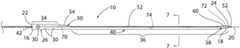
- FIG. 1is a schematic perspective view of a nail in a fibula in accordance with the principles of the present disclosure.
- FIGS. 2 - 4are schematic perspective views of different embodiments of a nail in a fibula in accordance with principles of the present disclosure.
- FIG. 5is a side view of an embodiment of a nail according to the present invention.
- FIG. 6is a partial cross-sectional view of the nail of FIG. 5 .
- FIG. 7is an end view of the nail of FIG. 5 taken from the right side of FIG. 5 .
- FIGS. 8 and 9are partial perspective views showing various aspects of the nail of FIG. 5 .
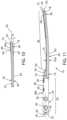
- FIG. 10is a partial cross-sectional view of a portion of the nail of FIG. 5 including a distal portion.
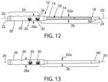
- FIGS. 11 - 13are a partial cross-sectional side view, top view, and bottom view of an embodiment of the nail according to the present invention.
- FIGS. 14 - 16are a partial cross-sectional side view, top view, and bottom view of an additional embodiment of the nail according to the present invention.
- FIGS. 17 - 19are a partial cross-sectional side view, top view, and bottom view of a further embodiment of the nail according to the present invention.
- FIGS. 20 - 24 aare schematic side and end views of a manufacturing process for making a nail according to the present invention.
- proximalrefers to something closer to the torso while “distal” refers to parts and places away from the torso.
- distalrefers to parts and places away from the torso.
- atwhen referring to the location or placement of an element or object means in, near or by the area or location occupied by the structure or element referred to.
- the longitudinal axisis a direction of orientation, along a lengthwise direction of the body or element.
- FIG. 1shows a bone nail or intramedullary nail 10 according to an embodiment of the present invention placed in an assembled condition within a bone 12 ; specifically, an antegrade insertion in a fibula.
- the term “nail” as used hererefers to a connective orthopedic implant, including but not limited to a nail for use in a fibula, and any other connective implant device suitable for use in any bone of interest, for example, the ulna and radius.
- the nail 10is typically inserted into the medullary cavity or marrow canal of a fibula.
- the nail 10may be referred to as an intramedullary nail because it is situated or placed within a medulla and uses the marrow space of a bone; intramedullary means the inside of a bone.
- the nail 10may be useful in other types of bones in addition to fibulas, in accordance with the principles of the present disclosure. While shown herein extending only partially along the length of the fibula, an embodiment of the present disclosure may include the nail 10 configured to extend substantially an entire length of the bone. For example, the phrase “substantial entire length” of a bone means approximately seventy-five percent of the length of the bone or more. Other embodiments of the nail may be configured to extend different lengths with respect to the bone.
- FIG. 1illustrates one configuration for fastening or connecting the head portion 34 , including the proximal portion 26 , of the nail 10 to the bone 12 , as shown, the fibula.
- Anterior-to-posterior (AP) screws or anchor members 32extend through the apertures or transverse bores 30 and into the fibula.
- a syndesmotic screw 44for example, a screw designed to replace the syndesmosis of the human body, usually temporarily, extends through an aperture or transverse bore 30 and into the tibia.
- a syndesmotic screwmay replace the inferior tibiofibular articulation and fix the tibia and fibula together at the lower joint.
- FIGS. 2 - 4illustrate different fastening configurations for fastening or connecting the nail 10 , that is fixing the nail 10 in position to stabilize a fracture of the fibula 12 .
- FIG. 2illustrates the use of two anterior-to-posterior (AP) screws or anchor members 32 received in the fibula 12 and two syndesmotic screws 44 extending through the fibula and received in the tibia 13 .
- FIG. 3illustrates the use of two anterior-to-posterior (AP) screws or anchor members 32 received in the fibula 12 and one syndesmotic screws 44 extending through the fibula and received in the tibia 13 .
- FIG. 2illustrates the use of two anterior-to-posterior (AP) screws or anchor members 32 received in the fibula 12 and one syndesmotic screws 44 extending through the fibula and received in the tibia 13 .
- APanterior-to-posterior
- FIG. 4illustrates the use of two anterior-to-posterior (AP) screws or anchor members 32 received in the fibula 12 and one oblique screw 46 also received in the fibula 12 , wherein no syndesmotic screws 44 are received in the tibia 13 .
- APanterior-to-posterior
- the nail 10includes an elongated body or member 14 formed of a metallic alloy, such as a titanium alloy.
- the elongated body 14having a proximal end 16 , a distal end 18 , and a longitudinal axis 20 extending between the proximal end 16 and the distal end 18 .
- the proximal end 16having a trailing or rear edge 22 and the distal end 18 having a leading or front edge 24 .
- the respective rear and front edgesbeing the transition between the location or transition from a longitudinal outer surface of the nail 10 .
- leading/front and trailing/rearreferring to the direction or orientation of insertion of the nail 10 .
- proximalrefers to that end or portion of the nail 10 typically placed at, adjacent or near an end of the bone 12
- distalrefers to that end or portion of the nail 10 typically extending further into the bone 12 , that is inwards from the end of the bone towards the center or medial portion thereof.
- the nail 10is designed for retrograde insertion into the intramedullary canal of the fibula 12 .
- the proximal end 16 of the intramedullary nail 10is located adjacent the distal end 12 a of the bone 12 .
- This positionreferred to as retrograde nailing wherein the proximal end 16 of the nail 10 is fixed in the distal end 12 a of the bone 12 .
- the distal end 18 of the nail 10is closer to the opposite end (not shown) of the bone 12 than the proximal end 16 of the nail 10 .
- antegrade nailingfixes the proximal end 16 of the nail 10 in the proximal end of the bone.
- the elongated bodyincludes a proximal portion or section 26 formed of a generally cylindrical configuration having an outer circumferential surface 28 and an outer diameter 28 a , a straight line passing from side to side through the center of a body or figure, here the proximal portion.
- the proximal portion or section 26including at least one and, in the disclosed embodiment, multiple openings or transverse bores 30 .
- the openings 30extend through the proximal portion or section 26 and across the longitudinal axis 20 and receive anchor members 32 , such as bone screws, to anchor the nail 10 in the bone 12 .
- the openings 30extend across the longitudinal axis 20 at an angle of 90° or less.
- the anchor members 32such as bone screws, received in the transverse bores 30 anchor the proximal portion or section 26 and correspondingly the proximal end 16 of the elongated body 14 within the distal end 12 a of the bone 12 .
- the anchor members 30may be bone screws or any other suitable variety of fastening mechanism known in the art for use with intramedullary nails.
- the shape, size, and configuration of the anchor members 30may vary within the scope of the present disclosure.
- the elongated body 14 of the nail 10includes a head portion 34 and a stem portion 36 .
- the head portion 34including the proximal portion or section 26 at the proximal end 16 .
- the stem portion 36including a distal portion or section 38 at the distal end 18 .
- FIG. 7shows the outer diameter of the head portion 34 , the outer diameter 28 a of proximal end 26 , being greater than the outer diameter 62 a of the outer surface 62 of the stem portion 36 .
- the stem portionmay also include the distal portion 38 having or including a conical tip 60 in at the distal end 18 .
- the stem portion or section 34includes the distal portion 38 and distal end 18 .
- the shape or configuration of the stem portion or section 34may vary between the proximal portion or section 26 and the leading or front edge 24 of the distal end 18 .
- the nail 10includes a passageway, seen generally at 50 , that extends longitudinally through the nail member 10 between the trailing or rear edge 22 of the proximal end 16 and the leading or front edge 24 of the distal end 18 .
- Passagewayis a way, typically having a wall(s); for example, a bore, duct, tube, canal, groove, path, channel, conduit, or similar structure.
- the passagewayconfigured to receive a guide wire 52 used for inserting the nail 10 .
- the passageway 50provides a longitudinal path for inserting the nail 10 over a guide wire 52 as shown in FIGS. 5 - 9 .
- the elongated body 14includes an intermediate, central, or medial portion or section 40 extending or lying between the proximal portion or section 26 at the proximal end 16 and the distal portion or section 38 at the distal end 18 .
- the nail 10may be viewed as including three areas or regions, a proximal portion 26 , a medial portion 40 and a distal portion 38 .
- the distal portion 38is that part of the nail 10 located nearby or adjacent to the distal end 18 . As explained subsequently, the distal portion 38 being that portion of the nail 10 including the bore or aperture 72 . It may also include a bend in the stem portion 36 , see FIG. 10 with the bend offset or extending at an angle ⁇ with respect to the longitudinal axis 20 , wherein a portion of the outer surface 62 of the medial portion 40 extends parallel to the longitudinal axis 20 .
- the proximal portion 26is that part of the nail 10 located nearby or adjacent to the proximal end 16 and including the bore or aperture 70 .
- the medial portion 40is that area of the nail 10 between the proximal and distal portions 26 , 38 and including the groove 74 .
- the stem portion 36encompasses the medial portion 40 and distal portion 38 , with the head portion 34 in the proximal portion 26 .
- the size or length of the respective areas in relation to one anothermay vary depending upon the overall length of the elongated body 14 of the nail 10 .
- the medial portionoccupies more than one-half (1 ⁇ 2) of the overall length of the elongated body 14 of the nail 10 and in some instances more than three quarters (3 ⁇ 4) of the overall length of the elongated body 14 .
- a fittingshown as slot 42 , may be disposed on the head portion 34 at the trailing or rear edge 22 of the proximal end 26 .
- the fitting 42configured for receiving a tool (not shown) for manipulating the nail 10 , or for attaching an alignment guide or jig.
- a transition portion 54extends between the intermediate or medial portion 40 and the proximal portion or section 26 .
- the transition portion 54may include a tapered portion extending inwardly from the outer surface 28 of the proximal portion or section 26 to the outer surface of the intermediate or medial portion 40 .
- at least part of the intermediate portion 40is offset from the longitudinal axis 20 of the nail 10 .
- the proximal portion or section 26is a longitudinally extending cylindrical member having a circular cross section.
- the intermediate portion 40has a crescent shaped cross section and is defined by a first arc 76 having a first radius 80 and a second arc 78 having a second radius 82 different than the first radius 80 .
- the crescent shapeis a cross-section of the intermediate portion 40 defined by a plane that is perpendicular to the longitudinal axis 56 .
- the longitudinal axis 56 of the intermediate or medial portion 40extends from the transition portion 54 toward the distal portion 38 and is offset from the longitudinal axis 20 of the nail 10 .
- the intermediate portion 40or at least part of the stem portion 36 , is radially offset from the longitudinal axis 20 extending through the passageway 50 in the head portion 34 .
- FIG. 7illustrates that a portion or part of the outer surface of the intermediate or medial portion 40 and a portion or part of the outer surface of the proximal portion 26 lie in a common plane. For example, as illustrated in FIG.
- one side of the transition portion 54includes an inwardly beveled or tapered section while the opposing side is a smooth, continuous extension of the outer surface 28 of the proximal portion to the outer surface of the medial portion, wherein the two surfaces share a common tangent, and may share a common plane or surface. That is the outer surface of one side, the top or upper side in FIG. 5 , of the nail has a discontinuity, an inwardly beveled part or portion of the transition portion 54 , while the opposite outer surface, on the opposite side or the bottom or lower side of the nail 10 has no irregularity, instead having a shared common surface, between the proximal portion 26 , transition portion 54 , and medial portion 40 , extending parallel to the longitudinal axis 20 .
- Respective cross sections, taken transverse the longitudinal axis 20 , of the proximal portion or section 26 and medial portion 40are closed shapes that touch internally, with both shapes on the same side of a common tangent.
- respective cross sectionsare circles with the circumference of each circle having a common tangent point with the smaller circle within the larger, see FIG. 7 .
- the longitudinal axis 20 of the nail 10coincides with the passageway 50 , including the open-faced channel or groove 74 in the medial portion 40 and the bore or aperture 72 in the distal portion or section 38 of the distal end 18 .
- the passageway 50 in the nail 10includes three sections, the bore or aperture 70 in the head portion 34 , the groove 74 in the medial portion 40 , and the bore or aperture 72 in the distal portion 38 . The foregoing results in the nail 10 captured at each end, both the proximal end 16 and the distal end 18 secured on and following the guide wire 52 .
- FIG. 10illustrates the exemplary embodiment of the nail 10 with the stem portion 36 of the nail 22 extends substantially straight, along parallel to the longitudinal axis 20 , with the distal portion 38 of the distal end 18 , including the conical tip 60 , bent upward, toward the side of the nail having the inwardly beveled or tapered section 58 .
- the bend or offsetextending at an angle ⁇ with respect to the longitudinal axis 20 .
- the passageway 50extends in a straight line or path coinciding with the longitudinal axis 20 of the head portion 34 including the proximal portion or section 26 . Because the stem portion is offset from the longitudinal axis 20 , the passageway forms a groove 74 in the stem portion.
- the conical tip 60intersects the longitudinal axis 20 wherein the passageway 50 forms a bore 72 in the distal end 18 of the nail 10 .
- the stem portion 36has a longitudinal axis 56 spaced from the longitudinal axis 20 , because the distal end 18 is bent upward, the respective longitudinal axes 20 , 56 converge at the distal portion 38 of the distal end 18 wherein instead of the passageway 50 forming a groove 74 on the surface of the distal end or portion, it forms a bore 72 in the distal end 18 , in particular the conical tip 60 .
- the conical tip 60is bent upwards, once the passageway 50 forms the bore 72 in the distal portion 38 of the distal end, the sidewall 64 surrounding the bore 72 varies in thickness.
- the conical tip 60having a longitudinal axis extending at the angle ⁇ , which differs, is incongruent, with the longitudinal axis of the bore 72 in the distal portion 38 . As explained subsequently, this occurs because the conical tip 60 is initially formed tapering inwardly toward the longitudinal axis 20 . The distal portion 38 is then bent upwardly until a conical surface 60 a of the conical tip 60 is parallel to the longitudinal axis 20 .
- the nail 10 the head portion 34 and stem portion 36are cylindrically shaped wherein the respective axes thereof are offset. As illustrated, the respective cylindrically shaped head portion and stem portion 34 , 36 are offset, so at least a portion of the outer surface of each cylindrical portion lies in a common plane. While the head portion 34 and stem portion 36 are shown with cylindrical shapes, that is circular cross-sections; other shapes or configurations having cross-sections other than circular are contemplated, the understanding being that the longitudinal axis of at least part of the stem portion 36 is offset from the longitudinal axis of the head portion 34 such that the majority of the body of the stem portion 36 sits or is on one side of the longitudinal axis defined by the centerline of the passageway 50 extending through the head portion 34 . As shown in FIG.
- the centerline of the passageway 50is the longitudinal axis 20 of the head portion 34 and coincides with the axis of the bore or aperture 70 .
- at least a portion of the longitudinal axis 56 of the stem portion 36is offset from and as shown spaced below the longitudinal axis 20 .
- the passageway extending past the transition portion 54results in longitudinally extending open-faced channel or groove 74 on an outer surface of the intermediate or medial portion 40 .
- the term “groove”means a narrow channel or indentation on the surface of a three-dimensional object. The groove has depth and walls that extend in the same direction as the longitudinal axis of the nail 10 .
- the passageway 50continues as groove 74 from the transition portion 54 to the distal portion 38 . At the distal portion 38 , the passageway 50 extends through the distal portion 38 as a bore or aperture 72 .
- the passageway 50extends from the leading or front edge 24 of the distal end to the trailing or rear edge 22 of the proximal end.
- the passageway 50receives insertion and extraction instrumentation, such as a guide wire 52 , used to position the nail member 10 within the bone 12 .
- a guide wire 52is inserted into the passageway 50 , initially into the bore or aperture 72 , in the distal end 18 at the leading or front edge 24 of the distal end 18 .
- the bore or aperture 72cannulates the distal portion 38 of the distal end 18 or of the nail 10 enabling it to accept and follow the guide wire 52 .
- the leading or front edge 24 of the distal end 18 of the nail member 10follows the path of the guide wire 52 and is inserted into the bone 12 first.
- the guide wire 52then travels along the channel or groove 74 and ultimately reaches and enters the bore or aperture 70 in the proximal portion or section 26 .
- the intermediate or medial portion 40is offset or sits to one side of the guide wire 52 .
- FIGS. 11 - 13illustrates an exemplary embodiment of the nail 10 having a degree of curvature such that the distal end 18 of the nail 10 bends upward, or curves inward toward the side having the inwardly beveled or tapered section 58 .
- the longitudinal axis 20 of the nailfollowing the degree of curvature. The degree of curvature providing easy of insertion and stability within the bone.
- FIGS. 11 - 13illustrate the nail 10 four transverse apertures 34 receiving, as shown in FIG. 2 , the two anterior-to-posterior (AP) screws or anchor members 32 received in the fibula 12 and the two syndesmotic screws 44 received in the tibia 13 .
- APanterior-to-posterior
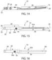
- FIGS. 14 - 16illustrate the nail 10 having three transverse apertures 30 for receiving, as shown in FIG. 3 , the two anterior-to-posterior (AP) screws or anchor members 32 received in the fibula 12 and one syndesmotic screws 44 received in the tibia 13 .
- APanterior-to-posterior
- FIGS. 17 - 19illustrate the nail 10 having three transverse apertures 30 for receiving, as shown in FIG. 4 the two anterior-to-posterior (AP) screws or anchor members 32 received in the fibula 12 and the one oblique screw 46 also received in the fibula 12 , wherein no syndesmotic screws 44 are received in the tibia 13 .
- APanterior-to-posterior
- FIGS. 20 - 24 and 20 a - 24 aschematically illustrate a manufacturing process for making the nail 10 .
- FIGS. 20 and 20 aillustrates that the process starts with machining a symmetrical nail; i.e., the nail 10 is symmetrical about its longitudinal axis 20 .
- the nail 10includes a cylindrical proximal portion 26 , a conical transition portion 54 and a cylindrical intermediate or medial portion 40 along with a cylindrical distal portion 38 .
- the nail 10starts with a cylindrical head portion 34 , conical transition portion 54 and cylindrical stem portion 36 . All three have a common longitudinal axis, that is a common centerline.
- FIGS. 21 and 21 aillustrates the next step which includes bending the stem portion 36 and transition portion 54 , at the start or beginning of the transition portion 54 , the interface between the head portion 34 and transition portion 54 , until an outer surface 54 a of the transition portion 54 lies in a common plane with the outer surface 28 of the head portion 34 .
- FIGS. 22 and 22 ashow the distal portion 38 extending below, or past the outer surface 28 of the head portion 34 .
- FIGS. 23 and 23 aillustrates the next step wherein the stem portion 36 or shaft is bent upwards, the bend occurring at the start or beginning of the stem portion 36 , the interface between the stem portion 36 and the transition portion 54 , until an outer surface 62 of the stem portion 36 lies in a common plane with the outer surface 28 of the head portion 34 .
- FIGS. 24 and 24 aillustrates the next step, which is to bend the distal portion 38 at the distal end 18 of the nail 10 upward in the direction of or toward the centerline or longitudinal axis 20 of the head portion 34 .
- FIG. 39 eshows the next step wherein the nail 10 including the head portion and stem portion are cannulated or provided with a passageway.
- the distal portion 38includes the conical tip 60 which is also cannulated or provided with a passageway or bore, see for example FIG. 10 .
- the nail 10may also include a bend or curvature.
- the processprovides a nail 10 having a longitudinally extending bore or apertures 70 , 72 in the proximate portion 26 and distal portion 38 .
- the longitudinally extending bores or apertures 70 , 72providing structure for placing the nail 10 on the guide wire 52 .
- Only the proximate portion 26 and distal portion 38have a longitudinally extending bore or aperture 70 , 72 forming part of the passageway 50 .
- the passageway 50As shown in FIG. 5 to the extent the passageway 50 extends in the intermediate or medial portion 40 it is only a groove or open-faced channel 74 , not a bore or aperture 70 , 72 .
- the intermediate or medial portion 40may not include a groove or open-faced channel 74 .
- the passageway 50can extend between the trailing or rear edge 22 through the proximate portion 26 and outside or space from an outer surface 54 a of the transition portion 54 .
- the passageway 50extends through the distal end 18 , or part of the distal portion 38 , and the leading or front edge 24 of the distal end 18 . Providing a passageway 50 in this manner helps keep the nail 10 on the guide wire 52 during insertion.
- nails 10using the foregoing inventive concepts, including providing a groove or open-faced channel 74 and an outer surface of the intermediate or medial portion 40 .
- Cannulating or providing the proximal and distal ends 16 , 18 with bores or apertures 70 , 72maintains a proper positional relationship of the nail 10 along the guide wire 52 and correspondingly in the bone.
Landscapes
- Health & Medical Sciences (AREA)
- Orthopedic Medicine & Surgery (AREA)
- Surgery (AREA)
- Life Sciences & Earth Sciences (AREA)
- Biomedical Technology (AREA)
- Public Health (AREA)
- Veterinary Medicine (AREA)
- Engineering & Computer Science (AREA)
- Nuclear Medicine, Radiotherapy & Molecular Imaging (AREA)
- Heart & Thoracic Surgery (AREA)
- Medical Informatics (AREA)
- Molecular Biology (AREA)
- Animal Behavior & Ethology (AREA)
- General Health & Medical Sciences (AREA)
- Neurology (AREA)
- Dentistry (AREA)
- Oral & Maxillofacial Surgery (AREA)
- Surgical Instruments (AREA)
Abstract
Description
Claims (8)
Priority Applications (1)
| Application Number | Priority Date | Filing Date | Title |
|---|---|---|---|
| US17/167,899US12076061B2 (en) | 2018-01-25 | 2021-02-04 | Bone nail |
Applications Claiming Priority (3)
| Application Number | Priority Date | Filing Date | Title |
|---|---|---|---|
| US201862622084P | 2018-01-25 | 2018-01-25 | |
| US16/258,001US10932828B2 (en) | 2018-01-25 | 2019-01-25 | Bone nail |
| US17/167,899US12076061B2 (en) | 2018-01-25 | 2021-02-04 | Bone nail |
Related Parent Applications (1)
| Application Number | Title | Priority Date | Filing Date |
|---|---|---|---|
| US16/258,001ContinuationUS10932828B2 (en) | 2018-01-25 | 2019-01-25 | Bone nail |
Publications (2)
| Publication Number | Publication Date |
|---|---|
| US20210153917A1 US20210153917A1 (en) | 2021-05-27 |
| US12076061B2true US12076061B2 (en) | 2024-09-03 |
Family
ID=67299679
Family Applications (2)
| Application Number | Title | Priority Date | Filing Date |
|---|---|---|---|
| US16/258,001ActiveUS10932828B2 (en) | 2018-01-25 | 2019-01-25 | Bone nail |
| US17/167,899Active2040-06-16US12076061B2 (en) | 2018-01-25 | 2021-02-04 | Bone nail |
Family Applications Before (1)
| Application Number | Title | Priority Date | Filing Date |
|---|---|---|---|
| US16/258,001ActiveUS10932828B2 (en) | 2018-01-25 | 2019-01-25 | Bone nail |
Country Status (1)
| Country | Link |
|---|---|
| US (2) | US10932828B2 (en) |
Families Citing this family (4)
| Publication number | Priority date | Publication date | Assignee | Title |
|---|---|---|---|---|
| US10932828B2 (en)* | 2018-01-25 | 2021-03-02 | Advanced Orthopaedic Solutions, Inc. | Bone nail |
| JP7622317B2 (en) | 2019-12-11 | 2025-01-28 | 日東電工株式会社 | Composite semipermeable membrane |
| WO2021211829A1 (en)* | 2020-04-15 | 2021-10-21 | Auston Darryl | Improved linear fibular nail |
| US20240148421A1 (en)* | 2022-11-09 | 2024-05-09 | DePuy Synthes Products, Inc. | Devices and methods for lateral fixation syndesmosis repair |
Citations (81)
| Publication number | Priority date | Publication date | Assignee | Title |
|---|---|---|---|---|
| US5034013A (en) | 1989-04-24 | 1991-07-23 | Zimmer Inc. | Intramedullary nail |
| US5112333A (en) | 1990-02-07 | 1992-05-12 | Fixel Irving E | Intramedullary nail |
| US5374235A (en) | 1992-04-10 | 1994-12-20 | Aap Gmbh & Co. Betriebs Kg | Marrow nail |
| US5429640A (en) | 1992-11-27 | 1995-07-04 | Clemson University | Intramedullary rod for fracture fixation of femoral shaft independent of ipsilateral femoral neck fracture fixation |
| US5472444A (en) | 1994-05-13 | 1995-12-05 | Acumed, Inc. | Humeral nail for fixation of proximal humeral fractures |
| US5620445A (en) | 1994-07-15 | 1997-04-15 | Brosnahan; Robert | Modular intramedullary nail |
| US5776194A (en) | 1996-04-25 | 1998-07-07 | Nuvana Medical Innovations, Llc | Intermedullary rod apparatus and methods of repairing proximal humerus fractures |
| US5814047A (en) | 1997-03-04 | 1998-09-29 | Industrial Technology Research Institute | Intramedullary nail fixation apparatus and its fixation method |
| US5971986A (en)* | 1996-07-23 | 1999-10-26 | Santori; Francesco Saverio | Intramedullary device for pinning bones |
| US6123708A (en) | 1999-02-03 | 2000-09-26 | Pioneer Laboratories, Inc. | Intramedullary bone fixation rod |
| US6126661A (en) | 1997-01-20 | 2000-10-03 | Orthofix S.R.L. | Intramedullary cavity nail and kit for the treatment of fractures of the hip |
| US6228086B1 (en) | 1997-03-19 | 2001-05-08 | Stryker Trauma-Selzach Ag | Modular intramedullary nail |
| US6296645B1 (en) | 1999-04-09 | 2001-10-02 | Depuy Orthopaedics, Inc. | Intramedullary nail with non-metal spacers |
| US20010053912A1 (en) | 1998-11-17 | 2001-12-20 | Robert Frigg | Medullary nail for the surgical treatment of forearm fractures |
| US20020103488A1 (en) | 2000-04-10 | 2002-08-01 | Lower Jerry L. | Intramedullary nail with snap-in window |
| US20020143337A1 (en) | 2000-02-01 | 2002-10-03 | Hand Innovations, Inc. | Fixation device for metaphyseal long bone fractures |
| US20020173792A1 (en)* | 1999-04-09 | 2002-11-21 | Depuy Orthopaedics, Inc. | Non-metal inserts for bone support assembly |
| US6527775B1 (en) | 2000-09-22 | 2003-03-04 | Piper Medical, Inc. | Intramedullary interlocking fixation device for the distal radius |
| US20030069581A1 (en) | 2001-10-04 | 2003-04-10 | Stinson David T. | Universal intramedullary nails, systems and methods of use thereof |
| US6547791B1 (en) | 1998-07-27 | 2003-04-15 | Stryker Trauma - Selzach Ag | Retrograde tibial nail |
| US20040172027A1 (en) | 2003-02-07 | 2004-09-02 | Stryker Trauma Gmbh | Locking nail for treating fractures of the proximal femur |
| US20050055023A1 (en) | 2002-07-23 | 2005-03-10 | Advanced Orthopaedic Solutions, Inc. | Intramedullary nail for long bone fractures |
| US20050075637A1 (en) | 2003-04-04 | 2005-04-07 | Semet Elliot Charles | Interlocking IM nails with outer screw |
| US20060149257A1 (en) | 2002-05-30 | 2006-07-06 | Orbay Jorge L | Fracture fixation device |
| US20060161155A1 (en) | 2003-06-12 | 2006-07-20 | Andre Schlienger | Surgical nail |
| US20060161156A1 (en) | 2002-05-30 | 2006-07-20 | Orbay Jorge L | Fracture fixation device |
| US20060200142A1 (en) | 2005-02-22 | 2006-09-07 | Sohngen Gary W | Humeral nail |
| US20060200160A1 (en) | 2005-02-18 | 2006-09-07 | Ebi, L.P. | Internal fixation assemblies and associated instruments |
| US20070100343A1 (en) | 2003-05-17 | 2007-05-03 | Cole Dean J | Intramedullary nail assembly |
| US20070123878A1 (en) | 2005-10-21 | 2007-05-31 | Shaver Joseph A | Orthopedic rod with locking aperture |
| US20070270845A1 (en) | 2003-09-08 | 2007-11-22 | Kohsuke Watanabe | Orthopaedic plate and screw assembly |
| US20070299447A1 (en)* | 2003-09-08 | 2007-12-27 | Kohsuke Watanabe | Orthopaedic plate and screw assembly |
| US20080140077A1 (en) | 2006-12-09 | 2008-06-12 | Adel Kebaish | Femoral Universal Nail |
| US20080183171A1 (en) | 2007-01-26 | 2008-07-31 | Ebi, L.P. | Lockable intermedullary fixation device |
| US20080262496A1 (en) | 2004-06-30 | 2008-10-23 | Sythes (U.S.A.) | Surgical Nail |
| US20080287958A1 (en) | 2007-05-14 | 2008-11-20 | Howmedica Osteonics Corp. | Flexible intramedullary rod |
| US20080287951A1 (en) | 2007-03-22 | 2008-11-20 | Stoneburner James D | Segmented intramedullary structure |
| US20080312702A1 (en) | 2005-04-06 | 2008-12-18 | Andre Schlienger | Reference Pin |
| US20090048600A1 (en) | 2007-06-22 | 2009-02-19 | Anthem Orthopaedics Van, Llc | Intramedullary rod with pivotable fastener and method for using same |
| US20090326534A1 (en) | 2008-06-30 | 2009-12-31 | Depuy Products, Inc. | Fracture Fixation Apparatus |
| US20100256639A1 (en) | 2008-06-24 | 2010-10-07 | Jeff Tyber | Fixation system, an intramedullary fixation assembly and method of use |
| US20100256638A1 (en) | 2008-06-24 | 2010-10-07 | Jeff Tyber | Intraosseous intramedullary fixation assembly and method of use |
| US20100324556A1 (en) | 2008-06-24 | 2010-12-23 | Jeff Tyber | Fixation system, an intramedullary fixation assembly and method of use |
| US20110087227A1 (en) | 2008-12-18 | 2011-04-14 | Mazur Kal U | Bone fixation device, tools and methods |
| US20110172667A1 (en) | 2008-06-26 | 2011-07-14 | AO Tecnology AG | Bone fixation device with cover |
| US20110282347A1 (en) | 2010-05-11 | 2011-11-17 | Gordon J Eric | Pediatric intramedullary nail |
| US20110295254A1 (en) | 2008-05-07 | 2011-12-01 | Tornier Sas | Implant locking device and corresponding implant |
| US20120059376A1 (en) | 2008-10-15 | 2012-03-08 | Smith & Nephew, Inc. | Composite internal fixators |
| US20120197255A1 (en) | 2007-01-26 | 2012-08-02 | Biomet Manufacturing Corp. | Lockable Intramedullary Fixation Device |
| US20130053847A1 (en) | 2011-08-31 | 2013-02-28 | Mark Siravo | Implant Devices Constructed with Metallic and Polymeric Components |
| US20130131679A1 (en) | 2010-06-03 | 2013-05-23 | Smith & Nephew, Inc. | Orthopaedic implants |
| US20130150851A1 (en)* | 2011-06-23 | 2013-06-13 | Reto NARDINI | Monofix nail |
| US20130172890A1 (en) | 2011-12-29 | 2013-07-04 | Synthes Usa, Llc | Suprapatellar Insertion System, Kit and Method |
| US20130204251A1 (en) | 2009-05-05 | 2013-08-08 | Synthes Usa, Llc | Nail locking systems |
| US20130274745A1 (en) | 2012-04-16 | 2013-10-17 | DePuy Synthes Products, LLC | Bump cut on hole edge |
| US20130325006A1 (en) | 2012-05-30 | 2013-12-05 | Acumed Llc | Articulated intramedullary nail |
| US20140058392A1 (en) | 2011-02-08 | 2014-02-27 | Stryker Trauma Gmbh | Implant system for bone fixation |
| US20140066932A1 (en) | 2012-08-30 | 2014-03-06 | Andreas Appenzeller | Intramedullary Fixation Assembly |
| US20140135769A1 (en) | 2012-11-12 | 2014-05-15 | Navid Ziran | Dynamic axial nail for intramedullary treatment of long bone fractures |
| US20140142575A1 (en) | 2012-11-14 | 2014-05-22 | Lutz Biedermann | Bone nail for the heel |
| US20140296853A1 (en) | 2013-03-28 | 2014-10-02 | Dietmar Wolter | Osteosynthesis system for the multidirectional, angular-stable treatment of fractures of tubular bones comprising an intramedullary nail and bone screws |
| US20140296854A1 (en) | 2013-03-28 | 2014-10-02 | Dietmar Wolter | Osteosynthesis system for the multidirectional, angular-stable treatment of fractures of tubular bones comprising an intramedullary nail and bone screws |
| US20150032110A1 (en) | 2013-07-24 | 2015-01-29 | Sreevathsa Boraiah | Interlocking intramedullary rod assembly for proximal femoral fractures, including unstable hip fractures |
| US20150112345A1 (en) | 2013-07-24 | 2015-04-23 | Sreevathsa Boraiah | Interlocking intramedullary rod assembly for proximal femoral fractures, including unstable hip fractures |
| US20150305791A1 (en) | 2014-04-25 | 2015-10-29 | DePuy Synthes Products, Inc. | Aiming device for distal locking of intramedullary nails and methods of use |
| US20170105776A1 (en) | 2014-03-24 | 2017-04-20 | Christian Lutz | Method for Producing an Osteosynthetic Implant, and Bone Nail |
| US9788871B2 (en)* | 2002-08-10 | 2017-10-17 | Howmedica Osteonics Corp. | Method and apparatus for repairing the mid-foot region via an intramedullary nail |
| US20170296241A1 (en) | 2016-04-15 | 2017-10-19 | Arthrex, Inc. | Arthrodesis devices for generating and applying compression within joints |
| US20180028241A1 (en) | 2016-07-28 | 2018-02-01 | Michael S Levy | Humeral nail having a bracket |
| US20180042651A1 (en) | 2015-02-17 | 2018-02-15 | The Sydney Children's Hospitals Network (Randwick And Westmead) | A bone rod |
| US20180078292A1 (en) | 2016-09-22 | 2018-03-22 | Globus Medical, Inc. | Systems and methods for intramedullary nail implantation |
| US20180177537A1 (en) | 2016-12-28 | 2018-06-28 | William Scott Van Dyke | Joint compression instrumentation and methods |
| US20180344377A1 (en) | 2017-06-05 | 2018-12-06 | DePuy Synthes Products, Inc. | Intramedullary nail insertion handle |
| US20190038326A1 (en) | 2016-09-22 | 2019-02-07 | Globus Medical, Inc. | Systems and methods for intramedullary nail implantation |
| US20190105086A1 (en) | 2017-10-06 | 2019-04-11 | Smith & Nephew, Inc. | Implantable bone adjustment devices |
| US20190105087A1 (en) | 2017-10-09 | 2019-04-11 | Acumed Llc | System and method for bone fixation using a nail locked to an encircling anchor |
| US20190117282A1 (en) | 2015-12-28 | 2019-04-25 | Glenhurst Labs, Llc | Surgical devices for small bone fracture surgery |
| US20190175232A1 (en) | 2017-12-13 | 2019-06-13 | DePuy Synthes Products, Inc. | Intramedullary nail with cannulation access hole |
| US20190216513A1 (en) | 2018-01-15 | 2019-07-18 | Steven Saam Sands | Hybrid Intramedullary Rods |
| US20190223925A1 (en) | 2018-01-25 | 2019-07-25 | Advanced Orthopaedic Solutions, Inc. | Bone nail |
| US20190314065A1 (en) | 2018-04-13 | 2019-10-17 | Stryker European Holdings I, Llc | Femoral Nail With Enhanced Bone Conforming Geometry |
Family Cites Families (1)
| Publication number | Priority date | Publication date | Assignee | Title |
|---|---|---|---|---|
| US5248313A (en) | 1991-04-17 | 1993-09-28 | Greene Bruce L | Fibular intramedullary rod |
- 2019
- 2019-01-25USUS16/258,001patent/US10932828B2/enactiveActive
- 2021
- 2021-02-04USUS17/167,899patent/US12076061B2/enactiveActive
Patent Citations (84)
| Publication number | Priority date | Publication date | Assignee | Title |
|---|---|---|---|---|
| US5034013A (en) | 1989-04-24 | 1991-07-23 | Zimmer Inc. | Intramedullary nail |
| US5112333A (en) | 1990-02-07 | 1992-05-12 | Fixel Irving E | Intramedullary nail |
| US5374235A (en) | 1992-04-10 | 1994-12-20 | Aap Gmbh & Co. Betriebs Kg | Marrow nail |
| US5429640A (en) | 1992-11-27 | 1995-07-04 | Clemson University | Intramedullary rod for fracture fixation of femoral shaft independent of ipsilateral femoral neck fracture fixation |
| US5472444A (en) | 1994-05-13 | 1995-12-05 | Acumed, Inc. | Humeral nail for fixation of proximal humeral fractures |
| US5620445A (en) | 1994-07-15 | 1997-04-15 | Brosnahan; Robert | Modular intramedullary nail |
| US5776194A (en) | 1996-04-25 | 1998-07-07 | Nuvana Medical Innovations, Llc | Intermedullary rod apparatus and methods of repairing proximal humerus fractures |
| US5971986A (en)* | 1996-07-23 | 1999-10-26 | Santori; Francesco Saverio | Intramedullary device for pinning bones |
| US6126661A (en) | 1997-01-20 | 2000-10-03 | Orthofix S.R.L. | Intramedullary cavity nail and kit for the treatment of fractures of the hip |
| US5814047A (en) | 1997-03-04 | 1998-09-29 | Industrial Technology Research Institute | Intramedullary nail fixation apparatus and its fixation method |
| US6228086B1 (en) | 1997-03-19 | 2001-05-08 | Stryker Trauma-Selzach Ag | Modular intramedullary nail |
| US6547791B1 (en) | 1998-07-27 | 2003-04-15 | Stryker Trauma - Selzach Ag | Retrograde tibial nail |
| US20010053912A1 (en) | 1998-11-17 | 2001-12-20 | Robert Frigg | Medullary nail for the surgical treatment of forearm fractures |
| US6123708A (en) | 1999-02-03 | 2000-09-26 | Pioneer Laboratories, Inc. | Intramedullary bone fixation rod |
| US6296645B1 (en) | 1999-04-09 | 2001-10-02 | Depuy Orthopaedics, Inc. | Intramedullary nail with non-metal spacers |
| US20020173792A1 (en)* | 1999-04-09 | 2002-11-21 | Depuy Orthopaedics, Inc. | Non-metal inserts for bone support assembly |
| US20020143337A1 (en) | 2000-02-01 | 2002-10-03 | Hand Innovations, Inc. | Fixation device for metaphyseal long bone fractures |
| US20020103488A1 (en) | 2000-04-10 | 2002-08-01 | Lower Jerry L. | Intramedullary nail with snap-in window |
| US6527775B1 (en) | 2000-09-22 | 2003-03-04 | Piper Medical, Inc. | Intramedullary interlocking fixation device for the distal radius |
| US20030069581A1 (en) | 2001-10-04 | 2003-04-10 | Stinson David T. | Universal intramedullary nails, systems and methods of use thereof |
| US20060161156A1 (en) | 2002-05-30 | 2006-07-20 | Orbay Jorge L | Fracture fixation device |
| US20060149257A1 (en) | 2002-05-30 | 2006-07-06 | Orbay Jorge L | Fracture fixation device |
| US20050055023A1 (en) | 2002-07-23 | 2005-03-10 | Advanced Orthopaedic Solutions, Inc. | Intramedullary nail for long bone fractures |
| US9788871B2 (en)* | 2002-08-10 | 2017-10-17 | Howmedica Osteonics Corp. | Method and apparatus for repairing the mid-foot region via an intramedullary nail |
| US20040172027A1 (en) | 2003-02-07 | 2004-09-02 | Stryker Trauma Gmbh | Locking nail for treating fractures of the proximal femur |
| US20050075637A1 (en) | 2003-04-04 | 2005-04-07 | Semet Elliot Charles | Interlocking IM nails with outer screw |
| US20070100343A1 (en) | 2003-05-17 | 2007-05-03 | Cole Dean J | Intramedullary nail assembly |
| US20060161155A1 (en) | 2003-06-12 | 2006-07-20 | Andre Schlienger | Surgical nail |
| US20070270845A1 (en) | 2003-09-08 | 2007-11-22 | Kohsuke Watanabe | Orthopaedic plate and screw assembly |
| US20070299447A1 (en)* | 2003-09-08 | 2007-12-27 | Kohsuke Watanabe | Orthopaedic plate and screw assembly |
| US20080262496A1 (en) | 2004-06-30 | 2008-10-23 | Sythes (U.S.A.) | Surgical Nail |
| US20060200160A1 (en) | 2005-02-18 | 2006-09-07 | Ebi, L.P. | Internal fixation assemblies and associated instruments |
| US20060200142A1 (en) | 2005-02-22 | 2006-09-07 | Sohngen Gary W | Humeral nail |
| US20080312702A1 (en) | 2005-04-06 | 2008-12-18 | Andre Schlienger | Reference Pin |
| US20070123878A1 (en) | 2005-10-21 | 2007-05-31 | Shaver Joseph A | Orthopedic rod with locking aperture |
| US20080140077A1 (en) | 2006-12-09 | 2008-06-12 | Adel Kebaish | Femoral Universal Nail |
| US20080183171A1 (en) | 2007-01-26 | 2008-07-31 | Ebi, L.P. | Lockable intermedullary fixation device |
| US20120197255A1 (en) | 2007-01-26 | 2012-08-02 | Biomet Manufacturing Corp. | Lockable Intramedullary Fixation Device |
| US20080287951A1 (en) | 2007-03-22 | 2008-11-20 | Stoneburner James D | Segmented intramedullary structure |
| US20080287958A1 (en) | 2007-05-14 | 2008-11-20 | Howmedica Osteonics Corp. | Flexible intramedullary rod |
| US20090048600A1 (en) | 2007-06-22 | 2009-02-19 | Anthem Orthopaedics Van, Llc | Intramedullary rod with pivotable fastener and method for using same |
| US20110295254A1 (en) | 2008-05-07 | 2011-12-01 | Tornier Sas | Implant locking device and corresponding implant |
| US20100324556A1 (en) | 2008-06-24 | 2010-12-23 | Jeff Tyber | Fixation system, an intramedullary fixation assembly and method of use |
| US20100256638A1 (en) | 2008-06-24 | 2010-10-07 | Jeff Tyber | Intraosseous intramedullary fixation assembly and method of use |
| US20100256639A1 (en) | 2008-06-24 | 2010-10-07 | Jeff Tyber | Fixation system, an intramedullary fixation assembly and method of use |
| US20110172667A1 (en) | 2008-06-26 | 2011-07-14 | AO Tecnology AG | Bone fixation device with cover |
| US20090326534A1 (en) | 2008-06-30 | 2009-12-31 | Depuy Products, Inc. | Fracture Fixation Apparatus |
| US20120059376A1 (en) | 2008-10-15 | 2012-03-08 | Smith & Nephew, Inc. | Composite internal fixators |
| US20190282279A1 (en) | 2008-10-15 | 2019-09-19 | Smith & Nephew, Inc. | Composite internal fixators |
| US20110087227A1 (en) | 2008-12-18 | 2011-04-14 | Mazur Kal U | Bone fixation device, tools and methods |
| US20130204251A1 (en) | 2009-05-05 | 2013-08-08 | Synthes Usa, Llc | Nail locking systems |
| US20110282347A1 (en) | 2010-05-11 | 2011-11-17 | Gordon J Eric | Pediatric intramedullary nail |
| US20130131679A1 (en) | 2010-06-03 | 2013-05-23 | Smith & Nephew, Inc. | Orthopaedic implants |
| US20140058392A1 (en) | 2011-02-08 | 2014-02-27 | Stryker Trauma Gmbh | Implant system for bone fixation |
| US20130150851A1 (en)* | 2011-06-23 | 2013-06-13 | Reto NARDINI | Monofix nail |
| US20130053847A1 (en) | 2011-08-31 | 2013-02-28 | Mark Siravo | Implant Devices Constructed with Metallic and Polymeric Components |
| US20130172890A1 (en) | 2011-12-29 | 2013-07-04 | Synthes Usa, Llc | Suprapatellar Insertion System, Kit and Method |
| US20130274745A1 (en) | 2012-04-16 | 2013-10-17 | DePuy Synthes Products, LLC | Bump cut on hole edge |
| US20130325006A1 (en) | 2012-05-30 | 2013-12-05 | Acumed Llc | Articulated intramedullary nail |
| US20140066932A1 (en) | 2012-08-30 | 2014-03-06 | Andreas Appenzeller | Intramedullary Fixation Assembly |
| US20140135769A1 (en) | 2012-11-12 | 2014-05-15 | Navid Ziran | Dynamic axial nail for intramedullary treatment of long bone fractures |
| US20140142575A1 (en) | 2012-11-14 | 2014-05-22 | Lutz Biedermann | Bone nail for the heel |
| US20140296853A1 (en) | 2013-03-28 | 2014-10-02 | Dietmar Wolter | Osteosynthesis system for the multidirectional, angular-stable treatment of fractures of tubular bones comprising an intramedullary nail and bone screws |
| US20140296854A1 (en) | 2013-03-28 | 2014-10-02 | Dietmar Wolter | Osteosynthesis system for the multidirectional, angular-stable treatment of fractures of tubular bones comprising an intramedullary nail and bone screws |
| US20150112345A1 (en) | 2013-07-24 | 2015-04-23 | Sreevathsa Boraiah | Interlocking intramedullary rod assembly for proximal femoral fractures, including unstable hip fractures |
| US20150032110A1 (en) | 2013-07-24 | 2015-01-29 | Sreevathsa Boraiah | Interlocking intramedullary rod assembly for proximal femoral fractures, including unstable hip fractures |
| US20170105776A1 (en) | 2014-03-24 | 2017-04-20 | Christian Lutz | Method for Producing an Osteosynthetic Implant, and Bone Nail |
| US20150305791A1 (en) | 2014-04-25 | 2015-10-29 | DePuy Synthes Products, Inc. | Aiming device for distal locking of intramedullary nails and methods of use |
| US20180042651A1 (en) | 2015-02-17 | 2018-02-15 | The Sydney Children's Hospitals Network (Randwick And Westmead) | A bone rod |
| US20190117282A1 (en) | 2015-12-28 | 2019-04-25 | Glenhurst Labs, Llc | Surgical devices for small bone fracture surgery |
| US20170296241A1 (en) | 2016-04-15 | 2017-10-19 | Arthrex, Inc. | Arthrodesis devices for generating and applying compression within joints |
| US20190274742A1 (en) | 2016-04-15 | 2019-09-12 | Arthrex, Inc. | Arthrodesis devices for generating and applying compression within joints |
| US20180028241A1 (en) | 2016-07-28 | 2018-02-01 | Michael S Levy | Humeral nail having a bracket |
| US20190038326A1 (en) | 2016-09-22 | 2019-02-07 | Globus Medical, Inc. | Systems and methods for intramedullary nail implantation |
| US20180078292A1 (en) | 2016-09-22 | 2018-03-22 | Globus Medical, Inc. | Systems and methods for intramedullary nail implantation |
| US20180177537A1 (en) | 2016-12-28 | 2018-06-28 | William Scott Van Dyke | Joint compression instrumentation and methods |
| US20180344377A1 (en) | 2017-06-05 | 2018-12-06 | DePuy Synthes Products, Inc. | Intramedullary nail insertion handle |
| US20190105086A1 (en) | 2017-10-06 | 2019-04-11 | Smith & Nephew, Inc. | Implantable bone adjustment devices |
| US20190105087A1 (en) | 2017-10-09 | 2019-04-11 | Acumed Llc | System and method for bone fixation using a nail locked to an encircling anchor |
| US20190175232A1 (en) | 2017-12-13 | 2019-06-13 | DePuy Synthes Products, Inc. | Intramedullary nail with cannulation access hole |
| US20190216513A1 (en) | 2018-01-15 | 2019-07-18 | Steven Saam Sands | Hybrid Intramedullary Rods |
| US20190223925A1 (en) | 2018-01-25 | 2019-07-25 | Advanced Orthopaedic Solutions, Inc. | Bone nail |
| US10932828B2 (en)* | 2018-01-25 | 2021-03-02 | Advanced Orthopaedic Solutions, Inc. | Bone nail |
| US20190314065A1 (en) | 2018-04-13 | 2019-10-17 | Stryker European Holdings I, Llc | Femoral Nail With Enhanced Bone Conforming Geometry |
Also Published As
| Publication number | Publication date |
|---|---|
| US20210153917A1 (en) | 2021-05-27 |
| US10932828B2 (en) | 2021-03-02 |
| US20190223925A1 (en) | 2019-07-25 |
Similar Documents
| Publication | Publication Date | Title |
|---|---|---|
| US12076061B2 (en) | Bone nail | |
| US11395691B2 (en) | Alignment guide apparatus, methods and systems | |
| US20220287747A1 (en) | Bone plating kit for foot and ankle applications | |
| US20210161575A1 (en) | Bone fixation system, assembly, implants, devices, alignment guides, and methods of use | |
| US12232784B2 (en) | Trochanteric nail with locking opening | |
| US8926612B2 (en) | Arthrodesis apparatus and method | |
| US10869704B2 (en) | Metacarpal neck plate | |
| US20180028243A1 (en) | Locking First Metacarpal Plate | |
| US20060122601A1 (en) | Intramedullary nail | |
| AU2019204554B2 (en) | Phalangeal head plate | |
| US9974584B2 (en) | Locking Web Plate | |
| US9895181B2 (en) | Variable angle locking rotation correction plate |
Legal Events
| Date | Code | Title | Description |
|---|---|---|---|
| FEPP | Fee payment procedure | Free format text:ENTITY STATUS SET TO UNDISCOUNTED (ORIGINAL EVENT CODE: BIG.); ENTITY STATUS OF PATENT OWNER: LARGE ENTITY | |
| STPP | Information on status: patent application and granting procedure in general | Free format text:APPLICATION DISPATCHED FROM PREEXAM, NOT YET DOCKETED | |
| AS | Assignment | Owner name:ARTHREX TRAUMA, INC., FLORIDA Free format text:ASSIGNMENT OF ASSIGNORS INTEREST;ASSIGNOR:ADVANCED ORTHOPAEDIC SOLUTIONS, INC.;REEL/FRAME:055519/0662 Effective date:20201231 | |
| STPP | Information on status: patent application and granting procedure in general | Free format text:DOCKETED NEW CASE - READY FOR EXAMINATION | |
| STPP | Information on status: patent application and granting procedure in general | Free format text:NON FINAL ACTION MAILED | |
| STPP | Information on status: patent application and granting procedure in general | Free format text:RESPONSE TO NON-FINAL OFFICE ACTION ENTERED AND FORWARDED TO EXAMINER | |
| STPP | Information on status: patent application and granting procedure in general | Free format text:FINAL REJECTION MAILED | |
| STPP | Information on status: patent application and granting procedure in general | Free format text:NON FINAL ACTION MAILED | |
| STPP | Information on status: patent application and granting procedure in general | Free format text:NON FINAL ACTION MAILED | |
| STPP | Information on status: patent application and granting procedure in general | Free format text:RESPONSE TO NON-FINAL OFFICE ACTION ENTERED AND FORWARDED TO EXAMINER | |
| STPP | Information on status: patent application and granting procedure in general | Free format text:NOTICE OF ALLOWANCE MAILED -- APPLICATION RECEIVED IN OFFICE OF PUBLICATIONS | |
| STPP | Information on status: patent application and granting procedure in general | Free format text:PUBLICATIONS -- ISSUE FEE PAYMENT RECEIVED | |
| STPP | Information on status: patent application and granting procedure in general | Free format text:PUBLICATIONS -- ISSUE FEE PAYMENT VERIFIED | |
| STCF | Information on status: patent grant | Free format text:PATENTED CASE |