US12076045B2 - Surgical systems for percutaneously inserting surgical devices - Google Patents
Surgical systems for percutaneously inserting surgical devicesDownload PDFInfo
- Publication number
- US12076045B2 US12076045B2US17/191,011US202117191011AUS12076045B2US 12076045 B2US12076045 B2US 12076045B2US 202117191011 AUS202117191011 AUS 202117191011AUS 12076045 B2US12076045 B2US 12076045B2
- Authority
- US
- United States
- Prior art keywords
- cutting
- surgical system
- surgical
- cannula
- hollow cylindrical
- Prior art date
- Legal status (The legal status is an assumption and is not a legal conclusion. Google has not performed a legal analysis and makes no representation as to the accuracy of the status listed.)
- Active, expires
Links
Images


Classifications
- A—HUMAN NECESSITIES
- A61—MEDICAL OR VETERINARY SCIENCE; HYGIENE
- A61B—DIAGNOSIS; SURGERY; IDENTIFICATION
- A61B17/00—Surgical instruments, devices or methods
- A61B17/34—Trocars; Puncturing needles
- A61B17/3417—Details of tips or shafts, e.g. grooves, expandable, bendable; Multiple coaxial sliding cannulas, e.g. for dilating
- A61B17/3421—Cannulas
- A61B17/3423—Access ports, e.g. toroid shape introducers for instruments or hands
- A—HUMAN NECESSITIES
- A61—MEDICAL OR VETERINARY SCIENCE; HYGIENE
- A61B—DIAGNOSIS; SURGERY; IDENTIFICATION
- A61B17/00—Surgical instruments, devices or methods
- A61B17/34—Trocars; Puncturing needles
- A61B17/3417—Details of tips or shafts, e.g. grooves, expandable, bendable; Multiple coaxial sliding cannulas, e.g. for dilating
- A61B17/3421—Cannulas
- A—HUMAN NECESSITIES
- A61—MEDICAL OR VETERINARY SCIENCE; HYGIENE
- A61B—DIAGNOSIS; SURGERY; IDENTIFICATION
- A61B17/00—Surgical instruments, devices or methods
- A61B17/16—Instruments for performing osteoclasis; Drills or chisels for bones; Trepans
- A61B17/1604—Chisels; Rongeurs; Punches; Stamps
- A—HUMAN NECESSITIES
- A61—MEDICAL OR VETERINARY SCIENCE; HYGIENE
- A61B—DIAGNOSIS; SURGERY; IDENTIFICATION
- A61B17/00—Surgical instruments, devices or methods
- A61B17/34—Trocars; Puncturing needles
- A61B17/3417—Details of tips or shafts, e.g. grooves, expandable, bendable; Multiple coaxial sliding cannulas, e.g. for dilating
- A—HUMAN NECESSITIES
- A61—MEDICAL OR VETERINARY SCIENCE; HYGIENE
- A61B—DIAGNOSIS; SURGERY; IDENTIFICATION
- A61B17/00—Surgical instruments, devices or methods
- A61B17/34—Trocars; Puncturing needles
- A61B17/3494—Trocars; Puncturing needles with safety means for protection against accidental cutting or pricking, e.g. limiting insertion depth, pressure sensors
- A61B17/3496—Protecting sleeves or inner probes; Retractable tips
- A—HUMAN NECESSITIES
- A61—MEDICAL OR VETERINARY SCIENCE; HYGIENE
- A61M—DEVICES FOR INTRODUCING MEDIA INTO, OR ONTO, THE BODY; DEVICES FOR TRANSDUCING BODY MEDIA OR FOR TAKING MEDIA FROM THE BODY; DEVICES FOR PRODUCING OR ENDING SLEEP OR STUPOR
- A61M25/00—Catheters; Hollow probes
- A61M25/01—Introducing, guiding, advancing, emplacing or holding catheters
- A61M25/09—Guide wires
- A—HUMAN NECESSITIES
- A61—MEDICAL OR VETERINARY SCIENCE; HYGIENE
- A61B—DIAGNOSIS; SURGERY; IDENTIFICATION
- A61B17/00—Surgical instruments, devices or methods
- A61B17/16—Instruments for performing osteoclasis; Drills or chisels for bones; Trepans
- A61B17/1613—Component parts
- A61B17/1615—Drill bits, i.e. rotating tools extending from a handpiece to contact the worked material
- A—HUMAN NECESSITIES
- A61—MEDICAL OR VETERINARY SCIENCE; HYGIENE
- A61B—DIAGNOSIS; SURGERY; IDENTIFICATION
- A61B17/00—Surgical instruments, devices or methods
- A61B17/56—Surgical instruments or methods for treatment of bones or joints; Devices specially adapted therefor
- A61B17/58—Surgical instruments or methods for treatment of bones or joints; Devices specially adapted therefor for osteosynthesis, e.g. bone plates, screws or setting implements
- A61B17/88—Osteosynthesis instruments; Methods or means for implanting or extracting internal or external fixation devices
- A61B17/8897—Guide wires or guide pins
- A—HUMAN NECESSITIES
- A61—MEDICAL OR VETERINARY SCIENCE; HYGIENE
- A61B—DIAGNOSIS; SURGERY; IDENTIFICATION
- A61B17/00—Surgical instruments, devices or methods
- A61B2017/00831—Material properties
- A61B2017/00902—Material properties transparent or translucent
- A—HUMAN NECESSITIES
- A61—MEDICAL OR VETERINARY SCIENCE; HYGIENE
- A61B—DIAGNOSIS; SURGERY; IDENTIFICATION
- A61B17/00—Surgical instruments, devices or methods
- A61B17/22—Implements for squeezing-off ulcers or the like on inner organs of the body; Implements for scraping-out cavities of body organs, e.g. bones; for invasive removal or destruction of calculus using mechanical vibrations; for removing obstructions in blood vessels, not otherwise provided for
- A61B2017/22038—Implements for squeezing-off ulcers or the like on inner organs of the body; Implements for scraping-out cavities of body organs, e.g. bones; for invasive removal or destruction of calculus using mechanical vibrations; for removing obstructions in blood vessels, not otherwise provided for with a guide wire
- A—HUMAN NECESSITIES
- A61—MEDICAL OR VETERINARY SCIENCE; HYGIENE
- A61B—DIAGNOSIS; SURGERY; IDENTIFICATION
- A61B17/00—Surgical instruments, devices or methods
- A61B17/34—Trocars; Puncturing needles
- A61B17/3417—Details of tips or shafts, e.g. grooves, expandable, bendable; Multiple coaxial sliding cannulas, e.g. for dilating
- A61B2017/3454—Details of tips
- A61B2017/346—Details of tips with wings
- A—HUMAN NECESSITIES
- A61—MEDICAL OR VETERINARY SCIENCE; HYGIENE
- A61B—DIAGNOSIS; SURGERY; IDENTIFICATION
- A61B17/00—Surgical instruments, devices or methods
- A61B17/34—Trocars; Puncturing needles
- A61B2017/348—Means for supporting the trocar against the body or retaining the trocar inside the body
- A61B2017/3482—Means for supporting the trocar against the body or retaining the trocar inside the body inside
- A61B2017/349—Trocar with thread on outside
Definitions
- This disclosurerelates to surgical systems for percutaneously inserting surgical devices.
- Suture anchorsare used in many orthopedic surgical procedures to attach suture to bone. Once attached, the suture can be used to secure soft tissue to the bone. Suture anchors may be inserted through an arthroscopic cannula or percutaneously (i.e., through the skin).
- a surgical system for percutaneously inserting a surgical deviceincludes, among other things, a cannula and a cutting obturator insertable through the cannula and including a cutting tip.
- the cutting tipincludes a hollow cylindrical body and two or more cutting blades that protrude radially outwardly from an outer surface of the hollow cylindrical body.
- the cannulais comprised of a transparent material and includes a hub having a first threaded portion that is adapted to engage a second threaded portion of a handle of the cutting obturator.
- At least a portion of the cutting tipprotrudes beyond a distal end portion of the cannula when the cutting obturator is received within the cannula.
- the cutting obturatorincludes a tubular body, and the tubular body and the cutting tip together establish an inner lumen of the cutting obturator.
- the cutting tipis integrally formed with a distal portion of the tubular body.
- the cutting tipis a separate piece from the tubular body and includes an inner shaft that is received within the tubular body.
- the tubular bodyincludes a plastic material
- the cutting tipincludes a metallic material
- the two or more cutting bladesare equidistantly circumferentially spaced about the outer surface of the hollow cylindrical body.
- each of the two or more cutting bladesincludes a knife edge located at a leading end of the cutting blade.
- the knife edgeis disposed proximal to a flat distal-most end of the hollow cylindrical body.
- the knife edgeis tapered and extends at a sloped angle relative to a proximal body portion of the cutting blade.
- opposed outer sides of the two or more cutting bladesextend longitudinally and are parallel to one another.
- the surgical systemis part of a surgical instrument set that further includes a guidewire.
- the setincludes a spinal needle.
- a surgical methodincludes, among other things, inserting a needle through a skin of a patient.
- the needleestablishes a trajectory for percutaneously accessing a joint space underlying the skin.
- the methodmay further include inserting a guidewire through a cannulation of the needle, and inserting a surgical system over the guidewire.
- the surgical systemincludes a cannula and a cutting obturator received through the cannula.
- the methodmay further include rotating the surgical system into the skin until a cutting tip of the cutting obturator and a distal end portion of the cannula are positioned within the joint space, and then removing the cutting obturator from the cannula.
- the methodincludes pressing the surgical system into the skin during the rotating.
- the methodincludes penetrating and dilating a tissue located between the skin and the joint space during the rotating.
- the methodincludes removing a trocar from the needle prior to inserting the guidewire through the cannulation of the needle and removing the needle after inserting the guidewire.
- the methodincludes inserting a surgical instrument into the joint space through the cannula after removing the cutting obturator.
- the cutting tipincludes a hollow cylindrical body and two or more cutting blades that protrude radially outwardly from an outer surface of the hollow cylindrical body.
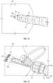
- FIG. 1illustrates a surgical system for performing a surgical procedure.
- FIG. 2is an exploded view of the surgical system of FIG. 1 .
- FIG. 3illustrates select portions of an exemplary cutting obturator of the surgical system of FIGS. 1 - 2 .
- FIG. 4illustrates a cutting tip of an exemplary cutting obturator of the surgical system of FIGS. 1 - 2 .
- FIG. 5is another view of the cutting tip of FIG. 4 .
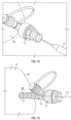
- FIGS. 6 , 7 , 8 , 9 , 10 , 11 , 12 , 13 , 14 , and 15schematically illustrate an exemplary surgical method for percutaneously inserting surgical devices.
- exemplary surgical systemsmay include a cannula and a cutting obturator insertable through the cannula.
- the cutting obturatormay include a cutting tip configured for penetrating and dilating tissue during percutaneous insertions into a joint space.
- FIGS. 1 - 2illustrate a surgical system 10 for performing orthopedic surgical procedures that involve the percutaneous insertion of surgical devices.
- the term “percutaneous”refers to surgical procedures in which access to tissue or other underlying joint anatomies is achieved by puncturing or piercing through the patient's skin rather than by using either an open surgical approach or an arthroscopic surgical approach performed through an arthroscopic cannula or other portal.
- Exemplary orthopedic surgical procedures that can benefit from the percutaneous insertion of surgical devicesinclude glenoid labrum repairs and rotator cuff repairs of the shoulder.
- the surgical system 10 of this disclosurecould be utilized for performing various other orthopedic surgical procedures performed at various other locations of the human musculoskeletal system.
- the surgical system 10may include a cannula 12 and a cutting obturator 14 that is insertable through an internal bore 16 of the cannula 12 .
- the cannula 12 and the cutting obturator 14may be used together as an assembly for percutaneously inserting and maneuvering the cannula 12 through soft tissue and into a targeted joint space during an orthopedic surgical procedure.
- the cannula 12extends longitudinally between a proximal end portion 18 and a distal end portion 20 .
- the internal bore 16extends longitudinally from the proximal end portion 18 to the distal end portion 20 and thus extends across an entire length of the cannula 12 .
- the cutting obturator 14may extend beyond the distal end portion 20 when received within the internal bore 16 of the cannula 12 .
- the proximal end portion 18 of the cannula 12includes a hub 22 adapted for removably coupling the cutting obturator 14 to the cannula 12 .
- a proximal-most section 25 of the hub 22may include a threaded portion 24 adapted to connect to a handle 26 of the cutting obturator 14 .
- other coupling arrangements between the cannula 12 and the cutting obturator 14are also contemplated within the scope of this disclosure.
- the cannula 12 of the surgical system 10may be made from a transparent material.
- the transparent materialmay be a transparent polymeric material that permits the transmission of light through the cannula 12 .
- the transparency of the cannula 12permits the direct visualization of instruments inserted therethrough and of the anatomical structures surrounding the cannula 12 , such as via an endoscope, during orthopedic surgical procedures.
- the cutting obturator 14may include a tubular body 28 and a cutting tip 30 .
- the tubular body 28 and the cutting tip 30may establish an inner lumen 36 for using the cutting obturator 14 over a guidewire for providing targeted insertion of the surgical system 10 into a joint space.
- the cutting tip 30is integrally formed with a distal portion 32 of the tubular body 28 (see FIG. 2 ). In another embodiment, the cutting tip 30 is a separate piece from the tubular body 28 and includes an inner shaft 34 that is received within the tubular body 28 (see FIG. 3 ). The distance the inner shaft 34 extends into the tubular body 28 is not intended to limit this disclosure.
- the tubular body 28 and the cutting tip 30may be made of various materials.
- the tubular body 28 and the cutting tip 30may be made of a metallic material, a polymeric blend, polyether ether ketone (PEEK), or any combination of these materials.
- PEEKpolyether ether ketone
- the tubular body 28may be made of a plastic material and the inner shaft 34 of the cutting tip 30 may be made of a metallic material.
- Other material configurationsare also contemplated within the scope of this disclosure.
- the handle 26 of the cutting obturator 14may be secured at a proximal portion 38 of the tubular body 28 .
- the handle 26may include a distally-extending hub 40 .
- a threaded portion 42may be provided on an inner diameter surface of the hub 40 .
- the threaded portion 42is adapted to engage the threaded portion 24 of the cannula 12 for removably connecting the cutting obturator 14 to the cannula 12 .
- the handle 26 of the cutting obturator 14may be twisted or rotated in a first direction D 1 (e.g., clockwise) to connect the cutting obturator 14 to the cannula 12 , and may be twisted or rotated in a second, opposite direction D 2 (e.g., counterclockwise) to disengage the cutting obturator 14 from the cannula 12 .
- a first direction D 1e.g., clockwise
- D 2e.g., counterclockwise
- the cutting tip 30 of the cutting obturator 14is further illustrated with reference to FIGS. 4 - 5 .
- the cutting tip 30may include a hollow cylindrical body 44 and two or more cutting blades 46 (e.g., 2, 3, 4, etc.) that protrude radially outwardly from an outer surface 48 of the hollow cylindrical body 44 .
- the cutting blades 46are equidistantly circumferentially spaced about the outer surface 48 .
- Each cutting blade 46may include a knife edge 50 located at a leading end of the cutting blade 46 .
- the knife edges 50are located just proximal to a flat distal-most end 52 of the hollow cylindrical body 44 .
- the knife edges 50could alternatively extend to the flat distal-most end 52 .
- the knife edges 50may be tapered and may extend at a sloped angle relative to a proximal body portion 54 (e.g., a cutting flute) of the cutting blade 46 .
- the taper/slope of each knife edge 50provides for a dilating insertion technique of the surgical system 10 while requiring minimal to no skin incision.
- opposed outer sides 56 of the cutting blades 46extend longitudinally and are parallel to one another.
- the cutting blades 46are formed by removing material from the cutting tip 30 , altering the cutting tip 30 by adding an insert or material, or molding the cutting tip 30 to shape to form two or more cutting flutes that each include the knife edge 50 at their leading ends.
- the cutting tip 30may be formed like a drill point to facilitate insertion through skin/tissue.
- the cutting flutesmay project outwardly relative to the outer surface 48 of the hollow cylindrical body 44 to allow ease of insertion and removal of cut material while maintaining strength and stiffness at the cutting tip 30 of the cutting obturator 14 .
- FIGS. 6 - 15schematically illustrate an exemplary surgical method involving the percutaneous insertion of surgical devices.
- the unique design of the surgical system 10assists with penetrating and dilating tissue during its percutaneous insertion into a joint space. Fewer or additional steps than are recited below could be performed within the scope of this disclosure, and the recited order of steps depicted in FIGS. 6 - 15 is not intended to limit this disclosure.
- a spinal needle 58may be inserted through a skin 60 of a patient P and into an underlying joint space.
- the spinal needle 58may be used to locate and establish the correct trajectory and position for the subsequent percutaneous insertion of the surgical system 10 into the joint space.
- a trocar 62may be removed from the spinal needle 58 (see FIG. 7 ).
- a guidewire 64such as a nitinol guidewire, for example, may be inserted through a cannulation 66 of the spinal needle 58 .
- the cannulation 66is accessible upon removing the trocar 62 and extends entirely through the spinal needle 58 .
- the spinal needle 58may be removed by sliding the spinal needle 58 in a rearward direction RD over top of the guidewire 64 (see FIG. 9 ).
- FIG. 10shows the guidewire 64 in a ready position for receiving the surgical system 10 .
- the surgical system 10may next be inserted over the guidewire 64 .
- the guidewire 64is received within the inner lumen 36 of the cutting obturator 14 in order to position the surgical system 10 for the percutaneous insertion into a joint space underlying the skin 60 .
- the surgical system 10may be slid down over the guidewire 64 until the cutting tip 30 of the cutting obturator 14 contacts the skin 60 (see FIG. 12 ).
- the cutting obturator 14may be pressed and rotated in a direction D 1 (e.g., a clockwise direction) into the skin 60 until the cutting tip 30 in inserted into the underlying joint space, which is schematically shown at reference numeral 68 .
- the cutting blades 46 of the cutting tip 30may penetrate and dilate tissue 72 located between the skin 60 and the underlying joint space 68 as the cutting obturator 14 is rotated further into the skin 60 .
- the handle 26 of the cutting obturator 14may be rotated in a second, opposite direction D 2 (e.g., counterclockwise) to disengage the cutting obturator 14 relative to the cannula 12 .
- the cutting obturator 14may then be removed from the cannula 12 (see FIG. 14 ).
- the cannula 12is shown in a fully inserted and ready position RP in FIG. 15 .
- the cannula 12is ready to receive one or more surgical instruments 70 , such as a drill guide, a drill, a suture anchor inserter, etc., for performing the desired orthopedic surgical procedure on the patient P.
- the surgical instruments 70may be inserted through the internal bore 16 of the cannula 12 .
- the surgical system 10 described hereinmay be provided as part of a surgical instrument set.
- the surgical system 10could be packaged together as a kit with other surgical instruments, such as the spinal needle 58 and/or the guidewire 64 , for formulating the surgical instrument set.
- a cannula of the surgical systemmay be precisely positioned and placed within an underlying joint space by using a dilating insertion technique that can be achieved via the use of a cutting obturator of the surgical system.
- the cannulamay then facilitate the insertion of additional surgical instruments. Minimal to no skin incisions are required for achieving the percutaneous insertion of the cannula and the additional surgical instruments.
- the proposed surgical systemsreduce surgical operating times and associated surgical costs.
Landscapes
- Health & Medical Sciences (AREA)
- Life Sciences & Earth Sciences (AREA)
- Surgery (AREA)
- Animal Behavior & Ethology (AREA)
- General Health & Medical Sciences (AREA)
- Engineering & Computer Science (AREA)
- Biomedical Technology (AREA)
- Heart & Thoracic Surgery (AREA)
- Veterinary Medicine (AREA)
- Public Health (AREA)
- Medical Informatics (AREA)
- Molecular Biology (AREA)
- Nuclear Medicine, Radiotherapy & Molecular Imaging (AREA)
- Pathology (AREA)
- Dentistry (AREA)
- Oral & Maxillofacial Surgery (AREA)
- Orthopedic Medicine & Surgery (AREA)
- Biophysics (AREA)
- Pulmonology (AREA)
- Anesthesiology (AREA)
- Hematology (AREA)
- Surgical Instruments (AREA)
Abstract
Description
Claims (17)
Priority Applications (2)
| Application Number | Priority Date | Filing Date | Title |
|---|---|---|---|
| US17/191,011US12076045B2 (en) | 2021-03-03 | 2021-03-03 | Surgical systems for percutaneously inserting surgical devices |
| US18/811,993US20240407805A1 (en) | 2021-03-03 | 2024-08-22 | Surgical systems for percutaneously inserting surgical devices |
Applications Claiming Priority (1)
| Application Number | Priority Date | Filing Date | Title |
|---|---|---|---|
| US17/191,011US12076045B2 (en) | 2021-03-03 | 2021-03-03 | Surgical systems for percutaneously inserting surgical devices |
Related Child Applications (1)
| Application Number | Title | Priority Date | Filing Date |
|---|---|---|---|
| US18/811,993ContinuationUS20240407805A1 (en) | 2021-03-03 | 2024-08-22 | Surgical systems for percutaneously inserting surgical devices |
Publications (2)
| Publication Number | Publication Date |
|---|---|
| US20220280186A1 US20220280186A1 (en) | 2022-09-08 |
| US12076045B2true US12076045B2 (en) | 2024-09-03 |
Family
ID=83115816
Family Applications (2)
| Application Number | Title | Priority Date | Filing Date |
|---|---|---|---|
| US17/191,011Active2042-07-24US12076045B2 (en) | 2021-03-03 | 2021-03-03 | Surgical systems for percutaneously inserting surgical devices |
| US18/811,993PendingUS20240407805A1 (en) | 2021-03-03 | 2024-08-22 | Surgical systems for percutaneously inserting surgical devices |
Family Applications After (1)
| Application Number | Title | Priority Date | Filing Date |
|---|---|---|---|
| US18/811,993PendingUS20240407805A1 (en) | 2021-03-03 | 2024-08-22 | Surgical systems for percutaneously inserting surgical devices |
Country Status (1)
| Country | Link |
|---|---|
| US (2) | US12076045B2 (en) |
Citations (28)
| Publication number | Priority date | Publication date | Assignee | Title |
|---|---|---|---|---|
| US4642090A (en) | 1985-03-04 | 1987-02-10 | Utrata Peter J | Disposable combination scalpel blade and incision irrigator for ophthalmological use |
| US4719915A (en) | 1985-05-05 | 1988-01-19 | Michael Porat | Scalpel |
| US5057082A (en)* | 1988-11-04 | 1991-10-15 | Plastic Injectors, Inc. | Trocar assembly |
| US5071426A (en) | 1989-04-06 | 1991-12-10 | Stuart Dolgin | Surgical scalpel with retractable blade guard |
| US5423824A (en)* | 1992-03-23 | 1995-06-13 | Radi Medical Systems Ab | Method of accessing hard tissue |
| US5843108A (en) | 1997-10-23 | 1998-12-01 | Samuels; Shaun Laurence Wilkie | Over the wire scapel |
| US6048354A (en) | 1999-02-01 | 2000-04-11 | Lawrence; Jeffrey M. | Sliding knife and needle assembly for making a portal for endoscopic or arthroscopic surgery |
| US6110175A (en) | 1999-01-20 | 2000-08-29 | Synthes (Usa) | Surgical chisel and method of using same |
| US6224574B1 (en) | 1999-10-18 | 2001-05-01 | Hassan Al-Labban | Combined scalpel and syringe device |
| US6270501B1 (en) | 1999-11-08 | 2001-08-07 | The Regents Of The University Of Michigan | Surgical method and apparatus and cannulated scalpel for use therein |
| US6383179B1 (en) | 1999-08-11 | 2002-05-07 | Ceramoptec Industries Inc. | Diode laser scalpel |
| US6497687B1 (en) | 1999-06-22 | 2002-12-24 | Erblan Surgical Inc. | Safety trocar with progressive cutting tip guards and gas jet tissue deflector |
| DE20318220U1 (en) | 2003-02-01 | 2004-02-12 | Fresenius Kabi Deutschland Gmbh | Hollow organ puncturing in medicine, comprises using a tubular shaft with a holder at its proximal end, a distal end piece, and angled surfaces that form cutting edges |
| US6761726B1 (en) | 1998-05-15 | 2004-07-13 | Pyng Medical Corp. | Method and apparatus for the intraosseous introduction of a device such as an infusion tube |
| US20040220497A1 (en) | 2000-03-02 | 2004-11-04 | Findlay Judith M. | Patch for locating a target zone for penetration |
| US6960164B2 (en) | 2003-08-01 | 2005-11-01 | Neosurg Technologies, Inc. | Obturator tip for a trocar |
| US20060008771A1 (en)* | 2004-06-21 | 2006-01-12 | Straumann Holding Ag | Method for manufacturing disposable rotary cutting tools and disposable rotary tool for dental or medical applications |
| US20060015066A1 (en) | 2004-05-17 | 2006-01-19 | Turieo Melanie J | Intraosseous infusion device |
| US7097642B1 (en) | 2002-07-22 | 2006-08-29 | Uop Llc | Cauterizing scalpel blades |
| US7144414B2 (en) | 2000-06-27 | 2006-12-05 | Smith & Nephew, Inc. | Surgical procedures and instruments |
| US7320694B2 (en) | 2004-03-11 | 2008-01-22 | Coopersurgical, Inc. | Obturator tip |
| US20080045965A1 (en) | 2002-05-31 | 2008-02-21 | Miller Larry J | Apparatus and Methods for Biopsy and Aspiration of Bone Marrow |
| US20080262318A1 (en) | 2007-04-17 | 2008-10-23 | K2M, Inc. | Minimally open interbody access retraction device and surgical method |
| US20130331840A1 (en)* | 2012-05-14 | 2013-12-12 | DePuy Synthes Products, LLC | Bone access instrument |
| US20150142038A1 (en) | 2013-11-21 | 2015-05-21 | Cook Medical Technologies Llc | Stylet cutting tip for medical device, and method of making same |
| US20160051306A1 (en)* | 2014-08-20 | 2016-02-25 | Kyphon Sarl | Surgical instrument with graduated markings correlating to angulation |
| US9566086B2 (en) | 2006-10-18 | 2017-02-14 | VeriFlex, Inc. | Dilator |
| US10034674B2 (en) | 2006-02-02 | 2018-07-31 | Steven C Chudik | Universal anterior cruciate ligament repair and reconstruction system |
- 2021
- 2021-03-03USUS17/191,011patent/US12076045B2/enactiveActive
- 2024
- 2024-08-22USUS18/811,993patent/US20240407805A1/enactivePending
Patent Citations (29)
| Publication number | Priority date | Publication date | Assignee | Title |
|---|---|---|---|---|
| US4642090A (en) | 1985-03-04 | 1987-02-10 | Utrata Peter J | Disposable combination scalpel blade and incision irrigator for ophthalmological use |
| US4719915A (en) | 1985-05-05 | 1988-01-19 | Michael Porat | Scalpel |
| US5057082A (en)* | 1988-11-04 | 1991-10-15 | Plastic Injectors, Inc. | Trocar assembly |
| US5071426A (en) | 1989-04-06 | 1991-12-10 | Stuart Dolgin | Surgical scalpel with retractable blade guard |
| US5423824A (en)* | 1992-03-23 | 1995-06-13 | Radi Medical Systems Ab | Method of accessing hard tissue |
| US5843108A (en) | 1997-10-23 | 1998-12-01 | Samuels; Shaun Laurence Wilkie | Over the wire scapel |
| US6761726B1 (en) | 1998-05-15 | 2004-07-13 | Pyng Medical Corp. | Method and apparatus for the intraosseous introduction of a device such as an infusion tube |
| US6110175A (en) | 1999-01-20 | 2000-08-29 | Synthes (Usa) | Surgical chisel and method of using same |
| US6048354A (en) | 1999-02-01 | 2000-04-11 | Lawrence; Jeffrey M. | Sliding knife and needle assembly for making a portal for endoscopic or arthroscopic surgery |
| US6346115B1 (en) | 1999-02-01 | 2002-02-12 | Jeffrey M. Lawrence | Sliding knife and needle assembly for making a portal for endoscopic or arthroscopic surgery |
| US6497687B1 (en) | 1999-06-22 | 2002-12-24 | Erblan Surgical Inc. | Safety trocar with progressive cutting tip guards and gas jet tissue deflector |
| US6383179B1 (en) | 1999-08-11 | 2002-05-07 | Ceramoptec Industries Inc. | Diode laser scalpel |
| US6224574B1 (en) | 1999-10-18 | 2001-05-01 | Hassan Al-Labban | Combined scalpel and syringe device |
| US6270501B1 (en) | 1999-11-08 | 2001-08-07 | The Regents Of The University Of Michigan | Surgical method and apparatus and cannulated scalpel for use therein |
| US20040220497A1 (en) | 2000-03-02 | 2004-11-04 | Findlay Judith M. | Patch for locating a target zone for penetration |
| US7144414B2 (en) | 2000-06-27 | 2006-12-05 | Smith & Nephew, Inc. | Surgical procedures and instruments |
| US20080045965A1 (en) | 2002-05-31 | 2008-02-21 | Miller Larry J | Apparatus and Methods for Biopsy and Aspiration of Bone Marrow |
| US7097642B1 (en) | 2002-07-22 | 2006-08-29 | Uop Llc | Cauterizing scalpel blades |
| DE20318220U1 (en) | 2003-02-01 | 2004-02-12 | Fresenius Kabi Deutschland Gmbh | Hollow organ puncturing in medicine, comprises using a tubular shaft with a holder at its proximal end, a distal end piece, and angled surfaces that form cutting edges |
| US6960164B2 (en) | 2003-08-01 | 2005-11-01 | Neosurg Technologies, Inc. | Obturator tip for a trocar |
| US7320694B2 (en) | 2004-03-11 | 2008-01-22 | Coopersurgical, Inc. | Obturator tip |
| US20060015066A1 (en) | 2004-05-17 | 2006-01-19 | Turieo Melanie J | Intraosseous infusion device |
| US20060008771A1 (en)* | 2004-06-21 | 2006-01-12 | Straumann Holding Ag | Method for manufacturing disposable rotary cutting tools and disposable rotary tool for dental or medical applications |
| US10034674B2 (en) | 2006-02-02 | 2018-07-31 | Steven C Chudik | Universal anterior cruciate ligament repair and reconstruction system |
| US9566086B2 (en) | 2006-10-18 | 2017-02-14 | VeriFlex, Inc. | Dilator |
| US20080262318A1 (en) | 2007-04-17 | 2008-10-23 | K2M, Inc. | Minimally open interbody access retraction device and surgical method |
| US20130331840A1 (en)* | 2012-05-14 | 2013-12-12 | DePuy Synthes Products, LLC | Bone access instrument |
| US20150142038A1 (en) | 2013-11-21 | 2015-05-21 | Cook Medical Technologies Llc | Stylet cutting tip for medical device, and method of making same |
| US20160051306A1 (en)* | 2014-08-20 | 2016-02-25 | Kyphon Sarl | Surgical instrument with graduated markings correlating to angulation |
Also Published As
| Publication number | Publication date |
|---|---|
| US20240407805A1 (en) | 2024-12-12 |
| US20220280186A1 (en) | 2022-09-08 |
Similar Documents
| Publication | Publication Date | Title |
|---|---|---|
| US12016548B2 (en) | Suture anchor implantation instrumentation system | |
| US12257163B2 (en) | Bone harvester and bone marrow removal system and method | |
| US8827893B2 (en) | Slotted clear cannula | |
| US8821383B2 (en) | Slotted clear cannula | |
| US8075579B2 (en) | Pedicle dart system | |
| US8814914B2 (en) | Fusion method and pedicle access tool | |
| US7892207B2 (en) | Dilating stylet and cannula | |
| US20190191986A1 (en) | Retraction Devices, Systems, And Methods For Minimally Invasive Spinal Surgery | |
| US6916330B2 (en) | Non cannulated dilators | |
| EP2098177A1 (en) | Combined flip cutter and drill | |
| US20090187194A1 (en) | One step entry pedicular preparation device and disc access system | |
| US9888936B2 (en) | Device and methods for use during arthroscopic surgery | |
| US20090192545A1 (en) | Curved suture anchor guide and method of use | |
| CN111818880B (en) | Arthroscopic shoulder arthroplasty, components, instruments, and methods of use thereof | |
| US8821526B2 (en) | Trocar | |
| US10517613B2 (en) | Systems, devices, and methods for guiding surgical devices into bone | |
| US8956284B2 (en) | Minimally invasive retractor and posted screw | |
| US12076045B2 (en) | Surgical systems for percutaneously inserting surgical devices | |
| AU2018375222B2 (en) | Slotted canulla for arthroscopic surgery |
Legal Events
| Date | Code | Title | Description |
|---|---|---|---|
| AS | Assignment | Owner name:ARTHREX, INC., FLORIDA Free format text:ASSIGNMENT OF ASSIGNORS INTEREST;ASSIGNOR:CUSTODIO, CHRISTIANNE KATE SISON;REEL/FRAME:055481/0939 Effective date:20210303 | |
| FEPP | Fee payment procedure | Free format text:ENTITY STATUS SET TO UNDISCOUNTED (ORIGINAL EVENT CODE: BIG.); ENTITY STATUS OF PATENT OWNER: LARGE ENTITY | |
| STPP | Information on status: patent application and granting procedure in general | Free format text:DOCKETED NEW CASE - READY FOR EXAMINATION | |
| STPP | Information on status: patent application and granting procedure in general | Free format text:RESPONSE TO NON-FINAL OFFICE ACTION ENTERED AND FORWARDED TO EXAMINER | |
| STPP | Information on status: patent application and granting procedure in general | Free format text:NON FINAL ACTION MAILED | |
| STPP | Information on status: patent application and granting procedure in general | Free format text:RESPONSE TO NON-FINAL OFFICE ACTION ENTERED AND FORWARDED TO EXAMINER | |
| STPP | Information on status: patent application and granting procedure in general | Free format text:NOTICE OF ALLOWANCE MAILED -- APPLICATION RECEIVED IN OFFICE OF PUBLICATIONS | |
| STPP | Information on status: patent application and granting procedure in general | Free format text:PUBLICATIONS -- ISSUE FEE PAYMENT VERIFIED | |
| STCF | Information on status: patent grant | Free format text:PATENTED CASE |