US12075937B2 - Vertical pipe end connector - Google Patents
Vertical pipe end connectorDownload PDFInfo
- Publication number
- US12075937B2 US12075937B2US17/099,534US202017099534AUS12075937B2US 12075937 B2US12075937 B2US 12075937B2US 202017099534 AUS202017099534 AUS 202017099534AUS 12075937 B2US12075937 B2US 12075937B2
- Authority
- US
- United States
- Prior art keywords
- coupler
- pipe
- pipe end
- protrusion
- opening
- Prior art date
- Legal status (The legal status is an assumption and is not a legal conclusion. Google has not performed a legal analysis and makes no representation as to the accuracy of the status listed.)
- Active, expires
Links
- 239000002861polymer materialSubstances0.000claimsdescription2
- 239000000463materialSubstances0.000description7
- 229910000831SteelInorganic materials0.000description5
- 239000010959steelSubstances0.000description5
- XAGFODPZIPBFFR-UHFFFAOYSA-NaluminiumChemical compound[Al]XAGFODPZIPBFFR-UHFFFAOYSA-N0.000description2
- 229910052782aluminiumInorganic materials0.000description2
- 238000004519manufacturing processMethods0.000description2
- 229920004943Delrin®Polymers0.000description1
- 229920000122acrylonitrile butadiene styrenePolymers0.000description1
- 238000010276constructionMethods0.000description1
- 238000005516engineering processMethods0.000description1
- 238000003780insertionMethods0.000description1
- 230000037431insertionEffects0.000description1
- 238000005192partitionMethods0.000description1
- 229920003023plasticPolymers0.000description1
- 239000004033plasticSubstances0.000description1
- 229920002635polyurethanePolymers0.000description1
- 239000004814polyurethaneSubstances0.000description1
- 238000009987spinningMethods0.000description1
Images


Classifications
- A—HUMAN NECESSITIES
- A47—FURNITURE; DOMESTIC ARTICLES OR APPLIANCES; COFFEE MILLS; SPICE MILLS; SUCTION CLEANERS IN GENERAL
- A47H—FURNISHINGS FOR WINDOWS OR DOORS
- A47H1/00—Curtain suspension devices
- A47H1/10—Means for mounting curtain rods or rails
- A47H1/14—Brackets for supporting rods or rails
- A47H1/142—Brackets for supporting rods or rails for supporting rods
- E—FIXED CONSTRUCTIONS
- E04—BUILDING
- E04H—BUILDINGS OR LIKE STRUCTURES FOR PARTICULAR PURPOSES; SWIMMING OR SPLASH BATHS OR POOLS; MASTS; FENCING; TENTS OR CANOPIES, IN GENERAL
- E04H1/00—Buildings or groups of buildings for dwelling or office purposes; General layout, e.g. modular co-ordination or staggered storeys
- E04H1/12—Small buildings or other erections for limited occupation, erected in the open air or arranged in buildings, e.g. kiosks, waiting shelters for bus stops or for filling stations, roofs for railway platforms, watchmen's huts or dressing cubicles
- E04H1/1272—Exhibition stands
- F—MECHANICAL ENGINEERING; LIGHTING; HEATING; WEAPONS; BLASTING
- F16—ENGINEERING ELEMENTS AND UNITS; GENERAL MEASURES FOR PRODUCING AND MAINTAINING EFFECTIVE FUNCTIONING OF MACHINES OR INSTALLATIONS; THERMAL INSULATION IN GENERAL
- F16B—DEVICES FOR FASTENING OR SECURING CONSTRUCTIONAL ELEMENTS OR MACHINE PARTS TOGETHER, e.g. NAILS, BOLTS, CIRCLIPS, CLAMPS, CLIPS OR WEDGES; JOINTS OR JOINTING
- F16B7/00—Connections of rods or tubes, e.g. of non-circular section, mutually, including resilient connections
- F16B7/04—Clamping or clipping connections
- F16B7/0433—Clamping or clipping connections for rods or tubes being in parallel relationship
Definitions
- the present inventionrelates to couplers for drape rods of the type typically found in exhibit booths.
- the present inventionrelates to a coupler adaptor to affix to an end of a vertical pipe to allow accessories to be mounted.
- exhibit booths and the likeare constructed using a tubular framework supporting drapes as walls and or covers. Many of these booths are constructed using a hook-and-slot system, which utilize upright aluminum poles with slots formed near the top regions thereof for receiving hooks secured to and extending from the ends of horizontally-positioned tubular rods. Draping material is placed over the horizontal rods to form booths or partitions as may be required. Pipe and drape walls traditionally have a bumpy appearance due to the height difference of the vertical members in relation to the top of horizontally disposed connecting rods. Additionally, the steel hooks on industry standard horizontal drape rods have a tendency to “tear” the aluminum vertical uprights in a “can opener” effect when the steel hooks are inserted in the existing slots in the uprights.
- the present pipe-mounted couplerenables industry standard hooks on horizontal rods and other accessories to rest at such a height as to provide uniform appearance to the top of drape walls.
- a further objectis to allow a pipe-mounted coupler to mount on a pipe or rod vertical end to allow one or more accessory connections to be affixed to the vertical pipe.
- the pipe-mounted couplerincludes a locking protrusion that is insertable into a slotted opening on the pipe end to allow the pipe-mounted coupler to be secured onto the pipe end allowing minimal vertical movement or horizontal twisting.
- a further objectis to allow multiple horizontal rods to be mounted in parallel from a single vertical pipe.
- the pipe-mounted couplerprevents the steel hooks on industry standard horizontal drape rods from “tearing” into the support pipes.
- the pipe-mounted couplerallows accessories for the industry standard hooks to be inserted at a wider angle of insertion and to allow easier connection as compared to the narrow industry standard slots.
- the pipe-mounted coupleraccomplishes the foregoing benefits using industry standard fasteners or hooks.
- FIG. 1is a perspective view of one embodiment of a pipe-mounted coupler.
- FIG. 2is a perspective view of one embodiment of the pipe-mounted coupler.
- FIG. 3is a perspective view of one embodiment of the pipe-mounted coupler.
- FIG. 4is a side plan view of one embodiment of the pipe-mounted coupler.
- FIG. 5is a side plan view of one embodiment of the pipe-mounted coupler.
- FIG. 6is a top plan view of one embodiment of the pipe-mounted coupler.
- FIG. 7is a perspective view of one embodiment of the pipe-mounted coupler affixed to a vertical mount pipe.
- FIG. 8is a side plan view of one embodiment of the pipe-mounted coupler affixed to a vertical mount pipe.
- FIG. 9is a side plan view of one embodiment of the pipe-mounted coupler affixed to a vertical mount pipe.
- FIG. 10is a perspective view of one embodiment of the pipe-mounted coupler affixed to a vertical mount pipe.
- the example embodiments described hereinprovide a pipe-mounted coupler 40 that supports a coupler 10 for connecting substantially orthogonally disposed rods to vertical support pipes in a pipe and drape exhibit booth construction.
- the “Pipe and Drape” industryis a subset of exhibition and convention services in which frameworks are constructed from horizontally and vertically disposed members in such a fashion to allow draperies or curtains to hang and create division of space in convention halls or other similar areas by arranging drapery walls and booths.
- the pipe-mounted coupler 40is designed to provide an improvement to form and function over the industry standard hook and slot technology, yet allowing users of existing systems to continue using their inventory of components.
- the pipe-mounted coupler 40allows accessories, such as coupler 10 , to be affixed to the end of the vertical pipe.
- the accessoriesmight allow a coupler 10 to be affixed to the pipe-mounted coupler 40 in an offset position.
- the accessoriesmight allow a second and third coupler 10 be affixed to the pipe-mounted coupler 40 in offset positions to allow additional rods to be vertically supported.
- the couplers 10may be mounted in series extending from the pipe-mounted coupler 40 , in parallel on different sides of the pipe-mounted coupler 40 , or in any other suitable configuration.
- the pipe-mounted coupler 40allows additional rods to be connected to the top of a single vertical pipe. In examples herein, when one coupler 10 is being described, other examples that include two or more couplers 10 in any configuration may be envisioned to operate substantially similarly.
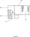
- FIG. 1provides a perspective view of the pipe-mounted coupler 40 , which is used to construct the aforesaid pipe and drape booths. Because the steel terminal hooks traditionally used on the transverse rods to connect to the vertical member are used to connect to the instant coupler 10 or other attached accessory, the steel hooks are not illustrated.
- the pipe-mounted coupler 40includes features such as a locking protrusion 44 , a connection bridge 43 , a stop rim 45 , a stop rim opening 46 , an opening 47 , and an accessory, such as coupler 10 .
- pipe-mounted coupler 40will be made from durable reinforced polymer material, ABS plastic, Delrin, polyurethane, or some other suitable material that has sufficient strength and rigidity to effectuate the connection.
- the pipe-mounted coupler 40fits onto a vertically configured pipe, rod, or other member.
- the pipesuch as pipe 30 in FIG. 7 , fits into the circular body of pipe-mounted coupler 40 because the inner diameter of the pipe-mounted coupler 40 is greater than the outer diameter of the pipe.
- the pipemay slide substantially to the top of the body of the pipe-mounted coupler 40 until the pipe meets the stop rim 45 .
- the stop rim 45has a smaller inner diameter than the outer diameter of the pipe, and thus the stop rim 45 prevents the pipe from protruding past the stop rim 45 and out of the body of the pipe-mounted coupler 40 .
- the stop rim 45includes a stop rim opening 46 .
- the stop rim opening 46is a break in the circular body of the stop rim 45 .
- the stop rim opening 46is located above the one or more locking protrusions 44 .
- the stop rim opening 46allows a mold or other manufacturing device to more easily release the locking protrusion 44 during manufacturing.
- the locking protrusion 44 of the pipe-mounted coupler 40protrudes into an opening of the pipe that is slightly larger than the locking protrusion 44 .
- the openingmay be a conventional slot in a pipe end for receiving industry standard hooks or other connection accessories.
- the pipe endmay have multiple openings, such as an opening on one, two, or four sides of the pipe end. In an example, the pipe end has four openings located at each of four cardinal directions around the pipe end.
- the locking protrusion 44may be in a single position on one side of the pipe-mounted coupler 40 or may be in two positions on opposing sides of the pipe-mounted coupler 40 .
- the locking protrusion 44protrudes farther in the middle of the locking protrusion 44 than on the ends. That is, the locking protrusion 44 may create a ramp or slope with the center of the locking protrusion 44 sloping downward towards each opposing end of the locking protrusion 44 .
- the locking protrusion 44when protruding into the opening of the pipe, prevents the pipe-mounted coupler 40 from spinning on the round pipe end.
- the locking protrusion 44when protruding into the opening of the pipe, also prevents the pipe-mounted coupler 40 from sliding vertically upwards or downwards on the pipe.
- a locking protrusion 44is positioned on opposing sides of the pipe-mounted coupler 40 .
- the locking protrusion 44is constructed of a material that is a semi-rigid plastic or similar material.
- the pipe-mounted coupler 40will not slide over the pipe end without at least one element deforming or flexing.
- the locking protrusion 44 and/or the pipe-mounted coupler 40may flex or deform to allow the pipe-mounted coupler 40 to fit over the pipe end.
- the pipeis rigid and does not deform, but the pipe-mounted coupler 40 flexes to create a larger diameter until the locking protrusion 44 slides into the opening.
- the pipe-mounted coupler 40When the locking protrusion 44 slides into the opening of the pipe end, the pipe-mounted coupler 40 returns to the undeformed state because the locking protrusion 44 is no longer forcing the pipe-mounted coupler 40 to expand around the pipe end.
- the pipe-mounted coupler 40fits over the pipe end without deforming.
- the pipe enddeforms to allow the rigid pipe-mounted coupler 40 to slide over the pipe end.
- both the pipe end and the pipe-mounted coupler 40are semi-rigid and deform or flex when the pipe-mounted coupler 40 is slid over the pipe end.
- connection bridge 43supports one or more accessories.
- the accessoriesmay be a coupler 10 , as illustrated in FIG. 1 .
- the accessorymay alternatively be any other type of accessory, such as a different type of hanger or support.
- the connection bridge 43may be constructed out of the same material as the pipe-mounted coupler 40 or any other suitable material.
- the pipe-mounted coupler 40has two or more connection bridges 43 .
- the connection bridges 43may extend from opposing sides of the pipe-mounted coupler 40 .
- the accessorysuch as the coupler 10
- the connection bridge 43is supported by the connection bridge 43 to allow a hook and rod or other element to be affixed to the pipe.
- the coupler 10may be at a height that is level with the openings in the pipe end.
- the coupler 10is raised or lowered by the connection bridge 43 to be at a different height than the openings in the pipe end.
- the coupler 10is raised by the connection bridge 43 to be higher than the openings on the pipe end, which allows drapes or other materials to be displayed in a layered format with one set of drapes being higher than the other.
- the pipe-mounted coupler 40includes an opening 47 .
- the opening 47is a semicircular, arched opening in the side of the pipe-mounted coupler 40 .
- the opening 47allows a user to have access to the pipe or rod that is inserted into the pipe-mounted coupler 40 , such as pipe 30 from FIG. 7 .
- the pipehas openings on each of four cardinal directions near the end of the pipe.
- the opening 47allows a hook and rod or other element to be affixed to the pipe at the same time that the pipe-mounted coupler 40 is mounted to the pipe.
- the opening 47may be located on opposing sides of the pipe-mounted coupler 40 .
- the opening 47may be located 90 degrees from the locking protrusion 44 .
- the opening 47is only on one position of the pipe-mounted coupler 40 . In alternate examples, the opening 47 is on three positions of the pipe-mounted coupler 40 . In alternate examples, the pipe-mounted coupler 40 does not have any openings. In this example, the pipe-mounted coupler 40 may have four locking protrusions 44 at the four cardinal points of the pipe-mounted coupler 40 .
- FIG. 2is a perspective view of one embodiment of the pipe-mounted coupler 40 .
- the illustrationincludes the locking protrusion 44 , the connection bridge 43 , the stop rim 45 , one or more openings 47 , and the accessory, such as coupler 10 , as described with reference to FIG. 1 .
- An opening 47is shown as being on two opposing sides of the pipe-mounted coupler 40 and each located 90 degrees in each direction from the locking protrusion 44 .
- FIG. 3is a perspective view of one embodiment of the pipe-mounted coupler 40 .
- the illustrationincludes the locking protrusion 44 , the connection bridge 43 , the opening 47 , and an accessory, such as coupler 10 , as described with reference to FIG. 1 .
- the locking protrusion 44is illustrated with the vertical center of the locking protrusion 44 protruding farther away from the body of the pipe-mounted coupler 40 than the top and bottom ends of the locking protrusion 44 .
- the locking protrusion 44slopes at an angle from the center of the locking protrusion 44 to either end of the locking protrusion 44 . When inserted into an opening, the center portion of the locking protrusion 44 will insert farther into the opening than the top and bottom ends of the locking protrusion 44 .
- FIG. 4is a side view of one embodiment of the pipe-mounted coupler 40 .
- the illustrationincludes one or more openings 47 and an accessory, such as coupler 10 , as described with reference to FIG. 1 .
- An opening 47is shown as being on two opposing sides of the pipe-mounted coupler 40 and each located 90 degrees from the locking protrusion 44 (not shown).
- FIG. 5is a side view of one embodiment of the pipe-mounted coupler 40 .
- the illustrationincludes the connection bridge 43 , the opening 47 , locking protusions 44 , and an accessory, such as coupler 10 , as described with reference to FIG. 1 .
- a locking protrusion 44is illustrated on opposing sides of the body of the pipe-mounted coupler 40 . In the example, only the center portions of the locking protrusion 44 are shown because the center portions protrude farther away from the body of the pipe-mounted coupler 40 than the top and bottom ends of the locking protrusion 44 .
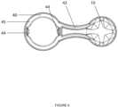
- FIG. 6is a top view of one embodiment of the pipe-mounted coupler 40 .
- the illustrationincludes the locking protrusion 44 , the connection bridge 43 , the stop rim 45 , and an accessory, such as coupler 10 , as described with reference to FIG. 1 .
- the locking protrusion 44is illustrated on opposing sides of the body of the pipe-mounted coupler 40 .
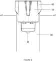
- FIG. 7is a perspective view of one embodiment of the pipe-mounted coupler 40 affixed to a vertical mount pipe 30 .
- the illustrationincludes the locking protrusion 44 , the connection bridge 43 , the stop rim 45 , the opening 47 , and an accessory, such as coupler 10 , as described with reference to FIG. 1 .
- the pipe-mounted coupler 40is illustrated as being mounted on a pipe 30 .
- the pipe 30is positioned inside the inner diameter of the pipe-mounted coupler 40 , up to the stop rim 45 .
- the stop rim 45prevents the pipe 30 from sliding further into the pipe-mounted coupler 40 .
- the pipe 30is illustrated with the pipe opening 31 in at least two positions of the pipe.
- the two pipe openings 31are illustrated as being 90 degrees apart around the circumference of the pipe 30 .
- One pipe opening 31is illustrated as being positioned adjacent to the locking protrusion 44 such that the locking protrusion 44 protrudes into the adjacent pipe opening 31 .
- the locking protrusion 44is visible through the unused opening 31 .
- the protrusionlocks the pipe-mounted coupler 40 in place and prevents the pipe 30 from turning inside the pipe-mounted coupler 40 .
- FIG. 8is a side view of one embodiment of the pipe-mounted coupler 40 affixed to a vertical mount pipe 30 .
- the illustrationincludes one or more openings 47 , and an accessory, such as coupler 10 , as described with reference to FIG. 1 .
- the pipe-mounted coupler 40is illustrated as being mounted on a pipe 30 .
- the pipe 30is illustrated with the pipe opening 31 positioned to mate with the locking protrusion 44 (not shown).
- FIG. 9is a side view of one embodiment of the pipe-mounted coupler 40 affixed to a vertical mount pipe 30 .
- the illustrationincludes the connection bridge 43 and an accessory, such as coupler 10 , as described with reference to FIG. 1 .
- the pipe-mounted coupler 40is illustrated as being mounted on a pipe 30 .
- the pipe 30is illustrated with the pipe opening 31 .
- a second, third, or fourth pipe opening 31may be positioned every 90 degrees around the circumference of the pipe 30 or in any other suitable configuration.
- a pipe opening 31may be positioned to mate with one or more locking protrusions 44 (not shown).
- FIG. 10is a perspective view of one embodiment of the pipe-mounted coupler affixed to a vertical mount pipe.
- the illustrationincludes the locking protrusion 44 , two connection bridges 43 , the stop rim 45 , the opening 47 , and two accessories, such as coupler 10 , as described with reference to FIG. 1 .
- the pipe-mounted coupler 40is illustrated as being mounted on a pipe 30 .
- the pipe 30is positioned inside the inner diameter of the pipe-mounted coupler 40 , up to the stop rim 45 .
- the stop rim 45prevents the pipe 30 from sliding further into the pipe-mounted coupler 40 .
- the pipe 30is illustrated with the pipe opening 31 in at least two positions of the pipe.
- the two pipe openings 31are illustrated as being 90 degrees apart around the circumference of the pipe 30 .
- One pipe opening 31is illustrated as being positioned adjacent to the locking protrusion 44 such that the locking protrusion 44 protrudes into the adjacent pipe opening 31 .
- the locking protrusion 44is visible through the unused opening 31 .
- the protrusionlocks the pipe-mounted coupler 40 in place and prevents the pipe 30 from turning inside the pipe-mounted coupler 40 .
- the inner diameter of the pipe-mounted coupler 40is 0.030 inches larger than the outer diameter of the pipe 30 .
- the outer diameter of a standard pipe 30is 1.482 inches and the inner diameter of the pipe-mounted coupler 40 is 1.522 inches.
- the locking protrusion 44protrudes 0.04 inches outward from the inner diameter of the pipe-mounted coupler 40 .
- the locking protrusion 44has a three-degree slope from the edge to the center of the locking protrusion 44 .
Landscapes
- Engineering & Computer Science (AREA)
- Architecture (AREA)
- General Engineering & Computer Science (AREA)
- Civil Engineering (AREA)
- Structural Engineering (AREA)
- Mechanical Engineering (AREA)
- Mutual Connection Of Rods And Tubes (AREA)
Abstract
Description
Claims (20)
Priority Applications (1)
| Application Number | Priority Date | Filing Date | Title |
|---|---|---|---|
| US17/099,534US12075937B2 (en) | 2016-11-03 | 2020-11-16 | Vertical pipe end connector |
Applications Claiming Priority (5)
| Application Number | Priority Date | Filing Date | Title |
|---|---|---|---|
| US201662417121P | 2016-11-03 | 2016-11-03 | |
| US15/727,695US10941560B2 (en) | 2016-11-03 | 2017-10-09 | Connector for pipes |
| US201962946795P | 2019-12-11 | 2019-12-11 | |
| US29/739,477USD1031945S1 (en) | 2017-10-09 | 2020-06-25 | Connector accessory for pipes |
| US17/099,534US12075937B2 (en) | 2016-11-03 | 2020-11-16 | Vertical pipe end connector |
Related Parent Applications (2)
| Application Number | Title | Priority Date | Filing Date |
|---|---|---|---|
| US15/727,695Continuation-In-PartUS10941560B2 (en) | 2016-11-03 | 2017-10-09 | Connector for pipes |
| US29/739,477Continuation-In-PartUSD1031945S1 (en) | 2016-11-03 | 2020-06-25 | Connector accessory for pipes |
Publications (2)
| Publication Number | Publication Date |
|---|---|
| US20210068576A1 US20210068576A1 (en) | 2021-03-11 |
| US12075937B2true US12075937B2 (en) | 2024-09-03 |
Family
ID=74850472
Family Applications (1)
| Application Number | Title | Priority Date | Filing Date |
|---|---|---|---|
| US17/099,534Active2040-03-03US12075937B2 (en) | 2016-11-03 | 2020-11-16 | Vertical pipe end connector |
Country Status (1)
| Country | Link |
|---|---|
| US (1) | US12075937B2 (en) |
Families Citing this family (2)
| Publication number | Priority date | Publication date | Assignee | Title |
|---|---|---|---|---|
| US12234846B2 (en)* | 2022-03-17 | 2025-02-25 | Philip DiTrolio | Extendable coupler accessory |
| US20240008671A1 (en)* | 2022-07-08 | 2024-01-11 | Philip DiTrolio | Accessory hanger |
Citations (94)
| Publication number | Priority date | Publication date | Assignee | Title |
|---|---|---|---|---|
| US409893A (en) | 1889-08-27 | Robert wray | ||
| US1064734A (en) | 1912-05-23 | 1913-06-17 | Alfred H Howe | Towel-rack. |
| US1199553A (en) | 1915-06-03 | 1916-09-26 | Meinecke & Company | Surgical-accessory-supporting appliance. |
| US1278348A (en) | 1915-10-04 | 1918-09-10 | John M Sarver | Curtain-pole. |
| US1710468A (en) | 1927-08-12 | 1929-04-23 | Molnar Louis | Extension clothes drier |
| US1893702A (en) | 1929-02-27 | 1933-01-10 | Edward R Glenn | Garment hanger support |
| US2689103A (en) | 1949-10-04 | 1954-09-14 | Howard A Ackerman | Curtain and drapery fixture |
| US3014717A (en) | 1957-03-21 | 1961-12-26 | Wagner Brothers Inc | Clamp |
| US3469810A (en) | 1968-01-31 | 1969-09-30 | Joseph E Dorris | Beam clamp |
| US3480243A (en) | 1966-12-20 | 1969-11-25 | Gardco Ind Inc | Mounting bracket |
| CH483819A (en)* | 1967-12-23 | 1970-01-15 | Efka Werke Kiehn Gmbh Fritz | Node element |
| US3498576A (en)* | 1967-10-19 | 1970-03-03 | Taco D Alissandratos | Post top closure bracket or cap |
| US3823439A (en) | 1970-07-13 | 1974-07-16 | R Selset | Apparatus for slidably supporting curtains and the like |
| US3902817A (en) | 1973-05-21 | 1975-09-02 | Agalme Gen Eng Ltd | Scaffolding |
| US4019298A (en) | 1973-07-18 | 1977-04-26 | Johnson Iv John J | Beam suspension system |
| US4036371A (en)* | 1975-02-18 | 1977-07-19 | Gebruder Vieler Gmbh | Support structure for furniture, shelves or the like |
| US4261138A (en) | 1978-10-27 | 1981-04-14 | St George Syms John G | Christmas tree holder |
| US4283035A (en) | 1979-04-23 | 1981-08-11 | Gonzalez Ojembarrena Luciano | Arrangement for supporting a curtain holding rod |
| US4361314A (en) | 1979-09-25 | 1982-11-30 | Ohlson Kurt L | Device for attaching a second component to a first component in a secure but detachable manner |
| FR2546953A1 (en) | 1983-06-02 | 1984-12-07 | Chenel Guy | Dismountable construction, particularly for a temporary exhibition |
| US4723384A (en) | 1984-04-25 | 1988-02-09 | Ing. Max Mengeringhausen | Rapid-construction framework, especially of steel, as support structure for ceiling and wall plates of a building |
| US4867598A (en) | 1987-10-16 | 1989-09-19 | Winter Amos G Iv | Tapered dovetail mortise and tenon joint structure |
| US4951438A (en) | 1987-04-07 | 1990-08-28 | Ostspenn Holding A/S | Building construction |
| US5111631A (en) | 1988-03-14 | 1992-05-12 | Ronald Flood | Modular display construction system |
| US5289665A (en) | 1991-09-26 | 1994-03-01 | Higgins Gregory J | Orthogonal framework for modular building systems |
| US5291708A (en) | 1992-09-28 | 1994-03-08 | Packer Plastics, Incorporated | Modular framing system |
| US5421556A (en)* | 1993-03-02 | 1995-06-06 | Associated Materials Inc. | Modular fencing components |
| US5433416A (en) | 1994-01-10 | 1995-07-18 | Johnson; Ruben R. | Article support system |
| GB2302852A (en) | 1995-06-30 | 1997-02-05 | Jac Products Inc | Adjustable clamp for securing an article support member to a roof rack. |
| US5657913A (en) | 1995-06-30 | 1997-08-19 | Jac Products, Inc. | Ski rack having clamping mechanism |
| US5667178A (en) | 1995-07-12 | 1997-09-16 | Yang; Nelson T. G. | Bracket assembly for mounting a shade |
| US5680737A (en) | 1996-02-16 | 1997-10-28 | Sheipline; Gary D. | Structural connector hub for exhibit booths |
| US5802798A (en) | 1995-11-25 | 1998-09-08 | Expo Mart Inc. | Set of building elements for framework structures |
| US5911762A (en) | 1994-12-29 | 1999-06-15 | Ott; Reinhold | Anti-theft device |
| US6216889B1 (en) | 2000-01-26 | 2001-04-17 | Tien-Tsai Chang | Rod rack supporting structure |
| US6375164B1 (en)* | 1999-06-18 | 2002-04-23 | Lawrence Metal Products , Inc. | Double-tape pedestrian traffic control device and method of assembling it |
| US6375140B1 (en) | 2000-12-15 | 2002-04-23 | Gee Mei Handicraft Company Limited | Fastening device for a top rod of a window shade |
| US20020063248A1 (en)* | 1999-06-18 | 2002-05-30 | Lawrence Metal Products, Inc. | Pedestrian traffic control device having tape below top of post |
| US20020096610A1 (en) | 2001-01-24 | 2002-07-25 | Fernandez Luciano Hinojosa | Support for advertising or publicity posters |
| US20020162929A1 (en) | 2001-05-01 | 2002-11-07 | Joanne Downey | Mounting bracket for curtain rods |
| US20020178998A1 (en) | 2001-06-01 | 2002-12-05 | Takuya Okumura | Flag sets |
| US20030037662A1 (en) | 2001-08-21 | 2003-02-27 | Wu-Hong Hsieh | Cymbal stand adjusting device |
| US6530338B2 (en) | 2000-03-15 | 2003-03-11 | Takuya Okumura | Flag set |
| US6588713B2 (en) | 2001-08-01 | 2003-07-08 | Magnetek, Inc. | Anchor assembly for electrified conductor bar |
| US6595496B1 (en)* | 2000-09-28 | 2003-07-22 | Waters Instruments, Inc. | Fence post assembly, portable fencing system and method |
| US6595498B1 (en) | 1998-08-20 | 2003-07-22 | Baby Dan A/S | Fencing device, particularly intended for small children |
| EP1384903A1 (en) | 2002-07-26 | 2004-01-28 | PLAMAC S.p.A. | Jointing assembly and tubular elements for the realisation of tubular structures |
| US6837016B2 (en) | 2001-08-30 | 2005-01-04 | Simmons Robert J | Moment-resistant building frame structure componentry and method |
| US20050023403A1 (en)* | 2003-07-30 | 2005-02-03 | Jin-Chu Lu | Strap supporting post capable of automatically winding a strap around it |
| US20050095062A1 (en) | 2003-10-31 | 2005-05-05 | Iverson Robert A. | Clamp fastener and method of using a clamp fastener |
| US20050098272A1 (en) | 2003-11-10 | 2005-05-12 | Rizzo Deborah J. | Universal window treatment hardware system |
| US6952905B2 (en) | 2003-02-03 | 2005-10-11 | Nickel Richard N | Stone panel connector |
| US6969211B2 (en) | 2002-12-19 | 2005-11-29 | Altman Lee E | Tubular frame structure connector system |
| DE202006001094U1 (en) | 2006-01-24 | 2006-06-08 | Huang, Wen Feng | Support for a shower curtain, as a curved telescopic rod, has a mounting at one end and a combination unit at the other end where the rod can be detached for the curtain to be pulled clear for cleaning or exchange |
| DE102004059072A1 (en) | 2004-12-07 | 2006-06-08 | Röder Zelt- und Veranstaltungsservice GmbH | Clamping device to fix profile rods to surface has first clamping part fixable by fixing part to surface. and second one able to be tightened up to first one |
| US20060165482A1 (en) | 2005-01-11 | 2006-07-27 | Olberding David J | Novel enhanced apparatus and method connecting structural members |
| US20060278777A1 (en) | 2002-11-09 | 2006-12-14 | Stephen Atkinson | Adjustable furniture support apparatus |
| US7198088B2 (en) | 2005-02-10 | 2007-04-03 | Mcmenamin Tim | Blind/curtain mounting bracket for curtain rods |
| US20070210293A1 (en) | 2006-03-13 | 2007-09-13 | Shu-Chen Cheng | Fencing device |
| EP1850045A1 (en)* | 2006-04-26 | 2007-10-31 | Isofix, S.L. | Support clip for pipes |
| US7343831B1 (en)* | 2003-12-11 | 2008-03-18 | Tamcsin Timothy A | Adjustable motorcycle handlebar assembly |
| US7861982B1 (en) | 2006-11-16 | 2011-01-04 | International Clamps, Inc. | Subsea clamp for hoses and control lines |
| US8020328B2 (en) | 2005-05-17 | 2011-09-20 | Erez Lavi | Connecting elements for construction |
| US8209925B2 (en) | 2009-11-12 | 2012-07-03 | The Foley Group, LLC | Connector system for securing an end portion of a steel structural member to a vertical cast concrete member |
| US8209924B2 (en) | 2009-11-12 | 2012-07-03 | The Foley Group, LLC | Connector system for securing an end portion of a steel structural member to a vertical cast concrete member |
| US8231093B2 (en) | 2009-03-06 | 2012-07-31 | Phillip Tran | Bracket for curtain rods and the like |
| US20120234990A1 (en)* | 2009-08-25 | 2012-09-20 | Robert Lewis Lewis | Barrier apparatus for supporting a flexible banner |
| DE202012004360U1 (en) | 2012-04-28 | 2012-10-11 | Helmut Stefan Waloschek | The "One" curtain rod suspension device for 2 curtains or the like to overlap |
| US8403280B2 (en) | 2010-08-25 | 2013-03-26 | Shure Acquisition Holdings, Inc. | Microphone mounting apparatus |
| US20140082898A1 (en) | 2012-09-21 | 2014-03-27 | Biopure Technology Limited | Nut and screw combination |
| US8844907B1 (en)* | 2009-03-10 | 2014-09-30 | James E. Davis | Fence/railing post cap system |
| US8905249B2 (en) | 2006-09-07 | 2014-12-09 | R. Dru Whitacre | Space divider and components |
| US8925238B2 (en) | 2012-03-29 | 2015-01-06 | Norman L. Anderson | Firearm sight |
| US9082324B1 (en) | 2013-11-25 | 2015-07-14 | The Meyers Printing Companies, Inc. | Signage support structure and signage assembly |
| US20150241174A1 (en) | 2014-02-27 | 2015-08-27 | Masina-Tuote Oy | Support for mounting an accessory to a weapon |
| US20150240515A1 (en)* | 2009-03-10 | 2015-08-27 | James E. Davis | Fence/railing post cap system |
| US9211027B2 (en) | 2010-06-04 | 2015-12-15 | Grovist Innovations, Llc | Coupler system |
| US9271593B1 (en) | 2015-06-10 | 2016-03-01 | Shih-Kuo Chang | Suspension device for shower rod |
| US9381866B2 (en) | 2009-06-15 | 2016-07-05 | Yakima Products, Inc. | Crossbar clamp devices |
| US20170349080A1 (en) | 2016-06-05 | 2017-12-07 | Yakima Products, Inc. | Vehicle rooftop rack assembly |
| US9890506B2 (en)* | 2014-02-04 | 2018-02-13 | Steven L. Weiner | Barrier apparatus and methods of use |
| US9909271B2 (en) | 2015-11-12 | 2018-03-06 | Rite-Hite Holding Corporation | Shock absorbing retractable bollard systems |
| US9931993B2 (en) | 2011-08-05 | 2018-04-03 | Horizon Global Americas Inc. | Accessory adapter bracket |
| US20180119410A1 (en) | 2016-11-03 | 2018-05-03 | Philip DiTrolio | Connector for pipes |
| US10035677B2 (en)* | 2016-12-21 | 2018-07-31 | Tera Autotech Corporation | Magnetic retractable line divider |
| US10702085B1 (en) | 2013-12-19 | 2020-07-07 | Deck Dressings, Llc. | Deck curtain system and method of use |
| US10765247B2 (en) | 2015-09-16 | 2020-09-08 | House of Atlas, LLC | Support bracket for rod assembly |
| CN212295405U (en) | 2020-07-19 | 2021-01-05 | 中标(浙江)智能技术有限公司 | Combined fence |
| WO2021010592A1 (en)* | 2019-07-16 | 2021-01-21 | 주식회사 코넬인터내셔널 | 6-way connector module |
| US10935070B2 (en)* | 2015-07-13 | 2021-03-02 | Lil Monkey Ltd. | Modular rotatable connecting joint |
| US11066870B1 (en) | 2017-12-19 | 2021-07-20 | Regalo International, Llc | Barrier having upside down joint |
| US11215209B2 (en)* | 2018-09-10 | 2022-01-04 | Willard Joseph Ramey | Friction clamp for tubular structures featuring lateral connectors |
| US11296648B1 (en) | 2021-05-14 | 2022-04-05 | Sunmodo Corporation | Solar panel racking system and devices for the same |
| US20220136187A1 (en)* | 2020-11-03 | 2022-05-05 | Banner Stakes, LLC | Post-mounted Retractable Ribbon Barrier |
- 2020
- 2020-11-16USUS17/099,534patent/US12075937B2/enactiveActive
Patent Citations (96)
| Publication number | Priority date | Publication date | Assignee | Title |
|---|---|---|---|---|
| US409893A (en) | 1889-08-27 | Robert wray | ||
| US1064734A (en) | 1912-05-23 | 1913-06-17 | Alfred H Howe | Towel-rack. |
| US1199553A (en) | 1915-06-03 | 1916-09-26 | Meinecke & Company | Surgical-accessory-supporting appliance. |
| US1278348A (en) | 1915-10-04 | 1918-09-10 | John M Sarver | Curtain-pole. |
| US1710468A (en) | 1927-08-12 | 1929-04-23 | Molnar Louis | Extension clothes drier |
| US1893702A (en) | 1929-02-27 | 1933-01-10 | Edward R Glenn | Garment hanger support |
| US2689103A (en) | 1949-10-04 | 1954-09-14 | Howard A Ackerman | Curtain and drapery fixture |
| US3014717A (en) | 1957-03-21 | 1961-12-26 | Wagner Brothers Inc | Clamp |
| US3480243A (en) | 1966-12-20 | 1969-11-25 | Gardco Ind Inc | Mounting bracket |
| US3498576A (en)* | 1967-10-19 | 1970-03-03 | Taco D Alissandratos | Post top closure bracket or cap |
| CH483819A (en)* | 1967-12-23 | 1970-01-15 | Efka Werke Kiehn Gmbh Fritz | Node element |
| US3469810A (en) | 1968-01-31 | 1969-09-30 | Joseph E Dorris | Beam clamp |
| US3823439A (en) | 1970-07-13 | 1974-07-16 | R Selset | Apparatus for slidably supporting curtains and the like |
| US3902817A (en) | 1973-05-21 | 1975-09-02 | Agalme Gen Eng Ltd | Scaffolding |
| US4019298A (en) | 1973-07-18 | 1977-04-26 | Johnson Iv John J | Beam suspension system |
| US4036371A (en)* | 1975-02-18 | 1977-07-19 | Gebruder Vieler Gmbh | Support structure for furniture, shelves or the like |
| US4261138A (en) | 1978-10-27 | 1981-04-14 | St George Syms John G | Christmas tree holder |
| US4283035A (en) | 1979-04-23 | 1981-08-11 | Gonzalez Ojembarrena Luciano | Arrangement for supporting a curtain holding rod |
| US4361314A (en) | 1979-09-25 | 1982-11-30 | Ohlson Kurt L | Device for attaching a second component to a first component in a secure but detachable manner |
| FR2546953A1 (en) | 1983-06-02 | 1984-12-07 | Chenel Guy | Dismountable construction, particularly for a temporary exhibition |
| US4723384A (en) | 1984-04-25 | 1988-02-09 | Ing. Max Mengeringhausen | Rapid-construction framework, especially of steel, as support structure for ceiling and wall plates of a building |
| US4951438A (en) | 1987-04-07 | 1990-08-28 | Ostspenn Holding A/S | Building construction |
| US4867598A (en) | 1987-10-16 | 1989-09-19 | Winter Amos G Iv | Tapered dovetail mortise and tenon joint structure |
| US5111631A (en) | 1988-03-14 | 1992-05-12 | Ronald Flood | Modular display construction system |
| US5289665A (en) | 1991-09-26 | 1994-03-01 | Higgins Gregory J | Orthogonal framework for modular building systems |
| US5291708A (en) | 1992-09-28 | 1994-03-08 | Packer Plastics, Incorporated | Modular framing system |
| US5421556A (en)* | 1993-03-02 | 1995-06-06 | Associated Materials Inc. | Modular fencing components |
| US5433416A (en) | 1994-01-10 | 1995-07-18 | Johnson; Ruben R. | Article support system |
| US5911762A (en) | 1994-12-29 | 1999-06-15 | Ott; Reinhold | Anti-theft device |
| GB2302852A (en) | 1995-06-30 | 1997-02-05 | Jac Products Inc | Adjustable clamp for securing an article support member to a roof rack. |
| US5769292A (en) | 1995-06-30 | 1998-06-23 | Jac Products, Inc. | Adjustable clamp for use with a vehicle article carrier |
| US5657913A (en) | 1995-06-30 | 1997-08-19 | Jac Products, Inc. | Ski rack having clamping mechanism |
| US5667178A (en) | 1995-07-12 | 1997-09-16 | Yang; Nelson T. G. | Bracket assembly for mounting a shade |
| US5802798A (en) | 1995-11-25 | 1998-09-08 | Expo Mart Inc. | Set of building elements for framework structures |
| US5680737A (en) | 1996-02-16 | 1997-10-28 | Sheipline; Gary D. | Structural connector hub for exhibit booths |
| US6595498B1 (en) | 1998-08-20 | 2003-07-22 | Baby Dan A/S | Fencing device, particularly intended for small children |
| US20020063248A1 (en)* | 1999-06-18 | 2002-05-30 | Lawrence Metal Products, Inc. | Pedestrian traffic control device having tape below top of post |
| US6375164B1 (en)* | 1999-06-18 | 2002-04-23 | Lawrence Metal Products , Inc. | Double-tape pedestrian traffic control device and method of assembling it |
| US6216889B1 (en) | 2000-01-26 | 2001-04-17 | Tien-Tsai Chang | Rod rack supporting structure |
| US6530338B2 (en) | 2000-03-15 | 2003-03-11 | Takuya Okumura | Flag set |
| US6595496B1 (en)* | 2000-09-28 | 2003-07-22 | Waters Instruments, Inc. | Fence post assembly, portable fencing system and method |
| US6375140B1 (en) | 2000-12-15 | 2002-04-23 | Gee Mei Handicraft Company Limited | Fastening device for a top rod of a window shade |
| US20020096610A1 (en) | 2001-01-24 | 2002-07-25 | Fernandez Luciano Hinojosa | Support for advertising or publicity posters |
| US20020162929A1 (en) | 2001-05-01 | 2002-11-07 | Joanne Downey | Mounting bracket for curtain rods |
| US6840482B2 (en) | 2001-05-01 | 2005-01-11 | Joanne Downey | Mounting bracket for curtain rods |
| US20020178998A1 (en) | 2001-06-01 | 2002-12-05 | Takuya Okumura | Flag sets |
| US6588713B2 (en) | 2001-08-01 | 2003-07-08 | Magnetek, Inc. | Anchor assembly for electrified conductor bar |
| US20030037662A1 (en) | 2001-08-21 | 2003-02-27 | Wu-Hong Hsieh | Cymbal stand adjusting device |
| US6837016B2 (en) | 2001-08-30 | 2005-01-04 | Simmons Robert J | Moment-resistant building frame structure componentry and method |
| EP1384903A1 (en) | 2002-07-26 | 2004-01-28 | PLAMAC S.p.A. | Jointing assembly and tubular elements for the realisation of tubular structures |
| US20060278777A1 (en) | 2002-11-09 | 2006-12-14 | Stephen Atkinson | Adjustable furniture support apparatus |
| US6969211B2 (en) | 2002-12-19 | 2005-11-29 | Altman Lee E | Tubular frame structure connector system |
| US6952905B2 (en) | 2003-02-03 | 2005-10-11 | Nickel Richard N | Stone panel connector |
| US20050023403A1 (en)* | 2003-07-30 | 2005-02-03 | Jin-Chu Lu | Strap supporting post capable of automatically winding a strap around it |
| US20050095062A1 (en) | 2003-10-31 | 2005-05-05 | Iverson Robert A. | Clamp fastener and method of using a clamp fastener |
| US20050098272A1 (en) | 2003-11-10 | 2005-05-12 | Rizzo Deborah J. | Universal window treatment hardware system |
| US7343831B1 (en)* | 2003-12-11 | 2008-03-18 | Tamcsin Timothy A | Adjustable motorcycle handlebar assembly |
| DE102004059072A1 (en) | 2004-12-07 | 2006-06-08 | Röder Zelt- und Veranstaltungsservice GmbH | Clamping device to fix profile rods to surface has first clamping part fixable by fixing part to surface. and second one able to be tightened up to first one |
| US20060165482A1 (en) | 2005-01-11 | 2006-07-27 | Olberding David J | Novel enhanced apparatus and method connecting structural members |
| US7198088B2 (en) | 2005-02-10 | 2007-04-03 | Mcmenamin Tim | Blind/curtain mounting bracket for curtain rods |
| US8020328B2 (en) | 2005-05-17 | 2011-09-20 | Erez Lavi | Connecting elements for construction |
| DE202006001094U1 (en) | 2006-01-24 | 2006-06-08 | Huang, Wen Feng | Support for a shower curtain, as a curved telescopic rod, has a mounting at one end and a combination unit at the other end where the rod can be detached for the curtain to be pulled clear for cleaning or exchange |
| US20070210293A1 (en) | 2006-03-13 | 2007-09-13 | Shu-Chen Cheng | Fencing device |
| EP1850045A1 (en)* | 2006-04-26 | 2007-10-31 | Isofix, S.L. | Support clip for pipes |
| US8905249B2 (en) | 2006-09-07 | 2014-12-09 | R. Dru Whitacre | Space divider and components |
| US7861982B1 (en) | 2006-11-16 | 2011-01-04 | International Clamps, Inc. | Subsea clamp for hoses and control lines |
| US8231093B2 (en) | 2009-03-06 | 2012-07-31 | Phillip Tran | Bracket for curtain rods and the like |
| US8844907B1 (en)* | 2009-03-10 | 2014-09-30 | James E. Davis | Fence/railing post cap system |
| US20150240515A1 (en)* | 2009-03-10 | 2015-08-27 | James E. Davis | Fence/railing post cap system |
| US9381866B2 (en) | 2009-06-15 | 2016-07-05 | Yakima Products, Inc. | Crossbar clamp devices |
| US20120234990A1 (en)* | 2009-08-25 | 2012-09-20 | Robert Lewis Lewis | Barrier apparatus for supporting a flexible banner |
| US8209924B2 (en) | 2009-11-12 | 2012-07-03 | The Foley Group, LLC | Connector system for securing an end portion of a steel structural member to a vertical cast concrete member |
| US8209925B2 (en) | 2009-11-12 | 2012-07-03 | The Foley Group, LLC | Connector system for securing an end portion of a steel structural member to a vertical cast concrete member |
| US9211027B2 (en) | 2010-06-04 | 2015-12-15 | Grovist Innovations, Llc | Coupler system |
| US8403280B2 (en) | 2010-08-25 | 2013-03-26 | Shure Acquisition Holdings, Inc. | Microphone mounting apparatus |
| US9931993B2 (en) | 2011-08-05 | 2018-04-03 | Horizon Global Americas Inc. | Accessory adapter bracket |
| US8925238B2 (en) | 2012-03-29 | 2015-01-06 | Norman L. Anderson | Firearm sight |
| DE202012004360U1 (en) | 2012-04-28 | 2012-10-11 | Helmut Stefan Waloschek | The "One" curtain rod suspension device for 2 curtains or the like to overlap |
| US20140082898A1 (en) | 2012-09-21 | 2014-03-27 | Biopure Technology Limited | Nut and screw combination |
| US9082324B1 (en) | 2013-11-25 | 2015-07-14 | The Meyers Printing Companies, Inc. | Signage support structure and signage assembly |
| US10702085B1 (en) | 2013-12-19 | 2020-07-07 | Deck Dressings, Llc. | Deck curtain system and method of use |
| US9890506B2 (en)* | 2014-02-04 | 2018-02-13 | Steven L. Weiner | Barrier apparatus and methods of use |
| US20150241174A1 (en) | 2014-02-27 | 2015-08-27 | Masina-Tuote Oy | Support for mounting an accessory to a weapon |
| US9271593B1 (en) | 2015-06-10 | 2016-03-01 | Shih-Kuo Chang | Suspension device for shower rod |
| US10935070B2 (en)* | 2015-07-13 | 2021-03-02 | Lil Monkey Ltd. | Modular rotatable connecting joint |
| US10765247B2 (en) | 2015-09-16 | 2020-09-08 | House of Atlas, LLC | Support bracket for rod assembly |
| US9909271B2 (en) | 2015-11-12 | 2018-03-06 | Rite-Hite Holding Corporation | Shock absorbing retractable bollard systems |
| US20170349080A1 (en) | 2016-06-05 | 2017-12-07 | Yakima Products, Inc. | Vehicle rooftop rack assembly |
| US20180119410A1 (en) | 2016-11-03 | 2018-05-03 | Philip DiTrolio | Connector for pipes |
| US10035677B2 (en)* | 2016-12-21 | 2018-07-31 | Tera Autotech Corporation | Magnetic retractable line divider |
| US11066870B1 (en) | 2017-12-19 | 2021-07-20 | Regalo International, Llc | Barrier having upside down joint |
| US11215209B2 (en)* | 2018-09-10 | 2022-01-04 | Willard Joseph Ramey | Friction clamp for tubular structures featuring lateral connectors |
| WO2021010592A1 (en)* | 2019-07-16 | 2021-01-21 | 주식회사 코넬인터내셔널 | 6-way connector module |
| CN212295405U (en) | 2020-07-19 | 2021-01-05 | 中标(浙江)智能技术有限公司 | Combined fence |
| US20220136187A1 (en)* | 2020-11-03 | 2022-05-05 | Banner Stakes, LLC | Post-mounted Retractable Ribbon Barrier |
| US11296648B1 (en) | 2021-05-14 | 2022-04-05 | Sunmodo Corporation | Solar panel racking system and devices for the same |
Non-Patent Citations (18)
Also Published As
| Publication number | Publication date |
|---|---|
| US20210068576A1 (en) | 2021-03-11 |
Similar Documents
| Publication | Publication Date | Title |
|---|---|---|
| US5492295A (en) | Hang rod mounting bracket | |
| US10941560B2 (en) | Connector for pipes | |
| US12075937B2 (en) | Vertical pipe end connector | |
| US5219406A (en) | Versatile modular office partitions | |
| US6247869B1 (en) | Tubing connector | |
| US11627824B2 (en) | Flat-mounted connector for pipes | |
| US11178985B2 (en) | Hanging assembly and frame apparatus incorporating the same | |
| CA2801766C (en) | Coupler system | |
| US10098479B1 (en) | Slatwall with slidable connector brackets | |
| WO2018125545A1 (en) | Interchangeable modular shelf system | |
| US9603468B2 (en) | Holding device for a bracket in a storage system | |
| CN112690679A (en) | Suspended shelf system | |
| US20210177185A1 (en) | Vertical pipe clamp coupler | |
| US10984688B2 (en) | Tubular display | |
| KR20050021636A (en) | Display stand | |
| JPH0316507A (en) | Supporting device | |
| US7000877B2 (en) | Bracket for clotheshorse | |
| US6257151B1 (en) | Shelving unit with internal leveling indicator | |
| US12089765B2 (en) | Connector accessory for pipes | |
| KR102055932B1 (en) | A sectional shelf capable of installing pipe hanger | |
| US12234846B2 (en) | Extendable coupler accessory | |
| JP4940029B2 (en) | Continuous panel wall structure | |
| KR200451957Y1 (en) | Prefab shelves | |
| US20240008671A1 (en) | Accessory hanger | |
| KR102161494B1 (en) | Multi-hanger |
Legal Events
| Date | Code | Title | Description |
|---|---|---|---|
| FEPP | Fee payment procedure | Free format text:ENTITY STATUS SET TO UNDISCOUNTED (ORIGINAL EVENT CODE: BIG.); ENTITY STATUS OF PATENT OWNER: SMALL ENTITY | |
| FEPP | Fee payment procedure | Free format text:ENTITY STATUS SET TO SMALL (ORIGINAL EVENT CODE: SMAL); ENTITY STATUS OF PATENT OWNER: SMALL ENTITY | |
| STPP | Information on status: patent application and granting procedure in general | Free format text:APPLICATION DISPATCHED FROM PREEXAM, NOT YET DOCKETED | |
| STPP | Information on status: patent application and granting procedure in general | Free format text:DOCKETED NEW CASE - READY FOR EXAMINATION | |
| STPP | Information on status: patent application and granting procedure in general | Free format text:NON FINAL ACTION MAILED | |
| STPP | Information on status: patent application and granting procedure in general | Free format text:RESPONSE TO NON-FINAL OFFICE ACTION ENTERED AND FORWARDED TO EXAMINER | |
| STPP | Information on status: patent application and granting procedure in general | Free format text:FINAL REJECTION MAILED | |
| STPP | Information on status: patent application and granting procedure in general | Free format text:ADVISORY ACTION MAILED | |
| STPP | Information on status: patent application and granting procedure in general | Free format text:DOCKETED NEW CASE - READY FOR EXAMINATION | |
| STPP | Information on status: patent application and granting procedure in general | Free format text:NOTICE OF ALLOWANCE MAILED -- APPLICATION RECEIVED IN OFFICE OF PUBLICATIONS | |
| ZAAB | Notice of allowance mailed | Free format text:ORIGINAL CODE: MN/=. | |
| STPP | Information on status: patent application and granting procedure in general | Free format text:PUBLICATIONS -- ISSUE FEE PAYMENT RECEIVED | |
| STPP | Information on status: patent application and granting procedure in general | Free format text:PUBLICATIONS -- ISSUE FEE PAYMENT VERIFIED | |
| STCF | Information on status: patent grant | Free format text:PATENTED CASE | |
| CC | Certificate of correction |