US12075873B2 - Ilumination assembly for a hat - Google Patents
Ilumination assembly for a hatDownload PDFInfo
- Publication number
- US12075873B2 US12075873B2US18/099,617US202318099617AUS12075873B2US 12075873 B2US12075873 B2US 12075873B2US 202318099617 AUS202318099617 AUS 202318099617AUS 12075873 B2US12075873 B2US 12075873B2
- Authority
- US
- United States
- Prior art keywords
- light
- assembly
- mounting bracket
- mounting plate
- hat
- Prior art date
- Legal status (The legal status is an assumption and is not a legal conclusion. Google has not performed a legal analysis and makes no representation as to the accuracy of the status listed.)
- Active
Links
Images


Classifications
- A—HUMAN NECESSITIES
- A42—HEADWEAR
- A42B—HATS; HEAD COVERINGS
- A42B1/00—Hats; Caps; Hoods
- A42B1/24—Hats; Caps; Hoods with means for attaching articles thereto, e.g. memorandum tablets or mirrors
- A42B1/242—Means for mounting detecting, signalling or lighting devices
- A42B1/244—Means for mounting lamps
- A—HUMAN NECESSITIES
- A42—HEADWEAR
- A42B—HATS; HEAD COVERINGS
- A42B1/00—Hats; Caps; Hoods
- A42B1/24—Hats; Caps; Hoods with means for attaching articles thereto, e.g. memorandum tablets or mirrors
- A42B1/242—Means for mounting detecting, signalling or lighting devices
Definitions
- the present disclosurerelates to an illumination assembly. More particularly, the present disclosure relates to an illumination assembly including a mounting bracket for being secured to a hat, and a light assembly that is removeably connectable to the mounting bracket such that the light assembly can easily be connected to, and removed from the hat.
- Illuminated hat assembliesare known in the art for providing hands-free illumination of a region in front of a user.
- U.S. Pat. No. 4,406,040 to Cannonediscloses an illuminated hat assembly that includes a mounting bracket for being clipped to a brim of a hat.
- a light assemblyis connectable to the mounting bracket via a pin and slot connection mechanism.
- the illuminated hat assemblyis complicated and bulky, and the entire assembly must be removed from the hat to replace batteries. There remains a need for improvements to such illuminated hat assemblies.
- an illumination assembly for a hatis provided that is simple and compact in design, and has a discrete, aesthetically pleasing appearance.
- an illumination assembly for a hathas a light housing that is easily removeable from a mounting plate to permit the light housing to be charged separately from a hat, thus permitting a user to wear the hat even while the light housing is charging.
- an illumination assembly for a hathas a light housing that is easily adjustable to different angles to adjust a region of illumination for the user.
- an illumination assembly for being connected to a hatincludes a mounting bracket for being coupled with the hat.
- a light assemblyis removeably connectable to the mounting bracket and includes at least one light emitter for emitting light in front of the hat.
- the mounting bracketincludes at least one rail that slideably receives the light assembly for connecting the light assembly to the mounting bracket.
- an illuminating hat assemblycomprises a hat that has a front region for being positioned along a forehead of a wearer.
- a mounting bracketis connected to the front region of the hat.
- a light assemblyis removably connectable to the mounting bracket and includes at least one light emitter for emitting light in front of the hat.
- the mounting bracketincludes a pair of rails that extend in spaced and parallel relationship with one another and slideably receive the light assembly for connecting the light assembly to the mounting bracket.
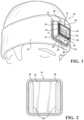
- FIG. 1is a perspective view of a first example embodiment of an illuminated hat assembly, illustrating a light assembly of the illuminated hat assembly connected to a mounting bracket, with the light assembly in an unpivoted position;
- FIG. 2is a front view of the mounting bracket of the first embodiment of the illuminated hat assembly
- FIG. 3is a front perspective view of a light assembly of the first embodiment of the illuminated hat assembly in a partially pivoted position
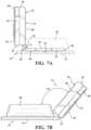
- FIG. 4is a front perspective view of the light assembly of the first embodiment of the illuminated hat assembly, illustrating hanging the light assembly from a nail while disconnected from the mounting bracket and while the light assembly is pivoted 180 degrees;
- FIG. 5is a rear perspective view of the light assembly of the first embodiment of the illuminated hat assembly in a partially pivoted position
- FIG. 6is front view of the first embodiment of the illuminated hat assembly, illustrating the light assembly in a partially pivoted position while connected to the mounting bracket;
- FIG. 7 Ais a side view of the first embodiment of the illuminated hat assembly, illustrating the light assembly in a partially pivoted position while connected to the mounting bracket;
- FIG. 7 Bis a side view of the first embodiment of the illuminated hat assembly, illustrating the light assembly pivoted 130 degrees;
- FIG. 8is a perspective view of a second embodiment of the illuminated hat assembly illustrating the light assembly in an un-pivoted position
- FIG. 9is a front perspective view of a mounting plate of the second embodiment of the illuminated hat assembly.
- FIG. 10is a front perspective view of a mounting bracket of the second embodiment of the illuminated hat assembly
- FIG. 11is a side view of a light assembly of the second embodiment of the illuminated hat assembly, illustrating an alternate charging port
- FIG. 12is a bottom, perspective, exploded view of the second embodiment of the illuminated hat assembly
- FIG. 13is a schematic diagram illustrating steps associated with activating different modes of operation of light emitters of the illuminated hat assembly.
- FIGS. 14 and 15are schematic diagrams illustrating exemplary dimming operations of the light emitters of the illuminated hat assembly.
- Example embodiments of an illuminated hat assembly 10 , 100 embodying the teachings of the present disclosurewill now be described more fully with reference to the accompanying drawings.
- the example embodimentsare only provided so that this disclosure will be thorough, and will fully convey the scope to those who are skilled in the art. Numerous specific details are set forth such as examples of specific components, devices, and methods, to provide a thorough understanding of embodiments of the present disclosure. It will be apparent to those skilled in the art that specific details need not be employed, that the example embodiments may be embodied in many different forms that may be combined in various ways, and that neither should be construed to limit the scope of the disclosure. In some example embodiments, well-known processes, well-known device structures, and well-known technologies are not described in detail.
- the illuminated hat assembly 10 , 100includes a hat 12 .
- the example embodimentillustrates a beanie style hat 12 , but the teachings herein may be applied to other styles of hats/headgear including, but not limited to, baseball caps, helmets and headbands. It should be appreciated that the term “hat” as used herein may include various types of headgear.
- FIGS. 1 - 7 Bshow a first example embodiment of the illuminated hat assembly 10 the illuminated hat assembly 12 .
- the illuminated hat assemblyincludes a mounting bracket 14 for being secured to a front of the hat 12 .
- the mounting bracket 12includes a generally square-shaped and planar base 16 .
- the base 16could have other shapes.
- a perimeter of the base 16is stitched to the hat 12 to secure the mounting bracket 14 to the hat 12 .
- Other fastening mechanismscould be used to connect the base 16 to the hat 12 including, but not limited to, an adhesive or bolts.
- the mounting bracket 12further includes a pair of spaced and parallel rails 18 that extend in a vertical direction, each along an edge of the base 16 .
- Each of the rails 18defines a vertically-extending groove 20 .
- the illuminated hat assembly 10further includes a light assembly 22 that is removably connectable to the mounting bracket 14 for illuminating a region in front of a user.
- the light assembly 22includes a generally square-shaped light housing 24 that has a front face 26 , a back face 28 , a top 30 , a bottom 32 and pair of sides 34 .
- One or more light emitters 36are located on a lower region of the front face 28 .
- the light emitters 36are comprised of four light emitting diodes (LEDs) 36 , however, other styles of light emitters could be used, e.g., incandescent bulbs, and any number of light emitters could be used without departing from the scope of the subject disclosure.
- a power button 38is located above the light emitters 36 on the front face 26 of the light housing 24 for activating, and changing settings of the light emitters 36 . More particularly, as will be discussed in further detail below, the power button 38 may be pressed to toggle between different settings of the light emitters 36 .
- a battery 40(schematically shown in FIG. 3 and shown as element 140 in FIG. 12 ) is located inside the light housing 24 for powering the light emitters 36 .
- a charging port 42 and associated cover/seal 44are located along one of the sides 34 of the light housing 24 for being coupled with a power cable 45 to charge the battery 40 .
- Various types of charging ports 42such as USB type B, micro USB or USBC ports may be utilized without departing from the scope of the subject disclosure.
- the cover 44is configured to provide a water tight seal to the charging port 42 .
- the light assembly 22further includes a generally square-shaped mounting plate 46 that is pivotally connected to a region of the bottom 32 of the light housing 24 along a hinge 48 .
- the mounting plate 46has a front surface 49 and a rear surface 51 opposite the front surface 49 , a top edge 50 , a bottom edge 39 , and a pair of parallel side edges 52 that extend between the bottom and top edges 39 , 50 .
- the side edges 52are snuggly received by the grooves 20 of the rails 18 to hold the light assembly 22 in position, and the rear surface 51 of the mounting plate 46 lies flush against the planar base 16 of the mounting bracket 14 .
- the light housing 24While coupled with the mounting bracket 14 , the light housing 24 is pivotable relative to the mounting plate 46 along the hinge 48 about a hinge axis A for adjusting an angle at which light is projected from the light emitters 36 . More particularly, the light housing 24 is pivotable about the hinge axis A at all angles between an un-pivoted position (shown in FIG. 1 ) and various pivoted positions (shown in FIGS. 3 - 7 B ). As shown, the hinge 48 may include a pair of first receivers 53 that are connected to the bottom edge 39 of the mounting plate 46 , and a second receiver 55 that is connected to the bottom 32 of the light housing 24 .
- the first and second receivers 53 , 55may each define a bore 57 along the hinge axis A, and a pin 59 may extend through the bores 57 to provide the pivoting movement of the light housing 24 relative to the mounting plate 46 .
- the hinge 48may also include a ratcheting mechanism 169 for locking the light housing 24 in specific positions.
- the ratcheting mechanism 169may be comprised of a flexible tab 171 that extends from the bottom edge 139 of the mounting plate 46 , 146 which engages a series of grooves 173 that extend linearly/axially along the second receiver 55 , 155 of the hinge 48 , 148 . Engagement of the flexible tab 171 into the grooves 173 resists, but not inhibit movement between the different rotational positions.
- the mounting plate 46defines a generally square-shaped opening 54 which includes a V-shaped notch 56 at an upper border thereof for allowing the mounting plate 46 to be hung from a screw, hook or other mounting device after being removed from the mounting bracket 14 .
- thisprovides a position for charging the device 10 , 100 without losing track of its location.
- FIGS. 8 - 12illustrate a second embodiment of the illuminated hat assembly 100 .
- the second embodimentis constructed and operates in a similar manner as the previously described first embodiment but includes some differences. More particularly, rather than including four light emitters 36 like the first embodiment, the second embodiments includes six light emitters/LEDs 136 as well as a light pipe 137 that extends through the top 130 of the light housing 124 .
- the light emitters 136 and light pipe 137are configured to emit light at various colors. As previously noted, it should be appreciated that any number of light emitters 136 may be employed. According to this embodiment, outside light emitters 136 a may emit a white colored light, while central light emitters 136 b may emit a red colored light, but other colors and configurations may be used.
- the light pipe 137may be configured to blink in a red color when the battery 140 is charging, it may emit a constant red light when the battery 140 is at a low power state, and it may emit a constant green light when the battery 140 is fully charged.
- the central light emitters 136 bmay be configured to emit a flashing red light in an alert mode, and may also be configured to blink a red light two or more times when the battery 40 is at a low power state.
- the light emitters 36may be configured to shine in high intensity or low intensity modes, and they may arranged to dim in order to provide power savings.
- the power button 138may be pressed to toggle between modes.
- the mounting plate 146may further include a pair of legs 158 that each extend along one of the side edges 152 of the mounting plate 146 and extend in spaced and parallel relationship with one another and terminate at a peak 163 that is located adjacent to the hinge 148 . Furthermore, each of the grooves 120 of the parallel rails 118 of the mounting bracket 114 terminate at an end component 165 , which defines a recess 160 .
- Each of the recesses 160are configured to receive one of the legs 158 for further inhibiting movement of the mounting plate 146 relative to the mounting bracket 114 via engagement of the peaks 165 of the legs 158 against the end component 165 in the recess 160 of the end component 165 , with the light housing 124 centered along the mounting bracket 114 .
- FIG. 12is an exploded view of the second embodiment of the illuminated hat assembly 110 illustrating an arrangement of the mounting bracket 114 , the mounting plate 146 , a case 125 of the light housing 124 , the seal 144 , the pin 159 of the hinge 148 , the battery 140 , a printed circuit board (PCB) 151 , a silicone cap 153 , a reflector 155 of the light housing 124 , a cover 157 of the light housing 124 and the power button 138 .
- the silicone cap 153functions as a button for the PCB 151 in that it serves as an interfacing unit between an interface between a switch 167 of the PCB 151 and the power button 138 .
- the silicone cap 153functions like a spring in that it pushes the power button 138 back to a non-depressed position after being pressed so that it may be pushed again.
- FIG. 13is a schematic diagram illustrating different options for operating the illuminated hat assembly 10 , 110 . More particularly, as illustrated, the illuminated hat assembly 10 , 110 may be turned on by holding the power button 38 , 138 for two seconds. Once activated, the light emitters 36 , 136 may be defaulted to shine at a level 4 (medium) intensity. The light emitters 36 , 136 may then be switched to different modes, e.g., low, and high intensity or red flashing, in response to quickly pressing the power button 38 . The light emitters 36 may be turned off in response to holding the power button 38 , 138 for two seconds. FIGS.
- the light emitters 36 , 136may be configured to automatically dim after predetermined intervals of use in order to preserve battery life. Furthermore, the gradual dimming changes avoid rapid changes in light intensity/lumen and provide an improved consumer experience through subtly lumen changes over time.
- the subject illuminated hat assembly 10 , 110provides a simple, compact and reliable arrangement for removably connecting the light assembly 22 , 122 to the mounting bracket 14 , 14 on the hat 12 . Additionally, the illuminated hat assembly 10 , 110 allows the light emitters 36 , 136 to easily be pivoted to different orientations to provide a desired lighting effect. Moreover, the light assembly 22 , 122 can easily be removed for charging while still allowing use of the hat 12 . Finally, the illuminated hat assembly 10 , 110 is aesthetically pleasing, especially in that the light housing 24 , 124 fits discretely in the mounting bracket 14 , 114 , and the mounting bracket 14 , 114 .
- first, second, third, etc.may be used herein to described various elements, components, regions, layers and/or sections, these elements, components, regions, layers and/or sections should not be limited by these terms. These terms may be only used to distinguish one element, component, region, layer or section from another region, layer or section. Terms such as “first,” “second,” and other numerical terms when used herein do not imply a sequence or order unless clearly indicated by the context. Thus, a first element, component, region, layer or section discussed below could be termed a second element, component, region, layer or section without departing from the teachings of the example embodiments.
- Spatially relative termssuch as “inner,” “outer,” “beneath,” “below,” “lower,” “above,” “upper,” and the like, may be used herein for ease of description to describe one element or feature's relationship to another element(s) or feature(s) as illustrated in the figures. Spatially relative terms may be intended to encompass different orientations of the device in use or operation in addition to the orientation depicted in the figures. For example, if the device in the figures is turned over, elements described as “below” or “beneath” other elements or features would then be oriented “above” the other elements or features. Thus, the example term “below” can encompass both an orientation of above and below. The device may be otherwise oriented (rotated 90 degrees or at other orientations) and the spatially relative descriptors used herein interpreted accordingly.
Landscapes
- Non-Portable Lighting Devices Or Systems Thereof (AREA)
Abstract
Description
Claims (18)
Priority Applications (1)
| Application Number | Priority Date | Filing Date | Title |
|---|---|---|---|
| US18/099,617US12075873B2 (en) | 2022-01-21 | 2023-01-20 | Ilumination assembly for a hat |
Applications Claiming Priority (2)
| Application Number | Priority Date | Filing Date | Title |
|---|---|---|---|
| US202263301700P | 2022-01-21 | 2022-01-21 | |
| US18/099,617US12075873B2 (en) | 2022-01-21 | 2023-01-20 | Ilumination assembly for a hat |
Publications (2)
| Publication Number | Publication Date |
|---|---|
| US20230232928A1 US20230232928A1 (en) | 2023-07-27 |
| US12075873B2true US12075873B2 (en) | 2024-09-03 |
Family
ID=87312953
Family Applications (1)
| Application Number | Title | Priority Date | Filing Date |
|---|---|---|---|
| US18/099,617ActiveUS12075873B2 (en) | 2022-01-21 | 2023-01-20 | Ilumination assembly for a hat |
Country Status (2)
| Country | Link |
|---|---|
| US (1) | US12075873B2 (en) |
| WO (1) | WO2023141274A1 (en) |
Cited By (1)
| Publication number | Priority date | Publication date | Assignee | Title |
|---|---|---|---|---|
| US20240122281A1 (en)* | 2018-08-03 | 2024-04-18 | Raquel GRAHAM | Headgear comprising headbands for receiving removable light apparatus and methods of making |
Citations (104)
| Publication number | Priority date | Publication date | Assignee | Title |
|---|---|---|---|---|
| US1586701A (en) | 1925-12-15 | 1926-06-01 | Reppa Andrew | Miner's cap |
| US1689090A (en) | 1926-09-28 | 1928-10-23 | Charles W Watkins | Electric-lamp-holding attachment for miners' caps |
| US1744777A (en) | 1928-04-24 | 1930-01-28 | Otto S Lundgren | Cap-supported lamp |
| US2399030A (en) | 1943-09-25 | 1946-04-23 | Hostetler James Leo | Holder for miners' lamp |
| US2640980A (en) | 1950-12-11 | 1953-06-02 | Ralph G Grossman | Illuminated head covering |
| US2926356A (en) | 1958-01-03 | 1960-03-01 | James P Taylor | Beanproof cap for baseball, racing and allied sports |
| FR1221782A (en) | 1959-01-10 | 1960-06-03 | Advanced visor and caps or the like provided with this visor | |
| US3032647A (en) | 1959-01-22 | 1962-05-01 | Wansky Morris Harold | Cap or hat light |
| US4156942A (en) | 1978-02-27 | 1979-06-05 | Isfeld Rodney H | Lamp assembly for helmets, hard hats and the like |
| US4406040A (en) | 1978-11-27 | 1983-09-27 | Cannone Robert P | Illumination devices |
| US4667274A (en) | 1985-10-17 | 1987-05-19 | Maurice Daniel | Self-illumination patch assembly |
| US4827384A (en) | 1988-04-18 | 1989-05-02 | Hans Von Schlemmer | Pocketed headwear |
| US4991068A (en) | 1990-02-14 | 1991-02-05 | Mickey Scott A | Lamp attachment for hat |
| US5111366A (en) | 1991-05-17 | 1992-05-05 | Gift Asylum, Inc. | Cap having illuminated indicia |
| US5363291A (en) | 1993-11-01 | 1994-11-08 | New Erra Group, Inc. | Portable light assembly |
| WO1995004896A1 (en) | 1993-08-11 | 1995-02-16 | Designodev Limited | Flashlight adaptor |
| US5404593A (en) | 1993-02-18 | 1995-04-11 | American Needle | Headwear piece with ornamental illumination |
| US5479325A (en) | 1994-04-12 | 1995-12-26 | Chien; Tseng-Lu | Headgear with an EL light strip |
| US5485358A (en) | 1994-05-18 | 1996-01-16 | Chien; Tseng L. | Universal L.E.D. safety light for head-wear |
| US5510961A (en) | 1995-05-31 | 1996-04-23 | Peng; Yu-Lin | Cap structure with sound recording and generating functions and warning lights |
| US5541816A (en) | 1995-06-07 | 1996-07-30 | Miserendino; Nicholas G. | Clip light source |
| US5567038A (en) | 1995-03-13 | 1996-10-22 | Lary; Banning G. | Cap with removable fluorescent light |
| US5667292A (en) | 1995-05-03 | 1997-09-16 | Sabalvaro, Jr.; Valentin C. | Hat light |
| DE19612618A1 (en) | 1996-03-29 | 1997-10-02 | German Schindler | Head mounted lamp |
| US5676449A (en) | 1996-04-25 | 1997-10-14 | Newsome; Jeffrey Lee | Head covering and lamp system with improved adjustment capabilities and increased safety |
| US5680718A (en) | 1994-12-20 | 1997-10-28 | First Choice Trading Limited | Illuminable hat |
| US5738432A (en) | 1996-12-04 | 1998-04-14 | Okko; Koussay | Illumination device and a method |
| US5741060A (en) | 1996-08-28 | 1998-04-21 | Johnson; Thomas R. | Baseball cap light |
| US5845987A (en) | 1996-10-08 | 1998-12-08 | Painter; John M. | Illuminated accessory and device |
| USD407187S (en) | 1997-12-08 | 1999-03-30 | Farhad Seyed Makki | Cap with lights |
| US6007211A (en) | 1997-09-08 | 1999-12-28 | Cheung; James | Molded illuminating device |
| US6056413A (en) | 1997-12-29 | 2000-05-02 | Urso; Charles L. | Cap lamp |
| US6116745A (en) | 1998-11-02 | 2000-09-12 | Gordon Industries Ltd. | Garment with an electroluminescent circuit |
| US6168286B1 (en) | 1998-08-03 | 2001-01-02 | Paul J. Duffy | Brim mounted novelty light for sports caps |
| EP1072204A2 (en) | 1999-07-23 | 2001-01-31 | Chang Sung Lim | Cap having a lantern |
| FR2798720A1 (en) | 1999-09-21 | 2001-03-23 | J S A | LIGHTING DEVICE FOR EQUIPPING A SUPPORT, IN PARTICULAR TEXTILE |
| US6206543B1 (en) | 1999-11-12 | 2001-03-27 | David Vincent Henry | Flashlight holder assembly |
| USD441518S1 (en) | 2000-04-14 | 2001-05-08 | Douglas A. Bean | Cap with top light the word ‘score’ in lights |
| US6256795B1 (en) | 1997-12-29 | 2001-07-10 | Carolyn Louise Habel | Novelty hat or clothing |
| US6328454B1 (en) | 1998-11-23 | 2001-12-11 | Keith Davis | Safety lighting |
| US20030026093A1 (en) | 2001-08-03 | 2003-02-06 | Sandberg Robert J. | Device for holding a light source |
| US6659618B2 (en) | 2001-11-07 | 2003-12-09 | Michael Waters | Headwear having a brim with illumination device |
| US6752511B1 (en) | 2003-04-15 | 2004-06-22 | Headlite Llc | Miniature hat light |
| US20040145888A1 (en) | 2003-01-22 | 2004-07-29 | Dae Up Sohn | Clip type light emitter |
| US20040228119A1 (en) | 2003-05-16 | 2004-11-18 | Kenneth Becker | Brim light |
| US20050047117A1 (en) | 2003-08-27 | 2005-03-03 | Scholl Susan R. | Head mounted face guard and light source |
| US6895602B2 (en) | 2002-06-17 | 2005-05-24 | Thomas P. Schlapkohl | Cap mounted light |
| US6923551B2 (en) | 2002-08-09 | 2005-08-02 | Robert Galli | Flashlight mounting system |
| US6941583B2 (en) | 2003-07-01 | 2005-09-13 | Suen Ching Yan | Illuminated headwear |
| US20050207143A1 (en) | 2004-02-27 | 2005-09-22 | Bishop Mose L | Flashing safety headwear |
| WO2006037845A1 (en) | 2004-10-07 | 2006-04-13 | Matti Lahtinen | Led illuminator for a headgear |
| US7055979B2 (en) | 2004-02-09 | 2006-06-06 | Best Cap | Lantern detachable cap |
| US20060198122A1 (en) | 2005-03-04 | 2006-09-07 | R2 Innovation Llc | Illuminated headwear |
| US7131745B2 (en) | 2004-04-29 | 2006-11-07 | Sibbett Gary M | Mountable illuminable display |
| CA2608746A1 (en) | 2005-05-17 | 2006-11-23 | Michael Waters | Hands-free lighting devices |
| AU2006241385A1 (en) | 1987-10-30 | 2006-12-14 | Naschem Co., Ltd | Clip Type Light Emitter |
| US7240883B2 (en)* | 2005-08-22 | 2007-07-10 | Su-Chang Liao | Head mount lamp seat |
| WO2007093132A1 (en) | 2006-02-17 | 2007-08-23 | Bing Liang | Head lamp |
| US20080080172A1 (en) | 2006-09-29 | 2008-04-03 | Bo Mayo | Hunting apparel with indicator lights |
| US20080212311A1 (en) | 2007-03-01 | 2008-09-04 | Hybrid Light | Portable Lighting System |
| US7427149B2 (en) | 2003-01-22 | 2008-09-23 | Dae Up Sohn | Clip type light detachably coupled with cap |
| US7506992B2 (en) | 2007-03-21 | 2009-03-24 | William Rex Carter | Led cap light |
| US7524081B2 (en) | 2001-04-09 | 2009-04-28 | Eveready Battery Company, Inc. | Lighting device |
| CA2709991A1 (en) | 2007-12-18 | 2009-06-25 | Michael Waters | Hands free lighting devices |
| US7611255B1 (en) | 2007-08-27 | 2009-11-03 | Kool Light, LLC | Illumination device mountable through an aperture in a clothing object |
| US7661818B2 (en) | 2001-11-07 | 2010-02-16 | Michael Waters | Clip-on light apparatus |
| US7699485B1 (en) | 2007-08-27 | 2010-04-20 | Koollight, Llc | Illumination device mountable to a clothing object |
| US20100142191A1 (en) | 2008-12-08 | 2010-06-10 | Sung-Yie Liao | Cap with Illuminated Rear Strap |
| US20100142192A1 (en) | 2008-12-09 | 2010-06-10 | Sung-Yie Liao | Illuminated Cap |
| US20100214767A1 (en) | 2007-12-18 | 2010-08-26 | Michael Waters | Lighted hat |
| US20100289433A1 (en) | 2009-05-15 | 2010-11-18 | Chi Hung Fermi Lau | Clip light |
| US20100301779A1 (en)* | 2008-01-25 | 2010-12-02 | Eveready Battery Company, Inc. | Lighting Device |
| US20100313335A1 (en) | 2007-12-18 | 2010-12-16 | Michael Waters | Hands free lighting devices |
| US20110122601A1 (en) | 2007-12-18 | 2011-05-26 | Michael Waters | Illuminated headgear having switch devices and packaging therefor |
| US20110157874A1 (en) | 2008-09-10 | 2011-06-30 | Eveready Battery Company, Inc. | Attachable Portable Lighting Device and Methods of Operation |
| US8002437B2 (en) | 2008-01-24 | 2011-08-23 | Dae Up Sohn | Light emitter to be attached to caps |
| US20110210685A1 (en) | 2010-02-26 | 2011-09-01 | Sung-Yie Liao | Lighted hat with a power supply device as flashlight |
| WO2011137400A1 (en) | 2010-04-30 | 2011-11-03 | Michael Waters | Lighted headgear and accessories therefor |
| US20130033852A1 (en) | 2008-10-16 | 2013-02-07 | Sung-Yie Liao | Hat with Solar System |
| US8388164B2 (en) | 2005-05-17 | 2013-03-05 | Michael Waters | Hands-Free lighting devices |
| CA2794370A1 (en) | 2011-11-04 | 2013-05-04 | Michael Waters | Hat with automated shut-off feature for electrical devices |
| US8444285B2 (en) | 2009-01-12 | 2013-05-21 | Chi Hung Fermi Lau | Clip light |
| WO2013096895A1 (en) | 2011-12-23 | 2013-06-27 | Michael Waters | Headgear having a camera device |
| WO2013096904A1 (en) | 2011-12-23 | 2013-06-27 | Michael Waters | Lighted hat |
| US20130198935A1 (en) | 2005-05-17 | 2013-08-08 | Michael Waters | Power modules for mounting to headgear |
| US20130242544A1 (en) | 2012-03-19 | 2013-09-19 | Sung-Yie Liao | Hat with Angle Adjustable Solar Powered Lamp |
| US20140049947A1 (en) | 2012-08-14 | 2014-02-20 | Penguin Brands, Inc. | Illuminated Apparel |
| US20140085871A1 (en) | 2012-09-26 | 2014-03-27 | Hsiu-Yu Tsao | Illumination Device For A Cap |
| US20140173807A1 (en) | 2012-12-19 | 2014-06-26 | Michael Waters | Lighted solar hat |
| US20140268683A1 (en) | 2011-12-23 | 2014-09-18 | Michael Waters | Lighted Hat |
| US20140268684A1 (en) | 2011-12-23 | 2014-09-18 | Michael Waters | Lighted hat |
| WO2014144276A2 (en) | 2013-03-15 | 2014-09-18 | Michael Waters | Lighted hat |
| US20140304891A1 (en) | 2011-12-23 | 2014-10-16 | Michael Waters | Headgear having a camera device |
| US9872531B2 (en)* | 2015-09-28 | 2018-01-23 | Alan Uke | Helmet assembly |
| KR20190000693U (en) | 2017-09-08 | 2019-03-18 | (주)삼정물산 | Safety helmet equipped with removable lighting units |
| KR20190042874A (en) | 2017-10-17 | 2019-04-25 | 주식회사 나스켐 | Portable Lighting Device |
| US20190231016A1 (en) | 2018-01-26 | 2019-08-01 | Klein Tools, Inc. | Safety Helmet |
| USD871726S1 (en) | 2017-12-06 | 2020-01-07 | Oc Global Services Llc | Hat |
| USD872425S1 (en) | 2017-12-06 | 2020-01-14 | Oc Global Services Llc | Hat |
| US20200037685A1 (en) | 2018-08-03 | 2020-02-06 | Raquel GRAHAM | Headgear comprising headbands for receiving removable light apparatus and methods of making |
| KR102121312B1 (en) | 2019-07-22 | 2020-06-11 | 주식회사 나스켐 | Portable Lighting Device |
| US10731835B2 (en) | 2017-12-07 | 2020-08-04 | First-Light Usa, Llc | Illumination device |
| US10791783B1 (en) | 2019-05-16 | 2020-10-06 | Waters Industries, Inc. | Lighted headgear and accessories therefor |
| US20200355353A1 (en) | 2019-05-06 | 2020-11-12 | LB Marketing, Inc. | Detachable dual-mode lighting device and associated headlamp system |
- 2023
- 2023-01-20WOPCT/US2023/011245patent/WO2023141274A1/ennot_activeCeased
- 2023-01-20USUS18/099,617patent/US12075873B2/enactiveActive
Patent Citations (175)
| Publication number | Priority date | Publication date | Assignee | Title |
|---|---|---|---|---|
| US1586701A (en) | 1925-12-15 | 1926-06-01 | Reppa Andrew | Miner's cap |
| US1689090A (en) | 1926-09-28 | 1928-10-23 | Charles W Watkins | Electric-lamp-holding attachment for miners' caps |
| US1744777A (en) | 1928-04-24 | 1930-01-28 | Otto S Lundgren | Cap-supported lamp |
| US2399030A (en) | 1943-09-25 | 1946-04-23 | Hostetler James Leo | Holder for miners' lamp |
| US2640980A (en) | 1950-12-11 | 1953-06-02 | Ralph G Grossman | Illuminated head covering |
| US2926356A (en) | 1958-01-03 | 1960-03-01 | James P Taylor | Beanproof cap for baseball, racing and allied sports |
| FR1221782A (en) | 1959-01-10 | 1960-06-03 | Advanced visor and caps or the like provided with this visor | |
| US3032647A (en) | 1959-01-22 | 1962-05-01 | Wansky Morris Harold | Cap or hat light |
| US4156942A (en) | 1978-02-27 | 1979-06-05 | Isfeld Rodney H | Lamp assembly for helmets, hard hats and the like |
| US4406040A (en) | 1978-11-27 | 1983-09-27 | Cannone Robert P | Illumination devices |
| US4667274A (en) | 1985-10-17 | 1987-05-19 | Maurice Daniel | Self-illumination patch assembly |
| AU2006241385A1 (en) | 1987-10-30 | 2006-12-14 | Naschem Co., Ltd | Clip Type Light Emitter |
| AU2006241385B2 (en) | 1987-10-30 | 2009-10-01 | Naschem Co., Ltd | Clip Type Light Emitter |
| US4827384A (en) | 1988-04-18 | 1989-05-02 | Hans Von Schlemmer | Pocketed headwear |
| US4991068A (en) | 1990-02-14 | 1991-02-05 | Mickey Scott A | Lamp attachment for hat |
| US5111366A (en) | 1991-05-17 | 1992-05-05 | Gift Asylum, Inc. | Cap having illuminated indicia |
| US5404593A (en) | 1993-02-18 | 1995-04-11 | American Needle | Headwear piece with ornamental illumination |
| WO1995004896A1 (en) | 1993-08-11 | 1995-02-16 | Designodev Limited | Flashlight adaptor |
| US6457838B1 (en)* | 1993-08-11 | 2002-10-01 | Designodev Limited | Flashlight adaptor |
| US5363291A (en) | 1993-11-01 | 1994-11-08 | New Erra Group, Inc. | Portable light assembly |
| US5479325A (en) | 1994-04-12 | 1995-12-26 | Chien; Tseng-Lu | Headgear with an EL light strip |
| US5485358A (en) | 1994-05-18 | 1996-01-16 | Chien; Tseng L. | Universal L.E.D. safety light for head-wear |
| US5680718A (en) | 1994-12-20 | 1997-10-28 | First Choice Trading Limited | Illuminable hat |
| US5567038A (en) | 1995-03-13 | 1996-10-22 | Lary; Banning G. | Cap with removable fluorescent light |
| US5667292A (en) | 1995-05-03 | 1997-09-16 | Sabalvaro, Jr.; Valentin C. | Hat light |
| US5510961A (en) | 1995-05-31 | 1996-04-23 | Peng; Yu-Lin | Cap structure with sound recording and generating functions and warning lights |
| US5541816A (en) | 1995-06-07 | 1996-07-30 | Miserendino; Nicholas G. | Clip light source |
| DE19612618A1 (en) | 1996-03-29 | 1997-10-02 | German Schindler | Head mounted lamp |
| DE19612618C2 (en) | 1996-03-29 | 2000-06-29 | German Schindler | Lamp held on a cap-like headgear |
| US5676449A (en) | 1996-04-25 | 1997-10-14 | Newsome; Jeffrey Lee | Head covering and lamp system with improved adjustment capabilities and increased safety |
| US5741060A (en) | 1996-08-28 | 1998-04-21 | Johnson; Thomas R. | Baseball cap light |
| US5845987A (en) | 1996-10-08 | 1998-12-08 | Painter; John M. | Illuminated accessory and device |
| US5738432A (en) | 1996-12-04 | 1998-04-14 | Okko; Koussay | Illumination device and a method |
| US6007211A (en) | 1997-09-08 | 1999-12-28 | Cheung; James | Molded illuminating device |
| USD407187S (en) | 1997-12-08 | 1999-03-30 | Farhad Seyed Makki | Cap with lights |
| US6256795B1 (en) | 1997-12-29 | 2001-07-10 | Carolyn Louise Habel | Novelty hat or clothing |
| US6056413A (en) | 1997-12-29 | 2000-05-02 | Urso; Charles L. | Cap lamp |
| US6168286B1 (en) | 1998-08-03 | 2001-01-02 | Paul J. Duffy | Brim mounted novelty light for sports caps |
| US6116745A (en) | 1998-11-02 | 2000-09-12 | Gordon Industries Ltd. | Garment with an electroluminescent circuit |
| US6328454B1 (en) | 1998-11-23 | 2001-12-11 | Keith Davis | Safety lighting |
| EP1072204A2 (en) | 1999-07-23 | 2001-01-31 | Chang Sung Lim | Cap having a lantern |
| EP1072204A3 (en) | 1999-07-23 | 2002-07-24 | Chang Sung Lim | Cap having a lantern |
| US6932487B2 (en) | 1999-09-21 | 2005-08-23 | Jacques Aknine | Lighting device designed to fit on a mounting, particularly textile |
| CA2355344A1 (en) | 1999-09-21 | 2001-03-29 | Castiel, Maurice | Lighting device designed to fit on a mounting, particularly textile |
| US20010024365A1 (en) | 1999-09-21 | 2001-09-27 | Jacques Aknine | Lighting device designed to fit on a mounting, particularly textile |
| WO2001021021A1 (en) | 1999-09-21 | 2001-03-29 | J.S.A | Illumination device designed to equip a support, in particular a textile support |
| FR2798720A1 (en) | 1999-09-21 | 2001-03-23 | J S A | LIGHTING DEVICE FOR EQUIPPING A SUPPORT, IN PARTICULAR TEXTILE |
| US6206543B1 (en) | 1999-11-12 | 2001-03-27 | David Vincent Henry | Flashlight holder assembly |
| USD441518S1 (en) | 2000-04-14 | 2001-05-08 | Douglas A. Bean | Cap with top light the word ‘score’ in lights |
| US7524081B2 (en) | 2001-04-09 | 2009-04-28 | Eveready Battery Company, Inc. | Lighting device |
| US20090135589A1 (en) | 2001-04-09 | 2009-05-28 | Eveready Battery Company, Inc. | Lighting Device |
| US20110075405A1 (en) | 2001-04-09 | 2011-03-31 | Eveready Battery Company, Inc. | Lighting Device Utilizing a Light Emitting Diode Disposed within a Tubular Lens |
| US7850331B2 (en) | 2001-04-09 | 2010-12-14 | Eveready Battery Company, Inc. | Lighting device utilizing a light emitting diode disposed within a tubular lens |
| USRE41795E1 (en) | 2001-04-09 | 2010-10-05 | Eveready Battery Company, Inc. | Lighting device |
| US6604837B2 (en) | 2001-08-03 | 2003-08-12 | Robert J. Sandberg | Device for holding a light source |
| US20030026093A1 (en) | 2001-08-03 | 2003-02-06 | Sandberg Robert J. | Device for holding a light source |
| US7661818B2 (en) | 2001-11-07 | 2010-02-16 | Michael Waters | Clip-on light apparatus |
| US6863416B2 (en) | 2001-11-07 | 2005-03-08 | Michael Waters | Lighting device |
| US6659618B2 (en) | 2001-11-07 | 2003-12-09 | Michael Waters | Headwear having a brim with illumination device |
| US7104670B2 (en) | 2001-11-07 | 2006-09-12 | Michael Waters | Lighting device |
| US6895602B2 (en) | 2002-06-17 | 2005-05-24 | Thomas P. Schlapkohl | Cap mounted light |
| US6923551B2 (en) | 2002-08-09 | 2005-08-02 | Robert Galli | Flashlight mounting system |
| US7708422B2 (en) | 2003-01-22 | 2010-05-04 | Dae Up Sohn | Clip type light emitter |
| US20040145888A1 (en) | 2003-01-22 | 2004-07-29 | Dae Up Sohn | Clip type light emitter |
| US7427149B2 (en) | 2003-01-22 | 2008-09-23 | Dae Up Sohn | Clip type light detachably coupled with cap |
| US7163309B2 (en) | 2003-01-22 | 2007-01-16 | Dae Up Sohn | Clip type light emitter |
| US7118241B2 (en) | 2003-01-22 | 2006-10-10 | Dae Up Sohn | Clip type light emitter |
| US6752511B1 (en) | 2003-04-15 | 2004-06-22 | Headlite Llc | Miniature hat light |
| EP1639294B1 (en) | 2003-05-16 | 2012-10-17 | Angel Lighting LLC | Brim light |
| EP1639294B8 (en) | 2003-05-16 | 2012-12-26 | Nite Ize, Inc. | Brim light |
| US7431472B2 (en) | 2003-05-16 | 2008-10-07 | Angel Lighting Llc | Lighting apparatus for mounting on hat brim |
| US7000841B2 (en) | 2003-05-16 | 2006-02-21 | Angel Lighting Llc | Lighting apparatus for mounting on hat brim |
| US20040228119A1 (en) | 2003-05-16 | 2004-11-18 | Kenneth Becker | Brim light |
| US20060157569A1 (en) | 2003-05-16 | 2006-07-20 | Kenneth Becker | Lighting apparatus for mounting on hat brim |
| US6941583B2 (en) | 2003-07-01 | 2005-09-13 | Suen Ching Yan | Illuminated headwear |
| US20050047117A1 (en) | 2003-08-27 | 2005-03-03 | Scholl Susan R. | Head mounted face guard and light source |
| US7055979B2 (en) | 2004-02-09 | 2006-06-06 | Best Cap | Lantern detachable cap |
| US20050207143A1 (en) | 2004-02-27 | 2005-09-22 | Bishop Mose L | Flashing safety headwear |
| US7131745B2 (en) | 2004-04-29 | 2006-11-07 | Sibbett Gary M | Mountable illuminable display |
| WO2006037845A1 (en) | 2004-10-07 | 2006-04-13 | Matti Lahtinen | Led illuminator for a headgear |
| US20060198122A1 (en) | 2005-03-04 | 2006-09-07 | R2 Innovation Llc | Illuminated headwear |
| WO2006096595A2 (en) | 2005-03-04 | 2006-09-14 | R2 Innovations Llc | Illuminated headwear |
| US20130198935A1 (en) | 2005-05-17 | 2013-08-08 | Michael Waters | Power modules for mounting to headgear |
| US8388164B2 (en) | 2005-05-17 | 2013-03-05 | Michael Waters | Hands-Free lighting devices |
| CA2608746A1 (en) | 2005-05-17 | 2006-11-23 | Michael Waters | Hands-free lighting devices |
| US7240883B2 (en)* | 2005-08-22 | 2007-07-10 | Su-Chang Liao | Head mount lamp seat |
| WO2007093132A1 (en) | 2006-02-17 | 2007-08-23 | Bing Liang | Head lamp |
| US20080080172A1 (en) | 2006-09-29 | 2008-04-03 | Bo Mayo | Hunting apparel with indicator lights |
| US20080212311A1 (en) | 2007-03-01 | 2008-09-04 | Hybrid Light | Portable Lighting System |
| US7506992B2 (en) | 2007-03-21 | 2009-03-24 | William Rex Carter | Led cap light |
| US7699485B1 (en) | 2007-08-27 | 2010-04-20 | Koollight, Llc | Illumination device mountable to a clothing object |
| US7611255B1 (en) | 2007-08-27 | 2009-11-03 | Kool Light, LLC | Illumination device mountable through an aperture in a clothing object |
| US9185278B2 (en) | 2007-12-18 | 2015-11-10 | Michael Waters | Hands free lighting devices |
| ES2478679T3 (en) | 2007-12-18 | 2014-07-22 | Michael Waters | Headrest with lights |
| US20130201299A1 (en) | 2007-12-18 | 2013-08-08 | Michael Waters | Hands free lighting devices |
| CA2709991A1 (en) | 2007-12-18 | 2009-06-25 | Michael Waters | Hands free lighting devices |
| EP2238386B1 (en) | 2007-12-18 | 2014-04-09 | Michael Waters | Lighted headgear |
| US8491145B2 (en) | 2007-12-18 | 2013-07-23 | Waters Industries, Inc. | Illuminated headgear having switch devices and packaging therefor |
| US20100214767A1 (en) | 2007-12-18 | 2010-08-26 | Michael Waters | Lighted hat |
| US20100313335A1 (en) | 2007-12-18 | 2010-12-16 | Michael Waters | Hands free lighting devices |
| US8757831B2 (en) | 2007-12-18 | 2014-06-24 | Michael Waters | Headgear having an electrical device and power source mounted thereto |
| US7753547B2 (en) | 2007-12-18 | 2010-07-13 | Michael Waters | Lighted headwear with brim sleeve |
| US20110122601A1 (en) | 2007-12-18 | 2011-05-26 | Michael Waters | Illuminated headgear having switch devices and packaging therefor |
| AU2008338320A1 (en) | 2007-12-18 | 2009-06-25 | Michael Waters | Hands-free lighting devices |
| WO2009079656A2 (en) | 2007-12-18 | 2009-06-25 | Michael Waters | Hands-free lighting devices |
| BRPI0819557A2 (en) | 2007-12-18 | 2015-05-05 | Michael Waters | "Light head accessory, camera and light head accessory combination, flap sleeve, packaging assembly and head accessory" |
| US8333485B2 (en) | 2007-12-18 | 2012-12-18 | Michael Waters | Headwear with switch shielding portion |
| US9585431B2 (en) | 2007-12-18 | 2017-03-07 | Waters Industries, Inc. | Lighted hat |
| WO2011137406A2 (en) | 2007-12-18 | 2011-11-03 | Michael Waters | Hands free lighting devices |
| US8550651B2 (en) | 2007-12-18 | 2013-10-08 | Waters Industries, Inc. | Lighted hat |
| US8002437B2 (en) | 2008-01-24 | 2011-08-23 | Dae Up Sohn | Light emitter to be attached to caps |
| US20100301779A1 (en)* | 2008-01-25 | 2010-12-02 | Eveready Battery Company, Inc. | Lighting Device |
| US20110157874A1 (en) | 2008-09-10 | 2011-06-30 | Eveready Battery Company, Inc. | Attachable Portable Lighting Device and Methods of Operation |
| US20130033852A1 (en) | 2008-10-16 | 2013-02-07 | Sung-Yie Liao | Hat with Solar System |
| US8783892B2 (en) | 2008-10-16 | 2014-07-22 | Chuan Cheng Hat Co., Ltd. | Hat with solar system |
| US7874693B2 (en) | 2008-12-08 | 2011-01-25 | Chuan Cheng Hat Co., Ltd. | Cap with illuminated rear strap |
| US20100142191A1 (en) | 2008-12-08 | 2010-06-10 | Sung-Yie Liao | Cap with Illuminated Rear Strap |
| US7810944B2 (en) | 2008-12-09 | 2010-10-12 | Chuan Cheng Hat Co., Ltd. | Illuminated cap having optical fiber strand and removable pouch |
| US20100142192A1 (en) | 2008-12-09 | 2010-06-10 | Sung-Yie Liao | Illuminated Cap |
| US8444285B2 (en) | 2009-01-12 | 2013-05-21 | Chi Hung Fermi Lau | Clip light |
| WO2010099504A1 (en) | 2009-02-27 | 2010-09-02 | Michael Waters | Lighted hat |
| ES2586621T3 (en) | 2009-02-27 | 2016-10-17 | Michael Waters | Hat with light |
| AU2011101143A4 (en) | 2009-02-27 | 2011-10-13 | Michael Waters | Lighted hat |
| AU2011101143B4 (en) | 2009-02-27 | 2014-04-17 | Michael Waters | Lighted hat |
| ES1077908U (en) | 2009-02-27 | 2012-10-25 | Michael Waters | Lighted hat |
| DE212010000023U1 (en) | 2009-02-27 | 2012-01-24 | Michael Waters | Lighting headgear |
| CA2753717A1 (en) | 2009-02-27 | 2010-09-02 | Michael Waters | Lighted hat |
| US20100289433A1 (en) | 2009-05-15 | 2010-11-18 | Chi Hung Fermi Lau | Clip light |
| US20110210685A1 (en) | 2010-02-26 | 2011-09-01 | Sung-Yie Liao | Lighted hat with a power supply device as flashlight |
| MX2012012646A (en) | 2010-04-30 | 2013-03-05 | Michael Waters | Lighted headgear and accessories therefor. |
| WO2011137400A1 (en) | 2010-04-30 | 2011-11-03 | Michael Waters | Lighted headgear and accessories therefor |
| CN203384917U (en) | 2010-04-30 | 2014-01-08 | 迈克尔·沃特斯 | trial equipment |
| CA2797973A1 (en) | 2010-04-30 | 2011-11-03 | Michael Waters | Hands free lighting devices |
| CA2797971A1 (en) | 2010-04-30 | 2011-11-03 | Michael Waters | Lighted headgear and accessories therefor |
| US20130192961A1 (en) | 2010-04-30 | 2013-08-01 | Michael Waters | Lighted headgear and accessories therefor |
| US20150250245A1 (en) | 2010-04-30 | 2015-09-10 | Michael Waters | Lighted Headgear and Accessories Therefor |
| MX2012012645A (en) | 2010-04-30 | 2013-02-26 | Michael Waters | Hands free lighting devices. |
| US10716350B2 (en) | 2010-04-30 | 2020-07-21 | Michael Waters | Lighted headgear and accessories therefor |
| US20140218962A1 (en) | 2010-04-30 | 2014-08-07 | Michael Waters | Lighted headgear and accessories therefor |
| US9101174B2 (en) | 2011-11-04 | 2015-08-11 | Michael Waters | Hat with automated shut-off feature for electrical devices |
| US20130111651A1 (en) | 2011-11-04 | 2013-05-09 | Michael Waters | Hat with automated shut-off feature for electrical devices |
| CA2794370A1 (en) | 2011-11-04 | 2013-05-04 | Michael Waters | Hat with automated shut-off feature for electrical devices |
| US20140304891A1 (en) | 2011-12-23 | 2014-10-16 | Michael Waters | Headgear having a camera device |
| WO2013096904A1 (en) | 2011-12-23 | 2013-06-27 | Michael Waters | Lighted hat |
| US20140268684A1 (en) | 2011-12-23 | 2014-09-18 | Michael Waters | Lighted hat |
| WO2013096895A1 (en) | 2011-12-23 | 2013-06-27 | Michael Waters | Headgear having a camera device |
| US9526287B2 (en) | 2011-12-23 | 2016-12-27 | Michael Waters | Lighted hat |
| US20140268683A1 (en) | 2011-12-23 | 2014-09-18 | Michael Waters | Lighted Hat |
| US9568173B2 (en) | 2011-12-23 | 2017-02-14 | Michael Waters | Lighted hat |
| US20130242544A1 (en) | 2012-03-19 | 2013-09-19 | Sung-Yie Liao | Hat with Angle Adjustable Solar Powered Lamp |
| US8721104B2 (en) | 2012-03-19 | 2014-05-13 | Chuan Cheng Hat Co., Ltd. | Hat with angle adjustable solar powered lamp |
| US20140049947A1 (en) | 2012-08-14 | 2014-02-20 | Penguin Brands, Inc. | Illuminated Apparel |
| US20140085871A1 (en) | 2012-09-26 | 2014-03-27 | Hsiu-Yu Tsao | Illumination Device For A Cap |
| US20140173807A1 (en) | 2012-12-19 | 2014-06-26 | Michael Waters | Lighted solar hat |
| WO2014100477A1 (en) | 2012-12-19 | 2014-06-26 | Michael Waters | Lighted solar hat |
| US10159294B2 (en) | 2012-12-19 | 2018-12-25 | Michael Waters | Lighted solar hat |
| AU2014227728A1 (en) | 2013-03-15 | 2015-09-24 | Michael Waters | Lighted hat |
| WO2014144276A2 (en) | 2013-03-15 | 2014-09-18 | Michael Waters | Lighted hat |
| CA2905067A1 (en) | 2013-03-15 | 2014-09-18 | Michael Waters | Lighted hat |
| WO2014144276A3 (en) | 2013-03-15 | 2014-11-13 | Michael Waters | Lighted hat |
| US9872531B2 (en)* | 2015-09-28 | 2018-01-23 | Alan Uke | Helmet assembly |
| KR20190000693U (en) | 2017-09-08 | 2019-03-18 | (주)삼정물산 | Safety helmet equipped with removable lighting units |
| KR20190042874A (en) | 2017-10-17 | 2019-04-25 | 주식회사 나스켐 | Portable Lighting Device |
| USD871726S1 (en) | 2017-12-06 | 2020-01-07 | Oc Global Services Llc | Hat |
| USD872425S1 (en) | 2017-12-06 | 2020-01-14 | Oc Global Services Llc | Hat |
| US10782006B1 (en) | 2017-12-07 | 2020-09-22 | First-Light Usa, Llc | Illumination device |
| US10731835B2 (en) | 2017-12-07 | 2020-08-04 | First-Light Usa, Llc | Illumination device |
| US20200318818A1 (en) | 2017-12-07 | 2020-10-08 | First-Light Usa, Llc | Illumination device |
| US20200378585A1 (en) | 2017-12-07 | 2020-12-03 | First-Light Usa, Llc | Illumination device |
| US10907811B2 (en) | 2017-12-07 | 2021-02-02 | First-Light Usa, Llc | Illumination device |
| US20190231016A1 (en) | 2018-01-26 | 2019-08-01 | Klein Tools, Inc. | Safety Helmet |
| US20200037685A1 (en) | 2018-08-03 | 2020-02-06 | Raquel GRAHAM | Headgear comprising headbands for receiving removable light apparatus and methods of making |
| US20200355353A1 (en) | 2019-05-06 | 2020-11-12 | LB Marketing, Inc. | Detachable dual-mode lighting device and associated headlamp system |
| US10791783B1 (en) | 2019-05-16 | 2020-10-06 | Waters Industries, Inc. | Lighted headgear and accessories therefor |
| KR102121312B1 (en) | 2019-07-22 | 2020-06-11 | 주식회사 나스켐 | Portable Lighting Device |
Non-Patent Citations (1)
| Title |
|---|
| International Search Report and Written Opinion of the International Search Authority from the International Searching Authority for related International Application No. PCT/US2023/011245 dated Apr. 25, 2023, 9 pages. |
Cited By (1)
| Publication number | Priority date | Publication date | Assignee | Title |
|---|---|---|---|---|
| US20240122281A1 (en)* | 2018-08-03 | 2024-04-18 | Raquel GRAHAM | Headgear comprising headbands for receiving removable light apparatus and methods of making |
Also Published As
| Publication number | Publication date |
|---|---|
| US20230232928A1 (en) | 2023-07-27 |
| WO2023141274A1 (en) | 2023-07-27 |
Similar Documents
| Publication | Publication Date | Title |
|---|---|---|
| US10627056B2 (en) | Helmet light | |
| US9526287B2 (en) | Lighted hat | |
| AU2011101143A4 (en) | Lighted hat | |
| US6994445B1 (en) | Cap with underside light | |
| US6923551B2 (en) | Flashlight mounting system | |
| US6659618B2 (en) | Headwear having a brim with illumination device | |
| US8157403B2 (en) | Light device with detachable clip member | |
| US9568173B2 (en) | Lighted hat | |
| KR101719271B1 (en) | Multi-useful head lantern | |
| CN101876400A (en) | Lighting device with removable cradle | |
| WO2013096904A9 (en) | Lighted hat | |
| US12075873B2 (en) | Ilumination assembly for a hat | |
| US7125139B2 (en) | Flashlight | |
| AU2014227728B2 (en) | Lighted hat | |
| CN201284927Y (en) | Head lamp | |
| CN212841007U (en) | Can throw shining tree lamp of arc facula | |
| US7695155B1 (en) | Illuminating device for glasses | |
| CN110822309A (en) | Induction head lamp | |
| CN223399704U (en) | Head lamp | |
| CN215112123U (en) | Portable lamp with multiple lighting positions | |
| CN210532113U (en) | Multifunctional LED portable lamp | |
| CN218209095U (en) | Cap lamp, night-light and cap | |
| TWM373432U (en) | Head lamp with adjustable lighting angle and range |
Legal Events
| Date | Code | Title | Description |
|---|---|---|---|
| AS | Assignment | Owner name:CARHARTT, INC., MICHIGAN Free format text:ASSIGNMENT OF ASSIGNORS INTEREST;ASSIGNORS:HAU, COLLEEN;WEST, JONATHAN;ISLAM, SAIF;SIGNING DATES FROM 20230117 TO 20230118;REEL/FRAME:062440/0151 | |
| FEPP | Fee payment procedure | Free format text:ENTITY STATUS SET TO UNDISCOUNTED (ORIGINAL EVENT CODE: BIG.); ENTITY STATUS OF PATENT OWNER: LARGE ENTITY | |
| STPP | Information on status: patent application and granting procedure in general | Free format text:NON FINAL ACTION MAILED | |
| STPP | Information on status: patent application and granting procedure in general | Free format text:RESPONSE TO NON-FINAL OFFICE ACTION ENTERED AND FORWARDED TO EXAMINER | |
| STPP | Information on status: patent application and granting procedure in general | Free format text:FINAL REJECTION MAILED | |
| STPP | Information on status: patent application and granting procedure in general | Free format text:RESPONSE AFTER FINAL ACTION FORWARDED TO EXAMINER | |
| STPP | Information on status: patent application and granting procedure in general | Free format text:NOTICE OF ALLOWANCE MAILED -- APPLICATION RECEIVED IN OFFICE OF PUBLICATIONS | |
| AS | Assignment | Owner name:CARHARTT, INC., MICHIGAN Free format text:ASSIGNMENT OF ASSIGNORS INTEREST;ASSIGNOR:SVENDSEN, SEAN;REEL/FRAME:068112/0052 Effective date:20240726 | |
| STPP | Information on status: patent application and granting procedure in general | Free format text:PUBLICATIONS -- ISSUE FEE PAYMENT RECEIVED | |
| STPP | Information on status: patent application and granting procedure in general | Free format text:PUBLICATIONS -- ISSUE FEE PAYMENT VERIFIED | |
| STCF | Information on status: patent grant | Free format text:PATENTED CASE |