US12072406B2 - Augmented reality precision tracking and display - Google Patents
Augmented reality precision tracking and displayDownload PDFInfo
- Publication number
- US12072406B2 US12072406B2US18/138,581US202318138581AUS12072406B2US 12072406 B2US12072406 B2US 12072406B2US 202318138581 AUS202318138581 AUS 202318138581AUS 12072406 B2US12072406 B2US 12072406B2
- Authority
- US
- United States
- Prior art keywords
- location
- virtual element
- current
- pulse
- physical environment
- Prior art date
- Legal status (The legal status is an assumption and is not a legal conclusion. Google has not performed a legal analysis and makes no representation as to the accuracy of the status listed.)
- Active
Links
Images


Classifications
- G—PHYSICS
- G06—COMPUTING OR CALCULATING; COUNTING
- G06F—ELECTRIC DIGITAL DATA PROCESSING
- G06F3/00—Input arrangements for transferring data to be processed into a form capable of being handled by the computer; Output arrangements for transferring data from processing unit to output unit, e.g. interface arrangements
- G06F3/01—Input arrangements or combined input and output arrangements for interaction between user and computer
- G06F3/011—Arrangements for interaction with the human body, e.g. for user immersion in virtual reality
- G—PHYSICS
- G01—MEASURING; TESTING
- G01S—RADIO DIRECTION-FINDING; RADIO NAVIGATION; DETERMINING DISTANCE OR VELOCITY BY USE OF RADIO WAVES; LOCATING OR PRESENCE-DETECTING BY USE OF THE REFLECTION OR RERADIATION OF RADIO WAVES; ANALOGOUS ARRANGEMENTS USING OTHER WAVES
- G01S1/00—Beacons or beacon systems transmitting signals having a characteristic or characteristics capable of being detected by non-directional receivers and defining directions, positions, or position lines fixed relatively to the beacon transmitters; Receivers co-operating therewith
- G01S1/02—Beacons or beacon systems transmitting signals having a characteristic or characteristics capable of being detected by non-directional receivers and defining directions, positions, or position lines fixed relatively to the beacon transmitters; Receivers co-operating therewith using radio waves
- G01S1/04—Details
- G01S1/042—Transmitters
- G01S1/0423—Mounting or deployment thereof
- G—PHYSICS
- G01—MEASURING; TESTING
- G01S—RADIO DIRECTION-FINDING; RADIO NAVIGATION; DETERMINING DISTANCE OR VELOCITY BY USE OF RADIO WAVES; LOCATING OR PRESENCE-DETECTING BY USE OF THE REFLECTION OR RERADIATION OF RADIO WAVES; ANALOGOUS ARRANGEMENTS USING OTHER WAVES
- G01S1/00—Beacons or beacon systems transmitting signals having a characteristic or characteristics capable of being detected by non-directional receivers and defining directions, positions, or position lines fixed relatively to the beacon transmitters; Receivers co-operating therewith
- G01S1/02—Beacons or beacon systems transmitting signals having a characteristic or characteristics capable of being detected by non-directional receivers and defining directions, positions, or position lines fixed relatively to the beacon transmitters; Receivers co-operating therewith using radio waves
- G01S1/04—Details
- G01S1/042—Transmitters
- G01S1/0428—Signal details
- G—PHYSICS
- G02—OPTICS
- G02B—OPTICAL ELEMENTS, SYSTEMS OR APPARATUS
- G02B27/00—Optical systems or apparatus not provided for by any of the groups G02B1/00 - G02B26/00, G02B30/00
- G02B27/01—Head-up displays
- G02B27/017—Head mounted
- G—PHYSICS
- G06—COMPUTING OR CALCULATING; COUNTING
- G06F—ELECTRIC DIGITAL DATA PROCESSING
- G06F3/00—Input arrangements for transferring data to be processed into a form capable of being handled by the computer; Output arrangements for transferring data from processing unit to output unit, e.g. interface arrangements
- G06F3/002—Specific input/output arrangements not covered by G06F3/01 - G06F3/16
- G06F3/005—Input arrangements through a video camera
- G—PHYSICS
- G06—COMPUTING OR CALCULATING; COUNTING
- G06F—ELECTRIC DIGITAL DATA PROCESSING
- G06F3/00—Input arrangements for transferring data to be processed into a form capable of being handled by the computer; Output arrangements for transferring data from processing unit to output unit, e.g. interface arrangements
- G06F3/01—Input arrangements or combined input and output arrangements for interaction between user and computer
- G06F3/011—Arrangements for interaction with the human body, e.g. for user immersion in virtual reality
- G06F3/012—Head tracking input arrangements
- G—PHYSICS
- G06—COMPUTING OR CALCULATING; COUNTING
- G06T—IMAGE DATA PROCESSING OR GENERATION, IN GENERAL
- G06T17/00—Three dimensional [3D] modelling, e.g. data description of 3D objects
- G06T17/10—Constructive solid geometry [CSG] using solid primitives, e.g. cylinders, cubes
- G—PHYSICS
- G06—COMPUTING OR CALCULATING; COUNTING
- G06T—IMAGE DATA PROCESSING OR GENERATION, IN GENERAL
- G06T19/00—Manipulating 3D models or images for computer graphics
- G06T19/006—Mixed reality
- G—PHYSICS
- G06—COMPUTING OR CALCULATING; COUNTING
- G06T—IMAGE DATA PROCESSING OR GENERATION, IN GENERAL
- G06T7/00—Image analysis
- G06T7/20—Analysis of motion
- H—ELECTRICITY
- H04—ELECTRIC COMMUNICATION TECHNIQUE
- H04B—TRANSMISSION
- H04B1/00—Details of transmission systems, not covered by a single one of groups H04B3/00 - H04B13/00; Details of transmission systems not characterised by the medium used for transmission
- H04B1/69—Spread spectrum techniques
- H04B1/7163—Spread spectrum techniques using impulse radio
- H04B1/71635—Transmitter aspects
- H—ELECTRICITY
- H04—ELECTRIC COMMUNICATION TECHNIQUE
- H04W—WIRELESS COMMUNICATION NETWORKS
- H04W4/00—Services specially adapted for wireless communication networks; Facilities therefor
- H04W4/80—Services using short range communication, e.g. near-field communication [NFC], radio-frequency identification [RFID] or low energy communication
Definitions
- Examples set forth in the present disclosurerelate to the field of augmented reality and wearable electronic devices, such as eyewear. More particularly, but not by way of limitation, the present disclosure describes the display of virtual elements in proximity to movable objects, which are tracked using ultra-wideband (UWB) technology.
- UWBultra-wideband
- Many types of computers and electronic devices available todaysuch as mobile devices (e.g., smartphones, tablets, and laptops), handheld devices, and wearable devices (e.g., smart glasses, digital eyewear, headwear, headgear, and head-mounted displays), include a variety of cameras, sensors, wireless transceivers, input systems, and displays.
- Ultra-widebandis a radio-based technology for short-range, high-bandwidth pulses for transmitting data.
- IEEE 802.15.4asets forth the international technical standard for the physical layers associated with UWB transmissions.
- UWB transmitters attached to movable objectsemit a pulse periodically.
- Each receivertimestamps the arrival of each pulse.
- the timestampsare used by multilateration algorithms to compute the precise location (x, y, z) of each transmitter (on each movable object) based on the time difference of arrival of each pulse at each receiver.
- the pulse transmittersbroadcast pulses over a relatively short range (e.g., up to 250 meters) and operate on relatively low power (e.g., one milliwatt).
- VRvirtual reality
- ARAugmented reality
- ARis a type of VR technology that combines real objects in a physical environment with virtual objects and displays the combination to a user. The combined display gives the impression that the virtual objects are authentically present in the environment, especially when the virtual objects appear and behave like the real objects.
- Computer vision and AR systemscontinually scan all the objects in a physical environment, both stationary and moving, without detecting the identity of any particular object or differentiating it from other objects. For example, an open door is detected and scanned without regard for whether it is related to the same door, in a closed position, detected in a previous scan. In the current scan, the open door is identified as a new door. Computer vision and AR systems do not maintain a continuity of identity associated with movable objects.
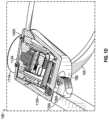
- FIG. 1 Ais a side view (right) of an example hardware configuration of an eyewear device suitable for use in a tracking and display system;
- FIG. 1 Bis a perspective, partly sectional view of a right corner of the eyewear device of FIG. 1 A depicting a right visible-light camera, and a circuit board;
- FIG. 1 Cis a side view (left) of an example hardware configuration of the eyewear device of FIG. 1 A , which shows a left visible-light camera;
- FIG. 1 Dis a perspective, partly sectional view of a left corner of the eyewear device of FIG. 1 C depicting the left visible-light camera, and a circuit board;
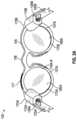
- FIGS. 2 A and 2 Bare rear views of example hardware configurations of an eyewear device of FIG. 1 A ;
- FIG. 3is a diagrammatic depiction of a three-dimensional scene, a left raw image captured by a left visible-light camera, and a right raw image captured by a right visible-light camera of the eyewear device of FIG. 1 A ;
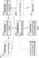
- FIG. 4is a functional block diagram of an example tracking and display system including pulse transmitters, receivers, a wearable device (e.g., an eyewear device) and a server system connected via various networks;
- a wearable devicee.g., an eyewear device
- server systemconnected via various networks;
- FIG. 5is a diagrammatic representation of an example hardware configuration for a mobile device of the tracking and display system of FIG. 4 ;
- FIG. 6is a functional block diagram of an example tracking and display system including ultra-wideband pulse transmitters coupled to movable objects, two ultra-wideband receivers, one or more eyewear devices, one or more mobile devices, and a collection of database elements;
- FIG. 7is a perspective illustration of an example physical environment showing ultra-wideband pulse transmitters coupled to movable objects, an example object mesh, and a portion of a static mesh;
- FIG. 8is a perspective illustration of an example virtual element presented near a movable object on an eyewear display.
- the system in this exampleincludes an ultra-wideband (UWB) pulse transmitter coupled to a movable object in a physical environment and configured to broadcast a pulse comprising a unique identifier, at least two synchronized receivers at fixed receiver locations relative to the physical environment.
- An object location applicationcalculates a current object location of the movable object based on the broadcast pulse.
- An eyewear device in paired communication with the receiversincludes a processor, a memory, a localization application, a rendering application, and a display.
- the localization applicationdetermines a current eyewear location of the eyewear device.
- the rendering applicationpresents a virtual element on a display as an overlay relative to the calculated current object location and in relative proximity to the determined current eyewear location.
- Coupledor “connected” as used herein refer to any logical, optical, physical, or electrical connection, including a link or the like by which the electrical or magnetic signals produced or supplied by one system element are imparted to another coupled or connected system element.
- coupled or connected elements or devicesare not necessarily directly connected to one another and may be separated by intermediate components, elements, or communication media, one or more of which may modify, manipulate, or carry the electrical signals.
- onmeans directly supported by an element or indirectly supported by the element through another element that is integrated into or supported by the element.
- proximalis used to describe an item or part of an item that is situated near, adjacent, or next to an object or person; or that is closer relative to other parts of the item, which may be described as “distal.”
- distalthe end of an item nearest an object
- the proximal endthe end of an item nearest an object
- distal endthe end of an item nearest an object
- the eyewear devicemay be oriented in any other direction suitable to the particular application of the eyewear device; for example, up, down, sideways, or any other orientation.
- any directional termsuch as front, rear, inward, outward, toward, left, right, lateral, longitudinal, up, down, upper, lower, top, bottom, side, horizontal, vertical, and diagonal are used by way of example only, and are not limiting as to the direction or orientation of any camera or inertial measurement unit as constructed or as otherwise described herein.
- Advanced AR technologiessuch as computer vision and object tracking, may be used to produce a perceptually enriched and immersive experience.
- Computer vision algorithmsextract three-dimensional data about the physical world from the data captured in digital images or video.
- Object recognition and tracking algorithmsare used to detect an object in a digital image or video, estimate its orientation or pose, and track its movement over time. Hand and finger recognition and tracking in real time is one of the most challenging and processing-intensive tasks in the field of computer vision.
- poserefers to the static position and orientation of an object at a particular instant in time.
- gesturerefers to the active movement of an object, such as a hand, through a series of poses, sometimes to convey a signal or idea.
- pose and gestureare sometimes used interchangeably in the field of computer vision and augmented reality.
- the terms “pose” or “gesture”are intended to be inclusive of both poses and gestures; in other words, the use of one term does not exclude the other.
- FIG. 1 Ais a side view (right) of an example hardware configuration of an eyewear device 100 which includes a touch-sensitive input device or touchpad 181 .
- the touchpad 181may have a boundary that is subtle and not easily seen; alternatively, the boundary may be plainly visible or include a raised or otherwise tactile edge that provides feedback to the user about the location and boundary of the touchpad 181 .
- the eyewear device 100may include a touchpad on the left side.
- the surface of the touchpad 181is configured to detect finger touches, taps, and gestures (e.g., moving touches) for use with a GUI displayed by the eyewear device, on an image display, to allow the user to navigate through and select menu options in an intuitive manner, which enhances and simplifies the user experience.
- finger touches, taps, and gesturese.g., moving touches
- Detection of finger inputs on the touchpad 181can enable several functions. For example, touching anywhere on the touchpad 181 may cause the GUI to display or highlight an item on the image display, which may be projected onto at least one of the optical assemblies 180 A, 180 B. Double tapping on the touchpad 181 may select an item or icon. Sliding or swiping a finger in a particular direction (e.g., from front to back, back to front, up to down, or down to) may cause the items or icons to slide or scroll in a particular direction; for example, to move to a next item, icon, video, image, page, or slide. Sliding the finger in another direction may slide or scroll in the opposite direction; for example, to move to a previous item, icon, video, image, page, or slide.
- the touchpad 181can be virtually anywhere on the eyewear device 100 .
- an identified finger gesture of a single tap on the touchpad 181initiates selection or pressing of a graphical user interface element in the image presented on the image display of the optical assembly 180 A, 180 B.
- An adjustment to the image presented on the image display of the optical assembly 180 A, 180 B based on the identified finger gesturecan be a primary action which selects or submits the graphical user interface element on the image display of the optical assembly 180 A, 180 B for further display or execution.
- the eyewear device 100includes a right visible-light camera 114 B.
- two cameras 114 A, 114 Bcapture image information for a scene from two separate viewpoints. The two captured images may be used to project a three-dimensional display onto an image display for viewing with 3D glasses.
- the eyewear device 100includes a right optical assembly 180 B with an image display to present images, such as depth images.
- the eyewear device 100includes the right visible-light camera 114 B.
- the eyewear device 100can include multiple visible-light cameras 114 A, 114 B that form a passive type of three-dimensional camera, such as stereo camera, of which the right visible-light camera 114 B is located on a right corner 110 B.
- the eyewear device 100also includes a left visible-light camera 114 A.
- Left and right visible-light cameras 114 A, 114 Bare sensitive to the visible-light range wavelength.
- Each of the visible-light cameras 114 A, 114 Bhave a different frontward facing field of view which are overlapping to enable generation of three-dimensional depth images, for example, right visible-light camera 114 B depicts a right field of view 111 B.
- a “field of view”is the part of the scene that is visible through the camera at a particular position and orientation in space.
- the fields of view 111 A and 111 Bhave an overlapping field of view 304 ( FIG. 3 ). Objects or object features outside the field of view 111 A, 111 B when the visible-light camera captures the image are not recorded in a raw image (e.g., photograph or picture).
- the field of viewdescribes an angle range or extent, which the image sensor of the visible-light camera 114 A, 114 B picks up electromagnetic radiation of a given scene in a captured image of the given scene.
- Field of viewcan be expressed as the angular size of the view cone; i.e., an angle of view.
- the angle of viewcan be measured horizontally, vertically, or diagonally.
- one or both visible-light cameras 114 A, 114 Bhas a field of view of 100° and a resolution of 480 ⁇ 480 pixels.
- the “angle of coverage”describes the angle range that a lens of visible-light cameras 114 A, 114 B or infrared camera 410 (see FIG. 2 A ) can effectively image.
- the camera lensproduces an image circle that is large enough to cover the film or sensor of the camera completely, possibly including some vignetting (e.g., a darkening of the image toward the edges when compared to the center). If the angle of coverage of the camera lens does not fill the sensor, the image circle will be visible, typically with strong vignetting toward the edge, and the effective angle of view will be limited to the angle of coverage.
- Examples of such visible-light cameras 114 A, 114 Binclude a high-resolution complementary metal-oxide-semiconductor (CMOS) image sensor and a digital VGA camera (video graphics array) capable of resolutions of 480p (e.g., 640 ⁇ 480 pixels), 720p, 1080p, or greater.
- CMOScomplementary metal-oxide-semiconductor
- VGA cameravideo graphics array
- Other examplesinclude visible-light cameras 114 A, 114 B that can capture high-definition (HD) video at a high frame rate (e.g., thirty to sixty frames per second, or more) and store the recording at a resolution of 1216 by 1216 pixels (or greater).
- HDhigh-definition
- the eyewear device 100may capture image sensor data from the visible-light cameras 114 A, 114 B along with geolocation data, digitized by an image processor, for storage in a memory.
- the visible-light cameras 114 A, 114 Bcapture respective left and right raw images in the two-dimensional space domain that comprise a matrix of pixels on a two-dimensional coordinate system that includes an X-axis for horizontal position and a Y-axis for vertical position.
- Each pixelincludes a color attribute value (e.g., a red pixel light value, a green pixel light value, or a blue pixel light value); and a position attribute (e.g., an X-axis coordinate and a Y-axis coordinate).
- the image processor 412may be coupled to the visible-light cameras 114 A, 114 B to receive and store the visual image information.
- the image processor 412controls operation of the visible-light cameras 114 A, 114 B to act as a stereo camera simulating human binocular vision and may add a timestamp to each image.
- the timestamp on each pair of imagesallows display of the images together as part of a three-dimensional projection.
- Three-dimensional projectionsproduce an immersive, life-like experience that is desirable in a variety of contexts, including virtual reality (VR) and video gaming.
- VRvirtual reality
- FIG. 1 Bis a perspective, cross-sectional view of a right corner 110 B of the eyewear device 100 of FIG. 1 A depicting the right visible-light camera 114 B of the camera system, and a circuit board.
- FIG. 1 Cis a side view (left) of an example hardware configuration of an eyewear device 100 of FIG. 1 A , which shows a left visible-light camera 114 A of the camera system.
- FIG. 1 Dis a perspective, cross-sectional view of a left corner 110 A of the eyewear device of FIG. 1 C depicting the left visible-light camera 114 A of the three-dimensional camera, and a circuit board.
- the eyewear device 100includes the right visible-light camera 114 B and a circuit board 140 B, which may be a flexible printed circuit board (PCB).
- a right hinge 126 Bconnects the right corner 110 B to a right temple 125 B of the eyewear device 100 .
- components of the right visible-light camera 114 B, the flexible PCB 140 B, or other electrical connectors or contactsmay be located on the right temple 125 B or the right hinge 126 B.
- a left hinge 126 Bconnects the left corner 110 A to a left temple 125 A of the eyewear device 100 .
- components of the left visible-light camera 114 A, the flexible PCB 140 A, or other electrical connectors or contactsmay be located on the left temple 125 A or the left hinge 126 A.
- the right corner 110 Bincludes corner body 190 and a corner cap, with the corner cap omitted in the cross-section of FIG. 1 B .
- various interconnected circuit boardssuch as PCBs or flexible PCBs, that include controller circuits for right visible-light camera 114 B, microphone(s), low-power wireless circuitry (e.g., for wireless short range network communication via BluetoothTM), high-speed wireless circuitry (e.g., for wireless local area network communication via Wi-Fi).
- the right visible-light camera 114 Bis coupled to or disposed on the flexible PCB 140 B and covered by a visible-light camera cover lens, which is aimed through opening(s) formed in the frame 105 .
- a visible-light camera cover lenswhich is aimed through opening(s) formed in the frame 105 .
- the right rim 107 B of the frame 105shown in FIG. 2 A , is connected to the right corner 110 B and includes the opening(s) for the visible-light camera cover lens.
- the frame 105includes a front side configured to face outward and away from the eye of the user.
- the opening for the visible-light camera cover lensis formed on and through the front or outward-facing side of the frame 105 .
- the right visible-light camera 114 Bhas an outward-facing field of view 111 B (shown in FIG.
- the visible-light camera cover lenscan also be adhered to a front side or outward-facing surface of the right corner 110 B in which an opening is formed with an outward-facing angle of coverage, but in a different outwardly direction.
- the couplingcan also be indirect via intervening components.
- flexible PCB 140 Bis disposed inside the right corner 110 B and is coupled to one or more other components housed in the right corner 110 B.
- the right visible-light camera 114 Bcan be formed on the circuit boards of the left corner 110 A, the temples 125 A, 125 B, or the frame 105 .
- FIGS. 2 A and 2 Bare perspective views, from the rear, of example hardware configurations of the eyewear device 100 , including two different types of image displays.
- the eyewear device 100is sized and shaped in a form configured for wearing by a user; the form of eyeglasses is shown in the example.
- the eyewear device 100can take other forms and may incorporate other types of frameworks; for example, a headgear, a headset, or a helmet.
- eyewear device 100includes a frame 105 including a left rim 107 A connected to a right rim 107 B via a bridge 106 adapted to be supported by a nose of the user.
- the left and right rims 107 A, 107 Binclude respective apertures 175 A, 175 B, which hold a respective optical element 180 A, 180 B, such as a lens and a display device.
- the term “lens”is meant to include transparent or translucent pieces of glass or plastic having curved or flat surfaces that cause light to converge or diverge or that cause little or no convergence or divergence.
- eyewear device 100can include other arrangements, such as a single optical element (or it may not include any optical element 180 A, 180 B), depending on the application or the intended user of the eyewear device 100 .
- eyewear device 100includes a left corner 110 A adjacent the left lateral side 170 A of the frame 105 and a right corner 110 B adjacent the right lateral side 170 B of the frame 105 .
- the corners 110 A, 110 Bmay be integrated into the frame 105 on the respective sides 170 A, 170 B (as illustrated) or implemented as separate components attached to the frame 105 on the respective sides 170 A, 170 B.
- the corners 110 A, 110 Bmay be integrated into temples (not shown) attached to the frame 105 .
- each optical assembly 180 A, 180 Bincludes an integrated image display. As shown in FIG. 2 A , each optical assembly 180 A, 180 B includes a suitable display matrix 177 , such as a liquid crystal display (LCD), an organic light-emitting diode (OLED) display, or any other such display. Each optical assembly 180 A, 180 B also includes an optical layer or layers 176 , which can include lenses, optical coatings, prisms, mirrors, waveguides, optical strips, and other optical components in any combination.
- the optical layers 176 A, 176 B, . . . 176 N(shown as 176 A-N in FIG.
- the prism of the optical layers 176 A-Nextends over all or at least a portion of the respective apertures 175 A, 175 B formed in the left and right rims 107 A, 107 B to permit the user to see the second surface of the prism when the eye of the user is viewing through the corresponding left and right rims 107 A, 107 B.
- the first surface of the prism of the optical layers 176 A-Nfaces upwardly from the frame 105 and the display matrix 177 overlies the prism so that photons and light emitted by the display matrix 177 impinge the first surface.
- the prismis sized and shaped so that the light is refracted within the prism and is directed toward the eye of the user by the second surface of the prism of the optical layers 176 A-N.
- the second surface of the prism of the optical layers 176 A-Ncan be convex to direct the light toward the center of the eye.
- the prismcan optionally be sized and shaped to magnify the image projected by the display matrix 177 , and the light travels through the prism so that the image viewed from the second surface is larger in one or more dimensions than the image emitted from the display matrix 177 .
- the optical layers 176 A-Nmay include an LCD layer that is transparent (keeping the lens open) unless and until a voltage is applied which makes the layer opaque (closing or blocking the lens).
- the image processor 412 on the eyewear device 100may execute programming to apply the voltage to the LCD layer in order to produce an active shutter system, making the eyewear device 100 suitable for viewing visual content when displayed as a three-dimensional projection. Technologies other than LCD may be used for the active shutter mode, including other types of reactive layers that are responsive to a voltage or another type of input.
- the image display device of optical assembly 180 A, 180 Bincludes a projection image display as shown in FIG. 2 B .
- Each optical assembly 180 A, 180 Bincludes a laser projector 150 , which is a three-color laser projector using a scanning mirror or galvanometer.
- an optical sourcesuch as a laser projector 150 is disposed in or on one of the temples 125 A, 125 B of the eyewear device 100 .
- Optical assembly 180 B in this exampleincludes one or more optical strips 155 A, 155 B, . . . 155 N (shown as 155 A-N in FIG. 2 B ) which are spaced apart and across the width of the lens of each optical assembly 180 A, 180 B or across a depth of the lens between the front surface and the rear surface of the lens.
- each optical assembly 180 A, 180 BAs the photons projected by the laser projector 150 travel across the lens of each optical assembly 180 A, 180 B, the photons encounter the optical strips 155 A-N. When a particular photon encounters a particular optical strip, the photon is either redirected toward the user's eye, or it passes to the next optical strip.
- a combination of modulation of laser projector 150 , and modulation of optical stripsmay control specific photons or beams of light.
- a processorcontrols optical strips 155 A-N by initiating mechanical, acoustic, or electromagnetic signals.
- the eyewear device 100can include other arrangements, such as a single or three optical assemblies, or each optical assembly 180 A, 180 B may have arranged different arrangement depending on the application or intended user of the eyewear device 100 .
- eyewear device 100includes a left corner 110 A adjacent the left lateral side 170 A of the frame 105 and a right corner 110 B adjacent the right lateral side 170 B of the frame 105 .
- the corners 110 A, 110 Bmay be integrated into the frame 105 on the respective lateral sides 170 A, 170 B (as illustrated) or implemented as separate components attached to the frame 105 on the respective sides 170 A, 170 B.
- the corners 110 A, 110 Bmay be integrated into temples 125 A, 125 B attached to the frame 105 .
- the eyewear device 100 shown in FIG. 2 Bmay include two projectors, a left projector 150 A (not shown) and a right projector 150 B (shown as projector 150 ).
- the left optical assembly 180 Amay include a left display matrix 177 A (not shown) or a left set of optical strips 155 ′A, 155 ′B, . . . 155 ′N ( 155 prime, A through N, not shown) which are configured to interact with light from the left projector 150 A.
- the right optical assembly 180 Bmay include a right display matrix 177 B (not shown) or a right set of optical strips 155 ′′A, 155 ′′B, . . . 155 ′′N ( 155 double prime, A through N, not shown) which are configured to interact with light from the right projector 150 B.
- the eyewear device 100includes a left display and a right display.
- FIG. 3is a diagrammatic depiction of a three-dimensional scene 306 , a left raw image 302 A captured by a left visible-light camera 114 A, and a right raw image 302 B captured by a right visible-light camera 114 B.
- the left field of view 111 Amay overlap, as shown, with the right field of view 111 B.
- the overlapping field of view 304represents that portion of the image captured by both cameras 114 A, 114 B.
- the term ‘overlapping’ when referring to field of viewmeans the matrix of pixels in the generated raw images overlap by thirty percent (30%) or more.
- ‘Substantially overlapping’means the matrix of pixels in the generated raw images—or in the infrared image of scene—overlap by fifty percent (50%) or more.
- the two raw images 302 A, 302 Bmay be processed to include a timestamp, which allows the images to be displayed together as part of a three-dimensional projection.
- a pair of raw red, green, and blue (RGB) imagesare captured of a real scene 306 at a given moment in time—a left raw image 302 A captured by the left camera 114 A and right raw image 302 B captured by the right camera 114 B.
- RGBred, green, and blue
- the pair of raw images 302 A, 302 Bare processed (e.g., by the image processor 412 )
- depth imagesare generated.
- the generated depth imagesmay be viewed on an optical assembly 180 A, 180 B of an eyewear device, on another display (e.g., the image display 580 on a mobile device 401 ), or on a screen.
- the generated depth imagesare in the three-dimensional space domain and can comprise a matrix of vertices on a three-dimensional location coordinate system that includes an X axis for horizontal position (e.g., length), a Y axis for vertical position (e.g., height), and a Z axis for depth (e.g., distance).
- Each vertexmay include a color attribute (e.g., a red pixel light value, a green pixel light value, or a blue pixel light value); a position attribute (e.g., an X location coordinate, a Y location coordinate, and a Z location coordinate); a texture attribute; a reflectance attribute; or a combination thereof.
- the texture attributequantifies the perceived texture of the depth image, such as the spatial arrangement of color or intensities in a region of vertices of the depth image.
- the tracking and display system 400( FIG. 4 ) includes the eyewear device 100 , which includes a frame 105 and a left temple 125 A extending from a left lateral side 170 A of the frame 105 and a right temple 125 B extending from a right lateral side 170 B of the frame 105 .
- the eyewear device 100may further include at least two visible-light cameras 114 A, 114 B having overlapping fields of view.
- the eyewear device 100includes a left visible-light camera 114 A with a left field of view 111 A, as illustrated in FIG. 3 .
- the left camera 114 Ais connected to the frame 105 or the left temple 125 A to capture a left raw image 302 A from the left side of scene 306 .
- the eyewear device 100further includes a right visible-light camera 114 B with a right field of view 111 B.
- the right camera 114 Bis connected to the frame 105 or the right temple 125 B to capture a right raw image 302 B from the right side of scene 306 .
- FIG. 4is a functional block diagram of an example tracking and display system 400 that includes a wearable device (e.g., an eyewear device 100 ), a mobile device 401 , and a server system 498 connected via various networks 495 such as the Internet.
- the tracking and display system 400includes a low-power wireless connection 425 and a high-speed wireless connection 437 between the eyewear device 100 and the mobile device 401 , as well as a wireless connection between the eyewear device 10 and one or more ultra-wideband (UWB) receivers 680 .
- UWBultra-wideband
- the eyewear device 100includes one or more visible-light cameras 114 A, 114 B that capture still images, video images, or both still and video images, as described herein.
- the cameras 114 A, 114 Bmay have a direct memory access (DMA) to high-speed circuitry 430 and function as a stereo camera.
- the cameras 114 A, 114 Bmay be used to capture initial-depth images that may be rendered into three-dimensional (3D) models that are texture-mapped images of a red, green, and blue (RGB) imaged scene.
- the device 100may also include a depth sensor 213 , which uses infrared signals to estimate the position of objects relative to the device 100 .
- the depth sensor 213in some examples includes one or more infrared emitter(s) 215 and infrared camera(s) 410 .
- the eyewear device 100further includes two image displays of each optical assembly 180 A, 180 B (one associated with the left side 170 A and one associated with the right side 170 B).
- the eyewear device 100also includes an image display driver 442 , an image processor 412 , low-power circuitry 420 , and high-speed circuitry 430 .
- the image displays of each optical assembly 180 A, 180 Bare for presenting images, including still images, video images, or still and video images.
- the image display driver 442is coupled to the image displays of each optical assembly 180 A, 180 B in order to control the display of images.
- the eyewear device 100additionally includes one or more speakers 440 (e.g., one associated with the left side of the eyewear device and another associated with the right side of the eyewear device).
- the speakers 440may be incorporated into the frame 105 , temples 125 , or corners 110 of the eyewear device 100 .
- the one or more speakers 440are driven by audio processor 443 under control of low-power circuitry 420 , high-speed circuitry 430 , or both.
- the speakers 440are for presenting audio signals including, for example, a beat track.
- the audio processor 443is coupled to the speakers 440 in order to control the presentation of sound.
- the components shown in FIG. 4 for the eyewear device 100are located on one or more circuit boards, for example a printed circuit board (PCB) or flexible printed circuit (FPC), located in the rims or temples. Alternatively, or additionally, the depicted components can be located in the corners, frames, hinges, or bridge of the eyewear device 100 .
- Left and right visible-light cameras 114 A, 114 Bcan include digital camera elements such as a complementary metal-oxide-semiconductor (CMOS) image sensor, a charge-coupled device, a lens, or any other respective visible or light capturing elements that may be used to capture data, including still images or video of scenes with unknown objects.
- CMOScomplementary metal-oxide-semiconductor
- high-speed circuitry 430includes a high-speed processor 432 , a memory 434 , and high-speed wireless circuitry 436 .
- the image display driver 442is coupled to the high-speed circuitry 430 and operated by the high-speed processor 432 in order to drive the left and right image displays of each optical assembly 180 A, 180 B.
- High-speed processor 432may be any processor capable of managing high-speed communications and operation of any general computing system needed for eyewear device 100 .
- High-speed processor 432includes processing resources needed for managing high-speed data transfers on high-speed wireless connection 437 to a wireless local area network (WLAN) using high-speed wireless circuitry 436 .
- WLANwireless local area network
- the high-speed processor 432executes an operating system such as a LINUX operating system or other such operating system of the eyewear device 100 and the operating system is stored in memory 434 for execution. In addition to any other responsibilities, the high-speed processor 432 executes a software architecture for the eyewear device 100 that is used to manage data transfers with high-speed wireless circuitry 436 .
- high-speed wireless circuitry 436is configured to implement Institute of Electrical and Electronic Engineers (IEEE) 802.11 communication standards, also referred to herein as Wi-Fi. In other examples, other high-speed communications standards may be implemented by high-speed wireless circuitry 436 .
- IEEEInstitute of Electrical and Electronic Engineers
- the low-power circuitry 420includes a low-power processor 422 and low-power wireless circuitry 424 .
- the low-power wireless circuitry 424 and the high-speed wireless circuitry 436 of the eyewear device 100can include short-range transceivers (BluetoothTM or Bluetooth Low-Energy (BLE)) and wireless wide, local, or wide-area network transceivers (e.g., cellular or Wi-Fi).
- Mobile device 401including the transceivers communicating via the low-power wireless connection 425 and the high-speed wireless connection 437 , may be implemented using details of the architecture of the eyewear device 100 , as can other elements of the network 495 .
- Memory 434includes any storage device capable of storing various data and applications, including, among other things, camera data generated by the left and right visible-light cameras 114 A, 114 B, the infrared camera(s) 410 , the image processor 412 , and images generated for display by the image display driver 442 on the image display of each optical assembly 180 A, 180 B.
- the memory 434is shown as integrated with high-speed circuitry 430 , the memory 434 in other examples may be an independent, standalone element of the eyewear device 100 .
- electrical routing linesmay provide a connection through a chip that includes the high-speed processor 432 from the image processor 412 or low-power processor 422 to the memory 434 .
- the high-speed processor 432may manage addressing of memory 434 such that the low-power processor 422 will boot the high-speed processor 432 any time that a read or write operation involving memory 434 is needed.
- the high-speed processor 432 of the eyewear device 100can be coupled to the camera system (visible-light cameras 114 A, 114 B), the image display driver 442 , the user input device 491 , and the memory 434 .
- the CPU 530 of the mobile device 401may be coupled to a camera system 570 , a mobile display driver 582 , a user input layer 591 , and a memory 540 A.
- the server system 498may be one or more computing devices as part of a service or network computing system, for example, that include a processor, a memory, and network communication interface to communicate over the network 495 with an eyewear device 100 and a mobile device 401 .
- the output components of the eyewear device 100include visual elements, such as the left and right image displays associated with each lens or optical assembly 180 A, 180 B as described in FIGS. 2 A and 2 B (e.g., a display such as a liquid crystal display (LCD), a plasma display panel (PDP), a light emitting diode (LED) display, a projector, or a waveguide).
- the eyewear device 100may include a user-facing indicator (e.g., an LED, a loudspeaker, or a vibrating actuator), or an outward-facing signal (e.g., an LED, a loudspeaker).
- the image displays of each optical assembly 180 A, 180 Bare driven by the image display driver 442 .
- the output components of the eyewear device 100further include additional indicators such as audible elements (e.g., loudspeakers), tactile components (e.g., an actuator such as a vibratory motor to generate haptic feedback), and other signal generators.
- the device 100may include a user-facing set of indicators, and an outward-facing set of signals.
- the user-facing set of indicatorsare configured to be seen or otherwise sensed by the user of the device 100 .
- the device 100may include an LED display positioned so the user can see it, a one or more speakers positioned to generate a sound the user can hear, or an actuator to provide haptic feedback the user can feel.
- the outward-facing set of signalsare configured to be seen or otherwise sensed by an observer near the device 100 .
- the device 100may include an LED, a loudspeaker, or an actuator that is configured and positioned to be sensed by an observer.
- the input components of the eyewear device 100may include alphanumeric input components (e.g., a touch screen or touchpad configured to receive alphanumeric input, a photo-optical keyboard, or other alphanumeric-configured elements), pointer-based input components (e.g., a mouse, a touchpad, a trackball, a joystick, a motion sensor, or other pointing instruments), tactile input components (e.g., a button switch, a touch screen or touchpad that senses the location, force or location and force of touches or touch gestures, or other tactile-configured elements), and audio input components (e.g., a microphone), and the like.
- the mobile device 401 and the server system 498may include alphanumeric, pointer-based, tactile, audio, and other input components.
- the eyewear device 100includes a collection of motion-sensing components referred to as an inertial measurement unit 472 .
- the motion-sensing componentsmay be micro-electro-mechanical systems (MEMS) with microscopic moving parts, often small enough to be part of a microchip.
- the inertial measurement unit (IMU) 472in some example configurations includes an accelerometer, a gyroscope, and a magnetometer.
- the accelerometersenses the linear acceleration of the device 100 (including the acceleration due to gravity) relative to three orthogonal axes (x, y, z).
- the gyroscopesenses the angular velocity of the device 100 about three axes of rotation (pitch, roll, yaw).
- the accelerometer and gyroscopecan provide position, orientation, and motion data about the device relative to six axes (x, y, z, pitch, roll, yaw).
- the magnetometerif present, senses the heading of the device 100 relative to magnetic north.
- the position of the device 100may be determined by location sensors, such as a GPS unit 473 , one or more transceivers to generate relative position coordinates, altitude sensors or barometers, and other orientation sensors.
- location sensorssuch as a GPS unit 473 , one or more transceivers to generate relative position coordinates, altitude sensors or barometers, and other orientation sensors.
- Such positioning system coordinatescan also be received over the wireless connections 425 , 437 from the mobile device 401 via the low-power wireless circuitry 424 or the high-speed wireless circuitry 436 .
- the IMU 472may include or cooperate with a digital motion processor or programming that gathers the raw data from the components and compute a number of useful values about the position, orientation, and motion of the device 100 .
- the acceleration data gathered from the accelerometercan be integrated to obtain the velocity relative to each axis (x, y, z); and integrated again to obtain the position of the device 100 (in linear coordinates, x, y, and z).
- the angular velocity data from the gyroscopecan be integrated to obtain the position of the device 100 (in spherical coordinates).
- the programming for computing these useful valuesmay be stored in memory 434 and executed by the high-speed processor 432 of the eyewear device 100 .
- the eyewear device 100may optionally include additional peripheral sensors, such as biometric sensors, specialty sensors, or display elements integrated with eyewear device 100 .
- peripheral device elementsmay include any I/O components including output components, motion components, position components, or any other such elements described herein.
- the biometric sensorsmay include components to detect expressions (e.g., hand expressions, facial expressions, vocal expressions, body gestures, or eye tracking), to measure bio signals (e.g., blood pressure, heart rate, body temperature, perspiration, or brain waves), or to identify a person (e.g., identification based on voice, retina, facial characteristics, fingerprints, or electrical bio signals such as electroencephalogram data), and the like.
- the mobile device 401may be a smartphone, tablet, laptop computer, access point, or any other such device capable of connecting with eyewear device 100 using a low-power wireless connection 425 or a high-speed wireless connection 437 .
- the mobile device 401is connected to the server system 498 and the network 495 .
- the network 495may include any combination of wired and wireless connections.
- the example tracking and display system 400includes a plurality of ultra-wideband (UWB) pulse transmitters 620 in wireless communication with one or more UWB receivers 680 .
- the UWB receivers 680are in wireless communication with one or more eyewear devices 100 which, in turn, are in wireless communication with one or more mobile devices 401 .
- these devices 620 , 680 , 100 , 401operate as nodes in a network.
- Network datamay be stored locally or remotely, on the servers or securely in the cloud.
- UWB transmitters 620are paired with the UWB receivers 680 .
- the eyewear devices 100 and mobile devices 410operate as subscribers to the UWB system 620 , 680 .
- One or more of the UWB receivers 680 in some example implementationsare coupled to a virtual element library 480 , a transmitter database 485 , and a movable object database 490 .
- the eyewear devices 100may also be coupled to one or more of the database elements 480 , 485 , 490 .
- the virtual element library 480stores data about each of a plurality of virtual elements 700 , including a name, a serial number or other identifier, and a set of image assets for use in rendering the virtual element 700 for display in a variety of contexts.
- the virtual element library 480may also include, for each virtual element 700 , a desired size (e.g., six inches tall) relative to the physical environment, and data about the one or more movable objects 610 where the virtual element 700 will be displayed.
- the transmitter database 485stores data about each of the UWB pulse transmitters 620 , including a unique transmitter identifier, a status, and a network number or other pairing information about the UWB receivers 680 to which each transmitter 620 is paired.
- the movable object database 490stores data about each of a plurality of movable objects 610 , including an object name, an object identifier or stock keeping unit (SKU), and a copy of (or a relational link to) the unique transmitter identifier for each of the one or more UWB pulse transmitters 620 that are coupled to each movable object 610 .
- a movable object 610such as a round tabletop may be associated with an object name (e.g., round tabletop), an object identifier or SKU (e.g., Tab-Round-4-09), and a copy of the unique transmitter identifier attached to the table (e.g., Tx-CTR-09).
- the movable object database 490in some implementations also stores a predefined object mesh 611 which includes one or more known dimensions associated with each movable object 610 .
- the predefined object mesh 611 for a movable object 610such as the round tabletop 610 - 1 shown in FIG. 7 , may include a diameter and a thickness. If the movable object 610 includes the entire table, the object mesh 611 includes geometric data and dimensions associated with all parts of the table, including the top, pedestal, and legs.
- the object mesh 611 for other objectsmay be geometrically complex.
- the predefined object mesh 611 for a door 610 - 2shown in FIG. 7 , may include a width, height, and thickness, as well as geometric data about the doorknob, hinges, panels, molding, rails, mullions, and other features of the door.
- the predefined object mesh 611 for a serving tray 610 - 3shown in FIG. 7 , may include a diameter and a thickness, as well as geometric data about the perimeter edge and other surface features.
- the libraries and databasesoperate as a set of relational databases with one or more shared keys linking the data to other database entries, and a database management system for maintaining and querying each database.
- the example tracking and display system 400includes an object location application 910 , a localization application 915 , and a rendering application 920 .
- the eyewear devices 100may be coupled to one or more of the applications 910 , 915 , 920 .
- the object location application 910includes the multilateration algorithms that compute the precise location of each pulse transmitter 620 in the network. Based on the location of each transmitter 620 , the object location application 910 calculates a current location 615 for the movable object 610 associated with that particular transmitter 620 (e.g., by retrieving data stored in the databases 480 , 485 , 490 ). In some example implementations, object location application 910 is executed by or on one or more of the UWB receivers 680 , as shown in FIG. 5
- the localization application 915determines a current location 902 of the eyewear device 100 relative to the physical environment.
- the localization datamay be derived from the data in one or more images captured by a camera, an IMU unit 472 , a GPS unit 473 , or a combination thereof.
- the localization application 915utilizes the fixed locations 685 of the one or more UWB receivers 680 to update the current eyewear position 902 relative to the physical environment 600 .
- the processor 432 of the eyewear device 100determines its position with respect to one or more receiver locations 685 relative to the coordinate system (x, y, z) for the physical environment 600 , thereby determining the current eyewear position 902 within the coordinate system. Additionally, the processor 432 may determine a head pose (roll, pitch, and yaw) of the eyewear device 100 within the environment by using two or more receiver locations 685 or by using one or more other known location. In this example, the known receiver locations 685 operate similar to the registered locations of virtual markers in augmented reality.
- the processor 432 within the eyewear device 100may construct a map of the physical environment 600 surrounding the eyewear device 100 , determine a current location 902 of the eyewear device within the mapped environment, and determine a relative position of the eyewear device to one or more objects in the mapped environment.
- the processor 432may construct the map and execute the localization application 915 to determine the current eyewear location 902 relative to the physical environment 600 .
- the localization application 915may utilize a simultaneous localization and mapping (SLAM) algorithm using data received from one or more sensors.
- SLAMsimultaneous localization and mapping
- Sensor dataincludes images received from one or both of the cameras 114 A, 114 B, distance(s) received from a laser range finder, position information received from a GPS unit 473 , motion and acceleration data received from an IMU 572 , or a combination of data from such sensors, or from other sensors that provide data useful in determining positional information.
- a SLAM algorithmis used to construct and update a map of an environment, while simultaneously tracking and updating the location of a device (or a user) within the mapped environment.
- the mathematical solutioncan be approximated using various statistical methods, such as particle filters, Kalman filters, extended Kalman filters, and covariance intersection.
- the SLAM algorithmupdates the map and the location of objects at least as frequently as the frame rate; in other words, calculating and updating the mapping and localization thirty times per second.
- a high-definition (HD) video camerathat captures video at a high frame rate (e.g., thirty frames per second)
- the SLAM algorithmupdates the map and the location of objects at least as frequently as the frame rate; in other words, calculating and updating the mapping and localization thirty times per second.
- the rendering application 920prepares a virtual element 700 for presentation on a display as an overlay relative to a movable object 610 .
- overlaymeans and includes presenting a virtual element 700 on a display in the foreground, relative to a physical, movable object 610 which appears in the background, except in situations where part of the virtual element 700 is obscured by a portion of the movable object 610 (e.g., when a movable door partially obscures part of a virtual element 700 presented nearby).
- the rendering application 920may utilize data from the object location application 910 , including the current movable object location 615 , and from the localization application 915 , including the current eyewear location 902 .
- the rendering application 920presents the virtual element 700 for display near the current movable object location 615 and in relative proximity to the current eyewear location 902 .
- the term “relative proximity”means and includes the coordination in a physical space between and among the current eyewear location 902 , the current movable object location 615 (in conjunction with the location of each attached pulse transmitter 620 ), the virtual element location 715 , and the UWB receiver locations 685 , all of which are expressed in coordinates (x, y, z) relative to the physical environment 600 (and relative to the eyewear location 902 , in some implementations) as illustrated in FIG. 8 .
- presenting a virtual element 700 on the display 180 B of an eyewear device 100requires localizing the eyewear device 100 in the physical environment and calculating the movable object location 615 , so the rendering application 920 can then present the virtual element 700 on the display so that it appears to be near the movable object 610 .
- the rendering application 920continually updates the display so that the virtual element 700 persistently appears near the movable object 610 . For example, as shown in FIG.
- the rendering application 920continually updates the display so the seated figure appears to remain on the serving tray as the serving tray moves, and with regard to any movement of the eyewear device 100 which supports the display 180 B.
- the tracking and display system 400accomplishes the real-time tracking of movable objects, and the display of virtual elements, without using computer vision and a tracking application (e.g., simultaneous localization and mapping (SLAM)).
- a tracking applicatione.g., simultaneous localization and mapping (SLAM)
- the physical environment 600including the fixed features and stationary objects, is stored as a predefined static mesh 605 , as described herein, instead of using a tracking application to map the fixed environment repeatedly. Nonetheless, in some implementations, the tracking and display system 400 cooperates with a tracking application that is configured to track moving items, such as people and objects which are not attached to a pulse transmitter.
- the tracking and display system 400includes computing devices, including the eyewear device 100 , mobile device, and receivers 680 , in a network.
- the applications 910 , 915 , 920utilize a memory for storing instructions and a processor for executing the instructions. Execution of the instructions configure the devices to communicate, exchange data, and otherwise cooperate in the network.
- the applicationsmay utilize the memory 434 of the eyewear device 100 , the memory elements 540 A, 540 B, 540 C of the mobile device 401 , and any memory elements associated with the server 490 and the UWB receivers 680 or transmitters 620 .
- the applicationsmay utilize the processor elements 432 , 422 of the eyewear device 100 , the central processing unit (CPU) 530 of the mobile device 401 , and any processing elements associated with the server 490 and the UWB receivers 680 or transmitters 620 .
- the memory and processing functions of the tracking and display system 400can be shared or distributed across the processors and memories of the eyewear device 100 , the mobile device 401 , the server system 498 , and the UWB receivers 680 and transmitters 620 .
- FIG. 5is a high-level functional block diagram of an example mobile device 401 .
- Mobile device 401includes a flash memory 540 A which stores programming to be executed by the CPU 530 to perform all or a subset of the functions described herein.
- the mobile device 401may include a camera 570 that comprises at least two visible-light cameras (first and second visible-light cameras with overlapping fields of view) or at least one visible-light camera and a depth sensor with substantially overlapping fields of view. Flash memory 540 A may further include multiple images or video, which are generated via the camera 570 .
- the mobile device 401includes an image display 580 , a mobile display driver 582 to control the image display 580 , and a display controller 584 .
- the image display 580includes a user input layer 591 (e.g., a touchscreen) that is layered on top of or otherwise integrated into the screen used by the image display 580 .
- FIG. 5therefore provides a block diagram illustration of the example mobile device 401 with a user interface that includes a touchscreen input layer 891 for receiving input (by touch, multi-touch, or gesture, and the like, by hand, stylus, or other tool) and an image display 580 for displaying content.
- a touchscreen input layer 891for receiving input (by touch, multi-touch, or gesture, and the like, by hand, stylus, or other tool)
- an image display 580for displaying content.
- the mobile device 401includes at least one digital transceiver (XCVR) 510 , shown as WWAN XCVRs, for digital wireless communications via a wide-area wireless mobile communication network.
- the mobile device 401also includes additional digital or analog transceivers, such as short-range transceivers (XCVRs) 520 for short-range network communication, such as via NFC, VLC, DECT, ZigBee, BluetoothTM, or Wi-Fi.
- short range XCVRs 520may take the form of any available two-way wireless local area network (WLAN) transceiver of a type that is compatible with one or more standard protocols of communication implemented in wireless local area networks, such as one of the Wi-Fi standards under IEEE 802.11.
- WLANwireless local area network
- the mobile device 401can include a global positioning system (GPS) receiver.
- GPSglobal positioning system
- the mobile device 401can utilize either or both the short range XCVRs 520 and WWAN XCVRs 510 for generating location coordinates for positioning.
- cellular network, Wi-Fi, or BluetoothTM based positioning systemscan generate very accurate location coordinates, particularly when used in combination.
- Such location coordinatescan be transmitted to the eyewear device over one or more network connections via XCVRs 510 , 520 .
- the client device 401in some examples includes a collection of motion-sensing components referred to as an inertial measurement unit (IMU) 572 for sensing the position, orientation, and motion of the client device 401 .
- the motion-sensing componentsmay be micro-electro-mechanical systems (MEMS) with microscopic moving parts, often small enough to be part of a microchip.
- the inertial measurement unit (IMU) 572in some example configurations includes an accelerometer, a gyroscope, and a magnetometer.
- the accelerometersenses the linear acceleration of the client device 401 (including the acceleration due to gravity) relative to three orthogonal axes (x, y, z).
- the gyroscopesenses the angular velocity of the client device 401 about three axes of rotation (pitch, roll, yaw). Together, the accelerometer and gyroscope can provide position, orientation, and motion data about the device relative to six axes (x, y, z, pitch, roll, yaw).
- the magnetometerif present, senses the heading of the client device 401 relative to magnetic north.
- the IMU 572may include or cooperate with a digital motion processor or programming that gathers the raw data from the components and compute a number of useful values about the position, orientation, and motion of the client device 401 .
- the acceleration data gathered from the accelerometercan be integrated to obtain the velocity relative to each axis (x, y, z); and integrated again to obtain the position of the client device 401 (in linear coordinates, x, y, and z).
- the angular velocity data from the gyroscopecan be integrated to obtain the position of the client device 401 (in spherical coordinates).
- the programming for computing these useful valuesmay be stored in on or more memory elements 540 A, 540 B, 540 C and executed by the CPU 530 of the client device 401 .
- the transceivers 510 , 520conforms to one or more of the various digital wireless communication standards utilized by modern mobile networks.
- WWAN transceivers 510include (but are not limited to) transceivers configured to operate in accordance with Code Division Multiple Access (CDMA) and 3rd Generation Partnership Project (3GPP) network technologies including, for example and without limitation, 3GPP type 2 (or 3GPP2) and LTE, at times referred to as “4G.”
- CDMACode Division Multiple Access
- 3GPP3rd Generation Partnership Project
- 3GPP type 2or 3GPP2
- LTELong Term Evolution
- the transceivers 510 , 520provide two-way wireless communication of information including digitized audio signals, still image and video signals, web page information for display as well as web-related inputs, and various types of mobile message communications to/from the mobile device 401 .
- the mobile device 401further includes a microprocessor that functions as a central processing unit (CPU); shown as CPU 530 in FIG. 4 .
- a processoris a circuit having elements structured and arranged to perform one or more processing functions, typically various data processing functions. Although discrete logic components could be used, the examples utilize components forming a programmable CPU.
- a microprocessorfor example includes one or more integrated circuit (IC) chips incorporating the electronic elements to perform the functions of the CPU.
- the CPU 530may be based on any known or available microprocessor architecture, such as a Reduced Instruction Set Computing (RISC) using an ARM architecture, as commonly used today in mobile devices and other portable electronic devices. Of course, other arrangements of processor circuitry may be used to form the CPU 530 or processor hardware in smartphone, laptop computer, and tablet.
- RISCReduced Instruction Set Computing
- the CPU 530serves as a programmable host controller for the mobile device 401 by configuring the mobile device 401 to perform various operations, for example, in accordance with instructions or programming executable by CPU 530 .
- operationsmay include various general operations of the mobile device, as well as operations related to the programming for applications on the mobile device.
- a processormay be configured by use of hardwired logic, typical processors in mobile devices are general processing circuits configured by execution of programming.
- the mobile device 401includes a memory or storage system, for storing programming and data.
- the memory systemmay include a flash memory 540 A, a random-access memory (RAM) 540 B, and other memory components 540 C, as needed.
- the RAM 540 Bserves as short-term storage for instructions and data being handled by the CPU 530 , e.g., as a working data processing memory.
- the flash memory 540 Atypically provides longer-term storage.
- the flash memory 540 Ais used to store programming or instructions for execution by the CPU 530 .
- the mobile device 401stores and runs a mobile operating system through which specific applications are executed. Examples of mobile operating systems include Google Android, Apple iOS (for iPhone or iPad devices), Windows Mobile, Amazon Fire OS, RIM BlackBerry OS, or the like.
- FIG. 6is a functional block diagram of an example tracking and display system 400 including ultra-wideband (UWB) pulse transmitters 620 coupled to movable objects 610 , two UWB receivers 680 , one or more eyewear devices 100 , one or more mobile devices 410 , and a collection of database elements 480 , 485 , 490 as described herein.
- Each UWB pulse transmitter 620includes an antenna, as shown, for wireless communication with the UWB receivers 680 .
- Each broadcast pulseincludes a unique transmitter identifier which is used by the UWB receivers 680 to identify the transmitter that broadcast each pulse.
- the pulseincludes a data packet comprising a preamble and a payload, which contains bits of data.
- the physical layer of each pulseis assembled according to the standards set forth in IEEE 802.15.4a and 4z.
- the pulsea short burst of electromagnetic energy having a duration sufficient to extract the bits of data, including data for measuring or determining the position of the transmitter.
- a first pulse transmitter 620 - 1is attached or coupled to a first movable object 610 - 1 .
- Attached to the second movable object 610 - 2is a pair of second pulse transmitters 620 - 2 a , 620 - 2 b , and a compass 640 .
- Attached to the third movable object 610 - 3is a pair of third pulse transmitters 620 - 3 a , 620 - 3 b , and an accelerometer 650 .
- the UWB receivers 680are placed in a physical environment 600 at fixed receiver locations 685 , as shown in FIG. 8 .
- the UWB receivers 680are time synchronized because the multilateration algorithms use the difference between the times of arrival for each pulse at each receiver 680 to calculate the precise location of each transmitter 620 .
- the precise location of each transmitter 620is then used to calculate a current object location 615 associated with each movable object 610 .
- the first UWB receiver 680 - 1includes an object location application 910 for calculating the current object location 615 .
- the UWB receivers 680are in paired wireless communication with one or more eyewear devices 100 and with one or more mobile devices 401 , as shown.
- the transmitters 620 , receivers 680 , eyewear devices 100 , and mobile devices 401operate as nodes in a network.
- the transmitters 620are paired with the receivers 680 .
- the eyewear devices 100 and mobile devices 410operate as subscribers to the UWB system 620 , 680 .
- the eyewear device 100 as described hereinincludes a processor, a memory, a localization application 915 , a rendering application 920 , and a display 180 B (as shown in FIG. 8 ).
- the localization application 915determines a current eyewear location 902 for each eyewear device 100 .
- the rendering application 920presents a virtual element 700 on the display 180 B at a virtual element location 715 as an overlay relative to the calculated current object location 615 and in relative proximity to the determined current eyewear location. For example, as illustrated in FIG.
- the process of rendering and presenting a virtual element 700 on the display 180 B of an eyewear device 100requires localizing the eyewear device 100 with the physical environment 600 and calculating the movable object location 615 , so the rendering application 920 can then present the virtual element 700 on the display so that it appears to be near the movable object 610 .
- the virtual element 700may be presented near the center of the movable object 610 or at some other specified location or defined anchor point on the movable object 610 .
- the virtual element 700may include any of a variety of elements suitable for rendering on a display, including figurative or realistic items, static or moving, alone or in combination with other items.
- the virtual element 700may include any graphical element suitable for rendering or presentation on a display, including but not limited to virtual objects associated with VR or AR experiences, game pieces related to a gaming experience, graphical elements such as icons, thumbnails, taskbars, and menu items, and selection control elements such as cursors, pointers, buttons, handles, and sliders; any of which may or may not be associated with a graphical user interface (GUI).
- GUIgraphical user interface
- FIG. 7is a perspective illustration of an example physical environment, as seen through a display (not shown), depicting virtual elements 700 presented near movable objects 610 .
- a first virtual element 700 - 1e.g., a standing figure
- a first movable object 610 - 1e.g., a round tabletop
- Attached to the tabletopis a first pulse transmitter 620 - 1 .
- a single pulse transmitter 620 - 1 attached to a known point, such as the center, along with the object mesh 611 as described herein,is sufficient to calculate the current object location 615 because a tabletop typically moves in a single plane.
- a second virtual element 700 - 2(e.g., a hanging figure) is presented near a second movable object 610 - 2 (e.g., a door).
- Attached to the dooris a pair of second pulse transmitters 620 - 2 a , 620 - 2 b and a compass 640 , either or both of which may be used to calculate the current object location 615 of the door.
- the compass 640may broadcast its own compass signal or, in some implementations, the broadcast pulse is composed so the data packet includes the compass data.
- the pair of transmitters 620 - 2 a , 620 - 2 b and the compass 640are sufficient to calculate the current object location 615 (which includes both position and orientation) because the door is movable in two dimensions, relative to its hinges.
- a third virtual element 700 - 3(e.g., a seated figure) is presented near a third movable object 610 - 3 (e.g., a serving tray).
- Attached to the trayis a pair of third pulse transmitters 620 - 3 a , 620 - 3 b and an accelerometer 650 , both of which may be used to calculate the current object location 615 (position, orientation, and heading) of the tray.
- the accelerometer 650may broadcast its own accelerometer signal or, in some implementations, the broadcast pulse is composed so the data packet includes the accelerometer data. Data from the accelerometer 650 provides information about the motion of the serving tray, which is movable in three dimensions, through the environment, over time.
- Both the eyewear device 100 and the movable objects 610are free to move through the environment.
- the rendering application 920continually updates the display so that the virtual element 700 persistently appears near the movable object 610 .
- the rendering application 920continually updates the display so the seated figure appears to remain on the serving tray as the serving tray moves, and with regard to any movement of the eyewear device 100 which supports the display 180 B.
- the virtual element library 480includes, for each virtual element 700 , a desired size relative to the physical environment 600 (along with a plurality of image assets used during by the rendering application 920 ).
- the rendering applicationpresents the virtual element 700 at a current size based on the image assets, the desired size, and the calculated current object location 615 , such that the virtual element 700 appears persistently at the desired size relative to the movable object 610 as it moves through the physical environment.
- the pulse transmitter 620includes a power supply (e.g., a battery), a pulse generator, a transmitter, an antenna, and a read-only memory (ROM) or a chip with read-write capability.
- the ROMincludes an object identifier or stock keeping unit (SKU) associated with the movable object, and a predefined object mesh 611 (as shown near the round tabletop 610 - 1 in FIG. 7 ).
- SKUstock keeping unit
- the predefined object mesh 611which includes one or more known dimensions associated with each movable object 610 .
- the object mesh 611may be generated and stored in one or more formats, to enable spatial reconstruction using various computer vision and AR applications.
- the object mesh 611may include a point cloud, a solid model (e.g., useful with computer-aided drawing or drafting (CAD) applications), a surface model, or a set of planar surfaces.
- the predefined object mesh 611 for the round tabletop 610 - 1includes a diameter and a thickness.
- data about the object mesh 611(stored in the ROM) is included in the broadcast pulse, so that the object location application 910 utilizes the object mesh 611 in calculating the current objection location 615 . Points along the object mesh 611 may be used by the rendering application 920 to place the virtual element 700 at a particular location on the movable object 610 .
- the predefined object mesh 611is stored in the movable object database 490 , along with the object identifier or stock keeping unit (SKU) associated with the movable object.
- SKUstock keeping unit
- the example tracking and display system 400may include a static mesh 605 associated with the physical environment 600 .
- a portion of the static mesh 605is shown near the door in FIG. 7 .
- the static mesh 605includes dimensions associated with a plurality of stationary objects located in the physical environment, including the walls, floors, ceiling, and structures and features that are fixed or stationary.
- the rendering application 920presents the virtual elements 700 relative to the stationary objects as described and stored in the static mesh 605 .
- the rendering application 920utilizes the static mesh 605 to establish a display priority for the virtual elements 700 and the movable objects 610 , so that the objects nearest the eyewear 100 are displayed in the foreground, and the objects or portions of objects further away are displayed in the background.
- a stationary object defined in the static mesh 605(e.g., a column) is utilized by the rendering application 920 to selectively obscure all or part of a virtual element 700 when the column is located in the foreground, between the virtual element 700 and the eyewear 100 .
- the static mesh 605is utilized to establish a map of the fixed environment, without the need for a tracking application (e.g., a SLAM algorithm) to continuously scan and map the fixed environment.
- a tracking applicatione.g., a SLAM algorithm
- the tracking and display system 400cooperates with a tracking application that is configured to track moving items, such as people and objects which are not attached to a pulse transmitter.
- the tracking applicationis limited to tracking only those moving items which are not attached to a pulse transmitter and not registered and stored in the movable object database 490 .
- real-time scanning and tracking of the static mesh 605 and those movable objects 610 defined by an object mesh 611is disabled, conserving computing resources without sacrificing precision location and tracking.
- a camera system coupled to the eyewear device 100captures frames of video data as the eyewear moves through the physical environment.
- the tracking applicationis synchronized in time with the UWB receivers 680 and with the object location application 910 ; and synchronized in space relative to the physical environment.
- the camera systemincludes one or more high-resolution, digital cameras equipped with a CMOS image sensor capable of capturing high-definition still images and high-definition video at relatively high frame rates (e.g., thirty frames per second or more).
- Each frame of digital videoincludes depth information for a plurality of pixels in the image.
- the cameraoperates as a high-definition scanner by capturing a detailed input image of the physical environment.
- the camerain some implementations, includes a pair of high-resolution digital cameras 114 A, 114 B coupled to the eyewear device 100 and spaced apart to acquire a left-camera raw image and a right-camera raw image, as described herein.
- the raw imagesform an input image that includes a matrix of three-dimensional pixel locations.
- the tracking applicationanalyzes captured frames of video data and identifies one or more moving items in the physical environment relative to the static mesh 605 . Using the locations of the identified moving items, the rendering application 920 presents the virtual element 700 on the display relative to the identified moving items.
- any of the functionality described herein for the eyewear device 100 , the mobile device 401 , and the server system 498can be embodied in one or more computer software applications or sets of programming instructions, as described herein.
- “function,” “functions,” “application,” “applications,” “instruction,” “instructions,” or “programming”are program(s) that execute functions defined in the programs.
- Various programming languagescan be employed to develop one or more of the applications, structured in a variety of manners, such as object-oriented programming languages (e.g., Objective-C, Java, or C++) or procedural programming languages (e.g., C or assembly language).
- a third-party applicationmay include mobile software running on a mobile operating system such as IOSTM, ANDROIDTM, WINDOWS® Phone, or another mobile operating system.
- the third-party applicationcan invoke API calls provided by the operating system to facilitate functionality described herein.
- Non-volatile storage mediainclude, for example, optical or magnetic disks, such as any of the storage devices in any computer devices or the like, such as may be used to implement the client device, media gateway, transcoder, etc. shown in the drawings.
- Volatile storage mediainclude dynamic memory, such as main memory of such a computer platform.
- Tangible transmission mediainclude coaxial cables; copper wire and fiber optics, including the wires that comprise a bus within a computer system.
- Carrier-wave transmission mediamay take the form of electric or electromagnetic signals, or acoustic or light waves such as those generated during radio frequency (RF) and infrared (IR) data communications.
- Computer-readable mediatherefore include for example: a floppy disk, a flexible disk, hard disk, magnetic tape, any other magnetic medium, a CD-ROM, DVD or DVD-ROM, any other optical medium, punch cards paper tape, any other physical storage medium with patterns of holes, a RAM, a PROM and EPROM, a FLASH-EPROM, any other memory chip or cartridge, a carrier wave transporting data or instructions, cables or links transporting such a carrier wave, or any other medium from which a computer may read programming code or data. Many of these forms of computer readable media may be involved in carrying one or more sequences of one or more instructions to a processor for execution.
- any and all measurements, values, ratings, positions, magnitudes, sizes, and other specifications that are set forth in this specification, including in the claims that follow,are approximate, not exact. Such amounts are intended to have a reasonable range that is consistent with the functions to which they relate and with what is customary in the art to which they pertain. For example, unless expressly stated otherwise, a parameter value or the like may vary by as much as plus or minus ten percent from the stated amount or range.
Landscapes
- Engineering & Computer Science (AREA)
- Physics & Mathematics (AREA)
- Theoretical Computer Science (AREA)
- General Physics & Mathematics (AREA)
- General Engineering & Computer Science (AREA)
- Computer Networks & Wireless Communication (AREA)
- Human Computer Interaction (AREA)
- Computer Graphics (AREA)
- Software Systems (AREA)
- Radar, Positioning & Navigation (AREA)
- Remote Sensing (AREA)
- Geometry (AREA)
- Signal Processing (AREA)
- Multimedia (AREA)
- Computer Vision & Pattern Recognition (AREA)
- Computer Hardware Design (AREA)
- Optics & Photonics (AREA)
- Eye Examination Apparatus (AREA)
- User Interface Of Digital Computer (AREA)
Abstract
Description
Claims (20)
Priority Applications (1)
| Application Number | Priority Date | Filing Date | Title |
|---|---|---|---|
| US18/138,581US12072406B2 (en) | 2020-12-30 | 2023-04-24 | Augmented reality precision tracking and display |
Applications Claiming Priority (3)
| Application Number | Priority Date | Filing Date | Title |
|---|---|---|---|
| US202063131961P | 2020-12-30 | 2020-12-30 | |
| US17/161,213US11740313B2 (en) | 2020-12-30 | 2021-01-28 | Augmented reality precision tracking and display |
| US18/138,581US12072406B2 (en) | 2020-12-30 | 2023-04-24 | Augmented reality precision tracking and display |
Related Parent Applications (1)
| Application Number | Title | Priority Date | Filing Date |
|---|---|---|---|
| US17/161,213ContinuationUS11740313B2 (en) | 2020-12-30 | 2021-01-28 | Augmented reality precision tracking and display |
Publications (2)
| Publication Number | Publication Date |
|---|---|
| US20230258756A1 US20230258756A1 (en) | 2023-08-17 |
| US12072406B2true US12072406B2 (en) | 2024-08-27 |
Family
ID=79287699
Family Applications (1)
| Application Number | Title | Priority Date | Filing Date |
|---|---|---|---|
| US18/138,581ActiveUS12072406B2 (en) | 2020-12-30 | 2023-04-24 | Augmented reality precision tracking and display |
Country Status (4)
| Country | Link |
|---|---|
| US (1) | US12072406B2 (en) |
| EP (1) | EP4272051A1 (en) |
| KR (1) | KR20230124077A (en) |
| WO (1) | WO2022146673A1 (en) |
Families Citing this family (3)
| Publication number | Priority date | Publication date | Assignee | Title |
|---|---|---|---|---|
| WO2023034025A1 (en) | 2021-09-02 | 2023-03-09 | Snap Inc. | Scan-based messaging for electronic eyewear devices |
| EP4396651A1 (en) | 2021-09-02 | 2024-07-10 | Snap Inc. | Snapshot messages for indicating user state |
| EP4396650A1 (en)* | 2021-09-02 | 2024-07-10 | Snap Inc. | Social connection through distributed and connected real-world objects |
Citations (155)
| Publication number | Priority date | Publication date | Assignee | Title |
|---|---|---|---|---|
| US6028271A (en) | 1992-06-08 | 2000-02-22 | Synaptics, Inc. | Object position detector with edge motion feature and gesture recognition |
| US6323846B1 (en) | 1998-01-26 | 2001-11-27 | University Of Delaware | Method and apparatus for integrating manual input |
| US20050271279A1 (en) | 2004-05-14 | 2005-12-08 | Honda Motor Co., Ltd. | Sign based human-machine interaction |
| US20070220108A1 (en) | 2006-03-15 | 2007-09-20 | Whitaker Jerry M | Mobile global virtual browser with heads-up display for browsing and interacting with the World Wide Web |
| KR100793834B1 (en) | 2006-12-06 | 2008-01-11 | 한국과학기술연구원 | Apparatus and method for controlling electronic devices using hand gestures |
| US20080219502A1 (en) | 2004-04-15 | 2008-09-11 | Gesturetek, Inc. | Tracking bimanual movements |
| US20090119609A1 (en) | 2007-11-06 | 2009-05-07 | Ziosoft, Inc. | Medical image processing apparatus |
| US20100085317A1 (en) | 2008-10-06 | 2010-04-08 | Samsung Electronics Co., Ltd. | Method and apparatus for displaying graphical user interface depending on a user's contact pattern |
| US20110213664A1 (en) | 2010-02-28 | 2011-09-01 | Osterhout Group, Inc. | Local advertising content on an interactive head-mounted eyepiece |
| US20120027263A1 (en) | 2010-08-02 | 2012-02-02 | Sony Corporation | Hand gesture detection |
| US20120027252A1 (en) | 2010-08-02 | 2012-02-02 | Sony Corporation | Hand gesture detection |
| US20120056730A1 (en) | 2010-03-10 | 2012-03-08 | Yoshihiro Ujiie | Click position control apparatus, click position control method, and touch sensor system |
| US20120086729A1 (en) | 2009-05-08 | 2012-04-12 | Sony Computer Entertainment Europe Limited | Entertainment device, system, and method |
| US20120113223A1 (en) | 2010-11-05 | 2012-05-10 | Microsoft Corporation | User Interaction in Augmented Reality |
| US20120194644A1 (en) | 2011-01-31 | 2012-08-02 | Microsoft Corporation | Mobile Camera Localization Using Depth Maps |
| US20120327117A1 (en) | 2011-06-23 | 2012-12-27 | Limitless Computing, Inc. | Digitally encoded marker-based augmented reality (ar) |
| US20130145320A1 (en) | 2010-08-16 | 2013-06-06 | Koninklijke Philips Electronics N.V. | Highlighting of objects on a display |
| US20130328927A1 (en) | 2011-11-03 | 2013-12-12 | Brian J. Mount | Augmented reality playspaces with adaptive game rules |
| US20130335324A1 (en) | 2011-01-06 | 2013-12-19 | Pointgrab Ltd. | Computer vision based two hand control of content |
| US20140043211A1 (en) | 2012-08-09 | 2014-02-13 | Lg Electronics Inc. | Head mounted display for adjusting audio output and video output in relation to each other and method for controlling the same |
| US20140212000A1 (en) | 2012-02-22 | 2014-07-31 | Aselsan Elektronik Sanayi Ve Ticaret Anonim Sirketi | System and method for optimizing tracker system |
| US8799821B1 (en) | 2008-04-24 | 2014-08-05 | Pixar | Method and apparatus for user inputs for three-dimensional animation |
| US20140225918A1 (en) | 2013-02-14 | 2014-08-14 | Qualcomm Incorporated | Human-body-gesture-based region and volume selection for hmd |
| US20140306993A1 (en) | 2013-04-12 | 2014-10-16 | Adam G. Poulos | Holographic snap grid |
| US20140347289A1 (en) | 2013-05-22 | 2014-11-27 | Samsung Electronics Co., Ltd. | Method and apparatus for displaying schedule on wearable device |
| US20140361988A1 (en) | 2011-09-19 | 2014-12-11 | Eyesight Mobile Technologies Ltd. | Touch Free Interface for Augmented Reality Systems |
| US20140368533A1 (en) | 2013-06-18 | 2014-12-18 | Tom G. Salter | Multi-space connected virtual data objects |
| US20150049017A1 (en) | 2012-08-16 | 2015-02-19 | Amazon Technologies, Inc. | Gesture recognition for device input |
| US20150073753A1 (en) | 2013-09-11 | 2015-03-12 | Dassault Systemes | Computer-Implemented Method For Designing An Industrial Product Modeled With A Binary Tree |
| US20150091824A1 (en) | 2012-08-07 | 2015-04-02 | Sony Corporation | Information processing apparatus, information processing method, and computer program |
| US20150097719A1 (en) | 2013-10-03 | 2015-04-09 | Sulon Technologies Inc. | System and method for active reference positioning in an augmented reality environment |
| US20150109197A1 (en) | 2012-05-09 | 2015-04-23 | Sony Corporation | Information processing apparatus, information processing method, and program |
| US20150109187A1 (en) | 2012-04-23 | 2015-04-23 | Japan Science And Technology Agency | Motion guide presentation method and system therefor, and motion guide presentation device |
| US9024842B1 (en) | 2011-07-08 | 2015-05-05 | Google Inc. | Hand gestures to signify what is important |
| US20150169176A1 (en) | 2013-12-16 | 2015-06-18 | Leap Motion, Inc. | User-defined virtual interaction space and manipulation of virtual configuration |
| US20150199780A1 (en) | 2014-01-16 | 2015-07-16 | Alex Beyk | Methods and systems for digital agreement establishment, signing, centralized management, and a storefront using head mounted displays and networks |
| US9098739B2 (en) | 2012-06-25 | 2015-08-04 | Aquifi, Inc. | Systems and methods for tracking human hands using parts based template matching |
| US20150269783A1 (en) | 2014-03-21 | 2015-09-24 | Samsung Electronics Co., Ltd. | Method and wearable device for providing a virtual input interface |
| US20150317833A1 (en) | 2014-05-01 | 2015-11-05 | Michael John Ebstyne | Pose tracking an augmented reality device |
| US20150331576A1 (en) | 2014-05-14 | 2015-11-19 | Purdue Research Foundation | Manipulating virtual environment using non-instrumented physical object |
| US9207771B2 (en) | 2013-07-08 | 2015-12-08 | Augmenta Oy | Gesture based user interface |
| WO2015192117A1 (en) | 2014-06-14 | 2015-12-17 | Magic Leap, Inc. | Methods and systems for creating virtual and augmented reality |
| US20150370321A1 (en) | 2013-02-19 | 2015-12-24 | Brilliantservice Co., Ltd. | Shape recognition device, shape recognition program, and shape recognition method |
| US20160035134A1 (en) | 2014-08-04 | 2016-02-04 | Canon Kabushiki Kaisha | Information processing apparatus and information processing method |
| US20160033770A1 (en) | 2013-03-26 | 2016-02-04 | Seiko Epson Corporation | Head-mounted display device, control method of head-mounted display device, and display system |
| US20160098093A1 (en) | 2014-10-01 | 2016-04-07 | Samsung Electronics Co., Ltd. | Display apparatus and method for controlling the same |
| US20160260251A1 (en) | 2015-03-06 | 2016-09-08 | Sony Computer Entertainment Inc. | Tracking System for Head Mounted Display |
| US20160261834A1 (en) | 2014-04-28 | 2016-09-08 | Boe Technology Group Co., Ltd. | Wearable projection equipment |
| US9459454B1 (en) | 2014-05-23 | 2016-10-04 | Google Inc. | Interactive social games on head-mountable devices |
| US20160306431A1 (en) | 2015-04-15 | 2016-10-20 | Sony Computer Entertainment Inc. | Pinch And Hold Gesture Navigation On A Head-Mounted Display |
| CN106199511A (en) | 2016-06-23 | 2016-12-07 | 郑州联睿电子科技有限公司 | VR location tracking system based on ultra broadband location and location tracking method thereof |
| US20170003746A1 (en) | 2015-06-30 | 2017-01-05 | International Business Machines Corporation | Hand-gesture input |
| US9541996B1 (en) | 2014-02-28 | 2017-01-10 | Google Inc. | Image-recognition based game |
| EP3116615A1 (en) | 2014-03-14 | 2017-01-18 | Sony Interactive Entertainment Inc. | Gaming device with rotatably placed cameras |
| US20170014683A1 (en) | 2015-07-15 | 2017-01-19 | Seiko Epson Corporation | Display device and computer program |
| US9552673B2 (en) | 2012-10-17 | 2017-01-24 | Microsoft Technology Licensing, Llc | Grasping virtual objects in augmented reality |
| US20170053447A1 (en) | 2015-08-20 | 2017-02-23 | Microsoft Technology Licensing, Llc | Augmented Reality |
| US20170097687A1 (en) | 2012-07-13 | 2017-04-06 | Softkinetic Software | Method and system for human-to-computer gesture based simultaneous interactions using singular points of interest on a hand |
| US20170123487A1 (en) | 2015-10-30 | 2017-05-04 | Ostendo Technologies, Inc. | System and methods for on-body gestural interfaces and projection displays |
| US20170124713A1 (en) | 2015-10-30 | 2017-05-04 | Snapchat, Inc. | Image based tracking in augmented reality systems |
| US20170140552A1 (en) | 2014-06-25 | 2017-05-18 | Korea Advanced Institute Of Science And Technology | Apparatus and method for estimating hand position utilizing head mounted color depth camera, and bare hand interaction system using same |
| US9671566B2 (en) | 2012-06-11 | 2017-06-06 | Magic Leap, Inc. | Planar waveguide apparatus with diffraction element(s) and system employing same |
| US20170235372A1 (en) | 2016-02-16 | 2017-08-17 | Samsung Electronics Co., Ltd. | Interactive three-dimensional display apparatus and method |
| US20170270711A1 (en) | 2016-03-16 | 2017-09-21 | Michael John Schoenberg | Virtual object pathing |
| US20170295446A1 (en) | 2016-04-08 | 2017-10-12 | Qualcomm Incorporated | Spatialized audio output based on predicted position data |
| US20170293364A1 (en) | 2012-03-20 | 2017-10-12 | Facebook, Inc. | Gesture-based control system |
| US20170323488A1 (en) | 2014-09-26 | 2017-11-09 | A9.Com, Inc. | Augmented reality product preview |
| US20170352184A1 (en) | 2016-06-06 | 2017-12-07 | Adam G. Poulos | Optically augmenting electromagnetic tracking in mixed reality |
| US20170357334A1 (en) | 2016-06-09 | 2017-12-14 | Alexandru Octavian Balan | Modular extension of inertial controller for six dof mixed reality input |
| US20180005443A1 (en) | 2016-06-30 | 2018-01-04 | Adam Gabriel Poulos | Interaction with virtual objects based on determined restrictions |
| US20180024641A1 (en) | 2016-07-20 | 2018-01-25 | Usens, Inc. | Method and system for 3d hand skeleton tracking |
| US20180039852A1 (en) | 2015-03-27 | 2018-02-08 | Mitsubishi Electric Corporation | Imaging apparatus and method, operation apparatus and method, and program and recording medium |
| US20180075659A1 (en) | 2016-09-13 | 2018-03-15 | Magic Leap, Inc. | Sensory eyewear |
| US9990029B2 (en) | 2012-02-06 | 2018-06-05 | Sony Interactive Entertainment Europe Limited | Interface object and motion controller for augmented reality |
| US9996983B2 (en) | 2013-06-03 | 2018-06-12 | Daqri, Llc | Manipulation of virtual object in augmented reality via intent |
| US20180196503A1 (en) | 2015-09-18 | 2018-07-12 | Sony Corporation | Information processing device, information processing method, and program |
| US10057400B1 (en) | 2012-11-02 | 2018-08-21 | Majen Tech, LLC | Lock screen interface for a mobile device apparatus |
| US20180259775A1 (en) | 2017-03-13 | 2018-09-13 | Seiko Epson Corporation | Transmission-type display device, display control method, and computer program |
| US20180329209A1 (en) | 2016-11-24 | 2018-11-15 | Rohildev Nattukallingal | Methods and systems of smart eyeglasses |
| US10146414B2 (en) | 2015-06-09 | 2018-12-04 | Pearson Education, Inc. | Augmented physical and virtual manipulatives |
| US20190025595A1 (en) | 2016-01-15 | 2019-01-24 | Meleap Inc. | Image display system, method for controlling image display system, image distribution system and head-mounted display |
| US20190025931A1 (en) | 2015-12-21 | 2019-01-24 | Intel Corporation | Techniques for Real Object and Hand Representation in Virtual Reality Content |
| US10220303B1 (en) | 2013-03-15 | 2019-03-05 | Harmonix Music Systems, Inc. | Gesture-based music game |
| US20190102927A1 (en) | 2017-09-29 | 2019-04-04 | Sony Interactive Entertainment Inc. | Rendering of virtual hand pose based on detected hand input |
| US20190122085A1 (en) | 2013-03-08 | 2019-04-25 | Microsoft Technology Licensing, Llc | Inconspicuous tag for generating augmented reality experiences |
| US20190139320A1 (en)* | 2017-11-09 | 2019-05-09 | The Boeing Company | Systems, methods, and tools for spatially-registering virtual content with physical environment in augmented reality platforms |
| US10288419B2 (en) | 2013-07-12 | 2019-05-14 | Magic Leap, Inc. | Method and system for generating a virtual user interface related to a totem |
| US20190146598A1 (en) | 2017-11-13 | 2019-05-16 | Samsung Electronics Co., Ltd | System and method for distributed device tracking |
| US20190155394A1 (en) | 2013-01-15 | 2019-05-23 | Leap Motion, Inc. | Dynamic, Free-Space User Interactions for Machine Control |
| US20190167352A1 (en)* | 2016-03-14 | 2019-06-06 | Techmah Medical Llc | Ultra-Wideband Positioning for Wireless Ultrasound Tracking and Communication |
| US20190220098A1 (en) | 2014-02-28 | 2019-07-18 | Vikas Gupta | Gesture Operated Wrist Mounted Camera System |
| US20190251696A1 (en) | 2018-02-12 | 2019-08-15 | Samsung Electronics Co., Ltd. | Device and method with pose estimator |
| US10429923B1 (en) | 2015-02-13 | 2019-10-01 | Ultrahaptics IP Two Limited | Interaction engine for creating a realistic experience in virtual reality/augmented reality environments |
| US20190299059A1 (en) | 2004-12-17 | 2019-10-03 | Nike, Inc. | Multi-Sensor Monitoring of Athletic Performance |
| US20190318544A1 (en) | 2018-04-17 | 2019-10-17 | Edx Technologies, Inc. | Systems, devices, and methods for augmented reality |
| US20190324553A1 (en) | 2018-04-20 | 2019-10-24 | Facebook Technologies, Llc | Personalized Gesture Recognition for User Interaction with Assistant Systems |
| US20190325651A1 (en) | 2016-10-11 | 2019-10-24 | Valve Corporation | Holding and Releasing Virtual Objects |
| US20190361521A1 (en) | 2018-05-22 | 2019-11-28 | Microsoft Technology Licensing, Llc | Accelerated gaze-supported manual cursor control |
| US20190362562A1 (en) | 2018-05-25 | 2019-11-28 | Leap Motion, Inc. | Throwable Interface for Augmented Reality and Virtual Reality Environments |
| US20190377416A1 (en) | 2018-06-07 | 2019-12-12 | Facebook, Inc. | Picture-Taking Within Virtual Reality |
| US10509461B2 (en) | 2007-10-11 | 2019-12-17 | Jeffrey David Mullen | Augmented reality video game systems |
| US20190385371A1 (en) | 2018-06-19 | 2019-12-19 | Google Llc | Interaction system for augmented reality objects |
| US20200005026A1 (en) | 2018-06-27 | 2020-01-02 | Facebook Technologies, Llc | Gesture-based casting and manipulation of virtual content in artificial-reality environments |
| US20200064924A1 (en) | 2014-06-03 | 2020-02-27 | Google Llc | Radar-Based Gesture-Recognition at a Surface of an Object |
| US20200097065A1 (en) | 2018-09-20 | 2020-03-26 | Dell Products, L.P. | POWER MANAGEMENT FOR GESTURE RECOGNITION IN VIRTUAL, AUGMENTED, AND MIXED REALITY (xR) APPLICATIONS |
| US10642369B2 (en) | 2018-06-14 | 2020-05-05 | Dell Products, L.P. | Distinguishing between one-handed and two-handed gesture sequences in virtual, augmented, and mixed reality (xR) applications |
| US20200151900A1 (en)* | 2010-03-05 | 2020-05-14 | Sony Interactive Entertainment America Llc | Tracking position of device inside-out for augmented reality interactivity |
| US20200218423A1 (en) | 2017-06-20 | 2020-07-09 | Sony Corporation | Information processing apparatus, information processing method, and recording medium |
| US10782779B1 (en) | 2018-09-27 | 2020-09-22 | Apple Inc. | Feedback coordination for a virtual interaction |
| US20200312029A1 (en) | 2016-05-27 | 2020-10-01 | HoloBuilder, Inc. | Augmented and virtual reality |
| US20200311396A1 (en) | 2019-03-25 | 2020-10-01 | Microsoft Technology Licensing, Llc | Spatially consistent representation of hand motion |
| US10853991B1 (en) | 2019-05-20 | 2020-12-01 | Facebook Technologies, Llc | Multi-layered artificial reality controller pose tracking architecture having prioritized motion models |
| US10852838B2 (en) | 2014-06-14 | 2020-12-01 | Magic Leap, Inc. | Methods and systems for creating virtual and augmented reality |
| US20200387228A1 (en) | 2019-06-07 | 2020-12-10 | Facebook Technologies, Llc | Artificial reality system having a sliding menu |
| US20210019036A1 (en) | 2019-07-17 | 2021-01-21 | Microsoft Technology Licensing, Llc | On-the-fly adjustment of orientation of virtual objects |
| US10902250B2 (en) | 2018-12-21 | 2021-01-26 | Microsoft Technology Licensing, Llc | Mode-changeable augmented reality interface |
| US20210026455A1 (en) | 2018-03-13 | 2021-01-28 | Magic Leap, Inc. | Gesture recognition system and method of using same |
| US10909762B2 (en) | 2018-08-24 | 2021-02-02 | Microsoft Technology Licensing, Llc | Gestures for facilitating interaction with pages in a mixed reality environment |
| US20210041702A1 (en) | 2018-03-12 | 2021-02-11 | Sony Corporation | Information processing device, information processing method, and computer program |
| US10936080B2 (en) | 2015-02-13 | 2021-03-02 | Ultrahaptics IP Two Limited | Systems and methods of creating a realistic displacement of a virtual object in virtual reality/augmented reality environments |
| US20210090337A1 (en) | 2019-09-20 | 2021-03-25 | Facebook Technologies, Llc | Projection casting in virtual environments |
| US20210096726A1 (en) | 2019-09-27 | 2021-04-01 | Apple Inc. | Devices, Methods, and Graphical User Interfaces for Interacting with Three-Dimensional Environments |
| US11003307B1 (en) | 2019-06-07 | 2021-05-11 | Facebook Technologies, Llc | Artificial reality systems with drawer simulation gesture for gating user interface elements |
| US20210174519A1 (en) | 2019-12-10 | 2021-06-10 | Google Llc | Scalable Real-Time Hand Tracking |
| US20210183158A1 (en)* | 2018-10-03 | 2021-06-17 | Google Llc | Placement and manipulation of objects in augmented reality environment |
| US20210181938A1 (en) | 2019-12-16 | 2021-06-17 | Microsoft Technology Licensing, Llc | Sub-display input areas and hidden inputs |
| US20210208698A1 (en) | 2018-05-31 | 2021-07-08 | Purple Tambourine Limited | Interacting with a virtual environment using a pointing controller |
| US20210209153A1 (en) | 2018-09-20 | 2021-07-08 | Hengzhong ZHANG | Adding system for adding scent information to digital photographs, and adding method for using the same |
| US11086126B1 (en) | 2018-05-14 | 2021-08-10 | Facebook Technologies, Llc | Distributed artificial reality system with a removable display |
| US20210263593A1 (en) | 2020-02-26 | 2021-08-26 | Magic Leap, Inc. | Hand gesture input for wearable system |
| US20210275914A1 (en) | 2019-05-30 | 2021-09-09 | Tencent Technology (Shenzhen) Company Limited | Method and apparatus for controlling shooting of virtual object, electronic device, and storage medium |
| US20210286502A1 (en) | 2020-03-16 | 2021-09-16 | Apple Inc. | Devices, Methods, and Graphical User Interfaces for Providing Computer-Generated Experiences |
| US20210334524A1 (en) | 2020-04-22 | 2021-10-28 | Ubtech Robotics Corp Ltd | Gesture recognition method and terminal device and computer readable storage medium using the same |
| US20210373650A1 (en) | 2020-05-26 | 2021-12-02 | Shin Hwun Kang | Interactive augmented reality experiences using positional tracking |
| US20210397266A1 (en) | 2020-06-19 | 2021-12-23 | Arizona Board Of Regents On Behalf Of Arizona State University | Systems and methods for language driven gesture understanding |
| US11275453B1 (en) | 2019-09-30 | 2022-03-15 | Snap Inc. | Smart ring for manipulating virtual objects displayed by a wearable device |
| US11277597B1 (en) | 2020-03-31 | 2022-03-15 | Snap Inc. | Marker-based guided AR experience |
| US20220088476A1 (en) | 2020-09-18 | 2022-03-24 | Ilteris Canberk | Tracking hand gestures for interactive game control in augmented reality |
| US20220103748A1 (en) | 2020-09-28 | 2022-03-31 | Ilteris Canberk | Touchless photo capture in response to detected hand gestures |
| US11294472B2 (en) | 2019-01-11 | 2022-04-05 | Microsoft Technology Licensing, Llc | Augmented two-stage hand gesture input |
| US11320911B2 (en) | 2019-01-11 | 2022-05-03 | Microsoft Technology Licensing, Llc | Hand motion and orientation-aware buttons and grabbable objects in mixed reality |
| US20220139056A1 (en) | 2020-12-04 | 2022-05-05 | VR-EDU, Inc. | Virtual information board for collaborative information sharing |
| US11334179B2 (en) | 2020-06-02 | 2022-05-17 | Wuhan Tianma Micro-Electronics Co., Ltd. | Display panel to mitigate short-circuiting between touch electrodes, and display device |
| US20220171479A1 (en) | 2019-04-25 | 2022-06-02 | Hap2U | 3d control device with haptic feedback |
| US20220179495A1 (en) | 2020-12-03 | 2022-06-09 | Motorola Mobility Llc | Snap motion gesture detection and response |
| US20220206102A1 (en) | 2020-12-30 | 2022-06-30 | Ted Brown | Augmented reality precision tracking and display |
| US20220206588A1 (en) | 2020-12-29 | 2022-06-30 | Snap Inc. | Micro hand gestures for controlling virtual and graphical elements |
| US11380021B2 (en) | 2019-06-24 | 2022-07-05 | Sony Interactive Entertainment Inc. | Image processing apparatus, content processing system, and image processing method |
| US20220326781A1 (en) | 2021-04-08 | 2022-10-13 | Snap Inc. | Bimanual interactions between mapped hand regions for controlling virtual and graphical elements |
| US20220334649A1 (en) | 2021-04-19 | 2022-10-20 | Snap Inc. | Hand gestures for animating and controlling virtual and graphical elements |
| US11481025B2 (en) | 2018-11-21 | 2022-10-25 | Sony Group Corporation | Display control apparatus, display apparatus, and display control method |
| US11500512B2 (en) | 2019-02-11 | 2022-11-15 | Siemens Aktiengesellschaft | Method and system for viewing virtual elements |
| US11531402B1 (en) | 2021-02-25 | 2022-12-20 | Snap Inc. | Bimanual gestures for controlling virtual and graphical elements |
| US20230082789A1 (en) | 2020-03-23 | 2023-03-16 | Huawei Technologies Co., Ltd. | Methods and systems for hand gesture-based control of a device |
| US20230274511A1 (en)* | 2014-04-18 | 2023-08-31 | Magic Leap, Inc. | Displaying virtual content in augmented reality using a map of the world |
- 2021
- 2021-12-14KRKR1020237025766Apatent/KR20230124077A/enactivePending
- 2021-12-14WOPCT/US2021/063295patent/WO2022146673A1/ennot_activeCeased
- 2021-12-14EPEP21840352.5Apatent/EP4272051A1/enactivePending
- 2023
- 2023-04-24USUS18/138,581patent/US12072406B2/enactiveActive
Patent Citations (168)
| Publication number | Priority date | Publication date | Assignee | Title |
|---|---|---|---|---|
| US6028271A (en) | 1992-06-08 | 2000-02-22 | Synaptics, Inc. | Object position detector with edge motion feature and gesture recognition |
| US6323846B1 (en) | 1998-01-26 | 2001-11-27 | University Of Delaware | Method and apparatus for integrating manual input |
| US20080219502A1 (en) | 2004-04-15 | 2008-09-11 | Gesturetek, Inc. | Tracking bimanual movements |
| US20050271279A1 (en) | 2004-05-14 | 2005-12-08 | Honda Motor Co., Ltd. | Sign based human-machine interaction |
| US20190299059A1 (en) | 2004-12-17 | 2019-10-03 | Nike, Inc. | Multi-Sensor Monitoring of Athletic Performance |
| US20070220108A1 (en) | 2006-03-15 | 2007-09-20 | Whitaker Jerry M | Mobile global virtual browser with heads-up display for browsing and interacting with the World Wide Web |
| KR100793834B1 (en) | 2006-12-06 | 2008-01-11 | 한국과학기술연구원 | Apparatus and method for controlling electronic devices using hand gestures |
| US10509461B2 (en) | 2007-10-11 | 2019-12-17 | Jeffrey David Mullen | Augmented reality video game systems |
| US20090119609A1 (en) | 2007-11-06 | 2009-05-07 | Ziosoft, Inc. | Medical image processing apparatus |
| US8799821B1 (en) | 2008-04-24 | 2014-08-05 | Pixar | Method and apparatus for user inputs for three-dimensional animation |
| US20100085317A1 (en) | 2008-10-06 | 2010-04-08 | Samsung Electronics Co., Ltd. | Method and apparatus for displaying graphical user interface depending on a user's contact pattern |
| US20120086729A1 (en) | 2009-05-08 | 2012-04-12 | Sony Computer Entertainment Europe Limited | Entertainment device, system, and method |
| US20110213664A1 (en) | 2010-02-28 | 2011-09-01 | Osterhout Group, Inc. | Local advertising content on an interactive head-mounted eyepiece |
| US20200151900A1 (en)* | 2010-03-05 | 2020-05-14 | Sony Interactive Entertainment America Llc | Tracking position of device inside-out for augmented reality interactivity |
| US20120056730A1 (en) | 2010-03-10 | 2012-03-08 | Yoshihiro Ujiie | Click position control apparatus, click position control method, and touch sensor system |
| US20120027263A1 (en) | 2010-08-02 | 2012-02-02 | Sony Corporation | Hand gesture detection |
| US20120027252A1 (en) | 2010-08-02 | 2012-02-02 | Sony Corporation | Hand gesture detection |
| US20130145320A1 (en) | 2010-08-16 | 2013-06-06 | Koninklijke Philips Electronics N.V. | Highlighting of objects on a display |
| US20120113223A1 (en) | 2010-11-05 | 2012-05-10 | Microsoft Corporation | User Interaction in Augmented Reality |
| US20130335324A1 (en) | 2011-01-06 | 2013-12-19 | Pointgrab Ltd. | Computer vision based two hand control of content |
| US20120194644A1 (en) | 2011-01-31 | 2012-08-02 | Microsoft Corporation | Mobile Camera Localization Using Depth Maps |
| US20120327117A1 (en) | 2011-06-23 | 2012-12-27 | Limitless Computing, Inc. | Digitally encoded marker-based augmented reality (ar) |
| US9024842B1 (en) | 2011-07-08 | 2015-05-05 | Google Inc. | Hand gestures to signify what is important |
| US11494000B2 (en) | 2011-09-19 | 2022-11-08 | Eyesight Mobile Technologies Ltd. | Touch free interface for augmented reality systems |
| US20140361988A1 (en) | 2011-09-19 | 2014-12-11 | Eyesight Mobile Technologies Ltd. | Touch Free Interface for Augmented Reality Systems |
| US20130328927A1 (en) | 2011-11-03 | 2013-12-12 | Brian J. Mount | Augmented reality playspaces with adaptive game rules |
| US9990029B2 (en) | 2012-02-06 | 2018-06-05 | Sony Interactive Entertainment Europe Limited | Interface object and motion controller for augmented reality |
| US20140212000A1 (en) | 2012-02-22 | 2014-07-31 | Aselsan Elektronik Sanayi Ve Ticaret Anonim Sirketi | System and method for optimizing tracker system |
| US20170293364A1 (en) | 2012-03-20 | 2017-10-12 | Facebook, Inc. | Gesture-based control system |
| US10394334B2 (en) | 2012-03-20 | 2019-08-27 | Facebook Technologies, Llc | Gesture-based control system |
| US20150109187A1 (en) | 2012-04-23 | 2015-04-23 | Japan Science And Technology Agency | Motion guide presentation method and system therefor, and motion guide presentation device |
| US20150109197A1 (en) | 2012-05-09 | 2015-04-23 | Sony Corporation | Information processing apparatus, information processing method, and program |
| US9671566B2 (en) | 2012-06-11 | 2017-06-06 | Magic Leap, Inc. | Planar waveguide apparatus with diffraction element(s) and system employing same |
| US9098739B2 (en) | 2012-06-25 | 2015-08-04 | Aquifi, Inc. | Systems and methods for tracking human hands using parts based template matching |
| US20170097687A1 (en) | 2012-07-13 | 2017-04-06 | Softkinetic Software | Method and system for human-to-computer gesture based simultaneous interactions using singular points of interest on a hand |
| US20150091824A1 (en) | 2012-08-07 | 2015-04-02 | Sony Corporation | Information processing apparatus, information processing method, and computer program |
| US20140043211A1 (en) | 2012-08-09 | 2014-02-13 | Lg Electronics Inc. | Head mounted display for adjusting audio output and video output in relation to each other and method for controlling the same |
| US20150049017A1 (en) | 2012-08-16 | 2015-02-19 | Amazon Technologies, Inc. | Gesture recognition for device input |
| US9552673B2 (en) | 2012-10-17 | 2017-01-24 | Microsoft Technology Licensing, Llc | Grasping virtual objects in augmented reality |
| US10057400B1 (en) | 2012-11-02 | 2018-08-21 | Majen Tech, LLC | Lock screen interface for a mobile device apparatus |
| US20190155394A1 (en) | 2013-01-15 | 2019-05-23 | Leap Motion, Inc. | Dynamic, Free-Space User Interactions for Machine Control |
| US20140225918A1 (en) | 2013-02-14 | 2014-08-14 | Qualcomm Incorporated | Human-body-gesture-based region and volume selection for hmd |
| US20150370321A1 (en) | 2013-02-19 | 2015-12-24 | Brilliantservice Co., Ltd. | Shape recognition device, shape recognition program, and shape recognition method |
| US20190122085A1 (en) | 2013-03-08 | 2019-04-25 | Microsoft Technology Licensing, Llc | Inconspicuous tag for generating augmented reality experiences |
| US10220303B1 (en) | 2013-03-15 | 2019-03-05 | Harmonix Music Systems, Inc. | Gesture-based music game |
| US20160033770A1 (en) | 2013-03-26 | 2016-02-04 | Seiko Epson Corporation | Head-mounted display device, control method of head-mounted display device, and display system |
| US20140306993A1 (en) | 2013-04-12 | 2014-10-16 | Adam G. Poulos | Holographic snap grid |
| US20140347289A1 (en) | 2013-05-22 | 2014-11-27 | Samsung Electronics Co., Ltd. | Method and apparatus for displaying schedule on wearable device |
| US9996983B2 (en) | 2013-06-03 | 2018-06-12 | Daqri, Llc | Manipulation of virtual object in augmented reality via intent |
| US9235051B2 (en) | 2013-06-18 | 2016-01-12 | Microsoft Technology Licensing, Llc | Multi-space connected virtual data objects |
| US20140368533A1 (en) | 2013-06-18 | 2014-12-18 | Tom G. Salter | Multi-space connected virtual data objects |
| US9207771B2 (en) | 2013-07-08 | 2015-12-08 | Augmenta Oy | Gesture based user interface |
| US10866093B2 (en) | 2013-07-12 | 2020-12-15 | Magic Leap, Inc. | Method and system for retrieving data in response to user input |
| US10288419B2 (en) | 2013-07-12 | 2019-05-14 | Magic Leap, Inc. | Method and system for generating a virtual user interface related to a totem |
| US20150073753A1 (en) | 2013-09-11 | 2015-03-12 | Dassault Systemes | Computer-Implemented Method For Designing An Industrial Product Modeled With A Binary Tree |
| US20150097719A1 (en) | 2013-10-03 | 2015-04-09 | Sulon Technologies Inc. | System and method for active reference positioning in an augmented reality environment |
| US20150169176A1 (en) | 2013-12-16 | 2015-06-18 | Leap Motion, Inc. | User-defined virtual interaction space and manipulation of virtual configuration |
| US20150199780A1 (en) | 2014-01-16 | 2015-07-16 | Alex Beyk | Methods and systems for digital agreement establishment, signing, centralized management, and a storefront using head mounted displays and networks |
| US9541996B1 (en) | 2014-02-28 | 2017-01-10 | Google Inc. | Image-recognition based game |
| US20190220098A1 (en) | 2014-02-28 | 2019-07-18 | Vikas Gupta | Gesture Operated Wrist Mounted Camera System |
| EP3116615A1 (en) | 2014-03-14 | 2017-01-18 | Sony Interactive Entertainment Inc. | Gaming device with rotatably placed cameras |
| US20150269783A1 (en) | 2014-03-21 | 2015-09-24 | Samsung Electronics Co., Ltd. | Method and wearable device for providing a virtual input interface |
| US20230274511A1 (en)* | 2014-04-18 | 2023-08-31 | Magic Leap, Inc. | Displaying virtual content in augmented reality using a map of the world |
| US20160261834A1 (en) | 2014-04-28 | 2016-09-08 | Boe Technology Group Co., Ltd. | Wearable projection equipment |
| US20150317833A1 (en) | 2014-05-01 | 2015-11-05 | Michael John Ebstyne | Pose tracking an augmented reality device |
| US10579207B2 (en) | 2014-05-14 | 2020-03-03 | Purdue Research Foundation | Manipulating virtual environment using non-instrumented physical object |
| US20150331576A1 (en) | 2014-05-14 | 2015-11-19 | Purdue Research Foundation | Manipulating virtual environment using non-instrumented physical object |
| US9459454B1 (en) | 2014-05-23 | 2016-10-04 | Google Inc. | Interactive social games on head-mountable devices |
| US20170028299A1 (en) | 2014-05-23 | 2017-02-02 | Google Inc. | Interactive Social Games on Head-Mountable Devices |
| US20200064924A1 (en) | 2014-06-03 | 2020-02-27 | Google Llc | Radar-Based Gesture-Recognition at a Surface of an Object |
| US10852838B2 (en) | 2014-06-14 | 2020-12-01 | Magic Leap, Inc. | Methods and systems for creating virtual and augmented reality |
| EP3699736A1 (en) | 2014-06-14 | 2020-08-26 | Magic Leap, Inc. | Methods and systems for creating virtual and augmented reality |
| WO2015192117A1 (en) | 2014-06-14 | 2015-12-17 | Magic Leap, Inc. | Methods and systems for creating virtual and augmented reality |
| US20170140552A1 (en) | 2014-06-25 | 2017-05-18 | Korea Advanced Institute Of Science And Technology | Apparatus and method for estimating hand position utilizing head mounted color depth camera, and bare hand interaction system using same |
| US20160035134A1 (en) | 2014-08-04 | 2016-02-04 | Canon Kabushiki Kaisha | Information processing apparatus and information processing method |
| US20170323488A1 (en) | 2014-09-26 | 2017-11-09 | A9.Com, Inc. | Augmented reality product preview |
| US20160098093A1 (en) | 2014-10-01 | 2016-04-07 | Samsung Electronics Co., Ltd. | Display apparatus and method for controlling the same |
| US10429923B1 (en) | 2015-02-13 | 2019-10-01 | Ultrahaptics IP Two Limited | Interaction engine for creating a realistic experience in virtual reality/augmented reality environments |
| US10936080B2 (en) | 2015-02-13 | 2021-03-02 | Ultrahaptics IP Two Limited | Systems and methods of creating a realistic displacement of a virtual object in virtual reality/augmented reality environments |
| US20160260251A1 (en) | 2015-03-06 | 2016-09-08 | Sony Computer Entertainment Inc. | Tracking System for Head Mounted Display |
| US20180039852A1 (en) | 2015-03-27 | 2018-02-08 | Mitsubishi Electric Corporation | Imaging apparatus and method, operation apparatus and method, and program and recording medium |
| US20160306431A1 (en) | 2015-04-15 | 2016-10-20 | Sony Computer Entertainment Inc. | Pinch And Hold Gesture Navigation On A Head-Mounted Display |
| US10146414B2 (en) | 2015-06-09 | 2018-12-04 | Pearson Education, Inc. | Augmented physical and virtual manipulatives |
| US20170003746A1 (en) | 2015-06-30 | 2017-01-05 | International Business Machines Corporation | Hand-gesture input |
| US20170014683A1 (en) | 2015-07-15 | 2017-01-19 | Seiko Epson Corporation | Display device and computer program |
| US20170053447A1 (en) | 2015-08-20 | 2017-02-23 | Microsoft Technology Licensing, Llc | Augmented Reality |
| US20180196503A1 (en) | 2015-09-18 | 2018-07-12 | Sony Corporation | Information processing device, information processing method, and program |
| US20170124713A1 (en) | 2015-10-30 | 2017-05-04 | Snapchat, Inc. | Image based tracking in augmented reality systems |
| US20170123487A1 (en) | 2015-10-30 | 2017-05-04 | Ostendo Technologies, Inc. | System and methods for on-body gestural interfaces and projection displays |
| US20190025931A1 (en) | 2015-12-21 | 2019-01-24 | Intel Corporation | Techniques for Real Object and Hand Representation in Virtual Reality Content |
| US20190025595A1 (en) | 2016-01-15 | 2019-01-24 | Meleap Inc. | Image display system, method for controlling image display system, image distribution system and head-mounted display |
| US20170235372A1 (en) | 2016-02-16 | 2017-08-17 | Samsung Electronics Co., Ltd. | Interactive three-dimensional display apparatus and method |
| US20190167352A1 (en)* | 2016-03-14 | 2019-06-06 | Techmah Medical Llc | Ultra-Wideband Positioning for Wireless Ultrasound Tracking and Communication |
| US20170270711A1 (en) | 2016-03-16 | 2017-09-21 | Michael John Schoenberg | Virtual object pathing |
| US20170295446A1 (en) | 2016-04-08 | 2017-10-12 | Qualcomm Incorporated | Spatialized audio output based on predicted position data |
| US20200312029A1 (en) | 2016-05-27 | 2020-10-01 | HoloBuilder, Inc. | Augmented and virtual reality |
| US20170352184A1 (en) | 2016-06-06 | 2017-12-07 | Adam G. Poulos | Optically augmenting electromagnetic tracking in mixed reality |
| US20170357334A1 (en) | 2016-06-09 | 2017-12-14 | Alexandru Octavian Balan | Modular extension of inertial controller for six dof mixed reality input |
| CN106199511A (en) | 2016-06-23 | 2016-12-07 | 郑州联睿电子科技有限公司 | VR location tracking system based on ultra broadband location and location tracking method thereof |
| US20180005443A1 (en) | 2016-06-30 | 2018-01-04 | Adam Gabriel Poulos | Interaction with virtual objects based on determined restrictions |
| US10372228B2 (en) | 2016-07-20 | 2019-08-06 | Usens, Inc. | Method and system for 3D hand skeleton tracking |
| US20180024641A1 (en) | 2016-07-20 | 2018-01-25 | Usens, Inc. | Method and system for 3d hand skeleton tracking |
| US20180075659A1 (en) | 2016-09-13 | 2018-03-15 | Magic Leap, Inc. | Sensory eyewear |
| US20190325651A1 (en) | 2016-10-11 | 2019-10-24 | Valve Corporation | Holding and Releasing Virtual Objects |
| US20180329209A1 (en) | 2016-11-24 | 2018-11-15 | Rohildev Nattukallingal | Methods and systems of smart eyeglasses |
| US20180259775A1 (en) | 2017-03-13 | 2018-09-13 | Seiko Epson Corporation | Transmission-type display device, display control method, and computer program |
| US20200218423A1 (en) | 2017-06-20 | 2020-07-09 | Sony Corporation | Information processing apparatus, information processing method, and recording medium |
| US20190102927A1 (en) | 2017-09-29 | 2019-04-04 | Sony Interactive Entertainment Inc. | Rendering of virtual hand pose based on detected hand input |
| US20190139320A1 (en)* | 2017-11-09 | 2019-05-09 | The Boeing Company | Systems, methods, and tools for spatially-registering virtual content with physical environment in augmented reality platforms |
| US20190146598A1 (en) | 2017-11-13 | 2019-05-16 | Samsung Electronics Co., Ltd | System and method for distributed device tracking |
| US20190251696A1 (en) | 2018-02-12 | 2019-08-15 | Samsung Electronics Co., Ltd. | Device and method with pose estimator |
| US20210041702A1 (en) | 2018-03-12 | 2021-02-11 | Sony Corporation | Information processing device, information processing method, and computer program |
| US20210026455A1 (en) | 2018-03-13 | 2021-01-28 | Magic Leap, Inc. | Gesture recognition system and method of using same |
| US20190318544A1 (en) | 2018-04-17 | 2019-10-17 | Edx Technologies, Inc. | Systems, devices, and methods for augmented reality |
| US20190324553A1 (en) | 2018-04-20 | 2019-10-24 | Facebook Technologies, Llc | Personalized Gesture Recognition for User Interaction with Assistant Systems |
| US11086126B1 (en) | 2018-05-14 | 2021-08-10 | Facebook Technologies, Llc | Distributed artificial reality system with a removable display |
| US20190361521A1 (en) | 2018-05-22 | 2019-11-28 | Microsoft Technology Licensing, Llc | Accelerated gaze-supported manual cursor control |
| US20190362562A1 (en) | 2018-05-25 | 2019-11-28 | Leap Motion, Inc. | Throwable Interface for Augmented Reality and Virtual Reality Environments |
| US20210208698A1 (en) | 2018-05-31 | 2021-07-08 | Purple Tambourine Limited | Interacting with a virtual environment using a pointing controller |
| US20190377416A1 (en) | 2018-06-07 | 2019-12-12 | Facebook, Inc. | Picture-Taking Within Virtual Reality |
| US10642369B2 (en) | 2018-06-14 | 2020-05-05 | Dell Products, L.P. | Distinguishing between one-handed and two-handed gesture sequences in virtual, augmented, and mixed reality (xR) applications |
| US20190385371A1 (en) | 2018-06-19 | 2019-12-19 | Google Llc | Interaction system for augmented reality objects |
| US20200005026A1 (en) | 2018-06-27 | 2020-01-02 | Facebook Technologies, Llc | Gesture-based casting and manipulation of virtual content in artificial-reality environments |
| US10909762B2 (en) | 2018-08-24 | 2021-02-02 | Microsoft Technology Licensing, Llc | Gestures for facilitating interaction with pages in a mixed reality environment |
| US20200097065A1 (en) | 2018-09-20 | 2020-03-26 | Dell Products, L.P. | POWER MANAGEMENT FOR GESTURE RECOGNITION IN VIRTUAL, AUGMENTED, AND MIXED REALITY (xR) APPLICATIONS |
| US20210209153A1 (en) | 2018-09-20 | 2021-07-08 | Hengzhong ZHANG | Adding system for adding scent information to digital photographs, and adding method for using the same |
| US10782779B1 (en) | 2018-09-27 | 2020-09-22 | Apple Inc. | Feedback coordination for a virtual interaction |
| US20210183158A1 (en)* | 2018-10-03 | 2021-06-17 | Google Llc | Placement and manipulation of objects in augmented reality environment |
| US11481025B2 (en) | 2018-11-21 | 2022-10-25 | Sony Group Corporation | Display control apparatus, display apparatus, and display control method |
| US10902250B2 (en) | 2018-12-21 | 2021-01-26 | Microsoft Technology Licensing, Llc | Mode-changeable augmented reality interface |
| US11320911B2 (en) | 2019-01-11 | 2022-05-03 | Microsoft Technology Licensing, Llc | Hand motion and orientation-aware buttons and grabbable objects in mixed reality |
| US11294472B2 (en) | 2019-01-11 | 2022-04-05 | Microsoft Technology Licensing, Llc | Augmented two-stage hand gesture input |
| US11500512B2 (en) | 2019-02-11 | 2022-11-15 | Siemens Aktiengesellschaft | Method and system for viewing virtual elements |
| US20200311396A1 (en) | 2019-03-25 | 2020-10-01 | Microsoft Technology Licensing, Llc | Spatially consistent representation of hand motion |
| US20220171479A1 (en) | 2019-04-25 | 2022-06-02 | Hap2U | 3d control device with haptic feedback |
| US10853991B1 (en) | 2019-05-20 | 2020-12-01 | Facebook Technologies, Llc | Multi-layered artificial reality controller pose tracking architecture having prioritized motion models |
| US20210275914A1 (en) | 2019-05-30 | 2021-09-09 | Tencent Technology (Shenzhen) Company Limited | Method and apparatus for controlling shooting of virtual object, electronic device, and storage medium |
| US20200387228A1 (en) | 2019-06-07 | 2020-12-10 | Facebook Technologies, Llc | Artificial reality system having a sliding menu |
| US11003307B1 (en) | 2019-06-07 | 2021-05-11 | Facebook Technologies, Llc | Artificial reality systems with drawer simulation gesture for gating user interface elements |
| US11380021B2 (en) | 2019-06-24 | 2022-07-05 | Sony Interactive Entertainment Inc. | Image processing apparatus, content processing system, and image processing method |
| US20210019036A1 (en) | 2019-07-17 | 2021-01-21 | Microsoft Technology Licensing, Llc | On-the-fly adjustment of orientation of virtual objects |
| US10928975B2 (en) | 2019-07-17 | 2021-02-23 | Microsoft Technology Licensing, Llc | On-the-fly adjustment of orientation of virtual objects |
| US20210090337A1 (en) | 2019-09-20 | 2021-03-25 | Facebook Technologies, Llc | Projection casting in virtual environments |
| US20210096726A1 (en) | 2019-09-27 | 2021-04-01 | Apple Inc. | Devices, Methods, and Graphical User Interfaces for Interacting with Three-Dimensional Environments |
| US11275453B1 (en) | 2019-09-30 | 2022-03-15 | Snap Inc. | Smart ring for manipulating virtual objects displayed by a wearable device |
| US20210174519A1 (en) | 2019-12-10 | 2021-06-10 | Google Llc | Scalable Real-Time Hand Tracking |
| US20210181938A1 (en) | 2019-12-16 | 2021-06-17 | Microsoft Technology Licensing, Llc | Sub-display input areas and hidden inputs |
| US20210263593A1 (en) | 2020-02-26 | 2021-08-26 | Magic Leap, Inc. | Hand gesture input for wearable system |
| US20210286502A1 (en) | 2020-03-16 | 2021-09-16 | Apple Inc. | Devices, Methods, and Graphical User Interfaces for Providing Computer-Generated Experiences |
| US20230082789A1 (en) | 2020-03-23 | 2023-03-16 | Huawei Technologies Co., Ltd. | Methods and systems for hand gesture-based control of a device |
| US11277597B1 (en) | 2020-03-31 | 2022-03-15 | Snap Inc. | Marker-based guided AR experience |
| US20210334524A1 (en) | 2020-04-22 | 2021-10-28 | Ubtech Robotics Corp Ltd | Gesture recognition method and terminal device and computer readable storage medium using the same |
| US11520399B2 (en) | 2020-05-26 | 2022-12-06 | Snap Inc. | Interactive augmented reality experiences using positional tracking |
| US20210373650A1 (en) | 2020-05-26 | 2021-12-02 | Shin Hwun Kang | Interactive augmented reality experiences using positional tracking |
| US11334179B2 (en) | 2020-06-02 | 2022-05-17 | Wuhan Tianma Micro-Electronics Co., Ltd. | Display panel to mitigate short-circuiting between touch electrodes, and display device |
| US20210397266A1 (en) | 2020-06-19 | 2021-12-23 | Arizona Board Of Regents On Behalf Of Arizona State University | Systems and methods for language driven gesture understanding |
| US20220088476A1 (en) | 2020-09-18 | 2022-03-24 | Ilteris Canberk | Tracking hand gestures for interactive game control in augmented reality |
| US20220103748A1 (en) | 2020-09-28 | 2022-03-31 | Ilteris Canberk | Touchless photo capture in response to detected hand gestures |
| US11546505B2 (en) | 2020-09-28 | 2023-01-03 | Snap Inc. | Touchless photo capture in response to detected hand gestures |
| US20220179495A1 (en) | 2020-12-03 | 2022-06-09 | Motorola Mobility Llc | Snap motion gesture detection and response |
| US20220139056A1 (en) | 2020-12-04 | 2022-05-05 | VR-EDU, Inc. | Virtual information board for collaborative information sharing |
| US11631228B2 (en) | 2020-12-04 | 2023-04-18 | Vr-Edu, Inc | Virtual information board for collaborative information sharing |
| US20220206588A1 (en) | 2020-12-29 | 2022-06-30 | Snap Inc. | Micro hand gestures for controlling virtual and graphical elements |
| US20220206102A1 (en) | 2020-12-30 | 2022-06-30 | Ted Brown | Augmented reality precision tracking and display |
| US11531402B1 (en) | 2021-02-25 | 2022-12-20 | Snap Inc. | Bimanual gestures for controlling virtual and graphical elements |
| US20230117197A1 (en) | 2021-02-25 | 2023-04-20 | Karen Stolzenberg | Bimanual gestures for controlling virtual and graphical elements |
| US20220326781A1 (en) | 2021-04-08 | 2022-10-13 | Snap Inc. | Bimanual interactions between mapped hand regions for controlling virtual and graphical elements |
| US20220334649A1 (en) | 2021-04-19 | 2022-10-20 | Snap Inc. | Hand gestures for animating and controlling virtual and graphical elements |
Non-Patent Citations (17)
| Title |
|---|
| 1st European Office Action for European Application No. 21773937.4 dated May 2, 2024, 6 pages. |
| Cas and Chary VR: https://www.youtube.com/watch?v = _8VqQfrHG94 , viewed on Dec. 4, 2021, published online on Feb. 25, 2020 (Year: 2020). |
| Chatain, Julia et al., "DigiGlo: Exploring the Palm as an Input and Display Mechanism through Digital Gloves," Association for Computing Machinery, CHI PLAY '20, Nov. 2-4, 2020, Virtual Event, Canada, 12 pages. |
| Cirulis Arnis: "Large Scale Augmented Reality for Collaborative Environments", Jul. 10, 2020 (Jul. 10, 2020), Computer Vision—ECCV 2020 : 16th European Conference, Glasgow, UK, Aug. 23-28, 2020 : Proceedings; [Lecture Notes in Computer Science ; ISSN 0302-9743], Springer International Publishing, Cham, pp. 325-335, XP047554326, ISBN: 978-3-030-58594-5. |
| Engadget: "Google Glass Gesture Recognition by OnTheGo Platforms at CES 2014 : Engadget", Jan. 8, 2014 (Jan. 8, 2014), XP055859805, Retrieved from the Internet: URL: https://www.youtube.com/watch?v=d_il_ZxPECg [retrieved on Nov. 11, 2021] 00:39s, 00:55s, 01:00-01:10s. |
| Google Atap: "Welcome to Project Soli", published May 29, 2015, XP055903745, Retrieved from the Internet: URL: https://www.youtube.com/watch?v=OQNiZf SsPc0&t=61s [retrieved on Mar. 21, 2022]. |
| International Search Report and Written Opinion for International Application No. PCT/US2021/033642, dated Aug. 30, 2021 (Aug. 30, 2021)—11 pages. |
| International Search Report and Written Opinion for International Application No. PCT/US2021/051109, dated Dec. 10, 2021 (Oct. 12, 2021)—17 pages. |
| International Search Report and Written Opinion for International Application No. PCT/US2021/063295, dated Mar. 17, 2022 (Mar. 17, 2022)—13 pages. |
| International Search Report and Written Opinion for International Application No. PCT/US2021/063340, dated Apr. 4, 2022 (Apr. 5, 2022)—10 pages. |
| International Search Report and Written Opinion for International Application No. PCT/US2022/023608, dated Jul. 11, 2022 (Nov. 7, 2022)—12 pages. |
| International Search Report and Written Opinion for International Application No. PCT/US2022/024565, dated Jul. 25, 2022 (Jul. 25, 2022)—15 pages. |
| Matthias Schwaller et al: "Pointing in the Air: Measuring the Effect of Hand Selection Strategies on Performance and Effort", Jul. 1, 2013 (Jul. 1, 2013), Human Factors in Computing and Informatics Springer Berlin Heidelberg, Berlin, Heidelberg, pp. 732-747, XP047033542, ISBN: 978-3-642-39061-6, p. 740; figure 4. |
| Partial International Search Report and Written Opinion for International Application No. PCT/US2021/047637, dated Jan. 7, 2022 (Jul. 1, 2022)—10 pages. |
| Song, Chen, "Sensor Fusion for Learning-based Tracking of Controller Movement in Virtual Reality". Sep. 2019, IEEE, pp. 1-5. (Year: 2019). |
| U.S. Appl. No. 16/865,995, filed May 4, 2020 to Canberk, et al. |
| U.S. Appl. No. 17/588,934, filed Jan. 31, 2022 to Stolzenberg, et al. |
Also Published As
| Publication number | Publication date |
|---|---|
| KR20230124077A (en) | 2023-08-24 |
| WO2022146673A1 (en) | 2022-07-07 |
| US20230258756A1 (en) | 2023-08-17 |
| EP4272051A1 (en) | 2023-11-08 |
Similar Documents
| Publication | Publication Date | Title |
|---|---|---|
| US12236535B2 (en) | Augmented reality guidance that generates guidance markers | |
| US11740313B2 (en) | Augmented reality precision tracking and display | |
| US12108011B2 (en) | Marker-based guided AR experience | |
| US11869156B2 (en) | Augmented reality eyewear with speech bubbles and translation | |
| US12293479B2 (en) | Augmented reality eyewear with 3D costumes | |
| US12256211B2 (en) | Immersive augmented reality experiences using spatial audio | |
| US11740852B2 (en) | Eyewear including multi-user, shared interactive experiences | |
| US12299933B2 (en) | Collaborative augmented reality eyewear with ego motion alignment | |
| US12374059B2 (en) | Augmented reality environment enhancement | |
| US12072406B2 (en) | Augmented reality precision tracking and display | |
| US12169968B2 (en) | Augmented reality eyewear with mood sharing | |
| CN116685934A (en) | Augmented reality accurate tracking and display |
Legal Events
| Date | Code | Title | Description |
|---|---|---|---|
| FEPP | Fee payment procedure | Free format text:ENTITY STATUS SET TO UNDISCOUNTED (ORIGINAL EVENT CODE: BIG.); ENTITY STATUS OF PATENT OWNER: LARGE ENTITY | |
| STPP | Information on status: patent application and granting procedure in general | Free format text:DOCKETED NEW CASE - READY FOR EXAMINATION | |
| AS | Assignment | Owner name:SNAP INC., CALIFORNIA Free format text:ASSIGNMENT OF ASSIGNORS INTEREST;ASSIGNOR:BROWN, TED;REEL/FRAME:065862/0682 Effective date:20210128 | |
| STPP | Information on status: patent application and granting procedure in general | Free format text:NON FINAL ACTION MAILED | |
| STPP | Information on status: patent application and granting procedure in general | Free format text:RESPONSE TO NON-FINAL OFFICE ACTION ENTERED AND FORWARDED TO EXAMINER | |
| STPP | Information on status: patent application and granting procedure in general | Free format text:NOTICE OF ALLOWANCE MAILED -- APPLICATION RECEIVED IN OFFICE OF PUBLICATIONS | |
| STPP | Information on status: patent application and granting procedure in general | Free format text:AWAITING TC RESP., ISSUE FEE NOT PAID | |
| STPP | Information on status: patent application and granting procedure in general | Free format text:NOTICE OF ALLOWANCE MAILED -- APPLICATION RECEIVED IN OFFICE OF PUBLICATIONS | |
| STPP | Information on status: patent application and granting procedure in general | Free format text:PUBLICATIONS -- ISSUE FEE PAYMENT RECEIVED | |
| STPP | Information on status: patent application and granting procedure in general | Free format text:PUBLICATIONS -- ISSUE FEE PAYMENT VERIFIED | |
| STCF | Information on status: patent grant | Free format text:PATENTED CASE |