US12072102B2 - Fuel nozzle with multiple air passages - Google Patents
Fuel nozzle with multiple air passagesDownload PDFInfo
- Publication number
- US12072102B2 US12072102B2US18/128,589US202318128589AUS12072102B2US 12072102 B2US12072102 B2US 12072102B2US 202318128589 AUS202318128589 AUS 202318128589AUS 12072102 B2US12072102 B2US 12072102B2
- Authority
- US
- United States
- Prior art keywords
- fuel
- air
- fuel nozzle
- air passages
- nozzle according
- Prior art date
- Legal status (The legal status is an assumption and is not a legal conclusion. Google has not performed a legal analysis and makes no representation as to the accuracy of the status listed.)
- Active
Links
- 239000000446fuelSubstances0.000titleclaimsabstractdescription138
- 238000002485combustion reactionMethods0.000claimsabstractdescription80
- 230000007704transitionEffects0.000claimsdescription18
- 230000008901benefitEffects0.000description12
- 238000001816coolingMethods0.000description6
- 239000007789gasSubstances0.000description5
- 239000000243solutionSubstances0.000description5
- 239000000567combustion gasSubstances0.000description3
- 238000011144upstream manufacturingMethods0.000description3
- 230000035515penetrationEffects0.000description2
- 230000002411adverseEffects0.000description1
- 230000009286beneficial effectEffects0.000description1
- 230000015572biosynthetic processEffects0.000description1
- 230000000694effectsEffects0.000description1
- 238000002347injectionMethods0.000description1
- 239000007924injectionSubstances0.000description1
- 238000004519manufacturing processMethods0.000description1
- 239000000203mixtureSubstances0.000description1
Images


Classifications
- F—MECHANICAL ENGINEERING; LIGHTING; HEATING; WEAPONS; BLASTING
- F23—COMBUSTION APPARATUS; COMBUSTION PROCESSES
- F23R—GENERATING COMBUSTION PRODUCTS OF HIGH PRESSURE OR HIGH VELOCITY, e.g. GAS-TURBINE COMBUSTION CHAMBERS
- F23R3/00—Continuous combustion chambers using liquid or gaseous fuel
- F23R3/28—Continuous combustion chambers using liquid or gaseous fuel characterised by the fuel supply
- F23R3/34—Feeding into different combustion zones
- F23R3/346—Feeding into different combustion zones for staged combustion
- F—MECHANICAL ENGINEERING; LIGHTING; HEATING; WEAPONS; BLASTING
- F23—COMBUSTION APPARATUS; COMBUSTION PROCESSES
- F23R—GENERATING COMBUSTION PRODUCTS OF HIGH PRESSURE OR HIGH VELOCITY, e.g. GAS-TURBINE COMBUSTION CHAMBERS
- F23R3/00—Continuous combustion chambers using liquid or gaseous fuel
- F23R3/28—Continuous combustion chambers using liquid or gaseous fuel characterised by the fuel supply
- F23R3/286—Continuous combustion chambers using liquid or gaseous fuel characterised by the fuel supply having fuel-air premixing devices
- F—MECHANICAL ENGINEERING; LIGHTING; HEATING; WEAPONS; BLASTING
- F23—COMBUSTION APPARATUS; COMBUSTION PROCESSES
- F23R—GENERATING COMBUSTION PRODUCTS OF HIGH PRESSURE OR HIGH VELOCITY, e.g. GAS-TURBINE COMBUSTION CHAMBERS
- F23R3/00—Continuous combustion chambers using liquid or gaseous fuel
- F23R3/42—Continuous combustion chambers using liquid or gaseous fuel characterised by the arrangement or form of the flame tubes or combustion chambers
- F23R3/58—Cyclone or vortex type combustion chambers
Definitions
- the inventiongenerally relates to a fuel nozzle, which is intentionally used at a combustion arrangement of a gas turbine as a second (or later) stage fuel injector downstream to a primary burner. Thereby the fuel nozzle enables the introduction of fuel and air into a secondary combustion zone.
- Combustion arrangements of gas turbinescomprise a combustion chamber with at least one primary burner arranged at the head end of the combustion chamber. This defines a primary combustion zone adjacent to the burner within the combustion chamber.
- a transitionis arranged downstream the combustion chamber guiding the combustion gases from the combustion chamber to an expansion turbine.
- combustion arrangementscomprise downstream to the primary combustion zone a further secondary combustion zone.
- Thisis enabled by the arrangement of secondary stage fuel nozzles within the transition. Examples of these fuel nozzles are presented in EP 3479025 B 1 , EP 3472518 B1 and EP 3436746 B1. All these kind of fuel nozzles are having one central air passage. The air is guided from outside of the transition through the fuel nozzle into the transition. At the cold side of the fuel nozzle in general a fuel distribution is attached injecting fuel into the air passage.
- the generic fuel nozzleis intentionally used in a combustion arrangement. First, it is not relevant which kind of combustion arrangement is given and for which purpose the combustion arrangement is used.
- the implementation of the fuel nozzleis in particular useful at a combustion arrangement of a gas turbine.
- the gas turbinecomprises as usual a compressor, a combustion arrangement and an expansion turbine.
- the generic combustion arrangementcomprises at least one combustion chamber with at least one primary burner arranged at the head end of the combustion chamber. This defines a primary combustion zone within the combustion chamber adjacent to the primary burner.
- the advantage embodiment of the combustion arrangementmakes use of at least one fuel nozzle as a second stage fuel injector arranged downstream of the primary combustion zone. Thereby the fuel nozzle enables a second stage combustion with a secondary combustion zone.
- the combustion arrangementcomprises further a transition, which is arranged downstream of the combustion chamber.
- the at least one fuel nozzleis arranged within the transition.
- several fuel nozzlesare arranged circumferentially distributed.
- the fuel nozzlecomprises a main body extending from a cold side to an opposite hot side.
- the hot sideis located at the combustion arrangement towards the combustion zone inside the combustion arrangement.
- the opposite cold sideis facing away from the combustion zone and is located outside the combustion arrangement.
- a generic fuel nozzlecomprises an air passage. Instead of a single air passage the solution makes use of a bunch of air passages arranged next to each other and enabling the stream of air from the cold side to the hot side. Here, it is required to implement at least five air passages. It is advantage if the fuel nozzle comprises at least ten air passages arranged next to each other.
- the air passagescross the fuel distribution chamber, thereby defining a passage wall dividing the air passage from the fuel distribution chamber.
- each of the air passagehas a surrounding passage wall.
- air passages esp. at the outer sideare only partly crossing the fuel distribution chamber and the passage wall only extends partly in circumferential direction (related to the respective air passage).
- the injection of fuel into the air passagesis enabled by the arrangement of fuel holes into the passage walls.
- a fuel holeis arranged within each passage wall. But at least half of the existing air passages needs to comprise at least one fuel hole inside the passage wall.
- a fuel holeis arranged within each of the passage walls.
- the mixing of the fuel within the airis improved with the bunch of air passages. This leads further to an improved combustion within the combustion arrangement. As result it is further possible to achieve reduced NOx emission compared to a combustion arrangement using a generic fuel nozzle.
- the distance between the separate air passagesis reduced to enable a joint flow of the air passing the air passages without adverse recirculation at the hot side between the air passages.
- the single air passagesfollow a bend or inclined curve towards a center axis of the fuel nozzle on their way from the cold side towards the hot side.
- the center axisis already within an air passage in the center of the fuel nozzle and has therefore preferred a straight course.
- the air passages having a greater distance to the center axis at the cold sideneeds to be bended/inclined more than those closer to the center axis.
- the center axisis extending from the cold side to the hot side in the middle of the fuel nozzle and/or in the middle of the bunch of air passages.
- the air passagesare shaped and arranged with their ends facing the hot side according to a honeycomb pattern. It is not required, that the end of each single air passage facing the hot side is exactly shaped as regular hexagon. Relevant is an arrangement of the air passages with their ends in a pattern close to each other with a minimum remaining space between adjacent air passages.
- a further improvement of the mixing of air and fuelcould be achieved with the advantage arrangement of turbulators within the air passages.
- a preferred designhas a triangular shape with a tip extending into the air passage at the end of the turbulator facing the hot side.
- each of the air passagescomprises one turbulator.
- the ends of the air passages facing the hot sideis shaped with a honeycomb pattern and that at the cold side the air passages are arranged with some more space with a for example circular shape it is further advantage to arrange the turbulator close to the cold side.
- the turbulators and the fuel holesare located at the same circumferential position within/at the respective air passage.
- the distance from the turbulator to the fuel holeshould not extend the height of the respective turbulator.
- the heightis defined as dimension of the turbulator from the passage wall extending into the air passage. It is in particular advantageous if the distance between the turbulator and the respective fuel hole is less than 0.5 times the height of the turbulator.
- the fuel nozzlecomprises further an air chamber arranged within the main body.
- the streams form the single air passagesshould pass the air chamber into the combustion zone. Therefore, the air chamber is arranged following to the ends of the air passages facing the hot side. Next the air chamber is open to the hot side.
- This solutionis further beneficial due to the fact, that the cross section of the air chamber could be chosen equal to the sum of the cross sections of the single air passages. Without dividing walls, as given at the single air passages, the overall size cross to the center axis could be reduced to the minimum needs.
- the air channelhas in a cross section a shape which is slanted relative to the center axis of the fuel nozzle respectively the bunch of air passages pointing towards the hot side. This leads to a similar velocity of the annular stream of cooling air as the stream of mixed air and fuel from the air passages crossing the air chamber.
- At least one air inletat the outer side of the main body which is connected with the air channel.
- Preferably a few air inletsare arranged at the outer side of the main body in connection with the air channel.
- the fuel nozzlecomprises a fuel connection arranged at the main body at the side facing the cold side.
- the inventive fuel nozzleenables an inventive combustion arrangement.
- the generic combustion arrangementcomprises a combustion chamber with at least one burner arranged at the upstream end of the combustion chamber. This defines a primary combustion zone at the outlet of the burner within the combustion chamber.
- At least one fuel nozzleis arranged downstream of the primary combustion zone.
- the fuel nozzleenables a secondary combustion zone.
- the inventive solutionmakes use of an inventive fuel nozzle.
- a transitionis arranged to guide the hot combustion gases further downstream of the combustion chamber.
- the fuel nozzleis preferably located at the transition.
- the combustion arrangementpreferably comprises at least four fuel nozzles which are distributed in circumferential direction at the combustion chamber or the transition.
- the following figuresshows an exemplary combustion arrangement and an example for an inventive fuel nozzle.
- FIG. 1presents schematically an example for a combustion arrangement comprising an inventive fuel nozzle.
- FIG. 2shows a longitudinal section through the exemplary fuel nozzle.
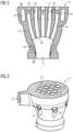
- FIG. 3shows an isometric view at the fuel nozzle.
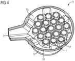
- FIG. 4show a transverse section through the fuel nozzle.
- FIG. 1an exemplary embodiment of an inventive combustion arrangement 01 is shown.
- Thiscomprises a combustion chamber 03 with a burner 02 arranged at the upstream end of the combustion chamber 032 . In operation this leads to a primary combustion zone within the combustion chamber 03 next to the burner 02 . Downstream of the combustion chamber 03 a transition 04 is arranged to guide the hot combustion gases.
- a number of fuel nozzles 11are arranged, which enable a further combustion of fuel in a secondary combustion zone within the transition.
- FIG. 2an exemplary embodiment of an inventive fuel nozzle 11 is shown in a longitudinal section. Used at the combustion arrangement the upper side is the cold side 08 at the fuel nozzle 11 facing away from the secondary combustion zone. The lower side in the figure is oriented towards the secondary combustion zone and is therefore the hot side 09 .
- the fuel nozzle 11comprises a main body 12 with a bunch of air passages 14 extending from the cold side 08 towards the hot side 09 .
- the air passages 14opens into an air chamber 13 arranged in the main body 12 between the air passages 14 and the hot side 09 .
- the single air passages 14have a curved course from the cold side 08 up to the air chamber 13 , wherein the central air passage 14 goes straight along a centerline of the fuel nozzle 11 , wherein those with a bigger distance to the centerline are more curved towards the center.
- each of the air passages 14changes from the cold side 08 towards the hot side 09 .
- the air passages 14have a circular cross section. This could be seen best in FIG. 3 .
- the air passages 14have a hexagonally cross section and are therefore arranged similar to a honeycomb (not shown here).
- FIG. 2Further shown in the FIG. 2 is the arrangement of a fuel distribution chamber 15 close to the cold side 08 within the main body 12 .
- the air passages 14cross the fuel distribution chamber 15 and accordingly each air passage 14 is separated from the fuel distribution chamber 15 with a respective passage wall 17 . This could also be seen best in FIG. 4 .
- a fuel pipe 21is attached to the main body 12 .
- one fuel hole 18is arranged.
- the position in circumferential direction in respect to the respective air passage 14 of these fuel holes 18differ between the different air passages 14 to avoid an identical flow through all the air passages 14 .
- a turbulator 19is arranged at the passage wall 17 extending into the respective air passage 14 . Thereby the mixing of the fuel into the air is enhanced.
- an annular air channel 16 surrounding the air chamber 13is arranged.
- This air channel 16opens with a gap into the air chamber 13 close to the hot side 09 .
- an air streamis achieved shielding the air-fuel stream from the air passages 14 .
Landscapes
- Engineering & Computer Science (AREA)
- Chemical & Material Sciences (AREA)
- Combustion & Propulsion (AREA)
- Mechanical Engineering (AREA)
- General Engineering & Computer Science (AREA)
- Spray-Type Burners (AREA)
Abstract
Description
Claims (16)
Applications Claiming Priority (3)
| Application Number | Priority Date | Filing Date | Title |
|---|---|---|---|
| EP22172962.7AEP4276358A1 (en) | 2022-05-12 | 2022-05-12 | Fuel nozzle with multiple air passages |
| EP22172962.7 | 2022-05-12 | ||
| EP22172962 | 2022-05-12 |
Publications (2)
| Publication Number | Publication Date |
|---|---|
| US20230366552A1 US20230366552A1 (en) | 2023-11-16 |
| US12072102B2true US12072102B2 (en) | 2024-08-27 |
Family
ID=81648342
Family Applications (1)
| Application Number | Title | Priority Date | Filing Date |
|---|---|---|---|
| US18/128,589ActiveUS12072102B2 (en) | 2022-05-12 | 2023-03-30 | Fuel nozzle with multiple air passages |
Country Status (3)
| Country | Link |
|---|---|
| US (1) | US12072102B2 (en) |
| EP (2) | EP4276358A1 (en) |
| CN (1) | CN117053232A (en) |
Cited By (1)
| Publication number | Priority date | Publication date | Assignee | Title |
|---|---|---|---|---|
| US12188658B1 (en)* | 2023-07-07 | 2025-01-07 | Ge Infrastructure Technology Llc | Fuel injection assembly for a combustor |
Citations (13)
| Publication number | Priority date | Publication date | Assignee | Title |
|---|---|---|---|---|
| US20060156730A1 (en) | 2005-01-17 | 2006-07-20 | General Electric Company | Multiple venturi tube gas fuel injector for a combustor |
| US20100008179A1 (en) | 2008-07-09 | 2010-01-14 | General Electric Company | Pre-mixing apparatus for a turbine engine |
| US20100170253A1 (en)* | 2009-01-07 | 2010-07-08 | General Electric Company | Method and apparatus for fuel injection in a turbine engine |
| US20110289928A1 (en)* | 2010-05-25 | 2011-12-01 | Fox Timothy A | Air/fuel supply system for use in a gas turbine engine |
| US20120192565A1 (en)* | 2011-01-31 | 2012-08-02 | General Electric Company | System for premixing air and fuel in a fuel nozzle |
| US20120198854A1 (en)* | 2011-02-09 | 2012-08-09 | Reinhard Schilp | Resonator system with enhanced combustor liner cooling |
| US20150285501A1 (en) | 2014-04-08 | 2015-10-08 | General Electric Company | System for cooling a fuel injector extending into a combustion gas flow field and method for manufacture |
| US20170370589A1 (en) | 2016-06-22 | 2017-12-28 | General Electric Company | Multi-tube late lean injector |
| WO2019020350A1 (en) | 2017-07-27 | 2019-01-31 | Siemens Aktiengesellschaft | GUESTURBINE BURNER WITH PRE-MIXED RAY FLAMES |
| EP3436746B1 (en) | 2016-03-30 | 2020-01-22 | Siemens Energy, Inc. | Injector assembly and ducting arrangement including such injector assemblies in a combustion system for a gas turbine engine |
| EP3472518B1 (en) | 2016-09-27 | 2020-11-18 | Siemens Aktiengesellschaft | Fuel oil axial stage combustion for improved turbine combustor performance |
| US20200378604A1 (en)* | 2019-05-30 | 2020-12-03 | Doosan Heavy Industries & Construction Co., Ltd. | Combustor with axial fuel staging system and gas turbine having the same |
| EP3479025B1 (en) | 2016-08-03 | 2021-11-03 | Siemens Energy Global GmbH & Co. KG | Injector assemblies configured to form a shielding flow of air injected into a combustion stage in a gas turbine engine |
Family Cites Families (1)
| Publication number | Priority date | Publication date | Assignee | Title |
|---|---|---|---|---|
| US8959921B2 (en)* | 2010-07-13 | 2015-02-24 | General Electric Company | Flame tolerant secondary fuel nozzle |
- 2022
- 2022-05-12EPEP22172962.7Apatent/EP4276358A1/ennot_activeWithdrawn
- 2023
- 2023-01-19EPEP23152425.7Apatent/EP4276359B1/enactiveActive
- 2023-03-30USUS18/128,589patent/US12072102B2/enactiveActive
- 2023-05-10CNCN202310526460.7Apatent/CN117053232A/enactivePending
Patent Citations (13)
| Publication number | Priority date | Publication date | Assignee | Title |
|---|---|---|---|---|
| US20060156730A1 (en) | 2005-01-17 | 2006-07-20 | General Electric Company | Multiple venturi tube gas fuel injector for a combustor |
| US20100008179A1 (en) | 2008-07-09 | 2010-01-14 | General Electric Company | Pre-mixing apparatus for a turbine engine |
| US20100170253A1 (en)* | 2009-01-07 | 2010-07-08 | General Electric Company | Method and apparatus for fuel injection in a turbine engine |
| US20110289928A1 (en)* | 2010-05-25 | 2011-12-01 | Fox Timothy A | Air/fuel supply system for use in a gas turbine engine |
| US20120192565A1 (en)* | 2011-01-31 | 2012-08-02 | General Electric Company | System for premixing air and fuel in a fuel nozzle |
| US20120198854A1 (en)* | 2011-02-09 | 2012-08-09 | Reinhard Schilp | Resonator system with enhanced combustor liner cooling |
| US20150285501A1 (en) | 2014-04-08 | 2015-10-08 | General Electric Company | System for cooling a fuel injector extending into a combustion gas flow field and method for manufacture |
| EP3436746B1 (en) | 2016-03-30 | 2020-01-22 | Siemens Energy, Inc. | Injector assembly and ducting arrangement including such injector assemblies in a combustion system for a gas turbine engine |
| US20170370589A1 (en) | 2016-06-22 | 2017-12-28 | General Electric Company | Multi-tube late lean injector |
| EP3479025B1 (en) | 2016-08-03 | 2021-11-03 | Siemens Energy Global GmbH & Co. KG | Injector assemblies configured to form a shielding flow of air injected into a combustion stage in a gas turbine engine |
| EP3472518B1 (en) | 2016-09-27 | 2020-11-18 | Siemens Aktiengesellschaft | Fuel oil axial stage combustion for improved turbine combustor performance |
| WO2019020350A1 (en) | 2017-07-27 | 2019-01-31 | Siemens Aktiengesellschaft | GUESTURBINE BURNER WITH PRE-MIXED RAY FLAMES |
| US20200378604A1 (en)* | 2019-05-30 | 2020-12-03 | Doosan Heavy Industries & Construction Co., Ltd. | Combustor with axial fuel staging system and gas turbine having the same |
Non-Patent Citations (2)
| Title |
|---|
| Beck, Machine Translation of WO-2019020350-A1 (2019), retrieved on Jan. 13, 2024 from Espacenet.com at https://translationportal.epo.org/emtp/translate/?ACTION=description-retrieval&COUNTRY=WO&ENGINE=google&FORMAT=docdb&KIND=A1&LOCALE=en_EP&NUMBER=2019020350&SRCLANG=de&TRGLANG=en (Year: 2019).* |
| European search report dated Oct. 25, 2022 for corresponding European patent application No. EP22172962.7. |
Cited By (2)
| Publication number | Priority date | Publication date | Assignee | Title |
|---|---|---|---|---|
| US12188658B1 (en)* | 2023-07-07 | 2025-01-07 | Ge Infrastructure Technology Llc | Fuel injection assembly for a combustor |
| US20250012445A1 (en)* | 2023-07-07 | 2025-01-09 | Ge Infrastructure Technology Llc | Fuel injection assembly for a combustor |
Also Published As
| Publication number | Publication date |
|---|---|
| US20230366552A1 (en) | 2023-11-16 |
| EP4276359C0 (en) | 2025-01-01 |
| EP4276358A1 (en) | 2023-11-15 |
| CN117053232A (en) | 2023-11-14 |
| EP4276359B1 (en) | 2025-01-01 |
| EP4276359A1 (en) | 2023-11-15 |
Similar Documents
| Publication | Publication Date | Title |
|---|---|---|
| US8316644B2 (en) | Burner having swirler with corrugated downstream wall sections | |
| EP3346187B1 (en) | Fuel injectors and methods of use in gas turbine combustor | |
| US8117846B2 (en) | Gas turbine burner and method of mixing fuel and air in a swirling area of a gas turbine burner | |
| US10125993B2 (en) | Burner, gas turbine having such a burner, and fuel nozzle | |
| CN103776060B (en) | Reheating burner is arranged | |
| EP3137814B1 (en) | Combustor burner arrangement | |
| EP2496883B1 (en) | Premixed burner for a gas turbine combustor | |
| US7000403B2 (en) | Primary fuel nozzle having dual fuel capability | |
| EP2743587B1 (en) | A fuel injector | |
| US20210095849A1 (en) | Gas Turbine Combustor | |
| JP2016041929A (en) | Fuel injector assembly in combustion turbine engine | |
| US20180187894A1 (en) | Fuel injectors and methods of use in gas turbine combustor | |
| CN118556172A (en) | Multi-tube pilot injector with flame anchor for gas turbine engine | |
| JP2010532860A (en) | Gas turbine burner | |
| CN105258157A (en) | Sequential combustor arrangement with a mixer | |
| US12072102B2 (en) | Fuel nozzle with multiple air passages | |
| CN107466354A (en) | Swirlers, burners and combustion devices for gas turbine engines | |
| US4092826A (en) | Fuel injectors for gas turbine engines | |
| US20170089584A1 (en) | Vortex generator, and fuel injection system of a gas turbine with such vortex generator | |
| US20060257807A1 (en) | Combustion device | |
| EP4187154A1 (en) | Fuel nozzle with restricted core air passage | |
| US20180266678A1 (en) | Staged burner | |
| US20150276225A1 (en) | Combustor wth pre-mixing fuel nozzle assembly | |
| EP1995521A1 (en) | Swirler vane | |
| CN116878027A (en) | Gas turbine combustion chamber nozzle structure and working method |
Legal Events
| Date | Code | Title | Description |
|---|---|---|---|
| FEPP | Fee payment procedure | Free format text:ENTITY STATUS SET TO UNDISCOUNTED (ORIGINAL EVENT CODE: BIG.); ENTITY STATUS OF PATENT OWNER: LARGE ENTITY | |
| STPP | Information on status: patent application and granting procedure in general | Free format text:DOCKETED NEW CASE - READY FOR EXAMINATION | |
| STPP | Information on status: patent application and granting procedure in general | Free format text:NON FINAL ACTION MAILED | |
| STPP | Information on status: patent application and granting procedure in general | Free format text:RESPONSE TO NON-FINAL OFFICE ACTION ENTERED AND FORWARDED TO EXAMINER | |
| STPP | Information on status: patent application and granting procedure in general | Free format text:NOTICE OF ALLOWANCE MAILED -- APPLICATION RECEIVED IN OFFICE OF PUBLICATIONS | |
| AS | Assignment | Owner name:SIEMENS ENERGY GLOBAL GMBH & CO. KG, GERMANY Free format text:ASSIGNMENT OF ASSIGNORS INTEREST;ASSIGNOR:SIEMENS ENERGY AB;REEL/FRAME:067827/0214 Effective date:20240621 Owner name:SIEMENS ENERGY AB (LEGAL SUCCESSOR OF SIEMENS INDUSTRIAL TURBOMACHINERY A.B.), SWEDEN Free format text:ASSIGNMENT OF ASSIGNORS INTEREST;ASSIGNORS:ANDERSSON, MATS;HEINEFELDT, RICKARD;LINDMAN, OLLE;AND OTHERS;SIGNING DATES FROM 20240506 TO 20240621;REEL/FRAME:067827/0163 | |
| STPP | Information on status: patent application and granting procedure in general | Free format text:PUBLICATIONS -- ISSUE FEE PAYMENT RECEIVED | |
| STPP | Information on status: patent application and granting procedure in general | Free format text:PUBLICATIONS -- ISSUE FEE PAYMENT VERIFIED | |
| STCF | Information on status: patent grant | Free format text:PATENTED CASE |