US12071814B2 - Wellbore notching assembly - Google Patents
Wellbore notching assemblyDownload PDFInfo
- Publication number
- US12071814B2 US12071814B2US17/114,150US202017114150AUS12071814B2US 12071814 B2US12071814 B2US 12071814B2US 202017114150 AUS202017114150 AUS 202017114150AUS 12071814 B2US12071814 B2US 12071814B2
- Authority
- US
- United States
- Prior art keywords
- shaft
- blade
- cutting device
- nut
- housing
- Prior art date
- Legal status (The legal status is an assumption and is not a legal conclusion. Google has not performed a legal analysis and makes no representation as to the accuracy of the status listed.)
- Active
Links
Images


Classifications
- E—FIXED CONSTRUCTIONS
- E21—EARTH OR ROCK DRILLING; MINING
- E21B—EARTH OR ROCK DRILLING; OBTAINING OIL, GAS, WATER, SOLUBLE OR MELTABLE MATERIALS OR A SLURRY OF MINERALS FROM WELLS
- E21B10/00—Drill bits
- E21B10/26—Drill bits with leading portion, i.e. drill bits with a pilot cutter; Drill bits for enlarging the borehole, e.g. reamers
- E21B10/32—Drill bits with leading portion, i.e. drill bits with a pilot cutter; Drill bits for enlarging the borehole, e.g. reamers with expansible cutting tools
- E21B10/327—Drill bits with leading portion, i.e. drill bits with a pilot cutter; Drill bits for enlarging the borehole, e.g. reamers with expansible cutting tools the cutter being pivoted about a longitudinal axis
- E—FIXED CONSTRUCTIONS
- E21—EARTH OR ROCK DRILLING; MINING
- E21B—EARTH OR ROCK DRILLING; OBTAINING OIL, GAS, WATER, SOLUBLE OR MELTABLE MATERIALS OR A SLURRY OF MINERALS FROM WELLS
- E21B10/00—Drill bits
- E21B10/26—Drill bits with leading portion, i.e. drill bits with a pilot cutter; Drill bits for enlarging the borehole, e.g. reamers
- E21B10/32—Drill bits with leading portion, i.e. drill bits with a pilot cutter; Drill bits for enlarging the borehole, e.g. reamers with expansible cutting tools
- E—FIXED CONSTRUCTIONS
- E21—EARTH OR ROCK DRILLING; MINING
- E21B—EARTH OR ROCK DRILLING; OBTAINING OIL, GAS, WATER, SOLUBLE OR MELTABLE MATERIALS OR A SLURRY OF MINERALS FROM WELLS
- E21B43/00—Methods or apparatus for obtaining oil, gas, water, soluble or meltable materials or a slurry of minerals from wells
- E21B43/11—Perforators; Permeators
- E21B43/112—Perforators with extendable perforating members, e.g. actuated by fluid means
Definitions
- This disclosurerelates to a wellbore tool, a notching system, and a method for producing a notch in an open-hole wellbore.
- hydraulic fracturingis used to enhance connectivity between hydrocarbon-bearing reservoir formations and wellbores.
- flow of hydrocarbons from reservoir formations towards wellboresis difficult to achieve and sustain at required levels.
- Such formationsoften include tight sandstones, tight carbonates, and shale. Hydraulic fractures can be created in vertical and horizontal wells both in cased-perforated and open-hole well completions.
- a well tool for generating a notch in an open-hole wellboreincludes a tool body.
- the tool bodyhas a housing defining at least one slot.
- the housingdefines an interior volume.
- the tool bodyfurther includes a cutting device disposed in the interior volume of the housing and configured to form a notch in a formation through which the wellbore is formed.
- the cutting devicehas a shaft disposed in the interior volume of the housing.
- the shafthas a first portion having first exterior threads that extend around the first portion in a first direction, and a second portion having second exterior threads that extend around the second portion in a second direction opposite the first direction.
- the cutting devicealso includes multiple blades having a first blade extending from the first portion of the shaft and a second blade extending from a second portion of the shaft. The first and second blade are attached. The multiple blades are configured to extend radially outward toward the formation through the slot or inward away from the formation.
- the multiple bladesextend radially outward toward the formation through the slot or inward away from the formation.
- the cutting devicefurther comprises a first nut having a first threaded surface defining a first opening, wherein the first opening receives the first portion of the shaft. In some embodiments, the cutting device further includes a second nut having a second threaded surface defining a second opening, wherein the second opening receives the second portion of the shaft.
- the well toolhas an extended position and a retracted position. In the extended position, multiple blades extend through the slot of the housing. In the retracted position the multiple blades are arranged in the interior volume of the housing. In some embodiments, the blade abuts the formation in the extended position.
- the first bladeattaches at a first end to the first portion of the shaft and the second blade attaches at a first end to the second portion of the shaft, wherein a second end of the first blade and a second end of the second blade attach at a blade hinge.
- a first nutconnects the first end of the first blade to the first portion of the shaft.
- a second nutconnects the first end of the second blade to the second portion of the shaft.
- a blade hingeconnects the first blade and the second blade.
- the well toolfurther includes a scribe connected to the blade hinge of the cutting device.
- the shaftdefines a longitudinal axis, wherein the scribe is centered on and extends along a second axis, orthogonal to the longitudinal axis. In some embodiments, the scribe is configured to rotate on the second axis.
- At least one slotis multiple slots, each slot aligned with the first blade and second blade of the multiple blades.
- the well toolfurther includes a first motor connected to the tool body operable to rotate the tool body. In some embodiments, the well tool further includes a second motor connected to the shaft operable to rotate the shaft. In some embodiments, the first motor is connected to the shaft and is operable to rotate the shaft.
- the well toolfurther includes a first motor connected to the shaft operable to rotate the shaft.
- a first nut arranged on the first portion of the shaftcomprises a first lock and a second nut arranged on the second portion of the shaft comprises a second lock.
- the first portion of the shaftis rotatable relative to the second portion of the shaft.
- the well toolfurther includes a first motor connected to the first portion of the shaft operable to rotate the first portion of the shaft.
- the well toolfurther includes a second motor connected to the second portion of the shaft operable to rotate the second portion of the shaft.
- the well toolfurther includes a third motor connected to the tool body, operable to rotate the tool body.
- the first motoris connected to the second portion of the shaft and is operable to rotate the second portion of the shaft.
- the at least one slot of the housingis a radial slot.
- the at least one slot of the housingis an axial slot.
- a methodincludes rotating a shaft of a well tool in a first direction such that a first nut of a cutting device of the well tool translates axially along the shaft towards a second nut of the cutting device of the well tool arranged on the shaft, wherein the translation of the first nut towards the second nut extends multiple blades of the cutting device; and rotating the well tool to form a notch in a formation.
- the translation of the first nut towards the second nutextends a hinge of the cutting device, wherein the hinge connects a first blade of the multiple blades and a second blade of the multiple blades.
- the shaftis rotated by a first motor. In some embodiments, the well tool is rotated by a second motor. In some embodiments, the well tool is rotated by the first motor.
- a rotational speed of the well toolis greater than a rotational speed of the shaft.
- rotating a shaft of a well tool in a first direction and rotating the well tool to form a notch in a formationoccur simultaneously.
- step rotating the well tool to form a notch in a formationcomprises stopping the rotation of the shaft.
- the methodfurther includes rotating the shaft in a second direction.
- the rotation of the shaft in the second directiontranslates the first nut of the cutting device of the well tool axially along shaft away from the second nut arranged on the shaft.
- the translation of the first nut away from the second nutretracts a blade hinge of the cutting device, wherein the blade hinge connects the first blade and the second blade.
- the notching system for forming a notch in an open-hole wellboreincludes a cutting device with a retracted position, an extended position, and a final position.
- the notchhas predetermined dimensions that are achieved using the notching system. Fractures produced during fracturing may be generated at lower injection pressures due to the presence and dimensions of the notch.
- the cutting deviceis also able to control the depth to width ratio of the notch.
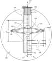
- FIG. 1is a view of a notching system having a well tool disposed in an open-hole wellbore.
- FIG. 2is a cross-sectional side view of the well tool having a cutting device in a first retracted position.
- FIG. 3is a cross-sectional side view of the cutting device of the well tool in the first retracted position, a second extended position, and a third final position.
- FIG. 4is a side view of the well tool having the cutting device in the third position and a corresponding notch.
- FIGS. 5 A and 5 Bare a cross-sectional side views of the notch formed by the notching system.
- FIG. 6is an example flowchart for a method generating a notch using the well tool.
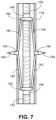
- FIG. 7is a cross-sectional side view of the well tool having a cutting device with a scribe.
- a wellbore notching systemincludes a wellbore tool.
- the wellbore toolincludes a cutting device having blades that cut a formation to form a notch in an open-hole (uncased) wellbore.
- the bladeshave a first position (retracted position), a second position (extended position), and a third position (final position).
- the blade positionsare controlled by rotation of a shaft of the cutting device.
- the bladesIn the retracted position, the blades are retained within an interior volume of a housing of the tool.
- the extended positionthe blades extend through the housing to engage with the formation.
- the final positionthe blades are fully extended and the notch in the formation is a final, predetermined size.
- the notching systemcan produce a variety of notch sizes and dimensions by controlling the angle and extension of the blades. The angle and extension of the blades is controlled by the cutting device and a controller.
- FIG. 1shows a wellbore notching system 100 for generating a notch 102 in a wellbore 104 surrounded by a formation 106 .
- the system 100includes a tubular body 108 that extends from the surface to a well tool 112 , for example by a coiled tubing, deployed into the wellbore 104 .
- a tool motor 110 (first motor) of a well tool 112is operable to rotate the well tool in a first rotational direction or a second rotational direction opposite the first.
- the tool motor 110anchors to the wellbore wall to enable steady rotation of the well tool 112 with respect to the wellbore.
- the tool motormay be hydraulically or electrically powered.
- the well toolis an integral portion of the tubular body.
- the second endis mounted to a second tubular body.
- the wellborehas an axis 117 and the well tool 112 is centered on the axis 117 .
- the wellbore 104has a radius R wb measured from the axis 117 to a wall 119 of the wellbore 104 .
- a penetration depth D n of the fully formed notch 102is known prior to generating the notch 102 .
- the penetration depth D nis measured from the wall 119 of the wellbore 104 to a tip 102 a of the fully formed notch 102 .
- the notch 102also has predetermined final radius R nfinal measured from the axis 117 to the tip 102 a of the fully formed notch 102 .
- the dimensions of the notch 102are described further with reference to FIG. 5 .
- the well tool 112 of the notching system 100has a tool body 113 that that includes connection end 114 mounted to the tubular body 108 and a free end 116 .
- the tool body 113 of the well tool 112also includes a housing 118 , centered on the axis 117 , that has slots.
- the slotsare arranged as axial slots 120 that extend from the first end 114 of the well tool 112 to the free end 116 of the well tool 112 .
- the housing 118also defines an interior volume 122 and a radius R h ( FIG. 2 ) that is measured from the axis 117 to an edge the housing 118 .
- the slots 120align with blades of a cutting device.
- FIG. 2is a cross-sectional side view of a cutting device 124 of the well body 113 of the well tool 112 in a retracted position.
- the well tool 112is arranged in the open-hole (uncased) wellbore 104 .
- the cutting device 124 of the well tool 112is arranged in the interior volume 122 of the housing 118 .
- the cutting device 124includes a shaft 126 disposed in the interior volume 122 of the housing, a shaft motor 127 (second motor) operable to rotate the shaft 126 , and multiple blades 128 attached to the shaft 126 .
- the shaft motor 127 and tool motor 110may include signal transceivers that transmit and receive signals from a controller 160 . Some controllers are arranged on the well tool.
- the controlleradjusts the shaft motor to rotate the shaft to control extension of the blades based on pressures exerted on the multiple blades as they are dragged against the rock face during the notch cutting.
- the multiple blades and/or the hingeshave pressure sensors that transmit the pressure detected by the pressure sensors to the controller. The controller may then adjust the rotational speed and/or direction of the shaft motor to produce a smooth notch curvature.
- the controlleris a computer system that includes one or more processors and a computer-readable medium (for example, a non-transitory computer-readable medium) storing instructions executable by the one or more processors to perform operations described in this disclosure.
- the controllercan include firmware, hardware, software, processing circuitry or any combination of them and configured to implement the operations described here.
- the shaft 126has a first portion 130 and a second portion 132 .
- the first portion 130includes a first exterior thread 134 that extends around the first portion 130 in a first helical direction (first pitch).
- the second portion 132has a second exterior thread 136 that extends around the second portion 132 in a second helical direction (second pitch).
- the second helical directionis opposite the first helical direction.
- the first helical direction (first pitch)may have a thread that is angled 45° relative to the axis 117 .
- the second helical direction (second pitch)may have a thread that is angled ⁇ 45° relative to the axis 117 .
- the multiple blades 128include two blade sets 138 each aligned with a slot 120 of the housing 118 .
- Each blade set 138has a first blade 140 , a second blade 142 , and a blade hinge 144 connecting the first blade 140 to the second blade 142 .
- a radius R b of the cutting device 124is measured from the axis 117 to the blade hinge 144 .
- the radius R b of the cutting device 124increases or decreases as the blades of the cutting device 124 move into different positions.
- the multiple blades 128connect to the first portion 130 of the shaft 126 by a first nut 146 .
- the multiple blades 128connect to the second portion 132 of the shaft 126 by a second nut 148 .
- the first nut 146 and second nut 148each have a central threaded opening (not shown) that engages with the exterior threads 134 , 136 of the first and second portions 130 , 132 of the shaft 126 , respectively.
- the first blade 140has a first end 150 and a second end 152 .
- the first end 150 of the first blade 140attaches to the first nut 146 by a connector 154 , for example connection hinge or joint.
- the second end 152 of the first blade 140connects to the blade hinge 144 .
- the second blade 142has a first end 156 and a second end 158 .
- the first end 156 of the second blade 142attaches to the second nut 148 by a connector 159 , for example connection hinge or joint.
- the second end 154 of the second blade 142connects to the blade hinge 144 .
- the first blade 140 and second blade 142are of equal length so that the blade hinge 144 is arranged equidistant from the first and second nuts 146 , 148 .
- the rotation of the shaft 126causes the first and second nuts 146 , 148 to translate in opposite axial directions, increasing or decreasing the radius R b of the cutting device 124 .
- rotation of the shaft 126 in the first rotational directionaxially translates the first nut 146 downhole and axially translates the second nut 148 uphole, increasing the radius R b of the cutting device 124 .
- Rotation of the shaft in the second rotational directionaxially translates the first nut 146 uphole and axially translates the second nut 148 downhole, decreasing the radius R b of the cutting device 124 .
- the blade sets 138flex or straighten about the blade hinge 144 to move cutting device 124 from the retracted position to the intermediate position, and onto to the final position, or vice versa
- FIG. 3is a cross-sectional side view of the well tool 112 with the cutting device 124 in the retracted position (A), extended position (B), and final position (C).
- the cutting device 124moves from the retracted position (A) to the extended position (B) and from the extended position (B) to the final position (C) by rotating the shaft in the first rotational direction (increasing the radius R b of the cutting device 124 ).
- the cutting device 124moves from the final position (C) to the extended position (B) and from the intermediate position (B) to the retracted position (A) by rotating the shaft in the second rotational direction (decreasing the radius R b of the cutting device 124 ).
- the radius R b of the cutting device 124is less than or equal to the radius R h of the housing 118 .
- the blade sets 138are arranged in the interior volume 122 of the housing 118 .
- the cutting device 124may be in the retracted position when transporting the well tool 112 into the wellbore 104 or removing the well tool 112 from the wellbore 104 .
- the shaft motor 127rotates the shaft 126 in the first direction so that the first nut 146 translates downhole and the second nut 148 translates uphole.
- the translation of the first nut 146moves the first end 150 of the first blade 140 downhole.
- the translation of the second nut 148moves the first end 156 of the second blade 142 uphole.
- the blade hinge 144moves radially outward due to the movement of the first ends 150 , 156 towards each other, thereby increasing the radius R b of the cutting device 124 .
- the cutting device 124is now in the extended position (B).
- the blade hinge 144In the extended position (B), the blade hinge 144 extends radially through the housing 118 via the axial slot 120 such that the radius R b of the blade is greater than the radius R h of the housing 118 but less than the final radius R nfinal of the notch 102 .
- the shaft 126continues to rotate until the blade sets 138 contact and begin to cut the formation 106 to form the notch 102 .
- the blade hinge 144first contacts the formation 106 and forms the tip 102 a of the notch 102 .
- the shaft motor 127continues to rotate the shaft 126 in the first direction so that the first nut 146 continues to translate downhole and the second nut 148 continues to translate uphole, extending the blade hinge 144 and second ends 152 , 158 radially further into the forming notch 102 and increasing the radius R b of the cutting device 124 .
- the desired shape of the notch 102is known (predetermined) prior to operating the cutting device 124 .
- the shaft 126continues to rotate until the predetermined notch depth, shape, and any other notch dimensions are achieved.
- the radius R b of the cutting device 124is equal to or slightly less than the final notch radius R nfinal .
- FIG. 4is a cross-sectional side view of the well tool 112 with the cutting device 124 in the final position (C) and the formed notch 102 .
- a curvature 162 of the notch 102is controlled by the changing slope of the first and second blades 140 , 142 , which is controlled by the rotation of the shaft 126 .
- the shaft motor 127is controlled by the controller 160 .
- the shaft motor 127may be electronically or hydraulically triggered by the controller 160 .
- FIGS. 5 A and 5 Bshow a cross-sectional side view of the notch 102 in the wellbore 104 without the notching system 100 .
- the controller 160may increase or decrease the extension of the blades by rotating the shaft to produce a notch having a specific dimensions.
- FIG. 5 Bshows the resultant notch shape 162 may be determined analytically in cylindrical coordinates (r,z) with the axis z coinciding with the wellbore axis 117 .
- the well tool 112is centralized on the wellbore axis 117 .
- the thickness of the blades 140 , 142is neglected as non-essential for the illustrational purposes in this disclosure.
- this standoff linecan be located anywhere within the housing 118 , so that the blades 140 , 142 are connected to the nuts 146 and 148 using any connection known in the art.
- ⁇ z ⁇ ( r ) ⁇⁇ 0.5 ⁇ W n + L ⁇ ( 1 - ( r + k c ⁇ R wb L ) 2 / 3 ) 3 / 2 , R wb ⁇ r ⁇ R nfinal - 0.5 ⁇ W n ; 0.5 ⁇ W n ⁇ ( 1 - ( 1 - R nfinal - r 0.5 ⁇ W n ) 2 ) 1 / 2 , R nfinal - 0.5 ⁇ W n ⁇ R nfinal .
- H nfinal2 ⁇ R nfinal ⁇ ( 0.5 ⁇ W n R w ⁇ R wb R nfinal + L R nfinal ⁇ ( 1 - ( ( 1 + k c ) ⁇ R wb L ) 2 / 3 ) 3 / 2 )
- the opening height H nfinal of the notch 102is larger as compared to a straight parallel face notch, due to the curvature 162 .
- the larger opening height H nfinalreduces friction during further hydraulic fracture propagation stages that favor a lower fracturing pressure.
- a shorter opening height H nfinalreduces the amount of extracted rock.
- the ratio of the opening height H nfinal to notch penetration depth D nmay be adjusted by using different blade length and varying standoff parameter k c with specific values assigned for the specific well case. For example, same final notch radius (penetration depth) can be achieved the using the shorter blade extracted to its final position (C), or by using longer blade in its extended position (B) only. In the latter case, the notch opening height is larger.
- notch openingcan be reduced by off centering the standoff line for the hinges 154 and 159 towards the tool housing by increasing parameter
- FIG. 6is an example flowchart of a method 200 for using a wellbore tool 112 to produce a notch of predetermined dimensions.
- the method 200is described with reference to the wellbore notching system 100 but may be used with any other applicable system.
- the well tool 112mounted to the tubular body 108 , is lowered into the wellbore 104 of the formation 106 a known depth until the cutting device 124 aligns with a portion of the wellbore 104 to be notched.
- the controller 160may prompt the stopping of the translation of the well tool 112 and prompt the tool motor 110 to engage with the wellbore to anchor the well tool 102 at a specific location in the wellbore.
- the controllerthen signals for the shaft motor 127 to rotate the shaft 126 of the well tool 112 in a first direction so that the first nut 146 of a cutting device 124 translates axially along the shaft 126 towards the second nut 148 of the cutting device 124 .
- the rotation of the shaft 126 by the shaft motor 127 in the first directionalso translates the second nut 148 axially along the shaft 126 , towards the first nut 146 .
- the first and second nuts 146 , 148translate at the same speed because a first pitch of the first exterior thread 134 on the first portion 130 of the shaft 126 is equal to a second pitch of the second exterior thread 136 on the second portion 132 of the shaft 126 .
- the translation of the first nut 146 towards the second nut 148 and the translation of the second nut 148 towards the first nut 146extends the blade sets 138 of the cutting device 124 , radially moving the hinge 144 outward and increasing the radius R b of the cutting device 124 .
- the rotation of the shaft 126 by the shaft motor 127continues as blade hinges 144 of the cutting device 124 extend through the slots 120 of the housing 118 and the cutting device 124 moves from the retracted position to the extended position.
- the shaft motor 127continues to rotate the shaft 126 until the hinges 144 contact the formation 106 .
- the radius R b of the cutting device 124is equal to the radius R wb of the wellbore 104 .
- the controller 160signals to the tool motor 110 to rotate the well tool 112 .
- the well tool 112rotates and the notch 102 begins to form in the formation 106 due to the contact between the multiple blades 128 and the formation 106 .
- Both the tool motor 110 and the shaft motor 127rotate so that the multiple blades 128 continue to cut deeper into the formation 106 to form the notch 102 .
- Both rotational speeds of the tool motor 110 and the shaft motor 127are constant. In some methods, the rotation speeds of the tool motor may vary during the course of the method. In some methods, the rotation of the shaft motor to move the cutting device from the retracted position to the extended position and the rotation of the tool motor to move the well tool occurs simultaneously.
- the controllermay adjust the rotational speed and/or direction of the shaft motor to produce a smooth notch curvature. This adjustment may be made based on the pressure readings from pressure sensors installed on multiple blades and hinges as they are dragged against the rock face during the notch cutting. In this way, rotational speed of the shaft may be reduced in a response to the drag exerted on the blade exceeds the predefined limiting value; or may be increased in opposite case when drag is low.
- the tool motor 110 and shaft motor 127continue to rotate until the cutting device 124 has reached the final position (C) indicating that the notch 102 has achieved the predetermined opening height H nfinal , penetration depth D n , curvature 162 , and radius R nfinal .
- the distance that the radius R b of the cutting device 124 increasescan be determined based on the number of turns of the shaft 126 , counted by the shaft motor 127 or the controller 160 . Therefore, in the method 200 , the controller 160 determines the dimensions of the notch 102 based on the radius R b of the cutting device 124 and known rotational speed(s) of the shaft 127 .
- the radius R b of the cutting devicecan be calculated based on the nuts on the first and second portions of the shaft and the length of the first and second blades.
- the notch 102is measured or imaged to confirm that the predetermined dimensions are met. In some cases, reaching the predefined notch penetration depth may occur prior to the full extension of the blades.
- the controllerprompts tool motor 110 to stop rotating the well tool 112 and prompts the shaft motor 127 to rotate in the second rotational direction.
- the rotation of the shaft motor 127 in the second rotational directionrotates the shaft 126 in the second rotational direction.
- Rotation of the shaft 126 in the second rotational directiontranslates the first nut 146 of the cutting device 124 axially along shaft 126 , away from the second nut 148 arranged on the shaft 126 .
- Rotation of the shaft 126 in the second rotational directionalso translates the second nut 148 of the cutting device 124 axially along shaft 126 , away from the first nut 146 arranged on the shaft 126 .
- the movement of the first and second nuts 146 , 148 away from each otherretracts the blade hinge 144 and decreases the radius R b of the cutting device, moving the cutting device from the final position (C) to the extended position (B).
- the shaft motor 127continues to rotate in the second rotational direction as the radius R b of the cutting device 124 decreases and the multiple blades 128 are received by the slots 120 in the housing 118 .
- the shaft motor 127continues to rotate until the blade hinges 144 pass the axial slots 120 and the cutting device is in the retracted position (A).
- the well tool 112is then removed from the wellbore 106 and further fracturing methods or procedures can be executed in the notched wellbore 106 . In some methods, the downhole tool is moved to notch another section of the wellbore.
- FIG. 7is a cross-sectional side view of the well tool 112 with a scribe 164 .
- the scribe 164is arranged on the blade hinge 144 and punctures the formation 106 in the extended position (B) of the cutting device 124 .
- the scribe 164sharpens the tip of the resulting notch 102 to increase stress concentration to form a transverse fracture.
- the scribe 164is statically mounted to the blade hinge 144 . In some systems, the scribe is arranged on a second axis, orthogonal to the axis 117 . The scribe may rotate about or on the orthogonal axis.
- the first blade and second blade of the multiple bladesare unequal in length.
- the first pitch of the first external thread of the shaft and the second pitch of the second external thread of the shaftare different. In some systems, the pitch of the first external thread is steeper than the pitch of the second external thread. In some systems, the pitch of the second external thread is steeper than the pitch of the first external thread.
- the pitches of the first and second external threadsare varied.
- the first external threadmay have a steep pitch on a section of the thread that corresponds to the retracted position of the cutting device, but may have a flatter pitch in a section of the external thread that corresponds to the extended position.
- the second external pitchhas the same varied pitch as the first external thread, in the extending opposite direction.
- the second external threadmay have a steep pitch on a section of the thread that corresponds to the retracted position of the cutting device, but may have a flatter pitch in a section of the external thread that corresponds to the extended position.
- the first nut 146includes a first lock 180 ( FIG. 7 ) configured to lock the first nut in an axial position on the first portion of the shaft.
- the second nutalso includes a second lock 182 ( FIG. 7 ) configured to lock the second nut in an axial position on the second portion of the shaft.
- the housing of the tool bodyalso has a lock to couple the housing to the shaft in a locked position.
- the tool bodyWhen the housing lock and locks 180 , 182 of the first and second nuts are engaged or locked (engaged position), the tool body (the housing and the cutting device) are rotationally coupled to the shaft and tool motor. In this configuration, the multiple blades are locked into a position (e.g., retracted, extended, or final) and rotate with the motor to cut the formation (if in the extended). The housing also rotates with the multiple blades.
- the tool bodyWhen the housing lock and locks of the first and second nuts are disengaged or unlocked (disengaged position), the tool body (the housing and the cutting device) are rotationally decoupled from the shaft and tool motor. For example, when the locks are disengaged, the tool motor rotates only the shaft. In this configuration, the housing is static, and the first and second nuts translate axially as the shaft rotates to move between the retracted, extended, or final position. In the disengaged position, the radius of the cutting device can increase or decrease as the shaft rotates.
- the nut locks and the tool housing lockmay be mechanical locks, magnetic locks, electric locks, or any combination thereof.
- the locks of the first and second nutsinclude elastic washers or springs that compress on the nut as the blades press against the formation.
- the cutting deviceis in the retracted position, the locks of the first nut and second nut and the housing lock are unlocked.
- the first and second nutsare free to rotate relative to the shaft.
- the tool motorrotates the shaft relative to the first nut, second nut, and the housing.
- the first and second nutsmove along the first and second exterior threads, extending the blades.
- the nutstranslate axially until the blades contact and press against the formation in the extended position.
- the contact between the formation and the bladescompress the elastic washer locks. Under a predetermined amount of pressure from the contact between the formation and the blades, the elastic washer locks the first and second nut to the shaft.
- the housing lockengages and the housing is rotationally coupled to the shaft and multiple blades.
- the tool motoralso rotates the housing and blades to cut the formation.
- the pressure between the blades and the formationlessens and the elastic washer or spring expands, unlocking the nuts from the shaft.
- Thisprompts the housing lock to also unlock.
- the tool motorcontinues to rotate the shaft relative to the first nut, second nut, multiple blades, and tool housing.
- the first and second nutagain move axially along the shaft to further extend the blades.
- the locks on the nuts and housing lockcontinue to unlock and lock, as the cutting device deepens the notch in the formation.
- the first and second exterior threadsmay have a stop face at which the cutting device is in the final position and the nuts are rotationally coupled to the shaft.
- the notchis formed having predetermined dimensions.
- first and second portions of the shafthave been described as rotationally coupled, however, in some shafts, the first and second portions of the shaft are rotatable relative to each other. In such a system, the shaft has a rotational joint connecting the first portion of the shaft and the second portion of the shaft. In other systems, the first portion of the shaft and the second portion of the shaft are disconnected and are distanced from each other.
- the shaft motormay rotationally couple to the first portion of the shaft and a second shaft motor (third motor) may rotationally couple to the second portion of the shaft.
- the first shaft motoris operable to rotate the first portion of the shaft in the first and second rotational directions.
- the second shaft motoris operable to rotate the second portion of the shaft in the first and second rotational directions.
- the shaft motoris connected to the first portion of the shaft and the second portion of the shaft, rotatable relative to the first portion of the shaft. In such a system, the shaft motor is operable to rotate the second portion of the shaft, independent of the rotation of the first portion of the shaft.
- Some toolinclude multiple cutting devices arranged axially within the interior volume of the housing. Such system form multiple transverse notches in the formation each using the multiple blades.
- Each cutting devicemay include a shaft, or the cutting devices may be arranged along an elongated shaft.
- the well toolis mounted on a drill string.
- some cutting devicesmay have more than two blade sets, for example four blade sets at increments of 90° around the shaft or six blade sets at increments of 60° around the shaft. In increased number of blade sets can result in a higher torque while reducing the load on individual blade pairs. Additional blade pairs may also centralize the tool during rotation and provide a smooth curvature.
Landscapes
- Engineering & Computer Science (AREA)
- Life Sciences & Earth Sciences (AREA)
- Geology (AREA)
- Mining & Mineral Resources (AREA)
- Physics & Mathematics (AREA)
- Environmental & Geological Engineering (AREA)
- Fluid Mechanics (AREA)
- General Life Sciences & Earth Sciences (AREA)
- Geochemistry & Mineralogy (AREA)
- Mechanical Engineering (AREA)
- Processing Of Stones Or Stones Resemblance Materials (AREA)
- Sawing (AREA)
Abstract
Description
this standoff line can be located anywhere within the
L=kcRwb+Rnfinal−0.5Wn,
Claims (34)
Priority Applications (4)
| Application Number | Priority Date | Filing Date | Title |
|---|---|---|---|
| US17/114,150US12071814B2 (en) | 2020-12-07 | 2020-12-07 | Wellbore notching assembly |
| PCT/US2021/062119WO2022125493A1 (en) | 2020-12-07 | 2021-12-07 | Wellbore notching assembly |
| CN202180082165.6ACN117716109A (en) | 2020-12-07 | 2021-12-07 | Shaft slotting components |
| US18/785,795US12421803B2 (en) | 2020-12-07 | 2024-07-26 | Wellbore notching assembly |
Applications Claiming Priority (1)
| Application Number | Priority Date | Filing Date | Title |
|---|---|---|---|
| US17/114,150US12071814B2 (en) | 2020-12-07 | 2020-12-07 | Wellbore notching assembly |
Related Child Applications (1)
| Application Number | Title | Priority Date | Filing Date |
|---|---|---|---|
| US18/785,795ContinuationUS12421803B2 (en) | 2020-12-07 | 2024-07-26 | Wellbore notching assembly |
Publications (2)
| Publication Number | Publication Date |
|---|---|
| US20220178208A1 US20220178208A1 (en) | 2022-06-09 |
| US12071814B2true US12071814B2 (en) | 2024-08-27 |
Family
ID=79170686
Family Applications (2)
| Application Number | Title | Priority Date | Filing Date |
|---|---|---|---|
| US17/114,150ActiveUS12071814B2 (en) | 2020-12-07 | 2020-12-07 | Wellbore notching assembly |
| US18/785,795ActiveUS12421803B2 (en) | 2020-12-07 | 2024-07-26 | Wellbore notching assembly |
Family Applications After (1)
| Application Number | Title | Priority Date | Filing Date |
|---|---|---|---|
| US18/785,795ActiveUS12421803B2 (en) | 2020-12-07 | 2024-07-26 | Wellbore notching assembly |
Country Status (3)
| Country | Link |
|---|---|
| US (2) | US12071814B2 (en) |
| CN (1) | CN117716109A (en) |
| WO (1) | WO2022125493A1 (en) |
Families Citing this family (1)
| Publication number | Priority date | Publication date | Assignee | Title |
|---|---|---|---|---|
| CN115538929A (en)* | 2022-09-27 | 2022-12-30 | 重庆交通大学 | Drill jumbo-based directional slotting tool bit sleeve for special-shaped hole motor |
Citations (141)
| Publication number | Priority date | Publication date | Assignee | Title |
|---|---|---|---|---|
| US84852A (en) | 1868-12-15 | Elias beach | ||
| US821816A (en) | 1905-11-14 | 1906-05-29 | Thomas William Myrick | Pipe or tube cutter. |
| US1822216A (en)* | 1927-02-26 | 1931-09-08 | Earl S Hartson | Underreamer |
| US2324956A (en)* | 1940-11-25 | 1943-07-20 | Standard Oil Dev Co | Borehole tool |
| US2372875A (en)* | 1944-06-06 | 1945-04-03 | Atlantic Refining Co | Coring device |
| US2450223A (en)* | 1944-11-25 | 1948-09-28 | William R Barbour | Well reaming apparatus |
| US2688369A (en) | 1949-06-16 | 1954-09-07 | W B Taylor | Formation tester |
| US2699212A (en) | 1948-09-01 | 1955-01-11 | Newton B Dismukes | Method of forming passageways extending from well bores |
| US2758653A (en) | 1954-12-16 | 1956-08-14 | Floyd H Desbrow | Apparatus for penetrating and hydraulically eracturing well formations |
| US3050122A (en) | 1960-04-04 | 1962-08-21 | Gulf Research Development Co | Formation notching apparatus |
| US3118501A (en) | 1960-05-02 | 1964-01-21 | Brents E Kenley | Means for perforating and fracturing earth formations |
| US3211221A (en) | 1962-06-14 | 1965-10-12 | Gulf Research Development Co | Process for fracturing an underground formation |
| US3254720A (en) | 1964-10-08 | 1966-06-07 | Gulf Research Development Co | Apparatus for cutting a notch in a subsurface formation |
| US3313348A (en) | 1963-12-27 | 1967-04-11 | Gulf Research Development Co | Process of forming vertical well bore fractures by use of circumferential notching |
| US3331439A (en) | 1964-08-14 | 1967-07-18 | Sanford Lawrence | Multiple cutting tool |
| US3379266A (en)* | 1965-10-21 | 1968-04-23 | Roy W. Fletcher | Earth boring mechanism with expansion underreamer |
| US3599734A (en)* | 1969-08-06 | 1971-08-17 | Nathandale Farris | Notching tool |
| US4189184A (en)* | 1978-10-13 | 1980-02-19 | Green Harold F | Rotary drilling and extracting process |
| US4220550A (en) | 1978-12-06 | 1980-09-02 | The Dow Chemical Company | Composition and method for removing sulfide-containing scale from metal surfaces |
| US4262745A (en) | 1979-12-14 | 1981-04-21 | Exxon Production Research Company | Steam stimulation process for recovering heavy oil |
| US4270618A (en) | 1979-04-20 | 1981-06-02 | The Robbins Company | Earth boring apparatus |
| US4289639A (en) | 1980-10-03 | 1981-09-15 | The Dow Chemical Company | Method and composition for removing sulfide-containing scale from metal surfaces |
| US4381950A (en) | 1981-05-22 | 1983-05-03 | Halliburton Company | Method for removing iron sulfide scale from metal surfaces |
| US4390067A (en) | 1981-04-06 | 1983-06-28 | Exxon Production Research Co. | Method of treating reservoirs containing very viscous crude oil or bitumen |
| SU1036926A1 (en) | 1982-02-15 | 1983-08-23 | Предприятие П/Я М-5703 | Device for making expansions in large-diameter wells |
| GB2172632A (en) | 1985-03-22 | 1986-09-24 | Fondedile Foundations Ltd | Under-reaming of small diameter boreholes |
| US4629702A (en) | 1984-10-04 | 1986-12-16 | Mobil Oil Corporation | Method for classifying the sedimentary kerogen for oil source |
| US4662440A (en) | 1986-06-20 | 1987-05-05 | Conoco Inc. | Methods for obtaining well-to-well flow communication |
| US4687061A (en) | 1986-12-08 | 1987-08-18 | Mobil Oil Corporation | Stimulation of earth formations surrounding a deviated wellbore by sequential hydraulic fracturing |
| US4754808A (en) | 1986-06-20 | 1988-07-05 | Conoco Inc. | Methods for obtaining well-to-well flow communication |
| US4809793A (en) | 1987-10-19 | 1989-03-07 | Hailey Charles D | Enhanced diameter clean-out tool and method |
| US4974675A (en) | 1990-03-08 | 1990-12-04 | Halliburton Company | Method of fracturing horizontal wells |
| US5016710A (en) | 1986-06-26 | 1991-05-21 | Institut Francais Du Petrole | Method of assisted production of an effluent to be produced contained in a geological formation |
| SU1680925A1 (en) | 1989-02-23 | 1991-09-30 | А.И Хрипков и Т.С Хрипкова | Device for reaming of hole walls |
| US5060738A (en) | 1990-09-20 | 1991-10-29 | Slimdril International, Inc. | Three-blade underreamer |
| EP0460927A2 (en) | 1990-06-06 | 1991-12-11 | Core Holdings B.V. | Method for logging hydraulic characteristics of a formation |
| US5074360A (en) | 1990-07-10 | 1991-12-24 | Guinn Jerry H | Method for repoducing hydrocarbons from low-pressure reservoirs |
| SU1709055A1 (en) | 1988-12-05 | 1992-01-30 | Khripkov Aleksandr | Blasthole reamer |
| EP0474350A1 (en) | 1990-09-07 | 1992-03-11 | Halliburton Company | Control of subterranean fracture orientation |
| US5228510A (en) | 1992-05-20 | 1993-07-20 | Mobil Oil Corporation | Method for enhancement of sequential hydraulic fracturing using control pulse fracturing |
| US5251286A (en) | 1992-03-16 | 1993-10-05 | Texaco, Inc. | Method for estimating formation permeability from wireline logs using neural networks |
| US5277062A (en) | 1992-06-11 | 1994-01-11 | Halliburton Company | Measuring in situ stress, induced fracture orientation, fracture distribution and spacial orientation of planar rock fabric features using computer tomography imagery of oriented core |
| US5450902A (en) | 1993-05-14 | 1995-09-19 | Matthews; Cameron M. | Method and apparatus for producing and drilling a well |
| US5517854A (en) | 1992-06-09 | 1996-05-21 | Schlumberger Technology Corporation | Methods and apparatus for borehole measurement of formation stress |
| US5735359A (en) | 1996-06-10 | 1998-04-07 | Weatherford/Lamb, Inc. | Wellbore cutting tool |
| US5853054A (en) | 1994-10-31 | 1998-12-29 | Smith International, Inc. | 2-Stage underreamer |
| US5999887A (en) | 1997-02-26 | 1999-12-07 | Massachusetts Institute Of Technology | Method and apparatus for determination of mechanical properties of functionally-graded materials |
| US6070677A (en)* | 1997-12-02 | 2000-06-06 | I.D.A. Corporation | Method and apparatus for enhancing production from a wellbore hole |
| US6095244A (en) | 1998-02-12 | 2000-08-01 | Halliburton Energy Services, Inc. | Methods of stimulating and producing multiple stratified reservoirs |
| US6119776A (en) | 1998-02-12 | 2000-09-19 | Halliburton Energy Services, Inc. | Methods of stimulating and producing multiple stratified reservoirs |
| US6140816A (en) | 1997-12-12 | 2000-10-31 | Schlumberger Technology Corporation | Method of determining the permeability of sedimentary strata |
| US6425448B1 (en) | 2001-01-30 | 2002-07-30 | Cdx Gas, L.L.P. | Method and system for accessing subterranean zones from a limited surface area |
| US6488087B2 (en) | 2000-03-14 | 2002-12-03 | Halliburton Energy Services, Inc. | Field development methods |
| US6516080B1 (en) | 2000-04-05 | 2003-02-04 | The Board Of Trustees Of The Leland Stanford Junior University | Numerical method of estimating physical properties of three-dimensional porous media |
| US6575255B1 (en)* | 2001-08-13 | 2003-06-10 | Cdx Gas, Llc | Pantograph underreamer |
| US6591922B1 (en)* | 2001-08-13 | 2003-07-15 | Cdx Gas, Llc | Pantograph underreamer and method for forming a well bore cavity |
| RU2211318C2 (en) | 2000-11-21 | 2003-08-27 | Открытое акционерное общество "Всероссийский нефтегазовый научно-исследовательский институт им. акад. А.П. Крылова" | Method of recovery of viscous oil with heat stimulation of formation |
| US6694262B2 (en) | 2000-03-31 | 2004-02-17 | Alexander T. Rozak | Method for determining geologic formation fracture porosity using geophysical logs |
| EA004186B1 (en) | 2000-07-18 | 2004-02-26 | Эксонмобил Апстрим Рисерч Компани | Method for treating multiple wellbore intervals |
| US6729394B1 (en) | 1997-05-01 | 2004-05-04 | Bp Corporation North America Inc. | Method of producing a communicating horizontal well network |
| US6843233B2 (en) | 2001-11-30 | 2005-01-18 | Robert Bosch Gmbh | Fuel injection system |
| US6866048B2 (en) | 2001-08-15 | 2005-03-15 | Mark Andrew Mattox | Method to decrease iron sulfide deposits in pipe lines |
| US20050060130A1 (en) | 2003-07-25 | 2005-03-17 | Vadim Shapiro | Modeling and analysis of objects having heterogeneous material properties |
| US6979547B2 (en)* | 1998-03-25 | 2005-12-27 | Cornell Research Foundation, Inc. | Methods for designing specific ion channel blockers |
| US20070051517A1 (en) | 2005-09-06 | 2007-03-08 | Surjaatmadja Jim B | Bottomhole assembly and method for stimulating a well |
| US20070203677A1 (en) | 2004-03-31 | 2007-08-30 | Awwiller David N | Method For Simulating And Estimating Sandstone Properties |
| US7369980B2 (en) | 2004-03-31 | 2008-05-06 | Exxonmobil Upstream Research Company | Method for constructing a geologic model of a subsurface reservoir |
| US7370696B2 (en) | 2004-09-07 | 2008-05-13 | Saudi Arabian Oil Company | Wellbore system for producing fluid |
| US20080179060A1 (en) | 2007-01-29 | 2008-07-31 | Surjaatmadja Jim B | Hydrajet Bottomhole Completion Tool and Process |
| US7419005B2 (en) | 2003-07-30 | 2008-09-02 | Saudi Arabian Oil Company | Method of stimulating long horizontal wells to improve well productivity |
| US20080264640A1 (en) | 2007-04-30 | 2008-10-30 | David Milton Eslinger | Well treatment using electric submersible pumping system |
| US7472748B2 (en) | 2006-12-01 | 2009-01-06 | Halliburton Energy Services, Inc. | Methods for estimating properties of a subterranean formation and/or a fracture therein |
| US20090193881A1 (en) | 2008-01-31 | 2009-08-06 | Jorg Finnberg | Method, Apparatus, and Nanoindenter for Determining an Elastic Ratio of Indentation Work |
| US20090266548A1 (en) | 2008-04-23 | 2009-10-29 | Tom Olsen | Rock Stress Modification Technique |
| US7637316B2 (en) | 2005-11-16 | 2009-12-29 | Shell Oil Company | Wellbore system |
| WO2010008684A2 (en) | 2008-07-15 | 2010-01-21 | Schlumberger Canada Limited | Apparatus and methods for characterizing a reservoir |
| US20100128982A1 (en) | 2008-11-24 | 2010-05-27 | Jack Dvorkin | Method for determining elastic-wave attenuation of rock formations using computer tomograpic images thereof |
| CN101726223A (en) | 2009-10-12 | 2010-06-09 | 中国矿业大学 | Device and method for directional fracture of rocks |
| WO2010074581A1 (en) | 2008-12-22 | 2010-07-01 | Shore-Tec Consult As | Data gathering device and method of removing contaminations from a borehole wall of a well before in situ gathering of formation data from the borehole wall |
| WO2010083166A2 (en) | 2009-01-13 | 2010-07-22 | Schlumberger Canada Limited | In-situ stress measurements in hydrocarbon bearing shales |
| US20100186520A1 (en) | 2008-11-12 | 2010-07-29 | Wheeler Iv Robert | Microtesting Rig with Variable Compliance Loading Fibers for Measuring Mechanical Properties of Small Specimens |
| US20100213579A1 (en) | 2009-02-25 | 2010-08-26 | Henry Michael D | Methods for fabrication of high aspect ratio micropillars and nanopillars |
| US20100279136A1 (en) | 2007-10-04 | 2010-11-04 | Antonio Bonucci | Method for manufacturing photovoltaic panels by the use of a polymeric tri-layer comprising a composite getter system |
| US20100282511A1 (en)* | 2007-06-05 | 2010-11-11 | Halliburton Energy Services, Inc. | Wired Smart Reamer |
| US20110017458A1 (en) | 2009-07-24 | 2011-01-27 | Halliburton Energy Services, Inc. | Method for Inducing Fracture Complexity in Hydraulically Fractured Horizontal Well Completions |
| US20110067870A1 (en) | 2009-09-24 | 2011-03-24 | Halliburton Energy Services, Inc. | Complex fracturing using a straddle packer in a horizontal wellbore |
| US8041510B2 (en) | 2005-11-03 | 2011-10-18 | Saudi Arabian Oil Company | Continuous reservoir monitoring for fluid pathways using microseismic data |
| US20110284214A1 (en) | 2010-05-19 | 2011-11-24 | Ayoub Joseph A | Methods and tools for multiple fracture placement along a wellbore |
| US8081802B2 (en) | 2008-11-29 | 2011-12-20 | Ingrain, Inc. | Method for determining permeability of rock formation using computer tomograpic images thereof |
| US8265915B2 (en) | 2007-08-24 | 2012-09-11 | Exxonmobil Upstream Research Company | Method for predicting well reliability by computer simulation |
| US20130032349A1 (en) | 2011-08-05 | 2013-02-07 | Schlumberger Technology Corporation | Method Of Fracturing Multiple Zones Within A Well Using Propellant Pre-Fracturing |
| US8380437B2 (en) | 2007-04-20 | 2013-02-19 | The Board Of Regents Of The University Of Oklahoma | Method of predicting mechanical properties of rocks using mineral compositions provided by in-situ logging tools |
| US8490685B2 (en) | 2005-08-19 | 2013-07-23 | Exxonmobil Upstream Research Company | Method and apparatus associated with stimulation treatments for wells |
| US20130199787A1 (en) | 2010-10-27 | 2013-08-08 | Bruce A. Dale | Method and System for Fracture Stimulation |
| US20130248192A1 (en) | 2012-03-22 | 2013-09-26 | Canadian Fracturing Ltd. | Multizone and zone-by-zone abrasive jetting tools and methods for fracturing subterranean formations |
| US8606524B2 (en) | 2005-01-08 | 2013-12-10 | Halliburton Energy Services, Inc. | Method and system for determining formation properties based on fracture treatment |
| US8614573B2 (en) | 2009-09-23 | 2013-12-24 | Schlumberger Technology Corporation | Estimating porosity and fluid volume |
| US20140048694A1 (en) | 2012-08-17 | 2014-02-20 | Schlumberger Technology Corporation | Method to characterize shales at high spatial resolution |
| US20140069653A1 (en) | 2012-09-10 | 2014-03-13 | Schlumberger Technology Corporation | Method for transverse fracturing of a subterranean formation |
| US20140078288A1 (en) | 2012-06-19 | 2014-03-20 | Schlumberger Technology Corporation | Far Field In Situ Maximum Horizontal Stress Direction Estimation Using Multi-Axial Induction And Borehole Image Data |
| US8731889B2 (en) | 2010-03-05 | 2014-05-20 | Schlumberger Technology Corporation | Modeling hydraulic fracturing induced fracture networks as a dual porosity system |
| WO2014116305A2 (en) | 2013-01-25 | 2014-07-31 | Landmark Graphics Corporation | Well integrity management using coupled engineering analysis |
| US8868385B2 (en) | 2010-01-21 | 2014-10-21 | Autodesk, Inc. | Automated method to determine composite material constituent properties |
| WO2014178504A1 (en) | 2013-04-30 | 2014-11-06 | Korea Gas Corporation | Method for determining permeability and flow velocity of porous medium by using equivalent permeability |
| US20140352968A1 (en) | 2013-06-03 | 2014-12-04 | Cameron International Corporation | Multi-well simultaneous fracturing system |
| US8967249B2 (en) | 2012-04-13 | 2015-03-03 | Schlumberger Technology Corporation | Reservoir and completion quality assessment in unconventional (shale gas) wells without logs or core |
| US20150096806A1 (en) | 2013-08-15 | 2015-04-09 | Shell Oil Company | Mechanized slot drilling |
| US20150136388A1 (en) | 2013-09-30 | 2015-05-21 | 1464684 Alberta Limited O/A Integrity Insitu | In-situ rock testing tool |
| US9046509B2 (en) | 2012-05-18 | 2015-06-02 | Ingrain, Inc. | Method and system for estimating rock properties from rock samples using digital rock physics imaging |
| US9063252B2 (en) | 2009-03-13 | 2015-06-23 | Saudi Arabian Oil Company | System, method, and nanorobot to explore subterranean geophysical formations |
| US20150176362A1 (en) | 2013-12-23 | 2015-06-25 | Baker Hughes Incorporated | Conformable Devices Using Shape Memory Alloys for Downhole Applications |
| US9097818B2 (en) | 2012-02-06 | 2015-08-04 | Baker Hughes Incorporated | Kerogen porosity volume and pore size distribution using NMR |
| US20150293256A1 (en) | 2012-10-24 | 2015-10-15 | Landmark Graphics Corporation | Method and system of determining characteristics of a formation |
| US9187992B2 (en) | 2012-04-24 | 2015-11-17 | Schlumberger Technology Corporation | Interacting hydraulic fracturing |
| WO2016094153A2 (en) | 2014-12-10 | 2016-06-16 | Bp Corporation North America Inc. | Estimation of conductivity for nanoporous materials |
| US20160201440A1 (en) | 2015-01-13 | 2016-07-14 | Schlumberger Technology Corporation | Fracture initiation with auxiliary notches |
| US20160203239A1 (en) | 2013-09-30 | 2016-07-14 | Landmark Graphics Corporation | Method and analysis for holistic casing design for planning and real-time |
| US20170030188A1 (en) | 2015-07-29 | 2017-02-02 | Baker Hughes Incorporated | Adaptive shell module with embedded functionality |
| US20170067836A1 (en) | 2015-09-03 | 2017-03-09 | Saudi Arabian Oil Company | Nano-level evaluation of kerogen-rich reservoir rock |
| WO2017065331A1 (en) | 2015-10-12 | 2017-04-20 | 한국가스공사 | Method for calculating permeability of porous medium using geometric equivalent permeability |
| WO2017078674A1 (en) | 2015-11-02 | 2017-05-11 | Halliburton Energy Services, Inc. | Three-dimensional geomechanical modeling of casing deformation for hydraulic fracturing treatment design |
| US20170176639A1 (en) | 2015-12-21 | 2017-06-22 | Schlumberger Technology Corporation | Thermal Maturity Estimation via Logs |
| US20170248011A1 (en) | 2016-02-25 | 2017-08-31 | Schlumberger Technology Corporation | Methods for improving matrix density and porosity estimates in subsurface formations |
| US20180119533A1 (en) | 2016-10-28 | 2018-05-03 | Saudi Arabian Oil Company | Wellbore System With Lateral Wells |
| US20180119535A1 (en) | 2015-05-08 | 2018-05-03 | Schlumberger Technology Corporation | Real time drilling monitoring |
| US20180266183A1 (en) | 2017-03-20 | 2018-09-20 | Saudi Arabian Oil Company | Notching a wellbore while drilling |
| WO2018174987A1 (en) | 2017-03-24 | 2018-09-27 | Fry Donald J | Enhanced wellbore design and methods |
| US20180321416A1 (en) | 2015-11-12 | 2018-11-08 | Schlumberger Technology Corporation | Method for formation evaluation of organic shale reservoirs using well logging data |
| US20180371903A1 (en) | 2017-06-21 | 2018-12-27 | Schlumberger Technology Corporation | Downhole characterization of formation pressure |
| WO2019064041A1 (en) | 2017-09-29 | 2019-04-04 | Schlumberger Technology Corporation | Stress testing with inflatable packer assembly |
| US20190112912A1 (en) | 2013-03-12 | 2019-04-18 | Chevron U.S.A. Inc. | System and method for detecting structural integrity of a well casing |
| US20190195043A1 (en) | 2016-07-13 | 2019-06-27 | Hallibururton Energy Services, Inc. | Methods for reducing fluid communication between wells |
| US10351758B2 (en) | 2015-09-03 | 2019-07-16 | Saudi Arabian Oil Company | Treatment of kerogen in subterranean formations |
| US20190218907A1 (en) | 2018-01-18 | 2019-07-18 | Saudi Arabian Oil Company | Tracers for petroleum reservoirs |
| US20190226956A1 (en) | 2018-01-22 | 2019-07-25 | Saudi Arabian Oil Company | Determining in-situ rock stress |
| US10415367B2 (en) | 2012-12-27 | 2019-09-17 | Halliburton Energy Services, Inc. | System and methods for estimation of intra-kerogen porosity of downhole formation samples from pyrolysis tests and basin modeling data |
| US20200024936A1 (en) | 2018-07-18 | 2020-01-23 | Saudi Arabian Oil Company | Method of subterranean fracturing |
| US20200024935A1 (en) | 2018-07-17 | 2020-01-23 | Dynaenergetics Gmbh & Co. Kg | Single charge perforating gun |
| US10612355B1 (en) | 2019-02-11 | 2020-04-07 | Saudi Arabian Oil Company | Stimulating u-shape wellbores |
| CN111894468A (en)* | 2020-07-31 | 2020-11-06 | 昆明理工大学 | A kind of reamer for plain geological exploration |
| US20220042409A1 (en)* | 2020-08-04 | 2022-02-10 | Schlumberger Technology Corporation | Method and downhole apparatus to accelerate wormhole initiation and propagation during matrix acidizing of a subterranean rock formation |
- 2020
- 2020-12-07USUS17/114,150patent/US12071814B2/enactiveActive
- 2021
- 2021-12-07CNCN202180082165.6Apatent/CN117716109A/enactivePending
- 2021-12-07WOPCT/US2021/062119patent/WO2022125493A1/ennot_activeCeased
- 2024
- 2024-07-26USUS18/785,795patent/US12421803B2/enactiveActive
Patent Citations (147)
| Publication number | Priority date | Publication date | Assignee | Title |
|---|---|---|---|---|
| US84852A (en) | 1868-12-15 | Elias beach | ||
| US821816A (en) | 1905-11-14 | 1906-05-29 | Thomas William Myrick | Pipe or tube cutter. |
| US1822216A (en)* | 1927-02-26 | 1931-09-08 | Earl S Hartson | Underreamer |
| US2324956A (en)* | 1940-11-25 | 1943-07-20 | Standard Oil Dev Co | Borehole tool |
| US2372875A (en)* | 1944-06-06 | 1945-04-03 | Atlantic Refining Co | Coring device |
| US2450223A (en)* | 1944-11-25 | 1948-09-28 | William R Barbour | Well reaming apparatus |
| US2699212A (en) | 1948-09-01 | 1955-01-11 | Newton B Dismukes | Method of forming passageways extending from well bores |
| US2688369A (en) | 1949-06-16 | 1954-09-07 | W B Taylor | Formation tester |
| US2758653A (en) | 1954-12-16 | 1956-08-14 | Floyd H Desbrow | Apparatus for penetrating and hydraulically eracturing well formations |
| US3050122A (en) | 1960-04-04 | 1962-08-21 | Gulf Research Development Co | Formation notching apparatus |
| US3118501A (en) | 1960-05-02 | 1964-01-21 | Brents E Kenley | Means for perforating and fracturing earth formations |
| US3211221A (en) | 1962-06-14 | 1965-10-12 | Gulf Research Development Co | Process for fracturing an underground formation |
| US3313348A (en) | 1963-12-27 | 1967-04-11 | Gulf Research Development Co | Process of forming vertical well bore fractures by use of circumferential notching |
| US3331439A (en) | 1964-08-14 | 1967-07-18 | Sanford Lawrence | Multiple cutting tool |
| US3254720A (en) | 1964-10-08 | 1966-06-07 | Gulf Research Development Co | Apparatus for cutting a notch in a subsurface formation |
| US3379266A (en)* | 1965-10-21 | 1968-04-23 | Roy W. Fletcher | Earth boring mechanism with expansion underreamer |
| US3599734A (en)* | 1969-08-06 | 1971-08-17 | Nathandale Farris | Notching tool |
| US4189184A (en)* | 1978-10-13 | 1980-02-19 | Green Harold F | Rotary drilling and extracting process |
| US4220550A (en) | 1978-12-06 | 1980-09-02 | The Dow Chemical Company | Composition and method for removing sulfide-containing scale from metal surfaces |
| US4270618A (en) | 1979-04-20 | 1981-06-02 | The Robbins Company | Earth boring apparatus |
| US4262745A (en) | 1979-12-14 | 1981-04-21 | Exxon Production Research Company | Steam stimulation process for recovering heavy oil |
| US4289639A (en) | 1980-10-03 | 1981-09-15 | The Dow Chemical Company | Method and composition for removing sulfide-containing scale from metal surfaces |
| US4390067A (en) | 1981-04-06 | 1983-06-28 | Exxon Production Research Co. | Method of treating reservoirs containing very viscous crude oil or bitumen |
| US4381950A (en) | 1981-05-22 | 1983-05-03 | Halliburton Company | Method for removing iron sulfide scale from metal surfaces |
| SU1036926A1 (en) | 1982-02-15 | 1983-08-23 | Предприятие П/Я М-5703 | Device for making expansions in large-diameter wells |
| US4629702A (en) | 1984-10-04 | 1986-12-16 | Mobil Oil Corporation | Method for classifying the sedimentary kerogen for oil source |
| GB2172632A (en) | 1985-03-22 | 1986-09-24 | Fondedile Foundations Ltd | Under-reaming of small diameter boreholes |
| US4662440A (en) | 1986-06-20 | 1987-05-05 | Conoco Inc. | Methods for obtaining well-to-well flow communication |
| US4754808A (en) | 1986-06-20 | 1988-07-05 | Conoco Inc. | Methods for obtaining well-to-well flow communication |
| US5016710A (en) | 1986-06-26 | 1991-05-21 | Institut Francais Du Petrole | Method of assisted production of an effluent to be produced contained in a geological formation |
| US4687061A (en) | 1986-12-08 | 1987-08-18 | Mobil Oil Corporation | Stimulation of earth formations surrounding a deviated wellbore by sequential hydraulic fracturing |
| US4809793A (en) | 1987-10-19 | 1989-03-07 | Hailey Charles D | Enhanced diameter clean-out tool and method |
| SU1709055A1 (en) | 1988-12-05 | 1992-01-30 | Khripkov Aleksandr | Blasthole reamer |
| SU1680925A1 (en) | 1989-02-23 | 1991-09-30 | А.И Хрипков и Т.С Хрипкова | Device for reaming of hole walls |
| US4974675A (en) | 1990-03-08 | 1990-12-04 | Halliburton Company | Method of fracturing horizontal wells |
| EP0460927A2 (en) | 1990-06-06 | 1991-12-11 | Core Holdings B.V. | Method for logging hydraulic characteristics of a formation |
| US5074360A (en) | 1990-07-10 | 1991-12-24 | Guinn Jerry H | Method for repoducing hydrocarbons from low-pressure reservoirs |
| EP0474350A1 (en) | 1990-09-07 | 1992-03-11 | Halliburton Company | Control of subterranean fracture orientation |
| US5111881A (en) | 1990-09-07 | 1992-05-12 | Halliburton Company | Method to control fracture orientation in underground formation |
| US5060738A (en) | 1990-09-20 | 1991-10-29 | Slimdril International, Inc. | Three-blade underreamer |
| US5251286A (en) | 1992-03-16 | 1993-10-05 | Texaco, Inc. | Method for estimating formation permeability from wireline logs using neural networks |
| US5228510A (en) | 1992-05-20 | 1993-07-20 | Mobil Oil Corporation | Method for enhancement of sequential hydraulic fracturing using control pulse fracturing |
| US5517854A (en) | 1992-06-09 | 1996-05-21 | Schlumberger Technology Corporation | Methods and apparatus for borehole measurement of formation stress |
| US5277062A (en) | 1992-06-11 | 1994-01-11 | Halliburton Company | Measuring in situ stress, induced fracture orientation, fracture distribution and spacial orientation of planar rock fabric features using computer tomography imagery of oriented core |
| US5450902A (en) | 1993-05-14 | 1995-09-19 | Matthews; Cameron M. | Method and apparatus for producing and drilling a well |
| US5853054A (en) | 1994-10-31 | 1998-12-29 | Smith International, Inc. | 2-Stage underreamer |
| US5735359A (en) | 1996-06-10 | 1998-04-07 | Weatherford/Lamb, Inc. | Wellbore cutting tool |
| US5999887A (en) | 1997-02-26 | 1999-12-07 | Massachusetts Institute Of Technology | Method and apparatus for determination of mechanical properties of functionally-graded materials |
| US6729394B1 (en) | 1997-05-01 | 2004-05-04 | Bp Corporation North America Inc. | Method of producing a communicating horizontal well network |
| US6070677A (en)* | 1997-12-02 | 2000-06-06 | I.D.A. Corporation | Method and apparatus for enhancing production from a wellbore hole |
| US6140816A (en) | 1997-12-12 | 2000-10-31 | Schlumberger Technology Corporation | Method of determining the permeability of sedimentary strata |
| US6119776A (en) | 1998-02-12 | 2000-09-19 | Halliburton Energy Services, Inc. | Methods of stimulating and producing multiple stratified reservoirs |
| US6095244A (en) | 1998-02-12 | 2000-08-01 | Halliburton Energy Services, Inc. | Methods of stimulating and producing multiple stratified reservoirs |
| US6979547B2 (en)* | 1998-03-25 | 2005-12-27 | Cornell Research Foundation, Inc. | Methods for designing specific ion channel blockers |
| US6488087B2 (en) | 2000-03-14 | 2002-12-03 | Halliburton Energy Services, Inc. | Field development methods |
| US6694262B2 (en) | 2000-03-31 | 2004-02-17 | Alexander T. Rozak | Method for determining geologic formation fracture porosity using geophysical logs |
| US6516080B1 (en) | 2000-04-05 | 2003-02-04 | The Board Of Trustees Of The Leland Stanford Junior University | Numerical method of estimating physical properties of three-dimensional porous media |
| EA004186B1 (en) | 2000-07-18 | 2004-02-26 | Эксонмобил Апстрим Рисерч Компани | Method for treating multiple wellbore intervals |
| RU2211318C2 (en) | 2000-11-21 | 2003-08-27 | Открытое акционерное общество "Всероссийский нефтегазовый научно-исследовательский институт им. акад. А.П. Крылова" | Method of recovery of viscous oil with heat stimulation of formation |
| US6425448B1 (en) | 2001-01-30 | 2002-07-30 | Cdx Gas, L.L.P. | Method and system for accessing subterranean zones from a limited surface area |
| US6591922B1 (en)* | 2001-08-13 | 2003-07-15 | Cdx Gas, Llc | Pantograph underreamer and method for forming a well bore cavity |
| US6575255B1 (en)* | 2001-08-13 | 2003-06-10 | Cdx Gas, Llc | Pantograph underreamer |
| US6866048B2 (en) | 2001-08-15 | 2005-03-15 | Mark Andrew Mattox | Method to decrease iron sulfide deposits in pipe lines |
| US6843233B2 (en) | 2001-11-30 | 2005-01-18 | Robert Bosch Gmbh | Fuel injection system |
| US20050060130A1 (en) | 2003-07-25 | 2005-03-17 | Vadim Shapiro | Modeling and analysis of objects having heterogeneous material properties |
| US7419005B2 (en) | 2003-07-30 | 2008-09-02 | Saudi Arabian Oil Company | Method of stimulating long horizontal wells to improve well productivity |
| US20070203677A1 (en) | 2004-03-31 | 2007-08-30 | Awwiller David N | Method For Simulating And Estimating Sandstone Properties |
| US7369980B2 (en) | 2004-03-31 | 2008-05-06 | Exxonmobil Upstream Research Company | Method for constructing a geologic model of a subsurface reservoir |
| US7370696B2 (en) | 2004-09-07 | 2008-05-13 | Saudi Arabian Oil Company | Wellbore system for producing fluid |
| US8606524B2 (en) | 2005-01-08 | 2013-12-10 | Halliburton Energy Services, Inc. | Method and system for determining formation properties based on fracture treatment |
| US8490685B2 (en) | 2005-08-19 | 2013-07-23 | Exxonmobil Upstream Research Company | Method and apparatus associated with stimulation treatments for wells |
| US20070051517A1 (en) | 2005-09-06 | 2007-03-08 | Surjaatmadja Jim B | Bottomhole assembly and method for stimulating a well |
| US8041510B2 (en) | 2005-11-03 | 2011-10-18 | Saudi Arabian Oil Company | Continuous reservoir monitoring for fluid pathways using microseismic data |
| US7637316B2 (en) | 2005-11-16 | 2009-12-29 | Shell Oil Company | Wellbore system |
| US7472748B2 (en) | 2006-12-01 | 2009-01-06 | Halliburton Energy Services, Inc. | Methods for estimating properties of a subterranean formation and/or a fracture therein |
| US20080179060A1 (en) | 2007-01-29 | 2008-07-31 | Surjaatmadja Jim B | Hydrajet Bottomhole Completion Tool and Process |
| US8380437B2 (en) | 2007-04-20 | 2013-02-19 | The Board Of Regents Of The University Of Oklahoma | Method of predicting mechanical properties of rocks using mineral compositions provided by in-situ logging tools |
| US20080264640A1 (en) | 2007-04-30 | 2008-10-30 | David Milton Eslinger | Well treatment using electric submersible pumping system |
| US20100282511A1 (en)* | 2007-06-05 | 2010-11-11 | Halliburton Energy Services, Inc. | Wired Smart Reamer |
| US8265915B2 (en) | 2007-08-24 | 2012-09-11 | Exxonmobil Upstream Research Company | Method for predicting well reliability by computer simulation |
| US20100279136A1 (en) | 2007-10-04 | 2010-11-04 | Antonio Bonucci | Method for manufacturing photovoltaic panels by the use of a polymeric tri-layer comprising a composite getter system |
| US20090193881A1 (en) | 2008-01-31 | 2009-08-06 | Jorg Finnberg | Method, Apparatus, and Nanoindenter for Determining an Elastic Ratio of Indentation Work |
| US20090266548A1 (en) | 2008-04-23 | 2009-10-29 | Tom Olsen | Rock Stress Modification Technique |
| US7828063B2 (en) | 2008-04-23 | 2010-11-09 | Schlumberger Technology Corporation | Rock stress modification technique |
| WO2010008684A2 (en) | 2008-07-15 | 2010-01-21 | Schlumberger Canada Limited | Apparatus and methods for characterizing a reservoir |
| US20100186520A1 (en) | 2008-11-12 | 2010-07-29 | Wheeler Iv Robert | Microtesting Rig with Variable Compliance Loading Fibers for Measuring Mechanical Properties of Small Specimens |
| US20100128982A1 (en) | 2008-11-24 | 2010-05-27 | Jack Dvorkin | Method for determining elastic-wave attenuation of rock formations using computer tomograpic images thereof |
| US8081802B2 (en) | 2008-11-29 | 2011-12-20 | Ingrain, Inc. | Method for determining permeability of rock formation using computer tomograpic images thereof |
| WO2010074581A1 (en) | 2008-12-22 | 2010-07-01 | Shore-Tec Consult As | Data gathering device and method of removing contaminations from a borehole wall of a well before in situ gathering of formation data from the borehole wall |
| US20120150515A1 (en) | 2009-01-13 | 2012-06-14 | Ramakrishnan Hariharan | In-Situ Stress Measurements In Hydrocarbon Bearing Shales |
| WO2010083166A2 (en) | 2009-01-13 | 2010-07-22 | Schlumberger Canada Limited | In-situ stress measurements in hydrocarbon bearing shales |
| US20100213579A1 (en) | 2009-02-25 | 2010-08-26 | Henry Michael D | Methods for fabrication of high aspect ratio micropillars and nanopillars |
| US9063252B2 (en) | 2009-03-13 | 2015-06-23 | Saudi Arabian Oil Company | System, method, and nanorobot to explore subterranean geophysical formations |
| US20110017458A1 (en) | 2009-07-24 | 2011-01-27 | Halliburton Energy Services, Inc. | Method for Inducing Fracture Complexity in Hydraulically Fractured Horizontal Well Completions |
| US8614573B2 (en) | 2009-09-23 | 2013-12-24 | Schlumberger Technology Corporation | Estimating porosity and fluid volume |
| US20110067870A1 (en) | 2009-09-24 | 2011-03-24 | Halliburton Energy Services, Inc. | Complex fracturing using a straddle packer in a horizontal wellbore |
| US8631872B2 (en) | 2009-09-24 | 2014-01-21 | Halliburton Energy Services, Inc. | Complex fracturing using a straddle packer in a horizontal wellbore |
| CN101726223A (en) | 2009-10-12 | 2010-06-09 | 中国矿业大学 | Device and method for directional fracture of rocks |
| US8868385B2 (en) | 2010-01-21 | 2014-10-21 | Autodesk, Inc. | Automated method to determine composite material constituent properties |
| US8731889B2 (en) | 2010-03-05 | 2014-05-20 | Schlumberger Technology Corporation | Modeling hydraulic fracturing induced fracture networks as a dual porosity system |
| US20110284214A1 (en) | 2010-05-19 | 2011-11-24 | Ayoub Joseph A | Methods and tools for multiple fracture placement along a wellbore |
| US20130199787A1 (en) | 2010-10-27 | 2013-08-08 | Bruce A. Dale | Method and System for Fracture Stimulation |
| US20130032349A1 (en) | 2011-08-05 | 2013-02-07 | Schlumberger Technology Corporation | Method Of Fracturing Multiple Zones Within A Well Using Propellant Pre-Fracturing |
| US9097818B2 (en) | 2012-02-06 | 2015-08-04 | Baker Hughes Incorporated | Kerogen porosity volume and pore size distribution using NMR |
| US20130248192A1 (en) | 2012-03-22 | 2013-09-26 | Canadian Fracturing Ltd. | Multizone and zone-by-zone abrasive jetting tools and methods for fracturing subterranean formations |
| US8967249B2 (en) | 2012-04-13 | 2015-03-03 | Schlumberger Technology Corporation | Reservoir and completion quality assessment in unconventional (shale gas) wells without logs or core |
| US9187992B2 (en) | 2012-04-24 | 2015-11-17 | Schlumberger Technology Corporation | Interacting hydraulic fracturing |
| US9046509B2 (en) | 2012-05-18 | 2015-06-02 | Ingrain, Inc. | Method and system for estimating rock properties from rock samples using digital rock physics imaging |
| US20140078288A1 (en) | 2012-06-19 | 2014-03-20 | Schlumberger Technology Corporation | Far Field In Situ Maximum Horizontal Stress Direction Estimation Using Multi-Axial Induction And Borehole Image Data |
| US20140048694A1 (en) | 2012-08-17 | 2014-02-20 | Schlumberger Technology Corporation | Method to characterize shales at high spatial resolution |
| US20140069653A1 (en) | 2012-09-10 | 2014-03-13 | Schlumberger Technology Corporation | Method for transverse fracturing of a subterranean formation |
| US9784085B2 (en) | 2012-09-10 | 2017-10-10 | Schlumberger Technology Corporation | Method for transverse fracturing of a subterranean formation |
| US20150293256A1 (en) | 2012-10-24 | 2015-10-15 | Landmark Graphics Corporation | Method and system of determining characteristics of a formation |
| US10415367B2 (en) | 2012-12-27 | 2019-09-17 | Halliburton Energy Services, Inc. | System and methods for estimation of intra-kerogen porosity of downhole formation samples from pyrolysis tests and basin modeling data |
| WO2014116305A2 (en) | 2013-01-25 | 2014-07-31 | Landmark Graphics Corporation | Well integrity management using coupled engineering analysis |
| US20190112912A1 (en) | 2013-03-12 | 2019-04-18 | Chevron U.S.A. Inc. | System and method for detecting structural integrity of a well casing |
| WO2014178504A1 (en) | 2013-04-30 | 2014-11-06 | Korea Gas Corporation | Method for determining permeability and flow velocity of porous medium by using equivalent permeability |
| US20140352968A1 (en) | 2013-06-03 | 2014-12-04 | Cameron International Corporation | Multi-well simultaneous fracturing system |
| US20150096806A1 (en) | 2013-08-15 | 2015-04-09 | Shell Oil Company | Mechanized slot drilling |
| US20160203239A1 (en) | 2013-09-30 | 2016-07-14 | Landmark Graphics Corporation | Method and analysis for holistic casing design for planning and real-time |
| US20150136388A1 (en) | 2013-09-30 | 2015-05-21 | 1464684 Alberta Limited O/A Integrity Insitu | In-situ rock testing tool |
| US20150176362A1 (en) | 2013-12-23 | 2015-06-25 | Baker Hughes Incorporated | Conformable Devices Using Shape Memory Alloys for Downhole Applications |
| WO2016094153A2 (en) | 2014-12-10 | 2016-06-16 | Bp Corporation North America Inc. | Estimation of conductivity for nanoporous materials |
| US20160201440A1 (en) | 2015-01-13 | 2016-07-14 | Schlumberger Technology Corporation | Fracture initiation with auxiliary notches |
| US20180119535A1 (en) | 2015-05-08 | 2018-05-03 | Schlumberger Technology Corporation | Real time drilling monitoring |
| US20170030188A1 (en) | 2015-07-29 | 2017-02-02 | Baker Hughes Incorporated | Adaptive shell module with embedded functionality |
| US20170067836A1 (en) | 2015-09-03 | 2017-03-09 | Saudi Arabian Oil Company | Nano-level evaluation of kerogen-rich reservoir rock |
| US10351758B2 (en) | 2015-09-03 | 2019-07-16 | Saudi Arabian Oil Company | Treatment of kerogen in subterranean formations |
| WO2017065331A1 (en) | 2015-10-12 | 2017-04-20 | 한국가스공사 | Method for calculating permeability of porous medium using geometric equivalent permeability |
| WO2017078674A1 (en) | 2015-11-02 | 2017-05-11 | Halliburton Energy Services, Inc. | Three-dimensional geomechanical modeling of casing deformation for hydraulic fracturing treatment design |
| US20180321416A1 (en) | 2015-11-12 | 2018-11-08 | Schlumberger Technology Corporation | Method for formation evaluation of organic shale reservoirs using well logging data |
| US20170176639A1 (en) | 2015-12-21 | 2017-06-22 | Schlumberger Technology Corporation | Thermal Maturity Estimation via Logs |
| US20170248011A1 (en) | 2016-02-25 | 2017-08-31 | Schlumberger Technology Corporation | Methods for improving matrix density and porosity estimates in subsurface formations |
| US20190195043A1 (en) | 2016-07-13 | 2019-06-27 | Hallibururton Energy Services, Inc. | Methods for reducing fluid communication between wells |
| US20180119533A1 (en) | 2016-10-28 | 2018-05-03 | Saudi Arabian Oil Company | Wellbore System With Lateral Wells |
| US20180266183A1 (en) | 2017-03-20 | 2018-09-20 | Saudi Arabian Oil Company | Notching a wellbore while drilling |
| WO2018175394A1 (en) | 2017-03-20 | 2018-09-27 | Saudi Arabian Oil Company | Notching a wellbore while drilling |
| WO2018174987A1 (en) | 2017-03-24 | 2018-09-27 | Fry Donald J | Enhanced wellbore design and methods |
| US20180371903A1 (en) | 2017-06-21 | 2018-12-27 | Schlumberger Technology Corporation | Downhole characterization of formation pressure |
| WO2019064041A1 (en) | 2017-09-29 | 2019-04-04 | Schlumberger Technology Corporation | Stress testing with inflatable packer assembly |
| US20190218907A1 (en) | 2018-01-18 | 2019-07-18 | Saudi Arabian Oil Company | Tracers for petroleum reservoirs |
| US20190226956A1 (en) | 2018-01-22 | 2019-07-25 | Saudi Arabian Oil Company | Determining in-situ rock stress |
| US20200024935A1 (en) | 2018-07-17 | 2020-01-23 | Dynaenergetics Gmbh & Co. Kg | Single charge perforating gun |
| US20200024936A1 (en) | 2018-07-18 | 2020-01-23 | Saudi Arabian Oil Company | Method of subterranean fracturing |
| US10612355B1 (en) | 2019-02-11 | 2020-04-07 | Saudi Arabian Oil Company | Stimulating u-shape wellbores |
| CN111894468A (en)* | 2020-07-31 | 2020-11-06 | 昆明理工大学 | A kind of reamer for plain geological exploration |
| US20220042409A1 (en)* | 2020-08-04 | 2022-02-10 | Schlumberger Technology Corporation | Method and downhole apparatus to accelerate wormhole initiation and propagation during matrix acidizing of a subterranean rock formation |
Non-Patent Citations (114)
| Title |
|---|
| Abad et al., "Evaluation of the Material Properties of the Multilayered Oxides formed on HCM12A using New and Novel Techniques," Manuscript No. OXID-D-15-00019, Manuscript Draft, 2015, 44 pages. |
| Abousleiman et al., "A Micromechanically Consistent Poroviscoelasticity Theory for Rock Mechanics Applications," International Journal of Rock Mechanics and Mining Services & Geomechanics, Abstracts, 1993, 30:7 (1177-1180), 4 pages. |
| Abousleiman et al., "Anisotropic Porothermoelastic Solution and Hydro-Thermal Effects on Fracture Width in Hydraulic Fracturing," International Journal for Numerical and Analytical Methods in Geomechanics, 2013, 25 pages. |
| Abousleiman et al., "GeoGenome Industry Consortium (G2IC)," JIP, 2004-2006, 6 pages. |
| Abousleiman et al., "Geomechanics Field and Laboratory Characterization of Woodford Shale: The Next Gas Play," SPE 110120, Society of Petroleum Engineers (SPE), presented at the 2007 SPE Annual Technical Conference and Exhibition on Nov. 11-14, 2007, 14 pages. |
| Abousleiman et al., "Geomechanics Field Characterization of the Two Prolific U.S. Mid-West Gas Plays with Advanced Wire-Line Logging Tools," SPE 124428, Society of Petroleum Engineers (SPE), presented at 2009 SPE Annual Technical Conference and Exhibition, Oct. 4-7, 2009, 19 pages. |
| Abousleiman et al., "Mandel's Problem Revisited," Geotechnique, 1996, 46:2 (187-195), 9 pages. |
| Abousleiman et al., "Mechanical Characterization of Small Shale Samples subjected to Fluid Exposure using the Inclined Direct Shear Testing Device," International Journal of Rock Mechanics and Mining Sciences, 2010, 47:3 (355-367), 13 pages. |
| Abousleiman et al., "Poroelastic Solutions in Transversely Isotropic Media for Wellbore and Cylinder," PPI: S0020-7683(98)00101-2, International Journal of Solids Structures, 1998, 35:34-35 (4905-4929), 25 pages. |
| Abousleiman et al., "Poroviscoelastic Analysis of Borehole and Cylinder Problems," ACTA Mechanica, 1996, 119: 199-219, 21 pages. |
| Abousleiman et al., "The Granular and Polymer Nature of Kerogen Rich Shale," Acta Geotechnica, Feb. 2016, 24 pages. |
| Aidagulov et al., "Model of Hydraulic Fracture Initiation from the Notched Open hole," SPE-178027-MS, Society of Petroleum Engineers (SPE), presented at the SPE Saudi Arabia Section Annual Technical Symposium and Exhibition, Apr. 21-23, 2015, 13 pages. |
| Aidagulov et al., "Notching as a New Promising Well Intervention Technique to Control Hydraulic Fracturing in Horizontal Open Holes," AAPG Datapages/Search and Discovery Article #90254, American Association of Petroleum Geologists (AAPG), presented at the 12th Middle East Geosciences Conference and Exhibition GEO-2016, Mar. 7-10, 2016. |
| Allan et al., "A Multiscale Methodology for the Analysis of Velocity Anisotropy in Organic-Rich Shale," Geophysics, Jul.-Aug. 2015, 80:4 (C73-C88), 16 pages. |
| Al-Qahtani et al., "A Semi-Analytical Model for Extended-Reach Wells with Wellbore Flow Splitting; a Production Optimization Scheme," SPE-177931, Society of Petroleum Engineers (SPE), presented at the Abu Dhabi International Petroleum Exhibition and Conference, Nov. 9-12, 2015, 21 pages. |
| Al-Yami et al., "Engineered Fit-for-Purpose Cement System to Withstand Life-of-the-Well Pressure and Temperature Cycling," SPE-188488-MS, Society of Petroleum Engineers (SPE), presented at the Abu Dhabi International Petroleum Exhibition & Conference, Nov. 2017, 14 pages. |
| Ananthan et al., "Influence of Strain Softening on the Fracture of Plain Concrete Beams," International Journal of Fracture, 1990, 45: 195-219, 25 pages. |
| Apageo.com [online], "Ménard Pressuremeter Pressuremeter test according," 2016, retrieved on Oct. 7, 2019, retrieved from URL <https://www.apageo.com/en/3/products%2Cpressuremeter-tests%2Cmenard-pressuremeter%2C14%2C5.html>, 2 pages. |
| Arns et al., "Computation of linear elastic properties from microtomographic images: Methodology and agreement between theory and experiment," Geophysics, Sep.-Oct. 2002, 67:5 (1396-1405), 10 pages. |
| Azizi et al, "Design of Deep Foundations Using the Pressuremeter Method," Proceedings of the Sixth International Offshore and Polar Engineering Conference, Los Angeles, May 1996, The International Offshore and Polar Engineers, 1, 9 pages. |
| Ballice, "Solvent Swelling Studies of Goynuk (Kerogen Type-I) and Beypazari Oil Shales (Kerogen Type-II)," Science Direct, Fuel, 2003, 82: 1317-1321, 5 pages. |
| Bazant et al., "Deformation of Progressively Cracking Reinforced Concrete Beams," Title No. 81-26, ACI Journal, Technical Paper, May-Jun. 1984, 81:3, 11 pages. |
| Bazant et al., "Strain-Softening Bar and Beam: Exact Non-Local Solution," International Journal of Solids Structures, 1988, 24:7 (659-673), 15 pages. |
| Benafan et al., "Shape Memory Alloy Rock Splitters (SMARS)—A Non-Explosive Method for Fracturing Planetary Rocklike Materials and Minerals," NASA/TM—2015-218832, NASA STI Program, Jul. 2015, 42 pages. |
| Bennett et al., "Instrumented Nanoindentation and 3D Mechanistic Modeling of a Shale at Multiple Scales," Acta Geotechnica, Jan. 2015, 10:21, 14 pages. |
| Berger et al., "Effect of eccentricity, voids, cement channels, and pore pressure decline on collapse resistance of casing," SPE-90045-MS, Society of Petroleum Engineers (SPE), presented at the SPE Annual Technical Conference and Exhibition, Sep. 26-29, 2004, 8 pages. |
| Bhandari et al., "Two-Dimensional DEM Analysis of Behavior of Geogrid-Reinforced Uniform Granular Bases under a Vertical Cyclic Load," Acta Geotechnica 10:469-480, 2014, 12 pages. |
| Biot, "General Theory of Three-Dimensional Consolidation," The Ernest Kempton Adams Fund for Physical Research of Columbia University, Reprint Series, Journal of Applied Physics, Feb. 1941, 12:2, 11 pages. |
| Bobko et al., "The Nanogranular Origin of Friction and Cohesion in Shale—A Strength Homogenization Approach to Interpretation of Nanoindentation Results," International Journal for Numerical Analytical Method in Geomechanics, 2010, 23 pages. |
| Boskey et al., "Perspective—Collagen and Bone Strength," Journal of Bone and Mineral Research, 1999, 14:3, 6 pages. |
| Bourbie and Zinszner, "Hydraulic and Acoustic Properties as a Function of Porosity in Fontainebleau Sandstone," Journal of Geophysical Research, 90:B13 (11524-11532), Nov. 1985, 9 pages. |
| Cai et al., "Experimental Investigation on Perforation of Shale with Ultra-High Pressure Abrasive Water Jet: Spake, Mechanism and Sensitivity," Journal of Natural Gas Science and Engineering, Jul. 2019, 67: 196-213, 18 pages. |
| Chang et al, "Multiple Fracture Initiation in Openhole without Mechanical Isolation: First Step to Fulfill an Ambition," SPE 168638, Society of Petroleum Engineers (SPE), presented at the SPE Hydraulic Fracturing Technology Conference, Feb. 4-6, 2014, 18 pages. |
| Chen et al., "Size Effect in Micro-Scale Cantilever Beam Bending," Acta Mech., 2011, 219: 291-307, 17 pages. |
| Chern et al., "Deformation of Progressively Cracking Partially Prestressed Concrete Beams," PCI Journal, Jan.-Feb. 1992, 37:1, 11 pages. |
| Chupin et al., "Finite Strain Analysis of Nonuniform Deformation Inside Shear Bands in Sands," International Journal for Numerical and Analytical Methods in Geomechanics, 2012, 36: 1651-1666, 16 pages. |
| Deirieh et al., "Nanochemomechanical Assessment of Shale: A Coupled WDS-Indentation Analysis," Acta Geotechnica, 2012, 25 pages. |
| Devarapalli et al., "Micro-CT and FIB-SEM imaging and pour structure characterization of dolomite rock at multiple scales," Arabian Journal of Geosciences, Aug. 2017, 9 pages, abstract only. |
| Dvorkin, "Kozeny-Carman Equation Revisited," 2009, 16 pages. |
| Ekbote et al., "Porochemoelastic Solution for an Included Borehole in a Transversely Isotropic Formation," Journal of Engineering Mechanics, ASCE, Jul. 2006, 10 pages. |
| Ertas et al., "Petroleum Expulsion Part 1. Theory of Kerogen Swelling in Multicomponent Solvents," Energy & Fuels, 2006, 20: 295-300, 6 pages. |
| Ewy, "Shale Swelling/Shrinkage and Water Content Change due to Imposed Suction and Due to Direct Brine Contact," Acta Geotechnica, 2014, 9: 869-886, 18 pages. |
| Finney, "Random packings and the structure of simple liquids I. The geometry of random close packing," Proceedings of the Royal Society A, May 1970, 319: 479-493, 15 pages. |
| Frazer et al., "Localized Mechanical Property Assessment of SiC/SiC Composite Materials," Science Direct, Composites: Part A, 2015, 70: 93-101, 9 pages. |
| Gao et al., "Materials Become Insensitive to Flaws at Nanoscale: Lessons from Nature," Proceedings of the National Academy of Sciences, PNAS, May 2003, 100:10 (5597-55600), 4 pages. |
| Garnero, "The Contribution of Collagen Crosslinks to Bone Strength," International Bone & Mineral Society, BoneKEy Reports, Sep. 2012, 1: 182, 8 pages. |
| Georgi et al., "Physics and Chemistry in Nanoscale Rocks," Society of Petroleum Engineers (SPE), SPE Forum Series, Frontier of Technology, Mar. 22-26, 2015, La Jolla, California, USA, 4 pages. |
| Goodman, "Chapter 3: Rock Strength and Failure Criteria," in Introduction to Rock Mechanics, John Wiley & Sons, 21 pages. |
| Han et al., "Impact of Depletion on Integrity of Sand Screen in Depleted Unconsolidated Sandstone Formation," ARMA-2015-301, American Rock Mechanics Association, (ARMA), presented in the 49th US Rock Mechanics/Geomechanics Symposium. American Rock Mechanics Association, Jun.-Jul. 2015, 9 pages. |
| Han et al., "LBM-DEM Modeling of Fluid-Solid Interaction in Porous Media," International Journal for Numerical and Analytical Methods in Geomechanics, 2013, 37: 1391-1407, 17 pages. |
| Han et al., "Numerical Modeling of Elastic Hemispherical Contact for Mohr-Coulomb Type Failures in Micro-Geomaterials," Experimental Mechanics, Jun. 2017, 57: 1091-1105, 14 pages. |
| Hay, "Development of an Insitu Rock Shear Testing Device," Dissertation for the Degree of Doctor of Philosophy, University of Florida, Graduate School, 2007, 67 pages. |
| Hirata et al., "Estimation of Damaged Region Around a Tunnel by Compact VSP Probe Using Super Elastic Alloy," 9th IRSM Congress, International Society for Rock Mechanics, Jan. 1999, 4 pages. |
| Hoang et al., "Correspondence Principle Between Anisotropic Poroviscoelasticity and Poroelasticity using Micromechanics and Application to Compression of Orthotropic Rectangular Strips," Journal of Applied Physics, American Institute of Physics, Aug. 2012, 112:044907, 16 pages. |
| Hornby et al., "Anisotropic Effective-Medium Modeling of the Elastic Properties of Shales," Geophysics, Oct. 1994, 59:10 (1570-1583), 14 pages. |
| Hosemann et al., "An Exploratory Study to Determine Applicability of Nano-Hardness and Micro-compression Measurements for Yield Stress Estimation," Science Direct, Journal of Nuclear Materials, 2008, 375: 135-143, 9 pages. |
| Hosemann et al., "Mechanical Characteristics of SiC Coating Layer in TRISO Fuel Particles," Journal of Nuclear Materials, 2013, 442: 133-142, 10 pages. |
| Huang et al., "A theoretical study of the critical external pressure for casing collapse" Journal of Natural Gas Science and Engineering, Nov. 2015, 27:1 (1-8), 8 pages. |
| Huang et al., "Collapse strength analysis of casing design using finite element method," International Journal of Pressure Vessels and Piping 2000, 77:359-367, 8 pages. |
| Huang et al., "Pressuremeter Tests in Poorly Cemented Weak Rocks," Rock Mechanics for Industry, Amadei, Kranz, Scott and Smealtie (eds), 1999, 6 pages. |
| Hull et al., "Oxidative Kerogen Degradation: A Potential Approach to Hydraulic Fracturing in Unconventionals," Energy Fuels 2019, 33:6 (4758-4766), 9 pages. |
| Inaba et al., "Static Rock Splitter Using Shape Memory Alloy as Pressure Source," Journal of Mining and Materials Processing Institute of Japan, Jan. 1991, 4 pages. |
| Iqbal et al., "In situ micro-cantilver tests to study fracture properties of NiAl single crystals," Acta Materialia, Feb. 2012, 60:3 (1193-1200), 8 pages. |
| Itasca, "Fast Lagrangian Analysis of Continua," Version 7.0. Minneapolis, Minnesota, 2011, 22 pages. |
| Itascag.com [online], "Three-dimensional Fast Lagrangian Analysis of Continua (FLAC3D)," available on or before 2012, [retrieved on Jun. 7, 2018], retrieved from URL: <https://www.itascacg.com/software/flac3d>, 4 pages. |
| Iyengar et al., "Analysis of Crack Propagation in Strain-Softening Beams," Engineering Fracture Mechanics, 2002, 69: 761-778, 18 pages. |
| Jose et al., "Continuous multi cycle nanoindentation studies on compositionally graded Ti1-xAIxN multilayer thin films," Materials Science and Engineering: A, Elsevier, Apr. 20, 2011, 528:21 (6438-6444), 7 pages. |
| Kelemen et al., "Petroleum Expulsion Part 2. Organic Matter Type and Maturity Effects on Kerogen Swelling by Solvents and Thermodynamic Parameters for Kerogen from Regular Solution Theory," Energy & Fuels, 2006, 20: 301-308, 8 pages. |
| Kolymbas, "Kinematics of Shear Bands," Acta Geotechnica, 2009, 4: 315-318, 4 pages. |
| Lam et al., "Experiments and Theory in Strain Gradient Elasticity," Journal of Mechanics and Physics of Solids, 2003, 51: 1477-1508, 32 pages. |
| Larsen et al., "Changes in the Cross-Link Density of Paris Basin Toarcian Kerogen During Maturation," Organic Geochemistry, 2002, 33:1143-1152, 10 pages. |
| Lee et al., "An Analytical Study on Casing Design for Stabilization of Geothermal Well," Korean J. Air-Conditioning and Ref. Eng., 2012, 11:24, 16 pages. |
| L'homme, "Initiation of hydraulic fractures in natural sandstones," Master of Science in Geomechanics, University of Minnesota, PhD dissertation, Delft University of Technology, Delft, 2005, 281 pages. |
| Li et al., "Mechanical Characterization of Micro/Nanoscale Structures for MEMS/NEMS Applications using Nanoindentation Techniques," Science Direct, Ultramicroscopy, 2003, 97:481-494, 14 pages. |
| Liu, "Dimension effect on mechanical behavior of silicon micro-cantilver beams," Measurement, Oct. 2008, 41:8 (885-895), 11 pages. |
| Liu, "Micro-cantilver Testing to Evaluate the Mechanical Properties of Thermal Barrier Coatings," 19th European Conference on Fracture (ECF19): Fracture Mechanics for Durability, Reliability and Safety; Conference Proceedings held Aug. 26-31, 2012, Kazan, Russia, 7 pages. |
| Mahabadi et al., "A novel approach for micro-scale characterization and modeling of geomaterials incorporating actual material heterogeneity," Geophysical Research Letters, American Geophysical Union, Jan. 1, 2012, 39: L01303, 6 pages. |
| Mahabadi et al., "Development of a new fully-parallel finite-discrete element code: Irazu," ARMA-2016-516, American Rock Mechanics Association (ARMA), presented at the 50th US Rock Mechanics/Geomechanics Symposium, Jun. 26-29, 2016, 9 pages. |
| Mahmoud et al., "Removal of Pyrite and Different Types of Iron Sulfide Scales in Oil and Gas Wells without H2S Generation," IPTC-18279-MS, International Petroleum Technology Conference (IPTC), presented at the International Petroleum Technology Conference, Doha, Qatar, Dec. 6-9, 2015, 8 pages. |
| Maio et al., "Measuring Fracture Toughness of Coatings using Focused-ion-beam-machined Microbeams," Journal of Materials Research, Feb. 2005, 20:2, 4 pages. |
| Medlin et al., "Laboratory investigation of Fracture Initiation and Orientation," SPE-6087-PA, Society of Petroleum Engineers (SPE), Society of Petroleum Engineers Journal, Apr. 1976, 19:02, 16 pages. |
| Mitchell et al., "Chapter 7—Casing and Tubing Design," Properties of Casing and Tubing, Petroleum well construction, 1998, 40 pages. |
| Mohammed et al., "Casing structural integrity and failure modes in a range of well types—A review," Journal of Natural Gas Science and Engineering, 2019, 68: 102898, 25 pages. |
| Okiongbo et al., "Changes in Type II Kerogen Density as a Function of Maturity: Evidence from the Kimmeridge Clay Formation," Energy Fuels, 2005, 19: 2495-2499, 5 pages. |
| Oliver, "An Improved Technique for Determining Hardness and Elastic Modulus using Load and Displacement Sensing Indentation Experiments," Journal of Materials Research, Jun. 1992, 7:6, 20 pages. |
| Ortega et al., "The Effect of Particle Shape and Grain-Scale Properties of Shale: A Micromechanics Approach," International Journal for Numerical and Analytical Methods in Geomechanics, 2010, 34: 1124-1156, 33 pages. |
| Ortega et al., "The Effect of the Nanogranular Nature of Shale on their Poroelastic Behavior," Acta Geotechnica, 2007, 2: 155-182, 28 pages. |
| Ortega et al., "The Nanogranular Acoustic Signature of Shale," Geophysics, May-Jun. 2009, 74:3 (D65-D84), 20 pages. |
| Passey et al., "From Oil-Prone Source Rock to Gas-Producing Shale Reservoir—Geologic and Petrophysical Characterization of Unconventional Shale-Gas Reservoirs," SPE-131350, Society of Petroleum Engineers (SPE), presented at the CPS/SPE International Oil & Gas Conference and Exhibition, Beijing, China, Jun. 8-10, 2010, 29 pages. |
| PCT International Search Report and Written Opinion in International Appln. No. PCT/US2021/062119, dated Mar. 3, 2022, 14 pages. |
| Pittman, "Investigation of Abrasive-Laden-Fluid Method for Perforation and Fracture Initiation," SPE 1607-G, Society of Petroleum Engineers (SPE), presented at the 31st Annual California Regional Fall Meeting of SPE, Oct. 20-21, 1960, Journal of Petroleum Technology, May 1961, 13:5 (489-495), 7 pages. |
| Podio et al., "Dynamic Properties of Dry and Water-Saturated Green River Shale under Stress," SPE 1825, Society of Petroleum Engineers (SPE), presented at SPE 42nd Annual Fall Meeting, Oct. 1-4, 1967, Society of Petroleum Engineers Journal, Jun. 1968, 16 pages. |
| Poon et al., "An Analysis of Nanoindentation in Linearly Elastic Solids," International Journal of Solids and Structures, Dec. 2008, 45:24 (6018-6033), 16 pages. |
| Richard et al, "Slow Relaxation and Compaction of Granular Systems," Nature Materials, Feb. 2005, 4, 8 pages. |
| Shi et al., "Research and Application of Drilling Technology of Extended-reach Horizontally-intersected Well Used to Extract Coalbed Methane," 2011 Xi'an International Conference on Fine Geological Exploration and Groundwater & Gas Hazards Control in Coal Mines, Procedia Earth and Panetary Science, Dec. 2011, 3: 446-454, 9 pages. |
| Shin et al., "Development and Testing of Microcompression for Post Irradiation Characterization of ODS Steels," Journal of Nuclear Materials, 2014, 444: 43-48, 6 pages. |
| Sierra et al., "Woodford Shale Mechanical Properties and the Impacts of Lithofacies," ARMA 10-461, American Rock Mechanics Association (ARMA), presented at the 44th US Rock Mechanics Symposium and 5th US-Canada Rock mechanics Symposium, Jun. 27-30, 2010, 10 pages. |
| Slatt et al., "Merging Sequence Stratigraphy and Geomechanics for Unconventional Gas Shales," The Leading Edge, Special Section: Shales, Mar. 2011, 8 pages. |
| Slatt et al., "Outcrop/Behind Outcrop (Quarry), Multiscale Characterization of the Woodford Gas Shale," Chapter 12 in Shale-Reservoirs—Giant Resources for the 21st Century: AAPG Memoir, 2011, 97: 1-21, 22 pages. |
| Sone et al., "Mechanical Properties of Shale-Gas Reservoir Rocks—Part 1: Static and Dynamic Elastic Properties and Anisotropy," Geophysics, Sep.-Oct. 2013, 78:5 (D381-D392), 12 pages. |
| Sone et al., "Mechanical Properties of Shale-Gas Reservoir Rocks—Part 2: Ductile Creep, Brittle Strength, and their Relation to the Elastic Modulus," Geophysics, Sep.-Oct. 2013, 78:5 (D393-D402), 10 pages. |
| Ulm et al., "Material Invariant Poromechanics Properties of Shales," Poromechanics III: Biot Centennial, Proceedings of the 3rd Biot Conference on Poromechanics, 2005, 8 pages. |
| Ulm et al., "The Nanogranular Nature of Shale," Acta Geotechnica, 2006, 12 pages. |
| Vanlandingham, "Review of Instrumented Indentation," Journal of Research of the National Institute of Standards and Technology, Jul.-Aug. 2003, 108:4 (249-265), 17 pages. |
| Vernik et al., "Ultrasonic Velocity and Anisotropy of Hydrocarbon Source Rocks," Geophysics, May 1992, 57:5 (727-735), 9 pages. |
| Wang et al., "A Numerical Study of Factors Affecting the Characterization of Nanoindentation on Silicon," Materials Science and Engineering: A, Feb. 25, 2007, 447:1 (244-253), 10 pages. |
| Wang et al., "Iron Sulfide Scale Dissolvers: How Effective Are They?" SPE-168063-MS, Society of Petroleum Engineers (SPE), presented at the SPE Saudi Arabia section Annual Technical Symposium and Exhibition, Khobar, Saudi Arabia, May 19-22, 2013, 22 pages. |
| Wenk et al., "Preferred Orientation and Elastic Anisotropy of Illite-Rich Shale," Geophysics, Mar.-Apr. 2007, 72:2 (E69-E75), 7 pages. |
| Wilson et al., "Fracture testing of bulk silicon microcantilever beams subjected to a side load," Journal of Microelectromechanical Systems, Sep. 1996, 5:3, 9 pages. |
| Winkler et al, "Effects of borehole stress concentrations on dipole anisotropy measurements," Geophysics, Jan. 1998, 63:1 (11-17), 7 pages. |
| Wurster et al., "Characterization of the fracture toughness of microsized tungsten single crystal notched specimens," Philosophical Magazine, May 2012, 92:14, 23 pages. |
| Xi et al., "Uncertainty Analysis Method for Intersecting Process of U-Shaped Horizontal Wells," Arabian Journal for Science and Engineering, 40:2 (615-625), Feb. 2015, 12 pages. |
| Zeszotarski et al., "Imaging and Mechanical Property Measurements of Kerogen via Nanoindentation," Geochimica et Cosmochimica Acta, 2004, 68:20, 7 pages. |
| Zwanenburg et al., "Well Abandonment: Abrasive Jetting to Access a Poorly Cemented Annulus and Placing a Sealant," SPE-159216-MS, Society of Petroleum Engineers (SPE), presented at the SPE Annual Technical Conference and Exhibition, Oct. 8-10, 2012, 11 pages. |
Also Published As
| Publication number | Publication date |
|---|---|
| US20220178208A1 (en) | 2022-06-09 |
| CN117716109A (en) | 2024-03-15 |
| US20240384603A1 (en) | 2024-11-21 |
| US12421803B2 (en) | 2025-09-23 |
| WO2022125493A1 (en) | 2022-06-16 |
Similar Documents
| Publication | Publication Date | Title |
|---|---|---|
| EP0690201B1 (en) | Forming casing window off whipstock set in cement plug | |
| US12421803B2 (en) | Wellbore notching assembly | |
| US9828807B2 (en) | System and method for forming a lateral wellbore | |
| US5964287A (en) | Window assembly for multiple wellbore completions | |
| WO2016039735A1 (en) | Charge tube with self-locking alignment fixtures | |
| CN1260458C (en) | Method of drilling an ultra-short radius borehole | |
| CA2352598C (en) | Multilateral reference point | |
| US10697241B2 (en) | Downhole turbine with an adjustable shroud | |
| US8205672B2 (en) | Acid tunneling bottom hole assembly and method utilizing reversible knuckle joints | |
| US20250092748A1 (en) | Debris resistant keyed running tool and method | |
| EP3516158B1 (en) | Extendable element systems for downhole tools | |
| US20190292853A1 (en) | Borehole cross-section steering | |
| CA2791710C (en) | Completion string deployment in a subterranean well | |
| US20230146814A1 (en) | Debris resistant alignment system and method | |
| WO2023278849A1 (en) | Pressure indication alignment using an orientation port and an orientation slot in a weighted swivel | |
| WO2023278825A1 (en) | Pressure indication alignment using an orientation port and orientation slot | |
| CN103184858B (en) | Stop means | |
| AU2006202284A1 (en) | Multilateral reference point | |
| WO2004065751A1 (en) | Short radium whipstock system |
Legal Events
| Date | Code | Title | Description |
|---|---|---|---|
| FEPP | Fee payment procedure | Free format text:ENTITY STATUS SET TO UNDISCOUNTED (ORIGINAL EVENT CODE: BIG.); ENTITY STATUS OF PATENT OWNER: LARGE ENTITY | |
| AS | Assignment | Owner name:SAUDI ARABIAN OIL COMPANY, SAUDI ARABIA Free format text:ASSIGNMENT OF ASSIGNORS INTEREST;ASSIGNORS:ALRUWAILI, KHALID MOHAMMED M.;ALTAMMAR, MURTADHA J.;SIGNING DATES FROM 20201202 TO 20201204;REEL/FRAME:054960/0259 Owner name:SCHLUMBERGER MIDDLE EAST, S.A., UNITED ARAB EMIRATES Free format text:ASSIGNMENT OF ASSIGNORS INTEREST;ASSIGNORS:AIDAGULOV, GALLYAM;GWABA, DEVON CHIKONGA;MUSTAPHA, ABBAD;REEL/FRAME:054879/0574 Effective date:20201202 | |
| STPP | Information on status: patent application and granting procedure in general | Free format text:NON FINAL ACTION MAILED | |
| STPP | Information on status: patent application and granting procedure in general | Free format text:RESPONSE TO NON-FINAL OFFICE ACTION ENTERED AND FORWARDED TO EXAMINER | |
| STPP | Information on status: patent application and granting procedure in general | Free format text:FINAL REJECTION MAILED | |
| STPP | Information on status: patent application and granting procedure in general | Free format text:RESPONSE AFTER FINAL ACTION FORWARDED TO EXAMINER | |
| STPP | Information on status: patent application and granting procedure in general | Free format text:NOTICE OF ALLOWANCE MAILED -- APPLICATION RECEIVED IN OFFICE OF PUBLICATIONS | |
| ZAAA | Notice of allowance and fees due | Free format text:ORIGINAL CODE: NOA | |
| ZAAB | Notice of allowance mailed | Free format text:ORIGINAL CODE: MN/=. | |
| STPP | Information on status: patent application and granting procedure in general | Free format text:PUBLICATIONS -- ISSUE FEE PAYMENT RECEIVED | |
| STPP | Information on status: patent application and granting procedure in general | Free format text:PUBLICATIONS -- ISSUE FEE PAYMENT VERIFIED | |
| STCF | Information on status: patent grant | Free format text:PATENTED CASE |