US12070276B2 - Surgical object tracking in visible light via fiducial seeding and synthetic image registration - Google Patents
Surgical object tracking in visible light via fiducial seeding and synthetic image registrationDownload PDFInfo
- Publication number
- US12070276B2 US12070276B2US16/896,553US202016896553AUS12070276B2US 12070276 B2US12070276 B2US 12070276B2US 202016896553 AUS202016896553 AUS 202016896553AUS 12070276 B2US12070276 B2US 12070276B2
- Authority
- US
- United States
- Prior art keywords
- tracking
- camera
- pose
- cameras
- surgical
- Prior art date
- Legal status (The legal status is an assumption and is not a legal conclusion. Google has not performed a legal analysis and makes no representation as to the accuracy of the status listed.)
- Active, expires
Links
Images


Classifications
- A—HUMAN NECESSITIES
- A61—MEDICAL OR VETERINARY SCIENCE; HYGIENE
- A61B—DIAGNOSIS; SURGERY; IDENTIFICATION
- A61B34/00—Computer-aided surgery; Manipulators or robots specially adapted for use in surgery
- A61B34/10—Computer-aided planning, simulation or modelling of surgical operations
- A—HUMAN NECESSITIES
- A61—MEDICAL OR VETERINARY SCIENCE; HYGIENE
- A61B—DIAGNOSIS; SURGERY; IDENTIFICATION
- A61B34/00—Computer-aided surgery; Manipulators or robots specially adapted for use in surgery
- A61B34/20—Surgical navigation systems; Devices for tracking or guiding surgical instruments, e.g. for frameless stereotaxis
- A—HUMAN NECESSITIES
- A61—MEDICAL OR VETERINARY SCIENCE; HYGIENE
- A61B—DIAGNOSIS; SURGERY; IDENTIFICATION
- A61B34/00—Computer-aided surgery; Manipulators or robots specially adapted for use in surgery
- A61B34/30—Surgical robots
- A61B34/37—Leader-follower robots
- A—HUMAN NECESSITIES
- A61—MEDICAL OR VETERINARY SCIENCE; HYGIENE
- A61B—DIAGNOSIS; SURGERY; IDENTIFICATION
- A61B34/00—Computer-aided surgery; Manipulators or robots specially adapted for use in surgery
- A61B34/70—Manipulators specially adapted for use in surgery
- A—HUMAN NECESSITIES
- A61—MEDICAL OR VETERINARY SCIENCE; HYGIENE
- A61B—DIAGNOSIS; SURGERY; IDENTIFICATION
- A61B90/00—Instruments, implements or accessories specially adapted for surgery or diagnosis and not covered by any of the groups A61B1/00 - A61B50/00, e.g. for luxation treatment or for protecting wound edges
- A61B90/06—Measuring instruments not otherwise provided for
- A—HUMAN NECESSITIES
- A61—MEDICAL OR VETERINARY SCIENCE; HYGIENE
- A61B—DIAGNOSIS; SURGERY; IDENTIFICATION
- A61B90/00—Instruments, implements or accessories specially adapted for surgery or diagnosis and not covered by any of the groups A61B1/00 - A61B50/00, e.g. for luxation treatment or for protecting wound edges
- A61B90/36—Image-producing devices or illumination devices not otherwise provided for
- A61B90/361—Image-producing devices, e.g. surgical cameras
- A—HUMAN NECESSITIES
- A61—MEDICAL OR VETERINARY SCIENCE; HYGIENE
- A61B—DIAGNOSIS; SURGERY; IDENTIFICATION
- A61B90/00—Instruments, implements or accessories specially adapted for surgery or diagnosis and not covered by any of the groups A61B1/00 - A61B50/00, e.g. for luxation treatment or for protecting wound edges
- A61B90/36—Image-producing devices or illumination devices not otherwise provided for
- A61B90/37—Surgical systems with images on a monitor during operation
- B—PERFORMING OPERATIONS; TRANSPORTING
- B25—HAND TOOLS; PORTABLE POWER-DRIVEN TOOLS; MANIPULATORS
- B25J—MANIPULATORS; CHAMBERS PROVIDED WITH MANIPULATION DEVICES
- B25J9/00—Programme-controlled manipulators
- B25J9/0009—Constructional details, e.g. manipulator supports, bases
- B25J9/0021—All motors in base
- G—PHYSICS
- G06—COMPUTING OR CALCULATING; COUNTING
- G06T—IMAGE DATA PROCESSING OR GENERATION, IN GENERAL
- G06T7/00—Image analysis
- G06T7/30—Determination of transform parameters for the alignment of images, i.e. image registration
- G06T7/38—Registration of image sequences
- A—HUMAN NECESSITIES
- A61—MEDICAL OR VETERINARY SCIENCE; HYGIENE
- A61B—DIAGNOSIS; SURGERY; IDENTIFICATION
- A61B17/00—Surgical instruments, devices or methods
- A61B2017/00017—Electrical control of surgical instruments
- A61B2017/00203—Electrical control of surgical instruments with speech control or speech recognition
- A—HUMAN NECESSITIES
- A61—MEDICAL OR VETERINARY SCIENCE; HYGIENE
- A61B—DIAGNOSIS; SURGERY; IDENTIFICATION
- A61B17/00—Surgical instruments, devices or methods
- A61B2017/00017—Electrical control of surgical instruments
- A61B2017/00207—Electrical control of surgical instruments with hand gesture control or hand gesture recognition
- A—HUMAN NECESSITIES
- A61—MEDICAL OR VETERINARY SCIENCE; HYGIENE
- A61B—DIAGNOSIS; SURGERY; IDENTIFICATION
- A61B34/00—Computer-aided surgery; Manipulators or robots specially adapted for use in surgery
- A61B34/10—Computer-aided planning, simulation or modelling of surgical operations
- A61B2034/101—Computer-aided simulation of surgical operations
- A61B2034/105—Modelling of the patient, e.g. for ligaments or bones
- A—HUMAN NECESSITIES
- A61—MEDICAL OR VETERINARY SCIENCE; HYGIENE
- A61B—DIAGNOSIS; SURGERY; IDENTIFICATION
- A61B34/00—Computer-aided surgery; Manipulators or robots specially adapted for use in surgery
- A61B34/10—Computer-aided planning, simulation or modelling of surgical operations
- A61B2034/107—Visualisation of planned trajectories or target regions
- A—HUMAN NECESSITIES
- A61—MEDICAL OR VETERINARY SCIENCE; HYGIENE
- A61B—DIAGNOSIS; SURGERY; IDENTIFICATION
- A61B34/00—Computer-aided surgery; Manipulators or robots specially adapted for use in surgery
- A61B34/10—Computer-aided planning, simulation or modelling of surgical operations
- A61B2034/108—Computer aided selection or customisation of medical implants or cutting guides
- A—HUMAN NECESSITIES
- A61—MEDICAL OR VETERINARY SCIENCE; HYGIENE
- A61B—DIAGNOSIS; SURGERY; IDENTIFICATION
- A61B34/00—Computer-aided surgery; Manipulators or robots specially adapted for use in surgery
- A61B34/20—Surgical navigation systems; Devices for tracking or guiding surgical instruments, e.g. for frameless stereotaxis
- A61B2034/2046—Tracking techniques
- A61B2034/2048—Tracking techniques using an accelerometer or inertia sensor
- A—HUMAN NECESSITIES
- A61—MEDICAL OR VETERINARY SCIENCE; HYGIENE
- A61B—DIAGNOSIS; SURGERY; IDENTIFICATION
- A61B34/00—Computer-aided surgery; Manipulators or robots specially adapted for use in surgery
- A61B34/20—Surgical navigation systems; Devices for tracking or guiding surgical instruments, e.g. for frameless stereotaxis
- A61B2034/2046—Tracking techniques
- A61B2034/2055—Optical tracking systems
- A61B2034/2057—Details of tracking cameras
- A—HUMAN NECESSITIES
- A61—MEDICAL OR VETERINARY SCIENCE; HYGIENE
- A61B—DIAGNOSIS; SURGERY; IDENTIFICATION
- A61B34/00—Computer-aided surgery; Manipulators or robots specially adapted for use in surgery
- A61B34/20—Surgical navigation systems; Devices for tracking or guiding surgical instruments, e.g. for frameless stereotaxis
- A61B2034/2046—Tracking techniques
- A61B2034/2065—Tracking using image or pattern recognition
- A—HUMAN NECESSITIES
- A61—MEDICAL OR VETERINARY SCIENCE; HYGIENE
- A61B—DIAGNOSIS; SURGERY; IDENTIFICATION
- A61B34/00—Computer-aided surgery; Manipulators or robots specially adapted for use in surgery
- A61B34/25—User interfaces for surgical systems
- A61B2034/252—User interfaces for surgical systems indicating steps of a surgical procedure
- A—HUMAN NECESSITIES
- A61—MEDICAL OR VETERINARY SCIENCE; HYGIENE
- A61B—DIAGNOSIS; SURGERY; IDENTIFICATION
- A61B34/00—Computer-aided surgery; Manipulators or robots specially adapted for use in surgery
- A61B34/30—Surgical robots
- A61B2034/301—Surgical robots for introducing or steering flexible instruments inserted into the body, e.g. catheters or endoscopes
- A—HUMAN NECESSITIES
- A61—MEDICAL OR VETERINARY SCIENCE; HYGIENE
- A61B—DIAGNOSIS; SURGERY; IDENTIFICATION
- A61B90/00—Instruments, implements or accessories specially adapted for surgery or diagnosis and not covered by any of the groups A61B1/00 - A61B50/00, e.g. for luxation treatment or for protecting wound edges
- A61B90/06—Measuring instruments not otherwise provided for
- A61B2090/064—Measuring instruments not otherwise provided for for measuring force, pressure or mechanical tension
- A61B2090/065—Measuring instruments not otherwise provided for for measuring force, pressure or mechanical tension for measuring contact or contact pressure
- A—HUMAN NECESSITIES
- A61—MEDICAL OR VETERINARY SCIENCE; HYGIENE
- A61B—DIAGNOSIS; SURGERY; IDENTIFICATION
- A61B90/00—Instruments, implements or accessories specially adapted for surgery or diagnosis and not covered by any of the groups A61B1/00 - A61B50/00, e.g. for luxation treatment or for protecting wound edges
- A61B90/36—Image-producing devices or illumination devices not otherwise provided for
- A61B2090/364—Correlation of different images or relation of image positions in respect to the body
- A61B2090/365—Correlation of different images or relation of image positions in respect to the body augmented reality, i.e. correlating a live optical image with another image
- A—HUMAN NECESSITIES
- A61—MEDICAL OR VETERINARY SCIENCE; HYGIENE
- A61B—DIAGNOSIS; SURGERY; IDENTIFICATION
- A61B90/00—Instruments, implements or accessories specially adapted for surgery or diagnosis and not covered by any of the groups A61B1/00 - A61B50/00, e.g. for luxation treatment or for protecting wound edges
- A61B90/36—Image-producing devices or illumination devices not otherwise provided for
- A61B90/37—Surgical systems with images on a monitor during operation
- A61B2090/371—Surgical systems with images on a monitor during operation with simultaneous use of two cameras
- A—HUMAN NECESSITIES
- A61—MEDICAL OR VETERINARY SCIENCE; HYGIENE
- A61B—DIAGNOSIS; SURGERY; IDENTIFICATION
- A61B90/00—Instruments, implements or accessories specially adapted for surgery or diagnosis and not covered by any of the groups A61B1/00 - A61B50/00, e.g. for luxation treatment or for protecting wound edges
- A61B90/36—Image-producing devices or illumination devices not otherwise provided for
- A61B90/37—Surgical systems with images on a monitor during operation
- A61B2090/372—Details of monitor hardware
- A—HUMAN NECESSITIES
- A61—MEDICAL OR VETERINARY SCIENCE; HYGIENE
- A61B—DIAGNOSIS; SURGERY; IDENTIFICATION
- A61B90/00—Instruments, implements or accessories specially adapted for surgery or diagnosis and not covered by any of the groups A61B1/00 - A61B50/00, e.g. for luxation treatment or for protecting wound edges
- A61B90/36—Image-producing devices or illumination devices not otherwise provided for
- A61B90/37—Surgical systems with images on a monitor during operation
- A61B2090/376—Surgical systems with images on a monitor during operation using X-rays, e.g. fluoroscopy
- A61B2090/3762—Surgical systems with images on a monitor during operation using X-rays, e.g. fluoroscopy using computed tomography systems [CT]
- A—HUMAN NECESSITIES
- A61—MEDICAL OR VETERINARY SCIENCE; HYGIENE
- A61B—DIAGNOSIS; SURGERY; IDENTIFICATION
- A61B90/00—Instruments, implements or accessories specially adapted for surgery or diagnosis and not covered by any of the groups A61B1/00 - A61B50/00, e.g. for luxation treatment or for protecting wound edges
- A61B90/39—Markers, e.g. radio-opaque or breast lesions markers
- A61B2090/3983—Reference marker arrangements for use with image guided surgery
- A—HUMAN NECESSITIES
- A61—MEDICAL OR VETERINARY SCIENCE; HYGIENE
- A61B—DIAGNOSIS; SURGERY; IDENTIFICATION
- A61B90/00—Instruments, implements or accessories specially adapted for surgery or diagnosis and not covered by any of the groups A61B1/00 - A61B50/00, e.g. for luxation treatment or for protecting wound edges
- A61B90/50—Supports for surgical instruments, e.g. articulated arms
- A61B2090/502—Headgear, e.g. helmet, spectacles
- A—HUMAN NECESSITIES
- A61—MEDICAL OR VETERINARY SCIENCE; HYGIENE
- A61B—DIAGNOSIS; SURGERY; IDENTIFICATION
- A61B34/00—Computer-aided surgery; Manipulators or robots specially adapted for use in surgery
- A61B34/30—Surgical robots
Definitions
- the present disclosurerelates to medical devices and systems, and more particularly, camera tracking systems used for computer assisted navigation during surgery.
- Computer assisted navigation during surgerycan provide a surgeon with computerized visualization of the present pose of a surgical tool relative to medical images of a patient's anatomy.
- Camera tracking systems for computer assisted navigationuse one or more stereo camera systems to track a set of fiducials attached to a surgical tool which is being positioned by a surgeon or other user during surgery.
- the set of fiducialsalso referred to as a dynamic reference array, allows the camera tracking system to determine a pose of the surgical tool relative to anatomical structure within a medical image and relative to a patient for display to the surgeon. The surgeon can thereby use the real-time pose feedback to navigate the surgical tool during a surgical procedure.
- Navigated surgery procedures using existing navigation systemsare prone to events triggering intermittent pauses when tracked objects are moved outside a tracking area of the camera system or become obstructed from camera view by intervening personnel and/or equipment. There is also a need to improve the tracking accuracy of navigation systems.
- the camera tracking systemcan include a camera bar, first and second tracking cameras, and a third tracking camera.
- the first and second tracking camerascan be attached at spaced apart locations on the camera bar.
- the third tracking cameracan be attached at a location on the camera bar that is between locations of the first and second tracking cameras and spaced apart a distance from a line extending through centers of the first and second tracking cameras.
- the surgical tool tracking arraycan include a multifaced reference array, a plurality of different optically coded patterns, and a tool holder.
- the multifaced reference arraycan have a plurality of planar faces.
- the plurality of different optically coded patternscan each be on a different one of the planar faces.
- the tool holdercan be configured to couple a portion of a surgical tool to the surgical tool tracking array.
- Still some other embodimentsare directed to a surgical system that includes a camera tracking system, a surgical robot, and at least one controller.
- the camera tracking systemcan include a camera bar, first and second tracking cameras, a third tracking camera, and at least one processor.
- the first and second tracking camerascan be attached at spaced apart locations on the camera bar.
- the third tracking cameracan be attached at a location on the camera bar that is between locations of the first and second tracking cameras and spaced apart a distance from a line extending through centers of the first and second tracking cameras.
- the at least one processorcan be operative to determine pose of a set of physical objects in three dimensional space based on triangulating locations of the objects imaged in video streams from the first, second, and third tracking cameras to locations of the first, second and third tracking cameras spaced apart in the three dimensional space.
- the surgical robotcan include a robot base, a robot arm, and at least one motor.
- the robot armcan be connected to the robot base, and be configured to connect to an end effector which guides movement of a surgical tool.
- the at least one motorcan be operatively connected to move the robot arm relative to the robot base.
- the at least one controllercan be connected to the at least one motor and be configured to determine a pose of the end effector relative to a planned pose of the end effector while guiding movement of the surgical tool to operate on a patient. Additionally, the at least one controller can also be configured to generate steering information based on comparison of the planned pose and the determined pose of the end effector, wherein the steering information indicates where the end effector needs to be moved to become aligned with the planned pose so the surgical tool will be guided by the end effector along a planned trajectory toward the patient.
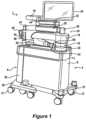
- FIG. 1illustrates an embodiment of a surgical system according to some embodiments of the present disclosure
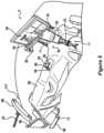
- FIG. 2illustrates a surgical robot component of the surgical system of FIG. 1 according to some embodiments of the present disclosure
- FIG. 3 Aillustrates a camera tracking system component of the surgical system of FIG. 1 according to some embodiments of the present disclosure
- FIGS. 3 B and 3 Cillustrate a front view and isometric view of another camera tracking system component which may be used with the surgical system of FIG. 1 according to some embodiments of the present disclosure
- FIG. 4illustrates an embodiment of an end effector that is connectable to a robot arm and configured according to some embodiments of the present disclosure
- FIG. 5illustrates a medical operation in which a surgical robot and a camera system are disposed around a patient
- FIG. 6illustrates a block diagram view of the components of the surgical system of FIG. 5 being used for a medical operation
- FIG. 7illustrates various display screens that may be displayed on the display of FIGS. 5 and 6 when using a navigation function of the surgical system
- FIG. 8illustrates a block diagram of some electrical components of a surgical robot according to some embodiments of the present disclosure
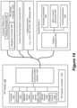
- FIG. 9illustrates a block diagram of components of a surgical system that includes imaging devices connected to a computer platform which can be operationally connected to a camera tracking system and/or surgical robot according to some embodiments of the present disclosure
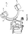
- FIG. 10illustrates an embodiment of a C-Arm imaging device that can be used in combination with the surgical robot in accordance with some embodiments of the present disclosure
- FIG. 11illustrates an embodiment of an O-Arm imaging device that can be used in combination with the surgical robot in accordance with some embodiments of the present disclosure
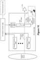
- FIG. 12illustrates a block diagram view of the components of a surgical system that includes a pair of XR headsets and an auxiliary tracking bar which operate in accordance with some embodiments of the present disclosure
- FIG. 13illustrates an XR headset which is configured in accordance with some embodiments of the present disclosure
- FIG. 14illustrates electrical components of the XR headset that can be operatively connected to a computer platform, imaging device(s), and/or a surgical robot in accordance with some embodiments of the present disclosure
- FIG. 15illustrates a block diagram showing arrangement of optical components of the XR headset in accordance with some embodiments of the present disclosure
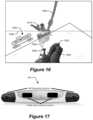
- FIG. 16illustrates an example view through the display screen of an XR headset for providing navigation assistance to manipulate a surgical tool during a medical procedure in accordance with some embodiments of the present disclosure
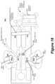
- FIG. 17illustrates an example configuration of an auxiliary tracking bar having two pairs of stereo cameras configured in accordance with some embodiments of the present disclosure
- FIG. 18illustrates a block diagram view of the components of a surgical system that includes tracking cameras in a pair of XR headsets and in an auxiliary tracking bar which collectively operate in accordance with some embodiments of the present disclosure
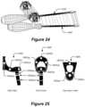
- FIG. 19illustrates an example configuration of a surgical tool tracking array with a camera bar having three stereo tracking cameras configured in accordance with some embodiments of the present disclosure
- FIG. 20 aillustrates a single point stereo camera triangulation using two tracking cameras
- FIG. 20 billustrates a single point triangulation using three tracking cameras in accordance with some embodiments of the present disclosure
- FIG. 21illustrates examples of a surgical tool attached to a physical reference array with fiducial disks, in accordance with some embodiments of the present disclosure
- FIG. 22Illustrates an example side view of the physical reference array attached to the surgical tool of FIG. 21 , in accordance with some embodiments of the present disclosure
- FIG. 23illustrates an example of a surgical tool tracking array that includes a multi-faced reference array, in accordance with some embodiments of the present disclosure
- FIG. 24illustrates an example of 2D image registration between undistorted image information and synthetic image information generated from the 3D model of the tool, in accordance with some embodiments of the present disclosure
- FIG. 25illustrates an example of an end effector with fiducial disks, in accordance with some embodiments of the present disclosure
- FIG. 26illustrates a flowchart of operations performed by the camera tracking system, in accordance with some embodiments of the present disclosure
- FIG. 27illustrates another flowchart of operations performed by the camera tracking system, in accordance with some embodiments of the present disclosure
- FIG. 28illustrates another flowchart of operations performed by the camera tracking system, in accordance with some embodiments of the present disclosure.
- FIG. 29illustrates another flowchart of operations performed by the camera tracking system, in accordance with some embodiments of the present disclosure.
- An extended reality (XR) headsetis operatively connected to the surgical system and configured to provide an interactive environment through which a surgeon, assistant, and/or other personnel can view and select among patient images, view and select among computer generated surgery navigation information, and/or control surgical equipment in the operating room.
- the XR headsetmay be configured to augment a real-world scene with computer generated XR images.
- the XR headsetmay be configured to provide an augmented reality (AR) viewing environment by displaying the computer generated XR images on a see-through display screen that allows light from the real-world scene to pass therethrough for combined viewing by the user.
- ARaugmented reality
- the XR headsetmay be configured to provide a virtual reality (VR) viewing environment by preventing or substantially preventing light from the real-world scene from being directly viewed by the user while the user is viewing the computer generated AR images on a display screen.
- An XR headsetcan be configured to provide both AR and VR viewing environments.
- both AR and VR viewing environmentsare provided by lateral bands of substantially differing opacity arranged between the see-through display screen and the real-world scene, so that a VR viewing environment is provided for XR images aligned with a high opacity band and an AR viewing environment is provided for XR images aligned with the low opacity band.
- both AR and VR viewing environmentsare provided by computer adjustable control of an opacity filter that variably constrains how much light from the real-world scene passes through a see-through display screen for combining with the XR images viewed by the user.
- the XR headsetcan also be referred to as an AR headset or a VR headset.
- FIG. 1illustrates an embodiment of a surgical system 2 according to some embodiments of the present disclosure.
- a three-dimensional (“3D”) image scanmay be taken of a planned surgical area of a patient using, e.g., the C-Arm imaging device 104 of FIG. 10 or O-Arm imaging device 106 of FIG. 11 , or from another medical imaging device such as a computed tomography (CT) image or MRI.
- CTcomputed tomography
- This scancan be taken pre-operatively (e.g. few weeks before procedure, most common) or intra-operatively.
- any known 3D or 2D image scanmay be used in accordance with various embodiments of the surgical system 2 .
- the image scanis sent to a computer platform in communication with the surgical system 2 , such as the computer platform 910 of the surgical system 900 ( FIG. 9 ) which may include the camera tracking system component 6 , the surgical robot 4 (e.g., robot 2 in FIG. 1 ), imaging devices (e.g., C-Arm 104 , O-Arm 106 , etc.), and an image database 950 for storing image scans of patients.
- the surgical robot 4e.g., robot 2 in FIG. 1
- imaging devicese.g., C-Arm 104 , O-Arm 106 , etc.
- an image database 950for storing image scans of patients.
- a surgeon reviewing the image scan(s) on a display device of the computer platform 910 ( FIG. 9 )generates a surgical plan defining a target pose for a surgical tool to be used during a surgical procedure on an anatomical structure of the patient.
- Example surgical toolscan include, without limitation, drills, screw drivers, saws, retractors, and implants such as a screws, spacers, interbody fusion devices, plates, rods, etc.
- the surgical plan defining the target planeis planned on the 3D image scan displayed on a display device.
- the term “pose”refers to the position and/or the rotational angle of one object (e.g., dynamic reference array, end effector, surgical tool, anatomical structure, etc.) relative to another object and/or to a defined coordinate system.
- a posemay therefore be defined based on only the multidimensional position of one object relative to another object and/or to a defined coordinate system, only on the multidimensional rotational angles of the object relative to another object and/or to a defined coordinate system, or on a combination of the multidimensional position and the multidimensional rotational angles.
- the term “pose”therefore is used to refer to position, rotational angle, or combination thereof.
- the surgical system 2 of FIG. 1can assist surgeons during medical procedures by, for example, holding tools, aligning tools, using tools, guiding tools, and/or positioning tools for use.
- surgical system 2includes a surgical robot 4 and a camera tracking system component 6 .
- the ability to mechanically couple surgical robot 4 and camera tracking system component 6can allow for surgical system 2 to maneuver and move as a single unit, and allow surgical system 2 to have a small footprint in an area, allow easier movement through narrow passages and around turns, and allow storage within a smaller area.
- a surgical proceduremay begin with the surgical system 2 moving from medical storage to a medical procedure room.
- the surgical system 2may be maneuvered through doorways, halls, and elevators to reach a medical procedure room.
- the surgical system 2may be physically separated into two separate and distinct systems, the surgical robot 4 and the camera tracking system component 6 .
- Surgical robot 4may be positioned adjacent the patient at any suitable location to properly assist medical personnel.
- Camera tracking system component 6may be positioned at the base of the patient, at the patient shoulders, or any other location suitable to track the present pose and movement of the pose of tracks portions of the surgical robot 4 and the patient.
- Surgical robot 4 and camera tracking system component 6may be powered by an onboard power source and/or plugged into an external wall outlet.
- Surgical robot 4may be used to assist a surgeon by holding and/or using tools during a medical procedure. To properly utilize and hold tools, surgical robot 4 may rely on a plurality of motors, computers, and/or actuators to function properly. Illustrated in FIG. 1 , robot body 8 may act as the structure in which the plurality of motors, computers, and/or actuators may be secured within surgical robot 4 . Robot body 8 may also provide support for robot telescoping support 16 . The size of robot body 8 may provide a solid platform supporting attached components, and may house, conceal, and protect the plurality of motors, computers, and/or actuators that may operate attached components.
- Robot base 10may act as a lower support for surgical robot 4 .
- robot base 10may support robot body 8 and may attach robot body 8 to a plurality of powered wheels 12 . This attachment to wheels may allow robot body 8 to move in space efficiently.
- Robot base 10may run the length and width of robot body 8 .
- Robot base 10may be about two inches to about 10 inches tall.
- Robot base 10may cover, protect, and support powered wheels 12 .
- At least one powered wheel 12may be attached to robot base 10 .
- Powered wheels 12may attach to robot base 10 at any location. Each individual powered wheel 12 may rotate about a vertical axis in any direction.
- a motormay be disposed above, within, or adjacent to powered wheel 12 . This motor may allow for surgical system 2 to maneuver into any location and stabilize and/or level surgical system 2 .
- a rod, located within or adjacent to powered wheel 12may be pressed into a surface by the motor.
- the rodnot pictured, may be made of any suitable metal to lift surgical system 2 .
- the rodmay lift powered wheel 10 , which may lift surgical system 2 , to any height required to level or otherwise fix the orientation of the surgical system 2 in relation to a patient.
- the weight of surgical system 2supported through small contact areas by the rod on each wheel, prevents surgical system 2 from moving during a medical procedure. This rigid positioning may prevent objects and/or people from moving surgical system 2 by accident.
- Moving surgical system 2may be facilitated using robot railing 14 .
- Robot railing 14provides a person with the ability to move surgical system 2 without grasping robot body 8 . As illustrated in FIG. 1 , robot railing 14 may run the length of robot body 8 , shorter than robot body 8 , and/or may run longer the length of robot body 8 . Robot railing 14 may further provide protection to robot body 8 , preventing objects and or personnel from touching, hitting, or bumping into robot body 8 .
- Robot body 8may provide support for a Selective Compliance Articulated Robot Arm, hereafter referred to as a “SCARA.”
- a SCARA 24may be beneficial to use within the surgical system 2 due to the repeatability and compactness of the robotic arm. The compactness of a SCARA may provide additional space within a medical procedure, which may allow medical professionals to perform medical procedures free of excess clutter and confining areas.
- SCARA 24may comprise robot telescoping support 16 , robot support arm 18 , and/or robot arm 20 .
- Robot telescoping support 16may be disposed along robot body 8 . As illustrated in FIG. 1 , robot telescoping support 16 may provide support for the SCARA 24 and display 34 . In some embodiments, robot telescoping support 16 may extend and contract in a vertical direction.
- the body of robot telescoping support 16may be any width and/or height configured to support the stress and weight placed upon it.
- medical personnelmay move SCARA 24 through a command submitted by the medical personnel.
- the commandmay originate from input received on display 34 , a tablet, and/or an XR headset (e.g., headset 920 in FIG. 9 ) as will be explained in further detail below.
- the XR headsetmay eliminate the need for medical personnel to refer to any other display such as the display 34 or a tablet, which enables the SCARA 24 to be configured without the display 34 and/or the tablet.
- the commandmay be generated by the depression of a switch and/or the depression of a plurality of switches, and/or may be generated based on a hand gesture command and/or voice command that is sensed by the XR headset as will be explained in further detail below.
- an activation assembly 60may include a switch and/or a plurality of switches.
- the activation assembly 60may be operable to transmit a move command to the SCARA 24 allowing an operator to manually manipulate the SCARA 24 .
- the switch, or plurality of switchesWhen the switch, or plurality of switches, is depressed the medical personnel may have the ability to move SCARA 24 through applied hand movements.
- an operatormay control movement of the SCARA 24 through hand gesture commands and/or voice commands that are sensed by the XR headset as will be explained in further detail below.
- the SCARA 24may lock in place to prevent accidental movement by personnel and/or other objects. By locking in place, the SCARA 24 provides a solid platform through which the end effector 26 can guide a surgical tool during a medical procedure.
- Robot support arm 18can be connected to robot telescoping support 16 by various mechanisms. In some embodiments, best seen in FIGS. 1 and 2 , robot support arm 18 rotates in any direction in regard to robot telescoping support 16 . Robot support arm 18 may rotate three hundred and sixty degrees around robot telescoping support 16 . Robot arm 20 may connect to robot support arm 18 at any suitable location and by various mechanisms that enable rotation in any direction relative to robot support arm 18 . In one embodiment, the robot arm 20 can rotate three hundred and sixty degrees relative to the robot support arm 18 . This free rotation allows an operator to position robot arm 20 according to a surgical plan.
- the end effector 26 shown in FIGS. 4 and 5may attach to robot arm 20 in any suitable location.
- the end effector 26can be configured to attach to an end effector coupler 22 of the robot arm 20 positioned by the surgical robot 4 .
- the example end effector 26includes a tubular guide that guides movement of an inserted surgical tool relative to an anatomical structure on which a surgical procedure is to be performed.
- a dynamic reference array 52is attached to the end effector 26 .
- Dynamic reference arraysalso referred to as “DRAB” and “reference arrays” herein, can be rigid bodies, markers, or other indicia which may be attached or formed on one or more XR headsets being worn by personnel in the operating room, the end effector, the surgical robot, a surgical tool in a navigated surgical procedure, and an anatomical structure (e.g., bone) of a patient.
- the computer platform 910in combination with the camera tracking system component 6 or other 3D localization system are configured to track in real-time the pose (e.g., positions and rotational orientations) of the DRA.
- the DRAcan include fiducials, such as the illustrated arrangement of balls. This tracking of 3D coordinates of the DRA can allow the surgical system 2 to determine the pose of the DRA in any multidimensional space in relation to the target anatomical structure of the patient 50 in FIG. 5 .
- a light indicator 28may be positioned on top of the SCARA 24 .
- Light indicator 28may illuminate as any type of light to indicate “conditions” in which surgical system 2 is currently operating.
- the lightmay be produced by LED bulbs, which may form a ring around light indicator 28 .
- Light indicator 28may comprise a fully permeable material that can let light shine through the entirety of light indicator 28 .
- Light indicator 28may be attached to lower display support 30 .
- Lower display support 30as illustrated in FIG. 2 may allow an operator to maneuver display 34 to any suitable location.
- Lower display support 30may attach to light indicator 28 by any suitable mechanism.
- lower display support 30may rotate about light indicator 28 or be rigidly attached thereto.
- Upper display support 32may attach to lower display support 30 by any suitable mechanism.
- a tabletmay be used in conjunction with display 34 and/or without display 34 .
- the tabletmay be disposed on upper display support 32 , in place of display 34 , and may be removable from upper display support 32 during a medical operation.
- the tabletmay communicate with display 34 .
- the tabletmay be able to connect to surgical robot 4 by any suitable wireless and/or wired connection.
- the tabletmay be able to program and/or control surgical system 2 during a medical operation. When controlling surgical system 2 with the tablet, all input and output commands may be duplicated on display 34 .
- the use of a tabletmay allow an operator to manipulate surgical robot 4 without having to move around patient 50 and/or to surgical robot 4 .
- a surgeon and/or other personnelcan wear XR headsets that may be used in conjunction with display 34 and/or a tablet or the XR head(s) may eliminate the need for use of the display 34 and/or tablet.
- camera tracking system component 6works in conjunction with surgical robot 4 through wired or wireless communication networks.
- camera tracking system component 6can include some similar components to the surgical robot 4 .
- camera body 36may provide the functionality found in robot body 8 .
- Robot body 8may provide an auxiliary tracking bar upon which cameras 46 are mounted.
- the structure within robot body 8may also provide support for the electronics, communication devices, and power supplies used to operate camera tracking system component 6 .
- Camera body 36may be made of the same material as robot body 8 .
- Camera tracking system component 6may communicate directly to an XR headset, tablet and/or display 34 by a wireless and/or wired network to enable the XR headset, tablet and/or display 34 to control the functions of camera tracking system component 6 .
- Camera body 36is supported by camera base 38 .
- Camera base 38may function as robot base 10 .
- camera base 38may be wider than robot base 10 .
- the width of camera base 38may allow for camera tracking system component 6 to connect with surgical robot 4 .
- the width of camera base 38may be large enough to fit outside robot base 10 .
- the additional width of camera base 38may allow surgical system 2 additional maneuverability and support for surgical system 2 .
- a plurality of powered wheels 12may attach to camera base 38 .
- Powered wheel 12may allow camera tracking system component 6 to stabilize and level or set fixed orientation in regards to patient 50 , similar to the operation of robot base 10 and powered wheels 12 .
- This stabilizationmay prevent camera tracking system component 6 from moving during a medical procedure and may keep cameras 46 on the auxiliary tracking bar from losing track of a DRA connected to an XR headset and/or the surgical robot 4 , and/or losing track of one or more DRAs 52 connected to an anatomical structure 54 and/or tool 58 within a designated area 56 as shown in FIGS. 3 A and 5 .
- This stability and maintenance of trackingenhances the ability of surgical robot 4 to operate effectively with camera tracking system component 6 .
- the wide camera base 38may provide additional support to camera tracking system component 6 .
- a wide camera base 38may prevent camera tracking system component 6 from tipping over when cameras 46 is disposed over a patient, as illustrated in FIGS. 3 A and 5 .
- Camera telescoping support 40may support cameras 46 on the auxiliary tracking bar. In some embodiments, telescoping support 40 moves cameras 46 higher or lower in the vertical direction.
- Camera handle 48may be attached to camera telescoping support 40 at any suitable location and configured to allow an operator to move camera tracking system component 6 into a planned position before a medical operation. In some embodiments, camera handle 48 is used to lower and raise camera telescoping support 40 . Camera handle 48 may perform the raising and lowering of camera telescoping support 40 through the depression of a button, switch, lever, and/or any combination thereof.
- Lower camera support arm 42may attach to camera telescoping support 40 at any suitable location, in embodiments, as illustrated in FIG. 1 , lower camera support arm 42 may rotate three hundred and sixty degrees around telescoping support 40 . This free rotation may allow an operator to position cameras 46 in any suitable location.
- Lower camera support arm 42may connect to telescoping support 40 by any suitable mechanism.
- Lower camera support arm 42may be used to provide support for cameras 46 .
- Cameras 46may be attached to lower camera support arm 42 by any suitable mechanism. Cameras 46 may pivot in any direction at the attachment area between cameras 46 and lower camera support arm 42 .
- a curved rail 44may be disposed on lower camera support arm 42 .
- Curved rail 44may be disposed at any suitable location on lower camera support arm 42 . As illustrated in FIG. 3 A , curved rail 44 may attach to lower camera support arm 42 by any suitable mechanism. Curved rail 44 may be of any suitable shape, a suitable shape may be a crescent, circular, oval, elliptical, and/or any combination thereof. Cameras 46 may be moveably disposed along curved rail 44 . Cameras 46 may attach to curved rail 44 by, for example, rollers, brackets, braces, motors, and/or any combination thereof. Motors and rollers, not illustrated, may be used to move cameras 46 along curved rail 44 . As illustrated in FIG.
- the motorsmay responsively move cameras 46 along curved rail 44 .
- This motorized movementmay allow cameras 46 to move to a new position that is no longer obstructed by the object without moving camera tracking system component 6 .
- camera tracking system component 6may send a stop signal to a surgical robot 4 , XR headset, display 34 , and/or a tablet.
- the stop signalmay prevent SCARA 24 from moving until cameras 46 has reacquired tracked DRAs 52 and/or can warn an operator wearing the XR headset and/or viewing the display 34 and/or the tablet.
- This SCARA 24can be configured to respond to receipt of a stop signal by stopping further movement of the base and/or end effector coupler 22 until the camera tracking system can resume tracking of DRAs.
- FIGS. 3 B and 3 Cillustrate a front view and isometric view of another camera tracking system component 6 ′ which may be used with the surgical system of FIG. 1 or may be used independent of a surgical robot.
- the camera tracking system component 6 ′may be used for providing navigated surgery without use of robotic guidance.
- One of the differences between the camera tracking system component 6 ′ of FIGS. 3 B and 3 C and the camera tracking system component 6 of FIG. 3 Ais that the camera tracking system component 6 ′ of FIGS. 3 B and 3 C includes a housing that transports the computer platform 910 .
- the computer platform 910can be configured to perform camera tracking operations to track DRAs, perform navigated surgery operations that provide surgical navigation information to a display device, e.g., XR headset and/or other display device, and perform other computational operations disclosed herein.
- the computer platform 910can therefore include a navigation computer, such as one or more of the navigation computers of FIG. 14 .
- FIG. 6illustrates a block diagram view of the components of the surgical system of FIG. 5 used for the medical operation.
- the tracking cameras 46 on the auxiliary tracking barhas a navigation field-of-view 600 in which the pose (e.g., position and orientation) of the reference array 602 attached to the patient, the reference array 604 attached to the surgical instrument, and the robot arm 20 are tracked.
- the tracking cameras 46may be part of the camera tracking system component 6 ′ of FIGS. 3 B and 3 C , which includes the computer platform 910 configured to perform the operations described below.
- the reference arraysenable tracking by reflecting light in known patterns, which are decoded to determine their respective poses by the tracking subsystem of the surgical robot 4 .
- a responsive notificationmay temporarily halt further movement of the robot arm 20 and surgical robot 4 , display a warning on the display 34 , and/or provide an audible warning to medical personnel.
- the display 34is accessible to the surgeon 610 and assistant 612 but viewing requires a head to be turned away from the patient and for eye focus to be changed to a different distance and location.
- the navigation softwaremay be controlled by a tech personnel 614 based on vocal instructions from the surgeon.
- FIG. 7illustrates various display screens that may be displayed on the display 34 of FIGS. 5 and 6 by the surgical robot 4 when using a navigation function of the surgical system 2 .
- the display screenscan include, without limitation, patient radiographs with overlaid graphical representations of models of instruments that are positioned in the display screens relative to the anatomical structure based on a developed surgical plan and/or based on poses of tracked reference arrays, various user selectable menus for controlling different stages of the surgical procedure and dimension parameters of a virtually projected implant (e.g. length, width, and/or diameter).
- processing componentse.g., computer platform 910
- associated softwaredescribed below are provided that enable pre-operatively planning of a surgical procedure, e.g., implant placement, and electronic transfer of the plan to computer platform 910 to provide navigation information to one or more users during the planned surgical procedure.
- various processing componentse.g., computer platform 910
- associated softwaredescribed below are provided that enable pre-operatively planning of a surgical procedure, e.g., implant placement, and electronic transfer of the plan to the surgical robot 4 .
- the surgical robot 4uses the plan to guide the robot arm 20 and connected end effector 26 to provide a target pose for a surgical tool relative to a patient anatomical structure for a step of the planned surgical procedure.
- Various embodiments beloware directed to using one or more XR headsets that can be worn by the surgeon 610 , the assistant 612 , and/or other medical personnel to provide an improved user interface for receiving information from and/or providing control commands to the surgical robot, the camera tracking system component 6 / 6 ′, and/or other medical equipment in the operating room.
- FIG. 8illustrates a block diagram of some electrical components of the surgical robot 4 according to some embodiments of the present disclosure.
- a load cell(not shown) may be configured to track force applied to end effector coupler 22 .
- the load cellmay communicate with a plurality of motors 850 , 851 , 852 , 853 , and/or 854 .
- Controller 846may take the force information from load cell and process it with a switch algorithm. The switch algorithm is used by the controller 846 to control a motor driver 842 .
- the motor driver 842controls operation of one or more of the motors 850 , 851 , 852 , 853 , and 854 .
- Motor driver 842may direct a specific motor to produce, for example, an equal amount of force measured by load cell through the motor.
- the force producedmay come from a plurality of motors, e.g., 850 - 854 , as directed by controller 846 .
- motor driver 842may receive input from controller 846 .
- Controller 846may receive information from load cell as to the direction of force sensed by load cell. Controller 846 may process this information using a motion controller algorithm. The algorithm may be used to provide information to specific motor drivers 842 .
- controller 846may activate and/or deactivate certain motor drivers 842 .
- Controller 846may control one or more motors, e.g. one or more of 850 - 854 , to induce motion of end effector 26 in the direction of force sensed by load cell.
- This force-controlled motionmay allow an operator to move SCARA 24 and end effector 26 effortlessly and/or with very little resistance. Movement of end effector 26 can be performed to position end effector 26 in any suitable pose (i.e., location and angular orientation relative to defined three-dimensional (3D) orthogonal reference axes) for use by medical personnel.
- Activation assembly 60may form of a bracelet that wraps around end effector coupler 22 .
- the activation assembly 60may be located on any part of SCARA 24 , any part of end effector coupler 22 , may be worn by medical personnel (and communicate wirelessly), and/or any combination thereof.
- Activation assembly 60may comprise of a primary button and a secondary button.
- Depressing primary buttonmay allow an operator to move SCARA 24 and end effector coupler 22 .
- SCARA 24 and end effector coupler 22may not move until an operator programs surgical robot 4 to move SCARA 24 and end effector coupler 22 , or is moved using primary button.
- itmay require the depression of at least two non-adjacent primary activation switches before SCARA 24 and end effector coupler 22 will respond to operator commands. Depression of at least two primary activation switches may prevent the accidental movement of SCARA 24 and end effector coupler 22 during a medical procedure.
- load cellmay measure the force magnitude and/or direction exerted upon end effector coupler 22 by an operator, i.e. medical personnel. This information may be transferred to one or more motors, e.g. one or more of 850 - 854 , within SCARA 24 that may be used to move SCARA 24 and end effector coupler 22 . Information as to the magnitude and direction of force measured by load cell may cause the one or more motors, e.g. one or more of 850 - 854 , to move SCARA 24 and end effector coupler 22 in the same direction as sensed by the load cell.
- motorse.g. one or more of 850 - 854
- This force-controlled movementmay allow the operator to move SCARA 24 and end effector coupler 22 easily and without large amounts of exertion due to the motors moving SCARA 24 and end effector coupler 22 at the same time the operator is moving SCARA 24 and end effector coupler 22 .
- a secondary buttonmay be used by an operator as a “selection” device.
- surgical robot 4may notify medical personnel to certain conditions by the XR headset(s) 920 , display 34 and/or light indicator 28 .
- the XR headset(s) 920are each configured to display images on a see-through display screen to form an extended reality image that is overlaid on real-world objects viewable through the see-through display screen. Medical personnel may be prompted by surgical robot 4 to select a function, mode, and/or assesses the condition of surgical system 2 .
- Depressing secondary button a single timemay activate certain functions, modes, and/or acknowledge information communicated to medical personnel through the XR headset(s) 920 , display 34 and/or light indicator 28 . Additionally, depressing the secondary button multiple times in rapid succession may activate additional functions, modes, and/or select information communicated to medical personnel through the XR headset(s) 920 , display 34 and/or light indicator 28 .
- electrical components of the surgical robot 4include platform subsystem 802 , computer subsystem 820 , motion control subsystem 840 , and tracking subsystem 830 .
- Platform subsystem 802includes battery 806 , power distribution module 804 , connector panel 808 , and charging station 810 .
- Computer subsystem 820includes computer 822 , display 824 , and speaker 826 .
- Motion control subsystem 840includes driver circuit 842 , motors 850 , 851 , 852 , 853 , 854 , stabilizers 855 , 856 , 857 , 858 , end effector connector 844 , and controller 846 .
- Tracking subsystem 830includes position sensor 832 and camera converter 834 .
- Surgical robot 4may also include a removable foot pedal 880 and removable tablet computer 890 .
- Input poweris supplied to surgical robot 4 via a power source which may be provided to power distribution module 804 .
- Power distribution module 804receives input power and is configured to generate different power supply voltages that are provided to other modules, components, and subsystems of surgical robot 4 .
- Power distribution module 804may be configured to provide different voltage supplies to connector panel 808 , which may be provided to other components such as computer 822 , display 824 , speaker 826 , driver 842 to, for example, power motors 850 - 854 and end effector coupler 844 , and provided to camera converter 834 and other components for surgical robot 4 .
- Power distribution module 804may also be connected to battery 806 , which serves as temporary power source in the event that power distribution module 804 does not receive power from an input power. At other times, power distribution module 804 may serve to charge battery 806 .
- Connector panel 808may serve to connect different devices and components to surgical robot 4 and/or associated components and modules.
- Connector panel 808may contain one or more ports that receive lines or connections from different components.
- connector panel 808may have a ground terminal port that may ground surgical robot 4 to other equipment, a port to connect foot pedal 880 , a port to connect to tracking subsystem 830 , which may include position sensor 832 , camera converter 834 , and DRA tracking cameras 870 .
- Connector panel 808may also include other ports to allow USB, Ethernet, HDMI communications to other components, such as computer 822 .
- the connector panel 808can include a wired and/or wireless interface for operatively connecting one or more XR headsets 920 to the tracking subsystem 830 and/or the computer subsystem 820 .
- Control panel 816may provide various buttons or indicators that control operation of surgical robot 4 and/or provide information from surgical robot 4 for observation by an operator.
- control panel 816may include buttons to power on or off surgical robot 4 , lift or lower vertical column 16 , and lift or lower stabilizers 855 - 858 that may be designed to engage casters 12 to lock surgical robot 4 from physically moving.
- Other buttonsmay stop surgical robot 4 in the event of an emergency, which may remove all motor power and apply mechanical brakes to stop all motion from occurring.
- Control panel 816may also have indicators notifying the operator of certain system conditions such as a line power indicator or status of charge for battery 806 .
- one or more XR headsets 920may communicate, e.g. via the connector panel 808 , to control operation of the surgical robot 4 and/or to received and display information generated by surgical robot 4 for observation by persons wearing the XR headsets 920 .
- Computer 822 of computer subsystem 820includes an operating system and software to operate assigned functions of surgical robot 4 .
- Computer 822may receive and process information from other components (for example, tracking subsystem 830 , platform subsystem 802 , and/or motion control subsystem 840 ) in order to display information to the operator.
- computer subsystem 820may provide output through the speaker 826 for the operator.
- the speakermay be part of the surgical robot, part of an XR headset 920 , or within another component of the surgical system 2 .
- the display 824may correspond to the display 34 shown in FIGS. 1 and 2 .
- Tracking subsystem 830may include position sensor 832 and camera converter 834 . Tracking subsystem 830 may correspond to the camera tracking system component 6 of FIG. 3 .
- the DRA tracking cameras 870operate with the position sensor 832 to determine the pose of DRAs 52 . This tracking may be conducted in a manner consistent with the present disclosure including the use of infrared or visible light technology that tracks the location of active or passive elements of DRAs 52 , such as LEDs or reflective fiducials (also called markers), respectively.
- the tracking subsystem 830 and the computer subsystem 820can be included in the computer platform 910 , which can be transported by the camera tracking system component 6 ′ of FIGS. 3 A and 3 B .
- the tracking subsystem 830can be configured to determine the poses, e.g., location and angular orientation of the tracked DRAs.
- the computer platform 910can also include a navigation controller that is configured to use the determined poses to provide navigation information to users that guides their movement of tracked tools relative to position-registered patient images and/or tracked anatomical structures during a planned surgical procedure.
- the computer platform 910can display information on the display of FIGS. 3 B and 3 C and/or to one or more XR headsets 920 .
- the computer platform 910when used with a surgical robot, can be configured to communicate with the computer subsystem 820 and other subsystems of FIG. 8 to control movement of the end effector 26 .
- the computer platform 910can generate a graphical representation of a patient's anatomical structure, surgical tool, user's hand, etc. with a displayed size, shape, color, and/or pose that is controlled based on the determined pose(s) of one or more the tracked DRAs, and which the graphical representation that is displayed can be dynamically modified to track changes in the determined poses over time.
- Motion control subsystem 840may be configured to physically move vertical column 16 , upper arm 18 , lower arm 20 , or rotate end effector coupler 22 .
- the physical movementmay be conducted through the use of one or more motors 850 - 854 .
- motor 850may be configured to vertically lift or lower vertical column 16 .
- Motor 851may be configured to laterally move upper arm 18 around a point of engagement with vertical column 16 as shown in FIG. 2 .
- Motor 852may be configured to laterally move lower arm 20 around a point of engagement with upper arm 18 as shown in FIG. 2 .
- Motors 853 and 854may be configured to move end effector coupler 22 to provide translational movement and rotation along in about three-dimensional axes.
- Motion control subsystem 840may be configured to measure position of the end effector coupler 22 and/or the end effector 26 using integrated position sensors (e.g. encoders).
- FIG. 9illustrates a block diagram of components of a surgical system that includes imaging devices (e.g., C-Arm 104 , O-Arm 106 , etc.) connected to a computer platform 910 which can be operationally connected to a camera tracking system component 6 ( FIG. 3 A ) or 6 ′ ( FIGS. 3 B, 3 C ) and/or to surgical robot 4 according to some embodiments of the present disclosure.
- imaging devicese.g., C-Arm 104 , O-Arm 106 , etc.
- a computer platform 910which can be operationally connected to a camera tracking system component 6 ( FIG. 3 A ) or 6 ′ ( FIGS. 3 B, 3 C ) and/or to surgical robot 4 according to some embodiments of the present disclosure.
- a camera tracking system component 6FIG. 3 A
- 6 ′FIGS. 3 B, 3 C
- the computer platform 910includes a display 912 , at least one processor circuit 914 (also referred to as a processor for brevity), at least one memory circuit 916 (also referred to as a memory for brevity) containing computer readable program code 918 , and at least one network interface 902 (also referred to as a network interface for brevity).
- the display 912may be part of an XR headset 920 in accordance with some embodiments of the present disclosure.
- the network interface 902can be configured to connect to a C-Arm imaging device 104 in FIG. 10 , an O-Arm imaging device 106 in FIG. 11 , another medical imaging device, an image database 950 containing patient medical images, components of the surgical robot 4 , and/or other electronic equipment.
- the display 912When used with a surgical robot 4 , the display 912 may correspond to the display 34 of FIG. 2 and/or the tablet 890 of FIG. 8 and/or the XR headset 920 that is operatively connected to the surgical robot 4 , the network interface 902 may correspond to the platform network interface 812 of FIG. 8 , and the processor 914 may correspond to the computer 822 of FIG. 8 .
- the network interface 902 of the XR headset 920may be configured to communicate through a wired network, e.g., thin wire ethernet, and/or through wireless RF transceiver link according to one or more wireless communication protocols, e.g., WLAN, 3GPP 4G and/or 5G (New Radio) cellular communication standards, etc.
- wireless communication protocolse.g., WLAN, 3GPP 4G and/or 5G (New Radio) cellular communication standards, etc.
- the processor 914may include one or more data processing circuits, such as a general purpose and/or special purpose processor, e.g., microprocessor and/or digital signal processor.
- the processor 914is configured to execute the computer readable program code 918 in the memory 916 to perform operations, which may include some or all of the operations described herein as being performed for surgery planning, navigated surgery, and/or robotic surgery.
- the computer platform 910can be configured to provide surgery planning functionality.
- the processor 914can operate to display on the display device 912 and/or on the XR headset 920 an image of an anatomical structure, e.g., vertebra, that is received from one of the imaging devices 104 and 106 and/or from the image database 950 through the network interface 920 .
- the processor 914receives an operator's definition of where the anatomical structure shown in one or more images is to have a surgical procedure, e.g., screw placement, such as by the operator touch selecting locations on the display 912 for planned procedures or using a mouse-based cursor to define locations for planned procedures.
- the XR headsetcan be configured to sense in gesture-based commands formed by the wearer and/or sense voice based commands spoken by the wearer, which can be used to control selection among menu items and/or control how objects are displayed on the XR headset 920 as will be explained in further detail below.
- the computer platform 910can be configured to enable anatomy measurement, which can be particularly useful for knee surgery, like measurement of various angles determining center of hip, center of angles, natural landmarks (e.g. transepicondylar line, Whitesides line, posterior condylar line), etc. Some measurements can be automatic while some others can involve human input or assistance.
- the computer platform 910may be configured to allow an operator to input a choice of the correct implant for a patient, including choice of size and alignment.
- the computer platform 910may be configured to perform automatic or semi-automatic (involving human input) segmentation (image processing) for CT images or other medical images.
- the surgical plan for a patientmay be stored in a cloud-based server, which may correspond to database 950 , for retrieval by the surgical robot 4 .
- a surgeonmay choose which cut to make (e.g. posterior femur, proximal tibia etc.) using a computer screen (e.g. touchscreen) or extended reality (XR) interaction (e.g., hand gesture based commands and/or voice based commands) via, e.g., the XR headset 920 .
- the computer platform 910can generate navigation information which provides visual guidance to the surgeon for performing the surgical procedure.
- the computer platform 910can provide guidance that allows the surgical robot 4 to automatically move the end effector 26 to a target pose so that the surgical tool is aligned with a target location to perform the surgical procedure on an anatomical structure.
- the surgical system 900can use two DRAs to track patient anatomy position, such as one connected to patient tibia and one connected to patient femur.
- the system 900may use standard navigated instruments for the registration and checks (e.g. a pointer similar to the one used in Globus ExcelsiusGPS system for spine surgery).
- a particularly challenging task in navigated surgeryis how to plan the position of an implant in spine, knee, and other anatomical structures where surgeons struggle to perform the task on a computer screen which is a 2D representation of the 3D anatomical structure.
- the system 900could address this problem by using the XR headset 920 to display a three-dimensional (3D) computer generated representations of the anatomical structure and a candidate implant device.
- the computer generated representationsare scaled and posed relative to each other on the display screen under guidance of the computer platform 910 and which can be manipulated by a surgeon while viewed through the XR headset 920 .
- a surgeonmay, for example, manipulate the displayed computer-generated representations of the anatomical structure, the implant, a surgical tool, etc., using hand gesture based commands and/or voice based commands that are sensed by the XR headset 920 .
- a surgeoncan view a displayed virtual handle on a virtual implant, and can manipulate (e.g., grab and move) the virtual handle to move the virtual implant to a desired pose and adjust a planned implant placement relative to a graphical representation of an anatomical structure.
- the computer platform 910could display navigation information through the XR headset 920 that facilitates the surgeon's ability to more accurately follow the surgical plan to insert the implant and/or to perform another surgical procedure on the anatomical structure.
- the progress of bone removale.g., depth of cut
- Other features that may be displayed through the XR headset 920can include, without limitation, gap or ligament balance along a range of joint motion, contact line on the implant along the range of joint motion, ligament tension and/or laxity through color or other graphical renderings, etc.
- the computer platform 910can allow planning for use of standard surgical tools and/or implants, e.g., posterior stabilized implants and cruciate retaining implants, cemented and cementless implants, revision systems for surgeries related to, for example, total or partial knee and/or hip replacement and/or trauma.
- standard surgical tools and/or implantse.g., posterior stabilized implants and cruciate retaining implants, cemented and cementless implants, revision systems for surgeries related to, for example, total or partial knee and/or hip replacement and/or trauma.
- An automated imaging systemcan be used in conjunction with the computer platform 910 to acquire pre-operative, intra-operative, post-operative, and/or real-time image data of an anatomical structure.
- Example automated imaging systemsare illustrated in FIGS. 10 and 11 .
- the automated imaging systemis a C-arm 104 ( FIG. 10 ) imaging device or an O-arm® 106 ( FIG. 11 ).
- O-arm®is copyrighted by Medtronic Navigation, Inc. having a place of business in Louisville, Colo., USA). It may be desirable to take x-rays of a patient from a number of different positions, without the need for frequent manual repositioning of the patient which may be required in an x-ray system.
- C-arm 104 x-ray diagnostic equipmentmay solve the problems of frequent manual repositioning and may be well known in the medical art of surgical and other interventional procedures.
- a C-armincludes an elongated C-shaped member terminating in opposing distal ends 112 of the “C” shape.
- C-shaped memberis attached to an x-ray source 114 and an image receptor 116 .
- the space within C-arm 104 of the armprovides room for the physician to attend to the patient substantially free of interference from the x-ray support structure.
- the C-armis mounted to enable rotational movement of the arm in two degrees of freedom, (i.e. about two perpendicular axes in a spherical motion).
- C-armis slidably mounted to an x-ray support structure, which allows orbiting rotational movement of the C-arm about its center of curvature, which may permit selective orientation of x-ray source 114 and image receptor 116 vertically and/or horizontally.
- the C-armmay also be laterally rotatable, (i.e. in a perpendicular direction relative to the orbiting direction to enable selectively adjustable positioning of x-ray source 114 and image receptor 116 relative to both the width and length of the patient).
- Spherically rotational aspects of the C-arm apparatusallow physicians to take x-rays of the patient at an optimal angle as determined with respect to the particular anatomical condition being imaged.
- the O-arm® 106 illustrated in FIG. 11includes a gantry housing 124 which may enclose an image capturing portion, not illustrated.
- the image capturing portionincludes an x-ray source and/or emission portion and an x-ray receiving and/or image receiving portion, which may be disposed about one hundred and eighty degrees from each other and mounted on a rotor (not illustrated) relative to a track of the image capturing portion.
- the image capturing portionmay be operable to rotate three hundred and sixty degrees during image acquisition.
- the image capturing portionmay rotate around a central point and/or axis, allowing image data of the patient to be acquired from multiple directions or in multiple planes.
- the O-arm® 106 with the gantry housing 124has a central opening for positioning around an object to be imaged, a source of radiation that is rotatable around the interior of gantry housing 124 , which may be adapted to project radiation from a plurality of different projection angles.
- a detector systemis adapted to detect the radiation at each projection angle to acquire object images from multiple projection planes in a quasi-simultaneous manner.
- the gantrymay be attached to a support structure O-arm® support structure, such as a wheeled mobile cart with wheels, in a cantilevered fashion.
- a positioning unittranslates and/or tilts the gantry to a planned position and orientation, preferably under control of a computerized motion control system.
- the gantrymay include a source and detector disposed opposite one another on the gantry.
- the source and detectormay be secured to a motorized rotor, which may rotate the source and detector around the interior of the gantry in coordination with one another.
- the sourcemay be pulsed at multiple positions and orientations over a partial and/or full three hundred and sixty degree rotation for multi-planar imaging of a targeted object located inside the gantry.
- the gantrymay further comprise a rail and bearing system for guiding the rotor as it rotates, which may carry the source and detector.
- Both and/or either O-arm® 106 and C-arm 104may be used as automated imaging system to scan a patient and send information to the surgical system 2 .
- Images captured by an imaging systemcan be displayed on the XR headset 920 and/or another display device of the computer platform 910 , the surgical robot 4 , and/or another component of the surgical system 900 .
- the XR headset 920may be connected to one or more of the imaging devices 104 and/or 106 and/or to the image database 950 , e.g., via the computer platform 910 , to display images therefrom.
- a usermay provide control inputs through the XR headset 920 , e.g., gesture and/or voice based commands, to control operation of one or more of the imaging devices 104 and/or 106 and/or the image database 950 .
- FIG. 12illustrates a block diagram view of the components of a surgical system that include a pair of XR headsets 920 (head-mounted displays HMD1 and HMD2), which may correspond to the XR headset 920 shown in FIG. 13 and operate in accordance with some embodiments of the present disclosure.
- XR headsets 920head-mounted displays HMD1 and HMD2
- the assistant 612 and surgeon 610are both wearing the XR headsets 920 , respectively. It is optional for the assistant 612 to wear the XR headset 920 .
- the XR headsets 920are configured to provide an interactive environment through which the wearers can view and interact with information related to a surgical procedure as will be described further below. This interactive XR based environment may eliminate a need for the tech personnel 614 shown in FIG. 6 to be present in the operating room and may eliminate a need for use of the display 34 shown in FIG. 6 .
- Each XR headset 920can include one or more cameras that are configured to provide an additional source of tracking of DRAs or other reference arrays attached to surgical tools, a patient's anatomical structure, the end effector 26 , and/or other equipment.
- XR headset 920has a field-of-view (FOV) 1202 for tracking DRAs and other objects
- FOV 1212partially overlapping FOV 1202 for tracking DRAs and other objects
- the tracking cameras 46has another FOV 600 partially overlapping FOVs 1202 and 1212 for tracking DRAs and other objects.
- the tracking subsystem 830 and/or navigation controller 828can continue to track the object seamlessly without loss of navigation. Additionally, if there is partial occlusion of the DRA from the perspective of one camera, but the entire DRA is visible via multiple camera sources, the tracking inputs of the cameras can be merged to continue navigation of the DRA.
- One of the XR headsets and/or the tracking cameras 46may view and track the DRA on another one of the XR headsets to enable the computer platform 910 ( FIGS.
- the tracking subsystem 830and/or another computing component to determine the pose of the DRA relative to one or more defined coordinate systems, e.g., of the XR headsets 920 , the tracking cameras 46 , and/or another coordinate system defined for the patient, table, and/or room.
- one or more defined coordinate systemse.g., of the XR headsets 920 , the tracking cameras 46 , and/or another coordinate system defined for the patient, table, and/or room.
- the XR headsets 920can be operatively connected to view video, pictures, and/or other received information and/or to provide commands that control various equipment in the surgical room, including but not limited to neuromonitoring, microscopes, video cameras, and anesthesia systems. Data from the various equipment may be processed and displayed within the headset, for example the display of patient vitals or the microscope feed.
- FIG. 13illustrates an XR headset 920 which is configured in accordance with some embodiments of the present disclosure.
- the XR headsetincludes a headband 1306 configured to secure the XR headset to a wearer's head, an electronic component enclosure 1304 supported by the headband 1306 , and a display screen 1302 that extends laterally across and downward from the electronic component enclosure 1304 .
- the display screen 1302may be a see-through LCD display device or a semi-reflective lens that reflects images projected by a display device toward the wearer's eyes.
- a set of DRA fiducials 1310e.g., dots, are painted or attached in a spaced apart known arranged on one or both sides of the headset.
- the DRA on the headsetenables the tracking cameras on the auxiliary tracking bar to track pose of the headset 920 and/or enables another XR headset to track pose of the headset 920 .
- the display screen 1302operates as a see-through display screen, also referred to as a combiner, that reflects light from display panels of a display device toward the user's eyes.
- the display panelscan be located between the electronic component enclosure and the user's head, and angled to project virtual content toward the display screen 1302 for reflection toward the user's eyes.
- the display screen 1302is semi-transparent and semi-reflective allowing the user to see reflected virtual content superimposed on the user's view of a real-world scene.
- the display screen 1302may have different opacity regions, such as the illustrated upper laterally band which has a higher opacity than the lower laterally band.
- Opacity of the display screen 1302may be electronically controlled to regulate how much light from the real-world scene passes through to the user's eyes.
- a high opacity configuration of the display screen 1302results in high-contrast virtual images overlaid on a dim view of the real-world scene.
- a low opacity configuration of the display screen 1302can result in more faint virtual images overlaid on a clearer view of the real-world scene.
- the opacitymay be controlled by applying an opaque material on a surface of the display screen 1302 .
- the surgical systemincludes an XR headset 920 and an XR headset controller, e.g., controller 1430 in FIG. 14 .
- the XR headset 920is configured to be worn by a user during a surgical procedure and has a see-through display screen 1302 that is configured to display an XR image and to allow at least a portion of a real-world scene to pass therethrough for viewing by the user.
- the XR headset 920also includes an opacity filter positioned between at least one of the user's eyes and the real-world scene when the see-through display screen 1302 is viewed by the user.
- the opacity filteris configured to provide opaqueness to light from the real-world scene.
- the XR headset controlleris configured to communicate with a navigation controller, e.g., controller(s) 828 A, 828 B, and/or 828 C in FIG. 14 , to receive navigation information from the navigation controller which provides guidance to the user during the surgical procedure on an anatomical structure, and is further configured to generate the XR image based on the navigation information for display on the see-through display screen 1302 .
- a navigation controllere.g., controller(s) 828 A, 828 B, and/or 828 C in FIG. 14 .
- Opacity of the display screen 1302may be configured as a gradient having a more continuously changing opacity with distance downward from a top portion of the display screen 1302 .
- the gradient's darkest pointcan be located at the top portion of the display screen 1302 , and gradually becoming less opaque further down on the display screen 1302 until the opacity is transparent or not present.
- the gradientcan change from about 90% opacity to entirely transparent approximately at the mid-eye level of the display screen 1302 . With the headset properly calibrated and positioned, the mid-eye level can correspond to the point where the user would look straight out, and the end of the gradient would be located at the “horizon” line of the eye. The darker portion of the gradient will allow crisp, clear visuals of the virtual content and help to block the intrusive brightness of the overhead operating room lights.
- Using an opacity filter in this mannerenables the XR headset 920 to provide virtual reality (VR) capabilities, by substantially or entirely blocking light from the real-world scene, along an upper portion of the display screen 1302 and to provide AR capabilities along a middle or lower portion of the display screen 1302 .
- Thisallows the user to have the semi-translucence of AR where needed and allowing clear optics of the patient anatomy during procedures.
- Configuring the display screen 1302 as a gradient instead of as a more constant opacity bandcan enable the wearer to experience a more natural transition between a more VR type view to a more AR type view without experiencing abrupt changes in brightness of the real-world scene and depth of view that may otherwise strain the eyes such as during more rapid shifting between upward and downward views.
- the display panels and display screen 1302can be configured to provide a wide field of view see-through XR display system. In one example configuration they provide an 80° diagonal field-of-view (FOV) with 55° of vertical coverage for a user to view virtual content. Other diagonal FOV angles and vertical coverage angles can be provided through different size display panels, different curvature lens, and/or different distances and angular orientations between the display panels and curved display screen 1302 .
- FOVfield-of-view
- FIG. 14illustrates electrical components of the XR headset 920 that can be operatively connected to the computer platform 910 , to one or more of the imaging devices, such as the C-arm imaging device 104 , the O-arm imaging device 106 , and/or the image database 950 , and/or to the surgical robot 800 in accordance with various embodiments of the present disclosure.
- the imaging devicessuch as the C-arm imaging device 104 , the O-arm imaging device 106 , and/or the image database 950 , and/or to the surgical robot 800 in accordance with various embodiments of the present disclosure.
- the XR headset 920provides an improved human interface for performing navigated surgical procedures.
- the XR headset 920can be configured to provide functionalities, e.g., via the computer platform 910 , that include without limitation any one or more of: identification of hand gesture based commands and/or voice based commands, display XR graphical objects on a display device 1450 .
- the display device 1450may be a video projector, flat panel display, etc., which projects the displayed XR graphical objects onto the display screen 1302 .
- the usercan view the XR graphical objects as an overlay anchored to particular real-world objects viewed through the display screen 1302 ( FIG. 13 ).
- the XR headset 920may additionally or alternatively be configured to display on the display screen 1450 video feeds from cameras mounted to one or more XR headsets 920 and other cameras.
- Electrical components of the XR headset 920can include a plurality of cameras 1440 , a microphone 1442 , a gesture sensor 1444 , a pose sensor (e.g., inertial measurement unit (IMU)) 1446 , a display module 1448 containing the display device 1450 , and a wireless/wired communication interface 1452 .
- the cameras 1440 of the XR headsetmay be visible light capturing cameras, near infrared capturing cameras, or a combination of both.
- the cameras 1440may be configured operate as the gesture sensor 1444 by capturing for identification user hand gestures performed within the field of view of the camera(s) 1440 .
- the gesture sensor 1444may be a proximity sensor and/or a touch sensor that senses hand gestures performed proximately to the gesture sensor 1444 and/or senses physical contact, e.g. tapping on the sensor or the enclosure 1304 .
- the pose sensor 1446e.g., IMU, may include a multi-axis accelerometer, a tilt sensor, and/or another sensor that can sense rotation and/or acceleration of the XR headset 920 along one or more defined coordinate axes. Some or all of these electrical components may be contained in the component enclosure 1304 or may be contained in another enclosure configured to be worn elsewhere, such as on the hip or shoulder.
- the surgical system 2includes a camera tracking system component 6 / 6 ′ and a tracking subsystem 830 which may be part of the computer platform 910 .
- the surgical systemmay include imaging devices (e.g., C-arm 104 , O-arm 106 , and/or image database 950 ) and/or a surgical robot 4 .
- the tracking subsystem 830is configured to determine a pose of DRAs attached to an anatomical structure, an end effector, a surgical tool, etc.
- a navigation controller 828is configured to determine a target pose for the surgical tool relative to an anatomical structure based on a surgical plan, e.g., from a surgical planning function performed by the computer platform 910 of FIG.
- the navigation controller 828may be further configured to generate steering information based on the target pose for the surgical tool, the pose of the anatomical structure, and the pose of the surgical tool and/or the end effector, where the steering information indicates where the surgical tool and/or the end effector of a surgical robot should be moved to perform the surgical plan.
- Various of the cameras 1440 of the XR headset 920may be connected to the camera tracking system component 6 / 6 ′ to track poses of DRAs, user's hand(s), etc.
- the electrical components of the XR headset 920can be operatively connected to the electrical components of the computer platform 910 through a wired/wireless interface 1452 .
- the electrical components of the XR headset 920may be operatively connected, e.g., through the computer platform 910 or directly connected, to various imaging devices, e.g., the C-arm imaging device 104 , the I/O-arm imaging device 106 , the image database 950 , and/or to other medical equipment through the wired/wireless interface 1452 .
- the surgical system 2further includes at least one XR headset controller 1430 (also referred to as “XR headset controller” for brevity) that may reside in the XR headset 920 , the computer platform 910 , and/or in another system component connected via wired cables and/or wireless communication links.
- XR headset controller 1430is configured to receive navigation information from the navigation controller 828 which provides guidance to the user during the surgical procedure on an anatomical structure, and is configured to generate an XR image based on the navigation information for display on the display device 1450 for projection on the see-through display screen 1302 .
- the configuration of the display device 1450 relative to the display screen (also referred to as “see-through display screen”) 1302is configured to display XR images in a manner such that when the user wearing the XR headset 920 looks through the display screen 1302 the XR images appear to be in the real world.
- the display screen 1302can be positioned by the headband 1306 in front of the user's eyes.
- the XR headset controller 1430can be within a housing that is configured to be worn on a user's head or elsewhere on the user's body while viewing the display screen 1302 or may be remotely located from the user viewing the display screen 1302 while being communicatively connected to the display screen 1302 .
- the XR headset controller 1430can be configured to operationally process signaling from the cameras 1440 , the microphone 142 , and/or the pose sensor 1446 , and is connected to display XR images on the display device 1450 for user viewing on the display screen 1302 .
- the XR headset controller 1430 illustrated as a circuit block within the XR headset 920is to be understood as being operationally connected to other illustrated components of the XR headset 920 but not necessarily residing within a common housing (e.g., the electronic component enclosure 1304 of FIG. 13 ) or being otherwise transportable by the user.
- the XR headset controller 1430may reside within the computer platform 910 which, in turn, may reside within a housing of the computer tracking system component 6 ′ shown in FIGS. 3 B and 3 C .
- FIG. 15illustrates a block diagram showing arrange of optical components of the XR headset 920 in accordance with some embodiments of the present disclosure.
- the display device 1450is configured to display XR images generated by the XR headset controller 1430 , light from which is projected as XR images 1500 toward the display screen 1302 .
- the display screen 1302is configured to combine light of the XR images 1500 and light from the real-world scene 1502 into a combined augmented view 1504 that is directed to the user's eye(s) 1510 .
- the display screen 1302 configured in this manneroperates as a see-through display screen.
- the XR headset 920can include any plural number of tracking cameras 1440 .
- the cameras 1440may be visible light capturing cameras, near infrared capturing cameras, or a combination of both.
- the XR headset operationscan display both 2D images and 3D models on the display screen 1302 .
- the 2D imagesmay preferably be displayed in a more opaque band of the display screen 1302 (upper band) and the 3D model may be more preferably displayed in the more transparent band of the display screen 1302 , otherwise known as the environmental region (bottom band). Below the lower band where the display screen 1302 ends the wearer has an unobstructed view of the surgical room.
- XR contentis display on the display screen 1302 may be fluidic. It is possible that where the 3D content is displayed moves to the opaque band depending on the position of the headset relative to the content, and where 2D content is displayed can be placed in the transparent band and stabilized to the real world.
- the entire display screen 1302may be darkened under electronic control to convert the headset into virtual reality for surgical planning or completely transparent during the medical procedure.
- the XR headset 920 and associated operationsnot only support navigated procedures, but also can be performed in conjunction with robotically assisted procedures.
- FIG. 16illustrates an example view through the display screen 1302 of the XR headset 920 for providing navigation assistance to a user who is manipulating a surgical tool 1602 during a medical procedure in accordance with some embodiments of the present disclosure.
- a graphical representation 1600 of the toolcan be displayed in 2D and/or 3D images in relation to a graphical representation 1610 of the anatomical structure.
- the usercan use the viewed graphical representations to adjust a trajectory 1620 of the surgical tool 1602 , which can be illustrated as extending from the graphical representation 2000 of the tool through the graphical representation 1610 of the anatomical structure.
- the XR headset 920may also display textual information and other objects 1640 .
- the dashed line 1650 extending across the viewed display screenrepresents an example division between different opacity level upper and lower bands.
- XR imagesvirtual content
- Other types of XR imagescan include, but are not limited to any one or more of:
- FIG. 17illustrates example configuration of an auxiliary tracking bar 46 having two pairs of stereo tracking cameras configured in accordance with some embodiments of the present disclosure.
- the auxiliary tracking bar 46is part of the camera tracking system component of FIGS. 3 A, 3 B, and 3 C .
- the stereo tracking camerasinclude a stereo pair of spaced apart visible light capturing cameras and another stereo pair of spaced apart near infrared capturing cameras, in accordance with one embodiment.
- only one stereo pair of visible light capturing cameras or only one stereo pair of near infrared capture camerascan used in the auxiliary tracking bar 46 . Any plural number of near infrared and/or visible light cameras can be used.
- navigated surgerycan include computer vision tracking and determination of pose (e.g., position and orientation in a six degree-of-freedom coordinate system) of surgical instruments, such as by determining pose of attached DRAs that include spaced apart fiducials, e.g., disks or spheres, arranged in a manner known to the camera tracking system.
- the computer visionuses spaced apart tracking cameras, e.g., stereo cameras, that are configured to capture near infrared and/or visible light.
- Computer operationsmay combine (chain) measured poses in ways that can improve optimization of one or more of the above three parameters by incorporating additional tracking cameras mounted to one or more XR headsets.
- a stereo pair of visible light tracking cameras and another stereo pair of near infrared tracking camerascan be attached to the auxiliary tracking bar of the camera tracking system component in accordance with some embodiments of the present disclosure.
- Operational algorithmsare disclosed that analyze the pose of DRAs that are fully observed or partially observed (e.g., when less than all of the fiducials of a DRA are viewed by a pair of stereo cameras), and combine the observed poses or partial poses in ways that can improve accuracy, robustness, and/or ergonomics during navigated surgery.
- the XR headsetmay be configured to augment a real-world scene with computer generated XR images.
- the XR headsetmay be configured to provide an XR viewing environment by displaying the computer generated XR images on a see-through display screen that allows light from the real-world scene to pass therethrough for combined viewing by the user.
- the XR headsetmay be configured to provide a VR viewing environment by preventing or substantially preventing light from the real-world scene from being directly viewed by the user along the viewing path of the displayed XR images.
- An XR headsetcan be configured to provide both AR and VR viewing environments.
- both AR and VR viewing environmentsare provided by lateral bands of substantially differing opacity arranged between the see-through display screen and the real-world scene, so that a VR viewing environment is provided for XR images aligned with a high opacity band and an AR viewing environment is provided for XR images aligned with the low opacity band.
- both AR and VR viewing environmentsare provided by computer adjustable control of an opacity filter that variably constrains how much light from the real-world scene passes through a see-through display screen for combining with the XR images viewed by the user.
- the XR headsetcan also be referred to as an AR headset or a VR headset.
- the XR headsetcan include near infrared tracking cameras and/or visible light tracking cameras that are configured to track fiducials of DRAs connected to surgical instruments, patient anatomy, other XR headset(s), and/or a robotic end effector.
- near infrared tracking and/or visible light tracking on the XR headsetprovides additional tracking volume coverage beyond what cameras on a single auxiliary tracking bar can provide. Adding near infrared tracking cameras to the existing auxiliary tracking bar allows for the headset location to be tracked more robustly but less accurately than in visible light.
- Mechanically calibrating the visible and near infrared tracking coordinate systemsenables the coordinate systems to be aligned sufficiently to perform 3D DRA fiducials triangulation operations using stereo matching to jointly identify pose of the DRA fiducials between the visible and near infrared tracking coordinate systems.
- Using both visible and near infrared tracking coordinate systemscan enable any one or more of: (a) identifying tools that would not be identified using a single coordinate system; (b) increased pose tracking accuracy; (c) enabling a wider range of motion without losing tracking of surgical instruments, patient anatomy, and/or a robotic end effector; and (d) naturally track an XR headset in the same coordinate system as the navigated surgical instruments.
- FIG. 18illustrates a block diagram view of the components of a surgical system that include tracking cameras in a pair of XR headsets 920 (head-mounted displays HMD1 and HMD2) and tracking cameras in a camera tracking bar in the camera tracking system component 6 ′ which houses the computer platform 910 .
- the computer platform 910can include the tracking subsystem 830 , the navigation controller 828 , and the XR headset controller 1430 as was earlier shown in FIG. 14 .
- a surgeon and an assistantare both wearing XR headsets HMD1 920 and HMD2 920 , respectively, each if which includes tracking cameras that may be configured as shown in FIG. 13 . It is optional for the assistant to wear the XR headset HMD2 920 .
- the combination of XR headsets HMD1 920 and HMD2 920 and the tracking cameras 46 on the auxiliary tracking barcan, in operation with the computer platform 910 , more robustly track the example objects of a patient reference array (R), robotic end effector (E), and surgical tool (T) or instrument.
- Rpatient reference array
- Erobotic end effector
- Tsurgical tool
- FIG. 12The overlapping views from different perspectives that are provided by the XR headsets HMD1 920 and HMD2 920 and the tracking cameras 46 on the auxiliary tracking bar are shown in FIG. 12 .
- T N2 Sis calibrated: T N3 A ; T N V , where the term “T” is defined as a six degree-of-freedom (6 DOF) homogeneous transformation between the two indicated coordinates systems.
- T N2 Sis a 6 DOF homogeneous transformation between the visible light coordinate system of the primary headset HMD1 920 and the NIR coordinate system of the primary headset HMD1 920 .
- the XR headsets HMD1 920 and HMD2 920have passive visible light fiducials painted or otherwise attached to them (coordinate systems S and A), such as the reference array fiducials 1310 shown in FIG. 13 .
- the tracking camerasare spatially calibrated to these passive fiducials (coordinate systems N2 and N3).
- the cameras on the XR headset HMD1 920 and HMD2 920 and the tracking cameras 46 on the auxiliary tracking barhave partially overlapping field of views. If one or more of the cameras on the XR headset HMD1 920 are obstructed from viewing a DRA attached to a tracked object, e.g., a tracked tool (T), but the DRA is in view of the cameras of the other XR headset HMD2 920 and/or the tracking cameras 46 on the auxiliary tracking bar, the computer platform 910 can continue to track the DRA seamlessly without loss of navigation.
- a tracked objecte.g., a tracked tool (T)
- the tracking inputs of the camerascan be merged to continue navigation of the DRA.
- the various coordinate systemscan be chained together by virtue of independent observations the various camera systems provided by the XR headsets HMD1 920 and HMD2 920 and the tracking cameras 46 on the auxiliary tracking bar.
- each of the XR headsets HMD1 920 and HMD2 920may require virtual augmentation of the robotic end effector (E). While one XR headset HMD1 920 (N2) and the tracking cameras 46 on the auxiliary tracking bar (N) are able to see (E), perhaps the other XR headset HMD2 920 (N3) cannot.
- the location of (E) with respect to (N3)can still be computed via one of several different operational methods. Operations according to one embodiment performing chaining of poses from a patient reference (R).
- the chainscan be arbitrarily long and are enabled by having more than one stereo camera system (e.g., N, N2, N3).
- the camera tracking systemcan be configured to receive tracking information related to tracked objects from a first tracking camera (e.g., N3) and a second tracking camera (e.g., N2) during a surgical procedure.
- the camera tracking systemcan determine a first pose transform (e.g., T N3 R ) between a first object (e.g., R) coordinate system and the first tracking camera (e.g., N3) coordinate system based on first object tracking information from the first tracking camera (e.g., N3) which indicates pose of the first object (e.g., R).
- the camera tracking systemcan determine a second pose transform (e.g., T R N2 ) between the first object (e.g., R) coordinate system and the second tracking camera (e.g., N2) coordinate system based on first object tracking information from the second tracking camera (e.g., N2) which indicates pose of the first object (e.g., R).
- the camera tracking systemcan determine a third pose transform (e.g., T N2 E ) between a second object (e.g., E) coordinate system and the second tracking camera (e.g., N2) coordinate system based on second object tracking information from the second tracking camera (e.g., N2) which indicates pose of the second object (e.g., E).
- the camera tracking systemcan determine a fourth pose transform (e.g., T N3 E ) between the second object (e.g., E) coordinate system and the first tracking camera (e.g., N3) coordinate system based on combining the first, second, and third pose transforms.
- a fourth pose transforme.g., T N3 E
- the camera systemcan further determine pose of the second object (e.g., E) and the first tracking camera system (e.g., N3) coordinate system based on processing the tracking information through the fourth pose transform.
- the camera tracking systemis capable of determining the pose of the second object (e.g., E) relative to first tracking camera (e.g., N3) when the first camera is blocked from seeing the second object (e.g., E).
- the camera tracking systemis further configured to determine the fourth pose transform (e.g., T N3 E ) between the second object (e.g., E) coordinate system and the first tracking camera (e.g., N3) coordinate system without use of any tracking information from the first tracking camera (e.g., N3) indicating pose of the second object (e.g., E).
- the camera tracking systemmay achieve higher tracking accuracy by merging synchronized imagery from multiple camera systems.
- the camera tracking systemcan determine pose of the second object (e.g., E) relative to first tracking camera (e.g., N3) by merging synchronized imagery of the second object (e.g., E) from multiple perspectives (first and second tracking cameras), and can use weighting which can be determined based on accuracy specs of the respective cameras.
- the camera tracking systemcan be further configured to determine the fourth pose transform (e.g., T N3 E ) between the second object (e.g., E) coordinate system and the first tracking camera (e.g., N3) coordinate system based on second object tracking information from the first tracking camera (e.g., N3) which indicates pose of the second object (e.g., E) and further based on a result of the combining of the first, second, and third pose transforms.
- the fourth pose transforme.g., T N3 E
- the first tracking camerae.g., N3 coordinate system
- the surgical systemmay be configured to display on the see-through display screen of an XR headset an XR image having a pose that is determined based on the fourth pose transform.
- the camera tracking systemmay be further configured to generate the XR image as a graphical representation of the second object (e.g., E) that is posed on the see-through display screen based on processing through the fourth pose transform the first object tracking information from the first and second tracking cameras and the second object tracking information from the second tracking camera.
- the camera tracking systemcan include a navigation controller 828 communicatively connected to the first tracking camera (e.g., N3) and the second tracking camera (e.g., N2) to receive the tracking information and configured to perform the determination of the first, second, third, and fourth pose transforms.
- a navigation controller 828communicatively connected to the first tracking camera (e.g., N3) and the second tracking camera (e.g., N2) to receive the tracking information and configured to perform the determination of the first, second, third, and fourth pose transforms.
- the camera tracking systemcan simultaneously track the poses of surgical tools which are being held or supported within the field-of-view of a set of tracking cameras, and can resume tracking of a surgical tool when it is moved from outside to inside that field-of-view, e.g., after being picked-up again.
- Many surgical toolsrequire software configuration to track properly. Because the camera tracking system tracks poses of the reference arrays attached to or on the surgical tools, the camera tracking system should be informed of which surgical tool characteristics are registered to which of the tracked reference arrays.
- the navigation controller 828( FIG. 14 ) can thereby operate with knowledge of the particular characteristics of the surgical tool.
- registration of surgical tool characteristics of the distance from an identified reference array to a tip of the surgical toolenables the navigation controller 828 to navigate a surgeon's movement of the tool tip during a surgical procedure.
- registration of a direction of curvature of a surgical tool relative to an identified reference arrayenables the navigation controller 828 to display an accurate graphical representation of the surgical tool through the XR headset 920 and accurately posed relative to a tracked anatomical structure during the surgical procedure.
- the registration processis also referred to as a pairing process during which a user holds a surgical tool having a reference array in the field-of-view of the set of tracking cameras for identification of the reference array, and the user then define characteristics of that surgical tool, in accordance with some embodiments.
- the registration processis repeated for each combination of reference array and surgical tool characteristics that will be tracked during a surgical procedure, and can be further repeated when a reference array is detached from one type of surgical tool and attached to a different type of surgical tool.
- Some further embodiments of the present disclosureare directed to using an XR headset during a registration process to register an identified reference array to characteristics of a surgical tool, and to display a representation of those characteristics through the XR headset so that a user can verify correctness of the registration.
- Using the XR headset during the registration processcan provide a more intuitive, time efficient and reliable process for surgeons and other medical personnel (users) to register surgical tools with a camera tracking system before and/or during a surgical procedure.
- the registration processmay be automatically initiated responsive to a reference array being brought into the field-of-view of a set of tracking cameras and the camera tracking system determining that the identified reference array has not yet been registered as being paired with characteristics of a surgical tool.
- an XR headsetincludes a set of tracking cameras which may, for example, be contained in the electronic component enclosure 1304 of the XR headset 920 as shown in FIG. 13 .
- the camera tracking systeme.g., system 6 in FIG. 18 identifies a reference array (e.g., physical reference array 1800 in FIGS. 21 - 22 ) which is tracked by the set of tracking cameras, such as by identifying reference array in video streams from the tracking cameras.
- the reference arrayscan be uniquely identified based on the differing orientations between the sets of fiducials forming respective reference arrays.
- the camera tracking systemdetermines whether the identified reference array is registered as being paired with characteristics of one of a plurality of surgical tools defined in a surgical tool database.
- the camera tracking systemBased on the reference array being determined to not be registered and based on receiving user input, the camera tracking system registers the reference array as being paired with characteristics of the surgical tool which is selected among the plurality of surgical tools based on the user input. The camera tracking system then provides a representation of the characteristics to a display device of the XR headset 920 for display to the user.
- a usercan initiate registration by raising the surgical tool into the field-of-view of the set of tracking cameras attached to the XR headset 920 .
- the camera tracking systemcan cause a visual prompt to be displayed through the XR headset 920 which prompts the user to perform registration of the reference array to characteristics of the associated surgical tool.
- the camera tracking systemreceives video from the tracking cameras, identifies the reference array based on the spacing and relative, and determines that the identified reference array has not yet been registered as being paired with any defined characteristics of a surgical tool defined in the surgical tool database.
- the camera tracking systemreceives user input identifying characteristics of the surgical tool, and registers the reference array as being paired with characteristics of the surgical tool.
- Example surgical tool characteristicscan include, without limitation, structural and/or operational characteristics of a drill, saw, screw driver, retractor, and implant such as a screw, spacer, interbody fusion device, plate, rod, etc.
- a single cameramay be all that is needed to solve for the six degree-of-freedom (6DOF) position and orientation of the object relative to the camera. If two cameras are well calibrated together, the 6DOF pose can be solved for using only three 3D points via stereo triangulation.
- a third camerais introduced and situated between but spaced apart from a line extending through the stereo camera pair. This third camera improves the accuracy by providing a third off-axis perspective of a 2D or 3D tracked object, edge, or point.
- Adding a third camerareduces the errors in (a.) due to simple averaging of noise while directly impacting errors due to (c.).
- the third cameramay also act as a verification of calibration accuracy of the other two cameras. If a stereo pair is out of calibration in heading and/or yaw, for example, the tracked object will appear well triangulated but be off in depth. This calibration error is directly observable with the addition of a third camera. Finally, by placing the third camera slightly above the other two and optionally angling it down, when all the cameras are visible light cameras, the third camera gains a new perspective on 3D geometry of objects not previously observable when using NIR cameras.
- FIG. 20 aillustrates a single point stereo camera triangulation using two tracking cameras ( 2010 and 2012 ).
- FIG. 20 billustrates a single point triangulation using three tracking cameras ( 2020 , 2022 , and 2024 ) in accordance with some embodiments of the present disclosure.
- FIG. 19illustrates an example configuration of a camera bar 1900 (e.g., auxiliary tracking bar of camera tracking system component 6 / 6 ′ of FIGS. 6 and 18 or part of the XR headset 920 ) having three stereo tracking cameras configured in accordance with some embodiments of the present disclosure.
- the camera bar 1900may be a part of the camera tracking system, and the camera tracking system may be within the camera tracking system component 6 / 6 ′, may be at least partially in navigation controller 828 , or may be within the XR headset 920 .
- the three tracking camerasmay be visible light cameras and/or the tracking cameras may be configured for near infrared (NIR) light sensing.
- NIRnear infrared
- the first and second tracking cameras ( 1910 and 1920 )may be attached at spaced apart locations on the camera bar 1900 . Centers of the first and second tracking cameras are spaced apart by a distance D1.
- the third tracking camera 1930may be attached at a location on the camera bar 1900 that is between locations of the first and second tracking cameras ( 1910 and 1920 ) and spaced apart a distance D2 from a line 1940 extending through the centers of the first and second tracking cameras ( 1910 and 1920 ).
- the distance D2 the third tracking camera 1930 is spaced apart from the line 1940may be between one-quarter and one-half a distance D1 between the centers of the first and second tracking cameras ( 1910 and 1920 ). Additionally, the third tracking camera 1930 may be the same distance from the first tracking camera 1910 as the third tracking camera 1930 is from the second tracking camera 1920 .
- the three tracking camerasmay all be pointed downward and be angled such that the tracking cameras views converge towards a single point that is within a distance range for which the tracking cameras are configured to track objects, such as the anticipated furthest and closest distance between objects being tracked in a surgical environment and the location of the tracking cameras.
- the use of visible light cameras and high contrast tracked objectswhich may be used in FIGS. 21 - 25 , provides an alternative to NIR solutions (a) disk-based objects with geometrically encoded identification and (b) edge dominated objects with QR or barcode style identification.
- FIGS. 21 - 22illustrate a surgical tool 1950 attached to a physical reference array 1800 including fiducial disks arranged in two parallel planes, each containing positions for at least one passive fiducial disk.
- the array of passive fiducial diskscan be simultaneously tracked by the multiple cameras at different angles.
- the arrangement of passive fiducial disksenables them to be visible to the tracking cameras even at steep trajectories.
- FIG. 21depicts different viewing angles of the surgical tool 1950 attached to an example physical reference array 1800 with five fiducial disks 1820 and 1830 a - d .
- the fiducial disk 1820is in a first plane that is parallel to and spaced apart from a plane that includes fiducial disks 1830 a - d .
- fiducial disks 1820 , 1830 a , 1830 dcan be referred to as outer disks and their location may remain the same across numerous physical reference arrays.
- Fiducial disks 1830 b , 1830 care inner disks and their position along their respective arms of the physical reference array may be different between different physical reference arrays and the difference may be detected to uniquely identify the physical reference array.
- Each physical reference arrayincludes a coupling element 1810 for attaching to a surgical tool 1950 (e.g., a surgical tool).
- the tracking systemcan detect a unique pattern of the fiducial disks 1820 , 1830 a - d , recognize the specific physical reference array, and therefore, determine the location of the surgical tool 1950 . Since the object identities are encoded in the 3D geometric distances between the fiducial disks, changing the relative locations of the two inner disks 1830 b and 1830 c relative to the rest of the array creates a different pattern and therefore changes the unique object identifier.
- the fiducial disksmay be detectable from a back view of the physical reference array 1800 .
- Thisallows for the surgical tool 1950 to be detected, identified, and tracked while the physical reference array 1800 is not facing, or is not angled directly, toward a camera.
- doctorsmay use the instruments (e.g., surgical tool 1950 ) with greater freedom without having to adjust the instrument, or use the instrument, in a manner allowing for the physical reference array 1800 to be facing toward the tracking cameras.
- the disksmust be at least 4 mm from center to center of adjacent disks to be detected as different disks and to be encoded as a unique pattern within the tracking software. These unique patterns will allow for tracking of multiple instruments at one time.
- fiducial disk 1830 bis obstructed by 1820 , however, the distance between fiducial disk 1830 c and fiducial disk 1830 d can be used to identify the physical reference array. While only three disks are needed for pose recovery, four disks are required to uniquely identify an object. This allows for any one disk to be covered or obstructed without any loss of functionality.
- fiducial diskscan either be inserted, painted, or laser etched onto the array. Since the arrays may not require sensitive electronics or retro-reflective beads, the array can be easily autoclaved.
- a different number of fiducial diskscan be used.
- a physical reference arraymay use only four fiducial disks and double the number of unique patterns that are available.
- a single inner fiducial diskcan be used instead of two inner fiducial disks (e.g., fiducial disks 1830 b - c ) and the position of the single inner fiducial disk can be adjusted to be any position along either arm of the physical reference array.
- each of the disksare consistent in shape and size, where the outer 3 disks locations remain constant between patterns.
- the size, shape and location of the disk markersmay be adjusted as long as the physical reference array includes at least two parallel planes that each include at least one fiducial disk.
- the disksare either retro-reflective or colored for visible light tracking.
- the disksmay be replaceable, for example, using a snap-in/push-out method from the back or the array face or a threaded feature.
- the disksmay be designed for visible light tracking and may also be machine washable. With visible light tracking, contrast can be important, so the disks may be replaced once their contrast has dissipated due to use and washing.
- parallel planesallow for tracking from multiple angles (e.g., top-down and side) depending on surgical field setup, which can reduce a risk of occlusion and loss of navigation.
- fiducial disks used in the tracking arraycan be designed for visible light and may be machine washable for multiple-case use.
- physical reference arrayscan allow for optimized accuracy while allowing the surgical site to be visible from surgeon's point of view.
- a physical reference arraycan use any shape fiducials.
- the physical reference arraycan include two or more parallel planes that each include at least one spherical fiducial.
- a number of fiducials used in the physical reference arraycan be predetermined to allow for either greater redundancy or a greater number of unique patterns to act as unique identifiers.
- FIG. 22illustrates a side view of the physical reference array 1800 attached to the surgical tool 1950 .
- the fiducial disksare not viewable because they are on edge.
- the first plane 1850 containing fiducial disk 1820is parallel to a second plane 1860 containing fiducial disks 1830 a - d , and the first and second planes are spaced apart in a direction orthogonal to the planes.
- FIG. 26illustrates an example of processes performed by the camera tracking system, including the camera bar 1900 and tracking cameras ( 1910 / 1920 / 1930 ), in accordance with some embodiments.
- the camera tracking systemwhich includes camera bar 1900 , may further include at least one processor operative to perform the processes of FIG. 26 .
- the at least one processormay, at block 2600 , determine pose of a set of physical objects in three dimensional space based on triangulating locations of the objects imaged in video streams from the first, second, and third tracking cameras (e.g., 1910 / 1920 / 1930 ) to locations of the first, second, and third tracking cameras spaced apart in the three dimensional space.
- the set of physical objectsmay be a physical reference array (e.g., physical reference array 1800 ) of spaced apart fiducials (e.g., fiducial disks 1820 and 1830 a - d ).
- a physical reference arraye.g., physical reference array 1800
- fiducial disks 1820 and 1830 a - dspaced apart fiducials
- the at least one processor of the camera tracking systemmay be further operative to select an identifier corresponding to the physical reference array from among a set of registered identifiers corresponding to a set of registered reference arrays defined in a database.
- the selection, of block 2602may be based on correlating similarity of a pattern of distances between the fiducials of the physical reference array imaged in the video streams to a pattern of distances between the fiducials in one of the registered reference arrays defined in the databased and selecting the identifier corresponding to the one of the registered reference arrays.
- the databasemay be stored in the camera tracking system, or the camera tracking system may be in communication with the database (e.g., database 950 ) through one or more networks (e.g., database stored in distributed cloud resources), such that the camera tracking system may be able to receive the registered reference array information necessary to perform these steps in the process.
- the databasee.g., database 950
- networkse.g., database stored in distributed cloud resources
- the at least one processormay be further operative to obtain from the database a registered spatial relationship between the fiducials of the physical reference array based on the identifier that is selected (in block 2602 ), and determine the pose of the physical reference array (e.g., 1800 ) based on the registered spatial relationship and triangulation of locations of the fiducials (e.g., 1820 and 1830 a - d ) of the physical reference array imaged in the video streams from the first, second, and third tracking cameras to the locations of the first, second, and third tracking cameras spaced apart in the three dimensional space.
- the physical reference arraye.g. 1800
- FIG. 27illustrates an additional or alternative example of processes performed by the camera tracking system, including the camera bar 1900 and tracking cameras ( 1910 / 1920 / 1930 ), in accordance with some embodiments.
- the camera tracking systemwhich includes camera bar 1900 , may further include at least one processor operative to perform the processes of FIG. 27 .
- the at least one processormay, at block 2700 , determine pose of a set of physical objects in three dimensional space based on triangulating locations of the objects imaged in video streams from the first, second, and third tracking cameras (e.g., 1910 / 1920 / 1930 ) to locations of the first, second, and third tracking cameras spaced apart in the three dimensional space.
- the set of physical objectsmay be a physical reference array (e.g., physical reference array 1800 ) of spaced apart fiducials (e.g., fiducial disks 1820 and 1830 a - d ).
- Block 2700may be performed in the same or similar manner as block 2600 above.
- the at least one processormay be further operative to determine a first pose of the physical reference array of spaced apart fiducials in the three dimensional space based on triangulating locations of the fiducials imaged in the video streams from the first and second tracking cameras to locations of the first and second tracking cameras spaced apart in the three dimensional space.
- the at least one processormay be further operative to determine a second pose of the physical reference array of spaced apart fiducials in the three dimensional space based on triangulating locations of the fiducials imaged in the video streams from the first and third tracking cameras to locations of the first and third tracking cameras spaced apart in the three dimensional space.
- the at least one processormay be further operative to determining a calibration accuracy of at least the first and second tracking cameras based on comparison of the first and second poses.
- the tracking camerasmay be inadvertently moved or adjusted.
- the calibration accuracymay indicate a level of precision or accuracy that the tracking cameras have. That is, how precise are the tracking cameras heading, yaw positioning, and/or spacing between the tracking cameras in 3D space.
- the at least one processormay be further operative to initiate a process to calibrate heading and/or yaw positioning of the first and second tracking cameras responsive to the calibration accuracy not satisfying a defined rule.
- the defined rulemay correspond to when the calibration accuracy is less than a defined threshold, which may indicate that one or more of the cameras have experienced excessive movement.
- the camera tracking systemcan make adjustments or indicate necessary adjustments that would correct/improve the calibration accuracy of the first and second tracking cameras.
- FIG. 28illustrates an additional or alternative example of processes performed by the camera tracking system, including the camera bar 1900 and tracking cameras ( 1910 / 1920 / 1930 ), in accordance with some embodiments.
- the camera tracking systemwhich includes camera bar 1900 , may further include at least one processor operative to perform the processes of FIG. 28 .
- the at least one processormay, at block 2800 , determine pose of a set of physical objects in three dimensional space based on triangulating locations of the objects imaged in video streams from the first, second, and third tracking cameras (e.g., 1910 / 1920 / 1930 ) to locations of the first, second, and third tracking cameras spaced apart in the three dimensional space.
- the set of physical objectsmay be a physical reference array (e.g., physical reference array 1800 ) of spaced apart fiducials (e.g., fiducials disks 1820 and 1830 a - d ).
- Block 2800may be performed in the same or similar manner as block 2600 above.
- the at least one processormay be further operative to detect potential disks (e.g., fiducial disks 1820 and 1830 a - d ) in frames of the video streams from the video streams from the first, second, and third tracking cameras.
- potential diskse.g., fiducial disks 1820 and 1830 a - d
- the process of block 2802may be accomplished by taking the frames of the video streams, increasing the contrast of the frames, and having the computer tracking system search for fiducials such as fiducial disks 1820 and 1830 a - d .
- the computer tracking systemmay be able to more easily detect the black fiducial disks 1820 and 1830 a - d on the physical reference array 1800 .
- the computer tracking systemmay additionally or alternatively invert the contrast in the frames, such that the computer tracking system looks for white disks that correspond to the fiducial disks 1820 and 1830 a - d.
- the at least one processormay be further operative to estimate centroid locations of the disks in the frames of the video streams.
- the at least one processormay be further operative to verify whether the centroid locations of the disks form a pattern which corresponds to a pattern of disks of a registered reference array in a database.
- the computer tracking systemcompares the pattern formed by the centroid locations of the disks to a pattern of a registered reference array in a database. If a pattern of a registered reference array matches the pattern formed by the centroid locations of the disks, then the estimated centroid locations and the pattern those estimated locations form are verified.
- the processmay go back to block 2800 . However, if the at least one processor is able to verify at block 2806 , then the process may continue to block 2808 .
- the at least one processormay be further operative to determine gradients along edges of the disks to generate gradient rays extending toward centroids of the disks. As stated above, the determination at block 2808 may be responsive to successful verification of the disks in block 2806 .
- the gradient raysare rays that are generated to be orthogonal to tangents at spaced apart locations around the edge of a disk. Once a number of gradient rays are generated for a disk, the gradient rays may be determined to converge at a point, and this point may be determined to be the centroid of the disk.
- the at least one processormay be further operative to adjust the gradient rays to reduce distortion based on defined intrinsic parameters of lenses of the first, second, and third tracking cameras, and output distortion compensated gradient rays.
- the defined intrinsic parameters of the lenses of the tracking camerasmay include the focal length of the lenses; the optical center (principal point) of the tracking camera; the lens distortion produced by each lens; the skew coefficient, which defines the angle between the x and y pixel axes; and/or the pixel coordinates.
- the at least one processormay be further operative to perform a dual conic ellipse fitting on the distortion compensated gradient rays to determine distortion compensated centroid locations of the disks.
- the compensated centroid location of each diskmay correspond to where the distortion compensated gradient rays for the disk converge.
- the at least one processormay be further operative to determine a pose of the physical reference array of spaced apart fiducials in the three dimensional space. This determination, of block 2814 , may be based on triangulating locations of the distortion compensated centroid locations of the disks in the video streams from the first, second, and third tracking cameras to locations of the first, second, and third tracking cameras spaced apart in the three dimensional space.
- FIG. 23illustrates an example of a surgical tool tracking array that includes a multi-faced reference array 2310 .
- the surgical tool tracking arraymay include a tool holder that couples a portion of a surgical tool 2300 to the surgical tool tracking array.
- the multi-faced reference array 2310may have a plurality of planar faces 2310 a - e .
- the planar facesmay include a front square planar face (e.g., 2310 a ) which may be configured to face away from the surgical tool 2300 when coupled to the tool holder.
- the planar facesmay also include a plurality of side square planar faces each extending from different side edges of the front square planar face and angled toward the surgical tool when coupled to the tool holder. For example, in FIG.
- the multi-faced reference array 2310includes four side square planar faces 2310 b - e each extending from different ones of the four side edges of the front square planar face 2310 a and angled toward the surgical tool when coupled to the tool holder.
- the planar faces 2310 a - emay each include a same or different optically coded pattern.
- the optically coded patternsmay include barcode patterns which optically encode planar face identifiers.
- the barcode patternshave the ability to encode a large number of potential identities by supporting an array of up to 6 ⁇ 6 black and white regions, each representing bits of information. The resulting 2 ⁇ circumflex over ( ) ⁇ 36 bits of information provides 6.8719E10 potential identification codes. This also allows for two bits of error correction and dividing by five faces per multi-faced reference array still allows for thousands of unique identification codes.
- the inclusion of multiple facesalso allows for object recognition and identification from larger off-axis perspectives than a physical reference array (e.g., 1800 ) and the arrays are smaller and less obstructive.
- planar facesWhile five planar faces are illustrated in this example, any number of planar faces may be used, and may be configured in any arrangement. Additionally, the planar faces may be other shapes other than a square and have optically coded patterns within the shape. For example, the planar faces may be a rectangle, triangle, oval, circle, etc.
- FIG. 24illustrates an example of 2D image registration between undistorted image information and synthetic image information generated from the 3D model 2420 of a surgical tool.
- a 3D model of the entire objecti.e., tools, robot end effectors, or other item types
- the 3D model 2420may be projected onto the 2D image plane 2400 of all tracking cameras in a location determined by fiducial pose recovery. Edges, corners and other prominent model features are then compared to the live undistorted camera image data and the model pose is iterated until all registration errors between the two objects (synthetic and real) are minimized. Assuming the tool or object is not defective, this optimized model pose represents an improved and more functionally relevant pose.
- This processallows for confirmation that the 3D model 2420 is properly being projected onto the 2D images, an iterative method of adjusting the 3D model to a more accurate location on the 2D images, and provides an ability to detect tool or object deformities.
- FIG. 25illustrates an example of an end effector 2500 with fiducial disks 2502 a - j .
- the use of fiducial disks 2502 a - j on the end effectormay provide for reliable and robust identification and tracking from up to 80 degrees off-axis of any of the perspectives (side view, front view, and top-down view) shown in FIG. 25 .
- rings 2504 a - cmay be inserted, painted, or laser etched on the end effector's shaft for optional accuracy enhancement or directional verification of the end effector.
- the rings 2504 a - cmay be used to create a barcode or other machine readable optical code that provides identification information for the end effector 2500 , or additionally or alternatively provide identification information for the shaft that the rings 2504 a - c are located on. Additionally, the camera tracking system may generate tangential or perpendicular rays for the rings 2504 a - c that may be used to determine a pose of the end effector. For example, by generating rays that are perpendicular to the rings 2504 a - c , the computer tracking system may be able to determine information regarding the pose of the end effector such as the pose the end effector's shaft is pointing.
- the end effector 2500is manufactured with metal that has gone through a black anodization process and has white fiducial disks thereon.
- the end effector 2500is a white metal with black fiducial disks thereon; however, the camera tracking system has inverted the contrast such that the camera tracking system detects a black end effector with white fiducial disks thereon.
- FIG. 29illustrates an example of processes performed by the camera tracking system, including the camera bar 1900 and tracking cameras ( 1910 / 1920 / 1930 ), in accordance with some embodiments.
- the camera tracking systemwhich includes camera bar 1900 , may further include at least one processor operative to perform the processes of FIG. 29 .
- the at least one processor of the camera tracking systemmay be operative to decode optically coded patterns which are each on a different one of a plurality of different planar faces (e.g., 2310 a - e ) of a multi-faced reference array (e.g., 2310 ) attachable to a surgical tool (e.g., 2300 ) and imaged in video streams from the first, second, and third tracking cameras (e.g., 1910 / 1920 / 1930 ). Additionally, the at least one processor may determine one or more identifiers for corresponding one or more of the plurality of faces of the multi-faced reference array imaged in the video streams. The determining, of block 2900 , may be based on decoding the optically coded patterns of the one or more of the plurality of faces of the multi-faced referenced array imaged in the video stream.
- the at least one processormay be further operative to decode the two dimensional barcode patterns.
- the at least one processormay be further operative to obtain from a database a registered spatial relationship between corners and/or edges of the optically coded patterns of the one or more of the plurality of faces of the multi-faced reference array imaged in the video streams based on the one or more identifiers that are determined in block 2900 . Additionally, the at least one processor may determine a pose of the multi-faced reference array based on the registered spatial relationship and triangulation of locations of the corners and/or edges of the optically coded patterns of the one or more of the plurality of faces of the multi-faced reference array imaged in the video streams to the locations of the first, second, and third tracking cameras spaced apart in the three dimensional space.
- the at least one processormay be further operative to obtain from a database a registered synthetic three dimensional model of a surgical tool that has been registered as attached to the multi-faced reference array.
- the at least one processormay be further operative to determine a relational projection of the registered synthetic three dimensional model onto a physical surgical tool imaged in a two dimensional plane of the frames in the video streams from the first, second, and third tracking cameras based on the determined pose of the multi-faced reference array, determined at block 2902 .
- the at least one processormay be further operative to identify offsets between locations of features of the registered synthetic three dimensional model and locations of features of the physical surgical tool imaged in a two dimensional plane of the frames in the video streams from the first, second, and third tracking cameras based on the determined relational projection of block 2906 .
- the at least one processormay be further operative to determine a pose of the physical surgical tool based on the identified offsets and the pose of the multi-faced reference array.
- the at least one processormay be further operative to identify when the physical surgical tool has an excessive deformity based on the identified offsets satisfying a tool deformity rule. If an excessive deformity is identified, the at least one processor may trigger a safety warning.
- the set of tracking camerasare separate and spaced apart from the XR headset while the camera tracking system is receiving the tracking information from the set of tracking cameras.
- Various operations disclosed herein for pose chainingmay be used to track poses of a reference array and/or a user's hand.
- the terms “comprise”, “comprising”, “comprises”, “include”, “including”, “includes”, “have”, “has”, “having”, or variants thereofare open-ended, and include one or more stated features, integers, elements, steps, components or functions but does not preclude the presence or addition of one or more other features, integers, elements, steps, components, functions or groups thereof.
- the common abbreviation “e.g.”, which derives from the Latin phrase “exempli gratia,”may be used to introduce or specify a general example or examples of a previously mentioned item, and is not intended to be limiting of such item.
- the common abbreviation “i.e.”, which derives from the Latin phrase “id est,”may be used to specify a particular item from a more general recitation.
- Example embodimentsare described herein with reference to block diagrams and/or flowchart illustrations of computer-implemented methods, apparatus (systems and/or devices) and/or computer program products. It is understood that a block of the block diagrams and/or flowchart illustrations, and combinations of blocks in the block diagrams and/or flowchart illustrations, can be implemented by computer program instructions that are performed by one or more computer circuits.
- These computer program instructionsmay be provided to a processor circuit of a general purpose computer circuit, special purpose computer circuit, and/or other programmable data processing circuit to produce a machine, such that the instructions, which execute via the processor of the computer and/or other programmable data processing apparatus, transform and control transistors, values stored in memory locations, and other hardware components within such circuitry to implement the functions/acts specified in the block diagrams and/or flowchart block or blocks, and thereby create means (functionality) and/or structure for implementing the functions/acts specified in the block diagrams and/or flowchart block(s).
- inventions of present inventive conceptsmay be embodied in hardware and/or in software (including firmware, resident software, micro-code, etc.) that runs on a processor such as a digital signal processor, which may collectively be referred to as “circuitry,” “a module” or variants thereof.
Landscapes
- Health & Medical Sciences (AREA)
- Engineering & Computer Science (AREA)
- Life Sciences & Earth Sciences (AREA)
- Surgery (AREA)
- Nuclear Medicine, Radiotherapy & Molecular Imaging (AREA)
- General Health & Medical Sciences (AREA)
- Molecular Biology (AREA)
- Veterinary Medicine (AREA)
- Public Health (AREA)
- Animal Behavior & Ethology (AREA)
- Biomedical Technology (AREA)
- Heart & Thoracic Surgery (AREA)
- Medical Informatics (AREA)
- Robotics (AREA)
- Oral & Maxillofacial Surgery (AREA)
- Pathology (AREA)
- Computer Vision & Pattern Recognition (AREA)
- Mechanical Engineering (AREA)
- Theoretical Computer Science (AREA)
- Physics & Mathematics (AREA)
- General Physics & Mathematics (AREA)
- Gynecology & Obstetrics (AREA)
- Radiology & Medical Imaging (AREA)
- Manipulator (AREA)
- Closed-Circuit Television Systems (AREA)
- Studio Devices (AREA)
Abstract
Description
- I) 2D Axial, Sagittal and/or Coronal views of patient anatomy;
- 2) overlay of planned vs currently tracked tool and surgical implant locations;
- 3) gallery of preoperative images;
- 4) video feeds from microscopes and other similar systems or remote video conferencing;
- 5) options and configuration settings and buttons;
- 6) floating 3D models of patient anatomy with surgical planning information;
- 7) real-time tracking of surgical instruments relative to floating patient anatomy;
- 8) augmented overlay of patient anatomy with instructions and guidance; and
- 9) augmented overlay of surgical equipment.
- A=visible light coordinate system of
second headset HMD2 920; - N3=near infra-red (NIR) coordinate system of
second headset HMD2 920; - S=visible light coordinate system of
primary headset HMD1 920; - N2=NIR coordinate system of the
primary headset HMD1 920; - N=NIR coordinate system of the
auxiliary navigation bar 46; - V=visible light coordinate system of the
auxiliary navigation bar 46; - R=NIR coordinate system of a patient reference
fiducial array 602; - T=NIR coordinate system of a tracked
tool 604; - E=NIR coordinate system of a tracked robot end effector on
robotic arm 20; and - W=Inertially navigated world coordinate system with stable gravity vector.
- A=visible light coordinate system of
TN3E=TN2ETRN2TN3R—or—TN3E=TNETRNTN3R
- a. how accurately features are localized in 2D images;
- b. how spread out the features of a tracked object are in 3D space;
- c. how spread out and numerous the tracking cameras are; and
- d. how well the cameras have been calibrated.
Claims (11)
Priority Applications (5)
| Application Number | Priority Date | Filing Date | Title |
|---|---|---|---|
| US16/896,553US12070276B2 (en) | 2020-06-09 | 2020-06-09 | Surgical object tracking in visible light via fiducial seeding and synthetic image registration |
| EP21177921.0AEP3922203B1 (en) | 2020-06-09 | 2021-06-07 | Surgical object tracking in visible light via fiducial seeding and synthetic image registration |
| JP2021096715AJP7611777B2 (en) | 2020-06-09 | 2021-06-09 | Object tracking and synthetic image registration in visible light surgery via fiducial seeds |
| CN202110645704.4ACN113768621B (en) | 2020-06-09 | 2021-06-09 | Camera tracking system for computer-aided navigation during surgery |
| US18/779,571US20240374321A1 (en) | 2020-06-09 | 2024-07-22 | Surgical object tracking in visible light via fiducial seeding and synthetic image registration |
Applications Claiming Priority (1)
| Application Number | Priority Date | Filing Date | Title |
|---|---|---|---|
| US16/896,553US12070276B2 (en) | 2020-06-09 | 2020-06-09 | Surgical object tracking in visible light via fiducial seeding and synthetic image registration |
Related Child Applications (1)
| Application Number | Title | Priority Date | Filing Date |
|---|---|---|---|
| US18/779,571DivisionUS20240374321A1 (en) | 2020-06-09 | 2024-07-22 | Surgical object tracking in visible light via fiducial seeding and synthetic image registration |
Publications (2)
| Publication Number | Publication Date |
|---|---|
| US20210378756A1 US20210378756A1 (en) | 2021-12-09 |
| US12070276B2true US12070276B2 (en) | 2024-08-27 |
Family
ID=76532025
Family Applications (2)
| Application Number | Title | Priority Date | Filing Date |
|---|---|---|---|
| US16/896,553Active2042-01-01US12070276B2 (en) | 2020-06-09 | 2020-06-09 | Surgical object tracking in visible light via fiducial seeding and synthetic image registration |
| US18/779,571PendingUS20240374321A1 (en) | 2020-06-09 | 2024-07-22 | Surgical object tracking in visible light via fiducial seeding and synthetic image registration |
Family Applications After (1)
| Application Number | Title | Priority Date | Filing Date |
|---|---|---|---|
| US18/779,571PendingUS20240374321A1 (en) | 2020-06-09 | 2024-07-22 | Surgical object tracking in visible light via fiducial seeding and synthetic image registration |
Country Status (4)
| Country | Link |
|---|---|
| US (2) | US12070276B2 (en) |
| EP (1) | EP3922203B1 (en) |
| JP (1) | JP7611777B2 (en) |
| CN (1) | CN113768621B (en) |
Families Citing this family (5)
| Publication number | Priority date | Publication date | Assignee | Title |
|---|---|---|---|---|
| US11744652B2 (en) | 2021-01-13 | 2023-09-05 | MediVis, Inc. | Visualization of predicted dosage |
| US11857274B2 (en)* | 2021-01-13 | 2024-01-02 | MediVis, Inc. | Medical instrument with fiducial markers |
| US12274522B2 (en)* | 2021-02-05 | 2025-04-15 | Alcon Inc. | Direct drive robot for vitreoretinal surgery |
| US11657247B2 (en)* | 2021-08-05 | 2023-05-23 | MediVis, Inc. | Adhesive fiducial markers for medical augmented reality |
| DE102023113045A1 (en)* | 2023-05-17 | 2024-11-21 | B. Braun New Ventures GmbH | assistance system, computer-implemented control procedure, and computer-readable storage medium |
Citations (555)
| Publication number | Priority date | Publication date | Assignee | Title |
|---|---|---|---|---|
| US4150293A (en) | 1976-04-01 | 1979-04-17 | Siemens Aktiengesellschaft | Tomographic apparatus for producing transverse layer images |
| US5246010A (en) | 1990-12-11 | 1993-09-21 | Biotrine Corporation | Method and apparatus for exhalation analysis |
| US5354314A (en) | 1988-12-23 | 1994-10-11 | Medical Instrumentation And Diagnostics Corporation | Three-dimensional beam localization apparatus and microscope for stereotactic diagnoses or surgery mounted on robotic type arm |
| US5397323A (en) | 1992-10-30 | 1995-03-14 | International Business Machines Corporation | Remote center-of-motion robot for surgery |
| US5598453A (en) | 1994-08-30 | 1997-01-28 | Hitachi Medical Corporation | Method for X-ray fluoroscopy or radiography, and X-ray apparatus |
| US5772594A (en) | 1995-10-17 | 1998-06-30 | Barrick; Earl F. | Fluoroscopic image guided orthopaedic surgery system with intraoperative registration |
| US5791908A (en) | 1995-03-29 | 1998-08-11 | Gillio; Robert G. | Apparatus and method for telesurgery |
| US5820559A (en) | 1997-03-20 | 1998-10-13 | Ng; Wan Sing | Computerized boundary estimation in medical images |
| US5825982A (en) | 1995-09-15 | 1998-10-20 | Wright; James | Head cursor control interface for an automated endoscope system for optimal positioning |
| US5887121A (en) | 1995-04-21 | 1999-03-23 | International Business Machines Corporation | Method of constrained Cartesian control of robotic mechanisms with active and passive joints |
| US5911449A (en) | 1997-04-30 | 1999-06-15 | Ethicon, Inc. | Semi-automated needle feed method and apparatus |
| US5951475A (en) | 1997-09-25 | 1999-09-14 | International Business Machines Corporation | Methods and apparatus for registering CT-scan data to multiple fluoroscopic images |
| US5987960A (en) | 1997-09-26 | 1999-11-23 | Picker International, Inc. | Tool calibrator |
| US6006126A (en) | 1991-01-28 | 1999-12-21 | Cosman; Eric R. | System and method for stereotactic registration of image scan data |
| US6012216A (en) | 1997-04-30 | 2000-01-11 | Ethicon, Inc. | Stand alone swage apparatus |
| US6031888A (en) | 1997-11-26 | 2000-02-29 | Picker International, Inc. | Fluoro-assist feature for a diagnostic imaging device |
| US6033415A (en) | 1998-09-14 | 2000-03-07 | Integrated Surgical Systems | System and method for performing image directed robotic orthopaedic procedures without a fiducial reference system |
| US6080181A (en) | 1995-06-07 | 2000-06-27 | Sri International | System and method for releasably holding a surgical instrument |
| US6106511A (en) | 1993-05-14 | 2000-08-22 | Sri International | Methods and devices for positioning a surgical instrument at a surgical site |
| US6122541A (en) | 1995-05-04 | 2000-09-19 | Radionics, Inc. | Head band for frameless stereotactic registration |
| US6144875A (en) | 1999-03-16 | 2000-11-07 | Accuray Incorporated | Apparatus and method for compensating for respiratory and patient motion during treatment |
| US6157853A (en) | 1997-11-12 | 2000-12-05 | Stereotaxis, Inc. | Method and apparatus using shaped field of repositionable magnet to guide implant |
| US6167292A (en) | 1998-06-09 | 2000-12-26 | Integrated Surgical Systems Sa | Registering method and apparatus for robotic surgery, and a registering device constituting an application thereof |
| US6167145A (en) | 1996-03-29 | 2000-12-26 | Surgical Navigation Technologies, Inc. | Bone navigation system |
| US6201984B1 (en) | 1991-06-13 | 2001-03-13 | International Business Machines Corporation | System and method for augmentation of endoscopic surgery |
| US6203196B1 (en) | 1998-09-01 | 2001-03-20 | Siemens Aktiengesellschaft | X-ray diagnostic apparatus with a beam transmitter and beam receiver mounted opposite one another on a curved holder |
| US6205411B1 (en) | 1997-02-21 | 2001-03-20 | Carnegie Mellon University | Computer-assisted surgery planner and intra-operative guidance system |
| US6212419B1 (en) | 1997-11-12 | 2001-04-03 | Walter M. Blume | Method and apparatus using shaped field of repositionable magnet to guide implant |
| US6231565B1 (en) | 1997-06-18 | 2001-05-15 | United States Surgical Corporation | Robotic arm DLUs for performing surgical tasks |
| US6236875B1 (en) | 1994-10-07 | 2001-05-22 | Surgical Navigation Technologies | Surgical navigation systems including reference and localization frames |
| US6301495B1 (en) | 1999-04-27 | 2001-10-09 | International Business Machines Corporation | System and method for intra-operative, image-based, interactive verification of a pre-operative surgical plan |
| US6306126B1 (en) | 1998-09-18 | 2001-10-23 | Stryker Leibinger Gmbh & Co Kg | Calibrating device |
| US20010036302A1 (en) | 1999-12-10 | 2001-11-01 | Miller Michael I. | Method and apparatus for cross modality image registration |
| US6312435B1 (en) | 1999-10-08 | 2001-11-06 | Intuitive Surgical, Inc. | Surgical instrument with extended reach for use in minimally invasive surgery |
| US6314311B1 (en) | 1999-07-28 | 2001-11-06 | Picker International, Inc. | Movable mirror laser registration system |
| US6320929B1 (en) | 1999-02-12 | 2001-11-20 | Siemens Aktiengesellschaft | Method for scanning an examination subject with a CT device |
| US6322567B1 (en) | 1998-12-14 | 2001-11-27 | Integrated Surgical Systems, Inc. | Bone motion tracking system |
| US6325808B1 (en) | 1998-12-08 | 2001-12-04 | Advanced Realtime Control Systems, Inc. | Robotic system, docking station, and surgical tool for collaborative control in minimally invasive surgery |
| US6340363B1 (en) | 1998-10-09 | 2002-01-22 | Surgical Navigation Technologies, Inc. | Image guided vertebral distractor and method for tracking the position of vertebrae |
| US6377011B1 (en) | 2000-01-26 | 2002-04-23 | Massachusetts Institute Of Technology | Force feedback user interface for minimally invasive surgical simulator and teleoperator and other similar apparatus |
| US6379302B1 (en) | 1999-10-28 | 2002-04-30 | Surgical Navigation Technologies Inc. | Navigation information overlay onto ultrasound imagery |
| US6402762B2 (en) | 1999-10-28 | 2002-06-11 | Surgical Navigation Technologies, Inc. | System for translation of electromagnetic and optical localization systems |
| US6424885B1 (en) | 1999-04-07 | 2002-07-23 | Intuitive Surgical, Inc. | Camera referenced control in a minimally invasive surgical apparatus |
| US6447503B1 (en) | 1998-01-29 | 2002-09-10 | International Business Machines Corporation | Laser dermablator and dermablation |
| US6451027B1 (en) | 1998-12-16 | 2002-09-17 | Intuitive Surgical, Inc. | Devices and methods for moving an image capture device in telesurgical systems |
| US6477400B1 (en) | 1998-08-20 | 2002-11-05 | Sofamor Danek Holdings, Inc. | Fluoroscopic image guided orthopaedic surgery system with intraoperative registration |
| US6484049B1 (en) | 2000-04-28 | 2002-11-19 | Ge Medical Systems Global Technology Company, Llc | Fluoroscopic tracking and visualization system |
| US6487267B1 (en) | 1999-06-18 | 2002-11-26 | Siemens Aktiengesellschaft | X-ray diagnostic device for producing computed tomography and radioscopic exposures |
| US6501981B1 (en) | 1999-03-16 | 2002-12-31 | Accuray, Inc. | Apparatus and method for compensating for respiratory and patient motions during treatment |
| US6499488B1 (en) | 1999-10-28 | 2002-12-31 | Winchester Development Associates | Surgical sensor |
| US6535756B1 (en) | 2000-04-07 | 2003-03-18 | Surgical Navigation Technologies, Inc. | Trajectory storage apparatus and method for surgical navigation system |
| US6560354B1 (en) | 1999-02-16 | 2003-05-06 | University Of Rochester | Apparatus and method for registration of images to physical space using a weighted combination of points and surfaces |
| US6565554B1 (en) | 1999-04-07 | 2003-05-20 | Intuitive Surgical, Inc. | Friction compensation in a minimally invasive surgical apparatus |
| US6587750B2 (en) | 2001-09-25 | 2003-07-01 | Intuitive Surgical, Inc. | Removable infinite roll master grip handle and touch sensor for robotic surgery |
| US6614453B1 (en) | 2000-05-05 | 2003-09-02 | Koninklijke Philips Electronics, N.V. | Method and apparatus for medical image display for surgical tool planning and navigation in clinical environments |
| US6614871B1 (en) | 1999-03-26 | 2003-09-02 | Hitachi Medical Corporation | Medical X-ray apparatus |
| US6619840B2 (en) | 2001-10-15 | 2003-09-16 | Koninklijke Philips Electronics N.V. | Interventional volume scanner |
| US6636757B1 (en) | 2001-06-04 | 2003-10-21 | Surgical Navigation Technologies, Inc. | Method and apparatus for electromagnetic navigation of a surgical probe near a metal object |
| US6645196B1 (en) | 2000-06-16 | 2003-11-11 | Intuitive Surgical, Inc. | Guided tool change |
| US6666579B2 (en) | 2000-12-28 | 2003-12-23 | Ge Medical Systems Global Technology Company, Llc | Method and apparatus for obtaining and displaying computed tomography images using a fluoroscopy imaging system |
| US6701173B2 (en) | 1996-02-27 | 2004-03-02 | Kent Ridge Digital Labs | Curved surgical instruments and method of mapping a curved path for stereotactic surgery |
| US20040076259A1 (en) | 2000-08-26 | 2004-04-22 | Jensen Vernon Thomas | Integrated fluoroscopic surgical navigation and workstation with command protocol |
| US6757068B2 (en) | 2000-01-28 | 2004-06-29 | Intersense, Inc. | Self-referenced tracking |
| US6782287B2 (en) | 2000-06-27 | 2004-08-24 | The Board Of Trustees Of The Leland Stanford Junior University | Method and apparatus for tracking a medical instrument based on image registration |
| US6783524B2 (en) | 2001-04-19 | 2004-08-31 | Intuitive Surgical, Inc. | Robotic surgical tool with ultrasound cauterizing and cutting instrument |
| US6786896B1 (en) | 1997-09-19 | 2004-09-07 | Massachusetts Institute Of Technology | Robotic apparatus |
| US6788018B1 (en) | 1999-08-03 | 2004-09-07 | Intuitive Surgical, Inc. | Ceiling and floor mounted surgical robot set-up arms |
| US6804581B2 (en) | 1992-08-10 | 2004-10-12 | Computer Motion, Inc. | Automated endoscope system for optimal positioning |
| US6827351B2 (en) | 2001-08-09 | 2004-12-07 | Nuovo Pignone Holding S.P.A. | Link mechanism of surgical robot |
| US6837892B2 (en) | 2000-07-24 | 2005-01-04 | Mazor Surgical Technologies Ltd. | Miniature bone-mounted surgical robot |
| US6839612B2 (en) | 2001-12-07 | 2005-01-04 | Institute Surgical, Inc. | Microwrist system for surgical procedures |
| US6856827B2 (en) | 2000-04-28 | 2005-02-15 | Ge Medical Systems Global Technology Company, Llc | Fluoroscopic tracking and visualization system |
| US6856826B2 (en) | 2000-04-28 | 2005-02-15 | Ge Medical Systems Global Technology Company, Llc | Fluoroscopic tracking and visualization system |
| US6879880B2 (en) | 1999-04-07 | 2005-04-12 | Intuitive Surgical, Inc. | Grip strength with tactile feedback for robotic surgery |
| US20050096502A1 (en) | 2003-10-29 | 2005-05-05 | Khalili Theodore M. | Robotic surgical device |
| US6892090B2 (en) | 2002-08-19 | 2005-05-10 | Surgical Navigation Technologies, Inc. | Method and apparatus for virtual endoscopy |
| US6922632B2 (en) | 2002-08-09 | 2005-07-26 | Intersense, Inc. | Tracking, auto-calibration, and map-building system |
| US20050171558A1 (en) | 2003-10-17 | 2005-08-04 | Abovitz Rony A. | Neurosurgery targeting and delivery system for brain structures |
| US6978166B2 (en) | 1994-10-07 | 2005-12-20 | Saint Louis University | System for use in displaying images of a body part |
| US6988009B2 (en) | 2003-02-04 | 2006-01-17 | Zimmer Technology, Inc. | Implant registration device for surgical navigation system |
| US6991627B2 (en) | 1996-05-20 | 2006-01-31 | Intuitive Surgical Inc. | Articulated surgical instrument for performing minimally invasive surgery with enhanced dexterity and sensitivity |
| US6996487B2 (en) | 2000-03-15 | 2006-02-07 | Orthosoft Inc. | Automatic calibration system for computer-aided surgical instruments |
| US6999852B2 (en) | 1992-01-21 | 2006-02-14 | Sri International | Flexible robotic surgery system and method |
| US7016457B1 (en) | 1998-12-31 | 2006-03-21 | General Electric Company | Multimode imaging system for generating high quality images |
| US20060100610A1 (en) | 2004-03-05 | 2006-05-11 | Wallace Daniel T | Methods using a robotic catheter system |
| US7043961B2 (en) | 2001-01-30 | 2006-05-16 | Z-Kat, Inc. | Tool calibrator and tracker system |
| US7062006B1 (en) | 2005-01-19 | 2006-06-13 | The Board Of Trustees Of The Leland Stanford Junior University | Computed tomography with increased field of view |
| US7063705B2 (en) | 2001-06-29 | 2006-06-20 | Sdgi Holdings, Inc. | Fluoroscopic locator and registration device |
| US7072707B2 (en) | 2001-06-27 | 2006-07-04 | Vanderbilt University | Method and apparatus for collecting and processing physical space data for use while performing image-guided surgery |
| US7083615B2 (en) | 2003-02-24 | 2006-08-01 | Intuitive Surgical Inc | Surgical tool having electrocautery energy supply conductor with inhibited current leakage |
| US20060173329A1 (en) | 2002-10-18 | 2006-08-03 | Kazuyoshi Irioka | Ultrasonic probe |
| US20060184396A1 (en) | 2005-01-28 | 2006-08-17 | Dennis Charles L | System and method for surgical navigation |
| US7099428B2 (en) | 2002-06-25 | 2006-08-29 | The Regents Of The University Of Michigan | High spatial resolution X-ray computed tomography (CT) system |
| US7097640B2 (en) | 1996-06-24 | 2006-08-29 | Intuitive Surgical, Inc. | Multi-functional surgical control system and switching interface |
| US7108421B2 (en) | 2002-03-19 | 2006-09-19 | Breakaway Imaging, Llc | Systems and methods for imaging large field-of-view objects |
| US20060241416A1 (en) | 2003-02-04 | 2006-10-26 | Joel Marquart | Method and apparatus for computer assistance with intramedullary nail procedure |
| US7139418B2 (en) | 2000-09-25 | 2006-11-21 | Z-Kat, Inc. | Fluoroscopic registration artifact with optical and/or magnetic markers |
| US7155316B2 (en) | 2002-08-13 | 2006-12-26 | Microbotics Corporation | Microsurgical robot system |
| US20060291612A1 (en) | 2005-06-24 | 2006-12-28 | Ge Medical Systems Global Technology Company, Llc | X-ray CT method and X-ray CT apparatus |
| US7164968B2 (en) | 2002-04-05 | 2007-01-16 | The Trustees Of Columbia University In The City Of New York | Robotic scrub nurse |
| US20070015987A1 (en) | 2002-10-01 | 2007-01-18 | Benlloch Baviera Jose M | Functional navigator |
| US7167738B2 (en) | 2000-08-01 | 2007-01-23 | Stryker Leibinger Gmbh & Co., Kg | Method for navigating in the interior of the body using three-dimensionally visualized structures |
| US20070021738A1 (en) | 2005-06-06 | 2007-01-25 | Intuitive Surgical Inc. | Laparoscopic ultrasound robotic surgical system |
| US7169141B2 (en) | 1998-02-24 | 2007-01-30 | Hansen Medical, Inc. | Surgical instrument |
| US7172627B2 (en) | 2001-04-03 | 2007-02-06 | Scient'x | Stabilized interbody fusion system for vertebrae |
| US20070038059A1 (en) | 2005-07-07 | 2007-02-15 | Garrett Sheffer | Implant and instrument morphing |
| US7194120B2 (en) | 2003-05-29 | 2007-03-20 | Board Of Regents, The University Of Texas System | Methods and systems for image-guided placement of implants |
| US7197107B2 (en) | 2003-04-30 | 2007-03-27 | J. Morita Manufacturing Corporation | X-ray CT apparatus and X-ray CT method |
| US20070073133A1 (en) | 2005-09-15 | 2007-03-29 | Schoenefeld Ryan J | Virtual mouse for use in surgical navigation |
| US7231063B2 (en) | 2002-08-09 | 2007-06-12 | Intersense, Inc. | Fiducial detection system |
| US7231014B2 (en) | 2005-02-14 | 2007-06-12 | Varian Medical Systems Technologies, Inc. | Multiple mode flat panel X-ray imaging system |
| US7239940B2 (en) | 2001-09-07 | 2007-07-03 | Intuitive Surgical, Inc | Modularity system for computer assisted surgery |
| US20070156121A1 (en) | 2005-06-30 | 2007-07-05 | Intuitive Surgical Inc. | Robotic surgical systems with fluid flow control for irrigation, aspiration, and blowing |
| US20070156157A1 (en) | 2004-06-15 | 2007-07-05 | Zimmer Gmbh | Imageless robotized device and method for surgical tool guidance |
| US20070167712A1 (en) | 2005-11-24 | 2007-07-19 | Brainlab Ag | Medical tracking system using a gamma camera |
| US7248914B2 (en) | 2002-06-28 | 2007-07-24 | Stereotaxis, Inc. | Method of navigating medical devices in the presence of radiopaque material |
| US20070233238A1 (en) | 2006-03-31 | 2007-10-04 | Medtronic Vascular, Inc. | Devices for Imaging and Navigation During Minimally Invasive Non-Bypass Cardiac Procedures |
| US7302288B1 (en) | 1996-11-25 | 2007-11-27 | Z-Kat, Inc. | Tool position indicator |
| US7313430B2 (en) | 2003-08-28 | 2007-12-25 | Medtronic Navigation, Inc. | Method and apparatus for performing stereotactic surgery |
| US20080004523A1 (en) | 2006-06-29 | 2008-01-03 | General Electric Company | Surgical tool guide |
| US7318827B2 (en) | 2002-12-02 | 2008-01-15 | Aesculap Ag & Co. Kg | Osteotomy procedure |
| US7319897B2 (en) | 2002-12-02 | 2008-01-15 | Aesculap Ag & Co. Kg | Localization device display method and apparatus |
| US20080013809A1 (en) | 2006-07-14 | 2008-01-17 | Bracco Imaging, Spa | Methods and apparatuses for registration in image guided surgery |
| US7324623B2 (en) | 2003-07-15 | 2008-01-29 | Koninklijke Philips Electronics N. V. | Computed tomography scanner with large gantry bore |
| US7327865B2 (en) | 2004-06-30 | 2008-02-05 | Accuray, Inc. | Fiducial-less tracking with non-rigid image registration |
| US20080033283A1 (en) | 2004-07-20 | 2008-02-07 | Raffaele Dellaca | Apparatus for Navigation and for Fusion of Ecographic and Volumetric Images of a Patient Which Uses a Combination of Active and Passive Optical Markers |
| US7333642B2 (en) | 1992-01-21 | 2008-02-19 | Sri International, Inc. | Method and apparatus for transforming coordinate systems in a telemanipulation system |
| US7331967B2 (en) | 2002-09-09 | 2008-02-19 | Hansen Medical, Inc. | Surgical instrument coupling mechanism |
| US20080046122A1 (en) | 2003-06-30 | 2008-02-21 | Intuitive Surgical, Inc. | Maximum torque driving of robotic surgical tools in robotic surgical systems |
| US7339341B2 (en) | 2003-07-08 | 2008-03-04 | Board Of Regents Of The University Of Nebraska | Surgical camera robot |
| US20080082109A1 (en) | 2006-09-08 | 2008-04-03 | Hansen Medical, Inc. | Robotic surgical system with forward-oriented field of view guide instrument navigation |
| US7366562B2 (en) | 2003-10-17 | 2008-04-29 | Medtronic Navigation, Inc. | Method and apparatus for surgical navigation |
| US20080108991A1 (en) | 2006-11-08 | 2008-05-08 | General Electric Company | Method and apparatus for performing pedicle screw fusion surgery |
| US20080109012A1 (en) | 2006-11-03 | 2008-05-08 | General Electric Company | System, method and apparatus for tableside remote connections of medical instruments and systems using wireless communications |
| US20080108912A1 (en) | 2006-11-07 | 2008-05-08 | General Electric Company | System and method for measurement of clinical parameters of the knee for use during knee replacement surgery |
| US7379790B2 (en) | 2004-05-04 | 2008-05-27 | Intuitive Surgical, Inc. | Tool memory-based software upgrades for robotic surgery |
| US7386365B2 (en) | 2004-05-04 | 2008-06-10 | Intuitive Surgical, Inc. | Tool grip calibration for robotic surgery |
| US20080144906A1 (en) | 2006-10-09 | 2008-06-19 | General Electric Company | System and method for video capture for fluoroscopy and navigation |
| US20080161682A1 (en) | 2007-01-02 | 2008-07-03 | Medtronic Navigation, Inc. | System and method for tracking positions of uniform marker geometries |
| US20080161680A1 (en) | 2006-12-29 | 2008-07-03 | General Electric Company | System and method for surgical navigation of motion preservation prosthesis |
| US20080177203A1 (en) | 2006-12-22 | 2008-07-24 | General Electric Company | Surgical navigation planning system and method for placement of percutaneous instrumentation and implants |
| US20080214922A1 (en) | 2007-03-01 | 2008-09-04 | Steven L. Hartmann | Method for localizing an imaging device with a surgical navigation system |
| US7422592B2 (en) | 2000-12-29 | 2008-09-09 | Intuitive Surgical, Inc. | Bipolar cauterizing instrument |
| US20080228196A1 (en) | 1996-02-20 | 2008-09-18 | Intuitive Surgical, Inc. | Surgical robotic system for performing minimally invasive surgical procedures |
| US20080228068A1 (en) | 2007-03-13 | 2008-09-18 | Viswanathan Raju R | Automated Surgical Navigation with Electro-Anatomical and Pre-Operative Image Data |
| US20080235052A1 (en) | 2007-03-19 | 2008-09-25 | General Electric Company | System and method for sharing medical information between image-guided surgery systems |
| US7435216B2 (en) | 2004-04-22 | 2008-10-14 | Korea Advanced Institute Of Science And Technology | Robotized laparoscopic system |
| US7440793B2 (en) | 2004-07-22 | 2008-10-21 | Sunita Chauhan | Apparatus and method for removing abnormal tissue |
| US20080269596A1 (en) | 2004-03-10 | 2008-10-30 | Ian Revie | Orthpaedic Monitoring Systems, Methods, Implants and Instruments |
| US20080287781A1 (en) | 2004-03-05 | 2008-11-20 | Depuy International Limited | Registration Methods and Apparatus |
| US20080287771A1 (en) | 2007-05-17 | 2008-11-20 | General Electric Company | Surgical navigation system with electrostatic shield |
| US20080300477A1 (en) | 2007-05-30 | 2008-12-04 | General Electric Company | System and method for correction of automated image registration |
| US20080300478A1 (en) | 2007-05-30 | 2008-12-04 | General Electric Company | System and method for displaying real-time state of imaged anatomy during a surgical procedure |
| US20080302950A1 (en) | 2005-08-11 | 2008-12-11 | The Brigham And Women's Hospital, Inc. | System and Method for Performing Single Photon Emission Computed Tomography (Spect) with a Focal-Length Cone-Beam Collimation |
| US20080306490A1 (en) | 2007-05-18 | 2008-12-11 | Ryan Cameron Lakin | Trackable diagnostic scope apparatus and methods of use |
| US7466303B2 (en) | 2004-02-10 | 2008-12-16 | Sunnybrook Health Sciences Center | Device and process for manipulating real and virtual objects in three-dimensional space |
| US20080319311A1 (en) | 2007-06-22 | 2008-12-25 | General Electric Company | System and method for accuracy verification for image based surgical navigation |
| US20090012509A1 (en) | 2007-04-24 | 2009-01-08 | Medtronic, Inc. | Navigated Soft Tissue Penetrating Laser System |
| US20090030428A1 (en) | 2007-07-25 | 2009-01-29 | Terumo Kabushiki Kaisha | Operating mechanism, medical manipulator, and surgical robot system |
| US7493153B2 (en) | 2001-06-13 | 2009-02-17 | Volume Interactions Pte., Ltd. | Augmented reality system controlled by probe position |
| US20090080737A1 (en) | 2007-09-25 | 2009-03-26 | General Electric Company | System and Method for Use of Fluoroscope and Computed Tomography Registration for Sinuplasty Navigation |
| US7533892B2 (en) | 2006-01-05 | 2009-05-19 | Intuitive Surgical, Inc. | Steering system for heavy mobile medical equipment |
| US7542791B2 (en) | 2003-01-30 | 2009-06-02 | Medtronic Navigation, Inc. | Method and apparatus for preplanning a surgical procedure |
| US7555331B2 (en) | 2004-08-26 | 2009-06-30 | Stereotaxis, Inc. | Method for surgical navigation utilizing scale-invariant registration between a navigation system and a localization system |
| US20090185655A1 (en) | 2004-10-06 | 2009-07-23 | Koninklijke Philips Electronics N.V. | Computed tomography method |
| US7567834B2 (en) | 2004-05-03 | 2009-07-28 | Medtronic Navigation, Inc. | Method and apparatus for implantation between two vertebral bodies |
| US20090198121A1 (en) | 2008-02-01 | 2009-08-06 | Martin Hoheisel | Method and apparatus for coordinating contrast agent injection and image acquisition in c-arm computed tomography |
| US20090216113A1 (en) | 2005-11-17 | 2009-08-27 | Eric Meier | Apparatus and Methods for Using an Electromagnetic Transponder in Orthopedic Procedures |
| US20090228019A1 (en) | 2008-03-10 | 2009-09-10 | Yosef Gross | Robotic surgical system |
| US7594912B2 (en) | 2004-09-30 | 2009-09-29 | Intuitive Surgical, Inc. | Offset remote center manipulator for robotic surgery |
| US20090259230A1 (en) | 2008-04-15 | 2009-10-15 | Medtronic, Inc. | Method And Apparatus For Optimal Trajectory Planning |
| US20090259123A1 (en) | 2006-05-16 | 2009-10-15 | Surgiceye Gmbh | Method and device for 3d acquisition, 3d visualization and computer guided surgery using nuclear probes |
| US7606613B2 (en) | 1999-03-23 | 2009-10-20 | Medtronic Navigation, Inc. | Navigational guidance via computer-assisted fluoroscopic imaging |
| US20090264899A1 (en) | 2008-04-17 | 2009-10-22 | Medtronic, Inc. | Method And Apparatus For Cannula Fixation For An Array Insertion Tube Set |
| US7607440B2 (en) | 2001-06-07 | 2009-10-27 | Intuitive Surgical, Inc. | Methods and apparatus for surgical planning |
| US20090281417A1 (en) | 2008-05-06 | 2009-11-12 | Medtronic Navigation, Inc. | Method and apparatus for tracking a patient |
| US7623902B2 (en) | 2005-03-07 | 2009-11-24 | Leucadia 6, Llc | System and methods for improved access to vertebral bodies for kyphoplasty, vertebroplasty, vertebral body biopsy or screw placement |
| US7630753B2 (en) | 2002-02-28 | 2009-12-08 | Medtronic Navigation, Inc. | Method and apparatus for perspective inversion |
| US7630752B2 (en) | 2002-08-06 | 2009-12-08 | Stereotaxis, Inc. | Remote control of medical devices using a virtual device interface |
| US7643862B2 (en) | 2005-09-15 | 2010-01-05 | Biomet Manufacturing Corporation | Virtual mouse for use in surgical navigation |
| US20100022874A1 (en) | 2008-07-25 | 2010-01-28 | Jaw-Lin Wang | Image Guided Navigation System and Method Thereof |
| US7660623B2 (en) | 2003-01-30 | 2010-02-09 | Medtronic Navigation, Inc. | Six degree of freedom alignment display for medical procedures |
| US20100039506A1 (en) | 2008-08-15 | 2010-02-18 | Amir Sarvestani | System for and method of visualizing an interior of body |
| US7683331B2 (en) | 2006-12-08 | 2010-03-23 | Rush University Medical Center | Single photon emission computed tomography (SPECT) system for cardiac imaging |
| US7683332B2 (en) | 2006-12-08 | 2010-03-23 | Rush University Medical Center | Integrated single photon emission computed tomography (SPECT)/transmission computed tomography (TCT) system for cardiac imaging |
| US7689320B2 (en) | 2005-12-20 | 2010-03-30 | Intuitive Surgical Operations, Inc. | Robotic surgical system with joint motion controller adapted to reduce instrument tip vibrations |
| US7691098B2 (en) | 2001-06-29 | 2010-04-06 | Intuitive Surgical, Inc. | Platform link wrist mechanism |
| US7702379B2 (en) | 2004-08-25 | 2010-04-20 | General Electric Company | System and method for hybrid tracking in surgical navigation |
| US7702477B2 (en) | 2006-07-05 | 2010-04-20 | Aesculap Ag | Calibration method and calibration device for a surgical referencing unit |
| US7711406B2 (en) | 2005-11-23 | 2010-05-04 | General Electric Company | System and method for detection of electromagnetic radiation by amorphous silicon x-ray detector for metal detection in x-ray imaging |
| US7711083B2 (en) | 2006-09-01 | 2010-05-04 | Siemens Aktiengesellschaft | Method for reconstructing a three-dimensional image volume and x-ray devices |
| US7720523B2 (en) | 2005-04-20 | 2010-05-18 | General Electric Company | System and method for managing power deactivation within a medical imaging system |
| US20100125286A1 (en) | 2008-11-20 | 2010-05-20 | Jaw-Lin Wang | Surgical Positioning Device and Image Guided Navigation System Using The Same |
| US20100130986A1 (en) | 2008-11-11 | 2010-05-27 | Perception Raisonnement Action En Medecine | Surgical robotic system |
| US7726171B2 (en) | 2004-09-15 | 2010-06-01 | Ao Technology Ag | Device and process for calibrating geometrical measurements of surgical tools and orienting the same in space |
| US7742801B2 (en) | 2006-08-08 | 2010-06-22 | Brainlab Ag | Planning method and system for free-form implant modification |
| US7760849B2 (en) | 2006-04-14 | 2010-07-20 | William Beaumont Hospital | Tetrahedron beam computed tomography |
| US7763015B2 (en) | 2005-01-24 | 2010-07-27 | Intuitive Surgical Operations, Inc. | Modular manipulator support for robotic surgery |
| US7762825B2 (en) | 2005-12-20 | 2010-07-27 | Intuitive Surgical Operations, Inc. | Electro-mechanical interfaces to mount robotic surgical arms |
| US7787699B2 (en) | 2005-08-17 | 2010-08-31 | General Electric Company | Real-time integration and recording of surgical image data |
| US20100228265A1 (en) | 2009-03-09 | 2010-09-09 | Intuitive Surgical, Inc. | Operator Input Device for a Robotic Surgical System |
| US20100228117A1 (en) | 2009-03-09 | 2010-09-09 | Medtronic Navigation, Inc | System And Method For Image-Guided Navigation |
| US7796728B2 (en) | 2004-08-05 | 2010-09-14 | Elekta Ab (Publ) | X-ray apparatus |
| US20100249571A1 (en) | 2009-03-31 | 2010-09-30 | General Electric Company | Surgical navigation system with wireless magnetoresistance tracking sensors |
| US7813838B2 (en) | 2004-08-31 | 2010-10-12 | Siemens Aktiengesellschaft | Medical examination and treatment apparatus |
| US7819859B2 (en) | 2005-12-20 | 2010-10-26 | Intuitive Surgical Operations, Inc. | Control system for reducing internally generated frictional and inertial resistance to manual positioning of a surgical manipulator |
| US20100274120A1 (en) | 2007-12-21 | 2010-10-28 | Koninklijke Philips Electronics N.V. | Synchronous interventional scanner |
| US7824401B2 (en) | 2004-10-08 | 2010-11-02 | Intuitive Surgical Operations, Inc. | Robotic tool with wristed monopolar electrosurgical end effectors |
| US20100280363A1 (en) | 2009-04-24 | 2010-11-04 | Medtronic, Inc. | Electromagnetic Navigation of Medical Instruments for Cardiothoracic Surgery |
| US7831294B2 (en) | 2004-10-07 | 2010-11-09 | Stereotaxis, Inc. | System and method of surgical imagining with anatomical overlay for navigation of surgical devices |
| US7834484B2 (en) | 2007-07-16 | 2010-11-16 | Tyco Healthcare Group Lp | Connection cable and method for activating a voltage-controlled generator |
| US7835778B2 (en) | 2003-10-16 | 2010-11-16 | Medtronic Navigation, Inc. | Method and apparatus for surgical navigation of a multiple piece construct for implantation |
| US7835784B2 (en) | 2005-09-21 | 2010-11-16 | Medtronic Navigation, Inc. | Method and apparatus for positioning a reference frame |
| US7835557B2 (en) | 2006-11-28 | 2010-11-16 | Medtronic Navigation, Inc. | System and method for detecting status of imaging device |
| US7840253B2 (en) | 2003-10-17 | 2010-11-23 | Medtronic Navigation, Inc. | Method and apparatus for surgical navigation |
| US7840256B2 (en) | 2005-06-27 | 2010-11-23 | Biomet Manufacturing Corporation | Image guided tracking array and method |
| US7844320B2 (en) | 1996-06-28 | 2010-11-30 | Ramin Shahidi | Method and apparatus for volumetric image navigation |
| US7843158B2 (en) | 2008-03-31 | 2010-11-30 | Intuitive Surgical Operations, Inc. | Medical robotic system adapted to inhibit motions resulting in excessive end effector forces |
| US7853313B2 (en) | 2003-06-11 | 2010-12-14 | Accuray Incorporated | Apparatus and method for radiosurgery |
| US20100331858A1 (en) | 2008-01-30 | 2010-12-30 | The Trustees Of Columbia University In The City Of New York | Systems, devices, and methods for robot-assisted micro-surgical stenting |
| US20110022229A1 (en) | 2008-06-09 | 2011-01-27 | Bae Sang Jang | Master interface and driving method of surgical robot |
| US7881770B2 (en) | 2000-03-01 | 2011-02-01 | Medtronic Navigation, Inc. | Multiple cannula image guided tool for image guided procedures |
| USD631966S1 (en) | 2009-11-10 | 2011-02-01 | Globus Medical, Inc. | Basilar invagination implant |
| US7879045B2 (en) | 2007-04-10 | 2011-02-01 | Medtronic, Inc. | System for guiding instruments having different sizes |
| US7881767B2 (en) | 2003-01-13 | 2011-02-01 | Mediguide Ltd. | Method and system for registering a medical situation associated with a first coordinate system, in a second coordinate system using an MPS system |
| US7886743B2 (en) | 2008-03-31 | 2011-02-15 | Intuitive Surgical Operations, Inc. | Sterile drape interface for robotic surgical instrument |
| USRE42194E1 (en) | 1997-09-24 | 2011-03-01 | Medtronic Navigation, Inc. | Percutaneous registration apparatus and method for use in computer-assisted surgical navigation |
| US7900524B2 (en) | 2008-09-09 | 2011-03-08 | Intersense, Inc. | Monitoring tools |
| US7907166B2 (en) | 2005-12-30 | 2011-03-15 | Intuitive Surgical Operations, Inc. | Stereo telestration for robotic surgery |
| US20110077504A1 (en) | 2009-08-31 | 2011-03-31 | Worcester Polytechnic Institute | System and method for robotic surgical intervention |
| US7925653B2 (en) | 2008-02-27 | 2011-04-12 | General Electric Company | Method and system for accessing a group of objects in an electronic document |
| US7930065B2 (en) | 2005-12-30 | 2011-04-19 | Intuitive Surgical Operations, Inc. | Robotic surgery system including position sensors using fiber bragg gratings |
| US20110098553A1 (en) | 2009-10-28 | 2011-04-28 | Steven Robbins | Automatic registration of images for image guided surgery |
| US7935130B2 (en) | 2006-11-16 | 2011-05-03 | Intuitive Surgical Operations, Inc. | Two-piece end-effectors for robotic surgical tools |
| US7940999B2 (en) | 2006-04-24 | 2011-05-10 | Siemens Medical Solutions Usa, Inc. | System and method for learning-based 2D/3D rigid registration for image-guided surgery using Jensen-Shannon divergence |
| US7945021B2 (en) | 2002-12-18 | 2011-05-17 | Varian Medical Systems, Inc. | Multi-mode cone beam CT radiotherapy simulator and treatment machine with a flat panel imager |
| US7945012B2 (en) | 2006-08-17 | 2011-05-17 | Koninklijke Philips Electronics N.V. | Computed tomography image acquisition |
| US7953470B2 (en) | 2000-10-23 | 2011-05-31 | Deutsches Krebsforschungszentrum Stiftung des öffentlichen Rechts | Method, device and navigation aid for navigation during medical interventions |
| US7954397B2 (en) | 2008-10-13 | 2011-06-07 | Meerecompany | Surgical slave robot |
| US20110137152A1 (en) | 2009-12-03 | 2011-06-09 | General Electric Company | System and method for cooling components of a surgical navigation system |
| US7974674B2 (en) | 2004-05-28 | 2011-07-05 | St. Jude Medical, Atrial Fibrillation Division, Inc. | Robotic surgical system and method for surface modeling |
| US7979157B2 (en) | 2004-07-23 | 2011-07-12 | Mcmaster University | Multi-purpose robotic operating system and method |
| US7983733B2 (en) | 2004-10-26 | 2011-07-19 | Stereotaxis, Inc. | Surgical navigation using a three-dimensional user interface |
| US7988215B2 (en) | 2007-05-11 | 2011-08-02 | Deutsches Zentrum Fuer Luft-Und Raumfahrt E.V. | Surgical robotic system |
| US7996110B2 (en) | 2001-07-03 | 2011-08-09 | Macdonald, Dettwiler And Associates Ltd. | Surgical robot and robotic controller |
| US8004229B2 (en) | 2005-05-19 | 2011-08-23 | Intuitive Surgical Operations, Inc. | Software center and highly configurable robotic systems for surgery and other uses |
| US8010177B2 (en) | 2007-04-24 | 2011-08-30 | Medtronic, Inc. | Intraoperative image registration |
| US20110213384A1 (en) | 2008-10-31 | 2011-09-01 | Chang Wook Jeong | Surgical robot system having tool for minimally invasive surgery |
| US8019045B2 (en) | 2008-08-08 | 2011-09-13 | Canon Kabushiki Kaisha | X-ray imaging apparatus |
| US8021310B2 (en) | 2006-04-21 | 2011-09-20 | Nellcor Puritan Bennett Llc | Work of breathing display for a ventilation system |
| US20110230967A1 (en) | 2010-03-17 | 2011-09-22 | O'halloran Damien | Intervertebral Nucleus and Annulus Implants and Method of Use Thereof |
| US20110238080A1 (en) | 2010-03-25 | 2011-09-29 | Date Ranjit | Robotic Surgical Instrument System |
| US8035685B2 (en) | 2007-07-30 | 2011-10-11 | General Electric Company | Systems and methods for communicating video data between a mobile imaging system and a fixed monitor system |
| US8046057B2 (en) | 2001-04-11 | 2011-10-25 | Clarke Dana S | Tissue structure identification in advance of instrument |
| US8046054B2 (en) | 2006-01-23 | 2011-10-25 | Industry-University Cooperation Foundation, HANYANG UNIVERSITY, a university foundation of Seoul | Bi-planar fluoroscopy guided robot system for minimally invasive surgery and the control method thereof |
| US8054752B2 (en) | 2005-12-22 | 2011-11-08 | Intuitive Surgical Operations, Inc. | Synchronous data communication |
| US8052688B2 (en) | 2006-10-06 | 2011-11-08 | Wolf Ii Erich | Electromagnetic apparatus and method for nerve localization during spinal surgery |
| US8054184B2 (en) | 2008-07-31 | 2011-11-08 | Intuitive Surgical Operations, Inc. | Identification of surgical instrument attached to surgical robot |
| US20110276058A1 (en) | 2009-02-11 | 2011-11-10 | Seung Wook Choi | Surgical robot system, and method for controlling same |
| US8057397B2 (en) | 2007-05-16 | 2011-11-15 | General Electric Company | Navigation and imaging system sychronized with respiratory and/or cardiac activity |
| US20110282189A1 (en) | 2010-05-12 | 2011-11-17 | Rainer Graumann | Method and system for determination of 3d positions and orientations of surgical objects from 2d x-ray images |
| US8062375B2 (en) | 2009-10-15 | 2011-11-22 | Globus Medical, Inc. | Expandable fusion device and method of installation thereof |
| US20110286573A1 (en) | 2009-01-21 | 2011-11-24 | Koninklijke Philips Electronics N.V. | Method and apparatus for large field of view imaging and detection and compensation of motion artifacts |
| US20110295370A1 (en) | 2010-06-01 | 2011-12-01 | Sean Suh | Spinal Implants and Methods of Use Thereof |
| US20110295062A1 (en) | 2008-12-11 | 2011-12-01 | Fundacio Clinic Per A La Recerca Biomedica Fcrb | Equipment for infrared vision of anatomical structures and signal processing methods thereof |
| US8073335B2 (en) | 2008-09-30 | 2011-12-06 | Intuitive Surgical Operations, Inc. | Operator input device for a robotic surgical system |
| US20110306986A1 (en) | 2009-03-24 | 2011-12-15 | Min Kyu Lee | Surgical robot system using augmented reality, and method for controlling same |
| US8079950B2 (en) | 2005-09-29 | 2011-12-20 | Intuitive Surgical Operations, Inc. | Autofocus and/or autoscaling in telesurgery |
| US8086299B2 (en) | 1999-03-16 | 2011-12-27 | Accuray Incorporated | Frameless radiosurgery treatment system and method |
| US8092370B2 (en) | 2007-09-19 | 2012-01-10 | Sriort, LLC | Direct visualization robotic intra-operative radiation therapy applicator device |
| US8098914B2 (en) | 2007-03-05 | 2012-01-17 | Siemens Aktiengesellschaft | Registration of CT volumes with fluoroscopic images |
| US8100950B2 (en) | 2007-07-27 | 2012-01-24 | The Cleveland Clinic Foundation | Oblique lumbar interbody fusion |
| US8105320B2 (en) | 2002-04-18 | 2012-01-31 | Intuitive Surgical Operations Inc. | Methods for replaceable end-effector cartridges |
| US8108025B2 (en) | 2007-04-24 | 2012-01-31 | Medtronic, Inc. | Flexible array for use in navigated surgery |
| US8112292B2 (en) | 2006-04-21 | 2012-02-07 | Medtronic Navigation, Inc. | Method and apparatus for optimizing a therapy |
| US8109877B2 (en) | 2004-03-11 | 2012-02-07 | Stryker Leibinger Gmbh & Co. Kg | Method for determining a position of an object utilizing and ultrasonic imaging device |
| US20120035507A1 (en) | 2010-07-22 | 2012-02-09 | Ivan George | Device and method for measuring anatomic geometries |
| US8121249B2 (en) | 2009-06-04 | 2012-02-21 | Virginia Tech Intellectual Properties, Inc. | Multi-parameter X-ray computed tomography |
| US8120301B2 (en) | 2009-03-09 | 2012-02-21 | Intuitive Surgical Operations, Inc. | Ergonomic surgeon control console in robotic surgical systems |
| US20120046668A1 (en) | 2010-08-23 | 2012-02-23 | Bernard Gantes | Robotic surgery system |
| US20120051498A1 (en) | 2010-08-30 | 2012-03-01 | Fujifilm Corporation | X-ray imaging system and x-ray imaging method |
| US20120053597A1 (en) | 2009-03-10 | 2012-03-01 | Mcmaster University | Mobile robotic surgical system |
| US20120059248A1 (en) | 2010-08-20 | 2012-03-08 | Troy Holsing | Apparatus and method for airway registration and navigation |
| US8133229B1 (en) | 2000-01-14 | 2012-03-13 | Marctec, Llc. | Knee arthroplasty method |
| US8142420B2 (en) | 2006-01-25 | 2012-03-27 | Intuitive Surgical Operations Inc. | Robotic arm with five-bar spherical linkage |
| US8150498B2 (en) | 2006-09-08 | 2012-04-03 | Medtronic, Inc. | System for identification of anatomical landmarks |
| US8150497B2 (en) | 2006-09-08 | 2012-04-03 | Medtronic, Inc. | System for navigating a planned procedure within a body |
| US8150494B2 (en) | 2007-03-29 | 2012-04-03 | Medtronic Navigation, Inc. | Apparatus for registering a physical space to image space |
| US8165658B2 (en) | 2008-09-26 | 2012-04-24 | Medtronic, Inc. | Method and apparatus for positioning a guide relative to a base |
| US20120108954A1 (en) | 2010-10-29 | 2012-05-03 | Medtronic, Inc. | Error correction techniques in surgical navigation |
| US8179073B2 (en) | 2003-07-08 | 2012-05-15 | The Board Of Regents Of The University Of Nebraska | Robotic devices with agent delivery components and related methods |
| US8182476B2 (en) | 1998-12-08 | 2012-05-22 | Intuitive Surgical Operations, Inc. | In vivo accessories for minimally invasive robotic surgery |
| US8184880B2 (en) | 2008-12-31 | 2012-05-22 | Intuitive Surgical Operations, Inc. | Robust sparse image matching for robotic surgery |
| US20120136372A1 (en) | 2009-05-22 | 2012-05-31 | Universitat Politecnica De Catalunya | Robotic System for Laparoscopic Surgery |
| US20120143084A1 (en) | 2009-08-17 | 2012-06-07 | Moshe Shoham | Device for improving the accuracy of manual operations |
| US8202278B2 (en) | 1997-11-21 | 2012-06-19 | Intuitive Surgical Operations, Inc. | Sterile surgical drape |
| US8208988B2 (en) | 2005-05-13 | 2012-06-26 | General Electric Company | System and method for controlling a medical imaging device |
| US8208708B2 (en) | 2006-03-30 | 2012-06-26 | Koninklijke Philips Electronics N.V. | Targeting method, targeting device, computer readable medium and program element |
| US8219178B2 (en) | 2007-02-16 | 2012-07-10 | Catholic Healthcare West | Method and system for performing invasive medical procedures using a surgical robot |
| US8219177B2 (en) | 2006-02-16 | 2012-07-10 | Catholic Healthcare West | Method and system for performing invasive medical procedures using a surgical robot |
| US8224484B2 (en) | 2007-09-30 | 2012-07-17 | Intuitive Surgical Operations, Inc. | Methods of user interface with alternate tool mode for robotic surgical tools |
| US8224024B2 (en) | 2005-10-04 | 2012-07-17 | InterSense, LLC | Tracking objects with markers |
| US20120184839A1 (en) | 2009-09-30 | 2012-07-19 | Swen Woerlein | Two-part medical tracking marker |
| US8225798B2 (en) | 2009-05-18 | 2012-07-24 | Loma Linda University | Method and devices for performing minimally invasive surgery |
| US8228368B2 (en) | 2008-04-26 | 2012-07-24 | Intuitive Surgical Operations, Inc. | Augmented stereoscopic visualization for a surgical robot using a captured fluorescence image and captured stereoscopic visible images |
| US8231610B2 (en) | 2006-09-06 | 2012-07-31 | National Cancer Center | Robotic surgical system for laparoscopic surgery |
| US8239001B2 (en) | 2003-10-17 | 2012-08-07 | Medtronic Navigation, Inc. | Method and apparatus for surgical navigation |
| US8248413B2 (en) | 2006-09-18 | 2012-08-21 | Stryker Corporation | Visual navigation system for endoscopic surgery |
| US20120226145A1 (en) | 2011-03-03 | 2012-09-06 | National University Of Singapore | Transcutaneous robot-assisted ablation-device insertion navigation system |
| US8263933B2 (en) | 2008-09-04 | 2012-09-11 | Carl Zeiss Nts Gmbh | Device and method for analyzing an organic sample |
| US8271130B2 (en) | 2009-03-09 | 2012-09-18 | Intuitive Surgical Operations, Inc. | Master controller having redundant degrees of freedom and added forces to create internal motion |
| US20120235909A1 (en) | 2010-01-14 | 2012-09-20 | Rainer Birkenbach | Controlling and/or operating a medical device by means of a light pointer |
| US20120245596A1 (en) | 2009-10-02 | 2012-09-27 | Meenink Hildebert C M | Surgical Robot, Instrument Manipulator, Combination of an Operating Table and a Surgical Robot, and Master-Slave Operating System |
| US20120253360A1 (en) | 2011-03-30 | 2012-10-04 | University Of Washington | Motion and video capture for tracking and evaluating robotic surgery and associated systems and methods |
| US20120253332A1 (en) | 2007-02-02 | 2012-10-04 | Hansen Medical, Inc. | Surgery methods using a robotic instrument system |
| US8281670B2 (en) | 2005-12-30 | 2012-10-09 | Intuitive Surgical Operations, Inc. | Modular force sensor |
| US8282653B2 (en) | 2008-03-24 | 2012-10-09 | Board Of Regents Of The University Of Nebraska | System and methods for controlling surgical tool elements |
| US20120256092A1 (en) | 2011-04-06 | 2012-10-11 | General Electric Company | Ct system for use in multi-modality imaging system |
| US8301226B2 (en) | 2007-04-24 | 2012-10-30 | Medtronic, Inc. | Method and apparatus for performing a navigated procedure |
| US8311611B2 (en) | 2007-04-24 | 2012-11-13 | Medtronic, Inc. | Method for performing multiple registrations in a navigated procedure |
| US20120294498A1 (en) | 2010-01-13 | 2012-11-22 | Koninklijke Philips Electronics N.V. | Image integration based registration and navigation for endoscopic surgery |
| US20120296203A1 (en) | 2007-02-19 | 2012-11-22 | Medtronic Navigation, Inc. | Automatic Identification Of Tracked Surgical Devices Using An Electromagnetic Localization System |
| US8320991B2 (en) | 2006-12-01 | 2012-11-27 | Medtronic Navigation Inc. | Portable electromagnetic navigation system |
| US8332012B2 (en) | 2000-11-17 | 2012-12-11 | General Electric Company | Apparatus and method for improving the accuracy of navigated surgical instrument |
| US8333755B2 (en) | 2008-03-31 | 2012-12-18 | Intuitive Surgical Operations, Inc. | Coupler to transfer controller motion from a robotic manipulator to an attached instrument |
| US8335557B2 (en) | 2006-12-22 | 2012-12-18 | Siemens Aktiengesellschaft | System for carrying out and monitoring minimally-invasive interventions |
| US8335552B2 (en) | 2009-03-20 | 2012-12-18 | Medtronic, Inc. | Method and apparatus for instrument placement |
| US20130006267A1 (en) | 2011-06-30 | 2013-01-03 | Mako Surgical Corporation | Surgical Robotic Systems with Manual and Haptic and/or Active Control Modes |
| US8353963B2 (en) | 2010-01-12 | 2013-01-15 | Globus Medical | Expandable spacer and method for use thereof |
| US20130016889A1 (en) | 2011-07-14 | 2013-01-17 | Accuray, Inc. | Image Registration for Image-Guided Surgery |
| US8358818B2 (en) | 2006-11-16 | 2013-01-22 | Vanderbilt University | Apparatus and methods of compensating for organ deformation, registration of internal structures to images, and applications of same |
| US20130030571A1 (en) | 2010-04-07 | 2013-01-31 | Sofar Spa | Robotized surgery system with improved control |
| US20130035583A1 (en) | 2011-08-02 | 2013-02-07 | Samsung Electronics Co., Ltd. | Method and apparatus for processing medical image, and robotic surgery system using image guidance |
| US8374673B2 (en) | 2007-01-25 | 2013-02-12 | Warsaw Orthopedic, Inc. | Integrated surgical navigational and neuromonitoring system having automated surgical assistance and control |
| US8374723B2 (en) | 2008-12-31 | 2013-02-12 | Intuitive Surgical Operations, Inc. | Obtaining force information in a minimally invasive surgical procedure |
| US8379791B2 (en) | 2008-10-10 | 2013-02-19 | Koninklijke Philips Electronics N.V. | Method and apparatus to improve CT image acquisition using a displaced geometry |
| US8386019B2 (en) | 2007-02-23 | 2013-02-26 | Siemens Aktiengesellschaft | Arrangement for supporting a percutaneous intervention |
| US8392022B2 (en) | 2007-11-19 | 2013-03-05 | Kuka Laboratories Gmbh | Device comprising a robot, medical work station, and method for registering an object |
| US20130060146A1 (en) | 2010-04-28 | 2013-03-07 | Ryerson University | System and methods for intraoperative guidance feedback |
| US20130060337A1 (en) | 2011-09-06 | 2013-03-07 | Samuel Petersheim | Spinal Plate |
| US8394099B2 (en) | 2007-02-01 | 2013-03-12 | Interactive Neuroscience Center, Llc | Surgical navigation |
| US8400094B2 (en) | 2007-12-21 | 2013-03-19 | Intuitive Surgical Operations, Inc. | Robotic surgical system with patient support |
| US8398634B2 (en) | 2002-04-18 | 2013-03-19 | Intuitive Surgical Operations, Inc. | Wristed robotic surgical tool for pluggable end-effectors |
| US8414957B2 (en) | 2008-04-30 | 2013-04-09 | Nanosys, Inc. | Non-fouling surfaces for reflective spheres |
| US8418073B2 (en) | 2009-03-09 | 2013-04-09 | Intuitive Surgical Operations, Inc. | User interfaces for electrosurgical tools in robotic surgical systems |
| US20130094742A1 (en) | 2010-07-14 | 2013-04-18 | Thomas Feilkas | Method and system for determining an imaging direction and calibration of an imaging apparatus |
| US20130096574A1 (en) | 2011-10-18 | 2013-04-18 | Hyosig Kang | System and method for robotic surgery |
| US20130116706A1 (en) | 2011-12-23 | 2013-05-09 | Samsung Electronics Co., Ltd. | Surgical robot and control method thereof |
| US20130113791A1 (en) | 2011-10-05 | 2013-05-09 | Minispine, Inc. | Imaging System and Method for Use in Surgical and Interventional Medical Procedures |
| US20130131695A1 (en) | 2010-04-26 | 2013-05-23 | Scuola Superiore De Studi Universitari E Di Per- Fezionamento Sant'anna | Robotic apparatus for minimally invasive surgery |
| US8450694B2 (en) | 2005-12-26 | 2013-05-28 | Consejo Superior De Investigaciones Cientificas | Stand-alone mini gamma camera including a localization system for intrasurgical use |
| US20130144307A1 (en) | 2010-05-25 | 2013-06-06 | Chang Wook Jeong | Surgical robot system for realizing single-port surgery and multi-port surgery and method for controlling same |
| US8462911B2 (en) | 2007-11-06 | 2013-06-11 | Koninklijke Philips Electronics N.V. | Nuclear medicine SPECT-CT machine with integrated asymmetric flat panel cone-beam CT and SPECT system |
| US8465771B2 (en) | 2005-03-30 | 2013-06-18 | The University Of Western Ontario | Anisotropic hydrogels |
| US8465476B2 (en) | 2009-09-23 | 2013-06-18 | Intuitive Surgical Operations, Inc. | Cannula mounting fixture |
| US8469947B2 (en) | 2005-12-20 | 2013-06-25 | Intuitive Surgical Operations, Inc. | Wireless communication in a robotic surgical system |
| US8483434B2 (en) | 2009-09-21 | 2013-07-09 | Stryker Leibinger Gmbh & Co. Kg | Technique for registering image data of an object |
| US8483800B2 (en) | 2008-11-29 | 2013-07-09 | General Electric Company | Surgical navigation enabled imaging table environment |
| US20130178867A1 (en) | 2011-07-11 | 2013-07-11 | Board Of Regents Of The University Of Nebraska | Robotic Surgical Devices, Systems, and Related Methods |
| US20130178868A1 (en) | 2012-01-06 | 2013-07-11 | Samsung Electronics Co., Ltd. | Surgical robot and method for controlling the same |
| US8489235B2 (en) | 1998-11-20 | 2013-07-16 | Intuitive Surgical Operations, Inc. | Cooperative minimally invasive telesurgical system |
| USRE44392E1 (en) | 2001-03-16 | 2013-07-23 | Warsaw Orthopedic, Inc. | Spinal fixation system and related methods |
| US8500722B2 (en) | 2005-01-24 | 2013-08-06 | Intuitive Surgical Operations, Inc. | Methods for compact counter balance arms |
| US8500728B2 (en) | 2008-08-18 | 2013-08-06 | Encision, Inc. | Enhanced control systems including flexible shielding and support systems for electrosurgical applications |
| US20130204271A1 (en) | 2012-02-02 | 2013-08-08 | Intuitive Surgical Operations, Inc. | Systems and Methods for Controlling a Robotic Surgical System |
| US8506556B2 (en) | 2006-01-25 | 2013-08-13 | Intuitive Surgical Operations, Inc. | Robotic arm with five-bar spherical linkage |
| US8506555B2 (en) | 2006-02-03 | 2013-08-13 | The European Atomic Energy Community (Euratom) | Robotic surgical system for performing minimally invasive medical procedures |
| US20130211419A1 (en) | 2011-12-30 | 2013-08-15 | Mako Surgical Corp. | System for image-based robotic surgery |
| US20130211420A1 (en) | 2011-12-30 | 2013-08-15 | Mako Surgical Corp. | Method for image-based robotic surgery |
| US20130218142A1 (en) | 2008-10-21 | 2013-08-22 | Brainlab Ag | Integration of surgical instrument and display device for assisting in image-guided surgery |
| US8521331B2 (en) | 2009-11-13 | 2013-08-27 | Intuitive Surgical Operations, Inc. | Patient-side surgeon interface for a minimally invasive, teleoperated surgical instrument |
| US8518120B2 (en) | 2009-10-15 | 2013-08-27 | Globus Medical, Inc. | Expandable fusion device and method of installation thereof |
| US20130225942A1 (en) | 2012-02-22 | 2013-08-29 | Veran Medical Technologies, Inc. | Surgical catheter having side exiting medical instrument and related systems and methods for four dimensional soft tissue navigation |
| US8526700B2 (en) | 2010-10-06 | 2013-09-03 | Robert E. Isaacs | Imaging system and method for surgical and interventional medical procedures |
| US8526688B2 (en) | 2006-03-09 | 2013-09-03 | General Electric Company | Methods and systems for registration of surgical navigation data and image data |
| US8527094B2 (en) | 1998-11-20 | 2013-09-03 | Intuitive Surgical Operations, Inc. | Multi-user medical robotic system for collaboration or training in minimally invasive surgical procedures |
| US8528440B2 (en) | 2000-07-27 | 2013-09-10 | Intuitive Surgical Operations, Inc. | Method for minimally invasive surgery |
| US8532741B2 (en) | 2006-09-08 | 2013-09-10 | Medtronic, Inc. | Method and apparatus to optimize electrode placement for neurological stimulation |
| US20130237995A1 (en) | 2010-09-17 | 2013-09-12 | Samsung Electronics Co., Ltd. | Surgery robot system, surgery apparatus and method for providing tactile feedback |
| US20130245375A1 (en) | 2005-06-06 | 2013-09-19 | The Johns Hopkins University c/o John Hopkins Technology Transfer | Interactive user interfaces for robotic minimally invasive surgical systems |
| US20130261640A1 (en) | 2012-03-28 | 2013-10-03 | Samsung Electronics Co., Ltd. | Surgical robot system and method of controlling the same |
| US8551114B2 (en) | 2006-11-06 | 2013-10-08 | Human Robotics S.A. De C.V. | Robotic surgical device |
| US8560118B2 (en) | 2007-04-16 | 2013-10-15 | Neuroarm Surgical Ltd. | Methods, devices, and systems for non-mechanically restricting and/or programming movement of a tool of a manipulator along a single axis |
| US8556979B2 (en) | 2009-10-15 | 2013-10-15 | Globus Medical, Inc. | Expandable fusion device and method of installation thereof |
| US8556807B2 (en) | 2006-12-21 | 2013-10-15 | Intuitive Surgical Operations, Inc. | Hermetically sealed distal sensor endoscope |
| US20130272489A1 (en) | 2012-04-16 | 2013-10-17 | Neurologica Corp. | Imaging system with rigidly mounted fiducial markers |
| US20130272488A1 (en) | 2012-04-16 | 2013-10-17 | Neurologica Corp. | Wireless imaging system |
| US8561473B2 (en) | 2007-12-18 | 2013-10-22 | Intuitive Surgical Operations, Inc. | Force sensor temperature compensation |
| US20130281821A1 (en) | 2011-01-13 | 2013-10-24 | Koninklijke Philips Electronics N.V. | Intraoperative camera calibration for endoscopic surgery |
| US8573465B2 (en) | 2008-02-14 | 2013-11-05 | Ethicon Endo-Surgery, Inc. | Robotically-controlled surgical end effector system with rotary actuated closure systems |
| US8574303B2 (en) | 2007-04-27 | 2013-11-05 | Zimmer Gmbh, Inc. | Osteoarthritis treatment and device |
| US20130296884A1 (en) | 2012-05-01 | 2013-11-07 | The Johns Hopkins University | Method and apparatus for robotically assisted cochlear implant surgery |
| US20130307955A1 (en) | 2010-12-13 | 2013-11-21 | Ortho Kinematics, Inc., | Methods, systems and devices for a clinical data reporting and surgical navigation |
| US8594841B2 (en) | 2008-12-31 | 2013-11-26 | Intuitive Surgical Operations, Inc. | Visual force feedback in a minimally invasive surgical procedure |
| US20130317521A1 (en) | 2012-05-25 | 2013-11-28 | Samsung Electronics Co., Ltd. | Supporter device and surgical robot system including the same |
| US8600478B2 (en) | 2007-02-19 | 2013-12-03 | Medtronic Navigation, Inc. | Automatic identification of instruments used with a surgical navigation system |
| US20130325035A1 (en) | 2004-05-28 | 2013-12-05 | St.Jude Medical, Atrial Fibrillation Division,Inc. | Robotic surgical system and method for automated therapy delivery |
| US20130325033A1 (en) | 2012-06-01 | 2013-12-05 | Intuitive Surgical Operations, Inc. | Multi-port surgical robotic system architecture |
| US8603077B2 (en) | 2010-05-14 | 2013-12-10 | Intuitive Surgical Operations, Inc. | Force transmission for robotic surgical instrument |
| US20130331686A1 (en) | 2010-09-21 | 2013-12-12 | Medizinische Universitaet Innsbruck | Registration device, system, kit and method for a patient registration |
| US20130331858A1 (en) | 1996-12-12 | 2013-12-12 | Intuitive Surgical Operations, Inc. | Instrument interface of a robotic surgical system |
| US20130331861A1 (en) | 2011-02-21 | 2013-12-12 | Rimscience Co., Ltd. | Surgical robot system for performing surgery based on displacement information determined by the specification of the user, and method for controlling same |
| US8611985B2 (en) | 2009-01-29 | 2013-12-17 | Imactis | Method and device for navigation of a surgical tool |
| US8613230B2 (en) | 2005-12-30 | 2013-12-24 | Intuitive Surgical Operations, Inc. | Force sensing for surgical instruments |
| US20130345757A1 (en) | 2012-06-22 | 2013-12-26 | Shawn D. Stad | Image Guided Intra-Operative Contouring Aid |
| US20130345717A1 (en) | 2012-06-22 | 2013-12-26 | Board Of Regents Of The University Of Nebraska | Local Control Robotic Surgical Devices and Related Methods |
| US20140001235A1 (en) | 2012-06-28 | 2014-01-02 | Ethicon Endo-Surgery, Inc. | Robotically powered surgical device with manually-actuatable reversing system |
| US20140031664A1 (en) | 2012-07-30 | 2014-01-30 | Mako Surgical Corp. | Radiographic imaging device |
| US8644907B2 (en) | 1999-10-28 | 2014-02-04 | Medtronic Navigaton, Inc. | Method and apparatus for surgical navigation |
| US8641726B2 (en) | 2001-08-28 | 2014-02-04 | Bonutti Skeletal Innovations Llc | Method for robotic arthroplasty using navigation |
| US20140046132A1 (en) | 2012-08-10 | 2014-02-13 | Hans David Hoeg | Deployable imaging system equipped with solid state imager |
| US20140046128A1 (en) | 2012-08-07 | 2014-02-13 | Samsung Electronics Co., Ltd. | Surgical robot system and control method thereof |
| US20140046340A1 (en) | 2012-08-08 | 2014-02-13 | Board Of Regents Of The University Of Nebraska | Robotic Surgical Devices, Systems, and Related Methods |
| US20140049629A1 (en) | 2011-04-29 | 2014-02-20 | The Johns Hopkins University | Sytem and method for tracking and navigation |
| US8657809B2 (en) | 2010-09-29 | 2014-02-25 | Stryker Leibinger Gmbh & Co., Kg | Surgical navigation system |
| US8660635B2 (en) | 2006-09-29 | 2014-02-25 | Medtronic, Inc. | Method and apparatus for optimizing a computer assisted surgical procedure |
| US20140058406A1 (en) | 2012-08-24 | 2014-02-27 | Nikolaos V. Tsekos | Robotic Device and Systems for Image-Guided and Robot-Assisted Surgery |
| US8675939B2 (en) | 2010-07-13 | 2014-03-18 | Stryker Leibinger Gmbh & Co. Kg | Registration of anatomical data sets |
| US20140080086A1 (en) | 2012-09-20 | 2014-03-20 | Roger Chen | Image Navigation Integrated Dental Implant System |
| US8679125B2 (en) | 2010-09-22 | 2014-03-25 | Biomet Manufacturing, Llc | Robotic guided femoral head reshaping |
| US8682413B2 (en) | 2006-11-15 | 2014-03-25 | General Electric Company | Systems and methods for automated tracker-driven image selection |
| US20140088612A1 (en) | 2012-09-26 | 2014-03-27 | Innovative Surgical Solutions, Llc | Robotic surgical system with mechanomyography feedback |
| US8685098B2 (en) | 2010-06-25 | 2014-04-01 | Globus Medical, Inc. | Expandable fusion device and method of installation thereof |
| US8684253B2 (en) | 2007-01-10 | 2014-04-01 | Ethicon Endo-Surgery, Inc. | Surgical instrument with wireless communication between a control unit of a robotic system and remote sensor |
| US20140094851A1 (en) | 2012-09-28 | 2014-04-03 | Globus Medical, Inc. | Device and Method for Treatment of Spinal Deformity |
| US8694075B2 (en) | 2009-12-21 | 2014-04-08 | General Electric Company | Intra-operative registration for navigated surgical procedures |
| US8693730B2 (en) | 2011-11-15 | 2014-04-08 | Macdonald Dettwiler & Associates Inc. | Method of real-time tracking of moving/flexible surfaces |
| US20140096369A1 (en) | 2011-06-06 | 2014-04-10 | Ono & Co., Ltd. | Method for manufacturing registration template |
| US20140100587A1 (en) | 2012-08-08 | 2014-04-10 | Board Of Regents Of The University Of Nebraska | Robotic surgical devices, systems, and related methods |
| US8700123B2 (en) | 2008-10-20 | 2014-04-15 | The Johns Hopkins University | Environment property estimaton and graphical display |
| US8696458B2 (en) | 2008-02-15 | 2014-04-15 | Thales Visionix, Inc. | Motion tracking system and method using camera and non-camera sensors |
| US8706086B2 (en) | 2008-03-28 | 2014-04-22 | Telefonaktiebolaget L M Ericsson (Publ) | Identification of a manipulated or defect base station during handover |
| US20140121676A1 (en) | 2011-04-01 | 2014-05-01 | Ecole Polytechnique Federale De Lausanne (Epfl) | Robotic system and method for spinal and other surgeries |
| US8717430B2 (en) | 2010-04-26 | 2014-05-06 | Medtronic Navigation, Inc. | System and method for radio-frequency imaging, registration, and localization |
| US20140128882A1 (en) | 2012-11-06 | 2014-05-08 | Samsung Electronics Co., Ltd. | Surgical instrument, support equipment, and surgical robot system |
| US20140130810A1 (en) | 2012-11-14 | 2014-05-15 | Intuitive Surgical Operations, Inc. | Smart drapes for collision avoidance |
| US8727618B2 (en) | 2006-11-22 | 2014-05-20 | Siemens Aktiengesellschaft | Robotic device and method for trauma patient diagnosis and therapy |
| US20140142592A1 (en) | 2012-11-22 | 2014-05-22 | Samsung Electronics Co., Ltd. | Surgical robot and surgical robot control method |
| US20140142591A1 (en) | 2012-04-24 | 2014-05-22 | Auris Surgical Robotics, Inc. | Method, apparatus and a system for robotic assisted surgery |
| US8738181B2 (en) | 2007-04-16 | 2014-05-27 | Alexander Greer | Methods, devices, and systems for automated movements involving medical robots |
| US8738115B2 (en) | 2010-05-11 | 2014-05-27 | Siemens Aktiengesellschaft | Method and apparatus for selective internal radiation therapy planning and implementation |
| US8740882B2 (en) | 2010-07-30 | 2014-06-03 | Lg Electronics Inc. | Medical robotic system and method of controlling the same |
| US8746252B2 (en) | 2010-05-14 | 2014-06-10 | Intuitive Surgical Operations, Inc. | Surgical system sterile drape |
| US20140163581A1 (en) | 2005-12-20 | 2014-06-12 | Intuitive Surgical Operations, Inc. | Telescoping Insertion Axis of a Robotic Surgical System |
| US20140171781A1 (en) | 2012-12-14 | 2014-06-19 | Medtronic, Inc. | Method to Determine Distribution of a Material by an Infused Magnetic Resonance Image Contrast Agent |
| US20140171965A1 (en) | 2005-12-20 | 2014-06-19 | Intuitive Surgical Operations, Inc. | Wireless communication in a robotic surgical system |
| US20140171900A1 (en) | 2012-12-14 | 2014-06-19 | Medtronic, Inc. | Method to Determine a Material Distribution |
| US20140180309A1 (en) | 2012-12-20 | 2014-06-26 | avateramedical GmBH | Mounting and positioning device of a surgical instrument and.or an endoscope for minimally invasive surgery and asurgical robot system |
| US20140180308A1 (en) | 2012-12-20 | 2014-06-26 | avateramedical GmBH | Active Device for Positioning a Surgical Instrument and a Surgical Robotic System Comprising this Device |
| US8764448B2 (en) | 2010-09-01 | 2014-07-01 | Agency For Science, Technology And Research | Robotic device for use in image-guided robot assisted surgical training |
| US20140188132A1 (en) | 2012-12-31 | 2014-07-03 | Mako Surgical Corp. | System for image-based robotic surgery |
| US20140187915A1 (en) | 2012-12-27 | 2014-07-03 | General Electric Company | Method and system for position orientation correction in navigation |
| US8771170B2 (en) | 2008-08-01 | 2014-07-08 | Microaccess, Inc. | Methods and apparatus for transesophageal microaccess surgery |
| US20140194699A1 (en) | 2013-01-08 | 2014-07-10 | Samsung Electronics Co., Ltd. | Single port surgical robot and control method thereof |
| US8781186B2 (en) | 2010-05-04 | 2014-07-15 | Pathfinder Therapeutics, Inc. | System and method for abdominal surface matching using pseudo-features |
| US8781630B2 (en) | 2008-10-14 | 2014-07-15 | University Of Florida Research Foundation, Inc. | Imaging platform to provide integrated navigation capabilities for surgical guidance |
| US8787520B2 (en) | 2008-11-27 | 2014-07-22 | Hitachi Medical Corporation | Radiation imaging device |
| US8784385B2 (en) | 2008-10-31 | 2014-07-22 | The Invention Science Fund I, Llc | Frozen piercing implements and methods for piercing a substrate |
| US8798231B2 (en) | 2009-07-27 | 2014-08-05 | Shimadzu Corporation | Radiographic apparatus |
| US20140221819A1 (en) | 2013-02-01 | 2014-08-07 | David SARMENT | Apparatus, system and method for surgical navigation |
| US20140222023A1 (en) | 2013-02-04 | 2014-08-07 | Children's National Medical Center | Hybrid control surgical robotic system |
| US8800838B2 (en) | 2005-08-31 | 2014-08-12 | Ethicon Endo-Surgery, Inc. | Robotically-controlled cable-based surgical end effectors |
| US20140228631A1 (en) | 2013-02-14 | 2014-08-14 | Samsung Electronics Co., Ltd. | Surgical robot and control method for the same |
| US8812077B2 (en) | 2010-12-22 | 2014-08-19 | Viewray Incorporated | System and method for image guidance during medical procedures |
| US8808164B2 (en) | 2008-03-28 | 2014-08-19 | Intuitive Surgical Operations, Inc. | Controlling a robotic surgical tool with a display monitor |
| US20140234804A1 (en) | 2012-05-02 | 2014-08-21 | Eped Inc. | Assisted Guidance and Navigation Method in Intraoral Surgery |
| US8814793B2 (en) | 2002-12-03 | 2014-08-26 | Neorad As | Respiration monitor |
| US8820605B2 (en) | 2006-01-31 | 2014-09-02 | Ethicon Endo-Surgery, Inc. | Robotically-controlled surgical instruments |
| US8821511B2 (en) | 2007-03-15 | 2014-09-02 | General Electric Company | Instrument guide for use with a surgical navigation system |
| US8828024B2 (en) | 2007-07-12 | 2014-09-09 | Board Of Regents Of The University Of Nebraska | Methods, systems, and devices for surgical access and procedures |
| US8830224B2 (en) | 2008-12-31 | 2014-09-09 | Intuitive Surgical Operations, Inc. | Efficient 3-D telestration for local robotic proctoring |
| US20140257328A1 (en) | 2013-03-08 | 2014-09-11 | Samsung Electronics Co., Ltd. | Surgical robot system and method of operating the same |
| US20140257329A1 (en) | 2013-03-08 | 2014-09-11 | Samsung Electronics Co., Ltd. | Control methods of single-port surgical robot |
| US20140257330A1 (en) | 2013-03-06 | 2014-09-11 | Samsung Electronics Co., Ltd. | Surgical robot system and method of controlling the same |
| US20140276940A1 (en) | 2013-03-13 | 2014-09-18 | Samsung Electronics Co., Ltd. | Surgical robot and method of controlling the same |
| US20140276931A1 (en) | 2013-03-13 | 2014-09-18 | Ethicon Endo-Surgery, Inc. | Robotic ultrasonic surgical device with articulating end effector |
| US20140276944A1 (en) | 2013-03-14 | 2014-09-18 | Board Of Regents Of The University Of Nebraska | Methods, Systems, and Devices Relating to Robotic Surgical Devices, End Effectors, and Controllers |
| US20140275985A1 (en) | 2013-03-15 | 2014-09-18 | Hansen Medical, Inc. | Systems and methods for localizing, tracking and/or controlling medical instruments |
| US20140275760A1 (en) | 2013-03-13 | 2014-09-18 | Samsung Electronics Co., Ltd. | Augmented reality image display system and surgical robot system comprising the same |
| US20140288413A1 (en) | 2013-03-21 | 2014-09-25 | Samsung Electronics Co., Ltd. | Surgical robot system and method of controlling the same |
| US8844789B2 (en) | 2006-01-31 | 2014-09-30 | Ethicon Endo-Surgery, Inc. | Automated end effector component reloading system for use with a robotic system |
| US8855822B2 (en) | 2012-03-23 | 2014-10-07 | Innovative Surgical Solutions, Llc | Robotic surgical system with mechanomyography feedback |
| US20140299648A1 (en) | 2006-10-03 | 2014-10-09 | Ethicon Endo-Surgery, Inc. | Robotically-controlled surgical end effector system |
| US20140303434A1 (en) | 2013-03-15 | 2014-10-09 | Board Of Regents Of The University Of Nebraska | Robotic Surgical Devices, Systems, and Related Methods |
| US20140303643A1 (en) | 2013-04-08 | 2014-10-09 | Samsung Electronics Co., Ltd. | Surgical robot system |
| US8858598B2 (en) | 2008-12-12 | 2014-10-14 | Globus Medical, Inc. | Lateral spinous process spacer with deployable wings |
| US8860753B2 (en) | 2004-04-13 | 2014-10-14 | University Of Georgia Research Foundation, Inc. | Virtual surgical system and methods |
| US20140305995A1 (en) | 2011-05-27 | 2014-10-16 | Ethicon Endo-Surgery, Inc. | Robotic surgical system with removable motor housing |
| US20140309659A1 (en) | 2013-04-10 | 2014-10-16 | Samsung Electronics Co., Ltd. | Surgical robot and control method thereof |
| US8864798B2 (en) | 2008-01-18 | 2014-10-21 | Globus Medical, Inc. | Transverse connector |
| US8864833B2 (en) | 2011-09-30 | 2014-10-21 | Globus Medical, Inc. | Expandable fusion device and method of installation thereof |
| US20140316436A1 (en) | 2011-12-05 | 2014-10-23 | Mazor Robotics Ltd. | Active bed mount for surgical robot |
| US8870880B2 (en) | 2010-04-12 | 2014-10-28 | Globus Medical, Inc. | Angling inserter tool for expandable vertebral implant |
| US20140324070A1 (en) | 2013-04-30 | 2014-10-30 | Samsung Electronics Co., Ltd. | Surgical robot system and control method thereof |
| US8876866B2 (en) | 2010-12-13 | 2014-11-04 | Globus Medical, Inc. | Spinous process fusion devices and methods thereof |
| US8880223B2 (en) | 2012-07-16 | 2014-11-04 | Florida Institute for Human & Maching Cognition | Anthro-centric multisensory interface for sensory augmentation of telesurgery |
| US20140330288A1 (en) | 2010-03-25 | 2014-11-06 | Precision Automation And Robotics India Ltd. | Articulating Arm for a Robotic Surgical Instrument System |
| US8882803B2 (en) | 2009-04-01 | 2014-11-11 | Globus Medical, Inc. | Orthopedic clamp and extension rod |
| US8888821B2 (en) | 2012-04-05 | 2014-11-18 | Warsaw Orthopedic, Inc. | Spinal implant measuring system and method |
| US8894652B2 (en) | 2008-08-29 | 2014-11-25 | Globus Medical, Inc. | Devices and methods for treating bone |
| US8894691B2 (en) | 2004-04-08 | 2014-11-25 | Globus Medical, Inc. | Polyaxial screw |
| US8894688B2 (en) | 2011-10-27 | 2014-11-25 | Globus Medical Inc. | Adjustable rod devices and methods of using the same |
| US8906069B2 (en) | 2009-12-07 | 2014-12-09 | Globus Medical Inc. | Transforaminal prosthetic spinal disc apparatus |
| US20140364720A1 (en) | 2013-06-10 | 2014-12-11 | General Electric Company | Systems and methods for interactive magnetic resonance imaging |
| US20140371577A1 (en) | 2011-12-30 | 2014-12-18 | Medtech | Robotic medical device for monitoring the respiration of a patient and correcting the trajectory of a robotic arm |
| US20150039034A1 (en) | 2013-08-01 | 2015-02-05 | Musc Foundation For Research Development | Skeletal bone fixation mechanism |
| US8964934B2 (en) | 2013-04-25 | 2015-02-24 | Moshe Ein-Gal | Cone beam CT scanning |
| US20150085970A1 (en) | 2013-09-23 | 2015-03-26 | General Electric Company | Systems and methods for hybrid scanning |
| US8992580B2 (en) | 2008-12-01 | 2015-03-31 | Mazor Robotics Ltd. | Robot guided oblique spinal stabilization |
| US8996169B2 (en) | 2011-12-29 | 2015-03-31 | Mako Surgical Corp. | Neural monitor-based dynamic haptics |
| US9001963B2 (en) | 2009-08-06 | 2015-04-07 | Koninklijke Philips N.V. | Method and apparatus for generating computed tomography images with offset detector geometries |
| US20150146847A1 (en) | 2013-11-26 | 2015-05-28 | General Electric Company | Systems and methods for providing an x-ray imaging system with nearly continuous zooming capability |
| US9044190B2 (en) | 2006-09-25 | 2015-06-02 | Mazor Robotics Ltd. | C-arm computerized tomography system |
| US20150150524A1 (en) | 2012-05-18 | 2015-06-04 | Carestream Health, Inc. | Cone beam computed tomography volumetric imaging system |
| US20150196261A1 (en) | 2012-12-20 | 2015-07-16 | Triple Ring Technologies, Inc. | Method and apparatus for x-ray imaging with multiple source-detector pairs |
| US20150213633A1 (en) | 2011-04-06 | 2015-07-30 | The Trustees Of Columbia University In The City Of New York | System, method and computer-accessible medium for providing a panoramic cone beam computed tomography (cbct) |
| US9107683B2 (en) | 1999-09-17 | 2015-08-18 | Intuitive Surgical Operations, Inc. | Systems and methods for cancellation of joint motion using the null-space |
| US9125556B2 (en) | 2012-05-14 | 2015-09-08 | Mazor Robotics Ltd. | Robotic guided endoscope |
| US20150335480A1 (en) | 2012-04-24 | 2015-11-26 | Auris Surgical Robotics, Inc. | Apparatus and method for a global coordinate system for use in robotic surgery |
| US9215968B2 (en) | 2011-10-28 | 2015-12-22 | Ovesco Endoscopy Ag | Magnetic end effector and device for guiding and positioning the same |
| US20160166329A1 (en) | 2014-12-15 | 2016-06-16 | General Electric Company | Tomographic imaging for interventional tool guidance |
| US9380984B2 (en) | 2009-05-26 | 2016-07-05 | Tsinghua University | Computer tomography imaging device and method |
| US9393039B2 (en) | 2003-12-17 | 2016-07-19 | Brainlab Ag | Universal instrument or instrument set for computer guided surgery |
| US9398890B2 (en) | 2013-01-31 | 2016-07-26 | Ge Medical Systems Global Technology Company, Llc | Geometry calibration algorithm for large flat module detector CT scanner |
| US9414859B2 (en) | 2013-04-19 | 2016-08-16 | Warsaw Orthopedic, Inc. | Surgical rod measuring system and method |
| US20160235480A1 (en) | 2013-10-09 | 2016-08-18 | Nuvasive, Inc. | Surgical Spinal Correction |
| US9420975B2 (en) | 2010-07-09 | 2016-08-23 | Siemens Aktiengesellschaft | Imaging facility and radiation therapy device |
| US20160249990A1 (en) | 2013-10-07 | 2016-09-01 | Technion Research & Development Foundation Ltd. | Needle steering by shaft manipulation |
| US20160302871A1 (en) | 2015-04-15 | 2016-10-20 | Mobius Imaging, Llc | Integrated medical imaging and surgical robotic system |
| US20160320322A1 (en) | 2015-04-30 | 2016-11-03 | Shimadzu Corporation | X-ray analysis device |
| US9492235B2 (en) | 1999-09-17 | 2016-11-15 | Intuitive Surgical Operations, Inc. | Manipulator arm-to-patient collision avoidance using a null-space |
| US9592096B2 (en) | 2011-11-30 | 2017-03-14 | Medtech S.A. | Robotic-assisted device for positioning a surgical instrument relative to the body of a patient |
| US20170135770A1 (en) | 2014-06-17 | 2017-05-18 | Nuvasive, Inc. | Systems and Methods for Planning, Performing, and Assessing Spinal Correction During Surgery |
| US20170143426A1 (en) | 2012-03-12 | 2017-05-25 | Nuvasive, Inc. | Systems and methods for performing spinal surgery |
| US20170143284A1 (en) | 2015-11-25 | 2017-05-25 | Carestream Health, Inc. | Method to detect a retained surgical object |
| US20170156816A1 (en) | 2015-12-04 | 2017-06-08 | Zaki G. Ibrahim | Methods for performing minimally invasive transforaminal lumbar interbody fusion using guidance |
| US20170215825A1 (en) | 2016-02-03 | 2017-08-03 | Globus Medical, Inc. | Portable medical imaging system |
| US20170215826A1 (en) | 2016-02-03 | 2017-08-03 | Globus Medical, Inc. | Portable medical imaging system |
| US20170215827A1 (en) | 2016-02-03 | 2017-08-03 | Globus Medical, Inc. | Portable medical imaging system |
| US20170231710A1 (en) | 2016-01-22 | 2017-08-17 | Nuvasive, Inc. | Systems and Methods for Performing Spine Surgery |
| US9750465B2 (en) | 2009-12-10 | 2017-09-05 | Koninklijke Philips N.V. | Scanning system for differential phase contrast imaging |
| US20170258526A1 (en)* | 2016-03-12 | 2017-09-14 | Philipp K. Lang | Devices and methods for surgery |
| US20170258426A1 (en) | 2016-03-09 | 2017-09-14 | Medtronic Navigation, Inc. | Transformable Imaging System |
| US20170273748A1 (en) | 2014-09-17 | 2017-09-28 | Intuitive Surgical Operations, Inc. | Systems and methods for utilizing augmented jacobian to control manipulator joint movement |
| US9795354B2 (en) | 2013-10-31 | 2017-10-24 | Cefla Societá Cooperativa | Method and apparatus for increasing field of view in cone-beam computerized tomography acquisition |
| US9820783B2 (en) | 2010-01-13 | 2017-11-21 | Jcbd, Llc | Integrated electromagnetic implant guidance systems and methods of use for sacroiliac joint fusion |
| US20170360493A1 (en) | 2014-12-04 | 2017-12-21 | Mazor Robotics Ltd. | Shaper for vertebral fixation rods |
| US9848922B2 (en) | 2013-10-09 | 2017-12-26 | Nuvasive, Inc. | Systems and methods for performing spine surgery |
| US20180064496A1 (en)* | 2014-10-29 | 2018-03-08 | Intellijoint Surgical Inc. | Devices, systems and methods for natural feature tracking of surgical tools and other objects |
| US9925011B2 (en) | 2013-07-26 | 2018-03-27 | Abb Gomtec Gmbh | Surgical robot system |
| US9931025B1 (en) | 2016-09-30 | 2018-04-03 | Auris Surgical Robotics, Inc. | Automated calibration of endoscopes with pull wires |
| US10034717B2 (en) | 2014-03-17 | 2018-07-31 | Intuitive Surgical Operations, Inc. | System and method for breakaway clutching in an articulated arm |
| US20180325610A1 (en)* | 2012-06-21 | 2018-11-15 | Globus Medical, Inc. | Methods for indicating and confirming a point of interest using surgical navigation systems |
| US20190105514A1 (en) | 2017-10-09 | 2019-04-11 | Varian Medical Systems, Inc. | Optical system for radiation treatment |
| US10949986B1 (en)* | 2020-05-12 | 2021-03-16 | Proprio, Inc. | Methods and systems for imaging a scene, such as a medical scene, and tracking objects within the scene |
Family Cites Families (11)
| Publication number | Priority date | Publication date | Assignee | Title |
|---|---|---|---|---|
| US6675040B1 (en)* | 1991-01-28 | 2004-01-06 | Sherwood Services Ag | Optical object tracking system |
| DE19639615C5 (en)* | 1996-09-26 | 2008-11-06 | Brainlab Ag | Reflector referencing system for surgical and medical instruments |
| US6973202B2 (en)* | 1998-10-23 | 2005-12-06 | Varian Medical Systems Technologies, Inc. | Single-camera tracking of an object |
| EP2863827B1 (en)* | 2012-06-21 | 2022-11-16 | Globus Medical, Inc. | Surgical robot platform |
| US9008757B2 (en)* | 2012-09-26 | 2015-04-14 | Stryker Corporation | Navigation system including optical and non-optical sensors |
| US10552574B2 (en)* | 2013-11-22 | 2020-02-04 | Spinal Generations, Llc | System and method for identifying a medical device |
| EP3188660A4 (en)* | 2014-07-23 | 2018-05-16 | Kineticor, Inc. | Systems, devices, and methods for tracking and compensating for patient motion during a medical imaging scan |
| IL243384A (en)* | 2015-12-28 | 2017-05-29 | Schneider Ron | System and method for determining the position and orientation of a tool tip relative to eye tissue of interest |
| FR3062297B1 (en)* | 2017-02-01 | 2022-07-15 | Laurent Cazal | METHOD AND DEVICE FOR ASSISTING THE PLACEMENT OF A PROSTHESIS, PARTICULARLY OF THE HIP, BY A SURGEON FOLLOWING DIFFERENT SURGICAL PROTOCOLS |
| US10798339B2 (en)* | 2017-06-14 | 2020-10-06 | Roborep Inc. | Telepresence management |
| CA3030162C (en)* | 2018-01-15 | 2023-05-02 | Mariner Endosurgery Inc. | Organ retention device and system, and use of same for laparoscopic surgery |
- 2020
- 2020-06-09USUS16/896,553patent/US12070276B2/enactiveActive
- 2021
- 2021-06-07EPEP21177921.0Apatent/EP3922203B1/enactiveActive
- 2021-06-09CNCN202110645704.4Apatent/CN113768621B/enactiveActive
- 2021-06-09JPJP2021096715Apatent/JP7611777B2/enactiveActive
- 2024
- 2024-07-22USUS18/779,571patent/US20240374321A1/enactivePending
Patent Citations (682)
| Publication number | Priority date | Publication date | Assignee | Title |
|---|---|---|---|---|
| US4150293A (en) | 1976-04-01 | 1979-04-17 | Siemens Aktiengesellschaft | Tomographic apparatus for producing transverse layer images |
| US5354314A (en) | 1988-12-23 | 1994-10-11 | Medical Instrumentation And Diagnostics Corporation | Three-dimensional beam localization apparatus and microscope for stereotactic diagnoses or surgery mounted on robotic type arm |
| US6490467B1 (en) | 1990-10-19 | 2002-12-03 | Surgical Navigation Technologies, Inc. | Surgical navigation systems including reference and localization frames |
| US5246010A (en) | 1990-12-11 | 1993-09-21 | Biotrine Corporation | Method and apparatus for exhalation analysis |
| US6006126A (en) | 1991-01-28 | 1999-12-21 | Cosman; Eric R. | System and method for stereotactic registration of image scan data |
| US6201984B1 (en) | 1991-06-13 | 2001-03-13 | International Business Machines Corporation | System and method for augmentation of endoscopic surgery |
| US6999852B2 (en) | 1992-01-21 | 2006-02-14 | Sri International | Flexible robotic surgery system and method |
| US7333642B2 (en) | 1992-01-21 | 2008-02-19 | Sri International, Inc. | Method and apparatus for transforming coordinate systems in a telemanipulation system |
| US8123675B2 (en) | 1992-05-27 | 2012-02-28 | International Business Machines Corporation | System and method for augmentation of endoscopic surgery |
| US6804581B2 (en) | 1992-08-10 | 2004-10-12 | Computer Motion, Inc. | Automated endoscope system for optimal positioning |
| US5397323A (en) | 1992-10-30 | 1995-03-14 | International Business Machines Corporation | Remote center-of-motion robot for surgery |
| US20020035321A1 (en) | 1993-04-26 | 2002-03-21 | Bucholz Richard D. | Surgical navigation systems including reference and localization frames |
| US7139601B2 (en) | 1993-04-26 | 2006-11-21 | Surgical Navigation Technologies, Inc. | Surgical navigation systems including reference and localization frames |
| US6106511A (en) | 1993-05-14 | 2000-08-22 | Sri International | Methods and devices for positioning a surgical instrument at a surgical site |
| US5598453A (en) | 1994-08-30 | 1997-01-28 | Hitachi Medical Corporation | Method for X-ray fluoroscopy or radiography, and X-ray apparatus |
| US6978166B2 (en) | 1994-10-07 | 2005-12-20 | Saint Louis University | System for use in displaying images of a body part |
| US6236875B1 (en) | 1994-10-07 | 2001-05-22 | Surgical Navigation Technologies | Surgical navigation systems including reference and localization frames |
| US5791908A (en) | 1995-03-29 | 1998-08-11 | Gillio; Robert G. | Apparatus and method for telesurgery |
| US5887121A (en) | 1995-04-21 | 1999-03-23 | International Business Machines Corporation | Method of constrained Cartesian control of robotic mechanisms with active and passive joints |
| US6122541A (en) | 1995-05-04 | 2000-09-19 | Radionics, Inc. | Head band for frameless stereotactic registration |
| US6246900B1 (en) | 1995-05-04 | 2001-06-12 | Sherwood Services Ag | Head band for frameless stereotactic registration |
| US6080181A (en) | 1995-06-07 | 2000-06-27 | Sri International | System and method for releasably holding a surgical instrument |
| US5825982A (en) | 1995-09-15 | 1998-10-20 | Wright; James | Head cursor control interface for an automated endoscope system for optimal positioning |
| US5772594A (en) | 1995-10-17 | 1998-06-30 | Barrick; Earl F. | Fluoroscopic image guided orthopaedic surgery system with intraoperative registration |
| US20080228196A1 (en) | 1996-02-20 | 2008-09-18 | Intuitive Surgical, Inc. | Surgical robotic system for performing minimally invasive surgical procedures |
| US20040068172A1 (en) | 1996-02-27 | 2004-04-08 | Kent Ridge Digital Labs | Curved surgical instruments and method of mapping a curved path for stereotactic surgery |
| US6701173B2 (en) | 1996-02-27 | 2004-03-02 | Kent Ridge Digital Labs | Curved surgical instruments and method of mapping a curved path for stereotactic surgery |
| US6167145A (en) | 1996-03-29 | 2000-12-26 | Surgical Navigation Technologies, Inc. | Bone navigation system |
| US6991627B2 (en) | 1996-05-20 | 2006-01-31 | Intuitive Surgical Inc. | Articulated surgical instrument for performing minimally invasive surgery with enhanced dexterity and sensitivity |
| US7097640B2 (en) | 1996-06-24 | 2006-08-29 | Intuitive Surgical, Inc. | Multi-functional surgical control system and switching interface |
| US7844320B2 (en) | 1996-06-28 | 2010-11-30 | Ramin Shahidi | Method and apparatus for volumetric image navigation |
| US7302288B1 (en) | 1996-11-25 | 2007-11-27 | Z-Kat, Inc. | Tool position indicator |
| US20130331858A1 (en) | 1996-12-12 | 2013-12-12 | Intuitive Surgical Operations, Inc. | Instrument interface of a robotic surgical system |
| US6205411B1 (en) | 1997-02-21 | 2001-03-20 | Carnegie Mellon University | Computer-assisted surgery planner and intra-operative guidance system |
| US5820559A (en) | 1997-03-20 | 1998-10-13 | Ng; Wan Sing | Computerized boundary estimation in medical images |
| US6012216A (en) | 1997-04-30 | 2000-01-11 | Ethicon, Inc. | Stand alone swage apparatus |
| US5911449A (en) | 1997-04-30 | 1999-06-15 | Ethicon, Inc. | Semi-automated needle feed method and apparatus |
| US8512318B2 (en) | 1997-06-18 | 2013-08-20 | Covidien Lp | Robotic arms DLUs for performing surgical tasks |
| US6231565B1 (en) | 1997-06-18 | 2001-05-15 | United States Surgical Corporation | Robotic arm DLUs for performing surgical tasks |
| US6786896B1 (en) | 1997-09-19 | 2004-09-07 | Massachusetts Institute Of Technology | Robotic apparatus |
| USRE42194E1 (en) | 1997-09-24 | 2011-03-01 | Medtronic Navigation, Inc. | Percutaneous registration apparatus and method for use in computer-assisted surgical navigation |
| USRE44305E1 (en) | 1997-09-24 | 2013-06-18 | Medtronic Navigation, Inc. | Percutaneous registration apparatus and method for use in computer-assisted surgical navigation |
| USRE42226E1 (en) | 1997-09-24 | 2011-03-15 | Medtronic Navigation, Inc. | Percutaneous registration apparatus and method for use in computer-assisted surgical navigation |
| US5951475A (en) | 1997-09-25 | 1999-09-14 | International Business Machines Corporation | Methods and apparatus for registering CT-scan data to multiple fluoroscopic images |
| US5987960A (en) | 1997-09-26 | 1999-11-23 | Picker International, Inc. | Tool calibrator |
| US6212419B1 (en) | 1997-11-12 | 2001-04-03 | Walter M. Blume | Method and apparatus using shaped field of repositionable magnet to guide implant |
| US6157853A (en) | 1997-11-12 | 2000-12-05 | Stereotaxis, Inc. | Method and apparatus using shaped field of repositionable magnet to guide implant |
| US6507751B2 (en) | 1997-11-12 | 2003-01-14 | Stereotaxis, Inc. | Method and apparatus using shaped field of repositionable magnet to guide implant |
| US8202278B2 (en) | 1997-11-21 | 2012-06-19 | Intuitive Surgical Operations, Inc. | Sterile surgical drape |
| US6031888A (en) | 1997-11-26 | 2000-02-29 | Picker International, Inc. | Fluoro-assist feature for a diagnostic imaging device |
| US6447503B1 (en) | 1998-01-29 | 2002-09-10 | International Business Machines Corporation | Laser dermablator and dermablation |
| US7169141B2 (en) | 1998-02-24 | 2007-01-30 | Hansen Medical, Inc. | Surgical instrument |
| US6167292A (en) | 1998-06-09 | 2000-12-26 | Integrated Surgical Systems Sa | Registering method and apparatus for robotic surgery, and a registering device constituting an application thereof |
| US7130676B2 (en) | 1998-08-20 | 2006-10-31 | Sofamor Danek Holdings, Inc. | Fluoroscopic image guided orthopaedic surgery system with intraoperative registration |
| US6477400B1 (en) | 1998-08-20 | 2002-11-05 | Sofamor Danek Holdings, Inc. | Fluoroscopic image guided orthopaedic surgery system with intraoperative registration |
| US6203196B1 (en) | 1998-09-01 | 2001-03-20 | Siemens Aktiengesellschaft | X-ray diagnostic apparatus with a beam transmitter and beam receiver mounted opposite one another on a curved holder |
| US6033415A (en) | 1998-09-14 | 2000-03-07 | Integrated Surgical Systems | System and method for performing image directed robotic orthopaedic procedures without a fiducial reference system |
| US6306126B1 (en) | 1998-09-18 | 2001-10-23 | Stryker Leibinger Gmbh & Co Kg | Calibrating device |
| US6340363B1 (en) | 1998-10-09 | 2002-01-22 | Surgical Navigation Technologies, Inc. | Image guided vertebral distractor and method for tracking the position of vertebrae |
| US8504201B2 (en) | 1998-11-20 | 2013-08-06 | Intuitive Sugrical Operations, Inc. | Cooperative minimally invasive telesurgical system |
| US8666544B2 (en) | 1998-11-20 | 2014-03-04 | Intuitive Surgical Operations, Inc. | Cooperative minimally invasive telesurgical system |
| US8527094B2 (en) | 1998-11-20 | 2013-09-03 | Intuitive Surgical Operations, Inc. | Multi-user medical robotic system for collaboration or training in minimally invasive surgical procedures |
| US8489235B2 (en) | 1998-11-20 | 2013-07-16 | Intuitive Surgical Operations, Inc. | Cooperative minimally invasive telesurgical system |
| US8551116B2 (en) | 1998-12-08 | 2013-10-08 | Intuitive Surgical Operations, Inc | In vivo accessories for minimally invasive robotic surgery |
| US6325808B1 (en) | 1998-12-08 | 2001-12-04 | Advanced Realtime Control Systems, Inc. | Robotic system, docking station, and surgical tool for collaborative control in minimally invasive surgery |
| US8182476B2 (en) | 1998-12-08 | 2012-05-22 | Intuitive Surgical Operations, Inc. | In vivo accessories for minimally invasive robotic surgery |
| US6322567B1 (en) | 1998-12-14 | 2001-11-27 | Integrated Surgical Systems, Inc. | Bone motion tracking system |
| US6451027B1 (en) | 1998-12-16 | 2002-09-17 | Intuitive Surgical, Inc. | Devices and methods for moving an image capture device in telesurgical systems |
| US7016457B1 (en) | 1998-12-31 | 2006-03-21 | General Electric Company | Multimode imaging system for generating high quality images |
| US6320929B1 (en) | 1999-02-12 | 2001-11-20 | Siemens Aktiengesellschaft | Method for scanning an examination subject with a CT device |
| US6560354B1 (en) | 1999-02-16 | 2003-05-06 | University Of Rochester | Apparatus and method for registration of images to physical space using a weighted combination of points and surfaces |
| US7318805B2 (en) | 1999-03-16 | 2008-01-15 | Accuray Incorporated | Apparatus and method for compensating for respiratory and patient motion during treatment |
| US6144875A (en) | 1999-03-16 | 2000-11-07 | Accuray Incorporated | Apparatus and method for compensating for respiratory and patient motion during treatment |
| US6501981B1 (en) | 1999-03-16 | 2002-12-31 | Accuray, Inc. | Apparatus and method for compensating for respiratory and patient motions during treatment |
| US8086299B2 (en) | 1999-03-16 | 2011-12-27 | Accuray Incorporated | Frameless radiosurgery treatment system and method |
| US7606613B2 (en) | 1999-03-23 | 2009-10-20 | Medtronic Navigation, Inc. | Navigational guidance via computer-assisted fluoroscopic imaging |
| US6614871B1 (en) | 1999-03-26 | 2003-09-02 | Hitachi Medical Corporation | Medical X-ray apparatus |
| US6424885B1 (en) | 1999-04-07 | 2002-07-23 | Intuitive Surgical, Inc. | Camera referenced control in a minimally invasive surgical apparatus |
| US6565554B1 (en) | 1999-04-07 | 2003-05-20 | Intuitive Surgical, Inc. | Friction compensation in a minimally invasive surgical apparatus |
| US6879880B2 (en) | 1999-04-07 | 2005-04-12 | Intuitive Surgical, Inc. | Grip strength with tactile feedback for robotic surgery |
| US6301495B1 (en) | 1999-04-27 | 2001-10-09 | International Business Machines Corporation | System and method for intra-operative, image-based, interactive verification of a pre-operative surgical plan |
| US6487267B1 (en) | 1999-06-18 | 2002-11-26 | Siemens Aktiengesellschaft | X-ray diagnostic device for producing computed tomography and radioscopic exposures |
| US6314311B1 (en) | 1999-07-28 | 2001-11-06 | Picker International, Inc. | Movable mirror laser registration system |
| US6788018B1 (en) | 1999-08-03 | 2004-09-07 | Intuitive Surgical, Inc. | Ceiling and floor mounted surgical robot set-up arms |
| US9757203B2 (en) | 1999-09-17 | 2017-09-12 | Intuitive Surgical Operations, Inc. | Manipulator arm-to-patient collision avoidance using a null-space |
| US9107683B2 (en) | 1999-09-17 | 2015-08-18 | Intuitive Surgical Operations, Inc. | Systems and methods for cancellation of joint motion using the null-space |
| US9492235B2 (en) | 1999-09-17 | 2016-11-15 | Intuitive Surgical Operations, Inc. | Manipulator arm-to-patient collision avoidance using a null-space |
| US6312435B1 (en) | 1999-10-08 | 2001-11-06 | Intuitive Surgical, Inc. | Surgical instrument with extended reach for use in minimally invasive surgery |
| US6968224B2 (en) | 1999-10-28 | 2005-11-22 | Surgical Navigation Technologies, Inc. | Method of detecting organ matter shift in a patient |
| US6379302B1 (en) | 1999-10-28 | 2002-04-30 | Surgical Navigation Technologies Inc. | Navigation information overlay onto ultrasound imagery |
| US6669635B2 (en) | 1999-10-28 | 2003-12-30 | Surgical Navigation Technologies, Inc. | Navigation information overlay onto ultrasound imagery |
| US8057407B2 (en) | 1999-10-28 | 2011-11-15 | Medtronic Navigation, Inc. | Surgical sensor |
| US6402762B2 (en) | 1999-10-28 | 2002-06-11 | Surgical Navigation Technologies, Inc. | System for translation of electromagnetic and optical localization systems |
| US6499488B1 (en) | 1999-10-28 | 2002-12-31 | Winchester Development Associates | Surgical sensor |
| US7007699B2 (en) | 1999-10-28 | 2006-03-07 | Surgical Navigation Technologies, Inc. | Surgical sensor |
| US20140148692A1 (en) | 1999-10-28 | 2014-05-29 | Medtronic Navigation, Inc. | Method and Apparatus for Surgical Navigation |
| US8644907B2 (en) | 1999-10-28 | 2014-02-04 | Medtronic Navigaton, Inc. | Method and apparatus for surgical navigation |
| US20010036302A1 (en) | 1999-12-10 | 2001-11-01 | Miller Michael I. | Method and apparatus for cross modality image registration |
| US8133229B1 (en) | 2000-01-14 | 2012-03-13 | Marctec, Llc. | Knee arthroplasty method |
| US6377011B1 (en) | 2000-01-26 | 2002-04-23 | Massachusetts Institute Of Technology | Force feedback user interface for minimally invasive surgical simulator and teleoperator and other similar apparatus |
| US7301648B2 (en) | 2000-01-28 | 2007-11-27 | Intersense, Inc. | Self-referenced tracking |
| US6757068B2 (en) | 2000-01-28 | 2004-06-29 | Intersense, Inc. | Self-referenced tracking |
| US7881770B2 (en) | 2000-03-01 | 2011-02-01 | Medtronic Navigation, Inc. | Multiple cannula image guided tool for image guided procedures |
| US6996487B2 (en) | 2000-03-15 | 2006-02-07 | Orthosoft Inc. | Automatic calibration system for computer-aided surgical instruments |
| US6920347B2 (en) | 2000-04-07 | 2005-07-19 | Surgical Navigation Technologies, Inc. | Trajectory storage apparatus and method for surgical navigation systems |
| US7853305B2 (en) | 2000-04-07 | 2010-12-14 | Medtronic Navigation, Inc. | Trajectory storage apparatus and method for surgical navigation systems |
| US6535756B1 (en) | 2000-04-07 | 2003-03-18 | Surgical Navigation Technologies, Inc. | Trajectory storage apparatus and method for surgical navigation system |
| US8634897B2 (en) | 2000-04-07 | 2014-01-21 | Medtronic Navigation, Inc. | Trajectory storage apparatus and method for surgical navigation systems |
| US20140135796A1 (en) | 2000-04-07 | 2014-05-15 | Medtronic Navigation, Inc. | Trajectory Storage Apparatus and Method for Surgical Navigation Systems |
| US6856826B2 (en) | 2000-04-28 | 2005-02-15 | Ge Medical Systems Global Technology Company, Llc | Fluoroscopic tracking and visualization system |
| US6490475B1 (en) | 2000-04-28 | 2002-12-03 | Ge Medical Systems Global Technology Company, Llc | Fluoroscopic tracking and visualization system |
| US6484049B1 (en) | 2000-04-28 | 2002-11-19 | Ge Medical Systems Global Technology Company, Llc | Fluoroscopic tracking and visualization system |
| US6856827B2 (en) | 2000-04-28 | 2005-02-15 | Ge Medical Systems Global Technology Company, Llc | Fluoroscopic tracking and visualization system |
| US6614453B1 (en) | 2000-05-05 | 2003-09-02 | Koninklijke Philips Electronics, N.V. | Method and apparatus for medical image display for surgical tool planning and navigation in clinical environments |
| US6645196B1 (en) | 2000-06-16 | 2003-11-11 | Intuitive Surgical, Inc. | Guided tool change |
| US6782287B2 (en) | 2000-06-27 | 2004-08-24 | The Board Of Trustees Of The Leland Stanford Junior University | Method and apparatus for tracking a medical instrument based on image registration |
| US8571638B2 (en) | 2000-07-24 | 2013-10-29 | Mazor Robotics Ltd. | Miniature bone-attached surgical robot and method of use thereof |
| US6837892B2 (en) | 2000-07-24 | 2005-01-04 | Mazor Surgical Technologies Ltd. | Miniature bone-mounted surgical robot |
| US8528440B2 (en) | 2000-07-27 | 2013-09-10 | Intuitive Surgical Operations, Inc. | Method for minimally invasive surgery |
| US7167738B2 (en) | 2000-08-01 | 2007-01-23 | Stryker Leibinger Gmbh & Co., Kg | Method for navigating in the interior of the body using three-dimensionally visualized structures |
| US6823207B1 (en) | 2000-08-26 | 2004-11-23 | Ge Medical Systems Global Technology Company, Llc | Integrated fluoroscopic surgical navigation and imaging workstation with command protocol |
| US20040076259A1 (en) | 2000-08-26 | 2004-04-22 | Jensen Vernon Thomas | Integrated fluoroscopic surgical navigation and workstation with command protocol |
| US7139418B2 (en) | 2000-09-25 | 2006-11-21 | Z-Kat, Inc. | Fluoroscopic registration artifact with optical and/or magnetic markers |
| US7953470B2 (en) | 2000-10-23 | 2011-05-31 | Deutsches Krebsforschungszentrum Stiftung des öffentlichen Rechts | Method, device and navigation aid for navigation during medical interventions |
| US8332012B2 (en) | 2000-11-17 | 2012-12-11 | General Electric Company | Apparatus and method for improving the accuracy of navigated surgical instrument |
| US6666579B2 (en) | 2000-12-28 | 2003-12-23 | Ge Medical Systems Global Technology Company, Llc | Method and apparatus for obtaining and displaying computed tomography images using a fluoroscopy imaging system |
| US7422592B2 (en) | 2000-12-29 | 2008-09-09 | Intuitive Surgical, Inc. | Bipolar cauterizing instrument |
| US7043961B2 (en) | 2001-01-30 | 2006-05-16 | Z-Kat, Inc. | Tool calibrator and tracker system |
| USRE44392E1 (en) | 2001-03-16 | 2013-07-23 | Warsaw Orthopedic, Inc. | Spinal fixation system and related methods |
| US7172627B2 (en) | 2001-04-03 | 2007-02-06 | Scient'x | Stabilized interbody fusion system for vertebrae |
| US8046057B2 (en) | 2001-04-11 | 2011-10-25 | Clarke Dana S | Tissue structure identification in advance of instrument |
| US20130158542A1 (en) | 2001-04-19 | 2013-06-20 | Intuitive Surgical Operations, Inc. | Surgical systems with robotic surgical tool having pluggable end-effectors |
| US6783524B2 (en) | 2001-04-19 | 2004-08-31 | Intuitive Surgical, Inc. | Robotic surgical tool with ultrasound cauterizing and cutting instrument |
| US6636757B1 (en) | 2001-06-04 | 2003-10-21 | Surgical Navigation Technologies, Inc. | Method and apparatus for electromagnetic navigation of a surgical probe near a metal object |
| US7607440B2 (en) | 2001-06-07 | 2009-10-27 | Intuitive Surgical, Inc. | Methods and apparatus for surgical planning |
| US8571710B2 (en) | 2001-06-07 | 2013-10-29 | Intuitive Surgical Operations, Inc. | Methods and apparatus for surgical planning |
| US7493153B2 (en) | 2001-06-13 | 2009-02-17 | Volume Interactions Pte., Ltd. | Augmented reality system controlled by probe position |
| US7072707B2 (en) | 2001-06-27 | 2006-07-04 | Vanderbilt University | Method and apparatus for collecting and processing physical space data for use while performing image-guided surgery |
| US7063705B2 (en) | 2001-06-29 | 2006-06-20 | Sdgi Holdings, Inc. | Fluoroscopic locator and registration device |
| US7691098B2 (en) | 2001-06-29 | 2010-04-06 | Intuitive Surgical, Inc. | Platform link wrist mechanism |
| US7996110B2 (en) | 2001-07-03 | 2011-08-09 | Macdonald, Dettwiler And Associates Ltd. | Surgical robot and robotic controller |
| US8515576B2 (en) | 2001-07-03 | 2013-08-20 | Macdonald, Dettwiler And Associates Ltd. | Surgical robot and robotic controller |
| US6827351B2 (en) | 2001-08-09 | 2004-12-07 | Nuovo Pignone Holding S.P.A. | Link mechanism of surgical robot |
| US8834490B2 (en) | 2001-08-28 | 2014-09-16 | Bonutti Skeletal Innovations Llc | Method for robotic arthroplasty using navigation |
| US8641726B2 (en) | 2001-08-28 | 2014-02-04 | Bonutti Skeletal Innovations Llc | Method for robotic arthroplasty using navigation |
| US7239940B2 (en) | 2001-09-07 | 2007-07-03 | Intuitive Surgical, Inc | Modularity system for computer assisted surgery |
| US6587750B2 (en) | 2001-09-25 | 2003-07-01 | Intuitive Surgical, Inc. | Removable infinite roll master grip handle and touch sensor for robotic surgery |
| US6619840B2 (en) | 2001-10-15 | 2003-09-16 | Koninklijke Philips Electronics N.V. | Interventional volume scanner |
| US6839612B2 (en) | 2001-12-07 | 2005-01-04 | Institute Surgical, Inc. | Microwrist system for surgical procedures |
| US7630753B2 (en) | 2002-02-28 | 2009-12-08 | Medtronic Navigation, Inc. | Method and apparatus for perspective inversion |
| US8678647B2 (en) | 2002-03-19 | 2014-03-25 | Medtronic Navigation, Inc. | Systems and methods for imaging large field-of-view objects |
| US7661881B2 (en) | 2002-03-19 | 2010-02-16 | Medtronic Navigation, Inc. | Systems and methods for imaging large field-of-view objects |
| US7108421B2 (en) | 2002-03-19 | 2006-09-19 | Breakaway Imaging, Llc | Systems and methods for imaging large field-of-view objects |
| US9398886B2 (en) | 2002-03-19 | 2016-07-26 | Medtronic Navigation, Inc. | Systems and methods for imaging large field-of-view objects |
| US20160331335A1 (en) | 2002-03-19 | 2016-11-17 | Medtronic Navigation, Inc. | Systems And Methods For Imaging Large Field-Of-View Objects |
| US7164968B2 (en) | 2002-04-05 | 2007-01-16 | The Trustees Of Columbia University In The City Of New York | Robotic scrub nurse |
| US8827996B2 (en) | 2002-04-18 | 2014-09-09 | Intuitive Surgical Operations, Inc. | Methods for pluggable end-effectors of robotic surgical instruments |
| US8105320B2 (en) | 2002-04-18 | 2012-01-31 | Intuitive Surgical Operations Inc. | Methods for replaceable end-effector cartridges |
| US8398634B2 (en) | 2002-04-18 | 2013-03-19 | Intuitive Surgical Operations, Inc. | Wristed robotic surgical tool for pluggable end-effectors |
| US7099428B2 (en) | 2002-06-25 | 2006-08-29 | The Regents Of The University Of Michigan | High spatial resolution X-ray computed tomography (CT) system |
| US7460637B2 (en) | 2002-06-25 | 2008-12-02 | The Regents Of The University Of Michigan | High spatial resolution X-ray computed tomography (CT) method and system |
| US7248914B2 (en) | 2002-06-28 | 2007-07-24 | Stereotaxis, Inc. | Method of navigating medical devices in the presence of radiopaque material |
| US7630752B2 (en) | 2002-08-06 | 2009-12-08 | Stereotaxis, Inc. | Remote control of medical devices using a virtual device interface |
| US7725253B2 (en) | 2002-08-09 | 2010-05-25 | Intersense, Inc. | Tracking, auto-calibration, and map-building system |
| US7231063B2 (en) | 2002-08-09 | 2007-06-12 | Intersense, Inc. | Fiducial detection system |
| US6922632B2 (en) | 2002-08-09 | 2005-07-26 | Intersense, Inc. | Tracking, auto-calibration, and map-building system |
| US7155316B2 (en) | 2002-08-13 | 2006-12-26 | Microbotics Corporation | Microsurgical robot system |
| US6892090B2 (en) | 2002-08-19 | 2005-05-10 | Surgical Navigation Technologies, Inc. | Method and apparatus for virtual endoscopy |
| US20050143651A1 (en) | 2002-08-19 | 2005-06-30 | Laurent Verard | Method and apparatus for virtual endoscopy |
| US7331967B2 (en) | 2002-09-09 | 2008-02-19 | Hansen Medical, Inc. | Surgical instrument coupling mechanism |
| US20070015987A1 (en) | 2002-10-01 | 2007-01-18 | Benlloch Baviera Jose M | Functional navigator |
| US20060173329A1 (en) | 2002-10-18 | 2006-08-03 | Kazuyoshi Irioka | Ultrasonic probe |
| US8147494B2 (en) | 2002-12-02 | 2012-04-03 | Aesculap Ag | Osteotomy procedure |
| US7319897B2 (en) | 2002-12-02 | 2008-01-15 | Aesculap Ag & Co. Kg | Localization device display method and apparatus |
| US7318827B2 (en) | 2002-12-02 | 2008-01-15 | Aesculap Ag & Co. Kg | Osteotomy procedure |
| US8814793B2 (en) | 2002-12-03 | 2014-08-26 | Neorad As | Respiration monitor |
| US8867703B2 (en) | 2002-12-18 | 2014-10-21 | Varian Medical Systems, Inc. | Multi-mode cone beam CT radiotherapy simulator and treatment machine with a flat panel imager |
| US8116430B1 (en) | 2002-12-18 | 2012-02-14 | Varian Medical Systems, Inc. | Multi-mode cone beam CT radiotherapy simulator and treatment machine with a flat panel imager |
| US7945021B2 (en) | 2002-12-18 | 2011-05-17 | Varian Medical Systems, Inc. | Multi-mode cone beam CT radiotherapy simulator and treatment machine with a flat panel imager |
| US7881767B2 (en) | 2003-01-13 | 2011-02-01 | Mediguide Ltd. | Method and system for registering a medical situation associated with a first coordinate system, in a second coordinate system using an MPS system |
| US7542791B2 (en) | 2003-01-30 | 2009-06-02 | Medtronic Navigation, Inc. | Method and apparatus for preplanning a surgical procedure |
| US7660623B2 (en) | 2003-01-30 | 2010-02-09 | Medtronic Navigation, Inc. | Six degree of freedom alignment display for medical procedures |
| US7974677B2 (en) | 2003-01-30 | 2011-07-05 | Medtronic Navigation, Inc. | Method and apparatus for preplanning a surgical procedure |
| US20060241416A1 (en) | 2003-02-04 | 2006-10-26 | Joel Marquart | Method and apparatus for computer assistance with intramedullary nail procedure |
| US6988009B2 (en) | 2003-02-04 | 2006-01-17 | Zimmer Technology, Inc. | Implant registration device for surgical navigation system |
| US7083615B2 (en) | 2003-02-24 | 2006-08-01 | Intuitive Surgical Inc | Surgical tool having electrocautery energy supply conductor with inhibited current leakage |
| US7197107B2 (en) | 2003-04-30 | 2007-03-27 | J. Morita Manufacturing Corporation | X-ray CT apparatus and X-ray CT method |
| US7194120B2 (en) | 2003-05-29 | 2007-03-20 | Board Of Regents, The University Of Texas System | Methods and systems for image-guided placement of implants |
| US7853313B2 (en) | 2003-06-11 | 2010-12-14 | Accuray Incorporated | Apparatus and method for radiosurgery |
| US20080046122A1 (en) | 2003-06-30 | 2008-02-21 | Intuitive Surgical, Inc. | Maximum torque driving of robotic surgical tools in robotic surgical systems |
| US8179073B2 (en) | 2003-07-08 | 2012-05-15 | The Board Of Regents Of The University Of Nebraska | Robotic devices with agent delivery components and related methods |
| US7339341B2 (en) | 2003-07-08 | 2008-03-04 | Board Of Regents Of The University Of Nebraska | Surgical camera robot |
| US7324623B2 (en) | 2003-07-15 | 2008-01-29 | Koninklijke Philips Electronics N. V. | Computed tomography scanner with large gantry bore |
| US7313430B2 (en) | 2003-08-28 | 2007-12-25 | Medtronic Navigation, Inc. | Method and apparatus for performing stereotactic surgery |
| US8706185B2 (en) | 2003-10-16 | 2014-04-22 | Medtronic Navigation, Inc. | Method and apparatus for surgical navigation of a multiple piece construct for implantation |
| US7835778B2 (en) | 2003-10-16 | 2010-11-16 | Medtronic Navigation, Inc. | Method and apparatus for surgical navigation of a multiple piece construct for implantation |
| US8239001B2 (en) | 2003-10-17 | 2012-08-07 | Medtronic Navigation, Inc. | Method and apparatus for surgical navigation |
| US8549732B2 (en) | 2003-10-17 | 2013-10-08 | Medtronic Navigation, Inc. | Method of forming an electromagnetic sensing coil in a medical instrument |
| US8359730B2 (en) | 2003-10-17 | 2013-01-29 | Medtronic Navigation, Inc. | Method of forming an electromagnetic sensing coil in a medical instrument |
| US20050171558A1 (en) | 2003-10-17 | 2005-08-04 | Abovitz Rony A. | Neurosurgery targeting and delivery system for brain structures |
| US7840253B2 (en) | 2003-10-17 | 2010-11-23 | Medtronic Navigation, Inc. | Method and apparatus for surgical navigation |
| US7818044B2 (en) | 2003-10-17 | 2010-10-19 | Medtronic Navigation, Inc. | Method and apparatus for surgical navigation |
| US7971341B2 (en) | 2003-10-17 | 2011-07-05 | Medtronic Navigation, Inc. | Method of forming an electromagnetic sensing coil in a medical instrument for a surgical navigation system |
| US8271069B2 (en) | 2003-10-17 | 2012-09-18 | Medtronic Navigation, Inc. | Method and apparatus for surgical navigation |
| US7366562B2 (en) | 2003-10-17 | 2008-04-29 | Medtronic Navigation, Inc. | Method and apparatus for surgical navigation |
| US7751865B2 (en) | 2003-10-17 | 2010-07-06 | Medtronic Navigation, Inc. | Method and apparatus for surgical navigation |
| US20050096502A1 (en) | 2003-10-29 | 2005-05-05 | Khalili Theodore M. | Robotic surgical device |
| US9393039B2 (en) | 2003-12-17 | 2016-07-19 | Brainlab Ag | Universal instrument or instrument set for computer guided surgery |
| US7466303B2 (en) | 2004-02-10 | 2008-12-16 | Sunnybrook Health Sciences Center | Device and process for manipulating real and virtual objects in three-dimensional space |
| US7974681B2 (en) | 2004-03-05 | 2011-07-05 | Hansen Medical, Inc. | Robotic catheter system |
| US20060100610A1 (en) | 2004-03-05 | 2006-05-11 | Wallace Daniel T | Methods using a robotic catheter system |
| US20080287781A1 (en) | 2004-03-05 | 2008-11-20 | Depuy International Limited | Registration Methods and Apparatus |
| US20080269596A1 (en) | 2004-03-10 | 2008-10-30 | Ian Revie | Orthpaedic Monitoring Systems, Methods, Implants and Instruments |
| US8109877B2 (en) | 2004-03-11 | 2012-02-07 | Stryker Leibinger Gmbh & Co. Kg | Method for determining a position of an object utilizing and ultrasonic imaging device |
| US8894691B2 (en) | 2004-04-08 | 2014-11-25 | Globus Medical, Inc. | Polyaxial screw |
| US8860753B2 (en) | 2004-04-13 | 2014-10-14 | University Of Georgia Research Foundation, Inc. | Virtual surgical system and methods |
| US7435216B2 (en) | 2004-04-22 | 2008-10-14 | Korea Advanced Institute Of Science And Technology | Robotized laparoscopic system |
| US7567834B2 (en) | 2004-05-03 | 2009-07-28 | Medtronic Navigation, Inc. | Method and apparatus for implantation between two vertebral bodies |
| US8761930B2 (en) | 2004-05-04 | 2014-06-24 | Intuitive Surgical Operations, Inc. | Tool grip calibration for robotic surgery |
| US7379790B2 (en) | 2004-05-04 | 2008-05-27 | Intuitive Surgical, Inc. | Tool memory-based software upgrades for robotic surgery |
| US8634957B2 (en) | 2004-05-04 | 2014-01-21 | Intuitive Surgical Operations, Inc. | Tool memory-based software upgrades for robotic surgery |
| US8452447B2 (en) | 2004-05-04 | 2013-05-28 | Intuitive Surgical Operations, Inc. | Tool grip calibration for robotic surgery |
| US7386365B2 (en) | 2004-05-04 | 2008-06-10 | Intuitive Surgical, Inc. | Tool grip calibration for robotic surgery |
| US7974674B2 (en) | 2004-05-28 | 2011-07-05 | St. Jude Medical, Atrial Fibrillation Division, Inc. | Robotic surgical system and method for surface modeling |
| US20130325035A1 (en) | 2004-05-28 | 2013-12-05 | St.Jude Medical, Atrial Fibrillation Division,Inc. | Robotic surgical system and method for automated therapy delivery |
| US20070156157A1 (en) | 2004-06-15 | 2007-07-05 | Zimmer Gmbh | Imageless robotized device and method for surgical tool guidance |
| US7327865B2 (en) | 2004-06-30 | 2008-02-05 | Accuray, Inc. | Fiducial-less tracking with non-rigid image registration |
| US7505617B2 (en) | 2004-06-30 | 2009-03-17 | Accuray, Inc. | Fiducial-less tracking with non-rigid image registration |
| US20080033283A1 (en) | 2004-07-20 | 2008-02-07 | Raffaele Dellaca | Apparatus for Navigation and for Fusion of Ecographic and Volumetric Images of a Patient Which Uses a Combination of Active and Passive Optical Markers |
| US7440793B2 (en) | 2004-07-22 | 2008-10-21 | Sunita Chauhan | Apparatus and method for removing abnormal tissue |
| US7979157B2 (en) | 2004-07-23 | 2011-07-12 | Mcmaster University | Multi-purpose robotic operating system and method |
| US7796728B2 (en) | 2004-08-05 | 2010-09-14 | Elekta Ab (Publ) | X-ray apparatus |
| US7702379B2 (en) | 2004-08-25 | 2010-04-20 | General Electric Company | System and method for hybrid tracking in surgical navigation |
| US7555331B2 (en) | 2004-08-26 | 2009-06-30 | Stereotaxis, Inc. | Method for surgical navigation utilizing scale-invariant registration between a navigation system and a localization system |
| US7813838B2 (en) | 2004-08-31 | 2010-10-12 | Siemens Aktiengesellschaft | Medical examination and treatment apparatus |
| US7726171B2 (en) | 2004-09-15 | 2010-06-01 | Ao Technology Ag | Device and process for calibrating geometrical measurements of surgical tools and orienting the same in space |
| US7594912B2 (en) | 2004-09-30 | 2009-09-29 | Intuitive Surgical, Inc. | Offset remote center manipulator for robotic surgery |
| US8562594B2 (en) | 2004-09-30 | 2013-10-22 | Intuitive Surgical Operations, Inc. | Offset remote center manipulator for robotic surgery |
| US8062288B2 (en) | 2004-09-30 | 2011-11-22 | Intuitive Surgical Operations, Inc. | Offset remote center manipulator for robotic surgery |
| US8256319B2 (en) | 2004-09-30 | 2012-09-04 | Intuitive Surgical Operations, Inc. | Offset remote center manipulator for robotic surgery |
| US20090185655A1 (en) | 2004-10-06 | 2009-07-23 | Koninklijke Philips Electronics N.V. | Computed tomography method |
| US7831294B2 (en) | 2004-10-07 | 2010-11-09 | Stereotaxis, Inc. | System and method of surgical imagining with anatomical overlay for navigation of surgical devices |
| US7824401B2 (en) | 2004-10-08 | 2010-11-02 | Intuitive Surgical Operations, Inc. | Robotic tool with wristed monopolar electrosurgical end effectors |
| US7983733B2 (en) | 2004-10-26 | 2011-07-19 | Stereotaxis, Inc. | Surgical navigation using a three-dimensional user interface |
| US7062006B1 (en) | 2005-01-19 | 2006-06-13 | The Board Of Trustees Of The Leland Stanford Junior University | Computed tomography with increased field of view |
| US8834489B2 (en) | 2005-01-24 | 2014-09-16 | Intuitive Surgical Operations, Inc. | Modular manipulator support for robotic surgery |
| US7763015B2 (en) | 2005-01-24 | 2010-07-27 | Intuitive Surgical Operations, Inc. | Modular manipulator support for robotic surgery |
| US8348931B2 (en) | 2005-01-24 | 2013-01-08 | Intuitive Surgical Operations, Inc. | Modular mainpulator support for robotic surgery |
| US8500722B2 (en) | 2005-01-24 | 2013-08-06 | Intuitive Surgical Operations, Inc. | Methods for compact counter balance arms |
| US20060184396A1 (en) | 2005-01-28 | 2006-08-17 | Dennis Charles L | System and method for surgical navigation |
| US7231014B2 (en) | 2005-02-14 | 2007-06-12 | Varian Medical Systems Technologies, Inc. | Multiple mode flat panel X-ray imaging system |
| US7623902B2 (en) | 2005-03-07 | 2009-11-24 | Leucadia 6, Llc | System and methods for improved access to vertebral bodies for kyphoplasty, vertebroplasty, vertebral body biopsy or screw placement |
| US8465771B2 (en) | 2005-03-30 | 2013-06-18 | The University Of Western Ontario | Anisotropic hydrogels |
| US7720523B2 (en) | 2005-04-20 | 2010-05-18 | General Electric Company | System and method for managing power deactivation within a medical imaging system |
| US8208988B2 (en) | 2005-05-13 | 2012-06-26 | General Electric Company | System and method for controlling a medical imaging device |
| US8816628B2 (en) | 2005-05-19 | 2014-08-26 | Intuitive Surgical Operations, Inc. | Software center and highly configurable robotic systems for surgery and other uses |
| US8541970B2 (en) | 2005-05-19 | 2013-09-24 | Intuitive Surgical Operations, Inc. | Software center and highly configurable robotic systems for surgery and other uses |
| US8749189B2 (en) | 2005-05-19 | 2014-06-10 | Intuitive Surgical Operations, Inc. | Software center and highly configurable robotic systems for surgery and other uses |
| US8624537B2 (en) | 2005-05-19 | 2014-01-07 | Intuitive Surgical Operations, Inc. | Software center and highly configurable robotic systems for surgery and other uses |
| US8004229B2 (en) | 2005-05-19 | 2011-08-23 | Intuitive Surgical Operations, Inc. | Software center and highly configurable robotic systems for surgery and other uses |
| US8786241B2 (en) | 2005-05-19 | 2014-07-22 | Intuitive Surgical Operations, Inc. | Software center and highly configurable robotic systems for surgery and other uses |
| US8823308B2 (en) | 2005-05-19 | 2014-09-02 | Intuitive Surgical Operations, Inc. | Software center and highly configurable robotic systems for surgery and other uses |
| US8749190B2 (en) | 2005-05-19 | 2014-06-10 | Intuitive Surgical Operations, Inc. | Software center and highly configurable robotic systems for surgery and other uses |
| US20070021738A1 (en) | 2005-06-06 | 2007-01-25 | Intuitive Surgical Inc. | Laparoscopic ultrasound robotic surgical system |
| US20130245375A1 (en) | 2005-06-06 | 2013-09-19 | The Johns Hopkins University c/o John Hopkins Technology Transfer | Interactive user interfaces for robotic minimally invasive surgical systems |
| US20060291612A1 (en) | 2005-06-24 | 2006-12-28 | Ge Medical Systems Global Technology Company, Llc | X-ray CT method and X-ray CT apparatus |
| US7840256B2 (en) | 2005-06-27 | 2010-11-23 | Biomet Manufacturing Corporation | Image guided tracking array and method |
| US8241271B2 (en) | 2005-06-30 | 2012-08-14 | Intuitive Surgical Operations, Inc. | Robotic surgical instruments with a fluid flow control system for irrigation, aspiration, and blowing |
| US20070156121A1 (en) | 2005-06-30 | 2007-07-05 | Intuitive Surgical Inc. | Robotic surgical systems with fluid flow control for irrigation, aspiration, and blowing |
| US20120197182A1 (en) | 2005-06-30 | 2012-08-02 | Intuitive Surgical, Inc. | Robotic Surgical Systems With Fluid Flow Control For Irrigation, Aspiration, and Blowing |
| US20070038059A1 (en) | 2005-07-07 | 2007-02-15 | Garrett Sheffer | Implant and instrument morphing |
| US20080302950A1 (en) | 2005-08-11 | 2008-12-11 | The Brigham And Women's Hospital, Inc. | System and Method for Performing Single Photon Emission Computed Tomography (Spect) with a Focal-Length Cone-Beam Collimation |
| US7787699B2 (en) | 2005-08-17 | 2010-08-31 | General Electric Company | Real-time integration and recording of surgical image data |
| US8800838B2 (en) | 2005-08-31 | 2014-08-12 | Ethicon Endo-Surgery, Inc. | Robotically-controlled cable-based surgical end effectors |
| US20070073133A1 (en) | 2005-09-15 | 2007-03-29 | Schoenefeld Ryan J | Virtual mouse for use in surgical navigation |
| US7643862B2 (en) | 2005-09-15 | 2010-01-05 | Biomet Manufacturing Corporation | Virtual mouse for use in surgical navigation |
| US7835784B2 (en) | 2005-09-21 | 2010-11-16 | Medtronic Navigation, Inc. | Method and apparatus for positioning a reference frame |
| US8467851B2 (en) | 2005-09-21 | 2013-06-18 | Medtronic Navigation, Inc. | Method and apparatus for positioning a reference frame |
| US8079950B2 (en) | 2005-09-29 | 2011-12-20 | Intuitive Surgical Operations, Inc. | Autofocus and/or autoscaling in telesurgery |
| US8224024B2 (en) | 2005-10-04 | 2012-07-17 | InterSense, LLC | Tracking objects with markers |
| US20090216113A1 (en) | 2005-11-17 | 2009-08-27 | Eric Meier | Apparatus and Methods for Using an Electromagnetic Transponder in Orthopedic Procedures |
| US7711406B2 (en) | 2005-11-23 | 2010-05-04 | General Electric Company | System and method for detection of electromagnetic radiation by amorphous silicon x-ray detector for metal detection in x-ray imaging |
| US20070167712A1 (en) | 2005-11-24 | 2007-07-19 | Brainlab Ag | Medical tracking system using a gamma camera |
| US8864751B2 (en) | 2005-12-20 | 2014-10-21 | Intuitive Surgical Operations, Inc. | Control system for reducing internally generated frictional and inertial resistance to manual positioning of a surgical manipulator |
| US8066524B2 (en) | 2005-12-20 | 2011-11-29 | Intuitive Surgical Operations, Inc. | Surgical system with electro-mechanical interfaces to mount robotic surgical arms |
| US8585420B2 (en) | 2005-12-20 | 2013-11-19 | Intuitive Surgical Operations, Inc | Apparatus for surgical systems with electro-mechanical interfaces to mount robotic surgical arms |
| US7819859B2 (en) | 2005-12-20 | 2010-10-26 | Intuitive Surgical Operations, Inc. | Control system for reducing internally generated frictional and inertial resistance to manual positioning of a surgical manipulator |
| US7762825B2 (en) | 2005-12-20 | 2010-07-27 | Intuitive Surgical Operations, Inc. | Electro-mechanical interfaces to mount robotic surgical arms |
| US20130274761A1 (en) | 2005-12-20 | 2013-10-17 | Intuitive Surgical Operations, Inc. | Wireless Communication in a Robotic Surgical System |
| US8469947B2 (en) | 2005-12-20 | 2013-06-25 | Intuitive Surgical Operations, Inc. | Wireless communication in a robotic surgical system |
| US7865269B2 (en) | 2005-12-20 | 2011-01-04 | Intuitive Surgical Operations, Inc. | Robotic surgical system with joint motion controller adapted to reduce instrument tip vibrations |
| US7689320B2 (en) | 2005-12-20 | 2010-03-30 | Intuitive Surgical Operations, Inc. | Robotic surgical system with joint motion controller adapted to reduce instrument tip vibrations |
| US20140163581A1 (en) | 2005-12-20 | 2014-06-12 | Intuitive Surgical Operations, Inc. | Telescoping Insertion Axis of a Robotic Surgical System |
| US20140171965A1 (en) | 2005-12-20 | 2014-06-19 | Intuitive Surgical Operations, Inc. | Wireless communication in a robotic surgical system |
| US8054752B2 (en) | 2005-12-22 | 2011-11-08 | Intuitive Surgical Operations, Inc. | Synchronous data communication |
| US8838270B2 (en) | 2005-12-22 | 2014-09-16 | Intuitive Surgical Operations, Inc. | Synchronous data communication |
| US8450694B2 (en) | 2005-12-26 | 2013-05-28 | Consejo Superior De Investigaciones Cientificas | Stand-alone mini gamma camera including a localization system for intrasurgical use |
| US20110224687A1 (en) | 2005-12-30 | 2011-09-15 | Intuitive Surgical Operations, Inc. | Robotic surgery system including position sensors using fiber bragg gratings |
| US20110224685A1 (en) | 2005-12-30 | 2011-09-15 | Intuitive Surgical Operations, Inc. | Robotic surgery system including position sensors using fiber bragg gratings |
| US7907166B2 (en) | 2005-12-30 | 2011-03-15 | Intuitive Surgical Operations, Inc. | Stereo telestration for robotic surgery |
| US20110224688A1 (en) | 2005-12-30 | 2011-09-15 | Intuitive Surgical Operations, Inc. | Robotic surgery system including position sensors using fiber bragg gratings |
| US20110224684A1 (en) | 2005-12-30 | 2011-09-15 | Intuitive Surgical Operations, Inc. | Robotic surgery system including position sensors using fiber bragg gratings |
| US8613230B2 (en) | 2005-12-30 | 2013-12-24 | Intuitive Surgical Operations, Inc. | Force sensing for surgical instruments |
| US7930065B2 (en) | 2005-12-30 | 2011-04-19 | Intuitive Surgical Operations, Inc. | Robotic surgery system including position sensors using fiber bragg gratings |
| US20110224825A1 (en) | 2005-12-30 | 2011-09-15 | Intuitive Surgical Operations, Inc. | Robotic surgery system including position sensors using fiber bragg gratings |
| US20110224689A1 (en) | 2005-12-30 | 2011-09-15 | Intuitive Surgical Operations, Inc. | Robotic surgery system including position sensors using fiber bragg gratings |
| US20110224686A1 (en) | 2005-12-30 | 2011-09-15 | Intuitive Surgical Operations, Inc. | Robotic surgery system including position sensors using fiber bragg gratings |
| US8281670B2 (en) | 2005-12-30 | 2012-10-09 | Intuitive Surgical Operations, Inc. | Modular force sensor |
| US7909122B2 (en) | 2006-01-05 | 2011-03-22 | Intuitive Surgical Operations, Inc. | Methods of steering heavy mobile medical equipment |
| US7533892B2 (en) | 2006-01-05 | 2009-05-19 | Intuitive Surgical, Inc. | Steering system for heavy mobile medical equipment |
| US8046054B2 (en) | 2006-01-23 | 2011-10-25 | Industry-University Cooperation Foundation, HANYANG UNIVERSITY, a university foundation of Seoul | Bi-planar fluoroscopy guided robot system for minimally invasive surgery and the control method thereof |
| US8506556B2 (en) | 2006-01-25 | 2013-08-13 | Intuitive Surgical Operations, Inc. | Robotic arm with five-bar spherical linkage |
| US8142420B2 (en) | 2006-01-25 | 2012-03-27 | Intuitive Surgical Operations Inc. | Robotic arm with five-bar spherical linkage |
| US8844789B2 (en) | 2006-01-31 | 2014-09-30 | Ethicon Endo-Surgery, Inc. | Automated end effector component reloading system for use with a robotic system |
| US8820605B2 (en) | 2006-01-31 | 2014-09-02 | Ethicon Endo-Surgery, Inc. | Robotically-controlled surgical instruments |
| US8506555B2 (en) | 2006-02-03 | 2013-08-13 | The European Atomic Energy Community (Euratom) | Robotic surgical system for performing minimally invasive medical procedures |
| US8219177B2 (en) | 2006-02-16 | 2012-07-10 | Catholic Healthcare West | Method and system for performing invasive medical procedures using a surgical robot |
| US8526688B2 (en) | 2006-03-09 | 2013-09-03 | General Electric Company | Methods and systems for registration of surgical navigation data and image data |
| US8208708B2 (en) | 2006-03-30 | 2012-06-26 | Koninklijke Philips Electronics N.V. | Targeting method, targeting device, computer readable medium and program element |
| US20070233238A1 (en) | 2006-03-31 | 2007-10-04 | Medtronic Vascular, Inc. | Devices for Imaging and Navigation During Minimally Invasive Non-Bypass Cardiac Procedures |
| US7760849B2 (en) | 2006-04-14 | 2010-07-20 | William Beaumont Hospital | Tetrahedron beam computed tomography |
| US8597198B2 (en) | 2006-04-21 | 2013-12-03 | Covidien Lp | Work of breathing display for a ventilation system |
| US8021310B2 (en) | 2006-04-21 | 2011-09-20 | Nellcor Puritan Bennett Llc | Work of breathing display for a ventilation system |
| US8112292B2 (en) | 2006-04-21 | 2012-02-07 | Medtronic Navigation, Inc. | Method and apparatus for optimizing a therapy |
| US7940999B2 (en) | 2006-04-24 | 2011-05-10 | Siemens Medical Solutions Usa, Inc. | System and method for learning-based 2D/3D rigid registration for image-guided surgery using Jensen-Shannon divergence |
| US20090259123A1 (en) | 2006-05-16 | 2009-10-15 | Surgiceye Gmbh | Method and device for 3d acquisition, 3d visualization and computer guided surgery using nuclear probes |
| US20080004523A1 (en) | 2006-06-29 | 2008-01-03 | General Electric Company | Surgical tool guide |
| US7702477B2 (en) | 2006-07-05 | 2010-04-20 | Aesculap Ag | Calibration method and calibration device for a surgical referencing unit |
| US20080013809A1 (en) | 2006-07-14 | 2008-01-17 | Bracco Imaging, Spa | Methods and apparatuses for registration in image guided surgery |
| US7742801B2 (en) | 2006-08-08 | 2010-06-22 | Brainlab Ag | Planning method and system for free-form implant modification |
| US7945012B2 (en) | 2006-08-17 | 2011-05-17 | Koninklijke Philips Electronics N.V. | Computed tomography image acquisition |
| US7711083B2 (en) | 2006-09-01 | 2010-05-04 | Siemens Aktiengesellschaft | Method for reconstructing a three-dimensional image volume and x-ray devices |
| US8231610B2 (en) | 2006-09-06 | 2012-07-31 | National Cancer Center | Robotic surgical system for laparoscopic surgery |
| US20140012131A1 (en) | 2006-09-08 | 2014-01-09 | Medtronic, Inc. | Method And Apparatus To Optimize Electrode Placement For Neurological Stimulation |
| US8150497B2 (en) | 2006-09-08 | 2012-04-03 | Medtronic, Inc. | System for navigating a planned procedure within a body |
| US20080082109A1 (en) | 2006-09-08 | 2008-04-03 | Hansen Medical, Inc. | Robotic surgical system with forward-oriented field of view guide instrument navigation |
| US8532741B2 (en) | 2006-09-08 | 2013-09-10 | Medtronic, Inc. | Method and apparatus to optimize electrode placement for neurological stimulation |
| US8150498B2 (en) | 2006-09-08 | 2012-04-03 | Medtronic, Inc. | System for identification of anatomical landmarks |
| US8248413B2 (en) | 2006-09-18 | 2012-08-21 | Stryker Corporation | Visual navigation system for endoscopic surgery |
| US9044190B2 (en) | 2006-09-25 | 2015-06-02 | Mazor Robotics Ltd. | C-arm computerized tomography system |
| US8660635B2 (en) | 2006-09-29 | 2014-02-25 | Medtronic, Inc. | Method and apparatus for optimizing a computer assisted surgical procedure |
| US20140299648A1 (en) | 2006-10-03 | 2014-10-09 | Ethicon Endo-Surgery, Inc. | Robotically-controlled surgical end effector system |
| US8052688B2 (en) | 2006-10-06 | 2011-11-08 | Wolf Ii Erich | Electromagnetic apparatus and method for nerve localization during spinal surgery |
| US20080144906A1 (en) | 2006-10-09 | 2008-06-19 | General Electric Company | System and method for video capture for fluoroscopy and navigation |
| US20080109012A1 (en) | 2006-11-03 | 2008-05-08 | General Electric Company | System, method and apparatus for tableside remote connections of medical instruments and systems using wireless communications |
| US8551114B2 (en) | 2006-11-06 | 2013-10-08 | Human Robotics S.A. De C.V. | Robotic surgical device |
| US20080108912A1 (en) | 2006-11-07 | 2008-05-08 | General Electric Company | System and method for measurement of clinical parameters of the knee for use during knee replacement surgery |
| US20080108991A1 (en) | 2006-11-08 | 2008-05-08 | General Electric Company | Method and apparatus for performing pedicle screw fusion surgery |
| US8682413B2 (en) | 2006-11-15 | 2014-03-25 | General Electric Company | Systems and methods for automated tracker-driven image selection |
| US8358818B2 (en) | 2006-11-16 | 2013-01-22 | Vanderbilt University | Apparatus and methods of compensating for organ deformation, registration of internal structures to images, and applications of same |
| US7935130B2 (en) | 2006-11-16 | 2011-05-03 | Intuitive Surgical Operations, Inc. | Two-piece end-effectors for robotic surgical tools |
| US8727618B2 (en) | 2006-11-22 | 2014-05-20 | Siemens Aktiengesellschaft | Robotic device and method for trauma patient diagnosis and therapy |
| US7835557B2 (en) | 2006-11-28 | 2010-11-16 | Medtronic Navigation, Inc. | System and method for detecting status of imaging device |
| US8170313B2 (en) | 2006-11-28 | 2012-05-01 | Medtronic Navigation, Inc. | System and method for detecting status of imaging device |
| US8320991B2 (en) | 2006-12-01 | 2012-11-27 | Medtronic Navigation Inc. | Portable electromagnetic navigation system |
| US7683332B2 (en) | 2006-12-08 | 2010-03-23 | Rush University Medical Center | Integrated single photon emission computed tomography (SPECT)/transmission computed tomography (TCT) system for cardiac imaging |
| US7683331B2 (en) | 2006-12-08 | 2010-03-23 | Rush University Medical Center | Single photon emission computed tomography (SPECT) system for cardiac imaging |
| US8556807B2 (en) | 2006-12-21 | 2013-10-15 | Intuitive Surgical Operations, Inc. | Hermetically sealed distal sensor endoscope |
| US8335557B2 (en) | 2006-12-22 | 2012-12-18 | Siemens Aktiengesellschaft | System for carrying out and monitoring minimally-invasive interventions |
| US20080177203A1 (en) | 2006-12-22 | 2008-07-24 | General Electric Company | Surgical navigation planning system and method for placement of percutaneous instrumentation and implants |
| US20080161680A1 (en) | 2006-12-29 | 2008-07-03 | General Electric Company | System and method for surgical navigation of motion preservation prosthesis |
| US20080161682A1 (en) | 2007-01-02 | 2008-07-03 | Medtronic Navigation, Inc. | System and method for tracking positions of uniform marker geometries |
| US8684253B2 (en) | 2007-01-10 | 2014-04-01 | Ethicon Endo-Surgery, Inc. | Surgical instrument with wireless communication between a control unit of a robotic system and remote sensor |
| US8374673B2 (en) | 2007-01-25 | 2013-02-12 | Warsaw Orthopedic, Inc. | Integrated surgical navigational and neuromonitoring system having automated surgical assistance and control |
| US8394099B2 (en) | 2007-02-01 | 2013-03-12 | Interactive Neuroscience Center, Llc | Surgical navigation |
| US20130165937A1 (en) | 2007-02-01 | 2013-06-27 | Interactive Neuroscience Center, Llc | Surgical navigation |
| US20120253332A1 (en) | 2007-02-02 | 2012-10-04 | Hansen Medical, Inc. | Surgery methods using a robotic instrument system |
| US8219178B2 (en) | 2007-02-16 | 2012-07-10 | Catholic Healthcare West | Method and system for performing invasive medical procedures using a surgical robot |
| US20140081128A1 (en) | 2007-02-19 | 2014-03-20 | Medtronic Navigation, Inc. | Automatic Identification Of Instruments Used With A Surgical Navigation System |
| US20120296203A1 (en) | 2007-02-19 | 2012-11-22 | Medtronic Navigation, Inc. | Automatic Identification Of Tracked Surgical Devices Using An Electromagnetic Localization System |
| US8600478B2 (en) | 2007-02-19 | 2013-12-03 | Medtronic Navigation, Inc. | Automatic identification of instruments used with a surgical navigation system |
| US8386019B2 (en) | 2007-02-23 | 2013-02-26 | Siemens Aktiengesellschaft | Arrangement for supporting a percutaneous intervention |
| US20080214922A1 (en) | 2007-03-01 | 2008-09-04 | Steven L. Hartmann | Method for localizing an imaging device with a surgical navigation system |
| US8098914B2 (en) | 2007-03-05 | 2012-01-17 | Siemens Aktiengesellschaft | Registration of CT volumes with fluoroscopic images |
| US20080228068A1 (en) | 2007-03-13 | 2008-09-18 | Viswanathan Raju R | Automated Surgical Navigation with Electro-Anatomical and Pre-Operative Image Data |
| US8821511B2 (en) | 2007-03-15 | 2014-09-02 | General Electric Company | Instrument guide for use with a surgical navigation system |
| US20080235052A1 (en) | 2007-03-19 | 2008-09-25 | General Electric Company | System and method for sharing medical information between image-guided surgery systems |
| US8548563B2 (en) | 2007-03-29 | 2013-10-01 | Medtronic Navigation, Inc. | Method for registering a physical space to image space |
| US8150494B2 (en) | 2007-03-29 | 2012-04-03 | Medtronic Navigation, Inc. | Apparatus for registering a physical space to image space |
| US7879045B2 (en) | 2007-04-10 | 2011-02-01 | Medtronic, Inc. | System for guiding instruments having different sizes |
| US8560118B2 (en) | 2007-04-16 | 2013-10-15 | Neuroarm Surgical Ltd. | Methods, devices, and systems for non-mechanically restricting and/or programming movement of a tool of a manipulator along a single axis |
| US9131986B2 (en) | 2007-04-16 | 2015-09-15 | Neuroarm Surgical Ltd. | Methods, devices, and systems for non-mechanically restricting and/or programming movement of a tool of a manipulator along a single axis |
| US8738181B2 (en) | 2007-04-16 | 2014-05-27 | Alexander Greer | Methods, devices, and systems for automated movements involving medical robots |
| US8311611B2 (en) | 2007-04-24 | 2012-11-13 | Medtronic, Inc. | Method for performing multiple registrations in a navigated procedure |
| US8010177B2 (en) | 2007-04-24 | 2011-08-30 | Medtronic, Inc. | Intraoperative image registration |
| US8467852B2 (en) | 2007-04-24 | 2013-06-18 | Medtronic, Inc. | Method and apparatus for performing a navigated procedure |
| US8108025B2 (en) | 2007-04-24 | 2012-01-31 | Medtronic, Inc. | Flexible array for use in navigated surgery |
| US20090012509A1 (en) | 2007-04-24 | 2009-01-08 | Medtronic, Inc. | Navigated Soft Tissue Penetrating Laser System |
| US8301226B2 (en) | 2007-04-24 | 2012-10-30 | Medtronic, Inc. | Method and apparatus for performing a navigated procedure |
| US8574303B2 (en) | 2007-04-27 | 2013-11-05 | Zimmer Gmbh, Inc. | Osteoarthritis treatment and device |
| US7988215B2 (en) | 2007-05-11 | 2011-08-02 | Deutsches Zentrum Fuer Luft-Und Raumfahrt E.V. | Surgical robotic system |
| US8057397B2 (en) | 2007-05-16 | 2011-11-15 | General Electric Company | Navigation and imaging system sychronized with respiratory and/or cardiac activity |
| US20080287771A1 (en) | 2007-05-17 | 2008-11-20 | General Electric Company | Surgical navigation system with electrostatic shield |
| US20080306490A1 (en) | 2007-05-18 | 2008-12-11 | Ryan Cameron Lakin | Trackable diagnostic scope apparatus and methods of use |
| US20080300478A1 (en) | 2007-05-30 | 2008-12-04 | General Electric Company | System and method for displaying real-time state of imaged anatomy during a surgical procedure |
| US20080300477A1 (en) | 2007-05-30 | 2008-12-04 | General Electric Company | System and method for correction of automated image registration |
| US20080319311A1 (en) | 2007-06-22 | 2008-12-25 | General Electric Company | System and method for accuracy verification for image based surgical navigation |
| US8828024B2 (en) | 2007-07-12 | 2014-09-09 | Board Of Regents Of The University Of Nebraska | Methods, systems, and devices for surgical access and procedures |
| US7834484B2 (en) | 2007-07-16 | 2010-11-16 | Tyco Healthcare Group Lp | Connection cable and method for activating a voltage-controlled generator |
| US20090030428A1 (en) | 2007-07-25 | 2009-01-29 | Terumo Kabushiki Kaisha | Operating mechanism, medical manipulator, and surgical robot system |
| US8100950B2 (en) | 2007-07-27 | 2012-01-24 | The Cleveland Clinic Foundation | Oblique lumbar interbody fusion |
| US8035685B2 (en) | 2007-07-30 | 2011-10-11 | General Electric Company | Systems and methods for communicating video data between a mobile imaging system and a fixed monitor system |
| US8092370B2 (en) | 2007-09-19 | 2012-01-10 | Sriort, LLC | Direct visualization robotic intra-operative radiation therapy applicator device |
| US20090080737A1 (en) | 2007-09-25 | 2009-03-26 | General Electric Company | System and Method for Use of Fluoroscope and Computed Tomography Registration for Sinuplasty Navigation |
| US8224484B2 (en) | 2007-09-30 | 2012-07-17 | Intuitive Surgical Operations, Inc. | Methods of user interface with alternate tool mode for robotic surgical tools |
| US8462911B2 (en) | 2007-11-06 | 2013-06-11 | Koninklijke Philips Electronics N.V. | Nuclear medicine SPECT-CT machine with integrated asymmetric flat panel cone-beam CT and SPECT system |
| US8392022B2 (en) | 2007-11-19 | 2013-03-05 | Kuka Laboratories Gmbh | Device comprising a robot, medical work station, and method for registering an object |
| US8561473B2 (en) | 2007-12-18 | 2013-10-22 | Intuitive Surgical Operations, Inc. | Force sensor temperature compensation |
| US8400094B2 (en) | 2007-12-21 | 2013-03-19 | Intuitive Surgical Operations, Inc. | Robotic surgical system with patient support |
| US20100274120A1 (en) | 2007-12-21 | 2010-10-28 | Koninklijke Philips Electronics N.V. | Synchronous interventional scanner |
| US20130178870A1 (en) | 2007-12-21 | 2013-07-11 | Intuitive Surgical Operations, Inc. | Robotic surgical system with patient support |
| US8864798B2 (en) | 2008-01-18 | 2014-10-21 | Globus Medical, Inc. | Transverse connector |
| US20100331858A1 (en) | 2008-01-30 | 2010-12-30 | The Trustees Of Columbia University In The City Of New York | Systems, devices, and methods for robot-assisted micro-surgical stenting |
| US20090198121A1 (en) | 2008-02-01 | 2009-08-06 | Martin Hoheisel | Method and apparatus for coordinating contrast agent injection and image acquisition in c-arm computed tomography |
| US8573465B2 (en) | 2008-02-14 | 2013-11-05 | Ethicon Endo-Surgery, Inc. | Robotically-controlled surgical end effector system with rotary actuated closure systems |
| US8696458B2 (en) | 2008-02-15 | 2014-04-15 | Thales Visionix, Inc. | Motion tracking system and method using camera and non-camera sensors |
| US7925653B2 (en) | 2008-02-27 | 2011-04-12 | General Electric Company | Method and system for accessing a group of objects in an electronic document |
| US20090228019A1 (en) | 2008-03-10 | 2009-09-10 | Yosef Gross | Robotic surgical system |
| US8282653B2 (en) | 2008-03-24 | 2012-10-09 | Board Of Regents Of The University Of Nebraska | System and methods for controlling surgical tool elements |
| US8808164B2 (en) | 2008-03-28 | 2014-08-19 | Intuitive Surgical Operations, Inc. | Controlling a robotic surgical tool with a display monitor |
| US8706086B2 (en) | 2008-03-28 | 2014-04-22 | Telefonaktiebolaget L M Ericsson (Publ) | Identification of a manipulated or defect base station during handover |
| US20140323803A1 (en) | 2008-03-28 | 2014-10-30 | Intuitive Surgical Operations, Inc. | Methods of controlling a robotic surgical tool with a display monitor |
| US8395342B2 (en) | 2008-03-31 | 2013-03-12 | Intuitive Surgical Operations, Inc. | Medical robotic system adapted to inhibit motions resulting in excessive end effector forces |
| US7886743B2 (en) | 2008-03-31 | 2011-02-15 | Intuitive Surgical Operations, Inc. | Sterile drape interface for robotic surgical instrument |
| US8333755B2 (en) | 2008-03-31 | 2012-12-18 | Intuitive Surgical Operations, Inc. | Coupler to transfer controller motion from a robotic manipulator to an attached instrument |
| US8220468B2 (en) | 2008-03-31 | 2012-07-17 | Intuitive Surgical Operations, Inc. | Sterile drape interface for robotic surgical instrument |
| US7843158B2 (en) | 2008-03-31 | 2010-11-30 | Intuitive Surgical Operations, Inc. | Medical robotic system adapted to inhibit motions resulting in excessive end effector forces |
| US9002076B2 (en) | 2008-04-15 | 2015-04-07 | Medtronic, Inc. | Method and apparatus for optimal trajectory planning |
| US20090259230A1 (en) | 2008-04-15 | 2009-10-15 | Medtronic, Inc. | Method And Apparatus For Optimal Trajectory Planning |
| US20090264899A1 (en) | 2008-04-17 | 2009-10-22 | Medtronic, Inc. | Method And Apparatus For Cannula Fixation For An Array Insertion Tube Set |
| US8228368B2 (en) | 2008-04-26 | 2012-07-24 | Intuitive Surgical Operations, Inc. | Augmented stereoscopic visualization for a surgical robot using a captured fluorescence image and captured stereoscopic visible images |
| US8486532B2 (en) | 2008-04-30 | 2013-07-16 | Nanosys, Inc. | Non-fouling surfaces for reflective spheres |
| US8414957B2 (en) | 2008-04-30 | 2013-04-09 | Nanosys, Inc. | Non-fouling surfaces for reflective spheres |
| US20090281417A1 (en) | 2008-05-06 | 2009-11-12 | Medtronic Navigation, Inc. | Method and apparatus for tracking a patient |
| US20110022229A1 (en) | 2008-06-09 | 2011-01-27 | Bae Sang Jang | Master interface and driving method of surgical robot |
| US20100022874A1 (en) | 2008-07-25 | 2010-01-28 | Jaw-Lin Wang | Image Guided Navigation System and Method Thereof |
| US8054184B2 (en) | 2008-07-31 | 2011-11-08 | Intuitive Surgical Operations, Inc. | Identification of surgical instrument attached to surgical robot |
| US8771170B2 (en) | 2008-08-01 | 2014-07-08 | Microaccess, Inc. | Methods and apparatus for transesophageal microaccess surgery |
| US8630389B2 (en) | 2008-08-08 | 2014-01-14 | Canon Kabushiki Kaisha | X-ray imaging apparatus |
| US8019045B2 (en) | 2008-08-08 | 2011-09-13 | Canon Kabushiki Kaisha | X-ray imaging apparatus |
| US20100039506A1 (en) | 2008-08-15 | 2010-02-18 | Amir Sarvestani | System for and method of visualizing an interior of body |
| US8500728B2 (en) | 2008-08-18 | 2013-08-06 | Encision, Inc. | Enhanced control systems including flexible shielding and support systems for electrosurgical applications |
| US8894652B2 (en) | 2008-08-29 | 2014-11-25 | Globus Medical, Inc. | Devices and methods for treating bone |
| US8263933B2 (en) | 2008-09-04 | 2012-09-11 | Carl Zeiss Nts Gmbh | Device and method for analyzing an organic sample |
| US7900524B2 (en) | 2008-09-09 | 2011-03-08 | Intersense, Inc. | Monitoring tools |
| US8165658B2 (en) | 2008-09-26 | 2012-04-24 | Medtronic, Inc. | Method and apparatus for positioning a guide relative to a base |
| US8073335B2 (en) | 2008-09-30 | 2011-12-06 | Intuitive Surgical Operations, Inc. | Operator input device for a robotic surgical system |
| US8379791B2 (en) | 2008-10-10 | 2013-02-19 | Koninklijke Philips Electronics N.V. | Method and apparatus to improve CT image acquisition using a displaced geometry |
| US7954397B2 (en) | 2008-10-13 | 2011-06-07 | Meerecompany | Surgical slave robot |
| US8781630B2 (en) | 2008-10-14 | 2014-07-15 | University Of Florida Research Foundation, Inc. | Imaging platform to provide integrated navigation capabilities for surgical guidance |
| US8700123B2 (en) | 2008-10-20 | 2014-04-15 | The Johns Hopkins University | Environment property estimaton and graphical display |
| US8734432B2 (en) | 2008-10-21 | 2014-05-27 | Brainlab Ag | Integration of surgical instrument and display device for assisting in image-guided surgery |
| US20130218142A1 (en) | 2008-10-21 | 2013-08-22 | Brainlab Ag | Integration of surgical instrument and display device for assisting in image-guided surgery |
| US20110213384A1 (en) | 2008-10-31 | 2011-09-01 | Chang Wook Jeong | Surgical robot system having tool for minimally invasive surgery |
| US8784385B2 (en) | 2008-10-31 | 2014-07-22 | The Invention Science Fund I, Llc | Frozen piercing implements and methods for piercing a substrate |
| US20100130986A1 (en) | 2008-11-11 | 2010-05-27 | Perception Raisonnement Action En Medecine | Surgical robotic system |
| US20100125286A1 (en) | 2008-11-20 | 2010-05-20 | Jaw-Lin Wang | Surgical Positioning Device and Image Guided Navigation System Using The Same |
| US8787520B2 (en) | 2008-11-27 | 2014-07-22 | Hitachi Medical Corporation | Radiation imaging device |
| US8483800B2 (en) | 2008-11-29 | 2013-07-09 | General Electric Company | Surgical navigation enabled imaging table environment |
| US9814535B2 (en) | 2008-12-01 | 2017-11-14 | Mazor Robotics Ltd. | Robot guided oblique spinal stabilization |
| US8992580B2 (en) | 2008-12-01 | 2015-03-31 | Mazor Robotics Ltd. | Robot guided oblique spinal stabilization |
| US20110295062A1 (en) | 2008-12-11 | 2011-12-01 | Fundacio Clinic Per A La Recerca Biomedica Fcrb | Equipment for infrared vision of anatomical structures and signal processing methods thereof |
| US8858598B2 (en) | 2008-12-12 | 2014-10-14 | Globus Medical, Inc. | Lateral spinous process spacer with deployable wings |
| US8184880B2 (en) | 2008-12-31 | 2012-05-22 | Intuitive Surgical Operations, Inc. | Robust sparse image matching for robotic surgery |
| US8830224B2 (en) | 2008-12-31 | 2014-09-09 | Intuitive Surgical Operations, Inc. | Efficient 3-D telestration for local robotic proctoring |
| US8374723B2 (en) | 2008-12-31 | 2013-02-12 | Intuitive Surgical Operations, Inc. | Obtaining force information in a minimally invasive surgical procedure |
| US8706301B2 (en) | 2008-12-31 | 2014-04-22 | Intuitive Surgical Operations, Inc. | Obtaining force information in a minimally invasive surgical procedure |
| US8639000B2 (en) | 2008-12-31 | 2014-01-28 | Intuitive Surgical Operations, Inc. | Robust sparse image matching for robotic surgery |
| US8594841B2 (en) | 2008-12-31 | 2013-11-26 | Intuitive Surgical Operations, Inc. | Visual force feedback in a minimally invasive surgical procedure |
| US20110286573A1 (en) | 2009-01-21 | 2011-11-24 | Koninklijke Philips Electronics N.V. | Method and apparatus for large field of view imaging and detection and compensation of motion artifacts |
| US20160005194A1 (en) | 2009-01-21 | 2016-01-07 | Koninklijke Philips N.V. | Method and apparatus for large field of view imaging and detection and compensation of motion artifacts |
| US20140073914A1 (en) | 2009-01-29 | 2014-03-13 | Imactis | Method and device for navigation of a surgical tool |
| US8611985B2 (en) | 2009-01-29 | 2013-12-17 | Imactis | Method and device for navigation of a surgical tool |
| US20110276058A1 (en) | 2009-02-11 | 2011-11-10 | Seung Wook Choi | Surgical robot system, and method for controlling same |
| US8508173B2 (en) | 2009-03-09 | 2013-08-13 | Intuitive Surgical Operations, Inc. | Adjustable ergonomic control console with user login |
| US8638057B2 (en) | 2009-03-09 | 2014-01-28 | Intuitive Surgical Operations, Inc. | Selective additional control in a control console for surgical instruments |
| US20100228117A1 (en) | 2009-03-09 | 2010-09-09 | Medtronic Navigation, Inc | System And Method For Image-Guided Navigation |
| US8120301B2 (en) | 2009-03-09 | 2012-02-21 | Intuitive Surgical Operations, Inc. | Ergonomic surgeon control console in robotic surgical systems |
| US8271130B2 (en) | 2009-03-09 | 2012-09-18 | Intuitive Surgical Operations, Inc. | Master controller having redundant degrees of freedom and added forces to create internal motion |
| US20100228265A1 (en) | 2009-03-09 | 2010-09-09 | Intuitive Surgical, Inc. | Operator Input Device for a Robotic Surgical System |
| US8418073B2 (en) | 2009-03-09 | 2013-04-09 | Intuitive Surgical Operations, Inc. | User interfaces for electrosurgical tools in robotic surgical systems |
| US8638056B2 (en) | 2009-03-09 | 2014-01-28 | Intuitive Surgical Operations, Inc. | Control panel for an adjustable ergonomic control console |
| US20120053597A1 (en) | 2009-03-10 | 2012-03-01 | Mcmaster University | Mobile robotic surgical system |
| US8335552B2 (en) | 2009-03-20 | 2012-12-18 | Medtronic, Inc. | Method and apparatus for instrument placement |
| US20110306986A1 (en) | 2009-03-24 | 2011-12-15 | Min Kyu Lee | Surgical robot system using augmented reality, and method for controlling same |
| US20100249571A1 (en) | 2009-03-31 | 2010-09-30 | General Electric Company | Surgical navigation system with wireless magnetoresistance tracking sensors |
| US8882803B2 (en) | 2009-04-01 | 2014-11-11 | Globus Medical, Inc. | Orthopedic clamp and extension rod |
| US20100280363A1 (en) | 2009-04-24 | 2010-11-04 | Medtronic, Inc. | Electromagnetic Navigation of Medical Instruments for Cardiothoracic Surgery |
| US8225798B2 (en) | 2009-05-18 | 2012-07-24 | Loma Linda University | Method and devices for performing minimally invasive surgery |
| US20120136372A1 (en) | 2009-05-22 | 2012-05-31 | Universitat Politecnica De Catalunya | Robotic System for Laparoscopic Surgery |
| US9380984B2 (en) | 2009-05-26 | 2016-07-05 | Tsinghua University | Computer tomography imaging device and method |
| US8121249B2 (en) | 2009-06-04 | 2012-02-21 | Virginia Tech Intellectual Properties, Inc. | Multi-parameter X-ray computed tomography |
| US8798231B2 (en) | 2009-07-27 | 2014-08-05 | Shimadzu Corporation | Radiographic apparatus |
| US9001963B2 (en) | 2009-08-06 | 2015-04-07 | Koninklijke Philips N.V. | Method and apparatus for generating computed tomography images with offset detector geometries |
| US20120143084A1 (en) | 2009-08-17 | 2012-06-07 | Moshe Shoham | Device for improving the accuracy of manual operations |
| US20110077504A1 (en) | 2009-08-31 | 2011-03-31 | Worcester Polytechnic Institute | System and method for robotic surgical intervention |
| US8483434B2 (en) | 2009-09-21 | 2013-07-09 | Stryker Leibinger Gmbh & Co. Kg | Technique for registering image data of an object |
| US8465476B2 (en) | 2009-09-23 | 2013-06-18 | Intuitive Surgical Operations, Inc. | Cannula mounting fixture |
| US20120184839A1 (en) | 2009-09-30 | 2012-07-19 | Swen Woerlein | Two-part medical tracking marker |
| US20120245596A1 (en) | 2009-10-02 | 2012-09-27 | Meenink Hildebert C M | Surgical Robot, Instrument Manipulator, Combination of an Operating Table and a Surgical Robot, and Master-Slave Operating System |
| US8556979B2 (en) | 2009-10-15 | 2013-10-15 | Globus Medical, Inc. | Expandable fusion device and method of installation thereof |
| US8888853B2 (en) | 2009-10-15 | 2014-11-18 | Globus Medical Inc. | Expandable fusion device and method of installation thereof |
| US8888854B2 (en) | 2009-10-15 | 2014-11-18 | Globus Medical, Inc. | Expandable fusion device and method of installation thereof |
| US8518120B2 (en) | 2009-10-15 | 2013-08-27 | Globus Medical, Inc. | Expandable fusion device and method of installation thereof |
| US8062375B2 (en) | 2009-10-15 | 2011-11-22 | Globus Medical, Inc. | Expandable fusion device and method of installation thereof |
| US20110098553A1 (en) | 2009-10-28 | 2011-04-28 | Steven Robbins | Automatic registration of images for image guided surgery |
| USD631966S1 (en) | 2009-11-10 | 2011-02-01 | Globus Medical, Inc. | Basilar invagination implant |
| US8521331B2 (en) | 2009-11-13 | 2013-08-27 | Intuitive Surgical Operations, Inc. | Patient-side surgeon interface for a minimally invasive, teleoperated surgical instrument |
| US20110137152A1 (en) | 2009-12-03 | 2011-06-09 | General Electric Company | System and method for cooling components of a surgical navigation system |
| US8906069B2 (en) | 2009-12-07 | 2014-12-09 | Globus Medical Inc. | Transforaminal prosthetic spinal disc apparatus |
| US9750465B2 (en) | 2009-12-10 | 2017-09-05 | Koninklijke Philips N.V. | Scanning system for differential phase contrast imaging |
| US8694075B2 (en) | 2009-12-21 | 2014-04-08 | General Electric Company | Intra-operative registration for navigated surgical procedures |
| US8353963B2 (en) | 2010-01-12 | 2013-01-15 | Globus Medical | Expandable spacer and method for use thereof |
| US9833265B2 (en) | 2010-01-13 | 2017-12-05 | Jcbd, Llc | Integrated electromagnetic implant guidance systems and methods of use for sacroiliac joint fusion |
| US9820783B2 (en) | 2010-01-13 | 2017-11-21 | Jcbd, Llc | Integrated electromagnetic implant guidance systems and methods of use for sacroiliac joint fusion |
| US20120294498A1 (en) | 2010-01-13 | 2012-11-22 | Koninklijke Philips Electronics N.V. | Image integration based registration and navigation for endoscopic surgery |
| US20120235909A1 (en) | 2010-01-14 | 2012-09-20 | Rainer Birkenbach | Controlling and/or operating a medical device by means of a light pointer |
| US20110230967A1 (en) | 2010-03-17 | 2011-09-22 | O'halloran Damien | Intervertebral Nucleus and Annulus Implants and Method of Use Thereof |
| US20140330288A1 (en) | 2010-03-25 | 2014-11-06 | Precision Automation And Robotics India Ltd. | Articulating Arm for a Robotic Surgical Instrument System |
| US20110238080A1 (en) | 2010-03-25 | 2011-09-29 | Date Ranjit | Robotic Surgical Instrument System |
| US20130030571A1 (en) | 2010-04-07 | 2013-01-31 | Sofar Spa | Robotized surgery system with improved control |
| US8870880B2 (en) | 2010-04-12 | 2014-10-28 | Globus Medical, Inc. | Angling inserter tool for expandable vertebral implant |
| US8717430B2 (en) | 2010-04-26 | 2014-05-06 | Medtronic Navigation, Inc. | System and method for radio-frequency imaging, registration, and localization |
| US20130131695A1 (en) | 2010-04-26 | 2013-05-23 | Scuola Superiore De Studi Universitari E Di Per- Fezionamento Sant'anna | Robotic apparatus for minimally invasive surgery |
| US20130060146A1 (en) | 2010-04-28 | 2013-03-07 | Ryerson University | System and methods for intraoperative guidance feedback |
| US8781186B2 (en) | 2010-05-04 | 2014-07-15 | Pathfinder Therapeutics, Inc. | System and method for abdominal surface matching using pseudo-features |
| US8738115B2 (en) | 2010-05-11 | 2014-05-27 | Siemens Aktiengesellschaft | Method and apparatus for selective internal radiation therapy planning and implementation |
| US20110282189A1 (en) | 2010-05-12 | 2011-11-17 | Rainer Graumann | Method and system for determination of 3d positions and orientations of surgical objects from 2d x-ray images |
| US8603077B2 (en) | 2010-05-14 | 2013-12-10 | Intuitive Surgical Operations, Inc. | Force transmission for robotic surgical instrument |
| US8746252B2 (en) | 2010-05-14 | 2014-06-10 | Intuitive Surgical Operations, Inc. | Surgical system sterile drape |
| US20130144307A1 (en) | 2010-05-25 | 2013-06-06 | Chang Wook Jeong | Surgical robot system for realizing single-port surgery and multi-port surgery and method for controlling same |
| US20110295370A1 (en) | 2010-06-01 | 2011-12-01 | Sean Suh | Spinal Implants and Methods of Use Thereof |
| US8679183B2 (en) | 2010-06-25 | 2014-03-25 | Globus Medical | Expandable fusion device and method of installation thereof |
| US8685098B2 (en) | 2010-06-25 | 2014-04-01 | Globus Medical, Inc. | Expandable fusion device and method of installation thereof |
| US9420975B2 (en) | 2010-07-09 | 2016-08-23 | Siemens Aktiengesellschaft | Imaging facility and radiation therapy device |
| US20140094694A1 (en) | 2010-07-13 | 2014-04-03 | Stryker Leibinger Gmbh & Co. Kg | Registration of Anatomical Data Sets |
| US8675939B2 (en) | 2010-07-13 | 2014-03-18 | Stryker Leibinger Gmbh & Co. Kg | Registration of anatomical data sets |
| US20130094742A1 (en) | 2010-07-14 | 2013-04-18 | Thomas Feilkas | Method and system for determining an imaging direction and calibration of an imaging apparatus |
| US20120035507A1 (en) | 2010-07-22 | 2012-02-09 | Ivan George | Device and method for measuring anatomic geometries |
| US8740882B2 (en) | 2010-07-30 | 2014-06-03 | Lg Electronics Inc. | Medical robotic system and method of controlling the same |
| US20120071753A1 (en) | 2010-08-20 | 2012-03-22 | Mark Hunter | Apparatus and method for four dimensional soft tissue navigation including endoscopic mapping |
| US20120059248A1 (en) | 2010-08-20 | 2012-03-08 | Troy Holsing | Apparatus and method for airway registration and navigation |
| US20130303887A1 (en) | 2010-08-20 | 2013-11-14 | Veran Medical Technologies, Inc. | Apparatus and method for four dimensional soft tissue navigation |
| US20120046668A1 (en) | 2010-08-23 | 2012-02-23 | Bernard Gantes | Robotic surgery system |
| US20120051498A1 (en) | 2010-08-30 | 2012-03-01 | Fujifilm Corporation | X-ray imaging system and x-ray imaging method |
| US8764448B2 (en) | 2010-09-01 | 2014-07-01 | Agency For Science, Technology And Research | Robotic device for use in image-guided robot assisted surgical training |
| US20130237995A1 (en) | 2010-09-17 | 2013-09-12 | Samsung Electronics Co., Ltd. | Surgery robot system, surgery apparatus and method for providing tactile feedback |
| US20130331686A1 (en) | 2010-09-21 | 2013-12-12 | Medizinische Universitaet Innsbruck | Registration device, system, kit and method for a patient registration |
| US8679125B2 (en) | 2010-09-22 | 2014-03-25 | Biomet Manufacturing, Llc | Robotic guided femoral head reshaping |
| US8657809B2 (en) | 2010-09-29 | 2014-02-25 | Stryker Leibinger Gmbh & Co., Kg | Surgical navigation system |
| US20130342578A1 (en) | 2010-10-06 | 2013-12-26 | Robert E. Isaacs | Imaging System and Method for Use in Surgical and Interventional Medical Procedures |
| US8526700B2 (en) | 2010-10-06 | 2013-09-03 | Robert E. Isaacs | Imaging system and method for surgical and interventional medical procedures |
| US8792704B2 (en) | 2010-10-06 | 2014-07-29 | Saferay Spine Llc | Imaging system and method for use in surgical and interventional medical procedures |
| US20120108954A1 (en) | 2010-10-29 | 2012-05-03 | Medtronic, Inc. | Error correction techniques in surgical navigation |
| US20130307955A1 (en) | 2010-12-13 | 2013-11-21 | Ortho Kinematics, Inc., | Methods, systems and devices for a clinical data reporting and surgical navigation |
| US8876866B2 (en) | 2010-12-13 | 2014-11-04 | Globus Medical, Inc. | Spinous process fusion devices and methods thereof |
| US8812077B2 (en) | 2010-12-22 | 2014-08-19 | Viewray Incorporated | System and method for image guidance during medical procedures |
| US20130281821A1 (en) | 2011-01-13 | 2013-10-24 | Koninklijke Philips Electronics N.V. | Intraoperative camera calibration for endoscopic surgery |
| US20130331861A1 (en) | 2011-02-21 | 2013-12-12 | Rimscience Co., Ltd. | Surgical robot system for performing surgery based on displacement information determined by the specification of the user, and method for controlling same |
| US20120226145A1 (en) | 2011-03-03 | 2012-09-06 | National University Of Singapore | Transcutaneous robot-assisted ablation-device insertion navigation system |
| US20120253360A1 (en) | 2011-03-30 | 2012-10-04 | University Of Washington | Motion and video capture for tracking and evaluating robotic surgery and associated systems and methods |
| US20140121676A1 (en) | 2011-04-01 | 2014-05-01 | Ecole Polytechnique Federale De Lausanne (Epfl) | Robotic system and method for spinal and other surgeries |
| US9308050B2 (en) | 2011-04-01 | 2016-04-12 | Ecole Polytechnique Federale De Lausanne (Epfl) | Robotic system and method for spinal and other surgeries |
| US20150213633A1 (en) | 2011-04-06 | 2015-07-30 | The Trustees Of Columbia University In The City Of New York | System, method and computer-accessible medium for providing a panoramic cone beam computed tomography (cbct) |
| US20120256092A1 (en) | 2011-04-06 | 2012-10-11 | General Electric Company | Ct system for use in multi-modality imaging system |
| US20140049629A1 (en) | 2011-04-29 | 2014-02-20 | The Johns Hopkins University | Sytem and method for tracking and navigation |
| US20140305995A1 (en) | 2011-05-27 | 2014-10-16 | Ethicon Endo-Surgery, Inc. | Robotic surgical system with removable motor housing |
| US20140096369A1 (en) | 2011-06-06 | 2014-04-10 | Ono & Co., Ltd. | Method for manufacturing registration template |
| US20130006267A1 (en) | 2011-06-30 | 2013-01-03 | Mako Surgical Corporation | Surgical Robotic Systems with Manual and Haptic and/or Active Control Modes |
| US20130178867A1 (en) | 2011-07-11 | 2013-07-11 | Board Of Regents Of The University Of Nebraska | Robotic Surgical Devices, Systems, and Related Methods |
| US20130016889A1 (en) | 2011-07-14 | 2013-01-17 | Accuray, Inc. | Image Registration for Image-Guided Surgery |
| US8818105B2 (en) | 2011-07-14 | 2014-08-26 | Accuray Incorporated | Image registration for image-guided surgery |
| US20130035583A1 (en) | 2011-08-02 | 2013-02-07 | Samsung Electronics Co., Ltd. | Method and apparatus for processing medical image, and robotic surgery system using image guidance |
| US20130060337A1 (en) | 2011-09-06 | 2013-03-07 | Samuel Petersheim | Spinal Plate |
| US8864833B2 (en) | 2011-09-30 | 2014-10-21 | Globus Medical, Inc. | Expandable fusion device and method of installation thereof |
| US20130113791A1 (en) | 2011-10-05 | 2013-05-09 | Minispine, Inc. | Imaging System and Method for Use in Surgical and Interventional Medical Procedures |
| US20130096574A1 (en) | 2011-10-18 | 2013-04-18 | Hyosig Kang | System and method for robotic surgery |
| US8894688B2 (en) | 2011-10-27 | 2014-11-25 | Globus Medical Inc. | Adjustable rod devices and methods of using the same |
| US9215968B2 (en) | 2011-10-28 | 2015-12-22 | Ovesco Endoscopy Ag | Magnetic end effector and device for guiding and positioning the same |
| US8693730B2 (en) | 2011-11-15 | 2014-04-08 | Macdonald Dettwiler & Associates Inc. | Method of real-time tracking of moving/flexible surfaces |
| US9592096B2 (en) | 2011-11-30 | 2017-03-14 | Medtech S.A. | Robotic-assisted device for positioning a surgical instrument relative to the body of a patient |
| US20170202629A1 (en) | 2011-11-30 | 2017-07-20 | Pierre Maillet | Robotic-assisted device for positioning a surgical instrument relative to the body of a patient |
| US20140316436A1 (en) | 2011-12-05 | 2014-10-23 | Mazor Robotics Ltd. | Active bed mount for surgical robot |
| US20130116706A1 (en) | 2011-12-23 | 2013-05-09 | Samsung Electronics Co., Ltd. | Surgical robot and control method thereof |
| US8996169B2 (en) | 2011-12-29 | 2015-03-31 | Mako Surgical Corp. | Neural monitor-based dynamic haptics |
| US20130211420A1 (en) | 2011-12-30 | 2013-08-15 | Mako Surgical Corp. | Method for image-based robotic surgery |
| US20130211419A1 (en) | 2011-12-30 | 2013-08-15 | Mako Surgical Corp. | System for image-based robotic surgery |
| US20140371577A1 (en) | 2011-12-30 | 2014-12-18 | Medtech | Robotic medical device for monitoring the respiration of a patient and correcting the trajectory of a robotic arm |
| US20130178868A1 (en) | 2012-01-06 | 2013-07-11 | Samsung Electronics Co., Ltd. | Surgical robot and method for controlling the same |
| US20130204271A1 (en) | 2012-02-02 | 2013-08-08 | Intuitive Surgical Operations, Inc. | Systems and Methods for Controlling a Robotic Surgical System |
| US20130225942A1 (en) | 2012-02-22 | 2013-08-29 | Veran Medical Technologies, Inc. | Surgical catheter having side exiting medical instrument and related systems and methods for four dimensional soft tissue navigation |
| US20130223702A1 (en) | 2012-02-22 | 2013-08-29 | Veran Medical Technologies, Inc. | Systems, methods and devices for forming respiratory-gated point cloud for four dimensional soft tissue navigation |
| US20130225943A1 (en) | 2012-02-22 | 2013-08-29 | Veran Medical Technologies, Inc. | Steerable surgical catheter having biopsy devices and related systems and methods for four dimensional soft tissue navigation |
| US20130231556A1 (en) | 2012-02-22 | 2013-09-05 | Veran Medical Technologies, Inc. | Systems, methods and devices for placing a localization element in an organ of a patient for four dimensional soft tissue navigation |
| US20170143426A1 (en) | 2012-03-12 | 2017-05-25 | Nuvasive, Inc. | Systems and methods for performing spinal surgery |
| US8855822B2 (en) | 2012-03-23 | 2014-10-07 | Innovative Surgical Solutions, Llc | Robotic surgical system with mechanomyography feedback |
| US20130261640A1 (en) | 2012-03-28 | 2013-10-03 | Samsung Electronics Co., Ltd. | Surgical robot system and method of controlling the same |
| US8888821B2 (en) | 2012-04-05 | 2014-11-18 | Warsaw Orthopedic, Inc. | Spinal implant measuring system and method |
| US20130272488A1 (en) | 2012-04-16 | 2013-10-17 | Neurologica Corp. | Wireless imaging system |
| US20130272489A1 (en) | 2012-04-16 | 2013-10-17 | Neurologica Corp. | Imaging system with rigidly mounted fiducial markers |
| US20150335480A1 (en) | 2012-04-24 | 2015-11-26 | Auris Surgical Robotics, Inc. | Apparatus and method for a global coordinate system for use in robotic surgery |
| US20140142591A1 (en) | 2012-04-24 | 2014-05-22 | Auris Surgical Robotics, Inc. | Method, apparatus and a system for robotic assisted surgery |
| US20130296884A1 (en) | 2012-05-01 | 2013-11-07 | The Johns Hopkins University | Method and apparatus for robotically assisted cochlear implant surgery |
| US20140234804A1 (en) | 2012-05-02 | 2014-08-21 | Eped Inc. | Assisted Guidance and Navigation Method in Intraoral Surgery |
| US9125556B2 (en) | 2012-05-14 | 2015-09-08 | Mazor Robotics Ltd. | Robotic guided endoscope |
| US20150150524A1 (en) | 2012-05-18 | 2015-06-04 | Carestream Health, Inc. | Cone beam computed tomography volumetric imaging system |
| US20130317521A1 (en) | 2012-05-25 | 2013-11-28 | Samsung Electronics Co., Ltd. | Supporter device and surgical robot system including the same |
| US20130325033A1 (en) | 2012-06-01 | 2013-12-05 | Intuitive Surgical Operations, Inc. | Multi-port surgical robotic system architecture |
| US20170296277A1 (en) | 2012-06-01 | 2017-10-19 | Intuitive Surgical Operations, Inc. | Manipulator arm-to-patient collision avoidance using a null-space |
| US20180325610A1 (en)* | 2012-06-21 | 2018-11-15 | Globus Medical, Inc. | Methods for indicating and confirming a point of interest using surgical navigation systems |
| US20130345717A1 (en) | 2012-06-22 | 2013-12-26 | Board Of Regents Of The University Of Nebraska | Local Control Robotic Surgical Devices and Related Methods |
| US20130345757A1 (en) | 2012-06-22 | 2013-12-26 | Shawn D. Stad | Image Guided Intra-Operative Contouring Aid |
| US20140001235A1 (en) | 2012-06-28 | 2014-01-02 | Ethicon Endo-Surgery, Inc. | Robotically powered surgical device with manually-actuatable reversing system |
| US8880223B2 (en) | 2012-07-16 | 2014-11-04 | Florida Institute for Human & Maching Cognition | Anthro-centric multisensory interface for sensory augmentation of telesurgery |
| US20140031664A1 (en) | 2012-07-30 | 2014-01-30 | Mako Surgical Corp. | Radiographic imaging device |
| US20140046128A1 (en) | 2012-08-07 | 2014-02-13 | Samsung Electronics Co., Ltd. | Surgical robot system and control method thereof |
| US20140046340A1 (en) | 2012-08-08 | 2014-02-13 | Board Of Regents Of The University Of Nebraska | Robotic Surgical Devices, Systems, and Related Methods |
| US20140100587A1 (en) | 2012-08-08 | 2014-04-10 | Board Of Regents Of The University Of Nebraska | Robotic surgical devices, systems, and related methods |
| US20140046132A1 (en) | 2012-08-10 | 2014-02-13 | Hans David Hoeg | Deployable imaging system equipped with solid state imager |
| US20140058406A1 (en) | 2012-08-24 | 2014-02-27 | Nikolaos V. Tsekos | Robotic Device and Systems for Image-Guided and Robot-Assisted Surgery |
| US20140080086A1 (en) | 2012-09-20 | 2014-03-20 | Roger Chen | Image Navigation Integrated Dental Implant System |
| US20140088612A1 (en) | 2012-09-26 | 2014-03-27 | Innovative Surgical Solutions, Llc | Robotic surgical system with mechanomyography feedback |
| US20140094851A1 (en) | 2012-09-28 | 2014-04-03 | Globus Medical, Inc. | Device and Method for Treatment of Spinal Deformity |
| US20140128882A1 (en) | 2012-11-06 | 2014-05-08 | Samsung Electronics Co., Ltd. | Surgical instrument, support equipment, and surgical robot system |
| US20140130810A1 (en) | 2012-11-14 | 2014-05-15 | Intuitive Surgical Operations, Inc. | Smart drapes for collision avoidance |
| US20140142592A1 (en) | 2012-11-22 | 2014-05-22 | Samsung Electronics Co., Ltd. | Surgical robot and surgical robot control method |
| US20140171781A1 (en) | 2012-12-14 | 2014-06-19 | Medtronic, Inc. | Method to Determine Distribution of a Material by an Infused Magnetic Resonance Image Contrast Agent |
| US20140171900A1 (en) | 2012-12-14 | 2014-06-19 | Medtronic, Inc. | Method to Determine a Material Distribution |
| US20140180308A1 (en) | 2012-12-20 | 2014-06-26 | avateramedical GmBH | Active Device for Positioning a Surgical Instrument and a Surgical Robotic System Comprising this Device |
| US20140180309A1 (en) | 2012-12-20 | 2014-06-26 | avateramedical GmBH | Mounting and positioning device of a surgical instrument and.or an endoscope for minimally invasive surgery and asurgical robot system |
| US20150196261A1 (en) | 2012-12-20 | 2015-07-16 | Triple Ring Technologies, Inc. | Method and apparatus for x-ray imaging with multiple source-detector pairs |
| US20140187915A1 (en) | 2012-12-27 | 2014-07-03 | General Electric Company | Method and system for position orientation correction in navigation |
| US20140188132A1 (en) | 2012-12-31 | 2014-07-03 | Mako Surgical Corp. | System for image-based robotic surgery |
| US20140194699A1 (en) | 2013-01-08 | 2014-07-10 | Samsung Electronics Co., Ltd. | Single port surgical robot and control method thereof |
| US9398890B2 (en) | 2013-01-31 | 2016-07-26 | Ge Medical Systems Global Technology Company, Llc | Geometry calibration algorithm for large flat module detector CT scanner |
| US20140221819A1 (en) | 2013-02-01 | 2014-08-07 | David SARMENT | Apparatus, system and method for surgical navigation |
| US20140222023A1 (en) | 2013-02-04 | 2014-08-07 | Children's National Medical Center | Hybrid control surgical robotic system |
| US20140228631A1 (en) | 2013-02-14 | 2014-08-14 | Samsung Electronics Co., Ltd. | Surgical robot and control method for the same |
| US20140257330A1 (en) | 2013-03-06 | 2014-09-11 | Samsung Electronics Co., Ltd. | Surgical robot system and method of controlling the same |
| US20140257329A1 (en) | 2013-03-08 | 2014-09-11 | Samsung Electronics Co., Ltd. | Control methods of single-port surgical robot |
| US20140257328A1 (en) | 2013-03-08 | 2014-09-11 | Samsung Electronics Co., Ltd. | Surgical robot system and method of operating the same |
| US20140275760A1 (en) | 2013-03-13 | 2014-09-18 | Samsung Electronics Co., Ltd. | Augmented reality image display system and surgical robot system comprising the same |
| US20140276940A1 (en) | 2013-03-13 | 2014-09-18 | Samsung Electronics Co., Ltd. | Surgical robot and method of controlling the same |
| US20140276931A1 (en) | 2013-03-13 | 2014-09-18 | Ethicon Endo-Surgery, Inc. | Robotic ultrasonic surgical device with articulating end effector |
| US20140276944A1 (en) | 2013-03-14 | 2014-09-18 | Board Of Regents Of The University Of Nebraska | Methods, Systems, and Devices Relating to Robotic Surgical Devices, End Effectors, and Controllers |
| US20140303434A1 (en) | 2013-03-15 | 2014-10-09 | Board Of Regents Of The University Of Nebraska | Robotic Surgical Devices, Systems, and Related Methods |
| US20140275985A1 (en) | 2013-03-15 | 2014-09-18 | Hansen Medical, Inc. | Systems and methods for localizing, tracking and/or controlling medical instruments |
| US20140288413A1 (en) | 2013-03-21 | 2014-09-25 | Samsung Electronics Co., Ltd. | Surgical robot system and method of controlling the same |
| US20140303643A1 (en) | 2013-04-08 | 2014-10-09 | Samsung Electronics Co., Ltd. | Surgical robot system |
| US20140309659A1 (en) | 2013-04-10 | 2014-10-16 | Samsung Electronics Co., Ltd. | Surgical robot and control method thereof |
| US9414859B2 (en) | 2013-04-19 | 2016-08-16 | Warsaw Orthopedic, Inc. | Surgical rod measuring system and method |
| US8964934B2 (en) | 2013-04-25 | 2015-02-24 | Moshe Ein-Gal | Cone beam CT scanning |
| US20140324070A1 (en) | 2013-04-30 | 2014-10-30 | Samsung Electronics Co., Ltd. | Surgical robot system and control method thereof |
| US20140364720A1 (en) | 2013-06-10 | 2014-12-11 | General Electric Company | Systems and methods for interactive magnetic resonance imaging |
| US9925011B2 (en) | 2013-07-26 | 2018-03-27 | Abb Gomtec Gmbh | Surgical robot system |
| US20150039034A1 (en) | 2013-08-01 | 2015-02-05 | Musc Foundation For Research Development | Skeletal bone fixation mechanism |
| US20150342647A1 (en) | 2013-08-01 | 2015-12-03 | Musc Foundation For Research Development | Skeletal bone fixation mechanism |
| US20150085970A1 (en) | 2013-09-23 | 2015-03-26 | General Electric Company | Systems and methods for hybrid scanning |
| US20160249990A1 (en) | 2013-10-07 | 2016-09-01 | Technion Research & Development Foundation Ltd. | Needle steering by shaft manipulation |
| US9848922B2 (en) | 2013-10-09 | 2017-12-26 | Nuvasive, Inc. | Systems and methods for performing spine surgery |
| US20160235480A1 (en) | 2013-10-09 | 2016-08-18 | Nuvasive, Inc. | Surgical Spinal Correction |
| US9795354B2 (en) | 2013-10-31 | 2017-10-24 | Cefla Societá Cooperativa | Method and apparatus for increasing field of view in cone-beam computerized tomography acquisition |
| US20150146847A1 (en) | 2013-11-26 | 2015-05-28 | General Electric Company | Systems and methods for providing an x-ray imaging system with nearly continuous zooming capability |
| US10034717B2 (en) | 2014-03-17 | 2018-07-31 | Intuitive Surgical Operations, Inc. | System and method for breakaway clutching in an articulated arm |
| US20170135770A1 (en) | 2014-06-17 | 2017-05-18 | Nuvasive, Inc. | Systems and Methods for Planning, Performing, and Assessing Spinal Correction During Surgery |
| US20170273748A1 (en) | 2014-09-17 | 2017-09-28 | Intuitive Surgical Operations, Inc. | Systems and methods for utilizing augmented jacobian to control manipulator joint movement |
| US20180064496A1 (en)* | 2014-10-29 | 2018-03-08 | Intellijoint Surgical Inc. | Devices, systems and methods for natural feature tracking of surgical tools and other objects |
| US20170360493A1 (en) | 2014-12-04 | 2017-12-21 | Mazor Robotics Ltd. | Shaper for vertebral fixation rods |
| US20160166329A1 (en) | 2014-12-15 | 2016-06-16 | General Electric Company | Tomographic imaging for interventional tool guidance |
| US20160302871A1 (en) | 2015-04-15 | 2016-10-20 | Mobius Imaging, Llc | Integrated medical imaging and surgical robotic system |
| US20160320322A1 (en) | 2015-04-30 | 2016-11-03 | Shimadzu Corporation | X-ray analysis device |
| US20170143284A1 (en) | 2015-11-25 | 2017-05-25 | Carestream Health, Inc. | Method to detect a retained surgical object |
| US20170156816A1 (en) | 2015-12-04 | 2017-06-08 | Zaki G. Ibrahim | Methods for performing minimally invasive transforaminal lumbar interbody fusion using guidance |
| US20170231710A1 (en) | 2016-01-22 | 2017-08-17 | Nuvasive, Inc. | Systems and Methods for Performing Spine Surgery |
| US20170215825A1 (en) | 2016-02-03 | 2017-08-03 | Globus Medical, Inc. | Portable medical imaging system |
| US20170215826A1 (en) | 2016-02-03 | 2017-08-03 | Globus Medical, Inc. | Portable medical imaging system |
| US20170215827A1 (en) | 2016-02-03 | 2017-08-03 | Globus Medical, Inc. | Portable medical imaging system |
| US20170258426A1 (en) | 2016-03-09 | 2017-09-14 | Medtronic Navigation, Inc. | Transformable Imaging System |
| US20170258526A1 (en)* | 2016-03-12 | 2017-09-14 | Philipp K. Lang | Devices and methods for surgery |
| US9931025B1 (en) | 2016-09-30 | 2018-04-03 | Auris Surgical Robotics, Inc. | Automated calibration of endoscopes with pull wires |
| US20190105514A1 (en) | 2017-10-09 | 2019-04-11 | Varian Medical Systems, Inc. | Optical system for radiation treatment |
| US10949986B1 (en)* | 2020-05-12 | 2021-03-16 | Proprio, Inc. | Methods and systems for imaging a scene, such as a medical scene, and tracking objects within the scene |
Non-Patent Citations (3)
| Title |
|---|
| Crawford et al., "Ensuring navigation integrity using robotics in spine surgery," (Apr. 15, 2019), Journal of Robotic Surgery (2020) 14:177-183. (Year: 2019).* |
| Ouellete et al. ("A Simple Operator for Very Precise Estimation of Ellipses," (May 28, 2007), Fourth Canadian Conference on Computer and Robot Vision (CRV '07). (Year: 2007).* |
| US 8,231,638 B2, 07/2012, Swarup et al. (withdrawn) |
Also Published As
| Publication number | Publication date |
|---|---|
| US20210378756A1 (en) | 2021-12-09 |
| JP2021194538A (en) | 2021-12-27 |
| CN113768621B (en) | 2024-06-11 |
| US20240374321A1 (en) | 2024-11-14 |
| CN113768621A (en) | 2021-12-10 |
| EP3922203B1 (en) | 2025-09-10 |
| JP7611777B2 (en) | 2025-01-10 |
| EP3922203A1 (en) | 2021-12-15 |
Similar Documents
| Publication | Publication Date | Title |
|---|---|---|
| US12349987B2 (en) | Extended reality headset tool tracking and control | |
| US11883117B2 (en) | Pose measurement chaining for extended reality surgical navigation in visible and near infrared spectrums | |
| US20230200917A1 (en) | Registration of surgical tool with reference array tracked by cameras of an extended reality headset for assisted navigation during surgery | |
| US12239388B2 (en) | Camera tracking bar for computer assisted navigation during surgery | |
| US11737831B2 (en) | Surgical object tracking template generation for computer assisted navigation during surgical procedure | |
| US12295798B2 (en) | Displaying a virtual model of a planned instrument attachment to ensure correct selection of physical instrument attachment | |
| US11382713B2 (en) | Navigated surgical system with eye to XR headset display calibration | |
| US12070276B2 (en) | Surgical object tracking in visible light via fiducial seeding and synthetic image registration | |
| HK40058671A (en) | Surgical object tracking in visible light via fiducial seeding and synthetic image registration | |
| HK40053541B (en) | Registration of surgical tool with reference array tracked by cameras of an extended reality headset for assisted navigation during surgery | |
| HK40057927A (en) | Camera tracking bar for computer assisted navigation during surgery | |
| HK40053541A (en) | Registration of surgical tool with reference array tracked by cameras of an extended reality headset for assisted navigation during surgery | |
| HK40049857A (en) | Pose measurement chaining for extended reality surgical navigation in visible and near infrared spectrums |
Legal Events
| Date | Code | Title | Description |
|---|---|---|---|
| FEPP | Fee payment procedure | Free format text:ENTITY STATUS SET TO UNDISCOUNTED (ORIGINAL EVENT CODE: BIG.); ENTITY STATUS OF PATENT OWNER: LARGE ENTITY | |
| AS | Assignment | Owner name:GLOBUS MEDICAL, INC., PENNSYLVANIA Free format text:ASSIGNMENT OF ASSIGNORS INTEREST;ASSIGNORS:CALLOWAY, THOMAS;JOHNSON, NORBERT;SIGNING DATES FROM 20200611 TO 20200615;REEL/FRAME:052997/0539 | |
| STPP | Information on status: patent application and granting procedure in general | Free format text:DOCKETED NEW CASE - READY FOR EXAMINATION | |
| STPP | Information on status: patent application and granting procedure in general | Free format text:NON FINAL ACTION MAILED | |
| STPP | Information on status: patent application and granting procedure in general | Free format text:RESPONSE TO NON-FINAL OFFICE ACTION ENTERED AND FORWARDED TO EXAMINER | |
| STPP | Information on status: patent application and granting procedure in general | Free format text:NON FINAL ACTION MAILED | |
| STPP | Information on status: patent application and granting procedure in general | Free format text:FINAL REJECTION MAILED | |
| STPP | Information on status: patent application and granting procedure in general | Free format text:RESPONSE AFTER FINAL ACTION FORWARDED TO EXAMINER | |
| STPP | Information on status: patent application and granting procedure in general | Free format text:ADVISORY ACTION MAILED | |
| STPP | Information on status: patent application and granting procedure in general | Free format text:DOCKETED NEW CASE - READY FOR EXAMINATION | |
| STPP | Information on status: patent application and granting procedure in general | Free format text:NON FINAL ACTION MAILED | |
| STPP | Information on status: patent application and granting procedure in general | Free format text:RESPONSE TO NON-FINAL OFFICE ACTION ENTERED AND FORWARDED TO EXAMINER | |
| ZAAA | Notice of allowance and fees due | Free format text:ORIGINAL CODE: NOA | |
| STPP | Information on status: patent application and granting procedure in general | Free format text:NOTICE OF ALLOWANCE MAILED -- APPLICATION RECEIVED IN OFFICE OF PUBLICATIONS | |
| ZAAB | Notice of allowance mailed | Free format text:ORIGINAL CODE: MN/=. | |
| STPP | Information on status: patent application and granting procedure in general | Free format text:AWAITING TC RESP., ISSUE FEE NOT PAID | |
| STPP | Information on status: patent application and granting procedure in general | Free format text:NOTICE OF ALLOWANCE MAILED -- APPLICATION RECEIVED IN OFFICE OF PUBLICATIONS | |
| ZAAA | Notice of allowance and fees due | Free format text:ORIGINAL CODE: NOA | |
| STPP | Information on status: patent application and granting procedure in general | Free format text:PUBLICATIONS -- ISSUE FEE PAYMENT RECEIVED | |
| STPP | Information on status: patent application and granting procedure in general | Free format text:PUBLICATIONS -- ISSUE FEE PAYMENT VERIFIED | |
| STCF | Information on status: patent grant | Free format text:PATENTED CASE |