US12069831B2 - Building automation programming using UI representations of physical models - Google Patents
Building automation programming using UI representations of physical modelsDownload PDFInfo
- Publication number
- US12069831B2 US12069831B2US17/224,976US202117224976AUS12069831B2US 12069831 B2US12069831 B2US 12069831B2US 202117224976 AUS202117224976 AUS 202117224976AUS 12069831 B2US12069831 B2US 12069831B2
- Authority
- US
- United States
- Prior art keywords
- controller
- representation
- predefined unit
- unit model
- predefined
- Prior art date
- Legal status (The legal status is an assumption and is not a legal conclusion. Google has not performed a legal analysis and makes no representation as to the accuracy of the status listed.)
- Active
Links
Images


Classifications
- H—ELECTRICITY
- H05—ELECTRIC TECHNIQUES NOT OTHERWISE PROVIDED FOR
- H05K—PRINTED CIRCUITS; CASINGS OR CONSTRUCTIONAL DETAILS OF ELECTRIC APPARATUS; MANUFACTURE OF ASSEMBLAGES OF ELECTRICAL COMPONENTS
- H05K7/00—Constructional details common to different types of electric apparatus
- H05K7/14—Mounting supporting structure in casing or on frame or rack
- H05K7/1462—Mounting supporting structure in casing or on frame or rack for programmable logic controllers [PLC] for automation or industrial process control
- H05K7/1465—Modular PLC assemblies with separable functional units
- F—MECHANICAL ENGINEERING; LIGHTING; HEATING; WEAPONS; BLASTING
- F24—HEATING; RANGES; VENTILATING
- F24F—AIR-CONDITIONING; AIR-HUMIDIFICATION; VENTILATION; USE OF AIR CURRENTS FOR SCREENING
- F24F11/00—Control or safety arrangements
- F24F11/30—Control or safety arrangements for purposes related to the operation of the system, e.g. for safety or monitoring
- F24F11/32—Responding to malfunctions or emergencies
- F—MECHANICAL ENGINEERING; LIGHTING; HEATING; WEAPONS; BLASTING
- F24—HEATING; RANGES; VENTILATING
- F24F—AIR-CONDITIONING; AIR-HUMIDIFICATION; VENTILATION; USE OF AIR CURRENTS FOR SCREENING
- F24F11/00—Control or safety arrangements
- F24F11/30—Control or safety arrangements for purposes related to the operation of the system, e.g. for safety or monitoring
- F24F11/49—Control or safety arrangements for purposes related to the operation of the system, e.g. for safety or monitoring ensuring correct operation, e.g. by trial operation or configuration checks
- F—MECHANICAL ENGINEERING; LIGHTING; HEATING; WEAPONS; BLASTING
- F24—HEATING; RANGES; VENTILATING
- F24F—AIR-CONDITIONING; AIR-HUMIDIFICATION; VENTILATION; USE OF AIR CURRENTS FOR SCREENING
- F24F11/00—Control or safety arrangements
- F24F11/62—Control or safety arrangements characterised by the type of control or by internal processing, e.g. using fuzzy logic, adaptive control or estimation of values
- F24F11/63—Electronic processing
- F—MECHANICAL ENGINEERING; LIGHTING; HEATING; WEAPONS; BLASTING
- F24—HEATING; RANGES; VENTILATING
- F24F—AIR-CONDITIONING; AIR-HUMIDIFICATION; VENTILATION; USE OF AIR CURRENTS FOR SCREENING
- F24F11/00—Control or safety arrangements
- F24F11/88—Electrical aspects, e.g. circuits
- G—PHYSICS
- G01—MEASURING; TESTING
- G01R—MEASURING ELECTRIC VARIABLES; MEASURING MAGNETIC VARIABLES
- G01R31/00—Arrangements for testing electric properties; Arrangements for locating electric faults; Arrangements for electrical testing characterised by what is being tested not provided for elsewhere
- G01R31/50—Testing of electric apparatus, lines, cables or components for short-circuits, continuity, leakage current or incorrect line connections
- G01R31/55—Testing for incorrect line connections
- G—PHYSICS
- G05—CONTROLLING; REGULATING
- G05B—CONTROL OR REGULATING SYSTEMS IN GENERAL; FUNCTIONAL ELEMENTS OF SUCH SYSTEMS; MONITORING OR TESTING ARRANGEMENTS FOR SUCH SYSTEMS OR ELEMENTS
- G05B13/00—Adaptive control systems, i.e. systems automatically adjusting themselves to have a performance which is optimum according to some preassigned criterion
- G05B13/02—Adaptive control systems, i.e. systems automatically adjusting themselves to have a performance which is optimum according to some preassigned criterion electric
- G05B13/0265—Adaptive control systems, i.e. systems automatically adjusting themselves to have a performance which is optimum according to some preassigned criterion electric the criterion being a learning criterion
- G—PHYSICS
- G05—CONTROLLING; REGULATING
- G05B—CONTROL OR REGULATING SYSTEMS IN GENERAL; FUNCTIONAL ELEMENTS OF SUCH SYSTEMS; MONITORING OR TESTING ARRANGEMENTS FOR SUCH SYSTEMS OR ELEMENTS
- G05B15/00—Systems controlled by a computer
- G05B15/02—Systems controlled by a computer electric
- G—PHYSICS
- G05—CONTROLLING; REGULATING
- G05B—CONTROL OR REGULATING SYSTEMS IN GENERAL; FUNCTIONAL ELEMENTS OF SUCH SYSTEMS; MONITORING OR TESTING ARRANGEMENTS FOR SUCH SYSTEMS OR ELEMENTS
- G05B19/00—Programme-control systems
- G05B19/02—Programme-control systems electric
- G05B19/04—Programme control other than numerical control, i.e. in sequence controllers or logic controllers
- G05B19/048—Monitoring; Safety
- G—PHYSICS
- G05—CONTROLLING; REGULATING
- G05B—CONTROL OR REGULATING SYSTEMS IN GENERAL; FUNCTIONAL ELEMENTS OF SUCH SYSTEMS; MONITORING OR TESTING ARRANGEMENTS FOR SUCH SYSTEMS OR ELEMENTS
- G05B23/00—Testing or monitoring of control systems or parts thereof
- G05B23/02—Electric testing or monitoring
- G05B23/0205—Electric testing or monitoring by means of a monitoring system capable of detecting and responding to faults
- G05B23/0208—Electric testing or monitoring by means of a monitoring system capable of detecting and responding to faults characterized by the configuration of the monitoring system
- G05B23/0216—Human interface functionality, e.g. monitoring system providing help to the user in the selection of tests or in its configuration
- G—PHYSICS
- G05—CONTROLLING; REGULATING
- G05B—CONTROL OR REGULATING SYSTEMS IN GENERAL; FUNCTIONAL ELEMENTS OF SUCH SYSTEMS; MONITORING OR TESTING ARRANGEMENTS FOR SUCH SYSTEMS OR ELEMENTS
- G05B23/00—Testing or monitoring of control systems or parts thereof
- G05B23/02—Electric testing or monitoring
- G05B23/0205—Electric testing or monitoring by means of a monitoring system capable of detecting and responding to faults
- G05B23/0259—Electric testing or monitoring by means of a monitoring system capable of detecting and responding to faults characterized by the response to fault detection
- G05B23/0264—Control of logging system, e.g. decision on which data to store; time-stamping measurements
- G—PHYSICS
- G05—CONTROLLING; REGULATING
- G05B—CONTROL OR REGULATING SYSTEMS IN GENERAL; FUNCTIONAL ELEMENTS OF SUCH SYSTEMS; MONITORING OR TESTING ARRANGEMENTS FOR SUCH SYSTEMS OR ELEMENTS
- G05B23/00—Testing or monitoring of control systems or parts thereof
- G05B23/02—Electric testing or monitoring
- G05B23/0205—Electric testing or monitoring by means of a monitoring system capable of detecting and responding to faults
- G05B23/0259—Electric testing or monitoring by means of a monitoring system capable of detecting and responding to faults characterized by the response to fault detection
- G05B23/0267—Fault communication, e.g. human machine interface [HMI]
- G05B23/0272—Presentation of monitored results, e.g. selection of status reports to be displayed; Filtering information to the user
- G—PHYSICS
- G06—COMPUTING OR CALCULATING; COUNTING
- G06F—ELECTRIC DIGITAL DATA PROCESSING
- G06F1/00—Details not covered by groups G06F3/00 - G06F13/00 and G06F21/00
- G06F1/26—Power supply means, e.g. regulation thereof
- G06F1/32—Means for saving power
- G06F1/3203—Power management, i.e. event-based initiation of a power-saving mode
- G06F1/3206—Monitoring of events, devices or parameters that trigger a change in power modality
- G06F1/3209—Monitoring remote activity, e.g. over telephone lines or network connections
- G—PHYSICS
- G06—COMPUTING OR CALCULATING; COUNTING
- G06F—ELECTRIC DIGITAL DATA PROCESSING
- G06F1/00—Details not covered by groups G06F3/00 - G06F13/00 and G06F21/00
- G06F1/26—Power supply means, e.g. regulation thereof
- G06F1/32—Means for saving power
- G06F1/3203—Power management, i.e. event-based initiation of a power-saving mode
- G06F1/3234—Power saving characterised by the action undertaken
- G06F1/3246—Power saving characterised by the action undertaken by software initiated power-off
- G—PHYSICS
- G06—COMPUTING OR CALCULATING; COUNTING
- G06F—ELECTRIC DIGITAL DATA PROCESSING
- G06F3/00—Input arrangements for transferring data to be processed into a form capable of being handled by the computer; Output arrangements for transferring data from processing unit to output unit, e.g. interface arrangements
- G06F3/01—Input arrangements or combined input and output arrangements for interaction between user and computer
- G06F3/03—Arrangements for converting the position or the displacement of a member into a coded form
- G06F3/041—Digitisers, e.g. for touch screens or touch pads, characterised by the transducing means
- G06F3/0416—Control or interface arrangements specially adapted for digitisers
- G06F3/0418—Control or interface arrangements specially adapted for digitisers for error correction or compensation, e.g. based on parallax, calibration or alignment
- G06F3/04186—Touch location disambiguation
- G—PHYSICS
- G06—COMPUTING OR CALCULATING; COUNTING
- G06F—ELECTRIC DIGITAL DATA PROCESSING
- G06F3/00—Input arrangements for transferring data to be processed into a form capable of being handled by the computer; Output arrangements for transferring data from processing unit to output unit, e.g. interface arrangements
- G06F3/01—Input arrangements or combined input and output arrangements for interaction between user and computer
- G06F3/048—Interaction techniques based on graphical user interfaces [GUI]
- G06F3/0481—Interaction techniques based on graphical user interfaces [GUI] based on specific properties of the displayed interaction object or a metaphor-based environment, e.g. interaction with desktop elements like windows or icons, or assisted by a cursor's changing behaviour or appearance
- G06F3/0482—Interaction with lists of selectable items, e.g. menus
- G—PHYSICS
- G06—COMPUTING OR CALCULATING; COUNTING
- G06F—ELECTRIC DIGITAL DATA PROCESSING
- G06F3/00—Input arrangements for transferring data to be processed into a form capable of being handled by the computer; Output arrangements for transferring data from processing unit to output unit, e.g. interface arrangements
- G06F3/01—Input arrangements or combined input and output arrangements for interaction between user and computer
- G06F3/048—Interaction techniques based on graphical user interfaces [GUI]
- G06F3/0484—Interaction techniques based on graphical user interfaces [GUI] for the control of specific functions or operations, e.g. selecting or manipulating an object, an image or a displayed text element, setting a parameter value or selecting a range
- G06F3/04847—Interaction techniques to control parameter settings, e.g. interaction with sliders or dials
- G—PHYSICS
- G06—COMPUTING OR CALCULATING; COUNTING
- G06F—ELECTRIC DIGITAL DATA PROCESSING
- G06F3/00—Input arrangements for transferring data to be processed into a form capable of being handled by the computer; Output arrangements for transferring data from processing unit to output unit, e.g. interface arrangements
- G06F3/14—Digital output to display device ; Cooperation and interconnection of the display device with other functional units
- G06F3/147—Digital output to display device ; Cooperation and interconnection of the display device with other functional units using display panels
- G—PHYSICS
- G06—COMPUTING OR CALCULATING; COUNTING
- G06F—ELECTRIC DIGITAL DATA PROCESSING
- G06F30/00—Computer-aided design [CAD]
- G06F30/10—Geometric CAD
- G06F30/12—Geometric CAD characterised by design entry means specially adapted for CAD, e.g. graphical user interfaces [GUI] specially adapted for CAD
- G—PHYSICS
- G06—COMPUTING OR CALCULATING; COUNTING
- G06F—ELECTRIC DIGITAL DATA PROCESSING
- G06F30/00—Computer-aided design [CAD]
- G06F30/10—Geometric CAD
- G06F30/13—Architectural design, e.g. computer-aided architectural design [CAAD] related to design of buildings, bridges, landscapes, production plants or roads
- G—PHYSICS
- G06—COMPUTING OR CALCULATING; COUNTING
- G06F—ELECTRIC DIGITAL DATA PROCESSING
- G06F30/00—Computer-aided design [CAD]
- G06F30/10—Geometric CAD
- G06F30/18—Network design, e.g. design based on topological or interconnect aspects of utility systems, piping, heating ventilation air conditioning [HVAC] or cabling
- G—PHYSICS
- G06—COMPUTING OR CALCULATING; COUNTING
- G06F—ELECTRIC DIGITAL DATA PROCESSING
- G06F8/00—Arrangements for software engineering
- G06F8/40—Transformation of program code
- G06F8/41—Compilation
- G06F8/43—Checking; Contextual analysis
- G06F8/436—Semantic checking
- G—PHYSICS
- G06—COMPUTING OR CALCULATING; COUNTING
- G06F—ELECTRIC DIGITAL DATA PROCESSING
- G06F8/00—Arrangements for software engineering
- G06F8/40—Transformation of program code
- G06F8/51—Source to source
- G—PHYSICS
- G06—COMPUTING OR CALCULATING; COUNTING
- G06F—ELECTRIC DIGITAL DATA PROCESSING
- G06F8/00—Arrangements for software engineering
- G06F8/40—Transformation of program code
- G06F8/53—Decompilation; Disassembly
- G—PHYSICS
- G06—COMPUTING OR CALCULATING; COUNTING
- G06F—ELECTRIC DIGITAL DATA PROCESSING
- G06F8/00—Arrangements for software engineering
- G06F8/70—Software maintenance or management
- G06F8/74—Reverse engineering; Extracting design information from source code
- G—PHYSICS
- G06—COMPUTING OR CALCULATING; COUNTING
- G06F—ELECTRIC DIGITAL DATA PROCESSING
- G06F9/00—Arrangements for program control, e.g. control units
- G06F9/06—Arrangements for program control, e.g. control units using stored programs, i.e. using an internal store of processing equipment to receive or retain programs
- G06F9/44—Arrangements for executing specific programs
- G06F9/4401—Bootstrapping
- G06F9/4418—Suspend and resume; Hibernate and awake
- G—PHYSICS
- G06—COMPUTING OR CALCULATING; COUNTING
- G06Q—INFORMATION AND COMMUNICATION TECHNOLOGY [ICT] SPECIALLY ADAPTED FOR ADMINISTRATIVE, COMMERCIAL, FINANCIAL, MANAGERIAL OR SUPERVISORY PURPOSES; SYSTEMS OR METHODS SPECIALLY ADAPTED FOR ADMINISTRATIVE, COMMERCIAL, FINANCIAL, MANAGERIAL OR SUPERVISORY PURPOSES, NOT OTHERWISE PROVIDED FOR
- G06Q30/00—Commerce
- G06Q30/02—Marketing; Price estimation or determination; Fundraising
- G06Q30/0283—Price estimation or determination
- H—ELECTRICITY
- H02—GENERATION; CONVERSION OR DISTRIBUTION OF ELECTRIC POWER
- H02J—CIRCUIT ARRANGEMENTS OR SYSTEMS FOR SUPPLYING OR DISTRIBUTING ELECTRIC POWER; SYSTEMS FOR STORING ELECTRIC ENERGY
- H02J3/00—Circuit arrangements for AC mains or AC distribution networks
- H—ELECTRICITY
- H04—ELECTRIC COMMUNICATION TECHNIQUE
- H04B—TRANSMISSION
- H04B3/00—Line transmission systems
- H04B3/02—Details
- H04B3/46—Monitoring; Testing
- H—ELECTRICITY
- H04—ELECTRIC COMMUNICATION TECHNIQUE
- H04L—TRANSMISSION OF DIGITAL INFORMATION, e.g. TELEGRAPHIC COMMUNICATION
- H04L43/00—Arrangements for monitoring or testing data switching networks
- H04L43/50—Testing arrangements
- H—ELECTRICITY
- H04—ELECTRIC COMMUNICATION TECHNIQUE
- H04L—TRANSMISSION OF DIGITAL INFORMATION, e.g. TELEGRAPHIC COMMUNICATION
- H04L67/00—Network arrangements or protocols for supporting network services or applications
- H04L67/01—Protocols
- H04L67/12—Protocols specially adapted for proprietary or special-purpose networking environments, e.g. medical networks, sensor networks, networks in vehicles or remote metering networks
- H04L67/125—Protocols specially adapted for proprietary or special-purpose networking environments, e.g. medical networks, sensor networks, networks in vehicles or remote metering networks involving control of end-device applications over a network
- H—ELECTRICITY
- H04—ELECTRIC COMMUNICATION TECHNIQUE
- H04L—TRANSMISSION OF DIGITAL INFORMATION, e.g. TELEGRAPHIC COMMUNICATION
- H04L67/00—Network arrangements or protocols for supporting network services or applications
- H04L67/50—Network services
- H04L67/75—Indicating network or usage conditions on the user display
- H—ELECTRICITY
- H04—ELECTRIC COMMUNICATION TECHNIQUE
- H04M—TELEPHONIC COMMUNICATION
- H04M3/00—Automatic or semi-automatic exchanges
- H04M3/22—Arrangements for supervision, monitoring or testing
- H04M3/26—Arrangements for supervision, monitoring or testing with means for applying test signals or for measuring
- H04M3/28—Automatic routine testing ; Fault testing; Installation testing; Test methods, test equipment or test arrangements therefor
- H04M3/30—Automatic routine testing ; Fault testing; Installation testing; Test methods, test equipment or test arrangements therefor for subscriber's lines, for the local loop
- H04M3/305—Automatic routine testing ; Fault testing; Installation testing; Test methods, test equipment or test arrangements therefor for subscriber's lines, for the local loop testing of physical copper line parameters, e.g. capacitance or resistance
- H—ELECTRICITY
- H04—ELECTRIC COMMUNICATION TECHNIQUE
- H04W—WIRELESS COMMUNICATION NETWORKS
- H04W4/00—Services specially adapted for wireless communication networks; Facilities therefor
- H04W4/80—Services using short range communication, e.g. near-field communication [NFC], radio-frequency identification [RFID] or low energy communication
- H—ELECTRICITY
- H04—ELECTRIC COMMUNICATION TECHNIQUE
- H04W—WIRELESS COMMUNICATION NETWORKS
- H04W84/00—Network topologies
- H—ELECTRICITY
- H05—ELECTRIC TECHNIQUES NOT OTHERWISE PROVIDED FOR
- H05K—PRINTED CIRCUITS; CASINGS OR CONSTRUCTIONAL DETAILS OF ELECTRIC APPARATUS; MANUFACTURE OF ASSEMBLAGES OF ELECTRICAL COMPONENTS
- H05K7/00—Constructional details common to different types of electric apparatus
- H05K7/14—Mounting supporting structure in casing or on frame or rack
- H05K7/1462—Mounting supporting structure in casing or on frame or rack for programmable logic controllers [PLC] for automation or industrial process control
- H05K7/1468—Mechanical features of input/output (I/O) modules
- H—ELECTRICITY
- H05—ELECTRIC TECHNIQUES NOT OTHERWISE PROVIDED FOR
- H05K—PRINTED CIRCUITS; CASINGS OR CONSTRUCTIONAL DETAILS OF ELECTRIC APPARATUS; MANUFACTURE OF ASSEMBLAGES OF ELECTRICAL COMPONENTS
- H05K7/00—Constructional details common to different types of electric apparatus
- H05K7/14—Mounting supporting structure in casing or on frame or rack
- H05K7/1462—Mounting supporting structure in casing or on frame or rack for programmable logic controllers [PLC] for automation or industrial process control
- H05K7/1475—Bus assemblies for establishing communication between PLC modules
- H05K7/1477—Bus assemblies for establishing communication between PLC modules including backplanes
- H—ELECTRICITY
- H05—ELECTRIC TECHNIQUES NOT OTHERWISE PROVIDED FOR
- H05K—PRINTED CIRCUITS; CASINGS OR CONSTRUCTIONAL DETAILS OF ELECTRIC APPARATUS; MANUFACTURE OF ASSEMBLAGES OF ELECTRICAL COMPONENTS
- H05K7/00—Constructional details common to different types of electric apparatus
- H05K7/14—Mounting supporting structure in casing or on frame or rack
- H05K7/1462—Mounting supporting structure in casing or on frame or rack for programmable logic controllers [PLC] for automation or industrial process control
- H05K7/1481—User interface, e.g. status displays; Programming interface, e.g. connector for computer programming; Monitoring
- G—PHYSICS
- G06—COMPUTING OR CALCULATING; COUNTING
- G06F—ELECTRIC DIGITAL DATA PROCESSING
- G06F2111/00—Details relating to CAD techniques
- G06F2111/04—Constraint-based CAD
- G—PHYSICS
- G06—COMPUTING OR CALCULATING; COUNTING
- G06F—ELECTRIC DIGITAL DATA PROCESSING
- G06F2111/00—Details relating to CAD techniques
- G06F2111/16—Customisation or personalisation
- G—PHYSICS
- G06—COMPUTING OR CALCULATING; COUNTING
- G06F—ELECTRIC DIGITAL DATA PROCESSING
- G06F2113/00—Details relating to the application field
- G06F2113/04—Power grid distribution networks
- G—PHYSICS
- G06—COMPUTING OR CALCULATING; COUNTING
- G06F—ELECTRIC DIGITAL DATA PROCESSING
- G06F2113/00—Details relating to the application field
- G06F2113/16—Cables, cable trees or wire harnesses
- G—PHYSICS
- G06—COMPUTING OR CALCULATING; COUNTING
- G06F—ELECTRIC DIGITAL DATA PROCESSING
- G06F2115/00—Details relating to the type of the circuit
- G06F2115/12—Printed circuit boards [PCB] or multi-chip modules [MCM]
- G—PHYSICS
- G06—COMPUTING OR CALCULATING; COUNTING
- G06F—ELECTRIC DIGITAL DATA PROCESSING
- G06F30/00—Computer-aided design [CAD]
- G06F30/30—Circuit design
- G06F30/39—Circuit design at the physical level
- G06F30/392—Floor-planning or layout, e.g. partitioning or placement
- H—ELECTRICITY
- H02—GENERATION; CONVERSION OR DISTRIBUTION OF ELECTRIC POWER
- H02J—CIRCUIT ARRANGEMENTS OR SYSTEMS FOR SUPPLYING OR DISTRIBUTING ELECTRIC POWER; SYSTEMS FOR STORING ELECTRIC ENERGY
- H02J2310/00—The network for supplying or distributing electric power characterised by its spatial reach or by the load
- H02J2310/10—The network having a local or delimited stationary reach
- H02J2310/12—The local stationary network supplying a household or a building
Definitions
- the present disclosurerelates to using a controller to automate portions of building wiring diagram creation.
- a controller systemwith a processor, memory, a display apparatus, and the controller operationally able to accept a representation of a physical structure is disclosed; the controller operationally able to accept a predefined unit model from a list of predefined unit models displayed on the display apparatus; the controller operationally able to accept placement of the predefined unit model into the representation of the physical structure; and the controller operationally able to create a control system for the physical structure, the predefined unit model, and the controller model, wherein the predefined unit model is represented as being wired to the controller.
- a physical representation of at least a portion of the control systemis shown on the display apparatus.
- control system for the physical structurecomprises a network wiring diagram.
- the controlleris operationally able to allow a user to use the display apparatus to select a value between high labor cost and high controller cost.
- the controlleris operationally able to use a fill rate to create the network wiring diagram, wherein the fill rate describes percent of controller connectors that are optimally filled.
- the predefined unit modelis a resource model or a sensor model.
- the predefined unit modelcomprises a wiring diagram and further comprises generating a network wiring diagram using the wiring diagram.
- the controlleris operationally able to allow a user to use the display apparatus to modify the network wiring diagram.
- the controlleris operationally able to modify the network wiring diagram based on user input.
- a computer implemented methodcomprising: a controller with a processor, memory, and a display apparatus accepting a representation of a physical structure; the controller accepting a predefined unit model representation from a list of predefined unit models displayed on a display apparatus; the controller accepting placement of the predefined unit model representation into the representation of the physical structure; and the controller creating a control system for the physical structure, the predefined unit model representation, and the controller representation, wherein the predefined unit model representation is represented as being wired to the controller.
- the predefined unit model representationis represented as being wired to the controller through a device interface.
- the predefined unit model representationis represented as being wired to a module, the module in communication with the controller through a controller connector.
- the predefined unit model representationis represented as being wired to the module through a device connector.
- the predefined unit model representationcomprises a device, a quanta, a pin layout, or a protocol.
- the predefined unit modelis able to be modified by a user.
- control systemcomprises a pin layout display.
- the controllerfurther comprises a module, and wherein the controller connects to a device through the module.
- the modulecomprises multiple module types, and wherein a predefined unit module can only attach to certain module types.
- the predefined unit moduleis associated with a physical structure representation location.
- a computer-readable storage mediumconfigured with data and with instructions that upon execution by at least one processor in a controller system will cause the at least one processor to perform a technical process for creating a user-guided wiring system, the process comprising: a controller accepting a predefined unit model from a list of predefined unit models displayed on a display apparatus; the controller accepting placement of the predefined unit model into a representation of a physical structure; and the controller creating a control system for the physical structure, the predefined unit model, and the controller model, wherein the predefined unit model is represented as being wired to the controller.
- FIG. 1is a functional block diagram showing an exemplary embodiment of some features of a controller in conjunction which some described embodiments can be implemented.
- FIG. 2is a functional block diagram showing an exemplary embodiment of a controller topology pin conjunction with which some described embodiments can be implemented.
- FIG. 3is a functional block diagram showing an exemplary embodiment of a device interface in conjunction with which some described embodiments can be implemented.
- FIG. 4is a functional block diagram showing an exemplary embodiment of a physical structure representation interfacing with a controller in conjunction with which some described embodiments can be implemented.
- FIG. 5illustrates a method for creating and modifying a controller-device connection conjunction with which some described embodiments can be implemented.
- FIG. 6depicts a graphical representation of at least a portion of a control system in conjunction with which some described embodiments can be implemented.
- FIG. 7depicts one topology that depicts a possible control system in conjunction with which some described embodiments can be implemented.
- FIG. 8depicts an exemplary control system in conjunction with which some described embodiments can be implemented.
- FIG. 9depicts an example correlation between a unit model and a controller in conjunction with which some described embodiments can be implemented.
- FIG. 10depicts an exemplary screen shot with which zones can be created.
- FIGS. 11 and 12depict exemplary screen shots with which resources can be placed and defined.
- FIG. 13depicts depicts controller placement layout options in conjunction with which some described embodiments can be implemented.
- FIG. 14depicts an exemplary network wiring diagram.
- FIG. 15depicts an exemplary screen shot with which point maps can be modified.
- FIG. 16depicts depicts some device model types in conjunction with which some described embodiments can be implemented.
- FIG. 17discloses multiple module types in conjunction with which some described embodiments can be implemented.
- Disclosed beloware representative embodiments of methods, computer-readable media, and systems having particular applicability to systems and methods for automatically creating wiring diagrams. Described embodiments implement one or more of the described technologies.
- Embodiments in accordance with the present embodimentsmay be implemented as an apparatus, method, or computer program product. Accordingly, the present embodiments may take the form of an entirely hardware embodiment, an entirely software embodiment (including firmware, resident software, micro-code, etc.), or an embodiment combining software and hardware aspects that may all generally be referred to herein as a “module” or “system.” Furthermore, the present embodiments may take the form of a computer program product embodied in any tangible medium of expression having computer-usable program code embodied in the medium.
- a computer-readable mediummay include one or more of a portable computer diskette, a hard disk, a random access memory (RAM) device, a read-only memory (ROM) device, an erasable programmable read-only memory (EPROM or Flash memory) device, a portable compact disc read-only memory (CDROM), an optical storage device, and a magnetic storage device.
- Computer program code for carrying out operations of the present embodimentsmay be written in any combination of one or more programming languages.
- each block in the flowchart or block diagramsmay represent a module, segment, or portion of code, which comprises one or more executable instructions for implementing the specified logical function(s).
- each block of the block diagrams and/or flowchart illustrations, and combinations of blocks in the block diagrams and/or flowchart illustrationsmay be implemented by special purpose hardware-based systems that perform the specified functions or acts, or combinations of special purpose hardware and computer instructions.
- These computer program instructionsmay also be stored in a computer-readable medium that can direct a computer or other programmable data processing apparatus to function in a particular manner, such that the instructions stored in the computer-readable medium produce an article of manufacture including instruction means which implement the function/act specified in the flowchart and/or block diagram block or blocks.
- the terms “comprises,” “comprising,” “includes,” “including,” “has,” “having,” or any other variation thereof,are intended to cover a non-exclusive inclusion.
- a process, article, or apparatus that comprises a list of elementsis not necessarily limited to only those elements but may include other elements not expressly listed or inherent to such process, article, or apparatus.
- “or”refers to an inclusive or and not to an exclusive or. For example, a condition A or B is satisfied by any one of the following: A is true (or present) and B is false (or not present), A is false (or not present) and B is true (or present), and both A and B are true (or present).
- “Program”is used broadly herein, to include applications, kernels, drivers, interrupt handlers, firmware, state machines, libraries, and other code written by programmers (who are also referred to as developers) and/or automatically generated. “Optimize” means to improve, not necessarily to perfect. For example, it may be possible to make further improvements in a program or an algorithm which has been optimized.
- Processis sometimes used herein as a term of the computing science arts, and in that technical sense encompasses resource users, namely, coroutines, threads, tasks, interrupt handlers, application processes, kernel processes, procedures, and object methods, for example. “Process” is also used herein as a patent law term of art, e.g., in describing a process claim as opposed to a system claim or an article of manufacture (configured storage medium) claim. Similarly, “method” is used herein at times as a technical term in the computing science arts (a kind of “routine”) and also as a patent law term of art (a “process”).
- any examples or illustrations given hereinare not to be regarded in any way as restrictions on, limits to, or express definitions of any term or terms with which they are utilized. Instead, these examples or illustrations are to be regarded as being described with respect to one particular embodiment and as being illustrative only. Those of ordinary skill in the art will appreciate that any term or terms with which these examples or illustrations are utilized will encompass other embodiments which may or may not be given therewith or elsewhere in the specification and all such embodiments are intended to be included within the scope of that term or terms. Language designating such non-limiting examples and illustrations includes, but is not limited to: “for example,” “for instance,” “e.g.,” and “in one embodiment.”
- Some embodimentsaddress technical activities that are rooted in computing technology, such as providing an interface to more easily correlate devices and the controllers that they will be wired to. This allows easy changes to controllers during the construction process, as equipment is often moved around, controllers are moved, etc., without requiring days or weeks of effort to recreate the controller I/O wiring. Buildings can also be constructed more efficiently as benefits that are not apparent until the construction process can be implemented with little down-time, as wiring diagrams and point mapping diagrams can easily be recreated.
- the different controllersmay be self-federating, such that they can choose a master controller, can choose a different master controller if the original master has problems, can chunk computer programs to run on multiple controllers, etc.
- Other advantages based on the technical characteristics of the teachingswill also be apparent to one of skill from the description provided.
- the controlleris an interface between equipment associated with the building and sensors that monitor the building state. In some embodiments, it may replace building control panels in whole or in part.
- the controllercomprises a housing with a moveable screen; the moveable screen may be a sliding screen. When the moveable screen is opened, which may require unlocking, the modules of the controller that are wired to various resources in the building are displayed. When the screen is shut, the controller can be used to view building diagrams, resource allocation, etc. Unlock the screen and slide up, and the controller transforms into an installer control center. Real-time wiring feedback, live testing, protocol changes on the fly.
- the controllermay combine automation needs into a pre-manufactured control panel comprising wiring modules, setup interface, user access point, power supply, bussing, etc.
- This controller setupmay reduce install time by half, and project time by as much as 90%.
- the screenmay be able to be locked and unlocked. When the unlocked screen is moved out of the way of the housing, the controller can transform into an installer control center. Real-time wiring feedback, live testing, and protocol changes on the fly, to name a few functions, may be easily be performed.
- the controllermay have a housing that can be embedded in a wall just deep enough so that the screen is free to move outside the wall, such that the contents of the controller can be displayed.
- a userinputs a defined space layout into a controller system.
- This layoutmay be input in a variety of ways, without limitation, by inputting blueprints, by scanning an existing defined space using a 3-d scanning device, by using an interface associated with the controller system to input the defined space layout, etc.
- Some of the file types that may be usedare GBXML, IFC, RESCheck, ComCheck, etc.
- equipment and sensorsare placed within the defined space representation within the control system.
- the devicesare not just an icon, as far as the system is concerned, they, rather, are a piece of equipment that changes one or more types of state (e.g., temperature, humidity, sound, air quality, etc.) at a known rate, and uses energy at a known rate, is attached to other devices, which affects them, and so forth.
- statee.g., temperature, humidity, sound, air quality, etc.
- the defined space itselfmay not be just a series of lines. Rather, space portions are defined as objects with underlying physics qualities that define how they react in the world. This may include physics equations that define how they interact with other objects, whose physics equations are also known. This physics is not an unstructured bag-of-math, but rather, it defines what the object is, what it does, how it does it, how it affects other objects around it. Objects may interchange things. These things interchanged (i.e., quanta) may also be defined by physics equations. What quanta are interchanged and how the quanta is changed by the interchange may also be defined.
- doors and windowsdiffuse heat into a space rates; different walls with different compositions all may have different state movement rates; hot air in a location in a room diffuses through the air at some state; lamps produce heat at a location that also diffuses, the state in adjoining rooms affect each other, and so forth.
- weather and other outside forcescan be used to affect defined space behavior.
- a usercan add sensors to a building at specific locations. These sensors may be predefined and may be able to be dragged from a panel and then dropped into a specific location by a user.
- userscan add a variety of devices to a building using similar processes, such as lighting, ventilation, heat sources, cooling sources, solar thermal panels, heat pumps, heat storage, heat exchangers, renewables, VAV components, air components, and/or sensors, etc.
- These predefined resourcesare understood as actual physical objects with physics-defined properties that input and output quanta of the appropriate types, in the appropriate amounts, according to each definition.
- control loopscomprise a source connected to a transport which is connected to a sink.
- a sensormay be included.
- specificationsare also automatically added.
- a pumpa non-limiting example of some specifications that might be predefined for a specific pump and added automatically are: its fuel type, horsepower, phase, pump voltage, frequency, rpm, pump type, inlet diameter, outlet diameter, gallons per minute, Max. Total head (static), Maximum pressure (psi), maximum casing pressure, temperature range, port types, etc.
- a usermay define some or all specifications for a given resource.
- Sourceswhich may be modeled by the system or a user comprise, without limitation, utility generated electricity, site generated electricity, boiler, steam generator, gas turbine, gas heater, chiller, heat pump, adsorption heat pump, ground source heat pump, furnace, air conditioner, photovoltaics, solar hot water collector, wind turbine, hydro turbine, liquid or solid thermal storage tanks, mass thermal storage well, thermal electric generators including peltier junctions, carnot cycle engines, and water sources of irrigation.
- Other resources that may be automatically included or user-defined and then includedcomprise building zones, building surfaces, building surface interlayers, electric batteries, electric loads, outdoor surfaces including snow melt surfaces, irrigation consuming masses, HVAC system equipment, functional control equipment, lights, motors, liquid or solid thermal storage tanks, mass thermal storage, or phase change materials.
- Transports added and understood by the building system controllermay be comprised of pumps, fans, air handlers, dampers, valves, inverters, relays, actuators, linear divers, electromagnets, solenoids, switches, wires, pipes.
- Other resources that may be automatically included or user-includedcomprise drivable resources, thermal, energy or water sources or sinks, security systems (which may include camera systems), entertainment systems, etc.
- Sensors of the building system controllercomprises temperature sensors, flow sensors, humidity sensors, CO2 sensors, radiant temperature sensors, insolation sensors, wind sensors, occupancy sensors, rotational sensors, door movement sensors, rain sensors, snow sensors, light level sensors, etc.
- Some sensorsmay have multiple sensor functions. These sensors are able to collect external data feed which may be any of: weather data, tracking outdoor temperature data, wind data, humidity data, insolation data, calendar data, and calendar data of holidays.
- the occupancy sensormay be inferred via indirect data feeds of occupancy activity, including: computer network activity, door sensor activity, mobile device addresses on a local network, acoustic activity, visual occupant and thermal activity.
- the user interfaceis “drag and drop.”
- the userdrags and drops inputs sensors and resources that are to be used within the building into a representation of the building.
- the sensors and equipmentare added from a predefined list.
- information about the equipmentmay also be added automatically to the model.
- some resource representationshave detailed physics descriptions of the resource, inputs and outputs, automatically associated with it. For example, if a pump is selected, there may be 10 or so variables that define the physics of the pump associated with that pump added to the building model/digital twin. Some values further may have only a given range of values allowed. These are stored in the system and used in the simulation model. Some variables can be modified by a user. Some resources may not be controllable by a user, but still added, with their physics descriptions, inputs, outputs, etc.
- a structurecan comprise multiple zones (such as rooms or specific areas monitored by a sensor). Some zones may not be associated with a sensor. Some zones may overlap with other zones, while some zones do not. The entire structure may be covered in zones, or some locations within a structure may have no explicit zone. These zones can be designated using the user interface.
- a buildingmay require multiple controllers.
- a userchooses the number of controllers.
- the systemdetermines how many controllers to use.
- a usercan decide if the controller number and placement should be determined based on certain parameters. This process may be done by a constraint solver. These parameters may include cost rate and fill rate. That is, should controller placement be determined based on installation costs or how full each controller is, or on some percentage of each. When the controllers are closer to resources, less wiring is requires which allows labor savings but more controls, and vice/versa. These parameters may be selectable with slider bars on the user interface.
- the systemcan design.
- the systemdetermines where the controllers are, and develops a point map showing how the wires in the sensors, equipment, and other devices will connect to the controllers.
- the systemalso provides a guided wiring diagram for the electrical wiring in the defined space, such that the diagram can be used to wire the sensors, equipment, and other devices.
- the systemdetermines how many of each kind of I/O module is needed to fill in the controller topology—for example, a controller may have room for eight modules, while a satellite controller may have room for a different number of modules. In some implementations, satellite controllers may hold two modules.
- the controller systemdetermines how many pins and of what type the different I/O the different module types have.
- the controllerunderstands what are the requirements to wire the devices to either it or a different controller on the same system.
- the controlleralso understands what the controller device interface is, and which parts of which controllers will accept different devices. If there are devices that cannot be wired appropriately because of the current controller device interfaces, in some systems, the controllers can modify their device interfaces to meet the needs of the devices.
- the controllersfurther comprise modules which hold the device interfaces. These module pins (which are a part of the device interface) are then mapped to the device wires.
- the devicesare checked to determine what their wiring needs are; these specific wiring needs are matched to modules.
- the controllerdoes not have modules; the devices are mapped directly to the controllers.
- locations of the devices within a physical space and their wiring requirementsare already know through the model input into the controller. So, wiring paths between a specific device and a location that a controller or a satellite controller is in can be determined; details of how it is to be wired to the controller are also known.
- the controllercan modify its controller terminal to match the type of terminal required by the device.
- the wiring diagramis not set in stone. Because the system understands what and where each device is, and exactly how it is wired, changes can be easily be made on the user interface, which will then generate a new wiring diagram, changing the parts that have been modified. For example, if a problem arises during construction that requires placing a piece of equipment in a new location, that change can be made to the digital twin—the computer representation—using a controller interface. The system will then generate the new wiring diagram, including the new pin diagram if the piece of equipment needs to be moved to a different controller.
- each terminalin some embodiments, have a built in multimeter to ensure the wires are installed correctly in real time.
- modules in the controller, the terminals themselves, and/or the controllertest wires for short circuits, cut wires, and proper sensor and equipment connection. In other systems, only some wires are checked.
- FIG. 1depicts a system 100 that may be used, in whole, or in part, in any of the embodiments disclosed herein.
- System 100may include a defined space 105 .
- the space 105may be a building, a portion of a building, a zone within a building, a room in a building, a floor of a building, a collection of buildings, a collection of buildings and the grounds around them, a portion of a number of buildings, a garden with an irrigation system, and so forth.
- a defined space control system 110may controls aspects of the space 105 .
- the defined space control system 110may comprise a single controller 115 housed in a single controller box, may be multiple controllers 115 , 125 that work together, such as, for example, using distributed systems methods, and so on.
- the controllers 115 , 120 , 125may be connected by a network 130 .
- Network 130may be a wired or wireless network such as the Internet, an intranet, a LAN, a WAN, a cellular network or another type of network. It will be understood that network 130 may be a combination of multiple different kinds of wired or wireless networks.
- controllers 115 , 120 , 125may be capable of mastering the system for the physical space being modeled. At startup, the controllers may vote to elect a leader. If the internal network is damaged, a new leader may be elected, providing I.T. and built-in redundancy. Some controllers may be satellite controllers 120 that comprise a limited set of functions of a controller 115 .
- FIG. 2depicts a controller topology 200 that may be used, in whole, or in part, in any of the embodiments disclosed herein.
- the controller topology 200may include one or more controllers 205 .
- the controllersmay be communicatively coupled to each other over a network 240 .
- the controller 205may further comprise a processor/CPU 210 .
- Processor/CPU 210may include memory 220 , e.g., read only memory (ROM) and random access memory (RAM), storing processor-executable instructions and one or more processors that execute the processor-executable instructions.
- processing device 210includes two or more processors, the processors may operate in a parallel or distributed manner.
- Processing device 210may include programs executable on the processor/CPU 210 including those that execute an operating system of information server 245 or software associated with other elements of information server 245 .
- the memory 220can be any appropriate volatile or non-volatile storage subsystem.
- the external memorycan be volatile memory, e.g., static memory cells, as in FPGAs and some CPLDs; or non-volatile memory, e.g., FLASH memory, as in some CPLDs, or in any other appropriate type of memory cell.
- Memory 220may comprise a device that stores data generated or received by the network 240 .
- Memory device 220may include, but is not limited to a hard disc drive, an optical disc drive, and/or a flash memory drive.
- memory device 220may be configured to store information received from data sources. The information stored within memory device 220 may be accessed by other elements of information server 120 .
- memory device 220may include a plurality of entries to implement and run user-interface driven controls. Some of these entries may comprise controller representations 225 , physical structure representations 230 , and predefined unit representations 235 .
- a controller representation 225may comprise a representation of the controller 205 , including the number of device interfaces, the specific protocols that are allowed on each device interface, modules that may be plugged into the controller, requirements of different modules that may be plugged into the controller, information about other controllers within a defined space control system 110 , information about other controllers that may be added to a defined space control system, etc.
- the physical structure representation 230may include a drawing the actual floor plan using a user interface associated with the controller or importing an already existing floor plan blueprint.
- the physical structure representation 230may also comprise a floor plan that incorporates thermodynamic features into thermodynamically similar structures such as walls, windows, ceilings, etc.
- Some physical structure representations 230may comprise lower-level thermodynamic features such as, for a wall, a brick layer. a fiberglass layer, and a drywall area, each of which may have its own set of physics equations that determine its nature, including inputs and outputs, as well as its location.
- Some physical structure representationsmay comprise using a single representation for a room, or even a building with a set of physics equations that define it and its inputs and outputs, as well as what those inputs and outputs are able to be.
- a predefined unit representation 235may comprise features of a device the predefined unit representation is representing, such as size, number of wires to attach to a controller, the protocol of the wires, pin layout, specific requirements needed for a device interface on a controller to attach to it, and so on. Information needed to connect the device to other devices may also be included. This may comprise quanta—the type of substance exchanged between actors (e.g., water, air, sunshine electricity, etc.). A pump deals in the flow of liquid quants, a fan transports air quanta, a conveyor belt deals with box quanta, etc. Other features, such as the amount of input/output, and other information that may be useful in determining if one device can attach to another many also be included.
- quantathe type of substance exchanged between actors (e.g., water, air, sunshine electricity, etc.).
- a pumpdeals in the flow of liquid quants
- a fantransports air quanta
- a conveyor beltdeals with box quanta, etc.
- Other featuressuch as the amount of input
- I/O devices 260may include a display apparatus.
- the display apparatuscan be any display that is capable of displaying information in pictorial form. It should be able to accept input from the controller and display that input on a screen.
- the display apparatusmay include a graphical user interface.
- the term “graphical user interface”may include, but is not limited to being, a touch screen, a physical keyboard, a mouse, a camera, a video camera, a 3D measurement device (e.g., a 3D camera), a microphone, a joystick, a screen, a printer, and/or a speaker.
- GUI 260may be configured to receive inputs for creating wiring diagrams.
- I/O devices 260may include a communication device that allows an information server to communicate with another device, such as another controller 125 over network 240 .
- Communication device 260may include one or more wireless transceivers for performing wireless communication and/or one or more communication ports for performing wired communication.
- Communication device 260may also comprise one or more wired connections, and/or a combination of wired and wireless connections.
- the controller computer system 205may also include one or more computer-readable non-transient storage media 270 .
- Media 270may be of different physical types.
- the media 270may be volatile memory, non-volatile memory, fixed in place media, removable media, magnetic media, optical media, solid-state media, and/or of other types of physical durable storage media (as opposed to merely a propagated signal).
- a configured medium 270such as a portable external) hard drive, CD, DVD, memory stick, or other removable non-volatile, non-transient memory medium may become functionally a technological part of the computer system when inserted or otherwise installed, making its content accessible for interaction with and use by central processing unit 210 .
- the removable configured medium 270is an example of a computer-readable storage medium 270 .
- Some other examples of computer-readable storage media 270include built-in RAM, ROM, hard disks, and other memory storage devices which are not readily removable by users 285 .
- a computer-readable mediumshould not be considered a signal; neither should a computer-readable memory be considered a signal.
- the medium 270is configured with instructions 275 that are executable by a central processing unit 210 ; “executable” is used broadly to include, interpretable code, software interpreter code (e.g., bytecode and/or p-code), machine code and/or code that runs using a distributed system, for example.
- the medium 270is also configured with data 280 which is created, modified, referenced, and/or otherwise used for technical effect by execution of the instructions 275 .
- the instructions 275 and the data 280configure the memory or other storage medium 270 in which they reside; when that memory or other computer readable storage medium is a functional part of a given computer system, the computer system may be configured by the instructions 275 and data 280 .
- Controller 205is connected to devices 265 (such as any devices that can be connected to an electrical controller or an electrical control panel through a device interface 250 . These device interfaces are also called terminal connectors. Devices 265 that can be connected to a controller comprise, without limitation, HVAC equipment, lighting equipment, security equipment, entertainment equipment, etc. Devices have device interface values such as the protocols they run, etc.
- FIG. 3is a functional block diagram showing an exemplary embodiment of a device interface in conjunction with which some described embodiments can be implemented.
- FIG. 3describes the device interface 250 , 305 , in more detail.
- a device interface 305may comprise a controller 105 attached through a controller connector 310 to a module 315 .
- the modulemay have a device connector 320 which is attached to a device 325 .
- the controller resource interface 305is therefore connected to the device 325 through the module 315 .
- the controller connector 310 and the device connectorcan be any sort of wiring terminal that attaches a device or an intermediary (such as a module) to a controller, as known to those of skill in the art.
- a devicemay be physically wired to a wiring terminal, there may be connected by cable connectors (e.g., twisted-pair connectors, coaxial cable connectors, or fiber-optic connectors), USB connectors, pin connectors, and so on.
- cable connectorse.g., twisted-pair connectors, coaxial cable connectors, or fiber-optic connectors
- the devicemay correspond to a resource that may be wired to the controller, such as a piece of HVAC equipment, a sensor, a security resource, a sound/entertainment system, etc, or any other resource that has the ability to be connected to the controller 105 .
- a devicewill have a specific protocol, such as the signaling system they expect from the controller, the signals they send to the controller, the current and voltage that they use and report back, etc.
- One or more of these protocolscan comprise the device interface val tie 255 .
- FIG. 4is a functional block diagram 400 showing an exemplary embodiment of a physical structure representation interfacing with a controller in conjunction with which some described embodiments can be implemented.
- the controller 410comprises an I/O device 415 which is operationally able to accept representation of a physical structure 405 , which may be a blueprint in a computer-readable format 405 , may be a room scan (or series of scans of spaces) created using scanning hardware and/or software; the representation of the physical structure may be input into the controller using the I/O device 260 , or a combination of methods may be used.
- FIG. 5illustrates a method 500 for creating and modifying a controller-device connection in conjunction with which some described embodiments can be implemented.
- the operations of method 500 presented beloware intended to be illustrative. In some embodiments, method 500 may be accomplished with one or more additional operations not described, and/or without one or more of the operations discussed. Additionally, the order in which the operations of method 500 are illustrated in FIG. 5 and described below is not intended to be limiting.
- method 500may be implemented in one or more processing devices (e.g., distributed networked controllers, a digital processor, an analog processor, a digital circuit designed to process information, an analog circuit designed to process information, a state machine, and/or other mechanisms for electronically processing information).
- the one or more processing devicesmay include one or more devices executing some or all of the operations of method 500 in response to instructions stored electronically on an electronic storage medium.
- the one or more processing devicesmay include one or more devices configured through hardware, firmware, and/or software to be specifically designed for execution of one or more of the operations of method 500 .
- a representation of a physical structureis accepted. This representation may be accepted into memory 220 .
- Conventional automation systemsknow nothing about buildings; nothing about the overall way discrete parts of a building interact, nothing about how a resource affects the various zones about it; nothing about how a resource works.
- Prior artrequires weeks of programming to create a representation of a physical structure.
- the word “structure”should be understood to mean a structure or a portion of a structure.
- Creating the representation of the physical structuremay include drawing the actual floor plan using a user interface or importing an already existing floor plan. In some embodiments, the existing structure is scanned with a 3-D scanner to create a physical representation, then the scan is imported to the controller.
- each layer of the building that behaves differently thermodynamicallymay be input.
- a wallmay consist of a brick layer, a fiberglass insulation layer, and a drywall layer. Each of these layers maybe input, or the wall may be treated as a whole.
- Another wall in the same buildingmay be comprised of different layers.
- Floors, ceilings, and windowsalso have their own layers with their own thermodynamic characteristics.
- input of the layer typeshappens automatically—it can be read from the blueprint.
- the layersare input by hand, using a user interface on a display apparatus.
- the different layer typesare predefined and displayed on a user interface screen, and the user matches the layer types with the specific layers in the building representation.
- the systemmay already know thermodynamic characteristics of such layers.
- the userinputs the thermodynamic characteristics of the layers. In some embodiments, only the size of the building is input.
- the controlleris operationally able to accept a predefined unit model from a list of predefined unit models displayed on a display apparatus, e.g., 260 .
- FIG. 6depicts an exemplary user interface screen 600 which enables users to use physical representations of physical models to define a controller layout.
- a usermay chose a predefined unit model 605 from a list of predefined unit modules 610 using a WYSIWYG interface. Specifically, a user selects a type of unit model, such as a thermostat 665 , a user input 660 , an indicator, a heat source, a solar source, a pump, and so on.
- Predefined unit modelsmay be grouped, such that multiple types of similar resources may be displayed together 610 ; this case, sensors.
- a unit model 665has been chosen (in this case, a thermostat)
- a usercan use a cursor, a mouse, their finger, etc. to place the unit model 615 within a graphic representation of the physical structure, e.g., 620 . This allows the controller to know where the device is within the defined space.
- a specific unit modelmay not have a standard function in one or more areas.
- a usermay input values for that, type of unit model.
- a temperature sensorhas options 645 that are available from a drop-down menu. Each of those options has other sub-options: e.g., Coefficient A 650 , Coefficient 13655 associated with it, which define the unit model with more particularity. Different options may have different sub-options associated with them.
- a unit modelis given a label that defines at least one of the type of resource, the subtype, specific features about the resource, such as options and sub-options, the resource location within the control system, etc.
- LEFT DRAWERSFar left drawers 625 provide general categories of unit models. When a drawer is opened, specific predefined unit representations that can be chosen are exposed. The illustrative example shows sensor models.
- the defined space graph panel 620provides an overall drawing of a defined space that is being worked on. Moving a predefined unit representation 235 onto the defined space graph panel 620 may signal to the controller that a device 265 represented by the predefined unit representation 235 will be located at a corresponding spot to the physical structure representation 230 within the defined space 105 .
- RIGHT DRAWERSShown here to the right of the main graph panel at 630 , these drawers provide a user with a way to modify a chosen physical structure representation 230 . By doing so, the controller modifies the features of a device 265 associated with the physical structure representation 230 .
- Resources that are known to the systemmay be input into the system using an interface 600 . This process includes labeling the resource. By doing so, the system then understands the behavior of the resource. Resources that have unusual characteristics or that are unknown to the system may have details that describe them input by hand. These specifications may be by resource type, and may request standard physical behavior 650 , 655 . Resources may also be put in with more unknown characteristics.
- placement of the predefined device modelis accepted.
- the controlleris operationally able to accept the placement location of the predefined unit model type 615 , at the location shown.
- the physical modelmay be divided, with just a portion displayed at a named location 635 . These divisions are sometimes called zones. Possible divisions are: outdoor zone, first floor zones, second floor zones, third floor zones. Once a division is chosen, further subdivisions 640 may be chosen. Such subdivisions may comprise named portions of the structure such as entry, dining. sitting, kitchen, living, exercise, air studio, bath. The specific divisions and subdivisions may depend on the physical structure and how it has been represented within the controller.
- the controlleris operationally able to create a control system for the physical structure, the predefined unit model, and the controller model, with the predefined unit model represented as being wired to the controller.
- FIG. 7depicts one topology 700 that depicts a possible control system.
- a control systemis a system 710 whose output 715 can be managed (controlled or regulated) by modifying its input 705 .
- FIG. 8depicts a simple control system 800 .
- This exemplary systemcomprises three units, a solar panel 805 , a pump 825 , and a hot water tank 815 that uses the solar panel energy to heat up water. These units have specifications. Some possible solar panel specifications are shown at 810 , some possible hot water heater specifications at 820 , and some possible pump specifications at 830 .
- a predefined unit modelfurther comprises information such as type of device [eg., producer, consumer, transformer (transforms from one quanta to other), transport, store, router, etc.); quanta, i.e., kind of matter that is used (e.g., fluid, thermal, mechanical, fuel, etc.); and other information associated with a unit, such as the specific pin layout needed for wiring, the protocol; e.g., the set of control signals that the controller will use to control the device, that the device used to signal to the controller, such as error codes, etc.
- This informationincludes inputs and outputs, as represented by the lines connecting the unit models.
- FIG. 9depicts an example correlation between a unit model and a controller 900 .
- An exemplary simplified hot water tank wiring diagramis shown at 905 . It comprises wiring definitions for pins used to wire the hot water tank to a controller 915 .
- the controllerunderstands the nature of the physical structure of the unit model (such as a hot water tank 815 ), the location of the unit model (see FIG. 6 ), and the location of the controller is in, and so can determine the wire route and amount of wire necessary to wire the hot water tank to the controller. It may also understand more specific construction requirements, such as brackets and wiring harnesses that are used to wire the hot water tank to the controller (see FIG. 4 ).
- the controlleralso understands the wiring requirements 910 , 920 and so can determine what sort of wiring pins 925 are needed at the controller.
- the controllercan use its processor 210 and memory 220 to use the described information to create a control system, which may comprise a network wiring diagram.
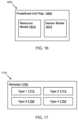
- FIG. 10depicts an exemplary user interface screen 1000 which enables users set up zones within a structure representation on a display apparatus.
- a zone icon 1005may be selected.
- the zonemay then be drawn over top of a portion of the physical structure representation as seen with reference to Zone 1 1010 , Zone 2 1015 , and Zone 3 1020 .
- the zonesmay be shown in a panel 1025 that also shows which sub-portion of a physical structure representation is showing on the display device, e.g., Floor 2 1035 .
- Resourcessuch as sensors, already placed in the zone, or in a larger subsystem, may be displayed on another panel 1030 .
- FIG. 11depicts an exemplary user interface screen 1100 which enables users to create interconnected resource systems within a zone on a display apparatus.
- an equipment panel 1105has a series of drawers 1110 that can be opened to display predefined unit models 1115 . Choosing a drawer opens it up. In the example shown, “Hydronics” 1110 has been opened, displaying the hydronics options.
- Many sorts of equipmente.g., predefined unit models), such as heat sources, cooling sources, solar thermal sources (such as solar panels), heat pumps, hydronics systems, heat storage, heat exchangers, renewables, VAV components, air components, sensors, irrigation systems, sprinkler systems, etc., may all have predefined unit models associated with drawers. Choosing a drawer opens it up.
- a predefined unit model 1115can then be selected and placed 1120 in a system panel 1145 . Selecting a predefined unit model that has been placed may display a settings panel 1150 that allows the predefined unit model to be modified by a user.
- the settings panelmay comprise a name of the predefined unit model 1125 , e.g., “circulator pump”.
- the zone in which the predefined unit model resides, or which the predefined unit model affectscan be set in a zone field 1130 . In some embodiments, multiple zones may be specified for a single predefined resource model. Specifications about the predefined unit model may be able to be modified. These modifications may be specific to the type of predefined unit model.
- a load manifold 1115may have different specifications the a variable speed pump, etc. Some specifications that may be modified may comprise manufacturer 1135 , model, behaviors such as on/off 1140 , percent on, etc.
- the predefined unit modelscomprise pin diagrams and protocols for pins, inputs and outputs,
- FIG. 12depicts an exemplary interconnected resource system 1200 .
- connections 1215 between the predefined unit modelscan be drawn.
- a usermay be able to select a connector tool 1205 , select and place a predefined unit model 1210 , then select and place another predefined unit model 1210 .
- a connection 1215may then automatically be drawn between the two.
- the usermay also be able to draw connections themself.
- An already placed unit modelmay be able to be moved around.
- the load manifold 1120moves to the far-right 1225 in a completed system shown in FIG. 12 . Because the predefined unit models understand the nature of their inputs and outputs, in some systems, the system may ensure that the chosen system connectors actually work.
- a predefined unit modelis connected by a user to another predefined unit model that does not fit for some reason, such as the quanta used as output is not used as input for the downstream connected predefined unit model, there may be an error message to warn of the problem, or the difficulties may be shown in a different way.
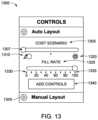
- FIG. 13is an exemplary diagram showing potential wiring constraints that can be used in some embodiments.
- Controllerscan be wired to some number of units. The number of devices that are able to be wired to a given controller depends on the controller and the device, in that different devices have different amount of wires to be wired to device connectors in the controller, and different controllers may have different numbers of device connectors. Large systems will need multiple controllers. How the controllers should be placed has some constraints that users can modify.
- a constraintcan be input by a user on a user interface, as shown at 1300 .
- constraintsare accepted a different way.
- Controllerscan be wired to some number of unit models (e.g., equipment, resources, sensors, etc.).
- a cost scenario 1305which allows a user to choose between higher labor costs and higher equipment cost.
- a cost scenario slider 1307goes from high labor costs (indicated by the icon of a human rolling a large ball 1310 ) to high equipment costs (indicated by the icon of a power switch 1320 ).
- a usercan accept a constraint by setting the slider thumb to a value somewhere between high labor cost and high equipment cost.
- the number of controllersis minimized, as fewer controllers will be used, but the devices will be further from their controller. This increases the average length from the controller any given device is, requiring more labor to install.
- Fill rate 1325indicates how full each of the controllers should be, which may be listed in percentages (0% 1330 , 20%, 40%, . . . 100% 1335 ), though other methods are envisioned, as well.
- a high fill ratesaves money on controllers, but most likely raises installation costs, as, on average, the controllers will be further from the resources they will be wired to.
- a low controller fill rateis chosen, such as 40%, it also provides more room for future unit models to be added to the controller, thus minimizing new controller installation costs.
- the thumb of the slider baris all the way over on the left side, there will be the fewest devices allocated per controller, which will give more room for expansion.
- a button 1340may automatically generate a network wiring diagram.
- another button 1345may allow a user to create a network wiring diagram.
- FIG. 14depicts an exemplary network wiring diagram 1400 .
- the control systemmay comprise a wiring diagram of the controller and the predefined unit model, a network wiring diagram comprising multiple controllers wired together, etc.
- the network wiringcomprises three controllers 1405 , 1410 , 1415 are shown connected 1445 using a wired connection.
- the controllershave modules 1420 associated with them.
- the modulesthemselves have devices 1440 connected to them.
- the modulesare of different types, e.g., 1420 , 1425 , 1430 , and 1435 may all be of different types.
- the modulesmay have predefined unit representations previously defined as resource or sensor representations 1440 , 1450 associated with them.
- usersmay move predefined unit representations from one controller to another, or one module to another.
- the predefined unit representation 1440may be moved by a user to a location on module 1420 .
- the usermay use a sWYSIWYG interface to select a given predefined unit representation and then move it to a new position. If modules of different types are used, then a predefined unit representation may be required to be moved to a module of a different type.
- FIG. 15discloses an illustrative screenshoot embodiment of a pin layout display 1500 that allows a user to set up and/or modify a controller unit model layout, which may include pin layout.
- a controller 205may have database(s) of predefined unit representations 235 stored within its memory 220 that a user can choose to add to specific locations on the controller 205 .
- An exampleis the VOC sensor 1525 . This may be used when a network wiring diagram 1400 does not include a predefined unit representation that has been placed within a physical structure representation using screens discussed with reference to FIGS. 6 , 11 , and 12 , is not currently represented within a network wiring diagram (e.g., FIG. 14 ).
- the databasemay be distributed amongst controllers belonging to a distributed controller system.
- the controllermay automatically place the unit models on a default controller representation screen 1500 .
- This screen 1500may be reached through a network wiring diagram 1400 .
- choosing a controller, e.g., 1405may open up a controller pin layout screen 1500 .
- the pin layout screenmay compose a controller representation 1500 with modules 1540 indicated 1545 .
- the modulesmay be indicated with a number 1545 , a color, or through a different method.
- a usermay move predefined unit representations around on the controller representation screen 1500 , using wysiwyg inputs, or a different type of input known to those of skill in the art.
- a usermay also modify pin layouts associated with device models. Moving around the predefined unit representations (or device wire pin layouts within a predefined unit representation) on the screen 1500 may reset controller expectations of what the controller wire connection expects.
- a usermay swap wires on a specific device representation on the moveable interactive display, which will change the types of wires that the controller expects at the specific locations where the wires were swiped on the moveable interactive display.
- the ( ⁇ ) wire 1515 representationmay be swapped with the (+) wire representation 1520 on the same predefined unit representation—1-Wire Bluetooth. This will change the protocol that the controller expects on those wires. When the device itself is wired to the controller, the controller will expect the new, swapped, protocols.
- the temperature sensor representation 1505can be moved by a user to, for example, three open slots on module 6 1535 , etc. These modifications will change the protocol that the controller expects on the eventual wires that a device 265 represented by the predefined unit representation, e.g. 1535 , is moved to.
- the controllermay send a signal through the module connector to the device connector 320 .
- An aspect of the display 1500allows a user to change protocols that a controller expects for a device 325 .
- selecting a protocol tag 1505 on a predefined unit representationopens up a menu 1510 that shows the available protocols: in this case, RTD, Thermistor, 0-10V, and 2-10V. Selecting a protocol changes the protocol that the controller expects to receive from a device 325 represented by the predefined unit representation. Some protocols require that device wires have a different protocol, which the controller understands. Devices, such as a VOC sensor 1525 that are expected to be connected to the controller but are not yet assigned a location on the controller may be able to be displayed on panel 1555 . Such a resource may be able to be moved into an open position e.g., 1535 , at which it may look similar to a VOC predefined unit representation icon 1530 .
- FIG. 16discloses a block diagram 1600 that describes different types of predefined unit model representations.
- a predefined unit model representation 1605may be a resource model 1610 or a sensor model 1615 .
- a sensor modelis a model of a piece of equipment that detects a physical property, such as temperature, humidity, sound loudness, VOC, occupancy level, occupancy location, and so forth.
- a resourceis something that is not a sensor.
- Some pieces of equipment that are normally thought of as resources, such as hot water heaters,may have attached sensors; in such edge cases, the attached sensor may be considered a sensor, and the hot water heater may be considered a resource.
- Other ways of dividing equipment between resources and sensorsare also within the scope of this specification.
- FIG. 17discloses a block diagram 1700 with multiple module types 1705 .
- a controllermay have one type, two types, . . . any number of types.
- some resourcesmay require one or more specific modules, due to their wiring requirements.
- the defined space controller system 110understands the nature of the modules and the nature of the specific wiring requirements of the devices through the predefined unit representation 235 stored in memory 220 .
- resourcesmay have specific requirements defined by a user, e.g., through settings described in FIG. 11 .
- the controllerunderstands the module requirements as well as the device requirements, and so can match devices to appropriate modules.
- a type of modulemay comprise the following options:
- a module type 1 1710may have 6 ⁇ Universal Ports, which may be thermistors, RTD, 1-Wire, 0-10 V Input/Output, 0-20 mA Input/Output, 0-480 VAC Input, 24 VACC Output, and/or Modbus/RS485 Interface.
- a module type 2 1715may have 2 ⁇ Power Control Blocks, which may be 120/240 VAC output—2 Amps, and/or 24 VAC output—2 Amps.
- a module type 3may have 2 ⁇ DC motor control blocks, which may further have 12/24 VDC motor drivers, PWM speed control, Real-time current monitoring, Real time voltage monitoring, Overcurrent/torque protection, and/or tachometer feedback.
- a module type 4may have 2 ⁇ Dry contact blocks. Such a module may also have SPDT relays (10 A), up to 240 VCD/VAC, real-time current monitoring, real-time voltage monitoring, and/or overcurrent protection.
- Modulesmay also comprise some combination of the following:
- Modulesmay comprise features not otherwise mentioned.
- the controllermodifies its controller connector 310 to fit the new requirements.
- the modulemodifies its device connector 320 to fit the new requirements.
Landscapes
- Engineering & Computer Science (AREA)
- Physics & Mathematics (AREA)
- Theoretical Computer Science (AREA)
- General Engineering & Computer Science (AREA)
- General Physics & Mathematics (AREA)
- Automation & Control Theory (AREA)
- Signal Processing (AREA)
- Software Systems (AREA)
- Geometry (AREA)
- Human Computer Interaction (AREA)
- Computer Networks & Wireless Communication (AREA)
- Microelectronics & Electronic Packaging (AREA)
- Computer Hardware Design (AREA)
- Evolutionary Computation (AREA)
- Chemical & Material Sciences (AREA)
- Business, Economics & Management (AREA)
- Combustion & Propulsion (AREA)
- Mechanical Engineering (AREA)
- Pure & Applied Mathematics (AREA)
- Mathematical Optimization (AREA)
- Mathematical Analysis (AREA)
- Computational Mathematics (AREA)
- Medical Informatics (AREA)
- Health & Medical Sciences (AREA)
- Development Economics (AREA)
- Architecture (AREA)
- Artificial Intelligence (AREA)
- Computing Systems (AREA)
- Strategic Management (AREA)
- Finance (AREA)
- Accounting & Taxation (AREA)
- General Health & Medical Sciences (AREA)
- Civil Engineering (AREA)
- Structural Engineering (AREA)
- Game Theory and Decision Science (AREA)
- General Business, Economics & Management (AREA)
- Computer Vision & Pattern Recognition (AREA)
- Entrepreneurship & Innovation (AREA)
- Fuzzy Systems (AREA)
- Computational Linguistics (AREA)
Abstract
Description
- A 0-10V DC analog voltage (via a DAC)
- A Strong 1-wire pullup (via a FET)
- A High-range voltage divider:
- A Ground connection (through a FET)
- A 24 VAC power connection (through a Triac)
- A 0-10V DC analog voltage (via a DAC)
- A Strong 1-wire pullup (via a FET)
- A High-range voltage divider
- A Low range voltage divider
- A 4-20 mA current shunt
- A 24 VAC current shunt
- A DC offset injector that can measure both halves of an DC waveform
- Real-time current monitoring and real-time voltage monitoring.
Claims (22)
Priority Applications (1)
| Application Number | Priority Date | Filing Date | Title |
|---|---|---|---|
| US17/224,976US12069831B2 (en) | 2020-08-26 | 2021-04-07 | Building automation programming using UI representations of physical models |
Applications Claiming Priority (2)
| Application Number | Priority Date | Filing Date | Title |
|---|---|---|---|
| US202063070460P | 2020-08-26 | 2020-08-26 | |
| US17/224,976US12069831B2 (en) | 2020-08-26 | 2021-04-07 | Building automation programming using UI representations of physical models |
Publications (2)
| Publication Number | Publication Date |
|---|---|
| US20220067230A1 US20220067230A1 (en) | 2022-03-03 |
| US12069831B2true US12069831B2 (en) | 2024-08-20 |
Family
ID=79293839
Family Applications (29)
| Application Number | Title | Priority Date | Filing Date |
|---|---|---|---|
| US17/021,965ActiveUS11553618B2 (en) | 2020-08-26 | 2020-09-15 | Methods and systems of building automation state load and user preference via network systems activity |
| US17/135,212Active2041-01-05US11490537B2 (en) | 2020-08-26 | 2020-12-28 | Distributed building automation controllers |
| US17/135,591ActiveUS11477905B2 (en) | 2020-08-26 | 2020-12-28 | Digital labeling control system terminals that enable guided wiring |
| US17/143,556ActiveUS11229138B1 (en) | 2020-08-26 | 2021-01-07 | Controller modules |
| US17/151,365Active2041-05-18US11706891B2 (en) | 2020-08-26 | 2021-01-18 | Perceptible indicators of wires being attached correctly to controller |
| US17/151,337Active2042-06-16US11871505B2 (en) | 2020-08-26 | 2021-01-18 | Automated line testing |
| US17/175,944AbandonedUS20220067226A1 (en) | 2020-08-26 | 2021-02-15 | Automated Point Mapping Interface |
| US17/177,061Active2042-05-26US12324120B2 (en) | 2020-08-26 | 2021-02-16 | Control system having an adjacent electronic display for auto labeling and guided wiring |
| US17/190,541Active2041-05-26US11596079B2 (en) | 2020-08-26 | 2021-03-03 | Methods, controllers, and machine-readable storage media for automated commissioning of equipment |
| US17/204,668Active2043-09-14US12156360B2 (en) | 2020-08-26 | 2021-03-17 | Controller with moveable interactive screen |
| US17/216,565AbandonedUS20220067227A1 (en) | 2020-08-26 | 2021-03-29 | Automated Point Mapping Generation |
| US17/224,976ActiveUS12069831B2 (en) | 2020-08-26 | 2021-04-07 | Building automation programming using UI representations of physical models |
| US17/347,672AbandonedUS20220066528A1 (en) | 2020-08-26 | 2021-06-15 | Energy Efficient Sensor |
| US17/409,636Active2042-08-07US12120838B2 (en) | 2020-08-26 | 2021-08-23 | Semantic labeling analysis |
| US17/410,072Active2041-08-26US11737231B2 (en) | 2020-08-26 | 2021-08-24 | Method and apparatus for generalized control of devices |
| US17/842,308Active2042-10-03US12376253B2 (en) | 2020-08-26 | 2022-06-16 | Method of digital labeling control system terminals that enables guided wiring |
| US17/865,228ActiveUS11832413B2 (en) | 2020-08-26 | 2022-07-14 | Method of building automation heat load and user preference inferring occupancy via network systems activity |
| US17/820,976ActiveUS11856723B2 (en) | 2020-08-26 | 2022-08-19 | Distributed building automation controllers |
| US17/990,350ActiveUS12089360B2 (en) | 2020-08-26 | 2022-11-18 | Perceptible indicators that wires are attached correctly to controller |
| US18/102,396ActiveUS11991851B2 (en) | 2020-08-26 | 2023-01-27 | Methods, controllers, and machine-readable storage media for automated commissioning of equipment |
| US18/209,383ActiveUS12108556B2 (en) | 2020-08-26 | 2023-06-13 | Method and apparatus for generalized control of devices |
| US18/616,009PendingUS20240244783A1 (en) | 2020-08-26 | 2024-03-25 | Methods, controllers, and machine-readable storage media for automated commissioning of equipment |
| US18/635,676PendingUS20240284627A1 (en) | 2020-08-26 | 2024-04-15 | Method and apparatus for generalized control of devices |
| US18/659,869ActiveUS12408287B2 (en) | 2020-08-26 | 2024-05-09 | Perceptible indicators of wires being attached correctly to controller |
| US18/795,854PendingUS20240397655A1 (en) | 2020-08-26 | 2024-08-06 | Semantic Labeling Analytics |
| US18/817,065PendingUS20240422934A1 (en) | 2020-08-26 | 2024-08-27 | Controller with moveable interactive screen |
| US18/907,008PendingUS20250031335A1 (en) | 2020-08-26 | 2024-10-04 | Automated Point Mapping Generation |
| US19/071,623PendingUS20250203801A1 (en) | 2020-08-26 | 2025-03-05 | Control System Having an Adjacent Electronic Display for Auto Labeling and Guided Wiring |
| US19/212,507PendingUS20250280504A1 (en) | 2020-08-26 | 2025-05-19 | Method of Digital Labeling Control System Terminals That Enables Guided Wiring |
Family Applications Before (11)
| Application Number | Title | Priority Date | Filing Date |
|---|---|---|---|
| US17/021,965ActiveUS11553618B2 (en) | 2020-08-26 | 2020-09-15 | Methods and systems of building automation state load and user preference via network systems activity |
| US17/135,212Active2041-01-05US11490537B2 (en) | 2020-08-26 | 2020-12-28 | Distributed building automation controllers |
| US17/135,591ActiveUS11477905B2 (en) | 2020-08-26 | 2020-12-28 | Digital labeling control system terminals that enable guided wiring |
| US17/143,556ActiveUS11229138B1 (en) | 2020-08-26 | 2021-01-07 | Controller modules |
| US17/151,365Active2041-05-18US11706891B2 (en) | 2020-08-26 | 2021-01-18 | Perceptible indicators of wires being attached correctly to controller |
| US17/151,337Active2042-06-16US11871505B2 (en) | 2020-08-26 | 2021-01-18 | Automated line testing |
| US17/175,944AbandonedUS20220067226A1 (en) | 2020-08-26 | 2021-02-15 | Automated Point Mapping Interface |
| US17/177,061Active2042-05-26US12324120B2 (en) | 2020-08-26 | 2021-02-16 | Control system having an adjacent electronic display for auto labeling and guided wiring |
| US17/190,541Active2041-05-26US11596079B2 (en) | 2020-08-26 | 2021-03-03 | Methods, controllers, and machine-readable storage media for automated commissioning of equipment |
| US17/204,668Active2043-09-14US12156360B2 (en) | 2020-08-26 | 2021-03-17 | Controller with moveable interactive screen |
| US17/216,565AbandonedUS20220067227A1 (en) | 2020-08-26 | 2021-03-29 | Automated Point Mapping Generation |
Family Applications After (17)
| Application Number | Title | Priority Date | Filing Date |
|---|---|---|---|
| US17/347,672AbandonedUS20220066528A1 (en) | 2020-08-26 | 2021-06-15 | Energy Efficient Sensor |
| US17/409,636Active2042-08-07US12120838B2 (en) | 2020-08-26 | 2021-08-23 | Semantic labeling analysis |
| US17/410,072Active2041-08-26US11737231B2 (en) | 2020-08-26 | 2021-08-24 | Method and apparatus for generalized control of devices |
| US17/842,308Active2042-10-03US12376253B2 (en) | 2020-08-26 | 2022-06-16 | Method of digital labeling control system terminals that enables guided wiring |
| US17/865,228ActiveUS11832413B2 (en) | 2020-08-26 | 2022-07-14 | Method of building automation heat load and user preference inferring occupancy via network systems activity |
| US17/820,976ActiveUS11856723B2 (en) | 2020-08-26 | 2022-08-19 | Distributed building automation controllers |
| US17/990,350ActiveUS12089360B2 (en) | 2020-08-26 | 2022-11-18 | Perceptible indicators that wires are attached correctly to controller |
| US18/102,396ActiveUS11991851B2 (en) | 2020-08-26 | 2023-01-27 | Methods, controllers, and machine-readable storage media for automated commissioning of equipment |
| US18/209,383ActiveUS12108556B2 (en) | 2020-08-26 | 2023-06-13 | Method and apparatus for generalized control of devices |
| US18/616,009PendingUS20240244783A1 (en) | 2020-08-26 | 2024-03-25 | Methods, controllers, and machine-readable storage media for automated commissioning of equipment |
| US18/635,676PendingUS20240284627A1 (en) | 2020-08-26 | 2024-04-15 | Method and apparatus for generalized control of devices |
| US18/659,869ActiveUS12408287B2 (en) | 2020-08-26 | 2024-05-09 | Perceptible indicators of wires being attached correctly to controller |
| US18/795,854PendingUS20240397655A1 (en) | 2020-08-26 | 2024-08-06 | Semantic Labeling Analytics |
| US18/817,065PendingUS20240422934A1 (en) | 2020-08-26 | 2024-08-27 | Controller with moveable interactive screen |
| US18/907,008PendingUS20250031335A1 (en) | 2020-08-26 | 2024-10-04 | Automated Point Mapping Generation |
| US19/071,623PendingUS20250203801A1 (en) | 2020-08-26 | 2025-03-05 | Control System Having an Adjacent Electronic Display for Auto Labeling and Guided Wiring |
| US19/212,507PendingUS20250280504A1 (en) | 2020-08-26 | 2025-05-19 | Method of Digital Labeling Control System Terminals That Enables Guided Wiring |
Country Status (1)
| Country | Link |
|---|---|
| US (29) | US11553618B2 (en) |
Cited By (3)
| Publication number | Priority date | Publication date | Assignee | Title |
|---|---|---|---|---|
| US12276420B2 (en) | 2016-02-03 | 2025-04-15 | Strong Force Iot Portfolio 2016, Llc | Industrial internet of things smart heating systems and methods that produce and use hydrogen fuel |
| US12353181B2 (en) | 2019-01-13 | 2025-07-08 | Strong Force Iot Portfolio 2016, Llc | Systems for monitoring and managing industrial settings |
| US12353203B2 (en) | 2018-05-07 | 2025-07-08 | Strong Force Iot Portfolio 2016, Llc | Methods and systems for data collection, learning, and streaming of machine signals for analytics and maintenance using the industrial Internet of Things |
Families Citing this family (118)
| Publication number | Priority date | Publication date | Assignee | Title |
|---|---|---|---|---|
| US9411327B2 (en) | 2012-08-27 | 2016-08-09 | Johnson Controls Technology Company | Systems and methods for classifying data in building automation systems |
| US10534326B2 (en) | 2015-10-21 | 2020-01-14 | Johnson Controls Technology Company | Building automation system with integrated building information model |
| US12196437B2 (en) | 2016-01-22 | 2025-01-14 | Tyco Fire & Security Gmbh | Systems and methods for monitoring and controlling an energy plant |
| US11268732B2 (en) | 2016-01-22 | 2022-03-08 | Johnson Controls Technology Company | Building energy management system with energy analytics |
| US11947785B2 (en) | 2016-01-22 | 2024-04-02 | Johnson Controls Technology Company | Building system with a building graph |
| CN109154802A (en) | 2016-03-31 | 2019-01-04 | 江森自控科技公司 | HVAC Unit Registration in Distributed Building Management System |
| US11774920B2 (en) | 2016-05-04 | 2023-10-03 | Johnson Controls Technology Company | Building system with user presentation composition based on building context |
| US10505756B2 (en) | 2017-02-10 | 2019-12-10 | Johnson Controls Technology Company | Building management system with space graphs |
| US10901373B2 (en) | 2017-06-15 | 2021-01-26 | Johnson Controls Technology Company | Building management system with artificial intelligence for unified agent based control of building subsystems |
| US10417451B2 (en) | 2017-09-27 | 2019-09-17 | Johnson Controls Technology Company | Building system with smart entity personal identifying information (PII) masking |
| US10684033B2 (en) | 2017-01-06 | 2020-06-16 | Johnson Controls Technology Company | HVAC system with automated device pairing |
| US11900287B2 (en) | 2017-05-25 | 2024-02-13 | Johnson Controls Tyco IP Holdings LLP | Model predictive maintenance system with budgetary constraints |
| US12184444B2 (en) | 2017-02-10 | 2024-12-31 | Johnson Controls Technology Company | Space graph based dynamic control for buildings |
| US11307538B2 (en) | 2017-02-10 | 2022-04-19 | Johnson Controls Technology Company | Web services platform with cloud-eased feedback control |
| US10515098B2 (en) | 2017-02-10 | 2019-12-24 | Johnson Controls Technology Company | Building management smart entity creation and maintenance using time series data |
| US11764991B2 (en) | 2017-02-10 | 2023-09-19 | Johnson Controls Technology Company | Building management system with identity management |
| US11994833B2 (en) | 2017-02-10 | 2024-05-28 | Johnson Controls Technology Company | Building smart entity system with agent based data ingestion and entity creation using time series data |
| US11360447B2 (en) | 2017-02-10 | 2022-06-14 | Johnson Controls Technology Company | Building smart entity system with agent based communication and control |
| US11280509B2 (en) | 2017-07-17 | 2022-03-22 | Johnson Controls Technology Company | Systems and methods for agent based building simulation for optimal control |
| US10169486B2 (en) | 2017-02-10 | 2019-01-01 | Johnson Controls Technology Company | Building management system with timeseries processing |
| US10452043B2 (en) | 2017-02-10 | 2019-10-22 | Johnson Controls Technology Company | Building management system with nested stream generation |
| US20190095518A1 (en) | 2017-09-27 | 2019-03-28 | Johnson Controls Technology Company | Web services for smart entity creation and maintenance using time series data |
| US11900021B2 (en) | 2017-02-22 | 2024-02-13 | Middle Chart, LLC | Provision of digital content via a wearable eye covering |
| US10740503B1 (en)* | 2019-01-17 | 2020-08-11 | Middle Chart, LLC | Spatial self-verifying array of nodes |
| US11900022B2 (en) | 2017-02-22 | 2024-02-13 | Middle Chart, LLC | Apparatus for determining a position relative to a reference transceiver |
| US11625510B2 (en) | 2017-02-22 | 2023-04-11 | Middle Chart, LLC | Method and apparatus for presentation of digital content |
| US11468209B2 (en) | 2017-02-22 | 2022-10-11 | Middle Chart, LLC | Method and apparatus for display of digital content associated with a location in a wireless communications area |
| US10740502B2 (en) | 2017-02-22 | 2020-08-11 | Middle Chart, LLC | Method and apparatus for position based query with augmented reality headgear |
| US12086507B2 (en) | 2017-02-22 | 2024-09-10 | Middle Chart, LLC | Method and apparatus for construction and operation of connected infrastructure |
| US12400048B2 (en) | 2020-01-28 | 2025-08-26 | Middle Chart, LLC | Methods and apparatus for two dimensional location based digital content |
| WO2018175912A1 (en) | 2017-03-24 | 2018-09-27 | Johnson Controls Technology Company | Building management system with dynamic channel communication |
| US11327737B2 (en) | 2017-04-21 | 2022-05-10 | Johnson Controls Tyco IP Holdings LLP | Building management system with cloud management of gateway configurations |
| US10788229B2 (en) | 2017-05-10 | 2020-09-29 | Johnson Controls Technology Company | Building management system with a distributed blockchain database |
| EP4421695A3 (en) | 2017-05-25 | 2024-11-27 | Johnson Controls Tyco IP Holdings LLP | Model predictive maintenance system for building equipment |
| US11022947B2 (en) | 2017-06-07 | 2021-06-01 | Johnson Controls Technology Company | Building energy optimization system with economic load demand response (ELDR) optimization and ELDR user interfaces |
| EP3655824A1 (en) | 2017-07-21 | 2020-05-27 | Johnson Controls Technology Company | Building management system with dynamic work order generation with adaptive diagnostic task details |
| US11726632B2 (en) | 2017-07-27 | 2023-08-15 | Johnson Controls Technology Company | Building management system with global rule library and crowdsourcing framework |
| US20190096014A1 (en) | 2017-09-27 | 2019-03-28 | Johnson Controls Technology Company | Building risk analysis system with risk decay |
| US10962945B2 (en) | 2017-09-27 | 2021-03-30 | Johnson Controls Technology Company | Building management system with integration of data into smart entities |
| WO2019067627A1 (en) | 2017-09-27 | 2019-04-04 | Johnson Controls Technology Company | Systems and methods for risk analysis |
| US11281169B2 (en) | 2017-11-15 | 2022-03-22 | Johnson Controls Tyco IP Holdings LLP | Building management system with point virtualization for online meters |
| US10809682B2 (en) | 2017-11-15 | 2020-10-20 | Johnson Controls Technology Company | Building management system with optimized processing of building system data |
| US11127235B2 (en) | 2017-11-22 | 2021-09-21 | Johnson Controls Tyco IP Holdings LLP | Building campus with integrated smart environment |
| US11954713B2 (en) | 2018-03-13 | 2024-04-09 | Johnson Controls Tyco IP Holdings LLP | Variable refrigerant flow system with electricity consumption apportionment |
| US11016648B2 (en) | 2018-10-30 | 2021-05-25 | Johnson Controls Technology Company | Systems and methods for entity visualization and management with an entity node editor |
| US20200162280A1 (en) | 2018-11-19 | 2020-05-21 | Johnson Controls Technology Company | Building system with performance identification through equipment exercising and entity relationships |
| US12367443B2 (en) | 2019-01-14 | 2025-07-22 | Tyco Fire & Security Gmbh | System and method for showing key performance indicators |
| US11164159B2 (en) | 2019-01-18 | 2021-11-02 | Johnson Controls Tyco IP Holdings LLP | Smart building automation system with digital signage |
| US10788798B2 (en) | 2019-01-28 | 2020-09-29 | Johnson Controls Technology Company | Building management system with hybrid edge-cloud processing |
| KR102183309B1 (en)* | 2019-05-21 | 2020-11-26 | 성균관대학교산학협력단 | A multi-type pressure sensor |
| US12197299B2 (en) | 2019-12-20 | 2025-01-14 | Tyco Fire & Security Gmbh | Building system with ledger based software gateways |
| US20210200912A1 (en) | 2019-12-31 | 2021-07-01 | Johnson Controls Technology Company | Building data platform with graph based policies |
| US11894944B2 (en) | 2019-12-31 | 2024-02-06 | Johnson Controls Tyco IP Holdings LLP | Building data platform with an enrichment loop |
| US11769066B2 (en) | 2021-11-17 | 2023-09-26 | Johnson Controls Tyco IP Holdings LLP | Building data platform with digital twin triggers and actions |
| US12021650B2 (en) | 2019-12-31 | 2024-06-25 | Tyco Fire & Security Gmbh | Building data platform with event subscriptions |
| US20210200713A1 (en) | 2019-12-31 | 2021-07-01 | Johnson Controls Technology Company | Systems and methods for generating a data structure from multiple bim files |
| US11640486B2 (en) | 2021-03-01 | 2023-05-02 | Middle Chart, LLC | Architectural drawing based exchange of geospatial related digital content |
| US12100280B2 (en) | 2020-02-04 | 2024-09-24 | Tyco Fire & Security Gmbh | Systems and methods for software defined fire detection and risk assessment |
| US11537386B2 (en) | 2020-04-06 | 2022-12-27 | Johnson Controls Tyco IP Holdings LLP | Building system with dynamic configuration of network resources for 5G networks |
| US11874809B2 (en) | 2020-06-08 | 2024-01-16 | Johnson Controls Tyco IP Holdings LLP | Building system with naming schema encoding entity type and entity relationships |
| USD944271S1 (en)* | 2020-06-21 | 2022-02-22 | Apple Inc. | Display screen or portion thereof with graphical user interface |
| US11553618B2 (en)* | 2020-08-26 | 2023-01-10 | PassiveLogic, Inc. | Methods and systems of building automation state load and user preference via network systems activity |
| US11283669B1 (en)* | 2020-09-04 | 2022-03-22 | Johnson Controls Tyco IP Holdings LLP | Building management system with control framework |
| US11635881B2 (en) | 2020-09-22 | 2023-04-25 | Microsoft Technology Licensing, Llc | Cross-platform computing skill execution |
| US12346381B2 (en) | 2020-09-30 | 2025-07-01 | Tyco Fire & Security Gmbh | Building management system with semantic model integration |
| US11954154B2 (en) | 2020-09-30 | 2024-04-09 | Johnson Controls Tyco IP Holdings LLP | Building management system with semantic model integration |
| US11397773B2 (en) | 2020-09-30 | 2022-07-26 | Johnson Controls Tyco IP Holdings LLP | Building management system with semantic model integration |
| US20220138492A1 (en) | 2020-10-30 | 2022-05-05 | Johnson Controls Technology Company | Data preprocessing and refinement tool |
| US12105491B2 (en) | 2020-12-18 | 2024-10-01 | Tyco Fire & Security Gmbh | VAV self commissioning in a building automation system |
| US12061453B2 (en) | 2020-12-18 | 2024-08-13 | Tyco Fire & Security Gmbh | Building management system performance index |
| US12085292B2 (en)* | 2020-12-21 | 2024-09-10 | Dr. Noze Best, LLC | Humidifier system and methods for using same |
| US12235617B2 (en) | 2021-02-08 | 2025-02-25 | Tyco Fire & Security Gmbh | Site command and control tool with dynamic model viewer |
| AU2022237623A1 (en) | 2021-03-17 | 2023-10-19 | Johnson Controls Tyco IP Holdings LLP | Systems and methods for determining equipment energy waste |
| FR3121289B1 (en)* | 2021-03-26 | 2023-06-30 | Schneider Electric Ind Sas | Electrical connection cabinet |
| USD1002556S1 (en)* | 2021-06-01 | 2023-10-24 | Siemens Aktiengesellschaft | Display module of an overcurrent release |
| US11899723B2 (en) | 2021-06-22 | 2024-02-13 | Johnson Controls Tyco IP Holdings LLP | Building data platform with context based twin function processing |
| US12250099B2 (en)* | 2021-09-08 | 2025-03-11 | PassiveLogic, Inc. | External activation of quiescent device |
| USD997977S1 (en)* | 2021-11-02 | 2023-09-05 | PassiveLogic, Inc. | Display screen or portion thereof with a graphical user interface |
| USD998639S1 (en)* | 2021-11-02 | 2023-09-12 | PassiveLogic, Inc. | Display screen or portion thereof with a graphical user interface |
| USD998638S1 (en)* | 2021-11-02 | 2023-09-12 | Passivelogic, Inc | Display screen or portion thereof with a graphical interface |
| US11796974B2 (en) | 2021-11-16 | 2023-10-24 | Johnson Controls Tyco IP Holdings LLP | Building data platform with schema extensibility for properties and tags of a digital twin |
| US11934966B2 (en) | 2021-11-17 | 2024-03-19 | Johnson Controls Tyco IP Holdings LLP | Building data platform with digital twin inferences |
| US12399467B2 (en) | 2021-11-17 | 2025-08-26 | Tyco Fire & Security Gmbh | Building management systems and methods for tuning fault detection thresholds |
| US11704311B2 (en) | 2021-11-24 | 2023-07-18 | Johnson Controls Tyco IP Holdings LLP | Building data platform with a distributed digital twin |
| US11714930B2 (en) | 2021-11-29 | 2023-08-01 | Johnson Controls Tyco IP Holdings LLP | Building data platform with digital twin based inferences and predictions for a graphical building model |
| US12013673B2 (en) | 2021-11-29 | 2024-06-18 | Tyco Fire & Security Gmbh | Building control system using reinforcement learning |
| US12412003B2 (en) | 2021-11-29 | 2025-09-09 | Tyco Fire & Security Gmbh | Building data platform with digital twin based predictive recommendation visualization |
| USD1001832S1 (en)* | 2021-11-30 | 2023-10-17 | Passivelogic, Inc | Display screen or portion thereof with a graphical user interface |
| USD1012100S1 (en)* | 2021-11-30 | 2024-01-23 | PassiveLogic, Inc. | Display screen or portion thereof with a graphical user interface |
| USD1083983S1 (en) | 2021-11-30 | 2025-07-15 | PassiveLogic, Inc. | Display screen or portion thereof with icon set |
| USD1012101S1 (en)* | 2021-12-01 | 2024-01-23 | Passivelogic, Inc | Display screen or portion thereof with a graphical user interface |
| US12333657B2 (en) | 2021-12-01 | 2025-06-17 | Tyco Fire & Security Gmbh | Building data platform with augmented reality based digital twins |
| USD998640S1 (en)* | 2021-12-01 | 2023-09-12 | PassiveLogic, Inc. | Display screen or portion thereof with a graphical user interface |
| USD998643S1 (en)* | 2021-12-02 | 2023-09-12 | PassiveLogic, Inc. | Display screen or portion thereof with a graphical user interface |
| USD1029002S1 (en)* | 2021-12-02 | 2024-05-28 | Passivelogic, Inc | Display screen or portion thereof with a graphical user interface |
| USD1023043S1 (en)* | 2021-12-02 | 2024-04-16 | PassiveLogic, Inc. | Display screen or portion thereof with a graphical user interface |
| USD998642S1 (en)* | 2021-12-02 | 2023-09-12 | PassiveLogic, Inc. | Display screen or portion thereof with a graphical user interface |
| USD1023028S1 (en)* | 2021-12-03 | 2024-04-16 | PassiveLogic, Inc. | Display screen or portion thereof with a graphical interface |
| USD999234S1 (en)* | 2021-12-03 | 2023-09-19 | PassiveLogic, Inc. | Display screen or portion thereof with a graphical user interface |
| US12418773B2 (en)* | 2021-12-20 | 2025-09-16 | Intel Corporation | Digital twin framework for next generation networks |
| US20240020445A1 (en)* | 2022-02-28 | 2024-01-18 | CELUS GmbH | Automated artificial intelligence based circuit and circuit board design |
| US11915010B2 (en)* | 2022-03-28 | 2024-02-27 | Microsoft Technology Licensing, Llc | Cross-platform multi-transport remote code activation |
| US12372955B2 (en) | 2022-05-05 | 2025-07-29 | Tyco Fire & Security Gmbh | Building data platform with digital twin functionality indicators |
| IT202200016437A1 (en)* | 2022-08-02 | 2024-02-02 | Sandro Nutini | “All around” safety monitoring system for ventilation machines” |
| USD1068819S1 (en)* | 2022-08-15 | 2025-04-01 | CELUS GmbH | Display screen or portion thereof with graphical user interface |
| US12061633B2 (en) | 2022-09-08 | 2024-08-13 | Tyco Fire & Security Gmbh | Building system that maps points into a graph schema |
| US12013823B2 (en) | 2022-09-08 | 2024-06-18 | Tyco Fire & Security Gmbh | Gateway system that maps points into a graph schema |
| US20240094696A1 (en)* | 2022-09-20 | 2024-03-21 | Honeywell International Inc. | Building controller with wiring terminals programmable between an input wiring terminal type, an output wiring terminal type, and a communication wiring terminal type |
| EP4343461B1 (en)* | 2022-09-26 | 2025-06-25 | Siemens Aktiengesellschaft | Method, automation station and method for operating an automation station |
| JP7459915B1 (en)* | 2022-10-27 | 2024-04-02 | Smc株式会社 | Safety modules and module connections |
| US20230117125A1 (en)* | 2022-12-16 | 2023-04-20 | Munters Corporation | Methods and control systems for controlling fluid conditioning system including plural fluid conditioning units |
| CN115903630B (en)* | 2022-12-29 | 2024-09-27 | 湖南湘科浩宇科技有限公司 | Ground test initiating and controlling equipment |
| US11734158B1 (en)* | 2023-02-16 | 2023-08-22 | GameDriver, Inc. | Methods and systems for emulating physical-device input for an automated-testing framework |
| USD1087154S1 (en) | 2023-06-02 | 2025-08-05 | Apple Inc. | Display screen or portion thereof showing a graphical user interface |
| WO2025071755A1 (en)* | 2023-09-29 | 2025-04-03 | Apple Inc. | Techniques for controlling output components |
| CN117007136B (en)* | 2023-10-07 | 2023-12-26 | 深圳市千岩科技有限公司 | Environment perception data detection method, device and equipment |
| US20250141201A1 (en)* | 2023-11-01 | 2025-05-01 | PassiveLogic, Inc. | Flexible element tensioning mechanism |
| CN117559502B (en)* | 2023-11-24 | 2024-05-10 | 许昌中天宇光电气技术有限公司 | New energy storage, variable flow and boosting integrated cabin |
Citations (150)
| Publication number | Priority date | Publication date | Assignee | Title |
|---|---|---|---|---|
| US5530643A (en) | 1993-08-24 | 1996-06-25 | Allen-Bradley Company, Inc. | Method of programming industrial controllers with highly distributed processing |
| US6275962B1 (en) | 1998-10-23 | 2001-08-14 | Teradyne, Inc. | Remote test module for automatic test equipment |
| US6301341B1 (en) | 1998-06-11 | 2001-10-09 | Conexant Systems, Inc. | System and method for performing telephone line-in-use detection, extension pick-up detection, and remote hang-up detection in a modem |
| US6362734B1 (en) | 2001-01-31 | 2002-03-26 | Ford Global Technologies, Inc. | Method and apparatus for monitoring seat belt use of rear seat passengers |
| US6437692B1 (en) | 1998-06-22 | 2002-08-20 | Statsignal Systems, Inc. | System and method for monitoring and controlling remote devices |
| US20030020715A1 (en) | 2001-06-13 | 2003-01-30 | Sumitomo Wiring Systems, Ltd. | Wiring harness designing method, computer program and system |
| US6645066B2 (en) | 2001-11-19 | 2003-11-11 | Koninklijke Philips Electronics N.V. | Space-conditioning control employing image-based detection of occupancy and use |
| US20040236547A1 (en) | 2003-01-22 | 2004-11-25 | Rappaport Theodore S. | System and method for automated placement or configuration of equipment for obtaining desired network performance objectives and for security, RF tags, and bandwidth provisioning |
| US20050040247A1 (en) | 2003-08-18 | 2005-02-24 | Pouchak Michael A. | Thermostat having modulated and non-modulated provisions |
| US6891838B1 (en) | 1998-06-22 | 2005-05-10 | Statsignal Ipc, Llc | System and method for monitoring and controlling residential devices |
| US7102502B2 (en) | 2001-12-05 | 2006-09-05 | Somfy Sas | Method for constituting a home automation network |
| US20070067063A1 (en) | 2005-08-30 | 2007-03-22 | Siemens Building Technologies, Inc. | Application of microsystems for real time IEQ control |
| US20070096902A1 (en) | 2005-10-27 | 2007-05-03 | Seeley John E | Method of designing, installing, and operating a fire alarm or security system |
| US20070162288A1 (en) | 2003-05-15 | 2007-07-12 | Endress + Hauser (De) Holding Gmhb | Method for automatically generating a spare parts list |
| US7304855B1 (en) | 2003-03-03 | 2007-12-04 | Storage Technology Corporation | Canister-based storage system |
| WO2008016500A2 (en) | 2006-08-02 | 2008-02-07 | Innovation By Design, Inc. | Method and system for controlling heating ventilation and air conditioning (hvac) units |
| US20080183316A1 (en) | 2007-01-26 | 2008-07-31 | Autani Corporation | Upgradeable Automation Devices, Systems, Architectures, and Methods |
| US20080277486A1 (en) | 2007-05-09 | 2008-11-13 | Johnson Controls Technology Company | HVAC control system and method |
| US20090189764A1 (en) | 2008-01-28 | 2009-07-30 | Tlc Integration, Llc | Universal occupancy adapter |
| US7578135B2 (en) | 2004-11-23 | 2009-08-25 | Mattheis Steven G | Recessed climate controller |
| US7587250B2 (en) | 2003-07-22 | 2009-09-08 | Siemens Building Technologies, Inc. | Controller with configurable connections between data processing components |
| US20100025483A1 (en) | 2008-07-31 | 2010-02-04 | Michael Hoeynck | Sensor-Based Occupancy and Behavior Prediction Method for Intelligently Controlling Energy Consumption Within a Building |
| US7702421B2 (en)* | 2007-08-27 | 2010-04-20 | Honeywell International Inc. | Remote HVAC control with building floor plan tool |
| US20100131933A1 (en) | 2008-11-21 | 2010-05-27 | Korea University Industrial & Academic Collaboration Foundation | System and Method for translating high programming level languages code into Hardware Description Language code |
| US7729882B2 (en) | 2007-01-25 | 2010-06-01 | Johnson Controls Technology Company | Method and system for assessing performance of control systems |
| US7734572B2 (en) | 2006-04-04 | 2010-06-08 | Panduit Corp. | Building automation system controller |
| US7917232B2 (en) | 2005-08-22 | 2011-03-29 | Trane International Inc. | Building automation system data management |
| US20110087988A1 (en) | 2009-10-12 | 2011-04-14 | Johnson Controls Technology Company | Graphical control elements for building management systems |
| US20110125930A1 (en) | 2009-11-24 | 2011-05-26 | Microsoft Corporation | Configurable connector for system-level communication |
| US8024054B2 (en) | 2005-08-22 | 2011-09-20 | Trane International, Inc. | Building automation system facilitating user customization |
| US8099178B2 (en) | 2005-08-22 | 2012-01-17 | Trane International Inc. | Building automation system facilitating user customization |
| WO2012019328A1 (en) | 2010-08-13 | 2012-02-16 | 清华大学 | Human-computer interface of two-way interactive architectural environment control system |
| US20120084231A1 (en)* | 2010-09-30 | 2012-04-05 | Mcnaught Catherine V | Fiber Project Evaluation Tool and Related Methods, Graphical User Interfaces, and Computer-Readable Media |
| US20120102472A1 (en) | 2010-10-26 | 2012-04-26 | Oracle International Corporation | Extending programming language semantics while maintaining standard syntax through aliasing |
| US20120221986A1 (en) | 2009-11-25 | 2012-08-30 | Draftlogic Inc. | System and process for automated circuiting and branch circuit wiring |
| US20130182558A1 (en) | 2010-09-06 | 2013-07-18 | Pal Orten | Method For Reassigning The Role Of A Wireless Node In A Wireless Network |
| US8503943B2 (en) | 2008-03-11 | 2013-08-06 | The Regents Of The University Of California | Wireless sensors and applications |
| US8628239B2 (en) | 2009-07-15 | 2014-01-14 | Teradyne, Inc. | Storage device temperature sensing |
| US8643476B2 (en) | 2009-06-29 | 2014-02-04 | Commscope, Inc. Of North Carolina | Dynamic labeling of patch panel ports |
| US20140088772A1 (en) | 2011-06-07 | 2014-03-27 | Koninklijke Philips N.V. | Methods for automatically commissioning of devices of a networked control system |
| US20140101082A1 (en) | 2012-09-30 | 2014-04-10 | Nest Labs, Inc. | Automated presence detection and presence-related control within an intelligent controller |
| US8749959B2 (en) | 2009-09-29 | 2014-06-10 | Nati Brook Ventures, Llc | Modular technology furniture |
| CN103926912A (en) | 2014-05-07 | 2014-07-16 | 桂林赛普电子科技有限公司 | Smart home monitoring system based on home service robot |
| US20140215446A1 (en) | 2013-01-29 | 2014-07-31 | ArtinSoft Corporation | Automated Porting of Application to Mobile Infrastructures |
| US20140277757A1 (en) | 2013-03-14 | 2014-09-18 | Pelco, Inc. | Method and apparatus for an energy saving heating, ventilation, and air conditioning (hvac) control system |
| US20140358291A1 (en) | 2013-05-30 | 2014-12-04 | Honeywell International Inc. | Comfort controller with user feedback |
| US20140364985A1 (en) | 2013-06-05 | 2014-12-11 | Accenture Global Services Limited | Master bill of materials creation |
| US8925358B2 (en) | 2011-02-28 | 2015-01-06 | Honeywell International Inc. | Methods and apparatus for configuring scheduling on a wall module |
| US20150059522A1 (en)* | 2013-09-04 | 2015-03-05 | J. C. Bamford Excavators Limited | Transmission arrangement |
| US20150081928A1 (en) | 2013-09-16 | 2015-03-19 | Axis Ab | Control system configuration within an operational environment |
| US20150198938A1 (en) | 2014-01-15 | 2015-07-16 | Green Edge Technologies, Inc. | Systems, devices, methods and graphical user interface for configuring a building automation system |
| US20150199088A1 (en)* | 2014-01-10 | 2015-07-16 | Ciambella Ltd. | Method and apparatus for automatic device program generation |
| US20150234381A1 (en) | 2014-02-14 | 2015-08-20 | Yokogawa Electric Corporation | Field device commissioning system and field device commissioning method |
| US20160016454A1 (en) | 2014-07-21 | 2016-01-21 | Ford Global Technologies, Llc | Integrated Vehicle Cabin With Driver Or Passengers' Prior Conditions And Activities |
| US20160062753A1 (en) | 2013-03-27 | 2016-03-03 | Netfective Technology Sa | Method for transforming first code instructions in a first programming language into second code instructions in a second programming language |
| US20160073521A1 (en) | 2014-09-08 | 2016-03-10 | Dell Products L.P. | Mezzanine-style structure with integrated wiring harness |
| US20160086242A1 (en) | 2014-09-23 | 2016-03-24 | Crestron Electronics, Inc. | System and method for modeling a lighting control system |
| US20160088438A1 (en) | 2014-09-24 | 2016-03-24 | James Thomas O'Keeffe | Mobile device assisted smart building control |
| US20160092427A1 (en) | 2014-09-30 | 2016-03-31 | Accenture Global Services Limited | Language Identification |
| US20160132308A1 (en) | 2014-11-12 | 2016-05-12 | Bank Of America Corpoaration | Leveraging legacy applications for use with modern applications |
| US20160179340A1 (en)* | 2013-08-07 | 2016-06-23 | Mitsubishi Electric Corporation | Installment location planning assistance method, terminal device, installment location planning assistance system, and program |
| US20160195856A1 (en) | 2014-01-08 | 2016-07-07 | Yechezkal Evan Spero | Integrated Docking System for Intelligent Devices |
| US20160205784A1 (en) | 2015-01-13 | 2016-07-14 | Dell Products L.P. | Systems and methods for loading of a component |
| US20160209868A1 (en) | 2015-01-21 | 2016-07-21 | Dell Products L.P. | Systems and methods for coupling information handling resource disposed in information handling system bezel |
| US9441847B2 (en) | 2012-03-19 | 2016-09-13 | Wojciech Maciej Grohman | System for controlling HVAC and lighting functionality |
| US20160295663A1 (en) | 2015-04-02 | 2016-10-06 | Elwha Llc | Systems and methods for controlling lighting based on a display |
| US9521724B1 (en) | 2011-09-09 | 2016-12-13 | Universal Lighting Technologies, Inc. | Method for automatically commissioning devices used in building lighting and controls |
| CN206002869U (en) | 2016-08-26 | 2017-03-08 | 特斯联(北京)科技有限公司 | A kind of intelligent domestic system based on wireless sensor network |
| US20170075323A1 (en) | 2014-03-05 | 2017-03-16 | View, Inc. | Monitoring sites containing switchable optical devices and controllers |
| US9602301B2 (en) | 2014-02-13 | 2017-03-21 | Robert Bosch Gmbh | System and method for commissioning wireless building system devices |
| US20170097259A1 (en) | 2015-10-06 | 2017-04-06 | View, Inc. | Multi-sensor |
| US20170131611A1 (en) | 2015-10-06 | 2017-05-11 | View, Inc. | Controllers for optically-switchable devices |
| US9664400B2 (en) | 2011-11-17 | 2017-05-30 | Trustees Of Boston University | Automated technique of measuring room air change rates in HVAC system |
| US20170176034A1 (en) | 2013-04-09 | 2017-06-22 | Keen Home Inc. | Smartvent and atmospheric controller apparatuses, methods and systems |
| US20170235848A1 (en) | 2012-08-29 | 2017-08-17 | Dennis Van Dusen | System and method for fuzzy concept mapping, voting ontology crowd sourcing, and technology prediction |
| US9740385B2 (en) | 2011-10-21 | 2017-08-22 | Google Inc. | User-friendly, network-connected, smart-home controller and related systems and methods |
| CN206489622U (en) | 2013-11-22 | 2017-09-12 | 霍尼韦尔国际公司 | building controller |
| US20170322579A1 (en) | 2014-04-21 | 2017-11-09 | Amber Flux Private Limited | Cognitive platform and method for energy management for enterprises |
| US20170365908A1 (en) | 2014-11-25 | 2017-12-21 | View, Inc. | Window antennas |
| US20170373875A1 (en) | 2016-06-22 | 2017-12-28 | Honeywell International Inc. | Point-to-point checkout automation |
| US9857238B2 (en) | 2014-04-18 | 2018-01-02 | Google Inc. | Thermodynamic model generation and implementation using observed HVAC and/or enclosure characteristics |
| US9860961B2 (en) | 2008-04-14 | 2018-01-02 | Digital Lumens Incorporated | Lighting fixtures and methods via a wireless network having a mesh network topology |
| US20180005195A1 (en) | 2016-07-01 | 2018-01-04 | Crestron Electronics, Inc. | Building automation scheduling system and method |
| US20180075168A1 (en) | 2015-03-24 | 2018-03-15 | Carrier Corporation | System and method for capturing and analyzing multidimensional building information |
| JP6301341B2 (en) | 2012-09-30 | 2018-03-28 | グーグル エルエルシー | Automatic presence detection and presence-related control in intelligent controllers |
| US20180089172A1 (en) | 2016-09-27 | 2018-03-29 | Intel Corporation | Communication system supporting blended-language messages |
| US9952573B2 (en) | 2010-11-19 | 2018-04-24 | Google Llc | Systems and methods for a graphical user interface of a controller for an energy-consuming system having spatially related discrete display elements |
| US20180123272A1 (en) | 2016-10-28 | 2018-05-03 | Dell Products L.P. | Vertical backplane connector |
| US20180202678A1 (en) | 2017-01-17 | 2018-07-19 | International Business Machines Corporation | Regulating environmental conditions within an event venue |
| US20180210429A1 (en) | 2015-10-12 | 2018-07-26 | Fisher-Rosemount Systems, Inc. | Determining Device System Tags for Commissioning Portions of a Disconnected Process Control Loop |
| US10042730B2 (en) | 2014-08-19 | 2018-08-07 | Western Digital Technologies, Inc. | Mass storage chassis assembly configured to accommodate predetermined number of storage drive failures |
| US20180266716A1 (en) | 2017-03-20 | 2018-09-20 | International Business Machines Corporation | Cognitive climate control based on individual thermal-comfort-related data |
| US10094586B2 (en) | 2015-04-20 | 2018-10-09 | Green Power Labs Inc. | Predictive building control system and method for optimizing energy use and thermal comfort for a building or network of buildings |
| US20180307781A1 (en) | 2017-04-24 | 2018-10-25 | General Electric Company | Systems and methods for managing attributes of computer-aided design models |
| US20180350180A1 (en) | 2004-06-01 | 2018-12-06 | Daniel William Onischuk | Computerized voting system |
| US20190011891A1 (en) | 2014-08-11 | 2019-01-10 | Energybill.Com, Llc | System, apparatus and method for energy management, for usage by consumers of energy from electric utility service providers, and monitoring and management of same |
| US10223721B1 (en) | 2015-02-25 | 2019-03-05 | Amazon Technologies, Inc. | Requesting an item available from a network-based resource |
| US20190087076A1 (en) | 2017-09-21 | 2019-03-21 | Honeywell International Inc. | Using a wireless mobile device and photographic image of a building space to commission and operate devices servicing the building space |
| US20190138704A1 (en) | 2012-04-13 | 2019-05-09 | View, Inc. | Controlling optically-switchable devices |
| US20190156443A1 (en) | 2010-05-05 | 2019-05-23 | Site 10.01, Inc. | System and method for monitoring and managing information |
| US20190173109A1 (en) | 2017-12-04 | 2019-06-06 | General Electric Company | Digital twin based management system and method and digital twin based fuel cell management system and method |
| US10334758B1 (en) | 2015-06-05 | 2019-06-25 | Amazon Technologies, Inc. | Process for incrementally commissioning mechanical infrastructure in a data center |
| US10331259B2 (en) | 2004-05-06 | 2019-06-25 | Apple Inc. | Multipoint touchscreen |
| US20190278442A1 (en)* | 2018-03-07 | 2019-09-12 | Lutron Technology Company Llc | Configuring a load control system |
| US20190294018A1 (en) | 2009-12-22 | 2019-09-26 | View, Inc. | Automated commissioning of controllers in a window network |
| US10512143B1 (en) | 2018-01-26 | 2019-12-17 | Universal Lighting Technologies, Inc. | Method for commissioning lighting system components using voice commands |
| US20200003444A1 (en) | 2018-07-02 | 2020-01-02 | Carrier Corporation | Commissioning method and commissioning system |
| US10528016B2 (en) | 2017-02-07 | 2020-01-07 | Johnson Controls Technology Company | Building management system with automatic remote server query for hands free commissioning and configuration |
| US20200018506A1 (en) | 2018-07-10 | 2020-01-16 | Emerson Electric Co. | System and method for dual occupancy detection |
| US20200045519A1 (en) | 2009-01-28 | 2020-02-06 | Headwater Research Llc | Service Plan Design, User Interfaces, Application Programming Interfaces, and Device Management |
| US10558248B2 (en) | 2017-09-09 | 2020-02-11 | Facebook, Inc. | Apparatus, system, and method for indicating the status of and securing hard drives |
| US10558183B2 (en) | 2014-04-11 | 2020-02-11 | Johnson Controls Technology Company | Systems and methods for creating and using equipment definitions |
| US10557889B2 (en) | 2012-05-07 | 2020-02-11 | Flextronics Ap, Llc | Universal device multi-function test apparatus |
| US10627124B2 (en) | 2014-02-21 | 2020-04-21 | Johnson Controls Technology Company | Systems and methods for auto-commissioning and self-diagnostics |
| US10640211B2 (en) | 2016-07-19 | 2020-05-05 | Eaton Intelligent Power Limited | Automated commissioning and floorplan configuration |
| US20200150508A1 (en) | 2017-04-26 | 2020-05-14 | View, Inc. | Building network |
| US10672293B2 (en) | 2013-03-15 | 2020-06-02 | Cornell University | Computer system methods for generating combined language content |
| US20200182486A1 (en) | 2014-03-07 | 2020-06-11 | Zinniatek Limited | Solar thermal roofing system |
| US20200187147A1 (en) | 2017-05-05 | 2020-06-11 | Signify Holding B.V. | Conditionally providing location-based functions |
| US10687435B2 (en) | 2017-08-28 | 2020-06-16 | Facebook, Inc. | Apparatus, system, and method for enabling multiple storage-system configurations |
| US20200221269A1 (en) | 2019-01-06 | 2020-07-09 | Palo Alto Innovation, LLC | User-Configurable Sensor Platform |
| US20200228759A1 (en) | 2017-05-05 | 2020-07-16 | VergeSense, Inc. | Method for monitoring occupancy in a work area |
| US20200226223A1 (en) | 2019-01-10 | 2020-07-16 | Johnson Controls Technology Company | Systems and methods for installing and wiring building equipment |
| US10736228B2 (en) | 2017-08-31 | 2020-08-04 | Facebook, Inc. | Removeable drive-plane apparatus, system, and method |
| US20200279482A1 (en) | 2017-05-16 | 2020-09-03 | Universal Lighting Technologies, Inc. | Method for automatically locating and commissioning lighting system components |
| US20200288558A1 (en) | 2019-03-08 | 2020-09-10 | Lutron Technology Company Llc | Commissioning and controlling load control devices |
| US20200342526A1 (en) | 2018-02-12 | 2020-10-29 | Michael Ablanczy | Bilateral bidding platform for use in bulk sale of items in an electronic marketplace |
| US20200379730A1 (en) | 2019-05-31 | 2020-12-03 | Apple Inc. | User interfaces for audio media control |
| US20200387041A1 (en) | 2009-12-22 | 2020-12-10 | View, Inc. | Automated commissioning of controllers in a window network |
| US20200387129A1 (en) | 2017-12-01 | 2020-12-10 | Ciambella Ltd. | Method and apparatus for creating and managing smart programmable logic controller (plc) solutions |
| US10892946B2 (en) | 2017-12-05 | 2021-01-12 | Veniam, Inc. | Systems and methods for managing a mobile network infrastructure in a network of moving things |
| US10900489B2 (en) | 2013-11-13 | 2021-01-26 | Schlumberger Technology Corporation | Automatic pumping system commissioning |
| US10943444B2 (en) | 2013-10-07 | 2021-03-09 | Google Llc | Smart home device providing intuitive illumination-based status signaling |
| US10942871B2 (en) | 2012-04-23 | 2021-03-09 | Geotab Inc. | Intelligent bluetooth beacon I/O expansion system |
| US20210073441A1 (en) | 2019-09-06 | 2021-03-11 | BeamUp, Ltd. | Structural design systems and methods for automatic selection of equipment and generation of wiring diagrams by modeling and simulation |
| US20210081880A1 (en) | 2019-09-13 | 2021-03-18 | Uber Technologies, Inc. | Optimizing service requests in transport supply-constrained sub-regions |
| US20210081504A1 (en) | 2019-09-13 | 2021-03-18 | Mccormick Systems, Inc. | System and method for construction cost estimation for non-computer aided design (cad) files |
| US10966342B2 (en) | 2019-01-31 | 2021-03-30 | Dell Products, L.P. | System and method for determining location and navigating a datacenter using augmented reality and available sensor data |
| US20210096824A1 (en) | 2019-09-26 | 2021-04-01 | Rockwell Automation Technologies, Inc. | Maintenance and commissioning |
| US10969133B2 (en) | 2017-05-31 | 2021-04-06 | PassiveLogic, Inc. | Methodology of occupant comfort management in buildings using occupant comfort models and user interfaces thereof |
| US20210123771A1 (en) | 2019-10-29 | 2021-04-29 | Martha Patricia Vega | Methods, systems, apparatuses and devices for optimizing utility consumption associated with at least one premises |
| US20210182660A1 (en) | 2019-12-16 | 2021-06-17 | Soundhound, Inc. | Distributed training of neural network models |
| US11088989B2 (en) | 2015-12-25 | 2021-08-10 | Huawei Technologies Co., Ltd. | Semantic validation method and apparatus |
| US20210248286A1 (en) | 2020-02-11 | 2021-08-12 | Honeywell International Inc. | Hvac system configuration with automatic schematics and graphics generation |
| US20210383041A1 (en) | 2020-06-05 | 2021-12-09 | PassiveLogic, Inc. | In-situ thermodynamic model training |
| US20210400787A1 (en) | 2018-08-28 | 2021-12-23 | Signify Holding B.V. | Method for integration of plug load controllers in a lighting system |
| US11222298B2 (en) | 2010-05-28 | 2022-01-11 | Daniel H. Abelow | User-controlled digital environment across devices, places, and times with continuous, variable digital boundaries |
| US20220058306A1 (en) | 2020-08-19 | 2022-02-24 | Rockwell Automation Technologies, Inc. | Line connector extraction from p&id |
| US20230180420A1 (en) | 2020-08-26 | 2023-06-08 | PassiveLogic, Inc. | Methods, controllers, and machine-readable storage media for automated commissioning of equipment |
| US20230228437A1 (en) | 2022-01-19 | 2023-07-20 | Google Llc | Customized instantiation of provider-defined energy saving setpoint adjustments |
Family Cites Families (169)
| Publication number | Priority date | Publication date | Assignee | Title |
|---|---|---|---|---|
| US4247941A (en)* | 1979-06-28 | 1981-01-27 | Honeywell Information Systems Inc. | Simulator for bit and byte synchronized data network |
| US4353653A (en) | 1979-10-19 | 1982-10-12 | International Business Machines Corporation | Font selection and compression for printer subsystem |
| US4651158A (en) | 1983-09-30 | 1987-03-17 | Rockwell International Corporation | DME morse code identity decoder |
| US5208765A (en) | 1990-07-20 | 1993-05-04 | Advanced Micro Devices, Inc. | Computer-based method and system for product development |
| US5390206A (en)* | 1991-10-01 | 1995-02-14 | American Standard Inc. | Wireless communication system for air distribution system |
| US5301207A (en)* | 1992-04-03 | 1994-04-05 | Integrated Network Corporation | Test apparatus and process for digital data service system |
| US5666378A (en) | 1994-03-18 | 1997-09-09 | Glenayre Electronics, Inc. | High performance modem using pilot symbols for equalization and frame synchronization |
| US6230109B1 (en)* | 1995-05-16 | 2001-05-08 | The United States Of America As Represented By The Secretary Of The Navy | Multiconductor continuity and intermittent fault analyzer with distributed processing and dynamic stimulation |
| US5754624A (en)* | 1996-09-04 | 1998-05-19 | Test-Um, Inc. | Telephone line test kit |
| JPH11242609A (en)* | 1998-02-25 | 1999-09-07 | Fujitsu Ltd | Back wiring board and its assembly device |
| US6813777B1 (en) | 1998-05-26 | 2004-11-02 | Rockwell Collins | Transaction dispatcher for a passenger entertainment system, method and article of manufacture |
| US6349235B1 (en) | 1998-11-17 | 2002-02-19 | Rockwell Automation Technologies, Inc. | Programmable logic controller system and method for module number assignment |
| US6425087B1 (en)* | 1999-05-28 | 2002-07-23 | Palm, Inc. | Method and apparatus for using residual energy in a battery-powered computer |
| US6606731B1 (en) | 1999-08-05 | 2003-08-12 | The Boeing Company | Intelligent wiring diagram system |
| US7526539B1 (en)* | 2000-01-04 | 2009-04-28 | Pni Corporation | Method and apparatus for a distributed home-automation-control (HAC) window |
| EP1245085B1 (en) | 2000-01-07 | 2006-07-05 | Aware, Inc. | Systems and methods for loop length and bridged tap length determination of a transmission line |
| US7418620B1 (en)* | 2001-02-16 | 2008-08-26 | Swsoft Holdings, Ltd. | Fault tolerant distributed storage method and controller using (N,K) algorithms |
| US7280558B1 (en) | 2001-06-28 | 2007-10-09 | Microsoft Corporation | Asynchronous pattern |
| TWI244297B (en)* | 2002-06-12 | 2005-11-21 | Thomson Licensing Sa | Apparatus and method adapted to communicate via a network |
| WO2004077386A1 (en)* | 2003-02-28 | 2004-09-10 | Semiconductor Energy Laboratory Co., Ltd. | Display and folding mobile terminal |
| JP4410486B2 (en) | 2003-05-12 | 2010-02-03 | インターナショナル・ビジネス・マシーンズ・コーポレーション | Machine translation apparatus and program |
| US7289887B2 (en)* | 2003-09-08 | 2007-10-30 | Smartsynch, Inc. | Systems and methods for remote power management using IEEE 802 based wireless communication links |
| JP4275559B2 (en)* | 2004-03-19 | 2009-06-10 | シャープ株式会社 | Image display device control circuit, display device, program thereof, and recording medium |
| TW200618644A (en) | 2004-11-18 | 2006-06-01 | Benq Corp | Remote controller capable of controlling a plurality of electric appliances selectively |
| US20080222584A1 (en) | 2006-07-24 | 2008-09-11 | Nazmul Habib | Method in a Computer-aided Design System for Generating a Functional Design Model of a Test Structure |
| US7512915B2 (en) | 2007-04-25 | 2009-03-31 | International Business Machines Corporation | Embedded test circuit for testing integrated circuits at the die level |
| US20090065596A1 (en)* | 2007-05-09 | 2009-03-12 | Johnson Controls Technology Company | Systems and methods for increasing building space comfort using wireless devices |
| JP5166773B2 (en) | 2007-05-28 | 2013-03-21 | ソニーモバイルコミュニケーションズ株式会社 | Non-contact power transmission device |
| US20090135753A1 (en)* | 2007-11-25 | 2009-05-28 | Michel Veillette | Power-conserving network device for advanced metering infrastructure |
| EP2068259A1 (en)* | 2007-12-04 | 2009-06-10 | X-FAB Semiconductor Foundries AG | Method and system for checking the ESD behaviour of integrated circuits at the circuit level |
| US8212377B2 (en) | 2008-02-05 | 2012-07-03 | J. Baxter Brinkman International Corporation | Smart control device |
| JP2009199283A (en) | 2008-02-21 | 2009-09-03 | Sony Corp | Information processor |
| US20100005218A1 (en) | 2008-07-01 | 2010-01-07 | International Business Machines Corporation | Enhanced cascade interconnected memory system |
| BRPI0917373B1 (en)* | 2008-08-21 | 2019-04-09 | Siemens Industry, Inc. | INPUT / OUTPUT MODULE FOR BUILDING AUTOMATION SYSTEM WITH MOUNTING PLATE |
| US9083548B2 (en)* | 2008-09-23 | 2015-07-14 | Fisher-Rosemount Systems, Inc. | Apparatus and methods to communicatively couple field devices to controllers in a process control system |
| US8595696B2 (en)* | 2008-09-30 | 2013-11-26 | International Business Machines Corporation | Development of networked applications |
| US20100162037A1 (en) | 2008-12-22 | 2010-06-24 | International Business Machines Corporation | Memory System having Spare Memory Devices Attached to a Local Interface Bus |
| TWI560456B (en) | 2009-03-20 | 2016-12-01 | Bravechips Microelectronics | Method of parallel ic test and wafer containing same function dies under test and ic chips containing same function blocks under test |
| US8914462B2 (en)* | 2009-04-14 | 2014-12-16 | Lg Electronics Inc. | Terminal and controlling method thereof |
| JP5233933B2 (en)* | 2009-09-15 | 2013-07-10 | 株式会社リコー | Circuit design support system, circuit design support method, and circuit design support program |
| JP5789792B2 (en)* | 2010-01-12 | 2015-10-07 | パナソニックIpマネジメント株式会社 | Supply and demand control device, supply and demand control method, and supply and demand control system |
| KR101166020B1 (en) | 2010-05-31 | 2012-07-19 | 삼성에스디아이 주식회사 | Contactless charging system and energy storage system including the same |
| US9038189B1 (en)* | 2011-02-24 | 2015-05-19 | Rexante, LLC | System and method for programming a trading system |
| US20120233589A1 (en) | 2011-03-10 | 2012-09-13 | Infosys Technologies Ltd. | Software development kit for blended services |
| US9049582B1 (en)* | 2011-07-19 | 2015-06-02 | Sprint Spectrum L.P. | Method and apparatus to monitor power management efficiency |
| GB2510282B (en)* | 2011-10-28 | 2020-04-08 | Hewlett Packard Development Co | Report updated threshold level based on parameter |
| US9304500B2 (en)* | 2012-01-06 | 2016-04-05 | Cortland Research Llc | System for building management of electricity via network control of point-of-use devices |
| US9130385B2 (en)* | 2012-01-11 | 2015-09-08 | Chen-Source Inc. | Tablet storage and charging cart |
| US20140143121A1 (en)* | 2012-02-23 | 2014-05-22 | Rexante Systems, Inc. | System and Method for Programming a Trading System |
| JP2013182389A (en)* | 2012-03-01 | 2013-09-12 | Canon Inc | Information processing unit, control method of the same, and program |
| US8869157B2 (en) | 2012-06-21 | 2014-10-21 | Breakingpoint Systems, Inc. | Systems and methods for distributing tasks and/or processing recources in a system |
| US8811401B2 (en) | 2012-06-21 | 2014-08-19 | Breakingpoint Systems, Inc. | Binding of network flows to process threads |
| US8891528B2 (en) | 2012-06-21 | 2014-11-18 | Breakingpoint Systems, Inc. | Managing the capture of packets in a computing system |
| US8891392B2 (en) | 2012-06-21 | 2014-11-18 | Breakingpoint Systems, Inc. | Dynamic latency analysis system |
| US9154413B2 (en) | 2012-06-21 | 2015-10-06 | Breakingpoint Systems, Inc. | High-speed CLD-based pipeline architecture |
| US10199849B1 (en) | 2014-08-21 | 2019-02-05 | Energous Corporation | Method for automatically testing the operational status of a wireless power receiver in a wireless power transmission system |
| US9252628B2 (en) | 2013-05-10 | 2016-02-02 | Energous Corporation | Laptop computer as a transmitter for wireless charging |
| US8806085B2 (en)* | 2012-08-09 | 2014-08-12 | Ge Intelligent Platforms, Inc. | Application specific integrated circuit (ASIC) disposed in input/output module connectable to programmable logic controller (PLC) based systems having plurality of connection paths |
| JP2014099799A (en)* | 2012-11-15 | 2014-05-29 | Canon Inc | Electronic apparatus and control method of the same, and program |
| US20140215450A1 (en)* | 2013-01-31 | 2014-07-31 | Trane International Inc. | System and method for updating software |
| US10330335B2 (en)* | 2013-02-07 | 2019-06-25 | Honeywell International Inc. | Method and system for detecting an operational mode of a building control component |
| EP2800459B1 (en) | 2013-02-20 | 2016-05-25 | Panasonic Intellectual Property Corporation of America | Program and method for controlling portable information terminal |
| US9026994B2 (en)* | 2013-03-07 | 2015-05-05 | Microsoft Technology Licensing, Llc | Cloud-based localization platform |
| US20140277765A1 (en)* | 2013-03-15 | 2014-09-18 | University Of Southern California | Human-building interaction framework for personalized comfort driven system operations in buildings |
| US20140280960A1 (en)* | 2013-03-15 | 2014-09-18 | Apple, Inc. | Methods and apparatus for dynamically allocating devices between multiple controllers |
| US9537357B2 (en) | 2013-05-10 | 2017-01-03 | Energous Corporation | Wireless sound charging methods and systems for game controllers, based on pocket-forming |
| US9619217B2 (en)* | 2013-11-20 | 2017-04-11 | Wolfram Research, Inc. | Methods and systems for cloud computing |
| JP6277716B2 (en)* | 2013-12-27 | 2018-02-14 | セイコーエプソン株式会社 | Biological information measuring device, biological information processing method, and program |
| US20170169075A1 (en) | 2014-02-28 | 2017-06-15 | Agency For Science, Technology And Research | Testing apparatuses, hierarchical priority encoders, methods for controlling a testing apparatus, and methods for controlling a hierarchical priority encoder |
| EP3161527B1 (en) | 2014-06-30 | 2018-08-01 | Siemens Aktiengesellschaft | Solar power forecasting using mixture of probabilistic principal component analyzers |
| US20160020854A1 (en) | 2014-07-15 | 2016-01-21 | Allen Howard Engel | System to enable communication, sometimes called Li-Fi or Visible Light Communication ( V.L.C. ) between computers or broadcast programs and simple microcontroller gadgets with limited user interfaces, to further the "internet of things" |
| DE212015000194U1 (en)* | 2014-08-06 | 2017-05-31 | Apple Inc. | Reduced user interfaces for battery management |
| US20160054712A1 (en)* | 2014-08-22 | 2016-02-25 | Siemens Industry, Inc. | Combined statistical and physics based model control and performance method and system |
| US9460442B2 (en)* | 2014-09-19 | 2016-10-04 | Salesforce.Com, Inc. | Sensor data gathering |
| TW202130977A (en)* | 2014-09-29 | 2021-08-16 | 美商唯景公司 | Combi-sensor systems |
| KR102294180B1 (en)* | 2014-10-31 | 2021-08-27 | 삼성전자주식회사 | Electronic device and method for controlling power in electronic device |
| US10196995B2 (en) | 2015-01-12 | 2019-02-05 | Tula Technology, Inc. | Engine torque smoothing |
| US20160248251A1 (en) | 2015-02-24 | 2016-08-25 | Qualcomm Incorporated | Variable feed-out energy management |
| US10095210B2 (en)* | 2015-03-06 | 2018-10-09 | Data I/O Corporation | Device programming system with multiple-device interface and method of operation thereof |
| CN107430387B (en)* | 2015-03-11 | 2021-12-24 | 西门子工业公司 | Building automation prediction |
| US9544209B2 (en) | 2015-03-23 | 2017-01-10 | Netapp, Inc. | Verifying communication lanes by individually disconnecting transmit wires by wire polarity |
| WO2016158027A1 (en) | 2015-03-30 | 2016-10-06 | オムロン株式会社 | Management device, management system, control method for management device, and control program |
| US9973903B2 (en)* | 2015-05-28 | 2018-05-15 | Qualcomm Incorporated | Traffic advertisement in a network |
| US9656621B2 (en) | 2015-09-14 | 2017-05-23 | Pearl Automation Inc. | System and method for sensor module power management |
| US10135295B2 (en) | 2015-09-22 | 2018-11-20 | Energous Corporation | Systems and methods for nullifying energy levels for wireless power transmission waves |
| US10455002B2 (en)* | 2015-10-29 | 2019-10-22 | Tharmalingam Satkunarajah | Apparatus and method for generating customizable software based networking platforms |
| EP3395010B1 (en)* | 2015-12-26 | 2020-08-26 | Intel Corporation | Distributed framework for resilient machine-to-machine system management |
| US10055114B2 (en)* | 2016-01-22 | 2018-08-21 | Johnson Controls Technology Company | Building energy management system with ad hoc dashboard |
| DE102016201883A1 (en)* | 2016-02-09 | 2017-08-10 | Siemens Schweiz Ag | Method and arrangement for commissioning a building automation system |
| MX387508B (en)* | 2016-04-05 | 2025-03-18 | Wellaware Holdings Inc | DEVICE FOR MONITORING AND CONTROLLING INDUSTRIAL EQUIPMENT. |
| US10047971B2 (en)* | 2016-04-15 | 2018-08-14 | Ametros Solutions LLC | Home automation system |
| US10983514B2 (en)* | 2016-05-09 | 2021-04-20 | Strong Force Iot Portfolio 2016, Llc | Methods and systems for equipment monitoring in an Internet of Things mining environment |
| US20210157312A1 (en) | 2016-05-09 | 2021-05-27 | Strong Force Iot Portfolio 2016, Llc | Intelligent vibration digital twin systems and methods for industrial environments |
| US20200348662A1 (en)* | 2016-05-09 | 2020-11-05 | Strong Force Iot Portfolio 2016, Llc | Platform for facilitating development of intelligence in an industrial internet of things system |
| US10650336B2 (en) | 2016-05-10 | 2020-05-12 | Conectric, Llc | Method and system for adaptively switching prediction strategies optimizing time-variant energy consumption of built environment |
| US9671777B1 (en)* | 2016-06-21 | 2017-06-06 | TruPhysics GmbH | Training robots to execute actions in physics-based virtual environment |
| US10191506B2 (en) | 2016-09-29 | 2019-01-29 | Enel X North America, Inc. | Demand response dispatch prediction system including automated validation, estimation, and editing rules configuration engine |
| US10241477B2 (en)* | 2016-11-02 | 2019-03-26 | Edison Labs, Inc. | Adaptive control methods for buildings with redundant circuitry |
| US10761516B2 (en)* | 2016-11-02 | 2020-09-01 | Johnson Controls Technology Company | Systems and methods for real-time detection and communication of health and performance degradation in a distributed building automation network |
| US10496047B2 (en)* | 2016-11-02 | 2019-12-03 | Edison Labs, Inc. | Adaptive control systems methods for buildings with security |
| CN108665933B (en)* | 2016-11-02 | 2020-10-16 | 旺宏电子股份有限公司 | Operating method of non-volatile memory element and its application |
| US10642231B1 (en)* | 2016-11-02 | 2020-05-05 | Edison Labs, Inc. | Switch terminal system with an activity assistant |
| US10254641B2 (en)* | 2016-12-01 | 2019-04-09 | Lam Research Corporation | Layout pattern proximity correction through fast edge placement error prediction |
| US11673272B2 (en)* | 2016-12-23 | 2023-06-13 | Gecko Robotics, Inc. | Inspection robot with stability assist device |
| PL3974823T3 (en)* | 2016-12-23 | 2024-07-15 | Gecko Robotics, Inc. | Inspection robot |
| US12358141B2 (en)* | 2016-12-23 | 2025-07-15 | Gecko Robotics, Inc. | Systems, methods, and apparatus for providing interactive inspection map for inspection robot |
| EP3563551B1 (en)* | 2016-12-30 | 2022-08-10 | Intel Corporation | Mechanism for efficient data reporting in iiot wsn |
| US11280509B2 (en)* | 2017-07-17 | 2022-03-22 | Johnson Controls Technology Company | Systems and methods for agent based building simulation for optimal control |
| US10746428B2 (en) | 2017-03-09 | 2020-08-18 | Johnson Controls Technology Company | Building automation system with a dynamic cloud based control framework |
| US10458669B2 (en)* | 2017-03-29 | 2019-10-29 | Johnson Controls Technology Company | Thermostat with interactive installation features |
| CN110612488A (en) | 2017-05-03 | 2019-12-24 | 西门子股份公司 | Process image within the controller for visibility and accessibility of real-world objects |
| US10845771B2 (en)* | 2017-05-22 | 2020-11-24 | PassiveLogic, Inc. | Automated method of generalized building automation from atomic physical models and control loops thereof |
| US11726822B2 (en) | 2017-06-05 | 2023-08-15 | Umajin Inc. | Systems and methods for providing digital twin-enabled applications |
| US10705492B2 (en)* | 2017-06-12 | 2020-07-07 | PassiveLogic, Inc. | Heuristic method of automated and learning control, and building automation systems thereof |
| US10708078B2 (en)* | 2017-06-13 | 2020-07-07 | PassiveLogic, Inc. | Automatic control method of generating sub-systems and sub-system arbitration from the deconstruction of a complex equipment graph |
| US10515177B1 (en) | 2017-06-29 | 2019-12-24 | Cadence Design Systems, Inc. | Method, system, and computer program product for implementing routing aware placement or floor planning for an electronic design |
| EP3428756B1 (en)* | 2017-07-10 | 2019-06-19 | Siemens Aktiengesellschaft | Integrity monitoring in automation systems |
| KR102346944B1 (en) | 2017-07-12 | 2022-01-05 | 오씨아이 주식회사 | Method and system for management charge and discharge of electric energy by prediction photovoltaic power generation and load |
| EP3655824A1 (en)* | 2017-07-21 | 2020-05-27 | Johnson Controls Technology Company | Building management system with dynamic work order generation with adaptive diagnostic task details |
| US10855482B2 (en)* | 2017-09-01 | 2020-12-01 | Charter Communications Operating, Llc | Automated methods and apparatus for facilitating the design and deployment of monitoring systems |
| EP3462338A1 (en)* | 2017-09-28 | 2019-04-03 | Siemens Aktiengesellschaft | Data processing device, data analyzing device, data processing system and method for processing data |
| US11262741B2 (en)* | 2017-10-06 | 2022-03-01 | Johnson Controls Tyco IP Holdings LLP | Building management system with automatic binding of equipment data |
| US10564993B2 (en) | 2017-11-07 | 2020-02-18 | General Electric Company | Contextual digital twin runtime environment |
| CN111587407B (en) | 2017-11-10 | 2024-01-23 | 辉达公司 | System and method for a safe and reliable autonomous vehicle |
| US10564616B2 (en) | 2017-11-15 | 2020-02-18 | Johnson Controls Technology Company | Building management system with automatic point mapping validation |
| US20190147154A1 (en)* | 2017-11-16 | 2019-05-16 | Qualcomm Incorporated | Techniques for validating user correlation to sensor data |
| JP6935740B2 (en)* | 2017-12-20 | 2021-09-15 | トヨタ自動車株式会社 | Solar power generation control device and control method |
| US10579123B2 (en) | 2018-01-12 | 2020-03-03 | Samsara Networks Inc. | Adaptive power management in a battery powered system based on expected solar energy levels |
| US20190258747A1 (en) | 2018-02-22 | 2019-08-22 | General Electric Company | Interactive digital twin |
| US11131474B2 (en)* | 2018-03-09 | 2021-09-28 | Johnson Controls Tyco IP Holdings LLP | Thermostat with user interface features |
| US20190295125A1 (en)* | 2018-03-26 | 2019-09-26 | Awenyx Inc. | Artificial intelligence autonomous building system |
| US11550299B2 (en)* | 2020-02-03 | 2023-01-10 | Strong Force TX Portfolio 2018, LLC | Automated robotic process selection and configuration |
| US20200133254A1 (en) | 2018-05-07 | 2020-04-30 | Strong Force Iot Portfolio 2016, Llc | Methods and systems for data collection, learning, and streaming of machine signals for part identification and operating characteristics determination using the industrial internet of things |
| US10921760B2 (en)* | 2018-06-12 | 2021-02-16 | PassiveLogic, Inc. | Predictive control loops using time-based simulation and building-automation systems thereof |
| EP3605326B1 (en)* | 2018-07-31 | 2021-09-08 | Hewlett Packard Enterprise Development LP | Combining computer applications |
| US10887447B2 (en)* | 2018-10-10 | 2021-01-05 | Amber Solutions, Inc. | Configuration and management of smart nodes with limited user interfaces |
| US10869554B2 (en)* | 2018-10-17 | 2020-12-22 | Gregory Rothweiler | Collapsible furniture assembly |
| US11131473B2 (en)* | 2019-07-12 | 2021-09-28 | Johnson Controls Tyco IP Holdings LLP | HVAC system design and operational tool for building infection control |
| US11774925B2 (en) | 2018-11-05 | 2023-10-03 | Johnson Controls Tyco IP Holdings LLP | Building management system with device twinning, communication connection validation, and block chain |
| FR3088463A1 (en)* | 2018-11-09 | 2020-05-15 | Adagos | METHOD OF CONSTRUCTING A NEURON ARRAY FOR THE SIMULATION OF REAL SYSTEMS |
| US20200167442A1 (en) | 2018-11-27 | 2020-05-28 | The Boeing Company | Apparatus and method of processor-aided wiring of components of an electrical system |
| US11005870B2 (en)* | 2018-11-27 | 2021-05-11 | General Electric Company | Framework to develop cyber-physical system behavior-based monitoring |
| WO2020120975A2 (en)* | 2018-12-12 | 2020-06-18 | Pentair Plc | Systems and methods for optimization of connected water devices |
| US11493911B2 (en)* | 2018-12-27 | 2022-11-08 | Utopus Insights, Inc. | System and method for proactive handling of multiple faults and failure modes in an electrical network of energy assets |
| US11164159B2 (en)* | 2019-01-18 | 2021-11-02 | Johnson Controls Tyco IP Holdings LLP | Smart building automation system with digital signage |
| WO2020148746A1 (en)* | 2019-01-20 | 2020-07-23 | Arilou Information Security Technologies Ltd. | System and method for data compression based on data position in frames structure |
| US11520881B2 (en)* | 2019-01-23 | 2022-12-06 | General Electric Company | Framework for cyber-physical system protection of electric vehicle charging stations and power grid |
| US11677576B2 (en)* | 2019-03-07 | 2023-06-13 | Honeywell International Inc. | Systems and approaches for establishing relationships between building automation system components |
| DE112020001131T5 (en) | 2019-03-08 | 2022-01-27 | Osram Gmbh | Component for a lidar sensor system, lidar sensor system, lidar sensor device, method for a lidar sensor system, and method for a lidar sensor device |
| CN115001539A (en)* | 2019-04-11 | 2022-09-02 | 奈克赛特公司 | Wireless device configured to transmit energy using harvested energy |
| US11244123B2 (en)* | 2019-06-05 | 2022-02-08 | International Business Machines Corporation | Addressing additional meanings resulting from language translation |
| EP3748933A1 (en)* | 2019-06-06 | 2020-12-09 | Siemens Aktiengesellschaft | Energy efficient communication between a sensor and a satellite |
| US20210003830A1 (en) | 2019-07-03 | 2021-01-07 | Raytheon Company | Compact dual-band sensor |
| US20210055716A1 (en)* | 2019-08-20 | 2021-02-25 | Gafcon, Inc. | Data harmonization across building lifecycle |
| US12093158B2 (en)* | 2019-09-30 | 2024-09-17 | International Business Machines Corporation | Digital twin maturation tracking |
| JP7110165B2 (en)* | 2019-09-30 | 2022-08-01 | アンリツ株式会社 | Communication terminal measurement system and measurement-related information display method |
| US11119882B2 (en)* | 2019-10-09 | 2021-09-14 | International Business Machines Corporation | Digital twin workflow simulation |
| WO2021102761A1 (en)* | 2019-11-27 | 2021-06-03 | 北京小米移动软件有限公司 | Information processing method and apparatus, communication device, and storage medium |
| US11087890B2 (en)* | 2019-12-19 | 2021-08-10 | Sap Se | Automatic onboarding of digital twins of physical assests in Internet-of-Things (IoT) systems |
| US11924738B1 (en)* | 2020-01-29 | 2024-03-05 | Amazon Technologies, Inc. | Managing connections in a mesh network having multiple provisioner devices |
| US11749572B2 (en) | 2020-05-19 | 2023-09-05 | Macronix International Co., Ltd. | Testing bonding pads for chiplet systems |
| EP3945697A1 (en)* | 2020-07-30 | 2022-02-02 | Carrier Corporation | Method and system for retrieving building automation system controller information using near field communication |
| US20220058497A1 (en)* | 2020-08-21 | 2022-02-24 | Siemens Industry, Inc. | Systems and methods for fault diagnostics in building automation systems |
| CN115868173A (en)* | 2020-09-22 | 2023-03-28 | 路创技术有限责任公司 | Transmission of aggregated sensor data |
| US20220138684A1 (en)* | 2020-10-29 | 2022-05-05 | PassiveLogic, Inc. | Automated Bill of Materials |
| US11573262B2 (en)* | 2020-12-31 | 2023-02-07 | Advantest Test Solutions, Inc. | Multi-input multi-zone thermal control for device testing |
| CN113535003A (en)* | 2021-07-30 | 2021-10-22 | 武汉华星光电半导体显示技术有限公司 | display panel |
| WO2023230913A1 (en)* | 2022-05-31 | 2023-12-07 | 京东方科技集团股份有限公司 | Touch display device |
| US20240053254A1 (en)* | 2022-08-11 | 2024-02-15 | PassiveLogic, Inc. | Configurable Test Platform |
- 2020
- 2020-09-15USUS17/021,965patent/US11553618B2/enactiveActive
- 2020-12-28USUS17/135,212patent/US11490537B2/enactiveActive
- 2020-12-28USUS17/135,591patent/US11477905B2/enactiveActive
- 2021
- 2021-01-07USUS17/143,556patent/US11229138B1/enactiveActive
- 2021-01-18USUS17/151,365patent/US11706891B2/enactiveActive
- 2021-01-18USUS17/151,337patent/US11871505B2/enactiveActive
- 2021-02-15USUS17/175,944patent/US20220067226A1/ennot_activeAbandoned
- 2021-02-16USUS17/177,061patent/US12324120B2/enactiveActive
- 2021-03-03USUS17/190,541patent/US11596079B2/enactiveActive
- 2021-03-17USUS17/204,668patent/US12156360B2/enactiveActive
- 2021-03-29USUS17/216,565patent/US20220067227A1/ennot_activeAbandoned
- 2021-04-07USUS17/224,976patent/US12069831B2/enactiveActive
- 2021-06-15USUS17/347,672patent/US20220066528A1/ennot_activeAbandoned
- 2021-08-23USUS17/409,636patent/US12120838B2/enactiveActive
- 2021-08-24USUS17/410,072patent/US11737231B2/enactiveActive
- 2022
- 2022-06-16USUS17/842,308patent/US12376253B2/enactiveActive
- 2022-07-14USUS17/865,228patent/US11832413B2/enactiveActive
- 2022-08-19USUS17/820,976patent/US11856723B2/enactiveActive
- 2022-11-18USUS17/990,350patent/US12089360B2/enactiveActive
- 2023
- 2023-01-27USUS18/102,396patent/US11991851B2/enactiveActive
- 2023-06-13USUS18/209,383patent/US12108556B2/enactiveActive
- 2024
- 2024-03-25USUS18/616,009patent/US20240244783A1/enactivePending
- 2024-04-15USUS18/635,676patent/US20240284627A1/enactivePending
- 2024-05-09USUS18/659,869patent/US12408287B2/enactiveActive
- 2024-08-06USUS18/795,854patent/US20240397655A1/enactivePending
- 2024-08-27USUS18/817,065patent/US20240422934A1/enactivePending
- 2024-10-04USUS18/907,008patent/US20250031335A1/enactivePending
- 2025
- 2025-03-05USUS19/071,623patent/US20250203801A1/enactivePending
- 2025-05-19USUS19/212,507patent/US20250280504A1/enactivePending
Patent Citations (161)
| Publication number | Priority date | Publication date | Assignee | Title |
|---|---|---|---|---|
| US5530643A (en) | 1993-08-24 | 1996-06-25 | Allen-Bradley Company, Inc. | Method of programming industrial controllers with highly distributed processing |
| US6301341B1 (en) | 1998-06-11 | 2001-10-09 | Conexant Systems, Inc. | System and method for performing telephone line-in-use detection, extension pick-up detection, and remote hang-up detection in a modem |
| US6891838B1 (en) | 1998-06-22 | 2005-05-10 | Statsignal Ipc, Llc | System and method for monitoring and controlling residential devices |
| US6437692B1 (en) | 1998-06-22 | 2002-08-20 | Statsignal Systems, Inc. | System and method for monitoring and controlling remote devices |
| US6275962B1 (en) | 1998-10-23 | 2001-08-14 | Teradyne, Inc. | Remote test module for automatic test equipment |
| US6362734B1 (en) | 2001-01-31 | 2002-03-26 | Ford Global Technologies, Inc. | Method and apparatus for monitoring seat belt use of rear seat passengers |
| US20030020715A1 (en) | 2001-06-13 | 2003-01-30 | Sumitomo Wiring Systems, Ltd. | Wiring harness designing method, computer program and system |
| US6645066B2 (en) | 2001-11-19 | 2003-11-11 | Koninklijke Philips Electronics N.V. | Space-conditioning control employing image-based detection of occupancy and use |
| US7102502B2 (en) | 2001-12-05 | 2006-09-05 | Somfy Sas | Method for constituting a home automation network |
| US20040236547A1 (en) | 2003-01-22 | 2004-11-25 | Rappaport Theodore S. | System and method for automated placement or configuration of equipment for obtaining desired network performance objectives and for security, RF tags, and bandwidth provisioning |
| US7304855B1 (en) | 2003-03-03 | 2007-12-04 | Storage Technology Corporation | Canister-based storage system |
| US20070162288A1 (en) | 2003-05-15 | 2007-07-12 | Endress + Hauser (De) Holding Gmhb | Method for automatically generating a spare parts list |
| US7587250B2 (en) | 2003-07-22 | 2009-09-08 | Siemens Building Technologies, Inc. | Controller with configurable connections between data processing components |
| US20050040247A1 (en) | 2003-08-18 | 2005-02-24 | Pouchak Michael A. | Thermostat having modulated and non-modulated provisions |
| US10331259B2 (en) | 2004-05-06 | 2019-06-25 | Apple Inc. | Multipoint touchscreen |
| US20180350180A1 (en) | 2004-06-01 | 2018-12-06 | Daniel William Onischuk | Computerized voting system |
| US7578135B2 (en) | 2004-11-23 | 2009-08-25 | Mattheis Steven G | Recessed climate controller |
| US8024054B2 (en) | 2005-08-22 | 2011-09-20 | Trane International, Inc. | Building automation system facilitating user customization |
| US8099178B2 (en) | 2005-08-22 | 2012-01-17 | Trane International Inc. | Building automation system facilitating user customization |
| US7917232B2 (en) | 2005-08-22 | 2011-03-29 | Trane International Inc. | Building automation system data management |
| US20070067063A1 (en) | 2005-08-30 | 2007-03-22 | Siemens Building Technologies, Inc. | Application of microsystems for real time IEQ control |
| US20070096902A1 (en) | 2005-10-27 | 2007-05-03 | Seeley John E | Method of designing, installing, and operating a fire alarm or security system |
| US7734572B2 (en) | 2006-04-04 | 2010-06-08 | Panduit Corp. | Building automation system controller |
| WO2008016500A3 (en) | 2006-08-02 | 2008-03-20 | Innovation By Design Inc | Method and system for controlling heating ventilation and air conditioning (hvac) units |
| WO2008016500A2 (en) | 2006-08-02 | 2008-02-07 | Innovation By Design, Inc. | Method and system for controlling heating ventilation and air conditioning (hvac) units |
| US7729882B2 (en) | 2007-01-25 | 2010-06-01 | Johnson Controls Technology Company | Method and system for assessing performance of control systems |
| US20080183316A1 (en) | 2007-01-26 | 2008-07-31 | Autani Corporation | Upgradeable Automation Devices, Systems, Architectures, and Methods |
| US20080277486A1 (en) | 2007-05-09 | 2008-11-13 | Johnson Controls Technology Company | HVAC control system and method |
| US7702421B2 (en)* | 2007-08-27 | 2010-04-20 | Honeywell International Inc. | Remote HVAC control with building floor plan tool |
| US20090189764A1 (en) | 2008-01-28 | 2009-07-30 | Tlc Integration, Llc | Universal occupancy adapter |
| US8503943B2 (en) | 2008-03-11 | 2013-08-06 | The Regents Of The University Of California | Wireless sensors and applications |
| US9860961B2 (en) | 2008-04-14 | 2018-01-02 | Digital Lumens Incorporated | Lighting fixtures and methods via a wireless network having a mesh network topology |
| US20100025483A1 (en) | 2008-07-31 | 2010-02-04 | Michael Hoeynck | Sensor-Based Occupancy and Behavior Prediction Method for Intelligently Controlling Energy Consumption Within a Building |
| US20100131933A1 (en) | 2008-11-21 | 2010-05-27 | Korea University Industrial & Academic Collaboration Foundation | System and Method for translating high programming level languages code into Hardware Description Language code |
| US20200045519A1 (en) | 2009-01-28 | 2020-02-06 | Headwater Research Llc | Service Plan Design, User Interfaces, Application Programming Interfaces, and Device Management |
| US8643476B2 (en) | 2009-06-29 | 2014-02-04 | Commscope, Inc. Of North Carolina | Dynamic labeling of patch panel ports |
| US8628239B2 (en) | 2009-07-15 | 2014-01-14 | Teradyne, Inc. | Storage device temperature sensing |
| US8749959B2 (en) | 2009-09-29 | 2014-06-10 | Nati Brook Ventures, Llc | Modular technology furniture |
| US20110087988A1 (en) | 2009-10-12 | 2011-04-14 | Johnson Controls Technology Company | Graphical control elements for building management systems |
| US20110125930A1 (en) | 2009-11-24 | 2011-05-26 | Microsoft Corporation | Configurable connector for system-level communication |
| US20120221986A1 (en) | 2009-11-25 | 2012-08-30 | Draftlogic Inc. | System and process for automated circuiting and branch circuit wiring |
| US20200387041A1 (en) | 2009-12-22 | 2020-12-10 | View, Inc. | Automated commissioning of controllers in a window network |
| US20190294018A1 (en) | 2009-12-22 | 2019-09-26 | View, Inc. | Automated commissioning of controllers in a window network |
| US20190156443A1 (en) | 2010-05-05 | 2019-05-23 | Site 10.01, Inc. | System and method for monitoring and managing information |
| US20220156653A1 (en) | 2010-05-28 | 2022-05-19 | Daniel H. Abelow | Goals Assembly Layers |
| US11222298B2 (en) | 2010-05-28 | 2022-01-11 | Daniel H. Abelow | User-controlled digital environment across devices, places, and times with continuous, variable digital boundaries |
| WO2012019328A1 (en) | 2010-08-13 | 2012-02-16 | 清华大学 | Human-computer interface of two-way interactive architectural environment control system |
| US20130182558A1 (en) | 2010-09-06 | 2013-07-18 | Pal Orten | Method For Reassigning The Role Of A Wireless Node In A Wireless Network |
| US20120084231A1 (en)* | 2010-09-30 | 2012-04-05 | Mcnaught Catherine V | Fiber Project Evaluation Tool and Related Methods, Graphical User Interfaces, and Computer-Readable Media |
| US8782619B2 (en) | 2010-10-26 | 2014-07-15 | Oracle International Corporation | Extending programming language semantics while maintaining standard syntax through aliasing |
| US20120102472A1 (en) | 2010-10-26 | 2012-04-26 | Oracle International Corporation | Extending programming language semantics while maintaining standard syntax through aliasing |
| US9952573B2 (en) | 2010-11-19 | 2018-04-24 | Google Llc | Systems and methods for a graphical user interface of a controller for an energy-consuming system having spatially related discrete display elements |
| US8925358B2 (en) | 2011-02-28 | 2015-01-06 | Honeywell International Inc. | Methods and apparatus for configuring scheduling on a wall module |
| US20140088772A1 (en) | 2011-06-07 | 2014-03-27 | Koninklijke Philips N.V. | Methods for automatically commissioning of devices of a networked control system |
| US9521724B1 (en) | 2011-09-09 | 2016-12-13 | Universal Lighting Technologies, Inc. | Method for automatically commissioning devices used in building lighting and controls |
| US9740385B2 (en) | 2011-10-21 | 2017-08-22 | Google Inc. | User-friendly, network-connected, smart-home controller and related systems and methods |
| US9664400B2 (en) | 2011-11-17 | 2017-05-30 | Trustees Of Boston University | Automated technique of measuring room air change rates in HVAC system |
| US9441847B2 (en) | 2012-03-19 | 2016-09-13 | Wojciech Maciej Grohman | System for controlling HVAC and lighting functionality |
| US20190138704A1 (en) | 2012-04-13 | 2019-05-09 | View, Inc. | Controlling optically-switchable devices |
| US10942871B2 (en) | 2012-04-23 | 2021-03-09 | Geotab Inc. | Intelligent bluetooth beacon I/O expansion system |
| US10557889B2 (en) | 2012-05-07 | 2020-02-11 | Flextronics Ap, Llc | Universal device multi-function test apparatus |
| US11080336B2 (en) | 2012-08-29 | 2021-08-03 | Dennis Van Dusen | System and method for fuzzy concept mapping, voting ontology crowd sourcing, and technology prediction |
| US20170235848A1 (en) | 2012-08-29 | 2017-08-17 | Dennis Van Dusen | System and method for fuzzy concept mapping, voting ontology crowd sourcing, and technology prediction |
| JP6301341B2 (en) | 2012-09-30 | 2018-03-28 | グーグル エルエルシー | Automatic presence detection and presence-related control in intelligent controllers |
| US20140101082A1 (en) | 2012-09-30 | 2014-04-10 | Nest Labs, Inc. | Automated presence detection and presence-related control within an intelligent controller |
| US20140215446A1 (en) | 2013-01-29 | 2014-07-31 | ArtinSoft Corporation | Automated Porting of Application to Mobile Infrastructures |
| US20140277757A1 (en) | 2013-03-14 | 2014-09-18 | Pelco, Inc. | Method and apparatus for an energy saving heating, ventilation, and air conditioning (hvac) control system |
| US9791872B2 (en) | 2013-03-14 | 2017-10-17 | Pelco, Inc. | Method and apparatus for an energy saving heating, ventilation, and air conditioning (HVAC) control system |
| US10672293B2 (en) | 2013-03-15 | 2020-06-02 | Cornell University | Computer system methods for generating combined language content |
| US20160062753A1 (en) | 2013-03-27 | 2016-03-03 | Netfective Technology Sa | Method for transforming first code instructions in a first programming language into second code instructions in a second programming language |
| US20170176034A1 (en) | 2013-04-09 | 2017-06-22 | Keen Home Inc. | Smartvent and atmospheric controller apparatuses, methods and systems |
| US20140358291A1 (en) | 2013-05-30 | 2014-12-04 | Honeywell International Inc. | Comfort controller with user feedback |
| US20140364985A1 (en) | 2013-06-05 | 2014-12-11 | Accenture Global Services Limited | Master bill of materials creation |
| US20160179340A1 (en)* | 2013-08-07 | 2016-06-23 | Mitsubishi Electric Corporation | Installment location planning assistance method, terminal device, installment location planning assistance system, and program |
| US20150059522A1 (en)* | 2013-09-04 | 2015-03-05 | J. C. Bamford Excavators Limited | Transmission arrangement |
| US20150081928A1 (en) | 2013-09-16 | 2015-03-19 | Axis Ab | Control system configuration within an operational environment |
| US10943444B2 (en) | 2013-10-07 | 2021-03-09 | Google Llc | Smart home device providing intuitive illumination-based status signaling |
| US10900489B2 (en) | 2013-11-13 | 2021-01-26 | Schlumberger Technology Corporation | Automatic pumping system commissioning |
| CN206489622U (en) | 2013-11-22 | 2017-09-12 | 霍尼韦尔国际公司 | building controller |
| US20160195856A1 (en) | 2014-01-08 | 2016-07-07 | Yechezkal Evan Spero | Integrated Docking System for Intelligent Devices |
| US20150199088A1 (en)* | 2014-01-10 | 2015-07-16 | Ciambella Ltd. | Method and apparatus for automatic device program generation |
| US20150198938A1 (en) | 2014-01-15 | 2015-07-16 | Green Edge Technologies, Inc. | Systems, devices, methods and graphical user interface for configuring a building automation system |
| US9602301B2 (en) | 2014-02-13 | 2017-03-21 | Robert Bosch Gmbh | System and method for commissioning wireless building system devices |
| US20150234381A1 (en) | 2014-02-14 | 2015-08-20 | Yokogawa Electric Corporation | Field device commissioning system and field device commissioning method |
| US10627124B2 (en) | 2014-02-21 | 2020-04-21 | Johnson Controls Technology Company | Systems and methods for auto-commissioning and self-diagnostics |
| US20170075323A1 (en) | 2014-03-05 | 2017-03-16 | View, Inc. | Monitoring sites containing switchable optical devices and controllers |
| US20200182486A1 (en) | 2014-03-07 | 2020-06-11 | Zinniatek Limited | Solar thermal roofing system |
| US10558183B2 (en) | 2014-04-11 | 2020-02-11 | Johnson Controls Technology Company | Systems and methods for creating and using equipment definitions |
| US9857238B2 (en) | 2014-04-18 | 2018-01-02 | Google Inc. | Thermodynamic model generation and implementation using observed HVAC and/or enclosure characteristics |
| US20170322579A1 (en) | 2014-04-21 | 2017-11-09 | Amber Flux Private Limited | Cognitive platform and method for energy management for enterprises |
| CN103926912A (en) | 2014-05-07 | 2014-07-16 | 桂林赛普电子科技有限公司 | Smart home monitoring system based on home service robot |
| US20160016454A1 (en) | 2014-07-21 | 2016-01-21 | Ford Global Technologies, Llc | Integrated Vehicle Cabin With Driver Or Passengers' Prior Conditions And Activities |
| US20190011891A1 (en) | 2014-08-11 | 2019-01-10 | Energybill.Com, Llc | System, apparatus and method for energy management, for usage by consumers of energy from electric utility service providers, and monitoring and management of same |
| US10042730B2 (en) | 2014-08-19 | 2018-08-07 | Western Digital Technologies, Inc. | Mass storage chassis assembly configured to accommodate predetermined number of storage drive failures |
| US20160073521A1 (en) | 2014-09-08 | 2016-03-10 | Dell Products L.P. | Mezzanine-style structure with integrated wiring harness |
| US20160086242A1 (en) | 2014-09-23 | 2016-03-24 | Crestron Electronics, Inc. | System and method for modeling a lighting control system |
| US20160088438A1 (en) | 2014-09-24 | 2016-03-24 | James Thomas O'Keeffe | Mobile device assisted smart building control |
| US20160092427A1 (en) | 2014-09-30 | 2016-03-31 | Accenture Global Services Limited | Language Identification |
| US20160132308A1 (en) | 2014-11-12 | 2016-05-12 | Bank Of America Corpoaration | Leveraging legacy applications for use with modern applications |
| US20170365908A1 (en) | 2014-11-25 | 2017-12-21 | View, Inc. | Window antennas |
| US20160205784A1 (en) | 2015-01-13 | 2016-07-14 | Dell Products L.P. | Systems and methods for loading of a component |
| US20160209868A1 (en) | 2015-01-21 | 2016-07-21 | Dell Products L.P. | Systems and methods for coupling information handling resource disposed in information handling system bezel |
| US10223721B1 (en) | 2015-02-25 | 2019-03-05 | Amazon Technologies, Inc. | Requesting an item available from a network-based resource |
| US20180075168A1 (en) | 2015-03-24 | 2018-03-15 | Carrier Corporation | System and method for capturing and analyzing multidimensional building information |
| US20160295663A1 (en) | 2015-04-02 | 2016-10-06 | Elwha Llc | Systems and methods for controlling lighting based on a display |
| US9678494B2 (en) | 2015-04-02 | 2017-06-13 | Elwha Llc | Systems and methods for controlling lighting based on a display |
| US10094586B2 (en) | 2015-04-20 | 2018-10-09 | Green Power Labs Inc. | Predictive building control system and method for optimizing energy use and thermal comfort for a building or network of buildings |
| US10334758B1 (en) | 2015-06-05 | 2019-06-25 | Amazon Technologies, Inc. | Process for incrementally commissioning mechanical infrastructure in a data center |
| US20170097259A1 (en) | 2015-10-06 | 2017-04-06 | View, Inc. | Multi-sensor |
| US20170131611A1 (en) | 2015-10-06 | 2017-05-11 | View, Inc. | Controllers for optically-switchable devices |
| US20180210429A1 (en) | 2015-10-12 | 2018-07-26 | Fisher-Rosemount Systems, Inc. | Determining Device System Tags for Commissioning Portions of a Disconnected Process Control Loop |
| US11088989B2 (en) | 2015-12-25 | 2021-08-10 | Huawei Technologies Co., Ltd. | Semantic validation method and apparatus |
| US20170373875A1 (en) | 2016-06-22 | 2017-12-28 | Honeywell International Inc. | Point-to-point checkout automation |
| US20180005195A1 (en) | 2016-07-01 | 2018-01-04 | Crestron Electronics, Inc. | Building automation scheduling system and method |
| US20200255142A1 (en) | 2016-07-19 | 2020-08-13 | Signify Holding B.V. | Automated commissioning and floorplan configuration |
| US10640211B2 (en) | 2016-07-19 | 2020-05-05 | Eaton Intelligent Power Limited | Automated commissioning and floorplan configuration |
| CN206002869U (en) | 2016-08-26 | 2017-03-08 | 特斯联(北京)科技有限公司 | A kind of intelligent domestic system based on wireless sensor network |
| US20180089172A1 (en) | 2016-09-27 | 2018-03-29 | Intel Corporation | Communication system supporting blended-language messages |
| US20180123272A1 (en) | 2016-10-28 | 2018-05-03 | Dell Products L.P. | Vertical backplane connector |
| US20180202678A1 (en) | 2017-01-17 | 2018-07-19 | International Business Machines Corporation | Regulating environmental conditions within an event venue |
| US20200050161A1 (en) | 2017-02-07 | 2020-02-13 | Johnson Controls Technology Company | Building management system with automatic remote server query for hands free commissioning and configuration |
| US10528016B2 (en) | 2017-02-07 | 2020-01-07 | Johnson Controls Technology Company | Building management system with automatic remote server query for hands free commissioning and configuration |
| US20180266716A1 (en) | 2017-03-20 | 2018-09-20 | International Business Machines Corporation | Cognitive climate control based on individual thermal-comfort-related data |
| US20180307781A1 (en) | 2017-04-24 | 2018-10-25 | General Electric Company | Systems and methods for managing attributes of computer-aided design models |
| US20200150508A1 (en) | 2017-04-26 | 2020-05-14 | View, Inc. | Building network |
| US11294254B2 (en) | 2017-04-26 | 2022-04-05 | View, Inc. | Building network |
| US20200187147A1 (en) | 2017-05-05 | 2020-06-11 | Signify Holding B.V. | Conditionally providing location-based functions |
| US20200228759A1 (en) | 2017-05-05 | 2020-07-16 | VergeSense, Inc. | Method for monitoring occupancy in a work area |
| US20200279482A1 (en) | 2017-05-16 | 2020-09-03 | Universal Lighting Technologies, Inc. | Method for automatically locating and commissioning lighting system components |
| US10969133B2 (en) | 2017-05-31 | 2021-04-06 | PassiveLogic, Inc. | Methodology of occupant comfort management in buildings using occupant comfort models and user interfaces thereof |
| US10687435B2 (en) | 2017-08-28 | 2020-06-16 | Facebook, Inc. | Apparatus, system, and method for enabling multiple storage-system configurations |
| US10736228B2 (en) | 2017-08-31 | 2020-08-04 | Facebook, Inc. | Removeable drive-plane apparatus, system, and method |
| US10558248B2 (en) | 2017-09-09 | 2020-02-11 | Facebook, Inc. | Apparatus, system, and method for indicating the status of and securing hard drives |
| US20190087076A1 (en) | 2017-09-21 | 2019-03-21 | Honeywell International Inc. | Using a wireless mobile device and photographic image of a building space to commission and operate devices servicing the building space |
| US20200387129A1 (en) | 2017-12-01 | 2020-12-10 | Ciambella Ltd. | Method and apparatus for creating and managing smart programmable logic controller (plc) solutions |
| US20190173109A1 (en) | 2017-12-04 | 2019-06-06 | General Electric Company | Digital twin based management system and method and digital twin based fuel cell management system and method |
| US10892946B2 (en) | 2017-12-05 | 2021-01-12 | Veniam, Inc. | Systems and methods for managing a mobile network infrastructure in a network of moving things |
| US10512143B1 (en) | 2018-01-26 | 2019-12-17 | Universal Lighting Technologies, Inc. | Method for commissioning lighting system components using voice commands |
| US20200342526A1 (en) | 2018-02-12 | 2020-10-29 | Michael Ablanczy | Bilateral bidding platform for use in bulk sale of items in an electronic marketplace |
| US20190278442A1 (en)* | 2018-03-07 | 2019-09-12 | Lutron Technology Company Llc | Configuring a load control system |
| US20200003444A1 (en) | 2018-07-02 | 2020-01-02 | Carrier Corporation | Commissioning method and commissioning system |
| US20200018506A1 (en) | 2018-07-10 | 2020-01-16 | Emerson Electric Co. | System and method for dual occupancy detection |
| US20210400787A1 (en) | 2018-08-28 | 2021-12-23 | Signify Holding B.V. | Method for integration of plug load controllers in a lighting system |
| US20200221269A1 (en) | 2019-01-06 | 2020-07-09 | Palo Alto Innovation, LLC | User-Configurable Sensor Platform |
| US10966068B2 (en) | 2019-01-06 | 2021-03-30 | Palo Alto Innovation, LLC | User-configurable sensor platform |
| US20200226223A1 (en) | 2019-01-10 | 2020-07-16 | Johnson Controls Technology Company | Systems and methods for installing and wiring building equipment |
| US10966342B2 (en) | 2019-01-31 | 2021-03-30 | Dell Products, L.P. | System and method for determining location and navigating a datacenter using augmented reality and available sensor data |
| US20200287786A1 (en) | 2019-03-08 | 2020-09-10 | Lutron Technology Company Llc | Commissioning and controlling load control devices |
| US20200288558A1 (en) | 2019-03-08 | 2020-09-10 | Lutron Technology Company Llc | Commissioning and controlling load control devices |
| US20200379730A1 (en) | 2019-05-31 | 2020-12-03 | Apple Inc. | User interfaces for audio media control |
| US20210073441A1 (en) | 2019-09-06 | 2021-03-11 | BeamUp, Ltd. | Structural design systems and methods for automatic selection of equipment and generation of wiring diagrams by modeling and simulation |
| US20210081504A1 (en) | 2019-09-13 | 2021-03-18 | Mccormick Systems, Inc. | System and method for construction cost estimation for non-computer aided design (cad) files |
| US20210081880A1 (en) | 2019-09-13 | 2021-03-18 | Uber Technologies, Inc. | Optimizing service requests in transport supply-constrained sub-regions |
| US20210096824A1 (en) | 2019-09-26 | 2021-04-01 | Rockwell Automation Technologies, Inc. | Maintenance and commissioning |
| US20210123771A1 (en) | 2019-10-29 | 2021-04-29 | Martha Patricia Vega | Methods, systems, apparatuses and devices for optimizing utility consumption associated with at least one premises |
| US20210182660A1 (en) | 2019-12-16 | 2021-06-17 | Soundhound, Inc. | Distributed training of neural network models |
| US20210248286A1 (en) | 2020-02-11 | 2021-08-12 | Honeywell International Inc. | Hvac system configuration with automatic schematics and graphics generation |
| US20210383041A1 (en) | 2020-06-05 | 2021-12-09 | PassiveLogic, Inc. | In-situ thermodynamic model training |
| US20220058306A1 (en) | 2020-08-19 | 2022-02-24 | Rockwell Automation Technologies, Inc. | Line connector extraction from p&id |
| US20230180420A1 (en) | 2020-08-26 | 2023-06-08 | PassiveLogic, Inc. | Methods, controllers, and machine-readable storage media for automated commissioning of equipment |
| US20230228437A1 (en) | 2022-01-19 | 2023-07-20 | Google Llc | Customized instantiation of provider-defined energy saving setpoint adjustments |
Non-Patent Citations (21)
| Title |
|---|
| Amin, Massoud, "Toward self-healing energy infrastructure systems," IEEE Computer Applications in Power 14.1 (2002): pp. 20-28. |
| BigLadder Software Full Ref, Occupant Thermal Comfort: Engineering Reference, 2014, The Board of Trustees of the University of Illinois and the Regents of the University of California through the Ernest Orlando Lawrence Berkeley National Laboratory (Year: 2014). |
| de Meester et al., SERIF:A Semantic ExeRcise Interchange FormatConference: Proceedings of the 1st International Workshop on LINKed EDucation, Oct. 2015. |
| Gou, Wendy et al., "Wireless mesh networks in intelligent building automation control: a survey." International Journal of Intelligent Control and Systems, vol. 16, No. 1, Mar. 2011, 28-36. |
| Gou, Wenqi, and Mengchu Zhou, "An emerging technology for improved building automation control," 2009, IEEE International Conference on Systems, Man and Cybernetics, IEEE, 2009, pp. 337-342. |
| Gungor et al., "Industrial Wireless Sensor Networks: Challenges, Design Principles, and Technical Approaches," IEEE Transactions on Industrial Electronics, vol. 56, No. 10, Oct. 2009. |
| Hagentoft et al. Full Reference, Assessment Method of Numerical Prediction Models for Combined Heat, Air and Moisture Transfer in Building Components: Benchmarks for One-dimensional Cases, Journal of Thermal Env. & Bldg. Sci., vol. 27, No. 4, Apr. 2004. |
| Kalagnanam et al., "A System For Automated Mapping of Bill-of_Materials Part Numbers", KDD '04: Proceedings of the tenth ACM SIGKDD international conference on Knowledge discovery and data mining, Aug. 2004, pp. 805-810. |
| Kastner, Wolfgang, et al., "Building Automation System Integration into the Internet of Things, The IoT6 Approach, Its Realization and Validation," Proceedings of the 2014 IEEE Emerging Technology and Factory Automation (ETFA), IEEE, 2014, pp. 1-9 (Year:2014). |
| Mouser Electronics News Release, Aug. 16, 2018. |
| Ouf et al., Effectiveness of using WiFi technologies to detect and predict building occupancy, Sust. Buildi. 2, 7 (2017). |
| Radiomaze, Inc., "WiFi signals enable motion recognition throughout the entire home," Dec. 4, 2017. |
| Sensorswarm, 2018. |
| Serale G., et al., Model Predictive Control (MPC) for Enhancing Building and HVAC System Energy Efficiency: Problem Formulation, Applications and Opportunities, Energies 2018, 11, 631; doi:10.3390, Mar. 12, 2018. |
| Shailendra, Eshan et al., "Analyzing home automation and networking technologies," IEEE Potentials 37.1 (2018): pp. 27-33, (Year: 2018). |
| Siano, P, "Demand response and smart grids—A survey", Renewable and Sustainable Energy Reviews 30 (2014) 461-478. |
| U.S. Appl. No. 15/995,019 (7340.2.2) Office Action mailed Apr. 15, 2020. |
| U.S. Appl. No. 15/995,019 (7340.2.2) Office Action mailed Jul. 26, 2019. |
| U.S. Appl. No. 15/995,019 (7340.2.2) Office Action mailed Oct. 8, 2020. |
| Wang et al., "A Practical Multi-Sensor Cooling Demand Estimation Approach Based on Visual Indoor and Outdoor Information Sensing," Sensors 2018, 18, 3591; doi: 10.3390. |
| Yegulap, Serdar, "What is LLVM? The power behind Swift, Rust, Clang, and more," Infoworld, Mar. 11, 2020. |
Cited By (3)
| Publication number | Priority date | Publication date | Assignee | Title |
|---|---|---|---|---|
| US12276420B2 (en) | 2016-02-03 | 2025-04-15 | Strong Force Iot Portfolio 2016, Llc | Industrial internet of things smart heating systems and methods that produce and use hydrogen fuel |
| US12353203B2 (en) | 2018-05-07 | 2025-07-08 | Strong Force Iot Portfolio 2016, Llc | Methods and systems for data collection, learning, and streaming of machine signals for analytics and maintenance using the industrial Internet of Things |
| US12353181B2 (en) | 2019-01-13 | 2025-07-08 | Strong Force Iot Portfolio 2016, Llc | Systems for monitoring and managing industrial settings |
Also Published As
Similar Documents
| Publication | Publication Date | Title |
|---|---|---|
| US12069831B2 (en) | Building automation programming using UI representations of physical models | |
| US11899413B2 (en) | Building automation system with integrated building information model | |
| US20230251676A1 (en) | Hvac system configuration and zone management | |
| US10785049B2 (en) | Configuring a common automation system controller | |
| JP5603316B2 (en) | User interface method, system and method for facilitating process plant configuration | |
| US20190354075A1 (en) | Systems and methods for forming a building information model | |
| JP2024001102A (en) | System and method for configuring and presenting display navigation hierarchy within process plant | |
| Ufuk Gökçe et al. | Integrated system platform for energy efficient building operations | |
| US9760257B2 (en) | Installation guide system for air conditioner and method of using the same | |
| US10371401B2 (en) | Creating domain visualizations | |
| US10140749B2 (en) | Data visualization | |
| Zolotová et al. | Objects for visualization of process data in supervisory control | |
| CN112292659A (en) | Code for programming a device from a controlling computer by invoking a development tool from a semantic zoom enhancement user interface | |
| Papaioannou et al. | Interactive 2D Design: A User Friendly Grid-Based Approach for Smart Digital Twins | |
| Irwan et al. | Distributed Coal Mill Simulator based on IEC 61499 | |
| Kawasaki et al. | SUSTIE Core Engine: Efficient IoT Platform for Smart Facility Solutions with Gateway, Spatiotemporal Database, and Simulation Interface | |
| HK1234505A1 (en) | Configuring a common automation system controller | |
| Peffer et al. | Software-defined solutions for managing energy use in small to medium sized commercial buildings | |
| Bouwer | Designing a dynamic thermal and energy system simulation scheme for cross industry applications | |
| Tran | Creating a User Interface For Home Automation |
Legal Events
| Date | Code | Title | Description |
|---|---|---|---|
| AS | Assignment | Owner name:PASSIVELOGIC, INC., UTAH Free format text:ASSIGNMENT OF ASSIGNORS INTEREST;ASSIGNORS:HARVEY, TROY AARON;FILLINGIM, JEREMY DAVID;REEL/FRAME:055858/0296 Effective date:20210407 | |
| FEPP | Fee payment procedure | Free format text:ENTITY STATUS SET TO UNDISCOUNTED (ORIGINAL EVENT CODE: BIG.); ENTITY STATUS OF PATENT OWNER: SMALL ENTITY | |
| FEPP | Fee payment procedure | Free format text:ENTITY STATUS SET TO SMALL (ORIGINAL EVENT CODE: SMAL); ENTITY STATUS OF PATENT OWNER: SMALL ENTITY | |
| STPP | Information on status: patent application and granting procedure in general | Free format text:DOCKETED NEW CASE - READY FOR EXAMINATION | |
| STPP | Information on status: patent application and granting procedure in general | Free format text:NON FINAL ACTION MAILED | |
| STPP | Information on status: patent application and granting procedure in general | Free format text:FINAL REJECTION MAILED | |
| STPP | Information on status: patent application and granting procedure in general | Free format text:DOCKETED NEW CASE - READY FOR EXAMINATION | |
| STPP | Information on status: patent application and granting procedure in general | Free format text:NON FINAL ACTION MAILED | |
| STPP | Information on status: patent application and granting procedure in general | Free format text:RESPONSE TO NON-FINAL OFFICE ACTION ENTERED AND FORWARDED TO EXAMINER | |
| STPP | Information on status: patent application and granting procedure in general | Free format text:NOTICE OF ALLOWANCE MAILED -- APPLICATION RECEIVED IN OFFICE OF PUBLICATIONS | |
| ZAAA | Notice of allowance and fees due | Free format text:ORIGINAL CODE: NOA | |
| ZAAB | Notice of allowance mailed | Free format text:ORIGINAL CODE: MN/=. | |
| STPP | Information on status: patent application and granting procedure in general | Free format text:AWAITING TC RESP., ISSUE FEE NOT PAID | |
| STPP | Information on status: patent application and granting procedure in general | Free format text:NOTICE OF ALLOWANCE MAILED -- APPLICATION RECEIVED IN OFFICE OF PUBLICATIONS | |
| ZAAA | Notice of allowance and fees due | Free format text:ORIGINAL CODE: NOA | |
| STPP | Information on status: patent application and granting procedure in general | Free format text:PUBLICATIONS -- ISSUE FEE PAYMENT VERIFIED | |
| STCF | Information on status: patent grant | Free format text:PATENTED CASE |