US12066748B2 - Door assemblies for image capture devices - Google Patents
Door assemblies for image capture devicesDownload PDFInfo
- Publication number
- US12066748B2 US12066748B2US17/638,160US202017638160AUS12066748B2US 12066748 B2US12066748 B2US 12066748B2US 202017638160 AUS202017638160 AUS 202017638160AUS 12066748 B2US12066748 B2US 12066748B2
- Authority
- US
- United States
- Prior art keywords
- locking mechanism
- image capture
- capture device
- door assembly
- biasing member
- Prior art date
- Legal status (The legal status is an assumption and is not a legal conclusion. Google has not performed a legal analysis and makes no representation as to the accuracy of the status listed.)
- Active, expires
Links
Images


Classifications
- G—PHYSICS
- G03—PHOTOGRAPHY; CINEMATOGRAPHY; ANALOGOUS TECHNIQUES USING WAVES OTHER THAN OPTICAL WAVES; ELECTROGRAPHY; HOLOGRAPHY
- G03B—APPARATUS OR ARRANGEMENTS FOR TAKING PHOTOGRAPHS OR FOR PROJECTING OR VIEWING THEM; APPARATUS OR ARRANGEMENTS EMPLOYING ANALOGOUS TECHNIQUES USING WAVES OTHER THAN OPTICAL WAVES; ACCESSORIES THEREFOR
- G03B17/00—Details of cameras or camera bodies; Accessories therefor
- G03B17/02—Bodies
- G03B17/08—Waterproof bodies or housings
- G—PHYSICS
- G03—PHOTOGRAPHY; CINEMATOGRAPHY; ANALOGOUS TECHNIQUES USING WAVES OTHER THAN OPTICAL WAVES; ELECTROGRAPHY; HOLOGRAPHY
- G03B—APPARATUS OR ARRANGEMENTS FOR TAKING PHOTOGRAPHS OR FOR PROJECTING OR VIEWING THEM; APPARATUS OR ARRANGEMENTS EMPLOYING ANALOGOUS TECHNIQUES USING WAVES OTHER THAN OPTICAL WAVES; ACCESSORIES THEREFOR
- G03B2217/00—Details of cameras or camera bodies; Accessories therefor
- G03B2217/002—Details of arrangement of components in or on camera body
- G—PHYSICS
- G03—PHOTOGRAPHY; CINEMATOGRAPHY; ANALOGOUS TECHNIQUES USING WAVES OTHER THAN OPTICAL WAVES; ELECTROGRAPHY; HOLOGRAPHY
- G03B—APPARATUS OR ARRANGEMENTS FOR TAKING PHOTOGRAPHS OR FOR PROJECTING OR VIEWING THEM; APPARATUS OR ARRANGEMENTS EMPLOYING ANALOGOUS TECHNIQUES USING WAVES OTHER THAN OPTICAL WAVES; ACCESSORIES THEREFOR
- G03B2217/00—Details of cameras or camera bodies; Accessories therefor
- G03B2217/007—Details of energy supply or management
Definitions
- the present disclosurerelates generally to image capture devices, and, more specifically, to an image capture device including a removable door assembly that is repositionable between closed and open positions to conceal, protect, and expose interior components of the image capture device.
- Image capture devicestypically include a plurality of doors that are used to conceal various internal components, such as, for example, a power source for the image capture device (e.g., one or more batteries); one or more accessory ports; an I/O interface; USB-C connectors; etc.
- a power source for the image capture devicee.g., one or more batteries
- accessory portse.g., one or more accessory ports
- I/O interfacee.g., USB-C connectors
- the doorsare often fixedly connected to (i.e., non-removable from) a body of the image capture device.
- image capture devicesthat include a single, removable door including an integrated sealing member.
- an image capture devicein one aspect of the present disclosure, includes a body defining a peripheral cavity, and a door assembly that is configured to close and seal the peripheral cavity.
- the door assemblyis movable (repositionable) between an open position and a closed position, and includes a door body with an engagement structure that is configured for removable connection to the body of the image capture device; a locking mechanism that is slidable in relation to the door body between a locked position and an unlocked position; and a biasing member that is configured for engagement with the locking mechanism to resist movement of the locking mechanism from the locked position to the unlocked position until a threshold force is applied to the locking mechanism.
- the door assemblyIn the locked position, the door assembly is rotationally fixed in relation to the body of the image capture device to inhibit movement of the door assembly from the closed position to the open position, and in the unlocked position, the door assembly is rotatable in relation to the body of the image capture device to allow for movement of the door assembly from the closed position to the open position.
- the biasing memberis configured for movement between a normal position and a deflected position upon the application of the threshold force. In the normal position, the biasing member extends at a first angle in relation to the locking mechanism, and in the deflected position, the biasing member extends at a second, greater angle in relation to the locking mechanism.
- the biasing membermay be configured for contact with the locking mechanism to define a range of relative motion between the locking mechanism and the door body.
- the locking mechanismmay include a deflector that is configured for engagement with the biasing member such that the biasing member traverses the deflector during movement of the locking mechanism between the normal position and the deflected position.
- the deflectormay define an angled surface that is configured to facilitate movement of the biasing member between the normal position and the deflected position.
- the biasing membermay include a generally T-shaped configuration defining a first wing and a second wing.
- the deflectormay include a first deflector that is configured for engagement with the first wing and a second deflector that is configured for engagement with the second wing.
- the engagement structuremay be configured to rotatably connect and axially fix the door body to the body of the image capture device such that the door assembly is rotatable in relation to the body of the image capture device during movement between the open position and the closed position.
- the locking mechanismmay include a locking member that is configured for engagement with a receptacle defined by the body of the image capture device.
- the locking membermay be positioned within the receptacle when the locking mechanism is in the locked position and may be separated from the receptacle when the locking mechanism is in the unlocked position.
- the biasing membermay extend in generally parallel relation to a longitudinal axis of the door assembly in the deflected position.
- the biasing membermay be axially fixed to the door body such that the locking mechanism is slidable in relation to the biasing member during movement between the locked position and the unlocked position.
- the door assemblymay further include a sealing member that is connected to the door body such that the locking mechanism and the biasing member are positioned between the door body and the sealing member.
- the sealing membermay include a resilient material and may be positioned such that the sealing member is compressed within the peripheral cavity during movement of the door assembly from the open position to the closed position to form a seal between the door assembly and the body of the image capture device when the door assembly is in the closed position.
- the locking mechanismmay include a tactile member that is configured for engagement by a user such that the locking mechanism is manually movable from the locked position to the unlocked position.
- the image capture devicemay further include one or more of a power source; an accessory port; an I/O interface; and a USB-C connector.
- the power source, the accessory port, the I/O interface, and/or the USB-C connectormay be positioned for access via the peripheral cavity when the door assembly is in the open position. It is envisioned that the image capture device described above may include any combination of features and elements described in this paragraph.
- a door assemblyfor an image capture device.
- the door assemblyincludes a door body that is configured for removable connection to the image capture device; a locking mechanism that is connected to the door body to lock and unlock the door assembly such that the door assembly is movable in relation to and is removable from the image capture device; a biasing member; and a sealing member.
- the locking mechanismis movable along an axis of movement that extends in generally parallel relation to a longitudinal axis of the door assembly.
- the biasing memberis configured for engagement with the locking mechanism to resist movement of the locking mechanism until a threshold force is applied to the locking mechanism, whereupon the biasing member is movable from a first position to a second position along an axis of movement that extends in generally orthogonal relation to a longitudinal axis of the door assembly.
- the sealing memberis configured to sealingly engage the image capture device upon closure of the door assembly and is secured to the door body such that the locking mechanism and the biasing member are positioned between the door body and the sealing member.
- the locking mechanismmay be movable between a first position, in which the door assembly is inhibited from rotating relative to the body of the image capture device, and a second position, in which the door assembly is freely rotatable in relation to the body of the image capture device.
- the locking mechanismmay include a locking member that is configured for engagement with the image capture device when the locking mechanism is in the first position.
- the locking membermay be disengageable from the image capture device as the locking mechanism moves from the first position to the second position.
- the biasing membermay be configured such that the biasing member extends at a first angle in relation to the locking mechanism when the locking mechanism is in the first position and at a second, greater angle in relation to the locking mechanism when the locking mechanism is in the second position.
- the biasing membermay be axially fixed to the door body such that the locking mechanism is movable in relation to the biasing member as the locking mechanism moves between the first position and the second position. It is envisioned that the door assembly described above may include any combination of features and elements described in this paragraph.
- a method of assembling an image capture device including a door assemblyincludes assembling a locking mechanism and a door body of the door assembly such that the locking mechanism is slidable in relation to the door body to lock and unlock the door assembly; axially fixing a biasing member to the door body such that the locking mechanism is positioned for contact with the biasing member, and such that the locking mechanism is slidable in relation to the biasing member upon application of a threshold force to the locking mechanism; connecting a sealing member to the door body such that the locking mechanism and the biasing member are positioned between the door body and the sealing member, and such that the sealing member sealingly engages a body of the image capture device upon closure of the door assembly; and removably connecting the door assembly to a body of the image capture device such that the door assembly is rotatable in relation to the body of the image capture device, and such that a locking member defined by the locking mechanism is movable into, and out of, a corresponding receptacle defined by
- assembling the locking mechanism and the door bodymay include positioning the locking mechanism such that the locking mechanism is slidable in relation to the door body along an axis of movement that extends in generally parallel relation to a longitudinal axis of the door assembly.
- axially fixing the biasing member to the door bodymay include connecting the biasing member to the door body such that the biasing member is deflectable along an axis of movement that extends in generally orthogonal relation to the longitudinal axis of the door assembly upon application of the threshold force. It is envisioned that the method described above may include any combination of features, elements, and/or tasks described in this paragraph.
- FIGS. 1 A-Dare isometric views of an example of an image capture device.
- FIGS. 2 A-Bare isometric views of another example of an image capture device.
- FIG. 2 Cis a cross-sectional view of the image capture device of FIGS. 2 A-B .
- FIGS. 3 A-Bare block diagrams of examples of image capture systems.
- FIG. 4 Ais a front, plan view of the image capture device including a door assembly according to the principles of the present disclosure shown in an open position.
- FIG. 4 Bis a front, perspective view of the image capture device with the door assembly shown in the open position.
- FIG. 4 Cis a side, plan view of the image capture device with the door assembly shown in the open position.
- FIG. 4 Dis a front, perspective view of the image capture device with the door assembly shown in a closed position.
- FIG. 5is a perspective view of the door assembly shown separated from the image capture device with parts separated, which includes a door body; a locking mechanism; a biasing member; a sealing member; and a spacer.
- FIG. 6is a bottom, perspective view of the door body.
- FIG. 7is a partial, (vertical) cross-sectional view of the door body shown connected to the image capture device via a pivot member.
- FIG. 8is a (horizontal) cross-sectional view of the door assembly.
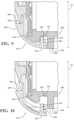
- FIG. 9is a partial, (vertical) cross-sectional view showing the locking mechanism in a locked position.
- FIG. 10is a partial, (vertical) cross-sectional view showing the locking mechanism in an unlocked position.
- FIG. 11is a side, perspective view of the door assembly with the locking mechanism shown in the locked position.
- FIG. 12is a side, perspective view of the door assembly with the locking mechanism shown in the unlocked position.
- FIG. 13is a partial, top, perspective view of the door assembly (with the sealing member and the spacer removed) showing the locking mechanism in the locked position.
- FIG. 14is a partial, top, perspective view of the door assembly (with the sealing member and the spacer removed) showing the locking mechanism in the unlocked position.
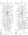
- FIG. 15is a side, (vertical) cross-sectional view of the door assembly with the locking mechanism shown in the locked position.
- FIG. 16is a side, (vertical) cross-sectional view of the door assembly with the locking mechanism shown in the unlocked position.
- FIG. 17is a partial, (vertical) cross-sectional view of the door assembly shown connected to the image capture device.
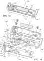
- FIG. 18is a perspective view of an alternate embodiment of the door assembly, which includes a door body; the locking mechanism, the biasing member, the sealing member, and the spacer seen in FIGS. 4 A- 17 ; and a clip.
- FIG. 19is a perspective view of the door assembly seen in FIG. 18 with parts separated.
- FIG. 20is a side, plan view illustrating connection of the clip to the door body (shown in phantom).
- FIG. 21is a side, plan view illustrating connection of the clip to the door body according to an alternate embodiment of the disclosure.
- FIG. 22is a perspective view of the clip according to an alternate embodiment of the disclosure.
- the present disclosuredescribes image capture devices and various embodiments of door assemblies for use therewith.
- the door assemblies described hereinare configured for removable connection to an image capture device, and are movable between open and closed positions to conceal and permit access to various internal components of the image capture device, including, for example, a power source (e.g., one or more batteries); one or more accessory ports; an I/O interface; USB-C connectors; etc.
- a power sourcee.g., one or more batteries
- accessory portse.g., one or more accessory ports
- an I/O interfacee.g., USB-C connectors; etc.
- the door assemblies described hereininclude a sealing member that is configured to form a (waterproof) seal with a body of the image capture device upon closure.
- the door assemblies described hereininclude a locking mechanism that is movable (e.g., slidable) between locked and unlocked positions; a biasing member (e.g., a spring clip); a spacer; and a door body that supports the various components of the door assembly.
- a locking mechanismthat is movable (e.g., slidable) between locked and unlocked positions
- a biasing membere.g., a spring clip
- spacere.g., a spacer
- a door bodythat supports the various components of the door assembly.
- the locking mechanismengages the body of the image capture device to inhibit opening of the door assembly
- the locking mechanismin the unlocked position, the locking mechanism is disengaged from the body of the image capture device to permit opening of the door assembly.
- the biasing memberacts upon the locking mechanism such that the locking mechanism remains in the locked position until the application of a threshold force thereto, thereby inhibiting (if not entirely preventing) inadvertent (e.g., accidental or unwanted) movement of the locking mechanism into the unlocked position (e.g., in the event that the image capture device is dropped), and, thus, inadvertent (e.g., accidental or unwanted) opening of the door assembly.
- the spaceris supported by (e.g., is secured to) the sealing member to reduce (if not entirely eliminate) undesirable relative movement between the components of the door assembly. Additionally, or alternatively, the spacer may enhance the seal formed between the sealing member and the image capture device upon closure of the door assembly; increase shock absorption; and/or enhance electrical connectivity between the components of the image capture device.
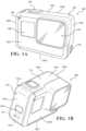
- FIGS. 1 A-Dare isometric views of an example of an image capture device 100 .
- the image capture device 100may include a body 102 having a lens 104 structured on a front surface of the body 102 , various indicators on the front surface of the body 102 (such as LEDs, displays, and the like), various input mechanisms (such as buttons, switches, and touchscreen mechanisms), and electronics (e.g., imaging electronics, power electronics, etc.) internal to the body 102 for capturing images via the lens 104 and/or performing other functions.
- the image capture device 100may be configured to capture images and video and to store captured images and video for subsequent display or playback.
- the image capture device 100may include various indicators, including LED lights 106 and an LCD display 108 .
- the image capture device 100may also include buttons 110 configured to allow a user of the image capture device 100 to interact with the image capture device 100 , to turn the image capture device 100 on, to operate latches or hinges associated with doors of the image capture device 100 , and/or to otherwise configure the operating mode of the image capture device 100 .
- the image capture device 100may also include a microphone 112 configured to receive and record audio signals in conjunction with recording video.
- the image capture device 100may include an I/O interface 114 (e.g., hidden as indicated using dotted lines). As best shown in FIG. 1 B , the I/O interface 114 can be covered and sealed by a removable door 115 of the image capture device 100 .
- the removable door 115can be secured, for example, using a latch mechanism 115 a (e.g., hidden as indicated using dotted lines) that is opened by engaging the associated button 110 as shown.
- the removable door 115can also be secured to the image capture device 100 using a hinge mechanism 115 b , allowing the removable door 115 to rotate (e.g., pivot) between an open position allowing access to the I/O interface 114 and a closed position blocking access to the I/O interface 114 .
- the removable door 115can also have a removed position (not shown) where the entire removable door 115 is separated from the image capture device 100 , that is, where both the latch mechanism 115 a and the hinge mechanism 115 b allow the removable door 115 to be removed from the image capture device 100 .
- the image capture device 100may also include another microphone 116 integrated into the body 102 .
- the front surface of the image capture device 100may include two drainage ports as part of a drainage channel 118 .
- the image capture device 100may include an interactive display 120 that allows for interaction with the image capture device 100 while simultaneously displaying information on a surface of the image capture device 100 .
- the image capture device 100may include the lens 104 that is configured to receive light incident upon the lens 104 and to direct received light onto an image sensor internal to the lens 104 .
- the image capture device 100 of FIGS. 1 A-Dincludes an exterior that encompasses and protects internal electronics.
- the exteriorincludes six surfaces (i.e., a front face 102 a , side (left and right) faces 102 b , 102 c , a back face 102 d , a top face 102 e , and a bottom face 102 f ) that form a rectangular cuboid.
- both the front and rear surfaces of the image capture device 100are rectangular.
- the exteriormay have a different shape.
- the image capture device 100may be made of a rigid material such as plastic, aluminum, steel, or fiberglass.
- the image capture device 100may include features other than those described herein.
- the image capture device 100may include additional buttons or different interface features, such as interchangeable lenses, cold shoes and hot shoes that can add functional features to the image capture device 100 , etc.
- the image capture device 100may include various types of image sensors, such as charge-coupled device (CCD) sensors, active pixel sensors (APS), complementary metal-oxide-semiconductor (CMOS) sensors, N-type metal-oxide-semiconductor (NMOS) sensors, and/or any other image sensor or combination of image sensors.
- CCDcharge-coupled device
- APSactive pixel sensors
- CMOScomplementary metal-oxide-semiconductor
- NMOSN-type metal-oxide-semiconductor
- the image capture device 100may include other additional electrical components (e.g., an image processor, camera SoC (system-on-chip), etc.), which may be included on one or more circuit boards within the body 102 of the image capture device 100 .
- additional electrical componentse.g., an image processor, camera SoC (system-on-chip), etc.
- the image capture device 100may interface with or communicate with an external device, such as an external user interface device, via a wired or wireless computing communication link (e.g., the I/O interface 114 ).
- the user interface devicemay, for example, be the personal computing device 360 described below with respect to FIG. 3 B . Any number of computing communication links may be used.
- the computing communication linkmay be a direct computing communication link or an indirect computing communication link, such as a link including another device, or a network, such as the Internet, may be used.
- the computing communication linkmay be a Wi-Fi link, an infrared link, a Bluetooth (BT) link, a cellular link, a ZigBee link, a near-field communications (NFC) link (such as an ISO/IEC 20643 protocol link), an Advanced Network Technology interoperability (ANT+) link, and/or any other wireless communications link or combination of links.
- BTBluetooth
- NFCnear-field communications
- ANT+Advanced Network Technology interoperability
- the computing communication linkmay be an HDMI link, a USB link, a digital video interface link, a display port interface link (such as a Video Electronics Standards Association (VESA) digital display interface link), an Ethernet link, a Thunderbolt link, and/or other wired computing communication link.
- VESAVideo Electronics Standards Association
- the image capture device 100may transmit images, such as panoramic images, or portions thereof, to the user interface device (not shown) via the computing communication link, and the user interface device may store, process, display, or a combination thereof the panoramic images.
- the user interface devicemay be a computing device, such as a smartphone, a tablet computer, a phablet, a smart watch, a portable computer, and/or another device or combination of devices configured to receive user input, communicate information with the image capture device 100 via the computing communication link, or receive user input and communicate information with the image capture device 100 via the computing communication link.
- a computing devicesuch as a smartphone, a tablet computer, a phablet, a smart watch, a portable computer, and/or another device or combination of devices configured to receive user input, communicate information with the image capture device 100 via the computing communication link, or receive user input and communicate information with the image capture device 100 via the computing communication link.
- the user interface devicemay display, or otherwise present, content, such as images or video, acquired by the image capture device 100 .
- contentsuch as images or video
- a display of the user interface devicemay be a viewport into the three-dimensional space represented by the panoramic images or video captured or created by the image capture device 100 .
- the user interface devicemay communicate information, such as metadata, to the image capture device 100 .
- the user interface devicemay send orientation information of the user interface device with respect to a defined coordinate system to the image capture device 100 , such that the image capture device 100 may determine an orientation of the user interface device relative to the image capture device 100 .
- the image capture device 100may identify a portion of the panoramic images or video captured by the image capture device 100 for the image capture device 100 to send to the user interface device for presentation as the viewport. In some implementations, based on the determined orientation, the image capture device 100 may determine the location of the user interface device and/or the dimensions for viewing of a portion of the panoramic images or video.
- the user interface devicemay implement or execute one or more applications to manage or control the image capture device 100 .
- the user interface devicemay include an application for controlling camera configuration, video acquisition, video display, or any other configurable or controllable aspect of the image capture device 100 .
- the user interface devicemay generate and share, such as via a cloud-based or social media service, one or more images, or short video clips, such as in response to user input.
- the user interface devicemay remotely control the image capture device 100 , such as in response to user input.
- the user interface devicemay display unprocessed or minimally processed images or video captured by the image capture device 100 contemporaneously with capturing the images or video by the image capture device 100 , such as for shot framing, which may be referred to herein as a live preview, and which may be performed in response to user input.
- the user interface devicemay mark one or more key moments contemporaneously with capturing the images or video by the image capture device 100 , such as with a tag, such as in response to user input.
- the user interface devicemay display, or otherwise present, marks or tags associated with images or video, such as in response to user input.
- marksmay be presented in a camera roll application for location review and/or playback of video highlights.
- the user interface devicemay wirelessly control camera software, hardware, or both.
- the user interface devicemay include a web-based graphical interface accessible by a user for selecting a live or previously recorded video stream from the image capture device 100 for display on the user interface device.
- the user interface devicemay receive information indicating a user setting, such as an image resolution setting (e.g., 3840 pixels by 2160 pixels), a frame rate setting (e.g., 60 frames per second (fps)), a location setting, and/or a context setting, which may indicate an activity, such as mountain biking, in response to user input, and may communicate the settings, or related information, to the image capture device 100 .
- a user settingsuch as an image resolution setting (e.g., 3840 pixels by 2160 pixels), a frame rate setting (e.g., 60 frames per second (fps)), a location setting, and/or a context setting, which may indicate an activity, such as mountain biking, in response to user input, and may communicate the settings, or related information, to the image capture device 100 .
- a user settingsuch as an image resolution setting (e.g., 3840 pixels by 2160 pixels), a frame rate setting (e.g., 60 frames per second (fps)), a location setting, and/or
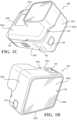
- FIGS. 2 A-Billustrate another example of an image capture device 200 .
- the image capture device 200includes a body 202 and two camera lenses 204 , 206 disposed on opposing surfaces of the body 202 , for example, in a back-to-back or Janus configuration.
- a camerait should be appreciated that the particular configuration of the image capture device 200 may be varied in alternate embodiments of the disclosure.
- the image capture device 200may instead take the form of a cell phone.
- the image capture devicemay include electronics (e.g., imaging electronics, power electronics, etc.) internal to the body 202 for capturing images via the lenses 204 , 206 and/or performing other functions.
- the image capture devicemay include various indicators, such as an LED light 212 and an LCD display 214 .
- the image capture device 200may include various input mechanisms, such as buttons, switches, and touchscreen mechanisms.
- the image capture device 200may include buttons 216 configured to allow a user of the image capture device 200 to interact with the image capture device 200 , to turn the image capture device 200 on, and to otherwise configure the operating mode of the image capture device 200 .
- the image capture device 200includes a shutter button and a mode button. It should be appreciated, however, that, in alternate embodiments, the image capture device 200 may include additional buttons to support and/or control additional functionality.
- the image capture device 200may also include one or more microphones 218 configured to receive and record audio signals (e.g., voice or other audio commands) in conjunction with recording video.
- audio signalse.g., voice or other audio commands
- the image capture device 200may include an I/O interface 220 and an interactive display 222 that allows for interaction with the image capture device 200 while simultaneously displaying information on a surface of the image capture device 200 .
- the image capture device 200may be made of a rigid material such as plastic, aluminum, steel, or fiberglass.
- the image capture device 200 described hereinincludes features other than those described.
- the image capture device 200may include additional interfaces or different interface features.
- the image capture device 200may include additional buttons or different interface features, such as interchangeable lenses, cold shoes and hot shoes that can add functional features to the image capture device 200 , etc.
- FIG. 2 Cis a cross-sectional view of an optical module 223 of the image capture device 200 of FIGS. 2 A-B .
- the optical module 223facilitates the capture of spherical images, and, accordingly, includes a first image capture device 224 and a second image capture device 226 .
- the first image capture device 224defines a first field-of-view 228 , as shown in FIG. 2 C , and includes a first integrated sensor-lens assembly (ISLA) 229 that receives and directs light onto a first image sensor 230 via the lens 204 .
- the second image capture device 226defines a second field-of-view 232 , as shown in FIG.
- the image capture devices 224 , 226may be arranged in a back-to-back (Janus) configuration such that the lenses 204 , 206 face in generally opposite directions.
- the fields-of-view 228 , 232 of the lenses 204 , 206are shown above and below boundaries 236 , 238 , respectively.
- the first image sensor 230may capture a first hyper-hemispherical image plane from light entering the first lens 204
- the second image sensor 234may capture a second hyper-hemispherical image plane from light entering the second lens 206 .
- One or more areasmay be outside of the fields-of-view 228 , 232 of the lenses 204 , 206 so as to define a “dead zone.” In the dead zone, light may be obscured from the lenses 204 , 206 and the corresponding image sensors 230 , 234 , and content in the blind spots 240 , 242 may be omitted from capture.
- the image capture devices 224 , 226may be configured to minimize the blind spots 240 , 242 .
- the fields-of-view 228 , 232may overlap.
- Stitch points 244 , 246 , proximal to the image capture device 200 , at which the fields-of-view 228 , 232 overlapmay be referred to herein as overlap points or stitch points.
- Content captured by the respective lenses 204 , 206 , distal to the stitch points 244 , 246may overlap.
- Images contemporaneously captured by the respective image sensors 230 , 234may be combined to form a combined image.
- Combining the respective imagesmay include correlating the overlapping regions captured by the respective image sensors 230 , 234 , aligning the captured fields-of-view 228 , 232 , and stitching the images together to form a cohesive combined image.
- a slight change in the alignment, such as position and/or tilt, of the lenses 204 , 206 , the image sensors 230 , 234 , or both,may change the relative positions of their respective fields-of-view 228 , 232 and the locations of the stitch points 244 , 246 .
- a change in alignmentmay affect the size of the blind spots 240 , 242 , which may include changing the size of the blind spots 240 , 242 unequally.
- Incomplete or inaccurate information indicating the alignment of the image capture devices 224 , 226 , such as the locations of the stitch points 244 , 246 ,may decrease the accuracy, efficiency, or both of generating a combined image.
- the image capture device 200may maintain information indicating the location and orientation of the lenses 204 , 206 and the image sensors 230 , 234 such that the fields-of-view 228 , 232 , the stitch points 244 , 246 , or both may be accurately determined, which may improve the accuracy, efficiency, or both of generating a combined image.
- the lenses 204 , 206may be laterally offset from each other, may be off-center from a central axis of the image capture device 200 , or may be laterally offset and off-center from the central axis.
- image capture devices including laterally offset lensesmay include substantially reduced thickness relative to the lengths of the lens barrels securing the lenses.
- the overall thickness of the image capture device 200may be close to the length of a single lens barrel as opposed to twice the length of a single lens barrel as in a back-to-back configuration. Reducing the lateral distance between the lenses 204 , 206 may improve the overlap in the fields-of-view 228 , 232 .
- Images or frames captured by the image capture devices 224 , 226may be combined, merged, or stitched together to produce a combined image, such as a spherical or panoramic image, which may be an equirectangular planar image.
- a combined imagesuch as a spherical or panoramic image, which may be an equirectangular planar image.
- generating a combined imagemay include three-dimensional, or spatiotemporal, noise reduction (3DNR).
- 3DNRthree-dimensional, or spatiotemporal, noise reduction
- pixels along the stitch boundarymay be matched accurately to minimize boundary discontinuities.
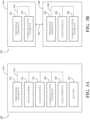
- FIGS. 3 A-Bare block diagrams of examples of image capture systems.
- the image capture system 300includes an image capture device 310 (e.g., a camera or a drone), which may, for example, be the image capture device 200 shown in FIGS. 2 A-C .
- an image capture device 310e.g., a camera or a drone
- FIGS. 2 A-Cthe image capture device 200 shown in FIGS. 2 A-C .
- the image capture device 310includes a processing apparatus 312 that is configured to receive a first image from a first image sensor 314 and receive a second image from a second image sensor 316 .
- the image capture device 310includes a communications interface 318 for transferring images to other devices.
- the image capture device 310includes a user interface 320 to allow a user to control image capture functions and/or view images.
- the image capture device 310includes a battery 322 for powering the image capture device 310 .
- the components of the image capture device 310may communicate with each other via the bus 324 .
- the processing apparatus 312may be configured to perform image signal processing (e.g., filtering, tone mapping, stitching, and/or encoding) to generate output images based on image data from the image sensors 314 and 316 .
- the processing apparatus 312may include one or more processors having single or multiple processing cores.
- the processing apparatus 312may include memory, such as a random-access memory (RAM) device, flash memory, or another suitable type of storage device, such as a non-transitory computer-readable memory.
- the memory of the processing apparatus 312may include executable instructions and data that can be accessed by one or more processors of the processing apparatus 312 .
- the processing apparatus 312may include one or more dynamic random-access memory (DRAM) modules, such as double data rate synchronous dynamic random-access memory (DDR SDRAM).
- DRAMdynamic random-access memory
- DDR SDRAMdouble data rate synchronous dynamic random-access memory
- the processing apparatus 312may include a digital signal processor (DSP).
- DSPdigital signal processor
- the processing apparatus 312may include an application specific integrated circuit (ASIC).
- ASICapplication specific integrated circuit
- the processing apparatus 312may include a custom image signal processor.
- the first image sensor 314 and the second image sensor 316may be configured to detect light of a certain spectrum (e.g., the visible spectrum or the infrared spectrum) and convey information constituting an image as electrical signals (e.g., analog or digital signals).
- the image sensors 314 and 316may include CCDs or active pixel sensors in a CMOS.
- the image sensors 314 and 316may detect light incident through a respective lens (e.g., a fisheye lens).
- the image sensors 314 and 316include digital-to-analog converters.
- the image sensors 314 and 316are held in a fixed orientation with respective fields-of-view that overlap.
- the communications interface 318may enable communications with a personal computing device (e.g., a smartphone, a tablet, a laptop computer, or a desktop computer).
- a personal computing devicee.g., a smartphone, a tablet, a laptop computer, or a desktop computer.
- the communications interface 318may be used to receive commands controlling image capture and processing in the image capture device 310 .
- the communications interface 318may be used to transfer image data to a personal computing device.
- the communications interface 318may include a wired interface, such as a high-definition multimedia interface (HDMI), a universal serial bus (USB) interface, or a FireWire interface.
- the communications interface 318may include a wireless interface, such as a Bluetooth interface, a ZigBee interface, and/or a Wi-Fi interface.
- the user interface 320may include an LCD display for presenting images and/or messages to a user.
- the user interface 320may include a button or switch enabling a person to manually turn the image capture device 310 on and off.
- the user interface 320may include a shutter button for snapping pictures.
- the battery 322may power the image capture device 310 and/or its peripherals.
- the battery 322may be charged wirelessly or through a micro-USB interface.
- the image capture system 300may be used to implement some or all of the techniques described in this disclosure.
- the image capture system 330includes an image capture device 340 and a personal computing device 360 that communicate via a communications link 350 .
- the image capture device 340may, for example, be the image capture device 100 shown in FIGS. 1 A-D .
- the personal computing device 360may, for example, be the user interface device described with respect to FIGS. 1 A-D .
- the image capture device 340includes an image sensor 342 that is configured to capture images.
- the image capture device 340includes a communications interface 344 configured to transfer images via the communication link 350 to the personal computing device 360 .
- the personal computing device 360includes a processing apparatus 362 that is configured to receive, using a communications interface 366 , images from the image sensor 342 .
- the processing apparatus 362may be configured to perform image signal processing (e.g., filtering, tone mapping, stitching, and/or encoding) to generate output images based on image data from the image sensor 342 .
- image signal processinge.g., filtering, tone mapping, stitching, and/or encoding
- the image sensor 342is configured to detect light of a certain spectrum (e.g., the visible spectrum or the infrared spectrum) and convey information constituting an image as electrical signals (e.g., analog or digital signals).
- the image sensor 342may include CCDs or active pixel sensors in a CMOS.
- the image sensor 342may detect light incident through a respective lens (e.g., a fisheye lens).
- the image sensor 342includes digital-to-analog converters. Image signals from the image sensor 342 may be passed to other components of the image capture device 340 via a bus 346 .
- the communications link 350may be a wired communications link or a wireless communications link.
- the communications interface 344 and the communications interface 366may enable communications over the communications link 350 .
- the communications interface 344 and the communications interface 366may include an HDMI port or other interface, a USB port or other interface, a FireWire interface, a Bluetooth interface, a ZigBee interface, and/or a Wi-Fi interface.
- the communications interface 344 and the communications interface 366may be used to transfer image data from the image capture device 340 to the personal computing device 360 for image signal processing (e.g., filtering, tone mapping, stitching, and/or encoding) to generate output images based on image data from the image sensor 342 .
- image signal processinge.g., filtering, tone mapping, stitching, and/or encoding
- the processing apparatus 362may include one or more processors having single or multiple processing cores.
- the processing apparatus 362may include memory, such as RAM, flash memory, or another suitable type of storage device, such as a non-transitory computer-readable memory.
- the memory of the processing apparatus 362may include executable instructions and data that can be accessed by one or more processors of the processing apparatus 362 .
- the processing apparatus 362may include one or more DRAM modules, such as DDR SDRAM.
- the processing apparatus 362may include a DSP. In some implementations, the processing apparatus 362 may include an integrated circuit, for example, an ASIC. For example, the processing apparatus 362 may include a custom image signal processor. The processing apparatus 362 may exchange data (e.g., image data) with other components of the personal computing device 360 via a bus 368 .
- datae.g., image data
- the personal computing device 360may include a user interface 364 .
- the user interface 364may include a touchscreen display for presenting images and/or messages to a user and receiving commands from a user.
- the user interface 364may include a button or switch enabling a person to manually turn the personal computing device 360 on and off.
- commandse.g., start recording video, stop recording video, or capture photo
- the image capture system 330may be used to implement some or all of the techniques described in this disclosure.
- FIGS. 4 A- 4 Da door assembly 400 will be discussed, which represents an alternate embodiment of the aforedescribed door 115 ( FIG. 1 B ). More specifically, FIG. 4 A provides a front, plan view of the image capture device 100 with the door assembly 400 shown in an open position; FIG. 4 B provides a front, perspective view of the image capture device 100 with the door assembly 400 shown in the open position; FIG. 4 C provides a side, plan view of the image capture device 100 with the door assembly 400 shown in the open position; and FIG. 4 D provides a front, perspective view of the image capture device 100 with the door assembly 400 shown in the closed position.
- the door assembly 400may be configured for use with any image capture device, such as the various embodiments described herein (e.g., the aforedescribed image capture devices 200 , 300 ).
- the door assembly 400is rotatably (e.g., pivotably) connected to the body 102 of the image capture device 100 such that the door assembly 400 is movable (repositionable) between the open position ( FIGS. 4 A- 4 C ) and the closed position ( FIG. 4 D ) to reveal and conceal a peripheral cavity 122 defined by the body 102 of the image capture device 100 .
- the peripheral cavity 122may include, accommodate, or otherwise provide access to one or more components C of the image capture device 100 , including, for example, a power source 124 for the image capture device 100 (e.g., the aforementioned battery 322 ); an accessory port 126 ; the aforementioned I/O interface 114 ( FIG. 1 B ); a USB-C connector 128 ; etc.
- the door assembly 400completes the exterior of the image capture device 100 , and extends along a side (e.g., the left face 102 b ) of the image capture device between opposite (upper and lower) corner sections 130 u , 130 l (e.g., between the top face 102 e and the bottom face 102 f ) of the image capture device 100 .
- the door assembly 400includes an upper (first) end 402 u that is pivotably connected to the body 102 at (or adjacent to) the corner section 130 u such that the upper end 402 u is positioned proximate (e.g., adjacent) to the top face 102 e of the image capture device 100 , and a lower (second) end 402 l that is positioned at (or adjacent to) the corner section 130 l (when the door assembly 400 is in the closed position) such that the lower end 402 l is positioned proximate (e.g., adjacent) to the bottom face 102 f of the image capture device 100 .
- FIG. 5provides a perspective view of the door assembly 400 separated from the image capture device 100 with parts separated.
- the door assembly 400includes a door body 500 ; a locking mechanism 600 ; a biasing member 700 (e.g., a spring clip 702 ); a sealing member 800 ; and a spacer 900 that is supported by (e.g., secured to) the sealing member 800 .
- FIG. 6provides a bottom, perspective view of the door body 500
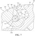
- FIG. 7provides a partial, (vertical) cross-sectional view of the door body 500 shown connected to the body 102 of the image capture device 100 via a pivot member 132 (e.g., a hinge pin 134 ).
- the door body 500may include any suitable material or combination of materials, and may be formed through any suitable method of manufacture.
- the door body 500includes a metallic material (e.g., stainless steel, aluminum, etc.), and is formed via injection molding.
- the door body 500includes an engagement structure 502 ; a plurality of bosses 504 i - 504 iv that facilitate connection of the biasing member 700 and the sealing member 800 to the door body 500 ; and flanges 506 that support the locking mechanism 600 .
- the engagement structure 502 of the door body 500is configured to facilitate connection of the door assembly 400 to the body 102 of the image capture device 100 , and includes a pair of clips 508 . Although shown as being integrally formed with the door body 500 in the illustrated embodiment, it should be appreciated that the engagement structure 502 may be formed as a separate, discrete component that is secured to the door body 500 (e.g., via adhesive, welding, etc.) without departing from the scope of the present disclosure.
- the clips 508are configured for engagement with the pivot member 132 ( FIG. 7 ) to axially (vertically) fix the door body 500 in relation to the housing 102 of the image capture device 100 while allowing the door assembly 400 to rotate in relation to the body 102 during opening and closure. More specifically, the door assembly 400 is rotatable about an axis of rotation XR ( FIGS. 4 B, 5 , 7 ) that extends through the pivot member 132 , and through the clips 508 .
- Each clip 508is generally C-shaped in configuration, and includes arms 510 i , 510 ii defining ends 512 i , 512 ii , respectively.
- the arms 510 i , 510 iidefine a channel 514 ( FIGS. 5 - 7 ) that is configured to receive the pivot member 132 such that the clip 508 is rotatable in relation to the pivot member 132 during opening and closure of the door assembly 400 .
- each clip 508may be configured to create an interference fit (e.g., a snap-fit) with the pivot member 132 .
- the clip 508is configured to create sufficient clearance with the pivot member 132 to allow for rotation of the clip 508 in relation to the pivot member 132 in the manner described herein.
- the clips 508may include a resilient (e.g., flexible) material, such as stainless steel, as mentioned above, such that the arm 510 ii is deflected outwardly (i.e., away from the arm 510 i ) during connection to the pivot member 132 , and is returned to its normal position (seen in FIGS. 5 , 6 ) upon receipt of the pivot member 132 within the channel 514 .
- a resilient (e.g., flexible) materialsuch as stainless steel
- the end 512 i of the arm 510 iincludes an arcuate recess 516 with a configuration that corresponds to an outer contour defined by the pivot member 132 such that the pivot member 132 is seated within the recess 516 upon connection.
- the pivot member 132seats within the recess 516 , due to the resilient (flexible) material used in construction of the clip 508 , and the resultant deflection created during connection of the clip 508 to the pivot member 132 , in certain embodiments, as the clip 508 returns to its normal position, it is envisioned that the clip 508 may provide an audible indication that the pivot member 132 has been properly connected to the clip 508 .
- each clip 508defines a bearing surface 518 that is configured for contact with a corresponding bearing surface 136 defined by the body 102 of the image capture device 100 within the peripheral cavity 122 . More specifically, the bearing surface 518 of each clip 508 includes segments 520 i , 520 ii defining an obtuse angle ⁇ therebetween, and the bearing surface 136 includes corresponding segments 138 i , 138 ii defining an angle ⁇ therebetween of approximately 90°.
- bearing surfaces 136 , 518may be varied in alternate embodiments without departing from the scope of the present disclosure (e.g., depending upon the desired functionality of the door assembly 400 ).
- the clips 508may be configured such that the bearing surface 518 contacts the bearing surface 136 upon positioning of the door assembly 400 in generally orthogonal relation to the body 102 of the image capture device 100 , as seen in FIGS. 4 B, 4 C , and that continued rotation of the door assembly 400 in relation to the body 102 of the image capture device 100 will cause detachment of the door assembly 400 from the image capture device 100 .
- the door assembly 400further includes a detent 522 (e.g., a protrusion, protuberance, etc.) that facilitates connection of the door assembly 400 to the body 102 of the image capture device 100 .
- the detent 522is positioned for contact with the pivot member 132 to urge the pivot member 132 into the channel 514 in each clip 508 .
- the detent 522may include a groove (recess) 524 ( FIG. 6 ) that is configured to receive (or otherwise accommodate) the pivot member 132 .
- the pivot member 132may experience resilient deflection (e.g., bending) via forces collectively applied to the pivot member 132 by the clips 508 and the detent 522 . More specifically, it is envisioned that the pivot member 132 may be deflected towards the clips 508 by the detent 522 and may return to its normal (linear) position upon seating within the channel 514 defined by each clip 508 . Additionally, it is envisioned that the forces applied to the pivot member 132 during connection of the door assembly 400 may further contribute to the audible indication created upon proper connection of the clips 508 to the pivot member 132 mentioned above.
- resilient deflectione.g., bending
- the door body 500includes bosses 504 i , 504 ii , 504 iii , 504 iv that are configured to receive corresponding fasteners 524 to secure the biasing member 700 and the sealing member 800 to the door body 500 . More specifically, fasteners 524 i extend through the sealing member 800 into the bosses 504 i , 504 ii , 504 iii to fixedly connect the sealing member 800 to the door body 500 , and a fastener 524 ii extends through the boss 504 iv to fixedly connect the biasing member 700 to the door body 500 , as described in further detail below.
- the boss 504 ivdefines an inclined surface 526 that is configured to support the biasing member 700 at an angle in relation to a longitudinal axis Y of the door assembly 400 (and in relation to the locking mechanism 600 ) in the manner described hereinbelow.
- the door body 500includes a post 528 that is configured for receipt within a corresponding opening 702 defined by the biasing member 700 , further details of which are provided below.
- the flanges 506extend inwardly from outer walls 530 i , 530 ii of the door body 500 so as to define channels 532 i , 532 ii that are configured to receive the locking mechanism 600 . More specifically, in the illustrated embodiment, the door body includes a pair of flanges 506 i , 506 ii that extend inwardly from the outer wall 530 i , and a pair of flanges 506 iii , 506 iv that extend inwardly from the outer wall 530 ii .
- flanges 506may be varied in alternate embodiments without departing from the scope of the present disclosure.
- the door body 500includes a single (e.g., more elongate) flange 506 on each outer wall 530 would also be within the scope of the present disclosure, as would embodiments including three or more flanges 506 on each outer wall 530 .
- the door body 500may further include a plurality of supports 534 that extend inwardly from an inner surface 536 of the door body 500 (i.e., towards the sealing member 800 ) to collectively define the channels 532 i , 532 ii with the flanges 506 . More specifically, in the illustrated embodiment, the door body 500 includes four supports 534 i - 534 iv configured as support blocks 538 i - 538 iv that are positioned in general registration (alignment) with the flanges 506 i - 506 iv , respectively.
- supports 534 included on the door body 500may be varied in alternate embodiments without departing from the scope of the present disclosure, as discussed above in connection with the flanges 506 .
- supports 536are configured as detents (or other such projections) would also be within the scope of the present disclosure, as would embodiments in which the door body 500 includes a pair of supports 534 that are positioned on opposite sides of the door body 500 .
- the door body 500may further include one or more stiffening ribs 540 (e.g., to reinforce and/or strengthen a lower (distal) end 542 of the door body 500 . More specifically, in the illustrated embodiment, the door body 500 includes a pair of stiffening ribs 540 i , 540 ii positioned adjacent to the boss 504 iii that extend vertically upward from the lower (distal) end 542 of the door body 500 at an angle to the outer walls 530 i , 530 ii , respectively.
- ribs 540 included on the door body 500may be varied in alternate embodiments without departing from the scope of the present disclosure.
- embodiments including greater and fewer ribs 540would also be within the scope of the present disclosure, as would embodiments including ribs 540 that extend in parallel and/or orthogonal relation to a length of the door body 500 .
- the ribs 540may be formed as separate, discrete structures that may be secured to the door body 500 (e.g., via adhesive, welding, etc.) without departing from the scope of the present disclosure.
- the locking mechanism 600may include any suitable material or combination of materials, and may be formed through any suitable method of manufacture.
- the locking mechanism 600includes a metallic material (e.g., stainless steel, aluminum, etc.), and is formed via injection molding.
- the locking mechanism 600includes a locking member 602 ; a tactile member 604 ; a body portion 606 including a pair of rails 608 ( FIG. 8 ); and one or more deflectors 610 .
- FIGS. 9 and 10provide partial, (vertical) cross-sectional views showing the locking mechanism 600 in the locked and unlocked positions, respectively;
- FIGS. 11 and 12provide side, perspective views of the door assembly 400 with the locking mechanism 600 shown in the locked position and the unlocked position, respectively;
- FIGS. 13 and 14provide partial, top, perspective views of the door assembly 400 (with the sealing member 800 and the spacer 900 removed) showing the locking mechanism 600 in the locked and unlocked positions, respectively;
- FIGS. 15 and 16provide side, (vertical) cross-sectional views of the door assembly 400 with the locking mechanism 600 shown in the locked and unlocked positions, respectively.
- the locking mechanism 600engages with the housing 102 of the image capture device 100 to rotationally fix the door assembly 400 in relation to the housing 102 , and, thus, maintain the door assembly 400 in the closed position.
- the locking mechanism 600is disengaged from the housing 102 of the image capture device 100 to permit rotation of the door assembly 400 in relation to the housing 102 , and, thus, movement of the door assembly 400 into the open position.
- the locking member 602is positioned at a lower (distal) end 612 of the locking mechanism 600 (i.e., at the end of the locking mechanism 600 opposite to the pivot member 132 ), and is configured for insertion into, and removal from, a corresponding receptacle 140 in the housing 102 of the image capture device 100 such that the locking member 602 is engageable with, and disengageable from, the housing 102 during movement of the locking mechanism 600 between the unlocked and locked positions. More specifically, in the illustrated embodiment, the locking member 602 is configured as a tooth 614 that is configured for insertion into an opening 142 (e.g., a channel or other such surface irregularity) defined by the housing 102 .
- an opening 142e.g., a channel or other such surface irregularity
- the locking member 602extends upwardly (vertically) from an end wall 616 of the locking mechanism 600 in the direction of movement of the locking mechanism 600 in transitioning from the unlocked position to the locked position so as to define a groove 618 with the end wall 616 .
- the end wall 616is arcuate in configuration so as to match the overall exterior contour defined by the housing 102 , whereby the end wall 616 sits flush with the bottom face 102 f of the image capture device 100 when the locking mechanism 600 is in the locked position.
- the locking mechanism 600includes the tactile member 604 , which is configured for manual engagement by a user such that a suitable force can be applied to the locking mechanism 600 to manually unlock the locking mechanism 600 .
- the tactile member 604is configured as an exterior flange 620 defining a finger grab 624 .
- the exterior flange 620in the locked position, is configured for contact with a lower (distal) end surface 544 defined by the door body 500 (e.g., to reduce, if not entirely eliminate, gapping between the locking mechanism 600 and the door body 500 when the locking mechanism 600 is in the locked position).
- the rails 608extend laterally (horizontally) from the body portion 606 of the locking mechanism 600 such that the rails 608 are positioned beneath the flanges 506 (i.e., between the flanges 506 and the supports 534 ). More specifically, in the embodiment of the disclosure shown throughout the figures, the body portion 606 includes a (first) rail 608 i that is configured for positioning beneath the flanges 506 i , 506 ii within the channel 532 i , and a (second) rail 608 ii that is configured for positioning beneath the flanges 506 iii , 506 iv within the channel 532 ii .
- the respective positioning of the rails 608 i , 608 ii within the channels 532 i , 532 iirestricts (if not entirely prevents) relative horizontal movement between the door body 500 and the locking mechanism 600 (i.e., movement of the locking mechanism 600 towards and/or away from the door body 500 ), while facilitating relative vertical movement (sliding) of the locking mechanism 600 relative to the door body 500 as the locking mechanism transitions between the locked and unlocked positions.
- the body portion 602 of the locking mechanism 600defines a chamber 622 ( FIG. 5 ) (e.g., a cavity 624 ) that accommodates the boss 504 iv and the biasing member 700 such that the biasing member 700 extends into the chamber 622 , as described in further detail below.
- the chamber 622is defined at an upper end 626 ( FIG. 13 ) by a (horizontal) end wall 628 that is configured for contact with the biasing member 700 to limit (vertical) movement of the locking mechanism 600 relative to the door body 500 .
- the end wall 628 of the locking mechanism 600defines a range of (vertical) motion for the locking mechanism 600 (e.g., relative to the door body 500 and the biasing member 700 ) that prevents overextension of the locking mechanism 600 , and inadvertent (e.g., accidental or unwanted) removal of the locking mechanism 600 from the door assembly 400 .
- the body portion 606 of the locking mechanism 600may also include a cutout 630 ( FIG. 5 ) that is configured to receive the boss 504 iii during movement of the locking mechanism 600 between the locked and unlocked positions, and/or a relief 632 that allows the overall weight of the locking mechanism 600 to be reduced.
- the deflector(s) 610are configured for engagement with the biasing member 700 to facilitate horizontal movement of the biasing member 700 relative to the door body 500 during movement of the locking mechanism 600 between the locked position and the unlocked position. More specifically, as elaborated upon below, the deflector(s) 610 are configured to deflect the biasing member 700 inwardly (i.e., away from the door body 500 , and towards the sealing member 800 ) as the locking mechanism 600 moves from the locked position to the unlocked position, and support the biasing member 700 during movement towards the door body 500 (and away from the sealing member 800 ) as the locking mechanism 600 moves from the unlocked position to the locked position.
- each deflector 610includes an inclined (ramped) surface 634 that extends vertically upward from the body portion 606 of the locking mechanism 600 (towards the pivot member 132 ) at an angle ⁇ ( FIG. 13 ), and a generally planar end 636 that extends from the inclined surface in a generally vertical orientation.
- the locking mechanism 600includes a pair of deflectors 610 i , 610 ii that are configured such that the angle ⁇ lies substantially within the range of approximately 30° to approximately 60°. It should be appreciated, however, that the number of deflectors 610 and/or the configuration of the deflector(s) 610 may be varied in alternate embodiments without departing from the scope of the present disclosure. For example, embodiments including a single deflector 610 would also be within the scope of the present disclosure, as would embodiments in which the deflector(s) 610 are configured such that the angle ⁇ lies outside the range indicated above.
- the locking mechanism 600may further include one or more stiffening sections 638 (e.g., to reinforce and/or strengthen the locking mechanism 600 ). More specifically, in the illustrated embodiment, the locking mechanism 600 includes a pair of stiffening sections 638 i , 638 ii that are positioned vertically above (proximally of) the deflectors 610 i , 610 ii , respectively.
- the biasing member 700may include any suitable material or combination of materials, and may be formed through any suitable method of manufacture (e.g., stamping, injection molding, machining, etc.).
- the biasing member 700is integrally (e.g., monolithically) formed from a resilient (e.g., flexible) metallic material (e.g., spring steel, aluminum, etc.).
- the biasing member 700is configured as a spring plate 704 that includes opposite upper and lower (first and second) ends 706 u , 706 l , and a body portion 708 that is positioned between the ends 706 u , 706 l .
- the upper end 706 uis spaced vertically from the lower end 706 l (i.e., closer to the pivot member 132 ), and is axially (vertically) fixed to the door body 500 .
- the upper end 706 uincludes a first section 710 defining the opening 702 that is configured to receive the post 528 extending from the door body 500 , and a second section 712 defining an opening 714 .
- the opening 714is configured to receive the fastener 524 ii such that the fastener 524 ii extends through the opening 714 in the second section 712 of the biasing member 700 , and into the boss 504 iv to fixedly connect the biasing member 700 to the door body 500 , whereby the second section 712 is supported by the boss 504 iv .
- the second section 712is spaced laterally inward from the first section 710 (i.e., the second section 712 is positioned closer to the sealing member 800 ) in generally parallel relation to the first section 710 .
- the second section 712is connected to the first section 710 by a (horizontal) flange 716 that is oriented in generally orthogonal relation to each of the sections 710 , 712 .
- the body portion 708 of the biasing member 700is generally linear in configuration and extends distally from the second section 712 of the upper end 706 u . More specifically, the body portion 708 extends from the second section 712 at an angle ⁇ ( FIG. 13 ) such that the lateral (horizontal) distance between the lower end 706 l and the sealing member 800 is greater than the lateral (horizontal) distance between the second section 712 and the sealing member 800 .
- the lower end 706 l of the biasing member 700includes a pair of wings 718 i , 718 ii that extend laterally (horizontally) from the body portion 708 such that the biasing member 700 includes an overall configuration that is generally T-shaped.
- the wings 718 i , 718 iiare configured for contact with the deflectors 610 i , 610 ii extending from the locking mechanism 600 , respectively, during movement of the locking mechanism 600 .
- Contact between the wings 718 i , 718 ii and the deflectors 610 i , 610 iiinhibits (if not entirely prevents) rotation of the biasing member 700 relative to the door body 500 during movement of the locking mechanism 600 .
- the number of deflectors 610 included on the locking mechanism 600may be varied in alternate embodiments of the disclosure (e.g., such that the locking mechanism 600 includes a single deflector 610 only).
- embodiments of the biasing member 700are also envisioned in which the biasing member 700 may include a single wing 718 only.
- the biasing member 700traverses the deflectors 610 i , 610 ii such that the wings 718 i , 718 ii travel (upwardly) across the inclined surfaces 634 .
- the wings 718 i , 718 iimay define beveled (angled) upper surfaces 720 i , 720 ii , respectively, that are angled in correspondence with the inclined surfaces 634 (i.e., such that the angle defined by the beveled upper surfaces 720 i , 720 ii approximates or matches the angle ⁇ ( FIG. 13 ) defined by the inclined surfaces 634 ).
- the biasing member 700traverses the deflectors 610 i , 610 ii , the biasing member 700 is deflected away from the door body 500 (and towards the sealing member 800 ) along an axis of movement XB that extends in generally orthogonal relation to the longitudinal axis Y of the door assembly, thereby reducing the angle ⁇ ( FIG. 13 ). As seen in FIG.
- the biasing member 700when the locking mechanism 600 is in the unlocked position, the biasing member 700 is supported by the respective ends 636 i , 636 ii of the deflectors 610 i , 610 ii in a generally linear configuration such that the biasing member 700 extends in generally parallel relation to the longitudinal axis Y of the door assembly 400 (and the locking mechanism 600 ).
- the biasing member 700traverses the deflectors 610 i , 610 ii such that the wings 718 i , 718 ii travel (downwardly) across the inclined surfaces 634 .
- the biasing member 700is, thus, returned to its normal configuration ( FIGS. 5 , 13 , 15 ), which is facilitated by the inclusion of resilient material(s) in construction of the biasing member 700 .
- the distance between the wings 718 i , 718 ii and the door body 500is reduced, and the angle ⁇ at which the body portion 708 of the biasing member 700 extends from the second section 712 is increased such that the biasing member 700 again extends at an angle to the longitudinal axis Y of the door assembly 400 (and at an angle to the locking mechanism 600 ).
- the biasing member 700is configured for receipt within the chamber 622 defined by the locking mechanism 600 .
- the locking mechanism 600When the locking mechanism 600 is fully extended (unlocked), the flange 716 connecting the sections 710 , 712 of the upper end 706 u of the biasing member 700 comes into contact with the end wall 628 defining the chamber 622 .
- the flange 716thus, provides a stop 722 ( FIG. 14 ) that limits (vertical) travel of the locking mechanism 600 .
- FIG. 17provides a partial, (vertical) cross-sectional view of the door assembly 400 shown connected to the body 102 of the image capture device 100 .
- the sealing member 800is configured in correspondence with the peripheral cavity 122 defined by the body 102 of the image capture device 100 such that the sealing member 800 is insertable into and removable from the peripheral cavity 122 during opening and closure of the door assembly 400 .
- the sealing member 800includes a pair of generally linear sidewalls 802 i , 802 ii ; a pair of generally linear end walls 804 i , 804 ii that extend between the sidewalls 802 i , 802 ii ; and radiused corner portions 806 i - 806 iv . It should be appreciated, however, that the specific configuration of the sealing member 800 may be altered in various embodiments without departing from the scope of the present disclosure (e.g., depending upon the particular configuration of the image capture device 100 , the peripheral cavity 122 , etc.).
- the sealing member 800includes a resilient, compressible material to facilitate sealed engagement with the body 102 of the image capture device 100 upon closure of the door assembly 400 , and, thus, the formation of a (waterproof) seal in the peripheral cavity 122 . More specifically, as the door assembly 400 is closed, pressure is applied to the sealing member 800 as the sealing member 800 is compressed against the body 102 of the image capture device 100 , which causes lateral (horizontal) and/or axial (vertical) expansion of the sealing member 800 to thereby seal against the body 102 . It is envisioned that the sealing member 800 may include (e.g., may be formed from) any material or combination of materials suitable for the intended purpose of sealing the body 102 (e.g., the peripheral cavity 122 ) in the manner described herein.
- the sealing member 800includes an outer layer 808 o ( FIG. 8 ) that is formed from a (first) compressible material (e.g., silicone rubber), and an inner layer (core) 808 i that is formed from a (second) material (e.g., a metallic material, polycarbonate, etc.) to increase rigidity and stability of the sealing member 800 and the door assembly 400 .
- firstcompressible material
- corecore
- secondmetallic material
- the sealing member 800may be formed from a single material only.
- the sealing member 800is spaced inwardly from the locking mechanism 600 (i.e., further from the door body 500 and closer to the body 102 of the image capture device 100 ) and is integrated into the door assembly 400 . More specifically, the sealing member 800 is fixedly connected to the door body 500 such that the locking mechanism 600 and the biasing member 700 are positioned between the door body 500 and the sealing member 800 .
- the sealing member 800includes a plurality of openings 810 that are configured to receive the fasteners 524 i such that the fasteners 524 i extend through the sealing member 800 into the bosses 504 i , 504 ii , 504 iii , as mentioned above.
- the door assembly 400may further include the aforementioned spacer 900 , which is seen in FIGS. 4 A, 4 B, and 5 , for example.
- the spacer 900is configured for positioning between the sealing member 800 and the body 102 of the image capture device 100 , and, in the illustrated embodiment, is configured as a foam block 902 .
- the spacer 900may include (e.g., may be formed from) any material suitable for the intended purpose(s) of enhancing the seal formed between the sealing member 800 and the body 102 of the image capture device 100 upon closure of the door assembly 400 ; reducing (if not entirely eliminating) undesirable relative movement between the components of the door assembly 400 ; increasing shock absorption; and/or enhancing electrical connectivity between the components of the image capture device (e.g., connection of the battery 322 ).
- the sealing member 800may include one or more raised ribs 812 (or other such projections or surface irregularities) on an inner face 814 thereof that collectively define a receiving space 816 for the spacer 900 to guide the spacer 900 into proper positioning. Additionally, or alternatively, it is envisioned that the spacer 900 may be secured to the sealing member 800 , such as, for example, through the use of one or more mechanical fasteners (e.g., screws), an adhesive, etc.
- mechanical fastenerse.g., screws
- the biasing member 700is secured to the door body by positioning the post 528 within the opening 702 defined by the upper end 706 u of the biasing member 700 , and by inserting the fastener 524 ii into the boss 504 iv , whereby the body portion 708 of the biasing member 700 is supported by the inclined surface 526 ( FIG. 6 ) defined by the boss 504 iv .
- the biasing member 700may be positioned within a cavity 546 ( FIG. 6 ) defined by the door body 500 .
- the locking mechanism 700is positioned such that the rail 608 i ( FIG. 8 ) is positioned beneath the flanges 506 i , 506 ii within the channel 532 i , and the rail 608 ii is positioned beneath the flanges 506 iii , 506 iv within the channel 532 ii .
- the body portion 606 of the locking mechanism 600overlays the first section 710 of the upper end 706 u of the biasing member 700 within a space 640 ( FIG.
- the sealing member 800can be connected to the door body 500 via insertion of the fasteners 524 i through the openings 810 and into the bosses 504 i , 504 ii , 504 iii on the door body 500 , and the spacer 900 can be connected to the sealing member 800 (e.g., by securing the spacer 900 within the receiving space 816 defined on the inner face 814 of the sealing member 800 by the ribs 812 ).
- a lower end 818 l of the sealing member 800is received within the groove 618 defined by the locking member 602 (e.g., the tooth 614 ) and the end wall 616 of the locking mechanism 600 .
- the door assembly 400can be moved from the closed position ( FIG. 4 D ) to the open position ( FIGS. 4 A- 4 C ) (e.g., to remove and/or replace the power source 124 (e.g., the battery 322 ) with a larger power source 124 , and/or to provide access to the accessory port 126 , the I/O interface 114 , the USB-C connector 128 , etc.).
- the locking mechanism 600is moved from the locked position ( FIGS. 9 , 11 , 13 , 15 ) into the unlocked position ( FIGS.
- the locking mechanism 600is movable relative to each of the door body 500 , the biasing member 700 , and the sealing member 800 during locking and unlocking.
- the door body 500 , the biasing member 700 , and the sealing member 800thus, collectively constitute a stationary subassembly, and the locking mechanism 600 constitutes a movable subassembly.
- the biasing member 700resists movement of the locking mechanism 600 via contact between the wings 718 i , 718 ii and the deflectors 610 i , 610 ii , respectively, ( FIGS. 5 , 13 - 16 ) until a threshold force is applied to the locking mechanism 600 (e.g., via the tactile member 604 ), which inhibits (if not entirely prevents) accidental or unwanted movement of the locking mechanism 600 into the unlocked position (e.g., in the event that the image capture device 100 is dropped), and, thus, inadvertent (e.g., accidental or unwanted) opening of the door assembly 400 .
- the lower end 706 l of the biasing member 700is deflected inwardly (i.e., towards the sealing member 800 ) as the wings 718 i , 718 ii begin to travel (upwardly) across the inclined surfaces 634 defined by the deflectors 610 i , 610 ii , thereby reducing the angle ⁇ ( FIG. 13 ) until the wings 718 i , 718 ii come to rest upon the respective ends 512 i , 512 ii of the deflectors 610 i , 610 ii upon full extension of the locking mechanism 600 , as seen in FIGS. 14 , 16 .
- the locking member 602moves (slides) distally (i.e., away from the pivot member 132 ), the locking member 602 is removed from the receptacle 140 ( FIGS. 9 , 10 ) in the housing 102 of the image capture device 100 .
- the door assembly 400can be rotated in relation to (i.e., away from) the body 102 of the image capture device 100 into the open position about the axis of rotation XR extending through the pivot member 132 , and through the clips 508 of the engagement structure 502 on the door body 500 .
- the door assembly 400can then be separated from the body 102 of the image capture device 100 .
- a pulling forcecan be applied to the door assembly 400 to deflect the arms 510 i , 510 ii of the clips 508 such that the clips 508 can be separated from the pivot member 132 .
- the door assembly 400can be rotated beyond the (generally orthogonal) threshold position seen in FIGS. 4 A, 4 B such that the bearing surface 518 ( FIG. 7 ) defined at the ends 512 i of the arms 510 i of each clip 508 contacts the bearing surface 136 defined by the body 102 of the image capture device 100 .
- the pivot member 132is re-inserted into the clips 508 .
- the resilient material used in construction of the clips 508allows for deflection of the clips 508 . More specifically, the pivot member 132 deflects the arm 510 ii of each clip 508 outwardly (away from the arm 510 i ), during which, the pivot member 132 may be resiliently deflected via forces collectively applied to the pivot member 132 by the clips 508 and the detent 522 ( FIG. 6 ).
- the pivot member 132Upon seating of the pivot member 132 within the channel 514 defined by each clip 508 , the pivot member 132 is returned to its normal (linear) configuration.
- the door assembly 400can be rotated in relation to (i.e., towards) the body 102 of the image capture device 100 into the closed position.
- the sealing member 800 and the spacer 900are compressed (e.g., via contact with the portions of the body 102 defining the peripheral cavity 122 ) so as to seal the door assembly 400 and the body 102 .
- the locking mechanism 600can be moved into the locked position ( FIGS.
- the biasing member 700may apply a force to the locking mechanism 600 during return of the biasing member 700 to its normal position ( FIGS. 13 , 15 ) that may urge the locking member 602 proximally (upwardly).
- the sliding motion of the locking member 602 during the locking and unlocking of the locking mechanism 600may improve the user feel and the overall user experience, in that unlocking of the door assembly 400 , opening of the door assembly 400 , and/or removal of the door assembly 400 from the body 102 of the image capture device 100 may be accomplished via a single motion (i.e., distal (downward) movement of the locking mechanism 600 ).
- an additional biasing membere.g., a spring
- the door assembly 400may be unlocked and opened by a single motion (i.e., by moving the locking mechanism 600 into the unlocked position).
- FIG. 18provides a perspective view of the door assembly 1000 , which includes a door body 1100 ; the aforementioned locking mechanism 600 , biasing member 700 , sealing member 800 , and spacer 900 ; and a clip 1200 ;
- FIG. 19provides a perspective view of the door assembly 1000 shown with parts separated;
- FIG. 20provides a side, plan view illustrating connection of the clip 1200 to the door body 1100 .
- the door assembly 1000is substantially similar to the door assembly 400 discussed above, but for the configuration of the door body 1100 and inclusion of the clip 1200 , and, accordingly, will only be discussed with respect thereto in the interest of brevity.
- the door body 1100is substantially similar to the door body 500 discussed above, but for the configuration of the bosses, which are identified by the reference characters 1102 i , 1102 ii .
- the bosses 1102 i , 1102 iiare each configured to receive one of the fasteners 524 i and respectively include detents 1104 i , 1104 ii that are configured for engagement (contact) with the clip 1200 , as described in further detail below.
- the clip 1200is positioned vertically above the locking mechanism 600 in generally adjacent relation to the engagement structure 502 and is configured to support and maintain secured engagement between the pivot member 132 ( FIG. 20 ) and the door body 1100 (e.g., the engagement structure 502 ).
- the clip 1200may include any suitable material or combination of materials and may be formed through any suitable method of manufacture (e.g., stamping, injection molding, machining, etc.).
- the clip 1200is integrally (e.g., monolithically) formed from a resilient (e.g., flexible) metallic material (e.g., spring steel, aluminum, etc.) and includes an upper (first) portion 1202 u ; a lower (second) portion 1202 l ; and an intermediate portion 1202 i that extends between the respective upper and lower portions 1202 u , 1202 l.
- a resilient (e.g., flexible) metallic materiale.g., spring steel, aluminum, etc.
- the upper portion 1202 uis configured for positioning within a space 1106 defined between the clips 508 of the engagement structure 502 . More specifically, the upper portion 1202 u defines a transverse (horizontal) dimension (e.g., a width) that is less than that defined by the space 1106 so as to inhibit (if not entirely prevent) contact between the clips 508 and the upper portion 1202 u of the clip 1200 .
- the upper portion 1202 uincludes a generally arcuate configuration defining a channel 1204 that is configured to receive the pivot member 132 so as to bias (urge) the pivot member 132 outwardly (i.e., towards the detent 122 ) and thereby reduce (if not entirely eliminate) relative movement between the pivot member 132 and the engagement structure 502 .
- the upper portion 1202 umay include a bend 1206 defining a finger 1208 , as seen in FIG. 21 , which provides a partial, side view of the clip 1200 shown connected to the door body 1100 according to an alternate embodiment of the disclosure.
- the finger 1208extends outwardly (i.e., towards the arm 510 i of the clip 508 and away from the arm 510 ii ) such that the clip 1200 further circumscribes the pivot member 132 upon receipt within the channel 1204 .
- the upper portion 1202 u of the clip 1200may be deflected inwardly (i.e., away from the arm 510 i and towards the arm 510 ii ) via engagement (contact) between the finger 1208 and the pivot member 132 during connection to the pivot member 132 to increase the bias applied to the pivot member 132 by the clip 1200 .
- the upper portion 1202 udefines a curvature that is similar to that defined by the engagement structure 502 (e.g., the clips 508 ).
- the curvature defined by the upper portion 1202 umay be slightly greater than that defined by the engagement structure 502 (e.g., to facilitate more secured engagement between the pivot member 132 and the upper portion 1202 u of the clip 1200 ).
- the intermediate portion 1202 i of the clip 1200extends from the upper portion 1202 u and includes a configuration that substantially approximates the contour defined by the inner surface 536 of the door body 1100 . More specifically, as can be appreciated through reference to FIGS. 18 and 19 , the intermediate portion 1202 i defines a curvature that is substantially similar (or identical) to the curvature defined by an upper end 1108 of the door body 1100 .
- the intermediate portion 1202 imay be configured for contact with the inner surface 536 of the door body 1100 such that that intermediate portion 1202 i of the clip 1200 is supported by the inner surface 536 of the door body 1100 (e.g., during closure of the door assembly 1000 ) to facilitate uniform and accurate force distribution across the clip 1200 .
- the curvatures defined by the upper portion 1202 u of the clip 1200 and the intermediate portion 1202 i of the clip 1200extend in different (e.g., opposite) directions. More specifically, whereas the curvature defined by the upper portion 1202 u extends generally away from the inner surface 536 of the door body 1100 , the curvature defined by the intermediate portion 1202 i extends generally towards the inner surface 536 of the door body 1100 .
- the intermediate portion 1202 i of the clip 1200may include one or more weakened sections 1210 to facilitate controlled deformation (flexure) of the clip 1200 (e.g., during opening and closing of the door assembly 1000 ).
- the weakened section 1210includes a plurality of apertures 1212 .
- the configuration of the weakened section 1210may varied in any suitable manner.
- the weakened section 1210may include one or more cutouts, reliefs, score lines, etc., either instead of, or in addition to, the apertures 1212 .
- the lower portion 1202 l of the clip 1200extends from the intermediate portion 1202 i and includes a generally planar (e.g., flat) configuration defining wings 1214 i , 1214 ii .
- the wings 1214 i , 1214 iiextend laterally (horizontally) outward from the intermediate portion 1202 i and are configured for engagement (contact) with the bosses 1102 i , 1102 ii on the door body 1100 .
- the bosses 1102 i , 1102 iisupport the clip 1200 such that the upper portion 1202 u is cantilevered and floats freely between the clips 508 , which allows the clip 1200 to flex (or otherwise deform) between the respective upper and lower portions 1202 u , 1202 l .
- the lower portion 1202 lincludes openings 1216 i , 1216 ii that are configured to receive the fasteners 524 i such that the fasteners 524 i extend through the sealing member 800 and into the bosses 1102 i , 1102 ii through the openings 1216 i , 1216 ii .
- Insertion of the fasteners 524 i into the bosses 1102 i , 1102 ii through the respective openings 1216 i , 1216 iifixedly secures the clip 1200 to the door body 1100 to limit (if not entirely prevent) rotational, axial (vertical), and/or transverse (horizontal) movement of the clip 1200 relative to the door body 1100 (e.g., movement of the clip 1200 towards and away from the pivot member 132 and/or movement of the clip 1200 towards and away from the sealing member 800 ).
- the lower portion 1202 lincludes openings 1218 i , 1218 ii , which are configured to receive the detents 1104 i , 1104 ii , respectively, to provide a location feature that facilitates proper location and/or orientation of the clip 1200 in relation to the door body 1100 .
- the lower end 1202 l of the clip 1200may include a relief 1220 that is configured to accommodate the locking mechanism 600 .
- the relief 1220includes an arcuate configuration that receives an upper end 640 of the locking mechanism 600 . It should be appreciated, however, that the particular configuration of the relief 1220 may be altered in various embodiments of the disclose, or eliminated altogether, depending upon the particular configuration of the locking mechanism 600 .
Landscapes
- Physics & Mathematics (AREA)
- General Physics & Mathematics (AREA)
- Studio Devices (AREA)
Abstract
Description
Claims (20)
Priority Applications (1)
| Application Number | Priority Date | Filing Date | Title |
|---|---|---|---|
| US17/638,160US12066748B2 (en) | 2019-09-18 | 2020-09-11 | Door assemblies for image capture devices |
Applications Claiming Priority (3)
| Application Number | Priority Date | Filing Date | Title |
|---|---|---|---|
| US201962901953P | 2019-09-18 | 2019-09-18 | |
| PCT/US2020/050479WO2021055250A1 (en) | 2019-09-18 | 2020-09-11 | Door assemblies for image capture devices |
| US17/638,160US12066748B2 (en) | 2019-09-18 | 2020-09-11 | Door assemblies for image capture devices |
Related Parent Applications (1)
| Application Number | Title | Priority Date | Filing Date |
|---|---|---|---|
| PCT/US2020/050479A-371-Of-InternationalWO2021055250A1 (en) | 2019-09-18 | 2020-09-11 | Door assemblies for image capture devices |
Related Child Applications (1)
| Application Number | Title | Priority Date | Filing Date |
|---|---|---|---|
| US18/741,189ContinuationUS12393103B2 (en) | 2019-09-18 | 2024-06-12 | Door assemblies for image capture devices |
Publications (2)
| Publication Number | Publication Date |
|---|---|
| US20220299846A1 US20220299846A1 (en) | 2022-09-22 |
| US12066748B2true US12066748B2 (en) | 2024-08-20 |
Family
ID=74884554
Family Applications (2)
| Application Number | Title | Priority Date | Filing Date |
|---|---|---|---|
| US17/638,160Active2040-11-03US12066748B2 (en) | 2019-09-18 | 2020-09-11 | Door assemblies for image capture devices |
| US18/741,189ActiveUS12393103B2 (en) | 2019-09-18 | 2024-06-12 | Door assemblies for image capture devices |
Family Applications After (1)
| Application Number | Title | Priority Date | Filing Date |
|---|---|---|---|
| US18/741,189ActiveUS12393103B2 (en) | 2019-09-18 | 2024-06-12 | Door assemblies for image capture devices |
Country Status (4)
| Country | Link |
|---|---|
| US (2) | US12066748B2 (en) |
| CN (1) | CN217770696U (en) |
| DE (1) | DE212020000723U1 (en) |
| WO (1) | WO2021055250A1 (en) |
Cited By (4)
| Publication number | Priority date | Publication date | Assignee | Title |
|---|---|---|---|---|
| USD1061682S1 (en) | 2022-08-04 | 2025-02-11 | Gopro, Inc. | Camera door |
| USD1066462S1 (en) | 2021-02-12 | 2025-03-11 | Gopro, Inc. | Camera door |
| US20250164860A1 (en)* | 2023-11-16 | 2025-05-22 | The Government of the United States of America, as represented by the Secretary of Homeland Security | Apparatus for protecting body worn devices |
| US12443093B2 (en)* | 2024-09-13 | 2025-10-14 | The Government of the United States of America, as represented by the Secretary of Homeland Security | Apparatus for protecting body worn devices |
Families Citing this family (2)
| Publication number | Priority date | Publication date | Assignee | Title |
|---|---|---|---|---|
| DE212020000722U1 (en) | 2019-09-18 | 2022-04-26 | Gopro, Inc. | door assemblies for imaging devices |
| WO2022000417A1 (en) | 2020-07-02 | 2022-01-06 | Gopro, Inc. | Removable battery door assemblies for image capture devices |
Citations (452)
| Publication number | Priority date | Publication date | Assignee | Title |
|---|---|---|---|---|
| US1033525A (en) | 1912-02-14 | 1912-07-23 | Ansco Company | Photographic camera. |
| CA168972A (en) | 1916-03-07 | 1916-04-18 | Carl Frederick Streit | Bed corner iron |
| US1612277A (en) | 1922-11-03 | 1926-12-28 | Drop Head Projector Company | Housing for portable motion-picture machines |
| US3508482A (en) | 1967-10-30 | 1970-04-28 | Eastman Kodak Co | Handle and battery compartment for photographic apparatus |
| US3721746A (en) | 1971-10-01 | 1973-03-20 | Motorola Inc | Shielding techniques for r.f. circuitry |
| USD243618S (en) | 1975-08-13 | 1977-03-08 | P. R. Mallory & Co., Inc. | Electric battery |
| US4091402A (en) | 1976-12-20 | 1978-05-23 | Philip Siegel | Camera support bracket and flash unit mounting device |
| US4208028A (en) | 1974-09-16 | 1980-06-17 | Garrett Brown | Support apparatus |
| US4223987A (en) | 1977-05-30 | 1980-09-23 | Canon Kabushiki Kaisha | Camera having a sound-making element |
| USD260513S (en) | 1979-03-15 | 1981-09-01 | Comstock Kenneth C | Housing for electrical circuits |
| US4469423A (en) | 1983-01-10 | 1984-09-04 | Eastman Kodak Company | Film light shield |
| US4646141A (en) | 1985-01-28 | 1987-02-24 | U.S. Philips Corporation | Television camera |
| US4733259A (en) | 1987-03-16 | 1988-03-22 | Ng Chong Y | Tiltable tripod attachment for a camera |
| USD299651S (en) | 1987-12-03 | 1989-01-31 | Siemens Aktiengesellschaft | Desk-top computer housing |
| US4980713A (en) | 1989-01-26 | 1990-12-25 | Kowa Company Ltd. | Film magazine |
| USD321705S (en) | 1988-08-31 | 1991-11-19 | Fuji Photo Film Co., Ltd. | Disposable camera |
| USD328888S (en) | 1989-10-16 | 1992-08-25 | Lloyd Wise & Company | Battery pack for a mobile telephone or the like |
| USD329040S (en) | 1990-09-10 | 1992-09-01 | Oki Electric Industry Co., Ltd. | Battery pack for a portable radio telephone |
| USD330499S (en) | 1989-04-06 | 1992-10-27 | Holiday Rambler Corporation | Door hinge |
| USD334169S (en) | 1991-10-02 | 1993-03-23 | Apple Computer, Inc. | Battery pack for a personal laptop computer |
| US5216371A (en) | 1989-06-12 | 1993-06-01 | Ricoh Company, Ltd. | Battery pack including measuring and indicating |
| USD338220S (en) | 1992-10-15 | 1993-08-10 | Fuji Photo Film Co., Ltd. | Camera |
| USD339365S (en) | 1990-05-21 | 1993-09-14 | James Urcuilio | Surveillance camera |
| JPH05304625A (en) | 1992-04-24 | 1993-11-16 | Sony Corp | Video camera |
| USD348043S (en) | 1992-04-07 | 1994-06-21 | Motorola, Inc. | Battery housing for a portable radio data terminal |
| USD354739S (en) | 1993-06-30 | 1995-01-24 | Durham Rodney L | Underground storage unit for items sensitive to environmental conditions |
| US5400234A (en) | 1994-03-09 | 1995-03-21 | Yu; Abraham | Light |
| USD372896S (en) | 1995-06-13 | 1996-08-20 | Motorola, Inc. | Battery housing |
| US5675834A (en) | 1993-06-30 | 1997-10-07 | Canon Kabushiki Kaisha | Camera using film cartridge with movable light shielding door |
| USD385283S (en) | 1996-09-24 | 1997-10-21 | Motorola, Inc. | Holder for a communication device |
| USD386147S (en) | 1996-03-25 | 1997-11-11 | Motorola, Inc. | Battery housing for portable communications device |
| US5708900A (en) | 1993-06-18 | 1998-01-13 | Olympus Optical Co., Ltd. | Camera |
| US5727940A (en) | 1996-10-08 | 1998-03-17 | Fildan Accessories Corporation | Dental head gear |
| USD392659S (en) | 1996-11-12 | 1998-03-24 | Matsushita Electric Industrial Co., Ltd. | Digital still camera |
| US5758220A (en) | 1995-11-27 | 1998-05-26 | Asahi Kogaku Kogyo Kabushiki Kaisha | Camera |
| US5808663A (en) | 1997-01-21 | 1998-09-15 | Dell Computer Corporation | Multimedia carousel for video conferencing and multimedia presentation applications |
| USD400496S (en) | 1998-01-21 | 1998-11-03 | Motorola, Inc. | Battery apparatus |
| USD402955S (en) | 1998-01-23 | 1998-12-22 | Duracell Inc. | Battery case |
| USD404356S (en) | 1997-05-01 | 1999-01-19 | Philip Morris Incorporated | Battery |
| USD407098S (en) | 1997-10-14 | 1999-03-23 | Matsushita Electric Industrial Co.Ltd. | Digital still camera |
| USD408796S (en) | 1998-04-24 | 1999-04-27 | Paradyne Corporation | Housing |
| USD409160S (en) | 1997-04-07 | 1999-05-04 | Fibox Oy Ab | Holder for electronics and instrumentation enclosure |
| US5915142A (en) | 1998-02-03 | 1999-06-22 | Eastman Kodak Company | Camera extracts film cartridge responsive to opening door |
| USD412153S (en) | 1998-09-21 | 1999-07-20 | Lao-Chen Chen | Battery |
| USD418107S (en) | 1997-12-03 | 1999-12-28 | Motorola, Inc. | Battery housing |
| USD423449S (en) | 1999-02-08 | 2000-04-25 | Nokia Nobile Phones Limited | Battery |
| USD432493S (en) | 1999-12-21 | 2000-10-24 | Eveready Battery Company, Inc. | Battery pack casing |
| US6153834A (en) | 1998-04-02 | 2000-11-28 | Motorola, Inc. | Flexible circuit with tabs for connection to battery cells |
| USD439218S1 (en) | 2000-04-17 | 2001-03-20 | Storm Electronics Company Limited | Rechargeable battery pack with vibrator and speaker for handheld electronic games |
| USD441386S1 (en) | 1998-04-23 | 2001-05-01 | Fujitsu General Limited | Body of a video camera |
| US6233400B1 (en) | 1992-05-18 | 2001-05-15 | Fuji Photo Film Co., Ltd. | Lens-fitted photographic film unit and method of manufacturing the same |
| USD442982S1 (en) | 2000-02-14 | 2001-05-29 | Elmo Company Limited | Surveillance camera body |
| JP2001217564A (en) | 2000-01-31 | 2001-08-10 | Canon Inc | Electronics |
| USD449577S1 (en) | 1999-07-07 | 2001-10-23 | Mitsumi Electric Co., Ltd. | Battery case |
| US20010034163A1 (en) | 2000-03-03 | 2001-10-25 | Chun-Hsiang Chiang | Battery connector |
| US6315180B1 (en) | 1997-08-28 | 2001-11-13 | D. Scott Watkins | Camera mount |
| US20020046218A1 (en) | 1999-06-23 | 2002-04-18 | Scott Gilbert | System for digitally capturing and recording panoramic movies |
| USD456006S1 (en) | 2001-05-17 | 2002-04-23 | Gen-X Of America, L.L.C. | Power supply |
| US6380713B2 (en) | 2000-04-28 | 2002-04-30 | Sanyo Electric Co., Ltd. | Battery pack |
| USD457132S1 (en) | 2000-08-03 | 2002-05-14 | 3M Innovative Properties Company | Battery |
| US20020090212A1 (en) | 2001-01-10 | 2002-07-11 | Takashi Shimamura | Waterproof case for camera |
| USD460411S1 (en) | 2000-08-28 | 2002-07-16 | Shu Jane Wang | Battery for a handsfree mobile phone |
| USD463469S1 (en) | 2001-11-02 | 2002-09-24 | Sony Corporation | Combined video camera and video tape recorder |
| US20020136557A1 (en) | 2001-03-21 | 2002-09-26 | Takashi Shimamura | Waterproof case for portable device |
| USD463774S1 (en) | 1998-06-17 | 2002-10-01 | Black & Decker Inc. | Battery pack terminal and housing |
| USD474489S1 (en) | 2002-06-12 | 2003-05-13 | Canon Kabushiki Kaisha | Remote control pan-tilt camera |
| JP2003142841A (en) | 2001-11-02 | 2003-05-16 | Olympus Optical Co Ltd | Battery cover structure and recording medium cover structure |
| US20030156212A1 (en) | 2002-02-20 | 2003-08-21 | Yasuhiro Kingetsu | Digital camera |
| USD480682S1 (en) | 2002-03-07 | 2003-10-14 | Sony Corporation | Battery |
| USD480741S1 (en) | 2002-08-01 | 2003-10-14 | Karl Storz Imaging, Inc. | Digital camera |
| USD481995S1 (en) | 2003-01-23 | 2003-11-11 | Sony Corporation | Rechargeable battery |
| USD483329S1 (en) | 2002-11-12 | 2003-12-09 | Chinfa Electronics Ind. Co., Ltd. | Power supply |
| USD484164S1 (en) | 2002-10-18 | 2003-12-23 | Fuji Photo Film Co., Ltd. | Digital camera |
| USD486510S1 (en) | 2002-10-18 | 2004-02-10 | Fuji Photo Film Co., Ltd. | Digital camera |
| USD487765S1 (en) | 2002-11-15 | 2004-03-23 | Hewlett-Packard Development Company, L.P. | Camera |
| US6718129B1 (en) | 2003-04-17 | 2004-04-06 | Eastman Kodak Company | Compact camera |
| USD490370S1 (en) | 2003-09-17 | 2004-05-25 | Koninklijke Philips Electronics N.V. | Automatic external defibrillator battery pack |
| USD492248S1 (en) | 2003-08-22 | 2004-06-29 | Gmp Wireless Medicine, Inc. | Battery pack for wireless ECG monitoring system |
| USD494940S1 (en) | 2002-01-14 | 2004-08-24 | European American Industries, Inc. | Enclosure |
| CN1531337A (en) | 2003-03-12 | 2004-09-22 | ���ְ�˹��ʽ���� | Cover device and digital camera |
| USD496674S1 (en) | 2003-06-06 | 2004-09-28 | Pentax Corporation | Digital camera |
| US20040223752A1 (en) | 2003-05-05 | 2004-11-11 | Ghanouni Amir Saied | Accessory assembly for photographic equipment |
| US20050019029A1 (en) | 2003-07-23 | 2005-01-27 | Ogram Design Co., Ltd | Camera case |
| USD504904S1 (en) | 2003-09-02 | 2005-05-10 | Ikegami Tsushinki Co., Ltd. | Surveillance camera |
| JP2005174919A (en) | 2004-11-15 | 2005-06-30 | Sony Corp | Electronic device |
| JP2005222827A (en) | 2004-02-06 | 2005-08-18 | Canon Inc | Electronics |
| USD509189S1 (en) | 1998-06-17 | 2005-09-06 | Black & Decker Inc. | Battery pack terminal and housing |
| US20050208345A1 (en) | 2004-01-28 | 2005-09-22 | Yoon Seog J | Secondary battery of assemble-type structure |
| US20050212959A1 (en) | 2004-03-24 | 2005-09-29 | Mitsuo Manabe | Rotational driving apparatus and camera using the rotational driving apparatus |
| USD510721S1 (en) | 2003-02-12 | 2005-10-18 | Arris International, Inc. | Battery cartridge |
| USD512371S1 (en) | 2003-07-11 | 2005-12-06 | Arris International, Inc. | Battery cartridge |
| USD515121S1 (en) | 2003-11-07 | 2006-02-14 | Scimeasure Analytical Systems, Inc. | CCD camera |
| USD515613S1 (en) | 2003-04-24 | 2006-02-21 | Holmes Joseph T | Webcam mount for flexible positioning |
| USD516502S1 (en) | 2000-06-09 | 2006-03-07 | Shoot The Moon Products Ii, Llc | Rechargeable battery pack |
| USD516503S1 (en) | 2004-10-20 | 2006-03-07 | Sony Corporation | Battery |
| USD521446S1 (en) | 2004-07-06 | 2006-05-23 | Shop Vac Corporation | Battery cartridge |
| USD521445S1 (en) | 2004-07-06 | 2006-05-23 | Shop Vac Corporation | Battery cartridge |
| USD523808S1 (en) | 2005-04-25 | 2006-06-27 | Motorola, Inc. | Rechargeable battery pack |
| USD524241S1 (en) | 2005-02-08 | 2006-07-04 | Sony Corporation | Battery |
| USD524836S1 (en) | 2004-10-01 | 2006-07-11 | Konica Minolta Photo Imaging, Inc. | Digital camera |
| USD526612S1 (en) | 2004-09-21 | 2006-08-15 | Sony Computer Entertainment Inc. | Battery |
| USD527403S1 (en) | 2005-03-29 | 2006-08-29 | Samsung Electronics Co., Ltd. | Digital camera |
| JP2006252825A (en) | 2005-03-08 | 2006-09-21 | Sony Corp | Electronics |
| US20060233545A1 (en) | 2005-04-14 | 2006-10-19 | Fuji Photo Film Co., Ltd | Camera system for attaching lens unit to electronics device |
| USD531199S1 (en) | 2004-08-23 | 2006-10-31 | Pentax Corporation | Digital camera |
| USD532029S1 (en) | 2005-01-26 | 2006-11-14 | Samsung Techwin Co., Ltd. | Digital camera |
| USD532030S1 (en) | 2004-12-16 | 2006-11-14 | Fuji Photo Film Co., Ltd. | Electronic camera |
| US20060257137A1 (en) | 2005-05-10 | 2006-11-16 | Fromm Wayne G | Apparatus for supporting a camera by hand |
| USD532433S1 (en) | 2004-12-10 | 2006-11-21 | Canon Kabushiki Kaisha | Digital camera |
| USD533574S1 (en) | 2004-12-15 | 2006-12-12 | Pentax Corporation | Digital camera |
| USD534564S1 (en) | 2005-04-29 | 2007-01-02 | Olympus Imaging Corporation | Digital camera |
| CN1892403A (en) | 2005-07-05 | 2007-01-10 | 三星电子株式会社 | Locking unit for a display unit in an image photographing apparatus |
| USD535249S1 (en) | 2005-06-24 | 2007-01-16 | Sony Corporation | Battery |
| US20070019948A1 (en) | 2005-07-19 | 2007-01-25 | Canon Kabushiki Kaisha | Lens barrel, driving method thereof, and image pickup device |
| JP2007057997A (en) | 2005-08-26 | 2007-03-08 | Sanyo Electric Co Ltd | Electrical apparatus having lid |
| USD538322S1 (en) | 2004-11-19 | 2007-03-13 | Fuji Photo Film Co., Ltd. | Digital camera |
| US20070071423A1 (en) | 2005-09-27 | 2007-03-29 | Fantone Stephen J | Underwater adaptive camera housing |
| USD544463S1 (en) | 2005-03-07 | 2007-06-12 | Brookstone Purchasing, Inc. | Audio sound system |
| US20070140686A1 (en) | 2005-12-19 | 2007-06-21 | Fujifilm Corporation | Camera |
| USD546277S1 (en) | 2004-12-23 | 2007-07-10 | Apple Inc. | Battery pack |
| USD551969S1 (en) | 2005-06-28 | 2007-10-02 | The Procter & Gamble Company | Carton |
| USD555587S1 (en) | 2005-12-26 | 2007-11-20 | Nintendo Co., Ltd. | Storage battery for electronic equipment |
| USD556196S1 (en) | 2006-01-05 | 2007-11-27 | Inventec Multimedia & Telecom Corporation | Combined storage device and camera |
| CN101078859A (en) | 2006-05-26 | 2007-11-28 | 三星电子株式会社 | Portable Electronic Devices and Cameras |
| USD556803S1 (en) | 2006-05-30 | 2007-12-04 | Sony Corporation | Video camera |
| USD561092S1 (en) | 2007-03-07 | 2008-02-05 | Jwin Electronics Corp. | Combined battery pack and silicone case for multimedia phone |
| USD566151S1 (en) | 2006-09-21 | 2008-04-08 | Lg Electronics Inc. | Surveillance camera |
| US20080117328A1 (en) | 2006-11-21 | 2008-05-22 | Michael Daoud | Retractable camera arm |
| USD576486S1 (en) | 2007-10-18 | 2008-09-09 | Sony Corporation | Headphone cork packaging block |
| USD577731S1 (en) | 2006-09-15 | 2008-09-30 | Innovative Office Products, Inc. | Boom extension arm |
| USD577729S1 (en) | 2006-10-06 | 2008-09-30 | Innovative Office Products, Inc. | Boom extension arm |
| US20080248703A1 (en) | 2007-04-09 | 2008-10-09 | Sean Anthony Joseph Russell | Buoyant mount for supporting articles in particular cinematographic apparatus upon or within a body of water. |
| CN101331815A (en) | 2005-12-15 | 2008-12-24 | 富士胶片株式会社 | Lid opening and closing mechanism |
| CN201177715Y (en) | 2007-12-28 | 2009-01-07 | 华晶科技股份有限公司 | Battery cover structure of camera |
| USD584683S1 (en) | 2008-06-19 | 2009-01-13 | Zih Corp. | Battery |
| US20090032420A1 (en) | 2007-08-03 | 2009-02-05 | Sony Corporation | Waterproof case for electronic device |
| USD590334S1 (en) | 2008-01-23 | 2009-04-14 | Sony Corporation | Rechargeable battery |
| USD594047S1 (en) | 2008-03-13 | 2009-06-09 | Samsung Electronics Co., Ltd. | Camera |
| USD594497S1 (en) | 2007-11-16 | 2009-06-16 | Panasonic Corporation | Camera |
| USD596217S1 (en) | 2008-04-30 | 2009-07-14 | Samsung Techwin Co., Ltd. | Digital camera |
| CN201311534Y (en) | 2008-11-21 | 2009-09-16 | 华晶科技股份有限公司 | Camera structure with battery cover module |
| US7617944B2 (en) | 2005-02-15 | 2009-11-17 | Sony Corporation | Electronic apparatus |
| US7626621B2 (en) | 2003-07-03 | 2009-12-01 | Fujifilm Corporation | Solid-state image pickup device and optical instrument using the same for adjusting curvatures of solid-state image pickup device based on focal length of lenses in optical instrument |
| US7653292B2 (en) | 2005-08-31 | 2010-01-26 | Sony Corporation | Imaging apparatus, imaging method, and waterproof housing |
| USD610539S1 (en) | 2008-10-02 | 2010-02-23 | Sunforce Products Inc. | PSW inverter |
| US20100060747A1 (en) | 2008-07-07 | 2010-03-11 | Woodman Nicholas D | Camera Housing With Integrated Expansion Module |
| US20100061711A1 (en) | 2008-07-07 | 2010-03-11 | Woodman Nicholas D | Mount System For Attaching Camera To A Sport Board |
| US7683968B2 (en) | 2006-01-19 | 2010-03-23 | Fujifilm Corporation | Image-taking apparatus |
| USD616480S1 (en) | 2008-12-10 | 2010-05-25 | Panasonic Corporation | Network camera |
| US7728905B2 (en) | 2006-03-03 | 2010-06-01 | Fujitsu Limited | Image capturing apparatus having an image capturing system disposed close to an illumination system |
| USD616742S1 (en) | 2008-02-01 | 2010-06-01 | Target Brands, Inc. | Cover |
| USD617360S1 (en) | 2008-11-18 | 2010-06-08 | Ikegami Tsushinki Co., Ltd. | Operating dial for an image adjusting apparatus |
| US7768727B2 (en) | 2008-01-22 | 2010-08-03 | Canon Kabushiki Kaisha | Optical lens barrel and image pickup apparatus |
| US20100194975A1 (en)* | 2009-01-28 | 2010-08-05 | Panasonic Corporation | Opening/closing door locking device |
| USD621860S1 (en) | 2008-04-18 | 2010-08-17 | Smc Corporation | Electric actuator |
| USD622591S1 (en) | 2009-09-25 | 2010-08-31 | Drug Plastics & Glass Company, Inc. | Bottle cap |
| US7801439B2 (en) | 2006-09-26 | 2010-09-21 | Olympus Corporation | Image taking device having a detachable optical unit, an attachment and displacement detection unit, and a control unit responsive to attachment and displacement detection |
| US20100242367A1 (en) | 2009-03-24 | 2010-09-30 | Sanyo Electric Co., Ltd. | Lid opening/closing apparatus of electronic device |
| US20110001834A1 (en) | 2009-07-03 | 2011-01-06 | Stephanie Herrell | Four-sided photography camera |
| USD631835S1 (en) | 2009-07-03 | 2011-02-01 | Team Orion Europe S.A. | Battery case |
| US20110042530A1 (en) | 2009-08-19 | 2011-02-24 | Mark Phillips | Flexipod with flexible bendable legs with a gripping surface |
| USD635607S1 (en) | 2009-04-01 | 2011-04-05 | Sony Corporation | Video camera |
| CN102005552A (en) | 2009-08-31 | 2011-04-06 | 佳能株式会社 | Electronic apparatus with detachable and openable lid |
| USD637552S1 (en) | 2010-08-27 | 2011-05-10 | Cisco Technology, Inc | Battery pack |
| US20110129210A1 (en) | 2009-12-01 | 2011-06-02 | Dr. Elliot McGucken | Heros journey 9shooter bracket and totem potem pole micro mini mount apparatus, system, and method for connecting multiple cameras, stills cameras, video cameras, DSLRs, monitors, microphones, flashes, radio receivers, recording devices, mounts, power packs, and more |
| USD640196S1 (en) | 2010-05-12 | 2011-06-21 | Chervon Limited | Battery pack |
| USD641389S1 (en) | 2009-03-11 | 2011-07-12 | Zahir Dastagir | Dual display camera |
| USD642517S1 (en) | 2010-08-27 | 2011-08-02 | Cisco Technology, Inc. | Battery pack |
| USD643809S1 (en) | 2010-05-12 | 2011-08-23 | Makita Corporation | Battery pack |
| US20110216195A1 (en) | 2010-03-05 | 2011-09-08 | Chihiro Tanaka | Image-capturing device and in-vehicle camera |
| USD644988S1 (en) | 2011-01-31 | 2011-09-13 | Research In Motion Limited | Battery |
| US20110223447A1 (en) | 2010-03-15 | 2011-09-15 | Research In Motion Limited | Power pack removal device for a portable electronic device |
| USD645814S1 (en) | 2010-06-11 | 2011-09-27 | Nintendo Co., Ltd. | Storage battery |
| USD646222S1 (en) | 2010-01-06 | 2011-10-04 | Sony Corporation | Battery |
| USD647554S1 (en) | 2009-08-18 | 2011-10-25 | Sanwa Technologies Limited | Waterproof camera case |
| USD647935S1 (en) | 2010-03-16 | 2011-11-01 | Microsoft Corporation | Electronic camera |
| USD647944S1 (en) | 2009-12-18 | 2011-11-01 | Red.Com, Inc. | Camera component |
| USD648270S1 (en) | 2011-01-26 | 2011-11-08 | Cham Battery Technology Co., Ltd. | Spare battery for cell phone |
| US20110317065A1 (en) | 2010-06-25 | 2011-12-29 | Omnivision Technologies, Inc. | Reinforcement structure for wafer-level camera module |
| USD654853S1 (en) | 2011-08-15 | 2012-02-28 | Symbol Technologies, Inc. | Tablet computer battery |
| USD654850S1 (en) | 2010-04-07 | 2012-02-28 | Sony Corporation | Rechargeable battery |
| USD657808S1 (en) | 2009-08-26 | 2012-04-17 | Woodman Labs | Camera housing |
| JP2012083494A (en) | 2010-10-08 | 2012-04-26 | Olympus Imaging Corp | Electronic device |
| USD660339S1 (en) | 2011-03-16 | 2012-05-22 | Panasonic Corporation | Camera |
| USD660788S1 (en) | 2011-03-04 | 2012-05-29 | Blount, Inc. | Battery |
| USD664995S1 (en) | 2010-08-16 | 2012-08-07 | Apple Inc. | Electronic device |
| US8241783B2 (en) | 2007-01-25 | 2012-08-14 | Panasonic Corporation | Battery lid structure for electronic device |
| US8247106B2 (en) | 2001-07-24 | 2012-08-21 | Sony Corporation | Method for preventing erroneous loading of component-to-be-loaded on main body side apparatus, component-to-be-loaded and battery pack |
| US20120211254A1 (en) | 2011-02-21 | 2012-08-23 | Sanyo Electric Co., Ltd. | Electronic device |
| USD667003S1 (en) | 2011-08-10 | 2012-09-11 | Harald Richter | Charging cradle for wireless phones |
| USD668247S1 (en) | 2010-10-29 | 2012-10-02 | Samsung Electronics Co., Ltd. | Vehicle mount |
| JP2012215667A (en) | 2011-03-31 | 2012-11-08 | Nikon Corp | Imaging apparatus |
| USD674749S1 (en) | 2011-12-19 | 2013-01-22 | Research In Motion Limited | Battery label |
| USD676476S1 (en) | 2011-11-17 | 2013-02-19 | Panasonic Corporation | Video camera for memory card |
| USD680097S1 (en) | 2011-07-27 | 2013-04-16 | Gp Acoustics International Limited | Loudspeaker |
| USD681550S1 (en) | 2012-05-23 | 2013-05-07 | Techtronic Outdoor Products Technology Limited | Battery |
| USD682778S1 (en) | 2012-10-10 | 2013-05-21 | Woodman Labs, Inc. | Battery |
| USD682777S1 (en) | 2012-08-29 | 2013-05-21 | Sumeet Kumar Gupta | Battery for electronic equipment |
| US8467675B2 (en) | 2011-03-04 | 2013-06-18 | Hong Fu Jin Precision Industry (Shenzhen) Co., Ltd. | Camera module |
| US20130186310A1 (en) | 2012-01-24 | 2013-07-25 | Dimitrios Lymberis | Hunting utility tray and folding arm assembly |
| USD687426S1 (en) | 2011-11-01 | 2013-08-06 | James Requa | Portable phone case |
| US20130200768A1 (en) | 2012-02-02 | 2013-08-08 | Sanyo Electric Co., Ltd. | Waterproof structure for electronic device |
| USD690280S1 (en) | 2012-01-09 | 2013-09-24 | Imation Corp. | Combined audio player and speaker |
| US8542308B2 (en) | 2008-07-17 | 2013-09-24 | Samsung Electronics Co., Ltd. | Digital photographing apparatus with lens unit configured for flexible printed circuit boards having different lengths |
| US8544643B2 (en) | 2009-12-21 | 2013-10-01 | Zear Corporation Limited | Waterproof camera case with a lock mechanism |
| USD692042S1 (en) | 2012-04-30 | 2013-10-22 | Icontrol Networks, Inc. | Remote camera |
| USD692939S1 (en) | 2012-10-16 | 2013-11-05 | Chicony Electronics Co., Ltd. | Camera |
| US20130321696A1 (en) | 2012-06-01 | 2013-12-05 | A&P Crebiz Co., Ltd | Camera Integrated with Connector for Vehicle and Method of Manufacturing Thereof |
| USD699672S1 (en) | 2012-12-28 | 2014-02-18 | Hitachi Koki Co., Ltd. | Rechargeable battery |
| USD700136S1 (en) | 2013-03-15 | 2014-02-25 | Microsoft Corporation | Battery housing |
| USD700166S1 (en) | 2011-08-19 | 2014-02-25 | Brookstone Purchasing, Inc. | Audio speaker |
| US20140060582A1 (en) | 2011-03-10 | 2014-03-06 | Evan Hartranft | Integrated automotive system, nozzle assembly and remote control method for cleaning an image sensor's exterior or objective lens surface |
| USD702278S1 (en) | 2012-01-06 | 2014-04-08 | Samsung Electronics Co., Ltd. | UV filter for digital camera |
| USD704246S1 (en) | 2012-11-13 | 2014-05-06 | James K Chun | Portable tripod base |
| US8743277B2 (en) | 2011-06-03 | 2014-06-03 | Canon Kabushiki Kaisha | Electronic apparatus |
| US20140160349A1 (en) | 2012-12-06 | 2014-06-12 | Chicony Electronics Co., Ltd. | Engaging structure of electronic imaging device |
| USD708189S1 (en) | 2012-12-28 | 2014-07-01 | Huizhou Tcl Mobile Communication Co., Ltd | Wireless USB adapter system |
| USD708571S1 (en) | 2013-05-22 | 2014-07-08 | By Robot Co., Ltd. | Battery pack |
| USD709439S1 (en) | 2012-12-28 | 2014-07-22 | Rfa Brands, Llc | Battery case for a mobile device |
| US8792003B2 (en) | 2010-02-12 | 2014-07-29 | Sony Corporation | Camera device |
| USD710921S1 (en) | 2013-07-18 | 2014-08-12 | Gopro, Inc. | Camera housing |
| USD710922S1 (en) | 2013-07-18 | 2014-08-12 | Gopro, Inc. | Camera housing |
| USD712391S1 (en) | 2013-07-18 | 2014-09-02 | Blackberry Limited | Electronic device shell |
| USD712347S1 (en) | 2013-10-22 | 2014-09-02 | 3M Innovative Properties Company | Battery |
| US8828601B2 (en) | 2010-03-29 | 2014-09-09 | Sony Corporation | Battery pack |
| US8837928B1 (en) | 2013-07-23 | 2014-09-16 | Gopro, Inc. | Camera housing |
| USD713868S1 (en) | 2013-06-19 | 2014-09-23 | Amaryllo International B.V. | Wireless IP camera |
| USD715347S1 (en) | 2013-09-25 | 2014-10-14 | Digital Ally, Inc. | Data recording device |
| US8865339B2 (en) | 2007-03-30 | 2014-10-21 | Sony Corporation | Battery pack |
| USD715789S1 (en) | 2013-05-31 | 2014-10-21 | Iottie, Inc. | Case for electronic device |
| USD718617S1 (en) | 2013-02-02 | 2014-12-02 | Sweet Concepts Limited | Confection container |
| USD721395S1 (en) | 2012-09-13 | 2015-01-20 | Gopro, Inc. | Camera |
| US20150022717A1 (en) | 2013-07-19 | 2015-01-22 | Gopro, Inc. | Simplified Draw Latch with Bent Wireform Mid-Linkage |
| USD722043S1 (en) | 2013-02-18 | 2015-02-03 | James Requa | Detachable battery case |
| USD722864S1 (en) | 2013-09-13 | 2015-02-24 | Nitroworks Corporation | Knuckle with a receiver for a pivot shaft |
| USD723456S1 (en) | 2014-01-22 | 2015-03-03 | Brunton Outdoor Inc. | Battery pack device |
| USD724013S1 (en) | 2014-04-09 | 2015-03-10 | Schawbel Technologies Llc | Battery pack for an insole |
| USD724638S1 (en) | 2012-10-10 | 2015-03-17 | Gopro, Inc. | Camera housing |
| USD724637S1 (en) | 2012-10-10 | 2015-03-17 | Gopro, Inc. | Camera housing |
| USD725590S1 (en) | 2014-07-11 | 2015-03-31 | Gopro, Inc. | Battery |
| USD725691S1 (en) | 2013-09-11 | 2015-03-31 | Socialmatic LLC | Camera |
| US8992102B1 (en) | 2014-01-06 | 2015-03-31 | Gopro, Inc. | Camera housing for a square-profile camera |
| US9004783B1 (en) | 2013-10-15 | 2015-04-14 | Gopro, Inc. | Camera mountable arm |
| USD726648S1 (en) | 2013-08-29 | 2015-04-14 | Carl Zealer | Power device |
| USD727387S1 (en) | 2014-03-21 | 2015-04-21 | Panasonic Intellectual Property Management Co., Ltd. | Monitoring camera |
| USD727991S1 (en) | 2014-03-21 | 2015-04-28 | Panasonic Intellectual Property Management Co., Ltd. | Monitoring camera |
| US20150122849A1 (en) | 2013-11-02 | 2015-05-07 | Russell Jones | Aquatic equipment-mounting headgear |
| USD729059S1 (en) | 2013-02-02 | 2015-05-12 | Sweet Concepts Limited | Confection container |
| USD729761S1 (en) | 2013-07-31 | 2015-05-19 | Shenzhen Rapoo Technology Co., Ltd. | Audio amplifier |
| USD729762S1 (en) | 2013-07-31 | 2015-05-19 | Shenzhen Rapoo Technology Co., Ltd. | Audio amplifier |
| US9033596B2 (en) | 2012-10-15 | 2015-05-19 | Gopro, Inc. | Camera mount vibration dampener |
| USD730287S1 (en) | 2013-12-31 | 2015-05-26 | Sony Corporation | Rechargeable battery |
| USD730423S1 (en) | 2014-01-05 | 2015-05-26 | C & A Marketing | Cubic action camera |
| USD733781S1 (en) | 2014-01-27 | 2015-07-07 | Sercomm Corporation | IP camera |
| US9077013B2 (en) | 2008-01-18 | 2015-07-07 | Mophie, Inc. | Battery pack, holster, and extendible processing and interface platform for mobile devices |
| USD733788S1 (en) | 2014-03-06 | 2015-07-07 | Gopro, Inc. | Camera dive filter |
| USD734799S1 (en) | 2012-09-11 | 2015-07-21 | Gopro, Inc. | Camera housing |
| USD741141S1 (en) | 2013-09-17 | 2015-10-20 | Modern Fence Technologies, Inc. | Hood to cover a hinge |
| USD741932S1 (en) | 2014-09-15 | 2015-10-27 | Chicony Electronics Co., Ltd. | Stand type of camera |
| US20150316835A1 (en) | 2014-05-01 | 2015-11-05 | Ryan Douglas Scott | Camera positioning and mounting apparatus |
| US20150318579A1 (en) | 2013-02-08 | 2015-11-05 | Lg Chem, Ltd. | Stepped electrode assembly including stepped unit cell |
| USD742952S1 (en) | 2014-02-06 | 2015-11-10 | Nikon Corporation | Digital camera |
| USD742818S1 (en) | 2014-07-18 | 2015-11-10 | Transducers Direct Llc | Battery pack |
| USD744572S1 (en) | 2012-08-01 | 2015-12-01 | Elmo Co., Ltd. | Camera |
| USD745589S1 (en) | 2014-08-21 | 2015-12-15 | Gopro, Inc. | Camera |
| US9260909B2 (en) | 2011-12-01 | 2016-02-16 | Ricoh Company, Ltd. | Cover unit including a lock mechanism |
| USD750146S1 (en) | 2014-05-30 | 2016-02-23 | Gopro, Inc. | Camera housing |
| USD750680S1 (en) | 2014-10-20 | 2016-03-01 | ShenZhen Dazzne Technical Limited | Camera housing |
| USD750686S1 (en) | 2014-10-27 | 2016-03-01 | ShenZhen Dazzne Technical Limited | Camera |
| USD752672S1 (en) | 2015-05-11 | 2016-03-29 | Gopro, Inc. | Camera housing |
| USD753749S1 (en) | 2014-08-29 | 2016-04-12 | Hangzhou Hikvision Digital Technology Co., Ltd | Sport video camera |
| USD754769S1 (en) | 2015-06-23 | 2016-04-26 | Taser International, Inc. | Body camera |
| US20160119516A1 (en) | 2014-10-22 | 2016-04-28 | Gopro, Inc. | Quick-Release Ball-and-Socket Joint Camera Mount |
| US20160116828A1 (en) | 2014-10-22 | 2016-04-28 | Gopro, Inc. | Quick-release ball-and-socket joint camera mount |
| USD755271S1 (en) | 2015-06-23 | 2016-05-03 | Taser International, Inc. | Body camera |
| USD755274S1 (en) | 2014-05-19 | 2016-05-03 | Altek Corporation | Lens camera |
| USD755270S1 (en) | 2014-12-29 | 2016-05-03 | Garmin Switzerland Gmbh | Camera |
| USD755874S1 (en) | 2015-04-30 | 2016-05-10 | Digilife Technologies Co., Ltd. | Digital camera |
| US20160131963A1 (en) | 2014-11-07 | 2016-05-12 | Gopro, Inc. | Swivel wrist mount |
| USD758467S1 (en) | 2013-12-02 | 2016-06-07 | Shenzhen AEE Technology Co., Ltd | Camera device |
| US9360742B1 (en) | 2015-01-23 | 2016-06-07 | Gopro, Inc. | Swivel camera mount |
| USD759585S1 (en) | 2013-10-30 | 2016-06-21 | Logitech Europe S.A. | Removable battery attachment for a mobile device |
| USD760309S1 (en) | 2014-05-30 | 2016-06-28 | Gopro, Inc. | Camera |
| US9395031B1 (en) | 2015-10-14 | 2016-07-19 | Gopro, Inc. | Camera mount |
| US20160209731A1 (en) | 2015-01-15 | 2016-07-21 | Xiaoyi Technology Co., Ltd. | Light structure for an electronic device |
| USD762759S1 (en) | 2014-07-11 | 2016-08-02 | Gopro, Inc. | Camera |
| USD763346S1 (en) | 2014-11-14 | 2016-08-09 | Withme Nevada, Inc. | Cashier station |
| USD763941S1 (en) | 2015-06-17 | 2016-08-16 | Jerry A. Smith | Camera case |
| USD764559S1 (en) | 2014-11-27 | 2016-08-23 | Hangzhou Hikvision Digital Technology Co., Ltd | Camera |
| USD765594S1 (en) | 2015-05-22 | 2016-09-06 | Shenzhen Innokin Technology Co., Limited. | Battery |
| USD766175S1 (en) | 2015-07-21 | 2016-09-13 | Symbol Technologies, Llc | Mobile computer battery |
| USD766351S1 (en) | 2014-12-31 | 2016-09-13 | Autel Aerotech Co., Ltd. | Camera |
| US20160274338A1 (en) | 2015-03-18 | 2016-09-22 | Gopro, Inc. | UniBody Dual-Lens Mount for a Spherical Camera |
| USD769346S1 (en) | 2015-11-17 | 2016-10-18 | Gopro, Inc. | Camera |
| USD769814S1 (en) | 2014-09-22 | 2016-10-25 | Limefuel, LLC | Rechargeable battery device |
| USD772804S1 (en) | 2013-09-05 | 2016-11-29 | Sony Corporation | Rechargeable battery |
| US9507245B1 (en) | 2015-09-15 | 2016-11-29 | Gopro, Inc. | Detachable camera mount |
| USD772966S1 (en) | 2016-01-13 | 2016-11-29 | Xiaoyi Technology Co., Ltd. | Camera |
| USD775254S1 (en) | 2014-07-21 | 2016-12-27 | Gopro, Inc. | Camera |
| USD776183S1 (en) | 2012-07-24 | 2017-01-10 | Sony Corporation | Video camera |
| USD776612S1 (en) | 2014-07-01 | 2017-01-17 | SZ DJI Technology Co., Ltd. | Chargeable battery |
| USD776610S1 (en) | 2014-04-22 | 2017-01-17 | Briggs & Stratton Corporation | Battery |
| USD776741S1 (en) | 2015-12-29 | 2017-01-17 | Gopro, Inc. | Camera dive housing |
| USD777236S1 (en) | 2014-06-17 | 2017-01-24 | Altek Corporation | Camera |
| USD777240S1 (en) | 2015-12-15 | 2017-01-24 | Gopro, Inc. | Camera socket mount adapter |
| USD777125S1 (en) | 2013-12-02 | 2017-01-24 | Tridonic Gmbh & Co Kg | Electrical housing |
| USD778335S1 (en) | 2015-05-05 | 2017-02-07 | Gopro, Inc. | Camera |
| USD779576S1 (en) | 2015-02-27 | 2017-02-21 | Fujifilm Corporation | Instant camera |
| USD780244S1 (en) | 2016-01-26 | 2017-02-28 | SZ DJI Technology Co., Ltd. | Camera |
| USD780112S1 (en) | 2015-02-18 | 2017-02-28 | Limefuel, LLC | Rechargeable battery device |
| US20170059967A1 (en) | 2015-09-01 | 2017-03-02 | Gopro, Inc. | Removable Camera Mount for a Helmet |
| US9588407B1 (en) | 2016-04-06 | 2017-03-07 | Gopro, Inc. | Invertible timer mount for camera |
| US20170111559A1 (en) | 2015-03-18 | 2017-04-20 | Gopro, Inc. | Dual-Lens Mounting for a Spherical Camera |
| USD785696S1 (en) | 2015-12-29 | 2017-05-02 | Gopro, Inc. | Camera frame |
| USD785692S1 (en) | 2013-12-24 | 2017-05-02 | SZI DJI Technology Co., Ltd. | Image capturing device |
| USD785697S1 (en) | 2015-12-29 | 2017-05-02 | Gopro, Inc. | Camera housing ball mount |
| US20170150236A1 (en) | 2015-11-24 | 2017-05-25 | Gopro, Inc. | Multi-Camera Time Synchronization |
| US20170171455A1 (en) | 2014-07-30 | 2017-06-15 | Sony Corporation | Image pickup apparatus |
| USD790454S1 (en) | 2017-01-20 | 2017-06-27 | Go Pro, Inc. | Battery |
| USD791211S1 (en) | 2015-12-25 | 2017-07-04 | Nikon Corporation | Digital camera |
| US20170195550A1 (en) | 2015-12-31 | 2017-07-06 | Jae Wan Kim | Action camera |
| USD791695S1 (en) | 2017-01-20 | 2017-07-11 | Gopro, Inc. | Battery |
| USD791848S1 (en) | 2015-09-22 | 2017-07-11 | Hangzhou Ezviz Network Co., Ltd. | Sports video camera |
| USD792919S1 (en) | 2016-02-02 | 2017-07-25 | Lg Electronics Inc. | Camera |
| USD793463S1 (en) | 2016-07-22 | 2017-08-01 | Garmin Switzerland Gmbh | Camera |
| USD794695S1 (en) | 2015-07-31 | 2017-08-15 | Shenzhen Hongfeng Century Technology | Video camera |
| USD794696S1 (en) | 2016-09-07 | 2017-08-15 | Gopro, Inc. | Camera |
| USD794554S1 (en) | 2016-03-21 | 2017-08-15 | Changs Ascending Enterprise Co., Ltd. | Battery |
| USD797040S1 (en) | 2015-01-20 | 2017-09-12 | My Core Control Development, Llc | Battery pack |
| USD798929S1 (en) | 2015-10-23 | 2017-10-03 | Gitup Limited | Camera |
| USD800202S1 (en) | 2016-09-29 | 2017-10-17 | Zhi Hui Hu | Sports camera |
| USD800817S1 (en) | 2016-09-21 | 2017-10-24 | Mohawk Innovations, Ltd. | 360 degree optical device |
| US20170324890A1 (en) | 2016-05-09 | 2017-11-09 | Gopro, Inc. | Smart Frame for Camera System |
| USD803925S1 (en) | 2015-12-25 | 2017-11-28 | Nikon Corporation | Digital camera |
| USD803705S1 (en) | 2016-02-12 | 2017-11-28 | Honeywell International Inc. | Thermostat housing |
| USD803920S1 (en) | 2015-09-11 | 2017-11-28 | Hanwha Techwin Co., Ltd. | Surveillance camera |
| USD803919S1 (en) | 2016-06-15 | 2017-11-28 | Lg Innotek Co., Ltd. | Black box for vehicle |
| USD805117S1 (en) | 2015-11-17 | 2017-12-12 | Gopro, Inc. | Camera |
| USD805569S1 (en) | 2016-03-15 | 2017-12-19 | Spectrum Optix Inc. | Square imaging aperture |
| JP1595273S (en) | 2015-12-15 | 2018-01-22 | ||
| USD808163S1 (en) | 2015-01-13 | 2018-01-23 | Xiaoyi Technology Co., Ltd. | Camera case |
| USD808898S1 (en) | 2014-09-03 | 2018-01-30 | Deben Group Industries Limited | Battery |
| US20180039162A1 (en) | 2016-08-05 | 2018-02-08 | Gopro, Inc. | Heat Spreader for Camera |
| CN207083334U (en) | 2017-08-25 | 2018-03-09 | 杭州海康威视数字技术股份有限公司 | A kind of rear housing structure |
| US20180084215A1 (en) | 2016-09-16 | 2018-03-22 | Gopro, Inc. | Beam forming for microphones on separate faces of a camera |
| US20180081258A1 (en) | 2016-09-16 | 2018-03-22 | Gopro, Inc. | Drainage channel for a submersible camera with drainage ports on two surfaces |
| US20180084194A1 (en) | 2016-09-19 | 2018-03-22 | Gopro, Inc. | Camera Battery Control Method For Low Ambient Temperatures |
| USD814543S1 (en) | 2016-07-20 | 2018-04-03 | Konica Minolta, Inc. | Monitoring camera |
| USD815032S1 (en) | 2015-02-20 | 2018-04-10 | Limefuel, LLC | Rechargeable battery device |
| US20180103190A1 (en) | 2016-10-06 | 2018-04-12 | Gopro, Inc. | Remote Camera Control in a Peer-to-Peer Camera Network |
| US20180103189A1 (en) | 2016-10-06 | 2018-04-12 | Gopro, Inc. | Remote Camera Control in a Peer-to-Peer Camera Network |
| US20180102123A1 (en) | 2016-10-06 | 2018-04-12 | Gopro, Inc. | Active acoustic and vibration noise canceling in waterproof camera |
| USD815677S1 (en) | 2016-09-19 | 2018-04-17 | Coasia Microelectronics(Shanghai) Co. Ltd | 360° panoramic camera |
| USD816753S1 (en) | 2016-09-02 | 2018-05-01 | Shenzhen Hongfeng Century Technology Ltd. | Camcorder |
| USD818028S1 (en) | 2015-09-18 | 2018-05-15 | Netgear, Inc. | Camera |
| USD818025S1 (en) | 2016-03-10 | 2018-05-15 | Tencent Technology (Shenzhen) Company Limited | Wearable camera |
| USD818029S1 (en) | 2015-12-25 | 2018-05-15 | Nikon Corporation | Digital camera |
| US20180146122A1 (en) | 2016-11-23 | 2018-05-24 | Gopro, Inc. | Underwater Housing with Offset Domes for Dual Lens Spherical Camera |
| USD819718S1 (en) | 2016-10-25 | 2018-06-05 | Shenzhen Arashi Vision Company Limited | Camera |
| USD820335S1 (en) | 2016-07-22 | 2018-06-12 | Garmin Switzerland Gmbh | Camera |
| USD820339S1 (en) | 2017-09-08 | 2018-06-12 | Tend Insights, Inc. | Security camera |
| CN207531231U (en) | 2017-10-16 | 2018-06-22 | Tcl新技术(惠州)有限公司 | door closure mechanism |
| JP2018107558A (en) | 2016-12-26 | 2018-07-05 | キヤノン株式会社 | Imaging device |
| US20180198989A1 (en) | 2017-01-12 | 2018-07-12 | Gopro, Inc. | Phased Camera Array System For Generation of High Quality Images and Video |
| USD824982S1 (en) | 2016-07-25 | 2018-08-07 | Transcend Information, Inc. | Wearable camera |
| USD825636S1 (en) | 2016-12-19 | 2018-08-14 | Decathlon | Video camera |
| US20180262682A1 (en) | 2017-03-09 | 2018-09-13 | Asia Vital Components Co., Ltd. | Panoramic camera device |
| USD832905S1 (en) | 2017-09-29 | 2018-11-06 | Shenzhen SaiNa Electronic Technology Co., Ltd | Camera |
| USD832906S1 (en) | 2017-08-31 | 2018-11-06 | Panasonic Intellectual Property Management Co., Ltd. | Monitoring camera |
| USD833505S1 (en) | 2016-09-13 | 2018-11-13 | Shenzhen Baker Av Digital Technology Co., Ltd. | Sports camera |
| USD835574S1 (en) | 2016-03-15 | 2018-12-11 | Symbol Technologies, Llc | Battery |
| USD835910S1 (en) | 2016-01-19 | 2018-12-18 | Nexark, Inc. | Waterproof case |
| USD836696S1 (en) | 2017-07-27 | 2018-12-25 | Jun Zhang | Camera |
| USD837861S1 (en) | 2017-07-22 | 2019-01-08 | Apeman International Co., Ltd. | Waterproof camera case |
| USD838762S1 (en) | 2017-01-04 | 2019-01-22 | C & A Marketing, Inc. | Camera |
| USD839945S1 (en) | 2017-03-10 | 2019-02-05 | Garmin Switzerland Gmbh | Camera |
| USD842142S1 (en) | 2017-07-19 | 2019-03-05 | A9.Com, Inc. | Motion sensor |
| USD848509S1 (en) | 2017-06-14 | 2019-05-14 | Transcend Information, Inc. | Wearable camera |
| USD849108S1 (en) | 2017-07-18 | 2019-05-21 | Via Technologies, Inc. | Camera device |
| USD849100S1 (en) | 2017-04-13 | 2019-05-21 | Facebook, Inc. | Panoramic virtual reality camera |
| USD849078S1 (en) | 2015-10-01 | 2019-05-21 | Motorola Solutions, Inc. | Communication device |
| USD849076S1 (en) | 2015-06-09 | 2019-05-21 | Wireless Cctv Limited | Digital camera |
| USD849084S1 (en) | 2017-09-19 | 2019-05-21 | Shenzhen Baker Av Digital Technology Co., Ltd. | Sports camera |
| USD849730S1 (en) | 2017-03-15 | 2019-05-28 | Ventus Networks Llc | Router |
| USD850513S1 (en) | 2017-06-15 | 2019-06-04 | Shenzhen Valuelink E-Commerce Co., Ltd. | Mobile digital video camera |
| USD851155S1 (en) | 2017-07-14 | 2019-06-11 | Shenzhen Baker Av Digital Technology Co., Ltd. | Sports camera |
| US20190179212A1 (en) | 2017-12-11 | 2019-06-13 | Handstands Promo, Llc | Privacy Shutter for Computer Camera |
| US20190179214A1 (en) | 2017-12-08 | 2019-06-13 | JVC Kenwood Corporation | Waterproof lid opening-closing structure and electronic device including the same |
| USD852256S1 (en) | 2017-09-12 | 2019-06-25 | Shenzhen Evomotion Co., Ltd. | Panorama camera |
| USD852255S1 (en) | 2017-12-26 | 2019-06-25 | Shenzhen Cnest Electronic Technology Co., Ltd. | Camera |
| USD854597S1 (en) | 2018-01-16 | 2019-07-23 | Shenzhen Cencom Technology Co., Ltd. | Sports camera |
| USD855675S1 (en) | 2017-07-18 | 2019-08-06 | Apeman International Co., Ltd. | Camera |
| USD857076S1 (en) | 2017-08-24 | 2019-08-20 | Shenzhen Tat Electronics Co., Ltd. | Action camera |
| USD859498S1 (en) | 2018-01-05 | 2019-09-10 | Shenzhen Aobaisen Electronic Technology Co., Ltd. | Children sport camera |
| USD861592S1 (en) | 2017-09-28 | 2019-10-01 | Gopro, Inc. | Battery |
| USD861761S1 (en) | 2018-03-20 | 2019-10-01 | Gopro, Inc. | Camera housing |
| USD861766S1 (en) | 2017-01-13 | 2019-10-01 | Gopro, Inc. | Camera lens filter |
| USD863404S1 (en) | 2017-10-30 | 2019-10-15 | Rylo, Inc. | Camera |
| USD864275S1 (en) | 2017-12-15 | 2019-10-22 | Via Technologies, Inc. | Camera |
| USD865843S1 (en) | 2017-11-29 | 2019-11-05 | Shenzhen Baker Av Digital Technology Co., Ltd. | Sports camera |
| USD865845S1 (en) | 2018-04-27 | 2019-11-05 | Fujifilm Corporation | Camera |
| USD865844S1 (en) | 2016-05-25 | 2019-11-05 | Hayat Jalala | Body camera |
| USD867420S1 (en) | 2018-01-12 | 2019-11-19 | Shenzhen Hongfeng Century Technology CO., LTD. | Motion camera |
| USD867427S1 (en) | 2017-09-12 | 2019-11-19 | Shenzhen Evomotion Co., Ltd | Panorama camera |
| USD870183S1 (en) | 2018-08-01 | 2019-12-17 | SZ DJI Technology Co., Ltd. | Camera |
| USD870176S1 (en) | 2017-08-25 | 2019-12-17 | Canon Kabushiki Kaisha | Digital cameras |
| USD869844S1 (en) | 2016-01-19 | 2019-12-17 | Nexark, Inc. | Low profile case |
| USD871480S1 (en) | 2018-04-17 | 2019-12-31 | Shenzhen Baker Av Digital Technology Co., Ltd. | Sports camera |
| US10523925B2 (en) | 2011-04-03 | 2019-12-31 | Gopro, Inc. | Modular configurable camera system |
| USD872162S1 (en) | 2018-01-02 | 2020-01-07 | Shenzhen Cencom Technology Co., Ltd. | Sports camera |
| USD880567S1 (en) | 2018-09-12 | 2020-04-07 | Zhongshan Forever Photographic Equipment Co. Ltd. | Camera frame |
| USD880569S1 (en) | 2018-03-28 | 2020-04-07 | Zhongshan Forever Photographic Equipment Co. Ltd. | Camera cover |
| USD884597S1 (en) | 2017-04-27 | 2020-05-19 | Tesla, Inc. | Battery pack |
| US20200159091A1 (en) | 2018-08-07 | 2020-05-21 | Gopro, Inc. | Camera and camera mount |
| USD886181S1 (en) | 2018-06-06 | 2020-06-02 | Ye Lu | Camera lens cover |
| US20200184690A1 (en) | 2018-12-10 | 2020-06-11 | Gopro, Inc. | Non-linear color correction |
| USD887970S1 (en) | 2018-09-28 | 2020-06-23 | Seiko Epson Corporation | Mobile battery |
| US20200204721A1 (en) | 2018-12-24 | 2020-06-25 | Gopro, Inc. | Generating long exposure images for high dynamic range processing |
| US20200204772A1 (en) | 2018-12-24 | 2020-06-25 | Gopro, Inc. | Reduction of Banding Artifacts in Image Processing |
| US20200218136A1 (en) | 2019-01-04 | 2020-07-09 | Gopro, Inc. | Underwater systems for digital image capturing devices |
| US20200221219A1 (en) | 2019-01-04 | 2020-07-09 | Gopro, Inc. | Microphone pattern based on selected image of dual lens image capture device |
| US20200221010A1 (en) | 2019-01-04 | 2020-07-09 | Gopro, Inc. | High dynamic range processing based on angular rate measurements |
| USD890709S1 (en) | 2018-08-29 | 2020-07-21 | Samsung Electronics Co., Ltd. | Case for a circuit board |
| USD890835S1 (en) | 2017-12-28 | 2020-07-21 | Gopro, Inc. | Camera |
| USD894256S1 (en) | 2018-08-31 | 2020-08-25 | Gopro, Inc. | Camera mount |
| US10768508B1 (en) | 2019-04-04 | 2020-09-08 | Gopro, Inc. | Integrated sensor-optical component accessory for image capture device |
| USD897403S1 (en) | 2019-09-11 | 2020-09-29 | Arashi Vision Inc. | Camera |
| USD897400S1 (en) | 2019-09-11 | 2020-09-29 | Arashi Vision Inc. | Camera |
| USD898807S1 (en) | 2019-04-01 | 2020-10-13 | Hashbay Electronics Hong Kong Limited | Webcam cover |
| USD903740S1 (en) | 2018-09-14 | 2020-12-01 | Gopro, Inc. | Camera |
| USD906396S1 (en) | 2017-03-02 | 2020-12-29 | Allied Vision Technologies Gmbh | Housing of a camera |
| USD907101S1 (en) | 2019-06-11 | 2021-01-05 | Gopro, Inc. | Camera |
| USD907680S1 (en) | 2018-08-31 | 2021-01-12 | Gopro, Inc. | Camera |
| USD907682S1 (en) | 2019-02-27 | 2021-01-12 | Axis Ab | Body-worn camera |
| USD911412S1 (en) | 2019-09-13 | 2021-02-23 | Gopro, Inc. | Camera housing |
| USD912120S1 (en) | 2019-09-30 | 2021-03-02 | Gopro, Inc. | Camera housing |
| USD920419S1 (en) | 2019-09-17 | 2021-05-25 | Gopro, Inc. | Camera |
| USD921086S1 (en) | 2020-12-01 | 2021-06-01 | Shenzhen Kean Digital Co., Ltd. | Camera |
| USD921737S1 (en) | 2019-09-13 | 2021-06-08 | Gopro, Inc. | Camera display |
| USD923075S1 (en) | 2019-12-31 | 2021-06-22 | Portable Multimedia Limited | Camera |
| USD925643S1 (en) | 2019-10-22 | 2021-07-20 | Cansonic Inc. | Dashboard camera |
| USD926182S1 (en) | 2017-01-30 | 2021-07-27 | Kameron Miller | Cell phone privacy cover |
| USD928863S1 (en) | 2019-09-17 | 2021-08-24 | Gopro, Inc. | Camera light |
| USD935507S1 (en) | 2020-12-01 | 2021-11-09 | Tuopu Weishi Shenzhen Technology Co., Ltd. | Battery camera |
| USD939610S1 (en) | 2020-08-31 | 2021-12-28 | Shenzhen Fuxin Electronics Co., Ltd. | Camera |
| USD939608S1 (en) | 2020-08-04 | 2021-12-28 | Shenzhen Fuxin Electronics Co., Ltd. | Camera |
| USD940066S1 (en) | 2017-09-28 | 2022-01-04 | Gopro, Inc. | Battery |
| USD942373S1 (en) | 2020-05-18 | 2022-02-01 | Rrc Power Solutions Gmbh | Battery pack |
| US20220317548A1 (en) | 2020-07-02 | 2022-10-06 | Gopro, Inc. | Removable battery door assemblies for image capture devices |
| USD967238S1 (en) | 2021-03-17 | 2022-10-18 | Shenzhen Yuansu Chuangda Technology Co., Ltd | Selfie stick clip |
| US20220365405A1 (en) | 2019-09-18 | 2022-11-17 | Gopro, Inc. | Door assemblies for image capture devices |
| USD976303S1 (en) | 2017-08-25 | 2023-01-24 | Canon Kabushiki Kaisha | Battery charger for digital camera |
Family Cites Families (1)
| Publication number | Priority date | Publication date | Assignee | Title |
|---|---|---|---|---|
| US7060921B2 (en)* | 2004-08-25 | 2006-06-13 | Sony Corporation | Water-resistant case for electronic devices |
- 2020
- 2020-09-11USUS17/638,160patent/US12066748B2/enactiveActive
- 2020-09-11WOPCT/US2020/050479patent/WO2021055250A1/ennot_activeCeased
- 2020-09-11DEDE212020000723.3Upatent/DE212020000723U1/enactiveActive
- 2020-09-11CNCN202090000787.0Upatent/CN217770696U/enactiveActive
- 2024
- 2024-06-12USUS18/741,189patent/US12393103B2/enactiveActive
Patent Citations (520)
| Publication number | Priority date | Publication date | Assignee | Title |
|---|---|---|---|---|
| US1033525A (en) | 1912-02-14 | 1912-07-23 | Ansco Company | Photographic camera. |
| CA168972A (en) | 1916-03-07 | 1916-04-18 | Carl Frederick Streit | Bed corner iron |
| US1612277A (en) | 1922-11-03 | 1926-12-28 | Drop Head Projector Company | Housing for portable motion-picture machines |
| US3508482A (en) | 1967-10-30 | 1970-04-28 | Eastman Kodak Co | Handle and battery compartment for photographic apparatus |
| US3721746A (en) | 1971-10-01 | 1973-03-20 | Motorola Inc | Shielding techniques for r.f. circuitry |
| US4208028A (en) | 1974-09-16 | 1980-06-17 | Garrett Brown | Support apparatus |
| USD243618S (en) | 1975-08-13 | 1977-03-08 | P. R. Mallory & Co., Inc. | Electric battery |
| US4091402A (en) | 1976-12-20 | 1978-05-23 | Philip Siegel | Camera support bracket and flash unit mounting device |
| US4223987A (en) | 1977-05-30 | 1980-09-23 | Canon Kabushiki Kaisha | Camera having a sound-making element |
| USD260513S (en) | 1979-03-15 | 1981-09-01 | Comstock Kenneth C | Housing for electrical circuits |
| US4469423A (en) | 1983-01-10 | 1984-09-04 | Eastman Kodak Company | Film light shield |
| US4646141A (en) | 1985-01-28 | 1987-02-24 | U.S. Philips Corporation | Television camera |
| US4733259A (en) | 1987-03-16 | 1988-03-22 | Ng Chong Y | Tiltable tripod attachment for a camera |
| USD299651S (en) | 1987-12-03 | 1989-01-31 | Siemens Aktiengesellschaft | Desk-top computer housing |
| USD321705S (en) | 1988-08-31 | 1991-11-19 | Fuji Photo Film Co., Ltd. | Disposable camera |
| US4980713A (en) | 1989-01-26 | 1990-12-25 | Kowa Company Ltd. | Film magazine |
| USD330499S (en) | 1989-04-06 | 1992-10-27 | Holiday Rambler Corporation | Door hinge |
| US5216371A (en) | 1989-06-12 | 1993-06-01 | Ricoh Company, Ltd. | Battery pack including measuring and indicating |
| USD328888S (en) | 1989-10-16 | 1992-08-25 | Lloyd Wise & Company | Battery pack for a mobile telephone or the like |
| USD339365S (en) | 1990-05-21 | 1993-09-14 | James Urcuilio | Surveillance camera |
| USD329040S (en) | 1990-09-10 | 1992-09-01 | Oki Electric Industry Co., Ltd. | Battery pack for a portable radio telephone |
| USD334169S (en) | 1991-10-02 | 1993-03-23 | Apple Computer, Inc. | Battery pack for a personal laptop computer |
| USD348043S (en) | 1992-04-07 | 1994-06-21 | Motorola, Inc. | Battery housing for a portable radio data terminal |
| JPH05304625A (en) | 1992-04-24 | 1993-11-16 | Sony Corp | Video camera |
| US6233400B1 (en) | 1992-05-18 | 2001-05-15 | Fuji Photo Film Co., Ltd. | Lens-fitted photographic film unit and method of manufacturing the same |
| USD338220S (en) | 1992-10-15 | 1993-08-10 | Fuji Photo Film Co., Ltd. | Camera |
| US5708900A (en) | 1993-06-18 | 1998-01-13 | Olympus Optical Co., Ltd. | Camera |
| US5675834A (en) | 1993-06-30 | 1997-10-07 | Canon Kabushiki Kaisha | Camera using film cartridge with movable light shielding door |
| USD354739S (en) | 1993-06-30 | 1995-01-24 | Durham Rodney L | Underground storage unit for items sensitive to environmental conditions |
| US5400234A (en) | 1994-03-09 | 1995-03-21 | Yu; Abraham | Light |
| USD372896S (en) | 1995-06-13 | 1996-08-20 | Motorola, Inc. | Battery housing |
| US5758220A (en) | 1995-11-27 | 1998-05-26 | Asahi Kogaku Kogyo Kabushiki Kaisha | Camera |
| USD386147S (en) | 1996-03-25 | 1997-11-11 | Motorola, Inc. | Battery housing for portable communications device |
| USD385283S (en) | 1996-09-24 | 1997-10-21 | Motorola, Inc. | Holder for a communication device |
| US5727940A (en) | 1996-10-08 | 1998-03-17 | Fildan Accessories Corporation | Dental head gear |
| USD392659S (en) | 1996-11-12 | 1998-03-24 | Matsushita Electric Industrial Co., Ltd. | Digital still camera |
| US5808663A (en) | 1997-01-21 | 1998-09-15 | Dell Computer Corporation | Multimedia carousel for video conferencing and multimedia presentation applications |
| USD409160S (en) | 1997-04-07 | 1999-05-04 | Fibox Oy Ab | Holder for electronics and instrumentation enclosure |
| USD404356S (en) | 1997-05-01 | 1999-01-19 | Philip Morris Incorporated | Battery |
| US6315180B1 (en) | 1997-08-28 | 2001-11-13 | D. Scott Watkins | Camera mount |
| USD407098S (en) | 1997-10-14 | 1999-03-23 | Matsushita Electric Industrial Co.Ltd. | Digital still camera |
| USD418107S (en) | 1997-12-03 | 1999-12-28 | Motorola, Inc. | Battery housing |
| USD400496S (en) | 1998-01-21 | 1998-11-03 | Motorola, Inc. | Battery apparatus |
| USD402955S (en) | 1998-01-23 | 1998-12-22 | Duracell Inc. | Battery case |
| US5915142A (en) | 1998-02-03 | 1999-06-22 | Eastman Kodak Company | Camera extracts film cartridge responsive to opening door |
| US6153834A (en) | 1998-04-02 | 2000-11-28 | Motorola, Inc. | Flexible circuit with tabs for connection to battery cells |
| USD441386S1 (en) | 1998-04-23 | 2001-05-01 | Fujitsu General Limited | Body of a video camera |
| USD408796S (en) | 1998-04-24 | 1999-04-27 | Paradyne Corporation | Housing |
| USD463774S1 (en) | 1998-06-17 | 2002-10-01 | Black & Decker Inc. | Battery pack terminal and housing |
| USD509189S1 (en) | 1998-06-17 | 2005-09-06 | Black & Decker Inc. | Battery pack terminal and housing |
| USD535253S1 (en) | 1998-06-17 | 2007-01-16 | Black & Decker Inc. | Battery pack terminal and housing |
| USD412153S (en) | 1998-09-21 | 1999-07-20 | Lao-Chen Chen | Battery |
| USD423449S (en) | 1999-02-08 | 2000-04-25 | Nokia Nobile Phones Limited | Battery |
| US20020046218A1 (en) | 1999-06-23 | 2002-04-18 | Scott Gilbert | System for digitally capturing and recording panoramic movies |
| USD449577S1 (en) | 1999-07-07 | 2001-10-23 | Mitsumi Electric Co., Ltd. | Battery case |
| USD432493S (en) | 1999-12-21 | 2000-10-24 | Eveready Battery Company, Inc. | Battery pack casing |
| JP2001217564A (en) | 2000-01-31 | 2001-08-10 | Canon Inc | Electronics |
| USD442982S1 (en) | 2000-02-14 | 2001-05-29 | Elmo Company Limited | Surveillance camera body |
| US20010034163A1 (en) | 2000-03-03 | 2001-10-25 | Chun-Hsiang Chiang | Battery connector |
| USD439218S1 (en) | 2000-04-17 | 2001-03-20 | Storm Electronics Company Limited | Rechargeable battery pack with vibrator and speaker for handheld electronic games |
| US6380713B2 (en) | 2000-04-28 | 2002-04-30 | Sanyo Electric Co., Ltd. | Battery pack |
| USD516502S1 (en) | 2000-06-09 | 2006-03-07 | Shoot The Moon Products Ii, Llc | Rechargeable battery pack |
| USD457132S1 (en) | 2000-08-03 | 2002-05-14 | 3M Innovative Properties Company | Battery |
| USD460411S1 (en) | 2000-08-28 | 2002-07-16 | Shu Jane Wang | Battery for a handsfree mobile phone |
| US20020090212A1 (en) | 2001-01-10 | 2002-07-11 | Takashi Shimamura | Waterproof case for camera |
| US20020136557A1 (en) | 2001-03-21 | 2002-09-26 | Takashi Shimamura | Waterproof case for portable device |
| USD456006S1 (en) | 2001-05-17 | 2002-04-23 | Gen-X Of America, L.L.C. | Power supply |
| US8247106B2 (en) | 2001-07-24 | 2012-08-21 | Sony Corporation | Method for preventing erroneous loading of component-to-be-loaded on main body side apparatus, component-to-be-loaded and battery pack |
| USD463469S1 (en) | 2001-11-02 | 2002-09-24 | Sony Corporation | Combined video camera and video tape recorder |
| JP2003142841A (en) | 2001-11-02 | 2003-05-16 | Olympus Optical Co Ltd | Battery cover structure and recording medium cover structure |
| USD494940S1 (en) | 2002-01-14 | 2004-08-24 | European American Industries, Inc. | Enclosure |
| US20030156212A1 (en) | 2002-02-20 | 2003-08-21 | Yasuhiro Kingetsu | Digital camera |
| USD480682S1 (en) | 2002-03-07 | 2003-10-14 | Sony Corporation | Battery |
| USD491137S1 (en) | 2002-03-07 | 2004-06-08 | Sony Corporation | Battery |
| USD474489S1 (en) | 2002-06-12 | 2003-05-13 | Canon Kabushiki Kaisha | Remote control pan-tilt camera |
| USD480741S1 (en) | 2002-08-01 | 2003-10-14 | Karl Storz Imaging, Inc. | Digital camera |
| USD484164S1 (en) | 2002-10-18 | 2003-12-23 | Fuji Photo Film Co., Ltd. | Digital camera |
| USD486510S1 (en) | 2002-10-18 | 2004-02-10 | Fuji Photo Film Co., Ltd. | Digital camera |
| USD483329S1 (en) | 2002-11-12 | 2003-12-09 | Chinfa Electronics Ind. Co., Ltd. | Power supply |
| USD487765S1 (en) | 2002-11-15 | 2004-03-23 | Hewlett-Packard Development Company, L.P. | Camera |
| USD481995S1 (en) | 2003-01-23 | 2003-11-11 | Sony Corporation | Rechargeable battery |
| USD510721S1 (en) | 2003-02-12 | 2005-10-18 | Arris International, Inc. | Battery cartridge |
| CN1531337A (en) | 2003-03-12 | 2004-09-22 | ���ְ�˹��ʽ���� | Cover device and digital camera |
| US6718129B1 (en) | 2003-04-17 | 2004-04-06 | Eastman Kodak Company | Compact camera |
| USD515613S1 (en) | 2003-04-24 | 2006-02-21 | Holmes Joseph T | Webcam mount for flexible positioning |
| US20040223752A1 (en) | 2003-05-05 | 2004-11-11 | Ghanouni Amir Saied | Accessory assembly for photographic equipment |
| USD496674S1 (en) | 2003-06-06 | 2004-09-28 | Pentax Corporation | Digital camera |
| US7626621B2 (en) | 2003-07-03 | 2009-12-01 | Fujifilm Corporation | Solid-state image pickup device and optical instrument using the same for adjusting curvatures of solid-state image pickup device based on focal length of lenses in optical instrument |
| USD512371S1 (en) | 2003-07-11 | 2005-12-06 | Arris International, Inc. | Battery cartridge |
| US20050019029A1 (en) | 2003-07-23 | 2005-01-27 | Ogram Design Co., Ltd | Camera case |
| USD492248S1 (en) | 2003-08-22 | 2004-06-29 | Gmp Wireless Medicine, Inc. | Battery pack for wireless ECG monitoring system |
| USD504904S1 (en) | 2003-09-02 | 2005-05-10 | Ikegami Tsushinki Co., Ltd. | Surveillance camera |
| USD490370S1 (en) | 2003-09-17 | 2004-05-25 | Koninklijke Philips Electronics N.V. | Automatic external defibrillator battery pack |
| USD515121S1 (en) | 2003-11-07 | 2006-02-14 | Scimeasure Analytical Systems, Inc. | CCD camera |
| US20050208345A1 (en) | 2004-01-28 | 2005-09-22 | Yoon Seog J | Secondary battery of assemble-type structure |
| JP2005222827A (en) | 2004-02-06 | 2005-08-18 | Canon Inc | Electronics |
| US20050212959A1 (en) | 2004-03-24 | 2005-09-29 | Mitsuo Manabe | Rotational driving apparatus and camera using the rotational driving apparatus |
| USD521446S1 (en) | 2004-07-06 | 2006-05-23 | Shop Vac Corporation | Battery cartridge |
| USD521445S1 (en) | 2004-07-06 | 2006-05-23 | Shop Vac Corporation | Battery cartridge |
| USD531199S1 (en) | 2004-08-23 | 2006-10-31 | Pentax Corporation | Digital camera |
| USD526612S1 (en) | 2004-09-21 | 2006-08-15 | Sony Computer Entertainment Inc. | Battery |
| USD524836S1 (en) | 2004-10-01 | 2006-07-11 | Konica Minolta Photo Imaging, Inc. | Digital camera |
| USD516503S1 (en) | 2004-10-20 | 2006-03-07 | Sony Corporation | Battery |
| JP2005174919A (en) | 2004-11-15 | 2005-06-30 | Sony Corp | Electronic device |
| USD538322S1 (en) | 2004-11-19 | 2007-03-13 | Fuji Photo Film Co., Ltd. | Digital camera |
| USD532433S1 (en) | 2004-12-10 | 2006-11-21 | Canon Kabushiki Kaisha | Digital camera |
| USD533574S1 (en) | 2004-12-15 | 2006-12-12 | Pentax Corporation | Digital camera |
| USD532030S1 (en) | 2004-12-16 | 2006-11-14 | Fuji Photo Film Co., Ltd. | Electronic camera |
| USD546277S1 (en) | 2004-12-23 | 2007-07-10 | Apple Inc. | Battery pack |
| USD532029S1 (en) | 2005-01-26 | 2006-11-14 | Samsung Techwin Co., Ltd. | Digital camera |
| USD524241S1 (en) | 2005-02-08 | 2006-07-04 | Sony Corporation | Battery |
| US7617944B2 (en) | 2005-02-15 | 2009-11-17 | Sony Corporation | Electronic apparatus |
| USD544463S1 (en) | 2005-03-07 | 2007-06-12 | Brookstone Purchasing, Inc. | Audio sound system |
| JP2006252825A (en) | 2005-03-08 | 2006-09-21 | Sony Corp | Electronics |
| USD527403S1 (en) | 2005-03-29 | 2006-08-29 | Samsung Electronics Co., Ltd. | Digital camera |
| US20060233545A1 (en) | 2005-04-14 | 2006-10-19 | Fuji Photo Film Co., Ltd | Camera system for attaching lens unit to electronics device |
| USD523808S1 (en) | 2005-04-25 | 2006-06-27 | Motorola, Inc. | Rechargeable battery pack |
| USD534564S1 (en) | 2005-04-29 | 2007-01-02 | Olympus Imaging Corporation | Digital camera |
| US20060257137A1 (en) | 2005-05-10 | 2006-11-16 | Fromm Wayne G | Apparatus for supporting a camera by hand |
| USD535249S1 (en) | 2005-06-24 | 2007-01-16 | Sony Corporation | Battery |
| USD551969S1 (en) | 2005-06-28 | 2007-10-02 | The Procter & Gamble Company | Carton |
| CN1892403A (en) | 2005-07-05 | 2007-01-10 | 三星电子株式会社 | Locking unit for a display unit in an image photographing apparatus |
| US20070019948A1 (en) | 2005-07-19 | 2007-01-25 | Canon Kabushiki Kaisha | Lens barrel, driving method thereof, and image pickup device |
| JP2007057997A (en) | 2005-08-26 | 2007-03-08 | Sanyo Electric Co Ltd | Electrical apparatus having lid |
| US7653292B2 (en) | 2005-08-31 | 2010-01-26 | Sony Corporation | Imaging apparatus, imaging method, and waterproof housing |
| US20070071423A1 (en) | 2005-09-27 | 2007-03-29 | Fantone Stephen J | Underwater adaptive camera housing |
| CN101331815A (en) | 2005-12-15 | 2008-12-24 | 富士胶片株式会社 | Lid opening and closing mechanism |
| US20070140686A1 (en) | 2005-12-19 | 2007-06-21 | Fujifilm Corporation | Camera |
| USD555587S1 (en) | 2005-12-26 | 2007-11-20 | Nintendo Co., Ltd. | Storage battery for electronic equipment |
| USD556196S1 (en) | 2006-01-05 | 2007-11-27 | Inventec Multimedia & Telecom Corporation | Combined storage device and camera |
| US7683968B2 (en) | 2006-01-19 | 2010-03-23 | Fujifilm Corporation | Image-taking apparatus |
| US7728905B2 (en) | 2006-03-03 | 2010-06-01 | Fujitsu Limited | Image capturing apparatus having an image capturing system disposed close to an illumination system |
| CN101078859A (en) | 2006-05-26 | 2007-11-28 | 三星电子株式会社 | Portable Electronic Devices and Cameras |
| USD556803S1 (en) | 2006-05-30 | 2007-12-04 | Sony Corporation | Video camera |
| USD577731S1 (en) | 2006-09-15 | 2008-09-30 | Innovative Office Products, Inc. | Boom extension arm |
| USD566151S1 (en) | 2006-09-21 | 2008-04-08 | Lg Electronics Inc. | Surveillance camera |
| US7801439B2 (en) | 2006-09-26 | 2010-09-21 | Olympus Corporation | Image taking device having a detachable optical unit, an attachment and displacement detection unit, and a control unit responsive to attachment and displacement detection |
| USD577729S1 (en) | 2006-10-06 | 2008-09-30 | Innovative Office Products, Inc. | Boom extension arm |
| US20080117328A1 (en) | 2006-11-21 | 2008-05-22 | Michael Daoud | Retractable camera arm |
| US8241783B2 (en) | 2007-01-25 | 2012-08-14 | Panasonic Corporation | Battery lid structure for electronic device |
| USD561092S1 (en) | 2007-03-07 | 2008-02-05 | Jwin Electronics Corp. | Combined battery pack and silicone case for multimedia phone |
| US8865339B2 (en) | 2007-03-30 | 2014-10-21 | Sony Corporation | Battery pack |
| US20080248703A1 (en) | 2007-04-09 | 2008-10-09 | Sean Anthony Joseph Russell | Buoyant mount for supporting articles in particular cinematographic apparatus upon or within a body of water. |
| US20090032420A1 (en) | 2007-08-03 | 2009-02-05 | Sony Corporation | Waterproof case for electronic device |
| USD576486S1 (en) | 2007-10-18 | 2008-09-09 | Sony Corporation | Headphone cork packaging block |
| USD594497S1 (en) | 2007-11-16 | 2009-06-16 | Panasonic Corporation | Camera |
| CN201177715Y (en) | 2007-12-28 | 2009-01-07 | 华晶科技股份有限公司 | Battery cover structure of camera |
| US9077013B2 (en) | 2008-01-18 | 2015-07-07 | Mophie, Inc. | Battery pack, holster, and extendible processing and interface platform for mobile devices |
| US7768727B2 (en) | 2008-01-22 | 2010-08-03 | Canon Kabushiki Kaisha | Optical lens barrel and image pickup apparatus |
| USD590334S1 (en) | 2008-01-23 | 2009-04-14 | Sony Corporation | Rechargeable battery |
| USD616742S1 (en) | 2008-02-01 | 2010-06-01 | Target Brands, Inc. | Cover |
| USD594047S1 (en) | 2008-03-13 | 2009-06-09 | Samsung Electronics Co., Ltd. | Camera |
| USD621860S1 (en) | 2008-04-18 | 2010-08-17 | Smc Corporation | Electric actuator |
| USD596217S1 (en) | 2008-04-30 | 2009-07-14 | Samsung Techwin Co., Ltd. | Digital camera |
| USD584683S1 (en) | 2008-06-19 | 2009-01-13 | Zih Corp. | Battery |
| US20100060747A1 (en) | 2008-07-07 | 2010-03-11 | Woodman Nicholas D | Camera Housing With Integrated Expansion Module |
| US8199251B2 (en)* | 2008-07-07 | 2012-06-12 | Woodman Labs, Inc. | Camera housing with integrated expansion module |
| USD754238S1 (en) | 2008-07-07 | 2016-04-19 | Gopro, Inc. | Camera housing |
| USD732593S1 (en) | 2008-07-07 | 2015-06-23 | Gopro, Inc. | Camera housing |
| US8014656B2 (en) | 2008-07-07 | 2011-09-06 | Woodman Labs | Mount system for attaching camera to a sport board |
| US20100061711A1 (en) | 2008-07-07 | 2010-03-11 | Woodman Nicholas D | Mount System For Attaching Camera To A Sport Board |
| USD702276S1 (en) | 2008-07-07 | 2014-04-08 | Gopro, Inc. | Camera housing |
| US8542308B2 (en) | 2008-07-17 | 2013-09-24 | Samsung Electronics Co., Ltd. | Digital photographing apparatus with lens unit configured for flexible printed circuit boards having different lengths |
| USD610539S1 (en) | 2008-10-02 | 2010-02-23 | Sunforce Products Inc. | PSW inverter |
| USD617360S1 (en) | 2008-11-18 | 2010-06-08 | Ikegami Tsushinki Co., Ltd. | Operating dial for an image adjusting apparatus |
| CN201311534Y (en) | 2008-11-21 | 2009-09-16 | 华晶科技股份有限公司 | Camera structure with battery cover module |
| USD616480S1 (en) | 2008-12-10 | 2010-05-25 | Panasonic Corporation | Network camera |
| US20100194975A1 (en)* | 2009-01-28 | 2010-08-05 | Panasonic Corporation | Opening/closing door locking device |
| USD641389S1 (en) | 2009-03-11 | 2011-07-12 | Zahir Dastagir | Dual display camera |
| US20100242367A1 (en) | 2009-03-24 | 2010-09-30 | Sanyo Electric Co., Ltd. | Lid opening/closing apparatus of electronic device |
| USD635607S1 (en) | 2009-04-01 | 2011-04-05 | Sony Corporation | Video camera |
| USD631835S1 (en) | 2009-07-03 | 2011-02-01 | Team Orion Europe S.A. | Battery case |
| US20110001834A1 (en) | 2009-07-03 | 2011-01-06 | Stephanie Herrell | Four-sided photography camera |
| USD647554S1 (en) | 2009-08-18 | 2011-10-25 | Sanwa Technologies Limited | Waterproof camera case |
| US20110042530A1 (en) | 2009-08-19 | 2011-02-24 | Mark Phillips | Flexipod with flexible bendable legs with a gripping surface |
| USD657808S1 (en) | 2009-08-26 | 2012-04-17 | Woodman Labs | Camera housing |
| US8752246B2 (en) | 2009-08-31 | 2014-06-17 | Canon Kabushiki Kaisha | Electronic apparatus with detachable and openable lid |
| CN102005552A (en) | 2009-08-31 | 2011-04-06 | 佳能株式会社 | Electronic apparatus with detachable and openable lid |
| USD622591S1 (en) | 2009-09-25 | 2010-08-31 | Drug Plastics & Glass Company, Inc. | Bottle cap |
| US20110129210A1 (en) | 2009-12-01 | 2011-06-02 | Dr. Elliot McGucken | Heros journey 9shooter bracket and totem potem pole micro mini mount apparatus, system, and method for connecting multiple cameras, stills cameras, video cameras, DSLRs, monitors, microphones, flashes, radio receivers, recording devices, mounts, power packs, and more |
| USD647944S1 (en) | 2009-12-18 | 2011-11-01 | Red.Com, Inc. | Camera component |
| US8544643B2 (en) | 2009-12-21 | 2013-10-01 | Zear Corporation Limited | Waterproof camera case with a lock mechanism |
| USD646222S1 (en) | 2010-01-06 | 2011-10-04 | Sony Corporation | Battery |
| US8792003B2 (en) | 2010-02-12 | 2014-07-29 | Sony Corporation | Camera device |
| US20110216195A1 (en) | 2010-03-05 | 2011-09-08 | Chihiro Tanaka | Image-capturing device and in-vehicle camera |
| US20110223447A1 (en) | 2010-03-15 | 2011-09-15 | Research In Motion Limited | Power pack removal device for a portable electronic device |
| USD647935S1 (en) | 2010-03-16 | 2011-11-01 | Microsoft Corporation | Electronic camera |
| US8828601B2 (en) | 2010-03-29 | 2014-09-09 | Sony Corporation | Battery pack |
| USD654850S1 (en) | 2010-04-07 | 2012-02-28 | Sony Corporation | Rechargeable battery |
| USD665340S1 (en) | 2010-04-07 | 2012-08-14 | Sony Corporation | Rechargeable battery |
| USD640196S1 (en) | 2010-05-12 | 2011-06-21 | Chervon Limited | Battery pack |
| USD643809S1 (en) | 2010-05-12 | 2011-08-23 | Makita Corporation | Battery pack |
| USD645814S1 (en) | 2010-06-11 | 2011-09-27 | Nintendo Co., Ltd. | Storage battery |
| US20110317065A1 (en) | 2010-06-25 | 2011-12-29 | Omnivision Technologies, Inc. | Reinforcement structure for wafer-level camera module |
| USD664995S1 (en) | 2010-08-16 | 2012-08-07 | Apple Inc. | Electronic device |
| USD642517S1 (en) | 2010-08-27 | 2011-08-02 | Cisco Technology, Inc. | Battery pack |
| USD637552S1 (en) | 2010-08-27 | 2011-05-10 | Cisco Technology, Inc | Battery pack |
| JP2012083494A (en) | 2010-10-08 | 2012-04-26 | Olympus Imaging Corp | Electronic device |
| USD668247S1 (en) | 2010-10-29 | 2012-10-02 | Samsung Electronics Co., Ltd. | Vehicle mount |
| USD648270S1 (en) | 2011-01-26 | 2011-11-08 | Cham Battery Technology Co., Ltd. | Spare battery for cell phone |
| USD644988S1 (en) | 2011-01-31 | 2011-09-13 | Research In Motion Limited | Battery |
| US20120211254A1 (en) | 2011-02-21 | 2012-08-23 | Sanyo Electric Co., Ltd. | Electronic device |
| US8467675B2 (en) | 2011-03-04 | 2013-06-18 | Hong Fu Jin Precision Industry (Shenzhen) Co., Ltd. | Camera module |
| USD660788S1 (en) | 2011-03-04 | 2012-05-29 | Blount, Inc. | Battery |
| US20140060582A1 (en) | 2011-03-10 | 2014-03-06 | Evan Hartranft | Integrated automotive system, nozzle assembly and remote control method for cleaning an image sensor's exterior or objective lens surface |
| USD660339S1 (en) | 2011-03-16 | 2012-05-22 | Panasonic Corporation | Camera |
| JP2012215667A (en) | 2011-03-31 | 2012-11-08 | Nikon Corp | Imaging apparatus |
| US10523925B2 (en) | 2011-04-03 | 2019-12-31 | Gopro, Inc. | Modular configurable camera system |
| US8743277B2 (en) | 2011-06-03 | 2014-06-03 | Canon Kabushiki Kaisha | Electronic apparatus |
| USD680097S1 (en) | 2011-07-27 | 2013-04-16 | Gp Acoustics International Limited | Loudspeaker |
| USD667003S1 (en) | 2011-08-10 | 2012-09-11 | Harald Richter | Charging cradle for wireless phones |
| USD654853S1 (en) | 2011-08-15 | 2012-02-28 | Symbol Technologies, Inc. | Tablet computer battery |
| USD700166S1 (en) | 2011-08-19 | 2014-02-25 | Brookstone Purchasing, Inc. | Audio speaker |
| USD687426S1 (en) | 2011-11-01 | 2013-08-06 | James Requa | Portable phone case |
| USD676476S1 (en) | 2011-11-17 | 2013-02-19 | Panasonic Corporation | Video camera for memory card |
| US9260909B2 (en) | 2011-12-01 | 2016-02-16 | Ricoh Company, Ltd. | Cover unit including a lock mechanism |
| USD674749S1 (en) | 2011-12-19 | 2013-01-22 | Research In Motion Limited | Battery label |
| USD702278S1 (en) | 2012-01-06 | 2014-04-08 | Samsung Electronics Co., Ltd. | UV filter for digital camera |
| USD690280S1 (en) | 2012-01-09 | 2013-09-24 | Imation Corp. | Combined audio player and speaker |
| US20130186310A1 (en) | 2012-01-24 | 2013-07-25 | Dimitrios Lymberis | Hunting utility tray and folding arm assembly |
| US20130200768A1 (en) | 2012-02-02 | 2013-08-08 | Sanyo Electric Co., Ltd. | Waterproof structure for electronic device |
| USD692042S1 (en) | 2012-04-30 | 2013-10-22 | Icontrol Networks, Inc. | Remote camera |
| USD681550S1 (en) | 2012-05-23 | 2013-05-07 | Techtronic Outdoor Products Technology Limited | Battery |
| US20130321696A1 (en) | 2012-06-01 | 2013-12-05 | A&P Crebiz Co., Ltd | Camera Integrated with Connector for Vehicle and Method of Manufacturing Thereof |
| USD776183S1 (en) | 2012-07-24 | 2017-01-10 | Sony Corporation | Video camera |
| USD744572S1 (en) | 2012-08-01 | 2015-12-01 | Elmo Co., Ltd. | Camera |
| USD682777S1 (en) | 2012-08-29 | 2013-05-21 | Sumeet Kumar Gupta | Battery for electronic equipment |
| USD734799S1 (en) | 2012-09-11 | 2015-07-21 | Gopro, Inc. | Camera housing |
| USD721395S1 (en) | 2012-09-13 | 2015-01-20 | Gopro, Inc. | Camera |
| USD751131S1 (en) | 2012-09-13 | 2016-03-08 | Gopro, Inc. | Camera |
| USD785695S1 (en) | 2012-09-13 | 2017-05-02 | Gopro, Inc. | Camera |
| USD737879S1 (en) | 2012-09-13 | 2015-09-01 | Gopro, Inc. | Camera |
| USD724638S1 (en) | 2012-10-10 | 2015-03-17 | Gopro, Inc. | Camera housing |
| USD682778S1 (en) | 2012-10-10 | 2013-05-21 | Woodman Labs, Inc. | Battery |
| USD724538S1 (en) | 2012-10-10 | 2015-03-17 | Gopro, Inc. | Battery |
| USD724637S1 (en) | 2012-10-10 | 2015-03-17 | Gopro, Inc. | Camera housing |
| US9033596B2 (en) | 2012-10-15 | 2015-05-19 | Gopro, Inc. | Camera mount vibration dampener |
| USD692939S1 (en) | 2012-10-16 | 2013-11-05 | Chicony Electronics Co., Ltd. | Camera |
| USD704246S1 (en) | 2012-11-13 | 2014-05-06 | James K Chun | Portable tripod base |
| US20140160349A1 (en) | 2012-12-06 | 2014-06-12 | Chicony Electronics Co., Ltd. | Engaging structure of electronic imaging device |
| USD709439S1 (en) | 2012-12-28 | 2014-07-22 | Rfa Brands, Llc | Battery case for a mobile device |
| USD708189S1 (en) | 2012-12-28 | 2014-07-01 | Huizhou Tcl Mobile Communication Co., Ltd | Wireless USB adapter system |
| USD699672S1 (en) | 2012-12-28 | 2014-02-18 | Hitachi Koki Co., Ltd. | Rechargeable battery |
| USD718617S1 (en) | 2013-02-02 | 2014-12-02 | Sweet Concepts Limited | Confection container |
| USD729059S1 (en) | 2013-02-02 | 2015-05-12 | Sweet Concepts Limited | Confection container |
| US20150318579A1 (en) | 2013-02-08 | 2015-11-05 | Lg Chem, Ltd. | Stepped electrode assembly including stepped unit cell |
| USD722043S1 (en) | 2013-02-18 | 2015-02-03 | James Requa | Detachable battery case |
| USD700136S1 (en) | 2013-03-15 | 2014-02-25 | Microsoft Corporation | Battery housing |
| USD708571S1 (en) | 2013-05-22 | 2014-07-08 | By Robot Co., Ltd. | Battery pack |
| USD715789S1 (en) | 2013-05-31 | 2014-10-21 | Iottie, Inc. | Case for electronic device |
| USD713868S1 (en) | 2013-06-19 | 2014-09-23 | Amaryllo International B.V. | Wireless IP camera |
| USD725169S1 (en) | 2013-07-18 | 2015-03-24 | Gopro, Inc. | Camera housing |
| USD821480S1 (en) | 2013-07-18 | 2018-06-26 | Gopro, Inc. | Camera housing |
| USD710921S1 (en) | 2013-07-18 | 2014-08-12 | Gopro, Inc. | Camera housing |
| USD710922S1 (en) | 2013-07-18 | 2014-08-12 | Gopro, Inc. | Camera housing |
| USD712391S1 (en) | 2013-07-18 | 2014-09-02 | Blackberry Limited | Electronic device shell |
| USD821481S1 (en) | 2013-07-18 | 2018-06-26 | Gopro, Inc. | Camera housing |
| USD740868S1 (en) | 2013-07-18 | 2015-10-13 | Gopro, Inc. | Camera housing |
| USD741394S1 (en) | 2013-07-18 | 2015-10-20 | Gopro, Inc. | Camera housing |
| USD777821S1 (en) | 2013-07-18 | 2017-01-31 | Gopro, Inc. | Camera housing |
| USD739451S1 (en) | 2013-07-18 | 2015-09-22 | Gopro, Inc. | Camera housing |
| USD778336S1 (en) | 2013-07-18 | 2017-02-07 | Gopro, Inc. | Camera housing |
| USD911418S1 (en) | 2013-07-18 | 2021-02-23 | Gopro, Inc. | Camera housing |
| US20150022717A1 (en) | 2013-07-19 | 2015-01-22 | Gopro, Inc. | Simplified Draw Latch with Bent Wireform Mid-Linkage |
| US8837928B1 (en) | 2013-07-23 | 2014-09-16 | Gopro, Inc. | Camera housing |
| USD729762S1 (en) | 2013-07-31 | 2015-05-19 | Shenzhen Rapoo Technology Co., Ltd. | Audio amplifier |
| USD729761S1 (en) | 2013-07-31 | 2015-05-19 | Shenzhen Rapoo Technology Co., Ltd. | Audio amplifier |
| USD726648S1 (en) | 2013-08-29 | 2015-04-14 | Carl Zealer | Power device |
| USD772804S1 (en) | 2013-09-05 | 2016-11-29 | Sony Corporation | Rechargeable battery |
| USD725691S1 (en) | 2013-09-11 | 2015-03-31 | Socialmatic LLC | Camera |
| USD722864S1 (en) | 2013-09-13 | 2015-02-24 | Nitroworks Corporation | Knuckle with a receiver for a pivot shaft |
| USD741141S1 (en) | 2013-09-17 | 2015-10-20 | Modern Fence Technologies, Inc. | Hood to cover a hinge |
| USD715347S1 (en) | 2013-09-25 | 2014-10-14 | Digital Ally, Inc. | Data recording device |
| US20150189131A1 (en) | 2013-10-15 | 2015-07-02 | Gopro, Inc. | Camera mountable arm |
| US9204021B2 (en) | 2013-10-15 | 2015-12-01 | Gopro, Inc. | Camera mountable arm |
| US9004783B1 (en) | 2013-10-15 | 2015-04-14 | Gopro, Inc. | Camera mountable arm |
| USD712347S1 (en) | 2013-10-22 | 2014-09-02 | 3M Innovative Properties Company | Battery |
| USD759585S1 (en) | 2013-10-30 | 2016-06-21 | Logitech Europe S.A. | Removable battery attachment for a mobile device |
| US20150122849A1 (en) | 2013-11-02 | 2015-05-07 | Russell Jones | Aquatic equipment-mounting headgear |
| USD777125S1 (en) | 2013-12-02 | 2017-01-24 | Tridonic Gmbh & Co Kg | Electrical housing |
| USD758467S1 (en) | 2013-12-02 | 2016-06-07 | Shenzhen AEE Technology Co., Ltd | Camera device |
| USD785692S1 (en) | 2013-12-24 | 2017-05-02 | SZI DJI Technology Co., Ltd. | Image capturing device |
| USD730287S1 (en) | 2013-12-31 | 2015-05-26 | Sony Corporation | Rechargeable battery |
| USD730423S1 (en) | 2014-01-05 | 2015-05-26 | C & A Marketing | Cubic action camera |
| US8992102B1 (en) | 2014-01-06 | 2015-03-31 | Gopro, Inc. | Camera housing for a square-profile camera |
| USD750687S1 (en) | 2014-01-06 | 2016-03-01 | Gopro, Inc. | Camera |
| US20170289413A1 (en) | 2014-01-06 | 2017-10-05 | Gopro, Inc. | Camera Housing for A Square-Profile Camera |
| USD723456S1 (en) | 2014-01-22 | 2015-03-03 | Brunton Outdoor Inc. | Battery pack device |
| USD733781S1 (en) | 2014-01-27 | 2015-07-07 | Sercomm Corporation | IP camera |
| USD742952S1 (en) | 2014-02-06 | 2015-11-10 | Nikon Corporation | Digital camera |
| USD733788S1 (en) | 2014-03-06 | 2015-07-07 | Gopro, Inc. | Camera dive filter |
| USD727387S1 (en) | 2014-03-21 | 2015-04-21 | Panasonic Intellectual Property Management Co., Ltd. | Monitoring camera |
| USD727991S1 (en) | 2014-03-21 | 2015-04-28 | Panasonic Intellectual Property Management Co., Ltd. | Monitoring camera |
| USD724013S1 (en) | 2014-04-09 | 2015-03-10 | Schawbel Technologies Llc | Battery pack for an insole |
| USD776610S1 (en) | 2014-04-22 | 2017-01-17 | Briggs & Stratton Corporation | Battery |
| US20150316835A1 (en) | 2014-05-01 | 2015-11-05 | Ryan Douglas Scott | Camera positioning and mounting apparatus |
| USD755274S1 (en) | 2014-05-19 | 2016-05-03 | Altek Corporation | Lens camera |
| USD750146S1 (en) | 2014-05-30 | 2016-02-23 | Gopro, Inc. | Camera housing |
| USD876521S1 (en) | 2014-05-30 | 2020-02-25 | Gopro, Inc. | Camera housing |
| USD790001S1 (en) | 2014-05-30 | 2017-06-20 | Gopro, Inc. | Camera |
| USD760309S1 (en) | 2014-05-30 | 2016-06-28 | Gopro, Inc. | Camera |
| USD804560S1 (en) | 2014-05-30 | 2017-12-05 | Gopro, Inc. | Camera housing |
| USD777236S1 (en) | 2014-06-17 | 2017-01-24 | Altek Corporation | Camera |
| USD776612S1 (en) | 2014-07-01 | 2017-01-17 | SZ DJI Technology Co., Ltd. | Chargeable battery |
| USD780111S1 (en) | 2014-07-11 | 2017-02-28 | Gopro, Inc. | Battery |
| USD725590S1 (en) | 2014-07-11 | 2015-03-31 | Gopro, Inc. | Battery |
| USD788835S1 (en) | 2014-07-11 | 2017-06-06 | Gopro, Inc. | Camera |
| USD762759S1 (en) | 2014-07-11 | 2016-08-02 | Gopro, Inc. | Camera |
| USD742818S1 (en) | 2014-07-18 | 2015-11-10 | Transducers Direct Llc | Battery pack |
| USD775254S1 (en) | 2014-07-21 | 2016-12-27 | Gopro, Inc. | Camera |
| USD837865S1 (en) | 2014-07-21 | 2019-01-08 | Gopro, Inc. | Camera |
| USD806155S1 (en) | 2014-07-21 | 2017-12-26 | Gopro, Inc. | Camera |
| US20170171455A1 (en) | 2014-07-30 | 2017-06-15 | Sony Corporation | Image pickup apparatus |
| USD773547S1 (en) | 2014-08-21 | 2016-12-06 | Gopro, Inc. | Camera |
| USD760312S1 (en) | 2014-08-21 | 2016-06-28 | Gopro, Inc. | Camera |
| USD750690S1 (en) | 2014-08-21 | 2016-03-01 | Gopro, Inc. | Camera |
| USD759145S1 (en) | 2014-08-21 | 2016-06-14 | Gopro, Inc. | Camera |
| USD745920S1 (en) | 2014-08-21 | 2015-12-22 | Gopro, Inc. | Camera |
| USD745589S1 (en) | 2014-08-21 | 2015-12-15 | Gopro, Inc. | Camera |
| USD753749S1 (en) | 2014-08-29 | 2016-04-12 | Hangzhou Hikvision Digital Technology Co., Ltd | Sport video camera |
| USD808898S1 (en) | 2014-09-03 | 2018-01-30 | Deben Group Industries Limited | Battery |
| USD741932S1 (en) | 2014-09-15 | 2015-10-27 | Chicony Electronics Co., Ltd. | Stand type of camera |
| USD769814S1 (en) | 2014-09-22 | 2016-10-25 | Limefuel, LLC | Rechargeable battery device |
| USD750680S1 (en) | 2014-10-20 | 2016-03-01 | ShenZhen Dazzne Technical Limited | Camera housing |
| US20160119516A1 (en) | 2014-10-22 | 2016-04-28 | Gopro, Inc. | Quick-Release Ball-and-Socket Joint Camera Mount |
| US20160116828A1 (en) | 2014-10-22 | 2016-04-28 | Gopro, Inc. | Quick-release ball-and-socket joint camera mount |
| USD750686S1 (en) | 2014-10-27 | 2016-03-01 | ShenZhen Dazzne Technical Limited | Camera |
| US20160131963A1 (en) | 2014-11-07 | 2016-05-12 | Gopro, Inc. | Swivel wrist mount |
| USD763346S1 (en) | 2014-11-14 | 2016-08-09 | Withme Nevada, Inc. | Cashier station |
| USD764559S1 (en) | 2014-11-27 | 2016-08-23 | Hangzhou Hikvision Digital Technology Co., Ltd | Camera |
| USD755270S1 (en) | 2014-12-29 | 2016-05-03 | Garmin Switzerland Gmbh | Camera |
| USD766351S1 (en) | 2014-12-31 | 2016-09-13 | Autel Aerotech Co., Ltd. | Camera |
| USD808163S1 (en) | 2015-01-13 | 2018-01-23 | Xiaoyi Technology Co., Ltd. | Camera case |
| US20160209731A1 (en) | 2015-01-15 | 2016-07-21 | Xiaoyi Technology Co., Ltd. | Light structure for an electronic device |
| USD797040S1 (en) | 2015-01-20 | 2017-09-12 | My Core Control Development, Llc | Battery pack |
| US9360742B1 (en) | 2015-01-23 | 2016-06-07 | Gopro, Inc. | Swivel camera mount |
| USD780112S1 (en) | 2015-02-18 | 2017-02-28 | Limefuel, LLC | Rechargeable battery device |
| USD815032S1 (en) | 2015-02-20 | 2018-04-10 | Limefuel, LLC | Rechargeable battery device |
| USD779576S1 (en) | 2015-02-27 | 2017-02-21 | Fujifilm Corporation | Instant camera |
| US10574871B2 (en) | 2015-03-18 | 2020-02-25 | Gopro, Inc. | Camera and lens assembly |
| US20170111559A1 (en) | 2015-03-18 | 2017-04-20 | Gopro, Inc. | Dual-Lens Mounting for a Spherical Camera |
| US20160274338A1 (en) | 2015-03-18 | 2016-09-22 | Gopro, Inc. | UniBody Dual-Lens Mount for a Spherical Camera |
| US20200259978A1 (en) | 2015-03-18 | 2020-08-13 | Gopro, Inc. | Camera and lens assembly |
| USD755874S1 (en) | 2015-04-30 | 2016-05-10 | Digilife Technologies Co., Ltd. | Digital camera |
| USD778335S1 (en) | 2015-05-05 | 2017-02-07 | Gopro, Inc. | Camera |
| USD752672S1 (en) | 2015-05-11 | 2016-03-29 | Gopro, Inc. | Camera housing |
| USD776738S1 (en) | 2015-05-11 | 2017-01-17 | Gopro, Inc. | Camera housing |
| USD765594S1 (en) | 2015-05-22 | 2016-09-06 | Shenzhen Innokin Technology Co., Limited. | Battery |
| USD849076S1 (en) | 2015-06-09 | 2019-05-21 | Wireless Cctv Limited | Digital camera |
| USD763941S1 (en) | 2015-06-17 | 2016-08-16 | Jerry A. Smith | Camera case |
| USD754769S1 (en) | 2015-06-23 | 2016-04-26 | Taser International, Inc. | Body camera |
| USD755271S1 (en) | 2015-06-23 | 2016-05-03 | Taser International, Inc. | Body camera |
| USD766175S1 (en) | 2015-07-21 | 2016-09-13 | Symbol Technologies, Llc | Mobile computer battery |
| USD794695S1 (en) | 2015-07-31 | 2017-08-15 | Shenzhen Hongfeng Century Technology | Video camera |
| US20170059967A1 (en) | 2015-09-01 | 2017-03-02 | Gopro, Inc. | Removable Camera Mount for a Helmet |
| USD803920S1 (en) | 2015-09-11 | 2017-11-28 | Hanwha Techwin Co., Ltd. | Surveillance camera |
| US9507245B1 (en) | 2015-09-15 | 2016-11-29 | Gopro, Inc. | Detachable camera mount |
| USD818028S1 (en) | 2015-09-18 | 2018-05-15 | Netgear, Inc. | Camera |
| USD791848S1 (en) | 2015-09-22 | 2017-07-11 | Hangzhou Ezviz Network Co., Ltd. | Sports video camera |
| USD849078S1 (en) | 2015-10-01 | 2019-05-21 | Motorola Solutions, Inc. | Communication device |
| US9395031B1 (en) | 2015-10-14 | 2016-07-19 | Gopro, Inc. | Camera mount |
| USD798929S1 (en) | 2015-10-23 | 2017-10-03 | Gitup Limited | Camera |
| USD892905S1 (en) | 2015-11-17 | 2020-08-11 | Gopro, Inc. | Camera |
| USD881974S1 (en) | 2015-11-17 | 2020-04-21 | Gopro, Inc. | Camera |
| USD769346S1 (en) | 2015-11-17 | 2016-10-18 | Gopro, Inc. | Camera |
| USD789435S1 (en) | 2015-11-17 | 2017-06-13 | Gopro, Inc. | Camera |
| USD790002S1 (en) | 2015-11-17 | 2017-06-20 | Gopro, Inc. | Camera |
| USD773546S1 (en) | 2015-11-17 | 2016-12-06 | Gopro, Inc. | Camera |
| USD805117S1 (en) | 2015-11-17 | 2017-12-12 | Gopro, Inc. | Camera |
| US20170150236A1 (en) | 2015-11-24 | 2017-05-25 | Gopro, Inc. | Multi-Camera Time Synchronization |
| USD868874S1 (en) | 2015-12-15 | 2019-12-03 | Gopro, Inc. | Multi-lens camera |
| JP1595273S (en) | 2015-12-15 | 2018-01-22 | ||
| USD900911S1 (en) | 2015-12-15 | 2020-11-03 | Gopro, Inc. | Multi-lens camera |
| USD861765S1 (en) | 2015-12-15 | 2019-10-01 | Gopro, Inc. | Multi-lens camera |
| USD830446S1 (en) | 2015-12-15 | 2018-10-09 | Gopro, Inc. | Multi-lens camera |
| USD777240S1 (en) | 2015-12-15 | 2017-01-24 | Gopro, Inc. | Camera socket mount adapter |
| JP1595299S (en) | 2015-12-15 | 2018-01-22 | ||
| USD880561S1 (en) | 2015-12-15 | 2020-04-07 | Gopro, Inc. | Multi-lens camera |
| USD791211S1 (en) | 2015-12-25 | 2017-07-04 | Nikon Corporation | Digital camera |
| USD818029S1 (en) | 2015-12-25 | 2018-05-15 | Nikon Corporation | Digital camera |
| USD820898S1 (en) | 2015-12-25 | 2018-06-19 | Nikon Corporation | Digital camera |
| USD829260S1 (en) | 2015-12-25 | 2018-09-25 | Nikon Corporation | Digital camera |
| USD803925S1 (en) | 2015-12-25 | 2017-11-28 | Nikon Corporation | Digital camera |
| USD835172S1 (en) | 2015-12-25 | 2018-12-04 | Nikon Corporation | Digital camera |
| USD776741S1 (en) | 2015-12-29 | 2017-01-17 | Gopro, Inc. | Camera dive housing |
| USD785697S1 (en) | 2015-12-29 | 2017-05-02 | Gopro, Inc. | Camera housing ball mount |
| USD785696S1 (en) | 2015-12-29 | 2017-05-02 | Gopro, Inc. | Camera frame |
| USD800819S1 (en) | 2015-12-29 | 2017-10-24 | Gopro, Inc. | Camera dive housing |
| US20170195550A1 (en) | 2015-12-31 | 2017-07-06 | Jae Wan Kim | Action camera |
| USD772966S1 (en) | 2016-01-13 | 2016-11-29 | Xiaoyi Technology Co., Ltd. | Camera |
| USD835910S1 (en) | 2016-01-19 | 2018-12-18 | Nexark, Inc. | Waterproof case |
| USD869844S1 (en) | 2016-01-19 | 2019-12-17 | Nexark, Inc. | Low profile case |
| USD780244S1 (en) | 2016-01-26 | 2017-02-28 | SZ DJI Technology Co., Ltd. | Camera |
| USD792919S1 (en) | 2016-02-02 | 2017-07-25 | Lg Electronics Inc. | Camera |
| USD803705S1 (en) | 2016-02-12 | 2017-11-28 | Honeywell International Inc. | Thermostat housing |
| USD818025S1 (en) | 2016-03-10 | 2018-05-15 | Tencent Technology (Shenzhen) Company Limited | Wearable camera |
| USD835574S1 (en) | 2016-03-15 | 2018-12-11 | Symbol Technologies, Llc | Battery |
| USD805569S1 (en) | 2016-03-15 | 2017-12-19 | Spectrum Optix Inc. | Square imaging aperture |
| USD794554S1 (en) | 2016-03-21 | 2017-08-15 | Changs Ascending Enterprise Co., Ltd. | Battery |
| US9588407B1 (en) | 2016-04-06 | 2017-03-07 | Gopro, Inc. | Invertible timer mount for camera |
| US20170324890A1 (en) | 2016-05-09 | 2017-11-09 | Gopro, Inc. | Smart Frame for Camera System |
| USD865844S1 (en) | 2016-05-25 | 2019-11-05 | Hayat Jalala | Body camera |
| USD803919S1 (en) | 2016-06-15 | 2017-11-28 | Lg Innotek Co., Ltd. | Black box for vehicle |
| USD814543S1 (en) | 2016-07-20 | 2018-04-03 | Konica Minolta, Inc. | Monitoring camera |
| USD793463S1 (en) | 2016-07-22 | 2017-08-01 | Garmin Switzerland Gmbh | Camera |
| USD820335S1 (en) | 2016-07-22 | 2018-06-12 | Garmin Switzerland Gmbh | Camera |
| USD824982S1 (en) | 2016-07-25 | 2018-08-07 | Transcend Information, Inc. | Wearable camera |
| US20180039162A1 (en) | 2016-08-05 | 2018-02-08 | Gopro, Inc. | Heat Spreader for Camera |
| USD839335S1 (en) | 2016-09-02 | 2019-01-29 | Shenzhen Hongfeng Century Technology Ltd. | Camcorder |
| USD816753S1 (en) | 2016-09-02 | 2018-05-01 | Shenzhen Hongfeng Century Technology Ltd. | Camcorder |
| USD868871S1 (en) | 2016-09-07 | 2019-12-03 | Gopro, Inc. | Camera |
| USD806775S1 (en) | 2016-09-07 | 2018-01-02 | Gopro, Inc. | Camera |
| USD892194S1 (en) | 2016-09-07 | 2020-08-04 | Gopro, Inc. | Camera |
| USD794696S1 (en) | 2016-09-07 | 2017-08-15 | Gopro, Inc. | Camera |
| USD840463S1 (en) | 2016-09-07 | 2019-02-12 | Gopro, Inc. | Camera |
| USD833505S1 (en) | 2016-09-13 | 2018-11-13 | Shenzhen Baker Av Digital Technology Co., Ltd. | Sports camera |
| US20180081258A1 (en) | 2016-09-16 | 2018-03-22 | Gopro, Inc. | Drainage channel for a submersible camera with drainage ports on two surfaces |
| US20180084215A1 (en) | 2016-09-16 | 2018-03-22 | Gopro, Inc. | Beam forming for microphones on separate faces of a camera |
| USD815677S1 (en) | 2016-09-19 | 2018-04-17 | Coasia Microelectronics(Shanghai) Co. Ltd | 360° panoramic camera |
| US20180084194A1 (en) | 2016-09-19 | 2018-03-22 | Gopro, Inc. | Camera Battery Control Method For Low Ambient Temperatures |
| USD800817S1 (en) | 2016-09-21 | 2017-10-24 | Mohawk Innovations, Ltd. | 360 degree optical device |
| USD800202S1 (en) | 2016-09-29 | 2017-10-17 | Zhi Hui Hu | Sports camera |
| US20180103189A1 (en) | 2016-10-06 | 2018-04-12 | Gopro, Inc. | Remote Camera Control in a Peer-to-Peer Camera Network |
| US20180102123A1 (en) | 2016-10-06 | 2018-04-12 | Gopro, Inc. | Active acoustic and vibration noise canceling in waterproof camera |
| US20180103190A1 (en) | 2016-10-06 | 2018-04-12 | Gopro, Inc. | Remote Camera Control in a Peer-to-Peer Camera Network |
| USD819718S1 (en) | 2016-10-25 | 2018-06-05 | Shenzhen Arashi Vision Company Limited | Camera |
| US10536615B2 (en) | 2016-11-23 | 2020-01-14 | Gopro, Inc. | Underwater housing with offset domes for dual lens spherical camera |
| US20180146122A1 (en) | 2016-11-23 | 2018-05-24 | Gopro, Inc. | Underwater Housing with Offset Domes for Dual Lens Spherical Camera |
| USD825636S1 (en) | 2016-12-19 | 2018-08-14 | Decathlon | Video camera |
| JP2018107558A (en) | 2016-12-26 | 2018-07-05 | キヤノン株式会社 | Imaging device |
| USD838762S1 (en) | 2017-01-04 | 2019-01-22 | C & A Marketing, Inc. | Camera |
| US20180198989A1 (en) | 2017-01-12 | 2018-07-12 | Gopro, Inc. | Phased Camera Array System For Generation of High Quality Images and Video |
| USD861766S1 (en) | 2017-01-13 | 2019-10-01 | Gopro, Inc. | Camera lens filter |
| USD791695S1 (en) | 2017-01-20 | 2017-07-11 | Gopro, Inc. | Battery |
| USD790454S1 (en) | 2017-01-20 | 2017-06-27 | Go Pro, Inc. | Battery |
| USD926182S1 (en) | 2017-01-30 | 2021-07-27 | Kameron Miller | Cell phone privacy cover |
| USD906396S1 (en) | 2017-03-02 | 2020-12-29 | Allied Vision Technologies Gmbh | Housing of a camera |
| US20180262682A1 (en) | 2017-03-09 | 2018-09-13 | Asia Vital Components Co., Ltd. | Panoramic camera device |
| USD839945S1 (en) | 2017-03-10 | 2019-02-05 | Garmin Switzerland Gmbh | Camera |
| USD849730S1 (en) | 2017-03-15 | 2019-05-28 | Ventus Networks Llc | Router |
| USD849100S1 (en) | 2017-04-13 | 2019-05-21 | Facebook, Inc. | Panoramic virtual reality camera |
| USD884597S1 (en) | 2017-04-27 | 2020-05-19 | Tesla, Inc. | Battery pack |
| USD848509S1 (en) | 2017-06-14 | 2019-05-14 | Transcend Information, Inc. | Wearable camera |
| USD850513S1 (en) | 2017-06-15 | 2019-06-04 | Shenzhen Valuelink E-Commerce Co., Ltd. | Mobile digital video camera |
| USD851155S1 (en) | 2017-07-14 | 2019-06-11 | Shenzhen Baker Av Digital Technology Co., Ltd. | Sports camera |
| USD855675S1 (en) | 2017-07-18 | 2019-08-06 | Apeman International Co., Ltd. | Camera |
| USD849108S1 (en) | 2017-07-18 | 2019-05-21 | Via Technologies, Inc. | Camera device |
| USD842142S1 (en) | 2017-07-19 | 2019-03-05 | A9.Com, Inc. | Motion sensor |
| USD837861S1 (en) | 2017-07-22 | 2019-01-08 | Apeman International Co., Ltd. | Waterproof camera case |
| USD836696S1 (en) | 2017-07-27 | 2018-12-25 | Jun Zhang | Camera |
| USD857076S1 (en) | 2017-08-24 | 2019-08-20 | Shenzhen Tat Electronics Co., Ltd. | Action camera |
| CN207083334U (en) | 2017-08-25 | 2018-03-09 | 杭州海康威视数字技术股份有限公司 | A kind of rear housing structure |
| USD870176S1 (en) | 2017-08-25 | 2019-12-17 | Canon Kabushiki Kaisha | Digital cameras |
| USD976303S1 (en) | 2017-08-25 | 2023-01-24 | Canon Kabushiki Kaisha | Battery charger for digital camera |
| USD832906S1 (en) | 2017-08-31 | 2018-11-06 | Panasonic Intellectual Property Management Co., Ltd. | Monitoring camera |
| USD820339S1 (en) | 2017-09-08 | 2018-06-12 | Tend Insights, Inc. | Security camera |
| USD867427S1 (en) | 2017-09-12 | 2019-11-19 | Shenzhen Evomotion Co., Ltd | Panorama camera |
| USD852256S1 (en) | 2017-09-12 | 2019-06-25 | Shenzhen Evomotion Co., Ltd. | Panorama camera |
| USD849084S1 (en) | 2017-09-19 | 2019-05-21 | Shenzhen Baker Av Digital Technology Co., Ltd. | Sports camera |
| USD861592S1 (en) | 2017-09-28 | 2019-10-01 | Gopro, Inc. | Battery |
| USD940066S1 (en) | 2017-09-28 | 2022-01-04 | Gopro, Inc. | Battery |
| USD832905S1 (en) | 2017-09-29 | 2018-11-06 | Shenzhen SaiNa Electronic Technology Co., Ltd | Camera |
| CN207531231U (en) | 2017-10-16 | 2018-06-22 | Tcl新技术(惠州)有限公司 | door closure mechanism |
| USD863404S1 (en) | 2017-10-30 | 2019-10-15 | Rylo, Inc. | Camera |
| USD865843S1 (en) | 2017-11-29 | 2019-11-05 | Shenzhen Baker Av Digital Technology Co., Ltd. | Sports camera |
| US20190179214A1 (en) | 2017-12-08 | 2019-06-13 | JVC Kenwood Corporation | Waterproof lid opening-closing structure and electronic device including the same |
| US20190179212A1 (en) | 2017-12-11 | 2019-06-13 | Handstands Promo, Llc | Privacy Shutter for Computer Camera |
| USD864275S1 (en) | 2017-12-15 | 2019-10-22 | Via Technologies, Inc. | Camera |
| USD852255S1 (en) | 2017-12-26 | 2019-06-25 | Shenzhen Cnest Electronic Technology Co., Ltd. | Camera |
| USD890835S1 (en) | 2017-12-28 | 2020-07-21 | Gopro, Inc. | Camera |
| USD872162S1 (en) | 2018-01-02 | 2020-01-07 | Shenzhen Cencom Technology Co., Ltd. | Sports camera |
| USD859498S1 (en) | 2018-01-05 | 2019-09-10 | Shenzhen Aobaisen Electronic Technology Co., Ltd. | Children sport camera |
| USD867420S1 (en) | 2018-01-12 | 2019-11-19 | Shenzhen Hongfeng Century Technology CO., LTD. | Motion camera |
| USD854597S1 (en) | 2018-01-16 | 2019-07-23 | Shenzhen Cencom Technology Co., Ltd. | Sports camera |
| USD861761S1 (en) | 2018-03-20 | 2019-10-01 | Gopro, Inc. | Camera housing |
| USD880569S1 (en) | 2018-03-28 | 2020-04-07 | Zhongshan Forever Photographic Equipment Co. Ltd. | Camera cover |
| USD871480S1 (en) | 2018-04-17 | 2019-12-31 | Shenzhen Baker Av Digital Technology Co., Ltd. | Sports camera |
| USD865845S1 (en) | 2018-04-27 | 2019-11-05 | Fujifilm Corporation | Camera |
| USD886181S1 (en) | 2018-06-06 | 2020-06-02 | Ye Lu | Camera lens cover |
| USD882666S1 (en) | 2018-08-01 | 2020-04-28 | SZ DJI Technology Co., Ltd. | Camera |
| USD926243S1 (en) | 2018-08-01 | 2021-07-27 | SZ DJI Technology Co., Ltd. | Camera |
| USD897408S1 (en) | 2018-08-01 | 2020-09-29 | SZ DJI Technology Co., Ltd. | Camera |
| USD870183S1 (en) | 2018-08-01 | 2019-12-17 | SZ DJI Technology Co., Ltd. | Camera |
| US20200159091A1 (en) | 2018-08-07 | 2020-05-21 | Gopro, Inc. | Camera and camera mount |
| USD890709S1 (en) | 2018-08-29 | 2020-07-21 | Samsung Electronics Co., Ltd. | Case for a circuit board |
| USD907680S1 (en) | 2018-08-31 | 2021-01-12 | Gopro, Inc. | Camera |
| USD894256S1 (en) | 2018-08-31 | 2020-08-25 | Gopro, Inc. | Camera mount |
| USD880567S1 (en) | 2018-09-12 | 2020-04-07 | Zhongshan Forever Photographic Equipment Co. Ltd. | Camera frame |
| USD903740S1 (en) | 2018-09-14 | 2020-12-01 | Gopro, Inc. | Camera |
| USD887970S1 (en) | 2018-09-28 | 2020-06-23 | Seiko Epson Corporation | Mobile battery |
| US20200184690A1 (en) | 2018-12-10 | 2020-06-11 | Gopro, Inc. | Non-linear color correction |
| US20200204772A1 (en) | 2018-12-24 | 2020-06-25 | Gopro, Inc. | Reduction of Banding Artifacts in Image Processing |
| US20200204721A1 (en) | 2018-12-24 | 2020-06-25 | Gopro, Inc. | Generating long exposure images for high dynamic range processing |
| US20200221010A1 (en) | 2019-01-04 | 2020-07-09 | Gopro, Inc. | High dynamic range processing based on angular rate measurements |
| US20200221219A1 (en) | 2019-01-04 | 2020-07-09 | Gopro, Inc. | Microphone pattern based on selected image of dual lens image capture device |
| US20200218136A1 (en) | 2019-01-04 | 2020-07-09 | Gopro, Inc. | Underwater systems for digital image capturing devices |
| USD907682S1 (en) | 2019-02-27 | 2021-01-12 | Axis Ab | Body-worn camera |
| USD898807S1 (en) | 2019-04-01 | 2020-10-13 | Hashbay Electronics Hong Kong Limited | Webcam cover |
| US10768508B1 (en) | 2019-04-04 | 2020-09-08 | Gopro, Inc. | Integrated sensor-optical component accessory for image capture device |
| USD921740S1 (en) | 2019-06-11 | 2021-06-08 | Gopro, Inc. | Camera |
| USD907101S1 (en) | 2019-06-11 | 2021-01-05 | Gopro, Inc. | Camera |
| USD941904S1 (en) | 2019-06-11 | 2022-01-25 | Gopro, Inc. | Camera |
| USD897403S1 (en) | 2019-09-11 | 2020-09-29 | Arashi Vision Inc. | Camera |
| USD897400S1 (en) | 2019-09-11 | 2020-09-29 | Arashi Vision Inc. | Camera |
| USD921737S1 (en) | 2019-09-13 | 2021-06-08 | Gopro, Inc. | Camera display |
| USD911412S1 (en) | 2019-09-13 | 2021-02-23 | Gopro, Inc. | Camera housing |
| USD920419S1 (en) | 2019-09-17 | 2021-05-25 | Gopro, Inc. | Camera |
| USD928863S1 (en) | 2019-09-17 | 2021-08-24 | Gopro, Inc. | Camera light |
| US20230259005A1 (en) | 2019-09-18 | 2023-08-17 | Gopro, Inc. | Door assemblies for image capture devices |
| US20220365405A1 (en) | 2019-09-18 | 2022-11-17 | Gopro, Inc. | Door assemblies for image capture devices |
| USD912120S1 (en) | 2019-09-30 | 2021-03-02 | Gopro, Inc. | Camera housing |
| USD925643S1 (en) | 2019-10-22 | 2021-07-20 | Cansonic Inc. | Dashboard camera |
| USD923075S1 (en) | 2019-12-31 | 2021-06-22 | Portable Multimedia Limited | Camera |
| USD942373S1 (en) | 2020-05-18 | 2022-02-01 | Rrc Power Solutions Gmbh | Battery pack |
| US20220317548A1 (en) | 2020-07-02 | 2022-10-06 | Gopro, Inc. | Removable battery door assemblies for image capture devices |
| USD939608S1 (en) | 2020-08-04 | 2021-12-28 | Shenzhen Fuxin Electronics Co., Ltd. | Camera |
| USD939610S1 (en) | 2020-08-31 | 2021-12-28 | Shenzhen Fuxin Electronics Co., Ltd. | Camera |
| USD935507S1 (en) | 2020-12-01 | 2021-11-09 | Tuopu Weishi Shenzhen Technology Co., Ltd. | Battery camera |
| USD921086S1 (en) | 2020-12-01 | 2021-06-01 | Shenzhen Kean Digital Co., Ltd. | Camera |
| USD967238S1 (en) | 2021-03-17 | 2022-10-18 | Shenzhen Yuansu Chuangda Technology Co., Ltd | Selfie stick clip |
Non-Patent Citations (30)
| Title |
|---|
| "Aluminum Replacement Waterproof Battery Cover Side Door for GoPro Hero 9 10 11 12 Black, 33ft Waterproof Battery Door Repair Part Accessories for GoPro Hero 9 10 11 12 Black" from Amazon.com, first available Apr. 23, 2023 from the internet <https:// www.amazon.com/Aluminum-Replacement-Waterproof-Battery-(Year: 2023) Accessories/dp/BOC3B7QJGR/>. |
| "FlyHi Battery". Found online Nov. 2, 2021 at amazon.com. Reference dated Nov. 21, 2016. 3 pages. Retrieved from https://www.amazon.com/ dp/B01MTQ9D74?tag=toptenbest-20. (Year: 2016). |
| "GoPro Rechargeable Battery". Found online Mar. 10, 2022 at amazon.co.uk Reference dated Oct. 7, 2016. 4 pages. Retrieved from https:// www.amazon.co.uk/GoPro-Rechargeable-Battery-Official-Accessory-Black/dp/B01MOPV67H/?th=1.(Year: 2016). |
| "HERO10 & HERO9 Black Replacement Battery Door" from Gopro.com, first retrieved Oct. 19, 2023 from the internet <https:// gopro.com/en/us/shop/mounts-accessories/camera-replacement-side-door/ADIOD-001.html>(Year: 2023). |
| "Newmowa Rechargeable Battery" Found online Mar. 14, 2022 at amazon.co.uk. Reference dated Mar. 26, 2017. 6 pages. Retrieved from https:// www.amazon.co.uk/Newmowa-Rechargeable-AHDBT-302-Replacement-3-Channel/dp/B06XW6R74Z. (Year: 2017). |
| "Tectra Battery". Found online Mar. 10, 2022 at joom.com. Reference dated Jun. 6, 2019. 3 pages. Retrieved from https://www.joom.com/en/ products/5c9356006ecda80101b7f260. (Year: 2019). |
| "TELESIN Batteries". Found online Mar. 10, 2022 at amazon.com Reference dated Mar. 29, 2019. 3 pages. Retrieved from https:// www.amazon.com/TELESIN-Replacement-Batteries-Function-Waterproof/dp/B07Q4C1MST.(Year: 2019). |
| Alex NLD AHDBT501 TinEye. Tineye.com [published Jan. 13, 2017][online][Accessed Feb. 28, 2017]<Url:https://tineye.com/search/a068519109ac11d29440a513c6a88863d1- dc6e51/?extension.sub.-ver=chrome-1.1.5>, 4 pages. |
| Amazon.com: Ailuki Rechargeable Battery 1490MAH 2 Pack and 3-Channel Charger for GoPro Hero. Published Jun. 22, 2017. Retrieved from the internet at <https://www.annazon.conn/Rechargeable-Battery-3-Channel-Compatible-Original/dp/B0734J76NN/>, Jan. 19, 2019. 1 page. (Year: 2017). |
| Amazon.com: GoPro Battery (Fusion) . . . Date First Available of Feb. 1, 2018. Retrieved from the internet at <https://www.amazon.com/GoPro-Camera-ASBBA-001-Fusion-Battery/dp/B078XY2L42/>, Sep. 14, 2020. 1 page. (Year: 2018). |
| Chinese Office Action, Chinese Application No. 201430488714.2, dated Mar. 12, 2015, 3 pages. |
| Design U.S. Appl. No. 29/631,230, filed Feb. 28, 2017, Huy Phuong Nguyen et al., 82 pages. |
| Design U.S. Appl. No. 29/663,435, filed Sep. 14, 2018, Au et al., 68 pages. |
| Design U.S. Appl. No. 29/694,559, filed Jun. 11, 2019, Coster et al., 27 pages. |
| Design U.S. Appl. No. 29/699,945, filed Jul. 30, 2019, Huy Phuong Nguyen et al., 11 pages. |
| International Preliminary Report on Patentability issued in App. No. PCT/CN2020/099915, dated Jan. 12, 2023, 6 pages. |
| International Search Report and Written Opinion for App. No. PCT/CN2020/099915, dated Mar. 25, 2021, 10 pages. |
| International Search Report and Written Opinion for App. No. PCT/US2020/050479 dated Dec. 3, 2020, 6 pages. |
| International Search Report and Written Opinion for App. No. PCT/US2020/050483 dated Nov. 12, 2020, 9 pages. |
| Kingma Ebay. Ebay.com. [published Nov. 10, 2016][online][Accessed Feb. 28, 2017]<URL:http://www.ebay.com/itm/KingMa-AHDBT-501-Li-ion-Battery-1220- mAh-Dual-Charger-For-Gopro-Hero-5-Camera-/272413104511>, 4 pages. |
| Office Action for Taiwanese Patent Application No. TW 103304745, dated Jan. 28, 2016, 3 Pages. |
| PCT International Search Report and Written Opinion for PCT/US2014/058465, dated Dec. 23, 2014, 17 pages. |
| PCT International Search Report and Written Opinion for PCT/US2014/070655, dated Apr. 29, 2015, 13 Pages. |
| Shopthewall Tin Eye. Tineye.com[published Feb. 9, 2017][online][Accessed Feb. 27, 2017]. <URL:https://tineye.com/search/2432380143a2cf364f8dd9e5150bce62a316525- f/?extension.sub.-ver=chrome-1.1.5>, 4 pages. |
| United States Office Action for U.S. Appl. No. 14/148,536, filed Jul. 9, 2014, 9 pages. |
| United States Office Action for U.S. Appl. No. 14/536,683, filed Dec. 18, 2014, 14 Pages. |
| United States Office Action for U.S. Appl. No. 14/536,683, filed Jun. 9, 2015, 16 pages. |
| United States Office Action for U.S. Appl. No. 14/536,683, filed Sep. 21, 2015. 15 Pages. |
| United States Office Action, U.S. Appl. No. 29/576,880, filed Mar. 9, 2017, 13 pages. |
| Youtube.com: Ailuki Battery Charger for GoPro Hero 5/6/7 at ˜9 seconds; published by Jake Wipp on Mar. 15, 2019; retrieved from the internet at «https://www.youtube.com/watch?v=M13sf6NBkVE» on Apr. 24, 2019; 1 page. |
Cited By (4)
| Publication number | Priority date | Publication date | Assignee | Title |
|---|---|---|---|---|
| USD1066462S1 (en) | 2021-02-12 | 2025-03-11 | Gopro, Inc. | Camera door |
| USD1061682S1 (en) | 2022-08-04 | 2025-02-11 | Gopro, Inc. | Camera door |
| US20250164860A1 (en)* | 2023-11-16 | 2025-05-22 | The Government of the United States of America, as represented by the Secretary of Homeland Security | Apparatus for protecting body worn devices |
| US12443093B2 (en)* | 2024-09-13 | 2025-10-14 | The Government of the United States of America, as represented by the Secretary of Homeland Security | Apparatus for protecting body worn devices |
Also Published As
| Publication number | Publication date |
|---|---|
| DE212020000723U1 (en) | 2022-04-26 |
| US20240329495A1 (en) | 2024-10-03 |
| US20220299846A1 (en) | 2022-09-22 |
| CN217770696U (en) | 2022-11-08 |
| WO2021055250A1 (en) | 2021-03-25 |
| US12393103B2 (en) | 2025-08-19 |
Similar Documents
| Publication | Publication Date | Title |
|---|---|---|
| US12066749B2 (en) | Door assemblies for image capture devices | |
| US12393103B2 (en) | Door assemblies for image capture devices | |
| US12253793B2 (en) | Removable battery door assemblies for image capture devices | |
| US12259640B2 (en) | Underwater systems for digital image capturing devices | |
| US12401872B2 (en) | Mounting structure for an integrated sensor-lens assembly in an image capture device | |
| US20250211840A1 (en) | Image capture device | |
| US11630376B2 (en) | Removable lens accessories for image capture devices | |
| US12080742B2 (en) | Image capture device | |
| US12379650B2 (en) | Reinforced image capture devices including interconnect mechanisms with a threaded accessory interface | |
| US11694861B2 (en) | Low-force button design |
Legal Events
| Date | Code | Title | Description |
|---|---|---|---|
| AS | Assignment | Owner name:GOPRO, INC., CALIFORNIA Free format text:ASSIGNMENT OF ASSIGNORS INTEREST;ASSIGNORS:CROW, KIELAN C.;SUN, JUNTAO;BAKER, MATT;SIGNING DATES FROM 20190918 TO 20211118;REEL/FRAME:059096/0177 | |
| FEPP | Fee payment procedure | Free format text:ENTITY STATUS SET TO UNDISCOUNTED (ORIGINAL EVENT CODE: BIG.); ENTITY STATUS OF PATENT OWNER: LARGE ENTITY | |
| STPP | Information on status: patent application and granting procedure in general | Free format text:DOCKETED NEW CASE - READY FOR EXAMINATION | |
| AS | Assignment | Owner name:GOPRO, INC., CALIFORNIA Free format text:ASSIGNMENT OF ASSIGNORS INTEREST;ASSIGNOR:SUN, JUNTAO;REEL/FRAME:062708/0215 Effective date:20211118 | |
| STPP | Information on status: patent application and granting procedure in general | Free format text:NON FINAL ACTION MAILED | |
| STPP | Information on status: patent application and granting procedure in general | Free format text:RESPONSE TO NON-FINAL OFFICE ACTION ENTERED AND FORWARDED TO EXAMINER | |
| ZAAB | Notice of allowance mailed | Free format text:ORIGINAL CODE: MN/=. | |
| STPP | Information on status: patent application and granting procedure in general | Free format text:NOTICE OF ALLOWANCE MAILED -- APPLICATION RECEIVED IN OFFICE OF PUBLICATIONS | |
| STPP | Information on status: patent application and granting procedure in general | Free format text:NOTICE OF ALLOWANCE MAILED -- APPLICATION RECEIVED IN OFFICE OF PUBLICATIONS | |
| STPP | Information on status: patent application and granting procedure in general | Free format text:PUBLICATIONS -- ISSUE FEE PAYMENT VERIFIED | |
| STCF | Information on status: patent grant | Free format text:PATENTED CASE | |
| STPP | Information on status: patent application and granting procedure in general | Free format text:AWAITING TC RESP., ISSUE FEE NOT PAID | |
| STPP | Information on status: patent application and granting procedure in general | Free format text:PUBLICATIONS -- ISSUE FEE PAYMENT VERIFIED | |
| STCF | Information on status: patent grant | Free format text:PATENTED CASE | |
| AS | Assignment | Owner name:WELLS FARGO BANK, NATIONAL ASSOCIATION, AS AGENT, CALIFORNIA Free format text:SECURITY INTEREST;ASSIGNOR:GOPRO, INC.;REEL/FRAME:072358/0001 Effective date:20250804 Owner name:FARALLON CAPITAL MANAGEMENT, L.L.C., AS AGENT, CALIFORNIA Free format text:SECURITY INTEREST;ASSIGNOR:GOPRO, INC.;REEL/FRAME:072340/0676 Effective date:20250804 |