US12066561B2 - Position tracking system and method using radio signals and inertial sensing - Google Patents
Position tracking system and method using radio signals and inertial sensingDownload PDFInfo
- Publication number
- US12066561B2 US12066561B2US17/509,392US202117509392AUS12066561B2US 12066561 B2US12066561 B2US 12066561B2US 202117509392 AUS202117509392 AUS 202117509392AUS 12066561 B2US12066561 B2US 12066561B2
- Authority
- US
- United States
- Prior art keywords
- mobile device
- signals
- position information
- sensor
- orientation
- Prior art date
- Legal status (The legal status is an assumption and is not a legal conclusion. Google has not performed a legal analysis and makes no representation as to the accuracy of the status listed.)
- Active, expires
Links
Images


Classifications
- G—PHYSICS
- G01—MEASURING; TESTING
- G01S—RADIO DIRECTION-FINDING; RADIO NAVIGATION; DETERMINING DISTANCE OR VELOCITY BY USE OF RADIO WAVES; LOCATING OR PRESENCE-DETECTING BY USE OF THE REFLECTION OR RERADIATION OF RADIO WAVES; ANALOGOUS ARRANGEMENTS USING OTHER WAVES
- G01S5/00—Position-fixing by co-ordinating two or more direction or position line determinations; Position-fixing by co-ordinating two or more distance determinations
- G01S5/02—Position-fixing by co-ordinating two or more direction or position line determinations; Position-fixing by co-ordinating two or more distance determinations using radio waves
- G01S5/0247—Determining attitude
- G—PHYSICS
- G01—MEASURING; TESTING
- G01S—RADIO DIRECTION-FINDING; RADIO NAVIGATION; DETERMINING DISTANCE OR VELOCITY BY USE OF RADIO WAVES; LOCATING OR PRESENCE-DETECTING BY USE OF THE REFLECTION OR RERADIATION OF RADIO WAVES; ANALOGOUS ARRANGEMENTS USING OTHER WAVES
- G01S5/00—Position-fixing by co-ordinating two or more direction or position line determinations; Position-fixing by co-ordinating two or more distance determinations
- G01S5/02—Position-fixing by co-ordinating two or more direction or position line determinations; Position-fixing by co-ordinating two or more distance determinations using radio waves
- G01S5/0257—Hybrid positioning
- G01S5/0263—Hybrid positioning by combining or switching between positions derived from two or more separate positioning systems
- G—PHYSICS
- G01—MEASURING; TESTING
- G01S—RADIO DIRECTION-FINDING; RADIO NAVIGATION; DETERMINING DISTANCE OR VELOCITY BY USE OF RADIO WAVES; LOCATING OR PRESENCE-DETECTING BY USE OF THE REFLECTION OR RERADIATION OF RADIO WAVES; ANALOGOUS ARRANGEMENTS USING OTHER WAVES
- G01S1/00—Beacons or beacon systems transmitting signals having a characteristic or characteristics capable of being detected by non-directional receivers and defining directions, positions, or position lines fixed relatively to the beacon transmitters; Receivers co-operating therewith
- G01S1/02—Beacons or beacon systems transmitting signals having a characteristic or characteristics capable of being detected by non-directional receivers and defining directions, positions, or position lines fixed relatively to the beacon transmitters; Receivers co-operating therewith using radio waves
- G01S1/68—Marker, boundary, call-sign, or like beacons transmitting signals not carrying directional information
- G—PHYSICS
- G01—MEASURING; TESTING
- G01S—RADIO DIRECTION-FINDING; RADIO NAVIGATION; DETERMINING DISTANCE OR VELOCITY BY USE OF RADIO WAVES; LOCATING OR PRESENCE-DETECTING BY USE OF THE REFLECTION OR RERADIATION OF RADIO WAVES; ANALOGOUS ARRANGEMENTS USING OTHER WAVES
- G01S5/00—Position-fixing by co-ordinating two or more direction or position line determinations; Position-fixing by co-ordinating two or more distance determinations
- G01S5/02—Position-fixing by co-ordinating two or more direction or position line determinations; Position-fixing by co-ordinating two or more distance determinations using radio waves
- G01S5/0257—Hybrid positioning
- G01S5/0263—Hybrid positioning by combining or switching between positions derived from two or more separate positioning systems
- G01S5/0264—Hybrid positioning by combining or switching between positions derived from two or more separate positioning systems at least one of the systems being a non-radio wave positioning system
- G—PHYSICS
- G01—MEASURING; TESTING
- G01S—RADIO DIRECTION-FINDING; RADIO NAVIGATION; DETERMINING DISTANCE OR VELOCITY BY USE OF RADIO WAVES; LOCATING OR PRESENCE-DETECTING BY USE OF THE REFLECTION OR RERADIATION OF RADIO WAVES; ANALOGOUS ARRANGEMENTS USING OTHER WAVES
- G01S2205/00—Position-fixing by co-ordinating two or more direction or position line determinations; Position-fixing by co-ordinating two or more distance determinations
- G01S2205/01—Position-fixing by co-ordinating two or more direction or position line determinations; Position-fixing by co-ordinating two or more distance determinations specially adapted for specific applications
- G01S2205/03—Airborne
- G—PHYSICS
- G01—MEASURING; TESTING
- G01S—RADIO DIRECTION-FINDING; RADIO NAVIGATION; DETERMINING DISTANCE OR VELOCITY BY USE OF RADIO WAVES; LOCATING OR PRESENCE-DETECTING BY USE OF THE REFLECTION OR RERADIATION OF RADIO WAVES; ANALOGOUS ARRANGEMENTS USING OTHER WAVES
- G01S5/00—Position-fixing by co-ordinating two or more direction or position line determinations; Position-fixing by co-ordinating two or more distance determinations
- G01S5/02—Position-fixing by co-ordinating two or more direction or position line determinations; Position-fixing by co-ordinating two or more distance determinations using radio waves
- G01S5/0257—Hybrid positioning
- G01S5/0258—Hybrid positioning by combining or switching between measurements derived from different systems
- G01S5/02585—Hybrid positioning by combining or switching between measurements derived from different systems at least one of the measurements being a non-radio measurement
- G—PHYSICS
- G01—MEASURING; TESTING
- G01S—RADIO DIRECTION-FINDING; RADIO NAVIGATION; DETERMINING DISTANCE OR VELOCITY BY USE OF RADIO WAVES; LOCATING OR PRESENCE-DETECTING BY USE OF THE REFLECTION OR RERADIATION OF RADIO WAVES; ANALOGOUS ARRANGEMENTS USING OTHER WAVES
- G01S5/00—Position-fixing by co-ordinating two or more direction or position line determinations; Position-fixing by co-ordinating two or more distance determinations
- G01S5/02—Position-fixing by co-ordinating two or more direction or position line determinations; Position-fixing by co-ordinating two or more distance determinations using radio waves
- G01S5/0294—Trajectory determination or predictive filtering, e.g. target tracking or Kalman filtering
Definitions
- the present disclosurerelates generally to position tracking of mobile devices. More particularly, the present disclosure relates to a position tracking system and method using radio signals and inertial sensing.
- GPSGlobal Positioning System
- satellites orbiting the earthtransmit signals to passive receivers on the ground.
- the receiversonly receive signals, but they do not transmit signals.
- One limitation of GPS receiversis that they require an unobstructed view of the sky. As a result, GPS receivers typically are better suited for outdoor use and in areas away from tall buildings or heavy tree cover.
- a further limitation of GPS location devicesis their dependence on an accurate external time reference.
- each of many GPS satellitetransmits a signal that includes data to indicate the satellite's location and current time.
- GPS systemsuse two carrier frequencies (L1 and L2) for transmitting information, including satellite location, ionospheric propagation delays, offsets between satellite clock time and true GPS time. Additionally, GPS measurements are determined from pseudoranges, which are range measurements biased by receiver and satellite clock errors.
- L1 and L2carrier frequencies
- GPS measurementsare determined from pseudoranges, which are range measurements biased by receiver and satellite clock errors.
- the GPS satellitesare all synchronized to transmit repeating signals at the same time. Because each satellite is located at a different distance from a receiver on the ground, transmitted signals arrive at the GPS receiver at slightly different times. The receiver uses the different receipt times for various signals to calculate the receiver's location in three dimensions.
- U.S. Pat. Nos. 5,953,683; 7,143,004; and 7,533,569describe sourceless orientation sensors.
- U.S. Pat. No. 7,533,569discloses a method of measuring positional changes of an object by using multiple accelerometers.
- U.S. Pat. No. 7,236,091describes a hybrid RF/inertial position tracking system having a “wide resolution” mode for general position tracking, and a “high-resolution” mode that employs kinematic models. In this system, the high-resolution position accuracy is considered to be within the order of meters.
- 7,409,290; 6,167,347; 6,292,750; 6,417,802; 6,496,778; 5,923,286; 6,630,904; 6,721,657; 7,193,559; and 6,697,736describe GPS-aided positioning and navigation methods.
- U.S. Pat. No. 7,409,290 altitude and heading informationare used to aid the GPS positioning when satellite signals are not available.
- high-accuracy systemsthat track mobile devices in three-dimensional space measure the time that a signal arrives from the mobile device to a system's connected (either wired or wireless) antennae. These systems do not have the bias errors that GPS has.
- These time-based, high-accuracy RF positioning systemsthat use networked antennae for comparing signal time of arrival or difference of arrival measurements consist of receiver hardware having multiple receiver antennae and transmitter hardware having one or more transmitter antennae. To track a single transmitter or transmitter antenna in three dimensions, at least four receiver antennae are required. Similarly, for tracking in two dimensions, at least three receiver antennae are required.
- the RF system's receiver antennaeprovide the reference frame in which the mobile antennae are tracked. More receiver antennae provide better coverage and more accuracy but do so with increased complexity and cost.
- the receiver antennaemust be distinct, fixed, and have a known location in space.
- More transmitter antennae attached to or embedded in a tracked objectallow the object's orientation to be calculated based on geometric principles. For example, two transmitter antennae, separated by a distance D, yield a pointer, since the two transmitter antennae form a line with known direction. Three transmitter antennae provide enough information to calculate three-dimensional position and orientation. The system can be reversed, with the receiver antennae being tracked and the transmitter antennae providing the reference frame.
- Sourceless navigation systemsare typically based on inertial sensors, which can consist of accelerometers and gyroscopes, as well as magnetic sensors.
- inertial sensorscan consist of accelerometers and gyroscopes, as well as magnetic sensors.
- a positioning solutionis obtained by numerically solving Newton's equations of motion using measurements of forces and rotation rates obtained from the inertial sensors.
- the magnetic sensorhelps to define azimuth based on the earth's magnetic field.
- the accelerometer, gyroscope, and magnetic sensor, and various combinations thereof, together with the associated hardware and electronicscomprise the inertial/magnetic devices subsystem (IMDS).
- IMDSinertial/magnetic devices subsystem
- Angular orientationmay be determined by integrating the output from angular rate sensors. A relatively small offset error on the gyroscope signal will introduce large integration errors. Accelerometers measure the vector sum of acceleration of the sensor and the gravitational acceleration (g). In most situations, g is dominant, thus providing inclination information that can be used to correct the drifted orientation estimate from gyroscopes.
- the principles for measuring orientation of a moving body segment fusing gyroscopes and accelerometers in a Kalman filterhave been described in H. J. Luinge, “ Inertial Sensing of Human Movement ” (Ph.D. Thesis, 2002), and is incorporated by reference herein in its entirety.
- the magnetic sensoris sensitive to the earth's magnetic field and it gives information about the heading direction in order to correct drift of the gyroscope about the vertical axis.
- Methods for integrating these devicesare described in E. R. Bachman, “ Inertial and Magnetic Tracking of Limb Segment Orientation for Inserting Humans into Synthetic Environments ” (Ph.D. Thesis 2000), and E. Foxlin, Inertial Head - Tracker Sensor Fusion by a Complementary Separate - Bias Kalman Filter Proc. of VRAIS '96, 185-94 (1996), both incorporated in their entireties by reference herein.
- Kalman filter implementationsuse accelerometers and magnetic sensors for low frequency components of the orientation and use gyroscopes to measure faster changes in orientation.
- accelerometer-only based position and orientation trackeris disclosed in “ Design and Error Analysis of Accelerometer - Based Inertial Navigation Systems ,” by Chin-Woo Tan Sungsu Park for the California Partners for Advanced Transit and Highways (PATH).
- Keir, et al“ Using Gravity to Estimate Accelerometer Orientation ,” by David Mizell, “ Setting up the MMA 7660 FC to do Orientation Detection ,” Freescale Semiconductor AN3840, “3 D Orientation Tracking Based on Unscented Kalman Filtering of Accelerometer and Magnetometer Data ,” Benoit Huyghea et al., “ Inertial and Magnetic Sensing of Human Movement near Ferromagnetic Materials ,” Daniel Roetenberg et al., “ An Extended Kalman Filter for Quaternion - Based Orientation Estimation Using MARG Sensors ,” Joao Luis Marins et al., “ An Improved Quaternion - Based Filtering Algorithm for Real - Time Tracking of Human Limb Segment Motions using Sourceless Sensors ,” Eric Bachmann et al., and are incorporated by reference herein in their entireties.
- RF-based position tracking systemsthat use inertial devices in a tracked mobile device to increase stability of the mobile device's RF signals received at the system's antennae. Therefore, what is needed is an RF position tracking system that tracks the position of one or more wireless mobile devices in two or three dimensions, improves on the limitations of GPS systems, and effectively integrates inertial sensing information in a combined system that allows the user to obtain a more stabilized and accurate position solution.
- IMDSinertial/magnetic subsystem
- IMDSinertial/magnetic devices subsystem
- Kalman filter implementationsin a RF system having accelerometers, magnetic sensors, and/or gyroscopes to measure faster changes in orientation.
- the present inventionrelates to RF position tracking system that tracks, in two or three dimensions, one or more wireless mobile device(s).
- the disclosurefeatures utilizing an inertial/magnetic subsystem (IMDS) integrated in the mobile device to better perform tracking by adding stability to the system's RF signals received at the system's receiver(s).
- IMDSinertial/magnetic subsystem
- the combined systemallows a user to obtain a more stabilized/accurate position solution.
- One embodiment of the inventionis a system for wirelessly tracking the physical position of an object.
- the systemhas at least one radio frequency (RF) device having an antenna and at least one inertial sensor.
- the RF deviceis configured to emit a radio signal.
- the systemhas at least three receiver antennae that are each configured to receive a radio signal emitted by the device and transmit that signal to a receiver.
- the systemalso has a receiver in communication with the three or more receiver antennae.
- the receiveris configured to receive the radio signal from each receiver antenna and is further configured to communicate data to a data processor.
- Another embodimentcomprises a positioning and/or navigation method and system thereof, in which the acceleration and/or velocity and/or position and/or heading from an inertial/magnetic navigation subsystem is/are used to supplement the carrier phase tracking of the RF positioning system signals, so as to enhance the performance of the RF positioning system during signal corruption or loss.
- a positioning and navigation systemreceives the acceleration, velocity, position, and/or heading measurements from an inertial/magnetic navigation subsystem.
- the inertial sensor measurement(s)is/are fused in a Kalman filter to supplement the carrier phase tracking of the RF positioning system signals, so as to enhance the performance of the RF positioning system during signal corruption or loss.
- the present inventionprovides an automatic power up/power down method that relies on the inertial/magnetic devices subsystem (IMDS).
- IMDSinertial/magnetic devices subsystem
- a method of tracking an object having an inertial sensor and capable of transmitting an RF signalincludes each one of at least three antennae receiving an RF signal transmitted from an object to be tracked.
- the antennaereceive an inertial signal from an inertial sensor integrated into or fixed onto the object.
- the systemprocesses the RF signal and the inertial signal to determine the position of the object.
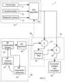
- FIG. 1is a block diagram illustrating an embodiment of a positioning and navigation system in which RF-based positioning system measurements and an inertial devices subsystem measurement are blended.
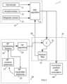
- FIG. 2is a block diagram illustrating an embodiment of an RF tracking system compatible with the positioning and navigation system of FIG. 1 , in which RF signal measurements are used to determine the position of a set of transmitter antennae with respect to a set of receiving antennae.
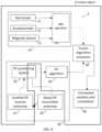
- FIG. 3is a block diagram showing an embodiment of a positioning and navigation system having a RF position-aided IMDS design.
- FIG. 4is a block diagram showing an embodiment of a positioning and navigation system having a RF range-aided IMDS design.
- FIG. 5is a block diagram showing another embodiment of a positioning and navigation system that implements feedback.
- FIG. 6is a block diagram showing an embodiment of a positioning and navigation system that incorporates acceleration and velocity data in a range-aided or position-aided IMDS design.
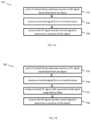
- FIGS. 7 a and 7 bare flow diagrams for alternate embodiments of a method of tracking an object having an inertial sensor and capable of transmitting an RF signal.
- FIG. 8is a block diagram illustrating the embodiment of a positioning and navigation system of FIG. 2 indicating where various functional blocks are located.
- FIG. 9is a block diagram illustrating an embodiment of a positioning and navigation system of FIG. 1 indicating where various functional blocks are located.
- FIG. 10is a block diagram illustrating another embodiment of an RF tracking system in which RF signal measurements are used to determine the position of a set of transmitter antennae at a base with respect to a set of receiving antennae on the tracked object.
- FIG. 11is a block diagram illustrating an embodiment of a positioning and navigation system employing the RF tracking system of FIG. 10 .
- FIG. 1illustrates one embodiment of a positioning and navigation system 1 .
- the positioning and navigation system 1includes inertial/magnetic devices subsystem 10 (IMDS), an RF tracking system 20 , a fusion algorithm processor 30 and a corrected position and orientation output interface 40 .
- the inertial/magnetic devices subsystem 10 (IMDS)may include gyroscopes 11 , and/or accelerometers 12 and/or magnetic sensors 13 , with their accompanying signal conditioning methods and algorithms processor 14 .
- INS algorithm block 14may be based on Kalman filtering techniques.
- the RF tracking system 20comprises a set of RF receiving antennae 21 , a set of RF transmitting antennae 22 , RF system hardware 23 , a tracking processor 24 , a fusion algorithm processor 30 , and a corrected position and orientation output interface 40 .
- the gyroscope 11may be based on fiber optics, ring lasers, vibrating masses, micro-machined devices (MEMS technology), or other technology.
- MEMS technologymicro-machined devices
- a typical three-axis MEMS-based gyroscope 11is the Analog Devices ADIS 16354, a high precision tri-axis inertial sensor. Multiple, single-axis gyroscopes could also be used.
- the accelerometer 12may be piezo-electric, capacitive, strain, optical, surface wave, micro-machined (MEMS technology) or one of the many other types of technologies used for measuring acceleration.
- MEMS technologymicro-machined
- a typical three-axis MEMS accelerometer 12is the Analog Devices ADXL325, a three-axis analog accelerometer.
- the magnetic sensor (magnetometer) 13can be a Hall effect, GMR, moving coil, magneto resistive, SQUID, spin dependent tunneling, proton precession, flux-gate, or other type of technology.
- An example of a three-axis magneto resistive magnetometeris the Honeywell HMC1 043 three-axis magnetic sensor.
- IMDS subsystem 10may also consist of a complete integrated solution, as exemplified by the Razor IMU for Sparkfun Electronics, a 9 degree-of-freedom system that incorporates three devices-an InvenSense ITG-3200 (triple-axis gyro), Analog Devices ADXL345 (triple-axis accelerometer), and a Honeywell HMC5883L (triple-axis magnetometer).
- the outputs of all sensors 11 , 12 , 13are processed by an on-board Atmel ATmega328 RISC processor 14 and the navigation solution, which is represented by the corrected position and orientation block 40 is output over a serial interface.
- the RF tracking system 20includes a set of RF receiving antennae 21 , a set of RF transmitting antennae 22 , RF system hardware 23 and a tracking processor 24 .
- the RF receiving antennae 21 and the transmitter antennae 22can be a dipole, patch or other antennae appropriate for the particular wavelength. Various combinations of antennae may also be used.
- the RF system hardware 23includes RF components that are explained more fully in the description of FIG. 2 .
- the processed results from RF system hardware 23are converted to a position and orientation solution by tracking processor 24 .
- Tracking processor 24may include a DSP, embedded processor or other such processing system that runs an algorithm to compute the position and orientation from the processed results.
- the RF tracking system 20includes multiple receiver antennae 21 , one or more transmitter antennae 22 and transmitter hardware, and RF system hardware 23 .
- RF system hardware 23may consist of amplifiers, limiters, filters, signal sources, demodulators, modulators, and other devices. These devices may be separate entities, may be embedded mathematically in a DSP or processor, or may be a combination of separate and embedded devices.
- the transmitter section 50consists of a sine wave 220 modulated with a pseudorandom noise sequence 215 by CDMA modulator 210 . This type of modulation may be of the type found in cell phones and other communication devices.
- the signalis amplified (not shown) and sent to transmitter antenna 22 .
- the signalis received by the receiver antennae 21 and receiver reference antenna 101 .
- Receiver antenna 101is the reference from which the time difference of arrival is measured.
- the receiver antennaereceive the transmitted signal and forward these signals to the receiver circuitry 110 for demodulation using another pseudo-random noise (PN) sequence 115 .
- PN sequence 115may be identical to PN sequence 215 , although not synchronized to it in time (in other words, the starting points are not the same). This means that both sequences contain the identical pseudo-random data, but that the data is read from different starting positions.
- CDMA demodulators 110retrieve the transmitted sine wave from sine wave generator 220 .
- the recovered reference sine waveis shifted by 90° so that when the other signals are multiplied by it and then integrated, the reference sine wave provides a measure of phase shift between the reference and the other received signals (i.e., differential phase).
- the differential phasesare used by the position and orientation algorithm in the tracking processor 24 to determine position and orientation 121 of a tracked object.
- Tracking a single transmitter device or transmitter antenna in three dimensionsrequires at least four receiver antennae 21 ; tracking in two dimensions requires at least three receiver antennae 21 .
- the receiver antennae 21provide the reference frame in which the transmitter antennae are tracked. More receiver antennae 21 provide better coverage and more accuracy but do so with increased complexity and cost.
- the receiver antennae 21must be distinct and their respective locations known in space. More transmitter antennae 21 attached to or embedded in a tracked object allow the object's orientation to be calculated based on geometric principles.
- two transmitter antennae 22separated by a distance D, yield a pointer, since the two transmitter antennae 22 form a line with known direction.
- Three transmitter antennae 22provide enough information to calculate a three-dimensional orientation.
- the system 1can be reversed, with the receiver antennae 21 being tracked and the transmitter antennae 22 providing the reference frame.
- Recent artcan be found in “ Communication Systems Engineering ,” by Proakis and Salehi, and is incorporated by reference herein. Many variations possible to achieve the same functionality and many of the noted components can be part of an integrated DSP.
- a DSPmight generate sine wave 220 and PN sequence 215 .
- Discrete multipliers and integratorsmight be implemented in hardware instead of firmware.
- the inertial/magnetic devices subsystem 10provides inertial and magnetic field measurements including body angular rates, specific forces, and information on the Earth's magnetic field direction which are sent to the fusion algorithm processor 30 for minimizing RF tracking system errors during loss or corruption of RF signal.
- the position and orientation of the transmitter antennae 22are calculated in RF algorithm block 24 .
- the position and orientation algorithmis based on solving the underlying range equations.
- the phaseis used to measure range.
- the operating wavelengths of the RF tracking systemprovide ambiguous phase measurements because phase measurements are modulo 2 ⁇ numbers. Without further information, only the fractional part of the phase can be determined, making the incorrect.
- Equations (1)-(3)illustrate the phase to range measurement relationship. ⁇ n is the range, ⁇ , is the wavelength (for a fixed frequency), ⁇ n is the measured phase and kn is the integer portion of the phase. Methods exist to determine the additional integer number of wavelengths corresponding to the actual range, but it should be noted that problems due to multipath, line-of-sight issues, and other problems can lead to loss of tracking.
- ⁇ 1⁇ ⁇ ( ⁇ 1 2 ⁇ ⁇ + k ⁇ 1 ) ( 1 )
- ⁇ 2⁇ ⁇ ( ⁇ 2 2 ⁇ ⁇ + k ⁇ 2 ) ⁇ ⁇ ⁇ ( 2 )
- ⁇ n⁇ ⁇ ( ⁇ ⁇ n 2 ⁇ ⁇ + kn ) ( 3 )
- values ⁇ 1- ⁇ 4represent distances between the receiver antennae positions and the transmitter position and are determined by the phases.
- Receiver positionsare denoted as rcvr_pos receivernumber,positioncoordinate , and are fixed, known quantities.
- Position coordinate x 1,2,3represent x,y,z, respectively.
- ⁇ 1( rcvr ⁇ _ ⁇ pos 1 , 1 - x 1 ) 2 + ( rcvr ⁇ _ ⁇ pos 1 , 2 - x 2 ) 2 + ( rcvr ⁇ _ ⁇ pos 1 , 3 - x 3 ) 2 ( 4 )
- ⁇ 2( rcvr ⁇ _ ⁇ pos 2 , 1 - x 1 ) 2 + ( rcvr ⁇ _ ⁇ pos 2 , 2 - x 2 ) 2 + ( rcvr ⁇ _ ⁇ pos 2 , 3 - x 3 ) 2 ( 5 )
- ⁇ 3( rcvr ⁇ _ ⁇ pos 3 , 1 - x 1 ) 2 + ( rcvr ⁇ _ ⁇ pos 3 , 2 - x 2 ) 2 + ( rcvr ⁇ _ ⁇ pos 3 , 3
- Phase differencessuch as formed from manipulating equations (4)-(7) into differences ⁇ 4 ⁇ 1, ⁇ 3 ⁇ 1, and ⁇ 2 ⁇ 1 provide the same information for determining position while allowing one of the received signals to act as a common reference.
- a loosely-coupled systemcalculates position using the RF solution only.
- the IMDScomputes position, velocity and attitude from the raw inertial sensor measurements and uses the RF solution to fix the IMDS errors.
- a benefit of a loosely coupled systemis that the RF system can be treated as a “black box.”
- the Kalman filterreceives phase measurements of range.
- Ultra-tightly coupled systemutilize contain feedback to the RF system itself.
- the fusion algorithm processor 30is shown as a separate processor, which may again take the form of a DSP or microprocessor subsystem. Its job is to combine the inertial/magnetic devices subsystem 10 (IMDS) outputs with those of the RF tracking system algorithm 24 in what might be called an uncoupled form of fusion or unaided inertial solution. Methods of merging the data could require ad-hoc methods to prevent errors from becoming unbounded. Merging these data streams could be done in a Kalman filter. The Kalman filter provides corrected position and orientation outputs 40 by combining the two outputs which could arrive at the fusion processor 30 at different rates. It is also possible to combine algorithm processing 14 , 30 and 24 into a single processor for all the algorithms or to combine various portions as necessary.
- IMDSinertial/magnetic devices subsystem 10
- This x,y,z position solution from RF algorithm 24is incorporated into the fusion algorithm processor 30 , which preferably includes a linearized or extended Kalman filter.
- the Kalman filter 33is a recursive filter that estimates the state of a dynamic system. It is commonly used in data fusion applications, among others.
- the Kalman filter 33is used to combine, in an optimal manner, the RF tracking system 20 data with those of the IMDS subsystem 10 . If the filter 33 detects short term divergence of the RF and IMDS subsystem, it weights the final solution towards the IMDS information and supplies a corrected position and orientation output 40 .
- FIG. 3represents different approaches to the second embodiment of the system 1 .
- interface 36When interface 36 is not included, the result is a linearized Kalman filtering approach.
- the resultWhen it 36 is there, the result is an extended Kalman filter.
- Linearized Kalman filtersare derived assuming a linearization was performed around the operating point of the filter.
- Extended Kalman filtersutilize non-linear models. Both filters have pros and cons, such as implementation simplicity and speed of processing.
- the fusion of RF tracking and inertial trackingis performed in a loosely coupled manner.
- a link 36sends the error signal from the Kalman filter 33 to the inertial sensing processor 14 to modify the IMDS 10 output.
- a feed-forward, complementary filter designalso known as a RF position aided IMDS design, is shown in FIG. 3 . Many of the main blocks were already defined in FIG. 1 .
- the IMDS stateis saved and used for comparison with the RF data.
- the filteris designed based on an error model, all model parameters can be properly defined in a stochastic sense.
- the responsiveness of the navigation systemis determined primarily by the update rate of the IMDS system 10 (assuming it has a faster update rate than the RF system) and the bandwidth of the inertial sensors 11 , 12 , 13 .
- the Kalman filter 33estimates slowly-varying error quantities, the system 1 can be a low-bandwidth system to attenuate any high-frequency error on the RF aiding signal. This error value is subtracted from the IMDS solution in block 32 to remove errors that occur over time in the IMDS system 10 .
- the INS algorithm 14can be modified to take the error signal generated by Kalman filter 33 and modify the IMDS 10 output at the computation source. This can reduce offsets and biases that are common in inertial hardware 11 , 12 , and 13 .
- the fusion of RF tracking and inertial trackingis performed in a loosely-coupled manner.
- loosely-coupled fusionis when link 36 sends the error signal from the Kalman filter 33 to the inertial sensing processor 14 to modify the IMDS 10 output.
- Many of the main blockswere already defined in FIGS. 1 and 3 .
- the RF algorithmis now incorporated into Kalman filter 33 . Transformation block 35 takes the position solution from the IMDS system 10 and converts it back into range data.
- Range erroris determined in block 31 by subtracting this ranged data from that obtained from RF positioning system 23 .
- This error range data output of block 31is now used by Kalman filter 33 to compute a position or position and orientation error solution, which in tum, is used to correct output 40 via block 32 .
- This embodimentalso provides a means to correct phase errors that occur due to multipath, line-of-sight issues, and other sources, since cycle slippage due to the phase being modulo 2 ⁇ numbers can be corrected.
- the INS algorithm 14can be modified to receive the error signal generated by Kalman filter 33 and modify the IMDS 10 output at the computation source 14 . This can reduce offsets and biases that are common in inertial hardware 11 , 12 and 13 .
- FIG. 5shows another embodiment in which complementary filters may be designed for feedback implementation.
- errors between the RF system 20 and the IMDS system 10are produced by block 31 . These errors are filtered by Kalman filter 33 to produce bias and drift compensation to the inertial components 11 , 12 and 13 .
- FIG. 6shows another embodiment of the system 1 in which the fusion of RF tracking and inertial tracking is performed in a tightly-coupled manner.
- link 36sends the error signal from the Kalman filter 33 to the inertial sensing processor 14 to modify the IMDS 10 output while interface 37 sends acceleration and velocity data to the RF algorithm 24 .
- This embodimenthas a feed-forward, complementary filter design, also known as a RF-aided IMDS design.
- This embodimentcan be either position- or range-aided, as described previously.
- a difference in this embodimentis the addition of interface 37 , which provides the RF algorithm 24 with acceleration and velocity data from the inertial hardware 11 , 12 , and/or 13 .
- Interface 37allows RF algorithm 24 , which would preferably be a Kalman filter, to incorporate acceleration and velocity data into its model.
- This embodimentalso provides a means to correct phase errors that occur due to multipath, line-of-sight issues, and other sources, since cycle slippage due to the phase being modulo 2n numbers, can be corrected.
- the accelerometers 12An additional use for the accelerometers 12 is as a power-saving device.
- the accelerometeris monitored for periods of no acceleration (hence no velocity or positional changes).
- the RF positioning systemespecially the RF transmitters, can be put into a low or no power state.
- the RF transmitterscould be powered up to resume RF tracking. Since the fusion algorithm processor 30 mediates this process, it would be able to keep track of the last computed position and orientation 40 , and once acceleration is detected, apply corrections to the position and orientation based on the IMDS subsystem 10 measurements until the RF tracking system 20 comes back on line.
- one or more components of the inertial/magnetic devices subsystem 10may or may not be present. Multiple units of each device 11 , 12 , and/or 13 may be used to sense various directional components. In a minimal embodiment, only one accelerometer 12 may be used to provide positional corrections over short periods of time. Also, while the fusion algorithm processor 30 is expected to run a Kalman filter, other methods for integrating the disparate measurements may be used.
- FIGS. 7 a and 7 bshow a method 700 of tracking an object having an inertial sensor and capable of transmitting an RF signal.
- each one of at least three antennaereceives an RF signal transmitted from an object to be tracked.
- the antennaereceive an inertial signal from an inertial sensor integrated into or fixed onto the object.
- the systemprocesses the RF signal and the inertial signal to determine the position of the object.
- the method 700may also comprise the step 725 of merging the received RF signal with the received inertial signal using a Kalman or similar filter.
- one or more inertial sensorsmay be used, including combinations of gyroscopes, accelerometers, and magnetic sensors.
- the processing step 730may include applying a fusing algorithm to the received RF signal and the received inertial signal. The method 700 may be used to determine the position of an object in two or three dimensions as explained above regarding the system. Additionally, the processing step 730 may be broken into a first step of pre-processing the received RF signal and a second step of processing the inertial signal. The method 700 may also embody variations and combinations of each embodiment described above.
- aspects of the position tracking system 1 and method 700 for using radio signals and inertial sensingcan be executed on various computing platforms and/or using various programing languages.
- Program aspects of the technologymay be thought of as “products” or “articles of manufacture” typically in the form of executable code and/or associated data that is carried on or embodied in a type of machine readable medium.
- “Storage” type mediainclude any or all of the memory of the computers, processors or the like, or associated modules thereof, such as various semiconductor memories, tape drives, disk drives and the like, which may provide storage at any time for the software programming. All or portions of the software may at times be communicated through the Internet or various other telecommunication networks. Such communications, for example, may enable loading of the software from one computer or processor into another computer or processor.
- another type of media that may bear the software elementsincludes optical, electrical and electromagnetic waves, such as used across physical interfaces between local devices, through wired and optical landline networks and over various air-links.
- the physical elements that carry such waves, such as wired or wireless links, optical links or the like,also may be considered as media bearing the software.
- terms such as computer or machine “readable medium”refer to any medium that participates in providing instructions to a processor for execution.
- Nonvolatile storage mediainclude, for example, optical or magnetic disks, such as any of the storage devices in any computer(s) or the like, such as may be used to implement the data aggregator, the customer communication system, etc. shown in the drawings.
- Volatile storage mediainclude dynamic memory, such as main memory of such a computer platform.
- Tangible transmission mediainclude coaxial cables; copper wire and fiber optics, including the wires that comprise a bus within a computer system.
- Carrier-wave transmission mediacan take the form of electric or electromagnetic signals, or acoustic or light waves such as those generated during radio frequency (RF) and infrared (IR) data communications.
- Computer-readable mediatherefore include for example: a floppy disk, a flexible disk, hard disk, magnetic tape, any other magnetic medium, a CD-ROM, DVD or DVD-ROM, any other optical medium, punch cards paper tape, any other physical storage medium with patterns of holes, a RAM, a PROM and EPROM, a FLASH-EPROM, any other memory chip or cartridge, a carrier wave transporting data or instructions, cables or links transporting such a carrier wave, or any other medium from which a computer can read programming code and/or data. Many of these forms of computer readable media may be involved in carrying one or more sequences of one or more instructions to a processor for execution.
- the object or wireless device being trackedis referred to as tracked object or as mobile device 3 .
- mobile devicesinclude, but are not limited to, unmanned or manned aerial or terrestrial vehicles, such as drones, automobiles, and trucks.
- FIG. 8shows one embodiment of the RF tracking system 20 .
- tracked object 3includes transmitter section 50 having the RF transmission electronics and at least one (mobile) RF transmitter antenna 22 . More than one RF transmitter antennae 22 allows for the position of each transmitting antenna 22 to be determined. If the positions of the RF transmitter antennae 22 on the tracked object 3 are known, then the relative positions will indicate an orientation angle around an axis of the tracked object 3 . Using several RF transmitter antennae 22 would provide orientation angles around several axes.
- This embodimentalso includes multiple (base) RF receiver antennae 21 that are spaced apart from each other at various locations but are not located on the tracked object 3 . These may be all located to a common base 120 - 1 or be located on several different bases 120 - 1 , 120 - 2 , 120 - 3 . These bases 120 - 1 , 120 - 2 , 120 - 3 may be located apart from each other.
- the bases 120 - 1 , 120 - 2 , 12 - 3are required to communicate among themselves. These may be connected by wired communications, such as between base 120 - 1 and 120 - 2 . They may also be connected by wireless communications, such as bases 120 - 1 and 120 - 3 .
- the steps of processing of the signals from the RF receiver antennae 21may be performed at one base, or any number of processing steps may be performed at any of the other bases.
- the RF receiver antennae 21is connected to the receiver section 60 , which includes CDMA demodulators 110 and the PN Sequence device 115 .
- the CDMA demodulators 110communicate with the tracking processor 24 .
- the tracking processor 24provides output to the position and orientation device 121 .
- the receiver section 60 , tracking processor 24 and position and orientation processor 121are not on the tracked object 3 . These may be located remote from the tracked object, at a fixed base 120 .
- This embodimentis designed to receive a signal transmitted by the tracked object 3 at the base 120 , and to calculate the position and orientation of tracked object 3 at the base 120 . Therefore, the tracked object 3 will not know its position and orientation. This information in this embodiment is only at the base 120 .
- the tracked object 3has an inertial/magnetic detection system (IMDS) 10 which uses inertia and magnetic sensors 11 - 13 to calculate its position and orientation.
- IMDSinertial/magnetic detection system
- FIG. 10An alternative embodiment of the current invention is shown in FIG. 10 in which the transmitter and receiver are reversed.
- a plurality of (base) RF transmitter antennae 22are spaced from each other and may be located on the same base 120 - 1 , or located on more than one base 120 - 1 , 120 - 2 , 120 - 3 .
- the plurality of (base) RF transmitter antennae 22include at least three spatially separated RF transmitter antennae 22 , each disposed at a known location in three-dimensional space.
- the bases 120 - 1 , 120 - 2 and 120 - 3must be able to communicate with each other by wired or wireless communication.
- Bases 120 - 1 and 120 - 2communicate by a direct wired communication link. However, bases 120 - 1 and 120 - 3 communicate with a wireless communication link.
- a transmitter section 50is connected to each RF transmitter antenna 22 - 1 , (and optionally 22 - 2 , 22 - 3 ) and causes them to transmit an RF signal.
- the tracked object 3has at least one (mobile) RF receiver antenna 21 that receives the RF signals. It can differentiate between the signals received from different RF transmitting antennae.
- the received signalsare passed to a receiver section 60 having CDMA demodulators 110 .
- the CDMA demodulators 110receive the output of the PN signal sequence device 115 to process the signals.
- the output of the CDMA demodulators 110is provided to the tracking processor 24 that runs an RF algorithm that determines distances between the mobile antenna 21 and each of the base antennae 22 based upon the received RF signals.
- the output of the tracking processor 24is then provided to the position and orientation device 121 that calculates the positions and orientations of the tracked object 3 .
- the mobile device 3is attached to the tracked object (i.e., mobile device) 3 .
- the mobile device 3is configured to be a self-positioning unit, that is, the mobile device determines its own position and orientation.
- the tracked object 3also includes an IMDS 10 (having the previously described inertial and magnetic sensors).
- the mobile device 3determines its own position and orientation from information obtained by sensing inertia and/or magnetic field orientation.
- IMDS 10monitors the inertia/magnetic field changes of the tracked wireless mobile device 3 .
- the information from the IMDS 10can create the location and orientation of the tracked wireless mobile device 3 .
- the IMDS system 10has inherent errors in its determinations of inertia. These errors accumulate for each determination. However, they are accurate for short periods of time.
- the output of the RF tracking system 20 and the output of the IMDS 10are fed to fusion algorithm processor 30 .
- the fusion algorithm processor 30uses the output from these devices to update the position and orientation of the tracked object 3 .
- This embodimentemploys a fusion algorithm processor 30 running a fusion algorithm that merges the position and orientation information determined by the IMDS with the position and orientation information determined from the RF signals, to produce a corrected position and orientation of the mobile device.
- the fusion algorithm device 30receives the location and orientation from both the IMDS 10 and the RF tracking system 20 and uses one or both the inputs to determine position and orientation.
- FIGS. 3 - 6Alternative embodiments of the fusion algorithm processor 30 are shown in FIGS. 3 - 6 and are described earlier in the specification. These show and describe the structure used to merge the output of the IMDS 10 and RF tracking system 20 . In the embodiment of FIG. 11 , all the elements shown in FIGS. 3 - 6 are located on the tracked object 3 , except for the RF transmitter antennae 22 and the transmitter section 50 of the RF positioning system 23 . In this case, the system may use a combination of the output of the RF tracking system 20 and IMDS 10 during normal operation. However, when the RF signal is weak, corrupted or missing, the system can use the IMDS 10 for tracking. Fusion algorithm processor 30 employs smoothing techniques to reduce tracking error.
- the system in which position and orientation calculations are made at the base 120may also be modified into an alternative embodiment capable of transmitting the calculated position and orientation of tracked object 3 from the base 120 back to the tracked object 3 , so the tracked object 3 may know of its position and orientation. This would allow it to have previous location and orientation to use in calculations when the RF signal is corrupted or lost. However, this embodiment would require an additional transmitter in the base 120 and a receiver in the tracked object 3 and add to the cost of producing the system.
Landscapes
- Engineering & Computer Science (AREA)
- Physics & Mathematics (AREA)
- General Physics & Mathematics (AREA)
- Radar, Positioning & Navigation (AREA)
- Remote Sensing (AREA)
- Computer Networks & Wireless Communication (AREA)
- Position Fixing By Use Of Radio Waves (AREA)
- Navigation (AREA)
Abstract
Description
Claims (18)
Priority Applications (2)
| Application Number | Priority Date | Filing Date | Title |
|---|---|---|---|
| US17/509,392US12066561B2 (en) | 2010-11-12 | 2021-10-25 | Position tracking system and method using radio signals and inertial sensing |
| US18/805,974US20240402283A1 (en) | 2010-11-12 | 2024-08-15 | Position tracking system and method using radio signals and inertial sensing |
Applications Claiming Priority (6)
| Application Number | Priority Date | Filing Date | Title |
|---|---|---|---|
| US41302610P | 2010-11-12 | 2010-11-12 | |
| US13/293,639US8957812B1 (en) | 2010-11-12 | 2011-11-10 | Position tracking system and method using radio signals and inertial sensing |
| US14/600,025US20150130664A1 (en) | 2010-11-12 | 2015-01-20 | Position tracking system and method using radio signals and inertial sensing |
| US15/685,493US10416276B2 (en) | 2010-11-12 | 2017-08-24 | Position tracking system and method using radio signals and inertial sensing |
| US16/571,622US11175375B2 (en) | 2010-11-12 | 2019-09-16 | Position tracking system and method using radio signals and inertial sensing |
| US17/509,392US12066561B2 (en) | 2010-11-12 | 2021-10-25 | Position tracking system and method using radio signals and inertial sensing |
Related Parent Applications (1)
| Application Number | Title | Priority Date | Filing Date |
|---|---|---|---|
| US16/571,622ContinuationUS11175375B2 (en) | 2010-11-12 | 2019-09-16 | Position tracking system and method using radio signals and inertial sensing |
Related Child Applications (1)
| Application Number | Title | Priority Date | Filing Date |
|---|---|---|---|
| US18/805,974ContinuationUS20240402283A1 (en) | 2010-11-12 | 2024-08-15 | Position tracking system and method using radio signals and inertial sensing |
Publications (2)
| Publication Number | Publication Date |
|---|---|
| US20220043102A1 US20220043102A1 (en) | 2022-02-10 |
| US12066561B2true US12066561B2 (en) | 2024-08-20 |
Family
ID=69102003
Family Applications (3)
| Application Number | Title | Priority Date | Filing Date |
|---|---|---|---|
| US16/571,622ActiveUS11175375B2 (en) | 2010-11-12 | 2019-09-16 | Position tracking system and method using radio signals and inertial sensing |
| US17/509,392Active2031-12-14US12066561B2 (en) | 2010-11-12 | 2021-10-25 | Position tracking system and method using radio signals and inertial sensing |
| US18/805,974PendingUS20240402283A1 (en) | 2010-11-12 | 2024-08-15 | Position tracking system and method using radio signals and inertial sensing |
Family Applications Before (1)
| Application Number | Title | Priority Date | Filing Date |
|---|---|---|---|
| US16/571,622ActiveUS11175375B2 (en) | 2010-11-12 | 2019-09-16 | Position tracking system and method using radio signals and inertial sensing |
Family Applications After (1)
| Application Number | Title | Priority Date | Filing Date |
|---|---|---|---|
| US18/805,974PendingUS20240402283A1 (en) | 2010-11-12 | 2024-08-15 | Position tracking system and method using radio signals and inertial sensing |
Country Status (1)
| Country | Link |
|---|---|
| US (3) | US11175375B2 (en) |
Cited By (2)
| Publication number | Priority date | Publication date | Assignee | Title |
|---|---|---|---|---|
| US20240281626A1 (en)* | 2023-02-22 | 2024-08-22 | Turck Holding Gmbh | Device and method for localizing an rfid tag |
| US12215979B2 (en)* | 2021-09-22 | 2025-02-04 | Denso Corporation | Vehicle position estimation device |
Families Citing this family (20)
| Publication number | Priority date | Publication date | Assignee | Title |
|---|---|---|---|---|
| US11175375B2 (en)* | 2010-11-12 | 2021-11-16 | Position Imaging, Inc. | Position tracking system and method using radio signals and inertial sensing |
| US10634761B2 (en) | 2013-12-13 | 2020-04-28 | Position Imaging, Inc. | Tracking system with mobile reader |
| US12000947B2 (en) | 2013-12-13 | 2024-06-04 | Position Imaging, Inc. | Tracking system with mobile reader |
| US10853757B1 (en) | 2015-04-06 | 2020-12-01 | Position Imaging, Inc. | Video for real-time confirmation in package tracking systems |
| US11416805B1 (en) | 2015-04-06 | 2022-08-16 | Position Imaging, Inc. | Light-based guidance for package tracking systems |
| US10148918B1 (en) | 2015-04-06 | 2018-12-04 | Position Imaging, Inc. | Modular shelving systems for package tracking |
| US11501244B1 (en) | 2015-04-06 | 2022-11-15 | Position Imaging, Inc. | Package tracking systems and methods |
| US11436553B2 (en) | 2016-09-08 | 2022-09-06 | Position Imaging, Inc. | System and method of object tracking using weight confirmation |
| US10634506B2 (en) | 2016-12-12 | 2020-04-28 | Position Imaging, Inc. | System and method of personalized navigation inside a business enterprise |
| US10634503B2 (en) | 2016-12-12 | 2020-04-28 | Position Imaging, Inc. | System and method of personalized navigation inside a business enterprise |
| US11120392B2 (en) | 2017-01-06 | 2021-09-14 | Position Imaging, Inc. | System and method of calibrating a directional light source relative to a camera's field of view |
| US12190542B2 (en) | 2017-01-06 | 2025-01-07 | Position Imaging, Inc. | System and method of calibrating a directional light source relative to a camera's field of view |
| US11342886B2 (en)* | 2017-11-21 | 2022-05-24 | GuRu Wireless, Inc. | In-situ low-cost small size sensing and measurement for wireless power transfer systems |
| US11629960B2 (en)* | 2018-09-20 | 2023-04-18 | GuRu Wireless, Inc. | Inertial and RF sensor fusion |
| US11361536B2 (en) | 2018-09-21 | 2022-06-14 | Position Imaging, Inc. | Machine-learning-assisted self-improving object-identification system and method |
| US11089232B2 (en) | 2019-01-11 | 2021-08-10 | Position Imaging, Inc. | Computer-vision-based object tracking and guidance module |
| FR3107347B1 (en)* | 2020-02-13 | 2022-01-07 | Continental Automotive | Angle sensor for motor vehicle. |
| US20210349177A1 (en)* | 2020-05-08 | 2021-11-11 | 7hugs Labs SAS | Low profile pointing device |
| CN115355907A (en)* | 2022-10-19 | 2022-11-18 | 东南大学 | Autonomous navigation system and method based on millimeter wave sensing integrated unmanned equipment |
| CN118566830B (en)* | 2024-08-05 | 2024-10-18 | 烟台欣飞智能系统有限公司 | Low-speed small-target flying object detection method and system based on radio detection |
Citations (198)
| Publication number | Priority date | Publication date | Assignee | Title |
|---|---|---|---|---|
| US2408122A (en) | 1940-11-15 | 1946-09-24 | Collins Radio Co | Heterodyne direction finder with single receiver |
| US3824596A (en) | 1972-09-27 | 1974-07-16 | Southwest Res Inst | Automatic sector indicating direction finder system |
| US3940700A (en) | 1972-08-15 | 1976-02-24 | Paul Haas | Method and installation for the detection of a source generating electro-magnetic oscillations |
| US4328499A (en) | 1979-10-24 | 1982-05-04 | The Marconi Company Limited | Radio direction finding systems |
| US5010343A (en) | 1988-04-26 | 1991-04-23 | Vaisala Oy | Method and device in the antenna and receiving system of a radio theodolite |
| US5343212A (en) | 1992-12-11 | 1994-08-30 | Litton Industries, Inc. | (AOA/LBI) emitter ranging method and apparatus |
| US5426438A (en) | 1992-12-30 | 1995-06-20 | Delfin Systems | Method and apparatus for adaptively determining the bearing angle of a radio frequency signal |
| US5510800A (en) | 1993-04-12 | 1996-04-23 | The Regents Of The University Of California | Time-of-flight radio location system |
| US5574468A (en) | 1995-04-20 | 1996-11-12 | Litton Systems, Inc. | Phase-equivalent interferometer arrays |
| US5592180A (en) | 1992-08-20 | 1997-01-07 | Nexus1994 Limited | Direction finding and mobile location system for trunked mobile radio systems |
| US5600330A (en) | 1994-07-12 | 1997-02-04 | Ascension Technology Corporation | Device for measuring position and orientation using non-dipole magnet IC fields |
| US5657026A (en) | 1996-01-26 | 1997-08-12 | Electronic Tracking Systems, Inc. | Beacon signal receiving system |
| US5923286A (en) | 1996-10-23 | 1999-07-13 | Honeywell Inc. | GPS/IRS global position determination method and apparatus with integrity loss provisions |
| US5953683A (en) | 1997-10-09 | 1999-09-14 | Ascension Technology Corporation | Sourceless orientation sensor |
| US6088653A (en) | 1996-12-31 | 2000-07-11 | Sheikh; Suneel I. | Attitude determination method and system |
| US6101178A (en) | 1997-07-10 | 2000-08-08 | Ksi Inc. | Pseudolite-augmented GPS for locating wireless telephones |
| US6167347A (en) | 1998-11-04 | 2000-12-26 | Lin; Ching-Fang | Vehicle positioning method and system thereof |
| WO2001006401A1 (en) | 1999-07-15 | 2001-01-25 | Pinpoint Corporation | Method and apparatus for mobile tag reading |
| US6255991B1 (en) | 2000-01-19 | 2001-07-03 | Trw Inc. | Low cost angle of arrival measurement system |
| US20020021277A1 (en) | 2000-04-17 | 2002-02-21 | Kramer James F. | Interface for controlling a graphical image |
| US6409687B1 (en) | 1998-04-17 | 2002-06-25 | Massachusetts Institute Of Technology | Motion tracking system |
| US6412748B1 (en) | 1998-08-24 | 2002-07-02 | Fix Plus | Ground anchoring mechanism |
| US6417802B1 (en) | 2000-04-26 | 2002-07-09 | Litton Systems, Inc. | Integrated inertial/GPS navigation system |
| US20020140745A1 (en) | 2001-01-24 | 2002-10-03 | Ellenby Thomas William | Pointing systems for addressing objects |
| US20020177476A1 (en) | 2001-05-22 | 2002-11-28 | Chou Y. Hong | Durable global asset-tracking device and a method of using the same |
| US6496778B1 (en) | 2000-09-14 | 2002-12-17 | American Gnc Corporation | Real-time integrated vehicle positioning method and system with differential GPS |
| US6512748B1 (en) | 1998-01-30 | 2003-01-28 | Ntt Mobile Communications Network Inc. | Radio paging signal coding control scheme using variable number of logical channels according to paging signal traffic |
| US20030053492A1 (en) | 2000-09-01 | 2003-03-20 | Osamu Matsunaga | Multiplexer, receiver, and multiplex transmission method |
| US20030120425A1 (en) | 2001-12-26 | 2003-06-26 | Kevin Stanley | Self-correcting wireless inertial navigation system and method |
| US6593885B2 (en) | 2000-04-27 | 2003-07-15 | Wherenet Corp | Low cost DTOA location processing system based on multiple readers-to-single processor architecture |
| US20030135327A1 (en)* | 2002-01-11 | 2003-07-17 | Seymour Levine | Low cost inertial navigator |
| US20030176196A1 (en) | 2002-03-18 | 2003-09-18 | Hall Christopher J. | Method and apparatus for geolocating a wireless communications device |
| US6630904B2 (en) | 1999-02-02 | 2003-10-07 | The Charles Stark Draper Laboratory, Inc. | Deeply-integrated adaptive INS/GPS navigator with extended-range code tracking |
| US20030195017A1 (en) | 1999-09-30 | 2003-10-16 | Tao Chen | Wireless communication system with base station beam sweeping |
| US6683568B1 (en) | 1999-05-14 | 2004-01-27 | Auckland Uniservices Limited | Position estimation services |
| US6697736B2 (en) | 2002-02-06 | 2004-02-24 | American Gnc Corporation | Positioning and navigation method and system thereof |
| US6721657B2 (en) | 2001-06-04 | 2004-04-13 | Novatel, Inc. | Inertial GPS navigation system |
| US6720920B2 (en) | 1997-10-22 | 2004-04-13 | Intelligent Technologies International Inc. | Method and arrangement for communicating between vehicles |
| US20040095907A1 (en) | 2000-06-13 | 2004-05-20 | Agee Brian G. | Method and apparatus for optimization of wireless multipoint electromagnetic communication networks |
| US6744436B1 (en) | 1999-05-25 | 2004-06-01 | Anthony Chirieleison, Jr. | Virtual reality warehouse management system complement |
| US20040107072A1 (en) | 2002-12-03 | 2004-06-03 | Arne Dietrich | Ins-based user orientation and navigation |
| US6750816B1 (en) | 2003-02-12 | 2004-06-15 | Novatel, Inc. | Integrated GPS-inertial system |
| JP2004518136A (en)* | 2001-01-23 | 2004-06-17 | コーニンクレッカ フィリップス エレクトロニクス エヌ ヴィ | Mobile device with GPS receiver |
| US20040176102A1 (en) | 2001-11-20 | 2004-09-09 | Integrinautics Corporation | Multiple antenna multi-frequency measurement system |
| US20040203846A1 (en) | 2002-03-26 | 2004-10-14 | Germano Caronni | Apparatus and method for the use of position information in wireless applications |
| US20050001712A1 (en) | 2003-07-03 | 2005-01-06 | Yarbrough Craig D. | RF ID tag |
| WO2005010550A1 (en) | 2003-07-12 | 2005-02-03 | Qinetiq Limited | Direction finding |
| US6861982B2 (en) | 2001-08-16 | 2005-03-01 | Itt Manufacturing Enterprises, Inc. | System for determining position of an emitter |
| US6867774B1 (en) | 2002-12-02 | 2005-03-15 | Ngrain (Canada) Corporation | Method and apparatus for transforming polygon data to voxel data for general purpose applications |
| US20050057647A1 (en) | 2003-09-15 | 2005-03-17 | Nowak Michael P. | Method and system for calibrating a sensor |
| US20050125141A1 (en)* | 2003-12-05 | 2005-06-09 | Honeywell International Inc. | System and method for using multiple aiding sensors in a deeply integrated navigation system |
| US20050143916A1 (en) | 2003-12-26 | 2005-06-30 | In-Jun Kim | Positioning apparatus and method combining RFID, GPS and INS |
| US20050275626A1 (en) | 2000-06-21 | 2005-12-15 | Color Kinetics Incorporated | Entertainment lighting system |
| US20060013070A1 (en) | 2002-12-04 | 2006-01-19 | Sverre Holm | Ultrasonic tracking and locating system |
| US6989789B2 (en) | 2000-02-25 | 2006-01-24 | Thales | Method for locating radioelectric sources using two-channel high resolution radiogoniometer |
| US20060022800A1 (en) | 2004-07-30 | 2006-02-02 | Reva Systems Corporation | Scheduling in an RFID system having a coordinated RFID tag reader array |
| US7009561B2 (en) | 2003-03-11 | 2006-03-07 | Menache, Llp | Radio frequency motion tracking system and method |
| US20060061469A1 (en) | 2004-09-21 | 2006-03-23 | Skyfence Inc. | Positioning system that uses signals from a point source |
| US20060066485A1 (en) | 2004-09-24 | 2006-03-30 | Guohua Min | Wireless tracking system based upon phase differences |
| US20060101497A1 (en) | 2004-06-25 | 2006-05-11 | International Business Machines Corporation | User-aware video display |
| US20060192709A1 (en) | 2002-08-19 | 2006-08-31 | Q-Track, Inc. | Low frequency asset tag tracking system and method |
| US7143004B2 (en) | 1998-12-09 | 2006-11-28 | Microstrain, Inc. | Solid state orientation sensor with 360 degree measurement capability |
| US20060279459A1 (en) | 2005-06-10 | 2006-12-14 | Fujitsu Limited | Calibration apparatus and method for array antenna |
| US20060290508A1 (en) | 2005-06-23 | 2006-12-28 | Samsung Electronics Co., Ltd. | Reader, tags, radio frequency identification (RFID) system, and method thereof |
| US7168618B2 (en) | 2004-08-12 | 2007-01-30 | International Business Machines Corporation | Retail store method and system |
| US7190309B2 (en) | 2004-09-24 | 2007-03-13 | Hill Edward L | Radio signal transmitter with multiple antennas for improved position detection |
| US20070060384A1 (en) | 2005-09-14 | 2007-03-15 | Nintendo Co., Ltd. | Storage medium storing video game program |
| US7193559B2 (en) | 2003-01-21 | 2007-03-20 | Novatel, Inc. | Inertial GPS navigation system with modified kalman filter |
| US20070138270A1 (en) | 2005-12-20 | 2007-06-21 | United States Postal Service | Method and system for interrogating and processing codes |
| US7236091B2 (en)* | 2005-02-10 | 2007-06-26 | Pinc Solutions | Position-tracking system |
| US7236092B1 (en) | 2004-08-02 | 2007-06-26 | Joy James A | Passive sensor technology incorporating energy storage mechanism |
| US20070205867A1 (en) | 2001-03-20 | 2007-09-06 | Lightwaves Systems, Inc. | Ultra wideband radio frequency identification system, method, and apparatus |
| US20070210920A1 (en) | 2006-03-09 | 2007-09-13 | George Panotopoulos | Identification (ID) system and method of operation thereof |
| US7274504B2 (en)* | 2005-01-14 | 2007-09-25 | L-3 Communications Corporation | System and method for advanced tight coupling of GPS and inertial navigation sensors |
| US20070222560A1 (en) | 2006-03-23 | 2007-09-27 | Joshua Posamentier | Parallel RFID system using CDMA |
| US7292189B2 (en) | 2004-09-10 | 2007-11-06 | Worcester Polytechnic Institute | Methods and apparatus for high resolution positioning |
| US7295925B2 (en) | 1997-10-22 | 2007-11-13 | Intelligent Technologies International, Inc. | Accident avoidance systems and methods |
| US7315281B2 (en) | 2004-07-30 | 2008-01-01 | G2 Microsystems Pty. Ltd. | Location determination method and system for asset tracking devices |
| US20080007398A1 (en) | 2006-07-05 | 2008-01-10 | General Electric Company | System and method for tracking assets |
| US7336078B1 (en) | 2003-10-04 | 2008-02-26 | Seektech, Inc. | Multi-sensor mapping omnidirectional sonde and line locators |
| US20080048913A1 (en) | 2004-12-02 | 2008-02-28 | Commissariat A L'energie Atomique | Local Positioning System and Method |
| US7346452B2 (en)* | 2003-09-05 | 2008-03-18 | Novatel, Inc. | Inertial GPS navigation system using injected alignment data for the inertial system |
| US20080091350A1 (en) | 2006-10-17 | 2008-04-17 | Smith Stephen F | Triply redundant integrated navigation and asset visibility system |
| US20080143482A1 (en) | 2006-12-18 | 2008-06-19 | Radiofy Llc, A California Limited Liability Company | RFID location systems and methods |
| US20080154691A1 (en) | 2006-12-13 | 2008-06-26 | Wellman Timothy A | Fleet management system |
| US20080150678A1 (en) | 2006-11-13 | 2008-06-26 | Giobbi John J | Configuration of Interfaces for a Location Detection System and Application |
| US20080174485A1 (en) | 2007-01-24 | 2008-07-24 | Carani Sherry L | Tracking System and Method with Asset Tool Bar for Polling, Message, Historic Report, Location, Map and Geo Fence Features |
| US7409290B2 (en) | 2004-04-17 | 2008-08-05 | American Gnc Corporation | Positioning and navigation method and system thereof |
| US20080204322A1 (en) | 2003-11-03 | 2008-08-28 | Gordon Kenneth Andrew Oswald | Determining Positional Information |
| US7443342B2 (en) | 2004-01-13 | 2008-10-28 | The Nippon Signal Co., Ltd. | Reception time determining apparatus and distance measuring apparatus using the same |
| US20080266253A1 (en) | 2007-04-25 | 2008-10-30 | Lisa Seeman | System and method for tracking a laser spot on a projected computer screen image |
| US20080281618A1 (en) | 2007-05-09 | 2008-11-13 | Jean-Francois Mermet | Method and system for the tracking of articles |
| US20080316324A1 (en) | 2007-06-22 | 2008-12-25 | Broadcom Corporation | Position detection and/or movement tracking via image capture and processing |
| US20090043504A1 (en) | 2007-05-31 | 2009-02-12 | Amrit Bandyopadhyay | System and method for locating, tracking, and/or monitoring the status of personnel and/or assets both indoors and outdoors |
| US7499711B2 (en) | 2001-10-09 | 2009-03-03 | General Electric Company | Transmitter location for ultra-wideband, transmitted-reference CDMA communication system |
| US7533569B2 (en) | 2006-03-15 | 2009-05-19 | Qualcomm, Incorporated | Sensor-based orientation system |
| US7538724B1 (en) | 2007-06-15 | 2009-05-26 | Itt Manufacturing Enterprises, Inc. | Method and system for relative tracking |
| US20090149202A1 (en) | 2007-12-07 | 2009-06-11 | Christian Steele | System and method for determination of position |
| US20090224040A1 (en) | 2008-03-07 | 2009-09-10 | Toshiba Tec Kabushiki Kaisha | Item management system and information processing device |
| US20090243932A1 (en) | 2008-03-31 | 2009-10-01 | Radliofy Llc | Methods and Systems for Determining the Location of an Electronic Device |
| US20090323586A1 (en) | 2007-01-26 | 2009-12-31 | Sony Deutschland Gmbh | User interface based on magnetic induction |
| US7646330B2 (en) | 2005-03-14 | 2010-01-12 | Alfred E. Mann Foundation For Scientific Research | System and method for locating objects and communicating with the same |
| US20100090852A1 (en) | 2008-10-10 | 2010-04-15 | Qualcomm Incorporated | Geographical boundary based tracking |
| US20100097208A1 (en) | 2008-10-20 | 2010-04-22 | G-Tracking, Llc | Method and System for Tracking Assets |
| US20100103173A1 (en) | 2008-10-27 | 2010-04-29 | Minkyu Lee | Real time object tagging for interactive image display applications |
| US20100103989A1 (en) | 2006-10-17 | 2010-04-29 | Smith Stephen F | Robust Low-Frequency Spread-Spectrum Navigation System |
| US20100123664A1 (en) | 2008-11-14 | 2010-05-20 | Samsung Electronics Co., Ltd. | Method for operating user interface based on motion sensor and a mobile terminal having the user interface |
| US20100159958A1 (en) | 2008-12-22 | 2010-06-24 | Qualcomm Incorporated | Post-deployment calibration for wireless position determination |
| US7868760B2 (en) | 2006-06-05 | 2011-01-11 | Bp Corporation North America Inc. | Method for accounting for people in emergencies in industrial settings |
| US20110006774A1 (en) | 2007-05-24 | 2011-01-13 | Penguin Automated Systems ,Inc. | Subsurface positioning system and method for monitoring movement underground |
| US7876268B2 (en) | 2006-08-22 | 2011-01-25 | James P. Jacobs | System and method for precise location of receiving antennas |
| US20110037573A1 (en) | 2009-08-11 | 2011-02-17 | Samsung Electronics Co. Ltd. | Apparatus and method for providing information of goods in mobile terminal |
| US7933730B2 (en) | 2006-12-21 | 2011-04-26 | General Electric Co. | Method and system for restoration of a navigation data loss in image-guided navigation |
| US20110184593A1 (en)* | 2006-04-19 | 2011-07-28 | Swope John M | System for facilitating control of an aircraft |
| US20110187600A1 (en) | 2010-01-29 | 2011-08-04 | Tc License Ltd. | System and method for measurement of distance to a tag by a modulated backscatter rfid reader |
| US20110208481A1 (en) | 2010-02-19 | 2011-08-25 | Vladimir Slastion | Extended range interferometric methods and systems |
| US20110210843A1 (en) | 2010-03-01 | 2011-09-01 | Andrew Llc | System and method for location of mobile devices in confined environments |
| US20110241942A1 (en) | 2010-04-02 | 2011-10-06 | Position Imaging, Inc. | Multiplexing receiver system |
| US20110256882A1 (en) | 2005-12-15 | 2011-10-20 | Invisitrack, Inc. | Multi-Path Mitigation in Rangefinding and Tracking Objects Using Reduced Attenuation RF Technology |
| US20110264520A1 (en) | 2009-12-10 | 2011-10-27 | John Christopher Puhakka | Findit product locator |
| US20120013509A1 (en) | 2010-07-14 | 2012-01-19 | Zebra Enterprise Solutions Corp. | Frequency channel diversity for real-time locating systems, methods, and computer program products |
| US20120127088A1 (en) | 2010-11-19 | 2012-05-24 | Apple Inc. | Haptic input device |
| US20120176227A1 (en) | 2011-01-12 | 2012-07-12 | Intermec Ip Corp. | Method and apparatus to mitigate multipath in rfid |
| US20120184285A1 (en) | 2011-01-14 | 2012-07-19 | Qualcomm Incorporated | Methods and apparatuses for use in providing positioning assistance data to mobile stations via a self-organizing network |
| US8269654B2 (en) | 2006-06-06 | 2012-09-18 | Jones Richard D | Flashing beacon |
| US8269624B2 (en)* | 2006-12-27 | 2012-09-18 | Industrial Technology Research Institute | Positioning apparatus and method |
| US20120286933A1 (en) | 2011-05-12 | 2012-11-15 | Knowledge Access, Inc. | First responder team tracking system and method |
| US20120319822A1 (en) | 2010-03-01 | 2012-12-20 | Innovative Timing Systems | Variably spaced multi-point rfid tag reader systems and methods |
| US20130018582A1 (en) | 2011-07-13 | 2013-01-17 | Miller Paul A | Inertial Navigation Common Azimuth Reference Determination System and Method |
| US20130021417A1 (en) | 2011-07-21 | 2013-01-24 | Seiko Epson Corporation | Recording apparatus |
| US8364401B2 (en)* | 2007-05-29 | 2013-01-29 | Deimos Engenharia S.A. | Highly integrated GPS, Galileo and inertial navigation system |
| US20130029685A1 (en) | 2011-07-26 | 2013-01-31 | Mehran Moshfeghi | Distributed method and system for determining the position of a mobile device using long-range signals and calibrating the position using short-range signals |
| US20130036043A1 (en) | 2011-07-06 | 2013-02-07 | Patrick Faith | Image-based product mapping |
| US8406470B2 (en) | 2011-04-19 | 2013-03-26 | Mitsubishi Electric Research Laboratories, Inc. | Object detection in depth images |
| US20130113993A1 (en) | 2011-11-04 | 2013-05-09 | Remote TelePointer, LLC | Method and system for user interface for interactive devices using a mobile device |
| US8457655B2 (en) | 2011-09-19 | 2013-06-04 | Qualcomm Incorporated | Hybrid time of arrival based positioning system |
| US20130281084A1 (en) | 2012-04-24 | 2013-10-24 | Cellco Partnership D/B/A Verizon Wireless | Providing derived location information for customer relationship in response to receipt of short range wireless beacon |
| US20130314210A1 (en) | 2012-05-22 | 2013-11-28 | Trimble Navigation Limited | Multi-modal entity tracking and display |
| US20140022058A1 (en) | 2011-12-27 | 2014-01-23 | The Gillette Company | Apparatus and Method for Providing Product Information |
| US20140253368A1 (en) | 2008-09-12 | 2014-09-11 | Propagation Research Associates, Inc. | Multi-mode, multi-static interferometer utilizing pseudo orthogonal codes |
| US20140300516A1 (en) | 2011-11-10 | 2014-10-09 | Position Imaging, Inc. | Systems and methods of wireless position tracking |
| US8860611B1 (en) | 2012-05-15 | 2014-10-14 | The United States Of America As Represented By The Secretary Of The Navy | RFID-based mobile vehicle localization |
| US20140361078A1 (en) | 2012-02-22 | 2014-12-11 | BAR CODE SPECIALTIES, INC.(DBA BCS Solutions) | Overhead antenna live inventory locating system |
| US20150009949A1 (en) | 2013-07-08 | 2015-01-08 | Alexey Khoryaev | Synchronizing peer-to-peer operation for outside network coverage and partial network coverage using lte air interface |
| US20150039458A1 (en) | 2013-07-24 | 2015-02-05 | Volitional Partners, Inc. | Method and system for automated retail checkout using context recognition |
| US8957812B1 (en) | 2010-11-12 | 2015-02-17 | Position Imaging, Inc. | Position tracking system and method using radio signals and inertial sensing |
| US20150091757A1 (en) | 2013-09-30 | 2015-04-02 | At&T Intellectual Property I, Lp | Systems and Methods for High Precision Indoor Location Tracking |
| US20150134418A1 (en) | 2013-11-08 | 2015-05-14 | Chon Hock LEOW | System and Method for Providing Real-time Location Previews |
| US20150133162A1 (en) | 2013-11-14 | 2015-05-14 | At&T Mobility Ii Llc | Wirelessly receiving information related to a mobile device at which another mobile device is pointed |
| US20150169916A1 (en) | 2013-12-13 | 2015-06-18 | Position Imaging, Inc. | Tracking system with mobile reader |
| US9063215B2 (en) | 2010-06-25 | 2015-06-23 | Innovationszentrum Fuer Telekommunikationstechnik Gmbh Izt | Method and system for determining a time difference, method and system for finding a position of a transmitter |
| US9092898B1 (en) | 2014-07-03 | 2015-07-28 | Federico Fraccaroli | Method, system and apparatus for the augmentation of radio emissions |
| US20150221135A1 (en) | 2014-02-06 | 2015-08-06 | Position Imaging, Inc. | Virtual reality and augmented reality functionality for mobile devices |
| US9120621B1 (en) | 2014-03-25 | 2015-09-01 | Amazon Technologies, Inc. | Verifying bin content in an automated materials handling facility |
| US9141194B1 (en) | 2012-01-04 | 2015-09-22 | Google Inc. | Magnetometer-based gesture sensing with a wearable device |
| US9174746B1 (en) | 2014-06-26 | 2015-11-03 | Rockwell Collins, Inc. | Visual aid generating system, device, and method |
| US20150323643A1 (en) | 2012-12-15 | 2015-11-12 | Position Imaging, Inc. | Cycling reference multiplexing receiver system |
| US20150362581A1 (en) | 2012-11-25 | 2015-12-17 | Pixie Technology Inc. | Rotation based alignment of a group of wireless tags |
| US20150379366A1 (en) | 2013-03-04 | 2015-12-31 | Nec Corporation | Article management system, information processing apparatus, and control method and control program of information processing apparatus |
| US20160035078A1 (en) | 2014-07-30 | 2016-02-04 | Adobe Systems Incorporated | Image assessment using deep convolutional neural networks |
| US20160142868A1 (en) | 2014-09-03 | 2016-05-19 | CloudLeaf, Inc. | Systems, methods and devices for asset status determination |
| US20160150196A1 (en) | 2014-11-25 | 2016-05-26 | Jon Patrik Horvath | Movement and distance triggered image recording system |
| US20160156409A1 (en) | 2012-09-21 | 2016-06-02 | Donald C.D. Chang | Multi-channel communication optimization methods and systems |
| US20160178727A1 (en) | 2014-12-22 | 2016-06-23 | Datalogic IP Tech, S.r.l. | Ultra-wideband location engine for self-shopping devices |
| US20160238692A1 (en) | 2015-02-13 | 2016-08-18 | Position Imaging, Inc. | Accurate geographic tracking of mobile devices |
| US20160256100A1 (en) | 2011-07-22 | 2016-09-08 | Tci3-Pressure Applications Llc | Systems and methods for monitoring and providing therapeutic support for a user |
| US9482741B1 (en) | 2013-01-18 | 2016-11-01 | Position Imaging, Inc. | System and method of locating a radio frequency (RF) tracking device using a calibration routine |
| US9497728B2 (en) | 2014-01-17 | 2016-11-15 | Position Imaging, Inc. | Wireless relay station for radio frequency-based tracking system |
| US9519344B1 (en) | 2012-08-14 | 2016-12-13 | Position Imaging, Inc. | User input system for immersive interaction |
| US20160371574A1 (en) | 2013-05-06 | 2016-12-22 | The Johns Hopkins University | System for preventing instrument retention |
| US20160370453A1 (en) | 2013-07-01 | 2016-12-22 | Elbit Systems Bmd And Land Ewelisra Ltd. | Mitigation of multipath distortions for tdoa-based geolocation |
| US9544552B2 (en) | 2011-07-06 | 2017-01-10 | Inspeedia Inc. | Pickup system and pickup method |
| US20170123426A1 (en) | 2015-02-13 | 2017-05-04 | Position Imaging, Inc. | Spatial diveristy for relative position tracking |
| US20170234979A1 (en) | 2006-04-28 | 2017-08-17 | Telecommunication Systems, Inc. | Gnss long-code acquisition, ambiguity resolution, and signal validation |
| US20170261592A1 (en) | 2016-03-08 | 2017-09-14 | Position Imaging, Inc. | Expandable, decentralized position tracking systems and methods |
| US20170280281A1 (en) | 2016-03-22 | 2017-09-28 | Cisco Technology, Inc. | Determining location via current and previous wireless signal attributes |
| US9782669B1 (en) | 2012-06-14 | 2017-10-10 | Position Imaging, Inc. | RF tracking with active sensory feedback |
| US20170323174A1 (en) | 2014-02-12 | 2017-11-09 | Microsoft Technology Licensing, Llc | Food logging from images |
| US20170350961A1 (en) | 2010-11-12 | 2017-12-07 | Position Imaging, Inc. | Position tracking system and method using radio signals and inertial sensing |
| US20170372524A1 (en) | 2012-06-14 | 2017-12-28 | Position Imaging, Inc. | Rf tracking with active sensory feedback |
| US9872151B1 (en) | 2016-08-25 | 2018-01-16 | Leantegra Inc. | System and method for discovery and collection of real-time location data |
| US20180068266A1 (en) | 2016-09-08 | 2018-03-08 | Position Imaging, Inc. | System and method of object tracking using weight confirmation |
| US9927530B2 (en)* | 2014-09-16 | 2018-03-27 | Israel Military Industries Ltd. | GPS-aided inertial navigation method and system |
| US9933509B2 (en) | 2011-11-10 | 2018-04-03 | Position Imaging, Inc. | System for tracking an object using pulsed frequency hopping |
| US20180164103A1 (en) | 2016-12-12 | 2018-06-14 | Position Imaging, Inc. | System and method of personalized navigation inside a business enterprise |
| US20180188381A1 (en)* | 2017-01-04 | 2018-07-05 | Qualcomm Incorporated | Motion propagated position for positioning fusion |
| US20180197139A1 (en) | 2017-01-06 | 2018-07-12 | Position Imaging, Inc. | Package delivery sharing systems and methods |
| US10082584B2 (en)* | 2012-06-21 | 2018-09-25 | Microsoft Technology Licensing, Llc | Hybrid device location determination system |
| US10163149B1 (en) | 2014-03-28 | 2018-12-25 | Amazon Technologies, Inc. | Providing item pick and place information to a user |
| US10180490B1 (en) | 2012-08-24 | 2019-01-15 | Position Imaging, Inc. | Radio frequency communication system |
| US20190090744A1 (en) | 2016-02-29 | 2019-03-28 | Mohamed R. Mahfouz | Connected Healthcare Environment |
| US20190295290A1 (en) | 2017-01-06 | 2019-09-26 | Position Imaging, Inc. | System and method of calibrating a directional light source relative to a camera's field of view |
| US10455364B2 (en) | 2016-12-12 | 2019-10-22 | Position Imaging, Inc. | System and method of personalized navigation inside a business enterprise |
| US10921460B2 (en)* | 2017-10-16 | 2021-02-16 | Samsung Electronics Co., Ltd. | Position estimating apparatus and method |
| CN113447028A (en)* | 2021-07-28 | 2021-09-28 | 徐州新电高科电气有限公司 | Unmanned aerial vehicle's inertial navigation system and unmanned aerial vehicle |
| US11175375B2 (en)* | 2010-11-12 | 2021-11-16 | Position Imaging, Inc. | Position tracking system and method using radio signals and inertial sensing |
| US11327181B2 (en)* | 2019-10-16 | 2022-05-10 | Valeo Comfort And Driving Assistance | Method and apparatus for accurate reporting of integrity of GNSS-based positioning system |
| US11789163B2 (en)* | 2020-04-14 | 2023-10-17 | Shanghai Huace Navigation Technology Ltd | Navigation board, multi-source data fusion method for navigation board and transporter |
- 2019
- 2019-09-16USUS16/571,622patent/US11175375B2/enactiveActive
- 2021
- 2021-10-25USUS17/509,392patent/US12066561B2/enactiveActive
- 2024
- 2024-08-15USUS18/805,974patent/US20240402283A1/enactivePending
Patent Citations (215)
| Publication number | Priority date | Publication date | Assignee | Title |
|---|---|---|---|---|
| US2408122A (en) | 1940-11-15 | 1946-09-24 | Collins Radio Co | Heterodyne direction finder with single receiver |
| US3940700A (en) | 1972-08-15 | 1976-02-24 | Paul Haas | Method and installation for the detection of a source generating electro-magnetic oscillations |
| US3824596A (en) | 1972-09-27 | 1974-07-16 | Southwest Res Inst | Automatic sector indicating direction finder system |
| US4328499A (en) | 1979-10-24 | 1982-05-04 | The Marconi Company Limited | Radio direction finding systems |
| US5010343A (en) | 1988-04-26 | 1991-04-23 | Vaisala Oy | Method and device in the antenna and receiving system of a radio theodolite |
| US5592180A (en) | 1992-08-20 | 1997-01-07 | Nexus1994 Limited | Direction finding and mobile location system for trunked mobile radio systems |
| US5343212A (en) | 1992-12-11 | 1994-08-30 | Litton Industries, Inc. | (AOA/LBI) emitter ranging method and apparatus |
| US5426438A (en) | 1992-12-30 | 1995-06-20 | Delfin Systems | Method and apparatus for adaptively determining the bearing angle of a radio frequency signal |
| US5510800A (en) | 1993-04-12 | 1996-04-23 | The Regents Of The University Of California | Time-of-flight radio location system |
| US5600330A (en) | 1994-07-12 | 1997-02-04 | Ascension Technology Corporation | Device for measuring position and orientation using non-dipole magnet IC fields |
| US5574468A (en) | 1995-04-20 | 1996-11-12 | Litton Systems, Inc. | Phase-equivalent interferometer arrays |
| US5657026A (en) | 1996-01-26 | 1997-08-12 | Electronic Tracking Systems, Inc. | Beacon signal receiving system |
| US5923286A (en) | 1996-10-23 | 1999-07-13 | Honeywell Inc. | GPS/IRS global position determination method and apparatus with integrity loss provisions |
| US6088653A (en) | 1996-12-31 | 2000-07-11 | Sheikh; Suneel I. | Attitude determination method and system |
| US6101178A (en) | 1997-07-10 | 2000-08-08 | Ksi Inc. | Pseudolite-augmented GPS for locating wireless telephones |
| US5953683A (en) | 1997-10-09 | 1999-09-14 | Ascension Technology Corporation | Sourceless orientation sensor |
| US6720920B2 (en) | 1997-10-22 | 2004-04-13 | Intelligent Technologies International Inc. | Method and arrangement for communicating between vehicles |
| US7295925B2 (en) | 1997-10-22 | 2007-11-13 | Intelligent Technologies International, Inc. | Accident avoidance systems and methods |
| US6512748B1 (en) | 1998-01-30 | 2003-01-28 | Ntt Mobile Communications Network Inc. | Radio paging signal coding control scheme using variable number of logical channels according to paging signal traffic |
| US6409687B1 (en) | 1998-04-17 | 2002-06-25 | Massachusetts Institute Of Technology | Motion tracking system |
| US6412748B1 (en) | 1998-08-24 | 2002-07-02 | Fix Plus | Ground anchoring mechanism |
| US6167347A (en) | 1998-11-04 | 2000-12-26 | Lin; Ching-Fang | Vehicle positioning method and system thereof |
| US6292750B1 (en) | 1998-11-04 | 2001-09-18 | Ching-Fang Lin | Vehicle positioning method and system thereof |
| US7143004B2 (en) | 1998-12-09 | 2006-11-28 | Microstrain, Inc. | Solid state orientation sensor with 360 degree measurement capability |
| US6630904B2 (en) | 1999-02-02 | 2003-10-07 | The Charles Stark Draper Laboratory, Inc. | Deeply-integrated adaptive INS/GPS navigator with extended-range code tracking |
| US6683568B1 (en) | 1999-05-14 | 2004-01-27 | Auckland Uniservices Limited | Position estimation services |
| US6744436B1 (en) | 1999-05-25 | 2004-06-01 | Anthony Chirieleison, Jr. | Virtual reality warehouse management system complement |
| WO2001006401A1 (en) | 1999-07-15 | 2001-01-25 | Pinpoint Corporation | Method and apparatus for mobile tag reading |
| US20030195017A1 (en) | 1999-09-30 | 2003-10-16 | Tao Chen | Wireless communication system with base station beam sweeping |
| US6255991B1 (en) | 2000-01-19 | 2001-07-03 | Trw Inc. | Low cost angle of arrival measurement system |
| US6989789B2 (en) | 2000-02-25 | 2006-01-24 | Thales | Method for locating radioelectric sources using two-channel high resolution radiogoniometer |
| US20020021277A1 (en) | 2000-04-17 | 2002-02-21 | Kramer James F. | Interface for controlling a graphical image |
| US6417802B1 (en) | 2000-04-26 | 2002-07-09 | Litton Systems, Inc. | Integrated inertial/GPS navigation system |
| US6593885B2 (en) | 2000-04-27 | 2003-07-15 | Wherenet Corp | Low cost DTOA location processing system based on multiple readers-to-single processor architecture |
| US20040095907A1 (en) | 2000-06-13 | 2004-05-20 | Agee Brian G. | Method and apparatus for optimization of wireless multipoint electromagnetic communication networks |
| US20050275626A1 (en) | 2000-06-21 | 2005-12-15 | Color Kinetics Incorporated | Entertainment lighting system |
| US20030053492A1 (en) | 2000-09-01 | 2003-03-20 | Osamu Matsunaga | Multiplexer, receiver, and multiplex transmission method |
| US6496778B1 (en) | 2000-09-14 | 2002-12-17 | American Gnc Corporation | Real-time integrated vehicle positioning method and system with differential GPS |
| JP2004518136A (en)* | 2001-01-23 | 2004-06-17 | コーニンクレッカ フィリップス エレクトロニクス エヌ ヴィ | Mobile device with GPS receiver |
| US20020140745A1 (en) | 2001-01-24 | 2002-10-03 | Ellenby Thomas William | Pointing systems for addressing objects |
| US20070205867A1 (en) | 2001-03-20 | 2007-09-06 | Lightwaves Systems, Inc. | Ultra wideband radio frequency identification system, method, and apparatus |
| US20020177476A1 (en) | 2001-05-22 | 2002-11-28 | Chou Y. Hong | Durable global asset-tracking device and a method of using the same |
| US6721657B2 (en) | 2001-06-04 | 2004-04-13 | Novatel, Inc. | Inertial GPS navigation system |
| US6861982B2 (en) | 2001-08-16 | 2005-03-01 | Itt Manufacturing Enterprises, Inc. | System for determining position of an emitter |
| US7499711B2 (en) | 2001-10-09 | 2009-03-03 | General Electric Company | Transmitter location for ultra-wideband, transmitted-reference CDMA communication system |
| US20040176102A1 (en) | 2001-11-20 | 2004-09-09 | Integrinautics Corporation | Multiple antenna multi-frequency measurement system |
| US20030120425A1 (en) | 2001-12-26 | 2003-06-26 | Kevin Stanley | Self-correcting wireless inertial navigation system and method |
| US20030135327A1 (en)* | 2002-01-11 | 2003-07-17 | Seymour Levine | Low cost inertial navigator |
| US6697736B2 (en) | 2002-02-06 | 2004-02-24 | American Gnc Corporation | Positioning and navigation method and system thereof |
| US20050184907A1 (en) | 2002-03-18 | 2005-08-25 | Hall Christopher J. | Method and apparatus for geolocating a wireless communications device |
| US20030176196A1 (en) | 2002-03-18 | 2003-09-18 | Hall Christopher J. | Method and apparatus for geolocating a wireless communications device |
| US20040203846A1 (en) | 2002-03-26 | 2004-10-14 | Germano Caronni | Apparatus and method for the use of position information in wireless applications |
| US20060192709A1 (en) | 2002-08-19 | 2006-08-31 | Q-Track, Inc. | Low frequency asset tag tracking system and method |
| US6867774B1 (en) | 2002-12-02 | 2005-03-15 | Ngrain (Canada) Corporation | Method and apparatus for transforming polygon data to voxel data for general purpose applications |
| US20040107072A1 (en) | 2002-12-03 | 2004-06-03 | Arne Dietrich | Ins-based user orientation and navigation |
| US20060013070A1 (en) | 2002-12-04 | 2006-01-19 | Sverre Holm | Ultrasonic tracking and locating system |
| US7193559B2 (en) | 2003-01-21 | 2007-03-20 | Novatel, Inc. | Inertial GPS navigation system with modified kalman filter |
| US6750816B1 (en) | 2003-02-12 | 2004-06-15 | Novatel, Inc. | Integrated GPS-inertial system |
| US7009561B2 (en) | 2003-03-11 | 2006-03-07 | Menache, Llp | Radio frequency motion tracking system and method |
| US20050001712A1 (en) | 2003-07-03 | 2005-01-06 | Yarbrough Craig D. | RF ID tag |
| US7612715B2 (en) | 2003-07-12 | 2009-11-03 | Qinetiq Limited | Direction finding |
| WO2005010550A1 (en) | 2003-07-12 | 2005-02-03 | Qinetiq Limited | Direction finding |
| US7346452B2 (en)* | 2003-09-05 | 2008-03-18 | Novatel, Inc. | Inertial GPS navigation system using injected alignment data for the inertial system |
| US20050057647A1 (en) | 2003-09-15 | 2005-03-17 | Nowak Michael P. | Method and system for calibrating a sensor |
| US7336078B1 (en) | 2003-10-04 | 2008-02-26 | Seektech, Inc. | Multi-sensor mapping omnidirectional sonde and line locators |
| US20080204322A1 (en) | 2003-11-03 | 2008-08-28 | Gordon Kenneth Andrew Oswald | Determining Positional Information |
| US7248964B2 (en)* | 2003-12-05 | 2007-07-24 | Honeywell International Inc. | System and method for using multiple aiding sensors in a deeply integrated navigation system |
| US20050125141A1 (en)* | 2003-12-05 | 2005-06-09 | Honeywell International Inc. | System and method for using multiple aiding sensors in a deeply integrated navigation system |
| US20050143916A1 (en) | 2003-12-26 | 2005-06-30 | In-Jun Kim | Positioning apparatus and method combining RFID, GPS and INS |
| US7443342B2 (en) | 2004-01-13 | 2008-10-28 | The Nippon Signal Co., Ltd. | Reception time determining apparatus and distance measuring apparatus using the same |
| US7409290B2 (en) | 2004-04-17 | 2008-08-05 | American Gnc Corporation | Positioning and navigation method and system thereof |
| US20060101497A1 (en) | 2004-06-25 | 2006-05-11 | International Business Machines Corporation | User-aware video display |
| US20060022800A1 (en) | 2004-07-30 | 2006-02-02 | Reva Systems Corporation | Scheduling in an RFID system having a coordinated RFID tag reader array |
| US7315281B2 (en) | 2004-07-30 | 2008-01-01 | G2 Microsystems Pty. Ltd. | Location determination method and system for asset tracking devices |
| US7236092B1 (en) | 2004-08-02 | 2007-06-26 | Joy James A | Passive sensor technology incorporating energy storage mechanism |
| US7168618B2 (en) | 2004-08-12 | 2007-01-30 | International Business Machines Corporation | Retail store method and system |
| US7292189B2 (en) | 2004-09-10 | 2007-11-06 | Worcester Polytechnic Institute | Methods and apparatus for high resolution positioning |
| US20060061469A1 (en) | 2004-09-21 | 2006-03-23 | Skyfence Inc. | Positioning system that uses signals from a point source |
| US20060066485A1 (en) | 2004-09-24 | 2006-03-30 | Guohua Min | Wireless tracking system based upon phase differences |
| US7190309B2 (en) | 2004-09-24 | 2007-03-13 | Hill Edward L | Radio signal transmitter with multiple antennas for improved position detection |
| US20080048913A1 (en) | 2004-12-02 | 2008-02-28 | Commissariat A L'energie Atomique | Local Positioning System and Method |
| US7274504B2 (en)* | 2005-01-14 | 2007-09-25 | L-3 Communications Corporation | System and method for advanced tight coupling of GPS and inertial navigation sensors |
| US7236091B2 (en)* | 2005-02-10 | 2007-06-26 | Pinc Solutions | Position-tracking system |
| US7646330B2 (en) | 2005-03-14 | 2010-01-12 | Alfred E. Mann Foundation For Scientific Research | System and method for locating objects and communicating with the same |
| US20060279459A1 (en) | 2005-06-10 | 2006-12-14 | Fujitsu Limited | Calibration apparatus and method for array antenna |
| US20060290508A1 (en) | 2005-06-23 | 2006-12-28 | Samsung Electronics Co., Ltd. | Reader, tags, radio frequency identification (RFID) system, and method thereof |
| US20070060384A1 (en) | 2005-09-14 | 2007-03-15 | Nintendo Co., Ltd. | Storage medium storing video game program |
| US20110256882A1 (en) | 2005-12-15 | 2011-10-20 | Invisitrack, Inc. | Multi-Path Mitigation in Rangefinding and Tracking Objects Using Reduced Attenuation RF Technology |
| US20070138270A1 (en) | 2005-12-20 | 2007-06-21 | United States Postal Service | Method and system for interrogating and processing codes |
| US20070210920A1 (en) | 2006-03-09 | 2007-09-13 | George Panotopoulos | Identification (ID) system and method of operation thereof |
| US7533569B2 (en) | 2006-03-15 | 2009-05-19 | Qualcomm, Incorporated | Sensor-based orientation system |
| US20070222560A1 (en) | 2006-03-23 | 2007-09-27 | Joshua Posamentier | Parallel RFID system using CDMA |
| US20110184593A1 (en)* | 2006-04-19 | 2011-07-28 | Swope John M | System for facilitating control of an aircraft |
| US20170234979A1 (en) | 2006-04-28 | 2017-08-17 | Telecommunication Systems, Inc. | Gnss long-code acquisition, ambiguity resolution, and signal validation |
| US7868760B2 (en) | 2006-06-05 | 2011-01-11 | Bp Corporation North America Inc. | Method for accounting for people in emergencies in industrial settings |
| US8269654B2 (en) | 2006-06-06 | 2012-09-18 | Jones Richard D | Flashing beacon |
| US20080007398A1 (en) | 2006-07-05 | 2008-01-10 | General Electric Company | System and method for tracking assets |
| US7876268B2 (en) | 2006-08-22 | 2011-01-25 | James P. Jacobs | System and method for precise location of receiving antennas |
| US20080091350A1 (en) | 2006-10-17 | 2008-04-17 | Smith Stephen F | Triply redundant integrated navigation and asset visibility system |
| US20100103989A1 (en) | 2006-10-17 | 2010-04-29 | Smith Stephen F | Robust Low-Frequency Spread-Spectrum Navigation System |
| US20080150678A1 (en) | 2006-11-13 | 2008-06-26 | Giobbi John J | Configuration of Interfaces for a Location Detection System and Application |
| US20080154691A1 (en) | 2006-12-13 | 2008-06-26 | Wellman Timothy A | Fleet management system |
| US20080143482A1 (en) | 2006-12-18 | 2008-06-19 | Radiofy Llc, A California Limited Liability Company | RFID location systems and methods |
| US7933730B2 (en) | 2006-12-21 | 2011-04-26 | General Electric Co. | Method and system for restoration of a navigation data loss in image-guided navigation |
| US8269624B2 (en)* | 2006-12-27 | 2012-09-18 | Industrial Technology Research Institute | Positioning apparatus and method |
| US20080174485A1 (en) | 2007-01-24 | 2008-07-24 | Carani Sherry L | Tracking System and Method with Asset Tool Bar for Polling, Message, Historic Report, Location, Map and Geo Fence Features |
| US20090323586A1 (en) | 2007-01-26 | 2009-12-31 | Sony Deutschland Gmbh | User interface based on magnetic induction |
| US20080266253A1 (en) | 2007-04-25 | 2008-10-30 | Lisa Seeman | System and method for tracking a laser spot on a projected computer screen image |
| US20080281618A1 (en) | 2007-05-09 | 2008-11-13 | Jean-Francois Mermet | Method and system for the tracking of articles |
| US20110006774A1 (en) | 2007-05-24 | 2011-01-13 | Penguin Automated Systems ,Inc. | Subsurface positioning system and method for monitoring movement underground |
| US8364401B2 (en)* | 2007-05-29 | 2013-01-29 | Deimos Engenharia S.A. | Highly integrated GPS, Galileo and inertial navigation system |
| US20090043504A1 (en) | 2007-05-31 | 2009-02-12 | Amrit Bandyopadhyay | System and method for locating, tracking, and/or monitoring the status of personnel and/or assets both indoors and outdoors |
| US7538724B1 (en) | 2007-06-15 | 2009-05-26 | Itt Manufacturing Enterprises, Inc. | Method and system for relative tracking |
| US20080316324A1 (en) | 2007-06-22 | 2008-12-25 | Broadcom Corporation | Position detection and/or movement tracking via image capture and processing |
| US20090149202A1 (en) | 2007-12-07 | 2009-06-11 | Christian Steele | System and method for determination of position |
| US20090224040A1 (en) | 2008-03-07 | 2009-09-10 | Toshiba Tec Kabushiki Kaisha | Item management system and information processing device |
| US20090243932A1 (en) | 2008-03-31 | 2009-10-01 | Radliofy Llc | Methods and Systems for Determining the Location of an Electronic Device |
| US20140253368A1 (en) | 2008-09-12 | 2014-09-11 | Propagation Research Associates, Inc. | Multi-mode, multi-static interferometer utilizing pseudo orthogonal codes |
| US20100090852A1 (en) | 2008-10-10 | 2010-04-15 | Qualcomm Incorporated | Geographical boundary based tracking |
| US20100097208A1 (en) | 2008-10-20 | 2010-04-22 | G-Tracking, Llc | Method and System for Tracking Assets |
| US20100103173A1 (en) | 2008-10-27 | 2010-04-29 | Minkyu Lee | Real time object tagging for interactive image display applications |
| US20100123664A1 (en) | 2008-11-14 | 2010-05-20 | Samsung Electronics Co., Ltd. | Method for operating user interface based on motion sensor and a mobile terminal having the user interface |
| US20100159958A1 (en) | 2008-12-22 | 2010-06-24 | Qualcomm Incorporated | Post-deployment calibration for wireless position determination |
| US20110037573A1 (en) | 2009-08-11 | 2011-02-17 | Samsung Electronics Co. Ltd. | Apparatus and method for providing information of goods in mobile terminal |
| US20110264520A1 (en) | 2009-12-10 | 2011-10-27 | John Christopher Puhakka | Findit product locator |
| US20110187600A1 (en) | 2010-01-29 | 2011-08-04 | Tc License Ltd. | System and method for measurement of distance to a tag by a modulated backscatter rfid reader |
| US20110208481A1 (en) | 2010-02-19 | 2011-08-25 | Vladimir Slastion | Extended range interferometric methods and systems |
| US20120319822A1 (en) | 2010-03-01 | 2012-12-20 | Innovative Timing Systems | Variably spaced multi-point rfid tag reader systems and methods |
| US20110210843A1 (en) | 2010-03-01 | 2011-09-01 | Andrew Llc | System and method for location of mobile devices in confined environments |
| US8749433B2 (en) | 2010-04-02 | 2014-06-10 | Position Imaging, Inc. | Multiplexing receiver system |
| US20110241942A1 (en) | 2010-04-02 | 2011-10-06 | Position Imaging, Inc. | Multiplexing receiver system |
| US9063215B2 (en) | 2010-06-25 | 2015-06-23 | Innovationszentrum Fuer Telekommunikationstechnik Gmbh Izt | Method and system for determining a time difference, method and system for finding a position of a transmitter |
| US20120013509A1 (en) | 2010-07-14 | 2012-01-19 | Zebra Enterprise Solutions Corp. | Frequency channel diversity for real-time locating systems, methods, and computer program products |
| US8957812B1 (en) | 2010-11-12 | 2015-02-17 | Position Imaging, Inc. | Position tracking system and method using radio signals and inertial sensing |
| US20150130664A1 (en) | 2010-11-12 | 2015-05-14 | Position Imaging, Inc. | Position tracking system and method using radio signals and inertial sensing |
| US20170350961A1 (en) | 2010-11-12 | 2017-12-07 | Position Imaging, Inc. | Position tracking system and method using radio signals and inertial sensing |
| US10416276B2 (en)* | 2010-11-12 | 2019-09-17 | Position Imaging, Inc. | Position tracking system and method using radio signals and inertial sensing |
| US11175375B2 (en)* | 2010-11-12 | 2021-11-16 | Position Imaging, Inc. | Position tracking system and method using radio signals and inertial sensing |
| US20120127088A1 (en) | 2010-11-19 | 2012-05-24 | Apple Inc. | Haptic input device |
| US20120176227A1 (en) | 2011-01-12 | 2012-07-12 | Intermec Ip Corp. | Method and apparatus to mitigate multipath in rfid |
| US20120184285A1 (en) | 2011-01-14 | 2012-07-19 | Qualcomm Incorporated | Methods and apparatuses for use in providing positioning assistance data to mobile stations via a self-organizing network |
| US8406470B2 (en) | 2011-04-19 | 2013-03-26 | Mitsubishi Electric Research Laboratories, Inc. | Object detection in depth images |
| US20120286933A1 (en) | 2011-05-12 | 2012-11-15 | Knowledge Access, Inc. | First responder team tracking system and method |
| US20130036043A1 (en) | 2011-07-06 | 2013-02-07 | Patrick Faith | Image-based product mapping |
| US9544552B2 (en) | 2011-07-06 | 2017-01-10 | Inspeedia Inc. | Pickup system and pickup method |
| US20130018582A1 (en) | 2011-07-13 | 2013-01-17 | Miller Paul A | Inertial Navigation Common Azimuth Reference Determination System and Method |
| US20130021417A1 (en) | 2011-07-21 | 2013-01-24 | Seiko Epson Corporation | Recording apparatus |
| US20160256100A1 (en) | 2011-07-22 | 2016-09-08 | Tci3-Pressure Applications Llc | Systems and methods for monitoring and providing therapeutic support for a user |
| US20130029685A1 (en) | 2011-07-26 | 2013-01-31 | Mehran Moshfeghi | Distributed method and system for determining the position of a mobile device using long-range signals and calibrating the position using short-range signals |
| US8457655B2 (en) | 2011-09-19 | 2013-06-04 | Qualcomm Incorporated | Hybrid time of arrival based positioning system |
| US20130113993A1 (en) | 2011-11-04 | 2013-05-09 | Remote TelePointer, LLC | Method and system for user interface for interactive devices using a mobile device |
| US9933509B2 (en) | 2011-11-10 | 2018-04-03 | Position Imaging, Inc. | System for tracking an object using pulsed frequency hopping |
| US20180231649A1 (en) | 2011-11-10 | 2018-08-16 | Position Imaging, Inc. | Systems and methods of wireless position tracking |
| US20140300516A1 (en) | 2011-11-10 | 2014-10-09 | Position Imaging, Inc. | Systems and methods of wireless position tracking |
| US20140022058A1 (en) | 2011-12-27 | 2014-01-23 | The Gillette Company | Apparatus and Method for Providing Product Information |
| US9141194B1 (en) | 2012-01-04 | 2015-09-22 | Google Inc. | Magnetometer-based gesture sensing with a wearable device |
| US20140361078A1 (en) | 2012-02-22 | 2014-12-11 | BAR CODE SPECIALTIES, INC.(DBA BCS Solutions) | Overhead antenna live inventory locating system |
| US20130281084A1 (en) | 2012-04-24 | 2013-10-24 | Cellco Partnership D/B/A Verizon Wireless | Providing derived location information for customer relationship in response to receipt of short range wireless beacon |
| US8860611B1 (en) | 2012-05-15 | 2014-10-14 | The United States Of America As Represented By The Secretary Of The Navy | RFID-based mobile vehicle localization |
| US20130314210A1 (en) | 2012-05-22 | 2013-11-28 | Trimble Navigation Limited | Multi-modal entity tracking and display |
| US20170372524A1 (en) | 2012-06-14 | 2017-12-28 | Position Imaging, Inc. | Rf tracking with active sensory feedback |
| US9782669B1 (en) | 2012-06-14 | 2017-10-10 | Position Imaging, Inc. | RF tracking with active sensory feedback |
| US10082584B2 (en)* | 2012-06-21 | 2018-09-25 | Microsoft Technology Licensing, Llc | Hybrid device location determination system |
| US10001833B2 (en) | 2012-08-14 | 2018-06-19 | Position Imaging, Inc. | User input system for immersive interaction |
| US9519344B1 (en) | 2012-08-14 | 2016-12-13 | Position Imaging, Inc. | User input system for immersive interaction |
| US20170031432A1 (en) | 2012-08-14 | 2017-02-02 | Position Imaging, Inc. | User input system for immersive interaction |
| US10180490B1 (en) | 2012-08-24 | 2019-01-15 | Position Imaging, Inc. | Radio frequency communication system |
| US20160156409A1 (en) | 2012-09-21 | 2016-06-02 | Donald C.D. Chang | Multi-channel communication optimization methods and systems |
| US20150362581A1 (en) | 2012-11-25 | 2015-12-17 | Pixie Technology Inc. | Rotation based alignment of a group of wireless tags |
| US20150323643A1 (en) | 2012-12-15 | 2015-11-12 | Position Imaging, Inc. | Cycling reference multiplexing receiver system |
| US9482741B1 (en) | 2013-01-18 | 2016-11-01 | Position Imaging, Inc. | System and method of locating a radio frequency (RF) tracking device using a calibration routine |
| US20160366561A1 (en) | 2013-01-18 | 2016-12-15 | Position Imaging, Inc. | System and method of locating a radio frequency (rf) tracking device using a calibration routine |
| US20150379366A1 (en) | 2013-03-04 | 2015-12-31 | Nec Corporation | Article management system, information processing apparatus, and control method and control program of information processing apparatus |
| US20160371574A1 (en) | 2013-05-06 | 2016-12-22 | The Johns Hopkins University | System for preventing instrument retention |
| US20160370453A1 (en) | 2013-07-01 | 2016-12-22 | Elbit Systems Bmd And Land Ewelisra Ltd. | Mitigation of multipath distortions for tdoa-based geolocation |
| US20160286508A1 (en) | 2013-07-08 | 2016-09-29 | Intel IP Corporation | Synchronizing peer-to-peer operation for outside network coverage and partial network coverage using lte air interface |
| US20150009949A1 (en) | 2013-07-08 | 2015-01-08 | Alexey Khoryaev | Synchronizing peer-to-peer operation for outside network coverage and partial network coverage using lte air interface |
| US20150039458A1 (en) | 2013-07-24 | 2015-02-05 | Volitional Partners, Inc. | Method and system for automated retail checkout using context recognition |
| US20150091757A1 (en) | 2013-09-30 | 2015-04-02 | At&T Intellectual Property I, Lp | Systems and Methods for High Precision Indoor Location Tracking |
| US20150134418A1 (en) | 2013-11-08 | 2015-05-14 | Chon Hock LEOW | System and Method for Providing Real-time Location Previews |
| US20150133162A1 (en) | 2013-11-14 | 2015-05-14 | At&T Mobility Ii Llc | Wirelessly receiving information related to a mobile device at which another mobile device is pointed |
| US20150169916A1 (en) | 2013-12-13 | 2015-06-18 | Position Imaging, Inc. | Tracking system with mobile reader |
| US20170030997A1 (en) | 2013-12-13 | 2017-02-02 | Position Imaging, Inc. | Tracking system with mobile reader |
| US9497728B2 (en) | 2014-01-17 | 2016-11-15 | Position Imaging, Inc. | Wireless relay station for radio frequency-based tracking system |
| US20180242111A1 (en) | 2014-01-17 | 2018-08-23 | Position Imaging, Inc. | Wireless relay station for radio frequency-based tracking system |
| US9961503B2 (en) | 2014-01-17 | 2018-05-01 | Position Imaging, Inc. | Wireless relay station for radio frequency-based tracking system |
| US10257654B2 (en) | 2014-01-17 | 2019-04-09 | Position Imaging, Inc. | Wireless relay station for radio frequency-based tracking system |
| US20150221135A1 (en) | 2014-02-06 | 2015-08-06 | Position Imaging, Inc. | Virtual reality and augmented reality functionality for mobile devices |
| US20170323174A1 (en) | 2014-02-12 | 2017-11-09 | Microsoft Technology Licensing, Llc | Food logging from images |
| US9120621B1 (en) | 2014-03-25 | 2015-09-01 | Amazon Technologies, Inc. | Verifying bin content in an automated materials handling facility |
| US10163149B1 (en) | 2014-03-28 | 2018-12-25 | Amazon Technologies, Inc. | Providing item pick and place information to a user |
| US9174746B1 (en) | 2014-06-26 | 2015-11-03 | Rockwell Collins, Inc. | Visual aid generating system, device, and method |
| US9092898B1 (en) | 2014-07-03 | 2015-07-28 | Federico Fraccaroli | Method, system and apparatus for the augmentation of radio emissions |
| US20160035078A1 (en) | 2014-07-30 | 2016-02-04 | Adobe Systems Incorporated | Image assessment using deep convolutional neural networks |
| US20160142868A1 (en) | 2014-09-03 | 2016-05-19 | CloudLeaf, Inc. | Systems, methods and devices for asset status determination |
| US9927530B2 (en)* | 2014-09-16 | 2018-03-27 | Israel Military Industries Ltd. | GPS-aided inertial navigation method and system |
| US20160150196A1 (en) | 2014-11-25 | 2016-05-26 | Jon Patrik Horvath | Movement and distance triggered image recording system |
| US20160178727A1 (en) | 2014-12-22 | 2016-06-23 | Datalogic IP Tech, S.r.l. | Ultra-wideband location engine for self-shopping devices |
| US20160238692A1 (en) | 2015-02-13 | 2016-08-18 | Position Imaging, Inc. | Accurate geographic tracking of mobile devices |
| US20170123426A1 (en) | 2015-02-13 | 2017-05-04 | Position Imaging, Inc. | Spatial diveristy for relative position tracking |
| US20190090744A1 (en) | 2016-02-29 | 2019-03-28 | Mohamed R. Mahfouz | Connected Healthcare Environment |
| US10444323B2 (en) | 2016-03-08 | 2019-10-15 | Position Imaging, Inc. | Expandable, decentralized position tracking systems and methods |
| US20170261592A1 (en) | 2016-03-08 | 2017-09-14 | Position Imaging, Inc. | Expandable, decentralized position tracking systems and methods |
| US20170280281A1 (en) | 2016-03-22 | 2017-09-28 | Cisco Technology, Inc. | Determining location via current and previous wireless signal attributes |
| US9872151B1 (en) | 2016-08-25 | 2018-01-16 | Leantegra Inc. | System and method for discovery and collection of real-time location data |
| US20180068266A1 (en) | 2016-09-08 | 2018-03-08 | Position Imaging, Inc. | System and method of object tracking using weight confirmation |
| US20180164103A1 (en) | 2016-12-12 | 2018-06-14 | Position Imaging, Inc. | System and method of personalized navigation inside a business enterprise |
| US10455364B2 (en) | 2016-12-12 | 2019-10-22 | Position Imaging, Inc. | System and method of personalized navigation inside a business enterprise |
| US20180188381A1 (en)* | 2017-01-04 | 2018-07-05 | Qualcomm Incorporated | Motion propagated position for positioning fusion |
| US20190295290A1 (en) | 2017-01-06 | 2019-09-26 | Position Imaging, Inc. | System and method of calibrating a directional light source relative to a camera's field of view |
| US20180197139A1 (en) | 2017-01-06 | 2018-07-12 | Position Imaging, Inc. | Package delivery sharing systems and methods |
| US10921460B2 (en)* | 2017-10-16 | 2021-02-16 | Samsung Electronics Co., Ltd. | Position estimating apparatus and method |
| US11327181B2 (en)* | 2019-10-16 | 2022-05-10 | Valeo Comfort And Driving Assistance | Method and apparatus for accurate reporting of integrity of GNSS-based positioning system |
| US11789163B2 (en)* | 2020-04-14 | 2023-10-17 | Shanghai Huace Navigation Technology Ltd | Navigation board, multi-source data fusion method for navigation board and transporter |
| CN113447028A (en)* | 2021-07-28 | 2021-09-28 | 徐州新电高科电气有限公司 | Unmanned aerial vehicle's inertial navigation system and unmanned aerial vehicle |
Non-Patent Citations (42)
| Title |
|---|
| "ADXL202/ADXL210 Product Sheet", Analog Devices, Inc., Analog.com, 1999. |
| Alban, Santago "Design and Performance of a Robust GPS/INS Attitude System for Automobile Applications", Dissertation, Stanford University, Jun. 2004; 218 pages. |
| Bachmann, Eric Robert "Intertial and magnetic tracking of limb segment into orientation for inserting humans into synthetic enviomments," Dissertation, Dec. 2000, Naval Postgraduate School, Montery, CA; http://www.nps.edu/library. |
| Bo, et al., "SmartLoc: Sensing Landmarks Silently for Smartphone Based Metropolitan Localization", Arxiv.org, arXiv:1310.8187v1 [cs.NI], Aug. 31, 2013. |
| Brown, Robert Grover and Patrick Y.C. Hwang, "Introduction to Random Signals and Applied Kalman Filtering," Fourth Edition, 2012, John Wiley and Sons, Inc., Hoboken, NJ. |
| Dictionary Definition for Peripheral Equipment. (2001). Hargrave's Communications Dictionary, Wiley. Hoboken, NJ: Wiley. Retrieved from Https://search.credorefernce.com/content/entry/hargravecomms/peripheral_equioment/0 (Year:2001). |
| Farrell and Barth, "The Global Positioning System & Interial Navigation", 1999, McGraw-Hill; pp. 245-252. |
| Farrell, et al. "Real-Time Differential Carrier Phase GPS-Aided INS", Jul. 2000, IEEE Transactions on Control Systems Technology, vol. 8, No. 4; 13 pages. |
| Filho, et al. "Integrated GPS/INS Navigation System Based on a Gyroscope-Free IMU", DINCON Brazilian Conference on Synamics, Control, and Their Applications, May 22-26, 2006; 6 pages. |
| Foxlin, Eric "Intertial Head-Tracker Sensor Fusion by a Complementary Separate-Bias Kalman Filter," IEEE, 1996, Proceedings of VRAIS, pp. 185-195. |
| Gao, Jianchen "Development of a Precise GPS/INS/On-Board Vehicle Sensors Integrated Vehicular Positioning System", Jun. 2007, UCGE Reports No. 20555; 245 pages. |
| Gautier, Jennifer Denise "GPS/INS Generalized Evaluation Tool (GIGET) for the Design and Testing of Integrated Navigation Systems", Dissertation, Stanford University, Jun. 2003; 160 pages. |
| Goodall, Christopher L. , "Improving Usability of Low-Cost INS/GPS Navigation Systems using Intelligent Techniques", Jan. 2009, UCGE Reports No. 20276; 234 pages. |
| Grewel and Andrews "Global Positioning Systems, Inertial Navigation, and Integration" Section 8.6-8.6.3.1, 2001, John Weiley and Sons, pp. 252-256. |
| Huyghe, et al. "3D orientation tracking based on unscented Kalman filtering of accelerometer and magnetometer data," Mar. 2009, IEEE Explore, Research Gate; 5 pages. |
| Keir, et al., "Accelerometer-based Orientation Sensing for Head Tracking in AR & Robots," 2007, UC Research Repository, Engineering: Conference Contributions, https://ir.canterbury.ac.nz/bitstream/handle/10092/1623/12606246_icst_2007%20-%20Head%20Tracking%20-%20FINAL.pdf?sequence=1&isAllowed=y. |
| Keir, Matthew Stuart "Robust Dynamic Orientation Sensing Using Accelerometers: Model-based Methods for Head Tracking in AR," Thesis, Sep. 24, 2008, University of Canterbury, New Zealand. |
| Luinge, H.J. "Inertial Sensing of Human Movement," Thesis, 2002, Twente University, the Netherlands. |
| Marins, et al. "An Extended Kalman Filter for Quaternion-Based Orientation Estimation Using MARG Sensors," Proceedings of the 2001 IEEE/RSJ International Conference on Intelligent Robots and Systems, Hawaii, Oct. 29-Nov. 3, 2001, pp. 2003-2011. |
| Mizell, David "Using Gravity to Estimate Accelerometer Orientation," Proceedings of the Seventh IEEE International Symposium on Wearable Computers, 2003. |
| Morbella N50: 5-inch GPS Navigator User's Manual, Maka Technologies Group, May 2012. |
| Non-Final Office Action in U.S. Appl. No. 13/293,639 mailed on Jun. 18, 2014; 7 pages. |
| Non-Final Office Action in U.S. Appl. No. 14/600,025 mailed on Feb. 28, 2017; 21 pages. |
| Non-Final Office Action in U.S. Appl. No. 16/571,622 mailed on Jan. 28, 2021. |
| Non-Final Office Action in U.S. Appl. No. 16/571,622 mailed on Jul. 22, 2020. |
| Notice of Allowance in U.S. Appl. No. 13/293,639 mailed on Oct. 14, 2014; 5 pages. |
| Notice of Allowance in U.S. Appl. No. 15/685,493 mailed on Jul. 3, 2019; 7 pages. |
| Notice of Allowance in U.S. Appl. No. 16/571,622 mailed on Jul. 1, 2021. |
| Pourhomayoun, Mohammad and Mark Fowler "Improving WLAN-based Indoor Mobile Positioning Using Sparsity," Conference Record of the Forty Sixth Asilomar Conference on Signals, Systems and Computers, Nov. 4-7, 2012, pp. 1393-1396, Pacific Grove, California. |
| Proakis, John G. and Masoud Salehi, "Communication Systems Engineering", Second Edition, Prentice-Hall, Inc., Upper Saddle River, New Jersey, 2002; 815 pages. |
| Restriction Requirement in U.S. Appl. No. 13/293,639 mailed on Jan. 28, 2014; 5 pages. |
| Roetenberg, et al. "Inertial and magnetic sensing of human movement near ferromagnetic materials," 2003, Proceedings of the Second IEEE and ACM International Symposium on Mixed and Augmented Reality. |
| Salhuana, Laura "Setting up the MMZ7660FC to do Orientation Detection," 2009, Freescale Semiconductor, Inc. |
| Schmidt and Phillips, "INS/GPS Integration Architectures", NATO RTO Lecture Seriers, First Presented Oct. 20-21, 2003; 24 pages. |
| Schumacher, Adrian "Integration of a GPS aided Strapdown Inertial Navigation System for Land Vehicles", Master of Science Thesis, KTH Electrical Engineering, 2006; 67 pages. |
| Sun, Debo "Ultra-Tight GPS/Reduced IMU for Land Vehicle Navigation", Mar. 2010, UCGE Reports No. 20305; 254 pages. |
| Sun, et al., "Analysis of the Kalman Filter With Different INS Error Models for GPSINS Integration in Aerial Remote Sensing Applications", Bejing, 2008, The International Archives of the Photogrammerty, Remote Sensing and Spatial Information Sciences vol. XXXVII, Part B5.; 8 pages. |
| Tan, Chin-Woo and Sungsu Park, "Design and Error Analysis of Accelerometer-Based Inertial Navigation Systems," Jun. 2002, California PATH Program, Institute of Transportation Studies, University of California, Berkeley. |
| Vikas Numar N. "Integration of Inertial Navigation System and Global Positioning System Using Kalman Filtering", M.Tech Dissertation, Indian Institute of Technology, Bombay, Mumbai, Jul. 2004; 69 pages. |
| Welch, Greg and Gary Bishop "An Introduction to the Kalman Filter, TR95-041," Department of Computer Science, University of North Carolina at Chapel Hill, Chapel Hill, NC 27599-3175, Updated: Monday, Jul. 24, 2006. |
| Wilde, Andreas, "Extended Tracking Range Delay-Locked Loop," Proceedings IEEE International Conference on Communications, Jun. 1995, pp. 1051-1054. |
| Yang, Yong "Tightly Coupled Mems INS/GPS Integration with INS Aided Receiver Tracking Loops", Jun. 2008, JCGE Reports No. 20270; 205 pages. |
Cited By (2)
| Publication number | Priority date | Publication date | Assignee | Title |
|---|---|---|---|---|
| US12215979B2 (en)* | 2021-09-22 | 2025-02-04 | Denso Corporation | Vehicle position estimation device |
| US20240281626A1 (en)* | 2023-02-22 | 2024-08-22 | Turck Holding Gmbh | Device and method for localizing an rfid tag |
Also Published As
| Publication number | Publication date |
|---|---|
| US11175375B2 (en) | 2021-11-16 |
| US20240402283A1 (en) | 2024-12-05 |
| US20200011961A1 (en) | 2020-01-09 |
| US20220043102A1 (en) | 2022-02-10 |
Similar Documents
| Publication | Publication Date | Title |
|---|---|---|
| US12066561B2 (en) | Position tracking system and method using radio signals and inertial sensing | |
| US10416276B2 (en) | Position tracking system and method using radio signals and inertial sensing | |
| US8957812B1 (en) | Position tracking system and method using radio signals and inertial sensing | |
| Chiang et al. | Assessment for INS/GNSS/odometer/barometer integration in loosely-coupled and tightly-coupled scheme in a GNSS-degraded environment | |
| US7970491B2 (en) | Robot localization system | |
| CA2802445C (en) | Moving platform ins range corrector (mpirc) | |
| Li et al. | Attitude determination by integration of MEMS inertial sensors and GPS for autonomous agriculture applications | |
| US10082583B2 (en) | Method and apparatus for real-time positioning and navigation of a moving platform | |
| EP2040036B1 (en) | Method of personal navigation using stride vectoring | |
| US20110238308A1 (en) | Pedal navigation using leo signals and body-mounted sensors | |
| US9395187B2 (en) | Portable device for determining azimuth | |
| US11960011B2 (en) | System and method for validating GNSS location input | |
| US8521428B1 (en) | Heading determination using sensors mounted on rotatable assembly | |
| Falco et al. | Positioning based on tightly coupled multiple sensors: A practical implementation and experimental assessment | |
| AU2020104248A4 (en) | Integrated gps and inertial navigation system for industrial robots | |
| US9217639B1 (en) | North-finding using inertial navigation system | |
| US9395447B2 (en) | Orientation measurements for drift correction | |
| LeMaster et al. | A local-area GPS pseudolite-based navigation system for mars rovers | |
| Vigrahala et al. | Attitude, Position and Velocity determination using Low-cost Inertial Measurement Unit for Global Navigation Satellite System Outages | |
| US10274317B2 (en) | Method and apparatus for determination of misalignment between device and vessel using radius of rotation | |
| Kis et al. | Development of state estimation system with INS, magnetometer and carrier phase GPS for vehicle navigation | |
| KR20140142610A (en) | Location measurement device and method | |
| Afia et al. | A GNSS/IMU/WSS/VSLAM hybridization using an extended kalman filter | |
| Moafipoor | Intelligent personal navigator supported by knowledge-based systems for estimating dead reckoning navigation parameters | |
| Wang et al. | An Attitude Data Measurement System Based on Dual-Band Antenna Direction Finding |
Legal Events
| Date | Code | Title | Description |
|---|---|---|---|
| AS | Assignment | Owner name:POSITION IMAGING, INC., NEW HAMPSHIRE Free format text:ASSIGNMENT OF ASSIGNORS INTEREST;ASSIGNORS:HILL, EDWARD L.;SCHNEIDER, MARK;SIGNING DATES FROM 20191002 TO 20191008;REEL/FRAME:057899/0257 | |
| FEPP | Fee payment procedure | Free format text:ENTITY STATUS SET TO UNDISCOUNTED (ORIGINAL EVENT CODE: BIG.); ENTITY STATUS OF PATENT OWNER: SMALL ENTITY | |
| FEPP | Fee payment procedure | Free format text:ENTITY STATUS SET TO SMALL (ORIGINAL EVENT CODE: SMAL); ENTITY STATUS OF PATENT OWNER: SMALL ENTITY | |
| STPP | Information on status: patent application and granting procedure in general | Free format text:DOCKETED NEW CASE - READY FOR EXAMINATION | |
| STPP | Information on status: patent application and granting procedure in general | Free format text:NON FINAL ACTION MAILED | |
| STPP | Information on status: patent application and granting procedure in general | Free format text:RESPONSE TO NON-FINAL OFFICE ACTION ENTERED AND FORWARDED TO EXAMINER | |
| AS | Assignment | Owner name:ANKURA TRUST COMPANY, LLC, CONNECTICUT Free format text:SECURITY INTEREST;ASSIGNOR:POSITION IMAGING IP LLC;REEL/FRAME:064688/0851 Effective date:20230822 | |
| STPP | Information on status: patent application and granting procedure in general | Free format text:NON FINAL ACTION MAILED | |
| STPP | Information on status: patent application and granting procedure in general | Free format text:RESPONSE TO NON-FINAL OFFICE ACTION ENTERED AND FORWARDED TO EXAMINER | |
| STPP | Information on status: patent application and granting procedure in general | Free format text:NOTICE OF ALLOWANCE MAILED -- APPLICATION RECEIVED IN OFFICE OF PUBLICATIONS | |
| ZAAA | Notice of allowance and fees due | Free format text:ORIGINAL CODE: NOA | |
| ZAAB | Notice of allowance mailed | Free format text:ORIGINAL CODE: MN/=. | |
| STPP | Information on status: patent application and granting procedure in general | Free format text:PUBLICATIONS -- ISSUE FEE PAYMENT VERIFIED | |
| STCF | Information on status: patent grant | Free format text:PATENTED CASE | |
| AS | Assignment | Owner name:POSITION IMAGING IP LLC, NEW HAMPSHIRE Free format text:ASSIGNMENT OF ASSIGNORS INTEREST;ASSIGNOR:POSITION IMAGING, INC.;REEL/FRAME:070342/0196 Effective date:20230822 |