US12065078B2 - Reflective backlit display with a liquid crystal cell - Google Patents
Reflective backlit display with a liquid crystal cellDownload PDFInfo
- Publication number
- US12065078B2 US12065078B2US16/063,121US201616063121AUS12065078B2US 12065078 B2US12065078 B2US 12065078B2US 201616063121 AUS201616063121 AUS 201616063121AUS 12065078 B2US12065078 B2US 12065078B2
- Authority
- US
- United States
- Prior art keywords
- reflective
- backlit display
- mirror
- liquid crystal
- display
- Prior art date
- Legal status (The legal status is an assumption and is not a legal conclusion. Google has not performed a legal analysis and makes no representation as to the accuracy of the status listed.)
- Active, expires
Links
Images


Classifications
- B—PERFORMING OPERATIONS; TRANSPORTING
- B60—VEHICLES IN GENERAL
- B60R—VEHICLES, VEHICLE FITTINGS, OR VEHICLE PARTS, NOT OTHERWISE PROVIDED FOR
- B60R1/00—Optical viewing arrangements; Real-time viewing arrangements for drivers or passengers using optical image capturing systems, e.g. cameras or video systems specially adapted for use in or on vehicles
- B60R1/12—Mirror assemblies combined with other articles, e.g. clocks
- G—PHYSICS
- G02—OPTICS
- G02F—OPTICAL DEVICES OR ARRANGEMENTS FOR THE CONTROL OF LIGHT BY MODIFICATION OF THE OPTICAL PROPERTIES OF THE MEDIA OF THE ELEMENTS INVOLVED THEREIN; NON-LINEAR OPTICS; FREQUENCY-CHANGING OF LIGHT; OPTICAL LOGIC ELEMENTS; OPTICAL ANALOGUE/DIGITAL CONVERTERS
- G02F1/00—Devices or arrangements for the control of the intensity, colour, phase, polarisation or direction of light arriving from an independent light source, e.g. switching, gating or modulating; Non-linear optics
- G02F1/01—Devices or arrangements for the control of the intensity, colour, phase, polarisation or direction of light arriving from an independent light source, e.g. switching, gating or modulating; Non-linear optics for the control of the intensity, phase, polarisation or colour
- G02F1/13—Devices or arrangements for the control of the intensity, colour, phase, polarisation or direction of light arriving from an independent light source, e.g. switching, gating or modulating; Non-linear optics for the control of the intensity, phase, polarisation or colour based on liquid crystals, e.g. single liquid crystal display cells
- G02F1/133—Constructional arrangements; Operation of liquid crystal cells; Circuit arrangements
- G02F1/1333—Constructional arrangements; Manufacturing methods
- G02F1/1335—Structural association of cells with optical devices, e.g. polarisers or reflectors
- G02F1/133553—Reflecting elements
- G—PHYSICS
- G02—OPTICS
- G02B—OPTICAL ELEMENTS, SYSTEMS OR APPARATUS
- G02B5/00—Optical elements other than lenses
- G02B5/04—Prisms
- G02B5/045—Prism arrays
- G—PHYSICS
- G02—OPTICS
- G02B—OPTICAL ELEMENTS, SYSTEMS OR APPARATUS
- G02B5/00—Optical elements other than lenses
- G02B5/30—Polarising elements
- G02B5/3025—Polarisers, i.e. arrangements capable of producing a definite output polarisation state from an unpolarised input state
- G02B5/3033—Polarisers, i.e. arrangements capable of producing a definite output polarisation state from an unpolarised input state in the form of a thin sheet or foil, e.g. Polaroid
- G02B5/3041—Polarisers, i.e. arrangements capable of producing a definite output polarisation state from an unpolarised input state in the form of a thin sheet or foil, e.g. Polaroid comprising multiple thin layers, e.g. multilayer stacks
- G02B5/305—Polarisers, i.e. arrangements capable of producing a definite output polarisation state from an unpolarised input state in the form of a thin sheet or foil, e.g. Polaroid comprising multiple thin layers, e.g. multilayer stacks including organic materials, e.g. polymeric layers
- G—PHYSICS
- G02—OPTICS
- G02B—OPTICAL ELEMENTS, SYSTEMS OR APPARATUS
- G02B5/00—Optical elements other than lenses
- G02B5/30—Polarising elements
- G02B5/3025—Polarisers, i.e. arrangements capable of producing a definite output polarisation state from an unpolarised input state
- G02B5/3058—Polarisers, i.e. arrangements capable of producing a definite output polarisation state from an unpolarised input state comprising electrically conductive elements, e.g. wire grids, conductive particles
- G—PHYSICS
- G02—OPTICS
- G02B—OPTICAL ELEMENTS, SYSTEMS OR APPARATUS
- G02B6/00—Light guides; Structural details of arrangements comprising light guides and other optical elements, e.g. couplings
- G02B6/0001—Light guides; Structural details of arrangements comprising light guides and other optical elements, e.g. couplings specially adapted for lighting devices or systems
- G02B6/0011—Light guides; Structural details of arrangements comprising light guides and other optical elements, e.g. couplings specially adapted for lighting devices or systems the light guides being planar or of plate-like form
- G02B6/0033—Means for improving the coupling-out of light from the light guide
- G02B6/0035—Means for improving the coupling-out of light from the light guide provided on the surface of the light guide or in the bulk of it
- G—PHYSICS
- G02—OPTICS
- G02B—OPTICAL ELEMENTS, SYSTEMS OR APPARATUS
- G02B6/00—Light guides; Structural details of arrangements comprising light guides and other optical elements, e.g. couplings
- G02B6/0001—Light guides; Structural details of arrangements comprising light guides and other optical elements, e.g. couplings specially adapted for lighting devices or systems
- G02B6/0011—Light guides; Structural details of arrangements comprising light guides and other optical elements, e.g. couplings specially adapted for lighting devices or systems the light guides being planar or of plate-like form
- G02B6/0033—Means for improving the coupling-out of light from the light guide
- G02B6/005—Means for improving the coupling-out of light from the light guide provided by one optical element, or plurality thereof, placed on the light output side of the light guide
- G02B6/0055—Reflecting element, sheet or layer
- G—PHYSICS
- G02—OPTICS
- G02F—OPTICAL DEVICES OR ARRANGEMENTS FOR THE CONTROL OF LIGHT BY MODIFICATION OF THE OPTICAL PROPERTIES OF THE MEDIA OF THE ELEMENTS INVOLVED THEREIN; NON-LINEAR OPTICS; FREQUENCY-CHANGING OF LIGHT; OPTICAL LOGIC ELEMENTS; OPTICAL ANALOGUE/DIGITAL CONVERTERS
- G02F1/00—Devices or arrangements for the control of the intensity, colour, phase, polarisation or direction of light arriving from an independent light source, e.g. switching, gating or modulating; Non-linear optics
- G02F1/01—Devices or arrangements for the control of the intensity, colour, phase, polarisation or direction of light arriving from an independent light source, e.g. switching, gating or modulating; Non-linear optics for the control of the intensity, phase, polarisation or colour
- G02F1/13—Devices or arrangements for the control of the intensity, colour, phase, polarisation or direction of light arriving from an independent light source, e.g. switching, gating or modulating; Non-linear optics for the control of the intensity, phase, polarisation or colour based on liquid crystals, e.g. single liquid crystal display cells
- G02F1/133—Constructional arrangements; Operation of liquid crystal cells; Circuit arrangements
- G02F1/1333—Constructional arrangements; Manufacturing methods
- G02F1/1335—Structural association of cells with optical devices, e.g. polarisers or reflectors
- G02F1/133528—Polarisers
- G02F1/133536—Reflective polarizers
- G—PHYSICS
- G02—OPTICS
- G02F—OPTICAL DEVICES OR ARRANGEMENTS FOR THE CONTROL OF LIGHT BY MODIFICATION OF THE OPTICAL PROPERTIES OF THE MEDIA OF THE ELEMENTS INVOLVED THEREIN; NON-LINEAR OPTICS; FREQUENCY-CHANGING OF LIGHT; OPTICAL LOGIC ELEMENTS; OPTICAL ANALOGUE/DIGITAL CONVERTERS
- G02F1/00—Devices or arrangements for the control of the intensity, colour, phase, polarisation or direction of light arriving from an independent light source, e.g. switching, gating or modulating; Non-linear optics
- G02F1/01—Devices or arrangements for the control of the intensity, colour, phase, polarisation or direction of light arriving from an independent light source, e.g. switching, gating or modulating; Non-linear optics for the control of the intensity, phase, polarisation or colour
- G02F1/13—Devices or arrangements for the control of the intensity, colour, phase, polarisation or direction of light arriving from an independent light source, e.g. switching, gating or modulating; Non-linear optics for the control of the intensity, phase, polarisation or colour based on liquid crystals, e.g. single liquid crystal display cells
- G02F1/133—Constructional arrangements; Operation of liquid crystal cells; Circuit arrangements
- G02F1/1333—Constructional arrangements; Manufacturing methods
- G02F1/1335—Structural association of cells with optical devices, e.g. polarisers or reflectors
- G02F1/1336—Illuminating devices
- G02F1/133615—Edge-illuminating devices, i.e. illuminating from the side
- B—PERFORMING OPERATIONS; TRANSPORTING
- B60—VEHICLES IN GENERAL
- B60R—VEHICLES, VEHICLE FITTINGS, OR VEHICLE PARTS, NOT OTHERWISE PROVIDED FOR
- B60R1/00—Optical viewing arrangements; Real-time viewing arrangements for drivers or passengers using optical image capturing systems, e.g. cameras or video systems specially adapted for use in or on vehicles
- B60R1/12—Mirror assemblies combined with other articles, e.g. clocks
- B60R2001/1215—Mirror assemblies combined with other articles, e.g. clocks with information displays
- G—PHYSICS
- G02—OPTICS
- G02F—OPTICAL DEVICES OR ARRANGEMENTS FOR THE CONTROL OF LIGHT BY MODIFICATION OF THE OPTICAL PROPERTIES OF THE MEDIA OF THE ELEMENTS INVOLVED THEREIN; NON-LINEAR OPTICS; FREQUENCY-CHANGING OF LIGHT; OPTICAL LOGIC ELEMENTS; OPTICAL ANALOGUE/DIGITAL CONVERTERS
- G02F1/00—Devices or arrangements for the control of the intensity, colour, phase, polarisation or direction of light arriving from an independent light source, e.g. switching, gating or modulating; Non-linear optics
- G02F1/01—Devices or arrangements for the control of the intensity, colour, phase, polarisation or direction of light arriving from an independent light source, e.g. switching, gating or modulating; Non-linear optics for the control of the intensity, phase, polarisation or colour
- G02F1/13—Devices or arrangements for the control of the intensity, colour, phase, polarisation or direction of light arriving from an independent light source, e.g. switching, gating or modulating; Non-linear optics for the control of the intensity, phase, polarisation or colour based on liquid crystals, e.g. single liquid crystal display cells
- G02F1/133—Constructional arrangements; Operation of liquid crystal cells; Circuit arrangements
- G02F1/1333—Constructional arrangements; Manufacturing methods
- G02F1/1335—Structural association of cells with optical devices, e.g. polarisers or reflectors
- G02F1/13356—Structural association of cells with optical devices, e.g. polarisers or reflectors characterised by the placement of the optical elements
- G02F1/133562—Structural association of cells with optical devices, e.g. polarisers or reflectors characterised by the placement of the optical elements on the viewer side
- G—PHYSICS
- G02—OPTICS
- G02F—OPTICAL DEVICES OR ARRANGEMENTS FOR THE CONTROL OF LIGHT BY MODIFICATION OF THE OPTICAL PROPERTIES OF THE MEDIA OF THE ELEMENTS INVOLVED THEREIN; NON-LINEAR OPTICS; FREQUENCY-CHANGING OF LIGHT; OPTICAL LOGIC ELEMENTS; OPTICAL ANALOGUE/DIGITAL CONVERTERS
- G02F1/00—Devices or arrangements for the control of the intensity, colour, phase, polarisation or direction of light arriving from an independent light source, e.g. switching, gating or modulating; Non-linear optics
- G02F1/01—Devices or arrangements for the control of the intensity, colour, phase, polarisation or direction of light arriving from an independent light source, e.g. switching, gating or modulating; Non-linear optics for the control of the intensity, phase, polarisation or colour
- G02F1/13—Devices or arrangements for the control of the intensity, colour, phase, polarisation or direction of light arriving from an independent light source, e.g. switching, gating or modulating; Non-linear optics for the control of the intensity, phase, polarisation or colour based on liquid crystals, e.g. single liquid crystal display cells
- G02F1/133—Constructional arrangements; Operation of liquid crystal cells; Circuit arrangements
- G02F1/1333—Constructional arrangements; Manufacturing methods
- G02F1/1335—Structural association of cells with optical devices, e.g. polarisers or reflectors
- G02F1/13356—Structural association of cells with optical devices, e.g. polarisers or reflectors characterised by the placement of the optical elements
- G02F1/133567—Structural association of cells with optical devices, e.g. polarisers or reflectors characterised by the placement of the optical elements on the back side
- G—PHYSICS
- G02—OPTICS
- G02F—OPTICAL DEVICES OR ARRANGEMENTS FOR THE CONTROL OF LIGHT BY MODIFICATION OF THE OPTICAL PROPERTIES OF THE MEDIA OF THE ELEMENTS INVOLVED THEREIN; NON-LINEAR OPTICS; FREQUENCY-CHANGING OF LIGHT; OPTICAL LOGIC ELEMENTS; OPTICAL ANALOGUE/DIGITAL CONVERTERS
- G02F1/00—Devices or arrangements for the control of the intensity, colour, phase, polarisation or direction of light arriving from an independent light source, e.g. switching, gating or modulating; Non-linear optics
- G02F1/01—Devices or arrangements for the control of the intensity, colour, phase, polarisation or direction of light arriving from an independent light source, e.g. switching, gating or modulating; Non-linear optics for the control of the intensity, phase, polarisation or colour
- G02F1/13—Devices or arrangements for the control of the intensity, colour, phase, polarisation or direction of light arriving from an independent light source, e.g. switching, gating or modulating; Non-linear optics for the control of the intensity, phase, polarisation or colour based on liquid crystals, e.g. single liquid crystal display cells
- G02F1/133—Constructional arrangements; Operation of liquid crystal cells; Circuit arrangements
- G02F1/1333—Constructional arrangements; Manufacturing methods
- G02F1/1335—Structural association of cells with optical devices, e.g. polarisers or reflectors
- G02F1/1336—Illuminating devices
- G02F1/133602—Direct backlight
- G02F1/133606—Direct backlight including a specially adapted diffusing, scattering or light controlling members
Definitions
- Mirrorsare used for many purposes, including for safety, aesthetics, and sartorial functions. Mirrors are commonly used in vehicles to view ambient road and traffic conditions generally behind the vehicle without needing to turn the head.
- Backlit displaysutilize a spatial light modulator to selectively transmit and absorb light. Backlit displays may display in color or in monochrome.
- the present descriptionrelates to reflective backlit displays.
- the present descriptionrelates to reflective backlit displays including a backlight, a liquid crystal cell including a liquid crystal layer disposed between two opposing transparent substrate layers, a first reflective polarizer, and a second reflective polarizer.
- the first and second reflective polarizersare each directly adjacent to one of the opposing transparent substrate layers.
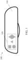
- FIG. 1is a front elevation view of a rear-view mirror including a reflective backlit display.
- FIG. 2is a side elevation view of a reflective backlit display stack.
- Rear view mirrors in vehicles, and in particular center (or inside) rear view mirrorsmay include display elements in order to provide navigational, status, safety, or other information to a driver.
- the inclusion of this information in a center rear view mirrormay be particularly useful because a driver can glance at such information without losing sight of the road and traffic in front of the vehicle. Further, a driver routinely scans the mirrors instinctively, and so important information displayed on the mirror will be reliably seen by the driver without having to get accustomed to looking in a new or unusual location.
- Conventional center rear view mirror displaysadapt a conventional display stack by simply adding a vapor coated mirror (sometimes described as a half- or partial-mirror or reflector) on the front of the display.
- a vapor coated mirrorsometimes described as a half- or partial-mirror or reflector
- Such an adaptationreflects some portion of the ambient light, creating a mirror-like appearance, but also reflects the same portion of the light from the convention display stack back away from the emission surface (the viewing surface) of the rear view mirror because the vapor coated mirror is a non-polarization-dependent reflector.
- This reflection lossis on top of the conventional losses in a display stack: from both the front and back absorbing polarizers and also the liquid crystal layer.
- Having the mirror-like appearanceallows for the full surface of the mirror to be useful or viewable when the display is not displaying information. Further, the mirror-like appearance may be aesthetically preferable by having uniformly appearing rear view mirror.
- the display stackcan incorporate the ambient light reflection functionality of a partial mirror without the need for additional layers. Further, the replacement of at least one absorbing polarizer with reflective polarizers eliminates at least some of the absorbing elements from the stack.
- FIG. 1is a front elevation view of a rear-view mirror including a reflective backlit display.
- Rear-view mirror 100includes mirror portion 110 and reflective backlit display portion 120 displaying information.
- Mirror portion 110 and reflective backlit display portion 120may have similar appearances.
- reflective backlit display portion 120may be capable of directly displaying generated information or images, while mirror 110 is not.
- mirror portion 110may be a small portion of rear-view mirror 100 , such as 40%, 30%, or 20% of the surface area.
- mirror portion 110may be a larger part of rear-view mirror 100 , such as 50%, 60%, 70%, 80%, 90% or more. In some embodiments, the mirror portion may be between 50% and 90% of the rear-view mirror.
- the display portionmay be 100% of the mirror portion; in other words, the mirror portion and the display portion may be the same and fill the entire reflective surface of the rear-view mirror.
- Rear-view mirror 100may include other elements, controls, or indicators on the border of the mirror or on attached parts.
- FIG. 2is a side elevation view of a reflective backlit display stack.
- Reflective backlit display stack 200includes light source 210 , lightguide 220 , prism film 230 , first reflective polarizer 240 , liquid crystal cell 250 , and second reflective polarizer 260 .
- Light source 210may be any suitable light source or combination of light sources. Conventional light sources such as light emitting diodes (LEDs), cold cathode fluorescent lamps (CCFLs), and even incandescent bulbs may be used. In some embodiments, although each light source 210 is depicted as a single object in FIG. 2 , combinations of LEDs (for example) may be used to provide a sufficiently white input light, but, depending on the application, any suitable spectrum or combination of spectra may be utilized. Light source 210 may include suitable injection or collimation optics to aid in coupling light into the structured lightguide or to help shape the light input for the structured lightguide. Light source 210 is disposed on either or both sides of the lightguide. Light source 210 on either side may be the same or similar light sources, or they may be different.
- Lightguide 220may be any suitable size and shape, and may be formed from any suitable material by any suitable process.
- lightguide 220may be acrylic or polycarbonate.
- Lightguide 120may be formed from a process such as injection molding.
- Lightguide 120has at least one input edge. The input edge is typically disposed on the surface of the lightguide closest to the light source(s). The input edge may have any suitable shape or structure, including structures to improve coupling of light from the light source into the structured lightguide.
- Lightguide 220also has one or more features for extracting light. These extraction features may be arranged in any suitable configuration, including a periodic pattern, a non-periodic pattern, or a gradient. The extraction features may be arranged in a pattern that increases the areal uniformity of light output from lightguide 220 .
- Prism film 230is optional in constructions described herein but may increase the overall on-axis brightness through light recycling.
- a reflector(not shown) may be used to redirect once again toward the front of reflective backlit stack 200 light that was reflected back from prism film 230 through total internal reflection at the interface between the prism film facets and air.
- the reflectormay be coated on to lightguide 220 or may not be present, where the reflective backlit stack simply relies on Fresnel reflections off the interfaces of the prism films and lightguides.
- the reflectoris a multilayer optical film, such as Enhanced Specular Reflector (ESR) (available from 3M Company, St. Paul, Minn.).
- ESREnhanced Specular Reflector
- Prism film 230has a plurality of prisms extending in a same first direction.
- prism film 230may instead have multiple films, with at least one film having prisms extending in a first direction and at least one film having prisms extending in a second direction orthogonal to the first direction.
- theymay be laminated to one another or may simply rest on one another.
- the prism filmsmay be formed by any suitable process, including microreplication, for example through a continuous-cast-and-cure process or the like.
- the prisms of prism film 230may have any suitable geometry, including included angle, base angle, height, pitch, width, and rotation—and one or more of these parameters may vary either along a prism or across prisms.
- Prism film 230may be, for example, Brightness Enhancing Film (BEF) (available from 3M Company, St. Paul, Minn.).
- BEFBrightness Enhancing Film
- First reflective polarizer 240 and second reflective polarizer 260are disposed on either side of liquid crystal layer 250 .
- Liquid crystal cell 250typically includes a layer of liquid crystal sandwiched by two layers of glass or another transparent substrate.
- the reflective polarizersmay both be adjacent to the transparent substrate or one or both may be laminated directly to the glass or transparent substrate of the liquid crystal cell. The lamination may be performed using. Alternatively, only one or even neither of the reflective polarizers may be laminated directly to the glass or transparent substrate of the liquid crystal cell.
- First reflective polarizer 240may be any suitable reflective type polarizer.
- the reflective polarizermay be an oriented multilayer polymeric optical film, such as DBEF or APF reflective polarizers (available from 3M Company, St. Paul, Minn.)
- the reflective polarizermay be a wire-grid or cholesteric reflective polarizer.
- the reflective polarizermay include one or more retardation or compensation layers, such as a quarter-wave plate, to convert between linear polarizations and circular or elliptical polarizations.
- First reflective polarizer 240may have any suitable thickness; in the case of a multilayer optical film, the reflective polarizer may be a thicker multi-packet or laminated construction or a relatively thinner single packet construction.
- Second reflective polarizer 260may be identical to first reflective polarizer 240 or they may be similar. In some embodiments, first reflective polarizer 240 and second reflective polarizer 260 may have some or many different characteristics. In some embodiments, an additional reflective polarizer or reflective polarizers may be disposed on either or both of the first and second reflective polarizers.
- the pass axes of the reflective polarizersshould be configured such that for a pixel in an “on” state—i.e., in a state where a voltage differential is generated across a pixel of the liquid crystal cell, the light from the light source either substantially passes through the second reflective polarizer or it is substantially not transmitted through the second reflective polarizer, and for a pixel in an “off” state—i.e., in a state where there is no voltage differential across the pixel of the liquid crystal cell, the light from the light source is treated oppositely.
- liquid crystal cellsThis may be a parallel arrangement of the pass axes of the reflective polarizers in some embodiments, or an orthogonal arrangement of the pass axes of the reflective polarizers.
- Any suitable driving electronics, conductive layers, or thin film transistors (TFTs)may be included or integrated into or included with liquid crystal cell 250 .
- the liquid crystal display for a SONY VAIO PCG-572N(available from Sony Corp., Tokyo, Japan) notebook computer was modified by removing, on one half only, the absorbing polarizers laminated to either side of the glass of the liquid crystal cell. After removing the absorbing polarizers on half of the display, the absorbing polarizers were replaced by laminating 3M APF-T35 reflective polarizers (available from 3M Company, St. Paul, Minn.) to the glass. The liquid crystal display was replaced and observed in both an “ON” (displaying an image) and “OFF” (displaying no image) state.
- the modified portion of the liquid crystal displayfunctioned as a reflective backlit display, functioning as a mirror when the display was OFF and showing a viewable image when the display was ON.
- Performancewas acceptable when compared to the reference half of the display, especially considering the reference display would further require a vapor-coated partial mirror to function as a reflective backlit display.
Landscapes
- Physics & Mathematics (AREA)
- Nonlinear Science (AREA)
- Optics & Photonics (AREA)
- General Physics & Mathematics (AREA)
- Crystallography & Structural Chemistry (AREA)
- Chemical & Material Sciences (AREA)
- Mathematical Physics (AREA)
- Engineering & Computer Science (AREA)
- Multimedia (AREA)
- Mechanical Engineering (AREA)
- Liquid Crystal (AREA)
- Polarising Elements (AREA)
- Planar Illumination Modules (AREA)
- Optical Elements Other Than Lenses (AREA)
Abstract
Description
- Item 1. A reflective backlit display, comprising:
- a backlight;
- a liquid crystal cell including a liquid crystal layer disposed between two opposing transparent substrate layers;
- a first reflective polarizer; and
- a second reflective polarizer;
- wherein the first and second reflective polarizers are each directly adjacent to one of the opposing transparent substrate layers.
- Item 2. The reflective backlit display of item 1, wherein at least one of the first or second reflective polarizers is a multilayer reflective polarizer.
- Item 3. The reflective backlit display of item 1, wherein each of the first or second reflective polarizers is a multilayer reflective polarizer.
- Item 4. The reflective backlit display of item 3, wherein the two transparent substrate layers are glass.
- Item 5. The reflective backlit display of item 1, wherein the first and second reflective polarizers are each directly laminated to one of the opposing transparent substrate layers.
- Item 6. The reflective backlit display of item 1, wherein the backlight includes a lightguide, a reflector disposed on the light guide, and a light source configured to inject light into the lightguide.
- Item 7. The reflective backlit display of item 1, further comprising a third reflective polarizer, wherein the third reflective polarizer is disposed on either the first or the second reflective polarizer.
- Item 8. A mirror, comprising:
- a mirror portion; and
- a reflective backlit display portion comprising the reflective backlit display of item 1;
- wherein the reflective backlit display is capable of directly displaying images, and the mirror portion is not.
- Item 9. A vehicle, comprising the mirror of item 8, the mirror being configured as a rear-view mirror.
- Item 10. The mirror of item 9, wherein the reflective backlit display portion is greater than 10% but less than 50% of an area of the mirror.
- Item 11. The reflective backlit display of item 1, wherein the reflective backlit display includes no absorbing polarizers.
- Item 12. The reflective backlit display of item 1, wherein the reflective backlit display includes no non-polarization-dependent partial reflector.
- Item 1. A reflective backlit display, comprising:
Claims (11)
Priority Applications (1)
| Application Number | Priority Date | Filing Date | Title |
|---|---|---|---|
| US16/063,121US12065078B2 (en) | 2015-12-17 | 2016-12-06 | Reflective backlit display with a liquid crystal cell |
Applications Claiming Priority (3)
| Application Number | Priority Date | Filing Date | Title |
|---|---|---|---|
| US201562268908P | 2015-12-17 | 2015-12-17 | |
| PCT/US2016/065183WO2017105926A1 (en) | 2015-12-17 | 2016-12-06 | Mirror including reflective backlit display |
| US16/063,121US12065078B2 (en) | 2015-12-17 | 2016-12-06 | Reflective backlit display with a liquid crystal cell |
Publications (2)
| Publication Number | Publication Date |
|---|---|
| US20200262351A1 US20200262351A1 (en) | 2020-08-20 |
| US12065078B2true US12065078B2 (en) | 2024-08-20 |
Family
ID=59057477
Family Applications (1)
| Application Number | Title | Priority Date | Filing Date |
|---|---|---|---|
| US16/063,121Active2039-04-26US12065078B2 (en) | 2015-12-17 | 2016-12-06 | Reflective backlit display with a liquid crystal cell |
Country Status (7)
| Country | Link |
|---|---|
| US (1) | US12065078B2 (en) |
| EP (1) | EP3391133A4 (en) |
| JP (2) | JP2019500651A (en) |
| KR (1) | KR20180086262A (en) |
| CN (1) | CN108369357A (en) |
| TW (1) | TW201734582A (en) |
| WO (1) | WO2017105926A1 (en) |
Families Citing this family (5)
| Publication number | Priority date | Publication date | Assignee | Title |
|---|---|---|---|---|
| US11187847B2 (en)* | 2017-06-06 | 2021-11-30 | 3M Innovative Properties Company | Backlight including wide-web turning film and reflective polarizer with quarter-wave retarder |
| CN109212812A (en)* | 2017-07-04 | 2019-01-15 | 京东方科技集团股份有限公司 | Display panel and preparation method thereof, display system |
| US20190351829A1 (en)* | 2018-04-16 | 2019-11-21 | Visteon Global Technologies, Inc. | Display system for a vehicle |
| US10996514B1 (en)* | 2019-01-25 | 2021-05-04 | Facebook Technologies, Llc | Offsetting non-uniform brightness using a backlight assembly |
| JP2023109630A (en)* | 2022-01-27 | 2023-08-08 | パナソニックIpマネジメント株式会社 | Display device and in-vehicle display device |
Citations (26)
| Publication number | Priority date | Publication date | Assignee | Title |
|---|---|---|---|---|
| EP0376207A2 (en) | 1988-12-26 | 1990-07-04 | Fuji Photo Film Co., Ltd. | Application device |
| WO1997001789A2 (en) | 1995-06-26 | 1997-01-16 | Minnesota Mining And Manufacturing Company | Optical panel capable of switching between reflective and transmissive states |
| JPH11248938A (en) | 1998-03-04 | 1999-09-17 | Seiko Epson Corp | Method of manufacturing reflective polarizer and method of manufacturing liquid crystal display device |
| US6271901B1 (en)* | 1997-07-14 | 2001-08-07 | Citizen Watch Co., Ltd. | Liquid crystal display device with two reflective polarizers providing metallic appearance effects |
| US20030043480A1 (en) | 2001-08-23 | 2003-03-06 | Burgner Lori L. | Vehicle information display |
| US6577361B1 (en) | 1998-12-09 | 2003-06-10 | Citizen Watch Co., Ltd. | Liquid crystal display |
| WO2003079318A1 (en) | 2002-03-18 | 2003-09-25 | Koninklijke Philips Electronics N.V. | Mirror with built-in display |
| JP2004170793A (en) | 2002-11-21 | 2004-06-17 | Seiko Epson Corp | Display device and electronic equipment |
| US6822711B1 (en) | 1999-09-30 | 2004-11-23 | Casio Computer Co., Ltd. | Liquid crystal display apparatus using polarizing element transmitting one of two polarizing components crossing at right angles and reflecting the other component |
| US20040246407A1 (en) | 2001-10-12 | 2004-12-09 | Rohm Co., Ltd. | Liquid crystal display apparatus, mirror apparatus, and electric device having liquid crystal display apparatus |
| US20060007550A1 (en) | 2004-07-12 | 2006-01-12 | Tonar William L | Variable reflectance mirrors and windows |
| US7221363B2 (en) | 2003-02-12 | 2007-05-22 | Gentex Corporation | Vehicle information displays |
| US20080068520A1 (en) | 2006-03-09 | 2008-03-20 | Minikey Danny L Jr | Vehicle Rearview Mirror Assembly Including a High Intensity Display |
| US20080151147A1 (en) | 2006-12-21 | 2008-06-26 | 3M Innovative Properties Company | Display including reflective polarizer |
| US20080186428A1 (en)* | 2007-02-06 | 2008-08-07 | Nitto Denko Corporation | Optical apparatus, image display, and liquid crystal display |
| US20090002576A1 (en) | 2007-06-28 | 2009-01-01 | Murakami Corporation | Liquid crystal glare-proof mirror |
| US20090128909A1 (en)* | 2007-11-20 | 2009-05-21 | Cambridge Research & Instrumentation, Inc. | Birefringent filter using reflective polarizers and dichroic elements |
| US20100020272A1 (en) | 2006-09-08 | 2010-01-28 | Tae-Su Kim | Mirror effect liquid crystal display device using reflection polarizer |
| JP2010079087A (en) | 2008-09-26 | 2010-04-08 | Casio Computer Co Ltd | Electronic equipment having display unit |
| US20100245701A1 (en) | 2009-03-24 | 2010-09-30 | Murakami Corporation | Mirror with monitor for vehicle |
| US7903335B2 (en) | 2003-11-11 | 2011-03-08 | Koninklijke Philips Electronics N.V. | Mirror with built-in display |
| US8237909B2 (en) | 2009-02-06 | 2012-08-07 | Gentex Corporation | Vehicular rearview mirror assembly including integrated backlighting for a liquid crystal display (LCD) |
| JP2014026058A (en) | 2012-07-25 | 2014-02-06 | Kyocera Display Corp | Liquid crystal display element |
| JP2014041274A (en) | 2012-08-23 | 2014-03-06 | Kyocera Display Corp | Liquid crystal display element |
| US20140098330A1 (en) | 2012-10-08 | 2014-04-10 | Samsung Display Co., Ltd. | Polarizer, liquid crystal display, and manufacturing method thereof |
| US20140340728A1 (en)* | 2012-01-31 | 2014-11-20 | Alphamicron Incorporated | Electronically dimmable optical device |
Family Cites Families (5)
| Publication number | Priority date | Publication date | Assignee | Title |
|---|---|---|---|---|
| CN1189224A (en)* | 1995-06-26 | 1998-07-29 | 美国3M公司 | Light panels switchable between reflective and transmissive states |
| US6930737B2 (en)* | 2001-01-16 | 2005-08-16 | Visteon Global Technologies, Inc. | LED backlighting system |
| JP3726900B2 (en) | 2002-06-24 | 2005-12-14 | セイコーエプソン株式会社 | Display device and electronic apparatus equipped with the same |
| US7525604B2 (en)* | 2005-03-15 | 2009-04-28 | Naxellent, Llc | Windows with electrically controllable transmission and reflection |
| US8836888B2 (en)* | 2009-12-15 | 2014-09-16 | Gentex Corporation | Modular light source/electronics and automotive rearview assemblies using the same |
- 2016
- 2016-12-06KRKR1020187019367Apatent/KR20180086262A/ennot_activeCeased
- 2016-12-06USUS16/063,121patent/US12065078B2/enactiveActive
- 2016-12-06WOPCT/US2016/065183patent/WO2017105926A1/ennot_activeCeased
- 2016-12-06EPEP16876397.7Apatent/EP3391133A4/ennot_activeWithdrawn
- 2016-12-06JPJP2018531492Apatent/JP2019500651A/enactivePending
- 2016-12-06CNCN201680074414.6Apatent/CN108369357A/enactivePending
- 2016-12-16TWTW105141704Apatent/TW201734582A/enunknown
- 2022
- 2022-03-04JPJP2022033047Apatent/JP2022084693A/enactivePending
Patent Citations (27)
| Publication number | Priority date | Publication date | Assignee | Title |
|---|---|---|---|---|
| EP0376207A2 (en) | 1988-12-26 | 1990-07-04 | Fuji Photo Film Co., Ltd. | Application device |
| WO1997001789A2 (en) | 1995-06-26 | 1997-01-16 | Minnesota Mining And Manufacturing Company | Optical panel capable of switching between reflective and transmissive states |
| US6271901B1 (en)* | 1997-07-14 | 2001-08-07 | Citizen Watch Co., Ltd. | Liquid crystal display device with two reflective polarizers providing metallic appearance effects |
| JPH11248938A (en) | 1998-03-04 | 1999-09-17 | Seiko Epson Corp | Method of manufacturing reflective polarizer and method of manufacturing liquid crystal display device |
| US6577361B1 (en) | 1998-12-09 | 2003-06-10 | Citizen Watch Co., Ltd. | Liquid crystal display |
| US6822711B1 (en) | 1999-09-30 | 2004-11-23 | Casio Computer Co., Ltd. | Liquid crystal display apparatus using polarizing element transmitting one of two polarizing components crossing at right angles and reflecting the other component |
| US20030043480A1 (en) | 2001-08-23 | 2003-03-06 | Burgner Lori L. | Vehicle information display |
| US20040246407A1 (en) | 2001-10-12 | 2004-12-09 | Rohm Co., Ltd. | Liquid crystal display apparatus, mirror apparatus, and electric device having liquid crystal display apparatus |
| WO2003079318A1 (en) | 2002-03-18 | 2003-09-25 | Koninklijke Philips Electronics N.V. | Mirror with built-in display |
| JP2004170793A (en) | 2002-11-21 | 2004-06-17 | Seiko Epson Corp | Display device and electronic equipment |
| US7221363B2 (en) | 2003-02-12 | 2007-05-22 | Gentex Corporation | Vehicle information displays |
| US7903335B2 (en) | 2003-11-11 | 2011-03-08 | Koninklijke Philips Electronics N.V. | Mirror with built-in display |
| US20060007550A1 (en) | 2004-07-12 | 2006-01-12 | Tonar William L | Variable reflectance mirrors and windows |
| US20080068520A1 (en) | 2006-03-09 | 2008-03-20 | Minikey Danny L Jr | Vehicle Rearview Mirror Assembly Including a High Intensity Display |
| US8339526B2 (en) | 2006-03-09 | 2012-12-25 | Gentex Corporation | Vehicle rearview mirror assembly including a high intensity display |
| US20100020272A1 (en) | 2006-09-08 | 2010-01-28 | Tae-Su Kim | Mirror effect liquid crystal display device using reflection polarizer |
| US20080151147A1 (en) | 2006-12-21 | 2008-06-26 | 3M Innovative Properties Company | Display including reflective polarizer |
| US20080186428A1 (en)* | 2007-02-06 | 2008-08-07 | Nitto Denko Corporation | Optical apparatus, image display, and liquid crystal display |
| US20090002576A1 (en) | 2007-06-28 | 2009-01-01 | Murakami Corporation | Liquid crystal glare-proof mirror |
| US20090128909A1 (en)* | 2007-11-20 | 2009-05-21 | Cambridge Research & Instrumentation, Inc. | Birefringent filter using reflective polarizers and dichroic elements |
| JP2010079087A (en) | 2008-09-26 | 2010-04-08 | Casio Computer Co Ltd | Electronic equipment having display unit |
| US8237909B2 (en) | 2009-02-06 | 2012-08-07 | Gentex Corporation | Vehicular rearview mirror assembly including integrated backlighting for a liquid crystal display (LCD) |
| US20100245701A1 (en) | 2009-03-24 | 2010-09-30 | Murakami Corporation | Mirror with monitor for vehicle |
| US20140340728A1 (en)* | 2012-01-31 | 2014-11-20 | Alphamicron Incorporated | Electronically dimmable optical device |
| JP2014026058A (en) | 2012-07-25 | 2014-02-06 | Kyocera Display Corp | Liquid crystal display element |
| JP2014041274A (en) | 2012-08-23 | 2014-03-06 | Kyocera Display Corp | Liquid crystal display element |
| US20140098330A1 (en) | 2012-10-08 | 2014-04-10 | Samsung Display Co., Ltd. | Polarizer, liquid crystal display, and manufacturing method thereof |
Non-Patent Citations (4)
| Title |
|---|
| "Indoor Equipment", Nissan, DAYZ, [online], [retrieved from the internet on Aug. 14, 2018], URLhttp://www.nissan.co.jp/DAYZ/equip_avm.html, 12 Pages. |
| International Search Report for PCT International Application No. PCT/US2016/065183, mailed on Mar. 20, 2017, 5pgs. |
| Merriam-webster/dictionary/disposed (accessed Jan. 23, 2024).* |
| Merriam-webster/dictionary/on (accessed Jan. 23, 2024).* |
Also Published As
| Publication number | Publication date |
|---|---|
| CN108369357A (en) | 2018-08-03 |
| EP3391133A4 (en) | 2019-07-31 |
| JP2022084693A (en) | 2022-06-07 |
| JP2019500651A (en) | 2019-01-10 |
| WO2017105926A1 (en) | 2017-06-22 |
| US20200262351A1 (en) | 2020-08-20 |
| KR20180086262A (en) | 2018-07-30 |
| TW201734582A (en) | 2017-10-01 |
| EP3391133A1 (en) | 2018-10-24 |
Similar Documents
| Publication | Publication Date | Title |
|---|---|---|
| US8836888B2 (en) | Modular light source/electronics and automotive rearview assemblies using the same | |
| US12065078B2 (en) | Reflective backlit display with a liquid crystal cell | |
| US8456593B2 (en) | Transparent display device | |
| KR101005466B1 (en) | Transparent see-through display device | |
| CN103376589B (en) | Display device | |
| US11307453B2 (en) | Display panel and display device | |
| US20140340865A1 (en) | Display Backlight System | |
| US20100123854A1 (en) | Optical sheet, illuminating device and liquid crystal display device | |
| US20100277669A1 (en) | Illuminating device and liquid crystal display device | |
| KR20110064669A (en) | Transparent liquid crystal display device | |
| KR20060042481A (en) | Liquid Crystal Display Including Reflective Polarizer | |
| US10661715B2 (en) | Rearview system and vehicle having the same | |
| US10578909B2 (en) | Display apparatus with dichroic filter | |
| CN101576680B (en) | Liquid crystal display device and assembly method thereof | |
| CN111580308A (en) | Backlight module and display device | |
| KR102485634B1 (en) | Liquid crystal display device | |
| US11016337B2 (en) | Light source module and dual display device | |
| US11506830B2 (en) | Backlight module and display device | |
| CN109143675A (en) | polarizing structure and display device | |
| US10677411B2 (en) | Luminous signalling device with LCD | |
| CN109307960B (en) | Transparent liquid crystal display panel | |
| CN221804437U (en) | Display device | |
| US20250189834A1 (en) | Polarization dichroism-based public/privacy display panels | |
| US20250123516A1 (en) | Display device | |
| JP2003331623A (en) | Light guide, lighting device and display device including the same |
Legal Events
| Date | Code | Title | Description |
|---|---|---|---|
| AS | Assignment | Owner name:3M INNOVATIVE PROPERTIES COMPANY, MINNESOTA Free format text:ASSIGNMENT OF ASSIGNORS INTEREST;ASSIGNOR:TOYOOKA, KAZUHIKO;REEL/FRAME:046103/0744 Effective date:20180419 | |
| FEPP | Fee payment procedure | Free format text:ENTITY STATUS SET TO UNDISCOUNTED (ORIGINAL EVENT CODE: BIG.); ENTITY STATUS OF PATENT OWNER: LARGE ENTITY | |
| STPP | Information on status: patent application and granting procedure in general | Free format text:FINAL REJECTION MAILED | |
| STPP | Information on status: patent application and granting procedure in general | Free format text:ADVISORY ACTION MAILED | |
| STPP | Information on status: patent application and granting procedure in general | Free format text:DOCKETED NEW CASE - READY FOR EXAMINATION | |
| STPP | Information on status: patent application and granting procedure in general | Free format text:NON FINAL ACTION MAILED | |
| STPP | Information on status: patent application and granting procedure in general | Free format text:RESPONSE TO NON-FINAL OFFICE ACTION ENTERED AND FORWARDED TO EXAMINER | |
| STPP | Information on status: patent application and granting procedure in general | Free format text:FINAL REJECTION MAILED | |
| STPP | Information on status: patent application and granting procedure in general | Free format text:ADVISORY ACTION MAILED | |
| STCV | Information on status: appeal procedure | Free format text:NOTICE OF APPEAL FILED | |
| STCV | Information on status: appeal procedure | Free format text:APPEAL BRIEF (OR SUPPLEMENTAL BRIEF) ENTERED AND FORWARDED TO EXAMINER | |
| STCV | Information on status: appeal procedure | Free format text:EXAMINER'S ANSWER TO APPEAL BRIEF MAILED | |
| STCV | Information on status: appeal procedure | Free format text:ON APPEAL -- AWAITING DECISION BY THE BOARD OF APPEALS | |
| STCV | Information on status: appeal procedure | Free format text:BOARD OF APPEALS DECISION RENDERED | |
| STPP | Information on status: patent application and granting procedure in general | Free format text:NOTICE OF ALLOWANCE MAILED -- APPLICATION RECEIVED IN OFFICE OF PUBLICATIONS | |
| ZAAA | Notice of allowance and fees due | Free format text:ORIGINAL CODE: NOA | |
| STPP | Information on status: patent application and granting procedure in general | Free format text:AWAITING TC RESP., ISSUE FEE NOT PAID | |
| ZAAB | Notice of allowance mailed | Free format text:ORIGINAL CODE: MN/=. | |
| STPP | Information on status: patent application and granting procedure in general | Free format text:NOTICE OF ALLOWANCE MAILED -- APPLICATION RECEIVED IN OFFICE OF PUBLICATIONS | |
| ZAAA | Notice of allowance and fees due | Free format text:ORIGINAL CODE: NOA | |
| STPP | Information on status: patent application and granting procedure in general | Free format text:PUBLICATIONS -- ISSUE FEE PAYMENT VERIFIED | |
| STCF | Information on status: patent grant | Free format text:PATENTED CASE |