US12064344B2 - Telescoping prosthetic valve and delivery system - Google Patents
Telescoping prosthetic valve and delivery systemDownload PDFInfo
- Publication number
- US12064344B2 US12064344B2US17/383,569US202117383569AUS12064344B2US 12064344 B2US12064344 B2US 12064344B2US 202117383569 AUS202117383569 AUS 202117383569AUS 12064344 B2US12064344 B2US 12064344B2
- Authority
- US
- United States
- Prior art keywords
- frame subcomponent
- valve
- anchor frame
- examples
- subcomponent
- Prior art date
- Legal status (The legal status is an assumption and is not a legal conclusion. Google has not performed a legal analysis and makes no representation as to the accuracy of the status listed.)
- Active, expires
Links
Images


Classifications
- A—HUMAN NECESSITIES
- A61—MEDICAL OR VETERINARY SCIENCE; HYGIENE
- A61F—FILTERS IMPLANTABLE INTO BLOOD VESSELS; PROSTHESES; DEVICES PROVIDING PATENCY TO, OR PREVENTING COLLAPSING OF, TUBULAR STRUCTURES OF THE BODY, e.g. STENTS; ORTHOPAEDIC, NURSING OR CONTRACEPTIVE DEVICES; FOMENTATION; TREATMENT OR PROTECTION OF EYES OR EARS; BANDAGES, DRESSINGS OR ABSORBENT PADS; FIRST-AID KITS
- A61F2/00—Filters implantable into blood vessels; Prostheses, i.e. artificial substitutes or replacements for parts of the body; Appliances for connecting them with the body; Devices providing patency to, or preventing collapsing of, tubular structures of the body, e.g. stents
- A61F2/02—Prostheses implantable into the body
- A61F2/24—Heart valves ; Vascular valves, e.g. venous valves; Heart implants, e.g. passive devices for improving the function of the native valve or the heart muscle; Transmyocardial revascularisation [TMR] devices; Valves implantable in the body
- A61F2/2412—Heart valves ; Vascular valves, e.g. venous valves; Heart implants, e.g. passive devices for improving the function of the native valve or the heart muscle; Transmyocardial revascularisation [TMR] devices; Valves implantable in the body with soft flexible valve members, e.g. tissue valves shaped like natural valves
- A61F2/2418—Scaffolds therefor, e.g. support stents
- A—HUMAN NECESSITIES
- A61—MEDICAL OR VETERINARY SCIENCE; HYGIENE
- A61F—FILTERS IMPLANTABLE INTO BLOOD VESSELS; PROSTHESES; DEVICES PROVIDING PATENCY TO, OR PREVENTING COLLAPSING OF, TUBULAR STRUCTURES OF THE BODY, e.g. STENTS; ORTHOPAEDIC, NURSING OR CONTRACEPTIVE DEVICES; FOMENTATION; TREATMENT OR PROTECTION OF EYES OR EARS; BANDAGES, DRESSINGS OR ABSORBENT PADS; FIRST-AID KITS
- A61F2/00—Filters implantable into blood vessels; Prostheses, i.e. artificial substitutes or replacements for parts of the body; Appliances for connecting them with the body; Devices providing patency to, or preventing collapsing of, tubular structures of the body, e.g. stents
- A61F2/02—Prostheses implantable into the body
- A61F2/24—Heart valves ; Vascular valves, e.g. venous valves; Heart implants, e.g. passive devices for improving the function of the native valve or the heart muscle; Transmyocardial revascularisation [TMR] devices; Valves implantable in the body
- A61F2/2427—Devices for manipulating or deploying heart valves during implantation
- A61F2/2436—Deployment by retracting a sheath
- A—HUMAN NECESSITIES
- A61—MEDICAL OR VETERINARY SCIENCE; HYGIENE
- A61F—FILTERS IMPLANTABLE INTO BLOOD VESSELS; PROSTHESES; DEVICES PROVIDING PATENCY TO, OR PREVENTING COLLAPSING OF, TUBULAR STRUCTURES OF THE BODY, e.g. STENTS; ORTHOPAEDIC, NURSING OR CONTRACEPTIVE DEVICES; FOMENTATION; TREATMENT OR PROTECTION OF EYES OR EARS; BANDAGES, DRESSINGS OR ABSORBENT PADS; FIRST-AID KITS
- A61F2/00—Filters implantable into blood vessels; Prostheses, i.e. artificial substitutes or replacements for parts of the body; Appliances for connecting them with the body; Devices providing patency to, or preventing collapsing of, tubular structures of the body, e.g. stents
- A61F2/02—Prostheses implantable into the body
- A61F2/24—Heart valves ; Vascular valves, e.g. venous valves; Heart implants, e.g. passive devices for improving the function of the native valve or the heart muscle; Transmyocardial revascularisation [TMR] devices; Valves implantable in the body
- A61F2/2442—Annuloplasty rings or inserts for correcting the valve shape; Implants for improving the function of a native heart valve
- A61F2/246—Devices for obstructing a leak through a native valve in a closed condition
- A—HUMAN NECESSITIES
- A61—MEDICAL OR VETERINARY SCIENCE; HYGIENE
- A61F—FILTERS IMPLANTABLE INTO BLOOD VESSELS; PROSTHESES; DEVICES PROVIDING PATENCY TO, OR PREVENTING COLLAPSING OF, TUBULAR STRUCTURES OF THE BODY, e.g. STENTS; ORTHOPAEDIC, NURSING OR CONTRACEPTIVE DEVICES; FOMENTATION; TREATMENT OR PROTECTION OF EYES OR EARS; BANDAGES, DRESSINGS OR ABSORBENT PADS; FIRST-AID KITS
- A61F2/00—Filters implantable into blood vessels; Prostheses, i.e. artificial substitutes or replacements for parts of the body; Appliances for connecting them with the body; Devices providing patency to, or preventing collapsing of, tubular structures of the body, e.g. stents
- A61F2/02—Prostheses implantable into the body
- A61F2/24—Heart valves ; Vascular valves, e.g. venous valves; Heart implants, e.g. passive devices for improving the function of the native valve or the heart muscle; Transmyocardial revascularisation [TMR] devices; Valves implantable in the body
- A61F2/2427—Devices for manipulating or deploying heart valves during implantation
- A61F2/243—Deployment by mechanical expansion
- A61F2/2433—Deployment by mechanical expansion using balloon catheter
- A—HUMAN NECESSITIES
- A61—MEDICAL OR VETERINARY SCIENCE; HYGIENE
- A61F—FILTERS IMPLANTABLE INTO BLOOD VESSELS; PROSTHESES; DEVICES PROVIDING PATENCY TO, OR PREVENTING COLLAPSING OF, TUBULAR STRUCTURES OF THE BODY, e.g. STENTS; ORTHOPAEDIC, NURSING OR CONTRACEPTIVE DEVICES; FOMENTATION; TREATMENT OR PROTECTION OF EYES OR EARS; BANDAGES, DRESSINGS OR ABSORBENT PADS; FIRST-AID KITS
- A61F2/00—Filters implantable into blood vessels; Prostheses, i.e. artificial substitutes or replacements for parts of the body; Appliances for connecting them with the body; Devices providing patency to, or preventing collapsing of, tubular structures of the body, e.g. stents
- A61F2/02—Prostheses implantable into the body
- A61F2/24—Heart valves ; Vascular valves, e.g. venous valves; Heart implants, e.g. passive devices for improving the function of the native valve or the heart muscle; Transmyocardial revascularisation [TMR] devices; Valves implantable in the body
- A61F2/2427—Devices for manipulating or deploying heart valves during implantation
- A61F2/2439—Expansion controlled by filaments
- A—HUMAN NECESSITIES
- A61—MEDICAL OR VETERINARY SCIENCE; HYGIENE
- A61F—FILTERS IMPLANTABLE INTO BLOOD VESSELS; PROSTHESES; DEVICES PROVIDING PATENCY TO, OR PREVENTING COLLAPSING OF, TUBULAR STRUCTURES OF THE BODY, e.g. STENTS; ORTHOPAEDIC, NURSING OR CONTRACEPTIVE DEVICES; FOMENTATION; TREATMENT OR PROTECTION OF EYES OR EARS; BANDAGES, DRESSINGS OR ABSORBENT PADS; FIRST-AID KITS
- A61F2/00—Filters implantable into blood vessels; Prostheses, i.e. artificial substitutes or replacements for parts of the body; Appliances for connecting them with the body; Devices providing patency to, or preventing collapsing of, tubular structures of the body, e.g. stents
- A61F2/02—Prostheses implantable into the body
- A61F2/24—Heart valves ; Vascular valves, e.g. venous valves; Heart implants, e.g. passive devices for improving the function of the native valve or the heart muscle; Transmyocardial revascularisation [TMR] devices; Valves implantable in the body
- A61F2/2442—Annuloplasty rings or inserts for correcting the valve shape; Implants for improving the function of a native heart valve
- A61F2/2454—Means for preventing inversion of the valve leaflets, e.g. chordae tendineae prostheses
- A—HUMAN NECESSITIES
- A61—MEDICAL OR VETERINARY SCIENCE; HYGIENE
- A61F—FILTERS IMPLANTABLE INTO BLOOD VESSELS; PROSTHESES; DEVICES PROVIDING PATENCY TO, OR PREVENTING COLLAPSING OF, TUBULAR STRUCTURES OF THE BODY, e.g. STENTS; ORTHOPAEDIC, NURSING OR CONTRACEPTIVE DEVICES; FOMENTATION; TREATMENT OR PROTECTION OF EYES OR EARS; BANDAGES, DRESSINGS OR ABSORBENT PADS; FIRST-AID KITS
- A61F2/00—Filters implantable into blood vessels; Prostheses, i.e. artificial substitutes or replacements for parts of the body; Appliances for connecting them with the body; Devices providing patency to, or preventing collapsing of, tubular structures of the body, e.g. stents
- A61F2/82—Devices providing patency to, or preventing collapsing of, tubular structures of the body, e.g. stents
- A61F2002/825—Devices providing patency to, or preventing collapsing of, tubular structures of the body, e.g. stents having longitudinal struts
- A—HUMAN NECESSITIES
- A61—MEDICAL OR VETERINARY SCIENCE; HYGIENE
- A61F—FILTERS IMPLANTABLE INTO BLOOD VESSELS; PROSTHESES; DEVICES PROVIDING PATENCY TO, OR PREVENTING COLLAPSING OF, TUBULAR STRUCTURES OF THE BODY, e.g. STENTS; ORTHOPAEDIC, NURSING OR CONTRACEPTIVE DEVICES; FOMENTATION; TREATMENT OR PROTECTION OF EYES OR EARS; BANDAGES, DRESSINGS OR ABSORBENT PADS; FIRST-AID KITS
- A61F2210/00—Particular material properties of prostheses classified in groups A61F2/00 - A61F2/26 or A61F2/82 or A61F9/00 or A61F11/00 or subgroups thereof
- A61F2210/0014—Particular material properties of prostheses classified in groups A61F2/00 - A61F2/26 or A61F2/82 or A61F9/00 or A61F11/00 or subgroups thereof using shape memory or superelastic materials, e.g. nitinol
- A—HUMAN NECESSITIES
- A61—MEDICAL OR VETERINARY SCIENCE; HYGIENE
- A61F—FILTERS IMPLANTABLE INTO BLOOD VESSELS; PROSTHESES; DEVICES PROVIDING PATENCY TO, OR PREVENTING COLLAPSING OF, TUBULAR STRUCTURES OF THE BODY, e.g. STENTS; ORTHOPAEDIC, NURSING OR CONTRACEPTIVE DEVICES; FOMENTATION; TREATMENT OR PROTECTION OF EYES OR EARS; BANDAGES, DRESSINGS OR ABSORBENT PADS; FIRST-AID KITS
- A61F2220/00—Fixations or connections for prostheses classified in groups A61F2/00 - A61F2/26 or A61F2/82 or A61F9/00 or A61F11/00 or subgroups thereof
- A61F2220/0008—Fixation appliances for connecting prostheses to the body
- A61F2220/0016—Fixation appliances for connecting prostheses to the body with sharp anchoring protrusions, e.g. barbs, pins, spikes
- A—HUMAN NECESSITIES
- A61—MEDICAL OR VETERINARY SCIENCE; HYGIENE
- A61F—FILTERS IMPLANTABLE INTO BLOOD VESSELS; PROSTHESES; DEVICES PROVIDING PATENCY TO, OR PREVENTING COLLAPSING OF, TUBULAR STRUCTURES OF THE BODY, e.g. STENTS; ORTHOPAEDIC, NURSING OR CONTRACEPTIVE DEVICES; FOMENTATION; TREATMENT OR PROTECTION OF EYES OR EARS; BANDAGES, DRESSINGS OR ABSORBENT PADS; FIRST-AID KITS
- A61F2220/00—Fixations or connections for prostheses classified in groups A61F2/00 - A61F2/26 or A61F2/82 or A61F9/00 or A61F11/00 or subgroups thereof
- A61F2220/0025—Connections or couplings between prosthetic parts, e.g. between modular parts; Connecting elements
- A61F2220/0075—Connections or couplings between prosthetic parts, e.g. between modular parts; Connecting elements sutured, ligatured or stitched, retained or tied with a rope, string, thread, wire or cable
- A—HUMAN NECESSITIES
- A61—MEDICAL OR VETERINARY SCIENCE; HYGIENE
- A61F—FILTERS IMPLANTABLE INTO BLOOD VESSELS; PROSTHESES; DEVICES PROVIDING PATENCY TO, OR PREVENTING COLLAPSING OF, TUBULAR STRUCTURES OF THE BODY, e.g. STENTS; ORTHOPAEDIC, NURSING OR CONTRACEPTIVE DEVICES; FOMENTATION; TREATMENT OR PROTECTION OF EYES OR EARS; BANDAGES, DRESSINGS OR ABSORBENT PADS; FIRST-AID KITS
- A61F2230/00—Geometry of prostheses classified in groups A61F2/00 - A61F2/26 or A61F2/82 or A61F9/00 or A61F11/00 or subgroups thereof
- A61F2230/0002—Two-dimensional shapes, e.g. cross-sections
- A61F2230/0028—Shapes in the form of latin or greek characters
- A61F2230/005—Rosette-shaped, e.g. star-shaped
- A—HUMAN NECESSITIES
- A61—MEDICAL OR VETERINARY SCIENCE; HYGIENE
- A61F—FILTERS IMPLANTABLE INTO BLOOD VESSELS; PROSTHESES; DEVICES PROVIDING PATENCY TO, OR PREVENTING COLLAPSING OF, TUBULAR STRUCTURES OF THE BODY, e.g. STENTS; ORTHOPAEDIC, NURSING OR CONTRACEPTIVE DEVICES; FOMENTATION; TREATMENT OR PROTECTION OF EYES OR EARS; BANDAGES, DRESSINGS OR ABSORBENT PADS; FIRST-AID KITS
- A61F2230/00—Geometry of prostheses classified in groups A61F2/00 - A61F2/26 or A61F2/82 or A61F9/00 or A61F11/00 or subgroups thereof
- A61F2230/0002—Two-dimensional shapes, e.g. cross-sections
- A61F2230/0028—Shapes in the form of latin or greek characters
- A61F2230/0052—T-shaped
- A—HUMAN NECESSITIES
- A61—MEDICAL OR VETERINARY SCIENCE; HYGIENE
- A61F—FILTERS IMPLANTABLE INTO BLOOD VESSELS; PROSTHESES; DEVICES PROVIDING PATENCY TO, OR PREVENTING COLLAPSING OF, TUBULAR STRUCTURES OF THE BODY, e.g. STENTS; ORTHOPAEDIC, NURSING OR CONTRACEPTIVE DEVICES; FOMENTATION; TREATMENT OR PROTECTION OF EYES OR EARS; BANDAGES, DRESSINGS OR ABSORBENT PADS; FIRST-AID KITS
- A61F2230/00—Geometry of prostheses classified in groups A61F2/00 - A61F2/26 or A61F2/82 or A61F9/00 or A61F11/00 or subgroups thereof
- A61F2230/0002—Two-dimensional shapes, e.g. cross-sections
- A61F2230/0028—Shapes in the form of latin or greek characters
- A61F2230/0054—V-shaped
- A—HUMAN NECESSITIES
- A61—MEDICAL OR VETERINARY SCIENCE; HYGIENE
- A61F—FILTERS IMPLANTABLE INTO BLOOD VESSELS; PROSTHESES; DEVICES PROVIDING PATENCY TO, OR PREVENTING COLLAPSING OF, TUBULAR STRUCTURES OF THE BODY, e.g. STENTS; ORTHOPAEDIC, NURSING OR CONTRACEPTIVE DEVICES; FOMENTATION; TREATMENT OR PROTECTION OF EYES OR EARS; BANDAGES, DRESSINGS OR ABSORBENT PADS; FIRST-AID KITS
- A61F2230/00—Geometry of prostheses classified in groups A61F2/00 - A61F2/26 or A61F2/82 or A61F9/00 or A61F11/00 or subgroups thereof
- A61F2230/0063—Three-dimensional shapes
- A61F2230/0069—Three-dimensional shapes cylindrical
- A—HUMAN NECESSITIES
- A61—MEDICAL OR VETERINARY SCIENCE; HYGIENE
- A61F—FILTERS IMPLANTABLE INTO BLOOD VESSELS; PROSTHESES; DEVICES PROVIDING PATENCY TO, OR PREVENTING COLLAPSING OF, TUBULAR STRUCTURES OF THE BODY, e.g. STENTS; ORTHOPAEDIC, NURSING OR CONTRACEPTIVE DEVICES; FOMENTATION; TREATMENT OR PROTECTION OF EYES OR EARS; BANDAGES, DRESSINGS OR ABSORBENT PADS; FIRST-AID KITS
- A61F2250/00—Special features of prostheses classified in groups A61F2/00 - A61F2/26 or A61F2/82 or A61F9/00 or A61F11/00 or subgroups thereof
- A61F2250/0014—Special features of prostheses classified in groups A61F2/00 - A61F2/26 or A61F2/82 or A61F9/00 or A61F11/00 or subgroups thereof having different values of a given property or geometrical feature, e.g. mechanical property or material property, at different locations within the same prosthesis
- A61F2250/0039—Special features of prostheses classified in groups A61F2/00 - A61F2/26 or A61F2/82 or A61F9/00 or A61F11/00 or subgroups thereof having different values of a given property or geometrical feature, e.g. mechanical property or material property, at different locations within the same prosthesis differing in diameter
- A—HUMAN NECESSITIES
- A61—MEDICAL OR VETERINARY SCIENCE; HYGIENE
- A61F—FILTERS IMPLANTABLE INTO BLOOD VESSELS; PROSTHESES; DEVICES PROVIDING PATENCY TO, OR PREVENTING COLLAPSING OF, TUBULAR STRUCTURES OF THE BODY, e.g. STENTS; ORTHOPAEDIC, NURSING OR CONTRACEPTIVE DEVICES; FOMENTATION; TREATMENT OR PROTECTION OF EYES OR EARS; BANDAGES, DRESSINGS OR ABSORBENT PADS; FIRST-AID KITS
- A61F2250/00—Special features of prostheses classified in groups A61F2/00 - A61F2/26 or A61F2/82 or A61F9/00 or A61F11/00 or subgroups thereof
- A61F2250/0058—Additional features; Implant or prostheses properties not otherwise provided for
- A61F2250/006—Additional features; Implant or prostheses properties not otherwise provided for modular
- A61F2250/0063—Nested prosthetic parts
Definitions
- the present disclosurerelates generally to prosthetic valves and more specifically to flexible leaflet-type prosthetic valve devices, systems and methods.
- Bioprosthetic valveshave been developed that attempt to mimic the function and performance of a native valve.
- Bioprosthetic valvesmay be formed from synthetic materials, natural tissue such as biological tissue, or a combination of synthetic materials and natural tissue.
- transcatheter techniquesoffer a number of advantages.
- a transcatheter prosthetic valve that is delivered endovascularly via a cathetercan help to minimize patient trauma as compared with an open-heart, surgical procedure.
- Open-heart surgeryinvolves extensive trauma to the patient, with attendant morbidity and extended recovery.
- a valve delivered to the recipient site via a catheteravoids the trauma of open-heart surgery and may be performed on patients too ill or feeble to survive the open-heart surgery.
- a prosthetic valve for replacing a native valve of a patient's anatomyincludes an anchor frame subcomponent, a valve frame subcomponent nestable within the anchor frame subcomponent, a tissue retention feature configured to engage tissue associated with the native valve and secure the leaflet of the native valve between the valve frame subcomponent and the anchor frame subcomponent.
- Example 2further to Example 1, one or more portions of the anchor frame subcomponent and the valve frame subcomponent overlap one another such that an annular space is defined between the overlapping portions of the valve frame subcomponent and the anchor frame subcomponent when the valve frame subcomponent is nested with the anchor frame subcomponent.
- the tissue retention featureis configured to secure the tissue associated with the native valve within the annular space.
- the tissue associated with the native valveincludes a leaflet of the native valve.
- tissue retention featureextends radially outwardly from the valve frame subcomponent into the annular space defined between the valve frame subcomponent and the anchor frame subcomponent when the valve frame subcomponent is nested with the anchor frame subcomponent.
- the tissue retention featureis integral with the valve frame subcomponent.
- tissue retention featureis distinct from and coupled to the valve frame subcomponent.
- the prosthetic valvefurther includes a film disposed about one or more portions of the valve frame subcomponent and the anchor frame subcomponent such that the anchor frame subcomponent is coupled to the valve frame subcomponent at least in part by a contiguous portion of the film.
- Example 9further to Example 8, a portion of the contiguous portion of the film is contained between the valve frame subcomponent and anchor frame subcomponent when the valve frame subcomponent is nested within the anchor frame subcomponent.
- Example 10further to Example 9, the tissue retention feature is positioned between the valve frame subcomponent and the film when the valve frame subcomponent is nested with the anchor frame subcomponent.
- the prosthetic valvefurther includes an interlock configured to maintain a nested position of the valve frame subcomponent within the anchor frame subcomponent.
- Example 12further to Example 11, the interlock is coupled to the valve frame subcomponent and is configured to engage the anchor frame subcomponent.
- the interlockis a resilient member that is transitionable between a deflected and extended position as the anchor frame subcomponent and the valve frame subcomponent are nested together.
- the prosthetic valvefurther includes one or more anchors configured for anchoring the prosthetic valve to tissue of the patient's anatomy.
- Example 15further to Example 14, the anchors are integral with the anchor frame subcomponent.
- Example 16further to Example 14, the anchors are coupled to the anchor frame subcomponent.
- the prosthetic valveis transitionable between a compressed configuration for transcatheter delivery and an expanded configuration wherein the prosthetic valve is operable to replace a native valve of a patient's anatomy.
- a prosthetic valve transitionable between a delivery configuration and a deployed configuration in-situincludes a valve frame subcomponent comprising a proximal end and a distal end, an anchor frame subcomponent coupled to the valve frame subcomponent, the anchor frame subcomponent comprising a proximal end and a distal end, and a tissue retention feature configured to engage tissue associated with a native valve of a patient's anatomy and secure the tissue of the native valve between the valve frame subcomponent and the anchor frame subcomponent.
- valve frame subcomponent and the anchor frame subcomponentare longitudinally offset from one another such that the proximal end of the valve frame subcomponent is situated distal of the distal end of the anchor frame subcomponent.
- the valve frame subcomponentis nested within an interior region defined by the anchor frame subcomponent.
- the tissue associated with the native valveincludes a leaflet of the native valve.
- the proximal end of the valve frame subcomponentis situated proximal of the distal end of the anchor frame subcomponent when the prosthetic is transitioned to the deployed configuration in-situ.
- a medical device systemincludes a catheter, and a prosthetic valve.
- the prosthetic valveincludes a valve frame subcomponent having a proximal end and a distal end, an anchor frame subcomponent coupled to the valve frame subcomponent, the anchor frame subcomponent comprising a proximal end and a distal end, and a tissue retention feature configured to engage tissue associated with a native valve of a patient's anatomy and secure the tissue between the valve frame subcomponent and the anchor frame subcomponent.
- the prosthetic valveis situated along the catheter in a delivery configuration such that the valve frame subcomponent and the anchor frame subcomponent are longitudinally offset from one another such that the proximal end of the valve frame subcomponent is situated distal of the distal end of the anchor frame subcomponent.
- the prosthetic valveis transitionable to a deployed configuration in-situ such that the valve frame subcomponent is nested within an interior region defined by the anchor frame subcomponent such that the tissue retention feature secures the leaflet of the native valve between the valve frame subcomponent and the anchor frame subcomponent.
- the tissue associated with the native valveincludes a leaflet of the native valve.
- a method of augmenting a native valve of a patient's anatomyincludes providing a prosthetic valve including an anchor frame subcomponent, a valve frame subcomponent nestable within the anchor frame subcomponent, and a tissue retention feature configured to engage tissue associated with the native valve and secure the tissue between the valve frame subcomponent and the anchor frame subcomponent.
- the methodfurther includes advancing the prosthetic valve in a delivery configuration to a treatment site within a patient's anatomy, wherein when in the delivery configuration the valve frame subcomponent and the anchor frame subcomponent are longitudinally offset from one another such that a proximal end of the valve frame subcomponent is situated distal of a distal end of the anchor frame subcomponent.
- the methodfurther includes nesting the valve frame subcomponent within the anchor frame subcomponent by changing a relative position between the valve frame subcomponent and the anchor frame subcomponent such that the tissue retention feature engages the tissue associated with the native valve and secures the tissue between the valve frame subcomponent and the anchor frame subcomponent.
- the tissue associated with the native valveincludes a leaflet of the native valve.
- valve frame subcomponentis nested with the outer fame such that the proximal end of the valve frame subcomponent is situated proximal of the distal end of the anchor frame subcomponent.
- the methodfurther includes deploying the prosthetic valve at the treatment site.
- valve frame subcomponentis nested within the anchor frame subcomponent after the prosthetic valve is deployed at the treatment site.
- the prosthetic valveis advanced to the treatment site via a catheter.
- nesting the valve frame subcomponent within the anchor frame subcomponentincludes drawing the valve frame subcomponent proximally relative to the anchor frame subcomponent.
- the methodfurther includes securing the prosthetic valve to a valve orifice of the native valve such that the prosthetic valve is operable to transition between an open position wherein fluid flow is permitted, and a closed position wherein fluid flow is obstructed.
- a delivery system for a prosthetic valveincludes a support portion configured to support a first frame and a second frame situated in series such that the first frame and the second frame are longitudinally offset from one another.
- the delivery systemfurther includes a plurality of locking elements including a first locking element and second locking element.
- the delivery systemfurther includes a first constraining element disposed about the first frame and operable to maintain the first frame in a delivery configuration, wherein the first constraining element is releasably engaged with the first locking element.
- the delivery systemfurther includes a second constraining element disposed about the second frame and operable to maintain the second frame in a delivery configuration, wherein the second constraining element is releasbly engaged with the second locking element, and wherein the first and second locking elements are operable to independent release the first and second constraining elements.
- the delivery systemfurther includes a plurality of guide elements including first guide element and a second guide element, wherein the first constraint extends through a portion of the first guide element and the second constraint extends through the second guide element.
- Example 3afurther to Example 2a, the first locking element extends through the first guide element.
- the anchor frame subcomponentis supported at least, at least in part, by the first guide element, and wherein the valve frame subcomponent is supported, at least in part, by the second guide element.
- the first frame and the second frameare longitudinally offset from one another such that a proximal end of the valve frame subcomponent is situated distal of a distal end of the anchor frame subcomponent.
- a method of delivering a prosthetic valveincludes providing a prosthetic valve that includes an anchor frame subcomponent, and a valve frame subcomponent nestable within the anchor frame subcomponent. The method further includes providing a delivery system that includes a first constraint and a second constraint, and a first locking element secured to the first constraint and a second locking element secured to the second constraint, wherein the prosthetic valve is loaded on the delivery system such that the valve frame subcomponent and the anchor frame subcomponent are longitudinally offset from one another.
- the methodfurther includes releasing the first constraint from the first locking element such that the anchor frame subcomponent expands from a delivery configuration to a deployed configuration, and after the anchor frame subcomponent has expanded, advancing the delivery system relative to the anchor frame subcomponent such that the valve frame subcomponent is advanced relative to the anchor frame subcomponent.
- the methodfurther includes nesting the valve frame subcomponent within the anchor frame subcomponent, and thereafter, releasing the first constraint from the first locking element such that the valve frame subcomponent expands from a delivery configuration to a deployed configuration.
- valve frame subcomponent and the anchor frame subcomponentare longitudinally offset from one another such that a proximal end of the valve frame subcomponent is situated distal of a distal end of the anchor frame subcomponent.
- the first constraintis release from the first locking element by proximally withdrawing the first locking element.
- the prosthetic valve of any one of the preceding examplesfurther comprises an interstage defining a tube coupling a proximal end of the valve frame subcomponent to a distal end of the anchor frame subcomponent, wherein the interstage is everted when the valve frame subcomponent is transitioned from an un-nested position to a nested position.
- the prosthetic valve of any one of the preceding examplesfurther comprises an interstage defining a tube coupling a proximal end of the valve frame subcomponent to a distal end of the anchor frame subcomponent, wherein the interstage comprises an inner film layer that defines an inner surface of the interstage and an outer film layer that defines an outer surface of the interstage, the inner film layer and the outer film layer being coupled together at least at the proximal end of the valve frame subcomponent and the distal end of the anchor frame subcomponent, the inner frame film defining at least one inner aperture therethrough adjacent the anchor frame subcomponent and the outer film layer defines at least one outer aperture therethrough adjacent the valve frame subcomponent, the inner film layer and the outer film layer being not coupled at least between one of the inner apertures and one of the outer apertures so as to define a flow space therebetween operable to permit blood flow therethrough when the valve frame subcomponent is not nested in the anchor frame subcomponent,
- the prosthetic valve of any one of the preceding examplesfurther comprises interconnecting struts coupling the proximal end of the valve frame subcomponent to the distal end of the anchor frame subcomponent operate to maintain the nested configuration of the anchor frame subcomponent and the valve frame subcomponent.
- the prosthetic valve of any one of the preceding examplesfurther comprises a continuous sinuous element coupled to the interstage between but not coupled to the proximal end of the valve frame subcomponent to the distal end of the anchor frame subcomponent operate to maintain the nested configuration of the anchor frame subcomponent and the valve frame subcomponent.
- a prosthetic valvetransitionable between a delivery configuration and a deployed configuration in-situ
- the prosthetic valvecomprises a valve frame subcomponent comprising a proximal end and a distal end, an anchor frame subcomponent comprising a proximal end and a distal end, and an interstage defining a tube coupling the proximal end of the valve frame subcomponent to the distal end of the anchor frame subcomponent, wherein when situated in the delivery configuration, the valve frame subcomponent and the anchor frame subcomponent are longitudinally offset from one another such that the proximal end of the valve frame subcomponent is situated distal of the distal end of the anchor frame subcomponent, wherein when transitioned to the deployed configuration in-situ, the interstage is everted and the valve frame subcomponent is nested within an interior region defined by the anchor frame subcomponent.
- the interstagecomprises an inner film layer that defines an inner surface of the interstage and an outer film layer that defines an outer surface of the interstage, the inner film layer and the outer film layer being coupled together at least at the proximal end of the valve frame subcomponent and the distal end of the anchor frame subcomponent, the inner frame film defining at least one inner aperture therethrough adjacent the anchor frame subcomponent and the outer film layer defines at least one outer aperture therethrough adjacent the valve frame subcomponent, the inner film layer and the outer film layer being not coupled at least between one of the inner apertures and one of the outer apertures so as to define a flow space therebetween operable to permit blood flow therethrough when the valve frame subcomponent is not nested in the anchor frame subcomponent, and is operable to restrict flow when the valve frame subcomponent is nested within the anchor frame subcomponent.
- Example 99further to any one of examples 99 and 99, further comprising interconnecting struts coupling the proximal end of the valve frame subcomponent to the distal end of the anchor frame subcomponent operate to maintain the nested configuration of the anchor frame subcomponent and the valve frame subcomponent.
- Example 99further to any one of examples 99 and 99, further comprising a continuous sinuous element coupled to the interstage between but not coupled to the proximal end of the valve frame subcomponent to the distal end of the anchor frame subcomponent operate to maintain the nested configuration of the anchor frame subcomponent and the valve frame subcomponent.
- the prosthetic valve of any one of the preceding examplesfurther comprises a plurality of leaflets coupled to the valve frame subcomponent operable to open to allow forward flow therethrough and to occlude the valve frame subcomponent to prevent retrograde flow, wherein the leaflets comprise a composite material including a porous synthetic fluoropolymer membrane defining pores and an elastomer or elastomeric material filling the pores; and a TFE-PMVE copolymer comprising from about 27 to about 32 weight percent perfluoromethyl vinyl ether and respectively from about 73 to about 68 weight percent tetrafluoroethylene on at least a portion of the composite material.
- the prosthetic valve of any one of the preceding examplesfurther comprises, wherein the interstage comprises an inner film layer that defines an inner surface of the interstage and an outer film layer that defines an outer surface of the interstage, the inner film layer and the outer film layer being coupled together at least at the proximal end of the valve frame subcomponent and the distal end of the anchor frame subcomponent, the inner frame film defining at least one inner aperture therethrough adjacent the anchor frame subcomponent and the outer film layer defines at least one outer aperture therethrough adjacent the valve frame subcomponent, the inner film layer and the outer film layer being not coupled at least between one of the inner apertures and one of the outer apertures so as to define a flow space therebetween operable to permit blood flow therethrough when the valve frame subcomponent is not nested in the anchor frame subcomponent, and is operable to restrict flow when the valve frame subcomponent is nested within the anchor frame subcomponent.
- the interstagefurther comprising a nesting retention element operable to maintain the nested configuration of the anchor frame subcomponent and the valve frame subcomponent.
- the interstagefurther comprising a nesting retention element in the form of interconnecting struts coupling the proximal end of the valve frame to the distal end of the anchor frame operable to maintain the nested configuration of the anchor frame subcomponent and the valve frame subcomponent.
- the interstagefurther comprising a nesting retention element in the form of a continuous sinuous element coupled to the interstage between but not coupled to the proximal end of the valve frame or the distal end of the anchor frame operable to maintain the nested configuration of the anchor frame subcomponent and the valve frame subcomponent.
- the interstagefurther comprising a nesting retention element in the form of a plurality of elongated elements coupled to the interstage between but not coupled to the proximal end of the valve frame or the distal end of the anchor frame operable to maintain the nested configuration of the anchor frame subcomponent and the valve frame subcomponent.
- the interstagefurther comprising a film or fabric comprising elongated stiffening features operable to maintain the nested configuration of the anchor frame subcomponent and the valve frame subcomponent.
- the anchor framefurther comprising a plurality of tissue anchoring elements operable to engage tissue.
- the leafletscomprise a composite material including a porous synthetic fluoropolymer membrane defining pores and an elastomer or elastomeric material filling the pores, and TFE-PMVE copolymer comprising from about 27 to about 32 weight percent perfluoromethyl vinyl ether and respectively from about 73 to about 68 weight percent tetrafluoroethylene on at least a portion of the composite material.
- a prosthetic valvetransitionable between a delivery configuration and a deployed configuration in-situ, the prosthetic valve comprising: a leaflet frame subcomponent comprising a proximal end and a distal end; an anchor frame subcomponent having a proximal end and a distal end; and interstage coupled to the leaflet frame subcomponent and the anchor frame subcomponent, the anchor frame subcomponent comprising a proximal end and a distal end, wherein when situated in the delivery configuration, the leaflet frame subcomponent and the anchor frame subcomponent are longitudinally offset from one another such that the proximal end of the leaflet frame subcomponent is situated distal of the distal end of the anchor frame subcomponent, and wherein when transitioned to the deployed configuration in-situ, the leaflet frame subcomponent is nested within an interior region defined by the anchor frame subcomponent, wherein when transitioned to the deployed configuration in-situ the proximal end of the
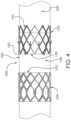
- FIG. 1 Ais a side view a prosthetic valve, according to some embodiments.
- FIG. 1 Bis a side view of a prosthetic valve, according to some embodiments.
- FIG. 1 Cis a perspective view of the prosthetic valve of FIG. 1 A , according to some embodiments;
- FIG. 1 Dis an axial view of the prosthetic valve of FIG. 1 A , according to some embodiments.
- FIG. 2 Ais a side view of a valve frame subcomponent of a medical device, according to some embodiments.
- FIG. 2 Bis an axial view of a valve frame subcomponent of the medical device of FIG. 2 A , according to some embodiments;
- FIG. 3 Ais a side view of an anchor frame subcomponent of a medical device, according to some embodiments.
- FIG. 3 Bis an axial view of the anchor frame subcomponent of the medical device of FIG. 3 A , according to some embodiments;
- FIG. 4is an illustration of a medical system, according to some embodiments.
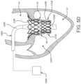
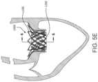
- FIGS. 5 A to 5 Eare cross-sectional views of a heart illustrating an exemplary medical device delivery procedure, according to some embodiments
- FIG. 5 Fis a cross-sectional view of the prosthetic valve constrained onto a delivery catheter and placed within a prosthetic valve orifice, in accordance with an embodiment
- FIG. 5 Gis a cross-sectional view of the prosthetic valve partially deployed from the delivery catheter of FIG. 7 E within the valve orifice of FIG. 5 F , in accordance with an embodiment
- FIG. 5 His a cross-sectional view of the prosthetic valve partially deployed within the prosthetic valve orifice of FIG. 5 F , in accordance with an embodiment
- FIG. 5 Iis a cross-sectional view of the prosthetic valve deployed within the prosthetic valve orifice of FIG. 5 F ;
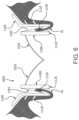
- FIG. 6is cross-sectional view of a medical device deployed in an anatomy, according to some embodiments.
- FIG. 7 Ais a front view of a prosthetic valve with flow enabling features in an open configuration, according to some embodiments.
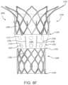
- FIG. 7 Bis a front view of the prosthetic valve of FIG. 7 A with the flow enabling features in a closed configuration, according to some embodiments;
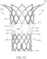
- FIG. 7 Cis a front view of a prosthetic valve with flow enabling features, according to some embodiments.
- FIG. 8 Ais a side view of a prosthetic valve in a delivery configuration, according to some embodiments.
- FIG. 8 Bis a perspective view of the prosthetic valve of FIG. 8 A in a deployed configuration, according to some embodiments;
- FIG. 8 Cis a side view of a prosthetic valve in a delivery configuration, according to some embodiments.
- FIG. 8 Dis a perspective view of the prosthetic valve of FIG. 8 C in a deployed configuration, according to some embodiments.
- FIG. 8 Eis a side view of a prosthetic valve in a delivery configuration, according to some embodiments.
- FIG. 8 Fis a side view of a prosthetic valve in a delivery configuration, according to some embodiments.
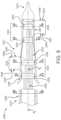
- FIG. 9is a side view of a delivery system, according to some embodiments.
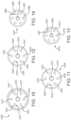
- FIG. 10is a sectional view taken along line 10 - 10 in FIG. 10 , according to some embodiments.
- FIG. 11is a sectional view taken along line 11 - 11 in FIG. 10 , according to some embodiments.
- FIG. 12is a sectional view taken along line 12 - 12 in FIG. 10 , according to some embodiments.
- FIG. 13is a sectional view taken along line 13 - 13 in FIG. 10 , according to some embodiments.
- FIG. 14is a sectional view taken along line 14 - 14 in FIG. 10 , according to some embodiments.
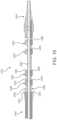
- FIG. 15is a side view of a delivery system, according to some embodiments.
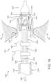
- FIG. 16is a side view of a delivery system, according to some embodiments.
- the present disclosurerelates to prosthetic valves used for cardiac valve replacement or other applications associated with native valve or other valve orifices, and related systems, methods, and apparatuses.
- the prosthetic valveis operable as a one-way prosthetic valve that defines a valve orifice into which leaflets open to permit flow and close so as to block or occlude the valve orifice and partially or entirely prevent flow in response to differential fluid pressure.
- Examples presented hereinprovide a prosthetic valve that includes a valve frame subcomponent, an anchor frame subcomponent, and an interstage therebetween.
- the valve frame subcomponentfurther includes leaflets that operate as a one-way valve.
- the anchor frame subcomponentis operable to couple to an implant site.
- the interstageis operable to permit the translation of the valve frame subcomponent into the anchor frame subcomponent during deployment. Further, in accordance with some embodiments, the interstage is operable to permit perfusion during deployment.
- prosthetic valve orificerefers to a location into which the prosthetic valve may be placed.
- a prosthetic valve orificeincludes a tissue orifice which includes anatomical structures into which a prosthetic valve can be placed.
- Such anatomical structuresinclude, but are not limited to, a location wherein a cardiac valve may or may not have been surgically removed.
- prosthetic valvesinclude, but are not limited to, veins, arteries, ducts and shunts.
- a prosthetic valve orificemay also refer to a location in a synthetic or biological conduit that may receive a prosthetic valve.
- leafletas used in the context of prosthetic valves is generally a flexible component operable to move between an open and closed position under the influence of pressure differentials. For example, in operation, the leaflets open when an inflow fluid pressure exceeds an outflow fluid pressure and close when the outflow fluid pressure exceeds the inflow fluid pressure. In a closed position, the leaflet, alone or in combination with one or more other leaflets, operates to substantially restrict or obstruct (or alternatively completely obstruct) retrograde flow through the prosthetic valve.
- coaptation of adjacent leafletsmay operate to completely block the flow of fluid (e.g., blood) through the prosthetic valve, while in other instances coaptation of adjacent leaflets may operate to block less than all of the flow of fluid (e.g., blood) through the prosthetic valve.
- the leafletsinclude a free edge, and the free edges of adjacently situated leaflets coapt under the influence of outflow fluid pressure, thereby closing the valve so as to restrict or obstruct fluid from flowing retrograde through the prosthetic valve.
- the prosthetic valveprovides a valve frame subcomponent that essentially floats within an anchor frame subcomponent supported by the interstage and does not directly couple with a prosthetic valve orifice.
- the anchor frame subcomponentmay conform to the shape of the prosthetic valve orifice whereas the valve frame subcomponent does not necessarily conform to the shape of the prosthetic valve orifice.
- the valve frame subcomponentmay remain cylindrical or at a preferred geometrical configuration so as to present the leaflets with a geometrically stable platform ensuring proper leaflet function, including coaptation and opening dynamics.
- the prosthetic valveis configured to stow or capture one or more of the native leaflets of a native valve being replaced by the prosthetic valve.
- Such a configurationprovides for a system that minimizes the consequential occlusive effect of the implanted prosthetic valve on downstream or antegrade anatomy distal to the prosthetic valve, as discussed in greater detail herein.
- the examples of the prosthetic valvemay be suitable for either surgical or transcatheter applications
- examples provided hereinare presented as for transcatheter applications to avoid the repetition if surgical examples are also presented. Therefore, the inventive concepts are applicable for both surgical or transcatheter applications and not limited to only transcatheter applications.
- FIG. 1 Ais a side view of the prosthetic valve 1000 in the pre-deployed configuration showing a valve frame subcomponent 1200 , an anchor frame subcomponent 1100 , and an interstage 1302 therebetween in coaxial serial alignment.
- FIG. 1 Bis a side view of the prosthetic valve 1000 in the deployed configuration showing the valve frame subcomponent 1200 translated into the anchor frame subcomponent 1100 , with the interstage 1302 therebetween in nested alignment.
- the valve frame subcomponent 1200provides the prosthetic valve 1000 with the functionality of a one-way valve. It is understood and appreciated that one-way valves are well known in the art and may be used herein. It is appreciated that mechanical valves, biological valves, and biological and synthetic leaflet valves may be used as the one-way valve of the valve frame subcomponent 1200 . It is also appreciated that, for transcatheter applications, the valve frame subcomponent 1200 is required to have a smaller-diameter compressed configuration and a larger-diameter expanded configuration, and that the one-way valve component must be able to accommodate that functionality.
- valve frame subcomponent 1200is configured to be received within at least a portion of the anchor frame subcomponent 1100 , as will be described in more detail below. It will be appreciated that nonlimiting examples of valve frame subcomponents 1200 can be provided with a diameter (e.g., a diameter of an interior or exterior surface of the valve frame subcomponent 1200 ) in a range of between twenty (20) millimeters and thirty (30) millimeters, depending on a patient's anatomy.
- a diametere.g., a diameter of an interior or exterior surface of the valve frame subcomponent 1200
- FIG. 2 Ais a side view of the valve frame 1201 without leaflets 1210 shown for clarity.
- FIG. 2 Bis an axial view of the valve frame 1201 showing the leaflets 1210 therein.
- the side of the valve frame 1201may be at least partially covered, such as with a film or fabric, not shown for clarity, suitable for a particular purpose, such as to restrict fluid from passing through the valve frame 1201 .
- the following examplesare suitable especially for a transcatheter application, but are also suitable for a surgical application.
- the valve frame subcomponent 1200includes a valve frame 1201 and leaflets 1210 .
- the valve frame 1201defines a cylindrical or tubular mesh having a framework defining apertures.
- the valve frame 1201includes a plurality of frame members 1212 that are interconnected and arranged in one or more patterns.
- the frame members 1112are connected to one another at various joints 1214 .
- these joints 1214operate as flex points so as to provide a preferential flexing location for the valve frame subcomponent 1200 , such as to flex when compressed to a smaller delivery diameter such as required for transcatheter delivery.
- a flex point or joint 1214comprises a site on the valve frame 1201 that undergoes a high degree of bending.
- the flex points or joints 1214may comprise a geometry, structural modification or material modification, among others, that biases the valve frame 1201 to bend at the joint 1214 when compressed or expanded between a larger diameter and a smaller.
- one or more closed cell apertures or voids 1216are defined between the joints 1214 and the interconnected frame members 1212 of the valve frame subcomponent 1200 . In some examples, these apertures or voids 1216 extend from the exterior surface 1208 to the interior surface 1206 of the valve frame subcomponent 1200 . As illustrated in the embodiments of FIGS. 2 A and 2 B , one or more of the apertures or voids 1216 define a diamond shape when the valve frame subcomponent 1200 is in a deployed configuration.
- one or more of the joints 1214 and the frame members 1212deform such that the apertures or voids 1216 generally define an elongated diamond shape (e.g., as shown generally in FIG. 4 ).
- the apertures or voids 1216Upon re-expanding the valve frame subcomponent 1200 to a larger diameter during deployment at a treatment site, the apertures or voids 1216 re-expand to define the generally wider diamond shape.
- the interconnected frame members 1212may be arranged in a number of alternative patterns without departing from the spirit or scope of the disclosure. That is, a number of alternative patterns are envisioned where the arrangement of frame members 1212 is configured in such a manner as to provide for an valve frame subcomponent 1200 that can be compressed to a smaller diameter for transcatheter delivery and subsequently expanded (or allowed to expand) to a larger diameter at a treatment site during deployment of the prosthetic valve 1000 . Accordingly, the disclosure should not be limited to arrangements of the frame members 1212 that define diamond-shaped apertures or voids 1216 .
- a framework of the valve frame subcomponent 1200can define any number of features, repeatable or otherwise, such as geometric shapes and/or linear or meandering series of sinusoids. Geometric shapes can comprise any shape that facilitates circumferential compressibility and expandability.
- valve frame subcomponent 1200may comprise or otherwise be formed from a cut tube, or any other element suitable for the particular purpose of the valve frame subcomponent 1200 as described herein.
- the valve frame subcomponent 1200may be etched, cut, laser cut, or stamped into a tube or a sheet of material, with the sheet then formed into a substantially cylindrical structure.
- an elongated materialsuch as a wire, bendable strip, or a series thereof, can be bent or braided and formed into a substantially cylindrical structure wherein the walls of the cylinder comprise an open framework that is compressible to a smaller diameter in a generally uniform and circumferential manner and expandable to a larger diameter as illustrated and described herein.
- the valve frame subcomponent 1200may comprise, such as, but not limited to, any elastically deformable metallic or polymeric biocompatible material, in accordance with embodiments.
- the valve frame subcomponent 1200may comprise a shape-memory material, such as nitinol, a nickel-titanium alloy.
- Other materials suitable for the valve frame subcomponent 1200include, but are not limited to, other titanium alloys, stainless steel, cobalt-nickel alloy, polypropylene, acetyl homopolymer, acetyl copolymer, other alloys or polymers, or any other biocompatible material having adequate physical and mechanical properties to function as a valve frame subcomponent 1200 as described herein.
- valve frame subcomponent 1200is elastically deformable so as to be self-expanding under spring loads, as those of skill will appreciate.
- the valve frame subcomponent 1200is plastically deformable so as to be mechanically expanded such as with a balloon, as those of skill will appreciate.
- the valve frame subcomponent 1200is plastically deformable as well as elastically deformable. That is, in some examples, the valve frame subcomponent 1200 includes one or more elastically deformable components or features and one or more plastically deformable components or features.
- the examples of the valve frame subcomponent 1200 presented hereinare not to be limited to a specific design or mode of expansion.
- the valve frame subcomponent 1200comprises a shape memory material operable to flex under load and retain its original shape when the load is removed, thus allowing the valve frame subcomponent 1200 to self-expand from a compressed shape to a predetermined shape.
- the valve frame subcomponent 1200 and the anchor frame subcomponent 1100may comprise the same or different materials.
- the valve frame subcomponent 1200is plastically deformable to be expanded by a balloon. In another embodiment the valve frame subcomponent 1200 is elastically deformable so as to be self-expanding.
- FIG. 3 Ais a side view of the anchor frame 1101 .
- FIG. 3 Bis an axial view of the anchor frame 1100 .
- the anchor frame subcomponent 1100includes an anchor frame 1101 .
- the side of the anchor frame 1101may be at least partially covered, such as with a film or fabric, not shown for clarity, suitable for a particular purpose, such as to restrict fluid from passing through the anchor frame 1101 , or to encourage tissue ingrowth at the implant site.
- the following examplesare suitable especially for a transcatheter application, but are also suitable for a surgical application.
- the anchor frame subcomponent 1100comprises a shape memory material operable to flex under load and retain its original shape when the load is removed, thus allowing the anchor frame subcomponent 1100 to self-expand from a compressed shape to a predetermined larger shape.
- the anchor frame subcomponent 1100may comprise the same or different materials as the valve frame subcomponent 1200 .
- the anchor frame subcomponent 1100is plastically deformable to be expanded by a balloon.
- the anchor frame subcomponent 1100is elastically deformable so as to be self-expanding.
- the interstage 1300includes a conduit 1302 that couples to an anchor frame distal end 1104 of the anchor frame 1100 at an interstage proximal end 1314 and couples to a leaflet frame proximal end 1202 at an interstage distal end 1316 .
- the conduit 1302may comprise any suitable material known in the art.
- the conduit 1302may be a film, fabric, among others.
- filmis use throughout this disclosure, it is understood that the term includes film, fabric, and other suitable materials.
- the interstage 1300further comprises a nesting retention element 1330 , such as shown in FIGS. 7 C- 7 E , to be described below, that is operable to retain the valve frame subcomponent 1200 as nested in the anchor frame subcomponent 1100 .
- nesting retention elements 1330are provided below.
- the nesting retention elements 1330may be elongated elements that bias the interstage 1300 in the nesting position.
- the nesting retention elements 1330are caused to evert during the deployment process of translating the valve frame subcomponent 1200 into the anchor frame subcomponent 1100 .
- the nesting retention elements 1330are provided with a predetermined stiffness or other property sufficient to permit eversion during deployment but not under normal biological forces.
- the nesting retention elements 1330are sized such that, when the anchor frame subcomponent 1100 is expanded and the valve frame subcomponent is compressed, the nesting retention elements 1330 are able to rotate lengthwise from a forward facing orientation to a backward facing orientation.
- the nesting retention elements 1330When the valve frame subcomponent 1200 is expanded, the nesting retention elements 1330 have a profile or length that prevents the nesting retention elements 1330 from rotating or flipping back to a forward facing orientation.
- the gap between the anchor frame subcomponent 1100 and the valve frame subcomponent 1200is too narrow to allow end over end rotation of the nesting retention elements 1330 .
- the nesting retention elements 1330are provided with a predetermined stiffness or other property sufficient to prevent eversion of the nesting retention elements 1330 within the gap between the anchor frame subcomponent 1100 and the valve frame subcomponent 1200 under normal biological forces.
- FIG. 1 Cis a perspective view showing the valve frame subcomponent 1200 and an anchor frame subcomponent 1100 of a prosthetic valve 1000 in a nested configuration, also referred to as the deployed position, leaflets not shown for clarity.
- FIG. 1 Bis a front view of the valve frame subcomponent 1200 and the anchor frame subcomponent 1100 of the prosthetic valve 1000 of FIG. 1 C . In both FIGS. 1 B and 1 C , the leaflets and any film, as will be discussed below, are not shown for clarity.
- FIG. 1 Dis an axial view of the valve frame subcomponent 1200 and the anchor frame subcomponent 1100 of the prosthetic valve 1000 of FIG. 1 A , showing the leaflets 1210 . In the axial view of FIG.
- valve frame subcomponent 1200three leaflets 1210 are shown coupled to the valve frame subcomponent 1200 . It is in this deployed position that the prosthetic valve 1000 remains in the prosthetic valve orifice to function as a prosthetic valve.
- the anchor frame subcomponent 1100 and the valve frame subcomponent 1200are longitudinally offset and generally coaxial relative to one another.
- a prosthetic valve 1000includes an anchor frame 1102 , and a valve frame 1202 .
- the valve frame subcomponent 1200onto which leaflets 1020 are coupled, is positioned at least partially within the anchor frame subcomponent 1100 .
- the prosthetic valve 1000has a proximal end or proximal portion 1002 and a distal end or distal portion 1004 .
- the proximal portion 1002 of the prosthetic valve 1000when deployed within the body, the proximal portion 1002 of the prosthetic valve 1000 is positioned upstream or retrograde relative to the distal portion 1004 of the prosthetic valve 1000 , which is positioned downstream or antegrade relative to the proximal portion 1002 .
- the anchor frame subcomponent 1100 and the valve frame subcomponent 1200are coupled together.
- a interstage 1300is disposed within and/or about the anchor frame subcomponent 1100 and the valve frame subcomponent 1200 .
- the interstage 1300is a contiguous film that at least extends between and operates to couple the anchor frame subcomponent 1100 and the valve frame subcomponent 1200 to one another.
- the interstage 1300extends not only between but also over or within either or both of the anchor frame subcomponent 1100 and the valve frame subcomponent 1200 .
- the portion of the interstage 1300 that extends between and couples with the anchor frame subcomponent 1100 and the valve frame subcomponent 1200is referred herein as the interstage portion 1302 .
- the interstage 1300is formed from a generally tubular material and at least partially covers one or more of the anchor frame subcomponent 1100 and the valve frame subcomponent 1200 .
- the interstage 1300is formed by wrapping a film over and around a cylindrical mandrel, with either or both of the anchor frame subcomponent 1100 and the valve frame subcomponent 1200 being slid over and bonded thereto to the inner surface of the frames.
- the interstage 1300is formed by wrapping the film over and around either or both of the anchor frame subcomponent 1100 and the valve frame subcomponent 1200 and bonded thereto to the outer surface of the frames.
- anchor frame subcomponent 1100 and the valve frame subcomponent 1200are comprised of metal
- Such configurationsminimize the potential for metals of varying composition to react with one another or corrode.
- the interstage 1300is generally any sheet-like material that is biologically compatible and configured to couple to the anchor frame subcomponent 1100 and the valve frame subcomponent 1200 .
- the biocompatible materialis a film that is not of a biological source and that is sufficiently flexible and strong for the particular purpose, such as a biocompatible polymer.
- the filmcomprises a biocompatible polymer (e.g., ePTFE).
- the filmis a composite of two or more materials.
- the filmmay comprise one or more of a membrane, composite material, or laminate.
- the construction of and materials used in the filmare such that the interstage 1300 promotes cellular ingrowth, adhesion, and/or attachment.
- the interstage 1300is constructed in a manner that promotes the ingrowth of tissue into one or more portions of the film. It will be appreciated that cellular ingrowth further increases sealing of the valve with the prosthetic valve orifice and helps minimize para-valvular leakage, that is, leakage between the prosthetic valve and the tissue into which it is coupled.
- the valve frame subcomponent 1200additionally supports or otherwise includes a valve structure.
- the valve structureincludes one or more leaflets 1210 as shown in FIG. 1 D .
- leaflets 1210as shown in FIG. 1 D .
- a variety of mechanical valve, biological leaflet, and synthetic leaflet designsare known in the medical technology arts, any of which may be incorporated into the valve frame subcomponent 1200 of the present disclosure. Examples of suitable leaflet constructions and methods of attachment to valve frame subcomponents are illustrated and described in U.S. patent application Ser. Nos. 13/833,650, 14/973,589, and 14/622,599, the contents of each of which are incorporated herein by reference. Further examples of suitable leaflet material are presented below.
- valve or leaflets 1020are coupled to the interior surface 1206 of the valve frame subcomponent 1200 .
- a film that comprises a leafletis contained between the valve frame subcomponent 1200 and the anchor frame subcomponent 1100 and extends through a leaflet window defined by the valve frame subcomponent 1200 .
- Such a configurationminimizes a potential for the leaflet to peel or delaminate, as compared to configurations where the leaflets are coupled to the interior surface 1206 of the valve frame subcomponent 1200 .
- one or more portions of the leafletsare wrapped about one or more portions of the valve frame subcomponent 1200 .
- the valve frame subcomponent 1200includes one or more projections and the leaflets 1020 include one or more apertures that are configured to be disposed about the one or more projections.
- the valve frame subcomponent 1200is nestable within the anchor frame subcomponent 1100 .
- the anchor frame subcomponent 1100 and the valve frame subcomponent 1200are sized and shaped in a manner that provides for the valve frame subcomponent 1200 being coaxially disposable or receivable at least partially within the anchor frame subcomponent 1100 .
- the anchor frame subcomponent 1100is configured such that a portion of (or alternatively all of) the valve frame subcomponent 1200 can be received by or otherwise positioned within a space defined by the anchor frame subcomponent 1100 .
- the valve frame subcomponent 1200is sized such that a diameter of the exterior surface of the valve frame subcomponent 1200 is less than a diameter of the interior surface of the anchor frame subcomponent 1100 . In some examples, a diameter of the exterior surface of the valve frame subcomponent 1200 is in a range of between seventy five percent (75%) and ninety percent (90%) of a diameter of the interior surface of the anchor frame subcomponent 1100 . In some examples, a diameter of the exterior surface of the valve frame subcomponent 1200 is seventy five percent (75%) or less than a diameter of the interior surface of the anchor frame subcomponent 1100 .
- valve frame subcomponent 1200can be received within the anchor frame subcomponent 1100 .
- anchor frame subcomponent 1100can deform, such as, but not limited to being out of round or generally oval-shaped, to accommodate or otherwise conform to the prosthetic valve orifice without causing a deformation of the valve frame subcomponent 1200 .
- the prosthetic valve 1000provides a valve frame subcomponent 1200 that essentially floats within the anchor frame subcomponent 1100 and does not directly couple with a prosthetic valve orifice.
- the anchor frame subcomponent 1100may conform to the shape of the prosthetic valve orifice whereas the valve frame subcomponent 1200 does not conform to the shape of the prosthetic valve orifice.
- the valve frame subcomponent 1200remains cylindrical or at a preferred geometrical configuration so as to present the leaflets 1210 with a geometrically stable platform ensuring proper leaflet function, including coaptation and opening dynamics. It is appreciated that these benefits associated with the valve frame subcomponent 1200 not needing to conform to the prosthetic valve orifice may be realized in either transcatheter or surgical placement of the prosthetic valve 1000 .
- the prosthetic valve 1000is configured such that the anchor frame subcomponent 1100 and the valve frame subcomponent 1200 can be nested in-situ after the anchor frame subcomponent 1100 and the valve frame subcomponent 1200 are deployed at a treatment site in a patient's anatomy. That is, in various embodiments, the prosthetic valve 1000 can be delivered to a treatment region within a patient's anatomy with the anchor frame subcomponent 1100 and the valve frame subcomponent 1200 longitudinally offset relative to one another and subsequently nested with one another at the treatment site.
- the prosthetic valve 1000is loaded onto a delivery catheter with the anchor frame subcomponent 1100 and the valve frame subcomponent 1200 longitudinally offset relative to one another which presents a lower profile or diameter than if the prosthetic valve 1000 were to be loaded onto the delivery catheter in the nested configuration.
- a lower delivery profile of a transcatheter delivered prosthetic valvehas well recognized advantages, including easier advancement though vessels.
- valve frame subcomponent 1200may also be realized in surgical placement of the prosthetic valve 1000 .
- the anchor frame subcomponent 1100may be more easily sutured into the prosthetic valve orifice without the valve frame subcomponent 1200 being within the anchor frame subcomponent 1100 and in close proximity to the suturing procedure lessening the chance of needle damage to the leaflets.
- the anchor frame subcomponent 1100 and the valve frame subcomponent 1200are operable to nest with one another by telescoping the anchor frame subcomponent 1100 and the valve frame subcomponent 1200 relative to one another in-situ.
- the valve frame subcomponent 1200 and the anchor frame subcomponent 1100are sized such that the valve frame subcomponent 1200 can be receive within the interior region 1110 of the anchor frame subcomponent 1100 .
- the anchor frame subcomponent 1100 , the valve frame subcomponent 1200 , and the film 1300are each configured to be compressed or collapsed to a delivery profile and then reexpanded in-situ to provide for transcatheter delivery of the prosthetic valve 1000 , as discussed in greater detail below.
- FIGS. 2 A and 2 Bare side and axial views, respectively, of the anchor frame subcomponent 1100 , in accordance with an embodiment.
- the anchor frame subcomponent 1100is a generally tubular member having a proximal end 1102 , a distal end 1104 , an interior surface 1106 , and an exterior surface 1108 .
- the anchor frame subcomponent 1100defines an interior region 1110 .
- the interior region 1110is a generally cylindrical void defined between the proximal and distal ends 1102 and 1104 , and the interior surface 1106 of the anchor frame subcomponent 1100 .
- the interior region 1110may adopt an irregular cross section, depending on the geometry of the prosthetic valve orifice.
- the anchor frame subcomponent 1100is configured to couple to a native valve orifice. Accordingly, in various examples, a diameter of the anchor frame subcomponent 1100 (e.g., a diameter of an interior or exterior surface of the anchor frame subcomponent 1100 ) is sized in accordance with patient anatomy. It will be appreciated that nonlimiting examples of anchor frame subcomponents 1100 can be provided with a diameter (e.g., a diameter of an interior or exterior surface of the anchor frame subcomponent 1100 ) in a range of between twenty five (25) millimeters and fifty (50) millimeters, depending on a patient's anatomy.
- anchor frame subcomponents 1100 having diameterse.g., a diameter of an interior or exterior surface of the anchor frame subcomponent 1100 ) in excess of fifty (50) millimeters are also envisioned and fall within the scope of the present disclosure, depending on patient anatomy.
- the anchor frame subcomponent 1100defines a cylindrical or tubular mesh having a framework defining apertures.
- the anchor frame subcomponent 1100includes a plurality of frame members 1112 that are interconnected and arranged in one or more patterns. In some examples, these patterns repeat one or more times.
- the frame members 1112are arranged and interconnected such that the anchor frame subcomponent 1100 includes a plurality of patterned rows. In various examples, the frame members 1112 are connected to one another at various joints 1114 .
- these joints 1114operate as flex points so as to provide a preferential flexing location for the anchor frame subcomponent 1100 to flex when compressed to a smaller delivery diameter and when forces from the surrounding anatomy act to compress the anchor frame subcomponent 1100 during normal operation after delivery and deployment of the prosthetic valve 1000 .
- a flex point or joint 1114comprises a site on the anchor frame subcomponent 1100 that undergoes a high degree of bending.
- the joints 1114may comprise a geometry, structural modification or material modification, among others, that biases the anchor frame subcomponent 1100 to bend at the flex point or joint 1114 when compressed.
- one or more closed cell apertures or voids 1116are defined between the joints 1114 and the interconnected frame members 1112 of the anchor frame subcomponent 1100 . In some examples, these apertures or voids 1116 extend from the exterior surface 1108 to the interior surface 1106 of the anchor frame subcomponent 1100 . As illustrated in the embodiments of FIGS. 2 A and 2 B , one or more of the apertures or voids 1116 define a diamond shape when the anchor frame subcomponent 1100 is in a deployed configuration.
- one or more of the joints 1114 and the frame members 1112deform such that the apertures or voids 1116 generally define an elongated diamond shape (e.g., as shown generally in FIG. 4 A ).
- the apertures or voids 1116Upon re-expanding the anchor frame subcomponent 1100 to a larger diameter during deployment at a treatment site, the apertures or voids 1116 re-expand to define the generally wider diamond shape.
- the anchor frame subcomponent 1100defines a flange or a flared portion at its proximal end 1102 that flares or tapers radially outward when in the deployed configuration.
- the proximal end 1102is flared or otherwise tapered radially outward when in the deployed configuration. That is, as shown, the proximal end 1102 of the anchor frame subcomponent 1100 has a larger deployed diameter than does the distal end 1104 of the anchor frame subcomponent 1100 .
- such a configurationoperates to minimize migration risks and helps facilitate abutment of the anchor frame subcomponent 1100 with native tissue at the treatment site.
- a framework of the anchor frame subcomponent 1100can define any number of features, repeatable or otherwise, such as geometric shapes and/or linear or meandering series of sinusoids. Geometric shapes can comprise any shape that facilitates circumferential compressibility and expandability of the anchor frame subcomponent 1100 .
- the arrangement of frame members 1112is configured in such a manner as to provide for an anchor frame subcomponent 1100 that can be compressed to a smaller diameter for transcatheter delivery and subsequently expanded (or allowed to expand) to a larger diameter at a treatment site during deployment of the prosthetic valve 1000 . Accordingly, the disclosure should not be read as being limited to arrangements of the frame members 1112 that define diamond-shaped apertures or voids 1116 .
- the anchor frame subcomponent 1100may comprise or otherwise be formed from a cut tube, or any other element suitable for the particular purpose of the anchor frame subcomponent 1100 as described herein.
- the anchor frame subcomponent 1100may be etched, cut, laser cut, or stamped into a tube or a sheet of material, with the sheet then formed into a substantially cylindrical structure.
- an elongated materialsuch as a wire, bendable strip, or a series thereof, can be bent or braided and formed into a substantially cylindrical structure wherein the walls of the cylinder comprise an open framework that is compressible to a smaller diameter in a generally uniform and circumferential manner and expandable to a larger diameter as illustrated and described herein.
- the anchor frame subcomponent 1100can comprise any metallic or polymeric biocompatible material.
- the anchor frame subcomponent 1100can comprise a material, such as, but not limited to nitinol, cobalt-nickel alloy, stainless steel, or polypropylene, acetyl homopolymer, acetyl copolymer, ePTFE, other alloys or polymers, or any other biocompatible material having adequate physical and mechanical properties to function as described herein.
- the anchor frame subcomponent 1100is elastically deformable so as to be self-expanding under spring loads, as those of skill will appreciate.
- the anchor frame subcomponent 1100is plastically deformable so as to be mechanically expanded such as with a balloon, as those of skill will appreciate.
- the anchor frame subcomponent 1100is plastically deformable as well as elastically deformable. That is, in some examples, the anchor frame subcomponent 1100 includes one or more elastically deformable components or features and one or more plastically deformable components or features.
- the examples of the anchor frame subcomponent 1100 presented hereinare not to be limited to a specific design or mode of expansion.
- the anchor frame subcomponent 1100is configured to provide positive engagement with an implant site to firmly anchor the prosthetic valve 1000 to the site.
- the anchor frame subcomponent 1100includes one or more tissue engagement features 1118 that are configured to engage one or more regions of tissue at the prosthetic valve orifice surrounding the prosthetic valve 1000 .
- the tissue engagement features 1118comprise one or more barbs or tissue anchors.
- the one or more tissue engagement features 1118project away from the interior and/or exterior surfaces 1106 and 1108 of the anchor frame subcomponent 1100 , radially outward from a longitudinal axis of the anchor frame subcomponent 1100 , and toward the tissue surrounding the prosthetic valve 1000 .
- the tissue engagement features 1118are operable to project away from the anchor frame subcomponent 1100 when the anchor frame subcomponent 1100 is deployed (e.g., when a constraining member is withdrawn or otherwise removed).
- the tissue engagement features 1118are operable to engage the tissue proximate the anchor frame subcomponent 1100 such that the tissue engagement features 1118 secure the anchor frame subcomponent 1100 to the surrounding tissue, as will be discussed in greater detail below.
- the tissue engagement featuresproject away from an exterior surface of the anchor frame subcomponent in a range of between thirty (30) and sixty (60) degrees. In some such examples, the tissue engagement features project away from an exterior surface of the anchor frame subcomponent at an angle of approximately forty five (45) degrees, though other configurations are contemplated and fall within the scope of the present application. Generally, any angle of projection is suitable provided that the tissue engagement features operate for their intended purpose of engaging the tissue surrounding the anchor frame subcomponent and causing the anchor frame subcomponent to be secured to the surrounding tissue.
- tissue engagement featuresmay include a variety of different lengths (depending on the angle from which they project from the anchor frame subcomponent), it will be appreciated that the tissue engagement features are of a length suitable for engaging tissue and securing the anchor frame subcomponent to the surrounding tissue, but not so long as to risk detrimental damage to the prosthetic valve orifice.
- One nonlimiting example configurationincludes tissue engagement features projecting from the anchor frame subcomponent in a range of between thirty (30) and sixty (60) degrees and having a length of between fifty (50) micron and two hundred (200) micron.
- the tissue engagement features 1118are positioned along the anchor frame subcomponent such that they are operable to engage tissue proximate the anchor frame subcomponent 1100 when the anchor frame subcomponent 1100 is expanded in-situ.
- the tissue engagement features 1118may be arranged in one or more rows along a longitudinal axis of the anchor frame subcomponent 1100 . That is, in various examples, anchor frame subcomponent may include a first set (or row) of anchors and a second set (or row) of anchors longitudinally offset relative to the first set of anchors. In one such example, the first set of anchors is more proximate the distal end 1104 of the anchor frame subcomponent 1100 than is the second set of anchors.
- the one or more tissue engagement features 1118are circumferentially arranged about the anchor frame subcomponent 1100 . In some examples, the one or more tissue engagement features 1118 are evenly dispersed about the circumference of the anchor frame subcomponent. For example, the tissue engagement features 1118 are dispersed about the frame and are offset from one another by ninety (90) degrees depending on the number of anchors. Alternatively, the tissue engagement features 1118 may be dispersed about the frame and offset from one another by sixty (60) degrees depending on the number of anchors. Generally, the angular offset between the anchors is a function of the number of anchors dispersed about the anchor frame subcomponent 1100 , as those of skill will appreciate. In some examples, the angular offset between the anchors is additionally or alternatively based on an arrangement or pattern of the frame members 1112 .
- tissue engagement features 1118project away from the anchor frame subcomponent 1100 when the anchor frame subcomponent 1100 is in the deployed configuration
- the tissue engagement features 1118are stowed or do not otherwise project away from the anchor frame subcomponent 1100 when the anchor frame subcomponent 1100 is compressed in the delivery configuration.
- the tissue engagement features 1118are stowable during delivery and are configured to transition to a deployed configuration where they project away from the anchor frame subcomponent 1100 .
- a constraining member disposed about the anchor frame subcomponent 1100 during deliveryfacilitates stowing of the tissue engagement features 1118 .
- the tissue engagement features 1118are stowed in associated apertures or voids 1116 of the anchor frame subcomponent 1100 .
- the tissue engagement features 1118are integral to the anchor frame subcomponent 1100 .
- one or more of the tissue engagement features 1118are formed in conjunction with and from the same material as the frame members 1112 .
- one or more of the tissue engagement features 1118are separate components additionally or alternatively coupled or attached to the anchor frame subcomponent 1100 .
- some non-limiting examplesinclude crimping and/or welding one or more tissue engagement features to the anchor frame subcomponent 1100 .
- the flared or tapered portion of the anchor frame subcomponent 1100is configured to deflect when the anchor frame subcomponent 1100 is in the delivery configuration.
- the flared or tapered proximal end 1102 of the anchor frame subcomponent 1100is deflected such that the anchor frame subcomponent 1100 has a substantially uniform delivery profile along its longitudinal axis.
- one or more constraining membersare disposed about the anchor frame subcomponent 1100 in the delivery configuration.
- a first constraining memberis disposed about the proximal end 1102 of the anchor frame subcomponent 1100 and a second constraining member is disposed about the distal end 1104 of the anchor frame subcomponent 1100 , as will be described in more detail when referring to FIGS. 9 - 16 .
- Each constraining membermay extend about an exterior surface 1108 of the anchor frame subcomponent 1100 , or one or more of the constraining members may be woven through one or more portions of the film disposed about the anchor frame subcomponent 1100 .
- one or more of the constraining members extending about the exterior surface 1108may extend through a portion of the film, and extend along a portion of the interior surface 1106 of the anchor frame subcomponent 1100 , and then extend back through the film to the exterior surface 1108 and extend therearound.
- the one or more constraining membersindividually or collectively operate to constrain the anchor frame subcomponent 1100 in a delivery configuration. In various examples, this includes one or more constraining members individually or collectively constrains the flange or flared portion of the anchor frame subcomponent 1100 in a delivery configuration.
- a removable constraining sheathis disposed about the flange or flared portion of the anchor frame subcomponent 1100 in a delivery configuration.
- the delivery systemmay include one or more flange stops (see e.g., flange stop 1562 in FIG. 16 ).
- the flange stopsoperate to constrain the anchor frame subcomponent 1100 from translating proximally as a constraining sheath (see, e.g., constraining sheath 1564 in FIG. 16 ) is withdrawn from one or more of the anchor frame subcomponent 1100 and the valve frame subcomponent 1200 .
- one or more constraining membersindividually or collectively constrain the tissue engagement features to a delivery (undeployed) configuration.
- a removable constraining sheathis disposed about the tissue engagement features of the anchor frame subcomponent 1100 .
- the one or more constraining membersare removed from the anchor frame subcomponent 1100 during deployment of the anchor frame subcomponent 1100 .
- the constraining membersincludes a fiber.
- the constraining membersincludes a wire.
- one or more lockwiresengage a first end of the one or more constraining members at or proximate the anchor frame subcomponent 1100 such that tension can be applied to an opposing second end of the one or more constraining members.
- tensioning the one or more constraining membersoperates to maintain the anchor frame subcomponent 1100 in the delivery configuration.
- one or more constraining membersare disposed about the valve frame subcomponent 1200 in the delivery configuration, as will be described in more detail when referring to FIGS. 9 - 16 .
- a third constraining memberis disposed about the proximal end 1202 of the valve frame subcomponent 1200 and a fourth constraining member is disposed about the distal end 1204 of the valve frame subcomponent 1200 .
- Each constraining membermay extend about an exterior surface 1208 of the valve frame subcomponent 1200 .
- one or more of the constraining membersmay be woven through one or more portions of the film disposed about the valve frame subcomponent 1200 .
- one or more of the constraining members extending about the exterior surface 1208may extend through a portion of the film, and extend along a portion of the interior 1206 of the valve frame subcomponent 1200 , and then extend back through the film to the exterior surface 1206 and extend therearound.
- the one or more constraining membersindividually or collectively operate to constrain the valve frame subcomponent 1200 in a delivery configuration.
- one or more constraining membersindividually or collectively constrain the tissue retention features to a delivery (undeployed) configuration.
- a removable constraining sheathis disposed about the tissue engagement features of the valve frame subcomponent 1200 .
- the removable constraining sheathmay be disposed about both the valve frame subcomponent 1200 and the anchor frame subcomponent 1100 (see discussion above).
- the one or more constraining membersare removed from the valve frame subcomponent 1200 during deployment of the valve frame subcomponent 1200 .
- the constraining membersincludes a fiber.
- the constraining membersincludes a wire.
- one or more lockwiresengage a first end of the one or more constraining members at or proximate the valve frame subcomponent 1200 such that tension can be applied to an opposing second end of the one or more constraining members.
- tensioning the one or more constraining membersoperates to maintain the valve frame subcomponent 1200 in the delivery configuration.
- the anchor frame subcomponent 1100in addition to facilitating a positive engagement with an implant site to anchor the prosthetic valve 1000 to the surrounding tissue, additionally or alternatively includes one or more mechanisms that facilitate a positive engagement with the valve frame subcomponent 1200 upon nesting the anchor frame subcomponent 1100 and the valve frame subcomponent 1200 .
- the anchor frame subcomponent 1100includes one or more interlock features 1120 that project into the interior region 1110 of the anchor frame subcomponent 1100 . These interlock features 1120 are configured to engage the nested valve frame subcomponent 1200 and maintain a relative axial position (or at least minimize relative axial movement) between the anchor frame subcomponent 1100 and the valve frame subcomponent 1200 .
- the interlock features 1120are structures that project or otherwise extend away from the interior and exterior surfaces 1106 and 1108 of the anchor frame subcomponent 1100 and toward the interior region 1110 defined by the anchor frame subcomponent 1100 .
- the one or more interlock features 1120are in the form of one or more tabs.
- the one or more interlock features 1120have a free end 1122 and a base 1124 .
- the free end 1122is an end that is not otherwise coupled to or mated with the anchor frame subcomponent 1100 .
- the base 1124is generally the portion of the interlock feature that couples to or is otherwise integral with the anchor frame subcomponent 1100 .
- the free end 1122is operable to move relative to the anchor frame subcomponent 1100 , while the base 1124 is coupled to the anchor frame subcomponent 1100 .
- the non-limiting exemplary interlock features 1120 illustrated in FIGS. 2 A and 2 Bare each elongate elements.
- the free end 1122is illustrated as being a generally blunt or round end, though the free end 1122 or the interlock feature 1120 , generally, may alternatively be pointed or possess other suitable geometry such as a curved shape (e.g., an s-shape).
- a curved shapee.g., an s-shape
- other geometries suitable for engaging the valve frame subcomponent 1200 when it is nested with the anchor frame subcomponent 1100 in the manner illustrated and described hereinare envisioned and may be utilized without departing from the spirit or scope of the disclosure.
- the free end 1122 of the interlock feature 1120is shaped such that it is operable to slide along the exterior of the valve frame subcomponent 1200 .
- a filme.g., film 1300
- the free end 1122 of the interlock feature 1120is shaped and sized in a manner that allows the interlock feature 1120 to slide along the exterior of the valve frame subcomponent 1200 without binding.
- the interlock feature 1120is approximately six hundred micron in length and is angled at approximately forty five (45) degrees relative to the interior of the anchor frame subcomponent. It will be appreciated, however, that a number of angle and length configurations are contemplated and fall within the scope of the present application.
- the interlock features 1120may be arranged in one or more rows along a longitudinal axis of the anchor frame subcomponent 1100 . That is, in various examples, anchor frame subcomponent 1100 may include a first set (e.g., a row) of interlock features and a second set (e.g., a row) of interlock features longitudinally offset relative to the first set of interlock features. In one such example, the first set of interlock features is more proximate the distal end 1104 of the anchor frame subcomponent 1100 than is the second set of interlock features.
- the interlock features 1120are configured to project away from the anchor frame subcomponent 1100 when the anchor frame subcomponent 1100 is in the deployed configuration, the interlock features 1120 are stowed or do not otherwise project away from the anchor frame subcomponent 1100 when the anchor frame subcomponent 1100 is compressed in the delivery configuration.
- the interlock features 1120are configured to transition between a stowed or delivery configuration and a projecting or deployed configuration.
- the interlock features 1120are resilient members that are configured to deflect under certain conditions.
- the interlock features 1120are configured to engage the valve frame subcomponent 1200 as it is nested with the anchor frame subcomponent 1100 in-situ. In some examples, as discussed further below, the interlock features 1120 temporarily deflect from an engaged position to enable nesting of the valve frame subcomponent 1200 with the anchor frame subcomponent 1100 , and subsequently return to the engaged position after the valve frame subcomponent 1200 is nested with the anchor frame subcomponent 1100 . In various examples, the interlock features 1120 return to the engaged position upon the valve frame subcomponent 1200 being proximally advanced a suitable amount relative to the anchor frame subcomponent 1100 .
- the interlock features 1120 of the anchor frame subcomponent 1100are operable to adopt an engaged position where they engage the valve frame subcomponent 1200 and minimize relative axial translation between the valve frame subcomponent 1200 and the anchor frame subcomponent 1100 upon proximally advancing the valve frame subcomponent 1200 a designated amount relative to the anchor frame subcomponent 1100 .
- a delivery catheter upon which the anchor frame subcomponent 1100 is loaded during deliverycauses stowing of the interlock features 1120 .
- the interlock features 1120are integral to the anchor frame subcomponent 1100 .
- one or more of the interlock features 1120are formed in conjunction with and from the same material as the frame members 1112 .
- one or more of the interlock features 1120are additionally or alternatively coupled to the anchor frame subcomponent 1100 . That is, in some examples, one or more interlock features 1120 are additionally or alternatively attached to the anchor frame subcomponent 1100 .
- the one or more interlock features 1120are circumferentially arranged about the anchor frame subcomponent 1100 . In some examples, the one or more interlock features 1120 are evenly dispersed about the circumference of the anchor frame subcomponent.
- the angular offset between the anchorsis generally a function of one or more of the arrangement of the frame members 1112 and the number of anchors dispersed about the anchor frame subcomponent 1100 , as those of skill will appreciate.
- valve frame subcomponentincludes one or more interlock features (not shown) that extend from the exterior surface 1208 away from the interior surface 1206 of the valve frame subcomponent 1200 and that are operable to engage the anchor frame subcomponent 1100 upon nesting of the anchor frame subcomponent 1100 and the valve frame subcomponent 1200 .
- the interlock features of the valve frame subcomponent 1200are positionable at a proximal end 1202 , a distal end 1204 , or some position between the proximal and distal ends 1202 and 1204 provided that the interlock features of the valve frame subcomponent are operable to engage the anchor frame subcomponent 1100 upon nesting of the anchor frame subcomponent 1100 and the valve frame subcomponent 1200 .
- the interlock features of the valve frame subcomponentare deflectable and stowable in a manner similar to the interlock features 1120 of the anchor frame subcomponent 1100 , as previously described.
- FIGS. 3 A and 3 Bare side and axial views, respectively, of the valve frame subcomponent 1200 , in accordance with an embodiment.
- the valve frame subcomponent 1200is generally cylindrical or tubular member having a proximal end 1202 , a distal end 1204 , an interior surface 1206 , and an exterior surface 1208 .
- the valve frame subcomponent 1200defines an interior region 9999 .
- interior regionis a generally cylindrical void defined between the proximal and distal ends 1202 and 1204 , and the interior surface 1206 of the valve frame subcomponent 1200 .
- the valve frame subcomponent 1200is configured to be received within at least a portion of the anchor frame subcomponent 1100 , as mentioned above.
- valve frame subcomponents 1200can be provided with a diameter (e.g., a diameter of an interior or exterior surface of the valve frame subcomponent 1200 ) in a range of between twenty (20) millimeters and thirty (30) millimeters, depending on a patient's anatomy.
- the valve frame subcomponent 1200includes one or more features that operate to grab or otherwise interface with native valve tissue (e.g., native leaflet tissue) or tissue surrounding the native valve being replaced.
- native valve tissuee.g., native leaflet tissue
- the valve frame subcomponent 1200includes one or more tissue retention features 1218 (also referred to herein as tissue graspers).
- tissue retention features 1218are projections of the valve frame subcomponent 1200 that are configured to interface with the patient's native tissue associated with the native valve.
- the one or more tissue retention features 1218are configured to engage the native tissue and cause it to be secured between the anchor frame subcomponent 1100 and the valve frame subcomponent 1200 as the anchor frame subcomponent 1100 and the valve frame subcomponent are nested together in-situ, as discussed in greater detail below.
- Such a configurationprovides that the native tissue does not interfere with or otherwise obstruct the flow of fluid (e.g., blood) downstream or antegrade to the prosthetic valve 1000 after the prosthetic valve 1000 has been deployed.
- fluide.g., blood
- mitral valve repair/augmentation proceduresfor example, the capture and securement of at least the native anterior leaflet of the native mitral valve minimized that potential for the native anterior leaflet to deflect into the left ventricle and create a left ventricle outflow tract obstruction.
- the one or more tissue retention features 1218are configured to interface with one or more of the native leaflets associated with the native valve.
- mitral valve repair/augmentation proceduresare discussed herein, it will be appreciated that the scope of the disclosure applies to repair/augmentation of the atrioventricular (AV) valves and the semilunar (SL) valves. The disclosure should therefore not be interpreted as being limited to mitral valve repair/augmentation.
- the tissue retention features 1218are structures that project or otherwise extend away from the interior and exterior surfaces 1206 and 1208 of the valve frame subcomponent 1200 and toward the tissue surrounding the prosthetic valve 1000 (e.g., the native valve orifice).
- the one or more tissue retention features 1218are in the form of one or more tabs.
- the one or more tissue retention features 1218are looped features having an apex and two ends, wherein the two ends are coupled to, integral with, extend from, or otherwise terminate into one or more portions of the valve frame subcomponent 1200 .
- the apexis a free end that is operable to deflect and project away from the valve frame subcomponent 1200 , as mentioned below.
- the one or more tissue retention features 1218have a free end 1220 and a base 1222 .
- the free end 1220is an end that is not otherwise coupled to or mated with the valve frame subcomponent 1200 .
- the base 1222includes one or more portions of the tissue retention feature 1218 that couple to or are otherwise integral with the valve frame subcomponent 1200 .
- the free end 1220is operable to move relative to the valve frame subcomponent 1200 , while the base 1222 is coupled to the valve frame subcomponent 1200 .
- the non-limiting exemplary tissue retention features 1218 illustrated in FIGS. 3 A and 3 Bare each generally triangularly shaped and include a free end 1220 and a base 1222 .
- the base 1222includes a plurality of ends 1224 and 1226 that are each coupled to, integral with, extend from, or otherwise terminate into the valve frame subcomponent 1200 . As shown, the plurality of ends 1224 and 1226 converge to form the free end 1220 .
- the free end 1220is illustrated as being a generally blunt or round end, the free end 1220 may alternatively be pointed or possess other suitable geometry.
- another non-limiting exemplary tissue retention featureincludes an end coupled to or otherwise integral with the valve frame subcomponent 1200 and a plurality of free ends extending from the end coupled to the valve frame subcomponent 1200 .
- Another non-limiting exemplary tissue retention featureincludes a barb or similar feature having opposed single ends coupled to or otherwise integral with the valve frame subcomponent 1200 .
- the profile of the free end 1220 of the tissue retention feature 1218is one generally well suited for penetrating tissue or penetrating between tissue of the surrounding anatomy.
- the tissue retention features 1218have a first side 1228 and a second side 1230 . As shown in FIGS. 3 A and 3 B , the first side 1228 faces the exterior surface 1208 of the valve frame subcomponent 1200 , and the second side 1230 faces away from the exterior surface 1208 of the valve frame subcomponent. In some examples, a void or open space region is defined between the first side 1228 and the exterior surface 1208 of the valve frame subcomponent 1200 . In various examples, as discussed below, this open space region between the first side 1228 and the exterior surface 1208 of the valve frame subcomponent 1200 is configured to accommodate a portion of native tissue (e.g., valve leaflets) from anatomy surrounding the prosthetic valve 1000 .
- native tissuee.g., valve leaflets
- the one or more tissue retention features 1218 of the valve frame subcomponent 1200are situated along the valve frame subcomponent 1200 proximate a distal end 1204 thereof.
- the base 1222 of the one or more tissue retention features 1218forms part of the distal end of the valve frame subcomponent 1200 .
- the base 1222 of the one or more tissue retention features 1218is situated proximal to the distal end 1204 of the valve frame subcomponent 1200 .
- the one or more tissue retention features 1218can be generally located at any position along the longitudinal axis of the valve frame subcomponent 1200 provided that the tissue retention features 1218 are appropriately sized and shaped for causing native tissue to be captured between the anchor frame subcomponent 1100 and the valve frame subcomponent 1200 upon nesting of the anchor frame subcomponent 1100 and the valve frame subcomponent 1200 .
- the one or more tissue retention features 1218are circumferentially arranged about the valve frame subcomponent 1200 .
- the one or more tissue retention features 1218are evenly dispersed about the circumference of the anchor frame subcomponent.
- the tissue retention features 1218are dispersed about the frame and are offset from one another by ninety (90) degrees depending on the number of tissue retention features.
- the tissue retention features 1218may be dispersed about the frame and offset from one another by sixty (60) degrees, or some other angular offset, depending on the number of tissue retention features.
- the angular offset between the anchorsis a function of the number of tissue retention features dispersed about the valve frame subcomponent 1200 , as those of skill will appreciate.
- the angular offset between the tissue retention featuresis additionally or alternatively based on an arrangement or pattern of the frame members 1212 .
- Such configurationsprovide for a prosthetic valve that is deployable in virtually any angular orientation about the longitudinal axis of the prosthetic valve 1000 . That is, such configurations minimize the need for physicians to orient the prosthetic valve 1000 about a longitudinal axis of the prosthetic valve 1000 relative to the surrounding native tissue.
- the tissue retention featuresare dispersed about the valve frame subcomponent based on the anatomy of the native tissue surrounding the natural valve to be replaced by the prosthetic valve.
- the mitral valveis comprised of two native leaflets.
- the tissue retention features of the valve frame subcomponentmay be more heavily distributed within certain angular regions to increase the number of tissue retention features in proximity to the native leaflets to capture the native leaflets.
- the one or more tissue retention features 1218project away from the valve frame subcomponent 1200 toward the surrounding tissue when the valve frame subcomponent 1200 is in the deployed configuration. In some examples, the one or more tissue retention features 1218 project away from the valve frame subcomponent 1200 such that the free end 1220 of the tissue retention feature 1218 is more radially offset from an axis of the valve frame subcomponent 1200 (e.g., extends more radially outwardly) than is the base 1222 of the tissue retention feature 1218 .
- one or more of the tissue retention feature 1218are angled relative to a longitudinal axis of the valve frame subcomponent 1200 and/or the exterior surface 1208 of the valve frame subcomponent 1200 when the valve frame subcomponent 1200 is in the deployed configuration.
- Such a configurationprovides that the open space region defined between the first side 1228 and the exterior surface 1208 of the valve frame subcomponent 1200 is tapered.
- the open space regionis wedge-shaped.
- a length and angle configuration of the tissue retention features 1218is based on the relative sizes of the anchor frame subcomponent 1100 and the valve frame subcomponent 1200 .
- the length and angle configuration of the tissue retention features 1218is such that the tissue retention features 1218 do not prevent or otherwise obstruct the valve frame subcomponent 1200 from telescoping or otherwise being nested with the anchor frame subcomponent 1100 .
- the length and angle configuration of the tissue retention features 1218is one that provides for the tissue engagement features engaging one or more of the native leaflets of the patient's anatomy, as discussed herein.
- the tissue retention features 1218have a length of between six hundred (600) and one thousand (1000) micron and that project away from the valve frame subcomponent 1200 at an angle in a range of between thirty (30) and sixty (60) degrees. Accordingly, though a variety of other configurations are contemplated, one nonlimiting example configuration includes tissue engagement features having a length of approximately eight hundred (800) micron and that project away from the valve frame subcomponent 1200 in the deployed configuration at an angle of approximately forty five (45) degrees.
- the tissue retention feature 1218is angled between fifteen (15) and forty five (45) degrees relative to the longitudinal axis of the valve frame subcomponent 1200 .
- the tissue retention feature 1218 of the valve frame subcomponent 1200when deployed, is angled at approximately thirty (30) degrees relative to a longitudinal axis of the valve frame subcomponent 1200 .
- the tissue retention feature 1218may be angled less than fifteen (15) or alternatively more than forty five (45) degrees relative to the longitudinal axis of the valve frame subcomponent 1200 , though as the angle approaches zero (0) degrees and ninety (90) degrees, the ability of the tissue retention feature 1218 to engage and capture tissue diminishes.
- the tissue retention features 1218 of the valve frame subcomponent 1200are generally oriented such that the free ends 1220 are situated proximal to the bases 1222 of the tissue retention features 1218 .
- tissue retention featurethat is operable to engage and capture native tissue as the valve frame subcomponent 1200 and the anchor frame subcomponent 1100 are nested in-situ and cause the native tissue to be captured between the nested frames.
- tissue retention features 1218are configured to project away from the valve frame subcomponent 1200 when the valve frame subcomponent 1200 is in the deployed configuration
- the tissue retention features 1218are stowed or do not otherwise project away from the valve frame subcomponent 1200 when the valve frame subcomponent 1200 is compressed or collapsed in the delivery configuration.
- a constraining memberdisposed about the valve frame subcomponent 1200 during delivery cases stowing of the tissue retention features 1218 .
- the tissue retention features 1218are stowed in associated voids or apertures or voids 1216 of the valve frame subcomponent 1200 .
- the tissue retention features 1218are configured to transition between a stowed or delivery configuration and a projecting or deployed configuration.
- the tissue retention features 1218are resilient structures. In some examples, the tissue retention features 1218 are biased to project away from the valve frame subcomponent 1200 . In other words, in various examples the tissue retention features 1218 naturally project away from the valve frame subcomponent 1200 upon the valve frame subcomponent 1200 expanding to the deployed configuration (or the constraining member otherwise being removed).
- the tissue retention features 1218are integral to the valve frame subcomponent 1200 .
- one or more of the tissue retention features 1218are formed in conjunction with and from the same material as the frame members 1212 .
- one or more of the tissue retention features 1218are additionally or alternatively coupled to the valve frame subcomponent 1200 . That is, in some examples, one or more tissue retention features 1218 are additionally or alternatively attached to the valve frame subcomponent 1200 .
- FIGS. 4 A and 4 Bare side views of the prosthetic valve 1000 in a predeployed and a partially deployed configuration (e.g., prior to nesting the anchor frame subcomponent 1100 and the valve frame subcomponent 1200 ) with the interstage 1302 therebetween.
- FIG. 4 Aillustrates the prosthetic valve 1000 loaded on a delivery device or delivery device 1500 (e.g., a catheter) in a predeployed configuration with the anchor frame subcomponent 1100 and the valve frame subcomponent 1200 being longitudinally offset from one another (also referred to as being delivered in series) and coupled together with the interstage 1302 therebetween.
- a delivery device or delivery device 1500e.g., a catheter
- FIG. 4 Billustrates the prosthetic valve 1000 in a partially deployed configuration prior to nesting the anchor frame subcomponent 1100 and the valve frame subcomponent 1200 with the interstage 1302 everted therebetween.
- the anchor frame subcomponent 1100 and the valve frame subcomponent 1200are longitudinally offset relative to one another.
- a proximal end 1202 of the valve frame subcomponent 1200is positioned distal to the distal end 1104 of the anchor frame subcomponent 1100 with the interstage 1302 coupled thereto and positioned therebetween coupling them together.
- the prosthetic valve 1000in the predeployed configuration, is loaded on a delivery device 1500 such that the anchor frame subcomponent 1100 and the valve frame subcomponent 1200 are longitudinally offset from one another. Specifically, as shown, a proximal end 1202 of the valve frame subcomponent 1200 is positioned distal to the distal end 1104 of the anchor frame subcomponent 1100 .
- a removable constraining member(not shown), such as a constraining sheath or a constraining tube is disposed about the prosthetic valve 1000 when the prosthetic valve 1000 is in the predeployed configuration, as those of skill in the art should appreciate.
- the constraining memberhas been removed in this illustrated example such that the underlying components of the prosthetic valve 1000 that would otherwise be masked or concealed by the constraining member are viewable.
- the longitudinal separation or offset of the anchor frame subcomponent 1100 and the valve frame subcomponent 1200provides for a low profile delivery configuration that can be easily tracked through the vasculature of the patient. For instance, by longitudinally offsetting the anchor frame subcomponent 1100 and the valve frame subcomponent 1200 , a profile of the delivery system can be minimized because, unlike conventional designs, the anchor frame subcomponent 1100 , the valve frame subcomponent 1200 , and the interstage 1302 do not overlap one another during delivery.
- a maximum profile of the delivery device 1500 including the prosthetic valve 1000 and the constraining membercan be twenty four French ( 24 F) or less.
- a region 1502 of the delivery device 1500 positioned between the anchor frame subcomponent 1100 and the valve frame subcomponent 1200 and adjacent to the interstage 1302is operable to bend such that the anchor frame subcomponent 1100 and the valve frame subcomponent 1200 are temporarily misaligned with one another.
- such a configurationis akin a rail cars navigating a curve.
- Such a configurationis beneficial in procedures where the prosthetic valve 1000 is delivered to a treatment region trans-septally, which may require a delivery device to bend ninety (90) degrees or more within the left atrium of the heart.
- the prosthetic valve 1000upon removing a constraining member (not shown) in-situ, the prosthetic valve 1000 is operable to adopt a partially deployed configuration.
- the anchor frame subcomponent 1100 and the valve frame subcomponent 1200remain longitudinally offset relative to one another.
- the anchor frame subcomponent 1100 and the valve frame subcomponent 1200are longitudinally offset from one another such that the proximal end 1202 of the valve frame subcomponent 1200 is positioned distal to the distal end 1104 of the anchor frame subcomponent 1100 with the interstage 1302 therebetween.
- the anchor frame subcomponent 1100 and the valve frame subcomponent 1200can be nested with one another, with the interstage 1302 being everted therebetween, in-situ.
- the prosthetic valve 1000can be percutaneously delivered to a treatment region of a patient's anatomy with the anchor frame subcomponent 1100 and the valve frame subcomponent 1200 longitudinally offset relative to one another (e.g., a proximal end of the valve frame subcomponent 1200 being positioned distal to a distal end of the anchor frame subcomponent 1100 ), and subsequently nested with one another (e.g., a proximal end of the valve frame subcomponent 1200 being repositioned to a position proximal to a distal end of the anchor frame subcomponent 1100 ) in-situ.
- FIGS. 5 A- 5 Eillustrate a an non-limiting exemplary deployment sequence and nesting configuration of the prosthetic valve 1000 in-situ during a mitral valve (“MV”) replacement procedure, with a cross-section of a portion of the heart for illustrative purposes.
- the left atrium (“LA”)is accessed trans-septally by a delivery device 1500 .
- the delivery device 1500delivered percutaneously and is coupled to a control system 1600 outside of the body. Accessing the left atrium trans-septally can be done in accordance with techniques as known those of skill in the art.
- the delivery device 1500positioned for deployment of the prosthetic valve 1000 . For example, as shown in FIG.
- the delivery device 1500is advanced through the mitral valve and into the left ventricle (“LV”).
- advancement of the delivery device 1500 through the mitral valvecauses the anterior leaflet (“AL”) and the posterior leaflet (“PL”) of the mitral valve to deflect into the left ventricle.
- ALanterior leaflet
- PLposterior leaflet
- the delivery device 1500is positioned such that the prosthetic valve 1000 is properly oriented relative to the mitral valve. As shown in FIG. 5 B , the delivery device 1500 is positioned such that the anchor frame subcomponent 1100 is adjacent a native mitral valve orifice and the native anterior and posterior leaflets. In various examples, once properly positioned, a constraining sheath 1504 of the delivery device 1500 is retracted relative to the prosthetic valve 1000 , thereby exposing the prosthetic valve 1000 . In various examples, the prosthetic valve is disposed about a core member 1506 of the delivery device 1500 , as discussed in greater detail below.
- the prosthetic valve 1000expands or is otherwise expanded via the use of one or more expansion aids, including but not limited to one or more inflatable balloons.
- expansion of the prosthetic valve 1000includes the anchor frame subcomponent 1100 expanding relative to the native tissue of the mitral valve. In some examples, such expansion causes the anterior and/or posterior leaflets of the mitral valve to deflect further into the left ventricle and further obstruct the left ventricular outflow tract (“LVOT”).
- LVOTleft ventricular outflow tract
- the one or more tissue engagement features 1118 of the anchor frame subcomponent 1100engage the native tissue surrounding the anchor frame subcomponent 1100 (e.g., the native mitral valve orifice) and secure the anchor frame subcomponent 1100 against dislodgement from the surrounding tissue, as those of skill in the art should appreciate.
- the anchor frame subcomponent 1100 and the valve frame subcomponent 1200are nested together.
- nesting of the anchor frame subcomponent 1100 and the valve frame subcomponent 1200 in-situinvolves proximally advancing the valve frame subcomponent 1200 relative to the anchor frame subcomponent 1100 .
- FIG. 5 Dillustrates the valve frame subcomponent 1200 as it is proximally advanced relative to the anchor frame subcomponent 1100 .
- the valve frame subcomponent 1200is proximally advanced relative to the anchor frame subcomponent 1100 by way of proximally withdrawing the delivery device 1500 .
- the delivery device 1500includes one or more of the constraining members referred to above.
- the constraining membersreleasably couple the delivery device 1500 to the valve frame subcomponent 1200 such that the one or more of the constraining members are operable to transfer a proximal translation of the delivery device 1500 into a proximal translation of the valve frame subcomponent 1200 .
- these constraining membersare configured to maintain a functional engagement between the delivery device 1500 and the valve frame subcomponent 1200 after deployment to facilitate in-situ nesting of the anchor frame subcomponent 1100 and the valve frame subcomponent 1200 .
- these constraining membersinclude one or more portions that pass between the interior surface 1206 and the exterior surface 1208 of the valve frame subcomponent 1200 by extending through the film disposed about the valve frame subcomponent 1200 , as discussed above. In these examples, withdrawing the delivery device 1500 proximally causes the valve frame subcomponent 1200 to translate proximally relative to the anchor frame subcomponent 1100 .
- the delivery device 1500includes a plurality of independently movable components (e.g., a plurality of catheters) that can be longitudinally advanced and retracted relative to one another.
- a first moveable componente.g., a first catheter
- a second movable componente.g., a second catheter
- the first moveable componente.g., the first catheter
- the first moveable componentmay be coupled to the valve frame subcomponent 1200 by way of one or more constraining members (as discussed herein) such that proximally withdrawing the first movable component relative to the anchor frame subcomponent 1100 and the second movable component (e.g., the second catheter) causes the valve frame subcomponent 1200 to be withdrawn into the anchor frame subcomponent 1100 such that the valve frame subcomponent 1200 can be nested with the anchor frame subcomponent 1100 .
- the second moveable component(e.g., the second catheter) may be coupled to the anchor frame subcomponent 1100 by way of one or more constraining members (as discussed herein) that maintaining a position of the second movable component relative to the anchor frame subcomponent 1100 as the first movable component (e.g., the first catheter) is proximally withdrawn relative to the second movable component the second movable component operates to maintain a position of anchor frame subcomponent 1100 such that the valve frame subcomponent 1200 can be nested therewith.
- constraining membersas discussed herein
- one or more tethersextend between the valve frame subcomponent 1200 and the delivery device 1500 .
- the one or more tethersare coupled to the valve frame subcomponent 1200 such that as the delivery device 1500 is withdrawn, the valve frame subcomponent 1200 is proximally advanced relative to the anchor frame subcomponent 1100 .
- the one or more tethersare woven through or otherwise disposed about one or more portions of the valve frame subcomponent 1200 . For instance, in some examples, a noose or similar feature is formed and disposed about a portion of the valve frame subcomponent 1200 .
- one or more lock wiresreleasably secure the one or more tethers to the valve frame subcomponent 1200 .
- the anchor frame subcomponent 1100in addition to proximally withdrawing or advancing the valve frame subcomponent 1200 , the anchor frame subcomponent 1100 is secured against longitudinal translation during the nesting procedure. In some examples, longitudinal movement of the anchor frame subcomponent 1100 is arrested by the tissue engagement features 1118 of the anchor frame subcomponent 1100 engaging the native tissue surrounding the prosthetic valve 1000 . Additionally or alternatively, in some examples, the delivery device 1500 includes one or more arresting mechanisms that operate to minimize longitudinal movement of the anchor frame subcomponent 1100 during the nesting procedure. In some examples, the delivery device 1500 includes a pushing element that abuts one or more portions of the anchor frame subcomponent 1100 while the valve frame subcomponent is proximally advanced.
- the one or more tissue retention features 1218 of the valve frame subcomponent 1200are advanced toward the native anterior and posterior leaflets of the native mitral valve and are configured to engage and capture the native anterior and/or posterior leaflets of the native mitral valve.
- the tissue retention features 1218 of the valve frame subcomponent 1200are configured to engage and capture the native anterior and posterior leaflets of the native mitral valve between the anchor frame subcomponent 1100 and the valve frame subcomponent 1200 when the anchor frame subcomponent 1100 and the valve frame subcomponent 1200 are in a nested configuration.
- valve frame subcomponent 1200is proximally advanced relative to the anchor frame subcomponent 1100 until the valve frame subcomponent 1200 becomes nested within the anchor frame subcomponent 1100 .
- the proximal end 1202 of the valve frame subcomponent 1200is positioned proximal to the distal end 1104 of the anchor frame subcomponent 1100 .
- FIG. 5 Eillustrates the valve frame subcomponent 1200 nested within the anchor frame subcomponent 1100 such the proximal end 1202 of the valve frame subcomponent 1200 is positioned proximal to the distal end 1104 of the anchor frame subcomponent 1100 .
- the captured portions of the leafletsare proximally advanced away from the left ventricle (and the left ventricle outflow tract in particular) and toward the left atrium as the valve frame subcomponent 1200 is proximally advanced relative to the anchor frame subcomponent 1100 .
- this action of proximally advancing the captured portions of the native anterior and posterior leaflets of the native mitral valveoperates to withdraw at least the native anterior leaflet of the mitral valve from obstructing or otherwise interfering with the left ventricular outflow tract. For example, as illustrated in FIGS.
- the native anterior leaflet of the native mitral valvewhen the prosthetic valve 1000 is deployed, the native anterior leaflet of the native mitral valve is deflected toward the left ventricular outflow tract.
- the deflected native anterior leaflet of the native mitral valveextends into the left ventricle and causes a narrowing of, a restriction of, and/or an obstruction of the left ventricular outflow tract. This narrowing, restriction, and/or obstruction of the left ventricular outflow tract can lead to a number of health risks and complications as those of skill in the art will appreciate.
- the prosthetic valve 1000 of the present applicationoperates to minimize or eliminate the risks associated with a narrowing, restriction, and/or obstruction of the left ventricular outflow tract.
- FIG. 5 Eis an illustration of the prosthetic valve 1000 in a fully deployed configuration wherein the anchor frame subcomponent 1100 and the valve frame subcomponent 1200 are nested and at least the native anterior leaflet of the native mitral valve is captured and retained between the anchor frame subcomponent 1100 and the valve frame subcomponent 1200 .
- the prosthetic valve 1000is fully deployed and operational upon the interlock features 1120 coupling together the anchor frame subcomponent 1100 and the valve frame subcomponent 1200 .
- the interlock features 1120are operable to adopt an engaged configuration wherein they engage the valve frame subcomponent 1200 and minimize relative axial translation between the anchor frame subcomponent 1100 and the valve frame subcomponent 1200 upon the valve frame subcomponent 1200 being proximally advanced a designated amount relative to the anchor frame subcomponent 1100 .
- FIG. 6is a cross-sectional view of FIG. 5 E and illustrated the arrangement and orientation of the various components of the prosthetic valve 1000 in the fully deployed and operational configuration.
- the native posterior and anterior leaflets of the native valveare coupled to papillary muscles within the left ventricle via the chordae tendineae.
- the chordae tendineaeare inelastic tendons attached at one end to papillary muscles in the left ventricle, and at the other to the valve cusps of the posterior and anterior leaflets.
- the tissue retention features 1218generally include a free end 1220 that projects away from a base 1222 and the valve frame subcomponent 1200 . This free end is configured to penetrate between the chordae tendineae to capture the anterior and posterior leaflets between the tissue retention features 1218 and the exterior surface 1208 of the valve frame subcomponent 1200 .
- the anchor frame subcomponent 1100 and the valve frame subcomponent 1200are nested together such that the valve frame subcomponent 1200 is coaxially received within the interior region 1110 ( FIG. 2 B ) of the anchor frame subcomponent 1100 .
- the native anterior and posterior leaflets of the native mitral valveare captured and secured between the valve frame subcomponent 1200 and the anchor frame subcomponent 1100 .
- the native anterior and posterior leaflets of the native mitral valveare captured and secured in an annular space defined between the exterior surface 1208 of the valve frame subcomponent 1200 and the interior surface 1106 of the anchor frame subcomponent 1100 .
- the annular spaceis defined between overlapping portions of the exterior surface 1208 of the valve frame subcomponent 1200 and the interior surface 1106 of the anchor frame subcomponent 1100 .
- the interstage 1302extends between and couples the anchor frame subcomponent 1100 with the valve frame subcomponent 1200 in the nested configuration.
- the interstage 1302is situated between the interior surface 1106 of the anchor frame subcomponent 1100 and the native anterior and posterior leaflets of the native mitral valve.
- the tissue retention features 1218 of the valve frame subcomponent 1200operate to maintain and secure the native anterior and posterior leaflets between the anchor frame subcomponent 1100 and the valve frame subcomponent 1200 .
- the interstage 1302extends between the anchor frame subcomponent 1100 and the valve frame subcomponent 1200 in the nested configuration (e.g., as shown in FIG. 6 ).
- the interstage 1302operates to obstruct undesirable retrograde flow through the prosthetic valve 1000 .
- the film extending between the anchor frame subcomponent 1100 and the valve frame subcomponent 1200 in the nested configurationoperates to prevent retrograde flow through the annular region defined between the anchor frame subcomponent 1100 and the valve frame subcomponent 1200 .
- the interstage 1302 extending between the anchor frame subcomponent 1100 and the valve frame subcomponent 1200also operates to minimize or prevent unintended retrograde flow through the prosthetic valve 1000 .
- the interlock features 1120 of the anchor frame subcomponent 1100engage the valve frame subcomponent 1200 and operate to maintain a relative position of the valve frame subcomponent 1200 with the anchor frame subcomponent 1100 .
- the interlock features 1120 of the anchor frame subcomponent 1100operated to minimize the potential for the valve frame subcomponent 1200 to dislodge distally from its nested position within the anchor frame subcomponent 1100 .
- the interlock features 1120extend from the anchor frame subcomponent 1100 to a position distal to one or more of the distal end 1204 of the valve frame subcomponent 1200 and the proximal end 1202 of the valve frame subcomponent 1200 .
- the interlock features 1120extend to and engage a portion of the valve frame subcomponent 1200 between the proximal and distal ends 1202 and 1204 thereof. In other examples, in the nested configuration, the interlock features 1120 extend to a position distal to the distal end 1204 of the valve frame subcomponent 1200 .
- the tissue engagement features 1118 of the anchor frame subcomponent 1100extend away from the anchor frame subcomponent 1100 and engage the tissue of the native valve orifice surrounding the prosthetic valve 1000 .
- the tissue engagement features 1118are configured to penetrate the tissue or otherwise embed within the tissue.
- this interaction of the tissue engagement features 1118 of the anchor frame subcomponent 1100 with the native tissue surrounding the prosthetic valve 1000operates to secure the anchor frame subcomponent 1100 (and thus the valve frame subcomponent 1200 ) to the native tissue (e.g., the native valve orifice).
- the proximal end 1102 of the anchor frame subcomponent 1100 illustrated in FIG. 6is flared radially outward and is situated adjacent to and in abutment with the native valve orifice, as shown.
- such a configurationprovides that the proximal end 1102 of the anchor frame subcomponent 1100 obstructs or otherwise limits the extent to which the anchor frame subcomponent 1100 is operable to extend through the native valve.
- a flared proximal end 1102limits the extent to which the anchor frame subcomponent 1100 can be advanced through the natural mitral valve orifice and into the left ventricle.
- such flared proximal end 1202additionally operates to minimize the potential for the anchor frame subcomponent 1100 to migrate distally.
- valve frame subcomponent 1200 and the anchor frame subcomponent 1100are nested by proximally advancing the valve frame subcomponent 1200 relative to the anchor frame subcomponent 1100 .
- a prosthetic valve and its associated delivery systemis configured to enable continued valve functionality during the deployment procedure.
- the native valve and native valve orificeare temporarily obstructed by the prosthetic valve and the delivery device.
- such obstructionsoccur prior to the prosthetic valve being deployed and becoming operational (e.g., prior to nesting the anchor frame subcomponent and the valve frame subcomponent).
- the prosthetic valves of the present disclosuremay additionally include one or more features that are configured to permit fluid to flow through or around the prosthetic valve during the implantation procedure, prior to the prosthetic valve becoming fully operational (e.g., prior to nesting the anchor frame subcomponent and the valve frame subcomponent).
- a prosthetic valve 2000includes one or more flow enabling features 2350 formed in the interstage 1302 extending between the anchor frame subcomponent 2100 and the valve frame subcomponent 2200 .
- FIG. 7 Ais a side view of the prosthetic valve 2000 with the flow enabling features 2350 in an open configuration where antegrade flow (denoted by arrow “A”) is permitted.
- FIG. 7 Bis a side view of the prosthetic valve 2000 with the flow enabling features 2350 in a closed configuration where retrograde (denoted by arrow “R”) flow is obstructed.
- the one or more flow enabling feature 2350include one or more perforations or apertures.
- the one or more flow enabling features 2350additionally or alternatively include one or more mechanisms that facilitate unidirectional flow.
- the flow enabling featuresare configured as one-way valves.
- one-way valvesinclude an aperture or perforation and a flap or element of material that overlays and is slightly larger than the aperture or perforation.
- the one-way valveis oriented to permit antegrade flow through the prosthetic valve, while minimizing or preventing retrograde flow through the prosthetic valve.
- the flow enabling features 2350include an aperture 2352 and a flap 2354 that operate to enable antegrade flow through the prosthetic valve 2000 prior to the anchor frame subcomponent 2100 and the valve frame subcomponent 2200 being nested together (i.e., while the anchor frame subcomponent 2100 and the valve frame subcomponent 2200 are longitudinally offset as illustrated and described herein).
- the flap 1354is oversized relative to the aperture 2352 to restrict or minimize retrograde flow through the flow enabling feature 2350 while permitting antegrade flow
- FIG. 7 Cis another embodiment of the interstage 1302 as shown coupled to the valve frame subcomponent 1200 and anchor frame subcomponent 1100 .
- the interstage 1302is a double layer of film 1300 , an inner film layer 1304 that defines an inner surface of the interstage 1302 and an outer film layer 1306 that defines an outer surface of the interstage 1300 as viewed in the partially deployed position.
- the inner film layer 1304 and the outer film layer 1306are coupled together at least at the proximal end 1202 of the valve frame subcomponent 1200 and the distal end 1104 of the anchor frame subcomponent 1100 .
- the inner film layer 1304defines at least one inner aperture 1312 therethrough adjacent the anchor frame subcomponent 1100 and the outer film layer 1306 defines at least one outer aperture 1310 therethrough adjacent the valve frame subcomponent 1200 .
- the inner film layer 1304 and the outer film layer 1306are not coupled at least between one of the inner apertures 1312 and one of the outer apertures 1310 so as to define a flow space 1320 therebetween.
- FIG. 5 Fshows the prosthetic valve in a constrained state on a delivery catheter 1508 , with the anchor frame subcomponent 1100 positioned within the prosthetic valve orifice 1342 . As shown in FIG.
- valve frame subcomponent 1200is translated into the anchor frame subcomponent 1100 , and as shown in FIG. 5 I with the valve frame subcomponent 1200 expanded into its final deployed configuration, whereby everting or folding/rotating the interstage 1302 , the inner film layer 1304 and the outer film layer 1306 are caused to come together under fluid pressure narrowing the flow space 1320 and closing the one or more inner apertures 1312 against the outer film layer 1306 and closing the one or more outer apertures 1310 against the inner film layer 1304 , preventing flow therethrough.
- blood profusionmay be maintained during substantially the entire deployment process.
- the prosthetic valve 1000includes one or more nest interlock features 1120 that operate to maintain a coupling between the valve frame subcomponent 1200 and the anchor frame subcomponent 1100 .
- the prosthetic valve 1000additionally or alternatively includes one or more features that extend between the anchor frame subcomponent 1100 and the valve frame subcomponent 1200 .
- the prosthetic valve 1000includes a plurality of interconnecting struts 1700 that extend between the anchor frame subcomponent 1100 and the valve frame subcomponent 1200 .
- FIG. 8 Ashows the prosthetic valve 1000 prior to telescoping or nesting of the anchor frame subcomponent 1100 and the valve frame subcomponent 1200 .
- FIG. 8 Ashows the prosthetic valve 1000 prior to telescoping or nesting of the anchor frame subcomponent 1100 and the valve frame subcomponent 1200 .
- the interconnecting struts 1700are configured to evert along with the interstage 1302 as the valve frame subcomponent 1200 is telescoped or nested with the anchor frame subcomponent 1100 .
- the interconnecting struts 1700are elongate elements that are curved or s-shaped. It will be appreciated that such a configuration provides that the interconnecting struts 1700 can be temporarily bent or folded upon themselves as the anchor frame subcomponent 1100 an the valve frame subcomponent 1200 are nested.
- the interconnecting struts 1700provides stiffening bias such that it takes a predetermined amount of force to nest the valve frame subcomponent 1200 into the anchor frame subcomponent 1100 and a corresponding predetermined amount of force to resist the movement of the valve frame subcomponent 1200 from the nested position, especially considering an interstage 1302 that does not provide sufficient resistance from movement of the valve frame subcomponent 1200 from the nested position.
- the interconnecting struts 1700also provides a predetermined amount of lateral and radial stiffness to facilitate handling and deployment dynamics, especially considering an interstage 1302 that does not provide sufficient stiffness to facilitate from handling and deployment dynamics.
- the interstage 1302is very thin and thus provides little to no radial or lateral stiffness to resist the movement of the valve frame subcomponent 1200 from the nested position and/or to facilitate handling and deployment dynamics.
- the interconnecting struts 1700may be coupled to the interstage 1302 , either on an inner surface, an outer surface or, in the examples having interstage 1302 that is a double layer of film 1300 , contained between the inner film layer 1304 and the outer film layer 1306 .
- the everted interconnecting struts 1700operate to maintain the nested configuration of the anchor frame subcomponent 1100 and the valve frame subcomponent 1200 .
- a column strength of the interconnecting struts 1700operates to resist compressive loads that would otherwise cause the valve frame subcomponent 1200 to de-nest or telescope out of and away from the anchor frame subcomponent 1100 .
- the prosthetic valve 1000includes a nesting retention element 9999 in the form of a continuous sinuous element 1702 that extends between the anchor frame subcomponent 1100 and the valve frame subcomponent 1200 but does not couple directly therewith.
- the sinuous element 1702provides stiffening bias to the interstage 1302 .
- FIG. 8 Cshows the prosthetic valve 1000 prior to telescoping or nesting of the anchor frame subcomponent 1100 and the valve frame subcomponent 1200 .
- FIG. 8 Dshows the prosthetic valve 1000 with the anchor frame subcomponent 1100 and the valve frame subcomponent 1200 in a nested configuration. As shown in FIGS.
- the sinuous element 1702is configured to evert along with the interstage 1302 as the valve frame subcomponent 1200 is telescoped or nested with the anchor frame subcomponent 1100 .
- the sinuous element 1702is an elongate element that is curved or s-shaped. It will be appreciated that such a configuration provides that the sinuous element 1702 can be temporarily elastically bent or folded upon itself as the anchor frame subcomponent 1100 an the valve frame subcomponent 1200 are nested.
- the sinuous element 1702provides stiffening bias such that it takes a predetermined amount of force to nest the valve frame subcomponent 1200 into the anchor frame subcomponent 1100 and a corresponding predetermined amount of force to resist the movement of the valve frame subcomponent 1200 from the nested position, especially considering an interstage 1302 that does not provide sufficient resistance from movement of the valve frame subcomponent 1200 from the nested position.
- the sinuous element 1702also provides a predetermined amount of lateral and radial stiffness to facilitate handling and deployment dynamics, especially considering an interstage 1302 that does not provide sufficient stiffness to facilitate from handling and deployment dynamics.
- the interstage 1302is very thin and thus provides little to no radial or lateral stiffness to resist the movement of the valve frame subcomponent 1200 from the nested position and/or to facilitate handling and deployment dynamics.
- the sinuous element 1702may be coupled to the interstage 1302 , either on an inner surface, an outer surface or, in the examples having interstage 1302 that is a double layer of film 1300 , contained between the inner film layer 1304 and the outer film layer 1306 .
- the everted sinuous element 1702operates to maintain the nested configuration of the anchor frame subcomponent 1100 and the valve frame subcomponent 1200 .
- a column strength of the sinuous element 1702operates to resist compressive loads that would otherwise cause the valve frame subcomponent 1200 to de-nest or telescope out of and away from the anchor frame subcomponent 1100 .
- the interstage 1300further comprises a nesting retention element 1330 , such as shown in FIGS. 7 C- 7 E , to be described below, that is operable to retain the valve frame subcomponent 1200 as nested in the anchor frame subcomponent 1100 .
- nesting retention elements 1330are provided below.
- the nesting retention elements 1330may be elongated elements that bias the interstage 1300 in the nesting position.
- the nesting retention elements 1330are caused to evert during the deployment process of translating the valve frame subcomponent 1200 into the anchor frame subcomponent 1100 .
- the nesting retention elements 1330are provided with a predetermined stiffness or other property sufficient to permit eversion during deployment but not under normal biological forces.
- the nesting retention elements 1330are sized such that, when the anchor frame subcomponent 1100 is expanded and the valve frame subcomponent is compressed, the nesting retention elements 1330 are able to rotate lengthwise from a forward facing orientation to a backward facing orientation.
- the nesting retention elements 1330When the valve frame subcomponent 1200 is expanded, the nesting retention elements 1330 have a profile or length that prevents the nesting retention elements 1330 from rotating or flipping back to a forward facing orientation. In other words, the gap between the anchor frame subcomponent 1100 and the valve frame subcomponent 1200 is too narrow to allow end over end rotation of the nesting retention elements 1330 .
- the nesting retention elements 1330are provided with a predetermined stiffness or other property sufficient to prevent eversion of the nesting retention elements 1330 within the gap between the anchor frame subcomponent 1100 and the valve frame subcomponent 1200 under normal biological forces.
- the leaflet 1020is formed of a biocompatible, synthetic material (e.g., including ePTFE and ePTFE composites, or other materials as desired). In other examples, the leaflet 1020 is formed of a natural material, such as repurposed tissue, including bovine tissue, porcine tissue, or the like.
- leaflet materialsmay be found in U.S. Pat. No. 8,961,599 to Bruchman et al. (“Durable High Strength Polymer Composite Suitable for Implant and Articles Produced Therefrom”); U.S. Pat. No. 8,945,212 to Bruchman et al. (“Durable Multi-Layer High Strength Polymer Composite Suitable for Implant and Articles Produced Therefrom”); U.S. Pat. No. 9,554,900 to Bruchman et al. (“Durable High Strength Polymer Composites Suitable for Implant and Articles Produced Therefrom”); and U.S. Pat. App. Pub. 2015/0224231 to Bruchman et al. (“Coherent Single Layer High Strength Synthetic Polymer Composites for Prosthetic Valves”).
- the term “elastomer”refers to a polymer or a mixture of polymers that has the ability to be stretched to at least 1.3 times its original length and to retract rapidly to approximately its original length when released.
- the term “elastomeric material”refers to a polymer or a mixture of polymers that displays stretch and recovery properties similar to an elastomer, although not necessarily to the same degree of stretch and/or recovery.
- non-elastomeric materialrefers to a polymer or a mixture of polymers that displays stretch and recovery properties not similar to either an elastomer or elastomeric material, that is, considered not an elastomer or elastomeric material.
- the leaflet 1020comprises a composite material having at least one porous synthetic polymer membrane layer having a plurality of pores and/or spaces and an elastomer and/or an elastomeric material and/or a non-elastomeric material filling the pores and/or spaces of the at least one synthetic polymer membrane layer.
- the leaflet 1020further comprises a layer of an elastomer and/or an elastomeric material and/or a non-elastomeric material on the composite material.
- the composite materialcomprises porous synthetic polymer membrane by weight in a range of about 10% to 90%.
- porous synthetic polymer membraneincludes expanded fluoropolymer membrane having a node and fibril structure defining the pores and/or spaces.
- the expanded fluoropolymer membraneis expanded polytetrafluoroethylene (ePTFE) membrane.
- ePTFEexpanded polytetrafluoroethylene
- porous synthetic polymer membraneincludes microporous polyethylene membrane.
- an elastomer and/or an elastomeric material and/or a non-elastomeric materialinclude, but are not limited to, copolymers of tetrafluoroethylene and perfluoromethyl vinyl ether (TFE/PMVE copolymer), (per)fluoroalkylvinylethers (PAVE), urethanes, silicones (organopolysiloxanes), copolymers of silicon-urethane, styrene/isobutylene copolymers, polyisobutylene, polyethylene-co-poly(vinyl acetate), polyester copolymers, nylon copolymers, fluorinated hydrocarbon polymers and copolymers or mixtures of each of the foregoing.
- TFE/PMVE copolymertetrafluoroethylene and perfluoromethyl vinyl ether
- PAVEperfluoroalkylvinylethers
- urethanessilicones (organopolysiloxa
- the TFE/PMVE copolymeris an elastomer comprising between 60 and 20 weight percent tetrafluoroethylene and respectively between 40 and 80 weight percent perfluoromethyl vinyl ether. In some examples, the TFE/PMVE copolymer is an elastomeric material comprising between 67 and 61 weight percent tetrafluoroethylene and respectively between 33 and 39 weight percent perfluoromethyl vinyl ether. In some examples, the TFE/PMVE copolymer is a non-elastomeric material comprising between 73 and 68 weight percent tetrafluoroethylene and respectively between 27 and 32 weight percent perfluorom ethyl vinyl ether.
- the TFE and PMVE components of the TFE-PMVE copolymerare presented in wt %.
- the wt % of PMVE of about 40, 33-39, and 27-32corresponds to a mol % of about 29, 23-28, and 18-22, respectively.
- the TFE-PMVE copolymerexhibits elastomer, elastomeric, and/or non-elastomeric properties.
- the composite materialfurther comprises a layer or coating of TFE-PMVE copolymer comprising from about 73 to about 68 weight percent tetrafluoroethylene and respectively from about 27 to about 32 weight percent perfluorom ethyl vinyl ether.
- the leaflet 1020is an expanded polytetrafluoroethylene (ePTFE) membrane having been imbibed with TFE-PMVE copolymer comprising from about 60 to about 20 weight percent tetrafluoroethylene and respectively from about 40 to about 80 weight percent perfluoromethyl vinyl ether, the leaflet 1020 further including a coating of TFE-PMVE copolymer comprising from about 73 to about 68 weight percent tetrafluoroethylene and respectively about 27 to about 32 weight percent perfluoromethyl vinyl ether on the blood-contacting surfaces.
- ePTFEexpanded polytetrafluoroethylene
- the elastomer and/or an elastomeric material and/or a non-elastomeric materialmay be combined with the expanded fluoropolymer membrane such that the elastomer and/or the elastomeric material and/or the non-elastomeric material occupies substantially all of the void space or pores within the expanded fluoropolymer membrane.
- leaflet materialsAlthough some examples of suitable leaflet materials have been provided, the foregoing examples are not meant to be read in a limiting sense, and additional or alternative materials are contemplated.
- the film 1300 and/or interstage 1302may comprise the leaflet material as described above.
- the prosthetic valve 1000is loaded on a delivery device 1500 in a pre-deployed configuration with the anchor frame subcomponent 1100 and the valve frame subcomponent 1200 being longitudinally offset from one another (e.g., arranged in series).
- one or more constraining membersreleasably and independently couple the valve frame subcomponent 1200 and the anchor frame subcomponent 1100 to the delivery device 1500 .
- the one or more constraining memberscan be selectively released from the valve frame subcomponent 1200 and the anchor frame subcomponent 1100 to facilitate in-situ nesting of the anchor frame subcomponent 1100 and the valve frame subcomponent 1200 .
- one or more of the constraining membersinclude one or more portions that may be woven through the film(s) disposed about the valve frame subcomponent 1200 and the anchor frame subcomponent 1100 , such that a longitudinal actuation of the delivery device 1500 is transferrable to one or more of the valve frame subcomponent 1200 and the anchor frame subcomponent 1100 via the one or more constraining members.
- FIG. 9is a side view of a delivery device 1500 , according to some embodiments.
- the delivery device 1500includes a body portion 1510 , a support portion 1512 , a tip portion 1514 , a plurality of constraints 1516 .
- the delivery device 1500further includes a plurality of locking members 1518 (see, e.g., FIG. 15 ).
- the body portion 1510defines a central longitudinal axis Xa and has a proximal section (not shown) and a distal section 1520 .
- the body portion 1510is of suitable length for a user (not shown) to manipulate the delivery device 1500 from a location outside the body of a patient into which the prosthetic valve 1000 is being implanted.
- the body portion 1510is of sufficient flexibility, length, and column strength such that it is suitable for traversing the vasculature or other bodily lumens and conduits within a patient (not shown).
- FIG. 10is a sectional view taken along line 10 - 10 in FIG. 9 , according to some embodiments.
- the body portion 1510has a plurality of lumens 1511 extending within the body portion 1510 , which can also be described as passages or channels.
- the plurality of lumens 1511extend the length of the body portion 1510 through the proximal and distal sections.
- the plurality of lumens 1511include a plurality of locking member lumens, such as first locking member lumen 1513 and second locking member lumen 1515 .
- the plurality of lumens 1511include a first constraint lumen 1517 , a second constraint lumen 1519 , a third constraint lumen 1521 , and a fourth constraint lumen 1523 , although a number of additional lumens (e.g., eight, ten, twelve, etc.), are contemplated. In some embodiments, the plurality of lumens 1511 further includes a central lumen 1525 .
- first and second locking member lumens 1513 and 1515are each optionally located at a desired angular position about the central longitudinal axis Xa of the body portion 1510 .
- the first locking member lumen 1513is at a position corresponding to 12 o'clock or 0 degrees
- the second locking member lumen 1515is at a position corresponding to 2 o'clock, or 60 degrees
- the first constraint lumen 1517is at a position corresponding to 4 o'clock or 120 degrees
- the second constraint lumen 1519is at a position corresponding to 6 o'clock or 180 degrees
- the third constraint lumen 1521is at a position corresponding to 8 o'clock or 240 degrees
- the fourth constraint lumen 1523is at a position corresponding to 10 o'clock, or 270 degrees.
- the central lumen 1525may be positioned coaxially with the longitudinal axis Xa of the body portion 1510 , although, again, any number of positions can be employed as desired.
- the distal section 1520 of the body portion 1510is coupled to the support portion 1512 and optionally includes one or more features for assisting with passing the distal section 1520 into, out of, and/or through a constraining sheath.
- the distal sectionmay include a flare, flange, or taper, to provide an increased diametric profile to the distal section 1520 adjacent the support portion 1512 .
- This increased diametric profilealso described as an outer transverse profile, has a relatively smooth transition to reduce snagging or mechanical friction between a constraining sheath and the distal section 1520 when the distal section 1520 is slid through, extended from, and/or retracted into such a constraining sheath and through the vasculature or other conduits within a patient (not shown).
- the support portion 1512is generally configured to be received in the prosthetic valve 1000 and to support the prosthetic valve 1000 through delivery to, and deployment at a desired treatment location in a body of a patient (not shown). As shown, the support portion 1512 extends from the distal section 1520 of the body portion 1510 and has a central longitudinal axis Xb. In various examples, the central longitudinal axis Xb of the support portion 1512 is parallel with the central longitudinal axis Xa of the body portion 1510 . In some examples, the central longitudinal axis Xb is coaxial with the central longitudinal axis Xa.
- the support portion 1512includes a shaft 1526 . In some examples, the shaft 1526 supports the one or more constraints of the plurality of constraints 1516 . In various embodiments, the shaft 1526 is a flexible elongate element and may optionally include a central lumen, such as for receiving a guidewire, as those of skill will appreciate.
- the support portion 1512further includes a first pair of guide elements 1522 and a second pair of guide elements 1524 , as discussed further below.
- the shaft 1526is formed as a hollow tube (e.g., hypotube), for example using nitinol, stainless steel, or other metallic or polymeric materials.
- the shaft 1526is configured to receive a guidewire (not shown) for guiding the delivery device 1500 to a desired treatment location within the patient's anatomy. If desired, however, the shaft 1526 may also be formed as a solid member without any internal lumen.
- the shaft 1526is optionally coupled to the tip portion 1514 (e.g., inserted into and press-fit or bonded to the tip portion 1514 ), extends a length of the support portion 1512 , and is coupled to the body portion 1510 (e.g., extending through the central lumen 1525 and out of the proximal end of the body portion 1510 ).
- the shaft 1526is optionally a single, unitary member, though separate connected components are also contemplated.
- each pair of guide elements 1522 and 1524is adapted and arranged to interface with one or more of the constraints 1516 .
- the first pair of guide elements 1522generally includes a proximal guide element 1528 and a distal guide element 1530 . It will be appreciated that the first pair of guide elements 1522 may additionally include an intermediate guide element situated between the proximal and distal guide elements 1528 and 1530 , as desired, though one is not illustrated.
- the second pair of guide elements 1524generally includes a proximal guide element 1532 and a distal guide element 1534 . It will be appreciated that the second pair of guide element may likewise additionally include an intermediate guide element situated between the proximal and distal guide elements 1532 and 1534 , as desired, though one is not illustrated.
- the proximal and distal guide elements 1528 and 1530 of the first pair of guide elements 1522are generally cylindrical overall, having transverse outer profiles that are cylindrical, which also corresponds to a transverse outer profile that is circular in transverse cross-section. It will be appreciated that although cylindrical profiles are contemplated, any of a variety of tapers, steps, chamfers and other features is also contemplated. In some examples the proximal and distal guide elements 1528 and 1530 are configured to support the valve frame subcomponent 1200
- each of the proximal and distal guide elements 1528 and 1530 of the first pair of guide elements 1522defines a central longitudinal axis (not separately labeled) that is coaxial with the central longitudinal axis Xa of the support portion 1512 and by transitive theory, the central longitudinal axis of the shaft 1526 , according to some examples.
- the proximal guide element 1528includes a central lumen 1527 through which the shaft 1526 is received, for coupling the proximal guide element 1528 to the shaft 1526 .
- the proximal guide element 1528also includes a plurality of passages 1529 , also described as channels or lumens.
- the plurality of passages 1529include a plurality of locking member passages, such as first locking member passage 1533 and second locking member passage 1535 .
- the plurality of passages 1529include a first constraint passage 1537 , a second constraint passage 1539 , a third constraint passage 1541 , and a fourth constraint passage 1543 , although a number of additional passages (e.g., eight, ten, twelve, etc.), are contemplated.
- the first and second locking member passages 1533 and 1535 , as well as the first constraint passage 1537 , the second constraint passage 1539 , the third constraint passage 1541 , and the fourth constraint passage 1543are each optionally located at a desired angular position about the central longitudinal axis Xb of the support portion 1512 .
- the locking member passages and the constraint member passagescorrespond in angle and in offset with the locking member lumens and the constraint member lumens of the body portion 1510 , discussed above.
- the first locking member passage 1533corresponds with the first locking member lumen 1513 in that the first locking member passage 1533 is at an angular position corresponding to 12 o'clock or 0 degrees.
- the distal guide element 1530is substantially similar to the proximal guide element 1528 .
- the distal guide element 1530is also cylindrical overall, having a transverse outer profile that is cylindrical, which also corresponds to a transverse outer profile that is circular in transverse cross-section, although any of a variety of tapers, steps, chamfers and other features are also contemplated, as mentioned above.
- the distal guide element 1530also defines a central longitudinal axis (not separately labeled) that is coaxial with the central longitudinal axis Xa of the support portion 1512 and by transitive theory, the central longitudinal axis of the shaft 1526 (as well as the proximal guide element 1528 ), according to some examples.
- the distal guide element 1530includes a central lumen 1545 through which the shaft 1526 is received, for coupling the distal guide element 1530 to the shaft 1526 .
- the distal guide element 1530also includes a plurality of passages 1547 , also described as channels or lumens.
- the plurality of passages 1547include a plurality of locking member passages, such as first locking member passage 1553 and second locking member passage 1555 .
- the plurality of passages 1547include a first constraint passage 1557 , a second constraint passage 1559 , a third constraint passage 1561 , and a fourth constraint passage 1563 , although a number of additional passages (e.g., eight, ten, twelve, etc.), are contemplated.
- the first and second locking member passages 1553 and 1555 , as well as the first constraint passage 1557 , the second constraint passage 1559 , the third constraint passage 1561 , and the fourth constraint passage 1563are each optionally located at a desired angular position about the central longitudinal axis Xb of the support portion 1512 .
- the locking member passages and the constraint member passagescorrespond in angle and in offset with the locking member lumens and the constraint member passages of the proximal guide element 1528 , discussed above.
- the first locking member passage 1553corresponds with the first locking member passage 1533 in that the first locking member passage 1553 is at an angular position corresponding to 12 o'clock or 0 degrees.
- each of the plurality of passages 1529 of the proximal guide element 1528is aligned with a correspond passage of the plurality of passages 1547 of the distal guide element 1530 .
- the first locking member passage 1533is angularly aligned with the first locking member passage 1553 , and the first constraint passage 1537 with the first constraint passage 1557 , etc., as mentioned above.
- one or more of the plurality of passages 1529 and the plurality of passages 1547may be angularly misaligned, or out of alignment with one another without departing from the spirit or scope of the present disclosure.
- the distal guide element 1530need not have the same number of passages as the proximal guide element 1528 , as discussed below.
- the proximal and distal guide elements 1532 and 1534 of the second pair of guide elements 1524are generally cylindrical overall, having transverse outer profiles that are cylindrical, which also corresponds to a transverse outer profile that is circular in transverse cross-section. It will be appreciated that although cylindrical profiles are contemplated, any of a variety of tapers, steps, chamfers and other features is also contemplated. In some examples, a diameter of the proximal and distal guide elements 1532 and 1534 of the second pair of guide elements 1524 is generally less than a diameter of the proximal and distal guide elements 1528 and 1530 of the second pair of guide elements 1524 .
- valve frame subcomponent 1200can be proximally retracted (e.g., telescoped) into an interior region defined by the anchor frame subcomponent 1100 . That is, by providing proximal and distal guide elements 1532 and 1534 that have a smaller diameter, the valve frame subcomponent 1200 can be reduced to a smaller cross sections suitable for being received within the anchor frame subcomponent 1100 . In some examples the proximal and distal guide elements 1532 and 1534 are configured to support the valve frame subcomponent 1200 .
- each of the proximal and distal guide elements 1532 and 1534 of the second pair of guide elements 1524defines a central longitudinal axis (not separately labeled) that is coaxial with the central longitudinal axis Xa of the support portion 1512 and by transitive theory, the central longitudinal axis of the shaft 1526 , according to some examples.
- the proximal guide element 1532includes a central lumen 1565 through which the shaft 1526 is received, for coupling the proximal guide element 1532 to the shaft 1526 .
- the proximal guide element 1532also includes a plurality of passages 1567 , also described as channels or lumens.
- the plurality of passages 1567include second locking member passage 1575 , a first constraint passage 1577 , and a second constraint passage 1579 , although a number of additional passages (e.g., eight, ten, twelve, etc.), are contemplated.
- the second locking member passage 1575as well as the first constraint passage 1577 and the second constraint passage 1579 , are each optionally located at a desired angular position about the central longitudinal axis Xb of the support portion 1512 .
- the locking member passage and the constraint member passagescorrespond in angle and in offset with the locking member passages and the constraint member passages of the distal guide element 1530 , discussed above.
- the second locking member passage 1575corresponds with the second locking member passage 1555 in that the second locking member passage 1575 is at an angular position corresponding to 2 o'clock or 60 degrees.
- the distal guide element 1534is substantially similar to the proximal guide element 1532 .
- the distal guide element 1534is also cylindrical overall, having a transverse outer profile that is cylindrical, which also corresponds to a transverse outer profile that is circular in transverse cross-section, although any of a variety of tapers, steps, chamfers and other features are also contemplated, as mentioned above.
- the distal guide element 1534also defines a central longitudinal axis (not separately labeled) that is coaxial with the central longitudinal axis Xa of the support portion 1512 and by transitive theory, the central longitudinal axis of the shaft 1526 (as well as the proximal guide element 1532 ), according to some examples.
- the distal guide element 1534includes a central lumen 1581 through which the shaft 1526 is received, for coupling the distal guide element 1534 to the shaft 1526 .
- the distal guide element 1534also includes a plurality of passages 1583 , also described as channels or lumens.
- the plurality of passages 1583include second locking member passage 1585 , a first constraint passage 1587 , and a second constraint passage 1589 , although a number of additional passages (e.g., eight, ten, twelve, etc.), are contemplated.
- the second locking member passage 1585as well as the first constraint passage 1587 and the second constraint passage 1589 , are each optionally located at a desired angular position about the central longitudinal axis Xb of the support portion 1512 .
- the locking member passage and the constraint member passagescorrespond in angle and in offset with the locking member passages and the constraint member passages of the proximal guide element 1532 , discussed above.
- the second locking member passage 1585corresponds with the second locking member passage 1575 in that the second locking member passage 1585 is at an angular position corresponding to 2 o'clock or 60 degrees.
- the plurality of constraints 1516comprise a first pair of constraints 1536 and a second pair of constraints 1538 , wherein the first pair of constraints 1536 are associated with the first pair of guide elements 1522 and wherein the second pair of constraints 1538 are associated with the second pair of guide elements 1524 .
- each pair of constraintsis adapted and arranged to interface with a respective one of the anchor frame subcomponent 1100 and the valve frame subcomponent 1200 .
- the first pair of constraints 1536generally includes a proximal constraint 1540 and a distal constraint 1542 .
- first pair of constraints 1536may additionally include an intermediate constraint situated between the proximal and distal constraints 1540 and 1542 , as desired, though one is not illustrated.
- the second pair of constraints 1538generally includes a proximal constraint 1544 and a distal constraint 1546 . It will be appreciated that the second pair of constraints 1538 may likewise additionally include an intermediate constraint situated between the proximal and distal constraints 1544 and 1546 , as desired, though one is not illustrated.
- each of the plurality of constraints 1516is formed as a fiber, strand, wire, combinations thereof or the like, and may be braided, wound, extruded, or otherwise formed of metallic or polymeric materials.
- each of the constraints 1516may be formed from braided strands of material, such as UHMWPE or ePTFE. Although three are shown, any number of constraints 28 (e.g., one, two, four, nine, etc.) are contemplated.
- the proximal constraint 1540includes a catch 1548 in the form of a terminal, closed loop or eyelet, for example.
- the catch 1548is optionally formed using braiding methods (e.g., by twisting the braid into itself or through a continuous braiding method that forks a single strand into two separates strands and then rebraids them into a single strand to form an eyelet).
- the distal constraint 1542similarly includes a catch 1550 , as does the proximal constraint 1544 , which includes catch 1552 .
- Distal constraint 1546includes a catch 1554 .
- the plurality of locking members 1518include a first locking member 1556 and a second locking member 1558 .
- the first locking member 1556is generally associated with securing or otherwise engaging with the first pair of constraints 1536 and the first pair of guide elements 1522
- the second locking member 1558is generally associated with securing or otherwise engaging with the second pair of constraints 1538 and the second pair of guide elements 1524 .
- the first locking member 1556extends through first locking member lumen 1513 of the body portion 1510 and into the first locking member passages 1533 and 1553 of the proximal and distal guide elements 1528 and 1530 of the first pair of guide elements 1522 .
- FIG. 15the first locking member 1556 extends through first locking member lumen 1513 of the body portion 1510 and into the first locking member passages 1533 and 1553 of the proximal and distal guide elements 1528 and 1530 of the first pair of guide elements 1522 .
- the second locking member 1558extends through second locking member lumen 1515 of the body portion 1510 , through the second locking member passages 1535 and 1555 of the proximal and distal guide elements 1528 and 1530 of the first pair of guide elements 1522 , and into the second locking member passages 1575 and 1585 of the proximal and distal guide elements 1532 and 1534 of the second pair of guide elements 1524 .
- the second locking element lumens and passagesare shown in FIG. 15 as rotated approximately 120 degrees for clarity.
- first and second locking members 1556 and 1558are each formed as a wire, strand, fiber or the like, and may be braided, wound, extruded, or otherwise formed of metallic or polymeric materials.
- the first and second locking members 1556 and 1558are wires formed of stainless steel, nitinol, or other material. It should be appreciated that while the second locking member 1558 is illustrated as extending into the tip portion 1514 , the second locking member 1558 may terminate proximal to the tip portion 1514 . In some such examples, the second locking member 1558 terminates in the distal guide element 1534 of the second pair of guide elements 1524 .
- each of the first and second locking members 1556 and 1558is slidably received in the respective locking member lumens and passages discussed above such that the first and second locking members 1556 and 1558 are retractable from the respective guide elements into and/or through which they extend.
- the first and second locking members 1556 and 1558 and the plurality of constraints 1516extend through the body portion 1510 to the support portion 1512 .
- the first and second locking members 1556 and 1558 and the plurality of constraints 1516extend from an actuation portion (not shown) coupled to the proximal end of the body portion 1510 .
- the actuation portionincludes a handle (not shown) that is operable to manipulate the first and second locking members 1556 and 1558 and the plurality of constraints 1516 .
- the handleincludes one or more spindles or other mechanisms that are each able to be rotated to proximally retracted or distally advance the respective constraint or locking member.
- one or more of the spindlesmay be optionally rotationally coupled to one another and/or are independently rotatable as desired.
- Term “coupled”should be read in a broad sense to refer to direct or indirect attachment and to include both fixed and translatable attachment.
- various forms of clutches, gears, or other means for controlling relative rotational speed, timing, or other interactions between the spindlesare contemplated.
- the spindlesmay be configured to be used to wind up, or tension, and let out, or de-tension, the various constraints 1516 and locking members (e.g., 1556 and 1558 ).
- the actuation portionis operable to actuate (e.g., proximally retract and/or distally advance) the first and second locking members 1556 and 1558 independent of one another.
- the actuation portionis operable to actuate one or more of the constraints of the plurality of constraints 1516 independent of each of the other constraints of the plurality of constraints. That is, in some examples each of the constraints can be independently actuated. Alternatively, in some examples, two or more constraints of the plurality of constraints 1516 may be operated in conjunction with one another, as those of skill will appreciate.
- the plurality of constraints 1516 and the first and second locking members 1556 and 1558extend through body portion. In some examples the plurality of constraints 1516 and the first and second locking members 1556 and 1558 then extend through one or more of the guide elements of the first and/or second pairs of guide elements 1522 and 1524 . For example, the plurality of constraints 1516 and the first and second locking members 1556 and 1558 extend through the respective constraint passages and locking member passages, respectively, of the proximal guide element 1528 discussed above.
- each constrainte.g., 1540 , 1542 , 1544 , 1546
- a respective portione.g., valve frame subcomponent 1200 or anchor frame subcomponent 1100
- the constraintis secured to the one of the first and second locking members 1556 and 1558 .
- the proximal and distal constraints 1540 and 1542 of the first pair of constraints 1536are secured by the first locking member 1556
- the proximal and distal constraints 1544 and 1546 of the second pair of constraints 1538are secured by the second locking member 1558 , as discussed herein.
- the constraintis routed such that the constraint forms loop and crosses back over itself (see, e.g., FIG. 16 ) before being secured to a respective locking member.
- the constraintsare secured to a respective one of the first and second locking members 1556 and 1558 by receiving the respective locking member through the catch of the constraint. As shown in FIG.
- each of the proximal and distal constraints 1544 and 1546are looped around the valve frame subcomponent 1200 and secured to the second locking element 1558 , wherein the second locking element 1558 is received by catches 1552 and 1554 of the proximal and distal constraints 1544 and 1546 , respectively.
- the constraintsare looped around the prosthetic valve 1000 (e.g., around a respective one of the valve frame subcomponent 1200 or the anchor frame subcomponent 1100 ).
- one or more of the constraints 1516is operable to be woven through one or more apertures formed in one or the other of the valve frame subcomponent 1200 and the anchor frame subcomponent 1100 .
- the proximal and distal constraints 1544 and 1546are operable to be woven through one or more apertures of the valve frame subcomponent 1200
- the proximal and distal constraints 1540 and 1542are operable to be woven through one or more apertures of the anchor frame subcomponent 1100 , as mentioned above.
- the aperturesare formed in a film, membrane, or other construct covering the valve frame subcomponent 1200 and the anchor frame subcomponent 1100 .
- the constraintspass exterior to the frame members 1212 of the valve frame subcomponent 1200 and exterior to the frame members 1112 of the anchor frame subcomponent 1100 . It will be appreciated that with the constraints woven through the apertures of the respective frames (e.g., the valve frame subcomponent 1200 or the anchor frame subcomponent 1100 ), the constraints can operate to retain the valve frame subcomponent 1200 and the anchor frame subcomponent in a compacted delivery profile.
- the constraintscan operate to transfer translational movement of the delivery device 1500 to the valve frame subcomponent 1200 and/or the anchor frame subcomponent 1100 .
- Such a configurationprovides that the delivery device 1500 and the valve frame subcomponent 1200 can be proximally retracted relative to the anchor frame subcomponent 1100 —after the anchor frame subcomponent 1100 is deployed from the delivery system—as discussed above.
- proximally tensioning the constraints 1516causes the constraints to constrict, thereby operating to reduce a diameter (or at least maintain a diameter) of the looped portion of the constraints, which results in looped portion of the constraint being operable to deliver a collapsing or constraining force to the prosthetic valve for example.
- release of the tensionpermits has the opposing effect (e.g., expanding the diameter of the looped portion of the constraints 1516 ).
- the first pair of constraints 1536e.g., proximal and distal constraints 1540 and 1542
- the anchor frame subcomponent 1100is operable to expand and engage a valve annulus of a mitral valve, for example.
- proximal and distal constraints 1544 and 1546remain coupled with second locking member 1558 and the valve frame subcomponent 1200 .
- each of the proximal and distal constraints 1544 and 1546are woven through one or more portions of the valve frame subcomponent 1200 as discussed above. It should also be appreciated that the valve frame subcomponent 1200 is illustrated without the tissue retention features 1218 shown so that the interaction between the second pair of constraints 1538 can be visualized. Thus, though not illustrated as such, it should be appreciated that, in some examples, the distal constraint 1546 operates to maintain the tissue retention features 1218 in the stowed or delivery configuration discussed above.
- the delivery device 1500can be proximally withdrawn in the direction of arrow 1560 (e.g., proximally translated) relative to the valve annulus and the anchor frame subcomponent 1100 such that the valve frame subcomponent 1200 is proximally withdrawn into the interior region defined by the anchor frame subcomponent 1100 , as discussed herein.
- the delivery device 1500is proximally withdrawn until the valve frame subcomponent 1200 becomes nested within the anchor frame subcomponent 1100 , as discussed herein.
- a tension in one or more of the proximal and distal constraints 1544 and 1546may be reduced, thereby enabling one or more of the valve frame subcomponent 1200 and the tissue retention features 1218 to partially deploy.
- the delivery device 1500is operable to partially deploy the valve frame subcomponent 1200 prior to proximally withdrawing the delivery device 1500 and the valve frame subcomponent 1200 .
- Such a configurationprovides that the tissue retention features 1218 are allowed to expand away from the valve frame subcomponent exterior surface 1208 to a position wherein the tissue retention features 1218 are operable to engage one or more of the native leaflets of the anatomy as discussed above.
- the delivery systemmay be operable with a single locking member.
- the locking membermay engage and retain each of a first constraint extending about the anchor frame subcomponent 1100 and a second constraint extending about the valve frame subcomponent 1200 .
- the locking memberis generally routed through one or more guide elements such that proximally retracting proximal end of the locking element results in a distal end of the locking element advancing at least initially distally along the support portion of the delivery system such that the constraint extending about the anchor frame subcomponent 1100 can be released prior to releasing the constraint extending about the valve frame subcomponent 1200 .
Landscapes
- Health & Medical Sciences (AREA)
- Cardiology (AREA)
- Engineering & Computer Science (AREA)
- Biomedical Technology (AREA)
- Heart & Thoracic Surgery (AREA)
- Transplantation (AREA)
- Oral & Maxillofacial Surgery (AREA)
- Vascular Medicine (AREA)
- Life Sciences & Earth Sciences (AREA)
- Animal Behavior & Ethology (AREA)
- General Health & Medical Sciences (AREA)
- Public Health (AREA)
- Veterinary Medicine (AREA)
- Mechanical Engineering (AREA)
- Prostheses (AREA)
Abstract
Description
Claims (8)
Priority Applications (2)
| Application Number | Priority Date | Filing Date | Title |
|---|---|---|---|
| US17/383,569US12064344B2 (en) | 2017-10-13 | 2021-07-23 | Telescoping prosthetic valve and delivery system |
| US18/779,019US20240374382A1 (en) | 2017-10-13 | 2024-07-21 | Telescoping prosthetic valve and delivery system |
Applications Claiming Priority (4)
| Application Number | Priority Date | Filing Date | Title |
|---|---|---|---|
| US201762572281P | 2017-10-13 | 2017-10-13 | |
| US201762579762P | 2017-10-31 | 2017-10-31 | |
| US16/129,779US11090153B2 (en) | 2017-10-13 | 2018-09-12 | Telescoping prosthetic valve and delivery system |
| US17/383,569US12064344B2 (en) | 2017-10-13 | 2021-07-23 | Telescoping prosthetic valve and delivery system |
Related Parent Applications (1)
| Application Number | Title | Priority Date | Filing Date |
|---|---|---|---|
| US16/129,779ContinuationUS11090153B2 (en) | 2017-10-13 | 2018-09-12 | Telescoping prosthetic valve and delivery system |
Related Child Applications (1)
| Application Number | Title | Priority Date | Filing Date |
|---|---|---|---|
| US18/779,019ContinuationUS20240374382A1 (en) | 2017-10-13 | 2024-07-21 | Telescoping prosthetic valve and delivery system |
Publications (2)
| Publication Number | Publication Date |
|---|---|
| US20210346156A1 US20210346156A1 (en) | 2021-11-11 |
| US12064344B2true US12064344B2 (en) | 2024-08-20 |
Family
ID=66097177
Family Applications (3)
| Application Number | Title | Priority Date | Filing Date |
|---|---|---|---|
| US16/129,779Active2039-06-27US11090153B2 (en) | 2017-10-13 | 2018-09-12 | Telescoping prosthetic valve and delivery system |
| US17/383,569Active2039-05-25US12064344B2 (en) | 2017-10-13 | 2021-07-23 | Telescoping prosthetic valve and delivery system |
| US18/779,019PendingUS20240374382A1 (en) | 2017-10-13 | 2024-07-21 | Telescoping prosthetic valve and delivery system |
Family Applications Before (1)
| Application Number | Title | Priority Date | Filing Date |
|---|---|---|---|
| US16/129,779Active2039-06-27US11090153B2 (en) | 2017-10-13 | 2018-09-12 | Telescoping prosthetic valve and delivery system |
Family Applications After (1)
| Application Number | Title | Priority Date | Filing Date |
|---|---|---|---|
| US18/779,019PendingUS20240374382A1 (en) | 2017-10-13 | 2024-07-21 | Telescoping prosthetic valve and delivery system |
Country Status (7)
| Country | Link |
|---|---|
| US (3) | US11090153B2 (en) |
| EP (2) | EP4470505A3 (en) |
| JP (2) | JP7036912B2 (en) |
| CN (2) | CN111447890B (en) |
| AU (2) | AU2018347852B2 (en) |
| CA (1) | CA3078699C (en) |
| WO (1) | WO2019074607A1 (en) |
Families Citing this family (46)
| Publication number | Priority date | Publication date | Assignee | Title |
|---|---|---|---|---|
| US9532868B2 (en)* | 2007-09-28 | 2017-01-03 | St. Jude Medical, Inc. | Collapsible-expandable prosthetic heart valves with structures for clamping native tissue |
| US10500038B1 (en) | 2011-05-20 | 2019-12-10 | Tel Hashomer Medical Research Infrastructure And Services Ltd. | Prosthetic mitral valve, and methods and devices for deploying the prosthetic mitral valve |
| JP6219377B2 (en) | 2012-05-20 | 2017-10-25 | テル ハショマー メディカル リサーチ インフラストラクチャー アンド サーヴィシーズ リミテッド | Artificial mitral valve |
| US9283072B2 (en) | 2012-07-25 | 2016-03-15 | W. L. Gore & Associates, Inc. | Everting transcatheter valve and methods |
| US10376360B2 (en) | 2012-07-27 | 2019-08-13 | W. L. Gore & Associates, Inc. | Multi-frame prosthetic valve apparatus and methods |
| US10966820B2 (en) | 2012-12-19 | 2021-04-06 | W. L. Gore & Associates, Inc. | Geometric control of bending character in prosthetic heart valve leaflets |
| US9968443B2 (en) | 2012-12-19 | 2018-05-15 | W. L. Gore & Associates, Inc. | Vertical coaptation zone in a planar portion of prosthetic heart valve leaflet |
| US9144492B2 (en) | 2012-12-19 | 2015-09-29 | W. L. Gore & Associates, Inc. | Truncated leaflet for prosthetic heart valves, preformed valve |
| US10321986B2 (en) | 2012-12-19 | 2019-06-18 | W. L. Gore & Associates, Inc. | Multi-frame prosthetic heart valve |
| US9101469B2 (en) | 2012-12-19 | 2015-08-11 | W. L. Gore & Associates, Inc. | Prosthetic heart valve with leaflet shelving |
| US10039638B2 (en) | 2012-12-19 | 2018-08-07 | W. L. Gore & Associates, Inc. | Geometric prosthetic heart valves |
| US9737398B2 (en) | 2012-12-19 | 2017-08-22 | W. L. Gore & Associates, Inc. | Prosthetic valves, frames and leaflets and methods thereof |
| US11007058B2 (en)* | 2013-03-15 | 2021-05-18 | Edwards Lifesciences Corporation | Valved aortic conduits |
| US9750603B2 (en) | 2014-01-27 | 2017-09-05 | Medtronic Vascular Galway | Stented prosthetic heart valve with variable stiffness and methods of use |
| BR112017003339A2 (en) | 2014-08-18 | 2017-11-28 | Gore & Ass | integral seamed structure for protective valves |
| US9827094B2 (en) | 2014-09-15 | 2017-11-28 | W. L. Gore & Associates, Inc. | Prosthetic heart valve with retention elements |
| WO2019055577A1 (en) | 2017-09-12 | 2019-03-21 | W. L. Gore & Associates, Inc. | Leaflet frame attachment for prosthetic valves |
| CN111132636B (en) | 2017-09-27 | 2022-04-08 | W.L.戈尔及同仁股份有限公司 | Prosthetic valve with expandable frame and related systems and methods |
| CN111163728B (en) | 2017-09-27 | 2022-04-29 | W.L.戈尔及同仁股份有限公司 | Prosthetic valve with mechanically coupled leaflets |
| US11090153B2 (en) | 2017-10-13 | 2021-08-17 | W. L. Gore & Associates, Inc. | Telescoping prosthetic valve and delivery system |
| CN111295158A (en) | 2017-10-31 | 2020-06-16 | W.L.戈尔及同仁股份有限公司 | Medical valve and valve leaflet for promoting tissue ingrowth |
| US11154397B2 (en) | 2017-10-31 | 2021-10-26 | W. L. Gore & Associates, Inc. | Jacket for surgical heart valve |
| EP3703618A1 (en) | 2017-10-31 | 2020-09-09 | W. L. Gore & Associates, Inc. | Prosthetic heart valve |
| JP7072062B2 (en) | 2017-10-31 | 2022-05-19 | ダブリュ.エル.ゴア アンド アソシエイツ,インコーポレイティド | Transcatheter placement system and related methods |
| CN117481869A (en) | 2018-01-25 | 2024-02-02 | 爱德华兹生命科学公司 | Delivery system for assisting in recapture and repositioning of replacement valves after deployment |
| US20200390552A1 (en)* | 2018-07-10 | 2020-12-17 | Syntach Ag | Implantable cardiac valve improvement device, system and procedure |
| WO2020091910A1 (en) | 2018-11-02 | 2020-05-07 | W. L. Gore & Associates, Inc. | Implantable ventricular assist devices and methods |
| USD926322S1 (en) | 2018-11-07 | 2021-07-27 | W. L. Gore & Associates, Inc. | Heart valve cover |
| JP7555919B2 (en) | 2018-11-14 | 2024-09-25 | シェバ インパクト リミテッド | Atrioventricular valve repair |
| JP7322155B2 (en)* | 2019-01-28 | 2023-08-07 | トライケアス | 2nd generation 3 part stent |
| US11497601B2 (en) | 2019-03-01 | 2022-11-15 | W. L. Gore & Associates, Inc. | Telescoping prosthetic valve with retention element |
| US20220000613A1 (en)* | 2019-03-21 | 2022-01-06 | The Trustees Of Columbia University In The City Of New York | Transcatheter dilatable biostable polymeric stented valved tube prosthesis |
| US11439504B2 (en)* | 2019-05-10 | 2022-09-13 | Boston Scientific Scimed, Inc. | Replacement heart valve with improved cusp washout and reduced loading |
| US20220273426A1 (en) | 2019-08-01 | 2022-09-01 | W. L. Gore & Associates, Inc. | Transcatheter prosthetic valve with multi-part frame subcomponent transverse deformation resistance |
| CA3149527A1 (en)* | 2019-08-14 | 2021-02-18 | Innovalve Bio Medical Ltd. | Atrioventricular valve replacement |
| EP3875060A1 (en)* | 2020-03-02 | 2021-09-08 | Biotronik AG | Heart valve prosthesis |
| WO2021178394A1 (en)* | 2020-03-03 | 2021-09-10 | W. L. Gore & Associates, Inc. | Tissue cutting elements and retention features for implants, and associated systems and methods |
| WO2021178135A1 (en)* | 2020-03-03 | 2021-09-10 | W. L. Gore & Associates, Inc. | Transcatheter tissue cutting system |
| WO2022116140A1 (en)* | 2020-12-04 | 2022-06-09 | Hangzhou Sequoia Medical Device Co., Ltd | Prosthetic heart valve device, system, and methods |
| CA3238585A1 (en)* | 2021-11-17 | 2023-05-25 | Beijing Balance Medical Technology Co., Ltd. | Split type precisely-anchorable transcatheter valve-in-ring system |
| JP2024541396A (en)* | 2021-11-17 | 2024-11-08 | 北京佰仁医療科技股▲ふん▼有限公司 | Separate, precisely anchored transcatheter tricuspid valve system |
| CN118382408A (en)* | 2021-11-19 | 2024-07-23 | 爱德华兹生命科学公司 | Heart valve repair device |
| CN114271994A (en)* | 2021-12-24 | 2022-04-05 | 宁波健世科技股份有限公司 | Valve prosthesis for preventing paravalvular leakage and delivery system thereof |
| CN114848233A (en)* | 2022-05-05 | 2022-08-05 | 上海汇禾医疗科技有限公司 | Prosthetic valve assembly, implantation system and implantation method |
| CN114886615B (en)* | 2022-05-09 | 2024-03-26 | 上海纽脉医疗科技股份有限公司 | Prosthetic valve and transcatheter prosthetic valve replacement system |
| CN115553977B (en)* | 2022-10-14 | 2024-08-23 | 上海诠昕医疗科技有限公司 | Prosthetic valve system |
Citations (507)
| Publication number | Priority date | Publication date | Assignee | Title |
|---|---|---|---|---|
| US654799A (en) | 1900-03-08 | 1900-07-31 | Morris H Levett | Display device. |
| US3739402A (en) | 1970-10-15 | 1973-06-19 | Cutter Lab | Bicuspid fascia lata valve |
| US3953566A (en) | 1970-05-21 | 1976-04-27 | W. L. Gore & Associates, Inc. | Process for producing porous products |
| US4178639A (en) | 1978-04-06 | 1979-12-18 | Carbomedics, Inc. | Two-leaflet heart valve |
| US4222126A (en) | 1978-12-14 | 1980-09-16 | The United States Of America As Represented By The Secretary Of The Department Of Health, Education & Welfare | Unitized three leaflet heart valve |
| US4265694A (en) | 1978-12-14 | 1981-05-05 | The United States Of America As Represented By The Department Of Health, Education And Welfare | Method of making unitized three leaflet heart valve |
| US4332035A (en) | 1978-11-30 | 1982-06-01 | Sumitomo Electric Industries, Ltd. | Porous structure of polytetrafluoroethylene and process for production thereof |
| US4340091A (en) | 1975-05-07 | 1982-07-20 | Albany International Corp. | Elastomeric sheet materials for heart valve and other prosthetic implants |
| US4477930A (en) | 1982-09-28 | 1984-10-23 | Mitral Medical International, Inc. | Natural tissue heat valve and method of making same |
| US4556996A (en) | 1983-08-04 | 1985-12-10 | Robert S. Wallace | Heart valve |
| US4626255A (en) | 1983-09-23 | 1986-12-02 | Christian Weinhold | Heart valve bioprothesis |
| FR2591100A1 (en) | 1985-12-09 | 1987-06-12 | Clinique Residence Parc | Tricuspid valvular prosthesis |
| US4759759A (en) | 1983-06-23 | 1988-07-26 | Walker David K | Bubble heart valve |
| EP0293090A2 (en) | 1987-04-28 | 1988-11-30 | BAXTER INTERNATIONAL INC. (a Delaware corporation) | Surgically implantable laminated plastics materials and processes for their production |
| EP0313263A2 (en) | 1987-10-19 | 1989-04-26 | W.L. Gore & Associates, Inc. | Rapid recoverable PTFE and a process for its manufacture |
| US4851000A (en) | 1987-07-31 | 1989-07-25 | Pacific Biomedical Holdings, Ltd. | Bioprosthetic valve stent |
| US4877661A (en) | 1987-10-19 | 1989-10-31 | W. L. Gore & Associates, Inc. | Rapidly recoverable PTFE and process therefore |
| US4955899A (en) | 1989-05-26 | 1990-09-11 | Impra, Inc. | Longitudinally compliant vascular graft |
| US5026513A (en) | 1987-10-19 | 1991-06-25 | W. L. Gore & Associates, Inc. | Process for making rapidly recoverable PTFE |
| US5064435A (en) | 1990-06-28 | 1991-11-12 | Schneider (Usa) Inc. | Self-expanding prosthesis having stable axial length |
| US5071609A (en) | 1986-11-26 | 1991-12-10 | Baxter International Inc. | Process of manufacturing porous multi-expanded fluoropolymers |
| US5123918A (en) | 1989-02-15 | 1992-06-23 | Dassault Aviation | Prosthetic heart valve |
| US5163955A (en) | 1991-01-24 | 1992-11-17 | Autogenics | Rapid assembly, concentric mating stent, tissue heart valve with enhanced clamping and tissue alignment |
| EP0582870A2 (en) | 1992-08-13 | 1994-02-16 | Cordis Corporation | A variable distention angioplasty balloon assembly |
| WO1994013224A1 (en) | 1992-12-11 | 1994-06-23 | W.L. Gore & Associates, Inc. | A prosthetic vascular graft |
| WO1994016802A1 (en) | 1993-01-25 | 1994-08-04 | Daikin Industries, Ltd. | Polytetrafluoroethylene porous film and method for manufacturing the same |
| WO1995005555A1 (en) | 1993-08-18 | 1995-02-23 | W. L. Gore & Associates, Inc. | A thin-wall polytetrafluoroethylene tube |
| WO1995009586A1 (en) | 1993-10-01 | 1995-04-13 | Emory University | Self-expanding intraluminal composite prosthesis |
| US5415667A (en) | 1990-06-07 | 1995-05-16 | Frater; Robert W. M. | Mitral heart valve replacements |
| US5469868A (en) | 1992-02-12 | 1995-11-28 | Reger Medical Inc. | Method of making an artificial heart valve stent |
| US5476589A (en) | 1995-03-10 | 1995-12-19 | W. L. Gore & Associates, Inc. | Porpous PTFE film and a manufacturing method therefor |
| WO1996002212A1 (en) | 1994-07-18 | 1996-02-01 | Block Peter C | Transluminally implantable inflatable prosthetic cardiovascular valve |
| US5489297A (en) | 1992-01-27 | 1996-02-06 | Duran; Carlos M. G. | Bioprosthetic heart valve with absorbable stent |
| WO1996007370A1 (en) | 1994-09-02 | 1996-03-14 | W.L. Gore & Associates, Inc. | An asymmetrical porous ptfe form and method of making |
| US5534007A (en) | 1995-05-18 | 1996-07-09 | Scimed Life Systems, Inc. | Stent deployment catheter with collapsible sheath |
| US5549663A (en) | 1994-03-09 | 1996-08-27 | Cordis Corporation | Endoprosthesis having graft member and exposed welded end junctions, method and procedure |
| US5554183A (en) | 1994-01-19 | 1996-09-10 | Nazari; Stefano | Vascular prosthesis for the substitution or internal lining of blood vessels of medium or large diameter and device for its application |
| US5562729A (en) | 1994-11-01 | 1996-10-08 | Biocontrol Technology, Inc. | Heart valve |
| WO1996040348A1 (en) | 1995-06-07 | 1996-12-19 | Boston Scientific Corporation | Expandable catheter |
| WO1997010871A1 (en) | 1995-09-18 | 1997-03-27 | W.L. Gore & Associates, Inc. | A balloon catheter device |
| US5628791A (en) | 1996-05-09 | 1997-05-13 | Medical Carbon Research Institute, Llc | Prosthetic trileaflet heart valve |
| EP0775472A2 (en) | 1995-11-21 | 1997-05-28 | Schneider (Usa) Inc. | Expandable stent graft covered with expanded polytetrafluoroethylene |
| JPH09241412A (en) | 1996-03-07 | 1997-09-16 | Sumitomo Electric Ind Ltd | Stretched polytetrafluoroethylene tube and method for producing the same |
| US5673102A (en) | 1991-02-22 | 1997-09-30 | Canon Kabushiki Kaisha | Image farming and microdevice manufacturing method and exposure apparatus in which a light source includes four quadrants of predetermined intensity |
| GB2312485A (en) | 1996-04-24 | 1997-10-29 | Endre Bodnar | Method of making bioprosthetic conduit, mould therefor and conduit so formed |
| EP0815806A2 (en) | 1996-06-27 | 1998-01-07 | Cordis Corporation | Controlled porosity endovascular implant |
| US5708044A (en) | 1994-09-02 | 1998-01-13 | W. L. Gore & Associates, Inc. | Polyetrafluoroethylene compositions |
| US5718973A (en) | 1993-08-18 | 1998-02-17 | W. L. Gore & Associates, Inc. | Tubular intraluminal graft |
| US5749852A (en) | 1996-07-23 | 1998-05-12 | Medtronic, Inc. | Sheath system for autoperfusion dilatation catheter balloon |
| US5752934A (en) | 1995-09-18 | 1998-05-19 | W. L. Gore & Associates, Inc. | Balloon catheter device |
| US5759192A (en) | 1994-11-28 | 1998-06-02 | Advanced Cardiovascular Systems, Inc. | Method and apparatus for direct laser cutting of metal stents |
| US5814405A (en) | 1995-08-04 | 1998-09-29 | W. L. Gore & Associates, Inc. | Strong, air permeable membranes of polytetrafluoroethylene |
| US5843171A (en) | 1996-01-29 | 1998-12-01 | W. L. Gore & Associates, Inc. | Method of insitu bypass to hold open venous valves |
| US5843158A (en) | 1996-01-05 | 1998-12-01 | Medtronic, Inc. | Limited expansion endoluminal prostheses and methods for their use |
| US5843161A (en) | 1996-06-26 | 1998-12-01 | Cordis Corporation | Endoprosthesis assembly for percutaneous deployment and method of deploying same |
| US5853419A (en) | 1997-03-17 | 1998-12-29 | Surface Genesis, Inc. | Stent |
| EP0893108A2 (en) | 1997-07-18 | 1999-01-27 | Gore Enterprise Holdings, Inc. | Kink-resistant stent-graft |
| WO1999026558A1 (en) | 1997-11-24 | 1999-06-03 | Gore Enterprise Holdings, Inc. | Multiple-layered leak-resistant tube |
| US5925061A (en) | 1997-01-13 | 1999-07-20 | Gore Enterprise Holdings, Inc. | Low profile vascular stent |
| US5928281A (en) | 1997-03-27 | 1999-07-27 | Baxter International Inc. | Tissue heart valves |
| US5935162A (en) | 1998-03-16 | 1999-08-10 | Medtronic, Inc. | Wire-tubular hybrid stent |
| US5935163A (en) | 1998-03-31 | 1999-08-10 | Shelhigh, Inc. | Natural tissue heart valve prosthesis |
| US5944654A (en) | 1996-11-14 | 1999-08-31 | Vista Medical Technologies, Inc. | Endoscope with replaceable irrigation tube |
| US5957974A (en) | 1997-01-23 | 1999-09-28 | Schneider (Usa) Inc | Stent graft with braided polymeric sleeve |
| JPH11290448A (en) | 1998-04-06 | 1999-10-26 | Japan Gore Tex Inc | Medical tubing |
| JPH11512635A (en) | 1995-10-03 | 1999-11-02 | メドトロニック インコーポレイテッド | Modular intraluminal prosthesis structure and method |
| US6010529A (en) | 1996-12-03 | 2000-01-04 | Atrium Medical Corporation | Expandable shielded vessel support |
| US6013854A (en) | 1994-06-17 | 2000-01-11 | Terumo Kabushiki Kaisha | Indwelling stent and the method for manufacturing the same |
| US6019785A (en) | 1992-05-20 | 2000-02-01 | Boston Scientific Corporation | Device with a prosthesis implantable in the body of a patient |
| US6042588A (en) | 1998-03-03 | 2000-03-28 | Scimed Life Systems, Inc | Stent delivery system |
| US6042606A (en) | 1997-09-29 | 2000-03-28 | Cook Incorporated | Radially expandable non-axially contracting surgical stent |
| WO2000018333A1 (en) | 1998-09-28 | 2000-04-06 | Autogenics | Heart valve having tissue retention with anchors and an outer sheath |
| US6086612A (en) | 1996-06-24 | 2000-07-11 | Adiam Medizintechnik Gmbh & Co. Kg | Mitral valve prosthesis |
| WO2000041649A1 (en) | 1999-01-15 | 2000-07-20 | Scimed Life Systems, Inc. | Stents with temporary retaining bands |
| WO2000047271A1 (en) | 1999-02-11 | 2000-08-17 | Gore Enterprise Holdings, Inc. | Multiple-layered leak-resistant tube |
| US6110198A (en) | 1995-10-03 | 2000-08-29 | Medtronic Inc. | Method for deploying cuff prostheses |
| US6117169A (en) | 1998-06-24 | 2000-09-12 | Sulzer Carbomedics Inc. | Living hinge attachment of leaflet to a valve body |
| US6129758A (en) | 1995-10-06 | 2000-10-10 | Cardiomend Llc | Products and methods for circulatory system valve repair |
| WO2000062716A1 (en) | 1999-04-16 | 2000-10-26 | Sulzer Carbomedics Inc. | Improved heart valve leaflet |
| CA2297536A1 (en) | 1999-06-01 | 2000-12-01 | Numed, Inc. | Replacement valve assembly and method of implanting same |
| US6161399A (en) | 1997-10-24 | 2000-12-19 | Iowa-India Investments Company Limited | Process for manufacturing a wire reinforced monolayer fabric stent |
| US6171335B1 (en) | 1997-01-24 | 2001-01-09 | Aortech Europe Limited | Heart valve prosthesis |
| US6174331B1 (en) | 1999-07-19 | 2001-01-16 | Sulzer Carbomedics Inc. | Heart valve leaflet with reinforced free margin |
| US6174329B1 (en) | 1996-08-22 | 2001-01-16 | Advanced Cardiovascular Systems, Inc. | Protective coating for a stent with intermediate radiopaque coating |
| US6190406B1 (en) | 1998-01-09 | 2001-02-20 | Nitinal Development Corporation | Intravascular stent having tapered struts |
| US6217609B1 (en) | 1998-06-30 | 2001-04-17 | Schneider (Usa) Inc | Implantable endoprosthesis with patterned terminated ends and methods for making same |
| WO2001028453A2 (en) | 1999-10-16 | 2001-04-26 | Sumit Roy | Low-profile, non-stented prosthesis for transluminal implantation |
| US6245012B1 (en) | 1999-03-19 | 2001-06-12 | Nmt Medical, Inc. | Free standing filter |
| WO2001041679A1 (en) | 1999-12-08 | 2001-06-14 | Aortech Europe Limited | Hearth valve prosthesis and method of manufacture |
| JP2001508641A (en) | 1995-10-25 | 2001-07-03 | オクトプルス ベーフェー | Synthetic transfection or blocking systems using cationic, acrylate, alkyl-substituted acrylate and corresponding acrylamide polymers |
| US6261320B1 (en) | 1996-11-21 | 2001-07-17 | Radiance Medical Systems, Inc. | Radioactive vascular liner |
| US6261620B1 (en) | 1999-06-28 | 2001-07-17 | Nestec S.A. | Method and apparatus for molding a food product |
| JP2001511030A (en) | 1997-01-24 | 2001-08-07 | ペトルス・アントニウス・ベッセリンク | Bistable spring structure for stents and other medical devices |
| US6283995B1 (en) | 1999-04-15 | 2001-09-04 | Sulzer Carbomedics Inc. | Heart valve leaflet with scalloped free margin |
| WO2001064278A1 (en) | 2000-02-28 | 2001-09-07 | Scimed Life Systems, Inc. | Balloon structure with ptfe component |
| US6287334B1 (en) | 1996-12-18 | 2001-09-11 | Venpro Corporation | Device for regulating the flow of blood through the blood system |
| WO2001074272A2 (en) | 2000-03-30 | 2001-10-11 | Advanced Cardiovascular Systems, Inc. | Composite intraluminal prostheses |
| US6328763B1 (en) | 1995-10-06 | 2001-12-11 | Cardiomend, Llc | Optimized geometry of a tissue pattern for semilunar heart valve reconstruction |
| US20010053929A1 (en) | 1998-12-09 | 2001-12-20 | Michael J. Vonesh | Multi-stage expandable stent-graft |
| WO2002007795A2 (en) | 2000-07-24 | 2002-01-31 | Jeffrey Grayzel | Stiffened balloon catheter for dilatation and stenting |
| US6352552B1 (en) | 2000-05-02 | 2002-03-05 | Scion Cardio-Vascular, Inc. | Stent |
| WO2002024119A1 (en) | 2000-09-21 | 2002-03-28 | St. Jude Medical, Inc. | Valved prostheses with reinforced polymer leaflets |
| WO2002024118A1 (en) | 2000-09-22 | 2002-03-28 | Edwards Lifesciences Corporation | Flexible heart valve having moveable commissures |
| US20020045936A1 (en) | 1999-04-16 | 2002-04-18 | Riyad Moe | Heart valve leaflet |
| US6379382B1 (en) | 2000-03-13 | 2002-04-30 | Jun Yang | Stent having cover with drug delivery capability |
| US20020055773A1 (en) | 1999-07-12 | 2002-05-09 | Louis A. Campbell | Polymer heart valve with insert molded fabric sewing cuff |
| WO2002045933A2 (en) | 2000-11-28 | 2002-06-13 | St. Jude Medical, Inc. | Mandrel and method for moulding polymer valve prostheses by dip coating |
| WO2002047468A1 (en) | 2000-12-13 | 2002-06-20 | Alexander James Sandall | Horticultural chamber |
| US20020076542A1 (en) | 2000-12-13 | 2002-06-20 | Valentin Kramer | ePTFE product for medical applications |
| US20020082687A1 (en) | 2000-12-21 | 2002-06-27 | Riyad Moe | Polymer heart valve with helical coaption surface |
| WO2002060506A1 (en) | 2000-11-17 | 2002-08-08 | Advanced Bio Prosthetic Surfaces, Ltd. | Device for in vivo delivery of bioactive agents and method of manufacture thereof |
| US20020133226A1 (en) | 1999-01-26 | 2002-09-19 | Salvador Marquez | Holder for flexible heart valve |
| US6454799B1 (en) | 2000-04-06 | 2002-09-24 | Edwards Lifesciences Corporation | Minimally-invasive heart valves and methods of use |
| US6461665B1 (en) | 1998-09-09 | 2002-10-08 | Carmeda Ab | Process for preparing surface modification substances |
| US20020151956A1 (en) | 2001-04-11 | 2002-10-17 | Trivascular, Inc. | Delivery system and method for endovascular graft |
| US20020151953A1 (en) | 2001-04-11 | 2002-10-17 | Trivascular, Inc. | Delivery system and method for bifurcated endovascular graft |
| US6482228B1 (en) | 2000-11-14 | 2002-11-19 | Troy R. Norred | Percutaneous aortic valve replacement |
| US6488701B1 (en) | 1998-03-31 | 2002-12-03 | Medtronic Ave, Inc. | Stent-graft assembly with thin-walled graft component and method of manufacture |
| US20020183840A1 (en) | 1998-06-05 | 2002-12-05 | Triflo Medical, Inc. | Mechanical heart valve |
| WO2002100301A1 (en) | 2001-06-13 | 2002-12-19 | Aortech Europe Limited | Heat valve prosthesis and method of manufacture |
| US20020198588A1 (en) | 1999-01-22 | 2002-12-26 | Armstrong Joseph R. | Covered endoprosthesis and delivery system |
| WO2003003946A1 (en) | 2001-07-03 | 2003-01-16 | Boston Scientific Limited | Eptfe graft with axial elongation properties |
| WO2003007795A2 (en) | 2001-07-16 | 2003-01-30 | Edwards Lifesciences Corporation | Tissue engineered heart valve |
| US20030055496A1 (en) | 2001-09-19 | 2003-03-20 | Cai Chad Q. | Polymer leaflet designs for medical devices |
| US20030055494A1 (en) | 2001-07-27 | 2003-03-20 | Deon Bezuidenhout | Adventitial fabric reinforced porous prosthetic graft |
| US20030060871A1 (en) | 2001-09-25 | 2003-03-27 | Scimed Life Systems, Inc. | ePTFE covering for endovascular prostheses and method of manufacture |
| US6541589B1 (en) | 2001-10-15 | 2003-04-01 | Gore Enterprise Holdings, Inc. | Tetrafluoroethylene copolymer |
| CA2462509A1 (en) | 2001-10-04 | 2003-04-10 | Neovasc Medical Ltd. | Flow reducing implant |
| US6558418B2 (en) | 1999-01-26 | 2003-05-06 | Edwards Lifesciences Corporation | Flexible heart valve |
| US20030097175A1 (en) | 1999-12-08 | 2003-05-22 | O'connor Bernard | Heart valve prosthesis and method of manufacture |
| WO2003047468A1 (en) | 2001-10-11 | 2003-06-12 | Percutaneous Valve Technologies | Implantable prosthetic valve |
| US6582464B2 (en) | 2000-05-03 | 2003-06-24 | Shlomo Gabbay | Biomechanical heart valve prosthesis and method for making same |
| US20030125805A1 (en) | 2002-01-02 | 2003-07-03 | Medtronic, Inc. | Heart valve system |
| US6613086B1 (en) | 1998-06-24 | 2003-09-02 | Carbomedics Inc. | Altering heart valve leaflet attachment geometry to influence the location and magnitude of maximum loaded stress on the leaflet |
| US6620190B1 (en) | 1994-05-06 | 2003-09-16 | Impra, Inc., A Subsidiary Of C.R. Bard, Inc. | Radially expandable polytetrafluoroethylene |
| US20030180488A1 (en) | 2002-03-21 | 2003-09-25 | Florencia Lim | Catheter balloon formed of ePTFE and a diene polymer |
| US6626939B1 (en) | 1997-12-18 | 2003-09-30 | Boston Scientific Scimed, Inc. | Stent-graft with bioabsorbable structural support |
| WO2003090834A2 (en) | 2002-04-25 | 2003-11-06 | The Board Of Trustees Of The Leland Stanford Junior University | Expandable guide sheath and apparatus and methods using such sheaths |
| US6645244B2 (en) | 1997-07-22 | 2003-11-11 | Medtronic, Inc. | Mechanical heart valve prosthesis |
| US20030209835A1 (en) | 2002-05-10 | 2003-11-13 | Iksoo Chun | Method of forming a tubular membrane on a structural frame |
| US20030229394A1 (en) | 2002-06-06 | 2003-12-11 | Ogle Matthew F. | Processed tissue for medical device formation |
| WO2004000375A1 (en) | 2002-06-25 | 2003-12-31 | Boston Scientific Limited | Elastomerically recoverable eptfe for vascular grafts |
| US6673107B1 (en) | 1999-12-06 | 2004-01-06 | Advanced Cardiovascular Systems, Inc. | Bifurcated stent and method of making |
| US6673102B1 (en) | 1999-01-22 | 2004-01-06 | Gore Enterprises Holdings, Inc. | Covered endoprosthesis and delivery system |
| US20040024448A1 (en) | 2002-08-05 | 2004-02-05 | Chang James W. | Thermoplastic fluoropolymer-coated medical devices |
| US20040024451A1 (en) | 2002-01-02 | 2004-02-05 | Medtronic, Inc. | Prosthetic heart valve system |
| US20040026245A1 (en) | 2002-08-09 | 2004-02-12 | Vivek Agarwal | High temperature oleophobic materials |
| US20040044401A1 (en) | 2002-08-30 | 2004-03-04 | Bales Thomas O. | Helical stent having improved flexibility and expandability |
| US20040044400A1 (en) | 2002-08-27 | 2004-03-04 | Cheng E. Tina | Stent for treating vulnerable plaque |
| US6726715B2 (en) | 2001-10-23 | 2004-04-27 | Childrens Medical Center Corporation | Fiber-reinforced heart valve prosthesis |
| US6730120B2 (en) | 1997-06-17 | 2004-05-04 | Medtronic, Inc. | Medical device for delivering a therapeutic substance and method therefor |
| US6755857B2 (en) | 2001-12-12 | 2004-06-29 | Sulzer Carbomedics Inc. | Polymer heart valve with perforated stent and sewing cuff |
| US6755856B2 (en) | 1998-09-05 | 2004-06-29 | Abbott Laboratories Vascular Enterprises Limited | Methods and apparatus for stenting comprising enhanced embolic protection, coupled with improved protection against restenosis and thrombus formation |
| US6758858B2 (en) | 1995-03-10 | 2004-07-06 | Bard Peripheral Vascular, Inc. | Diametrically adaptable encapsulated stent and methods for deployment thereof |
| US20040133266A1 (en) | 1997-05-27 | 2004-07-08 | Clerc Claude O. | Stent and stent-graft for treating branched vessels |
| US20040176839A1 (en) | 2000-06-01 | 2004-09-09 | Huynh Van Le | Low-profile heart valve sewing ring and method of use |
| US20040224442A1 (en) | 2000-02-24 | 2004-11-11 | Grigg Ford B. | Tape stiffener, semiconductor device component assemblies including same, and stereolithographic methods for fabricating same |
| US20040243222A1 (en) | 2003-05-19 | 2004-12-02 | Osborne Thomas A. | Implantable medical device with constrained expansion |
| US20040260277A1 (en) | 1999-03-19 | 2004-12-23 | Maguire Mark A. | Circumferential ablation device assembly and methods of use and manufacture providing an ablative circumferential band along an expandable member |
| US20040260389A1 (en) | 2003-04-24 | 2004-12-23 | Cook Incorporated | Artificial valve prosthesis with improved flow dynamics |
| US20040260393A1 (en) | 2000-09-20 | 2004-12-23 | Ample Medical, Inc. | Devices, systems, and methods for reshaping a heart valve annulus |
| US20050027348A1 (en) | 2003-07-31 | 2005-02-03 | Case Brian C. | Prosthetic valve devices and methods of making such devices |
| US20050080476A1 (en) | 2003-10-09 | 2005-04-14 | Gunderson Richard C. | Medical device delivery system |
| US6890350B1 (en) | 1999-07-28 | 2005-05-10 | Scimed Life Systems, Inc. | Combination self-expandable, balloon-expandable endoluminal device |
| US20050119722A1 (en) | 2003-09-12 | 2005-06-02 | Mikolaj Styrc | Device for treating a blood vessel and a method of preparing the device |
| US20050137682A1 (en) | 2003-12-22 | 2005-06-23 | Henri Justino | Stent mounted valve |
| US20050137680A1 (en) | 2003-12-22 | 2005-06-23 | John Ortiz | Variable density braid stent |
| US6916338B2 (en) | 2001-03-16 | 2005-07-12 | Mayo Foundation For Medical Education And Research | Synthetic leaflets for heart valve repair or replacement |
| US6936067B2 (en) | 2001-05-17 | 2005-08-30 | St. Jude Medical Inc. | Prosthetic heart valve with slit stent |
| US20050203614A1 (en) | 2004-02-27 | 2005-09-15 | Cardiacmd, Inc. | Prosthetic heart valves, scaffolding structures, and systems and methods for implantation of same |
| US20050261765A1 (en) | 2000-09-07 | 2005-11-24 | Liddicoat John R | Fixation band for affixing a prosthetic heart valve to tissue |
| US20050283224A1 (en) | 2004-06-22 | 2005-12-22 | Scimed Life Systems, Inc. | Implantable medical devices with antimicrobial and biodegradable matrices |
| US20060008497A1 (en) | 2004-07-09 | 2006-01-12 | Shlomo Gabbay | Implantable apparatus having improved biocompatibility and process of making the same |
| US20060009835A1 (en) | 2004-07-07 | 2006-01-12 | Osborne Thomas A | Graft, stent graft and method |
| US20060015171A1 (en) | 2004-07-16 | 2006-01-19 | Armstrong Joseph R | Deployment system for intraluminal devices |
| US20060036311A1 (en) | 2002-08-23 | 2006-02-16 | Yasuhide Nakayama | Stent and process for producing the same |
| US20060041091A1 (en) | 1999-01-19 | 2006-02-23 | Chang James W | Thermoplastic copolymer of tetrafluoroethylene and perfluoromethyl vinyl ether and medical devices employing the copolymer |
| US20060106337A1 (en) | 2003-06-24 | 2006-05-18 | Blankenship Delma M | Balloon catheter having a balloon with a thickened wall portion |
| WO2006058322A2 (en) | 2004-11-29 | 2006-06-01 | Gore Enterprise Holdings, Inc. | Implantable devices with reduced needle puncture site leakage |
| EP1666003A1 (en) | 2004-12-02 | 2006-06-07 | Nitinol Development Corporation | Prosthesis comprising a stent with a tapered central portion |
| US20060122693A1 (en) | 2004-05-10 | 2006-06-08 | Youssef Biadillah | Stent valve and method of manufacturing same |
| US20060135985A1 (en) | 2004-12-21 | 2006-06-22 | Cox Daniel L | Vulnerable plaque modification methods and apparatuses |
| US20060154365A1 (en) | 2004-08-30 | 2006-07-13 | Anthony Ratcliffe | Cultured three dimensional tissues and uses thereof |
| US20060161241A1 (en) | 2005-01-14 | 2006-07-20 | Denise Barbut | Methods and devices for treating aortic atheroma |
| US7083642B2 (en) | 2000-12-22 | 2006-08-01 | Avantec Vascular Corporation | Delivery of therapeutic capable agents |
| US20060190070A1 (en) | 2005-02-23 | 2006-08-24 | Dieck Martin S | Rail stent and methods of use |
| US7105018B1 (en) | 2002-12-30 | 2006-09-12 | Advanced Cardiovascular Systems, Inc. | Drug-eluting stent cover and method of use |
| US20060229719A1 (en) | 2005-04-06 | 2006-10-12 | Salvador Marquez | Highly flexible heart valve connecting band |
| US20060259136A1 (en) | 2005-05-13 | 2006-11-16 | Corevalve Sa | Heart valve prosthesis and methods of manufacture and use |
| US7137184B2 (en) | 2002-09-20 | 2006-11-21 | Edwards Lifesciences Corporation | Continuous heart valve support frame and method of manufacture |
| US20060265053A1 (en) | 2005-05-17 | 2006-11-23 | Cook Incorporated | Prosthetic valve devices and methods of making and using such devices |
| US20060271091A1 (en) | 1995-09-18 | 2006-11-30 | Campbell Carey V | Balloon catheter device |
| US20060276883A1 (en) | 2005-06-01 | 2006-12-07 | Cook Incorporated | Tapered and distally stented elephant trunk stent graft |
| US20060276813A1 (en) | 2005-05-20 | 2006-12-07 | The Cleveland Clinic Foundation | Apparatus and methods for repairing the function of a diseased valve and method for making same |
| US20060276888A1 (en) | 2005-06-03 | 2006-12-07 | Arbor Surgical Technologies, Inc. | Apparatus and methods for making leaflets and valve prostheses including such leaflets |
| US20060282162A1 (en) | 2005-06-09 | 2006-12-14 | Nguyen Trong T | Expandable annuloplasty ring and associated ring holder |
| US20060287719A1 (en) | 2005-05-24 | 2006-12-21 | Rowe Stanton J | Rapid deployment prosthetic heart valve |
| US20070010876A1 (en) | 2003-12-23 | 2007-01-11 | Amr Salahieh | Externally Expandable Heart Valve Anchor and Method |
| US7163556B2 (en) | 2002-03-21 | 2007-01-16 | Providence Health System - Oregon | Bioprosthesis and method for suturelessly making same |
| US20070012624A1 (en) | 2005-07-18 | 2007-01-18 | Bacino John E | Porous PTFE materials and articles produced therefrom |
| US20070021826A1 (en) | 2003-04-24 | 2007-01-25 | Cook Incorporated | Intralumenally implantable frames |
| WO2007016251A2 (en) | 2005-07-28 | 2007-02-08 | Cook Incorporated | Implantable thromboresistant valve |
| US20070060999A1 (en) | 2005-08-17 | 2007-03-15 | Michael Randall | Variable speed stent delivery system |
| US20070100435A1 (en) | 2003-04-24 | 2007-05-03 | Cook Incorporated | Artificial prostheses with preferred geometries |
| US20070118210A1 (en) | 2005-11-18 | 2007-05-24 | Leonard Pinchuk | Trileaflet Heart Valve |
| US20070129786A1 (en) | 2005-10-14 | 2007-06-07 | Bradley Beach | Helical stent |
| US7247167B2 (en) | 2004-02-19 | 2007-07-24 | Shlomo Gabbay | Low profile heart valve prosthesis |
| US20070208421A1 (en) | 2006-03-01 | 2007-09-06 | Boston Scientific Scimed, Inc. | Stent-graft having flexible geometries and methods of producing the same |
| US20070207816A1 (en) | 2003-02-24 | 2007-09-06 | Polaris Wireless, Inc. | Location Estimation of Wireless Terminals Based on Combinations of Signal-Strength Measurements and Geometry-of-Arrival Measurements |
| US20070207186A1 (en) | 2006-03-04 | 2007-09-06 | Scanlon John J | Tear and abrasion resistant expanded material and reinforcement |
| US20070208417A1 (en) | 2006-03-01 | 2007-09-06 | Cook Incorporated | Methods of reducing retrograde flow |
| JP2007526098A (en) | 2004-03-02 | 2007-09-13 | ボストン サイエンティフィック サイムド, インコーポレイテッド | MEDICAL DEVICE PROVIDED WITH METAL FILM AND METHOD FOR PRODUCING THE SAME |
| US20070244552A1 (en) | 2003-12-23 | 2007-10-18 | Amr Salahieh | Assessing the location and performance of replacement heart valves |
| CN101057796A (en) | 2007-05-29 | 2007-10-24 | 中国人民解放军第二军医大学 | Lung arterial support with valve |
| US20070250153A1 (en) | 2006-04-21 | 2007-10-25 | Cully Edward H | Expandable covered stent with wide range of wrinkle-free deployed diameters |
| US20070250146A1 (en) | 2006-04-21 | 2007-10-25 | Cully Edward H | Expandable stent with wrinkle-free elastomeric cover |
| US20070254012A1 (en) | 2006-04-28 | 2007-11-01 | Ludwig Florian N | Controlled degradation and drug release in stents |
| CN101091675A (en) | 2007-07-19 | 2007-12-26 | 中国人民解放军第二军医大学 | Atrioventricular valve bracket of artificial valve of dual discal straps |
| US20080009940A1 (en) | 1996-12-31 | 2008-01-10 | Alain Cribier | Valve prosthesis for implantation in body channels |
| US20080026190A1 (en) | 2006-07-28 | 2008-01-31 | General Electric Company | Durable membranes and methods for improving membrane durability |
| US20080039934A1 (en) | 2004-09-07 | 2008-02-14 | Laboratoires Perouse | Interchangeable Prosthetic Valve |
| WO2008021002A1 (en) | 2006-08-07 | 2008-02-21 | Gore Enterprise Holdings, Inc. | Non-shortening high angle wrapped balloons |
| WO2008021006A2 (en) | 2006-08-07 | 2008-02-21 | Gore Enterprise Holdings, Inc. | Non-shortening wrapped balloon |
| US20080051876A1 (en) | 2006-08-22 | 2008-02-28 | Advanced Cardiovascular Systems, Inc. | Intravascular stent |
| WO2008028964A2 (en) | 2006-09-07 | 2008-03-13 | Angiomed Gmbh & Co. Medizintechnik Kg | Helical implant having different ends |
| US20080065198A1 (en) | 2004-01-23 | 2008-03-13 | James Quintessenza | Bicuspid vascular valve and methods for making and implanting same |
| US20080071369A1 (en) | 2006-09-19 | 2008-03-20 | Yosi Tuval | Valve fixation member having engagement arms |
| WO2008036870A2 (en) | 2006-09-21 | 2008-03-27 | Cleveny Technologies | A specially configured and surface modified medical device with certain design features that utilize the intrinsic properties of tungsten, zirconium, tantalum and/or niobium |
| US20080082154A1 (en) | 2006-09-28 | 2008-04-03 | Cook Incorporated | Stent Graft Delivery System for Accurate Deployment |
| WO2008049045A2 (en) | 2006-10-18 | 2008-04-24 | Innovational Holdings, Llc | Stent with flexible hinges |
| US20080097401A1 (en) | 2006-09-22 | 2008-04-24 | Trapp Benjamin M | Cerebral vasculature device |
| US20080097582A1 (en) | 2006-10-18 | 2008-04-24 | Conor Medsystems, Inc. | Stent with flexible hinges |
| WO2008052421A1 (en) | 2006-10-31 | 2008-05-08 | Ning Wen | Stent valve with inner tongue structure and weaving method of the stent thereof |
| US20080119943A1 (en) | 2006-11-16 | 2008-05-22 | Armstrong Joseph R | Stent having flexibly connected adjacent stent elements |
| US20080133004A1 (en) | 2002-05-03 | 2008-06-05 | Massachusetts General Hospital | Involuted cylinder valve |
| US20080140178A1 (en) | 2006-11-30 | 2008-06-12 | William Cook Europe Aps | Implant release mechanism |
| WO2008091589A1 (en) | 2007-01-24 | 2008-07-31 | Pratt & Whitney Rocketdyne, Inc. | Continuous pressure letdown system |
| US20080195199A1 (en) | 2007-01-08 | 2008-08-14 | Arash Kheradvar | In-situ formation of a valve |
| WO2008097592A2 (en) | 2007-02-05 | 2008-08-14 | Boston Scientific Limited | Synthetic composite structures |
| WO2008097589A1 (en) | 2007-02-05 | 2008-08-14 | Boston Scientific Limited | Percutaneous valve, system, and method |
| US20080208327A1 (en) | 2007-02-27 | 2008-08-28 | Rowe Stanton J | Method and apparatus for replacing a prosthetic valve |
| US7419678B2 (en) | 2000-05-12 | 2008-09-02 | Cordis Corporation | Coated medical devices for the prevention and treatment of vascular disease |
| US20080220041A1 (en) | 2007-03-05 | 2008-09-11 | Boston Scientific Scimed, Inc. | Medical devices having improved performance |
| US20080228263A1 (en) | 2007-02-16 | 2008-09-18 | Ryan Timothy R | Delivery systems and methods of implantation for replacement prosthetic heart valves |
| WO2008150529A1 (en) | 2007-06-04 | 2008-12-11 | St. Jude Medical, Inc. | Prosthetic heart valves |
| US20080319531A1 (en) | 1995-03-01 | 2008-12-25 | Boston Scientific Scimed, Inc. | Flexible and expandable stent |
| US20090005854A1 (en) | 2007-06-29 | 2009-01-01 | Bin Huang | Stent having circumferentially deformable struts |
| US20090030499A1 (en) | 2006-02-28 | 2009-01-29 | C.R. Bard, Inc. | Flexible stretch stent-graft |
| US20090036976A1 (en) | 2007-08-02 | 2009-02-05 | Bradley Beach | Flexible stent |
| US20090043373A1 (en) | 2007-02-09 | 2009-02-12 | Duke Fiduciary, Llc | Vascular implants and methods of fabricating the same |
| CN101374477A (en) | 2005-12-22 | 2009-02-25 | 西美蒂斯股份公司 | Stent-valves for valve replacement and associated methods and systems for surgery |
| WO2009029199A1 (en) | 2007-08-24 | 2009-03-05 | St. Jude Medical, Inc. | Prosthetic aortic heart valves |
| US7513909B2 (en) | 2005-04-08 | 2009-04-07 | Arbor Surgical Technologies, Inc. | Two-piece prosthetic valves with snap-in connection and methods for use |
| WO2009045332A2 (en) | 2007-09-28 | 2009-04-09 | St. Jude Medical, Inc. | Prosthetic heart valves with flexible leaflets and leaflet edge clamping |
| US20090099640A1 (en) | 2006-03-30 | 2009-04-16 | Ning Weng | Axial Pullwire Tension Mechanism for Self-Expanding Stent |
| US20090104247A1 (en) | 2007-10-23 | 2009-04-23 | Pacetti Stephen D | Coating Designs For The Tailored Release Of Dual Drugs From Polymeric Coatings |
| CN101420913A (en) | 2006-02-24 | 2009-04-29 | 高尔韦爱尔兰国立大学 | Minimally invasive intravascular treatment device |
| US20090117334A1 (en) | 2007-02-05 | 2009-05-07 | Boston Scientific Scimed, Inc. | Synthetic composite structures |
| US7531611B2 (en) | 2005-07-05 | 2009-05-12 | Gore Enterprise Holdings, Inc. | Copolymers of tetrafluoroethylene |
| US20090138079A1 (en) | 2007-10-10 | 2009-05-28 | Vector Technologies Ltd. | Prosthetic heart valve for transfemoral delivery |
| US20090157175A1 (en) | 2007-12-14 | 2009-06-18 | Edwards Lifesciences Corporation | Leaflet attachment frame for a prosthetic valve |
| US20090182413A1 (en) | 2008-01-11 | 2009-07-16 | Burkart Dustin C | Stent having adjacent elements connected by flexible webs |
| US7563277B2 (en) | 2005-10-24 | 2009-07-21 | Cook Incorporated | Removable covering for implantable frame projections |
| WO2009100210A1 (en) | 2008-02-05 | 2009-08-13 | Silk Road Medical, Inc. | Interventional catheter system and methods |
| WO2009108355A1 (en) | 2008-02-28 | 2009-09-03 | Medtronic, Inc. | Prosthetic heart valve systems |
| US20090240320A1 (en) | 2008-03-18 | 2009-09-24 | Yosi Tuval | Valve suturing and implantation procedures |
| US20090264997A1 (en) | 2004-06-16 | 2009-10-22 | Amr Salahieh | Everting Heart Valve |
| US20090276039A1 (en) | 2005-12-23 | 2009-11-05 | Clinasys Llc | Implantable Prosthetic Valve |
| US20090281609A1 (en) | 2008-02-29 | 2009-11-12 | Edwards Lifesciences | Two-step heart valve implantation |
| US20090287305A1 (en) | 2008-05-19 | 2009-11-19 | Amalaha Leonard D | Wholly implantable non-natural heart for humans |
| US20090292350A1 (en) | 2008-01-24 | 2009-11-26 | Medtronic, Inc. | Stents for Prosthetic Heart Valves |
| US20090306762A1 (en) | 2002-11-15 | 2009-12-10 | Boston Scientific Scimed, Inc. | Braided stent and method for its manufacture |
| US20090306766A1 (en) | 2005-12-30 | 2009-12-10 | C.R.Bard Inc. | Stent with a bio-resorbable connector and methods |
| WO2010006783A1 (en) | 2008-07-17 | 2010-01-21 | W.L. Gore & Associates Gmbh | Polymer coatings comprising a complex of an ionic fluoropolyether and a counter ionic agent |
| US20100016940A1 (en) | 2008-01-10 | 2010-01-21 | Telesis Research, Llc | Biodegradable self-expanding prosthesis |
| WO2010008570A1 (en) | 2008-07-16 | 2010-01-21 | The Cleveland Clinic Foundation | Branched vessel endoluminal device |
| US20100023114A1 (en) | 2008-07-24 | 2010-01-28 | Cook Incorporated | Valve device with biased leaflets |
| US20100036021A1 (en) | 2003-02-19 | 2010-02-11 | Du Pont-Mitsui Fluorochemicals Co., Ltd. | Fluoropolymer composite composition |
| US20100036484A1 (en) | 2008-06-06 | 2010-02-11 | Edwards Lifesciences Corporation | Low profile transcatheter heart valve |
| US20100049294A1 (en) | 2008-06-04 | 2010-02-25 | Zukowski Stanislaw L | Controlled deployable medical device and method of making the same |
| JP4432400B2 (en) | 2003-07-25 | 2010-03-17 | 日産自動車株式会社 | Control device for fuel cell system |
| WO2010030766A1 (en) | 2008-09-10 | 2010-03-18 | Ev3 Inc. | Stents and catheters having improved stent depoyment |
| US20100082094A1 (en) | 2008-09-29 | 2010-04-01 | Arshad Quadri | Heart valve |
| US20100082089A1 (en) | 2008-10-01 | 2010-04-01 | Arshad Quadri | Delivery system for vascular implant |
| US20100094405A1 (en) | 2008-10-10 | 2010-04-15 | Orbusneich Medical, Inc. | Bioabsorbable Polymeric Medical Device |
| US20100094394A1 (en) | 2008-10-06 | 2010-04-15 | Bradley Beach | Reconstrainable stent delivery system |
| US20100106240A1 (en) | 2008-10-20 | 2010-04-29 | IMDS, Inc. | Systems and Methods for Aneurysm Treatment and Vessel Occlusion |
| US20100114307A1 (en) | 2008-11-06 | 2010-05-06 | Agnew Charles W | Frameless vascular valve |
| US20100131056A1 (en) | 2007-05-02 | 2010-05-27 | Lapeyre Industries Llc | Mechanical prosthetic heart valve |
| WO2010057262A1 (en) | 2008-11-21 | 2010-05-27 | Percutaneous Cardiovascular Solutions Pty Limited | Heart valve prosthesis and method |
| US7727274B2 (en) | 1998-11-23 | 2010-06-01 | Medtronic, Inc. | Porous synthetic vascular grafts with oriented ingrowth channels |
| US20100137998A1 (en) | 2008-06-20 | 2010-06-03 | Vysera Biomedical Limited | Esophageal valve |
| EP2193762A1 (en) | 2008-12-08 | 2010-06-09 | Hector Daniel Barone | Prosthetic valve for intraluminal implantation |
| US20100159171A1 (en) | 2008-12-19 | 2010-06-24 | Norman Ernest Clough | PTFE Fabric Articles and Method of Making Same |
| US7758640B2 (en) | 2004-12-16 | 2010-07-20 | Valvexchange Inc. | Cardiovascular valve assembly |
| US20100185277A1 (en) | 2007-09-26 | 2010-07-22 | St. Jude Medical, Inc. | Collapsible prosthetic heart valves |
| US20100185274A1 (en) | 2005-12-16 | 2010-07-22 | Micardia Corporation | Adjustable prosthetic valve implant |
| US20100191320A1 (en) | 2008-02-26 | 2010-07-29 | Helmut Straubinger | Stent for the positioning and anchoring of a valvular prosthesis in an implantation site in the heart of a patient |
| WO2010086460A1 (en) | 2009-02-25 | 2010-08-05 | Jenavalve Technology Inc. | Stent for the positioning and anchoring of a valvular prosthesis in an implantation site in the heart of a patient |
| US20100204785A1 (en) | 2007-09-28 | 2010-08-12 | Alkhatib Yousef F | Two-stage collapsible/expandable prosthetic heart valves and anchoring systems |
| US20100217382A1 (en) | 2009-02-25 | 2010-08-26 | Edwards Lifesciences | Mitral valve replacement with atrial anchoring |
| US20100249923A1 (en) | 2007-09-28 | 2010-09-30 | St Jude Medical Inc. | Collapsible/expandable prosthetic heart valves with native calcified leaflet retention features |
| US20100248324A1 (en) | 2009-03-24 | 2010-09-30 | Ping Xu | Expandable Functional TFE Copolymer Fine Powder, the Expandable Functional Products Obtained Therefrom and Reaction of the Expanded Products |
| CN101849863A (en) | 2004-06-30 | 2010-10-06 | 爱德华兹生命科学Pvt公司 | Detection, sealing, and prevention of perivalvular leaks |
| US20100256738A1 (en) | 2009-04-07 | 2010-10-07 | Medtronic Vascular, Inc. | Implantable temporary flow restrictor device |
| US20100262231A1 (en) | 2006-09-19 | 2010-10-14 | Yossi Tuval | Sinus-Engaging Valve Fixation Member |
| US7815763B2 (en) | 2001-09-28 | 2010-10-19 | Abbott Laboratories Vascular Enterprises Limited | Porous membranes for medical implants and methods of manufacture |
| US20100286760A1 (en) | 2009-04-24 | 2010-11-11 | Bradley Beach | Flexible devices |
| WO2010132707A1 (en) | 2009-05-14 | 2010-11-18 | Orbusneich Medical, Inc. | Self-expanding stent with polygon transition zone |
| US20100298931A1 (en) | 2009-04-15 | 2010-11-25 | Arshad Quadri | Vascular implant and delivery system |
| CN101902989A (en) | 2007-07-09 | 2010-12-01 | 莱曼心血管有限公司 | An intraparietal aortic valve reinforcement device and a reinforced biological aortic valve |
| CN101926699A (en) | 2010-07-13 | 2010-12-29 | 北京迈迪顶峰医疗科技有限公司 | Atrial septal pore-forming scaffold and conveyor thereof |
| WO2010150208A2 (en) | 2009-06-23 | 2010-12-29 | Endospan Ltd. | Vascular prostheses for treating aneurysms |
| US20110009953A1 (en) | 2009-07-09 | 2011-01-13 | Andrew Luk | Rapamycin reservoir eluting stent |
| US7879085B2 (en) | 2002-09-06 | 2011-02-01 | Boston Scientific Scimed, Inc. | ePTFE crimped graft |
| US7887562B2 (en) | 2001-08-01 | 2011-02-15 | Ev3 Endovascular, Inc. | Tissue opening occluder |
| CN201744060U (en) | 2010-08-17 | 2011-02-16 | 天健医疗科技(苏州)有限公司 | Step-type artery balloon expansion conduit |
| US20110040366A1 (en) | 2008-03-02 | 2011-02-17 | Transcatheter Technologies Gmbh | Stent which is reduceable again in its diameter from an expanded state in a controlled manner |
| US20110054515A1 (en) | 2009-08-25 | 2011-03-03 | John Bridgeman | Device and method for occluding the left atrial appendage |
| US20110064781A1 (en) | 2009-09-17 | 2011-03-17 | Cleek Robert L | Novel heparin entities and methods of use |
| CN102015009A (en) | 2008-03-31 | 2011-04-13 | Avidal导管股份有限公司 | Expansible biocompatible coats comprising a biologically active substance |
| US20110087318A1 (en) | 2009-10-09 | 2011-04-14 | Daugherty John R | Bifurcated highly conformable medical device branch access |
| US20110160836A1 (en) | 2008-06-20 | 2011-06-30 | Vysera Biomedical Limited | Valve device |
| CN102119013A (en) | 2008-07-17 | 2011-07-06 | Nvt股份公司 | Cardiac valve prosthesis system |
| US20110172784A1 (en) | 2010-01-12 | 2011-07-14 | Valve Medical Ltd. | Self-assembling modular percutaneous valve and methods of folding, assembly and delivery |
| WO2011098565A1 (en) | 2010-02-12 | 2011-08-18 | Aesculap Ag | Medical device made of eptfe partially coated with an antimicrobial material |
| US20110208283A1 (en) | 2010-02-24 | 2011-08-25 | Rust Matthew J | Transcatheter valve structure and methods for valve delivery |
| US20110218619A1 (en) | 2010-03-05 | 2011-09-08 | Edwards Lifesciences Corporation | Low-profile heart valve and delivery system |
| WO2011109450A2 (en) | 2010-03-01 | 2011-09-09 | Colibri Heart Valve Llc | Percutaneously deliverable heart valve and methods associated therewith |
| US20110257739A1 (en) | 2010-04-16 | 2011-10-20 | Abiomed, Inc. | Percutaneous valve deployment |
| US20110282439A1 (en) | 2005-05-27 | 2011-11-17 | Thill Gary A | Stentless Support Structure |
| RU2434604C1 (en) | 2010-04-30 | 2011-11-27 | Лео Антонович Бокерия | Aortal tricusp prosthesis of heart valve |
| US20110295363A1 (en) | 2010-05-25 | 2011-12-01 | Girard Michael J | Prosthetic Heart Valve And Transcatheter Delivered Endoprosthesis Comprising A Prosthetic Heart Valve And A Stent |
| US8092523B2 (en) | 2007-03-12 | 2012-01-10 | St. Jude Medical, Inc. | Prosthetic heart valves with flexible leaflets |
| WO2012004460A2 (en) | 2010-07-08 | 2012-01-12 | Aalto University Foundation | A method and apparatus for manufacturing organic solvents by microbes |
| WO2012011261A1 (en) | 2010-07-20 | 2012-01-26 | 株式会社 京都医療設計 | Stent device |
| US20120035722A1 (en) | 2010-02-24 | 2012-02-09 | Medtronic Ventor Technologies, Ltd | Mitral Prosthesis and Methods for Implantation |
| WO2012040643A2 (en) | 2010-09-23 | 2012-03-29 | Colibri Heart Valve Llc | Percutaneously deliverable heart or blood vessel valve with frame having abluminally situated tissue membrane |
| US20120078357A1 (en) | 2010-09-27 | 2012-03-29 | Edwards Lifesciences Corporation | Prosthetic Heart Valve Frame With Flexible Commissures |
| US20120089223A1 (en) | 2010-10-05 | 2012-04-12 | Edwards Lifesciences Corporation | Bar-less commissure attachment for prosthetic valve |
| US20120101567A1 (en) | 2009-06-29 | 2012-04-26 | Josef Jansen | Percutaneously implantable flap stent, device for applying the same and method for producing the flap stent |
| US8167935B2 (en) | 2000-11-21 | 2012-05-01 | Rex Medical, L.P. | Percutaneous aortic valve |
| US20120116498A1 (en) | 2010-11-05 | 2012-05-10 | Chuter Timothy A | Aortic valve prostheses |
| US20120116496A1 (en) | 2010-11-05 | 2012-05-10 | Chuter Timothy A | Stent structures for use with valve replacements |
| US20120123529A1 (en) | 2010-10-05 | 2012-05-17 | Edwards Lifesciences Corporation | Prosthetic heart valve |
| US20120123530A1 (en) | 2004-01-23 | 2012-05-17 | Edwards Lifesciences Corporation | Prosthetic heart valve with dissimilar leaflets |
| WO2012065080A2 (en) | 2010-11-11 | 2012-05-18 | Gore Enterprise Holdings, Inc. | Deployment of endoluminal devices |
| US20120130471A1 (en) | 2003-12-19 | 2012-05-24 | Boston Scientific Scimed, Inc. | Venous Valve Apparatus, System, and Method |
| US20120130468A1 (en) | 2010-07-27 | 2012-05-24 | Fred Khosravi | Methods and apparatus for treating neurovascular venous outflow obstruction |
| WO2012082952A2 (en) | 2010-12-14 | 2012-06-21 | Colibri Heart Valve Llc | Percutaneously deliverable heart valve including folded membrane cusps with integral leaflets |
| CN102573703A (en) | 2009-08-27 | 2012-07-11 | 麦德托尼克公司 | Transcatheter valve delivery systems and methods |
| WO2012099979A1 (en) | 2011-01-18 | 2012-07-26 | Loma Vista Medical, Inc. | Inflatable medical devices |
| JP2012152563A (en) | 2006-09-07 | 2012-08-16 | Symetis Sa | Stent-valve for valve replacement and method and system associated with surgery |
| US8246678B2 (en) | 2003-12-23 | 2012-08-21 | Sadra Medicl, Inc. | Methods and apparatus for endovascularly replacing a patient's heart valve |
| WO2012110767A2 (en) | 2011-02-18 | 2012-08-23 | David J Wheatley | Heart valve |
| US20120215303A1 (en) | 2009-09-29 | 2012-08-23 | Cardiaq Valve Technologies, Inc. | Replacement heart valve and method |
| US8252037B2 (en) | 2006-01-24 | 2012-08-28 | Laboratoires Perouse | Device for treating a duct through which blood flows and associated preparation method |
| WO2012116368A2 (en) | 2011-02-25 | 2012-08-30 | Edwards Lifesciences Corporation | Prosthetic heart valve delivery apparatus |
| CN102652694A (en) | 2012-05-24 | 2012-09-05 | 上海欣吉特生物科技有限公司 | Prosthetic heart valve |
| US20120253453A1 (en) | 2011-04-01 | 2012-10-04 | Gore Enterprise Holdings, Inc. | Durable high strength polymer composite suitable for implant and articles produced therefrom |
| CN102724937A (en) | 2009-11-27 | 2012-10-10 | 导管技术股份有限公司 | Apparatus and set for folding or unfolding a medical implant and method |
| US8303647B2 (en) | 2005-03-03 | 2012-11-06 | Cook Medical Technologies Llc | Medical valve leaflet structures with peripheral region receptive to tissue ingrowth |
| CN102764169A (en) | 2012-04-19 | 2012-11-07 | 杭州启明医疗器械有限公司 | Artificial cardiac valve and valve bracket for same |
| US20120290082A1 (en) | 2011-05-10 | 2012-11-15 | Biotronik Ag | Mechanical transcatheter heart valve prosthesis |
| WO2012158944A1 (en) | 2011-05-18 | 2012-11-22 | Vatrix Medical, Inc. | Coated balloons for blood vessel stabilization |
| WO2012167131A1 (en) | 2011-06-01 | 2012-12-06 | W.L. Gore & Associates, Inc. | Durable multi-layer high strength polymer composite suitable for implant and articles produced therefrom |
| CN102883684A (en) | 2010-05-10 | 2013-01-16 | 爱德华兹生命科学公司 | Prosthetic heart valve |
| US20130018458A1 (en) | 2011-07-15 | 2013-01-17 | Edwards Lifesciences Corporation | Perivalvular sealing for transcatheter heart valve |
| US20130018456A1 (en) | 2007-04-26 | 2013-01-17 | St. Jude Medical, Inc. | Techniques for attaching flexible leaflets of prosthetic heart valves to supporting structures |
| JP2013506439A (en) | 2009-08-28 | 2013-02-28 | 3エフ セラピュティックス インコーポレイテッド | Surgical delivery device and method of use |
| US20130079700A1 (en) | 2011-09-23 | 2013-03-28 | Zeus Industrial Products, Inc. | Composite prosthetic shunt device |
| CA2849030A1 (en) | 2011-10-19 | 2013-04-25 | Twelve, Inc. | Prosthetic heart valve devices, prosthetic mitral valves and associated systems and methods |
| CN103079498A (en) | 2010-05-05 | 2013-05-01 | 内奥瓦斯克公司 | Transcatheter mitral valve prosthesis |
| US20130116655A1 (en) | 2011-10-07 | 2013-05-09 | John E. Bacino | Balloon assemblies having controllably variable topographies |
| WO2013074990A1 (en) | 2011-11-16 | 2013-05-23 | Bolton Medical, Inc. | Device and method for aortic branched vessel repair |
| WO2013074663A2 (en) | 2011-11-16 | 2013-05-23 | W.L. Gore & Associates, Inc. | Lattice |
| US20130150956A1 (en) | 2011-12-09 | 2013-06-13 | Ziv Yohanan | Prosthetic heart valve having improved commissure supports |
| US20130158647A1 (en) | 2011-06-14 | 2013-06-20 | Patrick M. Norris | Apposition fiber for use in endoluminal deployment of expandable implants |
| WO2013096854A2 (en) | 2011-12-23 | 2013-06-27 | Abiomed, Inc. | Heart valve prosthesis with open stent |
| US20130184807A1 (en) | 2012-01-16 | 2013-07-18 | W. L. Gore & Associates, Inc. | Articles Including Expanded Polytetrafluoroethylene Membranes with Serpentine Fibrils and Having a Discontinuous Fluoropolymer Layer Thereon |
| US20130183515A1 (en) | 2012-01-16 | 2013-07-18 | Charles F. White | Articles including expanded polytetrafluoroethylene membranes with serpentine fibrils |
| WO2013109337A1 (en) | 2012-01-16 | 2013-07-25 | W.L. Gore & Associates, Inc. | Articles including expanded polytetrafluoroethylene membranes with serpentine fibrils and having a discontinuous fluoropolymer layer thereon |
| US20130197624A1 (en) | 2011-01-14 | 2013-08-01 | W. L. Gore & Associates, Inc. | Stent |
| US20130204360A1 (en) | 2012-02-01 | 2013-08-08 | Hlt, Inc. | Invertible Tissue Valve And Method |
| US20130253466A1 (en) | 2011-06-23 | 2013-09-26 | Carey V. Campbell | Controllable inflation profile balloon cover apparatus and methods |
| US8545525B2 (en) | 2009-11-03 | 2013-10-01 | Cook Medical Technologies Llc | Planar clamps for anastomosis |
| US20130297003A1 (en) | 2011-01-13 | 2013-11-07 | Innovia Llc | Endoluminal Drug Applicator and Method of Treating Diseased Vessels of the Body |
| US8585757B2 (en) | 2009-11-11 | 2013-11-19 | Efstathios-Andreas AGATHOS | Support system for bioprosthetic valves with commisural posts with heart-shaped openings |
| US20130338755A1 (en) | 2010-12-20 | 2013-12-19 | Transcatheter Technologies Gmbh | Apparatus Comprising Individual Shaft Fibers and Set for Folding or Unfolding a Medical Implant and Method |
| US20140005771A1 (en) | 2012-06-28 | 2014-01-02 | St. Jude Medical, Cardiology Division, Inc. | Leaflet in configuration for function in various shapes and sizes |
| US8637144B2 (en) | 2007-10-04 | 2014-01-28 | W. L. Gore & Associates, Inc. | Expandable TFE copolymers, method of making, and porous, expended articles thereof |
| WO2014018189A2 (en) | 2012-07-25 | 2014-01-30 | W. L. Gore & Associates, Inc. | Everting transcatheter valve and methods |
| WO2014018432A2 (en) | 2012-07-27 | 2014-01-30 | W. L. Gore & Associates, Inc. | Multi-frame prosthetic valve apparatus and methods |
| US20140094898A1 (en) | 2012-10-02 | 2014-04-03 | Biotronik Ag | Bioprosthetic components for an implant, in particular partly crosslinked biological heart valves |
| CN103732183A (en) | 2011-05-20 | 2014-04-16 | 爱德华兹生命科学公司 | Encapsulated heart valve |
| US20140106951A1 (en) | 2012-10-15 | 2014-04-17 | W. L. Gore & Associates, Inc. | Methods and systems for securing a sleeve for endoluminal devices |
| CN103781439A (en) | 2011-07-20 | 2014-05-07 | 爱德华兹生命科学公司 | Commissure modification of prosthetic heart valve frame for improved leaflet attachment |
| US8722178B2 (en) | 2009-10-29 | 2014-05-13 | W. L. Gore & Associates, Inc. | Syringe stopper |
| US20140135897A1 (en) | 2012-11-13 | 2014-05-15 | W. L. Gore & Associates, Inc. | Elastic Stent Graft |
| US8728103B2 (en) | 2009-06-26 | 2014-05-20 | Cook Medical Technologies Llc | Linear clamps for anastomosis |
| US20140163671A1 (en) | 2011-04-01 | 2014-06-12 | W. L. Gore & Associates, Inc. | Leaflet and valve apparatus |
| US20140163673A1 (en) | 2011-04-01 | 2014-06-12 | W. L. Gore & Associates, Inc. | Prosthetic heart valve leaflet adapted for external imaging |
| US20140172082A1 (en) | 2012-12-19 | 2014-06-19 | W. L. Gore & Associates, Inc. | Prosthetic heart valve with leaflet shelving |
| US20140172069A1 (en) | 2012-12-19 | 2014-06-19 | Cook Medical Technologies Llc | Repositionable diameter constraints |
| US20140172079A1 (en) | 2012-12-19 | 2014-06-19 | W. L. Gore & Associates, Inc. | Planar zone in prosthetic heart valve leaflet |
| US20140172083A1 (en) | 2012-12-19 | 2014-06-19 | W. L. Gore & Associates, Inc. | Geometric prosthetic heart valves |
| US20140172077A1 (en) | 2012-12-19 | 2014-06-19 | W. L. Gore & Associates, Inc. | Multi-frame prosthetic heart valve |
| US20140172066A1 (en) | 2012-12-19 | 2014-06-19 | W. L. Gore & Associates, Inc. | Medical balloon devices and methods |
| US20140172078A1 (en) | 2012-12-19 | 2014-06-19 | W. L. Gore & Associates, Inc. | Geometric control of bending character in prosthetic heart valve leaflets |
| US20140180400A1 (en) | 2012-12-19 | 2014-06-26 | W. L. Gore & Associates, Inc. | Prosthetic valves, frames and leaflets and methods thereof |
| WO2014099722A1 (en) | 2012-12-19 | 2014-06-26 | W.L. Gore & Associates, Inc. | Truncated leaflet for prosthetic heart valves |
| US20140180402A1 (en) | 2011-04-01 | 2014-06-26 | W. L. Gore & Associates, Inc. | Elastomeric leaflet for prosthetic heart valves |
| US8801774B2 (en) | 2009-07-15 | 2014-08-12 | W. L. Gore & Assoicates, Inc. | Tube with reverse necking properties |
| US8808848B2 (en) | 2010-09-10 | 2014-08-19 | W. L. Gore & Associates, Inc. | Porous article |
| US20140277413A1 (en) | 2013-03-15 | 2014-09-18 | Valve Medical Ltd. | System and method for sealing percutaneous valve |
| WO2014144937A2 (en) | 2013-03-15 | 2014-09-18 | Twelve, Inc. | Prosthetic heart valve devices, prosthetic mitral valves and associated systems and methods |
| US20140277418A1 (en) | 2013-03-15 | 2014-09-18 | Medtronic Ventor Technologies Ltd. | Stented Prosthetic Heart Valve and Methods for Making |
| WO2014149319A1 (en) | 2013-03-15 | 2014-09-25 | W.L. Gore & Associates, Inc. | Improved leaflet and valve apparatus |
| US8845709B2 (en) | 2005-06-15 | 2014-09-30 | Laboratories Perouse | Device for treating a blood vessel |
| US20140296969A1 (en) | 2013-04-02 | 2014-10-02 | Tendyne Holdlings, Inc. | Anterior Leaflet Clip Device for Prosthetic Mitral Valve |
| US8852272B2 (en) | 2011-08-05 | 2014-10-07 | Mitraltech Ltd. | Techniques for percutaneous mitral valve replacement and sealing |
| GB2513194A (en) | 2013-04-19 | 2014-10-22 | Strait Access Tech Holdings Pty Ltd | A valve |
| US8870948B1 (en) | 2013-07-17 | 2014-10-28 | Cephea Valve Technologies, Inc. | System and method for cardiac valve repair and replacement |
| US20140324164A1 (en) | 2011-08-05 | 2014-10-30 | Mitraltech Ltd. | Techniques for percutaneous mitral valve replacement and sealing |
| US20140330368A1 (en) | 2013-05-03 | 2014-11-06 | Medtronic, Inc. | Valve Delivery Tool |
| US20140343670A1 (en) | 2013-05-20 | 2014-11-20 | Edwards Lifesciences Corporation | Prosthetic heart valve delivery apparatus |
| WO2014210124A1 (en) | 2013-06-25 | 2014-12-31 | Mark Christianson | Thrombus management and structural compliance features for prosthetic heart valves |
| US20150005870A1 (en) | 2013-03-15 | 2015-01-01 | W. L. Gore & Associates, Inc. | Self-expanding, balloon expandable stent-grafts |
| US20150018944A1 (en) | 2013-07-11 | 2015-01-15 | Medtronic, Inc. | Valve Positioning Device |
| US8936634B2 (en) | 2009-07-15 | 2015-01-20 | W. L. Gore & Associates, Inc. | Self constraining radially expandable medical devices |
| US20150088250A1 (en) | 2013-09-20 | 2015-03-26 | Edwards Lifesciences Corporation | Heart valves with increased effective orifice area |
| WO2015045002A1 (en) | 2013-09-24 | 2015-04-02 | 富士機械製造株式会社 | Mounting apparatus |
| US9039757B2 (en) | 2011-10-19 | 2015-05-26 | Twelve, Inc. | Prosthetic heart valve devices, prosthetic mitral valves and associated systems and methods |
| WO2015085138A1 (en) | 2013-12-06 | 2015-06-11 | W.L. Gore & Associates, Inc. | Asymmetric opening and closing prosthetic valve leaflet |
| US20150157770A1 (en) | 2013-12-05 | 2015-06-11 | W. L. Gore & Associates, Inc. | Length extensible implantable device and methods for making such devices |
| US9101696B2 (en) | 2011-03-11 | 2015-08-11 | W.L. Gore & Associates, Inc. | Immobilised biological entities |
| US20150224231A1 (en) | 2011-04-01 | 2015-08-13 | W. L. Gore & Associates, Inc. | Coherent single layer high strength synthetic polymer composites for prosthetic valves |
| US9107771B2 (en) | 2009-04-07 | 2015-08-18 | C.R. Bard, Inc. | Delivery system for a prosthesis |
| US20150245910A1 (en) | 2012-11-20 | 2015-09-03 | Giovanni Righini | Device for the Deployment of a System of Guide Wires Within a Cardiac Chamber for Implanting a Prosthetic Heart Valve |
| US9125740B2 (en) | 2011-06-21 | 2015-09-08 | Twelve, Inc. | Prosthetic heart valve devices and associated systems and methods |
| CN105007955A (en) | 2013-03-13 | 2015-10-28 | W.L.戈尔及同仁股份有限公司 | Durable high strength polymer composites suitable for implant and articles produced therefrom |
| US20150313871A1 (en) | 2012-12-12 | 2015-11-05 | The Charlotte-Mecklenburg Hospital Authority D/B/A Carolinas Healthcare System | Methods of Treating Portal Hypertension |
| WO2015171743A2 (en) | 2014-05-07 | 2015-11-12 | Baylor College Of Medicine | Artificial, flexible valves and methods of fabricating and serially expanding the same |
| WO2015173794A1 (en) | 2014-05-16 | 2015-11-19 | Benichou, Netanel | Replacement heart valve |
| US9198787B2 (en) | 2010-12-31 | 2015-12-01 | Cook Medical Technologies Llc | Conformable prosthesis delivery system and method for deployment thereof |
| US20150366664A1 (en) | 2014-06-20 | 2015-12-24 | Edwards Lifesciences Corporation | Surgical heart valves identifiable post-implant |
| US20160001469A1 (en) | 2013-03-07 | 2016-01-07 | S.M. Scienzia Machinale S.R.L. | Apparatus and method for producing a biocompatible three-dimensional object |
| US20160015422A1 (en) | 2014-07-15 | 2016-01-21 | Volcano Corporation | Devices and methods for intrahepatic shunts |
| US9241695B2 (en) | 2002-03-25 | 2016-01-26 | W.L. Gore & Associates, Inc. | Patent foramen ovale (PFO) closure clips |
| WO2016028591A1 (en) | 2014-08-18 | 2016-02-25 | W.L. Gore & Associates, Inc. | Frame with integral sewing cuff for prosthetic valves |
| US20160074161A1 (en) | 2014-09-15 | 2016-03-17 | W. L. Gore & Associates, Inc. | Prosthetic heart valve with retention elements |
| US20160113699A1 (en) | 2013-05-23 | 2016-04-28 | CardioSonic Ltd. | Devices and methods for renal denervation and assessment thereof |
| US9345601B2 (en) | 2008-12-23 | 2016-05-24 | Cook Medical Technologies Llc | Gradually self-expanding stent |
| CN105662651A (en) | 2014-12-05 | 2016-06-15 | Nvt股份公司 | Prosthetic heart valve system and delivery system therefor |
| US20160175095A1 (en) | 2014-12-18 | 2016-06-23 | W. L. Gore & Associates, Inc. | Prosthetic valved conduits with mechanically coupled leaflets |
| WO2016100913A1 (en) | 2014-12-18 | 2016-06-23 | W.L. Gore & Associates, Inc. | Prosthetic valves with mechanically coupled leaflets |
| US9375308B2 (en) | 2012-03-13 | 2016-06-28 | W. L. Gore & Associates, Inc. | External steerable fiber for use in endoluminal deployment of expandable devices |
| CN105792780A (en) | 2013-11-22 | 2016-07-20 | 爱德华兹生命科学公司 | Apparatus and method for repairing aortic valve insufficiency |
| US20160206424A1 (en) | 2013-10-15 | 2016-07-21 | Cedars-Sinai Medical Center | Anatomically-orientated and self-positioning transcatheter mitral valve |
| US9399085B2 (en) | 2006-05-12 | 2016-07-26 | W. L. Gore & Associates, Inc. | Immobilized biologically active entities containing heparin having high biological activity following mechanical manipulation |
| US20160213465A1 (en) | 2013-08-30 | 2016-07-28 | Jenavalve Technology, Inc. | Radially collapsible frame for a prosthetic valve and method for manufacturing such a frame |
| US20160235525A1 (en) | 2015-02-12 | 2016-08-18 | Medtronic, Inc. | Integrated valve assembly and method of delivering and deploying an integrated valve assembly |
| US20160250051A1 (en) | 2013-07-31 | 2016-09-01 | Transcatheter Technologies Gmbh | Set comprising a catheter and a valve supporting implant |
| WO2016172349A1 (en) | 2015-04-21 | 2016-10-27 | Edwards Lifesciences Corporation | Percutaneous mitral valve replacement device |
| WO2016186909A1 (en) | 2015-05-18 | 2016-11-24 | Mayo Foundation For Medical Education And Research | Percutaneously-deployable prosthetic tricuspid valve |
| US9554900B2 (en) | 2011-04-01 | 2017-01-31 | W. L. Gore & Associates, Inc. | Durable high strength polymer composites suitable for implant and articles produced therefrom |
| US9554786B2 (en) | 2000-12-07 | 2017-01-31 | Integrated Vascular Systems, Inc. | Closure device and methods for making and using them |
| US20170056169A1 (en) | 2015-08-26 | 2017-03-02 | Edwards Lifesciences Cardiaq Llc | Delivery device and methods of use for transapical delivery of replacement mitral valve |
| WO2017038145A1 (en) | 2015-09-03 | 2017-03-09 | 日本ライフライン株式会社 | Stent and medical device |
| US20170100236A1 (en) | 2015-10-09 | 2017-04-13 | Medtronic Vascular, Inc. | Heart Valves Prostheses and Methods for Percutaneous Heart Valve Replacement |
| US20170105854A1 (en) | 2015-10-20 | 2017-04-20 | Cook Medical Technologies Llc | Woven stent device and manufacturing method |
| US20170106176A1 (en) | 2015-10-07 | 2017-04-20 | Edwards Lifesciences Corporation | Expandable cardiac shunt |
| US20170128199A1 (en) | 2015-11-10 | 2017-05-11 | Edwards Lifesciences Corporation | Transcatheter heart valve for replacing natural mitral valve |
| CN106794065A (en) | 2014-10-13 | 2017-05-31 | W.L.戈尔及同仁股份有限公司 | Valved conduit |
| WO2017096157A1 (en) | 2015-12-03 | 2017-06-08 | Tendyne Holdings, Inc. | Frame features for prosthetic mitral valves |
| US20170156859A1 (en) | 2015-12-02 | 2017-06-08 | Edwards Lifesciences Corporation | Suture deployment of prosthetic heart valve |
| US20170165067A1 (en) | 2015-12-14 | 2017-06-15 | Medtronic Vascular, Inc. | Devices and methods for transcatheter valve loading and implantation |
| US9681948B2 (en) | 2006-01-23 | 2017-06-20 | V-Wave Ltd. | Heart anchor device |
| US9743932B2 (en) | 2004-04-08 | 2017-08-29 | St. Jude Medical, Cardiology Division, Inc. | Flanged occlusion devices and methods |
| US20170252153A1 (en) | 2009-12-04 | 2017-09-07 | Mark Chau | Prosthetic valve for replacing mitral valve |
| US20170348101A1 (en) | 2016-06-06 | 2017-12-07 | Medtronic Vascular, Inc. | Transcatheter prosthetic heart valve delivery system with protective feature |
| WO2017218375A1 (en) | 2016-06-13 | 2017-12-21 | Tendyne Holdings, Inc. | Sequential delivery of two-part prosthetic mitral valve |
| US20180021129A1 (en) | 2016-07-21 | 2018-01-25 | Edwards Lifesciences Corporation | Replacement heart valve prosthesis |
| CN107690323A (en) | 2015-04-16 | 2018-02-13 | 爱德华兹生命科学公司 | For replacing mitral small profile heart valve prosthesis |
| WO2018029680A1 (en) | 2016-08-10 | 2018-02-15 | Mitraltech Ltd. | Prosthetic valve with concentric frames |
| US9931204B2 (en) | 2015-12-10 | 2018-04-03 | Medtronic, Inc. | Transcatheter heart valve replacement systems, heart valve prostheses, and methods for percutaneous heart valve replacement |
| US9968443B2 (en) | 2012-12-19 | 2018-05-15 | W. L. Gore & Associates, Inc. | Vertical coaptation zone in a planar portion of prosthetic heart valve leaflet |
| US20180271653A1 (en) | 2015-12-28 | 2018-09-27 | Tendyne Holdings, Inc. | Atrial pocket closures for prosthetic heart valves |
| CN108578016A (en) | 2018-04-26 | 2018-09-28 | 赛诺医疗科学技术股份有限公司 | It is a kind of through apex of the heart implanted mitral valve device |
| US20190076245A1 (en) | 2017-09-12 | 2019-03-14 | W. L. Gore & Associates, Inc. | Leaflet frame attachment for prosthetic valves |
| US20190091014A1 (en) | 2017-09-27 | 2019-03-28 | W. L. Gore & Associates, Inc. | Prosthetic valve with expandable frame and associated systems and methods |
| US20190091015A1 (en) | 2017-09-27 | 2019-03-28 | W. L. Gore & Associates, Inc. | Prosthetic valves with mechanically coupled leaflets |
| US20190110893A1 (en) | 2017-10-13 | 2019-04-18 | W. L. Gore & Associates, Inc. | Telescoping prosthetic valve and delivery system |
| WO2019074869A1 (en) | 2017-10-09 | 2019-04-18 | W. L. Gore & Associates, Inc. | Matched stent cover |
| US20190125530A1 (en) | 2017-10-31 | 2019-05-02 | W. L. Gore & Associates, Inc. | Jacket for surgical heart valve |
| US20190125528A1 (en) | 2017-10-31 | 2019-05-02 | W. L. Gore & Associates, Inc. | Medical valve and leaflet promoting tissue ingrowth |
| US20190125531A1 (en) | 2017-10-31 | 2019-05-02 | W. L. Gore & Associates, Inc. | Prosthetic heart valve |
| US20190125517A1 (en) | 2016-04-21 | 2019-05-02 | W. L. Gore & Associates, Inc. | Diametrically adjustable endoprostheses and associated systems and methods |
| US20190125534A1 (en) | 2017-10-31 | 2019-05-02 | W. L. Gore & Associates, Inc. | Transcatheter deployment systems and associated methods |
| US20190328525A1 (en) | 2017-01-23 | 2019-10-31 | Cephea Valve Technologies, Inc. | Replacement Mitral Valves |
| WO2019246268A1 (en) | 2018-06-20 | 2019-12-26 | W. L. Gore & Associates, Inc. | Support structure for an implantable device with enhanced compressive stiffness region(s) |
| US20200179663A1 (en) | 2018-12-11 | 2020-06-11 | W. L. Gore & Associates, Inc. | Medical devices for shunts, occluders, fenestrations and related systems and methods |
| US20200276014A1 (en) | 2019-03-01 | 2020-09-03 | W. L. Gore & Associates, Inc. | Telescoping prosthetic valve with retention element |
| USD926322S1 (en) | 2018-11-07 | 2021-07-27 | W. L. Gore & Associates, Inc. | Heart valve cover |
| US20220183831A1 (en) | 2019-04-12 | 2022-06-16 | W. L. Gore & Associates, Inc. | Valve with multi-part frame and associated resilient bridging features |
| US20220273426A1 (en) | 2019-08-01 | 2022-09-01 | W. L. Gore & Associates, Inc. | Transcatheter prosthetic valve with multi-part frame subcomponent transverse deformation resistance |
| EP2948103B1 (en) | 2013-01-24 | 2022-12-07 | Cardiovalve Ltd | Ventricularly-anchored prosthetic valves |
- 2018
- 2018-09-12USUS16/129,779patent/US11090153B2/enactiveActive
- 2018-09-12JPJP2020520450Apatent/JP7036912B2/enactiveActive
- 2018-09-12CNCN201880080094.4Apatent/CN111447890B/enactiveActive
- 2018-09-12CACA3078699Apatent/CA3078699C/enactiveActive
- 2018-09-12CNCN202310032223.5Apatent/CN116725739A/enactivePending
- 2018-09-12AUAU2018347852Apatent/AU2018347852B2/enactiveActive
- 2018-09-12EPEP24187369.4Apatent/EP4470505A3/enactivePending
- 2018-09-12EPEP18779923.4Apatent/EP3694445B1/enactiveActive
- 2018-09-12WOPCT/US2018/050786patent/WO2019074607A1/ennot_activeCeased
- 2021
- 2021-07-23USUS17/383,569patent/US12064344B2/enactiveActive
- 2021-11-08AUAU2021266184Apatent/AU2021266184A1/ennot_activeAbandoned
- 2022
- 2022-03-01JPJP2022030783Apatent/JP7401581B2/enactiveActive
- 2024
- 2024-07-21USUS18/779,019patent/US20240374382A1/enactivePending
Patent Citations (794)
| Publication number | Priority date | Publication date | Assignee | Title |
|---|---|---|---|---|
| US654799A (en) | 1900-03-08 | 1900-07-31 | Morris H Levett | Display device. |
| US3953566A (en) | 1970-05-21 | 1976-04-27 | W. L. Gore & Associates, Inc. | Process for producing porous products |
| US4187390A (en) | 1970-05-21 | 1980-02-05 | W. L. Gore & Associates, Inc. | Porous products and process therefor |
| US3739402A (en) | 1970-10-15 | 1973-06-19 | Cutter Lab | Bicuspid fascia lata valve |
| US4340091A (en) | 1975-05-07 | 1982-07-20 | Albany International Corp. | Elastomeric sheet materials for heart valve and other prosthetic implants |
| US4178639A (en) | 1978-04-06 | 1979-12-18 | Carbomedics, Inc. | Two-leaflet heart valve |
| US4332035A (en) | 1978-11-30 | 1982-06-01 | Sumitomo Electric Industries, Ltd. | Porous structure of polytetrafluoroethylene and process for production thereof |
| US4265694A (en) | 1978-12-14 | 1981-05-05 | The United States Of America As Represented By The Department Of Health, Education And Welfare | Method of making unitized three leaflet heart valve |
| US4222126A (en) | 1978-12-14 | 1980-09-16 | The United States Of America As Represented By The Secretary Of The Department Of Health, Education & Welfare | Unitized three leaflet heart valve |
| US4477930A (en) | 1982-09-28 | 1984-10-23 | Mitral Medical International, Inc. | Natural tissue heat valve and method of making same |
| US4759759A (en) | 1983-06-23 | 1988-07-26 | Walker David K | Bubble heart valve |
| US4556996A (en) | 1983-08-04 | 1985-12-10 | Robert S. Wallace | Heart valve |
| US4626255A (en) | 1983-09-23 | 1986-12-02 | Christian Weinhold | Heart valve bioprothesis |
| FR2591100A1 (en) | 1985-12-09 | 1987-06-12 | Clinique Residence Parc | Tricuspid valvular prosthesis |
| US5071609A (en) | 1986-11-26 | 1991-12-10 | Baxter International Inc. | Process of manufacturing porous multi-expanded fluoropolymers |
| EP0293090A2 (en) | 1987-04-28 | 1988-11-30 | BAXTER INTERNATIONAL INC. (a Delaware corporation) | Surgically implantable laminated plastics materials and processes for their production |
| US4851000A (en) | 1987-07-31 | 1989-07-25 | Pacific Biomedical Holdings, Ltd. | Bioprosthetic valve stent |
| EP0313263A2 (en) | 1987-10-19 | 1989-04-26 | W.L. Gore & Associates, Inc. | Rapid recoverable PTFE and a process for its manufacture |
| US4877661A (en) | 1987-10-19 | 1989-10-31 | W. L. Gore & Associates, Inc. | Rapidly recoverable PTFE and process therefore |
| JPH02645A (en) | 1987-10-19 | 1990-01-05 | W L Gore & Assoc Inc | Rapid recovery polytetrafluoroethylene and method for producing the same |
| US5026513A (en) | 1987-10-19 | 1991-06-25 | W. L. Gore & Associates, Inc. | Process for making rapidly recoverable PTFE |
| US5123918A (en) | 1989-02-15 | 1992-06-23 | Dassault Aviation | Prosthetic heart valve |
| US4955899A (en) | 1989-05-26 | 1990-09-11 | Impra, Inc. | Longitudinally compliant vascular graft |
| US5415667A (en) | 1990-06-07 | 1995-05-16 | Frater; Robert W. M. | Mitral heart valve replacements |
| US5064435A (en) | 1990-06-28 | 1991-11-12 | Schneider (Usa) Inc. | Self-expanding prosthesis having stable axial length |
| US5163955A (en) | 1991-01-24 | 1992-11-17 | Autogenics | Rapid assembly, concentric mating stent, tissue heart valve with enhanced clamping and tissue alignment |
| US5673102A (en) | 1991-02-22 | 1997-09-30 | Canon Kabushiki Kaisha | Image farming and microdevice manufacturing method and exposure apparatus in which a light source includes four quadrants of predetermined intensity |
| US5489297A (en) | 1992-01-27 | 1996-02-06 | Duran; Carlos M. G. | Bioprosthetic heart valve with absorbable stent |
| US5469868A (en) | 1992-02-12 | 1995-11-28 | Reger Medical Inc. | Method of making an artificial heart valve stent |
| US6019785A (en) | 1992-05-20 | 2000-02-01 | Boston Scientific Corporation | Device with a prosthesis implantable in the body of a patient |
| EP0582870A2 (en) | 1992-08-13 | 1994-02-16 | Cordis Corporation | A variable distention angioplasty balloon assembly |
| WO1994013224A1 (en) | 1992-12-11 | 1994-06-23 | W.L. Gore & Associates, Inc. | A prosthetic vascular graft |
| RU2124986C1 (en) | 1993-01-25 | 1999-01-20 | Дайкин Индастриз Лтд. | Porous polytetrafluoroethylene film and method of manufacturing thereof |
| WO1994016802A1 (en) | 1993-01-25 | 1994-08-04 | Daikin Industries, Ltd. | Polytetrafluoroethylene porous film and method for manufacturing the same |
| US5772884A (en) | 1993-01-25 | 1998-06-30 | Daikin Industries, Ltd. | Porous polytetrafluoroethylene film and process for preparation thereof |
| US5718973A (en) | 1993-08-18 | 1998-02-17 | W. L. Gore & Associates, Inc. | Tubular intraluminal graft |
| WO1995005555A1 (en) | 1993-08-18 | 1995-02-23 | W. L. Gore & Associates, Inc. | A thin-wall polytetrafluoroethylene tube |
| WO1995009586A1 (en) | 1993-10-01 | 1995-04-13 | Emory University | Self-expanding intraluminal composite prosthesis |
| US5554183A (en) | 1994-01-19 | 1996-09-10 | Nazari; Stefano | Vascular prosthesis for the substitution or internal lining of blood vessels of medium or large diameter and device for its application |
| US5549663A (en) | 1994-03-09 | 1996-08-27 | Cordis Corporation | Endoprosthesis having graft member and exposed welded end junctions, method and procedure |
| US5824043A (en) | 1994-03-09 | 1998-10-20 | Cordis Corporation | Endoprosthesis having graft member and exposed welded end junctions, method and procedure |
| US6620190B1 (en) | 1994-05-06 | 2003-09-16 | Impra, Inc., A Subsidiary Of C.R. Bard, Inc. | Radially expandable polytetrafluoroethylene |
| US6013854A (en) | 1994-06-17 | 2000-01-11 | Terumo Kabushiki Kaisha | Indwelling stent and the method for manufacturing the same |
| JPH10507097A (en) | 1994-07-18 | 1998-07-14 | ピーター シー. ブロック, | Transluminal implantable inflatable prosthetic cardiovascular valve |
| US5554185A (en) | 1994-07-18 | 1996-09-10 | Block; Peter C. | Inflatable prosthetic cardiovascular valve for percutaneous transluminal implantation of same |
| WO1996002212A1 (en) | 1994-07-18 | 1996-02-01 | Block Peter C | Transluminally implantable inflatable prosthetic cardiovascular valve |
| US5708044A (en) | 1994-09-02 | 1998-01-13 | W. L. Gore & Associates, Inc. | Polyetrafluoroethylene compositions |
| WO1996007370A1 (en) | 1994-09-02 | 1996-03-14 | W.L. Gore & Associates, Inc. | An asymmetrical porous ptfe form and method of making |
| US5562729A (en) | 1994-11-01 | 1996-10-08 | Biocontrol Technology, Inc. | Heart valve |
| US5759192A (en) | 1994-11-28 | 1998-06-02 | Advanced Cardiovascular Systems, Inc. | Method and apparatus for direct laser cutting of metal stents |
| US20080319531A1 (en) | 1995-03-01 | 2008-12-25 | Boston Scientific Scimed, Inc. | Flexible and expandable stent |
| US6758858B2 (en) | 1995-03-10 | 2004-07-06 | Bard Peripheral Vascular, Inc. | Diametrically adaptable encapsulated stent and methods for deployment thereof |
| US5476589A (en) | 1995-03-10 | 1995-12-19 | W. L. Gore & Associates, Inc. | Porpous PTFE film and a manufacturing method therefor |
| US5534007A (en) | 1995-05-18 | 1996-07-09 | Scimed Life Systems, Inc. | Stent deployment catheter with collapsible sheath |
| WO1996040348A1 (en) | 1995-06-07 | 1996-12-19 | Boston Scientific Corporation | Expandable catheter |
| US5814405A (en) | 1995-08-04 | 1998-09-29 | W. L. Gore & Associates, Inc. | Strong, air permeable membranes of polytetrafluoroethylene |
| US5752934A (en) | 1995-09-18 | 1998-05-19 | W. L. Gore & Associates, Inc. | Balloon catheter device |
| US20060271091A1 (en) | 1995-09-18 | 2006-11-30 | Campbell Carey V | Balloon catheter device |
| WO1997010871A1 (en) | 1995-09-18 | 1997-03-27 | W.L. Gore & Associates, Inc. | A balloon catheter device |
| JPH11512635A (en) | 1995-10-03 | 1999-11-02 | メドトロニック インコーポレイテッド | Modular intraluminal prosthesis structure and method |
| US6110198A (en) | 1995-10-03 | 2000-08-29 | Medtronic Inc. | Method for deploying cuff prostheses |
| US6129758A (en) | 1995-10-06 | 2000-10-10 | Cardiomend Llc | Products and methods for circulatory system valve repair |
| US6328763B1 (en) | 1995-10-06 | 2001-12-11 | Cardiomend, Llc | Optimized geometry of a tissue pattern for semilunar heart valve reconstruction |
| JP2001508641A (en) | 1995-10-25 | 2001-07-03 | オクトプルス ベーフェー | Synthetic transfection or blocking systems using cationic, acrylate, alkyl-substituted acrylate and corresponding acrylamide polymers |
| EP0775472A2 (en) | 1995-11-21 | 1997-05-28 | Schneider (Usa) Inc. | Expandable stent graft covered with expanded polytetrafluoroethylene |
| US6165211A (en) | 1995-11-21 | 2000-12-26 | Schneider (Usa) Inc. | Expandable stent-graft covered with expanded polytetrafluoroethylene |
| US5788626A (en) | 1995-11-21 | 1998-08-04 | Schneider (Usa) Inc | Method of making a stent-graft covered with expanded polytetrafluoroethylene |
| US6042605A (en) | 1995-12-14 | 2000-03-28 | Gore Enterprose Holdings, Inc. | Kink resistant stent-graft |
| US5843158A (en) | 1996-01-05 | 1998-12-01 | Medtronic, Inc. | Limited expansion endoluminal prostheses and methods for their use |
| US5843171A (en) | 1996-01-29 | 1998-12-01 | W. L. Gore & Associates, Inc. | Method of insitu bypass to hold open venous valves |
| JPH09241412A (en) | 1996-03-07 | 1997-09-16 | Sumitomo Electric Ind Ltd | Stretched polytetrafluoroethylene tube and method for producing the same |
| US6197143B1 (en) | 1996-04-24 | 2001-03-06 | Endre Bodnar | Bioprosthetic conduits |
| GB2312485A (en) | 1996-04-24 | 1997-10-29 | Endre Bodnar | Method of making bioprosthetic conduit, mould therefor and conduit so formed |
| US5628791A (en) | 1996-05-09 | 1997-05-13 | Medical Carbon Research Institute, Llc | Prosthetic trileaflet heart valve |
| US6086612A (en) | 1996-06-24 | 2000-07-11 | Adiam Medizintechnik Gmbh & Co. Kg | Mitral valve prosthesis |
| JP2000513248A (en) | 1996-06-24 | 2000-10-10 | アディアム メディツィンテヒニク ゲゼルシャフト ミット ベシュレンクテル ハフツング ウント コンパニー コマンディートゲゼルシャフト | Prosthetic mitral and heart valves |
| US5843161A (en) | 1996-06-26 | 1998-12-01 | Cordis Corporation | Endoprosthesis assembly for percutaneous deployment and method of deploying same |
| EP0815806A2 (en) | 1996-06-27 | 1998-01-07 | Cordis Corporation | Controlled porosity endovascular implant |
| US5769884A (en) | 1996-06-27 | 1998-06-23 | Cordis Corporation | Controlled porosity endovascular implant |
| US5749852A (en) | 1996-07-23 | 1998-05-12 | Medtronic, Inc. | Sheath system for autoperfusion dilatation catheter balloon |
| US6174329B1 (en) | 1996-08-22 | 2001-01-16 | Advanced Cardiovascular Systems, Inc. | Protective coating for a stent with intermediate radiopaque coating |
| US5944654A (en) | 1996-11-14 | 1999-08-31 | Vista Medical Technologies, Inc. | Endoscope with replaceable irrigation tube |
| US6261320B1 (en) | 1996-11-21 | 2001-07-17 | Radiance Medical Systems, Inc. | Radioactive vascular liner |
| US6010529A (en) | 1996-12-03 | 2000-01-04 | Atrium Medical Corporation | Expandable shielded vessel support |
| US6287334B1 (en) | 1996-12-18 | 2001-09-11 | Venpro Corporation | Device for regulating the flow of blood through the blood system |
| US20080009940A1 (en) | 1996-12-31 | 2008-01-10 | Alain Cribier | Valve prosthesis for implantation in body channels |
| US20120083839A1 (en) | 1996-12-31 | 2012-04-05 | Edwards Lifesciences Pvt, Inc. | Method of Manufacturing a Prosthetic Valve |
| JP2001509702A (en) | 1997-01-13 | 2001-07-24 | ゴア エンタープライズ ホールディングス,インコーポレイティド | Self-expanding vascular stent with low profile |
| US5925061A (en) | 1997-01-13 | 1999-07-20 | Gore Enterprise Holdings, Inc. | Low profile vascular stent |
| US5957974A (en) | 1997-01-23 | 1999-09-28 | Schneider (Usa) Inc | Stent graft with braided polymeric sleeve |
| US6171335B1 (en) | 1997-01-24 | 2001-01-09 | Aortech Europe Limited | Heart valve prosthesis |
| US20030074052A1 (en) | 1997-01-24 | 2003-04-17 | Jomed Gmbh | Bistable spring construction for a stent and other medical apparatus |
| JP2001511030A (en) | 1997-01-24 | 2001-08-07 | ペトルス・アントニウス・ベッセリンク | Bistable spring structure for stents and other medical devices |
| JP2001508681A (en) | 1997-01-24 | 2001-07-03 | エイオーテック・ユーロップ・リミテッド | Heart valve prosthesis |
| US5853419A (en) | 1997-03-17 | 1998-12-29 | Surface Genesis, Inc. | Stent |
| JP2000511459A (en) | 1997-03-27 | 2000-09-05 | バクスター インターナショナル インコーポレイテッド | Natural tissue heart valve and method of manufacturing the same |
| US5928281A (en) | 1997-03-27 | 1999-07-27 | Baxter International Inc. | Tissue heart valves |
| US20040133266A1 (en) | 1997-05-27 | 2004-07-08 | Clerc Claude O. | Stent and stent-graft for treating branched vessels |
| US6730120B2 (en) | 1997-06-17 | 2004-05-04 | Medtronic, Inc. | Medical device for delivering a therapeutic substance and method therefor |
| EP0893108A2 (en) | 1997-07-18 | 1999-01-27 | Gore Enterprise Holdings, Inc. | Kink-resistant stent-graft |
| US6645244B2 (en) | 1997-07-22 | 2003-11-11 | Medtronic, Inc. | Mechanical heart valve prosthesis |
| US6042606A (en) | 1997-09-29 | 2000-03-28 | Cook Incorporated | Radially expandable non-axially contracting surgical stent |
| US6161399A (en) | 1997-10-24 | 2000-12-19 | Iowa-India Investments Company Limited | Process for manufacturing a wire reinforced monolayer fabric stent |
| WO1999026558A1 (en) | 1997-11-24 | 1999-06-03 | Gore Enterprise Holdings, Inc. | Multiple-layered leak-resistant tube |
| US6626939B1 (en) | 1997-12-18 | 2003-09-30 | Boston Scientific Scimed, Inc. | Stent-graft with bioabsorbable structural support |
| US6190406B1 (en) | 1998-01-09 | 2001-02-20 | Nitinal Development Corporation | Intravascular stent having tapered struts |
| US6042588A (en) | 1998-03-03 | 2000-03-28 | Scimed Life Systems, Inc | Stent delivery system |
| US5935162A (en) | 1998-03-16 | 1999-08-10 | Medtronic, Inc. | Wire-tubular hybrid stent |
| US5935163A (en) | 1998-03-31 | 1999-08-10 | Shelhigh, Inc. | Natural tissue heart valve prosthesis |
| US6488701B1 (en) | 1998-03-31 | 2002-12-03 | Medtronic Ave, Inc. | Stent-graft assembly with thin-walled graft component and method of manufacture |
| JPH11290448A (en) | 1998-04-06 | 1999-10-26 | Japan Gore Tex Inc | Medical tubing |
| US20020183840A1 (en) | 1998-06-05 | 2002-12-05 | Triflo Medical, Inc. | Mechanical heart valve |
| US6117169A (en) | 1998-06-24 | 2000-09-12 | Sulzer Carbomedics Inc. | Living hinge attachment of leaflet to a valve body |
| US6613086B1 (en) | 1998-06-24 | 2003-09-02 | Carbomedics Inc. | Altering heart valve leaflet attachment geometry to influence the location and magnitude of maximum loaded stress on the leaflet |
| US6217609B1 (en) | 1998-06-30 | 2001-04-17 | Schneider (Usa) Inc | Implantable endoprosthesis with patterned terminated ends and methods for making same |
| US7927365B2 (en) | 1998-09-05 | 2011-04-19 | Abbott Laboratories Vascular Enterprises Limited | Methods and apparatus for stenting comprising enhanced embolic protection coupled with improved protections against restenosis and thrombus formation |
| US7811314B2 (en) | 1998-09-05 | 2010-10-12 | Abbott Laboratories Vascular Enterprises Limited | Methods and apparatus for stenting comprising enhanced embolic protection coupled with improved protections against restenosis and thrombus formation |
| US6755856B2 (en) | 1998-09-05 | 2004-06-29 | Abbott Laboratories Vascular Enterprises Limited | Methods and apparatus for stenting comprising enhanced embolic protection, coupled with improved protection against restenosis and thrombus formation |
| US7927364B2 (en) | 1998-09-05 | 2011-04-19 | Abbott Laboratories Vascular Enterprises Limited | Methods and apparatus for stenting comprising enhanced embolic protection coupled with improved protections against restenosis and thrombus formation |
| US20070213800A1 (en) | 1998-09-05 | 2007-09-13 | Abbott Laboratories Vascular Enterprises Limited | Method and apparatus for stenting comprising enhanced embolic protection coupled with improved protections against restenosis and thrombus formation |
| US6461665B1 (en) | 1998-09-09 | 2002-10-08 | Carmeda Ab | Process for preparing surface modification substances |
| US6334873B1 (en) | 1998-09-28 | 2002-01-01 | Autogenics | Heart valve having tissue retention with anchors and an outer sheath |
| WO2000018333A1 (en) | 1998-09-28 | 2000-04-06 | Autogenics | Heart valve having tissue retention with anchors and an outer sheath |
| JP2002525169A (en) | 1998-09-28 | 2002-08-13 | オートジェニックス | Heart valve with tissue and outer sheath secured by anchor |
| US7727274B2 (en) | 1998-11-23 | 2010-06-01 | Medtronic, Inc. | Porous synthetic vascular grafts with oriented ingrowth channels |
| US20010053929A1 (en) | 1998-12-09 | 2001-12-20 | Michael J. Vonesh | Multi-stage expandable stent-graft |
| US6336937B1 (en) | 1998-12-09 | 2002-01-08 | Gore Enterprise Holdings, Inc. | Multi-stage expandable stent-graft |
| WO2000041649A1 (en) | 1999-01-15 | 2000-07-20 | Scimed Life Systems, Inc. | Stents with temporary retaining bands |
| US7022132B2 (en) | 1999-01-15 | 2006-04-04 | Boston Scientific Scimed, Inc. | Stents with temporary retaining bands |
| US7462675B2 (en) | 1999-01-19 | 2008-12-09 | Gore Enterprise Holdings, Inc. | Thermoplastic copolymer of tetrafluoroethylene and perfluoromethyl vinyl ether and medical devices employing the copolymer |
| US7049380B1 (en) | 1999-01-19 | 2006-05-23 | Gore Enterprise Holdings, Inc. | Thermoplastic copolymer of tetrafluoroethylene and perfluoromethyl vinyl ether and medical devices employing the copolymer |
| US20060041091A1 (en) | 1999-01-19 | 2006-02-23 | Chang James W | Thermoplastic copolymer of tetrafluoroethylene and perfluoromethyl vinyl ether and medical devices employing the copolymer |
| US20020198588A1 (en) | 1999-01-22 | 2002-12-26 | Armstrong Joseph R. | Covered endoprosthesis and delivery system |
| US6673102B1 (en) | 1999-01-22 | 2004-01-06 | Gore Enterprises Holdings, Inc. | Covered endoprosthesis and delivery system |
| US20020133226A1 (en) | 1999-01-26 | 2002-09-19 | Salvador Marquez | Holder for flexible heart valve |
| US6558418B2 (en) | 1999-01-26 | 2003-05-06 | Edwards Lifesciences Corporation | Flexible heart valve |
| WO2000047271A1 (en) | 1999-02-11 | 2000-08-17 | Gore Enterprise Holdings, Inc. | Multiple-layered leak-resistant tube |
| US6245012B1 (en) | 1999-03-19 | 2001-06-12 | Nmt Medical, Inc. | Free standing filter |
| US20040260277A1 (en) | 1999-03-19 | 2004-12-23 | Maguire Mark A. | Circumferential ablation device assembly and methods of use and manufacture providing an ablative circumferential band along an expandable member |
| US6283995B1 (en) | 1999-04-15 | 2001-09-04 | Sulzer Carbomedics Inc. | Heart valve leaflet with scalloped free margin |
| US20020045936A1 (en) | 1999-04-16 | 2002-04-18 | Riyad Moe | Heart valve leaflet |
| JP2002541915A (en) | 1999-04-16 | 2002-12-10 | サルザー カーボメディクス インコーポレイテッド | Improved heart valve leaflet |
| WO2000062716A1 (en) | 1999-04-16 | 2000-10-26 | Sulzer Carbomedics Inc. | Improved heart valve leaflet |
| US6283994B1 (en) | 1999-04-16 | 2001-09-04 | Sulzer Carbomedics Inc. | Heart valve leaflet |
| US6666885B2 (en) | 1999-04-16 | 2003-12-23 | Carbomedics Inc. | Heart valve leaflet |
| CA2297536A1 (en) | 1999-06-01 | 2000-12-01 | Numed, Inc. | Replacement valve assembly and method of implanting same |
| EP1057460A1 (en) | 1999-06-01 | 2000-12-06 | Numed, Inc. | Replacement valve assembly and method of implanting same |
| JP2001000460A (en) | 1999-06-01 | 2001-01-09 | Nuumudo Inc | Valve substitute assembly and the implanting method |
| US6261620B1 (en) | 1999-06-28 | 2001-07-17 | Nestec S.A. | Method and apparatus for molding a food product |
| US20020055773A1 (en) | 1999-07-12 | 2002-05-09 | Louis A. Campbell | Polymer heart valve with insert molded fabric sewing cuff |
| US6174331B1 (en) | 1999-07-19 | 2001-01-16 | Sulzer Carbomedics Inc. | Heart valve leaflet with reinforced free margin |
| US6890350B1 (en) | 1999-07-28 | 2005-05-10 | Scimed Life Systems, Inc. | Combination self-expandable, balloon-expandable endoluminal device |
| WO2001028453A2 (en) | 1999-10-16 | 2001-04-26 | Sumit Roy | Low-profile, non-stented prosthesis for transluminal implantation |
| US6673107B1 (en) | 1999-12-06 | 2004-01-06 | Advanced Cardiovascular Systems, Inc. | Bifurcated stent and method of making |
| JP4335487B2 (en) | 1999-12-08 | 2009-09-30 | エイオーテック・インターナショナル・パブリック・リミテッド・カンパニー | Heart valve prosthesis and manufacturing method |
| WO2001041679A1 (en) | 1999-12-08 | 2001-06-14 | Aortech Europe Limited | Hearth valve prosthesis and method of manufacture |
| EP1235537B1 (en) | 1999-12-08 | 2008-12-31 | Aortech International PLC | Method of manufacture of a hearth valve prosthesis |
| US20030097175A1 (en) | 1999-12-08 | 2003-05-22 | O'connor Bernard | Heart valve prosthesis and method of manufacture |
| US20060290027A1 (en) | 1999-12-08 | 2006-12-28 | O'connor Bernard | Heart valve prosthesis and method of manufacture |
| US20040224442A1 (en) | 2000-02-24 | 2004-11-11 | Grigg Ford B. | Tape stiffener, semiconductor device component assemblies including same, and stereolithographic methods for fabricating same |
| US20040170782A1 (en) | 2000-02-28 | 2004-09-02 | Scimed Life Systems, Inc. | Balloon structure with PTFE component |
| WO2001064278A1 (en) | 2000-02-28 | 2001-09-07 | Scimed Life Systems, Inc. | Balloon structure with ptfe component |
| US6379382B1 (en) | 2000-03-13 | 2002-04-30 | Jun Yang | Stent having cover with drug delivery capability |
| WO2001074272A2 (en) | 2000-03-30 | 2001-10-11 | Advanced Cardiovascular Systems, Inc. | Composite intraluminal prostheses |
| US6436132B1 (en) | 2000-03-30 | 2002-08-20 | Advanced Cardiovascular Systems, Inc. | Composite intraluminal prostheses |
| US7381218B2 (en) | 2000-04-06 | 2008-06-03 | Edwards Lifesciences Corporation | System and method for implanting a two-part prosthetic heart valve |
| US20140222140A1 (en) | 2000-04-06 | 2014-08-07 | Edwards Lifesciences Corporation | Methods of implanting minimally-invasive prosthetic heart valves |
| US8349000B2 (en) | 2000-04-06 | 2013-01-08 | Edwards Lifesciences Corporation | Minimally-invasive heart valves |
| US20100211165A1 (en) | 2000-04-06 | 2010-08-19 | Stefan Schreck | Minimally-invasive heart valves |
| US20020198594A1 (en) | 2000-04-06 | 2002-12-26 | Stefan Schreck | Minimally-invasive heart valves and methods of use |
| US8709077B2 (en) | 2000-04-06 | 2014-04-29 | Edwards Lifesciences Corporation | Methods of implanting minimally-invasive prosthetic heart valves |
| US6454799B1 (en) | 2000-04-06 | 2002-09-24 | Edwards Lifesciences Corporation | Minimally-invasive heart valves and methods of use |
| US6352552B1 (en) | 2000-05-02 | 2002-03-05 | Scion Cardio-Vascular, Inc. | Stent |
| US6582464B2 (en) | 2000-05-03 | 2003-06-24 | Shlomo Gabbay | Biomechanical heart valve prosthesis and method for making same |
| US7419678B2 (en) | 2000-05-12 | 2008-09-02 | Cordis Corporation | Coated medical devices for the prevention and treatment of vascular disease |
| US20040176839A1 (en) | 2000-06-01 | 2004-09-09 | Huynh Van Le | Low-profile heart valve sewing ring and method of use |
| WO2002007795A2 (en) | 2000-07-24 | 2002-01-31 | Jeffrey Grayzel | Stiffened balloon catheter for dilatation and stenting |
| US20050261765A1 (en) | 2000-09-07 | 2005-11-24 | Liddicoat John R | Fixation band for affixing a prosthetic heart valve to tissue |
| US20040260393A1 (en) | 2000-09-20 | 2004-12-23 | Ample Medical, Inc. | Devices, systems, and methods for reshaping a heart valve annulus |
| JP2004510471A (en) | 2000-09-21 | 2004-04-08 | セント・ジュード・メディカル・インコーポレーテッド | Valve prostheses with enhanced polymer leaflets |
| EP1318775A1 (en) | 2000-09-21 | 2003-06-18 | St. Jude Medical, Inc. | Valved prostheses with reinforced polymer leaflets |
| WO2002024119A1 (en) | 2000-09-21 | 2002-03-28 | St. Jude Medical, Inc. | Valved prostheses with reinforced polymer leaflets |
| US20030014105A1 (en) | 2000-09-22 | 2003-01-16 | Dongbu Cao | Flexible heart valve leaflets with concave free edges |
| WO2002024118A1 (en) | 2000-09-22 | 2002-03-28 | Edwards Lifesciences Corporation | Flexible heart valve having moveable commissures |
| US6461382B1 (en) | 2000-09-22 | 2002-10-08 | Edwards Lifesciences Corporation | Flexible heart valve having moveable commissures |
| US6482228B1 (en) | 2000-11-14 | 2002-11-19 | Troy R. Norred | Percutaneous aortic valve replacement |
| WO2002060506A1 (en) | 2000-11-17 | 2002-08-08 | Advanced Bio Prosthetic Surfaces, Ltd. | Device for in vivo delivery of bioactive agents and method of manufacture thereof |
| US8167935B2 (en) | 2000-11-21 | 2012-05-01 | Rex Medical, L.P. | Percutaneous aortic valve |
| WO2002045933A2 (en) | 2000-11-28 | 2002-06-13 | St. Jude Medical, Inc. | Mandrel and method for moulding polymer valve prostheses by dip coating |
| US6953332B1 (en) | 2000-11-28 | 2005-10-11 | St. Jude Medical, Inc. | Mandrel for use in forming valved prostheses having polymer leaflets by dip coating |
| US9554786B2 (en) | 2000-12-07 | 2017-01-31 | Integrated Vascular Systems, Inc. | Closure device and methods for making and using them |
| WO2002047468A1 (en) | 2000-12-13 | 2002-06-20 | Alexander James Sandall | Horticultural chamber |
| US20020076542A1 (en) | 2000-12-13 | 2002-06-20 | Valentin Kramer | ePTFE product for medical applications |
| US6454798B1 (en) | 2000-12-21 | 2002-09-24 | Sulzer Carbomedics Inc. | Polymer heart valve with helical coaption surface |
| US20020082687A1 (en) | 2000-12-21 | 2002-06-27 | Riyad Moe | Polymer heart valve with helical coaption surface |
| US7083642B2 (en) | 2000-12-22 | 2006-08-01 | Avantec Vascular Corporation | Delivery of therapeutic capable agents |
| US6916338B2 (en) | 2001-03-16 | 2005-07-12 | Mayo Foundation For Medical Education And Research | Synthetic leaflets for heart valve repair or replacement |
| US20020151956A1 (en) | 2001-04-11 | 2002-10-17 | Trivascular, Inc. | Delivery system and method for endovascular graft |
| US20020151953A1 (en) | 2001-04-11 | 2002-10-17 | Trivascular, Inc. | Delivery system and method for bifurcated endovascular graft |
| JP2010188189A (en) | 2001-04-11 | 2010-09-02 | Trivascular2 Inc | Delivery system for graft |
| US6936067B2 (en) | 2001-05-17 | 2005-08-30 | St. Jude Medical Inc. | Prosthetic heart valve with slit stent |
| JP2005512611A (en) | 2001-06-13 | 2005-05-12 | エイオアテック、インターナショナル、ピーエルシー | Heart valve prosthesis and manufacturing method |
| WO2002100301A1 (en) | 2001-06-13 | 2002-12-19 | Aortech Europe Limited | Heat valve prosthesis and method of manufacture |
| EP1395205B1 (en) | 2001-06-13 | 2008-07-16 | Aortech International PLC | Method of manufacturing a heart valve prosthes |
| WO2003003946A1 (en) | 2001-07-03 | 2003-01-16 | Boston Scientific Limited | Eptfe graft with axial elongation properties |
| WO2003007795A2 (en) | 2001-07-16 | 2003-01-30 | Edwards Lifesciences Corporation | Tissue engineered heart valve |
| US20030027332A1 (en) | 2001-07-16 | 2003-02-06 | Edwards Lifesciences Corporation | Tissue engineered heart valve |
| JP2005500101A (en) | 2001-07-16 | 2005-01-06 | エドワーズ ライフサイエンシーズ コーポレイション | Tissue engineering heart valve |
| US20030055494A1 (en) | 2001-07-27 | 2003-03-20 | Deon Bezuidenhout | Adventitial fabric reinforced porous prosthetic graft |
| US7887562B2 (en) | 2001-08-01 | 2011-02-15 | Ev3 Endovascular, Inc. | Tissue opening occluder |
| US20030055496A1 (en) | 2001-09-19 | 2003-03-20 | Cai Chad Q. | Polymer leaflet designs for medical devices |
| US6562069B2 (en) | 2001-09-19 | 2003-05-13 | St. Jude Medical, Inc. | Polymer leaflet designs for medical devices |
| US20030060871A1 (en) | 2001-09-25 | 2003-03-27 | Scimed Life Systems, Inc. | ePTFE covering for endovascular prostheses and method of manufacture |
| US7815763B2 (en) | 2001-09-28 | 2010-10-19 | Abbott Laboratories Vascular Enterprises Limited | Porous membranes for medical implants and methods of manufacture |
| CA2462509A1 (en) | 2001-10-04 | 2003-04-10 | Neovasc Medical Ltd. | Flow reducing implant |
| US20030114913A1 (en) | 2001-10-11 | 2003-06-19 | Benjamin Spenser | Implantable prosthetic valve |
| US6730118B2 (en) | 2001-10-11 | 2004-05-04 | Percutaneous Valve Technologies, Inc. | Implantable prosthetic valve |
| US20170224481A1 (en) | 2001-10-11 | 2017-08-10 | Edwards Lifesciences Pvt, Inc. | Prosthetic heart valve and method |
| US6893460B2 (en) | 2001-10-11 | 2005-05-17 | Percutaneous Valve Technologies Inc. | Implantable prosthetic valve |
| US7510575B2 (en) | 2001-10-11 | 2009-03-31 | Edwards Lifesciences Corporation | Implantable prosthetic valve |
| US20040039436A1 (en) | 2001-10-11 | 2004-02-26 | Benjamin Spenser | Implantable prosthetic valve |
| WO2003047468A1 (en) | 2001-10-11 | 2003-06-12 | Percutaneous Valve Technologies | Implantable prosthetic valve |
| US6541589B1 (en) | 2001-10-15 | 2003-04-01 | Gore Enterprise Holdings, Inc. | Tetrafluoroethylene copolymer |
| US6726715B2 (en) | 2001-10-23 | 2004-04-27 | Childrens Medical Center Corporation | Fiber-reinforced heart valve prosthesis |
| US6755857B2 (en) | 2001-12-12 | 2004-06-29 | Sulzer Carbomedics Inc. | Polymer heart valve with perforated stent and sewing cuff |
| JP2005514108A (en) | 2002-01-02 | 2005-05-19 | メドトロニック・インコーポレーテッド | Prosthetic heart valve system |
| US20030125805A1 (en) | 2002-01-02 | 2003-07-03 | Medtronic, Inc. | Heart valve system |
| US20040024451A1 (en) | 2002-01-02 | 2004-02-05 | Medtronic, Inc. | Prosthetic heart valve system |
| US20030180488A1 (en) | 2002-03-21 | 2003-09-25 | Florencia Lim | Catheter balloon formed of ePTFE and a diene polymer |
| US7163556B2 (en) | 2002-03-21 | 2007-01-16 | Providence Health System - Oregon | Bioprosthesis and method for suturelessly making same |
| US9241695B2 (en) | 2002-03-25 | 2016-01-26 | W.L. Gore & Associates, Inc. | Patent foramen ovale (PFO) closure clips |
| WO2003090834A2 (en) | 2002-04-25 | 2003-11-06 | The Board Of Trustees Of The Leland Stanford Junior University | Expandable guide sheath and apparatus and methods using such sheaths |
| US20080133004A1 (en) | 2002-05-03 | 2008-06-05 | Massachusetts General Hospital | Involuted cylinder valve |
| US20030209835A1 (en) | 2002-05-10 | 2003-11-13 | Iksoo Chun | Method of forming a tubular membrane on a structural frame |
| US20030229394A1 (en) | 2002-06-06 | 2003-12-11 | Ogle Matthew F. | Processed tissue for medical device formation |
| US20040024442A1 (en) | 2002-06-25 | 2004-02-05 | Scimed Life Systems, Inc. | Elastomerically impregnated ePTFE to enhance stretch and recovery properties for vascular grafts and coverings |
| US7789908B2 (en) | 2002-06-25 | 2010-09-07 | Boston Scientific Scimed, Inc. | Elastomerically impregnated ePTFE to enhance stretch and recovery properties for vascular grafts and coverings |
| WO2004000375A1 (en) | 2002-06-25 | 2003-12-31 | Boston Scientific Limited | Elastomerically recoverable eptfe for vascular grafts |
| US20060259133A1 (en) | 2002-06-25 | 2006-11-16 | Scimed Life Systems, Inc. | Elastomerically impregnated ePTFE to enhance stretch and recovery properties for vascular grafts and coverings |
| US8048440B2 (en) | 2002-08-05 | 2011-11-01 | Gore Enterprise Holdings, Inc. | Thermoplastic fluoropolymer-coated medical devices |
| US20040024448A1 (en) | 2002-08-05 | 2004-02-05 | Chang James W. | Thermoplastic fluoropolymer-coated medical devices |
| US20040026245A1 (en) | 2002-08-09 | 2004-02-12 | Vivek Agarwal | High temperature oleophobic materials |
| US20060036311A1 (en) | 2002-08-23 | 2006-02-16 | Yasuhide Nakayama | Stent and process for producing the same |
| US20040044400A1 (en) | 2002-08-27 | 2004-03-04 | Cheng E. Tina | Stent for treating vulnerable plaque |
| US20040044401A1 (en) | 2002-08-30 | 2004-03-04 | Bales Thomas O. | Helical stent having improved flexibility and expandability |
| EP2255750A2 (en) | 2002-08-30 | 2010-12-01 | C.R. Bard, Inc. | Helical stent having improved flexibility and expandability |
| US7879085B2 (en) | 2002-09-06 | 2011-02-01 | Boston Scientific Scimed, Inc. | ePTFE crimped graft |
| US7137184B2 (en) | 2002-09-20 | 2006-11-21 | Edwards Lifesciences Corporation | Continuous heart valve support frame and method of manufacture |
| US20090306762A1 (en) | 2002-11-15 | 2009-12-10 | Boston Scientific Scimed, Inc. | Braided stent and method for its manufacture |
| US7105018B1 (en) | 2002-12-30 | 2006-09-12 | Advanced Cardiovascular Systems, Inc. | Drug-eluting stent cover and method of use |
| US20100036021A1 (en) | 2003-02-19 | 2010-02-11 | Du Pont-Mitsui Fluorochemicals Co., Ltd. | Fluoropolymer composite composition |
| US20070207816A1 (en) | 2003-02-24 | 2007-09-06 | Polaris Wireless, Inc. | Location Estimation of Wireless Terminals Based on Combinations of Signal-Strength Measurements and Geometry-of-Arrival Measurements |
| US20040260389A1 (en) | 2003-04-24 | 2004-12-23 | Cook Incorporated | Artificial valve prosthesis with improved flow dynamics |
| US20070100435A1 (en) | 2003-04-24 | 2007-05-03 | Cook Incorporated | Artificial prostheses with preferred geometries |
| US20070021826A1 (en) | 2003-04-24 | 2007-01-25 | Cook Incorporated | Intralumenally implantable frames |
| US20040243222A1 (en) | 2003-05-19 | 2004-12-02 | Osborne Thomas A. | Implantable medical device with constrained expansion |
| US20060106337A1 (en) | 2003-06-24 | 2006-05-18 | Blankenship Delma M | Balloon catheter having a balloon with a thickened wall portion |
| JP4432400B2 (en) | 2003-07-25 | 2010-03-17 | 日産自動車株式会社 | Control device for fuel cell system |
| US20050027348A1 (en) | 2003-07-31 | 2005-02-03 | Case Brian C. | Prosthetic valve devices and methods of making such devices |
| US20050119722A1 (en) | 2003-09-12 | 2005-06-02 | Mikolaj Styrc | Device for treating a blood vessel and a method of preparing the device |
| US20050080476A1 (en) | 2003-10-09 | 2005-04-14 | Gunderson Richard C. | Medical device delivery system |
| US7967829B2 (en) | 2003-10-09 | 2011-06-28 | Boston Scientific Scimed, Inc. | Medical device delivery system |
| US9314355B2 (en) | 2003-12-09 | 2016-04-19 | Cormove | Device for treating a blood vessel and a method of preparing the device |
| US20120130471A1 (en) | 2003-12-19 | 2012-05-24 | Boston Scientific Scimed, Inc. | Venous Valve Apparatus, System, and Method |
| US20050137680A1 (en) | 2003-12-22 | 2005-06-23 | John Ortiz | Variable density braid stent |
| US20050137682A1 (en) | 2003-12-22 | 2005-06-23 | Henri Justino | Stent mounted valve |
| US8246678B2 (en) | 2003-12-23 | 2012-08-21 | Sadra Medicl, Inc. | Methods and apparatus for endovascularly replacing a patient's heart valve |
| US20070244552A1 (en) | 2003-12-23 | 2007-10-18 | Amr Salahieh | Assessing the location and performance of replacement heart valves |
| US20070010876A1 (en) | 2003-12-23 | 2007-01-11 | Amr Salahieh | Externally Expandable Heart Valve Anchor and Method |
| US20120123530A1 (en) | 2004-01-23 | 2012-05-17 | Edwards Lifesciences Corporation | Prosthetic heart valve with dissimilar leaflets |
| US20080065198A1 (en) | 2004-01-23 | 2008-03-13 | James Quintessenza | Bicuspid vascular valve and methods for making and implanting same |
| US7247167B2 (en) | 2004-02-19 | 2007-07-24 | Shlomo Gabbay | Low profile heart valve prosthesis |
| US20050203614A1 (en) | 2004-02-27 | 2005-09-15 | Cardiacmd, Inc. | Prosthetic heart valves, scaffolding structures, and systems and methods for implantation of same |
| JP2007525291A (en) | 2004-02-27 | 2007-09-06 | エーオーテックス, インコーポレイテッド | Prosthetic heart valve delivery system and method |
| WO2005084595A1 (en) | 2004-02-27 | 2005-09-15 | Cardiacmd, Inc. | Prosthetic heart valve delivery systems and methods |
| JP2007526098A (en) | 2004-03-02 | 2007-09-13 | ボストン サイエンティフィック サイムド, インコーポレイテッド | MEDICAL DEVICE PROVIDED WITH METAL FILM AND METHOD FOR PRODUCING THE SAME |
| US9743932B2 (en) | 2004-04-08 | 2017-08-29 | St. Jude Medical, Cardiology Division, Inc. | Flanged occlusion devices and methods |
| US20060122693A1 (en) | 2004-05-10 | 2006-06-08 | Youssef Biadillah | Stent valve and method of manufacturing same |
| WO2005112827A2 (en) | 2004-05-14 | 2005-12-01 | Ample Medical, Inc. | Devices, systems, and methods for reshaping a heart valve annulus |
| JP2007536989A (en) | 2004-05-14 | 2007-12-20 | アンプル メディカル, インコーポレイテッド | Device, system and method for reconstructing an annulus of a heart valve |
| US20090264997A1 (en) | 2004-06-16 | 2009-10-22 | Amr Salahieh | Everting Heart Valve |
| US7780725B2 (en) | 2004-06-16 | 2010-08-24 | Sadra Medical, Inc. | Everting heart valve |
| US8992608B2 (en) | 2004-06-16 | 2015-03-31 | Sadra Medical, Inc. | Everting heart valve |
| US20050283224A1 (en) | 2004-06-22 | 2005-12-22 | Scimed Life Systems, Inc. | Implantable medical devices with antimicrobial and biodegradable matrices |
| CN101849863A (en) | 2004-06-30 | 2010-10-06 | 爱德华兹生命科学Pvt公司 | Detection, sealing, and prevention of perivalvular leaks |
| US20060009835A1 (en) | 2004-07-07 | 2006-01-12 | Osborne Thomas A | Graft, stent graft and method |
| US20060008497A1 (en) | 2004-07-09 | 2006-01-12 | Shlomo Gabbay | Implantable apparatus having improved biocompatibility and process of making the same |
| JP2008506459A (en) | 2004-07-16 | 2008-03-06 | ゴア エンタープライズ ホールディングス,インコーポレイティド | Intraluminal device deployment system |
| WO2006019626A2 (en) | 2004-07-16 | 2006-02-23 | Gore Enterprise Holdings, Inc. | Deployment system for intraluminal devices |
| US20060015171A1 (en) | 2004-07-16 | 2006-01-19 | Armstrong Joseph R | Deployment system for intraluminal devices |
| US20060154365A1 (en) | 2004-08-30 | 2006-07-13 | Anthony Ratcliffe | Cultured three dimensional tissues and uses thereof |
| US20080039934A1 (en) | 2004-09-07 | 2008-02-14 | Laboratoires Perouse | Interchangeable Prosthetic Valve |
| WO2006058322A2 (en) | 2004-11-29 | 2006-06-01 | Gore Enterprise Holdings, Inc. | Implantable devices with reduced needle puncture site leakage |
| US20060118236A1 (en) | 2004-11-29 | 2006-06-08 | House Wayne D | Implantable devices with reduced needle puncture site leakage |
| EP1666003A1 (en) | 2004-12-02 | 2006-06-07 | Nitinol Development Corporation | Prosthesis comprising a stent with a tapered central portion |
| US7758640B2 (en) | 2004-12-16 | 2010-07-20 | Valvexchange Inc. | Cardiovascular valve assembly |
| US20060135985A1 (en) | 2004-12-21 | 2006-06-22 | Cox Daniel L | Vulnerable plaque modification methods and apparatuses |
| US20060161241A1 (en) | 2005-01-14 | 2006-07-20 | Denise Barbut | Methods and devices for treating aortic atheroma |
| US20060190070A1 (en) | 2005-02-23 | 2006-08-24 | Dieck Martin S | Rail stent and methods of use |
| US8303647B2 (en) | 2005-03-03 | 2012-11-06 | Cook Medical Technologies Llc | Medical valve leaflet structures with peripheral region receptive to tissue ingrowth |
| JP2008535572A (en) | 2005-04-06 | 2008-09-04 | エドワーズ ライフサイエンシーズ コーポレイション | Connecting band and stress-absorbing frame for highly flexible heart valves |
| WO2006108090A2 (en) | 2005-04-06 | 2006-10-12 | Edwards Lifesciences Corporation | Connecting band and stress absorbing frame for highly flexible heart valve |
| US8062359B2 (en) | 2005-04-06 | 2011-11-22 | Edwards Lifesciences Corporation | Highly flexible heart valve connecting band |
| US20060229718A1 (en) | 2005-04-06 | 2006-10-12 | Salvador Marquez | Stress absorbing flexible heart valve frame |
| CN101188985A (en) | 2005-04-06 | 2008-05-28 | 爱德华兹生命科学公司 | Connecting band and stress absorbing frame for highly flexible heart valves |
| EP2359774B1 (en) | 2005-04-06 | 2013-01-09 | Edwards Lifesciences Corporation | Connecting band and stress absorbing frame for higly flexible heart valve |
| US20060229719A1 (en) | 2005-04-06 | 2006-10-12 | Salvador Marquez | Highly flexible heart valve connecting band |
| US7513909B2 (en) | 2005-04-08 | 2009-04-07 | Arbor Surgical Technologies, Inc. | Two-piece prosthetic valves with snap-in connection and methods for use |
| US8226710B2 (en) | 2005-05-13 | 2012-07-24 | Medtronic Corevalve, Inc. | Heart valve prosthesis and methods of manufacture and use |
| US7914569B2 (en) | 2005-05-13 | 2011-03-29 | Medtronics Corevalve Llc | Heart valve prosthesis and methods of manufacture and use |
| US20060259136A1 (en) | 2005-05-13 | 2006-11-16 | Corevalve Sa | Heart valve prosthesis and methods of manufacture and use |
| US20060265053A1 (en) | 2005-05-17 | 2006-11-23 | Cook Incorporated | Prosthetic valve devices and methods of making and using such devices |
| US8475512B2 (en) | 2005-05-17 | 2013-07-02 | Cook Medical Technologies Llc | Prosthetic valve devices and methods of making and using such devices |
| US20060276813A1 (en) | 2005-05-20 | 2006-12-07 | The Cleveland Clinic Foundation | Apparatus and methods for repairing the function of a diseased valve and method for making same |
| US20150105856A1 (en) | 2005-05-24 | 2015-04-16 | Edwards Lifesciences Corporation | Rapid deployment prosthetic heart valve |
| US7708775B2 (en) | 2005-05-24 | 2010-05-04 | Edwards Lifesciences Corporation | Methods for rapid deployment of prosthetic heart valves |
| US20060287717A1 (en) | 2005-05-24 | 2006-12-21 | Rowe Stanton J | Methods for rapid deployment of prosthetic heart valves |
| US20060287719A1 (en) | 2005-05-24 | 2006-12-21 | Rowe Stanton J | Rapid deployment prosthetic heart valve |
| US20110282439A1 (en) | 2005-05-27 | 2011-11-17 | Thill Gary A | Stentless Support Structure |
| US20060276883A1 (en) | 2005-06-01 | 2006-12-07 | Cook Incorporated | Tapered and distally stented elephant trunk stent graft |
| US7238200B2 (en) | 2005-06-03 | 2007-07-03 | Arbor Surgical Technologies, Inc. | Apparatus and methods for making leaflets and valve prostheses including such leaflets |
| US20060276888A1 (en) | 2005-06-03 | 2006-12-07 | Arbor Surgical Technologies, Inc. | Apparatus and methods for making leaflets and valve prostheses including such leaflets |
| US20060282162A1 (en) | 2005-06-09 | 2006-12-14 | Nguyen Trong T | Expandable annuloplasty ring and associated ring holder |
| US8845709B2 (en) | 2005-06-15 | 2014-09-30 | Laboratories Perouse | Device for treating a blood vessel |
| US7531611B2 (en) | 2005-07-05 | 2009-05-12 | Gore Enterprise Holdings, Inc. | Copolymers of tetrafluoroethylene |
| US20070012624A1 (en) | 2005-07-18 | 2007-01-18 | Bacino John E | Porous PTFE materials and articles produced therefrom |
| US7306729B2 (en) | 2005-07-18 | 2007-12-11 | Gore Enterprise Holdings, Inc. | Porous PTFE materials and articles produced therefrom |
| WO2007016251A2 (en) | 2005-07-28 | 2007-02-08 | Cook Incorporated | Implantable thromboresistant valve |
| US20070060999A1 (en) | 2005-08-17 | 2007-03-15 | Michael Randall | Variable speed stent delivery system |
| US7935141B2 (en) | 2005-08-17 | 2011-05-03 | C. R. Bard, Inc. | Variable speed stent delivery system |
| US20070129786A1 (en) | 2005-10-14 | 2007-06-07 | Bradley Beach | Helical stent |
| US7563277B2 (en) | 2005-10-24 | 2009-07-21 | Cook Incorporated | Removable covering for implantable frame projections |
| US20070118210A1 (en) | 2005-11-18 | 2007-05-24 | Leonard Pinchuk | Trileaflet Heart Valve |
| US20100185274A1 (en) | 2005-12-16 | 2010-07-22 | Micardia Corporation | Adjustable prosthetic valve implant |
| CN101374477A (en) | 2005-12-22 | 2009-02-25 | 西美蒂斯股份公司 | Stent-valves for valve replacement and associated methods and systems for surgery |
| US20090276039A1 (en) | 2005-12-23 | 2009-11-05 | Clinasys Llc | Implantable Prosthetic Valve |
| US20090306766A1 (en) | 2005-12-30 | 2009-12-10 | C.R.Bard Inc. | Stent with a bio-resorbable connector and methods |
| US9681948B2 (en) | 2006-01-23 | 2017-06-20 | V-Wave Ltd. | Heart anchor device |
| US8252037B2 (en) | 2006-01-24 | 2012-08-28 | Laboratoires Perouse | Device for treating a duct through which blood flows and associated preparation method |
| CN101420913A (en) | 2006-02-24 | 2009-04-29 | 高尔韦爱尔兰国立大学 | Minimally invasive intravascular treatment device |
| US20090030499A1 (en) | 2006-02-28 | 2009-01-29 | C.R. Bard, Inc. | Flexible stretch stent-graft |
| US20070208421A1 (en) | 2006-03-01 | 2007-09-06 | Boston Scientific Scimed, Inc. | Stent-graft having flexible geometries and methods of producing the same |
| US20070208417A1 (en) | 2006-03-01 | 2007-09-06 | Cook Incorporated | Methods of reducing retrograde flow |
| US20070207186A1 (en) | 2006-03-04 | 2007-09-06 | Scanlon John J | Tear and abrasion resistant expanded material and reinforcement |
| US8585753B2 (en) | 2006-03-04 | 2013-11-19 | John James Scanlon | Fibrillated biodegradable prosthesis |
| US20090099640A1 (en) | 2006-03-30 | 2009-04-16 | Ning Weng | Axial Pullwire Tension Mechanism for Self-Expanding Stent |
| US20070250153A1 (en) | 2006-04-21 | 2007-10-25 | Cully Edward H | Expandable covered stent with wide range of wrinkle-free deployed diameters |
| US20070250146A1 (en) | 2006-04-21 | 2007-10-25 | Cully Edward H | Expandable stent with wrinkle-free elastomeric cover |
| US20070254012A1 (en) | 2006-04-28 | 2007-11-01 | Ludwig Florian N | Controlled degradation and drug release in stents |
| US9399085B2 (en) | 2006-05-12 | 2016-07-26 | W. L. Gore & Associates, Inc. | Immobilized biologically active entities containing heparin having high biological activity following mechanical manipulation |
| US20080026190A1 (en) | 2006-07-28 | 2008-01-31 | General Electric Company | Durable membranes and methods for improving membrane durability |
| JP2010500107A (en) | 2006-08-07 | 2010-01-07 | ゴア エンタープライズ ホールディングス,インコーポレイティド | Balloon catheter device |
| US20080097301A1 (en) | 2006-08-07 | 2008-04-24 | Alpini Alfred A | Non-shortening high angle wrapped balloons |
| WO2008021006A2 (en) | 2006-08-07 | 2008-02-21 | Gore Enterprise Holdings, Inc. | Non-shortening wrapped balloon |
| WO2008021002A1 (en) | 2006-08-07 | 2008-02-21 | Gore Enterprise Holdings, Inc. | Non-shortening high angle wrapped balloons |
| WO2008021006A3 (en) | 2006-08-07 | 2008-08-21 | Gore Enterprise Holdings Inc | Non-shortening wrapped balloon |
| US20080051876A1 (en) | 2006-08-22 | 2008-02-28 | Advanced Cardiovascular Systems, Inc. | Intravascular stent |
| WO2008028964A2 (en) | 2006-09-07 | 2008-03-13 | Angiomed Gmbh & Co. Medizintechnik Kg | Helical implant having different ends |
| JP2012152563A (en) | 2006-09-07 | 2012-08-16 | Symetis Sa | Stent-valve for valve replacement and method and system associated with surgery |
| US20100262231A1 (en) | 2006-09-19 | 2010-10-14 | Yossi Tuval | Sinus-Engaging Valve Fixation Member |
| US20080071369A1 (en) | 2006-09-19 | 2008-03-20 | Yosi Tuval | Valve fixation member having engagement arms |
| US20100305682A1 (en) | 2006-09-21 | 2010-12-02 | Cleveny Technologies | Specially configured and surface modified medical device with certain design features that utilize the intrinsic properties of tungsten, zirconium, tantalum and/or niobium |
| JP2010504174A (en) | 2006-09-21 | 2010-02-12 | クレベニー テクノロジーズ | Specially constructed and surface-modified medical devices with certain design features that take advantage of the unique properties of tungsten, zirconium, tantalum, and / or niobium |
| WO2008036870A2 (en) | 2006-09-21 | 2008-03-27 | Cleveny Technologies | A specially configured and surface modified medical device with certain design features that utilize the intrinsic properties of tungsten, zirconium, tantalum and/or niobium |
| US20080097401A1 (en) | 2006-09-22 | 2008-04-24 | Trapp Benjamin M | Cerebral vasculature device |
| US20080082154A1 (en) | 2006-09-28 | 2008-04-03 | Cook Incorporated | Stent Graft Delivery System for Accurate Deployment |
| WO2008049045A2 (en) | 2006-10-18 | 2008-04-24 | Innovational Holdings, Llc | Stent with flexible hinges |
| US20080097579A1 (en) | 2006-10-18 | 2008-04-24 | Conor Medsystems, Inc. | Stent with flexible hinges |
| US20080097582A1 (en) | 2006-10-18 | 2008-04-24 | Conor Medsystems, Inc. | Stent with flexible hinges |
| WO2008052421A1 (en) | 2006-10-31 | 2008-05-08 | Ning Wen | Stent valve with inner tongue structure and weaving method of the stent thereof |
| US20080119943A1 (en) | 2006-11-16 | 2008-05-22 | Armstrong Joseph R | Stent having flexibly connected adjacent stent elements |
| US20080140178A1 (en) | 2006-11-30 | 2008-06-12 | William Cook Europe Aps | Implant release mechanism |
| US20080195199A1 (en) | 2007-01-08 | 2008-08-14 | Arash Kheradvar | In-situ formation of a valve |
| WO2008091589A1 (en) | 2007-01-24 | 2008-07-31 | Pratt & Whitney Rocketdyne, Inc. | Continuous pressure letdown system |
| JP2010517623A (en) | 2007-02-05 | 2010-05-27 | ボストン サイエンティフィック リミテッド | Percutaneous valves and systems |
| US20090117334A1 (en) | 2007-02-05 | 2009-05-07 | Boston Scientific Scimed, Inc. | Synthetic composite structures |
| US20110251678A1 (en) | 2007-02-05 | 2011-10-13 | Boston Scientific Scimed, Inc. | Percutaneous Valve, System, and Method |
| EP2109417B1 (en) | 2007-02-05 | 2013-11-06 | Boston Scientific Limited | Percutaneous valve and delivery system |
| WO2008097589A1 (en) | 2007-02-05 | 2008-08-14 | Boston Scientific Limited | Percutaneous valve, system, and method |
| US7967853B2 (en) | 2007-02-05 | 2011-06-28 | Boston Scientific Scimed, Inc. | Percutaneous valve, system and method |
| WO2008097592A2 (en) | 2007-02-05 | 2008-08-14 | Boston Scientific Limited | Synthetic composite structures |
| US20080300678A1 (en) | 2007-02-05 | 2008-12-04 | Eidenschink Tracee E J | Percutaneous valve, system and method |
| US20090043373A1 (en) | 2007-02-09 | 2009-02-12 | Duke Fiduciary, Llc | Vascular implants and methods of fabricating the same |
| US20080228263A1 (en) | 2007-02-16 | 2008-09-18 | Ryan Timothy R | Delivery systems and methods of implantation for replacement prosthetic heart valves |
| US20080208327A1 (en) | 2007-02-27 | 2008-08-28 | Rowe Stanton J | Method and apparatus for replacing a prosthetic valve |
| US20080220041A1 (en) | 2007-03-05 | 2008-09-11 | Boston Scientific Scimed, Inc. | Medical devices having improved performance |
| US8092523B2 (en) | 2007-03-12 | 2012-01-10 | St. Jude Medical, Inc. | Prosthetic heart valves with flexible leaflets |
| US8409274B2 (en) | 2007-04-26 | 2013-04-02 | St. Jude Medical, Inc. | Techniques for attaching flexible leaflets of prosthetic heart valves to supporting structures |
| US20130018456A1 (en) | 2007-04-26 | 2013-01-17 | St. Jude Medical, Inc. | Techniques for attaching flexible leaflets of prosthetic heart valves to supporting structures |
| US20100131056A1 (en) | 2007-05-02 | 2010-05-27 | Lapeyre Industries Llc | Mechanical prosthetic heart valve |
| CN101057796A (en) | 2007-05-29 | 2007-10-24 | 中国人民解放军第二军医大学 | Lung arterial support with valve |
| US20100168839A1 (en) | 2007-06-04 | 2010-07-01 | Braido Peter N | Prosthetic heart valves |
| WO2008150529A1 (en) | 2007-06-04 | 2008-12-11 | St. Jude Medical, Inc. | Prosthetic heart valves |
| JP2010528761A (en) | 2007-06-04 | 2010-08-26 | セント ジュード メディカル インコーポレイテッド | Prosthetic heart valve |
| US20090005854A1 (en) | 2007-06-29 | 2009-01-01 | Bin Huang | Stent having circumferentially deformable struts |
| CN101902989A (en) | 2007-07-09 | 2010-12-01 | 莱曼心血管有限公司 | An intraparietal aortic valve reinforcement device and a reinforced biological aortic valve |
| CN101091675A (en) | 2007-07-19 | 2007-12-26 | 中国人民解放军第二军医大学 | Atrioventricular valve bracket of artificial valve of dual discal straps |
| WO2009017827A1 (en) | 2007-08-02 | 2009-02-05 | Flexible Stenting Solutions, Inc. | Flexible stent |
| US20090036976A1 (en) | 2007-08-02 | 2009-02-05 | Bradley Beach | Flexible stent |
| JP2010535075A (en) | 2007-08-02 | 2010-11-18 | フレキシブル ステンティング ソリューションズ,インク. | Flexible stent |
| US20100204781A1 (en) | 2007-08-24 | 2010-08-12 | Alkhatib Yousef F | Prosthetic aortic heart valves |
| US20160317299A1 (en) | 2007-08-24 | 2016-11-03 | St. Jude Medical, Inc. | Prosthetic aortic heart valves |
| WO2009029199A1 (en) | 2007-08-24 | 2009-03-05 | St. Jude Medical, Inc. | Prosthetic aortic heart valves |
| JP2010536527A (en) | 2007-08-24 | 2010-12-02 | セント ジュード メディカル インコーポレイテッド | Artificial aortic heart valve |
| US8728154B2 (en) | 2007-08-24 | 2014-05-20 | St. Jude Medical, Inc. | Prosthetic aortic heart valves |
| US20140236289A1 (en) | 2007-08-24 | 2014-08-21 | St. Jude Medical, Inc. | Prosthetic aortic heart valves |
| US8845721B2 (en) | 2007-09-26 | 2014-09-30 | St. Jude Medical, Inc. | Collapsible prosthetic heart valves |
| US20100185277A1 (en) | 2007-09-26 | 2010-07-22 | St. Jude Medical, Inc. | Collapsible prosthetic heart valves |
| US7803186B1 (en) | 2007-09-28 | 2010-09-28 | St. Jude Medical, Inc. | Prosthetic heart valves with flexible leaflets and leaflet edge clamping |
| WO2009045332A2 (en) | 2007-09-28 | 2009-04-09 | St. Jude Medical, Inc. | Prosthetic heart valves with flexible leaflets and leaflet edge clamping |
| US8784481B2 (en) | 2007-09-28 | 2014-07-22 | St. Jude Medical, Inc. | Collapsible/expandable prosthetic heart valves with native calcified leaflet retention features |
| US20100204785A1 (en) | 2007-09-28 | 2010-08-12 | Alkhatib Yousef F | Two-stage collapsible/expandable prosthetic heart valves and anchoring systems |
| US20100249923A1 (en) | 2007-09-28 | 2010-09-30 | St Jude Medical Inc. | Collapsible/expandable prosthetic heart valves with native calcified leaflet retention features |
| US8637144B2 (en) | 2007-10-04 | 2014-01-28 | W. L. Gore & Associates, Inc. | Expandable TFE copolymers, method of making, and porous, expended articles thereof |
| US20090138079A1 (en) | 2007-10-10 | 2009-05-28 | Vector Technologies Ltd. | Prosthetic heart valve for transfemoral delivery |
| US20090104247A1 (en) | 2007-10-23 | 2009-04-23 | Pacetti Stephen D | Coating Designs For The Tailored Release Of Dual Drugs From Polymeric Coatings |
| US20090157175A1 (en) | 2007-12-14 | 2009-06-18 | Edwards Lifesciences Corporation | Leaflet attachment frame for a prosthetic valve |
| US20100016940A1 (en) | 2008-01-10 | 2010-01-21 | Telesis Research, Llc | Biodegradable self-expanding prosthesis |
| US20090182413A1 (en) | 2008-01-11 | 2009-07-16 | Burkart Dustin C | Stent having adjacent elements connected by flexible webs |
| US20090292350A1 (en) | 2008-01-24 | 2009-11-26 | Medtronic, Inc. | Stents for Prosthetic Heart Valves |
| US8628566B2 (en) | 2008-01-24 | 2014-01-14 | Medtronic, Inc. | Stents for prosthetic heart valves |
| WO2009100210A1 (en) | 2008-02-05 | 2009-08-13 | Silk Road Medical, Inc. | Interventional catheter system and methods |
| US20100191320A1 (en) | 2008-02-26 | 2010-07-29 | Helmut Straubinger | Stent for the positioning and anchoring of a valvular prosthesis in an implantation site in the heart of a patient |
| WO2009108355A1 (en) | 2008-02-28 | 2009-09-03 | Medtronic, Inc. | Prosthetic heart valve systems |
| US20090281609A1 (en) | 2008-02-29 | 2009-11-12 | Edwards Lifesciences | Two-step heart valve implantation |
| US20110040366A1 (en) | 2008-03-02 | 2011-02-17 | Transcatheter Technologies Gmbh | Stent which is reduceable again in its diameter from an expanded state in a controlled manner |
| US20090240320A1 (en) | 2008-03-18 | 2009-09-24 | Yosi Tuval | Valve suturing and implantation procedures |
| CN102015009A (en) | 2008-03-31 | 2011-04-13 | Avidal导管股份有限公司 | Expansible biocompatible coats comprising a biologically active substance |
| US20090287305A1 (en) | 2008-05-19 | 2009-11-19 | Amalaha Leonard D | Wholly implantable non-natural heart for humans |
| US20140194968A1 (en) | 2008-06-04 | 2014-07-10 | W. L. Gore & Associates, Inc. | Controlled deployable medical device and method of making the same |
| US20100049294A1 (en) | 2008-06-04 | 2010-02-25 | Zukowski Stanislaw L | Controlled deployable medical device and method of making the same |
| US20100036484A1 (en) | 2008-06-06 | 2010-02-11 | Edwards Lifesciences Corporation | Low profile transcatheter heart valve |
| US7993394B2 (en) | 2008-06-06 | 2011-08-09 | Ilia Hariton | Low profile transcatheter heart valve |
| US20110160836A1 (en) | 2008-06-20 | 2011-06-30 | Vysera Biomedical Limited | Valve device |
| US20100137998A1 (en) | 2008-06-20 | 2010-06-03 | Vysera Biomedical Limited | Esophageal valve |
| WO2010008570A1 (en) | 2008-07-16 | 2010-01-21 | The Cleveland Clinic Foundation | Branched vessel endoluminal device |
| CN102119013A (en) | 2008-07-17 | 2011-07-06 | Nvt股份公司 | Cardiac valve prosthesis system |
| WO2010006783A1 (en) | 2008-07-17 | 2010-01-21 | W.L. Gore & Associates Gmbh | Polymer coatings comprising a complex of an ionic fluoropolyether and a counter ionic agent |
| US20100023114A1 (en) | 2008-07-24 | 2010-01-28 | Cook Incorporated | Valve device with biased leaflets |
| WO2010030766A1 (en) | 2008-09-10 | 2010-03-18 | Ev3 Inc. | Stents and catheters having improved stent depoyment |
| US20100082094A1 (en) | 2008-09-29 | 2010-04-01 | Arshad Quadri | Heart valve |
| CN102292053A (en) | 2008-09-29 | 2011-12-21 | 卡迪尔克阀门技术公司 | Heart valve |
| JP2012504031A (en) | 2008-09-29 | 2012-02-16 | カルディアック バルブ テクノロジーズ,インコーポレーテッド | Heart valve |
| WO2010037141A1 (en) | 2008-09-29 | 2010-04-01 | Cardiaq Valve Technologies, Inc. | Heart valve |
| US20100082089A1 (en) | 2008-10-01 | 2010-04-01 | Arshad Quadri | Delivery system for vascular implant |
| US20100094394A1 (en) | 2008-10-06 | 2010-04-15 | Bradley Beach | Reconstrainable stent delivery system |
| US20100094405A1 (en) | 2008-10-10 | 2010-04-15 | Orbusneich Medical, Inc. | Bioabsorbable Polymeric Medical Device |
| US20100106240A1 (en) | 2008-10-20 | 2010-04-29 | IMDS, Inc. | Systems and Methods for Aneurysm Treatment and Vessel Occlusion |
| US20100114307A1 (en) | 2008-11-06 | 2010-05-06 | Agnew Charles W | Frameless vascular valve |
| CN102438546A (en) | 2008-11-21 | 2012-05-02 | 经皮心血管解决方案公司 | Prosthetic heart valve and method |
| WO2010057262A1 (en) | 2008-11-21 | 2010-05-27 | Percutaneous Cardiovascular Solutions Pty Limited | Heart valve prosthesis and method |
| US20120101571A1 (en) | 2008-11-21 | 2012-04-26 | Percutaneous Cardiovascular Solutions Pty Limited | Heart valve prosthesis and method |
| US20100145438A1 (en) | 2008-12-08 | 2010-06-10 | Hector Daniel Barone | Prosthetic valvle for intraluminal implantation |
| EP2193762A1 (en) | 2008-12-08 | 2010-06-09 | Hector Daniel Barone | Prosthetic valve for intraluminal implantation |
| US20100159171A1 (en) | 2008-12-19 | 2010-06-24 | Norman Ernest Clough | PTFE Fabric Articles and Method of Making Same |
| US9345601B2 (en) | 2008-12-23 | 2016-05-24 | Cook Medical Technologies Llc | Gradually self-expanding stent |
| EP2400923A1 (en) | 2009-02-25 | 2012-01-04 | JenaValve Technology Inc. | Stent for the positioning and anchoring of a valvular prosthesis in an implantation site in the heart of a patient |
| WO2010086460A1 (en) | 2009-02-25 | 2010-08-05 | Jenavalve Technology Inc. | Stent for the positioning and anchoring of a valvular prosthesis in an implantation site in the heart of a patient |
| US20100217382A1 (en) | 2009-02-25 | 2010-08-26 | Edwards Lifesciences | Mitral valve replacement with atrial anchoring |
| US9139669B2 (en) | 2009-03-24 | 2015-09-22 | W. L. Gore & Associates, Inc. | Expandable functional TFE copolymer fine powder, the expandable functional products obtained therefrom and reaction of the expanded products |
| US20100248324A1 (en) | 2009-03-24 | 2010-09-30 | Ping Xu | Expandable Functional TFE Copolymer Fine Powder, the Expandable Functional Products Obtained Therefrom and Reaction of the Expanded Products |
| US9107771B2 (en) | 2009-04-07 | 2015-08-18 | C.R. Bard, Inc. | Delivery system for a prosthesis |
| US20170027727A1 (en) | 2009-04-07 | 2017-02-02 | C.R. Bard, Inc. | Delivery system for a prosthesis |
| US20100256738A1 (en) | 2009-04-07 | 2010-10-07 | Medtronic Vascular, Inc. | Implantable temporary flow restrictor device |
| US20100298931A1 (en) | 2009-04-15 | 2010-11-25 | Arshad Quadri | Vascular implant and delivery system |
| US20100286760A1 (en) | 2009-04-24 | 2010-11-11 | Bradley Beach | Flexible devices |
| WO2010132707A1 (en) | 2009-05-14 | 2010-11-18 | Orbusneich Medical, Inc. | Self-expanding stent with polygon transition zone |
| WO2010150208A2 (en) | 2009-06-23 | 2010-12-29 | Endospan Ltd. | Vascular prostheses for treating aneurysms |
| US8728103B2 (en) | 2009-06-26 | 2014-05-20 | Cook Medical Technologies Llc | Linear clamps for anastomosis |
| US20120101567A1 (en) | 2009-06-29 | 2012-04-26 | Josef Jansen | Percutaneously implantable flap stent, device for applying the same and method for producing the flap stent |
| US20110009953A1 (en) | 2009-07-09 | 2011-01-13 | Andrew Luk | Rapamycin reservoir eluting stent |
| US8936634B2 (en) | 2009-07-15 | 2015-01-20 | W. L. Gore & Associates, Inc. | Self constraining radially expandable medical devices |
| US8801774B2 (en) | 2009-07-15 | 2014-08-12 | W. L. Gore & Assoicates, Inc. | Tube with reverse necking properties |
| US20110054515A1 (en) | 2009-08-25 | 2011-03-03 | John Bridgeman | Device and method for occluding the left atrial appendage |
| CN102573703A (en) | 2009-08-27 | 2012-07-11 | 麦德托尼克公司 | Transcatheter valve delivery systems and methods |
| US20170095330A1 (en) | 2009-08-28 | 2017-04-06 | Medtronic 3F Therapeutics, Inc. | Surgical delivery device and method of use |
| JP2013506439A (en) | 2009-08-28 | 2013-02-28 | 3エフ セラピュティックス インコーポレイテッド | Surgical delivery device and method of use |
| US20110064781A1 (en) | 2009-09-17 | 2011-03-17 | Cleek Robert L | Novel heparin entities and methods of use |
| US20120215303A1 (en) | 2009-09-29 | 2012-08-23 | Cardiaq Valve Technologies, Inc. | Replacement heart valve and method |
| US20110087318A1 (en) | 2009-10-09 | 2011-04-14 | Daugherty John R | Bifurcated highly conformable medical device branch access |
| US8722178B2 (en) | 2009-10-29 | 2014-05-13 | W. L. Gore & Associates, Inc. | Syringe stopper |
| US8545525B2 (en) | 2009-11-03 | 2013-10-01 | Cook Medical Technologies Llc | Planar clamps for anastomosis |
| US8585757B2 (en) | 2009-11-11 | 2013-11-19 | Efstathios-Andreas AGATHOS | Support system for bioprosthetic valves with commisural posts with heart-shaped openings |
| US20120277734A1 (en) | 2009-11-27 | 2012-11-01 | Transcatheter Technologies Gmbh | Apparatus and set for folding or unfolding a medical implant and method |
| CN102724937A (en) | 2009-11-27 | 2012-10-10 | 导管技术股份有限公司 | Apparatus and set for folding or unfolding a medical implant and method |
| US20170252153A1 (en) | 2009-12-04 | 2017-09-07 | Mark Chau | Prosthetic valve for replacing mitral valve |
| US20110172784A1 (en) | 2010-01-12 | 2011-07-14 | Valve Medical Ltd. | Self-assembling modular percutaneous valve and methods of folding, assembly and delivery |
| WO2011098565A1 (en) | 2010-02-12 | 2011-08-18 | Aesculap Ag | Medical device made of eptfe partially coated with an antimicrobial material |
| US20110208283A1 (en) | 2010-02-24 | 2011-08-25 | Rust Matthew J | Transcatheter valve structure and methods for valve delivery |
| US20120035722A1 (en) | 2010-02-24 | 2012-02-09 | Medtronic Ventor Technologies, Ltd | Mitral Prosthesis and Methods for Implantation |
| WO2011109450A2 (en) | 2010-03-01 | 2011-09-09 | Colibri Heart Valve Llc | Percutaneously deliverable heart valve and methods associated therewith |
| US20140324160A1 (en) | 2010-03-05 | 2014-10-30 | Edwards Lifesciences Corporation | Low-profile heart valve and delivery system |
| CN102791223A (en) | 2010-03-05 | 2012-11-21 | 爱德华兹生命科学公司 | Low-profile heart valve and delivery system |
| US20110218619A1 (en) | 2010-03-05 | 2011-09-08 | Edwards Lifesciences Corporation | Low-profile heart valve and delivery system |
| WO2011109801A2 (en) | 2010-03-05 | 2011-09-09 | Edwards Lifesciences Corporation | Low-profile heart valve and delivery system |
| WO2011112706A2 (en) | 2010-03-11 | 2011-09-15 | Medtronic Inc. | Sinus-engaging fixation member |
| US20110257739A1 (en) | 2010-04-16 | 2011-10-20 | Abiomed, Inc. | Percutaneous valve deployment |
| RU2434604C1 (en) | 2010-04-30 | 2011-11-27 | Лео Антонович Бокерия | Aortal tricusp prosthesis of heart valve |
| US20130110229A1 (en) | 2010-04-30 | 2013-05-02 | Leo Antonovich Bokeriya | Aortal tricuspid heart valve prosthesis |
| CN103079498A (en) | 2010-05-05 | 2013-05-01 | 内奥瓦斯克公司 | Transcatheter mitral valve prosthesis |
| CN102883684A (en) | 2010-05-10 | 2013-01-16 | 爱德华兹生命科学公司 | Prosthetic heart valve |
| US20110295363A1 (en) | 2010-05-25 | 2011-12-01 | Girard Michael J | Prosthetic Heart Valve And Transcatheter Delivered Endoprosthesis Comprising A Prosthetic Heart Valve And A Stent |
| EP2591100A2 (en) | 2010-07-08 | 2013-05-15 | Aalto University Foundation | A method and apparatus for manufacturing organic solvents by microbes |
| WO2012004460A2 (en) | 2010-07-08 | 2012-01-12 | Aalto University Foundation | A method and apparatus for manufacturing organic solvents by microbes |
| CN101926699A (en) | 2010-07-13 | 2010-12-29 | 北京迈迪顶峰医疗科技有限公司 | Atrial septal pore-forming scaffold and conveyor thereof |
| WO2012011261A1 (en) | 2010-07-20 | 2012-01-26 | 株式会社 京都医療設計 | Stent device |
| US20120130468A1 (en) | 2010-07-27 | 2012-05-24 | Fred Khosravi | Methods and apparatus for treating neurovascular venous outflow obstruction |
| CN201744060U (en) | 2010-08-17 | 2011-02-16 | 天健医疗科技(苏州)有限公司 | Step-type artery balloon expansion conduit |
| US8808848B2 (en) | 2010-09-10 | 2014-08-19 | W. L. Gore & Associates, Inc. | Porous article |
| WO2012040643A2 (en) | 2010-09-23 | 2012-03-29 | Colibri Heart Valve Llc | Percutaneously deliverable heart or blood vessel valve with frame having abluminally situated tissue membrane |
| JP2013543399A (en) | 2010-09-27 | 2013-12-05 | エドワーズ ライフサイエンシーズ コーポレイション | Prosthetic heart valve frame with flexible commissure |
| US20120078357A1 (en) | 2010-09-27 | 2012-03-29 | Edwards Lifesciences Corporation | Prosthetic Heart Valve Frame With Flexible Commissures |
| CN103228232A (en) | 2010-09-27 | 2013-07-31 | 爱德华兹生命科学公司 | Prosthetic heart valve frame with flexible commissures |
| WO2012047644A2 (en) | 2010-09-27 | 2012-04-12 | Edwards Lifesciences Corporation | Prosthetic heart valve frame with flexible commissures |
| US20120089223A1 (en) | 2010-10-05 | 2012-04-12 | Edwards Lifesciences Corporation | Bar-less commissure attachment for prosthetic valve |
| US9393110B2 (en) | 2010-10-05 | 2016-07-19 | Edwards Lifesciences Corporation | Prosthetic heart valve |
| US8568475B2 (en) | 2010-10-05 | 2013-10-29 | Edwards Lifesciences Corporation | Spiraled commissure attachment for prosthetic valve |
| CN103237524A (en) | 2010-10-05 | 2013-08-07 | 爱德华兹生命科学公司 | artificial heart valve |
| US20120123529A1 (en) | 2010-10-05 | 2012-05-17 | Edwards Lifesciences Corporation | Prosthetic heart valve |
| US20200323631A1 (en) | 2010-11-05 | 2020-10-15 | Cook Medical Technologies Llc | Stent structures for use with valve replacements |
| US20120116496A1 (en) | 2010-11-05 | 2012-05-10 | Chuter Timothy A | Stent structures for use with valve replacements |
| EP2489331A2 (en) | 2010-11-05 | 2012-08-22 | A. M. Timothy Chuter | Stent structures for use with valve replacement |
| US20120116498A1 (en) | 2010-11-05 | 2012-05-10 | Chuter Timothy A | Aortic valve prostheses |
| WO2012065080A2 (en) | 2010-11-11 | 2012-05-18 | Gore Enterprise Holdings, Inc. | Deployment of endoluminal devices |
| US20120185038A1 (en) | 2010-12-14 | 2012-07-19 | Colibri Heart Valve Llc | Percutaneously deliverable heart valve including folded membrane cusps with integral leaflets |
| WO2012082952A2 (en) | 2010-12-14 | 2012-06-21 | Colibri Heart Valve Llc | Percutaneously deliverable heart valve including folded membrane cusps with integral leaflets |
| US20130338755A1 (en) | 2010-12-20 | 2013-12-19 | Transcatheter Technologies Gmbh | Apparatus Comprising Individual Shaft Fibers and Set for Folding or Unfolding a Medical Implant and Method |
| US9198787B2 (en) | 2010-12-31 | 2015-12-01 | Cook Medical Technologies Llc | Conformable prosthesis delivery system and method for deployment thereof |
| US20130297003A1 (en) | 2011-01-13 | 2013-11-07 | Innovia Llc | Endoluminal Drug Applicator and Method of Treating Diseased Vessels of the Body |
| US9795496B2 (en) | 2011-01-14 | 2017-10-24 | W. L. Gore & Associates, Inc. | Stent |
| US20200022828A1 (en) | 2011-01-14 | 2020-01-23 | W. L. Gore & Associates, Inc. | Stent |
| US20130131780A1 (en) | 2011-01-14 | 2013-05-23 | W. L. Gore & Associates, Inc. | Lattice |
| US20170065400A1 (en) | 2011-01-14 | 2017-03-09 | W. L. Gore & Associates, Inc. | Lattice |
| US20170216062A1 (en) | 2011-01-14 | 2017-08-03 | W. L. Gore & Associates, Inc. | Lattice |
| US10166128B2 (en) | 2011-01-14 | 2019-01-01 | W. L. Gore & Associates. Inc. | Lattice |
| US9737422B2 (en) | 2011-01-14 | 2017-08-22 | W. L. Gore & Associates, Inc. | Stent |
| US20130204347A1 (en) | 2011-01-14 | 2013-08-08 | W. L. Gore & Associates, Inc. | Lattice |
| US10335298B2 (en) | 2011-01-14 | 2019-07-02 | W. L. Gore & Associates, Inc. | Stent |
| US9839540B2 (en) | 2011-01-14 | 2017-12-12 | W. L. Gore & Associates, Inc. | Stent |
| US10507124B2 (en) | 2011-01-14 | 2019-12-17 | W. L. Gore & Associates, Inc. | Lattice |
| US20130197624A1 (en) | 2011-01-14 | 2013-08-01 | W. L. Gore & Associates, Inc. | Stent |
| WO2012099979A1 (en) | 2011-01-18 | 2012-07-26 | Loma Vista Medical, Inc. | Inflatable medical devices |
| WO2012110767A2 (en) | 2011-02-18 | 2012-08-23 | David J Wheatley | Heart valve |
| US9259313B2 (en) | 2011-02-18 | 2016-02-16 | David J. Wheatley | Heart valve |
| CN103384505A (en) | 2011-02-18 | 2013-11-06 | D·J·威特利 | Heart valve |
| US20140005773A1 (en) | 2011-02-18 | 2014-01-02 | David J. Wheatley | Heart Valve |
| JP2014513585A (en) | 2011-02-25 | 2014-06-05 | エドワーズ ライフサイエンシーズ コーポレイション | Prosthetic heart valve delivery device |
| WO2012116368A2 (en) | 2011-02-25 | 2012-08-30 | Edwards Lifesciences Corporation | Prosthetic heart valve delivery apparatus |
| US9101696B2 (en) | 2011-03-11 | 2015-08-11 | W.L. Gore & Associates, Inc. | Immobilised biological entities |
| US20150224231A1 (en) | 2011-04-01 | 2015-08-13 | W. L. Gore & Associates, Inc. | Coherent single layer high strength synthetic polymer composites for prosthetic valves |
| JP2014517720A (en) | 2011-04-01 | 2014-07-24 | ダブリュ.エル.ゴア アンド アソシエイツ,インコーポレイティド | Durable high strength polymer composite suitable for implants and articles made from the polymer composite |
| US20120253453A1 (en) | 2011-04-01 | 2012-10-04 | Gore Enterprise Holdings, Inc. | Durable high strength polymer composite suitable for implant and articles produced therefrom |
| WO2012135603A2 (en) | 2011-04-01 | 2012-10-04 | W.L. Gore & Associates, Inc. | Durable high strength polymer composite suitable for implant and articles produced therefrom |
| US20130166021A1 (en) | 2011-04-01 | 2013-06-27 | W. L. Gore & Associates, Inc. | Durable multi-layer high strength polymer composite suitable for implant and articles produced therefrom |
| US8945212B2 (en) | 2011-04-01 | 2015-02-03 | W. L. Gore & Associates, Inc. | Durable multi-layer high strength polymer composite suitable for implant and articles produced therefrom |
| US8961599B2 (en) | 2011-04-01 | 2015-02-24 | W. L. Gore & Associates, Inc. | Durable high strength polymer composite suitable for implant and articles produced therefrom |
| CN106668949A (en) | 2011-04-01 | 2017-05-17 | W.L.戈尔及同仁股份有限公司 | Durable high strength polymer composite suitable for implant and articles produced therefrom |
| US9801712B2 (en) | 2011-04-01 | 2017-10-31 | W. L. Gore & Associates, Inc. | Coherent single layer high strength synthetic polymer composites for prosthetic valves |
| US20140180402A1 (en) | 2011-04-01 | 2014-06-26 | W. L. Gore & Associates, Inc. | Elastomeric leaflet for prosthetic heart valves |
| US20120323315A1 (en) | 2011-04-01 | 2012-12-20 | Bruchman William C | Durable multi-layer high strength polymer composite suitable for implant and articles produced therefrom |
| US9554900B2 (en) | 2011-04-01 | 2017-01-31 | W. L. Gore & Associates, Inc. | Durable high strength polymer composites suitable for implant and articles produced therefrom |
| US20140163673A1 (en) | 2011-04-01 | 2014-06-12 | W. L. Gore & Associates, Inc. | Prosthetic heart valve leaflet adapted for external imaging |
| US20140163671A1 (en) | 2011-04-01 | 2014-06-12 | W. L. Gore & Associates, Inc. | Leaflet and valve apparatus |
| US20120290082A1 (en) | 2011-05-10 | 2012-11-15 | Biotronik Ag | Mechanical transcatheter heart valve prosthesis |
| US20120323211A1 (en) | 2011-05-18 | 2012-12-20 | Ogle Matthew F | Coated Balloons for Blood Vessel Stabilization |
| WO2012158944A1 (en) | 2011-05-18 | 2012-11-22 | Vatrix Medical, Inc. | Coated balloons for blood vessel stabilization |
| CN103732183A (en) | 2011-05-20 | 2014-04-16 | 爱德华兹生命科学公司 | Encapsulated heart valve |
| WO2012167131A1 (en) | 2011-06-01 | 2012-12-06 | W.L. Gore & Associates, Inc. | Durable multi-layer high strength polymer composite suitable for implant and articles produced therefrom |
| US20130158647A1 (en) | 2011-06-14 | 2013-06-20 | Patrick M. Norris | Apposition fiber for use in endoluminal deployment of expandable implants |
| US9125740B2 (en) | 2011-06-21 | 2015-09-08 | Twelve, Inc. | Prosthetic heart valve devices and associated systems and methods |
| US20130253466A1 (en) | 2011-06-23 | 2013-09-26 | Carey V. Campbell | Controllable inflation profile balloon cover apparatus and methods |
| US20130018458A1 (en) | 2011-07-15 | 2013-01-17 | Edwards Lifesciences Corporation | Perivalvular sealing for transcatheter heart valve |
| CN103781439A (en) | 2011-07-20 | 2014-05-07 | 爱德华兹生命科学公司 | Commissure modification of prosthetic heart valve frame for improved leaflet attachment |
| US20140324164A1 (en) | 2011-08-05 | 2014-10-30 | Mitraltech Ltd. | Techniques for percutaneous mitral valve replacement and sealing |
| US8852272B2 (en) | 2011-08-05 | 2014-10-07 | Mitraltech Ltd. | Techniques for percutaneous mitral valve replacement and sealing |
| US20130079700A1 (en) | 2011-09-23 | 2013-03-28 | Zeus Industrial Products, Inc. | Composite prosthetic shunt device |
| US20130116655A1 (en) | 2011-10-07 | 2013-05-09 | John E. Bacino | Balloon assemblies having controllably variable topographies |
| CA2849030A1 (en) | 2011-10-19 | 2013-04-25 | Twelve, Inc. | Prosthetic heart valve devices, prosthetic mitral valves and associated systems and methods |
| US9039757B2 (en) | 2011-10-19 | 2015-05-26 | Twelve, Inc. | Prosthetic heart valve devices, prosthetic mitral valves and associated systems and methods |
| US20150142100A1 (en) | 2011-10-19 | 2015-05-21 | Twelve, Inc. | Prosthetic heart valve devices, prosthetic mitral valves and associated systems and methods |
| US9295552B2 (en) | 2011-10-19 | 2016-03-29 | Twelve, Inc. | Prosthetic heart valve devices, prosthetic mitral valves and associated systems and methods |
| CN103945796A (en) | 2011-11-16 | 2014-07-23 | W.L.戈尔及同仁股份有限公司 | grid |
| WO2013074663A2 (en) | 2011-11-16 | 2013-05-23 | W.L. Gore & Associates, Inc. | Lattice |
| WO2013074990A1 (en) | 2011-11-16 | 2013-05-23 | Bolton Medical, Inc. | Device and method for aortic branched vessel repair |
| CN104114127A (en) | 2011-12-09 | 2014-10-22 | 爱德华兹生命科学公司 | Prosthetic heart valve with improved commissural support |
| US9168131B2 (en) | 2011-12-09 | 2015-10-27 | Edwards Lifesciences Corporation | Prosthetic heart valve having improved commissure supports |
| US20130150956A1 (en) | 2011-12-09 | 2013-06-13 | Ziv Yohanan | Prosthetic heart valve having improved commissure supports |
| WO2013096854A2 (en) | 2011-12-23 | 2013-06-27 | Abiomed, Inc. | Heart valve prosthesis with open stent |
| US20130184807A1 (en) | 2012-01-16 | 2013-07-18 | W. L. Gore & Associates, Inc. | Articles Including Expanded Polytetrafluoroethylene Membranes with Serpentine Fibrils and Having a Discontinuous Fluoropolymer Layer Thereon |
| US20130183515A1 (en) | 2012-01-16 | 2013-07-18 | Charles F. White | Articles including expanded polytetrafluoroethylene membranes with serpentine fibrils |
| WO2013109337A1 (en) | 2012-01-16 | 2013-07-25 | W.L. Gore & Associates, Inc. | Articles including expanded polytetrafluoroethylene membranes with serpentine fibrils and having a discontinuous fluoropolymer layer thereon |
| US20130204360A1 (en) | 2012-02-01 | 2013-08-08 | Hlt, Inc. | Invertible Tissue Valve And Method |
| US9375308B2 (en) | 2012-03-13 | 2016-06-28 | W. L. Gore & Associates, Inc. | External steerable fiber for use in endoluminal deployment of expandable devices |
| CN102764169A (en) | 2012-04-19 | 2012-11-07 | 杭州启明医疗器械有限公司 | Artificial cardiac valve and valve bracket for same |
| DE212013000104U1 (en) | 2012-04-19 | 2014-11-20 | Venus Medech (Hangzhou), Inc. | Artificial heart valve and its flap holder |
| CN102652694A (en) | 2012-05-24 | 2012-09-05 | 上海欣吉特生物科技有限公司 | Prosthetic heart valve |
| US20140005771A1 (en) | 2012-06-28 | 2014-01-02 | St. Jude Medical, Cardiology Division, Inc. | Leaflet in configuration for function in various shapes and sizes |
| US9283072B2 (en) | 2012-07-25 | 2016-03-15 | W. L. Gore & Associates, Inc. | Everting transcatheter valve and methods |
| US20190209292A1 (en) | 2012-07-25 | 2019-07-11 | W. L. Gore & Associates, Inc. | Everting transcatheter valve and methods |
| US10285808B2 (en) | 2012-07-25 | 2019-05-14 | W. L. Gore & Associates, Inc. | Everting transcatheter valve and methods |
| WO2014018189A2 (en) | 2012-07-25 | 2014-01-30 | W. L. Gore & Associates, Inc. | Everting transcatheter valve and methods |
| US20220023032A1 (en) | 2012-07-25 | 2022-01-27 | W. L. Gore & Associates, Inc. | Everting transcatheter valve and methods |
| CN104487023A (en) | 2012-07-25 | 2015-04-01 | W·L·戈尔及同仁股份有限公司 | Inversion of transcatheter valves and methods |
| US20140031924A1 (en) | 2012-07-25 | 2014-01-30 | W. L. Gore & Associates, Inc. | Everting transcatheter valve and methods |
| US20160157998A1 (en) | 2012-07-25 | 2016-06-09 | W. L. Gore & Associates, Inc. | Everting transcatheter valve and methods |
| WO2014018432A2 (en) | 2012-07-27 | 2014-01-30 | W. L. Gore & Associates, Inc. | Multi-frame prosthetic valve apparatus and methods |
| US20140031927A1 (en) | 2012-07-27 | 2014-01-30 | W. L. Gore & Associates, Inc. | Multi-frame prosthetic valve apparatus and methods |
| JP2015523168A (en) | 2012-07-27 | 2015-08-13 | ダブリュ.エル.ゴア アンド アソシエイツ,インコーポレイティドW.L. Gore & Associates, Incorporated | Multi-frame artificial valve device and method |
| JP2018079352A (en) | 2012-07-27 | 2018-05-24 | ダブリュ.エル.ゴア アンド アソシエイツ,インコーポレイティドW.L. Gore & Associates, Incorporated | Multi-frame artificial valve device and method |
| US10376360B2 (en) | 2012-07-27 | 2019-08-13 | W. L. Gore & Associates, Inc. | Multi-frame prosthetic valve apparatus and methods |
| US20190254815A1 (en) | 2012-07-27 | 2019-08-22 | W. L. Gore & Associates, Inc. | Multi-frame prosthetic valve apparatus and methods |
| EP3797738A1 (en) | 2012-07-27 | 2021-03-31 | W. L. Gore & Associates, Inc. | Multi-frame prosthetic valve apparatus and methods |
| CA2878691A1 (en) | 2012-07-27 | 2014-01-30 | W.L. Gore & Associates, Inc. | Multi-frame prosthetic valve apparatus and methods |
| CN104507417A (en) | 2012-07-27 | 2015-04-08 | W.L.戈尔及同仁股份有限公司 | Multi-frame prosthetic valve apparatus and methods |
| CA2964546A1 (en) | 2012-07-27 | 2014-01-30 | W.L. Gore & Associates, Inc. | Multi-frame prosthetic valve apparatus and methods |
| US20140094898A1 (en) | 2012-10-02 | 2014-04-03 | Biotronik Ag | Bioprosthetic components for an implant, in particular partly crosslinked biological heart valves |
| US20140106951A1 (en) | 2012-10-15 | 2014-04-17 | W. L. Gore & Associates, Inc. | Methods and systems for securing a sleeve for endoluminal devices |
| US20140135897A1 (en) | 2012-11-13 | 2014-05-15 | W. L. Gore & Associates, Inc. | Elastic Stent Graft |
| US9931193B2 (en) | 2012-11-13 | 2018-04-03 | W. L. Gore & Associates, Inc. | Elastic stent graft |
| US20190216592A1 (en) | 2012-11-13 | 2019-07-18 | W. L. Gore & Associates, Inc. | Elastic stent graft |
| US20180177583A1 (en) | 2012-11-13 | 2018-06-28 | W. L. Gore & Associates, Inc. | Elastic stent graft |
| US20150245910A1 (en) | 2012-11-20 | 2015-09-03 | Giovanni Righini | Device for the Deployment of a System of Guide Wires Within a Cardiac Chamber for Implanting a Prosthetic Heart Valve |
| US20150313871A1 (en) | 2012-12-12 | 2015-11-05 | The Charlotte-Mecklenburg Hospital Authority D/B/A Carolinas Healthcare System | Methods of Treating Portal Hypertension |
| US20140172069A1 (en) | 2012-12-19 | 2014-06-19 | Cook Medical Technologies Llc | Repositionable diameter constraints |
| US20180125646A1 (en) | 2012-12-19 | 2018-05-10 | W. L. Gore & Associates, Inc. | Prosthetic valves, frames and leaflets and methods thereof |
| US10321986B2 (en) | 2012-12-19 | 2019-06-18 | W. L. Gore & Associates, Inc. | Multi-frame prosthetic heart valve |
| JP2016501115A (en) | 2012-12-19 | 2016-01-18 | ダブリュ.エル.ゴア アンド アソシエイツ,インコーポレイティドW.L. Gore & Associates, Incorporated | Artificial valve, frame, leaflet and method for producing the same |
| JP2016501104A (en) | 2012-12-19 | 2016-01-18 | ダブリュ.エル.ゴア アンド アソシエイツ,インコーポレイティドW.L. Gore & Associates, Incorporated | Multi-frame prosthetic heart valve |
| US10279084B2 (en) | 2012-12-19 | 2019-05-07 | W. L. Gore & Associates, Inc. | Medical balloon devices and methods |
| WO2014099722A1 (en) | 2012-12-19 | 2014-06-26 | W.L. Gore & Associates, Inc. | Truncated leaflet for prosthetic heart valves |
| WO2014099163A1 (en) | 2012-12-19 | 2014-06-26 | W.L. Gore & Associates, Inc. | Improved prosthetic heart valve with leaflet shelving |
| US20190209739A1 (en) | 2012-12-19 | 2019-07-11 | W. L. Gore & Associates, Inc. | Medical balloon devices and methods |
| WO2014099150A1 (en) | 2012-12-19 | 2014-06-26 | W. L. Gore & Associates, Inc. | Geometric control of bending character in prosthetic heart valve leaflets |
| US20140180400A1 (en) | 2012-12-19 | 2014-06-26 | W. L. Gore & Associates, Inc. | Prosthetic valves, frames and leaflets and methods thereof |
| US20140172078A1 (en) | 2012-12-19 | 2014-06-19 | W. L. Gore & Associates, Inc. | Geometric control of bending character in prosthetic heart valve leaflets |
| US20190269505A1 (en) | 2012-12-19 | 2019-09-05 | W. L. Gore & Associates, Inc. | Multi-frame prosthetic heart valve |
| US20150366663A1 (en) | 2012-12-19 | 2015-12-24 | W. L. Gore & Associates, Inc. | Truncated leaflet for prosthetic heart valves |
| US10463478B2 (en) | 2012-12-19 | 2019-11-05 | W. L. Gore & Associates, Inc. | Truncated leaflet for prosthetic heart valves |
| US20180318070A1 (en) | 2012-12-19 | 2018-11-08 | W. L. Gore & Associates, Inc. | Geometric prosthetic heart valves |
| US20140172066A1 (en) | 2012-12-19 | 2014-06-19 | W. L. Gore & Associates, Inc. | Medical balloon devices and methods |
| US20200000578A1 (en) | 2012-12-19 | 2020-01-02 | W. L. Gore & Associates, Inc. | Truncated leaflet for prosthetic heart valves |
| JP6392778B2 (en) | 2012-12-19 | 2018-09-19 | ダブリュ.エル.ゴア アンド アソシエイツ,インコーポレイティドW.L. Gore & Associates, Incorporated | Geometric control of bending characteristics in artificial heart valve leaflets |
| US20180221144A1 (en) | 2012-12-19 | 2018-08-09 | W. L. Gore & Associates, Inc. | Vertical coaptation zone in a planar portion of prosthetic heart valve leaflet |
| US10039638B2 (en) | 2012-12-19 | 2018-08-07 | W. L. Gore & Associates, Inc. | Geometric prosthetic heart valves |
| US9968443B2 (en) | 2012-12-19 | 2018-05-15 | W. L. Gore & Associates, Inc. | Vertical coaptation zone in a planar portion of prosthetic heart valve leaflet |
| US20140172077A1 (en) | 2012-12-19 | 2014-06-19 | W. L. Gore & Associates, Inc. | Multi-frame prosthetic heart valve |
| US10639144B2 (en) | 2012-12-19 | 2020-05-05 | W. L. Gore & Associates, Inc. | Vertical coaptation zone in a planar portion of prosthetic heart valve leaflet |
| US20180021128A1 (en) | 2012-12-19 | 2018-01-25 | W. L. Gore & Associates, Inc. | Methods for improved prosthetic heart valve with leaflet shelving |
| US10660745B2 (en) | 2012-12-19 | 2020-05-26 | W. L. Gore & Associates, Inc. | Methods for improved prosthetic heart valve with leaflet shelving |
| US20200237505A1 (en) | 2012-12-19 | 2020-07-30 | W. L. Gore & Associates, Inc. | Vertical coaptation zone in a planar portion of prosthetic heart valve leaflet |
| US20200246137A1 (en) | 2012-12-19 | 2020-08-06 | W. L. Gore & Associates, Inc. | Methods for improved prosthetic heart valve with leaflet shelving |
| US9144492B2 (en) | 2012-12-19 | 2015-09-29 | W. L. Gore & Associates, Inc. | Truncated leaflet for prosthetic heart valves, preformed valve |
| US9398952B2 (en) | 2012-12-19 | 2016-07-26 | W. L. Gore & Associates, Inc. | Planar zone in prosthetic heart valve leaflet |
| US9827089B2 (en) | 2012-12-19 | 2017-11-28 | W. L. Gore & Associates, Inc. | Methods for improved prosthetic heart valve with leaflet shelving |
| US9737398B2 (en) | 2012-12-19 | 2017-08-22 | W. L. Gore & Associates, Inc. | Prosthetic valves, frames and leaflets and methods thereof |
| US20140172083A1 (en) | 2012-12-19 | 2014-06-19 | W. L. Gore & Associates, Inc. | Geometric prosthetic heart valves |
| JP6802300B2 (en) | 2012-12-19 | 2020-12-16 | ダブリュ.エル.ゴア アンド アソシエイツ,インコーポレイティドW.L. Gore & Associates, Incorporated | Vertical junction area on the flat surface of the artificial heart valve leaflet |
| US10881507B2 (en) | 2012-12-19 | 2021-01-05 | W. L. Gore & Associates, Inc. | Prosthetic valves, frames and leaflets and methods thereof |
| CN104869948A (en) | 2012-12-19 | 2015-08-26 | W.L.戈尔及同仁股份有限公司 | Improved prosthetic heart valve with leaflet shelving |
| US20140172079A1 (en) | 2012-12-19 | 2014-06-19 | W. L. Gore & Associates, Inc. | Planar zone in prosthetic heart valve leaflet |
| AU2017202405A1 (en) | 2012-12-19 | 2017-04-27 | Edwards Lifesciences Corporation | Multi-frame prosthetic heart valve |
| US9101469B2 (en) | 2012-12-19 | 2015-08-11 | W. L. Gore & Associates, Inc. | Prosthetic heart valve with leaflet shelving |
| AU2013363172A1 (en) | 2012-12-19 | 2015-07-23 | Edwards Lifesciences Corporation | Truncated leaflet for prosthetic heart valves |
| US20210121289A1 (en) | 2012-12-19 | 2021-04-29 | W. L. Gore & Associates, Inc. | Prosthetic valves, frames and leaflets and methods thereof |
| US11039917B2 (en) | 2012-12-19 | 2021-06-22 | W. L. Gore & Associates, Inc. | Geometric prosthetic heart valves |
| US20140172082A1 (en) | 2012-12-19 | 2014-06-19 | W. L. Gore & Associates, Inc. | Prosthetic heart valve with leaflet shelving |
| US20210205074A1 (en) | 2012-12-19 | 2021-07-08 | W. L. Gore & Associates, Inc. | Geometric control of bending character in prosthetic heart valve leaflets |
| EP2948103B1 (en) | 2013-01-24 | 2022-12-07 | Cardiovalve Ltd | Ventricularly-anchored prosthetic valves |
| US20160001469A1 (en) | 2013-03-07 | 2016-01-07 | S.M. Scienzia Machinale S.R.L. | Apparatus and method for producing a biocompatible three-dimensional object |
| CN105007955A (en) | 2013-03-13 | 2015-10-28 | W.L.戈尔及同仁股份有限公司 | Durable high strength polymer composites suitable for implant and articles produced therefrom |
| US20140277418A1 (en) | 2013-03-15 | 2014-09-18 | Medtronic Ventor Technologies Ltd. | Stented Prosthetic Heart Valve and Methods for Making |
| JP2016512753A (en) | 2013-03-15 | 2016-05-09 | トゥエルヴ, インコーポレイテッド | Prosthetic heart valve device, prosthetic mitral valve, and related systems and methods |
| JP2016510645A (en) | 2013-03-15 | 2016-04-11 | ダブリュ.エル.ゴア アンド アソシエイツ,インコーポレイティドW.L. Gore & Associates, Incorporated | Improved leaflet and valve device |
| WO2014181188A2 (en) | 2013-03-15 | 2014-11-13 | Valve Medical Ltd. | System and method for sealing percutaneous valve |
| WO2014144937A2 (en) | 2013-03-15 | 2014-09-18 | Twelve, Inc. | Prosthetic heart valve devices, prosthetic mitral valves and associated systems and methods |
| US20140277413A1 (en) | 2013-03-15 | 2014-09-18 | Valve Medical Ltd. | System and method for sealing percutaneous valve |
| JP2016509932A (en) | 2013-03-15 | 2016-04-04 | バルブ メディカル リミテッド | System and method for sealing a percutaneous valve |
| US20150005870A1 (en) | 2013-03-15 | 2015-01-01 | W. L. Gore & Associates, Inc. | Self-expanding, balloon expandable stent-grafts |
| CN105101911A (en) | 2013-03-15 | 2015-11-25 | 托尔福公司 | Artificial heart valve device, artificial mitral valve, and related systems and methods |
| WO2014149319A1 (en) | 2013-03-15 | 2014-09-25 | W.L. Gore & Associates, Inc. | Improved leaflet and valve apparatus |
| US20140296969A1 (en) | 2013-04-02 | 2014-10-02 | Tendyne Holdlings, Inc. | Anterior Leaflet Clip Device for Prosthetic Mitral Valve |
| GB2513194A (en) | 2013-04-19 | 2014-10-22 | Strait Access Tech Holdings Pty Ltd | A valve |
| US20140330368A1 (en) | 2013-05-03 | 2014-11-06 | Medtronic, Inc. | Valve Delivery Tool |
| US9629718B2 (en) | 2013-05-03 | 2017-04-25 | Medtronic, Inc. | Valve delivery tool |
| JP2016518948A (en) | 2013-05-20 | 2016-06-30 | エドワーズ ライフサイエンシーズ コーポレイションEdwards Lifesciences Corporation | Prosthetic heart valve delivery device |
| US20140343670A1 (en) | 2013-05-20 | 2014-11-20 | Edwards Lifesciences Corporation | Prosthetic heart valve delivery apparatus |
| US20160113699A1 (en) | 2013-05-23 | 2016-04-28 | CardioSonic Ltd. | Devices and methods for renal denervation and assessment thereof |
| WO2014210124A1 (en) | 2013-06-25 | 2014-12-31 | Mark Christianson | Thrombus management and structural compliance features for prosthetic heart valves |
| US9597181B2 (en) | 2013-06-25 | 2017-03-21 | Tendyne Holdings, Inc. | Thrombus management and structural compliance features for prosthetic heart valves |
| US20160106537A1 (en) | 2013-06-25 | 2016-04-21 | Tendyne Holdings, Inc | Thrombus management and structural compliance features for prosthetic heart valves |
| US20150018944A1 (en) | 2013-07-11 | 2015-01-15 | Medtronic, Inc. | Valve Positioning Device |
| US8870948B1 (en) | 2013-07-17 | 2014-10-28 | Cephea Valve Technologies, Inc. | System and method for cardiac valve repair and replacement |
| US20160250051A1 (en) | 2013-07-31 | 2016-09-01 | Transcatheter Technologies Gmbh | Set comprising a catheter and a valve supporting implant |
| US20160213465A1 (en) | 2013-08-30 | 2016-07-28 | Jenavalve Technology, Inc. | Radially collapsible frame for a prosthetic valve and method for manufacturing such a frame |
| US20150088250A1 (en) | 2013-09-20 | 2015-03-26 | Edwards Lifesciences Corporation | Heart valves with increased effective orifice area |
| CN105263445A (en) | 2013-09-20 | 2016-01-20 | 爱德华兹生命科学公司 | Heart valves with increased effective orifice area |
| WO2015045002A1 (en) | 2013-09-24 | 2015-04-02 | 富士機械製造株式会社 | Mounting apparatus |
| US20160206424A1 (en) | 2013-10-15 | 2016-07-21 | Cedars-Sinai Medical Center | Anatomically-orientated and self-positioning transcatheter mitral valve |
| CN105792780A (en) | 2013-11-22 | 2016-07-20 | 爱德华兹生命科学公司 | Apparatus and method for repairing aortic valve insufficiency |
| US20150157770A1 (en) | 2013-12-05 | 2015-06-11 | W. L. Gore & Associates, Inc. | Length extensible implantable device and methods for making such devices |
| WO2015085138A1 (en) | 2013-12-06 | 2015-06-11 | W.L. Gore & Associates, Inc. | Asymmetric opening and closing prosthetic valve leaflet |
| US10368984B2 (en) | 2013-12-06 | 2019-08-06 | W. L. Gore & Associates, Inc. | Asymmetric opening and closing prosthetic valve leaflet |
| US20190314154A1 (en) | 2013-12-06 | 2019-10-17 | W. L. Gore & Associates, Inc. | Asymmetric opening and closing prosthetic valve leaflet |
| US20170042674A1 (en) | 2013-12-06 | 2017-02-16 | W. L. Gore & Associates, Inc. | Asymmetric opening and closing prosthetic valve leaflet |
| US20150157456A1 (en) | 2013-12-06 | 2015-06-11 | W. L. Gore & Associates, Inc. | Asymmetric opening and closing prosthetic valve leaflet |
| US9504565B2 (en) | 2013-12-06 | 2016-11-29 | W. L. Gore & Associates, Inc. | Asymmetric opening and closing prosthetic valve leaflet |
| WO2015171743A2 (en) | 2014-05-07 | 2015-11-12 | Baylor College Of Medicine | Artificial, flexible valves and methods of fabricating and serially expanding the same |
| WO2015173794A1 (en) | 2014-05-16 | 2015-11-19 | Benichou, Netanel | Replacement heart valve |
| EP3142608A1 (en) | 2014-05-16 | 2017-03-22 | Benichou, Netanel | Replacement heart valve |
| US20170095331A1 (en) | 2014-05-16 | 2017-04-06 | Netanel Benichou | Replacement heart valve |
| US20150366664A1 (en) | 2014-06-20 | 2015-12-24 | Edwards Lifesciences Corporation | Surgical heart valves identifiable post-implant |
| US20160015422A1 (en) | 2014-07-15 | 2016-01-21 | Volcano Corporation | Devices and methods for intrahepatic shunts |
| US11065112B2 (en) | 2014-08-18 | 2021-07-20 | W. L. Gore & Associates, Inc. | Frame with integral sewing cuff for prosthetic valves |
| US10314697B2 (en) | 2014-08-18 | 2019-06-11 | W. L. Gore & Associates, Inc. | Frame with integral sewing cuff for prosthetic valves |
| WO2016028591A1 (en) | 2014-08-18 | 2016-02-25 | W.L. Gore & Associates, Inc. | Frame with integral sewing cuff for prosthetic valves |
| US20190247185A1 (en) | 2014-08-18 | 2019-08-15 | W. L. Gore & Associates, Inc. | Frame with integral sewing cuff for prosthetic valves |
| WO2016044223A1 (en) | 2014-09-15 | 2016-03-24 | W.L. Gore & Associates, Inc. | Prosthetic heart valve with retention elements |
| CA2960034A1 (en) | 2014-09-15 | 2016-03-24 | W.L. Gore & Associates, Inc. | Prosthetic heart valve with retention elements |
| US20190374339A1 (en) | 2014-09-15 | 2019-12-12 | W. L. Gore & Associates, Inc. | Prosthetic heart valve with retention elements |
| US11471276B2 (en) | 2014-09-15 | 2022-10-18 | W. L. Gore & Associates, Inc. | Prosthetic heart valve with retention elements |
| US20230000623A1 (en) | 2014-09-15 | 2023-01-05 | W. L. Gore & Associates, Inc. | Prosthetic heart valve with retention elements |
| CN106714733A (en) | 2014-09-15 | 2017-05-24 | W.L.戈尔及同仁股份有限公司 | Prosthetic heart valve with retaining elements |
| US9827094B2 (en) | 2014-09-15 | 2017-11-28 | W. L. Gore & Associates, Inc. | Prosthetic heart valve with retention elements |
| US10342659B2 (en) | 2014-09-15 | 2019-07-09 | W. L. Gore & Associates, Inc. | Prosthetic heart valve with retention elements |
| JP2017527397A (en) | 2014-09-15 | 2017-09-21 | ダブリュ.エル.ゴア アンド アソシエイツ,インコーポレイティドW.L. Gore & Associates, Incorporated | Prosthetic heart valve including retention element |
| US20160074161A1 (en) | 2014-09-15 | 2016-03-17 | W. L. Gore & Associates, Inc. | Prosthetic heart valve with retention elements |
| CN106794065A (en) | 2014-10-13 | 2017-05-31 | W.L.戈尔及同仁股份有限公司 | Valved conduit |
| CN105662651A (en) | 2014-12-05 | 2016-06-15 | Nvt股份公司 | Prosthetic heart valve system and delivery system therefor |
| US9855141B2 (en) | 2014-12-18 | 2018-01-02 | W. L. Gore & Associates, Inc. | Prosthetic valves with mechanically coupled leaflets |
| US9937037B2 (en) | 2014-12-18 | 2018-04-10 | W. L. Gore & Associates, Inc. | Prosthetic valved conduits with mechanically coupled leaflets |
| CN107106294A (en) | 2014-12-18 | 2017-08-29 | W.L.戈尔及同仁股份有限公司 | Prosthetic valve with mechanically linked leaflets |
| US20160175095A1 (en) | 2014-12-18 | 2016-06-23 | W. L. Gore & Associates, Inc. | Prosthetic valved conduits with mechanically coupled leaflets |
| US20160175096A1 (en) | 2014-12-18 | 2016-06-23 | W. L. Gore & Associates, Inc. | Prosthetic valves with mechanically coupled leaflets |
| US10980633B2 (en) | 2014-12-18 | 2021-04-20 | W. L. Gore & Associates, Inc. | Prosthetic valved conduits with mechanically coupled leaflets |
| WO2016100913A1 (en) | 2014-12-18 | 2016-06-23 | W.L. Gore & Associates, Inc. | Prosthetic valves with mechanically coupled leaflets |
| US20160235525A1 (en) | 2015-02-12 | 2016-08-18 | Medtronic, Inc. | Integrated valve assembly and method of delivering and deploying an integrated valve assembly |
| CN107690323A (en) | 2015-04-16 | 2018-02-13 | 爱德华兹生命科学公司 | For replacing mitral small profile heart valve prosthesis |
| US10441416B2 (en) | 2015-04-21 | 2019-10-15 | Edwards Lifesciences Corporation | Percutaneous mitral valve replacement device |
| WO2016172349A1 (en) | 2015-04-21 | 2016-10-27 | Edwards Lifesciences Corporation | Percutaneous mitral valve replacement device |
| US20160310268A1 (en) | 2015-04-21 | 2016-10-27 | Edwards Lifesciences Corporation | Percutaneous mitral valve replacement device |
| WO2016186909A1 (en) | 2015-05-18 | 2016-11-24 | Mayo Foundation For Medical Education And Research | Percutaneously-deployable prosthetic tricuspid valve |
| US20170056169A1 (en) | 2015-08-26 | 2017-03-02 | Edwards Lifesciences Cardiaq Llc | Delivery device and methods of use for transapical delivery of replacement mitral valve |
| WO2017038145A1 (en) | 2015-09-03 | 2017-03-09 | 日本ライフライン株式会社 | Stent and medical device |
| US20170106176A1 (en) | 2015-10-07 | 2017-04-20 | Edwards Lifesciences Corporation | Expandable cardiac shunt |
| US20170100236A1 (en) | 2015-10-09 | 2017-04-13 | Medtronic Vascular, Inc. | Heart Valves Prostheses and Methods for Percutaneous Heart Valve Replacement |
| US20170105854A1 (en) | 2015-10-20 | 2017-04-20 | Cook Medical Technologies Llc | Woven stent device and manufacturing method |
| US20170128199A1 (en) | 2015-11-10 | 2017-05-11 | Edwards Lifesciences Corporation | Transcatheter heart valve for replacing natural mitral valve |
| US20170156859A1 (en) | 2015-12-02 | 2017-06-08 | Edwards Lifesciences Corporation | Suture deployment of prosthetic heart valve |
| US20180271651A1 (en) | 2015-12-03 | 2018-09-27 | Tendyne Holdings, Inc. | Frame features for prosthetic mitral valves |
| WO2017096157A1 (en) | 2015-12-03 | 2017-06-08 | Tendyne Holdings, Inc. | Frame features for prosthetic mitral valves |
| US9931204B2 (en) | 2015-12-10 | 2018-04-03 | Medtronic, Inc. | Transcatheter heart valve replacement systems, heart valve prostheses, and methods for percutaneous heart valve replacement |
| US20170165066A1 (en) | 2015-12-14 | 2017-06-15 | Medtronic Vascular, Inc. | Devices and methods for transcatheter valve loading and implantation |
| US20170165067A1 (en) | 2015-12-14 | 2017-06-15 | Medtronic Vascular, Inc. | Devices and methods for transcatheter valve loading and implantation |
| US20180271653A1 (en) | 2015-12-28 | 2018-09-27 | Tendyne Holdings, Inc. | Atrial pocket closures for prosthetic heart valves |
| US20190125517A1 (en) | 2016-04-21 | 2019-05-02 | W. L. Gore & Associates, Inc. | Diametrically adjustable endoprostheses and associated systems and methods |
| US20170348101A1 (en) | 2016-06-06 | 2017-12-07 | Medtronic Vascular, Inc. | Transcatheter prosthetic heart valve delivery system with protective feature |
| WO2017218375A1 (en) | 2016-06-13 | 2017-12-21 | Tendyne Holdings, Inc. | Sequential delivery of two-part prosthetic mitral valve |
| US20180021129A1 (en) | 2016-07-21 | 2018-01-25 | Edwards Lifesciences Corporation | Replacement heart valve prosthesis |
| WO2018029680A1 (en) | 2016-08-10 | 2018-02-15 | Mitraltech Ltd. | Prosthetic valve with concentric frames |
| US20190328525A1 (en) | 2017-01-23 | 2019-10-31 | Cephea Valve Technologies, Inc. | Replacement Mitral Valves |
| US20190076245A1 (en) | 2017-09-12 | 2019-03-14 | W. L. Gore & Associates, Inc. | Leaflet frame attachment for prosthetic valves |
| US20210177589A1 (en) | 2017-09-12 | 2021-06-17 | W. L. Gore & Associates, Inc. | Leaflet frame attachment for prosthetic valves |
| US20210393399A1 (en) | 2017-09-27 | 2021-12-23 | W. L. Gore & Associates, Inc. | Prosthetic valve with expandable frame and associated systems and methods |
| US20210338422A1 (en) | 2017-09-27 | 2021-11-04 | W. L. Gore & Associates, Inc. | Prosthetic valves with mechanically coupled leaflets |
| US11109963B2 (en) | 2017-09-27 | 2021-09-07 | W. L. Gore & Associates, Inc. | Prosthetic valves with mechanically coupled leaflets |
| US20190091014A1 (en) | 2017-09-27 | 2019-03-28 | W. L. Gore & Associates, Inc. | Prosthetic valve with expandable frame and associated systems and methods |
| US20190091015A1 (en) | 2017-09-27 | 2019-03-28 | W. L. Gore & Associates, Inc. | Prosthetic valves with mechanically coupled leaflets |
| WO2019067219A1 (en) | 2017-09-27 | 2019-04-04 | W. L. Gore & Associates, Inc. | Prosthetic valve with expandable frame and associated systems and methods |
| WO2019067220A1 (en) | 2017-09-27 | 2019-04-04 | W. L. Gore & Associates, Inc. | Prosthetic valves with mechanically coupled leaflets |
| US11020221B2 (en) | 2017-09-27 | 2021-06-01 | W. L. Gore & Associates, Inc. | Prosthetic valve with expandable frame and associated systems and methods |
| US20200237497A1 (en) | 2017-10-09 | 2020-07-30 | W. L. Gore & Associates, Inc. | Matched stent cover |
| WO2019074869A1 (en) | 2017-10-09 | 2019-04-18 | W. L. Gore & Associates, Inc. | Matched stent cover |
| US11090153B2 (en) | 2017-10-13 | 2021-08-17 | W. L. Gore & Associates, Inc. | Telescoping prosthetic valve and delivery system |
| US20190110893A1 (en) | 2017-10-13 | 2019-04-18 | W. L. Gore & Associates, Inc. | Telescoping prosthetic valve and delivery system |
| WO2019074607A1 (en) | 2017-10-13 | 2019-04-18 | W. L. Gore & Associates, Inc. | Telescoping prosthetic valve and delivery system |
| US11123183B2 (en) | 2017-10-31 | 2021-09-21 | W. L. Gore & Associates, Inc. | Prosthetic heart valve |
| US20190125534A1 (en) | 2017-10-31 | 2019-05-02 | W. L. Gore & Associates, Inc. | Transcatheter deployment systems and associated methods |
| US20190125531A1 (en) | 2017-10-31 | 2019-05-02 | W. L. Gore & Associates, Inc. | Prosthetic heart valve |
| US11439502B2 (en) | 2017-10-31 | 2022-09-13 | W. L. Gore & Associates, Inc. | Medical valve and leaflet promoting tissue ingrowth |
| US20210307905A1 (en) | 2017-10-31 | 2021-10-07 | W. L. Gore & Associates, Inc. | Transcatheter deployment systems and associated methods |
| US20220378575A1 (en) | 2017-10-31 | 2022-12-01 | W. L. Gore & Associates, Inc. | Medical valve and leaflet promoting tissue ingrowth |
| US20210361420A1 (en) | 2017-10-31 | 2021-11-25 | W. L. Gore & Associates, Inc. | Prosthetic heart valve |
| WO2019089138A1 (en) | 2017-10-31 | 2019-05-09 | W. L. Gore & Associates, Inc. | Prosthetic heart valve |
| US20220000611A1 (en) | 2017-10-31 | 2022-01-06 | W. L. Gore & Associates, Inc. | Jacket for surgical heart valve |
| US20190125530A1 (en) | 2017-10-31 | 2019-05-02 | W. L. Gore & Associates, Inc. | Jacket for surgical heart valve |
| US20190125528A1 (en) | 2017-10-31 | 2019-05-02 | W. L. Gore & Associates, Inc. | Medical valve and leaflet promoting tissue ingrowth |
| CN108578016A (en) | 2018-04-26 | 2018-09-28 | 赛诺医疗科学技术股份有限公司 | It is a kind of through apex of the heart implanted mitral valve device |
| WO2019246268A1 (en) | 2018-06-20 | 2019-12-26 | W. L. Gore & Associates, Inc. | Support structure for an implantable device with enhanced compressive stiffness region(s) |
| USD926322S1 (en) | 2018-11-07 | 2021-07-27 | W. L. Gore & Associates, Inc. | Heart valve cover |
| US20200179663A1 (en) | 2018-12-11 | 2020-06-11 | W. L. Gore & Associates, Inc. | Medical devices for shunts, occluders, fenestrations and related systems and methods |
| US20220257369A1 (en) | 2019-03-01 | 2022-08-18 | W. L. Gore & Associates, Inc. | Telescoping prosthetic valve with retention element |
| US20200276014A1 (en) | 2019-03-01 | 2020-09-03 | W. L. Gore & Associates, Inc. | Telescoping prosthetic valve with retention element |
| US20220183831A1 (en) | 2019-04-12 | 2022-06-16 | W. L. Gore & Associates, Inc. | Valve with multi-part frame and associated resilient bridging features |
| US20220273426A1 (en) | 2019-08-01 | 2022-09-01 | W. L. Gore & Associates, Inc. | Transcatheter prosthetic valve with multi-part frame subcomponent transverse deformation resistance |
Non-Patent Citations (19)
| Title |
|---|
| Cardiac Surgery in the Adult, Third Edition, Chapter 2 2008. |
| Clough, Norman E. Introducing a New Family of Gore ePTFE Fibers (2007), pp. 1-10. |
| English translation of RU2434604 (C1), filed 30.04.2010, translation powered by EPO and Google, 8 pages. |
| EPO Form 1002 for EP16196687.4 Filed Dec. 28, 2016. |
| Forward citations for E12 obtained from: https://scholar.google.com/scholar?cites=5981833429320176658&assdt=2005&sciodt=0,5&hl= en. |
| Google Image Search Results, "S-Shaped", accessed Nov. 1, 2013. |
| International Preliminary Report on Patentability received for PCT Patent Application No. PCT/US15/50113, mailed on Mar. 30, 2017, 9 pages. |
| International Preliminary Report on Patentability received for PCT Patent Application No. PCT/US2020/027921, mailed on Oct. 21, 2021, 11 pages. |
| International Preliminary Report on Patentability received for PCT Patent Application No. PCT/US2020/044603, mailed on Feb. 10, 2022, 9 pages. |
| International Search Report and Written Opinion from PCT/US2018/050768, mailed Dec. 17, 2018, 12 pages. |
| International Search Report and Written Opinion from PCT/US2018/050786 mailed Dec. 14, 2018, 13 pages. |
| International Search Report and Written Opinion received for PCT Patent Application No. PCT/US2020/027921, mailed on Jul. 24, 2020, 16 pages. |
| International Search Report and Written Opinion received for PCT Patent Application No. PCT/US2020/044603, mailed on Oct. 20, 2020, 12 pages. |
| Mano Thubrikar, "The Aortic Valve", Chapter 1: Geometry of the Aortic Valve, CRC Press, Inc., Informa Healthcare, 2011, 40 pages. |
| Nakayama, Yasuhide. Microporous Stent Achieves Brain Aneurysm Occlusion Without Disturbing Branching Flow. NeuroNews Nov. 2012; 8:1-2. |
| Nishi S, Nakayama Y, Ishibashi-Ueda FI, Okamoto Y, Yoshida M. Development of microporous self-expanding stent grafts for treating cerebral aneurysms: designing micropores to control intimal hyperplasia. J Artif Organs 2011; 14:348-356. |
| Norman E. Clough. Introducing a New Family of Gore (Trademark) ePTFE Fibers (2007). |
| Opposition from EP16196687.4, mailed on Dec. 12, 2019, 38 pages. |
| Opposition from EP17187595.8, filed Sep. 12, 2019, 50 pages. |
Also Published As
| Publication number | Publication date |
|---|---|
| US20210346156A1 (en) | 2021-11-11 |
| CN111447890B (en) | 2023-01-31 |
| JP7036912B2 (en) | 2022-03-15 |
| WO2019074607A9 (en) | 2019-10-10 |
| JP2020536661A (en) | 2020-12-17 |
| CN116725739A (en) | 2023-09-12 |
| US20190110893A1 (en) | 2019-04-18 |
| AU2018347852B2 (en) | 2021-08-19 |
| JP7401581B2 (en) | 2023-12-19 |
| AU2018347852A1 (en) | 2020-05-28 |
| US11090153B2 (en) | 2021-08-17 |
| WO2019074607A1 (en) | 2019-04-18 |
| EP4470505A2 (en) | 2024-12-04 |
| CA3078699C (en) | 2023-10-10 |
| JP2022066307A (en) | 2022-04-28 |
| CN111447890A (en) | 2020-07-24 |
| US20240374382A1 (en) | 2024-11-14 |
| CA3078699A1 (en) | 2019-04-18 |
| EP3694445B1 (en) | 2024-07-10 |
| AU2021266184A1 (en) | 2021-12-02 |
| EP3694445A1 (en) | 2020-08-19 |
| EP4470505A3 (en) | 2025-03-05 |
Similar Documents
| Publication | Publication Date | Title |
|---|---|---|
| US12064344B2 (en) | Telescoping prosthetic valve and delivery system | |
| US11730597B2 (en) | Prosthetic heart valve and delivery apparatus | |
| US10874510B2 (en) | Paravalvular sealing via extended cuff mechanisms | |
| AU2016370367B2 (en) | Delivery system having retractable wires as a coupling mechanism and a deployment mechanism for a self-expanding prosthesis | |
| US20200008939A1 (en) | Stent Assembly For Use in Prosthetic Heart Valves | |
| US10639149B2 (en) | Sutureless prosthetic heart valve | |
| CN102811682B (en) | Have recapture structure through conduit prosthetic heart valve delivery system and method | |
| EP3451974A1 (en) | Heart valve docking coils and systems | |
| CN108366856A (en) | Delivery system with the collapsible wire rod as coupling mechanism and unfolding mechanism for self expandable prosthese | |
| EP3592293B1 (en) | Delivery system having a short capsule segment and a cinch mechanism | |
| EP3344189A1 (en) | Introducer sheath having expandable portions | |
| CN115515535A (en) | Delivery system for prosthetic valve device with controlled release inflow and outflow ends | |
| US20230105063A1 (en) | Transcatheter tissue cutting system | |
| US20230129792A1 (en) | Tissue cutting elements and retention features for implants, and associated systems and methods |
Legal Events
| Date | Code | Title | Description |
|---|---|---|---|
| FEPP | Fee payment procedure | Free format text:ENTITY STATUS SET TO UNDISCOUNTED (ORIGINAL EVENT CODE: BIG.); ENTITY STATUS OF PATENT OWNER: LARGE ENTITY | |
| STPP | Information on status: patent application and granting procedure in general | Free format text:DOCKETED NEW CASE - READY FOR EXAMINATION | |
| AS | Assignment | Owner name:W. L. GORE & ASSOCIATES, INC., DELAWARE Free format text:ASSIGNMENT OF ASSIGNORS INTEREST;ASSIGNORS:HAARER, JOSHUA C;HARTMAN, CODY L;MANYGOATS, ROY;AND OTHERS;REEL/FRAME:062704/0932 Effective date:20180509 | |
| STPP | Information on status: patent application and granting procedure in general | Free format text:NON FINAL ACTION MAILED | |
| AS | Assignment | Owner name:EDWARDS LIFESCIENCES CORPORATION, CALIFORNIA Free format text:ASSIGNMENT OF ASSIGNORS INTEREST;ASSIGNOR:W.L. GORE & ASSOCIATES, INC.;REEL/FRAME:065021/0654 Effective date:20230308 | |
| STPP | Information on status: patent application and granting procedure in general | Free format text:RESPONSE TO NON-FINAL OFFICE ACTION ENTERED AND FORWARDED TO EXAMINER | |
| STPP | Information on status: patent application and granting procedure in general | Free format text:FINAL REJECTION MAILED | |
| STPP | Information on status: patent application and granting procedure in general | Free format text:RESPONSE AFTER FINAL ACTION FORWARDED TO EXAMINER | |
| STPP | Information on status: patent application and granting procedure in general | Free format text:NOTICE OF ALLOWANCE MAILED -- APPLICATION RECEIVED IN OFFICE OF PUBLICATIONS | |
| ZAAA | Notice of allowance and fees due | Free format text:ORIGINAL CODE: NOA | |
| ZAAB | Notice of allowance mailed | Free format text:ORIGINAL CODE: MN/=. | |
| STPP | Information on status: patent application and granting procedure in general | Free format text:PUBLICATIONS -- ISSUE FEE PAYMENT VERIFIED | |
| STCF | Information on status: patent grant | Free format text:PATENTED CASE |