US12064341B2 - Sealing member for prosthetic heart valve - Google Patents
Sealing member for prosthetic heart valveDownload PDFInfo
- Publication number
- US12064341B2 US12064341B2US16/120,112US201816120112AUS12064341B2US 12064341 B2US12064341 B2US 12064341B2US 201816120112 AUS201816120112 AUS 201816120112AUS 12064341 B2US12064341 B2US 12064341B2
- Authority
- US
- United States
- Prior art keywords
- yarns
- frame
- sealing member
- outer sealing
- heart valve
- Prior art date
- Legal status (The legal status is an assumption and is not a legal conclusion. Google has not performed a legal analysis and makes no representation as to the accuracy of the status listed.)
- Active
Links
Images


Classifications
- A—HUMAN NECESSITIES
- A61—MEDICAL OR VETERINARY SCIENCE; HYGIENE
- A61F—FILTERS IMPLANTABLE INTO BLOOD VESSELS; PROSTHESES; DEVICES PROVIDING PATENCY TO, OR PREVENTING COLLAPSING OF, TUBULAR STRUCTURES OF THE BODY, e.g. STENTS; ORTHOPAEDIC, NURSING OR CONTRACEPTIVE DEVICES; FOMENTATION; TREATMENT OR PROTECTION OF EYES OR EARS; BANDAGES, DRESSINGS OR ABSORBENT PADS; FIRST-AID KITS
- A61F2/00—Filters implantable into blood vessels; Prostheses, i.e. artificial substitutes or replacements for parts of the body; Appliances for connecting them with the body; Devices providing patency to, or preventing collapsing of, tubular structures of the body, e.g. stents
- A61F2/0077—Special surfaces of prostheses, e.g. for improving ingrowth
- A—HUMAN NECESSITIES
- A61—MEDICAL OR VETERINARY SCIENCE; HYGIENE
- A61F—FILTERS IMPLANTABLE INTO BLOOD VESSELS; PROSTHESES; DEVICES PROVIDING PATENCY TO, OR PREVENTING COLLAPSING OF, TUBULAR STRUCTURES OF THE BODY, e.g. STENTS; ORTHOPAEDIC, NURSING OR CONTRACEPTIVE DEVICES; FOMENTATION; TREATMENT OR PROTECTION OF EYES OR EARS; BANDAGES, DRESSINGS OR ABSORBENT PADS; FIRST-AID KITS
- A61F2/00—Filters implantable into blood vessels; Prostheses, i.e. artificial substitutes or replacements for parts of the body; Appliances for connecting them with the body; Devices providing patency to, or preventing collapsing of, tubular structures of the body, e.g. stents
- A61F2/02—Prostheses implantable into the body
- A61F2/24—Heart valves ; Vascular valves, e.g. venous valves; Heart implants, e.g. passive devices for improving the function of the native valve or the heart muscle; Transmyocardial revascularisation [TMR] devices; Valves implantable in the body
- A61F2/2409—Support rings therefor, e.g. for connecting valves to tissue
- A—HUMAN NECESSITIES
- A61—MEDICAL OR VETERINARY SCIENCE; HYGIENE
- A61F—FILTERS IMPLANTABLE INTO BLOOD VESSELS; PROSTHESES; DEVICES PROVIDING PATENCY TO, OR PREVENTING COLLAPSING OF, TUBULAR STRUCTURES OF THE BODY, e.g. STENTS; ORTHOPAEDIC, NURSING OR CONTRACEPTIVE DEVICES; FOMENTATION; TREATMENT OR PROTECTION OF EYES OR EARS; BANDAGES, DRESSINGS OR ABSORBENT PADS; FIRST-AID KITS
- A61F2/00—Filters implantable into blood vessels; Prostheses, i.e. artificial substitutes or replacements for parts of the body; Appliances for connecting them with the body; Devices providing patency to, or preventing collapsing of, tubular structures of the body, e.g. stents
- A61F2/02—Prostheses implantable into the body
- A61F2/24—Heart valves ; Vascular valves, e.g. venous valves; Heart implants, e.g. passive devices for improving the function of the native valve or the heart muscle; Transmyocardial revascularisation [TMR] devices; Valves implantable in the body
- A61F2/2412—Heart valves ; Vascular valves, e.g. venous valves; Heart implants, e.g. passive devices for improving the function of the native valve or the heart muscle; Transmyocardial revascularisation [TMR] devices; Valves implantable in the body with soft flexible valve members, e.g. tissue valves shaped like natural valves
- A61F2/2418—Scaffolds therefor, e.g. support stents
- A—HUMAN NECESSITIES
- A61—MEDICAL OR VETERINARY SCIENCE; HYGIENE
- A61F—FILTERS IMPLANTABLE INTO BLOOD VESSELS; PROSTHESES; DEVICES PROVIDING PATENCY TO, OR PREVENTING COLLAPSING OF, TUBULAR STRUCTURES OF THE BODY, e.g. STENTS; ORTHOPAEDIC, NURSING OR CONTRACEPTIVE DEVICES; FOMENTATION; TREATMENT OR PROTECTION OF EYES OR EARS; BANDAGES, DRESSINGS OR ABSORBENT PADS; FIRST-AID KITS
- A61F2/00—Filters implantable into blood vessels; Prostheses, i.e. artificial substitutes or replacements for parts of the body; Appliances for connecting them with the body; Devices providing patency to, or preventing collapsing of, tubular structures of the body, e.g. stents
- A61F2/0077—Special surfaces of prostheses, e.g. for improving ingrowth
- A61F2002/0081—Special surfaces of prostheses, e.g. for improving ingrowth directly machined on the prosthetic surface, e.g. holes, grooves
- A—HUMAN NECESSITIES
- A61—MEDICAL OR VETERINARY SCIENCE; HYGIENE
- A61F—FILTERS IMPLANTABLE INTO BLOOD VESSELS; PROSTHESES; DEVICES PROVIDING PATENCY TO, OR PREVENTING COLLAPSING OF, TUBULAR STRUCTURES OF THE BODY, e.g. STENTS; ORTHOPAEDIC, NURSING OR CONTRACEPTIVE DEVICES; FOMENTATION; TREATMENT OR PROTECTION OF EYES OR EARS; BANDAGES, DRESSINGS OR ABSORBENT PADS; FIRST-AID KITS
- A61F2/00—Filters implantable into blood vessels; Prostheses, i.e. artificial substitutes or replacements for parts of the body; Appliances for connecting them with the body; Devices providing patency to, or preventing collapsing of, tubular structures of the body, e.g. stents
- A61F2/0077—Special surfaces of prostheses, e.g. for improving ingrowth
- A61F2002/0086—Special surfaces of prostheses, e.g. for improving ingrowth for preferentially controlling or promoting the growth of specific types of cells or tissues
- A—HUMAN NECESSITIES
- A61—MEDICAL OR VETERINARY SCIENCE; HYGIENE
- A61F—FILTERS IMPLANTABLE INTO BLOOD VESSELS; PROSTHESES; DEVICES PROVIDING PATENCY TO, OR PREVENTING COLLAPSING OF, TUBULAR STRUCTURES OF THE BODY, e.g. STENTS; ORTHOPAEDIC, NURSING OR CONTRACEPTIVE DEVICES; FOMENTATION; TREATMENT OR PROTECTION OF EYES OR EARS; BANDAGES, DRESSINGS OR ABSORBENT PADS; FIRST-AID KITS
- A61F2230/00—Geometry of prostheses classified in groups A61F2/00 - A61F2/26 or A61F2/82 or A61F9/00 or A61F11/00 or subgroups thereof
- A61F2230/0002—Two-dimensional shapes, e.g. cross-sections
- A61F2230/0004—Rounded shapes, e.g. with rounded corners
- A61F2230/0006—Rounded shapes, e.g. with rounded corners circular
- A—HUMAN NECESSITIES
- A61—MEDICAL OR VETERINARY SCIENCE; HYGIENE
- A61F—FILTERS IMPLANTABLE INTO BLOOD VESSELS; PROSTHESES; DEVICES PROVIDING PATENCY TO, OR PREVENTING COLLAPSING OF, TUBULAR STRUCTURES OF THE BODY, e.g. STENTS; ORTHOPAEDIC, NURSING OR CONTRACEPTIVE DEVICES; FOMENTATION; TREATMENT OR PROTECTION OF EYES OR EARS; BANDAGES, DRESSINGS OR ABSORBENT PADS; FIRST-AID KITS
- A61F2230/00—Geometry of prostheses classified in groups A61F2/00 - A61F2/26 or A61F2/82 or A61F9/00 or A61F11/00 or subgroups thereof
- A61F2230/0063—Three-dimensional shapes
- A61F2230/0069—Three-dimensional shapes cylindrical
- A—HUMAN NECESSITIES
- A61—MEDICAL OR VETERINARY SCIENCE; HYGIENE
- A61F—FILTERS IMPLANTABLE INTO BLOOD VESSELS; PROSTHESES; DEVICES PROVIDING PATENCY TO, OR PREVENTING COLLAPSING OF, TUBULAR STRUCTURES OF THE BODY, e.g. STENTS; ORTHOPAEDIC, NURSING OR CONTRACEPTIVE DEVICES; FOMENTATION; TREATMENT OR PROTECTION OF EYES OR EARS; BANDAGES, DRESSINGS OR ABSORBENT PADS; FIRST-AID KITS
- A61F2230/00—Geometry of prostheses classified in groups A61F2/00 - A61F2/26 or A61F2/82 or A61F9/00 or A61F11/00 or subgroups thereof
- A61F2230/0063—Three-dimensional shapes
- A61F2230/0073—Quadric-shaped
- A61F2230/0076—Quadric-shaped ellipsoidal or ovoid
Definitions
- the present disclosurerelates to implantable, expandable prosthetic devices and to methods and apparatuses for such prosthetic devices.
- the human heartcan suffer from various valvular diseases. These valvular diseases can result in significant malfunctioning of the heart and ultimately require replacement of the native valve with an artificial valve.
- valvular diseasescan result in significant malfunctioning of the heart and ultimately require replacement of the native valve with an artificial valve.
- a prosthetic valveis configured to be implanted in a much less invasive procedure by way of catheterization.
- collapsible transcatheter prosthetic heart valvescan be crimped to a compressed state and percutaneously introduced in the compressed state on a catheter and expanded to a functional size at the desired position by balloon inflation or by utilization of a self-expanding frame or stent.
- a prosthetic valve for use in such a procedurecan include a radially collapsible and expandable frame to which leaflets of the prosthetic valve can be coupled.
- a radially collapsible and expandable frameto which leaflets of the prosthetic valve can be coupled.
- TSVsexemplary collapsible transcatheter heart valves
- a challenge in catheter-implanted prosthetic valvesis the process of crimping such a prosthetic valve to a profile suitable for percutaneous delivery to a subject. Another challenge is the control of paravalvular leakage around the valve, which can occur for a period of time following initial implantation.
- stentsincluded a fabric covering that allowed the stent to be used to isolate and reinforce the wall of a blood vessel from the lumen of the vessel.
- fabric coveringsserved essentially the same purpose on stents as did the sealing rings on surgical heart valves—they reduced the risk of blood leaking between the prosthesis and the surrounding tissue.
- Multiple graft designswere developed that further enhanced the external seal to prevent blood from flowing between the graft and surrounding cardiovascular tissue. For example, U.S. Pat. No.
- 6,015,431 to Thorntondiscloses a seal secured to the outer surface of a stent that is adapted to occlude leakage flow externally around the stent wall between the outer surface and the endolumenal wall when the stent is deployed, by conforming to the irregular surface of the surrounding tissue.
- U.S. Patent Publication 2003/0236567 to Elliotsimilarly discloses a tubular prosthesis having a stent and one or more fabric “skirts” to seal against endoleaks.
- a stent grafthaving a cuff portion that has an external sealing zone that extends around the body of the stent to prevent leakage.
- the cuff portioncould be folded over to create a pocket that collects any blood passing around the leading edge of the graft to prevent an endoleak.
- U.S. Pat. No. 5,411,552 to Andersendescribes a THV comprising a valve mounted within a collapsible and expandable stent structure. Certain embodiments have additional graft material used along the external and internal surface of the THV. As with stent grafts, the covers proposed to be used with THVs were designed to conform to the surface of the surrounding tissue to prevent paravalvular leaks.
- cuffsor other outer seals were used on THVs.
- U.S. Pat. No. 5,855,601 to Besslerdescribes a self-expanding THV having a cuff portion extending along the outside of the stent. Upon collapse of the stent for delivery, the outer seal collapses to form pleats, then expands with the stent to provide a seal between the THV and the surrounding tissue.
- Pavcnikin U.S. Patent Application Publication 2001/0039450.
- the enhanced sealing structure of Pavcnikis in the form of corner “flaps” or “pockets” secured to the stent at the edges of each “flap” or “pocket” and positioned at discrete locations around the prosthesis.
- the corner flapwas designed to catch retrograde blood flow to provide a better seal between the THV and the vessel wall, as well as to provide an improved substrate for ingrowth of native tissue.
- THVTHV with an outer covering.
- U.S. Pat. No. 7,510,575 to Spenserdiscloses a THV having a cuff portion wrapped around the outer surface of the support stent at the inlet. The cuff portion is rolled up over the edge of the frame so as to provide a “sleeve-like” portion at the inlet to form a cuff over the inlet that helps prevent blood leakage.
- U.S. Pat. No. 8,002,825 to Letac and Cribierdescribes an internal cover that extends from the base of the valve to the lower end of the stent and then up the external wall of the stent so as to form an external cover.
- the single-piece covercould be made with any of the materials disclosed for making the valve structure, which include fabric (e.g., Dacron), biological material (e.g., pericardium), or other synthetic materials (e.g., polyethylene).
- Embodiments of a radially collapsible and expandable prosthetic valveare disclosed herein that include an improved outer skirt for reducing perivalvular leakage, as well as related methods and apparatuses including such prosthetic valves.
- the disclosed prosthetic valvesare configured as replacement heart valves for implantation into a subject.
- a prosthetic heart valvecomprises an annular frame that comprises an inflow end and an outflow end and is radially compressible and expandable between a radially compressed configuration and a radially expanded configuration.
- the prosthetic heart valvefurther includes a leaflet structure positioned within the frame and secured thereto, and an outer sealing member mounted outside of the frame and adapted to seal against surrounding tissue when the prosthetic heart valve is implanted within a native heart valve annulus of a patient.
- the sealing membercan comprise a mesh layer and pile layer comprising a plurality of pile yarns extending outwardly from the mesh layer.
- the mesh layercomprises a knit or woven fabric.
- the pile yarnsare arranged to form a looped pile.
- the pile yarnsare cut to form a cut pile.
- the height of the pile yarnsvaries along a height and/or a circumference of the outer skirt.
- the pile yarnscomprise a first group of yarns along an upstream portion of the outer skirt and a second group of yarns along a downstream portion of the outer skirt, wherein the yarns of the first group have a height that is less than a height of the yarns of the second group.
- the pile yarnscomprise a first group of yarns along an upstream portion of the outer skirt and a second group of yarns along a downstream portion of the outer skirt, wherein the yarns of the first group have a height that is greater than a height of the yarns of the second group.
- the pile yarnscomprise a first group of yarns along an upstream portion of the outer skirt, a second group of yarns along a downstream portion of the outer skirt, and a third group of yarns between the first and second group of yarns, wherein the yarns of the first and second groups have a height that is greater than a height of the yarns of the third group.
- the prosthetic heart valvefurther comprises an inner skirt mounted on an inner surface of the frame, the inner skirt having an inflow end portion that is secured to an inflow end portion of the outer sealing member.
- the inflow end portion of the inner skirtis wrapped around an inflow end of the frame and overlaps the inflow end portion of the outer sealing member on the outside of the frame.
- the mesh layercomprises a first mesh layer and the outer sealing member further comprises a second mesh layer disposed radially outside of the pile layer.
- the outer sealing memberis configured to stretch axially when the frame is radially compressed to the radially compressed state.
- the mesh layercomprises warp yarns and weft yarns woven with the warp yarns
- the pile layercomprises the warp yarns or the weft yarns of the mesh layer that are woven or knitted to form the pile yarns.
- the mesh layercomprises a woven fabric layer and the pile layer comprises a separate pile layer that is stitched to the woven fabric layer.
- the mesh layerhas a first height extending axially along the frame and the pile layer comprises a second height extending axially along the frame, wherein the first height is greater than the second height.
- the mesh layerextends closer to the outflow end of the frame than the pile layer.
- a prosthetic heart valvecomprises an annular frame that comprises an inflow end and an outflow end and is radially compressible and expandable between a radially compressed configuration and a radially expanded configuration.
- the prosthetic heart valvefurther comprises a leaflet structure positioned within the frame and secured thereto, an outer sealing member mounted outside of the frame and adapted to seal against surrounding tissue when the prosthetic heart valve is implanted within a native heart valve annulus of a patient.
- the sealing membercan comprise a fabric having a variable thickness.
- the thickness of the fabric layervaries along a height and/or a circumference of the outer sealing member.
- the fabriccomprises a plush fabric.
- the fabriccomprises a plurality of pile yarns and the height of the pile yarns varies along a height and/or a circumference of the outer skirt.
- the pile yarnscomprise a first group of yarns along an upstream portion of the outer skirt and a second group of yarns along a downstream portion of the outer skirt, wherein the yarns of the first group have a height that is less than a height of the yarns of the second group.
- the pile yarnscomprise a first group of yarns along an upstream portion of the outer skirt and a second group of yarns along a downstream portion of the outer skirt, wherein the yarns of the first group have a height that is greater than a height of the yarns of the second group.
- the pile yarnscomprise a first group of yarns along an upstream portion of the outer skirt, a second group of yarns along a downstream portion of the outer skirt, and a third group of yarns between the first and second group of yarns, wherein the yarns of the first and second groups have a height that is greater than a height of the yarns of the third group.
- a prosthetic heart valvecomprises an annular frame that comprises an inflow end and an outflow end and is radially compressible and expandable between a radially compressed configuration and a radially expanded configuration.
- the prosthetic heart valvefurther comprises a leaflet structure positioned within the frame and secured thereto, an outer sealing member mounted outside of the frame and adapted to seal against surrounding tissue when the prosthetic heart valve is implanted within a native heart valve annulus of a patient.
- the sealing membercan comprise a pile fabric comprising a plurality of pile yarns, wherein the density of the pile yarns varies in an axial direction and/or a circumferential direction along the sealing member.
- the pile yarnsare arranged in circumferentially extending rows of pile yarns and the density of the pile yarns varies from row to row.
- the pile yarnsare arranged in axially extending rows pile yarns and the density of the pile yarns varies from row to row.
- the sealing membercomprises a mesh layer and a pile layer comprising the pile yarns.
- the weave density of the mesh layervaries in an axial direction and/or a circumferential direction along the sealing member.
- the mesh layercomprises one or more rows of higher-density mesh portions and one or more rows of lower-density mesh portions. The one or more rows of higher-density mesh portions and the one or more rows of lower-density mesh portions can be circumferentially extending rows and/or axially extending rows.
- a prosthetic heart valvecomprises an annular frame that comprises an inflow end and an outflow end and is radially compressible and expandable between a radially compressed configuration and a radially expanded configuration.
- the prosthetic heart valvefurther comprises a leaflet structure positioned within the frame and secured thereto, an outer sealing member mounted outside of the frame and adapted to seal against surrounding tissue when the prosthetic heart valve is implanted within a native heart valve annulus of a patient.
- the sealing membercomprises a textile formed from a plurality fibers arranged in a plurality of axially extending rows of higher stitch density interspersed between a plurality of axially extending rows of lower stitch density.
- the sealing memberis configured to stretch axially between a first, substantially relaxed, axially foreshortened configuration when the frame is the radially expanded configuration and a second, axially elongated configuration when the frame is in the radially compressed configuration.
- each of the rows of higher stitch densitycan extend in an undulating pattern when the sealing member is in the axially foreshortened configuration.
- the rows of higher stitch densitymove from the undulating pattern toward a straightened pattern.
- a prosthetic heart valvecomprises an annular frame that comprises an inflow end and an outflow end and is radially compressible and expandable between a radially compressed configuration and a radially expanded configuration.
- the prosthetic heart valvefurther comprises a leaflet structure positioned within the frame and secured thereto, an outer sealing member mounted outside of the frame and adapted to seal against surrounding tissue when the prosthetic heart valve is implanted within a native heart valve annulus of a patient.
- the sealing membercomprises a fabric comprising a plurality of axially extending filaments and a plurality of circumferentially extending filaments.
- the sealing memberis configured to stretch axially when the frame is radially compressed from the radially expanded configuration to the radially compressed configuration.
- the axially extending filamentsmove from a deformed or twisted state when the frame is in the radially expanded configuration to a less deformed or less twisted state when the frame is in the radially compressed configuration.
- the axially extending filamentsare heat set in the deformed or twisted state.
- the thickness of the sealing memberdecreases when the axially extending filaments move from the deformed or twisted state to the less deformed or twisted state.
- FIG. 1is a perspective view of a prosthetic heart valve, according to one embodiment.
- FIG. 2is an enlarged, perspective view of the inflow end portion of the prosthetic heart valve of FIG. 1 .
- FIG. 3is a cross-sectional view of the prosthetic heart valve of FIG. 1 , showing the attachment of the outer skirt to the inner skirt and the frame.
- FIGS. 4 - 10show an exemplary frame of the prosthetic heart valve of FIG. 1 .
- FIGS. 11 - 12show an exemplary inner skirt of the prosthetic heart valve of FIG. 1 .
- FIGS. 13 - 15show the assembly of the inner skirt of FIG. 11 with the frame of FIG. 4 .
- FIGS. 16 - 17show the assembly of an exemplary leaflet structure.
- FIG. 18shows the assembly of commissure portions of the leaflet structure with window frame portions of the frame.
- FIGS. 19 - 20show the assembly of the leaflet structure with the inner skirt along a lower edge of the leaflets.
- FIGS. 21 - 23are different views of an exemplary outer skirt of the prosthetic heart valve of FIG. 1 .
- FIG. 24 - 26are cross-sectional views similar to FIG. 3 but showing different embodiments of the outer skirt.
- FIGS. 27 - 28show an alternative way of securing an outer skirt to an inner skirt and/or the frame of a prosthetic heart valve.
- FIGS. 29 - 32show another way of securing an outer skirt to an inner skirt and/or the frame of a prosthetic heart valve.
- FIGS. 33 - 35show another embodiment of an outer sealing member for a prosthetic heart valve.
- FIG. 36shows another embodiment of an outer sealing member, shown mounted on the frame of a prosthetic heart valve.
- FIG. 37is a flattened view of a woven mesh layer of the sealing member of FIG. 36 .
- FIG. 38is a flattened view of a pile layer of the sealing member of FIG. 36 .
- FIG. 39is a flattened view of the outer surface of an outer sealing member for a prosthetic heart valve, according to another embodiment.
- FIG. 39 Ais a magnified view of a portion of the sealing member of FIG. 39 .
- FIG. 40is a flattened view of the inner surface of the sealing member of FIG. 39 .
- FIG. 40 Ais a magnified view of a portion of the sealing member of FIG. 40 .
- FIG. 41is flattened view of an outer sealing member for a prosthetic heart valve shown in a relaxed state when the prosthetic heart valve is radially expanded to its functional size, according to another embodiment.
- FIG. 42is a flattened view of the outer sealing member of FIG. 41 shown in an axially elongated, tensioned state when the prosthetic heart valve is in a radially compressed state for delivery.
- FIG. 43 Ais a magnified view of a portion of another embodiment of an outer sealing member for a prosthetic heart valve, wherein the sealing member is shown in a relaxed state when the prosthetic heart valve is radially expanded to its functional size.
- FIG. 43 Bis a magnified view of the sealing member of FIG. 43 A shown in an axially elongated, tensioned state when the prosthetic heart valve is in a radially compressed state for delivery.
- FIG. 44 Ais a cross-sectional view of the fabric of the sealing member of FIG. 43 A in a relaxed state.
- FIG. 44 Bis a cross-sectional view of the fabric of the sealing member of FIG. 43 B in a tensioned state.
- FIG. 1shows a prosthetic heart valve 10 , according to one embodiment.
- the illustrated prosthetic valveis adapted to be implanted in the native aortic annulus, although in other embodiments it can be adapted to be implanted in the other native annuluses of the heart (e.g., the pulmonary, mitral, and tricuspid valves).
- the prosthetic valvecan also be adapted to be implanted in other tubular organs or passageways in the body.
- the prosthetic valve 10can have four main components: a stent or frame 12 , a valvular structure 14 , an inner skirt 16 , and a perivalvular outer sealing member or outer skirt 18 .
- the prosthetic valve 10can have an inflow end portion 15 , an intermediate portion 17 , and an outflow end portion 19 .
- the valvular structure 14can comprise three leaflets 40 ( FIG. 17 ), collectively forming a leaflet structure, which can be arranged to collapse in a tricuspid arrangement.
- the lower edge of leaflet structure 14desirably has an undulating, curved scalloped shape (suture line 154 shown in FIG. 20 tracks the scalloped shape of the leaflet structure).
- the scalloped geometryalso reduces the amount of tissue material used to form leaflet structure, thereby allowing a smaller, more even crimped profile at the inflow end of the prosthetic valve.
- the leaflets 40can be formed of pericardial tissue (e.g., bovine pericardial tissue), biocompatible synthetic materials, or various other suitable natural or synthetic materials as known in the art and described in U.S. Pat. No. 6,730,118, which is incorporated by reference herein.
- the bare frame 12is shown in FIG. 4 .
- the frame 12can be formed with a plurality of circumferentially spaced slots, or commissure windows, 20 (three in the illustrated embodiment) that are adapted to mount the commissures of the valvular structure 14 to the frame, as described in greater detail below.
- the frame 12can be made of any of various suitable plastically-expandable materials (e.g., stainless steel, etc.) or self-expanding materials (e.g., nickel titanium alloy (NiTi), such as nitinol) as known in the art.
- the frame 12When constructed of a plastically-expandable material, the frame 12 (and thus the prosthetic valve 10 ) can be crimped to a radially collapsed configuration on a delivery catheter and then expanded inside a patient by an inflatable balloon or equivalent expansion mechanism.
- the frame 12When constructed of a self-expandable material, the frame 12 (and thus the prosthetic valve 10 ) can be crimped to a radially collapsed configuration and restrained in the collapsed configuration by insertion into a sheath or equivalent mechanism of a delivery catheter. Once inside the body, the prosthetic valve can be advanced from the delivery sheath, which allows the prosthetic valve to expand to its functional size.
- Suitable plastically-expandable materials that can be used to form the frame 12include, without limitation, stainless steel, a biocompatible, high-strength alloys (e.g., a cobalt-chromium or a nickel-cobalt-chromium alloys), polymers, or combinations thereof.
- frame 12is made of a nickel-cobalt-chromium-molybdenum alloy, such as MP35N® alloy (SPS Technologies, Jenkintown, Pa.), which is equivalent to UNS R30035 alloy (covered by ASTM F562-02).
- MP35N® alloy/UNS R30035 alloycomprises 35% nickel, 35% cobalt, 20% chromium, and 10% molybdenum, by weight.
- MP35N® alloyto form frame 12 provides superior structural results over stainless steel.
- MP35N® alloyis used as the frame material, less material is needed to achieve the same or better performance in radial and crush force resistance, fatigue resistances, and corrosion resistance.
- the crimped profile of the framecan be reduced, thereby providing a lower profile prosthetic valve assembly for percutaneous delivery to the treatment location in the body.
- the frame 12 in the illustrated embodimentcomprises a first, lower row I of angled struts 22 arranged end-to-end and extending circumferentially at the inflow end of the frame; a second row II of circumferentially extending, angled struts 24 ; a third row III of circumferentially extending, angled struts 26 ; a fourth row IV of circumferentially extending, angled struts 28 ; and a fifth row V of circumferentially extending, angled struts 32 at the outflow end of the frame.
- a plurality of substantially straight axially extending struts 34can be used to interconnect the struts 22 of the first row I with the struts 24 of the second row II.
- the fifth row V of angled struts 32are connected to the fourth row IV of angled struts 28 by a plurality of axially extending window frame portions 30 (which define the commissure windows 20 ) and a plurality of axially extending struts 31 .
- Each axial strut 31 and each frame portion 30extends from a location defined by the convergence of the lower ends of two angled struts 32 to another location defined by the convergence of the upper ends of two angled struts 28 .
- FIGS. 6 , 7 , 8 , 9 , and 10are enlarged views of the portions of the frame 12 identified by letters A, B, C, D, and E, respectively, in FIG. 5 .
- Each commissure window frame portion 30mounts a respective commissure of the leaflet structure 14 .
- each frame portion 30is secured at its upper and lower ends to the adjacent rows of struts to provide a robust configuration that enhances fatigue resistance under cyclic loading of the prosthetic valve compared to known, cantilevered struts for supporting the commissures of the leaflet structure.
- This configurationenables a reduction in the frame wall thickness to achieve a smaller crimped diameter of the prosthetic valve.
- the thickness T of the frame 12 ( FIG. 4 ) measured between the inner diameter and outer diameteris about 0.48 mm or less.
- the struts and frame portions of the framecollectively define a plurality of open cells of the frame.
- struts 22 , struts 24 , and struts 34define a lower row of cells defining openings 36 .
- the second, third, and fourth rows of struts 24 , 26 , and 28define two intermediate rows of cells defining openings 38 .
- the fourth and fifth rows of struts 28 and 32 , along with frame portions 30 and struts 31define an upper row of cells defining openings 40 .
- the openings 41are relatively large and are sized to allow portions of the leaflet structure 14 to protrude, or bulge, into and/or through the openings 40 when the frame 12 is crimped in order to minimize the crimping profile.
- the lower end of the strut 31is connected to two struts 28 at a node or junction 44
- the upper end of the strut 31is connected to two struts 32 at a node or junction 46 .
- the strut 31can have a thickness S 1 that is less than the thicknesses S 2 of the junctions 44 , 46 .
- the junctions 44 , 46along with junctions 64 , prevent full closure of openings 40 .
- the geometry of the struts 31 , and junctions 44 , 46 , and 64assists in creating enough space in openings 41 in the collapsed configuration to allow portions of the prosthetic leaflets to protrude or bulge outwardly through openings. This allows the prosthetic valve to be crimped to a relatively smaller diameter than if all of the leaflet material were constrained within the crimped frame.
- the frame 12is configured to reduce, to prevent, or to minimize possible over-expansion of the prosthetic valve at a predetermined balloon pressure, especially at the outflow end portion of the frame, which supports the leaflet structure 14 .
- the frameis configured to have relatively larger angles 42 a , 42 b , 42 c , 42 d , 42 e between struts, as shown in FIG. 5 .
- the larger the anglethe greater the force required to open (expand) the frame.
- the angles between the struts of the framecan be selected to limit radial expansion of the frame at a given opening pressure (e.g., inflation pressure of the balloon).
- these anglesare at least 110 degrees or greater when the frame is expanded to its functional size, and even more particularly these angles are up to about 120 degrees when the frame is expanded to its functional size.
- the inflow and outflow ends of a framegenerally tend to over-expand more so than the middle portion of the frame due to the “dog-boning” effect of the balloon used to expand the prosthetic valve.
- the leaflet structuredesirably is secured to the frame 12 below the upper row of struts 32 , as best shown in FIG. 1 .
- the leaflet structureis positioned at a level below where over-expansion is likely to occur, thereby protecting the leaflet structure from over-expansion.
- portions of the leafletscan protrude longitudinally beyond the outflow end of the frame when the prosthetic valve is crimped if the leaflets are mounted too close to the distal end of the frame.
- the delivery catheter on which the crimped prosthetic valve is mountedincludes a pushing mechanism or stop member that pushes against or abuts the outflow end of the prosthetic valve (for example, to maintain the position of the crimped prosthetic valve on the delivery catheter), the pushing member or stop member can damage the portions of the exposed leaflets that extend beyond the outflow end of the frame.
- Another benefit of mounting the leaflets at a location spaced away from the outflow end of the frameis that when the prosthetic valve is crimped on a delivery catheter, the outflow end of the frame 12 rather than the leaflets 40 is the proximal-most component of the prosthetic valve 10 .
- the delivery catheterincludes a pushing mechanism or stop member that pushes against or abuts the outflow end of the prosthetic valve, the pushing mechanism or stop member contacts the outflow end of the frame, and not leaflets 40 , so as to avoid damage to the leaflets.
- the openings 36 of the lowermost row of openings in the frameare relatively larger than the openings 38 of the two intermediate rows of openings. This allows the frame, when crimped, to assume an overall tapered shape that tapers from a maximum diameter at the outflow end of the prosthetic valve to a minimum diameter at the inflow end of the prosthetic valve.
- the frame 12When crimped, has a reduced diameter region extending along a portion of the frame adjacent the inflow end of the frame that generally corresponds to the region of the frame covered by the outer skirt 18 .
- the reduced diameter regionis reduced compared to the diameter of the upper portion of the frame (which is not covered by the outer skirt) such that the outer skirt 18 does not increase the overall crimp profile of the prosthetic valve.
- the framecan expand to the generally cylindrical shape shown in FIG. 4 .
- the frame of a 26-mm prosthetic valvewhen crimped, had a first diameter of 14 French at the outflow end of the prosthetic valve and a second diameter of 12 French at the inflow end of the prosthetic valve.
- the main functions of the inner skirt 16are to assist in securing the valvular structure 14 to the frame 12 and to assist in forming a good seal between the prosthetic valve and the native annulus by blocking the flow of blood through the open cells of the frame 12 below the lower edge of the leaflets.
- the inner skirt 16desirably comprises a tough, tear resistant material such as polyethylene terephthalate (PET), although various other synthetic materials or natural materials (e.g., pericardial tissue) can be used.
- PETpolyethylene terephthalate
- the thickness of the skirtdesirably is less than about 0.15 mm (about 6 mil), and desirably less than about 0.1 mm (about 4 mil), and even more desirably about 0.05 mm (about 2 mil).
- the skirt 16can have a variable thickness, for example, the skirt can be thicker at at least one of its edges than at its center.
- the skirt 16can comprise a PET skirt having a thickness of about 0.07 mm at its edges and about 0.06 mm at its center. The thinner skirt can provide for better crimping performances while still providing good perivalvular sealing.
- the inner skirt 16can be secured to the inside of frame 12 via sutures 70 , as shown in FIG. 20 .
- Valvular structure 14can be attached to the skirt via one or more reinforcing strips 72 (which collectively can form a sleeve), for example thin, PET reinforcing strips, discussed below, which enables a secure suturing and protects the pericardial tissue of the leaflet structure from tears.
- Valvular structure 14can be sandwiched between skirt 16 and the thin PET strips 72 as shown in FIG. 19 .
- Sutures 154which secure the PET strip and the leaflet structure 14 to skirt 16 , can be any suitable suture, such as Ethibond Excel® PET suture (Johnson & Johnson, New Brunswick, N.J.).
- Sutures 154desirably track the curvature of the bottom edge of leaflet structure 14 , as described in more detail below.
- Known fabric skirtsmay comprise a weave of warp and weft fibers that extend perpendicularly to each other and with one set of the fibers extending longitudinally between the upper and lower edges of the skirt.
- the metal frame to which the fabric skirt is securedis radially compressed, the overall axial length of the frame increases.
- a fabric skirt with limited elasticitycannot elongate along with the frame and therefore tends to deform the struts of the frame and to prevent uniform crimping.
- the skirt 16desirably is woven from a first set of fibers, or yarns or strands, 78 and a second set of fibers, or yarns or strands, 80 , both of which are non-perpendicular to the upper edge 82 and the lower edge 84 of the skirt.
- the first set of fibers 78 and the second set of fibers 80extend at angles of about 45 degrees relative to the upper and lower edges 82 , 84 .
- the first set of fibers 78 and the second set of fibers 80extend at angles other than about 45 degrees relative to the upper and lower edges 82 , 84 , e.g., at angles of 15 and 75 degrees, respectively, or 30 and 60 degrees, respectively, relative to the upper and lower edges 82 , 84 .
- the skirt 16can be formed by weaving the fibers at 45 degree angles relative to the upper and lower edges of the fabric.
- the skirt 16can be diagonally cut (cut on a bias) from a vertically woven fabric (where the fibers extend perpendicularly to the edges of the material) such that the fibers extend at 45 degree angles relative to the cut upper and lower edges of the skirt. As further shown in FIG.
- the opposing short edges 86 , 88 of the skirtdesirably are non-perpendicular to the upper and lower edges 82 , 84 .
- the short edges 86 , 88desirably extend at angles of about 45 degrees relative to the upper and lower edges and therefore are aligned with the first set of fibers 78 . Therefore the overall general shape of the skirt is that of a rhomboid or parallelogram.
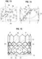
- FIGS. 13 and 14show the inner skirt 16 after opposing short edge portions 90 , 92 have been sewn together to form the annular shape of the skirt.
- the edge portion 90can be placed in an overlapping relationship relative to the opposite edge portion 92 , and the two edge portions can be sewn together with a diagonally extending suture line 94 that is parallel to short edges 86 , 88 .
- the upper edge portion of the inner skirt 16can be formed with a plurality of projections 96 that define an undulating shape that generally follows the shape or contour of the fourth row of struts 28 immediately adjacent the lower ends of axial struts 31 . In this manner, as best shown in FIG.
- the upper edge of the inner skirt 16can be tightly secured to struts 28 with sutures 70 .
- the inner skirt 16can also be formed with slits 98 to facilitate attachment of the skirt to the frame. Slits 98 are dimensioned so as to allow an upper edge portion of the inner skirt 16 to be partially wrapped around struts 28 and to reduce stresses in the skirt during the attachment procedure.
- the inner skirt 16is placed on the inside of frame 12 and an upper edge portion of the skirt is wrapped around the upper surfaces of struts 28 and secured in place with sutures 70 . Wrapping the upper edge portion of the inner skirt 16 around struts 28 in this manner provides for a stronger and more durable attachment of the skirt to the frame.
- the inner skirt 16can also be secured to the first, second, and/or third rows of struts 22 , 24 , and 26 , respectively, with sutures 70 .
- each cell of the metal frame in the illustrated embodimentincludes at least four angled struts that rotate towards the axial direction on crimping (e.g., the angled struts become more aligned with the length of the frame).
- the angled struts of each cellfunction as a mechanism for rotating the fibers of the skirt in the same direction of the struts, allowing the skirt to elongate along the length of the struts. This allows for greater elongation of the skirt and avoids undesirable deformation of the struts when the prosthetic valve is crimped.
- the spacing between the woven fibers or yarnscan be increased to facilitate elongation of the skirt in the axial direction.
- the yarn densitycan be about 15% to about 30% lower than in a typical PET skirt.
- the yarn spacing of the inner skirt 16can be from about 60 yarns per cm (about 155 yarns per inch) to about 70 yarns per cm (about 180 yarns per inch), such as about 63 yarns per cm (about 160 yarns per inch), whereas in a typical PET skirt the yarn spacing can be from about 85 yarns per cm (about 217 yarns per inch) to about 97 yarns per cm (about 247 yarns per inch).
- the oblique edges 86 , 88promote a uniform and even distribution of the fabric material along inner circumference of the frame during crimping so as to reduce or minimize bunching of the fabric to facilitate uniform crimping to the smallest possible diameter. Additionally, cutting diagonal sutures in a vertical manner may leave loose fringes along the cut edges. The oblique edges 86 , 88 help minimize this from occurring. Compared to the construction of a typical skirt (fibers running perpendicularly to the upper and lower edges of the skirt), the construction of the inner skirt 16 avoids undesirable deformation of the frame struts and provides more uniform crimping of the frame.
- the skirtcan be formed from woven elastic fibers that can stretch in the axial direction during crimping of the prosthetic valve.
- the warp and weft fiberscan run perpendicularly and parallel to the upper and lower edges of the skirt, or alternatively, they can extend at angles between 0 and 90 degrees relative to the upper and lower edges of the skirt, as described above.
- the inner skirt 16can be sutured to the frame 12 at locations away from the suture line 154 so that the skirt can be more pliable in that area. This configuration can avoid stress concentrations at the suture line 154 , which attaches the lower edges of the leaflets to the inner skirt 16 .
- the leaflet structure 14 in the illustrated embodimentincludes three flexible leaflets 40 (although a greater or a smaller number of leaflets can be used). Additional information regarding the leaflets, as well as additional information regarding skirt material, can be found, for example, in U.S. patent application Ser. No. 14/704,861, filed May 5, 2015, which is incorporated by reference in its entirety.
- the leaflets 40can be secured to one another at their adjacent sides to form commissures 122 of the leaflet structure ( FIG. 20 ).
- a plurality of flexible connectors 124(one of which is shown in FIG. 16 ) can be used to interconnect pairs of adjacent sides of the leaflets and to mount the leaflets to the commissure window frame portions 30 ( FIG. 5 ).
- FIG. 16shows the adjacent sides of two leaflets 40 interconnected by a flexible connector 124 .
- Three leaflets 40can be secured to each other side-to-side using three flexible connectors 124 , as shown in FIG. 17 . Additional information regarding connecting the leaflets to each other, as well as connecting the leaflets to the frame, can be found, for example, in U.S. Patent Application Publication No. 2012/0123529, which is incorporated by reference herein in its entirety.
- the inner skirt 16can be used to assist in suturing the leaflet structure 14 to the frame.
- the inner skirt 16can have an undulating temporary marking suture to guide the attachment of the lower edges of each leaflet 40 .
- the inner skirt 16itself can be sutured to the struts of the frame 12 using sutures 70 , as noted above, before securing the leaflet structure 14 to the skirt 16 .
- the struts that intersect the marking suturedesirably are not attached to the inner skirt 16 . This allows the inner skirt 16 to be more pliable in the areas not secured to the frame and minimizes stress concentrations along the suture line that secures the lower edges of the leaflets to the skirt.
- the fibers 78 , 80 of the skirtwhen the skirt is secured to the frame, the fibers 78 , 80 of the skirt (see FIG. 12 ) generally align with the angled struts of the frame to promote uniform crimping and expansion of the frame.
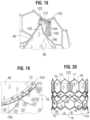
- FIG. 18shows one specific approach for securing the commissure portions 122 of the leaflet structure 14 to the commissure window frame portions 30 of the frame.
- the flexible connector 124( FIG. 17 ) securing two adjacent sides of two leaflets is folded widthwise and the upper tab portions 112 are folded downwardly against the flexible connector.
- Each upper tab portion 112is creased lengthwise (vertically) to assume an L-shape having a first portion 142 folded against a surface of the leaflet and a second portion 144 folded against the connector 124 .
- the second portion 144can then be sutured to the connector 124 along a suture line 146 .
- the commissure tab assemblyis inserted through the commissure window 20 of a corresponding window frame portion 30 , and the folds outside of the window frame portion 30 can be sutured to portions 144 .
- FIG. 18also shows that the folded down upper tab portions 112 can form a double layer of leaflet material at the commissures.
- the first portions 142 of the upper tab portions 112are positioned flat against layers of the two leaflets 40 forming the commissures, such that each commissure comprises four layers of leaflet material just inside of the window frames 30 .
- This four-layered portion of the commissurescan be more resistant to bending, or articulating, than the portion of the leaflets 40 just radially inward from the relatively more-rigid four-layered portion.
- leaflets 40This causes the leaflets 40 to articulate primarily at inner edges 143 of the folded-down first portions 142 in response to blood flowing through the prosthetic valve during operation within the body, as opposed to articulating about or proximal to the axial struts of the window frames 30 . Because the leaflets articulate at a location spaced radially inwardly from the window frames 30 , the leaflets can avoid contact with and damage from the frame. However, under high forces, the four layered portion of the commissures can splay apart about a longitudinal axis adjacent to the window frame 30 , with each first portion 142 folding out against the respective second portion 144 . For example, this can occur when the prosthetic valve 10 is compressed and mounted onto a delivery shaft, allowing for a smaller crimped diameter.
- the four-layered portion of the commissurescan also splay apart about the longitudinal axis when the balloon catheter is inflated during expansion of the prosthetic valve, which can relieve some of the pressure on the commissures caused by the balloon, reducing potential damage to the commissures during expansion.
- each leaflet 40can be sutured to the inner skirt 16 along suture line 154 using, for example, Ethibond Excel® PET thread.
- the suturescan be in-and-out sutures extending through each leaflet 40 , the inner skirt 16 , and each reinforcing strip 72 .
- Each leaflet 40 and respective reinforcing strip 72can be sewn separately to the inner skirt 16 . In this manner, the lower edges of the leaflets are secured to the frame 12 via the inner skirt 16 . As shown in FIG.
- FIG. 20shows a side view of the frame 12 , leaflet structure 14 and the inner skirt 16 after securing the leaflet structure 14 and the inner skirt 16 to the frame 12 and the leaflet structure 14 to the inner skirt 16 .
- FIG. 21is a flattened view of the outer skirt 18 prior to its attachment to the frame 12 , showing the outer surface of the skirt.
- FIG. 22is a flattened view of the outer skirt 18 prior to its attachment to the frame 12 , showing the inner surface of the skirt.
- FIG. 23is a perspective view of the outer skirt prior to its attachment to the frame 12 .
- the outer skirt 18can be laser cut or otherwise formed from a strong, durable material such as PET or various other suitable synthetic or natural materials configured to restrict and/or prevent blood-flow therethrough.
- the outer skirt 18can comprise a substantially straight lower (inflow or upstream) edge portion 160 and an upper (outflow or downstream) edge portion 162 defining a plurality of alternating projections 164 and notches 166 , or castellations, that generally follow the shape of a row of struts of the frame.
- the lower and upper edge portions 160 , 162can have other shapes in alternative embodiments.
- the lower edge portion 160can be formed with a plurality of projections generally conforming to the shape of a row of struts of the frame 12 , while the upper edge portion 162 can be straight.
- the outer skirt 18can comprise at least one soft, plush surface 168 oriented radially outward so as to cushion and seal against native tissues surrounding the prosthetic valve.
- the outer skirt 18can be made from any of a variety of woven, knitted, or crocheted fabrics wherein the surface 168 is the surface of a plush nap or pile of the fabric. Exemplary fabrics having a pile include velour, velvet, velveteen, corduroy, terrycloth, fleece, etc.
- the outer skirtcan have a base layer 170 (a first layer) from which a pile layer 172 (a second layer) extends.
- the base layer 170can comprise warp and weft yarns woven or knitted into a mesh-like structure.
- the yarns of the base layer 170can be flat yarns and can have a denier range of from about 7 dtex to about 100 dtex, and can be knitted with a density of from about 20 to about 100 wales per inch and from about 30 to about 110 courses per inch.
- the yarnscan be made from, for example, biocompatible thermoplastic polymers such as PET, PTFE (polytetrafluoroethylene), Nylon, etc., or any other suitable natural or synthetic fibers.
- the pile layer 172can comprise pile yarns 174 woven or knitted into loops.
- the pile yarns 174can be the warp yarns or the weft yarns of the base layer 170 woven or knitted to form the loops.
- the pile yarns 174can also be separate yarns incorporated into the base layer, depending upon the particular characteristics desired.
- the pile yarns 174can be flat yarns and can have a denier range of from about 7 dtex to about 100 dtex, and can be knitted with a density of from about 20 to about 100 wales per inch and from about 30 to about 110 courses per inch.
- the pile yarnscan be made from, for example, biocompatible thermoplastic polymers such as PET, PTFE, Nylon, etc., or any other suitable natural or synthetic fibers.
- the loopscan be cut such that the pile layer 172 is a cut pile in the manner of, for example, a velour fabric.
- FIGS. 1 and 21illustrate a representative embodiment of the outer skirt 18 configured as a velour fabric.
- the loopscan be left intact to form a looped pile in the manner of, for example, terrycloth.
- FIG. 23illustrates a representative embodiment of the outer skirt 18 in which the pile yarns 174 are knitted to form loops 176 .
- the height of the pile yarns 174can be the same for all pile yarns across the entire extent of the outer skirt so as to provide an outer skirt having a constant thickness.
- the height of the pile yarns 174can vary along the height and/or circumference of the outer skirt so as to vary the thickness of the outer skirt along its height and/or circumference, as further described below.
- the pile layer 172has a much greater surface area than similarly sized skirts formed from flat or woven materials, and therefore can enhance tissue ingrowth compared to known skirts. Promoting tissue growth into the pile layer 172 can decrease perivaluvular leakage, increase retention of the valve at the implant site and contribute to long-term stability of the valve.
- the surface area of the pile yarns 174can be further increased by using textured yarns having an increased surface area due to, for example, a wavy or undulating structure.
- the loop structure and the increased surface area provided by the textured yarn of the loops 176can allow the loops to act as a scaffold for tissue growth into and around the loops of the pile.
- the outer skirt embodiments described hereincan also contribute to improved compressibility and shape memory properties of the outer skirt over known valve coverings and skirts.
- the pile layer 172can be compliant such that it compresses under load (e.g., when in contact with tissue, other implants, or the like), and returns to its original size and shape when the load is relieved. This can help to improve sealing between the outer skirt and the tissue of the native annulus, or a surrounding support structure in which the prosthetic valve is deployed.
- Embodiments of an implantable support structure that is adapted to receive a prosthetic valve and retain it within the native mitral valveare disclosed in co-pending Application No. 62/449,320, filed Jan. 23, 2017, and application Ser. No. 15/876,053, filed Jan.
- the compressibility provided by the pile layer 172 of the outer skirt 18is also beneficial in reducing the crimp profile of the valve. Additionally, the outer skirt 18 can prevent the leaflets 40 or portions thereof from extending through spaces between the struts of the frame 12 as the prosthetic valve is crimped, thereby protecting against damage to the leaflets due to pinching of the leaflets between struts.
- the outer skirt 18be made of a non-woven fabric such as felt, or fibers such as non-woven cotton fibers.
- the outer skirt 18can also be made of porous or spongey materials such as, for example, any of a variety of compliant polymeric foam materials, or woven fabrics, such as woven PET.
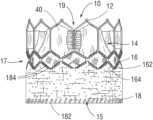
- a lower edge portion 180 of the inner skirt 16can be wrapped around the inflow end 15 of the frame 12 , and the lower edge portion 160 of the outer skirt 18 can be attached to the lower edge portion 180 of the inner skirt 16 and/or the frame 12 , such as with one or more sutures or stitches 182 (as best shown in FIG. 2 ) and/or an adhesive.
- the outer skirt 18can be attached to the inner skirt 16 , for example, by ultrasonic welding.
- the lower edge portion 160 of the outer skirt 18can be free of loops, and the lower edge portion 180 of the inner skirt 16 can overlap and can be secured to the base layer 170 of the outer skirt 18 .
- the lower edge portion 180 of the inner skirt 16can extend over one or more rows of loops 176 of the pile layer 172 (see FIG. 27 ), as further described below.
- the lower edge portion 180 of the inner skirt 18can be wrapped around the inflow end of the frame and extend between the outer surface of the frame and the outer skirt 18 (i.e., the outer skirt 18 is radially outward of the lower edge portion 180 of the inner skirt 18 ).
- each projection 164 of the outer skirt 18can be attached to the third row III of struts 26 ( FIG. 5 ) of the frame 12 .
- the projections 164can, for example, be wrapped over respective struts 26 of row III and secured with sutures 184 .
- the outer skirt 18can be further secured to the frame 12 by suturing an intermediate portion of the outer skirt (a portion between the lower and upper edge portions) to struts of the frame, such as struts 24 of the second row II of struts.
- the height of the outer skirtcan vary in alternative embodiments.
- the outer skirtcan cover the entire outer surface of the frame 12 , with the lower edge portion 160 secured to the inflow end of the frame 12 and the upper edge portion secured to the outflow end of the frame.
- the outer skirt 18can extend from the inflow end of the frame to the second row II of struts 24 , or to the fourth row IV of struts 28 , or to a location along the frame between two rows of struts.
- the outer skirt 18need not extend all the way to the inflow end of the frame, and instead the inflow end of the outer skirt can secured to another location on the frame, such as to the second row II of struts 24 .
- the outer skirt 18desirably is sized and shaped relative to the frame such that when the prosthetic valve 10 is in its radially expanded state, the outer skirt 18 fits snugly (in a tight-fitting manner) against the outer surface of the frame.
- the portion of the frame on which the outer skirt is mountedcan elongate axially.
- the outer skirt 18desirably has sufficient elasticity to stretch in the axial direction upon radial compression of the frame so that it does not to prevent full radial compression of the frame or deform the struts during the crimping process.
- skirts that have material slack or folds when the prosthetic valve is expanded to its functional sizeare difficult to assemble because the material must be adjusted as it is sutured to the frame.
- the outer skirt 18is sized to fit snugly around the frame in its fully expanded state, the assembly process of securing the skirt to the frame is greatly simplified.
- the outer skirtcan be placed around the frame with the frame in its fully expanded state and the outer skirt in its final shape and position when the valve is fully functional. In this position, the skirt can then be sutured to the frame and/or the inner skirt. This simplifies the suturing process compared to skirts that are designed to have slack or folds when radially expanded.
- the height of the loops of the pile layer 172can be constant across the entire extent of the outer skirt such that the outer skirt 18 has a constant thickness, except along the upper and lower edge portions which can be free of loops to facilitate attachment of the outer skirt to the frame and/or the inner skirt 16 .
- the “height” of the loopsis measured in the radial direction when the skirt is mounted on the frame.
- the loopscan comprise lower loops 176 a along the lower or upstream portion of the skirt that are relatively shorter in height (as represented by a thinner cross-sectional area) than upper loops 176 b (as represented by a thicker cross-sectional area) along the upper or downstream portion of the skirt.
- the skirt 18can further include a group of intermediate loops 176 c that gradually increase in height from the lower loops 176 a to the upper loops 176 b .
- the thickness of outer skirt 18increases from a minimum thickness along the lower portion to a maximum thickness along the upper portion.
- FIG. 25shows another embodiment in which the loops of the outer skirt comprise lower loops 176 d along the lower portion of the skirt that are relatively higher or longer in height than upper loops 176 e along the upper portion of the skirt.
- the skirt 18can further include a group of intermediate loops 176 f that gradually decrease in height from the lower loops 176 d to the upper loops 176 e .
- the thickness of outer skirt 18decreases from a maximum thickness along the lower portion to a minimum thickness along the upper portion.
- FIG. 26shows another embodiment in which the loops comprise lower loops 176 g , upper loops 176 h , and intermediate loops 176 i that are relative shorter in height than the lower and upper loops.
- the lower loops 176 gcan gradually decrease in height from the lower edge of the skirt toward the intermediate loops 176 i
- the upper loops 176 hcan gradually decrease in height from the upper edge of the skirt toward the intermediate loops 176 i.
- the thickness of the outer skirtdecreases from a maximum thickness along the lower portion to a minimum thickness along the intermediate portion, and then increases from the intermediate portion to the maximum thickness along the upper portion.
- the upper portion of the skirt containing the upper loops 176 hhas the same thickness as the lower portion of the skirt containing the lower loops 176 g .
- the thickness of the upper portion of the skirt containing the upper loops 176 hcan be greater or less than the same thickness of the lower portion of the skirt containing the lower loops 176 g.
- an outer skirtcan have loops of different heights, wherein the height of the loops change abruptly at locations along the skirt.
- the lower portion of the skirt containing the lower loops 176 acan extend all the way to the upper portion of the skirt containing the upper loops 176 g without the intermediate loops 176 c forming a transition between the upper and lower portions.
- the height of the loops 176can vary along the circumference of the outer skirt.
- the height of the loopscan be increased along circumferential sections of the skirt where larger gaps might be expected between the outer skirt and the native annulus, such as circumferential sections of the skirt that are aligned with the commissures of the native valve.
- FIGS. 27 and 28show an alternative configuration for mounting the outer skirt 18 to the frame 12 .
- the lower edge portion 180 of the inner skirt 16is wrapped around the inflow end of the frame and extended over one or more rows of loops along the lower edge portion 160 of the outer skirt.
- the lower edge portion 180 of the inner skirt 16can then be secured to the lower edge portion 160 of the outer skirt, such as with sutures or stitching 186 ( FIG. 28 ), an adhesive, and/or welding (e.g., ultrasonic welding).
- the stitching 186can also extend around selected struts adjacent the inflow end of the frame.
- the lower edge portion 180 of the inner skirtis effective to partially compress the loops of the pile layer 172 , which creates a tapered edge at the inflow end of the prosthetic valve.
- the tapered edgereduces the insertion force required to push the prosthetic valve through an introducer sheath when being inserted into a patient's body.
- the stitching 186secures the lower edge portion 180 of the inner skirt to the outer skirt 18 at a distance of at least 1 mm from the lowermost edge of the outer skirt.
- the upper edge portion 162 and the intermediate portion of the outer skirtcan then be secured to the frame as previously described.
- FIGS. 29 - 32show another configuration for mounting the outer skirt 18 to the frame 12 .
- the outer skirt 18is initially placed in a tubular configuration with the base layer 170 facing outwardly and the lower edge portion 160 (which can be free of loops 176 ) can be placed between the inner surface of the frame 12 and the lower edge portion 180 of the inner skirt 16 , as depicted in FIG. 30 .
- the lower edge portions of the outer skirt and the inner skirtcan be secured to each other, such as with stitches, an adhesive, and/or welding (e.g., ultrasonic welding).
- the lower edge portions of the outer skirt and the inner skirtare secured to each other with in-and-out stitches and locking stitches.
- the outer skirt 18is then inverted and pulled upwardly around the outer surface of the frame 12 such that the base layer 170 is placed against the outer surface of the frame and the pile layer 172 faces outwardly, as depicted in FIG. 29 .
- the lower edge portion 160 of the outer skirtwraps around the inflow end of the frame and is secured to the inner skirt inside of the frame.
- the upper edge portion 162 and the intermediate portion of the outer skirtcan then be secured to the frame as previously described.
- the prosthetic valve 10can be configured for and mounted on a suitable delivery apparatus for implantation in a subject.
- a suitable delivery apparatusfor implantation in a subject.
- catheter-based delivery apparatusesare known; a non-limiting example of a suitable catheter-based delivery apparatus includes that disclosed in U.S. Patent Application Publication No. 2013/0030519, which is incorporated by reference herein in its entirety, and U.S. Patent Application Publication No. 2012/0123529.
- the prosthetic valve 10 including the outer skirt 18can be crimped on an elongated shaft of a delivery apparatus.
- the prosthetic valvetogether with the delivery apparatus, can form a delivery assembly for implanting the prosthetic valve 10 in a patient's body.
- the shaftcan comprise an inflatable balloon for expanding the prosthetic valve within the body.
- the prosthetic valve 10can then be percutaneously delivered to a desired implantation location (e.g., a native aortic valve region).
- a desired implantation locatione.g., a native aortic valve region.
- the outer skirt 18can fill-in gaps between the frame 12 and the surrounding native annulus to assist in forming a good, fluid-tight seal between the prosthetic valve 10 and the native annulus.
- the outer skirt 18therefore cooperates with the inner skirt 16 to avoid perivalvular leakage after implantation of the prosthetic valve 10 .
- the pile layer of the outer skirtfurther enhances perivalvular sealing by promoting tissue ingrowth with the surrounding tissue.
- a self-expanding prosthetic valve 10can be crimped to a radially collapsed configuration and restrained in the collapsed configuration by inserting the prosthetic valve 10 , including the outer skirt 18 , into a sheath or equivalent mechanism of a delivery catheter.
- the prosthetic valve 10can then be percutaneously delivered to a desired implantation location. Once inside the body, the prosthetic valve 10 can be advanced from the delivery sheath, which allows the prosthetic valve to expand to its functional state.
- FIG. 33illustrates a sealing member 200 for a prosthetic valve, according to another embodiment.
- the sealing member 200 in the illustrated embodimentis formed from a spacer fabric.
- the sealing member 200can be positioned around the outer surface of the frame 12 of a prosthetic valve (in place of the outer skirt 18 ) and secured to the inner skirt 16 and/or the frame using stitching, an adhesive, and/or welding (e.g., ultrasonic welding).
- the spacer fabriccan comprise a first, inner layer 206 , a second, outer layer 208 , and an intermediate spacer layer 210 extending between the first and second layers to create a three-dimensional fabric.
- the first and second layers 206 , 208can be woven fabric or mesh layers. In certain configurations, one or more of the first and second layers 206 , 208 can be woven such that they define a plurality of openings 212 . In some examples, openings such as the openings 212 can promote tissue growth into the sealing member 200 . In other embodiments, the layers 206 , 208 need not define openings, but can be porous, as desired.
- the spacer layer 210can comprise a plurality of pile yarns 214 .
- the pile yarns 214can be, for example, monofilament yarns arranged to form a scaffold-like structure between the first and second layers 206 , 208 .
- FIGS. 34 and 35illustrate an embodiment in which the pile yarns 214 extend between the first and second layers 206 , 208 in a sinusoidal or looping pattern.
- the pile yarns 214can have a rigidity that is greater than the rigidity of the fabric of the first and second layers 206 , 208 such that the pile yarns 214 can extend between the first and second layers 206 , 208 without collapsing under the weight of the second layer 208 .
- the pile yarns 214can also be sufficiently resilient such that the pile yarns can bend or give when subjected to a load, allowing the fabric to compress, and return to their non-deflected state when the load is removed.
- the pile yarns 214can compress to reduce the overall crimp profile of the prosthetic valve, and then return to their non-deflected state when deployed from the delivery sheath or the introducer sheath, as the case may be.
- the spacer fabriccan be warp-knitted, or weft-knitted, as desired.
- Some configurations of the spacer clothcan be made on a double-bar knitting machine.
- the yarns of the first and second layers 206 , 208can have a denier range of from about 10 dtex to about 70 dtex
- the yarns of the monofilament pile yarns 214can have a denier range of from about 2 mil to about 10 mil.
- the pile yarns 214can have a knitting density of from about 20 to about 100 wales per inch, and from about 30 to about 110 courses per inch.
- materials with different flexibility propertiesmay be incorporated into the spacer cloth to improve the overall flexibility of the spacer cloth.
- FIG. 36shows an outer sealing member 18 ′ mounted on the outside of the frame 12 of a prosthetic heart valve 10 , according to another embodiment.
- FIG. 37shows the base layer 170 of the sealing member 18 ′ in a flattened configuration.
- FIG. 38shows the pile layer 172 of the sealing member 18 ′ in a flattened configuration.
- the outer sealing member 18 ′is similar to the sealing member 18 of FIGS. 1 and 21 - 23 , except that the height (H 1 ) of the base layer 170 is greater than the height (H 2 ) of the pile layer 172 .
- the sealing member 18 ′desirably is sized and shaped relative to the frame 12 such that when the prosthetic valve is in its radially expanded state, both layers 170 , 172 of the sealing member 18 fit snugly (in a tight-fitting manner) around the outer surface of the frame.
- the base layer 170extends axially from the inlet end of the frame 12 to the third row III of struts 26 of the frame 12 .
- the upstream and downstream edges of the base layer 170can be sutured to the struts 22 of the first row I and to the struts 26 of the third row III with sutures 182 and 184 , respectively, as previously described.
- the pile layer 172 in the illustrated configurationextends from the inlet end of the frame 12 to a plane that intersects the frame at the nodes formed at the intersection of the upper ends of struts 24 of the second row II and the lower ends of struts 26 of the third row III, wherein the plane is perpendicular to the central axis of the frame.
- the pile layer 172can be separately formed from and subsequently attached to the base layer 170 , such as with sutures, an adhesive, and/or welding. Alternatively, the pile layer 172 can be formed from yarns or fibers woven into the base layer 170 . The pile layer 172 can have any of the configurations shown in FIGS. 24 - 26 .
- the height H 1 of the base layer 170can be about 9 mm to about 25 mm or about 13 mm to about 20 mm, with about 19 mm being a specific example.
- the height H 2 of the pile layer 172can be at least 2 mm less than H 1 , at least 3 mm less than H 1 , at least 4 mm less than H 1 , at least 5 mm less than H 1 , at least 6 mm less than H 1 , at least 7 mm less than H 1 , at least 8 mm less than H 1 , at least 9 mm than H 1 , or at least 10 mm less than H 1 .
- the height of the frame 12 in the radially expanded statecan be about 12 mm to about 27 mm or about 15 mm to about 23 mm, with about 20 mm being a specific example.
- the relatively shorter pile layer 172reduces the crimp profile along the mid-section of the prosthetic valve 10 but still provides for enhanced paravalvular sealing along the majority of the landing zone of the prosthetic valve.
- the base layer 170also provides a sealing function downstream of the downstream edge of the pile layer 172 .
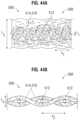
- FIGS. 39 - 40show an outer sealing member 300 for a prosthetic heart valve (e.g., a prosthetic heart valve 10 ), according to another embodiment.
- FIGS. 39 A and 40 Aare magnified views of portions of the sealing member shown in FIGS. 39 and 40 , respectively.
- the sealing member 300can be mounted on the outside of the frame 12 of a prosthetic valve 10 in lieu of sealing member 18 using, for example, sutures, ultrasonic welding, or any other suitable attachment method.
- the sealing member 300desirably is sized and shaped relative to the frame 12 such that when the prosthetic valve is in its radially expanded state, the sealing member 300 fits snugly (in a tight-fitting manner) against the outer surface of the frame.
- the sealing member 300can be a dual-layer fabric comprising a base layer 302 and a pile layer 304 .
- FIG. 39shows the outer surface of the sealing member 300 defined by the pile layer 304 .
- FIG. 40shows the inner surface of the sealing member 300 defined by the base layer 302 .
- the base layer 302 in the illustrated configurationcomprises a mesh weave having circumferentially extending rows or stripes 306 of higher-density mesh portions interspersed with rows or stripes 308 of lower-density mesh portions.
- the yarn count of yarns extending in the circumferential directionis greater in the higher-density rows 306 than in the lower-density rows 308 .
- the yarn count of yarns extending in the circumferential direction and the yarn count of yarns extending in the axial directionis greater in the higher-density rows 306 than in the lower-density rows 308 .
- the pile layer 304can be formed from yarns woven into the base layer 302 .
- the pile layer 304can comprise a velour weave formed from yarns incorporated in the base layer 302 .
- the pile layer 304can comprise circumferentially extending rows or stripes 310 of pile formed at axially-spaced locations along the height of the sealing member 300 such that there are axial extending gaps between adjacent rows 310 . In this manner, the density of the pile layer varies along the height of the sealing member.
- the pile layer 304can be formed without gaps between adjacent rows of pile, but the pile layer can comprise circumferentially extending rows or stripes of higher-density pile interspersed with rows or stripes 312 of lower-density pile.
- the base layer 302can comprise a uniform mesh weave (the density of the weave pattern is uniform) and the pile layer 304 has a varying density.
- Varying the density of the pile layer 304 and/or the base layer 302 along the height of the sealing member 300is advantageous in that it facilitates axially elongation of the sealing member 300 caused by axial elongation of the frame 12 when the prosthetic heart valve is crimped to a radially compressed state for delivery.
- the varying densityalso reduces the bulkiness of the sealing member in the radially collapsed state and therefore reduces the overall crimp profile of the prosthetic heart valve.
- the density of the sealing member 300can vary along the circumference of the sealing member to reduce the bulkiness of the sealing member in the radially collapsed state.
- the pile layer 304can comprise a plurality of axially-extending, circumferentially-spaced, rows of pile yarns, or alternatively, alternating axially-extending rows of higher-density pile interspersed with axially-extending rows of lower-density pile.
- the base layer 302can comprise a plurality axially-extending rows of higher-density mesh interspersed with rows of lower-density mesh.
- the sealing member 300can include a base layer 302 and/or a pile layer 304 that varies in density along the circumference of the sealing member and along the height of the sealing member.
- a sealing membercan be knitted, crocheted, or woven to have rows or sections of higher stitch density and rows or sections of lower stitch density without two distinct layers.
- FIG. 41shows a sealing member 400 comprising a fabric having a plurality of axially-extending rows 402 of higher-density stitching alternating with axially-extending rows 404 of lower-density stitching.
- the sealing member 400can be formed, for example, by knitting, crocheting, or weaving a single layer fabric having rows 402 , 404 formed by increasing the stitch density along the rows 402 and decreasing the stitch density along the rows 404 while the fabric is formed.
- the sealing member 400can be mounted on the outside of the frame 12 of a prosthetic valve 10 in lieu of sealing member 18 using, for example, sutures, ultrasonic welding, or any other suitable attachment method.
- the sealing member 400desirably is sized and shaped relative to the frame 12 such that when the prosthetic valve is in its radially expanded state, the sealing member 400 fits snugly (in a tight-fitting manner) against the outer surface of the frame.
- the sealing member 400can be resiliently stretchable between a first, substantially relaxed, axially foreshortened configuration ( FIG. 41 ) corresponding to a radially expanded state of the prosthetic valve, and a second, axially elongated, or tensioned configuration ( FIG. 42 ) corresponding to a radially compressed state of the prosthetic valve.
- FIG. 41when the prosthetic valve is radially expanded and the sealing member 400 is in the first configuration, the higher-density rows 402 extend in an undulating pattern from the lower (upstream edge) to the upper (downstream edge) of the sealing member 400 .
- each of the higher-density rows 402comprises a plurality of straight angled sections 406 a , 406 b arranged end-to-end in a zig-zag or herringbone pattern extending from the lower (upstream edge) to the upper (downstream edge) of the sealing member 400 .
- the rows 402can be sinusoidal-shaped rows having curved longitudinal edges.
- FIG. 42depicts the higher-density rows 402 as straight sections extending from the inflow edge to the outflow edge of the sealing member.
- the higher-density rows 402need not form perfectly straight rows when the prosthetic valve is in the radially compressed state. Instead, “straightening” of the higher-density rows 402 occurs when the angle 408 between adjacent angled segments 406 a , 406 b of each row increases upon axial elongation of the sealing member.
- the varying stitch density of the sealing member 400reduces overall bulkiness of the sealing member to minimize the crimp profile of the prosthetic valve.
- the zig-zag or undulating pattern of the higher-density rows 402 in the radially expanded state of the prosthetic valvefacilitates stretching of the sealing member in the axial direction upon radial compression of the prosthetic valve and allows the sealing member to return to its pre-stretched state in which the sealing member fits snugly around the frame upon radial expansion of the prosthetic valve.
- the zig-zag or undulating pattern of the higher-density rows 402 in the radially expanded state of the prosthetic valveeliminates any straight flow paths for blood between adjacent rows 402 extending along the outer surface of the sealing member from its outflow edge to its inflow edge to facilitate sealing and tissue ingrowth with surrounding tissue.
- a sealing member 400can have a plurality of circumferentially extending higher-density rows (like rows 402 but extending in the circumferential direction) interspersed with a plurality of circumferentially extending lower-density rows (like rows 404 but extending in the circumferential direction).
- a sealing member 400can have axially-extending and circumferential-extending higher-density rows interspersed with axially-extending and circumferential-extending lower-density rows.
- FIGS. 43 A, 43 B, 44 A, and 44 Billustrate an outer sealing member 500 for a prosthetic heart valve (e.g., a prosthetic heart valve 10 ), according to another embodiment.
- the sealing member 500can have a plush exterior surface 504 .
- the sealing member 500can be secured to a frame 12 of the prosthetic valve using, for example, sutures, ultrasonic welding, or any other suitable attachment method as previously described herein. For purposes of illustration, enlarged or magnified portions of the sealing member 500 are shown in the figures. It should be understood that the overall size and shape of the sealing member 500 can be modified as needed to cover the entire outer surface of the frame 12 or portion of the outer surface of the frame, as previously described herein.
- the sealing member 500can comprise a woven or knitted fabric.
- the fabriccan be resiliently stretchable between a first, natural, or relaxed configuration ( FIG. 43 A ), and a second, axially elongated, or tensioned configuration ( FIG. 43 B ).
- the relaxed configurationcan correspond to the radially expanded, functional configuration of the prosthetic valve
- the elongated configurationcan correspond to the radially collapsed delivery configuration of the prosthetic valve.
- the sealing member 500can have a first length L 1 in the axial direction when the prosthetic valve is in the radially expanded configuration, and a second length L 2 ( FIG. 43 B ) in the axial direction that is longer than L 1 when the valve is crimped to the delivery configuration, as described in greater detail below.
- the fabriccan comprise a plurality of circumferentially extending warp yarns 512 and a plurality of axially extending weft yarns 514 .
- the warp yarns 512can have a denier of from about 1 D to about 300 D, about 10 D to about 200 D, or about 10 D to about 100 D.
- the warp yarns 512can have a thickness t 1 ( FIG. 44 A ) of from about 0.01 mm to about 0.5 mm, about 0.02 mm to about 0.3 mm, or about 0.03 mm to about 0.1 mm.
- the warp yarns 512can have a thickness t 1 of about 0.03 mm, about 0.04 mm, about 0.05 mm, about 0.06 mm, about 0.07 mm, about 0.08 mm, about 0.09 mm, or about 0.1 mm. In a representative embodiment, the warp yarns 512 can have a thickness of about 0.06 mm.
- the weft yarns 514can be texturized yarns comprising a plurality of texturized filaments 516 .
- the filaments 516 of the weft yarns 514can be bulked, wherein, for example, the filaments 516 are twisted, heat set, and untwisted such that the filaments retain their deformed, twisted shape in the relaxed, non-stretched configuration.
- the filaments 516can also be texturized by crimping, coiling, etc. When the weft yarns 514 are in a relaxed, non-tensioned state, the filaments 516 can be loosely packed and can provide compressible volume or bulk to the fabric, as well as a plush surface.
- the weft yarns 514can have a denier of from about 1 D to about 500 D, about 10 D to about 400 D, about 20 D to about 350 D, about 20 D to about 300 D, or about 40 D to about 200 D. In certain embodiments, the weft yarns 514 can have a denier of about 150 D. In some embodiments, a filament count of the weft yarns 514 can be from 2 filaments per yarn to 200 filaments per yarn, 10 filaments per yarn to 100 filaments per yarn, 20 filaments per yarn to 80 filaments per yarn, or about 30 filaments per yarn to 60 filaments per yarn.
- the fabricmay also be manufactured such that the axially-extending textured yarns are warp yarns and the circumferentially-extending yarns are weft yarns.
- FIGS. 44 A and 44 Billustrate a cross-sectional view of the sealing member in which the weft yarns 512 extend into the plane of the page.
- the fabric of the sealing member 500can have a thickness t 2 of from about 0.1 mm to about 10 mm, about 1 mm to about 8 mm, about 1 mm to about 5 mm, about 1 mm to about 3 mm, about 0.5 mm, about 1 mm, about 1.5 mm, about 2 mm, about 2.5 mm, or about 3 mm when in a relaxed state and secured to a frame.
- the sealing member 500can have a thickness of about 0.1 mm, about 0.2 mm, about 0.3 mm, about 0.4 mm, or about 0.5 mm as measured in a relaxed state with a weighted drop gauge having a presser foot.
- the sealing membercan have a thickness of about 1.5 mm when secured to a prosthetic valve frame in the relaxed state.
- the texturized, loosely packed filaments 516 of the weft yarns 514 in the relaxed statecan also promote tissue growth into the sealing member 500 .
- the textured filaments 516 of the weft yarns 514can be widely dispersed such that individual weft yarns are not readily discerned, as depicted in FIG. 43 A .
- the filaments 516 of the weft yarns 514can be drawn together as the weft yarns elongate and the kinks, twists, etc., of the filaments are pulled straight such that the fabric is stretched and the thickness decreases.
- the textured fibers 516can be pulled together such that individual weft yarns 514 become discernable, as best shown in FIG. 43 B .
- the sealing memberwhen fully stretched, can have a second thickness t 3 , as shown in FIG. 44 B that is less than the thickness t 2 .
- the thickness of the tensioned weft yarns 514may be the same or nearly the same as the thickness t 1 of the warp yarns 512 .
- the fabricwhen stretched the fabric can have a thickness t 3 that is the same or nearly the same as three times the thickness t 1 of the warp yarns 512 depending upon, for example, the amount of flattening of the weft yarns 514 .
- the thickness of the sealing membercan vary between about 0.2 mm and about 1.5 mm as the fabric stretches and relaxes. Stated differently, the thickness of the fabric can vary by 750% or more as the fabric stretches and relaxes.
- the warp yarns 512can be spaced apart from each other in the fabric by a distance y 1 when the outer covering is in a relaxed state. As shown in FIGS. 43 B and 44 B , when tension is applied to the fabric in the direction perpendicular to the warp yarns 512 and parallel to the weft yarns 514 , the distance between the warp yarns 512 can increase as the weft yarns 514 lengthen. In the example illustrated in FIG.
- the distance between the warp yarns 512can increase to a new distance y 2 that is greater than the distance y 1 .
- the distance y 1can be, for example, about 1 mm to about 10 mm, about 2 mm to about 8 mm, or about 3 mm to about 5 mm. In a representative example, the distance y 1 can be about 3 mm. In some embodiments, when the fabric is stretched as in FIGS. 43 B and 44 B , the distance y 2 can be about 6 mm to about 10 mm.
- the length of the sealing member 500 in the axial directioncan vary by 100% or more between the relaxed length L 1 and the fully stretched length (e.g., L 2 ). The fabric's ability to lengthen in this manner facilitates crimping of the prosthetic valve.
- the sealing member 500can be soft and voluminous when the prosthetic valve is expanded to its functional size, and relatively thin when the prosthetic valve is crimped to minimize the overall crimp profile of the prosthetic valve.
- the disclosed embodimentscan be adapted to deliver and implant prosthetic devices in any of the native annuluses of the heart (e.g., the pulmonary, mitral, and tricuspid annuluses), and can be used with any of various approaches (e.g., retrograde, antegrade, transseptal, transventricular, transatrial, etc.).
- the disclosed embodimentscan also be used to implant prostheses in other lumens of the body.
- the delivery assembly embodiments described hereincan be adapted to deliver and implant various other prosthetic devices such as stents and/or other prosthetic repair devices.
- the singular forms “a,” “an,” and “the”include the plural forms unless the context clearly dictates otherwise.
- the term “includes”means “comprises.”
- the terms “coupled” and “associated”generally mean electrically, electromagnetically, and/or physically (e.g., mechanically or chemically) coupled or linked and does not exclude the presence of intermediate elements between the coupled or associated items absent specific contrary language.
- proximalrefers to a position, direction, or portion of a device that is closer to the user and further away from the implantation site.
- distalrefers to a position, direction, or portion of a device that is further away from the user and closer to the implantation site.
- proximal motion of a deviceis motion of the device toward the user
- distal motion of the deviceis motion of the device away from the user.
- longitudinal and axialrefer to an axis extending in the proximal and distal directions, unless otherwise expressly defined.
- integrally formedand “unitary construction” refer to a construction that does not include any welds, fasteners, or other means for securing separately formed pieces of material to each other.
Landscapes
- Health & Medical Sciences (AREA)
- Engineering & Computer Science (AREA)
- Biomedical Technology (AREA)
- Cardiology (AREA)
- Oral & Maxillofacial Surgery (AREA)
- Transplantation (AREA)
- Heart & Thoracic Surgery (AREA)
- Vascular Medicine (AREA)
- Life Sciences & Earth Sciences (AREA)
- Animal Behavior & Ethology (AREA)
- General Health & Medical Sciences (AREA)
- Public Health (AREA)
- Veterinary Medicine (AREA)
- Prostheses (AREA)
Abstract
Description
Claims (20)
Priority Applications (4)
| Application Number | Priority Date | Filing Date | Title |
|---|---|---|---|
| US16/120,112US12064341B2 (en) | 2017-05-31 | 2018-08-31 | Sealing member for prosthetic heart valve |
| US17/708,428US11883281B2 (en) | 2017-05-31 | 2022-03-30 | Sealing member for prosthetic heart valve |
| US18/542,482US12357452B2 (en) | 2017-05-31 | 2023-12-15 | Sealing member for prosthetic heart valve |
| US19/239,132US20250312148A1 (en) | 2017-05-31 | 2025-06-16 | Sealing member for prosthetic heart valve |
Applications Claiming Priority (3)
| Application Number | Priority Date | Filing Date | Title |
|---|---|---|---|
| US201762513348P | 2017-05-31 | 2017-05-31 | |
| US201815991325A | 2018-05-29 | 2018-05-29 | |
| US16/120,112US12064341B2 (en) | 2017-05-31 | 2018-08-31 | Sealing member for prosthetic heart valve |
Related Parent Applications (1)
| Application Number | Title | Priority Date | Filing Date |
|---|---|---|---|
| US201815991325AContinuation-In-Part | 2017-05-31 | 2018-05-29 |
Related Child Applications (1)
| Application Number | Title | Priority Date | Filing Date |
|---|---|---|---|
| US17/708,428ContinuationUS11883281B2 (en) | 2017-05-31 | 2022-03-30 | Sealing member for prosthetic heart valve |
Publications (3)
| Publication Number | Publication Date |
|---|---|
| US20190365530A1 US20190365530A1 (en) | 2019-12-05 |
| US20210401571A9 US20210401571A9 (en) | 2021-12-30 |
| US12064341B2true US12064341B2 (en) | 2024-08-20 |
Family
ID=79032895
Family Applications (4)
| Application Number | Title | Priority Date | Filing Date |
|---|---|---|---|
| US16/120,112ActiveUS12064341B2 (en) | 2017-05-31 | 2018-08-31 | Sealing member for prosthetic heart valve |
| US17/708,428ActiveUS11883281B2 (en) | 2017-05-31 | 2022-03-30 | Sealing member for prosthetic heart valve |
| US18/542,482ActiveUS12357452B2 (en) | 2017-05-31 | 2023-12-15 | Sealing member for prosthetic heart valve |
| US19/239,132PendingUS20250312148A1 (en) | 2017-05-31 | 2025-06-16 | Sealing member for prosthetic heart valve |
Family Applications After (3)
| Application Number | Title | Priority Date | Filing Date |
|---|---|---|---|
| US17/708,428ActiveUS11883281B2 (en) | 2017-05-31 | 2022-03-30 | Sealing member for prosthetic heart valve |
| US18/542,482ActiveUS12357452B2 (en) | 2017-05-31 | 2023-12-15 | Sealing member for prosthetic heart valve |
| US19/239,132PendingUS20250312148A1 (en) | 2017-05-31 | 2025-06-16 | Sealing member for prosthetic heart valve |
Country Status (1)
| Country | Link |
|---|---|
| US (4) | US12064341B2 (en) |
Cited By (4)
| Publication number | Priority date | Publication date | Assignee | Title |
|---|---|---|---|---|
| US20220154370A1 (en)* | 2019-08-02 | 2022-05-19 | Edwards Lifesciences Corporation | Rotary fibrous material application to medical devices |
| US20230277306A1 (en)* | 2017-08-11 | 2023-09-07 | Edwards Lifesciences Corporation | Sealing element for prosthetic heart valve |
| US20240115375A1 (en)* | 2017-05-31 | 2024-04-11 | Edwards Lifesciences Corporation | Sealing member for prosthetic heart valve |
| WO2025101895A1 (en) | 2023-11-09 | 2025-05-15 | Edwards Lifesciences Corporation | Percutaneous valve leaflet modification |
Families Citing this family (66)
| Publication number | Priority date | Publication date | Assignee | Title |
|---|---|---|---|---|
| US9532868B2 (en)* | 2007-09-28 | 2017-01-03 | St. Jude Medical, Inc. | Collapsible-expandable prosthetic heart valves with structures for clamping native tissue |
| US8870950B2 (en) | 2009-12-08 | 2014-10-28 | Mitral Tech Ltd. | Rotation-based anchoring of an implant |
| US20110224785A1 (en) | 2010-03-10 | 2011-09-15 | Hacohen Gil | Prosthetic mitral valve with tissue anchors |
| US9763657B2 (en) | 2010-07-21 | 2017-09-19 | Mitraltech Ltd. | Techniques for percutaneous mitral valve replacement and sealing |
| US11653910B2 (en) | 2010-07-21 | 2023-05-23 | Cardiovalve Ltd. | Helical anchor implantation |
| WO2013021374A2 (en) | 2011-08-05 | 2013-02-14 | Mitraltech Ltd. | Techniques for percutaneous mitral valve replacement and sealing |
| EP2739214B1 (en) | 2011-08-05 | 2018-10-10 | Cardiovalve Ltd | Percutaneous mitral valve replacement and sealing |
| US20150351906A1 (en) | 2013-01-24 | 2015-12-10 | Mitraltech Ltd. | Ventricularly-anchored prosthetic valves |
| WO2015126711A1 (en)* | 2014-02-18 | 2015-08-27 | St. Jude Medical, Cardiology Division, Inc. | Bowed runners and corresponding valve assemblies for paravalvular leak protection |
| EP3174502B1 (en) | 2014-07-30 | 2022-04-06 | Cardiovalve Ltd | Apparatus for implantation of an articulatable prosthetic valve |
| US9974651B2 (en) | 2015-02-05 | 2018-05-22 | Mitral Tech Ltd. | Prosthetic valve with axially-sliding frames |
| CN110141399B (en) | 2015-02-05 | 2021-07-27 | 卡迪尔维尔福股份有限公司 | Prosthetic valve with axial sliding frame |
| US11833034B2 (en) | 2016-01-13 | 2023-12-05 | Shifamed Holdings, Llc | Prosthetic cardiac valve devices, systems, and methods |
| US10531866B2 (en) | 2016-02-16 | 2020-01-14 | Cardiovalve Ltd. | Techniques for providing a replacement valve and transseptal communication |
| US20190231525A1 (en) | 2016-08-01 | 2019-08-01 | Mitraltech Ltd. | Minimally-invasive delivery systems |
| CA3031187A1 (en) | 2016-08-10 | 2018-02-15 | Cardiovalve Ltd. | Prosthetic valve with concentric frames |
| US10548722B2 (en)* | 2016-08-26 | 2020-02-04 | St. Jude Medical, Cardiology Division, Inc. | Prosthetic heart valve with paravalvular leak mitigation features |
| US11246704B2 (en) | 2017-08-03 | 2022-02-15 | Cardiovalve Ltd. | Prosthetic heart valve |
| US12064347B2 (en) | 2017-08-03 | 2024-08-20 | Cardiovalve Ltd. | Prosthetic heart valve |
| US11793633B2 (en) | 2017-08-03 | 2023-10-24 | Cardiovalve Ltd. | Prosthetic heart valve |
| US10888421B2 (en) | 2017-09-19 | 2021-01-12 | Cardiovalve Ltd. | Prosthetic heart valve with pouch |
| US20190083242A1 (en) | 2017-09-19 | 2019-03-21 | Cardiovalve Ltd. | Systems and methods for implanting a prosthetic valve within a native heart valve |
| US9895226B1 (en) | 2017-10-19 | 2018-02-20 | Mitral Tech Ltd. | Techniques for use with prosthetic valve leaflets |
| GB201720803D0 (en) | 2017-12-13 | 2018-01-24 | Mitraltech Ltd | Prosthetic Valve and delivery tool therefor |
| GB201800399D0 (en) | 2018-01-10 | 2018-02-21 | Mitraltech Ltd | Temperature-control during crimping of an implant |
| AU2019325548B2 (en) | 2018-08-21 | 2025-06-26 | Shifamed Holdings, Llc | Prosthetic cardiac valve devices, systems, and methods |
| US10779946B2 (en) | 2018-09-17 | 2020-09-22 | Cardiovalve Ltd. | Leaflet-testing apparatus |
| CN113260337A (en) | 2018-10-05 | 2021-08-13 | 施菲姆德控股有限责任公司 | Prosthetic heart valve devices, systems, and methods |
| CN113056302B (en) | 2018-10-19 | 2023-03-28 | 施菲姆德控股有限责任公司 | Adjustable medical device |
| GB201901887D0 (en) | 2019-02-11 | 2019-04-03 | Cardiovalve Ltd | Device for conditioning ex vivo pericardial tissue |
| EP3941391B1 (en) | 2019-03-19 | 2024-12-04 | Shifamed Holdings, LLC | Prosthetic cardiac valve devices, systems |
| CA3143011A1 (en) | 2019-12-06 | 2021-06-10 | Edwards Lifesciences Corporation | Belt for prosthetic heart valve |
| US12011349B2 (en)* | 2020-03-04 | 2024-06-18 | Medtronic, Inc. | Balloon expandable stent with lengthened commissure posts for transcatheter implantation of a cardiac valve prosthesis |
| EP4103108A2 (en) | 2020-03-17 | 2022-12-21 | Edwards Lifesciences Corporation | Modification of existing valvular structures for prosthetic heart valve implantation |
| CN219289798U (en) | 2020-05-28 | 2023-07-04 | 爱德华兹生命科学公司 | System for lobule capture |
| CN116056668A (en) | 2020-06-11 | 2023-05-02 | 爱德华兹生命科学公司 | Rigid braid member for prosthetic valve delivery device |
| US11744702B1 (en)* | 2020-07-01 | 2023-09-05 | Aortic Innovations, Llc | Transcatheter aortic valve repair and replacement |
| EP4185241B1 (en) | 2020-07-21 | 2024-11-13 | Edwards Lifesciences Corporation | Prosthetic heart valves with h-shaped commissure windows and methods for assembly thereof |
| EP4175590A1 (en) | 2020-08-17 | 2023-05-10 | Edwards Lifesciences Corporation | Implantable frame and frame retaining mechanism |
| CN116456937A (en) | 2020-08-31 | 2023-07-18 | 施菲姆德控股有限责任公司 | Prosthetic Valve Delivery System |
| EP4210634B1 (en) | 2020-09-09 | 2025-07-16 | Edwards Lifesciences Corporation | Tapered prosthetic heart valves with valvular structures forming tapered flow channels |
| WO2022076492A1 (en) | 2020-10-06 | 2022-04-14 | Edwards Lifesciences Corporation | Commissure locking member |
| CN114452040A (en) | 2020-11-10 | 2022-05-10 | 爱德华兹生命科学公司 | Prosthetic heart valve with air barrier or valve structure to reduce risk of thrombosis |
| CA3199758A1 (en) | 2020-11-11 | 2022-05-19 | Edwards Lifesciences Corporation | Prosthetic heart valves with sealing frames to reduce paravalvular leakage |
| EP4243734A1 (en) | 2020-11-12 | 2023-09-20 | Edwards Lifesciences Corporation | Prosthetic heart valve leaflet assemblies and methods |
| US12357459B2 (en) | 2020-12-03 | 2025-07-15 | Cardiovalve Ltd. | Transluminal delivery system |
| US12329635B2 (en) | 2020-12-04 | 2025-06-17 | Shifamed Holdings, Llc | Flared prosthetic cardiac valve delivery devices and systems |
| WO2022155336A1 (en) | 2021-01-14 | 2022-07-21 | Edwards Lifesciences Corporation | Implantable medical devices |
| CN217390969U (en) | 2021-01-20 | 2022-09-09 | 爱德华兹生命科学公司 | Mechanically expandable double-cavity venous docking device |
| US12201521B2 (en) | 2021-03-22 | 2025-01-21 | Shifamed Holdings, Llc | Anchor position verification for prosthetic cardiac valve devices |
| KR20230160297A (en) | 2021-03-23 | 2023-11-23 | 에드워즈 라이프사이언시스 코포레이션 | Artificial heart valve with elongated sealing member |
| EP4326195A1 (en) | 2021-04-22 | 2024-02-28 | Edwards Lifesciences Corporation | Prosthetic heart valves with ratcheting lock mechanisms, and methods for fabrication and use |
| WO2022248961A1 (en)* | 2021-05-27 | 2022-12-01 | Medtronic, Inc. | Composite skirts for prosthetic valve devices |
| EP4346701A1 (en) | 2021-06-03 | 2024-04-10 | Edwards Lifesciences Corporation | Skirt for prosthetic heart valve |
| EP4422552A1 (en) | 2021-10-27 | 2024-09-04 | Edwards Lifesciences Corporation | System and method for crimping and loading a prosthetic heart valve |
| EP4429598A1 (en) | 2021-11-13 | 2024-09-18 | Edwards Lifesciences Corporation | Prosthetic heart valves with releasably attached outer skirts and methods associated therewith |
| WO2023091419A1 (en) | 2021-11-16 | 2023-05-25 | Edwards Lifesciences Corporation | Device for folding valve leaflets |
| EP4433127A1 (en) | 2021-11-17 | 2024-09-25 | Edwards Lifesciences Corporation | Prosthetic valve delivery apparatus with strain relief nosecone |
| WO2023219818A1 (en) | 2022-05-09 | 2023-11-16 | Edwards Lifesciences Corporation | Pressure-reduction systems and methods for prosthetic valves |
| CN115153960B (en)* | 2022-06-27 | 2024-10-15 | 东华大学 | Reinforced seal type flocking skirt for prosthetic heart valve and prosthetic heart valve |
| WO2024019909A1 (en) | 2022-07-19 | 2024-01-25 | Edwards Lifesciences Corporation | Devices and systems for docking a prosthetic valve |
| WO2024151474A1 (en) | 2023-01-11 | 2024-07-18 | Edwards Lifesciences Corporation | Outer skirts for expandable prosthetic heart valves |
| WO2024215659A1 (en)* | 2023-04-10 | 2024-10-17 | Atex Technologies, Inc. | Mesh with reinforced edges and method of making the same |
| WO2024226420A1 (en) | 2023-04-25 | 2024-10-31 | Edwards Lifesciences Corporation | Prosthetic valves with releasable outer skirts |
| WO2024226066A1 (en) | 2023-04-28 | 2024-10-31 | Edwards Lifesciences Corporation | Prosthetic heart valves with releasably attached outer skirts and methods associated therewith |
| WO2025171218A1 (en) | 2024-02-09 | 2025-08-14 | Edwards Lifesciences Corporation | Prosthetic valve assembly with a radially biased anchoring frame |
Citations (345)
| Publication number | Priority date | Publication date | Assignee | Title |
|---|---|---|---|---|
| DE144167C (en) | 1903-09-28 | |||
| US3365728A (en) | 1964-12-18 | 1968-01-30 | Edwards Lab Inc | Upholstered heart valve having a sealing ring adapted for dispensing medicaments |
| US3409013A (en) | 1965-08-23 | 1968-11-05 | Berry Henry | Instrument for inserting artificial heart valves |
| US3548417A (en) | 1967-09-05 | 1970-12-22 | Ronnie G Kischer | Heart valve having a flexible wall which rotates between open and closed positions |
| US3587115A (en) | 1966-05-04 | 1971-06-28 | Donald P Shiley | Prosthetic sutureless heart valves and implant tools therefor |
| GB1264472A (en) | 1969-09-25 | 1972-02-23 | ||
| US3657744A (en) | 1970-05-08 | 1972-04-25 | Univ Minnesota | Method for fixing prosthetic implants in a living body |
| US3671979A (en) | 1969-09-23 | 1972-06-27 | Univ Utah | Catheter mounted artificial heart valve for implanting in close proximity to a defective natural heart valve |
| US3714671A (en) | 1970-11-30 | 1973-02-06 | Cutter Lab | Tissue-type heart valve with a graft support ring or stent |
| DE2246526A1 (en) | 1971-09-24 | 1973-03-29 | Smiths Industries Ltd | MEDICAL AND / OR SURGICAL EQUIPMENT |
| US3755823A (en) | 1971-04-23 | 1973-09-04 | Hancock Laboratories Inc | Flexible stent for heart valve |
| US3878565A (en) | 1971-07-14 | 1975-04-22 | Providence Hospital | Vascular prosthesis with external pile surface |
| US4035849A (en) | 1975-11-17 | 1977-07-19 | William W. Angell | Heart valve stent and process for preparing a stented heart valve prosthesis |
| US4056854A (en) | 1976-09-28 | 1977-11-08 | The United States Of America As Represented By The Department Of Health, Education And Welfare | Aortic heart valve catheter |
| US4106129A (en) | 1976-01-09 | 1978-08-15 | American Hospital Supply Corporation | Supported bioprosthetic heart valve with compliant orifice ring |
| US4222126A (en) | 1978-12-14 | 1980-09-16 | The United States Of America As Represented By The Secretary Of The Department Of Health, Education & Welfare | Unitized three leaflet heart valve |
| GB2056023A (en) | 1979-08-06 | 1981-03-11 | Ross D N Bodnar E | Stent for a cardiac valve |
| US4265694A (en) | 1978-12-14 | 1981-05-05 | The United States Of America As Represented By The Department Of Health, Education And Welfare | Method of making unitized three leaflet heart valve |
| US4297749A (en) | 1977-04-25 | 1981-11-03 | Albany International Corp. | Heart valve prosthesis |
| USRE30912E (en) | 1968-09-16 | 1982-04-27 | Hancock Laboratories, Inc. | Stent for heart valve |
| US4339831A (en) | 1981-03-27 | 1982-07-20 | Medtronic, Inc. | Dynamic annulus heart valve and reconstruction ring |
| US4345340A (en) | 1981-05-07 | 1982-08-24 | Vascor, Inc. | Stent for mitral/tricuspid heart valve |
| US4373216A (en) | 1980-10-27 | 1983-02-15 | Hemex, Inc. | Heart valves having edge-guided occluders |
| US4406022A (en) | 1981-11-16 | 1983-09-27 | Kathryn Roy | Prosthetic valve means for cardiovascular surgery |
| EP0103546A1 (en) | 1982-08-09 | 1984-03-21 | Domenico Iorio | Surgical instrument for implanting prosthetic heart valves or the like |
| US4441216A (en) | 1980-11-03 | 1984-04-10 | Shiley, Inc. | Tissue heart valve and stent |
| US4470157A (en) | 1981-04-27 | 1984-09-11 | Love Jack W | Tricuspid prosthetic tissue heart valve |
| US4535483A (en) | 1983-01-17 | 1985-08-20 | Hemex, Inc. | Suture rings for heart valves |
| US4574803A (en) | 1979-01-19 | 1986-03-11 | Karl Storz | Tissue cutter |
| US4592340A (en) | 1984-05-02 | 1986-06-03 | Boyles Paul W | Artificial catheter means |
| US4605407A (en) | 1983-01-11 | 1986-08-12 | The University Of Sheffield | Heart valve replacements |
| US4612011A (en) | 1983-07-22 | 1986-09-16 | Hans Kautzky | Central occluder semi-biological heart valve |
| SU1271508A1 (en) | 1984-11-29 | 1986-11-23 | Горьковский государственный медицинский институт им.С.М.Кирова | Artificial heart valve |
| US4643732A (en) | 1984-11-17 | 1987-02-17 | Beiersdorf Aktiengesellschaft | Heart valve prosthesis |
| US4655771A (en) | 1982-04-30 | 1987-04-07 | Shepherd Patents S.A. | Prosthesis comprising an expansible or contractile tubular body |
| US4692164A (en) | 1986-03-06 | 1987-09-08 | Moskovskoe Vysshee Tekhnicheskoe Uchilische, Imeni N.E. Baumana | Bioprosthetic heart valve, methods and device for preparation thereof |
| US4733665A (en) | 1985-11-07 | 1988-03-29 | Expandable Grafts Partnership | Expandable intraluminal graft, and method and apparatus for implanting an expandable intraluminal graft |
| US4759758A (en) | 1984-12-07 | 1988-07-26 | Shlomo Gabbay | Prosthetic heart valve |
| US4762128A (en) | 1986-12-09 | 1988-08-09 | Advanced Surgical Intervention, Inc. | Method and apparatus for treating hypertrophy of the prostate gland |
| US4777951A (en) | 1986-09-19 | 1988-10-18 | Mansfield Scientific, Inc. | Procedure and catheter instrument for treating patients for aortic stenosis |
| US4787901A (en) | 1984-07-17 | 1988-11-29 | Doguhan Baykut | Two-way acting valve and cardiac valve prosthesis |
| US4787899A (en) | 1983-12-09 | 1988-11-29 | Lazarus Harrison M | Intraluminal graft device, system and method |
| US4796629A (en) | 1987-06-03 | 1989-01-10 | Joseph Grayzel | Stiffened dilation balloon catheter device |
| US4820299A (en) | 1985-09-23 | 1989-04-11 | Avions Marcel Dassault-Breguet Aviation | Prosthetic cardiac valve |
| US4829990A (en) | 1987-06-25 | 1989-05-16 | Thueroff Joachim | Implantable hydraulic penile erector |
| US4851001A (en) | 1987-09-17 | 1989-07-25 | Taheri Syde A | Prosthetic valve for a blood vein and an associated method of implantation of the valve |
| US4856516A (en) | 1989-01-09 | 1989-08-15 | Cordis Corporation | Endovascular stent apparatus and method |
| US4878906A (en) | 1986-03-25 | 1989-11-07 | Servetus Partnership | Endoprosthesis for repairing a damaged vessel |
| US4878495A (en) | 1987-05-15 | 1989-11-07 | Joseph Grayzel | Valvuloplasty device with satellite expansion means |
| US4883458A (en) | 1987-02-24 | 1989-11-28 | Surgical Systems & Instruments, Inc. | Atherectomy system and method of using the same |
| US4892539A (en) | 1988-02-08 | 1990-01-09 | D-R Medical Systems, Inc. | Vascular graft |
| US4922905A (en) | 1985-11-30 | 1990-05-08 | Strecker Ernst P | Dilatation catheter |
| US4966604A (en) | 1989-01-23 | 1990-10-30 | Interventional Technologies Inc. | Expandable atherectomy cutter with flexibly bowed blades |
| US4979939A (en) | 1984-05-14 | 1990-12-25 | Surgical Systems & Instruments, Inc. | Atherectomy system with a guide wire |
| US4986830A (en) | 1989-09-22 | 1991-01-22 | Schneider (U.S.A.) Inc. | Valvuloplasty catheter with balloon which remains stable during inflation |
| US4994077A (en) | 1989-04-21 | 1991-02-19 | Dobben Richard L | Artificial heart valve for implantation in a blood vessel |
| US5007896A (en) | 1988-12-19 | 1991-04-16 | Surgical Systems & Instruments, Inc. | Rotary-catheter for atherectomy |
| US5026366A (en) | 1984-03-01 | 1991-06-25 | Cardiovascular Laser Systems, Inc. | Angioplasty catheter and method of use thereof |
| US5032128A (en) | 1988-07-07 | 1991-07-16 | Medtronic, Inc. | Heart valve prosthesis |
| US5037434A (en) | 1990-04-11 | 1991-08-06 | Carbomedics, Inc. | Bioprosthetic heart valve with elastic commissures |
| US5047041A (en) | 1989-08-22 | 1991-09-10 | Samuels Peter B | Surgical apparatus for the excision of vein valves in situ |
| US5059177A (en) | 1990-04-19 | 1991-10-22 | Cordis Corporation | Triple lumen balloon catheter |
| WO1991017720A1 (en) | 1990-05-18 | 1991-11-28 | Henning Rud Andersen | A valve prosthesis for implantation in the body and a catheter for implantating such valve prosthesis |
| US5080668A (en) | 1988-11-29 | 1992-01-14 | Biotronik Mess- und Therapiegerate GmbH & Co. KG Ingenieurburo Berlin | Cardiac valve prosthesis |
| US5085635A (en) | 1990-05-18 | 1992-02-04 | Cragg Andrew H | Valved-tip angiographic catheter |
| US5089015A (en) | 1989-11-28 | 1992-02-18 | Promedica International | Method for implanting unstented xenografts and allografts |
| US5152771A (en) | 1990-12-31 | 1992-10-06 | The Board Of Supervisors Of Louisiana State University | Valve cutter for arterial by-pass surgery |
| WO1992017118A1 (en) | 1991-04-04 | 1992-10-15 | Shturman Cardiology Systems, Inc. | Method and apparatus for in vivo heart valve decalcification |
| US5163953A (en) | 1992-02-10 | 1992-11-17 | Vince Dennis J | Toroidal artificial heart valve stent |
| US5167628A (en) | 1991-05-02 | 1992-12-01 | Boyles Paul W | Aortic balloon catheter assembly for indirect infusion of the coronary arteries |
| WO1993001768A1 (en) | 1991-07-16 | 1993-02-04 | Stevens John H | Endovascular aortic valve replacement |
| US5192297A (en) | 1991-12-31 | 1993-03-09 | Medtronic, Inc. | Apparatus and method for placement and implantation of a stent |
| US5266073A (en) | 1987-12-08 | 1993-11-30 | Wall W Henry | Angioplasty stent |
| US5282847A (en) | 1991-02-28 | 1994-02-01 | Medtronic, Inc. | Prosthetic vascular grafts with a pleated structure |
| US5332402A (en) | 1992-05-12 | 1994-07-26 | Teitelbaum George P | Percutaneously-inserted cardiac valve |
| US5360444A (en) | 1991-03-19 | 1994-11-01 | Kenji Kusuhara | Occluder supporter and a method of attachment thereof |
| US5397351A (en) | 1991-05-13 | 1995-03-14 | Pavcnik; Dusan | Prosthetic valve for percutaneous insertion |
| US5411552A (en) | 1990-05-18 | 1995-05-02 | Andersen; Henning R. | Valve prothesis for implantation in the body and a catheter for implanting such valve prothesis |
| US5411055A (en) | 1992-11-24 | 1995-05-02 | Mannesmann Aktiengesellschaft | Flow limiting throttle element |
| US5480424A (en) | 1993-11-01 | 1996-01-02 | Cox; James L. | Heart valve replacement using flexible tubes |
| US5500014A (en) | 1989-05-31 | 1996-03-19 | Baxter International Inc. | Biological valvular prothesis |
| US5545209A (en) | 1993-09-30 | 1996-08-13 | Texas Petrodet, Inc. | Controlled deployment of a medical device |
| US5549665A (en) | 1993-06-18 | 1996-08-27 | London Health Association | Bioprostethic valve |
| US5554185A (en) | 1994-07-18 | 1996-09-10 | Block; Peter C. | Inflatable prosthetic cardiovascular valve for percutaneous transluminal implantation of same |
| US5558644A (en) | 1991-07-16 | 1996-09-24 | Heartport, Inc. | Retrograde delivery catheter and method for inducing cardioplegic arrest |
| US5571175A (en) | 1995-06-07 | 1996-11-05 | St. Jude Medical, Inc. | Suture guard for prosthetic heart valve |
| US5584803A (en) | 1991-07-16 | 1996-12-17 | Heartport, Inc. | System for cardiac procedures |
| US5591195A (en) | 1995-10-30 | 1997-01-07 | Taheri; Syde | Apparatus and method for engrafting a blood vessel |
| US5591185A (en) | 1989-12-14 | 1997-01-07 | Corneal Contouring Development L.L.C. | Method and apparatus for reprofiling or smoothing the anterior or stromal cornea by scraping |
| US5609626A (en) | 1989-05-31 | 1997-03-11 | Baxter International Inc. | Stent devices and support/restrictor assemblies for use in conjunction with prosthetic vascular grafts |
| DE19532846A1 (en) | 1995-09-06 | 1997-03-13 | Georg Dr Berg | Valve for use in heart |
| US5628792A (en) | 1992-03-13 | 1997-05-13 | Jcl Technic Ab | Cardiac valve with recessed valve flap hinges |
| US5639274A (en) | 1995-06-02 | 1997-06-17 | Fischell; Robert E. | Integrated catheter system for balloon angioplasty and stent delivery |
| DE19546692A1 (en) | 1995-12-14 | 1997-06-19 | Figulla Hans Reiner Prof Dr Me | Self-expandable heart valve bio-prosthesis or synthetic polyurethane valve |
| WO1997024080A1 (en) | 1995-12-28 | 1997-07-10 | Cogent | Kit for surgical treatment of intracorporal lumens |
| US5665115A (en) | 1992-02-21 | 1997-09-09 | Boston Scientific Technology, Inc. | Intraluminal stent |
| US5716417A (en) | 1995-06-07 | 1998-02-10 | St. Jude Medical, Inc. | Integral supporting structure for bioprosthetic heart valve |
| US5728068A (en) | 1994-06-14 | 1998-03-17 | Cordis Corporation | Multi-purpose balloon catheter |
| US5749890A (en) | 1996-12-03 | 1998-05-12 | Shaknovich; Alexander | Method and system for stent placement in ostial lesions |
| US5756476A (en) | 1992-01-14 | 1998-05-26 | The United States Of America As Represented By The Department Of Health And Human Services | Inhibition of cell proliferation using antisense oligonucleotides |
| US5769812A (en) | 1991-07-16 | 1998-06-23 | Heartport, Inc. | System for cardiac procedures |
| EP0850607A1 (en) | 1996-12-31 | 1998-07-01 | Cordis Corporation | Valve prosthesis for implantation in body channels |
| US5800508A (en) | 1994-02-09 | 1998-09-01 | Boston Scientific Technology, Inc. | Bifurcated endoluminal prosthesis |
| US5855597A (en) | 1997-05-07 | 1999-01-05 | Iowa-India Investments Co. Limited | Stent valve and stent graft for percutaneous surgery |
| US5855602A (en) | 1996-09-09 | 1999-01-05 | Shelhigh, Inc. | Heart valve prosthesis |
| US5855601A (en) | 1996-06-21 | 1999-01-05 | The Trustees Of Columbia University In The City Of New York | Artificial heart valve and method and device for implanting the same |
| WO1999030646A1 (en) | 1997-12-17 | 1999-06-24 | St. Jude Medical, Inc. | Prosthetic heart valve stent utilizing mounting clips |
| WO1999033414A1 (en) | 1997-12-29 | 1999-07-08 | Ivan Vesely | System for minimally invasive insertion of a bioprosthetic heart valve |
| US5925063A (en) | 1997-09-26 | 1999-07-20 | Khosravi; Farhad | Coiled sheet valve, filter or occlusive device and methods of use |
| US5957949A (en) | 1997-05-01 | 1999-09-28 | World Medical Manufacturing Corp. | Percutaneous placement valve stent |
| US6027525A (en) | 1996-05-23 | 2000-02-22 | Samsung Electronics., Ltd. | Flexible self-expandable stent and method for making the same |
| WO2000018333A1 (en) | 1998-09-28 | 2000-04-06 | Autogenics | Heart valve having tissue retention with anchors and an outer sheath |
| DE19857887A1 (en) | 1998-12-15 | 2000-07-06 | Fraunhofer Ges Forschung | Anchoring support for a heart valve prosthesis comprises a single-piece component which is formed of rod shaped elements made of a memory metal, and has at least in part a lattice structure |
| FR2788217A1 (en) | 1999-01-12 | 2000-07-13 | Brice Letac | PROSTHETIC VALVE IMPLANTABLE BY CATHETERISM, OR SURGICAL |
| DE19907646A1 (en) | 1999-02-23 | 2000-08-24 | Georg Berg | Valve for blood vessels uses flap holders and counterpart holders on stent to latch together in place and all channeled for guide wire. |
| US6110198A (en) | 1995-10-03 | 2000-08-29 | Medtronic Inc. | Method for deploying cuff prostheses |
| US6132473A (en) | 1997-05-02 | 2000-10-17 | St. Jude Medical, Inc. | Differential treatment of prosthetic devices |
| EP1057460A1 (en) | 1999-06-01 | 2000-12-06 | Numed, Inc. | Replacement valve assembly and method of implanting same |
| US6171335B1 (en) | 1997-01-24 | 2001-01-09 | Aortech Europe Limited | Heart valve prosthesis |
| US6174327B1 (en) | 1998-02-27 | 2001-01-16 | Scimed Life Systems, Inc. | Stent deployment apparatus and method |
| US6210408B1 (en) | 1999-02-24 | 2001-04-03 | Scimed Life Systems, Inc. | Guide wire system for RF recanalization of vascular blockages |
| EP1088529A2 (en) | 1999-09-30 | 2001-04-04 | SORIN BIOMEDICA CARDIO S.p.A. | A device for cardiac valve replacement or repair operations |
| US6217585B1 (en) | 1996-08-16 | 2001-04-17 | Converge Medical, Inc. | Mechanical stent and graft delivery system |
| US6221102B1 (en) | 1983-12-09 | 2001-04-24 | Endovascular Technologies, Inc. | Intraluminal grafting system |
| US6231602B1 (en) | 1999-04-16 | 2001-05-15 | Edwards Lifesciences Corporation | Aortic annuloplasty ring |
| WO2001035878A2 (en) | 1999-11-18 | 2001-05-25 | Thermamed Gmbh | Medical warming device |
| US6245102B1 (en) | 1997-05-07 | 2001-06-12 | Iowa-India Investments Company Ltd. | Stent, stent graft and stent valve |
| WO2001049213A2 (en) | 1999-12-31 | 2001-07-12 | Advanced Bio Prosthetic Surfaces, Ltd. | Endoluminal cardiac and venous valve prostheses and methods of manufacture and delivery thereof |
| WO2001054624A1 (en) | 2000-01-27 | 2001-08-02 | 3F Therapeutics, Inc. | Prosthetic heart valve |
| WO2001054625A1 (en) | 2000-01-31 | 2001-08-02 | Cook Biotech Incorporated | Stent valves and uses of same |
| WO2001062189A1 (en) | 2000-02-28 | 2001-08-30 | Fraunhofer-Gesellschaft zur Förderung der angewandten Forschung e.V. | Device for fastening and anchoring cardiac valve prostheses |
| WO2001064137A1 (en) | 2000-02-28 | 2001-09-07 | Fraunhofer-Gesellschaft zur Förderung der angewandten Forschung e.V. | Anchoring system for implantable heart valve prostheses |
| WO2000047139A9 (en) | 1999-02-10 | 2001-09-13 | Heartport Inc | Methods and devices for implanting cardiac valves |
| US6299637B1 (en) | 1999-08-20 | 2001-10-09 | Samuel M. Shaolian | Transluminally implantable venous valve |
| WO2001076510A2 (en) | 2000-04-06 | 2001-10-18 | Edwards Lifesciences Corporation | Minimally-invasive heart valves and methods of use |
| US6338740B1 (en) | 1999-01-26 | 2002-01-15 | Edwards Lifesciences Corporation | Flexible heart valve leaflets |
| US6350277B1 (en) | 1999-01-15 | 2002-02-26 | Scimed Life Systems, Inc. | Stents with temporary retaining bands |
| US20020026094A1 (en) | 1993-02-22 | 2002-02-28 | Roth Alex T. | Devices for less-invasive intracardiac interventions |
| US6352547B1 (en) | 1999-09-22 | 2002-03-05 | Scimed Life Systems, Inc. | Stent crimping system |
| US20020032481A1 (en) | 2000-09-12 | 2002-03-14 | Shlomo Gabbay | Heart valve prosthesis and sutureless implantation of a heart valve prosthesis |
| WO2002022054A1 (en) | 2000-09-12 | 2002-03-21 | Gabbay S | Valvular prosthesis and method of using same |
| WO2002028314A2 (en) | 2000-10-03 | 2002-04-11 | Scimed Life Systems, Inc. | High profile fabric graft for arteriovenous access |
| DE10049812A1 (en) | 2000-10-09 | 2002-04-18 | Universitaetsklinikum Freiburg | Blood-filter consists of two filter screens placed on connecting axis with facing concave sides and operated by catheter |
| DE10049813C1 (en) | 2000-10-09 | 2002-04-18 | Universitaetsklinikum Freiburg | Instrument for the local removal of built-up matter at an aortic valve, in a human or animal heart, is a hollow catheter with a cutting unit at the far end within a closure cap for minimum invasion |
| DE10049814A1 (en) | 2000-10-09 | 2002-04-18 | Universitaetsklinikum Freiburg | Operating framework has anchoring elements attaching it to vessel's inner wall, is coiled or folded into cylindrical, and has connecting or contact structure. |
| DE10049815A1 (en) | 2000-10-09 | 2002-04-25 | Universitaetsklinikum Freiburg | Aortic valve removal system uses hollow catheter flexibly conforming to aortic arch and fluid tightly fitted to sharp-edged sleeve with projecting spiral element. |
| US20020052649A1 (en) | 2000-10-31 | 2002-05-02 | Greenhalgh E. Skott | Graft having region for biological seal formation |
| FR2815844A1 (en) | 2000-10-31 | 2002-05-03 | Jacques Seguin | TUBULAR SUPPORT FOR SETTING UP, BY PERCUTANEOUS, OF A REPLACEMENT HEART VALVE |
| WO2002041789A2 (en) | 2000-11-21 | 2002-05-30 | Rex Medical, L.P. | Percutaneous aortic valve |
| WO2002043620A1 (en) | 2000-12-01 | 2002-06-06 | Prodesco, Inc. | Endovascular valve |
| WO2002047575A2 (en) | 2000-12-15 | 2002-06-20 | Angiomed Gmbh & Co. Medizintechnik Kg | Stent with valve |
| WO2002049540A2 (en) | 2000-12-21 | 2002-06-27 | The Cleveland Clinic Foundation | Bioprosthetic cardiovascular valve system |
| US20020116070A1 (en) | 2001-02-20 | 2002-08-22 | Amara Ryan A. | Pile mesh prosthesis |
| US6440764B1 (en) | 2000-11-22 | 2002-08-27 | Agere Systems Guardian Corp. | Enhancement of carrier concentration in As-containing contact layers |
| US20020138135A1 (en) | 2001-03-21 | 2002-09-26 | Duerig Thomas W. | Stent-based venous valves |
| US20020143390A1 (en) | 2001-03-30 | 2002-10-03 | Tatsuzo Ishii | Stent |
| US6461382B1 (en) | 2000-09-22 | 2002-10-08 | Edwards Lifesciences Corporation | Flexible heart valve having moveable commissures |
| US20020151958A1 (en)* | 2000-03-03 | 2002-10-17 | Chuter Timothy A.M. | Large vessel stents and occluders |
| US6468660B2 (en) | 2000-12-29 | 2002-10-22 | St. Jude Medical, Inc. | Biocompatible adhesives |
| US6482228B1 (en) | 2000-11-14 | 2002-11-19 | Troy R. Norred | Percutaneous aortic valve replacement |
| US20020173842A1 (en) | 2001-05-17 | 2002-11-21 | Buchanan Eric S. | Prosthetic heart valve with slit stent |
| US6488704B1 (en) | 2001-05-07 | 2002-12-03 | Biomed Solutions, Llc | Implantable particle measuring apparatus |
| US6527979B2 (en) | 1999-08-27 | 2003-03-04 | Corazon Technologies, Inc. | Catheter systems and methods for their use in the treatment of calcified vascular occlusions |
| US20030050694A1 (en) | 2001-09-13 | 2003-03-13 | Jibin Yang | Methods and apparatuses for deploying minimally-invasive heart valves |
| US20030100939A1 (en) | 2001-11-23 | 2003-05-29 | Mindguard Ltd. | Expandable delivery appliance particularly for delivering intravascular devices |
| WO2003047468A1 (en) | 2001-10-11 | 2003-06-12 | Percutaneous Valve Technologies | Implantable prosthetic valve |
| US6605112B1 (en) | 1996-12-18 | 2003-08-12 | Venpro Corporation | Device for regulating the flow of blood through the blood system |
| US20030158597A1 (en) | 1993-08-05 | 2003-08-21 | Quiachon Dinah B. | Multicapsule intraluminal grafting system and method |
| US20030204249A1 (en) | 2002-04-25 | 2003-10-30 | Michel Letort | Endovascular stent graft and fixation cuff |
| US20030212454A1 (en) | 2002-05-08 | 2003-11-13 | Scott Michael J. | Compressed tissue for heart valve leaflets |
| US20040024452A1 (en) | 2002-08-02 | 2004-02-05 | Kruse Steven D. | Valved prostheses with preformed tissue leaflets |
| US6689123B2 (en) | 1998-12-22 | 2004-02-10 | Medinol Ltd. | Apparatus and method for securing a stent on a balloon |
| US6716244B2 (en) | 2000-12-20 | 2004-04-06 | Carbomedics, Inc. | Sewing cuff assembly for heart valves |
| US20040078074A1 (en) | 1999-04-28 | 2004-04-22 | St. Jude Medical, Inc. | Efficient implantation of heart valve prostheses |
| US6729356B1 (en) | 2000-04-27 | 2004-05-04 | Endovascular Technologies, Inc. | Endovascular graft for providing a seal with vasculature |
| US6733525B2 (en) | 2001-03-23 | 2004-05-11 | Edwards Lifesciences Corporation | Rolled minimally-invasive heart valves and methods of use |
| US6769161B2 (en) | 1997-10-16 | 2004-08-03 | Scimed Life Systems, Inc. | Radial stent crimper |
| US6783542B2 (en) | 2001-02-22 | 2004-08-31 | Scimed Life Systems, Inc | Crimpable balloon/stent protector |
| US20040186558A1 (en) | 2001-02-05 | 2004-09-23 | Cook Incorporated | Implantable vascular device |
| US20040186563A1 (en) | 2003-03-18 | 2004-09-23 | Lobbi Mario M. | Minimally-invasive heart valve with cusp positioners |
| US20040243211A1 (en) | 2001-05-01 | 2004-12-02 | Olivier Colliou | Endoscopic instrument for engaging a device |
| US6830584B1 (en) | 1999-11-17 | 2004-12-14 | Jacques Seguin | Device for replacing a cardiac valve by percutaneous route |
| US20040260389A1 (en) | 2003-04-24 | 2004-12-23 | Cook Incorporated | Artificial valve prosthesis with improved flow dynamics |
| US20040256759A1 (en) | 2001-12-19 | 2004-12-23 | Hartley David Ernest | Stent graft with improved graft adhesion |
| US20050010285A1 (en) | 1999-01-27 | 2005-01-13 | Lambrecht Gregory H. | Cardiac valve procedure methods and devices |
| US20050075725A1 (en) | 2003-10-02 | 2005-04-07 | Rowe Stanton J. | Implantable prosthetic valve with non-laminar flow |
| US20050075728A1 (en) | 2003-10-06 | 2005-04-07 | Nguyen Tuoc Tan | Minimally invasive valve replacement system |
| US6878162B2 (en) | 2002-08-30 | 2005-04-12 | Edwards Lifesciences Ag | Helical stent having improved flexibility and expandability |
| WO2005055883A1 (en) | 2003-12-04 | 2005-06-23 | The Brigham And Women's Hospital, Inc. | Aortic valve annuloplasty rings |
| US20050137690A1 (en) | 2003-12-23 | 2005-06-23 | Sadra Medical | Low profile heart valve and delivery system |
| US6918926B2 (en) | 2002-04-25 | 2005-07-19 | Medtronic Vascular, Inc. | System for transrenal/intraostial fixation of endovascular prosthesis |
| US20050188525A1 (en) | 2004-02-26 | 2005-09-01 | Scimed Life Systems, Inc. | Crimper |
| EP1570809A1 (en) | 2004-03-03 | 2005-09-07 | Sorin Biomedica Cardio S.R.L. | "Cardiac-valve prosthesis" |
| US20050203617A1 (en) | 2004-02-27 | 2005-09-15 | Cardiacmd, Inc. | Prosthetic heart valves, scaffolding structures, and systems and methods for implantation of same |
| US20050234546A1 (en) | 2004-02-05 | 2005-10-20 | Alan Nugent | Transcatheter delivery of a replacement heart valve |
| WO2005102015A2 (en) | 2004-04-23 | 2005-11-03 | 3F Therapeutics, Inc. | Implantable prosthetic valve |
| US20060004469A1 (en) | 2004-06-16 | 2006-01-05 | Justin Sokel | Tissue prosthesis processing technology |
| WO2006005015A2 (en) | 2004-06-30 | 2006-01-12 | Edwards Lifesciences Pvt, Inc. | Paravalvular leak detection, sealing and prevention |
| WO2006014233A2 (en) | 2004-07-02 | 2006-02-09 | Xtent, Inc. | Apparatus and methods for positioning prostheses for deployment from a catheter |
| US20060058872A1 (en) | 2003-12-23 | 2006-03-16 | Amr Salahieh | Methods and apparatus for endovascular heart valve replacement comprising tissue grasping elements |
| WO2006032051A2 (en) | 2004-09-14 | 2006-03-23 | Edwards Lifesciences Ag | Device and method for treatment of heart valve regurgitation |
| US7018406B2 (en) | 1999-11-17 | 2006-03-28 | Corevalve Sa | Prosthetic valve for transluminal delivery |
| WO2006034008A2 (en) | 2004-09-17 | 2006-03-30 | Acclarent, Inc. | Apparatus and methods for dilating and modifying ostia of paranasal sinuses and other intranasal or paranasal structures |
| US20060074484A1 (en) | 2004-10-02 | 2006-04-06 | Huber Christoph H | Methods and devices for repair or replacement of heart valves or adjacent tissue without the need for full cardiopulmonary support |
| US20060095025A1 (en) | 2002-08-01 | 2006-05-04 | The General Hospital Corporation | Cardiac devices and methods for minimally invasive repair of ischemic mitral regurgitation |
| US20060108090A1 (en) | 2000-09-26 | 2006-05-25 | Ingo Ederer | Device for pattern building in layers |
| US20060149350A1 (en) | 2003-06-05 | 2006-07-06 | Flowmedica, Inc. | Systems and methods for performing bi-lateral interventions or diagnosis in branched body lumens |
| US20060183383A1 (en) | 2005-02-15 | 2006-08-17 | Boston Scientific Scimed, Inc. | Protective sheet loader |
| US7096554B2 (en) | 2003-04-04 | 2006-08-29 | Boston Scientific Scimed, Inc. | Protective loading of stents |
| US20060195183A1 (en) | 2005-02-18 | 2006-08-31 | The Cleveland Clinic Foundation | Apparatus and methods for replacing a cardiac valve |
| US20060229719A1 (en) | 2005-04-06 | 2006-10-12 | Salvador Marquez | Highly flexible heart valve connecting band |
| WO2006111391A1 (en) | 2005-04-21 | 2006-10-26 | Edwards Lifesciences Ag | A blood flow controlling apparatus |
| US20060259137A1 (en) | 2003-10-06 | 2006-11-16 | Jason Artof | Minimally invasive valve replacement system |
| US20060259136A1 (en) | 2005-05-13 | 2006-11-16 | Corevalve Sa | Heart valve prosthesis and methods of manufacture and use |
| WO2006127089A1 (en) | 2005-05-25 | 2006-11-30 | Boston Scientific Limited | Method and apparatus for reducing a stent |
| US20060287717A1 (en) | 2005-05-24 | 2006-12-21 | Rowe Stanton J | Methods for rapid deployment of prosthetic heart valves |
| WO2006138173A2 (en) | 2005-06-13 | 2006-12-28 | Edwards Lifesciences Corporation | Heart valve delivery system |
| US20070010876A1 (en) | 2003-12-23 | 2007-01-11 | Amr Salahieh | Externally Expandable Heart Valve Anchor and Method |
| US20070010877A1 (en) | 2003-12-23 | 2007-01-11 | Amr Salahieh | Methods and Apparatus for Endovascularly Replacing a Heart Valve |
| WO2007047488A2 (en) | 2005-10-18 | 2007-04-26 | Edwards Lifesciences Corporation | Heart valve delivery system with valve catheter |
| US20070112422A1 (en) | 2005-11-16 | 2007-05-17 | Mark Dehdashtian | Transapical heart valve delivery system and method |
| US7225518B2 (en) | 2004-02-23 | 2007-06-05 | Boston Scientific Scimed, Inc. | Apparatus for crimping a stent assembly |
| WO2007067942A1 (en) | 2005-12-07 | 2007-06-14 | Arbor Surgical Technologies, Inc. | Connection systems for two piece prosthetic heart valve assemblies |
| US20070142907A1 (en) | 2005-12-16 | 2007-06-21 | Micardia Corporation | Adjustable prosthetic valve implant |
| US20070162102A1 (en) | 2006-01-11 | 2007-07-12 | Medtronic, Inc. | Sterile cover for compressible stents used in percutaneous device delivery systems |
| US20070203575A1 (en) | 2006-02-27 | 2007-08-30 | Cardiacmd, Inc., A California Corporation | Methods and devices for delivery of prosthetic heart valves and other prosthetics |
| US20070203576A1 (en) | 2005-06-03 | 2007-08-30 | Arbor Surgical Technologies, Inc. | Apparatus and methods for making leaflets and valve prostheses including such leaflets |
| US20070203503A1 (en) | 2003-12-23 | 2007-08-30 | Amr Salahieh | Systems and methods for delivering a medical implant |
| US20070208550A1 (en) | 2006-03-02 | 2007-09-06 | Hengchu Cao | Virtual heart valve |
| US20070213813A1 (en) | 2005-12-22 | 2007-09-13 | Symetis Sa | Stent-valves for valve replacement and associated methods and systems for surgery |
| US20070233228A1 (en) | 2006-03-28 | 2007-10-04 | Medtronic, Inc. | Prosthetic cardiac valve formed from pericardium material and methods of making same |
| US20070260305A1 (en) | 2006-04-29 | 2007-11-08 | Drews Michael J | Guide shields for multiple component prosthetic heart valve assemblies and apparatus and methods for using them |
| US20070265700A1 (en) | 2005-10-26 | 2007-11-15 | Eliasen Kenneth A | Safety for Mitral Valve Plug |
| US7316710B1 (en) | 2002-12-30 | 2008-01-08 | Advanced Cardiovascular Systems, Inc. | Flexible stent |
| WO2008005405A2 (en) | 2006-06-28 | 2008-01-10 | Lemaitre Vascular, Inc. | Non-occluding dilation device |
| FR2903292A1 (en) | 2006-11-28 | 2008-01-11 | Perouse Soc Par Actions Simpli | Surgical cutting tool for cardiac surgery field, has cutting head with blade and counter blade mobile with respect to each other for defining cutting line, and unit controlling relative displacement of blade and counter blade |
| US7318278B2 (en) | 2002-09-20 | 2008-01-15 | Edwards Lifesciences Corporation | Method of manufacture of a heart valve support frame |
| US20080021546A1 (en) | 2006-07-18 | 2008-01-24 | Tim Patz | System for deploying balloon-expandable heart valves |
| WO2008015257A2 (en) | 2006-08-02 | 2008-02-07 | Syntach Ag | Luminal implant with large expansion ratio |
| WO2008035337A2 (en) | 2006-09-19 | 2008-03-27 | Ventor Technologies, Ltd. | Fixation member for valve |
| US20080114442A1 (en) | 2006-11-14 | 2008-05-15 | Medtronic Vascular, Inc. | Delivery System for Stent-Graft With Anchoring Pins |
| US7374571B2 (en) | 2001-03-23 | 2008-05-20 | Edwards Lifesciences Corporation | Rolled minimally-invasive heart valves and methods of manufacture |
| US20080154355A1 (en) | 2006-12-22 | 2008-06-26 | Netanel Benichou | Implantable prosthetic valve assembly and method of making the same |
| US20080183271A1 (en) | 2007-01-31 | 2008-07-31 | Abbott Laboratories | Compliant crimping sheath |
| WO2008091515A2 (en) | 2007-01-19 | 2008-07-31 | Medtronic, Inc. | Stented heart valve devices and methods for atrioventricular valve replacement |
| US20080208327A1 (en) | 2007-02-27 | 2008-08-28 | Rowe Stanton J | Method and apparatus for replacing a prosthetic valve |
| US20080243245A1 (en) | 2004-03-11 | 2008-10-02 | Percutaneous Cardiovascular Solutions Pty Limited | Percutaneous Heart Valve Prosthesis |
| US20080255660A1 (en) | 2007-04-13 | 2008-10-16 | Volker Guyenot | Medical device for treating a heart valve insufficiency |
| US20080275537A1 (en) | 2007-05-04 | 2008-11-06 | Limon Timothy A | Stents with High Radial Strength and Methods of Manufacturing Same |
| JP2008538937A (en) | 2005-04-25 | 2008-11-13 | イバルブ・インコーポレーテッド | Apparatus and method for endovascular annuloplasty |
| US20080294248A1 (en) | 2007-05-25 | 2008-11-27 | Medical Entrepreneurs Ii, Inc. | Prosthetic Heart Valve |
| US7462191B2 (en) | 2004-06-30 | 2008-12-09 | Edwards Lifesciences Pvt, Inc. | Device and method for assisting in the implantation of a prosthetic valve |
| WO2008150529A1 (en) | 2007-06-04 | 2008-12-11 | St. Jude Medical, Inc. | Prosthetic heart valves |
| US20080319521A1 (en) | 2007-06-20 | 2008-12-25 | Stephanie Booz Norris | Compressible Resilient Fabric, Devices, and Methods |
| WO2009033469A1 (en) | 2007-09-13 | 2009-03-19 | Georg Lutter | Heart valve stent |
| WO2009042196A2 (en) | 2007-09-26 | 2009-04-02 | St. Jude Medical, Inc. | Collapsible prosthetic heart valves |
| WO2009051682A1 (en) | 2007-10-18 | 2009-04-23 | Myocor, Inc. | Devices, methods, and tools for effecting heart valve treatment |
| US7524331B2 (en) | 2006-04-06 | 2009-04-28 | Medtronic Vascular, Inc. | Catheter delivered valve having a barrier to provide an enhanced seal |
| WO2009053497A1 (en) | 2007-10-25 | 2009-04-30 | Symetis Sa | Stents, valved-stents and methods and systems for delivery thereof |
| US20090118826A1 (en) | 2001-05-01 | 2009-05-07 | Asghar Khaghani | Valve prosthesis |
| US20090125118A1 (en) | 2006-11-15 | 2009-05-14 | Victoria Gong | Patterned mold for medical device |
| WO2009061389A2 (en) | 2007-11-05 | 2009-05-14 | St. Jude Medical, Inc. | Collapsible/expandable prosthetic heart valves with non-expanding stent posts and retrieval features |
| US20090157175A1 (en) | 2007-12-14 | 2009-06-18 | Edwards Lifesciences Corporation | Leaflet attachment frame for a prosthetic valve |
| WO2009116041A2 (en) | 2008-03-18 | 2009-09-24 | Ventor Technologies Ltd. | Valve suturing and implantation procedures |
| US20090276040A1 (en) | 2008-05-01 | 2009-11-05 | Edwards Lifesciences Corporation | Device and method for replacing mitral valve |
| US20090281619A1 (en) | 2008-05-09 | 2009-11-12 | Edwards Lifesciences Corporation | Low Profile Delivery System for Transcatheter Heart Valve |
| US20090287299A1 (en) | 2008-01-24 | 2009-11-19 | Charles Tabor | Stents for prosthetic heart valves |
| US20090287296A1 (en) | 2008-05-16 | 2009-11-19 | Sorin Biomedica Cardio S.R.L. | Atraumatic prosthetic heart valve prosthesis |
| US20090299452A1 (en) | 2008-05-30 | 2009-12-03 | Boston Scientific Scimed, Inc. | Devices and methods for abluminally coating medical devices |
| WO2009149462A2 (en) | 2008-06-06 | 2009-12-10 | Edwards Lifesciences Corporation | Low profile transcatheter heart valve |
| US20090319037A1 (en) | 2008-06-20 | 2009-12-24 | Edwards Lifesciences Corporation | Retaining mechanisms for prosthetic valves |
| WO2010011699A2 (en) | 2008-07-21 | 2010-01-28 | White Jennifer K | Repositionable endoluminal support structure and its applications |
| US20100049313A1 (en) | 2008-08-22 | 2010-02-25 | Edwards Lifesciences Corporation | Prosthetic heart valve and delivery apparatus |
| US20100082094A1 (en) | 2008-09-29 | 2010-04-01 | Arshad Quadri | Heart valve |
| US20100168844A1 (en) | 2007-01-26 | 2010-07-01 | 3F Therapeutics, Inc. | Methods and systems for reducing paravalvular leakage in heart valves |
| US20100204781A1 (en) | 2007-08-24 | 2010-08-12 | Alkhatib Yousef F | Prosthetic aortic heart valves |
| US7785366B2 (en) | 2005-10-26 | 2010-08-31 | Maurer Christopher W | Mitral spacer |
| WO2010121076A2 (en) | 2009-04-15 | 2010-10-21 | Cardiaq Valve Technologies, Inc. | Vascular implant and delivery system |
| US20100298927A1 (en) | 2005-05-20 | 2010-11-25 | The Cleveland Clinic Foundation | Apparatus and methods for repairing the function of a diseased valve and method for making same |
| US20110015729A1 (en) | 2009-07-14 | 2011-01-20 | Edwards Lifesciences Corporation | Transapical delivery system for heart valves |
| US20110098802A1 (en) | 2008-07-15 | 2011-04-28 | St. Jude Medical, Inc. | Collapsible and re-expandable prosthetic heart valve cuff designs and complementary technological applications |
| WO2011051043A1 (en) | 2009-11-02 | 2011-05-05 | Symetis Sa | Aortic bioprosthesis and systems for delivery thereof |
| US20110137397A1 (en) | 2009-12-04 | 2011-06-09 | Edwards Lifesciences Corporation | Prosthetic valve for replacing mitral valve |
| US7959665B2 (en) | 2003-07-31 | 2011-06-14 | Abbott Cardiovascular Systems Inc. | Intravascular stent with inverted end rings |
| US7959672B2 (en) | 2003-12-23 | 2011-06-14 | Sadra Medical | Replacement valve and anchor |
| US20110218619A1 (en) | 2010-03-05 | 2011-09-08 | Edwards Lifesciences Corporation | Low-profile heart valve and delivery system |
| US8029556B2 (en) | 2006-10-04 | 2011-10-04 | Edwards Lifesciences Corporation | Method and apparatus for reshaping a ventricle |
| WO2011133787A1 (en) | 2010-04-21 | 2011-10-27 | Medtronic Inc. | Prosthetic valve with sealing members and methods of use thereof |
| US8075611B2 (en) | 2009-06-02 | 2011-12-13 | Medtronic, Inc. | Stented prosthetic heart valves |
| US8128686B2 (en) | 2008-04-18 | 2012-03-06 | Cook Medical Technologies Llc | Branched vessel prosthesis |
| US20120089223A1 (en) | 2010-10-05 | 2012-04-12 | Edwards Lifesciences Corporation | Bar-less commissure attachment for prosthetic valve |
| WO2012048035A2 (en) | 2010-10-05 | 2012-04-12 | Edwards Lifesciences Corporation | Prosthetic heart valve |
| US20120101571A1 (en) | 2008-11-21 | 2012-04-26 | Percutaneous Cardiovascular Solutions Pty Limited | Heart valve prosthesis and method |
| US8348998B2 (en) | 2009-06-26 | 2013-01-08 | Edwards Lifesciences Corporation | Unitary quick connect prosthetic heart valve and deployment system and methods |
| US20130023985A1 (en) | 2011-01-28 | 2013-01-24 | Middle Peak Medical, Inc. | Device, system, and method for transcatheter treatment of valve regurgitation |
| US20130046373A1 (en) | 2010-06-24 | 2013-02-21 | Syntheon Cardiology, Llc | Actively Controllable Stent, Stent Graft, Heart Valve and Method of Controlling Same |
| US20130090729A1 (en) | 2011-10-05 | 2013-04-11 | Boston Scientific Scimed, Inc. | Profile reduction seal |
| US8449606B2 (en) | 2005-10-26 | 2013-05-28 | Cardiosolutions, Inc. | Balloon mitral spacer |
| US20130150956A1 (en) | 2011-12-09 | 2013-06-13 | Ziv Yohanan | Prosthetic heart valve having improved commissure supports |
| WO2013086132A1 (en) | 2011-12-06 | 2013-06-13 | Aortic Innovations Llc | Device for endovascular aortic repair and method of using the same |
| US20130166017A1 (en) | 2007-07-31 | 2013-06-27 | Syntheon Cardiology, Llc | Actively Controllable Stent, Stent Graft, Heart Valve and Method of Controlling Same |
| WO2013106585A1 (en) | 2012-01-10 | 2013-07-18 | White Jennifer K | Articulated support structure with secondary strut features |
| US20130190857A1 (en) | 2011-09-09 | 2013-07-25 | Endoluminal Sciences Pty Ltd. | Means for controlled sealing of endovascular devices |
| US20130274873A1 (en) | 2012-03-22 | 2013-10-17 | Symetis Sa | Transcatheter Stent-Valves and Methods, Systems and Devices for Addressing Para-Valve Leakage |
| US20130331929A1 (en) | 2011-09-09 | 2013-12-12 | Endoluminal Sciences Pty Ltd. | Means for Controlled Sealing of Endovascular Devices |
| US8652203B2 (en) | 2010-09-23 | 2014-02-18 | Cardiaq Valve Technologies, Inc. | Replacement heart valves, delivery devices and methods |
| US8747463B2 (en) | 2003-08-22 | 2014-06-10 | Medtronic, Inc. | Methods of using a prosthesis fixturing device |
| US20140194981A1 (en) | 2013-01-10 | 2014-07-10 | Medtronic CV Luxembourg S.a.r.l. | Anti-Paravalvular Leakage Components for a Transcatheter Valve Prosthesis |
| US20140200661A1 (en) | 2010-09-10 | 2014-07-17 | Edwards Lifesciences Corporation | Rapidly deployable surgical heart valves |
| US20140209238A1 (en) | 2011-05-20 | 2014-07-31 | Edwards Lifesciences Corporation | Methods of making encapsulated heart valves |
| US20140222136A1 (en) | 2013-02-04 | 2014-08-07 | Edwards Lifesciences Corporation | Prosthetic valve for replacing mitral valve |
| US20140277419A1 (en) | 2013-03-12 | 2014-09-18 | Medtronic, Inc. | Anti-Paravalvular Leakage Component for a Transcatheter Valve Prosthesis |
| US20140277563A1 (en) | 2013-03-13 | 2014-09-18 | Jenesis Surgical, Llc | Articulated commissure valve stents and methods |
| US20140277417A1 (en) | 2013-03-14 | 2014-09-18 | St. Jude Medical, Cardiology Division, Inc. | Cuff configurations for prosthetic heart valve |
| US20140277424A1 (en) | 2013-03-12 | 2014-09-18 | St. Jude Medical, Cardiology Division, Inc. | Paravalvular leak protection |
| US20140296962A1 (en) | 2011-10-21 | 2014-10-02 | Syntheon Cardiology, Llc | Actively Controllable Stent, Stent Graft, Heart Valve and Method of Controlling Same |
| WO2014164832A1 (en) | 2013-03-12 | 2014-10-09 | Edwards Lifesciences Corporation | Rapidly deployable surgical heart valves |
| US20140330372A1 (en) | 2013-05-03 | 2014-11-06 | Medtronic, Inc. | Medical Devices for Implanting in a Valve and Associated Methods |
| US20140343671A1 (en) | 2011-07-15 | 2014-11-20 | Edwards Lifesciences Corporation | Perivalvular sealing for transcatheter heart valve |
| US20140343670A1 (en) | 2013-05-20 | 2014-11-20 | Edwards Lifesciences Corporation | Prosthetic heart valve delivery apparatus |
| JP2014534874A (en) | 2012-10-05 | 2014-12-25 | ジャイラス エーシーエムアイ インク | Surgical resection instrument by electromechanical resection |
| US20150073545A1 (en) | 2013-09-12 | 2015-03-12 | St. Jude Medical, Cardiology Division, Inc. | Stent designs for prosthetic heart valves |
| US20150135506A1 (en) | 2013-11-11 | 2015-05-21 | Jenesis Surgical, Llc | Systems and methods for manufacturing a stent frame |
| US20150157455A1 (en) | 2013-12-05 | 2015-06-11 | Edwards Lifesciences Corporation | Prosthetic heart valve and delivery apparatus |
| WO2015168410A1 (en) | 2014-04-30 | 2015-11-05 | Edwards Lifesciences Corporation | Holder and deployment system for surgical heart valves |
| US20150320556A1 (en)* | 2014-05-12 | 2015-11-12 | Edwards Lifesciences Corporation | Prosthetic heart valve |
| US20160120646A1 (en) | 2014-11-05 | 2016-05-05 | Medtronic Vascular, Inc. | Transcatheter valve prosthesis having an external skirt for sealing and preventing paravalvular leakage |
| WO2016126511A2 (en) | 2015-02-03 | 2016-08-11 | Boston Scientific Scimed, Inc. | Prosthetic heart valve having tubular seal |
| US20160354201A1 (en) | 2015-06-05 | 2016-12-08 | Medtronic, Inc. | Filtered sealing components for a transcatheter valve prosthesis |
| US20170014229A1 (en) | 2015-07-14 | 2017-01-19 | Edwards Lifesciences Corporation | Prosthetic heart valve |
| US9585748B2 (en) | 2012-09-25 | 2017-03-07 | Edwards Lifesciences Corporation | Methods for replacing a native heart valve and aorta with a prosthetic heart valve and conduit |
| US20170071734A1 (en) | 2012-03-22 | 2017-03-16 | Symetis Sa | Transcatheter Stent-Valves and Methods, Systems and Devices for Addressing Para-Valve Leakage |
| US20170231761A1 (en)* | 2016-02-12 | 2017-08-17 | Edwards Lifesciences Corporation | Prosthetic heart valve having multi-level sealing member |
| US20180028310A1 (en) | 2016-08-01 | 2018-02-01 | Edwards Lifesciences Corporation | Prosthetic heart valve |
| WO2018081252A1 (en) | 2016-10-26 | 2018-05-03 | Medtronic Vascular Inc. | Stented prosthetic heart valve having a paravalvular sealing wrap |
| US20180153689A1 (en) | 2016-12-06 | 2018-06-07 | Edwards Lifesciences Corporation | Mechanically expanding heart valve and delivery apparatus therefor |
| WO2018136971A1 (en) | 2017-01-23 | 2018-07-26 | Edwards Lifesciences Corporation | Covered prosthetic heart valve |
| US20180325665A1 (en) | 2017-05-15 | 2018-11-15 | Edwards Lifesciences Corporation | Devices and methods of commissure formation for prosthetic heart valve |
| US20180344456A1 (en) | 2017-06-05 | 2018-12-06 | Edwards Lifesciences Corporation | Mechanically expandable heart valve |
| JP2019503232A (en) | 2001-06-12 | 2019-02-07 | エシコン エルエルシーEthicon LLC | Modular battery powered hand-held surgical instrument including an elongated multilayer shaft |
| US20190046314A1 (en)* | 2017-08-11 | 2019-02-14 | Edwards Lifesciences Corporation | Sealing element for prosthetic heart valve |
| US10898319B2 (en)* | 2017-08-17 | 2021-01-26 | Edwards Lifesciences Corporation | Sealing member for prosthetic heart valve |
| US20230028375A1 (en)* | 2020-04-03 | 2023-01-26 | Edwards Lifesciences Corporation | Multi-layer covering for a prosthetic heart valve |
| US11654023B2 (en) | 2017-01-23 | 2023-05-23 | Edwards Lifesciences Corporation | Covered prosthetic heart valve |
| US11883281B2 (en)* | 2017-05-31 | 2024-01-30 | Edwards Lifesciences Corporation | Sealing member for prosthetic heart valve |
Family Cites Families (17)
| Publication number | Priority date | Publication date | Assignee | Title |
|---|---|---|---|---|
| US30912A (en) | 1860-12-18 | Horse-collab | ||
| US5397346A (en)* | 1992-04-28 | 1995-03-14 | Carbomedics, Inc. | Prosthetic heart valve with sewing ring |
| US6440164B1 (en)* | 1999-10-21 | 2002-08-27 | Scimed Life Systems, Inc. | Implantable prosthetic valve |
| US6726715B2 (en)* | 2001-10-23 | 2004-04-27 | Childrens Medical Center Corporation | Fiber-reinforced heart valve prosthesis |
| US7270675B2 (en) | 2002-05-10 | 2007-09-18 | Cordis Corporation | Method of forming a tubular membrane on a structural frame |
| US7044962B2 (en) | 2002-06-25 | 2006-05-16 | Scimed Life Systems, Inc. | Implantable prosthesis with displaceable skirt |
| US7175652B2 (en)* | 2002-08-20 | 2007-02-13 | Cook Incorporated | Stent graft with improved proximal end |
| US7867274B2 (en)* | 2005-02-23 | 2011-01-11 | Boston Scientific Scimed, Inc. | Valve apparatus, system and method |
| CA2767035C (en) | 2009-07-02 | 2015-07-21 | The Cleveland Clinic Foundation | Apparatus and method for replacing a diseased cardiac valve |
| US20140303719A1 (en)* | 2011-06-24 | 2014-10-09 | Inceptus Medical, Llc | Percutaneously implantable artificial heart valve system and associated methods and devices |
| US9510946B2 (en)* | 2012-09-06 | 2016-12-06 | Edwards Lifesciences Corporation | Heart valve sealing devices |
| US20140277427A1 (en)* | 2013-03-14 | 2014-09-18 | Cardiaq Valve Technologies, Inc. | Prosthesis for atraumatically grasping intralumenal tissue and methods of delivery |
| US9668856B2 (en)* | 2013-06-26 | 2017-06-06 | St. Jude Medical, Cardiology Division, Inc. | Puckering seal for reduced paravalvular leakage |
| EP3142604B1 (en)* | 2014-05-16 | 2024-01-10 | St. Jude Medical, Cardiology Division, Inc. | Transcatheter valve with paravalvular leak sealing ring |
| US10433993B2 (en)* | 2017-01-20 | 2019-10-08 | Medtronic Vascular, Inc. | Valve prosthesis having a radially-expandable sleeve integrated thereon for delivery and prevention of paravalvular leakage |
| US11583397B2 (en)* | 2019-09-24 | 2023-02-21 | Medtronic, Inc. | Prosthesis with anti-paravalvular leakage component including a one-way valve |
| CN114452040A (en)* | 2020-11-10 | 2022-05-10 | 爱德华兹生命科学公司 | Prosthetic heart valve with air barrier or valve structure to reduce risk of thrombosis |
- 2018
- 2018-08-31USUS16/120,112patent/US12064341B2/enactiveActive
- 2022
- 2022-03-30USUS17/708,428patent/US11883281B2/enactiveActive
- 2023
- 2023-12-15USUS18/542,482patent/US12357452B2/enactiveActive
- 2025
- 2025-06-16USUS19/239,132patent/US20250312148A1/enactivePending
Patent Citations (439)
| Publication number | Priority date | Publication date | Assignee | Title |
|---|---|---|---|---|
| DE144167C (en) | 1903-09-28 | |||
| US3365728A (en) | 1964-12-18 | 1968-01-30 | Edwards Lab Inc | Upholstered heart valve having a sealing ring adapted for dispensing medicaments |
| US3409013A (en) | 1965-08-23 | 1968-11-05 | Berry Henry | Instrument for inserting artificial heart valves |
| US3587115A (en) | 1966-05-04 | 1971-06-28 | Donald P Shiley | Prosthetic sutureless heart valves and implant tools therefor |
| US3548417A (en) | 1967-09-05 | 1970-12-22 | Ronnie G Kischer | Heart valve having a flexible wall which rotates between open and closed positions |
| USRE30912E (en) | 1968-09-16 | 1982-04-27 | Hancock Laboratories, Inc. | Stent for heart valve |
| US3671979A (en) | 1969-09-23 | 1972-06-27 | Univ Utah | Catheter mounted artificial heart valve for implanting in close proximity to a defective natural heart valve |
| GB1264472A (en) | 1969-09-25 | 1972-02-23 | ||
| US3657744A (en) | 1970-05-08 | 1972-04-25 | Univ Minnesota | Method for fixing prosthetic implants in a living body |
| US3714671A (en) | 1970-11-30 | 1973-02-06 | Cutter Lab | Tissue-type heart valve with a graft support ring or stent |
| US3755823A (en) | 1971-04-23 | 1973-09-04 | Hancock Laboratories Inc | Flexible stent for heart valve |
| US3878565A (en) | 1971-07-14 | 1975-04-22 | Providence Hospital | Vascular prosthesis with external pile surface |
| DE2246526A1 (en) | 1971-09-24 | 1973-03-29 | Smiths Industries Ltd | MEDICAL AND / OR SURGICAL EQUIPMENT |
| US4035849A (en) | 1975-11-17 | 1977-07-19 | William W. Angell | Heart valve stent and process for preparing a stented heart valve prosthesis |
| US4106129A (en) | 1976-01-09 | 1978-08-15 | American Hospital Supply Corporation | Supported bioprosthetic heart valve with compliant orifice ring |
| US4056854A (en) | 1976-09-28 | 1977-11-08 | The United States Of America As Represented By The Department Of Health, Education And Welfare | Aortic heart valve catheter |
| US4297749A (en) | 1977-04-25 | 1981-11-03 | Albany International Corp. | Heart valve prosthesis |
| US4222126A (en) | 1978-12-14 | 1980-09-16 | The United States Of America As Represented By The Secretary Of The Department Of Health, Education & Welfare | Unitized three leaflet heart valve |
| US4265694A (en) | 1978-12-14 | 1981-05-05 | The United States Of America As Represented By The Department Of Health, Education And Welfare | Method of making unitized three leaflet heart valve |
| US4574803A (en) | 1979-01-19 | 1986-03-11 | Karl Storz | Tissue cutter |
| GB2056023A (en) | 1979-08-06 | 1981-03-11 | Ross D N Bodnar E | Stent for a cardiac valve |
| US4343048A (en) | 1979-08-06 | 1982-08-10 | Ross Donald N | Stent for a cardiac valve |
| US4373216A (en) | 1980-10-27 | 1983-02-15 | Hemex, Inc. | Heart valves having edge-guided occluders |
| US4441216A (en) | 1980-11-03 | 1984-04-10 | Shiley, Inc. | Tissue heart valve and stent |
| US4339831A (en) | 1981-03-27 | 1982-07-20 | Medtronic, Inc. | Dynamic annulus heart valve and reconstruction ring |
| US4470157A (en) | 1981-04-27 | 1984-09-11 | Love Jack W | Tricuspid prosthetic tissue heart valve |
| US4345340A (en) | 1981-05-07 | 1982-08-24 | Vascor, Inc. | Stent for mitral/tricuspid heart valve |
| US4406022A (en) | 1981-11-16 | 1983-09-27 | Kathryn Roy | Prosthetic valve means for cardiovascular surgery |
| US4655771B1 (en) | 1982-04-30 | 1996-09-10 | Medinvent Ams Sa | Prosthesis comprising an expansible or contractile tubular body |
| US4655771A (en) | 1982-04-30 | 1987-04-07 | Shepherd Patents S.A. | Prosthesis comprising an expansible or contractile tubular body |
| EP0103546A1 (en) | 1982-08-09 | 1984-03-21 | Domenico Iorio | Surgical instrument for implanting prosthetic heart valves or the like |
| US4605407A (en) | 1983-01-11 | 1986-08-12 | The University Of Sheffield | Heart valve replacements |
| US4535483A (en) | 1983-01-17 | 1985-08-20 | Hemex, Inc. | Suture rings for heart valves |
| US4612011A (en) | 1983-07-22 | 1986-09-16 | Hans Kautzky | Central occluder semi-biological heart valve |
| US6221102B1 (en) | 1983-12-09 | 2001-04-24 | Endovascular Technologies, Inc. | Intraluminal grafting system |
| US4787899A (en) | 1983-12-09 | 1988-11-29 | Lazarus Harrison M | Intraluminal graft device, system and method |
| US5026366A (en) | 1984-03-01 | 1991-06-25 | Cardiovascular Laser Systems, Inc. | Angioplasty catheter and method of use thereof |
| US4592340A (en) | 1984-05-02 | 1986-06-03 | Boyles Paul W | Artificial catheter means |
| US4979939A (en) | 1984-05-14 | 1990-12-25 | Surgical Systems & Instruments, Inc. | Atherectomy system with a guide wire |
| US4787901A (en) | 1984-07-17 | 1988-11-29 | Doguhan Baykut | Two-way acting valve and cardiac valve prosthesis |
| US4643732A (en) | 1984-11-17 | 1987-02-17 | Beiersdorf Aktiengesellschaft | Heart valve prosthesis |
| SU1271508A1 (en) | 1984-11-29 | 1986-11-23 | Горьковский государственный медицинский институт им.С.М.Кирова | Artificial heart valve |
| US4759758A (en) | 1984-12-07 | 1988-07-26 | Shlomo Gabbay | Prosthetic heart valve |
| US4820299A (en) | 1985-09-23 | 1989-04-11 | Avions Marcel Dassault-Breguet Aviation | Prosthetic cardiac valve |
| US4733665B1 (en) | 1985-11-07 | 1994-01-11 | Expandable Grafts Partnership | Expandable intraluminal graft,and method and apparatus for implanting an expandable intraluminal graft |
| US4733665C2 (en) | 1985-11-07 | 2002-01-29 | Expandable Grafts Partnership | Expandable intraluminal graft and method and apparatus for implanting an expandable intraluminal graft |
| US4733665A (en) | 1985-11-07 | 1988-03-29 | Expandable Grafts Partnership | Expandable intraluminal graft, and method and apparatus for implanting an expandable intraluminal graft |
| US4922905A (en) | 1985-11-30 | 1990-05-08 | Strecker Ernst P | Dilatation catheter |
| US4692164A (en) | 1986-03-06 | 1987-09-08 | Moskovskoe Vysshee Tekhnicheskoe Uchilische, Imeni N.E. Baumana | Bioprosthetic heart valve, methods and device for preparation thereof |
| US4878906A (en) | 1986-03-25 | 1989-11-07 | Servetus Partnership | Endoprosthesis for repairing a damaged vessel |
| US4777951A (en) | 1986-09-19 | 1988-10-18 | Mansfield Scientific, Inc. | Procedure and catheter instrument for treating patients for aortic stenosis |
| US4762128A (en) | 1986-12-09 | 1988-08-09 | Advanced Surgical Intervention, Inc. | Method and apparatus for treating hypertrophy of the prostate gland |
| US4883458A (en) | 1987-02-24 | 1989-11-28 | Surgical Systems & Instruments, Inc. | Atherectomy system and method of using the same |
| US4878495A (en) | 1987-05-15 | 1989-11-07 | Joseph Grayzel | Valvuloplasty device with satellite expansion means |
| US4796629A (en) | 1987-06-03 | 1989-01-10 | Joseph Grayzel | Stiffened dilation balloon catheter device |
| US4829990A (en) | 1987-06-25 | 1989-05-16 | Thueroff Joachim | Implantable hydraulic penile erector |
| US4851001A (en) | 1987-09-17 | 1989-07-25 | Taheri Syde A | Prosthetic valve for a blood vein and an associated method of implantation of the valve |
| US5266073A (en) | 1987-12-08 | 1993-11-30 | Wall W Henry | Angioplasty stent |
| US4892539A (en) | 1988-02-08 | 1990-01-09 | D-R Medical Systems, Inc. | Vascular graft |
| US5032128A (en) | 1988-07-07 | 1991-07-16 | Medtronic, Inc. | Heart valve prosthesis |
| US5080668A (en) | 1988-11-29 | 1992-01-14 | Biotronik Mess- und Therapiegerate GmbH & Co. KG Ingenieurburo Berlin | Cardiac valve prosthesis |
| US5007896A (en) | 1988-12-19 | 1991-04-16 | Surgical Systems & Instruments, Inc. | Rotary-catheter for atherectomy |
| US4856516A (en) | 1989-01-09 | 1989-08-15 | Cordis Corporation | Endovascular stent apparatus and method |
| US4966604A (en) | 1989-01-23 | 1990-10-30 | Interventional Technologies Inc. | Expandable atherectomy cutter with flexibly bowed blades |
| US4994077A (en) | 1989-04-21 | 1991-02-19 | Dobben Richard L | Artificial heart valve for implantation in a blood vessel |
| US5609626A (en) | 1989-05-31 | 1997-03-11 | Baxter International Inc. | Stent devices and support/restrictor assemblies for use in conjunction with prosthetic vascular grafts |
| US5500014A (en) | 1989-05-31 | 1996-03-19 | Baxter International Inc. | Biological valvular prothesis |
| US5047041A (en) | 1989-08-22 | 1991-09-10 | Samuels Peter B | Surgical apparatus for the excision of vein valves in situ |
| US4986830A (en) | 1989-09-22 | 1991-01-22 | Schneider (U.S.A.) Inc. | Valvuloplasty catheter with balloon which remains stable during inflation |
| US5089015A (en) | 1989-11-28 | 1992-02-18 | Promedica International | Method for implanting unstented xenografts and allografts |
| US5591185A (en) | 1989-12-14 | 1997-01-07 | Corneal Contouring Development L.L.C. | Method and apparatus for reprofiling or smoothing the anterior or stromal cornea by scraping |
| US5037434A (en) | 1990-04-11 | 1991-08-06 | Carbomedics, Inc. | Bioprosthetic heart valve with elastic commissures |
| US5059177A (en) | 1990-04-19 | 1991-10-22 | Cordis Corporation | Triple lumen balloon catheter |
| US5411552A (en) | 1990-05-18 | 1995-05-02 | Andersen; Henning R. | Valve prothesis for implantation in the body and a catheter for implanting such valve prothesis |
| US5840081A (en) | 1990-05-18 | 1998-11-24 | Andersen; Henning Rud | System and method for implanting cardiac valves |
| US6168614B1 (en) | 1990-05-18 | 2001-01-02 | Heartport, Inc. | Valve prosthesis for implantation in the body |
| US7618446B2 (en) | 1990-05-18 | 2009-11-17 | Edwards Lifesciences Ag | Valve prosthesis for implantation in the body and a catheter for implanting such valve prosthesis |
| WO1991017720A1 (en) | 1990-05-18 | 1991-11-28 | Henning Rud Andersen | A valve prosthesis for implantation in the body and a catheter for implantating such valve prosthesis |
| US5085635A (en) | 1990-05-18 | 1992-02-04 | Cragg Andrew H | Valved-tip angiographic catheter |
| US6582462B1 (en) | 1990-05-18 | 2003-06-24 | Heartport, Inc. | Valve prosthesis for implantation in the body and a catheter for implanting such valve prosthesis |
| US5152771A (en) | 1990-12-31 | 1992-10-06 | The Board Of Supervisors Of Louisiana State University | Valve cutter for arterial by-pass surgery |
| US5282847A (en) | 1991-02-28 | 1994-02-01 | Medtronic, Inc. | Prosthetic vascular grafts with a pleated structure |
| US5607464A (en) | 1991-02-28 | 1997-03-04 | Medtronic, Inc. | Prosthetic vascular graft with a pleated structure |
| US5360444A (en) | 1991-03-19 | 1994-11-01 | Kenji Kusuhara | Occluder supporter and a method of attachment thereof |
| US5443446A (en) | 1991-04-04 | 1995-08-22 | Shturman Cardiology Systems, Inc. | Method and apparatus for in vivo heart valve decalcification |
| WO1992017118A1 (en) | 1991-04-04 | 1992-10-15 | Shturman Cardiology Systems, Inc. | Method and apparatus for in vivo heart valve decalcification |
| US5295958A (en) | 1991-04-04 | 1994-03-22 | Shturman Cardiology Systems, Inc. | Method and apparatus for in vivo heart valve decalcification |
| US5167628A (en) | 1991-05-02 | 1992-12-01 | Boyles Paul W | Aortic balloon catheter assembly for indirect infusion of the coronary arteries |
| US5397351A (en) | 1991-05-13 | 1995-03-14 | Pavcnik; Dusan | Prosthetic valve for percutaneous insertion |
| US5558644A (en) | 1991-07-16 | 1996-09-24 | Heartport, Inc. | Retrograde delivery catheter and method for inducing cardioplegic arrest |
| US5370685A (en) | 1991-07-16 | 1994-12-06 | Stanford Surgical Technologies, Inc. | Endovascular aortic valve replacement |
| US5584803A (en) | 1991-07-16 | 1996-12-17 | Heartport, Inc. | System for cardiac procedures |
| US5769812A (en) | 1991-07-16 | 1998-06-23 | Heartport, Inc. | System for cardiac procedures |
| US5545214A (en) | 1991-07-16 | 1996-08-13 | Heartport, Inc. | Endovascular aortic valve replacement |
| WO1993001768A1 (en) | 1991-07-16 | 1993-02-04 | Stevens John H | Endovascular aortic valve replacement |
| US5192297A (en) | 1991-12-31 | 1993-03-09 | Medtronic, Inc. | Apparatus and method for placement and implantation of a stent |
| US5756476A (en) | 1992-01-14 | 1998-05-26 | The United States Of America As Represented By The Department Of Health And Human Services | Inhibition of cell proliferation using antisense oligonucleotides |
| US5163953A (en) | 1992-02-10 | 1992-11-17 | Vince Dennis J | Toroidal artificial heart valve stent |
| US5665115A (en) | 1992-02-21 | 1997-09-09 | Boston Scientific Technology, Inc. | Intraluminal stent |
| US5628792A (en) | 1992-03-13 | 1997-05-13 | Jcl Technic Ab | Cardiac valve with recessed valve flap hinges |
| US5332402A (en) | 1992-05-12 | 1994-07-26 | Teitelbaum George P | Percutaneously-inserted cardiac valve |
| US5411055A (en) | 1992-11-24 | 1995-05-02 | Mannesmann Aktiengesellschaft | Flow limiting throttle element |
| US20020026094A1 (en) | 1993-02-22 | 2002-02-28 | Roth Alex T. | Devices for less-invasive intracardiac interventions |
| US5549665A (en) | 1993-06-18 | 1996-08-27 | London Health Association | Bioprostethic valve |
| US20030158597A1 (en) | 1993-08-05 | 2003-08-21 | Quiachon Dinah B. | Multicapsule intraluminal grafting system and method |
| US5545209A (en) | 1993-09-30 | 1996-08-13 | Texas Petrodet, Inc. | Controlled deployment of a medical device |
| US5480424A (en) | 1993-11-01 | 1996-01-02 | Cox; James L. | Heart valve replacement using flexible tubes |
| US6302906B1 (en) | 1994-02-09 | 2001-10-16 | Boston Scientific Technology, Inc. | System for delivering a prosthesis |
| US5800508A (en) | 1994-02-09 | 1998-09-01 | Boston Scientific Technology, Inc. | Bifurcated endoluminal prosthesis |
| US5728068A (en) | 1994-06-14 | 1998-03-17 | Cordis Corporation | Multi-purpose balloon catheter |
| US5554185A (en) | 1994-07-18 | 1996-09-10 | Block; Peter C. | Inflatable prosthetic cardiovascular valve for percutaneous transluminal implantation of same |
| US5639274A (en) | 1995-06-02 | 1997-06-17 | Fischell; Robert E. | Integrated catheter system for balloon angioplasty and stent delivery |
| US5716417A (en) | 1995-06-07 | 1998-02-10 | St. Jude Medical, Inc. | Integral supporting structure for bioprosthetic heart valve |
| US5571175A (en) | 1995-06-07 | 1996-11-05 | St. Jude Medical, Inc. | Suture guard for prosthetic heart valve |
| DE19532846A1 (en) | 1995-09-06 | 1997-03-13 | Georg Dr Berg | Valve for use in heart |
| US6110198A (en) | 1995-10-03 | 2000-08-29 | Medtronic Inc. | Method for deploying cuff prostheses |
| US5591195A (en) | 1995-10-30 | 1997-01-07 | Taheri; Syde | Apparatus and method for engrafting a blood vessel |
| DE19546692A1 (en) | 1995-12-14 | 1997-06-19 | Figulla Hans Reiner Prof Dr Me | Self-expandable heart valve bio-prosthesis or synthetic polyurethane valve |
| WO1997024080A1 (en) | 1995-12-28 | 1997-07-10 | Cogent | Kit for surgical treatment of intracorporal lumens |
| US6027525A (en) | 1996-05-23 | 2000-02-22 | Samsung Electronics., Ltd. | Flexible self-expandable stent and method for making the same |
| US5855601A (en) | 1996-06-21 | 1999-01-05 | The Trustees Of Columbia University In The City Of New York | Artificial heart valve and method and device for implanting the same |
| US6217585B1 (en) | 1996-08-16 | 2001-04-17 | Converge Medical, Inc. | Mechanical stent and graft delivery system |
| US5855602A (en) | 1996-09-09 | 1999-01-05 | Shelhigh, Inc. | Heart valve prosthesis |
| US5749890A (en) | 1996-12-03 | 1998-05-12 | Shaknovich; Alexander | Method and system for stent placement in ostial lesions |
| US6605112B1 (en) | 1996-12-18 | 2003-08-12 | Venpro Corporation | Device for regulating the flow of blood through the blood system |
| WO1998029057A1 (en) | 1996-12-31 | 1998-07-09 | Cordis Corporation | Valve prosthesis for implantation in body channels |
| US6908481B2 (en) | 1996-12-31 | 2005-06-21 | Edwards Lifesciences Pvt, Inc. | Value prosthesis for implantation in body channels |
| EP0850607A1 (en) | 1996-12-31 | 1998-07-01 | Cordis Corporation | Valve prosthesis for implantation in body channels |
| US7585321B2 (en) | 1996-12-31 | 2009-09-08 | Edwards Lifesciences Pvt, Inc. | Methods of implanting a prosthetic heart valve within a native heart valve |
| US6171335B1 (en) | 1997-01-24 | 2001-01-09 | Aortech Europe Limited | Heart valve prosthesis |
| US5957949A (en) | 1997-05-01 | 1999-09-28 | World Medical Manufacturing Corp. | Percutaneous placement valve stent |
| US6132473A (en) | 1997-05-02 | 2000-10-17 | St. Jude Medical, Inc. | Differential treatment of prosthetic devices |
| US6245102B1 (en) | 1997-05-07 | 2001-06-12 | Iowa-India Investments Company Ltd. | Stent, stent graft and stent valve |
| US5855597A (en) | 1997-05-07 | 1999-01-05 | Iowa-India Investments Co. Limited | Stent valve and stent graft for percutaneous surgery |
| US5925063A (en) | 1997-09-26 | 1999-07-20 | Khosravi; Farhad | Coiled sheet valve, filter or occlusive device and methods of use |
| US6221091B1 (en) | 1997-09-26 | 2001-04-24 | Incept Llc | Coiled sheet valve, filter or occlusive device and methods of use |
| US6769161B2 (en) | 1997-10-16 | 2004-08-03 | Scimed Life Systems, Inc. | Radial stent crimper |
| WO1999030646A1 (en) | 1997-12-17 | 1999-06-24 | St. Jude Medical, Inc. | Prosthetic heart valve stent utilizing mounting clips |
| WO1999033414A1 (en) | 1997-12-29 | 1999-07-08 | Ivan Vesely | System for minimally invasive insertion of a bioprosthetic heart valve |
| US6569196B1 (en) | 1997-12-29 | 2003-05-27 | The Cleveland Clinic Foundation | System for minimally invasive insertion of a bioprosthetic heart valve |
| US6174327B1 (en) | 1998-02-27 | 2001-01-16 | Scimed Life Systems, Inc. | Stent deployment apparatus and method |
| WO2000018333A1 (en) | 1998-09-28 | 2000-04-06 | Autogenics | Heart valve having tissue retention with anchors and an outer sheath |
| DE19857887A1 (en) | 1998-12-15 | 2000-07-06 | Fraunhofer Ges Forschung | Anchoring support for a heart valve prosthesis comprises a single-piece component which is formed of rod shaped elements made of a memory metal, and has at least in part a lattice structure |
| US6689123B2 (en) | 1998-12-22 | 2004-02-10 | Medinol Ltd. | Apparatus and method for securing a stent on a balloon |
| FR2788217A1 (en) | 1999-01-12 | 2000-07-13 | Brice Letac | PROSTHETIC VALVE IMPLANTABLE BY CATHETERISM, OR SURGICAL |
| US6350277B1 (en) | 1999-01-15 | 2002-02-26 | Scimed Life Systems, Inc. | Stents with temporary retaining bands |
| US6338740B1 (en) | 1999-01-26 | 2002-01-15 | Edwards Lifesciences Corporation | Flexible heart valve leaflets |
| US20050010285A1 (en) | 1999-01-27 | 2005-01-13 | Lambrecht Gregory H. | Cardiac valve procedure methods and devices |
| US6425916B1 (en) | 1999-02-10 | 2002-07-30 | Michi E. Garrison | Methods and devices for implanting cardiac valves |
| WO2000047139A9 (en) | 1999-02-10 | 2001-09-13 | Heartport Inc | Methods and devices for implanting cardiac valves |
| DE19907646A1 (en) | 1999-02-23 | 2000-08-24 | Georg Berg | Valve for blood vessels uses flap holders and counterpart holders on stent to latch together in place and all channeled for guide wire. |
| US6210408B1 (en) | 1999-02-24 | 2001-04-03 | Scimed Life Systems, Inc. | Guide wire system for RF recanalization of vascular blockages |
| US6231602B1 (en) | 1999-04-16 | 2001-05-15 | Edwards Lifesciences Corporation | Aortic annuloplasty ring |
| US7563280B2 (en) | 1999-04-28 | 2009-07-21 | St. Jude Medical, Inc. | Efficient implantation of heart valve prostheses |
| US20040078074A1 (en) | 1999-04-28 | 2004-04-22 | St. Jude Medical, Inc. | Efficient implantation of heart valve prostheses |
| EP1057460A1 (en) | 1999-06-01 | 2000-12-06 | Numed, Inc. | Replacement valve assembly and method of implanting same |
| US6299637B1 (en) | 1999-08-20 | 2001-10-09 | Samuel M. Shaolian | Transluminally implantable venous valve |
| US6527979B2 (en) | 1999-08-27 | 2003-03-04 | Corazon Technologies, Inc. | Catheter systems and methods for their use in the treatment of calcified vascular occlusions |
| US6352547B1 (en) | 1999-09-22 | 2002-03-05 | Scimed Life Systems, Inc. | Stent crimping system |
| EP1088529A2 (en) | 1999-09-30 | 2001-04-04 | SORIN BIOMEDICA CARDIO S.p.A. | A device for cardiac valve replacement or repair operations |
| US7018406B2 (en) | 1999-11-17 | 2006-03-28 | Corevalve Sa | Prosthetic valve for transluminal delivery |
| US6830584B1 (en) | 1999-11-17 | 2004-12-14 | Jacques Seguin | Device for replacing a cardiac valve by percutaneous route |
| WO2001035878A2 (en) | 1999-11-18 | 2001-05-25 | Thermamed Gmbh | Medical warming device |
| US6458153B1 (en) | 1999-12-31 | 2002-10-01 | Abps Venture One, Ltd. | Endoluminal cardiac and venous valve prostheses and methods of manufacture and delivery thereof |
| US7018408B2 (en) | 1999-12-31 | 2006-03-28 | Abps Venture One, Ltd. | Endoluminal cardiac and venous valve prostheses and methods of manufacture and delivery thereof |
| WO2001049213A2 (en) | 1999-12-31 | 2001-07-12 | Advanced Bio Prosthetic Surfaces, Ltd. | Endoluminal cardiac and venous valve prostheses and methods of manufacture and delivery thereof |
| US6652578B2 (en) | 1999-12-31 | 2003-11-25 | Abps Venture One, Ltd. | Endoluminal cardiac and venous valve prostheses and methods of manufacture and delivery thereof |
| US20010021872A1 (en) | 1999-12-31 | 2001-09-13 | Bailey Steven R. | Endoluminal cardiac and venous valve prostheses and methods of manufacture and delivery thereof |
| US20080125853A1 (en) | 1999-12-31 | 2008-05-29 | Abps Venture One, Ltd. | Endoluminal cardiac and venous valve prostheses and methods of manufacture and delivery thereof |
| WO2001054624A1 (en) | 2000-01-27 | 2001-08-02 | 3F Therapeutics, Inc. | Prosthetic heart valve |
| US20050096736A1 (en) | 2000-01-31 | 2005-05-05 | Osse Francisco J. | Percutaneous heart valve devices |
| WO2001054625A1 (en) | 2000-01-31 | 2001-08-02 | Cook Biotech Incorporated | Stent valves and uses of same |
| WO2001062189A1 (en) | 2000-02-28 | 2001-08-30 | Fraunhofer-Gesellschaft zur Förderung der angewandten Forschung e.V. | Device for fastening and anchoring cardiac valve prostheses |
| WO2001064137A1 (en) | 2000-02-28 | 2001-09-07 | Fraunhofer-Gesellschaft zur Förderung der angewandten Forschung e.V. | Anchoring system for implantable heart valve prostheses |
| US20020151958A1 (en)* | 2000-03-03 | 2002-10-17 | Chuter Timothy A.M. | Large vessel stents and occluders |
| US6454799B1 (en) | 2000-04-06 | 2002-09-24 | Edwards Lifesciences Corporation | Minimally-invasive heart valves and methods of use |
| US6767362B2 (en) | 2000-04-06 | 2004-07-27 | Edwards Lifesciences Corporation | Minimally-invasive heart valves and methods of use |
| US20040186565A1 (en) | 2000-04-06 | 2004-09-23 | Stefan Schreck | Minimally-invasive heart valves with wireforms |
| WO2001076510A2 (en) | 2000-04-06 | 2001-10-18 | Edwards Lifesciences Corporation | Minimally-invasive heart valves and methods of use |
| US6729356B1 (en) | 2000-04-27 | 2004-05-04 | Endovascular Technologies, Inc. | Endovascular graft for providing a seal with vasculature |
| US20020032481A1 (en) | 2000-09-12 | 2002-03-14 | Shlomo Gabbay | Heart valve prosthesis and sutureless implantation of a heart valve prosthesis |
| WO2002022054A1 (en) | 2000-09-12 | 2002-03-21 | Gabbay S | Valvular prosthesis and method of using same |
| US6461382B1 (en) | 2000-09-22 | 2002-10-08 | Edwards Lifesciences Corporation | Flexible heart valve having moveable commissures |
| US20030014105A1 (en) | 2000-09-22 | 2003-01-16 | Dongbu Cao | Flexible heart valve leaflets with concave free edges |
| US20060108090A1 (en) | 2000-09-26 | 2006-05-25 | Ingo Ederer | Device for pattern building in layers |
| US6547820B1 (en) | 2000-10-03 | 2003-04-15 | Scimed Life Systems, Inc. | High profile fabric graft for arteriovenous access |
| WO2002028314A2 (en) | 2000-10-03 | 2002-04-11 | Scimed Life Systems, Inc. | High profile fabric graft for arteriovenous access |
| DE10049813C1 (en) | 2000-10-09 | 2002-04-18 | Universitaetsklinikum Freiburg | Instrument for the local removal of built-up matter at an aortic valve, in a human or animal heart, is a hollow catheter with a cutting unit at the far end within a closure cap for minimum invasion |
| DE10049812A1 (en) | 2000-10-09 | 2002-04-18 | Universitaetsklinikum Freiburg | Blood-filter consists of two filter screens placed on connecting axis with facing concave sides and operated by catheter |
| DE10049814A1 (en) | 2000-10-09 | 2002-04-18 | Universitaetsklinikum Freiburg | Operating framework has anchoring elements attaching it to vessel's inner wall, is coiled or folded into cylindrical, and has connecting or contact structure. |
| DE10049815A1 (en) | 2000-10-09 | 2002-04-25 | Universitaetsklinikum Freiburg | Aortic valve removal system uses hollow catheter flexibly conforming to aortic arch and fluid tightly fitted to sharp-edged sleeve with projecting spiral element. |
| US20020052649A1 (en) | 2000-10-31 | 2002-05-02 | Greenhalgh E. Skott | Graft having region for biological seal formation |
| FR2815844A1 (en) | 2000-10-31 | 2002-05-03 | Jacques Seguin | TUBULAR SUPPORT FOR SETTING UP, BY PERCUTANEOUS, OF A REPLACEMENT HEART VALVE |
| WO2002036048A1 (en) | 2000-10-31 | 2002-05-10 | Jacques Seguin | Tubular support for setting, by percutaneous route, a substitution cusp |
| US6482228B1 (en) | 2000-11-14 | 2002-11-19 | Troy R. Norred | Percutaneous aortic valve replacement |
| WO2002041789A2 (en) | 2000-11-21 | 2002-05-30 | Rex Medical, L.P. | Percutaneous aortic valve |
| US6440764B1 (en) | 2000-11-22 | 2002-08-27 | Agere Systems Guardian Corp. | Enhancement of carrier concentration in As-containing contact layers |
| WO2002043620A1 (en) | 2000-12-01 | 2002-06-06 | Prodesco, Inc. | Endovascular valve |
| WO2002047575A2 (en) | 2000-12-15 | 2002-06-20 | Angiomed Gmbh & Co. Medizintechnik Kg | Stent with valve |
| US6716244B2 (en) | 2000-12-20 | 2004-04-06 | Carbomedics, Inc. | Sewing cuff assembly for heart valves |
| WO2002049540A2 (en) | 2000-12-21 | 2002-06-27 | The Cleveland Clinic Foundation | Bioprosthetic cardiovascular valve system |
| US6468660B2 (en) | 2000-12-29 | 2002-10-22 | St. Jude Medical, Inc. | Biocompatible adhesives |
| US20040186558A1 (en) | 2001-02-05 | 2004-09-23 | Cook Incorporated | Implantable vascular device |
| US20020116070A1 (en) | 2001-02-20 | 2002-08-22 | Amara Ryan A. | Pile mesh prosthesis |
| US6783542B2 (en) | 2001-02-22 | 2004-08-31 | Scimed Life Systems, Inc | Crimpable balloon/stent protector |
| US20020138135A1 (en) | 2001-03-21 | 2002-09-26 | Duerig Thomas W. | Stent-based venous valves |
| US6733525B2 (en) | 2001-03-23 | 2004-05-11 | Edwards Lifesciences Corporation | Rolled minimally-invasive heart valves and methods of use |
| US7276084B2 (en) | 2001-03-23 | 2007-10-02 | Edwards Lifesciences Corporation | Rolled minimally invasive heart valves |
| US7374571B2 (en) | 2001-03-23 | 2008-05-20 | Edwards Lifesciences Corporation | Rolled minimally-invasive heart valves and methods of manufacture |
| US20020143390A1 (en) | 2001-03-30 | 2002-10-03 | Tatsuzo Ishii | Stent |
| US20090118826A1 (en) | 2001-05-01 | 2009-05-07 | Asghar Khaghani | Valve prosthesis |
| US20040243211A1 (en) | 2001-05-01 | 2004-12-02 | Olivier Colliou | Endoscopic instrument for engaging a device |
| US6488704B1 (en) | 2001-05-07 | 2002-12-03 | Biomed Solutions, Llc | Implantable particle measuring apparatus |
| US6936067B2 (en) | 2001-05-17 | 2005-08-30 | St. Jude Medical Inc. | Prosthetic heart valve with slit stent |
| US20020173842A1 (en) | 2001-05-17 | 2002-11-21 | Buchanan Eric S. | Prosthetic heart valve with slit stent |
| JP2019503232A (en) | 2001-06-12 | 2019-02-07 | エシコン エルエルシーEthicon LLC | Modular battery powered hand-held surgical instrument including an elongated multilayer shaft |
| US20030050694A1 (en) | 2001-09-13 | 2003-03-13 | Jibin Yang | Methods and apparatuses for deploying minimally-invasive heart valves |
| US7393360B2 (en) | 2001-10-11 | 2008-07-01 | Edwards Lifesciences Pvt, Inc. | Implantable prosthetic valve |
| US6730118B2 (en) | 2001-10-11 | 2004-05-04 | Percutaneous Valve Technologies, Inc. | Implantable prosthetic valve |
| WO2003047468A1 (en) | 2001-10-11 | 2003-06-12 | Percutaneous Valve Technologies | Implantable prosthetic valve |
| US6893460B2 (en) | 2001-10-11 | 2005-05-17 | Percutaneous Valve Technologies Inc. | Implantable prosthetic valve |
| US20040039436A1 (en) | 2001-10-11 | 2004-02-26 | Benjamin Spenser | Implantable prosthetic valve |
| US7510575B2 (en) | 2001-10-11 | 2009-03-31 | Edwards Lifesciences Corporation | Implantable prosthetic valve |
| US20030153974A1 (en) | 2001-10-11 | 2003-08-14 | Benjamin Spenser | Implantable prosthetic valve |
| US20030100939A1 (en) | 2001-11-23 | 2003-05-29 | Mindguard Ltd. | Expandable delivery appliance particularly for delivering intravascular devices |
| US20040256759A1 (en) | 2001-12-19 | 2004-12-23 | Hartley David Ernest | Stent graft with improved graft adhesion |
| US20030204249A1 (en) | 2002-04-25 | 2003-10-30 | Michel Letort | Endovascular stent graft and fixation cuff |
| US6918926B2 (en) | 2002-04-25 | 2005-07-19 | Medtronic Vascular, Inc. | System for transrenal/intraostial fixation of endovascular prosthesis |
| US20030212454A1 (en) | 2002-05-08 | 2003-11-13 | Scott Michael J. | Compressed tissue for heart valve leaflets |
| US20060095025A1 (en) | 2002-08-01 | 2006-05-04 | The General Hospital Corporation | Cardiac devices and methods for minimally invasive repair of ischemic mitral regurgitation |
| US20040024452A1 (en) | 2002-08-02 | 2004-02-05 | Kruse Steven D. | Valved prostheses with preformed tissue leaflets |
| US6878162B2 (en) | 2002-08-30 | 2005-04-12 | Edwards Lifesciences Ag | Helical stent having improved flexibility and expandability |
| US7318278B2 (en) | 2002-09-20 | 2008-01-15 | Edwards Lifesciences Corporation | Method of manufacture of a heart valve support frame |
| US7316710B1 (en) | 2002-12-30 | 2008-01-08 | Advanced Cardiovascular Systems, Inc. | Flexible stent |
| US20040186563A1 (en) | 2003-03-18 | 2004-09-23 | Lobbi Mario M. | Minimally-invasive heart valve with cusp positioners |
| US7096554B2 (en) | 2003-04-04 | 2006-08-29 | Boston Scientific Scimed, Inc. | Protective loading of stents |
| US7618447B2 (en) | 2003-04-24 | 2009-11-17 | Cook Incorporated | Artificial valve prosthesis with improved flow dynamics |
| US20040260389A1 (en) | 2003-04-24 | 2004-12-23 | Cook Incorporated | Artificial valve prosthesis with improved flow dynamics |
| US20060149350A1 (en) | 2003-06-05 | 2006-07-06 | Flowmedica, Inc. | Systems and methods for performing bi-lateral interventions or diagnosis in branched body lumens |
| US7959665B2 (en) | 2003-07-31 | 2011-06-14 | Abbott Cardiovascular Systems Inc. | Intravascular stent with inverted end rings |
| US8747463B2 (en) | 2003-08-22 | 2014-06-10 | Medtronic, Inc. | Methods of using a prosthesis fixturing device |
| WO2005034812A1 (en) | 2003-10-02 | 2005-04-21 | Edwards Lifesciences Corporation | Implantable prosthetic valve with non-laminar flow |
| US20050075725A1 (en) | 2003-10-02 | 2005-04-07 | Rowe Stanton J. | Implantable prosthetic valve with non-laminar flow |
| US20050096738A1 (en) | 2003-10-06 | 2005-05-05 | Cali Douglas S. | Minimally invasive valve replacement system |
| US20050075728A1 (en) | 2003-10-06 | 2005-04-07 | Nguyen Tuoc Tan | Minimally invasive valve replacement system |
| US20060259137A1 (en) | 2003-10-06 | 2006-11-16 | Jason Artof | Minimally invasive valve replacement system |
| WO2005055883A1 (en) | 2003-12-04 | 2005-06-23 | The Brigham And Women's Hospital, Inc. | Aortic valve annuloplasty rings |
| US20070203503A1 (en) | 2003-12-23 | 2007-08-30 | Amr Salahieh | Systems and methods for delivering a medical implant |
| US20050137690A1 (en) | 2003-12-23 | 2005-06-23 | Sadra Medical | Low profile heart valve and delivery system |
| US20070010877A1 (en) | 2003-12-23 | 2007-01-11 | Amr Salahieh | Methods and Apparatus for Endovascularly Replacing a Heart Valve |
| US20070010876A1 (en) | 2003-12-23 | 2007-01-11 | Amr Salahieh | Externally Expandable Heart Valve Anchor and Method |
| US20060058872A1 (en) | 2003-12-23 | 2006-03-16 | Amr Salahieh | Methods and apparatus for endovascular heart valve replacement comprising tissue grasping elements |
| US7959672B2 (en) | 2003-12-23 | 2011-06-14 | Sadra Medical | Replacement valve and anchor |
| US20050234546A1 (en) | 2004-02-05 | 2005-10-20 | Alan Nugent | Transcatheter delivery of a replacement heart valve |
| US7225518B2 (en) | 2004-02-23 | 2007-06-05 | Boston Scientific Scimed, Inc. | Apparatus for crimping a stent assembly |
| US20050188525A1 (en) | 2004-02-26 | 2005-09-01 | Scimed Life Systems, Inc. | Crimper |
| US20050203617A1 (en) | 2004-02-27 | 2005-09-15 | Cardiacmd, Inc. | Prosthetic heart valves, scaffolding structures, and systems and methods for implantation of same |
| US20050203614A1 (en) | 2004-02-27 | 2005-09-15 | Cardiacmd, Inc. | Prosthetic heart valves, scaffolding structures, and systems and methods for implantation of same |
| WO2005084595A1 (en) | 2004-02-27 | 2005-09-15 | Cardiacmd, Inc. | Prosthetic heart valve delivery systems and methods |
| EP1570809A1 (en) | 2004-03-03 | 2005-09-07 | Sorin Biomedica Cardio S.R.L. | "Cardiac-valve prosthesis" |
| US20080243245A1 (en) | 2004-03-11 | 2008-10-02 | Percutaneous Cardiovascular Solutions Pty Limited | Percutaneous Heart Valve Prosthesis |
| US20070270944A1 (en) | 2004-04-23 | 2007-11-22 | 3F Therapeutics, Inc. | Implantable Valve Prosthesis |
| WO2005102015A3 (en) | 2004-04-23 | 2007-04-19 | 3F Therapeutics Inc | Implantable prosthetic valve |
| US20060025857A1 (en) | 2004-04-23 | 2006-02-02 | Bjarne Bergheim | Implantable prosthetic valve |
| WO2005102015A2 (en) | 2004-04-23 | 2005-11-03 | 3F Therapeutics, Inc. | Implantable prosthetic valve |
| US20060004469A1 (en) | 2004-06-16 | 2006-01-05 | Justin Sokel | Tissue prosthesis processing technology |
| WO2006005015A2 (en) | 2004-06-30 | 2006-01-12 | Edwards Lifesciences Pvt, Inc. | Paravalvular leak detection, sealing and prevention |
| US7276078B2 (en) | 2004-06-30 | 2007-10-02 | Edwards Lifesciences Pvt | Paravalvular leak detection, sealing, and prevention |
| US7462191B2 (en) | 2004-06-30 | 2008-12-09 | Edwards Lifesciences Pvt, Inc. | Device and method for assisting in the implantation of a prosthetic valve |
| WO2006014233A2 (en) | 2004-07-02 | 2006-02-09 | Xtent, Inc. | Apparatus and methods for positioning prostheses for deployment from a catheter |
| WO2006032051A2 (en) | 2004-09-14 | 2006-03-23 | Edwards Lifesciences Ag | Device and method for treatment of heart valve regurgitation |
| US20100198347A1 (en) | 2004-09-14 | 2010-08-05 | Edwards Lifesciences Ag | Device and method for treatment of heart valve regurgitation |
| WO2006034008A2 (en) | 2004-09-17 | 2006-03-30 | Acclarent, Inc. | Apparatus and methods for dilating and modifying ostia of paranasal sinuses and other intranasal or paranasal structures |
| US20060074484A1 (en) | 2004-10-02 | 2006-04-06 | Huber Christoph H | Methods and devices for repair or replacement of heart valves or adjacent tissue without the need for full cardiopulmonary support |
| US20060183383A1 (en) | 2005-02-15 | 2006-08-17 | Boston Scientific Scimed, Inc. | Protective sheet loader |
| US20060195183A1 (en) | 2005-02-18 | 2006-08-31 | The Cleveland Clinic Foundation | Apparatus and methods for replacing a cardiac valve |
| US20060229719A1 (en) | 2005-04-06 | 2006-10-12 | Salvador Marquez | Highly flexible heart valve connecting band |
| WO2006111391A1 (en) | 2005-04-21 | 2006-10-26 | Edwards Lifesciences Ag | A blood flow controlling apparatus |
| JP2008538937A (en) | 2005-04-25 | 2008-11-13 | イバルブ・インコーポレーテッド | Apparatus and method for endovascular annuloplasty |
| US20120259409A1 (en) | 2005-05-13 | 2012-10-11 | Medtronic Corevalve, Inc. | Heart Valve Prosthesis and Methods of Manufacture and Use |
| US20060259136A1 (en) | 2005-05-13 | 2006-11-16 | Corevalve Sa | Heart valve prosthesis and methods of manufacture and use |
| WO2006124649A2 (en) | 2005-05-13 | 2006-11-23 | Corevalve, Inc. | Heart valve prothesis and methods of manufacture and use |
| US20100298927A1 (en) | 2005-05-20 | 2010-11-25 | The Cleveland Clinic Foundation | Apparatus and methods for repairing the function of a diseased valve and method for making same |
| US20060287717A1 (en) | 2005-05-24 | 2006-12-21 | Rowe Stanton J | Methods for rapid deployment of prosthetic heart valves |
| US20130317598A1 (en) | 2005-05-24 | 2013-11-28 | Edwards Lifesciences Corporation | Rapid deployment prosthetic heart valves |
| WO2006127089A1 (en) | 2005-05-25 | 2006-11-30 | Boston Scientific Limited | Method and apparatus for reducing a stent |
| US20070203576A1 (en) | 2005-06-03 | 2007-08-30 | Arbor Surgical Technologies, Inc. | Apparatus and methods for making leaflets and valve prostheses including such leaflets |
| WO2006138173A2 (en) | 2005-06-13 | 2006-12-28 | Edwards Lifesciences Corporation | Heart valve delivery system |
| US20070005131A1 (en) | 2005-06-13 | 2007-01-04 | Taylor David M | Heart valve delivery system |
| WO2007047488A2 (en) | 2005-10-18 | 2007-04-26 | Edwards Lifesciences Corporation | Heart valve delivery system with valve catheter |
| US8167932B2 (en) | 2005-10-18 | 2012-05-01 | Edwards Lifesciences Corporation | Heart valve delivery system with valve catheter |
| US8449606B2 (en) | 2005-10-26 | 2013-05-28 | Cardiosolutions, Inc. | Balloon mitral spacer |
| US20070265700A1 (en) | 2005-10-26 | 2007-11-15 | Eliasen Kenneth A | Safety for Mitral Valve Plug |
| US7785366B2 (en) | 2005-10-26 | 2010-08-31 | Maurer Christopher W | Mitral spacer |
| US20070112422A1 (en) | 2005-11-16 | 2007-05-17 | Mark Dehdashtian | Transapical heart valve delivery system and method |
| WO2007067942A1 (en) | 2005-12-07 | 2007-06-14 | Arbor Surgical Technologies, Inc. | Connection systems for two piece prosthetic heart valve assemblies |
| US20070142907A1 (en) | 2005-12-16 | 2007-06-21 | Micardia Corporation | Adjustable prosthetic valve implant |
| US20070213813A1 (en) | 2005-12-22 | 2007-09-13 | Symetis Sa | Stent-valves for valve replacement and associated methods and systems for surgery |
| US20070162102A1 (en) | 2006-01-11 | 2007-07-12 | Medtronic, Inc. | Sterile cover for compressible stents used in percutaneous device delivery systems |
| US9078781B2 (en) | 2006-01-11 | 2015-07-14 | Medtronic, Inc. | Sterile cover for compressible stents used in percutaneous device delivery systems |
| WO2007097983A2 (en) | 2006-02-14 | 2007-08-30 | Sadra Medical, Inc. | Systems and methods for delivering a medical implant |
| US20070203575A1 (en) | 2006-02-27 | 2007-08-30 | Cardiacmd, Inc., A California Corporation | Methods and devices for delivery of prosthetic heart valves and other prosthetics |
| US20070208550A1 (en) | 2006-03-02 | 2007-09-06 | Hengchu Cao | Virtual heart valve |
| US20070233228A1 (en) | 2006-03-28 | 2007-10-04 | Medtronic, Inc. | Prosthetic cardiac valve formed from pericardium material and methods of making same |
| US7524331B2 (en) | 2006-04-06 | 2009-04-28 | Medtronic Vascular, Inc. | Catheter delivered valve having a barrier to provide an enhanced seal |
| US20070260305A1 (en) | 2006-04-29 | 2007-11-08 | Drews Michael J | Guide shields for multiple component prosthetic heart valve assemblies and apparatus and methods for using them |
| WO2008005405A2 (en) | 2006-06-28 | 2008-01-10 | Lemaitre Vascular, Inc. | Non-occluding dilation device |
| US20080021546A1 (en) | 2006-07-18 | 2008-01-24 | Tim Patz | System for deploying balloon-expandable heart valves |
| WO2008015257A2 (en) | 2006-08-02 | 2008-02-07 | Syntach Ag | Luminal implant with large expansion ratio |
| WO2008035337A2 (en) | 2006-09-19 | 2008-03-27 | Ventor Technologies, Ltd. | Fixation member for valve |
| US8029556B2 (en) | 2006-10-04 | 2011-10-04 | Edwards Lifesciences Corporation | Method and apparatus for reshaping a ventricle |
| US20080114442A1 (en) | 2006-11-14 | 2008-05-15 | Medtronic Vascular, Inc. | Delivery System for Stent-Graft With Anchoring Pins |
| US7655034B2 (en) | 2006-11-14 | 2010-02-02 | Medtronic Vascular, Inc. | Stent-graft with anchoring pins |
| US20090125118A1 (en) | 2006-11-15 | 2009-05-14 | Victoria Gong | Patterned mold for medical device |
| FR2903292A1 (en) | 2006-11-28 | 2008-01-11 | Perouse Soc Par Actions Simpli | Surgical cutting tool for cardiac surgery field, has cutting head with blade and counter blade mobile with respect to each other for defining cutting line, and unit controlling relative displacement of blade and counter blade |
| US20080154355A1 (en) | 2006-12-22 | 2008-06-26 | Netanel Benichou | Implantable prosthetic valve assembly and method of making the same |
| WO2008091515A2 (en) | 2007-01-19 | 2008-07-31 | Medtronic, Inc. | Stented heart valve devices and methods for atrioventricular valve replacement |
| US20100168844A1 (en) | 2007-01-26 | 2010-07-01 | 3F Therapeutics, Inc. | Methods and systems for reducing paravalvular leakage in heart valves |
| US20080183271A1 (en) | 2007-01-31 | 2008-07-31 | Abbott Laboratories | Compliant crimping sheath |
| US20080208327A1 (en) | 2007-02-27 | 2008-08-28 | Rowe Stanton J | Method and apparatus for replacing a prosthetic valve |
| US20080255660A1 (en) | 2007-04-13 | 2008-10-16 | Volker Guyenot | Medical device for treating a heart valve insufficiency |
| US20080275537A1 (en) | 2007-05-04 | 2008-11-06 | Limon Timothy A | Stents with High Radial Strength and Methods of Manufacturing Same |
| US20080294248A1 (en) | 2007-05-25 | 2008-11-27 | Medical Entrepreneurs Ii, Inc. | Prosthetic Heart Valve |
| WO2008147964A1 (en) | 2007-05-25 | 2008-12-04 | Medical Entrepreneurs Ii, Inc. | Prosthetic heart valve |
| WO2008150529A1 (en) | 2007-06-04 | 2008-12-11 | St. Jude Medical, Inc. | Prosthetic heart valves |
| US20150073546A1 (en) | 2007-06-04 | 2015-03-12 | St. Jude Medical, Inc. | Prosthetic heart valves |
| US20080319521A1 (en) | 2007-06-20 | 2008-12-25 | Stephanie Booz Norris | Compressible Resilient Fabric, Devices, and Methods |
| US7921678B2 (en) | 2007-06-20 | 2011-04-12 | Atex Technologies, Inc. | Compressible resilient fabric, devices, and methods |
| US20130166017A1 (en) | 2007-07-31 | 2013-06-27 | Syntheon Cardiology, Llc | Actively Controllable Stent, Stent Graft, Heart Valve and Method of Controlling Same |
| US20100204781A1 (en) | 2007-08-24 | 2010-08-12 | Alkhatib Yousef F | Prosthetic aortic heart valves |
| WO2009033469A1 (en) | 2007-09-13 | 2009-03-19 | Georg Lutter | Heart valve stent |
| WO2009042196A2 (en) | 2007-09-26 | 2009-04-02 | St. Jude Medical, Inc. | Collapsible prosthetic heart valves |
| US20100185277A1 (en) | 2007-09-26 | 2010-07-22 | St. Jude Medical, Inc. | Collapsible prosthetic heart valves |
| WO2009051682A1 (en) | 2007-10-18 | 2009-04-23 | Myocor, Inc. | Devices, methods, and tools for effecting heart valve treatment |
| US20110022157A1 (en) | 2007-10-25 | 2011-01-27 | Jacques Essinger | Stents, Valved-Stents, and Methods and Systems for Delivery Thereof |
| WO2009053497A1 (en) | 2007-10-25 | 2009-04-30 | Symetis Sa | Stents, valved-stents and methods and systems for delivery thereof |
| WO2009061389A2 (en) | 2007-11-05 | 2009-05-14 | St. Jude Medical, Inc. | Collapsible/expandable prosthetic heart valves with non-expanding stent posts and retrieval features |
| US20090157175A1 (en) | 2007-12-14 | 2009-06-18 | Edwards Lifesciences Corporation | Leaflet attachment frame for a prosthetic valve |
| US20090287299A1 (en) | 2008-01-24 | 2009-11-19 | Charles Tabor | Stents for prosthetic heart valves |
| WO2009116041A2 (en) | 2008-03-18 | 2009-09-24 | Ventor Technologies Ltd. | Valve suturing and implantation procedures |
| US8128686B2 (en) | 2008-04-18 | 2012-03-06 | Cook Medical Technologies Llc | Branched vessel prosthesis |
| US20090276040A1 (en) | 2008-05-01 | 2009-11-05 | Edwards Lifesciences Corporation | Device and method for replacing mitral valve |
| US20090281619A1 (en) | 2008-05-09 | 2009-11-12 | Edwards Lifesciences Corporation | Low Profile Delivery System for Transcatheter Heart Valve |
| US20090287296A1 (en) | 2008-05-16 | 2009-11-19 | Sorin Biomedica Cardio S.R.L. | Atraumatic prosthetic heart valve prosthesis |
| US8291570B2 (en) | 2008-05-30 | 2012-10-23 | Boston Scientific Scimed, Inc. | Methods for abluminally coating medical devices |
| US20090299452A1 (en) | 2008-05-30 | 2009-12-03 | Boston Scientific Scimed, Inc. | Devices and methods for abluminally coating medical devices |
| US8454685B2 (en) | 2008-06-06 | 2013-06-04 | Edwards Lifesciences Corporation | Low profile transcatheter heart valve |
| WO2009149462A2 (en) | 2008-06-06 | 2009-12-10 | Edwards Lifesciences Corporation | Low profile transcatheter heart valve |
| US7993394B2 (en) | 2008-06-06 | 2011-08-09 | Ilia Hariton | Low profile transcatheter heart valve |
| US20110319991A1 (en) | 2008-06-06 | 2011-12-29 | Edwards Lifesciences Corporation | Low Profile Transcatheter Heart Valve |
| US20130310926A1 (en) | 2008-06-06 | 2013-11-21 | Edwards Lifesciences Corporation | Low profile transcatheter heart valve |
| US20090319037A1 (en) | 2008-06-20 | 2009-12-24 | Edwards Lifesciences Corporation | Retaining mechanisms for prosthetic valves |
| US20110098802A1 (en) | 2008-07-15 | 2011-04-28 | St. Jude Medical, Inc. | Collapsible and re-expandable prosthetic heart valve cuff designs and complementary technological applications |
| US20140350667A1 (en) | 2008-07-15 | 2014-11-27 | St. Jude Medical, Inc. | Collapsible and re-expandable prosthetic heart valve cuff designs and complementary technological applications |
| WO2010011699A2 (en) | 2008-07-21 | 2010-01-28 | White Jennifer K | Repositionable endoluminal support structure and its applications |
| US20110066224A1 (en) | 2008-07-21 | 2011-03-17 | White Jennifer K | Repositionable endoluminal support structure and its applications |
| US20100049313A1 (en) | 2008-08-22 | 2010-02-25 | Edwards Lifesciences Corporation | Prosthetic heart valve and delivery apparatus |
| US20100082094A1 (en) | 2008-09-29 | 2010-04-01 | Arshad Quadri | Heart valve |
| US20120101571A1 (en) | 2008-11-21 | 2012-04-26 | Percutaneous Cardiovascular Solutions Pty Limited | Heart valve prosthesis and method |
| WO2010121076A2 (en) | 2009-04-15 | 2010-10-21 | Cardiaq Valve Technologies, Inc. | Vascular implant and delivery system |
| US8075611B2 (en) | 2009-06-02 | 2011-12-13 | Medtronic, Inc. | Stented prosthetic heart valves |
| US8348998B2 (en) | 2009-06-26 | 2013-01-08 | Edwards Lifesciences Corporation | Unitary quick connect prosthetic heart valve and deployment system and methods |
| US20110015729A1 (en) | 2009-07-14 | 2011-01-20 | Edwards Lifesciences Corporation | Transapical delivery system for heart valves |
| WO2011051043A1 (en) | 2009-11-02 | 2011-05-05 | Symetis Sa | Aortic bioprosthesis and systems for delivery thereof |
| US20110137397A1 (en) | 2009-12-04 | 2011-06-09 | Edwards Lifesciences Corporation | Prosthetic valve for replacing mitral valve |
| US20110218619A1 (en) | 2010-03-05 | 2011-09-08 | Edwards Lifesciences Corporation | Low-profile heart valve and delivery system |
| WO2011133787A1 (en) | 2010-04-21 | 2011-10-27 | Medtronic Inc. | Prosthetic valve with sealing members and methods of use thereof |
| US20130046373A1 (en) | 2010-06-24 | 2013-02-21 | Syntheon Cardiology, Llc | Actively Controllable Stent, Stent Graft, Heart Valve and Method of Controlling Same |
| US20140200661A1 (en) | 2010-09-10 | 2014-07-17 | Edwards Lifesciences Corporation | Rapidly deployable surgical heart valves |
| US8652203B2 (en) | 2010-09-23 | 2014-02-18 | Cardiaq Valve Technologies, Inc. | Replacement heart valves, delivery devices and methods |
| WO2012048035A2 (en) | 2010-10-05 | 2012-04-12 | Edwards Lifesciences Corporation | Prosthetic heart valve |
| US9393110B2 (en) | 2010-10-05 | 2016-07-19 | Edwards Lifesciences Corporation | Prosthetic heart valve |
| US20120123529A1 (en) | 2010-10-05 | 2012-05-17 | Edwards Lifesciences Corporation | Prosthetic heart valve |
| US20120089223A1 (en) | 2010-10-05 | 2012-04-12 | Edwards Lifesciences Corporation | Bar-less commissure attachment for prosthetic valve |
| US20130023985A1 (en) | 2011-01-28 | 2013-01-24 | Middle Peak Medical, Inc. | Device, system, and method for transcatheter treatment of valve regurgitation |
| US20140209238A1 (en) | 2011-05-20 | 2014-07-31 | Edwards Lifesciences Corporation | Methods of making encapsulated heart valves |
| US20140343671A1 (en) | 2011-07-15 | 2014-11-20 | Edwards Lifesciences Corporation | Perivalvular sealing for transcatheter heart valve |
| US20130190857A1 (en) | 2011-09-09 | 2013-07-25 | Endoluminal Sciences Pty Ltd. | Means for controlled sealing of endovascular devices |
| US20130331929A1 (en) | 2011-09-09 | 2013-12-12 | Endoluminal Sciences Pty Ltd. | Means for Controlled Sealing of Endovascular Devices |
| US20130090729A1 (en) | 2011-10-05 | 2013-04-11 | Boston Scientific Scimed, Inc. | Profile reduction seal |
| US20140296962A1 (en) | 2011-10-21 | 2014-10-02 | Syntheon Cardiology, Llc | Actively Controllable Stent, Stent Graft, Heart Valve and Method of Controlling Same |
| US11337834B2 (en)* | 2011-12-06 | 2022-05-24 | Aortic Innovations, Llc | Transcatheter valve repair having improved paravalvular seal |
| US10987236B1 (en) | 2011-12-06 | 2021-04-27 | Aortic Innovations, Llc | Transcatheter aortic valve repair having improved paravalvular seal |
| US10792172B2 (en) | 2011-12-06 | 2020-10-06 | Aortic Innovations, Llc | Heart valve replacement device for endovascular aortic repair and method of using the same |
| US20200352751A1 (en) | 2011-12-06 | 2020-11-12 | Aortic Innovations, Llc | Device for aortic repair and method of using the same |
| US10857011B2 (en) | 2011-12-06 | 2020-12-08 | Aortic Innovations, Llc | Device for endovascular aortic repair and method of using the same |
| US10881538B1 (en) | 2011-12-06 | 2021-01-05 | Aortic Innovations, Llc | Method for aortic repair and aortic replacement |
| US10888441B1 (en) | 2011-12-06 | 2021-01-12 | Aortic Innovations, Llc | Device for endovascular aortic repair |
| US10966846B2 (en)* | 2011-12-06 | 2021-04-06 | Aortis Innovations, LLC | Device for endovascular aortic repair |
| US11129735B2 (en) | 2011-12-06 | 2021-09-28 | Aortic Innovations, Llc | Transcatheter valve repair having improved paravalvular seal |
| US20210275330A1 (en) | 2011-12-06 | 2021-09-09 | Aortic Innovations, Llc | Transcatheter valve repair having improved paravalvular seal |
| US8940040B2 (en) | 2011-12-06 | 2015-01-27 | Aortic Innovations, Llc | Device for endovascular aortic repair and method of using the same |
| US11026817B2 (en) | 2011-12-06 | 2021-06-08 | Aortic Innovations, Llc | Device for aortic repair and method of using the same |
| US20210212846A1 (en) | 2011-12-06 | 2021-07-15 | Aortic Innovations, Llc | Transcatheter valve repair having improved paravalvular seal |
| US20210401599A1 (en) | 2011-12-06 | 2021-12-30 | Aortic Innovations, Llc | Transcatheter valve repair having improved paravalvular seal |
| WO2013086132A1 (en) | 2011-12-06 | 2013-06-13 | Aortic Innovations Llc | Device for endovascular aortic repair and method of using the same |
| US11497634B2 (en)* | 2011-12-06 | 2022-11-15 | Aortic Innovations, Llc | Transcatheter valve repair having improved paravalvular seal |
| US20130150956A1 (en) | 2011-12-09 | 2013-06-13 | Ziv Yohanan | Prosthetic heart valve having improved commissure supports |
| WO2013106585A1 (en) | 2012-01-10 | 2013-07-18 | White Jennifer K | Articulated support structure with secondary strut features |
| US20130274873A1 (en) | 2012-03-22 | 2013-10-17 | Symetis Sa | Transcatheter Stent-Valves and Methods, Systems and Devices for Addressing Para-Valve Leakage |
| US20170071734A1 (en) | 2012-03-22 | 2017-03-16 | Symetis Sa | Transcatheter Stent-Valves and Methods, Systems and Devices for Addressing Para-Valve Leakage |
| US9585748B2 (en) | 2012-09-25 | 2017-03-07 | Edwards Lifesciences Corporation | Methods for replacing a native heart valve and aorta with a prosthetic heart valve and conduit |
| JP2014534874A (en) | 2012-10-05 | 2014-12-25 | ジャイラス エーシーエムアイ インク | Surgical resection instrument by electromechanical resection |
| US20140194981A1 (en) | 2013-01-10 | 2014-07-10 | Medtronic CV Luxembourg S.a.r.l. | Anti-Paravalvular Leakage Components for a Transcatheter Valve Prosthesis |
| US20140222136A1 (en) | 2013-02-04 | 2014-08-07 | Edwards Lifesciences Corporation | Prosthetic valve for replacing mitral valve |
| US20140277419A1 (en) | 2013-03-12 | 2014-09-18 | Medtronic, Inc. | Anti-Paravalvular Leakage Component for a Transcatheter Valve Prosthesis |
| WO2014164832A1 (en) | 2013-03-12 | 2014-10-09 | Edwards Lifesciences Corporation | Rapidly deployable surgical heart valves |
| US20140277424A1 (en) | 2013-03-12 | 2014-09-18 | St. Jude Medical, Cardiology Division, Inc. | Paravalvular leak protection |
| US20140277563A1 (en) | 2013-03-13 | 2014-09-18 | Jenesis Surgical, Llc | Articulated commissure valve stents and methods |
| US20140277417A1 (en) | 2013-03-14 | 2014-09-18 | St. Jude Medical, Cardiology Division, Inc. | Cuff configurations for prosthetic heart valve |
| US20140330372A1 (en) | 2013-05-03 | 2014-11-06 | Medtronic, Inc. | Medical Devices for Implanting in a Valve and Associated Methods |
| US20140343670A1 (en) | 2013-05-20 | 2014-11-20 | Edwards Lifesciences Corporation | Prosthetic heart valve delivery apparatus |
| US20150073545A1 (en) | 2013-09-12 | 2015-03-12 | St. Jude Medical, Cardiology Division, Inc. | Stent designs for prosthetic heart valves |
| US20150135506A1 (en) | 2013-11-11 | 2015-05-21 | Jenesis Surgical, Llc | Systems and methods for manufacturing a stent frame |
| US20150157455A1 (en) | 2013-12-05 | 2015-06-11 | Edwards Lifesciences Corporation | Prosthetic heart valve and delivery apparatus |
| WO2015085218A1 (en) | 2013-12-05 | 2015-06-11 | Edwards Lifesciences Corporation | Prosthetic heart valve and delivery apparatus |
| US11376122B2 (en)* | 2014-04-30 | 2022-07-05 | Edwards Lifesciences Corporation | Holder and deployment system for surgical heart valves |
| WO2015168410A1 (en) | 2014-04-30 | 2015-11-05 | Edwards Lifesciences Corporation | Holder and deployment system for surgical heart valves |
| US20150320556A1 (en)* | 2014-05-12 | 2015-11-12 | Edwards Lifesciences Corporation | Prosthetic heart valve |
| US20160120646A1 (en) | 2014-11-05 | 2016-05-05 | Medtronic Vascular, Inc. | Transcatheter valve prosthesis having an external skirt for sealing and preventing paravalvular leakage |
| WO2016073189A1 (en) | 2014-11-05 | 2016-05-12 | Medtronic Vascular Inc. | Transcatheter valve prosthesis having an external skirt for sealing and preventing paravalvular leakage |
| WO2016126511A2 (en) | 2015-02-03 | 2016-08-11 | Boston Scientific Scimed, Inc. | Prosthetic heart valve having tubular seal |
| US20160354201A1 (en) | 2015-06-05 | 2016-12-08 | Medtronic, Inc. | Filtered sealing components for a transcatheter valve prosthesis |
| US20170014229A1 (en) | 2015-07-14 | 2017-01-19 | Edwards Lifesciences Corporation | Prosthetic heart valve |
| US20170231761A1 (en)* | 2016-02-12 | 2017-08-17 | Edwards Lifesciences Corporation | Prosthetic heart valve having multi-level sealing member |
| US20180028310A1 (en) | 2016-08-01 | 2018-02-01 | Edwards Lifesciences Corporation | Prosthetic heart valve |
| WO2018026865A1 (en) | 2016-08-01 | 2018-02-08 | Edwards Lifesciences Corporation | Prosthetic heart valve |
| WO2018081252A1 (en) | 2016-10-26 | 2018-05-03 | Medtronic Vascular Inc. | Stented prosthetic heart valve having a paravalvular sealing wrap |
| US20180153689A1 (en) | 2016-12-06 | 2018-06-07 | Edwards Lifesciences Corporation | Mechanically expanding heart valve and delivery apparatus therefor |
| EP3570782A1 (en) | 2017-01-23 | 2019-11-27 | Edwards Lifesciences Corporation | Covered prosthetic heart valve |
| US11654023B2 (en) | 2017-01-23 | 2023-05-23 | Edwards Lifesciences Corporation | Covered prosthetic heart valve |
| WO2018136971A1 (en) | 2017-01-23 | 2018-07-26 | Edwards Lifesciences Corporation | Covered prosthetic heart valve |
| US20220079750A1 (en)* | 2017-01-23 | 2022-03-17 | Edwards Lifesciences Corporation | Covered prosthetic heart valve |
| US20180325665A1 (en) | 2017-05-15 | 2018-11-15 | Edwards Lifesciences Corporation | Devices and methods of commissure formation for prosthetic heart valve |
| US11883281B2 (en)* | 2017-05-31 | 2024-01-30 | Edwards Lifesciences Corporation | Sealing member for prosthetic heart valve |
| US20180344456A1 (en) | 2017-06-05 | 2018-12-06 | Edwards Lifesciences Corporation | Mechanically expandable heart valve |
| US20190046314A1 (en)* | 2017-08-11 | 2019-02-14 | Edwards Lifesciences Corporation | Sealing element for prosthetic heart valve |
| US10898319B2 (en)* | 2017-08-17 | 2021-01-26 | Edwards Lifesciences Corporation | Sealing member for prosthetic heart valve |
| US20230028375A1 (en)* | 2020-04-03 | 2023-01-26 | Edwards Lifesciences Corporation | Multi-layer covering for a prosthetic heart valve |
Non-Patent Citations (41)
| Title |
|---|
| Akin, Jodi and Sharma, Pooja. Chapter 8: "The Edwards Sapien Transcatheter Aortic Heart Valve System", Transcatheter Aortic Valve Implantation edited by Patrick W. Serruys, et al., CRC Press. pp. 102-114. 2010. |
| Alkashkari, et al. "Percutaneous Pulmonary Valve Implantation for RVOT Defects". Cardiac Interventions Today. pp. 21-29. 2010. |
| Al-Khaja, et al. "Eleven Years' Experience with Carpentier-Edwards Biological Valves in Relation to Survival and Complications," European Journal of Cardiothoracic Surgery, vol. 3. pp. 305-311. 1989. |
| Azadani. "Transcatheter Heart Valves for Failing Bioprostheses: State-of-the-Art Review of Valve-in-Valve Implantation", Cir Cardiovascular Intervention 4. pp. 621-628. 2011. |
| Bailey, S. "Percutaneous Expandable Prosthetic Valves," Textbook of Interventional Cardiology vol. 2, 2nd Ed. pp. 1268-1276. 1994. |
| Cheung, Anson, et al., Transapical Transcatheter Mitral Valve-in-Valve Implantation in a Human, Annals of Thoracic Surgery, 87:e 18-20 (2009). |
| Cheung, et al. "Transapical Transcatheter Mitral Valve-in-Valve Implantation in a Human". Annals of Thoracic Surgery 87. pp. e18-e20. 2009. |
| Conradi, et al. "Transcatheter aortic and mitral valve interventions: update 2010", 2(4) Interventional Cardiology. pp. 513-523. 2010. |
| Criado. "Iliac Arterial Conduits for Endovascular Access: Technical Consideration". J. Endovasc. Ther. 14. pp. 347-351. 2007. |
| Cribier, et al. "Early Experience with Percutaneous Transcatheter Implantation of Heart Valve Prosthesis for the Treatment of End-Stage Inoperable Patients with Calcific Aortic Stenosis", 43 J. of the Am. College of Cardiology 4. pp. 698-703. 2004. |
| Cribier, et al. "Percutaneous Transcatheter Implantation of an Aortic Valve Prosthesis for Calcific Aortic Stenosis", 1006 Circulation. pp. 3006-3008. 2002. |
| Cribier, et al. Technique of Transcatheter Aortic Valve Implantation with the Edwards-Sapien Heart Valve Using the Transfemoral Approach. Herz, 34. pp. 347-56. 2009. |
| Edwards Sapien Transcatheter Heart Valve with the RetroFlex 3 Delivery System Instructions For Use. pp. 1-11. 2011. |
| H.R. Andersen "History of Percutaneous Aortic Valve Prosthesis," Herz No. 34. pp. 343-346. 2009. |
| H.R. Andersen, et al. "Transluminal Implantation of Artificial Heart Valve. Description of a New Expandable Aortic Valve and Initial Results with implantation by Catheter Technique in Closed Chest Pig," European Heart Journal, No. 13, pp. 704-708. 1992. |
| Kainuma, et al. "Transcatheter aortic valve implantation: first trans-iliac experience in Japan", General Thoracic Cardiovascular Surgery 59. pp. 273-276. 2011. |
| Kothari, et al. "Hairiness properties of polyester-cotton blended yarns," 29 Indian J. of Fibre & Textile Research. pp. 30-34. 2004. |
| Nietlispach, et al. "Current Balloon-Expandable Transcatheter Heart Valve and Delivery Systems", Catheterization and Cardiovascular Interventions 75. pp. 295-300. 2010. |
| Original Complaint for Patent Infringement filed by Aortic Innovations LLC ("AI"), dated Sep. 28, 2021, in the lawsuit of Aortic Innovations LLC v. Edwards Lifesciences Corporation, Edwards Lifesciences LLC, and Edwards Lifesciences (U.S.) Inc. (collectively "Edwards"), in the United States District Court for the District of Delaware, Case No. 1:21-cv-01377-RGA, including Exhibits 1-51, in 1279 pages. |
| Pavcnik, et al. "Development and initial Experimental Evaluation of a Prosthetic Aortic Valve for Transcatheter Placement," Cardiovascular Radiology, vol. 183, No. 1. pp. 151-154. 1992. |
| Piazza, et al. "Anatomy of the Aortic Valvar Complex and Its Implications for Transcatheter Implantation of the Aortic Valve", Cir Cardiovascular Intervention 1. pp. 74-81. 2008. |
| Press Release: "Edwards Lifesciences Receives CE Mark for Edwards Sapien Transcatheter Heart Valve." 2007. |
| Press Release: "Edwards Lifesciences Receives FDA Approval for First Catheter-Based Aortic Heart Valve in the U.S." 2011. |
| Press Release: "Edwards Sapien XT Transcatheter Valve and Delivery Systems Receive CE Mark." 2010. |
| Press Release: "FDA Approves Expanded Indication for Edwards Lifesciences' Transcatheter Valve." 2012. |
| Roselli. "Engineering transcatheter aortic valve devices: a surgeon's perspective", 225 J. Engineering in Medicine. pp. 207-219. 2011. |
| Ross, "Aortic Valve Surgery," At a meeting of the Council on Aug. 4, 1966. pp. 192-197. |
| Sabbah, et al. "Mechanical Factors in the Degeneration of Porcine Bioprosthetic Valves: An Overview," Journal of Cardiac Surgery, vol. 4, No. 4. pp. 302-309. 1989. |
| Saia, et al. "In-hospital and thirty-day outcomes of the Sapien 3 Ultra balloon-expandable transcatheter aortic valve: the S3U registry", EuroIntervention 15. pp. 1240-1247. 2020. (Nov. 2019). |
| Smith, et al. "Transcatheter versus Surgical Aortic-Valve Replacement in High-Risk Patients", 364 N. Engl. J. Med. 23. pp. 2187-2198. 2011. |
| Tyagi. "Yarn structure and properties from different spinning techniques", Advances in yarn spinning technology, Woodhead Publishing Series in Textiles: No. 99. pp. 119-154. 2010. |
| U.S. Appl. No. 61/723,446, filed Nov. 7, 2012, including its complete image file wrapper and supplemental content, in 66 pages. |
| Uchida, "Modifications of Gianturco Expandable Wire Stents," American Journal of Roentgenology, vol. 150. pp. 1185-1187. (May 1988). |
| Uchida, "Modifications of Gianturco Expandable Wire Stents," American Journal of Roentgenology, vol. 150. pp. 1185-1187. 1986. |
| Walther, et al. "Transapical Minimally Invasive Aortic Valve Implantation", 116 [suppl I] Circulation. pp. I-240-1-245. 2007. |
| Walther, et al. "Trans-catheter valve-in-valve implantation: in vitro hydrodynamic performance of Sapien + cloth trans-catheter heart valve in the Carpentier-Edwards Perimount valves", 40 Euro. J. of Cardio-thoracic Surgery. pp. 1120-1126. 2011. |
| Walther, Thomas et al., "Trans-catheter valve-in-valve implantation: in vitro hydrodynamic performance of the Sapien + cloth trans-catheter heart valve in the Carpentier-Edwards Perimount valves" European Journal of Cardio-Thoracic Surgery, vol. 40, No. 1120, Apr. 3, 2011. |
| Webb, John G. and Binder, Ronald K. "Transcatheter aortic valve implantation: The evolution of prostheses, delivery systems and approaches", Archives of Cardiovascular Disease 105. pp. 153-159. 2012. |
| Wheatley, "Valve Prostheses," Operative Surgery, 4th ed. pp. 415-424. 1986. |
| Yuksel. "Balloon-Expandable Transcatheter Aortic Valve Implantation", Cardiac Interventions Today. pp. 51-55. 2009. |
| Zajarias, Alan and Cribier, Alain G. "Outcomes and Safety of Percutaneous Aortic Valve Replacement", 53 J. Am. College of Cardiology 20. pp. 1829-1836. 2009. |
Cited By (6)
| Publication number | Priority date | Publication date | Assignee | Title |
|---|---|---|---|---|
| US20240115375A1 (en)* | 2017-05-31 | 2024-04-11 | Edwards Lifesciences Corporation | Sealing member for prosthetic heart valve |
| US12357452B2 (en)* | 2017-05-31 | 2025-07-15 | Edwards Lifesciences Corporation | Sealing member for prosthetic heart valve |
| US20230277306A1 (en)* | 2017-08-11 | 2023-09-07 | Edwards Lifesciences Corporation | Sealing element for prosthetic heart valve |
| US20220154370A1 (en)* | 2019-08-02 | 2022-05-19 | Edwards Lifesciences Corporation | Rotary fibrous material application to medical devices |
| US12385163B2 (en)* | 2019-08-02 | 2025-08-12 | Edwards Lifesciences Corporation | Rotary fibrous material application to medical devices |
| WO2025101895A1 (en) | 2023-11-09 | 2025-05-15 | Edwards Lifesciences Corporation | Percutaneous valve leaflet modification |
Also Published As
| Publication number | Publication date |
|---|---|
| US20190365530A1 (en) | 2019-12-05 |
| US20220218468A1 (en) | 2022-07-14 |
| US20210401571A9 (en) | 2021-12-30 |
| US12357452B2 (en) | 2025-07-15 |
| US20250312148A1 (en) | 2025-10-09 |
| US11883281B2 (en) | 2024-01-30 |
| US20240115375A1 (en) | 2024-04-11 |
Similar Documents
| Publication | Publication Date | Title |
|---|---|---|
| US12357452B2 (en) | Sealing member for prosthetic heart valve | |
| JP7741270B2 (en) | Seal member for prosthetic heart valves | |
| US11938021B2 (en) | Covered prosthetic heart valve | |
| HK40026882B (en) | Sealing member for prosthetic heart valve | |
| HK40026882A (en) | Sealing member for prosthetic heart valve | |
| HK40027723A (en) | Sealing member for prosthetic heart valve | |
| HK40027723B (en) | Sealing member for prosthetic heart valve | |
| HK40083165A (en) | Covered prosthetic heart valve | |
| HK40081561A (en) | Covered prosthetic heart valve | |
| HK40083165B (en) | Covered prosthetic heart valve | |
| HK40019981B (en) | Sealing member for prosthetic heart valve | |
| HK40019981A (en) | Sealing member for prosthetic heart valve |
Legal Events
| Date | Code | Title | Description |
|---|---|---|---|
| FEPP | Fee payment procedure | Free format text:ENTITY STATUS SET TO UNDISCOUNTED (ORIGINAL EVENT CODE: BIG.); ENTITY STATUS OF PATENT OWNER: LARGE ENTITY | |
| AS | Assignment | Owner name:EDWARDS LIFESCIENCES CORPORATION, CALIFORNIA Free format text:ASSIGNMENT OF ASSIGNORS INTEREST;ASSIGNORS:HOANG, LIEN HUONG THI;NGUYEN, SON V.;NGO, HIEN TRAN;AND OTHERS;SIGNING DATES FROM 20180610 TO 20180628;REEL/FRAME:046795/0009 | |
| STPP | Information on status: patent application and granting procedure in general | Free format text:NON FINAL ACTION MAILED | |
| STPP | Information on status: patent application and granting procedure in general | Free format text:RESPONSE TO NON-FINAL OFFICE ACTION ENTERED AND FORWARDED TO EXAMINER | |
| STPP | Information on status: patent application and granting procedure in general | Free format text:FINAL REJECTION MAILED | |
| STPP | Information on status: patent application and granting procedure in general | Free format text:DOCKETED NEW CASE - READY FOR EXAMINATION | |
| STPP | Information on status: patent application and granting procedure in general | Free format text:FINAL REJECTION MAILED | |
| FEPP | Fee payment procedure | Free format text:PETITION RELATED TO MAINTENANCE FEES GRANTED (ORIGINAL EVENT CODE: PTGR); ENTITY STATUS OF PATENT OWNER: LARGE ENTITY | |
| STPP | Information on status: patent application and granting procedure in general | Free format text:DOCKETED NEW CASE - READY FOR EXAMINATION | |
| STPP | Information on status: patent application and granting procedure in general | Free format text:NOTICE OF ALLOWANCE MAILED -- APPLICATION RECEIVED IN OFFICE OF PUBLICATIONS | |
| ZAAA | Notice of allowance and fees due | Free format text:ORIGINAL CODE: NOA | |
| ZAAB | Notice of allowance mailed | Free format text:ORIGINAL CODE: MN/=. | |
| STPP | Information on status: patent application and granting procedure in general | Free format text:AWAITING TC RESP., ISSUE FEE NOT PAID | |
| STPP | Information on status: patent application and granting procedure in general | Free format text:NOTICE OF ALLOWANCE MAILED -- APPLICATION RECEIVED IN OFFICE OF PUBLICATIONS | |
| ZAAA | Notice of allowance and fees due | Free format text:ORIGINAL CODE: NOA | |
| STPP | Information on status: patent application and granting procedure in general | Free format text:NOTICE OF ALLOWANCE MAILED -- APPLICATION RECEIVED IN OFFICE OF PUBLICATIONS | |
| ZAAA | Notice of allowance and fees due | Free format text:ORIGINAL CODE: NOA | |
| ZAAB | Notice of allowance mailed | Free format text:ORIGINAL CODE: MN/=. | |
| STPP | Information on status: patent application and granting procedure in general | Free format text:AWAITING TC RESP., ISSUE FEE NOT PAID | |
| STPP | Information on status: patent application and granting procedure in general | Free format text:NOTICE OF ALLOWANCE MAILED -- APPLICATION RECEIVED IN OFFICE OF PUBLICATIONS | |
| ZAAA | Notice of allowance and fees due | Free format text:ORIGINAL CODE: NOA | |
| STPP | Information on status: patent application and granting procedure in general | Free format text:DOCKETED NEW CASE - READY FOR EXAMINATION | |
| STPP | Information on status: patent application and granting procedure in general | Free format text:NOTICE OF ALLOWANCE MAILED -- APPLICATION RECEIVED IN OFFICE OF PUBLICATIONS | |
| ZAAA | Notice of allowance and fees due | Free format text:ORIGINAL CODE: NOA | |
| ZAAB | Notice of allowance mailed | Free format text:ORIGINAL CODE: MN/=. | |
| STPP | Information on status: patent application and granting procedure in general | Free format text:DOCKETED NEW CASE - READY FOR EXAMINATION | |
| STPP | Information on status: patent application and granting procedure in general | Free format text:NON FINAL ACTION MAILED | |
| STPP | Information on status: patent application and granting procedure in general | Free format text:NOTICE OF ALLOWANCE MAILED -- APPLICATION RECEIVED IN OFFICE OF PUBLICATIONS | |
| ZAAA | Notice of allowance and fees due | Free format text:ORIGINAL CODE: NOA | |
| ZAAB | Notice of allowance mailed | Free format text:ORIGINAL CODE: MN/=. | |
| STPP | Information on status: patent application and granting procedure in general | Free format text:DOCKETED NEW CASE - READY FOR EXAMINATION | |
| STPP | Information on status: patent application and granting procedure in general | Free format text:NOTICE OF ALLOWANCE MAILED -- APPLICATION RECEIVED IN OFFICE OF PUBLICATIONS | |
| ZAAA | Notice of allowance and fees due | Free format text:ORIGINAL CODE: NOA | |
| ZAAB | Notice of allowance mailed | Free format text:ORIGINAL CODE: MN/=. | |
| STPP | Information on status: patent application and granting procedure in general | Free format text:PUBLICATIONS -- ISSUE FEE PAYMENT VERIFIED | |
| STCF | Information on status: patent grant | Free format text:PATENTED CASE |