US12064229B2 - Surgical tools having electromagnetic tracking components - Google Patents
Surgical tools having electromagnetic tracking componentsDownload PDFInfo
- Publication number
- US12064229B2 US12064229B2US17/162,872US202117162872AUS12064229B2US 12064229 B2US12064229 B2US 12064229B2US 202117162872 AUS202117162872 AUS 202117162872AUS 12064229 B2US12064229 B2US 12064229B2
- Authority
- US
- United States
- Prior art keywords
- sensors
- sensor
- core
- surgical tool
- surgical
- Prior art date
- Legal status (The legal status is an assumption and is not a legal conclusion. Google has not performed a legal analysis and makes no representation as to the accuracy of the status listed.)
- Active, expires
Links
- 238000000034methodMethods0.000claimsdescription25
- 238000005286illuminationMethods0.000claimsdescription13
- CWYNVVGOOAEACU-UHFFFAOYSA-NFe2+Chemical group[Fe+2]CWYNVVGOOAEACU-UHFFFAOYSA-N0.000claimsdescription12
- 230000008447perceptionEffects0.000claimsdescription12
- 238000005259measurementMethods0.000claimsdescription11
- 230000004044responseEffects0.000claimsdescription6
- 229910000859α-FeInorganic materials0.000claimsdescription6
- 210000003484anatomyAnatomy0.000claims1
- 230000008859changeEffects0.000abstractdescription19
- 230000005672electromagnetic fieldEffects0.000abstractdescription10
- 239000011162core materialSubstances0.000description53
- 230000035945sensitivityEffects0.000description13
- 239000013598vectorSubstances0.000description13
- 239000000463materialSubstances0.000description12
- 230000003993interactionEffects0.000description11
- 230000008901benefitEffects0.000description10
- 238000001356surgical procedureMethods0.000description9
- 206010033557PalpitationsDiseases0.000description4
- 230000035699permeabilityEffects0.000description3
- 239000007787solidSubstances0.000description3
- 238000004891communicationMethods0.000description2
- 238000010586diagramMethods0.000description2
- 238000003384imaging methodMethods0.000description2
- 230000008569processEffects0.000description2
- 229910001047Hard ferriteInorganic materials0.000description1
- 229910001035Soft ferriteInorganic materials0.000description1
- 230000003213activating effectEffects0.000description1
- 230000004913activationEffects0.000description1
- 230000001154acute effectEffects0.000description1
- 238000003491arrayMethods0.000description1
- 239000002800charge carrierSubstances0.000description1
- 230000001419dependent effectEffects0.000description1
- 238000001514detection methodMethods0.000description1
- 239000003814drugSubstances0.000description1
- 230000000694effectsEffects0.000description1
- 230000005684electric fieldEffects0.000description1
- 238000001839endoscopyMethods0.000description1
- 239000000835fiberSubstances0.000description1
- 238000002594fluoroscopyMethods0.000description1
- 230000004907fluxEffects0.000description1
- 230000001788irregularEffects0.000description1
- 229910001092metal group alloyInorganic materials0.000description1
- 239000000203mixtureSubstances0.000description1
- 230000004048modificationEffects0.000description1
- 238000012986modificationMethods0.000description1
- 230000037361pathwayEffects0.000description1
- 238000012552reviewMethods0.000description1
- 239000004065semiconductorSubstances0.000description1
- 238000006467substitution reactionMethods0.000description1
Images


Classifications
- A—HUMAN NECESSITIES
- A61—MEDICAL OR VETERINARY SCIENCE; HYGIENE
- A61B—DIAGNOSIS; SURGERY; IDENTIFICATION
- A61B5/00—Measuring for diagnostic purposes; Identification of persons
- A61B5/06—Devices, other than using radiation, for detecting or locating foreign bodies ; Determining position of diagnostic devices within or on the body of the patient
- A61B5/065—Determining position of the probe employing exclusively positioning means located on or in the probe, e.g. using position sensors arranged on the probe
- A—HUMAN NECESSITIES
- A61—MEDICAL OR VETERINARY SCIENCE; HYGIENE
- A61B—DIAGNOSIS; SURGERY; IDENTIFICATION
- A61B1/00—Instruments for performing medical examinations of the interior of cavities or tubes of the body by visual or photographical inspection, e.g. endoscopes; Illuminating arrangements therefor
- A61B1/005—Flexible endoscopes
- A—HUMAN NECESSITIES
- A61—MEDICAL OR VETERINARY SCIENCE; HYGIENE
- A61B—DIAGNOSIS; SURGERY; IDENTIFICATION
- A61B1/00—Instruments for performing medical examinations of the interior of cavities or tubes of the body by visual or photographical inspection, e.g. endoscopes; Illuminating arrangements therefor
- A61B1/012—Instruments for performing medical examinations of the interior of cavities or tubes of the body by visual or photographical inspection, e.g. endoscopes; Illuminating arrangements therefor characterised by internal passages or accessories therefor
- A61B1/018—Instruments for performing medical examinations of the interior of cavities or tubes of the body by visual or photographical inspection, e.g. endoscopes; Illuminating arrangements therefor characterised by internal passages or accessories therefor for receiving instruments
- A—HUMAN NECESSITIES
- A61—MEDICAL OR VETERINARY SCIENCE; HYGIENE
- A61B—DIAGNOSIS; SURGERY; IDENTIFICATION
- A61B1/00—Instruments for performing medical examinations of the interior of cavities or tubes of the body by visual or photographical inspection, e.g. endoscopes; Illuminating arrangements therefor
- A61B1/06—Instruments for performing medical examinations of the interior of cavities or tubes of the body by visual or photographical inspection, e.g. endoscopes; Illuminating arrangements therefor with illuminating arrangements
- A61B1/0661—Endoscope light sources
- A61B1/0676—Endoscope light sources at distal tip of an endoscope
- A—HUMAN NECESSITIES
- A61—MEDICAL OR VETERINARY SCIENCE; HYGIENE
- A61B—DIAGNOSIS; SURGERY; IDENTIFICATION
- A61B34/00—Computer-aided surgery; Manipulators or robots specially adapted for use in surgery
- A61B34/20—Surgical navigation systems; Devices for tracking or guiding surgical instruments, e.g. for frameless stereotaxis
- A61B2034/2046—Tracking techniques
- A61B2034/2051—Electromagnetic tracking systems
Definitions
- the field of the present applicationpertains to medical devices. More particularly, the field of the invention pertains to surgical tools having electromagnetic tracking components and methods of tracking the same.
- Surgical toolsmay be used to perform a surgical procedure on a patient.
- the surgical toolsmay include endoscopes, catheters, ureteroscopes, or other similar devices.
- Endoscopyis a widely-used, minimally invasive technique for both imaging and delivering therapeutics to anatomical locations within the human body.
- a flexible endoscopeis used to deliver tools to an operative site inside the body—e.g., through small incisions or a natural orifice in the body—where a surgical procedure is to be performed.
- Endoscopesmay have imaging, lighting and steering capabilities at the distal end of a flexible shaft enabling navigation of non-linear lumens or pathways.
- surgical toolscomprise one or more electromagnetic (EM) sensors that may be used to track placement and/or movement of the surgical tools during a surgical procedure.
- the surgical toolsmay interact with a field that is generated within an EM system for tracking of surgical tools.
- the one or more sensors associated with a surgical toolmay be tracked based on interactions of the one or more sensors with an electromagnetic field.
- Examples of surgical tools having EM sensors that may be used as tracking componentsmay include endoscopes having one or more EM sensors disposed at the tip of the endoscope.
- the EM sensorsmay be placed at oblique angles to one another so as provide additional orientation vectors (for example, but not limited to, roll, pitch, and yaw) that may be determined by comparing interactions of each EM sensor with an electromagnetic field.
- a surgical tool having one or more EM sensorsmay include an inwardly extended core so as to enhance sensor sensitivity.
- a surgical tool having one or more EM sensorsmay include an outwardly extended core for sensing of force and/or mechanical palpitations.
- Additional examples of surgical tools having EM sensors that may be used as tracking componentsmay include catheters having a plurality of EM sensors placed along the length of the surgical tool.
- EM sensorsmay be placed at predetermined distances along a surgical tool so as to allow the tracking of a portion of the length of the surgical tool within a patient.
- the orientation of the surgical toolmay be determined.
- sensors placed along a length of the surgical toolmay be used to detect the changing shape of the surgical tool as it moves, such as when a catheter moves within a patient during surgery.
- a surgical tool having an electromagnetic (EM) sensor componentcomprises a flexible shaft portion. Additionally, the surgical tool comprises a rigid portion attached to the flexible shaft portion. The rigid portion comprises at least one EM sensor within the rigid portion. Additionally, the at least one EM sensor comprises an extended core portion surrounded by a coil. Further, the at least one EM sensor generates a change in voltage when exposed to an electromagnetic field.
- EMelectromagnetic
- a surgical tool having an electromagnetic (EM) sensor componentcomprises a flexible shaft portion. Additionally, the surgical tool comprises a rigid portion attached to the flexible shaft portion. The rigid portion comprises two EM sensors within the rigid portion. Additionally, at least one EM sensor of the two EM sensors comprises an extended core portion surrounded by a coil.
- EMelectromagnetic
- an electromagnetic (EM) systemfor tracking a surgical tool having at least one EM sensor integrated therein.
- the EM systemcomprises a plurality of field generator coils disposed within a surgical bed, wherein the field generator coils are configured to generate an electromagnetic field within a control volume. Additionally, the EM system comprises an EM system controller configured to activate the field generator coils to generate the electromagnetic field within the control volume.
- the EM systemalso comprises at least one EM sensor integrated within a surgical tool, wherein the at least one EM sensor has an extended core, and wherein the at least one EM sensor is configured to generate a sensor signal in response to the electromagnetic field when the at least one EM sensor is located inside the control volume.
- another surgical tool having an electromagnetic (EM) sensor componentcomprising a flexible shaft portion. Additionally, the surgical tool comprises a plurality of EM sensors positioned along the flexible shaft portion. The plurality of EM sensors are placed with a predetermined distance between successive EM sensors. Additionally, each EM sensor of the plurality of EM sensors comprises a core portion surrounded by a coil. At least one EM sensor of the plurality of EM sensors has a force sensing component. Further, each EM sensor of the plurality of EM sensors generates a change in voltage when exposed to an electromagnetic field.
- EMelectromagnetic
- FIG. 1illustrates a perspective view of an internal cross-section of an endoscope having electromagnetic (EM) sensors, in accordance with some embodiments
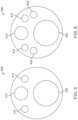
- FIGS. 2 A and 2 Billustrate configurations of two EM sensors within an endoscopic tip, in accordance with some embodiments
- FIG. 3illustrates a schematic of an EM tracking surgical system, in accordance with some embodiments
- FIG. 4illustrates a schematic circuit diagram of an EM tracking surgical system, in accordance with some embodiments
- FIG. 5illustrates a front view of an endoscopic tip having EM sensors within, in accordance with some embodiments
- FIG. 6illustrates a view of an internal cross-section of an endoscopic tip having EM sensors within, in accordance with some embodiments
- FIG. 7illustrates a side view of a cross-section of an endoscope with EM sensors within, in accordance with some embodiments
- FIG. 8illustrates a side view of a cross-section of an endoscope with EM sensors having an internally extending core, in accordance with some embodiments
- FIG. 9illustrates a side view of a cross-section of an endoscope with EM sensors having an externally extending core, in accordance with some embodiments.
- FIG. 10illustrates a catheter having external EM sensors, in accordance with some embodiments.
- FIG. 11illustrates schematic views of an EM tracking surgical system having reconfigurable bed portions, in accordance with some embodiments.
- Surgical tools having one or more EM sensorsmay be provided.
- EM sensorsmay be embedded within surgical tools.
- EM sensorsmay be integrated with surgical tools.
- EM sensorsmay be coupled to one or more external portions of surgical tools.
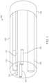
- FIG. 1illustrates a perspective view 100 of an internal cross-section of an endoscope having electromagnetic (EM) sensors 120 , in accordance with some embodiments.
- the internal cross-section of the endoscopecomprises a rigid portion 105 and a flexible portion 130 .
- the rigid portion 105may comprise a tip of the endoscope.
- the EM sensors 120 within the endoscopemay be used to spatially track the tip of the endoscope.
- the flexible portion 130may form part of a shaft of the endoscope.
- the flexible portion 130may be operable connected to a robotic arm.
- endoscope that is partially illustrated in FIG. 1may be used in conjunction with a robotic arm to assist in surgery of a patient.
- the rigid portion 105 of an endoscopemay include a camera 110 , illumination sources 115 , and a channel 125 for holding various surgical tools.
- illumination sources 115may include fiber optics-illumination sources.
- the rigid portionmay include a pair of EM sensors 120 that may be used as tracking components.
- the EM sensors 120may be used for tracking a position of the rigid portion 105 .
- Each EM sensor 120may be surrounded by coils that may interact with an EM field that is generated by field generator coils.
- the system providedmay be used for alternating current (AC) EM tracking.
- the systemmay be used for direct current (DC) EM tracking.
- an EM sensor associated with a surgical toolmay be tracked when voltage is induced within a sensor coil that is placed within the electromagnetic field.
- the system providedmay be used for alternating current (AC) EM tracking.
- the systemmay be used for direct current (DC) EM tracking.
- the EM sensors 120may output voltage information which is related to a change in the EM field as the position and/or orientation of the EM sensors 120 changes.
- the change in the position and/or orientation of the EM sensors 120may be associated with the change in the location of the rigid portion 105 of the surgical tool that contains the EM sensors 120 .
- the positional variationscan have a spatial resolution of less than about 10 mm, 9 mm, 8 mm, 7 mm, 6 mm, 5 mm, 4 mm, 3 mm, 2 mm, or 1 mm. In some cases, the spatial resolution may be greater than about 10 mm.
- the position of the endoscopemay be determined based on input from the EM sensors 120 as well as input from camera 110 .
- an initial position of the rigid portion 105 of the surgical toolmay be determined based on interactions of the EM sensors 120 with an EM field, and the position of the rigid portion 105 may be confirmed based on input received from camera 110 .
- an initial position of the rigid portion 105 of the surgical toolmay be determined based on input received from camera 110 , and the position of the rigid portion 105 may be confirmed based on an assessed location of the EM sensors 120 .
- two EM sensorsmay be positioned within a surgical tool. In examples where the two EM sensors are positioned obliquely with respect to one another, a positional state of the surgical tool may be determined in six degrees of freedom.
- EM sensorssuch as EM sensors 120 of FIG. 1 , may be positioned within surgical tools in different configurations.
- EM sensorsmay be formed of coils wrapped around a ferrous core.
- the ferrous coremay comprise ferrites.
- the ferrous coremay comprise soft ferrites.
- the ferrous coremay comprise hard ferrites.
- the ferrous coremay comprise a high permeability metal alloy.
- the diameter of each EM sensormay be 300 ⁇ m.
- the diameter of an EM sensormay be 250 ⁇ m, may be 200 ⁇ m, may be 150 ⁇ m, may be 100 ⁇ m, may be 50 ⁇ m, or may be less than 50 ⁇ m. In further examples, the diameter of an EM sensor may be 350 ⁇ m, may be 400 ⁇ m, may be 450 ⁇ m, may be 500 ⁇ m, may be 800 ⁇ m, 1 mm, 1.5 mm, or may be more than 1.5 mm. Additionally, in examples, the outer diameter of the EM sensor may be minimized. Two examples of configurations of EM sensors are provided in FIGS. 2 A and 2 B . In particular, FIGS. 2 A and 2 B illustrate configurations of two EM sensors within an endoscopic tip, in accordance with some embodiments.
- FIG. 2 Aillustrates an endoscopic tip 200 having EM sensors 210 , 220 positioned obliquely with respect to one another.
- the two sensors 210 , 220may be placed at a same distance from an end of the endoscope.
- one of sensors 210 , 220may be placed closer to a tip of an endoscope and one of sensors 210 , 220 may be placed further from a tip of an endoscope.
- Positioning EM sensors 210 , 220 oblique to each otherprovides a benefit of assessing orientation of a surgical tool in addition to assessing a location of the surgical tool.
- interactions of the EM sensors 210 , 220 with a generated EM fieldmay be assessed to determine yaw, pitch, and roll of a portion of a surgical tool that contains EM sensors 210 , 220 .
- This determinationis made based on the voltage that is produced by each EM sensor 210 , 220 as each sensor passes through the EM field.
- the voltageis generated by the intersection of an electric field of the sensor with the magnetic flux lines in the EM field.
- the change in voltagemay then be used to determine the spatial position of each sensor as the sensors move within a controlled volume, such as a controlled volume that contains the EM field.
- a controlled volumesuch as a controlled volume that contains the EM field.
- the difference in angled positionmay be assessed to determine an orientation of the surgical tool containing the EM sensors, such as endoscopic tip 200 that contains EM sensors 210 , 220 .
- the EM sensorsmay be positioned acutely to one another (not shown). When the EM sensors are positioned acutely to one another, the difference in angled positioned may also be assessed to determine an orientation of the surgical tool containing the EM sensors.
- FIG. 2 Billustrates an endoscopic tip 250 having EM sensors 260 , 270 positioned generally parallel to one another.
- the sensorsmay be used to determine a location of the endoscopic tip 250 within a patient.
- the interaction of sensors 260 , 270 with an EM fieldmay be used to generate a voltage which may identify a location of the endoscopic tip 250 that includes sensors 260 , 270 within three-dimensional special coordinates.
- the sensors 260 , 270are not positioned at an oblique or acute angle with respect to each other, it may be more difficult to assess a particular orientation of the endoscopic tip 250 .
- sensors 260 , 270share a same general orientation, it may be more difficult to distinguish each of the sensors 260 , 270 from the other.
- the sensitivity of the detection of the sensors 260 , 270is high enough, though, that the sensors 260 , 270 may be distinguished from each other even as the sensors 260 , 270 are generally parallel, the tracking of the individual sensors 260 , 270 with respect to each other may be used to assess these additional three degrees of freedom.
- providing EM sensors at different orientationswould provide a benefit of more easily distinguishing each of the EM sensors from one another, as discussed in FIG. 2 A .
- FIGS. 2 A and 2 Billustrate endoscopic tips 200 , 250 having EM sensors 210 , 220 and 260 , 270 , respectively
- an endoscopic tipmay have one EM sensor integrated therein at a position similar to EM sensor 210 within endoscopic tip 200 ; similar to EM sensor 220 within endoscopic tip 200 ; similar to EM sensor 260 within endoscopic tip 250 ; or similar to EM sensor 270 within endoscopic tip 250 .
- an EM sensormay be located near a central axis of an endoscopic tip.
- an EM sensormay partially overlap a central axis of the endoscopic tip.
- an EM sensormay be located near the periphery of the endoscopic tip.
- the one or more EM sensorsmay be tracked using an EM tracking surgical system, as discussed below in FIG. 3 .
- an EM tracking surgical systemmay be provided in which field generator coils are provided so as to generate an EM field over at least a portion of a surgical bed.
- field generator coilsmay be incorporated within a surgical bed, and/or the field generator coils may be otherwise positioned relative to the surgical bed and/or to a patient on the surgical bed.
- the location of the surgical toolmay be determined. Additionally, movements of the surgical tool may be tracked based on the interactions with the EM field.
- the measured difference between the two EM sensorsmay be assessed to provide additional sensitivity with respect to the location of the surgical tool.
- a force perception componentmay be utilized to determine a position of the surgical tool with respect to nearby tissue that is detected using the externally extended core of the EM sensor.
- EM sensorsmay be placed along a surgical tool so as to determine a shape and location of the surgical tool within a patient.
- a plurality of EM sensorsmay be placed along a surgical tool, such as a catheter.
- the interactions of the EM sensors with a generated fieldmay be assessed individually and collectively so as to determine characteristics about the position of the surgical tool with respect to the patient.
- FIG. 3illustrates a schematic of an EM tracking surgical system, in accordance with some embodiments.
- EM tracking surgical system 300may comprise a surgical bed 302 on a base 301 , a plurality of field generator coils 303 , an EM system controller 308 , a switch module 310 , a working volume 312 , and a position sensor 316 .
- the surgical bed 302may be configured to support a patient. A physician may perform a surgical procedure on the patient while the patient is placed on the surgical bed 302 .
- the surgical bed 302may comprise multiple sections that are movable relative to one another. In those embodiments, the patient's body can be moved into different positions by moving different sections of the surgical bed 302 relative to one another.
- the surgical bed 302may be formed monolithically as a single rigid structure.
- Field generator coils 303may be embedded or integrated along edge portions of the surgical bed 302 .
- the plurality of field generator coils 303may be embedded along a length of the surgical bed 302 in two rows. The rows may extend parallel to each other along the edge of the surgical bed 302 .
- the placement of the field generator coils 303 along the edges of the surgical bed 302can allow unobstructed use of fluoroscopy to image the patient's body during a surgical procedure.
- the field generator coilsmay be placed in other positions within, or around, the surgical bed 302 so as to generate a working volume 312 that may be used to track sensor 316 .
- the field generator coilsmay be incorporated within the surgical bed 302 .
- the field generator coilsmay be otherwise positioned relative to a patient and/or a surgical bed 302 .
- the shape of the working volume 312may be determined based on the shape and strength of the EM field generated by the field generator coils 303 as activated by the EM system controller 308 .
- the strength of the EM field that is generatedmay be controlled by EM system controller 308 .
- the working volume 312may be defined by the volume that includes the presence of an EM field that is strong enough to generate a detectable voltage when it interacts with an EM sensor 316 , such as EM sensors that may be disposed within surgical tools.
- an EM fieldmay have the strength of 1 nanotesla (nT), 10 nT, 100 nT, 500 nT, 1 microtelsa ( ⁇ T), 10 ⁇ T, 100 ⁇ T, 500 ⁇ T, 1 millitesla (mT), 10 mT, 100 mT, or more than 100 mT.
- the field generator coils 303may be fixed in place relative to one another.
- the field generator coilsmay be spaced apart by a predetermined distance and/or at a predefined pitch along the edges of the surgical bed 302 .
- the field generator coilsmay be nominally fixed relative to the surgical bed 302 in a global coordinate system. Any portion of the surgical bed 302 may serve as an origin of the global coordinate system.
- a datum point that lies substantially above a center portion of the surgical bed 302may serve as the origin of the global coordinate system.
- the positions of the field generator coilsmay be defined relative to the datum point.
- the field generator coils 303may not be fixed in position relative to one another. Instead, the field generator coils 303 may be located on one or more movable sections, and can move relative to one another when one or more sections of the surgical bed 302 move. In those embodiments, global tracking of a surgical tool can be facilitated by adding sensors to the surgical bed 302 that can detect changes in the configuration of the surgical bed 302 .
- working volume 312may be generated based on the placement of field generator coils 303 .
- an EM system controller 308may be configured to provide electrical current pulses to the field generator coils 303 to generate an EM field comprising the working volume 312 .
- the EM system controller 308can selectively activate or unactivate the EM field by controlling one or more switches in the switch module 310 .
- electrical current pulsesmay be provided from the EM system controller 308 to the field generator coils 303 via one or more switches in the switch module 310 .
- the switchesmay include electronic switches such as power MOSFETs, solid state relays, power transistors, and/or insulated gate bipolar transistors (IGBTs). Different types of electronic switches may be provided for controlling current to the field generator coils 303 .
- An electronic switchmay utilize solid state electronics to control current flow.
- an electronic switchmay have no moving parts and/or may not utilize an electro-mechanical device (for example, but not limited to, traditional relays or switches with moving parts).
- electrons or other charge carriers of the electronic switchmay be confined to a solid state device.
- the electronic switchmay optionally have a binary state (for example, but not limited to, switched-on or switched-off).
- the electronic switchesmay be used to control current flow to the field generator coils. The operation of switches to selectively activate the field generator coils 303 is described with reference to FIG. 4 , below.
- the EM system controller 308may be located on the surgical bed 302 , for example on a base 301 configured to support the surgical bed 302 . In some embodiments, the EM system controller 308 may be located remotely from the surgical bed 302 . For example, the EM system controller 308 may be disposed in a remote server that is in communication with the field generator coils 303 and the switch module 310 . The EM system controller 308 may be software and/or hardware components included with the server.
- the servercan have one or more processors and at least one memory for storing program instructions.
- the processor(s)can be a single or multiple microprocessors, field programmable gate arrays (FPGAs), or digital signal processors (DSPs) capable of executing particular sets of instructions.
- Computer-readable instructionscan be stored on a tangible non-transitory computer-readable medium, such as a flexible disk, a hard disk, a CD-ROM (compact disk-read only memory), and MO (magneto-optical), a DVD-ROM (digital versatile disk-read only memory), a DVD RAM (digital versatile disk-random access memory), or a semiconductor memory.
- a tangible non-transitory computer-readable mediumsuch as a flexible disk, a hard disk, a CD-ROM (compact disk-read only memory), and MO (magneto-optical), a DVD-ROM (digital versatile disk-read only memory), a DVD RAM (digital versatile disk-random access memory), or a semiconductor memory.
- the program instructionscan be implemented in hardware components or combinations of hardware and software such as, for example, ASICs, special purpose computers, or general purpose computers.
- the EM system controller 308may also be provided at any other type of external device (for example, but not limited to, a remote controller for controlling the surgical bed 302 and/or a surgical tool, any movable object or non-movable object, etc.). In some instances, the EM system controller 308 may be distributed on a cloud computing infrastructure. The EM system controller 108 may reside in different locations where the EM system controller 303 is capable of controlling the switch module 310 and selectively activating the field generator coils 303 based on the spatial information of the position sensor 316 . For instance, EM system controller 108 may activate an FG coil when a position sensor comes within a threshold distance of the FG coil. Additionally, EM system controller 308 may de-activate an FG coil when a position sensor moves beyond a threshold distance from the FG coil.
- the position sensor 316may be disposed in or on a portion of a surgical tool.
- the position sensor 316may be disposed at a distal end of the surgical tool.
- surgical toolsmay include endoscopes, catheters, ureteroscopes, forceps, different kinds of scopes, or other similar devices or surgical accessories.
- a position sensorsuch as position sensor 316 may be configured to generate an electrical signal (for example, but not limited to, voltage or current signal) in response to EM fields generated by the field generator coils 303 .
- Position sensor 316may be an EM sensor. As position sensor 316 moves within a control volume 312 , the interaction of the position sensor 316 with the EM field within the control volume 312 may cause electrical signals to be generated. The electrical signals may vary as the position sensor 316 moves between different locations within a control volume 312 . Additionally, electrical signals may vary as the position sensor 316 moves between different control volumes.
- the EM system controller 308may be configured to receive electrical signals from the position sensor 316 .
- the EM system controller 308may analyze the signals to compute a local position of the sensor 316 .
- the local position of the sensor 316may be computed relative to a local coordinate system.
- the local coordinate systemmay be defined at active field generator coils 303 corresponding to the control volume 312 in which the position sensor 316 is located.
- the EM system controller 308may be further configured to compute a global position of the sensor 316 relative to a global coordinate system.
- the global coordinate systemmay be defined at the surgical bed 302 (for example, but not limited to, above a center portion of the surgical bed 302 ).
- the global position of the sensor 316may be computed based on: (1) the local position of the sensor 316 within the control volume 312 above active field generator coils 303 , and (2) the position of the active field generator coils 303 relative to the surgical bed 302 .
- the global position of the sensor 316may be used to determine a position of a surgical tool relative to a patient on the surgical bed 302 .
- the EM system controller 308may be configured to control the switch module 310 based on one or more inputs.
- the control of the switch module 310 , and the selective activation of one or more subsets of field generator coils 303may be manual and/or automatic.
- the EM system controller 308may control the switch module 310 based on a user input corresponding to a selection of a region (or working volume 312 ) of the surgical bed 302 where tracking of a surgical tool is desired. For example, a physician may plan to perform a surgical procedure on a patient in a region within the working volume 312 . Accordingly, the physician or the physician's assistant may provide an input to the EM system controller 308 to activate the field generator coils 303 , so that movement of the surgical tool can be tracked within the first control volume via the position sensor 316 .
- a local position of the sensor 316may be determined based on distances between the sensor 316 and a plurality of reference points in different local coordinate systems.
- the different local coordinate systemsmay within and/or outside control volume 312 .
- the EM system controller 308may be configured to determine a minimum distance from those distances, and activate field generator coils 303 corresponding to the control volume 112 based on the minimum distance. Additionally, during a surgical procedure, the EM system controller 308 may be configured to track the position and/or movement of the sensor 316 within a control volume 312 corresponding to active field generator coils 303 .
- FIG. 4illustrates a schematic circuit diagram of an EM tracking surgical system, in accordance with some embodiments.
- an EM tracking surgical system 400may comprise field generator coils 403 electrically connected to a power supply 418 .
- An EM system controller 408may be in operable communication with a switch K 1 and a position sensor 416 .
- Switch K 1may be located in a switch module (for example, but not limited to, switch module 310 of FIG. 3 ).
- the EM system controller 408may be configured to selectively activate field generator coils 403 based on a position and/or movement of the position sensor 416 within and/or outside a control volume (for example, but not limited to, control volumes 312 of FIG. 3 ).
- an EM system controller 408may activate field generator coils when a position sensor 416 within a surgical tool indicates that the surgical tool is nearing a working volume that is associated with a patient.
- an EM system controller 408may activate field generator coils when a position sensor 416 within a surgical tool indicates that the surgical tool is within a threshold distance of a working volume that is associated with the patient.
- the threshold distancemay be less than 1 mm, 1 mm, 2 mm, 3 mm, 4 mm, 5 mm, 6 mm, 8 mm, 10 mm, or more than 10 mm.
- an EM system controller 408may de-activate field generator coils 403 when a position sensor 416 within a surgical tool indicates that the surgical tool has left a working area that is associated with a patient. For example, an EM system controller 408 may de-activate field generator coils when a position sensor 416 within a surgical tool indicates that the surgical tool is beyond a threshold distance of a working volume that is associated with the patient. In examples, the threshold distance may be less than 1 mm, 1 mm, 2 mm, 3 mm, 4 mm, 5 mm, 6 mm, 8 mm, 10 mm, or more than 10 mm.
- the EM system controller 408may also activate field generator coils 403 in response to receiving a request to initiate the field generator coils 403 .
- the EM system controller 408may de-activate the field generator coils 403 when a predetermined amount of time has passed without sensing movement of the position sensor 416 .
- FIG. 5illustrates a front view 500 of an endoscopic tip having EM sensors (not shown) fully integrated within. Having EM sensors fully integrated within provides a benefit of encapsulating the sensor materials so as to prevent exposure of the sensor materials to the patient, as well as to prevent exposure of potential corrosive materials to the sensor materials.
- an external view of endoscopic tipmay provide a camera 510 , illumination components 515 , and a working channel 525 .
- illumination sources 515may be placed closer to a proximate edge of a face of an endoscopic tip so as to allow an area for one or more EM sensors to reside internally within the endoscopic tip.
- illumination sources 515may be placed closer to a proximate edge of a face of an endoscopic tip so as to allow an area for one or more EM sensors to reside internally within the endoscopic tip.
- two illumination sourcesare illustrated in FIG. 5 , other examples may provide a single illumination source. In additional examples, more than two illumination sources may be provided.
- illumination sourcesmay be provided.
- the placement of the illumination sourcesmay be configured so as to allow for the placement of at least one EM sensor within a portion of a surgical tool, such as within an endoscopic tip of the surgical tool.
- FIG. 6illustrates a view 600 of an internal cross-section of an endoscopic tip having EM sensors 620 within, in accordance with some embodiments.
- EM sensors 620are positioned relative to a camera 610 , illumination sources 615 , and a working channel 625 .
- EM sensors 620are positioned between illumination sources 615 and the working channel 625 . While two EM sensors 620 are illustrated in FIG. 6 , in other examples a single EM sensor may be provided. In additional examples, more than two EM sensors may be provided.
- each EM sensordoes not need to be within a same area of the surgical tool.
- the two EM sensors as shown in FIG. 6are both within a tip of an endoscope, additional examples may provide that EM sensors are provided in staggered placement along a length of a surgical tool and/or along a length of a tip of an endoscope. Additionally, staggered positioning of EM sensors may provide for an effective lengthening of a sensor area that induces voltage change when exposed to an EM field. This, in turn, may make a a location and/or orientation of a surgical tool more readily identifiable.
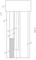
- FIG. 7illustrates a side view 700 of a cross-section of a portion of an endoscope with EM sensors within, in accordance with some embodiments.
- FIG. 7illustrates a rigid portion 705 , a camera 710 , a first EM sensor 720 having a core 722 , a working channel 725 , and a flexible portion 730 .
- Rigid portion 705may be attached to flexible portion 730 .
- a core 722 of a first EM sensor 720may stay within the rigid portion 705 of the endoscope.
- the length of the core 722 of the first EM sensormay match the length of the coil that surrounds the core 722 of the EM sensor.
- coil that surrounds the core 722 of the EM sensormay have a short length.
- coil of EM sensor 720may surround the core 722 of the EM sensor continuously.
- coil of the EM sensor 720may surround the core of the EM sensor discontinuously.
- the rigid portion 705may also comprise a second EM sensor (not shown).
- a length of a second EM sensormay match the length of the first EM sensor 720 .
- a length of a second EM sensormay be greater than the length of the first EM sensor.
- a length of a second EM sensormay be shorter than the length of the first EM sensor.
- a core of a first EM sensormay be extended so as to increase sensitivity of voltage measurement.
- a voltage that is measured between the first and second EM sensorsmay be assessed to determine a magnitude and a direction of a generated magnetic field. This information may, in turn, be used to determine information associated with a change of position of the surgical tool having the first and second EM sensors integrated therein. Additionally, the determined magnitude and direction of a generated magnetic field may be used to determine a change in orientation of the surgical tool having the first and second EM sensors integrated therein.
- the first EM sensor 820 of the first and second EM sensorsmay have a core that is extended internally.
- FIG. 8illustrates a side view 800 of a cross-section of an endoscope portion with an EM sensor 820 having an internally extending core 822 , in accordance with some embodiments.
- FIG. 8provides a first EM sensor 820 disposed between a camera 810 and a working channel 825 within an endoscope.
- the internally extending core 822extends from a rigid portion 805 of the endoscope to a flexible portion 830 .
- extending a core of a first EM sensor 820may increase the sensitivity when assessing a change in voltage induced by the first EM sensor 820 and the second EM sensor (not shown) interacting with an EM field generated by field generator coils that are activated by an EM controlling system.
- an extended coresuch as extended core 822 of first EM sensor 820
- an EM sensor with an extended coremay have increased sensitivity relative to an EM sensor without an extended core based on an aspect ratio of the EM sensor.
- sensitivity of the EM sensormay be improved.
- minimizing a length of a sensor strip while maintaining a length of the core of an EM sensormay also increase an aspect ratio of the EM sensor, thereby also increasing sensitivity of the sensor.
- sensitivity of an EM sensormay be increased based on a material composition of the EM sensor.
- sensitivity of an EM sensormay be affected by shape permeability. Shape permeability may be influenced by sensor orientation, size, and dimensions in addition to aspect ratio and core material as previously discussed.
- the first EM sensor 920 of the first and second EM sensorsmay have a core that is extended externally.
- FIG. 9illustrates a side view 900 of a cross-section of an endoscope portion with an EM sensor 920 having an externally extending core 922 , in accordance with some embodiments.
- a diameter of core 922may be less than 1 mm, 1 mm, 2 mm, 3 mm, 4 mm, 5 mm, or more than 5 mm.
- FIG. 9provides a first EM sensor 920 disposed between a camera 910 and a working channel 925 within an endoscope. As seen in FIG.
- the externally extending core 922extends from a rigid portion 905 of the endoscope to an external portion of the endoscope. As such, externally extending core 922 may contact tissue and other materials that may be found at a surgical location within a patient. In examples, the externally extending core 922 may be used to measure properties of materials, such as tissue, at a surgical site through the application of mechanical force and/or palpitations. In particular, the externally extending core 922 may be used to apply force or palpitations and/or may be used to measure the response of materials to the application of force or palpitations.
- extending a core of a first EM sensor 920may increase the sensitivity when assessing a change in voltage induced by the first EM sensor 920 and the second EM sensor (not shown) interacting with an EM field generated by field generator coils that are activated by an EM controlling system.
- an externally extended core 922may also be used to obtain information based on applying a force to materials at a surgical site.
- a force perception structuremay be attached to a free end of an extended core.
- the force perception structuremay be ball-shaped so as to maximize surface area for contact as well as to minimize negative invasive effects when the force perception structure encounters materials, such as tissue, at a surgical site.
- the force perception structuremay be shaped as a pyramid, cylinder, cube, or a flat sheet, in addition to other examples.
- the force perception structureWhen the force perception structure comes into contact with material, the force perception structure may generate an output in response to the contact interaction.
- force applied to an extended coremay be assessed based upon a degree of deflection when the extended core is pressed against tissue.
- the non-extended core of a second EM sensormay be used as reference point for differential measurement between the first EM sensor having an externally extended core and the second EM sensor that does not have an externally extended core.
- both the first and second EM sensorsmay have cores that are extended relative to a length of a coiled material provided around the core of the EM sensor. In these examples, however, the length and/or direction of core extension between the first and second EM sensor may differ so as to provide a greater differential between voltage measurements between the two sensors.
- FIG. 10illustrates a view 1000 of a catheter 1005 having external EM sensors 1010 , in accordance with some embodiments.
- the plurality of EM sensors 1010are located at different locations along the length of the catheter 1005 .
- Each of the EM sensors 1010may generate a change in voltage when exposed to an electromagnetic field. By detecting this change in voltage, the location of the catheter may be determined.
- the change of voltage that is generated by the plurality of EM sensors 1010may be used to determine a shape of the catheter 1005 . Further, as the catheter moves within a patient, the change of shape of the catheter may also be determined based on the detected change of voltage that is measured.
- a minimal interval distancemay be provided between each EM sensor 1010 and a subsequent EM sensor. By providing a minimal interval distance, interference between EM sensors may be minimized.
- the interval distance between two adjacent EM sensorsmay be in the range of 5-10 cm. In some examples, the interval distance may be less than 2 cm, 2 cm, 3 cm, 4 cm, 5 cm, 6 cm, 7 cm, 8 cm, 9 cm, 10 cm, 11 cm, 12 cm, 13 cm, 14 cm, 15 cm, 20 cm, or more than 20 cm. Additionally, the distance between each EM sensor may differ, such as within a particular distance. For example, EM sensors along a catheter may be between 5 cm and 10 cm apart. In some examples, the EM sensors along a catheter may be 5 cm apart.
- the EM sensors along a cathetermay be 10 cm apart. In some examples, the EM sensors along a catheter may be at least 5 cm apart. The spacing between EM sensors may be continuous, may be based on a pattern, and/or may be consistent within a threshold range of distances.
- each EM sensor placed along a surgical toolmay have a length that extends along the length of the shaft of the surgical tool that is between 2-4 mm. In some examples, the EM sensor may have a length along the shaft of the surgical tool of less than 1 mm, 1 mm, 2 mm, 3 mm, 4 mm, 5 mm, 6 mm, 7 mm, 8 mm, 9 mm, 10 mm, 20 mm, 30 mm, 40 mm, 50 mm, 60 mm, 70 mm, 80 mm, 90 mm, 1 cm, or more than 1 cm. Additionally, in examples, each EM sensor may comprise a core with coils wound around. The core may be a ferrous core. In examples, the core may be a type of ferrite.
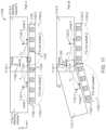
- FIG. 11illustrates schematic views of an EM tracking surgical system having reconfigurable bed portions, in accordance with some embodiments.
- Part A of FIG. 11illustrates a side view of a portion of an EM tracking surgical system 1100 when a surgical bed is in a first position.
- Part B of FIG. 11illustrates the side view of the system 1100 when the surgical bed is in a second position.
- a surgical bed 1102may comprise reconfigurable bed portions that can move relative to each other.
- the surgical bed 1102may comprise a first bed portion 1102 - 1 and a second bed portion 1102 - 2 connected at a hinge 1124 that allows the bed portions to move (for example, but not limited to, rotate and/or slide) relative to each other.
- a first subset of field generator coils 1103 - 1may be embedded along a length of the first bed portion 1102 - 1 .
- a second subset of field generator coils 1103 - 2may be embedded along a length of the second bed portion 1102 - 2 . Accordingly, the first and second subsets of field generator coils 1103 may be embedded along a length portion of the surgical bed 1102 .
- a first working volume 1112 - 1may be defined above the first subset of field generator coils 1103 - 1
- a second working volume 1112 - 2may be defined above the second subset of field generator coils 1103 - 2 .
- the dimensions and/or size of the first and second working volumes 1112 - 1 and 1112 - 2may be the same.
- the dimensions and/or size of the first and second working volumes 1112 - 1 and 1112 - 2may be different.
- the first and second working volumesmay overlap so as to form a first overlapping working volume 1114 - 1 disposed at a boundary between the first and second subsets of field generator coils 1103 - 1 and 1103 - 2 .
- the first and second working volumes 1112 - 1 and 1112 - 2may be configured to overlap by various amounts.
- the first and second working volumes 1112 - 1 and 1112 - 2may be configured to overlap by 1%, 2%, 5%, 10%, 15%, 20%, 25%, 30%, or more than 30%.
- the first and second working volumes 1112 - 1 and 1112 - 2may be configured to overlap such that one or more position sensors, such as position sensors 1116 discussed above, can be accurately tracked and controlled near the boundaries of the control volumes 1112 , and as the position sensor(s) 1116 moves between adjacent working volumes 1112 .
- a global coordinate system 1120may be defined above a center portion of the surgical bed 1102 .
- the global coordinate system 1120may be defined above a boundary line between the first bed portion 1102 - 1 and the second bed portion 1102 - 2 .
- An origin of the global coordinate system 1120may lie above the center portion of the surgical bed 1102 along the Z-direction.
- the origin of the global coordinate system 1120may also lie at a predetermined location above the hinge 1124 when the surgical bed is in the position shown in part A of FIG. 11 .
- the origin of the global coordinate system 1120may serve as a datum point from which the positions of a patient's body, the field generator coils 1103 , and the working volume 1112 may be defined.
- a first local coordinate system 1122 - 1may be defined above a center portion of the first bed portion 1102 - 1 .
- a second local coordinate system 1122 - 2may be defined above a center portion of the second bed portion 1102 - 2 .
- the first local coordinate system 1122 - 1may or may not have an origin that lies at a center portion of the first working volume 1112 - 1 .
- the second local coordinate system 1122 - 2may or may not have an origin that lies at a center portion of the second working volume 1112 - 2 .
- the origin of the first local coordinate system 1122 - 1may lie below the center portion of the first working volume 1112 - 1 , and in close proximity to the first bed portion 1102 - 1 .
- the origin of the second local coordinate system 1122 - 2may lie below the center portion of the second working volume 1112 - 2 , and in close proximity to the second bed portion 1102 - 2 .
- Vectorsmay be defined between the global coordinate system 1120 and the local coordinate systems 1122 - 1 and 1122 - 2 .
- a vector T 1may be defined from the origin of the first local coordinate system 1122 - 1 to the origin of the global coordinate system 1120 .
- a vector T 2may be defined from the origin of the second local coordinate system 1122 - 2 to the origin of the global coordinate system 1120 .
- another vector(not shown) may be defined from the origin of the first local coordinate system 1122 - 1 to the origin of the second local coordinate system 1122 - 2 .
- the vectors T 1 and T 2may be used to define the spatial relationship between the first working volume 1112 - 1 and the second working volume 1112 - 2 .
- the vectors T 1 and T 2may be used to define the spatial relationship between the first and second working volumes 1112 - 1 and 1112 - 2 relative to the datum point (for example, but not limited to, origin of the global coordinate system 1120 ) as the first and second bed portions 1102 - 1 and 1102 - 2 move relative to each other.
- the datum pointfor example, but not limited to, origin of the global coordinate system 1120
- the first bed portion 1102 - 1 and the second bed portion 1102 - 2may initially lie on a same horizontal plane extending along the Y-axis direction.
- the first and second bed portions 1102 - 1 and 1102 - 2may be configured to move relative to each other.
- the first bed portion 1102 - 1may rotate by an angle ⁇ in a clockwise direction about an X-axis extending through the hinge 1124 .
- the first bed portion 1102 - 1may be rotated, for example, to lower or raise a portion of a patient's body that is supported by the first bed portion 1102 - 1 .
- the first control volume 1112 - 1may also rotate by the angle ⁇ in a clockwise direction about the X-axis. As shown in part B of FIG. 11 , it may be observed that the origin of the first local coordinates system 1122 - 1 has shifted to a new location. Accordingly, a new vector T 1 ′ may be defined from the shifted origin of the first local coordinates system 1122 - 1 to the origin of the global coordinates system 1120 , whereby the vector T 1 ′ is different from the vector T 1 .
- the vectors T 1 ′ and T 2may be used to define the spatial relationship between the first and second working volumes 1112 - 1 and 1112 - 2 relative to the datum point (for example, but not limited to, origin of the global coordinate system 1120 ) after the first bed portion 1102 - 1 has moved relative to the second bed portion 1102 - 2 .
- part B of FIG. 11illustrates movement of the first bed portion 1102 - 1 relative to the second bed portion 1102 - 2
- the movement between the bed portionsis not limited thereto.
- the second bed portion 1102 - 2may move relative to the first bed portion 1102 - 1 .
- the first and second bed portions 1102 - 1 and 1102 - 2may simultaneously move relative to each other such that the origins of the first and second local coordinate systems shift to different locations.
- the relative movement between the bed portions 1102 - 1 and 1102 - 2may comprise a rotational motion, a translational motion, and/or a combination of rotational and translational motion, about one or more axes. Accordingly, relative movement of the bed portions 1102 - 1 and 1102 - 2 in one or more degrees of freedom (for example, but not limited to, six degrees of freedom) may be contemplated.
- a position, shape, and/or size of the overlapping working volume 1114 between adjacent working volumesmay change when the bed portions move relative to each other.
- a center (or centroid) of the first overlapping working volume 1114 - 1may be located at the origin of the global coordinates system 1120 .
- the first overlapping working volume 1114 - 1may have a regular shape (for example, but not limited to, defined by a length U 1 , width W, and height H).
- the position, shape, and/or size of the first overlapping working volume 1114 - 1may change.
- the first overlapping working volume 1114 - 1may transform to overlapping working volume 1114 - 1 ′ having an irregular shape (for example, but not limited to, having a trapezoidal-like profile as viewed from a side of the overlapping working volume 1114 - 1 ′).
- the origin of the global coordinates system 1120remains unchanged by the relative rotation of the bed portions. Unlike part A of FIG.
- the center (or centroid) of the overlapping working volume 1114 - 1 ′is not located at the origin of the global coordinates system 1120 after the rotation. Instead, the center (or centroid) of the overlapping working volume 1114 - 1 ′ may be offset from the origin of the global coordinates system 1120 by a vector T 3 after the rotation.
- relative termssuch as “lower” or “bottom” and “upper” or “top” may be used herein to describe one element's relationship to other elements as illustrated in the figures. It will be understood that relative terms are intended to encompass different orientations of the elements in addition to the orientation depicted in the figures. For example, if the element in one of the figures is turned over, elements described as being on the “lower” side of other elements would then be oriented on the “upper” side of the other elements. The exemplary term “lower” can, therefore, encompass both an orientation of “lower” and “upper,” depending upon the particular orientation of the figure.
Landscapes
- Health & Medical Sciences (AREA)
- Life Sciences & Earth Sciences (AREA)
- Surgery (AREA)
- Engineering & Computer Science (AREA)
- General Health & Medical Sciences (AREA)
- Animal Behavior & Ethology (AREA)
- Pathology (AREA)
- Veterinary Medicine (AREA)
- Public Health (AREA)
- Biophysics (AREA)
- Biomedical Technology (AREA)
- Heart & Thoracic Surgery (AREA)
- Medical Informatics (AREA)
- Molecular Biology (AREA)
- Physics & Mathematics (AREA)
- Optics & Photonics (AREA)
- Nuclear Medicine, Radiotherapy & Molecular Imaging (AREA)
- Radiology & Medical Imaging (AREA)
- Human Computer Interaction (AREA)
- Endoscopes (AREA)
Abstract
Description
Claims (18)
Priority Applications (1)
| Application Number | Priority Date | Filing Date | Title |
|---|---|---|---|
| US17/162,872US12064229B2 (en) | 2016-01-26 | 2021-01-29 | Surgical tools having electromagnetic tracking components |
Applications Claiming Priority (3)
| Application Number | Priority Date | Filing Date | Title |
|---|---|---|---|
| US201662287370P | 2016-01-26 | 2016-01-26 | |
| US15/411,562US10932691B2 (en) | 2016-01-26 | 2017-01-20 | Surgical tools having electromagnetic tracking components |
| US17/162,872US12064229B2 (en) | 2016-01-26 | 2021-01-29 | Surgical tools having electromagnetic tracking components |
Related Parent Applications (2)
| Application Number | Title | Priority Date | Filing Date |
|---|---|---|---|
| US15/411,562DivisionUS10932691B2 (en) | 2016-01-26 | 2017-01-20 | Surgical tools having electromagnetic tracking components |
| US15/411,562ContinuationUS10932691B2 (en) | 2016-01-26 | 2017-01-20 | Surgical tools having electromagnetic tracking components |
Publications (2)
| Publication Number | Publication Date |
|---|---|
| US20210145305A1 US20210145305A1 (en) | 2021-05-20 |
| US12064229B2true US12064229B2 (en) | 2024-08-20 |
Family
ID=59359449
Family Applications (2)
| Application Number | Title | Priority Date | Filing Date |
|---|---|---|---|
| US15/411,562Active2039-10-27US10932691B2 (en) | 2016-01-26 | 2017-01-20 | Surgical tools having electromagnetic tracking components |
| US17/162,872Active2037-09-03US12064229B2 (en) | 2016-01-26 | 2021-01-29 | Surgical tools having electromagnetic tracking components |
Family Applications Before (1)
| Application Number | Title | Priority Date | Filing Date |
|---|---|---|---|
| US15/411,562Active2039-10-27US10932691B2 (en) | 2016-01-26 | 2017-01-20 | Surgical tools having electromagnetic tracking components |
Country Status (1)
| Country | Link |
|---|---|
| US (2) | US10932691B2 (en) |
Families Citing this family (174)
| Publication number | Priority date | Publication date | Assignee | Title |
|---|---|---|---|---|
| US8414505B1 (en) | 2001-02-15 | 2013-04-09 | Hansen Medical, Inc. | Catheter driver system |
| WO2005087128A1 (en) | 2004-03-05 | 2005-09-22 | Hansen Medical, Inc. | Robotic catheter system |
| JP2009500086A (en) | 2005-07-01 | 2009-01-08 | ハンセン メディカル,インク. | Robotic guide catheter system |
| US12290277B2 (en) | 2007-01-02 | 2025-05-06 | Aquabeam, Llc | Tissue resection with pressure sensing |
| US9232959B2 (en) | 2007-01-02 | 2016-01-12 | Aquabeam, Llc | Multi fluid tissue resection methods and devices |
| ES2769535T3 (en) | 2008-03-06 | 2020-06-26 | Aquabeam Llc | Tissue ablation and cauterization with optical energy carried in a fluid stream |
| US9254123B2 (en) | 2009-04-29 | 2016-02-09 | Hansen Medical, Inc. | Flexible and steerable elongate instruments with shape control and support elements |
| US8672837B2 (en) | 2010-06-24 | 2014-03-18 | Hansen Medical, Inc. | Methods and devices for controlling a shapeable medical device |
| US20120071752A1 (en) | 2010-09-17 | 2012-03-22 | Sewell Christopher M | User interface and method for operating a robotic medical system |
| US20120191079A1 (en) | 2011-01-20 | 2012-07-26 | Hansen Medical, Inc. | System and method for endoluminal and translumenal therapy |
| US20130030363A1 (en) | 2011-07-29 | 2013-01-31 | Hansen Medical, Inc. | Systems and methods utilizing shape sensing fibers |
| US9452276B2 (en) | 2011-10-14 | 2016-09-27 | Intuitive Surgical Operations, Inc. | Catheter with removable vision probe |
| US9387048B2 (en) | 2011-10-14 | 2016-07-12 | Intuitive Surgical Operations, Inc. | Catheter sensor systems |
| US20130303944A1 (en) | 2012-05-14 | 2013-11-14 | Intuitive Surgical Operations, Inc. | Off-axis electromagnetic sensor |
| US10238837B2 (en) | 2011-10-14 | 2019-03-26 | Intuitive Surgical Operations, Inc. | Catheters with control modes for interchangeable probes |
| EP3351196A1 (en) | 2012-02-29 | 2018-07-25 | Procept Biorobotics Corporation | Automated image-guided tissue resection and treatment |
| US10383765B2 (en) | 2012-04-24 | 2019-08-20 | Auris Health, Inc. | Apparatus and method for a global coordinate system for use in robotic surgery |
| US20130317519A1 (en) | 2012-05-25 | 2013-11-28 | Hansen Medical, Inc. | Low friction instrument driver interface for robotic systems |
| US20140148673A1 (en) | 2012-11-28 | 2014-05-29 | Hansen Medical, Inc. | Method of anchoring pullwire directly articulatable region in catheter |
| US10231867B2 (en) | 2013-01-18 | 2019-03-19 | Auris Health, Inc. | Method, apparatus and system for a water jet |
| US9668814B2 (en) | 2013-03-07 | 2017-06-06 | Hansen Medical, Inc. | Infinitely rotatable tool with finite rotating drive shafts |
| US10149720B2 (en) | 2013-03-08 | 2018-12-11 | Auris Health, Inc. | Method, apparatus, and a system for facilitating bending of an instrument in a surgical or medical robotic environment |
| US10080576B2 (en) | 2013-03-08 | 2018-09-25 | Auris Health, Inc. | Method, apparatus, and a system for facilitating bending of an instrument in a surgical or medical robotic environment |
| US9057600B2 (en) | 2013-03-13 | 2015-06-16 | Hansen Medical, Inc. | Reducing incremental measurement sensor error |
| US9566414B2 (en) | 2013-03-13 | 2017-02-14 | Hansen Medical, Inc. | Integrated catheter and guide wire controller |
| US20140277334A1 (en) | 2013-03-14 | 2014-09-18 | Hansen Medical, Inc. | Active drives for robotic catheter manipulators |
| US11213363B2 (en) | 2013-03-14 | 2022-01-04 | Auris Health, Inc. | Catheter tension sensing |
| US9173713B2 (en) | 2013-03-14 | 2015-11-03 | Hansen Medical, Inc. | Torque-based catheter articulation |
| US9326822B2 (en) | 2013-03-14 | 2016-05-03 | Hansen Medical, Inc. | Active drives for robotic catheter manipulators |
| US9498601B2 (en) | 2013-03-14 | 2016-11-22 | Hansen Medical, Inc. | Catheter tension sensing |
| US10849702B2 (en) | 2013-03-15 | 2020-12-01 | Auris Health, Inc. | User input devices for controlling manipulation of guidewires and catheters |
| US10376672B2 (en) | 2013-03-15 | 2019-08-13 | Auris Health, Inc. | Catheter insertion system and method of fabrication |
| US20140276936A1 (en) | 2013-03-15 | 2014-09-18 | Hansen Medical, Inc. | Active drive mechanism for simultaneous rotation and translation |
| US9629595B2 (en) | 2013-03-15 | 2017-04-25 | Hansen Medical, Inc. | Systems and methods for localizing, tracking and/or controlling medical instruments |
| US9408669B2 (en) | 2013-03-15 | 2016-08-09 | Hansen Medical, Inc. | Active drive mechanism with finite range of motion |
| US9271663B2 (en) | 2013-03-15 | 2016-03-01 | Hansen Medical, Inc. | Flexible instrument localization from both remote and elongation sensors |
| US20140276647A1 (en) | 2013-03-15 | 2014-09-18 | Hansen Medical, Inc. | Vascular remote catheter manipulator |
| US9014851B2 (en) | 2013-03-15 | 2015-04-21 | Hansen Medical, Inc. | Systems and methods for tracking robotically controlled medical instruments |
| US9452018B2 (en) | 2013-03-15 | 2016-09-27 | Hansen Medical, Inc. | Rotational support for an elongate member |
| US9283046B2 (en) | 2013-03-15 | 2016-03-15 | Hansen Medical, Inc. | User interface for active drive apparatus with finite range of motion |
| US11020016B2 (en) | 2013-05-30 | 2021-06-01 | Auris Health, Inc. | System and method for displaying anatomy and devices on a movable display |
| WO2014201165A1 (en) | 2013-06-11 | 2014-12-18 | Auris Surgical Robotics, Inc. | System for robotic assisted cataract surgery |
| US10426661B2 (en) | 2013-08-13 | 2019-10-01 | Auris Health, Inc. | Method and apparatus for laser assisted cataract surgery |
| EP3060157B1 (en) | 2013-10-24 | 2019-12-11 | Auris Health, Inc. | System for robotic-assisted endolumenal surgery |
| EP3243476B1 (en) | 2014-03-24 | 2019-11-06 | Auris Health, Inc. | Systems and devices for catheter driving instinctiveness |
| US10046140B2 (en) | 2014-04-21 | 2018-08-14 | Hansen Medical, Inc. | Devices, systems, and methods for controlling active drive systems |
| US10569052B2 (en) | 2014-05-15 | 2020-02-25 | Auris Health, Inc. | Anti-buckling mechanisms for catheters |
| US9744335B2 (en) | 2014-07-01 | 2017-08-29 | Auris Surgical Robotics, Inc. | Apparatuses and methods for monitoring tendons of steerable catheters |
| US10792464B2 (en) | 2014-07-01 | 2020-10-06 | Auris Health, Inc. | Tool and method for using surgical endoscope with spiral lumens |
| US9561083B2 (en) | 2014-07-01 | 2017-02-07 | Auris Surgical Robotics, Inc. | Articulating flexible endoscopic tool with roll capabilities |
| US10159533B2 (en) | 2014-07-01 | 2018-12-25 | Auris Health, Inc. | Surgical system with configurable rail-mounted mechanical arms |
| EP3200718A4 (en) | 2014-09-30 | 2018-04-25 | Auris Surgical Robotics, Inc | Configurable robotic surgical system with virtual rail and flexible endoscope |
| US10499999B2 (en) | 2014-10-09 | 2019-12-10 | Auris Health, Inc. | Systems and methods for aligning an elongate member with an access site |
| US10314463B2 (en) | 2014-10-24 | 2019-06-11 | Auris Health, Inc. | Automated endoscope calibration |
| US11819636B2 (en) | 2015-03-30 | 2023-11-21 | Auris Health, Inc. | Endoscope pull wire electrical circuit |
| US20160287279A1 (en) | 2015-04-01 | 2016-10-06 | Auris Surgical Robotics, Inc. | Microsurgical tool for robotic applications |
| WO2016164824A1 (en) | 2015-04-09 | 2016-10-13 | Auris Surgical Robotics, Inc. | Surgical system with configurable rail-mounted mechanical arms |
| US9622827B2 (en) | 2015-05-15 | 2017-04-18 | Auris Surgical Robotics, Inc. | Surgical robotics system |
| CN108348133B (en) | 2015-09-09 | 2020-11-13 | 奥瑞斯健康公司 | Instrument Manipulators for Surgical Robotic Systems |
| JP6824967B2 (en) | 2015-09-18 | 2021-02-03 | オーリス ヘルス インコーポレイテッド | Tubular net navigation |
| US10231793B2 (en) | 2015-10-30 | 2019-03-19 | Auris Health, Inc. | Object removal through a percutaneous suction tube |
| US9955986B2 (en) | 2015-10-30 | 2018-05-01 | Auris Surgical Robotics, Inc. | Basket apparatus |
| US9949749B2 (en) | 2015-10-30 | 2018-04-24 | Auris Surgical Robotics, Inc. | Object capture with a basket |
| US10143526B2 (en) | 2015-11-30 | 2018-12-04 | Auris Health, Inc. | Robot-assisted driving systems and methods |
| US10932861B2 (en) | 2016-01-14 | 2021-03-02 | Auris Health, Inc. | Electromagnetic tracking surgical system and method of controlling the same |
| US10932691B2 (en) | 2016-01-26 | 2021-03-02 | Auris Health, Inc. | Surgical tools having electromagnetic tracking components |
| US10151606B1 (en) | 2016-02-24 | 2018-12-11 | Ommo Technologies, Inc. | Tracking position and movement using a magnetic field |
| US11324554B2 (en) | 2016-04-08 | 2022-05-10 | Auris Health, Inc. | Floating electromagnetic field generator system and method of controlling the same |
| US10454347B2 (en) | 2016-04-29 | 2019-10-22 | Auris Health, Inc. | Compact height torque sensing articulation axis assembly |
| US11037464B2 (en) | 2016-07-21 | 2021-06-15 | Auris Health, Inc. | System with emulator movement tracking for controlling medical devices |
| US10463439B2 (en) | 2016-08-26 | 2019-11-05 | Auris Health, Inc. | Steerable catheter with shaft load distributions |
| US11241559B2 (en) | 2016-08-29 | 2022-02-08 | Auris Health, Inc. | Active drive for guidewire manipulation |
| KR20230096148A (en) | 2016-08-31 | 2023-06-29 | 아우리스 헬스, 인코포레이티드 | Length conservative surgical instrument |
| US9931025B1 (en)* | 2016-09-30 | 2018-04-03 | Auris Surgical Robotics, Inc. | Automated calibration of endoscopes with pull wires |
| US10136959B2 (en) | 2016-12-28 | 2018-11-27 | Auris Health, Inc. | Endolumenal object sizing |
| US10543048B2 (en) | 2016-12-28 | 2020-01-28 | Auris Health, Inc. | Flexible instrument insertion using an adaptive insertion force threshold |
| US10244926B2 (en) | 2016-12-28 | 2019-04-02 | Auris Health, Inc. | Detecting endolumenal buckling of flexible instruments |
| CN108934160B (en) | 2017-03-28 | 2021-08-31 | 奥瑞斯健康公司 | Shaft actuating handle |
| WO2018183727A1 (en) | 2017-03-31 | 2018-10-04 | Auris Health, Inc. | Robotic systems for navigation of luminal networks that compensate for physiological noise |
| US10285574B2 (en) | 2017-04-07 | 2019-05-14 | Auris Health, Inc. | Superelastic medical instrument |
| EP3606400B1 (en) | 2017-04-07 | 2022-03-09 | Auris Health, Inc. | Patient introducer alignment |
| KR102643758B1 (en) | 2017-05-12 | 2024-03-08 | 아우리스 헬스, 인코포레이티드 | Biopsy devices and systems |
| KR102576296B1 (en) | 2017-05-17 | 2023-09-08 | 아우리스 헬스, 인코포레이티드 | Interchangeable working channels |
| US10022192B1 (en) | 2017-06-23 | 2018-07-17 | Auris Health, Inc. | Automatically-initialized robotic systems for navigation of luminal networks |
| US10299870B2 (en) | 2017-06-28 | 2019-05-28 | Auris Health, Inc. | Instrument insertion compensation |
| CN116725667A (en) | 2017-06-28 | 2023-09-12 | 奥瑞斯健康公司 | System for providing positioning information and method for positioning an instrument within an anatomical structure |
| US11026758B2 (en) | 2017-06-28 | 2021-06-08 | Auris Health, Inc. | Medical robotics systems implementing axis constraints during actuation of one or more motorized joints |
| WO2019005696A1 (en) | 2017-06-28 | 2019-01-03 | Auris Health, Inc. | Electromagnetic distortion detection |
| US10426559B2 (en) | 2017-06-30 | 2019-10-01 | Auris Health, Inc. | Systems and methods for medical instrument compression compensation |
| DE102017008148A1 (en)* | 2017-08-29 | 2019-02-28 | Joimax Gmbh | Sensor unit, intraoperative navigation system and method for detecting a surgical instrument |
| US10464209B2 (en) | 2017-10-05 | 2019-11-05 | Auris Health, Inc. | Robotic system with indication of boundary for robotic arm |
| US10016900B1 (en) | 2017-10-10 | 2018-07-10 | Auris Health, Inc. | Surgical robotic arm admittance control |
| US10145747B1 (en) | 2017-10-10 | 2018-12-04 | Auris Health, Inc. | Detection of undesirable forces on a surgical robotic arm |
| US10555778B2 (en) | 2017-10-13 | 2020-02-11 | Auris Health, Inc. | Image-based branch detection and mapping for navigation |
| US11058493B2 (en) | 2017-10-13 | 2021-07-13 | Auris Health, Inc. | Robotic system configured for navigation path tracing |
| EP3684282B1 (en) | 2017-12-06 | 2024-02-21 | Auris Health, Inc. | Systems to correct for uncommanded instrument roll |
| WO2019113391A1 (en) | 2017-12-08 | 2019-06-13 | Auris Health, Inc. | System and method for medical instrument navigation and targeting |
| JP7208237B2 (en) | 2017-12-08 | 2023-01-18 | オーリス ヘルス インコーポレイテッド | Systems and medical devices for performing medical procedures |
| CN111770736A (en) | 2017-12-11 | 2020-10-13 | 奥瑞斯健康公司 | Systems and methods for instrument-based insertion architectures |
| US11510736B2 (en) | 2017-12-14 | 2022-11-29 | Auris Health, Inc. | System and method for estimating instrument location |
| WO2019125964A1 (en) | 2017-12-18 | 2019-06-27 | Auris Health, Inc. | Methods and systems for instrument tracking and navigation within luminal networks |
| KR102264368B1 (en) | 2018-01-17 | 2021-06-17 | 아우리스 헬스, 인코포레이티드 | Surgical platform with adjustable arm support |
| USD901018S1 (en) | 2018-01-17 | 2020-11-03 | Auris Health, Inc. | Controller |
| EP3740150A4 (en) | 2018-01-17 | 2021-11-03 | Auris Health, Inc. | SURGICAL ROBOTIC SYSTEMS WITH IMPROVED ROBOTIC ARMS |
| USD873878S1 (en) | 2018-01-17 | 2020-01-28 | Auris Health, Inc. | Robotic arm |
| USD901694S1 (en) | 2018-01-17 | 2020-11-10 | Auris Health, Inc. | Instrument handle |
| USD932628S1 (en) | 2018-01-17 | 2021-10-05 | Auris Health, Inc. | Instrument cart |
| USD924410S1 (en) | 2018-01-17 | 2021-07-06 | Auris Health, Inc. | Instrument tower |
| KR20240118200A (en) | 2018-02-13 | 2024-08-02 | 아우리스 헬스, 인코포레이티드 | System and method for driving medical instrument |
| WO2019191144A1 (en) | 2018-03-28 | 2019-10-03 | Auris Health, Inc. | Systems and methods for registration of location sensors |
| CN117017505A (en) | 2018-03-28 | 2023-11-10 | 奥瑞斯健康公司 | Composite instrument and robotic system |
| JP7225259B2 (en) | 2018-03-28 | 2023-02-20 | オーリス ヘルス インコーポレイテッド | Systems and methods for indicating probable location of instruments |
| US11179213B2 (en) | 2018-05-18 | 2021-11-23 | Auris Health, Inc. | Controllers for robotically-enabled teleoperated systems |
| US10905499B2 (en) | 2018-05-30 | 2021-02-02 | Auris Health, Inc. | Systems and methods for location sensor-based branch prediction |
| JP7371026B2 (en) | 2018-05-31 | 2023-10-30 | オーリス ヘルス インコーポレイテッド | Path-based navigation of tubular networks |
| KR102567087B1 (en) | 2018-05-31 | 2023-08-17 | 아우리스 헬스, 인코포레이티드 | Robotic systems and methods for navigation of luminal networks detecting physiological noise |
| MX2020012904A (en) | 2018-05-31 | 2021-02-26 | Auris Health Inc | Image-based airway analysis and mapping. |
| JP7267309B2 (en) | 2018-06-07 | 2023-05-01 | オーリス ヘルス インコーポレイテッド | Robotic medical system with high-strength instruments |
| KR102712920B1 (en) | 2018-06-27 | 2024-10-07 | 아우리스 헬스, 인코포레이티드 | Alignment and attachment systems for medical devices |
| WO2020005370A1 (en) | 2018-06-27 | 2020-01-02 | Auris Health, Inc. | Systems and techniques for providing multiple perspectives during medical procedures |
| JP7391886B2 (en) | 2018-06-28 | 2023-12-05 | オーリス ヘルス インコーポレイテッド | Medical system incorporating pulley sharing |
| WO2020033318A1 (en) | 2018-08-07 | 2020-02-13 | Auris Health, Inc. | Combining strain-based shape sensing with catheter control |
| WO2020036685A1 (en) | 2018-08-15 | 2020-02-20 | Auris Health, Inc. | Medical instruments for tissue cauterization |
| WO2020036686A1 (en) | 2018-08-17 | 2020-02-20 | Auris Health, Inc. | Bipolar medical instrument |
| CN113164184B (en) | 2018-08-24 | 2024-06-14 | 奥瑞斯健康公司 | Medical instrument capable of being controlled manually and robotically |
| JP7427654B2 (en) | 2018-09-17 | 2024-02-05 | オーリス ヘルス インコーポレイテッド | Systems and methods for performing associated medical procedures |
| CN112804933B (en) | 2018-09-26 | 2024-10-18 | 奥瑞斯健康公司 | Articulating medical device |
| CN112770689B (en) | 2018-09-26 | 2024-07-19 | 奥瑞斯健康公司 | Systems and instruments for suction and irrigation |
| KR102852843B1 (en) | 2018-09-28 | 2025-09-03 | 아우리스 헬스, 인코포레이티드 | System and method for docking medical devices |
| WO2020069080A1 (en) | 2018-09-28 | 2020-04-02 | Auris Health, Inc. | Devices, systems, and methods for manually and robotically driving medical instruments |
| CN112804959B (en) | 2018-09-28 | 2025-01-28 | 奥瑞斯健康公司 | Robotic systems and methods for accompanying endoscopic and percutaneous medical procedures |
| US11576738B2 (en) | 2018-10-08 | 2023-02-14 | Auris Health, Inc. | Systems and instruments for tissue sealing |
| US11254009B2 (en) | 2018-12-20 | 2022-02-22 | Auris Health, Inc. | Systems and methods for robotic arm alignment and docking |
| WO2020131529A1 (en) | 2018-12-20 | 2020-06-25 | Auris Health, Inc. | Shielding for wristed instruments |
| WO2020139973A1 (en) | 2018-12-28 | 2020-07-02 | Auris Health, Inc. | Medical instrument with articulable segment |
| CN113226202B (en) | 2018-12-28 | 2024-12-03 | 奥瑞斯健康公司 | Percutaneous sheath and method for robotic medical system |
| EP3883492B1 (en) | 2019-01-25 | 2025-05-21 | Auris Health, Inc. | Vessel sealer with heating capabilities |
| US11857277B2 (en) | 2019-02-08 | 2024-01-02 | Auris Health, Inc. | Robotically controlled clot manipulation and removal |
| CN113453642B (en) | 2019-02-22 | 2025-06-03 | 奥瑞斯健康公司 | Surgical platform with motorized arm for adjustable arm support |
| US10945904B2 (en) | 2019-03-08 | 2021-03-16 | Auris Health, Inc. | Tilt mechanisms for medical systems and applications |
| WO2020197671A1 (en) | 2019-03-22 | 2020-10-01 | Auris Health, Inc. | Systems and methods for aligning inputs on medical instruments |
| EP3908201B1 (en) | 2019-03-25 | 2024-04-24 | Auris Health, Inc. | Instruments for medical stapling |
| US11617627B2 (en) | 2019-03-29 | 2023-04-04 | Auris Health, Inc. | Systems and methods for optical strain sensing in medical instruments |
| EP3952779A4 (en) | 2019-04-08 | 2023-01-18 | Auris Health, Inc. | SYSTEMS, PROCESSES AND WORKFLOW FOR CONCURRENT PROCEEDINGS |
| CN114126529A (en) | 2019-06-25 | 2022-03-01 | 奥瑞斯健康公司 | Medical instrument including a wrist with hybrid redirecting surfaces |
| US12023119B2 (en) | 2019-06-26 | 2024-07-02 | Auris Health, Inc. | Systems and methods for robotic arm alignment and docking |
| WO2020263629A1 (en) | 2019-06-27 | 2020-12-30 | Auris Health, Inc. | Systems and methods for a medical clip applier |
| WO2020264418A1 (en) | 2019-06-28 | 2020-12-30 | Auris Health, Inc. | Console overlay and methods of using same |
| WO2020263949A1 (en) | 2019-06-28 | 2020-12-30 | Auris Health, Inc. | Medical instruments including wrists with hybrid redirect surfaces |
| US11653988B2 (en) | 2019-07-29 | 2023-05-23 | Verb Surgical Inc. | Mitigating electromagnetic field distortion for a surgical robotic system |
| USD978348S1 (en) | 2019-08-15 | 2023-02-14 | Auris Health, Inc. | Drive device for a medical instrument |
| US11896330B2 (en) | 2019-08-15 | 2024-02-13 | Auris Health, Inc. | Robotic medical system having multiple medical instruments |
| USD975275S1 (en) | 2019-08-15 | 2023-01-10 | Auris Health, Inc. | Handle for a medical instrument |
| WO2021028883A1 (en) | 2019-08-15 | 2021-02-18 | Auris Health, Inc. | Medical device having multiple bending sections |
| US11272995B2 (en) | 2019-08-15 | 2022-03-15 | Auris Health, Inc. | Axial motion drive devices, systems, and methods for a robotic medical system |
| US11207141B2 (en) | 2019-08-30 | 2021-12-28 | Auris Health, Inc. | Systems and methods for weight-based registration of location sensors |
| US11147633B2 (en) | 2019-08-30 | 2021-10-19 | Auris Health, Inc. | Instrument image reliability systems and methods |
| EP4025921A4 (en) | 2019-09-03 | 2023-09-06 | Auris Health, Inc. | DETECTION AND COMPENSATION OF ELECTROMAGNETIC DISTORTION |
| CN114375182A (en) | 2019-09-10 | 2022-04-19 | 奥瑞斯健康公司 | System and method for kinematic optimization using shared robot degrees of freedom |
| WO2021059100A1 (en) | 2019-09-26 | 2021-04-01 | Auris Health, Inc. | Systems and methods for collision avoidance using object models |
| US10959792B1 (en) | 2019-09-26 | 2021-03-30 | Auris Health, Inc. | Systems and methods for collision detection and avoidance |
| US11737845B2 (en) | 2019-09-30 | 2023-08-29 | Auris Inc. | Medical instrument with a capstan |
| US11737835B2 (en) | 2019-10-29 | 2023-08-29 | Auris Health, Inc. | Braid-reinforced insulation sheath |
| CN114727850A (en) | 2019-11-21 | 2022-07-08 | 奥瑞斯健康公司 | Systems and methods for draping surgical systems |
| EP4084721B1 (en) | 2019-12-31 | 2025-10-01 | Auris Health, Inc. | Anatomical feature identification and targeting |
| CN114901188A (en) | 2019-12-31 | 2022-08-12 | 奥瑞斯健康公司 | Dynamic pulley system |
| WO2021137109A1 (en) | 2019-12-31 | 2021-07-08 | Auris Health, Inc. | Alignment techniques for percutaneous access |
| WO2021137108A1 (en) | 2019-12-31 | 2021-07-08 | Auris Health, Inc. | Alignment interfaces for percutaneous access |
| EP4084724A4 (en) | 2019-12-31 | 2023-12-27 | Auris Health, Inc. | ADVANCED BASKET DRIVE MODE |
| US11737663B2 (en) | 2020-03-30 | 2023-08-29 | Auris Health, Inc. | Target anatomical feature localization |
| US12370002B2 (en) | 2020-03-30 | 2025-07-29 | Auris Health, Inc. | Workspace optimization for robotic surgery |
| CN115802975A (en) | 2020-06-29 | 2023-03-14 | 奥瑞斯健康公司 | System and method for detecting contact between a connecting rod and an external object |
| US11357586B2 (en) | 2020-06-30 | 2022-06-14 | Auris Health, Inc. | Systems and methods for saturated robotic movement |
| CN115734765A (en) | 2020-06-30 | 2023-03-03 | 奥瑞斯健康公司 | Robotic medical system with crash proximity indicator |
Citations (209)
| Publication number | Priority date | Publication date | Assignee | Title |
|---|---|---|---|---|
| US1011038A (en) | 1911-03-11 | 1911-12-05 | Harry L Davenport | Surgical operating-table. |
| US3428307A (en) | 1964-11-06 | 1969-02-18 | Philips Corp | Adjustable couches |
| US3620210A (en) | 1969-03-21 | 1971-11-16 | Paramount Health Equip Corp | Sacroiliac rotator |
| US3751028A (en) | 1971-07-22 | 1973-08-07 | Siemens Ag | Supporting table for patients |
| US4173228A (en)* | 1977-05-16 | 1979-11-06 | Applied Medical Devices | Catheter locating device |
| US5253647A (en)* | 1990-04-13 | 1993-10-19 | Olympus Optical Co., Ltd. | Insertion position and orientation state pickup for endoscope |
| US5318025A (en) | 1992-04-01 | 1994-06-07 | General Electric Company | Tracking system to monitor the position and orientation of a device using multiplexed magnetic resonance detection |
| US5429132A (en)* | 1990-08-24 | 1995-07-04 | Imperial College Of Science Technology And Medicine | Probe system |
| US5558091A (en) | 1993-10-06 | 1996-09-24 | Biosense, Inc. | Magnetic determination of position and orientation |
| US5727553A (en)* | 1996-03-25 | 1998-03-17 | Saad; Saad A. | Catheter with integral electromagnetic location identification device |
| US5913168A (en) | 1995-06-16 | 1999-06-15 | France Telecom | Method of controlling handover in a multicellular radio communications network, and speed estimation methods relating thereto |
| US6004271A (en) | 1998-05-07 | 1999-12-21 | Boston Scientific Corporation | Combined motor drive and automated longitudinal position translator for ultrasonic imaging system |
| US6253770B1 (en)* | 1996-02-15 | 2001-07-03 | Biosense, Inc. | Catheter with lumen |
| US20010009976A1 (en) | 1997-09-26 | 2001-07-26 | Ep Technologies, Inc. | Systems for recording use of structures deployed in association with heart tissue |
| US20010029366A1 (en) | 1993-10-15 | 2001-10-11 | Swanson David K. | Composite structures and methods for ablating tissue to form complex lesion patterns in the treatment of cardiac conditions and the like |
| US6310573B1 (en) | 1997-06-18 | 2001-10-30 | Telefonaktiebolaget Lm Ericsson (Publ) | Velocity calculation |
| US20010047133A1 (en)* | 1998-08-02 | 2001-11-29 | Super Dimension Ltd. | Imaging device with magnetically permeable compensator |
| US20020065455A1 (en)* | 1995-01-24 | 2002-05-30 | Shlomo Ben-Haim | Medical diagnosis, treatment and imaging systems |
| US20020087169A1 (en) | 1998-02-24 | 2002-07-04 | Brock David L. | Flexible instrument |
| US20020095730A1 (en) | 2000-07-21 | 2002-07-25 | Adil Al-Kassim | Tabletop for radiation therapy and diagnostic imaging |
| US20020167313A1 (en)* | 2001-05-11 | 2002-11-14 | Taimisto Miriam H. | Method and apparatus for improved sensor accuracy |
| US20020177789A1 (en) | 2001-05-06 | 2002-11-28 | Ferry Steven J. | System and methods for advancing a catheter |
| US6511417B1 (en)* | 1998-09-03 | 2003-01-28 | Olympus Optical Co., Ltd. | System for detecting the shape of an endoscope using source coils and sense coils |
| US6530913B1 (en) | 1997-04-04 | 2003-03-11 | Jeffrey Giba | Steerable catheter |
| US20030052785A1 (en)* | 2001-09-14 | 2003-03-20 | Margo Gisselberg | Miniature resonating marker assembly |
| US6544230B1 (en) | 1998-03-31 | 2003-04-08 | Transvascular, Inc. | Catheters, systems and methods for percutaneous in situ arterio-venous bypass |
| US20030074011A1 (en) | 1998-09-24 | 2003-04-17 | Super Dimension Ltd. | System and method of recording and displaying in context of an image a location of at least one point-of-interest in a body during an intra-body medical procedure |
| US6572535B2 (en)* | 2001-03-12 | 2003-06-03 | Olympus Optical Co., Ltd. | Endoscope |
| US20030129750A1 (en)* | 1998-02-05 | 2003-07-10 | Yitzhack Schwartz | Homing of donor cells to a target zone in tissue using active therapeutics or substances |
| US20030135204A1 (en) | 2001-02-15 | 2003-07-17 | Endo Via Medical, Inc. | Robotically controlled medical instrument with a flexible section |
| US6610007B2 (en) | 2000-04-03 | 2003-08-26 | Neoguide Systems, Inc. | Steerable segmented endoscope and method of insertion |
| US6636757B1 (en) | 2001-06-04 | 2003-10-21 | Surgical Navigation Technologies, Inc. | Method and apparatus for electromagnetic navigation of a surgical probe near a metal object |
| US6669709B1 (en) | 1996-03-15 | 2003-12-30 | Transvascular, Inc. | Catheter apparatus and methodology for generating a fistula on-demand between closely associated blood vessels at a pre-chosen anatomic site in-vivo |
| US20040162487A1 (en)* | 2002-11-29 | 2004-08-19 | Klaus Klingenbeck-Regn | Medical examination and/or treatment system |
| US20040162480A1 (en) | 2002-11-28 | 2004-08-19 | Esaote S.P.A. | Combination magnetic resonance imaging apparatus and patient table |
| US20040176751A1 (en) | 2002-08-14 | 2004-09-09 | Endovia Medical, Inc. | Robotic medical instrument system |
| US20040172757A1 (en) | 2002-11-26 | 2004-09-09 | Baskar Somasundaram | Multiconfiguration braking system |
| US20040193146A1 (en) | 2001-02-15 | 2004-09-30 | Endo Via Medical, Inc. | Robotically controlled surgical instruments |
| US20040199072A1 (en) | 2003-04-01 | 2004-10-07 | Stacy Sprouse | Integrated electromagnetic navigation and patient positioning device |
| US20040220461A1 (en)* | 2003-04-29 | 2004-11-04 | Yitzhack Schwartz | Transseptal facilitation using sheath with electrode arrangement |
| US6905460B2 (en) | 1996-02-20 | 2005-06-14 | Intuitive Surgical, Inc. | Method and apparatus for performing minimally invasive surgical procedures |
| US20050143944A1 (en)* | 2003-12-21 | 2005-06-30 | Automotive Systems Laboratory, Inc. | Magnetic sensor |
| US20050182295A1 (en) | 2003-12-12 | 2005-08-18 | University Of Washington | Catheterscope 3D guidance and interface system |
| US20050197767A1 (en) | 2004-02-05 | 2005-09-08 | Nortrup Edward H. | Smart answering machine |
| US6944492B1 (en) | 2001-10-01 | 2005-09-13 | Fonar Corporation | Patient bed support for an open MRI system |
| US20050245821A1 (en)* | 2004-03-05 | 2005-11-03 | Assaf Govari | Position sensing system for orthopedic applications |
| US20060116571A1 (en)* | 2004-12-01 | 2006-06-01 | Siemens Aktiengesellschaft | Guidewire for vascular catheters |
| US20060241397A1 (en) | 2005-02-22 | 2006-10-26 | Assaf Govari | Reference pad for position sensing |
| US20070016007A1 (en)* | 2005-07-15 | 2007-01-18 | Assaf Govari | Hybrid magnetic-based and impedance-based position sensing |
| US20070025527A1 (en) | 2005-07-21 | 2007-02-01 | Mario Eichenseer | Computed tomography apparatus and patient positioning table therefor allowing rotation of the patient support plate |
| US20070049797A1 (en)* | 2004-03-19 | 2007-03-01 | Olympus Corporation | Double-balloon endoscope system |
| US20070060879A1 (en) | 2001-02-15 | 2007-03-15 | Hansen Medical, Inc. | Coaxial catheter system |
| US20070208252A1 (en)* | 2004-04-21 | 2007-09-06 | Acclarent, Inc. | Systems and methods for performing image guided procedures within the ear, nose, throat and paranasal sinuses |
| US20070244388A1 (en)* | 2004-12-17 | 2007-10-18 | Ryoji Sato | Position Detection System, Guidance System, Position Detection Method, Medical Device, and Medical Magnetic-Induction and Position-Detection System |
| US7371210B2 (en) | 1998-02-24 | 2008-05-13 | Hansen Medical, Inc. | Flexible instrument |
| US20080139915A1 (en)* | 2006-12-07 | 2008-06-12 | Medtronic Vascular, Inc. | Vascular Position Locating and/or Mapping Apparatus and Methods |
| US20080300592A1 (en) | 2001-02-15 | 2008-12-04 | Hansen Medical, Inc. | Catheter driver system |
| US20090054884A1 (en) | 1997-09-11 | 2009-02-26 | Farley Brian E | Method of ligating hollow anatomical structures |
| US20090064413A1 (en) | 2007-09-06 | 2009-03-12 | Orbital Therapy Llc | Patient support system for full access prone position breast radiotherapy |
| US20090126113A1 (en) | 2007-09-13 | 2009-05-21 | Thomas Hejkal | Rotatable Surgery Table |
| US20090139030A1 (en) | 2007-11-30 | 2009-06-04 | Cyberknife Center Of Philadelphia, Llc | Patient alignment device |
| US20100016757A1 (en)* | 2008-07-10 | 2010-01-21 | Superdimension, Ltd. | Integrated Multi-Functional Endoscopic Tool |
| US20100210939A1 (en)* | 1999-10-28 | 2010-08-19 | Medtronic Navigation, Inc. | Method and Apparatus for Surgical Navigation |
| US7789874B2 (en) | 2005-05-03 | 2010-09-07 | Hansen Medical, Inc. | Support assembly for robotic catheter system |
| US20100228191A1 (en) | 2009-03-05 | 2010-09-09 | Hansen Medical, Inc. | Lockable support assembly and method |
| US20100319121A1 (en) | 2009-06-19 | 2010-12-23 | Jeff Polomsky | Maneuverable patient transfer device |
| US20100324412A1 (en)* | 2009-06-22 | 2010-12-23 | Assaf Govari | Catheter with obliquely-oriented coils |
| US20100331856A1 (en) | 2008-12-12 | 2010-12-30 | Hansen Medical Inc. | Multiple flexible and steerable elongate instruments for minimally invasive operations |
| US20110066029A1 (en)* | 2009-09-11 | 2011-03-17 | Medtronic, Inc. | Electromagnetic Medical Device |
| US20110152880A1 (en) | 2009-12-23 | 2011-06-23 | Hansen Medical, Inc. | Flexible and steerable elongate instruments with torsion control |
| US20110172519A1 (en)* | 2007-10-11 | 2011-07-14 | Tufts University | Systems, devices and methods employing fiber optic shape tracking |
| US20120053453A1 (en) | 2009-05-13 | 2012-03-01 | Rainer Graumann | Medical navigation system |
| US8146874B2 (en) | 2007-02-02 | 2012-04-03 | Hansen Medical, Inc. | Mounting support assembly for suspending a medical instrument driver above an operating table |
| US20120158011A1 (en) | 2010-12-16 | 2012-06-21 | Sandhu Kulbir S | Proximity sensor interface in a robotic catheter system |
| US20120172761A1 (en)* | 2010-12-29 | 2012-07-05 | Nimrod Meller | Medical device guidewire with a position sensor |
| US20120172712A1 (en) | 2010-12-29 | 2012-07-05 | Bar-Tal Meir | Respiratory effect reduction in catheter position sensing |
| US20120174317A1 (en) | 2004-04-06 | 2012-07-12 | Saracen Michael J | Robotic arm for patient positioning assembly |
| US8302221B1 (en) | 2009-03-03 | 2012-11-06 | Pivot Assist, Llc | Medical assist device with lift seat |
| US20130054168A1 (en)* | 2010-06-09 | 2013-02-28 | Olympus Medical Systems Corp. | Probe shape detection apparatus and probe shape detection method |
| US20130162775A1 (en)* | 2011-11-29 | 2013-06-27 | Harald Baumann | Apparatus and method for endoscopic 3D data Collection |
| US8505137B1 (en) | 2008-01-22 | 2013-08-13 | Artec Imaging, Llc | Equine CT table |
| US20130225943A1 (en)* | 2012-02-22 | 2013-08-29 | Veran Medical Technologies, Inc. | Steerable surgical catheter having biopsy devices and related systems and methods for four dimensional soft tissue navigation |
| US20130317519A1 (en) | 2012-05-25 | 2013-11-28 | Hansen Medical, Inc. | Low friction instrument driver interface for robotic systems |
| US8602031B2 (en) | 2009-01-12 | 2013-12-10 | Hansen Medical, Inc. | Modular interfaces and drive actuation through barrier |
| US20130338538A1 (en)* | 2012-04-16 | 2013-12-19 | Agency For Science, Technology And Research | Guide wire arrangement |
| US20140033432A1 (en) | 2012-07-31 | 2014-02-06 | Varian Medical Systems Uk Limited | Patient positioning and support systems |
| US20140100463A1 (en)* | 2012-07-13 | 2014-04-10 | Olympus Medical Systems Corp. | Probe and endoscope |
| US8720448B2 (en) | 2008-11-07 | 2014-05-13 | Hansen Medical, Inc. | Sterile interface apparatus |
| US20140142591A1 (en) | 2012-04-24 | 2014-05-22 | Auris Surgical Robotics, Inc. | Method, apparatus and a system for robotic assisted surgery |
| US8827948B2 (en) | 2010-09-17 | 2014-09-09 | Hansen Medical, Inc. | Steerable catheters |
| US20140276939A1 (en) | 2013-03-15 | 2014-09-18 | Hansen Medical, Inc. | Active drive mechanism with finite range of motion |
| US20140309649A1 (en) | 2013-01-18 | 2014-10-16 | Auris Surgical Robotics, Inc. | Method, apparatus and system for a water jet |
| US8894610B2 (en) | 2012-11-28 | 2014-11-25 | Hansen Medical, Inc. | Catheter having unirail pullwire architecture |
| US20140350387A1 (en) | 2011-05-12 | 2014-11-27 | The Johns Hopkins University | Electromagnetic tracking system and methods of using same |
| US20140357984A1 (en) | 2013-05-30 | 2014-12-04 | Translucent Medical, Inc. | System and method for displaying anatomy and devices on a movable display |
| US20140364870A1 (en) | 2013-06-11 | 2014-12-11 | Auris Surgical Robotics, Inc. | Method, apparatus, and a system for robotic assisted cataract surgery |
| US20140379000A1 (en) | 2013-03-08 | 2014-12-25 | Auris Surgical Robotics, Inc. | Method, apparatus, and a system forfacilitating bending of an instrument in asurgical or medical robotic environment |
| US20150026889A1 (en) | 2012-04-13 | 2015-01-29 | Stille Ab | Surgical tables |
| US20150051592A1 (en) | 2013-08-13 | 2015-02-19 | Auris Surgical Robotics, Inc. | Method and apparatus for laser assisted cataract surgery |
| US20150047125A1 (en) | 2013-08-13 | 2015-02-19 | Samsung Electronics Co., Ltd. | Apparatus for capturing medical image and method of adjusting table thereof |
| US20150101442A1 (en) | 2013-03-08 | 2015-04-16 | Auris Surgical Robotics, Inc. | Method, apparatus, and a system for facilitating bending of an instrument in a surgical or medical robotic environment |
| US20150119638A1 (en) | 2013-10-24 | 2015-04-30 | Auris Surgical Robotics, Inc. | Instrument device manipulator with tension sensing apparatus |
| US20150335480A1 (en) | 2012-04-24 | 2015-11-26 | Auris Surgical Robotics, Inc. | Apparatus and method for a global coordinate system for use in robotic surgery |
| US20160000627A1 (en) | 2014-07-07 | 2016-01-07 | Roger P. Jackson | Single and dual column patient positioning and support structure |
| US20160001038A1 (en) | 2014-07-01 | 2016-01-07 | Auris Surgical Robotics, Inc. | Tool and method for using surgical endoscope with spiral lumens |
| US9254123B2 (en) | 2009-04-29 | 2016-02-09 | Hansen Medical, Inc. | Flexible and steerable elongate instruments with shape control and support elements |
| US9301726B2 (en) | 2014-05-02 | 2016-04-05 | Wisconsin Alumni Research Foundation | CT machine for multi-angle scanning of stationary patients |
| US20160100772A1 (en)* | 2013-07-02 | 2016-04-14 | Olympus Corporation | Medical instrument |
| US9326822B2 (en) | 2013-03-14 | 2016-05-03 | Hansen Medical, Inc. | Active drives for robotic catheter manipulators |
| US20160270865A1 (en) | 2014-07-01 | 2016-09-22 | Auris Surgical Robotics, Inc. | Reusable catheter with disposable balloon attachment and tapered tip |
| US9452018B2 (en) | 2013-03-15 | 2016-09-27 | Hansen Medical, Inc. | Rotational support for an elongate member |
| US20160278852A1 (en)* | 2013-12-12 | 2016-09-29 | St. Jude Medical, Cardiology Division, Inc. | Medical device with contact force sensing tip |
| US20160287279A1 (en) | 2015-04-01 | 2016-10-06 | Auris Surgical Robotics, Inc. | Microsurgical tool for robotic applications |
| US20160296294A1 (en) | 2014-07-01 | 2016-10-13 | Auris Surgical Robotics, Inc. | Surgical system with configurable rail-mounted mechanical arms |
| US20160324474A1 (en)* | 2015-05-08 | 2016-11-10 | St. Jude Medical, Cardiology Division, Inc. | Integrated Sensors for Medical Devices and Method of Making Integrated Sensors for Medical Devices |
| US9504604B2 (en) | 2011-12-16 | 2016-11-29 | Auris Surgical Robotics, Inc. | Lithotripsy eye treatment |
| US20160374541A1 (en) | 2014-10-24 | 2016-12-29 | Auris Surgical Robotics, Inc. | Automated endoscope calibration |
| US20170007337A1 (en) | 2014-07-01 | 2017-01-12 | Auris Surgical Robotics, Inc. | Driver-mounted torque sensing mechanism |
| US9561083B2 (en) | 2014-07-01 | 2017-02-07 | Auris Surgical Robotics, Inc. | Articulating flexible endoscopic tool with roll capabilities |
| US20170065364A1 (en) | 2013-10-24 | 2017-03-09 | Auris Surgical Robotics, Inc. | Instrument device manipulator with roll mechanism |
| US9622827B2 (en) | 2015-05-15 | 2017-04-18 | Auris Surgical Robotics, Inc. | Surgical robotics system |
| US20170105804A1 (en) | 2013-03-15 | 2017-04-20 | Hansen Medical, Inc. | Vascular remote catheter manipulator |
| US20170119481A1 (en) | 2015-10-30 | 2017-05-04 | Auris Surgical Robotics, Inc. | Process for percutaneous operations |
| US20170202627A1 (en) | 2016-01-14 | 2017-07-20 | Auris Surgical Robotics, Inc. | Electromagnetic tracking surgical system and method of controlling the same |
| US20170209073A1 (en) | 2016-01-26 | 2017-07-27 | Auris Surgical Robotics, Inc. | Surgical tools having electromagnetic tracking components |
| US20170215978A1 (en) | 2004-03-05 | 2017-08-03 | Hansen Medical, Inc. | Robotic catheter system |
| US9727963B2 (en) | 2015-09-18 | 2017-08-08 | Auris Surgical Robotics, Inc. | Navigation of tubular networks |
| US9737371B2 (en) | 2014-09-30 | 2017-08-22 | Auris Surgical Robotics, Inc. | Configurable robotic surgical system with virtual rail and flexible endoscope |
| US9744335B2 (en) | 2014-07-01 | 2017-08-29 | Auris Surgical Robotics, Inc. | Apparatuses and methods for monitoring tendons of steerable catheters |
| US20170290631A1 (en) | 2016-04-08 | 2017-10-12 | Auris Surgical Robotics, Inc. | Floating electromagnetic field generator system and method of controlling the same |
| US9788910B2 (en) | 2014-07-01 | 2017-10-17 | Auris Surgical Robotics, Inc. | Instrument-mounted tension sensing mechanism for robotically-driven medical instruments |
| US9818681B2 (en) | 2014-12-25 | 2017-11-14 | Shinko Electric Industries Co., Ltd. | Wiring substrate |
| US20170367767A1 (en)* | 2014-12-22 | 2017-12-28 | Intuitive Surgical Operations, Inc. | Flexible Electromagnetic Sensor |
| US20170367782A1 (en) | 2015-09-09 | 2017-12-28 | Auris Surgical Robotics, Inc. | Instrument device manipulator with back-mounted tool attachment mechanism |
| US9867635B2 (en) | 2013-03-08 | 2018-01-16 | Auris Surgical Robotics, Inc. | Method, apparatus and system for a water jet |
| US20180025666A1 (en) | 2016-07-21 | 2018-01-25 | Auris Surgical Robotics, Inc. | System with emulator movement tracking for controlling medical devices |
| US9918681B2 (en) | 2011-09-16 | 2018-03-20 | Auris Surgical Robotics, Inc. | System and method for virtually tracking a surgical tool on a movable display |
| US9931025B1 (en) | 2016-09-30 | 2018-04-03 | Auris Surgical Robotics, Inc. | Automated calibration of endoscopes with pull wires |
| US9949749B2 (en) | 2015-10-30 | 2018-04-24 | Auris Surgical Robotics, Inc. | Object capture with a basket |
| US9955986B2 (en) | 2015-10-30 | 2018-05-01 | Auris Surgical Robotics, Inc. | Basket apparatus |
| US9962228B2 (en) | 2016-08-31 | 2018-05-08 | Auris Surgical Robotics, Inc. | Length conservative surgical instrument |
| US9974501B2 (en)* | 2011-01-28 | 2018-05-22 | Medtronic Navigation, Inc. | Method and apparatus for image-based navigation |
| US10016900B1 (en) | 2017-10-10 | 2018-07-10 | Auris Health, Inc. | Surgical robotic arm admittance control |
| US10022192B1 (en) | 2017-06-23 | 2018-07-17 | Auris Health, Inc. | Automatically-initialized robotic systems for navigation of luminal networks |
| US20180279852A1 (en) | 2017-03-31 | 2018-10-04 | Auris Health, Inc. | Robotic systems for navigation of luminal networks that compensate for physiological noise |
| US20180280660A1 (en) | 2017-03-28 | 2018-10-04 | Auris Health, Inc. | Shaft actuating handle |
| US20180289431A1 (en) | 2017-04-07 | 2018-10-11 | Auris Health, Inc. | Patient introducer alignment |
| US20180325499A1 (en) | 2017-05-12 | 2018-11-15 | Auris Health, Inc. | Biopsy apparatus and system |
| US20180333044A1 (en) | 2017-05-17 | 2018-11-22 | Auris Health, Inc. | Exchangeable working channel |
| US10136959B2 (en) | 2016-12-28 | 2018-11-27 | Auris Health, Inc. | Endolumenal object sizing |
| US10145747B1 (en) | 2017-10-10 | 2018-12-04 | Auris Health, Inc. | Detection of undesirable forces on a surgical robotic arm |
| US20190000576A1 (en) | 2017-06-28 | 2019-01-03 | Auris Health, Inc. | Medical robotics systems implementing axis constraints during actuation of one or more motorized joints |
| US20190000559A1 (en) | 2017-06-28 | 2019-01-03 | Auris Health, Inc. | Electromagnetic field generator alignment |
| US20190000560A1 (en) | 2017-06-28 | 2019-01-03 | Auris Health, Inc. | Electromagnetic distortion detection |
| US20190083183A1 (en) | 2015-04-09 | 2019-03-21 | Auris Health, Inc. | Surgical system with configurable rail-mounted mechanical arms |
| US10244926B2 (en) | 2016-12-28 | 2019-04-02 | Auris Health, Inc. | Detecting endolumenal buckling of flexible instruments |
| US20190110843A1 (en) | 2017-10-13 | 2019-04-18 | Auris Health, Inc. | Image-based branch detection and mapping for navigation |
| US20190110839A1 (en) | 2017-10-13 | 2019-04-18 | Auris Health, Inc. | Robotic system configured for navigation path tracing |
| US10285574B2 (en) | 2017-04-07 | 2019-05-14 | Auris Health, Inc. | Superelastic medical instrument |
| US10299870B2 (en) | 2017-06-28 | 2019-05-28 | Auris Health, Inc. | Instrument insertion compensation |
| US20190167366A1 (en) | 2017-12-06 | 2019-06-06 | Auris Health, Inc. | Systems and methods to correct for uncommanded instrument roll |
| US20190175799A1 (en) | 2017-12-08 | 2019-06-13 | Auris Health, Inc. | Directed fluidics |
| US20190175062A1 (en) | 2017-12-08 | 2019-06-13 | Auris Health, Inc. | System and method for medical instrument navigation and targeting |
| US20190183587A1 (en) | 2017-12-18 | 2019-06-20 | Auris Health, Inc. | Methods and systems for instrument tracking and navigation within luminal networks |
| US20190183585A1 (en) | 2017-12-14 | 2019-06-20 | Auris Health, Inc. | System and method for estimating instrument location |
| US20190216576A1 (en) | 2018-01-17 | 2019-07-18 | Auris Health, Inc. | Surgical platform with adjustable arm supports |
| US20190246882A1 (en) | 2018-02-13 | 2019-08-15 | Auris Health, Inc. | System and method for driving medical instrument |
| US20190269468A1 (en) | 2018-03-01 | 2019-09-05 | Auris Health, Inc. | Methods and systems for mapping and navigation |
| US10426559B2 (en) | 2017-06-30 | 2019-10-01 | Auris Health, Inc. | Systems and methods for medical instrument compression compensation |
| US20190298460A1 (en) | 2018-03-28 | 2019-10-03 | Auris Health, Inc. | Medical instruments with variable bending stiffness profiles |
| US20190298160A1 (en) | 2018-03-28 | 2019-10-03 | Auris Health, Inc. | Systems and methods for displaying estimated location of instrument |
| US20190298465A1 (en) | 2018-03-29 | 2019-10-03 | Auris Health, Inc. | Robotically-enabled medical systems with multifunction end effectors having rotational offsets |
| US10464209B2 (en) | 2017-10-05 | 2019-11-05 | Auris Health, Inc. | Robotic system with indication of boundary for robotic arm |
| US10470830B2 (en) | 2017-12-11 | 2019-11-12 | Auris Health, Inc. | Systems and methods for instrument based insertion architectures |
| US20190365486A1 (en) | 2018-05-31 | 2019-12-05 | Auris Health, Inc. | Path-based navigation of tubular networks |
| US20190365479A1 (en) | 2018-05-30 | 2019-12-05 | Auris Health, Inc. | Systems and methods for location sensor-based branch prediction |
| US20190365209A1 (en) | 2018-05-31 | 2019-12-05 | Auris Health, Inc. | Robotic systems and methods for navigation of luminal network that detect physiological noise |
| US20190375383A1 (en) | 2018-06-06 | 2019-12-12 | Sensata Technologies, Inc. | Electromechanical braking connector |
| US20190374297A1 (en) | 2018-06-07 | 2019-12-12 | Auris Health, Inc. | Robotic medical systems with high force instruments |
| US20190380787A1 (en) | 2018-05-31 | 2019-12-19 | Auris Health, Inc. | Image-based airway analysis and mapping |
| US20200000533A1 (en) | 2018-06-28 | 2020-01-02 | Auris Health, Inc. | Medical systems incorporating pulley sharing |
| US20200000530A1 (en) | 2018-06-27 | 2020-01-02 | Auris Health, Inc. | Systems and techniques for providing multiple perspectives during medical procedures |
| US10524866B2 (en) | 2018-03-28 | 2020-01-07 | Auris Health, Inc. | Systems and methods for registration of location sensors |
| US10543048B2 (en) | 2016-12-28 | 2020-01-28 | Auris Health, Inc. | Flexible instrument insertion using an adaptive insertion force threshold |
| US20200046434A1 (en) | 2018-08-07 | 2020-02-13 | Auris Health, Inc. | Combining strain-based shape sensing with catheter control |
| US20200054408A1 (en) | 2018-08-15 | 2020-02-20 | Auris Health, Inc. | Medical instruments for tissue cauterization |
| US20200060516A1 (en) | 2018-08-24 | 2020-02-27 | Auris Health, Inc. | Manually and robotically controllable medical instruments |
| US20200085516A1 (en) | 2018-09-17 | 2020-03-19 | Auris Health, Inc. | Systems and methods for concomitant medical procedures |
| US20200093554A1 (en) | 2018-09-26 | 2020-03-26 | Auris Health, Inc. | Articulating medical instruments |
| US20200093549A1 (en) | 2018-09-26 | 2020-03-26 | Auris Health, Inc. | Systems and instruments for suction and irrigation |
| US20200100845A1 (en) | 2018-09-28 | 2020-04-02 | Auris Health, Inc. | Devices, systems, and methods for manually and robotically driving medical instruments |
| US20200100853A1 (en) | 2018-09-28 | 2020-04-02 | Auris Health, Inc. | Systems and methods for docking medical instruments |
| US20200100855A1 (en) | 2018-09-28 | 2020-04-02 | Auris Health, Inc. | Robotic systems and methods for concomitant endoscopic and percutaneous medical procedures |
| US20200107894A1 (en) | 2018-10-08 | 2020-04-09 | Auris Health, Inc. | Systems and instruments for tissue sealing |
| US10617374B2 (en) | 2011-01-28 | 2020-04-14 | Medtronic Navigation, Inc. | Method and apparatus for image-based navigation |
| US10639114B2 (en) | 2018-08-17 | 2020-05-05 | Auris Health, Inc. | Bipolar medical instrument |
| US10646279B2 (en) | 2013-04-12 | 2020-05-12 | Koninklijke Philips N.V. | Imaging apparatus for brachytherapy or biopsy |
| US10677910B2 (en) | 2013-11-14 | 2020-06-09 | Technische Universiteit Eindhoven | System for locating an object using an antenna array with partially overlapping coils |
| US20200197112A1 (en) | 2018-12-20 | 2020-06-25 | Auris Health, Inc. | Shielding for wristed instruments |
| US20200206472A1 (en) | 2018-12-28 | 2020-07-02 | Auris Health, Inc. | Percutaneous sheath for robotic medical systems and methods |
| US10702346B2 (en) | 2014-07-15 | 2020-07-07 | Koninklijke Philips N.V. | Image integration and robotic endoscope control in X-ray suite |
| US10722140B2 (en) | 2014-07-03 | 2020-07-28 | St. Jude Medical International Holding S.À R.L. | Localized magnetic field generator |
| US20200268460A1 (en) | 2019-02-22 | 2020-08-27 | Auris Health, Inc. | Surgical platform with motorized arms for adjustable arm supports |
| US20200281787A1 (en) | 2019-03-08 | 2020-09-10 | Auris Health, Inc. | Tilt mechanisms for medical systems and applications |
| US20200297437A1 (en) | 2019-03-22 | 2020-09-24 | Auris Health, Inc. | Systems and methods for aligning inputs on medical instruments |
| US20200305989A1 (en) | 2019-03-25 | 2020-10-01 | Auris Health, Inc. | Systems and methods for medical stapling |
| US20200305922A1 (en) | 2017-10-19 | 2020-10-01 | Innolcon Medical Technology (Suzhou) Co., Ltd. | Ultrasonic surgical blade, waveguide and ultrasonic scalpel thereof |
| US20200305983A1 (en) | 2019-03-29 | 2020-10-01 | Auris Health, Inc. | Systems and methods for optical strain sensing in medical instruments |
| US20200315723A1 (en) | 2019-04-08 | 2020-10-08 | Auris Health, Inc. | Systems, methods, and workflows for concomitant procedures |
- 2017
- 2017-01-20USUS15/411,562patent/US10932691B2/enactiveActive
- 2021
- 2021-01-29USUS17/162,872patent/US12064229B2/enactiveActive
Patent Citations (283)
| Publication number | Priority date | Publication date | Assignee | Title |
|---|---|---|---|---|
| US1011038A (en) | 1911-03-11 | 1911-12-05 | Harry L Davenport | Surgical operating-table. |
| US3428307A (en) | 1964-11-06 | 1969-02-18 | Philips Corp | Adjustable couches |
| US3620210A (en) | 1969-03-21 | 1971-11-16 | Paramount Health Equip Corp | Sacroiliac rotator |
| US3751028A (en) | 1971-07-22 | 1973-08-07 | Siemens Ag | Supporting table for patients |
| US4173228A (en)* | 1977-05-16 | 1979-11-06 | Applied Medical Devices | Catheter locating device |
| US5253647A (en)* | 1990-04-13 | 1993-10-19 | Olympus Optical Co., Ltd. | Insertion position and orientation state pickup for endoscope |
| US5429132A (en)* | 1990-08-24 | 1995-07-04 | Imperial College Of Science Technology And Medicine | Probe system |
| US5318025A (en) | 1992-04-01 | 1994-06-07 | General Electric Company | Tracking system to monitor the position and orientation of a device using multiplexed magnetic resonance detection |
| US5558091A (en) | 1993-10-06 | 1996-09-24 | Biosense, Inc. | Magnetic determination of position and orientation |
| US20010029366A1 (en) | 1993-10-15 | 2001-10-11 | Swanson David K. | Composite structures and methods for ablating tissue to form complex lesion patterns in the treatment of cardiac conditions and the like |
| US6690963B2 (en)* | 1995-01-24 | 2004-02-10 | Biosense, Inc. | System for determining the location and orientation of an invasive medical instrument |
| US20020065455A1 (en)* | 1995-01-24 | 2002-05-30 | Shlomo Ben-Haim | Medical diagnosis, treatment and imaging systems |
| US5913168A (en) | 1995-06-16 | 1999-06-15 | France Telecom | Method of controlling handover in a multicellular radio communications network, and speed estimation methods relating thereto |
| US6253770B1 (en)* | 1996-02-15 | 2001-07-03 | Biosense, Inc. | Catheter with lumen |
| US6905460B2 (en) | 1996-02-20 | 2005-06-14 | Intuitive Surgical, Inc. | Method and apparatus for performing minimally invasive surgical procedures |
| US6669709B1 (en) | 1996-03-15 | 2003-12-30 | Transvascular, Inc. | Catheter apparatus and methodology for generating a fistula on-demand between closely associated blood vessels at a pre-chosen anatomic site in-vivo |
| US5727553A (en)* | 1996-03-25 | 1998-03-17 | Saad; Saad A. | Catheter with integral electromagnetic location identification device |
| US6530913B1 (en) | 1997-04-04 | 2003-03-11 | Jeffrey Giba | Steerable catheter |
| US6310573B1 (en) | 1997-06-18 | 2001-10-30 | Telefonaktiebolaget Lm Ericsson (Publ) | Velocity calculation |
| US20090054884A1 (en) | 1997-09-11 | 2009-02-26 | Farley Brian E | Method of ligating hollow anatomical structures |
| US20010009976A1 (en) | 1997-09-26 | 2001-07-26 | Ep Technologies, Inc. | Systems for recording use of structures deployed in association with heart tissue |
| US20030129750A1 (en)* | 1998-02-05 | 2003-07-10 | Yitzhack Schwartz | Homing of donor cells to a target zone in tissue using active therapeutics or substances |
| US20020087169A1 (en) | 1998-02-24 | 2002-07-04 | Brock David L. | Flexible instrument |
| US7371210B2 (en) | 1998-02-24 | 2008-05-13 | Hansen Medical, Inc. | Flexible instrument |
| US6544230B1 (en) | 1998-03-31 | 2003-04-08 | Transvascular, Inc. | Catheters, systems and methods for percutaneous in situ arterio-venous bypass |
| US6004271A (en) | 1998-05-07 | 1999-12-21 | Boston Scientific Corporation | Combined motor drive and automated longitudinal position translator for ultrasonic imaging system |
| US20010047133A1 (en)* | 1998-08-02 | 2001-11-29 | Super Dimension Ltd. | Imaging device with magnetically permeable compensator |
| US6593884B1 (en)* | 1998-08-02 | 2003-07-15 | Super Dimension Ltd. | Intrabody navigation system for medical applications |
| US6511417B1 (en)* | 1998-09-03 | 2003-01-28 | Olympus Optical Co., Ltd. | System for detecting the shape of an endoscope using source coils and sense coils |
| US20030074011A1 (en) | 1998-09-24 | 2003-04-17 | Super Dimension Ltd. | System and method of recording and displaying in context of an image a location of at least one point-of-interest in a body during an intra-body medical procedure |
| US20100210939A1 (en)* | 1999-10-28 | 2010-08-19 | Medtronic Navigation, Inc. | Method and Apparatus for Surgical Navigation |
| US6610007B2 (en) | 2000-04-03 | 2003-08-26 | Neoguide Systems, Inc. | Steerable segmented endoscope and method of insertion |
| US6904630B2 (en) | 2000-07-21 | 2005-06-14 | Siemens Medical Solutions Usa, Inc. | Tabletop for radiation therapy and diagnostic imaging |
| US20020095730A1 (en) | 2000-07-21 | 2002-07-25 | Adil Al-Kassim | Tabletop for radiation therapy and diagnostic imaging |
| US20080300592A1 (en) | 2001-02-15 | 2008-12-04 | Hansen Medical, Inc. | Catheter driver system |
| US20040193146A1 (en) | 2001-02-15 | 2004-09-30 | Endo Via Medical, Inc. | Robotically controlled surgical instruments |
| US20030135204A1 (en) | 2001-02-15 | 2003-07-17 | Endo Via Medical, Inc. | Robotically controlled medical instrument with a flexible section |
| US20070060879A1 (en) | 2001-02-15 | 2007-03-15 | Hansen Medical, Inc. | Coaxial catheter system |
| US6572535B2 (en)* | 2001-03-12 | 2003-06-03 | Olympus Optical Co., Ltd. | Endoscope |
| US20020177789A1 (en) | 2001-05-06 | 2002-11-28 | Ferry Steven J. | System and methods for advancing a catheter |
| US20020167313A1 (en)* | 2001-05-11 | 2002-11-14 | Taimisto Miriam H. | Method and apparatus for improved sensor accuracy |
| US6636757B1 (en) | 2001-06-04 | 2003-10-21 | Surgical Navigation Technologies, Inc. | Method and apparatus for electromagnetic navigation of a surgical probe near a metal object |
| US20030052785A1 (en)* | 2001-09-14 | 2003-03-20 | Margo Gisselberg | Miniature resonating marker assembly |
| US6944492B1 (en) | 2001-10-01 | 2005-09-13 | Fonar Corporation | Patient bed support for an open MRI system |
| US20040176751A1 (en) | 2002-08-14 | 2004-09-09 | Endovia Medical, Inc. | Robotic medical instrument system |
| US20040172757A1 (en) | 2002-11-26 | 2004-09-09 | Baskar Somasundaram | Multiconfiguration braking system |
| US20040162480A1 (en) | 2002-11-28 | 2004-08-19 | Esaote S.P.A. | Combination magnetic resonance imaging apparatus and patient table |
| US20040162487A1 (en)* | 2002-11-29 | 2004-08-19 | Klaus Klingenbeck-Regn | Medical examination and/or treatment system |
| US20040199072A1 (en) | 2003-04-01 | 2004-10-07 | Stacy Sprouse | Integrated electromagnetic navigation and patient positioning device |
| US20040220461A1 (en)* | 2003-04-29 | 2004-11-04 | Yitzhack Schwartz | Transseptal facilitation using sheath with electrode arrangement |
| US20130158346A1 (en) | 2003-12-12 | 2013-06-20 | University Of Washington | Catheterscope 3D Guidance and Interface System |
| US9226687B2 (en) | 2003-12-12 | 2016-01-05 | University Of Washington | Catheterscope 3D guidance and interface system |
| US20050182295A1 (en) | 2003-12-12 | 2005-08-18 | University Of Washington | Catheterscope 3D guidance and interface system |
| US20050143944A1 (en)* | 2003-12-21 | 2005-06-30 | Automotive Systems Laboratory, Inc. | Magnetic sensor |
| US20050197767A1 (en) | 2004-02-05 | 2005-09-08 | Nortrup Edward H. | Smart answering machine |
| US20050245821A1 (en)* | 2004-03-05 | 2005-11-03 | Assaf Govari | Position sensing system for orthopedic applications |
| US20170215978A1 (en) | 2004-03-05 | 2017-08-03 | Hansen Medical, Inc. | Robotic catheter system |
| US20070049797A1 (en)* | 2004-03-19 | 2007-03-01 | Olympus Corporation | Double-balloon endoscope system |
| US20120174317A1 (en) | 2004-04-06 | 2012-07-12 | Saracen Michael J | Robotic arm for patient positioning assembly |
| US20070208252A1 (en)* | 2004-04-21 | 2007-09-06 | Acclarent, Inc. | Systems and methods for performing image guided procedures within the ear, nose, throat and paranasal sinuses |
| US20060116571A1 (en)* | 2004-12-01 | 2006-06-01 | Siemens Aktiengesellschaft | Guidewire for vascular catheters |
| US20070244388A1 (en)* | 2004-12-17 | 2007-10-18 | Ryoji Sato | Position Detection System, Guidance System, Position Detection Method, Medical Device, and Medical Magnetic-Induction and Position-Detection System |
| US20060241397A1 (en) | 2005-02-22 | 2006-10-26 | Assaf Govari | Reference pad for position sensing |
| US7789874B2 (en) | 2005-05-03 | 2010-09-07 | Hansen Medical, Inc. | Support assembly for robotic catheter system |
| US8968333B2 (en) | 2005-05-03 | 2015-03-03 | Hansen Medical, Inc. | Support assembly for robotic catheter system |
| US20070016007A1 (en)* | 2005-07-15 | 2007-01-18 | Assaf Govari | Hybrid magnetic-based and impedance-based position sensing |
| US20070025527A1 (en) | 2005-07-21 | 2007-02-01 | Mario Eichenseer | Computed tomography apparatus and patient positioning table therefor allowing rotation of the patient support plate |
| US20080139915A1 (en)* | 2006-12-07 | 2008-06-12 | Medtronic Vascular, Inc. | Vascular Position Locating and/or Mapping Apparatus and Methods |
| US9566201B2 (en) | 2007-02-02 | 2017-02-14 | Hansen Medical, Inc. | Mounting support assembly for suspending a medical instrument driver above an operating table |
| US8146874B2 (en) | 2007-02-02 | 2012-04-03 | Hansen Medical, Inc. | Mounting support assembly for suspending a medical instrument driver above an operating table |
| US20090064413A1 (en) | 2007-09-06 | 2009-03-12 | Orbital Therapy Llc | Patient support system for full access prone position breast radiotherapy |
| US20090126113A1 (en) | 2007-09-13 | 2009-05-21 | Thomas Hejkal | Rotatable Surgery Table |
| US20110172519A1 (en)* | 2007-10-11 | 2011-07-14 | Tufts University | Systems, devices and methods employing fiber optic shape tracking |
| US20090139030A1 (en) | 2007-11-30 | 2009-06-04 | Cyberknife Center Of Philadelphia, Llc | Patient alignment device |
| US8505137B1 (en) | 2008-01-22 | 2013-08-13 | Artec Imaging, Llc | Equine CT table |
| US20100016757A1 (en)* | 2008-07-10 | 2010-01-21 | Superdimension, Ltd. | Integrated Multi-Functional Endoscopic Tool |
| US8932207B2 (en)* | 2008-07-10 | 2015-01-13 | Covidien Lp | Integrated multi-functional endoscopic tool |
| US8720448B2 (en) | 2008-11-07 | 2014-05-13 | Hansen Medical, Inc. | Sterile interface apparatus |
| US20100331856A1 (en) | 2008-12-12 | 2010-12-30 | Hansen Medical Inc. | Multiple flexible and steerable elongate instruments for minimally invasive operations |
| US20140069437A1 (en) | 2009-01-12 | 2014-03-13 | Hansen Medical, Inc. | Modular interfaces and drive actuation through barrier |
| US9204933B2 (en) | 2009-01-12 | 2015-12-08 | Hansen Medical, Inc. | Modular interfaces and drive actuation through barrier |
| US8602031B2 (en) | 2009-01-12 | 2013-12-10 | Hansen Medical, Inc. | Modular interfaces and drive actuation through barrier |
| US8302221B1 (en) | 2009-03-03 | 2012-11-06 | Pivot Assist, Llc | Medical assist device with lift seat |
| US20100228191A1 (en) | 2009-03-05 | 2010-09-09 | Hansen Medical, Inc. | Lockable support assembly and method |
| US20160151122A1 (en) | 2009-04-29 | 2016-06-02 | Hansen Medical, Inc. | Flexible and steerable elongate instruments with shape control and support elements |
| US9254123B2 (en) | 2009-04-29 | 2016-02-09 | Hansen Medical, Inc. | Flexible and steerable elongate instruments with shape control and support elements |
| US20120053453A1 (en) | 2009-05-13 | 2012-03-01 | Rainer Graumann | Medical navigation system |
| US20100319121A1 (en) | 2009-06-19 | 2010-12-23 | Jeff Polomsky | Maneuverable patient transfer device |
| US20100324412A1 (en)* | 2009-06-22 | 2010-12-23 | Assaf Govari | Catheter with obliquely-oriented coils |
| US8706193B2 (en)* | 2009-06-22 | 2014-04-22 | Biosense Webster, Inc. | Catheter with obliquely-oriented coils |
| US20110066029A1 (en)* | 2009-09-11 | 2011-03-17 | Medtronic, Inc. | Electromagnetic Medical Device |
| US20110152880A1 (en) | 2009-12-23 | 2011-06-23 | Hansen Medical, Inc. | Flexible and steerable elongate instruments with torsion control |
| US20130054168A1 (en)* | 2010-06-09 | 2013-02-28 | Olympus Medical Systems Corp. | Probe shape detection apparatus and probe shape detection method |
| US8827948B2 (en) | 2010-09-17 | 2014-09-09 | Hansen Medical, Inc. | Steerable catheters |
| US9314306B2 (en) | 2010-09-17 | 2016-04-19 | Hansen Medical, Inc. | Systems and methods for manipulating an elongate member |
| US8961533B2 (en) | 2010-09-17 | 2015-02-24 | Hansen Medical, Inc. | Anti-buckling mechanisms and methods |
| US20120158011A1 (en) | 2010-12-16 | 2012-06-21 | Sandhu Kulbir S | Proximity sensor interface in a robotic catheter system |
| US20120172761A1 (en)* | 2010-12-29 | 2012-07-05 | Nimrod Meller | Medical device guidewire with a position sensor |
| US20120172712A1 (en) | 2010-12-29 | 2012-07-05 | Bar-Tal Meir | Respiratory effect reduction in catheter position sensing |
| US9974501B2 (en)* | 2011-01-28 | 2018-05-22 | Medtronic Navigation, Inc. | Method and apparatus for image-based navigation |
| US10617374B2 (en) | 2011-01-28 | 2020-04-14 | Medtronic Navigation, Inc. | Method and apparatus for image-based navigation |
| US20140350387A1 (en) | 2011-05-12 | 2014-11-27 | The Johns Hopkins University | Electromagnetic tracking system and methods of using same |
| US9918681B2 (en) | 2011-09-16 | 2018-03-20 | Auris Surgical Robotics, Inc. | System and method for virtually tracking a surgical tool on a movable display |
| US20130162775A1 (en)* | 2011-11-29 | 2013-06-27 | Harald Baumann | Apparatus and method for endoscopic 3D data Collection |
| US9504604B2 (en) | 2011-12-16 | 2016-11-29 | Auris Surgical Robotics, Inc. | Lithotripsy eye treatment |
| US20130225943A1 (en)* | 2012-02-22 | 2013-08-29 | Veran Medical Technologies, Inc. | Steerable surgical catheter having biopsy devices and related systems and methods for four dimensional soft tissue navigation |
| US20150026889A1 (en) | 2012-04-13 | 2015-01-29 | Stille Ab | Surgical tables |
| US20130338538A1 (en)* | 2012-04-16 | 2013-12-19 | Agency For Science, Technology And Research | Guide wire arrangement |
| US20140142591A1 (en) | 2012-04-24 | 2014-05-22 | Auris Surgical Robotics, Inc. | Method, apparatus and a system for robotic assisted surgery |
| US20150335480A1 (en) | 2012-04-24 | 2015-11-26 | Auris Surgical Robotics, Inc. | Apparatus and method for a global coordinate system for use in robotic surgery |
| US20130317519A1 (en) | 2012-05-25 | 2013-11-28 | Hansen Medical, Inc. | Low friction instrument driver interface for robotic systems |
| US20160338783A1 (en) | 2012-05-25 | 2016-11-24 | Hansen Medical, Inc. | Low friction instrument driver interface for robotic systems |
| US20140100463A1 (en)* | 2012-07-13 | 2014-04-10 | Olympus Medical Systems Corp. | Probe and endoscope |
| US20140033432A1 (en) | 2012-07-31 | 2014-02-06 | Varian Medical Systems Uk Limited | Patient positioning and support systems |
| US8894610B2 (en) | 2012-11-28 | 2014-11-25 | Hansen Medical, Inc. | Catheter having unirail pullwire architecture |
| US20190151148A1 (en) | 2013-01-18 | 2019-05-23 | Auris Health, Inc. | Method, apparatus and system for a water jet |
| US20140309649A1 (en) | 2013-01-18 | 2014-10-16 | Auris Surgical Robotics, Inc. | Method, apparatus and system for a water jet |
| US20150101442A1 (en) | 2013-03-08 | 2015-04-16 | Auris Surgical Robotics, Inc. | Method, apparatus, and a system for facilitating bending of an instrument in a surgical or medical robotic environment |
| US20180360435A1 (en) | 2013-03-08 | 2018-12-20 | Auris Health, Inc. | Method, apparatus, and system for facilitating bending of an instrument in a surgical or medical robotic environment |
| US20140379000A1 (en) | 2013-03-08 | 2014-12-25 | Auris Surgical Robotics, Inc. | Method, apparatus, and a system forfacilitating bending of an instrument in asurgical or medical robotic environment |
| US9867635B2 (en) | 2013-03-08 | 2018-01-16 | Auris Surgical Robotics, Inc. | Method, apparatus and system for a water jet |
| US9326822B2 (en) | 2013-03-14 | 2016-05-03 | Hansen Medical, Inc. | Active drives for robotic catheter manipulators |
| US9408669B2 (en) | 2013-03-15 | 2016-08-09 | Hansen Medical, Inc. | Active drive mechanism with finite range of motion |
| US20170105804A1 (en) | 2013-03-15 | 2017-04-20 | Hansen Medical, Inc. | Vascular remote catheter manipulator |
| US20160338785A1 (en) | 2013-03-15 | 2016-11-24 | Hansen Medical, Inc. | Active drive mechanism with finite range of motion |
| US9452018B2 (en) | 2013-03-15 | 2016-09-27 | Hansen Medical, Inc. | Rotational support for an elongate member |
| US20140276939A1 (en) | 2013-03-15 | 2014-09-18 | Hansen Medical, Inc. | Active drive mechanism with finite range of motion |
| US10646279B2 (en) | 2013-04-12 | 2020-05-12 | Koninklijke Philips N.V. | Imaging apparatus for brachytherapy or biopsy |
| US20140357984A1 (en) | 2013-05-30 | 2014-12-04 | Translucent Medical, Inc. | System and method for displaying anatomy and devices on a movable display |
| US20140364870A1 (en) | 2013-06-11 | 2014-12-11 | Auris Surgical Robotics, Inc. | Method, apparatus, and a system for robotic assisted cataract surgery |
| US20160100772A1 (en)* | 2013-07-02 | 2016-04-14 | Olympus Corporation | Medical instrument |
| US20200121502A1 (en) | 2013-08-13 | 2020-04-23 | Auris Health, Inc. | Method and apparatus for laser assisted cataract surgery |
| US20150047125A1 (en) | 2013-08-13 | 2015-02-19 | Samsung Electronics Co., Ltd. | Apparatus for capturing medical image and method of adjusting table thereof |
| US20150051592A1 (en) | 2013-08-13 | 2015-02-19 | Auris Surgical Robotics, Inc. | Method and apparatus for laser assisted cataract surgery |
| US20150164596A1 (en) | 2013-10-24 | 2015-06-18 | Auris Surgical Robotics, Inc. | Endoscopic device with double-helical lumen design |
| US9844412B2 (en) | 2013-10-24 | 2017-12-19 | Auris Surgical Robotics, Inc. | Methods and apparatus for constructing endoscopic device with helical lumen design |
| US9713509B2 (en) | 2013-10-24 | 2017-07-25 | Auris Surgical Robotics, Inc. | Instrument device manipulator with back-mounted tool attachment mechanism |
| US20190336238A1 (en) | 2013-10-24 | 2019-11-07 | Auris Health, Inc. | Instrument device manipulator with tension sensing apparatus |
| US20170065364A1 (en) | 2013-10-24 | 2017-03-09 | Auris Surgical Robotics, Inc. | Instrument device manipulator with roll mechanism |
| US20170065365A1 (en) | 2013-10-24 | 2017-03-09 | Auris Surgical Robotics, Inc. | Instrument Device Manipulator with Surgical Tool De-Articulation |
| US20150119638A1 (en) | 2013-10-24 | 2015-04-30 | Auris Surgical Robotics, Inc. | Instrument device manipulator with tension sensing apparatus |
| US9737373B2 (en) | 2013-10-24 | 2017-08-22 | Auris Surgical Robotics, Inc. | Instrument device manipulator and surgical drape |
| US20150164594A1 (en) | 2013-10-24 | 2015-06-18 | Auris Surgical Robotics, Inc. | Endoscopic device with helical lumen design |
| US9763741B2 (en) | 2013-10-24 | 2017-09-19 | Auris Surgical Robotics, Inc. | System for robotic-assisted endolumenal surgery and related methods |
| US20190223974A1 (en) | 2013-10-24 | 2019-07-25 | Auris Health, Inc. | Endoscopic device with helical lumen design |
| US10677910B2 (en) | 2013-11-14 | 2020-06-09 | Technische Universiteit Eindhoven | System for locating an object using an antenna array with partially overlapping coils |
| US20160278852A1 (en)* | 2013-12-12 | 2016-09-29 | St. Jude Medical, Cardiology Division, Inc. | Medical device with contact force sensing tip |
| US9301726B2 (en) | 2014-05-02 | 2016-04-05 | Wisconsin Alumni Research Foundation | CT machine for multi-angle scanning of stationary patients |
| US20170100199A1 (en) | 2014-07-01 | 2017-04-13 | Auris Surgical Robotics, Inc. | Articulating flexible endoscopic tool with roll capabilities |
| US20190380797A1 (en) | 2014-07-01 | 2019-12-19 | Auris Health, Inc. | Medical instrument having translatable spool |
| US20170007337A1 (en) | 2014-07-01 | 2017-01-12 | Auris Surgical Robotics, Inc. | Driver-mounted torque sensing mechanism |
| US20160001038A1 (en) | 2014-07-01 | 2016-01-07 | Auris Surgical Robotics, Inc. | Tool and method for using surgical endoscope with spiral lumens |
| US9561083B2 (en) | 2014-07-01 | 2017-02-07 | Auris Surgical Robotics, Inc. | Articulating flexible endoscopic tool with roll capabilities |
| US20160270865A1 (en) | 2014-07-01 | 2016-09-22 | Auris Surgical Robotics, Inc. | Reusable catheter with disposable balloon attachment and tapered tip |
| US20200101264A1 (en) | 2014-07-01 | 2020-04-02 | Auris Health, Inc. | Apparatuses and methods for monitoring tendons of steerable catheters |
| US9744335B2 (en) | 2014-07-01 | 2017-08-29 | Auris Surgical Robotics, Inc. | Apparatuses and methods for monitoring tendons of steerable catheters |
| US20170333679A1 (en) | 2014-07-01 | 2017-11-23 | Auris Surgical Robotics, Inc. | Apparatuses and methods for monitoring tendons of steerable catheters |
| US20160296294A1 (en) | 2014-07-01 | 2016-10-13 | Auris Surgical Robotics, Inc. | Surgical system with configurable rail-mounted mechanical arms |
| US9788910B2 (en) | 2014-07-01 | 2017-10-17 | Auris Surgical Robotics, Inc. | Instrument-mounted tension sensing mechanism for robotically-driven medical instruments |
| US10722140B2 (en) | 2014-07-03 | 2020-07-28 | St. Jude Medical International Holding S.À R.L. | Localized magnetic field generator |
| US20160000627A1 (en) | 2014-07-07 | 2016-01-07 | Roger P. Jackson | Single and dual column patient positioning and support structure |
| US10702346B2 (en) | 2014-07-15 | 2020-07-07 | Koninklijke Philips N.V. | Image integration and robotic endoscope control in X-ray suite |
| US20170340396A1 (en) | 2014-09-30 | 2017-11-30 | Auris Surgical Robotics, Inc. | Configurable robotic surgical system with virtual rail and flexible endoscope |
| US9737371B2 (en) | 2014-09-30 | 2017-08-22 | Auris Surgical Robotics, Inc. | Configurable robotic surgical system with virtual rail and flexible endoscope |
| US20200261172A1 (en) | 2014-09-30 | 2020-08-20 | Auris Health, Inc. | Configurable robotic surgical system with virtual rail and flexible endoscope |
| US20160374541A1 (en) | 2014-10-24 | 2016-12-29 | Auris Surgical Robotics, Inc. | Automated endoscope calibration |
| US20170367767A1 (en)* | 2014-12-22 | 2017-12-28 | Intuitive Surgical Operations, Inc. | Flexible Electromagnetic Sensor |
| US9818681B2 (en) | 2014-12-25 | 2017-11-14 | Shinko Electric Industries Co., Ltd. | Wiring substrate |
| US20160287279A1 (en) | 2015-04-01 | 2016-10-06 | Auris Surgical Robotics, Inc. | Microsurgical tool for robotic applications |
| US20170165011A1 (en) | 2015-04-01 | 2017-06-15 | Auris Surgical Robotics, Inc. | Microsurgical tool for robotic applications |
| US20200315717A1 (en) | 2015-04-01 | 2020-10-08 | Auris Health, Inc. | Microsurgical tool for robotic applications |
| US20190083183A1 (en) | 2015-04-09 | 2019-03-21 | Auris Health, Inc. | Surgical system with configurable rail-mounted mechanical arms |
| US20200323596A1 (en) | 2015-04-09 | 2020-10-15 | Auris Health, Inc. | Surgical system with configurable rail-mounted mechanical arms |
| US20160324474A1 (en)* | 2015-05-08 | 2016-11-10 | St. Jude Medical, Cardiology Division, Inc. | Integrated Sensors for Medical Devices and Method of Making Integrated Sensors for Medical Devices |
| US9636184B2 (en) | 2015-05-15 | 2017-05-02 | Auris Surgical Robotics, Inc. | Swivel bed for a surgical robotics system |
| US20170172673A1 (en) | 2015-05-15 | 2017-06-22 | Auris Surgical Robotics, Inc. | Surgical robotics system |
| US9622827B2 (en) | 2015-05-15 | 2017-04-18 | Auris Surgical Robotics, Inc. | Surgical robotics system |
| US20200188043A1 (en) | 2015-05-15 | 2020-06-18 | Auris Health, Inc. | Surgical robotics system |
| US20190290109A1 (en) | 2015-06-26 | 2019-09-26 | Auris Health, Inc. | Automated endoscope calibration |
| US20170367782A1 (en) | 2015-09-09 | 2017-12-28 | Auris Surgical Robotics, Inc. | Instrument device manipulator with back-mounted tool attachment mechanism |
| US20180271616A1 (en) | 2015-09-09 | 2018-09-27 | Auris Health, Inc. | Instrument device manipulator with roll mechanism |
| US20170365055A1 (en) | 2015-09-18 | 2017-12-21 | Auris Surgical Robotics, Inc. | Navigation of tubular networks |
| US10482599B2 (en) | 2015-09-18 | 2019-11-19 | Auris Health, Inc. | Navigation of tubular networks |
| US20190228525A1 (en) | 2015-09-18 | 2019-07-25 | Auris Health, Inc. | Navigation of tubular networks |
| US9727963B2 (en) | 2015-09-18 | 2017-08-08 | Auris Surgical Robotics, Inc. | Navigation of tubular networks |
| US20180221038A1 (en) | 2015-10-30 | 2018-08-09 | Auris Health, Inc. | Object capture with a basket |
| US9955986B2 (en) | 2015-10-30 | 2018-05-01 | Auris Surgical Robotics, Inc. | Basket apparatus |
| US20190274764A1 (en) | 2015-10-30 | 2019-09-12 | Auris Health, Inc. | Object removal through a percutaneous suction tube |
| US20170119413A1 (en) | 2015-10-30 | 2017-05-04 | Auris Surgical Robotics, Inc. | Object removal through a percutaneous suction tube |
| US20180221039A1 (en) | 2015-10-30 | 2018-08-09 | Auris Health, Inc. | Basket apparatus |
| US10231793B2 (en) | 2015-10-30 | 2019-03-19 | Auris Health, Inc. | Object removal through a percutaneous suction tube |
| US20200330167A1 (en) | 2015-10-30 | 2020-10-22 | Auris Health, Inc. | Process for percutaneous operations |
| US20170119481A1 (en) | 2015-10-30 | 2017-05-04 | Auris Surgical Robotics, Inc. | Process for percutaneous operations |
| US9949749B2 (en) | 2015-10-30 | 2018-04-24 | Auris Surgical Robotics, Inc. | Object capture with a basket |
| US20170202627A1 (en) | 2016-01-14 | 2017-07-20 | Auris Surgical Robotics, Inc. | Electromagnetic tracking surgical system and method of controlling the same |
| US20170209073A1 (en) | 2016-01-26 | 2017-07-27 | Auris Surgical Robotics, Inc. | Surgical tools having electromagnetic tracking components |
| US20170290631A1 (en) | 2016-04-08 | 2017-10-12 | Auris Surgical Robotics, Inc. | Floating electromagnetic field generator system and method of controlling the same |
| US20180025666A1 (en) | 2016-07-21 | 2018-01-25 | Auris Surgical Robotics, Inc. | System with emulator movement tracking for controlling medical devices |
| US9962228B2 (en) | 2016-08-31 | 2018-05-08 | Auris Surgical Robotics, Inc. | Length conservative surgical instrument |
| US20180250083A1 (en) | 2016-08-31 | 2018-09-06 | Auris Health, Inc. | Length conservative surgical instrument |
| US9931025B1 (en) | 2016-09-30 | 2018-04-03 | Auris Surgical Robotics, Inc. | Automated calibration of endoscopes with pull wires |
| US20180214011A1 (en) | 2016-09-30 | 2018-08-02 | Auris Health, Inc. | Automated calibration of surgical instruments with pull wires |
| US10543048B2 (en) | 2016-12-28 | 2020-01-28 | Auris Health, Inc. | Flexible instrument insertion using an adaptive insertion force threshold |
| US10136959B2 (en) | 2016-12-28 | 2018-11-27 | Auris Health, Inc. | Endolumenal object sizing |
| US20190365201A1 (en) | 2016-12-28 | 2019-12-05 | Auris Health, Inc. | Detecting endolumenal buckling of flexible instruments |
| US10244926B2 (en) | 2016-12-28 | 2019-04-02 | Auris Health, Inc. | Detecting endolumenal buckling of flexible instruments |
| US20190175009A1 (en) | 2016-12-28 | 2019-06-13 | Auris Health, Inc. | Endolumenal object sizing |
| US20200268459A1 (en) | 2016-12-28 | 2020-08-27 | Auris Health, Inc. | Flexible instrument insertion using an adaptive insertion force threshold |
| US20180280660A1 (en) | 2017-03-28 | 2018-10-04 | Auris Health, Inc. | Shaft actuating handle |
| US20180279852A1 (en) | 2017-03-31 | 2018-10-04 | Auris Health, Inc. | Robotic systems for navigation of luminal networks that compensate for physiological noise |
| US20180289431A1 (en) | 2017-04-07 | 2018-10-11 | Auris Health, Inc. | Patient introducer alignment |
| US10285574B2 (en) | 2017-04-07 | 2019-05-14 | Auris Health, Inc. | Superelastic medical instrument |
| US20190328213A1 (en) | 2017-04-07 | 2019-10-31 | Auris Health, Inc. | Superelastic medical instrument |
| US20180325499A1 (en) | 2017-05-12 | 2018-11-15 | Auris Health, Inc. | Biopsy apparatus and system |
| US20180333044A1 (en) | 2017-05-17 | 2018-11-22 | Auris Health, Inc. | Exchangeable working channel |
| US20200345216A1 (en) | 2017-05-17 | 2020-11-05 | Auris Health, Inc. | Exchangeable working channel |
| US10159532B1 (en) | 2017-06-23 | 2018-12-25 | Auris Health, Inc. | Robotic systems for determining a roll of a medical device in luminal networks |
| US20190216548A1 (en) | 2017-06-23 | 2019-07-18 | Auris Health, Inc. | Robotic systems for determining a roll of a medical device in luminal networks |
| US10022192B1 (en) | 2017-06-23 | 2018-07-17 | Auris Health, Inc. | Automatically-initialized robotic systems for navigation of luminal networks |
| US20190000576A1 (en) | 2017-06-28 | 2019-01-03 | Auris Health, Inc. | Medical robotics systems implementing axis constraints during actuation of one or more motorized joints |
| US20190000559A1 (en) | 2017-06-28 | 2019-01-03 | Auris Health, Inc. | Electromagnetic field generator alignment |
| US20190262086A1 (en) | 2017-06-28 | 2019-08-29 | Auris Health, Inc. | Instrument insertion compensation |
| US10299870B2 (en) | 2017-06-28 | 2019-05-28 | Auris Health, Inc. | Instrument insertion compensation |
| US20190000560A1 (en) | 2017-06-28 | 2019-01-03 | Auris Health, Inc. | Electromagnetic distortion detection |
| US10426559B2 (en) | 2017-06-30 | 2019-10-01 | Auris Health, Inc. | Systems and methods for medical instrument compression compensation |
| US20200038123A1 (en) | 2017-06-30 | 2020-02-06 | Auris Health, Inc. | Systems and methods for medical instrument compression compensation |
| US20200171660A1 (en) | 2017-10-05 | 2020-06-04 | Auris Health, Inc. | Robotic system with indication of boundary for robotic arm |
| US10464209B2 (en) | 2017-10-05 | 2019-11-05 | Auris Health, Inc. | Robotic system with indication of boundary for robotic arm |
| US10145747B1 (en) | 2017-10-10 | 2018-12-04 | Auris Health, Inc. | Detection of undesirable forces on a surgical robotic arm |
| US10016900B1 (en) | 2017-10-10 | 2018-07-10 | Auris Health, Inc. | Surgical robotic arm admittance control |
| US10434660B2 (en) | 2017-10-10 | 2019-10-08 | Auris Health, Inc. | Surgical robotic arm admittance control |
| US10539478B2 (en) | 2017-10-10 | 2020-01-21 | Auris Health, Inc. | Detection of misalignment of robotic arms |
| US20200039086A1 (en) | 2017-10-10 | 2020-02-06 | Auris Health, Inc. | Surgical robotic arm admittance control |
| US20200217733A1 (en) | 2017-10-10 | 2020-07-09 | Auris Health, Inc. | Detection of undesirable forces on a robotic manipulator |
| US20190110839A1 (en) | 2017-10-13 | 2019-04-18 | Auris Health, Inc. | Robotic system configured for navigation path tracing |
| US20190110843A1 (en) | 2017-10-13 | 2019-04-18 | Auris Health, Inc. | Image-based branch detection and mapping for navigation |
| US20200170720A1 (en) | 2017-10-13 | 2020-06-04 | Auris Health, Inc. | Image-based branch detection and mapping for navigation |
| US20200305922A1 (en) | 2017-10-19 | 2020-10-01 | Innolcon Medical Technology (Suzhou) Co., Ltd. | Ultrasonic surgical blade, waveguide and ultrasonic scalpel thereof |
| US20190167366A1 (en) | 2017-12-06 | 2019-06-06 | Auris Health, Inc. | Systems and methods to correct for uncommanded instrument roll |
| US20190175799A1 (en) | 2017-12-08 | 2019-06-13 | Auris Health, Inc. | Directed fluidics |
| US20190175062A1 (en) | 2017-12-08 | 2019-06-13 | Auris Health, Inc. | System and method for medical instrument navigation and targeting |
| US10470830B2 (en) | 2017-12-11 | 2019-11-12 | Auris Health, Inc. | Systems and methods for instrument based insertion architectures |
| US20200022767A1 (en) | 2017-12-11 | 2020-01-23 | Auris Health, Inc. | Systems and methods for instrument based insertion architectures |
| US20190183585A1 (en) | 2017-12-14 | 2019-06-20 | Auris Health, Inc. | System and method for estimating instrument location |
| US20190183587A1 (en) | 2017-12-18 | 2019-06-20 | Auris Health, Inc. | Methods and systems for instrument tracking and navigation within luminal networks |
| US20190216576A1 (en) | 2018-01-17 | 2019-07-18 | Auris Health, Inc. | Surgical platform with adjustable arm supports |
| US10517692B2 (en) | 2018-01-17 | 2019-12-31 | Auris Health, Inc. | Surgical platform with adjustable arm supports |
| US20200146769A1 (en) | 2018-01-17 | 2020-05-14 | Auris Health, Inc. | Surgical platform with adjustable arm supports |
| US20190246882A1 (en) | 2018-02-13 | 2019-08-15 | Auris Health, Inc. | System and method for driving medical instrument |
| US20190269468A1 (en) | 2018-03-01 | 2019-09-05 | Auris Health, Inc. | Methods and systems for mapping and navigation |
| US10524866B2 (en) | 2018-03-28 | 2020-01-07 | Auris Health, Inc. | Systems and methods for registration of location sensors |
| US20190298460A1 (en) | 2018-03-28 | 2019-10-03 | Auris Health, Inc. | Medical instruments with variable bending stiffness profiles |
| US20190298160A1 (en) | 2018-03-28 | 2019-10-03 | Auris Health, Inc. | Systems and methods for displaying estimated location of instrument |
| US20190298465A1 (en) | 2018-03-29 | 2019-10-03 | Auris Health, Inc. | Robotically-enabled medical systems with multifunction end effectors having rotational offsets |
| US20190365479A1 (en) | 2018-05-30 | 2019-12-05 | Auris Health, Inc. | Systems and methods for location sensor-based branch prediction |
| US20190380787A1 (en) | 2018-05-31 | 2019-12-19 | Auris Health, Inc. | Image-based airway analysis and mapping |
| US20190365486A1 (en) | 2018-05-31 | 2019-12-05 | Auris Health, Inc. | Path-based navigation of tubular networks |
| US20190365209A1 (en) | 2018-05-31 | 2019-12-05 | Auris Health, Inc. | Robotic systems and methods for navigation of luminal network that detect physiological noise |
| US20190375383A1 (en) | 2018-06-06 | 2019-12-12 | Sensata Technologies, Inc. | Electromechanical braking connector |
| US20190374297A1 (en) | 2018-06-07 | 2019-12-12 | Auris Health, Inc. | Robotic medical systems with high force instruments |
| US20200237458A1 (en) | 2018-06-27 | 2020-07-30 | Auris Health, Inc. | Systems and techniques for providing multiple perspectives during medical procedures |
| US20200000530A1 (en) | 2018-06-27 | 2020-01-02 | Auris Health, Inc. | Systems and techniques for providing multiple perspectives during medical procedures |
| US20200000533A1 (en) | 2018-06-28 | 2020-01-02 | Auris Health, Inc. | Medical systems incorporating pulley sharing |
| US20200046434A1 (en) | 2018-08-07 | 2020-02-13 | Auris Health, Inc. | Combining strain-based shape sensing with catheter control |
| US20200054408A1 (en) | 2018-08-15 | 2020-02-20 | Auris Health, Inc. | Medical instruments for tissue cauterization |
| US10639114B2 (en) | 2018-08-17 | 2020-05-05 | Auris Health, Inc. | Bipolar medical instrument |
| US20200222134A1 (en) | 2018-08-17 | 2020-07-16 | Auris Health, Inc. | Medical instrument with mechanical interlock |
| US20200060516A1 (en) | 2018-08-24 | 2020-02-27 | Auris Health, Inc. | Manually and robotically controllable medical instruments |
| US20200085516A1 (en) | 2018-09-17 | 2020-03-19 | Auris Health, Inc. | Systems and methods for concomitant medical procedures |
| US20200093554A1 (en) | 2018-09-26 | 2020-03-26 | Auris Health, Inc. | Articulating medical instruments |
| US20200093549A1 (en) | 2018-09-26 | 2020-03-26 | Auris Health, Inc. | Systems and instruments for suction and irrigation |
| US20200100855A1 (en) | 2018-09-28 | 2020-04-02 | Auris Health, Inc. | Robotic systems and methods for concomitant endoscopic and percutaneous medical procedures |
| US20200100845A1 (en) | 2018-09-28 | 2020-04-02 | Auris Health, Inc. | Devices, systems, and methods for manually and robotically driving medical instruments |
| US20200100853A1 (en) | 2018-09-28 | 2020-04-02 | Auris Health, Inc. | Systems and methods for docking medical instruments |
| US20200107894A1 (en) | 2018-10-08 | 2020-04-09 | Auris Health, Inc. | Systems and instruments for tissue sealing |
| US20200197112A1 (en) | 2018-12-20 | 2020-06-25 | Auris Health, Inc. | Shielding for wristed instruments |
| US20200206472A1 (en) | 2018-12-28 | 2020-07-02 | Auris Health, Inc. | Percutaneous sheath for robotic medical systems and methods |
| US20200268460A1 (en) | 2019-02-22 | 2020-08-27 | Auris Health, Inc. | Surgical platform with motorized arms for adjustable arm supports |
| US20200281787A1 (en) | 2019-03-08 | 2020-09-10 | Auris Health, Inc. | Tilt mechanisms for medical systems and applications |
| US20200297437A1 (en) | 2019-03-22 | 2020-09-24 | Auris Health, Inc. | Systems and methods for aligning inputs on medical instruments |
| US20200305989A1 (en) | 2019-03-25 | 2020-10-01 | Auris Health, Inc. | Systems and methods for medical stapling |
| US20200305983A1 (en) | 2019-03-29 | 2020-10-01 | Auris Health, Inc. | Systems and methods for optical strain sensing in medical instruments |
| US20200315723A1 (en) | 2019-04-08 | 2020-10-08 | Auris Health, Inc. | Systems, methods, and workflows for concomitant procedures |
Non-Patent Citations (4)
| Title |
|---|
| Advisory Action for U.S. Appl. No. 15/411,562, dated Oct. 14, 2020. 3 pages. |
| Final Rejection for U.S. Appl. No. 15/411,562, dated Aug. 10, 2020, 20 pages. |
| Non-Final Rejection for U.S. Appl. No. 15/411,562, dated Apr. 2, 2020, 19 pages. |
| Notice of Allowance for U.S. Appl. No. 15/411,562, dated Dec. 2, 2020, 9 pages. |
Also Published As
| Publication number | Publication date |
|---|---|
| US10932691B2 (en) | 2021-03-02 |
| US20170209073A1 (en) | 2017-07-27 |
| US20210145305A1 (en) | 2021-05-20 |
Similar Documents
| Publication | Publication Date | Title |
|---|---|---|
| US12064229B2 (en) | Surgical tools having electromagnetic tracking components | |
| US11911113B2 (en) | Electromagnetic tracking surgical system and method of controlling the same | |
| US12310673B2 (en) | Floating electromagnetic field generator system and method of controlling the same | |
| US11439318B2 (en) | Active magnetic position sensor | |
| US11484367B2 (en) | Device and method of determining location of sheath using electromagnetic sensors on sheath | |
| JP7229656B2 (en) | Catheters and medical devices | |
| JP5270341B2 (en) | System and method for magnetic tracking of a sensor for the purpose of localization of a therapeutic instrument | |
| US20130303878A1 (en) | System and method to estimate location and orientation of an object | |
| US8175681B2 (en) | Combination of electromagnetic and electropotential localization | |
| US20040097803A1 (en) | 3-D catheter localization using permanent magnets with asymmetrical properties about their longitudinal axis | |
| EP3021748B1 (en) | Magnetic field generator with minimal image occlusion and minimal impact on dimensions in c-arm x-ray environments | |
| JP2006187634A (en) | Position detection based on current | |
| JP6199079B2 (en) | Position detection using electric dipole fields | |
| KR20140051284A (en) | Needle length determination and calibration for insertion guidance system | |
| JP7695939B2 (en) | Magnetic Field Probe for Determining Implantable Marker Placement Using Two or More Detection Zones - Patent application | |
| JP2017012760A (en) | Planar positioning pad using non-concentric coils | |
| US20240415407A1 (en) | System and apparatus for detecting catheters relative to introducers | |
| JP2020036897A (en) | Single axis sensor (SAS) with Hall sensor using external magnet | |
| US10835151B2 (en) | Sensor assemblies for electromagnetic navigation systems | |
| JP2019202134A (en) | Calibration jig for catheter comprising position sensor | |
| US11872027B2 (en) | Magnetic sensor for tracking the location of an object |
Legal Events
| Date | Code | Title | Description |
|---|---|---|---|
| FEPP | Fee payment procedure | Free format text:ENTITY STATUS SET TO UNDISCOUNTED (ORIGINAL EVENT CODE: BIG.); ENTITY STATUS OF PATENT OWNER: LARGE ENTITY | |
| AS | Assignment | Owner name:AURIS HEALTH, INC., CALIFORNIA Free format text:CHANGE OF NAME;ASSIGNOR:AURIS SURGICAL ROBOTICS, INC.;REEL/FRAME:055213/0182 Effective date:20180316 Owner name:AURIS SURGICAL ROBOTICS, INC., CALIFORNIA Free format text:ASSIGNMENT OF ASSIGNORS INTEREST;ASSIGNORS:SRAMEK, CHRISTOPHER;KINTZ, GREGORY J.;ROMO, ENRIQUE;AND OTHERS;SIGNING DATES FROM 20170807 TO 20170823;REEL/FRAME:055137/0828 | |
| STPP | Information on status: patent application and granting procedure in general | Free format text:DOCKETED NEW CASE - READY FOR EXAMINATION | |
| STPP | Information on status: patent application and granting procedure in general | Free format text:NON FINAL ACTION MAILED | |
| STPP | Information on status: patent application and granting procedure in general | Free format text:DOCKETED NEW CASE - READY FOR EXAMINATION | |
| STPP | Information on status: patent application and granting procedure in general | Free format text:NON FINAL ACTION MAILED | |
| STPP | Information on status: patent application and granting procedure in general | Free format text:RESPONSE TO NON-FINAL OFFICE ACTION ENTERED AND FORWARDED TO EXAMINER | |
| STPP | Information on status: patent application and granting procedure in general | Free format text:FINAL REJECTION MAILED | |
| STPP | Information on status: patent application and granting procedure in general | Free format text:DOCKETED NEW CASE - READY FOR EXAMINATION | |
| STPP | Information on status: patent application and granting procedure in general | Free format text:NOTICE OF ALLOWANCE MAILED -- APPLICATION RECEIVED IN OFFICE OF PUBLICATIONS | |
| ZAAA | Notice of allowance and fees due | Free format text:ORIGINAL CODE: NOA | |
| ZAAB | Notice of allowance mailed | Free format text:ORIGINAL CODE: MN/=. | |
| STPP | Information on status: patent application and granting procedure in general | Free format text:PUBLICATIONS -- ISSUE FEE PAYMENT RECEIVED | |
| STPP | Information on status: patent application and granting procedure in general | Free format text:PUBLICATIONS -- ISSUE FEE PAYMENT VERIFIED | |
| STCF | Information on status: patent grant | Free format text:PATENTED CASE |