US12064129B2 - Shock wave electrodes - Google Patents
Shock wave electrodesDownload PDFInfo
- Publication number
- US12064129B2 US12064129B2US17/725,435US202217725435AUS12064129B2US 12064129 B2US12064129 B2US 12064129B2US 202217725435 AUS202217725435 AUS 202217725435AUS 12064129 B2US12064129 B2US 12064129B2
- Authority
- US
- United States
- Prior art keywords
- electrode
- electrodes
- recess
- shock wave
- protrusion
- Prior art date
- Legal status (The legal status is an assumption and is not a legal conclusion. Google has not performed a legal analysis and makes no representation as to the accuracy of the status listed.)
- Active, expires
Links
Images


Classifications
- A—HUMAN NECESSITIES
- A61—MEDICAL OR VETERINARY SCIENCE; HYGIENE
- A61B—DIAGNOSIS; SURGERY; IDENTIFICATION
- A61B17/00—Surgical instruments, devices or methods
- A61B17/22—Implements for squeezing-off ulcers or the like on inner organs of the body; Implements for scraping-out cavities of body organs, e.g. bones; for invasive removal or destruction of calculus using mechanical vibrations; for removing obstructions in blood vessels, not otherwise provided for
- A61B17/22004—Implements for squeezing-off ulcers or the like on inner organs of the body; Implements for scraping-out cavities of body organs, e.g. bones; for invasive removal or destruction of calculus using mechanical vibrations; for removing obstructions in blood vessels, not otherwise provided for using mechanical vibrations, e.g. ultrasonic shock waves
- A61B17/22012—Implements for squeezing-off ulcers or the like on inner organs of the body; Implements for scraping-out cavities of body organs, e.g. bones; for invasive removal or destruction of calculus using mechanical vibrations; for removing obstructions in blood vessels, not otherwise provided for using mechanical vibrations, e.g. ultrasonic shock waves in direct contact with, or very close to, the obstruction or concrement
- A61B17/2202—Implements for squeezing-off ulcers or the like on inner organs of the body; Implements for scraping-out cavities of body organs, e.g. bones; for invasive removal or destruction of calculus using mechanical vibrations; for removing obstructions in blood vessels, not otherwise provided for using mechanical vibrations, e.g. ultrasonic shock waves in direct contact with, or very close to, the obstruction or concrement the ultrasound transducer being inside patient's body at the distal end of the catheter
- A—HUMAN NECESSITIES
- A61—MEDICAL OR VETERINARY SCIENCE; HYGIENE
- A61B—DIAGNOSIS; SURGERY; IDENTIFICATION
- A61B17/00—Surgical instruments, devices or methods
- A61B17/22—Implements for squeezing-off ulcers or the like on inner organs of the body; Implements for scraping-out cavities of body organs, e.g. bones; for invasive removal or destruction of calculus using mechanical vibrations; for removing obstructions in blood vessels, not otherwise provided for
- A61B17/22004—Implements for squeezing-off ulcers or the like on inner organs of the body; Implements for scraping-out cavities of body organs, e.g. bones; for invasive removal or destruction of calculus using mechanical vibrations; for removing obstructions in blood vessels, not otherwise provided for using mechanical vibrations, e.g. ultrasonic shock waves
- A61B17/22012—Implements for squeezing-off ulcers or the like on inner organs of the body; Implements for scraping-out cavities of body organs, e.g. bones; for invasive removal or destruction of calculus using mechanical vibrations; for removing obstructions in blood vessels, not otherwise provided for using mechanical vibrations, e.g. ultrasonic shock waves in direct contact with, or very close to, the obstruction or concrement
- A61B17/22022—Implements for squeezing-off ulcers or the like on inner organs of the body; Implements for scraping-out cavities of body organs, e.g. bones; for invasive removal or destruction of calculus using mechanical vibrations; for removing obstructions in blood vessels, not otherwise provided for using mechanical vibrations, e.g. ultrasonic shock waves in direct contact with, or very close to, the obstruction or concrement using electric discharge
- A—HUMAN NECESSITIES
- A61—MEDICAL OR VETERINARY SCIENCE; HYGIENE
- A61B—DIAGNOSIS; SURGERY; IDENTIFICATION
- A61B17/00—Surgical instruments, devices or methods
- A61B17/22—Implements for squeezing-off ulcers or the like on inner organs of the body; Implements for scraping-out cavities of body organs, e.g. bones; for invasive removal or destruction of calculus using mechanical vibrations; for removing obstructions in blood vessels, not otherwise provided for
- A61B2017/22001—Angioplasty, e.g. PCTA
- A—HUMAN NECESSITIES
- A61—MEDICAL OR VETERINARY SCIENCE; HYGIENE
- A61B—DIAGNOSIS; SURGERY; IDENTIFICATION
- A61B17/00—Surgical instruments, devices or methods
- A61B17/22—Implements for squeezing-off ulcers or the like on inner organs of the body; Implements for scraping-out cavities of body organs, e.g. bones; for invasive removal or destruction of calculus using mechanical vibrations; for removing obstructions in blood vessels, not otherwise provided for
- A61B17/22004—Implements for squeezing-off ulcers or the like on inner organs of the body; Implements for scraping-out cavities of body organs, e.g. bones; for invasive removal or destruction of calculus using mechanical vibrations; for removing obstructions in blood vessels, not otherwise provided for using mechanical vibrations, e.g. ultrasonic shock waves
- A61B17/22012—Implements for squeezing-off ulcers or the like on inner organs of the body; Implements for scraping-out cavities of body organs, e.g. bones; for invasive removal or destruction of calculus using mechanical vibrations; for removing obstructions in blood vessels, not otherwise provided for using mechanical vibrations, e.g. ultrasonic shock waves in direct contact with, or very close to, the obstruction or concrement
- A61B17/2202—Implements for squeezing-off ulcers or the like on inner organs of the body; Implements for scraping-out cavities of body organs, e.g. bones; for invasive removal or destruction of calculus using mechanical vibrations; for removing obstructions in blood vessels, not otherwise provided for using mechanical vibrations, e.g. ultrasonic shock waves in direct contact with, or very close to, the obstruction or concrement the ultrasound transducer being inside patient's body at the distal end of the catheter
- A61B2017/22021—Implements for squeezing-off ulcers or the like on inner organs of the body; Implements for scraping-out cavities of body organs, e.g. bones; for invasive removal or destruction of calculus using mechanical vibrations; for removing obstructions in blood vessels, not otherwise provided for using mechanical vibrations, e.g. ultrasonic shock waves in direct contact with, or very close to, the obstruction or concrement the ultrasound transducer being inside patient's body at the distal end of the catheter electric leads passing through the catheter
- A—HUMAN NECESSITIES
- A61—MEDICAL OR VETERINARY SCIENCE; HYGIENE
- A61B—DIAGNOSIS; SURGERY; IDENTIFICATION
- A61B17/00—Surgical instruments, devices or methods
- A61B17/22—Implements for squeezing-off ulcers or the like on inner organs of the body; Implements for scraping-out cavities of body organs, e.g. bones; for invasive removal or destruction of calculus using mechanical vibrations; for removing obstructions in blood vessels, not otherwise provided for
- A61B17/22004—Implements for squeezing-off ulcers or the like on inner organs of the body; Implements for scraping-out cavities of body organs, e.g. bones; for invasive removal or destruction of calculus using mechanical vibrations; for removing obstructions in blood vessels, not otherwise provided for using mechanical vibrations, e.g. ultrasonic shock waves
- A61B17/22012—Implements for squeezing-off ulcers or the like on inner organs of the body; Implements for scraping-out cavities of body organs, e.g. bones; for invasive removal or destruction of calculus using mechanical vibrations; for removing obstructions in blood vessels, not otherwise provided for using mechanical vibrations, e.g. ultrasonic shock waves in direct contact with, or very close to, the obstruction or concrement
- A61B2017/22025—Implements for squeezing-off ulcers or the like on inner organs of the body; Implements for scraping-out cavities of body organs, e.g. bones; for invasive removal or destruction of calculus using mechanical vibrations; for removing obstructions in blood vessels, not otherwise provided for using mechanical vibrations, e.g. ultrasonic shock waves in direct contact with, or very close to, the obstruction or concrement applying a shock wave
- A—HUMAN NECESSITIES
- A61—MEDICAL OR VETERINARY SCIENCE; HYGIENE
- A61B—DIAGNOSIS; SURGERY; IDENTIFICATION
- A61B17/00—Surgical instruments, devices or methods
- A61B17/22—Implements for squeezing-off ulcers or the like on inner organs of the body; Implements for scraping-out cavities of body organs, e.g. bones; for invasive removal or destruction of calculus using mechanical vibrations; for removing obstructions in blood vessels, not otherwise provided for
- A61B2017/22051—Implements for squeezing-off ulcers or the like on inner organs of the body; Implements for scraping-out cavities of body organs, e.g. bones; for invasive removal or destruction of calculus using mechanical vibrations; for removing obstructions in blood vessels, not otherwise provided for with an inflatable part, e.g. balloon, for positioning, blocking, or immobilisation
- A61B2017/22061—Implements for squeezing-off ulcers or the like on inner organs of the body; Implements for scraping-out cavities of body organs, e.g. bones; for invasive removal or destruction of calculus using mechanical vibrations; for removing obstructions in blood vessels, not otherwise provided for with an inflatable part, e.g. balloon, for positioning, blocking, or immobilisation for spreading elements apart
Definitions
- the present disclosurerelates generally to shock wave electrodes, and, more specifically, to electrodes for the generation of shock waves within vascular structures.
- Electrohydraulic lithotripsyhas been typically used for breaking calcified deposits or “stones” in the urinary or biliary track. Recent work by the assignee shows that lithotripsy electrodes may similarly be useful for breaking calcified plaques in the wall of a vascular structure. Shock waves generated by lithotripsy electrodes may be used to controllably fracture a calcified lesion to help prevent sudden stress and injury to the vessel or valve wall when it is dilated using a balloon. A method and system for treating stenotic or calcified vessels is described in U.S. Pat. Nos. 8,956,371, 8,888,788, and 9,011,463 incorporated herein by reference.
- a method and system for treating stenotic or calcified aortic valvesis described in U.S. Pat. No. 9,044,618 incorporated herein by reference.
- a balloonis placed adjacent leaflets of a valve or vessel to be treated and is inflated with a liquid.
- the balloonWithin the balloon are one or more shock wave electrodes that produce shock waves that propagate through the liquid and impinge upon the valve or vessel.
- the impinging shock wavessoften, break and/or loosen the calcified regions for removal or displacement to open the valve or vessel (e.g., to enlarge the valve opening or clear the lumen of the vessel).
- a pair of electrodesis used to generate a shock wave.
- a plasma arcforms between them, giving rise to a steam bubble in the fluid.
- a first shock waveoccurs when the steam bubble first forms and a second shock wave occurs as the steam bubble collapses.
- the timing and size of the bubble, along with the sonic output and propagation direction of the resultant shock wavesdepend at least in part on the location, geometry and size of the electrodes.
- the size and arrangement of the electrodesalso impact the types of vascular structures that may be accessed and treated by the shock wave catheter.
- coaxial shock wave electrode pairscan comprise an inner wire that is inserted within an outer cable, where the conductive portions of each are exposed at the tips.
- a high voltage applied across the inner wire and outer cablegives rise to a shock wave that propagates away from the exposed tips of the inner wire and outer cable.
- Additional improved lithotripsy or shock wave electrodesthat can readily access and generate sufficient sonic output to treat various locations in the vasculature for angioplasty and/or valvuloplasty procedures may be desirable.
- a shock wave electrode paircomprises a first electrode that is circumferentially disposed over an outer surface of an elongate member and a second electrode also circumferentially disposed over the outer surface of the elongate member, where a spark gap is formed at the narrowest separation distance between the two electrodes.
- the first and second electrodesmay be coplanar along the surface of the elongate member (e.g., located along a single layer).
- the first electrodemay comprise a recess and the second electrode may comprise a projection that is located within the recess such that the separation between the projection and the recess form the spark gap.
- Each electrodemay comprise a portion that is covered by an insulating layer or coating and a portion that is not covered by an insulating layer or coating so that the electrically conductive substrate of the electrode is exposed.
- a cathetermay have one or more of these electrode pairs arranged in series.
- a voltage generatormay be provided and a first wire may connect the proximal-most electrode to a positive terminal of the voltage generator and a second wire may connect the distal-most electrode to a negative terminal of the voltage generator, and a high voltage may be applied across the positive and negative terminals in order to generate a series of shock waves along the length of the catheter at each of the electrode pairs.
- a shock wave cathetermay comprise an axially extending elongate member, a first electrode circumferentially disposed over an outer surface of the elongate member, the first electrode comprising a recess along an edge of the first electrode, and a second electrode circumferentially disposed over the outer surface of the elongate member and adjacent to the first electrode, the second electrode comprising a projection along the edge of the second electrode that is received by the recess.
- a spark gapmay be formed by a separation between the projection and the recess.
- the cathetermay be configured such that when a voltage is applied across the first and second electrodes, a current may flow across the spark gap between the first electrode and the second electrode such that a shockwave is initiated at the spark gap.
- Some systemsmay further comprise a voltage source and a first wire that connects the first electrode to a positive terminal of the voltage source, and a second wire connects the second electrode to a negative terminal of the voltage source.
- the first wire and the second wiremay be located on the outer surface of the elongate member.
- the axially extending elongate membermay comprise a guide wire lumen extending therethrough.
- Some shock wave catheter variationsmay further comprise a third electrode circumferentially disposed over the outer surface of the elongate member and adjacent to the second electrode, where the second electrode may comprise a recess and the third electrode may comprise a projection that is received by the recess of the second electrode, and where a space between the projection of the third electrode and the recess of the second electrode may form a second spark gap such that when a voltage is applied across the first and third electrodes, a current may flow across the first spark gap to initiate a first shock wave and across the second spark gap to initiate a second shock wave.
- the shock wave cathetermay further comprise a fourth electrode circumferentially disposed over the outer surface of the elongate member and adjacent to the third electrode, and a fifth electrode circumferentially disposed over the outer surface of the elongate member and adjacent to the fourth electrode.
- the fourth electrodemay comprise a projection that is received by a recess of the third electrode, and a space between the projection of the fourth electrode and the recess of the third electrode may form a third spark gap.
- the fourth electrodemay also comprise a recess that receives a projection of the fifth electrode, and a space between the recess of the fourth electrode and the protrusion of the fifth electrode may form a fourth spark gap so that when a voltage is applied across the first and fifth electrodes, a current may flow across the first spark gap to initiate a first shock wave, across the second spark gap to initiate a second shock wave, across the third spark gap to initiate a third shock wave, and across the fourth spark gap to initiate a fourth shock wave.
- some shock wave cathetersmay further comprise a sixth electrode circumferentially disposed over the outer surface of the elongate member and adjacent to the fifth electrode, and a seventh electrode circumferentially disposed over the outer surface of the elongate member and adjacent to the sixth electrode.
- the sixth electrodemay comprise a projection that is received by a recess of the fifth electrode, and a space between the projection of the sixth electrode and the recess of the fifth electrode may form a fifth spark gap.
- the sixth electrodemay further comprise a recess that receives a projection of the seventh electrode, and a space between the recess of the sixth electrode and the protrusion of the seventh electrode may form a sixth spark gap such that when a voltage is applied across the first and seventh electrodes, a current may flow across the first spark gap to initiate a first shock wave, across the second spark gap to initiate a second shock wave, across the third spark gap to initiate a third shock wave, across the fourth spark gap to initiate a second shock wave, across the fifth spark gap to initiate a fifth shock wave, and across the sixth spark gap to initiate a sixth shock wave.
- any of the electrode pairs described hereinmay comprise a first electrode having a recess and a second electrode adjacent to and co-planar with the first electrode and having a protrusion and the recess may have a concave curve and the protrusion may have a convex curve that corresponds with the concave curve.
- An electrodemay comprise a proximal end, a distal end, and a spiral body therebetween.
- the spiral bodymay comprise one or more helices that wrap along the outer surface of the elongate body.
- a shock wave cathetermay comprise an axially extending elongate member, a first electrode circumferentially disposed over an outer surface of the elongate member, the first electrode comprising a first electrically conductive region having a first surface area and a second electrode circumferentially disposed over the outer surface of the elongate member that is coplanar and adjacent to the first electrode.
- the second electrodemay comprise a second electrically conductive region having a second surface area that is greater than the first surface area.
- a spark gapmay be formed by a separation between the conductive region of the first electrode and the conductive region of the second electrode such that when a voltage is applied across the first and second electrodes, a current may flow across the spark gap between the first electrode and the second electrode such that a shockwave is initiated at the spark gap.
- Some variationsmay further comprise a voltage source, and a first wire may connect the first electrode to a positive terminal of the voltage source, and a second wire may connect the second electrode to a negative terminal of the voltage source, and the first wire and the second wire may be located on the outer surface of the elongate member.
- the axially extending elongate membermay comprise a guide wire lumen extending therethrough.
- the conductive region of the first electrodemay have a first arcuate portion and the conductive region of the second electrode may have a second arcuate portion that is complementary to the first arcuate portion.
- the first arcuate portionmay comprise a convex curve and the second arcuate portion may comprise a concave curve.
- the first arcuate portionmay comprise a concave curve and the second arcuate portion may comprise a convex curve.
- the radius of curvature of the first arcuate portionmay be larger than the radius of curvature of the second arcuate portion, or alternatively, the radius of curvature of the first arcuate portion may be less than the radius of curvature of the second arcuate portion.
- the first arcuate portionmay comprise a circular protrusion and the second arcuate portion may comprise a circular groove.
- the first arcuate portionmay comprise a circular groove and the second arcuate portion may comprise a circular protrusion.
- a ratio of the surface area of the first conductive region to the surface area of the second conductive regionmay be from about 1:2 to about 1:20, e.g., from about 1:4 to about 1:10.
- the second electrodemay comprise a proximal end, a distal end, and an electrically conductive body extending therebetween.
- the electrically conductive bodymay comprise one or more flexible spirals and/or one or more flexible helices.
- the electrically conductive bodymay comprise a flexible twisted portion.
- a shock wave cathetermay comprise an axially extending elongate member, a first ring electrode mounted circumferentially around the elongate member, a second ring electrode mounted circumferentially around the elongate member and positioned adjacent to the first ring electrode, and a third ring electrode mounted circumferentially around the elongate member and positioned adjacent to the first ring electrode.
- a first spark gapmay be defined between the first and second ring electrodes and a second spark gap may be defined between the second and third ring electrodes.
- Each spark gapmay include an arcuate recess formed along a side edge of one of the ring electrodes and a complimentary arcuate projection formed along the side edge of the adjacent ring electrode, where the projection may fit into the associated recess.
- the first spark gapmay be circumferentially offset from the second spark gap.
- the first and third ring electrodesmay be connectable to a high voltage source.
- the second ring electrodemay be a non-insulated metal and the recess of the first and second spark gaps may be formed in the second ring electrode.
- the projection of the first spark gapmay be formed in the first ring electrode and the projection of the second spark gap may be formed in the third ring electrode, where the first and second ring electrodes may have an insulating coating except in the region of the projections.
- the surface area of the second ring electrodemay be greater than the surface area of each of the projections of the first and third ring electrodes.
- the first electrode and the third electrodemay each have a proximal portion, a distal portion, and a body therebetween, where the body may extend longitudinally along the axially extending elongate member and may comprise a spiral. In some variations, the body may comprise a helix, and/or one or more turns around the surface of the elongate member.
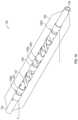
- FIG. 1 Adepicts one variation of shock wave catheter comprising single-layer electrodes.
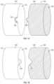
- FIG. 1 Bdepicts one variation of a single-layer electrode.
- FIG. 1 Cdepicts one variation of a pair of single-layer electrodes.
- FIG. 1 Ddepicts another variation of a pair of single-layer electrodes.
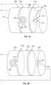
- FIG. 2 Adepicts one variation of single-layer electrodes of a shock wave catheter that interfit with each other.
- FIG. 2 Bdepicts another variation of single-layer electrodes of a shock wave catheter that interfit with each other.
- FIG. 2 Cdepicts one variation of three single-layer electrodes (i.e., two electrode pairs) that have multiple spark gaps per electrode pair.
- FIG. 3 Ais a perspective view of one variation of a shock wave catheter (balloon not shown).
- FIG. 3 Bis perspective view of the single-layer electrodes of the shock wave catheter of FIG. 3 A .
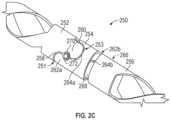
- FIG. 3 Cis a close-up view of three single-layer electrodes of the shock wave catheter of FIG. 3 A .
- FIG. 4 Ais a table that depicts experimental data that reflects the sonic output of a shock wave catheter similar to the shock wave catheter depicted in FIGS. 3 A- 3 C , where the width of the spark gap is 0.003 inch.
- FIG. 4 Bis a table that depicts experimental data that reflects the sonic output of a shock wave catheter similar to the shock wave catheter depicted in FIGS. 3 A- 3 C , where the width of the spark gap is 0.004 inch.
- FIG. 5depicts a prospective view of one variation of an electrode pair comprising a band.
- FIG. 6depicts a prospect view of one variation of an electrode pair.
- a shock wave electrode paircomprises a first electrode that is circumferentially disposed over an outer surface of an elongate member and a second electrode also circumferentially disposed over the outer surface of the elongate member, where a spark gap may be formed at the narrowest separation distance between the two electrodes.
- the electrodesmay be planar electrodes that are coplanar with each other (e.g., located along a single layer) over the outer surface of the elongate member (e.g., catheter).
- the first electrodemay have a recess (or protrusion) that corresponds with a protrusion (or groove) of the second electrode.
- the separation between the edge of the recess (or protrusion) of the first electrode and the edge of the protrusion (or recess) of the second electrodemay be the shortest distance between the first and second electrodes, and form the spark gap.
- Multiple pairs of these coplanar or single-layer electrodesmay be arranged in series along the surface of an elongate member.
- a voltage generatorcomprising a positive terminal and a negative terminal may be provided, and a first wire may connect the proximal-most electrode with the positive terminal and a second wire may connect the distal-most electrode with the negative terminal, without the need for additional interconnecting wires between the electrode pairs.
- Reducing the number of wires that extend along the length of the elongate membermay help to maintain the flexibility and steerability of the overall shock wave catheter system, which may facilitate the navigation of the shock wave catheter within tortuous vascular pathways. Reducing the number of wires along the length of the elongate member may also help reduce the thickness or diameter of the overall shock wave catheter.
- shock wave catheter systemscomprising the single-layer electrodes described herein (i.e., where the surfaces of the first and second electrodes are coplanar) may have a reduced thickness or diameter as compared to shock wave catheter systems comprising stacked multi-layer electrodes (e.g., where the first electrode is on a first layer, the second electrode is on a second layer that is stacked over the first layer and an insulating layer that separates the first and second electrodes).
- the diameter or thickness of an elongate member with single-layer electrodesmay be about 0.025 inch or less
- the diameter or thickness of an elongate member with multi-layer electrodesmay be about 0.032 inch or less.
- shock wave catheter systemscomprise an angioplasty balloon having an inflated diameter of about 2 mm or less, and single-layer shock wave electrodes may be better suited for this size scale than multi-layer electrodes.
- shock wavesare initiated by plasma arcs that extend across the insulating layer between the electrodes.
- the plasma arcextends across the spark gap between the electrodes along the surface of the elongate member, thereby eliminating the need for an additional insulating layer.
- Reducing the overall thickness of the electrode assembly and/or diameter of the shock wave cathetermay allow the catheter to be navigated to smaller vascular structures for treatment.
- shock wave catheters having single-layer electrodesmay be more readily inserted in the coronary arteries than shock wave catheters having multi-layer electrodes.
- FIG. 1 Adepicts an example of a shock wave catheter that may be advanced into a patient's vasculature.
- a shock wave catheter 100may comprise an elongate member 102 , a guide wire lumen 104 , a tube 106 , and one or more pairs of electrodes 108 enclosed within the tube 106 .
- the tubecan be the form of an inflatable, angioplasty balloon.
- balloonmay not be required.
- a single electrodemay be part of two electrode pairs.
- the proximal end 105 of electrode 107is part of electrode pair 108 a and the distal end 109 of electrode 107 is part of electrode pair 108 b .
- the balloon 106may be collapsed while the shock wave catheter 100 navigates through the vasculature, and expanded (as shown in FIG. 1 A ) after the catheter is located at the desired treatment position.
- the cathetermay comprise a fluid lumen (not shown) that is in communication with a fluid source that introduces fluid into the balloon 106 .
- the shock wave catheter systemmay also comprise a voltage generator having a positive terminal and a negative terminal, and a first wire that connects that proximal-most electrode to the positive terminal and a second wire that connects the distal-most electrode to the negative terminal (of course, the polarity may be reversed).
- shock wave catheter 100After the balloon has been expanded with a fluid to a certain pressure, a voltage pulse may be applied to the electrodes, thereby generating one or more shock waves that may propagate through the fluid and the balloon wall to impinge on a calcification in contact with the balloon. Shock waves may be generated repeatedly, as may be desirable by the practitioner.
- the shock wave catheter 100is depicted as having four electrode pairs (e.g., electrode pairs 108 a - d ), it should be understood that other variations of shock wave catheters may have a different number of electrode pairs (e.g., 1, 2, 4, 5, 7, 8, 10, 12, 16, 20, etc.). In the description of shock wave catheters and electrodes below, a fluid-filled balloon is not depicted, though such a balloon may be included in any of the variations described herein.
- a single-layer shock wave electrode pairmay comprise a first electrode comprising a protrusion and a second electrode comprising a recess that receives the protrusion, where a separation between the edge of the protrusion and the edge of the recess forms a spark gap.
- the first electrodemay comprise a recess and the second electrode may comprise a protrusion that is received by the recess such that the separation between the protrusion and the recess forms a spark gap.
- a spark gapis a separation between two electrodes across which a plasma arc is likely to form in the presence of a high voltage pulse across those electrodes.
- the protrusion and the corresponding recessmay have any suitable geometry or shape, and may be, for example, shaped like a circle, oval, ellipse, square, hexagon, octagon, triangle, and the like. Protrusions and recesses may have corresponding arcuate shapes or curves. In some variations, the shape of the protrusion and the recess may be selected such that the separation between the first and second electrode is fairly uniform.
- the protrusionmay be circular, so that the distance between the edge of the circular protrusion to the edge of the recess in the second electrode that receives that protrusion may be substantially uniform.
- the shape of the protrusion and the recessmay be selected such that the likelihood of a spark or arc forming at any location along the length of the spark gap is substantially the same.
- the protrusion and the recessmay be configured such that the likelihood of a spark forming between the protrusion and the recess is substantially uniform or equal along the length of the spark gap.
- the protrusion and the corresponding recessmay have a smooth contour (i.e., without acute angles, tight turns, or small radii of curvature) such as an arcuate or rounded curve.
- Arranging the electrodes such that the location of the spark along the spark gap is randomizedmay help to extend the life of the electrodes as compared to electrodes where the spark always occurs at the same location or region of the spark gap.
- the wear on the electrodemay be distributed along the gap instead of wearing down a single location along the gap. This may help to lengthen the life of the electrodes as compared to electrodes where sparks originate at the same location or region of the spark gap.
- Some electrodesmay have one protrusion on one side and one recess on another side (e.g., a protrusion on the proximal edge of the electrode and/or at a first radial position, a recess on the distal edge of the electrode and/or second radial position), and/or a first protrusion on one side and a second protrusion on another side (e.g., a first protrusion on the proximal edge of the electrode and/or at a first radial position, a second protrusion on the distal edge of the electrode and/or at a second radial position), and/or a first recess on one side and a second recess on another side (e.g., a first recess on the proximal edge of the electrode and/or at a first radial position, a second recess on the distal edge of the electrode and/or at a second radial position).
- the first electrodemay comprise any number or combination of protrusions and/or recesses (such as those described above) while the second electrode may comprise a corresponding number or combination of recesses and/or protrusions that are complementary to the protrusions and/or recesses of the first electrode.
- a spark or arcmay form between only one of the protrusion/recess pairs at a time (e.g., per voltage pulse), and there may be some variability as to which of the protrusion/recess pairs will spark at a particular time.
- the spark or arcwill only happen at one of the protrusion/recess pairs, while the next spark or arc may be at another one of the protrusion/recess pairs.
- This variabilitymay help to distribute the wear across the multiple protrusion/recess pairs so that the overall life and/or durability of the electrode pair is extended as compared to an electrode pair where all of the sparks are formed across the same protrusion/recess pair.
- the distal and/or proximal edges of the first electrode and the proximal and/or distal edges from the second electrodemay have multiple undulating curves, lobes, peaks and troughs, such that the interface between them comprises a space (which may be a spark gap) that curves between the edges of the electrodes.
- the space between the two electrodesmay have varying distances, which may in turn determine where a spark or plasma arc extends between the electrodes during the generation of a shock wave. For example, to reduce the likelihood that a spark occurs at a particular location between the two electrodes, the spacing at that location may be greater than the spacing in the surrounding areas. To increase the likelihood that a spark occurs at a particular location between the two electrodes, the spacing at that location may be less than the spacing in the surrounding areas. Examples of electrode pairs with varying degrees of separation are further described below.
- the electrodesmay be coated with an insulating material in certain regions and not coated with insulating material (i.e., electrically exposed) in other regions.
- the location of the insulated regions and exposed regionsmay also help to increase the likelihood of generating a plasma arc in certain regions while decreasing the likelihood of generating a plasma arc in other regions.
- insulating the region of the electrodes where the separation between the electrodes is narrowe.g., may be the narrowest separation
- the location of a spark gapmay be determined at least in part by the relative locations of insulated regions and exposed regions of the electrodes, as well as the size of the spacing/separation between the electrodes at the exposed regions.
- the location of spark gaps and the characteristics of the shock waves produced by the plasma arcs that span those spark gapsmay be determined at least in part by the size, shape and location of the exposed regions of the electrodes.
- FIG. 1 Bdepicts one variation of an electrode that may be used in any of the shock wave catheters described herein.
- Electrode 120may be shaped as a cylindrical band configured to be disposed over the surface of an elongate member.
- Electrode 120may comprise a sleeve 122 with a lumen 124 therethrough and a protrusion 126 extending from the sleeve 122 .
- the protrusion 126may have any of the shapes described and depicted herein, and in the variation of FIG. 1 B , may comprise a stem portion 128 and a lobe 130 at the end of the stem. In this example, the shaded region of the lobe 130 may be exposed while the unshaded regions of the electrode 120 are covered by an insulating material.
- the lobe 130may be the region of the electrode that interfaces with a recess of a second electrode that has exposed edges (e.g., may be substantially or entirely exposed), and the separation/spacing between the lobe and the edges of the recess may form a spark gap. Exposed or uninsulated regions of two electrodes in close proximity to each other may form a spark gap, regardless of the geometry of the electrodes.
- the exposed regions of the electrodesmay be treated (e.g., coated) to help enhance heat dissipation capabilities.
- the exposed regions of any of the electrodes described hereinmay have a silver or gold coating.
- the protrusions or recesses of one electrode and the complementary recesses or protrusions of an adjacent electrode that interfaces with the first electrodemay have exposed regions of electrically conductive material to form a spark gap at those interfaces.
- Teflon, kapton, varnish or oxides and anodized insulationsare just a few examples of many suitable insulation materials.
- the relative surface area of the exposed regions of an electrode pairmay also increase or decrease the likelihood of a spark or arc forming across the spacing/separation between electrodes.
- the first electrodemay have a first exposed region with a first surface area and the second electrode may have a second exposed region with a second surface area, and in some variations, the second surface area may be greater than the first surface area.
- the ratio between the first surface area and the second surface areamay be from about 1:2 to about 1:50, e.g., from about 1:2 to about 1:10, from about 1:4 to about 1:10, from about 1:2 to about 1:20, from about 1:10 to about 1:30, from about 1:20 to about 1:40, from about 1:30 to about 1:50.
- the area of the first surface area(e.g., of the electrode with the smaller exposed region) may have a radius of about 0.008 inch, and the ratio between the first surface area and the second surface area may be about 1:4.
- FIG. 1 Cdepicts one variation of an electrode pair 140 comprising a first electrode 142 having a recess 144 and a second electrode 146 having a protrusion 148 that corresponds with the recess 144 .
- the recess and protrusionboth have arcuate shapes.
- the first electrode 142 and second electrode 146may be tubular, each with a lumen 141 , 145 therethrough configured to be disposed over the surface of an elongate member such that they are coplanar (e.g., in a single layer).
- the shaded/patterned portions of the electrodesrepresent electrically exposed (i.e., uninsulated) regions of the electrodes and the unshaded portions represented electrically insulated regions. While the entire surface of the second electrode 146 may be exposed, a small region 143 of the first electrode 142 located around the edge of the recess may be exposed. The surface of the small region 143 is smaller than the surface area of the second electrode, and the ratio between them may be any of the ratios described above.
- FIG. 1 Ddepicts another variation of an electrode pair 160 comprising a first electrode 162 having a protrusion 164 and a second electrode 166 having a recess 168 that corresponds with the portrusion 164 .
- the protrusion and the recessboth have arcuate shapes.
- the first electrode 162 and second electrode 166may be tubular, each with a lumen 161 , 165 therethrough configured to be disposed over the surface of an elongate member such that they are coplanar (e.g., in a single layer). While the entire surface of the second electrode 166 may be exposed, only the protrusion 164 of the first electrode may be exposed.
- the surface of the protrusion 164is smaller than the surface area of the second electrode, and the ratio between them may be any of the ratios described above. Other variations with different areas and shapes of insulated and exposed electrode regions are described and depicted herein.
- FIG. 2 Adepicts one example of two electrode pairs, where one electrode (e.g., the middle electrode) is a part of both pairs.
- the first electrode pair 202may comprise a first electrode 204 and a second electrode 206
- the second electrode pair 210may comprise the second electrode 206 and a third electrode 208 .
- the first electrode 204may be electrically connected to the positive terminal of a voltage generator while the third electrode 208 may be electrically connected to the negative terminal of a voltage generator (e.g., by a wire for each connection).
- the first, second, and third electrodesmay be ring-shaped and have a lumen 217 therethrough, and be disposed over the surface of an elongate body on a single-layer (i.e., the electrodes may be co-planar with each other over the surface of the elongate body).
- the first electrode 204i.e., the proximal electrode
- the second electrode 206may comprise a recess 207 that is sized and shaped to receive the protrusion 205 such that there is a space or gap 209 between the edge of the protrusion 205 and the edge of the recess 207 .
- the second electrode 206 and third electrode 208may have a similar interface on the opposite side of the system. That is, the second electrode 206 may have a second recess 211 and the third electrode 208 may have a protrusion 213 that is received by the second recess 211 such that there is a space or gap 215 between them.
- the protrusion 213may have a stem and a circular lobe similar in size and shape to the protrusion 205 , or may have a different size or shape, as may be desired.
- the circular lobes of the protrusions 205 , 213 and the edges of the recesses that receive the protrusions (recesses 207 , 211 )may be electrically exposed or conductive, while the remainder of the electrodes may be electrically insulated. In this variation, the entire surface of the second electrode 206 may be exposed or uninsulated. As such, spark gaps may be formed at the interfaces of the protrusions and the recesses.
- the location of the first protrusion 205 and corresponding recess 207 and the location of the second protrusion 213 and corresponding recess 211may vary according to the desired initiation location of a shock wave.
- the first pair and second pair of protrusions/recessesare located radially opposite to each other, with the first pair located on a proximal edge of the electrode and the second pair located on a distal edge of the electrode.
- the first and second pairmay both be located on the proximal side (or the distal side) of the middle electrode 206 , but radially opposite each other.
- the first and second pairmay be radially offset with respect to each other, where the offset angle may be anywhere from about 30 degrees to about 180 degrees in either direction (clockwise or counterclockwise).
- the first electrode 204may have an additional protrusion or recess at a different radial location and the second electrode 206 may have an additional corresponding recess or protrusion.
- each of the electrodesmay be covered by an insulating material while other regions are exposed.
- the portions of the protrusion 205 and the protrusion 213 that are shadedmay be exposed, while the remainder of the electrode 204 and the electrode 208 may be covered by an insulating material.
- the second electrode 206may be entirely exposed and uninsulated.
- at least the regions around the edges of the recesses 207 and 211may be exposed, while the remainder of the electrode may be insulated.
- the exposed regionsmay optionally have a silver or gold coating.
- the relative sizing of the surface area of the exposed regions between the electrodes in a pairmay help to facilitate and guide the electric current flow between electrodes so that plasma arcs or sparks occur at the desired spark gap location.
- the likelihood of creating a plasma arc that is capable of generating a shock waveis increased when the surface area of the exposed (i.e., uninsulated) region of a first electrode is smaller than the surface area of the exposed region of a second electrode that is adjacent to it.
- the exposed surface area differentialmay be represented by the ratio of the surface area of an exposed region of a first electrode to the surface area of an exposed region of a second electrode.
- the interface between the electrodes of a pair described in any of the shock wave catheters disclosed herein, regardless of their shape or location,may have the exposed surface area differential described above.
- FIG. 2 Bdepicts another variation of two electrode pairs that are similar to the electrode pairs depicted in FIG. 2 A , except that where there was a protrusion, there is now a recess and where there was a recess, there is now a protrusion.
- the first electrode pair 222comprises a first (proximal) electrode 224 and a second (middle) electrode 226 .
- the first electrode 224comprises a recess 225 .
- the second (middle) electrode 226comprising a protrusion 227 that is located within the recess 225 .
- the second electrode pair 230comprises the second electrode 226 and a third (distal) electrode 228 .
- the second electrode 226comprises a second protrusion 231 .
- the third (distal) electrode 228comprises a recess 233 within which the protrusion 231 is located.
- the middle electrodeinstead of the middle electrode having two radially offset and opposite recesses as illustrated in FIG. 2 A , the middle electrode now has two radially offset and opposite protrusions as illustrated in FIG. 2 B .
- the first electrode 224may be connected to the positive terminal of a voltage generator while the third electrode 228 may be connected to the negative terminal of a voltage generator (e.g., by a wire for each connection).
- the various parameters and variants described above for FIG. 2 Amay also be applicable in the variation depicted in FIG. 2 B .
- FIG. 2 Cdepicts an example of a shock wave catheter 250 comprising a first electrode 252 , second electrode 254 , and third electrode 256 (for clarity, the elongate body, guide wire lumen, and wiring of the catheter 250 are not shown).
- the first, second and third electrodesare coplanar with each other, arranged on a single layer along the surface of the elongate body of the catheter.
- the first electrode 252may comprise a first recess 258 and a first protrusion 260 .
- the second electrode 254may comprise a second protrusion 262 a , a second recess 264 a , a third protrusion 262 b opposite to the second protrusion 262 a , and a third recess 264 b opposite to the second recess 264 a .
- the third electrode 256may comprise a fourth recess 266 and a fourth protrusion 268 .
- Theremay be two spark gaps located between the first and second electrodes, and two other spark gaps located between the second and third electrodes. In some variations, of the two spark gaps between an electrode pair, only one spark gap will form a plasma arc during a voltage pulse.
- the location and arcuate curvature of the first recess 258may correspond with the location and arcuate curvature of the second protrusion 262 a to form a first spark gap 251 therebetween, and the location and arcuate curvature of the first protrusion 260 may correspond with the location and arcuate curvature of the second recess 264 a to form a second spark gap 253 therebetween.
- the location and arcuate curvature of the third recess 264 bmay correspond with the location and arcuate curvature of the fourth protrusion 268 to form a third spark gap 255 therebetween, and the location and arcuate curvature of the third protrusion 262 b may correspond with the location and arcuate curvature of the fourth recess 266 to form a fourth spark gap therebetween (not visible in this view). While it may be desirable that some regions of the separation between the electrodes (i.e., the protrusions and recesses) form spark gaps where the likelihood of plasma arc formation is relatively high, there may be some electrode separation regions where it is desirable for the likelihood of plasma arc formation to be relatively low.
- the first electrode 252comprises a recess or groove 270 and the second electrode 254 comprises a recess or groove 272 that is aligned with the groove 270 of the first electrode 252 . Aligning two recesses or grooves may increase the width of the separation between the first electrode 252 and second electrode 254 relative to the width of the separation in the intended spark gap regions.
- a first electrodemay have a recess while the second electrode may have a straight edge (e.g., no protrusion) in the region of the recess.
- a recessmay have straight edges (e.g., a square shape, rectangular shape, triangular shape, etc.), and/or have curved edges (e.g., circle, oval, ellipse, semi-circle, semi-oval, semi-ellipse, etc.), and/or a combination of straight and curved edges (e.g., rectangular, triangular or any polygon with rounded corners and/or undulating edges).
- the increased separation between the electrodes provided by one or more recessesmay help to reduce the likelihood of formation of a plasma arc at the recessed region(s).
- one or both of the electrodes in a pairmay have edge(s) that curve away from the edge of the other electrode.
- the electrodesmay have an undulating curved edge (comprising one or more concave or convex curves) where the peaks and troughs do not follow each other (e.g., are out-of-phase with each other).
- one electrodemay have a straight edge (i.e., without a recess or protrusion), while the other electrode may have undulating curves comprising a convex curve at a desired spark gap region and a concave curve in regions where no spark gap is desired.
- regionsmay be electrically insulated, which may also help to impede the formation of a plasma arc.
- the shock wave catheter 300may comprise an elongate member 302 , a guide wire lumen 304 , and five electrodes 306 a,b,c,d,e that form four electrode pairs 308 a,b,c,d .
- the shock wave catheter 300may also comprise a balloon (e.g., an angioplasty balloon) that encloses the electrodes (not shown), a first wire that connects the proximal-most electrode 306 a to a positive terminal of a voltage source and a second wire that connects the distal-most electrode 306 e to a negative terminal of a voltage source.
- a balloone.g., an angioplasty balloon
- the balloonis filled with a fluid medium before a voltage is applied across the electrodes for the generation of shock waves.
- the first and second wiresmay each extend along the surface and/or lumen and/or within the wall of the elongate member 302 . In some variations, the wires may extend along interior walls of the guide wire lumen 304 .
- Each electrode pairmay have one or more spark gaps as may be desirable. For example, a first electrode pair may have one spark gap capable of initiating one shock wave, while a second electrode pair may have two spark gaps capable of initiating two shock waves (i.e., one shock wave per spark gap). In other examples, an electrode pair may have more than two spark gaps, and may have three, four, five or more spark gaps.
- a series of plasma arcsmay form serially across the spark gaps between the electrodes (i.e., from electrode 306 a to electrode 306 b , from electrode 306 b to electrode 306 c , from electrode 306 c to electrode 306 d , from electrode 306 d to electrode 306 e , which then guides the current back to the negative terminal of the voltage source via the wire) to initiate a series of expanding shock waves.
- the number of initiated shock wavesmay correspond to the number of spark gaps between the electrodes (e.g., each spark gap gives rise to one plasma arc per voltage pulse and/or each plasma arc initiates one shock wave), and/or may be greater than (e.g., a spark gap may give rise to more than one plasma arc per voltage pulse, and/or each plasma arc initiates one or more shock waves) or less than (e.g., plasma arcs may not form across all of the spark gaps) the number of spark gaps.
- FIG. 3 Bdepicts the electrodes 306 a,b,c,d,e without the elongate member 302 . The length of each electrode with respect to each other may vary.
- the proximal-most electrode 306 a and the distal-most electrode 306 emay be shorter than the second electrode 306 b and fourth electrode 306 d .
- the shortest electrodemay be the center electrode 306 c .
- Electrodes whose lengths extend along a substantial segment of the elongate membermay be configured such that their effect on the flexibility and bendability of the elongate member is reduced.
- electrode 306 b(as well as electrode 306 d ) may comprise a proximal portion (e.g., a band) 310 , a distal portion (e.g., a band) 312 , and a body portion 314 extending between the proximal and distal portions.
- the proximal and distal portionsmay be generally cylindrical or marker band-like structures.
- the body portionmay be covered by an insulating material, which may help to facilitate current flow between the proximal and distal portions along the body portion.
- the structure of the body portion 314may be selected to help facilitate bending of the electrode 306 b as the elongate body 302 bends.
- the body portion 314may comprise a helical structure or spiral that wraps around the surface of the elongate body 302 between the proximal and distal portions.
- the threads of the helical structure or spiral of the body portion 314may be selected in order to accommodate flexion, torqueing, and/or steering of the shock wave catheter.
- the body portion 314may have a pair of spirals (e.g., a double-helix), where each spiral has one twist.
- FIG. 3 Cis a close view of the interface between electrodes 306 b,c,d .
- electrode 306 bhas a recess 320 that corresponds to a protrusion 322 on electrode 306 c (which form electrode pair 308 b )
- electrode 306 chas a recess 324 that corresponds to protrusion 326 on electrode 306 d (which form electrode pair 308 d ).
- the protrusions 322 , 326may have a circular lobular portion 328 connected to a stem 330 .
- the stem 330may extend between the widest part of the separation 323 between the electrodes, while the perimeter of the circular lobular portion 328 may comprise at least a portion of the spark gap 323 .
- the protrusions and recesses for both electrode pairshave the same or similar shape and size, however, in other variations, the protrusions and recesses may have different shapes or sizes.
- the electrodes 306 b,c,dmay have electrically insulated regions and exposed (i.e., electrically non-insulated) regions, the location and sizing of which may be configured to help guide the direction of the current flow and/or to facilitate the formation of plasma arcs or sparks at the desired spark gap locations.
- the majority of the surface area of the electrode 306 bmay be exposed or uninsulated, while the majority of the surface area of the electrode 306 c is insulated, except for the regions that are adjacent to the spark gap 325 .
- the protrusion 322e.g., the circular lobe of the protrusion
- the region along the edge of the recess 324 of the electrode 306 cmay be exposed, but the remainder of the electrode 306 c may be insulated (e.g., the stem portion of the protrusion, the cylindrical region or body of the electrode extending between the proximal and distal portions or bands of the electrode, the spiral or twisted region of the body, the body region between the proximal and distal portions or bands of the electrode, etc.).
- the circular lobular portion 328 of the electrode 306 dmay be exposed, while the stem portion 328 and the body of the electrode (e.g., the portion extending between the proximal and distal ends) may be insulated.
- the surface area of the exposed portion the electrode 306 bmay be larger than the surface area of the protrusion 322 that is exposed.
- the ratio between the surface area of the exposed portionmay be from about 1:2 to about 1:50, e.g., from about 1:2 to about 1:10, from about 1:2 to about 1:20, from about 1:10 to about 1:30, from about 1:20 to about 1:40, from about 1:30 to about 1:50.
- the surface area of the circular lobular portion 328may be smaller than the surface area of the exposed region along the edge of recess 324 , and may have similar ratio values described above.
- Some variations of electrodesmay have a proximal portion with an exposed protrusion or recess edge, a distal portion with another exposed protrusion or recess edge, and a body portion between the proximal and distal portions that is insulated.
- the surface area of the one or more exposed regions of an electrodemay affect the strength, shape, location, etc. of the plasma arc formed, which in turn affects the sonic output and/or direction of the initiated shock wave.
- FIGS. 4 A and 4 Bare tables that represent the sonic output of shock wave generated across the electrodes depicted in FIGS. 3 A- 3 C .
- the shock wave electrodeswere located in the center of a 2.5 mm ⁇ 25 mm L2140 balloon filled with saline solution at a pressure of 4 ATM.
- the magnitude of the generated sonic outputwas measured 2 microseconds from the initiation time of the plasma arc or spark.
- the propagation distance of a shock wave at this time delayis about 3 mm.
- the voltage pulse widthwas 1 microsecond, with a magnitude of 3000 volts.
- the diameter of the wires that connected the electrodes to the positive and negative terminals of the voltage sourcewas 0.005 inch and the length was about 170 cm. Insulated portions of the wire were covered with a polyimide insulation layer with a thickness of 0.0005 inch.
- Two spark gap sizeswere tested by measuring the sonic output of the generated shock waves.
- the table of FIG. 4 Adepicts sonic output data from an electrode pair with a spark gap of about 0.003 inch.
- the table of FIG. 4 Bdepicts sonic output data from an electrode pair with a spark gap of about 0.004 inch. Based on this set of experiments, a smaller spark gap (e.g., with a smaller width) may give rise to shock waves with higher sonic output than a larger spark gap.
- FIG. 5depicts a prospective view of an electrode pair comprising a band.
- an electrode pair 500may comprise a first electrode and a second electrode.
- the first electrodemay comprise band 520 .
- the second electrodemay comprise a portion of a wire 512 that is exposed or uninsulated.
- the wire 502may be electrically coupled to a positive terminal of a voltage source, and the wire 512 may be electrically coupled to a negative terminal of the voltage source, or vice versa.
- the wire portion 506e.g., a portion of the wire 502
- the wire portion 510e.g., a portion of the wire 512
- the band 520may comprise one or more grooves, such as a first groove 504 and a second groove 508 .
- the first groove 504may have a dimension (e.g., width) that is smaller than the corresponding dimension of the second groove 508 .
- the wire portion 506may be snuggly disposed in the first groove 504 and the wire portion 510 may be loosely disposed in the second groove 508 .
- the wire portion 510may be loosely disposed in groove 508 to prevent shorted circuit between the wire portion 510 and the band 520 . This feature also maintains the spark gap as the wire portion 510 erodes away.
- the wire 502may comprise the wire portion 506 that is disposed in the first groove 504 .
- the wire 502is insulated with an uninsulated or exposed section (e.g., wire portion 506 ).
- the wire portion 506which is exposed or uninsulated, may be snuggly disposed in groove 504 to have a good electrical connection between the wire 502 and the band 520 (no spark in this region).
- the band 520thus forms the first electrode.
- the wire 512may comprise the wire portion 510 disposed in the second groove 508 of band 520 .
- the wire 512 and the wire portion 510are insulated, and insulation is removed at the end or tip of the wire portion 510 to form a spark gap 514 .
- the exposed or uninsulated portion of wire portion 510thus forms the second electrode.
- the spark gap 514separates the first electrode (e.g., band 520 ) and the second electrode (e.g., the exposed or uninsulated end or tip of wire portion 510 ).
- the surface area of the one or more exposed regions of the first and second electrodesmay affect the strength, shape, location, etc. of the plasma arc formed, which in turn affects the sonic output and/or direction of the initiated shock wave.
- the increase or decrease of the separation between the first and second electrodesmay also increase or decrease the likelihood of formation of a plasma arc at the spark gap.
- FIG. 6depicts a prospective view of one variation of an electrode pair.
- an electrode pair 600comprises a first electrode 602 and a second electrode 604 .
- the first electrode 602 and the second electrode 604may be shaped as a cylindrical band configured to be disposed over the surface of an elongate member.
- the first electrode 602may comprise a protrusion (e.g., a tongue) 606 ; and the second electrode 604 may comprise a recess (e.g., a groove) 608 .
- the protrusion 606 and the recess 608may be oriented perpendicular to the axis of the first electrode 602 and the second electrode 604 , respectively.
- the protrusion 606 and the recess 608may have corresponding arcuate shapes or curves.
- the protrusion 606 and the corresponding recess 608may have any suitable geometry or shape, and may be, for example, shaped like a circle, oval, ellipse, square, hexagon, octagon, triangle, and the like.
- the first electrode 602may be electrically coupled to a positive terminal of a voltage source, and the second electrode 604 may be electrically coupled to a negative terminal of the voltage source, or vice versa.
- the surface area of the protrusion 606e.g., a tongue
- the surface area of recess 608may also be electrically insulated using a polyimide coat except the end region of the recess 608 (e.g., the groove area).
- the end or tip region of the protrusion 606 and the end region of the recess 608are exposed to enable the generating of a spark.
- the surface area of the one or more exposed regions of the first and second electrodesmay affect the strength, shape, location, etc. of the plasma arc formed, which in turn affects the sonic output and/or direction of the initiated shock wave.
- the increase or decrease of the separation between the first and second electrodesmay also increase or decrease the likelihood of formation of a plasma arc at the spark gap.
- the insulatione.g., the polyimide coating
- the insulationmay erode away after repeated spark generation. The erosion of the insulation may expose additional areas and thus increase or maintain the spark generation.
Landscapes
- Health & Medical Sciences (AREA)
- Surgery (AREA)
- Engineering & Computer Science (AREA)
- Life Sciences & Earth Sciences (AREA)
- Biomedical Technology (AREA)
- Nuclear Medicine, Radiotherapy & Molecular Imaging (AREA)
- Vascular Medicine (AREA)
- Orthopedic Medicine & Surgery (AREA)
- Mechanical Engineering (AREA)
- Heart & Thoracic Surgery (AREA)
- Medical Informatics (AREA)
- Molecular Biology (AREA)
- Animal Behavior & Ethology (AREA)
- General Health & Medical Sciences (AREA)
- Public Health (AREA)
- Veterinary Medicine (AREA)
- Surgical Instruments (AREA)
Abstract
Description
Claims (5)
Priority Applications (3)
| Application Number | Priority Date | Filing Date | Title |
|---|---|---|---|
| US17/725,435US12064129B2 (en) | 2015-11-18 | 2022-04-20 | Shock wave electrodes |
| US18/755,486US12245782B2 (en) | 2015-11-18 | 2024-06-26 | Shock wave electrodes |
| US19/030,774US20250295423A1 (en) | 2015-11-18 | 2025-01-17 | Shock wave electrodes |
Applications Claiming Priority (4)
| Application Number | Priority Date | Filing Date | Title |
|---|---|---|---|
| US201562257141P | 2015-11-18 | 2015-11-18 | |
| US15/346,132US10555744B2 (en) | 2015-11-18 | 2016-11-08 | Shock wave electrodes |
| US16/691,449US11337713B2 (en) | 2015-11-18 | 2019-11-21 | Shock wave electrodes |
| US17/725,435US12064129B2 (en) | 2015-11-18 | 2022-04-20 | Shock wave electrodes |
Related Parent Applications (2)
| Application Number | Title | Priority Date | Filing Date |
|---|---|---|---|
| US16/691,449DivisionUS11337713B2 (en) | 2015-11-18 | 2019-11-21 | Shock wave electrodes |
| US16/691,449ContinuationUS11337713B2 (en) | 2015-11-18 | 2019-11-21 | Shock wave electrodes |
Related Child Applications (1)
| Application Number | Title | Priority Date | Filing Date |
|---|---|---|---|
| US18/755,486DivisionUS12245782B2 (en) | 2015-11-18 | 2024-06-26 | Shock wave electrodes |
Publications (2)
| Publication Number | Publication Date |
|---|---|
| US20220240958A1 US20220240958A1 (en) | 2022-08-04 |
| US12064129B2true US12064129B2 (en) | 2024-08-20 |
Family
ID=57517977
Family Applications (5)
| Application Number | Title | Priority Date | Filing Date |
|---|---|---|---|
| US15/346,132Active2037-09-14US10555744B2 (en) | 2015-11-18 | 2016-11-08 | Shock wave electrodes |
| US16/691,449Active2037-11-27US11337713B2 (en) | 2015-11-18 | 2019-11-21 | Shock wave electrodes |
| US17/725,435Active2037-06-25US12064129B2 (en) | 2015-11-18 | 2022-04-20 | Shock wave electrodes |
| US18/755,486ActiveUS12245782B2 (en) | 2015-11-18 | 2024-06-26 | Shock wave electrodes |
| US19/030,774PendingUS20250295423A1 (en) | 2015-11-18 | 2025-01-17 | Shock wave electrodes |
Family Applications Before (2)
| Application Number | Title | Priority Date | Filing Date |
|---|---|---|---|
| US15/346,132Active2037-09-14US10555744B2 (en) | 2015-11-18 | 2016-11-08 | Shock wave electrodes |
| US16/691,449Active2037-11-27US11337713B2 (en) | 2015-11-18 | 2019-11-21 | Shock wave electrodes |
Family Applications After (2)
| Application Number | Title | Priority Date | Filing Date |
|---|---|---|---|
| US18/755,486ActiveUS12245782B2 (en) | 2015-11-18 | 2024-06-26 | Shock wave electrodes |
| US19/030,774PendingUS20250295423A1 (en) | 2015-11-18 | 2025-01-17 | Shock wave electrodes |
Country Status (2)
| Country | Link |
|---|---|
| US (5) | US10555744B2 (en) |
| WO (1) | WO2017087195A1 (en) |
Families Citing this family (92)
| Publication number | Priority date | Publication date | Assignee | Title |
|---|---|---|---|---|
| US9044618B2 (en) | 2008-11-05 | 2015-06-02 | Shockwave Medical, Inc. | Shockwave valvuloplasty catheter system |
| US9642673B2 (en) | 2012-06-27 | 2017-05-09 | Shockwave Medical, Inc. | Shock wave balloon catheter with multiple shock wave sources |
| AU2013300176B2 (en) | 2012-08-06 | 2017-08-17 | Shockwave Medical, Inc. | Low profile electrodes for an angioplasty shock wave catheter |
| US9554815B2 (en) | 2012-08-08 | 2017-01-31 | Shockwave Medical, Inc. | Shockwave valvuloplasty with multiple balloons |
| US9522012B2 (en) | 2012-09-13 | 2016-12-20 | Shockwave Medical, Inc. | Shockwave catheter system with energy control |
| US9333000B2 (en) | 2012-09-13 | 2016-05-10 | Shockwave Medical, Inc. | Shockwave catheter system with energy control |
| WO2017087195A1 (en) | 2015-11-18 | 2017-05-26 | Shockwave Medical, Inc. | Shock wave electrodes |
| AU2017339980B2 (en) | 2016-10-06 | 2022-08-18 | Shockwave Medical, Inc. | Aortic leaflet repair using shock wave applicators |
| US11020135B1 (en) | 2017-04-25 | 2021-06-01 | Shockwave Medical, Inc. | Shock wave device for treating vascular plaques |
| US10966737B2 (en) | 2017-06-19 | 2021-04-06 | Shockwave Medical, Inc. | Device and method for generating forward directed shock waves |
| EP3648678A4 (en) | 2017-07-06 | 2021-03-24 | Raghuveer Basude | TISSUE GRIPPING DEVICES AND RELATED PROCEDURES |
| US11071557B2 (en)* | 2017-10-19 | 2021-07-27 | Medtronic Vascular, Inc. | Catheter for creating pulse wave within vasculature |
| US10709462B2 (en) | 2017-11-17 | 2020-07-14 | Shockwave Medical, Inc. | Low profile electrodes for a shock wave catheter |
| US11103262B2 (en) | 2018-03-14 | 2021-08-31 | Boston Scientific Scimed, Inc. | Balloon-based intravascular ultrasound system for treatment of vascular lesions |
| US11819229B2 (en) | 2019-06-19 | 2023-11-21 | Boston Scientific Scimed, Inc. | Balloon surface photoacoustic pressure wave generation to disrupt vascular lesions |
| EP3809988B1 (en) | 2018-06-21 | 2023-06-07 | Shockwave Medical, Inc. | System for treating occlusions in body lumens |
| WO2020086361A1 (en) | 2018-10-24 | 2020-04-30 | Boston Scientific Scimed, Inc. | Photoacoustic pressure wave generation for intravascular calcification disruption |
| US11266817B2 (en) | 2018-10-25 | 2022-03-08 | Medtronic Vascular, Inc. | Cavitation catheter |
| US11826092B2 (en)* | 2018-10-25 | 2023-11-28 | Medtronic Vascular, Inc. | Cavitation guidewire |
| US11266425B2 (en) | 2018-10-25 | 2022-03-08 | Medtronic Vascular, Inc. | Cavitation catheter |
| CN111184553B (en)* | 2019-04-29 | 2023-05-09 | 谱创医疗科技(上海)有限公司 | High coverage low profile electrode assembly for angioplasty impact waveguides |
| US11931522B2 (en)* | 2019-05-09 | 2024-03-19 | Neuravi Limited | Inflation lumen kink protection and balloon profile |
| US11607531B2 (en) | 2019-05-09 | 2023-03-21 | Neuravi Limited | Balloon catheter with venting of residual air in a proximal direction |
| US12402946B2 (en) | 2019-06-19 | 2025-09-02 | Boston Scientific Scimed, Inc. | Breakdown of laser pulse energy for breakup of vascular calcium |
| US11717139B2 (en) | 2019-06-19 | 2023-08-08 | Bolt Medical, Inc. | Plasma creation via nonaqueous optical breakdown of laser pulse energy for breakup of vascular calcium |
| US11660427B2 (en) | 2019-06-24 | 2023-05-30 | Boston Scientific Scimed, Inc. | Superheating system for inertial impulse generation to disrupt vascular lesions |
| US12280223B2 (en) | 2019-06-26 | 2025-04-22 | Boston Scientific Scimed, Inc. | Focusing element for plasma system to disrupt vascular lesions |
| WO2021061523A1 (en) | 2019-09-24 | 2021-04-01 | Shockwave Medical, Inc. | System for treating thrombus in body lumens |
| WO2021061451A1 (en) | 2019-09-24 | 2021-04-01 | Shockwave Medical, Inc. | Lesion crossing shock wave catheter |
| EP4512350A3 (en) | 2019-09-24 | 2025-05-07 | Shockwave Medical, Inc. | Low profile electrodes for a shock wave catheter |
| US11583339B2 (en) | 2019-10-31 | 2023-02-21 | Bolt Medical, Inc. | Asymmetrical balloon for intravascular lithotripsy device and method |
| US12102384B2 (en) | 2019-11-13 | 2024-10-01 | Bolt Medical, Inc. | Dynamic intravascular lithotripsy device with movable energy guide |
| US12274497B2 (en) | 2019-12-18 | 2025-04-15 | Bolt Medical, Inc. | Multiplexer for laser-driven intravascular lithotripsy device |
| US11672599B2 (en) | 2020-03-09 | 2023-06-13 | Bolt Medical, Inc. | Acoustic performance monitoring system and method within intravascular lithotripsy device |
| US20210290286A1 (en) | 2020-03-18 | 2021-09-23 | Bolt Medical, Inc. | Optical analyzer assembly and method for intravascular lithotripsy device |
| US11707323B2 (en) | 2020-04-03 | 2023-07-25 | Bolt Medical, Inc. | Electrical analyzer assembly for intravascular lithotripsy device |
| US12295654B2 (en) | 2020-06-03 | 2025-05-13 | Boston Scientific Scimed, Inc. | System and method for maintaining balloon integrity within intravascular lithotripsy device with plasma generator |
| US12207870B2 (en) | 2020-06-15 | 2025-01-28 | Boston Scientific Scimed, Inc. | Spectroscopic tissue identification for balloon intravascular lithotripsy guidance |
| US11992232B2 (en) | 2020-10-27 | 2024-05-28 | Shockwave Medical, Inc. | System for treating thrombus in body lumens |
| MX2023006886A (en) | 2020-12-11 | 2023-07-18 | Shockwave Medical Inc | Lesion crossing shock wave catheter. |
| US12016610B2 (en) | 2020-12-11 | 2024-06-25 | Bolt Medical, Inc. | Catheter system for valvuloplasty procedure |
| US12232755B2 (en) | 2020-12-11 | 2025-02-25 | Shockwave Medical, Inc. | Lesion crossing shock wave catheter |
| CN113951972A (en)* | 2020-12-16 | 2022-01-21 | 深圳市赛禾医疗技术有限公司 | Pressure wave sacculus pipe |
| EP4265203A4 (en)* | 2020-12-16 | 2024-10-16 | Sonosemi Medical Co., Ltd. | PRESSURE WAVE BALLOON CATHETER AND MEDICAL DEVICE |
| US11672585B2 (en) | 2021-01-12 | 2023-06-13 | Bolt Medical, Inc. | Balloon assembly for valvuloplasty catheter system |
| EP4277548B1 (en) | 2021-01-12 | 2025-06-04 | Bolt Medical, Inc. | Balloon assembly for valvuloplasty catheter system |
| CN114869400B (en)* | 2021-02-05 | 2025-02-18 | 沛嘉医疗科技(苏州)有限公司 | Electrode for shock wave device and shock wave device for treating heart valve or blood vessel calcification |
| US11911056B2 (en)* | 2021-02-26 | 2024-02-27 | Fastwave Medical Inc. | Intravascular lithotripsy |
| US11944331B2 (en) | 2021-02-26 | 2024-04-02 | Fastwave Medical Inc. | Intravascular lithotripsy |
| US11484327B2 (en)* | 2021-02-26 | 2022-11-01 | Fastwave Medical Inc. | Intravascular lithotripsy |
| CN112932651B (en)* | 2021-03-24 | 2025-02-21 | 上海微创旋律医疗科技有限公司 | Electrode components and electrode balloon catheters |
| CN112914719A (en)* | 2021-03-24 | 2021-06-08 | 上海微创旋律医疗科技有限公司 | Electrode balloon catheter and high-voltage generation treatment device |
| US11648057B2 (en) | 2021-05-10 | 2023-05-16 | Bolt Medical, Inc. | Optical analyzer assembly with safety shutdown system for intravascular lithotripsy device |
| US11806075B2 (en) | 2021-06-07 | 2023-11-07 | Bolt Medical, Inc. | Active alignment system and method for laser optical coupling |
| US20230040190A1 (en)* | 2021-08-05 | 2023-02-09 | Nextern Innovation, Llc | Systems, devices and methods for generating subsonic pressure waves in intravascular lithotripsy |
| US12089861B2 (en) | 2021-08-05 | 2024-09-17 | Nextern Innovation, Llc | Intravascular lithotripsy system and device |
| US11896248B2 (en) | 2021-08-05 | 2024-02-13 | Nextern Innovation, Llc | Systems, devices and methods for generating subsonic pressure waves in intravascular lithotripsy |
| DE112022003823T5 (en)* | 2021-08-05 | 2024-05-23 | Nextern Innovation, Llc | Lithoplasty balloon systems, devices and procedures with multiple spark gap electrode pairs |
| US11877761B2 (en) | 2021-08-05 | 2024-01-23 | Nextern Innovation, Llc | Systems, devices and methods for monitoring voltage and current and controlling voltage of voltage pulse generators |
| US20240307081A1 (en)* | 2021-08-05 | 2024-09-19 | Nextern Innovation, Llc | Intravascular lithoplasty balloon systems, devices and methods |
| US11957369B2 (en) | 2021-08-05 | 2024-04-16 | Nextern Innovation, Llc | Intravascular lithotripsy systems and methods |
| US11801066B2 (en) | 2021-08-05 | 2023-10-31 | Nextern Innovation, Llc | Systems, devices and methods for selection of arc location within a lithoplasty balloon spark gap |
| CN113598878B (en)* | 2021-08-13 | 2025-02-25 | 苏州中荟医疗科技有限公司 | A catheter and shock wave generating system |
| CN113633346B (en)* | 2021-08-31 | 2024-05-03 | 苏州中荟医疗科技有限公司 | Electrode device and shock wave generating system |
| US12023098B2 (en) | 2021-10-05 | 2024-07-02 | Shockwave Medical, Inc. | Lesion crossing shock wave catheter |
| CR20240179A (en)* | 2021-10-19 | 2024-06-12 | Shockwave Medical Inc | Intravascular lithotripsy catheter with interfering shock waves |
| CN113855163B (en)* | 2021-11-09 | 2024-03-22 | 上海蓝帆博元医疗科技有限公司 | Shock wave electrode assembly, balloon catheter device and medical equipment |
| CN116322534A (en)* | 2021-11-18 | 2023-06-23 | 科塞尔医疗科技(苏州)有限公司 | Balloon catheter |
| US11839391B2 (en) | 2021-12-14 | 2023-12-12 | Bolt Medical, Inc. | Optical emitter housing assembly for intravascular lithotripsy device |
| CN114886503A (en)* | 2022-05-27 | 2022-08-12 | 深圳英美达医疗技术有限公司 | Shock wave sacculus pipe based on point discharge |
| US12193738B2 (en) | 2022-06-01 | 2025-01-14 | Fastwave Medical Inc. | Intravascular lithotripsy |
| AU2023280407A1 (en)* | 2022-06-01 | 2024-11-07 | Fastwave Medical Inc. | Intravascular lithotripsy |
| CN115337076A (en)* | 2022-07-15 | 2022-11-15 | 深圳英美达医疗技术有限公司 | Shock wave balloon catheter |
| CN117503265B (en)* | 2022-07-26 | 2025-08-22 | 苏州生科智能科技有限公司 | Shock wave balloon catheter device |
| CN116784933A (en)* | 2022-09-26 | 2023-09-22 | 苏州润迈德医疗科技有限公司 | Shock wave sacculus catheter device |
| WO2024081361A1 (en)* | 2022-10-14 | 2024-04-18 | Cardiovascular Systems, Inc. | Intravascular lithotripsy devices and systems with forward facing electrodes and flex circuit arrangements |
| WO2024138212A1 (en)* | 2022-12-23 | 2024-06-27 | Nextern Innovation, Llc | Intravascular lithoplasty system with improved durability, efficiency and pressure output variability |
| US12290268B2 (en) | 2023-03-31 | 2025-05-06 | Shockwave Medical, Inc. | Shockwave catheters for treating rhinosinusitis |
| AU2023443541A1 (en)* | 2023-04-13 | 2025-09-11 | Fastwave Medical Inc. | Intravascular lithotripsy |
| US12035932B1 (en) | 2023-04-21 | 2024-07-16 | Shockwave Medical, Inc. | Intravascular lithotripsy catheter with slotted emitter bands |
| US12220141B2 (en) | 2023-06-29 | 2025-02-11 | Shockwave Medical, Inc. | Catheter system with independently controllable bubble and arc generation |
| US12426904B2 (en) | 2023-11-17 | 2025-09-30 | Shockwave Medical, Inc. | Intravascular lithotripsy catheter with oscillating impactor |
| WO2025111596A1 (en)* | 2023-11-24 | 2025-05-30 | Fastwave Medical Inc. | Improved user interface and user experience for an intravascular lithotripsy system |
| CN117281580B (en)* | 2023-11-27 | 2024-03-15 | 沛嘉医疗科技(苏州)有限公司 | Electrode device for treating tissue calcification and shock wave device |
| US12402899B2 (en) | 2023-11-30 | 2025-09-02 | Shockwave Medical, Inc. | Systems, devices, and methods for generating shock waves in a forward direction |
| WO2025137664A1 (en)* | 2023-12-23 | 2025-06-26 | Cardiovascular Systems, Inc. | Intravascular lithoplasty system with improved durability, efficiency and pressure output variability |
| WO2025137665A1 (en)* | 2023-12-23 | 2025-06-26 | Cardiovascular Systems, Inc. | Intravascular lithotripsy catheter with improved balloon durability |
| CN119184796A (en)* | 2023-12-27 | 2024-12-27 | 凯诺威医疗科技(武汉)有限公司 | Electrode assembly and shock wave balloon |
| WO2025151198A1 (en)* | 2024-01-08 | 2025-07-17 | Fastwave Medical Inc. | Improved user interface and user experience for an intravascular lithotripsy system |
| WO2025171173A1 (en) | 2024-02-08 | 2025-08-14 | IV-X Medical, LLC | Intravascular lithotripsy system |
| US12433620B2 (en) | 2024-02-23 | 2025-10-07 | Shockwave Medical, Inc. | Locus emitter shock wave catheter devices with increased longevity and higher sonic output |
| US12178458B1 (en) | 2024-05-16 | 2024-12-31 | Shockwave Medical, Inc. | Guidewireless shock wave catheters |
Citations (230)
| Publication number | Priority date | Publication date | Assignee | Title |
|---|---|---|---|---|
| US2916647A (en) | 1959-03-18 | 1959-12-08 | Roscoe H George | Spark gap impulse generator |
| US3412288A (en) | 1965-01-25 | 1968-11-19 | Gen Motors Corp | Arc suppression circuit for inductive loads |
| US3413976A (en) | 1963-07-29 | 1968-12-03 | G Elektrotekhnichesky Zd Vef | Arrangement for removal of concretions from urinary tract |
| US3524101A (en) | 1963-10-28 | 1970-08-11 | Comp Generale Electricite | Triggering device for spark-gap |
| US3583766A (en) | 1969-05-22 | 1971-06-08 | Louis R Padberg Jr | Apparatus for facilitating the extraction of minerals from the ocean floor |
| US3785382A (en) | 1971-05-14 | 1974-01-15 | Wolf Gmbh Richard | Device for destroying stones in the bladder, in the ureter, in the kidneys and the like |
| US3902499A (en) | 1974-01-02 | 1975-09-02 | Hoffman Saul | Stone disintegrator |
| US3942531A (en) | 1973-10-12 | 1976-03-09 | Dornier System Gmbh | Apparatus for breaking-up, without contact, concrements present in the body of a living being |
| US4027674A (en) | 1975-06-06 | 1977-06-07 | Tessler Arthur N | Method and device for removing concretions within human ducts |
| US4030505A (en) | 1975-11-28 | 1977-06-21 | Calculus Instruments Ltd. | Method and device for disintegrating stones in human ducts |
| DE3038445A1 (en) | 1980-10-11 | 1982-05-27 | Dornier Gmbh, 7990 Friedrichshafen | Pressure wave generator for diagnosis and therapy - has spark gap in inflatable balloon at end of catheter |
| US4445509A (en) | 1982-02-04 | 1984-05-01 | Auth David C | Method and apparatus for removal of enclosed abnormal deposits |
| US4662126A (en) | 1986-05-23 | 1987-05-05 | Fike Corporation | Vibration resistant explosion control vent |
| US4662375A (en) | 1985-04-04 | 1987-05-05 | Dornier System Gmbh | Alleviating pain during extracoporal lithotripsy |
| US4671254A (en) | 1985-03-01 | 1987-06-09 | Memorial Hospital For Cancer And Allied Diseases | Non-surgical method for suppression of tumor growth |
| JPS6299210U (en) | 1985-12-12 | 1987-06-24 | ||
| US4685458A (en) | 1984-03-01 | 1987-08-11 | Vaser, Inc. | Angioplasty catheter and method for use thereof |
| JPS62275446A (en) | 1986-05-21 | 1987-11-30 | オリンパス光学工業株式会社 | Discharge stone crushing apparatus |
| US4741405A (en) | 1987-01-06 | 1988-05-03 | Tetra Corporation | Focused shock spark discharge drill using multiple electrodes |
| US4809682A (en) | 1985-12-12 | 1989-03-07 | Dornier Medizintechnik Gmbh | Underwater electrodes for contactless lithotripsy |
| US4813934A (en) | 1987-08-07 | 1989-03-21 | Target Therapeutics | Valved catheter device and method |
| US4878495A (en) | 1987-05-15 | 1989-11-07 | Joseph Grayzel | Valvuloplasty device with satellite expansion means |
| WO1989011307A1 (en) | 1988-05-26 | 1989-11-30 | The Regents Of The University Of California | Perfusion balloon catheter |
| US4890603A (en) | 1987-11-09 | 1990-01-02 | Filler William S | Extracorporeal shock wave lithotripsy employing non-focused, spherical-sector shock waves |
| US4900303A (en) | 1978-03-10 | 1990-02-13 | Lemelson Jerome H | Dispensing catheter and method |
| US4990134A (en) | 1986-01-06 | 1991-02-05 | Heart Technology, Inc. | Transluminal microdissection device |
| US4994032A (en) | 1987-12-01 | 1991-02-19 | Terumo Kabushiki Kaisha | Balloon catheter |
| JPH0363059A (en) | 1989-04-26 | 1991-03-19 | Advanced Cardiovascular Syst Inc | Blood flow measurement using self-irrigation catheter for blood vessel formation and its device |
| US5009232A (en) | 1988-08-17 | 1991-04-23 | Siemens Aktiengesellschaft | Extracorporeal lithotripsy apparatus using high intensity shock waves for calculus disintegration and low intensity shock waves for imaging |
| EP0442199A2 (en) | 1990-02-12 | 1991-08-21 | BS & B SAFETY SYSTEMS, INC. | Low pressure non-fragmenting rupture disks |
| US5057106A (en) | 1986-02-27 | 1991-10-15 | Kasevich Associates, Inc. | Microwave balloon angioplasty |
| US5057103A (en) | 1990-05-01 | 1991-10-15 | Davis Emsley A | Compressive intramedullary nail |
| US5061240A (en) | 1990-04-02 | 1991-10-29 | George Cherian | Balloon tip catheter for venous valve ablation |
| US5078717A (en) | 1989-04-13 | 1992-01-07 | Everest Medical Corporation | Ablation catheter with selectively deployable electrodes |
| US5102402A (en) | 1991-01-04 | 1992-04-07 | Medtronic, Inc. | Releasable coatings on balloon catheters |
| US5103804A (en) | 1990-07-03 | 1992-04-14 | Boston Scientific Corporation | Expandable tip hemostatic probes and the like |
| US5116227A (en) | 1991-03-01 | 1992-05-26 | Endo Technic Corporation | Process for cleaning and enlarging passages |
| US5152767A (en) | 1990-11-23 | 1992-10-06 | Northgate Technologies, Inc. | Invasive lithotripter with focused shockwave |
| US5152768A (en) | 1991-02-26 | 1992-10-06 | Bhatta Krishna M | Electrohydraulic lithotripsy |
| US5154722A (en) | 1988-05-05 | 1992-10-13 | Circon Corporation | Electrohydraulic probe having a controlled discharge path |
| US5176675A (en) | 1985-04-24 | 1993-01-05 | The General Hospital Corporation | Use of lasers to break down objects for removal from within the body |
| US5195508A (en) | 1990-05-18 | 1993-03-23 | Dornier Medizintechnik Gmbh | Spark gap unit for lithotripsy |
| US5246447A (en) | 1989-02-22 | 1993-09-21 | Physical Sciences, Inc. | Impact lithotripsy |
| US5245988A (en) | 1989-11-15 | 1993-09-21 | Dormer Gmbh | Preparing a circuit for the production of shockwaves |
| US5254121A (en) | 1992-05-22 | 1993-10-19 | Meditron Devices, Inc. | Method and device for removing concretions within human ducts |
| EP0571306A1 (en) | 1992-05-22 | 1993-11-24 | LASER MEDICAL TECHNOLOGY, Inc. | Apparatus and method for removal of deposits from the walls of body passages |
| US5281231A (en) | 1989-02-22 | 1994-01-25 | Physical Sciences, Inc. | Impact lithotrypsy |
| US5295958A (en) | 1991-04-04 | 1994-03-22 | Shturman Cardiology Systems, Inc. | Method and apparatus for in vivo heart valve decalcification |
| US5304134A (en) | 1992-01-17 | 1994-04-19 | Danforth Biomedical, Inc. | Lubricious yet bondable catheter channel sleeve for over-the-wire catheters |
| JPH06125915A (en) | 1992-10-21 | 1994-05-10 | Inter Noba Kk | Catheter type medical instrument |
| US5321715A (en) | 1993-05-04 | 1994-06-14 | Coherent, Inc. | Laser pulse format for penetrating an absorbing fluid |
| US5324255A (en) | 1991-01-11 | 1994-06-28 | Baxter International Inc. | Angioplasty and ablative devices having onboard ultrasound components and devices and methods for utilizing ultrasound to treat or prevent vasopasm |
| US5336234A (en) | 1992-04-17 | 1994-08-09 | Interventional Technologies, Inc. | Method and apparatus for dilatation of a stenotic vessel |
| US5362309A (en) | 1992-09-14 | 1994-11-08 | Coraje, Inc. | Apparatus and method for enhanced intravascular phonophoresis including dissolution of intravascular blockage and concomitant inhibition of restenosis |
| EP0623360A1 (en) | 1993-02-05 | 1994-11-09 | The Joe W. And Dorothy Dorsett Brown Foundation | Ultrasonic angioplasty balloon catheter |
| US5364393A (en) | 1990-07-02 | 1994-11-15 | Heart Technology, Inc. | Tissue dissipative recanalization catheter |
| US5368591A (en) | 1988-10-28 | 1994-11-29 | Prutech Research And Development Partnership Ii | Heated balloon catheters |
| CA2104414A1 (en) | 1993-08-19 | 1995-02-20 | Krishna M. Bhatta | Electrohydraulic lithotripsy |
| US5395335A (en) | 1991-05-24 | 1995-03-07 | Jang; G. David | Universal mode vascular catheter system |
| EP0647435A1 (en) | 1993-10-12 | 1995-04-12 | Arrow International Investment Corporation | Electrode-carrying catheter and method of making same |
| US5425735A (en) | 1989-02-22 | 1995-06-20 | Psi Medical Products, Inc. | Shielded tip catheter for lithotripsy |
| US5454809A (en) | 1989-01-06 | 1995-10-03 | Angioplasty Systems, Inc. | Electrosurgical catheter and method for resolving atherosclerotic plaque by radio frequency sparking |
| US5472406A (en) | 1991-10-03 | 1995-12-05 | The General Hospital Corporation | Apparatus and method for vasodilation |
| WO1996024297A1 (en) | 1995-02-09 | 1996-08-15 | C.R. Bard, Inc. | Angioplasty catheter used to expand and/or open up blood vessels |
| US5582578A (en) | 1995-08-01 | 1996-12-10 | Duke University | Method for the comminution of concretions |
| US5584843A (en) | 1994-12-20 | 1996-12-17 | Boston Scientific Corporation | Shaped wire multi-burr rotational ablation device |
| US5603731A (en) | 1994-11-21 | 1997-02-18 | Whitney; Douglass G. | Method and apparatus for thwarting thrombosis |
| US5709676A (en) | 1990-02-14 | 1998-01-20 | Alt; Eckhard | Synergistic treatment of stenosed blood vessels using shock waves and dissolving medication |
| JPH1099444A (en) | 1996-09-27 | 1998-04-21 | Advanced Cardeovascular Syst Inc | Vibratory stent to open calcified lesion part |
| JPH10314177A (en) | 1997-04-26 | 1998-12-02 | Convergenza Ag | Device with treating catheter |
| US5846218A (en) | 1996-09-05 | 1998-12-08 | Pharmasonics, Inc. | Balloon catheters having ultrasonically driven interface surfaces and methods for their use |
| CN1204242A (en) | 1995-10-13 | 1999-01-06 | 血管转换公司 | Methods and devices for bypassing and/or other transvascular procedures for arterial blockages |
| WO1999000060A1 (en) | 1997-06-26 | 1999-01-07 | Advanced Coronary Intervention | Electrosurgical catheter for resolving obstructions by radio frequency ablation |
| WO1999002096A1 (en) | 1997-07-08 | 1999-01-21 | The Regents Of The University Of California | Circumferential ablation device assembly and method |
| US5891089A (en) | 1994-05-17 | 1999-04-06 | Hadasit Medical Research Services & Development | System and method for coronary angioplasty |
| US5893840A (en) | 1991-01-04 | 1999-04-13 | Medtronic, Inc. | Releasable microcapsules on balloon catheters |
| US5931805A (en) | 1997-06-02 | 1999-08-03 | Pharmasonics, Inc. | Catheters comprising bending transducers and methods for their use |
| US6056722A (en) | 1997-09-18 | 2000-05-02 | Iowa-India Investments Company Limited Of Douglas | Delivery mechanism for balloons, drugs, stents and other physical/mechanical agents and methods of use |
| US6080119A (en) | 1997-05-02 | 2000-06-27 | Hmt Holding Ag | Process and device for generating shock waves for medical uses |
| US6090104A (en) | 1995-06-07 | 2000-07-18 | Cordis Webster, Inc. | Catheter with a spirally wound flat ribbon electrode |
| US6113560A (en) | 1994-09-21 | 2000-09-05 | Hmt High Medical Techologies | Method and device for generating shock waves for medical therapy, particularly for electro-hydraulic lithotripsy |
| WO2000056237A2 (en) | 1999-03-19 | 2000-09-28 | Atrionix, Inc. | Atrial annulus ablation device |
| US6132444A (en) | 1997-08-14 | 2000-10-17 | Shturman Cardiology Systems, Inc. | Eccentric drive shaft for atherectomy device and method for manufacture |
| US6146358A (en) | 1989-03-14 | 2000-11-14 | Cordis Corporation | Method and apparatus for delivery of therapeutic agent |
| US6186963B1 (en) | 1997-05-02 | 2001-02-13 | Hmt Holding Ag | Device for generating acoustic shock waves, especially for medical applications |
| US6210408B1 (en) | 1999-02-24 | 2001-04-03 | Scimed Life Systems, Inc. | Guide wire system for RF recanalization of vascular blockages |
| US6215734B1 (en) | 1996-08-05 | 2001-04-10 | Tetra Corporation | Electrohydraulic pressure wave projectors |
| US6217531B1 (en) | 1997-10-24 | 2001-04-17 | Its Medical Technologies & Services Gmbh | Adjustable electrode and related method |
| US6267747B1 (en) | 1998-05-11 | 2001-07-31 | Cardeon Corporation | Aortic catheter with porous aortic root balloon and methods for inducing cardioplegic arrest |
| US6277138B1 (en) | 1999-08-17 | 2001-08-21 | Scion Cardio-Vascular, Inc. | Filter for embolic material mounted on expandable frame |
| US20010044596A1 (en) | 2000-05-10 | 2001-11-22 | Ali Jaafar | Apparatus and method for treatment of vascular restenosis by electroporation |
| US6352535B1 (en) | 1997-09-25 | 2002-03-05 | Nanoptics, Inc. | Method and a device for electro microsurgery in a physiological liquid environment |
| US6364894B1 (en) | 2000-06-12 | 2002-04-02 | Cordis Corporation | Method of making an angioplasty balloon catheter |
| US6367203B1 (en) | 2000-09-11 | 2002-04-09 | Oklahoma Safety Equipment Co., Inc. | Rupture panel |
| US6371971B1 (en) | 1999-11-15 | 2002-04-16 | Scimed Life Systems, Inc. | Guidewire filter and methods of use |
| US20020045890A1 (en) | 1996-04-24 | 2002-04-18 | The Regents Of The University O F California | Opto-acoustic thrombolysis |
| US6398792B1 (en) | 1999-06-21 | 2002-06-04 | O'connor Lawrence | Angioplasty catheter with transducer using balloon for focusing of ultrasonic energy and method for use |
| US6406486B1 (en) | 1991-10-03 | 2002-06-18 | The General Hospital Corporation | Apparatus and method for vasodilation |
| US20020082553A1 (en) | 2000-12-22 | 2002-06-27 | Advanced Cardiovascular Systems, Inc. | Balloon designs for angioplasty |
| US6440124B1 (en) | 1998-07-22 | 2002-08-27 | Endovasix, Inc. | Flexible flow apparatus and method for the disruption of occlusions |
| US6494890B1 (en) | 1997-08-14 | 2002-12-17 | Shturman Cardiology Systems, Inc. | Eccentric rotational atherectomy device |
| US20030004434A1 (en) | 2001-06-29 | 2003-01-02 | Francesco Greco | Catheter system having disposable balloon |
| US6514203B2 (en) | 2001-02-12 | 2003-02-04 | Sonata Technologies Ltd. | Method for ultrasonic coronary thrombolysis |
| US6524251B2 (en) | 1999-10-05 | 2003-02-25 | Omnisonics Medical Technologies, Inc. | Ultrasonic device for tissue ablation and sheath for use therewith |
| US6589253B1 (en) | 1999-12-30 | 2003-07-08 | Advanced Cardiovascular Systems, Inc. | Ultrasonic angioplasty transmission wire |
| US6607003B1 (en) | 2001-04-23 | 2003-08-19 | Oklahoma Safety Equipment Co, | Gasket-lined rupture panel |
| US20030176873A1 (en) | 2002-03-12 | 2003-09-18 | Lithotech Medical Ltd. | Method for intracorporeal lithotripsy fragmentation and apparatus for its implementation |
| US6638246B1 (en) | 2000-11-28 | 2003-10-28 | Scimed Life Systems, Inc. | Medical device for delivery of a biologically active material to a lumen |
| US6652547B2 (en) | 1999-10-05 | 2003-11-25 | Omnisonics Medical Technologies, Inc. | Apparatus and method of removing occlusions using ultrasonic medical device operating in a transverse mode |
| US20030229370A1 (en) | 2002-06-11 | 2003-12-11 | Miller Paul James | Catheter balloon with ultrasonic microscalpel blades |
| US6666834B2 (en) | 2001-01-11 | 2003-12-23 | Hmt High Medical Technologies Ag | Method and apparatus for generating shock waves |
| US20040006333A1 (en) | 1994-09-09 | 2004-01-08 | Cardiofocus, Inc. | Coaxial catheter instruments for ablation with radiant energy |
| US20040010249A1 (en) | 2000-08-01 | 2004-01-15 | Csaba Truckai | Voltage threshold ablation apparatus |
| JP2004081374A (en) | 2002-08-26 | 2004-03-18 | Dairin Kk | Instrument for removing sediment in tubular organ |
| US6736784B1 (en) | 1999-06-24 | 2004-05-18 | Ferton Holding S.A. | Medical instrument for treating biological tissue and method for transmitting pressure waves |
| US20040097996A1 (en) | 1999-10-05 | 2004-05-20 | Omnisonics Medical Technologies, Inc. | Apparatus and method of removing occlusions using an ultrasonic medical device operating in a transverse mode |
| US20040097963A1 (en) | 2002-11-19 | 2004-05-20 | Seddon J. Michael | Method and apparatus for disintegrating urinary tract stones |
| US6740081B2 (en) | 2002-01-25 | 2004-05-25 | Applied Medical Resources Corporation | Electrosurgery with improved control apparatus and method |
| US6755821B1 (en) | 1998-12-08 | 2004-06-29 | Cardiocavitational Systems, Inc. | System and method for stimulation and/or enhancement of myocardial angiogenesis |
| US20040162508A1 (en) | 2003-02-19 | 2004-08-19 | Walter Uebelacker | Shock wave therapy method and device |
| US20040249401A1 (en) | 1999-10-05 | 2004-12-09 | Omnisonics Medical Technologies, Inc. | Apparatus and method for an ultrasonic medical device with a non-compliant balloon |
| US20040254570A1 (en) | 2003-06-13 | 2004-12-16 | Andreas Hadjicostis | Endoscopic medical treatment involving acoustic ablation |
| JP2004357792A (en) | 2003-06-02 | 2004-12-24 | Keio Gijuku | Apparatus for preventing and treating vascular restenosis by sound pressure wave induced by high intensity pulsed light irradiation |
| US20050015953A1 (en) | 2003-07-21 | 2005-01-27 | Yaron Keidar | Method for making a spiral array ultrasound transducer |
| US20050021013A1 (en) | 1997-10-21 | 2005-01-27 | Endo Vasix, Inc. | Photoacoustic removal of occlusions from blood vessels |
| US20050059965A1 (en) | 2003-09-15 | 2005-03-17 | Scimed Life Systems, Inc. | Catheter balloons |
| US20050075662A1 (en) | 2003-07-18 | 2005-04-07 | Wesley Pedersen | Valvuloplasty catheter |
| JP2005095410A (en) | 2003-09-25 | 2005-04-14 | Keisei Ika Kogyo Kk | Catheter for thrombus removal |
| US20050090888A1 (en) | 2003-10-28 | 2005-04-28 | Hines Richard A. | Pleated stent assembly |
| US20050113822A1 (en) | 2002-07-23 | 2005-05-26 | Fuimaono Kristine B. | Ablation catheter having stabilizing array |
| US20050113722A1 (en) | 2003-03-14 | 2005-05-26 | Sws Shock Wave Systems Ag | Apparatus and process for optimized electro-hydraulic pressure pulse generation |
| US20050171527A1 (en) | 2003-12-31 | 2005-08-04 | Sumita Bhola | Circumferential ablation device assembly with an expandable member |
| US6939320B2 (en) | 1998-05-18 | 2005-09-06 | Boston Scientific Scimed., Inc. | Localized delivery of drug agents |
| US20050228372A1 (en) | 2000-08-01 | 2005-10-13 | Sciogen, Inc. | Voltage threshold ablation apparatus |
| WO2005099594A1 (en) | 2004-04-08 | 2005-10-27 | Boston Scientific Limited | Cutting balloon catheter and method for blade mounting |
| WO2005102199A1 (en) | 2004-04-19 | 2005-11-03 | Prorhythm, Inc. | Ablation devices with sensor structures |
| US20050245866A1 (en) | 1996-05-20 | 2005-11-03 | Medtronic Vascular, Inc. | Exchange method for emboli containment |
| US20050251131A1 (en) | 1997-05-09 | 2005-11-10 | Lesh Michael D | Circumferential ablation device assembly |
| US20060004286A1 (en) | 2004-04-21 | 2006-01-05 | Acclarent, Inc. | Methods and devices for performing procedures within the ear, nose, throat and paranasal sinuses |
| WO2006006169A2 (en) | 2004-07-14 | 2006-01-19 | By-Pass, Inc. | Material delivery system |
| US6989009B2 (en) | 2002-04-19 | 2006-01-24 | Scimed Life Systems, Inc. | Cryo balloon |
| US20060069424A1 (en) | 2004-09-27 | 2006-03-30 | Xtent, Inc. | Self-constrained segmented stents and methods for their deployment |
| US20060074484A1 (en) | 2004-10-02 | 2006-04-06 | Huber Christoph H | Methods and devices for repair or replacement of heart valves or adjacent tissue without the need for full cardiopulmonary support |
| US7066904B2 (en) | 1990-12-28 | 2006-06-27 | Boston Scientific Scimed, Inc. | Triggered release hydrogel drug delivery system |
| US20060184076A1 (en) | 2004-12-01 | 2006-08-17 | Gill Robert P | Ultrasonic device and method for treating stones within the body |
| US20060221528A1 (en) | 2005-04-05 | 2006-10-05 | Texas Instruments Incorporated | Systems and methods for providing over-current protection in a switching power supply |
| WO2006127158A2 (en) | 2005-05-23 | 2006-11-30 | Qi Yu | An intravascular ultrasound catheter device and method for ablating atheroma |
| DE202006014285U1 (en) | 2006-09-13 | 2006-12-28 | Walz Elektronik Gmbh | Probe for generating an electro-hydraulic pressure wave for shattering concrete bodies has coil electrode wound around rod electrode at the end of a sheath |
| US20070016112A1 (en) | 2005-06-09 | 2007-01-18 | Reiner Schultheiss | Shock Wave Treatment Device and Method of Use |
| US20070088380A1 (en) | 2005-10-14 | 2007-04-19 | Endocross Ltd. | Balloon catheter system for treating vascular occlusions |
| US20070156129A1 (en) | 2006-01-03 | 2007-07-05 | Alcon, Inc. | System For Dissociation and Removal of Proteinaceous Tissue |
| WO2007088546A2 (en) | 2006-02-02 | 2007-08-09 | Releaf Medical Ltd. | Shock-wave generating device, such as for the treatment of calcific aortic stenosis |
| CN101043914A (en) | 2004-07-14 | 2007-09-26 | 旁路公司 | Material delivery system |
| US20070239082A1 (en) | 2006-01-27 | 2007-10-11 | General Patent, Llc | Shock Wave Treatment Device |
| US20070239253A1 (en) | 2006-04-06 | 2007-10-11 | Jagger Karl A | Oscillation assisted drug elution apparatus and method |
| US20070244423A1 (en) | 2002-05-29 | 2007-10-18 | Jona Zumeris | Acoustic add-on device for biofilm prevention in urinary catheter |
| US20070250052A1 (en) | 2006-04-24 | 2007-10-25 | Sherwood Services Ag | Arc based adaptive control system for an electrosurgical unit |
| US20070255270A1 (en) | 2006-04-27 | 2007-11-01 | Medtronic Vascular, Inc. | Intraluminal guidance system using bioelectric impedance |
| US20070282301A1 (en) | 2004-02-26 | 2007-12-06 | Segalescu Victor A | Dilatation Balloon Catheter Including External Means For Endoluminal Therapy And For Drug Activation |
| US7309324B2 (en) | 2004-10-15 | 2007-12-18 | Futuremed Interventional, Inc. | Non-compliant medical balloon having an integral woven fabric layer |
| US20070299481A1 (en) | 2006-06-21 | 2007-12-27 | Intrapace, Inc. | Endoscopic device delivery system |
| WO2007149905A2 (en) | 2006-06-20 | 2007-12-27 | Aortx, Inc. | Prosthetic valve implant site preparation techniques |
| US20080097251A1 (en) | 2006-06-15 | 2008-04-24 | Eilaz Babaev | Method and apparatus for treating vascular obstructions |
| US7389148B1 (en) | 2004-05-05 | 2008-06-17 | Pacesetter, Inc. | Electrode design for defibrillation and/or sensing capabilities |
| US20080188913A1 (en) | 2006-10-18 | 2008-08-07 | Minnow Medical, Inc. | Inducing desirable temperature effects on body tissue |
| US20090041833A1 (en) | 2005-04-18 | 2009-02-12 | Bracco Research S.A. | Composition comprising gas-filled microcapsules for ultrasound mediated delivery |
| US7505812B1 (en) | 1993-05-10 | 2009-03-17 | Arthrocare Corporation | Electrosurgical system for treating restenosis of body lumens |
| US20090230822A1 (en) | 2008-03-13 | 2009-09-17 | Leonid Kushculey | Patterned ultrasonic transducers |
| US20090247945A1 (en) | 2006-10-13 | 2009-10-01 | Endocross | Balloons and balloon catheter systems for treating vascular occlusions |
| WO2009121017A1 (en) | 2008-03-27 | 2009-10-01 | The Regents Of The University Of California | Balloon catheter for reducing restenosis via irreversible electroporation |
| WO2009126544A1 (en) | 2008-04-08 | 2009-10-15 | Arizona Board Of Regents, A Body Corporate Of The State Of Arizona Acting For And On Behalf Of Arizona State University | Assemblies and methods for reducing warp and bow of a flexible substrate during semiconductor processing |
| WO2009136268A2 (en) | 2008-05-07 | 2009-11-12 | Northgate Technologies Inc. | Radially-firing electrohydraulic lithotripsy probe |
| US20090299447A1 (en) | 2005-07-01 | 2009-12-03 | Marc Jensen | Deployable epicardial electrode and sensor array |
| WO2009152352A2 (en) | 2008-06-13 | 2009-12-17 | Aspen Medtech, Inc. | Shockwave balloon catheter system |
| US20100016862A1 (en) | 2008-07-16 | 2010-01-21 | Daniel Hawkins | Method of providing embolic protection and shockwave angioplasty therapy to a vessel |
| WO2010014515A2 (en) | 2008-07-27 | 2010-02-04 | Klein, David | Fracturing calcifications in heart valves |
| US20100094209A1 (en) | 2008-10-10 | 2010-04-15 | Intervalve, Inc. | Valvuloplasty Catheter And Methods |
| US20100114020A1 (en) | 2008-11-05 | 2010-05-06 | Daniel Hawkins | Shockwave valvuloplasty catheter system |
| US20100114065A1 (en) | 2008-11-04 | 2010-05-06 | Daniel Hawkins | Drug delivery shockwave balloon catheter system |
| US20100121322A1 (en) | 2002-09-24 | 2010-05-13 | Endoscopic Technologies, Inc. (Estech) | Electrophysiology electrode having multiple power connections and electrophysiology devices including the same |
| US20100179424A1 (en) | 2009-01-09 | 2010-07-15 | Reinhard Warnking | Methods and apparatus for treatment of mitral valve insufficiency |
| US20100286709A1 (en) | 2007-12-12 | 2010-11-11 | Lithotech Medical Ltd. | Device and method for fragmenting and removing concretions from body ducts and cavities |
| EP2253884A1 (en) | 2008-03-14 | 2010-11-24 | Yantai Longyuan Power Technology Co. Ltd. | A method of reducing nitrogen oxides of a pulverized coal boiler using inner combustion type burners |
| US7850685B2 (en) | 2005-06-20 | 2010-12-14 | Medtronic Ablation Frontiers Llc | Ablation catheter |
| US7853332B2 (en) | 2005-04-29 | 2010-12-14 | Medtronic, Inc. | Lead electrode for use in an MRI-safe implantable medical device |
| WO2011006017A1 (en) | 2009-07-08 | 2011-01-13 | Sanuwave, Inc. | Usage of extracorporeal and intracorporeal pressure shock waves in medicine |
| US7873404B1 (en) | 2008-05-29 | 2011-01-18 | Seth Caplan | Method for performing angioplasty and angiography with a single catheter |
| CN102057422A (en) | 2008-04-14 | 2011-05-11 | 阿夫纳·斯佩科特 | Automatic adjustable voltage for pressure stabilization of shock wave medical therapy equipment |
| WO2011094111A2 (en) | 2010-01-29 | 2011-08-04 | Ethicon Endo-Surgery, Inc. | Surgical instrument comprising an electrode |
| US20110208185A1 (en) | 2010-02-24 | 2011-08-25 | Valery Diamant | Method and system for assisting a wire guide to cross occluded ducts |
| US20110257523A1 (en) | 2010-04-14 | 2011-10-20 | Roger Hastings | Focused ultrasonic renal denervation |
| WO2011143468A2 (en) | 2010-05-12 | 2011-11-17 | Shifamed, Llc | Low profile electrode assembly |
| US8103360B2 (en)* | 2008-05-09 | 2012-01-24 | Foster Arthur J | Medical lead coil conductor with spacer element |
| CN102355856A (en) | 2009-01-19 | 2012-02-15 | 美敦力 | System and method for monitoring bioimpedance and respiration |
| WO2012025833A2 (en) | 2010-08-27 | 2012-03-01 | Socpra- Sciences Et Génie, S.E.C. | Mechanical wave generator and method thereof |
| US20120095461A1 (en) | 2010-04-09 | 2012-04-19 | Minnow Medical, Inc. | Power generating and control apparatus for the treatment of tissue |
| US20120116289A1 (en) | 2010-11-09 | 2012-05-10 | Daniel Hawkins | Shockwave valvuloplasty device with guidewire and debris basket |
| US8177801B2 (en) | 2008-04-18 | 2012-05-15 | Cardiovascular Systems, Inc. | Method and apparatus for increasing rotational amplitude of abrasive element on high-speed rotational atherectomy device |
| US20120143177A1 (en) | 2010-12-07 | 2012-06-07 | Boaz Avitall | Catheter Systems for Cardiac Arrhythmia Ablation |
| US20120157991A1 (en) | 2010-12-17 | 2012-06-21 | Christian Steven C | Irrigant distribution system for flexible electrodes |
| US20120203255A1 (en) | 2011-02-04 | 2012-08-09 | Daniel Hawkins | High pressure balloon shockwave catheter and method |
| US20120221013A1 (en) | 2008-06-13 | 2012-08-30 | Daniel Hawkins | Non-cavitation shockwave balloon catheter system |
| US20120253358A1 (en) | 2009-12-05 | 2012-10-04 | Erez Golan | Fracturing calcifications in heart valves |
| CN102765785A (en) | 2012-07-16 | 2012-11-07 | 广州埔玛电气有限公司 | Device and method for sterilizing and disinfecting wastewater by pulsed liquid-phase discharge plasma |
| US8353923B2 (en) | 2005-05-26 | 2013-01-15 | Cardiovascular Systems, Inc. | Rotational device with eccentric abrasive element and method of use |
| US20130030431A1 (en) | 2008-06-13 | 2013-01-31 | Adams John M | Shock wave balloon catheter system with off center shock wave generator |
| US20130041355A1 (en) | 2011-08-11 | 2013-02-14 | Tammo Heeren | Reducing Damage From A Dielectric Breakdown in Surgical Applications |
| WO2013059735A1 (en) | 2011-10-19 | 2013-04-25 | Mercator Medsystems, Inc. | Localized modulation of tissues and cells to enhance therapeutic effects including renal denervation |
| US20130116714A1 (en) | 2011-11-08 | 2013-05-09 | John M. Adams | Shock wave valvuloplasty device with moveable shock wave generator |
| US20130123694A1 (en) | 2010-09-17 | 2013-05-16 | Angiometrix Corporation | Diagnostic kit and method for measuring balloon dimension in vivo |
| US20130150874A1 (en) | 2011-12-12 | 2013-06-13 | Kassab Kughn Endovascular Devices Llc | Catheter system with balloon-mounted plaque-modifying elements |
| US20130253622A1 (en) | 2010-12-01 | 2013-09-26 | Michael D. Hooven | Method and apparatus for remodeling/profiling a tissue lumen, particularly in the urethral lumen in the prostate gland |
| US20140005576A1 (en)* | 2012-06-27 | 2014-01-02 | Shockwave Medical, Inc. | Shock wave balloon catheter with multiple shock wave sources |
| US20140039513A1 (en)* | 2012-08-06 | 2014-02-06 | Shockwave Medical, Inc. | Low profile electrodes for an angioplasty shock wave catheter |
| WO2014025620A1 (en) | 2012-08-06 | 2014-02-13 | Shockwave Medical, Inc. | Shockwave catheter |
| US20140046229A1 (en) | 2012-08-10 | 2014-02-13 | Shockwave Medical, Inc. | Shockwave nerve therapy system and method |
| US20140052145A1 (en) | 2012-08-17 | 2014-02-20 | Shockwave Medical, Inc. | Shock wave catheter system with arc preconditioning |
| US20140074111A1 (en) | 2012-09-13 | 2014-03-13 | Shockwave Medical, Inc. | Shockwave catheter system with energy control |
| CN203564304U (en) | 2013-07-08 | 2014-04-30 | 刘京山 | Shock-wave guide tube of in-vivo electro-hydraulic lithotripsy electrode |
| US20140288570A1 (en) | 2012-09-13 | 2014-09-25 | Shockwave Medical, Inc. | Shockwave catheter system with energy control |
| WO2015017499A1 (en) | 2013-07-31 | 2015-02-05 | Shockwave Medical, Inc. | Device for generating shockwaves |
| US20150320432A1 (en) | 2014-05-08 | 2015-11-12 | Shockwave Medical, Inc. | Shock wave guide wire |
| US9198825B2 (en) | 2012-06-22 | 2015-12-01 | Sanuwave, Inc. | Increase electrode life in devices used for extracorporeal shockwave therapy (ESWT) |
| US20170135709A1 (en) | 2015-11-18 | 2017-05-18 | Shockwave Medical, Inc. | Shock wave electrodes |
| US10118015B2 (en) | 2010-06-16 | 2018-11-06 | St. Jude Medical, Atrial Fibrillation Division, Inc. | Catheter having flexible tip with multiple flexible segments |
| US10154799B2 (en) | 2016-08-12 | 2018-12-18 | Elucent Medical, Inc. | Surgical device guidance and monitoring devices, systems, and methods |
| WO2019099218A1 (en) | 2017-11-17 | 2019-05-23 | Shockwave Medical, Inc. | Low profile electrodes for a shock wave catheter |
| US10702293B2 (en) | 2008-06-13 | 2020-07-07 | Shockwave Medical, Inc. | Two-stage method for treating calcified lesions within the wall of a blood vessel |
| US20210085383A1 (en) | 2019-09-24 | 2021-03-25 | Shockwave Medical, Inc. | Low profile electrodes for a shock wave catheter |
| US11534187B2 (en) | 2004-09-20 | 2022-12-27 | P Tech, Llc | Acoustic therapy device |
Family Cites Families (3)
| Publication number | Priority date | Publication date | Assignee | Title |
|---|---|---|---|---|
| JPS6125915A (en) | 1984-07-14 | 1986-02-05 | Fuji Heavy Ind Ltd | Intake-air device in internal-combustion engine |
| US6903809B2 (en)* | 2003-05-29 | 2005-06-07 | Perkinelmer, Inc. | Integrated, in-line bumping and exposure system |
| US9193111B2 (en)* | 2012-07-02 | 2015-11-24 | United Technologies Corporation | Super polish masking of integrally bladed rotor |
- 2016
- 2016-11-07WOPCT/US2016/060817patent/WO2017087195A1/ennot_activeCeased
- 2016-11-08USUS15/346,132patent/US10555744B2/enactiveActive
- 2019
- 2019-11-21USUS16/691,449patent/US11337713B2/enactiveActive
- 2022
- 2022-04-20USUS17/725,435patent/US12064129B2/enactiveActive
- 2024
- 2024-06-26USUS18/755,486patent/US12245782B2/enactiveActive
- 2025
- 2025-01-17USUS19/030,774patent/US20250295423A1/enactivePending
Patent Citations (349)
| Publication number | Priority date | Publication date | Assignee | Title |
|---|---|---|---|---|
| US2916647A (en) | 1959-03-18 | 1959-12-08 | Roscoe H George | Spark gap impulse generator |
| US3413976A (en) | 1963-07-29 | 1968-12-03 | G Elektrotekhnichesky Zd Vef | Arrangement for removal of concretions from urinary tract |
| US3524101A (en) | 1963-10-28 | 1970-08-11 | Comp Generale Electricite | Triggering device for spark-gap |
| US3412288A (en) | 1965-01-25 | 1968-11-19 | Gen Motors Corp | Arc suppression circuit for inductive loads |
| US3583766A (en) | 1969-05-22 | 1971-06-08 | Louis R Padberg Jr | Apparatus for facilitating the extraction of minerals from the ocean floor |
| US3785382A (en) | 1971-05-14 | 1974-01-15 | Wolf Gmbh Richard | Device for destroying stones in the bladder, in the ureter, in the kidneys and the like |
| US3942531A (en) | 1973-10-12 | 1976-03-09 | Dornier System Gmbh | Apparatus for breaking-up, without contact, concrements present in the body of a living being |
| US3902499A (en) | 1974-01-02 | 1975-09-02 | Hoffman Saul | Stone disintegrator |
| US4027674A (en) | 1975-06-06 | 1977-06-07 | Tessler Arthur N | Method and device for removing concretions within human ducts |
| US4030505A (en) | 1975-11-28 | 1977-06-21 | Calculus Instruments Ltd. | Method and device for disintegrating stones in human ducts |
| US4900303A (en) | 1978-03-10 | 1990-02-13 | Lemelson Jerome H | Dispensing catheter and method |
| DE3038445A1 (en) | 1980-10-11 | 1982-05-27 | Dornier Gmbh, 7990 Friedrichshafen | Pressure wave generator for diagnosis and therapy - has spark gap in inflatable balloon at end of catheter |
| US4445509A (en) | 1982-02-04 | 1984-05-01 | Auth David C | Method and apparatus for removal of enclosed abnormal deposits |
| US4685458A (en) | 1984-03-01 | 1987-08-11 | Vaser, Inc. | Angioplasty catheter and method for use thereof |
| US4671254A (en) | 1985-03-01 | 1987-06-09 | Memorial Hospital For Cancer And Allied Diseases | Non-surgical method for suppression of tumor growth |
| US4662375A (en) | 1985-04-04 | 1987-05-05 | Dornier System Gmbh | Alleviating pain during extracoporal lithotripsy |
| US5176675A (en) | 1985-04-24 | 1993-01-05 | The General Hospital Corporation | Use of lasers to break down objects for removal from within the body |
| JPS6299210U (en) | 1985-12-12 | 1987-06-24 | ||
| US4809682A (en) | 1985-12-12 | 1989-03-07 | Dornier Medizintechnik Gmbh | Underwater electrodes for contactless lithotripsy |
| US4990134B1 (en) | 1986-01-06 | 1996-11-05 | Heart Techn Inc | Transluminal microdissection device |
| US4990134A (en) | 1986-01-06 | 1991-02-05 | Heart Technology, Inc. | Transluminal microdissection device |
| US5057106A (en) | 1986-02-27 | 1991-10-15 | Kasevich Associates, Inc. | Microwave balloon angioplasty |
| JPS62275446A (en) | 1986-05-21 | 1987-11-30 | オリンパス光学工業株式会社 | Discharge stone crushing apparatus |
| US4662126A (en) | 1986-05-23 | 1987-05-05 | Fike Corporation | Vibration resistant explosion control vent |
| US4741405A (en) | 1987-01-06 | 1988-05-03 | Tetra Corporation | Focused shock spark discharge drill using multiple electrodes |
| US4878495A (en) | 1987-05-15 | 1989-11-07 | Joseph Grayzel | Valvuloplasty device with satellite expansion means |
| US4813934A (en) | 1987-08-07 | 1989-03-21 | Target Therapeutics | Valved catheter device and method |
| US4813934B1 (en) | 1987-08-07 | 1992-05-12 | Target Therapeutics Inc | |
| US4890603A (en) | 1987-11-09 | 1990-01-02 | Filler William S | Extracorporeal shock wave lithotripsy employing non-focused, spherical-sector shock waves |
| US4994032A (en) | 1987-12-01 | 1991-02-19 | Terumo Kabushiki Kaisha | Balloon catheter |
| US5154722A (en) | 1988-05-05 | 1992-10-13 | Circon Corporation | Electrohydraulic probe having a controlled discharge path |
| WO1989011307A1 (en) | 1988-05-26 | 1989-11-30 | The Regents Of The University Of California | Perfusion balloon catheter |
| US5009232A (en) | 1988-08-17 | 1991-04-23 | Siemens Aktiengesellschaft | Extracorporeal lithotripsy apparatus using high intensity shock waves for calculus disintegration and low intensity shock waves for imaging |
| US5368591A (en) | 1988-10-28 | 1994-11-29 | Prutech Research And Development Partnership Ii | Heated balloon catheters |
| US5454809A (en) | 1989-01-06 | 1995-10-03 | Angioplasty Systems, Inc. | Electrosurgical catheter and method for resolving atherosclerotic plaque by radio frequency sparking |
| US5281231A (en) | 1989-02-22 | 1994-01-25 | Physical Sciences, Inc. | Impact lithotrypsy |
| US5425735A (en) | 1989-02-22 | 1995-06-20 | Psi Medical Products, Inc. | Shielded tip catheter for lithotripsy |
| US5246447A (en) | 1989-02-22 | 1993-09-21 | Physical Sciences, Inc. | Impact lithotripsy |
| US6146358A (en) | 1989-03-14 | 2000-11-14 | Cordis Corporation | Method and apparatus for delivery of therapeutic agent |
| US5078717A (en) | 1989-04-13 | 1992-01-07 | Everest Medical Corporation | Ablation catheter with selectively deployable electrodes |
| US5046503A (en) | 1989-04-26 | 1991-09-10 | Advanced Cardiovascular Systems, Inc. | Angioplasty autoperfusion catheter flow measurement method and apparatus |
| JPH0363059A (en) | 1989-04-26 | 1991-03-19 | Advanced Cardiovascular Syst Inc | Blood flow measurement using self-irrigation catheter for blood vessel formation and its device |
| US5245988A (en) | 1989-11-15 | 1993-09-21 | Dormer Gmbh | Preparing a circuit for the production of shockwaves |
| EP0442199A2 (en) | 1990-02-12 | 1991-08-21 | BS & B SAFETY SYSTEMS, INC. | Low pressure non-fragmenting rupture disks |
| US5709676A (en) | 1990-02-14 | 1998-01-20 | Alt; Eckhard | Synergistic treatment of stenosed blood vessels using shock waves and dissolving medication |
| US5061240A (en) | 1990-04-02 | 1991-10-29 | George Cherian | Balloon tip catheter for venous valve ablation |
| US5057103A (en) | 1990-05-01 | 1991-10-15 | Davis Emsley A | Compressive intramedullary nail |
| US5195508A (en) | 1990-05-18 | 1993-03-23 | Dornier Medizintechnik Gmbh | Spark gap unit for lithotripsy |
| US5364393A (en) | 1990-07-02 | 1994-11-15 | Heart Technology, Inc. | Tissue dissipative recanalization catheter |
| US5103804A (en) | 1990-07-03 | 1992-04-14 | Boston Scientific Corporation | Expandable tip hemostatic probes and the like |
| US5152767A (en) | 1990-11-23 | 1992-10-06 | Northgate Technologies, Inc. | Invasive lithotripter with focused shockwave |
| US7066904B2 (en) | 1990-12-28 | 2006-06-27 | Boston Scientific Scimed, Inc. | Triggered release hydrogel drug delivery system |
| US5102402A (en) | 1991-01-04 | 1992-04-07 | Medtronic, Inc. | Releasable coatings on balloon catheters |
| US5893840A (en) | 1991-01-04 | 1999-04-13 | Medtronic, Inc. | Releasable microcapsules on balloon catheters |
| US5324255A (en) | 1991-01-11 | 1994-06-28 | Baxter International Inc. | Angioplasty and ablative devices having onboard ultrasound components and devices and methods for utilizing ultrasound to treat or prevent vasopasm |
| US5152768A (en) | 1991-02-26 | 1992-10-06 | Bhatta Krishna M | Electrohydraulic lithotripsy |
| US5116227A (en) | 1991-03-01 | 1992-05-26 | Endo Technic Corporation | Process for cleaning and enlarging passages |
| US5295958A (en) | 1991-04-04 | 1994-03-22 | Shturman Cardiology Systems, Inc. | Method and apparatus for in vivo heart valve decalcification |
| US5395335A (en) | 1991-05-24 | 1995-03-07 | Jang; G. David | Universal mode vascular catheter system |
| US5662590A (en) | 1991-10-03 | 1997-09-02 | The General Hospital Corporation | Apparatus and method for vasodilation |
| US6406486B1 (en) | 1991-10-03 | 2002-06-18 | The General Hospital Corporation | Apparatus and method for vasodilation |
| US5472406A (en) | 1991-10-03 | 1995-12-05 | The General Hospital Corporation | Apparatus and method for vasodilation |
| US6033371A (en) | 1991-10-03 | 2000-03-07 | The General Hospital Corporation | Apparatus and method for vasodilation |
| US5304134A (en) | 1992-01-17 | 1994-04-19 | Danforth Biomedical, Inc. | Lubricious yet bondable catheter channel sleeve for over-the-wire catheters |
| US5336234A (en) | 1992-04-17 | 1994-08-09 | Interventional Technologies, Inc. | Method and apparatus for dilatation of a stenotic vessel |
| JPH0889511A (en) | 1992-05-22 | 1996-04-09 | Laser Medical Technol Inc | Method and device to remove deposit from lumen |
| US5254121A (en) | 1992-05-22 | 1993-10-19 | Meditron Devices, Inc. | Method and device for removing concretions within human ducts |
| EP0571306A1 (en) | 1992-05-22 | 1993-11-24 | LASER MEDICAL TECHNOLOGY, Inc. | Apparatus and method for removal of deposits from the walls of body passages |
| US5362309A (en) | 1992-09-14 | 1994-11-08 | Coraje, Inc. | Apparatus and method for enhanced intravascular phonophoresis including dissolution of intravascular blockage and concomitant inhibition of restenosis |
| JPH06125915A (en) | 1992-10-21 | 1994-05-10 | Inter Noba Kk | Catheter type medical instrument |
| JPH0747135A (en) | 1993-02-05 | 1995-02-21 | Joe W & Dorothy Dorsett Brown Found:The | Ultrasonic angioplasty balloon catheter |
| EP0623360A1 (en) | 1993-02-05 | 1994-11-09 | The Joe W. And Dorothy Dorsett Brown Foundation | Ultrasonic angioplasty balloon catheter |
| US5609606A (en) | 1993-02-05 | 1997-03-11 | Joe W. & Dorothy Dorsett Brown Foundation | Ultrasonic angioplasty balloon catheter |
| US5321715A (en) | 1993-05-04 | 1994-06-14 | Coherent, Inc. | Laser pulse format for penetrating an absorbing fluid |
| US7505812B1 (en) | 1993-05-10 | 2009-03-17 | Arthrocare Corporation | Electrosurgical system for treating restenosis of body lumens |
| CA2104414A1 (en) | 1993-08-19 | 1995-02-20 | Krishna M. Bhatta | Electrohydraulic lithotripsy |
| US5417208A (en) | 1993-10-12 | 1995-05-23 | Arrow International Investment Corp. | Electrode-carrying catheter and method of making same |
| EP0647435A1 (en) | 1993-10-12 | 1995-04-12 | Arrow International Investment Corporation | Electrode-carrying catheter and method of making same |
| US5891089A (en) | 1994-05-17 | 1999-04-06 | Hadasit Medical Research Services & Development | System and method for coronary angioplasty |
| US20040006333A1 (en) | 1994-09-09 | 2004-01-08 | Cardiofocus, Inc. | Coaxial catheter instruments for ablation with radiant energy |
| US6113560A (en) | 1994-09-21 | 2000-09-05 | Hmt High Medical Techologies | Method and device for generating shock waves for medical therapy, particularly for electro-hydraulic lithotripsy |
| US5603731A (en) | 1994-11-21 | 1997-02-18 | Whitney; Douglass G. | Method and apparatus for thwarting thrombosis |
| US5584843A (en) | 1994-12-20 | 1996-12-17 | Boston Scientific Corporation | Shaped wire multi-burr rotational ablation device |
| JPH10513379A (en) | 1995-02-09 | 1998-12-22 | シー.アール.バード インコーポレイテッド | Angioplasty catheter for dilating and / or opening blood vessels |
| US6007530A (en) | 1995-02-09 | 1999-12-28 | C.R. Bard, Inc. | Angioplasty catheter for expanding and/or opening up blood vessels |
| WO1996024297A1 (en) | 1995-02-09 | 1996-08-15 | C.R. Bard, Inc. | Angioplasty catheter used to expand and/or open up blood vessels |
| US6090104A (en) | 1995-06-07 | 2000-07-18 | Cordis Webster, Inc. | Catheter with a spirally wound flat ribbon electrode |
| US5582578A (en) | 1995-08-01 | 1996-12-10 | Duke University | Method for the comminution of concretions |
| CN1204242A (en) | 1995-10-13 | 1999-01-06 | 血管转换公司 | Methods and devices for bypassing and/or other transvascular procedures for arterial blockages |
| US20020045890A1 (en) | 1996-04-24 | 2002-04-18 | The Regents Of The University O F California | Opto-acoustic thrombolysis |
| US20050245866A1 (en) | 1996-05-20 | 2005-11-03 | Medtronic Vascular, Inc. | Exchange method for emboli containment |
| US6215734B1 (en) | 1996-08-05 | 2001-04-10 | Tetra Corporation | Electrohydraulic pressure wave projectors |
| US6287272B1 (en) | 1996-09-05 | 2001-09-11 | Pharmasonics, Inc. | Balloon catheters having ultrasonically driven interface surfaces and methods for their use |
| US5846218A (en) | 1996-09-05 | 1998-12-08 | Pharmasonics, Inc. | Balloon catheters having ultrasonically driven interface surfaces and methods for their use |
| US20020177889A1 (en) | 1996-09-05 | 2002-11-28 | Pharmasonics, Inc. | Ballon catheters having ultraonically driven interface surfaces and methods for their use |
| US6083232A (en) | 1996-09-27 | 2000-07-04 | Advanced Cardivascular Systems, Inc. | Vibrating stent for opening calcified lesions |
| JPH1099444A (en) | 1996-09-27 | 1998-04-21 | Advanced Cardeovascular Syst Inc | Vibratory stent to open calcified lesion part |
| JPH10314177A (en) | 1997-04-26 | 1998-12-02 | Convergenza Ag | Device with treating catheter |
| US6689089B1 (en) | 1997-04-26 | 2004-02-10 | Convergenza Ag | Therapeutic catheter having sensor for monitoring distal environment |
| US20070129667A1 (en) | 1997-04-26 | 2007-06-07 | Convergenza Ag | Device with a therapeutic catheter |
| US6186963B1 (en) | 1997-05-02 | 2001-02-13 | Hmt Holding Ag | Device for generating acoustic shock waves, especially for medical applications |
| US6080119A (en) | 1997-05-02 | 2000-06-27 | Hmt Holding Ag | Process and device for generating shock waves for medical uses |
| US20050251131A1 (en) | 1997-05-09 | 2005-11-10 | Lesh Michael D | Circumferential ablation device assembly |
| US5931805A (en) | 1997-06-02 | 1999-08-03 | Pharmasonics, Inc. | Catheters comprising bending transducers and methods for their use |
| WO1999000060A1 (en) | 1997-06-26 | 1999-01-07 | Advanced Coronary Intervention | Electrosurgical catheter for resolving obstructions by radio frequency ablation |
| WO1999002096A1 (en) | 1997-07-08 | 1999-01-21 | The Regents Of The University Of California | Circumferential ablation device assembly and method |
| CN1269708A (en) | 1997-07-08 | 2000-10-11 | 加利福尼亚大学董事会 | Circumferential ablation device assembly and method |
| US6132444A (en) | 1997-08-14 | 2000-10-17 | Shturman Cardiology Systems, Inc. | Eccentric drive shaft for atherectomy device and method for manufacture |
| US6494890B1 (en) | 1997-08-14 | 2002-12-17 | Shturman Cardiology Systems, Inc. | Eccentric rotational atherectomy device |
| US6056722A (en) | 1997-09-18 | 2000-05-02 | Iowa-India Investments Company Limited Of Douglas | Delivery mechanism for balloons, drugs, stents and other physical/mechanical agents and methods of use |
| US6352535B1 (en) | 1997-09-25 | 2002-03-05 | Nanoptics, Inc. | Method and a device for electro microsurgery in a physiological liquid environment |
| US20050021013A1 (en) | 1997-10-21 | 2005-01-27 | Endo Vasix, Inc. | Photoacoustic removal of occlusions from blood vessels |
| US6217531B1 (en) | 1997-10-24 | 2001-04-17 | Its Medical Technologies & Services Gmbh | Adjustable electrode and related method |
| US6267747B1 (en) | 1998-05-11 | 2001-07-31 | Cardeon Corporation | Aortic catheter with porous aortic root balloon and methods for inducing cardioplegic arrest |
| US6939320B2 (en) | 1998-05-18 | 2005-09-06 | Boston Scientific Scimed., Inc. | Localized delivery of drug agents |
| US6440124B1 (en) | 1998-07-22 | 2002-08-27 | Endovasix, Inc. | Flexible flow apparatus and method for the disruption of occlusions |
| US6755821B1 (en) | 1998-12-08 | 2004-06-29 | Cardiocavitational Systems, Inc. | System and method for stimulation and/or enhancement of myocardial angiogenesis |
| US6210408B1 (en) | 1999-02-24 | 2001-04-03 | Scimed Life Systems, Inc. | Guide wire system for RF recanalization of vascular blockages |
| JP2002538932A (en) | 1999-03-19 | 2002-11-19 | アトリオニクス・インコーポレーテツド | Perimeter linear reformer assembly for providing a modifying perimeter linear band along an inflatable member and method of use and manufacture thereof |
| US7241295B2 (en) | 1999-03-19 | 2007-07-10 | Astrionix | Circumferential ablation device assembly and methods of use and manufacture providing an ablative circumferential band along an expandable member |
| WO2000056237A2 (en) | 1999-03-19 | 2000-09-28 | Atrionix, Inc. | Atrial annulus ablation device |
| US6398792B1 (en) | 1999-06-21 | 2002-06-04 | O'connor Lawrence | Angioplasty catheter with transducer using balloon for focusing of ultrasonic energy and method for use |
| US6736784B1 (en) | 1999-06-24 | 2004-05-18 | Ferton Holding S.A. | Medical instrument for treating biological tissue and method for transmitting pressure waves |
| US6277138B1 (en) | 1999-08-17 | 2001-08-21 | Scion Cardio-Vascular, Inc. | Filter for embolic material mounted on expandable frame |
| US6652547B2 (en) | 1999-10-05 | 2003-11-25 | Omnisonics Medical Technologies, Inc. | Apparatus and method of removing occlusions using ultrasonic medical device operating in a transverse mode |
| US20040249401A1 (en) | 1999-10-05 | 2004-12-09 | Omnisonics Medical Technologies, Inc. | Apparatus and method for an ultrasonic medical device with a non-compliant balloon |
| US6524251B2 (en) | 1999-10-05 | 2003-02-25 | Omnisonics Medical Technologies, Inc. | Ultrasonic device for tissue ablation and sheath for use therewith |
| US20040097996A1 (en) | 1999-10-05 | 2004-05-20 | Omnisonics Medical Technologies, Inc. | Apparatus and method of removing occlusions using an ultrasonic medical device operating in a transverse mode |
| US6371971B1 (en) | 1999-11-15 | 2002-04-16 | Scimed Life Systems, Inc. | Guidewire filter and methods of use |
| US6589253B1 (en) | 1999-12-30 | 2003-07-08 | Advanced Cardiovascular Systems, Inc. | Ultrasonic angioplasty transmission wire |
| US20010044596A1 (en) | 2000-05-10 | 2001-11-22 | Ali Jaafar | Apparatus and method for treatment of vascular restenosis by electroporation |
| US6364894B1 (en) | 2000-06-12 | 2002-04-02 | Cordis Corporation | Method of making an angioplasty balloon catheter |
| JP2005501597A (en) | 2000-08-01 | 2005-01-20 | トラッカイ,サバ | Voltage threshold excision method and apparatus |
| US20050228372A1 (en) | 2000-08-01 | 2005-10-13 | Sciogen, Inc. | Voltage threshold ablation apparatus |
| US20040010249A1 (en) | 2000-08-01 | 2004-01-15 | Csaba Truckai | Voltage threshold ablation apparatus |
| US20100305565A1 (en) | 2000-08-01 | 2010-12-02 | Arqos Surgical, Inc. | Voltage threshold ablation apparatus |
| US6367203B1 (en) | 2000-09-11 | 2002-04-09 | Oklahoma Safety Equipment Co., Inc. | Rupture panel |
| US20040044308A1 (en) | 2000-11-28 | 2004-03-04 | Scimed Life Systems, Inc. | Medical device for delivery of a biologically active material to a lumen |
| US7569032B2 (en) | 2000-11-28 | 2009-08-04 | Boston Scientific Scimed, Inc. | Medical device for delivery of a biologically active material to a lumen |
| US6638246B1 (en) | 2000-11-28 | 2003-10-28 | Scimed Life Systems, Inc. | Medical device for delivery of a biologically active material to a lumen |
| US20020082553A1 (en) | 2000-12-22 | 2002-06-27 | Advanced Cardiovascular Systems, Inc. | Balloon designs for angioplasty |
| US6666834B2 (en) | 2001-01-11 | 2003-12-23 | Hmt High Medical Technologies Ag | Method and apparatus for generating shock waves |
| US6514203B2 (en) | 2001-02-12 | 2003-02-04 | Sonata Technologies Ltd. | Method for ultrasonic coronary thrombolysis |
| US6607003B1 (en) | 2001-04-23 | 2003-08-19 | Oklahoma Safety Equipment Co, | Gasket-lined rupture panel |
| US20030004434A1 (en) | 2001-06-29 | 2003-01-02 | Francesco Greco | Catheter system having disposable balloon |
| US6740081B2 (en) | 2002-01-25 | 2004-05-25 | Applied Medical Resources Corporation | Electrosurgery with improved control apparatus and method |
| JP2005515825A (en) | 2002-01-25 | 2005-06-02 | アプライド メディカル リソーシーズ コーポレイション | Electrosurgical instrument using improved control device and method of handling the same |
| US7087061B2 (en) | 2002-03-12 | 2006-08-08 | Lithotech Medical Ltd | Method for intracorporeal lithotripsy fragmentation and apparatus for its implementation |
| US20030176873A1 (en) | 2002-03-12 | 2003-09-18 | Lithotech Medical Ltd. | Method for intracorporeal lithotripsy fragmentation and apparatus for its implementation |
| US6989009B2 (en) | 2002-04-19 | 2006-01-24 | Scimed Life Systems, Inc. | Cryo balloon |
| US20070244423A1 (en) | 2002-05-29 | 2007-10-18 | Jona Zumeris | Acoustic add-on device for biofilm prevention in urinary catheter |
| US20030229370A1 (en) | 2002-06-11 | 2003-12-11 | Miller Paul James | Catheter balloon with ultrasonic microscalpel blades |
| US20050113822A1 (en) | 2002-07-23 | 2005-05-26 | Fuimaono Kristine B. | Ablation catheter having stabilizing array |
| JP2004081374A (en) | 2002-08-26 | 2004-03-18 | Dairin Kk | Instrument for removing sediment in tubular organ |
| US20100121322A1 (en) | 2002-09-24 | 2010-05-13 | Endoscopic Technologies, Inc. (Estech) | Electrophysiology electrode having multiple power connections and electrophysiology devices including the same |
| US20040097963A1 (en) | 2002-11-19 | 2004-05-20 | Seddon J. Michael | Method and apparatus for disintegrating urinary tract stones |
| JP2006516465A (en) | 2003-02-03 | 2006-07-06 | カーディオフォーカス・インコーポレイテッド | Coaxial catheter device for ablation with radiant energy |
| WO2004069072A2 (en) | 2003-02-03 | 2004-08-19 | Cardiofocus, Inc. | Coaxial catheter instruments for ablation with radiant energy |
| US20040162508A1 (en) | 2003-02-19 | 2004-08-19 | Walter Uebelacker | Shock wave therapy method and device |
| US20050113722A1 (en) | 2003-03-14 | 2005-05-26 | Sws Shock Wave Systems Ag | Apparatus and process for optimized electro-hydraulic pressure pulse generation |
| JP2004357792A (en) | 2003-06-02 | 2004-12-24 | Keio Gijuku | Apparatus for preventing and treating vascular restenosis by sound pressure wave induced by high intensity pulsed light irradiation |
| US20040254570A1 (en) | 2003-06-13 | 2004-12-16 | Andreas Hadjicostis | Endoscopic medical treatment involving acoustic ablation |
| US20050075662A1 (en) | 2003-07-18 | 2005-04-07 | Wesley Pedersen | Valvuloplasty catheter |
| US20050015953A1 (en) | 2003-07-21 | 2005-01-27 | Yaron Keidar | Method for making a spiral array ultrasound transducer |
| US20050059965A1 (en) | 2003-09-15 | 2005-03-17 | Scimed Life Systems, Inc. | Catheter balloons |
| JP2005095410A (en) | 2003-09-25 | 2005-04-14 | Keisei Ika Kogyo Kk | Catheter for thrombus removal |
| US20050090888A1 (en) | 2003-10-28 | 2005-04-28 | Hines Richard A. | Pleated stent assembly |
| US20050171527A1 (en) | 2003-12-31 | 2005-08-04 | Sumita Bhola | Circumferential ablation device assembly with an expandable member |
| US20070282301A1 (en) | 2004-02-26 | 2007-12-06 | Segalescu Victor A | Dilatation Balloon Catheter Including External Means For Endoluminal Therapy And For Drug Activation |
| JP2007532182A (en) | 2004-04-08 | 2007-11-15 | ボストン サイエンティフィック リミテッド | Cutting balloon catheter and blade mounting method |
| WO2005099594A1 (en) | 2004-04-08 | 2005-10-27 | Boston Scientific Limited | Cutting balloon catheter and method for blade mounting |
| CN1942145A (en) | 2004-04-19 | 2007-04-04 | 普罗里森姆股份有限公司 | Ablation devices with sensor structures |
| WO2005102199A1 (en) | 2004-04-19 | 2005-11-03 | Prorhythm, Inc. | Ablation devices with sensor structures |
| US20060004286A1 (en) | 2004-04-21 | 2006-01-05 | Acclarent, Inc. | Methods and devices for performing procedures within the ear, nose, throat and paranasal sinuses |
| US7389148B1 (en) | 2004-05-05 | 2008-06-17 | Pacesetter, Inc. | Electrode design for defibrillation and/or sensing capabilities |
| US20060190022A1 (en) | 2004-07-14 | 2006-08-24 | By-Pass, Inc. | Material delivery system |
| WO2006006169A2 (en) | 2004-07-14 | 2006-01-19 | By-Pass, Inc. | Material delivery system |
| CN101043914A (en) | 2004-07-14 | 2007-09-26 | 旁路公司 | Material delivery system |
| JP2008506447A (en) | 2004-07-14 | 2008-03-06 | バイ−パス, インコーポレイテッド | Material delivery system |
| US11534187B2 (en) | 2004-09-20 | 2022-12-27 | P Tech, Llc | Acoustic therapy device |
| US20060069424A1 (en) | 2004-09-27 | 2006-03-30 | Xtent, Inc. | Self-constrained segmented stents and methods for their deployment |
| US20060074484A1 (en) | 2004-10-02 | 2006-04-06 | Huber Christoph H | Methods and devices for repair or replacement of heart valves or adjacent tissue without the need for full cardiopulmonary support |
| US7309324B2 (en) | 2004-10-15 | 2007-12-18 | Futuremed Interventional, Inc. | Non-compliant medical balloon having an integral woven fabric layer |
| US20060184076A1 (en) | 2004-12-01 | 2006-08-17 | Gill Robert P | Ultrasonic device and method for treating stones within the body |
| US20060221528A1 (en) | 2005-04-05 | 2006-10-05 | Texas Instruments Incorporated | Systems and methods for providing over-current protection in a switching power supply |
| US20090041833A1 (en) | 2005-04-18 | 2009-02-12 | Bracco Research S.A. | Composition comprising gas-filled microcapsules for ultrasound mediated delivery |
| US7853332B2 (en) | 2005-04-29 | 2010-12-14 | Medtronic, Inc. | Lead electrode for use in an MRI-safe implantable medical device |
| WO2006127158A2 (en) | 2005-05-23 | 2006-11-30 | Qi Yu | An intravascular ultrasound catheter device and method for ablating atheroma |
| US8353923B2 (en) | 2005-05-26 | 2013-01-15 | Cardiovascular Systems, Inc. | Rotational device with eccentric abrasive element and method of use |
| US20070016112A1 (en) | 2005-06-09 | 2007-01-18 | Reiner Schultheiss | Shock Wave Treatment Device and Method of Use |
| US8162859B2 (en) | 2005-06-09 | 2012-04-24 | General Patent , LLC | Shock wave treatment device and method of use |
| US7850685B2 (en) | 2005-06-20 | 2010-12-14 | Medtronic Ablation Frontiers Llc | Ablation catheter |
| US20090299447A1 (en) | 2005-07-01 | 2009-12-03 | Marc Jensen | Deployable epicardial electrode and sensor array |
| US20090254114A1 (en) | 2005-10-14 | 2009-10-08 | Eran Hirszowicz | Balloon catheter system for treating vascular occlusions |
| US20070088380A1 (en) | 2005-10-14 | 2007-04-19 | Endocross Ltd. | Balloon catheter system for treating vascular occlusions |
| US20070156129A1 (en) | 2006-01-03 | 2007-07-05 | Alcon, Inc. | System For Dissociation and Removal of Proteinaceous Tissue |
| US20070239082A1 (en) | 2006-01-27 | 2007-10-11 | General Patent, Llc | Shock Wave Treatment Device |
| WO2007088546A2 (en) | 2006-02-02 | 2007-08-09 | Releaf Medical Ltd. | Shock-wave generating device, such as for the treatment of calcific aortic stenosis |
| US20090227992A1 (en) | 2006-02-02 | 2009-09-10 | Releaf Medical Ltd | Shock-Wave Generating Device, Such as for the Treatment of Calcific Aortic Stenosis |
| US20070239253A1 (en) | 2006-04-06 | 2007-10-11 | Jagger Karl A | Oscillation assisted drug elution apparatus and method |
| US20070250052A1 (en) | 2006-04-24 | 2007-10-25 | Sherwood Services Ag | Arc based adaptive control system for an electrosurgical unit |
| JP2007289707A (en) | 2006-04-24 | 2007-11-08 | Sherwood Services Ag | Arc-based adaptive control system for electrosurgical units |
| US20070255270A1 (en) | 2006-04-27 | 2007-11-01 | Medtronic Vascular, Inc. | Intraluminal guidance system using bioelectric impedance |
| US20080097251A1 (en) | 2006-06-15 | 2008-04-24 | Eilaz Babaev | Method and apparatus for treating vascular obstructions |
| WO2007149905A2 (en) | 2006-06-20 | 2007-12-27 | Aortx, Inc. | Prosthetic valve implant site preparation techniques |
| US20070299481A1 (en) | 2006-06-21 | 2007-12-27 | Intrapace, Inc. | Endoscopic device delivery system |
| DE202006014285U1 (en) | 2006-09-13 | 2006-12-28 | Walz Elektronik Gmbh | Probe for generating an electro-hydraulic pressure wave for shattering concrete bodies has coil electrode wound around rod electrode at the end of a sheath |
| US20090247945A1 (en) | 2006-10-13 | 2009-10-01 | Endocross | Balloons and balloon catheter systems for treating vascular occlusions |
| US20080188913A1 (en) | 2006-10-18 | 2008-08-07 | Minnow Medical, Inc. | Inducing desirable temperature effects on body tissue |
| US20100286709A1 (en) | 2007-12-12 | 2010-11-11 | Lithotech Medical Ltd. | Device and method for fragmenting and removing concretions from body ducts and cavities |
| US20090230822A1 (en) | 2008-03-13 | 2009-09-17 | Leonid Kushculey | Patterned ultrasonic transducers |
| JP2011513694A (en) | 2008-03-14 | 2011-04-28 | 煙台竜源電力技術股▲ふん▼有限公司 | Method for reducing nitrogen oxides in pulverized coal boilers using an internal combustion burner |
| EP2253884A1 (en) | 2008-03-14 | 2010-11-24 | Yantai Longyuan Power Technology Co. Ltd. | A method of reducing nitrogen oxides of a pulverized coal boiler using inner combustion type burners |
| WO2009121017A1 (en) | 2008-03-27 | 2009-10-01 | The Regents Of The University Of California | Balloon catheter for reducing restenosis via irreversible electroporation |
| WO2009126544A1 (en) | 2008-04-08 | 2009-10-15 | Arizona Board Of Regents, A Body Corporate Of The State Of Arizona Acting For And On Behalf Of Arizona State University | Assemblies and methods for reducing warp and bow of a flexible substrate during semiconductor processing |
| JP2011520248A (en) | 2008-04-08 | 2011-07-14 | アリゾナ ボード オブ リージェンツ ア ボディー コーポレート アクティング オン ビハーフ オブ アリゾナ ステイト ユニバーシティ | Assembly and method for reducing warp and bow of a flexible substrate during semiconductor processing |
| CN102057422A (en) | 2008-04-14 | 2011-05-11 | 阿夫纳·斯佩科特 | Automatic adjustable voltage for pressure stabilization of shock wave medical therapy equipment |
| US8177801B2 (en) | 2008-04-18 | 2012-05-15 | Cardiovascular Systems, Inc. | Method and apparatus for increasing rotational amplitude of abrasive element on high-speed rotational atherectomy device |
| WO2009136268A2 (en) | 2008-05-07 | 2009-11-12 | Northgate Technologies Inc. | Radially-firing electrohydraulic lithotripsy probe |
| US20120071889A1 (en) | 2008-05-07 | 2012-03-22 | Northgate Technologies Inc. | Radially-firing electrohydraulic lithotripsy probe |
| US20100036294A1 (en) | 2008-05-07 | 2010-02-11 | Robert Mantell | Radially-Firing Electrohydraulic Lithotripsy Probe |
| US8103360B2 (en)* | 2008-05-09 | 2012-01-24 | Foster Arthur J | Medical lead coil conductor with spacer element |
| US7873404B1 (en) | 2008-05-29 | 2011-01-18 | Seth Caplan | Method for performing angioplasty and angiography with a single catheter |
| US20130030431A1 (en) | 2008-06-13 | 2013-01-31 | Adams John M | Shock wave balloon catheter system with off center shock wave generator |
| US10702293B2 (en) | 2008-06-13 | 2020-07-07 | Shockwave Medical, Inc. | Two-stage method for treating calcified lesions within the wall of a blood vessel |
| US10959743B2 (en) | 2008-06-13 | 2021-03-30 | Shockwave Medical, Inc. | Shockwave balloon catheter system |
| US11771449B2 (en) | 2008-06-13 | 2023-10-03 | Shockwave Medical, Inc. | Shockwave balloon catheter system |
| WO2009152352A2 (en) | 2008-06-13 | 2009-12-17 | Aspen Medtech, Inc. | Shockwave balloon catheter system |
| US20090312768A1 (en) | 2008-06-13 | 2009-12-17 | Aspen Medtech, Inc. | Shockwave balloon catheter system |
| US20230380849A1 (en) | 2008-06-13 | 2023-11-30 | Shockwave Medical, Inc. | Shockwave balloon catheter system |
| US20110166570A1 (en) | 2008-06-13 | 2011-07-07 | Daniel Hawkins | Shockwave balloon catheter system |
| US20120221013A1 (en) | 2008-06-13 | 2012-08-30 | Daniel Hawkins | Non-cavitation shockwave balloon catheter system |
| US10039561B2 (en) | 2008-06-13 | 2018-08-07 | Shockwave Medical, Inc. | Shockwave balloon catheter system |
| US20150238208A1 (en) | 2008-06-13 | 2015-08-27 | Shockwave Medical, Inc. | Shockwave balloon catheter system |
| JP2011524203A (en) | 2008-06-13 | 2011-09-01 | ダニエル ホーキンス、 | Shock wave balloon catheter device |
| US9072534B2 (en) | 2008-06-13 | 2015-07-07 | Shockwave Medical, Inc. | Non-cavitation shockwave balloon catheter system |
| US9011462B2 (en) | 2008-06-13 | 2015-04-21 | Shockwave Medical, Inc. | Shockwave balloon catheter system |
| US8956374B2 (en) | 2008-06-13 | 2015-02-17 | Shockwave Medical, Inc. | Shockwave balloon catheter system |
| US20130030447A1 (en) | 2008-06-13 | 2013-01-31 | Adams John M | Shockwave balloon catheter system |
| US8956371B2 (en) | 2008-06-13 | 2015-02-17 | Shockwave Medical, Inc. | Shockwave balloon catheter system |
| US20100016862A1 (en) | 2008-07-16 | 2010-01-21 | Daniel Hawkins | Method of providing embolic protection and shockwave angioplasty therapy to a vessel |
| WO2010014515A2 (en) | 2008-07-27 | 2010-02-04 | Klein, David | Fracturing calcifications in heart valves |
| JP2011528963A (en) | 2008-07-27 | 2011-12-01 | ゴラン、エレズ | Fracture of calcified part in heart valve |
| US20110118634A1 (en) | 2008-07-27 | 2011-05-19 | Erez Golan | Fracturing calcifications in heart valves |
| JP2012505050A (en) | 2008-10-10 | 2012-03-01 | インターバルブ, インコーポレイテッド | Valvuloplasty catheter and method |
| US7951111B2 (en) | 2008-10-10 | 2011-05-31 | Intervalve, Inc. | Valvuloplasty catheter and methods |
| US20100094209A1 (en) | 2008-10-10 | 2010-04-15 | Intervalve, Inc. | Valvuloplasty Catheter And Methods |
| US20100114065A1 (en) | 2008-11-04 | 2010-05-06 | Daniel Hawkins | Drug delivery shockwave balloon catheter system |
| JP6029828B2 (en) | 2008-11-05 | 2016-11-24 | ショックウェーブ メディカル, インコーポレイテッド | Shock wave valve forming catheter system |
| US20100114020A1 (en) | 2008-11-05 | 2010-05-06 | Daniel Hawkins | Shockwave valvuloplasty catheter system |
| CN102271748A (en) | 2008-11-05 | 2011-12-07 | 丹尼尔·霍金斯 | Shockwave Valvuloplasty Catheter System |
| US20210338258A1 (en) | 2008-11-05 | 2021-11-04 | Shockwave Medical, Inc. | Shockwave valvuloplasty catheter system |
| AU2009313507B2 (en) | 2008-11-05 | 2014-11-27 | Djt, Llc | Shockwave valvuloplasty catheter system |
| US20160324534A1 (en) | 2008-11-05 | 2016-11-10 | Shockwave Medical, Inc. | Shockwave valvuloplasty catheter system |
| US9044619B2 (en) | 2008-11-05 | 2015-06-02 | Shockwave Medical, Inc. | Shockwave valvuloplasty catheter system |
| US10149690B2 (en) | 2008-11-05 | 2018-12-11 | Shockwave Medical, Inc. | Shockwave valvuloplasty catheter system |
| JP2012508042A (en) | 2008-11-05 | 2012-04-05 | ダニエル ホーキンス、 | Shock wave valve forming catheter system |
| US9044618B2 (en) | 2008-11-05 | 2015-06-02 | Shockwave Medical, Inc. | Shockwave valvuloplasty catheter system |
| US20110295227A1 (en) | 2008-11-05 | 2011-12-01 | Daniel Hawkins | Shockwave valvuloplasty catheter system |
| WO2010054048A2 (en) | 2008-11-05 | 2010-05-14 | Daniel Hawkins | Shockwave valvuloplasty catheter system |
| EP2362798B1 (en) | 2008-11-05 | 2014-04-09 | Djt, Llc. | Shockwave valvuloplasty catheter system |
| JP6081510B2 (en) | 2008-11-05 | 2017-02-15 | ショックウェーブ メディカル, インコーポレイテッド | Shock wave valve forming catheter system |
| US11000299B2 (en) | 2008-11-05 | 2021-05-11 | Shockwave Medical, Inc. | Shockwave valvuloplasty catheter system |
| WO2010054048A3 (en) | 2008-11-05 | 2010-09-02 | Daniel Hawkins | Shockwave valvuloplasty catheter system |
| US9421025B2 (en) | 2008-11-05 | 2016-08-23 | Shockwave Medical, Inc. | Shockwave valvuloplasty catheter system |
| US20100179424A1 (en) | 2009-01-09 | 2010-07-15 | Reinhard Warnking | Methods and apparatus for treatment of mitral valve insufficiency |
| CN102355856A (en) | 2009-01-19 | 2012-02-15 | 美敦力 | System and method for monitoring bioimpedance and respiration |
| US8556813B2 (en) | 2009-07-08 | 2013-10-15 | Sanuwave, Inc. | Extracorporeal pressure shock wave device |
| US20110034832A1 (en) | 2009-07-08 | 2011-02-10 | Iulian Cioanta | Usage of Extracorporeal and Intracorporeal Pressure Shock Waves in Medicine |
| WO2011006017A1 (en) | 2009-07-08 | 2011-01-13 | Sanuwave, Inc. | Usage of extracorporeal and intracorporeal pressure shock waves in medicine |
| US20120253358A1 (en) | 2009-12-05 | 2012-10-04 | Erez Golan | Fracturing calcifications in heart valves |
| WO2011094111A2 (en) | 2010-01-29 | 2011-08-04 | Ethicon Endo-Surgery, Inc. | Surgical instrument comprising an electrode |
| US20110208185A1 (en) | 2010-02-24 | 2011-08-25 | Valery Diamant | Method and system for assisting a wire guide to cross occluded ducts |
| US20120095461A1 (en) | 2010-04-09 | 2012-04-19 | Minnow Medical, Inc. | Power generating and control apparatus for the treatment of tissue |
| US20110257523A1 (en) | 2010-04-14 | 2011-10-20 | Roger Hastings | Focused ultrasonic renal denervation |
| WO2011143468A2 (en) | 2010-05-12 | 2011-11-17 | Shifamed, Llc | Low profile electrode assembly |
| US10118015B2 (en) | 2010-06-16 | 2018-11-06 | St. Jude Medical, Atrial Fibrillation Division, Inc. | Catheter having flexible tip with multiple flexible segments |
| WO2012025833A2 (en) | 2010-08-27 | 2012-03-01 | Socpra- Sciences Et Génie, S.E.C. | Mechanical wave generator and method thereof |
| US20130123694A1 (en) | 2010-09-17 | 2013-05-16 | Angiometrix Corporation | Diagnostic kit and method for measuring balloon dimension in vivo |
| US20120116289A1 (en) | 2010-11-09 | 2012-05-10 | Daniel Hawkins | Shockwave valvuloplasty device with guidewire and debris basket |
| US20130253622A1 (en) | 2010-12-01 | 2013-09-26 | Michael D. Hooven | Method and apparatus for remodeling/profiling a tissue lumen, particularly in the urethral lumen in the prostate gland |
| US20120143177A1 (en) | 2010-12-07 | 2012-06-07 | Boaz Avitall | Catheter Systems for Cardiac Arrhythmia Ablation |
| US20120157991A1 (en) | 2010-12-17 | 2012-06-21 | Christian Steven C | Irrigant distribution system for flexible electrodes |
| US20120203255A1 (en) | 2011-02-04 | 2012-08-09 | Daniel Hawkins | High pressure balloon shockwave catheter and method |
| US20130041355A1 (en) | 2011-08-11 | 2013-02-14 | Tammo Heeren | Reducing Damage From A Dielectric Breakdown in Surgical Applications |
| WO2013059735A1 (en) | 2011-10-19 | 2013-04-25 | Mercator Medsystems, Inc. | Localized modulation of tissues and cells to enhance therapeutic effects including renal denervation |
| US8574247B2 (en) | 2011-11-08 | 2013-11-05 | Shockwave Medical, Inc. | Shock wave valvuloplasty device with moveable shock wave generator |
| US20160151081A1 (en) | 2011-11-08 | 2016-06-02 | Shockwave Medical, Inc. | Shock wave valvuloplasty device with moveable shock wave generator |
| US20130116714A1 (en) | 2011-11-08 | 2013-05-09 | John M. Adams | Shock wave valvuloplasty device with moveable shock wave generator |
| US20140214061A1 (en) | 2011-11-08 | 2014-07-31 | Shockwave Medical, Inc. | Shock wave valvuloplasty device with moveable shock wave generator |
| US20130150874A1 (en) | 2011-12-12 | 2013-06-13 | Kassab Kughn Endovascular Devices Llc | Catheter system with balloon-mounted plaque-modifying elements |
| US9198825B2 (en) | 2012-06-22 | 2015-12-01 | Sanuwave, Inc. | Increase electrode life in devices used for extracorporeal shockwave therapy (ESWT) |
| US20230310073A1 (en) | 2012-06-27 | 2023-10-05 | Shockwave Medical, Inc. | Shock wave balloon catheter with multiple shock wave sources |
| US9642673B2 (en) | 2012-06-27 | 2017-05-09 | Shockwave Medical, Inc. | Shock wave balloon catheter with multiple shock wave sources |
| US9993292B2 (en) | 2012-06-27 | 2018-06-12 | Shockwave Medical, Inc. | Shock wave balloon catheter with multiple shock wave sources |
| AU2013284490B2 (en) | 2012-06-27 | 2018-05-17 | Shockwave Medical, Inc. | Shock wave balloon catheter with multiple shock wave sources |
| US10682178B2 (en) | 2012-06-27 | 2020-06-16 | Shockwave Medical, Inc. | Shock wave balloon catheter with multiple shock wave sources |
| US20140005576A1 (en)* | 2012-06-27 | 2014-01-02 | Shockwave Medical, Inc. | Shock wave balloon catheter with multiple shock wave sources |
| US11696799B2 (en) | 2012-06-27 | 2023-07-11 | Shockwave Medical, Inc. | Shock wave balloon catheter with multiple shock wave sources |
| US20200383724A1 (en) | 2012-06-27 | 2020-12-10 | Shockwave Medical, Inc. | Shock wave balloon catheter with multiple shock wave sources |
| US9011463B2 (en) | 2012-06-27 | 2015-04-21 | Shockwave Medical, Inc. | Shock wave balloon catheter with multiple shock wave sources |
| CN102765785A (en) | 2012-07-16 | 2012-11-07 | 广州埔玛电气有限公司 | Device and method for sterilizing and disinfecting wastewater by pulsed liquid-phase discharge plasma |
| US20220015785A1 (en) | 2012-08-06 | 2022-01-20 | Shockwave Medical, Inc. | Low profile electrodes for an angioplasty shock wave catheter |
| WO2014025620A1 (en) | 2012-08-06 | 2014-02-13 | Shockwave Medical, Inc. | Shockwave catheter |
| US9433428B2 (en) | 2012-08-06 | 2016-09-06 | Shockwave Medical, Inc. | Low profile electrodes for an angioplasty shock wave catheter |
| WO2014025397A1 (en) | 2012-08-06 | 2014-02-13 | Shockwave Medical, Inc. | Low profile electrodes for an angioplasty shock wave catheter |
| US20140039513A1 (en)* | 2012-08-06 | 2014-02-06 | Shockwave Medical, Inc. | Low profile electrodes for an angioplasty shock wave catheter |
| US8888788B2 (en) | 2012-08-06 | 2014-11-18 | Shockwave Medical, Inc. | Low profile electrodes for an angioplasty shock wave catheter |
| US11076874B2 (en) | 2012-08-06 | 2021-08-03 | Shockwave Medical, Inc. | Low profile electrodes for an angioplasty shock wave catheter |
| US8747416B2 (en) | 2012-08-06 | 2014-06-10 | Shockwave Medical, Inc. | Low profile electrodes for an angioplasty shock wave catheter |
| US10206698B2 (en) | 2012-08-06 | 2019-02-19 | Shockwave Medical, Inc. | Low profile electrodes for an angioplasty shock wave catheter |
| JP2015528327A (en) | 2012-08-06 | 2015-09-28 | ショックウェーブ メディカル, インコーポレイテッド | Thin electrodes for shock wave catheters for angioplasty |
| US20190269426A1 (en) | 2012-08-06 | 2019-09-05 | Shockwave Medical, Inc. | Low profile electrodes for an angioplasty shock wave catheter |
| US20140046229A1 (en) | 2012-08-10 | 2014-02-13 | Shockwave Medical, Inc. | Shockwave nerve therapy system and method |
| US20140052145A1 (en) | 2012-08-17 | 2014-02-20 | Shockwave Medical, Inc. | Shock wave catheter system with arc preconditioning |
| US9138249B2 (en) | 2012-08-17 | 2015-09-22 | Shockwave Medical, Inc. | Shock wave catheter system with arc preconditioning |
| JP2015525657A (en) | 2012-08-17 | 2015-09-07 | ショックウェーブ メディカル, インコーポレイテッド | Shock wave catheter system with arc preconditioning |
| US20140074111A1 (en) | 2012-09-13 | 2014-03-13 | Shockwave Medical, Inc. | Shockwave catheter system with energy control |
| US20140288570A1 (en) | 2012-09-13 | 2014-09-25 | Shockwave Medical, Inc. | Shockwave catheter system with energy control |
| US20140074113A1 (en) | 2012-09-13 | 2014-03-13 | Shockwave Medical, Inc. | Shockwave catheter system with energy control |
| US20230329731A1 (en) | 2012-09-13 | 2023-10-19 | Shockwave Medical, Inc. | Shockwave catheter system with energy control |
| US10517621B1 (en) | 2012-09-13 | 2019-12-31 | Shockwave Medical, Inc. | Method of managing energy delivered by a shockwave through dwell time compensation |
| US10517620B2 (en) | 2012-09-13 | 2019-12-31 | Shockwave Medical, Inc. | Shock wave catheter system with energy control |
| US8728091B2 (en) | 2012-09-13 | 2014-05-20 | Shockwave Medical, Inc. | Shockwave catheter system with energy control |
| US20140243847A1 (en) | 2012-09-13 | 2014-08-28 | Shockwave Medical, Inc. | Shockwave catheter system with energy control |
| US11596424B2 (en) | 2012-09-13 | 2023-03-07 | Shockwave Medical, Inc. | Shockwave catheter system with energy control |
| US20230043475A1 (en) | 2012-09-13 | 2023-02-09 | Shockwave Medical, Inc. | Shock wave catheter system with energy control |
| US10159505B2 (en) | 2012-09-13 | 2018-12-25 | Shockwave Medical, Inc. | Shockwave catheter system with energy control |
| US9522012B2 (en) | 2012-09-13 | 2016-12-20 | Shockwave Medical, Inc. | Shockwave catheter system with energy control |
| US11432834B2 (en) | 2012-09-13 | 2022-09-06 | Shockwave Medical, Inc. | Shock wave catheter system with energy control |
| US20160183957A1 (en) | 2012-09-13 | 2016-06-30 | Shockwave Medical, Inc. | Shockwave catheter system with energy control |
| US10973538B2 (en) | 2012-09-13 | 2021-04-13 | Shockwave Medical, Inc. | Shockwave catheter system with energy control |
| US9333000B2 (en) | 2012-09-13 | 2016-05-10 | Shockwave Medical, Inc. | Shockwave catheter system with energy control |
| US9005216B2 (en) | 2012-09-13 | 2015-04-14 | Shockwave Medical, Inc. | Shockwave catheter system with energy control |
| CN203564304U (en) | 2013-07-08 | 2014-04-30 | 刘京山 | Shock-wave guide tube of in-vivo electro-hydraulic lithotripsy electrode |
| WO2015017499A1 (en) | 2013-07-31 | 2015-02-05 | Shockwave Medical, Inc. | Device for generating shockwaves |
| US20150320432A1 (en) | 2014-05-08 | 2015-11-12 | Shockwave Medical, Inc. | Shock wave guide wire |
| US20170311965A1 (en) | 2014-05-08 | 2017-11-02 | Shockwave Medical, Inc. | Shock wave guide wire |
| US20170135709A1 (en) | 2015-11-18 | 2017-05-18 | Shockwave Medical, Inc. | Shock wave electrodes |
| US20220240958A1 (en) | 2015-11-18 | 2022-08-04 | Shockwave Medical, Inc. | Shock wave electrodes |
| US20200085458A1 (en) | 2015-11-18 | 2020-03-19 | Shockwave Medical, Inc. | Shock wave electrodes |
| US10555744B2 (en) | 2015-11-18 | 2020-02-11 | Shockware Medical, Inc. | Shock wave electrodes |
| US11337713B2 (en) | 2015-11-18 | 2022-05-24 | Shockwave Medical, Inc. | Shock wave electrodes |
| US10154799B2 (en) | 2016-08-12 | 2018-12-18 | Elucent Medical, Inc. | Surgical device guidance and monitoring devices, systems, and methods |
| US10709462B2 (en) | 2017-11-17 | 2020-07-14 | Shockwave Medical, Inc. | Low profile electrodes for a shock wave catheter |
| US11622780B2 (en) | 2017-11-17 | 2023-04-11 | Shockwave Medical, Inc. | Low profile electrodes for a shock wave catheter |
| US20230293197A1 (en) | 2017-11-17 | 2023-09-21 | Shockwave Medical, Inc. | Low profile electrodes for a shock wave catheter |
| WO2019099218A1 (en) | 2017-11-17 | 2019-05-23 | Shockwave Medical, Inc. | Low profile electrodes for a shock wave catheter |
| US20210085383A1 (en) | 2019-09-24 | 2021-03-25 | Shockwave Medical, Inc. | Low profile electrodes for a shock wave catheter |
Non-Patent Citations (233)
| Title |
|---|
| Abraham et al. (1992). "Effect of Humidity and on the dc Breakdown and Rod-Plane Temperature of Rod-Rod Gaps," IEEE Transactions on Electrical Insulation, 27(2):207-213. |
| Advisory Action received for U.S. Appl. No. 12/482,995, mailed on Jun. 2, 2014, 3 pages. |
| Advisory Action received for U.S. Appl. No. 12/482,995, mailed on Sep. 29, 2011, 2 pages. |
| Advisory Action received for U.S. Appl. No. 12/581,295, mailed on Jul. 3, 2014, 3 pages. |
| Advisory Action received for U.S. Appl. No. 13/049,199, mailed on Jun. 7, 2012, 3 pages. |
| Advisory Action received for U.S. Appl. No. 13/267,383, mailed on Jan. 6, 2014, 4 pages. |
| Advisory Action received for U.S. Appl. No. 13/615,107, mailed on Nov. 6, 2015, 3 pages. |
| Allen et al. (1993). "Dielectric Breakdown in Nonuniform Field Air Gaps: Ranges of Applicability to dc Voltage Measurement," IEEE Transactions on Electrical Insulation, 28(2):183-191. |
| Allibone et al. (1972). "Influence of Humidity on the Breakdown of Sphere and Rod Gaps Under Impulse Voltages of Short and Long Wavefronts," Proceedings of the Institution of Electrical Engineers, 119(9):1417-1422. |
| Amighi et al. (2005). "Impact of the Rapid-Exchange Versus Over-the-Wire Technique on Procedural Complications of Renal Artery Angioplasty," J Endovasc Ther., vol. 12, pp. 233-239. |
| Anvari et al. (1973). "Study of a 40 KV Multistage Spark Gap Operated in Air at Atmospheric Pressure," Exhibit 1044, Declaration of Juanita DeLoach, Ph.D., 3 pages. |
| Armstrong, Ehrin, "Responses to Question 6 by Patent Owner's Declarants Ehrin Armstrong," Jan. 29, 2020, 5 pages. |
| Armstrong, Ehrin, "Responses to Questions 1-5 by Patent Owner's Declarants Ehrin Armstrong," Jan. 24, 2020, 4 pages. |
| Athanasoulis (1980). "Percutaneous Transluminal Angioplasty: General Principles," American journal of Roentgenology, vol. 135, pp. 893-900. |
| Bank of America Merrill Lynch, "A Simple Solution to a Difficult (and Large) Problem—Initiating Coverage of SWAV," Shockwave Medical Inc., Apr. 1, 2019, pp. 1-22. |
| Becker et al. (1988). "Radiofrequency Balloon Angioplasty. Rationale and Proof of Principle," Investigative Radiology, 23(11):810-817. |
| Belmouss (2015). "Effect of Electrode Geometry on High Energy Spark Discharges in Air," Purdue University Open Access Theses, 216 pages. |
| Bittl et al. (1993). "Coronary Artery Perforation during Excimer Laser Coronary Angioplasty," Journal of the American College of Cardiology, 21(5):1158-1165. |
| Bittl et al. (1993). "Publication Information—Coronary Artery Perforation during Excimer Laser Coronary Angioplasty," Journal of the American College of Cardiology, 21(5):1-6. |
| Brace et al. (2009). "Pulmonary Thermal Ablation: Comparison of Radiofrequency and Microwave Devices by Using Gross Pathologic and CT Findings in a Swine Model," Radiology, 251(3):705-711. |
| Brief for Appellee Cardiovascular Systems, Inc. for CAFC Case No. 20-2314 dated Apr. 14, 2021, 71 pages. |
| Brinton et al. (2016). "Publication Information—TCT-777 Safety and Performance of the Shockwave Medical Lithoplasty® System in Treating Calcified Peripheral Vascular Lesions: 6-Month Results from the Two-Phase Disrupt Pad Study," Journal of the American College of Cardiology, 68, No. 18, Supplement, pp. 1-5. |
| Brinton et al. (2016). "TCT-777 Safety and Performance of the Shockwave Medical Lithoplasty® System in Treating Calcified Peripheral Vascular Lesions: 6-Month Results from the Two-Phase Disrupt Pad Study," Journal of the American College of Cardiology, 68, No. 18, Supplement B, p. B314. |
| Cardiology Today's Intervention, "Shockwave Attracts Additional Investment from Abiomed, has IPO," Available Online at <https://www.healio.com/cardiac-vascular-intervention/peripheral/news/online/%7Bf96c1e20-b4a9-4167-bdb8-254e86a8182a%7D/shockwave-attracts-additional-investment-from-abiomed-has-ipo>, Mar. 12, 2019, pp. 1-2. |
| Cleveland et al. (2000). "Design and Characterization of a Research Electrohydraulic Lithotripter Patterned after the Dornier HM3," Review of Scientific Instruments, 71(6):2514-2525. |
| Cleveland et al. (2000). "Publication Information—Design and Characterization of a Research Electrohydraulic Lithotripter Patterned after the Dornier HM3," Review of Scientific Instruments, 71, No. 6, 4 pages. |
| Cleveland et al. (2012). "The Physics of Shock Wave Lithotripsy," Extracorporeal Shock Wave Lithotripsy, Part IV, Chapter 38, pp. 317-332. |
| Concise Description Of Relevance Accompanying Third Party Preissuance Submission Under 37 CFR 1.290 for U.S. Appl. No. 15/817,073, filed Aug. 5, 2019, 31 pages. |
| Concise Description of Relevance Accompanying Third Party Preissuance Submission Under 37 CFR 1.290 U.S. Appl. No. 16/240,556, filed Sep. 20, 2019, 14 pages. |
| Connors et al. (2003). "Renal Nerves Mediate Changes in Contralateral Renal Blood Flow after Extracorporeal Shockwave Lithotripsy," Nephron Physiology, vol. 95, pp. 67-75. |
| Deagon (2019). "Technology—Shockwave Medical IPO Soars On First Day Of Trading," Investor's Business Daily, Available Online at <https://www.investors.com/news/technology/shockwave-medical-ipo-soars-trading/>, pp. 1-15. |
| Decision Instituting Inter Partes Review of U.S. Pat. No. 9,642,673, by the Patent Trial and Appeal Board dated Jul. 22, 2019, 22 pages. |
| Decision to Grant received for European Patent Application No. 13756766.5, mailed on May 27, 2016, 2 pages. |
| Decision to Grant received for European Patent Application No. 13827971.6, mailed on Jan. 31, 2019, 2 pages. |
| Decision to Grant received for Japanese Patent Application No. 2011-513694, malled on Oct. 7, 2014, 3 pages. |
| Declaration of Dr. Morten Olgaard Jensen, Dec. 6, 2018, pp. 1-113. |
| Declaration of Juanita DeLoach, Exhibit 1236, Case IPR2019-00408 Feb. 18, 2020, 4 pages. |
| Declaration of Natalie J. Grace, Apr. 22, 2019, pp. 1-5. |
| Declaration of William Patrick Stephens, Apr. 22, 2019, pp. 1-6. |
| Dodd (1842). "Two Cases of Calculus in the Bladder, in Which Lithotripsy Was Performed," Provincial Medical & Surgical Journal, 3(71):368-370. |
| Drilling Research on the Electrical Detonation and Subsequent Cavitation in a Liquid Technique (Spark Drilling), Drilling Research Division—5718, Sandia Laboratories, Status Report Jul. 1-Dec. 31, 1975, 53 pages. |
| Extended European Search Report (includes Supplementary European Search Report and Search Opinion) received for European Patent Application No. 09763640.1, mailed on Oct. 10, 2013, 5 pages. |
| Extended European Search Report received for European Patent Application No. 13827971.6, mailed on Apr. 12, 2016, 8 pages. |
| FDA Clears Lithoplasty Balloon That Shatters Calcified Lesions With Ultrasound, Diagnostic and Interventional Cardiology, Available Online at <https://www.dicardiology.com/product/fda-clearslithoplasty-balloon-shatters-calcified-lesions-ultrasound>, Sep. 16, 2016, pp. 1-5. |
| File History for U.S. Pat. No. 9,642,673, May 9, 2017, pp. 1-1789. |
| Final Office Action received for U.S. Appl. No. 12/482,995, mailed on Feb. 20, 2014, 11 pages. |
| Final Office Action received for U.S. Appl. No. 12/581,295, mailed on Jun. 5, 2014, 14 pages. |
| Final Office Action received for U.S. Appl. No. 13/049,199 mailed on Aug. 11, 2014, 8 pages. |
| Final Office Action received for U.S. Appl. No. 13/267,383, mailed on May 28, 2015, 12 pages. |
| Final Office Action received for U.S. Appl. No. 13/267,383, mailed on Oct. 25, 2013, 8 pages. |
| Final Office Action received for U.S. Appl. No. 13/534,658, mailed on Aug. 23, 2016, 11 pages. |
| Final Office Action received for U.S. Appl. No. 13/615,107, mailed on Sep. 1, 2015, 9 pages. |
| Final Office Action received for U.S. Appl. No. 13/646,570, mailed on Dec. 23, 2014, 10 pages,. |
| Final Office Action received for U.S. Appl. No. 14/271,342, mailed on Feb. 27, 2015, 7 pages. |
| Final Office Action received for U.S. Appl. No. 15/346,132, mailed on Jun. 5, 2019, 12 pages. |
| Final Office Action received for U.S. Appl. No. 15/979,182, mailed on Oct. 21, 2019, 6 pages. |
| Final Written Decision for IPR2019-00408 dated Jul. 20, 2020, 62 pages. |
| Fung (1993). "Biomechanics—Mechanical Properties of Living Tissues," Second Edition, Springer, 14 pages. |
| Gambihler et al. (1994). "Permeabilization of the Plasma Membrane of L1210 Mouse Leukemia Cells Using Lithotripter Shock Waves," The Journal of Membrane Biology, vol. 141, pp. 267-275. |
| Goryachev et al. "Mechanism of Electrode Erosion in Pulsed Discharges in Water with a Pulse Energy of ˜1 J," Tech. Phys. Lett. vol. 23(5):386-387. |
| Gottlieb (2018). "U.S. Department of Health and Human Services, Food and Drug Administration Report to Congress by Scott Gottlieb," Exhibit 1217, 10 pages. |
| Grassi et al. (2012). "Novel Antihypertensive Therapies: Renal Sympathetic Nerve Ablation and Carotid Baroreceptor Stimulation," Current Hypertension Reports, vol. 14, pp. 567-572. |
| Grocela et al. (1997). "Intracorporeal Lithotripsy. Instrumentation and Development," Urologic Clinics of North America, 24(1):13-23. |
| Hawkins et al. U.S. Appl. No. 61/061,170, filed Jun. 13, 2008, titled "Shockwave Balloon Catheter System". pp. 1-50. |
| Hill (2019). "Deposition Transcript (compressed) of Jonathan M. Hill, M.d.," Exhibit 1211, Case No. IPR2019-00408, U.S. Pat. No. 9,642,673, 63 pages. |
| Intention to Grant received for European Patent Application No. 13756766.5, mailed on Jan. 8, 2016, 5 pages. |
| Intention to Grant received for European Patent Application No. 13827971.6, mailed on Sep. 28, 2018, 8 pages. |
| International Preliminary Report on Patentability received for PCT Patent Application No. PCT/US2009/047070, mailed on Dec. 23, 2010, 7 pages. |
| International Preliminary Report on Patentability received for PCT Patent Application No. PCT/US2011/047070, mailed on Feb. 21, 2013, 7 pages. |
| International Preliminary Report on Patentability received for PCT Patent Application No. PCT/US2012/023172, mailed on Aug. 15, 2013, 6 pages. |
| International Preliminary Report on Patentability received for PCT Patent Application No. PCT/US2012/063925, mailed on May 22, 2014, 12 pages. |
| International Preliminary Report on Patentability received for PCT Patent Application No. PCT/US2013/031805, mailed on Feb. 19, 2015, 11 pages. |
| International Preliminary Report on Patentability received for PCT Patent Application No. PCT/US2013/039987, issued on Nov. 20, 2014, 11 pages. |
| International Preliminary Report on Patentability received for PCT Patent Application No. PCT/US2013/048277, mailed on Jan. 8, 2015, 9 pages. |
| International Preliminary Report on Patentability received for PCT Patent Application No. PCT/US2013/055431, mailed on Feb. 26, 2015, 7 pages. |
| International Preliminary Report on Patentability received for PCT Patent Application No. PCT/US2013/059533, mailed on Mar. 26, 2015, 10 pages. |
| International Preliminary Report on Patentability received for PCT Patent Application No. PCT/US2016/060817, mailed on May 31, 2018, 9 pages. |
| International Preliminary Report on Patentability received for PCT Patent Application No. PCT/US2018/059083, mailed on May 28, 2020, 7 pages. |
| International Search Report and Written Opinion Received for PCT Application No. PCT/US2018/059083, mailed on Jan. 22, 2019, 8 pages. |
| International Search Report and Written Opinion received for PCT Patent Application No. PCT/US2013/031805, mailed on May 20, 2013, 13 pages. |
| International Search Report and Written Opinion received for PCT Patent Application No. PCT/US2013/039987, mailed on Sep. 23, 2013, 15 pages. |
| International Search Report and Written Opinion received for PCT Patent Application No. PCT/US2013/048277, mailed on Oct. 2, 2013, 14 pages. |
| International Search Report and Written Opinion received for PCT Patent Application No. PCT/US2013/055431, mailed on Nov. 12, 2013, 9 pages. |
| International Search Report and Written Opinion received for PCT Patent Application No. PCT/US2013/059533, mailed on Nov. 7, 2013, 14 pages. |
| International Search Report and Written Opinion received for PCT Patent Application No. PCT/US2015/029088, mailed on Jul. 16, 2015, 13 pages. |
| International Search Report and Written Opinion received for PCT Patent Application No. PCT/US2016/060817, mailed on Feb. 20, 2017, 13 pages. |
| International Search Report and Written Opinion received for PCT Patent Application No. PCT/US2020/046134, mailed on Oct. 26, 2020, 18 pages. |
| International Search Report received for PCT Patent Application No. PCT/US2009/047070, mailed on Jan. 19, 2010, 4 pages. |
| International Search Report received for PCT Patent Application No. PCT/US2012/023172, mailed on Sep. 28, 2012, 3 pages. |
| International Written Opinion received for PCT Patent Application No. PCT/US2009/047070, mailed on Jan. 19, 2010, 5 pages. |
| International Written Opinion received for PCT Patent Application No. PCT/US2011/047070, mailed on May 1, 2012, 5 pages. |
| International Written Opinion received for PCT Patent Application No. PCT/US2012/023172, mailed on Sep. 28, 2012, 4 pages. |
| Jacob (1993). "Applications and Design with Analog Integrated Circuits," Second Edition, Prentice-Hall International Editions, pp. 1-8. |
| Jahnke et al. (2008). "Retrospective Study of Rapid-Exchange Monorail Versus Over-the-Wire Technique for Femoropopliteal Angioplasty," Cardiovascular and Interventional Radiology, vol. 31, pp. 854-859. |
| Jensen, Morten O. "Supplemental Declaration of Dr. Morten Olgaard Jensen in Support of Petitioner's Reply," Case IPR2019-00408, U.S. Pat. No. 9,642,673 B2, Feb. 18, 2020, 54 pages. |
| Johnson et al. (1992). "Electric Circuit Analysis—Second Edition," Prentice-Hall International Editions, pp. 1-17. |
| Kaplan et al. (1993). "Healing after Arterial Dilatation with Radiofrequency Thermal and Nonthermal Balloon Angioplasty Systems," Journal of Investigative Surgery, vol. 6, pp. 33-52. |
| Kereiakes, Dean J. "Deposition Transcript (compressed) of Dean J. Kereiakes", Exhibit 1213, Cases No. 2019-00405, 00408 and 00409, Jan. 7, 2020., 65 pages. |
| Kodama et al. (2002). "Shock Wave-Mediated Molecular Delivery into Cells," Biochimica et Biophysica Acta. vol. 1542, pp. 186-194. |
| Laeseke et al. (2006). "Multiple-Electrode RF Ablation Creates Confluent Areas of Necrosis: Results in in vivo Porcine Liver," Radiology, 241(1):116-124. |
| Lauer et al. (1997). "Shock Wave Permeabilization as a New Gene Transfer Method," Gene Therapy, vol. 4, pp. 710-715. |
| Linnemeier et al. (1993). "Radiation Exposure: Comparison of Rapid Exchange and Conventional Over-the-Wire Coronary Angioplasty Systems," Catheterization and Cardiovascular Diagnosis, vol. 30, pp. 11-14. |
| Liu et al. (2015). "Current Understanding of Coronary Artery Calcification," Journal of Geriatric Cardiology, vol. 12, pp. 668-675. |
| Llewellyn-Jones (1963). "The Mechanism of Electrode Erosion in Electrical Discharges," Platinum Metals Rev. vol. 7(2):58-65. |
| Loske (2007). "Shock Wave Physics for Urologists," Universidad Nacional Autónoma de México, pp. 1-188. |
| Millman et al. (1987). "Microelectronics—Second Edition," McGraw-Hill International Editions, pp. 1-15. |
| Mills et al. (2019). "Cracking the Code on Calcium; Initiate with Buy, $39 Target," Canaccord Genuity—Capital Markets, US Equity Research, pp. 1-63. |
| Mitomo (2018). "Intravascular lithotripsy: A Novel Technology for Treating Calcified Coronary Stenoses," Cardiovascular News, Online Available at <https://cardiovascularnews.com/intravascular-lithotripsy-anovel-technology-for-treating-calcified-coronary-stenoses>, pp. 1-4. |
| Mooney et al. (1990). "Monorail Piccolino Catheter: A New Rapid Exchange/Ultralow Profile Coronary Angioplasty System," Catheterization and Cardiovascular Diagnosis, vol. 20, pp. 114-119. |
| Nichols et al. (2005). "McDonald's Blood Flow in Arteries: Theoretical, Experimental and Clinical Principles," 5th Edition, Oxford University Press, pp. 1-9. |
| Nisonson et al. (1986). "Ambulatory Extracorporeal Shockwave Lithotripsy," Urology, 28(5):381-384. |
| Non Final Office Action received for U.S. Appl. No. 12/611,997, mailed on Nov. 26, 2014, 8 pages. |
| Non-Final Office Action received for U.S. Appl. No. 12/482,995, mailed on Aug. 13, 2014, 10 pages. |
| Non-Final Office Action received for U.S. Appl. No. 12/482,995, mailed on Jul. 12, 2013, 11 pages. |
| Non-Final Office Action received for U.S. Appl. No. 12/501,619, mailed on Jan. 28, 2014, 10 pages. |
| Non-Final Office Action received for U.S. Appl. No. 12/581,295, mailed on Jan. 15, 2015, 14 pages. |
| Non-Final Office Action received for U.S. Appl. No. 12/581,295, mailed on Mar. 10, 2014, 11 pages. |
| Non-Final Office Action received for U.S. Appl. No. 13/049,199, mailed on Feb. 4, 2014, 8 pages. |
| Non-Final Office Action received for U.S. Appl. No. 13/267,383, mailed on Feb. 25, 2015, 9 pages. |
| Non-Final Office Action received for U.S. Appl. No. 13/465,264, mailed on Dec. 23, 2014, 13 pages. |
| Non-Final Office Action received for U.S. Appl. No. 13/465,264, mailed on Oct. 29, 2014, 13 pages. |
| Non-Final Office Action received for U.S. Appl. No. 13/534,658, mailed on Mar. 11, 2016, 12 pages. |
| Non-Final Office Action received for U.S. Appl. No. 13/615,107, mailed on Apr. 24, 2015, 9 pages. |
| Non-Final Office Action received for U.S. Appl. No. 13/646,570, mailed on Oct. 29, 2014, 10 pages. |
| Non-Final Office Action received for U.S. Appl. No. 13/646,583, mailed on Oct. 31, 2014, 8 pages. |
| Non-Final Office Action received for U.S. Appl. No. 14/061,554, mailed on Mar. 12, 2014, 14 pages. |
| Non-Final Office Action received for U.S. Appl. No. 14/079,463, mailed on Mar. 4, 2014, 9 pages. |
| Non-Final Office Action received for U.S. Appl. No. 14/271,276, mailed on Aug. 4, 2014, 7 pages. |
| Non-Final Office Action received for U.S. Appl. No. 14/271,342, malled on Sep. 2, 2014, 6 pages. |
| Non-Final Office Action received for U.S. Appl. No. 14/273,063, mailed on Jun. 3, 2016, 9 pages. |
| Non-Final Office Action received for U.S. Appl. No. 14/515,130, mailed on Jan. 14, 2016, 16 pages. |
| Non-Final Office Action received for U.S. Appl. No. 15/346,132, mailed on Dec. 20, 2018, 14 pages. |
| Non-Final Office Action received for U.S. Appl. No. 15/474,885, mailed on Oct. 5, 2017, 9 pages. |
| Non-Final Office Action received for U.S. Appl. No. 15/817,073, mailed on Nov. 12, 2019, 18 pages. |
| Non-Final Office Action received for U.S. Appl. No. 15/979,182, mailed on Aug. 9, 2019, 6 pages. |
| Non-Final Office Action received for U.S. Appl. No. 16/893,400, mailed on Aug. 1, 2022, 9 pages. |
| Notice of Acceptance received for Australian Patent Application No. 2009257368, mailed on Aug. 28, 2014, 2 pages. |
| Notice of Acceptance received for Australian Patent Application No. 2013284490, mailed on May 8, 2018, 3 pages. |
| Notice of Acceptance received for Australian Patent Application No. 2013300176, mailed on Aug. 7, 2017, 3 pages. |
| Notice of Acceptance received for Australian Patent Application No. 2018204691, mailed on Jun. 18, 2019, 3 pages. |
| Notice of Allowance received for Canadian Patent Application No. 2,727,429, mailed on May 26, 2015, 1 page. |
| Notice of Allowance received for Canadian Patent Application No. 2,881,208, mailed on Oct. 24, 2019, 1 page. |
| Notice of Allowance received for Chinese Patent Application No. 201380041656.1, mailed on Mar. 3, 2017, 4 pages. |
| Notice of Allowance received for European Patent Application No. 18804877.1, mailed on May 24, 2022, 5 pages. |
| Notice of Allowance received for Japanese Patent Application No. 2015-520522, mailed on Feb. 23, 2017, 3 pages. |
| Notice of Allowance received for Japanese Patent Application No. 2015-526523, mailed on Dec. 4, 2017, 3 pages (See Communication under 37 CFR § 1.98(a) (3)). |
| Notice of Allowance received for U.S. Appl. No. 12/482,995, mailed on Dec. 24, 2014, 6 pages. |
| Notice of Allowance received for U.S. Appl. No. 12/581,295, mailed on Jul. 10, 2015, 15 pages. |
| Notice of Allowance received for U.S. Appl. No. 12/581,295, mailed on Jul. 29, 2015, 7 pages. |
| Notice of Allowance received for U.S. Appl. No. 13/049,199, mailed on Dec. 15, 2014, 7 pages. |
| Notice of Allowance received for U.S. Appl. No. 13/049,199, mailed on Jan. 13, 2015, 4 pages. |
| Notice of Allowance received for U.S. Appl. No. 13/465,264, mailed on May 8, 2015, 7 pages. |
| Notice of Allowance received for U.S. Appl. No. 13/534,658, mailed on Jan. 18, 2017, 4 pages. |
| Notice of Allowance received for U.S. Appl. No. 13/534,658, mailed on Jan. 5, 2017, 6 pages. |
| Notice of Allowance received for U.S. Appl. No. 13/646,570, mailed on Mar. 11, 2015, 7 pages. |
| Notice of Allowance received for U.S. Appl. No. 13/777,807, mailed on May 19, 2015, 13 pages. |
| Notice of Allowance received for U.S. Appl. No. 13/831,543, mailed on Oct. 8, 2014, 14 pages. |
| Notice of Allowance received for U.S. Appl. No. 14/061,554, mailed on Apr. 25, 2014, 8 pages. |
| Notice of Allowance received for U.S. Appl. No. 14/079,463, mailed on Apr. 1, 2014, 5 pages. |
| Notice of Allowance received for U.S. Appl. No. 14/218,858, mailed on Aug. 26, 2016, 8 pages. |
| Notice of Allowance received for U.S. Appl. No. 14/271,276, mailed on Feb. 25, 2015, 8 pages. |
| Notice of Allowance received for U.S. Appl. No. 14/271,342, mailed on Mar. 13, 2015, 5 pages. |
| Notice of Allowance received for U.S. Appl. No. 14/515,130, mailed on May 2, 2016, 8 pages. |
| Notice of Allowance received for U.S. Appl. No. 14/515,130, mailed on May 25, 2016, 3 pages. |
| Notice of Allowance received for U.S. Appl. No. 15/220,999, mailed on Oct. 10, 2018, 10 pages. |
| Notice of Allowance received for U.S. Appl. No. 15/346,132, mailed on Aug. 21, 2019, 8 pages. |
| Notice of Allowance received for U.S. Appl. No. 15/346,132, mailed on Dec. 17, 2019, 7 pages. |
| Notice of Allowance received for U.S. Appl. No. 15/474,885, mailed on Feb. 14, 2018, 5 pages. |
| Notice of Allowance received for U.S. Appl. No. 15/817,073, mailed on Mar. 13, 2020, 8 pages. |
| Office Action received for Australian Patent Application No. 2009257368, issued on Apr. 28, 2014, 4 pages. |
| Office Action received for Australian Patent Application No. 2009257368, issued on Jul. 31, 2013, 4 pages. |
| Office Action received for Australian Patent Application No. 2013284490, mailed on Jun. 5, 2017, 4 pages. |
| Office Action received for Australian Patent Application No. 2013284490, mailed on May 3, 2018, 5 pages. |
| Office Action received for Australian Patent Application No. 2013300176, mailed on Nov. 10, 2016, 2 pages. |
| Office Action received for Australian Patent Application No. 2018204691, mailed on Jul. 12, 2018, 2 pages. |
| Office Action received for Canadian Patent Application No. 2,727,429, mailed on Apr. 14, 2015, 4 pages. |
| Office Action received for Canadian Patent Application No. 2,877,160, mailed on Feb. 7, 2019, 4 pages. |
| Office Action received for Canadian Patent Application No. 2,881,208, mailed on Feb. 12, 2019, 4 pages. |
| Office Action received for Chinese Patent Application No. 201380033808.3, mailed on Jul. 5, 2016, 9 pages. |
| Office Action received for Chinese Patent Application No. 201380041656.1, mailed on Jul. 5, 2016, 9 pages. |
| Office Action received for Chinese Patent Application No. 201380042887.4, mailed on Aug. 8, 2016, 9 pages. |
| Office Action received for European Patent Application No. 13735174.8, mailed on Oct. 15, 2018, 5 pages. |
| Office Action received for Japanese Patent Application No. 2011-513694, mailed on Aug. 27, 2013, 6 pages. |
| Office Action received for Japanese Patent Application No. 2011-513694, mailed on Jun. 10, 2014, 4 pages. |
| Office Action received for Japanese Patent Application No. 2011-534914, mailed on Jul. 15, 2014, 3 pages. |
| Office Action received for Japanese Patent Application No. 2014-158517, mailed on May 19, 2015, 5 pages. |
| Office Action received for Japanese Patent Application No. 2015-526523, mailed on Jan. 25, 2017, 8 pages. |
| Opening Brief of Appellant Shockwave Medical, Inc. for Case No. 20-2314 dated Feb. 3, 2021, 158 pages. |
| Patent Owner Preliminary Response for U.S. Pat. No. 9,642,673, by the Patent Trial and Appeal Board dated Apr. 24, 2019, 56 pages. |
| Patterson et al. (1985). "The Etiology and Treatment of delayed Bleeding following Percutaneous Lithotripsy," The Journal of Urology, vol. 133, pp. 447-451. |
| Petition for Inter Partes Review of U.S. Pat. No. 9,642,673, issued on May 9, 2017, 77 pages. |
| Petitioner Power of Attorney for U.S. Pat. No. 9,642,673, dated Dec. 6, 2018, pp. 1-2. |
| Petitioner's Reply Brief, Dated Feb. 18, 2020, 32 pages. |
| Publicly Available Professional & Educational Background Summary for Actus Medical, Nov. 2, 2020, 9 pages. |
| Publicly Available Professional & Educational Background Summary for Alex Asconeguy, Nov. 2, 2020, 4 pages. |
| Publicly Available Professional & Educational Background Summary for Chris Kunis, 2012, 3 pages. |
| Publicly Available Professional & Educational Background Summary for Clifton Alferness, 2013, 3 pages. |
| Publicly Available Professional & Educational Background Summary for Daniel Hawkins, 2018, 2 pages. |
| Publicly Available Professional & Educational Background Summary for Doug Hakala, 2016, 5 pages. |
| Publicly Available Professional & Educational Background Summary for J. Christopher Flaherty, Nov. 2, 2020, 2 pages. |
| Publicly Available Professional & Educational Background Summary for John Adams, 2009, 2 pages. |
| Publicly Available Professional & Educational Background Summary for Michael D. Lesh, 2017, 4 pages. |
| Publicly Available Professional & Educational Background Summary for Randy Werneth, Nov. 2, 2020, 3 pages. |
| Publicly Available Professional & Educational Background Summary for Tom Goff, 2017, 3 pages. |
| Ricks (2019). "Long Island Doctors Using Sound Waves to Loosen Calcium Deposits from Arteries, Restore Blood Flow," News/Health, Available Online at <https://www.newsday.com/news/health/calcium-treatment-st-francis-hospital-1.27314331>, pp. 1-4. |
| Rocha-Singh et al. (2014). "Peripheral Arterial Calcification: Prevalence, Mechanism, Detection, and Clinical Implications," Catheterization and Cardiovascular Interventions, vol. 86, pp. E212-E220. |
| Rosenschein et al. (1992). "Shock-Wave Thrombus Ablation, a New Method for Noninvasive Mechanical Thrombolysis," The American Journal of Cardiology, vol. 70, pp. 1358-1361. |
| shockwavemedical.com, "Intravascular Lithotripsy (IVL)," Available Online at <https://shockwavemedical.com/technology/intravascular-lithotripsy-ivl/?country=Egypt>, 2019, pp. 1-4. |
| Simpson et al. (1962). "A New Catheter System for Coronary Angioplasty," The American Journal of Cardiology, vol. 49, pp. 1216-1222. |
| Soukas, Peter, "Deposition Transcript (compressed) of Peter Soukas," Cases: IPR2019-00405, IPR2019-00408, IPR2019-00409, Dec. 30, 2019, 81 pages. |
| Stephens, William, "Deposition Transcript (compressed) of William Patrick Stephens," Case No. IPR2019-00408, Jan. 22, 2020, 55 pages. |
| Summons to attend oral proceedings received for European Patent Application No. 18804877.1 mailed on Dec. 23, 2021, 7 pages. |
| Sweers et al. (2012). "Lightning Strikes: Protection, Inspection, and Repair," Aero Magazine, Quarter 4, pp. 19-28. |
| Tanaka et al. (2001). "A New Radiofrequency Thermal Balloon Catheter for Pulmonary Vein Isolation," Journal of the American College of Cardiology, 38(7):2079-2086. |
| Third Party Preissuance Submission for U.S. Appl. No. 15/817,073, filed Aug. 5, 2019, 3 pages. |
| Third Party Preissuance Submission for U.S. Appl. No. 16/240,556, filed Sep. 20, 2019, 3 pages. |
| Third-Party Submission Under 37 CFR 1.290 Concise Description Of Relevance for U.S. Appl. No. 15/817,073, filed Aug. 5, 2019, 3 pages. |
| Third-Party Submission Under 37 CFR 1.290 Concise Description of Relevance for U.S. Appl. No. 16/240,556, filed Sep. 20, 2019, 4 pages. |
| Tomlinson (1991). "Electrical Networks and Filters: Theory and Design," Prentice Hall, pp. 1-9. |
| Top Cardiovascular Innovation Award, Cardiovascular Research Technologies (CRT), 2015, p. 1. |
| Viljoen (2008). "Flashover Performance of a Rod-Rod Gap Containing a Floating Rod Under Switching Impulses with Critical and Near Critical Times to Crest," A Dissertation Submitted to the Faculty of Engineering and the Built Environment, University of the Witwatersrand, 128 pages. |
| Vorreuther et al. (1992). "Impact of Voltage and Capacity on the Electrical and Acoustic Output of Intracorporeal Electrohydraulic Lithotripsy," Urological Research, 20(5):355-359. |
| Vorreuther et al. (1992). "Publication Information—Impact of Voltage and Capacity on the Electrical and Acoustic Output of Intracorporeal Electrohydraulic Lithotripsy," Urological Research, 20, No. 5, Available Online at <https://rd.springer.com/article/10.1007/BF00922748>): pp. 1-3. |
| Wagner et al. (1961). "Mechanism of Breakdown of Laboratory Gaps," Transactions of the American Institute of Electrical Engineers. Part III: Power Apparatus and Systems, 80(3):604-618. |
| Wakerly (1990). "Digital Design: Principles and Practices," Prentice Hall Inc., pp. 1-19. |
| Weide, Daniel, "Deposition Transcript (compressed) of Daniel Van Der Weide, Ph.d.," Exhibit 1203, Case No. IPR2019-00408, U.S. Pat. No. 9,642,673 B2, Jan. 13, 2020, 94 pages. |
| Weide, Daniel, "Exhibit 1116 to Deposition of Daniel Van Der Weide," Jan. 13, 2020, 1 page. |
| Weide, Daniel, "Exhibit to 1117 Deposition of Daniel Van Der Weide, Ph.d.," Jan. 13, 2020, 1 page. |
| Weide, Daniel, "Exhibit to 1118 Deposition of Daniel Van Der Weide, Ph.d.," Jan. 13, 2020, 1 page. |
| Wells Fargo Securities LLC, "SWAV: Initiating With A Market Perform Rating," Shockwave Medical Inc., Apr. 1, 2019, pp. 1-34. |
| Whitaker (2001). "Modelling of Three-Dimensional Field Around Lightning Rods," University of Tasmania, pp. 1-64. |
| Whitaker (2001). "Publication Information—Modelling of Three-Dimensional Field Around Lightning Rods," University of Tasmania, 1 page. |
| Zhong et al. (1997). "Transient Oscillation of Cavitation Bubbles Near Stone Surface During Electrohydraulic Lithotripsy," Journal of Endourology, 11(1):55-61. |
Also Published As
| Publication number | Publication date |
|---|---|
| US11337713B2 (en) | 2022-05-24 |
| WO2017087195A1 (en) | 2017-05-26 |
| US12245782B2 (en) | 2025-03-11 |
| US20240341787A1 (en) | 2024-10-17 |
| US10555744B2 (en) | 2020-02-11 |
| US20250295423A1 (en) | 2025-09-25 |
| US20200085458A1 (en) | 2020-03-19 |
| US20220240958A1 (en) | 2022-08-04 |
| US20170135709A1 (en) | 2017-05-18 |
Similar Documents
| Publication | Publication Date | Title |
|---|---|---|
| US12064129B2 (en) | Shock wave electrodes | |
| US11020135B1 (en) | Shock wave device for treating vascular plaques | |
| US12226111B2 (en) | Low profile electrodes for an angioplasty shock wave catheter | |
| US12232752B2 (en) | Low profile electrodes for a shock wave catheter | |
| EP4134016A1 (en) | Lithoplasty balloon systems, devices and methods with electrode pairs having multiple spark gaps | |
| US20230044926A1 (en) | Methods, systems and devices for generating subsonic pressure waves in intravascular lithotripsy | |
| US20230038308A1 (en) | Methods for generating subsonic pressure waves in intravascular lithotripsy with more than one spark gap | |
| CN116077136B (en) | Improved shock wave balloon | |
| CN115837115A (en) | shock wave balloon |
Legal Events
| Date | Code | Title | Description |
|---|---|---|---|
| FEPP | Fee payment procedure | Free format text:ENTITY STATUS SET TO UNDISCOUNTED (ORIGINAL EVENT CODE: BIG.); ENTITY STATUS OF PATENT OWNER: LARGE ENTITY | |
| STPP | Information on status: patent application and granting procedure in general | Free format text:DOCKETED NEW CASE - READY FOR EXAMINATION | |
| AS | Assignment | Owner name:SHOCKWAVE MEDICAL, INC., CALIFORNIA Free format text:ASSIGNMENT OF ASSIGNORS INTEREST;ASSIGNORS:NGUYEN, HOA D.;ADAMS, JOHN M.;REEL/FRAME:060312/0348 Effective date:20161209 | |
| AS | Assignment | Owner name:WELLS FARGO BANK, NATIONAL ASSOCIATION, NORTH CAROLINA Free format text:SECURITY AGREEMENT;ASSIGNOR:SHOCKWAVE MEDICAL, INC.;REEL/FRAME:061728/0132 Effective date:20221019 | |
| STPP | Information on status: patent application and granting procedure in general | Free format text:NOTICE OF ALLOWANCE MAILED -- APPLICATION RECEIVED IN OFFICE OF PUBLICATIONS | |
| ZAAA | Notice of allowance and fees due | Free format text:ORIGINAL CODE: NOA | |
| ZAAB | Notice of allowance mailed | Free format text:ORIGINAL CODE: MN/=. | |
| STPP | Information on status: patent application and granting procedure in general | Free format text:DOCKETED NEW CASE - READY FOR EXAMINATION | |
| STPP | Information on status: patent application and granting procedure in general | Free format text:NOTICE OF ALLOWANCE MAILED -- APPLICATION RECEIVED IN OFFICE OF PUBLICATIONS | |
| ZAAA | Notice of allowance and fees due | Free format text:ORIGINAL CODE: NOA | |
| ZAAB | Notice of allowance mailed | Free format text:ORIGINAL CODE: MN/=. | |
| AS | Assignment | Owner name:SHOCKWAVE MEDICAL, INC., CALIFORNIA Free format text:TERMINATION OF PATENT SECURITY AGREEMENT;ASSIGNOR:WELLS FARGO BANK, NATIONAL ASSOCIATION, AS ADMINISTRATIVE AGENT;REEL/FRAME:067605/0799 Effective date:20240531 | |
| STPP | Information on status: patent application and granting procedure in general | Free format text:PUBLICATIONS -- ISSUE FEE PAYMENT VERIFIED | |
| STCF | Information on status: patent grant | Free format text:PATENTED CASE |