US12064063B2 - Automated toilet seat cover dispenser - Google Patents
Automated toilet seat cover dispenserDownload PDFInfo
- Publication number
- US12064063B2 US12064063B2US17/028,003US202017028003AUS12064063B2US 12064063 B2US12064063 B2US 12064063B2US 202017028003 AUS202017028003 AUS 202017028003AUS 12064063 B2US12064063 B2US 12064063B2
- Authority
- US
- United States
- Prior art keywords
- sheet product
- dispensing
- sheet
- leading
- dispenser
- Prior art date
- Legal status (The legal status is an assumption and is not a legal conclusion. Google has not performed a legal analysis and makes no representation as to the accuracy of the status listed.)
- Active, expires
Links
Images


Classifications
- A—HUMAN NECESSITIES
- A47—FURNITURE; DOMESTIC ARTICLES OR APPLIANCES; COFFEE MILLS; SPICE MILLS; SUCTION CLEANERS IN GENERAL
- A47K—SANITARY EQUIPMENT NOT OTHERWISE PROVIDED FOR; TOILET ACCESSORIES
- A47K10/00—Body-drying implements; Toilet paper; Holders therefor
- A47K10/24—Towel dispensers, e.g. for piled-up or folded textile towels; Toilet paper dispensers; Dispensers for piled-up or folded textile towels provided or not with devices for taking-up soiled towels as far as not mechanically driven
- A47K10/32—Dispensers for paper towels or toilet paper
- A47K10/34—Dispensers for paper towels or toilet paper dispensing from a web, e.g. with mechanical dispensing means
- A47K10/36—Dispensers for paper towels or toilet paper dispensing from a web, e.g. with mechanical dispensing means with mechanical dispensing, roll switching or cutting devices
- A47K10/3606—The cutting devices being motor driven
- A47K10/3612—The cutting devices being motor driven with drive and pinch rollers
- A—HUMAN NECESSITIES
- A47—FURNITURE; DOMESTIC ARTICLES OR APPLIANCES; COFFEE MILLS; SPICE MILLS; SUCTION CLEANERS IN GENERAL
- A47K—SANITARY EQUIPMENT NOT OTHERWISE PROVIDED FOR; TOILET ACCESSORIES
- A47K10/00—Body-drying implements; Toilet paper; Holders therefor
- A47K10/24—Towel dispensers, e.g. for piled-up or folded textile towels; Toilet paper dispensers; Dispensers for piled-up or folded textile towels provided or not with devices for taking-up soiled towels as far as not mechanically driven
- A47K10/32—Dispensers for paper towels or toilet paper
- A47K10/34—Dispensers for paper towels or toilet paper dispensing from a web, e.g. with mechanical dispensing means
- A47K10/36—Dispensers for paper towels or toilet paper dispensing from a web, e.g. with mechanical dispensing means with mechanical dispensing, roll switching or cutting devices
- A47K10/3606—The cutting devices being motor driven
- A47K10/3625—The cutting devices being motor driven with electronic control means
- A—HUMAN NECESSITIES
- A47—FURNITURE; DOMESTIC ARTICLES OR APPLIANCES; COFFEE MILLS; SPICE MILLS; SUCTION CLEANERS IN GENERAL
- A47K—SANITARY EQUIPMENT NOT OTHERWISE PROVIDED FOR; TOILET ACCESSORIES
- A47K13/00—Seats or covers for all kinds of closets
- A47K13/14—Protecting covers for closet seats
- A47K13/16—Protecting covers for closet seats of single sheets of paper or plastic foil or film
- A47K13/165—Dispensers therefor
- A—HUMAN NECESSITIES
- A47—FURNITURE; DOMESTIC ARTICLES OR APPLIANCES; COFFEE MILLS; SPICE MILLS; SUCTION CLEANERS IN GENERAL
- A47K—SANITARY EQUIPMENT NOT OTHERWISE PROVIDED FOR; TOILET ACCESSORIES
- A47K17/00—Other equipment, e.g. separate apparatus for deodorising, disinfecting or cleaning devices without flushing for toilet bowls, seats or covers; Holders for toilet brushes
- A47K17/003—Dispensers or holders for protecting covers for toilet bowls, seats or covers
- B—PERFORMING OPERATIONS; TRANSPORTING
- B65—CONVEYING; PACKING; STORING; HANDLING THIN OR FILAMENTARY MATERIAL
- B65H—HANDLING THIN OR FILAMENTARY MATERIAL, e.g. SHEETS, WEBS, CABLES
- B65H35/00—Delivering articles from cutting or line-perforating machines; Article or web delivery apparatus incorporating cutting or line-perforating devices, e.g. adhesive tape dispensers
- B65H35/0006—Article or web delivery apparatus incorporating cutting or line-perforating devices
- B65H35/006—Article or web delivery apparatus incorporating cutting or line-perforating devices with means for delivering a predetermined length of tape
- A—HUMAN NECESSITIES
- A47—FURNITURE; DOMESTIC ARTICLES OR APPLIANCES; COFFEE MILLS; SPICE MILLS; SUCTION CLEANERS IN GENERAL
- A47K—SANITARY EQUIPMENT NOT OTHERWISE PROVIDED FOR; TOILET ACCESSORIES
- A47K13/00—Seats or covers for all kinds of closets
- A47K13/14—Protecting covers for closet seats
- A47K13/18—Protecting covers for closet seats of paper or plastic webs
- A47K13/22—Protecting covers for closet seats of paper or plastic webs rolled-up; Dispensers therefor
- A—HUMAN NECESSITIES
- A47—FURNITURE; DOMESTIC ARTICLES OR APPLIANCES; COFFEE MILLS; SPICE MILLS; SUCTION CLEANERS IN GENERAL
- A47K—SANITARY EQUIPMENT NOT OTHERWISE PROVIDED FOR; TOILET ACCESSORIES
- A47K10/00—Body-drying implements; Toilet paper; Holders therefor
- A47K10/24—Towel dispensers, e.g. for piled-up or folded textile towels; Toilet paper dispensers; Dispensers for piled-up or folded textile towels provided or not with devices for taking-up soiled towels as far as not mechanically driven
- A47K10/32—Dispensers for paper towels or toilet paper
- A47K10/34—Dispensers for paper towels or toilet paper dispensing from a web, e.g. with mechanical dispensing means
- A47K10/36—Dispensers for paper towels or toilet paper dispensing from a web, e.g. with mechanical dispensing means with mechanical dispensing, roll switching or cutting devices
- A47K2010/3668—Detection of the presence of a user
- A—HUMAN NECESSITIES
- A47—FURNITURE; DOMESTIC ARTICLES OR APPLIANCES; COFFEE MILLS; SPICE MILLS; SUCTION CLEANERS IN GENERAL
- A47K—SANITARY EQUIPMENT NOT OTHERWISE PROVIDED FOR; TOILET ACCESSORIES
- A47K10/00—Body-drying implements; Toilet paper; Holders therefor
- A47K10/24—Towel dispensers, e.g. for piled-up or folded textile towels; Toilet paper dispensers; Dispensers for piled-up or folded textile towels provided or not with devices for taking-up soiled towels as far as not mechanically driven
- A47K10/32—Dispensers for paper towels or toilet paper
- A47K10/34—Dispensers for paper towels or toilet paper dispensing from a web, e.g. with mechanical dispensing means
- A47K10/38—Dispensers for paper towels or toilet paper dispensing from a web, e.g. with mechanical dispensing means the web being rolled up with or without tearing edge
- A47K2010/3881—Dispensers for paper towels or toilet paper dispensing from a web, e.g. with mechanical dispensing means the web being rolled up with or without tearing edge with tearing edges having movable parts
Definitions
- Example embodiments of the present inventiongenerally relate to dispensers and, more particularly to, sheet product dispensers capable of providing toilet seat covers, such as from sheet product rolls.
- toilet seat coversare, thus, often available in the restroom environment to enable a user to cover the toilet seat during use.
- Such toilet seat coversare often provided in a manual dispenser in interfolded form, which leads to a number of undesirable results. For example, a user may take more than one toilet seat cover at one time, which leads to damaged and wasted toilet seat covers (and often increased incident of toilet clogging when the user flushes extra material down the toilet).
- the crease in the toilet seat covercan make laying the toilet seat cover flat on the toilet seat frustrating and difficult—often requiring additional adjustments and sometimes leading to portions of the toilet seat cover falling into the toilet water.
- such dispensershave hygiene concerns due to, for example, incidental touching of additional toilet seat covers when a user reaches their hand into the dispenser to obtain a toilet seat cover.
- Embodiments of the present inventionprovide automated toilet seat cover dispensers with various features that provide many benefits and improvements over current toilet seat cover dispensers. Notably, however, even providing toilet seat covers in automated dispensers presents many difficulties that embodiments of the present invention overcome. In this regard, in addition to difficulties noted with respect to manual dispensers, even known techniques used in automated dispensers for other types of sheet product, such as paper towel and tissue paper, are not easily translatable to automated toilet seat cover dispensers and do not solve all the difficulties presented with automatically dispensing toilet seat covers.
- each toilet seat cover sheetmust be relatively large (to cover the toilet seat) compared to other typically-sized dispensed portions of sheet product (e.g., paper towel or tissue paper) that are utilized with common automated sheet product dispensers.
- sheet producte.g., paper towel or tissue paper
- utilizing a rolled format for the toilet seat covers, which removes the undesirable creasepresents challenges due to the large size of the supply and the limited available space in the typical restroom environment (e.g., the size of the stall).
- the toilet seat coversmay be flushable (e.g., capable of passing through the plumbing of the toilet) and, in some embodiments, dispersible (e.g., capable of at least partially disintegrating in water).
- dispersiblee.g., capable of at least partially disintegrating in water.
- the type of sheet product used to form the toilet seat coversmay make it difficult to employ common automatic dispenser techniques used for other types of sheet product.
- the substrate of the toilet seat coveris made of flushable and/or dispersible paper and the width of the toilet seat cover sheet is relatively large, the toilet seat cover is prone to improper tearing when a user grabs it for a dispense. This can, unfortunately, lead to a wasted toilet seat cover and a frustrating user experience.
- embodiments of the present inventionprovide systems, methods, and apparatuses for providing a toilet seat cover to a user for use through an automatic dispenser.
- embodiments of the present inventionprovide automated sheet product dispensers for toilet seat covers that overcome and/or address the above noted difficulties.
- An example sheet product (e.g., toilet seat cover) dispenseris configured to dispense predetermined portions (e.g., individually-sized toilet seat covers, sheets, etc.) from a sheet product roll.
- the sheet product rollincludes a plurality of the predetermined portions, where a line of perforations separates consecutive predetermined portions.
- a motoroperates to drive a drive roller to cause movement of the sheet product along a dispensing pathway to position a leading predetermined portion of the sheet product into a dispensing position such that the trailing edge of the leading predetermined portion is positioned within the housing and the leading edge of the leading predetermined portion is positioned outside of a dispensing chute to enable removal of the leading predetermined portion of the sheet product (e.g., a user can tear off a single portion corresponding to a toilet seat cover).
- various embodiments of the present inventionprovide advantageous components/features that improve the dispensing quality and experience for users.
- the substratebeing flushable and/or dispersible paper and the relatively long width of each predetermined portion, it can be important to tear the line of perforations appropriately.
- pulling the predetermined portion in an undesirable mannere.g., at an angle, applying too much pull force on one side, etc.
- embodiments of the present inventionhave developed one or more features/components to aid in ensuring proper tearing and, thus, providing an intact toilet seat cover to the user.
- an elongated chute(e.g., from the nip of the dispensing mechanism to the end (e.g., exit) of the dispensing chute) can help in ensuring a proper tear occurs when a user pulls on the leading predetermined portion that is in the dispensing position.
- the elongated chutemay enable the line of perforations to be positioned along the dispensing pathway in the dispensing chute (so that tearing thereof can occur), but still enable a significant portion of the leading predetermined portion to be contained within the dispensing chute also. This directs a user's pulling force by limiting side pulling of the predetermined portion (which is restricted due to being contained within the dispensing chute).
- staged dispensingis employed, such as to help maintain hygiene by keeping the “next” leading predetermined portion inside the housing in a staged position, while still enabling a short time period required for advancing the leading predetermined portion to a dispensing position at least partially outside of the housing—thereby maintaining a pleasant user experience.
- the predetermined portionshave markings thereon that can be “read” by one or more sensors along the dispensing pathway within the dispenser and used to position the predetermined portions appropriately.
- the sensor(s)may read the marking and operate the motor accordingly to position the predetermined portion into the staged position or the dispensing position depending on the desired operation at the time.
- perforation tear assist featuresare provided to aid in proper separation of the line of perforations between the predetermined portions, such as to help ensure occurrence of a proper dispense for a user.
- one or more ribsmay be positioned within the dispensing chute at one or more positions along the dispensing pathway.
- the protrusion(s)may extend into the dispensing pathway and provide increased tension on the predetermined portion when a user pulls on the predetermined portion for a dispense. That increased tension may be directed toward the line of perforations to aid in ensuring proper tearing of the perforations and, thus, providing the desired dispense.
- the dispensermay be configured to align the line of perforations with the one or more protrusions when the predetermined portion is in the dispensing position, such as using markings.
- a plurality of ribscan extend into the dispensing pathway at varying heights, which can help direct a tear, such as toward the center of the predetermined portion.
- Another example contemplated perforation tear assist featureincludes providing a lever within the dispensing pathway that pivots downwardly when a user pulls on the leading predetermined portion to reveal one or more protrusions that align with the line of perforations to spread them apart to help ensure proper separation of the perforations.
- a further example perforation tear assist featureincludes a brake feature that is configured to interact with the sheet product such that when a user pulls on the leading predetermined portion, the brake feature moves to engage and “brake” one of the drive roller or the nip roller to prevent further sheet product from being pulled through the nip. This also creates tension that can help ensure proper tearing of the line of perforations to ensure a proper dispense.
- the motormay be designed to operate to provide an electronic “brake” that may achieve a similar result.
- nipscan be used to “pop” or automatically tear the line of perforations to ensure proper removal of the toilet seat cover.
- a first nipe.g., a drive roller for the first nip
- the second nipe.g., a drive roller for the second nip
- a detached predetermined portione.g., toilet seat cover
- the dispensermay employ clamps to hold the predetermined portion to encourage proper tearing (e.g., through increased tension).
- a cuttere.g., a rotary cutter
- a chute extensioncan extend from the housing to further elongate the dispensing chute and define/direct removal of the leading predetermined portion by the user.
- different shapesmay be used to block access to certain portions of the leading predetermined portion—thereby forcing removal using the exposed portions.
- notificationssuch as color (e.g., red or green) indication lights, may be utilized to inform the end user when it is OK to remove the leading predetermined portion.
- Another contemplated beneficial feature/componentincludes providing printed indicia on the toilet seat covers to encourage and direct proper conversion of the dispensed portion for placement and use on the toilet seat.
- the sheet product used to form the toilet seat coverscan be printed, such as to provide a certain appearance (e.g., embossing, premium quality etc.).
- each predetermined portionmay include a series of perforations that can be torn in order to form a center hole corresponding to the opening in the toilet.
- certain perforation typescan be employed to help direct tearing to form the center hole.
- a catch portion of a perforationmay be angled so as to catch and redirect errant tears and help ensure that the predetermined portion does not get unnecessarily torn (which may otherwise lead to discarding of the torn toilet seat cover).
- a finger assist perforationmay be used to direct the initial tearing of a user trying to form the center hole.
- a further contemplated beneficial feature/componentincludes providing the activation sensor (e.g., the hand wave sensor) at different positions and oriented at different angles along the housing to prevent inadvertent dispensing.
- the activation sensormay be angled to look for user interaction (e.g., hand waves) at an upward angle outwardly and forwardly from the housing—which may avoid a user inadvertently activating a dispense when sitting on the toilet seat if the dispenser is mounted behind the toilet.
- the activation sensormay be positioned and oriented to sense downwardly of the dispenser or out to the side of the dispenser.
- a further contemplated beneficial feature/componentincludes providing various monitoring and reporting capabilities, such as with respect to an installed sheet product roll (e.g., the amount of sheet product remaining, whether the roll is authorized, among other things).
- various manufacturing techniques for forming the sheet product rollsare contemplated herein.
- a sheet product dispenserfor dispensing sheet product from a roll of sheet product.
- the sheet productdefines a plurality of sheets separated by a line of perforations.
- the sheet product dispensercomprises a roll holder configured to support the roll of sheet product and a dispensing mechanism operable to dispense the sheet product from the roll.
- the sheet product dispenserfurther includes a dispensing chute defining an elongated portion extending within the dispensing chute from the dispensing mechanism to an end of the dispensing chute.
- the sheet product dispenserfurther includes a dispensing pathway extending at least from the roll holder to the end of the dispensing chute.
- the elongated portion of the dispensing chutedefines a length of the dispensing pathway that is at least half of a length of a sheet of the sheet product.
- the sheet product dispenserfurther includes a motor operable to cause the dispensing mechanism to move the sheet product along the dispensing pathway, a sensor configured to detect detachment of a leading sheet from the sheet product roll, and a controller.
- the controlleris operable to receive an indication of detachment of the leading sheet from the sensor; and cause, in response to receiving the indication, the motor to operate the dispensing mechanism to move a next leading sheet of the sheet product into a staged position such that the next leading sheet of the sheet product is positioned along the dispensing pathway with a leading edge inside the dispensing chute.
- the sheet product dispenserfurther comprises an activation sensor.
- the controlleris further operable to receive an indication of user input from the activation sensor; and cause, in response to receiving the indication, the motor to operate the dispensing mechanism to move the next leading sheet from the staged position into a dispensing position such that the next leading sheet is positioned with the leading edge outside of the end of the dispensing chute and a trailing edge inside dispensing chute and along the dispensing pathway downstream of the dispensing mechanism.
- the controlleris further operable to wait a predetermined amount of time after receiving the indication of detachment of the leading sheet before causing the motor to operate the dispensing mechanism to move the next leading sheet into the staged position.
- the leading edge of the next leading sheetis positioned less than 6 inches from the end of the dispensing chute.
- the roll holderis positioned vertically below a nip of the dispensing mechanism and the end of the dispensing chute is positioned vertically below the roll holder.
- the dispensing pathwayleads upwardly from the roll holder through the nip and back down through the dispensing chute.
- the elongated portionis between 14 inches and 24 inches in length.
- the housing of the sheet product dispenserdefines a length between 12 inches and 24 inches, a width between 16 inches and 22 inches; and a depth between 4 inches and 6 inches.
- a trailing edge of the next leading sheetis positioned along the dispensing pathway between the dispensing mechanism and the roll holder.
- a method for operating a sheet product dispenser to dispense sheet product from a sheet product rollcomprises receiving a dispense request and causing, in response to receiving the dispense request, a motor to operate to cause advancement of the sheet product along a dispensing pathway such that a leading predetermined portion of the sheet product moves into a dispensing position with a leading edge of the leading predetermined portion positioned outside of an end of a dispensing chute of the sheet product dispenser and a trailing edge of the leading predetermined portion positioned inside the dispensing chute in a first position.
- the methodfurther includes determining removal of the leading predetermined portion; and causing, after removal of the leading predetermined portion, the motor to operate to cause further advancement of the sheet product along the dispensing pathway so as to position a next leading predetermined portion in a staged position with a leading edge of the next leading predetermined portion being positioned within the dispensing chute at a second position along the dispensing pathway that is downstream of a dispensing mechanism and upstream of the end of the dispensing chute.
- the second positionis closer to the end of the dispensing chute than the first position.
- causing the motor to operate to cause advancement of the sheet product along the dispensing pathway such that the leading predetermined portion of the sheet product moves into the dispensing positioncomprises causing the trailing edge of the leading predetermined portion to align with a perforation tear assist feature positioned along the dispensing pathway within the dispensing chute.
- the perforation tear assist featureis configured to aid in removal of the leading predetermined portion along a line of perforations at the trailing edge of the leading predetermined portion.
- causing the motor to operate to cause advancement of the sheet product along the dispensing pathway such that the leading predetermined portion of the sheet product moves into the dispensing positioncomprises causing, based on mark detector data from a mark detector, the motor to cease operation to position the leading predetermined portion of the sheet product in the dispensing position.
- the mark detectoris configured to detect one or more markings on the sheet product.
- a systemcomprising a sheet product roll, wherein the sheet product roll comprises a plurality of predetermined portions.
- Each of the plurality of predetermined portionsdefines a toilet seat cover.
- Consecutive predetermined portionsare separated by a line of perforations extending along a width direction of the sheet product.
- Each of the plurality of predetermined portionsincludes at least one cut-out or a series of perforations that define at least a portion of a shape corresponding to an opening in a toilet seat.
- Each of the plurality of predetermined portionsdefine a length extending from a leading edge to a trailing edge. The line of perforations extends along the width direction of the sheet product at the trailing edge.
- the systemfurther includes a toilet seat cover dispenser comprising a housing with a dispensing chute.
- the dispenserfurther includes a roll holder positioned within the housing and configured to support the sheet product roll; a drive roller positioned within the housing; and a nip roller positioned within the housing and configured to, with the drive roller, define a nip that receives sheet product from the sheet product roll.
- the dispenserfurther includes a dispensing pathway extending from the roll holder to an end of the dispensing chute; a motor configured to operate to drive the drive roller to cause advancement of the sheet product along the dispensing pathway within the housing; a sensor configured to detect detachment of a leading predetermined portion of the sheet product roll; and a controller.
- the controlleris operable to receive an indication of detachment of the leading predetermined portion from the sensor; and cause, in response to receiving the indication, the motor to operate to cause advancement of the sheet product along the dispensing pathway to move a next leading predetermined portion of the sheet product into a staged position such that the next leading predetermined portion of the sheet product is positioned along the dispensing pathway with a leading edge inside the dispensing chute.
- the systemfurther includes an activation sensor.
- the controlleris further operable to receive an indication of user input from the activation sensor; and cause, in response to receiving the indication, the motor to operate to cause advancement of the next leading predetermined portion from the staged position into a dispensing position such that the next leading predetermined portion is positioned with the leading edge outside of the end of the dispensing chute and a trailing edge inside dispensing chute and along the dispensing pathway downstream of the nip.
- the leading edge of the new leading predetermined portionwhen the new leading predetermined portion is in the staged position, is positioned less than 6 inches from an end of the dispensing chute.
- the roll holderis positioned vertically below the nip and the end of the dispensing chute is positioned vertically below the roll holder.
- the dispensing pathwayleads upwardly from the roll holder through the nip and back down through the dispensing chute.
- the housing of the toilet seat cover dispenserdefines a length between 12 inches and 24 inches, a width between 16 inches and 22 inches; and a depth between 4 inches and 6 inches.
- the systemfurther includes a perforation tear assist feature that is configured to aid in removal of the leading predetermined portion along the line of perforations at the trailing edge of the leading predetermined portion, and wherein the controller is configured to cause the motor to operate to cause the leading predetermined portion to move into the dispensing position such that the trailing edge of the leading predetermined portion aligns with the perforation tear assist feature.
- the perforation tear assist featurecomprises at least one rib that extends into the dispensing pathway within the dispensing chute such that, when a user pulls on the leading predetermined portion for removal thereof, tension is focused at a position on the sheet product corresponding to the trailing edge of the leading predetermined portion so as to aid in removal via separation of the line of perforations at the trailing edge.
- the at least one ribcomprises a plurality of ribs that extend into the dispensing pathway at varying heights. In some embodiments, the plurality of ribs are positioned across the width direction so as to each align with a perforation opening of the line of perforations.
- the plurality of ribsare positioned across the width direction, wherein at least two gaps between consecutive ribs of the plurality of ribs define different distances. In some embodiments, the plurality of ribs define a stepped reduction in height extending into the dispensing pathway leading from a position proximate a side edge of the line of perforations at the trailing edge of the leading predetermined portion toward a center of the line of perforations at the trailing edge of the leading predetermined portion.
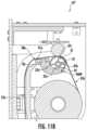
- the perforation tear assist featurecomprises a brake feature movable between a first position and a second position.
- the brake featurecomprises a body extending into the dispensing pathway.
- the brake featureis biased to the first position.
- the brake featureengages with at least one of the drive roller or the nip roller to prevent further rotation thereof.
- the brake featureis configured to move to the second position when a user pulls on the leading predetermined portion for removal thereof so as to cause the nip to hold the sheet product therein without enabling further translation therethrough and to create tension in the sheet product to aid in removal of the leading predetermined portion via separation of the line of perforations at the trailing edge.
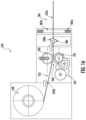
- the brake featureis a roller.
- the rollerfurther includes at least one rib that extends into the dispensing pathway within the dispensing chute such that, when a user pulls on the leading predetermined portion for removal thereof, tension is focused at a position on the sheet product corresponding to the trailing edge of the leading predetermined portion so as to aid in removal via separation of the line of perforations at the trailing edge
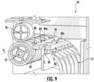
- the perforation tear assist featurecomprises a lever that is movable between a first position and a second position.
- the levercomprises a body with a top surface and a hole extending through the body and the top surface.
- the leveris biased to the first position.
- the perforation tear assist featureincludes a projection that extends toward the dispensing pathway and into the hole of the lever.
- the projectionis configured to focus pressure onto a position of the sheet product when a user pulls on the leading predetermined portion for removal thereof.
- the top surfaceis positioned above the projection with respect to the dispensing pathway when the lever is in the first position.
- the top surfaceis positioned below a top of the projection with respect to the dispensing pathway when the lever is in the second position.
- the leveris configured to move to the second position when the user pulls on the leading predetermined portion for removal thereof so as to enable the projection to contact the sheet product to focus pressure onto the sheet product to aid in removal of the leading predetermined portion via separation of the line of perforations at the trailing edge.
- the systemfurther comprises a mark detector configured to detect one or more markings on the sheet product.
- the controlleris configured to cause, based on mark detector data received from the mark detector, the motor to cease operation to position the leading predetermined portion of the sheet product in the dispensing position.
- the controlleris configured to determine a type or characteristic of the sheet product installed on the roll holder based on the mark detector data received from the mark detector.
- each of the plurality of predetermined portionscomprises printed indicia indicating one or more directions for a user regarding converting the predetermined portion into a use configuration using the at least cut-out or the series of perforations.
- the sheet productis dispersible paper-based.
- the systemfurther comprises a chassis configured to move between a stowed position inside the housing and an unstowed position.
- the roll holderis positioned on the chassis and configured to move with the chassis.
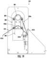
- the dispensing chuteis positioned below the chassis.
- the sheet product dispenserdefines a dispensing pathway leading from the nip roller to behind the chassis and to the dispensing chute.
- a seat cover dispenserfor dispensing from a sheet product roll.
- the dispensercomprises a roll holder for supporting the sheet product roll.
- the sheet product rollcomprises a plurality of predetermined portions, wherein consecutive predetermined portions are separated by a line of perforations extending along a width direction of the sheet product.
- Each of the plurality of predetermined portionsincludes at least one cut-out or a series of perforations that define at least a portion of a shape corresponding to an opening in a toilet seat.
- a width of a predetermined portion of the sheet product rollis between 10 inches and 18 inches and a length of the predetermined portion of the sheet product roll is between 12 inches and 22 inches.
- the dispenserincludes a dispensing mechanism and a dispensing pathway leading through a nip of the dispensing mechanism to a dispensing outlet.
- a ratio of the length of the predetermined portion of the sheet product roll to a length of a portion of the dispensing pathway extending from the nip to the dispensing outletis between 0.5 and 1 so as to cover a portion of a leading predetermined portion when the leading predetermined portion is in a dispensing position with a trailing edge at a first position along the dispensing pathway downstream of the nip and a leading edge at a second position outside of the dispensing outlet.
- the ratio of the length of the predetermined portion of the sheet product roll to the length of at least the portion of the dispensing pathwayis between 0.6 and 0.8.
- a line of perforations at the trailing edge of the leading predetermined portionis past the nip along the dispensing pathway.
- the line of perforations at the trailing edgeis aligned with a perforation tear assist feature that is configured to aid in removal of the leading predetermined portion along the line of perforations at the trailing edge.
- a sheet product roll of continuous sheet productcomprises a plurality of predetermined portions.
- Each of the plurality of predetermined portionsdefine a length extending from a leading edge to a trailing edge. Consecutive predetermined portions are separated by a line of perforations extending along a width direction of the sheet product. The line of perforations extends along the width direction of the sheet product at the trailing edge.
- Each of the plurality of predetermined portionsincludes a series of perforations that define at least a portion of a shape corresponding to an opening in a toilet seat. The series of perforations comprise at least one first perforation that comprises a catch portion and a main portion.
- the main portiondefines a length extending along at least a portion of a periphery of the shape corresponding to the opening in the toilet seat.
- the lengthdefines a start and an end.
- the catch portionextends from the start of the main portion and defines at least one branch portion extending at a non-zero angle with respect to the main portion that is designed to redirect a tear in the sheet product toward the main portion of the first perforation.
- the series of perforationsfurther comprise a finger assist perforation.
- the finger assist perforationdefines a curved portion corresponding to a shape of a finger or a hand.
- the finger assist perforationis positioned at a top of the shape corresponding to the opening in the toilet seat.
- the at least one first perforationis positioned such that the start of the main portion is positioned relatively closer to the finger assist perforation than the end of the main portion.
- a sheet product dispenserin yet another example embodiment, includes a housing comprising a dispensing chute and a roll holder positioned within the housing and configured to support a sheet product roll.
- the sheet product rollcomprises a plurality of predetermined portions, wherein consecutive predetermined portions are separated by a line of perforations extending along a width direction of the sheet product.
- Each of the plurality of predetermined portionsincludes at least one cut-out or a series of perforations that define at least a portion of a shape corresponding to an opening in a toilet seat.
- Each of the plurality of predetermined portionsdefine a length extending from a leading edge to a trailing edge.
- the line of perforationsextends along the width direction of the sheet product at the trailing edge.
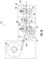
- the sheet product dispenserincludes a first drive roller positioned within the housing, a first nip roller positioned within the housing and configured to, with the first drive roller, define a first nip that receives sheet product from the sheet product roll, a second drive roller positioned within the housing, and a second nip roller positioned within the housing and configured to, with the second drive roller, define a second nip that receives sheet product from the sheet product roll, wherein the second nip is downstream of the first nip along a dispensing pathway leading from the roll holder to the dispensing chute.
- the sheet product dispenserfurther includes at least one motor configured to operate to drive at least one of the first drive roller and the second drive roller to cause movement of the sheet product along the dispensing pathway.
- the first drive rolleris independently operable with respect to the second drive roller.
- the sheet product dispenserfurther includes an activation sensor configured to sense user input and a controller.
- the controlleris configured to receive sensor data from the activation sensor, cause, in response to receiving the sensor data, the at least one motor to operate to cause translation of the sheet product along the dispensing pathway to a first position in which the trailing edge of a leading predetermined portion of the sheet product is positioned between the first nip and the second nip, and cause at least one of the first drive roller or the second drive roller to operate such that the first drive roller and the second drive roller operate at different speeds or in different directions to cause separation of the line of perforations at the trailing edge of the leading predetermined portion so as to enable a user to pull the leading predetermined portion from the dispensing chute.
- the controlleris further configured to cause the at least one motor to operate to cause the second drive roller to cause dispensing of the leading predetermined portion through the dispensing chute after separation of the line of perforations.
- the sheet product dispenserfurther includes a mark detector configured to detect one or more markings on the sheet product, and the controller is configured to cause, based on mark detector data received from the mark detector, the motor to cease operation to position the leading predetermined portion of the sheet product such that the trailing edge of the leading predetermined portion is between the first nip and the second nip.
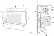
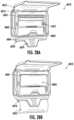
- FIG. 1 Ashows a top perspective view of an example sheet product (e.g., toilet seat cover) dispenser, in accordance with some embodiments discussed herein;
- an example sheet producte.g., toilet seat cover
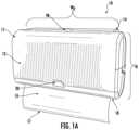
- FIG. 1 Bshows a perspective view of another example sheet product (e.g., toilet seat cover) dispenser, in accordance with some embodiments discussed herein;
- another example sheet producte.g., toilet seat cover
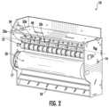
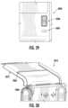
- FIG. 2shows an isometric view of an example sheet product dispenser with a cover removed, in accordance with some embodiments discussed herein;
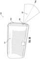
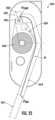
- FIG. 3 Ashows a right side view of an example sheet product dispenser, where a detection zone of an activation sensor is illustrated, in accordance with some embodiments discussed herein;
- FIG. 3 Bshows a top perspective view of an example sheet product dispenser, where a detection zone of an activation sensor is illustrated, in accordance with some embodiments discussed herein;
- FIG. 3 Cshows a right side view of an example sheet product dispenser, where a detection zone of an activation sensor is illustrated, in accordance with some embodiments discussed herein;
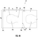
- FIG. 4 Ashows an example sheet product roll, such as for use with the example sheet product dispensers described herein, in accordance with some embodiments discussed herein;
- FIG. 4 Billustrates a portion of an example sheet product roll, showing a leading predetermined portion, in accordance with some embodiments discussed herein;
- FIGS. 4 C-Eillustrate example perforation patterns for the line of perforations that separates consecutive predetermined portions of the sheet product, in accordance with some embodiments discussed herein;
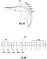
- FIG. 4 Fillustrates an example perforation pattern for a series of perforations that defines a shape corresponding to the opening in the toilet for an example predetermined portion of sheet product, in accordance with some embodiments discussed herein;
- FIG. 4 Gis a close up view of a portion of the perforation pattern shown in FIG. 4 F , wherein a tear is illustrated progressing through the perforation pattern, in accordance with some embodiments discussed herein;
- FIGS. 4 H-Jillustrate example predetermined portions of the sheet product that include printed indicia, in accordance with some embodiments discussed herein;
- FIG. 4 Killustrates example printing patterns for sheet product, in accordance with some embodiments discussed herein;
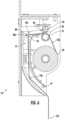
- FIG. 5shows cross-sectional view of an example sheet product dispenser, where a leading predetermined portion of sheet product is shown in the staged position, in accordance with some embodiments discussed herein;
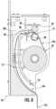
- FIG. 6shows cross-sectional view of the example sheet product dispenser shown in FIG. 5 , where the leading predetermined portion of sheet product is shown in the dispensing position, in accordance with some embodiments discussed herein;
- FIG. 6 Aillustrates a schematic cross-sectional view of an example portion of a dispensing chute, where a plurality of ribs with varying heights are shown, in accordance with some embodiments discussed herein;
- FIG. 6 Billustrates a schematic top view of an example portion of the dispensing chute, where the different heights of the plurality of ribs are illustrated, in accordance with some embodiments discussed herein;
- FIG. 6 Cillustrates a schematic top view of an example portion of the dispensing chute, where different gap distances between consecutive pairs of ribs are illustrated, in accordance with some embodiments discussed herein;
- FIG. 7shows cross-sectional view of another example sheet product dispenser, where a leading predetermined portion of sheet product is shown in the dispensing position, in accordance with some embodiments discussed herein;
- FIG. 8shows a cross-sectional view of another example sheet product dispenser, where the example sheet product dispenser includes a perforation tear assist feature with a lever and a hidden projection, in accordance with some embodiments discussed herein;
- FIG. 9shows a close-up isometric view of the perforation tear assist feature shown in FIG. 8 , in accordance with some embodiments discussed herein;
- FIG. 10shows a cross-sectional view of yet another example sheet product dispenser, where the example sheet product dispenser includes a perforation tear assist feature with a brake lever, in accordance with some embodiments discussed herein;
- FIG. 11 Ashows a close-up cross-sectional view of the perforation tear assist feature shown in FIG. 10 , wherein the brake lever is in the disengaged position, in accordance with some embodiments discussed herein;
- FIG. 11 Bshows a close-up cross-sectional view of the perforation tear assist feature shown in FIG. 10 , wherein the brake lever is in the engaged position, in accordance with some embodiments discussed herein;
- FIG. 12shows a cross-sectional view of yet another example sheet product dispenser, where the example sheet product dispenser includes a perforation tear assist feature with a brake roller, in accordance with some embodiments discussed herein;
- FIG. 12 Ashows a close-up perspective view of interaction between the brake roller and the drive roller for the example sheet product dispenser shown in FIG. 12 , in accordance with some example embodiments discussed herein;
- FIG. 13shows a cross-sectional view of yet another example sheet product dispenser, where the example sheet product dispenser includes two nips, where a leading predetermined portion is shown in the staged position, in accordance with some embodiments discussed herein;
- FIG. 14shows a cross-sectional view of the example sheet product dispenser shown in FIG. 13 , where the leading predetermined portion is shown in the dispensing position, in accordance with some embodiments discussed herein;
- FIG. 15shows a cross-sectional schematic view of an example sheet product dispenser, where the example sheet product dispenser includes a perforation tear assist feature including a clamping mechanism, in accordance with some embodiments discussed herein;
- FIG. 16shows a cross-sectional schematic view of an example sheet product dispenser, where the example sheet product dispenser includes a perforation tear assist feature including a clamping and cutting mechanism, in accordance with some embodiments discussed herein;
- FIG. 17shows a cross-sectional schematic view of an example sheet product dispenser, where the example sheet product dispenser includes a perforation tear assist feature including a clamping and rotary cutting mechanism, in accordance with some embodiments discussed herein;
- FIG. 18shows a cross-sectional schematic view of an example sheet product dispenser, where the example sheet product dispenser includes a perforation tear assist feature including a rotary cutting mechanism that is located between two nips, in accordance with some embodiments discussed herein;
- FIG. 19shows a cross sectional view of another example sheet product dispenser, where a movable chassis is illustrated, in accordance with some embodiments discussed herein;
- FIGS. 20 A- 20 Billustrate an example portion of a sheet product dispenser that includes a perforation tear assist feature for tearing at least some of a series of perforations defining a shape corresponding to the opening in the toilet (e.g., the central opening for the predetermined portion), in accordance with some embodiments discussed herein;
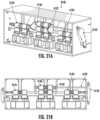
- FIGS. 21 A- 21 Billustrate another example portion of a sheet product dispenser that includes a perforation tear assist feature for tearing at least some of a series of perforations defining a shape corresponding to the opening in the toilet (e.g., the central opening for the predetermined portion), in accordance with some embodiments discussed herein;
- FIG. 22illustrates another example portion of a sheet product dispenser that includes a perforation tear assist feature for tearing at least some of a series of perforations defining a shape corresponding to the opening in the toilet (e.g., the central opening for the predetermined portion), in accordance with some embodiments discussed herein;
- FIG. 23illustrates a cross-sectional schematic view of an example sheet product dispenser, in accordance with some embodiments discussed herein;
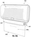
- FIG. 24 Ashows a top perspective view of an example sheet product dispenser, where the dispenser includes an extension portion that extends from the dispensing chute, in accordance with some embodiments discussed herein;
- FIG. 24 Bshows a right side view of the example sheet product dispenser shown in FIG. 24 A , in accordance with some embodiments discussed herein;
- FIGS. 25 A-Cshow front views of example sheet product dispensers with differently shaped extension portions, in accordance with some embodiments discussed herein;
- FIG. 26 Ashows a front view of an example sheet product dispenser, where no light is illuminated while the leading predetermined portion is still in the process of moving to the dispensing position, in accordance with some embodiments discussed herein;
- FIG. 26 Bshows a front view of the example sheet product dispenser shown in FIG. 26 A , where a green light is illuminated when the leading predetermined portion advances to the dispensing position such that the user is aware that it is available for removal, in accordance with some embodiments discussed herein;
- FIG. 27 Ashows an example roll holder and inserted sheet product roll that may be used with various example sheet product dispensers described herein, in accordance with some embodiments discussed herein;
- FIG. 27 Bshows an example sheet product roll, in accordance with some embodiments discussed herein;
- FIGS. 27 C-Dshow example roll holder receiving portions that are each configured to receive and hold a side of a sheet product roll, in accordance with some embodiments discussed herein;
- FIG. 28 Aillustrates an example sheet product dispenser with the cover opened and no roll of sheet product installed, in accordance with some embodiments discussed herein;
- FIG. 28 Billustrates the example sheet product dispenser shown in FIG. 28 A , but with a roll of sheet product installed and a current predetermined portion in the dispensed position, in accordance with some embodiments discussed herein;
- FIG. 29shows a close up view of a portion of a user interface of the example sheet product dispenser shown in FIG. 28 A , in accordance with some embodiments discussed herein;
- FIG. 30shows a close up view of an example sheet product dispenser with the cover in the open position, in accordance with some embodiments discussed herein;
- FIG. 31illustrates an example jam scenario in the dispensing chute of an example sheet product dispenser, where the chassis is raised to an unstowed position to reveal the sheet product, in accordance with some embodiments discussed herein;
- FIG. 32illustrates an example sheet product dispenser with the chassis in the unstowed position and the cover in the open position, in accordance with some embodiments discussed herein;
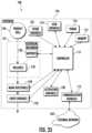
- FIG. 33shows a block diagram illustrating an example sheet product dispenser, in accordance with some embodiments discussed herein;
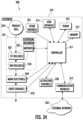
- FIG. 34shows a block diagram illustrating another example sheet product dispenser, in accordance with some embodiments discussed herein;
- FIG. 35illustrates a flowchart of an example method of controlling and operating an example sheet product dispenser, in accordance with some embodiments discussed herein;
- FIG. 36illustrates a flowchart of an example method of controlling and operating an example sheet product dispenser to advance the sheet product to an appropriate position (e.g., to a staged position or a dispensing position), in accordance with some embodiments discussed herein;
- FIG. 37illustrates a flowchart of another example method of controlling and operating an example sheet product dispenser, in accordance with some embodiments discussed herein.
- a “user” of example product dispensersmay be a maintainer (e.g., a maintenance person, a janitor, a facility manager, etc.) or a consumer (e.g., end user, a person receiving a dispensed predetermined portion, etc.).
- a “user”may act as both a maintainer and a consumer.
- sheet productincludes a product that is relatively thin in comparison to its length and width. Further, the sheet product may define a relatively flat, planar configuration. In some embodiments, the sheet product is flexible or bendable to permit, for example, folding, rolling, stacking, or the like. In this regard, sheet product may, in some cases, be formed into stacks or rolls for use with various embodiments described herein. Some example sheet products include towel, bath tissue, facial tissue, napkin, wipe, wrapping paper, aluminum foil, wax paper, plastic wrap, or other sheet-like products. Sheet products may be made from paper, cloth, non-woven, metallic, polymer or other materials, and in some cases may include multiple layers or plies.
- the sheet product(such as in roll or stacked form) may be a continuous sheet that is severable or separable into individual sheets using, for example, a tear bar or cutting blade. Additionally or alternatively, the sheet product may include predefined areas of weakness, such as lines of perforations, that define individual sheets and facilitate separation and/or tearing. In some such embodiments, the lines of perforations may extend along the width of the sheet product to define individual sheets that can be torn off by a user.
- the term “dispersible paper”includes sheet product that is designed to at least partially disintegrate in water such as for use with flushing down a toilet drain (e.g., the sheet product is flushable).
- the sheet productmay have a low wet strength characteristic to help facilitate dispersibility and/or flushability.
- the dispersible papermay be formed partially of hardwood (e.g., wood that is formed of shorter fibers, such as from gum, maple, and oak trees) and softwood (e.g., wood that is formed of longer fibers, such as from Douglas firs and Southern pines).
- Such dispersible papermay, in some embodiments, encompass one or more of the above noted examples of sheet product (e.g., wipe, bath tissue, napkin, facial tissue, etc.) and/or one or more qualities/characteristics of such examples.
- sheet producte.g., wipe, bath tissue, napkin, facial tissue, etc.
- dispersible paperis not meant to be limited to a specific type of sheet product unless otherwise stated.
- FIG. 1 Ashows an example sheet product dispenser 10 according to various embodiments of the present invention.
- the sheet product dispenser 10may include a housing 11 defined by a base portion 14 and a cover 12 .
- the sheet product dispenser 10may be configured to be mounted, such as to a wall or a bathroom stall.
- the sheet product dispenser 10may include one or more mounting structures (e.g., screw holes, clips, attachment features, etc.) on the rear side of the base portion 14 to facilitate mounting the sheet product dispenser 10 .
- the cover 12may be movable between a closed position (shown in FIG. 1 A ) and an open position (e.g., shown in FIG. 28 A ).
- FIG. 2illustrates an example base portion 14 with the cover 12 removed.
- the cover 12may be movable while remaining attached to the base portion 14 .
- the cover 12may be configured to rotate about an axis.
- a lock feature 98may be provided to permit locking of the cover 12 to the base portion 14 .
- a maintainermay, for example, have a key that can be inserted into the lock feature 98 to enable opening of the cover 12 .
- the lock feature 98may be operated via an unlocked button to enable opening of the cover 12 .
- the maintainercan perform maintenance on the sheet product dispenser 10 , such as repairing or replacing various components or batteries and/or replacing the sheet product roll 50 that is on the roll holder 17 (shown, for example, in FIG. 2 ).
- FIG. 1 Billustrates another example sheet product dispenser 2010 that includes an extension portion 2019 extending from the chute 2018 . Additional detail regarding example extension portions is described herein with respect to FIGS. 24 A- 25 C .
- the sheet product dispenser 2010includes a housing 2011 defined by a base portion 2014 and a cover 2012 .
- An activation sensor 2020is positioned in the relative lower, center of the dispenser and can be utilized by a user to initiate a dispense (such as described herein).
- the sheet product dispenser 2010includes a lock feature 2098 that enables a user (e.g., a maintenance professional) to access the inside of the sheet product dispenser 2010 , such as by opening the cover 2012 .
- the sheet product dispenser 10may be configured to enable dispensing of a portion of sheet product, such as in response to a user providing corresponding user input to the dispenser 10 .
- the sheet product dispenser 10may include one or more activation sensors 20 that can be utilized for providing user input indicating a desire to cause a dispense of the sheet product (e.g., a leading predetermined portion 55 of the sheet product is shown in a dispensing position in FIG. 1 A ).
- the sheet product dispenser 10may operate to cause a portion of the sheet product to dispense therefrom (e.g., hang down from the dispensing chute 18 ). More detail regarding how the dispense occurs is described herein.
- the user input indicating the desire to dispense the portion of sheet productmay be provided to any type of activation sensor/device, such as a handle, button, sensor, among others.
- the user inputmay be provided via touch-free user input such as may be desirable to avoid the need to touch the dispenser (e.g., the user may have dirty hands).
- one or more emergency dispense featurese.g., an emergency dispense handle, lever, or other structure
- the sheet product dispenser 10may include a roll holder 17 for receiving and holding a sheet product roll 50 (such as described in greater detail herein).
- the roll holder 17may include one or more attachment features that are configured to rotatably hold the sheet product roll 50 , such as during operation of the dispenser. Additionally, the roll holder 17 may be configured to enable detachment and attachment to enable replacement of the sheet product roll 50 , such as by a maintainer.
- the roll holder 17may include one or more sensors, such as may be configured to determine one or more characteristics regarding the sheet product roll (e.g., whether one is installed and/or was just installed, the weight of the sheet product roll, rotation of the sheet product roll, etc.).
- the sheet product dispenser 10may include one or more drive rollers 31 and corresponding nip rollers 33 (e.g., nip rollers 33 a , 33 b , 33 c . . . ).
- a motormay be configured to operate the one or more drive rollers 31 and/or nip rollers 33 to cause movement of the sheet product along a dispensing pathway such as out of the dispensing chute 18 .
- the nip roller 33may be formed of a plurality of nip rollers 33 a , 33 b , 33 c , . . . that are spaced apart along a width direction (D W ) of the dispensing pathway of the dispenser 10 .
- each nip roller 33 aincludes a corresponding mounting structure 34 , such as may be biased toward the drive roller 31 .
- each of the plurality of nip rollersis independently actuatable to move (e.g., upwardly/downwardly, although pivoting and pitching is also contemplated), such as between a first position and a second position.
- the plurality of independently actuatable nip rollersmay account for any inconsistencies in the dispense (e.g., the sheet product got moved in the width direction such that one of the nip rollers is not touching the sheet product) to thereby avoid negative effects on the sheet product (e.g., crinkling, folding, etc.) which can result in providing a less desirable dispense and/or lead to clogging of the dispenser.
- one or more mark detectors 40can be positioned between consecutive nip rollers (e.g., between nip roller 33 b and 33 c ) and aimed toward the sheet product that is moving through the nip 36 .
- Example mark detectors and their various possible functionsare described in greater detail herein. Further, some embodiments contemplate different or additional positions for the mark detectors within the dispenser 10 .
- the dispensing chute 18may be positioned within the dispenser 10 and along the dispensing pathway to provide the dispensed portion to the user.
- one or more sensorsmay be positioned within the dispensing chute 18 , such as for determining whether a dispensed portion is present. Further detail regarding example dispensing chutes and various components/features provided for the dispensing chute 18 are described herein.
- example sheet product dispensers 10can be found herein, such as with respect to FIGS. 33 and 34 (e.g., depending on various desired configurations of the sheet product dispenser).
- the sheet product dispenser 10may be designed to be mounted in a restroom to provide individual toilet seat covers to a user.
- the sheet product dispenser 10may be shaped and/or sized to fit within the restroom environment, such as within a stall (which may be small/narrow/etc. and which may also have a toilet, along with other fixtures, such as tissue paper rolls/dispensers).
- the sheet product dispenser 10may be mounted to a stall wall, a back of stall door, or behind the toilet.
- the sheet product dispenser 10may define a width (W D ), length (L D ), and depth (D D ) so as to be mounted within the stall and still provide the corresponding dispensed portion (e.g., a predetermined portion corresponding to an individual toilet seat cover).
- the depth of the dispenser 10may be relatively small (e.g., ⁇ 4 in.-6 in.) compared to the length (e.g., ⁇ 12 in.-24 in.) and width (e.g., ⁇ 16 in.-22 in.).
- the widthmay be determined according to the width of the sheet product itself.
- the activation sensor 20may be designed to enable accurate sensing of user input regarding a desire to receive a dispense. For example, due to potential mounting positions of the sheet product dispenser within the restroom environment and the size of the sheet product dispenser itself, there may be a risk of inadvertent activation of the sheet product dispenser. For example, a user sitting down on the toilet may inadvertently activate the activation sensor of a sheet product dispenser mounted behind or next to the toilet. Thus, some embodiments of the present invention contemplate certain positioning and orientation of the activation sensor 20 such that a detection zone for detecting user input for activating a dispense is defined to avoid or limit risk of such inadvertent activation. In this regard, in some example embodiments, the activation sensor is oriented relative to the housing and configured to sense an object positioned within a detection zone relative to the housing.
- an example sheet product dispenser 910includes an activation sensor 920 that is positioned on a front surface 919 a of the housing 911 .
- the activation sensor 920is oriented so as to define the detection zone (where the sensor 920 senses user input) such that it is generally forward and upward of the dispenser housing 911 .
- the center line D HAF of the detection zone 921 for the activation sensor 920extends at an upwardly extending angle ⁇ of approximately 45 degrees with respect to a forward direction D F .
- the center linemay extend at an upwardly extending angle of at least 30 degrees with respect to the forward direction D F .
- FIG. 3 Billustrates another example positioning and orientation of the activation sensor to avoid or limit inadvertent activation.
- an example sheet product dispenser 910 ′includes an activation sensor 920 ′ that is positioned on a side surface 919 c ′ of the housing 911 ′.
- the activation sensor 920 ′is oriented so as to define the detection zone (where the sensor 920 ′ senses user input) such that it is generally outward to the side of the dispenser housing 911 ′.
- the center line D HAS of the detection zone 921 ′ for the activation sensor 920 ′extends to the side of the dispenser housing 911 ′.
- FIG. 3 Cillustrates yet another example positioning and orientation of the activation sensor to avoid or limit inadvertent activation.
- an example sheet product dispenser 910 ′′includes an activation sensor 920 ′′ that is positioned on a bottom surface 919 d ′′ of the housing 911 ′′.
- the activation sensor 920 ′′is oriented so as to define the detection zone (where the sensor 920 ′′ senses user input) such that it is generally downward below the dispenser housing 911 ′′.
- the center line D HAD of the detection zone 921 ′′ for the activation sensor 920 ′′extends below the dispenser housing 911 ′′.
- volume 921 , 921 ′, 921 ′′ of a detection zonesuch a volume is meant for explanatory purposes and is not meant to be limiting.
- different types of activation sensorse.g., infrared, time-of-flight, capacitance, optical, etc.
- example embodiments of the present inventionprovide a sheet product dispenser 10 configured to dispense a predetermined portion of flushable and/or dispersible paper that is designed to be converted and used as a toilet seat cover.
- some such sheet product dispensers 10are also designed to dispense such predetermined portions from a sheet product roll 50 (e.g., as opposed to the toilet seat covers being held in stacked form).
- FIG. 4 Aillustrates an example sheet product roll 50 that includes a continuous web of sheet product.
- the continuous webis defined by a plurality of predetermined portions 55 that each correspond to a toilet seat cover.
- Consecutive predetermined portions 55are separated by a line of perforations 51 extending along a width direction of the sheet product, wherein each of the plurality of predetermined portions includes at least one cut-out or a series of perforations 53 that define at least a portion 54 of a shape corresponding to an opening in a toilet seat (see e.g., the portion 54 corresponds to the shape of toilet seat opening).
- Each of the plurality of predetermined portions 55define a length extending from a leading edge 57 to a trailing edge 58 .
- FIG. 4 Billustrates a portion of the sheet product roll 50 , showing the leading predetermined portion 55 a followed by a next predetermined portion 55 b .
- the leading predetermined portion 55 adefines a length (L S ) extending from a leading edge 57 a to a trailing edge 58 a .
- the leading predetermined portion 55 ais separated from the next predetermined portion 55 b by a line of perforations 51 extending along the width (W S ) of the sheet product at its trailing edge 58 a .
- the trailing edge 58 a of the leading predetermined portion 55 ais adjacent the leading edge 57 b of the next predetermined portion 55 b .
- the leading predetermined portion 55 aincludes a series of perforations 53 that define at least a portion 54 a of a shape corresponding to an opening in a toilet seat.
- a remaining edge 52 of the portion 54 a(e.g., as also defined by the series of perforations 53 ) may not include perforations such that the portion 54 a remains connected to the remainder of the leading predetermined portion 55 a through the edge 52 when a user separates the series of perforations 53 to convert the predetermined portion into a useable toilet seat cover.
- the portion 54 a corresponding to the opening in the toilet seatmay fall into the toilet and hang via the edge 52 .
- the predetermined portionmay define a size such that it fits over and covers a toilet seat.
- the predetermined portionmay define a width that ranges from ⁇ 10 in.-18 in. (with a preferred range of ⁇ 13 in.-18 in.) and a length that ranges from ⁇ 12 in.-22 in. (with a preferred range of ⁇ 15 in.-20 in.).
- the line of perforationsmay be defined by a perforation pattern that is configured to encourage proper separation of consecutive predetermined portions when a separation tear is initiated.
- the perforation patternmay be designed to maintain the connection between the consecutive predetermined portions until the separation is actually desired (e.g., to avoid premature separation, such as during interaction with the dispenser and its components and/or from a false pulling on an exposed leading edge).
- the perforation patternmay be important to achieve both desirable outcomes.
- FIGS. 4 C-Eillustrate example perforation patterns for the line of perforations that separates consecutive predetermined portions of the sheet product. As shown, different variables such as the length of an edge cut, the length of a cut, the length of a bonded (uncut) section of the sheet product, the repeated nature of the cuts and bonded sections, among other things, are just some of the factors that are considered for designing a beneficial perforation pattern.
- FIG. 4 Cillustrates a first example perforation pattern 2051 for a sheet product roll 2050 .
- the perforation pattern 2051includes an edge cut (e.g., leading from one edge toward the center of the sheet product) of 0.5 inches, followed by a repeated pattern of a bonded section of 0.028 inches and a cut of 0.112 inches.
- FIG. 4 Dillustrates a second example perforation pattern 2051 ′ for a sheet product roll 2050 ′.
- the perforation pattern 2051 ′includes an edge cut (e.g., leading from one edge toward the center of the sheet product) of 0.5 inches, followed by a repeated pattern of a bonded section of 0.028 inches and a cut of 0.159 inches.
- example desirable perforation patterns when using a single line of perforationsmay include a length of repeated cuts ranging from 0.1 in.-0.2 in. (with a preferred range, in some embodiments, of 0.112 in.-0.159 in.). This produces a desirable ratio of repeated cut over (repeated cut plus bonded section) of ⁇ 0.78-0.88 (with a preferred ratio, in some embodiments, of 0.8-0.85).
- the perforation patternmay be designed to achieve a desired ratio of ⁇ 0.9.
- different sections of the perforation patternmay have different desired ratios—such as 0.85 towards the edges and 0.9 in the middle.
- FIG. 4 Eillustrates a third example perforation pattern 2051 ′′ for a sheet product roll 2050 ′′.
- this perforation pattern 2051 ′′includes a first perforation line 2051 a ′′ and a second perforation line 2051 b ′′.
- both the first perforation line 2051 a ′′ and the second perforation line 2051 b ′′include an edge cut (e.g., leading from one edge toward the center of the sheet product) of 0.25 inches, followed by a repeated pattern of a bonded section of 0.028 inches and a cut of 0.112 inches. While shown as matching, in some embodiments, the repeated cut and bonded section may be offset, such as by having a different edge cut length between the two perforation lines.
- Example embodimentsthat provide two perforation lines for a perforation pattern help provide additional redundancy for maintaining the connection until desired, and also provide for recapturing errant tears and maintaining the remainder of the predetermined portion intact during an otherwise errant tear.
- the tearmay continue along the same perforation line 2051 b ′′ across the width of the predetermined portion.
- the first perforation line 2051 a ′′may “catch” the errant tear and redirect it along the first perforation line 2051 a ′′—thereby preventing the errant tear from moving into the rest of the predetermined portion for which it is desirable to remain intact (such as for its intended end use for covering the toilet seat).
- a further downward errant tear from the first perforation line 2051 a ′′may be caught again and redirected by the second perforation line 2051 b ′′, with the same benefits being applied across the width of the predetermined portion.
- edge cut lengthcan be reduced as there is less need to extend the duration of direction of the initial tear due to having the second perforation line to catch an errant tear.
- the line of perforations 2050 ′′may be more likely to stay intact until the desired separation tear is initiated.
- the example perforation patterns 2051 , 2051 ′, 2051 ′′have been shown in testing to provide the desired outcome to maintain the sheet connection until a dispensing event and then achieve a proper separation during the dispensing event (e.g., a user initiating a dispensing tear).
- a dispensing evente.g., a user initiating a dispensing tear.
- the combination of the example perforation pattern and other beneficial featureshelp ensure that proper separation occurs.
- the predetermined portionmay include a series of perforations that can be removed to form an opening (e.g., center hole) that corresponds to the opening in the toilet. While some embodiments envision a user tearing out the series of perforations after a dispense is completed (e.g., to convert the predetermined portion into a toilet seat cover), in some embodiments, the series of perforations may naturally be torn away once a substance (e.g., water, urine, fecal matter, etc.) is dropped thereon (such as if a user simply places the predetermined portion over the toilet seat without first removing the series of perforations). Likewise, in some embodiments, such an opening may be pre-removed before dispensing (and may not have had a series of perforations) and/or such a series of perforations may be torn away via one or more features of the dispenser).
- a substancee.g., water, urine, fecal matter, etc.
- FIG. 4 Fillustrates an example perforation pattern for a series of perforations 2153 that defines a shape 2154 corresponding to the opening in the toilet.
- the sheet product 2150includes a finger assist perforation 2153 a and a plurality of main perforations 2153 b.
- the finger assist perforation 2153 ais shaped to correspond to a user's hand and/or finger such as to enable a user to reach their hand and/or finger through the finger assist perforation 2153 a grab the sheet product and pull down to initiate the tear (e.g., along arrow D Tear ).
- the finger assist perforation 2153 adefines a curved portion corresponding to a shape of a finger or a hand.
- the end points of the finger assist perforation 2153 bmay encourage the tear to travel toward a first main perforation on each side of the shape (e.g., consider the end point 2158 to the first main perforation 2153 b ′ on the left side of the shape). This will encourage proper tearing of the series of perforations 2153 to form the desired shape 2154 .
- the main perforation 2153may include a catch portion 2159 and a main portion 2157 .
- the main portion 2157defines a length extending from a start 2157 a to an end 2157 b along at least a portion of the periphery of the shape corresponding to the opening in the toilet seat.
- the catch portion 2159extends from the start 2157 a of the main portion 2157 and defines at least one branch portion 2159 a , 2159 b extending at a non-zero angle with respect to the main portion 2157 that is designed to redirect a tear in the sheet product toward the main portion 2157 .
- FIG. 4 Gillustrates progression of a tear through the left side of the series of perforations.
- the tear 2189may continue along the sheet product 2150 through the bonded section (e.g., illustrated as 2189 a ).
- the tear 2189 amay not travel directly to the start 2157 a of the main portion 2157 and, instead, may deviate (e.g., to the left or the right) through the sheet product 2150 .
- the branch portions 2159 a , 2159 b of the catch portion 2159are designed to extend outwardly in one or more directions to “catch” and redirect the tear to the start 2157 a of the main portion 2157 so that the tear then moves along the main portion 2157 and the proper shape 2154 is removed during removal of the series of perforations 2153 .
- FIG. 4 Gillustrates that the tear 2189 a is caught by the branch portion 2159 b and redirected to the main portion 2157 . Later after passing past the end 2157 b of the main perforation 2153 ′′, the tear 2189 b deviates left a bit, but is caught by the catch portion 2159 ′′ of the next main perforation 2153 b ′′′.
- the predetermined portionsmay each include one or more markings 65 .
- the markings 65may be any form of mark that is detectable, such as by the mark detector(s) described herein.
- the markingmay define a 0.5 in. by 1 in. black rectangle, such as markings 65 a , 65 b shown in FIG. 4 B , although other shapes/sizes are contemplated.
- the markingsmay be positioned at predetermined locations on the predetermined portions. In such a manner, the predetermined locations may ensure alignment with the mark detector(s) during operation of the dispenser (e.g., so the mark detector can sense the marking).
- knowing the predetermined location on the predetermined portionenables the dispenser (such as via a controller) to position the predetermined portions appropriately along the dispensing pathway (e.g., in the staged position or the dispensing position—such as described in greater detail herein).
- the markingsmay carry additional coding information.
- the markingsmay be QR codes, or carry other coded features (e.g., colors, lengths, widths, spacing, etc.) that enable information to be determined based on sensor data from the mark detector(s) “reading” the markings.
- the markingsmay define a shape, size, color, or other features that enable verification of an installed authorized sheet product roll by the dispenser. In such a manner, the dispenser 10 may be configured to (such as through data received from the mark detector(s)) prevent or limit operation if an unauthorized sheet product roll is detected as being installed.
- other informationmay be gathered from the data of the mark detector(s), such as may be useful for reporting and monitoring operation of the sheet product dispenser (e.g., for maintenance, for determining a remaining number of predetermined portions on the installed sheet product roll, among other things).
- the markingsmay be repeated one or more times on each individual predetermined portion. Such an example embodiment may help prevent missed markings by the mark detector (such as due to an off center predetermined portion, an errant fold, etc.). In some such embodiments, the mark detector may be configured to ignore counting multiple occurrences of a marking within a certain time threshold of each other.
- the predetermined portionsmay include printed indicia such as to help provide instructions or a user for converting the predetermined portion into a useable toilet seat cover (e.g., into a use configuration).
- FIG. 4 Hillustrates an example predetermined portion 55 ′ that includes a printed outline of a portion of the toilet seat 77 ′ along with printings of an indication of the edge 72 ′ surrounding a part of the portion 54 ′ that is designed to be separated (e.g., the printed edge 72 ′ may indicate where to “fold” the portion 54 ′ so that it hangs into the toilet).
- a printed arrow and water droplet 73 ′further illustrates how to manipulate the portion 54 ′ when converting the predetermined portion 55 ′.
- FIG. 4 Iillustrates another example predetermined portion 55 ′′ with a printed full toilet seat outline 77 ′′ and corresponding other printed indicia 72 ′′ and 73 ′′ for helping a user convert the predetermined portion 55 ′′ using the portion 54 ′′.
- FIG. 4 Iillustrates another example predetermined portion 55 ′′ with a printed full toilet seat outline 77 ′′ and corresponding other printed indicia 72 ′′ and 73 ′′ for helping a user convert the predetermined portion 55 ′′ using the portion 54 ′′.
- 4 Jillustrates another example predetermined portion 55 ′′′ with a printed flush mechanism 79 ′′′ and corresponding other printed indicia 73 ′′ for helping a user convert the predetermined portion 55 ′′′ using the portion 54 ′′′ and, thereafter, properly orienting the predetermined portion 55 ′′′ on the toilet seat (e.g., the printed flush mechanism 79 ′′′ can be positioned relative to the flush mechanism of the toilet).
- the sheet productmay be pre-printed, such as with a pattern.
- the sheet productmay be pre-printed with a pattern that makes an aesthetically pleasing appearance.
- FIG. 4 Kshows example sheet product where three of the sheet products have been pre-printed, thereby illustrating the aesthetic effect.
- sheet product 2250 ahas been pre-printed with offset columns of grey dots
- sheet product 2250 bhas been pre-printed with offset rows of blue dots (with less frequency of the dots)
- sheet product 2250 chas been pre-printed with offset rows of grey lines.
- sheet product 2250 dhas not been pre-printed and is generally white. Testing has shown a preference by users for some level of patterned printing.
- various embodimentscontemplate different features, such as differently sized dots or lines, different positions, or patterns, etc.
- various embodiments of the present inventionprovide advantageous components/features that improve the dispensing quality and experience for users of sheet product dispensers (e.g., toilet seat cover dispensers).
- sheet product dispenserse.g., toilet seat cover dispensers.
- the dispensed substratebeing flushable and/or dispersible paper and the relatively long width of each predetermined portion, it can be important to ensure tearing the line of perforations appropriately to receive an intact dispense.
- some embodiments of the present inventionprovide an elongated chute (e.g., from the nip of the dispensing mechanism (e.g., dispensing mechanisms 121 , 321 shown in and described with respect to FIGS. 33 and 34 , respectively) to the end (e.g., exit) of the dispensing chute), which can help in ensuring a proper tear occurs when a user pulls on the leading predetermined portion that is in the dispensing position.
- the elongated chutemay enable the line of perforations to be positioned along the dispensing pathway in the dispensing chute.
- the userhas the opportunity to separate the perforations by pulling on the leading predetermined portion that extends from the dispensing chute.
- the elongated portion of the chutestill encloses and constrains lateral movement of a significant portion of the leading predetermined portion. This directs a user's pulling force by limiting side pulling of the predetermined portion (which is restricted due to being contained within the dispensing chute).
- FIG. 5illustrates a cross-sectional view of an example sheet product dispenser 10 , showing an installed sheet product roll 50 on a roll holder 17 .
- a leading predetermined portion 55 aextends along a dispensing pathway 13 from the sheet product roll 50 into a dispensing nip 36 (defined between a drive roller 31 and a nip roller 33 ) and into the dispensing chute 18 .
- the elongated portionextends within the dispensing chute 18 from the nip 36 to an outlet 18 b .
- the elongated portiondefines a length that is equivalent to or greater than the length of each of the plurality of predetermined portions.
- the elongated portiondefines a length that is between ⁇ 14 in. and 24 in.
- some embodiments of the present inventionprovide certain relative positions of various components of the dispenser.
- the roll holder 17 of the dispenser 10is positioned vertically below the nip 36 and an outlet 18 b of the dispensing chute 18 is positioned vertically below the roll holder 17 , wherein the dispensing pathway 13 leads upwardly from the roll holder 17 through the nip 36 and back down through the dispensing chute 18 .
- the componentsneed not be vertically aligned and, instead, may just be vertically above and not in vertical alignment. By positioning such components in such relative positions, the sheet product dispenser 10 may maintain a relatively small depth and length, while still providing the desired length of the elongated portion of the dispensing chute.
- FIG. 7illustrates another example sheet product dispenser 810 the provides an elongated portion of the dispensing chute 818 .
- the sheet product dispenser 810includes a nip 836 defined by a drive roller 831 and nip roller 833 .
- a sheet product roll 850can be installed on the roll holder 817 .
- the dispensing chute 818defines an elongated shape that defines a first vertical portion 813 a , a curved portion 813 b , and a second vertical portion 813 c , wherein the roll holder 817 is positioned vertically below the nip 836 , wherein the dispensing pathway 813 leads upwardly from the roll holder 817 through the first vertical portion 813 a and downwardly through the second vertical portion 813 c toward an end 818 b of the dispending chute 818 .
- the sheet product dispenser 10may maintain a relatively small depth and length, while still providing the desired length of the elongated portion of the dispensing chute.
- the sheet product dispensermay be configured to operate to cause staged dispensing of the sheet product.
- staged dispensingmay provide for a beneficial user experience despite there being a relatively long length of each predetermined portion and an elongated dispensing pathway (which may, otherwise, require a long waiting time for a user to receive a dispense as the user would have to wait for the entire length of the predetermined portion to dispense each time they activated the dispenser).
- staged dispensingmay help maintain hygiene by keeping the “next” leading predetermined portion inside the housing in a staged position until the user is actually present and ready to receive the dispense, while still providing a relatively short time period required for advancing the leading predetermined portion to a dispensing position at least partially outside of the housing.
- FIGS. 5 - 6illustrate an example staged dispensing approach.
- FIG. 5illustrates a leading predetermined portion 55 a in a staged position, where the leading edge 57 a of the leading predetermined portion 55 a is still within the dispensing chute 18 (and, thus, hygienically protected by the dispensing housing).
- the trailing edge 58 ais between the dispensing mechanism (e.g., the nip 36 of the dispensing mechanism) and the roll holder 17 when the leading predetermined portion 55 a is in the staged position.
- the leading edge 57 a of the leading predetermined portion 55 amay be less than 6 in.
- FIG. 6illustrates the leading predetermined portion 55 a in an example dispensing position, where the leading edge 57 a of the leading predetermined portion 55 a is positioned outside of the housing past the dispensing outlet 18 b .
- the trailing edge 58 a of the leading predetermined portion 55 ais still within the dispensing chute 18 .
- the trailing edge 58 amay be positioned within the dispensing chute 18 so as to ensure that a significant portion of the leading predetermined portion 55 a is still contained within the dispensing chute 18 (such as may help in ensuring a proper dispense occurs when a user pulls on the leading edge 57 a of the leading predetermined portion 55 a ).
- the dispensing positionmay be designed such that the trailing edge 58 a of the leading predetermined portion 55 a aligns with one or more perforation tear assist features.
- the trailing edge 58 a(which is also where the leading edge 57 b of the next leading predetermined portion 55 b is) may be at a position within the dispensing chute that is further from an end of the dispensing chute than the position the leading edge 57 a was in when the leading predetermined portion 55 a was in the staged position ( FIG. 5 ).
- the controllermay operate (sometimes after a delay) to cause the motor to advance the next leading predetermined portion into the staged position (e.g., consider FIG. 5 again).
- FIG. 7illustrates another example dispensing position, this time for the leading predetermined portion 855 a within the example sheet product dispenser 810 . Similar to the dispensing position shown in FIG. 6 , the leading edge 857 a of the leading predetermined portion 855 a is positioned outside of the outlet 818 b of the dispensing chute 818 and the trailing edge 858 a is positioned within the dispensing chute 818 with a significant portion of the leading predetermined portion 855 a still within the dispensing chute 818 .
- the dispenser 10may operate (e.g., automatically) to move the next predetermined portion 55 b into the staged position (e.g., the position of the leading predetermined portion 55 a shown in FIG. 5 ).
- the controllermay be configured to apply a delay time between removal of the leading predetermined portion 55 a and initiation of the motor to position the next leading predetermined portion in the staged position.
- the dispenser 10may include a chute sensor 41 associated with the dispensing chute 18 and configured to detect removal of the leading predetermined portion 55 a .
- the controllere.g., controller 111 , 311 as shown in and described with respect to FIGS. 33 and 34 , respectively
- the controllermay be configured to determine, based on chute sensor data received from the chute sensor 41 , that the leading predetermined portion 55 a has been removed, and, in response, cause the motor (e.g., motor 122 , 322 as shown in and described with respect to FIGS. 33 and 34 , respectively) to operate to cause the sheet product to advance along the dispensing pathway to position the new leading predetermined portion 55 b in the staged position.
- the predetermined portionsmay have pre-printed markings thereon that can be “read” by one or more mark detectors along the dispensing pathway within the dispenser. Knowing the pre-set location of the markings on the predetermined portions and the location of the mark detector along the dispensing pathway, the controller may be configured to operate the motor for the amount of time needed to cause movement of the predetermined portion along the dispensing pathway such that the leading predetermined portion moves to the staged position or the dispensing position as desired. As an example, in some embodiments, the rotation of the drive roller may cause movement of the sheet product along the dispensing pathway.
- the amount of rotation of the drive roller(which can be controlled by the motor) provides the distance that the sheet product has traveled along the dispensing pathway.
- the position of the mark detector and the known location of the marking on the predetermined portioncan be used to determine how far the predetermined portion needs to travel along the dispensing pathway once the marking is detected.
- the controllermay be configured to determine that detection of the marking has occurred and, then, operate the motor to cause the predetermined portion to travel the needed distance along the dispensing pathway to thereby position the predetermined portion in the desired position.
- perforation tear assist featuresare provided to help ensure that a user's pulling on the leading edge of the leading predetermined portion results in proper separation of the line of perforations between the predetermined portions to create a desired dispense with an intact toilet seat cover. Described herein are many different perforation tear assist features. Depending on the configuration of the dispenser and the perforation tear assist features, some of the perforation tear assist features may be used in conjunction with each other. Such example embodiments may provide an even greater chance of ensuring proper separation of the line of perforations between the leading predetermined portion and the next predetermined portion.
- the perforation tear assist featuremay be configured to aid in removal of the leading predetermined portion along the line of perforations at the trailing edge of the leading predetermined portion.
- the controllermay be configured to cause the motor to operate to cause the leading predetermined portion to move into the dispensing position such that the trailing edge of the leading predetermined portion aligns with the perforation tear assist feature.
- the markings on the predetermined portions and the corresponding mark detector within the dispensermay aid in such proper positioning.
- an example perforation tear assist featureincludes one or more protrusions 80 (e.g., ribs) that are positioned within the dispensing chute 18 , such as at one or more positions along the dispensing pathway 13 .
- Each protrusion 80may define a body portion 81 that extends into the dispensing pathway 13 and provides increased tension on the predetermined portion 55 a when a user pulls on the leading predetermined portion 55 a for a dispense. That increased tension may be directed toward the line of perforations at the trailing edge 58 a to cause the perforations to spread apart as the user pulls on the predetermined portion—which is designed to aid in ensuring proper tearing of the perforations and, thus, providing the desired dispense.
- a plurality of protrusions 80extend along a width direction of the dispensing pathway.
- one protrusion 80may define a width that extends along at least a significant portion of the width of the dispensing pathway. Such example embodiments may help ensure that the desired tension is applied across at least a majority of the line of perforations.
- the controllermay be configured to position the leading predetermined portion so as to align the line of perforations (e.g., at the trailing edge 58 a of the leading predetermined portion 55 a ) with the one or more protrusions 80 when the leading predetermined portion is in the dispensing position (shown in FIG. 6 ).
- the line of perforationse.g., at the trailing edge 58 a of the leading predetermined portion 55 a
- the one or more protrusionsmay be positioned anywhere in the dispensing chute 18 to provide the increased tension to aid in proper separation of the perforations and need not align with the line of perforations.
- the one or more protrusionsmay be utilized in conjunction with other perforation tear assist features, such as the brake lever embodiment described herein and the electronic brake embodiment described herein, among others.
- the protrusionsmay be formed of a plurality of ribs that extend into the dispensing pathway.
- one or more of the plurality of ribsmay be positioned along the width direction of the dispensing chute so as to align with corresponding perforation openings in the line of perforations.
- increased tensionmay be applied directly to the perforation opening (such as due to the rib pushing thereon as the user pulls downwardly) to thereby assist in proper tearing of the line of perforations.
- the plurality of ribsmay have varying heights that may, for example, help direct tearing during removal of the predetermined portion along the line of perforations.
- FIG. 6 Aillustrates a schematic cross-sectional view of a portion of a dispensing chute, where a plurality of ribs with varying heights are shown.
- FIG. 6 Billustrates the different heights of the plurality of ribs.
- a width of the predetermined portionmay extend in the dispensing chute over the plurality of ribs 2257 .
- the outside most rib 2257 amay extend furthest into the dispensing chute and be designed to apply the most tension at that corresponding position along the width of the predetermined portion (e.g., at the line of perforations) when the user pulls down on the leading edge of the leading predetermined portion to initiate a tearing along the line of perforations. Since the tension is highest at the edge, the tear is encouraged to begin at the edge. Then after the edge tears, the next rib from the outside 2257 b is the next highest and now applies the most tension—thereby encouraging tearing to occur at that position.
- the perforation pattern along the line of perforationsmay be designed to align with the plurality of ribs, such as by having cuts of certain length designed to align with the plurality of ribs or certain ones of the plurality of ribs (e.g., at certain heights)—which may, thus, work together to encourage proper tearing along the line of perforations.
- the ribsmay define varying gap distances between consecutive ribs along the width of the dispensing chute. Depending on the design of the positioning of the ribs, enabling different gap distances may provide for different focus points of tension along the width direction of the line of perforations—which may assist in proper tearing thereof.
- the plurality of ribs 2257 ′may include a number of ribs extending across the width direction of the dispensing chute.
- a first gap distance D Gap1 between two consecutive ribs 2257 b ′ and 2257 c ′may be less than a second gap distance D Gap2 between two consecutive ribs 2257 c ′ and 2257 d ′.
- increased tensionmay be focused on, such as on certain portions of the line of perforations—thereby assisting in proper tearing of the line of perforations.
- FIGS. 8 - 9Another example contemplated perforation tear assist feature includes providing a lever within the dispensing pathway that pivots downwardly when a user pulls on the leading predetermined portion to reveal one or more protrusions that align with the line of perforations to spread them apart to help ensure proper separation of the perforations.
- FIGS. 8 - 9Such an example perforation tear assist feature is shown in FIGS. 8 - 9 .
- the dispenser 10 ′is shown with the leading predetermined portion 55 a in the dispensing position with its leading edge 57 a hanging outside of the dispensing chute 18 .
- the perforation tear assist featurecomprises a lever 82 (shown in close-up in FIG. 9 ) that is movable between a first position (shown in FIGS. 8 and 9 ) and a second position (not shown).
- the lever 82comprises a body 87 with a top surface 83 and at least one hole 85 extending through the body 87 and the top surface 83 .
- the perforation tear assist featurefurther includes at least one projection 84 that extends toward the dispensing pathway 13 and into the hole 85 of the lever 82 . This is best shown in FIG. 9 .
- the projection 84may also be referred to as a “blade” or pointed structure—although it may not have a blade that results in cutting of the sheet product.
- the top surface 83is positioned above the projection(s) 84 with respect to the dispensing pathway 13 when the lever 82 is in the first position—thereby blocking the protrusion(s) 84 from contacting the sheet product in the dispensing pathway 13 and allowing advancement of the sheet product along the dispensing pathway 13 .
- the top surface 83is positioned below a top 84 a of the projection 84 with respect to the dispensing pathway 13 (e.g., the top surface 83 has moved downwardly such that the protrusion(s) 84 extend up through their corresponding hole(s) 85 ).
- the top(s) 84 a of the projection(s) 84extend into the dispensing pathway 13 .
- the lever 82is configured to move to the second position when the user pulls on the leading predetermined portion 55 a for removal thereof so as to enable the projection(s) 84 to contact the sheet product.
- the lever 82may be pivotably attached to the dispenser 10 , such as between portions of the drive roller 31 (e.g., a pivot arm 86 connected to the body 87 extends from a rotational axis P L —such as shown in FIG. 9 ).
- the force on the front edge 83 a of the lever 82causes the lever 82 to rotate about the axis P L —thereby moving the lever 82 to the second position and allowing the protrusion(s) 84 (which do not move) to contact the sheet product.
- the protrusion(s) 84focus pressure onto the sheet product to aid in removal of the leading predetermined portion 55 a via separation of the line of perforations at the trailing edge 58 a of the leading predetermined portion 55 a.
- the lever 82is biased to the first position. In this regard, after removal of the leading predetermined portion, the lever is configured to return to the first position. In some embodiments, the lever 82 may be configured such that returning to the first position causes it to wipe any residue of the sheet product from the projection(s) 84 .
- the body 87comprises a plurality of holes 85 that align with a corresponding plurality of projections 84 extending along a width direction of the dispensing pathway 13 . Further, in some embodiments, when the leading predetermined portion 55 a is in the dispensing position, the plurality of projections 84 may be designed to align with a corresponding one of the lines of perforations of the leading predetermined portion 55 a .
- each of the plurality of projections 84is designed to insert into the corresponding perforation to cause the perforation to spread (e.g., as the perforation is pulled down the tapered protrusion 84 ) so as to aid in removal of the leading predetermined portion 55 a via separation of the line of perforations 51 .
- the controllermay be configured to position the leading predetermined portion so as to align the line of perforations (e.g., at the trailing edge 58 a of the leading predetermined portion 55 a ) with the protrusion(s) 84 when the leading predetermined portion is in the dispensing position (shown in FIG. 8 ).
- a further example perforation tear assist featureincludes a brake lever that is configured to interact with the sheet product such that when a user pulls on the leading predetermined portion, the brake lever pivots to engage and “brake” at least one of the drive roller or the nip roller to prevent further sheet product from being pulled through the nip. This also creates tension that can help ensure proper tearing of the line of perforations to ensure a proper dispense.
- a brake leverthat is configured to interact with the sheet product such that when a user pulls on the leading predetermined portion, the brake lever pivots to engage and “brake” at least one of the drive roller or the nip roller to prevent further sheet product from being pulled through the nip. This also creates tension that can help ensure proper tearing of the line of perforations to ensure a proper dispense.
- FIGS. 10 - 11 BSuch an example perforation tear assist feature is shown in FIGS. 10 - 11 B . With reference to FIG. 10 , the dispenser 10 ′′ is shown with
- the perforation tear assist featurecomprises a brake lever 90 movable between a first position (shown in FIG. 11 A ) and a second position (shown in FIGS. 10 and 11 B ).
- the brake lever 90comprises a body 91 with a top surface 93 extending along the dispensing pathway 13 and a brake engagement feature 97 .
- the brake lever 90is pivotable between the first position and the second position, such as about the pivot axis 94 .
- the top surface 93is adjacent to the dispensing pathway 13 and enables advancement of the sheet product along the dispensing pathway 13 .
- the brake engagement feature 97engages with at least one of the drive roller or the nip roller to prevent further rotation thereof.
- the brake engagement feature 97may be configured to fit within at least one brake receive feature 37 .
- the brake receive feature 37is configured to receive and engage with the brake engagement feature 97 to prevent rotation of the drive roller 31 or nip roller 33 .
- the brake engagement feature 97is seated against a ledge 37 a of the brake receive feature 37 such that counterclockwise rotation of the drive roller 31 is prevented (e.g., counterclockwise rotation of the drive roller 31 may correspond to advancement of the sheet product along the dispensing pathway).
- the brake receive feature 37includes four ledges 37 a , 37 b , 37 c , 37 d that each radially extend from the center axis of the drive roller in different directions—thereby providing four different opportunities (during a full rotation) for the brake receive feature 37 to receive (e.g., catch) the brake engagement feature 97 when the brake lever 90 is moved to the second position.
- the illustrated embodimentprovides the brake receive feature 37 on the drive roller, some embodiments of the present invention contemplate positioning the brake receive feature 37 on the nip roller 33 (which may, for example, cause some minor rearranging of various components).
- the brake lever 90is configured to move to the second position when a user pulls on the leading predetermined portion 55 a for removal thereof. This causes the nip 36 to hold the sheet product therein (e.g., between the drive roller and nip roller) without enabling further translation therethrough—thereby creating tension in the sheet product to aid in removal of the leading predetermined portion 55 a via separation of the line of perforations at the trailing edge 58 a .
- the sheet productmay contact a first edge 91 a of the body 91 of the brake lever 90 .
- tensionis also focused at a position on the sheet product due to the contact between the first edge 91 a of the brake lever 90 contacting the sheet product—which also may correspond to the trailing edge 58 a of the leading predetermined portion 55 a so as to further aid in removal via separation of the line of perforations at the trailing edge 58 a .
- the controllermay be configured to position the leading predetermined portion so as to align the line of perforations (e.g., at the trailing edge 58 a of the leading predetermined portion 55 a ) with the front edge 91 a of the brake lever 90 when the leading predetermined portion is in the dispensing position (shown in FIG. 11 B ).
- the brake lever 90is biased to the first position such that after removal of the leading predetermined portion 55 a , the brake lever 90 is configured to return to the first position and enable rotation of the drive roller 31 .
- the brake lever 90comprises a center of gravity that causes the brake lever 90 to bias to the first position via gravity.
- the brake lever 90is biased to the first position via a spring or other biasing mechanism.
- the controllermay be further configured to cause, after removal of the leading predetermined portion, the motor to operate in reverse to cause the brake engagement feature 97 of the brake lever 90 to disengage from the brake receive feature 37 .
- the perforation tear assist feature of the brake lever 90may be combined with other perforation tear assist features.
- the use of the brake levermay be combined with positioning one or more protrusions (e.g., ribs) within the dispensing chute to provide, when the user pulls on the leading predetermined portion, further tension that is focused at a position on the leading predetermined portion so as to further aid in removal of the leading predetermined portion via separation of the line of perforations at the trailing edge.
- the motormay be designed to operate to hold its position to provide an electronic “brake” that may achieve a similar result as the “braking” achieved by the example brake lever feature.
- the controllermay be configured to determine when the user pulls on the leading predetermined portion for removal thereof and cause, in response thereto, the motor to brake to prevent rotation of the drive roller. Such a braking action may hold the sheet product within the nip to prevent further translation through the nip and to create tension in the sheet product to aid in removal of the leading predetermined portion via separation of the line of perforations at the trailing edge.
- Such example embodimentsmay, in some cases, be combined with other perforation tear assist features, such as in conjunction with positioning one or more protrusions (e.g., ribs) within the dispensing chute to provide, when the user pulls on the leading predetermined portion, further tension that is focused at a position on the leading predetermined portion so as to further aid in removal of the leading predetermined portion via separation of the line of perforations at the trailing edge.
- protrusionse.g., ribs
- a tear bar switchmay be used to determine when a tear has occurred.
- An example tear bar switch 9099is shown in FIG. 11 B .
- the brake leverrotates and interacts with the tear bar switch 9099 to indicate occurrence of a tear (e.g., occurrence of a dispense).
- occurrence of a teare.g., occurrence of a dispense.
- Such datacan be used in various features, such as counting the amount of product that has been dispensed, determining when a tear occurs, determining the amount of product remaining on an installed roll, confirming that the dispenser is operating properly, etc.
- Other example locations and interactions with tear bar switchesare contemplated by various example embodiments.
- another example perforation tear assist feature of a brake rollermay be used.
- the brake rollermay be similar in operation to the brake lever.
- the brake rollermay be configured to interact with the sheet product such that when a user pulls on the leading predetermined portion, the brake roller moves to engage and “brake” at least one of the drive roller or the nip roller to prevent further sheet product from being pulled through the nip. This also creates tension that can help ensure proper tearing of the line of perforations to ensure a proper dispense.
- Such an example perforation tear assist featureis shown in FIGS. 12 - 12 A .
- the perforation tear assist featurecomprises a brake roller 90 ′′′ movable between a first position and a second position (e.g., along line DBR).
- the brake roller 90 ′′′in the first position, the brake roller 90 ′′′ extends further into the dispensing pathway 13 and is spaced apart from the one of the nip roller or the drive roller.
- the brake roller 90 ′′′may be free to rotate about its axis 91 ′′′ so as to allow free advancement of the sheet product.
- the brake roller 90 ′′′is engaged with the one of the nip roller or the drive roller so as to prevent or limit further rotation of the engaged nip roller or drive roller.
- the brake roller 90 ′′may comprise a brake engagement feature 97 ′, such as in the form of a rubber portion that is designed to interact with a corresponding brake receive feature 37 ′′′ of the nip or drive roller (in the illustrated embodiment, the drive roller 31 includes a rubber portion that acts as the brake receive feature 37 ′′′).
- the brake roller 90 ′′′is configured to move to the second position when a user pulls on the leading predetermined portion 55 a for removal thereof. This causes the nip 36 to hold the sheet product therein (e.g., between the drive roller and nip roller) without enabling further translation therethrough—thereby creating tension in the sheet product to aid in removal of the leading predetermined portion 55 a via separation of the line of perforations at the trailing edge 58 a . To explain, when a user pulls down on the leading predetermined portion 55 a , the sheet product may contact a portion of the brake roller 90 ′′′.
- tensionis also focused at one or more positions on the sheet product due to the contact between one or more ribs 99 ′′′ of the brake roller 90 ′′′ contacting the sheet product—which also may correspond to the trailing edge 58 a of the leading predetermined portion 55 a so as to further aid in removal via separation of the line of perforations at the trailing edge 58 a .
- the controllermay be configured to position the leading predetermined portion so as to align the line of perforations (e.g., at the trailing edge 58 a of the leading predetermined portion 55 a ) with the one or more ribs 99 ′′′ of the brake roller 90 ′ when the leading predetermined portion is in the dispensing position (shown in FIG. 12 ).
- the one or more ribs 99 ′′′may vary in height so as to create increased tension at certain positions along the line of perforations. Likewise, as shown in FIG.
- the one or more ribs 99 ′′′may be positioned at different positions along the brake roller 90 ′ and, in some cases, may be grouped together (e.g., rib 99 a ′′′, rib 99 b ′′′, and rib 99 c ′′′ form a group).
- consecutive ribsmay be separated by a gap that corresponds to a reduced diameter for the brake roller 90 ′′′.
- a gap 98 ′′′is shown between ribs 99 a ′′′ and 99 b ′′′.
- the gapmay be beneficial in allowing a corresponding rib or other feature on the drive roller 31 to be inserted therein to enable the brake roller 90 ′′′ to move to the second position (and “brake” the drive roller 31 as described herein).
- the drive roller 31may include corresponding ribs 39 a ′′′, 39 b ′′′ and/or gaps 38 a ′′′, 38 b ′′′ to also enable such engagement.
- the brake roller 90 ′′′is biased to the first position such that after removal of the leading predetermined portion 55 a , the brake roller 90 ′′′ is configured to return to the first position and enable rotation of the drive roller 31 .
- the brake roller 90 ′′′is biased to the first position via a spring or other biasing mechanism.
- the perforation tear assist feature of the brake roller 90 ′′′may be combined with other perforation tear assist features.
- the use of the brake rollermay be combined with positioning one or more protrusions (e.g., ribs) within the dispensing chute to provide, when the user pulls on the leading predetermined portion, further tension that is focused at a position on the leading predetermined portion so as to further aid in removal of the leading predetermined portion via separation of the line of perforations at the trailing edge.
- the sheet product dispenser 210may include two nips (a first nip 236 and a second nip 239 ) that can be used to “pop” or automatically separate the line of perforations at a trailing edge of a leading predetermined portion to ensure proper removal of the leading predetermined portion.
- the sheet product dispenser 210may include many similar components and features as described with respect to sheet product dispenser 10 . However, as noted above, the sheet product dispenser 210 may include two nips and two corresponding drive roller/nip roller combinations.
- FIG. 13illustrates the sheet product dispenser 210 with the leading predetermined portion 255 a in the staged position, where the leading edge 257 a is still within the dispensing chute 218 .
- the dispensing pathway 213may be defined, for example, from a sheet product roll 250 (e.g., installed on a roll holder) through a first nip 236 and subsequently through a second nip 239 and then out of the dispensing chute 218 .
- the second nip 239is positioned downstream of the first nip 236 along the dispensing pathway 213 .
- the first nip 236is defined by contact between at least one drive roller 231 and at least one nip roller 233 .
- the second nip 239is defined by contact between at least one drive roller 237 and at least one nip roller 238 .
- One or more motorse.g., motor(s) 322 shown and described with respect to FIG. 34
- the motor(s)may operate either or both of the drive rollers 231 , 237 to advance the sheet product along the dispensing pathway 213 (e.g., to the staged position (shown in FIG. 13 ) or the dispensing position (shown in FIG. 14 ).
- FIG. 14illustrates the sheet product dispenser 210 with a leading predetermined portion 255 a in the dispensing position such that a leading edge 257 a is hanging outside of the dispensing chute 218 .
- the trailing edge 258 a(and the corresponding line of perforations between the leading predetermined portion 255 a and the next predetermined portion 255 b ) is located within a perforation detachment zone 299 located between the first nip 236 and the second nip 239 .
- the controllere.g., the controller 311 shown in and described with respect to FIG. 34
- the controllermay be configured to operate the motor(s) to cause a different speed and/or a direction of rotation between the first and second nips to cause sufficient tension to form across the line of perforations (in the perforation zone 299 ) to cause separation of the line of perforations (and, thus, separation of the leading predetermined portion 255 a ).
- the difference in speedcan be accomplished in a number of different ways.
- the motorcan operate only the first drive roller 231 while holding the second drive roller 237 with no operation.
- the motorcan operate only the second drive roller 237 while holding the second drive roller 231 with no operation.
- the motor(s)can operate both drive rollers, but have them operate at different speeds. Additionally or alternatively, the motor(s) can operate one or more of the drive rollers in different directions (although in some cases that may be considered a negative speed and, thus, be a different speed in addition to being in a different direction).
- the dispenser 210can ensure proper separation—thereby negating any chance of user error that may occur during separation.
- the use of the two nipsprovides a perforation tear assist feature.
- the leading predetermined portion 255 amay be provided to a user.
- the second nip 239may retain the leading predetermined portion 255 a in place but enable a user to pull the leading portion therethrough to cause a dispense.
- the controllermay operate the motor to cause the drive roller 237 of the second nip 239 to advance the detached leading predetermined portion 255 a further along the dispensing pathway 213 for presentment to the user (such as to form a second, further dispensing position). The user can then retrieve the detached leading predetermined portion 255 a .
- the controller of the sheet product dispenser 210may be configured to operate one or more of the drive rollers 231 , 237 to cause the next predetermined portion 255 b to advance to the staged position (e.g., shown in FIG. 13 ).
- the sheet product dispensermay employ other features and/or components to provide a perforation tear assist feature.
- FIGS. 15 - 18illustrate example different possible configurations for sheet product dispensers 410 , 510 , 610 , 710 to provide a perforation assist feature.
- the example sheet product dispensers 410 , 510 , 610 , 710may include other components/features described herein, such as with respect to sheet product dispensers 10 , 110 , 210 , 310 .
- the example sheet product dispenser 410includes a dispensing pathway 413 leading from a sheet product roll 450 through a nip 436 and a clamping mechanism 481 .
- the nip 436is defined by contact between at least one drive roller 431 and at least one nip roller 433 .
- a motormay operate the drive roller 431 (e.g., through gears 421 ) to cause advancement of the sheet product along the dispensing pathway 413 .
- the controllermay be configured to engage the clamping mechanism 481 such that the one or more of the first clamp 481 a or the second clamp 481 b moves toward each other to clamp down on the sheet product (e.g., at a point on the next predetermined portion 455 b such that the trailing edge 458 a of the leading predetermined portion 455 a is downstream thereof).
- the clamping mechanism 481With the clamping mechanism 481 engaged, the user can pull on the leading predetermined portion 455 a , which causes tension to form (e.g., due to the next predetermined portion 455 b being held in place by the clamping mechanism 481 ) that aids in proper separation of the line of perforations at the trailing edge 458 a of the leading predetermined portion 455 a .
- the clamping mechanism 481provides a similar tension to the sheet product as in the above described embodiments that employ a brake.
- the controllermay operate to disengage the clamping mechanism 481 and operate the drive roller 431 to advance the next predetermined portion 455 b along the dispensing pathway 413 , such as to a staged position.
- the example sheet product dispenser 510includes a dispensing pathway 513 leading from a sheet product roll 550 through a nip 536 and a clamping mechanism 581 .
- the nip 536is defined by contact between at least one drive roller 531 and at least one nip roller 533 .
- a motormay operate the drive roller 531 (e.g., through gears 521 ) to cause advancement of the sheet product along the dispensing pathway 513 .
- the sheet product dispenser 510also includes a cutting mechanism 585 that is configured to cut the sheet product, such as to cause separation of a predetermined portion. Such cutting may occur with or without a preformed line of perforations.
- the cutting mechanism 585may move between a disengaged position that enables advancement of the sheet product along the dispensing pathway 513 and an engaged position that provides for cutting of the sheet product.
- the controllermay be configured to engage the clamping mechanism 581 such that the one or more of the first clamp 581 a or the second clamp 581 b moves toward each other to clamp down on the sheet product (e.g., at a point on the leading predetermined portion 555 a such that the trailing edge 558 a of the leading predetermined portion 555 a is aligned with and held at the cutting mechanism 585 ).
- the controllermay operate the cutting mechanism 585 to cause separation of the leading predetermined portion 555 a at its trailing edge 558 a .
- the controllermay operate to disengage the clamping mechanism 581 so that the user can retrieve the now separate leading predetermined portion 555 a .
- the controllermay operate the drive roller 531 to advance the next predetermined portion 555 b along the dispensing pathway 513 , such as to a staged position.
- the example sheet product dispenser 610includes a dispensing pathway 613 leading from a sheet product roll 650 through a nip 636 and a clamping mechanism 681 .
- the nip 636is defined by contact between at least one drive roller 631 and at least one nip roller 633 .
- a motormay operate the drive roller 631 (e.g., through gears 621 ) to cause advancement of the sheet product along the dispensing pathway 613 .
- the sheet product dispenser 610also includes a cutting mechanism 686 with a cutting block 687 that is configured to cut the sheet product, such as to cause separation of a predetermined portion. Such cutting may occur with or without a preformed line of perforations.
- the cutting mechanism 686may move between a disengaged position that enables advancement of the sheet product along the dispensing pathway 613 and an engaged position that provides for cutting of the sheet product.
- the controllermay be configured to engage the clamping mechanism 681 such that the one or more of the first clamp 681 a or the second clamp 681 b moves toward each other to clamp down on the sheet product (e.g., at a point on the leading predetermined portion 655 a such that the trailing edge 658 a of the leading predetermined portion 555 a is aligned with and held at the cutting mechanism 686 ).
- the controllermay operate the cutting mechanism 686 to cause separation of the leading predetermined portion 655 a at its trailing edge 658 a .
- the controllermay operate to disengage the clamping mechanism 681 so that the user can retrieve the now separate leading predetermined portion 655 a .
- the controllermay operate the drive roller 631 to advance the next predetermined portion 655 b along the dispensing pathway 613 , such as to a staged position.
- the example sheet product dispenser 710includes a dispensing pathway 713 leading from a sheet product roll 750 through a first nip 736 and a second nip 739 .
- the first nip 736is defined by contact between at least one drive roller 731 and at least one nip roller 733 .
- the second nip 739is defined by contact between at least one drive roller 737 and at least one nip roller 738 .
- a motormay operate one or more of the drive roller 731 (e.g., through gears 721 ) or the drive roller 737 (e.g., through a drive belt 723 —although the motor could be separately rotationally connected to the drive roller 737 ) to cause advancement of the sheet product along the dispensing pathway 713 .
- the sheet product dispenser 710also includes a cutting mechanism 786 with a cutting block 787 that is configured to cut the sheet product, such as to cause separation of a predetermined portion. Such cutting may occur with or without a preformed line of perforations.
- different types of cuttersare contemplated (e.g., rotary cutters, straight blades, saws, etc.), which may or may not include serration.
- the cutting mechanism 786may move between a disengaged position that enables advancement of the sheet product along the dispensing pathway 713 and an engaged position that provides for cutting of the sheet product.
- the controllermay be configured to operate the cutting mechanism 786 to cause separation of the leading predetermined portion 755 a at its trailing edge 758 a . Thereafter, a user may retrieve the now separate leading predetermined portion 755 a , such as by pulling it through the second nip 739 . After removal of the leading predetermined portion 755 a , the controller may operate the one or more of the drive roller 731 or the drive roller 737 to advance the next predetermined portion 755 b along the dispensing pathway 713 , such as to a staged position.
- a sheet product dispensermay include a movable chassis that moves within the dispenser housing and changes the pathway of the sheet product within the dispensing chute to provide increased tension at an appropriate position along the sheet product (e.g., at the line of perforations at the trailing edge of the leading predetermined portion).
- a sheet product dispenser 810includes a movable chassis 880 that includes a contact roller 885 that is in the dispensing pathway and configured to rotate as the user pulls downwardly on the leading predetermined portion 855 a ′.
- the movable chassis 880is movable between a first position (shown) and a second position (not shown, but generally below the shown position as, for example, the rollers 883 move along the track 882 ).
- the pulling force applied by the usercauses the contact roller 885 and the movable chassis 880 to move downwardly.
- the leading predetermined portion being pulled onalso changes positions.
- the leading edge of the leading predetermined portionextends outwardly from a stationary dispensing chute 818 , but the position of the trailing edge 858 a (which includes the line of perforations) moves from the first position (shown as 858 a ) to a second position (shown as 858 a ′).
- the sheet product dispensermay include a perforation tear feature for tearing a series of perforations defining a shape corresponding to the opening in the toilet.
- the center hole in the predetermined portionmay be pre-torn and/or removed prior to a user receiving the predetermined portion.
- a perforation popping featuresuch as similar to various features described herein, may be employed to perform the tear and/or removal prior to and/or during dispensing of the leading predetermined portion.
- FIGS. 20 A- 20 Billustrate an example portion 3130 of a sheet product dispenser, where the portion 3130 includes a perforation tear assist feature for tearing at least some of the series of perforations defining a shape corresponding to the opening in the toilet (e.g., the central opening for the predetermined portion).
- the portion 3130includes a set of outside sheet nip rollers 3134 that are configured to enable translation and holding of the predetermined portion (e.g., the portion of the predetermined portion on the outside of the central opening) through the dispensing chute.
- popping rollers 3132are angled (e.g., at about 45 degrees) and are configured to operate at a different speed (e.g., ⁇ 1.414 times faster) than the outside sheet nip rollers 3134 .
- the popping rollers 3132may have separate motors 3133 a , 3133 b .
- the popping rollers 3132are positioned to interact with the portion of the predetermined portion that is inside the series of perforations defining the central opening. In this way, as the predetermined portion passes through the dispensing chute (and through the rollers 3132 and 3134 ), the speed differential causes increased focused tension that at least partially separates the series of perforations defining the central opening.
- FIGS. 21 A- 21 Billustrate another example portion 4130 of a sheet product dispenser, where the portion 4130 includes a perforation tear assist feature for tearing at least some of the series of perforations defining a shape corresponding to the opening in the toilet (e.g., the central opening for the predetermined portion).
- the portion 4130includes a set of outside sheet nip rollers 4134 that are configured to enable translation and holding of the predetermined portion (e.g., the portion of the predetermined portion on the outside of the central opening) through the dispensing chute.
- a set of popping rollers 4132 , 4136are positioned to interact with the portion of the predetermined portion that is inside the series of perforations defining the central opening.
- the second set of popping rollers 4136are on a separate axis 4139 .
- the motor 4133may be configured to drive the second set of popping rollers 4136 at a different speed than the remaining rollers, and the friction between the second set of popping rollers 4136 and the first set of popping rollers 4132 may cause a speed differential that creates increased focused tension that at least partially separates the series of perforations defining the central opening as the predetermined portion passes through the dispensing chute (and through the rollers 3132 , 3134 , 3136 ).
- FIG. 22illustrates another example portion 5130 of a sheet product dispenser, where the portion 5130 includes a perforation tear assist feature for tearing at least some of the series of perforations defining a shape corresponding to the opening in the toilet (e.g., the central opening for the predetermined portion).
- the portion 5130includes a first set of nip rollers 5132 that have a corresponding motor 5133 and extend across the width of a predetermined portion that is passing through the dispensing chute.
- the portion 5130also includes a second set of nip rollers 5136 that have a corresponding motor 5137 and extend across the width of a predetermined portion that is passing through the dispensing chute.
- the portion 5130includes a third set of nip rollers 5134 that are positioned to interact with the only the portion of the predetermined portion that is inside the series of perforations defining the central opening.
- the third set of nip rollers 5134also have a separate corresponding motor 5135 .
- the first set of nip rollers 5132may operate at a different speed (e.g., slower than) the second set of nip rollers 5136 —which may cause increased tension in the predetermined portion between the first and second set of nip rollers 5132 , 5136 .
- the third set of nip rollers 5134(which is positioned between the first and second set of nip rollers 5132 , 5136 ) may then operate to cause increased tension in the central opening to cause the corresponding series of perforations to separate.
- the third set of nip rollers 5134may be operated either slower, faster, or pulse on and off to aid in creating the tension to separate the series of perforations of the central opening.
- the size of the dispensing chute(e.g., from the nip to the dispensing outlet) can be beneficial for maintaining hygiene (e.g., by blocking access to at least a portion of the leading predetermined portion) and/or for directing how tearing of the line of perforations occurs (e.g., by limiting lateral movement and directing where the user can grab the leading predetermined portion).
- the length of the dispensing chutemay need to be relatively long because the line of perforations at the trailing edge of the leading predetermined portion may need to be positioned past the nip so as to allow removal of the leading predetermined portion once the line of perforations has been torn.
- the relative length of the dispensing chute with respect to the length of the predetermined portionmay be important for obtaining such benefits.
- the housing of the sheet product dispenseris designed to obtain a beneficial ratio of the length of the predetermined portion to the length of the dispensing chute (e.g., from the nip to the dispensing outlet).
- An example length of the dispensing chute of an example sheet product dispenser 5010is shown in FIG. 23 as “DC”—which extends from “DC Start ” at the nip 5031 (defined between the nip roller 5033 and the drive roller 5037 ) to the end of the chute 5018 at “DC End ”.
- an extension portion 5017extends in portions (e.g., the center) beyond the end of the chute 5018 . As detailed herein, in some embodiments, an extension portion may not be present.
- a length of the predetermined portion of the sheet product rollis between 12 inches and 22 inches
- the desired ratio of the length of the predetermined portion of the sheet product roll to a length of at least a portion of the pathway leading from the nip to the dispensing outletis between 0.5 and 1 so as to cover a portion of a leading predetermined portion when the leading predetermined portion is in a dispensing position such that the leading predetermined portion extends along the pathway past the nip and at least partially out of the dispensing outlet.
- the ratio of the length of the predetermined portion of the sheet product roll to the length of at least the portion of the pathwayis between 0.6 and 0.8.
- the ratiomay be defined based on a desired amount of sheet product extending outwardly of the dispensing chute for a user to grasp (e.g., ⁇ 4 in.-6 in.). In some such embodiments, this may help dictate the desired length of the portion of the pathway leading from the nip to the dispensing outlet—as the length of the predetermined portion may be known.
- the sheet product dispenser 5010may include a product level sensor, such as a fuel gauge arm 5079 .
- the fuel gauge arm 5079may define a paddle section that rests against the outer circumference of the roll of sheet product 5050 . As the sheet product is depleted, the paddle rotates about an axis inward toward the roll of sheet product 5050 . That movement is measured and utilized to determine the remaining amount of product left on the roll 5050 .
- the product level datamay be monitored and utilized for various functionality, such as informing a maintainer of a need for a replacement roll of sheet product.
- a fuel gauge armis just one example product level sensor, as other types are contemplated, such as an infrared sensor, time-of-flight sensor, mechanical switch(es), etc.
- the sheet product dispensermay include an extension portion (e.g., a chute extension) that extends from the housing to further elongate the dispensing chute and define/direct removal of the leading predetermined portion by the user.
- the extension portionmay extend the dispensing pathway a desired distance, such as at least 4 in. (although other distances are contemplated by embodiments of the present invention).
- the extension portionmay be designed to leave exposed a certain width of sheet product, which may have been determined to be desirable for encouraging a proper tear.
- a desirable range of available width of sheet product to graspis ⁇ 4 in. to 6 in. (with a preferred width of ⁇ 5 in.).
- an example sheet product dispenser 1010includes a housing 1011 with an extension portion 1019 extending downwardly therefrom and thereby extending the dispensing pathway.
- the extension portion 1019defines an elongated body 1019 a with an outlet 1019 b .
- the body 1019 aextends downwardly from the housing 1011 of the dispenser 1010 .
- the extension portion 1019attaches to the housing 1011 in alignment with the dispensing pathway such that the leading predetermined portion 1055 a is configured to advance such that its leading edge 1057 a extends outwardly from the outlet 1019 b (such as shown in FIG. 24 A ).
- more of the leading predetermined portion 1055 amay be covered while in the dispensing position. This essentially extends the elongated dispensing chute and further limits the ability of user to improperly pull on the leading predetermined portion during dispensing (e.g., more of the leading predetermined portion 1055 a is constrained by the extension portion 1019 ).
- instructions 1017are printed on the extension portion 1019 to help direct a user as to how to properly use a dispensed predetermined portion (e.g., toilet seat cover).
- a dispensed predetermined portione.g., toilet seat cover
- other images/instructionsare contemplated by various embodiments of the present invention.
- FIGS. 25 A- 25 Cillustrate example sheet product dispensers 1110 , 1110 ′, 1110 ′′ that each include a differently shaped extension portion 1119 , 1119 ′, 1119 ′′, respectively.
- the sheet product dispenser 1110includes a housing 1111 and an outlet for the dispensing chute 1118 .
- the extension portion 1119extends downwardly from the dispensing chute 1118 and defines a shape (e.g., a downwardly extending isosceles trapezoidal shape) that enables access for a user to grasp either side 1152 a , 1152 b of the leading predetermined portion 1155 a in the dispensing position.
- the extension portion 1119defines a width (which may be defined as an average or as a width (e.g., W EP1 ) across a specific portion of the extension portion 1119 ) that is less than a width of the leading predetermined portion 1155 a such that the extension portion covers a portion of the leading predetermined portion 1155 a without covering at least one remainder portion (e.g., 1152 a , 1152 b ) of the leading predetermined portion 1155 a .
- the sheet product dispenser 1110 ′includes a housing 1111 ′ and an outlet for the dispensing chute 1118 ′.
- the extension portion 1119 ′extends downwardly from the dispensing chute 1118 ′ and defines a shape (e.g., a rectangular shape with curved edges) that enables access for a user to grasp either side 1152 a ′, 1152 b ′ of the leading predetermined portion 1155 a ′ in the dispensing position.
- the extension portion 1119 ′defines a width (which may be defined as an average or as a width (e.g., W EP2 ) across a specific portion of the extension portion 1119 ′) that is less than a width of the leading predetermined portion 1155 a ′ such that the extension portion covers a portion of the leading predetermined portion 1155 a ′ without covering at least one remainder portion (e.g., 1152 a ′, 1152 b ′) of the leading predetermined portion 1155 a ′.
- W EP2width across a specific portion of the extension portion 1119 ′
- the sheet product dispenser 1110 ′′includes a housing 1111 ′′ and an outlet for the dispensing chute 1118 ′′.
- the extension portion 1119 ′′extends downwardly from the dispensing chute 1118 ′′ and defines a shape (e.g., a right trapezoidal shape with curved edges) that covers one side 1152 a ′′ and enables access for a user to grasp the other side 1152 b ′′ of the leading predetermined portion 1155 a ′′ in the dispensing position.
- the extension portion 1119 ′′defines a width (which may be defined as an average or as a width (e.g., W EP3 ) across a specific portion of the extension portion 1119 ′′) that is less than a width of the leading predetermined portion 1155 a ′′ such that the extension portion covers a portion of the leading predetermined portion 1155 a ′′ without covering at least one remainder portion (e.g., 1152 b ′′) of the leading predetermined portion 1155 a ′′.
- W EP3width
- a useris forced to grasp the leading predetermined portion from a certain side only (as the other side is covered).
- the sheet product dispensermay be configured to provide a notification for a user to know when it is ok to pull on the leading predetermined portion to perform removal thereof. For example, it has been determined that premature pulling on the leading predetermined portion (e.g., before the leading predetermined portion reaches the dispensing position) leads to a greater risk of performing an improper separation.
- the controllermay be configured to provide a notification (e.g., emit a green light, such as from a light source on the housing) to indicate that the leading predetermined portion has reached a position where it is appropriate for the user to begin pulling thereon.
- the controllermay provide a notification (e.g., emit a red light) to indicate that the user should not yet pull on the leading predetermined portion.
- a notificatione.g., emit a red light
- other forms of notificationscan be used instead of lights, such as known to those of ordinary skill in the art (e.g., audible alerts, text, etc.).
- FIGS. 26 A-Billustrate an example sheet product dispenser 1210 that includes a light source 1226 .
- the leading predetermined portion 1255 ais still advancing along the dispensing pathway out of the dispensing chute 1218 (such as shown in FIG. 26 A )
- there is no light emittedalthough there could be a red light or other “do not pull” notification.
- a lighte.g., a green light
- a lightcan be emitted from the light source 1226 —thereby indicating that it is now OK for a user to pull on and remove the leading predetermined portion 1255 a.
- the sheet product dispensermay include a communication interface (e.g., the communication interface 113 , 313 shown in and described with respect to FIGS. 33 and 34 , respectively).
- a controllere.g., the controller 111 , 311 shown in and described with respect to FIGS. 33 and 34 , respectively
- other datamay be sent to the remote device/server.
- datamay be utilized (e.g., by the controller or the remote device/server) to determine various information, such as the remaining number of predetermined portions on an installed sheet product roll, an estimated time when the sheet product roll will be depleted, the time since last roll replacement, the time since the last dispense, the number of dispenses within a time period (e.g., hour, day, etc.), the battery status, and a jam status of the dispenser.
- the datacan be used to perform various functions, such as to form reports, determine the operational status of the dispenser, determine or perform maintenance for the dispenser, determine or perform inventory management for the dispenser (or a corresponding environment in which the dispenser is mounted—e.g., the inventory for the building), among other things.
- the sheet product dispensermay include a roll holder that is configured to receive and hold the sheet product roll.
- FIG. 27 Aillustrates an example roll holder 1317 that can be used with various example sheet product dispensers described herein.
- the roll holder 1317(or portions thereof) may be included (e.g., built-in) to various structures (e.g., the housing) of some example sheet product dispensers.
- the roll holder 1317may include a first roll holder receiving portion 1317 a configured to receive and hold a first side of the sheet product roll 1350 and a second roll holder receiving portion 1317 b configured to receive and hold an opposite second side of the sheet product roll 1350 .
- the sheet product roll 1350may include a plug 1350 a on one side that is configured to fit within a central opening of the sheet product roll 1350 . Additionally, the plug 1350 a may be configured to be received and held by the first roll holder receiving portion 1317 a .
- the first roll holder receiving portion 1317 amay include a center receptacle portion 1365 that is configured to hold a corresponding protrusion of the plug 1350 a , while still enabling rotation of the plug 1350 a therein.
- the other side of the sheet product rolldoes not include a plug and may instead rely on the central opening of the sheet product roll to fit within a corresponding center projection 1375 of the second roll holder portion 1317 b (shown in FIG. 27 D ).
- a usermay fit the protrusion of the plug 1350 a into an insertion slot 1362 of the first roll holder receiving portion 1317 a and past the snaps 1366 into the center receptacle portion 1365 (the snaps 1366 may flex outwardly to allow the plug to fit past them and then return to their biased position to help retain the plug 1350 a in the center receptacle portion 1365 ).
- the central opening of the sheet product roll 1350may push the center projection 1375 of the second roll holder receiving portion 1317 b inwardly (e.g., the center projection 1375 is cantilevered due to its arm 1376 ).
- the center projection 1375may return to its original position which may now be partially inside the central opening of the sheet product roll 1350 —thereby helping hold the sheet product roll in place.
- a benefit of utilizing a sheet product roll with a plug on only one sideis that the user is forced to install the sheet product roll in only one orientation, which can be used to dictate whether the leading edge of the sheet product extends from the top or the bottom of the installed sheet product roll. This can help in determining (and perhaps counteracting) how curl is formed on the sheet product as it travels through the dispenser. Further, it may also help with aligning the markings with the mark detector (e.g., make sure the markings are on the correct side of the sheet product dispenser).
- the leading edge of the sheet product rollmay be fed through the nip.
- the motorcan be operated to help feed the leading edge past the nip so that the sheet product dispenser is primed and ready for dispensing.
- one or more buttons or other user inputscan be operated during installation to assist with priming of the sheet product dispenser.
- the usercan simply remove the sheet product roll by pulling it outwardly from the roll holder receiving portions 1317 a , 1317 b.
- the cover of the sheet product dispensermay be configured to open, such as to enable a user (e.g., a maintainer) to access various components of the sheet product dispenser and/or perform maintenance thereon (e.g., install a replacement roll of sheet product, clear a jam, etc.).
- the covermay be configured to open upwardly, such as may be preferable based on the anticipated surroundings for the sheet product dispenser (e.g., the sheet product dispenser may be installed above a toilet)—although other directions of opening are contemplated (outwardly to the left and/or right, downwardly, etc.).
- FIG. 28 A- 28 Billustrate an example sheet product dispenser 6010 that includes a cover 6012 that opens upwardly (e.g., the cover rotates upwardly about an axis 6013 located near a top of the sheet product dispenser—as shown).
- a cover 6012that opens upwardly (e.g., the cover rotates upwardly about an axis 6013 located near a top of the sheet product dispenser—as shown).
- one or more featuresmay be provided to help keep the cover in the open position to prevent the user from having to hold the cover open.
- another example sheet product dispenser 7010includes a spring 7069 that biases the cover 7012 to the open position (e.g., the cover 7012 has been rotated upwardly about the axis 7068 ).
- some embodiments of the present inventioncontemplate other features for maintaining the cover in the open position, such as one or more ratchet-type ribs (e.g., friction hinges) that interact with the rotation of the cover to hold the cover in the open position until the rib is overcome (e.g., as the user rotates the cover back down to the closed position).
- a movable brace armthat can be used to prop open the cover (e.g., similar to a hood of a car).
- the sheet product dispensermay include a lock feature (e.g., lock feature 2098 shown in FIG. 1 A ) near the bottom of the cover so that the lock interacts with the distal end of the cover (when the cover is in the closed position)—although other locations for the lock feature are contemplated.
- the lock featuremay form an “unlocked” press button or a lock (e.g., unlockable with a key).
- the usere.g., maintainer
- the sheet product dispensermay include a chassis for holding one or more components (e.g., of various components described herein).
- the chassismay be mountable internal (or at least partially internal) to the housing and may enable maintenance by a user (e.g., a maintainer).
- the chassismay house one or more components, such as the controller or sensors, and the user may be able to replace or fix such components in the chassis.
- the chassismay be replaceable for easy upgrade or maintenance.
- the usere.g., maintainer
- the chassismay be able to swap out the chassis for a new chassis.
- FIG. 28 A- 28 Billustrate an example sheet product dispenser 6010 with a chassis 6062 .
- the usermay open the cover 6012 (e.g., upwardly as shown). Once the cover 6012 is in the open position, the chassis 6062 may be revealed such that a user (e.g., a maintainer) may access the chassis 6062 .
- the chassis 6062may include one or more roll holders 6017 configured to receive and hold a roll of sheet product 6050 (such as described herein). The user may install the roll of sheet product 6050 in the roll holders 6017 and feed a leading edge of the sheet product in a nip 6031 to prime the sheet product dispenser 6010 for dispensing therefrom.
- a usermay initiate a feed operation to cause the motor to operate to pull the leading edge through the nip 6031 and prime the sheet product dispenser 6010 for the next dispense (e.g., the leading predetermined portion may be positioned into a staged position for dispensing).
- the feed operationmay be utilized to cause a dispense to occur (e.g., the leading predetermined portion 6055 can be positioned into a dispensing position, such as out of the dispensing chute 6018 —as shown in FIG. 28 B ).
- the leading predetermined portion 6055may be ready for removal by a user.
- the chassismay include one or more buttons or other user interface features.
- a portion 6063 of the chassismay include a feed toggle 6066 , such as may include an option to Advance Feed (e.g., make the motor operate to translate sheet product along the dispensing pathway through the nip 6031 ) and an option to Reverse Feed (e.g., make the motor operate in reverse to retract sheet product along the dispensing pathway through the nip 6031 ).
- a sensor range toggle 6067that enables selection of various hand sensor ranges (e.g., short, medium, long, etc.) for sensing a user's hand in order to initiate a dispense.
- various embodiments of the present inventioncontemplate other user interface features (e.g., buttons, touchscreen, switches, etc.) and corresponding other operations (e.g., setting a length of sheet product to hang past the dispensing chute, setting a delay between dispenses, etc.).
- user interface featurese.g., buttons, touchscreen, switches, etc.
- corresponding other operationse.g., setting a length of sheet product to hang past the dispensing chute, setting a delay between dispenses, etc.
- the chassismay be movable while still being attached to the housing (or other portion of the sheet product dispenser).
- the sheet productmay be configured to pass behind the chassis and down out of the dispensing chute (see e.g., the dispensing pathway illustrated in FIG. 23 ).
- there may be a chance of an occurrence of a jamming scenario(such as may be due to an extended distance of travel of the sheet product within the dispensing chute). With the chassis in the way, however, it may difficult for a maintainer to clear the jam.
- the chassismay be configured to move between a stowed position and an unstowed position, where a maintainer may access at least a portion of the dispensing chute when the chassis is in the unstowed position.
- a maintainermay access at least a portion of the dispensing chute when the chassis is in the unstowed position.
- an example sheet product dispenser 8010includes a housing with a cover 8012 that is shown in the open position. Further, a chassis 8062 is shown in an unstowed position, having been rotated (e.g., along arrow C OPEN ) from the stowed position (an example stowed position is illustrated in FIGS. 28 A-B ).
- the chassis 8062has been rotated about an axis 8061 , although other movable connection features and options are contemplated.
- the userWith the chassis 8062 in the unstowed position, the user has access to the dispensing chute 8018 , such as to clear a jam (e.g., illustrated as bunched sheet product 8056 ). Once cleared, the user may close the chassis 8062 to the stowed position and reset the sheet product dispenser 8010 for the next dispense.
- FIG. 32illustrates another example sheet product dispenser 9010 with an open cover 9012 and base portion 9014 .
- the sheet product dispenser 9010also includes a chassis 9062 , shown in the unstowed position. In this illustrated embodiment, the chassis 9062 has been rotated downwardly about an axis 9061 .
- FIG. 33A schematic representation of components of an example sheet product dispenser system 100 according to various embodiments described herein is shown in FIG. 33 . It should be appreciated that the illustration in FIG. 33 is for purposes of description and that the relative size and placement of the respective components may differ.
- the sheet product dispenser system 100which includes a product dispenser 110 (e.g., a sheet product dispenser according to various embodiments described herein), includes components and systems that are utilized in various embodiments described herein.
- the product dispenser 110may include many different components and/or systems (such as shown in FIG. 33 ), including, for example, a controller 111 , a dispensing mechanism 121 that includes a motor 122 and one or more rollers 132 (e.g., drive roller(s) and/or nip roller(s)), a memory 112 , a communication interface 113 , one or more user interfaces 114 , a power system 116 , one or more activation sensors 120 , other sensors 125 (e.g., a product sensor), mark detector(s) 140 , chute sensor(s) 170 , and other system(s)/sensor(s) such as described herein. Though shown in FIG. 33 ), including, for example, a controller 111 , a dispensing mechanism 121 that includes a motor 122 and one or more rollers 132 (e.g., drive roller(s) and/or nip roller(s)), a memory 112 , a communication interface 113 , one
- product dispensers of various embodiments described hereinmay include different components, but still function according to the desired embodiment.
- some embodimentsmay include more than one product roll 150 and, in some cases, may include additional sets of components (e.g., additional reservoirs, additional dispensing mechanism, additional pumps, etc.).
- additional sets of componentse.g., additional reservoirs, additional dispensing mechanism, additional pumps, etc.
- other components/features described in various embodiments hereinmay also be included.
- the sheet product dispenser 110may include various clamp mechanisms, cutting mechanisms, light sources, or other described features.
- the depicted embodiment of FIG. 33is provided for explanatory purposes and is not meant to be limiting.
- the controller 111provides logic and control functionality used during operation of the product dispenser 110 .
- the functionality of the controller 111may be distributed to several controllers that each provides more limited functionality to discrete portions of the operation of product dispenser 110 .
- the product dispenser 110may be configured to hold a full sheet product roll, such as the flushable and/or dispersible paper rolls described herein.
- the depicted product dispenser 110includes a cavity configured to receive and hold a product roll 150 .
- the activation sensor(s) 120may be configured to sense/receive user input (such as a user's hand or portion thereof) indicating a desire to cause the product dispenser 110 to dispense a predetermined portion of sheet product (e.g., from the product roll 150 )—e.g., a dispense request.
- the activation sensor(s) 120may be any type of sensor or feature capable of receiving user input to begin dispensing, including for example, a capacitive sensor, a light sensor, an IR sensor, a mechanical lever or button, etc.
- the activation sensor(s) 120may be in communication with the controller 111 such that the controller 111 can determine when to cause dispensing of the sheet product (e.g., advancement of the leading predetermined portion to the dispensing position).
- the dispensing mechanism 121may be configured to cause dispensing of a portion of the sheet product, such as a predetermined portion of the sheet product roll 150 .
- the dispensing mechanism 121may comprise one or more motor(s) 122 that drive one or more rollers 132 (e.g., the drive roller(s) described herein).
- a portion of the product rollmay be sandwiched (e.g., in frictional contact) between a drive roller and a nip roller such that operation/rotation of the drive roller causes advancement of the sheet product along the dispensing pathway.
- the dispensing mechanism motor 122may be in communication with the controller 111 such that the controller 111 may control operation of the motor 122 .
- the chute sensor(s) 170may be positioned relative to an outlet of the sheet product dispenser 110 and configured to sense the sheet product. In some embodiments, the chute sensor(s) 170 may be configured to sense the leading edge of the sheet product. In some embodiments, the chute sensor(s) 170 may be configured to utilize IR sensing capabilities. In some embodiments, however, other types of sensors may be utilized (e.g., capacitive sensors, light sensors, mechanical sensors, etc.). The chute sensor(s) 170 may be in communication with the controller 111 such that the controller 111 may determine when product is present or absent. In this regard, the controller 111 may be configured to utilize the information from the chute sensor(s) 170 for operation of the motor as described herein.
- the mark detector(s) 140may be positioned along the dispensing pathway of the dispenser 110 and aimed at the dispensing pathway so as to enable detection (e.g., “reading”) of one or more markings that are pre-formed or printed on the sheet product.
- the mark detector(s) 140may be configured to utilize known detection technology to determine one or more characteristics regarding the markings on the sheet product.
- the mark detector(s) 140may comprise one or more optical readers, cameras, reflective infrared, or the like so as to enable detection of the markings.
- the mark detector(s) 140may be configured to detect the occurrence of the markings.
- the mark detector(s) 140may be configured to detect one or more characteristics of the markings (e.g., color, width, length, position, spacing within the marking, among other things).
- the mark detector(s) 140may be configured to “read” or decode a marking, such as in the instance in which the marking forms a barcode or quick response (QR) code.
- the mark detector(s) 140may be in communication with the controller 111 such that the controller 111 may receive the data from the mark detector(s) 140 and perform various operations accordingly (e.g., operate the motor 122 , transmit data to a remote device/server using the communication interface 113 , etc.).
- the controller 111is a suitable electronic device capable of executing dispenser functionality via hardware and/or software control, with the preferred embodiment accepting data and instructions, executing the instructions to process the data, and presenting the results. Controller 111 may accept instructions through the user interface 114 , or through other means such as, but not limited to, the activation sensor(s) 120 , other sensors, voice activation means, manually-operable selection and control means, radiated wavelength and electronic or electrical transfer.
- the controller 111can be, but is not limited to, a microprocessor, microcomputer, a minicomputer, an optical computer, a board computer, a complex instruction set computer, an ASIC (application specific integrated circuit), a reduced instruction set computer, an analog computer, a digital computer, a molecular computer, a quantum computer, a cellular computer, a solid-state computer, a single-board computer, a buffered computer, a computer network, a desktop computer, a laptop computer, a personal digital assistant (PDA) or a hybrid of any of the foregoing.
- PDApersonal digital assistant
- the controller 111may be operably coupled with one or more components of the product dispenser 110 . Such operable coupling may include, but is not limited to, solid-core wiring, twisted pair wiring, coaxial cable, fiber optic cable, mechanical, wireless, radio, and infrared. Controller 111 may be configured to provide one or more operating signals to these components and to receive data from these components. Such communication can occur using a well-known computer communications protocol such as Inter-Integrated Circuit (I2C), Serial Peripheral Interface (SPI), System Management Bus (SMBus), Transmission Control Protocol/Internet Protocol (TCP/IP), RS-232, ModBus, or any other communications protocol suitable for the purposes disclosed herein.
- I2CInter-Integrated Circuit
- SPISerial Peripheral Interface
- SMBsSystem Management Bus
- TCP/IPTransmission Control Protocol/Internet Protocol
- RS-232ModBus
- the controller 111may include one or more processors coupled to a memory device 112 . Controller 111 may optionally be connected to one or more input/output (I/O) controllers or data interface devices (not shown).
- the memory 112may be any form of memory such as an EPROM (Erasable Programmable Read Only Memory) chip, a flash memory chip, a disk drive, or the like. As such, the memory 112 may store various data, protocols, instructions, computer program code, operational parameters, etc.
- controller 111may include operation control methods embodied in application code. These methods are embodied in computer instructions written to be executed by one or more processors, typically in the form of software.
- the softwarecan be encoded in any language, including, but not limited to, machine language, assembly language, VHDL (Verilog Hardware Description Language), VHSIC HDL (Very High Speed IC Hardware Description Language), Fortran (formula translation), C, C++, Visual C++, Java, ALGOL (algorithmic language), BASIC (beginners all-purpose symbolic instruction code), visual BASIC, ActiveX, HTML (HyperText Markup Language), and any combination or derivative of at least one of the foregoing.
- an operatorcan use an existing software application such as a spreadsheet or database and correlate various cells with the variables enumerated in the algorithms.
- the softwarecan be independent of other software or dependent upon other software, such as in the form of integrated software.
- controller 111may be configured to execute computer program code instructions to perform aspects of various embodiments of the present invention described herein.
- the user interface 114may be configured to provide information and/or indications to a user.
- the user interface 114may comprise one or more light emitting diodes (LEDs) to indicate such information (e.g., low battery, dispensing is occurring, low product amount, etc.).
- the user interface 114may include a screen to display such information.
- the user interface 114may be configured to receive user input such as through a keypad, touchscreen, buttons, or other input device.
- the user interface 114may be in communication with the controller 111 such that the controller 111 can operate the user interface 114 and/or receive instructions or information from the user interface 114 .
- the communication interface 113may be configured to enable connection to external systems (e.g., an external network 102 ). In this manner, the controller 111 may retrieve data and/or instructions from or transmit data and/or instructions to a remote, external device/server via the external network 102 in addition to or as an alternative to the memory 112 .
- external systemse.g., an external network 102
- the controller 111may retrieve data and/or instructions from or transmit data and/or instructions to a remote, external device/server via the external network 102 in addition to or as an alternative to the memory 112 .
- the electrical energy (e.g., power 116 ) for operating the product dispenser 110may be provided by a battery, which may be comprised of one or more batteries arranged in series or in parallel to provide the desired electrical energy. Additionally or alternatively, the power 116 may be supplied by an external power source, such as an alternating current (“AC”) power source or a solar power source, or any other alternative power source as may be appropriate for an application.
- ACalternating current
- the other sensor(s)/system(s) 125may be any other type of sensors or systems that are usable in various embodiments of the present invention.
- additional sensors or systemsinclude a position sensor, a time sensor, a product sensor, a jam sensor (such as may be positioned within the dispensing chute), among many others.
- FIG. 34illustrates a schematic representation of components of another example sheet product dispenser system 300 according to various embodiments described herein.
- the sheet product dispenser system 300 and its componentsare similar to and, where appropriate, are the same as (or provide the same functionality as) the sheet product dispenser system 100 and its components (as shown in and described with respect to FIG. 33 ).
- the product dispenser 310may include many different components and/or systems, including, for example, a controller 311 , a dispensing mechanism 321 that includes one or more motors 322 and one or more first rollers 332 (e.g., drive roller(s) and/or nip roller(s)) and second rollers 334 (e.g., drive roller(s) and/or nip roller(s)), a memory 312 , a communication interface 313 , one or more user interfaces 314 (e.g., to communication via an external network 302 ), a power system 316 , one or more activation sensors 320 , other sensors 325 (e.g., a product sensor), mark detector(s) 340 , chute sensor(s) 370 , and other system(s)/sensor(s) such as described herein—all of which may correspond to and encompass, as appropriate, such similar components described with respect to FIG.
- a controller 311a dispensing mechanism 321 that includes one or more motor
- the controller 111e.g., the controller 111 , the dispensing mechanism 121 that includes a motor 122 and one or more rollers 132 (e.g., drive roller(s) and/or nip roller(s)), the memory 112 , the communication interface 113 , the one or more user interfaces 114 , the power system 116 , the one or more activation sensors 120 , the other sensors 125 (e.g., a product sensor), the mark detector(s) 140 , the chute sensor(s) 170 , and the other system(s)/sensor(s).
- the controller 111the dispensing mechanism 121 that includes a motor 122 and one or more rollers 132 (e.g., drive roller(s) and/or nip roller(s))
- the memory 112e.g., the communication interface 113 , the one or more user interfaces 114 , the power system 116 , the one or more activation sensors 120 , the other sensors 125 (e
- the sheet product dispenser system 300 of FIG. 34differs from the sheet product dispenser system 100 of FIG. 33 in that it includes two nips, where a first nip is defined by the first set of rollers 332 (e.g., at least one first drive roller and at least one first nip roller) and a second nip is defined by the second set of rollers 334 (e.g., at least one second drive roller and at least one second nip roller).
- the motor(s) 322may be configured to cause rotation of either or both of the sets of rollers 332 , 334 independently and/or simultaneously—such as is consistent with various embodiments described herein (e.g., the example sheet product dispenser 210 described with respect to FIGS. 13 - 14 ).
- Embodiments of the present inventionprovide methods, apparatuses and computer program products for controlling and operating sheet product dispensers according to various embodiments described herein. Various examples of the operations performed in accordance with embodiments of the present invention will now be provided with reference to FIGS. 35 - 37 .
- FIG. 35illustrates a flowchart according to an example method for controlling operation of a sheet product dispenser, such as to provide a dispense of a leading predetermined portion (e.g., a toilet seat cover) according to an example embodiment 1500 .
- a leading predetermined portione.g., a toilet seat cover
- 35may, for example, be performed by, with the assistance of, and/or under the control of one or more of the controller 111 , 311 , memory 112 , 312 , communication interface 113 , 313 , user interface 114 , 314 , activation sensor(s) 120 , 320 , dispensing mechanism 121 , 321 , motor(s) 122 , 322 , roller(s) 132 , 332 , 334 , other sensor(s) 125 , 325 , mark detector(s) 140 , 340 , chute sensor(s) 170 , 370 , and/or other sensor(s)/component(s) of the example sheet product dispensers described herein (e.g., sheet product dispenser 10 , 110 , 210 , 310 , 410 , 510 , 610 , 710 , 810 , 1010 , 1110 , 1210 ).
- sheet product dispenser 10e.g., sheet product dispenser 10 , 110
- Operation 1502may comprise receiving user input indicating that the user desires occurrence of a dispense of sheet product.
- the activation sensor(s) 120 , 320 , controller 110 , 310 , memory 112 , 312 , communication interface 113 , 313 , and/or user interface 114 , 314may, for example, provide means for performing operation 1502 .
- Operation 1504may comprise causing operation of the motor to cause advancement of the sheet product to cause a leading predetermined portion to advance to the dispensing position.
- the controller 110 , 310 , memory 112 , 312 , communication interface 113 , 313 , mark detector(s) 140 , 340 , chute sensor(s) 170 , 370 , dispensing mechanism 121 , 321 , motor(s) 122 , 322 , and/or rollers 132 , 332 , 334may, for example, provide means for performing operation 1504 .
- Operation 1506may comprise determining that the leading predetermined portion has been removed.
- the controller 110 , 310 , memory 112 , 312 , communication interface 113 , 313 , mark detector(s) 140 , 340 , and/or chute sensor(s) 170 , 370may, for example, provide means for performing operation 1506 .
- Operation 1508may comprise causing operation of the motor to cause advancement of the next predetermined portion to a staged position within the dispenser.
- the controller 110 , 310 , memory 112 , 312 , communication interface 113 , 313 , mark detector(s) 140 , 340 , chute sensor(s) 170 , 370 , dispensing mechanism 121 , 321 , motor(s) 122 , 322 , and/or rollers 132 , 332 , 334may, for example, provide means for performing operation 1508 .
- FIG. 36illustrates a flowchart according to an example method of controlling and operating an example sheet product dispenser to advance the sheet product to an appropriate position (e.g., to a staged position or a dispensing position) according to an example embodiment 1600 .
- an appropriate positione.g., to a staged position or a dispensing position
- sheet product dispenser 10e.g., sheet product dispenser 10 , 110 , 210 , 310 , 410 , 510 , 610 , 710 , 8
- Operation 1602may comprise causing operation of the motor to cause advancement of the sheet product along the dispensing pathway.
- the controller 110 , 310 , memory 112 , 312 , communication interface 113 , 313 , dispensing mechanism 121 , 321 , motor(s) 122 , 322 , and/or rollers 132 , 332 , 334may, for example, provide means for performing operation 1602 .
- Operation 1604may comprise detecting one or more markings on the sheet product as it advances.
- the controller 110 , 310 , memory 112 , 312 , communication interface 113 , 313 , and/or mark detector(s) 140 , 340may, for example, provide means for performing operation 1604 .
- Operation 1606may comprise determining the remaining advancement needed (e.g., how long to operate the motor(s)) to properly position the sheet product (e.g., such that the leading predetermined portion is in the desired position, such as the staged position or the dispensing position).
- the controller 110 , 310 , memory 112 , 312 , communication interface 113 , 313 , mark detector(s) 140 , 340 , and/or chute sensor(s) 170 , 370may, for example, provide means for performing operation 1606 .
- Operation 1608may comprise causing operation of the motor to cease at the appropriate time to position the leading predetermined portion in the proper position (e.g., the staged position or the dispensing position).
- the controller 110 , 310 , memory 112 , 312 , communication interface 113 , 313 , mark detector(s) 140 , 340 , chute sensor(s) 170 , 370 , dispensing mechanism 121 , 321 , motor(s) 122 , 322 , and/or rollers 132 , 332 , 334may, for example, provide means for performing operation 1608 .
- FIG. 37illustrates a flowchart according to another example method for controlling operation of a sheet product dispenser, such as to provide a dispense of a leading predetermined portion (e.g., a toilet seat cover) according to an example embodiment 1700 .
- a leading predetermined portione.g., a toilet seat cover
- sheet product dispenser 10e.g., sheet product dispenser 10 , 110 , 210 , 310 , 410 , 510 , 610 , 710 , 8
- Operation 1702may comprise receiving user input indicating that the user desires occurrence of a dispense of sheet product.
- the activation sensor(s) 120 , 320 , controller 110 , 310 , memory 112 , 312 , communication interface 113 , 313 , and/or user interface 114 , 314may, for example, provide means for performing operation 1702 .
- Operation 1704may comprise causing operation of the motor to cause advancement of the sheet product to cause a leading predetermined portion to advance to the dispensing position.
- the controller 110 , 310 , memory 112 , 312 , communication interface 113 , 313 , mark detector(s) 140 , 340 , chute sensor(s) 170 , 370 , dispensing mechanism 121 , 321 , motor(s) 122 , 322 , and/or rollers 132 , 332 , 334may, for example, provide means for performing operation 1704 .
- Operation 1706may comprise causing performance of a perforation tear assist feature operation (e.g., perform automatic perforation tearing, perform braking, perform cutting, and/or perform other perforation tear assist feature operations as described in various embodiments herein).
- the controller 110 , 310 , memory 112 , 312 , communication interface 113 , 313 , mark detector(s) 140 , 340 , chute sensor(s) 170 , 370 , dispensing mechanism 121 , 321 , motor(s) 122 , 322 , rollers 132 , 332 , 334 , and/or other components/features described in various embodiments hereinmay, for example, provide means for performing operation 1706 .
- Operation 1708may comprise determining that the leading predetermined portion has been removed.
- the controller 110 , 310 , memory 112 , 312 , communication interface 113 , 313 , mark detector(s) 140 , 340 , and/or chute sensor(s) 170 , 370may, for example, provide means for performing operation 1708 .
- Operation 1710may comprise causing operation of the motor to cause advancement of the next predetermined portion to a staged position within the dispenser.
- the controller 110 , 310 , memory 112 , 312 , communication interface 113 , 313 , mark detector(s) 140 , 340 , chute sensor(s) 170 , 370 , dispensing mechanism 121 , 321 , motor(s) 122 , 322 , and/or rollers 132 , 332 , 334may, for example, provide means for performing operation 1710 .
- FIGS. 35 - 37illustrate example flowcharts of a system, method, and computer program product according to various example embodiments described herein. It will be understood that each block of the flowcharts, and combinations of blocks in the flowcharts, may be implemented by various means, such as hardware and/or a computer program product comprising one or more computer-readable mediums having computer readable program instructions stored thereon. For example, one or more of the procedures described herein may be embodied by computer program instructions of a computer program product. In this regard, the computer program product(s) which embody the procedures described herein may be stored by, for example, the memory 112 and executed by, for example, the controller 111 .
- any such computer program productmay be loaded onto a computer or other programmable apparatus, such that the computer program product including the instructions which execute on the computer or other programmable apparatus creates means for implementing the functions specified in the flowcharts block(s).
- the computer program productmay comprise one or more non-transitory computer-readable mediums on which the computer program instructions may be stored such that the one or more computer-readable memories can direct a computer or other programmable device to cause a series of operations to be performed on the computer or other programmable apparatus to produce a computer-implemented process such that the instructions which execute on the computer or other programmable apparatus implement the functions specified in the flowcharts block(s).
Landscapes
- Health & Medical Sciences (AREA)
- Public Health (AREA)
- Epidemiology (AREA)
- General Health & Medical Sciences (AREA)
- Toilet Supplies (AREA)
Abstract
Description
Claims (29)
Priority Applications (1)
| Application Number | Priority Date | Filing Date | Title |
|---|---|---|---|
| US17/028,003US12064063B2 (en) | 2019-09-23 | 2020-09-22 | Automated toilet seat cover dispenser |
Applications Claiming Priority (3)
| Application Number | Priority Date | Filing Date | Title |
|---|---|---|---|
| US201962904161P | 2019-09-23 | 2019-09-23 | |
| US202062992200P | 2020-03-20 | 2020-03-20 | |
| US17/028,003US12064063B2 (en) | 2019-09-23 | 2020-09-22 | Automated toilet seat cover dispenser |
Publications (2)
| Publication Number | Publication Date |
|---|---|
| US20210085136A1 US20210085136A1 (en) | 2021-03-25 |
| US12064063B2true US12064063B2 (en) | 2024-08-20 |
Family
ID=74879880
Family Applications (1)
| Application Number | Title | Priority Date | Filing Date |
|---|---|---|---|
| US17/028,003Active2041-06-12US12064063B2 (en) | 2019-09-23 | 2020-09-22 | Automated toilet seat cover dispenser |
Country Status (1)
| Country | Link |
|---|---|
| US (1) | US12064063B2 (en) |
Families Citing this family (3)
| Publication number | Priority date | Publication date | Assignee | Title |
|---|---|---|---|---|
| US11246460B2 (en) | 2018-11-28 | 2022-02-15 | Charles Agnew Osborne, Jr. | Sheet material dispenser assembly for selectively dispensing sheet material from a plurality of supplies of rolled sheet material |
| US12171890B2 (en)* | 2021-11-16 | 2024-12-24 | Russel Long Davis | Disease protection sheets |
| EP4476154A1 (en) | 2022-02-08 | 2024-12-18 | Valve Solutions, Inc. | A sheet material dispenser assembly for selectively dispensing sheet material from a plurality of supplies of rolled sheet material |
Citations (532)
| Publication number | Priority date | Publication date | Assignee | Title |
|---|---|---|---|---|
| US1419212A (en) | 1921-04-14 | 1922-06-13 | Brewer Mary Green | Sanitary toilet-seat cover and pad of toilet paper |
| US1582645A (en) | 1923-01-29 | 1926-04-27 | William F Findley | Combination liquid-soap dispenser and towel rack |
| US1722523A (en) | 1927-07-21 | 1929-07-30 | Hunter Omer Benjamin | Water top |
| US1856083A (en) | 1930-03-08 | 1932-05-03 | Edmund O Sather | Siphon device |
| US2198458A (en) | 1940-01-11 | 1940-04-23 | Wallace Press | Continuous web manifolding assembly |
| US2266958A (en) | 1939-04-01 | 1941-12-23 | Scott Paper Co | Perforated web |
| US2424680A (en) | 1945-01-11 | 1947-07-29 | Mary R Doyle | Paper bib |
| GB618311A (en) | 1946-11-22 | 1949-02-18 | Talfacto Ltd | An improved device for containing and delivering toilet paper and other sheet materials especially for toilet and allied purposes |
| GB653297A (en) | 1948-12-17 | 1951-05-09 | Brookgate Ind Ltd | Improvements in and relating to paper-dispensing cabinets |
| US2624597A (en) | 1949-11-23 | 1953-01-06 | Ibm | Record card |
| US2967010A (en) | 1958-03-21 | 1961-01-03 | Kimberly Clark Co | Cellulosic product |
| US3001646A (en) | 1959-02-09 | 1961-09-26 | Jack A Cooper | Disposable bib and package |
| US3187949A (en) | 1964-04-03 | 1965-06-08 | John J Mangel | Spray dispenser for pressurized liquid having timer control |
| US3228347A (en) | 1963-10-24 | 1966-01-11 | Calmar Inc | Pump |
| US3237571A (en) | 1963-12-16 | 1966-03-01 | Calmar Inc | Dispenser |
| US3250444A (en) | 1964-09-10 | 1966-05-10 | Seary Ltd | Metering button valve construction |
| US3268136A (en) | 1965-01-14 | 1966-08-23 | Hamilton Tool Co | Data card and method of making same |
| US3332547A (en) | 1965-06-15 | 1967-07-25 | Kimberly Clark Co | Disposable bib |
| US3351240A (en) | 1966-01-17 | 1967-11-07 | Chem Spray Controls Inc | Automatic aerosol dispenser |
| US3379189A (en) | 1966-08-08 | 1968-04-23 | Gen Electric | Forced convection oven |
| US3379136A (en) | 1966-08-26 | 1968-04-23 | Diamond Int Corp | Liquid dispenser |
| US3394866A (en) | 1966-03-03 | 1968-07-30 | Silver Stanley Milton | Blank for siftproof cartons |
| US3419189A (en) | 1967-08-21 | 1968-12-31 | Iketani Taisho | Device for automatically and intermittently spraying pressurized products |
| US3463039A (en) | 1967-01-04 | 1969-08-26 | Stanley Milton Silver | Knife for cutting tear-lines in cardboard and method for forming the same |
| US3495571A (en) | 1968-02-19 | 1970-02-17 | Kimberly Clark Co | Combined liquid dispenser and roll tissue holder |
| US3627176A (en) | 1969-09-24 | 1971-12-14 | William M Sailors | Automatic spray dispenser for pressurized fluid |
| US3632020A (en) | 1970-12-17 | 1972-01-04 | Virginia Chemicals Inc | Dispenser for aerosol bombs |
| US3666144A (en) | 1970-12-11 | 1972-05-30 | Air Guard Control Canada Ltd | Aerosol dispensing apparatus having disc-shaped solenoid-actuated plunger |
| US3693198A (en) | 1969-11-13 | 1972-09-26 | Gerardus M Tromp | Closet seat |
| US3751738A (en) | 1971-01-25 | 1973-08-14 | N Vairo | Dispenser for toilet seat covers |
| US3753262A (en) | 1972-01-19 | 1973-08-21 | B Watsky | Germ protector toilet seat cover |
| US3756453A (en) | 1972-01-17 | 1973-09-04 | Sanitor Manufacturing Co | Dispenser |
| US3796185A (en) | 1968-03-25 | 1974-03-12 | P Boone | Device for cleansing and sanitation purposes |
| US3802606A (en) | 1972-05-05 | 1974-04-09 | Courtsey Prod Corp | Stopper type liquid dispensing apparatus |
| US3865271A (en) | 1972-05-16 | 1975-02-11 | Max Gold | Dispenser and liquid applicator for toilet paper, paper towels, and the like |
| US3910229A (en) | 1974-07-30 | 1975-10-07 | Henry C Spencer | Toilet roll paper moistening device |
| US3963048A (en) | 1975-02-27 | 1976-06-15 | General Gas Light Company | Poppet valve assembly |
| US3972447A (en) | 1976-01-02 | 1976-08-03 | Fegley Charles R | Fluid dispensing anti-burglar device |
| US3995321A (en) | 1976-04-28 | 1976-12-07 | Lawrence Peska Associates, Inc. | Disposable protective bib |
| US3999221A (en) | 1975-10-01 | 1976-12-28 | Lawrence Peska Associates, Inc. | Disposable bib |
| US4018419A (en) | 1975-01-06 | 1977-04-19 | Societe Anonyme D.B.A. | Miniature solenoid valve |
| US4050105A (en) | 1976-03-31 | 1977-09-27 | The Raymond Lee Organization, Inc. | Disposable toilet seat cover |
| US4079862A (en) | 1975-02-03 | 1978-03-21 | Fegley Charles R | Chemical dispensing anti-burglary booby trap device |
| US4106135A (en) | 1977-08-30 | 1978-08-15 | Lawrence Peska Associates, Inc. | Water closet basin assembly |
| FR2395003A1 (en) | 1977-06-24 | 1979-01-19 | Cavaille Jacques | Electric machine supplying paper covers to toilet seat - has rollers moving strip and is activated by releasing seat hood |
| US4144987A (en) | 1973-11-07 | 1979-03-20 | Yoshino Kogyosho Co., Ltd. | Liquid sprayer |
| US4185661A (en) | 1978-08-17 | 1980-01-29 | Double A Products | Solenoid operated directional valve with detent mechanism |
| US4245671A (en) | 1976-08-26 | 1981-01-20 | Shoketsu Kinzoku Kogyo Kabushiki Kaisha | Solenoid pilot operated valve |
| US4274560A (en) | 1976-04-30 | 1981-06-23 | Emson Research Incorporated | Atomizing pump dispenser |
| US4277001A (en) | 1975-07-21 | 1981-07-07 | Yoshino Kogyosho Co., Ltd. | Invertible miniature atomizer of manual type |
| US4297750A (en) | 1979-08-28 | 1981-11-03 | Lutz Rainer M | Toilet and cover |
| CA1115459A (en) | 1979-08-27 | 1982-01-05 | Rainer M. Lutz | Toilet seat covers |
| US4339109A (en) | 1979-04-04 | 1982-07-13 | Aisin Seiki Kabushiki Kaisha | Electromagnetically operated valve unit |
| DE2732965C2 (en) | 1977-07-21 | 1982-12-30 | Berend 2974 Krummhörn Dreessen | Hygiene cover for toilet seats |
| GB2108170A (en) | 1981-10-15 | 1983-05-11 | Margaret Annie Layton | Paper covers for toilet seats |
| US4389003A (en) | 1979-01-31 | 1983-06-21 | Philip Meshberg | Sliding inlet seal for an atomizing pump dispenser |
| DE2808590C2 (en) | 1978-02-28 | 1983-08-04 | Rainer M. 7827 Löffingen Lutz | Toilet seat with pad protection |
| CA1165053A (en) | 1981-01-16 | 1984-04-10 | Kimberly-Clark Corporation | Bib |
| GB2058867B (en) | 1979-08-22 | 1984-04-26 | Lutz R M | Dispensing paper covers for wc seats |
| US4454963A (en) | 1981-12-14 | 1984-06-19 | Fegley Charles R | Fluid dispensing anti-burglar device |
| US4494747A (en) | 1983-07-01 | 1985-01-22 | Diebold, Incorporated | Paper currency dispenser friction picker mechanism |
| CA1184542A (en) | 1984-07-17 | 1985-03-26 | Jehuda Neudorfer | Sanitary toilet seat cover dispensing machine |
| DE3341469A1 (en) | 1983-11-17 | 1985-05-30 | Beiersdorf Ag, 2000 Hamburg | Disposable bib on a continuous roll |
| US4531547A (en) | 1983-01-17 | 1985-07-30 | Hadden Edward H | Miniaturized valve |
| US4552179A (en) | 1983-08-25 | 1985-11-12 | Ckd Corporation | Miniature solenoid valve |
| US4557426A (en) | 1984-06-28 | 1985-12-10 | Siciliano Stephen J | Dispenser for toilet paper and the like |
| US4569467A (en) | 1984-03-05 | 1986-02-11 | Bernard Kaminstein | Dispenser for automatically advancing a length of web |
| WO1986005076A1 (en) | 1985-03-08 | 1986-09-12 | Rose Constance R | Disposable babies bibs, related packaging and affixing tabs |
| US4627117A (en) | 1983-06-13 | 1986-12-09 | Kanji Morishita | Paper cover for lavatory seat |
| CA1220902A (en) | 1985-09-27 | 1987-04-28 | Paun Chisar | Hygienic seat |
| US4662009A (en) | 1984-10-12 | 1987-05-05 | Chronomarine Ag | Actuating apparatus in a lavatory seat covering system |
| US4667846A (en) | 1983-11-14 | 1987-05-26 | Ippolito Marceau | Toilet paper dispenser |
| DE3342921C2 (en) | 1983-11-26 | 1987-11-05 | Leonhard 6983 Kreuzwertheim De Tratz | |
| US4721265A (en) | 1986-06-09 | 1988-01-26 | Hawkins F Jr | Electronic toilet tissue dispenser |
| US4720880A (en) | 1985-01-22 | 1988-01-26 | Barreau Jean Paul | Protective lining for toilets provided with seats |
| US4735347A (en) | 1985-05-28 | 1988-04-05 | Emson Research, Inc. | Single puff atomizing pump dispenser |
| JPS63154566A (en) | 1986-12-12 | 1988-06-27 | Omron Tateisi Electronics Co | Sheet in roll |
| DE8806609U1 (en) | 1988-05-20 | 1988-07-07 | Assel, Sonja, 6520 Worms | Napkin |
| DE8804967U1 (en) | 1988-03-24 | 1988-07-21 | Erka GmbH, 8134 Pöcking | Toilet seat |
| US4766617A (en) | 1985-08-12 | 1988-08-30 | Thygesen Eskild G | Disposable sanitary toilet seat cover |
| EP0292946A1 (en) | 1987-05-28 | 1988-11-30 | Toto Ltd. | Toilet seat structure capable of automatically feeding a seat covering paper on a toilet seat |
| FR2616422A1 (en) | 1987-06-11 | 1988-12-16 | Raffegeau Didier | Device for dispensing, sheet by sheet, toilet-seat covers and product acting as a toilet-seat cover |
| US4796825A (en) | 1986-06-09 | 1989-01-10 | Hawkins F Jr | Electronic paper towel dispenser |
| US4798312A (en) | 1987-01-12 | 1989-01-17 | Scheiber John G | Fluid Dispenser |
| GB2208122A (en) | 1987-06-17 | 1989-03-01 | Ahmet Mustafa Onder | Dispenser for paper toilet seat covers |
| FR2622183A2 (en) | 1987-06-11 | 1989-04-28 | Raffegeau Didier | Device for dispensing toilet-seat covers sheet by sheet and product acting as a toilet-seat cover |
| US4830235A (en) | 1988-02-01 | 1989-05-16 | Miller Michael D | Siphon tube apparatus |
| EP0316865A1 (en) | 1987-11-20 | 1989-05-24 | Toto Ltd. | Toilet seat structure capable of automatically feeding seat covering paper on toilet seat |
| DE3329157C2 (en) | 1983-08-12 | 1989-08-10 | ||
| JPH01212521A (en) | 1988-02-19 | 1989-08-25 | Toto Ltd | Automatic seat paper feeding toilet stool seat |
| GB2214536A (en) | 1988-01-23 | 1989-09-06 | George Ivor Hartman Stocks | Disposable toilet seat cover |
| EP0334315A1 (en) | 1988-03-24 | 1989-09-27 | Erka Gmbh | Toilet seat |
| US4875242A (en) | 1987-10-23 | 1989-10-24 | Alvin S. Haining | Compact toilet seat cover |
| JPH01293825A (en) | 1988-05-24 | 1989-11-27 | Suparoo Japan:Kk | Stool seat device |
| US4882875A (en) | 1988-12-23 | 1989-11-28 | Green Kenneth P | Plant holder apparatus |
| US4884720A (en) | 1987-06-05 | 1989-12-05 | The Coca-Cola Company | Post-mix beverage dispenser valve with continuous solenoid modulation |
| US4887321A (en) | 1982-07-29 | 1989-12-19 | Maclean Mary | Sanitary toilet seat cover |
| US4913399A (en) | 1988-04-07 | 1990-04-03 | Luciano Migliori | Solenoid valve assembly |
| US4921131A (en) | 1988-07-27 | 1990-05-01 | Horst Binderbauer | Liquid dispenser |
| US4935967A (en) | 1989-02-16 | 1990-06-26 | Cour Regina A | Automated toilet seat cover apparatus |
| US4944046A (en) | 1987-10-14 | 1990-07-31 | Huh Phil Yool | Cover sheet apparatus for toilet seat |
| WO1990009137A1 (en) | 1989-02-20 | 1990-08-23 | Noetzold Norbert | Accessory for water closets, in the form of a compact, adaptable, automatic dispenser of protective seat covers made of paper |
| US4963406A (en) | 1988-10-20 | 1990-10-16 | James River Corporation Of Virginia | Absorbent paper towel or tissue product |
| US4964543A (en) | 1987-01-12 | 1990-10-23 | Scheiber John G | Fluid dispenser |
| DE3916371A1 (en) | 1989-05-19 | 1990-11-22 | Norbert Noetzold | WC ADDITIONAL DEVICE - COMPACT AND ADAPTABLE AS A PAPER COVER RESERVOIR WITH AUTOMATIC APPLICATION TECHNOLOGY, AS WELL AS A FAECAL SMELL SUCTION AND WATER WETING OF THE WC BASIN |
| US4975990A (en) | 1990-02-02 | 1990-12-11 | Chan Paul S | Disposable, splash-suppressing toilet seat cover with folded annular and bridging inner portions |
| US4979237A (en) | 1989-08-25 | 1990-12-25 | Hazar Mitchell M | Disposable sanitary protector cover for toilet |
| JPH031830A (en) | 1989-05-30 | 1991-01-08 | Aichi Electric Co Ltd | Automatic seat paper supply stool |
| USD314829S (en) | 1988-02-23 | 1991-02-19 | Jean-Jacques Brock | Interlocking paving stone |
| US4998559A (en) | 1988-09-13 | 1991-03-12 | Coltec Industries Inc. | Solenoid operated pressure control valve |
| EP0417834A1 (en) | 1989-09-13 | 1991-03-20 | Marleen Van Daele | Bib |
| US5029729A (en) | 1983-12-09 | 1991-07-09 | Milliken Denmark A/S | Method of dispensing vapor to the air in a room and an apparatus for carrying out the method |
| WO1992004181A1 (en) | 1990-09-12 | 1992-03-19 | The Tranzonic Companies | Seat cover forming machine |
| EP0488877A1 (en) | 1990-11-26 | 1992-06-03 | Toto Ltd. | Apparatus for automatically feeding seat covering paper for toilet seats |
| US5134961A (en) | 1990-09-10 | 1992-08-04 | The Regents Of The University Of California | Electrically actuated variable flow control system |
| WO1993005695A1 (en) | 1991-09-16 | 1993-04-01 | Knuepfer Reiner | Toilet seat |
| JPH0584155A (en) | 1991-09-30 | 1993-04-06 | Toto Ltd | Automatic sheet paper feeder |
| US5203036A (en) | 1990-09-28 | 1993-04-20 | Nihon-Isued Co., Ltd. | Apparatus for delivering laying paper for closet seat |
| JPH0595851A (en) | 1991-10-09 | 1993-04-20 | Toto Ltd | Automatic seat paper supplying device |
| JPH0595852A (en) | 1991-10-09 | 1993-04-20 | Toto Ltd | Closet seat automatically supplying seat paper |
| JPH05146375A (en) | 1991-11-26 | 1993-06-15 | Toto Ltd | Toilet with privates washer having automatically seat paper supplying function |
| JPH05184480A (en) | 1992-01-08 | 1993-07-27 | Toto Ltd | Automatic sheet paper feeder |
| JPH0556731B2 (en) | 1987-10-29 | 1993-08-20 | Toto Ltd | |
| US5253372A (en) | 1992-02-12 | 1993-10-19 | Sani-Tech Industries, Inc. | Apparatus for dispensing measured lengths of tubular films onto an armature |
| US5255861A (en) | 1992-05-26 | 1993-10-26 | Saul Lerner | Toilet paper holder assembly with auxiliary tissue roll |
| JPH0580892B2 (en) | 1988-01-27 | 1993-11-10 | Toto Ltd | |
| DE4217878A1 (en) | 1992-05-29 | 1993-12-02 | Fichtner Utta | Tear-off bib for children and old people - has lower collector pocket for food, perforation on roll. |
| USD343086S (en) | 1992-08-20 | 1994-01-11 | Dynatec International Inc. | Toilet paper storage unit |
| US5277559A (en) | 1992-11-25 | 1994-01-11 | Emson Research, Inc. | Sliding seal pump |
| US5295272A (en) | 1991-12-17 | 1994-03-22 | Nihon-Isued Co., Ltd. | Laid-on paper cut-off system for toilet seat |
| US5312021A (en) | 1993-09-15 | 1994-05-17 | Nelson Eric C | Motorized toilet tissue dispenser |
| US5374029A (en) | 1992-06-26 | 1994-12-20 | Wright Components, Inc. | Solenoid flow control valve and frictionless plunger assembly |
| US5383580A (en) | 1993-04-05 | 1995-01-24 | Winder; Gary C. | Aerosol spray can adaptor |
| US5417258A (en) | 1991-12-13 | 1995-05-23 | Conceptair Anstalt | Rechargeable device for spraying a fluid |
| WO1995016381A1 (en) | 1993-12-16 | 1995-06-22 | Haertlein Reinhold | Toilet seat |
| US5427277A (en) | 1994-03-15 | 1995-06-27 | Electro Spray Co. | Utility-power operated tamper-proof pressurized spray can |
| WO1995019304A1 (en) | 1994-01-15 | 1995-07-20 | Douglas Christopher Barker | Dispenser |
| US5443084A (en) | 1991-05-07 | 1995-08-22 | Saleur; Remy | Paper moistener device and moist toilet paper dispenser |
| US5445189A (en) | 1992-11-20 | 1995-08-29 | Unisia Jecs Corporation | Structure for control valve |
| JPH0737591Y2 (en) | 1990-08-08 | 1995-08-30 | 株式会社イナックス | Sheet paper feeder |
| US5456626A (en) | 1994-09-08 | 1995-10-10 | Ming-Kang; Liao | Dually-operated odor and sound generating means |
| US5464125A (en) | 1994-06-16 | 1995-11-07 | Daansen; Warren S. | Dispensing apparatus having a pump tube |
| US5465878A (en) | 1994-10-31 | 1995-11-14 | Armijo; Orlando M. | Portable household water dispenser |
| US5492247A (en) | 1994-06-02 | 1996-02-20 | Shu; Aling | Automatic soap dispenser |
| US5513832A (en) | 1994-04-22 | 1996-05-07 | Lectron Products, Inc. | Variable force solenoid valve |
| US5535783A (en) | 1994-06-17 | 1996-07-16 | Smc Corporation | Balanced type direct-acting electromagnetic valve |
| US5551096A (en) | 1995-05-30 | 1996-09-03 | Gardner; G. Byron | Disposable toilet seat cover apparatus |
| US5561867A (en) | 1994-07-22 | 1996-10-08 | Roginsky; Jacob | Sanitary toilet seat apparatus |
| US5590424A (en) | 1993-06-10 | 1997-01-07 | M N Engineering Kabushiki Kaisya | Device for providing sanitary covers for toilet seats |
| JP2571243B2 (en) | 1987-12-18 | 1997-01-16 | 東陶機器株式会社 | Automatic sheet paper feeder |
| US5622282A (en) | 1994-12-21 | 1997-04-22 | Toyo Aerosol Industry Co., Ltd. | Double-wall aerosol container |
| WO1997020489A1 (en) | 1995-12-06 | 1997-06-12 | Michel Kassapian | Dispenser for toilet seat cover sheets |
| DE19546850A1 (en) | 1995-12-15 | 1997-06-19 | Karl Breitenbach | Toilet-seat with paper cover |
| DE29622548U1 (en) | 1996-12-30 | 1997-07-31 | Bernstein, Steffen, 40724 Hilden | Automatic toilet paper dispenser |
| JP2642678B2 (en) | 1988-08-03 | 1997-08-20 | 東陶機器株式会社 | Automatic sheet paper feeder |
| JP2652179B2 (en) | 1987-12-29 | 1997-09-10 | 愛知電機株式会社 | Automatic feeding control device for sheet paper |
| JP2651193B2 (en) | 1988-04-13 | 1997-09-10 | 東陶機器株式会社 | Toilet seat device |
| JP2685782B2 (en) | 1988-02-24 | 1997-12-03 | 東陶機器株式会社 | Sheet paper and its feeding device |
| JP2694873B2 (en) | 1988-12-28 | 1997-12-24 | 東陶機器株式会社 | Thin leaf mounting device |
| US5702031A (en) | 1995-06-20 | 1997-12-30 | Emson, Inc. | Dispensing pump with priming feature |
| JP2699089B2 (en) | 1988-10-25 | 1998-01-19 | 愛知電機株式会社 | Thin seat mounting device for toilet seat |
| US5746728A (en) | 1994-10-03 | 1998-05-05 | Py; Daniel | Fluid pump without dead volume |
| JP2777721B2 (en) | 1988-12-12 | 1998-07-23 | 愛知電機株式会社 | Thin leaf feeding device |
| US5791520A (en) | 1996-12-14 | 1998-08-11 | Tichenor; Clyde L. | Utility-power operated aerosol spray can |
| US5799895A (en) | 1995-12-27 | 1998-09-01 | Providence Products, Inc. | Paper dispensing apparatus and method |
| US5802974A (en) | 1996-03-25 | 1998-09-08 | The Procter & Gamble Company | Apparatus for sheet having indicia registered with lines of termination |
| US5809568A (en) | 1997-02-28 | 1998-09-22 | Morris-Jones; Muriel | Disposable bibs |
| US5819314A (en) | 1996-10-17 | 1998-10-13 | The Procter & Gamble Company | Bib having concave side edges |
| US5839688A (en) | 1997-08-08 | 1998-11-24 | Paper Converting Machine Co. | Method and apparatus for producing a roll of bathroom tissue or kitchen toweling with a pattern being repeated between each pair of transverse perforations |
| JP2844823B2 (en) | 1990-04-09 | 1999-01-13 | 東陶機器株式会社 | Automatic sheet paper feeder |
| JP2852523B2 (en) | 1989-01-30 | 1999-02-03 | 愛知電機株式会社 | Thin leaf feeding device |
| US5887759A (en) | 1997-06-06 | 1999-03-30 | Ayigbe; Ayomore | Liquid dispenser for moistening paper articles |
| US5918778A (en) | 1997-12-19 | 1999-07-06 | Emson, Inc. | Pump and pump securing device which maintains consistent dosage accuracy, and method of securing a pump to a container |
| US5934667A (en) | 1996-01-12 | 1999-08-10 | Ricoh Company, Ltd. | Paper feeding mechanism to feed individual sheets from a tray or cassette |
| US5937448A (en) | 1998-09-18 | 1999-08-17 | Brill Hygienic Products, Inc. | Hygienic toilet seat |
| WO1999045803A1 (en) | 1998-03-09 | 1999-09-16 | The Procter & Gamble Company | Bib having side edges with stress relief means |
| US5984049A (en) | 1997-05-02 | 1999-11-16 | Lammers; Thomas | Roll of web-shaped material with a signal-generating means |
| US5996628A (en) | 1996-01-16 | 1999-12-07 | Saturn Electronics & Engineering, Inc. | Proportional variable force solenoid control valve |
| KR200176337Y1 (en) | 1999-11-08 | 2000-03-15 | 여영구 | Toilet seat cover automatic feeding mechanism for sanitary |
| US6039212A (en) | 1998-02-20 | 2000-03-21 | Ccl Industries Inc. | Aerosol dispenser |
| US6038708A (en) | 1998-02-16 | 2000-03-21 | Rosch Holding S.A. | Automatic toilet seat with protective covering |
| US6068157A (en) | 1997-03-25 | 2000-05-30 | Super Planning Co., Ltd. | Stacked-paper dispenser |
| US6079305A (en) | 1994-03-04 | 2000-06-27 | Kimberly-Clark Worldwide, Inc. | Rolled web dispenser and cutting apparatus |
| US6086042A (en) | 1998-04-08 | 2000-07-11 | Wabash Magnetics, Inc. | Fluid resistant solenoid actuated valve |
| JP3071865B2 (en) | 1991-05-30 | 2000-07-31 | 東陶機器株式会社 | Automatic sheet paper feeding device for toilet seat |
| US6151716A (en) | 1996-06-11 | 2000-11-28 | Patterson; Melanie S. | Disposable paper bib |
| US6209751B1 (en) | 1999-09-14 | 2001-04-03 | Woodward Laboratories, Inc. | Fluid dispenser |
| US6212693B1 (en) | 2000-05-26 | 2001-04-10 | D'aleo Joseph N | Sanitary toilet seat |
| US6216925B1 (en) | 1999-06-04 | 2001-04-17 | Multi-Vet Ltd. | Automatic aerosol dispenser |
| WO2001041614A1 (en) | 1999-12-07 | 2001-06-14 | Joachim Zeusnik | Toilette paper moistening device |
| US6267297B1 (en) | 1999-10-12 | 2001-07-31 | Waterbury Companies, Inc. | Programmable dispenser |
| US6273313B1 (en) | 1999-06-02 | 2001-08-14 | The Proctor & Gamble Company | Process and apparatus for controlling the registration of converting operations with prints on a web |
| US20010014980A1 (en) | 1996-06-11 | 2001-08-23 | Melanie Patterson | Disposable paper bib |
| US6293442B1 (en) | 2000-05-16 | 2001-09-25 | Girard D. Mollayan | Timed aerosol spray dispenser |
| US6293486B1 (en) | 1998-02-16 | 2001-09-25 | Mosinee Paper Corporation | Hands-free paper towel dispensers |
| WO2001072194A1 (en) | 2000-03-31 | 2001-10-04 | Tomasz Lukomski | Once-use-cover on toilet seat |
| US6315268B1 (en) | 1999-07-24 | 2001-11-13 | Hydraulik-Ring Gmbh | Solenoid and hydraulic valve with a solenoid |
| US20010040169A1 (en) | 1999-12-28 | 2001-11-15 | Masachika Kohno | Dispenser for supplying a toilet seat cover sheet |
| DE10033876A1 (en) | 2000-07-12 | 2002-01-24 | Daniel Schneller | Kitchen towel consists of roll of paper divided by transverse perforations into individual sheets, each sheet containing circular section with perforations around its edge, allowing it to be detached from main sheet |
| US6343714B1 (en) | 1999-06-11 | 2002-02-05 | Electro Spray Inc. | Anti-graffiti aerosol spray can having an internal spray head valve control assembly |
| US6346153B1 (en) | 1998-12-17 | 2002-02-12 | Kimberly-Clark Worldwide, Inc. | Wet or dry web dispenser |
| US6349851B1 (en) | 2000-10-04 | 2002-02-26 | Allure Home Creation Co., Inc. | Vocal dispensing device |
| US6363825B1 (en) | 1996-04-25 | 2002-04-02 | Hagleitner Betriebshygiene Ges. M.B.H. & Co. Kg | Blade guide for a device for dispensing of paper sections |
| JP2002113398A (en) | 2000-10-05 | 2002-04-16 | Yasushi Kobayashi | Automatic spray device for aerosol can |
| CN2486091Y (en) | 2001-05-29 | 2002-04-17 | 王诚 | Wetting feeder of toilet paper |
| US6409093B2 (en) | 1997-04-22 | 2002-06-25 | Board Of Trustees Of Michigan State University | Automated electronically controlled microsprayer |
| US6415962B1 (en) | 1998-11-27 | 2002-07-09 | Rexam Sofab | Device for connecting a pump |
| US6419122B1 (en) | 1998-04-29 | 2002-07-16 | Peter Arthur Charles Chown | Magnetically operated apparatus for dispensing a chemical |
| US6435372B1 (en) | 1998-01-16 | 2002-08-20 | 1263152 Ontario Inc. | Delivery system for a medicament and method for the assembly thereof |
| US6450198B1 (en) | 1999-11-24 | 2002-09-17 | Parker Hannifin Rak Sa | Miniature solenoid valve, and methods of manufacturing it |
| US20020162164A1 (en) | 2001-01-22 | 2002-11-07 | Mark Kamysz | Low maintenance hygenic toilet seat |
| WO2002094043A1 (en) | 2001-05-22 | 2002-11-28 | Luciano Ferrari | Disposable bib |
| US6497345B1 (en) | 2000-11-28 | 2002-12-24 | The Procter & Gamble Company | Dispensing apparatus |
| US6527249B2 (en) | 2000-05-26 | 2003-03-04 | Aisin Seiki Kabushiki Kaisha | Electromagnetic valve |
| US20030052136A1 (en) | 2001-12-14 | 2003-03-20 | Weng August M. H. | Hygiene device |
| US6581500B1 (en) | 1997-10-21 | 2003-06-24 | Englewood Ventures Inc. | Paper towel dispensing apparatus |
| US20030132254A1 (en) | 2001-11-29 | 2003-07-17 | Giangreco Guillermo Luis | Automatic actuator for aerosol valves |
| US6607103B2 (en) | 2001-10-12 | 2003-08-19 | Gerenraich Family Trust | Touch free dispenser |
| JP2003246380A (en) | 2002-02-22 | 2003-09-02 | Kyowa Industrial Co Ltd | Aerosol can and its cap |
| US6612468B2 (en) | 2000-09-15 | 2003-09-02 | Rieke Corporation | Dispenser pumps |
| US6619616B1 (en) | 2002-03-15 | 2003-09-16 | Denso Corporation | Solenoid valve device |
| US20030205580A1 (en) | 2000-01-25 | 2003-11-06 | Shimon Yahav | Spray dispenser |
| US20030208836A1 (en) | 2002-05-09 | 2003-11-13 | Bankemper Marian E. | Disposable sanitary barrier for public restroom use |
| WO2003096861A1 (en) | 2002-05-22 | 2003-11-27 | Felipe Armenta Garcia | Disposable, impermeable, self-adhesive cover for toilet seat |
| US6669166B2 (en) | 2000-07-28 | 2003-12-30 | Nippon Soken, Inc. | Electromagnetic valve |
| DE20316635U1 (en) | 2003-10-29 | 2004-01-15 | Hutter, Theresia | Disposable toilet cover supplied on roll hanging above toilet and to be used after being guided through gap between seat and lid |
| US6688334B2 (en) | 2001-03-29 | 2004-02-10 | Denso Corporation | Solenoid valve with improved magnetic attractive force |
| US6695246B1 (en) | 1996-02-16 | 2004-02-24 | Bay West Paper Corporation | Microprocessor controlled hands-free paper towel dispenser |
| US6736348B1 (en)* | 2000-06-28 | 2004-05-18 | Georgia-Pacific Corporation | Power transfer system apparatus |
| US6739578B2 (en) | 2001-01-30 | 2004-05-25 | Ballard Power Systems Inc. | Coupling mechanism and valve system for a pressurized fluid container |
| USD490935S1 (en) | 2002-11-08 | 2004-06-01 | Zlatko Zadro | Cosmetic article basket and mirror |
| US20040154949A1 (en) | 2003-02-04 | 2004-08-12 | Mitchel Lenhard | Package for toilet seat covers |
| US6780372B2 (en) | 2000-06-06 | 2004-08-24 | The Procter & Gamble Company | Process of forming a perforated web |
| US6783110B2 (en) | 2001-12-03 | 2004-08-31 | Tgk Co., Ltd. | Proportional solenoid valve |
| US6813784B1 (en) | 2003-01-15 | 2004-11-09 | Sensible Concepts, Llc | Sanitary toilet seat protector |
| US6820821B2 (en) | 2001-04-13 | 2004-11-23 | S.C. Johnson & Son, Inc. | Automated cleansing sprayer |
| KR20050005743A (en) | 2003-06-25 | 2005-01-14 | 정지융 | Sanitary cover sheet for toilet, and Supply equipment of it |
| US20050039293A1 (en) | 2003-06-30 | 2005-02-24 | Mcreynolds Kent B. | Dispenser assembly for dispensing liquid onto a removable sheet contained by an implement |
| US6877636B2 (en) | 2003-02-18 | 2005-04-12 | Dekko Technologies, Inc. | Method of discharging an aerosolized fluid |
| US6883787B2 (en) | 2002-11-06 | 2005-04-26 | Sloan Valve Company | Paper towel dispenser with deodorizer |
| US6892620B2 (en) | 2001-12-19 | 2005-05-17 | Kimberly-Clark Worldwide, Inc. | Electro-mechanical roll product dispenser |
| US20050133752A1 (en) | 2003-12-18 | 2005-06-23 | Purvines Stephen H. | Miniature electrically operated solenoid valve |
| US6918513B1 (en) | 2004-04-05 | 2005-07-19 | Kevin Downey | Toilet tissue dispenser with liquid spray |
| US6929838B1 (en) | 1996-03-25 | 2005-08-16 | The Procter & Gamble Company | Sheet having indicia registered with lines of termination |
| US6928929B1 (en) | 1996-03-25 | 2005-08-16 | The Procter & Gamble Company | Process for making sheet having indicia registered with lines of termination |
| US20050183194A1 (en) | 2004-02-25 | 2005-08-25 | Haile Malcolm J.Jr. | Device for moistening paper or cloth |
| WO2005092167A1 (en) | 2004-03-25 | 2005-10-06 | Li An Zhang | A toilet bowl for continuously dispensing film |
| FR2848590B1 (en) | 2002-12-16 | 2005-10-14 | Alexis Mihajlovic | AUTONOMOUS DEVICE FOR DISINFECTING THE DOOR HANDLES BY PRODUCT SPRAY |
| US6974091B2 (en) | 2000-11-17 | 2005-12-13 | Mclisky Nigel Haig | Dispensing means |
| US6983686B2 (en) | 2003-06-23 | 2006-01-10 | The Procter & Gamble Company | Process for producing highly registered printed images and embossment patterns on stretchable substrates |
| US6996859B1 (en) | 2003-05-26 | 2006-02-14 | Raul Alonso | Toilet seat cover |
| US20060049208A1 (en) | 2004-09-09 | 2006-03-09 | Daansen Warren S | Slit valves and dispensing nozzles employing same |
| US20060060615A1 (en) | 2002-06-11 | 2006-03-23 | Mclisky Nigel H | Dispenser |
| US7040566B1 (en) | 2003-04-08 | 2006-05-09 | Alwin Manufacturing Co., Inc. | Dispenser with material-recognition apparatus and material-recognition method |
| US7044421B1 (en) | 1999-04-20 | 2006-05-16 | The Colman Group, Inc. | Electronically controlled roll towel dispenser with data communication system |
| DE202006002677U1 (en) | 2006-02-17 | 2006-06-01 | Krauss, Robert | Toilet paper moistening tank for integration in cover or system of toilet paper holders, has moisturization mechanism to moisten toilet papers with liquid while unrolling papers from toilet paper roll |
| CN2794408Y (en) | 2005-05-16 | 2006-07-12 | 郝玉寿 | Automatic paper placing device for toilet sitting ring |
| US7101441B2 (en) | 2003-03-02 | 2006-09-05 | Kennard Wayne M | Toilet paper dispenser |
| US7118088B2 (en) | 2004-04-13 | 2006-10-10 | Tgk Co., Ltd. | Fluid control valve |
| GB2425544A (en) | 2005-04-30 | 2006-11-01 | Roy Basil Walter Lowndes | Disposable plastics toilet seat cover |
| US7155749B1 (en) | 2004-04-05 | 2007-01-02 | Ida Gelbart | Toilet seat cover dispenser system |
| US7163139B2 (en) | 2002-02-08 | 2007-01-16 | Meadwestvaco Packaging Systems, Llc | Carton and carton blank |
| US20070014961A1 (en) | 2005-07-15 | 2007-01-18 | Schneider Gregory M | Truncated corner paper toweling and method |
| US7168597B1 (en) | 1999-03-12 | 2007-01-30 | Smithkline Beecham Corporation | Aerosol metering valve |
| US20070034149A1 (en) | 2003-10-17 | 2007-02-15 | Miguel Gonzalez Escobar | Toilet paper roll holder |
| US20070044928A1 (en) | 2005-08-31 | 2007-03-01 | Kimberly-Clark Worldwide, Inc. | Rolled bath tissue product for children |
| US20070051742A1 (en) | 2005-09-07 | 2007-03-08 | Tai Cheuk Yin | Toilet paper dispenser combined with a liquid dispenser |
| US20070084099A1 (en) | 2005-10-13 | 2007-04-19 | Sarbo Benjamin C | Toilet paper for potty training |
| US7226034B2 (en) | 2005-09-27 | 2007-06-05 | Emerson Electric Co. | Solenoid valve actuator |
| US7242307B1 (en) | 2003-10-20 | 2007-07-10 | Cognetive Systems Incorporated | System for monitoring hygiene appliances |
| US7254845B1 (en) | 2006-06-30 | 2007-08-14 | Worldwide Integrated Resources, Inc. | Toilet seat cover made of a disposable paper sheet containing finger holes to facilitate easy tearing off of a center portion of the sheet |
| US20070209099A1 (en) | 2006-03-13 | 2007-09-13 | David Issachar | Tissue and toilet seat-cover sanitary paper |
| US20070220664A1 (en) | 2006-03-22 | 2007-09-27 | Getahun Tezera A | Pull over toilet paper cover |
| US20070236110A1 (en) | 2004-12-29 | 2007-10-11 | Sca Hygiene Products Ab | Hands-free paper towel dispenser and dispensing system |
| US7303099B2 (en) | 2005-04-22 | 2007-12-04 | Gotohti.Com Inc. | Stepped pump foam dispenser |
| US7320418B2 (en) | 2005-01-10 | 2008-01-22 | Hyso Technology Llc | Controllable door handle sanitizer system and method |
| US20080022872A1 (en) | 2006-07-28 | 2008-01-31 | The Procter & Gamble Company | Apparatus for perforating printed or embossed substrates |
| US7370826B2 (en) | 2004-07-30 | 2008-05-13 | Georgia-Pacific France | Toilet paper dispenser housing a roll, toilet paper roll and dispenser |
| US7374066B2 (en) | 2001-07-13 | 2008-05-20 | Roger Basil Lawson Scheepers | Dispenser for a flowable product |
| US7384505B2 (en) | 2003-10-30 | 2008-06-10 | Sca Hygiene Products Gmbh | Method of manufacturing a hygiene paper product, apparatus for such manufacture and hygiene paper product |
| CN100393264C (en) | 2005-05-16 | 2008-06-11 | 郝玉寿 | Toilet seat automatic paper pad device |
| US20080156896A1 (en) | 2005-02-15 | 2008-07-03 | Reckitt Benckiser (Uk) Limited | Spray Device |
| US7398944B2 (en) | 2004-12-01 | 2008-07-15 | Kimberly-Clark Worldwide, Inc. | Hands-free electronic towel dispenser |
| US20080172768A1 (en) | 2007-01-23 | 2008-07-24 | Five Star Import Group Llc | Disposable bib with integral placemat |
| US7407065B2 (en) | 2003-02-18 | 2008-08-05 | Pent Technologies, Inc. | Method of discharging an aerosolized fluid |
| WO2008115391A2 (en) | 2007-03-19 | 2008-09-25 | S. C. Johnson & Son, Inc. | Compact spray device |
| US20080235857A1 (en) | 2007-03-26 | 2008-10-02 | Chia-Yuan Tzeng | Cushion paper assembly for toilet seat |
| US20080256694A1 (en) | 2007-04-19 | 2008-10-23 | Wilbarger Marilyn Deward | Toilet seat cover system |
| US20080272208A1 (en) | 2005-10-18 | 2008-11-06 | Reckitt Benckiser (Uk) Limited | Spraying Device |
| CN201146840Y (en) | 2007-12-28 | 2008-11-12 | 陈文祥 | Disposal paper apron |
| US20080277501A1 (en) | 2007-05-10 | 2008-11-13 | Everett William F | Compact solenoid valve |
| US20080290120A1 (en) | 2007-05-25 | 2008-11-27 | Helf Thomas A | Actuator cap for a spray device |
| US20080290113A1 (en) | 2007-05-25 | 2008-11-27 | Helf Thomas A | Actuator cap for a spray device |
| US20080309441A1 (en) | 2005-10-18 | 2008-12-18 | Reckitt Benckiser (Uk) Limited | Spraying Device |
| US20090047461A1 (en) | 2006-01-13 | 2009-02-19 | Q-Matic Ab | Ticket Device |
| US7497214B2 (en) | 2002-09-16 | 2009-03-03 | 3M Innovative Properties Company | Aerosol dispensers and adaptors therefor |
| US20090057478A1 (en)* | 2007-08-31 | 2009-03-05 | John Michael Conner | Electric Dispenser for Dispensing Sheets from a Roll of Perforated Web Material |
| US20090090737A1 (en) | 2007-10-09 | 2009-04-09 | Mary Bernice Franco | Combined towel and soap dispenser provided for personal hygiene |
| US7520447B2 (en) | 2002-10-10 | 2009-04-21 | Monsanto Europe S.A. | Spray bottle |
| WO2009117113A1 (en) | 2008-03-19 | 2009-09-24 | S. C. Johnson & Son, Inc. | Aerosol dispenser |
| US7624897B2 (en) | 2004-06-10 | 2009-12-01 | Rexam Dispensing Systems S.A.S. | Simplified airless dispensing pump for liquid product |
| US20090293183A1 (en) | 2008-05-28 | 2009-12-03 | Wei Shao-Tsung | Automatic sanitary film dispensing system for toilet |
| EP2135539A1 (en) | 2008-06-19 | 2009-12-23 | Shao-Tsung Wei | Automatic sanitary film dispensing system for toilet |
| US7641077B2 (en) | 2002-04-17 | 2010-01-05 | Rieke Corporation | Pump dispensers |
| US20100044407A1 (en) | 2008-08-22 | 2010-02-25 | Georgia-Pacific Consumer Products Lp | Sheet Product Dispenser and Method of Operation |
| US7669735B1 (en) | 2007-01-19 | 2010-03-02 | Alleyne Lorris L | Toothpaste dispenser |
| US7681765B2 (en) | 2007-10-23 | 2010-03-23 | Technical Concepts, Llc | Dispenser with draw-back mechanism |
| US7708166B2 (en) | 2005-04-22 | 2010-05-04 | Gotohti.Com | Bellows dispenser |
| US7726630B2 (en) | 2005-05-20 | 2010-06-01 | Parker-Hannifin Corporation | Solenoid valve |
| US20100155432A1 (en) | 2008-12-22 | 2010-06-24 | Christianson Jeffrey J | Dispensing system |
| US7743945B2 (en) | 2005-01-20 | 2010-06-29 | Trudell Medical International | Dispensing device |
| US7757899B2 (en) | 2005-04-29 | 2010-07-20 | Rexam Airspray N.V. | Dispensing device |
| MX2010006136A (en) | 2007-12-21 | 2010-07-21 | Sca Hygiene Prod Ab | Hands-free paper towel dispenser. |
| US7774096B2 (en) | 2003-12-31 | 2010-08-10 | Kimberly-Clark Worldwide, Inc. | Apparatus for dispensing and identifying product in washrooms |
| US7770874B2 (en) | 2005-04-22 | 2010-08-10 | Gotohii.com Inc. | Foam pump with spring |
| US7774869B2 (en) | 2006-03-02 | 2010-08-17 | Massey Jr William Yates | Portable toilet seat cover |
| US7783380B2 (en) | 2003-12-31 | 2010-08-24 | Kimberly-Clark Worldwide, Inc. | System and method for measuring, monitoring and controlling washroom dispensers and products |
| US7779839B2 (en) | 2005-01-25 | 2010-08-24 | Valois S.A.S | Fluid product dispensing device |
| USD623453S1 (en) | 2009-06-30 | 2010-09-14 | Sca Hygiene Products Ab | Center pull dispenser |
| US7814582B2 (en) | 2003-12-31 | 2010-10-19 | Kimberly-Clark Worldwide, Inc. | System and method for measuring and monitoring overflow or wetness conditions in a washroom |
| US20100275912A1 (en) | 2006-11-20 | 2010-11-04 | Cipla Limited | aerosol device |
| US20100288851A1 (en) | 2009-05-15 | 2010-11-18 | Stormes Cuuvene Ltd. | Multi-Channel Valves and Spray Containers Comprising Multi-Channel Valves |
| US7878371B2 (en) | 2008-09-04 | 2011-02-01 | Hyso Technology Llc | Controllable door handle sanitizer |
| US7938340B2 (en) | 2005-10-18 | 2011-05-10 | Reckitt Benckiser (Uk) Limited | Spraying device |
| US7954674B2 (en) | 2006-11-16 | 2011-06-07 | Rexam Dispensing Systems S.A.S. | Pump for delivering a fluid product |
| WO2011083401A2 (en) | 2010-01-10 | 2011-07-14 | Bclean Projects Ltd. | A composition and dispenser for personal hygiene |
| US7987756B2 (en) | 2007-12-03 | 2011-08-02 | Kimberly-Clark Worldwide Inc. | Electro-manual dispenser |
| US7998121B2 (en) | 2009-02-06 | 2011-08-16 | Zevex, Inc. | Automatic safety occluder |
| US8002150B2 (en) | 2007-06-22 | 2011-08-23 | Gotohti.Com Inc. | Split engagement flange for soap dispenser pump piston |
| US8016978B2 (en) | 2005-03-22 | 2011-09-13 | Sca Hygiene Products Gmbh | Method and apparatus of manufacturing a hygiene paper product |
| WO2011116734A1 (en) | 2010-03-23 | 2011-09-29 | Simko Pavel | Disposable sanitary sheet, especially for use in wc |
| KR20110113823A (en) | 2010-04-12 | 2011-10-19 | 이재택 | Disposable Paper Toilet Seat Sheet Mounting Machine |
| US20110276178A1 (en) | 2008-08-22 | 2011-11-10 | Georgia-Pacific Consumer Products Lp | Sheet product dispenser and method of operation |
| CA2555022C (en) | 2004-01-30 | 2011-11-22 | Charles Agnew Osborne | Intelligent dispensing system |
| US8070017B2 (en) | 2008-04-28 | 2011-12-06 | Green Ronald D | Unified mounting cup and valve stem assembly |
| US8079498B2 (en) | 2005-02-15 | 2011-12-20 | Reckitt Benckiser (Uk) Limited | Holder for a spray container |
| US20110308405A1 (en) | 2010-06-21 | 2011-12-22 | Mcneil Kevin Benson | Apparatus for perforating a web material |
| US8091738B2 (en) | 2008-12-16 | 2012-01-10 | Gojo Industries, Inc. | Manual skin-care product dispenser |
| US20120043353A1 (en) | 2010-08-18 | 2012-02-23 | Summit Packaging Systems, Inc. | High flow aerosol valve |
| US8152116B2 (en) | 2008-02-27 | 2012-04-10 | Baxter International Inc. | Dialysate bag seal breakage sensor incorporated in dialysate bag management |
| US8165716B1 (en) | 2007-12-21 | 2012-04-24 | Georgia-Pacific Consumer Products Lp | Product, dispenser and method of dispensing product |
| USD658604S1 (en) | 2010-06-15 | 2012-05-01 | Toshiba Lighting & Technology Corporation | Light emitting diode module |
| US20120104141A1 (en)* | 2007-09-12 | 2012-05-03 | William Bryant Troutman | Dispensing gap defined between loading door and main body of automatic towel dispenser |
| US20120152973A1 (en) | 2009-08-06 | 2012-06-21 | Maurice Granger | Device for dispensing of wiping material by means of a dispensing apparatus for sanitary, hygienic, and industrial use |
| US20120175540A1 (en) | 2009-09-28 | 2012-07-12 | Hirofumi Hase | Hydraulic pressure controlling solenoid valve |
| US20120216342A1 (en) | 2011-02-25 | 2012-08-30 | Val Vaniakin | Disposable Protective Toilet Seat Cover |
| US8261942B2 (en) | 2008-09-03 | 2012-09-11 | Bobson Hygiene International Inc. | Liquid dispenser |
| US8261941B2 (en) | 2008-06-13 | 2012-09-11 | American Sterilizer Company | Fluid dispenser |
| US8261950B2 (en) | 2007-10-22 | 2012-09-11 | Georgia-Pacific Consumer Products Lp | Pumping dispenser |
| US8268429B2 (en) | 2010-06-21 | 2012-09-18 | The Procter & Gamble Company | Perforated web product |
| US8283013B2 (en) | 2010-06-21 | 2012-10-09 | The Procter & Gamble Company | Uniquely perforated web product |
| US8287976B2 (en) | 2010-06-21 | 2012-10-16 | The Procter & Gamble Company | Uniquely perforated web product |
| US8287977B2 (en) | 2010-06-21 | 2012-10-16 | The Procter & Gamble Company | Uniquely perforated web product |
| US8308027B2 (en) | 2009-12-01 | 2012-11-13 | Regent Medical Center | Automatic soap dispenser with top-side motor and methods |
| EP2522265A1 (en) | 2011-05-09 | 2012-11-14 | Bagdi, Sándor | Touch-free toilet-seat paper dispensing device |
| US8336740B1 (en) | 2005-11-02 | 2012-12-25 | Daansen Warren S | Fluid dispenser and pump adapter system therefor |
| DE202013000668U1 (en) | 2013-01-23 | 2013-02-04 | Duravit Ag | Shower tray with a drain opening and a drain body |
| US8365965B2 (en) | 2008-06-12 | 2013-02-05 | Gotohti.com, Inc. | Withdrawal discharging piston pump |
| US8371479B2 (en) | 2009-08-18 | 2013-02-12 | Green Bay Converting, Inc. | Cleaning tool |
| US8383223B2 (en) | 2007-03-28 | 2013-02-26 | Georgia-Pacific France | Roll of fibrous cellulose-based product |
| US8387827B2 (en) | 2008-03-24 | 2013-03-05 | S.C. Johnson & Son, Inc. | Volatile material dispenser |
| US8418889B2 (en) | 2010-01-11 | 2013-04-16 | Rieke Corporation | Inverted dispenser pump with liquid inlet cup valve |
| US8418724B2 (en) | 2009-06-30 | 2013-04-16 | Jtekt Corporation | Solenoid valve |
| CA2572341C (en) | 2004-06-30 | 2013-04-30 | Alwin Manufacturing Co., Inc. | Dispenser with material-recognition apparatus and material-recognition method |
| USD681649S1 (en) | 2012-01-05 | 2013-05-07 | Flextronics Ap, Llc | Display panel with graphical user interface for analyzing and presenting supply, fabrication, and logistics data |
| US8443725B2 (en) | 2010-06-21 | 2013-05-21 | The Procter & Gamble Company | Method of perforating a web |
| US8464914B2 (en) | 2007-08-24 | 2013-06-18 | Cipla Limited | Valve for an aerosol device |
| US8468938B2 (en) | 2010-06-21 | 2013-06-25 | The Procter & Gamble Company | Apparatus for perforating a web material |
| US8479957B2 (en) | 2010-06-25 | 2013-07-09 | Gotohti.Com Inc. | Combined toilet paper and fluid dispenser |
| US8496137B2 (en) | 2011-02-18 | 2013-07-30 | S.C. Johnson & Son, Inc. | Solenoid valve assembly for a dispensing system |
| US20130193249A1 (en) | 2012-01-31 | 2013-08-01 | Georgia-Pacific Consumer Products Lp | Product, Dispenser and Method of Dispensing Product |
| US20130213995A1 (en) | 2010-08-23 | 2013-08-22 | Georgia-Pacific Consumer Products Lp | Sheet product dispensing unit and a cartridge therefore |
| US8535483B2 (en) | 2010-06-21 | 2013-09-17 | The Procter & Gamble Company | Apparatus for uniquely perforating a web material |
| CN103307213A (en) | 2012-03-14 | 2013-09-18 | 王聪杰 | Transmission module of toilet sanitary cover replacing device |
| US8540227B2 (en) | 2009-04-06 | 2013-09-24 | Reinhard Buri | Accumulating apparatus for discrete paper or film objects and related methods |
| USD690720S1 (en) | 2012-01-05 | 2013-10-01 | Nooka Inc. | Display screen with graphical user interface for time keeping |
| US8544785B2 (en) | 2007-10-22 | 2013-10-01 | San Jamar, Inc. | Discriminating web material dispenser |
| US20130264507A1 (en) | 2010-12-17 | 2013-10-10 | Pierburg Gmbh | Solenoid valve |
| US8556122B2 (en) | 2007-08-16 | 2013-10-15 | S.C. Johnson & Son, Inc. | Apparatus for control of a volatile material dispenser |
| US8590750B2 (en) | 2011-03-16 | 2013-11-26 | Consort Medical Plc | Fluid delivery device |
| US8590743B2 (en) | 2007-05-10 | 2013-11-26 | S.C. Johnson & Son, Inc. | Actuator cap for a spray device |
| US8599007B2 (en) | 2010-07-02 | 2013-12-03 | Sca Hygiene Products Ab | Dispenser and roll of flexible sheet material |
| US8668116B2 (en) | 2008-09-11 | 2014-03-11 | Gojo Industries, Inc. | Pump having a flexible mechanism for engagement with a dispenser |
| US20140135245A1 (en) | 2011-06-24 | 2014-05-15 | Sca Tissue France | Cleaning composition |
| US8734392B2 (en) | 2003-05-20 | 2014-05-27 | Aptar Radolfzell Gmbh | Dosing device having a pumping device |
| USD706283S1 (en) | 2012-07-17 | 2014-06-03 | Metalast, S.A. | Display screen with graphical user interface |
| US8740015B2 (en) | 2003-09-09 | 2014-06-03 | S.C. Johnson & Son, Inc. | Spray dispenser activated by sensed light level |
| US8777065B2 (en) | 2007-03-27 | 2014-07-15 | S.C. Johnson & Son, Inc. | Container with dip tube holder |
| US8802211B2 (en) | 2006-10-31 | 2014-08-12 | Georgia-Pacific Consumer Products Lp | Method for manufacturing a sheet product for use in a dispenser and strip of sheet product |
| US20140224893A1 (en) | 2013-02-13 | 2014-08-14 | Earl Roy Finch | Apparatus and method for moistening sanitary paper products |
| US8807475B2 (en) | 2009-11-16 | 2014-08-19 | Alwin Manufacturing Co., Inc. | Dispenser with low-material sensing system |
| US8807398B2 (en) | 2010-04-22 | 2014-08-19 | Sca Hygiene Products Ab | Dispenser and liquid container |
| US8814008B2 (en) | 2005-02-15 | 2014-08-26 | Reckitt Benckiser (Uk) Limited | Seal assembly for a pressurised container |
| US8815171B2 (en) | 2011-09-09 | 2014-08-26 | Ecolab Usa Inc. | Cast solid product dispenser |
| US8826470B2 (en) | 2010-05-21 | 2014-09-09 | S.C. Johnson & Son, Inc. | Aerosol dispenser control system |
| US20140252042A1 (en) | 2013-03-06 | 2014-09-11 | Georgia-Pacific Consumer Products Lp | Fluid dispenser |
| US8833691B1 (en) | 2007-12-21 | 2014-09-16 | Georgia-Pacific Consumer Products Lp | Product, dispenser and method of dispensing product |
| US20140259340A1 (en) | 2013-03-14 | 2014-09-18 | Brill Hygienic Products, Inc. | Automated hygienic toilet seat with guide shield |
| US20140259337A1 (en) | 2013-03-14 | 2014-09-18 | Brill Hygienic Products, Inc. | Automatic hygienic toilet seat with wireless proximity sensor and controller |
| US8844437B2 (en) | 2007-04-27 | 2014-09-30 | Kimberly-Clark Worldwide, Inc. | Process and system for aligning printed images with perforated sheets |
| US8844766B2 (en) | 2009-07-14 | 2014-09-30 | Sterilogy, Llc | Dispenser assembly for dispensing disinfectant fluid and data collection and monitoring system for monitoring and reporting dispensing events |
| USD716327S1 (en) | 2012-07-19 | 2014-10-28 | Desire26am Incorporated | Display screen with graphical user interface |
| US8870030B2 (en) | 2011-02-04 | 2014-10-28 | S.C. Johnson & Son, Inc. | Attachment mechanism for a container |
| USD716325S1 (en) | 2011-10-21 | 2014-10-28 | Sequent Software Inc. | Display screen with a graphical user interface |
| US8876383B2 (en) | 2012-04-09 | 2014-11-04 | Kraft Foods Group Brands Llc | Flexible packages having multiple lines of weakness to facilitate opening |
| US8881945B2 (en) | 2011-09-19 | 2014-11-11 | S.C. Johnson & Son, Inc. | Spray dispenser |
| US8888013B2 (en) | 2000-11-17 | 2014-11-18 | S.C. Johnson & Son, Inc. | Dispensing means |
| US20140346704A1 (en) | 2013-05-22 | 2014-11-27 | The Procter & Gamble Company | Method for producing an absorbent paper product having visual elements |
| US20140349056A1 (en) | 2013-05-22 | 2014-11-27 | The Procter & Gamble Company | Absorbent paper product having visual elements |
| US8899449B2 (en) | 2004-09-09 | 2014-12-02 | Warren S. Daansen | Nozzle tip with slit valve for fluid dispenser |
| USD721084S1 (en) | 2012-10-15 | 2015-01-13 | Square, Inc. | Display with graphic user interface |
| US8960588B2 (en) | 1996-02-16 | 2015-02-24 | Wausu Papere Towel & Tissue, LLC | Hands-free paper towel dispenser |
| US8985398B2 (en) | 2011-02-04 | 2015-03-24 | S.C. Johnson & Son, Inc. | Attachment mechanism for a container |
| US8991647B2 (en) | 2011-04-04 | 2015-03-31 | Encore Industrial Supply, Llc | Combination toilet paper dispenser, disinfecting station, and deodorizing station |
| US20150125343A1 (en) | 2013-11-05 | 2015-05-07 | Douglas Hall | Automatic Solution Dispensing paper Fixture |
| US20150165635A1 (en) | 2012-07-19 | 2015-06-18 | Voith Patent Gmbh | Cutting device and method for cross-cutting a moving fiber web |
| US9132954B2 (en) | 2011-10-29 | 2015-09-15 | Inkit Ab | Fluid reservoir, a system for fluid supply comprising said reservoir and use of said reservoir in a system for supply of ink to an ink jet printer |
| US9204625B2 (en) | 2012-08-17 | 2015-12-08 | S.C. Johnson & Son, Inc. | Dispenser |
| USD746295S1 (en) | 2012-11-16 | 2015-12-29 | Nec Corporation | Display screen with graphical user interface |
| USD746828S1 (en) | 2012-11-16 | 2016-01-05 | Nec Corporation | Display screen with graphical user interface |
| USD748648S1 (en) | 2010-09-15 | 2016-02-02 | Samsung Electronics Co., Ltd | Washing machine with full-touch LCD having graphical user interface |
| US9254490B2 (en) | 2012-10-09 | 2016-02-09 | Vhsc, Ltd. | Process for treating fly ash and a rotary mill therefor |
| US9254954B2 (en) | 2010-08-18 | 2016-02-09 | Summit Packaging Systems, Inc. | Metering valve |
| US9259848B2 (en) | 2010-06-21 | 2016-02-16 | The Procter & Gamble Company | Method for providing a web with unique lines of weakness |
| USD750101S1 (en) | 2014-01-30 | 2016-02-23 | Pepsico, Inc. | Display screen or portion thereof with graphical user interface |
| US20160051098A1 (en) | 2013-03-22 | 2016-02-25 | Sca Tissue France | Dispenser assembly |
| USD751108S1 (en) | 2012-09-11 | 2016-03-08 | Mx Technologies, Inc. | Display screen or portion thereof with a graphical user interface |
| USD754686S1 (en) | 2015-03-12 | 2016-04-26 | QuickPivot Corporation | Display screen with graphical user interface |
| USD754446S1 (en) | 2013-08-22 | 2016-04-26 | Simplehuman, Llc | Vanity mirror |
| USD755201S1 (en) | 2013-12-30 | 2016-05-03 | Samsung Electronics Co., Ltd. | Display screen or portion thereof with icon |
| US20160121350A1 (en) | 2014-11-03 | 2016-05-05 | World Biotechnology LLC | Hygiene device for moisturizing tissue paper |
| US9353881B2 (en) | 2014-08-12 | 2016-05-31 | Hsu-Hui Chang | Isolated electrically-controlled valve |
| WO2016094969A1 (en) | 2014-12-15 | 2016-06-23 | Creavest Bvba | Dispenser for dispensing hand-cleaning agents |
| USD760761S1 (en) | 2015-04-07 | 2016-07-05 | Domo, Inc. | Display screen or portion thereof with a graphical user interface |
| USD760729S1 (en) | 2013-11-12 | 2016-07-05 | Lincoln Global, Inc. | Display screen or portion thereof of a device with graphical user interface for a welding system |
| US20160193618A1 (en) | 2013-08-12 | 2016-07-07 | Stan Engineering Corp. S.R.L. | Delivering device, in particular for pasty or creamy products |
| US9394096B2 (en) | 2011-11-09 | 2016-07-19 | Conopco, Inc. | Actuator cap for a fluid dispenser |
| US9409372B2 (en) | 2008-12-29 | 2016-08-09 | Kimberly-Clark Worldwide, Inc. | Method for perforating tissue sheets |
| USD763288S1 (en) | 2013-08-30 | 2016-08-09 | Samsung Electronics Co., Ltd. | Display screen or portion thereof with graphical user interface |
| CA2975970A1 (en) | 2015-02-05 | 2016-08-11 | Eliyahu SHIMON | A device for automatically providing a disposable seating-surface cover for a toilet-seat |
| WO2016124059A1 (en) | 2015-02-03 | 2016-08-11 | 林伟东 | Portable wet tissue preparing device |
| USD764516S1 (en) | 2012-11-13 | 2016-08-23 | Wartsila Finland Oy | Display screen with graphical user interface |
| USD764491S1 (en) | 2013-03-15 | 2016-08-23 | Jason Green | Display screen of an engine control system with a graphical user interface |
| US9428898B1 (en) | 2014-11-29 | 2016-08-30 | sigmund lindsay clements | Automatic body eliminations identifying bidet |
| US20160256020A1 (en) | 2014-01-31 | 2016-09-08 | Daio Paper Corporation | Pocket tissue |
| USD767297S1 (en) | 2015-09-15 | 2016-09-27 | Georgia-Pacific Consumer Products Lp | Dispenser |
| WO2016152881A1 (en) | 2015-03-23 | 2016-09-29 | 有限会社ファイブ | Buttocks wiping device |
| US20160280422A1 (en) | 2015-03-27 | 2016-09-29 | Linda Bagneschi Dorrance | Bathroom Tissue Spray Caddy |
| US9456718B1 (en) | 2013-12-31 | 2016-10-04 | Patricia Myatt | Paper towel and toilet paper portable dispenser |
| WO2016162660A1 (en) | 2015-04-08 | 2016-10-13 | Reckitt Benckiser Llc | Wrist-mountable soap dispenser |
| US20160309969A1 (en) | 2015-02-13 | 2016-10-27 | Frank C. Brants | Apparatus for Toilet Paper Spritzer |
| WO2016169632A1 (en) | 2015-04-20 | 2016-10-27 | Linde Aktiengesellschaft | Cylinder exclusive connection |
| US9486932B2 (en) | 2014-04-16 | 2016-11-08 | Kimberly-Clark Worldwide, Inc. | Perforation blade for perforating tissue products |
| CA2982366A1 (en) | 2015-05-12 | 2016-11-17 | Tranzonic Companies | Systems, methods, and apparatuses for dispensing sheets of material |
| USD773202S1 (en) | 2015-09-15 | 2016-12-06 | Georgia-Pacific Consumer Products Lp | Dispenser |
| US20160353945A1 (en) | 2015-06-04 | 2016-12-08 | Charles Agnew Osborne, Jr. | Dispenser for rolled sheet materials with cutting system |
| US20160353947A1 (en) | 2015-06-04 | 2016-12-08 | Charles Agnew Osborne, Jr. | Dispenser for rolled sheet materials with motorized spindle |
| US20160353946A1 (en) | 2015-06-04 | 2016-12-08 | Charles Agnew Osborne, Jr. | Electronic dispenser for flexible rolled sheet material |
| USD773849S1 (en) | 2015-03-13 | 2016-12-13 | Buckeye International, Inc. | Dispenser for dispensing a cleaning solution |
| US20160362051A1 (en) | 2015-05-13 | 2016-12-15 | Dimitri Clair-Chalupka | Hand sanitizer for vehicles |
| US9522775B2 (en) | 2012-10-15 | 2016-12-20 | Smart Wave Technologies Corp. | Aerosol dispensing apparatus |
| USD775195S1 (en) | 2014-09-09 | 2016-12-27 | Mx Technologies, Inc. | Display screen or portion thereof with a graphical user interface |
| US9527656B2 (en) | 2009-07-31 | 2016-12-27 | Seaquistperfect Dispensing L.L.C. | Touchless dispenser |
| US9532684B2 (en) | 2014-01-10 | 2017-01-03 | The Procter & Gamble Company | Wet/dry sheet dispenser and method of using |
| USD775497S1 (en) | 2014-12-19 | 2017-01-03 | Georgia-Pacific Consumer Products Lp | Napkin dispenser |
| US9541213B2 (en) | 2010-07-08 | 2017-01-10 | Magna Steyr Fahrzeugtechnik Ag & Co Kg | Electromagnetic valve for a pressure container |
| US20170008692A1 (en) | 2014-02-14 | 2017-01-12 | Summit Packaging Systems, Inc. | Dispensing valve incorporating a metering valve |
| USD778292S1 (en) | 2014-05-21 | 2017-02-07 | Panasonic Intellectual Property Management Co., Ltd. | Portion of a vehicle display screen with graphical user interface |
| US20170042390A1 (en) | 2014-04-25 | 2017-02-16 | Sca Hygiene Products Ab | Interface for an automatic hygienic sheet paper dispenser |
| WO2017025707A1 (en) | 2015-08-07 | 2017-02-16 | Deb Ip Limited | A dispenser |
| USD780303S1 (en) | 2015-07-24 | 2017-02-28 | Van M. Kassouni | Ice melting tablet for melting ice and snow on walkways |
| USD780870S1 (en) | 2014-01-30 | 2017-03-07 | Mark Hamilton | Golf ring |
| US9604811B2 (en) | 2013-10-01 | 2017-03-28 | Georgia-Pacific Consumer Products Lp | Automatic paper product dispenser with data collection and method |
| USD784360S1 (en) | 2014-05-21 | 2017-04-18 | Dolby International Ab | Display screen or portion thereof with a graphical user interface |
| USD784361S1 (en) | 2015-03-03 | 2017-04-18 | Ricoh Company, Ltd. | Portion of display screen with animated graphical user interface |
| US9649400B2 (en) | 2012-08-17 | 2017-05-16 | S.C. Johnson & Son, Inc. | Method and system for dispensing a composition |
| USD787552S1 (en) | 2016-03-31 | 2017-05-23 | Td Ameritrade Ip Company, Inc. | Display screen or portion thereof with animated graphical user interface |
| USD787526S1 (en) | 2015-08-06 | 2017-05-23 | Medidata Solutions, Inc. | Display screen with a transitional graphical user interface |
| USD787536S1 (en) | 2014-12-12 | 2017-05-23 | Thomas Lerory Pantelis | Display screen with a graphical user interface |
| USD787527S1 (en) | 2015-08-14 | 2017-05-23 | Sonos, Inc. | Display device with animated graphical user interface element |
| USD788165S1 (en) | 2015-09-04 | 2017-05-30 | Chargepoint Technology Ltd. | Display screen with transitional icon |
| USD788792S1 (en) | 2015-10-28 | 2017-06-06 | Technogym S.P.A. | Portion of a display screen with a graphical user interface |
| US20170164793A1 (en) | 2015-12-13 | 2017-06-15 | Jerry Staub | Foaming Dispenser for Toilet Paper |
| US9694199B2 (en) | 2012-02-17 | 2017-07-04 | Aptar France S.A.S. | Fluid dispenser |
| US9717377B2 (en) | 2010-07-29 | 2017-08-01 | Sca Tissue France | System for dispensing a strip of absorbent product wound into a roll that complies therewith |
| USD794666S1 (en) | 2016-05-27 | 2017-08-15 | Adp, Llc | Display screen or portion thereof with graphical user interface |
| USD794649S1 (en) | 2015-02-20 | 2017-08-15 | Sony Corporation | Display panel or screen with animated graphical user interface |
| USD795903S1 (en) | 2015-12-25 | 2017-08-29 | Neusoft Corporation | Onboard vehicle device with graphical user interface |
| USD796520S1 (en) | 2015-11-03 | 2017-09-05 | Erbe Elektromedizin Gmbh | Display screen with icon |
| US20170251884A1 (en) | 2016-03-04 | 2017-09-07 | Georgia-Pacific Consumer Products Lp | Dispenser with stroke adjustment capabilities |
| US20170259292A1 (en) | 2014-10-14 | 2017-09-14 | Conopco, Inc., D/B/A Unilever | Spraying device |
| USD797765S1 (en) | 2016-05-18 | 2017-09-19 | Cyberlink Corp. | Display screen with graphical user interface |
| USD798316S1 (en) | 2016-10-26 | 2017-09-26 | Microsoft Corporation | Display screen with graphical user interface |
| USD798311S1 (en) | 2015-01-19 | 2017-09-26 | Lennox Industries Inc. | Display screen with graphical user interface |
| USD798886S1 (en) | 2014-10-10 | 2017-10-03 | Salesforce.Com, Inc. | Display screen or portion thereof with animated graphical user interface |
| USD799498S1 (en) | 2015-01-20 | 2017-10-10 | Ricoh Company, Ltd. | Portion of display screen with graphical user interface |
| US20170290473A1 (en)* | 2016-04-11 | 2017-10-12 | Georgia-Pacific Consumer Products Lp | Sheet product dispenser |
| USD800144S1 (en) | 2016-06-29 | 2017-10-17 | Naturalmotion Ltd. | Display screen or portion thereof with graphical user interface |
| USD801347S1 (en) | 2015-07-27 | 2017-10-31 | Musical.Ly, Inc | Display screen with a graphical user interface for a sound added video making and sharing app |
| USD801350S1 (en) | 2015-11-02 | 2017-10-31 | Classic Auto Air Manufacturing LP | Portable electronic device with graphical user interface |
| USD801349S1 (en) | 2015-08-24 | 2017-10-31 | General Electric Company | Display screen or portion thereof with graphical user interface |
| USD802008S1 (en) | 2014-11-24 | 2017-11-07 | Gd Midea Air-Conditioning Equipment Co., Ltd. | Portion of a display screen with graphical user interface |
| USD801986S1 (en) | 2015-12-04 | 2017-11-07 | Airbus Operations Gmbh | Display screen or portion thereof with graphical user interface |
| USD801992S1 (en) | 2015-11-06 | 2017-11-07 | Siemens Schweiz Ag | Display screen with graphical user interface or portion thereof |
| USD802603S1 (en) | 2014-03-14 | 2017-11-14 | Microsoft Corporation | Display screen with animated graphical user interface |
| USD803230S1 (en) | 2015-02-20 | 2017-11-21 | Google Inc. | Portion of a display panel with a graphical user interface |
| USD803233S1 (en) | 2015-08-14 | 2017-11-21 | Sonos, Inc. | Display device with animated graphical user interface element |
| USD803234S1 (en) | 2015-08-26 | 2017-11-21 | General Electric Company | Display screen or portion thereof with graphical user interface |
| USD803247S1 (en) | 2016-06-29 | 2017-11-21 | Symantec Corporation | Display screen with graphical user interface |
| USD803870S1 (en) | 2016-05-25 | 2017-11-28 | Microsoft Corporation | Display screen with animated graphical user interface |
| USD804492S1 (en) | 2015-10-16 | 2017-12-05 | Ricoh Company, Ltd. | Portion of display screen with animated graphical user interface |
| US20170354984A1 (en) | 2016-06-09 | 2017-12-14 | Thomas W. Beal | Toilet tissue mister |
| USD807076S1 (en) | 2015-08-13 | 2018-01-09 | Kimberly-Clark Worldwide, Inc. | Tissue dispenser |
| US20180049487A1 (en) | 2016-08-16 | 2018-02-22 | Walter W. Blackshear | Disposable bib system |
| WO2018052973A1 (en) | 2016-09-14 | 2018-03-22 | Crown Packaging Technology, Inc. | Compact aerosol container |
| US9950892B2 (en) | 2015-03-17 | 2018-04-24 | The Procter & Gamble Company | Method for perforating a nonlinear line of weakness |
| US20180154533A1 (en) | 2016-12-07 | 2018-06-07 | The Procter & Gamble Company | Flexible curvilinear knife |
| US10005197B2 (en) | 2013-06-12 | 2018-06-26 | The Procter & Gamble Company | Nonlinear line of weakness formed by a perforating apparatus |
| US20180177348A1 (en)* | 2016-04-11 | 2018-06-28 | Gpcp Ip Holdings Llc | Sheet product dispenser with motor operation sensing |
| US20180263433A1 (en) | 2015-06-04 | 2018-09-20 | Charles Agnew Osborne, Jr. | Dispenser for Rolled Sheet Materials |
| US20180325334A1 (en)* | 2017-05-10 | 2018-11-15 | Gpcp Ip Holdings Llc | Automatic paper product dispenser and associated methods |
| WO2019098260A1 (en) | 2017-11-15 | 2019-05-23 | 株式会社アスラビット | Roll material holder |
| US20190239701A1 (en) | 2014-02-07 | 2019-08-08 | GOJO Industries, Inc., | Dispenser and container |
| US10383487B2 (en) | 2014-05-23 | 2019-08-20 | Hans Georg Hagleitner | Support bar and roll assembly with a coreless roll and a support bar |
| CN209269525U (en) | 2018-10-26 | 2019-08-20 | 青岛益耐雅生活用纸有限公司 | A kind of only piece packaging toilet seat cover paper of roll type |
| US10383489B2 (en) | 2012-02-10 | 2019-08-20 | Gpcp Ip Holdings Llc | Automatic napkin dispenser |
| US10398264B2 (en) | 2016-01-26 | 2019-09-03 | Gpcp Ip Holdings Llc | Mechanical dispenser for perforated sheet products |
| US10433683B2 (en) | 2017-08-22 | 2019-10-08 | Robert Dale Beadles | Disposable toilet seat cover and bowl sanitizer |
| US10548437B2 (en)* | 2015-08-31 | 2020-02-04 | Georgia-Pacific Consumer Products Lp | Sheet product dispensers with reduced sheet product accumulation and related methods |
| US20200055658A1 (en) | 2018-08-15 | 2020-02-20 | Gpcp Ip Holdings Llc | Automated flowable material dispensers and related methods for dispensing flowable material |
| CA2988638C (en) | 2015-06-18 | 2020-07-21 | Charles Agnew Osborne, Jr. | Dispenser for rolled sheet materials with cutting system |
| US20200329927A1 (en) | 2019-04-19 | 2020-10-22 | Biao Han | Automatic toilet seat cover dispensers and methods of using the same |
- 2020
- 2020-09-22USUS17/028,003patent/US12064063B2/enactiveActive
Patent Citations (607)
| Publication number | Priority date | Publication date | Assignee | Title |
|---|---|---|---|---|
| US1419212A (en) | 1921-04-14 | 1922-06-13 | Brewer Mary Green | Sanitary toilet-seat cover and pad of toilet paper |
| US1582645A (en) | 1923-01-29 | 1926-04-27 | William F Findley | Combination liquid-soap dispenser and towel rack |
| US1722523A (en) | 1927-07-21 | 1929-07-30 | Hunter Omer Benjamin | Water top |
| US1856083A (en) | 1930-03-08 | 1932-05-03 | Edmund O Sather | Siphon device |
| US2266958A (en) | 1939-04-01 | 1941-12-23 | Scott Paper Co | Perforated web |
| US2198458A (en) | 1940-01-11 | 1940-04-23 | Wallace Press | Continuous web manifolding assembly |
| US2424680A (en) | 1945-01-11 | 1947-07-29 | Mary R Doyle | Paper bib |
| GB618311A (en) | 1946-11-22 | 1949-02-18 | Talfacto Ltd | An improved device for containing and delivering toilet paper and other sheet materials especially for toilet and allied purposes |
| GB653297A (en) | 1948-12-17 | 1951-05-09 | Brookgate Ind Ltd | Improvements in and relating to paper-dispensing cabinets |
| US2624597A (en) | 1949-11-23 | 1953-01-06 | Ibm | Record card |
| US2967010A (en) | 1958-03-21 | 1961-01-03 | Kimberly Clark Co | Cellulosic product |
| US3001646A (en) | 1959-02-09 | 1961-09-26 | Jack A Cooper | Disposable bib and package |
| US3228347A (en) | 1963-10-24 | 1966-01-11 | Calmar Inc | Pump |
| US3237571A (en) | 1963-12-16 | 1966-03-01 | Calmar Inc | Dispenser |
| US3187949A (en) | 1964-04-03 | 1965-06-08 | John J Mangel | Spray dispenser for pressurized liquid having timer control |
| US3250444A (en) | 1964-09-10 | 1966-05-10 | Seary Ltd | Metering button valve construction |
| US3268136A (en) | 1965-01-14 | 1966-08-23 | Hamilton Tool Co | Data card and method of making same |
| US3332547A (en) | 1965-06-15 | 1967-07-25 | Kimberly Clark Co | Disposable bib |
| US3351240A (en) | 1966-01-17 | 1967-11-07 | Chem Spray Controls Inc | Automatic aerosol dispenser |
| US3394866A (en) | 1966-03-03 | 1968-07-30 | Silver Stanley Milton | Blank for siftproof cartons |
| US3379189A (en) | 1966-08-08 | 1968-04-23 | Gen Electric | Forced convection oven |
| US3379136A (en) | 1966-08-26 | 1968-04-23 | Diamond Int Corp | Liquid dispenser |
| US3463039A (en) | 1967-01-04 | 1969-08-26 | Stanley Milton Silver | Knife for cutting tear-lines in cardboard and method for forming the same |
| US3419189A (en) | 1967-08-21 | 1968-12-31 | Iketani Taisho | Device for automatically and intermittently spraying pressurized products |
| US3495571A (en) | 1968-02-19 | 1970-02-17 | Kimberly Clark Co | Combined liquid dispenser and roll tissue holder |
| US3796185A (en) | 1968-03-25 | 1974-03-12 | P Boone | Device for cleansing and sanitation purposes |
| US3627176A (en) | 1969-09-24 | 1971-12-14 | William M Sailors | Automatic spray dispenser for pressurized fluid |
| US3693198A (en) | 1969-11-13 | 1972-09-26 | Gerardus M Tromp | Closet seat |
| US3666144A (en) | 1970-12-11 | 1972-05-30 | Air Guard Control Canada Ltd | Aerosol dispensing apparatus having disc-shaped solenoid-actuated plunger |
| US3632020A (en) | 1970-12-17 | 1972-01-04 | Virginia Chemicals Inc | Dispenser for aerosol bombs |
| US3751738A (en) | 1971-01-25 | 1973-08-14 | N Vairo | Dispenser for toilet seat covers |
| US3756453A (en) | 1972-01-17 | 1973-09-04 | Sanitor Manufacturing Co | Dispenser |
| US3753262A (en) | 1972-01-19 | 1973-08-21 | B Watsky | Germ protector toilet seat cover |
| US3802606A (en) | 1972-05-05 | 1974-04-09 | Courtsey Prod Corp | Stopper type liquid dispensing apparatus |
| US3865271A (en) | 1972-05-16 | 1975-02-11 | Max Gold | Dispenser and liquid applicator for toilet paper, paper towels, and the like |
| US4144987A (en) | 1973-11-07 | 1979-03-20 | Yoshino Kogyosho Co., Ltd. | Liquid sprayer |
| US3910229A (en) | 1974-07-30 | 1975-10-07 | Henry C Spencer | Toilet roll paper moistening device |
| US4018419A (en) | 1975-01-06 | 1977-04-19 | Societe Anonyme D.B.A. | Miniature solenoid valve |
| US4079862A (en) | 1975-02-03 | 1978-03-21 | Fegley Charles R | Chemical dispensing anti-burglary booby trap device |
| US3963048A (en) | 1975-02-27 | 1976-06-15 | General Gas Light Company | Poppet valve assembly |
| US4277001A (en) | 1975-07-21 | 1981-07-07 | Yoshino Kogyosho Co., Ltd. | Invertible miniature atomizer of manual type |
| US3999221A (en) | 1975-10-01 | 1976-12-28 | Lawrence Peska Associates, Inc. | Disposable bib |
| US3972447A (en) | 1976-01-02 | 1976-08-03 | Fegley Charles R | Fluid dispensing anti-burglar device |
| US4050105A (en) | 1976-03-31 | 1977-09-27 | The Raymond Lee Organization, Inc. | Disposable toilet seat cover |
| US3995321A (en) | 1976-04-28 | 1976-12-07 | Lawrence Peska Associates, Inc. | Disposable protective bib |
| US4274560A (en) | 1976-04-30 | 1981-06-23 | Emson Research Incorporated | Atomizing pump dispenser |
| US4245671A (en) | 1976-08-26 | 1981-01-20 | Shoketsu Kinzoku Kogyo Kabushiki Kaisha | Solenoid pilot operated valve |
| FR2395003A1 (en) | 1977-06-24 | 1979-01-19 | Cavaille Jacques | Electric machine supplying paper covers to toilet seat - has rollers moving strip and is activated by releasing seat hood |
| DE2732965C2 (en) | 1977-07-21 | 1982-12-30 | Berend 2974 Krummhörn Dreessen | Hygiene cover for toilet seats |
| US4106135A (en) | 1977-08-30 | 1978-08-15 | Lawrence Peska Associates, Inc. | Water closet basin assembly |
| DE2808590C2 (en) | 1978-02-28 | 1983-08-04 | Rainer M. 7827 Löffingen Lutz | Toilet seat with pad protection |
| US4185661A (en) | 1978-08-17 | 1980-01-29 | Double A Products | Solenoid operated directional valve with detent mechanism |
| US4389003A (en) | 1979-01-31 | 1983-06-21 | Philip Meshberg | Sliding inlet seal for an atomizing pump dispenser |
| US4339109A (en) | 1979-04-04 | 1982-07-13 | Aisin Seiki Kabushiki Kaisha | Electromagnetically operated valve unit |
| GB2058867B (en) | 1979-08-22 | 1984-04-26 | Lutz R M | Dispensing paper covers for wc seats |
| CA1115459A (en) | 1979-08-27 | 1982-01-05 | Rainer M. Lutz | Toilet seat covers |
| US4297750A (en) | 1979-08-28 | 1981-11-03 | Lutz Rainer M | Toilet and cover |
| CA1165053A (en) | 1981-01-16 | 1984-04-10 | Kimberly-Clark Corporation | Bib |
| US4442552A (en) | 1981-01-16 | 1984-04-17 | Kimberly-Clark Corporation | Bib |
| GB2108170A (en) | 1981-10-15 | 1983-05-11 | Margaret Annie Layton | Paper covers for toilet seats |
| US4454963A (en) | 1981-12-14 | 1984-06-19 | Fegley Charles R | Fluid dispensing anti-burglar device |
| US4887321A (en) | 1982-07-29 | 1989-12-19 | Maclean Mary | Sanitary toilet seat cover |
| US4531547A (en) | 1983-01-17 | 1985-07-30 | Hadden Edward H | Miniaturized valve |
| US4627117A (en) | 1983-06-13 | 1986-12-09 | Kanji Morishita | Paper cover for lavatory seat |
| US4494747A (en) | 1983-07-01 | 1985-01-22 | Diebold, Incorporated | Paper currency dispenser friction picker mechanism |
| DE3329157C2 (en) | 1983-08-12 | 1989-08-10 | ||
| US4552179A (en) | 1983-08-25 | 1985-11-12 | Ckd Corporation | Miniature solenoid valve |
| US4667846A (en) | 1983-11-14 | 1987-05-26 | Ippolito Marceau | Toilet paper dispenser |
| DE3341469A1 (en) | 1983-11-17 | 1985-05-30 | Beiersdorf Ag, 2000 Hamburg | Disposable bib on a continuous roll |
| DE3342921C2 (en) | 1983-11-26 | 1987-11-05 | Leonhard 6983 Kreuzwertheim De Tratz | |
| US5029729A (en) | 1983-12-09 | 1991-07-09 | Milliken Denmark A/S | Method of dispensing vapor to the air in a room and an apparatus for carrying out the method |
| US4569467A (en) | 1984-03-05 | 1986-02-11 | Bernard Kaminstein | Dispenser for automatically advancing a length of web |
| US4557426A (en) | 1984-06-28 | 1985-12-10 | Siciliano Stephen J | Dispenser for toilet paper and the like |
| CA1184542A (en) | 1984-07-17 | 1985-03-26 | Jehuda Neudorfer | Sanitary toilet seat cover dispensing machine |
| US4662009A (en) | 1984-10-12 | 1987-05-05 | Chronomarine Ag | Actuating apparatus in a lavatory seat covering system |
| US4720880A (en) | 1985-01-22 | 1988-01-26 | Barreau Jean Paul | Protective lining for toilets provided with seats |
| WO1986005076A1 (en) | 1985-03-08 | 1986-09-12 | Rose Constance R | Disposable babies bibs, related packaging and affixing tabs |
| US4884299A (en) | 1985-03-08 | 1989-12-05 | Connie Rose | Disposable bibs, packaging and affixing tabs |
| US4735347A (en) | 1985-05-28 | 1988-04-05 | Emson Research, Inc. | Single puff atomizing pump dispenser |
| US4766617A (en) | 1985-08-12 | 1988-08-30 | Thygesen Eskild G | Disposable sanitary toilet seat cover |
| CA1220902A (en) | 1985-09-27 | 1987-04-28 | Paun Chisar | Hygienic seat |
| US4721265A (en) | 1986-06-09 | 1988-01-26 | Hawkins F Jr | Electronic toilet tissue dispenser |
| US4796825A (en) | 1986-06-09 | 1989-01-10 | Hawkins F Jr | Electronic paper towel dispenser |
| JPS63154566A (en) | 1986-12-12 | 1988-06-27 | Omron Tateisi Electronics Co | Sheet in roll |
| US4964543A (en) | 1987-01-12 | 1990-10-23 | Scheiber John G | Fluid dispenser |
| US4798312A (en) | 1987-01-12 | 1989-01-17 | Scheiber John G | Fluid Dispenser |
| EP0292946A1 (en) | 1987-05-28 | 1988-11-30 | Toto Ltd. | Toilet seat structure capable of automatically feeding a seat covering paper on a toilet seat |
| US4928325A (en) | 1987-05-28 | 1990-05-29 | Toto Ltd. | Toilet seat structure capable of automatically feeding a seat covering paper onto a toilet seat |
| US4926504A (en) | 1987-05-28 | 1990-05-22 | Toto Ltd. | Toilet seat structure capable of automatically feeding a seat covering paper onto a toilet seat |
| US4884720A (en) | 1987-06-05 | 1989-12-05 | The Coca-Cola Company | Post-mix beverage dispenser valve with continuous solenoid modulation |
| FR2622183A2 (en) | 1987-06-11 | 1989-04-28 | Raffegeau Didier | Device for dispensing toilet-seat covers sheet by sheet and product acting as a toilet-seat cover |
| FR2616422A1 (en) | 1987-06-11 | 1988-12-16 | Raffegeau Didier | Device for dispensing, sheet by sheet, toilet-seat covers and product acting as a toilet-seat cover |
| GB2208122A (en) | 1987-06-17 | 1989-03-01 | Ahmet Mustafa Onder | Dispenser for paper toilet seat covers |
| GB2208122B (en) | 1987-06-17 | 1991-11-06 | Ahmet Mustafa Onder | Dispenser for paper toilet seat covers |
| US4944046A (en) | 1987-10-14 | 1990-07-31 | Huh Phil Yool | Cover sheet apparatus for toilet seat |
| EP0312053B1 (en) | 1987-10-14 | 1993-01-27 | Huh, Phil-yool | Cover sheet apparatus for toilet seat |
| US4875242A (en) | 1987-10-23 | 1989-10-24 | Alvin S. Haining | Compact toilet seat cover |
| JPH0556731B2 (en) | 1987-10-29 | 1993-08-20 | Toto Ltd | |
| EP0316865A1 (en) | 1987-11-20 | 1989-05-24 | Toto Ltd. | Toilet seat structure capable of automatically feeding seat covering paper on toilet seat |
| US4926505A (en) | 1987-11-20 | 1990-05-22 | Toto Ltd. | Toilet seat structure capable of automatically feeding seat covering paper on toilet seat |
| JP2571243B2 (en) | 1987-12-18 | 1997-01-16 | 東陶機器株式会社 | Automatic sheet paper feeder |
| JP2652179B2 (en) | 1987-12-29 | 1997-09-10 | 愛知電機株式会社 | Automatic feeding control device for sheet paper |
| GB2214536A (en) | 1988-01-23 | 1989-09-06 | George Ivor Hartman Stocks | Disposable toilet seat cover |
| JPH0580892B2 (en) | 1988-01-27 | 1993-11-10 | Toto Ltd | |
| US4830235A (en) | 1988-02-01 | 1989-05-16 | Miller Michael D | Siphon tube apparatus |
| JPH01212521A (en) | 1988-02-19 | 1989-08-25 | Toto Ltd | Automatic seat paper feeding toilet stool seat |
| USD314829S (en) | 1988-02-23 | 1991-02-19 | Jean-Jacques Brock | Interlocking paving stone |
| JP2685782B2 (en) | 1988-02-24 | 1997-12-03 | 東陶機器株式会社 | Sheet paper and its feeding device |
| DE8804967U1 (en) | 1988-03-24 | 1988-07-21 | Erka GmbH, 8134 Pöcking | Toilet seat |
| EP0334315A1 (en) | 1988-03-24 | 1989-09-27 | Erka Gmbh | Toilet seat |
| US4913399A (en) | 1988-04-07 | 1990-04-03 | Luciano Migliori | Solenoid valve assembly |
| JP2651193B2 (en) | 1988-04-13 | 1997-09-10 | 東陶機器株式会社 | Toilet seat device |
| DE8806609U1 (en) | 1988-05-20 | 1988-07-07 | Assel, Sonja, 6520 Worms | Napkin |
| JPH01293825A (en) | 1988-05-24 | 1989-11-27 | Suparoo Japan:Kk | Stool seat device |
| US4921131A (en) | 1988-07-27 | 1990-05-01 | Horst Binderbauer | Liquid dispenser |
| JP2642678B2 (en) | 1988-08-03 | 1997-08-20 | 東陶機器株式会社 | Automatic sheet paper feeder |
| US4998559A (en) | 1988-09-13 | 1991-03-12 | Coltec Industries Inc. | Solenoid operated pressure control valve |
| US4963406A (en) | 1988-10-20 | 1990-10-16 | James River Corporation Of Virginia | Absorbent paper towel or tissue product |
| JP2699089B2 (en) | 1988-10-25 | 1998-01-19 | 愛知電機株式会社 | Thin seat mounting device for toilet seat |
| JP2777721B2 (en) | 1988-12-12 | 1998-07-23 | 愛知電機株式会社 | Thin leaf feeding device |
| US4882875A (en) | 1988-12-23 | 1989-11-28 | Green Kenneth P | Plant holder apparatus |
| JP2694873B2 (en) | 1988-12-28 | 1997-12-24 | 東陶機器株式会社 | Thin leaf mounting device |
| JP2852523B2 (en) | 1989-01-30 | 1999-02-03 | 愛知電機株式会社 | Thin leaf feeding device |
| US4935967A (en) | 1989-02-16 | 1990-06-26 | Cour Regina A | Automated toilet seat cover apparatus |
| WO1990009137A1 (en) | 1989-02-20 | 1990-08-23 | Noetzold Norbert | Accessory for water closets, in the form of a compact, adaptable, automatic dispenser of protective seat covers made of paper |
| DE3916371A1 (en) | 1989-05-19 | 1990-11-22 | Norbert Noetzold | WC ADDITIONAL DEVICE - COMPACT AND ADAPTABLE AS A PAPER COVER RESERVOIR WITH AUTOMATIC APPLICATION TECHNOLOGY, AS WELL AS A FAECAL SMELL SUCTION AND WATER WETING OF THE WC BASIN |
| JPH031830A (en) | 1989-05-30 | 1991-01-08 | Aichi Electric Co Ltd | Automatic seat paper supply stool |
| US4979237A (en) | 1989-08-25 | 1990-12-25 | Hazar Mitchell M | Disposable sanitary protector cover for toilet |
| EP0417834A1 (en) | 1989-09-13 | 1991-03-20 | Marleen Van Daele | Bib |
| US4975990A (en) | 1990-02-02 | 1990-12-11 | Chan Paul S | Disposable, splash-suppressing toilet seat cover with folded annular and bridging inner portions |
| JP2844823B2 (en) | 1990-04-09 | 1999-01-13 | 東陶機器株式会社 | Automatic sheet paper feeder |
| JPH0737591Y2 (en) | 1990-08-08 | 1995-08-30 | 株式会社イナックス | Sheet paper feeder |
| US5134961A (en) | 1990-09-10 | 1992-08-04 | The Regents Of The University Of California | Electrically actuated variable flow control system |
| WO1992004181A1 (en) | 1990-09-12 | 1992-03-19 | The Tranzonic Companies | Seat cover forming machine |
| US5203036A (en) | 1990-09-28 | 1993-04-20 | Nihon-Isued Co., Ltd. | Apparatus for delivering laying paper for closet seat |
| US5438711A (en) | 1990-11-26 | 1995-08-08 | Toto Ltd. | Apparatus for automatically feeding seat covering paper toilet seat |
| EP0488877A1 (en) | 1990-11-26 | 1992-06-03 | Toto Ltd. | Apparatus for automatically feeding seat covering paper for toilet seats |
| US5443084A (en) | 1991-05-07 | 1995-08-22 | Saleur; Remy | Paper moistener device and moist toilet paper dispenser |
| JP3071865B2 (en) | 1991-05-30 | 2000-07-31 | 東陶機器株式会社 | Automatic sheet paper feeding device for toilet seat |
| WO1993005695A1 (en) | 1991-09-16 | 1993-04-01 | Knuepfer Reiner | Toilet seat |
| JPH0584155A (en) | 1991-09-30 | 1993-04-06 | Toto Ltd | Automatic sheet paper feeder |
| JPH0595852A (en) | 1991-10-09 | 1993-04-20 | Toto Ltd | Closet seat automatically supplying seat paper |
| JPH0595851A (en) | 1991-10-09 | 1993-04-20 | Toto Ltd | Automatic seat paper supplying device |
| JPH05146375A (en) | 1991-11-26 | 1993-06-15 | Toto Ltd | Toilet with privates washer having automatically seat paper supplying function |
| US5417258A (en) | 1991-12-13 | 1995-05-23 | Conceptair Anstalt | Rechargeable device for spraying a fluid |
| US5295272A (en) | 1991-12-17 | 1994-03-22 | Nihon-Isued Co., Ltd. | Laid-on paper cut-off system for toilet seat |
| JPH05184480A (en) | 1992-01-08 | 1993-07-27 | Toto Ltd | Automatic sheet paper feeder |
| US5253372A (en) | 1992-02-12 | 1993-10-19 | Sani-Tech Industries, Inc. | Apparatus for dispensing measured lengths of tubular films onto an armature |
| US5255861A (en) | 1992-05-26 | 1993-10-26 | Saul Lerner | Toilet paper holder assembly with auxiliary tissue roll |
| DE4217878A1 (en) | 1992-05-29 | 1993-12-02 | Fichtner Utta | Tear-off bib for children and old people - has lower collector pocket for food, perforation on roll. |
| US5374029A (en) | 1992-06-26 | 1994-12-20 | Wright Components, Inc. | Solenoid flow control valve and frictionless plunger assembly |
| USD343086S (en) | 1992-08-20 | 1994-01-11 | Dynatec International Inc. | Toilet paper storage unit |
| US5445189A (en) | 1992-11-20 | 1995-08-29 | Unisia Jecs Corporation | Structure for control valve |
| US5277559A (en) | 1992-11-25 | 1994-01-11 | Emson Research, Inc. | Sliding seal pump |
| US5383580A (en) | 1993-04-05 | 1995-01-24 | Winder; Gary C. | Aerosol spray can adaptor |
| US5590424A (en) | 1993-06-10 | 1997-01-07 | M N Engineering Kabushiki Kaisya | Device for providing sanitary covers for toilet seats |
| US5312021A (en) | 1993-09-15 | 1994-05-17 | Nelson Eric C | Motorized toilet tissue dispenser |
| WO1995016381A1 (en) | 1993-12-16 | 1995-06-22 | Haertlein Reinhold | Toilet seat |
| WO1995019304A1 (en) | 1994-01-15 | 1995-07-20 | Douglas Christopher Barker | Dispenser |
| US6079305A (en) | 1994-03-04 | 2000-06-27 | Kimberly-Clark Worldwide, Inc. | Rolled web dispenser and cutting apparatus |
| US5427277A (en) | 1994-03-15 | 1995-06-27 | Electro Spray Co. | Utility-power operated tamper-proof pressurized spray can |
| US5513832A (en) | 1994-04-22 | 1996-05-07 | Lectron Products, Inc. | Variable force solenoid valve |
| US5492247A (en) | 1994-06-02 | 1996-02-20 | Shu; Aling | Automatic soap dispenser |
| US5464125A (en) | 1994-06-16 | 1995-11-07 | Daansen; Warren S. | Dispensing apparatus having a pump tube |
| US5535783A (en) | 1994-06-17 | 1996-07-16 | Smc Corporation | Balanced type direct-acting electromagnetic valve |
| US5561867A (en) | 1994-07-22 | 1996-10-08 | Roginsky; Jacob | Sanitary toilet seat apparatus |
| US5456626A (en) | 1994-09-08 | 1995-10-10 | Ming-Kang; Liao | Dually-operated odor and sound generating means |
| US5746728A (en) | 1994-10-03 | 1998-05-05 | Py; Daniel | Fluid pump without dead volume |
| US5465878A (en) | 1994-10-31 | 1995-11-14 | Armijo; Orlando M. | Portable household water dispenser |
| US5622282A (en) | 1994-12-21 | 1997-04-22 | Toyo Aerosol Industry Co., Ltd. | Double-wall aerosol container |
| US5551096A (en) | 1995-05-30 | 1996-09-03 | Gardner; G. Byron | Disposable toilet seat cover apparatus |
| US5702031A (en) | 1995-06-20 | 1997-12-30 | Emson, Inc. | Dispensing pump with priming feature |
| US6047856A (en) | 1995-06-20 | 2000-04-11 | Emson, Inc. | Dispensing pump with priming feature |
| FR2742036B1 (en) | 1995-12-06 | 1998-01-16 | Kassapian Michel | SHEET DISPENSER FOR INSULATION OF W.C. |
| WO1997020489A1 (en) | 1995-12-06 | 1997-06-12 | Michel Kassapian | Dispenser for toilet seat cover sheets |
| DE19546850A1 (en) | 1995-12-15 | 1997-06-19 | Karl Breitenbach | Toilet-seat with paper cover |
| US5799895A (en) | 1995-12-27 | 1998-09-01 | Providence Products, Inc. | Paper dispensing apparatus and method |
| US5934667A (en) | 1996-01-12 | 1999-08-10 | Ricoh Company, Ltd. | Paper feeding mechanism to feed individual sheets from a tray or cassette |
| US5996628A (en) | 1996-01-16 | 1999-12-07 | Saturn Electronics & Engineering, Inc. | Proportional variable force solenoid control valve |
| US20060163416A1 (en) | 1996-02-16 | 2006-07-27 | Bay West Paper Corporation | Hands-free paper towel dispensers |
| US6854684B2 (en) | 1996-02-16 | 2005-02-15 | Mosinee Paper Corporation | Hands-free paper towel dispensers |
| US6695246B1 (en) | 1996-02-16 | 2004-02-24 | Bay West Paper Corporation | Microprocessor controlled hands-free paper towel dispenser |
| US20040035976A1 (en) | 1996-02-16 | 2004-02-26 | Bay West Paper Corporation | Hands-free paper towel dispensers |
| US20040041057A1 (en) | 1996-02-16 | 2004-03-04 | Bay West Paper Corporation | Hands-free paper towel dispensers |
| US20040135027A1 (en) | 1996-02-16 | 2004-07-15 | Bay West Paper Corporation | Microprocessor controlled hands-free paper towel dispenser |
| US8960588B2 (en) | 1996-02-16 | 2015-02-24 | Wausu Papere Towel & Tissue, LLC | Hands-free paper towel dispenser |
| US7354015B2 (en) | 1996-02-16 | 2008-04-08 | Wausau Paper Towel & Tissue, Llc | Hands-free paper towel dispensers |
| US7325768B2 (en) | 1996-02-16 | 2008-02-05 | Wausau Paper Towel & Tissue, Llc | Hands-free paper towel dispensers |
| US7325767B2 (en) | 1996-02-16 | 2008-02-05 | Wausau Paper Towel & Tissue, Llc | Microprocessor controlled hands-free paper towel dispenser |
| US7089854B2 (en) | 1996-03-25 | 2006-08-15 | The Procter & Gamble Company | Process of making sheet having indicia registered with lines of termination |
| US6929838B1 (en) | 1996-03-25 | 2005-08-16 | The Procter & Gamble Company | Sheet having indicia registered with lines of termination |
| US6928929B1 (en) | 1996-03-25 | 2005-08-16 | The Procter & Gamble Company | Process for making sheet having indicia registered with lines of termination |
| US5802974A (en) | 1996-03-25 | 1998-09-08 | The Procter & Gamble Company | Apparatus for sheet having indicia registered with lines of termination |
| US6363825B1 (en) | 1996-04-25 | 2002-04-02 | Hagleitner Betriebshygiene Ges. M.B.H. & Co. Kg | Blade guide for a device for dispensing of paper sections |
| US20010014980A1 (en) | 1996-06-11 | 2001-08-23 | Melanie Patterson | Disposable paper bib |
| US6282716B1 (en) | 1996-06-11 | 2001-09-04 | Melanie S. Patterson | Disposable paper bib |
| US6151716A (en) | 1996-06-11 | 2000-11-28 | Patterson; Melanie S. | Disposable paper bib |
| US5819314A (en) | 1996-10-17 | 1998-10-13 | The Procter & Gamble Company | Bib having concave side edges |
| US5791520A (en) | 1996-12-14 | 1998-08-11 | Tichenor; Clyde L. | Utility-power operated aerosol spray can |
| DE29622548U1 (en) | 1996-12-30 | 1997-07-31 | Bernstein, Steffen, 40724 Hilden | Automatic toilet paper dispenser |
| US5809568A (en) | 1997-02-28 | 1998-09-22 | Morris-Jones; Muriel | Disposable bibs |
| US6068157A (en) | 1997-03-25 | 2000-05-30 | Super Planning Co., Ltd. | Stacked-paper dispenser |
| US6409093B2 (en) | 1997-04-22 | 2002-06-25 | Board Of Trustees Of Michigan State University | Automated electronically controlled microsprayer |
| US5984049A (en) | 1997-05-02 | 1999-11-16 | Lammers; Thomas | Roll of web-shaped material with a signal-generating means |
| US5887759A (en) | 1997-06-06 | 1999-03-30 | Ayigbe; Ayomore | Liquid dispenser for moistening paper articles |
| US5839688A (en) | 1997-08-08 | 1998-11-24 | Paper Converting Machine Co. | Method and apparatus for producing a roll of bathroom tissue or kitchen toweling with a pattern being repeated between each pair of transverse perforations |
| US6581500B1 (en) | 1997-10-21 | 2003-06-24 | Englewood Ventures Inc. | Paper towel dispensing apparatus |
| US5918778A (en) | 1997-12-19 | 1999-07-06 | Emson, Inc. | Pump and pump securing device which maintains consistent dosage accuracy, and method of securing a pump to a container |
| US6435372B1 (en) | 1998-01-16 | 2002-08-20 | 1263152 Ontario Inc. | Delivery system for a medicament and method for the assembly thereof |
| US6038708A (en) | 1998-02-16 | 2000-03-21 | Rosch Holding S.A. | Automatic toilet seat with protective covering |
| US6293486B1 (en) | 1998-02-16 | 2001-09-25 | Mosinee Paper Corporation | Hands-free paper towel dispensers |
| CA2260322C (en) | 1998-02-16 | 2002-08-06 | Rosch Holding S.A. | Automatic toilet seat with protective covering |
| US6039212A (en) | 1998-02-20 | 2000-03-21 | Ccl Industries Inc. | Aerosol dispenser |
| WO1999045803A1 (en) | 1998-03-09 | 1999-09-16 | The Procter & Gamble Company | Bib having side edges with stress relief means |
| US6061827A (en) | 1998-03-09 | 2000-05-16 | The Procter & Gamble Company | Bib having side edges with stress relief means |
| US6086042A (en) | 1998-04-08 | 2000-07-11 | Wabash Magnetics, Inc. | Fluid resistant solenoid actuated valve |
| US6419122B1 (en) | 1998-04-29 | 2002-07-16 | Peter Arthur Charles Chown | Magnetically operated apparatus for dispensing a chemical |
| US5937448A (en) | 1998-09-18 | 1999-08-17 | Brill Hygienic Products, Inc. | Hygienic toilet seat |
| US6308346B1 (en) | 1998-09-18 | 2001-10-30 | Brill Hygienic Products, Inc. | Hygienic toilet seat |
| US6415962B1 (en) | 1998-11-27 | 2002-07-09 | Rexam Sofab | Device for connecting a pump |
| US6346153B1 (en) | 1998-12-17 | 2002-02-12 | Kimberly-Clark Worldwide, Inc. | Wet or dry web dispenser |
| US7168597B1 (en) | 1999-03-12 | 2007-01-30 | Smithkline Beecham Corporation | Aerosol metering valve |
| US7044421B1 (en) | 1999-04-20 | 2006-05-16 | The Colman Group, Inc. | Electronically controlled roll towel dispenser with data communication system |
| US6273313B1 (en) | 1999-06-02 | 2001-08-14 | The Proctor & Gamble Company | Process and apparatus for controlling the registration of converting operations with prints on a web |
| US6216925B1 (en) | 1999-06-04 | 2001-04-17 | Multi-Vet Ltd. | Automatic aerosol dispenser |
| US6343714B1 (en) | 1999-06-11 | 2002-02-05 | Electro Spray Inc. | Anti-graffiti aerosol spray can having an internal spray head valve control assembly |
| US6315268B1 (en) | 1999-07-24 | 2001-11-13 | Hydraulik-Ring Gmbh | Solenoid and hydraulic valve with a solenoid |
| US6209751B1 (en) | 1999-09-14 | 2001-04-03 | Woodward Laboratories, Inc. | Fluid dispenser |
| US6267297B1 (en) | 1999-10-12 | 2001-07-31 | Waterbury Companies, Inc. | Programmable dispenser |
| KR200176337Y1 (en) | 1999-11-08 | 2000-03-15 | 여영구 | Toilet seat cover automatic feeding mechanism for sanitary |
| US6450198B1 (en) | 1999-11-24 | 2002-09-17 | Parker Hannifin Rak Sa | Miniature solenoid valve, and methods of manufacturing it |
| WO2001041614A1 (en) | 1999-12-07 | 2001-06-14 | Joachim Zeusnik | Toilette paper moistening device |
| US20010040169A1 (en) | 1999-12-28 | 2001-11-15 | Masachika Kohno | Dispenser for supplying a toilet seat cover sheet |
| US20030205580A1 (en) | 2000-01-25 | 2003-11-06 | Shimon Yahav | Spray dispenser |
| WO2001072194A1 (en) | 2000-03-31 | 2001-10-04 | Tomasz Lukomski | Once-use-cover on toilet seat |
| US6293442B1 (en) | 2000-05-16 | 2001-09-25 | Girard D. Mollayan | Timed aerosol spray dispenser |
| US6212693B1 (en) | 2000-05-26 | 2001-04-10 | D'aleo Joseph N | Sanitary toilet seat |
| US6527249B2 (en) | 2000-05-26 | 2003-03-04 | Aisin Seiki Kabushiki Kaisha | Electromagnetic valve |
| US6780372B2 (en) | 2000-06-06 | 2004-08-24 | The Procter & Gamble Company | Process of forming a perforated web |
| US6736348B1 (en)* | 2000-06-28 | 2004-05-18 | Georgia-Pacific Corporation | Power transfer system apparatus |
| DE10033876A1 (en) | 2000-07-12 | 2002-01-24 | Daniel Schneller | Kitchen towel consists of roll of paper divided by transverse perforations into individual sheets, each sheet containing circular section with perforations around its edge, allowing it to be detached from main sheet |
| US6669166B2 (en) | 2000-07-28 | 2003-12-30 | Nippon Soken, Inc. | Electromagnetic valve |
| US6612468B2 (en) | 2000-09-15 | 2003-09-02 | Rieke Corporation | Dispenser pumps |
| US6349851B1 (en) | 2000-10-04 | 2002-02-26 | Allure Home Creation Co., Inc. | Vocal dispensing device |
| JP2002113398A (en) | 2000-10-05 | 2002-04-16 | Yasushi Kobayashi | Automatic spray device for aerosol can |
| US8888013B2 (en) | 2000-11-17 | 2014-11-18 | S.C. Johnson & Son, Inc. | Dispensing means |
| US6974091B2 (en) | 2000-11-17 | 2005-12-13 | Mclisky Nigel Haig | Dispensing means |
| US6497345B1 (en) | 2000-11-28 | 2002-12-24 | The Procter & Gamble Company | Dispensing apparatus |
| US20030172449A1 (en) | 2001-01-22 | 2003-09-18 | Mark Kamysz | Low maintenance hygienic toilet seat |
| US20030159201A1 (en) | 2001-01-22 | 2003-08-28 | Mark Kamysz | Low maintenance hygienic toilet seat |
| US20020162164A1 (en) | 2001-01-22 | 2002-11-07 | Mark Kamysz | Low maintenance hygenic toilet seat |
| US6757917B2 (en) | 2001-01-22 | 2004-07-06 | Seat One, Inc. | Low maintenance hygienic toilet seat |
| US7003814B2 (en) | 2001-01-22 | 2006-02-28 | Seat One, Inc. | Bobbin assembly for a sleeve dispensing toilet seat |
| US6966076B2 (en) | 2001-01-22 | 2005-11-22 | Seat One, Inc. | Low maintenance hygienic toilet seat |
| US20030196257A1 (en) | 2001-01-22 | 2003-10-23 | Mark Kamysz | Low maintenance hygienic toilet seat |
| US6739578B2 (en) | 2001-01-30 | 2004-05-25 | Ballard Power Systems Inc. | Coupling mechanism and valve system for a pressurized fluid container |
| US6688334B2 (en) | 2001-03-29 | 2004-02-10 | Denso Corporation | Solenoid valve with improved magnetic attractive force |
| US6820821B2 (en) | 2001-04-13 | 2004-11-23 | S.C. Johnson & Son, Inc. | Automated cleansing sprayer |
| US7775458B2 (en) | 2001-04-13 | 2010-08-17 | S.C. Johnson & Son, Inc. | Automated cleansing sprayer |
| WO2002094043A1 (en) | 2001-05-22 | 2002-11-28 | Luciano Ferrari | Disposable bib |
| CN2486091Y (en) | 2001-05-29 | 2002-04-17 | 王诚 | Wetting feeder of toilet paper |
| US7374066B2 (en) | 2001-07-13 | 2008-05-20 | Roger Basil Lawson Scheepers | Dispenser for a flowable product |
| US6607103B2 (en) | 2001-10-12 | 2003-08-19 | Gerenraich Family Trust | Touch free dispenser |
| US20030132254A1 (en) | 2001-11-29 | 2003-07-17 | Giangreco Guillermo Luis | Automatic actuator for aerosol valves |
| US6783110B2 (en) | 2001-12-03 | 2004-08-31 | Tgk Co., Ltd. | Proportional solenoid valve |
| US20030052136A1 (en) | 2001-12-14 | 2003-03-20 | Weng August M. H. | Hygiene device |
| US6892620B2 (en) | 2001-12-19 | 2005-05-17 | Kimberly-Clark Worldwide, Inc. | Electro-mechanical roll product dispenser |
| WO2003061447A1 (en) | 2002-01-22 | 2003-07-31 | Seat One Inc. | Low maintenance hygienic toilet seat |
| US7163139B2 (en) | 2002-02-08 | 2007-01-16 | Meadwestvaco Packaging Systems, Llc | Carton and carton blank |
| JP2003246380A (en) | 2002-02-22 | 2003-09-02 | Kyowa Industrial Co Ltd | Aerosol can and its cap |
| US6619616B1 (en) | 2002-03-15 | 2003-09-16 | Denso Corporation | Solenoid valve device |
| US7641077B2 (en) | 2002-04-17 | 2010-01-05 | Rieke Corporation | Pump dispensers |
| US20030208836A1 (en) | 2002-05-09 | 2003-11-13 | Bankemper Marian E. | Disposable sanitary barrier for public restroom use |
| WO2003096861A1 (en) | 2002-05-22 | 2003-11-27 | Felipe Armenta Garcia | Disposable, impermeable, self-adhesive cover for toilet seat |
| US20060060615A1 (en) | 2002-06-11 | 2006-03-23 | Mclisky Nigel H | Dispenser |
| US7497214B2 (en) | 2002-09-16 | 2009-03-03 | 3M Innovative Properties Company | Aerosol dispensers and adaptors therefor |
| US7520447B2 (en) | 2002-10-10 | 2009-04-21 | Monsanto Europe S.A. | Spray bottle |
| US6883787B2 (en) | 2002-11-06 | 2005-04-26 | Sloan Valve Company | Paper towel dispenser with deodorizer |
| USD490935S1 (en) | 2002-11-08 | 2004-06-01 | Zlatko Zadro | Cosmetic article basket and mirror |
| FR2848590B1 (en) | 2002-12-16 | 2005-10-14 | Alexis Mihajlovic | AUTONOMOUS DEVICE FOR DISINFECTING THE DOOR HANDLES BY PRODUCT SPRAY |
| US6813784B1 (en) | 2003-01-15 | 2004-11-09 | Sensible Concepts, Llc | Sanitary toilet seat protector |
| US20040154949A1 (en) | 2003-02-04 | 2004-08-12 | Mitchel Lenhard | Package for toilet seat covers |
| US6877636B2 (en) | 2003-02-18 | 2005-04-12 | Dekko Technologies, Inc. | Method of discharging an aerosolized fluid |
| US7407065B2 (en) | 2003-02-18 | 2008-08-05 | Pent Technologies, Inc. | Method of discharging an aerosolized fluid |
| US7101441B2 (en) | 2003-03-02 | 2006-09-05 | Kennard Wayne M | Toilet paper dispenser |
| US7040566B1 (en) | 2003-04-08 | 2006-05-09 | Alwin Manufacturing Co., Inc. | Dispenser with material-recognition apparatus and material-recognition method |
| US8734392B2 (en) | 2003-05-20 | 2014-05-27 | Aptar Radolfzell Gmbh | Dosing device having a pumping device |
| US6996859B1 (en) | 2003-05-26 | 2006-02-14 | Raul Alonso | Toilet seat cover |
| US6983686B2 (en) | 2003-06-23 | 2006-01-10 | The Procter & Gamble Company | Process for producing highly registered printed images and embossment patterns on stretchable substrates |
| KR20050005743A (en) | 2003-06-25 | 2005-01-14 | 정지융 | Sanitary cover sheet for toilet, and Supply equipment of it |
| US20050039293A1 (en) | 2003-06-30 | 2005-02-24 | Mcreynolds Kent B. | Dispenser assembly for dispensing liquid onto a removable sheet contained by an implement |
| US8740015B2 (en) | 2003-09-09 | 2014-06-03 | S.C. Johnson & Son, Inc. | Spray dispenser activated by sensed light level |
| US20070034149A1 (en) | 2003-10-17 | 2007-02-15 | Miguel Gonzalez Escobar | Toilet paper roll holder |
| US7242307B1 (en) | 2003-10-20 | 2007-07-10 | Cognetive Systems Incorporated | System for monitoring hygiene appliances |
| DE20316635U1 (en) | 2003-10-29 | 2004-01-15 | Hutter, Theresia | Disposable toilet cover supplied on roll hanging above toilet and to be used after being guided through gap between seat and lid |
| US7384505B2 (en) | 2003-10-30 | 2008-06-10 | Sca Hygiene Products Gmbh | Method of manufacturing a hygiene paper product, apparatus for such manufacture and hygiene paper product |
| US20050133752A1 (en) | 2003-12-18 | 2005-06-23 | Purvines Stephen H. | Miniature electrically operated solenoid valve |
| US8160742B2 (en) | 2003-12-31 | 2012-04-17 | Kimberly-Clark Worldwide Inc. | Apparatus for dispensing and identifying product in washrooms |
| US7783380B2 (en) | 2003-12-31 | 2010-08-24 | Kimberly-Clark Worldwide, Inc. | System and method for measuring, monitoring and controlling washroom dispensers and products |
| US7814582B2 (en) | 2003-12-31 | 2010-10-19 | Kimberly-Clark Worldwide, Inc. | System and method for measuring and monitoring overflow or wetness conditions in a washroom |
| US7774096B2 (en) | 2003-12-31 | 2010-08-10 | Kimberly-Clark Worldwide, Inc. | Apparatus for dispensing and identifying product in washrooms |
| CA2552123C (en) | 2003-12-31 | 2012-03-20 | Kimberly-Clark Worldwide, Inc. | System and method for measuring, monitoring and controlling washroom dispensers and products |
| CA2555022C (en) | 2004-01-30 | 2011-11-22 | Charles Agnew Osborne | Intelligent dispensing system |
| US20050183194A1 (en) | 2004-02-25 | 2005-08-25 | Haile Malcolm J.Jr. | Device for moistening paper or cloth |
| WO2005092167A1 (en) | 2004-03-25 | 2005-10-06 | Li An Zhang | A toilet bowl for continuously dispensing film |
| US7155749B1 (en) | 2004-04-05 | 2007-01-02 | Ida Gelbart | Toilet seat cover dispenser system |
| US6918513B1 (en) | 2004-04-05 | 2005-07-19 | Kevin Downey | Toilet tissue dispenser with liquid spray |
| US7118088B2 (en) | 2004-04-13 | 2006-10-10 | Tgk Co., Ltd. | Fluid control valve |
| US7624897B2 (en) | 2004-06-10 | 2009-12-01 | Rexam Dispensing Systems S.A.S. | Simplified airless dispensing pump for liquid product |
| CA2572341C (en) | 2004-06-30 | 2013-04-30 | Alwin Manufacturing Co., Inc. | Dispenser with material-recognition apparatus and material-recognition method |
| US7370826B2 (en) | 2004-07-30 | 2008-05-13 | Georgia-Pacific France | Toilet paper dispenser housing a roll, toilet paper roll and dispenser |
| US8899449B2 (en) | 2004-09-09 | 2014-12-02 | Warren S. Daansen | Nozzle tip with slit valve for fluid dispenser |
| US20160131267A1 (en) | 2004-09-09 | 2016-05-12 | Warren S. Daansen | Nozzle tip with slit valve for fluid dispenser |
| US20060049208A1 (en) | 2004-09-09 | 2006-03-09 | Daansen Warren S | Slit valves and dispensing nozzles employing same |
| US8887954B2 (en) | 2004-10-12 | 2014-11-18 | S.C. Johnson & Son, Inc. | Compact spray device |
| US9457951B2 (en) | 2004-10-12 | 2016-10-04 | S. C. Johnson & Son, Inc. | Compact spray device |
| US8342363B2 (en) | 2004-10-12 | 2013-01-01 | S.C. Johnson & Son, Inc. | Compact spray device |
| US7398944B2 (en) | 2004-12-01 | 2008-07-15 | Kimberly-Clark Worldwide, Inc. | Hands-free electronic towel dispenser |
| US7954405B2 (en) | 2004-12-29 | 2011-06-07 | Sca Hygiene Products Ab | Hands-free paper towel dispenser and dispensing system |
| US20070236110A1 (en) | 2004-12-29 | 2007-10-11 | Sca Hygiene Products Ab | Hands-free paper towel dispenser and dispensing system |
| US20110210137A1 (en) | 2004-12-29 | 2011-09-01 | Sca Hygiene Products Ab | Hands-free paper towel dispenser and dispensing system |
| US7320418B2 (en) | 2005-01-10 | 2008-01-22 | Hyso Technology Llc | Controllable door handle sanitizer system and method |
| US7743945B2 (en) | 2005-01-20 | 2010-06-29 | Trudell Medical International | Dispensing device |
| US7779839B2 (en) | 2005-01-25 | 2010-08-24 | Valois S.A.S | Fluid product dispensing device |
| US8814008B2 (en) | 2005-02-15 | 2014-08-26 | Reckitt Benckiser (Uk) Limited | Seal assembly for a pressurised container |
| US8079498B2 (en) | 2005-02-15 | 2011-12-20 | Reckitt Benckiser (Uk) Limited | Holder for a spray container |
| US20080156896A1 (en) | 2005-02-15 | 2008-07-03 | Reckitt Benckiser (Uk) Limited | Spray Device |
| US8016978B2 (en) | 2005-03-22 | 2011-09-13 | Sca Hygiene Products Gmbh | Method and apparatus of manufacturing a hygiene paper product |
| US7303099B2 (en) | 2005-04-22 | 2007-12-04 | Gotohti.Com Inc. | Stepped pump foam dispenser |
| US7708166B2 (en) | 2005-04-22 | 2010-05-04 | Gotohti.Com | Bellows dispenser |
| US7770874B2 (en) | 2005-04-22 | 2010-08-10 | Gotohii.com Inc. | Foam pump with spring |
| US8474664B2 (en) | 2005-04-22 | 2013-07-02 | Gotohti.Com Inc. | Foam pump with bellows spring |
| US7757899B2 (en) | 2005-04-29 | 2010-07-20 | Rexam Airspray N.V. | Dispensing device |
| GB2425544A (en) | 2005-04-30 | 2006-11-01 | Roy Basil Walter Lowndes | Disposable plastics toilet seat cover |
| CN2794408Y (en) | 2005-05-16 | 2006-07-12 | 郝玉寿 | Automatic paper placing device for toilet sitting ring |
| CN100393264C (en) | 2005-05-16 | 2008-06-11 | 郝玉寿 | Toilet seat automatic paper pad device |
| US7726630B2 (en) | 2005-05-20 | 2010-06-01 | Parker-Hannifin Corporation | Solenoid valve |
| US20070014961A1 (en) | 2005-07-15 | 2007-01-18 | Schneider Gregory M | Truncated corner paper toweling and method |
| US20070044928A1 (en) | 2005-08-31 | 2007-03-01 | Kimberly-Clark Worldwide, Inc. | Rolled bath tissue product for children |
| US20070051742A1 (en) | 2005-09-07 | 2007-03-08 | Tai Cheuk Yin | Toilet paper dispenser combined with a liquid dispenser |
| US7226034B2 (en) | 2005-09-27 | 2007-06-05 | Emerson Electric Co. | Solenoid valve actuator |
| US20070084099A1 (en) | 2005-10-13 | 2007-04-19 | Sarbo Benjamin C | Toilet paper for potty training |
| US7938340B2 (en) | 2005-10-18 | 2011-05-10 | Reckitt Benckiser (Uk) Limited | Spraying device |
| US20080309441A1 (en) | 2005-10-18 | 2008-12-18 | Reckitt Benckiser (Uk) Limited | Spraying Device |
| US20080272208A1 (en) | 2005-10-18 | 2008-11-06 | Reckitt Benckiser (Uk) Limited | Spraying Device |
| US8336740B1 (en) | 2005-11-02 | 2012-12-25 | Daansen Warren S | Fluid dispenser and pump adapter system therefor |
| US20090047461A1 (en) | 2006-01-13 | 2009-02-19 | Q-Matic Ab | Ticket Device |
| DE202006002677U1 (en) | 2006-02-17 | 2006-06-01 | Krauss, Robert | Toilet paper moistening tank for integration in cover or system of toilet paper holders, has moisturization mechanism to moisten toilet papers with liquid while unrolling papers from toilet paper roll |
| US7774869B2 (en) | 2006-03-02 | 2010-08-17 | Massey Jr William Yates | Portable toilet seat cover |
| US20070209099A1 (en) | 2006-03-13 | 2007-09-13 | David Issachar | Tissue and toilet seat-cover sanitary paper |
| US7707661B2 (en) | 2006-03-13 | 2010-05-04 | David Issachar | Tissue and toilet seat-cover sanitary paper |
| US20070220664A1 (en) | 2006-03-22 | 2007-09-27 | Getahun Tezera A | Pull over toilet paper cover |
| US7254845B1 (en) | 2006-06-30 | 2007-08-14 | Worldwide Integrated Resources, Inc. | Toilet seat cover made of a disposable paper sheet containing finger holes to facilitate easy tearing off of a center portion of the sheet |
| US20080022872A1 (en) | 2006-07-28 | 2008-01-31 | The Procter & Gamble Company | Apparatus for perforating printed or embossed substrates |
| MX2009001054A (en) | 2006-07-28 | 2009-02-06 | Procter & Gamble | An apparatus for perforating printed or embossed substrates. |
| US8802211B2 (en) | 2006-10-31 | 2014-08-12 | Georgia-Pacific Consumer Products Lp | Method for manufacturing a sheet product for use in a dispenser and strip of sheet product |
| US10531770B2 (en) | 2006-10-31 | 2020-01-14 | Gpcp Ip Holdings Llc | Automatic napkin dispenser |
| US7954674B2 (en) | 2006-11-16 | 2011-06-07 | Rexam Dispensing Systems S.A.S. | Pump for delivering a fluid product |
| US20100275912A1 (en) | 2006-11-20 | 2010-11-04 | Cipla Limited | aerosol device |
| US7669735B1 (en) | 2007-01-19 | 2010-03-02 | Alleyne Lorris L | Toothpaste dispenser |
| US20080172768A1 (en) | 2007-01-23 | 2008-07-24 | Five Star Import Group Llc | Disposable bib with integral placemat |
| US7469425B2 (en) | 2007-01-23 | 2008-12-30 | Sabo Worldwide Llc | Disposable bib with integral placemat |
| WO2008115391A2 (en) | 2007-03-19 | 2008-09-25 | S. C. Johnson & Son, Inc. | Compact spray device |
| US20080235857A1 (en) | 2007-03-26 | 2008-10-02 | Chia-Yuan Tzeng | Cushion paper assembly for toilet seat |
| US8777065B2 (en) | 2007-03-27 | 2014-07-15 | S.C. Johnson & Son, Inc. | Container with dip tube holder |
| EP2142060B1 (en) | 2007-03-28 | 2019-08-28 | Essity Operations France | Roll of fibrous cellulose-based product |
| US8383223B2 (en) | 2007-03-28 | 2013-02-26 | Georgia-Pacific France | Roll of fibrous cellulose-based product |
| US20080256694A1 (en) | 2007-04-19 | 2008-10-23 | Wilbarger Marilyn Deward | Toilet seat cover system |
| US8844437B2 (en) | 2007-04-27 | 2014-09-30 | Kimberly-Clark Worldwide, Inc. | Process and system for aligning printed images with perforated sheets |
| US20080277501A1 (en) | 2007-05-10 | 2008-11-13 | Everett William F | Compact solenoid valve |
| US8746504B2 (en) | 2007-05-10 | 2014-06-10 | S.C. Johnson & Son, Inc. | Actuator cap for a spray device |
| US8590743B2 (en) | 2007-05-10 | 2013-11-26 | S.C. Johnson & Son, Inc. | Actuator cap for a spray device |
| US20080290120A1 (en) | 2007-05-25 | 2008-11-27 | Helf Thomas A | Actuator cap for a spray device |
| US20080290113A1 (en) | 2007-05-25 | 2008-11-27 | Helf Thomas A | Actuator cap for a spray device |
| US8464912B2 (en) | 2007-06-22 | 2013-06-18 | Gotohti.Com Inc. | Split engagement flange for soap dispenser pump piston |
| US8002150B2 (en) | 2007-06-22 | 2011-08-23 | Gotohti.Com Inc. | Split engagement flange for soap dispenser pump piston |
| US8272540B2 (en) | 2007-06-22 | 2012-09-25 | Gotohti.Con Inc | Split engagement flange for soap dispenser pump piston |
| US8556122B2 (en) | 2007-08-16 | 2013-10-15 | S.C. Johnson & Son, Inc. | Apparatus for control of a volatile material dispenser |
| US9061821B2 (en) | 2007-08-16 | 2015-06-23 | S.C. Johnson & Son, Inc. | Apparatus for control of a volatile material dispenser |
| US8464914B2 (en) | 2007-08-24 | 2013-06-18 | Cipla Limited | Valve for an aerosol device |
| US20090057478A1 (en)* | 2007-08-31 | 2009-03-05 | John Michael Conner | Electric Dispenser for Dispensing Sheets from a Roll of Perforated Web Material |
| US20120104141A1 (en)* | 2007-09-12 | 2012-05-03 | William Bryant Troutman | Dispensing gap defined between loading door and main body of automatic towel dispenser |
| US20090090737A1 (en) | 2007-10-09 | 2009-04-09 | Mary Bernice Franco | Combined towel and soap dispenser provided for personal hygiene |
| US8261950B2 (en) | 2007-10-22 | 2012-09-11 | Georgia-Pacific Consumer Products Lp | Pumping dispenser |
| US8544785B2 (en) | 2007-10-22 | 2013-10-01 | San Jamar, Inc. | Discriminating web material dispenser |
| US8746510B2 (en) | 2007-10-22 | 2014-06-10 | Georgia-Pacific Consumer Products Lp | Pumping dispenser |
| US7681765B2 (en) | 2007-10-23 | 2010-03-23 | Technical Concepts, Llc | Dispenser with draw-back mechanism |
| US7987756B2 (en) | 2007-12-03 | 2011-08-02 | Kimberly-Clark Worldwide Inc. | Electro-manual dispenser |
| EP2214542B1 (en) | 2007-12-03 | 2016-08-10 | Kimberly-Clark Worldwide, Inc. | Electro-manual dispenser |
| MX2010006136A (en) | 2007-12-21 | 2010-07-21 | Sca Hygiene Prod Ab | Hands-free paper towel dispenser. |
| US8833691B1 (en) | 2007-12-21 | 2014-09-16 | Georgia-Pacific Consumer Products Lp | Product, dispenser and method of dispensing product |
| US8165716B1 (en) | 2007-12-21 | 2012-04-24 | Georgia-Pacific Consumer Products Lp | Product, dispenser and method of dispensing product |
| US20100269653A1 (en)* | 2007-12-21 | 2010-10-28 | Sca Hygiene Products Ab | Hands-free paper towel dispenser |
| CN201146840Y (en) | 2007-12-28 | 2008-11-12 | 陈文祥 | Disposal paper apron |
| US8152116B2 (en) | 2008-02-27 | 2012-04-10 | Baxter International Inc. | Dialysate bag seal breakage sensor incorporated in dialysate bag management |
| WO2009117113A1 (en) | 2008-03-19 | 2009-09-24 | S. C. Johnson & Son, Inc. | Aerosol dispenser |
| US8387827B2 (en) | 2008-03-24 | 2013-03-05 | S.C. Johnson & Son, Inc. | Volatile material dispenser |
| US9089622B2 (en) | 2008-03-24 | 2015-07-28 | S.C. Johnson & Son, Inc. | Volatile material dispenser |
| US8070017B2 (en) | 2008-04-28 | 2011-12-06 | Green Ronald D | Unified mounting cup and valve stem assembly |
| US20090293183A1 (en) | 2008-05-28 | 2009-12-03 | Wei Shao-Tsung | Automatic sanitary film dispensing system for toilet |
| US20130112715A1 (en) | 2008-06-12 | 2013-05-09 | Gotohti.Com Inc. | Withdrawal discharging piston pump |
| US8365965B2 (en) | 2008-06-12 | 2013-02-05 | Gotohti.com, Inc. | Withdrawal discharging piston pump |
| US8261941B2 (en) | 2008-06-13 | 2012-09-11 | American Sterilizer Company | Fluid dispenser |
| EP2135539A1 (en) | 2008-06-19 | 2009-12-23 | Shao-Tsung Wei | Automatic sanitary film dispensing system for toilet |
| US20110276178A1 (en) | 2008-08-22 | 2011-11-10 | Georgia-Pacific Consumer Products Lp | Sheet product dispenser and method of operation |
| US7996108B2 (en) | 2008-08-22 | 2011-08-09 | Georgia-Pacific Consumer Products Lp | Sheet product dispenser and method of operation |
| US8600547B2 (en) | 2008-08-22 | 2013-12-03 | Georgia-Pacific Consumer Products Lp | Sheet product dispenser and method of operation |
| US20100044407A1 (en) | 2008-08-22 | 2010-02-25 | Georgia-Pacific Consumer Products Lp | Sheet Product Dispenser and Method of Operation |
| US8261942B2 (en) | 2008-09-03 | 2012-09-11 | Bobson Hygiene International Inc. | Liquid dispenser |
| US7878371B2 (en) | 2008-09-04 | 2011-02-01 | Hyso Technology Llc | Controllable door handle sanitizer |
| US8668116B2 (en) | 2008-09-11 | 2014-03-11 | Gojo Industries, Inc. | Pump having a flexible mechanism for engagement with a dispenser |
| US8091738B2 (en) | 2008-12-16 | 2012-01-10 | Gojo Industries, Inc. | Manual skin-care product dispenser |
| US8777062B2 (en) | 2008-12-16 | 2014-07-15 | Nick E. Ciavarella | Manual skin-care product dispenser |
| US20100155432A1 (en) | 2008-12-22 | 2010-06-24 | Christianson Jeffrey J | Dispensing system |
| US9409372B2 (en) | 2008-12-29 | 2016-08-09 | Kimberly-Clark Worldwide, Inc. | Method for perforating tissue sheets |
| US7998121B2 (en) | 2009-02-06 | 2011-08-16 | Zevex, Inc. | Automatic safety occluder |
| US8540227B2 (en) | 2009-04-06 | 2013-09-24 | Reinhard Buri | Accumulating apparatus for discrete paper or film objects and related methods |
| US20100288851A1 (en) | 2009-05-15 | 2010-11-18 | Stormes Cuuvene Ltd. | Multi-Channel Valves and Spray Containers Comprising Multi-Channel Valves |
| US8418724B2 (en) | 2009-06-30 | 2013-04-16 | Jtekt Corporation | Solenoid valve |
| USD623453S1 (en) | 2009-06-30 | 2010-09-14 | Sca Hygiene Products Ab | Center pull dispenser |
| US8844766B2 (en) | 2009-07-14 | 2014-09-30 | Sterilogy, Llc | Dispenser assembly for dispensing disinfectant fluid and data collection and monitoring system for monitoring and reporting dispensing events |
| US9527656B2 (en) | 2009-07-31 | 2016-12-27 | Seaquistperfect Dispensing L.L.C. | Touchless dispenser |
| US20120152973A1 (en) | 2009-08-06 | 2012-06-21 | Maurice Granger | Device for dispensing of wiping material by means of a dispensing apparatus for sanitary, hygienic, and industrial use |
| US8371479B2 (en) | 2009-08-18 | 2013-02-12 | Green Bay Converting, Inc. | Cleaning tool |
| US20120175540A1 (en) | 2009-09-28 | 2012-07-12 | Hirofumi Hase | Hydraulic pressure controlling solenoid valve |
| US8807475B2 (en) | 2009-11-16 | 2014-08-19 | Alwin Manufacturing Co., Inc. | Dispenser with low-material sensing system |
| US8308027B2 (en) | 2009-12-01 | 2012-11-13 | Regent Medical Center | Automatic soap dispenser with top-side motor and methods |
| WO2011083401A2 (en) | 2010-01-10 | 2011-07-14 | Bclean Projects Ltd. | A composition and dispenser for personal hygiene |
| US8418889B2 (en) | 2010-01-11 | 2013-04-16 | Rieke Corporation | Inverted dispenser pump with liquid inlet cup valve |
| WO2011116734A1 (en) | 2010-03-23 | 2011-09-29 | Simko Pavel | Disposable sanitary sheet, especially for use in wc |
| KR20110113823A (en) | 2010-04-12 | 2011-10-19 | 이재택 | Disposable Paper Toilet Seat Sheet Mounting Machine |
| US8807398B2 (en) | 2010-04-22 | 2014-08-19 | Sca Hygiene Products Ab | Dispenser and liquid container |
| US8826470B2 (en) | 2010-05-21 | 2014-09-09 | S.C. Johnson & Son, Inc. | Aerosol dispenser control system |
| USD658604S1 (en) | 2010-06-15 | 2012-05-01 | Toshiba Lighting & Technology Corporation | Light emitting diode module |
| US8283013B2 (en) | 2010-06-21 | 2012-10-09 | The Procter & Gamble Company | Uniquely perforated web product |
| US8763526B2 (en) | 2010-06-21 | 2014-07-01 | The Procter & Gamble Company | Apparatus for perforating a web material |
| US8268429B2 (en) | 2010-06-21 | 2012-09-18 | The Procter & Gamble Company | Perforated web product |
| US8535483B2 (en) | 2010-06-21 | 2013-09-17 | The Procter & Gamble Company | Apparatus for uniquely perforating a web material |
| US20110308405A1 (en) | 2010-06-21 | 2011-12-22 | Mcneil Kevin Benson | Apparatus for perforating a web material |
| US9259848B2 (en) | 2010-06-21 | 2016-02-16 | The Procter & Gamble Company | Method for providing a web with unique lines of weakness |
| US8468938B2 (en) | 2010-06-21 | 2013-06-25 | The Procter & Gamble Company | Apparatus for perforating a web material |
| US8287977B2 (en) | 2010-06-21 | 2012-10-16 | The Procter & Gamble Company | Uniquely perforated web product |
| US8287976B2 (en) | 2010-06-21 | 2012-10-16 | The Procter & Gamble Company | Uniquely perforated web product |
| US8443725B2 (en) | 2010-06-21 | 2013-05-21 | The Procter & Gamble Company | Method of perforating a web |
| US8479957B2 (en) | 2010-06-25 | 2013-07-09 | Gotohti.Com Inc. | Combined toilet paper and fluid dispenser |
| US8599007B2 (en) | 2010-07-02 | 2013-12-03 | Sca Hygiene Products Ab | Dispenser and roll of flexible sheet material |
| US9541213B2 (en) | 2010-07-08 | 2017-01-10 | Magna Steyr Fahrzeugtechnik Ag & Co Kg | Electromagnetic valve for a pressure container |
| US9717377B2 (en) | 2010-07-29 | 2017-08-01 | Sca Tissue France | System for dispensing a strip of absorbent product wound into a roll that complies therewith |
| US9254954B2 (en) | 2010-08-18 | 2016-02-09 | Summit Packaging Systems, Inc. | Metering valve |
| US20120043353A1 (en) | 2010-08-18 | 2012-02-23 | Summit Packaging Systems, Inc. | High flow aerosol valve |
| US20130213995A1 (en) | 2010-08-23 | 2013-08-22 | Georgia-Pacific Consumer Products Lp | Sheet product dispensing unit and a cartridge therefore |
| USD748648S1 (en) | 2010-09-15 | 2016-02-02 | Samsung Electronics Co., Ltd | Washing machine with full-touch LCD having graphical user interface |
| US20130264507A1 (en) | 2010-12-17 | 2013-10-10 | Pierburg Gmbh | Solenoid valve |
| US8985398B2 (en) | 2011-02-04 | 2015-03-24 | S.C. Johnson & Son, Inc. | Attachment mechanism for a container |
| US8870030B2 (en) | 2011-02-04 | 2014-10-28 | S.C. Johnson & Son, Inc. | Attachment mechanism for a container |
| US8496137B2 (en) | 2011-02-18 | 2013-07-30 | S.C. Johnson & Son, Inc. | Solenoid valve assembly for a dispensing system |
| US20120216342A1 (en) | 2011-02-25 | 2012-08-30 | Val Vaniakin | Disposable Protective Toilet Seat Cover |
| US8590750B2 (en) | 2011-03-16 | 2013-11-26 | Consort Medical Plc | Fluid delivery device |
| US8991647B2 (en) | 2011-04-04 | 2015-03-31 | Encore Industrial Supply, Llc | Combination toilet paper dispenser, disinfecting station, and deodorizing station |
| EP2522265A1 (en) | 2011-05-09 | 2012-11-14 | Bagdi, Sándor | Touch-free toilet-seat paper dispensing device |
| US20140135245A1 (en) | 2011-06-24 | 2014-05-15 | Sca Tissue France | Cleaning composition |
| US8815171B2 (en) | 2011-09-09 | 2014-08-26 | Ecolab Usa Inc. | Cast solid product dispenser |
| US8881945B2 (en) | 2011-09-19 | 2014-11-11 | S.C. Johnson & Son, Inc. | Spray dispenser |
| USD716325S1 (en) | 2011-10-21 | 2014-10-28 | Sequent Software Inc. | Display screen with a graphical user interface |
| US9132954B2 (en) | 2011-10-29 | 2015-09-15 | Inkit Ab | Fluid reservoir, a system for fluid supply comprising said reservoir and use of said reservoir in a system for supply of ink to an ink jet printer |
| US9394096B2 (en) | 2011-11-09 | 2016-07-19 | Conopco, Inc. | Actuator cap for a fluid dispenser |
| USD681649S1 (en) | 2012-01-05 | 2013-05-07 | Flextronics Ap, Llc | Display panel with graphical user interface for analyzing and presenting supply, fabrication, and logistics data |
| USD690720S1 (en) | 2012-01-05 | 2013-10-01 | Nooka Inc. | Display screen with graphical user interface for time keeping |
| US20130193249A1 (en) | 2012-01-31 | 2013-08-01 | Georgia-Pacific Consumer Products Lp | Product, Dispenser and Method of Dispensing Product |
| US10383489B2 (en) | 2012-02-10 | 2019-08-20 | Gpcp Ip Holdings Llc | Automatic napkin dispenser |
| US9694199B2 (en) | 2012-02-17 | 2017-07-04 | Aptar France S.A.S. | Fluid dispenser |
| US9095242B2 (en) | 2012-03-14 | 2015-08-04 | Tsung-Chieh Wang | Transmission module of a toilet seat sanitation paper dispenser |
| CN103307213A (en) | 2012-03-14 | 2013-09-18 | 王聪杰 | Transmission module of toilet sanitary cover replacing device |
| CN103307213B (en) | 2012-03-14 | 2016-01-20 | 王聪杰 | Transmission module of toilet sanitary cover replacing device |
| US9382053B2 (en) | 2012-04-09 | 2016-07-05 | Kraft Foods Group Brands Llc | Flexible packages having multiple lines of weakness to facilitate opening |
| US8876383B2 (en) | 2012-04-09 | 2014-11-04 | Kraft Foods Group Brands Llc | Flexible packages having multiple lines of weakness to facilitate opening |
| USD706283S1 (en) | 2012-07-17 | 2014-06-03 | Metalast, S.A. | Display screen with graphical user interface |
| US20150165635A1 (en) | 2012-07-19 | 2015-06-18 | Voith Patent Gmbh | Cutting device and method for cross-cutting a moving fiber web |
| USD716327S1 (en) | 2012-07-19 | 2014-10-28 | Desire26am Incorporated | Display screen with graphical user interface |
| US9649400B2 (en) | 2012-08-17 | 2017-05-16 | S.C. Johnson & Son, Inc. | Method and system for dispensing a composition |
| US9204625B2 (en) | 2012-08-17 | 2015-12-08 | S.C. Johnson & Son, Inc. | Dispenser |
| USD751108S1 (en) | 2012-09-11 | 2016-03-08 | Mx Technologies, Inc. | Display screen or portion thereof with a graphical user interface |
| US9254490B2 (en) | 2012-10-09 | 2016-02-09 | Vhsc, Ltd. | Process for treating fly ash and a rotary mill therefor |
| US9522775B2 (en) | 2012-10-15 | 2016-12-20 | Smart Wave Technologies Corp. | Aerosol dispensing apparatus |
| USD721084S1 (en) | 2012-10-15 | 2015-01-13 | Square, Inc. | Display with graphic user interface |
| USD764516S1 (en) | 2012-11-13 | 2016-08-23 | Wartsila Finland Oy | Display screen with graphical user interface |
| USD746828S1 (en) | 2012-11-16 | 2016-01-05 | Nec Corporation | Display screen with graphical user interface |
| USD746295S1 (en) | 2012-11-16 | 2015-12-29 | Nec Corporation | Display screen with graphical user interface |
| DE202013000668U1 (en) | 2013-01-23 | 2013-02-04 | Duravit Ag | Shower tray with a drain opening and a drain body |
| US9375745B2 (en) | 2013-02-13 | 2016-06-28 | Clean Ends Inc. | Apparatus and method for moistening sanitary paper products |
| US20140224893A1 (en) | 2013-02-13 | 2014-08-14 | Earl Roy Finch | Apparatus and method for moistening sanitary paper products |
| US20140252042A1 (en) | 2013-03-06 | 2014-09-11 | Georgia-Pacific Consumer Products Lp | Fluid dispenser |
| US20140259337A1 (en) | 2013-03-14 | 2014-09-18 | Brill Hygienic Products, Inc. | Automatic hygienic toilet seat with wireless proximity sensor and controller |
| WO2014159686A1 (en) | 2013-03-14 | 2014-10-02 | Brill Hygienic Products, Inc. | Automatic toilet seat with wireless proximity sensor |
| US20140259340A1 (en) | 2013-03-14 | 2014-09-18 | Brill Hygienic Products, Inc. | Automated hygienic toilet seat with guide shield |
| USD764491S1 (en) | 2013-03-15 | 2016-08-23 | Jason Green | Display screen of an engine control system with a graphical user interface |
| US20160051098A1 (en) | 2013-03-22 | 2016-02-25 | Sca Tissue France | Dispenser assembly |
| US20140346704A1 (en) | 2013-05-22 | 2014-11-27 | The Procter & Gamble Company | Method for producing an absorbent paper product having visual elements |
| US20140349056A1 (en) | 2013-05-22 | 2014-11-27 | The Procter & Gamble Company | Absorbent paper product having visual elements |
| US10005197B2 (en) | 2013-06-12 | 2018-06-26 | The Procter & Gamble Company | Nonlinear line of weakness formed by a perforating apparatus |
| US20160193618A1 (en) | 2013-08-12 | 2016-07-07 | Stan Engineering Corp. S.R.L. | Delivering device, in particular for pasty or creamy products |
| USD754446S1 (en) | 2013-08-22 | 2016-04-26 | Simplehuman, Llc | Vanity mirror |
| USD763288S1 (en) | 2013-08-30 | 2016-08-09 | Samsung Electronics Co., Ltd. | Display screen or portion thereof with graphical user interface |
| US10392217B2 (en) | 2013-10-01 | 2019-08-27 | Gpcp Ip Holdings Llc | Automatic paper product dispenser with data collection and method |
| US9604811B2 (en) | 2013-10-01 | 2017-03-28 | Georgia-Pacific Consumer Products Lp | Automatic paper product dispenser with data collection and method |
| US9963314B2 (en) | 2013-10-01 | 2018-05-08 | Gpcp Ip Holdings Llc | Automatic paper product dispenser with data collection and method |
| US20150125343A1 (en) | 2013-11-05 | 2015-05-07 | Douglas Hall | Automatic Solution Dispensing paper Fixture |
| USD760729S1 (en) | 2013-11-12 | 2016-07-05 | Lincoln Global, Inc. | Display screen or portion thereof of a device with graphical user interface for a welding system |
| USD755201S1 (en) | 2013-12-30 | 2016-05-03 | Samsung Electronics Co., Ltd. | Display screen or portion thereof with icon |
| US9456718B1 (en) | 2013-12-31 | 2016-10-04 | Patricia Myatt | Paper towel and toilet paper portable dispenser |
| US9532684B2 (en) | 2014-01-10 | 2017-01-03 | The Procter & Gamble Company | Wet/dry sheet dispenser and method of using |
| USD780870S1 (en) | 2014-01-30 | 2017-03-07 | Mark Hamilton | Golf ring |
| USD750101S1 (en) | 2014-01-30 | 2016-02-23 | Pepsico, Inc. | Display screen or portion thereof with graphical user interface |
| US20160256020A1 (en) | 2014-01-31 | 2016-09-08 | Daio Paper Corporation | Pocket tissue |
| US20190239701A1 (en) | 2014-02-07 | 2019-08-08 | GOJO Industries, Inc., | Dispenser and container |
| US20170008692A1 (en) | 2014-02-14 | 2017-01-12 | Summit Packaging Systems, Inc. | Dispensing valve incorporating a metering valve |
| USD802603S1 (en) | 2014-03-14 | 2017-11-14 | Microsoft Corporation | Display screen with animated graphical user interface |
| US9486932B2 (en) | 2014-04-16 | 2016-11-08 | Kimberly-Clark Worldwide, Inc. | Perforation blade for perforating tissue products |
| US20170042390A1 (en) | 2014-04-25 | 2017-02-16 | Sca Hygiene Products Ab | Interface for an automatic hygienic sheet paper dispenser |
| USD778292S1 (en) | 2014-05-21 | 2017-02-07 | Panasonic Intellectual Property Management Co., Ltd. | Portion of a vehicle display screen with graphical user interface |
| USD784360S1 (en) | 2014-05-21 | 2017-04-18 | Dolby International Ab | Display screen or portion thereof with a graphical user interface |
| US10383487B2 (en) | 2014-05-23 | 2019-08-20 | Hans Georg Hagleitner | Support bar and roll assembly with a coreless roll and a support bar |
| US9353881B2 (en) | 2014-08-12 | 2016-05-31 | Hsu-Hui Chang | Isolated electrically-controlled valve |
| USD775195S1 (en) | 2014-09-09 | 2016-12-27 | Mx Technologies, Inc. | Display screen or portion thereof with a graphical user interface |
| USD798886S1 (en) | 2014-10-10 | 2017-10-03 | Salesforce.Com, Inc. | Display screen or portion thereof with animated graphical user interface |
| US20170259292A1 (en) | 2014-10-14 | 2017-09-14 | Conopco, Inc., D/B/A Unilever | Spraying device |
| US20160121350A1 (en) | 2014-11-03 | 2016-05-05 | World Biotechnology LLC | Hygiene device for moisturizing tissue paper |
| USD802008S1 (en) | 2014-11-24 | 2017-11-07 | Gd Midea Air-Conditioning Equipment Co., Ltd. | Portion of a display screen with graphical user interface |
| US9428898B1 (en) | 2014-11-29 | 2016-08-30 | sigmund lindsay clements | Automatic body eliminations identifying bidet |
| USD787536S1 (en) | 2014-12-12 | 2017-05-23 | Thomas Lerory Pantelis | Display screen with a graphical user interface |
| WO2016094969A1 (en) | 2014-12-15 | 2016-06-23 | Creavest Bvba | Dispenser for dispensing hand-cleaning agents |
| USD775497S1 (en) | 2014-12-19 | 2017-01-03 | Georgia-Pacific Consumer Products Lp | Napkin dispenser |
| USD798311S1 (en) | 2015-01-19 | 2017-09-26 | Lennox Industries Inc. | Display screen with graphical user interface |
| USD799498S1 (en) | 2015-01-20 | 2017-10-10 | Ricoh Company, Ltd. | Portion of display screen with graphical user interface |
| WO2016124059A1 (en) | 2015-02-03 | 2016-08-11 | 林伟东 | Portable wet tissue preparing device |
| US20170332852A1 (en) | 2015-02-05 | 2017-11-23 | Eliyahu Shimon | Device for automatically providing a disposable seating-surface cover for a toilet seat |
| CA2975970A1 (en) | 2015-02-05 | 2016-08-11 | Eliyahu SHIMON | A device for automatically providing a disposable seating-surface cover for a toilet-seat |
| US20160309969A1 (en) | 2015-02-13 | 2016-10-27 | Frank C. Brants | Apparatus for Toilet Paper Spritzer |
| USD794649S1 (en) | 2015-02-20 | 2017-08-15 | Sony Corporation | Display panel or screen with animated graphical user interface |
| USD803230S1 (en) | 2015-02-20 | 2017-11-21 | Google Inc. | Portion of a display panel with a graphical user interface |
| USD784361S1 (en) | 2015-03-03 | 2017-04-18 | Ricoh Company, Ltd. | Portion of display screen with animated graphical user interface |
| USD754686S1 (en) | 2015-03-12 | 2016-04-26 | QuickPivot Corporation | Display screen with graphical user interface |
| USD773849S1 (en) | 2015-03-13 | 2016-12-13 | Buckeye International, Inc. | Dispenser for dispensing a cleaning solution |
| US9950892B2 (en) | 2015-03-17 | 2018-04-24 | The Procter & Gamble Company | Method for perforating a nonlinear line of weakness |
| WO2016152881A1 (en) | 2015-03-23 | 2016-09-29 | 有限会社ファイブ | Buttocks wiping device |
| US20160280422A1 (en) | 2015-03-27 | 2016-09-29 | Linda Bagneschi Dorrance | Bathroom Tissue Spray Caddy |
| USD760761S1 (en) | 2015-04-07 | 2016-07-05 | Domo, Inc. | Display screen or portion thereof with a graphical user interface |
| WO2016162660A1 (en) | 2015-04-08 | 2016-10-13 | Reckitt Benckiser Llc | Wrist-mountable soap dispenser |
| US20180106431A1 (en) | 2015-04-20 | 2018-04-19 | Linde Aktiengesellschaft | Cylinder exclusive connection |
| WO2016169632A1 (en) | 2015-04-20 | 2016-10-27 | Linde Aktiengesellschaft | Cylinder exclusive connection |
| US20190282044A1 (en) | 2015-05-12 | 2019-09-19 | Tranzonic Companies | Systems, methods, and apparatuses for dispensing sheets of material |
| MX2017014086A (en) | 2015-05-12 | 2018-11-12 | Tranzonic Companies | Systems, methods, and apparatuses for dispensing sheets of material. |
| US20180049609A1 (en) | 2015-05-12 | 2018-02-22 | Kenneth F. Vuylsteke | Systems, methods, and apparatuses for dispensing sheets of material |
| US10149583B2 (en) | 2015-05-12 | 2018-12-11 | Tranzonic Companies | Systems, methods, and apparatuses for dispensing sheets of material |
| US20190104897A1 (en) | 2015-05-12 | 2019-04-11 | Tranzonic Companies | Systems, methods, and apparatuses for dispensing sheets of material |
| US20190125144A1 (en) | 2015-05-12 | 2019-05-02 | Tranzonic Companies | Systems, methods and apparatus for dispensing sheets of material |
| CA2982366A1 (en) | 2015-05-12 | 2016-11-17 | Tranzonic Companies | Systems, methods, and apparatuses for dispensing sheets of material |
| US10314445B2 (en) | 2015-05-12 | 2019-06-11 | Tranzonic Comanies | Systems, methods, and apparatuses for dispensing sheets of material |
| US20160362051A1 (en) | 2015-05-13 | 2016-12-15 | Dimitri Clair-Chalupka | Hand sanitizer for vehicles |
| US20160353945A1 (en) | 2015-06-04 | 2016-12-08 | Charles Agnew Osborne, Jr. | Dispenser for rolled sheet materials with cutting system |
| US20180263433A1 (en) | 2015-06-04 | 2018-09-20 | Charles Agnew Osborne, Jr. | Dispenser for Rolled Sheet Materials |
| US20160353947A1 (en) | 2015-06-04 | 2016-12-08 | Charles Agnew Osborne, Jr. | Dispenser for rolled sheet materials with motorized spindle |
| US20160353946A1 (en) | 2015-06-04 | 2016-12-08 | Charles Agnew Osborne, Jr. | Electronic dispenser for flexible rolled sheet material |
| CA2988638C (en) | 2015-06-18 | 2020-07-21 | Charles Agnew Osborne, Jr. | Dispenser for rolled sheet materials with cutting system |
| USD780303S1 (en) | 2015-07-24 | 2017-02-28 | Van M. Kassouni | Ice melting tablet for melting ice and snow on walkways |
| USD801347S1 (en) | 2015-07-27 | 2017-10-31 | Musical.Ly, Inc | Display screen with a graphical user interface for a sound added video making and sharing app |
| USD787526S1 (en) | 2015-08-06 | 2017-05-23 | Medidata Solutions, Inc. | Display screen with a transitional graphical user interface |
| WO2017025707A1 (en) | 2015-08-07 | 2017-02-16 | Deb Ip Limited | A dispenser |
| USD807076S1 (en) | 2015-08-13 | 2018-01-09 | Kimberly-Clark Worldwide, Inc. | Tissue dispenser |
| USD803233S1 (en) | 2015-08-14 | 2017-11-21 | Sonos, Inc. | Display device with animated graphical user interface element |
| USD787527S1 (en) | 2015-08-14 | 2017-05-23 | Sonos, Inc. | Display device with animated graphical user interface element |
| USD801349S1 (en) | 2015-08-24 | 2017-10-31 | General Electric Company | Display screen or portion thereof with graphical user interface |
| USD803234S1 (en) | 2015-08-26 | 2017-11-21 | General Electric Company | Display screen or portion thereof with graphical user interface |
| US10548437B2 (en)* | 2015-08-31 | 2020-02-04 | Georgia-Pacific Consumer Products Lp | Sheet product dispensers with reduced sheet product accumulation and related methods |
| USD788165S1 (en) | 2015-09-04 | 2017-05-30 | Chargepoint Technology Ltd. | Display screen with transitional icon |
| USD773202S1 (en) | 2015-09-15 | 2016-12-06 | Georgia-Pacific Consumer Products Lp | Dispenser |
| USD767297S1 (en) | 2015-09-15 | 2016-09-27 | Georgia-Pacific Consumer Products Lp | Dispenser |
| USD804492S1 (en) | 2015-10-16 | 2017-12-05 | Ricoh Company, Ltd. | Portion of display screen with animated graphical user interface |
| USD788792S1 (en) | 2015-10-28 | 2017-06-06 | Technogym S.P.A. | Portion of a display screen with a graphical user interface |
| USD801350S1 (en) | 2015-11-02 | 2017-10-31 | Classic Auto Air Manufacturing LP | Portable electronic device with graphical user interface |
| USD796520S1 (en) | 2015-11-03 | 2017-09-05 | Erbe Elektromedizin Gmbh | Display screen with icon |
| USD801992S1 (en) | 2015-11-06 | 2017-11-07 | Siemens Schweiz Ag | Display screen with graphical user interface or portion thereof |
| USD801986S1 (en) | 2015-12-04 | 2017-11-07 | Airbus Operations Gmbh | Display screen or portion thereof with graphical user interface |
| US20170164793A1 (en) | 2015-12-13 | 2017-06-15 | Jerry Staub | Foaming Dispenser for Toilet Paper |
| USD795903S1 (en) | 2015-12-25 | 2017-08-29 | Neusoft Corporation | Onboard vehicle device with graphical user interface |
| US10398264B2 (en) | 2016-01-26 | 2019-09-03 | Gpcp Ip Holdings Llc | Mechanical dispenser for perforated sheet products |
| US20170251884A1 (en) | 2016-03-04 | 2017-09-07 | Georgia-Pacific Consumer Products Lp | Dispenser with stroke adjustment capabilities |
| USD787552S1 (en) | 2016-03-31 | 2017-05-23 | Td Ameritrade Ip Company, Inc. | Display screen or portion thereof with animated graphical user interface |
| US20170290473A1 (en)* | 2016-04-11 | 2017-10-12 | Georgia-Pacific Consumer Products Lp | Sheet product dispenser |
| US20180177348A1 (en)* | 2016-04-11 | 2018-06-28 | Gpcp Ip Holdings Llc | Sheet product dispenser with motor operation sensing |
| USD797765S1 (en) | 2016-05-18 | 2017-09-19 | Cyberlink Corp. | Display screen with graphical user interface |
| USD803870S1 (en) | 2016-05-25 | 2017-11-28 | Microsoft Corporation | Display screen with animated graphical user interface |
| USD794666S1 (en) | 2016-05-27 | 2017-08-15 | Adp, Llc | Display screen or portion thereof with graphical user interface |
| US20170354984A1 (en) | 2016-06-09 | 2017-12-14 | Thomas W. Beal | Toilet tissue mister |
| USD803247S1 (en) | 2016-06-29 | 2017-11-21 | Symantec Corporation | Display screen with graphical user interface |
| USD800144S1 (en) | 2016-06-29 | 2017-10-17 | Naturalmotion Ltd. | Display screen or portion thereof with graphical user interface |
| US20180049487A1 (en) | 2016-08-16 | 2018-02-22 | Walter W. Blackshear | Disposable bib system |
| WO2018052973A1 (en) | 2016-09-14 | 2018-03-22 | Crown Packaging Technology, Inc. | Compact aerosol container |
| US20180127195A1 (en) | 2016-09-14 | 2018-05-10 | Crown Packaging Technology, Inc. | Compact Aerosol Container |
| USD798316S1 (en) | 2016-10-26 | 2017-09-26 | Microsoft Corporation | Display screen with graphical user interface |
| US20180154533A1 (en) | 2016-12-07 | 2018-06-07 | The Procter & Gamble Company | Flexible curvilinear knife |
| US20180325334A1 (en)* | 2017-05-10 | 2018-11-15 | Gpcp Ip Holdings Llc | Automatic paper product dispenser and associated methods |
| US10433683B2 (en) | 2017-08-22 | 2019-10-08 | Robert Dale Beadles | Disposable toilet seat cover and bowl sanitizer |
| WO2019098260A1 (en) | 2017-11-15 | 2019-05-23 | 株式会社アスラビット | Roll material holder |
| US20200055658A1 (en) | 2018-08-15 | 2020-02-20 | Gpcp Ip Holdings Llc | Automated flowable material dispensers and related methods for dispensing flowable material |
| CN209269525U (en) | 2018-10-26 | 2019-08-20 | 青岛益耐雅生活用纸有限公司 | A kind of only piece packaging toilet seat cover paper of roll type |
| US20200329927A1 (en) | 2019-04-19 | 2020-10-22 | Biao Han | Automatic toilet seat cover dispensers and methods of using the same |
Non-Patent Citations (3)
| Title |
|---|
| "HYSO D3 Micro Automatic Door Handle Sanitizer;" Aug. 2010; retrieved Nov. 30, 2020 from https://www.aston-pharma.com/_productFiles/40/HYSOD3Micro_SpecSheet.pdf. |
| "Sani-seat;" retrieved Nov. 30, 2020 from https://www.saniseat.com/. |
| Brill Hygienic Products, Inc.; Toilet Seat Cover Dispensers; retrieved Nov. 30, 2020 from https://brillseat.com/toilet-seat-cover-dispensers/. |
Also Published As
| Publication number | Publication date |
|---|---|
| US20210085136A1 (en) | 2021-03-25 |
Similar Documents
| Publication | Publication Date | Title |
|---|---|---|
| US12064063B2 (en) | Automated toilet seat cover dispenser | |
| AU2017205395B2 (en) | A rolled media dispenser | |
| US6412679B2 (en) | Paper towel dispenser | |
| US8382026B2 (en) | Multi-function paper toweling dispenser | |
| US8297160B2 (en) | Hybrid towel dispenser | |
| US8555761B2 (en) | Paper sheet material dispenser apparatus | |
| EP1830687B1 (en) | A hands-free paper towel dispenser and dispensing system | |
| US9248988B2 (en) | Multi-function dispenser for dispensing paper sheet material | |
| US20070176041A1 (en) | Automated toilet paper dispenser | |
| US20100102101A1 (en) | Paper toweling dispenser apparatus | |
| US20110133019A1 (en) | Multi-function paper toweling dispenser | |
| CN101325900A (en) | Loading arrangement for a dispenser and method of loading a dispenser | |
| WO2006041519A1 (en) | No touch dispenser for sheet material with automatic advance | |
| US9730559B2 (en) | Electro-mechanical paper sheet material dispenser with tail sensor | |
| US11534037B2 (en) | Automated wetted or dry sheet product dispensers | |
| US20070228208A1 (en) | Articulated nip in a dispenser apparatus | |
| CN211862655U (en) | Automatic paper packing device for toilet seat, toilet seat packing paper and automatic paper packing toilet | |
| US11903532B2 (en) | Product removal switch shuttle for product dispensers | |
| US20230284841A1 (en) | Dual roll sheet product dispenser with compact design | |
| EP2522265A1 (en) | Touch-free toilet-seat paper dispensing device | |
| EP2945519A1 (en) | Multi-function dispenser for dispensing paper sheet material | |
| JP2652179B2 (en) | Automatic feeding control device for sheet paper | |
| JPH0519416B2 (en) | ||
| JPH0529678Y2 (en) | ||
| JPH0725119Y2 (en) | Seat paper automatic supply toilet seat |
Legal Events
| Date | Code | Title | Description |
|---|---|---|---|
| FEPP | Fee payment procedure | Free format text:ENTITY STATUS SET TO UNDISCOUNTED (ORIGINAL EVENT CODE: BIG.); ENTITY STATUS OF PATENT OWNER: LARGE ENTITY | |
| AS | Assignment | Owner name:GPCP IP HOLDINGS LLC, GEORGIA Free format text:ASSIGNMENT OF ASSIGNORS INTEREST;ASSIGNORS:BARTMAN, DANIEL JOSEPH;LAITALA, JOHN PATRICK;GROSZ, JOHN WILLIAM, JR.;AND OTHERS;SIGNING DATES FROM 20210128 TO 20210216;REEL/FRAME:055409/0023 | |
| STPP | Information on status: patent application and granting procedure in general | Free format text:DOCKETED NEW CASE - READY FOR EXAMINATION | |
| STPP | Information on status: patent application and granting procedure in general | Free format text:NON FINAL ACTION MAILED | |
| STPP | Information on status: patent application and granting procedure in general | Free format text:RESPONSE TO NON-FINAL OFFICE ACTION ENTERED AND FORWARDED TO EXAMINER | |
| STPP | Information on status: patent application and granting procedure in general | Free format text:RESPONSE TO NON-FINAL OFFICE ACTION ENTERED AND FORWARDED TO EXAMINER | |
| STPP | Information on status: patent application and granting procedure in general | Free format text:FINAL REJECTION MAILED | |
| STPP | Information on status: patent application and granting procedure in general | Free format text:RESPONSE AFTER FINAL ACTION FORWARDED TO EXAMINER | |
| STPP | Information on status: patent application and granting procedure in general | Free format text:ADVISORY ACTION MAILED | |
| STPP | Information on status: patent application and granting procedure in general | Free format text:DOCKETED NEW CASE - READY FOR EXAMINATION | |
| STPP | Information on status: patent application and granting procedure in general | Free format text:NON FINAL ACTION MAILED | |
| STPP | Information on status: patent application and granting procedure in general | Free format text:RESPONSE TO NON-FINAL OFFICE ACTION ENTERED AND FORWARDED TO EXAMINER | |
| STPP | Information on status: patent application and granting procedure in general | Free format text:NOTICE OF ALLOWANCE MAILED -- APPLICATION RECEIVED IN OFFICE OF PUBLICATIONS | |
| ZAAA | Notice of allowance and fees due | Free format text:ORIGINAL CODE: NOA | |
| ZAAB | Notice of allowance mailed | Free format text:ORIGINAL CODE: MN/=. | |
| STPP | Information on status: patent application and granting procedure in general | Free format text:PUBLICATIONS -- ISSUE FEE PAYMENT VERIFIED | |
| STCF | Information on status: patent grant | Free format text:PATENTED CASE |