US12060879B2 - System and method for dispensing liquids - Google Patents
System and method for dispensing liquidsDownload PDFInfo
- Publication number
- US12060879B2 US12060879B2US17/845,179US202217845179AUS12060879B2US 12060879 B2US12060879 B2US 12060879B2US 202217845179 AUS202217845179 AUS 202217845179AUS 12060879 B2US12060879 B2US 12060879B2
- Authority
- US
- United States
- Prior art keywords
- fluid
- pod
- float
- nozzle
- reservoir
- Prior art date
- Legal status (The legal status is an assumption and is not a legal conclusion. Google has not performed a legal analysis and makes no representation as to the accuracy of the status listed.)
- Active
Links
Images


Classifications
- F—MECHANICAL ENGINEERING; LIGHTING; HEATING; WEAPONS; BLASTING
- F04—POSITIVE - DISPLACEMENT MACHINES FOR LIQUIDS; PUMPS FOR LIQUIDS OR ELASTIC FLUIDS
- F04B—POSITIVE-DISPLACEMENT MACHINES FOR LIQUIDS; PUMPS
- F04B53/00—Component parts, details or accessories not provided for in, or of interest apart from, groups F04B1/00 - F04B23/00 or F04B39/00 - F04B47/00
- F04B53/06—Venting
- A—HUMAN NECESSITIES
- A24—TOBACCO; CIGARS; CIGARETTES; SIMULATED SMOKING DEVICES; SMOKERS' REQUISITES
- A24F—SMOKERS' REQUISITES; MATCH BOXES; SIMULATED SMOKING DEVICES
- A24F40/00—Electrically operated smoking devices; Component parts thereof; Manufacture thereof; Maintenance or testing thereof; Charging means specially adapted therefor
- A24F40/50—Control or monitoring
- A—HUMAN NECESSITIES
- A24—TOBACCO; CIGARS; CIGARETTES; SIMULATED SMOKING DEVICES; SMOKERS' REQUISITES
- A24F—SMOKERS' REQUISITES; MATCH BOXES; SIMULATED SMOKING DEVICES
- A24F40/00—Electrically operated smoking devices; Component parts thereof; Manufacture thereof; Maintenance or testing thereof; Charging means specially adapted therefor
- A24F40/60—Devices with integrated user interfaces
- A—HUMAN NECESSITIES
- A24—TOBACCO; CIGARS; CIGARETTES; SIMULATED SMOKING DEVICES; SMOKERS' REQUISITES
- A24F—SMOKERS' REQUISITES; MATCH BOXES; SIMULATED SMOKING DEVICES
- A24F40/00—Electrically operated smoking devices; Component parts thereof; Manufacture thereof; Maintenance or testing thereof; Charging means specially adapted therefor
- A24F40/65—Devices with integrated communication means, e.g. wireless communication means
- F—MECHANICAL ENGINEERING; LIGHTING; HEATING; WEAPONS; BLASTING
- F04—POSITIVE - DISPLACEMENT MACHINES FOR LIQUIDS; PUMPS FOR LIQUIDS OR ELASTIC FLUIDS
- F04B—POSITIVE-DISPLACEMENT MACHINES FOR LIQUIDS; PUMPS
- F04B13/00—Pumps specially modified to deliver fixed or variable measured quantities
- F—MECHANICAL ENGINEERING; LIGHTING; HEATING; WEAPONS; BLASTING
- F04—POSITIVE - DISPLACEMENT MACHINES FOR LIQUIDS; PUMPS FOR LIQUIDS OR ELASTIC FLUIDS
- F04B—POSITIVE-DISPLACEMENT MACHINES FOR LIQUIDS; PUMPS
- F04B23/00—Pumping installations or systems
- F04B23/02—Pumping installations or systems having reservoirs
- F—MECHANICAL ENGINEERING; LIGHTING; HEATING; WEAPONS; BLASTING
- F04—POSITIVE - DISPLACEMENT MACHINES FOR LIQUIDS; PUMPS FOR LIQUIDS OR ELASTIC FLUIDS
- F04B—POSITIVE-DISPLACEMENT MACHINES FOR LIQUIDS; PUMPS
- F04B43/00—Machines, pumps, or pumping installations having flexible working members
- F04B43/02—Machines, pumps, or pumping installations having flexible working members having plate-like flexible members, e.g. diaphragms
- F—MECHANICAL ENGINEERING; LIGHTING; HEATING; WEAPONS; BLASTING
- F04—POSITIVE - DISPLACEMENT MACHINES FOR LIQUIDS; PUMPS FOR LIQUIDS OR ELASTIC FLUIDS
- F04B—POSITIVE-DISPLACEMENT MACHINES FOR LIQUIDS; PUMPS
- F04B45/00—Pumps or pumping installations having flexible working members and specially adapted for elastic fluids
- F04B45/04—Pumps or pumping installations having flexible working members and specially adapted for elastic fluids having plate-like flexible members, e.g. diaphragms
- F—MECHANICAL ENGINEERING; LIGHTING; HEATING; WEAPONS; BLASTING
- F04—POSITIVE - DISPLACEMENT MACHINES FOR LIQUIDS; PUMPS FOR LIQUIDS OR ELASTIC FLUIDS
- F04B—POSITIVE-DISPLACEMENT MACHINES FOR LIQUIDS; PUMPS
- F04B49/00—Control, e.g. of pump delivery, or pump pressure of, or safety measures for, machines, pumps, or pumping installations, not otherwise provided for, or of interest apart from, groups F04B1/00 - F04B47/00
- F04B49/02—Stopping, starting, unloading or idling control
- F04B49/025—Stopping, starting, unloading or idling control by means of floats
- F—MECHANICAL ENGINEERING; LIGHTING; HEATING; WEAPONS; BLASTING
- F04—POSITIVE - DISPLACEMENT MACHINES FOR LIQUIDS; PUMPS FOR LIQUIDS OR ELASTIC FLUIDS
- F04B—POSITIVE-DISPLACEMENT MACHINES FOR LIQUIDS; PUMPS
- F04B53/00—Component parts, details or accessories not provided for in, or of interest apart from, groups F04B1/00 - F04B23/00 or F04B39/00 - F04B47/00
- F04B53/16—Casings; Cylinders; Cylinder liners or heads; Fluid connections
- A—HUMAN NECESSITIES
- A24—TOBACCO; CIGARS; CIGARETTES; SIMULATED SMOKING DEVICES; SMOKERS' REQUISITES
- A24F—SMOKERS' REQUISITES; MATCH BOXES; SIMULATED SMOKING DEVICES
- A24F40/00—Electrically operated smoking devices; Component parts thereof; Manufacture thereof; Maintenance or testing thereof; Charging means specially adapted therefor
- A24F40/10—Devices using liquid inhalable precursors
- A—HUMAN NECESSITIES
- A24—TOBACCO; CIGARS; CIGARETTES; SIMULATED SMOKING DEVICES; SMOKERS' REQUISITES
- A24F—SMOKERS' REQUISITES; MATCH BOXES; SIMULATED SMOKING DEVICES
- A24F40/00—Electrically operated smoking devices; Component parts thereof; Manufacture thereof; Maintenance or testing thereof; Charging means specially adapted therefor
- A24F40/40—Constructional details, e.g. connection of cartridges and battery parts
- A24F40/48—Fluid transfer means, e.g. pumps
- A24F40/485—Valves; Apertures
Definitions
- the present inventionis directed to a dispensing device, system, and method for the dispensing of a fluid supplement.
- the dispensing of fluidssuch as in the form of a concentrated fluid containing flavoring, nutrients, medication, and/or other supplements.
- the systemas provided in certain embodiments, comprises a handheld apparatus which allows the dispensing of predetermined amount of a fluid with single-handed use.
- the use of concentrates for the addition of a supplementis a common method of administering supplements—such as vitamins, medication, and electrolytes.
- supplementssuch as vitamins, medication, and electrolytes.
- the practice of using fluidshas been adopted for ease of use, for those that have difficulty swallowing, as well as those that simply prefer to administer their supplements in fluid form to imbibe with a beverage.
- cannabis-based medications and treatmentshave increased in use, however the traditional means of ingesting cannabis-based medications including compounds such as tetrahydrocannabinol (THC) or cannabidiol (CBD) may be impractical, socially unacceptable, inappropriate, or undesirable.
- THCtetrahydrocannabinol
- CBDcannabidiol
- a traditional means of ingesting or administering cannabis-based medicationsis the inhalation of smoke generated through the burning of portions of the cannabis plant. This method is imprecise with regard to the dosage to an individual and is increasingly discouraged in public settings. Furthermore, the inhalation of smoke are not recommended for certain users—such as children, the elderly, and those who are in a state of respiratory compromise—who may benefit from the use of cannabis derived compounds. For instance, cannabis derived compounds are used frequently for patients undergoing chemotherapy in efforts to stimulate hunger. Furthermore, in the medical community, there have been clinical findings which indicate that the use of CBD assists in the treatment and reduction of seizures in children suffering from severe forms of epilepsy such as Lennox-Gastaut syndrome and Dravet Syndrome.
- vapingAnother popular means for the ingesting of cannabis-based compound surrounds the act of “vaping,” which operate on a similar basis as electronic cigarettes. Vaping surrounds the vaporization of a fluid within which the cannabis compound is contained. Pulmonary health concerns exist surrounding the act of vaping as vaping has shown in some clinical trials to result in inflammation of the lungs and lung damage. In some cases, vaping has been attributed as a cause of death in some individuals. A further risk associated with vaping surrounds the dosage. The dose amount when vaping is heavily dependent upon a user and the amount they inhale.
- a more recent means of ingesting or administering cannabis-based medicationsis the oral ingestion of prepared edible portions which are prepared in a form such as cookies, gummy candies, or other edible forms.
- This methodalthough more precise and less likely to create corresponding health-risks, is still imprecise and is unable to be personalized for a specific user to provide appropriate dosage, track dosage, and to prevent over-dosage.
- mistakenly ingesting such ediblesmay create unsafe situation such as overdosing which results in an undesirable psychological state, particularly with children.
- the present inventionsurrounds the use of a dispenser unit which interconnects with interchangeable pods for the purposes of dispensing different fluids.
- the dispenser unitreads and records unique identifying information from the pod by reading a unique identifier or using a digital key to gain access to the dispenser function.
- the identifying informationincludes, but is not limited to minimum dosage, maximum dosage, potency, viscosity, electric requirements for pod operation, remaining fluid in the pod, recommended intervals for dosing, and predefined dose.
- the interchangeability of pods with the dispenserallows a user to easily change the fluid, which is dispensed by the device, thereby negating the need to completely exhaust a first pod prior to using a second pod, and allowing a user to dispense different fluids without the need to carry multiple devices. Rather a user may carry a single dispenser and a plurality of pods which are configured to interconnect with the dispenser.
- a combination of one-way valves, and anti-suction elementsprevent the leakage of fluid from a pod.
- a one-way valve intended for filling the podfor instance, allows the filling of a reservoir from an external aspect of the pod, but does not allow flow of the liquid in the opposite direction.
- the “external aspect” as used hereinis defined to include the common and ordinary meaning of the term, and the ambient environment surrounding the pod and device.
- a dispensing nozzleis configured to be large enough to allow the fluid to dispense under pressure, however the nozzle is small enough wherein the cohesive forces within the fluid prevent the fluid from leaking out of the nozzle.
- the dispensing nozzleis used in independently or in conjunction with a one-way valve are within the spirit and scope of the present invention.
- embodiments wherein a first one-way valve and a second one-way valve are used in series for the dispensing of a fluidare within the spirit and scope of the present invention.
- the nozzle or second one-way valve used in conjunction with a first one-way valveserves to maintain backpressure on first one-way valve wherein the backpressure on the first one-way valve in order to maintain the first one-way valve sealed and thereby prevent leakage therethrough.
- a one-way valve intended for dispensing a fluidin certain embodiments for instance, allows flow of fluid from the pod to an external aspect of the pod further.
- the one-way valvefurther comprises an anti-suction feature.
- certain embodimentscomprise an anti-suction channel connecting the external aspect of the one-way valve to an aspect of the pod wherein a user is unable to place their mouth over the one-way valve to suck the fluid from the pod. Sucking on the dispensing region of a pod would only result in drawing air from an external aspect of the pod located away from the one-way valve.
- a dispenser and pod of certain embodimentsallows the repeatable delivery of a predetermined amount. Furthermore, the dispenser tracks the amount dispensed, time of dispensing, and type of fluid dispensed.
- a dispenserinterconnects with disposable or reusable pods wherein the fluid is contained.
- the podshave a self-contained dispensing mechanism actuated by the dispenser.
- the dispenserdoes not have direct contact with fluid and does not require cleaning.
- the lack of direct contact of fluid with the dispenserprevents cross-contamination of fluids when changing pods.
- Air bubbles entrained in a fluid dispensing devicecan negatively affect the use of a fluid dispensing device wherein the air bubbles prevent the dispensing of a fluid or result in inaccurate amounts of fluid being dispensed.
- an inlet port wherethrough liquid is drawn into the diaphragm pumpis located above the outlet port when the pod is in an upright configuration. The location of the inlet port above the outlet port prevents entrained air-bubbles from being forced through the outlet port during an ejection stroke of the diaphragm pump. Thus, any air bubbles that enter the diaphragm pump have a tendency to rise upward and away from the outlet port of the diaphragm pump.
- a siphon tubewhich transmits fluid from a reservoir to the inlet port of the diaphragm pump—further comprises an air chamber configured to trap air bubbles and prevent their entrance into the diaphragm pump through the inlet port.
- the air chambercomprises a volume located above the inlet port wherein air bubbles which travel up the siphon tube are captured in the air chamber.
- a semi-permeable membraneis interconnected with the air chamber and is configured to be permeable to air but not to a liquid. The semi-permeable allows air which is captured in the air chamber to permeate therethrough to prevent a build-up of air in the air chamber.
- the semi-permeable membraneallows air to pass from the air chamber to the ambient air, while alternate embodiments of the semi-permeable membrane to pass from the air chamber to the reservoir.
- a siphon tubecomprises a mechanism for preventing the entry or entrainment of air bubbles within the fluid or siphon tube to prevent the delivery of air bubbles into the diaphragm pump.
- the mechanismsuch as a float vent valve, comprises a float configured to be buoyant in the fluid held within the pod wherein when the pod is in an inverted configuration, the float traverses toward the inlet apertures of the siphon tube.
- the inlet end of the siphon tubeconstricts inward wherein the float impedes the flow of fluid or air and prevents the entry of air into the siphon tube.
- a fluid bypassallows fluid to pass around the float and drawn through the siphon tube toward the pump inlet during an intake stroke.
- hydrophobic materials or hydrophobic coatingscan attract cannabinoid compounds and therefore lowers the cannabinoid content of an infused liquid. This reduces the intended potency or concentration of a given fluid and can result in inconsistent dosing. It is an aspect of certain embodiments of the present invention to apply a hydrophilic coating within the reservoir to prevent the attraction of cannabinoids of a fluid to the inner surfaces of the reservoir.
- FIG. 1A front view of certain embodiments of a device for dispensing fluids.
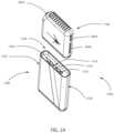
- FIG. 2 AA perspective exploded view of a device for dispensing fluids comprising a dispenser and a removably interconnected pod.
- FIG. 2 BA perspective exploded view of a device for dispensing fluids comprising a dispenser and a removably interconnected pod.
- FIG. 3A diagrammatic system representation of certain embodiments of a device for dispensing a fluid.
- FIG. 4 AA perspective exploded view of a device for dispensing fluids comprising a pod.
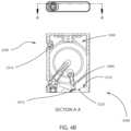
- FIG. 4 BA front cross-sectional view of a device for dispensing fluids comprising a pod.
- FIG. 5 AA perspective exploded view of a device for dispensing fluids comprising a pod.
- FIG. 5 BA side cross-sectional view of a device for dispensing fluids comprising a pod.
- FIG. 6 AA side cross-sectional view of a device for dispensing fluids comprising a pod in an intake stroke configuration.
- FIG. 6 BA side cross-sectional view of a device for dispensing fluids comprising a pod in an ejection stroke configuration.
- FIG. 7A front cross-sectional view of a device for dispensing fluids comprising a pod.
- FIG. 8A perspective exploded view of a device for dispensing fluids comprising a pod.
- FIG. 9A diagrammatic representation of a method for dispensing fluids.
- FIG. 10 AA bottom perspective view of certain embodiments of the present invention
- FIG. 10 BA top perspective view of certain embodiments of the present invention
- FIG. 11 AA front view of certain embodiments of the present invention
- FIG. 11 BA side view of certain embodiments of the present invention
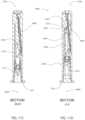
- FIG. 11 CA side cross-sectional view of the embodiment shown in FIG. 11 A
- FIG. 11 DA side cross-sectional view of the embodiment shown in FIG. 11 A
- FIG. 11 EA front cross-sectional view of the embodiment shown in FIG. 11 B
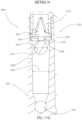
- FIG. 11 FA detail cross-sectional view of the embodiment shown in FIG. 11 E
- FIG. 11 GA detail cross-sectional view of the embodiment shown in FIG. 11 F
- FIG. 11 HA detail cross-sectional view of the embodiment shown in FIG. 11 F
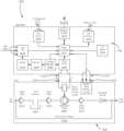
- FIG. 1 - FIG. 3Certain embodiments of the present invention, shown in FIG. 1 - FIG. 3 , comprises a device 1000 for the dispensing of fluids, the device comprises a dispenser 1100 and a pod 1200 .
- the dispenser 1100comprises a power source 2000 , central processing unit or controller (CPU) 2010 .
- CPUcentral processing unit
- a bottom surface 1105 of the dispenseris configured to interconnect with a top aspect 1220 of the pod. It will be appreciated that the interconnection of the dispenser 1100 with the pod 1200 using alternative sides is within the spirit and scope of the present invention.
- the dispenser 1200When the dispenser 1100 is interconnected with the pod 1200 , the dispenser 1200 is able to actuate the dispensing of a fluid from the pod 1200 by sending electrical signals from electrical connections 1110 of the dispenser, through electrical connections 1210 of the pod to the pod 1200 . It will be appreciated that it is within the spirit and scope of the present invention send electromagnetic signals through electrical connections 1110 .
- the dispenser 1100 of certain embodimentsinterconnects to the pod through use of electrical connections 1110 , such as 1310 which comprise magnets 1300 .
- the magnets 1300 of certain embodimentsare located on the pod 1200 , alternate embodiments comprise magnets 1300 on the dispenser 1100 , and further alternate embodiments comprise magnets 1300 on pod 1200 and dispenser 1100 .
- the magnets 1300 of such embodimentsprovide a mechanical connection between the pod 1200 and dispenser 1100 . It will be appreciated that alternative mechanical connections known to those skilled in the art are within the spirit and scope of the present invention.
- FIG. 2 A - FIG. 3comprise a pod 1200 having a plurality of magnets 1300 configured to interconnect with a plurality of magnets 1300 of a dispenser.
- the pod 1200 and the dispenser 1100are configured to be interconnected with the pod 1200 in a first orientation, or a second orientation wherein the pod 1200 is rotated 180-degrees from the first orientation wherein the magnets 1300 of the dispenser, and the magnets 1300 of the pod are configured to interconnect in either the first orientation or the second orientation.
- Certain embodimentsseen in FIG. 2 A - FIG. 3 , comprise a pod 1200 having a plurality of magnets 1300 configured to interconnect with a plurality of magnets 1300 of a dispenser. It may be desired to prevent the interconnection of a dispenser 1100 in a manner other than intended. Accordingly, the magnets 1300 of certain embodiments are configured in an asymmetric manner to prevent the mating of the dispenser to the pod in a manner other than intended. Further still, certain embodiments comprise a configuration of magnets 1300 on a pod wherein the poles (North and South) of the magnets prevent interconnecting the pod 1200 to the dispenser 1100 incorrectly.
- certain embodimentscomprise four magnets embedded into a surface of the pod 1200 , typically a top aspect 1220 , wherein a first pair of magnets 1300 adjacent to a first side 1230 of the pod are directed with a first polarity toward the top aspect 1220 , and a second pair of magnets adjacent to a second side 1230 of the pod are directed with a second polarity toward the top aspect 1220 .
- a dispenser 1100 having magnets 1300 configured to interconnect with the magnets 1300 of the pod having opposite polaritiesare able to interconnect when the pod 1200 is aligned in the intended orientation.
- the magnets 1300 of the podwill align with magnets of the dispenser having matching polarities resulting in the dispenser 1100 and pod 1100 repelling each other and preventing the interconnection of the pod 1200 and dispenser 1100 .
- a top aspect 1220 of a podcomprises a first and second electrical contacts 1210 comprising spring-loaded electrical connectors 1310 .
- the electrical contactsallow the electrical connection between the dispenser 1100 and the pod 1200 , and allows the dispenser 1100 to send electrical signals to the pod to dispense an amount of fluid.
- Certain embodimentscomprise spring-loaded electrical connectors 1310 often referred to as “pogo-pins” by those skilled in the art.
- Certain embodimentscomprise the electrical connections 1110 of the dispenser comprising spring-loaded electrical connectors 1310 .
- Certain embodiments comprising a pod 1200shown in FIG. 4 A comprise a body t surrounded by a sleeve 3100 .
- the sleeve 3100is slidably disposed over the body 3000 of the pod.
- a sleeveis disposed around the body of the pod, thereby obscuring view and access to portions of the body of the pod except a top aspect 1220 and bottom aspect 1225 of the pod.
- a pod 1200 of certain embodimentsas shown in FIG. 4 A - FIG. 4 B comprises a body 3000 having a fill-port 3200 comprising a one-way valve 3210 disposed in an external surface of the body 3000 .
- the one-way valve 3210provides fluid communication between an external aspect of the body and a reservoir 3300 disposed within the body 3000 .
- the fill-port 3200is typically configured to be adjacent to a top aspect 1220 of the body when the body is held in an orientation for dispensing.
- a fill port 3200can be located adjacent to other aspects of the body 3000 —such as a bottom aspect, or side aspect—while in keeping with the spirit and scope of the present invention.
- the reservoir 3300comprises a cavity within the body 3000 wherein the fluid can be contained and drawn from for the dispensing of the fluid.
- the reservoircomprises a volume having a bottom aspect 3310 further comprising a sump 3320 .
- sumprefers to a low point, pit, hollow, or concavity configured to accumulate fluid.
- a sump 3320is typically disposed at the lowest point of the reservoir 3300 when the body 3000 is held in an orientation for dispensing and thus preventing air from entering into the siphon tube 3400 and into the pump 4000 ( FIG. 5 A ).
- a siphon tube 3400is disposed within the sump 3320 of the reservoir to draw fluid from the reservoir 3300 when fluid is dispensed. While embodiments illustrated herein show a siphon tube 3400 which is configured to draw fluid upward from the sump 3320 of the reservoir, it will be appreciated that alternate embodiments comprising a siphon tube 3400 configured to draw fluid downward or laterally from the reservoir 3300 is within the spirit and scope of the present invention.
- the siphon tube 3400is configured to draw fluid upward from the sump 3320 of the reservoir, wherein the siphon tube 3400 is interconnected with the sump 3320 of the reservoir, and further comprises apertures 3410 through the siphon tube 3400 , wherethrough the fluid is drawn from the reservoir 3300 and into the siphon tube 3400 .
- the apertures 3410are located at the bottom of the sump 3320 , further preventing air from entering the siphon tube 3400 or the pump 4000 .
- a pump 4000 of certain embodiments, shown in FIG. 4 B - FIG. 5 Bis disposed within the body 3000 , wherein the pump 4000 has fluid communication the reservoir 3300 through a siphon tube 3400 .
- a one-way valve 3210is disposed between the siphon tube 3400 and the reservoir 3300 wherein the fluid passes through the one-way valve 3210 before entering the pump 4000 . It will be appreciated that alternate embodiments wherein the one-way valve 3210 is disposed between the siphon tube 3400 and the reservoir 3300 are within the spirit and scope of the present invention.
- a pump 4000comprises a diaphragm pump comprising an O-ring 4010 , a diaphragm 4020 , and a compression element 4030 .
- the O-ring 4010 of certain embodimentsis disposed against a bottom aspect 4110 of a threaded recess 4100 of the body.
- a first face 4021 of the diaphragmis disposed against the O-ring 4010
- the threaded compression element 4030is disposed against a second face 4022 of the diaphragm.
- the threaded compression element 4030is configured to threadably interconnect with the threaded recess 4100 of the body in order to impart pressure on the second face 4022 of the diaphragm.
- the threaded compression element 4030imparts pressure on the second face 4022 of the diaphragm, thereby resulting in the first face 4021 of the diaphragm imparting pressure on the O-ring 4010 .
- the O-ring 4010When pressure is imparted on the O-ring 4010 , the O-ring compresses and deforms thereby creating a seal between the O-ring 4010 and the bottom aspect 4110 of the threaded recess and a seal between the O-ring 4010 and the first face 4021 of the diaphragm.
- a pump 4000is assembled within the body 3000 wherein the pump 4000 and associated elements are integrated with the body 3000 through the use of soldering, welding, over-molding, adhesive, or other methods appreciated by those skilled in the art.
- a diaphragm pumpis a positive displacement pump that uses a combination of a reciprocating action of a flexible membrane to pump a fluid.
- the diaphragm of a diaphragm pump 4000 of various embodimentscomprise rubber, thermoplastics, Teflon® and/or metal while remaining within the spirit and scope of the present invention.
- FIG. 5 A - FIG. 6 Bcomprise a diaphragm pump 4000 which actuates an intake stroke 4500 and ejection stroke 4600 using piezoelectric effects.
- the diaphragm 4020deforms away from the body 3000 in an intake stroke 4500 , drawing fluid into the pump 4000 through the inlet port 4200 .
- the diaphragm 4020rebounds to its resting configuration toward the body 3000 in an ejection stroke 4600 , forcing fluid out of the pump through the outlet port 4300 .
- the diaphragm pump 4000creates a suction action wherein fluid is drawn from the reservoir 3300 , through the siphon tube 3400 , through a one-way valve 3210 , and through an inlet port 4200 into the pump 4000 .
- the diaphragm pump 4000In an ejection stroke 4600 , the diaphragm pump 4000 , the diaphragm creates a positive pressure, forcing the fluid out of the pump 4000 through an outlet port 4300 .
- a diaphragm pump 4000comprises a concave 4400 surface wherein the inlet port 4200 and outlet port 4300 are disposed.
- the concave surface 4400is configured to interface with the diaphragm 4020 of the diaphragm pump and control the pump “one-stroke” capacity.
- the inlet port 4200is located in the concave surface 4400 , offset from a central aspect of the concave surface 4400 .
- the outlet port 4300is located in the concave surface 4400 , adjacent or coincident with the central aspect of the concave surface 4400 .
- the proximity of the outlet port 4300 to the center of the concave surface 4400allows for most power is in the center more complete ejection of all fluid in the diaphragm pump 4000 during an ejection stroke 4600 ( FIG. 6 B ).
- the concavity of the concave surface 4400is configured to match the curvature of the diaphragm 4020 in an ejection stroke 4600 .
- an outlet duct 5000is connected to the outlet port 4300 .
- the outlet duct 5000provides fluid communication between the outlet port 4300 and an external aspect of the pod 1200 .
- an outlet 5100 comprising a one-way valve 3210is disposed between the outlet duct 5000 and an external aspect 6000 of the pod.
- the one-way valve 3210allows fluid flow only in the direction from the outlet duct 5000 to the external aspect 6000 of the pod.
- the one-way valve 3210 between the outlet duct 5000 and the external aspect 6000 of the podis disposed on a bottom aspect 1225 of the body of the pod.
- an anti-suction channel 5500is in gaseous communication with the outlet valve 3210 and the fill-port 3200 of the pod.
- the anti-suction channel 5500provides an air-filled volume which serves multiple purposes.
- a first purpose of the anti-suction channel 5500is to provide make-up air for the fill-port 3200 . As fluid is dispensed, this creates a suction in the reservoir 3300 ( FIG. 4 B ) which is relieved by the fill-port 3200 permitting the passage of air from the anti-suction channel 5500 into the reservoir 3300 .
- a second purpose of the anti-suction channel 5500is to prevent the misuse of the pod whereby an individual attempts to suck fluid from the outlet valve.
- the anti-suction channelprovides an unsealed plenum of ambient air wherein the sucking of air from a bottom aspect of the pod results in drawing air from the anti-suction channel 5500 and gaps between the body 3000 and the sleeve 3100 .
- a method 7000 for the dispensing of a fluidcomprise:
- a usersets 7050 a preferred dose amount which is saved 7100 to the controller of the dispenser.
- the dispenseris configured to be removably connected to a pod, and when a user connects 7150 a pod to the dispenser, the dispenser reads 7200 the information from the pod and stores it on the controller.
- the reading step 7200comprises reading a max dosage permitted for dispensing in a predetermined time period.
- Certain embodimentsfurther comprise a comparing 7325 step performed prior to the sending electrical signal 7350 step. The comparing step 7325 compares the recorded dispensed amount from previous recording steps 7650 in the predetermined time period prior to the depressing 7300 of the button.
- the dispenserwill not send an electrical signal 7350 , thus preventing the dispensing in excess of the max dosage within the predetermined time period.
- the dispenserwill not further dispense fluid until enough time has passed such that less than the max dosage has been dispensed in the predetermined time period prior to the depressing 7300 of the button on the dispenser.
- the dispenser of certain embodimentsfurther comprises a wireless module 2020 which allows wireless communication with other computing devices 2030 such as a smart phone, computer, or other computing device having local network or internet connectivity.
- the dispenser of certain embodimentsfurther comprises user input devices, such as buttons 2040 , a display 2050 , a USB port 2060 for wired connection to other computing devices, a charging circuit 2070 , a battery for power storage 2000 , a voltage regulator 2080 , a driver 2090 for the delivery of electrical signals from the dispenser to a pod, electrical connections for the purposes of providing power and electrical signals between the dispenser and pod, and electrical connections for the purpose allowing the reading and writing of data between the dispenser and the pod.
- user input devicessuch as buttons 2040 , a display 2050 , a USB port 2060 for wired connection to other computing devices, a charging circuit 2070 , a battery for power storage 2000 , a voltage regulator 2080 , a driver 2090 for the delivery of electrical signals from the dispenser to a pod, electrical connections for the purposes of providing power and
- the podcomprises memory storage 2110 wherein the dispenser can store the data associated with the dispensed amount, date of dispensing, and/or the amount of fluid remaining in the pod.
- the podcomprises a piezo-electric crystal 2100 .
- user inputsuch as the depressing of a button 2040 ( FIG. 1 - FIG. 3 ) indicates to the dispenser that the user wishes to dispense the pre-programmed desired amount of fluid.
- the depressing 7300 of the buttoninitiates the controller sending 7350 electrical signals through the driver and through the driver to the pod.
- the electrical signalactuates 7400 the pump into an intake stroke wherein the diaphragm deflects from the body and away from the concave surface of the body.
- the fluidis drawn from the reservoir, through the siphon tube, and through a first one-way valve into the pump.
- the dispenserrecords 7600 the dispensed amount and time of dispensing to the dispenser.
- the methodfurther comprises a step wherein the dispenser records 7650 the amount remaining within the pod to the memory of the pod.
- the dispenserfurther comprises a tilt sensor 2200 ( FIG. 3 ), wherein the dispense does not send an electrical signal unless the device is in an upright orientation ( FIG. 1 ) or substantially upright to ensure dispensing in the right direction and prevent air from entering the pump.
- a tilt sensor 2200 of certain embodimentscomprises an accelerometer to measure the direction of gravitational acceleration, thus confirming the upright orientation of the pod prior to dispensing.
- FIG. 10 A and FIG. 10 Bshow certain alternate embodiments of a pod 1200 for dispensing wherein fluid is dispensed through the bottom aspect 1225 of the pod, and the top aspect 1220 of the pod is configured to interconnect with a dispenser unit.
- the inlet port 3210 of the pumpis located vertically above the outlet port 4300 of the pump when the pod 1200 is in an upright orientation.
- an air that may enter the pump 4000 through the inlet port 3210floats up and away from the outlet port 4300 thus preventing the air from entering the outlet port 4300 when dispensing.
- an “upright orientation” as referred to hereinis defined as when the top aspect 1220 of the pod is elevated above the bottom aspect 1225 of the pod.
- a nozzle 5110is interconnected the outlet duct 5100 wherein the nozzle 5110 is configured to dispense fluid therethrough to an external aspect 6000 of the pod.
- nozzle 5110is configured to allow the flow of fluid therethrough when under positive pressure, but prevent the passive flow of fluid therethrough under neutral pressure between the outlet duct and the external aspect of the pod.
- an ejection stroke 4600FIG. 5 A — 6 B creates a positive pressure differential wherein the pressure within the outlet duct 5100 is greater than the external aspect of the pod 6000 , thereby dispensing fluid through the nozzle 5110 .
- the nozzle 5110comprises an aperture 5120 for the dispensing of fluid therethrough wherein a minimum diameter 5125 of the aperture is configured accordingly with the cohesive properties of the fluid to be dispensed, and the viscosity of the fluid to be dispensed to prevent passive flow therethrough.
- the minimum diameter 5125 of the aperture of the nozzleis less than 1 mm, while further embodiments comprise a minimum diameter 5125 between 0.25 mm and 0.75 mm.
- Alternate embodiments having a nozzle outside of the provided values to accommodate a more viscous or less viscous fluid for dispensingare within the spirit and scope of the present invention.
- the aperture 5120comprises a tapered profile, however the aperture 5120 of the nozzle of alternate embodiments can comprise a stepped profile, inverted stepped profile, constant diameter profile, or inverted tapered profile while in keeping the spirit and scope of the present invention.
- the outlet duct 5100further comprises a one-way valve 3210 interconnected between the nozzle 5110 and the outlet port 4300 .
- the one-way valve 3210 of the outlet ductis configured to allow flow from the outlet port 4300 and the external aspect 6000 of the pod, but restrict flow in the opposite direction.
- the one-way valve 3210further prevents passive flow through the nozzle wherein the one-way valve 3210 is configured to maintain a neutral pressure differential between the one-way valve 3210 and the nozzle, and thereby further prevents passive flow or leakage through the nozzle 5110 .
- the nozzle 5110comprises a one-way valve 3210 , thus the nozzle and the 5110 and the one-way valve 3210 located between the nozzle 5110 and the outlet port 4300 work together to prevent passive flow or leakage from the nozzle 5110 .
- the siphon tube 3400further comprises a float vent valve 5200 configured to prevent the entry of air bubbles into the siphon tube 3400 when the pod 1200 is in an inverted orientation, and allow fluid flow when the pod 1200 is in an upright orientation.
- An “inverted orientation” as referred to hereinis defined as when the bottom aspect 1225 of the pod is elevated above the top aspect 1220 of the pod.
- the float vent valve 5200comprises a float 5210 configured to travel along the length of a tube 5220 .
- the tube 5220 of the float valvecomprises a first end 5221 configured to receive fluid from the reservoir 3300 through an aperture 3410 in the siphon tube 3400 , for subsequent communication toward the inlet port 4200 and into the pump 4000 .
- the tubecomprises a maximum inner diameter 5225 greater than a maximum diameter 5215 of the float.
- the first end of the tube 5221comprises a constricted portion 5230 wherein the maximum inner diameter 5235 of the constricted portion is less than the maximum outer diameter 5215 of the float.
- the second end 5222 of the tubecomprises a fluid bypass 5240 configured to arrest the travel of the float 5210 toward the inlet port 4200 while allowing the flow of fluid therethrough.
- the fluid bypass 5240comprises at least one aperture 5241 having a maximum diameter 5245 , wherein the maximum diameter 5245 of the aperture of the fluid bypass is less than the maximum outer diameter 5215 of the float.
- the float 5210is arrested and fluid is permitted to pass through the fluid bypass 5240 .
- the fluid bypass 5240comprises a plate 5248 comprising a plurality of apertures 5245 therethrough.
- the siphon tube 3400further comprises a one-way valve 3210 interconnected between the float vent valve 5200 and the inlet port 4200 , wherein the use of the one-way valve 3210 in conjunction with the float vent valve 5200 maintains a static pressure within the tube 5220 configured to maintain fluid within the tube 5220 .
- the float 5210buoys to the second end 5222 of the tube 5220 and allows the drawing of fluid therethrough during in intake stroke 4500 ( FIG. 5 A - FIG. 6 B ) and prevents the flow of fluid from the pump 4000 toward the reservoir in an ejection stroke 4600 or passively when the pod 1200 is not in use.
- the float 5210buoys to the first end 5221 of the tube wherein the float 5210 interfaces with the constricted portion 5230 of the tube which prevents the flow of fluid or gas from the reservoir 3300 into the siphon tube 3400 .
- Certain embodiments of the present inventioncomprise a recess 5300 in the bottom aspect 1225 of the pod.
- the nozzle 5110is interconnected to the pod 1200 within the recess 5300 , wherein the nozzle 5110 extends downward from an upper aspect 5306 of the recess.
- the recess 5300comprises a depth 5305 which is greater than the height 5115 of the nozzle, thus the nozzle 5110 is contained within the recess 5300 and does not extend beyond the bottom aspect 1225 of the pod.
- the podfurther comprises an air volume 5400 in gaseous communication with an external aspect 6000 of the device.
- the air volumecomprises a one-way valve 3210 interconnected thereto configured to allow the flow of air from the air volume 5400 to the reservoir 3300 .
- the one-way valve 3210 of the air volume 5400is configured to allow the flow of air from an external aspect 6000 of the pod into the reservoir 3300 following an ejection stroke to equalize a negative pressure differential caused by the displacement of fluid out of the reservoir 3300 .
- the air volume 5400is in adjacent to and in gaseous communication with the recess 5300 , however alternate embodiments do not require the proximal location or gaseous interconnection of the air volume 5400 in relation to the recess 5300 .
- the siphon tube 3400comprises an air chamber 5500 interconnected thereto wherein the air chamber 5500 is configured to separate air from the fluid for dispensing.
- the air chamber 5500is configured to extend upward from the siphon tube 3400 , and preferably with an upper aspect 5510 of the air chamber above the inlet port 4200 when the pod is in an upright orientation.
- the air chamberis configured to separate air bubbles entrained in the fluid for dispensing prior to entering the pump 4000 through the inlet port 4200 .
- the air upper aspect 5510 of the air chamberfurther comprises a semi-permeable membrane 5520 configured to allow gasses to pass therethrough but prevent the passage of liquids.
- the semi-permeable membrane 5520 as shownis configured to allow gas to travel from the air chamber 5500 to the reservoir 3300 .
- alternate embodiments wherein the semi-permeable membrane is configured to allow the travel of gas from the air chamber 5500 to the external aspect of the pod 1200are within the spirit and scope of the present invention.
Landscapes
- Engineering & Computer Science (AREA)
- Mechanical Engineering (AREA)
- General Engineering & Computer Science (AREA)
- Human Computer Interaction (AREA)
- Computer Networks & Wireless Communication (AREA)
- Containers And Packaging Bodies Having A Special Means To Remove Contents (AREA)
Abstract
Description
- a) Setting7050 a preferred dose on a dispenser;
- b) Saving7100 the preferred dose amount to a controller of the dispenser;
- c) Connecting7150 a pod to the dispenser;
- d)
Reading 7200 pod information from the pod, and saving the pod information to the dispenser; - e) Communicating7250 wirelessly the pod information from the dispenser to a connected computing device;
- f) Depressing7300 a button disposed on the dispenser;
- g) Sending
electrical signal 7350 to the pod to actuate an intake stroke; - h) Actuating the
intake stroke 7400 of a diaphragm pump resulting in drawing the fluid from a reservoir, through a first one-way valve, through an inlet port, and into the diaphragm pump; - i) Cutting
electrical signal 7450 of the electrical signal resulting in actuating an ejection stroke of the diaphragm pump; - j)
Ejecting 7500 the fluid from the diaphragm pump through an outlet port and through a second one-way valve; - k)
Dispensing 7550 the fluid from the pod; - l) Recording dispensed
amount 7600 and time of dispensing to the dispenser; - m)
Recording remaining amount 7650 of fluid to the pod; and - n) Displaying7700 the remaining amount of fluid remaining.
Claims (19)
Priority Applications (1)
| Application Number | Priority Date | Filing Date | Title |
|---|---|---|---|
| US17/845,179US12060879B2 (en) | 2019-07-30 | 2022-06-21 | System and method for dispensing liquids |
Applications Claiming Priority (4)
| Application Number | Priority Date | Filing Date | Title |
|---|---|---|---|
| US201962880230P | 2019-07-30 | 2019-07-30 | |
| US202063035539P | 2020-06-05 | 2020-06-05 | |
| US16/943,045US11396417B2 (en) | 2019-07-30 | 2020-07-30 | System and method for dispensing liquids |
| US17/845,179US12060879B2 (en) | 2019-07-30 | 2022-06-21 | System and method for dispensing liquids |
Related Parent Applications (1)
| Application Number | Title | Priority Date | Filing Date |
|---|---|---|---|
| US16/943,045Continuation-In-PartUS11396417B2 (en) | 2019-07-30 | 2020-07-30 | System and method for dispensing liquids |
Publications (2)
| Publication Number | Publication Date |
|---|---|
| US20220316469A1 US20220316469A1 (en) | 2022-10-06 |
| US12060879B2true US12060879B2 (en) | 2024-08-13 |
Family
ID=83449682
Family Applications (1)
| Application Number | Title | Priority Date | Filing Date |
|---|---|---|---|
| US17/845,179ActiveUS12060879B2 (en) | 2019-07-30 | 2022-06-21 | System and method for dispensing liquids |
Country Status (1)
| Country | Link |
|---|---|
| US (1) | US12060879B2 (en) |
Cited By (1)
| Publication number | Priority date | Publication date | Assignee | Title |
|---|---|---|---|---|
| US20250017286A1 (en)* | 2021-11-24 | 2025-01-16 | Nicoventures Trading Limited | Refilling device with venting nozzle, and refilling apparatus |
Families Citing this family (2)
| Publication number | Priority date | Publication date | Assignee | Title |
|---|---|---|---|---|
| TW202011845A (en)* | 2018-07-24 | 2020-04-01 | 瑞士商傑太日煙國際股份有限公司 | Side-by-side terminal for personal vaporizing device |
| US12060879B2 (en)* | 2019-07-30 | 2024-08-13 | Voyager Products Inc. | System and method for dispensing liquids |
Citations (56)
| Publication number | Priority date | Publication date | Assignee | Title |
|---|---|---|---|---|
| US5653227A (en) | 1993-06-23 | 1997-08-05 | Bespak Plc | Atomizing dispenser |
| US20030178024A1 (en) | 2001-09-19 | 2003-09-25 | Allan Robert David | Inhaler |
| US20050087555A1 (en)* | 2003-10-28 | 2005-04-28 | Hatton Jason D. | Fluid dispensing components |
| US20060049208A1 (en)* | 2004-09-09 | 2006-03-09 | Daansen Warren S | Slit valves and dispensing nozzles employing same |
| US20070000337A1 (en) | 2005-06-20 | 2007-01-04 | Karl Gross | Method and apparatus for handling small quantities of fluids |
| US20070181611A1 (en)* | 2004-10-20 | 2007-08-09 | Santiago Julian Pidevall | Pump having a sealing mechanism |
| WO2007092618A2 (en) | 2006-02-09 | 2007-08-16 | Deka Products Limited Partnership | Fluid delivery systems and methods |
| US20070186923A1 (en) | 2006-01-06 | 2007-08-16 | Aceirx Pharmaceuticals, Inc. | Drug storage and dispensing devices and systems comprising the same |
| DE102006043637A1 (en)* | 2006-05-18 | 2007-11-22 | Boehringer Ingelheim Pharma Gmbh & Co. Kg | atomizer |
| US20080163695A1 (en) | 2004-06-15 | 2008-07-10 | Canon Kabushiki Kaisha | Semiconductor Device |
| CA3059311A1 (en) | 2007-12-31 | 2009-07-16 | Deka Products Limited Partnership | Wearable infusion pump assembly |
| US20090194562A1 (en) | 2006-06-07 | 2009-08-06 | Arndt Kessler | Metering apparatus for flowable compositions |
| US7677412B2 (en) | 2003-10-15 | 2010-03-16 | Zavida Coffee Company Inc. | Fluid dispensing system suitable for dispensing liquid flavorings |
| US20100132748A1 (en) | 2007-03-22 | 2010-06-03 | Arnd Kessler | Mobile dosing system |
| US20120085344A1 (en) | 2009-02-27 | 2012-04-12 | Pari Pharma Gmbh | Method for operating an aerosol inhalation device and aerosol inhalation device |
| US20120218333A1 (en) | 2011-02-24 | 2012-08-30 | Baku Nishikawa | Drive apparatus for liquid ejection head, liquid ejection apparatus and inkjet recording apparatus |
| US20130085460A1 (en) | 2009-10-21 | 2013-04-04 | Johnson & Johson Vision Care, Inc. | Method and apparatus for liquid dispensing |
| US8414563B2 (en) | 2007-12-31 | 2013-04-09 | Deka Products Limited Partnership | Pump assembly with switch |
| US20130172831A1 (en) | 2011-08-31 | 2013-07-04 | Leslie A. Voss | Liquid dispensing reservoir |
| US20130255404A1 (en) | 2010-10-04 | 2013-10-03 | Eppendorf Ag | Electronic pipette |
| US8584673B2 (en) | 2007-06-01 | 2013-11-19 | Boehringer Ingelheim International Gmbh | Dispensing device |
| US8893927B2 (en)* | 2004-05-24 | 2014-11-25 | Pur Water Purification Products, Inc. | Cartridge for an additive dispensing system |
| US20150136158A1 (en) | 2013-11-15 | 2015-05-21 | Jj 206, Llc | Systems and methods for a vaporization device and product usage control and documentation |
| US20150150803A1 (en) | 2011-06-07 | 2015-06-04 | Parion Sciences, Inc. | Aerosol delivery systems, compositions and methods |
| US20150151857A1 (en) | 2013-07-03 | 2015-06-04 | Deka Products Limited Partnership | Apparatus, System and Method for Fluid Delivery |
| US20150157053A1 (en) | 2013-12-10 | 2015-06-11 | Michael James Mayor | Liquid tanks, end caps, and seals for electronic cigarettes |
| WO2015112750A1 (en) | 2014-01-22 | 2015-07-30 | E-Nicotine Technology, Inc. | Methods and devices for smoking urge relief |
| US20150245654A1 (en) | 2014-02-28 | 2015-09-03 | Beyond Twenty Ltd. | E-cigarette personal vaporizer |
| US20150247786A1 (en) | 2012-09-24 | 2015-09-03 | Alexander Parker | On-demand vapour generator |
| US20150260179A1 (en)* | 2012-12-04 | 2015-09-17 | Aptargroup, Inc. | Fluent Product Dispensing Package and Diaphragm Pump For Use Therein |
| US20150294551A1 (en) | 2012-12-27 | 2015-10-15 | Kaleo, Inc. | Devices, systems and methods for locating and interacting with medicament delivery systems |
| US20150305974A1 (en) | 2014-04-24 | 2015-10-29 | Sympara Medical, Inc. | Methods and devices for treating hypertension |
| US20160213065A1 (en) | 2015-01-22 | 2016-07-28 | Fontem Holdings 1 B.V. | Electronic vaporization devices |
| US20170233114A1 (en) | 2013-03-15 | 2017-08-17 | Pax Labs, Inc. | Fillable vaporizer cartridge and method of filling |
| US20170245552A1 (en) | 2016-02-25 | 2017-08-31 | Altria Client Sevices LLC | Electrically operated aerosol-generating system with tilt sensor |
| US20180038357A1 (en) | 2007-02-27 | 2018-02-08 | Deka Products Limited Partnership | Pumping cassette |
| US9937303B1 (en) | 2016-10-11 | 2018-04-10 | Kaer Biotherapeutics Corporation | Two-stage apparatus and method for generating and concentrating fine particle aerosols |
| US20180177325A1 (en) | 2014-12-05 | 2018-06-28 | LifeFuels, Inc. | Portable system for dispensing controlled quantities of additives into a beverage |
| US20190105619A1 (en) | 2016-04-11 | 2019-04-11 | Altopa, Inc. | Secure portable, on-demand, microfluidic mixing and dispensing device |
| US20190307170A1 (en) | 2018-04-10 | 2019-10-10 | Pezhman Zarifian | Systems and Methods to Precisely Vaporize Liquid Chemicals |
| US20200022416A1 (en) | 2018-07-23 | 2020-01-23 | Wellness Insight Technologies, Inc. | System for analyzing and controlling consumable media dosing information |
| US20200061362A1 (en) | 2018-08-27 | 2020-02-27 | Alcyone Lifesciences, Inc. | Fluid delivery systems and methods |
| US20200061337A1 (en) | 2018-08-27 | 2020-02-27 | Alcyone Lifesciences, Inc. | Fluid delivery systems and methods |
| US20200113787A1 (en) | 2018-10-10 | 2020-04-16 | Sensal Health, LLC | Medication adherence apparatus and methods of use |
| US20200114087A1 (en) | 2018-02-22 | 2020-04-16 | Eli Lilly And Company | Dose detection system module for medication delivery device |
| US20200163389A1 (en) | 2018-11-28 | 2020-05-28 | Rai Strategic Holdings, Inc. | Micropump for an aerosol delivery device |
| US20200214625A1 (en) | 2019-01-04 | 2020-07-09 | Enable Injections, Inc. | Medical fluid injection apparatus and method with detachable patch and monitoring |
| US20200367553A1 (en) | 2019-05-22 | 2020-11-26 | Rai Strategic Holdings, Inc. | Reservoir configuration for aerosol delivery device |
| US20210023315A1 (en) | 2019-03-29 | 2021-01-28 | Remedio Laboratories, Inc. | Controlled-dose medicinal liquid vaping device |
| US20210023585A1 (en) | 2018-04-09 | 2021-01-28 | Vermes Microdispensing GmbH | Dosing system having a piezoceramic actuator |
| US20210052007A1 (en) | 2019-08-23 | 2021-02-25 | Mabee Engineered Solutions, Inc. | Vaporizer apparatus having both a vacuum pump and a heating element, and method of using same |
| US20210052013A1 (en) | 2019-08-23 | 2021-02-25 | Mabee Engineered Solutions, Inc. | Vaporizer apparatus |
| US20210170095A1 (en) | 2019-12-06 | 2021-06-10 | Quasuras, Inc. | Rotary microfluidic medical pump |
| US20210354168A1 (en) | 2018-10-05 | 2021-11-18 | Vermes Microdispensing GmbH | Dosing system with a cooling device |
| US11396417B2 (en)* | 2019-07-30 | 2022-07-26 | Voyager Products Inc. | System and method for dispensing liquids |
| US20220316469A1 (en)* | 2019-07-30 | 2022-10-06 | Voyager Products Inc. | System and method for dispensing liquids |
- 2022
- 2022-06-21USUS17/845,179patent/US12060879B2/enactiveActive
Patent Citations (95)
| Publication number | Priority date | Publication date | Assignee | Title |
|---|---|---|---|---|
| US5653227A (en) | 1993-06-23 | 1997-08-05 | Bespak Plc | Atomizing dispenser |
| US20030178024A1 (en) | 2001-09-19 | 2003-09-25 | Allan Robert David | Inhaler |
| US7677412B2 (en) | 2003-10-15 | 2010-03-16 | Zavida Coffee Company Inc. | Fluid dispensing system suitable for dispensing liquid flavorings |
| US20050087555A1 (en)* | 2003-10-28 | 2005-04-28 | Hatton Jason D. | Fluid dispensing components |
| US8893927B2 (en)* | 2004-05-24 | 2014-11-25 | Pur Water Purification Products, Inc. | Cartridge for an additive dispensing system |
| US20080163695A1 (en) | 2004-06-15 | 2008-07-10 | Canon Kabushiki Kaisha | Semiconductor Device |
| US20060049208A1 (en)* | 2004-09-09 | 2006-03-09 | Daansen Warren S | Slit valves and dispensing nozzles employing same |
| US20070181611A1 (en)* | 2004-10-20 | 2007-08-09 | Santiago Julian Pidevall | Pump having a sealing mechanism |
| US20070000337A1 (en) | 2005-06-20 | 2007-01-04 | Karl Gross | Method and apparatus for handling small quantities of fluids |
| US20070186923A1 (en) | 2006-01-06 | 2007-08-16 | Aceirx Pharmaceuticals, Inc. | Drug storage and dispensing devices and systems comprising the same |
| US8905964B2 (en)* | 2006-01-06 | 2014-12-09 | Acelrx Pharmaceuticals, Inc. | Drug storage and dispensing devices and systems comprising the same |
| WO2007092618A3 (en) | 2006-02-09 | 2007-12-06 | Deka Products Lp | Fluid delivery systems and methods |
| WO2007092618A2 (en) | 2006-02-09 | 2007-08-16 | Deka Products Limited Partnership | Fluid delivery systems and methods |
| DE102006043637A1 (en)* | 2006-05-18 | 2007-11-22 | Boehringer Ingelheim Pharma Gmbh & Co. Kg | atomizer |
| US20070267015A1 (en)* | 2006-05-18 | 2007-11-22 | Boehringer Ingelheim International Gmbh | Atomizer |
| WO2007134794A1 (en)* | 2006-05-18 | 2007-11-29 | Boehringer Ingelheim International Gmbh | Atomiser |
| WO2007134793A1 (en)* | 2006-05-18 | 2007-11-29 | Boehringer Ingelheim International Gmbh | Atomiser |
| US20080001008A1 (en)* | 2006-05-18 | 2008-01-03 | Boehringer Ingelheim International Gmbh | Atomizer |
| US20140366871A1 (en)* | 2006-05-18 | 2014-12-18 | Boehringer Ingelheim International Gmbh | Atomizer |
| US8240304B2 (en)* | 2006-05-18 | 2012-08-14 | Boehringer Ingelheim International Gmbh | Atomizer |
| US20090194562A1 (en) | 2006-06-07 | 2009-08-06 | Arndt Kessler | Metering apparatus for flowable compositions |
| US20180038357A1 (en) | 2007-02-27 | 2018-02-08 | Deka Products Limited Partnership | Pumping cassette |
| US20100132748A1 (en) | 2007-03-22 | 2010-06-03 | Arnd Kessler | Mobile dosing system |
| US8584673B2 (en) | 2007-06-01 | 2013-11-19 | Boehringer Ingelheim International Gmbh | Dispensing device |
| US8414563B2 (en) | 2007-12-31 | 2013-04-09 | Deka Products Limited Partnership | Pump assembly with switch |
| CA3059311A1 (en) | 2007-12-31 | 2009-07-16 | Deka Products Limited Partnership | Wearable infusion pump assembly |
| US20120085344A1 (en) | 2009-02-27 | 2012-04-12 | Pari Pharma Gmbh | Method for operating an aerosol inhalation device and aerosol inhalation device |
| US20130085460A1 (en) | 2009-10-21 | 2013-04-04 | Johnson & Johson Vision Care, Inc. | Method and apparatus for liquid dispensing |
| US20130255404A1 (en) | 2010-10-04 | 2013-10-03 | Eppendorf Ag | Electronic pipette |
| US20120218333A1 (en) | 2011-02-24 | 2012-08-30 | Baku Nishikawa | Drive apparatus for liquid ejection head, liquid ejection apparatus and inkjet recording apparatus |
| US20150150803A1 (en) | 2011-06-07 | 2015-06-04 | Parion Sciences, Inc. | Aerosol delivery systems, compositions and methods |
| US20130172831A1 (en) | 2011-08-31 | 2013-07-04 | Leslie A. Voss | Liquid dispensing reservoir |
| US20150247786A1 (en) | 2012-09-24 | 2015-09-03 | Alexander Parker | On-demand vapour generator |
| US20150260179A1 (en)* | 2012-12-04 | 2015-09-17 | Aptargroup, Inc. | Fluent Product Dispensing Package and Diaphragm Pump For Use Therein |
| US20190206220A1 (en)* | 2012-12-27 | 2019-07-04 | Kaleo, Inc. | Devices, systems and methods for locating and interacting with medicament delivery systems |
| US9836948B2 (en)* | 2012-12-27 | 2017-12-05 | Kaleo, Inc. | Devices, systems and methods for locating and interacting with medicament delivery systems |
| US20150294551A1 (en) | 2012-12-27 | 2015-10-15 | Kaleo, Inc. | Devices, systems and methods for locating and interacting with medicament delivery systems |
| US10726701B2 (en)* | 2012-12-27 | 2020-07-28 | Kaleo, Inc. | Devices, systems and methods for locating and interacting with medicament delivery systems |
| US10229578B2 (en)* | 2012-12-27 | 2019-03-12 | Kaleo, Inc. | Devices, systems and methods for locating and interacting with medicament delivery systems |
| US9542826B2 (en)* | 2012-12-27 | 2017-01-10 | Kaleo, Inc. | Devices, systems and methods for locating and interacting with medicament delivery systems |
| US20170092101A1 (en)* | 2012-12-27 | 2017-03-30 | Kaleo, Inc. | Devices, systems and methods for locating and interacting with medicament delivery systems |
| US20180033286A1 (en)* | 2012-12-27 | 2018-02-01 | Kaleo, Inc. | Devices, systems and methods for locating and interacting with medicament delivery systems |
| US20170233114A1 (en) | 2013-03-15 | 2017-08-17 | Pax Labs, Inc. | Fillable vaporizer cartridge and method of filling |
| US20150151857A1 (en) | 2013-07-03 | 2015-06-04 | Deka Products Limited Partnership | Apparatus, System and Method for Fluid Delivery |
| US20150136158A1 (en) | 2013-11-15 | 2015-05-21 | Jj 206, Llc | Systems and methods for a vaporization device and product usage control and documentation |
| US20150157053A1 (en) | 2013-12-10 | 2015-06-11 | Michael James Mayor | Liquid tanks, end caps, and seals for electronic cigarettes |
| WO2015112750A1 (en) | 2014-01-22 | 2015-07-30 | E-Nicotine Technology, Inc. | Methods and devices for smoking urge relief |
| US10015995B2 (en)* | 2014-02-28 | 2018-07-10 | Beyond Twenty Ltd. | E-cigarette personal vaporizer |
| US9247773B2 (en)* | 2014-02-28 | 2016-02-02 | Beyond Twenty Ltd. | E-cigarette personal vaporizer |
| US9848648B2 (en)* | 2014-02-28 | 2017-12-26 | Beyond Twenty Ltd. | E-cigarette personal vaporizer |
| US9848647B2 (en)* | 2014-02-28 | 2017-12-26 | Beyond Twenty Ltd. | E-cigarette personal vaporizer |
| US9668522B2 (en)* | 2014-02-28 | 2017-06-06 | Beyond Twenty Ltd. | E-cigarette personal vaporizer |
| US9883697B2 (en)* | 2014-02-28 | 2018-02-06 | Beyond Twenty Ltd. | E-cigarette personal vaporizer |
| US9320301B2 (en)* | 2014-02-28 | 2016-04-26 | Beyond Twenty Ltd. | E-cigarette personal vaporizer |
| US10021916B2 (en)* | 2014-02-28 | 2018-07-17 | Beyond Twenty Ltd. | E-cigarette personal vaporizer |
| US9955736B2 (en)* | 2014-02-28 | 2018-05-01 | Beyond Twenty Ltd. | E-cigarette personal vaporizer |
| US9986770B2 (en)* | 2014-02-28 | 2018-06-05 | Beyond Twenty Ltd. | E-cigarette personal vaporizer |
| US9993029B2 (en)* | 2014-02-28 | 2018-06-12 | Beyond Twenty Ltd. | E-cigarette personal vaporizer |
| US9993031B2 (en)* | 2014-02-28 | 2018-06-12 | Beyond Twenty Ltd. | E-cigarette personal vaporizer |
| US9993033B2 (en)* | 2014-02-28 | 2018-06-12 | Beyond Twenty Ltd. | E-cigarette personal vaporizer |
| US9993030B2 (en)* | 2014-02-28 | 2018-06-12 | Beyond Twenty Ltd. | E-cigarette personal vaporizer |
| US9993032B2 (en)* | 2014-02-28 | 2018-06-12 | Beyond Twenty Ltd. | E-cigarette personal vaporizer |
| US9999260B2 (en)* | 2014-02-28 | 2018-06-19 | Beyond Twenty Ltd. | E-cigarette personal vaporizer |
| US9999259B2 (en)* | 2014-02-28 | 2018-06-19 | Beyond Twenty Ltd. | E-cigarette personal vaporizer |
| US20150245654A1 (en) | 2014-02-28 | 2015-09-03 | Beyond Twenty Ltd. | E-cigarette personal vaporizer |
| US10015996B2 (en)* | 2014-02-28 | 2018-07-10 | Beyond Twenty Ltd. | E-cigarette personal vaporizer |
| US20150305974A1 (en) | 2014-04-24 | 2015-10-29 | Sympara Medical, Inc. | Methods and devices for treating hypertension |
| US20180177325A1 (en) | 2014-12-05 | 2018-06-28 | LifeFuels, Inc. | Portable system for dispensing controlled quantities of additives into a beverage |
| US10674857B2 (en)* | 2014-12-05 | 2020-06-09 | LifeFuels, Inc. | Portable system for dispensing controlled quantities of additives into a beverage |
| US20160213065A1 (en) | 2015-01-22 | 2016-07-28 | Fontem Holdings 1 B.V. | Electronic vaporization devices |
| US20170245552A1 (en) | 2016-02-25 | 2017-08-31 | Altria Client Sevices LLC | Electrically operated aerosol-generating system with tilt sensor |
| US10632432B2 (en)* | 2016-04-11 | 2020-04-28 | Altopa, Inc. | Secure portable, on-demand, microfluidic mixing and dispensing device |
| US20190105619A1 (en) | 2016-04-11 | 2019-04-11 | Altopa, Inc. | Secure portable, on-demand, microfluidic mixing and dispensing device |
| US20200406205A1 (en)* | 2016-04-11 | 2020-12-31 | Altopa, Inc. | Secure portable, on-demand, microfluidic mixing and dispensing device |
| US9937303B1 (en) | 2016-10-11 | 2018-04-10 | Kaer Biotherapeutics Corporation | Two-stage apparatus and method for generating and concentrating fine particle aerosols |
| US20200114087A1 (en) | 2018-02-22 | 2020-04-16 | Eli Lilly And Company | Dose detection system module for medication delivery device |
| US11071831B2 (en)* | 2018-02-22 | 2021-07-27 | Eli Lilly And Company | Dose detection system module for medication delivery device |
| US20210023585A1 (en) | 2018-04-09 | 2021-01-28 | Vermes Microdispensing GmbH | Dosing system having a piezoceramic actuator |
| US20190307170A1 (en) | 2018-04-10 | 2019-10-10 | Pezhman Zarifian | Systems and Methods to Precisely Vaporize Liquid Chemicals |
| US20200022416A1 (en) | 2018-07-23 | 2020-01-23 | Wellness Insight Technologies, Inc. | System for analyzing and controlling consumable media dosing information |
| US10940290B2 (en)* | 2018-08-27 | 2021-03-09 | Alcyone Lifesciences, Inc. | Fluid delivery systems and methods |
| US20200061337A1 (en) | 2018-08-27 | 2020-02-27 | Alcyone Lifesciences, Inc. | Fluid delivery systems and methods |
| US20200061362A1 (en) | 2018-08-27 | 2020-02-27 | Alcyone Lifesciences, Inc. | Fluid delivery systems and methods |
| US20210354168A1 (en) | 2018-10-05 | 2021-11-18 | Vermes Microdispensing GmbH | Dosing system with a cooling device |
| US20200113787A1 (en) | 2018-10-10 | 2020-04-16 | Sensal Health, LLC | Medication adherence apparatus and methods of use |
| US20200163389A1 (en) | 2018-11-28 | 2020-05-28 | Rai Strategic Holdings, Inc. | Micropump for an aerosol delivery device |
| US20200214625A1 (en) | 2019-01-04 | 2020-07-09 | Enable Injections, Inc. | Medical fluid injection apparatus and method with detachable patch and monitoring |
| US11109800B2 (en)* | 2019-01-04 | 2021-09-07 | Enable Injections, Inc. | Medical fluid injection apparatus and method with detachable patch and monitoring |
| US20210023315A1 (en) | 2019-03-29 | 2021-01-28 | Remedio Laboratories, Inc. | Controlled-dose medicinal liquid vaping device |
| US20200367553A1 (en) | 2019-05-22 | 2020-11-26 | Rai Strategic Holdings, Inc. | Reservoir configuration for aerosol delivery device |
| US11396417B2 (en)* | 2019-07-30 | 2022-07-26 | Voyager Products Inc. | System and method for dispensing liquids |
| US20220316469A1 (en)* | 2019-07-30 | 2022-10-06 | Voyager Products Inc. | System and method for dispensing liquids |
| US20210052013A1 (en) | 2019-08-23 | 2021-02-25 | Mabee Engineered Solutions, Inc. | Vaporizer apparatus |
| US20210052007A1 (en) | 2019-08-23 | 2021-02-25 | Mabee Engineered Solutions, Inc. | Vaporizer apparatus having both a vacuum pump and a heating element, and method of using same |
| US20210170095A1 (en) | 2019-12-06 | 2021-06-10 | Quasuras, Inc. | Rotary microfluidic medical pump |
Non-Patent Citations (3)
| Title |
|---|
| International Search Report dated Jan. 6, 2021 issued in PCT/IB2020/000650. |
| Notice of Allowance issued Apr. 1, 2022 in U.S. Appl. No. 16/943,045. |
| Written Opinion dated Jan. 6, 2020 issued in PCT/IB2020/000650. |
Cited By (1)
| Publication number | Priority date | Publication date | Assignee | Title |
|---|---|---|---|---|
| US20250017286A1 (en)* | 2021-11-24 | 2025-01-16 | Nicoventures Trading Limited | Refilling device with venting nozzle, and refilling apparatus |
Also Published As
| Publication number | Publication date |
|---|---|
| US20220316469A1 (en) | 2022-10-06 |
Similar Documents
| Publication | Publication Date | Title |
|---|---|---|
| US12060879B2 (en) | System and method for dispensing liquids | |
| US11497862B2 (en) | Intranasal drug delivery device, system, and process | |
| US8720496B2 (en) | Device, kit, and method for filling a flexible reservoir container in a negative pressure chamber | |
| ES2396748T3 (en) | Volumetric Micropump | |
| US9801757B2 (en) | Liquid dispensing reservoir | |
| JP2023509269A (en) | Intranasal drug delivery devices, systems and processes | |
| CN1993152A (en) | inhalation device | |
| US7442181B2 (en) | Device for dispensing medical active ingredients | |
| DE60330605D1 (en) | Apparatus for the intradermal administration of medicaments | |
| US11396417B2 (en) | System and method for dispensing liquids | |
| CN103990201A (en) | Drug delivery devices and related systems and methods | |
| US20180214636A1 (en) | Smart Cartridge System For Containing And Releasing Medicament With Pumping Mechanism And Compressible Reservoir | |
| JP7299900B2 (en) | fluid dosing assembly | |
| CN107050581A (en) | For fluid to be entered to the free jet dosing system being fed into skin or below skin | |
| CN218900434U (en) | Fluid delivery device and system for infusing and delivering a drug | |
| WO2006009607A3 (en) | Methods and devices for assisting drug delivery to the lungs | |
| JPH09173448A (en) | Fluid injector | |
| EP3994079A1 (en) | System and method for dispensing liquids | |
| WO2024254545A9 (en) | Apparatus, methods, and systems for atomized delivery of a composition to a patient | |
| HK40082164A (en) | System and method for dispensing liquids | |
| CN115175863A (en) | System and method for dispensing liquids | |
| US20230062996A1 (en) | Intranasal drug delivery device, system, and process | |
| US6776778B2 (en) | Nasal douche | |
| CN111279161A (en) | Droplet dispensing apparatus and system | |
| US12156966B2 (en) | Methods and systems for delivering formulations to users using modular device having removable cartridge |
Legal Events
| Date | Code | Title | Description |
|---|---|---|---|
| FEPP | Fee payment procedure | Free format text:ENTITY STATUS SET TO UNDISCOUNTED (ORIGINAL EVENT CODE: BIG.); ENTITY STATUS OF PATENT OWNER: SMALL ENTITY | |
| FEPP | Fee payment procedure | Free format text:ENTITY STATUS SET TO SMALL (ORIGINAL EVENT CODE: SMAL); ENTITY STATUS OF PATENT OWNER: SMALL ENTITY | |
| STPP | Information on status: patent application and granting procedure in general | Free format text:DOCKETED NEW CASE - READY FOR EXAMINATION | |
| AS | Assignment | Owner name:VOYAGER PRODUCTS INC., CANADA Free format text:ASSIGNMENT OF ASSIGNORS INTEREST;ASSIGNORS:DE GUZMAN, ART;BUENTELLO, ANDRES CHOY;REEL/FRAME:061047/0432 Effective date:20220706 | |
| AS | Assignment | Owner name:VOYAGER PRODUCTS INC., CANADA Free format text:ASSIGNMENT OF ASSIGNORS INTEREST;ASSIGNORS:GIAMPUZZI, PAOLO ANTON;BARAK, ELAD;REEL/FRAME:061631/0518 Effective date:20221013 | |
| STPP | Information on status: patent application and granting procedure in general | Free format text:NON FINAL ACTION MAILED | |
| STPP | Information on status: patent application and granting procedure in general | Free format text:RESPONSE TO NON-FINAL OFFICE ACTION ENTERED AND FORWARDED TO EXAMINER | |
| STPP | Information on status: patent application and granting procedure in general | Free format text:NOTICE OF ALLOWANCE MAILED -- APPLICATION RECEIVED IN OFFICE OF PUBLICATIONS | |
| ZAAA | Notice of allowance and fees due | Free format text:ORIGINAL CODE: NOA | |
| ZAAB | Notice of allowance mailed | Free format text:ORIGINAL CODE: MN/=. | |
| STPP | Information on status: patent application and granting procedure in general | Free format text:PUBLICATIONS -- ISSUE FEE PAYMENT VERIFIED | |
| STCF | Information on status: patent grant | Free format text:PATENTED CASE |