US12059765B2 - Assembly comprising a tool and packaging - Google Patents
Assembly comprising a tool and packagingDownload PDFInfo
- Publication number
- US12059765B2 US12059765B2US17/054,574US201917054574AUS12059765B2US 12059765 B2US12059765 B2US 12059765B2US 201917054574 AUS201917054574 AUS 201917054574AUS 12059765 B2US12059765 B2US 12059765B2
- Authority
- US
- United States
- Prior art keywords
- packaging
- tool
- storage station
- base body
- machining
- Prior art date
- Legal status (The legal status is an assumption and is not a legal conclusion. Google has not performed a legal analysis and makes no representation as to the accuracy of the status listed.)
- Active, expires
Links
- 238000004806packaging method and processMethods0.000titleclaimsabstractdescription154
- 238000003754machiningMethods0.000claimsabstractdescription81
- 230000015654memoryEffects0.000description40
- 239000000463materialSubstances0.000description8
- 238000003801millingMethods0.000description3
- 239000000047productSubstances0.000description3
- 230000000712assemblyEffects0.000description2
- 238000000429assemblyMethods0.000description2
- 238000005553drillingMethods0.000description2
- 238000000227grindingMethods0.000description2
- 238000003780insertionMethods0.000description2
- 230000037431insertionEffects0.000description2
- 238000000034methodMethods0.000description2
- 238000004026adhesive bondingMethods0.000description1
- 230000008901benefitEffects0.000description1
- 230000008859changeEffects0.000description1
- 230000009977dual effectEffects0.000description1
- 239000000428dustSubstances0.000description1
- 230000006870functionEffects0.000description1
- 230000006872improvementEffects0.000description1
- 238000010348incorporationMethods0.000description1
- 239000013067intermediate productSubstances0.000description1
- 230000008707rearrangementEffects0.000description1
Images


Classifications
- A—HUMAN NECESSITIES
- A61—MEDICAL OR VETERINARY SCIENCE; HYGIENE
- A61C—DENTISTRY; APPARATUS OR METHODS FOR ORAL OR DENTAL HYGIENE
- A61C13/00—Dental prostheses; Making same
- A61C13/0003—Making bridge-work, inlays, implants or the like
- A61C13/0022—Blanks or green, unfinished dental restoration parts
- A—HUMAN NECESSITIES
- A61—MEDICAL OR VETERINARY SCIENCE; HYGIENE
- A61C—DENTISTRY; APPARATUS OR METHODS FOR ORAL OR DENTAL HYGIENE
- A61C13/00—Dental prostheses; Making same
- A61C13/12—Tools for fastening artificial teeth; Holders, clamps, or stands for artificial teeth
- B—PERFORMING OPERATIONS; TRANSPORTING
- B23—MACHINE TOOLS; METAL-WORKING NOT OTHERWISE PROVIDED FOR
- B23Q—DETAILS, COMPONENTS, OR ACCESSORIES FOR MACHINE TOOLS, e.g. ARRANGEMENTS FOR COPYING OR CONTROLLING; MACHINE TOOLS IN GENERAL CHARACTERISED BY THE CONSTRUCTION OF PARTICULAR DETAILS OR COMPONENTS; COMBINATIONS OR ASSOCIATIONS OF METAL-WORKING MACHINES, NOT DIRECTED TO A PARTICULAR RESULT
- B23Q3/00—Devices holding, supporting, or positioning work or tools, of a kind normally removable from the machine
- B23Q3/155—Arrangements for automatic insertion or removal of tools, e.g. combined with manual handling
- B23Q3/1552—Arrangements for automatic insertion or removal of tools, e.g. combined with manual handling parts of devices for automatically inserting or removing tools
- B23Q3/15526—Storage devices; Drive mechanisms therefor
- B—PERFORMING OPERATIONS; TRANSPORTING
- B23—MACHINE TOOLS; METAL-WORKING NOT OTHERWISE PROVIDED FOR
- B23Q—DETAILS, COMPONENTS, OR ACCESSORIES FOR MACHINE TOOLS, e.g. ARRANGEMENTS FOR COPYING OR CONTROLLING; MACHINE TOOLS IN GENERAL CHARACTERISED BY THE CONSTRUCTION OF PARTICULAR DETAILS OR COMPONENTS; COMBINATIONS OR ASSOCIATIONS OF METAL-WORKING MACHINES, NOT DIRECTED TO A PARTICULAR RESULT
- B23Q3/00—Devices holding, supporting, or positioning work or tools, of a kind normally removable from the machine
- B23Q3/155—Arrangements for automatic insertion or removal of tools, e.g. combined with manual handling
- B23Q3/1556—Arrangements for automatic insertion or removal of tools, e.g. combined with manual handling of non-rotary tools
- B23Q3/15566—Arrangements for automatic insertion or removal of tools, e.g. combined with manual handling of non-rotary tools the tool being inserted in a tool holder directly from a storage device, i.e. without using transfer devices
- B—PERFORMING OPERATIONS; TRANSPORTING
- B65—CONVEYING; PACKING; STORING; HANDLING THIN OR FILAMENTARY MATERIAL
- B65D—CONTAINERS FOR STORAGE OR TRANSPORT OF ARTICLES OR MATERIALS, e.g. BAGS, BARRELS, BOTTLES, BOXES, CANS, CARTONS, CRATES, DRUMS, JARS, TANKS, HOPPERS, FORWARDING CONTAINERS; ACCESSORIES, CLOSURES, OR FITTINGS THEREFOR; PACKAGING ELEMENTS; PACKAGES
- B65D25/00—Details of other kinds or types of rigid or semi-rigid containers
- B65D25/02—Internal fittings
- B65D25/10—Devices to locate articles in containers
- B—PERFORMING OPERATIONS; TRANSPORTING
- B65—CONVEYING; PACKING; STORING; HANDLING THIN OR FILAMENTARY MATERIAL
- B65D—CONTAINERS FOR STORAGE OR TRANSPORT OF ARTICLES OR MATERIALS, e.g. BAGS, BARRELS, BOTTLES, BOXES, CANS, CARTONS, CRATES, DRUMS, JARS, TANKS, HOPPERS, FORWARDING CONTAINERS; ACCESSORIES, CLOSURES, OR FITTINGS THEREFOR; PACKAGING ELEMENTS; PACKAGES
- B65D81/00—Containers, packaging elements, or packages, for contents presenting particular transport or storage problems, or adapted to be used for non-packaging purposes after removal of contents
- B65D81/36—Containers, packaging elements, or packages, for contents presenting particular transport or storage problems, or adapted to be used for non-packaging purposes after removal of contents adapted to be used for non-packaging purposes after removal of contents
- B—PERFORMING OPERATIONS; TRANSPORTING
- B65—CONVEYING; PACKING; STORING; HANDLING THIN OR FILAMENTARY MATERIAL
- B65D—CONTAINERS FOR STORAGE OR TRANSPORT OF ARTICLES OR MATERIALS, e.g. BAGS, BARRELS, BOTTLES, BOXES, CANS, CARTONS, CRATES, DRUMS, JARS, TANKS, HOPPERS, FORWARDING CONTAINERS; ACCESSORIES, CLOSURES, OR FITTINGS THEREFOR; PACKAGING ELEMENTS; PACKAGES
- B65D85/00—Containers, packaging elements or packages, specially adapted for particular articles or materials
- B65D85/20—Containers, packaging elements or packages, specially adapted for particular articles or materials for incompressible or rigid rod-shaped or tubular articles
- B—PERFORMING OPERATIONS; TRANSPORTING
- B23—MACHINE TOOLS; METAL-WORKING NOT OTHERWISE PROVIDED FOR
- B23Q—DETAILS, COMPONENTS, OR ACCESSORIES FOR MACHINE TOOLS, e.g. ARRANGEMENTS FOR COPYING OR CONTROLLING; MACHINE TOOLS IN GENERAL CHARACTERISED BY THE CONSTRUCTION OF PARTICULAR DETAILS OR COMPONENTS; COMBINATIONS OR ASSOCIATIONS OF METAL-WORKING MACHINES, NOT DIRECTED TO A PARTICULAR RESULT
- B23Q13/00—Equipment for use with tools or cutters when not in operation, e.g. protectors for storage
- B—PERFORMING OPERATIONS; TRANSPORTING
- B23—MACHINE TOOLS; METAL-WORKING NOT OTHERWISE PROVIDED FOR
- B23Q—DETAILS, COMPONENTS, OR ACCESSORIES FOR MACHINE TOOLS, e.g. ARRANGEMENTS FOR COPYING OR CONTROLLING; MACHINE TOOLS IN GENERAL CHARACTERISED BY THE CONSTRUCTION OF PARTICULAR DETAILS OR COMPONENTS; COMBINATIONS OR ASSOCIATIONS OF METAL-WORKING MACHINES, NOT DIRECTED TO A PARTICULAR RESULT
- B23Q3/00—Devices holding, supporting, or positioning work or tools, of a kind normally removable from the machine
- B23Q3/155—Arrangements for automatic insertion or removal of tools, e.g. combined with manual handling
- B23Q3/1552—Arrangements for automatic insertion or removal of tools, e.g. combined with manual handling parts of devices for automatically inserting or removing tools
- B23Q3/15526—Storage devices; Drive mechanisms therefor
- B23Q2003/15527—Storage devices; Drive mechanisms therefor the storage device including means to latch tools
- B—PERFORMING OPERATIONS; TRANSPORTING
- B23—MACHINE TOOLS; METAL-WORKING NOT OTHERWISE PROVIDED FOR
- B23Q—DETAILS, COMPONENTS, OR ACCESSORIES FOR MACHINE TOOLS, e.g. ARRANGEMENTS FOR COPYING OR CONTROLLING; MACHINE TOOLS IN GENERAL CHARACTERISED BY THE CONSTRUCTION OF PARTICULAR DETAILS OR COMPONENTS; COMBINATIONS OR ASSOCIATIONS OF METAL-WORKING MACHINES, NOT DIRECTED TO A PARTICULAR RESULT
- B23Q3/00—Devices holding, supporting, or positioning work or tools, of a kind normally removable from the machine
- B23Q3/155—Arrangements for automatic insertion or removal of tools, e.g. combined with manual handling
- B23Q3/1552—Arrangements for automatic insertion or removal of tools, e.g. combined with manual handling parts of devices for automatically inserting or removing tools
- B23Q3/15526—Storage devices; Drive mechanisms therefor
- B23Q2003/15532—Storage devices; Drive mechanisms therefor the storage device including tool pots, adaptors or the like
- B—PERFORMING OPERATIONS; TRANSPORTING
- B23—MACHINE TOOLS; METAL-WORKING NOT OTHERWISE PROVIDED FOR
- B23Q—DETAILS, COMPONENTS, OR ACCESSORIES FOR MACHINE TOOLS, e.g. ARRANGEMENTS FOR COPYING OR CONTROLLING; MACHINE TOOLS IN GENERAL CHARACTERISED BY THE CONSTRUCTION OF PARTICULAR DETAILS OR COMPONENTS; COMBINATIONS OR ASSOCIATIONS OF METAL-WORKING MACHINES, NOT DIRECTED TO A PARTICULAR RESULT
- B23Q3/00—Devices holding, supporting, or positioning work or tools, of a kind normally removable from the machine
- B23Q3/155—Arrangements for automatic insertion or removal of tools, e.g. combined with manual handling
- B23Q3/1552—Arrangements for automatic insertion or removal of tools, e.g. combined with manual handling parts of devices for automatically inserting or removing tools
- B23Q3/15526—Storage devices; Drive mechanisms therefor
- B23Q3/15539—Plural magazines, e.g. involving tool transfer from one magazine to another
- B—PERFORMING OPERATIONS; TRANSPORTING
- B23—MACHINE TOOLS; METAL-WORKING NOT OTHERWISE PROVIDED FOR
- B23Q—DETAILS, COMPONENTS, OR ACCESSORIES FOR MACHINE TOOLS, e.g. ARRANGEMENTS FOR COPYING OR CONTROLLING; MACHINE TOOLS IN GENERAL CHARACTERISED BY THE CONSTRUCTION OF PARTICULAR DETAILS OR COMPONENTS; COMBINATIONS OR ASSOCIATIONS OF METAL-WORKING MACHINES, NOT DIRECTED TO A PARTICULAR RESULT
- B23Q3/00—Devices holding, supporting, or positioning work or tools, of a kind normally removable from the machine
- B23Q3/155—Arrangements for automatic insertion or removal of tools, e.g. combined with manual handling
- B23Q3/157—Arrangements for automatic insertion or removal of tools, e.g. combined with manual handling of rotary tools
- B23Q3/15713—Arrangements for automatic insertion or removal of tools, e.g. combined with manual handling of rotary tools a transfer device taking a single tool from a storage device and inserting it in a spindle
- B23Q3/1572—Arrangements for automatic insertion or removal of tools, e.g. combined with manual handling of rotary tools a transfer device taking a single tool from a storage device and inserting it in a spindle the storage device comprising rotating or circulating storing means
- B23Q3/15722—Rotary discs or drums
- Y—GENERAL TAGGING OF NEW TECHNOLOGICAL DEVELOPMENTS; GENERAL TAGGING OF CROSS-SECTIONAL TECHNOLOGIES SPANNING OVER SEVERAL SECTIONS OF THE IPC; TECHNICAL SUBJECTS COVERED BY FORMER USPC CROSS-REFERENCE ART COLLECTIONS [XRACs] AND DIGESTS
- Y10—TECHNICAL SUBJECTS COVERED BY FORMER USPC
- Y10T—TECHNICAL SUBJECTS COVERED BY FORMER US CLASSIFICATION
- Y10T483/00—Tool changing
- Y10T483/11—Tool changing with safety means
- Y10T483/115—Guard
- Y—GENERAL TAGGING OF NEW TECHNOLOGICAL DEVELOPMENTS; GENERAL TAGGING OF CROSS-SECTIONAL TECHNOLOGIES SPANNING OVER SEVERAL SECTIONS OF THE IPC; TECHNICAL SUBJECTS COVERED BY FORMER USPC CROSS-REFERENCE ART COLLECTIONS [XRACs] AND DIGESTS
- Y10—TECHNICAL SUBJECTS COVERED BY FORMER USPC
- Y10T—TECHNICAL SUBJECTS COVERED BY FORMER US CLASSIFICATION
- Y10T483/00—Tool changing
- Y10T483/17—Tool changing including machine tool or component
- Y10T483/1733—Rotary spindle machine tool [e.g., milling machine, boring, machine, grinding machine, etc.]
- Y10T483/179—Direct tool exchange between spindle and matrix
- Y10T483/1793—Spindle comprises tool changer
- Y10T483/1795—Matrix indexes selected tool to transfer position
- Y—GENERAL TAGGING OF NEW TECHNOLOGICAL DEVELOPMENTS; GENERAL TAGGING OF CROSS-SECTIONAL TECHNOLOGIES SPANNING OVER SEVERAL SECTIONS OF THE IPC; TECHNICAL SUBJECTS COVERED BY FORMER USPC CROSS-REFERENCE ART COLLECTIONS [XRACs] AND DIGESTS
- Y10—TECHNICAL SUBJECTS COVERED BY FORMER USPC
- Y10T—TECHNICAL SUBJECTS COVERED BY FORMER US CLASSIFICATION
- Y10T483/00—Tool changing
- Y10T483/18—Tool transfer to or from matrix
- Y10T483/1809—Matrix including means to latch tool
- Y—GENERAL TAGGING OF NEW TECHNOLOGICAL DEVELOPMENTS; GENERAL TAGGING OF CROSS-SECTIONAL TECHNOLOGIES SPANNING OVER SEVERAL SECTIONS OF THE IPC; TECHNICAL SUBJECTS COVERED BY FORMER USPC CROSS-REFERENCE ART COLLECTIONS [XRACs] AND DIGESTS
- Y10—TECHNICAL SUBJECTS COVERED BY FORMER USPC
- Y10T—TECHNICAL SUBJECTS COVERED BY FORMER US CLASSIFICATION
- Y10T483/00—Tool changing
- Y10T483/18—Tool transfer to or from matrix
- Y10T483/1845—Plural matrices
- Y—GENERAL TAGGING OF NEW TECHNOLOGICAL DEVELOPMENTS; GENERAL TAGGING OF CROSS-SECTIONAL TECHNOLOGIES SPANNING OVER SEVERAL SECTIONS OF THE IPC; TECHNICAL SUBJECTS COVERED BY FORMER USPC CROSS-REFERENCE ART COLLECTIONS [XRACs] AND DIGESTS
- Y10—TECHNICAL SUBJECTS COVERED BY FORMER USPC
- Y10T—TECHNICAL SUBJECTS COVERED BY FORMER US CLASSIFICATION
- Y10T483/00—Tool changing
- Y10T483/18—Tool transfer to or from matrix
- Y10T483/1864—Tool transfer to or from matrix including tool pot or adapter
- Y—GENERAL TAGGING OF NEW TECHNOLOGICAL DEVELOPMENTS; GENERAL TAGGING OF CROSS-SECTIONAL TECHNOLOGIES SPANNING OVER SEVERAL SECTIONS OF THE IPC; TECHNICAL SUBJECTS COVERED BY FORMER USPC CROSS-REFERENCE ART COLLECTIONS [XRACs] AND DIGESTS
- Y10—TECHNICAL SUBJECTS COVERED BY FORMER USPC
- Y10T—TECHNICAL SUBJECTS COVERED BY FORMER US CLASSIFICATION
- Y10T483/00—Tool changing
- Y10T483/18—Tool transfer to or from matrix
- Y10T483/1873—Indexing matrix
- Y10T483/1882—Rotary disc
Definitions
- the present inventionrelates to an assembly comprising a tool and a packaging for holding the tool, wherein the tool comprises at least one machining head for the material-removing machining of a workpiece, in particular a dental workpiece, by a machining unit, and a clamping portion for securing the tool in a chuck of the machining unit during the material-removing machining of the workpiece, and wherein the tool can repeatedly be removed from the packaging and arranged in the packaging again.
- the chuck with the tool, on the one hand, and the workpiece, on the other hand,can thereby be moved relative to one another in a manner known per se. All this is shown, for example, in EP 2 683 322 B1.
- the toolswhich can be, for example, milling tools, drills or grinders, are marketed packed in a packaging and must then generally be inserted by hand into an intermediate tool storage station of the machining unit. The required tool can then be removed from the intermediate tool storage station and clamped into the chuck, in order then to machine the workpiece with removal of material by the tool clamped in the chuck.
- the sorting of new tools into the intermediate tool storage station by handis on the one hand laborious and on the other hand can also lead to errors. If a tool is arranged at the incorrect position in an intermediate tool storage station, it may happen that the incorrect tool for the particular intended machining operation is clamped into the chuck.
- the object of the inventionis to propose an improvement here, which simplifies at least the insertion of new tools into the intermediate tool storage station.
- the packaginghas at least one securing device for fixing the packaging in an intermediate tool storage station of the machining unit.
- the toolsare thus no longer first removed from the sales packaging and then inserted individually into the intermediate tool storage station.
- the tool in question, together with the packagingis inserted by the securing device of the packaging into the intermediate tool storage station of the machining unit and fixed in the intermediate tool storage station.
- the toolis then held in the intermediate tool storage station of the machining unit by the packaging, or in other words with the interposition of the packaging.
- a corresponding methodcan accordingly provide, in the case of a corresponding assembly, that the packaging is fixed in the intermediate tool storage station of the machining unit by its at least one securing device. The tool in question is then arranged in the intermediate tool storage station of the machining unit with the interposition of the packaging.
- FIG. 1shows a machining unit, represented schematically, for the material-removing machining of a workpiece, in particular a dental workpiece, having an intermediate tool storage station in which a plurality of tools are fixed by their respective packaging;
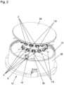
- FIG. 2shows the intermediate tool storage station according to FIG. 1 on an enlarged scale
- FIGS. 3 and 4show parts of the intermediate tool storage station in an arrangement separated from one another
- FIGS. 5 to 8show representations relating to the exemplary embodiment used here of an assembly according to the invention.
- FIGS. 9 and 10show representations relating to the fixing of the packaging, together with the tool, in the intermediate tool storage station.
- FIG. 1shows, in a schematic representation, an assembly according to the invention in which the assembly comprises a plurality of tools 1 and packagings 2 , wherein the packagings 2 are fixed by their securing devices 11 in an intermediate tool storage station 12 of the machining unit 5 .
- the intermediate tool storage station 12 and also the machining unit 5can thereby also be seen as part of the assembly.
- the machining unit 5can be, for example, a generally computer-controlled CAD/CAM machine which, apart from the innovations according to the invention, is known per se and by which the workpieces 4 to be machined can be machined with removal of material, that is to say, for example, by drilling, milling or grinding.
- the computer-assisted control of such machining unitsis known per se and does not require further explanation here.
- the workpiece 4is arranged on a carrier arm 24 in a machining chamber 27 of the machining unit 5 in such a manner that it is movable and pivotable in multiple spatial directions.
- a tool 1is secured by its clamping portion 6 in the chuck 7 of the machining unit 5 , so that the workpiece 4 can be machined with removal of material by the machining head 3 of that tool 1 .
- the machining head 3 of the tool 1can be, for example, a grinding head or also a drilling head or a milling head.
- the tool 1 and in particular its machining head 3can of course be of very different forms. This is known per se in the prior art and does not require further explanation here.
- the tool 1 clamped in the chuck 7is in any case rotated in one of the directions 26 in the example shown here.
- the spindle drive 25which also ensures this rotation, the chuck 7 with the tool 1 secured therein can be moved relative to the workpiece 4 preferably in all three spatial directions and optionally also in other degrees of freedom. Due to the corresponding degrees of freedom of the carrier arm 24 on the one hand and of the chuck 7 on the other hand, very different machining angles can be achieved on the workpiece 4 . This is also known per se and does not require further explanation.
- the chuck 7is in any case the part of the machining unit 5 in which the particular tool 1 currently required for the material-removing machining of the workpiece 4 is held during the material-removing machining.
- the tool 1is generally also correspondingly driven via the chuck 7 .
- the tools 1 that are not required for the machining step that is to be performed at the present timeare located during that step in the intermediate tool storage station 12 , which in the exemplary embodiment shown here is likewise located within the machining chamber 27 of the machining unit 5 .
- the packagings 2 of a particular tool 1each have at least one securing device 11 for fixing the packaging 2 in question in the intermediate tool storage station 12 of the machining unit 5 .
- the intermediate tool storage station 12has, in addition to the holders for the packagings 2 with the tools 1 in the packaging holder 34 , also a storage station wall 28 and a storage station cover 29 .
- the storage station cover 29lies against the storage station wall 28 , preferably with the interposition of a seal 31 , in such a manner that there is formed in the interior enclosed jointly by the storage station wall 28 and by the storage station cover 29 a storage space which is sufficiently sealed with respect to the remainder of the machining chamber 27 and in which the tools 1 that are not currently required, together with their packagings 2 , are protected from moisture, dust and the like.
- the storage station cover 29is preferably brought into the open position shown in FIG.
- the storage station coverfor opening and closing the storage station cover 29 , the storage station cover, in the exemplary embodiment shown here, together with the packaging holder 34 of the intermediate tool storage station 12 , in which the packagings 2 , together with the tools 1 , are secured, is displaceably mounted on a storage station pin 30 .
- the intermediate tool storage station 12By retracting or extending the storage station pin 30 , the intermediate tool storage station 12 can thus be opened and closed.
- Preferred variantsprovide that the storage station cover 29 , together with the packaging holders 34 , can be taken off the storage station pin 30 .
- corresponding packaging holders 34with corresponding tools 1 arranged in their packagings 2 which are required for a specific material type of a workpiece 4 , in order thus to be able to introduce an entire set of new tools 1 into the intermediate tool storage station 12 in a simple manner when a different material, or a different workpiece 4 , is to be machined.
- an adapter 32which forms a releasable connection.
- the corresponding adapter counter-piece 33which can be connected to the adapter 32 , is correspondingly located on the packaging holders 34 , or on the storage station cover 29 , so that simple removal and optionally also exchange of the storage station cover 29 , together with the packaging holders 34 , is possible.
- the index pin 35in conjunction with the index pin receiver 36 therefor, ensures that the packaging holders 34 of the intermediate tool storage station 12 , together with the storage station cover 29 , can be secured to the storage station pin 30 in only a defined position.
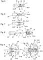
- FIGS. 5 to 8show an embodiment according to the invention of an assembly comprising a tool 1 and a packaging 2 for holding the tool 1 .
- FIG. 5is a perspective view.
- FIGS. 6 and 7are each side views rotated through 90° relative to one another.
- FIG. 8is an exploded view. In FIGS. 5 to 7 , the packaging 2 is closed, and in the exploded view according to FIG. 8 it is shown correspondingly opened.
- the packaging 2or here the base body 19 thereof, including the tool 1 arranged in the packaging 2
- the packaging 2is arranged in a corresponding holder of the packaging holder 34 and thus of the intermediate tool storage station 12 and fixed by the securing device 11 .
- Fixed heremeans, in the sense of releasably fixed, that the packaging 2 is held by the securing device(s) 11 stably and permanently in the packaging holder 34 or, generally speaking, in the intermediate tool storage station 12 in such a manner that the tool 1 can, simply and without problems, repeatedly be removed from the packaging 2 , or here the base body 19 thereof, and arranged in the packaging again, while the packaging 2 remains in the packaging holder 34 or, generally speaking, in the intermediate tool storage station 12 .
- FIG. 10shows a section through the packaging holder 34 , the packaging 2 and the workpiece 1 .
- the tool 1can, as has already been explained, repeatedly be removed from the packaging 2 and arranged in the packaging again.
- the packaging 2is thus so designed that the tool 1 can be removed from the packaging and introduced into the packaging again repeatedly, or many times.
- the packaging 2 according to the inventionis a sales packaging in which the tool 1 is sold. It can accordingly be provided in the invention that the tool 1 can be marketed with a packaging 2 with which it can then also immediately be secured in the intermediate tool storage station 12 of the machining unit 5 .
- the packaging 2is accordingly on the one hand a sales packaging in which tools 1 are sold on the market but on the other hand also a securing means for securing a tool 1 that is currently not required in the intermediate tool storage station 12 of the machining unit 5 .
- the packaging 2has a single holding space 14 delimited by at least one holding space wall 13 of the packaging 2 , wherein the tool 1 can be arranged as a single tool 1 in the holding space 14 .
- the tool 1is arranged with its machining head 3 in the holding space 14 of the packaging 2 .
- the packaging 2is formed of a base body 19 and a cover part 20 which can be releasably secured thereto, and accordingly is in two parts.
- the holding space 14is preferably located in the base body 19 , so that the machining head 3 of the tool 1 can be inserted into the base body 19 .
- the clamping portion 6which serves to secure the tool 1 in the chuck 7 , protrudes beyond the base body 19 when the tool 1 is inserted with its machining head 3 in the holding space 14 .
- the cover part 20when sold, encloses the clamping portion 6 of the tool 1 , so that the tool 1 , for marketing, is received completely in the packaging 2 and is enclosed thereby.
- the at least one securing device 11can, as is also implemented here, be arranged on the outside wall 15 of the packaging 2 , preferably of the base body 19 of the packaging 2 .
- the securing device 11can thereby be all that permits corresponding, preferably releasable, fixing of the packaging 2 in the intermediate tool storage station 12 .
- the securing device(s) 11can in principle be, for example, all possible suitable interlocking and/or force-based and/or friction-based means for securing. Examples are screw connections, clamped connections and the like.
- the securing device(s) 11face outwards or protrude outwards from the outside wall 15 of the packaging 2 or, preferably, of its base body 19 .
- the securing devices 11 with which the packaging 2 in question can be fixed in the intermediate tool storage station 12 of the machining unit 5are part of a latching connection.
- the securing device 11 of the packaging 2can have at least one latching projection for forming a latching connection with the intermediate tool storage station 12 of the machining unit 5 .
- the two securing devices 11 provided here in the example shown for each packaging 2are secured with their respective latching projections 16 in a corresponding latching projection receiver 17 of the intermediate tool storage station 12 , or here specifically of the packaging holder 34 of the intermediate tool storage station 12 , in such a manner that a latching connection is formed.
- the latching projections of the securing device 11are preferably, as is also implemented here, secured, preferably molded on, in an elastically resilient manner to the packaging 2 , preferably to the base body 19 and particularly preferably to the outside wall 15 thereof.
- the respective securing device 11has at least one latching projection receiver 17 for forming a latching connection with the intermediate tool storage station 12 .
- the corresponding latching projections 16could be formed on the intermediate tool storage station 12 , or on the packaging holder 34 thereof.
- the packaging 2has an actuating element 18 for releasing the securing device 11 .
- the actuating element 18is so configured that the securing device 11 can be released by hand, that is to say without the need for a tool.
- the actuating element 18 and the latching projection 16are secured as a spring-mounted lever, or a spring tongue, to the packaging 2 , preferably to the outside wall 15 thereof and most particularly preferably to the outside wall 15 of the base body 19 .
- a correspondingly lengthened region of that lever, or of that spring tonguecan then also be configured, as implemented here, as an actuating element 18 for releasing the securing means 11 .
- the securing device 11is configured not only for fixing the packaging 2 in the intermediate tool storage station 12 but additionally also for fixing the cover part 20 to the base body 19 .
- the actuating element 18is configured as an additional latching projection 37 , or an additional latching projection is formed on the securing device 11 , which serves for releasably connecting the cover part 20 to the base body 19 and thus for releasably fixing the cover part 20 to the base body 19 .
- a securing means 23configured as a tab on the cover part 20 is located on the cover part 20 for this purpose.
- the securing device 11can then engage into this securing means 23 , as here, for example, specifically with the additional latching projection 37 , in order thus to fix the cover part 20 to the base body 19 , in particular during sale or marketing.
- this dual function of the securing device 11can also be configured differently than specifically shown here, on the one hand for fixing the packaging 2 in the intermediate tool storage station 12 and on the other hand for securing the cover part 20 to the base body 19 .
- FIGS. 9 and 10show, by way of example, an assembly comprising a packaging 2 and a tool 1 arranged therein, and an intermediate tool storage station 12 , or the packaging holder 34 thereof, of the machining unit 5 , wherein the tool 1 is held in the packaging, here specifically in the base body 19 of the packaging 2 , and the packaging 2 , again preferably the base body 19 of the packaging 2 , is fixed by the securing device(s) 11 in the intermediate tool storage station 12 of the machining unit 5 .
- a plurality of slots 38are provided in the packaging holder 34 , or in the intermediate tool storage station 12 , so that a plurality of tools 1 with their respective packaging 2 can be fixed in the intermediate tool storage station 12 .
- the packaging 2 in questioncan be secured in the intermediate tool storage station 12 , or in one of the slots 28 of the packaging holder 34 , in only a single defined orientation.
- packaging 2preferably the base body 19 of the packaging 2 , has an outer contour 21 which permits only a single orientation of the packaging 2 when the packaging 2 is arranged in the intermediate tool storage station 12 .
- the packaginghas a data memory 8 .
- This data memory 8is preferably repeatedly machine readable and repeatedly machine writable.
- itis an electronic data memory 8 . It is thereby possible to store on the data memory 8 of the packaging 2 specific and individual data for the particular tool 1 arranged in the packaging 2 . This can be used for identifying the tool 1 . It is, however, especially possible in this manner, generally speaking, with a corresponding configuration, to store the history of each individual tool 1 and read it out again if required.
- the data memory 8is preferably repeatedly machine readable and also machine writable.
- the data memory 8 of the packaging 2is a transponder or part of a transponder.
- Corresponding transpondersare also referred to in the prior art as tags. They could also be referred to as a chip.
- a transponderis the combination of a transmitter and a responder. Particularly preferably it is a passive transponder, which does not have its own power supply but is fed with energy solely from the field of another transmitting and receiving unit.
- the transponderis a RFID (radio frequency identification) known per se.
- Specific information for the tool 1 in questioncan be stored in the data memory 8 of the packaging 2 . This can be, for example, information relating to the identity of the tool 1 . It can thus be a type designation, a serial number or the like.
- the data memory 8can be secured to and/or integrated into the packaging 2 in many different ways. For example, incorporation, casting-in, adhesive bonding and the like are conceivable. In the variant shown, the data memory 8 , or transponder, is held, for example, in a pocket-like data memory holder 22 of the packaging 2 , or here specifically of the base body 19 .
- the machining unit 5In order to be able to read and also re-write the data memory 8 of the packaging 2 of the tool 1 in question, preferred variants provide that the machining unit 5 , preferably the intermediate tool storage station 12 thereof, has a reader for reading data from the data memory 8 of the packaging 2 or preferably a reader and writer 9 for reading data from the data memory 8 of the packaging 2 and for writing data to the data memory 8 of the packaging 2 . In the case of the reader and writer 9 , it is then possible both to read data from the data memory 8 of the packaging 2 in question and to store data on the data memory 8 of the packaging 2 in question. It is preferably provided that the machining unit 5 additionally has a data memory 10 , preferably an electronic data memory, which is repeatedly machine readable and repeatedly machine writable.
- this reader and writer 9is integrated into the intermediate tool storage station 12 , as can be seen particularly clearly in FIG. 2 .
- the data memory 10can likewise be integrated into this reader and writer 9 , as is shown schematically in FIG. 2 .
- the mentioned specific data for the tool 1 arranged in the packaging 2 in questioncan both be stored on the data memory 8 of the packaging 2 and read therefrom and be stored on the data memory 10 of the machining unit 5 and read therefrom again.
- a method for operating a corresponding assemblywhich is characterized in that, by the reader and writer 9 of the machining unit 5 , data are read from the data memory 8 of the packaging 2 of the tool 1 and/or written to the data memory 8 of the packaging 2 of the tool 1 and/or data are read from the data memory 10 of the machining unit 5 and/or data are written to the data memory 10 of the machining unit 5 .
- datais in each case correspondingly only read from the data memory 8 and/or 10 .
- the dataare read from the data memory 8 of the packaging 2 in the course of securing the tool 1 in the chuck 7 of the machining unit 5 .
- the course of securingcan be before, preferably shortly before, securing, during securing but also after, preferably shortly after, securing the tool 1 in the chuck 7 .
- the dataare written to the data memory 8 of the packaging 2 and/or to the data memory 10 of the machining unit 5 in the course of the re-arrangement of the tool 1 in the packaging 2 .
- the workpieces 4are particularly preferably dental workpieces 4 , that is to say workpieces 4 from which dental products such as, for example, bridges, full and/or partial dentures, artificial teeth or the like can be produced.
Landscapes
- Engineering & Computer Science (AREA)
- Mechanical Engineering (AREA)
- Health & Medical Sciences (AREA)
- Oral & Maxillofacial Surgery (AREA)
- Dentistry (AREA)
- Epidemiology (AREA)
- Life Sciences & Earth Sciences (AREA)
- Animal Behavior & Ethology (AREA)
- General Health & Medical Sciences (AREA)
- Public Health (AREA)
- Veterinary Medicine (AREA)
- Automatic Tool Replacement In Machine Tools (AREA)
- Packaging Of Annular Or Rod-Shaped Articles, Wearing Apparel, Cassettes, Or The Like (AREA)
- Workshop Equipment, Work Benches, Supports,Or Storage Means (AREA)
- Dental Tools And Instruments Or Auxiliary Dental Instruments (AREA)
- Packages (AREA)
Abstract
Description
- 1 tool
- 2 packaging
- 3 machining head
- 4 workpiece
- 5 machining unit
- 6 clamping portion
- 7 chuck
- 8 data memory
- 9 reader and writer
- 10 data memory
- 11 securing device
- 12 intermediate tool storage station
- 13 holding space wall
- 14 holding space
- 15 outside wall
- 16 latching projection
- 17 latching projection receiver
- 18 actuating element
- 19 base body
- 20 cover part
- 21 outer contour
- 22 data memory holder
- 23 securing means
- 24 carrier arm
- 25 spindle drive
- 26 rotation
- 27 machining chamber
- 28 storage station wall
- 29 storage station cover
- 30 storage station pin
- 31 seal
- 32 adapter
- 33 adapter counter-piece
- 34 packaging holder
- 35 index pin
- 36 index pin receiver
- 37 additional latching projection
- 38 slot
Claims (10)
Applications Claiming Priority (3)
| Application Number | Priority Date | Filing Date | Title |
|---|---|---|---|
| DE202018102658.5 | 2018-05-11 | ||
| DE202018102658.5UDE202018102658U1 (en) | 2018-05-11 | 2018-05-11 | Arrangement with a tool and a packaging |
| PCT/AT2019/000009WO2019213677A1 (en) | 2018-05-11 | 2019-04-05 | Assembly comprising a tool and packaging |
Publications (2)
| Publication Number | Publication Date |
|---|---|
| US20210086319A1 US20210086319A1 (en) | 2021-03-25 |
| US12059765B2true US12059765B2 (en) | 2024-08-13 |
Family
ID=62568363
Family Applications (1)
| Application Number | Title | Priority Date | Filing Date |
|---|---|---|---|
| US17/054,574Active2040-06-02US12059765B2 (en) | 2018-05-11 | 2019-04-05 | Assembly comprising a tool and packaging |
Country Status (7)
| Country | Link |
|---|---|
| US (1) | US12059765B2 (en) |
| EP (1) | EP3790703B1 (en) |
| JP (1) | JP7426948B2 (en) |
| KR (1) | KR102633250B1 (en) |
| CN (1) | CN112203799B (en) |
| DE (1) | DE202018102658U1 (en) |
| WO (1) | WO2019213677A1 (en) |
Families Citing this family (5)
| Publication number | Priority date | Publication date | Assignee | Title |
|---|---|---|---|---|
| WO2019053900A1 (en)* | 2017-09-15 | 2019-03-21 | 株式会社牧野フライス製作所 | Machine tool system |
| EP3797731A1 (en)* | 2019-09-24 | 2021-03-31 | DENTSPLY SIRONA Inc. | Dental tool having a miniaturized rfid tag |
| EP3865247A1 (en) | 2020-02-14 | 2021-08-18 | Ivoclar Vivadent AG | Clamping device for a tool on a machine tool |
| EP4140641A4 (en)* | 2020-04-24 | 2023-06-21 | DMG Mori Co., Ltd. | PROCESSING MACHINE |
| JP7108111B1 (en) | 2021-08-18 | 2022-07-27 | Dmg森精機株式会社 | Tool magazine device |
Citations (39)
| Publication number | Priority date | Publication date | Assignee | Title |
|---|---|---|---|---|
| DE2135240A1 (en) | 1970-07-15 | 1972-01-27 | Cincinnati Gilbert Machine Too | Tool changer for machine tools |
| JPS5253780U (en) | 1975-10-16 | 1977-04-18 | ||
| US4413731A (en)* | 1982-07-07 | 1983-11-08 | Tulon, Inc. | Packaging arrangement for cutting tools such as drills |
| WO1987006167A1 (en) | 1986-04-18 | 1987-10-22 | Dynamotion Corporation | High speed precision drilling system |
| US4858302A (en) | 1988-10-17 | 1989-08-22 | Precision Carbide Tool Co., Inc. | Tool deployment apparatus |
| JPH0310734A (en) | 1989-06-03 | 1991-01-18 | Hiraoka Kogyo Kk | Automatic tool changing device of core drill for printed wiring board |
| US4995513A (en)* | 1989-04-13 | 1991-02-26 | Rose-Plastic Gmbh | Container for oblong articles |
| EP0522498A1 (en) | 1991-07-10 | 1993-01-13 | DÖRRIES SCHARMANN GmbH | Tool magazine with tool changer |
| EP0541020A2 (en) | 1991-11-08 | 1993-05-12 | PLURITEC ITALIA S.p.A. | Automatic tool change device for printed circuit board machines |
| JPH0636737A (en) | 1992-07-16 | 1994-02-10 | Nissin Electric Co Ltd | Ion implanter |
| US5595294A (en)* | 1992-08-14 | 1997-01-21 | Mckenzie; Archibald M. | Modular packaging and holder for tool bits |
| US5846036A (en)* | 1996-09-12 | 1998-12-08 | Mst Corporation | Protective cover |
| DE19806217A1 (en)* | 1998-02-16 | 1999-08-19 | Roesler | Long packaging for e.g. drill bit or other tools with surfaces or cutting edges requiring protection |
| EP1099511A2 (en) | 1999-11-10 | 2001-05-16 | Disco Corporation | Rotary tool including a cutting blade and cutting apparatus comprising the same |
| US20030093103A1 (en) | 2001-08-08 | 2003-05-15 | Don Malackowski | Surgical tool system with components that perform inductive data transfer |
| DE10260706A1 (en) | 2002-12-23 | 2004-07-01 | Hilti Ag | transponder receptacle |
| DE202005002005U1 (en)* | 2005-02-09 | 2005-05-12 | Bürkert Werke GmbH & Co. KG | Cutter protection device for milling machine cutter and similar tools is in form of one-piece beaker that is open at bottom; protection device consists of elastic material, preferably of plastic; it is made of transparent material |
| WO2006066259A2 (en) | 2004-12-17 | 2006-06-22 | Milwaukee Electric Tool Corporation | Smart acessories for power tools |
| DE102005013617A1 (en) | 2005-03-24 | 2006-09-28 | Wera Werk Hermann Werner Gmbh & Co. Kg | Tool or accessory for a tool |
| DE102005058881A1 (en) | 2005-12-09 | 2007-06-14 | Gebr. Brasseler Gmbh & Co. Kg | Dental medical or surgical instrument e.g. dental drill, is detachably connected with drive unit, where identification unit is attached to instrument, and is automatically readable for transmission of instrument specific data |
| DE102006057338A1 (en) | 2006-12-05 | 2008-06-12 | Gebr. Brasseler Gmbh & Co. Kg | Rotating tool or instrument, particularly surgical or dental medical instrument or tool, has base body with electronic identification element, where identification element is formed in form of transponder chip |
| DE102007005515B3 (en)* | 2007-02-03 | 2008-08-07 | Rösler, Peter | Single packaging for precision tools |
| EP2233103A2 (en) | 2009-03-26 | 2010-09-29 | W & H Dentalwerk Bürmoos GmbH | Medical, in particular dental tool holder |
| US20110192746A1 (en)* | 2010-02-11 | 2011-08-11 | Chi-Tsai Chang | Secure hanging structure of tool case |
| CN102378848A (en) | 2009-04-10 | 2012-03-14 | 钴碳化钨硬质合金公司 | Rotatable cutting tool-tool holder-base assembly |
| US20120234709A1 (en)* | 2011-03-17 | 2012-09-20 | Chi-Tsai Chang | Drill bit suspension structure |
| JP5253780B2 (en) | 2007-09-13 | 2013-07-31 | 株式会社三共 | Game machine |
| EP2683322A1 (en) | 2011-08-10 | 2014-01-15 | Amann Girrbach AG | Clamping device |
| CN104044014A (en) | 2013-03-12 | 2014-09-17 | 贝特霍尔德·赫姆勒机器制造股份公司 | Vertical machining centre in gantry form with integrated tool magazine storage unit integrated into machine |
| DE102013206166A1 (en) | 2013-04-08 | 2014-10-09 | Robert Bosch Gmbh | Hand machine tool control device |
| CN104249178A (en)* | 2013-06-28 | 2014-12-31 | 江苏天工工具有限公司 | Radial edge drill bit with protection sleeve |
| KR101488256B1 (en) | 2014-09-17 | 2015-01-30 | 태림메디텍 주식회사 | Tool Rack for Automatic Tool Changer |
| CN105069912A (en) | 2015-08-01 | 2015-11-18 | 深圳市美思美科智能科技有限公司 | Automatic tool vending machine and system |
| CN105583671A (en) | 2015-02-02 | 2016-05-18 | 德克尔马霍塞巴赫公司 | Link of buckle chain and tool magazine with buckle chain |
| DE202015008056U1 (en) | 2015-11-24 | 2017-03-01 | Isel Facility GmbH | Tool change system for a processing machine |
| US9724794B1 (en)* | 2014-01-28 | 2017-08-08 | Kerr Machine Co. | Machine tool protection |
| EP3372338A1 (en) | 2017-03-10 | 2018-09-12 | STEGER, Heinrich | Processing device for a dental workpiece |
| US20200230761A1 (en)* | 2017-09-15 | 2020-07-23 | Makino Milling Machine Co., Ltd. | Machine tool system |
| DE112014004191B4 (en) | 2013-09-13 | 2023-09-28 | Komatsu Ntc Ltd. | Tool magazine device and machine tool |
Family Cites Families (2)
| Publication number | Priority date | Publication date | Assignee | Title |
|---|---|---|---|---|
| JPS62201636U (en)* | 1986-06-13 | 1987-12-22 | ||
| JPH0636737U (en)* | 1992-10-15 | 1994-05-17 | 博一 矢野 | Individualized tool name display Safety cover for machining tools |
- 2018
- 2018-05-11DEDE202018102658.5Upatent/DE202018102658U1/enactiveActive
- 2019
- 2019-04-05WOPCT/AT2019/000009patent/WO2019213677A1/ennot_activeCeased
- 2019-04-05KRKR1020207032291Apatent/KR102633250B1/enactiveActive
- 2019-04-05CNCN201980031748.9Apatent/CN112203799B/enactiveActive
- 2019-04-05EPEP19720023.1Apatent/EP3790703B1/enactiveActive
- 2019-04-05JPJP2020562207Apatent/JP7426948B2/enactiveActive
- 2019-04-05USUS17/054,574patent/US12059765B2/enactiveActive
Patent Citations (45)
| Publication number | Priority date | Publication date | Assignee | Title |
|---|---|---|---|---|
| DE2135240A1 (en) | 1970-07-15 | 1972-01-27 | Cincinnati Gilbert Machine Too | Tool changer for machine tools |
| US3780423A (en) | 1970-07-15 | 1973-12-25 | Cincinnati Gilbert Machine Too | Tool changer |
| JPS5253780U (en) | 1975-10-16 | 1977-04-18 | ||
| US4413731A (en)* | 1982-07-07 | 1983-11-08 | Tulon, Inc. | Packaging arrangement for cutting tools such as drills |
| WO1987006167A1 (en) | 1986-04-18 | 1987-10-22 | Dynamotion Corporation | High speed precision drilling system |
| US4858302A (en) | 1988-10-17 | 1989-08-22 | Precision Carbide Tool Co., Inc. | Tool deployment apparatus |
| US4995513A (en)* | 1989-04-13 | 1991-02-26 | Rose-Plastic Gmbh | Container for oblong articles |
| JPH0310734A (en) | 1989-06-03 | 1991-01-18 | Hiraoka Kogyo Kk | Automatic tool changing device of core drill for printed wiring board |
| EP0522498A1 (en) | 1991-07-10 | 1993-01-13 | DÖRRIES SCHARMANN GmbH | Tool magazine with tool changer |
| EP0541020A2 (en) | 1991-11-08 | 1993-05-12 | PLURITEC ITALIA S.p.A. | Automatic tool change device for printed circuit board machines |
| JPH0636737A (en) | 1992-07-16 | 1994-02-10 | Nissin Electric Co Ltd | Ion implanter |
| US5595294A (en)* | 1992-08-14 | 1997-01-21 | Mckenzie; Archibald M. | Modular packaging and holder for tool bits |
| US5846036A (en)* | 1996-09-12 | 1998-12-08 | Mst Corporation | Protective cover |
| DE19806217A1 (en)* | 1998-02-16 | 1999-08-19 | Roesler | Long packaging for e.g. drill bit or other tools with surfaces or cutting edges requiring protection |
| EP1099511A2 (en) | 1999-11-10 | 2001-05-16 | Disco Corporation | Rotary tool including a cutting blade and cutting apparatus comprising the same |
| US20030093103A1 (en) | 2001-08-08 | 2003-05-15 | Don Malackowski | Surgical tool system with components that perform inductive data transfer |
| DE10260706A1 (en) | 2002-12-23 | 2004-07-01 | Hilti Ag | transponder receptacle |
| US20040135692A1 (en) | 2002-12-23 | 2004-07-15 | Armin Below | Transponder holder |
| DE112005003148T5 (en) | 2004-12-17 | 2007-10-31 | Milwaukee Electric Tool Corp., Brookfield | Intelligent accessory for power tools |
| WO2006066259A2 (en) | 2004-12-17 | 2006-06-22 | Milwaukee Electric Tool Corporation | Smart acessories for power tools |
| DE202005002005U1 (en)* | 2005-02-09 | 2005-05-12 | Bürkert Werke GmbH & Co. KG | Cutter protection device for milling machine cutter and similar tools is in form of one-piece beaker that is open at bottom; protection device consists of elastic material, preferably of plastic; it is made of transparent material |
| DE102005013617A1 (en) | 2005-03-24 | 2006-09-28 | Wera Werk Hermann Werner Gmbh & Co. Kg | Tool or accessory for a tool |
| DE102005058881A1 (en) | 2005-12-09 | 2007-06-14 | Gebr. Brasseler Gmbh & Co. Kg | Dental medical or surgical instrument e.g. dental drill, is detachably connected with drive unit, where identification unit is attached to instrument, and is automatically readable for transmission of instrument specific data |
| DE102006057338A1 (en) | 2006-12-05 | 2008-06-12 | Gebr. Brasseler Gmbh & Co. Kg | Rotating tool or instrument, particularly surgical or dental medical instrument or tool, has base body with electronic identification element, where identification element is formed in form of transponder chip |
| DE102007005515B3 (en)* | 2007-02-03 | 2008-08-07 | Rösler, Peter | Single packaging for precision tools |
| JP5253780B2 (en) | 2007-09-13 | 2013-07-31 | 株式会社三共 | Game machine |
| EP2233103A2 (en) | 2009-03-26 | 2010-09-29 | W & H Dentalwerk Bürmoos GmbH | Medical, in particular dental tool holder |
| US20100248177A1 (en) | 2009-03-26 | 2010-09-30 | W&H Dentalwerk Bürmoos GmbH | Medical or dental handpiece with inductive coupling |
| CN102378848A (en) | 2009-04-10 | 2012-03-14 | 钴碳化钨硬质合金公司 | Rotatable cutting tool-tool holder-base assembly |
| US8302772B2 (en)* | 2010-02-11 | 2012-11-06 | Chi-Tsai Chang | Secure hanging structure of tool case |
| US20110192746A1 (en)* | 2010-02-11 | 2011-08-11 | Chi-Tsai Chang | Secure hanging structure of tool case |
| US20120234709A1 (en)* | 2011-03-17 | 2012-09-20 | Chi-Tsai Chang | Drill bit suspension structure |
| US9265592B2 (en) | 2011-08-10 | 2016-02-23 | Armann Girrbach Ag | Clamping device |
| EP2683322A1 (en) | 2011-08-10 | 2014-01-15 | Amann Girrbach AG | Clamping device |
| CN104044014A (en) | 2013-03-12 | 2014-09-17 | 贝特霍尔德·赫姆勒机器制造股份公司 | Vertical machining centre in gantry form with integrated tool magazine storage unit integrated into machine |
| DE102013206166A1 (en) | 2013-04-08 | 2014-10-09 | Robert Bosch Gmbh | Hand machine tool control device |
| CN104249178A (en)* | 2013-06-28 | 2014-12-31 | 江苏天工工具有限公司 | Radial edge drill bit with protection sleeve |
| DE112014004191B4 (en) | 2013-09-13 | 2023-09-28 | Komatsu Ntc Ltd. | Tool magazine device and machine tool |
| US9724794B1 (en)* | 2014-01-28 | 2017-08-08 | Kerr Machine Co. | Machine tool protection |
| KR101488256B1 (en) | 2014-09-17 | 2015-01-30 | 태림메디텍 주식회사 | Tool Rack for Automatic Tool Changer |
| CN105583671A (en) | 2015-02-02 | 2016-05-18 | 德克尔马霍塞巴赫公司 | Link of buckle chain and tool magazine with buckle chain |
| CN105069912A (en) | 2015-08-01 | 2015-11-18 | 深圳市美思美科智能科技有限公司 | Automatic tool vending machine and system |
| DE202015008056U1 (en) | 2015-11-24 | 2017-03-01 | Isel Facility GmbH | Tool change system for a processing machine |
| EP3372338A1 (en) | 2017-03-10 | 2018-09-12 | STEGER, Heinrich | Processing device for a dental workpiece |
| US20200230761A1 (en)* | 2017-09-15 | 2020-07-23 | Makino Milling Machine Co., Ltd. | Machine tool system |
Also Published As
| Publication number | Publication date |
|---|---|
| BR112020022986A2 (en) | 2021-02-02 |
| CN112203799A (en) | 2021-01-08 |
| JP2021523023A (en) | 2021-09-02 |
| EP3790703B1 (en) | 2024-02-28 |
| WO2019213677A8 (en) | 2020-01-16 |
| CN112203799B (en) | 2022-11-11 |
| WO2019213677A1 (en) | 2019-11-14 |
| JP7426948B2 (en) | 2024-02-02 |
| US20210086319A1 (en) | 2021-03-25 |
| KR20210006908A (en) | 2021-01-19 |
| KR102633250B1 (en) | 2024-02-02 |
| EP3790703C0 (en) | 2024-02-28 |
| DE202018102658U1 (en) | 2018-05-24 |
| EP3790703A1 (en) | 2021-03-17 |
Similar Documents
| Publication | Publication Date | Title |
|---|---|---|
| US12059765B2 (en) | Assembly comprising a tool and packaging | |
| US8376671B2 (en) | Tool holder | |
| US8316742B2 (en) | Cutting tool with integrated circuit chip | |
| US4809426A (en) | Information processing apparatus of tool holder | |
| EP1339014B1 (en) | RFID-tags holding unit | |
| JP2003025176A (en) | Tool management system | |
| US5715934A (en) | CD-ROM label with positioning means | |
| US20160091887A1 (en) | Cutting apparatus | |
| JP2005537143A (en) | Tool holder | |
| CN112672711A (en) | Package for medical tools with automatic tool recognition and packaging method using the same | |
| JP6813550B2 (en) | Modular design component handling device with component gripping tool protruding from the axis of rotation | |
| JP4450376B2 (en) | Magazine rack for chip changer | |
| BR112020022986B1 (en) | ARRANGEMENT | |
| US7048679B2 (en) | Tool-changing system | |
| TWM512462U (en) | Pull stud with tool recognition capability and tool set | |
| CN110315377B (en) | Authentication device for tools or machine sets | |
| US3173203A (en) | Machine tools | |
| CN101297369A (en) | Removable data cartridge | |
| JPH0710484B2 (en) | Tool information collection device for machine tools | |
| JP7648057B2 (en) | Radio Frequency Identification RFID Tag Embedding Tool | |
| JPH0349848A (en) | Mounting structure of contactless information memory element | |
| EP1235218B1 (en) | Apparatus and method for retrieving data related to a data cartridge in a media storage system | |
| DE102018111343A1 (en) | Arrangement with a tool and a packaging | |
| JPS6423303A (en) | Commodity information reading device | |
| JPH0615139B2 (en) | Tool information management method for numerically controlled machine tools |
Legal Events
| Date | Code | Title | Description |
|---|---|---|---|
| FEPP | Fee payment procedure | Free format text:ENTITY STATUS SET TO UNDISCOUNTED (ORIGINAL EVENT CODE: BIG.); ENTITY STATUS OF PATENT OWNER: LARGE ENTITY | |
| FEPP | Fee payment procedure | Free format text:ENTITY STATUS SET TO SMALL (ORIGINAL EVENT CODE: SMAL); ENTITY STATUS OF PATENT OWNER: LARGE ENTITY | |
| STPP | Information on status: patent application and granting procedure in general | Free format text:APPLICATION DISPATCHED FROM PREEXAM, NOT YET DOCKETED | |
| STPP | Information on status: patent application and granting procedure in general | Free format text:DOCKETED NEW CASE - READY FOR EXAMINATION | |
| AS | Assignment | Owner name:AMANN GIRRBACH AG, AUSTRIA Free format text:ASSIGNMENT OF ASSIGNORS INTEREST;ASSIGNOR:AMANN, JURGEN;REEL/FRAME:058094/0521 Effective date:20201116 | |
| FEPP | Fee payment procedure | Free format text:ENTITY STATUS SET TO UNDISCOUNTED (ORIGINAL EVENT CODE: BIG.); ENTITY STATUS OF PATENT OWNER: LARGE ENTITY | |
| STPP | Information on status: patent application and granting procedure in general | Free format text:FINAL REJECTION MAILED | |
| STPP | Information on status: patent application and granting procedure in general | Free format text:DOCKETED NEW CASE - READY FOR EXAMINATION | |
| STPP | Information on status: patent application and granting procedure in general | Free format text:NON FINAL ACTION MAILED | |
| STPP | Information on status: patent application and granting procedure in general | Free format text:RESPONSE TO NON-FINAL OFFICE ACTION ENTERED AND FORWARDED TO EXAMINER | |
| STPP | Information on status: patent application and granting procedure in general | Free format text:NOTICE OF ALLOWANCE MAILED -- APPLICATION RECEIVED IN OFFICE OF PUBLICATIONS | |
| ZAAA | Notice of allowance and fees due | Free format text:ORIGINAL CODE: NOA | |
| ZAAB | Notice of allowance mailed | Free format text:ORIGINAL CODE: MN/=. | |
| STPP | Information on status: patent application and granting procedure in general | Free format text:PUBLICATIONS -- ISSUE FEE PAYMENT VERIFIED | |
| STCF | Information on status: patent grant | Free format text:PATENTED CASE |