US12059559B2 - Sensors for catheter pumps - Google Patents
Sensors for catheter pumpsDownload PDFInfo
- Publication number
- US12059559B2 US12059559B2US16/950,649US202016950649AUS12059559B2US 12059559 B2US12059559 B2US 12059559B2US 202016950649 AUS202016950649 AUS 202016950649AUS 12059559 B2US12059559 B2US 12059559B2
- Authority
- US
- United States
- Prior art keywords
- impeller
- assembly
- pressure
- sensor
- catheter
- Prior art date
- Legal status (The legal status is an assumption and is not a legal conclusion. Google has not performed a legal analysis and makes no representation as to the accuracy of the status listed.)
- Active, expires
Links
Images


Classifications
- A—HUMAN NECESSITIES
- A61—MEDICAL OR VETERINARY SCIENCE; HYGIENE
- A61M—DEVICES FOR INTRODUCING MEDIA INTO, OR ONTO, THE BODY; DEVICES FOR TRANSDUCING BODY MEDIA OR FOR TAKING MEDIA FROM THE BODY; DEVICES FOR PRODUCING OR ENDING SLEEP OR STUPOR
- A61M60/00—Blood pumps; Devices for mechanical circulatory actuation; Balloon pumps for circulatory assistance
- A61M60/80—Constructional details other than related to driving
- A61M60/855—Constructional details other than related to driving of implantable pumps or pumping devices
- A61M60/857—Implantable blood tubes
- A—HUMAN NECESSITIES
- A61—MEDICAL OR VETERINARY SCIENCE; HYGIENE
- A61B—DIAGNOSIS; SURGERY; IDENTIFICATION
- A61B5/00—Measuring for diagnostic purposes; Identification of persons
- A61B5/68—Arrangements of detecting, measuring or recording means, e.g. sensors, in relation to patient
- A61B5/6846—Arrangements of detecting, measuring or recording means, e.g. sensors, in relation to patient specially adapted to be brought in contact with an internal body part, i.e. invasive
- A61B5/6847—Arrangements of detecting, measuring or recording means, e.g. sensors, in relation to patient specially adapted to be brought in contact with an internal body part, i.e. invasive mounted on an invasive device
- A61B5/6852—Catheters
- A—HUMAN NECESSITIES
- A61—MEDICAL OR VETERINARY SCIENCE; HYGIENE
- A61M—DEVICES FOR INTRODUCING MEDIA INTO, OR ONTO, THE BODY; DEVICES FOR TRANSDUCING BODY MEDIA OR FOR TAKING MEDIA FROM THE BODY; DEVICES FOR PRODUCING OR ENDING SLEEP OR STUPOR
- A61M60/00—Blood pumps; Devices for mechanical circulatory actuation; Balloon pumps for circulatory assistance
- A61M60/10—Location thereof with respect to the patient's body
- A61M60/122—Implantable pumps or pumping devices, i.e. the blood being pumped inside the patient's body
- A61M60/126—Implantable pumps or pumping devices, i.e. the blood being pumped inside the patient's body implantable via, into, inside, in line, branching on, or around a blood vessel
- A61M60/13—Implantable pumps or pumping devices, i.e. the blood being pumped inside the patient's body implantable via, into, inside, in line, branching on, or around a blood vessel by means of a catheter allowing explantation, e.g. catheter pumps temporarily introduced via the vascular system
- A—HUMAN NECESSITIES
- A61—MEDICAL OR VETERINARY SCIENCE; HYGIENE
- A61M—DEVICES FOR INTRODUCING MEDIA INTO, OR ONTO, THE BODY; DEVICES FOR TRANSDUCING BODY MEDIA OR FOR TAKING MEDIA FROM THE BODY; DEVICES FOR PRODUCING OR ENDING SLEEP OR STUPOR
- A61M60/00—Blood pumps; Devices for mechanical circulatory actuation; Balloon pumps for circulatory assistance
- A61M60/10—Location thereof with respect to the patient's body
- A61M60/122—Implantable pumps or pumping devices, i.e. the blood being pumped inside the patient's body
- A61M60/165—Implantable pumps or pumping devices, i.e. the blood being pumped inside the patient's body implantable in, on, or around the heart
- A61M60/17—Implantable pumps or pumping devices, i.e. the blood being pumped inside the patient's body implantable in, on, or around the heart inside a ventricle, e.g. intraventricular balloon pumps
- A61M60/174—Implantable pumps or pumping devices, i.e. the blood being pumped inside the patient's body implantable in, on, or around the heart inside a ventricle, e.g. intraventricular balloon pumps discharging the blood to the ventricle or arterial system via a cannula internal to the ventricle or arterial system
- A—HUMAN NECESSITIES
- A61—MEDICAL OR VETERINARY SCIENCE; HYGIENE
- A61M—DEVICES FOR INTRODUCING MEDIA INTO, OR ONTO, THE BODY; DEVICES FOR TRANSDUCING BODY MEDIA OR FOR TAKING MEDIA FROM THE BODY; DEVICES FOR PRODUCING OR ENDING SLEEP OR STUPOR
- A61M60/00—Blood pumps; Devices for mechanical circulatory actuation; Balloon pumps for circulatory assistance
- A61M60/20—Type thereof
- A61M60/205—Non-positive displacement blood pumps
- A61M60/216—Non-positive displacement blood pumps including a rotating member acting on the blood, e.g. impeller
- A—HUMAN NECESSITIES
- A61—MEDICAL OR VETERINARY SCIENCE; HYGIENE
- A61M—DEVICES FOR INTRODUCING MEDIA INTO, OR ONTO, THE BODY; DEVICES FOR TRANSDUCING BODY MEDIA OR FOR TAKING MEDIA FROM THE BODY; DEVICES FOR PRODUCING OR ENDING SLEEP OR STUPOR
- A61M60/00—Blood pumps; Devices for mechanical circulatory actuation; Balloon pumps for circulatory assistance
- A61M60/40—Details relating to driving
- A61M60/403—Details relating to driving for non-positive displacement blood pumps
- A61M60/408—Details relating to driving for non-positive displacement blood pumps the force acting on the blood contacting member being mechanical, e.g. transmitted by a shaft or cable
- A61M60/411—Details relating to driving for non-positive displacement blood pumps the force acting on the blood contacting member being mechanical, e.g. transmitted by a shaft or cable generated by an electromotor
- A—HUMAN NECESSITIES
- A61—MEDICAL OR VETERINARY SCIENCE; HYGIENE
- A61M—DEVICES FOR INTRODUCING MEDIA INTO, OR ONTO, THE BODY; DEVICES FOR TRANSDUCING BODY MEDIA OR FOR TAKING MEDIA FROM THE BODY; DEVICES FOR PRODUCING OR ENDING SLEEP OR STUPOR
- A61M60/00—Blood pumps; Devices for mechanical circulatory actuation; Balloon pumps for circulatory assistance
- A61M60/50—Details relating to control
- A61M60/508—Electronic control means, e.g. for feedback regulation
- A61M60/538—Regulation using real-time blood pump operational parameter data, e.g. motor current
- A61M60/554—Regulation using real-time blood pump operational parameter data, e.g. motor current of blood pressure
- A—HUMAN NECESSITIES
- A61—MEDICAL OR VETERINARY SCIENCE; HYGIENE
- A61M—DEVICES FOR INTRODUCING MEDIA INTO, OR ONTO, THE BODY; DEVICES FOR TRANSDUCING BODY MEDIA OR FOR TAKING MEDIA FROM THE BODY; DEVICES FOR PRODUCING OR ENDING SLEEP OR STUPOR
- A61M60/00—Blood pumps; Devices for mechanical circulatory actuation; Balloon pumps for circulatory assistance
- A61M60/80—Constructional details other than related to driving
- A61M60/802—Constructional details other than related to driving of non-positive displacement blood pumps
- A61M60/804—Impellers
- A61M60/806—Vanes or blades
- A61M60/808—Vanes or blades specially adapted for deformable impellers, e.g. expandable impellers
- A—HUMAN NECESSITIES
- A61—MEDICAL OR VETERINARY SCIENCE; HYGIENE
- A61M—DEVICES FOR INTRODUCING MEDIA INTO, OR ONTO, THE BODY; DEVICES FOR TRANSDUCING BODY MEDIA OR FOR TAKING MEDIA FROM THE BODY; DEVICES FOR PRODUCING OR ENDING SLEEP OR STUPOR
- A61M60/00—Blood pumps; Devices for mechanical circulatory actuation; Balloon pumps for circulatory assistance
- A61M60/80—Constructional details other than related to driving
- A61M60/802—Constructional details other than related to driving of non-positive displacement blood pumps
- A61M60/81—Pump housings
- A61M60/816—Sensors arranged on or in the housing, e.g. ultrasound flow sensors
- A—HUMAN NECESSITIES
- A61—MEDICAL OR VETERINARY SCIENCE; HYGIENE
- A61M—DEVICES FOR INTRODUCING MEDIA INTO, OR ONTO, THE BODY; DEVICES FOR TRANSDUCING BODY MEDIA OR FOR TAKING MEDIA FROM THE BODY; DEVICES FOR PRODUCING OR ENDING SLEEP OR STUPOR
- A61M60/00—Blood pumps; Devices for mechanical circulatory actuation; Balloon pumps for circulatory assistance
- A61M60/80—Constructional details other than related to driving
- A61M60/802—Constructional details other than related to driving of non-positive displacement blood pumps
- A61M60/818—Bearings
- A61M60/825—Contact bearings, e.g. ball-and-cup or pivot bearings
- A—HUMAN NECESSITIES
- A61—MEDICAL OR VETERINARY SCIENCE; HYGIENE
- A61M—DEVICES FOR INTRODUCING MEDIA INTO, OR ONTO, THE BODY; DEVICES FOR TRANSDUCING BODY MEDIA OR FOR TAKING MEDIA FROM THE BODY; DEVICES FOR PRODUCING OR ENDING SLEEP OR STUPOR
- A61M60/00—Blood pumps; Devices for mechanical circulatory actuation; Balloon pumps for circulatory assistance
- A61M60/80—Constructional details other than related to driving
- A61M60/802—Constructional details other than related to driving of non-positive displacement blood pumps
- A61M60/827—Sealings between moving parts
- A—HUMAN NECESSITIES
- A61—MEDICAL OR VETERINARY SCIENCE; HYGIENE
- A61M—DEVICES FOR INTRODUCING MEDIA INTO, OR ONTO, THE BODY; DEVICES FOR TRANSDUCING BODY MEDIA OR FOR TAKING MEDIA FROM THE BODY; DEVICES FOR PRODUCING OR ENDING SLEEP OR STUPOR
- A61M60/00—Blood pumps; Devices for mechanical circulatory actuation; Balloon pumps for circulatory assistance
- A61M60/80—Constructional details other than related to driving
- A61M60/855—Constructional details other than related to driving of implantable pumps or pumping devices
- A61M60/865—Devices for guiding or inserting pumps or pumping devices into the patient's body
- A61M60/867—Devices for guiding or inserting pumps or pumping devices into the patient's body using position detection during deployment, e.g. for blood pumps mounted on and driven through a catheter
- A—HUMAN NECESSITIES
- A61—MEDICAL OR VETERINARY SCIENCE; HYGIENE
- A61B—DIAGNOSIS; SURGERY; IDENTIFICATION
- A61B90/00—Instruments, implements or accessories specially adapted for surgery or diagnosis and not covered by any of the groups A61B1/00 - A61B50/00, e.g. for luxation treatment or for protecting wound edges
- A61B90/06—Measuring instruments not otherwise provided for
- A61B2090/064—Measuring instruments not otherwise provided for for measuring force, pressure or mechanical tension
- A—HUMAN NECESSITIES
- A61—MEDICAL OR VETERINARY SCIENCE; HYGIENE
- A61B—DIAGNOSIS; SURGERY; IDENTIFICATION
- A61B90/00—Instruments, implements or accessories specially adapted for surgery or diagnosis and not covered by any of the groups A61B1/00 - A61B50/00, e.g. for luxation treatment or for protecting wound edges
- A61B90/39—Markers, e.g. radio-opaque or breast lesions markers
- A61B2090/3966—Radiopaque markers visible in an X-ray image
- A—HUMAN NECESSITIES
- A61—MEDICAL OR VETERINARY SCIENCE; HYGIENE
- A61M—DEVICES FOR INTRODUCING MEDIA INTO, OR ONTO, THE BODY; DEVICES FOR TRANSDUCING BODY MEDIA OR FOR TAKING MEDIA FROM THE BODY; DEVICES FOR PRODUCING OR ENDING SLEEP OR STUPOR
- A61M2205/00—General characteristics of the apparatus
- A61M2205/13—General characteristics of the apparatus with means for the detection of operative contact with patient, e.g. lip sensor
- A—HUMAN NECESSITIES
- A61—MEDICAL OR VETERINARY SCIENCE; HYGIENE
- A61M—DEVICES FOR INTRODUCING MEDIA INTO, OR ONTO, THE BODY; DEVICES FOR TRANSDUCING BODY MEDIA OR FOR TAKING MEDIA FROM THE BODY; DEVICES FOR PRODUCING OR ENDING SLEEP OR STUPOR
- A61M2205/00—General characteristics of the apparatus
- A61M2205/32—General characteristics of the apparatus with radio-opaque indicia
- A—HUMAN NECESSITIES
- A61—MEDICAL OR VETERINARY SCIENCE; HYGIENE
- A61M—DEVICES FOR INTRODUCING MEDIA INTO, OR ONTO, THE BODY; DEVICES FOR TRANSDUCING BODY MEDIA OR FOR TAKING MEDIA FROM THE BODY; DEVICES FOR PRODUCING OR ENDING SLEEP OR STUPOR
- A61M2205/00—General characteristics of the apparatus
- A61M2205/33—Controlling, regulating or measuring
- A61M2205/3306—Optical measuring means
- A—HUMAN NECESSITIES
- A61—MEDICAL OR VETERINARY SCIENCE; HYGIENE
- A61M—DEVICES FOR INTRODUCING MEDIA INTO, OR ONTO, THE BODY; DEVICES FOR TRANSDUCING BODY MEDIA OR FOR TAKING MEDIA FROM THE BODY; DEVICES FOR PRODUCING OR ENDING SLEEP OR STUPOR
- A61M2205/00—General characteristics of the apparatus
- A61M2205/33—Controlling, regulating or measuring
- A61M2205/3331—Pressure; Flow
- A61M2205/3334—Measuring or controlling the flow rate
- A—HUMAN NECESSITIES
- A61—MEDICAL OR VETERINARY SCIENCE; HYGIENE
- A61M—DEVICES FOR INTRODUCING MEDIA INTO, OR ONTO, THE BODY; DEVICES FOR TRANSDUCING BODY MEDIA OR FOR TAKING MEDIA FROM THE BODY; DEVICES FOR PRODUCING OR ENDING SLEEP OR STUPOR
- A61M2205/00—General characteristics of the apparatus
- A61M2205/50—General characteristics of the apparatus with microprocessors or computers
- A61M2205/52—General characteristics of the apparatus with microprocessors or computers with memories providing a history of measured variating parameters of apparatus or patient
- A—HUMAN NECESSITIES
- A61—MEDICAL OR VETERINARY SCIENCE; HYGIENE
- A61M—DEVICES FOR INTRODUCING MEDIA INTO, OR ONTO, THE BODY; DEVICES FOR TRANSDUCING BODY MEDIA OR FOR TAKING MEDIA FROM THE BODY; DEVICES FOR PRODUCING OR ENDING SLEEP OR STUPOR
- A61M60/00—Blood pumps; Devices for mechanical circulatory actuation; Balloon pumps for circulatory assistance
- A61M60/10—Location thereof with respect to the patient's body
- A61M60/122—Implantable pumps or pumping devices, i.e. the blood being pumped inside the patient's body
- A61M60/126—Implantable pumps or pumping devices, i.e. the blood being pumped inside the patient's body implantable via, into, inside, in line, branching on, or around a blood vessel
- A61M60/148—Implantable pumps or pumping devices, i.e. the blood being pumped inside the patient's body implantable via, into, inside, in line, branching on, or around a blood vessel in line with a blood vessel using resection or like techniques, e.g. permanent endovascular heart assist devices
- A—HUMAN NECESSITIES
- A61—MEDICAL OR VETERINARY SCIENCE; HYGIENE
- A61M—DEVICES FOR INTRODUCING MEDIA INTO, OR ONTO, THE BODY; DEVICES FOR TRANSDUCING BODY MEDIA OR FOR TAKING MEDIA FROM THE BODY; DEVICES FOR PRODUCING OR ENDING SLEEP OR STUPOR
- A61M60/00—Blood pumps; Devices for mechanical circulatory actuation; Balloon pumps for circulatory assistance
- A61M60/20—Type thereof
- A61M60/205—Non-positive displacement blood pumps
- A61M60/211—Non-positive displacement blood pumps using a jet, venturi or entrainment effect for pumping the blood
- A—HUMAN NECESSITIES
- A61—MEDICAL OR VETERINARY SCIENCE; HYGIENE
- A61M—DEVICES FOR INTRODUCING MEDIA INTO, OR ONTO, THE BODY; DEVICES FOR TRANSDUCING BODY MEDIA OR FOR TAKING MEDIA FROM THE BODY; DEVICES FOR PRODUCING OR ENDING SLEEP OR STUPOR
- A61M60/00—Blood pumps; Devices for mechanical circulatory actuation; Balloon pumps for circulatory assistance
- A61M60/40—Details relating to driving
- A61M60/403—Details relating to driving for non-positive displacement blood pumps
- A61M60/408—Details relating to driving for non-positive displacement blood pumps the force acting on the blood contacting member being mechanical, e.g. transmitted by a shaft or cable
- A61M60/411—Details relating to driving for non-positive displacement blood pumps the force acting on the blood contacting member being mechanical, e.g. transmitted by a shaft or cable generated by an electromotor
- A61M60/414—Details relating to driving for non-positive displacement blood pumps the force acting on the blood contacting member being mechanical, e.g. transmitted by a shaft or cable generated by an electromotor transmitted by a rotating cable, e.g. for blood pumps mounted on a catheter
- A—HUMAN NECESSITIES
- A61—MEDICAL OR VETERINARY SCIENCE; HYGIENE
- A61M—DEVICES FOR INTRODUCING MEDIA INTO, OR ONTO, THE BODY; DEVICES FOR TRANSDUCING BODY MEDIA OR FOR TAKING MEDIA FROM THE BODY; DEVICES FOR PRODUCING OR ENDING SLEEP OR STUPOR
- A61M60/00—Blood pumps; Devices for mechanical circulatory actuation; Balloon pumps for circulatory assistance
- A61M60/50—Details relating to control
- A61M60/508—Electronic control means, e.g. for feedback regulation
- A61M60/577—High-frequency driving
Definitions
- This applicationis directed to a catheter pump for mechanical circulatory support of a heart, and related components, systems and methods.
- this applicationis directed to sensors used in catheter pumps.
- Heart diseaseis a major health problem that has high mortality rate. Physicians increasingly use mechanical circulatory support systems for treating heart failure. The treatment of acute heart failure requires a device that can provide support to the patient quickly. Physicians desire treatment options that can be deployed quickly and minimally-invasively.
- Intra-aortic balloon pumpsare currently the most common type of circulatory support devices for treating acute heart failure.
- IABPsare commonly used to treat heart failure, such as to stabilize a patient after cardiogenic shock, during treatment of acute myocardial infarction (MI) or decompensated heart failure, or to support a patient during high risk percutaneous coronary intervention (PCI).
- Circulatory support systemsmay be used alone or with pharmacological treatment.
- an IABPis positioned in the aorta and actuated in a counterpulsation fashion to provide partial support to the circulatory system.
- More recently minimally-invasive rotary blood pumphave been developed in an attempt to increase the level of potential support (i.e. higher flow).
- Rotary pumpshave become more common recently for treating heart failure.
- a rotary blood pumpis typically inserted into the body and connected to the cardiovascular system, for example, to the left ventricle and the ascending aorta to assist the pumping function of the heart.
- Other known applicationsinclude pumping venous blood from the right ventricle to the pulmonary artery for support of the right side of the heart.
- Rotary blood pumpsgenerally utilize an electric motor which drives an impeller pump at relatively high speeds.
- the pumpis remote from the motor, for example where the impeller is in the body and the motor is outside the body, there is a need for a robust and reliable connection between the motor and the impeller.
- connection of a flexible proximal body to a more rigid distal segment of a catheter assemblycan be better secured with an robust mechanical interface between one or more features of these components.
- a distal end of the flexible proximal bodycan be fitted with a device or structure providing an interface that mechanically engages the flexible proximal body and that can be directly joined, e.g. welded, to a structure to which a load is applied.
- a catheter assemblyin one embodiment, can include a catheter and a cannula coupled to a distal portion of the catheter.
- the cannulacan have a proximal port for permitting the flow of blood therethrough.
- the catheter assemblycan include a sensor to be disposed near the proximal port.
- a processing unitcan be programmed to process a signal detected by the sensor, the processing unit comprising a computer-readable set of rules to evaluate the signal to determine a position of the cannula relative to a cardiac valve of a patient during a treatment procedure.
- a catheter assemblyin another embodiment, can include a catheter and a cannula coupled to a distal portion of the catheter.
- the cannulacan have a proximal port and a distal port for permitting the flow of blood therethrough.
- the catheter assemblycan include a sensor assembly.
- the sensor assemblycan comprise at least one of: (a) a proximal sensor coupled with the catheter body and having a distal portion near the proximal port, and (b) a distal sensor coupled with the cannula and having a distal portion near the distal port.
- a method of pumping blood through a patientcan include inserting a catheter pump into the patient, the catheter pump comprising a catheter body, a cannula coupled with the catheter body, an impeller within the cannula, a sensor assembly near the impeller, and a sheath disposed about the catheter body.
- the methodcan include providing relative motion between the sheath and the sensor assembly to expose the sensor assembly to the blood.
- the methodcan include rotating the impeller.
- the methodcan include measuring a pressure of the blood with the sensor assembly.
- providing relative motioncan comprise sliding the sheath proximally relative to the cannula and the sensor assembly.
- the cannula and impellerexpand to deployed configurations upon sliding the sheath proximally.
- the sensor assemblyis disposed proximal the impeller, the method comprising sliding the sheath until a sensor element is exposed through a window of the catheter pump.
- the sensor assemblyis disposed on a wall of the cannula, the method comprising sliding the sheath until a sensor element is exposed to the blood.
- the sensor assemblyis disposed in a central lumen of the catheter pump that extends distal the impeller, the method comprising sliding the sheath until a sensor element is exposed through an opening or window in the central lumen.
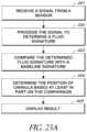
- a computer-implemented method for determining a position of a cannula relative to an anatomy of a patientcan comprise receiving a signal from a sensor disposed near a proximal port of the cannula.
- the methodcan also include processing the signal to determine a fluid signature related to a property of the fluid flowing through the proximal port.
- the methodcan comprise comparing the determined fluid signature with a baseline signature, the baseline signature associated with a proper position of the cannula during a treatment procedure.
- the methodcan include determining the position of the cannula based at least in part on the comparison of the determined fluid signature with the baseline signature.
- a non-transitory computer-readable medium having instructions stored thereoncomprising receiving a signal from a sensor disposed near a proximal port of the cannula.
- the methodcan include processing the signal to determine a fluid signature related to a property of the fluid flowing through the proximal port.
- the methodcan also comprise comparing the determined fluid signature with a baseline signature, the baseline signature associated with a proper position of the cannula during a treatment procedure.
- the methodcan include determining the position of the cannula based at least in part on the comparison of the determined fluid signature with the baseline signature.
- a method of manufacturing a catheter assemblycan include coupling a sensor assembly to a cannula disposed about an impeller, the cannula coupled to a distal portion of the catheter assembly.
- the sensor assemblycan be configured to measure a property of blood flowing through the cannula.
- a method of pumping blood through a patientcan include advancing an impeller assembly through a vascular system of the patient to a left ventricle of the patient.
- the impeller assemblycan comprise an impeller and a sensor near one or more inlets of the impeller assembly.
- the sensorcan be configured to measure a pressure of blood flowing through the inlet(s).
- the methodcan include activating the impeller to pump blood through an aorta of the patient at a flow rate of at least about 2 liters per minute (Lpm).
- the methodcan further comprise maintaining an average pressure of less than about 15 mmHg in the left ventricle of the patient.
- a catheter pumpin another embodiment, can include an impeller assembly comprising an impeller and a sensor near one or more inlets of the impeller assembly.
- the sensorcan be configured to measure a pressure of blood flowing through the inlet(s).
- the impeller assemblyan be configured such that the inlet(s) are positioned in a left ventricle of the patient during a treatment procedure.
- the impeller assemblycan be configured to pump blood through an aorta of the patient at a flow rate of at least about 2 liters per minute (Lpm) and to maintain a pressure of less than about 15 mmHg in the left ventricle of the patient.
- Lpmliters per minute
- a method of pumping blood through a patientcan include advancing an impeller assembly through a vascular system of the patient to a left ventricle of the patient, the impeller assembly comprising an impeller and a sensor near one or more inlets of the impeller assembly, the sensor configured to measure a pressure of blood flowing through the inlet(s).
- the methodcan include activating the impeller to pump blood through an aorta of the patient at a flow rate of at least about 2 liters per minute (Lpm).
- the methodcan include maintaining an average pressure in the left ventricle of the patient of less than about 135% of the normal human average ventricular pressure.
- a catheter pump assemblyin one embodiment, includes an elongate polymeric catheter body, a cannula, and a tubular interface.
- the elongate polymeric catheter bodyhas a proximal end and a distal end.
- the cannulahas an expandable portion disposed distally of the elongate polymeric catheter body.
- the cannulacan also have another tubular portion that is proximal to the distal portion.
- the tubular interfacehas an outer surface configured to be joined to the tubular portion of the cannula and an inner surface.
- the inner surfaceis disposed over the distal end of the elongate polymeric catheter body.
- the tubular interfacehas a plurality of transverse channels extending outward from the inner surface of the tubular interface. An outer surface of the elongate polymeric catheter body projects into the transverse channels to mechanically integrate the elongate polymeric catheter body with the tubular interface.
- a catheter pump assemblyin another embodiment, includes an elongate polymeric catheter body, a tubular member, and a mechanical interface.
- the elongate polymeric catheter bodyhas a proximal end and a distal end. At least a portion of the tubular member is disposed distally of the elongate polymeric catheter body.
- the mechanical interfaceis disposed between a portion of the elongate polymeric catheter body and the tubular member. The mechanical interface is configured to mechanically integrate with a surface of the elongate polymeric catheter body.
- a catheter pump assemblyin another embodiment, includes an elongate catheter body, a metallic tubular member, and first and second mechanical interfaces.
- the elongate catheter bodyhas a proximal portion and a distal portion.
- the metallic tubular memberis disposed at least partially distally of the elongate catheter body.
- the first mechanical interfacehas a first portion joined to the distal portion of the elongate catheter body and a second portion welded to the metallic tubular member.
- the second mechanical interfaceis disposed on an outside surface of the catheter pump assembly.
- the second mechanical interfacehas a deflectable member configured to be disposed adjacent to the outside surface of the catheter pump assembly in a first configuration.
- the deflectable memberis configured to be disposed inward of the outside surface of the catheter pump assembly in a second configuration. When in the second configuration, the deflectable member mechanically and securely engages the outside surface of the catheter pump assembly with a structure disposed inward of the second mechanical interface.
- a methodfor coupling components of a catheter pump assembly together.
- An elongate polymeric tubular bodyis provided that has a proximal end and a distal end.
- a metallic tubular bodyis provided that has a proximal portion and a distal portion.
- a mechanical interfacehaving a first interface zone and a second interface zone is positioned such that the first interface zone is disposed over a portion of the elongate polymeric tubular body adjacent to the distal end thereof.
- the polymeris then caused to flow into the first interface zone, whereby the elongate polymeric tubular body becomes joined with the first interface zone of the mechanical interface.
- the metallic tubular bodyis coupled with the second interface zone of the mechanical interface.
- the polymeris caused to flow by heating the elongate polymeric tubular body to cause at least a portion of elongate polymeric tubular body adjacent to the distal end thereof to transition to a state with low resistance to deformation.
- a catheter pump assemblyin another embodiment, includes a proximal portion, a distal portion, and a catheter body having a lumen extending therebetween along a longitudinal axis.
- the catheter pump assemblyalso includes a torque assembly that has a first portion disposed in the lumen of the catheter body and a second portion disposed distal of the first portion. The second portion coupled with an impeller.
- the torque assemblycauses the impeller to rotate upon rotation of the first portion of the torque assembly.
- the catheter pump assemblyalso includes a thrust bearing and a thrust bearing brace.
- the thrust bearingis disposed within the catheter pump assembly adjacent to the distal end of the catheter body.
- the thrust bearingresists movement of the torque assembly along the longitudinal axis.
- the thrust bearing braceis disposed on the outside surface of the torque assembly.
- the thrust bearing bracehas a distal face that is directly adjacent to a proximal face of the thrust bearing.
- a catheter assemblyin another embodiment, includes an elongate flexible body, a torque assembly, a bearing assembly, and a sleeve.
- the elongate flexible bodyis disposed along a proximal portion of the catheter assembly and has a proximal infusate channel formed therein.
- the torque assemblyextends through the elongate flexible body.
- the bearing assemblycomprises a housing having an outer surface and a bearing surface disposed within the housing. The bearing surface provides for rotation of the torque assembly within the bearing housing.
- the sleevecomprises and an inner surface configured to be disposed over the outer surface of the housing of the bearing assembly and a fluid communication structure that extends through the walls of the sleeve.
- the catheter assemblyalso includes a distal infusate channel in fluid communication with the proximal infusate channel, the distal infusate channel disposed over the outer surface of the bearing housing and through side walls of the slot.
- a catheter pump assemblyin another embodiment, includes a proximal portion, a distal portion, and a catheter body having a lumen extending along a longitudinal axis between the proximal and distal portions.
- the catheter pump assemblyalso includes an impeller disposed at the distal portion and a stator disposed distal of the impeller to straighten flow downstream from the impeller.
- the statoris collapsible from a deployed configuration to a collapsed configuration.
- a catheter systemin another embodiment, includes an elongate polymeric catheter body, a cannula, and at least one expandable component disposed within the cannula.
- the elongate polymeric catheter bodyhas a proximal end and a distal end.
- the cannulahas an expandable portion disposed distally of the elongate polymeric catheter body.
- the catheter systemalso includes an elongate sheath body that has a retracted position in which the elongate sheath body is proximal of the expandable portion of the cannula and the at least one expandable component and a forward position in which the elongate sheath body is disposed over the expandable portion of the cannula and the at least one expandable component.
- a first segment of the elongate sheath body disposed over the expandable portion of the cannula and the at least one expandable componentis configured to resist kinking to a greater extent than a second segment of the elongate sheath body disposed adjacent to the first segment.
- FIG. 1illustrates one embodiment of a catheter pump configured for percutaneous application and operation
- FIG. 2is a plan view of one embodiment of a catheter adapted to be used with the catheter pump of FIG. 1 ;
- FIG. 3show a distal portion of the catheter system similar to that of FIG. 2 in position within the anatomy
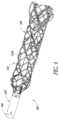
- FIG. 4is a perspective view of a distal portion of a catheter assembly according to one embodiment
- FIG. 5is a perspective partial assembly detail view of a portion of the catheter assembly of FIG. 4 .
- FIG. 6is a cross-sectional view of a portion of a connection zone of the catheter assembly of FIG. 4 .
- FIG. 6 Ais a schematic view of embodiments of an outer sheath configured to enhanced delivery and retrieval performance.
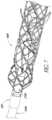
- FIG. 7is a perspective view of a distal portion of a catheter assembly according to another embodiment.
- FIG. 8is a perspective partial assembly detail view of a portion of the catheter assembly of FIG. 7 ;
- FIG. 9is a detail view of a mechanical interface of a catheter assembly
- FIG. 10is a cross-sectional view of a portion of a connection zone of the catheter assembly of FIG. 9 ;
- FIGS. 11 - 14illustrate features of additional embodiments of catheter assemblies having robust mechanical interface
- FIGS. 15 - 17illustrate features of additional embodiments of catheter assemblies having robust mechanical interface.
- FIG. 18 Ais a schematic system diagram of a catheter pump system, according to some embodiments.
- FIG. 18 Bis a schematic side view of a catheter assembly having a proximal sensor assembly and a distal sensor assembly, according to one embodiment.
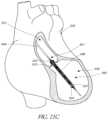
- FIG. 19is a schematic side, sectional view of the impeller assembly positioned at a proper location during a left ventricular assist procedure.
- FIG. 20illustrates theoretical plots of pressure over time for pressures detected by the proximal sensor assembly and the distal sensor assembly when the impeller assembly is disposed at a proper treatment location.
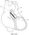
- FIGS. 21 A- 21 Care schematic side, sectional views of the impeller assembly as the clinician advances the impeller assembly through the patient.
- FIG. 21 Dis a theoretical plot of pressure over time measured by the distal sensor assembly at the positions illustrated in FIGS. 21 A- 21 B .
- FIG. 22 Ais a schematic side cross-sectional view of a heart having a region of myocardial infarction.
- FIG. 22 Bis a schematic front cross-sectional view of the heart shown in FIG. 22 A .
- FIGS. 22 C- 22 Eare theoretical, exemplary plots of pressure over time in the left ventricle of the heart of FIGS. 22 A- 22 B , in accordance with various embodiments.
- FIG. 23 Ais a flowchart illustrating a computer-implemented method for determining a position of a cannula relative to an anatomy of a patient.
- FIG. 23 Bis a schematic system diagram of a processor configured to process signals received from one or more sensor assemblies.
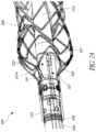
- FIG. 24is a schematic perspective view of a catheter assembly having a proximal sensor assembly disposed near an outlet of a cannula, according to some embodiments.
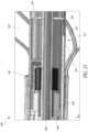
- FIG. 25is a side cross-sectional view of the catheter assembly of FIG. 24 .
- FIG. 26is a front end, cross-sectional view of the elongate catheter body shown in FIG. 24 .
- FIG. 27is a schematic perspective view of the bearing housing shown in FIG. 25 .
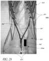
- FIG. 28is an image of a cannula having a distal sensor assembly at the first distal sensor location shown in FIG. 18 B , according to one embodiment.
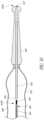
- FIG. 29is an image of a cannula having a distal sensor assembly at the first distal sensor location shown in FIG. 18 B , according to another embodiment.
- FIG. 30is a schematic side cross-sectional view of a cannula having a distal sensor assembly at the second distal sensor location shown in FIG. 18 B , according to one embodiment.
- a high performance catheter pumpis desired to provide sufficient output to approach and in some cases exceed natural heart output. Performance of this nature can be achieved with inventive components disclosed herein.
- FIGS. 1 - 3show aspects of a catheter pump 10 that can provide high performance including flow rates similar to full cardiac output.
- the pump 10includes a motor driven by a controller 22 .
- the controller 22directs the operation of the motor 14 and an infusion system 26 that supplies a flow of infusate in the pump 10 .
- a catheter system 80 that can be coupled with the motor 14houses an impeller within a distal portion thereof.
- the impelleris rotated remotely by the motor 14 when the pump 10 is operating.
- the motor 14can be is disposed outside the patient.
- the motor 14is separate from the controller 22 , e.g., to be placed closer to the patient.
- the motor 14is part of the controller 22 .
- the motoris miniaturized to be insertable into the patient.
- Such embodimentsallow the drive shaft to be much shorter, e.g., shorter than the distance from the aortic valve to the aortic arch (about 5 mm or less).
- FIG. 3illustrates one use of the catheter pump 10 .
- a distal portion of the pump 10is placed in the left ventricle LV of the heart to pump blood from the LV into the aorta.
- the pump 10can be used in this way to treat patients with a wide range of conditions, including cardiogenic shock, myocardial infarction, and acutely decompensated heart failure, and also to support a patient during a procedure such as percutaneous coronary intervention.
- One convenient manner of placement of the distal portion of the pump 10 in the heartis by percutaneous access and delivery using the Seldinger technique or other methods familiar to cardiologists. These approaches enable the pump 10 to be used in emergency medicine, a catheter lab and in other non-surgical settings.
- FIG. 2shows features that facilitate small blood vessel percutaneous delivery and high performance up to and in some cases exceeding normal cardiac output in all phases of the cardiac cycle.
- the catheter system 80includes a catheter body 84 and a sheath assembly 88 .
- An impeller assembly 92is coupled with the distal end of the catheter body 84 .
- the impeller assembly 92is expandable and collapsible. In the collapsed state, the distal end of the catheter system 80 can be advanced to the heart. In the expanded state the impeller assembly 92 is able to pump blood at high flow rates.
- FIGS. 2 and 3illustrate the expanded state.
- the collapsed statecan be provided by advancing a distal end 94 of an elongate body 96 distally over the impeller assembly 92 to cause the impeller assembly 92 to collapse.
- Thisprovides an outer profile throughout the catheter assembly 80 that is of small diameter, for example 12.5 French as discussed further below.
- itmay be important to measure various properties and/or characteristics during a treatment procedure, such as flow rate and pressure. It may also be important to use this data to determine a position of the impeller assembly 92 relative to the anatomy.
- One or more sensorse.g., pressure sensors
- the impeller assembly 92includes a self-expanding material that facilitates expansion.
- the catheter body 84on the other hand preferably is a polymeric body that has high flexibility. When the impeller assembly 92 is collapsed, as discussed above, high forces are applied to the impeller assembly 92 . These forces are concentrated at a connection zone, where the impeller assembly 92 and the catheter body 84 are coupled together. These high forces, if not carefully managed can result in damage to the catheter assembly 80 and in some cases render the impeller within the impeller assembly 92 inoperable. A reliable mechanical interface is provided to assure high performance.
- the impelleris disposed proximal of an expandable cannula in a rigid segment (e.g., a pump ring) and an expandable cannula is provided.
- a rigid segmente.g., a pump ring
- an expandable cannulais provided.
- the mechanical interfaces and inner and outer sheath assembliesfacilitate the collapse of the cannula in such embodiments.
- a further designpermits the impeller to be withdrawn into a rigid structure, e.g., a pump ring, to collapse the impeller before the cannula is collapsed.
- the mechanical components rotatably supporting the impeller within the impeller assembly 92permit high rotational speeds while controlling heat and particle generation that can come with high speeds.
- the impellermay be rotated as speeds above 6000 RPM, above 9000 RPM, above 10,000 RPM, above 15,000 RPM, above 20,000 RPM, above 25,000 RPM, or above 30,000 RPM.
- the infusion system 26delivers a cooling and lubricating solution to the distal portion of the catheter system 100 for these purposes.
- the space for delivery of this fluidis extremely limited. Some of the space is also used for return of the infusate. Providing secure connection and reliable routing of infusate into and out of the catheter assembly 80 is critical and challenging in view of the small profile of the catheter body 84 .
- FIGS. 4 - 6show a first embodiment of a working end of a catheter assembly 100 forming a part of one embodiment of the catheter pump 10 .
- the catheter assembly 100is similar to the catheter system 84 except as discussed differently below.
- the catheter assembly 100includes an elongate catheter body 104 .
- a proximal end of the catheter body 104can be coupled with a motor housing.
- a distal portion of the catheter body 104is coupled to a cannula 108 configured to house a high flow rate impeller 112 .
- the exemplary catheter pumpcan be configured to produce an average flow rate of 4 liters/minute or more at physiologic conditions, e.g., at the typical systolic pressure of a patient needing treatment, such as 60 mmHg.
- the pumpcan be configured to produce a maximum flow rate (e.g. low mm Hg) of greater than 4 Lpm, greater than 4.5 Lpm, greater than 5 Lpm, greater than 5.5 Lpm, greater than 6 Lpm, greater than 6.5 Lpm, greater than 7 Lpm, greater than 7.5 Lpm, greater than 8 Lpm, greater than 9 Lpm, or greater than 10 Lpm.
- the pumpcan be configured to produce an average flow rate at 60 mmHg of greater than 2 Lpm, greater than 2.5 Lpm, greater than 3 Lpm, greater than 3.5 Lpm, greater than 4 Lpm, greater than 4.25 Lpm, greater than 4.5 Lpm, greater than 5 Lpm, greater than 5.5 Lpm, or greater than 6 Lpm.
- both the cannula 108 and the impeller 112are actuatable from a first configuration for delivery through a patient to a working site to a second configuration for generating high flow at the working site.
- the first configurationmay be a low profile configuration and the second configuration may be an expanded configuration.
- the low profile configurationpreferably enables access via a femoral artery or other peripheral blood vessel without excessive obstruction of blood flow in the vessel, as discussed further below.
- the catheter body 104preferably has a plurality of lumens, including a first lumen 140 adapted for housing a drive shaft 144 , a second lumen 140 B for conveying a medical fluid distally within the catheter body 104 , and a third lumen 140 C for anchoring a bearing housing 146 to the catheter body 104 .
- the drive shaft 144extends proximally within the catheter body 104 from the impeller 112 .
- the drive shaft 144couples with the motor at the proximal end and with the impeller 112 at the distal end thereof.
- the drive shaft 144can be formed with any suitable structure, but should be sufficient flexible to traverse at least from a peripheral (e.g., femoral) artery to a heart chamber, such as the left ventricle, as well as sufficiently durable to rotate at a high speed for several hours, for several days, and in some cases, months.
- the drive shaft 144can be coupled with an impeller assembly 112 including an expandable impeller 112 A) disposed on a tubular body 112 B FIGS. 4 and 6 shows these structures.
- the impeller 112 Apreferably includes an elastomeric polymer structure that can be formed as a unitary body.
- the tubular body 112 Bcan be a metal hypotube.
- the tubular body 112 Bcan be received in a distal portion of the drive shaft 144 .
- the catheter body 104has an inner layer 148 surrounding the lumen 140 that comprises high density polyethylene (HDPE).
- HDPEhigh density polyethylene
- Marlex 4903 HDPEcan be disposed about the lumen 140 .
- the inner layer 148has a thickness that is sufficient to withstand wear caused by interaction with the drive shaft 144 , which can be rotated at a very high speed in some applications, for example from 20,000-40,000 revolutions per minute.
- the inner layercan have a thickness of 0.003 inches.
- the second lumen 140 Bextends from a proximal end in fluid communication with a source of infusate, which can be a medical fluid (e.g., saline), to a distal end adjacent to the impeller assembly 112 .
- a source of infusatewhich can be a medical fluid (e.g., saline)
- the second lumen 140 Bcan have an outlet disposed adjacent to a flow channel formed in or about the bearing housing 146 . Examples of bearing housing flow channels are shown in FIGS. 5 , 10 , and in application Ser. No. 13/343,618, which is hereby incorporated by reference.
- the second lumen 140 Bis generally circumferentially elongated, for example having two sides that are curved with an arc length of about 0.030 inches and two sides that are straight, disposed along a radial direction of the catheter body 104 and about 0.010 inches in length.
- a proximal end of the second lumen 140 Bis coupled with a port, which may be similar to the luer 145 in FIG. 2 , or other fluid connection device. Any suitable connection between a port and lumen can be used, e.g., a skived connection can be used.
- the third lumen 140 Ccan be used to enhance the security of the connection between the catheter body 104 , 104 A and the bearing housing 146 .
- the third lumen 140 Ccan be sized to receive a plurality of, e.g., two, pull wires 160 .
- the pull wires 160can take any suitable form, but preferably are sized to be easily received within the lumen 140 C.
- the lumen 140 Cis spaced apart from but about the same size as the second lumen 140 B and the pull wires are generally rectangular in shape, e.g., having a thickness of about 0.005 inches and a width of about 0.010 inches.
- the pull wires 160can be formed of any material that is sufficiently rigid in tension, e.g., of stainless steel with pull strength of at least about 300 ksi. In one arrangement, the pull wires 160 extend at least about three inches into the elongate body 104 in the third lumen 140 C and extend out of the third lumen 140 C to overlay the bearing housing 146 as shown in FIG. 5 .
- FIG. 6shows one approach to compactly arranging the pull wires 160 and structure coupled together thereby.
- a proximal portion 160 A of the wiresis received within a distal length of the third lumen 140 C and a distal portion 160 C of the wires is disposed distal of the catheter body 104 .
- a transition 160 Bis provided between the zones 160 A, 160 C causing the proximal portion 160 A to be disposed closer to the longitudinal axis of the impeller catheter assembly 100 than is the distal portion 160 C.
- Providing a plurality of pull wiresprovides redundancy in the connection between the catheter body 104 , 104 A and the bearing housing 146 . In some cases, this redundancy is not needed and a single wire can be used. The redundancy is beneficial, however, because substantial tension force is applied at this connection point when the expandable cannula 108 is collapsed.
- relative motionis provided between the catheter body 104 , 104 A and an outer sheath disposed over the catheter body until the outer sheath slides over a proximal portion of the cannula 108 . Further relative motion causes the cannula 108 to be compressed, but not without a substantial force being applied thereto. This force is born at several points, including at the junction between the catheter body 104 , 104 A and the bearing housing 146 . Disconnection of the bearing housing 146 would be problematic, requiring complex procedures to extract the disconnected distal working end of the catheter assembly 100 .
- the pull wires 160preferably are located close together on the same side of the catheter body 104 , 104 A. This arrangement enhances bending flexibility, which is beneficial if tortuous vasculature must be traversed to deliver the catheter assembly 100 to a treatment site, e.g., a heart chamber.
- FIGS. 12 - 14illustrate other techniques for enhancing the security of the connection of the bearing housing 146 to a catheter body.
- placing a radiopaque marker on a distal portion of the catheter assembly 100is advantageous to confirm the location of the working end, e.g., of the cannula 108 and/or impeller 112 prior to and/or after deployment.
- Gross mechanical properties of the catheter body 104can be varied along the length thereof to provide appropriate flexibility and maneuverability within the vasculature to facilitate delivery and operation of the catheter pump into which the catheter assembly 100 is incorporated.
- the catheter body 104is stiffest near the distal end where the catheter body 104 is joined to the working end.
- a distal section of the catheter body 104comprises a material, such as Pebax, having a hardness of about 72D.
- a proximal section of the catheter body 104comprises a material, such as Vestamid having a hardness greater than about 72D.
- a middle section of the catheter bodycomprises a material having a lower hardness, e.g., MX1205 Pedbax.
- the low hardness sectionprovides a softer structure in the vicinity of the aortic arch, where the catheter will be consistently resting on the vessel wall.
- One or more intermediate hardness sectionscan be provided between the distal, proximal and middle sections.
- the catheter body 104can have different diameters along its length to provide several important performance benefits.
- the diameter of a proximal portion of the catheter body 104can be relatively large to enhance pushability and trackability of the catheter assembly 100 .
- the diameter of a distal portion of the catheter body 104can be relatively small to enhance flexibility of the distal tip and also to match the profile of the bearing housing 146 such that the lumens 140 B align with flow channels at least partly defined by the bearing housing (e.g., the slots 220 discussed below).
- the enlarged diameter and enhanced hardness at the proximal endboth contribute to the maneuverability of the catheter assembly 100 .
- a separate stiffening componentsuch as a braid 188
- a braid 188can be disposed in the catheter body 104 , 104 A.
- a 0.001 inch by 0.003 inch flat wire of 304V stainless steelis embedded in the catheter body 104 , 104 A and the braid includes a 70 ppi configuration.
- the braid 188can be positioned in any suitable location, e.g., between an inner layer 148 and an outer layer, as shown in FIG. 9 of the drawings.
- the catheter assembly 100preferably also includes an outer sheath or sheath assembly 88 provided over the elongate body 104 , 104 A to aid in delivering, deploying and/or removing the impeller 112 .
- the outer sheath 88can include an elongate body 96 comprising an inner surface surrounding a lumen disposed therein.
- the inner lumencan comprise a low friction material or layer.
- a thickness of PTFEcan be provided adjacent the inner lumen.
- one or more separate materialscan be provided at an outer surface of the elongate body 96 .
- the elongate body 96preferably is connected at the proximal end with a proximal hub and/or a suitable connector, such as a Tuohy Borst connector.
- a proximal hubcan include a luer fitting.
- the outer sheath 88also may have varied hardness or other gross mechanical properties along its length to provide appropriate flexibility and maneuverability within the vasculature to facilitate delivery and operation of the catheter pump into which the outer sheath is incorporated, and also to facilitate collapse of the cannula 108 after deployment thereof.
- FIG. 6 Aillustrates schematically bulk property variation in two embodiments of the sheath assembly 88 .
- an elongate body extending between the proximal and distal ends of the sheath assembly 88has different hardness at different locations along the length.
- the different hardnessesenhance the maneuverability of the sheath assemblies 88 A, 88 B to minimize kinking of the elongate body as the catheter assembly 100 is tracking toward the heart and/or when the elongate body is used to collapse an expandable cannula or impeller, as discussed elsewhere herein.
- the elongate body of the sheath assembly 88 Ahas a proximal portion “A” with a highest hardness.
- the proximal portion Acan comprise vestamid or other similar material.
- a portion “B” distal of the proximal portion A and residing over a zone of the cannula in which the impeller I and the distal bearing support S (if present) are housedcan have a hardness that is lower than that of the portion A.
- Portion Bcan comprise 55D pebax.
- a portion “C” disposed distal of the portion Bcan comprise a material with the lowest hardness of the elongate body of the sheath assembly 88 A, e.g., can comprise MX1205.
- a portion “D” at the distal end of the elongate body of the sheath assembly 88 Acan have a relatively high hardness, e.g., 72D pebax.
- the sheath assembly 88 A upon distal movement over the expanded cannulainitially contacts the cannula with the relatively hard material of portion D.
- the relatively soft portion Cmay contact the vasculature as the catheter assembly 100 is advanced, and its relatively soft structure is biocompatible.
- Portion Bhas a hardness that is high enough to protect the zones I and S of the cannula, impeller, and support.
- Portion Ais the hardest of the materials used in the sheath assembly 88 A, to aid in maneuverability.
- the elongate body of the sheath assembly 88 Bhas a proximal portion and distal bearing zone portion “A” with a highest hardness.
- the proximal portion Acan comprise vestamid or other similar material.
- the portion Bresides adjacent to the transition from the catheter body 104 to the cannula proximal portion 116 and can have a hardness that is lower than that of the portion A.
- Portion Bcan comprise 55D pebax.
- Portions C and D in the sheath assembly 88 Bare the same as in the sheath assembly 88 A.
- a portion Eis disposed between the portions A and C, e.g., distal of the portion A disposed over the distal bearing support.
- Portion Ecan include a series of progressively softer lengths, e.g., a first length of 72D pebax, a second length of 63D pebax, and a third length of 55D pebax.
- Other materials and hardnessescan be used that provide good resistance to kinking in the delivery of the catheter assembly 100 and/or in the process of re-sheathing the expanded cannula and impeller.
- FIGS. 7 - 10incorporate the discussion above and illustrate additional features and embodiments.
- FIGS. 7 and 9illustrate aspects of a mechanical interface between a bearing housing 146 A and the catheter body 104 A.
- a coupler 200is provided between the bearing housing 146 A and the catheter body 104 A.
- the coupler 200(also shown in FIG. 6 ) is similar to the coupler 628 disclosed in U.S. application Ser. No. 13/343,618, which is hereby incorporated by reference herein.
- a thrust bearing 204is provided in the bearing housing 146 A.
- a thrust bearing brace 208is disposed just proximal of the thrust bearing 204 .
- the thrust bearing brace 208can take any suitable form, but preferably provides a shoulder or other radial protrusion from the outer surface to the impeller shaft 112 B that abuts a proximal face of the thrust bearing 204 .
- the thrust bearing brace 208minimizes or completely prevents movement of the thrust bearing 204 on the impeller shaft 112 B. Such movement is possible because the impeller on the impeller shaft 112 B generates significant distally oriented thrust.
- the thrust bearing 204is interference fit onto the impeller shaft 112 B. When sized and fit properly, this connection maintains the relative position of thrust bearing 204 to the impeller shaft 112 B under the thrust forces that are applied.
- the thrust bearing brace 208provides redundancy of this connection.
- the thrust bearing brace 208comprises a short hypotube that is coupled with, e.g., laser welded to the impeller shaft 112 B.
- the weldcompletely prevents relative axial movement between the impeller shaft 112 B and the thrust bearing brace 208 .
- the abutment between the trust bearing 204 and the thrust bearing brace 208prevent relative movement between the thrust bearing 204 and impeller shaft 112 B if the coupling between the impeller shaft 112 B and the thrust bearing 204 loosens.
- FIG. 8shows that an outer surface of the bearing housing 146 A can be covered by a cylindrical sleeve 216 .
- the sleevehas at least one slot 220 formed therein.
- the slot 220can be circumferentially aligned to or otherwise in fluid communication with the second lumen 140 B such that infusate fluid flowing distally in the lumen enters the slot and can be directed distally in a space formed between the bearing housing 146 A, the sleeve 216 and an outer sleeve, that may be a proximal portion 222 of the frame-like structure of the cannula 108 .
- This structureis shown in FIGS. 4 and 5 .
- FIG. 4 and 5In FIG.
- the cannula 108is displaced proximally to reveal the sleeve 216 , which would be covered by a proximal cylindrical portion 222 of the cannula 108 when the catheter assembly 100 is assembled.
- a difference between the impeller assembly/catheter body interface of the embodiment of FIGS. 4 - 6 and the embodiment of FIGS. 7 - 11is that the sleeve 216 A includes recess 220 A in fluid communication with the lumen 140 B.
- the recesses 220 Aare fluid flow structures. Other ports into the inside of the bearing housing 146 A can be accessed through apertures 224 that do not extend to the proximal end of the sleeve 216 .
- the aperturesare fluid communication structures through which fluid can flow into the bearing housing. Flow from the lumen 104 B to the apertures 224 can be provided through a circumferential space defined between the outer surface of the sleeve 216 and an inner surface of the proximal portion 222 of the cannula 108 . See FIG. 10 . In some cases, the apertures 224 are additionally or alternately adapted to receive components of secondary mechanical interface discussed below. In other embodiments, troughs are formed in an outer surface of the bearing housing are enclosed by the inner surface of the sleeve 216 to form enclosed flow channels for infusate.
- Catheter pumps incorporating the catheter assembly and variation thereofcan be configured to deliver average flow rates of over 4 liters/minute for a treatment period.
- a treatment periodcan be up to 10 days for acute needs, such as patient in cardiogenic shock.
- Catheter pumps incorporating the catheter assembly 100 or such modifications thereofcan be used for shorter periods as well, e.g., for support during high risk catheter or surgical procedures.
- catheter pumps incorporating the catheter assembly 100 or modifications thereofcan be used for left or right side heart support.
- Example modifications that could be used for right side supportinclude providing delivery features and/or shaping a distal portion that is to be placed through at least one heart valve from the venous side, such as is discussed in U.S. Pat. Nos. 6,544,216; 7,070,555; and US 2012-0203056A1, all of which are hereby incorporated by reference herein in their entirety for all purposes.
- the catheter assembly 100 or modifications thereofcan be configured to be collapsed to be deliverable through a 13 French introducer sheath and can be expanded to up to 24 French when deployed.
- the outer profile of the catheter assembly 100 or modifications thereofis approximately 12 French, but can be any size that is insertable into a femoral artery without requiring surgical cutdown.
- the catheter assembly 100can be as large as 12.5 F to be inserted through a 13 French introducer sheath.
- One methodinvolves deployment of the cannula 108 , having an expandable nitinol structure, across the aortic valve. In this position, the impeller 112 can be disposed on the aorta side of the valve and a distal length of the cannula 108 within the ventricle.
- the outer profile of the catheter assembly 100 or modifications thereofis less than 12 French, e.g., about 10 French.
- the 10 French configurationcan be useful for patients with lower flow needs, e.g., about 3 liters per minute or less at physiologic conditions.
- an 8 French configurationcan be useful for patients with lower flow needs, e.g., about 2 liters per minute or less at physiologic conditions.
- FIGS. 11 - 14illustrate additional embodiments in which the structural integrity of a catheter assembly 300 is enhanced to provide security in connection with sheathing an expandable portion.
- FIG. 11shows that a distal portion of the catheter assembly 300 includes components similar to those hereinbefore described.
- the catheter assembly 300includes a catheter body 304 , an expandable cannula 308 and an expandable impeller 312 .
- the catheter bodycan take any suitable form.
- the catheter body 304has variable hardness along its length.
- the cannula 308includes a self-expanding structure enclosed in a polymeric film.
- the self-expanding structurecan be a distal portion of a member having a non-expanding tubular portion 316 proximal of the self-expanding structure.
- the tubular portion 316plays a role in anchoring the cannula 308 to the catheter body 304 .
- FIG. 11shows that a support member 328 can be positioned within the cannula 308 to prevent unacceptable variance in the gap between the tip of the impeller 312 and the inside surface of the cannula. More details of this structure are set forth in concurrently filed application Ser. No. 13/802,556, entitled “DISTAL BEARING SUPPORT,” filed on Mar. 13, 2013, which is incorporated hereby by reference herein for all purposes. Successful collapse of the cannula 308 , the impeller 312 , and the support 328 focuses forces on a joint between the cannula 308 and the catheter body 304 .
- FIGS. 11 - 14illustrate features that enhance the security of the connection catheter body 304 and the cannula 308 .
- FIG. 11no separate structure is shown between the catheter body 304 and the non-expanding tubular portion 316 . These structures are joined in other manners, such as indirectly by the force transfer capability of the pull wires discussed above and/or by an adhesive.
- FIG. 12the distal end of the catheter body 304 is coupled with a ferrule 336 .
- the ferrule 336is an example of a structure to mechanically join the catheter body 304 to the cannula 308 .
- the ferrule 336includes a distal zone 340 for mechanically joining the ferrule 336 to the catheter body 304 .
- the distal zone 340is also configured to mechanically couple with the cannula 308 , for example by welding.
- a plurality of apertures 344is provided in one embodiment for mechanically joining the ferrule 336 to the catheter body 304 .
- the apertures 344enable the material of the catheter body 304 to extend into the distal zone 340 .
- the ferrule 336is disposed over the catheter body 304 which extends into the apertures 344 .
- the apertures 344can be arranged in multiple zones.
- a first zoneis disposed distally of the second zone.
- the first zonecan be disposed adjacent to the distal end of the ferrule 336 and the second zone is disposed proximal of the first zone.
- the first zonecan include four apertures 344 A spaced evenly about the periphery of the body of the ferrule.
- the second zonecan include a plurality of (e.g., four) apertures 344 B spaced evenly about the periphery of the body of the ferrule 336 .
- a specific advantageous embodimentprovides four apertures 344 B in the second zone.
- the apertures 344 B of the second zonecan be spaced evenly about the body of the ferrule 336 .
- the apertures 344 of the first and second zonesare offset to provide a great deal of redundancy in the security of the connection of the catheter body 304 to the ferrule 336 .
- the apertures 344 in the first and second zonescan be offset by one-half the circumferential distance between adjacent apertures 344 .
- the ferrule 336also includes a proximal zone 348 disposed proximally of the aperture 344 .
- the proximal zone 348preferably is configured to provide an excellent fluid seal between the ferrule and the non-expandable tubular portion 316 of the cannula 308 .
- the proximal zone 348includes a plurality of recesses 352 in the outer surface of the proximal portion 348 .
- the recesses 352can take any form consistent with good sealing, and in one embodiment the recesses are turns of a continuous helical groove in the outer surface of the ferrule 336 .
- the helical grooveis configured to receive a sealant that can bridge from the base of the grooves to the inner surface of the proximal portion 316 of the cannula 308 .
- the sealantincludes an adhesive that can flow into the helical groove and be adhered to the inner surface of the proximal portion 316 of the cannula 308 .
- FIG. 11illustrates one embodiment in which a mechanical securement device 360 is provided.
- the mechanical securement device 360includes a cantilevered member that can be deformed from the non-expandable proximal portion 316 of the cannula 308 into corresponding recesses disposed inward of the securement device.
- a recess 364is provided within the catheter assembly 300 to receive the securement device 360 .
- the recesses 364can be formed in an internal structure disposed within the proximal portion 316 .
- a sleeve 368is provided immediately within the non-expandable proximal portion 316 of the cannula 308 .
- the sleeve 368is provided and fills the volume between a bearing housing 372 and the proximal portion 316 .
- the bearing housing 372facilitates rotation of the impeller shaft and the flow of infusate.
- the sleeve 368has slots and/or other fluid communication structures formed therein that direct flow from channels in the catheter body 308 to flow channels in the bearing housing 372 .
- the sleeve 368has a plurality of small apertures that are disposed between flow slots.
- the apertures and slotscan be similar is shape and form to the apertures 224 and slots 220 discussed above.
- aperturescan be formed in the bearing housing 372 .
- the bearing housing 372can have a plurality of channels aligned with flow passages in the catheter body 304 .
- apertures for receiving the securement device 360can be provided directly in the bearing housing 372 .
- aperturesare provided that extend through the sleeve 368 and into the bearing housing 372 .
- Modifications of catheter pumps incorporating the catheter assembly 300can be used for right side support.
- the elongate body 304can be formed to have a deployed shape corresponding to the shape of the vasculature traversed between a peripheral vascular access point and the right ventricle.
- any suitable manufacturing methodcan be used to cause a portion of the catheter body 304 to be disposed in the apertures 344 .
- the catheter body 304 and the cannula 308are to be joined.
- the cannula 308has the tubular portion 316 which is to be disposed over the catheter body 304 .
- the ferrule 336is a metallic body that is an important part of one form of a mechanical interface.
- the ferrule 336has an inner surface and apertures 344 that act as a first interface zone and an outer surface that acts as a second interface zone.
- the ferrule 336is positioned such that the inner surface is disposed over the outer surface of short length of the catheter body 304 adjacent to the distal end thereof.
- the outer surface of the catheter body 304is mechanically coupled to the ferrule 336 by a process that involves heating.
- the distal portion of the catheter body 304 and the ferrule 336are heated sufficiently to cause at least a portion of the catheter body to transition to a state with low resistance to deformation.
- the low resistance statecan be a fluid state or just a state in which the material of the catheter body 304 if more malleable.
- the catheter body 304flows through or protrudes into the apertures 344 . Because the material is formed continuously from a location inside the inner surface of the ferrule to outside the inner surface, a strong mechanical coupling is provided between these components.
- the tubular portion 316 of the cannula 308can be coupled with the ferrule 336 by any suitable technique.
- the tubular portion 316 and the ferrule 336are indirectly coupled through sleeve 368 discussed more below.
- the distal end of the ferrule 336can be welded to the proximal end of the sleeve 368 and a second connection can be provided between the portion 316 and the sleeve as discussed elsewhere herein.
- the ferrule 336can be directly connected by a suitable technique, such as welding if suitable materials are provided.
- the foregoing technique of heating the catheter body 304 to cause the material thereof to be coupled with the proximal portion 160 A of the pull wire(s) 160is by an epoxy or other adhesive at the proximal end of the wires and/or catheter body 304 .
- a distal section of the pull wires 160 within the catheter body 304can be left un-adhered to the catheter body, such that this section of the pull wires 160 can move relative to the catheter body or “float” to enhance flexibility of the distal portion of the catheter body in some embodiments.
- the proximal portion 160 Aprovides a first interface zone of a mechanical interface between the catheter body 104 and the bearing housing 146 .
- the distal portion 160 Cprovides a second interface zone that can be coupled with the bearing housing 146 by a suitable technique, such as welding.
- a suitable techniquesuch as welding.
- the sleeve 216 , 216 Ais formed of a material to which the pull wires can be welded or otherwise mechanically secured.
- FIG. 11illustrates an additional optional feature that can facilitate treatment with a catheter pump including the catheter assemblies disclosed herein or any of the pumps discussed in U.S. application Ser. Nos. 13/343,618 and 13/343,617, which are hereby incorporated herein by reference.
- a deployment systemis provided by combining the catheter assembly 300 (or any other discussed or claimed herein) with a guide wire guide 240 .
- the guide wire guide 240can be configured as a small elongate tubular member sized to be advanced in a lumen formed in the drive shaft 144 .
- the guide wire guide 240includes a lumen that is sized to receive a guidewire (not shown).
- the wall thickness of the guide wire guide 240is thin enough to fit within the allotted tolerance for tracking the catheter assemblies discussed herein through the vasculature.
- the guide wire guide 240 wall thicknessis also thin enough to permit the guide wire guide 240 to be withdrawn from between the guide wire and the catheter assembly once the guidewire is in place without damaging either of these structures or disrupting the position of guidewire excessively.
- the guide wire guide 240includes a self healing member that remains within the catheter assembly when the tubular portion is removed.
- the self-healing memberhas an end wall that re-seals when the guidewire is removed.
- the guide wire guide 240facilitates loading the catheter assemblies onto a guidewire for a percutaneous delivery within a patient.
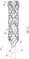
- FIGS. 15 - 17show details of a catheter assembly 400 having a stator assembly 402 disposed in a distal portion thereof.
- the stator assembly 402enhances the performance of a catheter pump including the catheter assembly 400 .
- the stator assembly 402can include a stator blade body 404 having one or a plurality of, e.g., three, blades 408 extending outwardly from a central body 412 .
- the stator blade body 404is at a downstream location of the impeller 312 .
- the stator blade body 404In a percutaneous left ventricle application, the stator blade body 404 is disposed proximal of the impeller 312 .
- the stator blade body 404In a percutaneous right ventricle application, the stator blade body 404 is located distal of the impeller 312 .
- the stator blade body 404is disposed distal of the impeller 312 .
- the stator blades 408are configured to act on the fluid flow generated by the impeller 312 to provide a more optimal fluid flow regime downstream of the stator assembly 402 .
- This fluid flow regimecan correspond to a more optimal fluid flow regime out of the outlet of the catheter pump.
- the stator blades 408preferably convert at least the radial component of flow generated by the impeller 312 to a flow that is substantially entirely axial.
- the stator blades 408are configured to reduce other inefficiencies of the flow generated by the impeller 312 , e.g., minimize turbulent flow, flow eddies, etc. Removing the radial components of the flow can be achieved with blades that are oriented in an opposite direction to the orientation of the blades of the impeller 312 , for example, clockwise versus counterclockwise oriented blade surface.
- stator blades 408act on the flow generated by the impeller 312
- the fluidsalso act on the stator assembly 402 .
- the stator blade body 404experiences a torque generated by the interaction of the blades 408 with the blood as it flows past the stator assembly 402 .
- a robust mechanical interface 420is provided between the central body 412 and a distal portion of the catheter assembly 400 .
- a bearing housing 424is provided that is similar to the bearing housing 372 , except as described differently below.
- the bearing housing 424includes an elongate portion 428 that projects into a lumen of the central body 412 .
- the elongate portion 428preferably has an outer periphery that is smaller than an outer periphery of a portion of the bearing housing 424 immediately proximal of the elongate portion 428 .
- This structureprovides an interface 432 disposed between the elongate portion and the portion just distal thereto.
- the interface 432can be a shoulder having a radial extent that is approximately equal to that of the central body 412 .
- a flush surfaceis provided between the outer surface of the central body 412 and a distal outer surface of the sleeve 368 such that the radial extent of the shoulder of the interface 432 is less than that of the central body 412 by an amount approximately equal to the thickness of the sleeve 368 .
- the interface 432can also or alternately includes an engagement feature between the inner surface of the lumen of the central body 412 and the outer surface of the elongate portion 428 .
- the outer surface of the elongate portion 428has a helical projection or groove and the central body 412 has corresponding and mating helical grooves or projections.
- These featurescan be or can be analogous to screw threads.
- the helix portionis arranged such that the torque felt by the stator assembly 402 generates a tightening of the engagement between the elongate portion 428 and the central body 412 .
- the projections or grooves in the central body 412can be formed by molding the central body 412 over the elongate projection 428 .
- a small gapis provided between the stator assembly 402 and the impeller 312 such that no or minimal contact is provided between these components, but the flow between the blades of these structures smoothly transitions between the blades thereof.
- Such an arrangementis useful in that the impeller 312 rotates at more than 10,000 RPM while the stator assembly 412 is stationary.
- the deployed working endpreferably is collapsed, including the cannula 308 , the stator blade body 404 , and the impeller 312 . This can be done by providing distal relative motion of the sheath assembly 88 . The forces applied by the sheath assembly 88 to the catheter body 400 , stator blade body 404 , and the impeller 312 and focused at the mechanical joints are enhanced due to the presence of the stator blade body 404 .
- the catheter assemblymay be modified based on the respective anatomy to suit the desired vascular approach.
- the catheter assembly in the insertion statemay be shaped for introduction through the subclavian artery to the heart.
- the catheter pumpmay be configured for insertion through a smaller opening and with a lower average flow rate for right side support.
- the catheter assemblyis scaled up for a higher flow rate for sicker patients and/or larger patients.
- it can be desirable to measure local properties of the fluid flowsuch as pressure, flow rate, turbulence, viscosity, and/or chemical or biological composition. It may also be desirable to measure other properties including, but not limited to, properties based on the surrounding anatomy, cardiovascular system, or pulmonary system. It may also be desirable to measure changes to these properties. For example, it may be desirable to measure and record the rate of change or minimum and maximum values within a period of time.
- Suitable devices for measuring the local propertiesinclude, but are not limited to, sensors to measure pressure, flow, and blood chemistry.
- Exemplary flow rate sensorsinclude a differential pressure flowmeter, a velocity flowmeter, a positive displacement flowmeter, a mass flowmeter, and an open channel flowmeter.
- Exemplary flow sensorsinclude Doppler ultrasound and time of flight. Additional details regarding exemplary sensor assemblies are provided below.
- the position and/or orientation of the impeller assembly of a catheter pump relative to the anatomycan be determined using measured parameters. For example, as explained in more detail herein, in left ventricular assist devices (LVADs), a desired target position for an exemplary catheter pump is such that the aortic valve is between the inlets and the outlets of the catheter pump. If the catheter pump is positioned too far within the left ventricle or too far within the aorta, then the flow rate may be meaningfully reduced and patient outcomes may be negatively affected. Typically the catheter pump is positively placed in a target position under fluoroscopy.
- LVADsleft ventricular assist devices
- the pumpcan become displaced because of several factors including operation of the pump and forces on the pump from the aortic valve, aortic walls, and left ventricle. It can be desirable to continuously monitor the position of the impeller assembly of the catheter pump relative to the anatomy to ensure continued alignment at a target position.
- cardiac assist devicessuch as right ventricular assist devices, or RVADs, or biventricular assist devices, or BiVADs
- BiVADsbiventricular assist devices
- a catheter assemblycan include a cannula having a proximal portion and a distal portion.
- a proximal sensor assemblycan be disposed near the proximal portion of the cannula.
- a distal sensor assemblycan also be disposed near the distal portion of the cannula.
- only a proximal sensor assemblycan be used, while in other embodiments, only a distal sensor assembly can be used.
- the catheter pumpis configured for positioning across the aortic valve such that blood is moved from the left ventricle to the ascending aorta.
- An optional proximal sensor assembly positioned proximal the valvemeasures a fluid property (e.g., pressure) in the aorta of the patient.
- An optional distal sensor assembly positioned distal the valvemeasures a fluid property (e.g., pressure) in the left ventricle.
- the catheter assemblyincludes at least two sensors and calculates a difference in the measured values between the at least two sensors. In other procedures, however, it should be appreciated that the proximal and distal sensor assemblies can measure other properties and/or characteristics, such as flow rate, chemical/biological composition, etc.
- the proximal and/or distal sensorscan be configured to be disposed in other parts of the anatomy or other chambers of the heart (such as the right atrium, right ventricle, and/or pulmonary artery for right-side assist procedures).
- a physicianmay confirm placement at a target location using conventional techniques like fluoroscopy or x-ray.
- the one or more sensorsthen transmit a baseline signal to a controller indicative of proper positioning of the catheter pump.
- the controllercan include a processing unit configured to store and analyze a baseline signature based on the signal received from the sensor(s), which can be representative of proper placement of the distal portion of the catheter pump, e.g., such that the aorta straddles the inlets and outlets of the impeller assembly for an exemplary left-side assist procedure. If the impeller assembly becomes misaligned or otherwise out of position relative to the anatomy, then the signal transmitted by the sensor(s) is expected to change.
- the processing unitwhich processes the signal detects an event based on the signal.
- the processormay detect a disturbance signature.
- the processormay identify a signature in the sensor signal indicative of improper placement of the catheter pump.
- the processoridentifies an event based on one or more of the following factors: an amplitude, a maximum value, a minimum value, a frequency, a wavelength, a shape of the signal waveform, a rate of change (first derivative) of a characteristic of the signal, whether the signal is positive or negative, and whether the signal changes between positive and negative.
- Various signal processing techniques and/or look-up tablesas will be understood from the description herein can be used to determine analyze the signal.
- the processorcompares the received signal to the baseline signature and identifies a disturbance event (e.g.
- the controllercan send a notification to the clinician.
- the cliniciancan accordingly reposition the working end of the catheter pump in the proper orientation.
- the processormakes use of heuristics, fuzzy logic, neural networks, machine learning, and/or other advanced processing and learning techniques.
- the processorevaluates the signal information using artificial intelligence including inference rules related to the target location and/or position in the pathway to the target location, comparisons to information in a database, and probabilities, among others.
- the processormay improve or learn over time.
- the processordetects a fault in the pump based on the received signal and returns an alarm notification for the clinician, e.g., by way of a user interface on a console.
- the processordetects the fault in the pump using stored values such as expert data. If the processor determines that the pump is properly positioned, but a determined flow rate is below an expected value, the processor may identify a failure in the pump. In another example, the processor identifies a mechanical failure and displays an alarm representative of the failure mode to the physician. The physician resets the alarm, indicating the pump is working properly, and after one or more resets the processor learns that the circumstances or parameters are a false positive. Likewise, the processor can use past information to improve the accuracy of its event detection techniques.
- the catheter pump systemincludes at least one sensor to measure pressure and/or flow rate.
- the systemincludes a pressure sensor to measure pressure as a proxy for flow rate.
- the systemcan determine a flow rate based on the measured pressure using a standard pressure-flow curve.
- the processormakes use of the pressure and/or flow pattern.
- the flow pattern in the ventricleis expected to be different than the atria and blood vessels, not just in absolute values, but also in flow patterns. The ventricle experiences distinct flow patterns commensurate with the cardiac cycle.
- the flow on the venous side of the vasculatureis relatively low pressure and turbulent compared to the arterial side.
- the processorcan make use of such knowledge of the physiology to identify where the sensor is located and the local conditions.
- the processormakes use of information from adjunctive devices like a heart rate monitor, ECG or EEG, blood glucose monitor, or accelerometer.
- the processormay make use of inputs from a physician (e.g. hematocrit or pulmonary capillary wedge pressure).
- the processormakes use of biomarkers.
- biomarkerslactate dehydrogenase (LDH) and brain natriuretic peptide (BNP) can be used as biomarkers for developing a thrombosis risk index.
- LDHlactate dehydrogenase
- BNPbrain natriuretic peptide
- the processorcan identify a particular event based on the thrombosis risk index. For example, if the thrombosis risk index suggests a high likelihood of thrombus while the flow rate is significantly below an expected value and the current to the pump spikes, the processor may determine that thrombus is present in the pump.
- the processormakes use of various inputs including, but not limited to, the signal from the sensor(s), motor current, motor voltage, and back electromagnetic force (emf) from the motor.
- various inputsincluding, but not limited to, the signal from the sensor(s), motor current, motor voltage, and back electromagnetic force (emf) from the motor.
- FIG. 18 Ais a schematic system diagram of a catheter pump system 501 , according to some embodiments.
- the system 501can include a catheter assembly 500 .
- the catheter assembly 500can be the same as or similar to the catheter assemblies disclosed above with respect to FIGS. 1 - 17 .
- the catheter assembly 500can include a proximal sensor assembly 521 and/or a distal sensor assembly 524 .
- the proximal and/or distal sensor assemblies 521 , 524can be configured to detect a suitable fluid property or characteristic, such as pressure, flow rate, etc.
- the proximal and/or distal sensor assemblies 521 , 524comprise pressure sensors, e.g., optical pressure sensors.
- the system 501can include a controller 502 having a processing unit 503 .
- the processor unitcan be separate from the controller.
- the processor unitcan also be placed anywhere, including in the body.
- the proximal and distal sensor assemblies 521 , 524can be in data communication with the controller 502 .
- the proximal and distal sensor assemblies 521 , 524can be in optical communication with the controller 502 by way of one or more optical fibers.
- the controller 502may be physically coupled to or housed in a console in some arrangements.
- the processing unit 503can include one or more processors programmed to perform methods that are encoded on software stored and/or compiled on any suitable type of storage medium, such as a non-transitory computer-readable storage medium.
- Any suitable processorcan be used in the processing unit 503 , including, but not limited to, field programmable gate arrays (FPGAs), application-specific integrated circuits (ASICs), complex programmable logic devices (CPLDs), programmable logic arrays (PLAs), general purpose processors, microprocessors, or other similar processing devices.
- the computer-implemented instructionsmay be stored on any suitable storage medium, such as optical storage devices, volatile or non-volatile memory devices, RAM, EEPROM, ROM, etc.
- the controller 502can electrically communicate with a user interface 505 .
- the user interface 505can include visual (e.g., a display), audio, and/or other outputs for notifying the clinician of various events during a treatment procedure.
- the controller 502can communicate various properties or characteristics of the treatment procedure to the user interface 505 , which can notify the clinician of such properties or characteristics.
- the controller 502can determine whether or not the catheter assembly 500 is properly or improperly positioned relative to the patient's anatomy, and the user interface 505 can notify the clinician about the proper or improper position.
- the user interfacecan signal to the clinician that the catheter assembly needs to be pushed in further or retracted.
- the user interface 505can also include one or more input devices configured to receive instructions from the clinician, for example, for initiating, modifying, and/or terminating a treatment procedure.
- FIG. 18 Bis a schematic side view of a catheter assembly 500 having a proximal sensor assembly 521 and a distal sensor assembly 524 , according to one embodiment.
- the catheter assembly 500can include an elongate catheter body 504 having one or more lumens therethrough.
- the elongate catheter body 504can be configured to provide fluid, optical, and/or electronic communication to/from outside the patient's body to the sensor (e.g. at the working end of the catheter assembly 500 ).
- An impeller assembly 592can be coupled to a distal end portion of the elongate catheter body 504 .
- the connection between the impeller assembly 592 and the catheter body 504can be provided using any suitable mechanism, such as the mechanisms disclosed above.
- the impeller assembly 592can comprise an impeller 512 disposed at least partially within a cannula 508 .
- the cannula 508 and/or the impeller 512can have a compact, stored configuration, in which the impeller assembly 592 can be inserted percutaneously into the vascular system of the patient.
- the cannula 508 and/or the impeller 512can have an expanded configuration, in which the cannula 508 and/or the impeller 512 can pump blood to assist the heart in providing adequate circulation within the patient's body.
- the catheter assembly 500can include a tip member 526 .
- the tip member 526can be any suitable tip, such as the elongate and rounded tip member 526 shown in FIG. 18 B .
- the tip member 526can comprise a relatively soft and/or flexible material to help guide the impeller assembly 592 within the vasculature of the patient.
- the soft tip member 526can assist in preventing damage to the anatomy caused by impact of the tip against tissue.
- the tip member 526can have a distal opening 527 , through which various system components can be inserted, as explained herein.
- a distal lumen 525can extend past the impeller 512 between the impeller 512 and the tip member 526 .
- the distal lumen 525can pass through the tip member 526 . As shown in FIG. 18 B , the distal lumen 525 can be radially centered relative to the cannula 508 . In other embodiments, the distal lumen 525 can be radially offset relative to the cannula 508 .
- the cannula 508can include one or more fluid inlets 523 near a distal portion of the cannula 508 and one or more fluid outlets 522 near a proximal portion of the cannula 508 .
- the impeller 512can rotate, pulling fluid in a proximal direction relative to the catheter assembly 500 .
- bloodcan be pulled from a left ventricle through the inlets 523 and can propagate within the cannula 508 .
- the bloodcan exit the cannula 508 through the outlets 522 near the proximal portion of the cannula 508 .
- bloodcan flow distally (e.g. in an RVAD configuration).
- the proximal sensor assembly 521can be disposed near the proximal portion of the cannula 508 , e.g., near the outlets 522 .
- the proximal sensor assembly 521can include a sensor body and sensor (e.g., a pressure sensor) configured to convert detected properties of the fluid to a signal readable by the controller 502 .
- the sensorcan be housed in the sensor body or housing for protecting the sensor from the anatomy and/or blood.
- the sensoris exposed to the fluid to be measured through an aperture.
- the sensoris isolated by a pressure transmitting medium such as a foam-like material.
- the proximal sensor assembly 521can be positioned at any suitable proximal location.
- FIG. 18 Billustrates two exemplary suitable proximal sensor locations, a first proximal sensor location 521 A and a second proximal sensor location 521 B.
- a suitable sensor(such as a pressure sensor) can be disposed at one or both of the proximal sensor locations 521 A, 521 B.
- a pressure sensorcan be positioned at the second proximal sensor location 521 B, which may be located proximal the outlets 522 .
- the sensormay be disposed through a sensing zone such as a proximal window in the catheter assembly 500 , e.g., a window in the elongate catheter body 504 .
- the senorcan comprise an element exposed to fluid flow.
- Any suitable type of sensorcan be employed as understood by a skilled artisan, such as a distal end of a fiber optic cable, a resistive sensor, Wheatstone bridge sensor, microelectromechanical systems (MEMS) sensors, acoustic sensor, etc.
- the sensor elementcan comprise a device that generates electrical current and/or an optical signal when exposed to pressure, e.g., absolute pressure, differential pressure, and/or pressure fluctuations.
- the first proximal sensor location 521 Acan be disposed nearer the outlets 522 than the second proximal sensor location 521 B.
- the first sensor location 521 Acan be disposed proximate the outlets 522 , e.g., substantially aligned with the outlets 522 along an axial direction in some embodiments.
- the sensorWhen positioned at the first proximal sensor location 521 A, the sensor can be disposed near a window near the proximal portion of the cannula 508 , e.g., near an interface between the cannula 508 and the distal end portion of the elongate catheter body 504 or the fluid outlet.
- the first proximal sensor location 521 Amay provide more accurate fluid measurements in some embodiments.
- the proximity of the first proximal sensor location 521 A with the outlets 522may provide measurements of fluid properties (e.g., pressure) as the blood leaves the outlets 522 . Improving the accuracy of measurements near the outlets 522 can be advantageous in estimating the position and/or orientation of the impeller housing 592 relative to the anatomy.
- the distal sensor assembly 524can be disposed near the distal portion of the catheter assembly 500 .
- the distal sensor assembly 524can include a sensor body configured to convert a fluid property (e.g., pressure) to a signal readable by the controller 502 (e.g., an optical signal, a voltage, or a current).
- the distal sensor assembly 524can be disposed at one or more distal sensor locations. As shown in FIG. 18 B , for example, the sensor body of the distal sensor assembly 524 can be disposed at one or more of a first distal sensor location 524 A, a second distal sensor location 524 B, and a third distal sensor location 524 C.
- the first distal sensor location 524 Acan be disposed along an outer wall of the cannula 508 near the inlets 523 .
- the second distal sensor location 524 Bcan be disposed at a radially central or internal position relative to the cannula 508 .
- the second distal sensor location 524 Bcan be disposed through a window in the distal lumen 525 .
- the first and second distal sensor locations 524 A, 524 Bcan provide accurate fluid measurements (e.g., pressure measurements) of blood as it flows through the inlets 523 . Improving the accuracy of such fluid measurements near the inlets 523 can improve the accuracy with which the position of the impeller assembly 592 is measured.
- the distal sensor assembly 524can be positioned at the third distal sensor location 524 C.
- the third distal sensor location 524 Ccan be disposed at or near a distal-most end of the catheter assembly 500 .
- the third distal sensor location 524 Ccan be disposed at the distal end of the tip member 526 .
- the third distal sensor location 524 Ccan be disposed at or near the distal opening 527 .
- the distal sensor assembly 524can measure fluid properties, such as pressure, at the distal-most portion of the assembly 500 , which may be within the left ventricle for left-side assist procedures.
- FIG. 19is a schematic side, sectional view of the impeller assembly 592 positioned at a proper target location during a left ventricular assist procedure, e.g., at a position and/or orientation at which adequate cardiac assistance is provided to the patient by the impeller assembly 592 .
- a human heart 530 having a left ventricle 532 , an aorta 531 , and an aortic valve 533is illustrated in FIG. 19 .
- the impeller assembly 592can be inserted through the vascular system of the patient in a compact, stored configuration.
- the impeller assembly 592can be advanced to the heart 530 and can be positioned across the aortic valve 533 .
- the inlets 523can be disposed in the left ventricle 532 , and the outlets 522 can be disposed in the aorta 531 .
- the cliniciancan use any suitable positioning system (e.g., radiographic markers under fluoroscopy, etc.) to ensure that the impeller assembly 592 is properly positioned in the heart 530 .
- the inlets 523 and outlets 522can be positioned sufficiently far from the aortic valve 533 such that the opening and closing of the valve 533 does not affect or occlude the flow of blood through the cannula 508 .
- Positioning the inlets 523 and outlets 522 on opposing sides of the aortic valve 533can ensure that blood is freely drawn from the left ventricle 532 and conveyed past the aortic valve 533 and into the aorta 531 .
- the impeller 512rotates in the cannula 508
- bloodcan be drawn from the left ventricle 532 through the inlets 523 .
- the bloodcan pass through the cannula 508 and out from the outlets 522 into the aorta 531 .
- the proximal sensor assembly 521can measure fluid properties (e.g., pressure) representative of blood flow through the aorta 531 .
- the distal sensor assembly 524can measure fluid properties (e.g., pressure) representative of blood flow in the left ventricle 532 .
- the impeller assembly 592can be collapsed and withdrawn from the patient.
- FIG. 20illustrates theoretical plots of pressure over time for baseline pressures P 1 ′, P 2 ′ that may be detected by the proximal sensor assembly 521 (top) and the distal sensor assembly 524 (bottom), respectively, when the impeller assembly 592 is disposed at a proper treatment location (such as that illustrated in FIG. 19 ) and activated at operational speeds.
- a pressure curve P 1 0illustrates a theoretical plot of pressure over time in an aorta 531 in a normal human heart 530 without the impeller assembly 592 , e.g., during normal operation of the heart.
- the pressure curve P 1 0reflects the pulsatility that is generated during systole and diastole during normal cardiac activity.
- the proximal sensor assembly 521may measure a pressure curve similar to the theoretical, exemplary pressure curve P 1 ′ shown in the top plot of FIG. 20 .
- the proximal sensor assembly 521can measure the pressure in the aorta 531 .
- the operation of the impeller 508may create a more continuous flow pattern through the heart 530 than that illustrated in pressure plot P 1 0 , which is reflected in the relatively smooth, less pulsatile pressure curve P 1 ′ representing pressure in the aorta during treatment.
- the impeller 508is contributing to some of the blood flow, evening out the pressure curves corresponding to blood flow in the aorta.
- the proximal sensor assembly 521may nevertheless be sensitive enough to detect a small amount of pulsatility as the ventricle unloads, which is reflected in the smooth, relatively small peaks shown in FIG. 20 .
- the average pressure of the pressure curve P 1 ′may be about the same as the average pressure in the pressure curve P 1 0 , even though P 1 ′ illustrates reduced pulsatility.
- the bottom plot in FIG. 20is a theoretical, exemplary pressure curve P 2 ′ that may be measured by the distal sensor assembly 521 when the impeller assembly 592 is disposed in a proper treatment position and rotated at operational speeds.
- the impeller assembly 592may be in the configuration shown in FIG. 19 when in a proper treatment position, in which the distal sensor assembly 521 is disposed in the left ventricle 532 .
- the bottom plot of FIG. 20also illustrates a theoretical pressure curve P 2 0 representing the pressure in the left ventricle 532 during a normal cardiac cycle (e.g., without the impeller assembly 592 ).
- the flow through the left ventricle 532 without assistance from the impeller 508typically exhibits pulsatility, e.g., relatively large pressure peaks as the ventricle unloads.
- pressure in the left ventricle 532may be in a range of between about 15 mmHg to about 20 mmHg before systole, and may peak to over 100 mmHg after systole. In some patients, the pressure in the left ventricle 532 may be in a range of about 6 mmHg to about 20 mmHg, or between about 11 mmHg to about 15 mmHg before systole.
- the pumpcan reduce loading on the left ventricle.
- the ventriclehas a volume such that it pumps 5.5 Lpm at full cardiac output and an exemplary pump can flow 4 Lpm
- the heartwill still pump 1.5 Lpm even when the pump is operating.
- the heart rateis 150 bpm
- the pumpcan pump blood through the impeller assembly 592 at flow rates of at least about 3.5 liters per minute (Lpm), at least about 4 Lpm, at least about 4.5 Lpm, at least about 5 Lpm, etc. In some arrangements, the pump can pump blood through the impeller assembly 592 at flow rates in a range of about 3.5 Lpm to about 6 Lpm, or in a range of about 4 Lpm to about 5.5 Lpm. In some arrangements, the pump can pump blood through the impeller assembly 592 at flow rates in a range of about 4.5 Lpm to about 5.5 Lpm. Additional details of impellers 508 capable of pumping blood at these flow rates is described in U.S.
- the impeller 508can reduce the ventricular pressures considerably, which can improve patient outcomes, as explained herein.
- the pressure P 2 ′ in the left ventricle 532may be reduced to less than about 6 mmHg, or less than about 5 mmHg.
- Such reductions in ventricular pressuresare believed improve the health outcomes of patients who have suffered a myocardial infarction.
- a reduction in LV pressuremay reduce pressure on the coronary arteries. This can increase perfusion to the through the coronary arteries thereby improving clinical outcomes.
- the ventricular pressure P 2 ′may be relatively smooth, exhibiting reduced pulsatility.
- the pressure curve P 2 ′(reflecting ventricular pressures when the impeller assembly 592 is in a proper treatment position) may exhibit less pulsatility than the pressure curve P 1 ′ (reflecting aortic pressures when the impeller assembly 592 is in the proper treatment position).
- the pressure curves P 1 ′ and P 2 ′may represent baseline signatures of the treatment procedure when the impeller assembly 592 is in a correct or proper treatment position (e.g., FIG. 19 ).
- the methods and systems disclosed hereincan utilize the baseline signatures P 1 ′ and P 2 ′ for determining the position of the impeller assembly 592 relative to the heart 530 .
- the distal sensor assembly 524can be positioned within the left ventricle 532 and can detect fluid flow having a baseline signature similar to that plotted in P 2 ′, which may correspond to a ventricular baseline signature V.
- the proximal sensor assembly 521can be positioned within the aorta 531 , and can detect fluid flow having a baseline signature similar to that plotted in P 1 ′, which may correspond to an aortic baseline signature A.
- the processing unit 503can process the signals transmitted to the controller 502 by the sensor assemblies 521 and/or 524 . For example, various pre-processing procedures may be performed to convert the raw sensor data (e.g., an optical signal representative of pressure) into data to be processed by the processing unit 503 .
- the pre-processingcan include applying a filter to the signal.
- the pre-processingcan be performed by the processor or a separate component.
- the processing unit 503can associate ventricular and/or aortic baseline signatures V, A with a proper placement configuration.
- any suitable signal processing techniques in the time domain and/or frequency domainmay be performed on the baseline signatures A, V to characterize the signals detected by the sensor assemblies 521 , 524 when the impeller assembly 592 is positioned at a desirable or proper position and orientation.
- the controller 502can store the baseline signatures A, V in memory for comparison with other signatures detected by the sensors and processed by the controller 502 .
- the catheter pumpis properly positioned and aligned (e.g., across the aortic valve 533 in the exemplary embodiment) throughout the treatment procedure, so that the pump provides adequate, consistent cardiac assistance to the patient.
- the impeller assembly 592may become misaligned in a variety of ways during a treatment procedure. For example, the proximal end of the catheter body 504 may be disturbed by the patient, or other external forces may cause the impeller assembly 592 to move within the heart 530 .
- the impeller assembly 592may be initially aligned in a proper treatment location, such as that shown in FIG. 19 .
- the embodiments disclosed hereincan monitor the position of the impeller assembly 592 to ensure that the impeller assembly 592 does not slide distally or proximally to an undesired position.
- the embodiments disclosed hereincan monitor the impeller assembly 592 to alert the clinician if the impeller assembly is moving from a proper target position (such as that shown in FIG. 19 ) towards an improper position.
- the catheter assembly 500may not provide adequate cardiac assistance to the patient.
- misalignment of the impeller assembly 592may also damage the patient's anatomy or pose other risks.
- portions of the aortic valve 533 or the walls of the vasculaturemay be sucked into the inlets 523 or outlets 522 , which can damage the patient and lead to negative patient outcomes.
- Misalignmentcan also increase the risk of thrombus and stroke.
- Disturbance signatureswhich may be determined based on plots of pressure detected by the proximal and/or distal sensor assemblies, may comprise a signature representative of a configuration in which the impeller assembly 592 is misaligned relative to a proper orientation or position.
- a disturbance signature V′(not shown) detected by the distal sensor assembly 524 may represent a misaligned configuration in which the inlets 523 are proximal and/or near the aortic valve 533 .
- the pressure signature V′ detected by the distal sensor assembly 524 and processed by the controller 502may be substantially different from the baseline pressure signature V when the impeller assembly 592 is properly positioned in the anatomy.
- the disturbance pressure signature V′may be at different absolute pressures than the baseline pressure signature V when the inlets 523 and the distal sensor assembly 524 are positioned fully within the left ventricle 532 .
- the disturbance pressure signature V′may exhibit different pulsatility and/or pressure spikes than the baseline pressure signature V.
- a pressure difference ⁇ P v′ of the disturbance signature V′ between minimum and maximum pressuresmay also be different from the pressure difference ⁇ P v of the baseline signature V.
- the disturbance signature V′may also be substantially different from the baseline signature V over time.
- the disturbance signature V′may have a period or wavelength that is sufficiently different from the wavelength of the baseline signature V so as to indicate that the inlets 523 are near the aortic valve 533 . In some cases, there may also be a time lead or lag between the disturbance and baseline signatures.
- an aortic disturbance signature A′ detected by the proximal sensor assembly 521may represent a misaligned configuration in which the outlets 522 are near and/or distal the aortic valve 533 . If the outlets 522 are disposed distal, over, near, and/or aligned with the aortic valve 533 , the disturbance pressure signature A′ detected by the proximal sensor assembly 521 and processed by the controller 502 may be substantially different from the baseline pressure signature A when the impeller assembly 592 is properly positioned in the anatomy, e.g., within the aorta 531 . Furthermore, in some cases, the pulsatility of the aortic disturbance signature A′ may be different as compared with the baseline signature A. As with the ventricular disturbance signature V′, there may be other substantial differences relative to the aortic baseline signature A.
- the impeller assembly 592can be misaligned in other ways.
- the entire impeller assembly 592may be positioned completely within the left ventricle 532 .
- blood flowing through the outlets 522may be occluded by the valve 533 , such that the flow rate through the aorta 531 and vascular system is not appreciably increased relative to the normal cardiac output of the patient's heart.
- the measurements detected by the proximal sensor assembly 521 and the distal sensor assembly 524may be about the same (i.e. the difference is negligible), which would indicate the assembly 592 is entirely in the left ventricle 532 or aorta 531 , depending on the pressure reading.
- the processoridentify imminent misplacement in either the aorta or ventricle.
- FIG. 21 Ais a schematic side view of an impeller assembly 592 as the clinician advances it through the patient proximal the aortic valve 533 .
- FIG. 21 Bis a schematic side view of the impeller assembly 592 as the impeller assembly 592 reaches a proper, target location across the aortic valve 533 .
- FIG. 21 Cis a schematic side view of the impeller assembly 592 showing the impeller assembly as fully disposed in the left ventricle 532 , e.g., in a situation in which the clinician overshoots the target position.
- FIGS. 21 Ais a schematic side view of an impeller assembly 592 as the clinician advances it through the patient proximal the aortic valve 533 .
- FIG. 21 Bis a schematic side view of the impeller assembly 592 as the impeller assembly 592 reaches a proper, target location across the aortic valve 533 .
- FIG. 21 Cis a schematic side view of the impeller assembly 592 showing the imp
- the impeller 508is inactive (e.g., not rotating) as the clinician advances the impeller assembly 592 through the vasculature.
- the distal sensor assembly 524can monitor the location of the impeller assembly 592 as the impeller assembly 592 approaches the target position. The distal sensor assembly 524 can also determine whether the impeller assembly 592 overshoots the target position (e.g., FIG. 21 C ).
- FIG. 21 Dis a theoretical plot of pressure over time measured by the distal sensor assembly at the positions illustrated in FIGS. 21 A- 21 B , when the impeller is not rotating.
- the plots shown in FIG. 21 Dcan be used to recognize when the pump is moving from the position of FIG. 21 A to the positions of FIGS. 21 B- 21 C .
- the pressure curvemay look like either curve A or curve B illustrated in FIG. 21 D .
- the shape of the curvedepends on whether pulsatility can be detected. For example, if pulsatility is detected, the pressure detected by the distal sensor assembly 524 may appear similar to the plot in curve A.
- the pressuremay appear similar to the plot in curve B.
- the overall level of pressurewould be relatively high in both curves A and B because the distal sensor assembly 524 is influenced by the aortic pressure when positioned as shown in FIG. 21 A .
- the pressuremay drop as mostly the ventricular pressure is detected by the distal sensor assembly 524 .
- the pressure curvemay move from curve A or B to curve C, as shown in FIG. 21 D .
- the shape of the curvemay smooth or flatten relative to curves A or B.
- the algorithmcan recognize that, if the pressure plot moves from curve A or curve B to curve C as the clinician pushes the pump distally, the impeller housing 592 is moving from proximal the aortic valve towards the target position.
- the algorithmmay also compare the pressure plots to various history or expert data to determine whether the impeller assembly 592 is in the proper target location (e.g., FIG. 21 B ) or if the impeller assembly 592 is disposed entirely within the left ventricle 532 .
- pressure data measured by both sensors 521 , 524may be used to determine if the impeller assembly 592 is positioned in the configuration of FIG. 21 C .
- FIG. 22 Ais a schematic side cross-sectional view of a heart 730 having a region of myocardial infarction 734 along a wall of the left ventricle 732 .
- FIG. 22 Bis a schematic front cross-sectional view of the heart 730 shown in FIG. 22 A .
- regions of the heartmay comprise dead tissue, or an infarct 734 . Edges of the infarct may still be alive but ischemic; accordingly, it can be advantageous to prevent the infarct 734 from spreading to surrounding healthy heart tissue. Reducing the extension of the myocardial infarct 734 can considerably improve patient outcomes.
- One way to prevent the extension of the infarct 734is to reduce the pressure P 2 exerted against the ventricular walls. For example, lowering the pressure P 2 can reduce the extent to which coronary arteries are squeezed, improving endocardial circulation which promotes the flow of blood to the infarct 734 . In this way the infarct continues to receive blood and the extension of the infarct may be curtailed. This may lead to dramatic improvements in acute outcomes and also reduce the number of myocardial infarction patients who present with chronic heart failure. As explained herein, various embodiments disclosed herein can prevent the infarct 734 from spreading by an amount ⁇ to a larger region 735 shown in dashed lines in FIG. 22 B .
- the impeller assembly 592can reduce the spread of the infarct 734 by an amount ⁇ in a range of about 3 mm to about 8 mm, e.g., about 5 mm. Even such small reductions in the extension of the infarct 734 can dramatically improve patient outcomes, because small reductions in the extension can result in large reductions of area of the infarct 734 .
- Various embodiments disclosed hereincan advantageously reduce the average pressure in the left ventricle 732 by a significant amount, which can improve patient outcomes.
- itcan be advantageous to initially provide sufficient support to the heart such that the heart and impeller assembly 592 pump at least about 2 Lpm (e.g., at least about 4 Lpm) to ensure sufficient organ perfusion even if the heart is barely able to pump.
- the impeller 508may be configured pump blood through the impeller assembly 592 at flow rates of at least about 2 liters per minute (Lpm), at least about 2.5 Lpm, at least about 3.5 Lpm, at least about 4 Lpm, at least about 4.5 Lpm, at least about 5 Lpm, etc.
- the pumpcan pump blood through the impeller assembly 592 at flow rates in a range of about 2 Lpm to about 6 Lpm, or in a range of about 4 Lpm to about 5.5 Lpm. In some arrangements, the pump can pump blood through the impeller assembly 592 at flow rates in a range of about 4.5 Lpm to about 5.5 Lpm. Additional details of impellers 508 capable of pumping blood at these flow rates is described in U.S. patent application Ser. No. 13/802,570, entitled “IMPELLER FOR CATHETER PUMP,” filed on Mar. 13, 2013, which is incorporated by reference herein in its entirety and for all purposes.
- the cliniciancan insert the impeller assembly 592 to a desired treatment location (e.g., FIG. 19 ) and can activate the impeller 508 at operational speeds.
- the impeller 508can pump blood at a sufficient flow rate to ensure that blood adequately perfuses into the patient's organs to support the patient.
- the cliniciancan adjust the position of the impeller assembly 592 to achieve desirable pressure profiles in the left ventricle 732 .
- the distal sensor assemblycan measure the pressure P 2 within the left ventricle 732 during the treatment procedure.
- FIG. 22 Cis a theoretical, exemplary plot of pressure P 2 over time in the left ventricle 732 of the heart 730 of FIGS. 22 A- 22 B prior to activation of the impeller assembly 592 .
- FIG. 22 Cillustrate a theoretical, example pressure P 2 that may be detected by distal sensor assembly 524 before the pump is activated to support the heart.
- the impeller 508may not be activated (or may not be fully ramped to speed) such that the ventricular pressures are relatively high.
- patients that have suffered a heart attackmay have average ventricular pressures P 2 as high as 15 mmHg to about 20 mmHg, or higher pressures (such 30 mmHg).
- patients who have suffered a heart attackmay have average ventricular pressures (e.g., left ventricular end-diastolic pressure, or LVEDP) that are about 25% to about 300% higher than normal average ventricular pressures, e.g., average ventricular pressures that are about 30% to about 100% higher than normal average ventricular pressures.
- LVEDPleft ventricular end-diastolic pressure
- the extent of pressure increases in the left ventricle for heart attack patientscan vary, but typically the pressures in the left ventricle are significantly higher for heart attack patients than for normal human cardiac activity.
- Such high ventricular pressurescan squeeze the tissue in the walls of the ventricle 732 , which may cause the infarct 734 to spread.
- the cliniciancan move the impeller assembly 592 relative to the aortic valve 533 until the impeller 508 provides adequate flow rate and reduced ventricular pressure.
- the motor speed that drives the impeller 508can also be adjusted by the clinician.
- the cliniciancan estimate how far the inlets 523 are past the aortic valve 533 . For example, to provide adequate flow and/or reduced ventricular pressures P 2 , it may be desirable to place the inlets 523 between about 0.5 cm and about 4 cm distal the aortic valve 533 .
- the inlets 523can be placed in a range of about 1.5 cm to about 3 cm distal the aortic valve 533 , e.g., about 2 cm distal the aortic valve 533 in one embodiment.
- the cliniciancan use a mechanical marker at the proximal end of the catheter body outside the patient's body to provide a rough estimate of the position of the impeller assembly 592 relative to the aortic valve 533 .
- the cliniciancan manipulate the impeller assembly 592 until the pressures detected by the distal sensor assembly 724 are at suitably low average levels.
- FIG. 22 Drepresents a theoretical, example pressure profile after providing a coarse adjustment of the impeller housing 592 relative to the aortic valve 533 .
- the cliniciancan estimate a distance of about 2 cm below the aortic valve 533 (using, for example, hash marks on the catheter body or other techniques), and can place the inlets 523 and distal sensor assembly 524 near that location.
- the impeller assembly 592can pump blood at flow rates sufficient to perfuse organs (e.g., at least about 4 Lpm) while also significantly reducing the pressure in the left ventricle 732 . For example, as shown in FIG.
- the average ventricular pressure P 2can be reduced to less than about 15 mmHg, less than about 10 mmHg, less than about 6 mmHg, or more particularly, less than about 5 mmHg. In some embodiments, the ventricular pressure P 2 can be reduced to be in a range of about 2 mmHg to about 15 mmHg, about 3 mmHg to about 10 mmHg, about 4 mmHg to about 8 mmHg, about 4 mmHg to about 6 mmHg, about 4 mmHg to about 5 mmHg, etc.
- the average ventricular pressure for heart attack patientscan be reduced to a level that is less than about 135% of the normal average ventricular pressure (e.g., normal average pressure for humans that have normal cardiac health), less than about 130% of the normal average ventricular pressure, less than about 125% of the normal average ventricular pressure, less than about 120% of the normal average ventricular pressure, less than about 115% of the normal average ventricular pressure, less than about 110% of the normal average ventricular pressure, or less than about 105% of the normal average ventricular pressure.
- the extension of the myocardial infarct 734can be reduced, which can result in considerable improvement for patient outcomes.
- the peak ventricular pressure(e.g., the maximum pressure) can be reduced to less than about 6 mmHg, or more particularly, less than about 5 mmHG. In some embodiments, the peak ventricular pressure can be reduced to be in a range of about 2 mmHg to about 8 mmHg, about 3 mmHG to about 6 mmHg, about 4 mmHg to about 5 mmHg, etc.
- the peak ventricular pressurecan be reduced to be less than about 135% of the normal peak ventricular pressure (e.g., normal peak or maximum pressure for humans that have normal cardiac health), less than about 130% of the normal peak ventricular pressure, less than about 125% of the normal peak ventricular pressure, less than about 120% of the normal peak ventricular pressure, less than about 115% of the normal peak ventricular pressure, less than about 110% of the normal peak ventricular pressure, or less than about 105% of the normal peak ventricular pressure.
- the normal peak ventricular pressuree.g., normal peak or maximum pressure for humans that have normal cardiac health
- the cliniciancan optimize positioning by moving impeller assembly 592 to reduce pressure spikes and smooth out the pressure profile P 2 . As shown in FIG. 22 D , even though the value of the pressure P 2 is relatively low, there are numerous pressure spikes, which may damage the ventricle walls and permit the infarct 734 to spread.
- the cliniciancan view the pressure plot P 2 on a user interface and can adjust the pump to reduce the spikes and/or smooth out the pressure curve P 2 in real-time.
- the cliniciancan move the impeller assembly 592 proximally or distally (and may also adjust the motor speed) until the pressure curve P 2 becomes relatively smooth and flat, e.g., which may correspond to of the pressure plot shown in FIG. 22 E .
- the smooth curve P 2 at low pressures in the ventricle 732can significantly improve patient outcomes.
- a processor or controller(such as the processing units disclosed herein) can process the detected pressures and can indicate on the user interface whether the measured pressures are acceptably low in the left ventricle.
- the pump disclosed hereincan also reduce remodeling of the left ventricle 732 .
- the left ventricle 732may gradually become remodeled, which may lead to long-term heart problems, such as chronic heart failure (e.g. dilated cardiomyopathy).
- the pump disclosed hereinmay reduce the extent of ventricular remodeling when operated at a proper treatment position over time.
- using the impeller assembly 592 disclosed herein even for several hoursmay have positive effects on remodeling.
- Use of the pump for longer periodse.g. days, weeks, or even months
- operating the impeller assembly 592 at pressure profilessuch as that shown in FIG.
- the pump 22 E for a duration of between about 1 hour and 10 hours, or between about 5 hours and 10 hours,may reduce remodeling.
- the pumpcan be used for even longer periods of time, such as over a period of several days.
- using the pump at sufficient flow rates and low pressurescan reduce the degree of ventricular remodeling after a heart attack.
- the impeller assembly 592when properly positioned, can advantageously provide sufficient support to the heart to maintain flow rates high enough to adequately perfuse the organs of a patient.
- the impeller assembly 592can significantly reduce the pressures in the left ventricle, which can dramatically reduce the extension of a myocardial infarct, significantly improving patient outcomes.
- the impeller assembly 592can also reduce the extent of ventricular remodeling after a heart attack, reducing the risk of chronic heart failure.
- FIG. 23 Ais a flowchart illustrating a computer-implemented method 600 for determining a position of a cannula relative to an anatomy of a patient.
- the methodcan be encoded in various software modules, which can be implemented on the processing unit 503 .
- the methodcan be implemented in software, firmware, and/or hardware.
- the method 600can begin in a block 601 to receive a signal from a sensor disposed near a proximal port of the cannula.
- the sensorcan be any suitable sensor configured to measure a property and/or characteristic of the fluid passing through the cannula.
- the sensoris a pressure sensor, e.g., an optical pressure sensor.
- the proximal portcan comprise a fluid outlet, and the sensor can measure fluid properties of blood flowing through the fluid outlet.
- a distal sensorcan be disposed near a distal port of the cannula, which may act as a fluid inlet in some arrangements.
- the distal sensorcan be any suitable sensor, such as a pressure sensor.
- the distal sensorcan measure fluid properties of blood flowing through the inlets.
- the signalcan be processed to determine a fluid signature related to a property of the fluid flowing through the proximal port.
- the raw signal from the sensorcan be pre-processed to convert the detected signal (e.g., an optical signal, a voltage, a current, etc.) into a parameter data representative of fluid flow.
- a processorcan filter the raw signal to extract the parameter data, e.g., pressure values.
- the parameter datacan comprise data that can be manipulated by a processor.
- the processorcan detect a signature of the parameter data.
- the processorcan determine the shape of the pressure waveform over time, including, e.g., first and second derivatives of the pressure data and other operations that may be used to identify a signature of the flow.
- the signalcan comprise a pressure signal (e.g., an optical signal representative of the sensed pressure), and the signature can represent the pressure of the fluid flowing through the proximal port.
- a pressure signale.g., an optical signal representative of the sensed pressure
- the signaturecan represent the pressure of the fluid flowing through the proximal port.
- the raw signal from the distal sensorcan be processed into a distal signature.
- the determined fluid signaturecan be compared with a baseline signature.
- the baseline signaturecan be associated with a proper position of the cannula during a treatment procedure. For example, as explained herein with respect to left-side support procedures, it may be desirable to position the cannula within the patient such that the aortic valve is disposed between the inlets and outlets of the cannula. Accordingly, in a proper positioning of the cannula during the procedure, the proximal port can be disposed proximal the aortic valve. In embodiments with a distal port and distal sensor, the distal port can be disposed distal the aortic valve relative to the cannula.
- the baseline signaturecan be representative of the pressure (or other fluid property) of the blood flowing through the inlets and outlets when the cannula is properly positioned.
- the position of the cannulacan be determined based at least in part on the comparison of the determined fluid signature with the baseline signature. In some embodiments, if the determined fluid signature (e.g., a disturbance signature) is significantly different from the baseline signature, the method 600 can determine that the cannula is in an improper position during the procedure. In a block 605 , the determination or result can be displayed to the clinician, e.g. to notify the clinician whether or not the impeller housing is in a proper treatment position. For example, a user interface can notify the clinician that the impeller assembly is in an improper position, and the clinician can reposition the cannula accordingly.
- the determined fluid signaturee.g., a disturbance signature
- the method 600can compute a difference between a mean baseline signature and a mean disturbance signature. If the computed difference exceeds a predetermined threshold, then it can be determined that the cannula is misaligned. In some arrangements, the method 600 can compare pressure differences AP associated with the difference between minimum and maximum pressures, P min and P max , respectively, between the baseline signature and the determined signature. If the compared pressure differences AP are substantially different, then the method 600 can determine that the cannula is misaligned. In various embodiments, substantially different means greater than 5%, greater than 10%, greater than 25%, or greater than 50%. In various embodiments, substantially different means greater than 100%, greater than 150%, greater than 200%, greater than 250%, or greater than 300%.
- the period or wavelength ⁇ of the determined signaturecan be compared with the period or wavelength ⁇ of the baseline signature. If the wavelength ⁇ of the determined signature differs substantially from the wavelength ⁇ of the baseline signature, then the method 600 may determine that the cannula is misaligned. It should be appreciated that other metrics may be used to determine whether or not the cannula is misaligned relative to the anatomy. Indeed, any suitable time-domain and/or frequency domain signal processing methods, look-up tables, or other techniques may be used to determine the position of the cannula relative to the anatomy.
- the method 600can determine whether the outlets 522 or inlets 523 of the cannula are near and/or substantially aligned with a cardiac valve, such as the aortic valve 533 .
- a determinationmay indicate, for example, that the cannula 508 is sliding distally (in the case of the outlets 522 approaching the valve 533 ) or proximally (in the case of the inlets 523 approaching the valve 533 ).
- the cannula 508may be initially positioned properly such that the valve 533 is between the inlets 522 and outlets 523 , the cannula 508 may slide distally due to some external disturbance.
- the controller 502can process the signal detected by the sensor tip and may determine that the processed or determined signature A′ (e.g., representative of pressure in the aorta 531 ) is substantially similar to the baseline aortic signature A. In such a case, the controller 502 may indicate that the cannula 508 is properly positioned, even though the cannula 508 may have moved distally by a small amount.
- the processed or determined signature A′e.g., representative of pressure in the aorta 531
- the outlets 522 and the proximal sensor assembly 521may approach the aortic valve 533 such that the outlets 522 and proximal sensor assembly 521 are brought into close proximity to (and/or are substantially aligned with) the aortic valve 533 .
- the signal received from the proximal sensor assembly 521may be processed by the controller 502 to determine a signature of the flow through the outlets 522 .
- the controller 502may determine that the determined signature A′ is substantially different from the baseline aortic signature A.
- the controller 502may therefore indicate that the cannula 508 is misaligned. Furthermore, based on known or estimated flow signatures when the outlets 522 overlie the aortic valve 533 , the controller 502 may recognize that the outlets 522 overlie, align with, and/or are in close proximity with the aortic valve 533 . The controller 502 may communicate with the user interface 505 , which can inform the clinician that the cannula 508 is sliding distally and that the clinician should reposition the cannula 508 .
- the embodiments disclosed hereincan also determine whether or not the inlets 523 and/or outlets 522 are in close proximity to and/or overlying the aortic valve 533 (or another cardiac valve).
- FIG. 23 Bis a schematic of an exemplary system architecture for implementing the techniques described herein.
- the systemincludes a processor 610 configured to process signals received from one or more sensor assemblies 621 , 624 .
- a proximal sensor assembly 621 and/or a distal sensor assembly 624may transduce information relating to a flow condition in the impeller assembly, such as pressure.
- the sensor assembly 621 , 624can optically detect the pressure at a proximal or distal sensor location.
- the processor 610can include a filter 613 and/or other components, e.g., an analog-to-digital converter (ADC) to filter the raw data and convert the measured signals into pressure data that represents the pressure in the anatomy.
- ADCanalog-to-digital converter
- the processor 610can also receive additional inputs, such as information 611 from adjunctive devices such as a heart rate monitor, ECG or EEG, blood glucose monitor, pulmonary catheter (for measuring pulmonary capillary wedge pressure), or an accelerometer.
- the adjunctive devicescan provide the processor 610 with additional information 611 to help inform decisions made by the processor 610 during treatment.
- expert data 612can be received and processed by the processor 610 .
- Expert data 612can comprise any suitable data that can inform the clinician about the status of the catheter pump. For example, expert data 612 can inform the clinician about whether or not the pump is functioning properly, blockage in the pump, etc.
- the processor 610can include a comparator 614 configured to compare and otherwise manipulate multiple values relative to one another, e.g., based on a comparison of voltages and/or currents.
- the comparator 614can evaluate stored baselines 615 and signatures 616 (which may be stored in a look-up table 617 , for example) to determine whether the impeller assembly is aligned or misaligned, in accordance with the embodiments described herein.
- the processor 610can be programmed to decide whether or not the impeller assembly is aligned, and can notify the clinician by way of a user interface 618 .
- the cliniciancan monitor the pressures displayed on the user interface 618 in real-time and can adjust the impeller assembly 592 to achieve a desired pressure profile.
- a distal portion of a cannulacan be positioned in one part of the anatomy having a first baseline pressure signature and a proximal portion of the cannula can be positioned in another part of the anatomy having a second baseline pressure signature. If the proximal and/or distal portions become misaligned from a desired orientation, the controller can detect respective disturbance signatures indicating such misalignment.
- the methods and systems disclosed hereincan continuously monitor the position and movement of the impeller assembly 592 throughout a treatment procedure. If the cannula 508 of the impeller assembly 592 moves relative to the anatomy, the embodiments disclosed herein can track in real-time the position of the cannula 508 and can notify the clinician if misalignment of the cannula 508 is imminent.
- the embodiments disclosed hereinmay relate to position detection of the impeller assembly 592 using pressure sensors, it should be appreciated that the sensor assemblies can be used to measure other properties, such as flow rate, biological or chemical composition, temperature, etc.
- FIG. 24is a schematic perspective view of a catheter assembly 500 having a proximal sensor assembly 521 disposed near an outlet 522 at a proximal portion of a cannula 508 .
- Reference numerals used in FIG. 24may refer to similarly-numbered components in FIG. 18 B .
- the catheter assembly 500can include a catheter body 504 , a cannula 508 , and an impeller 512 disposed in the cannula 508 .
- the cannula 508can be coupled with a distal end portion of the catheter body 504 using any suitable mechanism.
- a tubular portion 516 of the cannula 508can couple to the catheter body 504 by way of a ferrule 536 , as explained above with respect to FIGS. 11 - 15 .
- the proximal sensor assembly 521can be disposed at the first proximal sensor location 521 A, which can be positioned near the outlets 522 (e.g., substantially axially aligned with the outlets 522 in some arrangements). By disposing the proximal sensor assembly 521 close to the outlets 522 (e.g., substantially aligned relative to the outlets 522 along the axis of the catheter pump), assembly 521 can obtain accurate measurements of various fluid properties of blood that flows through the outlets 522 , such as the pressure of fluid flowing through the outlets 522 .
- the proximal sensor assembly 521can include a sensor tip 542 and an elongate connector 541 providing data communication between the sensor tip 542 and the controller 502 (shown in FIG. 18 A ).
- the proximal sensor assembly 521can comprise a pressure sensor assembly, such as an optical fiber sensor.
- fiber optic sensorsaccurately measure pressure because such optical sensors may be more sensitive to slight pressure variations than other types of pressure sensors (such as MEMS-based pressure sensors or other types of sensors).
- An example of a suitable sensor assembly 521is the FOP-M260 fiber optic pressure transducer, manufactured by FISO Technologies Inc., of Quebec, Canada. In other arrangements, any other suitable type of sensor can be used.
- the sensor tip 542can be disposed proximate a proximal window 537 formed through an outer surface of the catheter assembly 500 (e.g., the sensor tip 542 can be substantially axially aligned with the window 537 ).
- the window 537can be formed through a tube or sleeve of the cannula 508 disposed about the bearing housing.
- the window 537can be formed through an outer surface of the elongate catheter body 504 , or through an outer surface of a connector or other structure disposed between the catheter body 504 and the impeller 512 .
- the window 537can be formed through a proximal portion of the impeller 512 , e.g., formed through an outer surface of an impeller hub.
- the window 537can provide fluid communication between the sensor tip 542 and the blood flowing through the outlets 522 , so that the sensor tip 542 can detect properties of the blood, e.g., the localized blood pressure.
- the window 537 and the proximal sensor tip 542can be disposed along and/or near an outer surface of a tubular body of the catheter assembly 500 near the outlets 522 .
- the window 537can be substantially aligned with the outlets 522 of the pump.
- the elongate body 96 of the sheath assembly 88can be moved relative to the sensor assembly 521 and/or the impeller 512 to expose the window 537 and/or the sensor tip 542 .
- the cliniciancan slide the elongate body 96 proximally such that a distal-most end of the elongate body 96 exposes the window 537 and/or the sensor tip 542 .
- Moving the elongate body 96 proximallycan also cause the cannula and/or impeller 512 to expand to deployed configurations.
- FIG. 25is a side cross-sectional view of the catheter assembly 500 of FIG. 24 .
- the catheter assembly 500 of FIG. 24can include a bearing housing 546 (which may be similar to the bearing housing 146 A of FIG. 10 ), a thrust bearing 547 (which may be similar to the thrust bearing 204 of FIG. 10 ), a thrust bearing brace 548 (which may be similar to the thrust bearing brace 208 of FIG. 10 ), a coupler 549 (which may be similar to the coupler 200 of FIG. 10 ), and an impeller shaft 538 attached to the impeller 512 .
- the elongate connector 541can pass along the length of the catheter assembly 500 , and the sensor tip 542 can emerge at the window 537 near the outlets 522 .
- FIG. 26is a front end, cross-sectional view of the elongate catheter body 504 .
- the catheter body 504can include a central lumen 540 A for receiving the drive shaft of the catheter pump (e.g., similar to drive shaft 144 disclosed above).
- the catheter body 504can also include a second, infusate lumen 540 B configured to supply infusate (such as saline) to a distal end near the impeller assembly 512 .
- the catheter body 504can include a third, pull-wire lumen 540 C configured to receive pull wires for enhancing the connection between the catheter body 504 and the bearing housing 546 .
- the elongate catheter body 504can also comprise a proximal sensor lumen 540 D.
- the elongate connector 541can extend from near a proximal end of the catheter body 504 through the proximal sensor lumen 540 to a distal portion of the catheter body 504 . As shown in FIG.
- the sensor lumen 540 Dcan be disposed opposite the pull-wire lumen 540 C (e.g., by about 180°), and the infusate lumen 540 B can be disposed between the sensor lumen 540 D and the pull-wire lumen 540 C (e.g., by about 90° relative to the other lumens 540 C, 540 D).
- the sensor lumen 540 D and the infusate lumen 540 Bcan be disposed directly opposite one another, e.g., separated by about 180°.
- separating the lumens 540 B- 540 D from one another by a maximum amountcan prevent accidental fluidic shorting between the lumens.
- FIG. 27is a schematic perspective view of the bearing housing 546 shown in FIG. 25 .
- the bearing housing 546can include a trough 539 formed in an outer surface of the bearing housing 546 .
- the trough 539can be sized and shaped to receive the connector 541 and/or sensor tip 542 of the proximal sensor assembly 521 .
- the connector 541 and the sensor tip 542can pass from the sensor lumen 540 D through the trough 539 between the bearing housing 546 and an outer sleeve surrounding the bearing housing 546 , e.g., the tubular portion 516 of the cannula 508 .
- the trough 539can be formed in any suitable manner, for example, by machining.
- the elongate connector 541 of the proximal sensor assembly 521can extend proximally to the proximal end portion of the catheter body 504 .
- the connector 541e.g., an optical fiber cable
- the connector 541can pass through an aperture or opening formed through the outer surface of the catheter body 504 at the proximal end portion.
- the connector 521can extend laterally through a motor housing or flow diverter at a proximal end of the assembly 500 outside the patient.
- a proximal sensor assembly 521can extend from outside the patient to a proximal portion of the cannula 508 near the outlets 522 (e.g., substantially axially aligned with the outlets 522 in some arrangements).
- the assembly 521can comprise a pressure sensor, which can comprise a fiber optic pressure sensor.
- fiber optic sensorsmay be delicate. For example, fiber optic sensors may be easily damaged and/or broken during operation or manipulation of the catheter pump, or during insertion of the sensor assembly 521 . Typically the failure mode is by bending or cutting. Accordingly, it can be important to provide sufficient protection to the sensor assembly (including the sensor tip 542 and connector 541 ) to prevent damage to the optical fiber.
- the embodiments disclosed hereinenable the use of fiber optic sensors, because the sensor pathways are sufficiently sized to allow for passage of the optical fibers without imparting excessive stresses on the fibers. Any stresses experienced by the fiber are tensive, and such fibers are generally resilient when exposed to tensile forces as opposed to bending.
- the use of a sensor lumen in the catheter body 504 and a trough 539 in the bearing housing 546can accommodate the use of relatively delicate optical fibers.
- the relatively smooth transition between the catheter body 504 and the cannula 508in addition to the careful routing of the connector 541 , may at least in part act to protect optical fiber pressure sensors from abrasion, rubbing, and kinking.
- using optical fibers to measure pressure at the outlets 522can improve the accuracy of pressure measurements.
- FIG. 28is an image of a cannula 508 having a distal sensor assembly 524 at the first distal sensor location 524 A shown in FIG. 18 B , according to one embodiment.
- the distal sensor assembly 524can include a sensor tip 542 (shown schematically in the image of FIG. 28 ) and an elongate connector 541 extending proximally from the first distal sensor location 524 A to the proximal end of the catheter assembly 500 .
- the cannula 508can include a plurality of circumferential rings 551 that provide radial stiffness to the cannula 508 .
- An elastic coating 552can be applied over the rings 551 to form a flow duct through which blood can flow.
- the distal sensor assembly 524 shown in FIG. 28comprises a fiber optic pressure sensor.
- the distal sensor assembly 524 shown in FIG. 28comprises the FOP-M260 fiber optic pressure transducer, manufactured by FISO Technologies Inc., of Quebec, Canada.
- any other suitable type of sensorcan be used.
- optical fiber sensorscan provide more accurate pressure readings than other types of sensors.
- it can be challenging to incorporate optical fiber sensors into catheter assembliesbecause catheter assemblies typically traverse through a tortuous vascular system and include features that may damage the fibers (e.g. valve leaflets and the aortic arch).
- catheter assembliestypically involve components which risk damaging the optical fiber like edges and corners. It can be especially challenging to incorporate optical fiber sensors into the exemplary application because the cannula is expandable and collapsible and subjected to constant, strong forces from the aortic valve during continued use.
- the connector 541 and tip 542are embedded in or on an outer wall 553 of the cannula 508 .
- the connector 541 and tip 542can be encapsulated in the polymer or elastic coating 552 surrounding spiral pattern rings 551 , which corresponds to the circumference of the cannula 508 .
- the connector 541 and tip 542 of the fiber optic sensorcan be coated with the rings 551 when the elastic coating 552 is applied over the rings 551 . As shown in FIG.
- the fiber connector 541can be inserted under the rings 551 of the cannula 508 , and the elastic coating 552 can be applied over both the rings 551 and the sensor assembly 524 .
- the coating 552can be applied over the connector 541 such that at least some slack remains in the connector 541 .
- the integrity of the sensor assembly 521can be maintained, e.g., the connector 541 may be protected from rupture when the rings 551 move.
- the elongate body 96 of the outer sheath assembly 88may be moved relative to the distal assembly 524 to expose the sensing portion of the sensor assembly 524 to blood. For example, as explained above, the clinician can slide the elongate body 96 proximally to expose the tip 542 to blood.
- Coating the sensor assembly 524 in or on the cannula wall 553can provide one effective way to position the distal sensor assembly 524 near the inlets 523 of the cannula 508 .
- disposing the connector 541 adjacent the rings 551may damage the optical fiber.
- a protective tube 554can be disposed about the outer wall 553 of the cannula 508 to provide additional protection for the optical fiber.
- FIG. 29is an image of a cannula 508 having a distal sensor assembly 524 at the first distal sensor location 524 A shown in FIG. 18 B , according to another embodiment.
- the protective tube 554can be adhered, coated, or otherwise attached to the outer wall 553 of the cannula 508 .
- the protective tube 554can pass around the circumference of the wall 553 in a spiral pattern.
- the protective tube 554can be any suitable tubing, such as Pebax® 72D, 0.019′′ ⁇ 0.027′′ tubing.
- the elongate connector 541may be disposed through and along the protective tube 554 before or after deploying the cannula 508 from the stored configuration to the expanded configuration.
- the cannula 508 and protective tube 554are inserted into the heart 530 in the stored configuration and are expanded into the expanded configuration prior to the activating the impeller 512 .
- the distal sensor assembly 524can be inserted through the protective tube 554 once the cannula 508 is expanded to prevent damage to the fiber during deployment.
- the fibercan be disposed within the protective tube 554 during deployment of the cannula 508 from the stored configuration to the expanded configuration.
- the distal sensor assembly 524can be advanced through the protective tube 554 , and the tip 542 (not shown in FIG. 29 ) can extend through a distal opening of the tube 554 at a suitable sensor location, such as the first distal sensor location 524 A shown in FIG. 29 .
- the configuration of FIG. 29can further protect the optical fiber by using the protective tube 554 to shield the fiber from external forces and stresses.
- the tip 542can act to protect the sensor assembly 524 , by preventing the sensor from being sucked against the ventricle wall.
- the cliniciancan slide the elongate body 96 of the sheath assembly 88 proximally to expose the tip 542 to blood.
- FIG. 30is a schematic side cross-sectional view of a cannula 508 having a distal sensor assembly 524 at the second distal sensor location 524 B shown in FIG. 18 B , according to one embodiment.
- a distal lumen 525can pass distal the impeller 512 .
- the distal lumen 525can pass at least partially through a tip member 526 , and can provide access to the distal portion of the catheter assembly 500 .
- the distal lumen 525can be substantially radially centered relative to the cannula 508 . In other embodiments, the distal lumen may be radially offset relative to the cannula 508 .
- the connector 541 and sensor tip 542may pass through the distal lumen 525 .
- the sensor tip 542can be disposed adjacent a distal window 555 formed through the distal lumen 525 .
- the distal window 555can provide fluid communication between the sensor tip 542 and blood flowing into the inlet 523 of the cannula 508 .
- the sensor tip 542can measure a suitable fluid property, such as pressure.
- the distal sensor assembly 524can be inserted through the distal lumen 525 after deployment of the cannula 508 within the heart 530 .
- the sensor assembly 524can be disposed through the distal lumen 525 during deployment of the cannula 508 .
- the embodiment disclosed in FIG. 30can act to protect delicate sensors, such as fiber optic sensors, by disposing them within a protective lumen 525 .
- centering the sensor assembly 524 relative to the outlets 523may result in improved pressure detection in some arrangements, because the sensor may detect local pressure fluctuations if disposed at the wall 553 of the cannula 508 .
- a single distal window 555is illustrated in FIG. 30 , it should be appreciated that additional windows may be formed through the distal lumen 525 to provide sensor readings at multiple locations along the lumen 525 .
- the tip member 526can include a distal opening 527 passing therethrough.
- the third distal sensor location 524 Cmay be disposed at or near the distal opening 527 to provide sensor measurements at the distal-most position of the catheter assembly 500 .
- the distal sensor assembly 524can pass through the tip member 26 , and the sensor tip 542 can be positioned at or near the distal opening 527 .
- the sensor tip 542can measure properties, such as pressure, in the left ventricle at the third sensor location 524 C.
- the cliniciancan provide relative motion between the elongate body 96 of the sheath assembly 88 to expose the sensor assembly 524 to blood.
- the cliniciancan move the body 96 proximally to cause the impeller and cannula to expand and to expose the sensor tip 542 to blood.
- the distal lumen 525can extend proximally to a proximal portion of the catheter assembly 500 .
- the distal lumen 525can emerge from the proximal portion at any suitable location, such as an aperture formed in the catheter body 504 , or through a back end of an external motor or drive assembly.
- the tip 542can act to protect the distal sensor assembly 524 , by preventing the sensor from being sucked against the ventricle wall and damaging the sensor.
Landscapes
- Health & Medical Sciences (AREA)
- Engineering & Computer Science (AREA)
- Heart & Thoracic Surgery (AREA)
- Life Sciences & Earth Sciences (AREA)
- Cardiology (AREA)
- General Health & Medical Sciences (AREA)
- Veterinary Medicine (AREA)
- Biomedical Technology (AREA)
- Public Health (AREA)
- Animal Behavior & Ethology (AREA)
- Anesthesiology (AREA)
- Hematology (AREA)
- Mechanical Engineering (AREA)
- Vascular Medicine (AREA)
- Biophysics (AREA)
- Physics & Mathematics (AREA)
- Pathology (AREA)
- Medical Informatics (AREA)
- Molecular Biology (AREA)
- Surgery (AREA)
- External Artificial Organs (AREA)
- Pulmonology (AREA)
Abstract
Description
Claims (42)
Priority Applications (2)
| Application Number | Priority Date | Filing Date | Title |
|---|---|---|---|
| US16/950,649US12059559B2 (en) | 2014-04-15 | 2020-11-17 | Sensors for catheter pumps |
| US18/762,863US20240424285A1 (en) | 2014-04-15 | 2024-07-03 | Sensors for catheter pumps |
Applications Claiming Priority (4)
| Application Number | Priority Date | Filing Date | Title |
|---|---|---|---|
| US201461979920P | 2014-04-15 | 2014-04-15 | |
| US14/687,493US10029037B2 (en) | 2014-04-15 | 2015-04-15 | Sensors for catheter pumps |
| US16/020,674US10864308B2 (en) | 2014-04-15 | 2018-06-27 | Sensors for catheter pumps |
| US16/950,649US12059559B2 (en) | 2014-04-15 | 2020-11-17 | Sensors for catheter pumps |
Related Parent Applications (1)
| Application Number | Title | Priority Date | Filing Date |
|---|---|---|---|
| US16/020,674ContinuationUS10864308B2 (en) | 2014-04-15 | 2018-06-27 | Sensors for catheter pumps |
Related Child Applications (1)
| Application Number | Title | Priority Date | Filing Date |
|---|---|---|---|
| US18/762,863ContinuationUS20240424285A1 (en) | 2014-04-15 | 2024-07-03 | Sensors for catheter pumps |
Publications (2)
| Publication Number | Publication Date |
|---|---|
| US20210069392A1 US20210069392A1 (en) | 2021-03-11 |
| US12059559B2true US12059559B2 (en) | 2024-08-13 |
Family
ID=54264194
Family Applications (4)
| Application Number | Title | Priority Date | Filing Date |
|---|---|---|---|
| US14/687,493Active2036-08-25US10029037B2 (en) | 2014-04-15 | 2015-04-15 | Sensors for catheter pumps |
| US16/020,674Active2035-09-03US10864308B2 (en) | 2014-04-15 | 2018-06-27 | Sensors for catheter pumps |
| US16/950,649Active2037-08-06US12059559B2 (en) | 2014-04-15 | 2020-11-17 | Sensors for catheter pumps |
| US18/762,863PendingUS20240424285A1 (en) | 2014-04-15 | 2024-07-03 | Sensors for catheter pumps |
Family Applications Before (2)
| Application Number | Title | Priority Date | Filing Date |
|---|---|---|---|
| US14/687,493Active2036-08-25US10029037B2 (en) | 2014-04-15 | 2015-04-15 | Sensors for catheter pumps |
| US16/020,674Active2035-09-03US10864308B2 (en) | 2014-04-15 | 2018-06-27 | Sensors for catheter pumps |
Family Applications After (1)
| Application Number | Title | Priority Date | Filing Date |
|---|---|---|---|
| US18/762,863PendingUS20240424285A1 (en) | 2014-04-15 | 2024-07-03 | Sensors for catheter pumps |
Country Status (3)
| Country | Link |
|---|---|
| US (4) | US10029037B2 (en) |
| EP (2) | EP3799918B1 (en) |
| WO (1) | WO2015160943A1 (en) |
Cited By (11)
| Publication number | Priority date | Publication date | Assignee | Title |
|---|---|---|---|---|
| US12201823B2 (en) | 2018-05-30 | 2025-01-21 | Kardion Gmbh | Line device for conducting a blood flow for a heart support system, heart support system, and method for producing a line device |
| US12222267B2 (en) | 2018-06-06 | 2025-02-11 | Kardion Gmbh | Analysis device and method for analyzing a viscosity of a fluid |
| US12257424B2 (en) | 2018-06-06 | 2025-03-25 | Kardion Gmbh | Implantable ventricular assist system and method for operating same |
| US12263333B2 (en) | 2018-06-21 | 2025-04-01 | Kardion Gmbh | Stator vane device for guiding the flow of a fluid flowing out of an outlet opening of a ventricular assist device, ventricular assist device with stator vane device, method for operating a stator vane device and manufacturing method |
| US12311160B2 (en) | 2018-06-06 | 2025-05-27 | Kardion Gmbh | Method and system for determining the speed of sound in a fluid in the region of a cardiac support system |
| US12310708B2 (en) | 2018-06-06 | 2025-05-27 | Kardion Gmbh | Systems and methods for determining a flow speed of a fluid flowing through a cardiac assist device |
| US12324906B2 (en) | 2018-06-06 | 2025-06-10 | Kardion Gmbh | Systems and methods for determining a total blood volume flow in a cardiac support system and vascular support system |
| US12377256B2 (en) | 2018-06-06 | 2025-08-05 | Kardion Gmbh | Cardiac support system flow measurement using pressure sensors |
| US12383727B2 (en) | 2018-05-30 | 2025-08-12 | Kardion Gmbh | Motor housing module for a heart support system, and heart support system and method for mounting a heart support system |
| US12390633B2 (en) | 2018-08-07 | 2025-08-19 | Kardion Gmbh | Bearing device for a heart support system, and method for rinsing a space in a bearing device for a heart support system |
| US12403296B2 (en) | 2018-05-30 | 2025-09-02 | Kardion Gmbh | Apparatus for anchoring a ventricular assist system in a blood vessel, operating method, production method for producing an apparatus and ventricular assist system |
Families Citing this family (116)
| Publication number | Priority date | Publication date | Assignee | Title |
|---|---|---|---|---|
| US7393181B2 (en) | 2004-09-17 | 2008-07-01 | The Penn State Research Foundation | Expandable impeller pump |
| CN102380135A (en) | 2006-03-23 | 2012-03-21 | 宾州研究基金会 | Heart assist device with expandable impeller pump |
| WO2012094641A2 (en) | 2011-01-06 | 2012-07-12 | Thoratec Corporation | Percutaneous heart pump |
| DE102012207053A1 (en) | 2012-04-27 | 2013-10-31 | Abiomed Europe Gmbh | INTRAVASAL ROTATION BLOOD PUMP |
| EP4218887A1 (en) | 2012-05-14 | 2023-08-02 | Tc1 Llc | Mechanical circulatory support device for stabilizing a patient after cardiogenic shock |
| US8721517B2 (en) | 2012-05-14 | 2014-05-13 | Thoratec Corporation | Impeller for catheter pump |
| US9446179B2 (en) | 2012-05-14 | 2016-09-20 | Thoratec Corporation | Distal bearing support |
| US9872947B2 (en) | 2012-05-14 | 2018-01-23 | Tc1 Llc | Sheath system for catheter pump |
| US9421311B2 (en) | 2012-07-03 | 2016-08-23 | Thoratec Corporation | Motor assembly for catheter pump |
| EP4186557A1 (en) | 2012-07-03 | 2023-05-31 | Tc1 Llc | Motor assembly for catheter pump |
| US9358329B2 (en) | 2012-07-03 | 2016-06-07 | Thoratec Corporation | Catheter pump |
| WO2014164136A1 (en) | 2013-03-13 | 2014-10-09 | Thoratec Corporation | Fluid handling system |
| US11077294B2 (en) | 2013-03-13 | 2021-08-03 | Tc1 Llc | Sheath assembly for catheter pump |
| US11033728B2 (en) | 2013-03-13 | 2021-06-15 | Tc1 Llc | Fluid handling system |
| EP4190376A1 (en) | 2013-03-15 | 2023-06-07 | Tc1 Llc | Catheter pump assembly including a stator |
| US9308302B2 (en) | 2013-03-15 | 2016-04-12 | Thoratec Corporation | Catheter pump assembly including a stator |
| EP3131599B1 (en) | 2014-04-15 | 2019-02-20 | Tc1 Llc | Catheter pump with access ports |
| WO2015160943A1 (en) | 2014-04-15 | 2015-10-22 | Thoratec Corporation | Sensors for catheter pumps |
| EP3131597B1 (en) | 2014-04-15 | 2020-12-02 | Tc1 Llc | Catheter pump introducer systems |
| US10583232B2 (en) | 2014-04-15 | 2020-03-10 | Tc1 Llc | Catheter pump with off-set motor position |
| EP3583973A1 (en) | 2014-08-18 | 2019-12-25 | Tc1 Llc | Guide features for percutaneous catheter pump |
| WO2016118781A2 (en) | 2015-01-22 | 2016-07-28 | Thoratec Corporation | Motor assembly with heat exchanger for catheter pump |
| US9770543B2 (en) | 2015-01-22 | 2017-09-26 | Tc1 Llc | Reduced rotational mass motor assembly for catheter pump |
| US9675738B2 (en) | 2015-01-22 | 2017-06-13 | Tc1 Llc | Attachment mechanisms for motor of catheter pump |
| US9907890B2 (en) | 2015-04-16 | 2018-03-06 | Tc1 Llc | Catheter pump with positioning brace |
| EP3135326A1 (en)* | 2015-08-24 | 2017-03-01 | Berlin Heart GmbH | Heart pump and method for operating a heart pump |
| US11833034B2 (en) | 2016-01-13 | 2023-12-05 | Shifamed Holdings, Llc | Prosthetic cardiac valve devices, systems, and methods |
| EP3205359B1 (en)* | 2016-02-11 | 2018-08-29 | Abiomed Europe GmbH | Blood pump system |
| DE102016209871A1 (en) | 2016-06-06 | 2017-12-07 | Robert Bosch Gmbh | Punching device and method for punching a lumen and implanting an implant device |
| US10342906B2 (en)* | 2016-06-06 | 2019-07-09 | Abiomed, Inc. | Blood pump assembly having a sensor and a sensor shield |
| US11160970B2 (en) | 2016-07-21 | 2021-11-02 | Tc1 Llc | Fluid seals for catheter pump motor assembly |
| EP3808401A1 (en) | 2016-07-21 | 2021-04-21 | Tc1 Llc | Gas-filled chamber for catheter pump motor assembly |
| CA3039285A1 (en) | 2016-10-25 | 2018-05-03 | Magenta Medical Ltd. | Ventricular assist device |
| EP4327732A3 (en) | 2017-01-12 | 2024-04-24 | The Regents of The University of California | Endovascular perfusion augmentation for critical care |
| KR20250126145A (en)* | 2017-01-19 | 2025-08-22 | 히그흐딤 게엠베하 | Devices and methods for determining heart function of a living subject |
| US11185623B2 (en)* | 2017-01-24 | 2021-11-30 | Alcon Inc. | On-demand fluidics system control based on frequency-domain processing |
| DE102017102823A1 (en)* | 2017-02-13 | 2018-08-16 | Cardiobridge Gmbh | Catheter pump with a pump head for insertion into the arterial vasculature |
| CA3060519A1 (en) | 2017-04-21 | 2018-10-25 | The Regents Of The University Of California | Aortic flow meter and pump for partial-aortic occlusion |
| WO2018213089A1 (en) | 2017-05-16 | 2018-11-22 | Heartware, Inc. | Intra ventricular ambulatory implantable pv loop system |
| CA3066361A1 (en) | 2017-06-07 | 2018-12-13 | Shifamed Holdings, Llc | Intravascular fluid movement devices, systems, and methods of use |
| WO2019094963A1 (en) | 2017-11-13 | 2019-05-16 | Shifamed Holdings, Llc | Intravascular fluid movement devices, systems, and methods of use |
| US10905808B2 (en) | 2018-01-10 | 2021-02-02 | Magenta Medical Ltd. | Drive cable for use with a blood pump |
| EP3638336B1 (en)* | 2018-01-10 | 2022-04-06 | Magenta Medical Ltd. | Ventricular assist device |
| DE102018201030B4 (en) | 2018-01-24 | 2025-10-16 | Kardion Gmbh | Magnetic dome element with magnetic bearing function |
| CN112004563B (en) | 2018-02-01 | 2024-08-06 | 施菲姆德控股有限责任公司 | Intravascular blood pump and methods of use and manufacture |
| IL277236B2 (en)* | 2018-03-16 | 2024-12-01 | Abiomed Inc | Systems and methods for estimating a position of a heart pump |
| DE102018206724A1 (en) | 2018-05-02 | 2019-11-07 | Kardion Gmbh | Energy transmission system and method for wireless energy transmission |
| DE102018206750A1 (en) | 2018-05-02 | 2019-11-07 | Kardion Gmbh | Device for inductive energy transfer into a human body and its use |
| DE102018206725A1 (en) | 2018-05-02 | 2019-11-07 | Kardion Gmbh | Receiving unit, transmitting unit, energy transmission system and method for wireless energy transmission |
| DE102018206754A1 (en) | 2018-05-02 | 2019-11-07 | Kardion Gmbh | Method and device for determining the temperature at a surface and use of the method |
| DE102018206731A1 (en) | 2018-05-02 | 2019-11-07 | Kardion Gmbh | Device for inductive energy transmission in a human body and use of the device |
| DE102018207575A1 (en) | 2018-05-16 | 2019-11-21 | Kardion Gmbh | Magnetic face turning coupling for the transmission of torques |
| DE102018207611A1 (en) | 2018-05-16 | 2019-11-21 | Kardion Gmbh | Rotor bearing system |
| DE102018208538A1 (en) | 2018-05-30 | 2019-12-05 | Kardion Gmbh | Intravascular blood pump and process for the production of electrical conductors |
| DE102018208541A1 (en) | 2018-05-30 | 2019-12-05 | Kardion Gmbh | Axial pump for a cardiac assist system and method of making an axial pump for a cardiac assist system |
| US10668195B2 (en) | 2018-06-01 | 2020-06-02 | Fbr Medical, Inc. | Catheter pump with fixed-diameter impeller |
| DE102018208931A1 (en)* | 2018-06-06 | 2019-12-12 | Kardion Gmbh | Apparatus for determining cardiac output for a cardiac assist system, cardiac assistive system and method for determining cardiac output |
| DE102018208927A1 (en)* | 2018-06-06 | 2019-12-12 | Kardion Gmbh | An implantable device for determining a fluid volume flow through a blood vessel |
| DE102018208929A1 (en) | 2018-06-06 | 2019-12-12 | Kardion Gmbh | A method of determining a flow rate of fluid flowing through an implanted vascular support system |
| DE102018208936A1 (en) | 2018-06-06 | 2019-12-12 | Kardion Gmbh | Determining device and method for determining a viscosity of a fluid |
| DE102018210076A1 (en) | 2018-06-21 | 2019-12-24 | Kardion Gmbh | Method and device for detecting a state of wear of a cardiac support system, method and device for operating a cardiac support system and cardiac support system |
| DE102018211327A1 (en) | 2018-07-10 | 2020-01-16 | Kardion Gmbh | Impeller for an implantable vascular support system |
| WO2020018742A1 (en)* | 2018-07-19 | 2020-01-23 | Abiomed, Inc. | Systems and methods for reducing leaks from a catheter |
| DE102018212153A1 (en) | 2018-07-20 | 2020-01-23 | Kardion Gmbh | Inlet line for a pump unit of a cardiac support system, cardiac support system and method for producing an inlet line for a pump unit of a cardiac support system |
| US11013904B2 (en)* | 2018-07-30 | 2021-05-25 | Cardiovascular Systems, Inc. | Intravascular pump with proximal and distal pressure or flow sensors and distal sensor tracking |
| US12161857B2 (en) | 2018-07-31 | 2024-12-10 | Shifamed Holdings, Llc | Intravascular blood pumps and methods of use |
| AU2019325548B2 (en) | 2018-08-21 | 2025-06-26 | Shifamed Holdings, Llc | Prosthetic cardiac valve devices, systems, and methods |
| EP3852833A1 (en) | 2018-09-21 | 2021-07-28 | Abiomed, Inc. | Use of optical fiber sensor as a diagnostic tool in catheter-based medical devices |
| CN113260337A (en) | 2018-10-05 | 2021-08-13 | 施菲姆德控股有限责任公司 | Prosthetic heart valve devices, systems, and methods |
| WO2020073047A1 (en) | 2018-10-05 | 2020-04-09 | Shifamed Holdings, Llc | Intravascular blood pumps and methods of use |
| CN113164117B (en)* | 2018-10-09 | 2024-12-20 | 新泽西州立罗格斯大学 | Ultrasound-guided alignment and insertion of percutaneous catheter instruments |
| CN113056302B (en) | 2018-10-19 | 2023-03-28 | 施菲姆德控股有限责任公司 | Adjustable medical device |
| US12004848B2 (en) | 2018-11-02 | 2024-06-11 | Boston Scientific Medical Device Limited | Blood flow meter |
| EP3656411A1 (en)* | 2018-11-26 | 2020-05-27 | Berlin Heart GmbH | Blood pump for supporting a cardiac function and method for producing a pump housing of a blood pump |
| AU2020211431B2 (en) | 2019-01-24 | 2024-10-24 | Magenta Medical Ltd | Ventricular assist device |
| EP3941391B1 (en) | 2019-03-19 | 2024-12-04 | Shifamed Holdings, LLC | Prosthetic cardiac valve devices, systems |
| US11975157B2 (en) | 2019-04-12 | 2024-05-07 | Covidien Lp | Method of manufacturing an elongated catheter having multiple sensors for three-dimensional location of the catheter |
| EP3984100A1 (en)* | 2019-06-11 | 2022-04-20 | Stäubli Electrical Connectors AG | Socket, method for producing same, and plug connector |
| CA3144061A1 (en)* | 2019-06-28 | 2020-12-30 | Abiomed, Inc. | Optical sensor assembly in catheter-based medical devices |
| WO2021011473A1 (en) | 2019-07-12 | 2021-01-21 | Shifamed Holdings, Llc | Intravascular blood pumps and methods of manufacture and use |
| US11654275B2 (en) | 2019-07-22 | 2023-05-23 | Shifamed Holdings, Llc | Intravascular blood pumps with struts and methods of use and manufacture |
| LT4007619T (en)* | 2019-08-02 | 2023-04-11 | Hollister Incorporated | Spool valve for trans-anal irrigation device |
| AU2020341540B2 (en)* | 2019-09-05 | 2023-11-23 | Boston Scientific Scimed Inc. | Circulatory support device with integrated cannula |
| US12171994B2 (en) | 2019-09-11 | 2024-12-24 | Boston Scientific Scimed, Inc. | Reduced thrombosis blood pump with washout bearing |
| WO2021062265A1 (en) | 2019-09-25 | 2021-04-01 | Shifamed Holdings, Llc | Intravascular blood pump systems and methods of use and control thereof |
| EP4501393A3 (en) | 2019-09-25 | 2025-04-09 | Shifamed Holdings, LLC | Catheter blood pumps and collapsible pump housings |
| US12121713B2 (en) | 2019-09-25 | 2024-10-22 | Shifamed Holdings, Llc | Catheter blood pumps and collapsible blood conduits |
| US12383723B2 (en)* | 2019-10-05 | 2025-08-12 | Puzzle Medical Devices Inc. | Mammalian body implantable fluid flow influencing device |
| EP4072650A4 (en) | 2019-12-11 | 2024-01-10 | Shifamed Holdings, LLC | Descending aorta and vena cava blood pumps |
| DE102020102474A1 (en) | 2020-01-31 | 2021-08-05 | Kardion Gmbh | Pump for conveying a fluid and method for manufacturing a pump |
| EP4121159A2 (en) | 2020-03-16 | 2023-01-25 | Certus Critical Care, Inc. | Blood flow control devices, systems, and methods and error detection thereof |
| CN115427001A (en)* | 2020-03-30 | 2022-12-02 | E.Z.N.G科技有限责任公司 | Device and method for nasogastric tube insertion guidance |
| EP3984589B1 (en) | 2020-04-07 | 2023-08-23 | Magenta Medical Ltd. | Magnetic phase sensing |
| CN116456937A (en) | 2020-08-31 | 2023-07-18 | 施菲姆德控股有限责任公司 | Prosthetic Valve Delivery System |
| US11699551B2 (en) | 2020-11-05 | 2023-07-11 | Kardion Gmbh | Device for inductive energy transmission in a human body and use of the device |
| AU2021381515A1 (en)* | 2020-11-20 | 2023-07-06 | Kardion Gmbh | Purgeless mechanical circulatory support system with magnetic drive |
| US12329635B2 (en) | 2020-12-04 | 2025-06-17 | Shifamed Holdings, Llc | Flared prosthetic cardiac valve delivery devices and systems |
| WO2022125663A1 (en) | 2020-12-10 | 2022-06-16 | Abiomed, Inc. | Sysems and methods for determining positioning of intracardiac devives |
| US12201521B2 (en) | 2021-03-22 | 2025-01-21 | Shifamed Holdings, Llc | Anchor position verification for prosthetic cardiac valve devices |
| EP4291287A1 (en) | 2021-04-14 | 2023-12-20 | Boston Scientific Scimed Inc. | Flexible tip for transvalvular circulatory support device |
| NL2028130B1 (en) | 2021-05-03 | 2022-11-10 | Cardiacbooster B V | Cardiac assist device with high frequency operation |
| CN118215523A (en)* | 2021-11-16 | 2024-06-18 | 波士顿科学国际有限公司 | Percutaneous circulatory support device including a proximal pressure sensor |
| JP2024536407A (en)* | 2021-11-16 | 2024-10-04 | ボストン サイエンティフィック サイムド,インコーポレイテッド | PERCUTANEOUS CIRCULATING ASSIST DEVICE COMPRISING A PROXIMAL PRESSURE SENSOR - Patent application |
| AU2022390146B2 (en) | 2021-11-17 | 2025-04-03 | Boston Scientific Scimed Inc. | Device housing features to facilitate damage free guidewire translations |
| KR20240108429A (en)* | 2021-11-23 | 2024-07-09 | 아비오메드, 인크. | Systems and methods for cannula fiber lumen strain relief |
| WO2023096892A1 (en) | 2021-11-23 | 2023-06-01 | Boston Scientific Scimed Inc. | Percutaneous circulatory support device facilitating reduced hemolysis |
| EP4201468A1 (en)* | 2021-12-22 | 2023-06-28 | Royal College of Surgeons in Ireland | A system to treat heart failure with preserved ejection fraction (hfpef) |
| US20230201566A1 (en)* | 2021-12-27 | 2023-06-29 | Tc1 Llc | Percutaneous heart pump catheter with pressure sensor |
| EP4472721A4 (en)* | 2022-02-02 | 2025-08-06 | Shifamed Holdings Llc | HUBS FOR CATHETER BLOOD PUMPS |
| EP4537890A1 (en)* | 2022-06-10 | 2025-04-16 | Shenzhen Core Medical Technology Co., Ltd. | Driving device and blood pump |
| CN115192899B (en)* | 2022-07-07 | 2024-02-13 | 心擎医疗(苏州)股份有限公司 | Catheter assembly and ventricular assist device |
| CN115263771B (en)* | 2022-07-19 | 2025-06-24 | 深圳核心医疗科技股份有限公司 | Test equipment |
| WO2024226831A1 (en)* | 2023-04-25 | 2024-10-31 | Shifamed Holdings, Llc | Catheter blood pumps and associated methods |
| US20240358996A1 (en)* | 2023-04-28 | 2024-10-31 | Boston Scientific Scimed, Inc. | Circulatory support system |
| IL305304A (en)* | 2023-08-16 | 2025-03-01 | Cathalert Ltd | System and method for processing images of catheterization procedure and providing alerts |
| CN117899349B (en)* | 2024-03-18 | 2024-06-04 | 生命盾医疗技术(苏州)有限公司 | A ventricular assist device control method, device, electronic device and storage medium |
Citations (488)
| Publication number | Priority date | Publication date | Assignee | Title |
|---|---|---|---|---|
| US1902418A (en) | 1931-11-02 | 1933-03-21 | Jensen Salsbery Lab Inc | Surgical instrument |
| US2356659A (en) | 1941-11-24 | 1944-08-22 | Aguiar Clovis De Paiva | Nozzle for duodenal pump tubes |
| US2649052A (en) | 1947-04-17 | 1953-08-18 | Marine Products Company | Rotary pump or motor |
| US2664050A (en) | 1949-03-02 | 1953-12-29 | Gen Motors Corp | Domestic appliance |
| US2684035A (en) | 1947-10-02 | 1954-07-20 | Philip G Kemp | Fluid pump |
| US2789511A (en) | 1953-05-25 | 1957-04-23 | Jabsco Pump Co | Flexible vane pump impeller |
| US2896926A (en) | 1956-01-10 | 1959-07-28 | Chapman Harold Eric | Device for mixing or treating fluids or free-flowing powders |
| US2935068A (en) | 1955-08-04 | 1960-05-03 | Donaldson John Shearman | Surgical procedure and apparatus for use in carrying out the same |
| US3080824A (en) | 1961-02-27 | 1963-03-12 | James A Boyd | Fluid moving device |
| US3455540A (en) | 1968-01-04 | 1969-07-15 | Emil G Marcmann | Stirring device |
| US3510229A (en) | 1968-07-23 | 1970-05-05 | Maytag Co | One-way pump |
| JPS4823295U (en) | 1971-07-23 | 1973-03-16 | ||
| US3812812A (en) | 1973-06-25 | 1974-05-28 | M Hurwitz | Trolling propeller with self adjusting hydrodynamic spoilers |
| US3860968A (en) | 1969-11-20 | 1975-01-21 | Max Shapiro | Compact, implantable apparatus for pumping blood to sustain blood circulation in a living body |
| US3904901A (en) | 1972-11-03 | 1975-09-09 | Anvar | Rotary electric machine with super-conducting winding |
| FR2267800A1 (en) | 1974-04-17 | 1975-11-14 | Anvar | Catheter insertion system - uses auxiliary fluid injected in catheter and forming propulsion jets |
| US3995617A (en) | 1972-05-31 | 1976-12-07 | Watkins David H | Heart assist method and catheter |
| US4115040A (en) | 1976-05-28 | 1978-09-19 | Franz Klaus-Union | Permanent magnet type pump |
| US4129129A (en) | 1977-03-18 | 1978-12-12 | Sarns, Inc. | Venous return catheter and a method of using the same |
| US4135253A (en) | 1976-11-30 | 1979-01-23 | Medtronic, Inc. | Centrifugal blood pump for cardiac assist |
| US4143425A (en) | 1977-10-27 | 1979-03-13 | Runge Thomas M | Left atrial to descending thoracic aorta left ventricular assist device |
| US4149535A (en) | 1976-05-06 | 1979-04-17 | Gist-Brocades N.V. | Catheter holding device |
| US4304524A (en) | 1979-09-07 | 1981-12-08 | Woodcoxon Engineering (International) Limited | Marine propellers |
| USD264134S (en) | 1979-05-07 | 1982-04-27 | Stewart-Reiss Laboratories, Inc. | Disposable cassette for use in a peristaltic pump |
| US4382199A (en) | 1980-11-06 | 1983-05-03 | Nu-Tech Industries, Inc. | Hydrodynamic bearing system for a brushless DC motor |
| US4392836A (en) | 1980-05-21 | 1983-07-12 | Kanto Seiki Co., Ltd. | Device for connecting speedometer to flexible shaft |
| JPS58190448A (en) | 1982-04-20 | 1983-11-07 | カ−ル・アイグナ− | Double cathetel for infusion |
| US4458366A (en) | 1975-05-09 | 1984-07-10 | Macgregor David C | Artificial implantable blood pump |
| US4537561A (en) | 1983-02-24 | 1985-08-27 | Medical Technology, Ltd. | Peristaltic infusion pump and disposable cassette for use therewith |
| US4560375A (en) | 1983-06-30 | 1985-12-24 | Pudenz-Schulte Medical Research Corp. | Flow control valve |
| US4589822A (en) | 1984-07-09 | 1986-05-20 | Mici Limited Partnership Iv | Centrifugal blood pump with impeller |
| US4625712A (en) | 1983-09-28 | 1986-12-02 | Nimbus, Inc. | High-capacity intravascular blood pump utilizing percutaneous access |
| US4655745A (en) | 1985-07-29 | 1987-04-07 | Corbett Joseph E | Ventricular catheter |
| US4673334A (en) | 1984-05-25 | 1987-06-16 | Isco, Inc. | Peristaltic pump |
| US4686982A (en) | 1985-06-19 | 1987-08-18 | John Nash | Spiral wire bearing for rotating wire drive catheter |
| US4696667A (en) | 1986-03-20 | 1987-09-29 | Helmut Masch | Intravascular catheter and method |
| US4704121A (en) | 1983-09-28 | 1987-11-03 | Nimbus, Inc. | Anti-thrombogenic blood pump |
| US4728319A (en) | 1986-03-20 | 1988-03-01 | Helmut Masch | Intravascular catheter |
| US4753221A (en) | 1986-10-22 | 1988-06-28 | Intravascular Surgical Instruments, Inc. | Blood pumping catheter and method of use |
| US4769006A (en) | 1985-05-13 | 1988-09-06 | Kos Medical Technologies, Ltd. | Hydrodynamically propelled pacing catheter |
| US4817586A (en) | 1987-11-24 | 1989-04-04 | Nimbus Medical, Inc. | Percutaneous bloom pump with mixed-flow output |
| US4846152A (en) | 1987-11-24 | 1989-07-11 | Nimbus Medical, Inc. | Single-stage axial flow blood pump |
| US4895557A (en) | 1987-12-07 | 1990-01-23 | Nimbus Medical, Inc. | Drive mechanism for powering intravascular blood pumps |
| US4900227A (en) | 1988-06-14 | 1990-02-13 | Thomson-Brandt-Armements | Wind power of hydraulic power machine with axial feed, radial outflow, and variable geometry vanes, and projectiles fitted with wind power or hydraulic power machines of this type |
| US4902272A (en) | 1987-06-17 | 1990-02-20 | Abiomed Cardiovascular, Inc. | Intra-arterial cardiac support system |
| US4906229A (en) | 1988-05-03 | 1990-03-06 | Nimbus Medical, Inc. | High-frequency transvalvular axisymmetric blood pump |
| US4908012A (en) | 1988-08-08 | 1990-03-13 | Nimbus Medical, Inc. | Chronic ventricular assist system |
| US4919647A (en) | 1988-10-13 | 1990-04-24 | Kensey Nash Corporation | Aortically located blood pumping catheter and method of use |
| US4944722A (en) | 1989-02-23 | 1990-07-31 | Nimbus Medical, Inc. | Percutaneous axial flow blood pump |
| JPH02211169A (en) | 1988-09-28 | 1990-08-22 | Takizawa Saburo | circulation device |
| US4954129A (en) | 1988-07-25 | 1990-09-04 | Abbott Laboratories | Hydrodynamic clot flushing |
| US4955856A (en) | 1989-06-30 | 1990-09-11 | Phillips Steven J | Method and apparatus for installing a ventricular assist device cannulae |
| US4957504A (en) | 1988-12-02 | 1990-09-18 | Chardack William M | Implantable blood pump |
| US4964864A (en) | 1988-09-27 | 1990-10-23 | American Biomed, Inc. | Heart assist pump |
| US4969865A (en) | 1989-01-09 | 1990-11-13 | American Biomed, Inc. | Helifoil pump |
| US4976270A (en) | 1989-03-28 | 1990-12-11 | Vanderbilt University | Apparatus for continuously sampling plasma |
| US4985014A (en) | 1989-07-11 | 1991-01-15 | Orejola Wilmo C | Ventricular venting loop |
| US4995857A (en) | 1989-04-07 | 1991-02-26 | Arnold John R | Left ventricular assist device and method for temporary and permanent procedures |
| US5000177A (en) | 1990-01-29 | 1991-03-19 | Cardiac Pacemakers, Inc. | Bipolar lead adapter with resilient housing and rigid retainers for plug seals |
| US5021048A (en) | 1989-08-04 | 1991-06-04 | Medtronic, Inc. | Blood pump drive system |
| GB2239675A (en) | 1989-12-05 | 1991-07-10 | Man Fai Shiu | Pump for pumping liquid |
| US5045072A (en) | 1989-06-13 | 1991-09-03 | Cordis Corporation | Catheter having highly radiopaque, flexible tip |
| US5044902A (en) | 1989-03-13 | 1991-09-03 | Edouard Malbec | Cartridge for peristaltic pump with a flexible tube, and peristaltic pump fitted with such a cartridge |
| US5049134A (en) | 1989-05-08 | 1991-09-17 | The Cleveland Clinic Foundation | Sealless heart pump |
| US5059174A (en) | 1990-08-23 | 1991-10-22 | Vaillancourt Vincent L | Fluid infusion delivery system |
| EP0453234A1 (en) | 1990-04-20 | 1991-10-23 | Cook Incorporated | Catheter for extracorporeal treatment |
| US5061256A (en) | 1987-12-07 | 1991-10-29 | Johnson & Johnson | Inflow cannula for intravascular blood pumps |
| US5089016A (en) | 1989-06-15 | 1992-02-18 | Abiomed Cardiovascular, Inc. | Blood pump |
| US5092844A (en) | 1990-04-10 | 1992-03-03 | Mayo Foundation For Medical Education And Research | Intracatheter perfusion pump apparatus and method |
| US5098256A (en) | 1989-11-21 | 1992-03-24 | The Cleveland Clinic Foundation | Viscous seal blood pump |
| US5112200A (en) | 1990-05-29 | 1992-05-12 | Nu-Tech Industries, Inc. | Hydrodynamically suspended rotor axial flow blood pump |
| US5112292A (en) | 1989-01-09 | 1992-05-12 | American Biomed, Inc. | Helifoil pump |
| US5129883A (en) | 1990-07-26 | 1992-07-14 | Michael Black | Catheter |
| US5142155A (en) | 1991-03-11 | 1992-08-25 | Hewlett-Packard Company | Catheter tip fluorescence-quenching fiber optic pressure sensor |
| US5147186A (en) | 1989-08-04 | 1992-09-15 | Bio Medicus, Inc. | Blood pump drive system |
| US5163910A (en) | 1990-04-10 | 1992-11-17 | Mayo Foundation For Medical Education And Research | Intracatheter perfusion pump apparatus and method |
| US5169378A (en) | 1990-07-20 | 1992-12-08 | Diego Figuera | Intra-ventricular expansible assist pump |
| US5171212A (en) | 1991-02-08 | 1992-12-15 | Minnesota Mining And Manufacturing Company | Blood pumping system with backflow warning |
| US5190528A (en) | 1990-10-19 | 1993-03-02 | Boston University | Percutaneous transseptal left atrial cannulation system |
| US5195960A (en) | 1987-04-27 | 1993-03-23 | Site Microsurgical Systems, Inc. | Disposable vacuum/peristaltic pump cassette system |
| EP0533432A1 (en) | 1991-09-17 | 1993-03-24 | Yamauchi, Teiyu | Catheter device |
| US5201679A (en) | 1991-12-13 | 1993-04-13 | Attwood Corporation | Marine propeller with breakaway hub |
| US5211546A (en) | 1990-05-29 | 1993-05-18 | Nu-Tech Industries, Inc. | Axial flow blood pump with hydrodynamically suspended rotor |
| US5221270A (en) | 1991-06-28 | 1993-06-22 | Cook Incorporated | Soft tip guiding catheter |
| US5234407A (en) | 1991-03-06 | 1993-08-10 | Baxter International Inc. | Method and device for exchanging cardiovascular guide catheter while a previously inserted angioplasty guide wire remains in place |
| US5234416A (en) | 1991-06-06 | 1993-08-10 | Advanced Cardiovascular Systems, Inc. | Intravascular catheter with a nontraumatic distal tip |
| US5286259A (en) | 1990-03-15 | 1994-02-15 | Diagnostic Devices Group Limited | Dual-diameter multifunction catheter |
| US5290227A (en) | 1992-08-06 | 1994-03-01 | Pasque Michael K | Method of implanting blood pump in ascending aorta or main pulmonary artery |
| US5300112A (en) | 1992-07-14 | 1994-04-05 | Aai Corporation | Articulated heart pump |
| JPH06114101A (en) | 1992-09-30 | 1994-04-26 | Nippon Zeon Co Ltd | Blood circulation device |
| US5312341A (en) | 1992-08-14 | 1994-05-17 | Wayne State University | Retaining apparatus and procedure for transseptal catheterization |
| US5344443A (en) | 1992-09-17 | 1994-09-06 | Rem Technologies, Inc. | Heart pump |
| US5346458A (en) | 1990-06-25 | 1994-09-13 | Klaus Affeld | Electrohydraulic energy converter for cardiac assist devices and artificial hearts |
| US5360317A (en) | 1992-07-30 | 1994-11-01 | Spin Corporation | Centrifugal blood pump |
| US5376114A (en) | 1992-10-30 | 1994-12-27 | Jarvik; Robert | Cannula pumps for temporary cardiac support and methods of their application and use |
| US5393197A (en) | 1993-11-09 | 1995-02-28 | Lemont Aircraft Corporation | Propulsive thrust ring system |
| US5393207A (en) | 1993-01-21 | 1995-02-28 | Nimbus, Inc. | Blood pump with disposable rotor assembly |
| US5405341A (en) | 1993-06-03 | 1995-04-11 | Med-Pro Design, Inc. | Catheter with multiple lumens |
| US5415637A (en) | 1993-04-14 | 1995-05-16 | Advanced Cardiovascular Systems, Inc. | Temporary stenting catheter with drug delivery capabilities |
| US5437541A (en) | 1993-12-30 | 1995-08-01 | Vainrub; John | Blade for axial fan |
| US5449342A (en) | 1991-09-30 | 1995-09-12 | Nippon Zeon Co., Ltd. | Apparatus for assisting blood circulation |
| WO1995026695A2 (en) | 1994-04-01 | 1995-10-12 | Prograft Medical, Inc. | Self-expandable stent and stent-graft and method of using them |
| US5458459A (en) | 1992-07-30 | 1995-10-17 | Haemonetics Corporation | Centrifugal blood pump with impeller blades forming a spin inducer |
| US5490763A (en) | 1994-09-15 | 1996-02-13 | Abrams; Andrew L. | Pump for shear sensitive fluids |
| US5505701A (en) | 1993-11-22 | 1996-04-09 | Anaya Fernandez De Lomana; Eugenio F. | Intra-aortic balloon catheter |
| US5527159A (en) | 1993-11-10 | 1996-06-18 | The United States Of America As Represented By The Administrator Of The National Aeronautics And Space Administration | Rotary blood pump |
| US5533957A (en) | 1994-05-06 | 1996-07-09 | Trustees Of Boston University | Method of tissue retroperfusion |
| US5534287A (en) | 1993-04-23 | 1996-07-09 | Schneider (Europe) A.G. | Methods for applying an elastic coating layer on stents |
| JPH08196624A (en) | 1994-10-06 | 1996-08-06 | Minnesota Mining & Mfg Co <3M> | Aorta cannula |
| US5554114A (en) | 1994-10-20 | 1996-09-10 | Micro Therapeutics, Inc. | Infusion device with preformed shape |
| US5586868A (en) | 1994-05-13 | 1996-12-24 | Abbott Laboratories | Method of delivering liquid to a patient via a disposable pumping cassette having a flow control & pressure monitoring member |
| US5588812A (en) | 1995-04-19 | 1996-12-31 | Nimbus, Inc. | Implantable electric axial-flow blood pump |
| US5609574A (en) | 1992-11-02 | 1997-03-11 | Localmed, Inc. | Intravascular catheter with infusion array |
| US5613935A (en) | 1994-12-16 | 1997-03-25 | Jarvik; Robert | High reliability cardiac assist system |
| WO1997015228A1 (en) | 1995-10-26 | 1997-05-01 | Medisystems Technology Corporation | Pressure measurement in blood treatment |
| US5702418A (en) | 1995-09-12 | 1997-12-30 | Boston Scientific Corporation | Stent delivery system |
| US5704926A (en) | 1994-11-23 | 1998-01-06 | Navarre Biomedical, Ltd. | Flexible catheter |
| US5707218A (en) | 1995-04-19 | 1998-01-13 | Nimbus, Inc. | Implantable electric axial-flow blood pump with blood cooled bearing |
| US5722930A (en) | 1992-08-06 | 1998-03-03 | Electric Boat Corporation | Reciprocating pump circulatory assist arrangement |
| US5725570A (en) | 1992-03-31 | 1998-03-10 | Boston Scientific Corporation | Tubular medical endoprostheses |
| US5725513A (en) | 1994-05-18 | 1998-03-10 | Schneider (Usa) Inc | Thin wall catheter with reinforcing sleeve |
| US5730628A (en) | 1996-09-25 | 1998-03-24 | Pacesetter, Inc. | Multi-contact connector for an implantable medical device |
| US5735897A (en) | 1993-10-19 | 1998-04-07 | Scimed Life Systems, Inc. | Intravascular stent pump |
| US5738649A (en) | 1996-04-16 | 1998-04-14 | Cardeon Corporation | Peripheral entry biventricular catheter system for providing access to the heart for cardiopulmonary surgery or for prolonged circulatory support of the heart |
| US5741234A (en) | 1996-07-16 | 1998-04-21 | Aboul-Hosn; Walid Nagib | Anatomical cavity access sealing condit |
| JPH1099447A (en) | 1996-06-13 | 1998-04-21 | Nitinol Devices & Components Inc | Stent |
| US5741429A (en) | 1991-09-05 | 1998-04-21 | Cardia Catheter Company | Flexible tubular device for use in medical applications |
| US5746709A (en) | 1996-04-25 | 1998-05-05 | Medtronic, Inc. | Intravascular pump and bypass assembly and method for using the same |
| US5749855A (en) | 1992-09-02 | 1998-05-12 | Reitan; Oyvind | Catheter pump |
| US5776161A (en) | 1995-10-16 | 1998-07-07 | Instent, Inc. | Medical stents, apparatus and method for making same |
| US5776111A (en) | 1996-11-07 | 1998-07-07 | Medical Components, Inc. | Multiple catheter assembly |
| US5779721A (en) | 1996-07-26 | 1998-07-14 | Kensey Nash Corporation | System and method of use for revascularizing stenotic bypass grafts and other blood vessels |
| US5807311A (en) | 1996-11-29 | 1998-09-15 | Palestrant; Aubrey M. | Dialysis catheter having rigid and collapsible lumens and related method |
| US5814011A (en) | 1996-04-25 | 1998-09-29 | Medtronic, Inc. | Active intravascular lung |
| US5824070A (en) | 1995-10-30 | 1998-10-20 | Jarvik; Robert | Hybrid flow blood pump |
| US5851174A (en) | 1996-09-17 | 1998-12-22 | Robert Jarvik | Cardiac support device |
| US5859482A (en) | 1997-02-14 | 1999-01-12 | General Electric Company | Liquid cooled electric motor frame |
| US5868703A (en) | 1996-04-10 | 1999-02-09 | Endoscopic Technologies, Inc. | Multichannel catheter |
| US5868702A (en) | 1991-07-16 | 1999-02-09 | Heartport, Inc. | System for cardiac procedures |
| US5888242A (en) | 1996-11-01 | 1999-03-30 | Nimbus, Inc. | Speed control system for implanted blood pumps |
| US5911685A (en) | 1996-04-03 | 1999-06-15 | Guidant Corporation | Method and apparatus for cardiac blood flow assistance |
| US5927956A (en) | 1998-09-01 | 1999-07-27 | Linvatec Corporation | Peristaltic pump tubing system with latching cassette |
| US5941813A (en) | 1996-07-23 | 1999-08-24 | Cardiotools Herzchirurgietechnik Gmbh | Cardiac assist device |
| US5957941A (en) | 1996-09-27 | 1999-09-28 | Boston Scientific Corporation | Catheter system and drive assembly thereof |
| US5964694A (en) | 1997-04-02 | 1999-10-12 | Guidant Corporation | Method and apparatus for cardiac blood flow assistance |
| US5993420A (en) | 1995-03-06 | 1999-11-30 | Sabratek Corporation | Cassette for an infusion pump |
| US6007478A (en) | 1997-11-13 | 1999-12-28 | Impella Cardiotechnik Aktiengesellschaft | Cannula having constant wall thickness with increasing distal flexibility and method of making |
| US6007479A (en) | 1996-07-08 | 1999-12-28 | H.D.S. Systems Ltd. | Heart assist system and method |
| US6015434A (en) | 1996-07-26 | 2000-01-18 | Agency Of Industrial Science & Technology, Ministry Of International Trade & Industry | Artificial heart pump |
| US6015272A (en) | 1996-06-26 | 2000-01-18 | University Of Pittsburgh | Magnetically suspended miniature fluid pump and method of designing the same |
| US6018208A (en) | 1999-01-26 | 2000-01-25 | Nimbus, Inc. | Articulated motor stator assembly for a pump |
| US6027863A (en) | 1991-09-05 | 2000-02-22 | Intratherapeutics, Inc. | Method for manufacturing a tubular medical device |
| WO2000019097A1 (en) | 1998-09-30 | 2000-04-06 | A-Med Systems, Inc. | Blood pump system with magnetic cable drive |
| US6053705A (en) | 1996-09-10 | 2000-04-25 | Sulzer Electronics Ag | Rotary pump and process to operate it |
| US6056719A (en) | 1998-03-04 | 2000-05-02 | Scimed Life Systems, Inc. | Convertible catheter incorporating a collapsible lumen |
| US6059760A (en) | 1997-08-14 | 2000-05-09 | Medtronic, Inc. | Cannula having reverse flow tip |
| US6068610A (en) | 1993-04-29 | 2000-05-30 | Scimed Life Systems, Inc. | Intravascular catheter with a recoverable guide wire lumen and method of use |
| US6071093A (en) | 1996-10-18 | 2000-06-06 | Abiomed, Inc. | Bearingless blood pump and electronic drive system |
| US6083260A (en) | 1997-07-11 | 2000-07-04 | A-Med Systems, Inc. | Reverse flow transport pump and organ stabilization apparatus including related methods |
| US6086527A (en) | 1998-04-02 | 2000-07-11 | Scimed Life Systems, Inc. | System for treating congestive heart failure |
| US6086570A (en) | 1998-09-29 | 2000-07-11 | A-Med Systems, Inc. | Hemostasis valve with membranes having offset apertures |
| WO2000043062A1 (en) | 1999-01-22 | 2000-07-27 | Cardeon Corporation | Aortic catheter with flow divider and methods for preventing cerebral embolization |
| US6106494A (en) | 1999-03-19 | 2000-08-22 | Stryker Corporation | Self-contained fluid management pump system for surgical procedures |
| US6109895A (en) | 1996-09-10 | 2000-08-29 | Conseil-Ray S.A. | Portable peristaltic pump |
| US6113536A (en) | 1998-09-30 | 2000-09-05 | A-Med Systems, Inc. | Device and method of attaching a blood pump and tubes to a surgical retractor |
| US6123659A (en) | 1999-01-26 | 2000-09-26 | Nimbus Inc. | Blood pump with profiled outflow region |
| US6132363A (en) | 1997-09-30 | 2000-10-17 | L.Vad Technology, Inc. | Cardiovascular support control system |
| US6135943A (en) | 1998-08-07 | 2000-10-24 | Cardiac Assist Technologies, Inc. | Non-invasive flow indicator for a rotary blood pump |
| US6136025A (en) | 1999-07-27 | 2000-10-24 | Barbut; Denise R. | Endoscopic arterial pumps for treatment of cardiac insufficiency and venous pumps for right-sided cardiac support |
| WO2000069489A1 (en) | 1999-05-18 | 2000-11-23 | A-Med Systems, Inc. | Supplemental port for catheter perfusion of surgical site |
| US6152704A (en) | 1998-09-30 | 2000-11-28 | A-Med Systems, Inc. | Blood pump with turbine drive |
| US6162194A (en) | 1998-05-20 | 2000-12-19 | Apollo Camera, Llc | Surgical irrigation apparatus and methods for use |
| US6176822B1 (en) | 1998-03-31 | 2001-01-23 | Impella Cardiotechnik Gmbh | Intracardiac blood pump |
| US6176848B1 (en) | 1996-04-04 | 2001-01-23 | Impella Cardiotechnik Gmbh | Intravascular blood pump |
| US6186665B1 (en) | 1999-01-26 | 2001-02-13 | Nimbus, Inc. | Motor rotor bearing assembly for a blood pump |
| US6190304B1 (en) | 1999-07-13 | 2001-02-20 | University Of North Texas Health Science Center At Fort Worth | Enhanced intra-aortic balloon assist device |
| US6190357B1 (en) | 1998-04-21 | 2001-02-20 | Cardiothoracic Systems, Inc. | Expandable cannula for performing cardiopulmonary bypass and method for using same |
| US6200260B1 (en) | 1997-10-09 | 2001-03-13 | Fore Flow Corporation | Implantable heart assist system |
| US6203528B1 (en) | 1995-03-06 | 2001-03-20 | Baxter International Inc. | Unitary molded elastomer conduit for use with a medical infusion pump |
| US6210318B1 (en) | 1999-03-09 | 2001-04-03 | Abiomed, Inc. | Stented balloon pump system and method for using same |
| US6210397B1 (en) | 1999-01-13 | 2001-04-03 | A-Med Systems, Inc. | Sealing cannula device |
| US6210133B1 (en) | 1998-09-30 | 2001-04-03 | A-Med Systems, Inc. | Blood pump with sterile motor housing |
| US6214846B1 (en) | 1997-06-27 | 2001-04-10 | Merck Sharp & Dohme Limited | Substituted 3-(benzylamino)piperidine derivatives and their use as therapeutic agents |
| WO2001024867A1 (en) | 1999-10-06 | 2001-04-12 | Thomas Wolffgram | Catheter for carrying out the combined examination of the left ventricle and of the right and left coronary arteries |
| US6217541B1 (en) | 1999-01-19 | 2001-04-17 | Kriton Medical, Inc. | Blood pump using cross-flow principles |
| US6227797B1 (en) | 1997-09-05 | 2001-05-08 | Ventrassist Pty Ltd And University Of Technology | Rotary pump with hydrodynamically suspended impeller |
| US6234995B1 (en) | 1998-11-12 | 2001-05-22 | Advanced Interventional Technologies, Inc. | Apparatus and method for selectively isolating a proximal anastomosis site from blood in an aorta |
| US6234960B1 (en) | 1998-09-30 | 2001-05-22 | A-Med Systems, Inc. | Heart stabilizer apparatus |
| US6245007B1 (en) | 1999-01-28 | 2001-06-12 | Terumo Cardiovascular Systems Corporation | Blood pump |
| US6245026B1 (en) | 1996-07-29 | 2001-06-12 | Farallon Medsystems, Inc. | Thermography catheter |
| US6247892B1 (en) | 1999-07-26 | 2001-06-19 | Impsa International Inc. | Continuous flow rotary pump |
| US6248091B1 (en) | 1996-06-04 | 2001-06-19 | Wolfram Voelker | Balloon catheter |
| US6254564B1 (en) | 1998-09-10 | 2001-07-03 | Percardia, Inc. | Left ventricular conduit with blood vessel graft |
| US6254359B1 (en) | 1996-05-10 | 2001-07-03 | The United States Of America As Represented By The Administrator Of The National Aeronautics And Space Administration | Method for providing a jewel bearing for supporting a pump rotor shaft |
| US6287336B1 (en) | 1995-10-16 | 2001-09-11 | Medtronic, Inc. | Variable flexibility stent |
| US6287319B1 (en) | 1999-03-30 | 2001-09-11 | Amed Systems, Inc. | Cannula with balloon tip |
| US6295877B1 (en) | 1999-03-30 | 2001-10-02 | A-Med Systems, Inc. | Pressure sensing cannula |
| US6299635B1 (en) | 1997-09-29 | 2001-10-09 | Cook Incorporated | Radially expandable non-axially contracting surgical stent |
| US6305962B1 (en) | 1999-02-16 | 2001-10-23 | Nimbus, Incorporated | Inline cable connector |
| US20020010487A1 (en) | 2000-03-31 | 2002-01-24 | Evans Michael A. | Expansible shearing catheters for thrombus removal |
| US20020047435A1 (en) | 2000-05-25 | 2002-04-25 | Norio Takahashi | Permanent magnet reluctance motor |
| US6387037B1 (en) | 1997-10-09 | 2002-05-14 | Orqis Medical Corporation | Implantable heart assist system and method of applying same |
| US6395026B1 (en) | 1998-05-15 | 2002-05-28 | A-Med Systems, Inc. | Apparatus and methods for beating heart bypass surgery |
| US6413222B1 (en) | 2000-04-13 | 2002-07-02 | Boston Scientific Corporation | Catheter drive shaft clutch |
| US20020094287A1 (en) | 1988-05-17 | 2002-07-18 | Davis David Lyle | Infusion device with disposable elements |
| US6422990B1 (en) | 1997-11-26 | 2002-07-23 | Vascor, Inc. | Blood pump flow rate control method and apparatus utilizing multiple sensors |
| US6425007B1 (en) | 1995-06-30 | 2002-07-23 | Sun Microsystems, Inc. | Network navigation and viewing system for network management system |
| US20020107506A1 (en) | 2001-01-09 | 2002-08-08 | Mcguckin James F | Dialysis catheter |
| US20020111663A1 (en) | 2000-12-29 | 2002-08-15 | Roger Dahl | System for providing electrical stimulation to a left chamber of a heart |
| TW500877B (en) | 2001-11-09 | 2002-09-01 | Ind Tech Res Inst | Thermolysis reaction actuating pump system |
| WO2002070039A2 (en) | 2001-03-01 | 2002-09-12 | Three Arch Partners | Intravascular device for treatment of hypertension |
| US6454775B1 (en) | 1999-12-06 | 2002-09-24 | Bacchus Vascular Inc. | Systems and methods for clot disruption and retrieval |
| US20020151761A1 (en) | 1997-10-09 | 2002-10-17 | Anthony Viole | Implantable heart assist system and method of applying same |
| US6468298B1 (en) | 2000-12-28 | 2002-10-22 | Advanced Cardiovascular Systems, Inc. | Gripping delivery system for self-expanding stents and method of using the same |
| US6494694B2 (en) | 2001-04-25 | 2002-12-17 | Abbott Laboratories | Disposable infusion cassette with low air bubble retention and improved valves |
| US6503224B1 (en) | 1997-06-12 | 2003-01-07 | Scimed Life Systems, Inc. | Perfusion balloon catheter |
| US6508787B2 (en) | 1995-09-26 | 2003-01-21 | Fraunhofer-Gesellschaft Zur Foerderung Der Angewandten Forschung E.V. | System for actively supporting the flow of body fluids |
| US6508777B1 (en) | 1998-05-08 | 2003-01-21 | Cardeon Corporation | Circulatory support system and method of use for isolated segmental perfusion |
| US20030018380A1 (en) | 2000-07-07 | 2003-01-23 | Craig Charles H. | Platinum enhanced alloy and intravascular or implantable medical devices manufactured therefrom |
| US20030023201A1 (en) | 2001-04-25 | 2003-01-30 | A-Med Systems, Inc. | Systems and methods for performing minimally invasive cardiac medical procedures |
| US6517528B1 (en) | 2000-04-13 | 2003-02-11 | Scimed Life Systems, Inc. | Magnetic catheter drive shaft clutch |
| US6517315B2 (en) | 2001-05-29 | 2003-02-11 | Hewlett-Packard Company | Enhanced performance fan with the use of winglets |
| US6527699B1 (en) | 2000-06-02 | 2003-03-04 | Michael P. Goldowsky | Magnetic suspension blood pump |
| US20030045772A1 (en)* | 2001-08-16 | 2003-03-06 | Sanford Reich | Physiological heart pump control |
| US6532964B2 (en) | 1997-07-11 | 2003-03-18 | A-Med Systems, Inc. | Pulmonary and circulatory blood flow support devices and methods for heart surgery procedures |
| US6533716B1 (en) | 1998-03-07 | 2003-03-18 | Thomas Schmitz-Rode | Self-deploying axial-flow pump introduced intravascularly for temporary cardiac support |
| US6544216B1 (en) | 1998-05-13 | 2003-04-08 | Impella Cardiotechnik Aktiengesellschaft | Intracardiac blood pump |
| US6547519B2 (en) | 2001-04-13 | 2003-04-15 | Hewlett Packard Development Company, L.P. | Blower impeller apparatus with pivotable blades |
| US6565598B1 (en) | 1999-10-26 | 2003-05-20 | Biotronik Mess -Und Therapiegeraete Gmbh & Co. Ingenieurbuero Berlin | Stent with a closed structure |
| US20030100816A1 (en) | 2000-04-01 | 2003-05-29 | Thorsten Siess | Paracardial blood pump |
| US6572349B2 (en) | 1999-11-10 | 2003-06-03 | Alcon, Inc. | Peristaltic pump and cassette |
| US20030135086A1 (en) | 2001-11-19 | 2003-07-17 | University Of Medicine And Dentistry Of New Jersey | Temporary blood circulation assist device |
| US6613008B2 (en) | 2000-06-13 | 2003-09-02 | A-Med Systems, Inc. | Integrated system for cardiopulmonary bypass and related methods |
| US6616323B2 (en) | 2000-10-04 | 2003-09-09 | Mcgill Technology Limited | Food blending apparatus |
| US6623475B1 (en) | 1998-12-02 | 2003-09-23 | Impella Cardiosystems Ag | Blood pump without bearing |
| US20030187322A1 (en) | 2000-08-18 | 2003-10-02 | Thorsten Siess | Intracardiac blood pump |
| US6641558B1 (en) | 1998-09-30 | 2003-11-04 | A-Med Systems, Inc. | Method and apparatus for preventing air embolisms |
| US6641093B2 (en) | 2000-11-24 | 2003-11-04 | Newfrey Llc | Clip arrangement for releasably fastening an object to at least one line |
| US20030208097A1 (en) | 1999-06-18 | 2003-11-06 | Aboul-Hosn Walid N | Cannulation system and related methods |
| US20030205233A1 (en) | 1999-12-02 | 2003-11-06 | A-Med Systems, Inc. | Surgical drape and panel assembly |
| US6645241B1 (en) | 1992-07-08 | 2003-11-11 | Ernst Peter Strecker | Endoprosthesis that can be percutaneously implanted in the patient's body |
| US20030228214A1 (en) | 2001-10-26 | 2003-12-11 | Mcbride Mark W. | Mixed flow pump |
| US20030231959A1 (en) | 2002-06-12 | 2003-12-18 | William Hackett | Impeller assembly for centrifugal pumps |
| WO2003103745A2 (en) | 2002-06-11 | 2003-12-18 | Walid Aboul-Hosn | Expandable blood pump and related methods |
| US6673105B1 (en) | 2001-04-02 | 2004-01-06 | Advanced Cardiovascular Systems, Inc. | Metal prosthesis coated with expandable ePTFE |
| US20040010229A1 (en) | 2002-07-11 | 2004-01-15 | Eric Houde | Fluid management system for coronary intervention |
| EP1393762A1 (en) | 2002-08-29 | 2004-03-03 | Precimedix S.A. | Peristaltic medical pump |
| US20040044266A1 (en) | 2000-12-01 | 2004-03-04 | Thorsten Siess | Intravascular pump |
| US6709418B1 (en) | 1997-07-11 | 2004-03-23 | A-Med Systems, Inc. | Apparatus and methods for entering cavities of the body |
| US6716189B1 (en) | 1996-10-04 | 2004-04-06 | United States Surgical Corporation | Circulatory support system |
| US20040101406A1 (en) | 2002-11-27 | 2004-05-27 | John Hoover | Fan with collapsible blades, redundant fan system, and related method |
| US6749598B1 (en) | 1999-01-11 | 2004-06-15 | Flowmedica, Inc. | Apparatus and methods for treating congestive heart disease |
| US20040113502A1 (en) | 2000-10-25 | 2004-06-17 | Guo-Kun Li | Magnetic suspension bearing |
| US20040116862A1 (en) | 2001-04-10 | 2004-06-17 | Claude Ray | Programmable cassette pump for injecting medicaments |
| US20040152944A1 (en) | 2000-03-27 | 2004-08-05 | Alexander Medvedev | Chronic performance control system for rotodynamic blood pumps |
| US6776794B1 (en) | 2001-11-28 | 2004-08-17 | Advanced Cardiovascular Systems, Inc. | Stent pattern with mirror image |
| US6783328B2 (en) | 1996-09-30 | 2004-08-31 | Terumo Cardiovascular Systems Corporation | Method and apparatus for controlling fluid pumps |
| US6790171B1 (en) | 1999-03-09 | 2004-09-14 | Universitair Medisch Cenrum Utrecht | Method and device for transventricular mechanical circulatory support |
| US6794789B2 (en) | 2000-11-25 | 2004-09-21 | Impella Cardiosystems Ag | Miniature motor |
| US6818001B2 (en) | 2000-04-05 | 2004-11-16 | Pathway Medical Technologies, Inc. | Intralumenal material removal systems and methods |
| US6817836B2 (en) | 2002-09-10 | 2004-11-16 | Miwatec Incorporated | Methods and apparatus for controlling a continuous flow rotary blood pump |
| US20040253129A1 (en) | 1999-08-31 | 2004-12-16 | Sorensen Gary P. | Liquid venting surgical cassette |
| US6835049B2 (en) | 2001-01-31 | 2004-12-28 | Precimedix S.A. | Occlusion detector for rotary peristaltic pump |
| US20050049696A1 (en) | 1999-02-06 | 2005-03-03 | Thorsten Siess | Device for intravascular cardiac valve surgery |
| US6866805B2 (en) | 2001-12-27 | 2005-03-15 | Advanced Cardiovascular Systems, Inc. | Hybrid intravascular stent |
| US6866625B1 (en) | 1999-04-23 | 2005-03-15 | Ventrassist Pty Ltd | Rotary blood pump and control system therefor |
| US20050085683A1 (en) | 2003-10-15 | 2005-04-21 | Bolling Steven F. | Implantable heart assist system and method of applying same |
| US20050090883A1 (en) | 1998-08-12 | 2005-04-28 | Cardiac Pacemakers, Inc. | Seal for use with medical device and system |
| US6889082B2 (en) | 1997-10-09 | 2005-05-03 | Orqis Medical Corporation | Implantable heart assist system and method of applying same |
| US6887215B2 (en) | 2001-06-01 | 2005-05-03 | Boston Scientific Scimed, Inc. | Compressible ureteral stent for comfort |
| US20050095124A1 (en) | 2003-10-31 | 2005-05-05 | The Gorman-Rupp Co. | Impeller and wear plate |
| US20050113631A1 (en) | 2003-11-12 | 2005-05-26 | Bolling Steven F. | Cannulae having a redirecting tip |
| US20050135942A1 (en) | 2003-09-25 | 2005-06-23 | Medforte Research Foundation | Streamlined unobstructed one-pass axial-flow pump |
| US20050137680A1 (en) | 2003-12-22 | 2005-06-23 | John Ortiz | Variable density braid stent |
| US20050165466A1 (en) | 1999-10-29 | 2005-07-28 | Medtronic, Inc. | Methods and systems for accessing the pericardial space |
| US6926662B1 (en) | 1998-12-23 | 2005-08-09 | A-Med Systems, Inc. | Left and right side heart support |
| US6949066B2 (en) | 2002-08-21 | 2005-09-27 | World Heart Corporation | Rotary blood pump diagnostics and cardiac output controller |
| WO2005089674A1 (en) | 2004-03-15 | 2005-09-29 | Medtronic Vascular Inc. | Radially crush-resistant stent |
| EP1591079A1 (en) | 2004-04-29 | 2005-11-02 | Cordis Corporation | Locking stent having multiple locking points |
| US6962488B2 (en) | 1999-11-10 | 2005-11-08 | Alcon, Inc. | Surgical cassette having an aspiration pressure sensor |
| US20050250975A1 (en) | 2003-05-13 | 2005-11-10 | Michel Carrier | Blood pump with dual inlet passages |
| US6966748B2 (en) | 1997-09-05 | 2005-11-22 | Ventrassist PTY Ltd. and University of Technology at Sydney | Rotary pump with exclusively hydrodynamically suspended impeller |
| US6972956B2 (en) | 2003-01-16 | 2005-12-06 | Hewlett-Packard Development Company, L.P. | Collapsible fan and system and method incorporating same |
| US20050277912A1 (en) | 2003-07-16 | 2005-12-15 | Sasha John | Programmable medical drug delivery systems and methods for delivery of multiple fluids and concentrations |
| WO2005123158A1 (en) | 2004-06-10 | 2005-12-29 | Orqis Medical Corporation | Cannulae and system having reduced flow resistance |
| US6984392B2 (en) | 2000-08-31 | 2006-01-10 | Bio-Gate Bioinnovative Materials Gmbh | Antimicrobial material for implanting in bones |
| US20060008349A1 (en) | 2004-05-20 | 2006-01-12 | Kenneth Khaw | Replaceable expandable transmyocardial ventricular assist device |
| US20060005886A1 (en) | 2002-09-06 | 2006-01-12 | Andrea Parrino | Multiway wave |
| US20060036127A1 (en) | 2004-08-13 | 2006-02-16 | Delgado Reynolds M Iii | Method and apparatus for long-term assisting a left ventricle to pump blood |
| US7010954B2 (en) | 2000-12-05 | 2006-03-14 | Impella Cardiosystems Ag | Method for calibrating a pressure sensor or a flow sensor at a rotary pump |
| US7011620B1 (en) | 1999-12-04 | 2006-03-14 | Impella Cardiosystems Ag | Intravascular blood pump |
| US20060058869A1 (en) | 2004-09-14 | 2006-03-16 | Vascular Architects, Inc., A Delaware Corporation | Coiled ladder stent |
| US7014417B2 (en) | 2001-11-28 | 2006-03-21 | Horn Gmbh & Co. Kg | Auto suction hybrid pump |
| US20060063965A1 (en) | 1998-06-19 | 2006-03-23 | Aboul-Hosn Walid N | Apparatus and methods for entering cavities of the body |
| US20060062672A1 (en) | 2004-09-17 | 2006-03-23 | Mcbride Mark W | Expandable impeller pump |
| US7018182B2 (en) | 2003-03-13 | 2006-03-28 | Chf Solutions, Inc. | Self-loading peristaltic pump for extracorporeal blood circuit |
| US7022100B1 (en) | 1999-09-03 | 2006-04-04 | A-Med Systems, Inc. | Guidable intravascular blood pump and related methods |
| US20060089521A1 (en) | 2004-10-21 | 2006-04-27 | Chang Sheldon S L | Rotor driven linear flow blood pump |
| US20060155158A1 (en) | 2002-06-11 | 2006-07-13 | Aboul-Hosn Walid N | Percutaneously introduced blood pump and related methods |
| US20060167404A1 (en) | 2003-07-11 | 2006-07-27 | Marco Pirovano | System of infusion of pharmacological solutions |
| US7122019B1 (en) | 2000-11-28 | 2006-10-17 | Flowmedica Inc. | Intra-aortic renal drug delivery catheter |
| US7150711B2 (en) | 2001-04-30 | 2006-12-19 | Berlin Heart Ag | Method for controlling an assist pump for fluid delivery systems with pulsatile pressure |
| US7160243B2 (en) | 2004-03-25 | 2007-01-09 | Terumo Corporation | Method and system for controlling blood pump flow |
| US7172551B2 (en) | 2004-04-12 | 2007-02-06 | Scimed Life Systems, Inc. | Cyclical pressure coronary assist pump |
| US7175588B2 (en) | 2002-01-08 | 2007-02-13 | Micromed Technology, Inc. | Method and system for detecting ventricular collapse |
| US7214038B2 (en) | 2002-09-23 | 2007-05-08 | Ismatec Sa | Hose cartridge for a peristaltic pump |
| US20070142785A1 (en) | 2003-11-28 | 2007-06-21 | Health Equipment Denmark Aps | Medical securing device |
| US7238010B2 (en) | 2003-04-14 | 2007-07-03 | Stryker Corporation | Surgical irrigation pump and tool system |
| US20070156006A1 (en) | 2005-06-06 | 2007-07-05 | The Cleveland Clinic Foundation And Foster-Miller, Inc. | Blood pump |
| US7241257B1 (en) | 2002-06-28 | 2007-07-10 | Abbott Cardiovascular Systems, Inc. | Devices and methods to perform minimally invasive surgeries |
| US20070203442A1 (en) | 2004-01-09 | 2007-08-30 | Bio-Gate Ag | Wound Covering |
| US20070212240A1 (en) | 2004-06-22 | 2007-09-13 | Claude Voyeux | Peristaltic pump with a removable cassette |
| US20070217933A1 (en) | 2006-02-20 | 2007-09-20 | C/O W.O.M. World Of Medicine Ag | Tubing cassette for a peristaltic pump |
| US20070217932A1 (en) | 2004-06-22 | 2007-09-20 | Claude Voyeux | Method and system for providing adjustable compression force on a tube in a peristaltic pump |
| US20070233270A1 (en) | 2006-03-29 | 2007-10-04 | Boston Scientific Scimed, Inc. | Stent with overlap and high expansion |
| US20070237739A1 (en) | 2006-04-07 | 2007-10-11 | Medtronic Vascular, Inc., A Delaware Corporation | Closed Loop Catheter Photopolymerization System and Method of Treating a Vascular Condition |
| US7284956B2 (en) | 2002-09-10 | 2007-10-23 | Miwatec Co., Ltd. | Methods and apparatus for controlling a continuous flow rotary blood pump |
| US20070248477A1 (en) | 2006-03-29 | 2007-10-25 | Alcon, Inc. | Cassette having elastomeric clamping ribs |
| US7288111B1 (en) | 2002-03-26 | 2007-10-30 | Thoratec Corporation | Flexible stent and method of making the same |
| US7290929B2 (en) | 2004-02-09 | 2007-11-06 | Varian Medical Systems Technologies, Inc. | Mounting system for an X-ray tube |
| US20080004690A1 (en) | 2006-06-30 | 2008-01-03 | Boston Scientific Scimed, Inc. | Stent Design with Variable Expansion Columns along Circumference |
| US20080004645A1 (en) | 2006-06-30 | 2008-01-03 | Atheromed, Inc. | Atherectomy devices and methods |
| US20080031953A1 (en) | 2004-10-05 | 2008-02-07 | Inovex Co., Ltd. | Composition And Method For Treating Or Preventing Psychiatric Symptom |
| US7329236B2 (en) | 1999-01-11 | 2008-02-12 | Flowmedica, Inc. | Intra-aortic renal drug delivery catheter |
| US20080103516A1 (en) | 2006-10-04 | 2008-05-01 | Pathway Medical Technologies, Inc. | Interventional catheters having cutter assemblies and differential cutting surfaces for use in such assemblies |
| US20080103591A1 (en) | 2004-11-12 | 2008-05-01 | Thorsten Siess | Foldable Intravascularly Inserted Blood Pump |
| US20080114339A1 (en) | 2006-03-23 | 2008-05-15 | The Penn State Research Foundation | Heart assist device with expandable impeller pump |
| US20080119943A1 (en) | 2006-11-16 | 2008-05-22 | Armstrong Joseph R | Stent having flexibly connected adjacent stent elements |
| US20080132748A1 (en) | 2006-12-01 | 2008-06-05 | Medical Value Partners, Llc | Method for Deployment of a Medical Device |
| US20080167679A1 (en) | 2007-01-06 | 2008-07-10 | Papp John E | Cage and Sleeve Assembly for a Filtering Device |
| US20080168796A1 (en) | 2007-01-17 | 2008-07-17 | Honeywell International Inc. | Thermal and secondary flow management of electrically driven compressors |
| US20080306327A1 (en) | 2007-06-05 | 2008-12-11 | Medical Value Partners, Llc | Apparatus Comprising a Drive Cable for a Medical Device |
| US20090018567A1 (en) | 2006-06-30 | 2009-01-15 | Artheromed, Inc. | Atherectomy devices, systems, and methods |
| US7478999B2 (en) | 2004-03-04 | 2009-01-20 | Cole-Parmer Instrument Company | Peristaltic pump |
| US20090023975A1 (en) | 2007-07-19 | 2009-01-22 | Circulite, Inc. | Cannula for heart chamber implantation and related systems and methods |
| US20090024085A1 (en) | 2006-06-30 | 2009-01-22 | Artheromed, Inc | Atherectomy devices, systems, and methods |
| US7491163B2 (en) | 2001-06-06 | 2009-02-17 | Orqis Medical Corporation | Multilumen catheter for minimizing limb ischemia |
| US20090053085A1 (en) | 2007-08-24 | 2009-02-26 | Thompson Loren M | Peristalitic pump assembly and method for attaching a cassette thereto |
| US20090062597A1 (en) | 2007-08-29 | 2009-03-05 | Medical Value Partners, Llc | Article Comprising an Impeller |
| US20090073037A1 (en) | 2005-06-08 | 2009-03-19 | Nxp B.V. | Gps processing arrangement |
| US20090087325A1 (en) | 2007-09-27 | 2009-04-02 | Voltenburg Jr Robert R | Peristaltic pump assembly and regulator therefor |
| US20090093764A1 (en) | 2007-10-08 | 2009-04-09 | Ais Gmbh Aachen Innovative Solutions | Catheter device |
| US20090093796A1 (en) | 2007-10-08 | 2009-04-09 | Ais Gmbh Aachen Innovative Solutions | Catheter device |
| US20090093765A1 (en) | 2007-10-09 | 2009-04-09 | Glenn Bradley J | Enhanced stability implantable medical device |
| US20090099638A1 (en) | 2007-10-11 | 2009-04-16 | Med Institute, Inc. | Motorized deployment system |
| CA2701810A1 (en) | 2007-10-08 | 2009-04-16 | Ais Gmbh Aachen Innovative Solutions | Catheter device |
| US20090112312A1 (en) | 2007-02-26 | 2009-04-30 | Larose Jeffrey A | Intravascular ventricular assist device |
| US20090118567A1 (en) | 2007-11-01 | 2009-05-07 | Thorsten Siess | Purge-free miniature rotary pump |
| US7534258B2 (en) | 2001-06-11 | 2009-05-19 | Advanced Cardiovascular Systems, Inc. | Intravascular stent |
| WO2009073037A1 (en) | 2007-12-07 | 2009-06-11 | Medical Value Partners, Llc | Medical device |
| WO2009076460A2 (en) | 2007-12-12 | 2009-06-18 | Cornova, Inc. | Flexible expandable stent and methods of deployment |
| US20090163864A1 (en) | 2007-12-21 | 2009-06-25 | Breznock Eugene M | Method and apparatus for prevention of catheter air intake |
| US20090171137A1 (en) | 2006-09-14 | 2009-07-02 | Circulite, Inc. | Intravascular blood pump and catheter |
| US20090182188A1 (en) | 2006-08-30 | 2009-07-16 | Circulite, Inc. | Devices, methods and systems for establishing supplemental blood flow in the circulatory system |
| US20090234378A1 (en) | 2007-10-22 | 2009-09-17 | Atheromed, Inc. | Atherectomy devices and methods |
| US20100030161A1 (en) | 2008-07-30 | 2010-02-04 | Niall Duffy | Integrated slitter for medical instrument inserter |
| US20100030186A1 (en) | 2008-07-31 | 2010-02-04 | Boston Scientific Scimed, Inc. | Extendable aspiration catheter |
| US20100041939A1 (en) | 2007-03-24 | 2010-02-18 | Abiomed Europe Gmbh | Blood pump with micromotor |
| US20100047099A1 (en) | 2008-08-20 | 2010-02-25 | Seiko Epson Corporation | Micropump |
| US7682673B2 (en) | 1998-12-28 | 2010-03-23 | Tayside Flow Technologies Limited | Blood-flow tubing |
| US20100087773A1 (en) | 2007-03-16 | 2010-04-08 | Markus Ferrari | Device for supporting the heart and circulatory system |
| US20100094089A1 (en) | 2004-09-30 | 2010-04-15 | Boston Scientific Scimed, Inc. | Multi-fluid delivery system |
| US7722568B2 (en) | 2007-01-29 | 2010-05-25 | Onset Medical Corporation | Expandable intra-aortic balloon pump sheath |
| US20100127871A1 (en) | 2008-11-26 | 2010-05-27 | Pontin Srl | System and method for verification of shipped products using rfid tags |
| US20100137802A1 (en) | 2007-05-11 | 2010-06-03 | Ofer Yodfat | Methods and appratus for monitoring rotation of an infusion pump driving mechanism |
| US7736296B2 (en) | 2004-10-14 | 2010-06-15 | Abiomed Europe Gmbh | Intracardiac blood pump |
| US20100174239A1 (en) | 2007-06-27 | 2010-07-08 | Ofer Yodfat | Tubing for Fluid Delivery Device |
| US20100191035A1 (en) | 2009-01-23 | 2010-07-29 | Wei-Chang Kang | Percutaneous Intra-Aortic Ventricular Assist Device |
| US7766892B2 (en) | 1999-01-11 | 2010-08-03 | Gad Keren | Apparatus and methods for treating congestive heart disease |
| US20100197994A1 (en) | 2007-07-18 | 2010-08-05 | Hormoz Mehmanesh | Cardiac Assist Device |
| US20100268017A1 (en) | 2003-08-08 | 2010-10-21 | Thorsten Siess | Intracardiac Pumping Device |
| US20100274330A1 (en) | 2003-03-14 | 2010-10-28 | Light Sciences Oncology, Inc. | Device for treatment of blood vessels using light |
| US20100286791A1 (en) | 2006-11-21 | 2010-11-11 | Goldsmith David S | Integrated system for the ballistic and nonballistic infixion and retrieval of implants |
| US20100286210A1 (en) | 2004-10-29 | 2010-11-11 | Zeria Pharmaceutical Co., Ltd. | Carbazole derivative, solvate thereof, or pharmaceutically acceptable salt thereof |
| WO2010133567A1 (en) | 2009-05-18 | 2010-11-25 | Cardiobridge Gmbh | Catheter pump |
| WO2010149393A1 (en) | 2009-06-25 | 2010-12-29 | Ecp Entwicklungsgesellschaft Mbh | Compressible and expandable blade for a fluid pump |
| US20110004291A1 (en) | 2009-07-02 | 2011-01-06 | Tryton Medical, Inc. | Ostium support for treating vascular bifurcations |
| US20110004046A1 (en) | 2009-07-01 | 2011-01-06 | The Penn State Research Foundation | Blood pump with expandable cannula |
| US20110009687A1 (en) | 2007-02-27 | 2011-01-13 | Miracor Medical Systems Gmbh | Catheter to assist the performance of a heart |
| US20110015610A1 (en) | 2009-07-15 | 2011-01-20 | Fresenius Medical Care Holdings, Inc. | Medical fluid cassettes and related systems and methods |
| US7878967B1 (en) | 2005-10-06 | 2011-02-01 | Sanjaya Khanal | Heart failure/hemodynamic device |
| US20110034874A1 (en) | 2008-06-23 | 2011-02-10 | Oeyvind Reitan | Catheter pump for circulatory support |
| EP2298374A1 (en) | 2007-10-08 | 2011-03-23 | Ais Gmbh Aachen Innovative Solutions | Catheter device |
| WO2011035926A1 (en) | 2009-09-22 | 2011-03-31 | Ecp Entwicklungsgesellschaft Mbh | Rotor for an axial flow pump for conveying a fluid |
| WO2011035929A2 (en) | 2009-09-22 | 2011-03-31 | Ecp Entwicklungsgesellschaft Mbh | Compressible rotor for a fluid pump |
| US20110076439A1 (en) | 2008-05-30 | 2011-03-31 | Jacob Zeilon | Multi-layered structure, product comprising said structure and a method for producing said structure |
| WO2011039091A1 (en) | 2009-09-30 | 2011-04-07 | Abiomed Europe Gmbh | Heart support system |
| US20110098805A1 (en) | 2009-08-27 | 2011-04-28 | Joshua Dwork | Transcatheter valve delivery systems and methods |
| US7934912B2 (en) | 2007-09-27 | 2011-05-03 | Curlin Medical Inc | Peristaltic pump assembly with cassette and mounting pin arrangement |
| US20110106004A1 (en) | 2009-08-12 | 2011-05-05 | Pathway Medical Technologies, Inc. | Systems and methods for operating interventional catheters using a common operating console and adaptive interface components |
| US7942844B2 (en) | 2006-04-28 | 2011-05-17 | Medtronic Minimed, Inc. | Remote monitoring for networked fluid infusion systems |
| US20110152831A1 (en) | 2009-12-22 | 2011-06-23 | Q-Core Medical Ltd | Peristaltic Pump with Linear Flow Control |
| US20110152907A1 (en) | 2006-06-30 | 2011-06-23 | Atheromed, Inc. | Devices, systems, and methods for performing atherectomy including delivery of a bioactive material |
| WO2011076439A1 (en) | 2009-12-23 | 2011-06-30 | Ecp Entwicklungsgesellschaft Mbh | Radially compressible and expandable rotor for a fluid pump |
| WO2011089022A1 (en) | 2010-01-25 | 2011-07-28 | Ecp Entwicklungsgesellschaft Mbh | Fluid pump having a radially compressible rotor |
| US7998190B2 (en) | 2002-06-17 | 2011-08-16 | California Institute Of Technology | Intravascular miniature stent pump |
| US20110218516A1 (en) | 2008-09-15 | 2011-09-08 | Leonid Grigorov | Methods and Devices for Programmable Delivery of Microdoses of Liquid Drugs |
| US8025647B2 (en) | 2003-03-21 | 2011-09-27 | Impella Cardiosystems Gmbh | Introduction device for introducing an object into a vessel of a body |
| US20110237863A1 (en) | 2008-09-26 | 2011-09-29 | WorldHeart, Inc. | Magnetically-levitated blood pump with optimization method enabling miniaturization |
| US20110257462A1 (en) | 2008-10-06 | 2011-10-20 | Indiana University and Technology Corporation | Active or passive assistance in the circulatory system |
| US20110270182A1 (en) | 2007-12-21 | 2011-11-03 | Indian Wells Medical, Inc. | Method and Apparatus for Prevention of Catheter Air Intake |
| US8052399B2 (en) | 2007-10-18 | 2011-11-08 | Cole-Parmer Instrument Company | Peristaltic pump |
| US20110275884A1 (en) | 2008-12-05 | 2011-11-10 | Ecp Entwicklungsgesellschaft Mbh | Fluid pump with a rotor |
| US8062008B2 (en) | 2007-09-27 | 2011-11-22 | Curlin Medical Inc. | Peristaltic pump and removable cassette therefor |
| US20110300010A1 (en) | 2009-08-12 | 2011-12-08 | Pathway Medical Technologies, Inc. | Peristaltic pump assemblies, tubing cassettes, and systems incorporating such pump assemblies |
| WO2012007140A1 (en) | 2010-07-15 | 2012-01-19 | Ecp Entwicklungsgesellschaft Mbh | Radially compressible and expandable rotor for a pump having an impeller blade |
| WO2012007141A1 (en) | 2010-07-15 | 2012-01-19 | Ecp Entwicklungsgesellschaft Mbh | Rotor for a pump, produced with a first elastic material |
| US8114008B2 (en) | 2008-02-22 | 2012-02-14 | Mitsubishi Heavy Industries, Ltd. | Blood pump and pump unit |
| US8123669B2 (en) | 2005-04-16 | 2012-02-28 | Abiomed Europe Gmbh | Method for controlling a blood pump |
| US20120059213A1 (en) | 2010-09-07 | 2012-03-08 | Spence Paul A | Cannula Systems and Methods |
| US8142400B2 (en) | 2009-12-22 | 2012-03-27 | Q-Core Medical Ltd. | Peristaltic pump with bi-directional pressure sensor |
| US20120083740A1 (en) | 2010-09-30 | 2012-04-05 | Tyco Healthcare Group Lp. | Introducer Sheath for Catheters |
| US8206350B2 (en) | 1998-08-18 | 2012-06-26 | Medtronic Minimed, Inc. | External infusion device with remote programming, bolus estimator and/or vibration alarm capabilities |
| US20120172654A1 (en) | 2010-12-30 | 2012-07-05 | Cook Incorporated | Ventricular assist device |
| US20120172656A1 (en)* | 2011-01-05 | 2012-07-05 | Walters Daniel A | Percutaneous heart pump |
| US20120172655A1 (en) | 2011-01-05 | 2012-07-05 | Campbell Robert L | Impeller housing for percutaneous heart pump |
| US8216122B2 (en) | 2006-06-12 | 2012-07-10 | Abiomed, Inc. | Method and apparatus for pumping blood |
| US20120178985A1 (en) | 2011-01-06 | 2012-07-12 | Walters Daniel A | Percutaneous heart pump |
| US20120178986A1 (en) | 2011-01-06 | 2012-07-12 | Campbell Robert L | Percutaneous heart pump |
| US20120184803A1 (en) | 2009-08-06 | 2012-07-19 | Ecp Entwicklungsgesellschaft Mbh | Catheter device having a coupling device for a drive device |
| US8236040B2 (en) | 2008-04-11 | 2012-08-07 | Endologix, Inc. | Bifurcated graft deployment systems and methods |
| US20120220854A1 (en) | 2007-11-26 | 2012-08-30 | C. R. Bard, Inc. | Integrated System for Intravascular Placement of a Catheter |
| US20120224970A1 (en) | 2009-09-22 | 2012-09-06 | Ecp Entwicklungsgesellschaft Mbh | Fluid pump having at least one impeller blade and a support device |
| US20120234411A1 (en) | 2009-09-22 | 2012-09-20 | Mario Scheckel | Functional element, in particular fluid pump, having a housing and a conveying element |
| US8277470B2 (en) | 1999-09-17 | 2012-10-02 | Tyco Healthcare Group Lp | Mechanical pump for removal of fragmented matter and methods of manufacture and use |
| US20120265002A1 (en) | 2009-10-23 | 2012-10-18 | Ecp Entwicklungsgesellschaft Mbh | Catheter pump arrangement and flexible shaft arrangement having a core |
| US8317715B2 (en) | 2009-03-17 | 2012-11-27 | Opsens Inc. | Eccentric pressure catheter with guidewire compatibility |
| US8333687B2 (en) | 2007-10-24 | 2012-12-18 | Circulite, Inc. | Methods of securing a cannula assembly, implanting a circulatory assist system and crossing a tissue barrier |
| US8364278B2 (en) | 2002-01-29 | 2013-01-29 | Boston Scientific Neuromodulation Corporation | Lead assembly for implantable microstimulator |
| US20130053623A1 (en) | 2011-08-29 | 2013-02-28 | Don W.E Evans | Expandable vascular pump |
| US20130053622A1 (en) | 2009-09-09 | 2013-02-28 | Abiomed, Inc | Method for simultaneously delivering fluid to a dual lumen catheter with a single fluid source |
| WO2013034547A1 (en) | 2011-09-05 | 2013-03-14 | Ecp Entwicklungsgesellschaft Mbh | Medical product comprising a functional element for the invasive use in a patient's body |
| US20130085318A1 (en) | 2010-06-25 | 2013-04-04 | Ecp Entwicklungsgesellschaft Mbh | System for introducing a pump |
| US20130085319A1 (en) | 2011-08-29 | 2013-04-04 | Don W. E. Evans | Expandable blood pumps and methods of their deployment and use |
| US20130096364A1 (en) | 2011-10-13 | 2013-04-18 | Steven H. Reichenbach | Pump and method for mixed flow blood pumping |
| US20130106212A1 (en) | 2011-10-27 | 2013-05-02 | Kabushiki Kaisha Kobe Seiko Sho (Kobe Steel, Ltd.) | Motor having heat transfer sheet |
| US20130138205A1 (en) | 2011-11-28 | 2013-05-30 | MI-VAD, Inc. | Ventricular assist device and method |
| US20130204362A1 (en) | 2010-07-15 | 2013-08-08 | Ecp Entwicklungsgesellschaft Mbh | Blood pump for the invasive application within a body of a patient |
| US20130209292A1 (en) | 2005-07-01 | 2013-08-15 | Doan Baykut | Axial flow blood pump with hollow rotor |
| US20130245360A1 (en) | 2010-08-27 | 2013-09-19 | Ecp Entwicklungsgesellschaft Mbh | Implantable Blood Conveying Device, Manipulating Device and Coupling Device |
| WO2013148697A1 (en) | 2012-03-26 | 2013-10-03 | Procyrion, Inc. | Systems and methods for fluid flows and/or pressures for circulation and perfusion enhancement |
| WO2013160407A1 (en) | 2012-04-27 | 2013-10-31 | Abiomed Europe Gmbh | Intravascular rotary blood pump |
| US20130303969A1 (en) | 2012-05-14 | 2013-11-14 | Thoratec Corporation | Sheath system for catheter pump |
| US20130303831A1 (en) | 2011-08-29 | 2013-11-14 | Minnetronix, Inc. | Expandable blood pump for cardiac support |
| US20130303970A1 (en) | 2012-05-14 | 2013-11-14 | Thoratec Corporation | Distal bearing support |
| US20130303830A1 (en)* | 2012-05-14 | 2013-11-14 | Thoratec Corporation | Impeller for catheter pump |
| US8608635B2 (en) | 2008-09-10 | 2013-12-17 | Heartware, Inc. | TET system for implanted medical device |
| US20140005555A1 (en)* | 2012-06-27 | 2014-01-02 | CamPlex LLC | Optical assembly providing a surgical microscope view for a surgical visualization system |
| US20140012065A1 (en) | 2012-07-03 | 2014-01-09 | Thoratec Corporation | Catheter pump |
| US20140010686A1 (en) | 2012-07-03 | 2014-01-09 | Thoratec Corporation | Motor assembly for catheter pump |
| US20140039465A1 (en) | 2011-03-10 | 2014-02-06 | Ecp Entwicklungsgesellschaft Mbh | Push device for the axial insertion of an elongate, flexible body |
| WO2014019274A1 (en) | 2012-08-03 | 2014-02-06 | 上海交通大学医学院附属上海儿童医学中心 | Single-fulcrum magnetomotive centrifugal blood pump |
| US20140051908A1 (en) | 2012-02-07 | 2014-02-20 | Hridaya Inc. | Hemodynamic Assist Device |
| US20140067057A1 (en) | 2012-08-31 | 2014-03-06 | Justin Aron Callaway | Ventricular cuff |
| US20140088455A1 (en) | 2003-03-04 | 2014-03-27 | Convatec Technologies Inc. | Apparatus for monitoring intra-abdominal pressure |
| US8690749B1 (en) | 2009-11-02 | 2014-04-08 | Anthony Nunez | Wireless compressible heart pump |
| US20140163664A1 (en) | 2006-11-21 | 2014-06-12 | David S. Goldsmith | Integrated system for the ballistic and nonballistic infixion and retrieval of implants with or without drug targeting |
| US8784441B2 (en) | 1998-05-01 | 2014-07-22 | Microvention, Inc. | Embolectomy catheters and methods for treating stroke and other small vessel thromboembolic disorders |
| US8790236B2 (en) | 2005-10-05 | 2014-07-29 | Heartware, Inc. | Axial flow-pump with multi-grooved rotor |
| US8795576B2 (en) | 2010-12-01 | 2014-08-05 | Abiomed, Inc. | Radiopaque cannula marker |
| US8814776B2 (en) | 2010-12-01 | 2014-08-26 | Abiomed, Inc. | Loading guide lumen |
| US20140255176A1 (en) | 2011-12-22 | 2014-09-11 | Ecp Entwicklungsgesellschaft Mbh | Pump housing with an interior for accommodating a pump rotor |
| US20140275726A1 (en) | 2013-03-15 | 2014-09-18 | Thoratec Corporation | Catheter pump assembly including a stator |
| US20140275725A1 (en) | 2013-03-13 | 2014-09-18 | Thoratec Corporation | Fluid handling system |
| US20140303596A1 (en) | 2011-12-22 | 2014-10-09 | Ecp Entwicklungsgesellschaft Mbh | Sheath device for inserting a catheter |
| US8944748B2 (en) | 2009-05-05 | 2015-02-03 | Ecp Entwicklungsgesellschaft Mbh | Fluid pump changeable in diameter, in particular for medical application |
| US20150051435A1 (en) | 2012-05-09 | 2015-02-19 | Abiomed Europe Gmbh | Intravascular blood pump |
| US20150051436A1 (en) | 2012-02-16 | 2015-02-19 | Abiomed Europe Gmbh | Intravascular blood pump |
| US20150080743A1 (en) | 2012-04-27 | 2015-03-19 | Abiomed Europe Gmbh | Intravascular rotary blood pump |
| US20150087890A1 (en) | 2012-04-27 | 2015-03-26 | Abiomed Europe Gmbh | Catheter system and intravascular blood pump comprising said catheter system |
| US8992406B2 (en) | 2010-05-26 | 2015-03-31 | Abiomed, Inc. | Anatomic fit of a percutaneous VAD for right heart support |
| WO2015063277A2 (en) | 2013-11-01 | 2015-05-07 | Ecp Entwicklungsgesellschaft Mbh | Pump, in particular a blood pump |
| US20150141739A1 (en) | 2012-07-31 | 2015-05-21 | Po-Lin Hsu | Axial-flow blood pump |
| US20150141738A1 (en) | 2011-12-22 | 2015-05-21 | Ecp Entwecklungsgesellschagt Mbh | Sheath device for inserting a catheter |
| US20150151032A1 (en) | 2012-06-06 | 2015-06-04 | Heartware, Inc. | Speed change algorithim for a continuous flow blood pump |
| US9089670B2 (en) | 2009-02-04 | 2015-07-28 | Ecp Entwicklungsgesellschaft Mbh | Catheter device having a catheter and an actuation device |
| US20150209498A1 (en) | 2010-02-17 | 2015-07-30 | F. Nicholas Franano | Blood pump systems and methods |
| US20150250935A1 (en) | 2014-03-05 | 2015-09-10 | Medtronic Vascular Galway | Modular Implantable Ventricular Assist Device |
| US20150290372A1 (en) | 2014-04-15 | 2015-10-15 | Thoratec Corporation | Sensors for catheter pumps |
| US20150343179A1 (en) | 2012-12-21 | 2015-12-03 | Epc Entwicklungsgesellschaft Mbh | Sheath assembly for insertion of a cord-shaped element, particularly a catheter, into the body of a patient |
| US9217442B2 (en) | 2010-03-05 | 2015-12-22 | Ecp Entwicklungsgesellschaft Mbh | Pump or rotary cutter for operation in a fluid |
| US9314558B2 (en) | 2009-12-23 | 2016-04-19 | Ecp Entwicklungsgesellschaft Mbh | Conveying blades for a compressible rotor |
| US9328741B2 (en) | 2010-05-17 | 2016-05-03 | Ecp Entwicklungsgesellschaft Mbh | Pump arrangement |
| US9327067B2 (en) | 2012-05-14 | 2016-05-03 | Thoratec Corporation | Impeller for catheter pump |
| US9358330B2 (en) | 2009-12-23 | 2016-06-07 | Ecp Entwicklungsgesellschaft Mbh | Pump device having a detection device |
| US20160250399A1 (en) | 2013-10-14 | 2016-09-01 | Ecp Entwicklungsgesellschaft Mbh | Method for operating a supply device which supplies a liquid to a channel, and supply device, hollow catheter, and catheter pump |
| US20160250400A1 (en) | 2013-10-11 | 2016-09-01 | Ecp Entwicklungsgesellschaft Mbh | Compressible motor, implantation arrangement, and method for positioning the motor |
| US20160256620A1 (en) | 2013-11-01 | 2016-09-08 | Ecp Entwicklungsgesellschaft Mbh | Flexible catheter with a drive shaft |
Family Cites Families (8)
| Publication number | Priority date | Publication date | Assignee | Title |
|---|---|---|---|---|
| JPS4823295B1 (en) | 1966-01-29 | 1973-07-12 | ||
| US4898576A (en)* | 1986-06-06 | 1990-02-06 | Philip James H | Intravenous fluid flow monitor |
| AU2807389A (en) | 1987-12-07 | 1989-07-05 | Nimbus Medical, Inc. | Inflow cannula for intravascular blood pumps |
| DE19613565C1 (en) | 1996-04-04 | 1997-07-24 | Guenter Prof Dr Rau | Intravasal blood pump with drive motor |
| US6178922B1 (en) | 1997-04-15 | 2001-01-30 | Seefar Technologies, Inc. | Mastication article possessing microbe-inhibiting properties |
| JP2002525138A (en) | 1998-08-27 | 2002-08-13 | エイ−メド システムズ, インコーポレイテッド | Intravascular cannula insertion device and method of use |
| AU7354400A (en) | 1999-09-03 | 2001-04-10 | A-Med Systems, Inc. | Guidable intravascular blood pump and related methods |
| AU2003220474A1 (en)* | 2002-03-21 | 2003-10-08 | Radiant Medical, Inc. | Measuring blood flow rate or cardiac output |
- 2015
- 2015-04-15WOPCT/US2015/025960patent/WO2015160943A1/enactiveApplication Filing
- 2015-04-15EPEP20209912.3Apatent/EP3799918B1/enactiveActive
- 2015-04-15EPEP15780621.7Apatent/EP3131615B1/enactiveActive
- 2015-04-15USUS14/687,493patent/US10029037B2/enactiveActive
- 2018
- 2018-06-27USUS16/020,674patent/US10864308B2/enactiveActive
- 2020
- 2020-11-17USUS16/950,649patent/US12059559B2/enactiveActive
- 2024
- 2024-07-03USUS18/762,863patent/US20240424285A1/enactivePending
Patent Citations (620)
| Publication number | Priority date | Publication date | Assignee | Title |
|---|---|---|---|---|
| US1902418A (en) | 1931-11-02 | 1933-03-21 | Jensen Salsbery Lab Inc | Surgical instrument |
| US2356659A (en) | 1941-11-24 | 1944-08-22 | Aguiar Clovis De Paiva | Nozzle for duodenal pump tubes |
| US2649052A (en) | 1947-04-17 | 1953-08-18 | Marine Products Company | Rotary pump or motor |
| US2684035A (en) | 1947-10-02 | 1954-07-20 | Philip G Kemp | Fluid pump |
| US2664050A (en) | 1949-03-02 | 1953-12-29 | Gen Motors Corp | Domestic appliance |
| US2789511A (en) | 1953-05-25 | 1957-04-23 | Jabsco Pump Co | Flexible vane pump impeller |
| US2935068A (en) | 1955-08-04 | 1960-05-03 | Donaldson John Shearman | Surgical procedure and apparatus for use in carrying out the same |
| US2896926A (en) | 1956-01-10 | 1959-07-28 | Chapman Harold Eric | Device for mixing or treating fluids or free-flowing powders |
| US3080824A (en) | 1961-02-27 | 1963-03-12 | James A Boyd | Fluid moving device |
| US3455540A (en) | 1968-01-04 | 1969-07-15 | Emil G Marcmann | Stirring device |
| US3510229A (en) | 1968-07-23 | 1970-05-05 | Maytag Co | One-way pump |
| US3860968A (en) | 1969-11-20 | 1975-01-21 | Max Shapiro | Compact, implantable apparatus for pumping blood to sustain blood circulation in a living body |
| JPS4823295U (en) | 1971-07-23 | 1973-03-16 | ||
| US3995617A (en) | 1972-05-31 | 1976-12-07 | Watkins David H | Heart assist method and catheter |
| US3904901A (en) | 1972-11-03 | 1975-09-09 | Anvar | Rotary electric machine with super-conducting winding |
| US3812812A (en) | 1973-06-25 | 1974-05-28 | M Hurwitz | Trolling propeller with self adjusting hydrodynamic spoilers |
| FR2267800A1 (en) | 1974-04-17 | 1975-11-14 | Anvar | Catheter insertion system - uses auxiliary fluid injected in catheter and forming propulsion jets |
| US4458366A (en) | 1975-05-09 | 1984-07-10 | Macgregor David C | Artificial implantable blood pump |
| US4458366C1 (en) | 1975-05-09 | 2001-02-20 | David C Macgregor | Artificial implantable blood pump |
| US4149535A (en) | 1976-05-06 | 1979-04-17 | Gist-Brocades N.V. | Catheter holding device |
| US4115040A (en) | 1976-05-28 | 1978-09-19 | Franz Klaus-Union | Permanent magnet type pump |
| US4135253A (en) | 1976-11-30 | 1979-01-23 | Medtronic, Inc. | Centrifugal blood pump for cardiac assist |
| US4129129A (en) | 1977-03-18 | 1978-12-12 | Sarns, Inc. | Venous return catheter and a method of using the same |
| US4143425A (en) | 1977-10-27 | 1979-03-13 | Runge Thomas M | Left atrial to descending thoracic aorta left ventricular assist device |
| USD264134S (en) | 1979-05-07 | 1982-04-27 | Stewart-Reiss Laboratories, Inc. | Disposable cassette for use in a peristaltic pump |
| US4304524A (en) | 1979-09-07 | 1981-12-08 | Woodcoxon Engineering (International) Limited | Marine propellers |
| US4392836A (en) | 1980-05-21 | 1983-07-12 | Kanto Seiki Co., Ltd. | Device for connecting speedometer to flexible shaft |
| US4382199A (en) | 1980-11-06 | 1983-05-03 | Nu-Tech Industries, Inc. | Hydrodynamic bearing system for a brushless DC motor |
| JPS58190448A (en) | 1982-04-20 | 1983-11-07 | カ−ル・アイグナ− | Double cathetel for infusion |
| US4540402A (en) | 1982-04-20 | 1985-09-10 | Karl Aigner | Double perfusion catheter |
| US4537561A (en) | 1983-02-24 | 1985-08-27 | Medical Technology, Ltd. | Peristaltic infusion pump and disposable cassette for use therewith |
| US4560375A (en) | 1983-06-30 | 1985-12-24 | Pudenz-Schulte Medical Research Corp. | Flow control valve |
| US4625712A (en) | 1983-09-28 | 1986-12-02 | Nimbus, Inc. | High-capacity intravascular blood pump utilizing percutaneous access |
| US4704121A (en) | 1983-09-28 | 1987-11-03 | Nimbus, Inc. | Anti-thrombogenic blood pump |
| US4673334A (en) | 1984-05-25 | 1987-06-16 | Isco, Inc. | Peristaltic pump |
| US4589822A (en) | 1984-07-09 | 1986-05-20 | Mici Limited Partnership Iv | Centrifugal blood pump with impeller |
| US4769006A (en) | 1985-05-13 | 1988-09-06 | Kos Medical Technologies, Ltd. | Hydrodynamically propelled pacing catheter |
| US4686982A (en) | 1985-06-19 | 1987-08-18 | John Nash | Spiral wire bearing for rotating wire drive catheter |
| US4655745A (en) | 1985-07-29 | 1987-04-07 | Corbett Joseph E | Ventricular catheter |
| US4728319A (en) | 1986-03-20 | 1988-03-01 | Helmut Masch | Intravascular catheter |
| US4696667A (en) | 1986-03-20 | 1987-09-29 | Helmut Masch | Intravascular catheter and method |
| US4753221A (en) | 1986-10-22 | 1988-06-28 | Intravascular Surgical Instruments, Inc. | Blood pumping catheter and method of use |
| US5195960A (en) | 1987-04-27 | 1993-03-23 | Site Microsurgical Systems, Inc. | Disposable vacuum/peristaltic pump cassette system |
| US4902272A (en) | 1987-06-17 | 1990-02-20 | Abiomed Cardiovascular, Inc. | Intra-arterial cardiac support system |
| US4817586A (en) | 1987-11-24 | 1989-04-04 | Nimbus Medical, Inc. | Percutaneous bloom pump with mixed-flow output |
| US4846152A (en) | 1987-11-24 | 1989-07-11 | Nimbus Medical, Inc. | Single-stage axial flow blood pump |
| US4895557A (en) | 1987-12-07 | 1990-01-23 | Nimbus Medical, Inc. | Drive mechanism for powering intravascular blood pumps |
| US5061256A (en) | 1987-12-07 | 1991-10-29 | Johnson & Johnson | Inflow cannula for intravascular blood pumps |
| US4906229A (en) | 1988-05-03 | 1990-03-06 | Nimbus Medical, Inc. | High-frequency transvalvular axisymmetric blood pump |
| US20020094287A1 (en) | 1988-05-17 | 2002-07-18 | Davis David Lyle | Infusion device with disposable elements |
| US4900227A (en) | 1988-06-14 | 1990-02-13 | Thomson-Brandt-Armements | Wind power of hydraulic power machine with axial feed, radial outflow, and variable geometry vanes, and projectiles fitted with wind power or hydraulic power machines of this type |
| US4954129A (en) | 1988-07-25 | 1990-09-04 | Abbott Laboratories | Hydrodynamic clot flushing |
| US4908012A (en) | 1988-08-08 | 1990-03-13 | Nimbus Medical, Inc. | Chronic ventricular assist system |
| US5112349A (en) | 1988-09-27 | 1992-05-12 | American Biomed, Inc. | Heart assist pump |
| US4964864A (en) | 1988-09-27 | 1990-10-23 | American Biomed, Inc. | Heart assist pump |
| US4994017A (en) | 1988-09-28 | 1991-02-19 | Toyo Boseki Kabushiki Kaisha | Circulation apparatus |
| JPH02211169A (en) | 1988-09-28 | 1990-08-22 | Takizawa Saburo | circulation device |
| US4919647A (en) | 1988-10-13 | 1990-04-24 | Kensey Nash Corporation | Aortically located blood pumping catheter and method of use |
| US4957504A (en) | 1988-12-02 | 1990-09-18 | Chardack William M | Implantable blood pump |
| US4969865A (en) | 1989-01-09 | 1990-11-13 | American Biomed, Inc. | Helifoil pump |
| US5112292A (en) | 1989-01-09 | 1992-05-12 | American Biomed, Inc. | Helifoil pump |
| US4944722A (en) | 1989-02-23 | 1990-07-31 | Nimbus Medical, Inc. | Percutaneous axial flow blood pump |
| US5044902A (en) | 1989-03-13 | 1991-09-03 | Edouard Malbec | Cartridge for peristaltic pump with a flexible tube, and peristaltic pump fitted with such a cartridge |
| US4976270A (en) | 1989-03-28 | 1990-12-11 | Vanderbilt University | Apparatus for continuously sampling plasma |
| US4995857A (en) | 1989-04-07 | 1991-02-26 | Arnold John R | Left ventricular assist device and method for temporary and permanent procedures |
| US5049134A (en) | 1989-05-08 | 1991-09-17 | The Cleveland Clinic Foundation | Sealless heart pump |
| US5045072A (en) | 1989-06-13 | 1991-09-03 | Cordis Corporation | Catheter having highly radiopaque, flexible tip |
| US5089016A (en) | 1989-06-15 | 1992-02-18 | Abiomed Cardiovascular, Inc. | Blood pump |
| US4955856A (en) | 1989-06-30 | 1990-09-11 | Phillips Steven J | Method and apparatus for installing a ventricular assist device cannulae |
| US4985014A (en) | 1989-07-11 | 1991-01-15 | Orejola Wilmo C | Ventricular venting loop |
| US5147186A (en) | 1989-08-04 | 1992-09-15 | Bio Medicus, Inc. | Blood pump drive system |
| US5021048A (en) | 1989-08-04 | 1991-06-04 | Medtronic, Inc. | Blood pump drive system |
| US5098256A (en) | 1989-11-21 | 1992-03-24 | The Cleveland Clinic Foundation | Viscous seal blood pump |
| GB2239675A (en) | 1989-12-05 | 1991-07-10 | Man Fai Shiu | Pump for pumping liquid |
| US5000177A (en) | 1990-01-29 | 1991-03-19 | Cardiac Pacemakers, Inc. | Bipolar lead adapter with resilient housing and rigid retainers for plug seals |
| US5286259A (en) | 1990-03-15 | 1994-02-15 | Diagnostic Devices Group Limited | Dual-diameter multifunction catheter |
| US5092844A (en) | 1990-04-10 | 1992-03-03 | Mayo Foundation For Medical Education And Research | Intracatheter perfusion pump apparatus and method |
| US5163910A (en) | 1990-04-10 | 1992-11-17 | Mayo Foundation For Medical Education And Research | Intracatheter perfusion pump apparatus and method |
| EP0453234A1 (en) | 1990-04-20 | 1991-10-23 | Cook Incorporated | Catheter for extracorporeal treatment |
| JP3208454B2 (en) | 1990-04-20 | 2001-09-10 | クック インコーポレイティド | Medical catheter device |
| US5106368A (en) | 1990-04-20 | 1992-04-21 | Cook Incorporated | Collapsible lumen catheter for extracorporeal treatment |
| US5112200A (en) | 1990-05-29 | 1992-05-12 | Nu-Tech Industries, Inc. | Hydrodynamically suspended rotor axial flow blood pump |
| US5211546A (en) | 1990-05-29 | 1993-05-18 | Nu-Tech Industries, Inc. | Axial flow blood pump with hydrodynamically suspended rotor |
| US5346458A (en) | 1990-06-25 | 1994-09-13 | Klaus Affeld | Electrohydraulic energy converter for cardiac assist devices and artificial hearts |
| US5169378A (en) | 1990-07-20 | 1992-12-08 | Diego Figuera | Intra-ventricular expansible assist pump |
| US5129883A (en) | 1990-07-26 | 1992-07-14 | Michael Black | Catheter |
| US5059174A (en) | 1990-08-23 | 1991-10-22 | Vaillancourt Vincent L | Fluid infusion delivery system |
| US5190528A (en) | 1990-10-19 | 1993-03-02 | Boston University | Percutaneous transseptal left atrial cannulation system |
| US5171212A (en) | 1991-02-08 | 1992-12-15 | Minnesota Mining And Manufacturing Company | Blood pumping system with backflow warning |
| US5234407A (en) | 1991-03-06 | 1993-08-10 | Baxter International Inc. | Method and device for exchanging cardiovascular guide catheter while a previously inserted angioplasty guide wire remains in place |
| US5142155A (en) | 1991-03-11 | 1992-08-25 | Hewlett-Packard Company | Catheter tip fluorescence-quenching fiber optic pressure sensor |
| US5234416A (en) | 1991-06-06 | 1993-08-10 | Advanced Cardiovascular Systems, Inc. | Intravascular catheter with a nontraumatic distal tip |
| US5221270A (en) | 1991-06-28 | 1993-06-22 | Cook Incorporated | Soft tip guiding catheter |
| US5868702A (en) | 1991-07-16 | 1999-02-09 | Heartport, Inc. | System for cardiac procedures |
| US6027863A (en) | 1991-09-05 | 2000-02-22 | Intratherapeutics, Inc. | Method for manufacturing a tubular medical device |
| US5741429A (en) | 1991-09-05 | 1998-04-21 | Cardia Catheter Company | Flexible tubular device for use in medical applications |
| EP0533432A1 (en) | 1991-09-17 | 1993-03-24 | Yamauchi, Teiyu | Catheter device |
| US5449342A (en) | 1991-09-30 | 1995-09-12 | Nippon Zeon Co., Ltd. | Apparatus for assisting blood circulation |
| US5201679A (en) | 1991-12-13 | 1993-04-13 | Attwood Corporation | Marine propeller with breakaway hub |
| US5725570A (en) | 1992-03-31 | 1998-03-10 | Boston Scientific Corporation | Tubular medical endoprostheses |
| US6645241B1 (en) | 1992-07-08 | 2003-11-11 | Ernst Peter Strecker | Endoprosthesis that can be percutaneously implanted in the patient's body |
| US5405383A (en) | 1992-07-14 | 1995-04-11 | Aai Corporation | Articulated heart pump and method of use |
| US5300112A (en) | 1992-07-14 | 1994-04-05 | Aai Corporation | Articulated heart pump |
| US5360317A (en) | 1992-07-30 | 1994-11-01 | Spin Corporation | Centrifugal blood pump |
| US5458459A (en) | 1992-07-30 | 1995-10-17 | Haemonetics Corporation | Centrifugal blood pump with impeller blades forming a spin inducer |
| US5290227A (en) | 1992-08-06 | 1994-03-01 | Pasque Michael K | Method of implanting blood pump in ascending aorta or main pulmonary artery |
| US5722930A (en) | 1992-08-06 | 1998-03-03 | Electric Boat Corporation | Reciprocating pump circulatory assist arrangement |
| US5312341A (en) | 1992-08-14 | 1994-05-17 | Wayne State University | Retaining apparatus and procedure for transseptal catheterization |
| US5749855A (en) | 1992-09-02 | 1998-05-12 | Reitan; Oyvind | Catheter pump |
| US5344443A (en) | 1992-09-17 | 1994-09-06 | Rem Technologies, Inc. | Heart pump |
| JPH06114101A (en) | 1992-09-30 | 1994-04-26 | Nippon Zeon Co Ltd | Blood circulation device |
| US5755784A (en) | 1992-10-30 | 1998-05-26 | Jarvik; Robert | Cannula pumps for temporary cardiac support and methods of their application and use |
| US5776190A (en) | 1992-10-30 | 1998-07-07 | Jarvik; Robert | Cannula pumps for temporary cardiac support and methods of their application and use |
| US5888241A (en) | 1992-10-30 | 1999-03-30 | Jarvik; Robert | Cannula pumps for temporary cardiac support and methods of their application and use |
| US5376114A (en) | 1992-10-30 | 1994-12-27 | Jarvik; Robert | Cannula pumps for temporary cardiac support and methods of their application and use |
| US5609574A (en) | 1992-11-02 | 1997-03-11 | Localmed, Inc. | Intravascular catheter with infusion array |
| US5393207A (en) | 1993-01-21 | 1995-02-28 | Nimbus, Inc. | Blood pump with disposable rotor assembly |
| US5643226A (en) | 1993-02-24 | 1997-07-01 | Minnesota Mining And Manufacturing | Low velocity aortic cannula |
| US5415637A (en) | 1993-04-14 | 1995-05-16 | Advanced Cardiovascular Systems, Inc. | Temporary stenting catheter with drug delivery capabilities |
| US5534287A (en) | 1993-04-23 | 1996-07-09 | Schneider (Europe) A.G. | Methods for applying an elastic coating layer on stents |
| US6068610A (en) | 1993-04-29 | 2000-05-30 | Scimed Life Systems, Inc. | Intravascular catheter with a recoverable guide wire lumen and method of use |
| US5405341A (en) | 1993-06-03 | 1995-04-11 | Med-Pro Design, Inc. | Catheter with multiple lumens |
| US5735897A (en) | 1993-10-19 | 1998-04-07 | Scimed Life Systems, Inc. | Intravascular stent pump |
| US5393197A (en) | 1993-11-09 | 1995-02-28 | Lemont Aircraft Corporation | Propulsive thrust ring system |
| US5692882A (en) | 1993-11-10 | 1997-12-02 | The United States Of America As Represented By The Administrator Of The National Aeronautics And Space Administration | Axial pump |
| US5678306A (en) | 1993-11-10 | 1997-10-21 | The United States Of America As Represented By The Administrator Of The National Aeronautics And Space Administration | Method for reducing pumping damage to blood |
| US5527159A (en) | 1993-11-10 | 1996-06-18 | The United States Of America As Represented By The Administrator Of The National Aeronautics And Space Administration | Rotary blood pump |
| US5505701A (en) | 1993-11-22 | 1996-04-09 | Anaya Fernandez De Lomana; Eugenio F. | Intra-aortic balloon catheter |
| US5437541A (en) | 1993-12-30 | 1995-08-01 | Vainrub; John | Blade for axial fan |
| WO1995026695A2 (en) | 1994-04-01 | 1995-10-12 | Prograft Medical, Inc. | Self-expandable stent and stent-graft and method of using them |
| US5533957A (en) | 1994-05-06 | 1996-07-09 | Trustees Of Boston University | Method of tissue retroperfusion |
| US5586868A (en) | 1994-05-13 | 1996-12-24 | Abbott Laboratories | Method of delivering liquid to a patient via a disposable pumping cassette having a flow control & pressure monitoring member |
| US5725513A (en) | 1994-05-18 | 1998-03-10 | Schneider (Usa) Inc | Thin wall catheter with reinforcing sleeve |
| US5490763A (en) | 1994-09-15 | 1996-02-13 | Abrams; Andrew L. | Pump for shear sensitive fluids |
| JPH08196624A (en) | 1994-10-06 | 1996-08-06 | Minnesota Mining & Mfg Co <3M> | Aorta cannula |
| US5554114A (en) | 1994-10-20 | 1996-09-10 | Micro Therapeutics, Inc. | Infusion device with preformed shape |
| US5704926A (en) | 1994-11-23 | 1998-01-06 | Navarre Biomedical, Ltd. | Flexible catheter |
| US5613935A (en) | 1994-12-16 | 1997-03-25 | Jarvik; Robert | High reliability cardiac assist system |
| US6203528B1 (en) | 1995-03-06 | 2001-03-20 | Baxter International Inc. | Unitary molded elastomer conduit for use with a medical infusion pump |
| US5993420A (en) | 1995-03-06 | 1999-11-30 | Sabratek Corporation | Cassette for an infusion pump |
| US5707218A (en) | 1995-04-19 | 1998-01-13 | Nimbus, Inc. | Implantable electric axial-flow blood pump with blood cooled bearing |
| US5951263A (en) | 1995-04-19 | 1999-09-14 | Nimbus, Inc. | Implantable electric axial-flow blood pump with blood-cooled bearing |
| US5588812A (en) | 1995-04-19 | 1996-12-31 | Nimbus, Inc. | Implantable electric axial-flow blood pump |
| US6425007B1 (en) | 1995-06-30 | 2002-07-23 | Sun Microsystems, Inc. | Network navigation and viewing system for network management system |
| US5702418A (en) | 1995-09-12 | 1997-12-30 | Boston Scientific Corporation | Stent delivery system |
| US6508787B2 (en) | 1995-09-26 | 2003-01-21 | Fraunhofer-Gesellschaft Zur Foerderung Der Angewandten Forschung E.V. | System for actively supporting the flow of body fluids |
| US6287336B1 (en) | 1995-10-16 | 2001-09-11 | Medtronic, Inc. | Variable flexibility stent |
| US5776161A (en) | 1995-10-16 | 1998-07-07 | Instent, Inc. | Medical stents, apparatus and method for making same |
| WO1997015228A1 (en) | 1995-10-26 | 1997-05-01 | Medisystems Technology Corporation | Pressure measurement in blood treatment |
| US5824070A (en) | 1995-10-30 | 1998-10-20 | Jarvik; Robert | Hybrid flow blood pump |
| US5911685A (en) | 1996-04-03 | 1999-06-15 | Guidant Corporation | Method and apparatus for cardiac blood flow assistance |
| US5921913A (en) | 1996-04-03 | 1999-07-13 | Guidant Corporation | Statorless intravascular microaxial flow pump |
| US6176848B1 (en) | 1996-04-04 | 2001-01-23 | Impella Cardiotechnik Gmbh | Intravascular blood pump |
| US5868703A (en) | 1996-04-10 | 1999-02-09 | Endoscopic Technologies, Inc. | Multichannel catheter |
| US5738649A (en) | 1996-04-16 | 1998-04-14 | Cardeon Corporation | Peripheral entry biventricular catheter system for providing access to the heart for cardiopulmonary surgery or for prolonged circulatory support of the heart |
| US5746709A (en) | 1996-04-25 | 1998-05-05 | Medtronic, Inc. | Intravascular pump and bypass assembly and method for using the same |
| US5814011A (en) | 1996-04-25 | 1998-09-29 | Medtronic, Inc. | Active intravascular lung |
| US6254359B1 (en) | 1996-05-10 | 2001-07-03 | The United States Of America As Represented By The Administrator Of The National Aeronautics And Space Administration | Method for providing a jewel bearing for supporting a pump rotor shaft |
| US6248091B1 (en) | 1996-06-04 | 2001-06-19 | Wolfram Voelker | Balloon catheter |
| JPH1099447A (en) | 1996-06-13 | 1998-04-21 | Nitinol Devices & Components Inc | Stent |
| US6015272A (en) | 1996-06-26 | 2000-01-18 | University Of Pittsburgh | Magnetically suspended miniature fluid pump and method of designing the same |
| US6007479A (en) | 1996-07-08 | 1999-12-28 | H.D.S. Systems Ltd. | Heart assist system and method |
| US5741234A (en) | 1996-07-16 | 1998-04-21 | Aboul-Hosn; Walid Nagib | Anatomical cavity access sealing condit |
| US6228063B1 (en) | 1996-07-16 | 2001-05-08 | A-Med Systems, Inc. | Anatomical cavity access sealing conduit |
| US5941813A (en) | 1996-07-23 | 1999-08-24 | Cardiotools Herzchirurgietechnik Gmbh | Cardiac assist device |
| US6015434A (en) | 1996-07-26 | 2000-01-18 | Agency Of Industrial Science & Technology, Ministry Of International Trade & Industry | Artificial heart pump |
| US5779721A (en) | 1996-07-26 | 1998-07-14 | Kensey Nash Corporation | System and method of use for revascularizing stenotic bypass grafts and other blood vessels |
| US6245026B1 (en) | 1996-07-29 | 2001-06-12 | Farallon Medsystems, Inc. | Thermography catheter |
| US6109895A (en) | 1996-09-10 | 2000-08-29 | Conseil-Ray S.A. | Portable peristaltic pump |
| US6053705A (en) | 1996-09-10 | 2000-04-25 | Sulzer Electronics Ag | Rotary pump and process to operate it |
| US5851174A (en) | 1996-09-17 | 1998-12-22 | Robert Jarvik | Cardiac support device |
| US5730628A (en) | 1996-09-25 | 1998-03-24 | Pacesetter, Inc. | Multi-contact connector for an implantable medical device |
| US5957941A (en) | 1996-09-27 | 1999-09-28 | Boston Scientific Corporation | Catheter system and drive assembly thereof |
| US6783328B2 (en) | 1996-09-30 | 2004-08-31 | Terumo Cardiovascular Systems Corporation | Method and apparatus for controlling fluid pumps |
| US6716189B1 (en) | 1996-10-04 | 2004-04-06 | United States Surgical Corporation | Circulatory support system |
| US7264606B2 (en) | 1996-10-04 | 2007-09-04 | United States Surgical Corporation | Circulatory support system |
| US6071093A (en) | 1996-10-18 | 2000-06-06 | Abiomed, Inc. | Bearingless blood pump and electronic drive system |
| US5888242A (en) | 1996-11-01 | 1999-03-30 | Nimbus, Inc. | Speed control system for implanted blood pumps |
| US5776111A (en) | 1996-11-07 | 1998-07-07 | Medical Components, Inc. | Multiple catheter assembly |
| US5807311A (en) | 1996-11-29 | 1998-09-15 | Palestrant; Aubrey M. | Dialysis catheter having rigid and collapsible lumens and related method |
| US5859482A (en) | 1997-02-14 | 1999-01-12 | General Electric Company | Liquid cooled electric motor frame |
| US5964694A (en) | 1997-04-02 | 1999-10-12 | Guidant Corporation | Method and apparatus for cardiac blood flow assistance |
| US6058593A (en) | 1997-04-02 | 2000-05-09 | Impella Cardiotechnick Gmbh | Method for producing a micro motor |
| US6139487A (en) | 1997-04-02 | 2000-10-31 | Impella Cardiotechnik Ag | Intracardiac pump device |
| US6609883B2 (en) | 1997-05-09 | 2003-08-26 | Ventrassist Pty Ltd | Rotary pump with hydrodynamically suspended impeller |
| US6503224B1 (en) | 1997-06-12 | 2003-01-07 | Scimed Life Systems, Inc. | Perfusion balloon catheter |
| US6214846B1 (en) | 1997-06-27 | 2001-04-10 | Merck Sharp & Dohme Limited | Substituted 3-(benzylamino)piperidine derivatives and their use as therapeutic agents |
| US6123725A (en) | 1997-07-11 | 2000-09-26 | A-Med Systems, Inc. | Single port cardiac support apparatus |
| US6083260A (en) | 1997-07-11 | 2000-07-04 | A-Med Systems, Inc. | Reverse flow transport pump and organ stabilization apparatus including related methods |
| US6709418B1 (en) | 1997-07-11 | 2004-03-23 | A-Med Systems, Inc. | Apparatus and methods for entering cavities of the body |
| US6532964B2 (en) | 1997-07-11 | 2003-03-18 | A-Med Systems, Inc. | Pulmonary and circulatory blood flow support devices and methods for heart surgery procedures |
| US6059760A (en) | 1997-08-14 | 2000-05-09 | Medtronic, Inc. | Cannula having reverse flow tip |
| US6966748B2 (en) | 1997-09-05 | 2005-11-22 | Ventrassist PTY Ltd. and University of Technology at Sydney | Rotary pump with exclusively hydrodynamically suspended impeller |
| US6227797B1 (en) | 1997-09-05 | 2001-05-08 | Ventrassist Pty Ltd And University Of Technology | Rotary pump with hydrodynamically suspended impeller |
| US6935344B1 (en) | 1997-09-19 | 2005-08-30 | A-Med Systems, Inc. | Methods and systems for providing right and/or left heart support during cardiac surgery |
| US6974436B1 (en) | 1997-09-19 | 2005-12-13 | A-Med Systems, Inc. | Integrated pump and cannula system and related methods |
| US6299635B1 (en) | 1997-09-29 | 2001-10-09 | Cook Incorporated | Radially expandable non-axially contracting surgical stent |
| US6132363A (en) | 1997-09-30 | 2000-10-17 | L.Vad Technology, Inc. | Cardiovascular support control system |
| US6889082B2 (en) | 1997-10-09 | 2005-05-03 | Orqis Medical Corporation | Implantable heart assist system and method of applying same |
| US6610004B2 (en) | 1997-10-09 | 2003-08-26 | Orqis Medical Corporation | Implantable heart assist system and method of applying same |
| US20020151761A1 (en) | 1997-10-09 | 2002-10-17 | Anthony Viole | Implantable heart assist system and method of applying same |
| US7144365B2 (en) | 1997-10-09 | 2006-12-05 | Orqis Medical Corporation | Implantable heart assist system and method of applying same |
| US6200260B1 (en) | 1997-10-09 | 2001-03-13 | Fore Flow Corporation | Implantable heart assist system |
| US7125376B2 (en) | 1997-10-09 | 2006-10-24 | Orqis Medical Corporation | Implantable heart assist system and method of applying same |
| US6387037B1 (en) | 1997-10-09 | 2002-05-14 | Orqis Medical Corporation | Implantable heart assist system and method of applying same |
| US7998054B2 (en) | 1997-10-09 | 2011-08-16 | Thoratec Corporation | Implantable heart assist system and method of applying same |
| US6428464B1 (en) | 1997-10-09 | 2002-08-06 | Orqis Medical Corporation | Implantable heart assist system |
| US6007478A (en) | 1997-11-13 | 1999-12-28 | Impella Cardiotechnik Aktiengesellschaft | Cannula having constant wall thickness with increasing distal flexibility and method of making |
| US6422990B1 (en) | 1997-11-26 | 2002-07-23 | Vascor, Inc. | Blood pump flow rate control method and apparatus utilizing multiple sensors |
| US6056719A (en) | 1998-03-04 | 2000-05-02 | Scimed Life Systems, Inc. | Convertible catheter incorporating a collapsible lumen |
| US6533716B1 (en) | 1998-03-07 | 2003-03-18 | Thomas Schmitz-Rode | Self-deploying axial-flow pump introduced intravascularly for temporary cardiac support |
| US6176822B1 (en) | 1998-03-31 | 2001-01-23 | Impella Cardiotechnik Gmbh | Intracardiac blood pump |
| US6086527A (en) | 1998-04-02 | 2000-07-11 | Scimed Life Systems, Inc. | System for treating congestive heart failure |
| US6190357B1 (en) | 1998-04-21 | 2001-02-20 | Cardiothoracic Systems, Inc. | Expandable cannula for performing cardiopulmonary bypass and method for using same |
| US8784441B2 (en) | 1998-05-01 | 2014-07-22 | Microvention, Inc. | Embolectomy catheters and methods for treating stroke and other small vessel thromboembolic disorders |
| US6508777B1 (en) | 1998-05-08 | 2003-01-21 | Cardeon Corporation | Circulatory support system and method of use for isolated segmental perfusion |
| US6544216B1 (en) | 1998-05-13 | 2003-04-08 | Impella Cardiotechnik Aktiengesellschaft | Intracardiac blood pump |
| US6395026B1 (en) | 1998-05-15 | 2002-05-28 | A-Med Systems, Inc. | Apparatus and methods for beating heart bypass surgery |
| US7381179B2 (en) | 1998-05-15 | 2008-06-03 | A-Med Systems, Inc. | Pulmonary and circulatory blood flow support devices and methods for heart surgery procedures |
| US6162194A (en) | 1998-05-20 | 2000-12-19 | Apollo Camera, Llc | Surgical irrigation apparatus and methods for use |
| US20060063965A1 (en) | 1998-06-19 | 2006-03-23 | Aboul-Hosn Walid N | Apparatus and methods for entering cavities of the body |
| US6447441B1 (en) | 1998-08-07 | 2002-09-10 | Cardiacassist, Inc. | Non-invasive flow indicator for a rotary blood pump |
| US6135943A (en) | 1998-08-07 | 2000-10-24 | Cardiac Assist Technologies, Inc. | Non-invasive flow indicator for a rotary blood pump |
| US20050090883A1 (en) | 1998-08-12 | 2005-04-28 | Cardiac Pacemakers, Inc. | Seal for use with medical device and system |
| US7657324B2 (en) | 1998-08-12 | 2010-02-02 | Cardiac Pacemakers, Inc. | Seal for use with cardiac lead |
| US8206350B2 (en) | 1998-08-18 | 2012-06-26 | Medtronic Minimed, Inc. | External infusion device with remote programming, bolus estimator and/or vibration alarm capabilities |
| US5927956A (en) | 1998-09-01 | 1999-07-27 | Linvatec Corporation | Peristaltic pump tubing system with latching cassette |
| US6254564B1 (en) | 1998-09-10 | 2001-07-03 | Percardia, Inc. | Left ventricular conduit with blood vessel graft |
| US6086570A (en) | 1998-09-29 | 2000-07-11 | A-Med Systems, Inc. | Hemostasis valve with membranes having offset apertures |
| US6152704A (en) | 1998-09-30 | 2000-11-28 | A-Med Systems, Inc. | Blood pump with turbine drive |
| WO2000019097A1 (en) | 1998-09-30 | 2000-04-06 | A-Med Systems, Inc. | Blood pump system with magnetic cable drive |
| US6641558B1 (en) | 1998-09-30 | 2003-11-04 | A-Med Systems, Inc. | Method and apparatus for preventing air embolisms |
| US6234960B1 (en) | 1998-09-30 | 2001-05-22 | A-Med Systems, Inc. | Heart stabilizer apparatus |
| US6113536A (en) | 1998-09-30 | 2000-09-05 | A-Med Systems, Inc. | Device and method of attaching a blood pump and tubes to a surgical retractor |
| US6210133B1 (en) | 1998-09-30 | 2001-04-03 | A-Med Systems, Inc. | Blood pump with sterile motor housing |
| US6234995B1 (en) | 1998-11-12 | 2001-05-22 | Advanced Interventional Technologies, Inc. | Apparatus and method for selectively isolating a proximal anastomosis site from blood in an aorta |
| US6623475B1 (en) | 1998-12-02 | 2003-09-23 | Impella Cardiosystems Ag | Blood pump without bearing |
| US7785246B2 (en) | 1998-12-23 | 2010-08-31 | Maquet Cardiovascular Llc | Left and right side heart support |
| US6926662B1 (en) | 1998-12-23 | 2005-08-09 | A-Med Systems, Inc. | Left and right side heart support |
| US8540615B2 (en) | 1998-12-23 | 2013-09-24 | Maquet Cardiovascular Llc | Left and right side heart support |
| US7682673B2 (en) | 1998-12-28 | 2010-03-23 | Tayside Flow Technologies Limited | Blood-flow tubing |
| US8110267B2 (en) | 1998-12-29 | 2012-02-07 | Tayside Flow Technologies Limited | Blood-flow tubing |
| US7329236B2 (en) | 1999-01-11 | 2008-02-12 | Flowmedica, Inc. | Intra-aortic renal drug delivery catheter |
| US7335192B2 (en) | 1999-01-11 | 2008-02-26 | Flowmedica, Inc. | Apparatus and methods for treating congestive heart disease |
| US7780628B1 (en) | 1999-01-11 | 2010-08-24 | Angiodynamics, Inc. | Apparatus and methods for treating congestive heart disease |
| US7766892B2 (en) | 1999-01-11 | 2010-08-03 | Gad Keren | Apparatus and methods for treating congestive heart disease |
| US6749598B1 (en) | 1999-01-11 | 2004-06-15 | Flowmedica, Inc. | Apparatus and methods for treating congestive heart disease |
| US7341570B2 (en) | 1999-01-11 | 2008-03-11 | Flowmedica, Inc. | Apparatus and methods for treating congestive heart disease |
| US6210397B1 (en) | 1999-01-13 | 2001-04-03 | A-Med Systems, Inc. | Sealing cannula device |
| US6217541B1 (en) | 1999-01-19 | 2001-04-17 | Kriton Medical, Inc. | Blood pump using cross-flow principles |
| WO2000043062A1 (en) | 1999-01-22 | 2000-07-27 | Cardeon Corporation | Aortic catheter with flow divider and methods for preventing cerebral embolization |
| US6123659A (en) | 1999-01-26 | 2000-09-26 | Nimbus Inc. | Blood pump with profiled outflow region |
| US6018208A (en) | 1999-01-26 | 2000-01-25 | Nimbus, Inc. | Articulated motor stator assembly for a pump |
| US6186665B1 (en) | 1999-01-26 | 2001-02-13 | Nimbus, Inc. | Motor rotor bearing assembly for a blood pump |
| US6245007B1 (en) | 1999-01-28 | 2001-06-12 | Terumo Cardiovascular Systems Corporation | Blood pump |
| US20050049696A1 (en) | 1999-02-06 | 2005-03-03 | Thorsten Siess | Device for intravascular cardiac valve surgery |
| US6305962B1 (en) | 1999-02-16 | 2001-10-23 | Nimbus, Incorporated | Inline cable connector |
| US6210318B1 (en) | 1999-03-09 | 2001-04-03 | Abiomed, Inc. | Stented balloon pump system and method for using same |
| US6790171B1 (en) | 1999-03-09 | 2004-09-14 | Universitair Medisch Cenrum Utrecht | Method and device for transventricular mechanical circulatory support |
| US6106494A (en) | 1999-03-19 | 2000-08-22 | Stryker Corporation | Self-contained fluid management pump system for surgical procedures |
| US6287319B1 (en) | 1999-03-30 | 2001-09-11 | Amed Systems, Inc. | Cannula with balloon tip |
| US6295877B1 (en) | 1999-03-30 | 2001-10-02 | A-Med Systems, Inc. | Pressure sensing cannula |
| US6866625B1 (en) | 1999-04-23 | 2005-03-15 | Ventrassist Pty Ltd | Rotary blood pump and control system therefor |
| WO2000069489A1 (en) | 1999-05-18 | 2000-11-23 | A-Med Systems, Inc. | Supplemental port for catheter perfusion of surgical site |
| US20030208097A1 (en) | 1999-06-18 | 2003-11-06 | Aboul-Hosn Walid N | Cannulation system and related methods |
| US6190304B1 (en) | 1999-07-13 | 2001-02-20 | University Of North Texas Health Science Center At Fort Worth | Enhanced intra-aortic balloon assist device |
| US6247892B1 (en) | 1999-07-26 | 2001-06-19 | Impsa International Inc. | Continuous flow rotary pump |
| US6136025A (en) | 1999-07-27 | 2000-10-24 | Barbut; Denise R. | Endoscopic arterial pumps for treatment of cardiac insufficiency and venous pumps for right-sided cardiac support |
| US20040253129A1 (en) | 1999-08-31 | 2004-12-16 | Sorensen Gary P. | Liquid venting surgical cassette |
| US7731675B2 (en) | 1999-09-03 | 2010-06-08 | Maquet Cardiovascular Llc | Guidable intravascular blood pump and related methods |
| US7022100B1 (en) | 1999-09-03 | 2006-04-04 | A-Med Systems, Inc. | Guidable intravascular blood pump and related methods |
| US8277470B2 (en) | 1999-09-17 | 2012-10-02 | Tyco Healthcare Group Lp | Mechanical pump for removal of fragmented matter and methods of manufacture and use |
| WO2001024867A1 (en) | 1999-10-06 | 2001-04-12 | Thomas Wolffgram | Catheter for carrying out the combined examination of the left ventricle and of the right and left coronary arteries |
| US6565598B1 (en) | 1999-10-26 | 2003-05-20 | Biotronik Mess -Und Therapiegeraete Gmbh & Co. Ingenieurbuero Berlin | Stent with a closed structure |
| US20050165466A1 (en) | 1999-10-29 | 2005-07-28 | Medtronic, Inc. | Methods and systems for accessing the pericardial space |
| US7758521B2 (en) | 1999-10-29 | 2010-07-20 | Medtronic, Inc. | Methods and systems for accessing the pericardial space |
| US6962488B2 (en) | 1999-11-10 | 2005-11-08 | Alcon, Inc. | Surgical cassette having an aspiration pressure sensor |
| US6572349B2 (en) | 1999-11-10 | 2003-06-03 | Alcon, Inc. | Peristaltic pump and cassette |
| US20030205233A1 (en) | 1999-12-02 | 2003-11-06 | A-Med Systems, Inc. | Surgical drape and panel assembly |
| US7011620B1 (en) | 1999-12-04 | 2006-03-14 | Impella Cardiosystems Ag | Intravascular blood pump |
| US6454775B1 (en) | 1999-12-06 | 2002-09-24 | Bacchus Vascular Inc. | Systems and methods for clot disruption and retrieval |
| US6660014B2 (en) | 1999-12-06 | 2003-12-09 | Bacchus Vascular, Inc. | Systems and methods for clot disruption and retrieval |
| US20040152944A1 (en) | 2000-03-27 | 2004-08-05 | Alexander Medvedev | Chronic performance control system for rotodynamic blood pumps |
| US7645225B2 (en) | 2000-03-27 | 2010-01-12 | Alexander Medvedev | Chronic performance control system for rotodynamic blood pumps |
| US6652548B2 (en) | 2000-03-31 | 2003-11-25 | Bacchus Vascular Inc. | Expansible shearing catheters for thrombus removal |
| US20020010487A1 (en) | 2000-03-31 | 2002-01-24 | Evans Michael A. | Expansible shearing catheters for thrombus removal |
| US20030100816A1 (en) | 2000-04-01 | 2003-05-29 | Thorsten Siess | Paracardial blood pump |
| US6942611B2 (en) | 2000-04-01 | 2005-09-13 | Impella Cardiosystems Ag | Paracardiac blood pump |
| US6818001B2 (en) | 2000-04-05 | 2004-11-16 | Pathway Medical Technologies, Inc. | Intralumenal material removal systems and methods |
| US6517528B1 (en) | 2000-04-13 | 2003-02-11 | Scimed Life Systems, Inc. | Magnetic catheter drive shaft clutch |
| US6413222B1 (en) | 2000-04-13 | 2002-07-02 | Boston Scientific Corporation | Catheter drive shaft clutch |
| US6794784B2 (en) | 2000-05-25 | 2004-09-21 | Kabushiki Kaisha Toshiba | Permanent magnet reluctance motor with embedded permanent magnet holes |
| US20020047435A1 (en) | 2000-05-25 | 2002-04-25 | Norio Takahashi | Permanent magnet reluctance motor |
| US6527699B1 (en) | 2000-06-02 | 2003-03-04 | Michael P. Goldowsky | Magnetic suspension blood pump |
| US6613008B2 (en) | 2000-06-13 | 2003-09-02 | A-Med Systems, Inc. | Integrated system for cardiopulmonary bypass and related methods |
| US20030018380A1 (en) | 2000-07-07 | 2003-01-23 | Craig Charles H. | Platinum enhanced alloy and intravascular or implantable medical devices manufactured therefrom |
| US20030187322A1 (en) | 2000-08-18 | 2003-10-02 | Thorsten Siess | Intracardiac blood pump |
| US7070555B2 (en) | 2000-08-18 | 2006-07-04 | Impella Cardiosystems Ag | Intracardiac blood pump |
| US6984392B2 (en) | 2000-08-31 | 2006-01-10 | Bio-Gate Bioinnovative Materials Gmbh | Antimicrobial material for implanting in bones |
| US6616323B2 (en) | 2000-10-04 | 2003-09-09 | Mcgill Technology Limited | Food blending apparatus |
| US20040113502A1 (en) | 2000-10-25 | 2004-06-17 | Guo-Kun Li | Magnetic suspension bearing |
| US7262531B2 (en) | 2000-10-25 | 2007-08-28 | Guokun Li | Magnetic suspension bearing |
| US6641093B2 (en) | 2000-11-24 | 2003-11-04 | Newfrey Llc | Clip arrangement for releasably fastening an object to at least one line |
| US6794789B2 (en) | 2000-11-25 | 2004-09-21 | Impella Cardiosystems Ag | Miniature motor |
| US7122019B1 (en) | 2000-11-28 | 2006-10-17 | Flowmedica Inc. | Intra-aortic renal drug delivery catheter |
| US20040044266A1 (en) | 2000-12-01 | 2004-03-04 | Thorsten Siess | Intravascular pump |
| US7027875B2 (en) | 2000-12-01 | 2006-04-11 | Impella Cardiosystems Ag | Intravascular pump |
| US7010954B2 (en) | 2000-12-05 | 2006-03-14 | Impella Cardiosystems Ag | Method for calibrating a pressure sensor or a flow sensor at a rotary pump |
| US6468298B1 (en) | 2000-12-28 | 2002-10-22 | Advanced Cardiovascular Systems, Inc. | Gripping delivery system for self-expanding stents and method of using the same |
| US20020111663A1 (en) | 2000-12-29 | 2002-08-15 | Roger Dahl | System for providing electrical stimulation to a left chamber of a heart |
| US6901289B2 (en) | 2000-12-29 | 2005-05-31 | Medtronic, Inc. | System for providing electrical stimulation to a left chamber of a heart |
| US20020107506A1 (en) | 2001-01-09 | 2002-08-08 | Mcguckin James F | Dialysis catheter |
| US6835049B2 (en) | 2001-01-31 | 2004-12-28 | Precimedix S.A. | Occlusion detector for rotary peristaltic pump |
| WO2002070039A2 (en) | 2001-03-01 | 2002-09-12 | Three Arch Partners | Intravascular device for treatment of hypertension |
| US6673105B1 (en) | 2001-04-02 | 2004-01-06 | Advanced Cardiovascular Systems, Inc. | Metal prosthesis coated with expandable ePTFE |
| US20040116862A1 (en) | 2001-04-10 | 2004-06-17 | Claude Ray | Programmable cassette pump for injecting medicaments |
| US6547519B2 (en) | 2001-04-13 | 2003-04-15 | Hewlett Packard Development Company, L.P. | Blower impeller apparatus with pivotable blades |
| US6814713B2 (en) | 2001-04-25 | 2004-11-09 | A-Med Systems, Inc. | Systems for performing minimally invasive cardiac medical procedures |
| US6494694B2 (en) | 2001-04-25 | 2002-12-17 | Abbott Laboratories | Disposable infusion cassette with low air bubble retention and improved valves |
| US20030023201A1 (en) | 2001-04-25 | 2003-01-30 | A-Med Systems, Inc. | Systems and methods for performing minimally invasive cardiac medical procedures |
| US7150711B2 (en) | 2001-04-30 | 2006-12-19 | Berlin Heart Ag | Method for controlling an assist pump for fluid delivery systems with pulsatile pressure |
| US6517315B2 (en) | 2001-05-29 | 2003-02-11 | Hewlett-Packard Company | Enhanced performance fan with the use of winglets |
| US6776578B2 (en) | 2001-05-29 | 2004-08-17 | Hewlett-Packard Development Company, L.P. | Winglet-enhanced fan |
| US6887215B2 (en) | 2001-06-01 | 2005-05-03 | Boston Scientific Scimed, Inc. | Compressible ureteral stent for comfort |
| US7491163B2 (en) | 2001-06-06 | 2009-02-17 | Orqis Medical Corporation | Multilumen catheter for minimizing limb ischemia |
| US7534258B2 (en) | 2001-06-11 | 2009-05-19 | Advanced Cardiovascular Systems, Inc. | Intravascular stent |
| US20030045772A1 (en)* | 2001-08-16 | 2003-03-06 | Sanford Reich | Physiological heart pump control |
| US6623420B2 (en) | 2001-08-16 | 2003-09-23 | Apex Medical, Inc. | Physiological heart pump control |
| US6692318B2 (en) | 2001-10-26 | 2004-02-17 | The Penn State Research Foundation | Mixed flow pump |
| US20030228214A1 (en) | 2001-10-26 | 2003-12-11 | Mcbride Mark W. | Mixed flow pump |
| TW500877B (en) | 2001-11-09 | 2002-09-01 | Ind Tech Res Inst | Thermolysis reaction actuating pump system |
| US20030135086A1 (en) | 2001-11-19 | 2003-07-17 | University Of Medicine And Dentistry Of New Jersey | Temporary blood circulation assist device |
| US6981942B2 (en) | 2001-11-19 | 2006-01-03 | University Of Medicine And Dentristy Of New Jersey | Temporary blood circulation assist device |
| US7014417B2 (en) | 2001-11-28 | 2006-03-21 | Horn Gmbh & Co. Kg | Auto suction hybrid pump |
| US6776794B1 (en) | 2001-11-28 | 2004-08-17 | Advanced Cardiovascular Systems, Inc. | Stent pattern with mirror image |
| US6866805B2 (en) | 2001-12-27 | 2005-03-15 | Advanced Cardiovascular Systems, Inc. | Hybrid intravascular stent |
| US7175588B2 (en) | 2002-01-08 | 2007-02-13 | Micromed Technology, Inc. | Method and system for detecting ventricular collapse |
| US8364278B2 (en) | 2002-01-29 | 2013-01-29 | Boston Scientific Neuromodulation Corporation | Lead assembly for implantable microstimulator |
| US7331921B2 (en) | 2002-02-15 | 2008-02-19 | Orqis Medical Corporation | Implantable heart assist system and method of applying same |
| US7288111B1 (en) | 2002-03-26 | 2007-10-30 | Thoratec Corporation | Flexible stent and method of making the same |
| WO2003103745A2 (en) | 2002-06-11 | 2003-12-18 | Walid Aboul-Hosn | Expandable blood pump and related methods |
| US20060155158A1 (en) | 2002-06-11 | 2006-07-13 | Aboul-Hosn Walid N | Percutaneously introduced blood pump and related methods |
| US20030231959A1 (en) | 2002-06-12 | 2003-12-18 | William Hackett | Impeller assembly for centrifugal pumps |
| US7998190B2 (en) | 2002-06-17 | 2011-08-16 | California Institute Of Technology | Intravascular miniature stent pump |
| US7241257B1 (en) | 2002-06-28 | 2007-07-10 | Abbott Cardiovascular Systems, Inc. | Devices and methods to perform minimally invasive surgeries |
| US7819833B2 (en) | 2002-06-28 | 2010-10-26 | Advanced Cardiovascular Systems, Inc. | Methods to perform minimally invasive surgeries |
| US20040010229A1 (en) | 2002-07-11 | 2004-01-15 | Eric Houde | Fluid management system for coronary intervention |
| US7267667B2 (en) | 2002-07-11 | 2007-09-11 | Boston Scientific Scimed, Inc. | Fluid management system for coronary intervention |
| US6949066B2 (en) | 2002-08-21 | 2005-09-27 | World Heart Corporation | Rotary blood pump diagnostics and cardiac output controller |
| EP1393762A1 (en) | 2002-08-29 | 2004-03-03 | Precimedix S.A. | Peristaltic medical pump |
| US20060005886A1 (en) | 2002-09-06 | 2006-01-12 | Andrea Parrino | Multiway wave |
| US7469716B2 (en) | 2002-09-06 | 2008-12-30 | Gambro Lundia Ab | Multiway valve |
| US7284956B2 (en) | 2002-09-10 | 2007-10-23 | Miwatec Co., Ltd. | Methods and apparatus for controlling a continuous flow rotary blood pump |
| US6817836B2 (en) | 2002-09-10 | 2004-11-16 | Miwatec Incorporated | Methods and apparatus for controlling a continuous flow rotary blood pump |
| US7214038B2 (en) | 2002-09-23 | 2007-05-08 | Ismatec Sa | Hose cartridge for a peristaltic pump |
| US20040101406A1 (en) | 2002-11-27 | 2004-05-27 | John Hoover | Fan with collapsible blades, redundant fan system, and related method |
| US6860713B2 (en) | 2002-11-27 | 2005-03-01 | Nidec Corporation | Fan with collapsible blades, redundant fan system, and related method |
| US6972956B2 (en) | 2003-01-16 | 2005-12-06 | Hewlett-Packard Development Company, L.P. | Collapsible fan and system and method incorporating same |
| US20140088455A1 (en) | 2003-03-04 | 2014-03-27 | Convatec Technologies Inc. | Apparatus for monitoring intra-abdominal pressure |
| US7018182B2 (en) | 2003-03-13 | 2006-03-28 | Chf Solutions, Inc. | Self-loading peristaltic pump for extracorporeal blood circuit |
| US20100274330A1 (en) | 2003-03-14 | 2010-10-28 | Light Sciences Oncology, Inc. | Device for treatment of blood vessels using light |
| US8025647B2 (en) | 2003-03-21 | 2011-09-27 | Impella Cardiosystems Gmbh | Introduction device for introducing an object into a vessel of a body |
| US7238010B2 (en) | 2003-04-14 | 2007-07-03 | Stryker Corporation | Surgical irrigation pump and tool system |
| US20050250975A1 (en) | 2003-05-13 | 2005-11-10 | Michel Carrier | Blood pump with dual inlet passages |
| US20060167404A1 (en) | 2003-07-11 | 2006-07-27 | Marco Pirovano | System of infusion of pharmacological solutions |
| US20050277912A1 (en) | 2003-07-16 | 2005-12-15 | Sasha John | Programmable medical drug delivery systems and methods for delivery of multiple fluids and concentrations |
| US7811279B2 (en) | 2003-07-16 | 2010-10-12 | Sasha John | Programmable medical drug delivery systems and methods for delivery of multiple fluids and concentrations |
| US20100268017A1 (en) | 2003-08-08 | 2010-10-21 | Thorsten Siess | Intracardiac Pumping Device |
| US7229258B2 (en) | 2003-09-25 | 2007-06-12 | Medforte Research Foundation | Streamlined unobstructed one-pass axial-flow pump |
| US20050135942A1 (en) | 2003-09-25 | 2005-06-23 | Medforte Research Foundation | Streamlined unobstructed one-pass axial-flow pump |
| US20050085683A1 (en) | 2003-10-15 | 2005-04-21 | Bolling Steven F. | Implantable heart assist system and method of applying same |
| US20050095124A1 (en) | 2003-10-31 | 2005-05-05 | The Gorman-Rupp Co. | Impeller and wear plate |
| US7037069B2 (en) | 2003-10-31 | 2006-05-02 | The Gorman-Rupp Co. | Impeller and wear plate |
| US20050113631A1 (en) | 2003-11-12 | 2005-05-26 | Bolling Steven F. | Cannulae having a redirecting tip |
| US20070142785A1 (en) | 2003-11-28 | 2007-06-21 | Health Equipment Denmark Aps | Medical securing device |
| US7918828B2 (en) | 2003-11-28 | 2011-04-05 | Health Equipment Denmark Aps | Medical securing device |
| US20050137680A1 (en) | 2003-12-22 | 2005-06-23 | John Ortiz | Variable density braid stent |
| US7605298B2 (en) | 2004-01-09 | 2009-10-20 | Bio-Gate Ag | Wound covering |
| US20070203442A1 (en) | 2004-01-09 | 2007-08-30 | Bio-Gate Ag | Wound Covering |
| US7290929B2 (en) | 2004-02-09 | 2007-11-06 | Varian Medical Systems Technologies, Inc. | Mounting system for an X-ray tube |
| US7478999B2 (en) | 2004-03-04 | 2009-01-20 | Cole-Parmer Instrument Company | Peristaltic pump |
| WO2005089674A1 (en) | 2004-03-15 | 2005-09-29 | Medtronic Vascular Inc. | Radially crush-resistant stent |
| US7160243B2 (en) | 2004-03-25 | 2007-01-09 | Terumo Corporation | Method and system for controlling blood pump flow |
| US7172551B2 (en) | 2004-04-12 | 2007-02-06 | Scimed Life Systems, Inc. | Cyclical pressure coronary assist pump |
| EP1591079A1 (en) | 2004-04-29 | 2005-11-02 | Cordis Corporation | Locking stent having multiple locking points |
| US20060008349A1 (en) | 2004-05-20 | 2006-01-12 | Kenneth Khaw | Replaceable expandable transmyocardial ventricular assist device |
| US7942804B2 (en) | 2004-05-20 | 2011-05-17 | Cor-Med Vascular, Inc. | Replaceable expandable transmyocardial ventricular assist device |
| WO2005123158A1 (en) | 2004-06-10 | 2005-12-29 | Orqis Medical Corporation | Cannulae and system having reduced flow resistance |
| US20070212240A1 (en) | 2004-06-22 | 2007-09-13 | Claude Voyeux | Peristaltic pump with a removable cassette |
| US20070217932A1 (en) | 2004-06-22 | 2007-09-20 | Claude Voyeux | Method and system for providing adjustable compression force on a tube in a peristaltic pump |
| US8012079B2 (en) | 2004-08-13 | 2011-09-06 | Procyrion, Inc. | Method and apparatus for long-term assisting a left ventricle to pump blood |
| US20060036127A1 (en) | 2004-08-13 | 2006-02-16 | Delgado Reynolds M Iii | Method and apparatus for long-term assisting a left ventricle to pump blood |
| US20060058869A1 (en) | 2004-09-14 | 2006-03-16 | Vascular Architects, Inc., A Delaware Corporation | Coiled ladder stent |
| US20130066140A1 (en) | 2004-09-17 | 2013-03-14 | Thoratec Corporation | Heart assist device with expandable impeller pump |
| US7927068B2 (en) | 2004-09-17 | 2011-04-19 | Thoratec Corporation | Expandable impeller pump |
| US20060062672A1 (en) | 2004-09-17 | 2006-03-23 | Mcbride Mark W | Expandable impeller pump |
| US7393181B2 (en) | 2004-09-17 | 2008-07-01 | The Penn State Research Foundation | Expandable impeller pump |
| US8376707B2 (en) | 2004-09-17 | 2013-02-19 | Thoratec Corporation | Expandable impeller pump |
| US20100094089A1 (en) | 2004-09-30 | 2010-04-15 | Boston Scientific Scimed, Inc. | Multi-fluid delivery system |
| US20080031953A1 (en) | 2004-10-05 | 2008-02-07 | Inovex Co., Ltd. | Composition And Method For Treating Or Preventing Psychiatric Symptom |
| US7820205B2 (en) | 2004-10-05 | 2010-10-26 | Inovex Co., Ltd. | Platinum colloid-containing aqueous solution for treating schizophrenia |
| US7736296B2 (en) | 2004-10-14 | 2010-06-15 | Abiomed Europe Gmbh | Intracardiac blood pump |
| US20060089521A1 (en) | 2004-10-21 | 2006-04-27 | Chang Sheldon S L | Rotor driven linear flow blood pump |
| US8329913B2 (en) | 2004-10-29 | 2012-12-11 | Zeria Pharmaceutical Co., Ltd. | Carbazole derivative, solvate thereof, or pharmaceutically acceptable salt thereof |
| US20100286210A1 (en) | 2004-10-29 | 2010-11-11 | Zeria Pharmaceutical Co., Ltd. | Carbazole derivative, solvate thereof, or pharmaceutically acceptable salt thereof |
| US8814933B2 (en) | 2004-11-12 | 2014-08-26 | Abiomed Europe Gmbh | Foldable intravascularly inserted blood pump |
| US20080103591A1 (en) | 2004-11-12 | 2008-05-01 | Thorsten Siess | Foldable Intravascularly Inserted Blood Pump |
| US20150031936A1 (en) | 2004-12-03 | 2015-01-29 | Heartware, Inc. | Axial flow pump with multi-grooved rotor |
| US8123669B2 (en) | 2005-04-16 | 2012-02-28 | Abiomed Europe Gmbh | Method for controlling a blood pump |
| US20070156006A1 (en) | 2005-06-06 | 2007-07-05 | The Cleveland Clinic Foundation And Foster-Miller, Inc. | Blood pump |
| US20120226097A1 (en) | 2005-06-06 | 2012-09-06 | Smith William A | Blood pump |
| US8177703B2 (en) | 2005-06-06 | 2012-05-15 | The Cleveland Clinic Foundation | Blood pump |
| US7619560B2 (en) | 2005-06-08 | 2009-11-17 | Nxp B.V. | GPS processing arrangement |
| US20090073037A1 (en) | 2005-06-08 | 2009-03-19 | Nxp B.V. | Gps processing arrangement |
| US20130209292A1 (en) | 2005-07-01 | 2013-08-15 | Doan Baykut | Axial flow blood pump with hollow rotor |
| US8790236B2 (en) | 2005-10-05 | 2014-07-29 | Heartware, Inc. | Axial flow-pump with multi-grooved rotor |
| US7878967B1 (en) | 2005-10-06 | 2011-02-01 | Sanjaya Khanal | Heart failure/hemodynamic device |
| US20070217933A1 (en) | 2006-02-20 | 2007-09-20 | C/O W.O.M. World Of Medicine Ag | Tubing cassette for a peristaltic pump |
| US7841976B2 (en) | 2006-03-23 | 2010-11-30 | Thoratec Corporation | Heart assist device with expandable impeller pump |
| US20080114339A1 (en) | 2006-03-23 | 2008-05-15 | The Penn State Research Foundation | Heart assist device with expandable impeller pump |
| US8348991B2 (en) | 2006-03-29 | 2013-01-08 | Boston Scientific Scimed, Inc. | Stent with overlap and high expansion |
| US20070248477A1 (en) | 2006-03-29 | 2007-10-25 | Alcon, Inc. | Cassette having elastomeric clamping ribs |
| US20070233270A1 (en) | 2006-03-29 | 2007-10-04 | Boston Scientific Scimed, Inc. | Stent with overlap and high expansion |
| US7955365B2 (en) | 2006-04-07 | 2011-06-07 | Medtronic Vascular, Inc. | Closed loop catheter photopolymerization system and method of treating a vascular condition |
| US20070237739A1 (en) | 2006-04-07 | 2007-10-11 | Medtronic Vascular, Inc., A Delaware Corporation | Closed Loop Catheter Photopolymerization System and Method of Treating a Vascular Condition |
| US7942844B2 (en) | 2006-04-28 | 2011-05-17 | Medtronic Minimed, Inc. | Remote monitoring for networked fluid infusion systems |
| US8216122B2 (en) | 2006-06-12 | 2012-07-10 | Abiomed, Inc. | Method and apparatus for pumping blood |
| US20090024085A1 (en) | 2006-06-30 | 2009-01-22 | Artheromed, Inc | Atherectomy devices, systems, and methods |
| US20090018567A1 (en) | 2006-06-30 | 2009-01-15 | Artheromed, Inc. | Atherectomy devices, systems, and methods |
| US20130103063A1 (en) | 2006-06-30 | 2013-04-25 | Atheromed, Inc. | Devices, systems, and methods for performing atherectomy including delivery of a bioactive material |
| US20110152907A1 (en) | 2006-06-30 | 2011-06-23 | Atheromed, Inc. | Devices, systems, and methods for performing atherectomy including delivery of a bioactive material |
| US20110152906A1 (en) | 2006-06-30 | 2011-06-23 | Atheromed, Inc. | Devices, systems, and methods for debulking restenosis of a blood vessel |
| US8236044B2 (en) | 2006-06-30 | 2012-08-07 | Boston Scientific Scimed, Inc. | Stent design with variable expansion columns along circumference |
| US20080004645A1 (en) | 2006-06-30 | 2008-01-03 | Atheromed, Inc. | Atherectomy devices and methods |
| US20080004690A1 (en) | 2006-06-30 | 2008-01-03 | Boston Scientific Scimed, Inc. | Stent Design with Variable Expansion Columns along Circumference |
| US20090182188A1 (en) | 2006-08-30 | 2009-07-16 | Circulite, Inc. | Devices, methods and systems for establishing supplemental blood flow in the circulatory system |
| US20140005467A1 (en) | 2006-09-14 | 2014-01-02 | Circulite, Inc. | Intravascular blood pump and catheter |
| US20090171137A1 (en) | 2006-09-14 | 2009-07-02 | Circulite, Inc. | Intravascular blood pump and catheter |
| US8545380B2 (en) | 2006-09-14 | 2013-10-01 | Circulite, Inc. | Intravascular blood pump and catheter |
| US20150025558A1 (en) | 2006-10-04 | 2015-01-22 | Boston Scientific Limited | Interventional catheters having cutter assemblies and differential cutting surfaces for use in such assemblies |
| US20080103516A1 (en) | 2006-10-04 | 2008-05-01 | Pathway Medical Technologies, Inc. | Interventional catheters having cutter assemblies and differential cutting surfaces for use in such assemblies |
| US20080119943A1 (en) | 2006-11-16 | 2008-05-22 | Armstrong Joseph R | Stent having flexibly connected adjacent stent elements |
| US20100286791A1 (en) | 2006-11-21 | 2010-11-11 | Goldsmith David S | Integrated system for the ballistic and nonballistic infixion and retrieval of implants |
| US20140163664A1 (en) | 2006-11-21 | 2014-06-12 | David S. Goldsmith | Integrated system for the ballistic and nonballistic infixion and retrieval of implants with or without drug targeting |
| US20080132748A1 (en) | 2006-12-01 | 2008-06-05 | Medical Value Partners, Llc | Method for Deployment of a Medical Device |
| US20080167679A1 (en) | 2007-01-06 | 2008-07-10 | Papp John E | Cage and Sleeve Assembly for a Filtering Device |
| US7633193B2 (en) | 2007-01-17 | 2009-12-15 | Honeywell International Inc. | Thermal and secondary flow management of electrically driven compressors |
| US20080168796A1 (en) | 2007-01-17 | 2008-07-17 | Honeywell International Inc. | Thermal and secondary flow management of electrically driven compressors |
| US7722568B2 (en) | 2007-01-29 | 2010-05-25 | Onset Medical Corporation | Expandable intra-aortic balloon pump sheath |
| US20120029265A1 (en) | 2007-02-26 | 2012-02-02 | Heartware, Inc. | Intravascular ventricular assist device |
| US20090112312A1 (en) | 2007-02-26 | 2009-04-30 | Larose Jeffrey A | Intravascular ventricular assist device |
| US20140148638A1 (en) | 2007-02-26 | 2014-05-29 | Heartware, Inc. | Intravascular ventricular assist device |
| US8255050B2 (en) | 2007-02-27 | 2012-08-28 | Miracor Medical Systems Gmbh | Catheter to assist the performance of a heart |
| US8801590B2 (en) | 2007-02-27 | 2014-08-12 | Miracor Medical Systems Gmbh | Catheter to assist the performance of a heart |
| US20110009687A1 (en) | 2007-02-27 | 2011-01-13 | Miracor Medical Systems Gmbh | Catheter to assist the performance of a heart |
| US8409128B2 (en) | 2007-03-16 | 2013-04-02 | Mwf Consult Ltd. | Device for supporting the heart and circulatory system |
| US20100087773A1 (en) | 2007-03-16 | 2010-04-08 | Markus Ferrari | Device for supporting the heart and circulatory system |
| US20100041939A1 (en) | 2007-03-24 | 2010-02-18 | Abiomed Europe Gmbh | Blood pump with micromotor |
| US20100137802A1 (en) | 2007-05-11 | 2010-06-03 | Ofer Yodfat | Methods and appratus for monitoring rotation of an infusion pump driving mechanism |
| US8388565B2 (en) | 2007-06-05 | 2013-03-05 | NuCardia, Inc. | Apparatus comprising a drive cable for a medical device (II) |
| US7828710B2 (en) | 2007-06-05 | 2010-11-09 | Medical Value Partners, Llc | Apparatus comprising a drive cable for a medical device |
| US20080306327A1 (en) | 2007-06-05 | 2008-12-11 | Medical Value Partners, Llc | Apparatus Comprising a Drive Cable for a Medical Device |
| US20100174239A1 (en) | 2007-06-27 | 2010-07-08 | Ofer Yodfat | Tubing for Fluid Delivery Device |
| US20100197994A1 (en) | 2007-07-18 | 2010-08-05 | Hormoz Mehmanesh | Cardiac Assist Device |
| US8585572B2 (en) | 2007-07-18 | 2013-11-19 | Surgery In Motion, Ltd | Cardiac assist device |
| US8545379B2 (en) | 2007-07-19 | 2013-10-01 | Circulite, Inc. | Cannula for heart chamber implantation and related systems and methods |
| US20090023975A1 (en) | 2007-07-19 | 2009-01-22 | Circulite, Inc. | Cannula for heart chamber implantation and related systems and methods |
| US20090053085A1 (en) | 2007-08-24 | 2009-02-26 | Thompson Loren M | Peristalitic pump assembly and method for attaching a cassette thereto |
| US8079948B2 (en) | 2007-08-29 | 2011-12-20 | NuCardia, Inc. | Article comprising an impeller |
| US20090062597A1 (en) | 2007-08-29 | 2009-03-05 | Medical Value Partners, Llc | Article Comprising an Impeller |
| US7934912B2 (en) | 2007-09-27 | 2011-05-03 | Curlin Medical Inc | Peristaltic pump assembly with cassette and mounting pin arrangement |
| US8062008B2 (en) | 2007-09-27 | 2011-11-22 | Curlin Medical Inc. | Peristaltic pump and removable cassette therefor |
| US20090087325A1 (en) | 2007-09-27 | 2009-04-02 | Voltenburg Jr Robert R | Peristaltic pump assembly and regulator therefor |
| US20090093796A1 (en) | 2007-10-08 | 2009-04-09 | Ais Gmbh Aachen Innovative Solutions | Catheter device |
| US8439859B2 (en) | 2007-10-08 | 2013-05-14 | Ais Gmbh Aachen Innovative Solutions | Catheter device |
| EP2298374A1 (en) | 2007-10-08 | 2011-03-23 | Ais Gmbh Aachen Innovative Solutions | Catheter device |
| US20090093764A1 (en) | 2007-10-08 | 2009-04-09 | Ais Gmbh Aachen Innovative Solutions | Catheter device |
| US8489190B2 (en) | 2007-10-08 | 2013-07-16 | Ais Gmbh Aachen Innovative Solutions | Catheter device |
| US20130345492A1 (en) | 2007-10-08 | 2013-12-26 | Ais Gmbh Aachen Innovative Solutions | Catheter device |
| US20130237744A1 (en) | 2007-10-08 | 2013-09-12 | Ais Gmbh Aachen Innovative Solutions | Catheter device |
| CA2701810A1 (en) | 2007-10-08 | 2009-04-16 | Ais Gmbh Aachen Innovative Solutions | Catheter device |
| US8209015B2 (en) | 2007-10-09 | 2012-06-26 | Stealth Therapeutics, Inc. | Enhanced stability implantable medical device |
| US20090093765A1 (en) | 2007-10-09 | 2009-04-09 | Glenn Bradley J | Enhanced stability implantable medical device |
| US20090099638A1 (en) | 2007-10-11 | 2009-04-16 | Med Institute, Inc. | Motorized deployment system |
| US8052399B2 (en) | 2007-10-18 | 2011-11-08 | Cole-Parmer Instrument Company | Peristaltic pump |
| US20090234378A1 (en) | 2007-10-22 | 2009-09-17 | Atheromed, Inc. | Atherectomy devices and methods |
| US8333687B2 (en) | 2007-10-24 | 2012-12-18 | Circulite, Inc. | Methods of securing a cannula assembly, implanting a circulatory assist system and crossing a tissue barrier |
| US20090118567A1 (en) | 2007-11-01 | 2009-05-07 | Thorsten Siess | Purge-free miniature rotary pump |
| US20120220854A1 (en) | 2007-11-26 | 2012-08-30 | C. R. Bard, Inc. | Integrated System for Intravascular Placement of a Catheter |
| WO2009073037A1 (en) | 2007-12-07 | 2009-06-11 | Medical Value Partners, Llc | Medical device |
| WO2009076460A2 (en) | 2007-12-12 | 2009-06-18 | Cornova, Inc. | Flexible expandable stent and methods of deployment |
| US8235943B2 (en) | 2007-12-21 | 2012-08-07 | Indian Wells Medical, Inc. | Method and apparatus for prevention of catheter air intake |
| US20110270182A1 (en) | 2007-12-21 | 2011-11-03 | Indian Wells Medical, Inc. | Method and Apparatus for Prevention of Catheter Air Intake |
| US20090163864A1 (en) | 2007-12-21 | 2009-06-25 | Breznock Eugene M | Method and apparatus for prevention of catheter air intake |
| US7935102B2 (en) | 2007-12-21 | 2011-05-03 | Indian Wells Medical, Inc | Method and apparatus for prevention of catheter air intake |
| US8114008B2 (en) | 2008-02-22 | 2012-02-14 | Mitsubishi Heavy Industries, Ltd. | Blood pump and pump unit |
| US8236040B2 (en) | 2008-04-11 | 2012-08-07 | Endologix, Inc. | Bifurcated graft deployment systems and methods |
| US20110076439A1 (en) | 2008-05-30 | 2011-03-31 | Jacob Zeilon | Multi-layered structure, product comprising said structure and a method for producing said structure |
| US8579858B2 (en) | 2008-06-23 | 2013-11-12 | Cardiobridge Gmbh | Catheter pump for circulatory support |
| US20110034874A1 (en) | 2008-06-23 | 2011-02-10 | Oeyvind Reitan | Catheter pump for circulatory support |
| US8727959B2 (en) | 2008-06-23 | 2014-05-20 | Cardiobridge Gmbh | Catheter pump for circulatory support |
| US20100030161A1 (en) | 2008-07-30 | 2010-02-04 | Niall Duffy | Integrated slitter for medical instrument inserter |
| US8257312B2 (en) | 2008-07-30 | 2012-09-04 | Medtronic, Inc. | Integrated slitter for medical instrument inserter |
| US20100030186A1 (en) | 2008-07-31 | 2010-02-04 | Boston Scientific Scimed, Inc. | Extendable aspiration catheter |
| US20100047099A1 (en) | 2008-08-20 | 2010-02-25 | Seiko Epson Corporation | Micropump |
| US8608635B2 (en) | 2008-09-10 | 2013-12-17 | Heartware, Inc. | TET system for implanted medical device |
| US20110218516A1 (en) | 2008-09-15 | 2011-09-08 | Leonid Grigorov | Methods and Devices for Programmable Delivery of Microdoses of Liquid Drugs |
| US20110237863A1 (en) | 2008-09-26 | 2011-09-29 | WorldHeart, Inc. | Magnetically-levitated blood pump with optimization method enabling miniaturization |
| US8449443B2 (en) | 2008-10-06 | 2013-05-28 | Indiana University Research And Technology Corporation | Active or passive assistance in the circulatory system |
| US20110257462A1 (en) | 2008-10-06 | 2011-10-20 | Indiana University and Technology Corporation | Active or passive assistance in the circulatory system |
| US20100127871A1 (en) | 2008-11-26 | 2010-05-27 | Pontin Srl | System and method for verification of shipped products using rfid tags |
| US8998792B2 (en) | 2008-12-05 | 2015-04-07 | Ecp Entwicklungsgesellschaft Mbh | Fluid pump with a rotor |
| US20140301822A1 (en) | 2008-12-05 | 2014-10-09 | Ecp Entwicklungsgesellschaft Mbh | Fluid pump with a rotor |
| US20110275884A1 (en) | 2008-12-05 | 2011-11-10 | Ecp Entwicklungsgesellschaft Mbh | Fluid pump with a rotor |
| US8721516B2 (en) | 2008-12-05 | 2014-05-13 | Ecp Entwicklungsgesellschaft Mbh | Fluid pump with a rotor |
| US20100191035A1 (en) | 2009-01-23 | 2010-07-29 | Wei-Chang Kang | Percutaneous Intra-Aortic Ventricular Assist Device |
| US7993259B2 (en) | 2009-01-23 | 2011-08-09 | Wei-Chang Kang | Percutaneous intra-aortic ventricular assist device |
| US9089670B2 (en) | 2009-02-04 | 2015-07-28 | Ecp Entwicklungsgesellschaft Mbh | Catheter device having a catheter and an actuation device |
| US8317715B2 (en) | 2009-03-17 | 2012-11-27 | Opsens Inc. | Eccentric pressure catheter with guidewire compatibility |
| US8944748B2 (en) | 2009-05-05 | 2015-02-03 | Ecp Entwicklungsgesellschaft Mbh | Fluid pump changeable in diameter, in particular for medical application |
| WO2010133567A1 (en) | 2009-05-18 | 2010-11-25 | Cardiobridge Gmbh | Catheter pump |
| US20120059460A1 (en) | 2009-05-18 | 2012-03-08 | Cardiobridge Gmbh | Catheter pump |
| US8617239B2 (en) | 2009-05-18 | 2013-12-31 | Cardiobridge Gmbh | Catheter pump |
| WO2010149393A1 (en) | 2009-06-25 | 2010-12-29 | Ecp Entwicklungsgesellschaft Mbh | Compressible and expandable blade for a fluid pump |
| US20120142994A1 (en) | 2009-06-25 | 2012-06-07 | Ecp[ Entwicklungsgellschaft Mbh | Compressible and expandable blade for a fluid pump |
| US8684904B2 (en) | 2009-07-01 | 2014-04-01 | Thoratec Corporation | Blood pump with expandable cannula |
| US20110004046A1 (en) | 2009-07-01 | 2011-01-06 | The Penn State Research Foundation | Blood pump with expandable cannula |
| US8535211B2 (en) | 2009-07-01 | 2013-09-17 | Thoratec Corporation | Blood pump with expandable cannula |
| US20130331639A1 (en) | 2009-07-01 | 2013-12-12 | Thoratec Corporation | Blood pump with expandable cannula |
| US8382818B2 (en) | 2009-07-02 | 2013-02-26 | Tryton Medical, Inc. | Ostium support for treating vascular bifurcations |
| US20110004291A1 (en) | 2009-07-02 | 2011-01-06 | Tryton Medical, Inc. | Ostium support for treating vascular bifurcations |
| US20110015610A1 (en) | 2009-07-15 | 2011-01-20 | Fresenius Medical Care Holdings, Inc. | Medical fluid cassettes and related systems and methods |
| US20120184803A1 (en) | 2009-08-06 | 2012-07-19 | Ecp Entwicklungsgesellschaft Mbh | Catheter device having a coupling device for a drive device |
| US20110300010A1 (en) | 2009-08-12 | 2011-12-08 | Pathway Medical Technologies, Inc. | Peristaltic pump assemblies, tubing cassettes, and systems incorporating such pump assemblies |
| US20110106004A1 (en) | 2009-08-12 | 2011-05-05 | Pathway Medical Technologies, Inc. | Systems and methods for operating interventional catheters using a common operating console and adaptive interface components |
| US8414645B2 (en) | 2009-08-27 | 2013-04-09 | Medtronic, Inc. | Transcatheter valve delivery systems and methods |
| US20110098805A1 (en) | 2009-08-27 | 2011-04-28 | Joshua Dwork | Transcatheter valve delivery systems and methods |
| US20130053622A1 (en) | 2009-09-09 | 2013-02-28 | Abiomed, Inc | Method for simultaneously delivering fluid to a dual lumen catheter with a single fluid source |
| US20120234411A1 (en) | 2009-09-22 | 2012-09-20 | Mario Scheckel | Functional element, in particular fluid pump, having a housing and a conveying element |
| US20120237357A1 (en) | 2009-09-22 | 2012-09-20 | Ecp Entwicklungsgesellschaft Mbh | Rotor for an axial flow pump for conveying a fluid |
| WO2011035926A1 (en) | 2009-09-22 | 2011-03-31 | Ecp Entwicklungsgesellschaft Mbh | Rotor for an axial flow pump for conveying a fluid |
| US20120224970A1 (en) | 2009-09-22 | 2012-09-06 | Ecp Entwicklungsgesellschaft Mbh | Fluid pump having at least one impeller blade and a support device |
| WO2011035929A2 (en) | 2009-09-22 | 2011-03-31 | Ecp Entwicklungsgesellschaft Mbh | Compressible rotor for a fluid pump |
| US9028216B2 (en) | 2009-09-22 | 2015-05-12 | Ecp Entwicklungsgesellschaft Mbh | Rotor for an axial flow pump for conveying a fluid |
| WO2011039091A1 (en) | 2009-09-30 | 2011-04-07 | Abiomed Europe Gmbh | Heart support system |
| US20120265002A1 (en) | 2009-10-23 | 2012-10-18 | Ecp Entwicklungsgesellschaft Mbh | Catheter pump arrangement and flexible shaft arrangement having a core |
| US8690749B1 (en) | 2009-11-02 | 2014-04-08 | Anthony Nunez | Wireless compressible heart pump |
| US8142400B2 (en) | 2009-12-22 | 2012-03-27 | Q-Core Medical Ltd. | Peristaltic pump with bi-directional pressure sensor |
| US20110152831A1 (en) | 2009-12-22 | 2011-06-23 | Q-Core Medical Ltd | Peristaltic Pump with Linear Flow Control |
| US9358330B2 (en) | 2009-12-23 | 2016-06-07 | Ecp Entwicklungsgesellschaft Mbh | Pump device having a detection device |
| US9314558B2 (en) | 2009-12-23 | 2016-04-19 | Ecp Entwicklungsgesellschaft Mbh | Conveying blades for a compressible rotor |
| WO2011076439A1 (en) | 2009-12-23 | 2011-06-30 | Ecp Entwicklungsgesellschaft Mbh | Radially compressible and expandable rotor for a fluid pump |
| WO2011089022A1 (en) | 2010-01-25 | 2011-07-28 | Ecp Entwicklungsgesellschaft Mbh | Fluid pump having a radially compressible rotor |
| US20130041202A1 (en) | 2010-01-25 | 2013-02-14 | Ecp Entwicklungsgesellschaft Mbh | Fluid pump having a radially compressible rotor |
| US20150209498A1 (en) | 2010-02-17 | 2015-07-30 | F. Nicholas Franano | Blood pump systems and methods |
| US9217442B2 (en) | 2010-03-05 | 2015-12-22 | Ecp Entwicklungsgesellschaft Mbh | Pump or rotary cutter for operation in a fluid |
| US9328741B2 (en) | 2010-05-17 | 2016-05-03 | Ecp Entwicklungsgesellschaft Mbh | Pump arrangement |
| US8992406B2 (en) | 2010-05-26 | 2015-03-31 | Abiomed, Inc. | Anatomic fit of a percutaneous VAD for right heart support |
| US20130085318A1 (en) | 2010-06-25 | 2013-04-04 | Ecp Entwicklungsgesellschaft Mbh | System for introducing a pump |
| WO2012007140A1 (en) | 2010-07-15 | 2012-01-19 | Ecp Entwicklungsgesellschaft Mbh | Radially compressible and expandable rotor for a pump having an impeller blade |
| WO2012007141A1 (en) | 2010-07-15 | 2012-01-19 | Ecp Entwicklungsgesellschaft Mbh | Rotor for a pump, produced with a first elastic material |
| US20130204362A1 (en) | 2010-07-15 | 2013-08-08 | Ecp Entwicklungsgesellschaft Mbh | Blood pump for the invasive application within a body of a patient |
| US20130245360A1 (en) | 2010-08-27 | 2013-09-19 | Ecp Entwicklungsgesellschaft Mbh | Implantable Blood Conveying Device, Manipulating Device and Coupling Device |
| US20120059213A1 (en) | 2010-09-07 | 2012-03-08 | Spence Paul A | Cannula Systems and Methods |
| US8262619B2 (en) | 2010-09-30 | 2012-09-11 | Tyco Healthcare Group Lp | Introducer sheath for catheters |
| US20120083740A1 (en) | 2010-09-30 | 2012-04-05 | Tyco Healthcare Group Lp. | Introducer Sheath for Catheters |
| US8814776B2 (en) | 2010-12-01 | 2014-08-26 | Abiomed, Inc. | Loading guide lumen |
| US8795576B2 (en) | 2010-12-01 | 2014-08-05 | Abiomed, Inc. | Radiopaque cannula marker |
| US20120172654A1 (en) | 2010-12-30 | 2012-07-05 | Cook Incorporated | Ventricular assist device |
| US20120172656A1 (en)* | 2011-01-05 | 2012-07-05 | Walters Daniel A | Percutaneous heart pump |
| US8597170B2 (en) | 2011-01-05 | 2013-12-03 | Thoratec Corporation | Catheter pump |
| US20120172655A1 (en) | 2011-01-05 | 2012-07-05 | Campbell Robert L | Impeller housing for percutaneous heart pump |
| US8485961B2 (en) | 2011-01-05 | 2013-07-16 | Thoratec Corporation | Impeller housing for percutaneous heart pump |
| US20120178985A1 (en) | 2011-01-06 | 2012-07-12 | Walters Daniel A | Percutaneous heart pump |
| US8591393B2 (en) | 2011-01-06 | 2013-11-26 | Thoratec Corporation | Catheter pump |
| US20120178986A1 (en) | 2011-01-06 | 2012-07-12 | Campbell Robert L | Percutaneous heart pump |
| US20140039465A1 (en) | 2011-03-10 | 2014-02-06 | Ecp Entwicklungsgesellschaft Mbh | Push device for the axial insertion of an elongate, flexible body |
| US8734331B2 (en) | 2011-08-29 | 2014-05-27 | Minnetronix, Inc. | Expandable blood pumps and methods of their deployment and use |
| US20130303831A1 (en) | 2011-08-29 | 2013-11-14 | Minnetronix, Inc. | Expandable blood pump for cardiac support |
| US20130053623A1 (en) | 2011-08-29 | 2013-02-28 | Don W.E Evans | Expandable vascular pump |
| US20130085319A1 (en) | 2011-08-29 | 2013-04-04 | Don W. E. Evans | Expandable blood pumps and methods of their deployment and use |
| US8849398B2 (en) | 2011-08-29 | 2014-09-30 | Minnetronix, Inc. | Expandable blood pump for cardiac support |
| WO2013034547A1 (en) | 2011-09-05 | 2013-03-14 | Ecp Entwicklungsgesellschaft Mbh | Medical product comprising a functional element for the invasive use in a patient's body |
| US20130096364A1 (en) | 2011-10-13 | 2013-04-18 | Steven H. Reichenbach | Pump and method for mixed flow blood pumping |
| US20130106212A1 (en) | 2011-10-27 | 2013-05-02 | Kabushiki Kaisha Kobe Seiko Sho (Kobe Steel, Ltd.) | Motor having heat transfer sheet |
| US20130138205A1 (en) | 2011-11-28 | 2013-05-30 | MI-VAD, Inc. | Ventricular assist device and method |
| US20140303596A1 (en) | 2011-12-22 | 2014-10-09 | Ecp Entwicklungsgesellschaft Mbh | Sheath device for inserting a catheter |
| US20150141738A1 (en) | 2011-12-22 | 2015-05-21 | Ecp Entwecklungsgesellschagt Mbh | Sheath device for inserting a catheter |
| US20140255176A1 (en) | 2011-12-22 | 2014-09-11 | Ecp Entwicklungsgesellschaft Mbh | Pump housing with an interior for accommodating a pump rotor |
| US20140051908A1 (en) | 2012-02-07 | 2014-02-20 | Hridaya Inc. | Hemodynamic Assist Device |
| US20150051436A1 (en) | 2012-02-16 | 2015-02-19 | Abiomed Europe Gmbh | Intravascular blood pump |
| US20140128659A1 (en) | 2012-03-26 | 2014-05-08 | Procyrion, Inc. | Systems and methods for fluid flows and/or pressures for circulation and perfusion enhancement |
| WO2013148697A1 (en) | 2012-03-26 | 2013-10-03 | Procyrion, Inc. | Systems and methods for fluid flows and/or pressures for circulation and perfusion enhancement |
| US20150087890A1 (en) | 2012-04-27 | 2015-03-26 | Abiomed Europe Gmbh | Catheter system and intravascular blood pump comprising said catheter system |
| WO2013160407A1 (en) | 2012-04-27 | 2013-10-31 | Abiomed Europe Gmbh | Intravascular rotary blood pump |
| US20150080743A1 (en) | 2012-04-27 | 2015-03-19 | Abiomed Europe Gmbh | Intravascular rotary blood pump |
| US20150051435A1 (en) | 2012-05-09 | 2015-02-19 | Abiomed Europe Gmbh | Intravascular blood pump |
| US8721517B2 (en) | 2012-05-14 | 2014-05-13 | Thoratec Corporation | Impeller for catheter pump |
| US9327067B2 (en) | 2012-05-14 | 2016-05-03 | Thoratec Corporation | Impeller for catheter pump |
| US20130303830A1 (en)* | 2012-05-14 | 2013-11-14 | Thoratec Corporation | Impeller for catheter pump |
| US20130303970A1 (en) | 2012-05-14 | 2013-11-14 | Thoratec Corporation | Distal bearing support |
| US20130303969A1 (en) | 2012-05-14 | 2013-11-14 | Thoratec Corporation | Sheath system for catheter pump |
| US20150151032A1 (en) | 2012-06-06 | 2015-06-04 | Heartware, Inc. | Speed change algorithim for a continuous flow blood pump |
| US20140005555A1 (en)* | 2012-06-27 | 2014-01-02 | CamPlex LLC | Optical assembly providing a surgical microscope view for a surgical visualization system |
| US20140010686A1 (en) | 2012-07-03 | 2014-01-09 | Thoratec Corporation | Motor assembly for catheter pump |
| US20140012065A1 (en) | 2012-07-03 | 2014-01-09 | Thoratec Corporation | Catheter pump |
| US20150141739A1 (en) | 2012-07-31 | 2015-05-21 | Po-Lin Hsu | Axial-flow blood pump |
| WO2014019274A1 (en) | 2012-08-03 | 2014-02-06 | 上海交通大学医学院附属上海儿童医学中心 | Single-fulcrum magnetomotive centrifugal blood pump |
| US20140067057A1 (en) | 2012-08-31 | 2014-03-06 | Justin Aron Callaway | Ventricular cuff |
| US20150343179A1 (en) | 2012-12-21 | 2015-12-03 | Epc Entwicklungsgesellschaft Mbh | Sheath assembly for insertion of a cord-shaped element, particularly a catheter, into the body of a patient |
| US20140275725A1 (en) | 2013-03-13 | 2014-09-18 | Thoratec Corporation | Fluid handling system |
| US20140275726A1 (en) | 2013-03-15 | 2014-09-18 | Thoratec Corporation | Catheter pump assembly including a stator |
| US9308302B2 (en) | 2013-03-15 | 2016-04-12 | Thoratec Corporation | Catheter pump assembly including a stator |
| US20160184500A1 (en) | 2013-03-15 | 2016-06-30 | Thoratec Corporation | Catheter pump assembly including a stator |
| US20160250400A1 (en) | 2013-10-11 | 2016-09-01 | Ecp Entwicklungsgesellschaft Mbh | Compressible motor, implantation arrangement, and method for positioning the motor |
| US20160250399A1 (en) | 2013-10-14 | 2016-09-01 | Ecp Entwicklungsgesellschaft Mbh | Method for operating a supply device which supplies a liquid to a channel, and supply device, hollow catheter, and catheter pump |
| WO2015063277A2 (en) | 2013-11-01 | 2015-05-07 | Ecp Entwicklungsgesellschaft Mbh | Pump, in particular a blood pump |
| US20160256620A1 (en) | 2013-11-01 | 2016-09-08 | Ecp Entwicklungsgesellschaft Mbh | Flexible catheter with a drive shaft |
| US20150250935A1 (en) | 2014-03-05 | 2015-09-10 | Medtronic Vascular Galway | Modular Implantable Ventricular Assist Device |
| US20150290372A1 (en) | 2014-04-15 | 2015-10-15 | Thoratec Corporation | Sensors for catheter pumps |
Non-Patent Citations (100)
| Title |
|---|
| "Statistical Analysis and Clinical Experience with the Recover® Pump Systems", Impella CardioSystems GmbH, Sep. 2005, 2 sheets. |
| Abiomed, "Impella 5.0 with the Impella Console, Circulatory Support System, Instructions for Use & Clinical Reference Manual," Jun. 2010, in 122 pages. |
| Abiomed—Recovering Hearts. Saving Lives., Impella 2.5 System, Instructions for Use, Jul. 2007, in 86 sheets. |
| Aboul-Hosn et al., "The Hemopump: Clinical Results and Future Applications", Assisted Circulation 4, 1995, in 14 pages. |
| Barras et al., "Nitinol—Its Use in Vascular Surgery and Other Applications," Eur. J. Vasc. Endovasc. Surg., 2000, pp. 564-569; vol. 19. |
| Biscarini et al., "Enhanced Nitinol Properties for Biomedical Applications," Recent Patents on Biomedical Engineering, 2008, pp. 180-196, vol. 1(3). |
| Cardiovascular Diseases (CVDs) Fact Sheet No. 317; World Health Organization [Online], Sep. 2011. http://www.who.int/mediacentre/factsheets/fs317/en/index.html, accessed on Aug. 29, 2012. |
| Compendium of Technical and Scientific Information for the Hemopump Temporary Cardiac Assist System, Johnson & Johnson Interventional Systems, 1988, in 15 pages. |
| Dekker et al., "Efficacy of a New Intraaortic Propeller Pump vs the Intraaortic Balloon Pump*, An Animal Study", Chest, Jun. 2003, vol. 123, No. 6, pp. 2089-2095. |
| Duerig et al., "An Overview of Nitinol Medical Applications," Materials Science Engineering, 1999, pp. 149-160; vol. A273. |
| European Search Report received in European Patent Application No. 05799883.3, dated May 10, 2011, in 4 pages. |
| Extended EP Search Report, dated Mar. 15, 2018, for related EP patent application No. EP 15833166.0, in 7 pages. |
| Extended EP Search Report, dated Mar. 3, 2021, for related EP patent application No. 20209912.3 (7 pages). |
| Extended European Search Report received in European Patent Application No. 07753903.9, dated Oct. 8, 2012, in 7 pages. |
| Extended European Search Report received in European Patent Application No. 13790890.1, dated Jan. 7, 2016, in 6 pages. |
| Extended European Search Report received in European Patent Application No. 13791118.6, dated Jan. 7, 2016, in 6 pages. |
| Extended European Search Report received in European Patent Application No. 13813687.4, dated Feb. 24, 2016, in 6 pages. |
| Extended European Search Report received in European Patent Application No. 13813867.2, dated Feb. 26, 2016, in 7 pages. |
| Extended European Search Report received in European Patent Application No. 14764392.8, dated Oct. 27, 2016, in 7 pages. |
| Extended European Search Report received in European Patent Application No. 14779928.2, dated Oct. 7, 2016, in 7 pages. |
| Federal and Drug Administration 510(k) Summary for Predicate Device Impella 2.5 (K112892), prepared Sep. 5, 2012. |
| Grech, "Percutaneous Coronary Intervention. I: History and Development," BMJ., May 17, 2003, pp. 1080-1082, vol. 326. |
| Hsu et al., "Review of Recent Patents on Foldable Ventricular Assist Devices," Recent Patents on Biomedical Engineering, 2012, pp. 208-222, vol. 5. |
| Ide et al., "Evaluation of the Pulsatility of a New Pulsatile Left Ventricular Assist Device—the Integrated Cardioassist Catheter—in Dogs," J. of Thorac and Cardiovasc Sur, Feb. 1994, pp. 569-0575, vol. 107(2). |
| Ide et al., "Hemodynamic Evaluation of a New Left Ventricular Assist Device: An Integrated Cardioassist Catheter as a Pulsatile Left Ventricle-Femoral Artery Bypass," Blackwell Scientific Publications, Inc., 1992, pp. 286-290, vol. 16(3). |
| Impella CP®—Instructions for Use & Clinical Reference Manual (United States only), Abiomed, Inc., Jul. 2014, 148 pages, www.abiomed.com. |
| Impella LD® with the Impella® Controller—Circulatory Support System—Instructions for Use & Clinical Reference Manual (United States only), Abiomed, Inc., Sep. 2010, 132 pages, www.abiomed.com. |
| International Preliminary Examination Report received in International Patent Application No. PCT/US2003/04401, dated May 18, 2004, in 4 pages. |
| International Preliminary Examination Report received in International Patent Application No. PCT/US2003/04853, mailed on Jul. 26, 2004, in 5 pages. |
| International Preliminary Report on Patentability and Written Opinion of the International Searching Authority received in International Patent Application No. PCT/US2005/033416, mailed on Mar. 20, 2007, in 7 pages. |
| International Preliminary Report on Patentability and Written Opinion of the International Searching Authority received in International Patent Application No. PCT/US2007/007313, mailed on Sep. 23, 2008, in 6 pages. |
| International Preliminary Report on Patentability and Written Opinion received in International Patent Application No. PCT/US2014/020878, mailed Sep. 15, 2015, in 8 pages. |
| International Search Report and Written Opinion received in International Patent Application No. PCT/US2005/033416, mailed on Dec. 11, 2006, in 8 pages. |
| International Search Report and Written Opinion received in International Patent Application No. PCT/US2007/007313, mailed on Mar. 4, 2008, in 6 pages. |
| International Search Report and Written Opinion received in International Patent Application No. PCT/US2010/040847, mailed on Jan. 6, 2011, in 15 pages. |
| International Search Report and Written Opinion received in International Patent Application No. PCT/US2012/020369, mailed on Jul. 30, 2012, in 10 pages. |
| International Search Report and Written Opinion received in International Patent Application No. PCT/US2012/020382, mailed on Jul. 31, 2012, in 11 pages. |
| International Search Report and Written Opinion received in International Patent Application No. PCT/US2012/020383, mailed on Aug. 17, 2012; in 9 pages. |
| International Search Report and Written Opinion received in International Patent Application No. PCT/US2012/020553, mailed on Aug. 17, 2012, in 8 pages. |
| International Search Report and Written Opinion received in International Patent Application No. PCT/US2013/040798, mailed Aug. 21, 2013, in 16 pages. |
| International Search Report and Written Opinion received in International Patent Application No. PCT/US2013/040799, mailed Aug. 21, 2013, in 19 pages. |
| International Search Report and Written Opinion received in International Patent Application No. PCT/US2013/040809, mailed Sep. 2, 2013, in 25 pages. |
| International Search Report and Written Opinion received in International Patent Application No. PCT/US2013/048332, mailed Oct. 16, 2013, in 14 pages. |
| International Search Report and Written Opinion received in International Patent Application No. PCT/US2013/048343, mailed Oct. 11, 2013, in 15 pages. |
| International Search Report and Written Opinion received in International Patent Application No. PCT/US2014/020790, mailed on Oct. 9, 2014, in 9 pages. |
| International Search Report and Written Opinion received in International Patent Application No. PCT/US2014/020878, mailed May 7, 2014, in 11 pages. |
| International Search Report and Written Opinion received in International Patent Application No. PCT/US2015/025959, mailed Oct. 22, 2015, in 9 pages. |
| International Search Report and Written Opinion received in International Patent Application No. PCT/US2015/025960, mailed Oct. 22, 2015, in 11 pages. |
| International Search Report and Written Opinion received in International Patent Application No. PCT/US2015/026013, mailed Oct. 22, 2015, in 8 pages. |
| International Search Report and Written Opinion received in International Patent Application No. PCT/US2015/026014, mailed Oct. 22, 2015, in 8 pages. |
| International Search Report and Written Opinion received in International Patent Application No. PCT/US2015/026025, mailed Oct. 22, 2015, in 12 pages. |
| International Search Report and Written Opinion received in International Patent Application No. PCT/US2015/045370, mailed Feb. 25, 2016, in 10 pages. |
| International Search Report and Written Opinion received in International Patent Application No. PCT/US2016/014371, mailed Jul. 28, 2016, in 16 pages. |
| International Search Report and Written Opinion received in International Patent Application No. PCT/US2016/014379, mailed Jul. 29, 2016, in 17 pages. |
| International Search Report and Written Opinion received in International Patent Application No. PCT/US2016/014391, mailed Jul. 28, 2016, in 15 pages. |
| International Search Report and Written Opinion received in International Patent Application No. PCT/US2016/051553, mailed Mar. 23, 2017, in 11 pages. |
| International Search Report received in International Patent Application No. PCT/US2003/004401, mailed on Jan. 22, 2004, in 7 pages. |
| International Search Report received in International Patent Application No. PCT/US2003/004853, mailed on Nov. 10, 2003, in 5 pages. |
| Jomed Reitan Catheter Pump RCP, Feb. 18, 2003, in 4 pages. |
| Jomed Reitan Catheter Pump RCP, Percutaneous Circulatory Support, in 10 pages, believed to be published prior to Oct. 15, 2003. |
| Krishnamani et al., "Emerging Ventricular Assist Devices for Long-Term Cardiac Support," National Review, Cardiology, Feb. 2010, pp. 71-76, vol. 7. |
| Kunst et al., "Integrated unit for programmable control of the 21F Hemopump and registration of physiological signals," Medical & Biological Engineering & Computing, Nov. 1994, pp. 694-696. |
| Mihaylov et al., "Development of a New Introduction Technique for the Pulsatile Catheter Pump," Artificial Organs, 1997, pp. 425-427; vol. 21(5). |
| Mihaylov et al., "Evaluation of the Optimal Driving Mode During Left Ventricular Assist with Pulsatile Catheter Pump in Calves," Artificial Organs, 1999, pp. 1117-1122; vol. 23(12). |
| Minimally Invasive Cardiac Assist Jomed Catheter PumpTM, in 6 pages, believed to be published prior to Jun. 16, 1999. |
| Morgan, "Medical Shape Memory Alloy Applications—The Market and its Products," Materials Science and Engineering, 2004, pp. 16-23, vol. A 378. |
| Morsink et al., "Numerical Modelling of Blood Flow Behaviour in the Valved Catheter of the PUCA-Pump, a LVAD," The International Journal of Artificial Organs, 1997, pp. 277-284; vol. 20(5). |
| Nishimura et al, "The Enabler Cannula Pump: A Novel Circulatory Support System," The International Journal of Artificial Organs, 1999, pp. 317-323; vol. 22(5). |
| Nullity Action against the owner of the German part DE 50 2007 005 015.6 of European patent EP 2 047 872 B1, dated Jul. 13, 2015, in 61 pages. |
| Petrini et al., "Biomedical Applications of Shape Memory Alloys," Journal of Metallurgy, 2011, pp. 1-15. |
| Raess et al., "Impella 2.5," J. Cardiovasc. Transl. Res., 2009, pp. 168-172, vol. 2(2). |
| Rakhorst et al., "In Vitro Evaluation of the Influence of Pulsatile Intraventricular Pumping on Ventricular Pressure Patterns," Artificial Organs, 1994, pp. 494-499, vol. 18(7). |
| Reitan et al., "Hemodynamic Effects of a New Percutaneous Circulatory Support Device in a Left Ventricular Failure Model," ASAIO Journal, 2003, pp. 731-736, vol. 49. |
| Reitan et al., "Hydrodynamic Properties of a New Percutaneous Intra-Aortic Axial Flow Pump," ASAIO Journal 2000, pp. 323-328. |
| Reitan, Evaluation of a New Percutaneous Cardiac Assist Device, Department of Cardiology, Faculty of Medicine, Lund University, Sweden, 2002, in 172 pages. |
| Rothman, "The Reitan Catheter Pump: A New Versatile Approach for Hemodynamic Support", London Chest Hospital Barts & The London NHS Trust, Oct. 22-27, 2006 (TCT 2006: Transcatheter Cardiovascular Therapeutics 18th Annual Scientific Symposium, Final Program), in 48 pages. |
| Schmitz-Rode et al., "An Expandable Percutaneous Catheter Pump for Left Ventricular Support," Journal of the American College of Cardiology, 2005, pp. 1856-1861, vol. 45(11). |
| Shabari et al., "Improved Hemodynamics with a Novel Miniaturized Intra-Aortic Axial Flow Pump in a Porcine Model of Acute Left Ventricular Dysfunction," ASAIO Journal, 2013, pp. 240-245; vol. 59. |
| Sharony et al, "Cardiopulmonary Support and Physiology—The Intra-Aortic Cannula Pump: A Novel Assist Device for the Acutely Failing Heart," The Journal of Thoracic and Cardiovascular Surgery, Nov. 1992, pp. 924-929, vol. 118(5). |
| Sharony et al., "Right Heart Support During Off-Pump Coronary Artery Surgery—A Multi-Center Study," The Heart Surgery Forum, 2002, pp. 13-16, vol. 5(1). |
| Siess et al., "Basic design criteria for rotary blood pumps," H. Masuda, Rotary Blood Pumps, Springer, Japan, 2000, pp. 69-83. |
| Siess et al., "Concept, realization, and first in vitro testing of an intraarterial microaxial blood pump," Artificial Organs, 1995, pp. 644-652, vol. 19, No. 7, Blackwell Science, Inc., Boston, International Society for Artificial Organs. |
| Siess et al., "From a lab type to a product: A retrospective view on Impella's assist technology," Artificial Organs, 2001, pp. 414-421, vol. 25, No. 5, Blackwell Science, Inc., International Society for Artificial Organs. |
| Sieß et al., "Hydraulic refinement of an intraarterial microaxial blood pump", The International Journal of Artificial Organs, 1995, vol. 18, No. 5, pp. 273-285. |
| Siess et al., "System analysis and development of intravascular rotation pumps for cardiac assist," Dissertation, Shaker Verlag, Aachen, 1999, 39 pages. |
| Sieß, "Systemanalyse und Entwicklung intravasaler Rotationspumpen zur Herzunterstützung", Helmholtz-Institut fur Blomedixinische Technik an der RWTH Aachen, Jun. 24, 1998, in 105 pages. |
| Smith et al., "First-In-Man Study of the Reitan Catheter Pump for Circulatory Support in Patients Undergoing High-Risk Percutaneous Coronary Intervention," Catheterization and Cardiovascular Interventions, 2009, pp. 859-865, vol. 73(7). |
| Sokolowski et al., "Medical Applications of Shape Memory Polymers," Biomed. Mater. 2007, pp. S23-S27, vol. 2. |
| Stoeckel et al., "Self-Expanding Nitinol Stents—Material and Design Considerations," European Radiology, 2003, in 13 sheets. |
| Stolinski et al., "The heart-pump interaction: effects of a microaxial blood pump," International Journal of Artificial Organs, 2002, pp. 1082-1088, vol. 25, Issue 11. |
| Supplemental European Search Report received from the European Patent Office in EP Application No. EP 05799883 dated Mar. 19, 2010, 3 pages. |
| Takagaki et al., "A Novel Miniature Ventricular Assist Device for Hemodynamic Support," ASAIO Journal, 2001, pp. 412-416; vol. 47. |
| Throckmorton et al., "Flexible Impeller Blades in an Axial Flow Pump for Intravascular Cavopulmonary Assistance of the Fontan Physiology," Cardiovascular Engineering and Technology, Dec. 2010, pp. 244-255, vol. 1(4). |
| Throckmorton et al., "Uniquely shaped cardiovascular stents enhance the pressure generation of intravascular blood pumps," The Journal of Thoracic and Cardiovascular Surgery, Sep. 2012, pp. 704-709, vol. 133, No. 3. |
| Verkerke et al., "Numerical Simulation of the PUCA Pump, A Left Ventricular Assist Device," Abstracts of the XIXth ESAO Congress, The International Journal of Artificial Organs, 1992, p. 543, vol. 15(9). |
| Verkerke et al., "Numerical Simulation of the Pulsating Catheter Pump: A Left Ventricular Assist Device," Artificial Organs, 1999, pp. 924-931, vol. 23(10). |
| Verkerke et al., "The PUCA Pump: A Left Ventricular Assist Device," Artificial Organs, 1993, pp. 365-368, vol. 17(5). |
| Wampler et al., "The Sternotomy Hemopump, A Second Generation Intraarterial Ventricular Assist Device," ASAIO Journal, 1993, pp. M218-M223, vol. 39. |
| Weber et al., "Principles of Impella Cardiac Support," Supplemental to Cardiac Interventions Today, Aug./Sep. 2009. |
| Written Opinion received in International Patent Application No. PCT/US2003/04853, dated Feb. 25, 2004, 5 pages. |
Cited By (11)
| Publication number | Priority date | Publication date | Assignee | Title |
|---|---|---|---|---|
| US12201823B2 (en) | 2018-05-30 | 2025-01-21 | Kardion Gmbh | Line device for conducting a blood flow for a heart support system, heart support system, and method for producing a line device |
| US12383727B2 (en) | 2018-05-30 | 2025-08-12 | Kardion Gmbh | Motor housing module for a heart support system, and heart support system and method for mounting a heart support system |
| US12403296B2 (en) | 2018-05-30 | 2025-09-02 | Kardion Gmbh | Apparatus for anchoring a ventricular assist system in a blood vessel, operating method, production method for producing an apparatus and ventricular assist system |
| US12222267B2 (en) | 2018-06-06 | 2025-02-11 | Kardion Gmbh | Analysis device and method for analyzing a viscosity of a fluid |
| US12257424B2 (en) | 2018-06-06 | 2025-03-25 | Kardion Gmbh | Implantable ventricular assist system and method for operating same |
| US12311160B2 (en) | 2018-06-06 | 2025-05-27 | Kardion Gmbh | Method and system for determining the speed of sound in a fluid in the region of a cardiac support system |
| US12310708B2 (en) | 2018-06-06 | 2025-05-27 | Kardion Gmbh | Systems and methods for determining a flow speed of a fluid flowing through a cardiac assist device |
| US12324906B2 (en) | 2018-06-06 | 2025-06-10 | Kardion Gmbh | Systems and methods for determining a total blood volume flow in a cardiac support system and vascular support system |
| US12377256B2 (en) | 2018-06-06 | 2025-08-05 | Kardion Gmbh | Cardiac support system flow measurement using pressure sensors |
| US12263333B2 (en) | 2018-06-21 | 2025-04-01 | Kardion Gmbh | Stator vane device for guiding the flow of a fluid flowing out of an outlet opening of a ventricular assist device, ventricular assist device with stator vane device, method for operating a stator vane device and manufacturing method |
| US12390633B2 (en) | 2018-08-07 | 2025-08-19 | Kardion Gmbh | Bearing device for a heart support system, and method for rinsing a space in a bearing device for a heart support system |
Also Published As
| Publication number | Publication date |
|---|---|
| WO2015160943A1 (en) | 2015-10-22 |
| US10029037B2 (en) | 2018-07-24 |
| US10864308B2 (en) | 2020-12-15 |
| EP3799918A1 (en) | 2021-04-07 |
| EP3131615A4 (en) | 2017-12-13 |
| US20180326131A1 (en) | 2018-11-15 |
| EP3799918B1 (en) | 2025-08-06 |
| US20150290372A1 (en) | 2015-10-15 |
| US20240424285A1 (en) | 2024-12-26 |
| EP3131615B1 (en) | 2021-06-09 |
| US20210069392A1 (en) | 2021-03-11 |
| EP3131615A1 (en) | 2017-02-22 |
Similar Documents
| Publication | Publication Date | Title |
|---|---|---|
| US12059559B2 (en) | Sensors for catheter pumps | |
| US11964144B2 (en) | Sheath system for catheter pump | |
| US11964119B2 (en) | Sheath assembly for catheter pump | |
| EP3829672B1 (en) | Intravascular pump with controls and display screen on handle | |
| US20250010057A1 (en) | Blood pumps | |
| US11478628B2 (en) | Heart pump providing adjustable outflow | |
| EP3884992B1 (en) | Sheath assembly for catheter pump | |
| CN110944689A (en) | Intravascular fluid movement devices, systems, and methods of use | |
| US20240316335A1 (en) | Sheath system for catheter pump | |
| US10729833B2 (en) | Intravascular pump with expandable region at least partially collapsible into recesses defined between impeller blades | |
| CN112533662A (en) | Intravascular pump with proximal and distal pressure or flow sensors and distal sensor tracking | |
| US20060229488A1 (en) | Blood pressure detecting device and system | |
| CN216603785U (en) | Interim left heart auxiliary device of intervention formula | |
| US20240216652A1 (en) | Sheath assembly for catheter pump | |
| Catena et al. | Role of echocardiography in the perioperative management of mechanical circulatory assistance | |
| AU2004257347B2 (en) | Blood pressure detecting device and system |
Legal Events
| Date | Code | Title | Description |
|---|---|---|---|
| AS | Assignment | Owner name:THORATEC CORPORATION, CALIFORNIA Free format text:ASSIGNMENT OF ASSIGNORS INTEREST;ASSIGNORS:MULLER, PAUL F.;FITZGERALD, KEIF M.;KEENAN, RICHARD L.;AND OTHERS;SIGNING DATES FROM 20150512 TO 20150515;REEL/FRAME:054395/0192 Owner name:THORATEC LLC, CALIFORNIA Free format text:ASSIGNMENT OF ASSIGNORS INTEREST;ASSIGNOR:THORATEC CORPORATION;REEL/FRAME:054452/0444 Effective date:20161128 Owner name:TC1 LLC, MINNESOTA Free format text:ASSIGNMENT OF ASSIGNORS INTEREST;ASSIGNOR:THORATEC LLC;REEL/FRAME:054452/0481 Effective date:20161128 | |
| FEPP | Fee payment procedure | Free format text:ENTITY STATUS SET TO UNDISCOUNTED (ORIGINAL EVENT CODE: BIG.); ENTITY STATUS OF PATENT OWNER: LARGE ENTITY | |
| STPP | Information on status: patent application and granting procedure in general | Free format text:APPLICATION DISPATCHED FROM PREEXAM, NOT YET DOCKETED | |
| STPP | Information on status: patent application and granting procedure in general | Free format text:DOCKETED NEW CASE - READY FOR EXAMINATION | |
| STPP | Information on status: patent application and granting procedure in general | Free format text:NON FINAL ACTION MAILED | |
| STPP | Information on status: patent application and granting procedure in general | Free format text:RESPONSE TO NON-FINAL OFFICE ACTION ENTERED AND FORWARDED TO EXAMINER | |
| STPP | Information on status: patent application and granting procedure in general | Free format text:FINAL REJECTION MAILED | |
| STPP | Information on status: patent application and granting procedure in general | Free format text:RESPONSE AFTER FINAL ACTION FORWARDED TO EXAMINER | |
| STPP | Information on status: patent application and granting procedure in general | Free format text:NOTICE OF ALLOWANCE MAILED -- APPLICATION RECEIVED IN OFFICE OF PUBLICATIONS | |
| STPP | Information on status: patent application and granting procedure in general | Free format text:PUBLICATIONS -- ISSUE FEE PAYMENT RECEIVED | |
| STPP | Information on status: patent application and granting procedure in general | Free format text:PUBLICATIONS -- ISSUE FEE PAYMENT VERIFIED | |
| STCF | Information on status: patent grant | Free format text:PATENTED CASE |