US12059344B2 - Leaflet frame attachment for prosthetic valves - Google Patents
Leaflet frame attachment for prosthetic valvesDownload PDFInfo
- Publication number
- US12059344B2 US12059344B2US17/183,014US202117183014AUS12059344B2US 12059344 B2US12059344 B2US 12059344B2US 202117183014 AUS202117183014 AUS 202117183014AUS 12059344 B2US12059344 B2US 12059344B2
- Authority
- US
- United States
- Prior art keywords
- leaflet
- frame
- prosthetic valve
- slot
- commissure
- Prior art date
- Legal status (The legal status is an assumption and is not a legal conclusion. Google has not performed a legal analysis and makes no representation as to the accuracy of the status listed.)
- Active, expires
Links
Images


Classifications
- A—HUMAN NECESSITIES
- A61—MEDICAL OR VETERINARY SCIENCE; HYGIENE
- A61F—FILTERS IMPLANTABLE INTO BLOOD VESSELS; PROSTHESES; DEVICES PROVIDING PATENCY TO, OR PREVENTING COLLAPSING OF, TUBULAR STRUCTURES OF THE BODY, e.g. STENTS; ORTHOPAEDIC, NURSING OR CONTRACEPTIVE DEVICES; FOMENTATION; TREATMENT OR PROTECTION OF EYES OR EARS; BANDAGES, DRESSINGS OR ABSORBENT PADS; FIRST-AID KITS
- A61F2/00—Filters implantable into blood vessels; Prostheses, i.e. artificial substitutes or replacements for parts of the body; Appliances for connecting them with the body; Devices providing patency to, or preventing collapsing of, tubular structures of the body, e.g. stents
- A61F2/02—Prostheses implantable into the body
- A61F2/24—Heart valves ; Vascular valves, e.g. venous valves; Heart implants, e.g. passive devices for improving the function of the native valve or the heart muscle; Transmyocardial revascularisation [TMR] devices; Valves implantable in the body
- A61F2/2412—Heart valves ; Vascular valves, e.g. venous valves; Heart implants, e.g. passive devices for improving the function of the native valve or the heart muscle; Transmyocardial revascularisation [TMR] devices; Valves implantable in the body with soft flexible valve members, e.g. tissue valves shaped like natural valves
- A61F2/2418—Scaffolds therefor, e.g. support stents
- A—HUMAN NECESSITIES
- A61—MEDICAL OR VETERINARY SCIENCE; HYGIENE
- A61F—FILTERS IMPLANTABLE INTO BLOOD VESSELS; PROSTHESES; DEVICES PROVIDING PATENCY TO, OR PREVENTING COLLAPSING OF, TUBULAR STRUCTURES OF THE BODY, e.g. STENTS; ORTHOPAEDIC, NURSING OR CONTRACEPTIVE DEVICES; FOMENTATION; TREATMENT OR PROTECTION OF EYES OR EARS; BANDAGES, DRESSINGS OR ABSORBENT PADS; FIRST-AID KITS
- A61F2/00—Filters implantable into blood vessels; Prostheses, i.e. artificial substitutes or replacements for parts of the body; Appliances for connecting them with the body; Devices providing patency to, or preventing collapsing of, tubular structures of the body, e.g. stents
- A61F2/02—Prostheses implantable into the body
- A61F2/24—Heart valves ; Vascular valves, e.g. venous valves; Heart implants, e.g. passive devices for improving the function of the native valve or the heart muscle; Transmyocardial revascularisation [TMR] devices; Valves implantable in the body
- A61F2/2412—Heart valves ; Vascular valves, e.g. venous valves; Heart implants, e.g. passive devices for improving the function of the native valve or the heart muscle; Transmyocardial revascularisation [TMR] devices; Valves implantable in the body with soft flexible valve members, e.g. tissue valves shaped like natural valves
- A61F2/2415—Manufacturing methods
- A—HUMAN NECESSITIES
- A61—MEDICAL OR VETERINARY SCIENCE; HYGIENE
- A61F—FILTERS IMPLANTABLE INTO BLOOD VESSELS; PROSTHESES; DEVICES PROVIDING PATENCY TO, OR PREVENTING COLLAPSING OF, TUBULAR STRUCTURES OF THE BODY, e.g. STENTS; ORTHOPAEDIC, NURSING OR CONTRACEPTIVE DEVICES; FOMENTATION; TREATMENT OR PROTECTION OF EYES OR EARS; BANDAGES, DRESSINGS OR ABSORBENT PADS; FIRST-AID KITS
- A61F2/00—Filters implantable into blood vessels; Prostheses, i.e. artificial substitutes or replacements for parts of the body; Appliances for connecting them with the body; Devices providing patency to, or preventing collapsing of, tubular structures of the body, e.g. stents
- A61F2/02—Prostheses implantable into the body
- A61F2/24—Heart valves ; Vascular valves, e.g. venous valves; Heart implants, e.g. passive devices for improving the function of the native valve or the heart muscle; Transmyocardial revascularisation [TMR] devices; Valves implantable in the body
- A61F2/2427—Devices for manipulating or deploying heart valves during implantation
- A61F2/243—Deployment by mechanical expansion
- A61F2/2433—Deployment by mechanical expansion using balloon catheter
- A—HUMAN NECESSITIES
- A61—MEDICAL OR VETERINARY SCIENCE; HYGIENE
- A61F—FILTERS IMPLANTABLE INTO BLOOD VESSELS; PROSTHESES; DEVICES PROVIDING PATENCY TO, OR PREVENTING COLLAPSING OF, TUBULAR STRUCTURES OF THE BODY, e.g. STENTS; ORTHOPAEDIC, NURSING OR CONTRACEPTIVE DEVICES; FOMENTATION; TREATMENT OR PROTECTION OF EYES OR EARS; BANDAGES, DRESSINGS OR ABSORBENT PADS; FIRST-AID KITS
- A61F2/00—Filters implantable into blood vessels; Prostheses, i.e. artificial substitutes or replacements for parts of the body; Appliances for connecting them with the body; Devices providing patency to, or preventing collapsing of, tubular structures of the body, e.g. stents
- A61F2/02—Prostheses implantable into the body
- A61F2/24—Heart valves ; Vascular valves, e.g. venous valves; Heart implants, e.g. passive devices for improving the function of the native valve or the heart muscle; Transmyocardial revascularisation [TMR] devices; Valves implantable in the body
- A61F2/2442—Annuloplasty rings or inserts for correcting the valve shape; Implants for improving the function of a native heart valve
- A61F2/2463—Implants forming part of the valve leaflets
- A—HUMAN NECESSITIES
- A61—MEDICAL OR VETERINARY SCIENCE; HYGIENE
- A61F—FILTERS IMPLANTABLE INTO BLOOD VESSELS; PROSTHESES; DEVICES PROVIDING PATENCY TO, OR PREVENTING COLLAPSING OF, TUBULAR STRUCTURES OF THE BODY, e.g. STENTS; ORTHOPAEDIC, NURSING OR CONTRACEPTIVE DEVICES; FOMENTATION; TREATMENT OR PROTECTION OF EYES OR EARS; BANDAGES, DRESSINGS OR ABSORBENT PADS; FIRST-AID KITS
- A61F2/00—Filters implantable into blood vessels; Prostheses, i.e. artificial substitutes or replacements for parts of the body; Appliances for connecting them with the body; Devices providing patency to, or preventing collapsing of, tubular structures of the body, e.g. stents
- A61F2/02—Prostheses implantable into the body
- A61F2/24—Heart valves ; Vascular valves, e.g. venous valves; Heart implants, e.g. passive devices for improving the function of the native valve or the heart muscle; Transmyocardial revascularisation [TMR] devices; Valves implantable in the body
- A61F2/2427—Devices for manipulating or deploying heart valves during implantation
- A61F2/2436—Deployment by retracting a sheath
- A—HUMAN NECESSITIES
- A61—MEDICAL OR VETERINARY SCIENCE; HYGIENE
- A61F—FILTERS IMPLANTABLE INTO BLOOD VESSELS; PROSTHESES; DEVICES PROVIDING PATENCY TO, OR PREVENTING COLLAPSING OF, TUBULAR STRUCTURES OF THE BODY, e.g. STENTS; ORTHOPAEDIC, NURSING OR CONTRACEPTIVE DEVICES; FOMENTATION; TREATMENT OR PROTECTION OF EYES OR EARS; BANDAGES, DRESSINGS OR ABSORBENT PADS; FIRST-AID KITS
- A61F2/00—Filters implantable into blood vessels; Prostheses, i.e. artificial substitutes or replacements for parts of the body; Appliances for connecting them with the body; Devices providing patency to, or preventing collapsing of, tubular structures of the body, e.g. stents
- A61F2/02—Prostheses implantable into the body
- A61F2/24—Heart valves ; Vascular valves, e.g. venous valves; Heart implants, e.g. passive devices for improving the function of the native valve or the heart muscle; Transmyocardial revascularisation [TMR] devices; Valves implantable in the body
- A61F2/2442—Annuloplasty rings or inserts for correcting the valve shape; Implants for improving the function of a native heart valve
- A61F2/246—Devices for obstructing a leak through a native valve in a closed condition
- A—HUMAN NECESSITIES
- A61—MEDICAL OR VETERINARY SCIENCE; HYGIENE
- A61F—FILTERS IMPLANTABLE INTO BLOOD VESSELS; PROSTHESES; DEVICES PROVIDING PATENCY TO, OR PREVENTING COLLAPSING OF, TUBULAR STRUCTURES OF THE BODY, e.g. STENTS; ORTHOPAEDIC, NURSING OR CONTRACEPTIVE DEVICES; FOMENTATION; TREATMENT OR PROTECTION OF EYES OR EARS; BANDAGES, DRESSINGS OR ABSORBENT PADS; FIRST-AID KITS
- A61F2/00—Filters implantable into blood vessels; Prostheses, i.e. artificial substitutes or replacements for parts of the body; Appliances for connecting them with the body; Devices providing patency to, or preventing collapsing of, tubular structures of the body, e.g. stents
- A61F2/02—Prostheses implantable into the body
- A61F2/24—Heart valves ; Vascular valves, e.g. venous valves; Heart implants, e.g. passive devices for improving the function of the native valve or the heart muscle; Transmyocardial revascularisation [TMR] devices; Valves implantable in the body
- A61F2/2442—Annuloplasty rings or inserts for correcting the valve shape; Implants for improving the function of a native heart valve
- A61F2/2466—Delivery devices therefor
- A—HUMAN NECESSITIES
- A61—MEDICAL OR VETERINARY SCIENCE; HYGIENE
- A61F—FILTERS IMPLANTABLE INTO BLOOD VESSELS; PROSTHESES; DEVICES PROVIDING PATENCY TO, OR PREVENTING COLLAPSING OF, TUBULAR STRUCTURES OF THE BODY, e.g. STENTS; ORTHOPAEDIC, NURSING OR CONTRACEPTIVE DEVICES; FOMENTATION; TREATMENT OR PROTECTION OF EYES OR EARS; BANDAGES, DRESSINGS OR ABSORBENT PADS; FIRST-AID KITS
- A61F2210/00—Particular material properties of prostheses classified in groups A61F2/00 - A61F2/26 or A61F2/82 or A61F9/00 or A61F11/00 or subgroups thereof
- A61F2210/0014—Particular material properties of prostheses classified in groups A61F2/00 - A61F2/26 or A61F2/82 or A61F9/00 or A61F11/00 or subgroups thereof using shape memory or superelastic materials, e.g. nitinol
- A—HUMAN NECESSITIES
- A61—MEDICAL OR VETERINARY SCIENCE; HYGIENE
- A61F—FILTERS IMPLANTABLE INTO BLOOD VESSELS; PROSTHESES; DEVICES PROVIDING PATENCY TO, OR PREVENTING COLLAPSING OF, TUBULAR STRUCTURES OF THE BODY, e.g. STENTS; ORTHOPAEDIC, NURSING OR CONTRACEPTIVE DEVICES; FOMENTATION; TREATMENT OR PROTECTION OF EYES OR EARS; BANDAGES, DRESSINGS OR ABSORBENT PADS; FIRST-AID KITS
- A61F2220/00—Fixations or connections for prostheses classified in groups A61F2/00 - A61F2/26 or A61F2/82 or A61F9/00 or A61F11/00 or subgroups thereof
- A61F2220/0008—Fixation appliances for connecting prostheses to the body
- A61F2220/0016—Fixation appliances for connecting prostheses to the body with sharp anchoring protrusions, e.g. barbs, pins, spikes
- A—HUMAN NECESSITIES
- A61—MEDICAL OR VETERINARY SCIENCE; HYGIENE
- A61F—FILTERS IMPLANTABLE INTO BLOOD VESSELS; PROSTHESES; DEVICES PROVIDING PATENCY TO, OR PREVENTING COLLAPSING OF, TUBULAR STRUCTURES OF THE BODY, e.g. STENTS; ORTHOPAEDIC, NURSING OR CONTRACEPTIVE DEVICES; FOMENTATION; TREATMENT OR PROTECTION OF EYES OR EARS; BANDAGES, DRESSINGS OR ABSORBENT PADS; FIRST-AID KITS
- A61F2220/00—Fixations or connections for prostheses classified in groups A61F2/00 - A61F2/26 or A61F2/82 or A61F9/00 or A61F11/00 or subgroups thereof
- A61F2220/0025—Connections or couplings between prosthetic parts, e.g. between modular parts; Connecting elements
- A61F2220/0033—Connections or couplings between prosthetic parts, e.g. between modular parts; Connecting elements made by longitudinally pushing a protrusion into a complementary-shaped recess, e.g. held by friction fit
- A—HUMAN NECESSITIES
- A61—MEDICAL OR VETERINARY SCIENCE; HYGIENE
- A61F—FILTERS IMPLANTABLE INTO BLOOD VESSELS; PROSTHESES; DEVICES PROVIDING PATENCY TO, OR PREVENTING COLLAPSING OF, TUBULAR STRUCTURES OF THE BODY, e.g. STENTS; ORTHOPAEDIC, NURSING OR CONTRACEPTIVE DEVICES; FOMENTATION; TREATMENT OR PROTECTION OF EYES OR EARS; BANDAGES, DRESSINGS OR ABSORBENT PADS; FIRST-AID KITS
- A61F2220/00—Fixations or connections for prostheses classified in groups A61F2/00 - A61F2/26 or A61F2/82 or A61F9/00 or A61F11/00 or subgroups thereof
- A61F2220/0025—Connections or couplings between prosthetic parts, e.g. between modular parts; Connecting elements
- A61F2220/005—Connections or couplings between prosthetic parts, e.g. between modular parts; Connecting elements using adhesives
- A—HUMAN NECESSITIES
- A61—MEDICAL OR VETERINARY SCIENCE; HYGIENE
- A61F—FILTERS IMPLANTABLE INTO BLOOD VESSELS; PROSTHESES; DEVICES PROVIDING PATENCY TO, OR PREVENTING COLLAPSING OF, TUBULAR STRUCTURES OF THE BODY, e.g. STENTS; ORTHOPAEDIC, NURSING OR CONTRACEPTIVE DEVICES; FOMENTATION; TREATMENT OR PROTECTION OF EYES OR EARS; BANDAGES, DRESSINGS OR ABSORBENT PADS; FIRST-AID KITS
- A61F2220/00—Fixations or connections for prostheses classified in groups A61F2/00 - A61F2/26 or A61F2/82 or A61F9/00 or A61F11/00 or subgroups thereof
- A61F2220/0025—Connections or couplings between prosthetic parts, e.g. between modular parts; Connecting elements
- A61F2220/0075—Connections or couplings between prosthetic parts, e.g. between modular parts; Connecting elements sutured, ligatured or stitched, retained or tied with a rope, string, thread, wire or cable
- A—HUMAN NECESSITIES
- A61—MEDICAL OR VETERINARY SCIENCE; HYGIENE
- A61F—FILTERS IMPLANTABLE INTO BLOOD VESSELS; PROSTHESES; DEVICES PROVIDING PATENCY TO, OR PREVENTING COLLAPSING OF, TUBULAR STRUCTURES OF THE BODY, e.g. STENTS; ORTHOPAEDIC, NURSING OR CONTRACEPTIVE DEVICES; FOMENTATION; TREATMENT OR PROTECTION OF EYES OR EARS; BANDAGES, DRESSINGS OR ABSORBENT PADS; FIRST-AID KITS
- A61F2220/00—Fixations or connections for prostheses classified in groups A61F2/00 - A61F2/26 or A61F2/82 or A61F9/00 or A61F11/00 or subgroups thereof
- A61F2220/0025—Connections or couplings between prosthetic parts, e.g. between modular parts; Connecting elements
- A61F2220/0083—Connections or couplings between prosthetic parts, e.g. between modular parts; Connecting elements using hook and loop-type fasteners
- A—HUMAN NECESSITIES
- A61—MEDICAL OR VETERINARY SCIENCE; HYGIENE
- A61F—FILTERS IMPLANTABLE INTO BLOOD VESSELS; PROSTHESES; DEVICES PROVIDING PATENCY TO, OR PREVENTING COLLAPSING OF, TUBULAR STRUCTURES OF THE BODY, e.g. STENTS; ORTHOPAEDIC, NURSING OR CONTRACEPTIVE DEVICES; FOMENTATION; TREATMENT OR PROTECTION OF EYES OR EARS; BANDAGES, DRESSINGS OR ABSORBENT PADS; FIRST-AID KITS
- A61F2230/00—Geometry of prostheses classified in groups A61F2/00 - A61F2/26 or A61F2/82 or A61F9/00 or A61F11/00 or subgroups thereof
- A61F2230/0002—Two-dimensional shapes, e.g. cross-sections
- A61F2230/0028—Shapes in the form of latin or greek characters
- A61F2230/0054—V-shaped
- A—HUMAN NECESSITIES
- A61—MEDICAL OR VETERINARY SCIENCE; HYGIENE
- A61F—FILTERS IMPLANTABLE INTO BLOOD VESSELS; PROSTHESES; DEVICES PROVIDING PATENCY TO, OR PREVENTING COLLAPSING OF, TUBULAR STRUCTURES OF THE BODY, e.g. STENTS; ORTHOPAEDIC, NURSING OR CONTRACEPTIVE DEVICES; FOMENTATION; TREATMENT OR PROTECTION OF EYES OR EARS; BANDAGES, DRESSINGS OR ABSORBENT PADS; FIRST-AID KITS
- A61F2230/00—Geometry of prostheses classified in groups A61F2/00 - A61F2/26 or A61F2/82 or A61F9/00 or A61F11/00 or subgroups thereof
- A61F2230/0063—Three-dimensional shapes
- A61F2230/0069—Three-dimensional shapes cylindrical
- A—HUMAN NECESSITIES
- A61—MEDICAL OR VETERINARY SCIENCE; HYGIENE
- A61F—FILTERS IMPLANTABLE INTO BLOOD VESSELS; PROSTHESES; DEVICES PROVIDING PATENCY TO, OR PREVENTING COLLAPSING OF, TUBULAR STRUCTURES OF THE BODY, e.g. STENTS; ORTHOPAEDIC, NURSING OR CONTRACEPTIVE DEVICES; FOMENTATION; TREATMENT OR PROTECTION OF EYES OR EARS; BANDAGES, DRESSINGS OR ABSORBENT PADS; FIRST-AID KITS
- A61F2250/00—Special features of prostheses classified in groups A61F2/00 - A61F2/26 or A61F2/82 or A61F9/00 or A61F11/00 or subgroups thereof
- A61F2250/0058—Additional features; Implant or prostheses properties not otherwise provided for
- A61F2250/0069—Sealing means
Definitions
- the present disclosurerelates to prosthetic valves, including prosthetic heart valves.
- prosthetic valve leafletstypically open after upstream fluid pressure exceeds downstream fluid pressure and close after downstream fluid pressure exceeds upstream fluid pressure.
- the terminal edges of the prosthetic valve leafletswill generally come into contact and coapt under the influence of downstream fluid pressure, closing the prosthetic valve to form a temporary seal that inhibits downstream blood from flowing retrograde through the prosthetic valve.
- the repeated opening and closing of leafletscan give rise to reliability issues, or even failure over time.
- Various embodimentsare directed toward prosthetic valves having a frame and a leaflet construct, where the leaflet is at least partially coupled to a frame outer side by a looped structure.
- Some examplesare directed to apparatuses, systems, and methods for valve replacement, such as cardiac valve replacement, although a variety of applications are contemplated.
- a prosthetic valveincludes a frame having a central longitudinal axis, an inner side, and an outer side, the frame including a plurality of frame members and a plurality of commissure posts spaced circumferentially about the frame, the frame defining a plurality of leaflet attachment regions, the plurality of commissure posts including a first commissure post extending in a longitudinal direction and having a first slot formed through the first commissure post in a longitudinal direction, the first slot having a height and a width; a leaflet construct including a plurality of leaflets spaced circumferentially about the leaflet construct, the plurality of leaflets including a first leaflet and a second leaflet positioned circumferentially-adjacent to the first leaflet, the first leaflet including a first outer retaining element, a body portion having a first side and a second side, a first commissure tab extending from the first side, and a second commissure tab extending from the second side of the body portion, the first
- the second leafletincludes a second outer retaining element, a body portion having a first side and a second side, a first commissure tab extending from the first side of the body portion, and a second commissure tab extending from the second side of the body portion, the second commissure tab of the second leaflet having a first portion that extends through the first slot and a second portion that extends through the first slot to define a second outer loop portion on the outer side of the frame, the second outer loop portion encircling the second outer retaining element such that the second outer loop portion has a width that is greater than the width of the first slot to secure the second outer loop portion from being pulled through the first slot.
- the first commissure posthas a second slot formed through the first commissure post in a longitudinal direction, the second slot having a height and a width
- the second leafletincludes a second outer retaining element, a body portion having a first side and a second side, a first commissure tab extending from the first side of the body portion, and a second commissure tab extending from the second side of the body portion, the second commissure tab of the second leaflet having a first portion that extends through the second slot and a second portion that extends through the second slot to define a second outer loop portion on the outer side of the frame, the second outer loop portion encircling the second outer retaining element such that the second outer loop portion has a width that is greater than the width of the second slot to secure the second outer loop portion from being pulled through the second slot.
- Example 4further to Examples 2 or 3, the first and second outer retaining elements are continuous to define a continuous outer retaining element extending between the first and second leaflets.
- the first commissure postfurther includes a hanging feature over which the outer continuous retaining element is hung to axially support the leaflet construct relative to the frame.
- the first leafletfurther includes a first inner retaining element and the first commissure tab of the first leaflet further defines a first inner loop portion on the inner side of the frame, the first inner loop portion encircling the first inner retaining element such that the first inner loop portion has a width that is greater than the width of the first slot to secure the first inner loop portion from being pulled through the first slot.
- At least one of the first inner retaining element and the first outer retaining elementis formed of one or more of a suture, a thread, a monofilament, a multifilament, and a bead of material.
- Example 8further to Example 6 the first inner retaining element and the first outer retaining element are continuous to define a continuous retaining element.
- the leaflet constructdefines a bridge between the first and second leaflets.
- Example 10further to any of the preceding examples, wherein the first outer retaining element of the first leaflet is coupled to the first commissure tab by being molded, adhered and/or bonded to the first commissure tab of the first leaflet or wherein the leaflet includes a polymeric membrane and the first outer retaining element is coupled to the polymeric membrane by being molded, adhered and/or bonded to the polymeric membrane.
- a prosthetic valvecomprises a leaflet construct including a first leaflet and a first retaining element coupled to the first leaflet; and a frame having a slot operable to receive a portion of the leaflet therethrough that defines a first outer loop portion on an outer side of the frame through which a portion of the first retaining element is received, the frame further including a projection over which the first retaining element is received to axially support the leaflet construct.
- the prosthetic valvefurther comprises a second leaflet, a portion of which is passed through the slot of the frame to define a second outer loop portion.
- Example 13further to Example 11, where the slot of the frame is a first slot and the frame further defines a second slot adjacent the first slot and the leaflet construct further includes a second leaflet, a portion of which is passed through the second slot of the frame to define a second outer loop portion.
- Example 14further to Example 11 the first leaflet defines a tab portion that extends through the slot at least two times, wherein the tab portion defines the outer loop portion.
- the first leafletdefines a tab portion that extends through the slot at least three times, wherein the tab portion defines the outer loop portion and an inner loop portion on an inner side of the frame.
- the leaflet constructfurther includes a second retaining element that extends through the inner loop portion.
- a terminal end of the tab portionis coupled to another part of the tab portion by being molded, adhered, and/or bonded to another part of the tab portion.
- a terminal end of the tab portionis coupled to another part of the first leaflet by being molded, adhered, and/or bonded to the other part of the first leaflet.
- the first leafletincludes a first tab portion a second tab portion, and a body portion between the first tab portion and the second tab portion, each of the first and second tab portions having a terminal end and a leaflet end opposite the terminal end, the first tab portion forming the first outer loop portion.
- Example 20further to Example 19, wherein the terminal end of the first tab portion is coupled to another part of the leaflet by being molded, adhered and/or bonded to the other part of the leaflet.
- a prosthetic valveincludes a leaflet construct including a first leaflet; a first retaining element coupled to the first leaflet; a second retaining element coupled to the first leaflet; and a frame having a central longitudinal axis and a slot operable to receive a portion of the first leaflet therethrough that defines a first outer loop portion on an outer side of the frame through which a portion of the first retaining element is received and a first inner loop portion on an inner side of the frame through which a portion of the second retaining element is received.
- the framefurther includes a projection over which at least one of the first and second retaining elements is received to axially support the leaflet construct.
- the leaflet constructincludes a second leaflet and a bridge interconnecting the first and the second leaflets, wherein the bridge hangs over the projection.
- the first leafletincludes a body portion, a first tab portion extending from a first side of the body portion to a terminal end, and a second tab portion extending from a second side of the body portion to a terminal end, the first tab portion forming the first inner loop portion and the first outer loop portion and the terminal end of the first tab portion be positioned adjacent the outer side of the frame.
- Example 25further to any of preceding Examples 21 to 24 where the slot is a closed slot or where the slot extends from an open end to a closed end.
- Example 26further to any of preceding Examples 21 to 25 where the first and second retaining elements are continuous.
- Example 27further to any preceding Examples 21 to 26 where the slot is formed through the frame in a radial direction relative to a central longitudinal axis of the frame or the slot is formed at an angle to a radial direction relative to the central longitudinal axis of the frame.
- Example 28further to any preceding claims 21 to 27 where tension on the first leaflet reduces a width of the slot.
- Example 29further to any preceding Examples 21 to 28 where a cross-sectional area of the first retaining element and the outer loop portion is greater than a width of the slot.
- Example 30further to any preceding Examples 21 to 29 where the first retaining element and the second retaining element define a continuous, closed loop portion.
- a prosthetic valvecomprises a leaflet construct including a first leaflet having a body portion, a first tab portion extending from the body portion, and a second tab portion extending from the body portion opposite to the first tab portion; a first retaining element coupled to the first leaflet; and a frame having a central longitudinal axis and a slot through which the first tab portion extends multiple times, including a first pass, a second pass, and a third pass through the slot.
- Example 32further to Example 31 the first pass and the third pass are coupled and positioned adjacent to one other.
- Example 33further to Example 31 the first pass is adjacent the second pass which is adjacent the third pass.
- Example 34further to any preceding Examples 31 to 33 the first, second, and third passes are coupled to each other.
- the first tab portionforms a first outer loop portion adjacent an outer side of the frame and that is restrained from pulling through the slot.
- the first tab portionforms a first inner loop portion adjacent an inner side of the frame and that is restrained from pulling through the slot.
- Example 37further to any preceding Examples 35 to 36 a first retaining element extends through the first outer loop portion.
- Example 38further to Example 37 the first retaining element is coupled to the first outer loop portion.
- Example 39further to any preceding Examples 35 to 38 a second retaining element extends through the first inner loop portion.
- Example 40further to Example 39 the second retaining element is coupled to the first inner loop portion.
- Example 41further to any preceding Examples 39 to 40 the first and second retaining elements are continuous.
- the first tab portionforms a first loop
- the leaflet constructfurther includes a second leaflet having a second tab portion defining a second loop, and further wherein the first retaining element extends into the first loop of the first leaflet and into the second loop of the second leaflet.
- Example 43further to any preceding Examples at least one end of the first retaining element is enlarged relative to an adjacent portion of the first retaining element.
- a prosthetic valveincludes a frame having a central longitudinal axis; a leaflet construct including a first leaflet defining a first commissure tab, a second commissure tab, and a body portion therebetween, each tab portion having a terminal end and a leaflet end opposite the terminal end; a first retaining element; and a second retaining element, the frame having an inner side and an outer side and defining a slot through which the first tab portion is received, the first tab portion passing through the slot from the inner side to the outer side, passing from the outer side to the inner side, and passing again from the inner side to the outer side to define a first loop defining a first outer loop portion adjacent the outer side of the frame through which a first retaining element is received and a second loop between the inner side and outer side through which a second retaining element is received.
- Example 45further to Example 44 the first leaflet defines a plurality of attachment tabs around a perimeter of the first leaflet that extend over the frame and coupled to the outer side of the frame.
- each the attachment tabsis separated from an adjacent attachment tab by an opening for receiving a portion of the frame and optionally wherein the attachment tabs of the leaflets each include a plurality of apertures.
- Example 47further to any one of Examples 44 to 46, in which the frame defines a plurality of commissure posts each including a first post leg and a second post leg that are spaced to define a slot.
- the leaflet constructincludes a plurality of leaflets interconnected with one another by a plurality of bridges that pass through the slots of the commissure posts.
- the frameincludes a plurality of frame elements that define a plurality of leaflet attachment regions each having a shape of an isosceles trapezoid having two leaflet attachment region sides diverging from a leaflet base.
- Example 50further to Example 49 the leaflet base is perpendicular to the frame central longitudinal axis.
- the leaflet constructcomprises at least one fluoropolymer membrane layer.
- Example 52further to Example 52 a second material is contained within a porous structure of the expanded fluoropolymer membrane layer, coated on one or both sides of the expanded fluoropolymer membrane layer, or a combination of coated on and contained within the expanded fluoropolymer membrane layer.
- the leaflet constructcomprises a composite having more than one fluoropolymer membrane layer.
- the framecomprises a metal, such as a shape memory metal, stainless steel, and/or a nickel-titanium alloy.
- Example 55further to any one of Examples 44 to 54, wherein the leaflet construct comprises a fluoropolymer membrane layer including ePTFE.
- Example 56further to any one of Examples 44 to 55 the leaflet construct defines a continuous annular ring.
- a method of implanting a prosthetic valve in a body of a patientincludes positioning a prosthetic valve according to any one of the preceding examples at a desired treatment location within the body and securing the prosthetic valve at the desired treatment location.
- the desired treatment locationis a native aortic valve orifice and the method includes positioning the prosthetic valve at the native aortic valve orifice and securing the prosthetic valve at the native aortic valve orifice.
- the methodincludes positioning the prosthetic valve at the desired treatment location endoluminally with a transcatheter delivery system.
- the prosthetic valveis a self-expanding prosthetic valve.
- the prosthetic valveis a balloon expandable prosthetic valve.
- the methodincludes surgically positioning the prosthetic valve at the desired treatment location.
- the prosthetic valveis a fixed frame, non-expandable prosthetic valve.
- each of the plurality of leafletsdefines two termini at an intersection of a leaflet free edge and a leaflet attachment region, the leaflet attachment region of each leaflet being coupled to the frame at a commissure attachment region of the frame such that the leaflet attachment regions adjacent the termini of two adjacent leaflets diverge relative to each other.
- the framedefines a pair of commissure attachment regions that diverge relative to each other toward a commissure post tip, and each leaflet is coupled to one of the commissure attachment regions such that adjacent leaflets define diverging free edges adjacent the commissure attachment regions.
- the framedefines a pair of adjacent commissure attachment regions that diverge relative to each other from a location away from a commissure post tip in an outflow direction towards the commissure post tip and a pair of adjacent leaflets of the plurality of leaflets is coupled to a respective one of the pair of adjacent commissure attachment regions such that the respective leaflet free edges of the pair of adjacent leaflets diverge from another at the adjacent commissure attachment regions when the pair of adjacent leaflets are in a closed, coapted configuration.
- each leafletis attached to the frame such that adjacent leaflet free edges at the frame diverge relative to each other.
- each leafletis attached to the frame at a diverging region of the frame such that adjacent leaflet free edges at the frame diverge relative to each other, wherein stress within each leaflet along the diverging region is reduced more than 40% relative to a non-diverging attachment when exposed to peak closing pressures of about 135 mmHg in the leaflet adjacent the free edges at the frame.
- a method of making the prosthetic valveincludes coupling the first retaining element of a first leaflet to the first commissure tab of the first leaflet; and coupling the leaflet construct to the frame by extending the first portion and the second portion of the first commissure tab through the first slot of the frame to define the first outer loop portion on the outer side of the frame such that the first outer loop portion encircles the first outer retaining element and the first outer loop portion has a width that is greater than the width of the first slot to secure the first outer loop portion from being pulled through the first slot.
- a method of making the prosthetic valveincludes coupling the first retaining element to a first leaflet; and coupling the first leaflet of the leaflet construct to the frame by, receiving a portion of the leaflet through the slot that defines the first outer loop portion on the outer side of the frame with the first retaining element received through the first outer loop portion on the outer side of the frame, and receiving the first retaining element over the hanging feature of the frame to axially support the leaflet construct.
- FIG. 1is an isometric view of a prosthetic valve, according to some embodiments.
- FIG. 2is an isometric view of a frame of the prosthetic valve of FIG. 1 , according to some embodiments.
- FIG. 3is an enlarged view of a portion of the frame of FIG. 2 , according to some embodiments.
- FIG. 4is an enlarged, schematic view of a portion of the frame of FIG. 3 corresponding to a first leaflet attachment region, according to some embodiments.
- FIG. 5is flat view of a leaflet construct prior to assembly to a frame, according to some embodiments.
- FIG. 6is a flat view of the leaflet construct of FIG. 5 , shown with retaining elements, according to some embodiments.
- FIG. 6 Ais an enlarged flat view of the leaflet construct of FIG. 6 , shown with retaining elements, according to some embodiments.
- FIG. 7is an enlarged, schematic view of a portion of the frame of FIG. 3 corresponding to a first leaflet attachment region, according to some embodiments.
- FIG. 8is a schematic, flat view showing a portion of the frame of FIG. 3 corresponding to a first leaflet attachment region superimposed on a portion of the leaflet construct of FIG. 6 corresponding to a first leaflet, according to some embodiments.
- FIG. 9is a sectional view showing a loop configuration of the prosthetic valve of FIG. 1 , according to some embodiments.
- FIG. 10is an enlarged view of a portion of the prosthetic valve of FIG. 1 during assembly, according to some embodiments.
- FIG. 11is a plan view of another prosthetic valve, according to some embodiments.
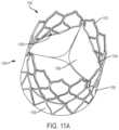
- FIG. 11 Ais an isometric view of the prosthetic valve of FIG. 11 , according to some embodiments.
- FIG. 12is a front view of a frame of the prosthetic valve of FIG. 11 , according to some embodiments.
- FIG. 13is an enlarged view of a commissure post of the frame of FIG. 12 , according to some embodiments.
- FIG. 14is a flat, schematic view of a portion of the frame of FIG. 12 , according to some embodiments.
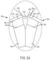
- FIG. 15is a view of a leaflet pattern of the prosthetic valve of FIG. 11 , according to some embodiments.
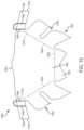
- FIG. 16is a flat, schematic view of a portion of the frame and an attachment element of the prosthetic valve of FIG. 11 , according to some embodiments.
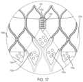
- FIG. 17is an overlay view for understanding assembly of the prosthetic valve of FIG. 11 , according to some embodiments.
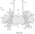
- FIG. 18is a transverse cross-section of the prosthetic valve of FIG. 11 at a commissure post of the prosthetic valve taken along line W-W on FIG. 12 , with portions of the prosthetic valve removed for ease of illustration, according to some embodiments.
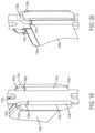
- FIGS. 19 and 20are isometric views of a commissure post of the prosthetic valve, with portions of the prosthetic valve removed for ease of illustration, according to some embodiments.
- FIG. 21shows another attachment arrangement between leaflets and a commissure post of a prosthetic valve, according to some embodiments.
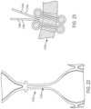
- FIGS. 22 and 23show features of another attachment arrangement between leaflets and a commissure post of a prosthetic valve, according to some embodiments.
- FIGS. 24 - 28show various retaining element arrangements usable for leaflets in attachment arrangements between leaflets and commissure posts, according to some embodiments.
- FIGS. 29 to 31show a potential modification for commissure attachment regions of the prosthetic valve of FIG. 11 , according to some embodiments.
- FIGS. 32 and 33show methods of implanting a prosthetic valve, according to some embodiments.
- the present disclosurerelates to prosthetic valves used for cardiac valve replacement or other applications associated with native valve or other valve orifices, and related systems, methods, and apparatuses.
- the prosthetic valveis operable as a one-way prosthetic valve that defines a valve orifice into which leaflets open to permit flow and close so as to block or occlude the valve orifice and partially or entirely prevent flow in response to differential fluid pressure.
- Implantable valve orificesinclude anatomical structures into which a prosthetic valve can be placed. Such anatomical structures include, but are not limited to, a location wherein a cardiac valve may or may not have been surgically removed. Other anatomical structures that can receive a prosthetic valve include, but are not limited to, veins, arteries, ducts and shunts. A valve orifice or implant site may also refer to a location in a synthetic or biological conduit that may receive a prosthetic valve.
- leafletas used in the context of prosthetic valves is generally a flexible component operable to move between an open and closed position under the influence of pressure differentials. In an open position, the leaflet allows blood to flow through the prosthetic valve. In a closed position, the leaflet substantially blocks retrograde flow through the prosthetic valve. This retrograde flow is at least partially blocked, and typically fully blocked by the leaflet. In embodiments comprising multiple leaflets, each leaflet cooperates with at least one neighboring leaflet to block the retrograde flow of blood.
- Various embodimentsrelate to attachment mechanisms for coupling leaflets to an associated frame such that the leaflets resist inward forces, outward forces, and/or axial forces on the leaflets relative to the associated frame.
- the leaflet frame attachment mechanisms for prosthetic valvesinclude the leaflet construct being at least partially coupled to a frame outer side by a looped structure. Such looped structures can help provide reduced stress concentrations, greater reliability of attachment, and ease of manufacture.
- the pressure differential in the blood actuating the leafletsis caused, for example, by the contraction of a ventricle or atrium of the heart, such pressure differential typically resulting from a fluid pressure building up on one side of the leaflets when closed.
- the leafletsopen and blood flows therethrough.
- the pressure on the inflow sideequalizes with the pressure on the outflow side.
- the leafletreturns to the closed position to partially or fully block retrograde flow of blood through the prosthetic valve.
- FIG. 1is an isometric view of a prosthetic valve 100 , according to some embodiments.
- the prosthetic valve 100includes a frame 102 , also described as a frame assembly or leaflet frame, a leaflet construct 104 , also described as a leaflet assembly or leaflet module, and an attachment element 106 , which can also be described as an attachment substrate or an attachment treatment.
- the prosthetic valve 100can include any of a variety of additional features, such as one more sealing cuffs, for example.
- the leaflet construct 104has a plurality of leaflets 180 ( FIG. 5 ) that come together where free edges 206 ( FIG.
- the prosthetic valve 100closes.
- the prosthetic valve 100closes in this fashion when the pressure of the blood on the outflow side O s is greater than the pressure of the blood on the inflow side I s of the prosthetic valve 100 .
- leaflet free edges of leaflet construct 104move apart to open the prosthetic valve 100 and to let blood flow through the prosthetic valve 100 from the inflow side I s when the pressure of the blood on the inflow side I s of the prosthetic valve 100 is greater than the pressure on the outflow side O s of the prosthetic valve 100 .
- the prosthetic valve 100defines a central longitudinal axis Xv, as well as an inner side 108 corresponding to a central lumen and an outer side 109 corresponding to the exterior of the prosthetic valve 100 .
- FIG. 2is a perspective view of the frame 102 of the prosthetic valve 100 , according to some embodiments.
- the frame 102serves to operatively support the leaflet construct 104 in a desired location within a patient (not shown).
- the frame 102is optionally collapsible to a reduced profile, delivery configuration and then expandable (e.g., self-expanding or expanded by the application of an external force, such as by balloon expansion) in situ.
- the frame 102is optionally annular, defining a cylinder (e.g., a right circular cylinder) or cylindrical shape, and has a central longitudinal axis Xf.
- the frame 102generally defines a circular transverse cross-section, it should be understood that any variety of cross-sections (e.g., oval- or rectangular-shaped) cross-sections are also contemplated.
- the frame 102has an inner side 110 and an outer side 112 opposite the inner side 110 .
- the inner side 110faces toward the central longitudinal axis Xf, and the outer side 112 faces outwardly, or away from the central longitudinal axis Xf.
- the frame 102includes a plurality of commissure posts 120 ( FIG. 3 ) and a plurality of frame elements 122 .
- the frame 102can be etched, cut, laser cut, stamped, three-dimensional printed or wire wound, among other suitable processes.
- the frame 102can comprise, such as, but not limited to, any metallic or polymeric material, such as an elastically (e.g., nitinol) or plastically (e.g., stainless steel) deformable metallic or polymeric material that is generally biocompatible.
- Other materials suitable for the frame 102include, but are not limited to, other titanium alloys, stainless steel, cobalt-nickel alloy, polypropylene, acetyl homopolymer, acetyl copolymer, a drawn filled tube (e.g., nitinol wire with a platinum core), other alloys or polymers, or any other material that is generally biocompatible having adequate physical and mechanical properties to function as a frame 102 as described herein.
- the plurality of commissure posts 120are spaced from one another, and arranged at desired locations (e.g., equally spaced locations) around a circumference of the frame 102 .
- the plurality of commissure posts 120extend parallel to the central longitudinal axis Xf, although angled configurations (e.g., commissure posts angled inwardly toward the central longitudinal axis Xf or outwardly away from the central longitudinal axis Xf) are also contemplated.
- three, equally circumferentially-spaced commissure posts 120are shown, any number and spacing of commissure posts are contemplated.
- the plurality of commissure posts 120define circumferentially-adjacent ones, or simply adjacent ones of the plurality of commissure posts 120 moving about the perimeter of the frame 102 .
- each of the commissure posts 120has a similar design, although examples where the commissure posts differ from one another in various respects are also contemplated.
- the features of each of the commissure posts 120will be described in association with a first commissure post 120 a , an enlarged view of which is shown in FIG. 3 .
- first commissure post 120 awill generally be referenced with a numeral followed by an “a.” Similar features of a second commissure post may be subsequently referenced with the same numeral as the first commissure post 120 a , but followed by a “b.” Similar features of a third commissure post may be subsequently referenced with the same numeral as the first commissure post 120 a , but followed by a “c.” Similarly, when features of each of the commissure posts 120 are referenced collectively, those features are referenced with the same numeral as identified for the first commissure post 120 a , but not followed by a letter.
- the first commissure post 120 aincludes a first leg 130 a , a second leg 132 a , a slot 134 a between the first leg 130 a and the second leg 132 a , which can also be described as a post slot, and a hanging feature 136 a , which can also be described as a protuberance, hook, or projection.
- the first commissure post 120 ahas an outer side corresponding to the frame outer side 112 ( FIG. 2 ) and a post inner side corresponding to the frame inner side 110 ( FIG. 2 ).
- first and second legs 130 a , 132 aextend longitudinally, or in a longitudinal direction.
- first and second legs 130 a , 132 aextend in a longitudinal direction that is parallel to the central longitudinal axis Xf ( FIG. 2 ) of the frame 102 .
- first and second legs 130 a , 132 aextend longitudinally, but at some offset relative to the central longitudinal axis Xf (e.g., angularly offset inwardly, toward the central longitudinal axis Xf, angularly offset transversely relative to the central longitudinal axis Xf, or a combination thereof).
- the slot 134 ais optionally formed between the first and second legs 130 a , 132 a and extends through a thickness of the first commissure post 120 a , from the inner side 110 ( FIG. 2 ) of the frame 102 to the outer side 112 ( FIG. 2 ) of the frame 102 .
- the slot 134 ais formed through the frame 102 in a radial direction relative to a central longitudinal axis Xf of the frame 102 or the slot 134 a is formed at an angle to a radial direction relative to the central longitudinal axis Xf of the frame 102 .
- the slot 134 aextends in a longitudinal direction that is parallel to the central longitudinal axis Xf ( FIG.
- the slot 134 aextends longitudinally, but at some offset relative to the central longitudinal axis Xf (e.g., angularly offset inwardly, toward the central longitudinal axis Xf, angularly offset transversely relative to the central longitudinal axis Xf, or a combination thereof).
- the slot 134 ais elongate in shape, with a length, or height, greater than its width (e.g., more than 2 ⁇ , 5 ⁇ , 10 ⁇ , 20 ⁇ , or 30 ⁇ , although a variety of dimensions are suitable), and extends from a first end 140 a to a second end 142 a .
- the first end 140 a of the slot 134 ais open and the second end 142 a of the slot 134 a is closed.
- the first end 140 ais “open” in the sense that it opens to a much wider area in the frame 102 (e.g., more than 5 ⁇ , 10 ⁇ , or 20 ⁇ )
- the second end 142 ais “closed” in the sense that it terminates at a distance from the first end 140 a of the slot 134 a .
- the width of the slot 134 ais generally selected to allow a desired number of passes or loops of leaflet material through the slot 134 a as described below.
- the hanging feature 136 awhich can also be described as a hanger, a protuberance, a projection a shoulder, a pin, or a hook, for example, includes a body portion 150 a and a head portion 152 a , where the body portion 150 a is secured through a hole 154 a , or aperture, in the frame 102 (the receiving hole is hidden in FIG. 3 , but can be seen in FIG. 2 without the hanging feature 136 a for ease of understanding).
- the head portion 152 agenerally defines a shoulder, and forms a channel 156 a between the head portion 152 a and the frame 102 .
- the depth and width of the channel 156 ais generally selected to receive and retain a filament or other desired portion of the leaflet construct 104 for axially supporting the leaflet construct 104 .
- the hanging feature 136 ais located longitudinally-adjacent the second end 142 a of the slot 134 a , and generally in alignment with the slot 134 a . In other examples, the hanging feature 136 a is offset from the slot 134 a (e.g., laterally/circumferentially).
- FIG. 4is an enlarged, flattened view of a first leaflet attachment region 160 a of the frame 102 between two adjacent commissure posts 120 , the first commissure post 120 a and second commissure post 120 b , according to some embodiments.
- the first leaflet attachment region 160 adefines a first side 162 a , a second side 164 a , and a base 166 a . Similar leaflet attachment regions 160 are defined between each of the adjacent commissure posts 120 , according to some embodiments.
- the first leaflet attachment region 160 a of the frame 102is represented in a flattened form for ease of illustration, although it should be understood that the frame 102 is three-dimensional and generally annular. As shown in FIG.
- the first commissure post 120 ais located at a first side of the first leaflet attachment region 160 a of the frame 102 and a second commissure post 120 b of the plurality of commissure posts 120 is located at a second side of the first leaflet attachment region 160 a of the frame 102 shown in FIG. 4 .
- the frame 102defines the first leaflet attachment region 160 a between the first and second commissure posts 120 a , 120 b , as well as leaflet attachment regions between the remaining commissure posts of the plurality of commissure posts 120 .
- the frame elements 122 of the frame 102include a plurality of leaflet attachment frame elements 170 , or simply leaflet attachment elements, that define leaflet attachment regions similar to the first leaflet attachment region 160 a shown in FIG. 4 .
- the leaflet attachment frame elements 170are arranged to support the leaflet construct 104 and to help define a shape of leaflets 180 ( FIG. 5 ) of the leaflet construct 104 , where that leaflet 180 will project from the corresponding leaflet attachment region, such as the first leaflet attachment region 160 a .
- FIG. 5the shape of leaflets 180
- the frame 102defines three sets of the leaflet attachment frame elements 170 corresponding to three leaflet attachment regions 160 that each generally follows the shape of an outline of a leaflet of the leaflet construct 104 .
- the leaflet attachment frame elements 170optionally support leaflets around at least a portion of each of the leaflets 180 except at the free edges 206 ( FIG. 5 ).
- FIG. 5shows the leaflet construct 104 as a flattened, plan view prior to assembly with the frame 102 .
- This flattened plan viewcan also be described as a cut pattern, or simply a leaflet pattern. From FIG. 1 , for example, it should be understood that the leaflet construct 104 is folded and formed into a cylindrical shape when assembled to the frame 102 .
- the leaflet construct 104includes a plurality of leaflets 180 and a plurality of bridges 182 , or bridge regions, interconnecting the circumferentially-adjacent leaflets 180 .
- the plurality of leaflets 180are spaced from one another, and arranged at desired locations around a circumference of the leaflet construct 104 corresponding to the respective leaflet attachment regions 160 and commissure posts 120 .
- the leaflet patterndefines a connected and continuous (e.g., monolithic, contiguous or seamless) annular ring formed as a single piece and including the plurality of leaflets 180 and bridges 182 between each of the plurality of leaflets 180 .
- the plurality of leaflets 180define circumferentially-adjacent ones, or simply adjacent ones of the plurality of leaflets 180 moving about the circumference of the leaflet construct 104 .
- the leaflet construct 104can be formed in a variety of manners, including cutting a cylinder of material into a desired shape, cutting a sheet of material into a desired shape, and/or molding (e.g., compression or injection molding) the leaflet construct 104 with a desired shape.
- the leaflet construct 104also includes a plurality of first retaining elements 184 , and a plurality of second retaining elements 186 (the retaining elements are not shown in FIG. 5 for ease of visualization of the bridges 182 ).
- a retaining elementincludes one or more of a strand, filament, monofilament, multifilament (whether braided, woven, twisted or an otherwise associated group of filaments), a bead of material, a thread, a suture, a rolled film, a multilayer lay-up of material, a wire, an embossed or other feature providing the functionality described herein.
- the first and second retaining elements 184 , 186are optionally molded, adhered, and/or heat bonded, or otherwise coupled to the leaflet construct 104 as desired.
- couplemeans to join, connect, attach, adhere, affix, or bond, whether directly or indirectly, and whether permanently or temporarily.
- the first retaining elements 184are not present.
- the retaining elements 184 a , 184 bmay be unnecessary in instances where there is a desired amount of support/retention provided by the second retaining elements 186 .
- each of the plurality of leaflets 180has a similar design, although examples where the leaflets differ from one another in various respects are also contemplated. Regardless, for ease of understanding, the features of each of the leaflets 180 will be described in association with a first leaflet 180 a .
- first leaflet 180 awill generally be referenced with a numeral followed by an “a.” Similar features of a second leaflet may be subsequently referenced with the same numeral as the first leaflet, but followed by a “b.” Similar features of a third leaflet may be subsequently referenced with the same numeral as the first leaflet 180 a , but followed by a “c.” Similarly, when features of each of the leaflets 180 are referenced collectively, those features are referenced with the same numeral as identified for the first leaflet 180 a , but not followed by a letter.
- the first leaflet 180 aoptionally includes a body portion 190 a , a plurality of attachment tabs 192 a extending from the body portion 190 a , a first commissure tab 194 a extending from the body portion 190 a , and a second commissure tab 196 a extending from the body portion 190 a (e.g., at opposite ends of free edge 206 a ).
- the second and leaflets 180 b , 180 coptionally include similar features.
- the second leaflet 180 bincludes a first commissure tab 194 b and a second commissure tab 196 b .
- the first commissure tab 194 ais positioned adjacent the second commissure tab 196 b and the second commissure tab 196 a is positioned adjacent a first commissure tab 194 c of the third leaflet 180 c.
- the body portion 190 aalso described as a leaflet belly, or belly portion, is bounded in broken lines for understanding purposes.
- the body portion 190 a of the first leaflet 180 ais the moving portion of the first leaflet 180 a in the prosthetic valve 100 .
- the boundaries of the body portion 190 aare defined and the body portion 190 a takes on a three dimensional shape, rather than the flat shape shown in FIG. 5 .
- the broken linesare provided for general visualization purposes of the body portion 190 a .
- the shape of the body portion 190 ais generally dictated by the lines, or areas of attachment to the frame 102 .
- the edges of the body portion 190 agenerally correspond to fold lines where the attachment tabs 192 a and the first commissure tab 194 a and the second commissure tab 196 a are secured to the frame 102 ( FIG. 2 ).
- the leaflet construct 104may be attached to the frame 102 using attachment element 106 ( FIG. 1 ), which in turn, may contribute to shape defined by the leaflet attachment regions 160 and the ultimate shape of the body portion 190 a.
- the body portion 190 a of the first leaflet 180 ahas the general shape of an isosceles trapezoid. Regardless of the exact shape, the body portion 190 a generally has a first side 200 a , a second side 202 a , a base 204 a , and a free edge 206 a opposite the leaflet base 204 a for coaptating with respective free edges 206 of respective other leaflets 180 .
- the shape of the body portion 190 acorresponds to the first side 162 a , the second side 164 a , and the base 166 a of the first leaflet attachment region 160 a ( FIG. 4 ).
- leaflet base 204 ais perpendicular to the central longitudinal axis Xf of the frame 102 following assembly.
- the body portion 190 ais shown to take on the general shape of an isosceles trapezoid, any number of shapes is contemplated, and the body portion 190 a need not be trapezoidal in overall appearance.
- the body portion 190 amay include a central region that defines a shape substantially that of an isosceles trapezoid, with side regions on each side that have a shape substantially that of a triangle.
- the body portion 190 amay outline a shape that can be described as U-shaped, parabolic shaped, or a V-shaped, depending on the geometric outline defined by the first leaflet attachment region 160 a.
- the first leaflet 180 agenerally defines a fold over portion 198 a , also described as a fold over region, outside of the body portion 190 a , as demarcated by the broken line in FIG. 5 .
- the fold over portion 198 a of the first leaflet 180 ais the portion that is used to secure the first leaflet 180 a to the frame 102 , where the remaining leaflets 180 optionally include similar features for securing to the frame 102 .
- the leaflet attachment frame elements 170( FIG. 4 ) fit into a fold that is formed between the body portion 190 a and the fold over portion 198 a .
- the leaflets 180extend radially inward from the frame 102 when coupled to the frame 102 .
- each leaflet 180includes enough material between the commissure posts 120 of the frame 102 so that the leaflet free edges 206 of the three leaflets 180 can come together or coapt in the interior of the prosthetic valve 100 to close the prosthetic valve 100 as shown in FIG. 1 .
- the plurality of attachment tabs 192 a located in the fold over portion 198 aare positioned about a perimeter of the body portion 190 a and are separated from one another by openings 208 a for receiving frame elements 122 (e.g., leaflet attachment frame elements 170 ) of the frame 102 .
- One or more of the plurality of attachment tabs 192 aoptionally includes a plurality of apertures (not shown) through the thickness of the attachment tabs 192 a .
- the aperturesmay assist with coupling or otherwise securing the attachment tabs 192 a to the frame 102 (e.g., directly or via the attachment element 106 ) using adhesives or bonding (e.g., to provide additional surface area for adhesion/bonding), fastening elements (e.g., holes for sutures), or combinations thereof.
- first commissure tab 194 a and the second commissure tab 196 aassist with securing the first leaflet 180 a to the first commissure post 120 a and second commissure post 120 b ( FIGS. 2 , 4 ).
- first commissure tab 194 aextends from the first side 200 a of the body portion 190 a and the second commissure tab 196 a extends from a second side 202 a of the body portion 190 a .
- the first commissure tab 194 aextends from a first end 210 a , also described as a leaflet end, to a terminal end 212 a ( FIG. 6 ).
- the second commissure tab 196 aextends from a first end 214 a to a terminal end 216 a ( FIG. 6 ).
- the first commissure tab 194 a and second commissure tab 196 aare shown with an optional taper toward the terminal ends 212 a , 216 a.
- FIG. 6 Ais an enlarged view of a portion of FIG. 6 , and illustrates a bridge 182 a of the plurality of bridges 182 .
- Each of the bridges 182is optionally substantially similar, and as such can be described cumulatively with reference to the bridge 182 a (although varying bridge designs from bridge-to-bridge are also contemplated).
- the bridge 182 ainterconnects, or otherwise extends between a first end 220 a adjacent to the first leaflet 180 a and a second end 222 a adjacent the second leaflet 180 b .
- the bridge 182 a(and each of the bridges 182 ) defines a loop between the first end 220 a and the second end 222 a .
- the loops defined by the bridges 182 , as well as the remaining portions of the leaflets 180 that are secured to the commissure posts 120can also be described as coaptation necks.
- These coaptation necksare operable to pass through the slots of the commissure posts 120 , such as the slot 134 a of the first commissure post 120 a , so that the loop formed by folding the bridge 182 a is adjacent to the outer side 112 of the frame 102 , which also corresponds to the outer side of the first commissure post 120 a ( FIG. 2 ).
- the first leaflet 180 aincludes a first retaining element 184 a that is located on the first commissure tab 194 a and the second leaflet 180 b includes a first retaining element 184 b that is located on the second commissure tab 196 b of the second leaflet 180 b near the first end 214 b of the second commissure tab 196 b .
- the first retaining elements 184 a , 184 b of the respective leaflets 180 a , 180 bare separate and discontinuous from one another and they are not formed as a single or contiguous piece.
- the second retaining element 186 aextends across, or overlays, the bridge 182 a and onto each of the first leaflet 180 a and the second leaflet 180 b and is optionally a single, connected and continuous (e.g., contiguous) member or element.
- the second retaining element 186 adefines a first portion 230 a on the first leaflet 180 a and a second portion 230 b on the second leaflet 180 b .
- Each of the portionsis optionally individually referred to as elements as well.
- the first leaflet 180 aincludes second retaining element 186 a
- the second leaflet 180 bincludes second retaining element 186 b
- the second retaining elements 186 a , 186 bare connected and continuous (e.g., contiguous) with one another as a single piece to define the second retaining element 186 a
- the first retaining elements 184 a , 184 bare spaced apart from the second retaining element 186 a .
- first retaining elements 184(e.g., 184 a , 184 b ) are spaced apart from their adjacent second retaining elements 186 (e.g., 186 a ) a distance at least as wide as the thickness of a corresponding commissure post 120 (e.g., 120 a ) as measured from the inner side 110 to the outer side 112 of the frame 102 .
- the various retaining elementscan take a variety of forms.
- the first retaining elements 184are formed as beads of material on the commissure tabs of the leaflets 180
- the second retaining elements 186are fibers (e.g., coated fibers).
- the various retaining elementsare optionally molded, adhered and/or bonded to the underlying material of the leaflets 180 , such as by thermal bonding.
- the second retaining elements 186help reinforce the bridges 182 , provide connections between the leaflets 180 , and/or are used to affect retention of the first and the second commissure tabs 194 , 196 in the slots 134 of the commissure posts 120 .
- the second retaining elements 186are located adjacent the slots 134 at the outer side 112 and the first retaining elements 184 are located adjacent the slots 134 at the inner side 110 of the frame 102 .
- the second retaining elements 186are optionally used to help prevent the first and the second commissure tabs 194 , 196 and bridges 182 from pulling inwardly through the slots 134
- the first retaining elements 184are optionally used to help prevent the leaflets 180 from pulling outwardly through the slots 134 to the outer side 112 of the frame 102 .
- cross-sectional areas of the retaining elements 184 , 186 and portions of the commissure tabs 194 , 196 looped over themare greater than the widths of the slots 134 .
- the first retaining elements 184 and/or the second retaining elements 186can be formed from polymeric or metallic materials, fluoropolymers, one or more of FEP, PEEK, ePTFE filament(s) (mono- or multi-), nitinol, stainless steel, multiple folds or layers of material (e.g., ePTFE film), combinations thereof, or any of a variety of features configured to resist movement relative to the slot(s) and/or hanging feature(s).
- FIG. 7is a schematic, flat view of a portion of the frame 102 and attachment element 106 .
- the gray area in FIG. 7represents locations where the attachment element 106 is not present.
- the attachment elementis optionally one or more layers of material applied to the frame material.
- the openings, or gray areas in the attachment element 106are optionally formed via laser cutting (e.g., where the attachment element is applied to the frame 102 as part of a tape wrapping process.
- Several locations of the attachment element 106are marked on FIG. 7 for ease of understanding.
- the prosthetic valve 100optionally includes attachment element 106 , which can also be described as an attachment substrate or an attachment treatment.
- the attachment element 106is optionally one or more layers of material attached to the frame 102 .
- the outer side 112 of the frame 102is covered with the attachment element 106 , which is in the form of one or more layers of film material.
- One or more portions of the leaflet construct 104can then be attached to the attachment element 106 , thereby helping to define the shapes of the leaflets 180 .
- FIG. 8shows an overlay of the frame 102 , the leaflet construct 104 , and the attachment element 106 in an area of the first leaflet attachment region 160 a , for understanding, where similar principles of which apply in assembling the remaining leaflets 180 to leaflet attachment regions of the frame 102 .
- the leaflet construct 104is attached to the frame 102 and/or attachment element 106 using fold over portions, such as the fold over portion 198 a of the first leaflet 180 a .
- Attachment tabssuch as the attachment tabs 192 a of the first leaflet 180 a are received over portions of the frame 102 and/or attachment element 106 and attached thereto to attach the leaflet construct 104 to the frame at the body portions of the leaflets 180 , such as the body portion 190 a ( FIG. 5 ).
- one or more of the attachment tabs 192 amay be folded to the attachment element 106 , rather than the frame 102 .
- the lowermost attachment tab 192 amay be folded to a relatively flat area at the bottom of the attachment element 106 , to define a relatively flat base corresponding to that shown for the body portion 190 a in FIG. 5 .
- the attachment tabsdo not necessarily have to follow the geometry of the frame 102 , but can follow a geometry separate from the frame 102 as defined by the attachment element 106 , for example.
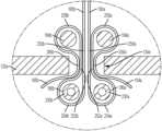
- FIGS. 9 and 10illustrate attachment of the leaflets 180 to the commissure posts 120 according to some examples.
- FIG. 9is a transverse cross-section through the commissure post 120 a at the slot 134 a
- FIG. 10is an isometric view of the prosthetic valve 100 in the area of the first commissure post 120 a .
- relatively sharp cornersare shown in FIG. 9 at the slot 134 a of the first commissure post 120 a , it should be understood that chamfers, rounds, reliefs coatings and other features may be provided to avoid stress concentrations or other wearing of the leaflets 180 a , 180 b at those slot edges.
- FIGS. 9is a transverse cross-section through the commissure post 120 a at the slot 134 a
- FIG. 10is an isometric view of the prosthetic valve 100 in the area of the first commissure post 120 a .
- relatively sharp cornersare shown in FIG. 9 at the slot 134 a of the first commissure post 120 a , it should be understood that
- the first commissure tab 194 a of the first leaflet 180 a and the second commissure tab 196 b of the second leaflet 180 beach pass through the slot 134 a of the first commissure post 120 a several times, with the first retaining elements 184 a , 184 b positioned on the inner side 110 of the frame 102 , and thus on the inner side of the first commissure post 120 a , and the first portion 230 a and the second portion 230 b of the second retaining element 186 a ( FIG. 10 ) on the outer side 112 of the frame 102 , and thus the outer side of the first commissure post 120 a .
- first retaining elements 184 a , 184 bsecure the first and the second commissure tabs 194 a , 196 b , respectively, from being pulled outwardly relative to the frame 102 .
- first and second portions 230 a , 230 b of the second retaining element 186 asecure the first and the second commissure tabs 194 a , 196 b , respectively, from being pulled inwardly relative to the frame 102 .
- sutures, film layers, adhesives, thermal bonding or other featurescan be used to help secure or otherwise couple the first retaining elements 184 a , 184 b and/or the second retaining elements 186 a , 186 b.
- the first commissure tab 194 a of the first leaflet 180 adefines a first pass 250 a through the slot 134 a (inside-out relative to the first commissure post 120 a ) and a second pass 252 a through the slot 134 a (outside-in relative to the first commissure post 120 a ) to define a first loop 254 a through the slot 134 a .
- the first portion 230 a of the second retaining element 186 ais positioned within the first loop 254 a to form a widened cross-section for the first loop 254 a on the outer side 112 of the frame 102 .
- the width of the first loop 254 ais selected to resist, or be restrained from, pulling through the slot 134 a .
- the first commissure tab 194 a of the first leaflet 180 adefines a third pass 256 a through the slot 134 a (outside-in relative to the first commissure post 120 a ) to define a second loop 258 a passing through the slot 134 a .
- the first retaining element 184 ais positioned within the second loop 258 a such that the second loop 258 a encircles the first retaining element 184 a to form a widened cross-section for the second loop 258 a on the outer side 112 of the frame 102 .
- the width of the second loop 258 ais selected to resist, or be restrained from, pulling through the slot 134 a .
- the first pass 250 ais positioned adjacent the second pass 252 a , which is positioned adjacent the third pass 256 a within the slot 134 a.
- the second commissure tab 196 b of the second leaflet 180 bdefines a first pass 250 b through the slot 134 a (inside-out relative to the first commissure post 120 a ) and a second pass 252 b through the slot 134 a (outside-in relative to the first commissure post 120 a ) to define a first loop 254 b through the slot 134 a .
- the second portion 230 b of the second retaining element 186 b( FIG. 10 ) is positioned within the first loop 254 b such that the first loop 254 b encircles the second retaining element 186 b to form a widened cross-section for the first loop 254 b on the outer side 112 of the frame 102 .
- the width of the first loop 254 bis selected to resist, or be restrained from, pulling through the slot 134 a .
- the second commissure tab 196 b of the second leaflet 180 bdefines a third pass 256 b through the slot 134 a (outside-in relative to the first commissure post 120 a ) to define a second loop 258 b passing through the slot 134 a .
- the first retaining element 184 bis positioned within the second loop 258 b such that the first retaining element 184 b is encircled by the second loop 258 b to form a widened cross-section for the second loop 258 b on the outer side 112 of the frame 102 .
- the width of the second loop 258 bis selected to resist, or be restrained from, pulling through the slot 134 a .
- the first pass 250 bis positioned adjacent the second pass 252 b , which is positioned adjacent the third pass 256 b within the slot 134 a.
- the first loops 254 a,bare optionally described as outer loops and the second loops 258 a,b are optionally described as inner loops.
- one or more of the passes 250 a,b , 252 a,b , 256 a,bare coupled to one another (e.g., by molding, heat sealing/bonding, adhesives, sutures, or other coupling means).
- the various passescan be inserted into the slot 134 a with the first retaining elements 184 a on the inner side 110 of the frame 102 and the second retaining element 186 a outer side of the frame 102 by sliding the first commissure tab 194 a and the second commissure tab 196 b into the slot 134 a through the first end 140 a ( FIG. 3 ) of the slot 134 a , which is an open end.
- first commissure tab 194 a and the second commissure tab 196 bare threaded through the slot 134 a inside-out and outside in to form the first loops 254 a,b and the second loops 258 a,b (e.g., as opposed being slid upwardly into the first slots 1134 a and the second slots 1136 a ).
- three passesare shown for each of the commissure tabs in FIG. 9 , fewer passes (two, where a single loop is desired) or more (e.g., where additional loops are desired) are contemplated.
- FIG. 10shows the second retaining element 186 a (which includes the bridge 182 a ( FIG. 6 A ) received over the hanging feature 136 a (head portion 152 a is shown), and in particular behind the head portion 152 a within the channel 156 a ( FIG. 3 ) formed between the head portion 152 a and the frame 102 .
- the second retaining element 186 athus defines a hanging loop 280 a for supporting the first leaflet 180 a and the second leaflet 180 b ( FIG. 9 ) to which the second retaining element 186 a is attached.
- the remaining first and second commissure tabs 194 , 196 of the leaflets 180are secured to and supported from the remaining commissure posts 120 .
- the relatively smooth turns and reinforcement provided by the retaining elements 184 , 186reduce stress concentrations at the commissure posts 120 due to transverse loading of the leaflet construct 104 .
- the axial support provided the hanging loopssimilar to hanging loop 280 a , provide axial support the leaflet construct 104 and help to reduce axial stress concentrations at the attachment interfaces between the commissure posts 120 and the leaflets 180 ( FIG. 5 ).
- FIG. 11is a plan view of another prosthetic valve 1100 and FIG. 11 A is an isometric view of the prosthetic valve 1100 , according to some embodiments.
- the prosthetic valve 1100includes a frame 1102 , also described as a frame assembly or leaflet frame, a leaflet construct 1104 including a plurality of leaflets 1180 , also described as a leaflet assembly or leaflet module, and an attachment element 1106 , which can also be described as an attachment substrate or an attachment treatment.
- the leaflet construct 1104may be comprised of a plurality of leaflets 1180 that are formed as individual components and then subsequently assembled to the frame 1102 to form the leaflet construct 1104 .
- the prosthetic valve 1100can include any of a variety of additional features, such as one or more sealing cuffs, for example. As shown, the prosthetic valve 1100 defines a central longitudinal axis Yv, as well as an inner side 1108 corresponding to a central lumen and an outer side 1109 corresponding to the exterior of the prosthetic valve 1100 .
- the leaflet construct 1104has three leaflets that come together, and in particular free edges that come together at a coaptation region in a Y-shaped pattern (when viewed from above), to close the prosthetic valve 1100 .
- the prosthetic valve 1100closes in this fashion when the pressure of the blood on the outflow side is greater than the pressure of the blood on the inflow side of the prosthetic valve 1100 .
- leaflet free edges of leaflet construct 1104move apart to open the prosthetic valve 1100 and to let blood flow through the prosthetic valve 1100 from the inflow side when the pressure of the blood on the inflow side of the prosthetic valve 1100 is greater than the pressure on the outflow side of the prosthetic valve 1100 .
- FIG. 12is a perspective view of the frame 1102 of the prosthetic valve 1100 , according to some embodiments.
- the frame 1102serves to operatively support the leaflet construct 1104 in a desired location within the body of a patient (not shown).
- the frame 1102is optionally collapsible to a reduced profile, delivery configuration and then expandable (e.g., self-expanding or expanded by the application of an external force, such as a balloon expansion) in situ.
- the frame 1102is optionally annular, defining a cylinder or cylindrical shape, and has a central longitudinal axis Yf.
- the frame 1102generally defines a circular transverse cross-section, it should be understood that any variety of cross-sections (e.g., oval- or rectangular-shaped) cross-sections are also contemplated.
- the frame 1102has an inner side 1110 and an outer side 1112 opposite the inner side 1110 .
- the inner side 1110faces toward the central longitudinal axis Yf, and the outer side 1112 faces outwardly, or away from the central longitudinal axis Yf.
- the frame 1102includes a plurality of commissure posts 1120 and a plurality of frame elements 1122 .
- the frame 1102can be etched, cut, laser cut, stamped, three-dimensional printed or wire wound, among other suitable processes.
- the frame 1102can comprise, such as, but not limited to, any elastically deformable metallic or polymeric material that is generally biocompatible.
- the frame 1102can comprise a shape-memory material, such as nitinol, a nickel-titanium alloy.
- Other materials suitable for the frame 1102include, but are not limited to, other titanium alloys, stainless steel, cobalt-nickel alloy, polypropylene, acetyl homopolymer, acetyl copolymer, other alloys or polymers, or any other material that is generally biocompatible having adequate physical and mechanical properties to function as a frame 1102 as described herein.
- the plurality of commissure posts 1120are spaced from one another, and arranged at desired locations around a circumference of the frame 1102 . As shown, the plurality of commissure posts 1120 extend parallel to the central longitudinal axis Yf, although angled configurations (e.g., commissure posts angled inwardly toward the central longitudinal axis Yf or outwardly away from the central longitudinal axis Yf) are also contemplated. Although three commissure posts 1120 are shown, any number of commissure posts are contemplated. The plurality of commissure posts 1120 define circumferentially-adjacent ones, or simply adjacent ones of the plurality of commissure posts 1120 moving about the perimeter of the frame 1102 .
- each of the commissure posts 1120has a similar design, although examples where the commissure posts differ from one another in various respects are also contemplated. Regardless, for ease of understanding, the features of each of the commissure posts 1120 will be described in association with a first commissure post 1120 a , an enlarged view of which is shown in FIG. 13 .
- first commissure post 1120 awill generally be referenced with a numeral followed by an “a.” Similar features of a second commissure post may be subsequently referenced with the same numeral as the first commissure post, but followed by a “b.” Similar features of a third commissure post may be subsequently referenced with the same numeral as the first commissure post 1120 a , but followed by a “c.” Similarly, when features of each of the commissure posts 1120 are referenced collectively, those features are referenced with the same numeral as identified for the first commissure post 1120 a , but not followed by a letter.
- the first commissure post 1120 aincludes a first leg 1130 a , a second leg 1132 a , a first slot 1134 a , which can also be described as a first post slot, and a second slot 1136 a , which can also be described as a second post slot.
- the first slot 1134 a and the second slot 1136 aare each located between the first leg 1130 a and the second leg 1132 a .
- the first commissure post 1120 aalso includes an intermediate leg 1138 a positioned between the first leg 1130 a and the second leg 1132 a .
- the first commissure post 1120 adefines the first slot 1134 a between the first leg 1130 a and the intermediate leg 1138 a and the second slot 1136 a between the second leg 1132 a and the intermediate leg 1138 a .
- the first commissure post 1120 ahas an outer side corresponding to the frame outer side 1112 and a post inner side corresponding to the frame inner side 1110 .
- first leg 1130 a and the second leg 1132 aextend longitudinally, or in a longitudinal direction.
- first leg 1130 a and the second leg 1132 aextend in a longitudinal direction that is parallel to the central longitudinal axis Yf ( FIG. 12 ) of the frame 1102 .
- first leg 1130 a and the second leg 1132 aextend longitudinally, but at some offset relative to the central longitudinal axis Yf (e.g., angularly offset inwardly, toward the central longitudinal axis Yf, angularly offset transversely relative to the central longitudinal axis Yf, or a combination thereof).
- each of the first slot 1134 a and the second slot 1136 aextends through a thickness of the first commissure post 1120 a , from the inner side 1110 ( FIG. 12 ) of the frame 1102 to the outer side 1112 ( FIG. 12 ) of the frame 1102 .
- the slots 1134 a , 1136 aare formed through the frame in a radial direction relative to a central longitudinal axis Yf of the frame 1102 or the slot is formed at an angle to a radial direction relative to the central longitudinal axis Yf of the frame 1102 .
- first slot 1134 a and the second slot 1136 aextend in a longitudinal direction that is parallel to the central longitudinal axis Yf ( FIG. 12 ) of the frame 1102 .
- first slot 1134 a and the second slot 1136 aextend longitudinally, but at some offset relative to the central longitudinal axis Yf (e.g., angularly offset inwardly, toward the central longitudinal axis Yf, angularly offset transversely relative to the central longitudinal axis Yf, or a combination thereof).
- first slot 1134 a and the second slot 1136 aare elongate in shape, with lengths, or heights, much greater than their widths (e.g., more than 2 ⁇ , 5 ⁇ , 10 ⁇ , 20 ⁇ , or 30 ⁇ , although a variety of dimensions are suitable).
- the first slot 1134 aextends from a first end 1140 a to a second end 1142 a and the second slot 1136 a extends from a first end 1144 a to a second end 1146 a .
- the first ends 1140 a , 1144 aare open and the second ends 1142 a , 1146 a are closed.
- first ends 1140 a , 1144 aare “open” in the sense that it opens to a much wider area in the frame 1102 (e.g., more than 5 ⁇ , 10 ⁇ , or 20 ⁇ ), whereas the second ends 1142 a , 1146 a are “closed” in the sense that it terminates at the width of the first slot 1134 a and the second slot 1136 a .
- the widths of the first slot 1134 a and the second slot 1136 aare generally selected to allow a desired number of passes or loops of leaflet material through the first slot 1134 a and the second slot 1136 a.
- the first commissure post 1120 adefines a first hanging feature 1150 a , also described as a protuberance, hook, or projection, and a second hanging feature 1152 a , also described as a protuberance, hook, or projection.
- Each of the first and second hanging features 1150 a , 1152 ais optionally described as a hanger, shoulder, pin, or hook, for example.
- the first hanging feature 1150 aoptionally projects longitudinally from the first leg 1130 a (e.g., parallel to the longitudinal axis Yf of the frame 1102 ).
- the second hanging feature 1152 aoptionally projects longitudinally from the second leg 1132 a (e.g., parallel to the longitudinal axis Yf of the frame 1102 ).
- the first commissure post 1120 aoptionally defines a first channel 1154 a between the first hanging feature 1150 a and the intermediate leg 1138 a .
- the first commissure post 1120 aalso optionally defines a second channel 1156 a between the second hanging feature 1152 a and the intermediate leg 1138 a .
- the depths and widths of the channels 1154 a , 1156 aare generally selected to receive and retain filaments or other desired portions of the leaflet construct 1104 for axially supporting the leaflet construct 1104 .
- the hanging features 1150 a , 1152 aare each located longitudinally-adjacent the second ends 1142 a , 1146 a of the slots 1134 a , 1136 a and generally in alignment with the first slot 1134 a and the second slot 1136 a .
- the hanging features 1150 a , 1152 aare offset from the first slot 1134 a and the second slot 1136 a (e.g., laterally/circumferentially).
- FIG. 14is an enlarged, flattened view of a portion of the frame 1102 between two adjacent commissure posts 1120 , according to some embodiments. Similar portions of the frame 1102 are defined between each of the adjacent commissure posts 1120 , according to some embodiments.
- the portion of the frame 1102is represented in a flattened form for ease of illustration, although it should be understood that the frame 1102 is three-dimensional and generally annular.
- the first commissure post 1120 ais located at a first side of the portion of the frame 1102 and a second commissure post 1120 b of the plurality of commissure posts 1120 is located at a second side of the portion of the frame 1102 shown in FIG. 4 .
- the frame 1102defines a first leaflet attachment region 1160 a between the first commissure post 1120 a and the second commissure post 1120 b , as well as leaflet attachment regions 1160 between the remaining commissure posts 1120 .
- the first leaflet attachment region 1160 adefines a first side 1162 a , a second side 1164 a , and a base 1166 a .
- Similar leaflet attachment regions 1160are defined between each of the adjacent commissure posts 1120 , according to some embodiments.
- the frame elements 1122 of the frame 1102include a plurality of leaflet attachment frame elements 1170 , or simply leaflet attachment elements, that define the leaflet attachment regions, including the first leaflet attachment region 1160 a shown in FIG. 14 .
- the leaflet attachment frame elements 1170are arranged to support the leaflet construct 1104 and to help define a shape of a leaflet of the leaflet construct 1104 , where that leaflet will project from the first leaflet attachment region 1160 a .
- the frame 1102defines three sets of the leaflet attachment frame elements 1170 that each generally follows the shape of an outline of a leaflet of the leaflet construct 1104 .
- the leaflet attachment frame elements 1170optionally support leaflets around the leaflet perimeters except at the free edges.
- the leaflet construct 1104includes a plurality of leaflets 1180 .
- FIG. 15shows a first leaflet 1180 a of a plurality of leaflets 1180 ( FIG. 11 ) from a flattened, plan view prior to assembly with the frame 1102 .
- This flattened plan viewcan also be described as a cut pattern, or simply a leaflet pattern.
- FIG. 11it should be understood that the leaflet construct 1104 is folded and turned into a cylindrical shape when assembled to the frame 1102 , with each of the plurality of leaflets 1180 being attached circumferentially about the frame 1102 .
- FIG. 15shows a first leaflet 1180 a of a plurality of leaflets 1180 ( FIG. 11 ) from a flattened, plan view prior to assembly with the frame 1102 .
- This flattened plan viewcan also be described as a cut pattern, or simply a leaflet pattern.
- the plurality of leaflets 1180are optionally formed as separate components, which are then separately assembled to the frame 1102 .
- the leaflet construct 1104optionally includes a plurality of bridges, or bridge regions (e.g. such as bridges 182 ), interconnecting circumferentially-adjacent leaflets 1180 .
- the leaflet patterndefines a connected and continuous (e.g., contiguous) annular ring including the plurality of leaflets and bridges between each of the plurality of leaflets.
- the plurality of leaflets 1180are spaced from one another, and arranged, or otherwise distributed at desired locations around a circumference of the leaflet construct 1104 .
- the plurality of leaflets 1180define circumferentially-adjacent ones, or simply adjacent ones of the plurality of leaflets 1180 moving about the circumference of the leaflet construct 1104 .
- the leaflet construct 1104can be formed in a variety of manners, including cutting a cylinder of polymer material into a desired shape, cutting a sheet of polymer material into a desired shape, and/or molding (e.g., compression or injection molding) the leaflet construct 1104 with a desired shape.
- each of the plurality of leaflets 1180has a similar design, although examples where the leaflets differ from one another in various respects are also contemplated. Regardless, for ease of understanding, the features of each of the leaflets 1180 will be described in association with a first leaflet 1180 a .
- first leaflet 1180 awill generally be referenced with a numeral followed by an “a.” Similar features of a second leaflet may be subsequently referenced with the same numeral as the first leaflet, but followed by a “b.” Similar features of a third leaflet may be subsequently referenced with the same numeral as the first leaflet 1180 a , but followed by a “c.” Similarly, when features of each of the leaflets are referenced collectively, those features are referenced with the same numeral, but not followed by a letter. Similarly, when features of each of the leaflets 1180 are referenced collectively, those features are referenced with the same numeral, but not followed by a letter.
- the first leaflet 1180 aincludes a plurality of first retaining elements 1184 a and a plurality of second retaining elements 1186 a , where each of the leaflets 1180 optionally includes a similar first retaining element 1184 and second retaining elements 1186 .
- the first plurality of retaining elements 1184 a and the second plurality of retaining elements 1186 aare optionally molded, adhered and/or heat bonded, or otherwise coupled to the leaflet construct 1104 ( FIG. 11 ) as desired.
- the first leaflet 1180 aoptionally includes a body portion 1190 a , a plurality of attachment tabs 1192 a extending from the body portion 1190 a , a first commissure tab 1194 a extending from the body portion 1190 a , and a second commissure tab 1196 a extending from the body portion 1190 a.
- the body portion 1190 aalso described as a leaflet belly, or belly portion, is bounded in broken lines for understanding purposes.
- the body portion 1190 a of the first leaflet 1180 ais the moving portion of the first leaflet 1180 a in the prosthetic valve 1100 ( FIG. 11 ).
- the boundaries of the body portion 1190 aare defined and the body portion 1190 a takes on a three dimensional shape, rather than the flat shape shown in FIG. 15 .
- the broken linesare provided for general visualization purposes of the body portion 1190 a .
- the shape of the body portion 1190 ais generally dictated by the lines, or areas of attachment to the frame 1102 .
- the edges of the body portion 1190 agenerally correspond to fold lines where the attachment tabs 1192 a and first commissure tab 1194 a and the second commissure tab 1196 a are secured to the frame 1102 .
- the leaflet construct 1104may be attached to the frame 1102 using attachment element 1106 ( FIG. 11 ), which in turn, may contribute to shape defined by the leaflet attachment regions 1160 and the ultimate shape of the body portion 1190 a.
- the body portion 1190 a of the first leaflet 1180 ahas the general shape of an isosceles trapezoid. Regardless of the exact shape, the body portion 1190 a generally has a first side 1200 a , a second side 1202 a , a leaflet base 1204 a , and a free edge 1206 a opposite the leaflet base 1204 a for coaptating with other leaflets 1180 .
- the shape of the body portion 1190 acorresponds to the sides and base of the first leaflet attachment region 1160 a ( FIG. 14 ).
- leaflet base 1204 ais perpendicular to the central longitudinal axis Yf of the frame 1102 following assembly.
- the body portion 1190 ais shown to take on the general shape of an isosceles trapezoid, any number of shapes is contemplated, and the body portion 1190 a need not be trapezoidal in overall appearance.
- the body portion 1190 amay include a central region that defines a shape substantially that of an isosceles trapezoid, with side regions on each side that have a shape substantially that of a triangle.
- the body portion 1190 amay outline a shape that can be described as U-shaped or a V-shapes, depending on the geometric outline defined by the first leaflet attachment region 1160 a ( FIG. 14 ).
- the first leaflet 1180 agenerally defines a fold over portion 1198 a , also described as a fold over region, outside of the body portion 1190 a , as demarcated by the broken line in FIG. 15 .
- the fold over portion 1198 a of the first leaflet 1180 ais the portion that is used to secure the first leaflet 1180 a to the frame 1102 , where the remaining leaflets 1180 optionally include similar features for securing to the frame 1102 .
- the leaflet attachment frame elements 1170( FIG. 14 ) fit into a fold that is formed between the body portion 1190 a and the fold over portion 1198 a .
- the leaflets 1180extend radially inward from the frame 1102 when coupled to the frame 1102 .
- each leaflet 1180includes enough material between the commissure posts 1120 of the frame 1102 so that the leaflet free edges of the three leaflet body portions can come together or coapt in the interior of the prosthetic valve 1100 to close the prosthetic valve 1100 as shown in FIG. 11 .
- the plurality of attachment tabs 1192 a located in the fold over portion 1198 aare positioned about a perimeter of the body portion 1190 a and are separated from one another by openings 1208 a for receiving frame elements 1122 (e.g., leaflet attachment frame elements 1170 ) of the frame 1102 .
- one or more of the plurality of attachment tabs 1192 aoptionally includes apertures (not shown) through the thickness of the attachment tabs 1192 a .
- the aperturesmay assist with securing the tabs 1192 a to the frame 1102 (e.g., directly or via the attachment element 1106 ) using molding, adhesives and/or bonding (e.g., to provide additional surface area for adhesion/bonding), fastening elements (e.g., holes for sutures), or combinations thereof.
- first commissure tab 1194 a and the second commissure tab 1196 aassist with securing the first leaflet 1180 a to the first commissure post 1120 a and second commissure post 1120 b ( FIG. 2 ).
- first commissure tab 1194 aextends from the first side 1200 a of the body portion 1190 a and the second commissure tab 1196 a extends from a second side 1202 a of the body portion 1190 a .
- the first commissure tab 1194 aextends from a first end 1210 a , also described as a leaflet end, to a terminal end 1212 a .
- the second commissure tab 1196 aextends from a first end 1214 a to a terminal end 1216 a .
- the first commissure tab 1194 a and the second commissure tab 1196 aare shown as generally rectangular in shape, with a constant width, although tapers (e.g., toward the terminal ends 1212 a , 1216 a ) are also contemplated.
- bridgesextend between and interconnect the plurality of leaflets 1180 .
- each of the bridgesis optionally substantially similar and interconnects, or otherwise extends between adjacent leaflets 1180 .
- the bridgesdefine loops for attachment to the commissure posts 1120 .
- the first leaflet 1180 aincludes first retaining elements 1184 a that are located on each of the first commissure tab 1194 a and the second commissure tab 1196 a .
- the first retaining elements 1184 of the respective leaflets 1180are separate and discontinuous from one another (in different terms, they are not contiguous).
- the first leaflet 1180 aalso includes second retaining elements 1186 a that are located on each of the first commissure tab 1194 a and the second commissure tab 1196 a .
- first retaining elements 1184 a and the second retaining elements 1186 a of the first commissure tab 1194 aare optionally connected and continuous with one another (e.g., contiguous) and are distinct and not connected to another one of the leaflets 1180 .
- first retaining elements 1184 a and the second retaining elements 1186 a of the second commissure tab 1196 aare also optionally connected and continuous with one another (e.g., contiguous) and are distinct and not connected to another one of the leaflets 1180 .
- connected and continuous (e.g., contiguous) retaining elements between adjacent leaflets 1180are contemplated.
- first retaining elements 1184 aare spaced apart from their adjacent second retaining elements 1186 a a distance at least as wide as the thickness of a corresponding commissure post 1120 (e.g., 1120 a ) as measured from the inner side 1110 to the outer side 1112 of the frame 1102 .
- the various retaining elementscan take a variety of forms.
- one or both of the first retaining elements 1184 , 1186are formed as beads of material and/or fibers (e.g., coated fibers) on the commissure tabs of the leaflets 1180 .
- the various retaining elementsare optionally molded, adhered and/or bonded to the underlying material of the leaflets 1180 , such as by thermal bonding.
- the second retaining elements 1186are located adjacent the slots 1134 , 1136 ( FIG. 13 ) at the outer side 1112 ( FIG. 11 ) and the first retaining elements 1184 ( FIG. 15 ) are located adjacent the slots 1134 , 1136 at the inner side 1110 of the frame 1102 ( FIG. 12 ).
- the second retaining elements 1186are optionally used to help prevent the first and second commissure tabs 1194 , 1196 ( FIG.
- first retaining elements 1184are optionally used to help prevent the commissure tabs 1194 , 1196 from pulling outwardly through the slots 1134 , 1136 to the outer side 1112 of the frame 1102 .
- the first retaining elements 1184 and the second retaining elements 1186can be formed similarly to, and from any of the materials described in association with the first retaining elements 1184 and the second retaining elements 1186 .
- FIG. 16shows a portion of the frame 1102 and attachment element 1106 .
- the prosthetic valve 1100optionally includes attachment element 1106 , which can also be described as an attachment substrate or an attachment treatment.
- the shaded area in FIG. 16represents locations where the attachment element 1106 is not present.
- the attachment element 1106is optionally one or more layers of material applied to the frame material.
- the openings, or gray areas in the attachment element 1106are optionally formed via laser cutting (e.g., where the attachment element is applied to the frame 1102 as part of a tape wrapping process. Several locations of the attachment element 1106 are marked on FIG. 7 for ease of understanding.
- the attachment element 1106is optionally one more layers of material attached to the frame 1102 .
- the outer side 1112 of the frame 1102is covered with the attachment element 1106 , which is in the form of one or more layers of film material.
- One or more portions of the leaflet construct 1104can then be attached to the attachment element 1106 , thereby helping to define the shapes of the leaflets 1180 .
- FIG. 17shows an overlay of portions of the prosthetic valve 1100 illustrating parts of the frame 1102 , first leaflet 1180 a and the second leaflet 1180 b of the leaflet construct 1104 , and the attachment element 1106 in an area of the first commissure post 1120 a , for understanding of assembly thereof, where similar concepts apply in assembling the remaining leaflets 1180 to the frame 1102 .
- the leaflet construct 1104FIG. 11
- the leaflet construct 1104is attached to the frame 1102 and/or attachment element 1106 using fold over portions, such as the fold over portion 1198 a ( FIG. 15 ) of the first leaflet 1180 a .
- Attachment tabssuch as the attachment tabs 1192 a , 1192 b of the first leaflet 1180 a and the second leaflet 1180 b are received over portions of the frame 1102 and/or attachment element 1106 and attached thereto to attach the leaflet construct 1104 to the frame.
- one or more of the attachment tabs 1192 a , 1192 bmay be folded to the attachment element 1106 , rather than the frame 1102 .
- the lowermost attachment tab 1192 amay be folded to a relatively flat area at the bottom of the attachment element 1106 (not shown), to define a relatively flat base corresponding to that shown for the body portion 1190 a in FIG. 15 .
- the attachment tabsdo not necessarily have to follow the geometry of the frame 1102 , but can be folded or otherwise attached to follow a geometry separate from that of the frame 1102 , such as that defined by the attachment element 1106 , for example.
- the fold over portionscan be secured in place using adhesives, sutures, sintering, or by other methods as desired.
- aperturessuch as the apertures 1199 a are used to assist with coupling (e.g., molding, adhering and/or bonding) and/or to assist with aligning the attachment tabs at their proper positions.
- FIGS. 18 to 20illustrate attachment of the leaflets 1180 to the commissure posts 1120 according to some examples.
- FIG. 18is a transverse cross-section through the first commissure post 1120 a at the first slot 1134 a and the second slot 1136 a . Although relatively sharp corners are shown in FIG. 18 at the first and second slots 1134 a , 1136 a of the first commissure post 1120 a , it should be understood that chamfers, rounds, reliefs coatings and other features may be provided to avoid stress concentrations or other wearing of the first and second leaflets 1180 a , 1180 b at those slot edges.
- FIGS. 19 and 20are isometric view of the prosthetic valve 1100 in the area of the first commissure post 1120 a .
- first commissure post 1120 afirst leaflet 1180 a
- second leaflet 1180 bsecond leaflet 1180 b
- the first commissure tab 1194 a of the first leaflet 1180 aextends through the first slot 1134 a and the second commissure tab 1196 b of the second leaflet 1180 b extends through the second slot 1136 a of the first commissure post 1120 a several times, with the first retaining elements 1184 a , 1184 b positioned on the inner side 1110 of the frame 1102 , and thus on the inner side of the first commissure post 1120 a .
- the second retaining elements 1186 a , 1186 bare shown on the outer side 1112 of the frame 1102 , and thus the outer side of the first commissure post 1120 a .
- first retaining elements 1184 a , 1184 bsecure the first and second commissure tabs 1194 a , 1196 b , respectively, from being pulled outwardly relative to the frame 1102 .
- the second retaining elements 1186 a , 1186 bsecure the commissure tabs 1194 a , 1196 b , respectively, from being pulled inwardly relative to the frame 1102 .
- cross-sectional areas of the first and second retaining elements 1184 , 1186 and portions of the commissure tabs 1194 , 1196 looped over themare greater than the widths of the slots 1134 .
- the first commissure tab 1194 a of the first leaflet 1180 adefines a first pass 1250 a through the first slot 1134 a (inside-out relative to the first commissure post 1120 a ) and a second pass 1252 a through the first slot 1134 a (outside-in relative to the first commissure post 120 a ) to define a first loop 1254 a through the first slot 1134 a .
- the second retaining element 1186 ais positioned within the first loop 1254 a such that the second retaining element 1186 a is encircled to form a widened cross-section for the first loop 1254 a on the outer side 1112 of the frame 1102 .
- the width of the first loop 1254 ais selected to resist, or be restrained from, pulling through the first slot 1134 a .
- the first commissure tab 1194 a of the first leaflet 1180 adefines a third pass 1256 a through the first slot 1134 a (inside-out relative to the first commissure post 1120 a ) to define a second loop 1258 a passing through the first slot 1134 a .
- the first retaining element 1184 ais positioned within the second loop 1258 a to encircle the first retaining element 1184 a and form a widened cross-section for the second loop 1258 a on the outer side 1112 of the frame 1102 .
- the width of the second loop 1258 ais selected to resist, or be restrained from, pulling through the first slot 1134 a .
- the first pass 1250 ais positioned adjacent, and opposite the second pass 1252 a , and adjacent the third pass 1256 a , with the third pass 1256 a between the first pass 1250 a and the second pass 1252 a within the first slot 1134 a.
- the second commissure tab 1196 b of the second leaflet 1180 bdefines a first pass 1250 b through the second slot 1136 a (inside-out relative to the first commissure post 1120 a ) and a second pass 1252 b through the second slot 1136 a (outside-in relative to the first commissure post 1120 a ) to define a first loop 1254 b through the second slot 1136 a .
- the second retaining element 1186 bis positioned within the first loop 1254 b to encircle the second retaining element 1186 b and form a widened cross-section for the first loop 1254 b on the outer side 1112 of the frame 1102 .
- the width of the first loop 1254 bis selected to resist, or be restrained from, pulling through the second slot 1136 a .
- the second commissure tab 1196 b of the second leaflet 1180 bdefines a third pass 1256 b through the first slot 1134 a (inside-out relative to the first commissure post 1120 a ) to define a second loop 1258 b passing through the first slot 1134 a .
- the first retaining element 1184 bis positioned within the second loop 1258 b to encircle the first retaining element 1184 b and form a widened cross-section for the second loop 1258 b on the outer side 1112 of the frame 1102 .
- the width of the second loop 1258 bis selected to resist, or be restrained from, pulling through the second slot 1136 a .
- the first pass 1250 bis positioned adjacent, and opposite the second pass 1252 b , and adjacent the third pass 1256 b with the third pass 1256 b between the first pass 1250 b and the second pass 1252 b within the second slot 1136 a.
- the first loops 1254 a,bare optionally described as outer loops and the second loops 1258 a,b are optionally described as inner loops.
- one or more of the passes 1250 a,b , 1252 a,b , 1256 a,bare coupled to one another (e.g., by molding, heat sealing/bonding, adhesives, sutures, or other means).
- the various passescan be inserted into the respective slots 1134 a , 1136 a with the first retaining elements 1184 a , 1184 b on the inner side 1110 of the frame 1102 and the second retaining elements 1186 a , 1186 b outer side of the frame 1102 by sliding the first commissure tab 1194 a and the second commissure tab 1196 b into the respective first slot 1134 a and second slot 1136 a through the first ends 1140 a , 1144 a ( FIG. 13 ) of the first and second slots 1134 a , 1136 a , respectively.
- each of the first ends 1140 a , 1144 aare open ends.
- first commissure tab 1194 a and the second commissure tab 1194 bare threaded through the slots 1134 a , 1136 a inside-out and outside-in to form the loops 1254 a,b , 1258 a,b (e.g., as opposed being slid upwardly into the slots 1134 a , 1136 a ).
- three passesare shown for each of the commissure tabs in FIG. 18 , fewer passes (two, where a single loop is desired) or more (e.g., where additional loops are desired) are contemplated.
- the first leaflet 1180 a and the second leaflet 1180 bare spaced from one another at the inner side 1110 of the frame 1102 , which can be described as the leaflets defining a commissure gap 1260 at the first commissure post 1120 a .
- the prosthetic valve 1100defines a similar commissure gap 1260 between each of the circumferentially-adjacent leaflets 1180 .
- the commissure gap 1260helps permit flow (e.g., both forward and backward flow) through the gap 1260 , forming a small leak through the gap 1260 .
- This localized flow region(available when valve closed, and also when the valve is open) helps prevent thrombus propagation adjacent the frame 1102 , next to the commissure posts 1120 , where there might otherwise be low, or stagnant flow.
- FIGS. 19 and 20shows the first retaining element 1184 a and the second retaining element 1186 a of the first leaflet 1180 a received over the first hanging feature 1150 a and in within the first channel 1154 a ( FIG. 13 ).
- the first retaining element 1184 a and the second retaining element 1186 athus defines a hanging loop 1280 a for supporting the first leaflet 1180 a , and specifically the first commissure tab 1194 a from the first commissure post 1120 a .
- the first retaining element 1184 b and the second retaining element 1186 b of the second leaflet 1180 bsimilarly received over the second hanging feature 1152 a and in within the second channel 1156 a ( FIG. 13 ).
- the first retaining element 1184 b and the second retaining element 1186 bthus define a hanging loop 1280 b for supporting the second leaflet 1180 b , and specifically the second commissure tab 1196 b from the first commissure post 1120 a.
- the remaining commissure tabs of the leaflets 1180are secured to and supported from the remaining commissure posts 1120 .
- the relatively smooth turns and reinforcement provided by the first and second retaining elements 1184 , 1186reduce stress concentrations at the commissure posts 1120 due to transverse loading of the leaflet construct 1104
- the axial support provided the hanging loopssimilar to hanging loops 1280 a , 1280 b provide axial support the leaflet construct 1104 and help to reduce axial stress concentrations at the attachment interfaces between the commissure posts 1120 and the leaflets 1180 .
- FIG. 21is illustrative of another leaflet attachment configuration between leaflets and commissure posts of a valve, such as the prosthetic valves 100 , 1100 , for example.
- FIG. 21shows a first commissure post 2120 a that includes the same features as the first commissure post 1120 a unless otherwise indicated.
- the description of the features and options of the first commissure post 1120 aapply equally with respect to the first commissure post 2120 a and operation and use of the first commissure post 2120 a should be understood with reference to substitution or modification of the features of the prosthetic valve 100 or the prosthetic valve 1100 .
- the first commissure post 2120 aincludes a first leg 2130 a , a second leg 2132 a , a first slot 2134 a , which can also be described as a first post slot, and a second slot 2136 a , which can also be described as a second post slot.
- the first slot 2134 a and the second slot 2136 aare each located between the first leg 2130 a and the second leg 2132 a .
- the first commissure post 2120 aalso includes an intermediate leg 2138 a positioned between the first leg 2130 a and the second leg 2132 a .
- the first commissure post 2120 adefines the first slot 2134 a between the first leg 2130 a and the intermediate leg 2138 a and the second slot 2136 a between the second leg 2132 a and the intermediate leg 2138 a .
- the first commissure post 2120 ahas an outer side corresponding to a frame outer side 2112 and a post inner side corresponding to a frame inner side 2110 .
- the first commissure post 2120 afurther defines a first side 2148 a , also described as a first lateral edge, and a second side 2149 a , also described as a second lateral edge.
- FIG. 21shows a first leaflet 2180 a that optionally includes the same features as the first leaflet 1180 a unless otherwise indicated. As such, the description of the features and options of the first leaflet 1180 a apply equally with respect to the first leaflet 2180 a .
- the first leaflet 2180 aincludes a first commissure tab 2194 a , a first retaining element 2184 a and a second retaining element 2186 a .
- the first retaining element 2184 a and the second retaining element 2186 aare optionally similar to the first retaining element 1184 a and the second retaining element 1186 a , with the first retaining element 2184 a and the second retaining element 2186 a being connected and continuous (e.g., contiguous) to define a loop (not shown) for hanging the first leaflet 2180 a (e.g., from a hanging feature of the first commissure post 2120 a similarly to the prosthetic valve 1100 ).
- first retaining element 2184 a and the second retaining element 2186 aare optionally connected and define a loop for hanging, they are optionally separate as desired (e.g., similar to the first retaining element 1184 a and the second retaining element 1186 a of the first leaflet 1180 a ).
- FIG. 21shows a second leaflet 2180 b that includes the same features as the second leaflet 1180 b unless otherwise indicated. As such, the description of the features and options of the second leaflet 1180 b apply equally with respect to the second leaflet 2180 b . As shown, the second leaflet 2180 b includes a second commissure tab 2196 b , a first retaining element 2184 b and a second retaining element 2186 b .
- the first retaining element 2184 b and the second retaining element 2186 bare optionally similar to the first retaining element 1184 b and the second retaining element 1186 b , with the first retaining element 2184 b and the second retaining element 2186 b being connected and continuous (e.g., contiguous) to define a loop (not shown) for hanging the second leaflet 2180 b .
- the first retaining element 2184 b and the second retaining element 2186 bare optionally connected and define a loop for hanging, they are optionally separate as desired (e.g., similar to the first retaining element 1184 b and the second retaining element 1186 b of the second leaflet 1180 b ).
- the first commissure tab 2194 a of the first leaflet 2180 aextends through the first slot 2134 a a plurality of times (also described as a plurality of passes) and the second commissure tab 2196 b of the second leaflet 2180 b extends through the second slot 2136 a of the first commissure post 2120 a a plurality of times (also described as a plurality of passes), with the first retaining elements 2184 a , 2184 b positioned on the outer side 2112 of the frame 2102 , and thus on the outer side of the first commissure post 2120 a.
- the second retaining elements 2186 a , 2186 bare also positioned on the outer side 2112 of the frame 2102 , and thus the outer side of the first commissure post 2120 a .
- the first retaining elements 2184 a , 2184 bsecure the commissure tabs 2194 a , 2196 b , respectively, from being pulled outwardly relative to the frame 2102 .
- the second retaining elements 2186 a , 2186 bsecure the commissure tabs 2194 a , 2196 b , respectively, from being pulled inwardly relative to the frame 2102 .
- the first commissure tab 2194 a of the first leaflet 2180 adefines a first pass 2250 a through the first slot 2134 a (inside-out relative to the first commissure post 2120 a ) and a second pass 2252 a through the first slot 2134 a (outside-in relative to the first commissure post 2120 a ) to define a first loop 2254 a through the first slot 2134 a .
- the second retaining element 2186 ais positioned within the first loop 2254 a to encircle the second retaining element 2186 a and form a widened cross-section for the first loop 2254 a on the outer side 2112 of the frame 2102 .
- the width of the first loop 2254 ais selected to resist, or be restrained from, pulling through the first slot 2134 a.
- the first commissure tab 2194 a of the first leaflet 2180 adefines a third pass 2256 a around the outside of the first commissure post 2120 a , from the inner side 2110 around the first side 2148 a to the outer side 2112 and then back from the outer side 2112 to the first side 2148 a to define a fourth pass 2259 a , the third and fourth passes 2256 a , 2259 a defining a second loop 2258 a passing outside the commissure post 2120 a on the first side 2148 a .
- the first retaining element 2184 ais positioned within the second loop 2258 a to encircle the first retaining element 2184 and form a widened cross-section for the second loop 2258 a on the outer side 2112 of the frame 2102 .
- the width of the second loop 2258 ais selected as desired (e.g., to fit against the outer side 2112 between the first leaflet 2180 a and the second leaflet 2180 b .
- the first pass 2250 ais positioned adjacent, and opposite the second pass 2252 a
- the third pass 2256 a and fourth pass 2259 aare positioned adjacent each other.
- the second commissure tab 2196 bdefines a similar set of features to those of the first commissure tab 2194 a , which are labeled on FIG. 21 for reference. As shown, the second commissure tab 2196 b of the second leaflet 2180 b defines a first pass 2250 b through the second slot 2136 a (inside-out relative to the first commissure post 2120 a ) and a second pass 2252 b through the second slot 2136 a (outside-in relative to the first commissure post 2120 a ) to define a first loop 2254 b through the second slot 2136 a .
- the second retaining element 2186 bis positioned within the first loop 2254 b to encircle the second retaining element 2186 b and form a widened cross-section for the first loop 2254 b on the outer side 2112 of the frame 2102 .
- the width of the first loop 2254 bis selected to resist, or be restrained from, pulling through the second slot 2136 a.
- the second commissure tab 2196 b of the second leaflet 2180 bdefines a third pass 2256 b around the outside of the first commissure post 2120 a , from the inner side 2110 around the second side 2149 a to the outer side 2112 and then back from the outer side 2112 to the second side 2149 a to define a fourth pass 2259 b , the third and fourth passes 2256 b , 2259 b defining a second loop 2258 b passing outside the commissure post 2120 a on the second side 2149 a .
- the first retaining element 2184 ais positioned within the second loop 2258 a to encircle the first retaining element 2184 a and form a widened cross-section for the second loop 2258 b on the outer side 2112 of the frame 2102 .
- the width of the second loop 2258 bis selected as desired (e.g., to fit against the outer side 2112 between the first leaflet 2180 a and the second leaflet 2180 b ).
- first retaining elements 2184 a , 2184 band thus the second loops 2258 a , 2258 b are secured together (e.g., with an adhesive or one or more fasteners, such as sutures or staples).
- a secondary coupler 2290is shown in broken lines secured around the first retaining elements 2184 a , 2184 b .
- the secondary coupler 2290is a filament, such as a suture or staple, for securing the first retaining elements 2184 a , 2184 b together.
- the secondary coupler 2290includes coating(s) or layer(s) of material over molded or otherwise disposed on the exterior and/or interior side of the frame 2102 to help couple the first loops 2254 and the second loops 2258 to one another and the frame 2102 .
- coating(s) or layer(s) of materialover molded or otherwise disposed on the exterior and/or interior side of the frame 2102 to help couple the first loops 2254 and the second loops 2258 to one another and the frame 2102 .
- one or more layers of tapemay be overwrapped onto first loops 2254 and/or second loops 2258
- one or more jackets or covers of materialmay be placed over and secured to the first loops 2254 and/or second loops 2258 , or other techniques may be employed.
- any of the other loop and post arrangements provided in this disclosuremay be coupled with one or more secondary couplers (e.g., by one or more sutures, filaments, layers, and/or coatings).
- the second loops 2258 a , 2258 bcan help prevent the first loops 2254 a , 2254 b from pulling outwardly (radial outward) from the commissure post 2120 a.
- the first loops 2254 a,bare optionally described as outer loops and the second loops 2258 a,b are also optionally described as outer loops.
- one or more of the passes 2250 a,b , 2252 a,b , 2256 a,b , 2259 a,bare coupled to one another (e.g., by molding, heat sealing, adhesives, sutures, or other means).
- the passescan be inserted into the first slot 2134 a and second slot 2136 a , respectively, with the first retaining elements 2184 a,b on the outer side 2112 of the frame 2102 and the second retaining elements 2186 a,b outer side of the frame 2102 by sliding the first and second commissure tabs 2194 a , 2196 b into the first slot 2134 a and the second slot 2136 a through open ends of the slots (not shown, but see the first commissure post 2120 a for an example).
- first and second commissure tabs 1194 a , 1194 bare threaded through the slots 2134 a , 2136 a and around the sides 2148 a , 2149 a (e.g., rather than being slid up into the slots 2134 a , 2136 a and around the first and second legs 2130 a , 2132 a .
- the described number of passesare shown for each of the commissure tabs in FIG. 21 , fewer or greater passes are also contemplated.
- first retaining elements 2184 , second retaining elements 2186 , first loops 2254 , or second loops 2258resides on the inner side 2110 of the frame 2102 .
- those featuresare outside of the flow field and do not interfere with blood flow through the prosthetic valve 1100 .
- relatively sharp cornersare shown in FIG. 21 at the first and second slots 2134 a , 2136 a of the first commissure post 2120 a , it should be understood that chamfers, rounds, reliefs coatings and other features may be provided to avoid stress concentrations or other wearing of the first and second leaflets 2180 a , 2180 b at those slot edges.
- the first leaflet 2180 a and the second leaflet 2180 bare spaced from one another at the inner side 2110 of the frame 2102 , which can be described as the leaflets defining a commissure gap 2260 at the commissure post 2120 a .
- the prosthetic valvee.g., prosthetic valve 1100
- FIG. 22shows another, first commissure post 3120 a for a prosthetic valve, such as the prosthetic valve 100 or prosthetic valve 1100 .
- the first commissure post 3120 ais substantially similar to the first commissure post 1120 a , although the first commissure post 3120 a forms a single slot 3134 a (as opposed to two slots as with the first commissure post 1120 a .
- FIGS. 24 - 28show various alternative arrangements of first retaining elements 5184 and second retaining elements 5186 on first commissure tabs 5194 and second commissure tabs 5196 of leaflets 5180 .
- the suffix “a”generally denotes a first one of the leaflets 5180 a and “b” a second one of the leaflets 5180 b .
- FIG. 24illustrates a similar arrangement as that of the prosthetic valve 100 .
- FIG. 25illustrates a similar arrangement as that of the prosthetic valve 100 , with the second retaining element 5186 being separate and a bridge 5182 extending between the leaflets 5180 .
- FIG. 26is similar to FIG. 25 , but without a bridge.
- FIG. 27shows a similar arrangement as FIG.
- FIG. 28shows an arrangement without a bridge and with first retaining elements and second retaining elements that are looped, or interconnected on each of the respective commissure tabs 5194 , 5196 . It should be understood that any of the foregoing arrangements are contemplated and can be employed as appropriate to achieve loop configurations for securing leaflets to commissure posts as described above.
- FIGS. 29 and 30show a commissure attachment region variation and associated leaflet closing profile at the outflow end that can be employed in any of the embodiments and examples previously described. Adjacent, diverging leaflet attachment regions, may provide beneficial overall stress profiles in the leaflet adjacent the commissure regions of the leaflets.
- commissure attachment regions 6034 , 6036(which may correspond to a modified version of the slots 1134 , 1136 of FIG. 13 or the slots 2134 , 2136 of FIG. 21 ) of commissure post 6120 (which may correspond to commissure posts 1120 or 2120 ) are modified to provide means by which to preserve, if not shorten, prosthetic valve height while reducing the peak commissure stress in the leaflet at the commissure post without altering the leaflet material properties.
- FIG. 30shows a prosthetic valve 6100 , which may be substantially the same as the prosthetic valve 1100 , apart from the diverging commissure attachment region modification.
- the prosthetic valve 6100includes a frame 6102 (designated generally in FIG. 30 ) including a plurality of the commissure posts 6120 configured similarly to the example of FIG. 29 .
- the prosthetic valve 6100also includes a plurality of leaflets 6040 coupled to and supported by the frame 6102 .
- adjacent commissure attachment regions 6134 , 6136e.g., the slots 1134 , 1136 or the slots 2134 , 2136
- the framee.g., the frame 1102 or 2102
- the adjacent commissure attachment regions 6134 , 6136 of each commissure post 6120optionally terminate by extending away from a middle axis Yf positioned centrally between each of the adjacent commissure attachment regions 6134 , 6136 , the pair diverging from a location below the commissure post tip in the outflow direction.
- the adjacent commissure attachment regions 6134 , 6136may diverge along their entire heights, or may have a base portion 6134 b , 6136 b that is parallel or otherwise non-diverging and a terminal portion 6134 t , 6136 t that is diverging as shown in FIG. 29 .
- FIG. 31is a schematic view of one of the plurality of leaflets 6040 (e.g., which may correspond to one of the plurality of leaflets 1180 or one of the plurality of leaflets 2180 ) having a cusp 6050 , a free edge 6054 , and commissure regions 6052 .
- the free edge 6054extends to two termini 6056 .
- the two termini 6056are defined at an intersection of the leaflet free edge 6054 and the leaflet attachment region 6043 .
- the leaflet attachment regions 6043 of adjacent leaflets 6040are configured to be coupled to the commissure posts 6120 at locations on the adjacent leaflets 6040 that are adjacent the termini 6056 of the adjacent leaflets 6040 .
- a (dashed) fold line 6058defines an outer margin 6042 of the cusp 6050 and commissure regions 6052 used to secure the leaflet 6040 to the frame 6102 (e.g., frame 1102 or frame 2102 ).
- a free edge region 6046is that location of the leaflet 6040 including and adjacent to the leaflet free edge 6054 .
- the outer margin 6042 of each leaflet 6040is coupled to the frame 6102 , and the free edge 6054 of the leaflet 6040 extends across a cylindrical region defined by the frame 6102 .
- the outer margin 6042corresponds to the fold over portion 1198 a , with the free edge 6054 corresponding to the free edge 1206 a ( FIG. 15 ).
- the same features of the leaflets 2180similarly correspond to those of the leaflet 6040 .
- the outer margin 6042(the fold over portions) are used to secure the leaflet 6040 onto a frame, such as the frame 1102 or frame 2102 .
- the commissure regions 6052 of adjacent ones of the leaflets 6040are operable to pass through the adjacent commissure attachment regions 6134 , 6136 (e.g., slots) in a side-by-side relationship.
- the commissure regions 6052 of adjacent leaflets 6040are coupled to the frame 6020 at the diverging commissure attachment regions 6134 , 6136 . Because the commissure post 6120 defines diverging commissure attachment regions 6134 , 6136 that diverge in the outflow direction towards the commissure post tip the commissure regions 6052 of adjacent, respective leaflets 6040 will also diverge from a location away from the commissure post tip in the outflow direction when adjacent leaflets are in a closed, coapted position.
- Non-diverging commissure attachment regionsmay have a maximal stress at the region corresponding to the terminus 6056 when a leaflet is in the closed position. It turn, use of diverging commissure attachment regions (e.g., as shown in FIGS. 29 and 30 ), may help translate the region of maximal stress away from the termini 6056 of adjacent leaflets 6040 , to be distributed over a larger area, and to also have a reduced magnitude.
- stress force vectors within the leaflets 6040 along diverging regions proximate the termini 6056may be reduced relative to the same basic frame and leaflet arrangement but with non-diverging commissure attachment regions by a reduction of 41% of peak stress in the leaflets 6040 in the free edges 6054 at the termini 6056 for a given frame length.
- the stress within the leaflets 6040 along the diverging region(e.g., in the free edges 6054 at the termini 6056 ) may be reduced more than 40% relative to a non-diverging attachment when exposed to peak closing pressures of about 135 mmHg for a given support structure length.
- the location of maximum loaded stresscan be moved to a predetermined and more favorable location and the magnitude and distribution of stress that a given region of the leaflet 6040 experiences can be changed by changing the geometry of the support attachment region (i.e., by using diverging attachment regions for adjacent leaflets), and similar results are expected by modifying the divergence and curvature of the slots 1134 , 1136 and slots 2134 , 2136 similar to that of the leaflet attachment regions 6134 , 6136 , for example.
- any of the leaflet constructs described hereinmay be formed of a biocompatible, synthetic material (e.g., including ePTFE and ePTFE composites, or other materials as desired).
- biocompatible polymerswhich can be suitable for use in synthetic leaflets include but are not limited to the groups of urethanes, silicones (organopolysiloxanes), copolymers of silicon-urethane, styrene/isobutylene copolymers, polyisobutylene, polyethylene-co-poly(vinyl acetate), polyester copolymers, nylon copolymers, fluorinated hydrocarbon polymers and copolymers or mixtures of each of the foregoing.
- such leaflet constructis formed of a natural material, such as repurposed tissue, including bovine tissue, porcine tissue, or the like.
- the term “elastomer”refers to a polymer or a mixture of polymers that has the ability to be stretched to at least 1.3 times its original length and to retract rapidly to approximately its original length when released.
- the term “elastomeric material”refers to a polymer or a mixture of polymers that displays stretch and recovery properties similar to an elastomer, although not necessarily to the same degree of stretch and/or recovery.
- non-elastomeric materialrefers to a polymer or a mixture of polymers that displays stretch and recovery properties not similar to either an elastomer or elastomeric material, that is, considered not an elastomer or elastomeric material.
- the leaflet constructcomprises a composite material having at least one porous synthetic polymer membrane layer having a plurality of pores and/or spaces and an elastomer and/or an elastomeric material and/or a non-elastomeric material filling the pores and/or spaces of the at least one synthetic polymer membrane layer.
- the leaflet constructfurther comprises a layer of an elastomer and/or an elastomeric material and/or a non-elastomeric material on the composite material.
- the composite materialcomprises porous synthetic polymer membrane by weight in a range of about 10% to 90%
- porous synthetic polymer membraneincludes expanded fluoropolymer membrane having a node and fibril structure defining the pores and/or spaces.
- the expanded fluoropolymer membraneis expanded polytetrafluoroethylene (ePTFE) membrane.
- ePTFEexpanded polytetrafluoroethylene
- porous synthetic polymer membraneincludes microporous polyethylene membrane.
- an elastomer and/or an elastomeric material and/or a non-elastomeric materialinclude, but are not limited to, copolymers of tetrafluoroethylene and perfluoromethyl vinyl ether (TFE/PMVE copolymer), (per)fluoroalkylvinylethers (PAVE), urethanes, silicones (organopolysiloxanes), copolymers of silicon-urethane, styrene/isobutylene copolymers, polyisobutylene, polyethylene-co-poly(vinyl acetate), polyester copolymers, nylon copolymers, fluorinated hydrocarbon polymers and copolymers or mixtures of each of the foregoing.
- TFE/PMVE copolymertetrafluoroethylene and perfluoromethyl vinyl ether
- PAVEperfluoroalkylvinylethers
- urethanessilicones (organopolysiloxa
- the TFE/PMVE copolymeris an elastomer comprising essentially of between 60 and 20 weight percent tetrafluoroethylene and respectively between 40 and 80 weight percent perfluoromethyl vinyl ether. In some examples, the TFE/PMVE copolymer is an elastomeric material comprising essentially of between 67 and 61 weight percent tetrafluoroethylene and respectively between 33 and 39 weight percent perfluoromethyl vinyl ether. In some examples, the TFE/PMVE copolymer is a non-elastomeric material comprising essentially of between 73 and 68 weight percent tetrafluoroethylene and respectively between 27 and 32 weight percent perfluoromethyl vinyl ether.
- the TFE and PMVE components of the TFE-PMVE copolymerare presented in wt %.
- the wt % of PMVE of 40, 33-39, and 27-32corresponds to a mol % of 29, 23-28, and 18-22, respectively.
- the TFE-PMVE copolymerexhibits elastomer, elastomeric, and/or non-elastomeric properties.
- the composite materialfurther comprises a layer or coating of TFE-PMVE copolymer comprising from about 73 to about 68 weight percent tetrafluoroethylene and respectively from about 27 to about 32 weight percent perfluoromethyl vinyl ether.
- the leaflet constructis an expanded polytetrafluoroethylene (ePTFE) membrane having been imbibed with TFE-PMVE copolymer comprising from about 60 to about 20 weight percent tetrafluoroethylene and respectively from about 40 to about 80 weight percent perfluoromethyl vinyl ether, the leaflet construct further including a coating of TFE-PMVE copolymer comprising from about 73 to about 68 weight percent tetrafluoroethylene and respectively about 27 to about 32 weight percent perfluoromethyl vinyl ether on the blood-contacting surfaces.
- ePTFEexpanded polytetrafluoroethylene
- the elastomer and/or an elastomeric material and/or a non-elastomeric materialmay be combined with the expanded fluoropolymer membrane such that the elastomer and/or the elastomeric material and/or the non-elastomeric material occupies substantially all of the void space or pores within the expanded fluoropolymer membrane.
- the composite materialcan include an expanded fluoropolymer material made from porous ePTFE membrane, for instance as generally described in U.S. Pat. No. 7,306,729 to Bacino.
- the expanded fluoropolymer membraneused to form some of the composites described, can comprise PTFE homopolymer.
- blends of PTFE, expandable modified PTFE and/or expanded copolymers of PTFEcan be used.
- suitable fluoropolymer materialsare described in, for example, U.S. Pat. No. 5,708,044, to Branca, U.S. Pat. No. 6,541,589, to Baillie, U.S. Pat. No. 7,531,611, to Sabol et al., U.S. patent application Ser. No. 11/906,877, to Ford, and U.S. patent application Ser. No. 12/410,050, to Xu et al.
- the various framescan be etched, cut, laser cut, stamped, three-dimensional printed or wire wound, among other suitable processes.
- the framescan be self-expanding or balloon expandable (e.g., when configured for transcatheter implantation) or non-expandable (e.g., when configured for surgical implantation).
- the various framescan comprise materials, such as, but not limited to, any metallic or polymeric material, such as an elastically (e.g., nitinol) or plastically (e.g., stainless steel) deformable metallic or polymeric material that is generally biocompatible.
- materials suitable for any of the frames described hereininclude, but are not limited to, other titanium alloys, stainless steel, cobalt-nickel alloy, polypropylene, acetyl homopolymer, acetyl copolymer, a drawn filled tube (e.g., nitinol wire with a platinum core), other alloys or polymers, or any other material that is generally biocompatible having adequate physical and mechanical properties to function as a frame as described herein.
- the methodsinclude providing a frame and a leaflet construct according to any of the above-described embodiments and securing the leaflet construct to the frame.
- the leaflet constructis at least partially coupled to the frame by a looped structure.
- part of the leaflet constructe.g., the bridge and/or the retaining element
- the commissure tabs of the leaflet constructdefine one or more loops that are passed through slots in the commissure posts of the frames, such as the commissure posts according to any of the frame embodiments previously described.
- inner retaining elementspass through one or more of the loops to help widen the loops and help prevent the loop(s), or passes of material, from pulling outwardly through the slots in the commissure posts.
- Outer retaining elementsadditionally or alternatively help prevent the loop(s), or passes of material, from pulling inwardly through the slots in the commissure posts.
- the loop(s) of materialare optionally coupled to one another and/or to the frame (e.g., bonded, over molded, coated, adhered by an outer wrap of film, sutured, and/or otherwise secured) to help secure the commissure tabs to the commissure posts.
- the body portions of the leafletsare optionally attached to the frame using attachment tabs secured through and folded over the outer side of the frame and/or attachment element.
- a prosthetic valve delivery system 7000comprises a prosthetic valve 7100 (such as any of the prosthetic valves previously described) configured as a transcatheter prosthetic valve having a collapsed configuration and an expanded configuration and an elongated flexible catheter 7200 , such as a balloon catheter, configured to deploy the prosthetic valve 7100 via catheter.
- the catheter 7200can comprise a balloon to expand the prosthetic valve 7100 and/or if required, to touch up the prosthetic valve 7100 to ensure proper seating.
- the prosthetic valve 7100can be mounted to the distal section of the catheter 7200 for delivery through the vasculature.
- the prosthetic valve delivery system 7000may further comprise a removable sheath (not shown) to closely fit over the transcatheter prosthetic valve 7100 .
- Some methods of deliveryinclude the steps of radially compressing a prosthetic valve (such as any of the prosthetic valves previously described) into its collapsed configuration onto the distal end of an elongate flexible catheter having proximal and distal ends; delivering the prosthetic valve to a tissue orifice, such as a native aortic valve orifice 7400 , via a transfemoral or transapical route, and expanding the prosthetic valve into the tissue orifice 7400 .
- the prosthetic valvecan be expanded by inflating a balloon or can be self-expanding, for example.
- Some methods of deliveryinclude the steps of radially compressing a prosthetic valve (such as any of the prosthetic valves previously described) into its collapsed configuration, onto the distal section of an elongated flexible catheter having proximal and distal ends.
- a restraintwhich can be connected to a tether that passes through the orifice of prosthetic valve and the lumen of the catheter, is fitted around the posts of the prosthetic valve.
- the prosthetic valveis then delivered to a native valve orifice, such as a native aortic valve orifice, via a route of delivery and expanded into the native orifice.
- the route of deliverycan comprise a transfemoral or transapical route, for example.
- the prosthetic valvecan be expanded by inflating a balloon or can be self-expanding, for example.
- a surgically implanted prosthetic valve 7100(such as any of the prosthetic valves previously described) may be substantially the same as those described above, with the addition of a sewing cuff 7300 adjacent to the frame outer side.
- the sewing cuff 7300which is well known in the art, is operable to provide structure that receives suture for coupling the prosthetic valve 7100 to an implant site, such as the tissue orifice 7400 .
- the sewing cuffmay comprise any suitable material, such as, but not limited to, double velour polyester.
- the sewing cuffmay be located circumferentially around the frame of the prosthetic valve 7100 or perivalvular depending from the frame of the prosthetic valve 7100 .
Landscapes
- Health & Medical Sciences (AREA)
- Cardiology (AREA)
- Engineering & Computer Science (AREA)
- Biomedical Technology (AREA)
- Life Sciences & Earth Sciences (AREA)
- Transplantation (AREA)
- Heart & Thoracic Surgery (AREA)
- Vascular Medicine (AREA)
- Oral & Maxillofacial Surgery (AREA)
- Animal Behavior & Ethology (AREA)
- General Health & Medical Sciences (AREA)
- Public Health (AREA)
- Veterinary Medicine (AREA)
- Manufacturing & Machinery (AREA)
- Mechanical Engineering (AREA)
- Prostheses (AREA)
Abstract
Description
Claims (33)
Priority Applications (2)
| Application Number | Priority Date | Filing Date | Title |
|---|---|---|---|
| US17/183,014US12059344B2 (en) | 2017-09-12 | 2021-02-23 | Leaflet frame attachment for prosthetic valves |
| US18/774,360US20240366368A1 (en) | 2017-09-12 | 2024-07-16 | Leaflet frame attachment for prosthetic valves |
Applications Claiming Priority (4)
| Application Number | Priority Date | Filing Date | Title |
|---|---|---|---|
| US201762557586P | 2017-09-12 | 2017-09-12 | |
| US201762564031P | 2017-09-27 | 2017-09-27 | |
| US16/129,651US10959842B2 (en) | 2017-09-12 | 2018-09-12 | Leaflet frame attachment for prosthetic valves |
| US17/183,014US12059344B2 (en) | 2017-09-12 | 2021-02-23 | Leaflet frame attachment for prosthetic valves |
Related Parent Applications (1)
| Application Number | Title | Priority Date | Filing Date |
|---|---|---|---|
| US16/129,651ContinuationUS10959842B2 (en) | 2017-09-12 | 2018-09-12 | Leaflet frame attachment for prosthetic valves |
Related Child Applications (1)
| Application Number | Title | Priority Date | Filing Date |
|---|---|---|---|
| US18/774,360DivisionUS20240366368A1 (en) | 2017-09-12 | 2024-07-16 | Leaflet frame attachment for prosthetic valves |
Publications (2)
| Publication Number | Publication Date |
|---|---|
| US20210177589A1 US20210177589A1 (en) | 2021-06-17 |
| US12059344B2true US12059344B2 (en) | 2024-08-13 |
Family
ID=65630191
Family Applications (3)
| Application Number | Title | Priority Date | Filing Date |
|---|---|---|---|
| US16/129,651Active2039-03-07US10959842B2 (en) | 2017-09-12 | 2018-09-12 | Leaflet frame attachment for prosthetic valves |
| US17/183,014Active2039-06-30US12059344B2 (en) | 2017-09-12 | 2021-02-23 | Leaflet frame attachment for prosthetic valves |
| US18/774,360PendingUS20240366368A1 (en) | 2017-09-12 | 2024-07-16 | Leaflet frame attachment for prosthetic valves |
Family Applications Before (1)
| Application Number | Title | Priority Date | Filing Date |
|---|---|---|---|
| US16/129,651Active2039-03-07US10959842B2 (en) | 2017-09-12 | 2018-09-12 | Leaflet frame attachment for prosthetic valves |
Family Applications After (1)
| Application Number | Title | Priority Date | Filing Date |
|---|---|---|---|
| US18/774,360PendingUS20240366368A1 (en) | 2017-09-12 | 2024-07-16 | Leaflet frame attachment for prosthetic valves |
Country Status (7)
| Country | Link |
|---|---|
| US (3) | US10959842B2 (en) |
| EP (1) | EP3681440A1 (en) |
| JP (1) | JP6974601B2 (en) |
| CN (2) | CN115568980A (en) |
| AU (2) | AU2018334191B2 (en) |
| CA (2) | CA3182971A1 (en) |
| WO (1) | WO2019055577A1 (en) |
Cited By (1)
| Publication number | Priority date | Publication date | Assignee | Title |
|---|---|---|---|---|
| US20210290382A1 (en)* | 2018-07-24 | 2021-09-23 | American Heart Of Poland S.A. | A low profile balloon expandable artificial prosthetic heart valve, particularly aortic, for transcatheter implantation |
Families Citing this family (54)
| Publication number | Priority date | Publication date | Assignee | Title |
|---|---|---|---|---|
| US11653910B2 (en) | 2010-07-21 | 2023-05-23 | Cardiovalve Ltd. | Helical anchor implantation |
| US9283072B2 (en) | 2012-07-25 | 2016-03-15 | W. L. Gore & Associates, Inc. | Everting transcatheter valve and methods |
| US10376360B2 (en) | 2012-07-27 | 2019-08-13 | W. L. Gore & Associates, Inc. | Multi-frame prosthetic valve apparatus and methods |
| US9737398B2 (en) | 2012-12-19 | 2017-08-22 | W. L. Gore & Associates, Inc. | Prosthetic valves, frames and leaflets and methods thereof |
| US9968443B2 (en) | 2012-12-19 | 2018-05-15 | W. L. Gore & Associates, Inc. | Vertical coaptation zone in a planar portion of prosthetic heart valve leaflet |
| US9144492B2 (en) | 2012-12-19 | 2015-09-29 | W. L. Gore & Associates, Inc. | Truncated leaflet for prosthetic heart valves, preformed valve |
| US9101469B2 (en) | 2012-12-19 | 2015-08-11 | W. L. Gore & Associates, Inc. | Prosthetic heart valve with leaflet shelving |
| US10321986B2 (en) | 2012-12-19 | 2019-06-18 | W. L. Gore & Associates, Inc. | Multi-frame prosthetic heart valve |
| US10966820B2 (en) | 2012-12-19 | 2021-04-06 | W. L. Gore & Associates, Inc. | Geometric control of bending character in prosthetic heart valve leaflets |
| US10039638B2 (en) | 2012-12-19 | 2018-08-07 | W. L. Gore & Associates, Inc. | Geometric prosthetic heart valves |
| BR112017003339A2 (en) | 2014-08-18 | 2017-11-28 | Gore & Ass | integral seamed structure for protective valves |
| US9827094B2 (en) | 2014-09-15 | 2017-11-28 | W. L. Gore & Associates, Inc. | Prosthetic heart valve with retention elements |
| CN110141399B (en) | 2015-02-05 | 2021-07-27 | 卡迪尔维尔福股份有限公司 | Prosthetic valve with axial sliding frame |
| US12064347B2 (en) | 2017-08-03 | 2024-08-20 | Cardiovalve Ltd. | Prosthetic heart valve |
| US11793633B2 (en) | 2017-08-03 | 2023-10-24 | Cardiovalve Ltd. | Prosthetic heart valve |
| WO2019051476A1 (en) | 2017-09-11 | 2019-03-14 | Incubar, LLC | Conduit vascular implant sealing device for reducing endoleak |
| WO2019055577A1 (en) | 2017-09-12 | 2019-03-21 | W. L. Gore & Associates, Inc. | Leaflet frame attachment for prosthetic valves |
| CN111163728B (en) | 2017-09-27 | 2022-04-29 | W.L.戈尔及同仁股份有限公司 | Prosthetic valve with mechanically coupled leaflets |
| CN111132636B (en) | 2017-09-27 | 2022-04-08 | W.L.戈尔及同仁股份有限公司 | Prosthetic valve with expandable frame and related systems and methods |
| US11090153B2 (en) | 2017-10-13 | 2021-08-17 | W. L. Gore & Associates, Inc. | Telescoping prosthetic valve and delivery system |
| CN111295158A (en) | 2017-10-31 | 2020-06-16 | W.L.戈尔及同仁股份有限公司 | Medical valve and valve leaflet for promoting tissue ingrowth |
| US11154397B2 (en) | 2017-10-31 | 2021-10-26 | W. L. Gore & Associates, Inc. | Jacket for surgical heart valve |
| JP7072062B2 (en) | 2017-10-31 | 2022-05-19 | ダブリュ.エル.ゴア アンド アソシエイツ,インコーポレイティド | Transcatheter placement system and related methods |
| EP3703618A1 (en) | 2017-10-31 | 2020-09-09 | W. L. Gore & Associates, Inc. | Prosthetic heart valve |
| WO2019195860A2 (en) | 2018-04-04 | 2019-10-10 | Vdyne, Llc | Devices and methods for anchoring transcatheter heart valve |
| US10321995B1 (en) | 2018-09-20 | 2019-06-18 | Vdyne, Llc | Orthogonally delivered transcatheter heart valve replacement |
| US11071627B2 (en) | 2018-10-18 | 2021-07-27 | Vdyne, Inc. | Orthogonally delivered transcatheter heart valve frame for valve in valve prosthesis |
| US12186187B2 (en) | 2018-09-20 | 2025-01-07 | Vdyne, Inc. | Transcatheter deliverable prosthetic heart valves and methods of delivery |
| US10595994B1 (en) | 2018-09-20 | 2020-03-24 | Vdyne, Llc | Side-delivered transcatheter heart valve replacement |
| US11278437B2 (en) | 2018-12-08 | 2022-03-22 | Vdyne, Inc. | Compression capable annular frames for side delivery of transcatheter heart valve replacement |
| US11344413B2 (en) | 2018-09-20 | 2022-05-31 | Vdyne, Inc. | Transcatheter deliverable prosthetic heart valves and methods of delivery |
| US11109969B2 (en) | 2018-10-22 | 2021-09-07 | Vdyne, Inc. | Guidewire delivery of transcatheter heart valve |
| USD926322S1 (en) | 2018-11-07 | 2021-07-27 | W. L. Gore & Associates, Inc. | Heart valve cover |
| US11253359B2 (en) | 2018-12-20 | 2022-02-22 | Vdyne, Inc. | Proximal tab for side-delivered transcatheter heart valves and methods of delivery |
| WO2020146842A1 (en) | 2019-01-10 | 2020-07-16 | Vdyne, Llc | Anchor hook for side-delivery transcatheter heart valve prosthesis |
| US11273032B2 (en) | 2019-01-26 | 2022-03-15 | Vdyne, Inc. | Collapsible inner flow control component for side-deliverable transcatheter heart valve prosthesis |
| US11185409B2 (en) | 2019-01-26 | 2021-11-30 | Vdyne, Inc. | Collapsible inner flow control component for side-delivered transcatheter heart valve prosthesis |
| US11497601B2 (en) | 2019-03-01 | 2022-11-15 | W. L. Gore & Associates, Inc. | Telescoping prosthetic valve with retention element |
| WO2020181154A2 (en) | 2019-03-05 | 2020-09-10 | Vdyne, Inc. | Tricuspid regurgitation control devices for orthogonal transcatheter heart valve prosthesis |
| US11076956B2 (en) | 2019-03-14 | 2021-08-03 | Vdyne, Inc. | Proximal, distal, and anterior anchoring tabs for side-delivered transcatheter mitral valve prosthesis |
| US11173027B2 (en) | 2019-03-14 | 2021-11-16 | Vdyne, Inc. | Side-deliverable transcatheter prosthetic valves and methods for delivering and anchoring the same |
| CA3138875A1 (en) | 2019-05-04 | 2020-11-12 | Vdyne, Inc. | Cinch device and method for deployment of a side-delivered prosthetic heart valve in a native annulus |
| EP4480458A3 (en) | 2019-08-20 | 2025-04-09 | Vdyne, Inc. | Delivery devices for side-deliverable transcatheter prosthetic valves |
| CN120531525A (en) | 2019-08-26 | 2025-08-26 | 维迪内股份有限公司 | Laterally deliverable transcatheter prosthetic valve and method for its delivery and anchoring |
| US11234813B2 (en) | 2020-01-17 | 2022-02-01 | Vdyne, Inc. | Ventricular stability elements for side-deliverable prosthetic heart valves and methods of delivery |
| CN115426980A (en)* | 2020-03-03 | 2022-12-02 | 爱德华兹生命科学公司 | Prosthetic heart valve leaflet commissure assemblies and methods |
| US12011349B2 (en)* | 2020-03-04 | 2024-06-18 | Medtronic, Inc. | Balloon expandable stent with lengthened commissure posts for transcatheter implantation of a cardiac valve prosthesis |
| WO2021202172A1 (en)* | 2020-03-31 | 2021-10-07 | Edwards Lifesciences Corporation | Leaflet commissure assemblies and assembly methods for a prosthetic heart valve |
| EP4146122A1 (en)* | 2020-05-04 | 2023-03-15 | Edwards Lifesciences Corporation | Leaflet attachment in prosthetic heart valves using buckle commissure clamps |
| CN216797940U (en)* | 2020-07-09 | 2022-06-24 | 爱德华兹生命科学公司 | Prosthetic Devices and Components |
| US12357459B2 (en) | 2020-12-03 | 2025-07-15 | Cardiovalve Ltd. | Transluminal delivery system |
| EP4376770A1 (en)* | 2021-07-28 | 2024-06-05 | Edwards Lifesciences Corporation | Prosthetic heart valve frames with radially offset commissure portions |
| EP4432983A1 (en)* | 2021-11-19 | 2024-09-25 | Edwards Lifesciences Corporation | Methods and devices for folding leaflets of a host valve using commissures of a prosthetic valve |
| WO2025059436A1 (en)* | 2023-09-14 | 2025-03-20 | Edwards Lifesciences Corporation | Implantable medical device |
Citations (502)
| Publication number | Priority date | Publication date | Assignee | Title |
|---|---|---|---|---|
| US654799A (en) | 1900-03-08 | 1900-07-31 | Morris H Levett | Display device. |
| US3739402A (en) | 1970-10-15 | 1973-06-19 | Cutter Lab | Bicuspid fascia lata valve |
| US3953566A (en) | 1970-05-21 | 1976-04-27 | W. L. Gore & Associates, Inc. | Process for producing porous products |
| US4178639A (en) | 1978-04-06 | 1979-12-18 | Carbomedics, Inc. | Two-leaflet heart valve |
| US4222126A (en) | 1978-12-14 | 1980-09-16 | The United States Of America As Represented By The Secretary Of The Department Of Health, Education & Welfare | Unitized three leaflet heart valve |
| US4265694A (en) | 1978-12-14 | 1981-05-05 | The United States Of America As Represented By The Department Of Health, Education And Welfare | Method of making unitized three leaflet heart valve |
| US4332035A (en) | 1978-11-30 | 1982-06-01 | Sumitomo Electric Industries, Ltd. | Porous structure of polytetrafluoroethylene and process for production thereof |
| US4340091A (en) | 1975-05-07 | 1982-07-20 | Albany International Corp. | Elastomeric sheet materials for heart valve and other prosthetic implants |
| US4477930A (en) | 1982-09-28 | 1984-10-23 | Mitral Medical International, Inc. | Natural tissue heat valve and method of making same |
| US4556996A (en) | 1983-08-04 | 1985-12-10 | Robert S. Wallace | Heart valve |
| US4626255A (en) | 1983-09-23 | 1986-12-02 | Christian Weinhold | Heart valve bioprothesis |
| FR2591100A1 (en) | 1985-12-09 | 1987-06-12 | Clinique Residence Parc | Tricuspid valvular prosthesis |
| US4759759A (en) | 1983-06-23 | 1988-07-26 | Walker David K | Bubble heart valve |
| EP0293090A2 (en) | 1987-04-28 | 1988-11-30 | BAXTER INTERNATIONAL INC. (a Delaware corporation) | Surgically implantable laminated plastics materials and processes for their production |
| EP0313263A2 (en) | 1987-10-19 | 1989-04-26 | W.L. Gore & Associates, Inc. | Rapid recoverable PTFE and a process for its manufacture |
| US4851000A (en) | 1987-07-31 | 1989-07-25 | Pacific Biomedical Holdings, Ltd. | Bioprosthetic valve stent |
| US4877661A (en) | 1987-10-19 | 1989-10-31 | W. L. Gore & Associates, Inc. | Rapidly recoverable PTFE and process therefore |
| US4955899A (en) | 1989-05-26 | 1990-09-11 | Impra, Inc. | Longitudinally compliant vascular graft |
| US5026513A (en) | 1987-10-19 | 1991-06-25 | W. L. Gore & Associates, Inc. | Process for making rapidly recoverable PTFE |
| US5064435A (en) | 1990-06-28 | 1991-11-12 | Schneider (Usa) Inc. | Self-expanding prosthesis having stable axial length |
| US5071609A (en) | 1986-11-26 | 1991-12-10 | Baxter International Inc. | Process of manufacturing porous multi-expanded fluoropolymers |
| US5123918A (en) | 1989-02-15 | 1992-06-23 | Dassault Aviation | Prosthetic heart valve |
| US5163955A (en) | 1991-01-24 | 1992-11-17 | Autogenics | Rapid assembly, concentric mating stent, tissue heart valve with enhanced clamping and tissue alignment |
| EP0582870A2 (en) | 1992-08-13 | 1994-02-16 | Cordis Corporation | A variable distention angioplasty balloon assembly |
| WO1994013224A1 (en) | 1992-12-11 | 1994-06-23 | W.L. Gore & Associates, Inc. | A prosthetic vascular graft |
| WO1994016802A1 (en) | 1993-01-25 | 1994-08-04 | Daikin Industries, Ltd. | Polytetrafluoroethylene porous film and method for manufacturing the same |
| WO1995005555A1 (en) | 1993-08-18 | 1995-02-23 | W. L. Gore & Associates, Inc. | A thin-wall polytetrafluoroethylene tube |
| WO1995009586A1 (en) | 1993-10-01 | 1995-04-13 | Emory University | Self-expanding intraluminal composite prosthesis |
| US5415667A (en) | 1990-06-07 | 1995-05-16 | Frater; Robert W. M. | Mitral heart valve replacements |
| US5469868A (en) | 1992-02-12 | 1995-11-28 | Reger Medical Inc. | Method of making an artificial heart valve stent |
| US5476589A (en) | 1995-03-10 | 1995-12-19 | W. L. Gore & Associates, Inc. | Porpous PTFE film and a manufacturing method therefor |
| WO1996002212A1 (en) | 1994-07-18 | 1996-02-01 | Block Peter C | Transluminally implantable inflatable prosthetic cardiovascular valve |
| US5489297A (en) | 1992-01-27 | 1996-02-06 | Duran; Carlos M. G. | Bioprosthetic heart valve with absorbable stent |
| WO1996007370A1 (en) | 1994-09-02 | 1996-03-14 | W.L. Gore & Associates, Inc. | An asymmetrical porous ptfe form and method of making |
| US5534007A (en) | 1995-05-18 | 1996-07-09 | Scimed Life Systems, Inc. | Stent deployment catheter with collapsible sheath |
| US5549663A (en) | 1994-03-09 | 1996-08-27 | Cordis Corporation | Endoprosthesis having graft member and exposed welded end junctions, method and procedure |
| US5554183A (en) | 1994-01-19 | 1996-09-10 | Nazari; Stefano | Vascular prosthesis for the substitution or internal lining of blood vessels of medium or large diameter and device for its application |
| US5562729A (en) | 1994-11-01 | 1996-10-08 | Biocontrol Technology, Inc. | Heart valve |
| WO1996040348A1 (en) | 1995-06-07 | 1996-12-19 | Boston Scientific Corporation | Expandable catheter |
| WO1997010871A1 (en) | 1995-09-18 | 1997-03-27 | W.L. Gore & Associates, Inc. | A balloon catheter device |
| US5628791A (en) | 1996-05-09 | 1997-05-13 | Medical Carbon Research Institute, Llc | Prosthetic trileaflet heart valve |
| EP0775472A2 (en) | 1995-11-21 | 1997-05-28 | Schneider (Usa) Inc. | Expandable stent graft covered with expanded polytetrafluoroethylene |
| JPH09241412A (en) | 1996-03-07 | 1997-09-16 | Sumitomo Electric Ind Ltd | Stretched polytetrafluoroethylene tube and method for producing the same |
| US5673102A (en) | 1991-02-22 | 1997-09-30 | Canon Kabushiki Kaisha | Image farming and microdevice manufacturing method and exposure apparatus in which a light source includes four quadrants of predetermined intensity |
| GB2312485A (en) | 1996-04-24 | 1997-10-29 | Endre Bodnar | Method of making bioprosthetic conduit, mould therefor and conduit so formed |
| EP0815806A2 (en) | 1996-06-27 | 1998-01-07 | Cordis Corporation | Controlled porosity endovascular implant |
| US5708044A (en) | 1994-09-02 | 1998-01-13 | W. L. Gore & Associates, Inc. | Polyetrafluoroethylene compositions |
| US5718973A (en) | 1993-08-18 | 1998-02-17 | W. L. Gore & Associates, Inc. | Tubular intraluminal graft |
| US5749852A (en) | 1996-07-23 | 1998-05-12 | Medtronic, Inc. | Sheath system for autoperfusion dilatation catheter balloon |
| US5752934A (en) | 1995-09-18 | 1998-05-19 | W. L. Gore & Associates, Inc. | Balloon catheter device |
| US5759192A (en) | 1994-11-28 | 1998-06-02 | Advanced Cardiovascular Systems, Inc. | Method and apparatus for direct laser cutting of metal stents |
| US5814405A (en) | 1995-08-04 | 1998-09-29 | W. L. Gore & Associates, Inc. | Strong, air permeable membranes of polytetrafluoroethylene |
| US5843158A (en) | 1996-01-05 | 1998-12-01 | Medtronic, Inc. | Limited expansion endoluminal prostheses and methods for their use |
| US5843171A (en) | 1996-01-29 | 1998-12-01 | W. L. Gore & Associates, Inc. | Method of insitu bypass to hold open venous valves |
| US5843161A (en) | 1996-06-26 | 1998-12-01 | Cordis Corporation | Endoprosthesis assembly for percutaneous deployment and method of deploying same |
| US5853419A (en) | 1997-03-17 | 1998-12-29 | Surface Genesis, Inc. | Stent |
| EP0893108A2 (en) | 1997-07-18 | 1999-01-27 | Gore Enterprise Holdings, Inc. | Kink-resistant stent-graft |
| WO1999026558A1 (en) | 1997-11-24 | 1999-06-03 | Gore Enterprise Holdings, Inc. | Multiple-layered leak-resistant tube |
| US5925061A (en) | 1997-01-13 | 1999-07-20 | Gore Enterprise Holdings, Inc. | Low profile vascular stent |
| US5928281A (en) | 1997-03-27 | 1999-07-27 | Baxter International Inc. | Tissue heart valves |
| US5935163A (en) | 1998-03-31 | 1999-08-10 | Shelhigh, Inc. | Natural tissue heart valve prosthesis |
| US5935162A (en) | 1998-03-16 | 1999-08-10 | Medtronic, Inc. | Wire-tubular hybrid stent |
| US5944654A (en) | 1996-11-14 | 1999-08-31 | Vista Medical Technologies, Inc. | Endoscope with replaceable irrigation tube |
| US5957974A (en) | 1997-01-23 | 1999-09-28 | Schneider (Usa) Inc | Stent graft with braided polymeric sleeve |
| JPH11290448A (en) | 1998-04-06 | 1999-10-26 | Japan Gore Tex Inc | Medical tubing |
| JPH11512635A (en) | 1995-10-03 | 1999-11-02 | メドトロニック インコーポレイテッド | Modular intraluminal prosthesis structure and method |
| US6010529A (en) | 1996-12-03 | 2000-01-04 | Atrium Medical Corporation | Expandable shielded vessel support |
| US6013854A (en) | 1994-06-17 | 2000-01-11 | Terumo Kabushiki Kaisha | Indwelling stent and the method for manufacturing the same |
| US6019785A (en) | 1992-05-20 | 2000-02-01 | Boston Scientific Corporation | Device with a prosthesis implantable in the body of a patient |
| US6042588A (en) | 1998-03-03 | 2000-03-28 | Scimed Life Systems, Inc | Stent delivery system |
| US6042606A (en) | 1997-09-29 | 2000-03-28 | Cook Incorporated | Radially expandable non-axially contracting surgical stent |
| WO2000018333A1 (en) | 1998-09-28 | 2000-04-06 | Autogenics | Heart valve having tissue retention with anchors and an outer sheath |
| US6086612A (en) | 1996-06-24 | 2000-07-11 | Adiam Medizintechnik Gmbh & Co. Kg | Mitral valve prosthesis |
| WO2000041649A1 (en) | 1999-01-15 | 2000-07-20 | Scimed Life Systems, Inc. | Stents with temporary retaining bands |
| WO2000047271A1 (en) | 1999-02-11 | 2000-08-17 | Gore Enterprise Holdings, Inc. | Multiple-layered leak-resistant tube |
| US6110198A (en) | 1995-10-03 | 2000-08-29 | Medtronic Inc. | Method for deploying cuff prostheses |
| US6117169A (en) | 1998-06-24 | 2000-09-12 | Sulzer Carbomedics Inc. | Living hinge attachment of leaflet to a valve body |
| US6129758A (en) | 1995-10-06 | 2000-10-10 | Cardiomend Llc | Products and methods for circulatory system valve repair |
| WO2000062716A1 (en) | 1999-04-16 | 2000-10-26 | Sulzer Carbomedics Inc. | Improved heart valve leaflet |
| CA2297536A1 (en) | 1999-06-01 | 2000-12-01 | Numed, Inc. | Replacement valve assembly and method of implanting same |
| US6161399A (en) | 1997-10-24 | 2000-12-19 | Iowa-India Investments Company Limited | Process for manufacturing a wire reinforced monolayer fabric stent |
| US6171335B1 (en) | 1997-01-24 | 2001-01-09 | Aortech Europe Limited | Heart valve prosthesis |
| US6174329B1 (en) | 1996-08-22 | 2001-01-16 | Advanced Cardiovascular Systems, Inc. | Protective coating for a stent with intermediate radiopaque coating |
| US6174331B1 (en) | 1999-07-19 | 2001-01-16 | Sulzer Carbomedics Inc. | Heart valve leaflet with reinforced free margin |
| US6190406B1 (en) | 1998-01-09 | 2001-02-20 | Nitinal Development Corporation | Intravascular stent having tapered struts |
| US6217609B1 (en) | 1998-06-30 | 2001-04-17 | Schneider (Usa) Inc | Implantable endoprosthesis with patterned terminated ends and methods for making same |
| WO2001028453A2 (en) | 1999-10-16 | 2001-04-26 | Sumit Roy | Low-profile, non-stented prosthesis for transluminal implantation |
| US6245012B1 (en) | 1999-03-19 | 2001-06-12 | Nmt Medical, Inc. | Free standing filter |
| WO2001041679A1 (en) | 1999-12-08 | 2001-06-14 | Aortech Europe Limited | Hearth valve prosthesis and method of manufacture |
| US6261320B1 (en) | 1996-11-21 | 2001-07-17 | Radiance Medical Systems, Inc. | Radioactive vascular liner |
| US6261620B1 (en) | 1999-06-28 | 2001-07-17 | Nestec S.A. | Method and apparatus for molding a food product |
| JP2001511030A (en) | 1997-01-24 | 2001-08-07 | ペトルス・アントニウス・ベッセリンク | Bistable spring structure for stents and other medical devices |
| US6283995B1 (en) | 1999-04-15 | 2001-09-04 | Sulzer Carbomedics Inc. | Heart valve leaflet with scalloped free margin |
| WO2001064278A1 (en) | 2000-02-28 | 2001-09-07 | Scimed Life Systems, Inc. | Balloon structure with ptfe component |
| US6287334B1 (en) | 1996-12-18 | 2001-09-11 | Venpro Corporation | Device for regulating the flow of blood through the blood system |
| WO2001074272A2 (en) | 2000-03-30 | 2001-10-11 | Advanced Cardiovascular Systems, Inc. | Composite intraluminal prostheses |
| US6328763B1 (en) | 1995-10-06 | 2001-12-11 | Cardiomend, Llc | Optimized geometry of a tissue pattern for semilunar heart valve reconstruction |
| US20010053929A1 (en) | 1998-12-09 | 2001-12-20 | Michael J. Vonesh | Multi-stage expandable stent-graft |
| WO2002007795A2 (en) | 2000-07-24 | 2002-01-31 | Jeffrey Grayzel | Stiffened balloon catheter for dilatation and stenting |
| US6352552B1 (en) | 2000-05-02 | 2002-03-05 | Scion Cardio-Vascular, Inc. | Stent |
| WO2002024118A1 (en) | 2000-09-22 | 2002-03-28 | Edwards Lifesciences Corporation | Flexible heart valve having moveable commissures |
| WO2002024119A1 (en) | 2000-09-21 | 2002-03-28 | St. Jude Medical, Inc. | Valved prostheses with reinforced polymer leaflets |
| US20020045936A1 (en) | 1999-04-16 | 2002-04-18 | Riyad Moe | Heart valve leaflet |
| US6379382B1 (en) | 2000-03-13 | 2002-04-30 | Jun Yang | Stent having cover with drug delivery capability |
| US20020055773A1 (en) | 1999-07-12 | 2002-05-09 | Louis A. Campbell | Polymer heart valve with insert molded fabric sewing cuff |
| WO2002045933A2 (en) | 2000-11-28 | 2002-06-13 | St. Jude Medical, Inc. | Mandrel and method for moulding polymer valve prostheses by dip coating |
| US20020076542A1 (en) | 2000-12-13 | 2002-06-20 | Valentin Kramer | ePTFE product for medical applications |
| WO2002047468A1 (en) | 2000-12-13 | 2002-06-20 | Alexander James Sandall | Horticultural chamber |
| US20020082687A1 (en) | 2000-12-21 | 2002-06-27 | Riyad Moe | Polymer heart valve with helical coaption surface |
| WO2002060506A1 (en) | 2000-11-17 | 2002-08-08 | Advanced Bio Prosthetic Surfaces, Ltd. | Device for in vivo delivery of bioactive agents and method of manufacture thereof |
| US20020133226A1 (en) | 1999-01-26 | 2002-09-19 | Salvador Marquez | Holder for flexible heart valve |
| US6454799B1 (en) | 2000-04-06 | 2002-09-24 | Edwards Lifesciences Corporation | Minimally-invasive heart valves and methods of use |
| US6461665B1 (en) | 1998-09-09 | 2002-10-08 | Carmeda Ab | Process for preparing surface modification substances |
| US20020151956A1 (en) | 2001-04-11 | 2002-10-17 | Trivascular, Inc. | Delivery system and method for endovascular graft |
| US20020151953A1 (en) | 2001-04-11 | 2002-10-17 | Trivascular, Inc. | Delivery system and method for bifurcated endovascular graft |
| US6482228B1 (en) | 2000-11-14 | 2002-11-19 | Troy R. Norred | Percutaneous aortic valve replacement |
| US6488701B1 (en) | 1998-03-31 | 2002-12-03 | Medtronic Ave, Inc. | Stent-graft assembly with thin-walled graft component and method of manufacture |
| US20020183840A1 (en) | 1998-06-05 | 2002-12-05 | Triflo Medical, Inc. | Mechanical heart valve |
| WO2002100301A1 (en) | 2001-06-13 | 2002-12-19 | Aortech Europe Limited | Heat valve prosthesis and method of manufacture |
| US20020198588A1 (en) | 1999-01-22 | 2002-12-26 | Armstrong Joseph R. | Covered endoprosthesis and delivery system |
| WO2003003946A1 (en) | 2001-07-03 | 2003-01-16 | Boston Scientific Limited | Eptfe graft with axial elongation properties |
| WO2003007795A2 (en) | 2001-07-16 | 2003-01-30 | Edwards Lifesciences Corporation | Tissue engineered heart valve |
| US20030055496A1 (en) | 2001-09-19 | 2003-03-20 | Cai Chad Q. | Polymer leaflet designs for medical devices |
| US20030055494A1 (en) | 2001-07-27 | 2003-03-20 | Deon Bezuidenhout | Adventitial fabric reinforced porous prosthetic graft |
| US20030060871A1 (en) | 2001-09-25 | 2003-03-27 | Scimed Life Systems, Inc. | ePTFE covering for endovascular prostheses and method of manufacture |
| US6541589B1 (en) | 2001-10-15 | 2003-04-01 | Gore Enterprise Holdings, Inc. | Tetrafluoroethylene copolymer |
| CA2462509A1 (en) | 2001-10-04 | 2003-04-10 | Neovasc Medical Ltd. | Flow reducing implant |
| US6558418B2 (en) | 1999-01-26 | 2003-05-06 | Edwards Lifesciences Corporation | Flexible heart valve |
| US20030097175A1 (en) | 1999-12-08 | 2003-05-22 | O'connor Bernard | Heart valve prosthesis and method of manufacture |
| WO2003047468A1 (en) | 2001-10-11 | 2003-06-12 | Percutaneous Valve Technologies | Implantable prosthetic valve |
| US6582464B2 (en) | 2000-05-03 | 2003-06-24 | Shlomo Gabbay | Biomechanical heart valve prosthesis and method for making same |
| US20030125805A1 (en) | 2002-01-02 | 2003-07-03 | Medtronic, Inc. | Heart valve system |
| US6613086B1 (en) | 1998-06-24 | 2003-09-02 | Carbomedics Inc. | Altering heart valve leaflet attachment geometry to influence the location and magnitude of maximum loaded stress on the leaflet |
| US6620190B1 (en) | 1994-05-06 | 2003-09-16 | Impra, Inc., A Subsidiary Of C.R. Bard, Inc. | Radially expandable polytetrafluoroethylene |
| US20030180488A1 (en) | 2002-03-21 | 2003-09-25 | Florencia Lim | Catheter balloon formed of ePTFE and a diene polymer |
| US6626939B1 (en) | 1997-12-18 | 2003-09-30 | Boston Scientific Scimed, Inc. | Stent-graft with bioabsorbable structural support |
| WO2003090834A2 (en) | 2002-04-25 | 2003-11-06 | The Board Of Trustees Of The Leland Stanford Junior University | Expandable guide sheath and apparatus and methods using such sheaths |
| US6645244B2 (en) | 1997-07-22 | 2003-11-11 | Medtronic, Inc. | Mechanical heart valve prosthesis |
| US20030209835A1 (en) | 2002-05-10 | 2003-11-13 | Iksoo Chun | Method of forming a tubular membrane on a structural frame |
| US20030229394A1 (en) | 2002-06-06 | 2003-12-11 | Ogle Matthew F. | Processed tissue for medical device formation |
| WO2004000375A1 (en) | 2002-06-25 | 2003-12-31 | Boston Scientific Limited | Elastomerically recoverable eptfe for vascular grafts |
| US6673102B1 (en) | 1999-01-22 | 2004-01-06 | Gore Enterprises Holdings, Inc. | Covered endoprosthesis and delivery system |
| US6673107B1 (en) | 1999-12-06 | 2004-01-06 | Advanced Cardiovascular Systems, Inc. | Bifurcated stent and method of making |
| US20040024448A1 (en) | 2002-08-05 | 2004-02-05 | Chang James W. | Thermoplastic fluoropolymer-coated medical devices |
| US20040024451A1 (en) | 2002-01-02 | 2004-02-05 | Medtronic, Inc. | Prosthetic heart valve system |
| US20040026245A1 (en) | 2002-08-09 | 2004-02-12 | Vivek Agarwal | High temperature oleophobic materials |
| US20040044400A1 (en) | 2002-08-27 | 2004-03-04 | Cheng E. Tina | Stent for treating vulnerable plaque |
| US20040044401A1 (en) | 2002-08-30 | 2004-03-04 | Bales Thomas O. | Helical stent having improved flexibility and expandability |
| US6726715B2 (en) | 2001-10-23 | 2004-04-27 | Childrens Medical Center Corporation | Fiber-reinforced heart valve prosthesis |
| US6730120B2 (en) | 1997-06-17 | 2004-05-04 | Medtronic, Inc. | Medical device for delivering a therapeutic substance and method therefor |
| US6755857B2 (en) | 2001-12-12 | 2004-06-29 | Sulzer Carbomedics Inc. | Polymer heart valve with perforated stent and sewing cuff |
| US6755856B2 (en) | 1998-09-05 | 2004-06-29 | Abbott Laboratories Vascular Enterprises Limited | Methods and apparatus for stenting comprising enhanced embolic protection, coupled with improved protection against restenosis and thrombus formation |
| US6758858B2 (en) | 1995-03-10 | 2004-07-06 | Bard Peripheral Vascular, Inc. | Diametrically adaptable encapsulated stent and methods for deployment thereof |
| US20040133266A1 (en) | 1997-05-27 | 2004-07-08 | Clerc Claude O. | Stent and stent-graft for treating branched vessels |
| US20040176839A1 (en) | 2000-06-01 | 2004-09-09 | Huynh Van Le | Low-profile heart valve sewing ring and method of use |
| US20040224442A1 (en) | 2000-02-24 | 2004-11-11 | Grigg Ford B. | Tape stiffener, semiconductor device component assemblies including same, and stereolithographic methods for fabricating same |
| US20040243222A1 (en) | 2003-05-19 | 2004-12-02 | Osborne Thomas A. | Implantable medical device with constrained expansion |
| US20040260277A1 (en) | 1999-03-19 | 2004-12-23 | Maguire Mark A. | Circumferential ablation device assembly and methods of use and manufacture providing an ablative circumferential band along an expandable member |
| US20040260389A1 (en) | 2003-04-24 | 2004-12-23 | Cook Incorporated | Artificial valve prosthesis with improved flow dynamics |
| US20040260393A1 (en) | 2000-09-20 | 2004-12-23 | Ample Medical, Inc. | Devices, systems, and methods for reshaping a heart valve annulus |
| US20050027348A1 (en) | 2003-07-31 | 2005-02-03 | Case Brian C. | Prosthetic valve devices and methods of making such devices |
| US20050080476A1 (en) | 2003-10-09 | 2005-04-14 | Gunderson Richard C. | Medical device delivery system |
| US6890350B1 (en) | 1999-07-28 | 2005-05-10 | Scimed Life Systems, Inc. | Combination self-expandable, balloon-expandable endoluminal device |
| US20050119722A1 (en) | 2003-09-12 | 2005-06-02 | Mikolaj Styrc | Device for treating a blood vessel and a method of preparing the device |
| US20050137682A1 (en) | 2003-12-22 | 2005-06-23 | Henri Justino | Stent mounted valve |
| US20050137680A1 (en) | 2003-12-22 | 2005-06-23 | John Ortiz | Variable density braid stent |
| US6916338B2 (en) | 2001-03-16 | 2005-07-12 | Mayo Foundation For Medical Education And Research | Synthetic leaflets for heart valve repair or replacement |
| US6936067B2 (en) | 2001-05-17 | 2005-08-30 | St. Jude Medical Inc. | Prosthetic heart valve with slit stent |
| WO2005084595A1 (en) | 2004-02-27 | 2005-09-15 | Cardiacmd, Inc. | Prosthetic heart valve delivery systems and methods |
| US20050261765A1 (en) | 2000-09-07 | 2005-11-24 | Liddicoat John R | Fixation band for affixing a prosthetic heart valve to tissue |
| US20050283224A1 (en) | 2004-06-22 | 2005-12-22 | Scimed Life Systems, Inc. | Implantable medical devices with antimicrobial and biodegradable matrices |
| US20060009835A1 (en) | 2004-07-07 | 2006-01-12 | Osborne Thomas A | Graft, stent graft and method |
| US20060008497A1 (en) | 2004-07-09 | 2006-01-12 | Shlomo Gabbay | Implantable apparatus having improved biocompatibility and process of making the same |
| US20060015171A1 (en) | 2004-07-16 | 2006-01-19 | Armstrong Joseph R | Deployment system for intraluminal devices |
| US20060036311A1 (en) | 2002-08-23 | 2006-02-16 | Yasuhide Nakayama | Stent and process for producing the same |
| US20060041091A1 (en) | 1999-01-19 | 2006-02-23 | Chang James W | Thermoplastic copolymer of tetrafluoroethylene and perfluoromethyl vinyl ether and medical devices employing the copolymer |
| US20060106337A1 (en) | 2003-06-24 | 2006-05-18 | Blankenship Delma M | Balloon catheter having a balloon with a thickened wall portion |
| WO2006058322A2 (en) | 2004-11-29 | 2006-06-01 | Gore Enterprise Holdings, Inc. | Implantable devices with reduced needle puncture site leakage |
| EP1666003A1 (en) | 2004-12-02 | 2006-06-07 | Nitinol Development Corporation | Prosthesis comprising a stent with a tapered central portion |
| US20060122693A1 (en) | 2004-05-10 | 2006-06-08 | Youssef Biadillah | Stent valve and method of manufacturing same |
| US20060135985A1 (en) | 2004-12-21 | 2006-06-22 | Cox Daniel L | Vulnerable plaque modification methods and apparatuses |
| US20060154365A1 (en) | 2004-08-30 | 2006-07-13 | Anthony Ratcliffe | Cultured three dimensional tissues and uses thereof |
| US20060161241A1 (en) | 2005-01-14 | 2006-07-20 | Denise Barbut | Methods and devices for treating aortic atheroma |
| US7083642B2 (en) | 2000-12-22 | 2006-08-01 | Avantec Vascular Corporation | Delivery of therapeutic capable agents |
| US20060190070A1 (en) | 2005-02-23 | 2006-08-24 | Dieck Martin S | Rail stent and methods of use |
| US7105018B1 (en) | 2002-12-30 | 2006-09-12 | Advanced Cardiovascular Systems, Inc. | Drug-eluting stent cover and method of use |
| US20060229719A1 (en) | 2005-04-06 | 2006-10-12 | Salvador Marquez | Highly flexible heart valve connecting band |
| US20060259136A1 (en) | 2005-05-13 | 2006-11-16 | Corevalve Sa | Heart valve prosthesis and methods of manufacture and use |
| US7137184B2 (en) | 2002-09-20 | 2006-11-21 | Edwards Lifesciences Corporation | Continuous heart valve support frame and method of manufacture |
| US20060265053A1 (en) | 2005-05-17 | 2006-11-23 | Cook Incorporated | Prosthetic valve devices and methods of making and using such devices |
| US20060271091A1 (en) | 1995-09-18 | 2006-11-30 | Campbell Carey V | Balloon catheter device |
| US20060276888A1 (en) | 2005-06-03 | 2006-12-07 | Arbor Surgical Technologies, Inc. | Apparatus and methods for making leaflets and valve prostheses including such leaflets |
| US20060276883A1 (en) | 2005-06-01 | 2006-12-07 | Cook Incorporated | Tapered and distally stented elephant trunk stent graft |
| US20060276813A1 (en) | 2005-05-20 | 2006-12-07 | The Cleveland Clinic Foundation | Apparatus and methods for repairing the function of a diseased valve and method for making same |
| US20060282162A1 (en) | 2005-06-09 | 2006-12-14 | Nguyen Trong T | Expandable annuloplasty ring and associated ring holder |
| US20060287719A1 (en) | 2005-05-24 | 2006-12-21 | Rowe Stanton J | Rapid deployment prosthetic heart valve |
| US20070010876A1 (en) | 2003-12-23 | 2007-01-11 | Amr Salahieh | Externally Expandable Heart Valve Anchor and Method |
| US7163556B2 (en) | 2002-03-21 | 2007-01-16 | Providence Health System - Oregon | Bioprosthesis and method for suturelessly making same |
| US20070012624A1 (en) | 2005-07-18 | 2007-01-18 | Bacino John E | Porous PTFE materials and articles produced therefrom |
| US20070021826A1 (en) | 2003-04-24 | 2007-01-25 | Cook Incorporated | Intralumenally implantable frames |
| WO2007016251A2 (en) | 2005-07-28 | 2007-02-08 | Cook Incorporated | Implantable thromboresistant valve |
| US20070060999A1 (en) | 2005-08-17 | 2007-03-15 | Michael Randall | Variable speed stent delivery system |
| US20070100435A1 (en) | 2003-04-24 | 2007-05-03 | Cook Incorporated | Artificial prostheses with preferred geometries |
| US20070118210A1 (en) | 2005-11-18 | 2007-05-24 | Leonard Pinchuk | Trileaflet Heart Valve |
| US20070129786A1 (en) | 2005-10-14 | 2007-06-07 | Bradley Beach | Helical stent |
| US7247167B2 (en) | 2004-02-19 | 2007-07-24 | Shlomo Gabbay | Low profile heart valve prosthesis |
| US20070207816A1 (en) | 2003-02-24 | 2007-09-06 | Polaris Wireless, Inc. | Location Estimation of Wireless Terminals Based on Combinations of Signal-Strength Measurements and Geometry-of-Arrival Measurements |
| US20070208417A1 (en) | 2006-03-01 | 2007-09-06 | Cook Incorporated | Methods of reducing retrograde flow |
| US20070207186A1 (en) | 2006-03-04 | 2007-09-06 | Scanlon John J | Tear and abrasion resistant expanded material and reinforcement |
| US20070208421A1 (en) | 2006-03-01 | 2007-09-06 | Boston Scientific Scimed, Inc. | Stent-graft having flexible geometries and methods of producing the same |
| JP2007526098A (en) | 2004-03-02 | 2007-09-13 | ボストン サイエンティフィック サイムド, インコーポレイテッド | MEDICAL DEVICE PROVIDED WITH METAL FILM AND METHOD FOR PRODUCING THE SAME |
| US20070244552A1 (en) | 2003-12-23 | 2007-10-18 | Amr Salahieh | Assessing the location and performance of replacement heart valves |
| CN101057796A (en) | 2007-05-29 | 2007-10-24 | 中国人民解放军第二军医大学 | Lung arterial support with valve |
| US20070250153A1 (en) | 2006-04-21 | 2007-10-25 | Cully Edward H | Expandable covered stent with wide range of wrinkle-free deployed diameters |
| US20070250146A1 (en) | 2006-04-21 | 2007-10-25 | Cully Edward H | Expandable stent with wrinkle-free elastomeric cover |
| US20070254012A1 (en) | 2006-04-28 | 2007-11-01 | Ludwig Florian N | Controlled degradation and drug release in stents |
| CN101091675A (en) | 2007-07-19 | 2007-12-26 | 中国人民解放军第二军医大学 | Atrioventricular valve bracket of artificial valve of dual discal straps |
| US20080009940A1 (en) | 1996-12-31 | 2008-01-10 | Alain Cribier | Valve prosthesis for implantation in body channels |
| US20080026190A1 (en) | 2006-07-28 | 2008-01-31 | General Electric Company | Durable membranes and methods for improving membrane durability |
| US20080039934A1 (en) | 2004-09-07 | 2008-02-14 | Laboratoires Perouse | Interchangeable Prosthetic Valve |
| WO2008021002A1 (en) | 2006-08-07 | 2008-02-21 | Gore Enterprise Holdings, Inc. | Non-shortening high angle wrapped balloons |
| WO2008021006A2 (en) | 2006-08-07 | 2008-02-21 | Gore Enterprise Holdings, Inc. | Non-shortening wrapped balloon |
| US20080051876A1 (en) | 2006-08-22 | 2008-02-28 | Advanced Cardiovascular Systems, Inc. | Intravascular stent |
| WO2008028964A2 (en) | 2006-09-07 | 2008-03-13 | Angiomed Gmbh & Co. Medizintechnik Kg | Helical implant having different ends |
| US20080065198A1 (en) | 2004-01-23 | 2008-03-13 | James Quintessenza | Bicuspid vascular valve and methods for making and implanting same |
| US20080071369A1 (en) | 2006-09-19 | 2008-03-20 | Yosi Tuval | Valve fixation member having engagement arms |
| WO2008036870A2 (en) | 2006-09-21 | 2008-03-27 | Cleveny Technologies | A specially configured and surface modified medical device with certain design features that utilize the intrinsic properties of tungsten, zirconium, tantalum and/or niobium |
| US20080082154A1 (en) | 2006-09-28 | 2008-04-03 | Cook Incorporated | Stent Graft Delivery System for Accurate Deployment |
| WO2008049045A2 (en) | 2006-10-18 | 2008-04-24 | Innovational Holdings, Llc | Stent with flexible hinges |
| US20080097582A1 (en) | 2006-10-18 | 2008-04-24 | Conor Medsystems, Inc. | Stent with flexible hinges |
| US20080097401A1 (en) | 2006-09-22 | 2008-04-24 | Trapp Benjamin M | Cerebral vasculature device |
| WO2008052421A1 (en) | 2006-10-31 | 2008-05-08 | Ning Wen | Stent valve with inner tongue structure and weaving method of the stent thereof |
| US20080119943A1 (en) | 2006-11-16 | 2008-05-22 | Armstrong Joseph R | Stent having flexibly connected adjacent stent elements |
| US20080133004A1 (en) | 2002-05-03 | 2008-06-05 | Massachusetts General Hospital | Involuted cylinder valve |
| US20080140178A1 (en) | 2006-11-30 | 2008-06-12 | William Cook Europe Aps | Implant release mechanism |
| WO2008091589A1 (en) | 2007-01-24 | 2008-07-31 | Pratt & Whitney Rocketdyne, Inc. | Continuous pressure letdown system |
| WO2008097589A1 (en) | 2007-02-05 | 2008-08-14 | Boston Scientific Limited | Percutaneous valve, system, and method |
| US20080195199A1 (en) | 2007-01-08 | 2008-08-14 | Arash Kheradvar | In-situ formation of a valve |
| WO2008097592A2 (en) | 2007-02-05 | 2008-08-14 | Boston Scientific Limited | Synthetic composite structures |
| US20080208327A1 (en) | 2007-02-27 | 2008-08-28 | Rowe Stanton J | Method and apparatus for replacing a prosthetic valve |
| US7419678B2 (en) | 2000-05-12 | 2008-09-02 | Cordis Corporation | Coated medical devices for the prevention and treatment of vascular disease |
| US20080220041A1 (en) | 2007-03-05 | 2008-09-11 | Boston Scientific Scimed, Inc. | Medical devices having improved performance |
| US20080228263A1 (en) | 2007-02-16 | 2008-09-18 | Ryan Timothy R | Delivery systems and methods of implantation for replacement prosthetic heart valves |
| WO2008150529A1 (en) | 2007-06-04 | 2008-12-11 | St. Jude Medical, Inc. | Prosthetic heart valves |
| US20080319531A1 (en) | 1995-03-01 | 2008-12-25 | Boston Scientific Scimed, Inc. | Flexible and expandable stent |
| US20090005854A1 (en) | 2007-06-29 | 2009-01-01 | Bin Huang | Stent having circumferentially deformable struts |
| US20090030499A1 (en) | 2006-02-28 | 2009-01-29 | C.R. Bard, Inc. | Flexible stretch stent-graft |
| WO2009017827A1 (en) | 2007-08-02 | 2009-02-05 | Flexible Stenting Solutions, Inc. | Flexible stent |
| US20090043373A1 (en) | 2007-02-09 | 2009-02-12 | Duke Fiduciary, Llc | Vascular implants and methods of fabricating the same |
| CN101374477A (en) | 2005-12-22 | 2009-02-25 | 西美蒂斯股份公司 | Stent-valves for valve replacement and associated methods and systems for surgery |
| WO2009029199A1 (en) | 2007-08-24 | 2009-03-05 | St. Jude Medical, Inc. | Prosthetic aortic heart valves |
| US7513909B2 (en) | 2005-04-08 | 2009-04-07 | Arbor Surgical Technologies, Inc. | Two-piece prosthetic valves with snap-in connection and methods for use |
| WO2009045332A2 (en) | 2007-09-28 | 2009-04-09 | St. Jude Medical, Inc. | Prosthetic heart valves with flexible leaflets and leaflet edge clamping |
| US20090099640A1 (en) | 2006-03-30 | 2009-04-16 | Ning Weng | Axial Pullwire Tension Mechanism for Self-Expanding Stent |
| US20090104247A1 (en) | 2007-10-23 | 2009-04-23 | Pacetti Stephen D | Coating Designs For The Tailored Release Of Dual Drugs From Polymeric Coatings |
| CN101420913A (en) | 2006-02-24 | 2009-04-29 | 高尔韦爱尔兰国立大学 | Minimally invasive intravascular treatment device |
| US20090117334A1 (en) | 2007-02-05 | 2009-05-07 | Boston Scientific Scimed, Inc. | Synthetic composite structures |
| US7531611B2 (en) | 2005-07-05 | 2009-05-12 | Gore Enterprise Holdings, Inc. | Copolymers of tetrafluoroethylene |
| US20090138079A1 (en) | 2007-10-10 | 2009-05-28 | Vector Technologies Ltd. | Prosthetic heart valve for transfemoral delivery |
| US20090157175A1 (en) | 2007-12-14 | 2009-06-18 | Edwards Lifesciences Corporation | Leaflet attachment frame for a prosthetic valve |
| US20090182413A1 (en) | 2008-01-11 | 2009-07-16 | Burkart Dustin C | Stent having adjacent elements connected by flexible webs |
| US7563277B2 (en) | 2005-10-24 | 2009-07-21 | Cook Incorporated | Removable covering for implantable frame projections |
| WO2009100210A1 (en) | 2008-02-05 | 2009-08-13 | Silk Road Medical, Inc. | Interventional catheter system and methods |
| WO2009108355A1 (en) | 2008-02-28 | 2009-09-03 | Medtronic, Inc. | Prosthetic heart valve systems |
| US20090240320A1 (en) | 2008-03-18 | 2009-09-24 | Yosi Tuval | Valve suturing and implantation procedures |
| US20090264997A1 (en) | 2004-06-16 | 2009-10-22 | Amr Salahieh | Everting Heart Valve |
| US20090276039A1 (en) | 2005-12-23 | 2009-11-05 | Clinasys Llc | Implantable Prosthetic Valve |
| US20090281609A1 (en) | 2008-02-29 | 2009-11-12 | Edwards Lifesciences | Two-step heart valve implantation |
| US20090287305A1 (en) | 2008-05-19 | 2009-11-19 | Amalaha Leonard D | Wholly implantable non-natural heart for humans |
| US20090292350A1 (en) | 2008-01-24 | 2009-11-26 | Medtronic, Inc. | Stents for Prosthetic Heart Valves |
| US20090306766A1 (en) | 2005-12-30 | 2009-12-10 | C.R.Bard Inc. | Stent with a bio-resorbable connector and methods |
| US20090306762A1 (en) | 2002-11-15 | 2009-12-10 | Boston Scientific Scimed, Inc. | Braided stent and method for its manufacture |
| WO2010008570A1 (en) | 2008-07-16 | 2010-01-21 | The Cleveland Clinic Foundation | Branched vessel endoluminal device |
| US20100016940A1 (en) | 2008-01-10 | 2010-01-21 | Telesis Research, Llc | Biodegradable self-expanding prosthesis |
| WO2010006783A1 (en) | 2008-07-17 | 2010-01-21 | W.L. Gore & Associates Gmbh | Polymer coatings comprising a complex of an ionic fluoropolyether and a counter ionic agent |
| US20100023114A1 (en) | 2008-07-24 | 2010-01-28 | Cook Incorporated | Valve device with biased leaflets |
| US20100036021A1 (en) | 2003-02-19 | 2010-02-11 | Du Pont-Mitsui Fluorochemicals Co., Ltd. | Fluoropolymer composite composition |
| US20100036484A1 (en) | 2008-06-06 | 2010-02-11 | Edwards Lifesciences Corporation | Low profile transcatheter heart valve |
| US20100049294A1 (en) | 2008-06-04 | 2010-02-25 | Zukowski Stanislaw L | Controlled deployable medical device and method of making the same |
| WO2010030766A1 (en) | 2008-09-10 | 2010-03-18 | Ev3 Inc. | Stents and catheters having improved stent depoyment |
| WO2010037141A1 (en) | 2008-09-29 | 2010-04-01 | Cardiaq Valve Technologies, Inc. | Heart valve |
| US20100082089A1 (en) | 2008-10-01 | 2010-04-01 | Arshad Quadri | Delivery system for vascular implant |
| US20100094405A1 (en) | 2008-10-10 | 2010-04-15 | Orbusneich Medical, Inc. | Bioabsorbable Polymeric Medical Device |
| US20100094394A1 (en) | 2008-10-06 | 2010-04-15 | Bradley Beach | Reconstrainable stent delivery system |
| US20100106240A1 (en) | 2008-10-20 | 2010-04-29 | IMDS, Inc. | Systems and Methods for Aneurysm Treatment and Vessel Occlusion |
| US20100114307A1 (en) | 2008-11-06 | 2010-05-06 | Agnew Charles W | Frameless vascular valve |
| WO2010057262A1 (en) | 2008-11-21 | 2010-05-27 | Percutaneous Cardiovascular Solutions Pty Limited | Heart valve prosthesis and method |
| US20100131056A1 (en) | 2007-05-02 | 2010-05-27 | Lapeyre Industries Llc | Mechanical prosthetic heart valve |
| US7727274B2 (en) | 1998-11-23 | 2010-06-01 | Medtronic, Inc. | Porous synthetic vascular grafts with oriented ingrowth channels |
| US20100137998A1 (en) | 2008-06-20 | 2010-06-03 | Vysera Biomedical Limited | Esophageal valve |
| EP2193762A1 (en) | 2008-12-08 | 2010-06-09 | Hector Daniel Barone | Prosthetic valve for intraluminal implantation |
| US20100159171A1 (en) | 2008-12-19 | 2010-06-24 | Norman Ernest Clough | PTFE Fabric Articles and Method of Making Same |
| US7758640B2 (en) | 2004-12-16 | 2010-07-20 | Valvexchange Inc. | Cardiovascular valve assembly |
| US20100185274A1 (en) | 2005-12-16 | 2010-07-22 | Micardia Corporation | Adjustable prosthetic valve implant |
| US20100185277A1 (en) | 2007-09-26 | 2010-07-22 | St. Jude Medical, Inc. | Collapsible prosthetic heart valves |
| US20100191320A1 (en) | 2008-02-26 | 2010-07-29 | Helmut Straubinger | Stent for the positioning and anchoring of a valvular prosthesis in an implantation site in the heart of a patient |
| WO2010086460A1 (en) | 2009-02-25 | 2010-08-05 | Jenavalve Technology Inc. | Stent for the positioning and anchoring of a valvular prosthesis in an implantation site in the heart of a patient |
| US20100204785A1 (en) | 2007-09-28 | 2010-08-12 | Alkhatib Yousef F | Two-stage collapsible/expandable prosthetic heart valves and anchoring systems |
| US20100217382A1 (en) | 2009-02-25 | 2010-08-26 | Edwards Lifesciences | Mitral valve replacement with atrial anchoring |
| US20100248324A1 (en) | 2009-03-24 | 2010-09-30 | Ping Xu | Expandable Functional TFE Copolymer Fine Powder, the Expandable Functional Products Obtained Therefrom and Reaction of the Expanded Products |
| US20100249923A1 (en) | 2007-09-28 | 2010-09-30 | St Jude Medical Inc. | Collapsible/expandable prosthetic heart valves with native calcified leaflet retention features |
| CN101849863A (en) | 2004-06-30 | 2010-10-06 | 爱德华兹生命科学Pvt公司 | Detection, sealing, and prevention of perivalvular leaks |
| US20100256738A1 (en) | 2009-04-07 | 2010-10-07 | Medtronic Vascular, Inc. | Implantable temporary flow restrictor device |
| US20100262231A1 (en) | 2006-09-19 | 2010-10-14 | Yossi Tuval | Sinus-Engaging Valve Fixation Member |
| US7815763B2 (en) | 2001-09-28 | 2010-10-19 | Abbott Laboratories Vascular Enterprises Limited | Porous membranes for medical implants and methods of manufacture |
| US20100286760A1 (en) | 2009-04-24 | 2010-11-11 | Bradley Beach | Flexible devices |
| WO2010132707A1 (en) | 2009-05-14 | 2010-11-18 | Orbusneich Medical, Inc. | Self-expanding stent with polygon transition zone |
| US20100298931A1 (en) | 2009-04-15 | 2010-11-25 | Arshad Quadri | Vascular implant and delivery system |
| CN101902989A (en) | 2007-07-09 | 2010-12-01 | 莱曼心血管有限公司 | An intraparietal aortic valve reinforcement device and a reinforced biological aortic valve |
| WO2010150208A2 (en) | 2009-06-23 | 2010-12-29 | Endospan Ltd. | Vascular prostheses for treating aneurysms |
| CN101926699A (en) | 2010-07-13 | 2010-12-29 | 北京迈迪顶峰医疗科技有限公司 | Atrial septal pore-forming scaffold and conveyor thereof |
| US20110009953A1 (en) | 2009-07-09 | 2011-01-13 | Andrew Luk | Rapamycin reservoir eluting stent |
| US7879085B2 (en) | 2002-09-06 | 2011-02-01 | Boston Scientific Scimed, Inc. | ePTFE crimped graft |
| US7887562B2 (en) | 2001-08-01 | 2011-02-15 | Ev3 Endovascular, Inc. | Tissue opening occluder |
| CN201744060U (en) | 2010-08-17 | 2011-02-16 | 天健医疗科技(苏州)有限公司 | Step-type artery balloon expansion conduit |
| US20110040366A1 (en) | 2008-03-02 | 2011-02-17 | Transcatheter Technologies Gmbh | Stent which is reduceable again in its diameter from an expanded state in a controlled manner |
| US20110054515A1 (en) | 2009-08-25 | 2011-03-03 | John Bridgeman | Device and method for occluding the left atrial appendage |
| US20110064781A1 (en) | 2009-09-17 | 2011-03-17 | Cleek Robert L | Novel heparin entities and methods of use |
| CN102015009A (en) | 2008-03-31 | 2011-04-13 | Avidal导管股份有限公司 | Expansible biocompatible coats comprising a biologically active substance |
| US20110087318A1 (en) | 2009-10-09 | 2011-04-14 | Daugherty John R | Bifurcated highly conformable medical device branch access |
| US20110160836A1 (en) | 2008-06-20 | 2011-06-30 | Vysera Biomedical Limited | Valve device |
| CN102119013A (en) | 2008-07-17 | 2011-07-06 | Nvt股份公司 | Cardiac valve prosthesis system |
| US20110172784A1 (en) | 2010-01-12 | 2011-07-14 | Valve Medical Ltd. | Self-assembling modular percutaneous valve and methods of folding, assembly and delivery |
| WO2011098565A1 (en) | 2010-02-12 | 2011-08-18 | Aesculap Ag | Medical device made of eptfe partially coated with an antimicrobial material |
| US20110208283A1 (en) | 2010-02-24 | 2011-08-25 | Rust Matthew J | Transcatheter valve structure and methods for valve delivery |
| US20110218619A1 (en) | 2010-03-05 | 2011-09-08 | Edwards Lifesciences Corporation | Low-profile heart valve and delivery system |
| WO2011109450A2 (en) | 2010-03-01 | 2011-09-09 | Colibri Heart Valve Llc | Percutaneously deliverable heart valve and methods associated therewith |
| US20110257739A1 (en) | 2010-04-16 | 2011-10-20 | Abiomed, Inc. | Percutaneous valve deployment |
| US20110282439A1 (en) | 2005-05-27 | 2011-11-17 | Thill Gary A | Stentless Support Structure |
| RU2434604C1 (en) | 2010-04-30 | 2011-11-27 | Лео Антонович Бокерия | Aortal tricusp prosthesis of heart valve |
| US20110295363A1 (en) | 2010-05-25 | 2011-12-01 | Girard Michael J | Prosthetic Heart Valve And Transcatheter Delivered Endoprosthesis Comprising A Prosthetic Heart Valve And A Stent |
| US8092523B2 (en) | 2007-03-12 | 2012-01-10 | St. Jude Medical, Inc. | Prosthetic heart valves with flexible leaflets |
| WO2012004460A2 (en) | 2010-07-08 | 2012-01-12 | Aalto University Foundation | A method and apparatus for manufacturing organic solvents by microbes |
| WO2012011261A1 (en) | 2010-07-20 | 2012-01-26 | 株式会社 京都医療設計 | Stent device |
| US20120035722A1 (en) | 2010-02-24 | 2012-02-09 | Medtronic Ventor Technologies, Ltd | Mitral Prosthesis and Methods for Implantation |
| US20120078357A1 (en) | 2010-09-27 | 2012-03-29 | Edwards Lifesciences Corporation | Prosthetic Heart Valve Frame With Flexible Commissures |
| WO2012040643A2 (en) | 2010-09-23 | 2012-03-29 | Colibri Heart Valve Llc | Percutaneously deliverable heart or blood vessel valve with frame having abluminally situated tissue membrane |
| US20120089223A1 (en) | 2010-10-05 | 2012-04-12 | Edwards Lifesciences Corporation | Bar-less commissure attachment for prosthetic valve |
| US20120101567A1 (en) | 2009-06-29 | 2012-04-26 | Josef Jansen | Percutaneously implantable flap stent, device for applying the same and method for producing the flap stent |
| US8167935B2 (en) | 2000-11-21 | 2012-05-01 | Rex Medical, L.P. | Percutaneous aortic valve |
| US20120116496A1 (en) | 2010-11-05 | 2012-05-10 | Chuter Timothy A | Stent structures for use with valve replacements |
| US20120116498A1 (en) | 2010-11-05 | 2012-05-10 | Chuter Timothy A | Aortic valve prostheses |
| US20120123530A1 (en) | 2004-01-23 | 2012-05-17 | Edwards Lifesciences Corporation | Prosthetic heart valve with dissimilar leaflets |
| US20120123529A1 (en) | 2010-10-05 | 2012-05-17 | Edwards Lifesciences Corporation | Prosthetic heart valve |
| WO2012065080A2 (en) | 2010-11-11 | 2012-05-18 | Gore Enterprise Holdings, Inc. | Deployment of endoluminal devices |
| US20120130471A1 (en) | 2003-12-19 | 2012-05-24 | Boston Scientific Scimed, Inc. | Venous Valve Apparatus, System, and Method |
| US20120130468A1 (en) | 2010-07-27 | 2012-05-24 | Fred Khosravi | Methods and apparatus for treating neurovascular venous outflow obstruction |
| WO2012082952A2 (en) | 2010-12-14 | 2012-06-21 | Colibri Heart Valve Llc | Percutaneously deliverable heart valve including folded membrane cusps with integral leaflets |
| CN102573703A (en) | 2009-08-27 | 2012-07-11 | 麦德托尼克公司 | Transcatheter valve delivery systems and methods |
| WO2012099979A1 (en) | 2011-01-18 | 2012-07-26 | Loma Vista Medical, Inc. | Inflatable medical devices |
| JP2012152563A (en) | 2006-09-07 | 2012-08-16 | Symetis Sa | Stent-valve for valve replacement and method and system associated with surgery |
| US8246678B2 (en) | 2003-12-23 | 2012-08-21 | Sadra Medicl, Inc. | Methods and apparatus for endovascularly replacing a patient's heart valve |
| WO2012110767A2 (en) | 2011-02-18 | 2012-08-23 | David J Wheatley | Heart valve |
| US20120215303A1 (en) | 2009-09-29 | 2012-08-23 | Cardiaq Valve Technologies, Inc. | Replacement heart valve and method |
| US8252037B2 (en) | 2006-01-24 | 2012-08-28 | Laboratoires Perouse | Device for treating a duct through which blood flows and associated preparation method |
| WO2012116368A2 (en) | 2011-02-25 | 2012-08-30 | Edwards Lifesciences Corporation | Prosthetic heart valve delivery apparatus |
| CN102652694A (en) | 2012-05-24 | 2012-09-05 | 上海欣吉特生物科技有限公司 | Prosthetic heart valve |
| WO2012135603A2 (en) | 2011-04-01 | 2012-10-04 | W.L. Gore & Associates, Inc. | Durable high strength polymer composite suitable for implant and articles produced therefrom |
| CN102724937A (en) | 2009-11-27 | 2012-10-10 | 导管技术股份有限公司 | Apparatus and set for folding or unfolding a medical implant and method |
| US8303647B2 (en) | 2005-03-03 | 2012-11-06 | Cook Medical Technologies Llc | Medical valve leaflet structures with peripheral region receptive to tissue ingrowth |
| CN102764169A (en) | 2012-04-19 | 2012-11-07 | 杭州启明医疗器械有限公司 | Artificial cardiac valve and valve bracket for same |
| US20120290082A1 (en) | 2011-05-10 | 2012-11-15 | Biotronik Ag | Mechanical transcatheter heart valve prosthesis |
| WO2012158944A1 (en) | 2011-05-18 | 2012-11-22 | Vatrix Medical, Inc. | Coated balloons for blood vessel stabilization |
| WO2012167131A1 (en) | 2011-06-01 | 2012-12-06 | W.L. Gore & Associates, Inc. | Durable multi-layer high strength polymer composite suitable for implant and articles produced therefrom |
| CN102883684A (en) | 2010-05-10 | 2013-01-16 | 爱德华兹生命科学公司 | Prosthetic heart valve |
| US20130018458A1 (en) | 2011-07-15 | 2013-01-17 | Edwards Lifesciences Corporation | Perivalvular sealing for transcatheter heart valve |
| US20130018456A1 (en) | 2007-04-26 | 2013-01-17 | St. Jude Medical, Inc. | Techniques for attaching flexible leaflets of prosthetic heart valves to supporting structures |
| JP2013506439A (en) | 2009-08-28 | 2013-02-28 | 3エフ セラピュティックス インコーポレイテッド | Surgical delivery device and method of use |
| US20130079700A1 (en) | 2011-09-23 | 2013-03-28 | Zeus Industrial Products, Inc. | Composite prosthetic shunt device |
| CA2849030A1 (en) | 2011-10-19 | 2013-04-25 | Twelve, Inc. | Prosthetic heart valve devices, prosthetic mitral valves and associated systems and methods |
| CN103079498A (en) | 2010-05-05 | 2013-05-01 | 内奥瓦斯克公司 | Transcatheter mitral valve prosthesis |
| US20130116655A1 (en) | 2011-10-07 | 2013-05-09 | John E. Bacino | Balloon assemblies having controllably variable topographies |
| WO2013074990A1 (en) | 2011-11-16 | 2013-05-23 | Bolton Medical, Inc. | Device and method for aortic branched vessel repair |
| US20130131780A1 (en) | 2011-01-14 | 2013-05-23 | W. L. Gore & Associates, Inc. | Lattice |
| US20130150956A1 (en) | 2011-12-09 | 2013-06-13 | Ziv Yohanan | Prosthetic heart valve having improved commissure supports |
| US20130158647A1 (en) | 2011-06-14 | 2013-06-20 | Patrick M. Norris | Apposition fiber for use in endoluminal deployment of expandable implants |
| WO2013096854A2 (en) | 2011-12-23 | 2013-06-27 | Abiomed, Inc. | Heart valve prosthesis with open stent |
| US20130183515A1 (en) | 2012-01-16 | 2013-07-18 | Charles F. White | Articles including expanded polytetrafluoroethylene membranes with serpentine fibrils |
| US20130184807A1 (en) | 2012-01-16 | 2013-07-18 | W. L. Gore & Associates, Inc. | Articles Including Expanded Polytetrafluoroethylene Membranes with Serpentine Fibrils and Having a Discontinuous Fluoropolymer Layer Thereon |
| WO2013109337A1 (en) | 2012-01-16 | 2013-07-25 | W.L. Gore & Associates, Inc. | Articles including expanded polytetrafluoroethylene membranes with serpentine fibrils and having a discontinuous fluoropolymer layer thereon |
| US20130197624A1 (en) | 2011-01-14 | 2013-08-01 | W. L. Gore & Associates, Inc. | Stent |
| US20130204360A1 (en) | 2012-02-01 | 2013-08-08 | Hlt, Inc. | Invertible Tissue Valve And Method |
| US20130253466A1 (en) | 2011-06-23 | 2013-09-26 | Carey V. Campbell | Controllable inflation profile balloon cover apparatus and methods |
| US8545525B2 (en) | 2009-11-03 | 2013-10-01 | Cook Medical Technologies Llc | Planar clamps for anastomosis |
| US20130297003A1 (en) | 2011-01-13 | 2013-11-07 | Innovia Llc | Endoluminal Drug Applicator and Method of Treating Diseased Vessels of the Body |
| US8585757B2 (en) | 2009-11-11 | 2013-11-19 | Efstathios-Andreas AGATHOS | Support system for bioprosthetic valves with commisural posts with heart-shaped openings |
| US20130338755A1 (en) | 2010-12-20 | 2013-12-19 | Transcatheter Technologies Gmbh | Apparatus Comprising Individual Shaft Fibers and Set for Folding or Unfolding a Medical Implant and Method |
| US20140005771A1 (en) | 2012-06-28 | 2014-01-02 | St. Jude Medical, Cardiology Division, Inc. | Leaflet in configuration for function in various shapes and sizes |
| US8637144B2 (en) | 2007-10-04 | 2014-01-28 | W. L. Gore & Associates, Inc. | Expandable TFE copolymers, method of making, and porous, expended articles thereof |
| WO2014018432A2 (en) | 2012-07-27 | 2014-01-30 | W. L. Gore & Associates, Inc. | Multi-frame prosthetic valve apparatus and methods |
| US20140031924A1 (en) | 2012-07-25 | 2014-01-30 | W. L. Gore & Associates, Inc. | Everting transcatheter valve and methods |
| US20140094898A1 (en) | 2012-10-02 | 2014-04-03 | Biotronik Ag | Bioprosthetic components for an implant, in particular partly crosslinked biological heart valves |
| CN103732183A (en) | 2011-05-20 | 2014-04-16 | 爱德华兹生命科学公司 | Encapsulated heart valve |
| US20140106951A1 (en) | 2012-10-15 | 2014-04-17 | W. L. Gore & Associates, Inc. | Methods and systems for securing a sleeve for endoluminal devices |
| CN103781439A (en) | 2011-07-20 | 2014-05-07 | 爱德华兹生命科学公司 | Commissure modification of prosthetic heart valve frame for improved leaflet attachment |
| US8722178B2 (en) | 2009-10-29 | 2014-05-13 | W. L. Gore & Associates, Inc. | Syringe stopper |
| US20140135897A1 (en) | 2012-11-13 | 2014-05-15 | W. L. Gore & Associates, Inc. | Elastic Stent Graft |
| US8728103B2 (en) | 2009-06-26 | 2014-05-20 | Cook Medical Technologies Llc | Linear clamps for anastomosis |
| US20140163673A1 (en) | 2011-04-01 | 2014-06-12 | W. L. Gore & Associates, Inc. | Prosthetic heart valve leaflet adapted for external imaging |
| US20140163671A1 (en) | 2011-04-01 | 2014-06-12 | W. L. Gore & Associates, Inc. | Leaflet and valve apparatus |
| US20140172083A1 (en) | 2012-12-19 | 2014-06-19 | W. L. Gore & Associates, Inc. | Geometric prosthetic heart valves |
| US20140172077A1 (en) | 2012-12-19 | 2014-06-19 | W. L. Gore & Associates, Inc. | Multi-frame prosthetic heart valve |
| US20140172082A1 (en) | 2012-12-19 | 2014-06-19 | W. L. Gore & Associates, Inc. | Prosthetic heart valve with leaflet shelving |
| US20140172069A1 (en) | 2012-12-19 | 2014-06-19 | Cook Medical Technologies Llc | Repositionable diameter constraints |
| US20140172078A1 (en) | 2012-12-19 | 2014-06-19 | W. L. Gore & Associates, Inc. | Geometric control of bending character in prosthetic heart valve leaflets |
| US20140172079A1 (en) | 2012-12-19 | 2014-06-19 | W. L. Gore & Associates, Inc. | Planar zone in prosthetic heart valve leaflet |
| US20140172066A1 (en) | 2012-12-19 | 2014-06-19 | W. L. Gore & Associates, Inc. | Medical balloon devices and methods |
| US20140180402A1 (en) | 2011-04-01 | 2014-06-26 | W. L. Gore & Associates, Inc. | Elastomeric leaflet for prosthetic heart valves |
| US20140180400A1 (en) | 2012-12-19 | 2014-06-26 | W. L. Gore & Associates, Inc. | Prosthetic valves, frames and leaflets and methods thereof |
| WO2014099722A1 (en) | 2012-12-19 | 2014-06-26 | W.L. Gore & Associates, Inc. | Truncated leaflet for prosthetic heart valves |
| US8801774B2 (en) | 2009-07-15 | 2014-08-12 | W. L. Gore & Assoicates, Inc. | Tube with reverse necking properties |
| US8808848B2 (en) | 2010-09-10 | 2014-08-19 | W. L. Gore & Associates, Inc. | Porous article |
| WO2014144937A2 (en) | 2013-03-15 | 2014-09-18 | Twelve, Inc. | Prosthetic heart valve devices, prosthetic mitral valves and associated systems and methods |
| US20140277413A1 (en) | 2013-03-15 | 2014-09-18 | Valve Medical Ltd. | System and method for sealing percutaneous valve |
| US20140277418A1 (en) | 2013-03-15 | 2014-09-18 | Medtronic Ventor Technologies Ltd. | Stented Prosthetic Heart Valve and Methods for Making |
| WO2014149319A1 (en) | 2013-03-15 | 2014-09-25 | W.L. Gore & Associates, Inc. | Improved leaflet and valve apparatus |
| US8845709B2 (en) | 2005-06-15 | 2014-09-30 | Laboratories Perouse | Device for treating a blood vessel |
| US20140296969A1 (en) | 2013-04-02 | 2014-10-02 | Tendyne Holdlings, Inc. | Anterior Leaflet Clip Device for Prosthetic Mitral Valve |
| US8852272B2 (en) | 2011-08-05 | 2014-10-07 | Mitraltech Ltd. | Techniques for percutaneous mitral valve replacement and sealing |
| GB2513194A (en) | 2013-04-19 | 2014-10-22 | Strait Access Tech Holdings Pty Ltd | A valve |
| US8870948B1 (en) | 2013-07-17 | 2014-10-28 | Cephea Valve Technologies, Inc. | System and method for cardiac valve repair and replacement |
| US20140324164A1 (en) | 2011-08-05 | 2014-10-30 | Mitraltech Ltd. | Techniques for percutaneous mitral valve replacement and sealing |
| US20140330368A1 (en) | 2013-05-03 | 2014-11-06 | Medtronic, Inc. | Valve Delivery Tool |
| US20140343670A1 (en) | 2013-05-20 | 2014-11-20 | Edwards Lifesciences Corporation | Prosthetic heart valve delivery apparatus |
| US20150005870A1 (en) | 2013-03-15 | 2015-01-01 | W. L. Gore & Associates, Inc. | Self-expanding, balloon expandable stent-grafts |
| US20150018944A1 (en) | 2013-07-11 | 2015-01-15 | Medtronic, Inc. | Valve Positioning Device |
| US8936634B2 (en) | 2009-07-15 | 2015-01-20 | W. L. Gore & Associates, Inc. | Self constraining radially expandable medical devices |
| US20150088250A1 (en) | 2013-09-20 | 2015-03-26 | Edwards Lifesciences Corporation | Heart valves with increased effective orifice area |
| WO2015045002A1 (en) | 2013-09-24 | 2015-04-02 | 富士機械製造株式会社 | Mounting apparatus |
| US9039757B2 (en) | 2011-10-19 | 2015-05-26 | Twelve, Inc. | Prosthetic heart valve devices, prosthetic mitral valves and associated systems and methods |
| US20150157456A1 (en) | 2013-12-06 | 2015-06-11 | W. L. Gore & Associates, Inc. | Asymmetric opening and closing prosthetic valve leaflet |
| US20150157770A1 (en) | 2013-12-05 | 2015-06-11 | W. L. Gore & Associates, Inc. | Length extensible implantable device and methods for making such devices |
| US9101696B2 (en) | 2011-03-11 | 2015-08-11 | W.L. Gore & Associates, Inc. | Immobilised biological entities |
| US20150224231A1 (en) | 2011-04-01 | 2015-08-13 | W. L. Gore & Associates, Inc. | Coherent single layer high strength synthetic polymer composites for prosthetic valves |
| US9107771B2 (en) | 2009-04-07 | 2015-08-18 | C.R. Bard, Inc. | Delivery system for a prosthesis |
| US20150245910A1 (en) | 2012-11-20 | 2015-09-03 | Giovanni Righini | Device for the Deployment of a System of Guide Wires Within a Cardiac Chamber for Implanting a Prosthetic Heart Valve |
| US9125740B2 (en) | 2011-06-21 | 2015-09-08 | Twelve, Inc. | Prosthetic heart valve devices and associated systems and methods |
| CN105007955A (en) | 2013-03-13 | 2015-10-28 | W.L.戈尔及同仁股份有限公司 | Durable high strength polymer composites suitable for implant and articles produced therefrom |
| US20150313871A1 (en) | 2012-12-12 | 2015-11-05 | The Charlotte-Mecklenburg Hospital Authority D/B/A Carolinas Healthcare System | Methods of Treating Portal Hypertension |
| WO2015171743A2 (en) | 2014-05-07 | 2015-11-12 | Baylor College Of Medicine | Artificial, flexible valves and methods of fabricating and serially expanding the same |
| WO2015173794A1 (en) | 2014-05-16 | 2015-11-19 | Benichou, Netanel | Replacement heart valve |
| US9198787B2 (en) | 2010-12-31 | 2015-12-01 | Cook Medical Technologies Llc | Conformable prosthesis delivery system and method for deployment thereof |
| US20150366664A1 (en) | 2014-06-20 | 2015-12-24 | Edwards Lifesciences Corporation | Surgical heart valves identifiable post-implant |
| US20160001469A1 (en) | 2013-03-07 | 2016-01-07 | S.M. Scienzia Machinale S.R.L. | Apparatus and method for producing a biocompatible three-dimensional object |
| US20160015422A1 (en) | 2014-07-15 | 2016-01-21 | Volcano Corporation | Devices and methods for intrahepatic shunts |
| US9241695B2 (en) | 2002-03-25 | 2016-01-26 | W.L. Gore & Associates, Inc. | Patent foramen ovale (PFO) closure clips |
| WO2016028591A1 (en) | 2014-08-18 | 2016-02-25 | W.L. Gore & Associates, Inc. | Frame with integral sewing cuff for prosthetic valves |
| US20160074161A1 (en) | 2014-09-15 | 2016-03-17 | W. L. Gore & Associates, Inc. | Prosthetic heart valve with retention elements |
| US20160106537A1 (en) | 2013-06-25 | 2016-04-21 | Tendyne Holdings, Inc | Thrombus management and structural compliance features for prosthetic heart valves |
| US20160113699A1 (en) | 2013-05-23 | 2016-04-28 | CardioSonic Ltd. | Devices and methods for renal denervation and assessment thereof |
| US9345601B2 (en) | 2008-12-23 | 2016-05-24 | Cook Medical Technologies Llc | Gradually self-expanding stent |
| CN105662651A (en) | 2014-12-05 | 2016-06-15 | Nvt股份公司 | Prosthetic heart valve system and delivery system therefor |
| US20160175095A1 (en) | 2014-12-18 | 2016-06-23 | W. L. Gore & Associates, Inc. | Prosthetic valved conduits with mechanically coupled leaflets |
| WO2016100913A1 (en) | 2014-12-18 | 2016-06-23 | W.L. Gore & Associates, Inc. | Prosthetic valves with mechanically coupled leaflets |
| US9375308B2 (en) | 2012-03-13 | 2016-06-28 | W. L. Gore & Associates, Inc. | External steerable fiber for use in endoluminal deployment of expandable devices |
| CN105792780A (en) | 2013-11-22 | 2016-07-20 | 爱德华兹生命科学公司 | Apparatus and method for repairing aortic valve insufficiency |
| US20160206424A1 (en) | 2013-10-15 | 2016-07-21 | Cedars-Sinai Medical Center | Anatomically-orientated and self-positioning transcatheter mitral valve |
| US9399085B2 (en) | 2006-05-12 | 2016-07-26 | W. L. Gore & Associates, Inc. | Immobilized biologically active entities containing heparin having high biological activity following mechanical manipulation |
| US20160213465A1 (en) | 2013-08-30 | 2016-07-28 | Jenavalve Technology, Inc. | Radially collapsible frame for a prosthetic valve and method for manufacturing such a frame |
| US20160235525A1 (en) | 2015-02-12 | 2016-08-18 | Medtronic, Inc. | Integrated valve assembly and method of delivering and deploying an integrated valve assembly |
| US20160250051A1 (en) | 2013-07-31 | 2016-09-01 | Transcatheter Technologies Gmbh | Set comprising a catheter and a valve supporting implant |
| WO2016172349A1 (en) | 2015-04-21 | 2016-10-27 | Edwards Lifesciences Corporation | Percutaneous mitral valve replacement device |
| WO2016186909A1 (en) | 2015-05-18 | 2016-11-24 | Mayo Foundation For Medical Education And Research | Percutaneously-deployable prosthetic tricuspid valve |
| US9554786B2 (en) | 2000-12-07 | 2017-01-31 | Integrated Vascular Systems, Inc. | Closure device and methods for making and using them |
| US9554900B2 (en) | 2011-04-01 | 2017-01-31 | W. L. Gore & Associates, Inc. | Durable high strength polymer composites suitable for implant and articles produced therefrom |
| US20170056169A1 (en) | 2015-08-26 | 2017-03-02 | Edwards Lifesciences Cardiaq Llc | Delivery device and methods of use for transapical delivery of replacement mitral valve |
| WO2017038145A1 (en) | 2015-09-03 | 2017-03-09 | 日本ライフライン株式会社 | Stent and medical device |
| US20170100236A1 (en) | 2015-10-09 | 2017-04-13 | Medtronic Vascular, Inc. | Heart Valves Prostheses and Methods for Percutaneous Heart Valve Replacement |
| US20170106176A1 (en) | 2015-10-07 | 2017-04-20 | Edwards Lifesciences Corporation | Expandable cardiac shunt |
| US20170105854A1 (en) | 2015-10-20 | 2017-04-20 | Cook Medical Technologies Llc | Woven stent device and manufacturing method |
| US20170128199A1 (en) | 2015-11-10 | 2017-05-11 | Edwards Lifesciences Corporation | Transcatheter heart valve for replacing natural mitral valve |
| CN106794065A (en) | 2014-10-13 | 2017-05-31 | W.L.戈尔及同仁股份有限公司 | Valved conduit |
| US20170156859A1 (en) | 2015-12-02 | 2017-06-08 | Edwards Lifesciences Corporation | Suture deployment of prosthetic heart valve |
| WO2017096157A1 (en) | 2015-12-03 | 2017-06-08 | Tendyne Holdings, Inc. | Frame features for prosthetic mitral valves |
| US20170165066A1 (en) | 2015-12-14 | 2017-06-15 | Medtronic Vascular, Inc. | Devices and methods for transcatheter valve loading and implantation |
| US9681948B2 (en) | 2006-01-23 | 2017-06-20 | V-Wave Ltd. | Heart anchor device |
| US9743932B2 (en) | 2004-04-08 | 2017-08-29 | St. Jude Medical, Cardiology Division, Inc. | Flanged occlusion devices and methods |
| US20170252153A1 (en) | 2009-12-04 | 2017-09-07 | Mark Chau | Prosthetic valve for replacing mitral valve |
| US20170348101A1 (en) | 2016-06-06 | 2017-12-07 | Medtronic Vascular, Inc. | Transcatheter prosthetic heart valve delivery system with protective feature |
| US20180021129A1 (en) | 2016-07-21 | 2018-01-25 | Edwards Lifesciences Corporation | Replacement heart valve prosthesis |
| CN107690323A (en) | 2015-04-16 | 2018-02-13 | 爱德华兹生命科学公司 | For replacing mitral small profile heart valve prosthesis |
| US9931204B2 (en) | 2015-12-10 | 2018-04-03 | Medtronic, Inc. | Transcatheter heart valve replacement systems, heart valve prostheses, and methods for percutaneous heart valve replacement |
| US9968443B2 (en) | 2012-12-19 | 2018-05-15 | W. L. Gore & Associates, Inc. | Vertical coaptation zone in a planar portion of prosthetic heart valve leaflet |
| US20180271653A1 (en) | 2015-12-28 | 2018-09-27 | Tendyne Holdings, Inc. | Atrial pocket closures for prosthetic heart valves |
| CN108578016A (en) | 2018-04-26 | 2018-09-28 | 赛诺医疗科学技术股份有限公司 | It is a kind of through apex of the heart implanted mitral valve device |
| US20190076245A1 (en) | 2017-09-12 | 2019-03-14 | W. L. Gore & Associates, Inc. | Leaflet frame attachment for prosthetic valves |
| US20190091015A1 (en) | 2017-09-27 | 2019-03-28 | W. L. Gore & Associates, Inc. | Prosthetic valves with mechanically coupled leaflets |
| US20190091014A1 (en) | 2017-09-27 | 2019-03-28 | W. L. Gore & Associates, Inc. | Prosthetic valve with expandable frame and associated systems and methods |
| US20190110893A1 (en) | 2017-10-13 | 2019-04-18 | W. L. Gore & Associates, Inc. | Telescoping prosthetic valve and delivery system |
| WO2019074869A1 (en) | 2017-10-09 | 2019-04-18 | W. L. Gore & Associates, Inc. | Matched stent cover |
| US20190125517A1 (en) | 2016-04-21 | 2019-05-02 | W. L. Gore & Associates, Inc. | Diametrically adjustable endoprostheses and associated systems and methods |
| US20190125531A1 (en) | 2017-10-31 | 2019-05-02 | W. L. Gore & Associates, Inc. | Prosthetic heart valve |
| US20190125534A1 (en) | 2017-10-31 | 2019-05-02 | W. L. Gore & Associates, Inc. | Transcatheter deployment systems and associated methods |
| US20190125528A1 (en) | 2017-10-31 | 2019-05-02 | W. L. Gore & Associates, Inc. | Medical valve and leaflet promoting tissue ingrowth |
| US20190125530A1 (en) | 2017-10-31 | 2019-05-02 | W. L. Gore & Associates, Inc. | Jacket for surgical heart valve |
| US20190328525A1 (en) | 2017-01-23 | 2019-10-31 | Cephea Valve Technologies, Inc. | Replacement Mitral Valves |
| WO2019246268A1 (en) | 2018-06-20 | 2019-12-26 | W. L. Gore & Associates, Inc. | Support structure for an implantable device with enhanced compressive stiffness region(s) |
| US20200179663A1 (en) | 2018-12-11 | 2020-06-11 | W. L. Gore & Associates, Inc. | Medical devices for shunts, occluders, fenestrations and related systems and methods |
| US20200276014A1 (en) | 2019-03-01 | 2020-09-03 | W. L. Gore & Associates, Inc. | Telescoping prosthetic valve with retention element |
| USD926322S1 (en) | 2018-11-07 | 2021-07-27 | W. L. Gore & Associates, Inc. | Heart valve cover |
| US20220183831A1 (en) | 2019-04-12 | 2022-06-16 | W. L. Gore & Associates, Inc. | Valve with multi-part frame and associated resilient bridging features |
| US20220273426A1 (en) | 2019-08-01 | 2022-09-01 | W. L. Gore & Associates, Inc. | Transcatheter prosthetic valve with multi-part frame subcomponent transverse deformation resistance |
Family Cites Families (1)
| Publication number | Priority date | Publication date | Assignee | Title |
|---|---|---|---|---|
| CA2770270C (en)* | 2009-08-18 | 2018-08-14 | Technion Research & Development Foundation Ltd. | Proton concentration topographies, methods and devices for producing the same |
- 2018
- 2018-09-12WOPCT/US2018/050764patent/WO2019055577A1/ennot_activeCeased
- 2018-09-12USUS16/129,651patent/US10959842B2/enactiveActive
- 2018-09-12EPEP18779540.6Apatent/EP3681440A1/enactivePending
- 2018-09-12CACA3182971Apatent/CA3182971A1/enactivePending
- 2018-09-12CACA3071133Apatent/CA3071133C/enactiveActive
- 2018-09-12CNCN202210399162.1Apatent/CN115568980A/enactivePending
- 2018-09-12CNCN201880058419.9Apatent/CN111182856B/enactiveActive
- 2018-09-12AUAU2018334191Apatent/AU2018334191B2/enactiveActive
- 2018-09-12JPJP2020514720Apatent/JP6974601B2/enactiveActive
- 2021
- 2021-02-23USUS17/183,014patent/US12059344B2/enactiveActive
- 2021-07-08AUAU2021204801Apatent/AU2021204801A1/ennot_activeAbandoned
- 2024
- 2024-07-16USUS18/774,360patent/US20240366368A1/enactivePending
Patent Citations (788)
| Publication number | Priority date | Publication date | Assignee | Title |
|---|---|---|---|---|
| US654799A (en) | 1900-03-08 | 1900-07-31 | Morris H Levett | Display device. |
| US4187390A (en) | 1970-05-21 | 1980-02-05 | W. L. Gore & Associates, Inc. | Porous products and process therefor |
| US3953566A (en) | 1970-05-21 | 1976-04-27 | W. L. Gore & Associates, Inc. | Process for producing porous products |
| US3739402A (en) | 1970-10-15 | 1973-06-19 | Cutter Lab | Bicuspid fascia lata valve |
| US4340091A (en) | 1975-05-07 | 1982-07-20 | Albany International Corp. | Elastomeric sheet materials for heart valve and other prosthetic implants |
| US4178639A (en) | 1978-04-06 | 1979-12-18 | Carbomedics, Inc. | Two-leaflet heart valve |
| US4332035A (en) | 1978-11-30 | 1982-06-01 | Sumitomo Electric Industries, Ltd. | Porous structure of polytetrafluoroethylene and process for production thereof |
| US4222126A (en) | 1978-12-14 | 1980-09-16 | The United States Of America As Represented By The Secretary Of The Department Of Health, Education & Welfare | Unitized three leaflet heart valve |
| US4265694A (en) | 1978-12-14 | 1981-05-05 | The United States Of America As Represented By The Department Of Health, Education And Welfare | Method of making unitized three leaflet heart valve |
| US4477930A (en) | 1982-09-28 | 1984-10-23 | Mitral Medical International, Inc. | Natural tissue heat valve and method of making same |
| US4759759A (en) | 1983-06-23 | 1988-07-26 | Walker David K | Bubble heart valve |
| US4556996A (en) | 1983-08-04 | 1985-12-10 | Robert S. Wallace | Heart valve |
| US4626255A (en) | 1983-09-23 | 1986-12-02 | Christian Weinhold | Heart valve bioprothesis |
| FR2591100A1 (en) | 1985-12-09 | 1987-06-12 | Clinique Residence Parc | Tricuspid valvular prosthesis |
| US5071609A (en) | 1986-11-26 | 1991-12-10 | Baxter International Inc. | Process of manufacturing porous multi-expanded fluoropolymers |
| EP0293090A2 (en) | 1987-04-28 | 1988-11-30 | BAXTER INTERNATIONAL INC. (a Delaware corporation) | Surgically implantable laminated plastics materials and processes for their production |
| US4851000A (en) | 1987-07-31 | 1989-07-25 | Pacific Biomedical Holdings, Ltd. | Bioprosthetic valve stent |
| US5026513A (en) | 1987-10-19 | 1991-06-25 | W. L. Gore & Associates, Inc. | Process for making rapidly recoverable PTFE |
| US4877661A (en) | 1987-10-19 | 1989-10-31 | W. L. Gore & Associates, Inc. | Rapidly recoverable PTFE and process therefore |
| EP0313263A2 (en) | 1987-10-19 | 1989-04-26 | W.L. Gore & Associates, Inc. | Rapid recoverable PTFE and a process for its manufacture |
| JPH02645A (en) | 1987-10-19 | 1990-01-05 | W L Gore & Assoc Inc | Rapid recovery polytetrafluoroethylene and method for producing the same |
| US5123918A (en) | 1989-02-15 | 1992-06-23 | Dassault Aviation | Prosthetic heart valve |
| US4955899A (en) | 1989-05-26 | 1990-09-11 | Impra, Inc. | Longitudinally compliant vascular graft |
| US5415667A (en) | 1990-06-07 | 1995-05-16 | Frater; Robert W. M. | Mitral heart valve replacements |
| US5064435A (en) | 1990-06-28 | 1991-11-12 | Schneider (Usa) Inc. | Self-expanding prosthesis having stable axial length |
| US5163955A (en) | 1991-01-24 | 1992-11-17 | Autogenics | Rapid assembly, concentric mating stent, tissue heart valve with enhanced clamping and tissue alignment |
| US5673102A (en) | 1991-02-22 | 1997-09-30 | Canon Kabushiki Kaisha | Image farming and microdevice manufacturing method and exposure apparatus in which a light source includes four quadrants of predetermined intensity |
| US5489297A (en) | 1992-01-27 | 1996-02-06 | Duran; Carlos M. G. | Bioprosthetic heart valve with absorbable stent |
| US5469868A (en) | 1992-02-12 | 1995-11-28 | Reger Medical Inc. | Method of making an artificial heart valve stent |
| US6019785A (en) | 1992-05-20 | 2000-02-01 | Boston Scientific Corporation | Device with a prosthesis implantable in the body of a patient |
| EP0582870A2 (en) | 1992-08-13 | 1994-02-16 | Cordis Corporation | A variable distention angioplasty balloon assembly |
| WO1994013224A1 (en) | 1992-12-11 | 1994-06-23 | W.L. Gore & Associates, Inc. | A prosthetic vascular graft |
| RU2124986C1 (en) | 1993-01-25 | 1999-01-20 | Дайкин Индастриз Лтд. | Porous polytetrafluoroethylene film and method of manufacturing thereof |
| US5772884A (en) | 1993-01-25 | 1998-06-30 | Daikin Industries, Ltd. | Porous polytetrafluoroethylene film and process for preparation thereof |
| WO1994016802A1 (en) | 1993-01-25 | 1994-08-04 | Daikin Industries, Ltd. | Polytetrafluoroethylene porous film and method for manufacturing the same |
| WO1995005555A1 (en) | 1993-08-18 | 1995-02-23 | W. L. Gore & Associates, Inc. | A thin-wall polytetrafluoroethylene tube |
| US5718973A (en) | 1993-08-18 | 1998-02-17 | W. L. Gore & Associates, Inc. | Tubular intraluminal graft |
| WO1995009586A1 (en) | 1993-10-01 | 1995-04-13 | Emory University | Self-expanding intraluminal composite prosthesis |
| US5554183A (en) | 1994-01-19 | 1996-09-10 | Nazari; Stefano | Vascular prosthesis for the substitution or internal lining of blood vessels of medium or large diameter and device for its application |
| US5549663A (en) | 1994-03-09 | 1996-08-27 | Cordis Corporation | Endoprosthesis having graft member and exposed welded end junctions, method and procedure |
| US5824043A (en) | 1994-03-09 | 1998-10-20 | Cordis Corporation | Endoprosthesis having graft member and exposed welded end junctions, method and procedure |
| US6620190B1 (en) | 1994-05-06 | 2003-09-16 | Impra, Inc., A Subsidiary Of C.R. Bard, Inc. | Radially expandable polytetrafluoroethylene |
| US6013854A (en) | 1994-06-17 | 2000-01-11 | Terumo Kabushiki Kaisha | Indwelling stent and the method for manufacturing the same |
| WO1996002212A1 (en) | 1994-07-18 | 1996-02-01 | Block Peter C | Transluminally implantable inflatable prosthetic cardiovascular valve |
| JPH10507097A (en) | 1994-07-18 | 1998-07-14 | ピーター シー. ブロック, | Transluminal implantable inflatable prosthetic cardiovascular valve |
| US5554185A (en) | 1994-07-18 | 1996-09-10 | Block; Peter C. | Inflatable prosthetic cardiovascular valve for percutaneous transluminal implantation of same |
| US5708044A (en) | 1994-09-02 | 1998-01-13 | W. L. Gore & Associates, Inc. | Polyetrafluoroethylene compositions |
| WO1996007370A1 (en) | 1994-09-02 | 1996-03-14 | W.L. Gore & Associates, Inc. | An asymmetrical porous ptfe form and method of making |
| US5562729A (en) | 1994-11-01 | 1996-10-08 | Biocontrol Technology, Inc. | Heart valve |
| US5759192A (en) | 1994-11-28 | 1998-06-02 | Advanced Cardiovascular Systems, Inc. | Method and apparatus for direct laser cutting of metal stents |
| US20080319531A1 (en) | 1995-03-01 | 2008-12-25 | Boston Scientific Scimed, Inc. | Flexible and expandable stent |
| US6758858B2 (en) | 1995-03-10 | 2004-07-06 | Bard Peripheral Vascular, Inc. | Diametrically adaptable encapsulated stent and methods for deployment thereof |
| US5476589A (en) | 1995-03-10 | 1995-12-19 | W. L. Gore & Associates, Inc. | Porpous PTFE film and a manufacturing method therefor |
| US5534007A (en) | 1995-05-18 | 1996-07-09 | Scimed Life Systems, Inc. | Stent deployment catheter with collapsible sheath |
| WO1996040348A1 (en) | 1995-06-07 | 1996-12-19 | Boston Scientific Corporation | Expandable catheter |
| US5814405A (en) | 1995-08-04 | 1998-09-29 | W. L. Gore & Associates, Inc. | Strong, air permeable membranes of polytetrafluoroethylene |
| US5752934A (en) | 1995-09-18 | 1998-05-19 | W. L. Gore & Associates, Inc. | Balloon catheter device |
| WO1997010871A1 (en) | 1995-09-18 | 1997-03-27 | W.L. Gore & Associates, Inc. | A balloon catheter device |
| US20060271091A1 (en) | 1995-09-18 | 2006-11-30 | Campbell Carey V | Balloon catheter device |
| US6110198A (en) | 1995-10-03 | 2000-08-29 | Medtronic Inc. | Method for deploying cuff prostheses |
| JPH11512635A (en) | 1995-10-03 | 1999-11-02 | メドトロニック インコーポレイテッド | Modular intraluminal prosthesis structure and method |
| US6328763B1 (en) | 1995-10-06 | 2001-12-11 | Cardiomend, Llc | Optimized geometry of a tissue pattern for semilunar heart valve reconstruction |
| US6129758A (en) | 1995-10-06 | 2000-10-10 | Cardiomend Llc | Products and methods for circulatory system valve repair |
| US5788626A (en) | 1995-11-21 | 1998-08-04 | Schneider (Usa) Inc | Method of making a stent-graft covered with expanded polytetrafluoroethylene |
| US6165211A (en) | 1995-11-21 | 2000-12-26 | Schneider (Usa) Inc. | Expandable stent-graft covered with expanded polytetrafluoroethylene |
| EP0775472A2 (en) | 1995-11-21 | 1997-05-28 | Schneider (Usa) Inc. | Expandable stent graft covered with expanded polytetrafluoroethylene |
| US6042605A (en) | 1995-12-14 | 2000-03-28 | Gore Enterprose Holdings, Inc. | Kink resistant stent-graft |
| US5843158A (en) | 1996-01-05 | 1998-12-01 | Medtronic, Inc. | Limited expansion endoluminal prostheses and methods for their use |
| US5843171A (en) | 1996-01-29 | 1998-12-01 | W. L. Gore & Associates, Inc. | Method of insitu bypass to hold open venous valves |
| JPH09241412A (en) | 1996-03-07 | 1997-09-16 | Sumitomo Electric Ind Ltd | Stretched polytetrafluoroethylene tube and method for producing the same |
| US6197143B1 (en) | 1996-04-24 | 2001-03-06 | Endre Bodnar | Bioprosthetic conduits |
| GB2312485A (en) | 1996-04-24 | 1997-10-29 | Endre Bodnar | Method of making bioprosthetic conduit, mould therefor and conduit so formed |
| US5628791A (en) | 1996-05-09 | 1997-05-13 | Medical Carbon Research Institute, Llc | Prosthetic trileaflet heart valve |
| US6086612A (en) | 1996-06-24 | 2000-07-11 | Adiam Medizintechnik Gmbh & Co. Kg | Mitral valve prosthesis |
| JP2000513248A (en) | 1996-06-24 | 2000-10-10 | アディアム メディツィンテヒニク ゲゼルシャフト ミット ベシュレンクテル ハフツング ウント コンパニー コマンディートゲゼルシャフト | Prosthetic mitral and heart valves |
| US5843161A (en) | 1996-06-26 | 1998-12-01 | Cordis Corporation | Endoprosthesis assembly for percutaneous deployment and method of deploying same |
| EP0815806A2 (en) | 1996-06-27 | 1998-01-07 | Cordis Corporation | Controlled porosity endovascular implant |
| US5769884A (en) | 1996-06-27 | 1998-06-23 | Cordis Corporation | Controlled porosity endovascular implant |
| US5749852A (en) | 1996-07-23 | 1998-05-12 | Medtronic, Inc. | Sheath system for autoperfusion dilatation catheter balloon |
| US6174329B1 (en) | 1996-08-22 | 2001-01-16 | Advanced Cardiovascular Systems, Inc. | Protective coating for a stent with intermediate radiopaque coating |
| US5944654A (en) | 1996-11-14 | 1999-08-31 | Vista Medical Technologies, Inc. | Endoscope with replaceable irrigation tube |
| US6261320B1 (en) | 1996-11-21 | 2001-07-17 | Radiance Medical Systems, Inc. | Radioactive vascular liner |
| US6010529A (en) | 1996-12-03 | 2000-01-04 | Atrium Medical Corporation | Expandable shielded vessel support |
| US6287334B1 (en) | 1996-12-18 | 2001-09-11 | Venpro Corporation | Device for regulating the flow of blood through the blood system |
| US20120083839A1 (en) | 1996-12-31 | 2012-04-05 | Edwards Lifesciences Pvt, Inc. | Method of Manufacturing a Prosthetic Valve |
| US20080009940A1 (en) | 1996-12-31 | 2008-01-10 | Alain Cribier | Valve prosthesis for implantation in body channels |
| JP2001509702A (en) | 1997-01-13 | 2001-07-24 | ゴア エンタープライズ ホールディングス,インコーポレイティド | Self-expanding vascular stent with low profile |
| US5925061A (en) | 1997-01-13 | 1999-07-20 | Gore Enterprise Holdings, Inc. | Low profile vascular stent |
| US5957974A (en) | 1997-01-23 | 1999-09-28 | Schneider (Usa) Inc | Stent graft with braided polymeric sleeve |
| JP2001508681A (en) | 1997-01-24 | 2001-07-03 | エイオーテック・ユーロップ・リミテッド | Heart valve prosthesis |
| JP2001511030A (en) | 1997-01-24 | 2001-08-07 | ペトルス・アントニウス・ベッセリンク | Bistable spring structure for stents and other medical devices |
| US20030074052A1 (en) | 1997-01-24 | 2003-04-17 | Jomed Gmbh | Bistable spring construction for a stent and other medical apparatus |
| US6171335B1 (en) | 1997-01-24 | 2001-01-09 | Aortech Europe Limited | Heart valve prosthesis |
| US5853419A (en) | 1997-03-17 | 1998-12-29 | Surface Genesis, Inc. | Stent |
| US5928281A (en) | 1997-03-27 | 1999-07-27 | Baxter International Inc. | Tissue heart valves |
| JP2000511459A (en) | 1997-03-27 | 2000-09-05 | バクスター インターナショナル インコーポレイテッド | Natural tissue heart valve and method of manufacturing the same |
| US20040133266A1 (en) | 1997-05-27 | 2004-07-08 | Clerc Claude O. | Stent and stent-graft for treating branched vessels |
| US6730120B2 (en) | 1997-06-17 | 2004-05-04 | Medtronic, Inc. | Medical device for delivering a therapeutic substance and method therefor |
| EP0893108A2 (en) | 1997-07-18 | 1999-01-27 | Gore Enterprise Holdings, Inc. | Kink-resistant stent-graft |
| US6645244B2 (en) | 1997-07-22 | 2003-11-11 | Medtronic, Inc. | Mechanical heart valve prosthesis |
| US6042606A (en) | 1997-09-29 | 2000-03-28 | Cook Incorporated | Radially expandable non-axially contracting surgical stent |
| US6161399A (en) | 1997-10-24 | 2000-12-19 | Iowa-India Investments Company Limited | Process for manufacturing a wire reinforced monolayer fabric stent |
| WO1999026558A1 (en) | 1997-11-24 | 1999-06-03 | Gore Enterprise Holdings, Inc. | Multiple-layered leak-resistant tube |
| US6626939B1 (en) | 1997-12-18 | 2003-09-30 | Boston Scientific Scimed, Inc. | Stent-graft with bioabsorbable structural support |
| US6190406B1 (en) | 1998-01-09 | 2001-02-20 | Nitinal Development Corporation | Intravascular stent having tapered struts |
| US6042588A (en) | 1998-03-03 | 2000-03-28 | Scimed Life Systems, Inc | Stent delivery system |
| US5935162A (en) | 1998-03-16 | 1999-08-10 | Medtronic, Inc. | Wire-tubular hybrid stent |
| US6488701B1 (en) | 1998-03-31 | 2002-12-03 | Medtronic Ave, Inc. | Stent-graft assembly with thin-walled graft component and method of manufacture |
| US5935163A (en) | 1998-03-31 | 1999-08-10 | Shelhigh, Inc. | Natural tissue heart valve prosthesis |
| JPH11290448A (en) | 1998-04-06 | 1999-10-26 | Japan Gore Tex Inc | Medical tubing |
| US20020183840A1 (en) | 1998-06-05 | 2002-12-05 | Triflo Medical, Inc. | Mechanical heart valve |
| US6613086B1 (en) | 1998-06-24 | 2003-09-02 | Carbomedics Inc. | Altering heart valve leaflet attachment geometry to influence the location and magnitude of maximum loaded stress on the leaflet |
| US6117169A (en) | 1998-06-24 | 2000-09-12 | Sulzer Carbomedics Inc. | Living hinge attachment of leaflet to a valve body |
| US6217609B1 (en) | 1998-06-30 | 2001-04-17 | Schneider (Usa) Inc | Implantable endoprosthesis with patterned terminated ends and methods for making same |
| US7927364B2 (en) | 1998-09-05 | 2011-04-19 | Abbott Laboratories Vascular Enterprises Limited | Methods and apparatus for stenting comprising enhanced embolic protection coupled with improved protections against restenosis and thrombus formation |
| US7927365B2 (en) | 1998-09-05 | 2011-04-19 | Abbott Laboratories Vascular Enterprises Limited | Methods and apparatus for stenting comprising enhanced embolic protection coupled with improved protections against restenosis and thrombus formation |
| US7811314B2 (en) | 1998-09-05 | 2010-10-12 | Abbott Laboratories Vascular Enterprises Limited | Methods and apparatus for stenting comprising enhanced embolic protection coupled with improved protections against restenosis and thrombus formation |
| US20070213800A1 (en) | 1998-09-05 | 2007-09-13 | Abbott Laboratories Vascular Enterprises Limited | Method and apparatus for stenting comprising enhanced embolic protection coupled with improved protections against restenosis and thrombus formation |
| US6755856B2 (en) | 1998-09-05 | 2004-06-29 | Abbott Laboratories Vascular Enterprises Limited | Methods and apparatus for stenting comprising enhanced embolic protection, coupled with improved protection against restenosis and thrombus formation |
| US6461665B1 (en) | 1998-09-09 | 2002-10-08 | Carmeda Ab | Process for preparing surface modification substances |
| WO2000018333A1 (en) | 1998-09-28 | 2000-04-06 | Autogenics | Heart valve having tissue retention with anchors and an outer sheath |
| JP2002525169A (en) | 1998-09-28 | 2002-08-13 | オートジェニックス | Heart valve with tissue and outer sheath secured by anchor |
| US6334873B1 (en) | 1998-09-28 | 2002-01-01 | Autogenics | Heart valve having tissue retention with anchors and an outer sheath |
| US7727274B2 (en) | 1998-11-23 | 2010-06-01 | Medtronic, Inc. | Porous synthetic vascular grafts with oriented ingrowth channels |
| US6336937B1 (en) | 1998-12-09 | 2002-01-08 | Gore Enterprise Holdings, Inc. | Multi-stage expandable stent-graft |
| US20010053929A1 (en) | 1998-12-09 | 2001-12-20 | Michael J. Vonesh | Multi-stage expandable stent-graft |
| WO2000041649A1 (en) | 1999-01-15 | 2000-07-20 | Scimed Life Systems, Inc. | Stents with temporary retaining bands |
| US7022132B2 (en) | 1999-01-15 | 2006-04-04 | Boston Scientific Scimed, Inc. | Stents with temporary retaining bands |
| US20060041091A1 (en) | 1999-01-19 | 2006-02-23 | Chang James W | Thermoplastic copolymer of tetrafluoroethylene and perfluoromethyl vinyl ether and medical devices employing the copolymer |
| US7049380B1 (en) | 1999-01-19 | 2006-05-23 | Gore Enterprise Holdings, Inc. | Thermoplastic copolymer of tetrafluoroethylene and perfluoromethyl vinyl ether and medical devices employing the copolymer |
| US7462675B2 (en) | 1999-01-19 | 2008-12-09 | Gore Enterprise Holdings, Inc. | Thermoplastic copolymer of tetrafluoroethylene and perfluoromethyl vinyl ether and medical devices employing the copolymer |
| US6673102B1 (en) | 1999-01-22 | 2004-01-06 | Gore Enterprises Holdings, Inc. | Covered endoprosthesis and delivery system |
| US20020198588A1 (en) | 1999-01-22 | 2002-12-26 | Armstrong Joseph R. | Covered endoprosthesis and delivery system |
| US6558418B2 (en) | 1999-01-26 | 2003-05-06 | Edwards Lifesciences Corporation | Flexible heart valve |
| US20020133226A1 (en) | 1999-01-26 | 2002-09-19 | Salvador Marquez | Holder for flexible heart valve |
| WO2000047271A1 (en) | 1999-02-11 | 2000-08-17 | Gore Enterprise Holdings, Inc. | Multiple-layered leak-resistant tube |
| US6245012B1 (en) | 1999-03-19 | 2001-06-12 | Nmt Medical, Inc. | Free standing filter |
| US20040260277A1 (en) | 1999-03-19 | 2004-12-23 | Maguire Mark A. | Circumferential ablation device assembly and methods of use and manufacture providing an ablative circumferential band along an expandable member |
| US6283995B1 (en) | 1999-04-15 | 2001-09-04 | Sulzer Carbomedics Inc. | Heart valve leaflet with scalloped free margin |
| US20020045936A1 (en) | 1999-04-16 | 2002-04-18 | Riyad Moe | Heart valve leaflet |
| JP2002541915A (en) | 1999-04-16 | 2002-12-10 | サルザー カーボメディクス インコーポレイテッド | Improved heart valve leaflet |
| WO2000062716A1 (en) | 1999-04-16 | 2000-10-26 | Sulzer Carbomedics Inc. | Improved heart valve leaflet |
| US6666885B2 (en) | 1999-04-16 | 2003-12-23 | Carbomedics Inc. | Heart valve leaflet |
| US6283994B1 (en) | 1999-04-16 | 2001-09-04 | Sulzer Carbomedics Inc. | Heart valve leaflet |
| CA2297536A1 (en) | 1999-06-01 | 2000-12-01 | Numed, Inc. | Replacement valve assembly and method of implanting same |
| EP1057460A1 (en) | 1999-06-01 | 2000-12-06 | Numed, Inc. | Replacement valve assembly and method of implanting same |
| JP2001000460A (en) | 1999-06-01 | 2001-01-09 | Nuumudo Inc | Valve substitute assembly and the implanting method |
| US6261620B1 (en) | 1999-06-28 | 2001-07-17 | Nestec S.A. | Method and apparatus for molding a food product |
| US20020055773A1 (en) | 1999-07-12 | 2002-05-09 | Louis A. Campbell | Polymer heart valve with insert molded fabric sewing cuff |
| US6174331B1 (en) | 1999-07-19 | 2001-01-16 | Sulzer Carbomedics Inc. | Heart valve leaflet with reinforced free margin |
| US6890350B1 (en) | 1999-07-28 | 2005-05-10 | Scimed Life Systems, Inc. | Combination self-expandable, balloon-expandable endoluminal device |
| WO2001028453A2 (en) | 1999-10-16 | 2001-04-26 | Sumit Roy | Low-profile, non-stented prosthesis for transluminal implantation |
| US6673107B1 (en) | 1999-12-06 | 2004-01-06 | Advanced Cardiovascular Systems, Inc. | Bifurcated stent and method of making |
| EP1235537B1 (en) | 1999-12-08 | 2008-12-31 | Aortech International PLC | Method of manufacture of a hearth valve prosthesis |
| WO2001041679A1 (en) | 1999-12-08 | 2001-06-14 | Aortech Europe Limited | Hearth valve prosthesis and method of manufacture |
| US20030097175A1 (en) | 1999-12-08 | 2003-05-22 | O'connor Bernard | Heart valve prosthesis and method of manufacture |
| US20060290027A1 (en) | 1999-12-08 | 2006-12-28 | O'connor Bernard | Heart valve prosthesis and method of manufacture |
| JP4335487B2 (en) | 1999-12-08 | 2009-09-30 | エイオーテック・インターナショナル・パブリック・リミテッド・カンパニー | Heart valve prosthesis and manufacturing method |
| US20040224442A1 (en) | 2000-02-24 | 2004-11-11 | Grigg Ford B. | Tape stiffener, semiconductor device component assemblies including same, and stereolithographic methods for fabricating same |
| US20040170782A1 (en) | 2000-02-28 | 2004-09-02 | Scimed Life Systems, Inc. | Balloon structure with PTFE component |
| WO2001064278A1 (en) | 2000-02-28 | 2001-09-07 | Scimed Life Systems, Inc. | Balloon structure with ptfe component |
| US6379382B1 (en) | 2000-03-13 | 2002-04-30 | Jun Yang | Stent having cover with drug delivery capability |
| WO2001074272A2 (en) | 2000-03-30 | 2001-10-11 | Advanced Cardiovascular Systems, Inc. | Composite intraluminal prostheses |
| US6436132B1 (en) | 2000-03-30 | 2002-08-20 | Advanced Cardiovascular Systems, Inc. | Composite intraluminal prostheses |
| US20020198594A1 (en) | 2000-04-06 | 2002-12-26 | Stefan Schreck | Minimally-invasive heart valves and methods of use |
| US8349000B2 (en) | 2000-04-06 | 2013-01-08 | Edwards Lifesciences Corporation | Minimally-invasive heart valves |
| US6454799B1 (en) | 2000-04-06 | 2002-09-24 | Edwards Lifesciences Corporation | Minimally-invasive heart valves and methods of use |
| US20100211165A1 (en) | 2000-04-06 | 2010-08-19 | Stefan Schreck | Minimally-invasive heart valves |
| US7381218B2 (en) | 2000-04-06 | 2008-06-03 | Edwards Lifesciences Corporation | System and method for implanting a two-part prosthetic heart valve |
| US20140222140A1 (en) | 2000-04-06 | 2014-08-07 | Edwards Lifesciences Corporation | Methods of implanting minimally-invasive prosthetic heart valves |
| US8709077B2 (en) | 2000-04-06 | 2014-04-29 | Edwards Lifesciences Corporation | Methods of implanting minimally-invasive prosthetic heart valves |
| US6352552B1 (en) | 2000-05-02 | 2002-03-05 | Scion Cardio-Vascular, Inc. | Stent |
| US6582464B2 (en) | 2000-05-03 | 2003-06-24 | Shlomo Gabbay | Biomechanical heart valve prosthesis and method for making same |
| US7419678B2 (en) | 2000-05-12 | 2008-09-02 | Cordis Corporation | Coated medical devices for the prevention and treatment of vascular disease |
| US20040176839A1 (en) | 2000-06-01 | 2004-09-09 | Huynh Van Le | Low-profile heart valve sewing ring and method of use |
| WO2002007795A2 (en) | 2000-07-24 | 2002-01-31 | Jeffrey Grayzel | Stiffened balloon catheter for dilatation and stenting |
| US20050261765A1 (en) | 2000-09-07 | 2005-11-24 | Liddicoat John R | Fixation band for affixing a prosthetic heart valve to tissue |
| US20040260393A1 (en) | 2000-09-20 | 2004-12-23 | Ample Medical, Inc. | Devices, systems, and methods for reshaping a heart valve annulus |
| JP2004510471A (en) | 2000-09-21 | 2004-04-08 | セント・ジュード・メディカル・インコーポレーテッド | Valve prostheses with enhanced polymer leaflets |
| EP1318775A1 (en) | 2000-09-21 | 2003-06-18 | St. Jude Medical, Inc. | Valved prostheses with reinforced polymer leaflets |
| WO2002024119A1 (en) | 2000-09-21 | 2002-03-28 | St. Jude Medical, Inc. | Valved prostheses with reinforced polymer leaflets |
| US20030014105A1 (en) | 2000-09-22 | 2003-01-16 | Dongbu Cao | Flexible heart valve leaflets with concave free edges |
| US6461382B1 (en) | 2000-09-22 | 2002-10-08 | Edwards Lifesciences Corporation | Flexible heart valve having moveable commissures |
| WO2002024118A1 (en) | 2000-09-22 | 2002-03-28 | Edwards Lifesciences Corporation | Flexible heart valve having moveable commissures |
| US6482228B1 (en) | 2000-11-14 | 2002-11-19 | Troy R. Norred | Percutaneous aortic valve replacement |
| WO2002060506A1 (en) | 2000-11-17 | 2002-08-08 | Advanced Bio Prosthetic Surfaces, Ltd. | Device for in vivo delivery of bioactive agents and method of manufacture thereof |
| US8167935B2 (en) | 2000-11-21 | 2012-05-01 | Rex Medical, L.P. | Percutaneous aortic valve |
| US6953332B1 (en) | 2000-11-28 | 2005-10-11 | St. Jude Medical, Inc. | Mandrel for use in forming valved prostheses having polymer leaflets by dip coating |
| WO2002045933A2 (en) | 2000-11-28 | 2002-06-13 | St. Jude Medical, Inc. | Mandrel and method for moulding polymer valve prostheses by dip coating |
| US9554786B2 (en) | 2000-12-07 | 2017-01-31 | Integrated Vascular Systems, Inc. | Closure device and methods for making and using them |
| US20020076542A1 (en) | 2000-12-13 | 2002-06-20 | Valentin Kramer | ePTFE product for medical applications |
| WO2002047468A1 (en) | 2000-12-13 | 2002-06-20 | Alexander James Sandall | Horticultural chamber |
| US20020082687A1 (en) | 2000-12-21 | 2002-06-27 | Riyad Moe | Polymer heart valve with helical coaption surface |
| US6454798B1 (en) | 2000-12-21 | 2002-09-24 | Sulzer Carbomedics Inc. | Polymer heart valve with helical coaption surface |
| US7083642B2 (en) | 2000-12-22 | 2006-08-01 | Avantec Vascular Corporation | Delivery of therapeutic capable agents |
| US6916338B2 (en) | 2001-03-16 | 2005-07-12 | Mayo Foundation For Medical Education And Research | Synthetic leaflets for heart valve repair or replacement |
| US20020151953A1 (en) | 2001-04-11 | 2002-10-17 | Trivascular, Inc. | Delivery system and method for bifurcated endovascular graft |
| US20020151956A1 (en) | 2001-04-11 | 2002-10-17 | Trivascular, Inc. | Delivery system and method for endovascular graft |
| JP2010188189A (en) | 2001-04-11 | 2010-09-02 | Trivascular2 Inc | Delivery system for graft |
| US6936067B2 (en) | 2001-05-17 | 2005-08-30 | St. Jude Medical Inc. | Prosthetic heart valve with slit stent |
| WO2002100301A1 (en) | 2001-06-13 | 2002-12-19 | Aortech Europe Limited | Heat valve prosthesis and method of manufacture |
| EP1395205B1 (en) | 2001-06-13 | 2008-07-16 | Aortech International PLC | Method of manufacturing a heart valve prosthes |
| JP2005512611A (en) | 2001-06-13 | 2005-05-12 | エイオアテック、インターナショナル、ピーエルシー | Heart valve prosthesis and manufacturing method |
| WO2003003946A1 (en) | 2001-07-03 | 2003-01-16 | Boston Scientific Limited | Eptfe graft with axial elongation properties |
| JP2005500101A (en) | 2001-07-16 | 2005-01-06 | エドワーズ ライフサイエンシーズ コーポレイション | Tissue engineering heart valve |
| US20030027332A1 (en) | 2001-07-16 | 2003-02-06 | Edwards Lifesciences Corporation | Tissue engineered heart valve |
| WO2003007795A2 (en) | 2001-07-16 | 2003-01-30 | Edwards Lifesciences Corporation | Tissue engineered heart valve |
| US20030055494A1 (en) | 2001-07-27 | 2003-03-20 | Deon Bezuidenhout | Adventitial fabric reinforced porous prosthetic graft |
| US7887562B2 (en) | 2001-08-01 | 2011-02-15 | Ev3 Endovascular, Inc. | Tissue opening occluder |
| US6562069B2 (en) | 2001-09-19 | 2003-05-13 | St. Jude Medical, Inc. | Polymer leaflet designs for medical devices |
| US20030055496A1 (en) | 2001-09-19 | 2003-03-20 | Cai Chad Q. | Polymer leaflet designs for medical devices |
| US20030060871A1 (en) | 2001-09-25 | 2003-03-27 | Scimed Life Systems, Inc. | ePTFE covering for endovascular prostheses and method of manufacture |
| US7815763B2 (en) | 2001-09-28 | 2010-10-19 | Abbott Laboratories Vascular Enterprises Limited | Porous membranes for medical implants and methods of manufacture |
| CA2462509A1 (en) | 2001-10-04 | 2003-04-10 | Neovasc Medical Ltd. | Flow reducing implant |
| US20030114913A1 (en) | 2001-10-11 | 2003-06-19 | Benjamin Spenser | Implantable prosthetic valve |
| US20040039436A1 (en) | 2001-10-11 | 2004-02-26 | Benjamin Spenser | Implantable prosthetic valve |
| WO2003047468A1 (en) | 2001-10-11 | 2003-06-12 | Percutaneous Valve Technologies | Implantable prosthetic valve |
| US6893460B2 (en) | 2001-10-11 | 2005-05-17 | Percutaneous Valve Technologies Inc. | Implantable prosthetic valve |
| US20170224481A1 (en) | 2001-10-11 | 2017-08-10 | Edwards Lifesciences Pvt, Inc. | Prosthetic heart valve and method |
| US7510575B2 (en) | 2001-10-11 | 2009-03-31 | Edwards Lifesciences Corporation | Implantable prosthetic valve |
| US6730118B2 (en) | 2001-10-11 | 2004-05-04 | Percutaneous Valve Technologies, Inc. | Implantable prosthetic valve |
| US6541589B1 (en) | 2001-10-15 | 2003-04-01 | Gore Enterprise Holdings, Inc. | Tetrafluoroethylene copolymer |
| US6726715B2 (en) | 2001-10-23 | 2004-04-27 | Childrens Medical Center Corporation | Fiber-reinforced heart valve prosthesis |
| US6755857B2 (en) | 2001-12-12 | 2004-06-29 | Sulzer Carbomedics Inc. | Polymer heart valve with perforated stent and sewing cuff |
| US20040024451A1 (en) | 2002-01-02 | 2004-02-05 | Medtronic, Inc. | Prosthetic heart valve system |
| US20030125805A1 (en) | 2002-01-02 | 2003-07-03 | Medtronic, Inc. | Heart valve system |
| JP2005514108A (en) | 2002-01-02 | 2005-05-19 | メドトロニック・インコーポレーテッド | Prosthetic heart valve system |
| US7163556B2 (en) | 2002-03-21 | 2007-01-16 | Providence Health System - Oregon | Bioprosthesis and method for suturelessly making same |
| US20030180488A1 (en) | 2002-03-21 | 2003-09-25 | Florencia Lim | Catheter balloon formed of ePTFE and a diene polymer |
| US9241695B2 (en) | 2002-03-25 | 2016-01-26 | W.L. Gore & Associates, Inc. | Patent foramen ovale (PFO) closure clips |
| WO2003090834A2 (en) | 2002-04-25 | 2003-11-06 | The Board Of Trustees Of The Leland Stanford Junior University | Expandable guide sheath and apparatus and methods using such sheaths |
| US20080133004A1 (en) | 2002-05-03 | 2008-06-05 | Massachusetts General Hospital | Involuted cylinder valve |
| US20030209835A1 (en) | 2002-05-10 | 2003-11-13 | Iksoo Chun | Method of forming a tubular membrane on a structural frame |
| US20030229394A1 (en) | 2002-06-06 | 2003-12-11 | Ogle Matthew F. | Processed tissue for medical device formation |
| WO2004000375A1 (en) | 2002-06-25 | 2003-12-31 | Boston Scientific Limited | Elastomerically recoverable eptfe for vascular grafts |
| US7789908B2 (en) | 2002-06-25 | 2010-09-07 | Boston Scientific Scimed, Inc. | Elastomerically impregnated ePTFE to enhance stretch and recovery properties for vascular grafts and coverings |
| US20060259133A1 (en) | 2002-06-25 | 2006-11-16 | Scimed Life Systems, Inc. | Elastomerically impregnated ePTFE to enhance stretch and recovery properties for vascular grafts and coverings |
| US20040024442A1 (en) | 2002-06-25 | 2004-02-05 | Scimed Life Systems, Inc. | Elastomerically impregnated ePTFE to enhance stretch and recovery properties for vascular grafts and coverings |
| US8048440B2 (en) | 2002-08-05 | 2011-11-01 | Gore Enterprise Holdings, Inc. | Thermoplastic fluoropolymer-coated medical devices |
| US20040024448A1 (en) | 2002-08-05 | 2004-02-05 | Chang James W. | Thermoplastic fluoropolymer-coated medical devices |
| US20040026245A1 (en) | 2002-08-09 | 2004-02-12 | Vivek Agarwal | High temperature oleophobic materials |
| US20060036311A1 (en) | 2002-08-23 | 2006-02-16 | Yasuhide Nakayama | Stent and process for producing the same |
| US20040044400A1 (en) | 2002-08-27 | 2004-03-04 | Cheng E. Tina | Stent for treating vulnerable plaque |
| EP2255750A2 (en) | 2002-08-30 | 2010-12-01 | C.R. Bard, Inc. | Helical stent having improved flexibility and expandability |
| US20040044401A1 (en) | 2002-08-30 | 2004-03-04 | Bales Thomas O. | Helical stent having improved flexibility and expandability |
| US7879085B2 (en) | 2002-09-06 | 2011-02-01 | Boston Scientific Scimed, Inc. | ePTFE crimped graft |
| US7137184B2 (en) | 2002-09-20 | 2006-11-21 | Edwards Lifesciences Corporation | Continuous heart valve support frame and method of manufacture |
| US20090306762A1 (en) | 2002-11-15 | 2009-12-10 | Boston Scientific Scimed, Inc. | Braided stent and method for its manufacture |
| US7105018B1 (en) | 2002-12-30 | 2006-09-12 | Advanced Cardiovascular Systems, Inc. | Drug-eluting stent cover and method of use |
| US20100036021A1 (en) | 2003-02-19 | 2010-02-11 | Du Pont-Mitsui Fluorochemicals Co., Ltd. | Fluoropolymer composite composition |
| US20070207816A1 (en) | 2003-02-24 | 2007-09-06 | Polaris Wireless, Inc. | Location Estimation of Wireless Terminals Based on Combinations of Signal-Strength Measurements and Geometry-of-Arrival Measurements |
| US20040260389A1 (en) | 2003-04-24 | 2004-12-23 | Cook Incorporated | Artificial valve prosthesis with improved flow dynamics |
| US20070021826A1 (en) | 2003-04-24 | 2007-01-25 | Cook Incorporated | Intralumenally implantable frames |
| US20070100435A1 (en) | 2003-04-24 | 2007-05-03 | Cook Incorporated | Artificial prostheses with preferred geometries |
| US20040243222A1 (en) | 2003-05-19 | 2004-12-02 | Osborne Thomas A. | Implantable medical device with constrained expansion |
| US20060106337A1 (en) | 2003-06-24 | 2006-05-18 | Blankenship Delma M | Balloon catheter having a balloon with a thickened wall portion |
| US20050027348A1 (en) | 2003-07-31 | 2005-02-03 | Case Brian C. | Prosthetic valve devices and methods of making such devices |
| US20050119722A1 (en) | 2003-09-12 | 2005-06-02 | Mikolaj Styrc | Device for treating a blood vessel and a method of preparing the device |
| US20050080476A1 (en) | 2003-10-09 | 2005-04-14 | Gunderson Richard C. | Medical device delivery system |
| US7967829B2 (en) | 2003-10-09 | 2011-06-28 | Boston Scientific Scimed, Inc. | Medical device delivery system |
| US9314355B2 (en) | 2003-12-09 | 2016-04-19 | Cormove | Device for treating a blood vessel and a method of preparing the device |
| US20120130471A1 (en) | 2003-12-19 | 2012-05-24 | Boston Scientific Scimed, Inc. | Venous Valve Apparatus, System, and Method |
| US20050137680A1 (en) | 2003-12-22 | 2005-06-23 | John Ortiz | Variable density braid stent |
| US20050137682A1 (en) | 2003-12-22 | 2005-06-23 | Henri Justino | Stent mounted valve |
| US8246678B2 (en) | 2003-12-23 | 2012-08-21 | Sadra Medicl, Inc. | Methods and apparatus for endovascularly replacing a patient's heart valve |
| US20070244552A1 (en) | 2003-12-23 | 2007-10-18 | Amr Salahieh | Assessing the location and performance of replacement heart valves |
| US20070010876A1 (en) | 2003-12-23 | 2007-01-11 | Amr Salahieh | Externally Expandable Heart Valve Anchor and Method |
| US20120123530A1 (en) | 2004-01-23 | 2012-05-17 | Edwards Lifesciences Corporation | Prosthetic heart valve with dissimilar leaflets |
| US20080065198A1 (en) | 2004-01-23 | 2008-03-13 | James Quintessenza | Bicuspid vascular valve and methods for making and implanting same |
| US7247167B2 (en) | 2004-02-19 | 2007-07-24 | Shlomo Gabbay | Low profile heart valve prosthesis |
| US20050203614A1 (en) | 2004-02-27 | 2005-09-15 | Cardiacmd, Inc. | Prosthetic heart valves, scaffolding structures, and systems and methods for implantation of same |
| WO2005084595A1 (en) | 2004-02-27 | 2005-09-15 | Cardiacmd, Inc. | Prosthetic heart valve delivery systems and methods |
| JP2007525291A (en) | 2004-02-27 | 2007-09-06 | エーオーテックス, インコーポレイテッド | Prosthetic heart valve delivery system and method |
| JP2007526098A (en) | 2004-03-02 | 2007-09-13 | ボストン サイエンティフィック サイムド, インコーポレイテッド | MEDICAL DEVICE PROVIDED WITH METAL FILM AND METHOD FOR PRODUCING THE SAME |
| US9743932B2 (en) | 2004-04-08 | 2017-08-29 | St. Jude Medical, Cardiology Division, Inc. | Flanged occlusion devices and methods |
| US20060122693A1 (en) | 2004-05-10 | 2006-06-08 | Youssef Biadillah | Stent valve and method of manufacturing same |
| JP2007536989A (en) | 2004-05-14 | 2007-12-20 | アンプル メディカル, インコーポレイテッド | Device, system and method for reconstructing an annulus of a heart valve |
| WO2005112827A2 (en) | 2004-05-14 | 2005-12-01 | Ample Medical, Inc. | Devices, systems, and methods for reshaping a heart valve annulus |
| US20090264997A1 (en) | 2004-06-16 | 2009-10-22 | Amr Salahieh | Everting Heart Valve |
| US7780725B2 (en) | 2004-06-16 | 2010-08-24 | Sadra Medical, Inc. | Everting heart valve |
| US8992608B2 (en) | 2004-06-16 | 2015-03-31 | Sadra Medical, Inc. | Everting heart valve |
| US20050283224A1 (en) | 2004-06-22 | 2005-12-22 | Scimed Life Systems, Inc. | Implantable medical devices with antimicrobial and biodegradable matrices |
| CN101849863A (en) | 2004-06-30 | 2010-10-06 | 爱德华兹生命科学Pvt公司 | Detection, sealing, and prevention of perivalvular leaks |
| US20060009835A1 (en) | 2004-07-07 | 2006-01-12 | Osborne Thomas A | Graft, stent graft and method |
| US20060008497A1 (en) | 2004-07-09 | 2006-01-12 | Shlomo Gabbay | Implantable apparatus having improved biocompatibility and process of making the same |
| JP2008506459A (en) | 2004-07-16 | 2008-03-06 | ゴア エンタープライズ ホールディングス,インコーポレイティド | Intraluminal device deployment system |
| US20060015171A1 (en) | 2004-07-16 | 2006-01-19 | Armstrong Joseph R | Deployment system for intraluminal devices |
| WO2006019626A2 (en) | 2004-07-16 | 2006-02-23 | Gore Enterprise Holdings, Inc. | Deployment system for intraluminal devices |
| US20060154365A1 (en) | 2004-08-30 | 2006-07-13 | Anthony Ratcliffe | Cultured three dimensional tissues and uses thereof |
| US20080039934A1 (en) | 2004-09-07 | 2008-02-14 | Laboratoires Perouse | Interchangeable Prosthetic Valve |
| US20060118236A1 (en) | 2004-11-29 | 2006-06-08 | House Wayne D | Implantable devices with reduced needle puncture site leakage |
| WO2006058322A2 (en) | 2004-11-29 | 2006-06-01 | Gore Enterprise Holdings, Inc. | Implantable devices with reduced needle puncture site leakage |
| EP1666003A1 (en) | 2004-12-02 | 2006-06-07 | Nitinol Development Corporation | Prosthesis comprising a stent with a tapered central portion |
| US7758640B2 (en) | 2004-12-16 | 2010-07-20 | Valvexchange Inc. | Cardiovascular valve assembly |
| US20060135985A1 (en) | 2004-12-21 | 2006-06-22 | Cox Daniel L | Vulnerable plaque modification methods and apparatuses |
| US20060161241A1 (en) | 2005-01-14 | 2006-07-20 | Denise Barbut | Methods and devices for treating aortic atheroma |
| US20060190070A1 (en) | 2005-02-23 | 2006-08-24 | Dieck Martin S | Rail stent and methods of use |
| US8303647B2 (en) | 2005-03-03 | 2012-11-06 | Cook Medical Technologies Llc | Medical valve leaflet structures with peripheral region receptive to tissue ingrowth |
| US20060229719A1 (en) | 2005-04-06 | 2006-10-12 | Salvador Marquez | Highly flexible heart valve connecting band |
| WO2006108090A2 (en) | 2005-04-06 | 2006-10-12 | Edwards Lifesciences Corporation | Connecting band and stress absorbing frame for highly flexible heart valve |
| CN101188985A (en) | 2005-04-06 | 2008-05-28 | 爱德华兹生命科学公司 | Connecting band and stress absorbing frame for highly flexible heart valves |
| US20060229718A1 (en) | 2005-04-06 | 2006-10-12 | Salvador Marquez | Stress absorbing flexible heart valve frame |
| US8062359B2 (en) | 2005-04-06 | 2011-11-22 | Edwards Lifesciences Corporation | Highly flexible heart valve connecting band |
| EP2359774B1 (en) | 2005-04-06 | 2013-01-09 | Edwards Lifesciences Corporation | Connecting band and stress absorbing frame for higly flexible heart valve |
| JP2008535572A (en) | 2005-04-06 | 2008-09-04 | エドワーズ ライフサイエンシーズ コーポレイション | Connecting band and stress-absorbing frame for highly flexible heart valves |
| US7513909B2 (en) | 2005-04-08 | 2009-04-07 | Arbor Surgical Technologies, Inc. | Two-piece prosthetic valves with snap-in connection and methods for use |
| US7914569B2 (en) | 2005-05-13 | 2011-03-29 | Medtronics Corevalve Llc | Heart valve prosthesis and methods of manufacture and use |
| US8226710B2 (en) | 2005-05-13 | 2012-07-24 | Medtronic Corevalve, Inc. | Heart valve prosthesis and methods of manufacture and use |
| US20060259136A1 (en) | 2005-05-13 | 2006-11-16 | Corevalve Sa | Heart valve prosthesis and methods of manufacture and use |
| US20060265053A1 (en) | 2005-05-17 | 2006-11-23 | Cook Incorporated | Prosthetic valve devices and methods of making and using such devices |
| US8475512B2 (en) | 2005-05-17 | 2013-07-02 | Cook Medical Technologies Llc | Prosthetic valve devices and methods of making and using such devices |
| US20060276813A1 (en) | 2005-05-20 | 2006-12-07 | The Cleveland Clinic Foundation | Apparatus and methods for repairing the function of a diseased valve and method for making same |
| US7708775B2 (en) | 2005-05-24 | 2010-05-04 | Edwards Lifesciences Corporation | Methods for rapid deployment of prosthetic heart valves |
| US20150105856A1 (en) | 2005-05-24 | 2015-04-16 | Edwards Lifesciences Corporation | Rapid deployment prosthetic heart valve |
| US20060287719A1 (en) | 2005-05-24 | 2006-12-21 | Rowe Stanton J | Rapid deployment prosthetic heart valve |
| US20110282439A1 (en) | 2005-05-27 | 2011-11-17 | Thill Gary A | Stentless Support Structure |
| US20060276883A1 (en) | 2005-06-01 | 2006-12-07 | Cook Incorporated | Tapered and distally stented elephant trunk stent graft |
| US7238200B2 (en) | 2005-06-03 | 2007-07-03 | Arbor Surgical Technologies, Inc. | Apparatus and methods for making leaflets and valve prostheses including such leaflets |
| US20060276888A1 (en) | 2005-06-03 | 2006-12-07 | Arbor Surgical Technologies, Inc. | Apparatus and methods for making leaflets and valve prostheses including such leaflets |
| US20060282162A1 (en) | 2005-06-09 | 2006-12-14 | Nguyen Trong T | Expandable annuloplasty ring and associated ring holder |
| US8845709B2 (en) | 2005-06-15 | 2014-09-30 | Laboratories Perouse | Device for treating a blood vessel |
| US7531611B2 (en) | 2005-07-05 | 2009-05-12 | Gore Enterprise Holdings, Inc. | Copolymers of tetrafluoroethylene |
| US7306729B2 (en) | 2005-07-18 | 2007-12-11 | Gore Enterprise Holdings, Inc. | Porous PTFE materials and articles produced therefrom |
| US20070012624A1 (en) | 2005-07-18 | 2007-01-18 | Bacino John E | Porous PTFE materials and articles produced therefrom |
| WO2007016251A2 (en) | 2005-07-28 | 2007-02-08 | Cook Incorporated | Implantable thromboresistant valve |
| US7935141B2 (en) | 2005-08-17 | 2011-05-03 | C. R. Bard, Inc. | Variable speed stent delivery system |
| US20070060999A1 (en) | 2005-08-17 | 2007-03-15 | Michael Randall | Variable speed stent delivery system |
| US20070129786A1 (en) | 2005-10-14 | 2007-06-07 | Bradley Beach | Helical stent |
| US7563277B2 (en) | 2005-10-24 | 2009-07-21 | Cook Incorporated | Removable covering for implantable frame projections |
| US20070118210A1 (en) | 2005-11-18 | 2007-05-24 | Leonard Pinchuk | Trileaflet Heart Valve |
| US20100185274A1 (en) | 2005-12-16 | 2010-07-22 | Micardia Corporation | Adjustable prosthetic valve implant |
| CN101374477A (en) | 2005-12-22 | 2009-02-25 | 西美蒂斯股份公司 | Stent-valves for valve replacement and associated methods and systems for surgery |
| US20090276039A1 (en) | 2005-12-23 | 2009-11-05 | Clinasys Llc | Implantable Prosthetic Valve |
| US20090306766A1 (en) | 2005-12-30 | 2009-12-10 | C.R.Bard Inc. | Stent with a bio-resorbable connector and methods |
| US9681948B2 (en) | 2006-01-23 | 2017-06-20 | V-Wave Ltd. | Heart anchor device |
| US8252037B2 (en) | 2006-01-24 | 2012-08-28 | Laboratoires Perouse | Device for treating a duct through which blood flows and associated preparation method |
| CN101420913A (en) | 2006-02-24 | 2009-04-29 | 高尔韦爱尔兰国立大学 | Minimally invasive intravascular treatment device |
| US20090030499A1 (en) | 2006-02-28 | 2009-01-29 | C.R. Bard, Inc. | Flexible stretch stent-graft |
| US20070208417A1 (en) | 2006-03-01 | 2007-09-06 | Cook Incorporated | Methods of reducing retrograde flow |
| US20070208421A1 (en) | 2006-03-01 | 2007-09-06 | Boston Scientific Scimed, Inc. | Stent-graft having flexible geometries and methods of producing the same |
| US8585753B2 (en) | 2006-03-04 | 2013-11-19 | John James Scanlon | Fibrillated biodegradable prosthesis |
| US20070207186A1 (en) | 2006-03-04 | 2007-09-06 | Scanlon John J | Tear and abrasion resistant expanded material and reinforcement |
| US20090099640A1 (en) | 2006-03-30 | 2009-04-16 | Ning Weng | Axial Pullwire Tension Mechanism for Self-Expanding Stent |
| US20070250153A1 (en) | 2006-04-21 | 2007-10-25 | Cully Edward H | Expandable covered stent with wide range of wrinkle-free deployed diameters |
| US20070250146A1 (en) | 2006-04-21 | 2007-10-25 | Cully Edward H | Expandable stent with wrinkle-free elastomeric cover |
| US20070254012A1 (en) | 2006-04-28 | 2007-11-01 | Ludwig Florian N | Controlled degradation and drug release in stents |
| US9399085B2 (en) | 2006-05-12 | 2016-07-26 | W. L. Gore & Associates, Inc. | Immobilized biologically active entities containing heparin having high biological activity following mechanical manipulation |
| US20080026190A1 (en) | 2006-07-28 | 2008-01-31 | General Electric Company | Durable membranes and methods for improving membrane durability |
| JP2010500107A (en) | 2006-08-07 | 2010-01-07 | ゴア エンタープライズ ホールディングス,インコーポレイティド | Balloon catheter device |
| WO2008021006A3 (en) | 2006-08-07 | 2008-08-21 | Gore Enterprise Holdings Inc | Non-shortening wrapped balloon |
| US20080097301A1 (en) | 2006-08-07 | 2008-04-24 | Alpini Alfred A | Non-shortening high angle wrapped balloons |
| WO2008021002A1 (en) | 2006-08-07 | 2008-02-21 | Gore Enterprise Holdings, Inc. | Non-shortening high angle wrapped balloons |
| WO2008021006A2 (en) | 2006-08-07 | 2008-02-21 | Gore Enterprise Holdings, Inc. | Non-shortening wrapped balloon |
| US20080051876A1 (en) | 2006-08-22 | 2008-02-28 | Advanced Cardiovascular Systems, Inc. | Intravascular stent |
| JP2012152563A (en) | 2006-09-07 | 2012-08-16 | Symetis Sa | Stent-valve for valve replacement and method and system associated with surgery |
| WO2008028964A2 (en) | 2006-09-07 | 2008-03-13 | Angiomed Gmbh & Co. Medizintechnik Kg | Helical implant having different ends |
| US20080071369A1 (en) | 2006-09-19 | 2008-03-20 | Yosi Tuval | Valve fixation member having engagement arms |
| US20100262231A1 (en) | 2006-09-19 | 2010-10-14 | Yossi Tuval | Sinus-Engaging Valve Fixation Member |
| JP2010504174A (en) | 2006-09-21 | 2010-02-12 | クレベニー テクノロジーズ | Specially constructed and surface-modified medical devices with certain design features that take advantage of the unique properties of tungsten, zirconium, tantalum, and / or niobium |
| WO2008036870A2 (en) | 2006-09-21 | 2008-03-27 | Cleveny Technologies | A specially configured and surface modified medical device with certain design features that utilize the intrinsic properties of tungsten, zirconium, tantalum and/or niobium |
| US20100305682A1 (en) | 2006-09-21 | 2010-12-02 | Cleveny Technologies | Specially configured and surface modified medical device with certain design features that utilize the intrinsic properties of tungsten, zirconium, tantalum and/or niobium |
| US20080097401A1 (en) | 2006-09-22 | 2008-04-24 | Trapp Benjamin M | Cerebral vasculature device |
| US20080082154A1 (en) | 2006-09-28 | 2008-04-03 | Cook Incorporated | Stent Graft Delivery System for Accurate Deployment |
| US20080097579A1 (en) | 2006-10-18 | 2008-04-24 | Conor Medsystems, Inc. | Stent with flexible hinges |
| WO2008049045A2 (en) | 2006-10-18 | 2008-04-24 | Innovational Holdings, Llc | Stent with flexible hinges |
| US20080097582A1 (en) | 2006-10-18 | 2008-04-24 | Conor Medsystems, Inc. | Stent with flexible hinges |
| WO2008052421A1 (en) | 2006-10-31 | 2008-05-08 | Ning Wen | Stent valve with inner tongue structure and weaving method of the stent thereof |
| US20080119943A1 (en) | 2006-11-16 | 2008-05-22 | Armstrong Joseph R | Stent having flexibly connected adjacent stent elements |
| US20080140178A1 (en) | 2006-11-30 | 2008-06-12 | William Cook Europe Aps | Implant release mechanism |
| US20080195199A1 (en) | 2007-01-08 | 2008-08-14 | Arash Kheradvar | In-situ formation of a valve |
| WO2008091589A1 (en) | 2007-01-24 | 2008-07-31 | Pratt & Whitney Rocketdyne, Inc. | Continuous pressure letdown system |
| WO2008097592A2 (en) | 2007-02-05 | 2008-08-14 | Boston Scientific Limited | Synthetic composite structures |
| US20090117334A1 (en) | 2007-02-05 | 2009-05-07 | Boston Scientific Scimed, Inc. | Synthetic composite structures |
| WO2008097589A1 (en) | 2007-02-05 | 2008-08-14 | Boston Scientific Limited | Percutaneous valve, system, and method |
| JP2010517623A (en) | 2007-02-05 | 2010-05-27 | ボストン サイエンティフィック リミテッド | Percutaneous valves and systems |
| US20080300678A1 (en) | 2007-02-05 | 2008-12-04 | Eidenschink Tracee E J | Percutaneous valve, system and method |
| US7967853B2 (en) | 2007-02-05 | 2011-06-28 | Boston Scientific Scimed, Inc. | Percutaneous valve, system and method |
| EP2109417B1 (en) | 2007-02-05 | 2013-11-06 | Boston Scientific Limited | Percutaneous valve and delivery system |
| US20110251678A1 (en) | 2007-02-05 | 2011-10-13 | Boston Scientific Scimed, Inc. | Percutaneous Valve, System, and Method |
| US20090043373A1 (en) | 2007-02-09 | 2009-02-12 | Duke Fiduciary, Llc | Vascular implants and methods of fabricating the same |
| US20080228263A1 (en) | 2007-02-16 | 2008-09-18 | Ryan Timothy R | Delivery systems and methods of implantation for replacement prosthetic heart valves |
| US20080208327A1 (en) | 2007-02-27 | 2008-08-28 | Rowe Stanton J | Method and apparatus for replacing a prosthetic valve |
| US20080220041A1 (en) | 2007-03-05 | 2008-09-11 | Boston Scientific Scimed, Inc. | Medical devices having improved performance |
| US8092523B2 (en) | 2007-03-12 | 2012-01-10 | St. Jude Medical, Inc. | Prosthetic heart valves with flexible leaflets |
| US20130018456A1 (en) | 2007-04-26 | 2013-01-17 | St. Jude Medical, Inc. | Techniques for attaching flexible leaflets of prosthetic heart valves to supporting structures |
| US8409274B2 (en) | 2007-04-26 | 2013-04-02 | St. Jude Medical, Inc. | Techniques for attaching flexible leaflets of prosthetic heart valves to supporting structures |
| US20100131056A1 (en) | 2007-05-02 | 2010-05-27 | Lapeyre Industries Llc | Mechanical prosthetic heart valve |
| CN101057796A (en) | 2007-05-29 | 2007-10-24 | 中国人民解放军第二军医大学 | Lung arterial support with valve |
| JP2010528761A (en) | 2007-06-04 | 2010-08-26 | セント ジュード メディカル インコーポレイテッド | Prosthetic heart valve |
| US20100168839A1 (en) | 2007-06-04 | 2010-07-01 | Braido Peter N | Prosthetic heart valves |
| WO2008150529A1 (en) | 2007-06-04 | 2008-12-11 | St. Jude Medical, Inc. | Prosthetic heart valves |
| US20090005854A1 (en) | 2007-06-29 | 2009-01-01 | Bin Huang | Stent having circumferentially deformable struts |
| CN101902989A (en) | 2007-07-09 | 2010-12-01 | 莱曼心血管有限公司 | An intraparietal aortic valve reinforcement device and a reinforced biological aortic valve |
| CN101091675A (en) | 2007-07-19 | 2007-12-26 | 中国人民解放军第二军医大学 | Atrioventricular valve bracket of artificial valve of dual discal straps |
| WO2009017827A1 (en) | 2007-08-02 | 2009-02-05 | Flexible Stenting Solutions, Inc. | Flexible stent |
| US20090036976A1 (en) | 2007-08-02 | 2009-02-05 | Bradley Beach | Flexible stent |
| JP2010535075A (en) | 2007-08-02 | 2010-11-18 | フレキシブル ステンティング ソリューションズ,インク. | Flexible stent |
| US20140236289A1 (en) | 2007-08-24 | 2014-08-21 | St. Jude Medical, Inc. | Prosthetic aortic heart valves |
| JP2010536527A (en) | 2007-08-24 | 2010-12-02 | セント ジュード メディカル インコーポレイテッド | Artificial aortic heart valve |
| US8728154B2 (en) | 2007-08-24 | 2014-05-20 | St. Jude Medical, Inc. | Prosthetic aortic heart valves |
| US20100204781A1 (en) | 2007-08-24 | 2010-08-12 | Alkhatib Yousef F | Prosthetic aortic heart valves |
| WO2009029199A1 (en) | 2007-08-24 | 2009-03-05 | St. Jude Medical, Inc. | Prosthetic aortic heart valves |
| US20160317299A1 (en) | 2007-08-24 | 2016-11-03 | St. Jude Medical, Inc. | Prosthetic aortic heart valves |
| US20100185277A1 (en) | 2007-09-26 | 2010-07-22 | St. Jude Medical, Inc. | Collapsible prosthetic heart valves |
| US8845721B2 (en) | 2007-09-26 | 2014-09-30 | St. Jude Medical, Inc. | Collapsible prosthetic heart valves |
| US20100249923A1 (en) | 2007-09-28 | 2010-09-30 | St Jude Medical Inc. | Collapsible/expandable prosthetic heart valves with native calcified leaflet retention features |
| WO2009045332A2 (en) | 2007-09-28 | 2009-04-09 | St. Jude Medical, Inc. | Prosthetic heart valves with flexible leaflets and leaflet edge clamping |
| US7803186B1 (en) | 2007-09-28 | 2010-09-28 | St. Jude Medical, Inc. | Prosthetic heart valves with flexible leaflets and leaflet edge clamping |
| US8784481B2 (en) | 2007-09-28 | 2014-07-22 | St. Jude Medical, Inc. | Collapsible/expandable prosthetic heart valves with native calcified leaflet retention features |
| US20100204785A1 (en) | 2007-09-28 | 2010-08-12 | Alkhatib Yousef F | Two-stage collapsible/expandable prosthetic heart valves and anchoring systems |
| US8637144B2 (en) | 2007-10-04 | 2014-01-28 | W. L. Gore & Associates, Inc. | Expandable TFE copolymers, method of making, and porous, expended articles thereof |
| US20090138079A1 (en) | 2007-10-10 | 2009-05-28 | Vector Technologies Ltd. | Prosthetic heart valve for transfemoral delivery |
| US20090104247A1 (en) | 2007-10-23 | 2009-04-23 | Pacetti Stephen D | Coating Designs For The Tailored Release Of Dual Drugs From Polymeric Coatings |
| US20090157175A1 (en) | 2007-12-14 | 2009-06-18 | Edwards Lifesciences Corporation | Leaflet attachment frame for a prosthetic valve |
| US20100016940A1 (en) | 2008-01-10 | 2010-01-21 | Telesis Research, Llc | Biodegradable self-expanding prosthesis |
| US20090182413A1 (en) | 2008-01-11 | 2009-07-16 | Burkart Dustin C | Stent having adjacent elements connected by flexible webs |
| US20090292350A1 (en) | 2008-01-24 | 2009-11-26 | Medtronic, Inc. | Stents for Prosthetic Heart Valves |
| US8628566B2 (en) | 2008-01-24 | 2014-01-14 | Medtronic, Inc. | Stents for prosthetic heart valves |
| WO2009100210A1 (en) | 2008-02-05 | 2009-08-13 | Silk Road Medical, Inc. | Interventional catheter system and methods |
| US20100191320A1 (en) | 2008-02-26 | 2010-07-29 | Helmut Straubinger | Stent for the positioning and anchoring of a valvular prosthesis in an implantation site in the heart of a patient |
| WO2009108355A1 (en) | 2008-02-28 | 2009-09-03 | Medtronic, Inc. | Prosthetic heart valve systems |
| US20090281609A1 (en) | 2008-02-29 | 2009-11-12 | Edwards Lifesciences | Two-step heart valve implantation |
| US20110040366A1 (en) | 2008-03-02 | 2011-02-17 | Transcatheter Technologies Gmbh | Stent which is reduceable again in its diameter from an expanded state in a controlled manner |
| US20090240320A1 (en) | 2008-03-18 | 2009-09-24 | Yosi Tuval | Valve suturing and implantation procedures |
| CN102015009A (en) | 2008-03-31 | 2011-04-13 | Avidal导管股份有限公司 | Expansible biocompatible coats comprising a biologically active substance |
| US20090287305A1 (en) | 2008-05-19 | 2009-11-19 | Amalaha Leonard D | Wholly implantable non-natural heart for humans |
| US20140194968A1 (en) | 2008-06-04 | 2014-07-10 | W. L. Gore & Associates, Inc. | Controlled deployable medical device and method of making the same |
| US20100049294A1 (en) | 2008-06-04 | 2010-02-25 | Zukowski Stanislaw L | Controlled deployable medical device and method of making the same |
| US7993394B2 (en) | 2008-06-06 | 2011-08-09 | Ilia Hariton | Low profile transcatheter heart valve |
| US20100036484A1 (en) | 2008-06-06 | 2010-02-11 | Edwards Lifesciences Corporation | Low profile transcatheter heart valve |
| US20110160836A1 (en) | 2008-06-20 | 2011-06-30 | Vysera Biomedical Limited | Valve device |
| US20100137998A1 (en) | 2008-06-20 | 2010-06-03 | Vysera Biomedical Limited | Esophageal valve |
| WO2010008570A1 (en) | 2008-07-16 | 2010-01-21 | The Cleveland Clinic Foundation | Branched vessel endoluminal device |
| WO2010006783A1 (en) | 2008-07-17 | 2010-01-21 | W.L. Gore & Associates Gmbh | Polymer coatings comprising a complex of an ionic fluoropolyether and a counter ionic agent |
| CN102119013A (en) | 2008-07-17 | 2011-07-06 | Nvt股份公司 | Cardiac valve prosthesis system |
| US20100023114A1 (en) | 2008-07-24 | 2010-01-28 | Cook Incorporated | Valve device with biased leaflets |
| WO2010030766A1 (en) | 2008-09-10 | 2010-03-18 | Ev3 Inc. | Stents and catheters having improved stent depoyment |
| WO2010037141A1 (en) | 2008-09-29 | 2010-04-01 | Cardiaq Valve Technologies, Inc. | Heart valve |
| CN102292053A (en) | 2008-09-29 | 2011-12-21 | 卡迪尔克阀门技术公司 | Heart valve |
| JP2012504031A (en) | 2008-09-29 | 2012-02-16 | カルディアック バルブ テクノロジーズ,インコーポレーテッド | Heart valve |
| US20100082094A1 (en) | 2008-09-29 | 2010-04-01 | Arshad Quadri | Heart valve |
| US20100082089A1 (en) | 2008-10-01 | 2010-04-01 | Arshad Quadri | Delivery system for vascular implant |
| US20100094394A1 (en) | 2008-10-06 | 2010-04-15 | Bradley Beach | Reconstrainable stent delivery system |
| US20100094405A1 (en) | 2008-10-10 | 2010-04-15 | Orbusneich Medical, Inc. | Bioabsorbable Polymeric Medical Device |
| US20100106240A1 (en) | 2008-10-20 | 2010-04-29 | IMDS, Inc. | Systems and Methods for Aneurysm Treatment and Vessel Occlusion |
| US20100114307A1 (en) | 2008-11-06 | 2010-05-06 | Agnew Charles W | Frameless vascular valve |
| WO2010057262A1 (en) | 2008-11-21 | 2010-05-27 | Percutaneous Cardiovascular Solutions Pty Limited | Heart valve prosthesis and method |
| US20120101571A1 (en) | 2008-11-21 | 2012-04-26 | Percutaneous Cardiovascular Solutions Pty Limited | Heart valve prosthesis and method |
| CN102438546A (en) | 2008-11-21 | 2012-05-02 | 经皮心血管解决方案公司 | Prosthetic heart valve and method |
| EP2193762A1 (en) | 2008-12-08 | 2010-06-09 | Hector Daniel Barone | Prosthetic valve for intraluminal implantation |
| US20100145438A1 (en) | 2008-12-08 | 2010-06-10 | Hector Daniel Barone | Prosthetic valvle for intraluminal implantation |
| US20100159171A1 (en) | 2008-12-19 | 2010-06-24 | Norman Ernest Clough | PTFE Fabric Articles and Method of Making Same |
| US9345601B2 (en) | 2008-12-23 | 2016-05-24 | Cook Medical Technologies Llc | Gradually self-expanding stent |
| WO2010086460A1 (en) | 2009-02-25 | 2010-08-05 | Jenavalve Technology Inc. | Stent for the positioning and anchoring of a valvular prosthesis in an implantation site in the heart of a patient |
| EP2400923A1 (en) | 2009-02-25 | 2012-01-04 | JenaValve Technology Inc. | Stent for the positioning and anchoring of a valvular prosthesis in an implantation site in the heart of a patient |
| US20100217382A1 (en) | 2009-02-25 | 2010-08-26 | Edwards Lifesciences | Mitral valve replacement with atrial anchoring |
| US20100248324A1 (en) | 2009-03-24 | 2010-09-30 | Ping Xu | Expandable Functional TFE Copolymer Fine Powder, the Expandable Functional Products Obtained Therefrom and Reaction of the Expanded Products |
| US9139669B2 (en) | 2009-03-24 | 2015-09-22 | W. L. Gore & Associates, Inc. | Expandable functional TFE copolymer fine powder, the expandable functional products obtained therefrom and reaction of the expanded products |
| US20100256738A1 (en) | 2009-04-07 | 2010-10-07 | Medtronic Vascular, Inc. | Implantable temporary flow restrictor device |
| US9107771B2 (en) | 2009-04-07 | 2015-08-18 | C.R. Bard, Inc. | Delivery system for a prosthesis |
| US20170027727A1 (en) | 2009-04-07 | 2017-02-02 | C.R. Bard, Inc. | Delivery system for a prosthesis |
| US20100298931A1 (en) | 2009-04-15 | 2010-11-25 | Arshad Quadri | Vascular implant and delivery system |
| US20100286760A1 (en) | 2009-04-24 | 2010-11-11 | Bradley Beach | Flexible devices |
| WO2010132707A1 (en) | 2009-05-14 | 2010-11-18 | Orbusneich Medical, Inc. | Self-expanding stent with polygon transition zone |
| WO2010150208A2 (en) | 2009-06-23 | 2010-12-29 | Endospan Ltd. | Vascular prostheses for treating aneurysms |
| US8728103B2 (en) | 2009-06-26 | 2014-05-20 | Cook Medical Technologies Llc | Linear clamps for anastomosis |
| US20120101567A1 (en) | 2009-06-29 | 2012-04-26 | Josef Jansen | Percutaneously implantable flap stent, device for applying the same and method for producing the flap stent |
| US20110009953A1 (en) | 2009-07-09 | 2011-01-13 | Andrew Luk | Rapamycin reservoir eluting stent |
| US8936634B2 (en) | 2009-07-15 | 2015-01-20 | W. L. Gore & Associates, Inc. | Self constraining radially expandable medical devices |
| US8801774B2 (en) | 2009-07-15 | 2014-08-12 | W. L. Gore & Assoicates, Inc. | Tube with reverse necking properties |
| US20110054515A1 (en) | 2009-08-25 | 2011-03-03 | John Bridgeman | Device and method for occluding the left atrial appendage |
| CN102573703A (en) | 2009-08-27 | 2012-07-11 | 麦德托尼克公司 | Transcatheter valve delivery systems and methods |
| US20170095330A1 (en) | 2009-08-28 | 2017-04-06 | Medtronic 3F Therapeutics, Inc. | Surgical delivery device and method of use |
| JP2013506439A (en) | 2009-08-28 | 2013-02-28 | 3エフ セラピュティックス インコーポレイテッド | Surgical delivery device and method of use |
| US20110064781A1 (en) | 2009-09-17 | 2011-03-17 | Cleek Robert L | Novel heparin entities and methods of use |
| US20120215303A1 (en) | 2009-09-29 | 2012-08-23 | Cardiaq Valve Technologies, Inc. | Replacement heart valve and method |
| US20110087318A1 (en) | 2009-10-09 | 2011-04-14 | Daugherty John R | Bifurcated highly conformable medical device branch access |
| US8722178B2 (en) | 2009-10-29 | 2014-05-13 | W. L. Gore & Associates, Inc. | Syringe stopper |
| US8545525B2 (en) | 2009-11-03 | 2013-10-01 | Cook Medical Technologies Llc | Planar clamps for anastomosis |
| US8585757B2 (en) | 2009-11-11 | 2013-11-19 | Efstathios-Andreas AGATHOS | Support system for bioprosthetic valves with commisural posts with heart-shaped openings |
| CN102724937A (en) | 2009-11-27 | 2012-10-10 | 导管技术股份有限公司 | Apparatus and set for folding or unfolding a medical implant and method |
| US20120277734A1 (en) | 2009-11-27 | 2012-11-01 | Transcatheter Technologies Gmbh | Apparatus and set for folding or unfolding a medical implant and method |
| US20170252153A1 (en) | 2009-12-04 | 2017-09-07 | Mark Chau | Prosthetic valve for replacing mitral valve |
| US20110172784A1 (en) | 2010-01-12 | 2011-07-14 | Valve Medical Ltd. | Self-assembling modular percutaneous valve and methods of folding, assembly and delivery |
| WO2011098565A1 (en) | 2010-02-12 | 2011-08-18 | Aesculap Ag | Medical device made of eptfe partially coated with an antimicrobial material |
| US20120035722A1 (en) | 2010-02-24 | 2012-02-09 | Medtronic Ventor Technologies, Ltd | Mitral Prosthesis and Methods for Implantation |
| US20110208283A1 (en) | 2010-02-24 | 2011-08-25 | Rust Matthew J | Transcatheter valve structure and methods for valve delivery |
| WO2011109450A2 (en) | 2010-03-01 | 2011-09-09 | Colibri Heart Valve Llc | Percutaneously deliverable heart valve and methods associated therewith |
| US20140324160A1 (en) | 2010-03-05 | 2014-10-30 | Edwards Lifesciences Corporation | Low-profile heart valve and delivery system |
| CN102791223A (en) | 2010-03-05 | 2012-11-21 | 爱德华兹生命科学公司 | Low-profile heart valve and delivery system |
| US20110218619A1 (en) | 2010-03-05 | 2011-09-08 | Edwards Lifesciences Corporation | Low-profile heart valve and delivery system |
| WO2011109801A2 (en) | 2010-03-05 | 2011-09-09 | Edwards Lifesciences Corporation | Low-profile heart valve and delivery system |
| WO2011112706A2 (en) | 2010-03-11 | 2011-09-15 | Medtronic Inc. | Sinus-engaging fixation member |
| US20110257739A1 (en) | 2010-04-16 | 2011-10-20 | Abiomed, Inc. | Percutaneous valve deployment |
| US20130110229A1 (en) | 2010-04-30 | 2013-05-02 | Leo Antonovich Bokeriya | Aortal tricuspid heart valve prosthesis |
| RU2434604C1 (en) | 2010-04-30 | 2011-11-27 | Лео Антонович Бокерия | Aortal tricusp prosthesis of heart valve |
| CN103079498A (en) | 2010-05-05 | 2013-05-01 | 内奥瓦斯克公司 | Transcatheter mitral valve prosthesis |
| CN102883684A (en) | 2010-05-10 | 2013-01-16 | 爱德华兹生命科学公司 | Prosthetic heart valve |
| US20110295363A1 (en) | 2010-05-25 | 2011-12-01 | Girard Michael J | Prosthetic Heart Valve And Transcatheter Delivered Endoprosthesis Comprising A Prosthetic Heart Valve And A Stent |
| EP2591100A2 (en) | 2010-07-08 | 2013-05-15 | Aalto University Foundation | A method and apparatus for manufacturing organic solvents by microbes |
| WO2012004460A2 (en) | 2010-07-08 | 2012-01-12 | Aalto University Foundation | A method and apparatus for manufacturing organic solvents by microbes |
| CN101926699A (en) | 2010-07-13 | 2010-12-29 | 北京迈迪顶峰医疗科技有限公司 | Atrial septal pore-forming scaffold and conveyor thereof |
| WO2012011261A1 (en) | 2010-07-20 | 2012-01-26 | 株式会社 京都医療設計 | Stent device |
| US20120130468A1 (en) | 2010-07-27 | 2012-05-24 | Fred Khosravi | Methods and apparatus for treating neurovascular venous outflow obstruction |
| CN201744060U (en) | 2010-08-17 | 2011-02-16 | 天健医疗科技(苏州)有限公司 | Step-type artery balloon expansion conduit |
| US8808848B2 (en) | 2010-09-10 | 2014-08-19 | W. L. Gore & Associates, Inc. | Porous article |
| WO2012040643A2 (en) | 2010-09-23 | 2012-03-29 | Colibri Heart Valve Llc | Percutaneously deliverable heart or blood vessel valve with frame having abluminally situated tissue membrane |
| WO2012047644A2 (en) | 2010-09-27 | 2012-04-12 | Edwards Lifesciences Corporation | Prosthetic heart valve frame with flexible commissures |
| CN103228232A (en) | 2010-09-27 | 2013-07-31 | 爱德华兹生命科学公司 | Prosthetic heart valve frame with flexible commissures |
| JP2013543399A (en) | 2010-09-27 | 2013-12-05 | エドワーズ ライフサイエンシーズ コーポレイション | Prosthetic heart valve frame with flexible commissure |
| US20120078357A1 (en) | 2010-09-27 | 2012-03-29 | Edwards Lifesciences Corporation | Prosthetic Heart Valve Frame With Flexible Commissures |
| US8568475B2 (en) | 2010-10-05 | 2013-10-29 | Edwards Lifesciences Corporation | Spiraled commissure attachment for prosthetic valve |
| US9393110B2 (en) | 2010-10-05 | 2016-07-19 | Edwards Lifesciences Corporation | Prosthetic heart valve |
| US20120089223A1 (en) | 2010-10-05 | 2012-04-12 | Edwards Lifesciences Corporation | Bar-less commissure attachment for prosthetic valve |
| US20120123529A1 (en) | 2010-10-05 | 2012-05-17 | Edwards Lifesciences Corporation | Prosthetic heart valve |
| CN103237524A (en) | 2010-10-05 | 2013-08-07 | 爱德华兹生命科学公司 | artificial heart valve |
| EP2489331A2 (en) | 2010-11-05 | 2012-08-22 | A. M. Timothy Chuter | Stent structures for use with valve replacement |
| US20200323631A1 (en) | 2010-11-05 | 2020-10-15 | Cook Medical Technologies Llc | Stent structures for use with valve replacements |
| US20120116498A1 (en) | 2010-11-05 | 2012-05-10 | Chuter Timothy A | Aortic valve prostheses |
| US20120116496A1 (en) | 2010-11-05 | 2012-05-10 | Chuter Timothy A | Stent structures for use with valve replacements |
| WO2012065080A2 (en) | 2010-11-11 | 2012-05-18 | Gore Enterprise Holdings, Inc. | Deployment of endoluminal devices |
| WO2012082952A2 (en) | 2010-12-14 | 2012-06-21 | Colibri Heart Valve Llc | Percutaneously deliverable heart valve including folded membrane cusps with integral leaflets |
| US20120185038A1 (en) | 2010-12-14 | 2012-07-19 | Colibri Heart Valve Llc | Percutaneously deliverable heart valve including folded membrane cusps with integral leaflets |
| US20130338755A1 (en) | 2010-12-20 | 2013-12-19 | Transcatheter Technologies Gmbh | Apparatus Comprising Individual Shaft Fibers and Set for Folding or Unfolding a Medical Implant and Method |
| US9198787B2 (en) | 2010-12-31 | 2015-12-01 | Cook Medical Technologies Llc | Conformable prosthesis delivery system and method for deployment thereof |
| US20130297003A1 (en) | 2011-01-13 | 2013-11-07 | Innovia Llc | Endoluminal Drug Applicator and Method of Treating Diseased Vessels of the Body |
| US20130197624A1 (en) | 2011-01-14 | 2013-08-01 | W. L. Gore & Associates, Inc. | Stent |
| US9839540B2 (en) | 2011-01-14 | 2017-12-12 | W. L. Gore & Associates, Inc. | Stent |
| US20170065400A1 (en) | 2011-01-14 | 2017-03-09 | W. L. Gore & Associates, Inc. | Lattice |
| US9737422B2 (en) | 2011-01-14 | 2017-08-22 | W. L. Gore & Associates, Inc. | Stent |
| US20130131780A1 (en) | 2011-01-14 | 2013-05-23 | W. L. Gore & Associates, Inc. | Lattice |
| US10166128B2 (en) | 2011-01-14 | 2019-01-01 | W. L. Gore & Associates. Inc. | Lattice |
| US20130204347A1 (en) | 2011-01-14 | 2013-08-08 | W. L. Gore & Associates, Inc. | Lattice |
| US10335298B2 (en) | 2011-01-14 | 2019-07-02 | W. L. Gore & Associates, Inc. | Stent |
| US9795496B2 (en) | 2011-01-14 | 2017-10-24 | W. L. Gore & Associates, Inc. | Stent |
| US10507124B2 (en) | 2011-01-14 | 2019-12-17 | W. L. Gore & Associates, Inc. | Lattice |
| US20170216062A1 (en) | 2011-01-14 | 2017-08-03 | W. L. Gore & Associates, Inc. | Lattice |
| US20200022828A1 (en) | 2011-01-14 | 2020-01-23 | W. L. Gore & Associates, Inc. | Stent |
| WO2012099979A1 (en) | 2011-01-18 | 2012-07-26 | Loma Vista Medical, Inc. | Inflatable medical devices |
| CN103384505A (en) | 2011-02-18 | 2013-11-06 | D·J·威特利 | Heart valve |
| WO2012110767A2 (en) | 2011-02-18 | 2012-08-23 | David J Wheatley | Heart valve |
| US9259313B2 (en) | 2011-02-18 | 2016-02-16 | David J. Wheatley | Heart valve |
| US20140005773A1 (en) | 2011-02-18 | 2014-01-02 | David J. Wheatley | Heart Valve |
| JP2014513585A (en) | 2011-02-25 | 2014-06-05 | エドワーズ ライフサイエンシーズ コーポレイション | Prosthetic heart valve delivery device |
| WO2012116368A2 (en) | 2011-02-25 | 2012-08-30 | Edwards Lifesciences Corporation | Prosthetic heart valve delivery apparatus |
| US9101696B2 (en) | 2011-03-11 | 2015-08-11 | W.L. Gore & Associates, Inc. | Immobilised biological entities |
| US20140180402A1 (en) | 2011-04-01 | 2014-06-26 | W. L. Gore & Associates, Inc. | Elastomeric leaflet for prosthetic heart valves |
| US20120323315A1 (en) | 2011-04-01 | 2012-12-20 | Bruchman William C | Durable multi-layer high strength polymer composite suitable for implant and articles produced therefrom |
| US20120253453A1 (en) | 2011-04-01 | 2012-10-04 | Gore Enterprise Holdings, Inc. | Durable high strength polymer composite suitable for implant and articles produced therefrom |
| US9801712B2 (en) | 2011-04-01 | 2017-10-31 | W. L. Gore & Associates, Inc. | Coherent single layer high strength synthetic polymer composites for prosthetic valves |
| US20130166021A1 (en) | 2011-04-01 | 2013-06-27 | W. L. Gore & Associates, Inc. | Durable multi-layer high strength polymer composite suitable for implant and articles produced therefrom |
| US20140163671A1 (en) | 2011-04-01 | 2014-06-12 | W. L. Gore & Associates, Inc. | Leaflet and valve apparatus |
| CN106668949A (en) | 2011-04-01 | 2017-05-17 | W.L.戈尔及同仁股份有限公司 | Durable high strength polymer composite suitable for implant and articles produced therefrom |
| US20140163673A1 (en) | 2011-04-01 | 2014-06-12 | W. L. Gore & Associates, Inc. | Prosthetic heart valve leaflet adapted for external imaging |
| US8945212B2 (en) | 2011-04-01 | 2015-02-03 | W. L. Gore & Associates, Inc. | Durable multi-layer high strength polymer composite suitable for implant and articles produced therefrom |
| US20150224231A1 (en) | 2011-04-01 | 2015-08-13 | W. L. Gore & Associates, Inc. | Coherent single layer high strength synthetic polymer composites for prosthetic valves |
| US8961599B2 (en) | 2011-04-01 | 2015-02-24 | W. L. Gore & Associates, Inc. | Durable high strength polymer composite suitable for implant and articles produced therefrom |
| US9554900B2 (en) | 2011-04-01 | 2017-01-31 | W. L. Gore & Associates, Inc. | Durable high strength polymer composites suitable for implant and articles produced therefrom |
| WO2012135603A2 (en) | 2011-04-01 | 2012-10-04 | W.L. Gore & Associates, Inc. | Durable high strength polymer composite suitable for implant and articles produced therefrom |
| JP2014517720A (en) | 2011-04-01 | 2014-07-24 | ダブリュ.エル.ゴア アンド アソシエイツ,インコーポレイティド | Durable high strength polymer composite suitable for implants and articles made from the polymer composite |
| US20120290082A1 (en) | 2011-05-10 | 2012-11-15 | Biotronik Ag | Mechanical transcatheter heart valve prosthesis |
| US20120323211A1 (en) | 2011-05-18 | 2012-12-20 | Ogle Matthew F | Coated Balloons for Blood Vessel Stabilization |
| WO2012158944A1 (en) | 2011-05-18 | 2012-11-22 | Vatrix Medical, Inc. | Coated balloons for blood vessel stabilization |
| CN103732183A (en) | 2011-05-20 | 2014-04-16 | 爱德华兹生命科学公司 | Encapsulated heart valve |
| WO2012167131A1 (en) | 2011-06-01 | 2012-12-06 | W.L. Gore & Associates, Inc. | Durable multi-layer high strength polymer composite suitable for implant and articles produced therefrom |
| US20130158647A1 (en) | 2011-06-14 | 2013-06-20 | Patrick M. Norris | Apposition fiber for use in endoluminal deployment of expandable implants |
| US9125740B2 (en) | 2011-06-21 | 2015-09-08 | Twelve, Inc. | Prosthetic heart valve devices and associated systems and methods |
| US20130253466A1 (en) | 2011-06-23 | 2013-09-26 | Carey V. Campbell | Controllable inflation profile balloon cover apparatus and methods |
| US20130018458A1 (en) | 2011-07-15 | 2013-01-17 | Edwards Lifesciences Corporation | Perivalvular sealing for transcatheter heart valve |
| CN103781439A (en) | 2011-07-20 | 2014-05-07 | 爱德华兹生命科学公司 | Commissure modification of prosthetic heart valve frame for improved leaflet attachment |
| US8852272B2 (en) | 2011-08-05 | 2014-10-07 | Mitraltech Ltd. | Techniques for percutaneous mitral valve replacement and sealing |
| US20140324164A1 (en) | 2011-08-05 | 2014-10-30 | Mitraltech Ltd. | Techniques for percutaneous mitral valve replacement and sealing |
| US20130079700A1 (en) | 2011-09-23 | 2013-03-28 | Zeus Industrial Products, Inc. | Composite prosthetic shunt device |
| US20130116655A1 (en) | 2011-10-07 | 2013-05-09 | John E. Bacino | Balloon assemblies having controllably variable topographies |
| CA2849030A1 (en) | 2011-10-19 | 2013-04-25 | Twelve, Inc. | Prosthetic heart valve devices, prosthetic mitral valves and associated systems and methods |
| US9039757B2 (en) | 2011-10-19 | 2015-05-26 | Twelve, Inc. | Prosthetic heart valve devices, prosthetic mitral valves and associated systems and methods |
| US20150142100A1 (en) | 2011-10-19 | 2015-05-21 | Twelve, Inc. | Prosthetic heart valve devices, prosthetic mitral valves and associated systems and methods |
| US9295552B2 (en) | 2011-10-19 | 2016-03-29 | Twelve, Inc. | Prosthetic heart valve devices, prosthetic mitral valves and associated systems and methods |
| CN103945796A (en) | 2011-11-16 | 2014-07-23 | W.L.戈尔及同仁股份有限公司 | grid |
| WO2013074990A1 (en) | 2011-11-16 | 2013-05-23 | Bolton Medical, Inc. | Device and method for aortic branched vessel repair |
| WO2013074663A2 (en) | 2011-11-16 | 2013-05-23 | W.L. Gore & Associates, Inc. | Lattice |
| CN104114127A (en) | 2011-12-09 | 2014-10-22 | 爱德华兹生命科学公司 | Prosthetic heart valve with improved commissural support |
| US9168131B2 (en) | 2011-12-09 | 2015-10-27 | Edwards Lifesciences Corporation | Prosthetic heart valve having improved commissure supports |
| US20130150956A1 (en) | 2011-12-09 | 2013-06-13 | Ziv Yohanan | Prosthetic heart valve having improved commissure supports |
| WO2013096854A2 (en) | 2011-12-23 | 2013-06-27 | Abiomed, Inc. | Heart valve prosthesis with open stent |
| US20130183515A1 (en) | 2012-01-16 | 2013-07-18 | Charles F. White | Articles including expanded polytetrafluoroethylene membranes with serpentine fibrils |
| US20130184807A1 (en) | 2012-01-16 | 2013-07-18 | W. L. Gore & Associates, Inc. | Articles Including Expanded Polytetrafluoroethylene Membranes with Serpentine Fibrils and Having a Discontinuous Fluoropolymer Layer Thereon |
| WO2013109337A1 (en) | 2012-01-16 | 2013-07-25 | W.L. Gore & Associates, Inc. | Articles including expanded polytetrafluoroethylene membranes with serpentine fibrils and having a discontinuous fluoropolymer layer thereon |
| US20130204360A1 (en) | 2012-02-01 | 2013-08-08 | Hlt, Inc. | Invertible Tissue Valve And Method |
| US9375308B2 (en) | 2012-03-13 | 2016-06-28 | W. L. Gore & Associates, Inc. | External steerable fiber for use in endoluminal deployment of expandable devices |
| CN102764169A (en) | 2012-04-19 | 2012-11-07 | 杭州启明医疗器械有限公司 | Artificial cardiac valve and valve bracket for same |
| DE212013000104U1 (en) | 2012-04-19 | 2014-11-20 | Venus Medech (Hangzhou), Inc. | Artificial heart valve and its flap holder |
| CN102652694A (en) | 2012-05-24 | 2012-09-05 | 上海欣吉特生物科技有限公司 | Prosthetic heart valve |
| US20140005771A1 (en) | 2012-06-28 | 2014-01-02 | St. Jude Medical, Cardiology Division, Inc. | Leaflet in configuration for function in various shapes and sizes |
| US20160157998A1 (en) | 2012-07-25 | 2016-06-09 | W. L. Gore & Associates, Inc. | Everting transcatheter valve and methods |
| US20190209292A1 (en) | 2012-07-25 | 2019-07-11 | W. L. Gore & Associates, Inc. | Everting transcatheter valve and methods |
| US10285808B2 (en) | 2012-07-25 | 2019-05-14 | W. L. Gore & Associates, Inc. | Everting transcatheter valve and methods |
| US9283072B2 (en) | 2012-07-25 | 2016-03-15 | W. L. Gore & Associates, Inc. | Everting transcatheter valve and methods |
| US20140031924A1 (en) | 2012-07-25 | 2014-01-30 | W. L. Gore & Associates, Inc. | Everting transcatheter valve and methods |
| US20220023032A1 (en) | 2012-07-25 | 2022-01-27 | W. L. Gore & Associates, Inc. | Everting transcatheter valve and methods |
| CN104487023A (en) | 2012-07-25 | 2015-04-01 | W·L·戈尔及同仁股份有限公司 | Inversion of transcatheter valves and methods |
| WO2014018189A2 (en) | 2012-07-25 | 2014-01-30 | W. L. Gore & Associates, Inc. | Everting transcatheter valve and methods |
| CA2878691A1 (en) | 2012-07-27 | 2014-01-30 | W.L. Gore & Associates, Inc. | Multi-frame prosthetic valve apparatus and methods |
| EP3797738A1 (en) | 2012-07-27 | 2021-03-31 | W. L. Gore & Associates, Inc. | Multi-frame prosthetic valve apparatus and methods |
| US20140031927A1 (en) | 2012-07-27 | 2014-01-30 | W. L. Gore & Associates, Inc. | Multi-frame prosthetic valve apparatus and methods |
| CN104507417A (en) | 2012-07-27 | 2015-04-08 | W.L.戈尔及同仁股份有限公司 | Multi-frame prosthetic valve apparatus and methods |
| US10376360B2 (en) | 2012-07-27 | 2019-08-13 | W. L. Gore & Associates, Inc. | Multi-frame prosthetic valve apparatus and methods |
| US20190254815A1 (en) | 2012-07-27 | 2019-08-22 | W. L. Gore & Associates, Inc. | Multi-frame prosthetic valve apparatus and methods |
| JP2015523168A (en) | 2012-07-27 | 2015-08-13 | ダブリュ.エル.ゴア アンド アソシエイツ,インコーポレイティドW.L. Gore & Associates, Incorporated | Multi-frame artificial valve device and method |
| WO2014018432A2 (en) | 2012-07-27 | 2014-01-30 | W. L. Gore & Associates, Inc. | Multi-frame prosthetic valve apparatus and methods |
| JP2018079352A (en) | 2012-07-27 | 2018-05-24 | ダブリュ.エル.ゴア アンド アソシエイツ,インコーポレイティドW.L. Gore & Associates, Incorporated | Multi-frame artificial valve device and method |
| CA2964546A1 (en) | 2012-07-27 | 2014-01-30 | W.L. Gore & Associates, Inc. | Multi-frame prosthetic valve apparatus and methods |
| US20140094898A1 (en) | 2012-10-02 | 2014-04-03 | Biotronik Ag | Bioprosthetic components for an implant, in particular partly crosslinked biological heart valves |
| US20140106951A1 (en) | 2012-10-15 | 2014-04-17 | W. L. Gore & Associates, Inc. | Methods and systems for securing a sleeve for endoluminal devices |
| US20140135897A1 (en) | 2012-11-13 | 2014-05-15 | W. L. Gore & Associates, Inc. | Elastic Stent Graft |
| US20190216592A1 (en) | 2012-11-13 | 2019-07-18 | W. L. Gore & Associates, Inc. | Elastic stent graft |
| US20180177583A1 (en) | 2012-11-13 | 2018-06-28 | W. L. Gore & Associates, Inc. | Elastic stent graft |
| US9931193B2 (en) | 2012-11-13 | 2018-04-03 | W. L. Gore & Associates, Inc. | Elastic stent graft |
| US20150245910A1 (en) | 2012-11-20 | 2015-09-03 | Giovanni Righini | Device for the Deployment of a System of Guide Wires Within a Cardiac Chamber for Implanting a Prosthetic Heart Valve |
| US20150313871A1 (en) | 2012-12-12 | 2015-11-05 | The Charlotte-Mecklenburg Hospital Authority D/B/A Carolinas Healthcare System | Methods of Treating Portal Hypertension |
| US20140172083A1 (en) | 2012-12-19 | 2014-06-19 | W. L. Gore & Associates, Inc. | Geometric prosthetic heart valves |
| US20180125646A1 (en) | 2012-12-19 | 2018-05-10 | W. L. Gore & Associates, Inc. | Prosthetic valves, frames and leaflets and methods thereof |
| WO2014099722A1 (en) | 2012-12-19 | 2014-06-26 | W.L. Gore & Associates, Inc. | Truncated leaflet for prosthetic heart valves |
| JP2016501104A (en) | 2012-12-19 | 2016-01-18 | ダブリュ.エル.ゴア アンド アソシエイツ,インコーポレイティドW.L. Gore & Associates, Incorporated | Multi-frame prosthetic heart valve |
| US10279084B2 (en) | 2012-12-19 | 2019-05-07 | W. L. Gore & Associates, Inc. | Medical balloon devices and methods |
| JP2016501115A (en) | 2012-12-19 | 2016-01-18 | ダブリュ.エル.ゴア アンド アソシエイツ,インコーポレイティドW.L. Gore & Associates, Incorporated | Artificial valve, frame, leaflet and method for producing the same |
| US20190209739A1 (en) | 2012-12-19 | 2019-07-11 | W. L. Gore & Associates, Inc. | Medical balloon devices and methods |
| US20140180400A1 (en) | 2012-12-19 | 2014-06-26 | W. L. Gore & Associates, Inc. | Prosthetic valves, frames and leaflets and methods thereof |
| WO2014099163A1 (en) | 2012-12-19 | 2014-06-26 | W.L. Gore & Associates, Inc. | Improved prosthetic heart valve with leaflet shelving |
| US20210121289A1 (en) | 2012-12-19 | 2021-04-29 | W. L. Gore & Associates, Inc. | Prosthetic valves, frames and leaflets and methods thereof |
| WO2014099150A1 (en) | 2012-12-19 | 2014-06-26 | W. L. Gore & Associates, Inc. | Geometric control of bending character in prosthetic heart valve leaflets |
| US20140172066A1 (en) | 2012-12-19 | 2014-06-19 | W. L. Gore & Associates, Inc. | Medical balloon devices and methods |
| US20190269505A1 (en) | 2012-12-19 | 2019-09-05 | W. L. Gore & Associates, Inc. | Multi-frame prosthetic heart valve |
| US10463478B2 (en) | 2012-12-19 | 2019-11-05 | W. L. Gore & Associates, Inc. | Truncated leaflet for prosthetic heart valves |
| US20180318070A1 (en) | 2012-12-19 | 2018-11-08 | W. L. Gore & Associates, Inc. | Geometric prosthetic heart valves |
| US20140172079A1 (en) | 2012-12-19 | 2014-06-19 | W. L. Gore & Associates, Inc. | Planar zone in prosthetic heart valve leaflet |
| US20150366663A1 (en) | 2012-12-19 | 2015-12-24 | W. L. Gore & Associates, Inc. | Truncated leaflet for prosthetic heart valves |
| US20200000578A1 (en) | 2012-12-19 | 2020-01-02 | W. L. Gore & Associates, Inc. | Truncated leaflet for prosthetic heart valves |
| US20140172078A1 (en) | 2012-12-19 | 2014-06-19 | W. L. Gore & Associates, Inc. | Geometric control of bending character in prosthetic heart valve leaflets |
| JP6392778B2 (en) | 2012-12-19 | 2018-09-19 | ダブリュ.エル.ゴア アンド アソシエイツ,インコーポレイティドW.L. Gore & Associates, Incorporated | Geometric control of bending characteristics in artificial heart valve leaflets |
| US20180221144A1 (en) | 2012-12-19 | 2018-08-09 | W. L. Gore & Associates, Inc. | Vertical coaptation zone in a planar portion of prosthetic heart valve leaflet |
| US10039638B2 (en) | 2012-12-19 | 2018-08-07 | W. L. Gore & Associates, Inc. | Geometric prosthetic heart valves |
| US9968443B2 (en) | 2012-12-19 | 2018-05-15 | W. L. Gore & Associates, Inc. | Vertical coaptation zone in a planar portion of prosthetic heart valve leaflet |
| US11039917B2 (en) | 2012-12-19 | 2021-06-22 | W. L. Gore & Associates, Inc. | Geometric prosthetic heart valves |
| US10639144B2 (en) | 2012-12-19 | 2020-05-05 | W. L. Gore & Associates, Inc. | Vertical coaptation zone in a planar portion of prosthetic heart valve leaflet |
| US20180021128A1 (en) | 2012-12-19 | 2018-01-25 | W. L. Gore & Associates, Inc. | Methods for improved prosthetic heart valve with leaflet shelving |
| US10660745B2 (en) | 2012-12-19 | 2020-05-26 | W. L. Gore & Associates, Inc. | Methods for improved prosthetic heart valve with leaflet shelving |
| US9398952B2 (en) | 2012-12-19 | 2016-07-26 | W. L. Gore & Associates, Inc. | Planar zone in prosthetic heart valve leaflet |
| US10321986B2 (en) | 2012-12-19 | 2019-06-18 | W. L. Gore & Associates, Inc. | Multi-frame prosthetic heart valve |
| US20200237505A1 (en) | 2012-12-19 | 2020-07-30 | W. L. Gore & Associates, Inc. | Vertical coaptation zone in a planar portion of prosthetic heart valve leaflet |
| US9827089B2 (en) | 2012-12-19 | 2017-11-28 | W. L. Gore & Associates, Inc. | Methods for improved prosthetic heart valve with leaflet shelving |
| US9737398B2 (en) | 2012-12-19 | 2017-08-22 | W. L. Gore & Associates, Inc. | Prosthetic valves, frames and leaflets and methods thereof |
| US20200246137A1 (en) | 2012-12-19 | 2020-08-06 | W. L. Gore & Associates, Inc. | Methods for improved prosthetic heart valve with leaflet shelving |
| US20140172069A1 (en) | 2012-12-19 | 2014-06-19 | Cook Medical Technologies Llc | Repositionable diameter constraints |
| US9144492B2 (en) | 2012-12-19 | 2015-09-29 | W. L. Gore & Associates, Inc. | Truncated leaflet for prosthetic heart valves, preformed valve |
| US20140172077A1 (en) | 2012-12-19 | 2014-06-19 | W. L. Gore & Associates, Inc. | Multi-frame prosthetic heart valve |
| JP6802300B2 (en) | 2012-12-19 | 2020-12-16 | ダブリュ.エル.ゴア アンド アソシエイツ,インコーポレイティドW.L. Gore & Associates, Incorporated | Vertical junction area on the flat surface of the artificial heart valve leaflet |
| CN104869948A (en) | 2012-12-19 | 2015-08-26 | W.L.戈尔及同仁股份有限公司 | Improved prosthetic heart valve with leaflet shelving |
| US9101469B2 (en) | 2012-12-19 | 2015-08-11 | W. L. Gore & Associates, Inc. | Prosthetic heart valve with leaflet shelving |
| AU2013363172A1 (en) | 2012-12-19 | 2015-07-23 | Edwards Lifesciences Corporation | Truncated leaflet for prosthetic heart valves |
| US10881507B2 (en) | 2012-12-19 | 2021-01-05 | W. L. Gore & Associates, Inc. | Prosthetic valves, frames and leaflets and methods thereof |
| US20140172082A1 (en) | 2012-12-19 | 2014-06-19 | W. L. Gore & Associates, Inc. | Prosthetic heart valve with leaflet shelving |
| AU2017202405A1 (en) | 2012-12-19 | 2017-04-27 | Edwards Lifesciences Corporation | Multi-frame prosthetic heart valve |
| US20210205074A1 (en) | 2012-12-19 | 2021-07-08 | W. L. Gore & Associates, Inc. | Geometric control of bending character in prosthetic heart valve leaflets |
| US20160001469A1 (en) | 2013-03-07 | 2016-01-07 | S.M. Scienzia Machinale S.R.L. | Apparatus and method for producing a biocompatible three-dimensional object |
| CN105007955A (en) | 2013-03-13 | 2015-10-28 | W.L.戈尔及同仁股份有限公司 | Durable high strength polymer composites suitable for implant and articles produced therefrom |
| US20140277418A1 (en) | 2013-03-15 | 2014-09-18 | Medtronic Ventor Technologies Ltd. | Stented Prosthetic Heart Valve and Methods for Making |
| WO2014144937A2 (en) | 2013-03-15 | 2014-09-18 | Twelve, Inc. | Prosthetic heart valve devices, prosthetic mitral valves and associated systems and methods |
| JP2016509932A (en) | 2013-03-15 | 2016-04-04 | バルブ メディカル リミテッド | System and method for sealing a percutaneous valve |
| WO2014181188A2 (en) | 2013-03-15 | 2014-11-13 | Valve Medical Ltd. | System and method for sealing percutaneous valve |
| JP2016510645A (en) | 2013-03-15 | 2016-04-11 | ダブリュ.エル.ゴア アンド アソシエイツ,インコーポレイティドW.L. Gore & Associates, Incorporated | Improved leaflet and valve device |
| US20150005870A1 (en) | 2013-03-15 | 2015-01-01 | W. L. Gore & Associates, Inc. | Self-expanding, balloon expandable stent-grafts |
| US20140277413A1 (en) | 2013-03-15 | 2014-09-18 | Valve Medical Ltd. | System and method for sealing percutaneous valve |
| WO2014149319A1 (en) | 2013-03-15 | 2014-09-25 | W.L. Gore & Associates, Inc. | Improved leaflet and valve apparatus |
| JP2016512753A (en) | 2013-03-15 | 2016-05-09 | トゥエルヴ, インコーポレイテッド | Prosthetic heart valve device, prosthetic mitral valve, and related systems and methods |
| CN105101911A (en) | 2013-03-15 | 2015-11-25 | 托尔福公司 | Artificial heart valve device, artificial mitral valve, and related systems and methods |
| US20140296969A1 (en) | 2013-04-02 | 2014-10-02 | Tendyne Holdlings, Inc. | Anterior Leaflet Clip Device for Prosthetic Mitral Valve |
| GB2513194A (en) | 2013-04-19 | 2014-10-22 | Strait Access Tech Holdings Pty Ltd | A valve |
| US20140330368A1 (en) | 2013-05-03 | 2014-11-06 | Medtronic, Inc. | Valve Delivery Tool |
| US9629718B2 (en) | 2013-05-03 | 2017-04-25 | Medtronic, Inc. | Valve delivery tool |
| JP2016518948A (en) | 2013-05-20 | 2016-06-30 | エドワーズ ライフサイエンシーズ コーポレイションEdwards Lifesciences Corporation | Prosthetic heart valve delivery device |
| US20140343670A1 (en) | 2013-05-20 | 2014-11-20 | Edwards Lifesciences Corporation | Prosthetic heart valve delivery apparatus |
| US20160113699A1 (en) | 2013-05-23 | 2016-04-28 | CardioSonic Ltd. | Devices and methods for renal denervation and assessment thereof |
| US20160106537A1 (en) | 2013-06-25 | 2016-04-21 | Tendyne Holdings, Inc | Thrombus management and structural compliance features for prosthetic heart valves |
| US9597181B2 (en) | 2013-06-25 | 2017-03-21 | Tendyne Holdings, Inc. | Thrombus management and structural compliance features for prosthetic heart valves |
| US20150018944A1 (en) | 2013-07-11 | 2015-01-15 | Medtronic, Inc. | Valve Positioning Device |
| US8870948B1 (en) | 2013-07-17 | 2014-10-28 | Cephea Valve Technologies, Inc. | System and method for cardiac valve repair and replacement |
| US20160250051A1 (en) | 2013-07-31 | 2016-09-01 | Transcatheter Technologies Gmbh | Set comprising a catheter and a valve supporting implant |
| US20160213465A1 (en) | 2013-08-30 | 2016-07-28 | Jenavalve Technology, Inc. | Radially collapsible frame for a prosthetic valve and method for manufacturing such a frame |
| US20150088250A1 (en) | 2013-09-20 | 2015-03-26 | Edwards Lifesciences Corporation | Heart valves with increased effective orifice area |
| CN105263445A (en) | 2013-09-20 | 2016-01-20 | 爱德华兹生命科学公司 | Heart valves with increased effective orifice area |
| WO2015045002A1 (en) | 2013-09-24 | 2015-04-02 | 富士機械製造株式会社 | Mounting apparatus |
| US20160206424A1 (en) | 2013-10-15 | 2016-07-21 | Cedars-Sinai Medical Center | Anatomically-orientated and self-positioning transcatheter mitral valve |
| CN105792780A (en) | 2013-11-22 | 2016-07-20 | 爱德华兹生命科学公司 | Apparatus and method for repairing aortic valve insufficiency |
| US20150157770A1 (en) | 2013-12-05 | 2015-06-11 | W. L. Gore & Associates, Inc. | Length extensible implantable device and methods for making such devices |
| US20170042674A1 (en) | 2013-12-06 | 2017-02-16 | W. L. Gore & Associates, Inc. | Asymmetric opening and closing prosthetic valve leaflet |
| US9504565B2 (en) | 2013-12-06 | 2016-11-29 | W. L. Gore & Associates, Inc. | Asymmetric opening and closing prosthetic valve leaflet |
| US20190314154A1 (en) | 2013-12-06 | 2019-10-17 | W. L. Gore & Associates, Inc. | Asymmetric opening and closing prosthetic valve leaflet |
| US20150157456A1 (en) | 2013-12-06 | 2015-06-11 | W. L. Gore & Associates, Inc. | Asymmetric opening and closing prosthetic valve leaflet |
| WO2015085138A1 (en) | 2013-12-06 | 2015-06-11 | W.L. Gore & Associates, Inc. | Asymmetric opening and closing prosthetic valve leaflet |
| US10368984B2 (en) | 2013-12-06 | 2019-08-06 | W. L. Gore & Associates, Inc. | Asymmetric opening and closing prosthetic valve leaflet |
| WO2015171743A2 (en) | 2014-05-07 | 2015-11-12 | Baylor College Of Medicine | Artificial, flexible valves and methods of fabricating and serially expanding the same |
| WO2015173794A1 (en) | 2014-05-16 | 2015-11-19 | Benichou, Netanel | Replacement heart valve |
| US20170095331A1 (en) | 2014-05-16 | 2017-04-06 | Netanel Benichou | Replacement heart valve |
| EP3142608A1 (en) | 2014-05-16 | 2017-03-22 | Benichou, Netanel | Replacement heart valve |
| US20150366664A1 (en) | 2014-06-20 | 2015-12-24 | Edwards Lifesciences Corporation | Surgical heart valves identifiable post-implant |
| US20160015422A1 (en) | 2014-07-15 | 2016-01-21 | Volcano Corporation | Devices and methods for intrahepatic shunts |
| WO2016028591A1 (en) | 2014-08-18 | 2016-02-25 | W.L. Gore & Associates, Inc. | Frame with integral sewing cuff for prosthetic valves |
| US20190247185A1 (en) | 2014-08-18 | 2019-08-15 | W. L. Gore & Associates, Inc. | Frame with integral sewing cuff for prosthetic valves |
| US10314697B2 (en) | 2014-08-18 | 2019-06-11 | W. L. Gore & Associates, Inc. | Frame with integral sewing cuff for prosthetic valves |
| US11065112B2 (en) | 2014-08-18 | 2021-07-20 | W. L. Gore & Associates, Inc. | Frame with integral sewing cuff for prosthetic valves |
| US10342659B2 (en) | 2014-09-15 | 2019-07-09 | W. L. Gore & Associates, Inc. | Prosthetic heart valve with retention elements |
| CN106714733A (en) | 2014-09-15 | 2017-05-24 | W.L.戈尔及同仁股份有限公司 | Prosthetic heart valve with retaining elements |
| JP2017527397A (en) | 2014-09-15 | 2017-09-21 | ダブリュ.エル.ゴア アンド アソシエイツ,インコーポレイティドW.L. Gore & Associates, Incorporated | Prosthetic heart valve including retention element |
| US20190374339A1 (en) | 2014-09-15 | 2019-12-12 | W. L. Gore & Associates, Inc. | Prosthetic heart valve with retention elements |
| CA2960034A1 (en) | 2014-09-15 | 2016-03-24 | W.L. Gore & Associates, Inc. | Prosthetic heart valve with retention elements |
| WO2016044223A1 (en) | 2014-09-15 | 2016-03-24 | W.L. Gore & Associates, Inc. | Prosthetic heart valve with retention elements |
| US20160074161A1 (en) | 2014-09-15 | 2016-03-17 | W. L. Gore & Associates, Inc. | Prosthetic heart valve with retention elements |
| US11471276B2 (en) | 2014-09-15 | 2022-10-18 | W. L. Gore & Associates, Inc. | Prosthetic heart valve with retention elements |
| US20230000623A1 (en) | 2014-09-15 | 2023-01-05 | W. L. Gore & Associates, Inc. | Prosthetic heart valve with retention elements |
| US9827094B2 (en) | 2014-09-15 | 2017-11-28 | W. L. Gore & Associates, Inc. | Prosthetic heart valve with retention elements |
| CN106794065A (en) | 2014-10-13 | 2017-05-31 | W.L.戈尔及同仁股份有限公司 | Valved conduit |
| CN105662651A (en) | 2014-12-05 | 2016-06-15 | Nvt股份公司 | Prosthetic heart valve system and delivery system therefor |
| US10980633B2 (en) | 2014-12-18 | 2021-04-20 | W. L. Gore & Associates, Inc. | Prosthetic valved conduits with mechanically coupled leaflets |
| US20160175095A1 (en) | 2014-12-18 | 2016-06-23 | W. L. Gore & Associates, Inc. | Prosthetic valved conduits with mechanically coupled leaflets |
| US20160175096A1 (en) | 2014-12-18 | 2016-06-23 | W. L. Gore & Associates, Inc. | Prosthetic valves with mechanically coupled leaflets |
| WO2016100913A1 (en) | 2014-12-18 | 2016-06-23 | W.L. Gore & Associates, Inc. | Prosthetic valves with mechanically coupled leaflets |
| US9937037B2 (en) | 2014-12-18 | 2018-04-10 | W. L. Gore & Associates, Inc. | Prosthetic valved conduits with mechanically coupled leaflets |
| US9855141B2 (en) | 2014-12-18 | 2018-01-02 | W. L. Gore & Associates, Inc. | Prosthetic valves with mechanically coupled leaflets |
| CN107106294A (en) | 2014-12-18 | 2017-08-29 | W.L.戈尔及同仁股份有限公司 | Prosthetic valve with mechanically linked leaflets |
| US20160235525A1 (en) | 2015-02-12 | 2016-08-18 | Medtronic, Inc. | Integrated valve assembly and method of delivering and deploying an integrated valve assembly |
| CN107690323A (en) | 2015-04-16 | 2018-02-13 | 爱德华兹生命科学公司 | For replacing mitral small profile heart valve prosthesis |
| US10441416B2 (en) | 2015-04-21 | 2019-10-15 | Edwards Lifesciences Corporation | Percutaneous mitral valve replacement device |
| WO2016172349A1 (en) | 2015-04-21 | 2016-10-27 | Edwards Lifesciences Corporation | Percutaneous mitral valve replacement device |
| US20160310268A1 (en) | 2015-04-21 | 2016-10-27 | Edwards Lifesciences Corporation | Percutaneous mitral valve replacement device |
| WO2016186909A1 (en) | 2015-05-18 | 2016-11-24 | Mayo Foundation For Medical Education And Research | Percutaneously-deployable prosthetic tricuspid valve |
| US20170056169A1 (en) | 2015-08-26 | 2017-03-02 | Edwards Lifesciences Cardiaq Llc | Delivery device and methods of use for transapical delivery of replacement mitral valve |
| WO2017038145A1 (en) | 2015-09-03 | 2017-03-09 | 日本ライフライン株式会社 | Stent and medical device |
| US20170106176A1 (en) | 2015-10-07 | 2017-04-20 | Edwards Lifesciences Corporation | Expandable cardiac shunt |
| US20170100236A1 (en) | 2015-10-09 | 2017-04-13 | Medtronic Vascular, Inc. | Heart Valves Prostheses and Methods for Percutaneous Heart Valve Replacement |
| US20170105854A1 (en) | 2015-10-20 | 2017-04-20 | Cook Medical Technologies Llc | Woven stent device and manufacturing method |
| US20170128199A1 (en) | 2015-11-10 | 2017-05-11 | Edwards Lifesciences Corporation | Transcatheter heart valve for replacing natural mitral valve |
| US20170156859A1 (en) | 2015-12-02 | 2017-06-08 | Edwards Lifesciences Corporation | Suture deployment of prosthetic heart valve |
| WO2017096157A1 (en) | 2015-12-03 | 2017-06-08 | Tendyne Holdings, Inc. | Frame features for prosthetic mitral valves |
| US20180271651A1 (en) | 2015-12-03 | 2018-09-27 | Tendyne Holdings, Inc. | Frame features for prosthetic mitral valves |
| US9931204B2 (en) | 2015-12-10 | 2018-04-03 | Medtronic, Inc. | Transcatheter heart valve replacement systems, heart valve prostheses, and methods for percutaneous heart valve replacement |
| US20170165067A1 (en) | 2015-12-14 | 2017-06-15 | Medtronic Vascular, Inc. | Devices and methods for transcatheter valve loading and implantation |
| US20170165066A1 (en) | 2015-12-14 | 2017-06-15 | Medtronic Vascular, Inc. | Devices and methods for transcatheter valve loading and implantation |
| US20180271653A1 (en) | 2015-12-28 | 2018-09-27 | Tendyne Holdings, Inc. | Atrial pocket closures for prosthetic heart valves |
| US20190125517A1 (en) | 2016-04-21 | 2019-05-02 | W. L. Gore & Associates, Inc. | Diametrically adjustable endoprostheses and associated systems and methods |
| US20170348101A1 (en) | 2016-06-06 | 2017-12-07 | Medtronic Vascular, Inc. | Transcatheter prosthetic heart valve delivery system with protective feature |
| US20180021129A1 (en) | 2016-07-21 | 2018-01-25 | Edwards Lifesciences Corporation | Replacement heart valve prosthesis |
| US20190328525A1 (en) | 2017-01-23 | 2019-10-31 | Cephea Valve Technologies, Inc. | Replacement Mitral Valves |
| US20190076245A1 (en) | 2017-09-12 | 2019-03-14 | W. L. Gore & Associates, Inc. | Leaflet frame attachment for prosthetic valves |
| US10959842B2 (en)* | 2017-09-12 | 2021-03-30 | W. L. Gore & Associates, Inc. | Leaflet frame attachment for prosthetic valves |
| US20210393399A1 (en) | 2017-09-27 | 2021-12-23 | W. L. Gore & Associates, Inc. | Prosthetic valve with expandable frame and associated systems and methods |
| US11109963B2 (en) | 2017-09-27 | 2021-09-07 | W. L. Gore & Associates, Inc. | Prosthetic valves with mechanically coupled leaflets |
| US20210338422A1 (en) | 2017-09-27 | 2021-11-04 | W. L. Gore & Associates, Inc. | Prosthetic valves with mechanically coupled leaflets |
| US11020221B2 (en) | 2017-09-27 | 2021-06-01 | W. L. Gore & Associates, Inc. | Prosthetic valve with expandable frame and associated systems and methods |
| WO2019067219A1 (en) | 2017-09-27 | 2019-04-04 | W. L. Gore & Associates, Inc. | Prosthetic valve with expandable frame and associated systems and methods |
| US20190091015A1 (en) | 2017-09-27 | 2019-03-28 | W. L. Gore & Associates, Inc. | Prosthetic valves with mechanically coupled leaflets |
| US20190091014A1 (en) | 2017-09-27 | 2019-03-28 | W. L. Gore & Associates, Inc. | Prosthetic valve with expandable frame and associated systems and methods |
| WO2019067220A1 (en) | 2017-09-27 | 2019-04-04 | W. L. Gore & Associates, Inc. | Prosthetic valves with mechanically coupled leaflets |
| US20200237497A1 (en) | 2017-10-09 | 2020-07-30 | W. L. Gore & Associates, Inc. | Matched stent cover |
| WO2019074869A1 (en) | 2017-10-09 | 2019-04-18 | W. L. Gore & Associates, Inc. | Matched stent cover |
| US11090153B2 (en) | 2017-10-13 | 2021-08-17 | W. L. Gore & Associates, Inc. | Telescoping prosthetic valve and delivery system |
| US20210346156A1 (en) | 2017-10-13 | 2021-11-11 | W. L. Gore & Associates, Inc. | Telescoping prosthetic valve and delivery system |
| US20190110893A1 (en) | 2017-10-13 | 2019-04-18 | W. L. Gore & Associates, Inc. | Telescoping prosthetic valve and delivery system |
| WO2019074607A1 (en) | 2017-10-13 | 2019-04-18 | W. L. Gore & Associates, Inc. | Telescoping prosthetic valve and delivery system |
| US11439502B2 (en) | 2017-10-31 | 2022-09-13 | W. L. Gore & Associates, Inc. | Medical valve and leaflet promoting tissue ingrowth |
| US20190125534A1 (en) | 2017-10-31 | 2019-05-02 | W. L. Gore & Associates, Inc. | Transcatheter deployment systems and associated methods |
| US20190125528A1 (en) | 2017-10-31 | 2019-05-02 | W. L. Gore & Associates, Inc. | Medical valve and leaflet promoting tissue ingrowth |
| US11123183B2 (en) | 2017-10-31 | 2021-09-21 | W. L. Gore & Associates, Inc. | Prosthetic heart valve |
| US20190125531A1 (en) | 2017-10-31 | 2019-05-02 | W. L. Gore & Associates, Inc. | Prosthetic heart valve |
| US20220378575A1 (en) | 2017-10-31 | 2022-12-01 | W. L. Gore & Associates, Inc. | Medical valve and leaflet promoting tissue ingrowth |
| US20210307905A1 (en) | 2017-10-31 | 2021-10-07 | W. L. Gore & Associates, Inc. | Transcatheter deployment systems and associated methods |
| US20190125530A1 (en) | 2017-10-31 | 2019-05-02 | W. L. Gore & Associates, Inc. | Jacket for surgical heart valve |
| US20210361420A1 (en) | 2017-10-31 | 2021-11-25 | W. L. Gore & Associates, Inc. | Prosthetic heart valve |
| WO2019089138A1 (en) | 2017-10-31 | 2019-05-09 | W. L. Gore & Associates, Inc. | Prosthetic heart valve |
| US20220000611A1 (en) | 2017-10-31 | 2022-01-06 | W. L. Gore & Associates, Inc. | Jacket for surgical heart valve |
| CN108578016A (en) | 2018-04-26 | 2018-09-28 | 赛诺医疗科学技术股份有限公司 | It is a kind of through apex of the heart implanted mitral valve device |
| WO2019246268A1 (en) | 2018-06-20 | 2019-12-26 | W. L. Gore & Associates, Inc. | Support structure for an implantable device with enhanced compressive stiffness region(s) |
| USD926322S1 (en) | 2018-11-07 | 2021-07-27 | W. L. Gore & Associates, Inc. | Heart valve cover |
| US20200179663A1 (en) | 2018-12-11 | 2020-06-11 | W. L. Gore & Associates, Inc. | Medical devices for shunts, occluders, fenestrations and related systems and methods |
| US20200276014A1 (en) | 2019-03-01 | 2020-09-03 | W. L. Gore & Associates, Inc. | Telescoping prosthetic valve with retention element |
| US20220257369A1 (en) | 2019-03-01 | 2022-08-18 | W. L. Gore & Associates, Inc. | Telescoping prosthetic valve with retention element |
| US20220183831A1 (en) | 2019-04-12 | 2022-06-16 | W. L. Gore & Associates, Inc. | Valve with multi-part frame and associated resilient bridging features |
| US20220273426A1 (en) | 2019-08-01 | 2022-09-01 | W. L. Gore & Associates, Inc. | Transcatheter prosthetic valve with multi-part frame subcomponent transverse deformation resistance |
Non-Patent Citations (23)
| Title |
|---|
| Application Data Sheet, Drawings, Specification, Claims, and Abstract filed under U.S. Appl. No. 13/843,196 on Mar. 15, 2013, 52 pages. |
| Cardiac Surgery in the Adult, Third Edition, Chapter 2 2008. |
| Clough, Norman E. Introducing a New Family of GORE ePTFE Fibers (2007), pp. 1-10. |
| English translation of RU2434604 (C1), filed Apr. 30, 2010, translation powered by EPO and Google, 8 pages. |
| EPO Form 1002 for EP16196687.4 Filed Dec. 28, 2016. |
| Forward citations for E12 obtained from: https://scholar.google.com/scholar?cites-5981833429320176658&assdt=2005&sciodt=0,5&hl= en. |
| Google Image Search Results, "S-Shaped", accessed Nov. 1, 2013. |
| International Preliminary Report on Patentability received for PCT Patent Application No. PCT/US15/50113, mailed on Mar. 30, 2017, 9 pages. |
| International Preliminary Report on Patentability received for PCT Patent Application No. PCT/US2018/050764, mailed on Mar. 26, 2020, 9 pages. |
| International Preliminary Report on Patentability received for PCT Patent Application No. PCT/US2020/027921, mailed on Oct. 21, 2021, 11 pages. |
| International Preliminary Report on Patentability received for PCT Patent Application No. PCT/US2020/044603, mailed on Feb. 10, 2022, 9 pages. |
| International Search Report and Written Opinion from PCT/US2018/050766, dated Mar. 11, 2019, 16 pages. |
| International Search Report and Written Opinion issued in PCT/US2018/050764, mailed Nov. 23, 2018, 13 pages. |
| International Search Report and Written Opinion issued in PCT/US2018/050778, mailed Nov. 29, 2018, 11 pages. |
| International Search Report and Written Opinion received for PCT Patent Application No. PCT/US2020/027921, mailed on Jul. 24, 2020, 16 pages. |
| International Search Report and Written Opinion received for PCT Patent Application No. PCT/US2020/044603, mailed on Oct. 20, 2020, 12 pages. |
| Mano Thubrikar, "The Aortic Valve", Chapter 1: Geometry of the Aortic Valve, CRC Press, Inc., Informa Healthcare, 2011, 40 pages. |
| Nakayama, Yasuhide. Microporous Stent Achieves Brain Aneurysm Occlusion Without Disturbing Branching Flow. NeuroNews Nov. 2012; 8:1-2. |
| Nishi S, Nakayama Y, Ishibashi-Ueda FI, Okamoto Y, Yoshida M. Development of microporous self-expanding stent grafts for treating cerebral aneurysms: designing micropores to control intimal hyperplasia. J Artif Organs 2011; 14:348-356. |
| Norman E. Clough. Introducing a New Family of GORE (Trademark) ePTFE Fibers (2007). |
| Opposition from EP16196687.4, mailed on Dec. 12, 2019, 38 pages. |
| Opposition from EP17187595.8, filed Sep. 12, 2019, 50 pages. |
| Priority Document for U.S. Appl. No. 61/739,721, received by the International Bureau Jan. 3, 2014, 1 page. |
Cited By (2)
| Publication number | Priority date | Publication date | Assignee | Title |
|---|---|---|---|---|
| US20210290382A1 (en)* | 2018-07-24 | 2021-09-23 | American Heart Of Poland S.A. | A low profile balloon expandable artificial prosthetic heart valve, particularly aortic, for transcatheter implantation |
| US12263082B2 (en)* | 2018-07-24 | 2025-04-01 | Innovations For Heart And Vessels Sp. Z O.O. | Low profile balloon expandable artificial prosthetic heart valve, particularly aortic, for transcatheter implantation |
Also Published As
| Publication number | Publication date |
|---|---|
| JP2020533113A (en) | 2020-11-19 |
| US10959842B2 (en) | 2021-03-30 |
| AU2018334191B2 (en) | 2021-04-08 |
| CA3182971A1 (en) | 2019-03-21 |
| EP3681440A1 (en) | 2020-07-22 |
| US20240366368A1 (en) | 2024-11-07 |
| CN111182856A (en) | 2020-05-19 |
| JP6974601B2 (en) | 2021-12-01 |
| CA3071133A1 (en) | 2019-03-21 |
| WO2019055577A1 (en) | 2019-03-21 |
| US20190076245A1 (en) | 2019-03-14 |
| CN111182856B (en) | 2022-04-29 |
| US20210177589A1 (en) | 2021-06-17 |
| CN115568980A (en) | 2023-01-06 |
| AU2021204801A1 (en) | 2021-08-05 |
| AU2018334191A1 (en) | 2020-04-23 |
| CA3071133C (en) | 2023-02-28 |
Similar Documents
| Publication | Publication Date | Title |
|---|---|---|
| US12059344B2 (en) | Leaflet frame attachment for prosthetic valves | |
| US12201520B2 (en) | Prosthetic heart valve | |
| AU2020273333B2 (en) | Prosthetic heart valve with retention elements | |
| US20240081987A1 (en) | Prosthetic valve with expandable frame and associated systems and methods |
Legal Events
| Date | Code | Title | Description |
|---|---|---|---|
| FEPP | Fee payment procedure | Free format text:ENTITY STATUS SET TO UNDISCOUNTED (ORIGINAL EVENT CODE: BIG.); ENTITY STATUS OF PATENT OWNER: LARGE ENTITY | |
| STPP | Information on status: patent application and granting procedure in general | Free format text:APPLICATION DISPATCHED FROM PREEXAM, NOT YET DOCKETED | |
| STPP | Information on status: patent application and granting procedure in general | Free format text:DOCKETED NEW CASE - READY FOR EXAMINATION | |
| STPP | Information on status: patent application and granting procedure in general | Free format text:NON FINAL ACTION MAILED | |
| AS | Assignment | Owner name:W. L. GORE & ASSOCIATES, INC., DELAWARE Free format text:ASSIGNMENT OF ASSIGNORS INTEREST;ASSIGNORS:ARCARO, DAVID J;PROBERT, STEPHEN M;DIENNO, DUSTIN V;REEL/FRAME:062616/0132 Effective date:20180117 | |
| AS | Assignment | Owner name:EDWARDS LIFESCIENCES CORPORATION, CALIFORNIA Free format text:ASSIGNMENT OF ASSIGNORS INTEREST;ASSIGNOR:W. L. GORE & ASSOCIATES, INC.;REEL/FRAME:064290/0295 Effective date:20230308 | |
| AS | Assignment | Owner name:EDWARDS LIFESCIENCES CORPORATION, CALIFORNIA Free format text:ASSIGNMENT OF ASSIGNORS INTEREST;ASSIGNOR:W. L. GORE & ASSOCIATES, INC.;REEL/FRAME:064314/0721 Effective date:20230308 | |
| AS | Assignment | Owner name:EDWARDS LIFESCIENCES CORPORATION, CALIFORNIA Free format text:ASSIGNMENT OF ASSIGNORS INTEREST;ASSIGNOR:HARTMAN, CODY L.;REEL/FRAME:064361/0202 Effective date:20190122 | |
| STPP | Information on status: patent application and granting procedure in general | Free format text:RESPONSE TO NON-FINAL OFFICE ACTION ENTERED AND FORWARDED TO EXAMINER | |
| STPP | Information on status: patent application and granting procedure in general | Free format text:NON FINAL ACTION MAILED | |
| STPP | Information on status: patent application and granting procedure in general | Free format text:RESPONSE TO NON-FINAL OFFICE ACTION ENTERED AND FORWARDED TO EXAMINER | |
| STPP | Information on status: patent application and granting procedure in general | Free format text:FINAL REJECTION MAILED | |
| STPP | Information on status: patent application and granting procedure in general | Free format text:ADVISORY ACTION MAILED | |
| STPP | Information on status: patent application and granting procedure in general | Free format text:DOCKETED NEW CASE - READY FOR EXAMINATION | |
| STPP | Information on status: patent application and granting procedure in general | Free format text:NOTICE OF ALLOWANCE MAILED -- APPLICATION RECEIVED IN OFFICE OF PUBLICATIONS | |
| STPP | Information on status: patent application and granting procedure in general | Free format text:PUBLICATIONS -- ISSUE FEE PAYMENT RECEIVED | |
| STPP | Information on status: patent application and granting procedure in general | Free format text:PUBLICATIONS -- ISSUE FEE PAYMENT VERIFIED | |
| STCF | Information on status: patent grant | Free format text:PATENTED CASE |