US12059281B2 - Systems and methods of fluoro-CT imaging for initial registration - Google Patents
Systems and methods of fluoro-CT imaging for initial registrationDownload PDFInfo
- Publication number
- US12059281B2 US12059281B2US16/889,431US202016889431AUS12059281B2US 12059281 B2US12059281 B2US 12059281B2US 202016889431 AUS202016889431 AUS 202016889431AUS 12059281 B2US12059281 B2US 12059281B2
- Authority
- US
- United States
- Prior art keywords
- reconstruction
- fluoroscopic
- image data
- images
- target
- Prior art date
- Legal status (The legal status is an assumption and is not a legal conclusion. Google has not performed a legal analysis and makes no representation as to the accuracy of the status listed.)
- Active, expires
Links
Images


Classifications
- A—HUMAN NECESSITIES
- A61—MEDICAL OR VETERINARY SCIENCE; HYGIENE
- A61B—DIAGNOSIS; SURGERY; IDENTIFICATION
- A61B6/00—Apparatus or devices for radiation diagnosis; Apparatus or devices for radiation diagnosis combined with radiation therapy equipment
- A61B6/48—Diagnostic techniques
- A61B6/486—Diagnostic techniques involving generating temporal series of image data
- A61B6/487—Diagnostic techniques involving generating temporal series of image data involving fluoroscopy
- G—PHYSICS
- G06—COMPUTING OR CALCULATING; COUNTING
- G06T—IMAGE DATA PROCESSING OR GENERATION, IN GENERAL
- G06T7/00—Image analysis
- G06T7/30—Determination of transform parameters for the alignment of images, i.e. image registration
- G06T7/33—Determination of transform parameters for the alignment of images, i.e. image registration using feature-based methods
- A—HUMAN NECESSITIES
- A61—MEDICAL OR VETERINARY SCIENCE; HYGIENE
- A61B—DIAGNOSIS; SURGERY; IDENTIFICATION
- A61B34/00—Computer-aided surgery; Manipulators or robots specially adapted for use in surgery
- A61B34/20—Surgical navigation systems; Devices for tracking or guiding surgical instruments, e.g. for frameless stereotaxis
- A—HUMAN NECESSITIES
- A61—MEDICAL OR VETERINARY SCIENCE; HYGIENE
- A61B—DIAGNOSIS; SURGERY; IDENTIFICATION
- A61B34/00—Computer-aided surgery; Manipulators or robots specially adapted for use in surgery
- A61B34/10—Computer-aided planning, simulation or modelling of surgical operations
- A—HUMAN NECESSITIES
- A61—MEDICAL OR VETERINARY SCIENCE; HYGIENE
- A61B—DIAGNOSIS; SURGERY; IDENTIFICATION
- A61B6/00—Apparatus or devices for radiation diagnosis; Apparatus or devices for radiation diagnosis combined with radiation therapy equipment
- A61B6/46—Arrangements for interfacing with the operator or the patient
- A61B6/461—Displaying means of special interest
- A61B6/466—Displaying means of special interest adapted to display 3D data
- A—HUMAN NECESSITIES
- A61—MEDICAL OR VETERINARY SCIENCE; HYGIENE
- A61B—DIAGNOSIS; SURGERY; IDENTIFICATION
- A61B6/00—Apparatus or devices for radiation diagnosis; Apparatus or devices for radiation diagnosis combined with radiation therapy equipment
- A61B6/48—Diagnostic techniques
- A61B6/488—Diagnostic techniques involving pre-scan acquisition
- G—PHYSICS
- G06—COMPUTING OR CALCULATING; COUNTING
- G06T—IMAGE DATA PROCESSING OR GENERATION, IN GENERAL
- G06T7/00—Image analysis
- G06T7/30—Determination of transform parameters for the alignment of images, i.e. image registration
- G06T7/32—Determination of transform parameters for the alignment of images, i.e. image registration using correlation-based methods
- A—HUMAN NECESSITIES
- A61—MEDICAL OR VETERINARY SCIENCE; HYGIENE
- A61B—DIAGNOSIS; SURGERY; IDENTIFICATION
- A61B34/00—Computer-aided surgery; Manipulators or robots specially adapted for use in surgery
- A61B34/10—Computer-aided planning, simulation or modelling of surgical operations
- A61B2034/101—Computer-aided simulation of surgical operations
- A61B2034/102—Modelling of surgical devices, implants or prosthesis
- A—HUMAN NECESSITIES
- A61—MEDICAL OR VETERINARY SCIENCE; HYGIENE
- A61B—DIAGNOSIS; SURGERY; IDENTIFICATION
- A61B34/00—Computer-aided surgery; Manipulators or robots specially adapted for use in surgery
- A61B34/10—Computer-aided planning, simulation or modelling of surgical operations
- A61B2034/107—Visualisation of planned trajectories or target regions
- A—HUMAN NECESSITIES
- A61—MEDICAL OR VETERINARY SCIENCE; HYGIENE
- A61B—DIAGNOSIS; SURGERY; IDENTIFICATION
- A61B34/00—Computer-aided surgery; Manipulators or robots specially adapted for use in surgery
- A61B34/20—Surgical navigation systems; Devices for tracking or guiding surgical instruments, e.g. for frameless stereotaxis
- A61B2034/2046—Tracking techniques
- A61B2034/2055—Optical tracking systems
- G—PHYSICS
- G06—COMPUTING OR CALCULATING; COUNTING
- G06T—IMAGE DATA PROCESSING OR GENERATION, IN GENERAL
- G06T2207/00—Indexing scheme for image analysis or image enhancement
- G06T2207/10—Image acquisition modality
- G06T2207/10064—Fluorescence image
- G—PHYSICS
- G06—COMPUTING OR CALCULATING; COUNTING
- G06T—IMAGE DATA PROCESSING OR GENERATION, IN GENERAL
- G06T2207/00—Indexing scheme for image analysis or image enhancement
- G06T2207/10—Image acquisition modality
- G06T2207/10068—Endoscopic image
- G—PHYSICS
- G06—COMPUTING OR CALCULATING; COUNTING
- G06T—IMAGE DATA PROCESSING OR GENERATION, IN GENERAL
- G06T2207/00—Indexing scheme for image analysis or image enhancement
- G06T2207/10—Image acquisition modality
- G06T2207/10072—Tomographic images
- G—PHYSICS
- G06—COMPUTING OR CALCULATING; COUNTING
- G06T—IMAGE DATA PROCESSING OR GENERATION, IN GENERAL
- G06T2207/00—Indexing scheme for image analysis or image enhancement
- G06T2207/10—Image acquisition modality
- G06T2207/10072—Tomographic images
- G06T2207/10081—Computed x-ray tomography [CT]
- G—PHYSICS
- G06—COMPUTING OR CALCULATING; COUNTING
- G06T—IMAGE DATA PROCESSING OR GENERATION, IN GENERAL
- G06T2207/00—Indexing scheme for image analysis or image enhancement
- G06T2207/30—Subject of image; Context of image processing
- G06T2207/30004—Biomedical image processing
- G06T2207/30021—Catheter; Guide wire
- G—PHYSICS
- G06—COMPUTING OR CALCULATING; COUNTING
- G06T—IMAGE DATA PROCESSING OR GENERATION, IN GENERAL
- G06T2207/00—Indexing scheme for image analysis or image enhancement
- G06T2207/30—Subject of image; Context of image processing
- G06T2207/30004—Biomedical image processing
- G06T2207/30061—Lung
Definitions
- the disclosurerelates to surgical imaging systems, and more particularly, to systems and methods for assisting a clinician performing surgery by registering pre-procedure images with intra-procedure images for navigation of tools through luminal networks.
- MRImagnetic resonance imaging
- CTcomputed tomography
- fluoroscopyas well as others are employed by clinicians to identify and navigate to areas of interest within a patient and ultimately a target for treatment.
- an endoscopic approachhas proven useful in navigating to areas of interest within a patient, and particularly so for areas within luminal networks of the body such as the lungs.
- endobronchial navigation systemshave been developed that use pre-procedural or previously acquired MRI data or CT image data to generate a three-dimensional (3D) renderings or models of the particular body part.
- the resulting 3D model or rendering generated from the MRI scan or CT scanis then utilized to create a navigation plan to facilitate the advancement of a navigation catheter (or other suitable medical device) through the bronchoscope and the luminal network, for example airways of a patient's lungs to an identified target or area of interest.
- the 3D model or rendering of the lungs derived from the pre-procedural imagesmust be registered to the patient's lungs. That is in order to ensure that the bronchoscope and other tools being inserted into the patient are following the pre-procedural plan, the position of the bronchoscope and other tools within the patient must be aligned with the pre-procedure plan.
- the disclosureis systems and method of registering fluoroscopic images and tissues and medical device found therein to pre-procedure CT image data. Further, the disclosure is directed to systems and methods of registering sensor location and position data to fluoroscopic images. Still further the disclosure is directed to using fluoroscopic imaging to register sensor location and position data with pre-operative CT image data.
- One aspect of the disclosureis a method of registering two image data sets, including performing a fluoroscopic sweep of a desired portion of a patient and generating a 3D reconstruction from data received from the fluoroscopic sweep.
- the methodalso includes receiving an indication of a point in the 3D reconstruction that appears in a pre-procedure CT image data, registering the 3D reconstruction to the pre-procedure CT image data, displaying the 3D reconstruction, and displaying portions of a navigation plan associated with the pre-procedure CT image data on the 3D reconstruction.
- Other embodiments of this aspectinclude corresponding computer systems, apparatus, and computer programs recorded on one or more computer storage devices, each configured to perform the actions of the methods.
- Implementationsmay include one or more of the following features.
- the received indication of a pointmay be the position of a main carina in the 3D reconstruction.
- the methodmay further include a step of receiving an indication of two additional points in the 3D reconstruction.
- the indications of the indicated three pointsmay be matched to points in the pre-procedure CT image data.
- the methodmay further include solving for two additional angles of orientation of the 3D reconstruction such that the 3D reconstruction matches the pre-procedure CT image data.
- the methodmay further include conducting a search of the 3D reconstruction and the pre-procedure CT image data to identify points of correlation.
- the methodmay further include a step of receiving an indication of a point in the 3D reconstruction that appears in a pre-procedure CT image data is a confirmation of a point selected from the search.
- the methodmay further include solving for three orientation angles such that the orientation of the 3D reconstruction matches the pre-procedure CT image data.
- the displaying portions of a navigation plandepicts the position of a target identified in the pre-procedure CT image data on the 3D reconstruction.
- One general aspectincludes a system for registering fluoroscopic image data with pre-operative CT image data including: a computing device including a processor and a memory, the memory storing therein an application that when executed by the processor causes the processor to execute the steps of generating a 3D reconstruction from data received from the fluoroscopic sweep, receiving an indication of a point in the 3D reconstruction that appears in a pre-procedure CT image data, registering the 3D reconstruction to the pre-procedure CT image data, and displaying the 3D reconstruction.
- the systemfurther includes a display for displaying a portion of a navigation plan associated with the pre-procedure CT image data on the 3D reconstruction based on the registration.
- a further aspectis directed to a method for registering an image to a patient including receiving location data of a sensor associated with the catheter, performing a fluoroscopic sweep.
- the methodalso includes generating a 3D reconstruction from data received from the fluoroscopic sweep and generating 2D slice images from the 3D reconstruction.
- the methodalso includes receiving an indication of the location of the catheter in the 2D slice images and registering the 3D reconstruction to the location data of the sensor.
- the methodmay further include receiving a second indication of the location of the catheter in a second 2D slice image. Additionally, the method may include performing image processing to determine the location of the catheter in additional 2D slice images. The indication of the location of the catheter in the 2D slice images may be generated by image processing techniques. The method may further include receiving an indication of a point in the 3D reconstruction that appears in a pre-procedure CT image data, registering the 3D reconstruction to the pre-procedure CT image data, displaying the 3D reconstruction, and displaying portions of a navigation plan associated with the pre-procedure CT image data on the 3D reconstruction. The method may further include displaying a position of the sensor associated with the catheter in the 3D reconstruction based on the received location data. The method further including updating the position of the sensor associated with the catheter as the catheter is navigated through a luminal network and new location data is received.
- FIG. 1depicts an imaging and navigation system in accordance with the disclosure
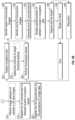
- FIG. 2 Ais a partial flow chart of an imaging and navigation procedure in accordance with the disclosure
- FIG. 2 Bis a partial flow chart of an imaging and navigation procedure in accordance with the disclosure.
- FIG. 3 Ais a partial flow chart of an imaging and navigation procedure in accordance with the disclosure.
- FIG. 3 Bis a partial flow chart of an imaging and navigation procedure in accordance with the disclosure.
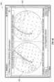
- FIG. 4depicts a user interface for marking structure in a fluoroscopic image in accordance with the disclosure
- FIG. 4 Adepicts a user interface for marking a catheter in a fluoroscopic image in accordance with the disclosure
- FIG. 5depicts a user interface for marking a target in a fluoroscopic image in accordance with the disclosure
- FIG. 6depicts a user interface for navigation to a target in accordance with the disclosure
- FIG. 7depicts a matt with markers to be placed under a patient in accordance with the disclosure
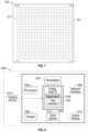
- FIG. 8depicts features and components of a computing device in accordance with the disclosure.
- the disclosureis directed to a system and method that enables registration of a pre-procedural image data set (e.g. CT data) or a 3D model derived therefrom with a patient's luminal structure (e.g., airways in the lungs) using intraprocedural fluoroscopic imaging techniques.
- a pre-procedural image data sete.g. CT data
- a 3D model derived therefromwith a patient's luminal structure (e.g., airways in the lungs) using intraprocedural fluoroscopic imaging techniques.
- Registrationcan be performed using a variety of techniques. For example, robotic systems can be deployed to navigate an endoscope to points within the lung. By contacting these points with the endoscope and correlating their position within the patient's lungs with positions within the 3D model the 3D model is registered to the patient's lungs, and with the coordinate system of the robot. In this manner the robot can then determine where within the lungs of the patient the area of interest is located and follow the navigation plan to the area of interest or develop a pathway through the lungs to the area of interest.
- flexible sensorsmay be employed to achieve registration.
- the shape of the flexible sensors(formed on or in the endoscope or other tools) as they advance and bend through the airways can have their sensed shape matched to the airways in the 3D model or rendering. This shape matching results in registration of the position of the endoscope in the patient to a position in a luminal network within the 3D model that has the same shape.
- a further method of registrationemploys electromagnetic (EM) sensors and EM navigation.
- the endoscope or another toolmay include an EM sensor.
- An EM field generatorgenerates an EM field, and when the EM sensor is placed in the EM field, a current is produced. That current is fed to a computer which can determine X, Y, Z, pitch, yaw, and roll coordinates (six degrees of freedom) of the EM sensor within the magnetic field.
- a computercan determine X, Y, Z, pitch, yaw, and roll coordinates (six degrees of freedom) of the EM sensor within the magnetic field.
- the EM sensorcan be placed in pre-defined locations within the patient that can be observed with a bronchoscope. Usually this is between 4 and 10 points.
- the matching of these points to the same points in the 3D model or renderingresults in a registration of the 3D model with the patient.
- the coordinates of the EM sensorare collected as the EM sensor is navigated through the luminal network. As many hundreds or thousands of these coordinates are collected a point cloud of coordinates is created.
- the point cloudwhich are assumed to be taken from within the luminal network has a 3D dimensional shape that can then be matched to the 3D shape of the interior of the luminal network. Once matched the luminal network in the 3D model and the luminal network of the patient are registered. Once registered the detected position of the EM sensor can be used to follow a navigation plan in the 3D model to an area of interest within the luminal network of the patient.
- FIG. 1is a perspective view of an exemplary system for navigation of a medical device, e.g., a biopsy or treatment tool, to a target via airways of the lungs.
- a medical devicee.g., a biopsy or treatment tool
- One aspect of the system 100is a software application for reviewing computed tomography (CT) image data that has been acquired separately from system 100 .
- CTcomputed tomography
- the review of the CT image dataallows a user to identify one or more targets and plan a pathway to an identified target. This is typically referred to as a planning phase.
- Another aspect of the software applicationis a navigation phase which allows a user to navigate a catheter or other tool to a target (navigation phase) using a user interface and confirm placement of the catheter or a tool relative to the target.
- the targetis typically tissue of interest for biopsy or treatment that was identified during the planning phase by review of the CT image data.
- a medical devicesuch as a biopsy tool or treatment tool, may be inserted into the catheter to obtain a tissue sample from the tissue located at, or proximate to, the target or to treat such tissue.
- the treatment toolmay be selected to achieve microwave ablation, radio-frequency ablation, cryogenic ablation, chemical ablation, or other treatment mechanism of the target as preferred by the clinician.
- FIG. 1is a catheter system 102 including a sensor 104 at a distal end.
- the catheter system 102includes a catheter 106 .
- catheter 106is inserted into a bronchoscope 108 for access to a luminal network of the patient P.
- catheter 106 of catheter guide assembly 106may be inserted into a working channel of bronchoscope 108 for navigation through a patient's luminal network.
- a locatable guide (LG) 110which may include the sensor 104 such as an EM sensor may be inserted into catheter 106 and locked into position such that sensor 104 extends a desired distance beyond the distal tip of catheter 106 .
- the sensor 104may be incorporated into one or more of the bronchoscope 108 , catheter 106 , or a biopsy or treatment tool, without departing from the scope of the disclosure.
- the distal end of the EWC 102 and LG 110both extend beyond the distal end of the bronchoscope 108 .
- the position or location and orientation of sensor 104 and thus the distal portion of LG 110 , within an electromagnetic fieldcan be derived based on location data in the form of currents produced by the presence of the EM sensors in a magnetic field, or by other means described herein.
- EM sensors and EMNare not required as part of this disclosure, their use may further augment the utility of the disclosure in endoluminal navigation (e.g., navigation of the lungs).
- bronchoscope 108catheter 106 , LG 110 or other tool could be used interchangeably or in combination herein, the term catheter will be used here to refer to one or more of these elements.
- flex sensorssuch as fiber Bragg sensors, ultrasound sensors, accelerometers, and others may be used in conjunction with the present disclosure to provide outputs to the tracking system 114 for determination of the position of a catheter including without limitation the bronchoscope 108 , catheter 106 , LG 110 , or biopsy or treatment tools, without departing from the scope of the present disclosure.
- System 100generally includes an operating table 112 configured to support a patient P, a bronchoscope 108 configured for insertion through patient P's mouth into patient P's airways; monitoring equipment 114 coupled to bronchoscope 108 (e.g., a video display, for displaying the video images received from the video imaging system of bronchoscope 108 ).
- monitoring equipment 114coupled to bronchoscope 108 (e.g., a video display, for displaying the video images received from the video imaging system of bronchoscope 108 ).
- system 100may include a locating or tracking system 114 and a locating module 116 , a plurality of reference EM sensors 118 and a transmitter mat 120 including a plurality of incorporated markers ( FIG. 7 ). Though shown in FIG.
- a computing device 122including software and/or hardware used to facilitate identification of a target, pathway planning to the target, navigation of a medical device to the target, and/or confirmation and/or determination of placement of catheter 106 , or a suitable device therethrough, relative to the target.
- Computing device 122may be similar to workstation 1001 of FIG. 8 and may be configured to execute the methods of the disclosure including the methods of FIGS. 2 and 3 ,
- Computing device 122may be any suitable computing device including a processor and storage medium, wherein the processor is capable of executing instructions stored on the storage medium as one or more applications.
- Computing device 122may further include a database configured to store patient data, CT data sets including CT images, fluoroscopic data sets including fluoroscopic images and video, fluoroscopic 3D reconstruction, navigation plans, and any other such data.
- computing device 122may include inputs, or may otherwise be configured to receive, CT data sets, fluoroscopic images/video and other data described herein.
- computing device 122includes a display configured to display graphical user interfaces. Computing device 122 may be connected to one or more networks through which one or more databases may be accessed. Further details of the computing device are described in connection with FIG. 8 , below.
- computing device 122utilizes previously acquired CT image data for generating and viewing a three-dimensional model or rendering of patient P's airways, enables the identification of a target on the three-dimensional model (automatically, semi-automatically, or manually), and allows for determining a pathway through patient P's airways to tissue located at and around the target. More specifically, CT images and CT image data sets acquired from CT scans are processed and assembled into a three-dimensional CT volume, which is then utilized to generate a three-dimensional model of patient P's airways.
- the three-dimensional modelmay be displayed on a display associated with computing device 122 , or in any other suitable fashion. An example of such a user interface can be seen in FIG. 6 .
- the enhanced two-dimensional imagesmay possess some three-dimensional capabilities because they are generated from three-dimensional data.
- the three-dimensional modelmay be manipulated to facilitate identification of target on the three-dimensional model or two-dimensional images, and selection of a suitable pathway through patient P's airways to access tissue located at the target can be made. Once selected, the pathway plan, three-dimensional model, and images derived therefrom, can be saved and exported to a navigation system for use during the navigation phase(s).
- a fluoroscopic imaging device 124capable of acquiring fluoroscopic or x-ray images or video of the patient P (fluoroscopic image data sets) is also included in system 100 .
- the images, sequence of images, or video captured by fluoroscopic imaging device 124may be stored within fluoroscopic imaging device 124 or transmitted to computing device 122 for storage, processing, and display. Additionally, fluoroscopic imaging device 124 may move relative to the patient P so that images may be acquired from different angles or perspectives relative to patient P to create a sequence of fluoroscopic images, such as a fluoroscopic video.
- the pose of fluoroscopic imaging device 124 relative to patient P and while capturing the imagesmay be estimated using the markers 121 and various pose estimation and image processing techniques.
- the markers 121may be incorporated into the transmitter mat 120 , incorporated into the operating table 112 , or otherwise incorporated into another appliance placed on or near the operating table 112 so that they can be seen in the fluoroscopic images.
- the markers 121are generally positioned under patient P and between patient P and a radiation source or a sensing unit of fluoroscopic imaging device 124 .
- Fluoroscopic imaging device 124may include a single imaging device or more than one imaging device.
- One method 200 of employing the fluoroscopic imaging device 124 in system 100is described with respect to FIGS. 2 A and 2 B .
- the navigation plancan be loaded and/or displayed on a display such as that associated with computer 122 .
- the clinicianmay insert the one or more of the bronchoscope 108 , catheter 106 , LG 110 into the luminal network of the patient (e.g., the airways).
- a fluoroscopic sweepmay be taken of the patient at step 204 . That is, a series of fluoroscopic images may be acquired as the fluoroscopic imaging device 124 is rotated about the patient. This sweep may be between about 20 and 180 degrees about the patient, in some embodiments between 25 and 150 degrees, between 30 and 120 degrees, between 40 and 100 degrees, between 50 and 80 degrees, between 60 and 70 degrees and any whole number integer between these angle ranges. In particular embodiments, the sweep is 30, 40, or 50 degrees, though other angles of sweep may be undertaken without departure from the scope of the present disclosure.
- a 3D reconstructioncan be generated at step 206 .
- the 3D reconstruction of the fluoroscopic imagesresults in a 3D volume of the areas imaged during the fluoroscopic sweep.
- This 3D volumecan be processed using a variety to techniques to provide real time information to the clinician.
- the 3D reconstructioncan be processed to produce a series of 2D slice images at step 208 .
- These 2D slice imagesare virtual fluoroscopic images in that they are generated from the 3D reconstruction but are ae not necessarily one of the fluoroscopic images acquired to render the 3D reconstruction.
- the 3D reconstructionmay be sliced to produce 2D slice images along any axis a clinician might desire, but for orientation purposes the 2D images may be displayed in one or more of the standard axial, coronal or sagittal views. These slice images may be presented in a user interface in a way that a user can scroll through the slice images.
- FIG. 4depicts a user interface 400 in which a user may scroll through a series of 2D slice images 402 using a tab 404 and bar 406 which represents the totality of the 2D slice images generated from the 3D reconstruction.
- an indication of the location of the main carina or another known anatomical featuremay be identified by the clinician and the indication of the location of the main carina or another known anatomical feature can be received by the application at step 210 .
- the main carinais a rigid cartilaginous tissue that is the first branching point of the airways in the lungs and marks the end of the trachea.
- the main carinais readily observable in fluoroscopic images and the 2D slice images from the fluoroscopic 3D reconstruction.
- other anatomical featuresare readily observable in fluoroscopic images and the 2D slice images from the fluoroscopic 3D reconstruction.
- the methodmay proceed to step 212 , wherein the system 100 receives two more indications of points in the 3D reconstruction.
- These pointsmay be carina, blood vessels, ribs, fissures, or other features in the 2D slices of the 3D reconstruction.
- the only limitationis that the point needs to be observable both in the 3D reconstruction and in the pre-procedure CT image data.
- the three pointsmay be the main carina and the carina of the second bifurcation of the left and right lobes of the lungs. All three of these points should be readily visible in the 3D reconstruction, and specifically the 2D slice images of the 3D reconstruction.
- these pointsshould be readily visible in the pre-procedure CT image data and the 3D model generated therefrom. These points of registration may have been identified in the CT image data when constructing the 3D model and the navigation plan. Or these points may be identified after generation of the 3D reconstruction and the identification of the three points therein. In either event, the three points identified in both the 3D reconstruction and 3D model from the CT image data must be matched to one another at step 214 .
- This matching of three points in each of the 3D model and the 3D reconstructionallows for registration of the 3D model with the 3D reconstruction at step 216 . Registration ensures that all features in the 3D model (not just the three points identified) are aligned with the 3D reconstruction.
- the applicationmay instead mathematically solve for the two additional degrees of freedom. That is, identification of the main carina or another known anatomical feature provides a single point for matching and secures a degree of freedom with respect to the comparison and registration of the 3D reconstruction and the 3D model from the CT image data. Specifically, by identifying the main carina or another known anatomical feature in the 3D reconstruction, the application has only a single point to register to the 3D model.
- the 3D modelneed merely rotate the 3D reconstruction about three axes (e.g., X, Y, and Z), to seek to match the orientation of the 3D model to the 3D reconstruction along these axes.
- the applicationsolves for at least two orientation angels such that other points in the 3D reconstruction and the 3D model match.
- the outcome of this matchingis a registration of the pre-procedure 3D model and the 3D reconstruction at step 216 .
- the applicationsolves for the two orientation angles by rotating the 3D reconstruction until it matches the 3D model as a comparison of the grey levels or brightness of certain features or other mutual information that appear in both the 3D model and the 3D reconstruction.
- a third option for registration of the 3D reconstruction to the 3D modelcan be undertaken without receiving any indication of a point in the 3D reconstruction for matching to points in the 3D model (e.g., without even manually identifying the main carina).
- a searchis conducted of the 3D reconstruction and the CT image data (or 3D model) at step 220 .
- the searchseeks out points of correlation between the 3D reconstruction and the CT image data by analyzing the grey levels and mutual information of the two image data sets. These points of grey level matching or mutual information are identified by the application at step 222 . Once a sufficient number of the points are identified the application can select one or more of these points of correlation or mutual information.
- One of these pointsmay well be the main carina, and the application can be optimized to solve for the main carina based on its size or general location or other parameters.
- the applicationcan select at least one of these points of correlation or mutual information. Once selected there are two options, in one aspect at step 226 , the application can present on a user interface a request for and receive a confirmation that the point of correlation or mutual information is correct. Once received this method proceeds to step 218 and solves for at least two orientation angels such that other points in the 3D reconstruction and the 3D model match, as described above.
- multiple pointsmay be selected by the application at step 224 and the application can proceed to step 228 where with multiple points of correlation and mutual information are identified the application can solve for all three orientation angles. Once these three angles are solved for the 3D reconstruction can be registered to the 3D model at step 316 .
- the process of the application selecting the points at step 224 and solving for the confirmation and mutual information at step 228may be performed by computing device 122 storing in memory therein a learning algorithm.
- the resultscan be analyzed by the learning algorithm to refine the properties and parameters of a point to be selected in accordance with these methods.
- the properties and parameterse.g., brightness in in the CT images, proximity to other points, etc.
- the properties and parametersare identified and added to the empirical aspects of learning algorithm to further refine the algorithm for future procedures.
- the computing device 122may utilize the positions of the markers 121 in the fluoroscopic images. This technique relies on instances where the markers 121 are positioned in a non-repeating pattern. This non-repeating pattern, however, is known and the relative position of any single marker 121 to the antenna of the transmitter mat 120 are also known. Essentially the positions of the markers 121 as compared to the antennae of the transmitter mat 120 are registered to one another during manufacture of the transmitter mat 120 . This known relative position of the marker 121 to the antennae of the transmitter mat 120 can be used by the computing device 122 and the fluoroscopic imaging device to identify specific ones of the markers 121 which appear in a fluoroscopic image.
- the computing deviceis able to register the coordinates of the fluoroscopic image to the coordinates of the antennae of the transmitter mat 121 using the known relative position of the marker 121 to the antennae of the transmitter mat 121 .
- the position of a catheter in a 3D reconstructioncan be compared to an EM detected position of the catheter, thus allowing the 3D reconstruction to be registered to the 3D model
- the applicationmay cause the 3D reconstruction to be displayed on a display associated with computing device 122 at step 230 .
- features from the navigation plancan be imported into and displayed on the 3D reconstruction. This may be as an overlay on the 3D reconstruction at step 232 .
- the imported features from the 3D modelcan be fused with the 3D reconstruction.
- Other techniques for incorporating the features from the from the 3D model and the navigation plan with the 3D reconstructionmay also be used without departing from the scope of the present disclosure.
- the featuresmay be applied to the 3D reconstruction selectively. For example, the pathway plan may be shown in the 3D reconstruction, and/or an indication of the location of the target.
- the navigation plancan be followed until the catheter (e.g., bronchoscope 108 , catheter 106 ) reaches the target.
- the applicationcan determine when, following the navigation plan the bronchoscope or tool is within a threshold distance from the target and provide an indication on a user interface. This may be done by comparing the bronchoscopic images generated by the bronchoscope to virtual bronchoscopic images generated from the 3D reconstruction. In instances where the bronchoscope has become wedged and no longer navigable through the airways, the proximity determination of the catheter 106 or other tools may require either a new fluoroscopic sweep (i.e. revert back to step 204 ), or other traditional fluoroscopic imaging techniques.
- a second fluoroscopic sweepis undertaken at step 236 .
- This second fluoroscopic sweepis to determine with heightened accuracy the location of the target and importantly the relative position of the bronchoscope or tool relative to the target.
- a user interfacemay present the user with a fluoroscopic image and request the user to identify the target in the fluoroscopic image at step 238 .
- An example of a user interface 500 that may be presented to the useris shown in FIG. 5 in which scrollable fluoroscopic images 502 are presented to the user.
- the user interfaceallows the user to scroll using a scroll bar 504 to identify a second fluoroscopic image in which to identify the target.
- the applicationmay search the fluoroscopic images and automatically identify the target.
- the user interfacemay present a user interface in which the user is identify the end of the catheter (e.g., bronchoscope 108 or catheter 106 ). This indication is received by the application at step 240 .
- a second 3D reconstructioncan be generated at step 242 and displayed at step 244 .
- This display of the 3D reconstructionincludes a clear definition of the target marked in the fluoroscopic images of the fluoroscopic sweep at step 240 .
- Thisprovides an accurate indication of the location of the target, and the relative location of the catheter (e.g., bronchoscope 108 or catheter 106 ) and determinations can be made whether the catheter is aligned with the target, and the distance to the target from the end of the catheter.
- the relative position datamay be displayed on the user interface or the clinician may simply make the determination of alignment based on observation of the 3D reconstruction. If the target and the bronchoscope or tool are aligned at step 246 , the method may proceed to step 248 where a biopsy sample or a treatment is undertaken.
- step 250the catheter (e.g., bronchoscope 108 or catheter 106 ) or tool is repositioned. After repositioning the method returns to step 236 to perform another fluoroscopic sweep. This procedure may be repeated as needed until alignment is achieved at step 246 and a biopsy or treatment can be undertaken at step 248 .
- the cathetere.g., bronchoscope 108 or catheter 106
- the fluoroscopic sweep 236can return the process back to the fluoroscopic sweep 204 , where a new 3D reconstruction is generated at step 206 .
- the processcan then continue as described in steps 206 - 216 , and all the permutations of registration (e.g., steps 210 - 228 ) described above, and the navigation plan data can be applied to and displayed in connection with the new 3D reconstruction.
- Such quick generation of a 3D reconstruction of a region of interestcan provide real-time 3D imaging of the target.
- Real-time imaging of the target and medical devices positioned in its areamay benefit numerous interventional procedures, such as biopsy and ablation procedures in various organs, vascular interventions and orthopedic surgeries.
- the aimmay be to receive accurate information about the position of a catheter relative to the target to ensure accurate treatment or biopsy.
- minimally invasive proceduressuch as laparoscopy procedures, including robotic-assisted surgery, may employ intraoperative fluoroscopy to increase visualization, e.g., for guidance and lesion locating, and to prevent unnecessary injury and complications.
- intraoperative fluoroscopyto increase visualization, e.g., for guidance and lesion locating, and to prevent unnecessary injury and complications.
- Employing the above-mentioned systems and methods for real-time reconstruction of fluoroscopic 3D imaging of a target area and for navigation based on the reconstructionmay benefit such procedures as well.
- system 100may be configured for electromagnetic navigation (EMN).
- EMMelectromagnetic navigation
- the system 100employs a six degrees-of-freedom electromagnetic locating or tracking system 114 , or other suitable system for determining location data of a sensor 104 such as an EM sensor.
- Tracking system 114is configured for use with a locatable guide 110 and particularly sensor 104 .
- locatable guide 110 and sensor 104are configured for insertion through catheter 106 into patient P's airways (either with or without bronchoscope 108 ) and are selectively lockable relative to one another via a locking mechanism.
- Transmitter mat 120is positioned beneath patient P. Transmitter mat 120 generates an electromagnetic field around at least a portion of the patient P within which the position of a plurality of reference sensors 118 and the sensor 104 can be determined with use of a tracking module 116 .
- a second electromagnetic sensor 104may also be incorporated into the end of the catheter 106 . Additionally, or alternatively, the second electromagnetic sensor 104 may be incorporated into biopsy tools or treatment tools for use in the procedure.
- the second electromagnetic sensor 104may be a five degree-of-freedom sensor or a six degree-of-freedom sensor.
- One or more of reference sensors 118are attached to the chest of the patient P.
- the six degrees of freedom coordinates of reference sensors 118are sent to computing device 122 (which includes the appropriate software) where they are used to calculate a patient coordinate frame of reference.
- system 100When system 100 is configured for EMN, registration is needed to transform the detected EM coordinates of the sensor 104 to CT image data coordinates such that a detected location or position of the sensor can be displayed in the CT image data (e.g., in the 3D model or navigation plan) and updating of the detected position of the sensor 104 as it is navigated through the luminal network.
- this registrationcan be undertaken (among other methods) by inserting the sensor 104 into the airways and generating a point cloud of detected positions of the sensor 104 . Matching of the point cloud to the airways of the 3D model registers the patient's actual airways to the 3D model.
- this processdefines a translation from the EMN coordinates (where the sensor is detected in the EM field) to the CT image data coordinates.
- the navigation plancan be followed and the detected location of the sensor 104 can be presented in the 3D model as the sensor 104 , and there with the catheter (e.g., bronchoscope 108 or catheter 106 ) is traversed through the luminal network.
- the cathetere.g., bronchoscope 108 or catheter 106
- a registration of the fluoroscopic image data from the fluoroscopic sweep with the detected position of the sensor 104 in combination with a registration of the fluoroscopic image data with the pre-operative CT image data and navigation planresults in an empirical transform that allows for registration of the EM coordinate system with the pre-operative CT image data coordinate system.
- FIGS. 3 A and 3 Bdepict a method of performing registration of the fluoroscopic image data to the detected EMN coordinates of a sensor 104 .
- Method 300starts with an application on computing device 122 loading the navigation plan developed from the pre-procedure CT image data at step 302 .
- a cathetere.g., bronchoscope 108 or catheter 106
- a sensor 104may be inserted into the EM field generated by the transmitter mat 120 .
- the transmitter mat 120is placed directly beneath the patient P and the EM field will be generated around the patient.
- placement of the sensor 104 in the EM fieldwill include placement of a catheter (e.g., bronchoscope 108 or catheter 106 ) having the sensor 104 into the airways of the patient, for example to a point near the main carina.
- a cathetere.g., bronchoscope 108 or catheter 106
- the exact location of placement of the catheter and sensor 104is not critical so long as is at a location that can be imaged by the fluoroscopic imaging device 124 .
- the sensor 104Once within the EM field the sensor 104 will generate an electrical current that can be analyzed by the locating module 116 in the tracking system 114 to determine the position of the sensor 104 in the EM field at step 304 . That is step 304 identifies the EM coordinates (location data) of the sensor 104 .
- the fluoroscopic imaging device 124can undertake a fluoroscopic sweep at step 306 .
- a 3D reconstructionmay be formed from the images taken by the fluoroscopic imaging device 124 at step 308 , and 2D slice images of the 3D reconstruction are generated at step 310 .
- Steps 306 - 310may be the same steps as 204 - 208 of FIG. 2 A and need not be repeated.
- the applicationmay at step 312 present one of the slices to the user on a user interface and request the user identify the location of a catheter tip in the image as depicted in FIG. 4 or 4 A .
- the location of the distal tip of the cathetere.g., the bronchoscope 108 , the catheter 106 , the LG 110 , or a biopsy or treatment tool
- the location of the sensor 104 relative to the tip of the cathetermay be known to the application, for example saved in the memory of computing device 122 .
- the user interfacepresents a second 2D slice image from the 3D reconstruction and requests identification of the tip of the catheter in the second 2D slice image. As shown in FIG. 4 A these two images may be presented simultaneously. If the two images are from wide-spread portions of the fluoroscopic sweep (i.e. at wide angles from one another), the application can accurately determine the position catheter tip, and there with the location of the sensor 104 in the 3D reconstruction.
- the EMN coordinate systems and the coordinate system of the fluoroscopic imaging device 124can be registered to one another at step 318 .
- the applicationmay perform an image processing step of identifying the catheter at step 316 . This may optionally be assisted by the presence of fiducial markers formed along the length of the catheter at intervals. Even without the fiducial markers, the shape of the catheter (e.g., the bronchoscope 108 , catheter 106 , LG 110 , or biopsy or treatment tools) should be readily identifiable in the 2D slices of the fluoroscopic 3D reconstruction.
- the applicationcan determine location of the tip and therewith the location of the sensor 104 in the 3D reconstruction.
- the applicationreceives an indication of the location of the catheter tip in two images and conducts image processing for all or a substantial portion of the of the remaining 2D slice images.
- the transform of the coordinates of the fluoroscopic imaging device 124 and image data derived therefrom to the EMN coordinatesis derived and the 3D reconstruction and be registered to the detected position of the sensor 104 , 128 in the EM field.
- the registration of 3D reconstruction to the pre-procedure CT image datacan be undertaken, as described above. Any of the methods for registering the 3D reconstruction with the pre-procedure CT image data may be employed. Once both registration processes have been undertaken, all three coordinate systems are registered to one another. Fluoroscopic coordinate system to the pre-procedure CT imaging coordinate system and Fluoroscopic coordinate system to EMN coordinate system. As a result, a transform is established for registration of EMN coordinates to the pre-procedure CT imaging coordinate system.
- the applicationcan proceed either by simply using the registration of the sensor 104 with the pre-procedure CT image data to update the detected position of the EM sensor in the navigation plan developed from the pre-procedure CT image data and display the navigation plan at step 322 .
- the detected position of the sensor 104and following a pathway defined in the navigation plan the sensor 104 can be navigated to a target in the navigation plan.
- the applicationcan determine when, following the navigation plan the catheter (e.g., bronchoscope 108 or WC 1060 is within a threshold distance from the target and provide an indication on a user interface.
- a second fluoroscopic sweepis undertaken at step 326 .
- This second fluoroscopic sweepis to determine with heightened accuracy the location of the target and importantly the relative position of the bronchoscope 108 or another tool relative to the target.
- a user interfacemay present the user with a fluoroscopic image and request the user to identify the target in the fluoroscopic image, the identity of the target is received by the application at step 328 . Once identified, the user interface may present the user with a second fluoroscopic image in which to identify the target as shown in FIG. 5 .
- the applicationmay search the fluoroscopic images and automatically identify the target.
- the user interfacemay present the user with fluoroscopic images in which identify the catheter tip in the fluoroscopic images, the identity of the catheter tip is received by the application at step 330 as shown in FIGS. 4 and 4 A .
- a second 3D reconstructioncan be generated at step 332 and the relative position of the catheter tip and the target can be updated in the navigation plan derived from the pre-procedure CT image data. This updated relative position can be displayed on the user interface 602 in the navigation plan at step 334 as seen in FIG. 6 .
- Thisprovides an accurate indication of the location of the catheter tip with respect to the target, and determinations can be made whether the sensor 104 is aligned with the target, and the distance to the target from the sensor 104 and therewith from the end of the bronchoscope 108 or other tool.
- This datamay be displayed on the user interface or the clinician may simply make the determination of alignment based on observation of the 3D reconstruction. If the target and the bronchoscope or tool are aligned at step 336 , the method may proceed to step 338 where a biopsy sample or a treatment is undertaken.
- step 340the bronchoscope 108 or another tool is repositioned. After repositioning the method returns to step 326 to perform another fluoroscopic sweep. This procedure may be repeated as needed until alignment is achieved at step 338 and a biopsy or treatment can be undertaken at step 338 .
- System 1000may include a workstation 1001 , and optionally a fluoroscopic imaging device or fluoroscope 1015 .
- workstation 1001may be coupled with fluoroscope 1015 , directly or indirectly, e.g., by wireless communication.
- Workstation 1001may include a memory 1002 , a processor 1004 , a display 1006 and an input device 1010 .
- Processor or hardware processor 1004may include one or more hardware processors.
- Workstation 1001may optionally include an output module 1012 and a network interface 1008 .
- Memory 1002may store an application 1018 and image data 1014 .
- Application 1018may include instructions executable by processor 1004 for executing the methods of the disclosure including the method of FIGS. 2 and 3 .
- Application 1018may further include a user interface 1016 .
- Image data 1014may include the CT scans, the generated fluoroscopic 3D reconstructions of the target area and/or any other fluoroscopic image data and/or the generated one or more virtual fluoroscopy images.
- Processor 1004may be coupled with memory 1002 , display 1006 , input device 1010 , output module 1012 , network interface 1008 and fluoroscope 1015 .
- Workstation 1001may be a stationary computing device, such as a personal computer, or a portable computing device such as a tablet computer. Workstation 1001 may embed a plurality of computer devices.
- Memory 1002may include any non-transitory computer-readable storage media for storing data and/or software including instructions that are executable by processor 1004 and which control the operation of workstation 1001 and, in some embodiments, may also control the operation of fluoroscope 1015 .
- Fluoroscope 1015may be used to capture a sequence of fluoroscopic images based on which the fluoroscopic 3D reconstruction is generated and to capture a live 2D fluoroscopic view according to this disclosure.
- memory 1002may include one or more storage devices such as solid-state storage devices, e.g., flash memory chips. Alternatively, or in addition to the one or more solid-state storage devices, memory 1002 may include one or more mass storage devices connected to the processor 1004 through a mass storage controller (not shown) and a communications bus (not shown).
- computer-readable storage mediacan be any available media that can be accessed by the processor 1004 . That is, computer readable storage media may include non-transitory, volatile and non-volatile, removable and non-removable media implemented in any method or technology for storage of information such as computer-readable instructions, data structures, program modules or other data.
- computer-readable storage mediamay include RAM, ROM, EPROM, EEPROM, flash memory or other solid-state memory technology, CD-ROM, DVD, Blu-Ray or other optical storage, magnetic cassettes, magnetic tape, magnetic disk storage or other magnetic storage devices, or any other medium which may be used to store the desired information, and which may be accessed by workstation 1001 .
- Application 1018may, when executed by processor 1004 , cause display 1006 to present user interface 1016 .
- User interface 1016may be configured to present to the user a single screen including a three-dimensional (3D) view of a 3D model of a target from the perspective of a tip of a medical device, a live two-dimensional (2D) fluoroscopic view showing the medical device, and a target mark, which corresponds to the 3D model of the target, overlaid on the live 2D fluoroscopic view.
- User interface 1016may be further configured to display the target mark in different colors depending on whether the medical device tip is aligned with the target in three dimensions.
- Network interface 1008may be configured to connect to a network such as a local area network (LAN) consisting of a wired network and/or a wireless network, a wide area network (WAN), a wireless mobile network, a Bluetooth network, and/or the Internet.
- Network interface 1008may be used to connect between workstation 1001 and fluoroscope 1015 .
- Network interface 1008may be also used to receive image data 1014 .
- Input device 1010may be any device by which a user may interact with workstation 1001 , such as, for example, a mouse, keyboard, foot pedal, touch screen, and/or voice interface.
- Output module 1012may include any connectivity port or bus, such as, for example, parallel ports, serial ports, universal serial busses (USB), or any other similar connectivity port known to those skilled in the art.
Landscapes
- Health & Medical Sciences (AREA)
- Engineering & Computer Science (AREA)
- Life Sciences & Earth Sciences (AREA)
- Medical Informatics (AREA)
- Surgery (AREA)
- Public Health (AREA)
- Physics & Mathematics (AREA)
- Heart & Thoracic Surgery (AREA)
- Biomedical Technology (AREA)
- Molecular Biology (AREA)
- Animal Behavior & Ethology (AREA)
- General Health & Medical Sciences (AREA)
- Nuclear Medicine, Radiotherapy & Molecular Imaging (AREA)
- Veterinary Medicine (AREA)
- Optics & Photonics (AREA)
- Biophysics (AREA)
- High Energy & Nuclear Physics (AREA)
- Pathology (AREA)
- Radiology & Medical Imaging (AREA)
- Robotics (AREA)
- Computer Vision & Pattern Recognition (AREA)
- General Physics & Mathematics (AREA)
- Theoretical Computer Science (AREA)
- Human Computer Interaction (AREA)
- Apparatus For Radiation Diagnosis (AREA)
Abstract
Description
Claims (15)
Priority Applications (6)
| Application Number | Priority Date | Filing Date | Title |
|---|---|---|---|
| US16/889,431US12059281B2 (en) | 2019-08-19 | 2020-06-01 | Systems and methods of fluoro-CT imaging for initial registration |
| AU2020204596AAU2020204596A1 (en) | 2019-08-19 | 2020-07-09 | Systems and methods of fluoro-CT imaging for initial registration |
| CA3086383ACA3086383A1 (en) | 2019-08-19 | 2020-07-10 | Systems and methods of fluoro-ct imaging for initial registration |
| JP2020131413AJP2021030073A (en) | 2019-08-19 | 2020-08-03 | Systems and methods of fluoroscopic ct imaging for initial registration |
| EP20191081.7AEP3783568A3 (en) | 2019-08-19 | 2020-08-14 | Systems and methods of fluoro-ct imaging for initial registration |
| CN202010831955.7ACN112386336A (en) | 2019-08-19 | 2020-08-18 | System and method for fluorescence-CT imaging with initial registration |
Applications Claiming Priority (2)
| Application Number | Priority Date | Filing Date | Title |
|---|---|---|---|
| US201962888905P | 2019-08-19 | 2019-08-19 | |
| US16/889,431US12059281B2 (en) | 2019-08-19 | 2020-06-01 | Systems and methods of fluoro-CT imaging for initial registration |
Publications (2)
| Publication Number | Publication Date |
|---|---|
| US20210052240A1 US20210052240A1 (en) | 2021-02-25 |
| US12059281B2true US12059281B2 (en) | 2024-08-13 |
Family
ID=72087933
Family Applications (1)
| Application Number | Title | Priority Date | Filing Date |
|---|---|---|---|
| US16/889,431Active2041-02-10US12059281B2 (en) | 2019-08-19 | 2020-06-01 | Systems and methods of fluoro-CT imaging for initial registration |
Country Status (6)
| Country | Link |
|---|---|
| US (1) | US12059281B2 (en) |
| EP (1) | EP3783568A3 (en) |
| JP (1) | JP2021030073A (en) |
| CN (1) | CN112386336A (en) |
| AU (1) | AU2020204596A1 (en) |
| CA (1) | CA3086383A1 (en) |
Cited By (8)
| Publication number | Priority date | Publication date | Assignee | Title |
|---|---|---|---|---|
| US12178666B2 (en) | 2019-07-29 | 2024-12-31 | Augmedics Ltd. | Fiducial marker |
| US12186028B2 (en) | 2020-06-15 | 2025-01-07 | Augmedics Ltd. | Rotating marker for image guided surgery |
| US12201384B2 (en) | 2018-11-26 | 2025-01-21 | Augmedics Ltd. | Tracking systems and methods for image-guided surgery |
| US12206837B2 (en) | 2015-03-24 | 2025-01-21 | Augmedics Ltd. | Combining video-based and optic-based augmented reality in a near eye display |
| US12290416B2 (en) | 2018-05-02 | 2025-05-06 | Augmedics Ltd. | Registration of a fiducial marker for an augmented reality system |
| US12354227B2 (en) | 2022-04-21 | 2025-07-08 | Augmedics Ltd. | Systems for medical image visualization |
| US12383369B2 (en) | 2019-12-22 | 2025-08-12 | Augmedics Ltd. | Mirroring in image guided surgery |
| US12417595B2 (en) | 2021-08-18 | 2025-09-16 | Augmedics Ltd. | Augmented-reality surgical system using depth sensing |
Families Citing this family (7)
| Publication number | Priority date | Publication date | Assignee | Title |
|---|---|---|---|---|
| US20210361357A1 (en)* | 2017-07-21 | 2021-11-25 | Globus Medical, Inc. | Robot surgical platform |
| CN112584738B (en)* | 2018-08-30 | 2024-04-23 | 奥林巴斯株式会社 | Recording device, image observation device, observation system, control method of observation system, and storage medium |
| CN113855242B (en)* | 2021-12-03 | 2022-04-19 | 杭州堃博生物科技有限公司 | Bronchoscope position determination method, device, system, equipment and medium |
| JP2024005113A (en)* | 2022-06-29 | 2024-01-17 | 富士フイルム株式会社 | Image processing device, method and program |
| CN119731696A (en)* | 2022-08-31 | 2025-03-28 | 波士顿科学国际有限公司 | System, apparatus and method for three-dimensional image registration |
| CN116965848A (en)* | 2023-09-25 | 2023-10-31 | 中南大学 | A three-dimensional ultrasound imaging method, system, equipment and storage medium |
| CN117796905B (en)* | 2023-12-18 | 2024-09-13 | 骨圣元化机器人(深圳)有限公司 | Spinal surgery assistance system and assistance device |
Citations (117)
| Publication number | Priority date | Publication date | Assignee | Title |
|---|---|---|---|---|
| US6373916B1 (en) | 1999-05-10 | 2002-04-16 | Shimadzu Corporation | X-ray CT apparatus |
| US6473634B1 (en) | 2000-11-22 | 2002-10-29 | Koninklijke Philips Electronics N.V. | Medical imaging at two temporal resolutions for tumor treatment planning |
| US20030013972A1 (en) | 2001-05-29 | 2003-01-16 | Makin Inder Raj. S. | Treatment of lung lesions using ultrasound |
| BR0013237A (en) | 1999-08-12 | 2003-07-15 | Johnson & Johnson | Antibacterial heterobicyclic substituted phenyl oxazolidinones |
| MXPA03005028A (en) | 2000-12-06 | 2004-01-29 | Johnson & Johnson | 6-0-carbamoyl ketolide derivatives of erythromycin useful as antibacterials. |
| US7551759B2 (en) | 2004-12-07 | 2009-06-23 | Siemens Medical Solutions Usa, Inc. | Target identification using time-based data sets |
| US7916918B2 (en) | 2004-07-09 | 2011-03-29 | Hologic, Inc. | Diagnostic system for multimodality mammography |
| US20120059248A1 (en)* | 2010-08-20 | 2012-03-08 | Troy Holsing | Apparatus and method for airway registration and navigation |
| US8335359B2 (en) | 2007-07-20 | 2012-12-18 | General Electric Company | Systems, apparatus and processes for automated medical image segmentation |
| US8482606B2 (en) | 2006-08-02 | 2013-07-09 | Inneroptic Technology, Inc. | System and method of providing real-time dynamic imagery of a medical procedure site using multiple modalities |
| US20130303945A1 (en) | 2012-05-14 | 2013-11-14 | Intuitive Surgical Operations, Inc. | Electromagnetic tip sensor |
| US8625869B2 (en) | 2010-05-21 | 2014-01-07 | Siemens Medical Solutions Usa, Inc. | Visualization of medical image data with localized enhancement |
| US20140035798A1 (en) | 2012-08-06 | 2014-02-06 | Sony Corporation | Display panel, display device and electronic apparatus |
| US8706184B2 (en) | 2009-10-07 | 2014-04-22 | Intuitive Surgical Operations, Inc. | Methods and apparatus for displaying enhanced imaging data on a clinical image |
| US20140229881A1 (en)* | 2011-09-19 | 2014-08-14 | Koninklijke Philips N.V. | Status-indicator for sub-volumes of multi-dimensional images in guis used in image processing |
| US8827934B2 (en) | 2011-05-13 | 2014-09-09 | Intuitive Surgical Operations, Inc. | Method and system for determining information of extrema during expansion and contraction cycles of an object |
| US20150148690A1 (en) | 2011-05-13 | 2015-05-28 | Intuitive Surgical Operations, Inc. | Method and system for determining a shape of a lumen in an anatomical structure |
| US20150265368A1 (en) | 2014-03-24 | 2015-09-24 | Intuitive Surgical Operations, Inc. | Systems and Methods for Anatomic Motion Compensation |
| US20160005224A1 (en) | 2014-07-02 | 2016-01-07 | Covidien Lp | Unified coordinate system for multiple ct scans of patient lungs |
| US20160157939A1 (en) | 2013-07-29 | 2016-06-09 | Intuitive Surgical Operations, Inc. | Shape sensor systems with redundant sensing |
| US20160183841A1 (en) | 2013-08-15 | 2016-06-30 | Intuitive Surgical Operations Inc. | Graphical User Interface For Catheter Positioning And Insertion |
| US20160192860A1 (en) | 2013-08-15 | 2016-07-07 | Intuitive Surgical Operations Inc. | Systems and methods for medical procedure confirmation |
| US20160242724A1 (en)* | 2013-11-04 | 2016-08-25 | Surgivisio | Method for reconstructing a 3d image from 2d x-ray images |
| US9433390B2 (en) | 2007-06-21 | 2016-09-06 | Surgix Ltd. | System for measuring the true dimensions and orientation of objects in a two dimensional image |
| US20160287344A1 (en) | 2012-06-25 | 2016-10-06 | Intuitive Surgical Operations, Inc. | Systems and methods for reducing measurement error in optical fiber shape sensors |
| US20170035380A1 (en) | 2015-08-06 | 2017-02-09 | Covidien Lp | System and method for navigating to target and performing procedure on target utilizing fluoroscopic-based local three dimensional volume reconstruction |
| WO2017030915A1 (en) | 2015-08-14 | 2017-02-23 | Intuitive Surgical Operations, Inc. | Systems and methods of registration for image-guided surgery |
| US20170112576A1 (en) | 2001-06-07 | 2017-04-27 | Intuitive Surgical Operations, Inc. | Methods and Apparatus for Surgical Planning |
| US9710921B2 (en) | 2013-03-15 | 2017-07-18 | Hansen Medical, Inc. | System and methods for tracking robotically controlled medical instruments |
| US20170209071A1 (en) | 2014-07-28 | 2017-07-27 | Intuitive Surgical Operations, Inc. | Systems and Methods for Intraoperative Segmentation |
| WO2017139621A1 (en) | 2016-02-12 | 2017-08-17 | Intuitive Surgical Operations, Inc. | Systems and methods for using registered fluoroscopic images in image-guided surgery |
| US20170265952A1 (en) | 2014-07-28 | 2017-09-21 | Intuitive Surgical Operations, Inc. | Systems and Methods for Planning Multiple Interventional Procedures |
| US20170311844A1 (en) | 2012-10-12 | 2017-11-02 | Intuitive Surgical Operations, Inc. | Determining Position of Medical Device in Branched Anatomical Structure |
| US20170319165A1 (en) | 2014-01-06 | 2017-11-09 | Body Vision Medical Ltd. | Surgical devices and methods of use thereof |
| US9833167B2 (en) | 1999-05-18 | 2017-12-05 | Mediguide Ltd. | Method and system for superimposing virtual anatomical landmarks on an image |
| US9888898B2 (en) | 2014-03-27 | 2018-02-13 | Toshiba Medical Systems Corporation | X-ray diagnostic apparatus |
| US9918659B2 (en) | 2013-03-15 | 2018-03-20 | Intuitive Surgical Operations, Inc. | Shape sensor systems for tracking interventional instruments and mehods of use |
| US20180078318A1 (en) | 2015-04-06 | 2018-03-22 | Intuitive Surgical Operations, Inc. | Systems and Methods of Registration Compensation in Image Guided Surgery |
| US20180153621A1 (en) | 2015-05-22 | 2018-06-07 | Intuitive Surgical Operations, Inc. | Systems and Methods of Registration for Image Guided Surgery |
| US20180240237A1 (en) | 2015-08-14 | 2018-08-23 | Intuitive Surgical Operations, Inc. | Systems and Methods of Registration for Image-Guided Surgery |
| US20180256262A1 (en) | 2015-09-10 | 2018-09-13 | Intuitive Surgical Operations, Inc, | Systems and Methods for Using Tracking in Image-Guided Medical Procedure |
| US20180263706A1 (en) | 2014-10-20 | 2018-09-20 | Body Vision Medical Ltd. | Surgical devices and methods of use thereof |
| US20180279852A1 (en) | 2017-03-31 | 2018-10-04 | Auris Health, Inc. | Robotic systems for navigation of luminal networks that compensate for physiological noise |
| US20180325419A1 (en) | 2012-05-14 | 2018-11-15 | Intuitive Surgical Operations, Inc. | Systems and methods for navigation based on ordered sensor records |
| US10130316B2 (en) | 2014-01-07 | 2018-11-20 | Toshiba Medical Systems Corporation | X-ray CT apparatus and display method for CT image |
| US20190000560A1 (en) | 2017-06-28 | 2019-01-03 | Auris Health, Inc. | Electromagnetic distortion detection |
| US20190000559A1 (en) | 2017-06-28 | 2019-01-03 | Auris Health, Inc. | Electromagnetic field generator alignment |
| US20190008413A1 (en) | 2012-05-14 | 2019-01-10 | Intuitive Surgical Operations,Inc. | Systems and methods for deformation compensation using shape sensing |
| US20190038365A1 (en) | 2016-02-12 | 2019-02-07 | Intuitive Surgical Operations, Inc | Systems and methods of pose estimation and calibration of perspective imaging system in image guided surgery |
| US20190065209A1 (en) | 2015-12-23 | 2019-02-28 | Intel Corporation | Byte and nibble sort instructions that produce sorted destination register and destination index mapping |
| US20190110839A1 (en) | 2017-10-13 | 2019-04-18 | Auris Health, Inc. | Robotic system configured for navigation path tracing |
| EP3478161A1 (en) | 2016-06-30 | 2019-05-08 | Intuitive Surgical Operations Inc. | Graphical user interface for displaying guidance information in a plurality of modes during an image-guided procedure |
| US20190175062A1 (en) | 2017-12-08 | 2019-06-13 | Auris Health, Inc. | System and method for medical instrument navigation and targeting |
| US20190183318A1 (en) | 2016-08-16 | 2019-06-20 | Intuitive Surgical Operations, Inc. | Augmented accuracy using large diameter shape fiber |
| US20190183585A1 (en) | 2017-12-14 | 2019-06-20 | Auris Health, Inc. | System and method for estimating instrument location |
| US20190183587A1 (en) | 2017-12-18 | 2019-06-20 | Auris Health, Inc. | Methods and systems for instrument tracking and navigation within luminal networks |
| US20190192234A1 (en) | 2016-08-23 | 2019-06-27 | Intuitive Surgical Operations, Inc. | Systems and methods for monitoring patient motion during a medical procedure |
| US20190209016A1 (en) | 2012-07-20 | 2019-07-11 | Intuitive Surgical Operations, Inc. | Processing images from annular receptor arrays |
| US20190209043A1 (en) | 2012-08-14 | 2019-07-11 | Intuitive Surgical Operations, Inc. | Systems and methods for registration of multiple vision systems |
| US20190216548A1 (en) | 2017-06-23 | 2019-07-18 | Auris Health, Inc. | Robotic systems for determining a roll of a medical device in luminal networks |
| US10373719B2 (en) | 2014-09-10 | 2019-08-06 | Intuitive Surgical Operations, Inc. | Systems and methods for pre-operative modeling |
| US20190239723A1 (en) | 2016-09-21 | 2019-08-08 | Intuitive Surgical Operations, Inc. | Systems and methods for instrument buckling detection |
| US20190239831A1 (en) | 2014-02-07 | 2019-08-08 | Intuitive Surgical Operations, Inc. | Systems and methods for using x-ray field emission to determine instrument position and orientation |
| US10376178B2 (en) | 2012-05-14 | 2019-08-13 | Intuitive Surgical Operations, Inc. | Systems and methods for registration of a medical device using rapid pose search |
| US20190250050A1 (en) | 2016-10-21 | 2019-08-15 | Intuitive Surgical Operations, Inc. | Shape sensing with multi-core fiber sensor |
| US20190254649A1 (en) | 2016-06-15 | 2019-08-22 | Intuitive Surgical Operations, Inc. | Systems and methods of integrated real-time visualization |
| US20190272634A1 (en) | 2018-03-01 | 2019-09-05 | Intuitive Surgical Operations, Inc. | Systems and methods for segmentation of anatomical structures for image-guided surgery |
| US20190269470A1 (en) | 2016-09-30 | 2019-09-05 | Intuitive Surgical Operations, Inc. | Systems and methods for entry point localization |
| US10405753B2 (en) | 2015-11-10 | 2019-09-10 | Intuitive Surgical Operations, Inc. | Pharmaceutical compositions of near IR closed chain, sulfo-cyanine dyes |
| US20190298160A1 (en) | 2018-03-28 | 2019-10-03 | Auris Health, Inc. | Systems and methods for displaying estimated location of instrument |
| US20190298451A1 (en) | 2018-03-27 | 2019-10-03 | Intuitive Surgical Operations, Inc. | Systems and methods for delivering targeted therapy |
| US20190320937A1 (en) | 2012-05-14 | 2019-10-24 | Intuitive Surgical Operations, Inc. | Systems and methods for registration of a medical device using a reduced search space |
| US20190320878A1 (en) | 2017-01-09 | 2019-10-24 | Intuitive Surgical Operations, Inc. | Systems and methods for registering elongate devices to three dimensional images in image-guided procedures |
| US20190336238A1 (en) | 2013-10-24 | 2019-11-07 | Auris Health, Inc. | Instrument device manipulator with tension sensing apparatus |
| US20190343424A1 (en) | 2014-10-10 | 2019-11-14 | Intuitive Surgical Operations, Inc. | Systems and methods for reducing measurement error using optical fiber shape sensors |
| US10480926B2 (en) | 2015-12-14 | 2019-11-19 | Intuitive Surgical Operations, Inc. | Apparatus and method for generating 3-D data for an anatomical target using optical fiber shape sensing |
| US10478162B2 (en) | 2014-08-23 | 2019-11-19 | Intuitive Surgical Operations, Inc. | Systems and methods for display of pathological data in an image guided procedure |
| US20190350659A1 (en) | 2016-12-08 | 2019-11-21 | Intuitive Surgical Operations, Inc, | Systems and methods for navigation in image-guided medical procedures |
| US20190365199A1 (en) | 2017-02-01 | 2019-12-05 | Intuitive Surgical Operations, Inc. | Systems and methods for data filtering of passageway sensor data |
| US20190365486A1 (en) | 2018-05-31 | 2019-12-05 | Auris Health, Inc. | Path-based navigation of tubular networks |
| US20190365479A1 (en) | 2018-05-30 | 2019-12-05 | Auris Health, Inc. | Systems and methods for location sensor-based branch prediction |
| US20190380787A1 (en) | 2018-05-31 | 2019-12-19 | Auris Health, Inc. | Image-based airway analysis and mapping |
| US20200000319A1 (en) | 2006-06-14 | 2020-01-02 | Intuitive Surgical Operations, Inc. | In-vivo visualization systems |
| US20200000526A1 (en) | 2017-02-01 | 2020-01-02 | Intuitive Surgical Operations, Inc. | Systems and methods of registration for image-guided procedures |
| US10524866B2 (en) | 2018-03-28 | 2020-01-07 | Auris Health, Inc. | Systems and methods for registration of location sensors |
| US20200008655A1 (en) | 2014-10-17 | 2020-01-09 | Intuitive Surgical Operations, Inc. | Systems and methods for reducing measurement error using optical fiber shape sensors |
| US20200030044A1 (en) | 2017-04-18 | 2020-01-30 | Intuitive Surgical Operations, Inc. | Graphical user interface for planning a procedure |
| US20200030461A1 (en) | 2016-04-18 | 2020-01-30 | Intuitive Surgical Operations, Inc. | Compositions of Near IR Closed Chain, Sulfo-Cyanine Dyes and Prostate Specific Membrane Antigen Ligands |
| US20200043207A1 (en) | 2018-08-03 | 2020-02-06 | Intuitive Surgical Operations, Inc. | Systems and methods for generating anatomical tree structures |
| US20200038750A1 (en) | 2018-08-01 | 2020-02-06 | Sony Interactive Entertainment LLC | Cross-Pollination Of In-Game Events, Assets and Persistent Communications Using Signs and Likes Across Virtual Environments In Gaming Sessions of a Video Game |
| US10555788B2 (en) | 2014-03-28 | 2020-02-11 | Intuitive Surgical Operations, Inc. | Surgical system with haptic feedback based upon quantitative three-dimensional imaging |
| US20200046431A1 (en) | 2016-11-02 | 2020-02-13 | Intuitive Surgical Operations, Inc. | Systems and methods of continuous registration for image-guided surgery |
| US20200046436A1 (en) | 2018-08-13 | 2020-02-13 | Body Vision Medical Ltd. | Methods and systems for multi view pose estimation using digital computational tomography |
| US20200054399A1 (en) | 2017-04-18 | 2020-02-20 | Intuitive Surgical. Operations, Inc. | Graphical user interface for monitoring an image-guided procedure |
| US20200060771A1 (en) | 2018-08-23 | 2020-02-27 | Intuitive Surgical Operations, Inc. | Systems and methods for generating anatomic tree structures using backward pathway growth |
| US20200069192A1 (en) | 2016-12-09 | 2020-03-05 | Intuitive Surgical Operations, Inc. | System and method for distributed heat flux sensing of body tissue |
| US20200078095A1 (en) | 2014-02-04 | 2020-03-12 | Intuitive Surgical Operations, Inc. | Systems and methods for non-rigid deformation of tissue for virtual navigation of interventional tools |
| US20200077870A1 (en) | 2014-03-17 | 2020-03-12 | Intuitive Surgical Operations, Inc. | Surgical system including a non-white light general illuminator |
| US20200085514A1 (en) | 2014-12-22 | 2020-03-19 | Intuitive Surgical Operations, Inc. | Flexible electromagnetic sensor |
| US10610306B2 (en) | 2013-12-09 | 2020-04-07 | Intuitive Surgical Operations, Inc. | Systems and methods for device-aware flexible tool registration |
| US20200109124A1 (en) | 2009-03-19 | 2020-04-09 | The Johns Hopkins Universt | Psma targeted fluorescent agents for image guided surgery |
| EP3641686A2 (en) | 2017-06-23 | 2020-04-29 | Intuitive Surgical Operations Inc. | Systems and methods for navigating to a target location during a medical procedure |
| US20200129239A1 (en) | 2016-06-30 | 2020-04-30 | Intuitive Surgical Operations, Inc. | Graphical user interface for displaying guidance information during an image-guided procedure |
| US20200129045A1 (en) | 2009-03-26 | 2020-04-30 | Intuitive Surgical Operations, Inc. | Method and system for assisting an operator in endoscopic navigation |
| US10638953B2 (en) | 2012-02-03 | 2020-05-05 | Intuitive Surgical Operations, Inc. | Steerable flexible needle with embedded shape sensing |
| US20200138515A1 (en) | 2018-11-02 | 2020-05-07 | Intuitive Surgical Operations, Inc | Coiled dipole antenna |
| US20200155116A1 (en) | 2012-12-31 | 2020-05-21 | Intuitive Surgical Operations, Inc. | Systems and methods for interventional procedure planning |
| US20200170720A1 (en) | 2017-10-13 | 2020-06-04 | Auris Health, Inc. | Image-based branch detection and mapping for navigation |
| US20200170623A1 (en) | 2017-05-24 | 2020-06-04 | Body Vision Medical Ltd. | Methods for using radial endobronchial ultrasound probes for three-dimensional reconstruction of images and improved target localization |
| US10674970B2 (en) | 2016-03-10 | 2020-06-09 | Body Vision Medical Ltd. | Methods and systems for using multi view pose estimation |
| US10682070B2 (en) | 2011-10-14 | 2020-06-16 | Intuitive Surgical Operations, Inc. | Electromagnetic sensor with probe and guide sensing elements |
| US20200188038A1 (en) | 2014-11-13 | 2020-06-18 | Intuitive Surgical Operations, Inc. | Systems and methods for filtering localization data |
| US20200229679A1 (en) | 2017-02-01 | 2020-07-23 | Intuitive Surgical Operations, Inc. | Systems and methods of registration for image-guided procedures |
| US20200297442A1 (en) | 2017-08-16 | 2020-09-24 | Intuitive Surgical Operations, Inc. | Systems and methods for monitoring patient motion during a medical procedure |
| US10796432B2 (en) | 2015-09-18 | 2020-10-06 | Auris Health, Inc. | Navigation of tubular networks |
| US20200330795A1 (en) | 2019-04-19 | 2020-10-22 | University Of Maryland, Baltimore | System and method for radiation therapy using spatial-functional mapping and dose sensitivity of branching structures and functional sub-volumes |
| US20200352427A1 (en) | 2016-03-14 | 2020-11-12 | Intuitive Surgical Operations, Inc. | Endoscopic instrument with compliant thermal interface |
- 2020
- 2020-06-01USUS16/889,431patent/US12059281B2/enactiveActive
- 2020-07-09AUAU2020204596Apatent/AU2020204596A1/ennot_activeAbandoned
- 2020-07-10CACA3086383Apatent/CA3086383A1/ennot_activeAbandoned
- 2020-08-03JPJP2020131413Apatent/JP2021030073A/enactivePending
- 2020-08-14EPEP20191081.7Apatent/EP3783568A3/enactivePending
- 2020-08-18CNCN202010831955.7Apatent/CN112386336A/enactivePending
Patent Citations (142)
| Publication number | Priority date | Publication date | Assignee | Title |
|---|---|---|---|---|
| US6373916B1 (en) | 1999-05-10 | 2002-04-16 | Shimadzu Corporation | X-ray CT apparatus |
| US9833167B2 (en) | 1999-05-18 | 2017-12-05 | Mediguide Ltd. | Method and system for superimposing virtual anatomical landmarks on an image |
| BR0013237A (en) | 1999-08-12 | 2003-07-15 | Johnson & Johnson | Antibacterial heterobicyclic substituted phenyl oxazolidinones |
| US6473634B1 (en) | 2000-11-22 | 2002-10-29 | Koninklijke Philips Electronics N.V. | Medical imaging at two temporal resolutions for tumor treatment planning |
| MXPA03005028A (en) | 2000-12-06 | 2004-01-29 | Johnson & Johnson | 6-0-carbamoyl ketolide derivatives of erythromycin useful as antibacterials. |
| BR0116004A (en) | 2000-12-06 | 2004-06-22 | Ortho Mcneil Pharm Inc | Erythromycin 6-o-carbamoyl ketolide derivatives useful as antibacterials |
| US20030013972A1 (en) | 2001-05-29 | 2003-01-16 | Makin Inder Raj. S. | Treatment of lung lesions using ultrasound |
| US20170112576A1 (en) | 2001-06-07 | 2017-04-27 | Intuitive Surgical Operations, Inc. | Methods and Apparatus for Surgical Planning |
| US10709506B2 (en) | 2001-06-07 | 2020-07-14 | Intuitive Surgical Operations, Inc. | Methods and apparatus for surgical planning |
| US7916918B2 (en) | 2004-07-09 | 2011-03-29 | Hologic, Inc. | Diagnostic system for multimodality mammography |
| US7551759B2 (en) | 2004-12-07 | 2009-06-23 | Siemens Medical Solutions Usa, Inc. | Target identification using time-based data sets |
| US20200000319A1 (en) | 2006-06-14 | 2020-01-02 | Intuitive Surgical Operations, Inc. | In-vivo visualization systems |
| US8482606B2 (en) | 2006-08-02 | 2013-07-09 | Inneroptic Technology, Inc. | System and method of providing real-time dynamic imagery of a medical procedure site using multiple modalities |
| US10127629B2 (en) | 2006-08-02 | 2018-11-13 | Inneroptic Technology, Inc. | System and method of providing real-time dynamic imagery of a medical procedure site using multiple modalities |
| US9433390B2 (en) | 2007-06-21 | 2016-09-06 | Surgix Ltd. | System for measuring the true dimensions and orientation of objects in a two dimensional image |
| US8335359B2 (en) | 2007-07-20 | 2012-12-18 | General Electric Company | Systems, apparatus and processes for automated medical image segmentation |
| US20200109124A1 (en) | 2009-03-19 | 2020-04-09 | The Johns Hopkins Universt | Psma targeted fluorescent agents for image guided surgery |
| US20200129045A1 (en) | 2009-03-26 | 2020-04-30 | Intuitive Surgical Operations, Inc. | Method and system for assisting an operator in endoscopic navigation |
| US8706184B2 (en) | 2009-10-07 | 2014-04-22 | Intuitive Surgical Operations, Inc. | Methods and apparatus for displaying enhanced imaging data on a clinical image |
| US8625869B2 (en) | 2010-05-21 | 2014-01-07 | Siemens Medical Solutions Usa, Inc. | Visualization of medical image data with localized enhancement |
| US20120059248A1 (en)* | 2010-08-20 | 2012-03-08 | Troy Holsing | Apparatus and method for airway registration and navigation |
| US20150148690A1 (en) | 2011-05-13 | 2015-05-28 | Intuitive Surgical Operations, Inc. | Method and system for determining a shape of a lumen in an anatomical structure |
| US8827934B2 (en) | 2011-05-13 | 2014-09-09 | Intuitive Surgical Operations, Inc. | Method and system for determining information of extrema during expansion and contraction cycles of an object |
| US20140229881A1 (en)* | 2011-09-19 | 2014-08-14 | Koninklijke Philips N.V. | Status-indicator for sub-volumes of multi-dimensional images in guis used in image processing |
| US10682070B2 (en) | 2011-10-14 | 2020-06-16 | Intuitive Surgical Operations, Inc. | Electromagnetic sensor with probe and guide sensing elements |
| US20200275860A1 (en) | 2011-10-14 | 2020-09-03 | Intuitive Surgical Operations, Inc. | Electromagnetic sensor with probe and guide sensing elements |
| US10638953B2 (en) | 2012-02-03 | 2020-05-05 | Intuitive Surgical Operations, Inc. | Steerable flexible needle with embedded shape sensing |
| US10376178B2 (en) | 2012-05-14 | 2019-08-13 | Intuitive Surgical Operations, Inc. | Systems and methods for registration of a medical device using rapid pose search |
| US20190320937A1 (en) | 2012-05-14 | 2019-10-24 | Intuitive Surgical Operations, Inc. | Systems and methods for registration of a medical device using a reduced search space |
| US20180325419A1 (en) | 2012-05-14 | 2018-11-15 | Intuitive Surgical Operations, Inc. | Systems and methods for navigation based on ordered sensor records |
| US20130303945A1 (en) | 2012-05-14 | 2013-11-14 | Intuitive Surgical Operations, Inc. | Electromagnetic tip sensor |
| US20190008413A1 (en) | 2012-05-14 | 2019-01-10 | Intuitive Surgical Operations,Inc. | Systems and methods for deformation compensation using shape sensing |
| US20160287344A1 (en) | 2012-06-25 | 2016-10-06 | Intuitive Surgical Operations, Inc. | Systems and methods for reducing measurement error in optical fiber shape sensors |
| US20190209016A1 (en) | 2012-07-20 | 2019-07-11 | Intuitive Surgical Operations, Inc. | Processing images from annular receptor arrays |
| US20140035798A1 (en) | 2012-08-06 | 2014-02-06 | Sony Corporation | Display panel, display device and electronic apparatus |
| US20190209043A1 (en) | 2012-08-14 | 2019-07-11 | Intuitive Surgical Operations, Inc. | Systems and methods for registration of multiple vision systems |
| US20170311844A1 (en) | 2012-10-12 | 2017-11-02 | Intuitive Surgical Operations, Inc. | Determining Position of Medical Device in Branched Anatomical Structure |
| US20200214664A1 (en) | 2012-12-31 | 2020-07-09 | Intuitive Surgical Operations, Inc. | Systems and methods for interventional procedure planning |
| US20200155116A1 (en) | 2012-12-31 | 2020-05-21 | Intuitive Surgical Operations, Inc. | Systems and methods for interventional procedure planning |
| US9710921B2 (en) | 2013-03-15 | 2017-07-18 | Hansen Medical, Inc. | System and methods for tracking robotically controlled medical instruments |
| US9918659B2 (en) | 2013-03-15 | 2018-03-20 | Intuitive Surgical Operations, Inc. | Shape sensor systems for tracking interventional instruments and mehods of use |
| US20160157939A1 (en) | 2013-07-29 | 2016-06-09 | Intuitive Surgical Operations, Inc. | Shape sensor systems with redundant sensing |
| US20160192860A1 (en) | 2013-08-15 | 2016-07-07 | Intuitive Surgical Operations Inc. | Systems and methods for medical procedure confirmation |
| US20160183841A1 (en) | 2013-08-15 | 2016-06-30 | Intuitive Surgical Operations Inc. | Graphical User Interface For Catheter Positioning And Insertion |
| US20190336238A1 (en) | 2013-10-24 | 2019-11-07 | Auris Health, Inc. | Instrument device manipulator with tension sensing apparatus |
| US20160242724A1 (en)* | 2013-11-04 | 2016-08-25 | Surgivisio | Method for reconstructing a 3d image from 2d x-ray images |
| US20200205904A1 (en) | 2013-12-09 | 2020-07-02 | Intuitive Surgical Operations, Inc. | Systems and methods for device-aware flexible tool registration |
| US10610306B2 (en) | 2013-12-09 | 2020-04-07 | Intuitive Surgical Operations, Inc. | Systems and methods for device-aware flexible tool registration |
| US20170319165A1 (en) | 2014-01-06 | 2017-11-09 | Body Vision Medical Ltd. | Surgical devices and methods of use thereof |
| US10130316B2 (en) | 2014-01-07 | 2018-11-20 | Toshiba Medical Systems Corporation | X-ray CT apparatus and display method for CT image |
| US20200078095A1 (en) | 2014-02-04 | 2020-03-12 | Intuitive Surgical Operations, Inc. | Systems and methods for non-rigid deformation of tissue for virtual navigation of interventional tools |
| US20190239831A1 (en) | 2014-02-07 | 2019-08-08 | Intuitive Surgical Operations, Inc. | Systems and methods for using x-ray field emission to determine instrument position and orientation |
| US20200077870A1 (en) | 2014-03-17 | 2020-03-12 | Intuitive Surgical Operations, Inc. | Surgical system including a non-white light general illuminator |
| US20150265368A1 (en) | 2014-03-24 | 2015-09-24 | Intuitive Surgical Operations, Inc. | Systems and Methods for Anatomic Motion Compensation |
| US9888898B2 (en) | 2014-03-27 | 2018-02-13 | Toshiba Medical Systems Corporation | X-ray diagnostic apparatus |
| US10555788B2 (en) | 2014-03-28 | 2020-02-11 | Intuitive Surgical Operations, Inc. | Surgical system with haptic feedback based upon quantitative three-dimensional imaging |
| US20160005224A1 (en) | 2014-07-02 | 2016-01-07 | Covidien Lp | Unified coordinate system for multiple ct scans of patient lungs |
| US20170209071A1 (en) | 2014-07-28 | 2017-07-27 | Intuitive Surgical Operations, Inc. | Systems and Methods for Intraoperative Segmentation |
| US20170265952A1 (en) | 2014-07-28 | 2017-09-21 | Intuitive Surgical Operations, Inc. | Systems and Methods for Planning Multiple Interventional Procedures |
| US10478162B2 (en) | 2014-08-23 | 2019-11-19 | Intuitive Surgical Operations, Inc. | Systems and methods for display of pathological data in an image guided procedure |
| US10373719B2 (en) | 2014-09-10 | 2019-08-06 | Intuitive Surgical Operations, Inc. | Systems and methods for pre-operative modeling |
| US20190343424A1 (en) | 2014-10-10 | 2019-11-14 | Intuitive Surgical Operations, Inc. | Systems and methods for reducing measurement error using optical fiber shape sensors |
| US20200008655A1 (en) | 2014-10-17 | 2020-01-09 | Intuitive Surgical Operations, Inc. | Systems and methods for reducing measurement error using optical fiber shape sensors |
| US10772485B2 (en) | 2014-10-17 | 2020-09-15 | Intuitive Surgical Operations, Inc. | Systems and methods for reducing measurement error using optical fiber shape sensors |
| US20180263706A1 (en) | 2014-10-20 | 2018-09-20 | Body Vision Medical Ltd. | Surgical devices and methods of use thereof |
| US20200188038A1 (en) | 2014-11-13 | 2020-06-18 | Intuitive Surgical Operations, Inc. | Systems and methods for filtering localization data |
| US20200085514A1 (en) | 2014-12-22 | 2020-03-19 | Intuitive Surgical Operations, Inc. | Flexible electromagnetic sensor |
| US20180078318A1 (en) | 2015-04-06 | 2018-03-22 | Intuitive Surgical Operations, Inc. | Systems and Methods of Registration Compensation in Image Guided Surgery |
| US20180153621A1 (en) | 2015-05-22 | 2018-06-07 | Intuitive Surgical Operations, Inc. | Systems and Methods of Registration for Image Guided Surgery |
| US20170035380A1 (en) | 2015-08-06 | 2017-02-09 | Covidien Lp | System and method for navigating to target and performing procedure on target utilizing fluoroscopic-based local three dimensional volume reconstruction |
| WO2017030915A1 (en) | 2015-08-14 | 2017-02-23 | Intuitive Surgical Operations, Inc. | Systems and methods of registration for image-guided surgery |
| US20180235709A1 (en) | 2015-08-14 | 2018-08-23 | Intuitive Surgical Operations, Inc. | Systems and Methods of Registration for Image-Guided Surgery |
| US20180240237A1 (en) | 2015-08-14 | 2018-08-23 | Intuitive Surgical Operations, Inc. | Systems and Methods of Registration for Image-Guided Surgery |
| US20200364865A1 (en) | 2015-08-14 | 2020-11-19 | Intuitive Surgical Operations, Inc. | Systems and methods of registration for image-guided surgery |
| US10706543B2 (en) | 2015-08-14 | 2020-07-07 | Intuitive Surgical Operations, Inc. | Systems and methods of registration for image-guided surgery |
| US20180256262A1 (en) | 2015-09-10 | 2018-09-13 | Intuitive Surgical Operations, Inc, | Systems and Methods for Using Tracking in Image-Guided Medical Procedure |
| US10796432B2 (en) | 2015-09-18 | 2020-10-06 | Auris Health, Inc. | Navigation of tubular networks |
| US10405753B2 (en) | 2015-11-10 | 2019-09-10 | Intuitive Surgical Operations, Inc. | Pharmaceutical compositions of near IR closed chain, sulfo-cyanine dyes |
| US10480926B2 (en) | 2015-12-14 | 2019-11-19 | Intuitive Surgical Operations, Inc. | Apparatus and method for generating 3-D data for an anatomical target using optical fiber shape sensing |
| US20190065209A1 (en) | 2015-12-23 | 2019-02-28 | Intel Corporation | Byte and nibble sort instructions that produce sorted destination register and destination index mapping |
| US10896506B2 (en) | 2016-02-12 | 2021-01-19 | Intuitive Surgical Operations, Inc | Systems and methods for using registered fluoroscopic images in image-guided surgery |
| EP3413830A4 (en) | 2016-02-12 | 2019-09-04 | Intuitive Surgical Operations Inc. | SYSTEMS AND METHODS OF USING ALIGNED RADIOSCOPIC IMAGES IN IMAGE GUIDED SURGERY |
| US20200242767A1 (en) | 2016-02-12 | 2020-07-30 | Intuitive Surgical Operations, Inc. | Systems and methods for using registered fluoroscopic images in image-guided surgery |
| EP3413830A1 (en) | 2016-02-12 | 2018-12-19 | Intuitive Surgical Operations Inc. | Systems and methods for using registered fluoroscopic images in image-guided surgery |
| US20190038365A1 (en) | 2016-02-12 | 2019-02-07 | Intuitive Surgical Operations, Inc | Systems and methods of pose estimation and calibration of perspective imaging system in image guided surgery |
| WO2017139621A1 (en) | 2016-02-12 | 2017-08-17 | Intuitive Surgical Operations, Inc. | Systems and methods for using registered fluoroscopic images in image-guided surgery |
| US20200315554A1 (en) | 2016-03-10 | 2020-10-08 | Body Vision Medical Ltd. | Methods and systems for using multi view pose estimation |
| US10674970B2 (en) | 2016-03-10 | 2020-06-09 | Body Vision Medical Ltd. | Methods and systems for using multi view pose estimation |
| US20200352427A1 (en) | 2016-03-14 | 2020-11-12 | Intuitive Surgical Operations, Inc. | Endoscopic instrument with compliant thermal interface |
| US20200030461A1 (en) | 2016-04-18 | 2020-01-30 | Intuitive Surgical Operations, Inc. | Compositions of Near IR Closed Chain, Sulfo-Cyanine Dyes and Prostate Specific Membrane Antigen Ligands |
| US20190254649A1 (en) | 2016-06-15 | 2019-08-22 | Intuitive Surgical Operations, Inc. | Systems and methods of integrated real-time visualization |
| US20200078103A1 (en) | 2016-06-30 | 2020-03-12 | Intuitive Surgical Operations, Inc. | Graphical user interface for displaying guidance information in a plurality of modes during an image-guided procedure |
| EP3478161A1 (en) | 2016-06-30 | 2019-05-08 | Intuitive Surgical Operations Inc. | Graphical user interface for displaying guidance information in a plurality of modes during an image-guided procedure |
| US20200129239A1 (en) | 2016-06-30 | 2020-04-30 | Intuitive Surgical Operations, Inc. | Graphical user interface for displaying guidance information during an image-guided procedure |
| EP3478161A4 (en) | 2016-06-30 | 2020-02-26 | Intuitive Surgical Operations Inc. | GRAPHIC USER INTERFACE FOR DISPLAYING GUIDE INFORMATION IN MULTIPLE OPERATING MODES DURING AN IMAGE-GUIDED PROCESS |
| US20190183318A1 (en) | 2016-08-16 | 2019-06-20 | Intuitive Surgical Operations, Inc. | Augmented accuracy using large diameter shape fiber |
| US20190192234A1 (en) | 2016-08-23 | 2019-06-27 | Intuitive Surgical Operations, Inc. | Systems and methods for monitoring patient motion during a medical procedure |
| US20190239723A1 (en) | 2016-09-21 | 2019-08-08 | Intuitive Surgical Operations, Inc. | Systems and methods for instrument buckling detection |
| US20190269470A1 (en) | 2016-09-30 | 2019-09-05 | Intuitive Surgical Operations, Inc. | Systems and methods for entry point localization |
| US20190250050A1 (en) | 2016-10-21 | 2019-08-15 | Intuitive Surgical Operations, Inc. | Shape sensing with multi-core fiber sensor |
| US10823627B2 (en) | 2016-10-21 | 2020-11-03 | Intuitive Surgical Operations, Inc. | Shape sensing with multi-core fiber sensor |
| US20200046431A1 (en) | 2016-11-02 | 2020-02-13 | Intuitive Surgical Operations, Inc. | Systems and methods of continuous registration for image-guided surgery |
| US20190350659A1 (en) | 2016-12-08 | 2019-11-21 | Intuitive Surgical Operations, Inc, | Systems and methods for navigation in image-guided medical procedures |
| US20200069192A1 (en) | 2016-12-09 | 2020-03-05 | Intuitive Surgical Operations, Inc. | System and method for distributed heat flux sensing of body tissue |
| US20190320878A1 (en) | 2017-01-09 | 2019-10-24 | Intuitive Surgical Operations, Inc. | Systems and methods for registering elongate devices to three dimensional images in image-guided procedures |
| US20200229679A1 (en) | 2017-02-01 | 2020-07-23 | Intuitive Surgical Operations, Inc. | Systems and methods of registration for image-guided procedures |
| US20190365199A1 (en) | 2017-02-01 | 2019-12-05 | Intuitive Surgical Operations, Inc. | Systems and methods for data filtering of passageway sensor data |
| US20200000526A1 (en) | 2017-02-01 | 2020-01-02 | Intuitive Surgical Operations, Inc. | Systems and methods of registration for image-guided procedures |
| US20180279852A1 (en) | 2017-03-31 | 2018-10-04 | Auris Health, Inc. | Robotic systems for navigation of luminal networks that compensate for physiological noise |
| US20200030044A1 (en) | 2017-04-18 | 2020-01-30 | Intuitive Surgical Operations, Inc. | Graphical user interface for planning a procedure |
| US20200054399A1 (en) | 2017-04-18 | 2020-02-20 | Intuitive Surgical. Operations, Inc. | Graphical user interface for monitoring an image-guided procedure |
| US20200170623A1 (en) | 2017-05-24 | 2020-06-04 | Body Vision Medical Ltd. | Methods for using radial endobronchial ultrasound probes for three-dimensional reconstruction of images and improved target localization |
| US20200179058A1 (en) | 2017-06-23 | 2020-06-11 | Intuitive Surgical Operations, Inc. | Systems and methods for navigating to a target location during a medical procedure |
| EP3641686A2 (en) | 2017-06-23 | 2020-04-29 | Intuitive Surgical Operations Inc. | Systems and methods for navigating to a target location during a medical procedure |
| US20190216548A1 (en) | 2017-06-23 | 2019-07-18 | Auris Health, Inc. | Robotic systems for determining a roll of a medical device in luminal networks |
| EP3644886A1 (en) | 2017-06-28 | 2020-05-06 | Auris Health, Inc. | Electromagnetic distortion detection |
| EP3644885A1 (en) | 2017-06-28 | 2020-05-06 | Auris Health, Inc. | Electromagnetic field generator alignment |
| US20190000559A1 (en) | 2017-06-28 | 2019-01-03 | Auris Health, Inc. | Electromagnetic field generator alignment |
| US20190000560A1 (en) | 2017-06-28 | 2019-01-03 | Auris Health, Inc. | Electromagnetic distortion detection |
| US20200297442A1 (en) | 2017-08-16 | 2020-09-24 | Intuitive Surgical Operations, Inc. | Systems and methods for monitoring patient motion during a medical procedure |
| US20190110839A1 (en) | 2017-10-13 | 2019-04-18 | Auris Health, Inc. | Robotic system configured for navigation path tracing |
| US20200170720A1 (en) | 2017-10-13 | 2020-06-04 | Auris Health, Inc. | Image-based branch detection and mapping for navigation |
| US20190175062A1 (en) | 2017-12-08 | 2019-06-13 | Auris Health, Inc. | System and method for medical instrument navigation and targeting |
| US10835153B2 (en) | 2017-12-08 | 2020-11-17 | Auris Health, Inc. | System and method for medical instrument navigation and targeting |
| US20190183585A1 (en) | 2017-12-14 | 2019-06-20 | Auris Health, Inc. | System and method for estimating instrument location |
| US20190183587A1 (en) | 2017-12-18 | 2019-06-20 | Auris Health, Inc. | Methods and systems for instrument tracking and navigation within luminal networks |
| US20190272634A1 (en) | 2018-03-01 | 2019-09-05 | Intuitive Surgical Operations, Inc. | Systems and methods for segmentation of anatomical structures for image-guided surgery |
| US10885630B2 (en) | 2018-03-01 | 2021-01-05 | Intuitive Surgical Operations, Inc | Systems and methods for segmentation of anatomical structures for image-guided surgery |
| US20190298451A1 (en) | 2018-03-27 | 2019-10-03 | Intuitive Surgical Operations, Inc. | Systems and methods for delivering targeted therapy |
| US10524866B2 (en) | 2018-03-28 | 2020-01-07 | Auris Health, Inc. | Systems and methods for registration of location sensors |
| US20200205903A1 (en) | 2018-03-28 | 2020-07-02 | Auris Health, Inc. | Systems and methods for registration of location sensors |
| US20190298160A1 (en) | 2018-03-28 | 2019-10-03 | Auris Health, Inc. | Systems and methods for displaying estimated location of instrument |
| US10827913B2 (en) | 2018-03-28 | 2020-11-10 | Auris Health, Inc. | Systems and methods for displaying estimated location of instrument |
| US20190365479A1 (en) | 2018-05-30 | 2019-12-05 | Auris Health, Inc. | Systems and methods for location sensor-based branch prediction |
| US20190365486A1 (en) | 2018-05-31 | 2019-12-05 | Auris Health, Inc. | Path-based navigation of tubular networks |
| US20190380787A1 (en) | 2018-05-31 | 2019-12-19 | Auris Health, Inc. | Image-based airway analysis and mapping |
| US20200038750A1 (en) | 2018-08-01 | 2020-02-06 | Sony Interactive Entertainment LLC | Cross-Pollination Of In-Game Events, Assets and Persistent Communications Using Signs and Likes Across Virtual Environments In Gaming Sessions of a Video Game |
| US20200043207A1 (en) | 2018-08-03 | 2020-02-06 | Intuitive Surgical Operations, Inc. | Systems and methods for generating anatomical tree structures |
| US20200046436A1 (en) | 2018-08-13 | 2020-02-13 | Body Vision Medical Ltd. | Methods and systems for multi view pose estimation using digital computational tomography |
| US20200060771A1 (en) | 2018-08-23 | 2020-02-27 | Intuitive Surgical Operations, Inc. | Systems and methods for generating anatomic tree structures using backward pathway growth |
| US20200138515A1 (en) | 2018-11-02 | 2020-05-07 | Intuitive Surgical Operations, Inc | Coiled dipole antenna |
| US20200330795A1 (en) | 2019-04-19 | 2020-10-22 | University Of Maryland, Baltimore | System and method for radiation therapy using spatial-functional mapping and dose sensitivity of branching structures and functional sub-volumes |
Non-Patent Citations (3)
| Title |
|---|
| Communication pursuant to Article 94(3) EPC issued in European Patent Application No. 20191081.7 dated May 8, 2023. |
| Extended European Search Report issued in European Application No. 20191081.7 dated Apr. 14, 2021. |
| Partial European Search Report issued in European Patent Application No. 20191081.7 dated Dec. 11, 2020. |
Cited By (9)
| Publication number | Priority date | Publication date | Assignee | Title |
|---|---|---|---|---|
| US12206837B2 (en) | 2015-03-24 | 2025-01-21 | Augmedics Ltd. | Combining video-based and optic-based augmented reality in a near eye display |
| US12290416B2 (en) | 2018-05-02 | 2025-05-06 | Augmedics Ltd. | Registration of a fiducial marker for an augmented reality system |
| US12201384B2 (en) | 2018-11-26 | 2025-01-21 | Augmedics Ltd. | Tracking systems and methods for image-guided surgery |
| US12178666B2 (en) | 2019-07-29 | 2024-12-31 | Augmedics Ltd. | Fiducial marker |
| US12383369B2 (en) | 2019-12-22 | 2025-08-12 | Augmedics Ltd. | Mirroring in image guided surgery |
| US12186028B2 (en) | 2020-06-15 | 2025-01-07 | Augmedics Ltd. | Rotating marker for image guided surgery |
| US12417595B2 (en) | 2021-08-18 | 2025-09-16 | Augmedics Ltd. | Augmented-reality surgical system using depth sensing |
| US12354227B2 (en) | 2022-04-21 | 2025-07-08 | Augmedics Ltd. | Systems for medical image visualization |
| US12412346B2 (en) | 2022-04-21 | 2025-09-09 | Augmedics Ltd. | Methods for medical image visualization |
Also Published As
| Publication number | Publication date |
|---|---|
| EP3783568A3 (en) | 2021-05-12 |
| CA3086383A1 (en) | 2021-02-19 |
| EP3783568A2 (en) | 2021-02-24 |
| JP2021030073A (en) | 2021-03-01 |
| AU2020204596A1 (en) | 2021-03-11 |
| CN112386336A (en) | 2021-02-23 |
| US20210052240A1 (en) | 2021-02-25 |
Similar Documents
| Publication | Publication Date | Title |
|---|---|---|
| US12059281B2 (en) | Systems and methods of fluoro-CT imaging for initial registration | |
| US11341692B2 (en) | System and method for identifying, marking and navigating to a target using real time two dimensional fluoroscopic data | |
| US11871913B2 (en) | Computed tomography enhanced fluoroscopic system, device, and method of utilizing the same | |
| US20230172670A1 (en) | Systems and methods for visualizing navigation of medical devices relative to targets | |
| US12064280B2 (en) | System and method for identifying and marking a target in a fluoroscopic three-dimensional reconstruction | |
| EP3689244B1 (en) | Method for displaying tumor location within endoscopic images | |
| CN115843232A (en) | Zoom detection and fluoroscopic movement detection for target coverage |
Legal Events
| Date | Code | Title | Description |
|---|---|---|---|
| AS | Assignment | Owner name:COVIDIEN LP, MASSACHUSETTS Free format text:ASSIGNMENT OF ASSIGNORS INTEREST;ASSIGNORS:WEINGARTEN, OREN P.;ALEXANDRONI, GUY;KOPEL, EVGENI;SIGNING DATES FROM 20200410 TO 20200417;REEL/FRAME:052804/0296 | |
| FEPP | Fee payment procedure | Free format text:ENTITY STATUS SET TO UNDISCOUNTED (ORIGINAL EVENT CODE: BIG.); ENTITY STATUS OF PATENT OWNER: LARGE ENTITY | |
| STPP | Information on status: patent application and granting procedure in general | Free format text:APPLICATION DISPATCHED FROM PREEXAM, NOT YET DOCKETED | |
| STPP | Information on status: patent application and granting procedure in general | Free format text:DOCKETED NEW CASE - READY FOR EXAMINATION | |
| STPP | Information on status: patent application and granting procedure in general | Free format text:NON FINAL ACTION MAILED | |
| STPP | Information on status: patent application and granting procedure in general | Free format text:RESPONSE TO NON-FINAL OFFICE ACTION ENTERED AND FORWARDED TO EXAMINER | |
| STPP | Information on status: patent application and granting procedure in general | Free format text:FINAL REJECTION MAILED | |
| STPP | Information on status: patent application and granting procedure in general | Free format text:RESPONSE AFTER FINAL ACTION FORWARDED TO EXAMINER | |
| STPP | Information on status: patent application and granting procedure in general | Free format text:ADVISORY ACTION MAILED | |
| STCV | Information on status: appeal procedure | Free format text:NOTICE OF APPEAL FILED | |
| STCV | Information on status: appeal procedure | Free format text:APPEAL BRIEF (OR SUPPLEMENTAL BRIEF) ENTERED AND FORWARDED TO EXAMINER | |
| STPP | Information on status: patent application and granting procedure in general | Free format text:NOTICE OF ALLOWANCE MAILED -- APPLICATION RECEIVED IN OFFICE OF PUBLICATIONS | |
| ZAAA | Notice of allowance and fees due | Free format text:ORIGINAL CODE: NOA | |
| ZAAB | Notice of allowance mailed | Free format text:ORIGINAL CODE: MN/=. | |
| STPP | Information on status: patent application and granting procedure in general | Free format text:PUBLICATIONS -- ISSUE FEE PAYMENT VERIFIED | |
| STCF | Information on status: patent grant | Free format text:PATENTED CASE |