US12059176B2 - Surgical access device with differential pressure induced fluid evacuation - Google Patents
Surgical access device with differential pressure induced fluid evacuationDownload PDFInfo
- Publication number
- US12059176B2 US12059176B2US17/063,582US202017063582AUS12059176B2US 12059176 B2US12059176 B2US 12059176B2US 202017063582 AUS202017063582 AUS 202017063582AUS 12059176 B2US12059176 B2US 12059176B2
- Authority
- US
- United States
- Prior art keywords
- chamber
- housing
- fluid
- nozzle
- tube
- Prior art date
- Legal status (The legal status is an assumption and is not a legal conclusion. Google has not performed a legal analysis and makes no representation as to the accuracy of the status listed.)
- Active, expires
Links
- 239000012530fluidSubstances0.000titleclaimsabstractdescription116
- 238000004891communicationMethods0.000claimsabstractdescription16
- 238000003780insertionMethods0.000claimsdescription5
- 230000037431insertionEffects0.000claimsdescription5
- 230000008878couplingEffects0.000claimsdescription2
- 238000010168coupling processMethods0.000claimsdescription2
- 238000005859coupling reactionMethods0.000claimsdescription2
- 239000000779smokeSubstances0.000description7
- 241000405070PercophidaeSpecies0.000description6
- 239000007789gasSubstances0.000description4
- 238000001356surgical procedureMethods0.000description3
- -1vaporSubstances0.000description3
- 239000000443aerosolSubstances0.000description2
- 238000013459approachMethods0.000description2
- 239000006227byproductSubstances0.000description2
- 238000010276constructionMethods0.000description2
- 230000007423decreaseEffects0.000description2
- 210000003815abdominal wallAnatomy0.000description1
- 238000002674endoscopic surgeryMethods0.000description1
- 238000001914filtrationMethods0.000description1
- 238000002357laparoscopic surgeryMethods0.000description1
- 239000000463materialSubstances0.000description1
- 238000000034methodMethods0.000description1
- 238000002324minimally invasive surgeryMethods0.000description1
- 238000012978minimally invasive surgical procedureMethods0.000description1
- 239000003595mistSubstances0.000description1
- 230000003068static effectEffects0.000description1
- 238000011144upstream manufacturingMethods0.000description1
Images


Classifications
- A—HUMAN NECESSITIES
- A61—MEDICAL OR VETERINARY SCIENCE; HYGIENE
- A61B—DIAGNOSIS; SURGERY; IDENTIFICATION
- A61B17/00—Surgical instruments, devices or methods
- A61B17/34—Trocars; Puncturing needles
- A61B17/3417—Details of tips or shafts, e.g. grooves, expandable, bendable; Multiple coaxial sliding cannulas, e.g. for dilating
- A61B17/3421—Cannulas
- A—HUMAN NECESSITIES
- A61—MEDICAL OR VETERINARY SCIENCE; HYGIENE
- A61B—DIAGNOSIS; SURGERY; IDENTIFICATION
- A61B17/00—Surgical instruments, devices or methods
- A61B17/34—Trocars; Puncturing needles
- A61B17/3462—Trocars; Puncturing needles with means for changing the diameter or the orientation of the entrance port of the cannula, e.g. for use with different-sized instruments, reduction ports, adapter seals
- A—HUMAN NECESSITIES
- A61—MEDICAL OR VETERINARY SCIENCE; HYGIENE
- A61B—DIAGNOSIS; SURGERY; IDENTIFICATION
- A61B17/00—Surgical instruments, devices or methods
- A61B17/34—Trocars; Puncturing needles
- A61B17/3417—Details of tips or shafts, e.g. grooves, expandable, bendable; Multiple coaxial sliding cannulas, e.g. for dilating
- A61B17/3421—Cannulas
- A61B17/3423—Access ports, e.g. toroid shape introducers for instruments or hands
- A—HUMAN NECESSITIES
- A61—MEDICAL OR VETERINARY SCIENCE; HYGIENE
- A61B—DIAGNOSIS; SURGERY; IDENTIFICATION
- A61B17/00—Surgical instruments, devices or methods
- A61B17/34—Trocars; Puncturing needles
- A61B17/3474—Insufflating needles, e.g. Veress needles
- A—HUMAN NECESSITIES
- A61—MEDICAL OR VETERINARY SCIENCE; HYGIENE
- A61B—DIAGNOSIS; SURGERY; IDENTIFICATION
- A61B17/00—Surgical instruments, devices or methods
- A61B17/34—Trocars; Puncturing needles
- A61B17/3498—Valves therefor, e.g. flapper valves, slide valves
- A—HUMAN NECESSITIES
- A61—MEDICAL OR VETERINARY SCIENCE; HYGIENE
- A61B—DIAGNOSIS; SURGERY; IDENTIFICATION
- A61B17/00—Surgical instruments, devices or methods
- A61B17/34—Trocars; Puncturing needles
- A61B17/3462—Trocars; Puncturing needles with means for changing the diameter or the orientation of the entrance port of the cannula, e.g. for use with different-sized instruments, reduction ports, adapter seals
- A61B2017/3464—Trocars; Puncturing needles with means for changing the diameter or the orientation of the entrance port of the cannula, e.g. for use with different-sized instruments, reduction ports, adapter seals with means acting on inner surface of valve or seal for expanding or protecting, e.g. inner pivoting fingers
- A—HUMAN NECESSITIES
- A61—MEDICAL OR VETERINARY SCIENCE; HYGIENE
- A61B—DIAGNOSIS; SURGERY; IDENTIFICATION
- A61B2217/00—General characteristics of surgical instruments
- A61B2217/002—Auxiliary appliance
- A61B2217/005—Auxiliary appliance with suction drainage system
Definitions
- the present disclosureis generally related to devices for accessing a surgical site. More particularly, this disclosure relates to a surgical access device with differential pressure induced fluid evacuation.
- a surgical access devicepermits the introduction of a variety of surgical instruments into a body cavity or opening.
- a surgical access devicee.g., a cannula
- tissuei.e., a naturally occurring orifice or an incision
- the incisionis typically made using an obturator having a blunt or sharp tip that has been inserted within the passageway of the surgical access device.
- a cannulahas a tube of rigid material with a thin wall construction, through which an obturator may be passed. The obturator is utilized to penetrate a body wall, such as an abdominal wall, or to introduce the surgical access device through the body wall and is then removed to permit introduction of additional surgical instrumentation through the surgical access device to perform the surgical procedure.
- a dedicated surgical access devicemay be configured to couple to a source of vacuum and remove the harmful fluids from the surgical site and away from the medical staff.
- Other surgical access devicesmay have separate channels, lumens, or tubes for filtering and removing harmful or contaminated fluids from the surgical site.
- a surgical access device that passively removes contaminated fluids from the field of view of, and away from, the medical staffis desired.
- the present disclosurepresents a surgical access device that rapidly and effectively removes fluids from a surgical site while also providing necessary insufflation fluid to maintain a proper surgical site in a body.
- This disclosuregenerally relates to a surgical access device including a tube defining a lumen and a housing coupled to a proximal portion of the tube.
- the housingis configured for passage of a surgical instrument therethrough.
- the housingincludes a first chamber axially aligned with the lumen of the tube.
- a second chamberis defined between an outer wall of the first chamber and an inner wall of the housing, the second chamber surrounding the first chamber.
- a sealis disposed in the first chamber.
- a portextends from the housing and is in fluid communication with the second chamber. The port is configured to be coupled to a source of vacuum.
- a distal portion of the outer wall of the first chamber and a wall of the housingdefine a nozzle that is in fluid communication with the lumen of the tube. The nozzle is configured to direct a proximally flowing fluid towards the second chamber.
- the nozzlemay be disposed distally of the seal.
- distalmost portions of the first chamber and the wall of the housingmay form a convergent nozzle section of the nozzle, and the walls of the housing and the second chamber may form a divergent nozzle section of the nozzle.
- the nozzlemay include a throat pressure that is less than a first chamber pressure of the first chamber and a second chamber pressure of the second chamber.
- the second chamber pressuremay be less than the first chamber pressure thereby defining a differential pressure such that proximally flowing fluid may be directed into the second chamber.
- the second chambermay have a pressure that is less than a pressure of the first chamber thus defining a differential pressure, such that when the fluid is flowing in a proximal direction, the fluid flows into the second chamber due to the differential pressure.
- the housingmay include a port, and fluid in the nozzle exits the surgical access device via tubing coupled to the port.
- the housingmay further include a duckbill valve and the nozzle is disposed distally of the duckbill valve and the seal.
- the opening of the first chambermay have a diameter that is approximately equal to a diameter of the lumen.
- the surgical access devicemay further include an input port, an output port, and a passage fluidly coupling the input and output ports, wherein fluid introduced into the input port is delivered to a working space via the output port.
- the passagemay be disposed between inner and outer walls of the tube.
- a housing assembly for a surgical access deviceincludes a seal assembly having a seal.
- a housingis coupled to the seal assembly.
- the housingincludes a first chamber and a second chamber.
- the second chamberis defined between an outer surface of the first chamber and an inner surface of the housing.
- the housingalso has a nozzle disposed distally of the seal.
- the nozzleis defined between a distal portion of the first chamber and the inner surface of the housing. The nozzle is configured to direct fluid into the second chamber.
- distalmost portions of the first chamber and the wall of the housingmay form a convergent nozzle section of the nozzle.
- the walls of the housing and the second chambermay form a divergent nozzle section of the nozzle.
- the second chambermay have a second chamber pressure that is less than a first chamber pressure thereby defining a differential pressure such that fluid flowing towards the seal assembly may be directed through the nozzle and into the second chamber due to the differential pressure.
- the seal assemblymay include an evacuation port in fluid communication with the second chamber, the evacuation port configured to be coupled to a source of vacuum.
- the housing assemblymay include an insufflation fluid port coupled to the housing.
- the insufflation fluid portmay be configured to allow an insufflation fluid to be introduced into a surgical working space in a body.
- an evacuation portis coupled to the housing, wherein the evacuation port is in fluid communication with the second chamber to permit fluid flowing into the second chamber to be evacuated from the housing.
- the housingmay be coupled to a tube, the tube configured to permit insertion and removal of a surgical instrument into a surgical working space.
- the first chambermay include an orifice at a distal portion thereof, the orifice spaced apart from a distal portion of walls of the housing thereby forming at least a portion of the nozzle.
- the orificemay be axially aligned with a tube coupled to the housing and may include a diameter approximately equal to a diameter of the tube.
- FIG. 1is a perspective view of a surgical access device including a seal assembly, a housing with an evacuation port and an insufflation port, and a tube extending from the housing;
- FIG. 2is a side cross-sectional view of the surgical access device of FIG. 1 taken along section line 2 - 2 illustrating the housing with a first chamber, a second chamber, a nozzle, and the evacuation port;
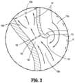
- FIG. 3is an enlarged view of the area of detail of FIG. 2 illustrating a flow path through and around the nozzle
- FIG. 4is a side cross-sectional view of a surgical instrument inserted through a surgical access device having a housing, a seal assembly, a nozzle, an evacuation port, and an insufflation port, in accordance with another aspect of this disclosure.
- distalrefers to that portion of the surgical access device, or component thereof, farther from the user, while the term “proximal” refers to that portion of the surgical access device, or component thereof, closer to the user.
- This disclosurerelates to a surgical access device configured to passively direct fluid, gas, and/or vapor out of and away from a surgical working space to maintain a clear field of vision and maintain a safe operating room environment for the surgeons and medical staff.
- smoke or contaminated vaporsmay be generated by surgical instruments during surgery, and with the removal and insertion of surgical instruments through a surgical access device, the smoke or contaminated vapors may escape into the operating room or blur the field of vision of a surgeon or other medical staff.
- a surgical access device 10 having a tube 20 and a housing 100is illustrated.
- the housing 100includes a fluid evacuation port 140 .
- the surgical access device 10may be positioned by a medical professional through an opening in a body to create access to a surgical working space.
- the surgical access device 10is configured to permit the removal and insertion of a surgical instrument into the working space while also evacuating smoke, vapor, gas, or other fluids from the surgical working space.
- an insufflation fluidmay be supplied to a surgical working space via an insufflation port 160 that is in fluid communication with a lumen 22 ( FIG. 2 ) of the tube 20 .
- An evacuation port 140may be coupled to a source of vacuum (not shown) using tubing 142 to remove fluid from the housing 100 .
- the housing 100 of the surgical access device 10includes a first chamber 110 , a second chamber 120 , a nozzle 130 defined between the first chamber 110 and the second chamber 120 , the evacuation port 140 , and a seal assembly 150 .
- the housing 100is in fluid communication with the lumen 22 of the tube 20 .
- the second chamber 120surrounds the first chamber 110 and is defined between a wall 114 of the first chamber 110 and a wall 102 of the housing 100 .
- the nozzle 130separates a distal portion of the first chamber 110 and a distal portion of the second chamber 120 .
- the nozzle 130is in fluid communication with the lumen 22 of the tube 20 and with the second chamber 120 .
- the nozzle 130is configured to direct fluid into the second chamber 120 and away from the first chamber 110 , such that a fluid (e.g., smoke or contaminated vapor) flowing proximally in the tube 20 is directed into the second chamber 120 .
- the evacuation port 140is in fluid communication with the second chamber 120 .
- the seal assembly 150is coupled to a proximal portion of the housing 100 .
- the seal assembly 150includes an instrument seal 152 and a duckbill valve or duckbill seal 154 .
- the duckbill seal 154extends distally into the first chamber 110 .
- the nozzle 130is disposed distally of the duckbill seal 154 of the seal assembly 150 .
- the insufflation port 160(see FIG. 1 ) provides an insufflation fluid through the lumen 22 , and thus maintains pressure in the surgical working space.
- An opening at a distal portion of the first chamber 110defines an orifice 112 .
- the orifice 112is concentric with the tube 20 and has a diameter approximately equal to the diameter of the tube 20 .
- the orifice 112 and the wall 114 of the first chamber 110are approximately collinear with the tube 20 .
- the wall 114 of the first chamber 110is collinear with the tube 20 at a distal portion 110 a of the first chamber 110 , and not collinear with the tube 20 at a proximal portion 110 b of the first chamber 110 .
- the wall 114 of the distal portion 110 a of the first chamber 110 and the wall 102 of the housing 100 near a distal portion 120 a of the second chamber 120are spaced apart from one another to define the nozzle 130 .
- the orifice 112is approximately adjacent to a distal portion of the nozzle 130 . In aspects, the orifice 112 is approximately adjacent to a throat 132 of the nozzle 130 ( FIG. 3 ).
- the nozzle 130may be a convergent-divergent (CD) nozzle 130 .
- a CD nozzlesuch as CD nozzle 130
- fluidinitially flows into a continuously convergent section 130 a such that the diameter of the nozzle 130 , and therefore the cross-sectional area of the nozzle 130 , constricts until it reaches its minimum chosen diameter or the minimum cross-sectional area commonly called the throat 132 of the nozzle 130 .
- the nozzle 130begins to diverge, or the diameter, and therefore the cross-sectional area, continuously enlarges in a divergent section 130 b .
- the flowis characterized by its change in velocity and pressure; as the fluid approaches the throat 132 , the velocity of the fluid increases and the pressure decreases. As the fluid leaves the throat 132 and flows through the divergent section 130 b , the velocity decreases and the pressure increases.
- incompressible flowwith Mach numbers below 1, the highest velocity and lowest pressure of the fluid flow will occur at the throat 132 .
- incompressible flowthe upstream portion of the flow, or that entering the convergent section 130 a of the nozzle 130 , has a higher pressure than the downstream portion of the flow exiting the nozzle 130 . Fluid normally flows in the direction of lower pressure, such that when presented with various paths of various pressures, more fluid will be pulled in the direction of the path with the lower pressure than the higher pressure.
- the nozzle 130may be a Venturi nozzle 130 .
- a Venturi nozzleoperates in a manner similar to a CD nozzle.
- a Venturi nozzle 130includes an elongated divergent section that is substantially longer than the convergent section and is configured to reduce pressure and energy loss at the nozzle exit.
- the nozzle 130is a divergent nozzle. In a divergent nozzle, the throat occurs at the very entrance of the nozzle, and the nozzle directs the flow into a wider area and introduces a pressure loss at the exit of the nozzle.
- the wall 102 of the housing 100 at a distal portion thereofis connected to the tube 20 .
- the wall 102 of the housing 100diverges from tube 20 which is approximately collinear with the wall 114 of the first chamber 110 .
- the second chamber 120is defined by the diverging wall 102 of the housing 100 and the wall 114 of the first chamber 110 .
- the second chamber 120has a diameter D 2
- the second chamber 120has a diameter D 3 ( FIG. 2 ).
- the diameters D 2 and D 3are measured between the wall 102 of the housing 100 and the wall 114 of the first chamber 110 .
- the diameter of the second chamber 120may continuously expand.
- the wall 102 of the housing 100expands progressively outward from a distal-most portion thereof such that second chamber 120 is wider at proximal portions of the housing 100 than distal portions of the housing 100 .
- the distal portion 120 a of the second chamber 120further defines a proximal portion 130 b of the nozzle 130 . Additionally, the diameters D 2 and D 3 of the second chamber 120 are always larger than the smallest diameter D 1 of the nozzle 130 , which occurs at the throat 132 of the nozzle 130 . Distal portion 130 a of the nozzle 130 is defined by the wall 102 of the housing 100 , a distal portion of the tube 20 , and the wall 114 of the first chamber 110 .
- the width of the second chamber 120may be generally uniform throughout, but narrow at the distal portion 120 a thereof that is near a proximal portion of the nozzle 130 .
- the proximal-most portion of the second chamber 120is positioned in the housing 100 distally of the seal assembly 150 .
- the second chamber 120is in fluid communication with the evacuation port 140 .
- the evacuation port 140may be coupled to tubing 142 .
- the tubing 142may be connected to a source of vacuum (not shown).
- the evacuation port 140is configured to remove fluid from the surgical access device 10 and away from the medical staff in an operating room.
- the evacuated fluidmay be filtered and/or contained downstream of the tubing 142 .
- the evacuation port 140may include a luer fitting.
- the tubing 142provides a passage for the evacuated fluid to flow away from a surgeon or medical staff in an operating room.
- the seal assembly 150is disposed proximally of the first chamber 110 with the duckbill seal 154 extending into the first chamber 110 .
- the seal assembly 150opens into the first chamber 110 and is configured to accept the insertion of a surgical instrument therethrough.
- the seal assembly 150is configured to inhibit fluid from escaping out of the housing 100 through the seal assembly 150 and into the environment.
- fluid pressuremay build in the first chamber 110 relative to the second chamber 120 .
- the first chamber 110has a first pressure or first chamber pressure P 1 and the second chamber has a second pressure or second chamber pressure P 2 , the difference between the pressures P 1 and P 2 defining a differential pressure.
- the first chamber 110is sealed off from the environment via the seal assembly 150 , causing fluid flowing proximally into the first chamber 110 to slow down and become approximately stagnate.
- the fluid in the first chamber 110has a static pressure that is approximately the same as the stagnation pressure since the fluid approximately stagnates and thus defines the first chamber pressure P 1 .
- the second chamber 120is open to the environment via the fluid evacuation port 140 . Since the fluid is flowing through the second chamber 120 , the second chamber 120 has a second chamber pressure P 2 that is less than the first chamber pressure P 1 . Additionally, when the evacuation port 140 , and therefore the second chamber 120 , is coupled to a source of vacuum the second chamber pressure P 2 will be further reduced relative to the first chamber pressure P 1 .
- the throat 132 of the nozzle 130has a throat pressure that is about as small or smaller than either of the first chamber pressure P 1 and the second chamber pressure P 2 .
- the fluid entering the nozzle 130will have the same pressure as the fluid flowing into the first chamber 110 .
- the pressure of the fluid flowing through the nozzle 130drops. Fluid flowing into the first chamber 110 is met by the first chamber pressure P 1 .
- the second chamber 120has a second chamber pressure P 2 that is lower than the first chamber pressure P 1 of the first chamber 110 , thereby defining the differential pressure, the fluid will be encouraged to flow along the path with lower pressure (i.e., the path of least resistance).
- lower pressurei.e., the path of least resistance
- the nozzle 130operates by directing fluid, as indicated by arrows “FF” in the tube to flow into the second chamber 120 and away from the orifice 112 of the first chamber 110 .
- the orifice 112has an inward curved lip 116 such that fluid inside the first chamber 110 is encouraged to flow around the lip 116 of the orifice 112 and into the second chamber 120 . Due to the no-slip condition and the lower pressure of the second chamber 120 and nozzle 130 relative to the first chamber 110 , the fluid in the distal portion 110 a of the first chamber 110 will be pulled around the lip 116 .
- a fluid at a surfacehas the same velocity of the surface creating a sharp velocity gradient that forms the basis of viscous shear flow. Fluid adjacent the fluid at the surface is affected by shear stress up until a boundary layer at which point the fluid is no longer affected by the shear stress exerted by the fluid at the surface.
- the shear stress acting on the fluidplays a role in the behavior of a fluid near a surface, including its velocity and flow path.
- a fluidmay follow a surface, such as the lip 116 .
- the curvature of the lip 116may be configured to reduce fluid eddies and stagnation in the first chamber 110 so that fluid in the first chamber 110 may more easily be pulled into the nozzle 130 around the lip 116 .
- the lip 116 of the orifice 112is configured to further define a convergent section 130 a of the nozzle 130 between the lip 116 and the wall 102 of the housing 100 . Most of the fluid will flow into the nozzle 130 as indicated by larger arrows FF, while some of the fluid will flow into the first chamber 110 as indicated by smaller arrows FF.
- the fluidflows through the tube 20 and has a tube pressure Pt in the tube 20 .
- the lower pressure P 2 of the second chamber 120draws the fluid through the nozzle 130 and away from the first chamber 110 and orifice 112 .
- a source of vacuum coupled to the fluid evacuation port 140further lowers the second chamber pressure P 2 of the second chamber 120 , and thus the fluid may flow faster through the nozzle 130 and into the second chamber 120 .
- the evacuation port 140is coupled to the second chamber 120 within the housing 100 distally of the seal assembly 150 .
- the tube pressure Ptmay be equal to or less than the first chamber pressure P 1 of the first chamber 110 .
- the surgical access device 10When no surgical instrument is inserted in the surgical access device 10 , fluid flows through the whole of the lumen 22 of the tube 20 .
- the duckbill seal 154inhibits the fluid flowing into and proximally out of the housing 100 via the chamber 110 . Pressure builds in the first chamber 110 when the duckbill seal 154 is closed or the instrument seal 152 is sealed about a surgical instrument inserted therein.
- the fluidAs the fluid travels proximally in the lumen 22 of the tube 20 , it is drawn by the nozzle 130 into the second chamber 120 .
- the fluid that traveled into the first chamber 110is pulled back into the nozzle 130 , as indicated in FIG. 3 , due to the lower pressure of the nozzle 130 and second chamber 120 .
- the surgical access device 10may passively remove fluid from the surgical working space.
- the surgical access device 10 ′includes a housing 100 ′, a tube 20 ′, and the seal assembly 150 .
- the housing 100 ′ of the surgical access device 10 ′includes an input port 170 .
- the input port 170is in fluid communication with a passage 172 that is coupled to or a part of the tube 20 ′.
- An output port 174is in fluid communication to an end of the passage 172 opposite the input port 170 .
- An insufflation fluidmay be supplied to the surgical working space via the input port 170 , fluid passage, 172 , and output port 174 .
- Insufflation fluidis supplied to the working space to offset any loss of insufflation fluid or pressure in the working space caused by fluid flowing out of the surgical working space through the lumen 22 ′ of the tube 20 ′ via the nozzle 130 , second chamber 120 , and the evacuation port 140 .
- the input port 170may include a luer fitting.
Landscapes
- Health & Medical Sciences (AREA)
- Surgery (AREA)
- Life Sciences & Earth Sciences (AREA)
- Biomedical Technology (AREA)
- Nuclear Medicine, Radiotherapy & Molecular Imaging (AREA)
- Engineering & Computer Science (AREA)
- Pathology (AREA)
- Heart & Thoracic Surgery (AREA)
- Medical Informatics (AREA)
- Molecular Biology (AREA)
- Animal Behavior & Ethology (AREA)
- General Health & Medical Sciences (AREA)
- Public Health (AREA)
- Veterinary Medicine (AREA)
- Surgical Instruments (AREA)
Abstract
Description
Claims (18)
Priority Applications (1)
| Application Number | Priority Date | Filing Date | Title |
|---|---|---|---|
| US17/063,582US12059176B2 (en) | 2020-10-05 | 2020-10-05 | Surgical access device with differential pressure induced fluid evacuation |
Applications Claiming Priority (1)
| Application Number | Priority Date | Filing Date | Title |
|---|---|---|---|
| US17/063,582US12059176B2 (en) | 2020-10-05 | 2020-10-05 | Surgical access device with differential pressure induced fluid evacuation |
Publications (2)
| Publication Number | Publication Date |
|---|---|
| US20220104848A1 US20220104848A1 (en) | 2022-04-07 |
| US12059176B2true US12059176B2 (en) | 2024-08-13 |
Family
ID=80930877
Family Applications (1)
| Application Number | Title | Priority Date | Filing Date |
|---|---|---|---|
| US17/063,582Active2042-05-16US12059176B2 (en) | 2020-10-05 | 2020-10-05 | Surgical access device with differential pressure induced fluid evacuation |
Country Status (1)
| Country | Link |
|---|---|
| US (1) | US12059176B2 (en) |
Citations (162)
| Publication number | Priority date | Publication date | Assignee | Title |
|---|---|---|---|---|
| US397060A (en) | 1889-01-29 | Island | ||
| US512456A (en) | 1894-01-09 | Garland b | ||
| US1213005A (en) | 1914-12-22 | 1917-01-16 | Victor Czeskleba | Obstetrical instrument. |
| US2912981A (en) | 1958-04-10 | 1959-11-17 | Frank J Keough | Inflatable retention catheter |
| US2936760A (en) | 1956-09-10 | 1960-05-17 | Davol Rubber Co | Positive pressure catheter |
| US3039468A (en) | 1959-01-07 | 1962-06-19 | Joseph L Price | Trocar and method of treating bloat |
| US3050066A (en) | 1958-12-31 | 1962-08-21 | Wilbur R Koehn | Retention catheters |
| US3253594A (en) | 1963-07-30 | 1966-05-31 | Frank E Matthews | Peritoneal cannula |
| US3397699A (en) | 1966-05-05 | 1968-08-20 | Gerald C. Kohl | Retaining catheter having resiliently biased wing flanges |
| US3545443A (en) | 1968-09-26 | 1970-12-08 | Amir H Ansari | Suprapubic cystostomy needle |
| US3713447A (en) | 1971-08-16 | 1973-01-30 | E Adair | Suprapubic shunt |
| US3774596A (en) | 1971-06-29 | 1973-11-27 | G Cook | Compliable cavity speculum |
| US3800788A (en) | 1972-07-12 | 1974-04-02 | N White | Antral catheter for reduction of fractures |
| US3882852A (en) | 1974-01-11 | 1975-05-13 | Manfred Sinnreich | Surgical dilators having insufflating means |
| US3896816A (en) | 1971-05-03 | 1975-07-29 | Martin Mattler | Disposable catheter |
| US3961632A (en) | 1974-12-13 | 1976-06-08 | Moossun Mohamed H | Stomach intubation and catheter placement system |
| USRE29207E (en) | 1973-06-25 | 1977-05-10 | Population Research Incorporated | Dispensing method and apparatus |
| US4083369A (en) | 1976-07-02 | 1978-04-11 | Manfred Sinnreich | Surgical instruments |
| US4217889A (en) | 1976-09-15 | 1980-08-19 | Heyer-Schulte Corporation | Flap development device and method of progressively increasing skin area |
| US4243050A (en) | 1977-12-13 | 1981-01-06 | Littleford Philip O | Method for inserting pacemaker electrodes and the like |
| US4276874A (en) | 1978-11-15 | 1981-07-07 | Datascope Corp. | Elongatable balloon catheter |
| US4312353A (en) | 1980-05-09 | 1982-01-26 | Mayfield Education And Research Fund | Method of creating and enlarging an opening in the brain |
| US4327709A (en) | 1978-03-06 | 1982-05-04 | Datascope Corp. | Apparatus and method for the percutaneous introduction of intra-aortic balloons into the human body |
| US4345606A (en) | 1977-12-13 | 1982-08-24 | Littleford Philip O | Split sleeve introducers for pacemaker electrodes and the like |
| US4411654A (en) | 1981-04-30 | 1983-10-25 | Baxter Travenol Laboratories, Inc. | Peelable catheter with securing ring and suture sleeve |
| US4416267A (en) | 1981-12-10 | 1983-11-22 | Garren Lloyd R | Method and apparatus for treating obesity |
| US4490137A (en) | 1982-09-30 | 1984-12-25 | Moukheibir Nabil W | Surgically implantable peritoneal dialysis apparatus |
| US4496345A (en) | 1982-08-30 | 1985-01-29 | Hasson Harrith M | Ballooned cannula |
| US4574806A (en) | 1984-10-01 | 1986-03-11 | Cordis Corporation | Tunnelling device for peripheral vascular reconstruction |
| US4581025A (en) | 1983-11-14 | 1986-04-08 | Cook Incorporated | Sheath |
| US4596554A (en) | 1985-04-19 | 1986-06-24 | Dastgeer Ghulam M | Colo-rectal evacuator |
| US4596559A (en) | 1984-11-02 | 1986-06-24 | Fleischhacker John J | Break-away handle for a catheter introducer set |
| US4608965A (en) | 1985-03-27 | 1986-09-02 | Anspach Jr William E | Endoscope retainer and tissue retracting device |
| US4644936A (en) | 1982-11-19 | 1987-02-24 | Iabp | Percutaneous intra-aortic balloon and method for using same |
| US4654030A (en) | 1986-02-24 | 1987-03-31 | Endotherapeutics | Trocar |
| US4685447A (en) | 1985-03-25 | 1987-08-11 | Pmt Corporation | Tissue expander system |
| US4701163A (en) | 1984-11-05 | 1987-10-20 | Medical Innovations Corporation | Gastrostomy feeding device |
| US4738666A (en) | 1985-06-11 | 1988-04-19 | Genus Catheter Technologies, Inc. | Variable diameter catheter |
| US4769038A (en) | 1986-03-18 | 1988-09-06 | C. R. Bard, Inc. | Prostheses and techniques and repair of inguinal and femoral hernias |
| US4772266A (en) | 1987-05-04 | 1988-09-20 | Catheter Technology Corp. | Catheter dilator/sheath assembly and method |
| US4779611A (en) | 1987-02-24 | 1988-10-25 | Grooters Ronald K | Disposable surgical scope guide |
| US4784133A (en) | 1987-01-28 | 1988-11-15 | Mackin Robert A | Working well balloon angioscope and method |
| US4793348A (en) | 1986-11-15 | 1988-12-27 | Palmaz Julio C | Balloon expandable vena cava filter to prevent migration of lower extremity venous clots into the pulmonary circulation |
| US4798205A (en) | 1986-05-08 | 1989-01-17 | Cox-Uphoff International | Method of using a subperiosteal tissue expander |
| US4800901A (en) | 1987-09-09 | 1989-01-31 | Lior Rosenberg | Balloon-type Tissue expansion device |
| US4802479A (en) | 1986-10-31 | 1989-02-07 | C. R. Bard, Inc. | Hand-held instrument for implanting, dispensing, and inflating an inflatable membrane |
| US4813429A (en) | 1986-05-12 | 1989-03-21 | Biodan Medical Systems Ltd. | Catheter and probe |
| US4840613A (en) | 1988-04-27 | 1989-06-20 | Menlo Care, Inc. | Protective sheath for catheter assembly |
| US4854316A (en) | 1986-10-03 | 1989-08-08 | Davis Emsley A | Apparatus and method for repairing and preventing para-stomal hernias |
| US4861334A (en) | 1988-06-24 | 1989-08-29 | Nawaz Arain | Self-retaining gastrostomy tube |
| US4865593A (en) | 1987-06-25 | 1989-09-12 | Sherwood Medical Company | Splittable cannula |
| US4869717A (en) | 1988-04-25 | 1989-09-26 | Adair Edwin Lloyd | Gas insufflation needle with instrument port |
| US4888000A (en) | 1987-06-04 | 1989-12-19 | Femcare Limited | Apparatus for the insertion of catheters |
| US4899747A (en) | 1981-12-10 | 1990-02-13 | Garren Lloyd R | Method and appartus for treating obesity |
| US4917668A (en) | 1988-03-18 | 1990-04-17 | B.. Braun Melsungen Ag | Valve for permanent venous cannulae or for catheter insertion means |
| US4931042A (en) | 1987-10-26 | 1990-06-05 | Endotherapeutics | Trocar assembly with improved latch |
| US4955895A (en) | 1986-12-23 | 1990-09-11 | Terumo Kabushiki Kaisha | Vasodilating catheter |
| US5002557A (en) | 1989-04-06 | 1991-03-26 | Hasson Harrith M | Laparoscopic cannula |
| US5009643A (en) | 1989-08-09 | 1991-04-23 | Richard Wolf Medical Instruments Corp. | Self-retaining electrically insulative trocar sleeve and trocar |
| US5030206A (en) | 1986-10-17 | 1991-07-09 | United States Surgical Corporation | Trocar |
| US5030227A (en) | 1988-06-02 | 1991-07-09 | Advanced Surgical Intervention, Inc. | Balloon dilation catheter |
| US5074871A (en) | 1989-12-07 | 1991-12-24 | Evi Corporation | Catheter atherotome |
| US5098392A (en) | 1991-06-28 | 1992-03-24 | Fleischhacker John J | Locking dilator for peel away introducer sheath |
| US5104383A (en) | 1989-10-17 | 1992-04-14 | United States Surgical Corporation | Trocar adapter seal and method of use |
| EP0480653A1 (en) | 1990-10-09 | 1992-04-15 | VANCE PRODUCTS INCORPORATED d/b/a COOK UROLOGICAL INCORPORATED | Surgical access sheath |
| WO1992006638A1 (en) | 1990-10-10 | 1992-04-30 | W.L. Gore & Associates, Inc. | A laparoscopy surgical instrument |
| US5116318A (en) | 1989-06-06 | 1992-05-26 | Cordis Corporation | Dilatation balloon within an elastic sleeve |
| US5116357A (en) | 1990-10-11 | 1992-05-26 | Eberbach Mark A | Hernia plug and introducer apparatus |
| US5122122A (en) | 1989-11-22 | 1992-06-16 | Dexide, Incorporated | Locking trocar sleeve |
| US5122155A (en) | 1990-10-11 | 1992-06-16 | Eberbach Mark A | Hernia repair apparatus and method of use |
| US5137512A (en) | 1989-03-17 | 1992-08-11 | Scimed Life Systems, Inc. | Multisegment balloon protector for dilatation catheter |
| US5141494A (en) | 1990-02-15 | 1992-08-25 | Danforth Biomedical, Inc. | Variable wire diameter angioplasty dilatation balloon catheter |
| US5141515A (en) | 1990-10-11 | 1992-08-25 | Eberbach Mark A | Apparatus and methods for repairing hernias |
| US5147374A (en) | 1991-12-05 | 1992-09-15 | Alfredo Fernandez | Prosthetic mesh patch for hernia repair |
| US5147302A (en) | 1989-04-21 | 1992-09-15 | Scimed Life Systems, Inc. | Method of shaping a balloon of a balloon catheter |
| US5147316A (en) | 1990-11-19 | 1992-09-15 | Castillenti Thomas A | Laparoscopic trocar with self-locking port sleeve |
| US5158545A (en) | 1991-05-02 | 1992-10-27 | Brigham And Women's Hospital | Diameter expansion cannula |
| WO1992018056A1 (en) | 1991-04-10 | 1992-10-29 | Wisap Gesellschaft für wissenschaftlichen Apparatebau mbH | Abdominal-cavity expander |
| US5159925A (en) | 1988-09-09 | 1992-11-03 | Gynelab, Inc. | Cauterizing apparatus and method for laparoscopic cholecystostomy, gallbladder ablation and treatment of benign prostate hypertrophy |
| US5163949A (en) | 1990-03-02 | 1992-11-17 | Bonutti Peter M | Fluid operated retractors |
| WO1992021293A1 (en) | 1991-05-29 | 1992-12-10 | Origin Medsystems, Inc. | Endoscopic inflatable retraction device, method of using, and method of making |
| US5176697A (en) | 1989-04-06 | 1993-01-05 | Hasson Harrith M | Laparoscopic cannula |
| US5176692A (en) | 1991-12-09 | 1993-01-05 | Wilk Peter J | Method and surgical instrument for repairing hernia |
| US5183463A (en) | 1989-02-03 | 1993-02-02 | Elie Debbas | Apparatus for locating a breast mass |
| US5188596A (en) | 1990-09-27 | 1993-02-23 | Mentor Corporation | Transparent prostate dilation balloon and scope |
| US5188630A (en) | 1991-03-25 | 1993-02-23 | Christoudias George C | Christoudias endospongestick probe |
| US5195507A (en) | 1990-11-06 | 1993-03-23 | Ethicon, Inc. | Endoscopic surgical instrument for displacing tissue or organs |
| US5201754A (en) | 1985-05-02 | 1993-04-13 | C. R. Bard, Inc. | Balloon dilatation catheter with varying radiopacity |
| US5201742A (en) | 1991-04-16 | 1993-04-13 | Hasson Harrith M | Support jig for a surgical instrument |
| US5209725A (en) | 1991-04-11 | 1993-05-11 | Roth Robert A | Prostatic urethra dilatation catheter system and method |
| WO1993009722A1 (en) | 1991-11-19 | 1993-05-27 | Origin Medsystems, Inc. | Endoscopic inflatable retraction devices for separating layers of tissue, and methods of using |
| US5215526A (en) | 1988-07-06 | 1993-06-01 | Ethicon, Inc. | Safety trocar |
| US5222970A (en) | 1991-09-06 | 1993-06-29 | William A. Cook Australia Pty. Ltd. | Method of and system for mounting a vascular occlusion balloon on a delivery catheter |
| US5226890A (en) | 1991-11-13 | 1993-07-13 | United States Surgical Corporation | Tissue gripping device |
| US5232451A (en) | 1989-11-22 | 1993-08-03 | Dexide, Inc. | Locking trocar sleeve |
| US5232446A (en) | 1991-10-30 | 1993-08-03 | Scimed Life Systems, Inc. | Multi-sinus perfusion balloon dilatation catheter |
| US5234454A (en) | 1991-08-05 | 1993-08-10 | Akron City Hospital | Percutaneous intragastric balloon catheter and method for controlling body weight therewith |
| US5250025A (en) | 1990-08-15 | 1993-10-05 | Intramed Laboratories | Percutaneous access catheter and method of use |
| US5258026A (en) | 1992-02-06 | 1993-11-02 | Johnson Gerald W | Endoscopic augmentation mammoplasty and instruments therefor |
| US5269753A (en) | 1992-07-14 | 1993-12-14 | Wilk Peter J | Method for use in laparoscopic hernia repair |
| US5308327A (en) | 1991-11-25 | 1994-05-03 | Advanced Surgical Inc. | Self-deployed inflatable retractor |
| US5309896A (en) | 1991-05-29 | 1994-05-10 | Origin Medsystems, Inc. | Retraction methods using endoscopic inflatable retraction devices |
| US5314443A (en) | 1990-06-25 | 1994-05-24 | Meadox Medicals, Inc. | Prostate balloon dilatation catheter |
| US5318012A (en) | 1991-07-15 | 1994-06-07 | Wilk Peter J | Method for lifting abdominal wall during laparoscopic surgery |
| US5330497A (en) | 1989-11-22 | 1994-07-19 | Dexide, Inc. | Locking trocar sleeve |
| EP0610099A2 (en) | 1993-02-04 | 1994-08-10 | Trigonon Inc. | Inflatable laparoscopic retractor |
| US5346504A (en) | 1992-11-19 | 1994-09-13 | Ethicon, Inc. | Intraluminal manipulator with a head having articulating links |
| US5359995A (en) | 1991-02-04 | 1994-11-01 | Sewell Jr Frank | Method of using an inflatable laparoscopic retractor |
| US5383889A (en) | 1991-05-29 | 1995-01-24 | Origin Medsystems, Inc. | Tethered everting balloon retractor for hollow bodies and method of using |
| US5397311A (en) | 1992-09-09 | 1995-03-14 | Menlo Care, Inc. | Bloodless splittable introducer |
| US5407433A (en) | 1993-02-10 | 1995-04-18 | Origin Medsystems, Inc. | Gas-tight seal accommodating surgical instruments with a wide range of diameters |
| US5431173A (en) | 1991-05-29 | 1995-07-11 | Origin Medsystems, Inc. | Method and apparatus for body structure manipulation and dissection |
| US5445615A (en) | 1991-11-06 | 1995-08-29 | Yoon; Inbae | Surgical instrument stabilizer |
| US5468248A (en) | 1991-05-29 | 1995-11-21 | Origin Medsystems, Inc. | Endoscopic inflatable retraction devices for separating layers of tissue |
| US5514153A (en) | 1990-03-02 | 1996-05-07 | General Surgical Innovations, Inc. | Method of dissecting tissue layers |
| US5514091A (en) | 1988-07-22 | 1996-05-07 | Yoon; Inbae | Expandable multifunctional manipulating instruments for various medical procedures |
| US5540711A (en) | 1992-06-02 | 1996-07-30 | General Surgical Innovations, Inc. | Apparatus and method for developing an anatomic space for laparoscopic procedures with laparoscopic visualization |
| US5540658A (en) | 1994-06-27 | 1996-07-30 | Innerdyne, Inc. | Transcervical uterine access and sealing device |
| US5607443A (en) | 1992-06-02 | 1997-03-04 | General Surgical Innovations, Inc. | Expansible tunneling apparatus for creating an anatomic working space with laparoscopic observation |
| US5607441A (en) | 1995-03-24 | 1997-03-04 | Ethicon Endo-Surgery, Inc. | Surgical dissector |
| US5632761A (en) | 1991-05-29 | 1997-05-27 | Origin Medsystems, Inc. | Inflatable devices for separating layers of tissue, and methods of using |
| WO1997021461A1 (en) | 1995-12-12 | 1997-06-19 | General Surgical Innovations, Inc. | Balloon dissectors |
| US5667520A (en) | 1990-03-02 | 1997-09-16 | General Surgical Innovations, Inc. | Method of performing balloon dissection |
| US5667479A (en) | 1994-06-01 | 1997-09-16 | Archimedes Surgical, Inc. | Method for resection of an anatomic structure |
| US5704372A (en) | 1991-05-29 | 1998-01-06 | Origin Medsystems, Inc. | Endoscopic inflatable retraction devices for separating layers of tissue, and methods of using |
| US5713869A (en) | 1995-03-08 | 1998-02-03 | Morejon; Orlando | Trocar assembly |
| US5728119A (en) | 1991-05-29 | 1998-03-17 | Origin Medsystems, Inc. | Method and inflatable chamber apparatus for separating layers of tissue |
| US5730748A (en) | 1995-05-19 | 1998-03-24 | General Surgical Innovations, Inc. | Methods and devices for blood vessel harvesting |
| US5730756A (en) | 1992-06-02 | 1998-03-24 | General Surgical Innovations, Inc. | Method for developing an anatomic space for laparoscopic procedures with laparoscopic visualization |
| US5738628A (en) | 1995-03-24 | 1998-04-14 | Ethicon Endo-Surgery, Inc. | Surgical dissector and method for its use |
| US5779728A (en) | 1991-05-29 | 1998-07-14 | Origin Medsystems, Inc. | Method and inflatable chamber apparatus for separating layers of tissue |
| US5797947A (en) | 1995-05-19 | 1998-08-25 | General Surgical Innovations, Inc. | Methods and devices for harvesting blood vessels with balloons |
| US5803901A (en) | 1991-05-29 | 1998-09-08 | Origin Medsystems, Inc. | Inflatable devices for separating layers of tissue and methods of using |
| US5810867A (en) | 1997-04-28 | 1998-09-22 | Medtronic, Inc. | Dilatation catheter with varied stiffness |
| US5814060A (en) | 1994-06-29 | 1998-09-29 | General Surgical Innovations, Inc. | Extraluminal balloon dissection |
| US5836961A (en) | 1992-06-02 | 1998-11-17 | General Surgical Innovations, Inc. | Apparatus and method for developing an anatomic space for laparoscopic hernia repair and patch for use therewith |
| US5836913A (en) | 1997-05-02 | 1998-11-17 | Innerdyne, Inc. | Device and method for accessing a body cavity |
| EP0880939A1 (en) | 1997-05-27 | 1998-12-02 | Ethicon Endo-Surgery, Inc. | Ultrasonic trocar assembly |
| US5865802A (en) | 1988-07-22 | 1999-02-02 | Yoon; Inbae | Expandable multifunctional instruments for creating spaces at obstructed sites endoscopically |
| WO1999012602A1 (en) | 1997-09-10 | 1999-03-18 | General Surgical Innovations, Inc. | Balloon dissecting instruments |
| US5893866A (en) | 1995-05-22 | 1999-04-13 | General Surgical Innovations, Inc. | Balloon dissecting instruments |
| WO2001026724A2 (en) | 1999-10-08 | 2001-04-19 | General Surgical Innovations, Inc. | Balloon dissection apparatus |
| US6361543B1 (en) | 1991-05-29 | 2002-03-26 | Sherwood Services Ag | Inflatable devices for separating layers of tissue, and methods of using |
| US6375665B1 (en) | 1995-05-22 | 2002-04-23 | General Surgical Innovations, Inc. | Apparatus and method for dissecting and retracting elongate structures |
| US6379372B1 (en) | 1996-09-12 | 2002-04-30 | Edwards Lifesciences Corp. | Endovascular delivery system |
| US6432121B1 (en) | 1992-06-02 | 2002-08-13 | General Surgical Innovations, Inc. | Apparatus and method for guiding placement of a minimally invasive surgical instrument |
| US20020128603A1 (en)* | 2000-09-08 | 2002-09-12 | Pall Corporation | Cannula assembly |
| US6468205B1 (en) | 1996-03-20 | 2002-10-22 | General Surgical Innovations, Inc. | Method and apparatus for combined dissection and retraction |
| WO2002096307A2 (en) | 2001-05-31 | 2002-12-05 | Tyco Healthcare Group Lp | Balloon cannula with over-center clamp |
| US6506200B1 (en) | 1995-07-13 | 2003-01-14 | Origin Medsystems, Inc. | Tissue separation cannula and method |
| US6517514B1 (en) | 1997-10-03 | 2003-02-11 | Boston Scientific Corporation | Balloon catheterization |
| US6540764B1 (en) | 1992-06-02 | 2003-04-01 | General Surgical Innovations, Inc. | Apparatus and method for dissecting tissue layers |
| WO2004032756A2 (en) | 2002-10-04 | 2004-04-22 | Tyco Healthcare Group, Lp | Balloon dissector with cannula |
| US6796960B2 (en) | 2001-05-04 | 2004-09-28 | Wit Ip Corporation | Low thermal resistance elastic sleeves for medical device balloons |
| US20070088275A1 (en)* | 2003-04-08 | 2007-04-19 | Ralph Stearns | Trocar assembly with pneumatic sealing |
| US8551050B2 (en) | 2011-06-10 | 2013-10-08 | Lexion Medical, Llc | Device and method for controlling the flow rate of evacuating surgical vapor and mist from a body cavity |
| US8551049B2 (en)* | 2011-06-10 | 2013-10-08 | Lexion Medical, Llc | Device and method for evacuating surgical vapor and mist from a body cavity |
| US8795223B2 (en) | 2011-03-08 | 2014-08-05 | Surgiquest, Inc. | Trocar assembly with pneumatic sealing |
| US20160158468A1 (en) | 2012-11-20 | 2016-06-09 | Surgiquest, Inc. | Systems and methods for conducting smoke evacuation during laparoscopic surgical procedures |
| US20170007295A1 (en)* | 2015-07-07 | 2017-01-12 | Lexion Medical, Llc | Method and system for gas maintenance to a body cavity using a trocar |
| WO2017184876A1 (en) | 2016-04-20 | 2017-10-26 | Buffalo Filter Llc | Smoke collecting trocar |
| WO2020036497A1 (en) | 2018-08-17 | 2020-02-20 | Fisher & Paykel Healthcare Limited | Venting surgical cannula for providing gases to a patient |
- 2020
- 2020-10-05USUS17/063,582patent/US12059176B2/enactiveActive
Patent Citations (182)
| Publication number | Priority date | Publication date | Assignee | Title |
|---|---|---|---|---|
| US397060A (en) | 1889-01-29 | Island | ||
| US512456A (en) | 1894-01-09 | Garland b | ||
| US1213005A (en) | 1914-12-22 | 1917-01-16 | Victor Czeskleba | Obstetrical instrument. |
| US2936760A (en) | 1956-09-10 | 1960-05-17 | Davol Rubber Co | Positive pressure catheter |
| US2912981A (en) | 1958-04-10 | 1959-11-17 | Frank J Keough | Inflatable retention catheter |
| US3050066A (en) | 1958-12-31 | 1962-08-21 | Wilbur R Koehn | Retention catheters |
| US3039468A (en) | 1959-01-07 | 1962-06-19 | Joseph L Price | Trocar and method of treating bloat |
| US3253594A (en) | 1963-07-30 | 1966-05-31 | Frank E Matthews | Peritoneal cannula |
| US3397699A (en) | 1966-05-05 | 1968-08-20 | Gerald C. Kohl | Retaining catheter having resiliently biased wing flanges |
| US3545443A (en) | 1968-09-26 | 1970-12-08 | Amir H Ansari | Suprapubic cystostomy needle |
| US3896816A (en) | 1971-05-03 | 1975-07-29 | Martin Mattler | Disposable catheter |
| US3774596A (en) | 1971-06-29 | 1973-11-27 | G Cook | Compliable cavity speculum |
| US3713447A (en) | 1971-08-16 | 1973-01-30 | E Adair | Suprapubic shunt |
| US3800788A (en) | 1972-07-12 | 1974-04-02 | N White | Antral catheter for reduction of fractures |
| USRE29207E (en) | 1973-06-25 | 1977-05-10 | Population Research Incorporated | Dispensing method and apparatus |
| US3882852A (en) | 1974-01-11 | 1975-05-13 | Manfred Sinnreich | Surgical dilators having insufflating means |
| US3961632A (en) | 1974-12-13 | 1976-06-08 | Moossun Mohamed H | Stomach intubation and catheter placement system |
| US4083369A (en) | 1976-07-02 | 1978-04-11 | Manfred Sinnreich | Surgical instruments |
| US4217889A (en) | 1976-09-15 | 1980-08-19 | Heyer-Schulte Corporation | Flap development device and method of progressively increasing skin area |
| US4243050A (en) | 1977-12-13 | 1981-01-06 | Littleford Philip O | Method for inserting pacemaker electrodes and the like |
| US4345606A (en) | 1977-12-13 | 1982-08-24 | Littleford Philip O | Split sleeve introducers for pacemaker electrodes and the like |
| US4327709A (en) | 1978-03-06 | 1982-05-04 | Datascope Corp. | Apparatus and method for the percutaneous introduction of intra-aortic balloons into the human body |
| US4276874A (en) | 1978-11-15 | 1981-07-07 | Datascope Corp. | Elongatable balloon catheter |
| US4312353A (en) | 1980-05-09 | 1982-01-26 | Mayfield Education And Research Fund | Method of creating and enlarging an opening in the brain |
| US4411654A (en) | 1981-04-30 | 1983-10-25 | Baxter Travenol Laboratories, Inc. | Peelable catheter with securing ring and suture sleeve |
| US4416267A (en) | 1981-12-10 | 1983-11-22 | Garren Lloyd R | Method and apparatus for treating obesity |
| US4899747A (en) | 1981-12-10 | 1990-02-13 | Garren Lloyd R | Method and appartus for treating obesity |
| US4496345A (en) | 1982-08-30 | 1985-01-29 | Hasson Harrith M | Ballooned cannula |
| US4490137A (en) | 1982-09-30 | 1984-12-25 | Moukheibir Nabil W | Surgically implantable peritoneal dialysis apparatus |
| US4644936A (en) | 1982-11-19 | 1987-02-24 | Iabp | Percutaneous intra-aortic balloon and method for using same |
| US4581025A (en) | 1983-11-14 | 1986-04-08 | Cook Incorporated | Sheath |
| US4574806A (en) | 1984-10-01 | 1986-03-11 | Cordis Corporation | Tunnelling device for peripheral vascular reconstruction |
| US4596559A (en) | 1984-11-02 | 1986-06-24 | Fleischhacker John J | Break-away handle for a catheter introducer set |
| US4701163A (en) | 1984-11-05 | 1987-10-20 | Medical Innovations Corporation | Gastrostomy feeding device |
| US4685447A (en) | 1985-03-25 | 1987-08-11 | Pmt Corporation | Tissue expander system |
| US4608965A (en) | 1985-03-27 | 1986-09-02 | Anspach Jr William E | Endoscope retainer and tissue retracting device |
| US4596554A (en) | 1985-04-19 | 1986-06-24 | Dastgeer Ghulam M | Colo-rectal evacuator |
| US5201754A (en) | 1985-05-02 | 1993-04-13 | C. R. Bard, Inc. | Balloon dilatation catheter with varying radiopacity |
| US4738666A (en) | 1985-06-11 | 1988-04-19 | Genus Catheter Technologies, Inc. | Variable diameter catheter |
| US4654030A (en) | 1986-02-24 | 1987-03-31 | Endotherapeutics | Trocar |
| US4769038A (en) | 1986-03-18 | 1988-09-06 | C. R. Bard, Inc. | Prostheses and techniques and repair of inguinal and femoral hernias |
| US4798205A (en) | 1986-05-08 | 1989-01-17 | Cox-Uphoff International | Method of using a subperiosteal tissue expander |
| US4813429A (en) | 1986-05-12 | 1989-03-21 | Biodan Medical Systems Ltd. | Catheter and probe |
| US4854316A (en) | 1986-10-03 | 1989-08-08 | Davis Emsley A | Apparatus and method for repairing and preventing para-stomal hernias |
| US5030206A (en) | 1986-10-17 | 1991-07-09 | United States Surgical Corporation | Trocar |
| US4802479A (en) | 1986-10-31 | 1989-02-07 | C. R. Bard, Inc. | Hand-held instrument for implanting, dispensing, and inflating an inflatable membrane |
| US4793348A (en) | 1986-11-15 | 1988-12-27 | Palmaz Julio C | Balloon expandable vena cava filter to prevent migration of lower extremity venous clots into the pulmonary circulation |
| US4955895A (en) | 1986-12-23 | 1990-09-11 | Terumo Kabushiki Kaisha | Vasodilating catheter |
| US4784133A (en) | 1987-01-28 | 1988-11-15 | Mackin Robert A | Working well balloon angioscope and method |
| US4779611A (en) | 1987-02-24 | 1988-10-25 | Grooters Ronald K | Disposable surgical scope guide |
| US4772266A (en) | 1987-05-04 | 1988-09-20 | Catheter Technology Corp. | Catheter dilator/sheath assembly and method |
| US4888000A (en) | 1987-06-04 | 1989-12-19 | Femcare Limited | Apparatus for the insertion of catheters |
| US4865593A (en) | 1987-06-25 | 1989-09-12 | Sherwood Medical Company | Splittable cannula |
| US4800901A (en) | 1987-09-09 | 1989-01-31 | Lior Rosenberg | Balloon-type Tissue expansion device |
| US4931042A (en) | 1987-10-26 | 1990-06-05 | Endotherapeutics | Trocar assembly with improved latch |
| US4917668A (en) | 1988-03-18 | 1990-04-17 | B.. Braun Melsungen Ag | Valve for permanent venous cannulae or for catheter insertion means |
| US4869717A (en) | 1988-04-25 | 1989-09-26 | Adair Edwin Lloyd | Gas insufflation needle with instrument port |
| US4840613A (en) | 1988-04-27 | 1989-06-20 | Menlo Care, Inc. | Protective sheath for catheter assembly |
| US4840613B1 (en) | 1988-04-27 | 1993-07-27 | Menlo Care Inc | |
| US5030227A (en) | 1988-06-02 | 1991-07-09 | Advanced Surgical Intervention, Inc. | Balloon dilation catheter |
| US4861334A (en) | 1988-06-24 | 1989-08-29 | Nawaz Arain | Self-retaining gastrostomy tube |
| US5215526A (en) | 1988-07-06 | 1993-06-01 | Ethicon, Inc. | Safety trocar |
| US5656013A (en) | 1988-07-22 | 1997-08-12 | Yoon; Inbae | Method of using an expandable multifunctional manipulating instrument for various medical procedures |
| US5865802A (en) | 1988-07-22 | 1999-02-02 | Yoon; Inbae | Expandable multifunctional instruments for creating spaces at obstructed sites endoscopically |
| US5514091A (en) | 1988-07-22 | 1996-05-07 | Yoon; Inbae | Expandable multifunctional manipulating instruments for various medical procedures |
| US5159925A (en) | 1988-09-09 | 1992-11-03 | Gynelab, Inc. | Cauterizing apparatus and method for laparoscopic cholecystostomy, gallbladder ablation and treatment of benign prostate hypertrophy |
| US5183463A (en) | 1989-02-03 | 1993-02-02 | Elie Debbas | Apparatus for locating a breast mass |
| US5137512A (en) | 1989-03-17 | 1992-08-11 | Scimed Life Systems, Inc. | Multisegment balloon protector for dilatation catheter |
| US5002557A (en) | 1989-04-06 | 1991-03-26 | Hasson Harrith M | Laparoscopic cannula |
| US5176697A (en) | 1989-04-06 | 1993-01-05 | Hasson Harrith M | Laparoscopic cannula |
| US5147302A (en) | 1989-04-21 | 1992-09-15 | Scimed Life Systems, Inc. | Method of shaping a balloon of a balloon catheter |
| US5342307A (en) | 1989-04-21 | 1994-08-30 | Scimed Life Systems, Inc. | Dilatation catheter with tri-fold balloon |
| US5116318A (en) | 1989-06-06 | 1992-05-26 | Cordis Corporation | Dilatation balloon within an elastic sleeve |
| US5009643A (en) | 1989-08-09 | 1991-04-23 | Richard Wolf Medical Instruments Corp. | Self-retaining electrically insulative trocar sleeve and trocar |
| US5104383A (en) | 1989-10-17 | 1992-04-14 | United States Surgical Corporation | Trocar adapter seal and method of use |
| US5330497A (en) | 1989-11-22 | 1994-07-19 | Dexide, Inc. | Locking trocar sleeve |
| US5232451A (en) | 1989-11-22 | 1993-08-03 | Dexide, Inc. | Locking trocar sleeve |
| US5122122A (en) | 1989-11-22 | 1992-06-16 | Dexide, Incorporated | Locking trocar sleeve |
| US5074871A (en) | 1989-12-07 | 1991-12-24 | Evi Corporation | Catheter atherotome |
| US5141494A (en) | 1990-02-15 | 1992-08-25 | Danforth Biomedical, Inc. | Variable wire diameter angioplasty dilatation balloon catheter |
| US5514153A (en) | 1990-03-02 | 1996-05-07 | General Surgical Innovations, Inc. | Method of dissecting tissue layers |
| US5667520A (en) | 1990-03-02 | 1997-09-16 | General Surgical Innovations, Inc. | Method of performing balloon dissection |
| US5163949A (en) | 1990-03-02 | 1992-11-17 | Bonutti Peter M | Fluid operated retractors |
| US5314443A (en) | 1990-06-25 | 1994-05-24 | Meadox Medicals, Inc. | Prostate balloon dilatation catheter |
| US5250025A (en) | 1990-08-15 | 1993-10-05 | Intramed Laboratories | Percutaneous access catheter and method of use |
| US5188596A (en) | 1990-09-27 | 1993-02-23 | Mentor Corporation | Transparent prostate dilation balloon and scope |
| EP0480653A1 (en) | 1990-10-09 | 1992-04-15 | VANCE PRODUCTS INCORPORATED d/b/a COOK UROLOGICAL INCORPORATED | Surgical access sheath |
| US5290249A (en) | 1990-10-09 | 1994-03-01 | Vance Products Incorporated | Surgical access sheath |
| WO1992006638A1 (en) | 1990-10-10 | 1992-04-30 | W.L. Gore & Associates, Inc. | A laparoscopy surgical instrument |
| US5116357A (en) | 1990-10-11 | 1992-05-26 | Eberbach Mark A | Hernia plug and introducer apparatus |
| US5122155A (en) | 1990-10-11 | 1992-06-16 | Eberbach Mark A | Hernia repair apparatus and method of use |
| US5141515A (en) | 1990-10-11 | 1992-08-25 | Eberbach Mark A | Apparatus and methods for repairing hernias |
| US5195507A (en) | 1990-11-06 | 1993-03-23 | Ethicon, Inc. | Endoscopic surgical instrument for displacing tissue or organs |
| US5147316A (en) | 1990-11-19 | 1992-09-15 | Castillenti Thomas A | Laparoscopic trocar with self-locking port sleeve |
| US5359995A (en) | 1991-02-04 | 1994-11-01 | Sewell Jr Frank | Method of using an inflatable laparoscopic retractor |
| US5188630A (en) | 1991-03-25 | 1993-02-23 | Christoudias George C | Christoudias endospongestick probe |
| WO1992018056A1 (en) | 1991-04-10 | 1992-10-29 | Wisap Gesellschaft für wissenschaftlichen Apparatebau mbH | Abdominal-cavity expander |
| US5209725A (en) | 1991-04-11 | 1993-05-11 | Roth Robert A | Prostatic urethra dilatation catheter system and method |
| US5201742A (en) | 1991-04-16 | 1993-04-13 | Hasson Harrith M | Support jig for a surgical instrument |
| US5158545A (en) | 1991-05-02 | 1992-10-27 | Brigham And Women's Hospital | Diameter expansion cannula |
| US5309896A (en) | 1991-05-29 | 1994-05-10 | Origin Medsystems, Inc. | Retraction methods using endoscopic inflatable retraction devices |
| US5402772A (en) | 1991-05-29 | 1995-04-04 | Origin Medsystems, Inc. | Endoscopic expandable retraction device |
| WO1992021295A1 (en) | 1991-05-29 | 1992-12-10 | Origin Medsystems, Inc. | Endoscopic inflatable retraction devices, methods of using, and a method of making |
| US5779728A (en) | 1991-05-29 | 1998-07-14 | Origin Medsystems, Inc. | Method and inflatable chamber apparatus for separating layers of tissue |
| WO1992021293A1 (en) | 1991-05-29 | 1992-12-10 | Origin Medsystems, Inc. | Endoscopic inflatable retraction device, method of using, and method of making |
| US5803901A (en) | 1991-05-29 | 1998-09-08 | Origin Medsystems, Inc. | Inflatable devices for separating layers of tissue and methods of using |
| US5468248A (en) | 1991-05-29 | 1995-11-21 | Origin Medsystems, Inc. | Endoscopic inflatable retraction devices for separating layers of tissue |
| US5431173A (en) | 1991-05-29 | 1995-07-11 | Origin Medsystems, Inc. | Method and apparatus for body structure manipulation and dissection |
| US5704372A (en) | 1991-05-29 | 1998-01-06 | Origin Medsystems, Inc. | Endoscopic inflatable retraction devices for separating layers of tissue, and methods of using |
| US5361752A (en) | 1991-05-29 | 1994-11-08 | Origin Medsystems, Inc. | Retraction apparatus and methods for endoscopic surgery |
| US5722986A (en) | 1991-05-29 | 1998-03-03 | Origin Medsystems, Inc. | Inflatable devices for separating layers of tissue, and methods of using |
| US5632761A (en) | 1991-05-29 | 1997-05-27 | Origin Medsystems, Inc. | Inflatable devices for separating layers of tissue, and methods of using |
| US5728119A (en) | 1991-05-29 | 1998-03-17 | Origin Medsystems, Inc. | Method and inflatable chamber apparatus for separating layers of tissue |
| US5370134A (en) | 1991-05-29 | 1994-12-06 | Orgin Medsystems, Inc. | Method and apparatus for body structure manipulation and dissection |
| US5383889A (en) | 1991-05-29 | 1995-01-24 | Origin Medsystems, Inc. | Tethered everting balloon retractor for hollow bodies and method of using |
| US5925058A (en) | 1991-05-29 | 1999-07-20 | Origin Medsystems, Inc. | Method and inflatable chamber apparatus for separating layers of tissue |
| US6361543B1 (en) | 1991-05-29 | 2002-03-26 | Sherwood Services Ag | Inflatable devices for separating layers of tissue, and methods of using |
| US5098392A (en) | 1991-06-28 | 1992-03-24 | Fleischhacker John J | Locking dilator for peel away introducer sheath |
| US5318012A (en) | 1991-07-15 | 1994-06-07 | Wilk Peter J | Method for lifting abdominal wall during laparoscopic surgery |
| US5234454A (en) | 1991-08-05 | 1993-08-10 | Akron City Hospital | Percutaneous intragastric balloon catheter and method for controlling body weight therewith |
| US5222970A (en) | 1991-09-06 | 1993-06-29 | William A. Cook Australia Pty. Ltd. | Method of and system for mounting a vascular occlusion balloon on a delivery catheter |
| US5232446A (en) | 1991-10-30 | 1993-08-03 | Scimed Life Systems, Inc. | Multi-sinus perfusion balloon dilatation catheter |
| US5445615A (en) | 1991-11-06 | 1995-08-29 | Yoon; Inbae | Surgical instrument stabilizer |
| US5226890A (en) | 1991-11-13 | 1993-07-13 | United States Surgical Corporation | Tissue gripping device |
| WO1993009722A1 (en) | 1991-11-19 | 1993-05-27 | Origin Medsystems, Inc. | Endoscopic inflatable retraction devices for separating layers of tissue, and methods of using |
| US5308327A (en) | 1991-11-25 | 1994-05-03 | Advanced Surgical Inc. | Self-deployed inflatable retractor |
| US5147374A (en) | 1991-12-05 | 1992-09-15 | Alfredo Fernandez | Prosthetic mesh patch for hernia repair |
| US5176692A (en) | 1991-12-09 | 1993-01-05 | Wilk Peter J | Method and surgical instrument for repairing hernia |
| US5258026A (en) | 1992-02-06 | 1993-11-02 | Johnson Gerald W | Endoscopic augmentation mammoplasty and instruments therefor |
| US5836961A (en) | 1992-06-02 | 1998-11-17 | General Surgical Innovations, Inc. | Apparatus and method for developing an anatomic space for laparoscopic hernia repair and patch for use therewith |
| US6514272B1 (en) | 1992-06-02 | 2003-02-04 | General Surgical Innovations, Inc. | Apparatus and method for developing an anatomic space for laparoscopic hernia repair and patch for use therewith |
| US5540711A (en) | 1992-06-02 | 1996-07-30 | General Surgical Innovations, Inc. | Apparatus and method for developing an anatomic space for laparoscopic procedures with laparoscopic visualization |
| US6540764B1 (en) | 1992-06-02 | 2003-04-01 | General Surgical Innovations, Inc. | Apparatus and method for dissecting tissue layers |
| US6432121B1 (en) | 1992-06-02 | 2002-08-13 | General Surgical Innovations, Inc. | Apparatus and method for guiding placement of a minimally invasive surgical instrument |
| US5607443A (en) | 1992-06-02 | 1997-03-04 | General Surgical Innovations, Inc. | Expansible tunneling apparatus for creating an anatomic working space with laparoscopic observation |
| US6368337B1 (en) | 1992-06-02 | 2002-04-09 | General Surgical Innovations, Inc. | Apparatus and method for developing an anatomic space for laparoscopic hernia repair and patch for use therewith |
| US5772680A (en) | 1992-06-02 | 1998-06-30 | General Surgical Innovations, Inc. | Apparatus and method for developing an anatomic space for laparoscopic procedures with laparoscopic visualization |
| US5730756A (en) | 1992-06-02 | 1998-03-24 | General Surgical Innovations, Inc. | Method for developing an anatomic space for laparoscopic procedures with laparoscopic visualization |
| US5269753A (en) | 1992-07-14 | 1993-12-14 | Wilk Peter J | Method for use in laparoscopic hernia repair |
| US5755693A (en) | 1992-09-09 | 1998-05-26 | Menlo Care, Inc. | Bloodless splittable introducer |
| US5397311A (en) | 1992-09-09 | 1995-03-14 | Menlo Care, Inc. | Bloodless splittable introducer |
| US5346504A (en) | 1992-11-19 | 1994-09-13 | Ethicon, Inc. | Intraluminal manipulator with a head having articulating links |
| EP0610099A2 (en) | 1993-02-04 | 1994-08-10 | Trigonon Inc. | Inflatable laparoscopic retractor |
| US5407433A (en) | 1993-02-10 | 1995-04-18 | Origin Medsystems, Inc. | Gas-tight seal accommodating surgical instruments with a wide range of diameters |
| US5667479A (en) | 1994-06-01 | 1997-09-16 | Archimedes Surgical, Inc. | Method for resection of an anatomic structure |
| US5762604A (en) | 1994-06-01 | 1998-06-09 | Archimedes Surgical, Inc. | Surgical instrument permitting endoscopic viewing and dissecting |
| US5540658A (en) | 1994-06-27 | 1996-07-30 | Innerdyne, Inc. | Transcervical uterine access and sealing device |
| US5814060A (en) | 1994-06-29 | 1998-09-29 | General Surgical Innovations, Inc. | Extraluminal balloon dissection |
| US6447529B2 (en) | 1994-06-29 | 2002-09-10 | General Surgical Innovations, Inc. | Extraluminal balloon dissection |
| US5713869A (en) | 1995-03-08 | 1998-02-03 | Morejon; Orlando | Trocar assembly |
| US5707382A (en) | 1995-03-24 | 1998-01-13 | Ethicon Endo Surgery, Inc. | Surgical dissector |
| US5738628A (en) | 1995-03-24 | 1998-04-14 | Ethicon Endo-Surgery, Inc. | Surgical dissector and method for its use |
| US5607441A (en) | 1995-03-24 | 1997-03-04 | Ethicon Endo-Surgery, Inc. | Surgical dissector |
| US5797947A (en) | 1995-05-19 | 1998-08-25 | General Surgical Innovations, Inc. | Methods and devices for harvesting blood vessels with balloons |
| US5730748A (en) | 1995-05-19 | 1998-03-24 | General Surgical Innovations, Inc. | Methods and devices for blood vessel harvesting |
| US6527787B1 (en) | 1995-05-19 | 2003-03-04 | General Surgical Innovations, Inc. | Methods and devices for blood vessel harvesting |
| US6375665B1 (en) | 1995-05-22 | 2002-04-23 | General Surgical Innovations, Inc. | Apparatus and method for dissecting and retracting elongate structures |
| US5893866A (en) | 1995-05-22 | 1999-04-13 | General Surgical Innovations, Inc. | Balloon dissecting instruments |
| US6506200B1 (en) | 1995-07-13 | 2003-01-14 | Origin Medsystems, Inc. | Tissue separation cannula and method |
| WO1997021461A1 (en) | 1995-12-12 | 1997-06-19 | General Surgical Innovations, Inc. | Balloon dissectors |
| US6468205B1 (en) | 1996-03-20 | 2002-10-22 | General Surgical Innovations, Inc. | Method and apparatus for combined dissection and retraction |
| US6379372B1 (en) | 1996-09-12 | 2002-04-30 | Edwards Lifesciences Corp. | Endovascular delivery system |
| US5810867A (en) | 1997-04-28 | 1998-09-22 | Medtronic, Inc. | Dilatation catheter with varied stiffness |
| US5836913A (en) | 1997-05-02 | 1998-11-17 | Innerdyne, Inc. | Device and method for accessing a body cavity |
| EP0880939A1 (en) | 1997-05-27 | 1998-12-02 | Ethicon Endo-Surgery, Inc. | Ultrasonic trocar assembly |
| WO1999012602A1 (en) | 1997-09-10 | 1999-03-18 | General Surgical Innovations, Inc. | Balloon dissecting instruments |
| US6517514B1 (en) | 1997-10-03 | 2003-02-11 | Boston Scientific Corporation | Balloon catheterization |
| WO2001026724A2 (en) | 1999-10-08 | 2001-04-19 | General Surgical Innovations, Inc. | Balloon dissection apparatus |
| US20020128603A1 (en)* | 2000-09-08 | 2002-09-12 | Pall Corporation | Cannula assembly |
| US6796960B2 (en) | 2001-05-04 | 2004-09-28 | Wit Ip Corporation | Low thermal resistance elastic sleeves for medical device balloons |
| WO2002096307A2 (en) | 2001-05-31 | 2002-12-05 | Tyco Healthcare Group Lp | Balloon cannula with over-center clamp |
| US8454645B2 (en) | 2002-10-04 | 2013-06-04 | Covidien Lp | Balloon dissector with cannula |
| WO2004032756A2 (en) | 2002-10-04 | 2004-04-22 | Tyco Healthcare Group, Lp | Balloon dissector with cannula |
| US20070088275A1 (en)* | 2003-04-08 | 2007-04-19 | Ralph Stearns | Trocar assembly with pneumatic sealing |
| US8795223B2 (en) | 2011-03-08 | 2014-08-05 | Surgiquest, Inc. | Trocar assembly with pneumatic sealing |
| US8551050B2 (en) | 2011-06-10 | 2013-10-08 | Lexion Medical, Llc | Device and method for controlling the flow rate of evacuating surgical vapor and mist from a body cavity |
| US8551049B2 (en)* | 2011-06-10 | 2013-10-08 | Lexion Medical, Llc | Device and method for evacuating surgical vapor and mist from a body cavity |
| US20160158468A1 (en) | 2012-11-20 | 2016-06-09 | Surgiquest, Inc. | Systems and methods for conducting smoke evacuation during laparoscopic surgical procedures |
| US20170007295A1 (en)* | 2015-07-07 | 2017-01-12 | Lexion Medical, Llc | Method and system for gas maintenance to a body cavity using a trocar |
| WO2017184876A1 (en) | 2016-04-20 | 2017-10-26 | Buffalo Filter Llc | Smoke collecting trocar |
| WO2020036497A1 (en) | 2018-08-17 | 2020-02-20 | Fisher & Paykel Healthcare Limited | Venting surgical cannula for providing gases to a patient |
| US20210267639A1 (en)* | 2018-08-17 | 2021-09-02 | Fisher & Paykel Healthcare Limited | Venting surgical cannula for providing gases to a patient |
Also Published As
| Publication number | Publication date |
|---|---|
| US20220104848A1 (en) | 2022-04-07 |
Similar Documents
| Publication | Publication Date | Title |
|---|---|---|
| US11123105B2 (en) | Visual insufflation port | |
| JP6689865B2 (en) | Bifurcated multi-lumen tube set for laparoscopic surgical procedures with smoke evacuation | |
| ES3024109T3 (en) | Single lumen gas sealed trocar for maintaining stable cavity pressure without allowing instrument access therethrough during endoscopic surgical procedures | |
| US9522017B2 (en) | Devices, systems, and methods for performing endoscopic surgical procedures | |
| US8915842B2 (en) | Methods and devices for maintaining visibility and providing irrigation and/or suction during surgical procedures | |
| US8551049B2 (en) | Device and method for evacuating surgical vapor and mist from a body cavity | |
| JP6351591B2 (en) | Medical insertion aid | |
| US11412921B2 (en) | Multi lumen access device | |
| US12059176B2 (en) | Surgical access device with differential pressure induced fluid evacuation | |
| EP3632293A2 (en) | Multi lumen access device | |
| JP7734017B2 (en) | Flexible cannula with selective stiffness | |
| AU2018217321B2 (en) | Visual insufflation obturator | |
| AU2014268150B2 (en) | Visual insufflation obturator |
Legal Events
| Date | Code | Title | Description |
|---|---|---|---|
| AS | Assignment | Owner name:COVIDIEN LP, MASSACHUSETTS Free format text:ASSIGNMENT OF ASSIGNORS INTEREST;ASSIGNORS:BARIL, JACOB C.;EBERSOLE, GARRETT P.;THOMAS, JUSTIN;AND OTHERS;SIGNING DATES FROM 20200916 TO 20200923;REEL/FRAME:053977/0667 | |
| FEPP | Fee payment procedure | Free format text:ENTITY STATUS SET TO UNDISCOUNTED (ORIGINAL EVENT CODE: BIG.); ENTITY STATUS OF PATENT OWNER: LARGE ENTITY | |
| STPP | Information on status: patent application and granting procedure in general | Free format text:DOCKETED NEW CASE - READY FOR EXAMINATION | |
| STPP | Information on status: patent application and granting procedure in general | Free format text:RESPONSE TO NON-FINAL OFFICE ACTION ENTERED AND FORWARDED TO EXAMINER | |
| STPP | Information on status: patent application and granting procedure in general | Free format text:FINAL REJECTION MAILED | |
| STPP | Information on status: patent application and granting procedure in general | Free format text:RESPONSE AFTER FINAL ACTION FORWARDED TO EXAMINER | |
| STPP | Information on status: patent application and granting procedure in general | Free format text:ADVISORY ACTION MAILED | |
| STPP | Information on status: patent application and granting procedure in general | Free format text:DOCKETED NEW CASE - READY FOR EXAMINATION | |
| STPP | Information on status: patent application and granting procedure in general | Free format text:NON FINAL ACTION MAILED | |
| STPP | Information on status: patent application and granting procedure in general | Free format text:RESPONSE TO NON-FINAL OFFICE ACTION ENTERED AND FORWARDED TO EXAMINER | |
| STPP | Information on status: patent application and granting procedure in general | Free format text:NOTICE OF ALLOWANCE MAILED -- APPLICATION RECEIVED IN OFFICE OF PUBLICATIONS | |
| STPP | Information on status: patent application and granting procedure in general | Free format text:PUBLICATIONS -- ISSUE FEE PAYMENT RECEIVED | |
| STPP | Information on status: patent application and granting procedure in general | Free format text:PUBLICATIONS -- ISSUE FEE PAYMENT VERIFIED | |
| STCF | Information on status: patent grant | Free format text:PATENTED CASE |