US12056820B2 - Three-dimensional modeling toolkit - Google Patents
Three-dimensional modeling toolkitDownload PDFInfo
- Publication number
- US12056820B2 US12056820B2US17/179,344US202117179344AUS12056820B2US 12056820 B2US12056820 B2US 12056820B2US 202117179344 AUS202117179344 AUS 202117179344AUS 12056820 B2US12056820 B2US 12056820B2
- Authority
- US
- United States
- Prior art keywords
- dental arch
- image
- user
- voxel grid
- mesh
- Prior art date
- Legal status (The legal status is an assumption and is not a legal conclusion. Google has not performed a legal analysis and makes no representation as to the accuracy of the status listed.)
- Active
Links
Images


Classifications
- G—PHYSICS
- G06—COMPUTING OR CALCULATING; COUNTING
- G06T—IMAGE DATA PROCESSING OR GENERATION, IN GENERAL
- G06T17/00—Three dimensional [3D] modelling, e.g. data description of 3D objects
- G06T17/20—Finite element generation, e.g. wire-frame surface description, tesselation
- G—PHYSICS
- G06—COMPUTING OR CALCULATING; COUNTING
- G06N—COMPUTING ARRANGEMENTS BASED ON SPECIFIC COMPUTATIONAL MODELS
- G06N3/00—Computing arrangements based on biological models
- G06N3/02—Neural networks
- G06N3/04—Architecture, e.g. interconnection topology
- G—PHYSICS
- G06—COMPUTING OR CALCULATING; COUNTING
- G06N—COMPUTING ARRANGEMENTS BASED ON SPECIFIC COMPUTATIONAL MODELS
- G06N3/00—Computing arrangements based on biological models
- G06N3/02—Neural networks
- G06N3/04—Architecture, e.g. interconnection topology
- G06N3/045—Combinations of networks
- G—PHYSICS
- G06—COMPUTING OR CALCULATING; COUNTING
- G06N—COMPUTING ARRANGEMENTS BASED ON SPECIFIC COMPUTATIONAL MODELS
- G06N3/00—Computing arrangements based on biological models
- G06N3/02—Neural networks
- G06N3/04—Architecture, e.g. interconnection topology
- G06N3/0464—Convolutional networks [CNN, ConvNet]
- G—PHYSICS
- G06—COMPUTING OR CALCULATING; COUNTING
- G06N—COMPUTING ARRANGEMENTS BASED ON SPECIFIC COMPUTATIONAL MODELS
- G06N3/00—Computing arrangements based on biological models
- G06N3/02—Neural networks
- G06N3/08—Learning methods
- G—PHYSICS
- G06—COMPUTING OR CALCULATING; COUNTING
- G06N—COMPUTING ARRANGEMENTS BASED ON SPECIFIC COMPUTATIONAL MODELS
- G06N3/00—Computing arrangements based on biological models
- G06N3/02—Neural networks
- G06N3/08—Learning methods
- G06N3/09—Supervised learning
- G—PHYSICS
- G06—COMPUTING OR CALCULATING; COUNTING
- G06N—COMPUTING ARRANGEMENTS BASED ON SPECIFIC COMPUTATIONAL MODELS
- G06N5/00—Computing arrangements using knowledge-based models
- G06N5/02—Knowledge representation; Symbolic representation
- G—PHYSICS
- G06—COMPUTING OR CALCULATING; COUNTING
- G06T—IMAGE DATA PROCESSING OR GENERATION, IN GENERAL
- G06T17/00—Three dimensional [3D] modelling, e.g. data description of 3D objects
- G06T17/10—Constructive solid geometry [CSG] using solid primitives, e.g. cylinders, cubes
- G—PHYSICS
- G06—COMPUTING OR CALCULATING; COUNTING
- G06T—IMAGE DATA PROCESSING OR GENERATION, IN GENERAL
- G06T7/00—Image analysis
- G06T7/0002—Inspection of images, e.g. flaw detection
- G06T7/0012—Biomedical image inspection
- G—PHYSICS
- G06—COMPUTING OR CALCULATING; COUNTING
- G06V—IMAGE OR VIDEO RECOGNITION OR UNDERSTANDING
- G06V10/00—Arrangements for image or video recognition or understanding
- G06V10/20—Image preprocessing
- G06V10/25—Determination of region of interest [ROI] or a volume of interest [VOI]
- G—PHYSICS
- G06—COMPUTING OR CALCULATING; COUNTING
- G06V—IMAGE OR VIDEO RECOGNITION OR UNDERSTANDING
- G06V10/00—Arrangements for image or video recognition or understanding
- G06V10/70—Arrangements for image or video recognition or understanding using pattern recognition or machine learning
- G06V10/764—Arrangements for image or video recognition or understanding using pattern recognition or machine learning using classification, e.g. of video objects
- G—PHYSICS
- G06—COMPUTING OR CALCULATING; COUNTING
- G06V—IMAGE OR VIDEO RECOGNITION OR UNDERSTANDING
- G06V10/00—Arrangements for image or video recognition or understanding
- G06V10/70—Arrangements for image or video recognition or understanding using pattern recognition or machine learning
- G06V10/82—Arrangements for image or video recognition or understanding using pattern recognition or machine learning using neural networks
- G—PHYSICS
- G06—COMPUTING OR CALCULATING; COUNTING
- G06V—IMAGE OR VIDEO RECOGNITION OR UNDERSTANDING
- G06V20/00—Scenes; Scene-specific elements
- G06V20/60—Type of objects
- G06V20/64—Three-dimensional objects
- G06V20/647—Three-dimensional objects by matching two-dimensional images to three-dimensional objects
- G—PHYSICS
- G06—COMPUTING OR CALCULATING; COUNTING
- G06V—IMAGE OR VIDEO RECOGNITION OR UNDERSTANDING
- G06V40/00—Recognition of biometric, human-related or animal-related patterns in image or video data
- G06V40/10—Human or animal bodies, e.g. vehicle occupants or pedestrians; Body parts, e.g. hands
- G06V40/16—Human faces, e.g. facial parts, sketches or expressions
- G06V40/168—Feature extraction; Face representation
- G06V40/171—Local features and components; Facial parts ; Occluding parts, e.g. glasses; Geometrical relationships
- G—PHYSICS
- G06—COMPUTING OR CALCULATING; COUNTING
- G06T—IMAGE DATA PROCESSING OR GENERATION, IN GENERAL
- G06T2200/00—Indexing scheme for image data processing or generation, in general
- G06T2200/08—Indexing scheme for image data processing or generation, in general involving all processing steps from image acquisition to 3D model generation
- G—PHYSICS
- G06—COMPUTING OR CALCULATING; COUNTING
- G06T—IMAGE DATA PROCESSING OR GENERATION, IN GENERAL
- G06T2207/00—Indexing scheme for image analysis or image enhancement
- G06T2207/20—Special algorithmic details
- G06T2207/20084—Artificial neural networks [ANN]
- G—PHYSICS
- G06—COMPUTING OR CALCULATING; COUNTING
- G06T—IMAGE DATA PROCESSING OR GENERATION, IN GENERAL
- G06T2207/00—Indexing scheme for image analysis or image enhancement
- G06T2207/30—Subject of image; Context of image processing
- G06T2207/30004—Biomedical image processing
- G06T2207/30036—Dental; Teeth
- G—PHYSICS
- G06—COMPUTING OR CALCULATING; COUNTING
- G06T—IMAGE DATA PROCESSING OR GENERATION, IN GENERAL
- G06T2210/00—Indexing scheme for image generation or computer graphics
- G06T2210/41—Medical
- G—PHYSICS
- G06—COMPUTING OR CALCULATING; COUNTING
- G06V—IMAGE OR VIDEO RECOGNITION OR UNDERSTANDING
- G06V2201/00—Indexing scheme relating to image or video recognition or understanding
- G06V2201/03—Recognition of patterns in medical or anatomical images
- G06V2201/033—Recognition of patterns in medical or anatomical images of skeletal patterns
Definitions
- Embodiments of the present disclosurerelate generally to three-dimensional (3D) modeling, and more particularly, to systems for generating 3D models.
- 3D modelingis the process of developing a mathematical representation of a surface of an object in three dimensions, via specialized sensors and software. 3D models represent the surfaces of objects using a collection of points in 3D space, connected by various geometric entities such as triangles, lines, and curved surfaces.
- 3D modelscan be generated by a 3D scanner, which can be based on many different technologies, each with their own limitations, advantages, and costs.
- FIG. 1is a block diagram showing an example 3D modeling system for exchanging data (e.g., messages and associated content) over a network in accordance with some embodiments, wherein the 3D modeling system includes a 3D modeling toolkit.
- FIG. 2is a block diagram illustrating various modules of a 3D modeling toolkit, according to certain example embodiments.
- FIG. 3is a flowchart illustrating a method for generating and causing display of a 3D model based on a point cloud, according to certain example embodiments.
- FIG. 4is a flowchart illustrating a method for preparing a training data set for a machine learned model, according to certain example embodiments.
- FIG. 5is a flowchart illustrating a method for presenting a value based on a point cloud, according to certain example embodiments.
- FIG. 6is an interface flow diagram illustrating interfaces presented by a 3D modeling toolkit, according to certain example embodiments.
- FIG. 7is a diagram depicting a labeled point cloud, according to certain example embodiments.
- FIG. 8is a diagram depicting a 3D model retrieved based on a point cloud, according to certain example embodiments.
- FIG. 9is a block diagram illustrating a representative software architecture, which may be used in conjunction with various hardware architectures herein described and used to implement various embodiments.
- FIG. 10is a block diagram illustrating components of a machine, according to some example embodiments, able to read instructions from a machine-readable medium (e.g., a machine-readable storage medium) and perform any one or more of the methodologies discussed herein.
- a machine-readable mediume.g., a machine-readable storage medium
- FIG. 11is a block diagram illustrating components of a 3D modeling toolkit that configure the 3D modeling toolkit to generate a 3D model based on a voxel grid, according to certain example embodiments.
- FIG. 12is a flowchart illustrating a method for generating a 3D model of an object based on a voxel grid, according to certain example embodiments.
- FIG. 13is a flowchart illustrating a method for generating a 3D model of a dental arch based on a voxel grid, according to certain example embodiments.
- FIG. 14is a flowchart illustrating a method for identifying teeth depicted in an image, according to certain example embodiments.
- FIG. 15is a flowchart illustrating a method for generating a 3D model of a dental arch from a voxel grid, according to certain example embodiments.
- 3D modelingis the process of developing a mathematical representation of a surface of an object in three dimensions, via specialized sensors and software. While existing methods of generating 3D models are functionally effective, they are often difficult and inconvenient to apply in a number of use cases. As a result, a more user-friendly approach is needed.
- Example embodiments described hereinrelate to a system that includes a 3D scanning toolkit to perform operations that include: accessing a first data stream at a client device, wherein the first data stream comprises at least image data; applying a bit mask to the first data stream, the bit mask identifying a portion of the image data; accessing a second data stream at the client device, the second data stream comprising depth data associated with the portion of the image data; generating a point cloud based on the depth data, the point cloud comprising a set of data points that define surface features of an object depicted in the first data stream; and causing display of a visualization of the point cloud upon a presentation of the first data stream at the client device.
- the first data stream and second data stream accessed at the client devicemay comprise RGB-D data, wherein each data point comprises an RGB component as well as a depth component.
- the depth data from the data streamindicates a distance between an image plane and an objected depicted by the data stream, where the image plane is identified as the plane of a display monitor or device users to view an image rendered based on the data stream.
- the systemaccesses and applies a bit-mask to the first data stream, wherein the bit-mask defines which data points of the data stream to scan for depth data.
- the bit-maskmay specify areas depicted by the data stream “to be scanned,” or “not to be scanned,” (i.e., sets areas depicted by the data stream that are not within the bit-mask to a null value) based on attributes of the data points.
- the data streammay depict a person, and the bit-mask may be configured to mask out everything but the person's head, or even specific portions of the person's head (i.e., just circumference of top of head) such that depth data indicating surface features of the person's head is collected.
- the 3D modeling toolkitmay provide an interface to enable a user to provide a selection of one or more bit-masks to be applied to a data stream, wherein each of the one or more bit-masks may correspond with a different object or category.
- the data streammay comprise image data (e.g., pictures or video) that depicts one or more objects or people.
- the bit-masksmay therefore be organized based on object categories, or measurement types. For example, a bit mask may be associated with a measurement category for “helmet,” or “glasses,” wherein the corresponding bit-masks mask out the pixels not needed for the measurements.
- a bit-mask associated with the “helmet” measurement categorymay filter out everything in the image but a person's head (or specific portions of a person's head).
- the 3D modeling toolkitmay perform one or more image recognition techniques to identify objects depicted in the image data of a data-stream in order to automatically select one or more bit-masks to present to a user of the 3D modeling toolkit as recommendations.
- the systemaccesses a portion of a second data stream that comprises depth data, wherein the portion of the second data stream is based on the bit-mask.
- the 3D modeling toolkitmay access portions of the second data stream that correspond with the pixels indicated based on the bit-mask applied to the first data stream.
- the bit-maskmay assign a binary value to each pixel of an image generated based on the image data, to indicate if the system “should,” or “should not” access the second data stream to scan a particular area depicted by the image data of the first data stream.
- a point cloudis a set of data points in a space which depicts the external surfaces of objects.
- the point cloudmay be converted into a 3D model.
- the point cloudmay be converted into a polygon mesh model, a triangle mesh model, a non-uniform rational basis spline (NURBS) surface model, or a CAD model through one or more surface reconstruction techniques.
- NURBSnon-uniform rational basis spline
- the systemcauses display of a visualization of the point cloud within a presentation of the image data from the first data stream at the client device.
- the visualizationmay for example be based on the 3D model generated based on the point cloud.
- the systemsaves the 3D model generated based on the point cloud at a memory location at the client device, or in some embodiments at a remote database.
- the systemmay present an option to save the 3D model in the presentation of the image data at the client device.
- the 3D modeling toolkitmay provide one or more interfaces to generate training data for a machine learned model.
- the 3D modeling toolkitmay access a memory repository that comprises one or more 3D models generated based on point clouds and provide an interface to display presentations of the 3D models at a client device.
- a user of the client devicemay provide semantic labels to be applied to the 3D models through the one or more interfaces.
- the labeled 3D modelsmay then be utilized to train a machine learned model.
- a machine learned modelmay be fit on a training dataset, wherein the training dataset is generated based on the point clouds collected by the 3D modeling toolkit.
- the machine learned modelmay then be trained using a supervised learning method.
- FIG. 1is a block diagram showing an example modeling system 100 for exchanging data over a network.
- the modeling system 100include one or more client devices 102 which host a number of applications including a client application 104 .
- Each client application 104is communicatively coupled to other instances of the client application 104 and a server system 108 via a network 106 (e.g., the Internet).
- a network 106e.g., the Internet
- each client application 104is able to communicate and exchange data with another client application 104 and with the server system 108 via the network 106 .
- the data exchanged between client applications 104 , and between a client application 104 and the server system 108includes functions (e.g., commands to invoke functions) as well as payload data (e.g., text, audio, video or other multimedia data).
- the server system 108provides server-side functionality via the network 106 to a particular client application 104 . While certain functions of the modeling system 100 are described herein as being performed by either a client application 104 or by the server system 108 , it will be appreciated that the location of certain functionality either within the client application 104 or the server system 108 is a design choice. For example, it may be technically preferable to initially deploy certain technology and functionality within the server system 108 , but to later migrate this technology and functionality to the client application 104 where a client device 102 has a sufficient processing capacity.
- the server system 108supports various services and operations that are provided to the client application 104 . Such operations include transmitting data to, receiving data from, and processing data generated by the client application 104 . In some embodiments, this data includes, image data, Red-blue-green (RBG) data, depth data, inertial measurement unit (IMU) data, client device information, geolocation information, as examples. In other embodiments, other data is used. Data exchanges within the modeling system 100 are invoked and controlled through functions available via GUIs of the client application 104 .
- RBGRed-blue-green
- IMUinertial measurement unit
- an Application Program Interface (API) server 110is coupled to, and provides a programmatic interface to, an application server 112 .
- the application server 112is communicatively coupled to a database server 118 , which facilitates access to a database 120 in which is stored data associated with messages processed by the application server 112 .
- this serverreceives and transmits data between the client device 102 and the application server 112 .
- the Application Program Interface (API) server 110provides a set of interfaces (e.g., routines and protocols) that can be called or queried by the client application 104 in order to invoke functionality of the application server 112 .
- the Application Program Interface (API) server 110exposes various functions supported by the application server 112 , including account registration, login functionality, the sending of messages or content, via the application server 112 , from a particular client application 104 to another client application 104 , the sending of media files (e.g., images or video) from a client application 104 to the server application 114 , and for possible access by another client application 104 , opening and application event (e.g., relating to the client application 104 ).
- APIApplication Program Interface
- the application server 112hosts a number of applications and subsystems, including a server application 114 , an image processing system 116 , and a 3D modeling toolkit 124 .
- the server application 114implements a number of image processing technologies and functions, particularly related to the aggregation and other processing of content (e.g., image data) received from multiple instances of the client application 104 .
- contente.g., image data
- the image data from multiple sourcesmay be aggregated into collections of content. These collections are then made available, by the server application 114 , to the client application 104 .
- Other processor and memory intensive processing of datamay also be performed server-side by the messaging server application 114 , in view of the hardware requirements for such processing.
- the application server 112also includes an image processing system 116 that is dedicated to performing various image processing operations, typically with respect to images or video received from one or more client devices 102 at the messaging server application 114 .
- the application server 112is communicatively coupled to a database server 118 , which facilitates access to a database 120 in which is stored data associated with image data processed by the messaging server application 114 .
- FIG. 2is a block diagram illustrating components of the 3D modeling toolkit 124 that configure the 3D modeling toolkit 124 to generate a 3D model based on a point cloud, according to certain example embodiments.
- the 3D modeling toolkit 124is shown as including an image module 202 , a bit mask module 204 , a depth data module 206 , a 3D model module 208 , and an analysis module 210 , all configured to communicate with each other (e.g., via a bus, shared memory, or a switch). Any one or more of these modules may be implemented using one or more processors 212 (e.g., by configuring such one or more processors to perform functions described for that module) and hence may include one or more of the processors 212 .
- any one or more of the modules describedmay be implemented using hardware alone (e.g., one or more of the processors 212 of a machine) or a combination of hardware and software.
- any module described of the 3D modeling toolkit 124may physically include an arrangement of one or more of the processors 212 (e.g., a subset of or among the one or more processors of the machine) configured to perform the operations described herein for that module.
- any module of the 3D modeling toolkit 124may include software, hardware, or both, that configure an arrangement of one or more processors 212 (e.g., among the one or more processors of the machine) to perform the operations described herein for that module.
- modules of the 3D modeling toolkit 124may include and configure different arrangements of such processors 212 or a single arrangement of such processors 212 at different points in time.
- any two or more modules of the 3D modeling toolkit 124may be combined into a single module, and the functions described herein for a single module may be subdivided among multiple modules.
- modules described herein as being implemented within a single machine, database, or devicemay be distributed across multiple machines, databases, or devices.
- FIG. 3is a flowchart illustrating a method 300 for generating and causing display of a 3D model at a client device 102 , according to certain example embodiments. Operations of the method 300 may be performed by the modules described above with respect to FIG. 2 . As shown in FIG. 3 , the method 300 includes one or more operations 302 , 304 , 306 , and 308 .
- the image module 202accesses a first data stream at the client device 102 , wherein the first data stream comprises image data.
- the image datamay include RGB data.
- the bit mask module 204applies a bit mask to the first data stream, wherein the bit mask identifies a portion of the image data.
- the bit mask module 204may access the bit mask based on an input received from the client device 102 or based on attributes of the image data from the first data stream. For example, the bit mask may be selected from among a plurality of bit masks, wherein each bit mask among the plurality of bit masks is configured based on features of image data.
- the bit mask module 204may apply a machine learned model to identify the portion of the image data. For example, as will be discussed in more detail in the method 400 of FIG. 4 , the bit mask module 204 may access a machine learned model based on attributes of the image data, wherein the machine learned model is trained to apply one or more semantic labels to the image data, wherein the one or more semantic labels may indicate regions within the image data to scan or not.
- the bit maskmay assign a binary pixel value to areas in the image data based on features of the image data. By doing so, some areas in the image data (i.e., those areas assigned a 0 pixel value) may be “masked,” indicating that those areas are not to be scanned, while other areas (i.e., those areas assigned a 1 pixel values) are scanned for depth data.
- the depth data module 206accesses a second data stream at the client device 102 , wherein the second data stream comprises depth data associated with the portion of the image data identified based on the bit mask applied to the image data.
- the depth data module 206generates a point cloud based on the depth data, wherein the point cloud comprises a set of data points that define surface features of an object depicted in the first data stream.
- the 3D modeling module 208generates and causes display of a visualization of the point cloud upon a presentation of the first data stream at the client device 102 .
- FIG. 4is a flowchart illustrating a method 400 for preparing a training data set for a machine learned model, according to certain example embodiments. Operations of the method 400 may be performed by the modules described above with respect to FIG. 2 . As shown in FIG. 4 , the method 400 includes one or more operations 402 , 404 , 406 , and 408 , that may be performed as a part of (e.g., a subroutine, or subsequent to) the method 300 depicted in FIG. 3 .
- the 3D modeling toolkit 124receives an input that selects a subset of the set of data points of the point cloud.
- the 3D modeling toolkit 124may cause display of an interface to receive inputs selecting the subset of the set of data points, wherein the inputs may for example include an input that “paints” the subset of the set of data points with a cursor, or in some embodiments through a tactile input.
- the 3D modeling toolkit 124applies a label to the subset of the set of data point identified based on the input.
- the labelmay include a semantic label, or a classification.
- semantic labeling featuresmay for example include: contextual features that correspond with a physical object, location, or surface; analogical features that reference some other known category or class; visual features that define visual or graphical properties of a surface or object; as well as material parameters that define properties of a surface or object and which may include a “roughness value,” a “metallic value,” a “specular value,” and a “base color value.”
- the 3D modeling toolkit 124generates a training dataset based on the label and the subset of the set of data points identified based on the input.
- the 3D modeling toolkit 124fits a machine learned model to the training dataset.
- the machine learned modelmay be trained to apply semantic labels to portions of image data, wherein the semantic labels include bit-mask values (i.e., binary values indicating to scan or not scan).
- FIG. 5is a flowchart illustrating a method 500 for presenting a value based on a point cloud, according to certain example embodiments. Operations of the method 500 may be performed by the modules described above with respect to FIG. 2 . As shown in FIG. 5 , the method 500 includes one or more operations 502 , 504 , 506 , 508 , 510 , 512 , and 514 , that may be performed as a part of (e.g., a subroutine, or subsequent to) the method 300 depicted in FIG. 3 .
- the analysis module 210accesses the point cloud generated by the depth data module 206 at operation 308 of the method 300 .
- the analysis module 210identifies a plurality of landmarks based on the point cloud.
- the analysis module 210determines a classification associated with the landmarks, and at operation 508 , causes the 3D model module 208 to retrieve a 3D model associated with the classification and the plurality of landmarks.
- the database 120may comprise a collection of 3D models accessible by the 3D modeling toolkit 124 , wherein each 3D model among the collection of 3D models is associated with one or more landmarks.
- the 3D model module 208applies the 3D model to a position in a 3D space relative to the point cloud based on at least the plurality of landmarks of the point cloud.
- the analysis module 210generates a value based on the position of the 3D model relative to the point cloud, and at operation 514 causes display of the value at the client device 102 .
- the point cloudmay depict a 3D representation of a human head.
- the analysis module 210may analyze the point cloud to detect key landmarks (e.g., facial landmarks, etc.) for alignment and classification, and to fill missing portions of the point cloud by using machine learning.
- key landmarkse.g., facial landmarks, etc.
- the 3D model module 208retrieves a 3D model of a helmet, and positions the 3D model of the helmet at a position relative to the point cloud that depicts the human head in order to calculate distances between the landmarks of the point cloud and the 3D model according to a geometric algorithm.
- the 3D model of the helmet and the point cloudare analyzed further in order to estimate sizing (i.e., a value), which can then be presented at a client device.
- the analysis module 210may filter a collection based on the value.
- the collectionmay comprise a plurality of objects with associated size values.
- the analysis module 210may access the collection and filter the collection based on the value generated based on the position of the 3D model relative to the point cloud. In some embodiments, the filtered collection may then be presented at the client device 102 .
- FIG. 6is an interface flow diagram 600 illustrating interfaces presented by the 3D modeling toolkit 124 , according to certain example embodiments, and as discussed in the method 300 depicted in FIG. 3 .
- Interface 602depicts an interface to initiate a 3D scan.
- a user of the 3D scanning toolkit 124may provide an input through the interface element 608 that causes one or more modules of the 3D scanning toolkit 124 to initiate a 3D scan.
- Interface 604depicts a presentation of depth data 610 based on a second data stream, as discussed in operation 306 of the method 300 .
- the depth dataprovides an indication of a distance of any given point to a reference position (i.e., a camera of the client device 102 ).
- Interface 606depicts a 3D model 612 generated based on a first data stream (i.e., image data), and a second data stream (i.e., depth data) presented at a client device 102 .
- the 3D modeling toolkit 124may save the 3D model 612 at a memory location at the client device 102 , or in some embodiments at a remote database such as the database 120 .
- FIG. 7is a diagram 700 depicting a labeled point cloud 702 , according to certain example embodiments, and as discussed in the method 400 depicted in FIG. 4 .
- a user of the 3D modeling toolkit 124may provide input applying one or more labels to the point cloud 702 .
- the depth data module 206generates a point cloud (i.e., the point cloud 702 ) based on depth data, wherein the point cloud 702 comprises a set of data points that define surface features of an object depicted in a first data stream.
- the point cloud 702comprises a set of data points that define surface features of an object depicted in a first data stream.
- each data point of the point cloud 702e.g., data point 706
- each data point of the point cloud 702comprises data attributes that include location data as well as depth data that identify a position of the data point in a space.
- the 3D modeling toolkit 124may provide one or more interfaces to generate training data for a machine learned model. For example, a user of the client device 102 may provide inputs that select one or more data points from among the plurality of data points that make up the point cloud 702 , to apply one or more semantic labels to the one or more data points. As seen in the diagram 700 , the labeled points 704 may be presented in a different color or pattern from the unlabeled points of the point cloud 702 .
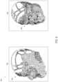
- FIG. 8is a diagram 800 depicting a 3D model 802 retrieved based on a point cloud 848 , according to certain example embodiments.
- the point cloud 804defines a set of surface features of an object (i.e., a face).
- the analysis module 210accesses the point cloud 804 generated by the depth data module 206 and identifies a plurality of landmarks based on the point cloud 804 .
- the analysis module 210determines a classification associated with the landmarks defined by the point cloud 804 and causes the 3D model module 208 to retrieve a 3D model 802 from a collection of 3D models, based on at least the classification associated with the plurality of landmarks.
- the 3D model 802may then be presented at a position among the presentation of the point cloud 804 at the client device 102 .
- the 3D modelling toolkit 124may employ Artificial Intelligence (AI) modeling techniques, such as Mesh Region Based Convolutional Neural Networks (R-CNN), that convert a two-dimensional (2D) image of an object into a 3D representation of the object.
- AIArtificial Intelligence
- R-CNNMesh Region Based Convolutional Neural Networks
- a 2D image depicting an objectis processed by the 3D modelling toolkit 124 to generate a voxel grid that represents a coarse 3D surface of the object.
- the voxel gridincludes occupancy probability values indicating a probability that each voxel is occupied by the object.
- the 3D modelling toolkit 124converts the voxel grid into a triangle mesh representation of the object (e.g., cubified mesh), which is then further refined to generate the 3D model of the object.
- the resulting 3D modelmay be used for a variety of use cases, such as manufacturing physical items based on the object.
- the described functionality of the 3D modelling toolkit 124may be used to manufacture personalized dental aligners for adjusting the alignment of a user's teeth.
- the 3D modelling toolkit 124uses a 2D image depicting the a dental arch of a user to generate a corresponding 3D model of the dental arch, which may then be used to manufacture a personalized dental aligner for the user.
- Manufacturing dental alignersis just one example, however, and is not meant to be limiting.
- FIG. 11is a block diagram illustrating components of a 3D modeling toolkit 124 that configure the 3D modeling toolkit 124 to generate a 3D model based on a voxel grid, according to certain example embodiments.
- the 3D modeling toolkit 124is shown as including an image module 1102 , an object detection module 1104 , an object classification module 1106 , a voxel grid generation module 1108 , and a 3D model generation module 1110 , all configured to communicate with each other (e.g., via a bus, shared memory, or a switch). Any one or more of these modules may be implemented using one or more processors 1112 (e.g., by configuring such one or more processors 1112 to perform functions described for that module) and hence may include one or more of the processors 1112 .
- the image module 1102accesses images and/or image data used to generate a 3D model of an object.
- the image module 1102may access an image from a client device 102 or from a database 120 .
- a usermay use a client application 104 executing on the client device 102 to submit/transmit images to the 3D modeling toolkit 124 , which are accessed by the image module 1102 .
- images received from one or more sourcesmay be stored in a database 120 and the image module 1102 may communicate with a database server 118 to access the images.
- An image accessed by the image module 1102may depict a physical object.
- the imagemay depict a physical object, such an automobile, person, and the like.
- the imagemay depict a dental arch of a human user.
- a dental archis a set of teeth, such as a top set of teeth or bottom set of teeth.
- the image module 1102may provide an accessed image or images to the other modules of the 3D modelling toolkit 124 for purposes of generating a 3D model of the object depicted in the image.
- the image module 1102may provide the image to the object detection module 1104 .
- the object detection module 1104detect individual objects depicted in the image or images.
- an imagemay depict multiple physical objects, such as multiple people, vehicles, and the like.
- an imagemay depict a physical object that consists of multiple individual physical objects.
- a physical objectsuch as a vehicle consists of individual physical objects such as tires, doors, windshield, frame, and the like.
- a physical object such as a dental archconsists of multiple individual teeth.
- the object detection module 1104may detect the individual objects using any of a variety of object recognition techniques.
- the object detection module 1104may utilize an object recognition technique such as Selective Search that is employed by a voxel branch of a mesh R-CNN, to identify the objects in the image.
- Selective Searchgenerates a hierarchy of successively larger regions that are recursively combined based on similarity to identify regions in the image that depict individual objects.
- the object detection module 1104may also use other object recognition techniques, such machine learning model trained based on labeled images of the object and retrained on false positives generated by the model. For example, images of a dental arch that are labeled to identify the individual teeth in the dental arch may be used to train an object recognition machine learning model to identify individual teeth from an image.
- the object detection module 1104generates a set of regions of the image that are determined to depict individual objects or groups of objects. For example, each region may depict one or more individual teeth in a dental arch.
- the object detection module 1104may provide data identifying the regions to the other modules of the 3D modelling toolkit 124 .
- the object detection module 1104may provide data identifying the regions to the object classification module 1106 .
- the object classification module 1106assigns labels to each identified region of an image that identify the object depicted in the region of the image. For example, the object classification module 1106 may assign a label to a region of an image indicating that the region depicts a tire. As another example the object classification module 1106 may assign a label to a region of an image indicating that the region depicts a tooth, group of teeth, or a specific tooth, such as by identifying the specific tooth number (e.g., T1, T2, etc.).
- the specific tooth numbere.g., T1, T2, etc.
- the object classification module 1106initially generates features defining the object depicted in each region.
- the object classification module 1106may use a convolutional neural network, such as employed by a voxel branch of a mesh R-CNN, to generate features for each of the respective regions of the image.
- the object classification module 1106assigns labels to each region based on the feature data generated for the regions of the image. For example, the object classification module 1106 may use the feature data describing the object in a particular region to assign a label to the region. To accomplish this, the object classification module 1106 may generate an input based on the feature data describing the object in the region, which is then provided as input into a machine learning model, such as a classification model, that provides probability values for a set of classification labels. Each probability value indicates the likelihood that a corresponding classification label properly classifies the object depicted in the region. The object classification module 1106 selects the classification label with the highest probability value to assign to the region of the image.
- a machine learning modelsuch as a classification model
- the voxel grid generation module 1108generates a voxel grid based on the set of features describing the objects in each region of the image.
- a voxel gridis a 3D grid of voxels representing a region of the image.
- Each voxel in the voxel gridincludes an occupancy probability value that represent a coarse 3D surface of the object depicted in the region of the image. For example, each occupancy probability value indicates the probability that its corresponding voxel is occupied by the object.
- the voxel grid generation module 1108provides the features included in each identified region of the image as input into a machine learning model, such as employed by a voxel branch of a mesh R-CNN, that generates the voxel grid and the occupancy probability values corresponding to each voxel.
- the voxel grid generation module 1108uses the featured data describing each identified object in the image as a singular input into the machine learning model to generate the voxel grid.
- the voxel grid generation module 1108generates separate inputs based on the featured data describing each individual identified object in the image, which are then separately input into machine learning models to generate the voxel grid. For example, an input generated based on features in a portion of the image may be provided to a specific a machine learning model trained specifically based on the type of object depicted in the portion of the image. Alternatively, a combination of these two approaches may be used.
- the voxel grid generation module 1108may generate the shape of the voxel grid based on a camera projection matrix. This allows for generation of an irregular shaped voxel grid that accounts for the depth of the object depicted in the image.
- the voxel grid generation module 1108uses the voxel grid to generate a triangle mesh representing a 3D surface of the object. For example, the voxel grid generation module 1108 generates a triangle mesh by merging shared vertices and edges between adjacent occupied voxels.
- the voxel grid generation module 1108provides the resulting triangle mesh to the 3D model generation module 1110 , which generates a refined 3D model of the object.
- the 3D model generation module 1110iteratively processes the triangle mesh of the physical object through a mesh refinement branch of a mesh R-CNN.
- the mesh refinement branchutilizes three separate stages to refine the triangle mesh.
- the mesh refinement branchincludes a vertex alignment stage, graph convolution stage, and a vertex refinement stage.
- the vertex alignment stageextracts image features for vertices included in the triangle mesh
- the graph convolution stagepropagates information along mesh edges
- the vertex refinement stageupdates vertex positions.
- the 3D model generation module 1110may iteratively repeat these three stages until a suitable refinement mesh representation of the object is achieved.
- FIG. 12is a flowchart illustrating a method 1200 for generating a 3D model of an object based on a voxel grid, according to certain example embodiments. Operations of the method 1200 may be performed by the modules described above with respect to FIG. 11 .
- the image module 1102accesses an image (e.g., one or more images) depicting an object.
- the image module 1102accesses images and/or images data used to generate a 3D model of an object.
- the image module 1102may access an image from a client device 102 or from a database 120 .
- a usermay use a client application 104 executing on the client device 102 to submit/transmit images to the 3D modeling toolkit 124 , which are accessed by the image module 1102 .
- images received from one or more sourcesmay be stored in a database 120 and the image module 1102 may communicate with a database server 118 to access the images.
- An image accessed by the image module 1102may depict a physical object.
- the imagemay depict a physical object, such an automobile, person, and the like.
- the imagemay depict a dental arch of a human user.
- a dental archis a set of teeth, such as a top set of teeth or bottom set of teeth.
- the image module 1102may provide an accessed image to the other modules of the 3D modelling toolkit 124 for purposes of generating a 3D model of the object depicted in the image.
- the image module 1102may provide the image to the object detection module 1104 .
- the object classification module 1106identifies, from the image, a set of features describing the object.
- the object classification module 1106may use a convolutional neural network, such as employed by a voxel branch of a mesh R-CNN, to generate the set of features.
- the voxel grid generation module 1108generates, based on the set of features, a voxel grid representing a 3D surface of the object.
- the voxel grid generation module 1108provides the features describing the object depicted in the image as input into a machine learning model, such as employed by a voxel branch of a mesh R-CNN, that generates the voxel grid and occupancy probability values corresponding to each voxel.
- the 3D model generation module 1110generates a 3D model of the object based on the voxel grid. For example, the 3D model generation module 1110 iteratively processes a triangle mesh of the physical object through a mesh refinement branch of a mesh R-CNN. The triangle mesh may be generated based on the voxel grid by merging shared vertices and edges between adjacent occupied voxels.
- FIG. 13is a flowchart illustrating a method 1300 for generating a 3D model of a dental arch based on a voxel grid, according to certain example embodiments. Operations of the method 1300 may be performed by the modules described above with respect to FIG. 11 .
- the image module 1102accesses an image (e.g., one or more images) depicting a dental arch of a user.
- the dental arch of a useris a row of individual teeth, either top or bottom.
- the image module 1102accesses the image from a client device 102 or from a database 120 .
- a usermay use a client application 104 executing on the client device 102 to submit/transmit the image to the 3D modeling toolkit 124 , which are accessed by the image module 1102 .
- images received from one or more sourcesmay be stored in a database 120 and the image module 1102 may communicate with a database server 118 to access the images.
- the image module 1102may provide the image to the other modules of the 3D modelling toolkit 124 for purposes of generating a 3D model of the dental arch depicted in the image.
- the image module 1102may provide the image to the object detection module 1104 .
- the object classification module 1106identifies, from the image, a set of features describing the dental arch of the user.
- the object classification module 1106may use a convolutional neural network, such as employed by a voxel branch of a mesh R-CNN, to generate the set of features.
- the voxel grid generation module 1108generates, based on the set of features, a voxel grid representing a 3D surface of the dental arch of the user.
- the voxel grid generation module 1108provides the features describing the dental arch (e.g., individual teeth, group of teeth, complete row of teeth) depicted in the image as input into a machine learning model, such as employed by a voxel branch of a mesh R-CNN.
- the machine learning modelin turn generates the voxel grid and occupancy probability values corresponding to each voxel.
- the voxel gridrepresents a 3D surface of the dental arch of the user.
- the voxel grid generation module 1108uses the featured data describing the entire dental arch (e.g., all of the teeth) in the image as a singular input into the machine learning model to generate the voxel grid. In other embodiments, the voxel grid generation module 1108 generates separate inputs based on the featured data describing each individual tooth or groups of teeth identified in the image, which are then separately input into machine learning models to generate the voxel grid. For example, an input generated based on features describing a tooth or group of teeth identified in the image may be provided to a specific a machine learning model trained specifically based on the determined type of tooth or group of teeth. Alternatively, a combination of these two approaches may be used.
- one voxel gridmay be generated using the entire dental arch as input into a machine learning model and a second voxel grid may be generated using the individual teeth as input into separate machine learning models.
- the two voxel gridsmay then be combined to generate a merged voxel grid representing the 3D surface of the dental arch of the user.
- the 3D model generation module 1110generates a 3D model of the dental arch of the user based on the voxel grid. For example, the 3D model generation module 1110 iteratively processes a triangle mesh of the dental arch through a mesh refinement branch of a mesh R-CNN. The triangle mesh may be generated based on the voxel grid by merging shared vertices and edges between adjacent occupied voxels.
- the 3D model of the dental archmay be used for a variety of purposes.
- the 3D model of the dental archmay be used to generate/manufacture a dental retainer or dental aligner that is customized to the user.
- the dental retainermay be designed to maintain a current alignment of the teeth included in the dental arch of the user.
- the dental alignermay be designed to adjust the alignment of one or more of the teeth of included in the dental arch of the user.
- the dental alignermay be used to adjust the alignment of the teeth to correct crooked or misplaced teeth.
- FIG. 14is a flowchart illustrating a method 1400 for identifying teeth depicted in an image, according to certain example embodiments. Operations of the method 1400 may be performed by the modules described above with respect to FIG. 11 .
- the object detection module 1104identifies regions of an image that depict one or more individual teeth included in a dental arch.
- the object detection module 1104may detect the one or more individual teeth using any of a variety of object recognition techniques.
- the object detection module 1104may utilize an object recognition technique such as Selective Search that is employed by a voxel branch of a mesh R-CNN, to identify the teeth in the image.
- Selective Searchgenerates a hierarchy of successively larger regions that are recursively combined based on similarity to identify regions in the image that depict one or more individual teeth.
- the object classification module 1106determines features describing the one or more individual teeth depicted in each region of the image. For example, the object classification module 1106 may use a convolutional neural network, such as employed by a voxel branch of a mesh R-CNN, to generate the set of features.
- a convolutional neural networksuch as employed by a voxel branch of a mesh R-CNN, to generate the set of features.
- the object classification module 1106assigns labels to each region of the image defining a type of the one or more individual teeth depicted in the region.
- the object classification module 1106assigns labels to each region based on the feature data generated for the regions of the image. For example, the object classification module 1106 may use the feature data describing the one or more teeth in a particular region to assign a label to the region. To accomplish this, the object classification module 1106 may generate an input based on the feature data describing the one or more teeth in the region.
- the object classification module 1106provides the input into a machine learning model, such as a classification model, that provides probability values for a set of classification labels that correspond to the different tooth types. Each probability value indicates the likelihood that a corresponding classification label properly classifies the type of the one or more teeth depicted in the region.
- the object classification module 1106selects the classification label with the highest probability value to assign to the region of the image.
- FIG. 15is a flowchart illustrating a method 1500 for generating a 3D model of a dental arch from a voxel grid, according to certain example embodiments. Operations of the method 1500 may be performed by the modules described above with respect to FIG. 11 .
- the voxel grid generation module 1108generates a voxel grid representing a 3D surface of a dental arch of a user.
- a voxel gridis a 3D grid of voxels representing the dental arch of the user.
- Each voxel in the voxel gridincludes an occupancy probability value that represent a coarse 3D surface of the dental arch depicted in the image. For example, each occupancy probability value indicates the probability that its corresponding voxel is occupied by the dental arch.
- the voxel grid generation module 1108generates a triangle mesh of the dental arch based on the voxel grid. For example, the voxel grid generation module 1108 generates a triangle mesh by merging shared vertices and edges between adjacent occupied voxels.
- the 3D model generation module 1110iteratively processes the triangle mesh through a mesh refinement process.
- the 3D model generation module 1110iteratively processes the triangle mesh of the physical object through a mesh refinement branch of a mesh R-CNN.
- the mesh refinement branchutilizes three separate stages to refine the triangle mesh.
- the mesh refinement branchincludes a vertex alignment stage, graph convolution stage, and a vertex refinement stage.
- the vertex alignment stageextracts image features for vertices included in the triangle mesh
- the graph convolution stagepropagates information along mesh edges
- the vertex refinement stageupdates vertex positions.
- the 3D model generation module 1110may iteratively repeat these three stages until a suitable refinement mesh representation of the object is achieved.
- FIG. 9is a block diagram illustrating an example software architecture 906 , which may be used in conjunction with various hardware architectures herein described.
- FIG. 9is a non-limiting example of a software architecture and it will be appreciated that many other architectures may be implemented to facilitate the functionality described herein.
- the software architecture 906may execute on hardware such as the machine 900 of FIG. 9 that includes, among other things, processors 904 , memory 914 , and I/O components 918 .
- a representative hardware layer 952is illustrated and can represent, for example, the machine 1000 of FIG. 10 .
- the representative hardware layer 952includes a processing unit 954 having associated executable instructions 904 .
- Executable instructions 904represent the executable instructions of the software architecture 906 , including implementation of the methods, components and so forth described herein.
- the hardware layer 952also includes memory and/or storage modules memory/storage 956 , which also have executable instructions 904 .
- the hardware layer 952may also comprise other hardware 958 .
- the software architecture 906may be conceptualized as a stack of layers where each layer provides particular functionality.
- the software architecture 906may include layers such as an operating system 902 , libraries 920 , applications 916 and a presentation layer 914 .
- the applications 916 and/or other components within the layersmay invoke application programming interface (API) API calls 908 through the software stack and receive a response as in response to the API calls 908 .
- APIapplication programming interface
- the layers illustratedare representative in nature and not all software architectures have all layers. For example, some mobile or special purpose operating systems may not provide a frameworks/middleware 918 , while others may provide such a layer. Other software architectures may include additional or different layers.
- the operating system 902may manage hardware resources and provide common services.
- the operating system 902may include, for example, a kernel 922 , services 924 and drivers 926 .
- the kernel 922may act as an abstraction layer between the hardware and the other software layers.
- the kernel 922may be responsible for memory management, processor management (e.g., scheduling), component management, networking, security settings, and so on.
- the services 924may provide other common services for the other software layers.
- the drivers 926are responsible for controlling or interfacing with the underlying hardware.
- the drivers 926include display drivers, camera drivers, Bluetooth® drivers, flash memory drivers, serial communication drivers (e.g., Universal Serial Bus (USB) drivers), Wi-Fi® drivers, audio drivers, power management drivers, and so forth depending on the hardware configuration.
- USBUniversal Serial Bus
- the libraries 920provide a common infrastructure that is used by the applications 916 and/or other components and/or layers.
- the libraries 920provide functionality that allows other software components to perform tasks in an easier fashion than to interface directly with the underlying operating system 902 functionality (e.g., kernel 922 , services 924 and/or drivers 926 ).
- the libraries 920may include system libraries 944 (e.g., C standard library) that may provide functions such as memory allocation functions, string manipulation functions, mathematical functions, and the like.
- libraries 920may include API libraries 946 such as media libraries (e.g., libraries to support presentation and manipulation of various media format such as MPREG4, H.264, MP3, AAC, AMR, JPG, PNG), graphics libraries (e.g., an OpenGL framework that may be used to render 2D and 3D in a graphic content on a display), database libraries (e.g., SQLite that may provide various relational database functions), web libraries (e.g., WebKit that may provide web browsing functionality), and the like.
- the libraries 920may also include a wide variety of other libraries 948 to provide many other APIs to the applications 916 and other software components/modules.
- the frameworks/middleware 918provide a higher-level common infrastructure that may be used by the applications 916 and/or other software components/modules.
- the frameworks/middleware 918may provide various graphic user interface (GUI) functions, high-level resource management, high-level location services, and so forth.
- GUIgraphic user interface
- the frameworks/middleware 918may provide a broad spectrum of other APIs that may be utilized by the applications 916 and/or other software components/modules, some of which may be specific to a particular operating system 902 or platform.
- the applications 916include built-in applications 938 and/or third-party applications 940 .
- built-in applications 938may include, but are not limited to, a contacts application, a browser application, a book reader application, a location application, a media application, a messaging application, and/or a game application.
- Third-party applications 940may include an application developed using the ANDROIDTM or IOSTM software development kit (SDK) by an entity other than the vendor of the particular platform, and may be mobile software running on a mobile operating system such as IOSTM, ANDROIDTM, WINDOWS® Phone, or other mobile operating systems.
- the third-party applications 940may invoke the API calls 908 provided by the mobile operating system (such as operating system 902 ) to facilitate functionality described herein.
- the applications 916may use built in operating system functions (e.g., kernel 922 , services 924 and/or drivers 926 ), libraries 920 , and frameworks/middleware 918 to create user interfaces to interact with users of the system. Alternatively, or additionally, in some systems interactions with a user may occur through a presentation layer, such as presentation layer 914 . In these systems, the application/component “logic” can be separated from the aspects of the application/component that interact with a user.
- FIG. 10is a block diagram illustrating components of a machine 1000 , according to some example embodiments, able to read instructions from a machine-readable medium (e.g., a machine-readable storage medium) and perform any one or more of the methodologies discussed herein.
- FIG. 10shows a diagrammatic representation of the machine 1000 in the example form of a computer system, within which instructions 1010 (e.g., software, a program, an application, an applet, an app, or other executable code) for causing the machine 1000 to perform any one or more of the methodologies discussed herein may be executed.
- the instructions 1010may be used to implement modules or components described herein.
- the instructions 1010transform the general, non-programmed machine 1000 into a particular machine 1000 programmed to carry out the described and illustrated functions in the manner described.
- the machine 1000operates as a standalone device or may be coupled (e.g., networked) to other machines.
- the machine 1000may operate in the capacity of a server machine or a client machine in a server-client network environment, or as a peer machine in a peer-to-peer (or distributed) network environment.
- the machine 1000may comprise, but not be limited to, a server computer, a client computer, a personal computer (PC), a tablet computer, a laptop computer, a netbook, a set-top box (STB), a personal digital assistant (PDA), an entertainment media system, a cellular telephone, a smart phone, a mobile device, a wearable device (e.g., a smart watch), a smart home device (e.g., a smart appliance), other smart devices, a web appliance, a network router, a network switch, a network bridge, or any machine capable of executing the instructions 1010 , sequentially or otherwise, that specify actions to be taken by machine 1000 .
- the term “machine”shall also be taken to include a collection of machines that individually or jointly execute the instructions 1010 to perform any one or more of the methodologies discussed herein.
- the machine 1000may include processors 1004 , memory memory/storage 1006 , and I/O components 1018 , which may be configured to communicate with each other such as via a bus 1002 .
- the memory/storage 1006may include a memory 1014 , such as a main memory, or other memory storage, and a storage unit 1016 , both accessible to the processors 1004 such as via the bus 1002 .
- the storage unit 1016 and memory 1014store the instructions 1010 embodying any one or more of the methodologies or functions described herein.
- the instructions 1010may also reside, completely or partially, within the memory 1014 , within the storage unit 1016 , within at least one of the processors 1004 (e.g., within the processor's cache memory), or any suitable combination thereof, during execution thereof by the machine 1000 . Accordingly, the memory 1014 , the storage unit 1016 , and the memory of processors 1004 are examples of machine-readable media.
- the I/O components 1018may include a wide variety of components to receive input, provide output, produce output, transmit information, exchange information, capture measurements, and so on.
- the specific 1 /components 1018 that are included in a particular machine 1000will depend on the type of machine. For example, portable machines such as mobile phones will likely include a touch input device or other such input mechanisms, while a headless server machine will likely not include such a touch input device. It will be appreciated that the I/O components 1018 may include many other components that are not shown in FIG. 10 .
- the I/O components 1018are grouped according to functionality merely for simplifying the following discussion and the grouping is in no way limiting. In various example embodiments, the I/O components 1018 may include output components 1026 and input components 1028 .
- the output components 1026may include visual components (e.g., a display such as a plasma display panel (PDP), a light emitting diode (LED) display, a liquid crystal display (LCD), a projector, or a cathode ray tube (CRT)), acoustic components (e.g., speakers), haptic components (e.g., a vibratory motor, resistance mechanisms), other signal generators, and so forth.
- a displaysuch as a plasma display panel (PDP), a light emitting diode (LED) display, a liquid crystal display (LCD), a projector, or a cathode ray tube (CRT)
- acoustic componentse.g., speakers
- haptic componentse.g., a vibratory motor, resistance mechanisms
- the input components 1028may include alphanumeric input components (e.g., a keyboard, a touch screen configured to receive alphanumeric input, a photo-optical keyboard, or other alphanumeric input components), point based input components (e.g., a mouse, a touchpad, a trackball, a joystick, a motion sensor, or other pointing instrument), tactile input components (e.g., a physical button, a touch screen that provides location and/or force of touches or touch gestures, or other tactile input components), audio input components (e.g., a microphone), and the like.
- alphanumeric input componentse.g., a keyboard, a touch screen configured to receive alphanumeric input, a photo-optical keyboard, or other alphanumeric input components
- point based input componentse.g., a mouse, a touchpad, a trackball, a joystick, a motion sensor, or other pointing instrument
- tactile input componentse.g., a physical button,
- the I/O components 1018may include biometric components 1030 , motion components 1034 , environmental environment components 1036 , or position components 1038 among a wide array of other components.
- the biometric components 1030may include components to detect expressions (e.g., hand expressions, facial expressions, vocal expressions, body gestures, or eye tracking), measure biosignals (e.g., blood pressure, heart rate, body temperature, perspiration, or brain waves), identify a person (e.g., voice identification, retinal identification, facial identification, fingerprint identification, or electroencephalogram based identification), and the like.
- the motion components 1034may include acceleration sensor components (e.g., accelerometer), gravitation sensor components, rotation sensor components (e.g., gyroscope), and so forth.
- the environment components 1036may include, for example, illumination sensor components (e.g., photometer), temperature sensor components (e.g., one or more thermometer that detect ambient temperature), humidity sensor components, pressure sensor components (e.g., barometer), acoustic sensor components (e.g., one or more microphones that detect background noise), proximity sensor components (e.g., infrared sensors that detect nearby objects), gas sensors (e.g., gas detection sensors to detection concentrations of hazardous gases for safety or to measure pollutants in the atmosphere), or other components that may provide indications, measurements, or signals corresponding to a surrounding physical environment.
- illumination sensor componentse.g., photometer
- temperature sensor componentse.g., one or more thermometer that detect ambient temperature
- humidity sensor componentse.g., pressure sensor components (e.g., barometer)
- the position components 1038may include location sensor components (e.g., a Global Position system (GPS) receiver component), altitude sensor components (e.g., altimeters or barometers that detect air pressure from which altitude may be derived), orientation sensor components (e.g., magnetometers), and the like.
- location sensor componentse.g., a Global Position system (GPS) receiver component
- altitude sensor componentse.g., altimeters or barometers that detect air pressure from which altitude may be derived
- orientation sensor componentse.g., magnetometers
- the I/O components 1018may include communication components 1040 operable to couple the machine 1000 to a network 1032 or devices 1020 via coupling 1022 and coupling 1024 respectively.
- the communication components 1040may include a network interface component or other suitable device to interface with the network 1032 .
- communication components 1040may include wired communication components, wireless communication components, cellular communication components, Near Field Communication (NFC) components, Bluetooth® components (e.g., Bluetooth® Low Energy), Wi-Fi® components, and other communication components to provide communication via other modalities.
- the devices 1020may be another machine or any of a wide variety of peripheral devices (e.g., a peripheral device coupled via a Universal Serial Bus (USB)).
- USBUniversal Serial Bus
- the communication components 1040may detect identifiers or include components operable to detect identifiers.
- the communication components 1040may include Radio Frequency Identification (RFID) tag reader components, NFC smart tag detection components, optical reader components (e.g., an optical sensor to detect one-dimensional bar codes such as Universal Product Code (UPC) bar code, multi-dimensional bar codes such as Quick Response (QR) code, Aztec code, Data Matrix, Dataglyph, MaxiCode, PDF417, Ultra Code, UCC RSS-2D bar code, and other optical codes), or acoustic detection components (e.g., microphones to identify tagged audio signals).
- RFIDRadio Frequency Identification
- NFC smart tag detection componentse.g., an optical sensor to detect one-dimensional bar codes such as Universal Product Code (UPC) bar code, multi-dimensional bar codes such as Quick Response (QR) code, Aztec code, Data Matrix, Dataglyph, MaxiCode, PDF417, Ultra Code, UCC RSS-2D bar code, and other optical codes
- IPInternet Protocol
- Wi-Fi®Wireless Fidelity
- NFC beacona variety of information may be derived via the communication components 1040 , such as, location via Internet Protocol (IP) geo-location, location via Wi-Fi® signal triangulation, location via detecting a NFC beacon signal that may indicate a particular location, and so forth.
- IPInternet Protocol
- CARRIER SIGNALin this context refers to any intangible medium that is capable of storing, encoding, or carrying instructions for execution by the machine, and includes digital or analog communications signals or other intangible medium to facilitate communication of such instructions. Instructions may be transmitted or received over the network using a transmission medium via a network interface device and using any one of a number of well-known transfer protocols.
- CLIENT DEVICEin this context refers to any machine that interfaces to a communications network to obtain resources from one or more server systems or other client devices.
- a client devicemay be, but is not limited to, a mobile phone, desktop computer, laptop, portable digital assistants (PDAs), smart phones, tablets, ultra books, netbooks, laptops, multi-processor systems, microprocessor-based or programmable consumer electronics, game consoles, set-top boxes, or any other communication device that a user may use to access a network.
- PDAsportable digital assistants
- smart phonestablets, ultra books, netbooks, laptops, multi-processor systems, microprocessor-based or programmable consumer electronics, game consoles, set-top boxes, or any other communication device that a user may use to access a network.
- “COMMUNICATIONS NETWORK” in this contextrefers to one or more portions of a network that may be an ad hoc network, an intranet, an extranet, a virtual private network (VPN), a local area network (LAN), a wireless LAN (WLAN), a wide area network (WAN), a wireless WAN (WWAN), a metropolitan area network (MAN), the Internet, a portion of the Internet, a portion of the Public Switched Telephone Network (PSTN), a plain old telephone service (POTS) network, a cellular telephone network, a wireless network, a Wi-Fi® network, another type of network, or a combination of two or more such networks.
- VPNvirtual private network
- LANlocal area network
- WLANwireless LAN
- WANwide area network
- WWANwireless WAN
- MANmetropolitan area network
- PSTNPublic Switched Telephone Network
- POTSplain old telephone service
- a network or a portion of a networkmay include a wireless or cellular network and the coupling may be a Code Division Multiple Access (CDMA) connection, a Global System for Mobile communications (GSM) connection, or other type of cellular or wireless coupling.
- CDMACode Division Multiple Access
- GSMGlobal System for Mobile communications
- the couplingmay implement any of a variety of types of data transfer technology, such as Single Carrier Radio Transmission Technology (1 ⁇ RTT), Evolution-Data Optimized (EVDO) technology, General Packet Radio Service (GPRS) technology, Enhanced Data rates for GSM Evolution (EDGE) technology, third Generation Partnership Project (3GPP) including 3G, fourth generation wireless (4G) networks, Universal Mobile Telecommunications System (UMTS), High Speed Packet Access (HSPA), Worldwide Interoperability for Microwave Access (WiMAX), Long Term Evolution (LTE) standard, others defined by various standard setting organizations, other long range protocols, or other data transfer technology.
- RTTSingle Carrier Radio Transmission Technology
- GPRSGeneral Packet Radio Service
- EDGEEnhanced Data rates for GSM Evolution
- 3GPPThird Generation Partnership Project
- 4Gfourth generation wireless (4G) networks
- Universal Mobile Telecommunications System (UMTS)Universal Mobile Telecommunications System
- HSPAHigh Speed Packet Access
- WiMAXWorldwide Interoperability for Microwave Access
- LTELong
- EMPHEMERAL MESSAGEin this context refers to a message that is accessible for a time-limited duration.
- An ephemeral messagemay be a text, an image, a video and the like.
- the access time for the ephemeral messagemay be set by the message sender. Alternatively, the access time may be a default setting or a setting specified by the recipient. Regardless of the setting technique, the message is transitory.
- MACHINE-READABLE MEDIUMin this context refers to a component, device or other tangible media able to store instructions and data temporarily or permanently and may include, but is not be limited to, random-access memory (RAM), read-only memory (ROM), buffer memory, flash memory, optical media, magnetic media, cache memory, other types of storage (e.g., Erasable Programmable Read-Only Memory (EEPROM)) and/or any suitable combination thereof.
- RAMrandom-access memory
- ROMread-only memory
- buffer memoryflash memory
- optical mediamagnetic media
- cache memoryother types of storage
- machine-readable mediumshould be taken to include a single medium or multiple media (e.g., a centralized or distributed database, or associated caches and servers) able to store instructions.
- machine-readable mediumshall also be taken to include any medium, or combination of multiple media, that is capable of storing instructions (e.g., code) for execution by a machine, such that the instructions, when executed by one or more processors of the machine, cause the machine to perform any one or more of the methodologies described herein. Accordingly, a “machine-readable medium” refers to a single storage apparatus or device, as well as “cloud-based” storage systems or storage networks that include multiple storage apparatus or devices. The term “machine-readable medium” excludes signals per se.
- “COMPONENT” in this contextrefers to a device, physical entity or logic having boundaries defined by function or subroutine calls, branch points, application program interfaces (APIs), or other technologies that provide for the partitioning or modularization of particular processing or control functions.
- Componentsmay be combined via their interfaces with other components to carry out a machine process.
- a componentmay be a packaged functional hardware unit designed for use with other components and a part of a program that usually performs a particular function of related functions.
- Componentsmay constitute either software components (e.g., code embodied on a machine-readable medium) or hardware components.
- a “hardware component”is a tangible unit capable of performing certain operations and may be configured or arranged in a certain physical manner.
- one or more computer systemsmay be configured by software (e.g., an application or application portion) as a hardware component that operates to perform certain operations as described herein.
- a hardware componentmay also be implemented mechanically, electronically, or any suitable combination thereof.
- a hardware componentmay include dedicated circuitry or logic that is permanently configured to perform certain operations.
- a hardware componentmay be a special-purpose processor, such as a Field-Programmable Gate Array (FPGA) or an Application Specific Integrated Circuit (ASIC).
- FPGAField-Programmable Gate Array
- ASICApplication Specific Integrated Circuit
- a hardware componentmay also include programmable logic or circuitry that is temporarily configured by software to perform certain operations.
- a hardware componentmay include software executed by a general-purpose processor or other programmable processor. Once configured by such software, hardware components become specific machines (or specific components of a machine) uniquely tailored to perform the configured functions and are no longer general-purpose processors. It will be appreciated that the decision to implement a hardware component mechanically, in dedicated and permanently configured circuitry, or in temporarily configured circuitry (e.g., configured by software) may be driven by cost and time considerations.
- the phrase “hardware component”should be understood to encompass a tangible entity, be that an entity that is physically constructed, permanently configured (e.g., hardwired), or temporarily configured (e.g., programmed) to operate in a certain manner or to perform certain operations described herein.
- hardware componentsare temporarily configured (e.g., programmed)
- each of the hardware componentsneed not be configured or instantiated at any one instance in time.
- a hardware componentcomprises a general-purpose processor configured by software to become a special-purpose processor
- the general-purpose processormay be configured as respectively different special-purpose processors (e.g., comprising different hardware components) at different times.
- Hardware componentscan provide information to, and receive information from, other hardware components. Accordingly, the described hardware components may be regarded as being communicatively coupled. Where multiple hardware components exist contemporaneously, communications may be achieved through signal transmission (e.g., over appropriate circuits and buses) between or among two or more of the hardware components. In embodiments in which multiple hardware components are configured or instantiated at different times, communications between such hardware components may be achieved, for example, through the storage and retrieval of information in memory structures to which the multiple hardware components have access.
- one hardware componentmay perform an operation and store the output of that operation in a memory device to which it is communicatively coupled. A further hardware component may then, at a later time, access the memory device to retrieve and process the stored output. Hardware components may also initiate communications with input or output devices, and can operate on a resource (e.g., a collection of information).
- a resourcee.g., a collection of information.
- the various operations of example methods described hereinmay be performed, at least partially, by one or more processors that are temporarily configured (e.g., by software) or permanently configured to perform the relevant operations. Whether temporarily or permanently configured, such processors may constitute processor-implemented components that operate to perform one or more operations or functions described herein.
- processor-implemented componentrefers to a hardware component implemented using one or more processors.
- the methods described hereinmay be at least partially processor-implemented, with a particular processor or processors being an example of hardware. For example, at least some of the operations of a method may be performed by one or more processors or processor-implemented components.
- the one or more processorsmay also operate to support performance of the relevant operations in a “cloud computing” environment or as a “software as a service” (SaaS).
- the operationsmay be performed by a group of computers (as examples of machines including processors), with these operations being accessible via a network (e.g., the Internet) and via one or more appropriate interfaces (e.g., an Application Program Interface (API)).
- the performance of certain of the operationsmay be distributed among the processors, not only residing within a single machine, but deployed across a number of machines.
- the processors or processor-implemented componentsmay be located in a single geographic location (e.g., within a home environment, an office environment, or a server farm). In other example embodiments, the processors or processor-implemented components may be distributed across a number of geographic locations.
- PROCESSORin this context refers to any circuit or virtual circuit (a physical circuit emulated by logic executing on an actual processor) that manipulates data values according to control signals (e.g., “commands”, “op codes”, “machine code”, etc.) and which produces corresponding output signals that are applied to operate a machine.
- a processormay, for example, be a Central Processing Unit (CPU), a Reduced Instruction Set Computing (RISC) processor, a Complex Instruction Set Computing (CISC) processor, a Graphics Processing Unit (GPU), a Digital Signal Processor (DSP), an Application Specific Integrated Circuit (ASIC), a Radio-Frequency Integrated Circuit (RFIC) or any combination thereof.
- a processormay further be a multi-core processor having two or more independent processors (sometimes referred to as “cores”) that may execute instructions contemporaneously.
- TIMESTAMPin this context refers to a sequence of characters or encoded information identifying when a certain event occurred, for example giving date and time of day, sometimes accurate to a small fraction of a second.
- 3D RECONSTRUCTIONin this context refers to a process of building a 3D model using multiple pieces of partial information about a subject.
- 3D SCANin this context refers to the result of a 3D reconstruction.
- SIMULTANEOUS LOCATION AND MAPPINGin this context refers to a method of building a map or model of an unknown scene or subject while simultaneously keeping track of a device position within an environment.
- DEPTH FRAMEin this context refers to a snapshot in time of depth values from a sensor, arranged in a 2D grid, like an RGB camera frame.
- the depth valuesare the distance in meters from a device to a subject.
- POINT CLOUDin this context refers to and unordered array of points in 3D, wherein each point has an XYZ position, a color, a normal (which is a vector indicating the point's orientation), and other information.
- “MESH” in this contextrefers to a collection of triangles.
Landscapes
- Engineering & Computer Science (AREA)
- Physics & Mathematics (AREA)
- Theoretical Computer Science (AREA)
- General Physics & Mathematics (AREA)
- Health & Medical Sciences (AREA)
- General Health & Medical Sciences (AREA)
- Software Systems (AREA)
- Evolutionary Computation (AREA)
- Multimedia (AREA)
- Artificial Intelligence (AREA)
- Computing Systems (AREA)
- Computer Vision & Pattern Recognition (AREA)
- Oral & Maxillofacial Surgery (AREA)
- Medical Informatics (AREA)
- Computational Linguistics (AREA)
- Geometry (AREA)
- Mathematical Physics (AREA)
- General Engineering & Computer Science (AREA)
- Data Mining & Analysis (AREA)
- Biophysics (AREA)
- Molecular Biology (AREA)
- Biomedical Technology (AREA)
- Life Sciences & Earth Sciences (AREA)
- Databases & Information Systems (AREA)
- Computer Graphics (AREA)
- Human Computer Interaction (AREA)
- Nuclear Medicine, Radiotherapy & Molecular Imaging (AREA)
- Radiology & Medical Imaging (AREA)
- Quality & Reliability (AREA)
- Image Analysis (AREA)
- Image Processing (AREA)
Abstract
Description
Claims (18)
Priority Applications (2)
| Application Number | Priority Date | Filing Date | Title |
|---|---|---|---|
| US17/179,344US12056820B2 (en) | 2019-05-17 | 2021-02-18 | Three-dimensional modeling toolkit |
| US18/793,273US20240394981A1 (en) | 2019-05-17 | 2024-08-02 | Three-dimensional modeling toolkit |
Applications Claiming Priority (3)
| Application Number | Priority Date | Filing Date | Title |
|---|---|---|---|
| US201962849286P | 2019-05-17 | 2019-05-17 | |
| US16/580,868US11030801B2 (en) | 2019-05-17 | 2019-09-24 | Three-dimensional modeling toolkit |
| US17/179,344US12056820B2 (en) | 2019-05-17 | 2021-02-18 | Three-dimensional modeling toolkit |
Related Parent Applications (1)
| Application Number | Title | Priority Date | Filing Date |
|---|---|---|---|
| US16/580,868Continuation-In-PartUS11030801B2 (en) | 2019-05-17 | 2019-09-24 | Three-dimensional modeling toolkit |
Related Child Applications (1)
| Application Number | Title | Priority Date | Filing Date |
|---|---|---|---|
| US18/793,273ContinuationUS20240394981A1 (en) | 2019-05-17 | 2024-08-02 | Three-dimensional modeling toolkit |
Publications (2)
| Publication Number | Publication Date |
|---|---|
| US20210174585A1 US20210174585A1 (en) | 2021-06-10 |
| US12056820B2true US12056820B2 (en) | 2024-08-06 |
Family
ID=76209844
Family Applications (2)
| Application Number | Title | Priority Date | Filing Date |
|---|---|---|---|
| US17/179,344ActiveUS12056820B2 (en) | 2019-05-17 | 2021-02-18 | Three-dimensional modeling toolkit |
| US18/793,273PendingUS20240394981A1 (en) | 2019-05-17 | 2024-08-02 | Three-dimensional modeling toolkit |
Family Applications After (1)
| Application Number | Title | Priority Date | Filing Date |
|---|---|---|---|
| US18/793,273PendingUS20240394981A1 (en) | 2019-05-17 | 2024-08-02 | Three-dimensional modeling toolkit |
Country Status (1)
| Country | Link |
|---|---|
| US (2) | US12056820B2 (en) |
Families Citing this family (3)
| Publication number | Priority date | Publication date | Assignee | Title |
|---|---|---|---|---|
| US11403813B2 (en)* | 2019-11-26 | 2022-08-02 | Sdc U.S. Smilepay Spv | Systems and methods for constructing a three-dimensional model from two-dimensional images |
| US11191619B1 (en)* | 2021-05-13 | 2021-12-07 | Oxilio Ltd | Methods and systems for determining occlusal contacts between teeth of a subject |
| CN113744410B (en)* | 2021-09-13 | 2025-03-14 | 浙江商汤科技开发有限公司 | Grid generation method, device, electronic device and computer readable storage medium |
Citations (129)
| Publication number | Priority date | Publication date | Assignee | Title |
|---|---|---|---|---|
| US5886702A (en) | 1996-10-16 | 1999-03-23 | Real-Time Geometry Corporation | System and method for computer modeling of 3D objects or surfaces by mesh constructions having optimal quality characteristics and dynamic resolution capabilities |
| US5945996A (en) | 1996-10-16 | 1999-08-31 | Real-Time Geometry Corporation | System and method for rapidly generating an optimal mesh model of a 3D object or surface |
| US6208347B1 (en) | 1997-06-23 | 2001-03-27 | Real-Time Geometry Corporation | System and method for computer modeling of 3D objects and 2D images by mesh constructions that incorporate non-spatial data such as color or texture |
| US20020028418A1 (en) | 2000-04-26 | 2002-03-07 | University Of Louisville Research Foundation, Inc. | System and method for 3-D digital reconstruction of an oral cavity from a sequence of 2-D images |
| US6971873B2 (en) | 2000-04-19 | 2005-12-06 | Orametrix, Inc. | Virtual bracket library and uses thereof in orthodontic treatment planning |
| US20060040236A1 (en) | 2004-08-17 | 2006-02-23 | Schmitt Stephen M | Design and manufacture of dental implant restorations |
| US20060127855A1 (en) | 2004-12-14 | 2006-06-15 | Huafeng Wen | Preventing interference between tooth models |
| US7077647B2 (en) | 2002-08-22 | 2006-07-18 | Align Technology, Inc. | Systems and methods for treatment analysis by teeth matching |
| US20060204078A1 (en) | 2005-03-08 | 2006-09-14 | Ulrich Orth | Method for obtaining a position match of 3D data sets in a dental CAD/CAM system |
| US20060263738A1 (en) | 2005-05-17 | 2006-11-23 | Align Technology, Inc. | Guide apparatus and methods for making tooth positioning appliances |
| US20060275736A1 (en) | 2005-04-22 | 2006-12-07 | Orthoclear Holdings, Inc. | Computer aided orthodontic treatment planning |
| US20070207437A1 (en) | 1999-11-30 | 2007-09-06 | Orametrix, Inc. | Unified workstation for virtual craniofacial diagnosis, treatment planning and therapeutics |
| US20080206705A1 (en) | 2007-02-26 | 2008-08-28 | Srinivas Kaza | System and method for digital tooth imaging |
| US20090148816A1 (en) | 2007-01-11 | 2009-06-11 | Geodigm Corporation | Design of dental appliances |
| US20090160855A1 (en) | 2007-12-21 | 2009-06-25 | Mako Surgical Corp. | Cumulative Buffering for Surface Imaging |
| US20090220134A1 (en) | 2008-02-29 | 2009-09-03 | Zimmer Dental, Inc. | Method of merging anatomical data and surface data of a patient's dentition |
| US20090316966A1 (en) | 2008-05-16 | 2009-12-24 | Geodigm Corporation | Method and apparatus for combining 3D dental scans with other 3D data sets |
| US7698014B2 (en) | 2006-01-20 | 2010-04-13 | 3M Innovative Properties Company | Local enforcement of accuracy in fabricated models |
| US7702492B2 (en) | 2004-03-11 | 2010-04-20 | Geodigm Corporation | System and method for generating an electronic model for a dental impression having a common coordinate system |
| US7831322B2 (en) | 2005-03-07 | 2010-11-09 | Align Technology, Inc. | Producing wrinkled dental aligner for dental treatment |
| US20100324875A1 (en) | 2008-02-12 | 2010-12-23 | Kalili Thomas K | Process for orthodontic, implant and dental prosthetic fabrication using 3d geometric mesh teeth manipulation process |
| US20110196653A1 (en) | 2010-02-10 | 2011-08-11 | Nobel Biocare Services Ag | Dental data planning |
| US20110200248A1 (en) | 2007-08-13 | 2011-08-18 | Aqsense S.L. | Method and system for aligning three-dimensional surfaces |
| US20120015316A1 (en) | 2001-04-13 | 2012-01-19 | Rohit Sachdeva | Unified three dimensional virtual craniofacial and dentition model and uses thereof |
| US8152523B2 (en) | 2001-04-13 | 2012-04-10 | Orametrix, Inc. | Method and system for comprehensive evaluation of orthodontic care using unified workstation |
| US20120191421A1 (en) | 2010-11-17 | 2012-07-26 | Greenberg Surgical Technologies, Llc | Oral Template for Integrated CT and Optical Images for Dental Implant Drilling Templates and Orthodontic Aligners |
| US8234000B2 (en) | 2006-10-27 | 2012-07-31 | Nobel Biocare Services Ag | Method and apparatus for obtaining data for a dental component and a physical dental model |
| US20120330447A1 (en) | 2010-11-16 | 2012-12-27 | Gerlach Adam R | Surface data acquisition, storage, and assessment system |
| US20130051516A1 (en) | 2011-08-31 | 2013-02-28 | Carestream Health, Inc. | Noise suppression for low x-ray dose cone-beam image reconstruction |
| US8417366B2 (en) | 2010-05-01 | 2013-04-09 | Orametrix, Inc. | Compensation orthodontic archwire design |
| US8478698B1 (en) | 2010-03-17 | 2013-07-02 | James Mah | Methods and systems for employing artificial intelligence in automated orthodontic diagnosis and treatment planning |
| US20130218530A1 (en) | 2010-06-29 | 2013-08-22 | 3Shape A/S | 2d image arrangement |
| US20140026419A1 (en) | 2012-07-27 | 2014-01-30 | Guided Surgery Solutions, Llc | Surgical guide fabrication |
| US20140037194A1 (en) | 2011-04-13 | 2014-02-06 | Unisantis Electronics Singapore Pte. Ltd. | Three-dimensional point cloud position data processing device, three-dimensional point cloud position data processing system, and three-dimensional point cloud position data processing method and program |
| US20140051037A1 (en) | 2010-12-22 | 2014-02-20 | Rune Fisker | Modeling and manufacturing the superstructure for a denture |
| US20140203463A1 (en) | 2012-07-27 | 2014-07-24 | Guided Surgery Solutions, Llc | Multi-layer surgical guide |
| US20140254919A1 (en) | 2013-03-06 | 2014-09-11 | Samsung Electronics Co., Ltd. | Device and method for image processing |
| US8896592B2 (en) | 2009-08-21 | 2014-11-25 | Align Technology, Inc. | Digital dental modeling |
| US20150055085A1 (en) | 2013-08-22 | 2015-02-26 | Bespoke, Inc. | Method and system to create products |
| US20150182316A1 (en) | 2013-12-27 | 2015-07-02 | James R. Glidewell Dental Ceramics, Inc. | Apparatus and Methods of Making Denture Devices |
| US20150199839A1 (en) | 2012-08-02 | 2015-07-16 | Earthmine, Inc. | Three-Dimentional Plane Panorama Creation Through Hough-Based Line Detection |
| US20150264299A1 (en) | 2014-03-14 | 2015-09-17 | Comcast Cable Communications, Llc | Adaptive resolution in software applications based on dynamic eye tracking |
| US20150348320A1 (en) | 2012-12-24 | 2015-12-03 | Dentlytec G.P.L. Ltd. | Device and method for subgingival measurement |
| CN105287027A (en) | 2015-10-12 | 2016-02-03 | 深圳市康泰健牙科器材有限公司 | Digital designing method of dental crown veneer |
| US9299192B2 (en) | 2010-07-19 | 2016-03-29 | Align Technology, Inc. | Methods and systems for creating and interacting with three dimensional virtual models |
| US20160125651A1 (en) | 2014-11-04 | 2016-05-05 | James R. Glidewell Dental Ceramics, Inc. | Method and Apparatus for Generation of 3D Models with Applications in Dental Restoration Design |
| US20160148375A1 (en) | 2014-11-21 | 2016-05-26 | Samsung Electronics Co., Ltd. | Method and Apparatus for Processing Medical Image |
| US20160175068A1 (en) | 2014-12-23 | 2016-06-23 | Shanghai Hui Yin Information Technology Co., Ltd | Direct fractional step method for generating tooth arrangement |
| US20160210602A1 (en)* | 2008-03-21 | 2016-07-21 | Dressbot, Inc. | System and method for collaborative shopping, business and entertainment |
| US20160220173A1 (en) | 2015-01-30 | 2016-08-04 | 3M Innovative Properties Company | Estimating and predicting tooth wear using intra-oral 3d scans |
| US20160220200A1 (en) | 2015-01-30 | 2016-08-04 | Dental Imaging Technologies Corporation | Dental variation tracking and prediction |
| US20160228212A1 (en) | 2013-09-19 | 2016-08-11 | H 43 Development S.A.R.L | Method for monitoring the position of teeth |
| US20160324597A1 (en) | 2009-05-11 | 2016-11-10 | Triagenics, Llc | Therapeutic Tooth Bud Ablation |
| US9566132B2 (en) | 2008-05-23 | 2017-02-14 | Align Technology, Inc. | Smile designer |
| US20170061588A1 (en) | 2015-08-31 | 2017-03-02 | Samsung Electronics Co., Ltd | Apparatus and method of processing magnetic resonance (mr) images |
| CN106504331A (en)* | 2016-09-27 | 2017-03-15 | 西安科技大学 | Teeth Modeling Method Based on 3D Model Retrieval |
| US20170085863A1 (en) | 2015-09-17 | 2017-03-23 | Legend3D, Inc. | Method of converting 2d video to 3d video using machine learning |
| US9626462B2 (en) | 2014-07-01 | 2017-04-18 | 3M Innovative Properties Company | Detecting tooth wear using intra-oral 3D scans |
| US20170161640A1 (en) | 2015-12-04 | 2017-06-08 | Google Inc. | Regularization of machine learning models |
| US9684952B2 (en) | 2010-04-20 | 2017-06-20 | Dental Imaging Technologies Corporation | Alignment of mixed-modality data sets for reduction and removal of imaging artifacts |
| US20170193699A1 (en) | 2015-12-31 | 2017-07-06 | Dassault Systemes | Reconstructing A 3D Modeled Object |
| US20170304950A1 (en) | 2014-07-02 | 2017-10-26 | Ultrasound Baby Face Ltd | Method of creating a subsurface 3d engraving in a crystal |
| US20170312060A1 (en) | 2013-12-27 | 2017-11-02 | James R. Glidewell Dental Ceramics, Inc. | Apparatus and Methods of Making Denture Devices |
| US9829710B1 (en) | 2016-03-02 | 2017-11-28 | Valve Corporation | Display with stacked emission and control logic layers |
| US20170345147A1 (en) | 2016-05-30 | 2017-11-30 | Fujitsu Limited | Tooth axis estimation program, tooth axis estimation device and method of the same, tooth profile data creation program, tooth profile data creation device and method of the same |
| US20170340390A1 (en) | 2016-05-27 | 2017-11-30 | University Of Washington | Computer-Assisted Osteocutaneous Free Flap Reconstruction |
| US9838670B2 (en) | 2013-03-11 | 2017-12-05 | Carestream Health, Inc. | Method and system for three-dimensional imaging |
| US20180025496A1 (en) | 2016-07-19 | 2018-01-25 | Qualcomm Incorporated | Systems and methods for improved surface normal estimation |
| US20180028294A1 (en) | 2016-07-27 | 2018-02-01 | James R. Glidewell Dental Ceramics, Inc. | Dental cad automation using deep learning |
| US20180085201A1 (en) | 2016-09-29 | 2018-03-29 | Disney Enterprises, Inc. | Model-based teeth reconstruction |
| US20180091169A1 (en) | 2013-03-15 | 2018-03-29 | TriAgenics, Inc. | Therapeutic Tooth Bud Ablation |
| CN107862738A (en)* | 2017-11-28 | 2018-03-30 | 武汉大学 | One kind carries out doors structure three-dimensional rebuilding method based on mobile laser measurement point cloud |
| US20180143023A1 (en) | 2016-07-29 | 2018-05-24 | Matterport, Inc. | Determining and/or generating a navigation path through a captured three-dimensional model rendered on a device |
| US20180168780A1 (en) | 2016-12-16 | 2018-06-21 | Align Technology, Inc. | Augmented reality enhancements for dental practitioners |
| US20180206940A1 (en) | 2017-01-24 | 2018-07-26 | Align Technology, Inc. | Adaptive orthodontic treatment |
| US10074178B2 (en) | 2015-01-30 | 2018-09-11 | Dental Imaging Technologies Corporation | Intra-oral image acquisition alignment |
| US20180263732A1 (en) | 2017-03-20 | 2018-09-20 | Align Technology, Inc. | Virtually representing an orthodontic treatment outcome using automated detection of facial and dental reference objects |
| US10109114B1 (en) | 2017-11-29 | 2018-10-23 | SmileDirectClub LLC | Technologies for merging three-dimensional models of dental impressions |
| US20180303581A1 (en) | 2017-04-21 | 2018-10-25 | Andrew S. Martz | Fabrication of Dental Appliances |
| US20180352150A1 (en) | 2017-05-31 | 2018-12-06 | The Procter & Gamble Company | System And Method For Guiding A User To Take A Selfie |
| US20180350134A1 (en) | 2017-05-31 | 2018-12-06 | Verizon Patent And Licensing Inc. | Methods and Systems for Rendering Virtual Reality Content Based on Two-Dimensional ("2D") Captured Imagery of a Three-Dimensional ("3D") Scene |
| US20180344430A1 (en) | 2017-05-30 | 2018-12-06 | Dental Monitoring | Method of determining an orthodontic treatment |
| US20180364717A1 (en)* | 2017-06-14 | 2018-12-20 | Zoox, Inc. | Voxel Based Ground Plane Estimation and Object Segmentation |
| US10162908B1 (en) | 2014-11-04 | 2018-12-25 | The Boeing Company | Systems and methods for extracting bounding planes of solid models |
| US20180368943A1 (en) | 2017-06-21 | 2018-12-27 | SmileDirectClub LLC | Arrangements for remote orthodontic treatment |
| WO2019002631A1 (en) | 2017-06-30 | 2019-01-03 | Promaton Holding B.V. | Classification and 3d modelling of 3d dento-maxillofacial structures using deep learning methods |
| US20190014005A1 (en) | 2016-01-08 | 2019-01-10 | NEC Laboratories Europe GmbH | System and method for operating a network |
| US20190026942A1 (en)* | 2017-07-18 | 2019-01-24 | Sony Corporation | Robust mesh tracking and fusion by using part-based key frames and priori model |
| US20190026599A1 (en) | 2017-07-21 | 2019-01-24 | Dental Monitoring | Method for analyzing an image of a dental arch |
| US20190026598A1 (en)* | 2017-07-21 | 2019-01-24 | Dental Monitoring | Method for analyzing an image of a dental arch |
| US20190090982A1 (en) | 2012-09-06 | 2019-03-28 | Align Technology, Inc. | Method and a system usable in creating a subsequent dental appliance |
| US20190090984A1 (en) | 2017-09-27 | 2019-03-28 | Martz Inc. | Fabrication of dental appliances |
| US10248883B2 (en) | 2015-08-20 | 2019-04-02 | Align Technology, Inc. | Photograph-based assessment of dental treatments and procedures |
| EP3462373A1 (en) | 2017-10-02 | 2019-04-03 | Promaton Holding B.V. | Automated classification and taxonomy of 3d teeth data using deep learning methods |
| US20190125493A1 (en) | 2016-04-22 | 2019-05-02 | Dental Monitoring | Dentition control method |
| US20190139300A1 (en) | 2017-11-08 | 2019-05-09 | Siemens Healthcare Gmbh | Medical scene model |
| US20190148005A1 (en) | 2017-11-16 | 2019-05-16 | Dommar LLC | Method and system of teeth alignment based on simulating of crown and root movement |
| US20190164353A1 (en) | 2017-11-29 | 2019-05-30 | SmileDirectClub LLC | Technologies for merging three-dimensional models of dental impressions |
| US20190175303A1 (en) | 2017-11-01 | 2019-06-13 | Align Technology, Inc. | Automatic treatment planning |
| US20190246000A1 (en) | 2018-02-05 | 2019-08-08 | Quanta Computer Inc. | Apparatus and method for processing three dimensional image |
| US10398539B2 (en) | 2009-03-20 | 2019-09-03 | Nobel Biocare Services Ag | System and method for aligning virtual dental models |
| US20190282344A1 (en) | 2018-03-19 | 2019-09-19 | James R. Glidewell Dental Ceramics, Inc. | Dental cad automation using deep learning |
| US20190295223A1 (en) | 2018-03-22 | 2019-09-26 | Adobe Inc. | Aesthetics-guided image enhancement |
| US10441395B2 (en) | 2015-07-22 | 2019-10-15 | James Mah | Devices and methods for shipping and analyzing dental impressions |
| US20190313963A1 (en) | 2018-04-17 | 2019-10-17 | VideaHealth, Inc. | Dental Image Feature Detection |
| US20190333622A1 (en) | 2018-04-30 | 2019-10-31 | Align Technology, Inc. | Systems and methods for treatment using domain-specific treatment protocols |
| US20190332875A1 (en) | 2018-04-30 | 2019-10-31 | Uber Technologies, Inc. | Traffic Signal State Classification for Autonomous Vehicles |
| US10485639B2 (en) | 2014-08-19 | 2019-11-26 | Align Technology, Inc. | Viewfinder with real-time tracking for intraoral scanning |
| US10485638B2 (en) | 2014-10-27 | 2019-11-26 | Dental Monitoring | Method for monitoring dentition |
| US10517696B2 (en) | 2007-06-08 | 2019-12-31 | Align Technology, Inc. | Treatment progress tracking and recalibration |
| US20200000552A1 (en) | 2018-06-29 | 2020-01-02 | Align Technology, Inc. | Photo of a patient with new simulated smile in an orthodontic treatment review software |
| US20200031934A1 (en) | 2017-03-31 | 2020-01-30 | Jiangsu Hengrui Medicine Co., Ltd. | B7-h3 antibody, antigen-binding fragment thereof and medical use thereof |
| EP3620130A1 (en) | 2018-09-04 | 2020-03-11 | Promaton Holding B.V. | Automated orthodontic treatment planning using deep learning |
| US20200100871A1 (en) | 2018-09-27 | 2020-04-02 | Align Technology, Inc. | Aligner damage prediction and mitigation |
| US10624716B2 (en) | 2007-06-08 | 2020-04-21 | Align Technology, Inc. | System and method for detecting deviations during the course of an orthodontic treatment to gradually reposition teeth |
| US20200311934A1 (en) | 2019-04-01 | 2020-10-01 | Align Technology, Inc. | Vision and geometric approaches to detect defects in dental appliances |
| US20200364927A1 (en) | 2019-05-17 | 2020-11-19 | Standard Cyborg, Inc. | Three-dimensional modeling toolkit |
| US20200404243A1 (en) | 2019-06-24 | 2020-12-24 | Align Technology, Inc. | Intraoral 3d scanner employing multiple miniature cameras and multiple miniature pattern projectors |
| US20200405464A1 (en) | 2019-06-25 | 2020-12-31 | James R. Glidewell Dental Ceramics, Inc. | Processing digital dental impression |
| CN112639880A (en)* | 2018-07-03 | 2021-04-09 | 普罗马顿控股有限责任公司 | Automatic determination of canonical poses of 3D objects and automatic superimposition of 3D objects using deep learning |
| US10977818B2 (en) | 2017-05-19 | 2021-04-13 | Manor Financial, Inc. | Machine learning based model localization system |
| US20210117308A1 (en) | 2019-10-16 | 2021-04-22 | Northrop Grumman Systems Corporation | Time-travel debugging with hot code replacement |
| US20210141986A1 (en) | 2019-11-07 | 2021-05-13 | Thales | Method and device for generating synthetic training data for an artificial-intelligence machine for assisting with landing an aircraft |
| US20210153986A1 (en) | 2019-11-25 | 2021-05-27 | Dentsply Sirona Inc. | Method, system and computer readable storage media for creating three-dimensional dental restorations from two dimensional sketches |
| US20210166445A1 (en) | 2019-11-29 | 2021-06-03 | Shanghai United Imaging Intelligence Co., Ltd. | System and method for reconstructing magnetic resonance images |
| US20210174604A1 (en) | 2017-11-29 | 2021-06-10 | Sdc U.S. Smilepay Spv | Systems and methods for constructing a three-dimensional model from two-dimensional images |
| US11043026B1 (en) | 2017-01-28 | 2021-06-22 | Pointivo, Inc. | Systems and methods for processing 2D/3D data for structures of interest in a scene and wireframes generated therefrom |
| US20210186659A1 (en) | 2019-12-23 | 2021-06-24 | Align Technology, Inc. | 2d-to-3d tooth reconstruction, optimization, and positioning frameworks using a differentiable renderer |
| US20220110723A1 (en) | 2018-12-31 | 2022-04-14 | 3M Innovative Properties Company | Combining data from multiple dental anatomy scans |
- 2021
- 2021-02-18USUS17/179,344patent/US12056820B2/enactiveActive
- 2024
- 2024-08-02USUS18/793,273patent/US20240394981A1/enactivePending
Patent Citations (144)
| Publication number | Priority date | Publication date | Assignee | Title |
|---|---|---|---|---|
| US5945996A (en) | 1996-10-16 | 1999-08-31 | Real-Time Geometry Corporation | System and method for rapidly generating an optimal mesh model of a 3D object or surface |
| US5886702A (en) | 1996-10-16 | 1999-03-23 | Real-Time Geometry Corporation | System and method for computer modeling of 3D objects or surfaces by mesh constructions having optimal quality characteristics and dynamic resolution capabilities |
| US6208347B1 (en) | 1997-06-23 | 2001-03-27 | Real-Time Geometry Corporation | System and method for computer modeling of 3D objects and 2D images by mesh constructions that incorporate non-spatial data such as color or texture |
| US20070207437A1 (en) | 1999-11-30 | 2007-09-06 | Orametrix, Inc. | Unified workstation for virtual craniofacial diagnosis, treatment planning and therapeutics |
| US8113829B2 (en) | 1999-11-30 | 2012-02-14 | Orametrix, Inc. | Unified workstation for virtual craniofacial diagnosis, treatment planning and therapeutics |
| US6971873B2 (en) | 2000-04-19 | 2005-12-06 | Orametrix, Inc. | Virtual bracket library and uses thereof in orthodontic treatment planning |
| US20020028418A1 (en) | 2000-04-26 | 2002-03-07 | University Of Louisville Research Foundation, Inc. | System and method for 3-D digital reconstruction of an oral cavity from a sequence of 2-D images |
| US7084868B2 (en) | 2000-04-26 | 2006-08-01 | University Of Louisville Research Foundation, Inc. | System and method for 3-D digital reconstruction of an oral cavity from a sequence of 2-D images |
| US20120015316A1 (en) | 2001-04-13 | 2012-01-19 | Rohit Sachdeva | Unified three dimensional virtual craniofacial and dentition model and uses thereof |
| US8152523B2 (en) | 2001-04-13 | 2012-04-10 | Orametrix, Inc. | Method and system for comprehensive evaluation of orthodontic care using unified workstation |
| US7077647B2 (en) | 2002-08-22 | 2006-07-18 | Align Technology, Inc. | Systems and methods for treatment analysis by teeth matching |
| US7702492B2 (en) | 2004-03-11 | 2010-04-20 | Geodigm Corporation | System and method for generating an electronic model for a dental impression having a common coordinate system |
| US20060040236A1 (en) | 2004-08-17 | 2006-02-23 | Schmitt Stephen M | Design and manufacture of dental implant restorations |
| US20060127855A1 (en) | 2004-12-14 | 2006-06-15 | Huafeng Wen | Preventing interference between tooth models |
| US7831322B2 (en) | 2005-03-07 | 2010-11-09 | Align Technology, Inc. | Producing wrinkled dental aligner for dental treatment |
| US20060204078A1 (en) | 2005-03-08 | 2006-09-14 | Ulrich Orth | Method for obtaining a position match of 3D data sets in a dental CAD/CAM system |
| US20060275736A1 (en) | 2005-04-22 | 2006-12-07 | Orthoclear Holdings, Inc. | Computer aided orthodontic treatment planning |
| US20060263738A1 (en) | 2005-05-17 | 2006-11-23 | Align Technology, Inc. | Guide apparatus and methods for making tooth positioning appliances |
| US7698014B2 (en) | 2006-01-20 | 2010-04-13 | 3M Innovative Properties Company | Local enforcement of accuracy in fabricated models |
| US8234000B2 (en) | 2006-10-27 | 2012-07-31 | Nobel Biocare Services Ag | Method and apparatus for obtaining data for a dental component and a physical dental model |
| US20090148816A1 (en) | 2007-01-11 | 2009-06-11 | Geodigm Corporation | Design of dental appliances |
| US10335252B2 (en) | 2007-02-26 | 2019-07-02 | Align Technology, Inc. | System and method for digital tooth imaging |
| US20190269483A1 (en) | 2007-02-26 | 2019-09-05 | Align Technology, Inc. | System and method for digital tooth imaging |
| US9301814B2 (en) | 2007-02-26 | 2016-04-05 | Align Technology, Inc. | System and method for digital tooth imaging |
| US10143537B2 (en) | 2007-02-26 | 2018-12-04 | Align Technology, Inc. | System and method for digital tooth imaging |
| US9839494B2 (en) | 2007-02-26 | 2017-12-12 | Align Technology, Inc. | System and method for digital tooth imaging |
| US8995732B2 (en) | 2007-02-26 | 2015-03-31 | Align Technology, Inc. | System and method for digital tooth imaging |
| US10405947B1 (en) | 2007-02-26 | 2019-09-10 | Align Technology, Inc. | System and method for digital tooth imaging |
| US20080206705A1 (en) | 2007-02-26 | 2008-08-28 | Srinivas Kaza | System and method for digital tooth imaging |
| US20190388188A1 (en) | 2007-02-26 | 2019-12-26 | Align Technology, Inc. | System and method for digital tooth imaging |
| US10517696B2 (en) | 2007-06-08 | 2019-12-31 | Align Technology, Inc. | Treatment progress tracking and recalibration |
| US10624716B2 (en) | 2007-06-08 | 2020-04-21 | Align Technology, Inc. | System and method for detecting deviations during the course of an orthodontic treatment to gradually reposition teeth |
| US20110200248A1 (en) | 2007-08-13 | 2011-08-18 | Aqsense S.L. | Method and system for aligning three-dimensional surfaces |
| US20090160855A1 (en) | 2007-12-21 | 2009-06-25 | Mako Surgical Corp. | Cumulative Buffering for Surface Imaging |
| US20100324875A1 (en) | 2008-02-12 | 2010-12-23 | Kalili Thomas K | Process for orthodontic, implant and dental prosthetic fabrication using 3d geometric mesh teeth manipulation process |
| US20090220134A1 (en) | 2008-02-29 | 2009-09-03 | Zimmer Dental, Inc. | Method of merging anatomical data and surface data of a patient's dentition |
| US20160210602A1 (en)* | 2008-03-21 | 2016-07-21 | Dressbot, Inc. | System and method for collaborative shopping, business and entertainment |
| US20090316966A1 (en) | 2008-05-16 | 2009-12-24 | Geodigm Corporation | Method and apparatus for combining 3D dental scans with other 3D data sets |
| US9566132B2 (en) | 2008-05-23 | 2017-02-14 | Align Technology, Inc. | Smile designer |
| US10398539B2 (en) | 2009-03-20 | 2019-09-03 | Nobel Biocare Services Ag | System and method for aligning virtual dental models |
| US20160324597A1 (en) | 2009-05-11 | 2016-11-10 | Triagenics, Llc | Therapeutic Tooth Bud Ablation |
| US8896592B2 (en) | 2009-08-21 | 2014-11-25 | Align Technology, Inc. | Digital dental modeling |
| US20110196653A1 (en) | 2010-02-10 | 2011-08-11 | Nobel Biocare Services Ag | Dental data planning |
| US8478698B1 (en) | 2010-03-17 | 2013-07-02 | James Mah | Methods and systems for employing artificial intelligence in automated orthodontic diagnosis and treatment planning |
| US9684952B2 (en) | 2010-04-20 | 2017-06-20 | Dental Imaging Technologies Corporation | Alignment of mixed-modality data sets for reduction and removal of imaging artifacts |
| US8417366B2 (en) | 2010-05-01 | 2013-04-09 | Orametrix, Inc. | Compensation orthodontic archwire design |
| US20130218530A1 (en) | 2010-06-29 | 2013-08-22 | 3Shape A/S | 2d image arrangement |
| US9299192B2 (en) | 2010-07-19 | 2016-03-29 | Align Technology, Inc. | Methods and systems for creating and interacting with three dimensional virtual models |
| US20120330447A1 (en) | 2010-11-16 | 2012-12-27 | Gerlach Adam R | Surface data acquisition, storage, and assessment system |
| US20120191421A1 (en) | 2010-11-17 | 2012-07-26 | Greenberg Surgical Technologies, Llc | Oral Template for Integrated CT and Optical Images for Dental Implant Drilling Templates and Orthodontic Aligners |
| US20140051037A1 (en) | 2010-12-22 | 2014-02-20 | Rune Fisker | Modeling and manufacturing the superstructure for a denture |
| US20140037194A1 (en) | 2011-04-13 | 2014-02-06 | Unisantis Electronics Singapore Pte. Ltd. | Three-dimensional point cloud position data processing device, three-dimensional point cloud position data processing system, and three-dimensional point cloud position data processing method and program |
| US20130051516A1 (en) | 2011-08-31 | 2013-02-28 | Carestream Health, Inc. | Noise suppression for low x-ray dose cone-beam image reconstruction |
| US20140026419A1 (en) | 2012-07-27 | 2014-01-30 | Guided Surgery Solutions, Llc | Surgical guide fabrication |
| US20140203463A1 (en) | 2012-07-27 | 2014-07-24 | Guided Surgery Solutions, Llc | Multi-layer surgical guide |
| US20150199839A1 (en) | 2012-08-02 | 2015-07-16 | Earthmine, Inc. | Three-Dimentional Plane Panorama Creation Through Hough-Based Line Detection |
| US20190090982A1 (en) | 2012-09-06 | 2019-03-28 | Align Technology, Inc. | Method and a system usable in creating a subsequent dental appliance |
| US20150348320A1 (en) | 2012-12-24 | 2015-12-03 | Dentlytec G.P.L. Ltd. | Device and method for subgingival measurement |
| US20140254919A1 (en) | 2013-03-06 | 2014-09-11 | Samsung Electronics Co., Ltd. | Device and method for image processing |
| US9838670B2 (en) | 2013-03-11 | 2017-12-05 | Carestream Health, Inc. | Method and system for three-dimensional imaging |
| US20180091169A1 (en) | 2013-03-15 | 2018-03-29 | TriAgenics, Inc. | Therapeutic Tooth Bud Ablation |
| US20150055085A1 (en) | 2013-08-22 | 2015-02-26 | Bespoke, Inc. | Method and system to create products |
| US20160228212A1 (en) | 2013-09-19 | 2016-08-11 | H 43 Development S.A.R.L | Method for monitoring the position of teeth |
| US20150182316A1 (en) | 2013-12-27 | 2015-07-02 | James R. Glidewell Dental Ceramics, Inc. | Apparatus and Methods of Making Denture Devices |
| US20170312060A1 (en) | 2013-12-27 | 2017-11-02 | James R. Glidewell Dental Ceramics, Inc. | Apparatus and Methods of Making Denture Devices |
| US20150264299A1 (en) | 2014-03-14 | 2015-09-17 | Comcast Cable Communications, Llc | Adaptive resolution in software applications based on dynamic eye tracking |
| US9626462B2 (en) | 2014-07-01 | 2017-04-18 | 3M Innovative Properties Company | Detecting tooth wear using intra-oral 3D scans |
| US20170304950A1 (en) | 2014-07-02 | 2017-10-26 | Ultrasound Baby Face Ltd | Method of creating a subsurface 3d engraving in a crystal |
| US10485639B2 (en) | 2014-08-19 | 2019-11-26 | Align Technology, Inc. | Viewfinder with real-time tracking for intraoral scanning |
| US10485638B2 (en) | 2014-10-27 | 2019-11-26 | Dental Monitoring | Method for monitoring dentition |
| US20160125651A1 (en) | 2014-11-04 | 2016-05-05 | James R. Glidewell Dental Ceramics, Inc. | Method and Apparatus for Generation of 3D Models with Applications in Dental Restoration Design |
| US10162908B1 (en) | 2014-11-04 | 2018-12-25 | The Boeing Company | Systems and methods for extracting bounding planes of solid models |
| US20160148375A1 (en) | 2014-11-21 | 2016-05-26 | Samsung Electronics Co., Ltd. | Method and Apparatus for Processing Medical Image |
| US20160175068A1 (en) | 2014-12-23 | 2016-06-23 | Shanghai Hui Yin Information Technology Co., Ltd | Direct fractional step method for generating tooth arrangement |
| US20160220200A1 (en) | 2015-01-30 | 2016-08-04 | Dental Imaging Technologies Corporation | Dental variation tracking and prediction |
| US9770217B2 (en) | 2015-01-30 | 2017-09-26 | Dental Imaging Technologies Corporation | Dental variation tracking and prediction |
| US20160220173A1 (en) | 2015-01-30 | 2016-08-04 | 3M Innovative Properties Company | Estimating and predicting tooth wear using intra-oral 3d scans |
| US10074178B2 (en) | 2015-01-30 | 2018-09-11 | Dental Imaging Technologies Corporation | Intra-oral image acquisition alignment |
| US10441395B2 (en) | 2015-07-22 | 2019-10-15 | James Mah | Devices and methods for shipping and analyzing dental impressions |
| US10248883B2 (en) | 2015-08-20 | 2019-04-02 | Align Technology, Inc. | Photograph-based assessment of dental treatments and procedures |
| US20170061588A1 (en) | 2015-08-31 | 2017-03-02 | Samsung Electronics Co., Ltd | Apparatus and method of processing magnetic resonance (mr) images |
| US20170085863A1 (en) | 2015-09-17 | 2017-03-23 | Legend3D, Inc. | Method of converting 2d video to 3d video using machine learning |
| CN105287027A (en) | 2015-10-12 | 2016-02-03 | 深圳市康泰健牙科器材有限公司 | Digital designing method of dental crown veneer |
| US20170161640A1 (en) | 2015-12-04 | 2017-06-08 | Google Inc. | Regularization of machine learning models |
| US20170193699A1 (en) | 2015-12-31 | 2017-07-06 | Dassault Systemes | Reconstructing A 3D Modeled Object |
| US20190014005A1 (en) | 2016-01-08 | 2019-01-10 | NEC Laboratories Europe GmbH | System and method for operating a network |
| US9829710B1 (en) | 2016-03-02 | 2017-11-28 | Valve Corporation | Display with stacked emission and control logic layers |
| US20190125493A1 (en) | 2016-04-22 | 2019-05-02 | Dental Monitoring | Dentition control method |
| US20170340390A1 (en) | 2016-05-27 | 2017-11-30 | University Of Washington | Computer-Assisted Osteocutaneous Free Flap Reconstruction |
| US20170345147A1 (en) | 2016-05-30 | 2017-11-30 | Fujitsu Limited | Tooth axis estimation program, tooth axis estimation device and method of the same, tooth profile data creation program, tooth profile data creation device and method of the same |
| US20180025496A1 (en) | 2016-07-19 | 2018-01-25 | Qualcomm Incorporated | Systems and methods for improved surface normal estimation |
| US20180028294A1 (en) | 2016-07-27 | 2018-02-01 | James R. Glidewell Dental Ceramics, Inc. | Dental cad automation using deep learning |
| US20180143023A1 (en) | 2016-07-29 | 2018-05-24 | Matterport, Inc. | Determining and/or generating a navigation path through a captured three-dimensional model rendered on a device |
| CN106504331A (en)* | 2016-09-27 | 2017-03-15 | 西安科技大学 | Teeth Modeling Method Based on 3D Model Retrieval |
| US20180085201A1 (en) | 2016-09-29 | 2018-03-29 | Disney Enterprises, Inc. | Model-based teeth reconstruction |
| US20180168781A1 (en) | 2016-12-16 | 2018-06-21 | Align Technology, Inc. | Augmented reality enhancements for dental practitioners |
| US20180168780A1 (en) | 2016-12-16 | 2018-06-21 | Align Technology, Inc. | Augmented reality enhancements for dental practitioners |
| US20180206940A1 (en) | 2017-01-24 | 2018-07-26 | Align Technology, Inc. | Adaptive orthodontic treatment |
| US11043026B1 (en) | 2017-01-28 | 2021-06-22 | Pointivo, Inc. | Systems and methods for processing 2D/3D data for structures of interest in a scene and wireframes generated therefrom |
| US20180263732A1 (en) | 2017-03-20 | 2018-09-20 | Align Technology, Inc. | Virtually representing an orthodontic treatment outcome using automated detection of facial and dental reference objects |
| US20180263731A1 (en) | 2017-03-20 | 2018-09-20 | Align Technology, Inc. | Generating a virtual depiction of an orthodontic treatment of a patient |
| US20200031934A1 (en) | 2017-03-31 | 2020-01-30 | Jiangsu Hengrui Medicine Co., Ltd. | B7-h3 antibody, antigen-binding fragment thereof and medical use thereof |
| US20180303581A1 (en) | 2017-04-21 | 2018-10-25 | Andrew S. Martz | Fabrication of Dental Appliances |
| US10977818B2 (en) | 2017-05-19 | 2021-04-13 | Manor Financial, Inc. | Machine learning based model localization system |
| US20180344430A1 (en) | 2017-05-30 | 2018-12-06 | Dental Monitoring | Method of determining an orthodontic treatment |
| US20180350134A1 (en) | 2017-05-31 | 2018-12-06 | Verizon Patent And Licensing Inc. | Methods and Systems for Rendering Virtual Reality Content Based on Two-Dimensional ("2D") Captured Imagery of a Three-Dimensional ("3D") Scene |
| US20180352150A1 (en) | 2017-05-31 | 2018-12-06 | The Procter & Gamble Company | System And Method For Guiding A User To Take A Selfie |
| US20180364717A1 (en)* | 2017-06-14 | 2018-12-20 | Zoox, Inc. | Voxel Based Ground Plane Estimation and Object Segmentation |
| US20180368943A1 (en) | 2017-06-21 | 2018-12-27 | SmileDirectClub LLC | Arrangements for remote orthodontic treatment |
| WO2019002631A1 (en) | 2017-06-30 | 2019-01-03 | Promaton Holding B.V. | Classification and 3d modelling of 3d dento-maxillofacial structures using deep learning methods |
| US20190026942A1 (en)* | 2017-07-18 | 2019-01-24 | Sony Corporation | Robust mesh tracking and fusion by using part-based key frames and priori model |
| US20190026599A1 (en) | 2017-07-21 | 2019-01-24 | Dental Monitoring | Method for analyzing an image of a dental arch |
| US20190026598A1 (en)* | 2017-07-21 | 2019-01-24 | Dental Monitoring | Method for analyzing an image of a dental arch |
| US20190090984A1 (en) | 2017-09-27 | 2019-03-28 | Martz Inc. | Fabrication of dental appliances |
| EP3462373A1 (en) | 2017-10-02 | 2019-04-03 | Promaton Holding B.V. | Automated classification and taxonomy of 3d teeth data using deep learning methods |
| US20190175303A1 (en) | 2017-11-01 | 2019-06-13 | Align Technology, Inc. | Automatic treatment planning |
| US20190139300A1 (en) | 2017-11-08 | 2019-05-09 | Siemens Healthcare Gmbh | Medical scene model |
| US20190148005A1 (en) | 2017-11-16 | 2019-05-16 | Dommar LLC | Method and system of teeth alignment based on simulating of crown and root movement |
| CN107862738A (en)* | 2017-11-28 | 2018-03-30 | 武汉大学 | One kind carries out doors structure three-dimensional rebuilding method based on mobile laser measurement point cloud |
| US10109114B1 (en) | 2017-11-29 | 2018-10-23 | SmileDirectClub LLC | Technologies for merging three-dimensional models of dental impressions |
| US20190164353A1 (en) | 2017-11-29 | 2019-05-30 | SmileDirectClub LLC | Technologies for merging three-dimensional models of dental impressions |
| US20210174604A1 (en) | 2017-11-29 | 2021-06-10 | Sdc U.S. Smilepay Spv | Systems and methods for constructing a three-dimensional model from two-dimensional images |
| US20190246000A1 (en) | 2018-02-05 | 2019-08-08 | Quanta Computer Inc. | Apparatus and method for processing three dimensional image |
| US20190282344A1 (en) | 2018-03-19 | 2019-09-19 | James R. Glidewell Dental Ceramics, Inc. | Dental cad automation using deep learning |
| US20190295223A1 (en) | 2018-03-22 | 2019-09-26 | Adobe Inc. | Aesthetics-guided image enhancement |
| US20190313963A1 (en) | 2018-04-17 | 2019-10-17 | VideaHealth, Inc. | Dental Image Feature Detection |
| US20190333622A1 (en) | 2018-04-30 | 2019-10-31 | Align Technology, Inc. | Systems and methods for treatment using domain-specific treatment protocols |
| US20190332875A1 (en) | 2018-04-30 | 2019-10-31 | Uber Technologies, Inc. | Traffic Signal State Classification for Autonomous Vehicles |
| US20200000552A1 (en) | 2018-06-29 | 2020-01-02 | Align Technology, Inc. | Photo of a patient with new simulated smile in an orthodontic treatment review software |
| CN112639880A (en)* | 2018-07-03 | 2021-04-09 | 普罗马顿控股有限责任公司 | Automatic determination of canonical poses of 3D objects and automatic superimposition of 3D objects using deep learning |
| EP3620130A1 (en) | 2018-09-04 | 2020-03-11 | Promaton Holding B.V. | Automated orthodontic treatment planning using deep learning |
| US20200100871A1 (en) | 2018-09-27 | 2020-04-02 | Align Technology, Inc. | Aligner damage prediction and mitigation |
| US20220110723A1 (en) | 2018-12-31 | 2022-04-14 | 3M Innovative Properties Company | Combining data from multiple dental anatomy scans |
| US20200311934A1 (en) | 2019-04-01 | 2020-10-01 | Align Technology, Inc. | Vision and geometric approaches to detect defects in dental appliances |
| US11030801B2 (en) | 2019-05-17 | 2021-06-08 | Standard Cyborg, Inc. | Three-dimensional modeling toolkit |
| US20200364927A1 (en) | 2019-05-17 | 2020-11-19 | Standard Cyborg, Inc. | Three-dimensional modeling toolkit |
| US20210174577A1 (en) | 2019-05-17 | 2021-06-10 | Standard Cyborg, Inc. | Three-dimensional modeling toolkit |
| US20200404243A1 (en) | 2019-06-24 | 2020-12-24 | Align Technology, Inc. | Intraoral 3d scanner employing multiple miniature cameras and multiple miniature pattern projectors |
| US20200405464A1 (en) | 2019-06-25 | 2020-12-31 | James R. Glidewell Dental Ceramics, Inc. | Processing digital dental impression |
| US20210117308A1 (en) | 2019-10-16 | 2021-04-22 | Northrop Grumman Systems Corporation | Time-travel debugging with hot code replacement |
| US20210141986A1 (en) | 2019-11-07 | 2021-05-13 | Thales | Method and device for generating synthetic training data for an artificial-intelligence machine for assisting with landing an aircraft |
| US20210153986A1 (en) | 2019-11-25 | 2021-05-27 | Dentsply Sirona Inc. | Method, system and computer readable storage media for creating three-dimensional dental restorations from two dimensional sketches |
| US20210166445A1 (en) | 2019-11-29 | 2021-06-03 | Shanghai United Imaging Intelligence Co., Ltd. | System and method for reconstructing magnetic resonance images |
| US20210186659A1 (en) | 2019-12-23 | 2021-06-24 | Align Technology, Inc. | 2d-to-3d tooth reconstruction, optimization, and positioning frameworks using a differentiable renderer |
Non-Patent Citations (28)
| Title |
|---|
| "U.S. Appl. No. 16/580,868, Advisory Action mailed Mar. 2, 2021", 3 pgs. |
| "U.S. Appl. No. 16/580,868, Examiner Interview Summary mailed Feb. 12, 2021", 2 pgs. |
| "U.S. Appl. No. 16/580,868, Examiner Interview Summary mailed Jan. 13, 2021", 2 pgs. |
| "U.S. Appl. No. 16/580,868, Final Office Action mailed Jan. 29, 2021", 20 pgs. |
| "U.S. Appl. No. 16/580,868, Non Final Office Action mailed Nov. 17, 2020". |
| "U.S. Appl. No. 16/580,868, Notice of Allowance mailed Apr. 29, 2021", 9 pgs. |
| "U.S. Appl. No. 16/580,868, Preliminary Amendment filed Apr. 22, 2020", 3 pgs. |
| "U.S. Appl. No. 16/580,868, Response filed Feb. 23, 2021 to Final Office Action mailed Jan. 29, 2021", 12 pgs. |
| Charrier et al., "Comparison of No-Reference Image Quality Assessment Machine Learning-based Algorithms on Compressed Images", Feb. 2015, San Francisco, California, 10 pages. |
| Chen et al., "Learning to Predict 3D Objects with an Interpolation-based Differentiable Renderer", https://arxiv.org/pdf/1908.01210.pdf, Nov. 21, 2019, 11 Pages. |
| Fan et al., "A Point Set Generation Network for 3D Object Reconstruction From a Single Image", Stanford University, Dec. 7, 2016, 12 pages. |
| Georgia Gkioxari et al., Mesh R-CNN, Facebook AI Research (FAIR), Jun. 6, 2019, 15 Pages. |
| Gregor et al., "DRAW: A Recurrent Neural Network for Image Generation", Google DeepMind, May 20, 2015, 10 pages. |
| Hochreiter et al., "Long Short-Term Memory", Neural Computation: 9(8), Dec. 1997, 33 pages. |
| Howard et al., "MobileNets: Efficient Convolutional Neural Networks for Mobile Vision Applications", Apr. 17, 2017, 9 pages. |
| International Search Report and Written Opinion for International Application No. PCT/US2018/062824, mail date Jan. 2, 2019, 8 pages. |
| International Search Report and Written Opinion for International Application No. PCT/US2020/014989, mail date May 13, 2020, 12 pages. |
| International Search Report and Written Opinion on International Application No. PCT/US2020/070820, mail date Mar. 12, 2021, 12 pages. |
| Kurenkov et al., "DeformNet: Free-Form Deformation Network for 3D Shape Reconstruction from a Single Image", Stanford Vision and Learning Lab, Aug. 11, 2017, 12 pages. |
| Li et al., "Point Cloud GAN", Carnegie Mellon University, Oct. 13, 2018, 19 pages. |
| Murtagh, Fionn, "Multilayer perceptrons for classification and regression", Jul. 1991, pp. 183-197. |
| Qi et al., "PointNet: Deep Hierarchical Feature Learning on Point Sets in a Metric Space", Stanford University, Jun. 7, 2017, 14 pages. |
| Rankred, "15 Tools to Instantly Convert 2d Images to 3d Ones", Jan. 1, 2020, http://www.rankred.com/convert-2d-images-to-3d, 23 pages. |
| Russakovsky et al., "ImageNet Large Scale Visual Recognition Challenge" Jan. 30, 2015, 43 pages. |
| Tatarchenko et al., "Octree Generating Networks: Efficient Convolutional Architectures for High-resolution 3D Outputs", University of Freiburg, Intel Labs, Aug. 7, 2017, 15 pages. |
| U.S. Appl. No. 16/580,868, filed Sep. 24, 2019, Three-Dimensional Modeling Toolkit. |
| U.S. Appl. No. 17/177,826, filed Feb. 17, 2021, Three-Dimensional Modeling Toolkit. |
| Wang et al., "MVPNet: Multi-View Point Regression Networks for 3D Object Reconstruction from a Single Image", Nov. 23, 2018, 8 pages. |
Also Published As
| Publication number | Publication date |
|---|---|
| US20240394981A1 (en) | 2024-11-28 |
| US20210174585A1 (en) | 2021-06-10 |
Similar Documents
| Publication | Publication Date | Title |
|---|---|---|
| US12039658B2 (en) | Semantic texture mapping system | |
| US11880509B2 (en) | Hand pose estimation from stereo cameras | |
| US12347151B2 (en) | Encoding and decoding a stylized custom graphic | |
| US20220414985A1 (en) | 3d hand shape and pose estimation | |
| US20210295020A1 (en) | Image face manipulation | |
| US11170035B2 (en) | Context based media curation | |
| US12436659B2 (en) | Dynamic media selection menu | |
| US11915400B2 (en) | Location mapping for large scale augmented-reality | |
| US11783539B2 (en) | Three-dimensional modeling toolkit | |
| US20240394981A1 (en) | Three-dimensional modeling toolkit | |
| KR20230013280A (en) | Classify and discover client application content | |
| US12223657B2 (en) | Image segmentation system | |
| US20240152747A1 (en) | Three-dimensional spatial-channel deep learning neural network | |
| US20210090292A1 (en) | Three-dimensional measurement interface |
Legal Events
| Date | Code | Title | Description |
|---|---|---|---|
| FEPP | Fee payment procedure | Free format text:ENTITY STATUS SET TO UNDISCOUNTED (ORIGINAL EVENT CODE: BIG.); ENTITY STATUS OF PATENT OWNER: LARGE ENTITY | |
| FEPP | Fee payment procedure | Free format text:ENTITY STATUS SET TO SMALL (ORIGINAL EVENT CODE: SMAL); ENTITY STATUS OF PATENT OWNER: LARGE ENTITY | |
| STPP | Information on status: patent application and granting procedure in general | Free format text:APPLICATION DISPATCHED FROM PREEXAM, NOT YET DOCKETED | |
| AS | Assignment | Owner name:STANDARD CYBORG, INC., CALIFORNIA Free format text:ASSIGNMENT OF ASSIGNORS INTEREST;ASSIGNORS:HUBER, JEFFREY;THOMPSON, AARON;REUSSER, RICKY;AND OTHERS;SIGNING DATES FROM 20210222 TO 20210317;REEL/FRAME:055758/0141 | |
| STPP | Information on status: patent application and granting procedure in general | Free format text:DOCKETED NEW CASE - READY FOR EXAMINATION | |
| STPP | Information on status: patent application and granting procedure in general | Free format text:NON FINAL ACTION MAILED | |
| AS | Assignment | Owner name:SMILEDIRECTCLUB LLC, TENNESSEE Free format text:ASSIGNMENT OF ASSIGNORS INTEREST;ASSIGNOR:STANDARD CYBORG, INC.;REEL/FRAME:059956/0390 Effective date:20220318 | |
| STPP | Information on status: patent application and granting procedure in general | Free format text:FINAL REJECTION MAILED | |
| STPP | Information on status: patent application and granting procedure in general | Free format text:NON FINAL ACTION MAILED | |
| STPP | Information on status: patent application and granting procedure in general | Free format text:RESPONSE TO NON-FINAL OFFICE ACTION ENTERED AND FORWARDED TO EXAMINER | |
| STPP | Information on status: patent application and granting procedure in general | Free format text:FINAL REJECTION MAILED | |
| FEPP | Fee payment procedure | Free format text:ENTITY STATUS SET TO UNDISCOUNTED (ORIGINAL EVENT CODE: BIG.); ENTITY STATUS OF PATENT OWNER: LARGE ENTITY | |
| AS | Assignment | Owner name:SDC U.S. SMILEPAY SPV, NEW YORK Free format text:ASSIGNMENT OF ASSIGNORS INTEREST;ASSIGNOR:SMILEDIRECTCLUB, LLC;REEL/FRAME:066619/0824 Effective date:20220427 | |
| STPP | Information on status: patent application and granting procedure in general | Free format text:DOCKETED NEW CASE - READY FOR EXAMINATION | |
| STPP | Information on status: patent application and granting procedure in general | Free format text:NOTICE OF ALLOWANCE MAILED -- APPLICATION RECEIVED IN OFFICE OF PUBLICATIONS | |
| ZAAA | Notice of allowance and fees due | Free format text:ORIGINAL CODE: NOA | |
| ZAAB | Notice of allowance mailed | Free format text:ORIGINAL CODE: MN/=. | |
| STPP | Information on status: patent application and granting procedure in general | Free format text:NOTICE OF ALLOWANCE MAILED -- APPLICATION RECEIVED IN OFFICE OF PUBLICATIONS | |
| ZAAA | Notice of allowance and fees due | Free format text:ORIGINAL CODE: NOA | |
| STPP | Information on status: patent application and granting procedure in general | Free format text:PUBLICATIONS -- ISSUE FEE PAYMENT VERIFIED | |
| STCF | Information on status: patent grant | Free format text:PATENTED CASE | |
| AS | Assignment | Owner name:OTIP HOLDING, LLC, FLORIDA Free format text:ASSIGNMENT OF ASSIGNORS INTEREST;ASSIGNOR:SDC U.S. SMILEPAY SPV;REEL/FRAME:068178/0379 Effective date:20240722 |