US12055264B2 - Insulating support bracket for jacketed pipe system - Google Patents
Insulating support bracket for jacketed pipe systemDownload PDFInfo
- Publication number
- US12055264B2 US12055264B2US18/197,310US202318197310AUS12055264B2US 12055264 B2US12055264 B2US 12055264B2US 202318197310 AUS202318197310 AUS 202318197310AUS 12055264 B2US12055264 B2US 12055264B2
- Authority
- US
- United States
- Prior art keywords
- flange portion
- central portion
- arcuate central
- saddles
- support bracket
- Prior art date
- Legal status (The legal status is an assumption and is not a legal conclusion. Google has not performed a legal analysis and makes no representation as to the accuracy of the status listed.)
- Active
Links
- 239000000463materialSubstances0.000claimsdescription18
- 239000011810insulating materialSubstances0.000claimsdescription5
- 125000006850spacer groupChemical group0.000description20
- 238000000034methodMethods0.000description17
- 238000009413insulationMethods0.000description10
- 239000000758substrateSubstances0.000description8
- 239000004744fabricSubstances0.000description7
- 239000003570airSubstances0.000description5
- 239000011152fibreglassSubstances0.000description5
- VNWKTOKETHGBQD-UHFFFAOYSA-NmethaneChemical groupCVNWKTOKETHGBQD-UHFFFAOYSA-N0.000description5
- 229920000049Carbon (fiber)Polymers0.000description4
- 239000004917carbon fiberSubstances0.000description4
- 238000005259measurementMethods0.000description4
- 238000012986modificationMethods0.000description4
- 230000004048modificationEffects0.000description4
- 230000008901benefitEffects0.000description3
- 239000002131composite materialSubstances0.000description3
- 239000010779crude oilSubstances0.000description3
- 239000007788liquidSubstances0.000description3
- 239000003921oilSubstances0.000description3
- 239000000123paperSubstances0.000description3
- 230000008569processEffects0.000description3
- IJGRMHOSHXDMSA-UHFFFAOYSA-NAtomic nitrogenChemical compoundN#NIJGRMHOSHXDMSA-UHFFFAOYSA-N0.000description2
- 229920000742CottonPolymers0.000description2
- 229910000831SteelInorganic materials0.000description2
- 230000006870functionEffects0.000description2
- 239000011521glassSubstances0.000description2
- 230000003993interactionEffects0.000description2
- 239000003949liquefied natural gasSubstances0.000description2
- 239000002184metalSubstances0.000description2
- 229910052751metalInorganic materials0.000description2
- ISWSIDIOOBJBQZ-UHFFFAOYSA-Nphenol groupChemical groupC1(=CC=CC=C1)OISWSIDIOOBJBQZ-UHFFFAOYSA-N0.000description2
- 229920000647polyepoxidePolymers0.000description2
- 229920002635polyurethanePolymers0.000description2
- 239000004814polyurethaneSubstances0.000description2
- 239000010959steelSubstances0.000description2
- 229920001187thermosetting polymerPolymers0.000description2
- 238000012546transferMethods0.000description2
- 239000010963304 stainless steelSubstances0.000description1
- OKTJSMMVPCPJKN-UHFFFAOYSA-NCarbonChemical compound[C]OKTJSMMVPCPJKN-UHFFFAOYSA-N0.000description1
- 229910000975Carbon steelInorganic materials0.000description1
- 239000004593EpoxySubstances0.000description1
- 241000124008MammaliaSpecies0.000description1
- 239000004640Melamine resinSubstances0.000description1
- 229920000877Melamine resinPolymers0.000description1
- 229920005830Polyurethane FoamPolymers0.000description1
- 229910000589SAE 304 stainless steelInorganic materials0.000description1
- 238000010521absorption reactionMethods0.000description1
- 230000006978adaptationEffects0.000description1
- 239000000853adhesiveSubstances0.000description1
- 230000001070adhesive effectEffects0.000description1
- 239000012080ambient airSubstances0.000description1
- 230000009286beneficial effectEffects0.000description1
- 230000005540biological transmissionEffects0.000description1
- 229910052799carbonInorganic materials0.000description1
- 230000015556catabolic processEffects0.000description1
- 229920002678cellulosePolymers0.000description1
- 239000001913celluloseSubstances0.000description1
- 239000000919ceramicSubstances0.000description1
- 230000001010compromised effectEffects0.000description1
- 239000002826coolantSubstances0.000description1
- 239000007799corkSubstances0.000description1
- 238000013461designMethods0.000description1
- 238000010586diagramMethods0.000description1
- 230000000694effectsEffects0.000description1
- 239000003822epoxy resinSubstances0.000description1
- 239000012530fluidSubstances0.000description1
- 230000005484gravityEffects0.000description1
- 239000012774insulation materialSubstances0.000description1
- 239000012212insulatorSubstances0.000description1
- 238000005304joiningMethods0.000description1
- 238000012423maintenanceMethods0.000description1
- 238000004519manufacturing processMethods0.000description1
- 150000002739metalsChemical class0.000description1
- 230000005012migrationEffects0.000description1
- 238000013508migrationMethods0.000description1
- 229910052757nitrogenInorganic materials0.000description1
- 239000003208petroleumSubstances0.000description1
- 229920001568phenolic resinPolymers0.000description1
- 230000000704physical effectEffects0.000description1
- 229920000642polymerPolymers0.000description1
- 239000011496polyurethane foamSubstances0.000description1
- 238000002360preparation methodMethods0.000description1
- 229920005989resinPolymers0.000description1
- 239000011347resinSubstances0.000description1
- 229920002050silicone resinPolymers0.000description1
- 229910001220stainless steelInorganic materials0.000description1
- 238000010257thawingMethods0.000description1
- 230000009466transformationEffects0.000description1
- XLYOFNOQVPJJNP-UHFFFAOYSA-NwaterSubstancesOXLYOFNOQVPJJNP-UHFFFAOYSA-N0.000description1
- 239000002023woodSubstances0.000description1
Images


Classifications
- F—MECHANICAL ENGINEERING; LIGHTING; HEATING; WEAPONS; BLASTING
- F16—ENGINEERING ELEMENTS AND UNITS; GENERAL MEASURES FOR PRODUCING AND MAINTAINING EFFECTIVE FUNCTIONING OF MACHINES OR INSTALLATIONS; THERMAL INSULATION IN GENERAL
- F16L—PIPES; JOINTS OR FITTINGS FOR PIPES; SUPPORTS FOR PIPES, CABLES OR PROTECTIVE TUBING; MEANS FOR THERMAL INSULATION IN GENERAL
- F16L7/00—Supporting pipes or cables inside other pipes or sleeves, e.g. for enabling pipes or cables to be inserted or withdrawn from under roads or railways without interruption of traffic
- F—MECHANICAL ENGINEERING; LIGHTING; HEATING; WEAPONS; BLASTING
- F16—ENGINEERING ELEMENTS AND UNITS; GENERAL MEASURES FOR PRODUCING AND MAINTAINING EFFECTIVE FUNCTIONING OF MACHINES OR INSTALLATIONS; THERMAL INSULATION IN GENERAL
- F16L—PIPES; JOINTS OR FITTINGS FOR PIPES; SUPPORTS FOR PIPES, CABLES OR PROTECTIVE TUBING; MEANS FOR THERMAL INSULATION IN GENERAL
- F16L59/00—Thermal insulation in general
- F16L59/12—Arrangements for supporting insulation from the wall or body insulated, e.g. by means of spacers between pipe and heat-insulating material; Arrangements specially adapted for supporting insulated bodies
- F16L59/135—Hangers or supports specially adapted for insulated pipes
- F—MECHANICAL ENGINEERING; LIGHTING; HEATING; WEAPONS; BLASTING
- F16—ENGINEERING ELEMENTS AND UNITS; GENERAL MEASURES FOR PRODUCING AND MAINTAINING EFFECTIVE FUNCTIONING OF MACHINES OR INSTALLATIONS; THERMAL INSULATION IN GENERAL
- F16L—PIPES; JOINTS OR FITTINGS FOR PIPES; SUPPORTS FOR PIPES, CABLES OR PROTECTIVE TUBING; MEANS FOR THERMAL INSULATION IN GENERAL
- F16L3/00—Supports for pipes, cables or protective tubing, e.g. hangers, holders, clamps, cleats, clips, brackets
- F16L3/08—Supports for pipes, cables or protective tubing, e.g. hangers, holders, clamps, cleats, clips, brackets substantially surrounding the pipe, cable or protective tubing
- F16L3/12—Supports for pipes, cables or protective tubing, e.g. hangers, holders, clamps, cleats, clips, brackets substantially surrounding the pipe, cable or protective tubing comprising a member substantially surrounding the pipe, cable or protective tubing
- F—MECHANICAL ENGINEERING; LIGHTING; HEATING; WEAPONS; BLASTING
- F16—ENGINEERING ELEMENTS AND UNITS; GENERAL MEASURES FOR PRODUCING AND MAINTAINING EFFECTIVE FUNCTIONING OF MACHINES OR INSTALLATIONS; THERMAL INSULATION IN GENERAL
- F16L—PIPES; JOINTS OR FITTINGS FOR PIPES; SUPPORTS FOR PIPES, CABLES OR PROTECTIVE TUBING; MEANS FOR THERMAL INSULATION IN GENERAL
- F16L59/00—Thermal insulation in general
- F16L59/12—Arrangements for supporting insulation from the wall or body insulated, e.g. by means of spacers between pipe and heat-insulating material; Arrangements specially adapted for supporting insulated bodies
- F—MECHANICAL ENGINEERING; LIGHTING; HEATING; WEAPONS; BLASTING
- F16—ENGINEERING ELEMENTS AND UNITS; GENERAL MEASURES FOR PRODUCING AND MAINTAINING EFFECTIVE FUNCTIONING OF MACHINES OR INSTALLATIONS; THERMAL INSULATION IN GENERAL
- F16L—PIPES; JOINTS OR FITTINGS FOR PIPES; SUPPORTS FOR PIPES, CABLES OR PROTECTIVE TUBING; MEANS FOR THERMAL INSULATION IN GENERAL
- F16L59/00—Thermal insulation in general
- F16L59/14—Arrangements for the insulation of pipes or pipe systems
- F16L59/143—Pre-insulated pipes
Definitions
- This disclosurerelates to piping. More specifically, this disclosure relates to piping insulation.
- pipingcan require insulation.
- insulationcan be implemented around a pipe. While various insulation methods and implementations exist in the various fields, there remains a need for structural piping insulation that is not especially fragile but maintains temperature of extremely hot or extremely cold fluids or other transported substrate media.
- an insulating support bracketincluding a plurality of standoffs, each standoff being formed of rigid insulating material; a plurality of saddles, each saddle being formed of a rigid material, each saddle being fastened to at least one standoff.
- a jacketed pipe systemincluding an inner pipe, the inner pipe being of an outer diameter d 1 and being hollow; an insulating support bracket itself including a plurality of standoffs, each standoff being formed of rigid insulating material; a plurality of saddles, each saddle being formed of a rigid material, each saddle being fastened to at least one standoff, the insulating support bracket being formed into a ring and surrounding the inner pipe; and an outer pipe, the outer pipe being of an inner diameter d 2 and being hollow and surrounding the insulating support bracket and the inner pipe.
- Also disclosed is a method of forming a jacketed pipe assemblyincluding the steps of obtaining an inner pipe, the inner pipe being of an outer diameter d 1 and being hollow; obtaining a plurality of standoffs and a plurality of saddles; arranging the plurality of standoffs and the plurality of saddles abutting the outer diameter d 1 and surrounding the inner pipe; fastening at least one standoff to at least one saddle to form a ring, thereby forming an insulating support bracket having an inner diameter d 1 and an outer diameter d o ; and arranging an outer pipe around the insulating support bracket, the outer pipe having an inner diameter d 2 , wherein the inner diameter d 1 is about the same as the outer diameter d 1 and wherein the outer dimeter d o is about the same as the inner diameter d 2 .
- a saddlecomprising an arcuate central portion defining a first end and a second end opposite the first end; a first flange portion bent radially inward from the arcuate central portion at the first end; and a second flange portion bend radially inward from the arcuate central portion at the second end.
- an insulating support bracketcomprising a saddle comprising an arcuate central portion and a first flange portion extending radially inward from the arcuate central portion, and a second flange portion extending radially inward from the arcuate central portion; and a first standoff fastened to the first flange portion; and a second standoff fastened to the second flange portion.
- a saddle for an insulating support bracketincludes an arcuate central portion defining a first end and a second end opposite the first end, at least one vent formed through the arcuate central portion; a first flange portion bent radially inward from the arcuate central portion at the first end, a first fastener hole formed through the first flange portion, wherein the first fastener hole is accessible through the at least one vent; and a second flange portion bend radially inward from the arcuate central portion at the second end, a second fastener hole formed through the second flange portion, wherein the second fastener hole is accessible through the at least one vent.
- an insulating support bracketcomprising a plurality of saddles, each saddle comprising an arcuate central portion, a first flange portion extending radially inward from the arcuate central portion, and a second flange portion extending radially inward from the arcuate central portion; and a plurality of standoffs, each standoff being fastened to the first flange portion of a first adjacent one of the saddles and the second flange portion of a second adjacent one of the saddles; wherein an outer diameter of the insulating support bracket is defined by the arcuate central portions of the plurality of saddles and an inner diameter of the insulating support bracket is defined by the plurality of standoffs.
- an insulating support bracket assemblycomprising an insulating support bracket comprising: a plurality of saddles, each saddle comprising an arcuate central portion; and a plurality of standoffs, each standoff being disposed between and fastened to an adjacent pair of the saddles; and a pipe received through the insulating support bracket and defining an outer surface, each of the standoffs abutting the outer surface of the pipe; wherein an arcuate gap is defined between each of the arcuate central portions and the outer surface of the pipe
- FIG. 1is a perspective view of one aspect of a jacketed pipe assembly.
- FIG. 2is a perspective view of an insulating spacer bracket as part of the jacketed pipe assembly of FIG. 1 .
- FIG. 3is another perspective view of the insulating spacer bracket of FIG. 2 .
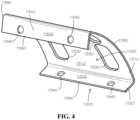
- FIG. 4is a perspective view of a saddle as part of the insulating spacer bracket of FIGS. 2 - 3 .
- FIG. 5is another perspective view of the saddle of FIG. 4 .
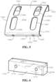
- FIG. 6is a perspective view of a standoff as part of the insulating spacer bracket of FIGS. 2 - 3 .
- Rangescan be expressed herein as from “about” one particular value, and/or to “about” another particular value. When such a range is expressed, another aspect includes from the one particular value and/or to the other particular value. Similarly, when values are expressed as approximations, by use of the antecedent “about,” it will be understood that the particular value forms another aspect. It will be further understood that the endpoints of each of the ranges are significant both in relation to the other endpoint, and independently of the other endpoint.
- a material property or dimension measuring about X or substantially X on a particular measurement scalemeasures within a range between X plus an industry-standard upper tolerance for the specified measurement and X minus an industry-standard lower tolerance for the specified measurement. Because tolerances can vary between different materials, processes and between different models, the tolerance for a particular measurement of a particular component can fall within a range of tolerances.
- the terms “optional” or “optionally”mean that the subsequently described event or circumstance can or cannot occur, and that the description includes instances where said event or circumstance occurs and instances where it does not.
- the jacketed pipeincludes an insulating spacer bracket. It would be understood by one of skill in the art that the disclosed bracket is described in but a few exemplary embodiments among many. No particular terminology or description should be considered limiting on the disclosure or the scope of any claims issuing therefrom.
- an insulating spacer bracket 1000for use with jacketed pipe is disclosed and described with reference to FIG. 1 .
- the spacercan be utilized to implement jacketed pipe to maintain structural integrity of the jacketed pipe while maintaining insulating properties unique to jacketed pipe.
- temperature-sensitive substrate materialscan be required to be transmitted through a pipe or pipeline.
- crude oil extracted from the groundcan exceed 120° Fahrenheit.
- crude oil or other substratescan exceed 150° Celsius, or over 300° Fahrenheit.
- Oil pipelinescan carry the crude oil from its source to a refinery where it can be refined in oil products such as petroleum. Some of these oil pipelines extend from permafrost regions—such as in the Yukon, Nunavut, and Northwest Territories in Canada—to areas more hospitable to a refinery location. Such a pipeline is undesirable above ground because it is exposed to the weather and because it prevents migration of ground mammals.
- liquefied natural gascan be transported through a pipe in a structure. Liquefied natural gas forms at ⁇ 265° Fahrenheit. At such temperature, insulation of some sort is necessary to prevent the environment surrounding it from affecting the product inside the piping.
- Other similar examples of temperature-sensitive liquids or gassesinclude liquid nitrogen ( ⁇ 346° Fahrenheit) or even simply high temperature and pressure water or steam, such as that ejected as exhaust by nuclear reactor coolant systems.
- jacketed pipecan be used as an insulating element to maintain substrate temperature.
- an inner pipecan be nested within an outer pipe.
- the inner pipecan have an outer diameter that is smaller than an inner diameter of the outer pipe such that an air gap is maintained between the inner pipe and the outer pipe.
- the air gapcan be of a thickness of several inches or several feet. Ambient air is an effective insulator so long as convection is minimized.
- the air gap between the inner pipe and the outer pipe in a jacketed pipe systemcan prevent heat transfer into or out of the substrate from the environment surrounding the jacketed pipe.
- an insulating materialcan be utilized to fill the air gap as well, such as a fiberglass, ceramic, or carbon insulation material.
- the air gapcan be partially filled by insulation.
- a jacketed pipe system 500can comprise the insulating spacer bracket 1000 .
- the insulated spacer bracket 1000can be located around an inner pipe 510 and positioned within an outer pipe (not shown).
- the insulating spacer bracket 1000can in various aspects be an assembly of smaller elements.
- the insulating spacer bracket 1000can be a single piece.
- the insulating spacer bracket 1000can be a clamshell design, or various other applications as would be understood by one of skill in the art.
- the insulating spacer bracketcan comprise a plurality of standoffs 1100 .
- six standoffs 1100can be included. In various aspects, more or fewer standoffs 1100 can be included.
- the standoffs 1100can be formed of substantially rigid but also insulating material.
- each standoff 1100can be formed from composites such as fiberglass, carbon fiber, linen, canvas, or other materials in resin.
- each standoff 1100can be formed of wood, phenolic, polymer, or other various materials suitable to the application.
- each standoff 1100can be formed of high density polyurethane or high density polyurethane foam.
- One suitable high density polyurethanecan be CoraFoam®.
- each standoff 1100can be formed of composites of linen, canvas, paper, fiberglass, carbon fiber or other fabric in a thermosetting plastic. Micarta® can be one such suitable material.
- Micarta®can comprise cellulosic material such as cellulose paper, cotton fabrics, synthetic yarn fabrics, glass fabrics, or unwoven fabric.
- Micarta®can comprise phenolic, epoxy, silicone, or melamine resin based thermoset materials reinforced with fiberglass, cork, cotton cloth, paper, carbon fiber or other substrates.
- each standoff 1100can be formed of Micarta® NP572.
- Micarta® NP572can be high strength, medium weave glass fabric with epoxy resin. Micarta® NP572 can maintain dimensional stability and high strength even with temperatures over 150° C.
- Micarta® NP572can, in various aspects, comprise the material properties indicated below.
- carbon fiber or fiberglass laminatescan also be utilized to form each standoff 1100 .
- varying materialscan be combined to form standoffs 1100 having various thermal or electrical insulating and structural properties
- each standoff 1100can be about rectangular in shape. In various aspects, each standoff 1100 can be contoured to the curvature of the inner pipe 510 . In various aspects, various other shapes can be suitable depending on the application.
- each standoff 1100can be joined, affixed, or fastened to at least one saddle 1200 .
- a plurality of saddles 1200can be fastened to the plurality of standoffs 1100 to form a ring-shaped insulating spacer bracket 1000 .
- Each saddle 1200can be substantially curved thereby connecting the rectangular standoffs 1100 in a curved or circular arrangement.
- Each saddle 1200can be fastened to at least one standoff 1100 by at least one fastener 1220 .
- each standoff 1100can be fastened to a pair of saddles 1200 by a pair of fasteners 1220 .
- each fastener 1220can be a bolt and nut assembly.
- each fastener 1220can be a threaded fastener to join directly to the standoff 1100 .
- adhesives, key/fit arrangements, or other joining elementscan be utilized as fasteners 1220 as would be understood by one of skill in the art.
- each saddle 1200can comprise a central portion 1310 and at least one flange portion 1320 .
- each central portion 1310can be curved to accommodate the inner diameter of the outer pipe (not shown).
- Each central portion 1310can define at least one vent 1330 .
- the central portion 1310can define a plurality of vents 1330 .
- each central portion 1310can define four vents 1330 .
- the vents 1330can provide a variety of purposes.
- each saddle 1200can be formed of a strong material, which can be rigid or ductile in various aspects.
- the saddle 1200can be formed of metal, composite, or other similar strong materials sufficient to carry the load necessary to hold the substrate and the jacketed pipe without collapsing.
- the saddle 1200can be made of steel, including stainless steels and carbon steels.
- the saddle 1200can be formed of 304 stainless steel. Because steel and other metals can be conductive of heat, vents 1330 can be introduced to reduce contact area with the outer pipe, which can thereby reduce the transmission of heat through the saddle 1200 to the outer pipe. Vents 1330 an also remove material from the saddles 1200 , thereby reducing the weight of each saddle 1200 and easing in assembly of the spacer 1000 from the saddles 1200 and standoffs 1100 .
- the insulating spacer bracket 1000can be formed around the inner pipe 510 by a field worker, in some aspects. As such, handling the saddle 1200 can be required by hand, and removing weight from the saddle 1200 can be helpful to assembly workers.
- vents 1330can also provide access for a technician to utilize a wrench for tightening fasteners 1220 .
- Each saddle 1200can also define a plurality of fastener holes 1340 .
- the fastener holes 1340can be sized and arranged to accommodate the fasteners 1220 .
- each flange portion 1320can define two (2) fastener holes 1340 .
- each flange portion 1320can be arranged to accommodate different types of fasteners 1220 and can comprise other methods, shapes, or arrangements of features depending on the type of fastener utilized.
- fastener holes 1340can comprise a 3-sided element such that bolts can be slid into the holes from the side, thereby allowing the off-site preparation of subassemblies that can be easily connected together in the field.
- various subassembliescan be connected together using bolts as with the depicted fasteners 1220 .
- the saddle 1200can define an inner surface 1262 and an outer surface 1266 .
- the central portion 1310can define a central portion inner surface 1312 and a central portion outer surface 1316 , each being part of the inner surface 1262 and the outer surface 1266 , respectively.
- each flange portion 1320can define a flange portion inner surface 1322 and a flange portion outer surface 1326 , each being part of the inner surface 1262 and the outer surface 1266 , respectively.
- each flange portion 1320 of each saddle 1200can define a flange end 1380 that can define an end of the saddle 1200 on one extent.
- the saddle 1200can also define a pair of bracket ends 1390 located along the entirety of the saddle 1200 , including the central portion 1310 and the flange portion 1320 .
- the standoff 1100can be of rectangular block shape in the current aspect.
- the standoff 1100can be about square in cross-section.
- the standoff 1100can be of various shapes meant to accommodate a pipeline or manufacturing and assembly requirements.
- Each standoff 1100can define at least one fastener hole 1410 .
- each standoff 1100can define two (2) fastener holes 1410 for interaction with the fasteners 1220 .
- Each standoff 1100can comprise lateral faces 1412 ( 1412 a shown, 1412 b on the other side, unseen), contact faces 1414 ( 1414 a shown, 1414 b on the other side, unseen), and end faces 1416 ( 1416 a shown, 1416 b on the other side, unseen).
- Each standoff 1100can be described by a height dimension 1420 as measured between the two contact faces 1414 , a width dimension 1430 as measured between the two end faces 1416 , and a thickness dimension 1440 as measured between the two lateral faces 1412 .
- Each fastener hole 1410can be arranged as extending entirely through the length of the thickness dimension 1440 from lateral face 1412 a to lateral face 1412 b .
- Each fastener hole 1410can be positioned about centrally along the height dimension 1420 —or, said differently, each fastener hole 1410 in the current aspect can be placed such that a center location of the fastener hole 1410 can be located about one-half the distance of the height dimension 1420 from either of the contact faces 1414 . In various aspects, the fastener holes 1410 can be positioned in other locations to accommodate various physical arrangements.
- each fastener hole 1340can be located close to the flange end 1380 than to the central portion 1310 .
- This arrangementallows the standoff 1100 to protrude below the flange end 1380 such that the standoff 1100 can be the only thing touching the inner pipe 500 .
- the saddle 1200 and the standoff 1100can be arranged such that the standoff 1100 can be the only thing touching the outer pipe as well with simple dimensional modifications.
- a protrusion 1490 of the standoff 1100can be seen as referenced (annotated with respect to only one of the six standoffs 1100 for clarity).
- the standoff 1100can be seen protruding below the flange end 1380 such that the contact face 1414 (inner contact face 1414 a ) can be in contact with an outer surface of the inner pipe 500 (seen in FIG. 1 ), which can also be excluded from contact with the saddle 1200 .
- the protrusion 1490can be measured as the distance from the flange end 1380 to the contact face 1414 . In the current aspect, the protrusion 1490 can be about one-fourth of the height dimension 1420 . In various aspects, the protrusion 1490 can be one-third of the height dimension 1420 . In various aspects, the protrusion 1490 can be one-fifth of the height dimension 1420 . In various aspects, the protrusion 1490 can be one-half of the height dimension 1420 . In various aspects, the protrusion 1490 can be eliminated.
- the plurality of standoffs 1100can define an inner diameter 1500 of the insulating spacer bracket 1000 .
- the inner diameter 1500can be defined by the inner contact faces 1414 a .
- the inner diameter 1500can be defined as the distance between inner contact faces 1414 a of adjacent standoffs 1100 .
- the inner diametercan be defined by determining the radius from a center of the insulating spacer bracket 1000 to the nearest inner contact face 1414 a .
- the inner diameter 1500can be similar to or substantially the same as an outer diameter 515 of the inner pipe 500 .
- the inner diameter 1500can be termed the “working diameter.”
- the insulating spacer bracket 1000can also define an outer diameter 1600 similarly to the inner diameter as measured from the outermost contact faces 1414 b .
- the outer diameter 1600 in the current aspectcan also be defined by the saddles 1200 , although in various aspects the saddles 1200 can be located interior to the outer diameter 1600 .
- the standoffs 1100can be located interior to the outer diameter 1600 such that the outer diameter 1600 can be defined by features of the saddles 1200 .
- the outer diameter 1600can be about similar to or substantially the same as the inner diameter of the outer pipe (not shown).
- conditional languagesuch as, among others, “can,” “could,” “might,” or “may,” unless specifically stated otherwise, or otherwise understood within the context as used, is generally intended to convey that certain embodiments include, while other embodiments do not include, certain features, elements and/or steps. Thus, such conditional language is not generally intended to imply that features, elements and/or steps are in any way required for one or more particular embodiments or that one or more particular embodiments necessarily include logic for deciding, with or without user input or prompting, whether these features, elements and/or steps are included or are to be performed in any particular embodiment.
Landscapes
- Engineering & Computer Science (AREA)
- General Engineering & Computer Science (AREA)
- Mechanical Engineering (AREA)
- Thermal Insulation (AREA)
- Supports For Pipes And Cables (AREA)
Abstract
Description
| Material Properties Chart of Micarta ® NP572 |
| Physical Properties | Metric | English | Comments |
| Specific Gravity | 1.89 g/cc | 1.89 g/cc | ASTM D792 |
| @ thickness 12.7 mm | @ thickness 0.500 in | ||
| Moisture Absorption | 0.200% | 0.200% | ASTM D570 |
| @ thickness 1.57 mm | @ thickness 0.062 in | Condition A | |
| Mechanical | |||
| Properties | Metric | English | Comments |
| Rockwell Hardness | 108 | 108 | ASTM D785 |
| @ thickness 6.35 mm | @ thickness 0.250 in | ||
| Tensile Strength | 241 MPa | 35000 psi | ASTM D638 |
| @ thickness 3.17 mm | @ thickness 0.125 in | Condition A- | |
| crosswise | |||
| 326 MPa | 47300 psi | ASTM D638 | |
| @ thickness 3.17 mm | @ thickness 0.125 in | Condition A- | |
| lengthwise | |||
| Flexural Strength | 365 MPa | 53000 psi | CrossWise; ASTM |
| @ thickness 1.57 mm | @ thickness | D790 Condition A | |
| 0.0620 in | |||
| 472 MPa | 68500 psi | Length Wise; ASTM | |
| @ thickness 1.57 mm | @ thickness | D790 Condition A | |
| 0.0620 in | |||
| Compressive | 497 MPa | 72100 psi | Flatwise; ASTM |
| Strength | @ thickness 12.7 mm | @ thickness 0.500 in | D695 Condition A |
| Shear Strength | 174 MPa | 25200 psi | perpendicular; ASTM |
| @ thickness 1.57 mm | @ thickness | D732 Condition A | |
| 0.0620 in | |||
| Izod Impact, | 5.50 J/cm | 10.3 ft-lb/in | CrossWise; ASTM |
| Unnotched | @ thickness 12.7 mm | @ thickness 0.500 in | D256 Condition E- |
| 48/50 | |||
| 6.67 J/cm | 12.5 ft-lb/in | Length Wise; ASTM | |
| @ thickness 12.7 mm | @ thickness 0.500 in | D256 Condition E- | |
| 48/50 | |||
| Electrical Properties | Metric | English | Comments |
| Dielectric Constant | 4.1 | 4.1 | ASTM D150 |
| @Thickness 1.57 | @Thickness 0.0620 | Condition D-24/23 | |
| mm, | in, | ||
| Frequency 1.00e+6 | Frequency 1.00e+6 | ||
| Hz | Hz | ||
| Dielectric Strength | 26.8 kV/ mm | 680 kV/in | ASTM D149 |
| @Thickness 1.57 mm | @Thickness 0.0620 | Condition A | |
| in | |||
| 29.9 kV/ mm | 760 kV/in | ASTM D149 | |
| @Thickness 1.57 mm | @Thickness 0.0620 | Condition D-48/50 | |
| in | |||
| Dielectric | 69000 V | 69000 V | ASTM D149 |
| Breakdown | @Thickness 1.57 mm | @Thickness 0.0620 | Condition A |
| in | |||
| Dissipation Factor | 0.018 | 0.018 | ASTM D150 |
| @Thickness 1.57 | @Thickness 0.0620 | Condition D-24/23 | |
| mm, | in, | ||
| Frequency 1.00e+6 | Frequency 1.00e+6 | ||
| Hz | Hz | ||
| Arc Resistance | 185 sec | 185 sec | ASTM D495 |
| @Thickness 3.17 mm | @Thickness 0.125 in | Conition A | |
| Thermal Properties | Metric | English | Comments |
| Transformation | 180° C. | 356° F. | DMA |
| Temperature, Tg | @Thickness 12.7 mm | @Thickness 0.500 in | |
| Flammability, UL94 | V-0 | V-0 | |
| @Thickness 1.57 mm | @Thickness 0.0620 | ||
| in | |||
| Descriptive | |||
| Properties | |||
| Bonding Strength | 1800 | [lb]; 0.5″; ASTM | |
| D229 Condition D- | |||
| 48/50 | |||
Claims (21)
Priority Applications (2)
| Application Number | Priority Date | Filing Date | Title |
|---|---|---|---|
| US18/197,310US12055264B2 (en) | 2020-05-19 | 2023-05-15 | Insulating support bracket for jacketed pipe system |
| US18/795,626US20250216018A1 (en) | 2020-05-19 | 2024-08-06 | Insulating support bracket for jacketed pipe system |
Applications Claiming Priority (3)
| Application Number | Priority Date | Filing Date | Title |
|---|---|---|---|
| US16/878,477US11280443B2 (en) | 2020-05-19 | 2020-05-19 | Insulting support bracket for jacketed pipe system |
| US17/669,065US11686422B2 (en) | 2020-05-19 | 2022-02-10 | Insulating support bracket for jacketed pipe system |
| US18/197,310US12055264B2 (en) | 2020-05-19 | 2023-05-15 | Insulating support bracket for jacketed pipe system |
Related Parent Applications (1)
| Application Number | Title | Priority Date | Filing Date |
|---|---|---|---|
| US17/669,065ContinuationUS11686422B2 (en) | 2020-05-19 | 2022-02-10 | Insulating support bracket for jacketed pipe system |
Related Child Applications (1)
| Application Number | Title | Priority Date | Filing Date |
|---|---|---|---|
| US18/795,626ContinuationUS20250216018A1 (en) | 2020-05-19 | 2024-08-06 | Insulating support bracket for jacketed pipe system |
Publications (2)
| Publication Number | Publication Date |
|---|---|
| US20230279986A1 US20230279986A1 (en) | 2023-09-07 |
| US12055264B2true US12055264B2 (en) | 2024-08-06 |
Family
ID=78608757
Family Applications (4)
| Application Number | Title | Priority Date | Filing Date |
|---|---|---|---|
| US16/878,477ActiveUS11280443B2 (en) | 2020-05-19 | 2020-05-19 | Insulting support bracket for jacketed pipe system |
| US17/669,065ActiveUS11686422B2 (en) | 2020-05-19 | 2022-02-10 | Insulating support bracket for jacketed pipe system |
| US18/197,310ActiveUS12055264B2 (en) | 2020-05-19 | 2023-05-15 | Insulating support bracket for jacketed pipe system |
| US18/795,626PendingUS20250216018A1 (en) | 2020-05-19 | 2024-08-06 | Insulating support bracket for jacketed pipe system |
Family Applications Before (2)
| Application Number | Title | Priority Date | Filing Date |
|---|---|---|---|
| US16/878,477ActiveUS11280443B2 (en) | 2020-05-19 | 2020-05-19 | Insulting support bracket for jacketed pipe system |
| US17/669,065ActiveUS11686422B2 (en) | 2020-05-19 | 2022-02-10 | Insulating support bracket for jacketed pipe system |
Family Applications After (1)
| Application Number | Title | Priority Date | Filing Date |
|---|---|---|---|
| US18/795,626PendingUS20250216018A1 (en) | 2020-05-19 | 2024-08-06 | Insulating support bracket for jacketed pipe system |
Country Status (1)
| Country | Link |
|---|---|
| US (4) | US11280443B2 (en) |
Families Citing this family (3)
| Publication number | Priority date | Publication date | Assignee | Title |
|---|---|---|---|---|
| US11280443B2 (en) | 2020-05-19 | 2022-03-22 | ASC Engineered Solutions, LLC | Insulting support bracket for jacketed pipe system |
| US11835170B1 (en)* | 2022-06-21 | 2023-12-05 | Greg Wargo | Pipe clamp for the protection of piping |
| CN116305566B (en)* | 2023-03-15 | 2025-08-01 | 上海外高桥造船有限公司 | Modeling method for ship piping insulation, electronic equipment and storage medium |
Citations (68)
| Publication number | Priority date | Publication date | Assignee | Title |
|---|---|---|---|---|
| US521149A (en) | 1894-06-12 | Pipe-hanger | ||
| US791504A (en) | 1904-05-23 | 1905-06-06 | Mortimer C Rosenfeld | Pipe-hanger. |
| US896333A (en)* | 1904-06-18 | 1908-08-18 | Anthony P Smith | Connecting branch sleeve. |
| US982028A (en)* | 1910-02-08 | 1911-01-17 | Josiah Boone Austin | Pipe-union. |
| US1903029A (en) | 1930-05-07 | 1933-03-28 | Victaulic Co Of America | Pipe coupling |
| US1970078A (en) | 1932-01-22 | 1934-08-14 | Stephen V Dillon | Pipe coupling |
| US2720016A (en)* | 1950-10-31 | 1955-10-11 | Brewer Titchener Corp | Pole band |
| US2733034A (en)* | 1956-01-31 | Pipe hangers | ||
| US2908061A (en) | 1957-11-15 | 1959-10-13 | Adams Pipe Repair Products | Pipe clamp device |
| US3004781A (en) | 1959-01-29 | 1961-10-17 | Jolly L Morris | Slotted shell coupling clamp |
| US3606218A (en) | 1969-03-21 | 1971-09-20 | Gen Dynamics Corp | Sound and vibration isolation support |
| US3905623A (en) | 1974-04-05 | 1975-09-16 | Cassel Thomas Richard | Pipe coupling with deformable outer sleeve |
| US3944265A (en) | 1974-11-15 | 1976-03-16 | Donaldson Company, Inc. | Exhaust system connector seal |
| US4056273A (en) | 1976-12-08 | 1977-11-01 | Cassel Thomas Richard | Coupling for pipe lap joints |
| US4258941A (en) | 1979-07-19 | 1981-03-31 | Mueller Co. | Service clamp for plastic pipe or the like |
| US4364588A (en) | 1980-11-10 | 1982-12-21 | Garlock, Inc. | Band seal clamp |
| US4429907A (en) | 1982-08-10 | 1984-02-07 | Timmons Fred A | Pipe coupler |
| US4530478A (en) | 1982-05-06 | 1985-07-23 | Pipe Shields, Inc. | Insulating pipe support apparatus |
| US4629226A (en) | 1985-04-16 | 1986-12-16 | Bks Company | Pipe lap joint with collapsible sealing zone and band clamp |
| US4714229A (en) | 1984-04-27 | 1987-12-22 | Novatome | Anti-vibratory support device for a pipe whose thickness is small relative to the diameter |
| US4730800A (en) | 1986-07-02 | 1988-03-15 | Engman Milton C | Universal tailpipe holding bracket |
| US4790574A (en) | 1987-01-16 | 1988-12-13 | Donaldson Company, Inc. | Apparatus for coupling tubular members |
| US4804158A (en) | 1986-06-17 | 1989-02-14 | Pipe Shields, Inc. | Insulated pipe anchor apparatus |
| US5588680A (en) | 1994-12-20 | 1996-12-31 | Bks Company | Pipe lap joint with improved collapsible sealing zone |
| US6089624A (en) | 1998-05-12 | 2000-07-18 | Bks Company | Pipe lap joint with improved collapsible slot |
| US6116659A (en) | 1998-02-24 | 2000-09-12 | Donaldson Company, Inc. | Band clamp for sealing lap joints and method thereof |
| US6158475A (en) | 1999-03-04 | 2000-12-12 | Clemmer; David Grant | Underground pipe support |
| US6269524B1 (en) | 1998-06-11 | 2001-08-07 | Thomas R. Cassel | Band clamp |
| US6318681B1 (en) | 1999-04-23 | 2001-11-20 | Aeroflex International Co. Ltd. | Insulating element for pipes |
| US20020014772A1 (en) | 2000-06-23 | 2002-02-07 | Amedure Michael E. | Pipe coupler |
| US6519815B2 (en) | 1998-06-11 | 2003-02-18 | Bks Company, Llc | Band clamp |
| US20040178632A1 (en) | 2003-03-13 | 2004-09-16 | Donaldson Company, Inc. | Sealing gasket for a clamp |
| US6796004B2 (en) | 2001-09-14 | 2004-09-28 | Donaldson Company, Inc. | Exhaust system clamp |
| US6877191B2 (en) | 2001-09-17 | 2005-04-12 | Dwws, Llc | Band clamp |
| US20050189768A1 (en) | 2004-02-26 | 2005-09-01 | Breeze-Torca Products, Llc | Pipe clamp with button engagement hole |
| US20060175837A1 (en) | 2005-02-10 | 2006-08-10 | Breeze-Torca Products, Llc | Pipe clamp with gasketed center rib |
| US20070063514A1 (en) | 2005-09-16 | 2007-03-22 | Yuji Noda | Housing type joint |
| US7364323B2 (en)* | 2006-01-25 | 2008-04-29 | Alain Francois | Pool light mounting system |
| US7441732B2 (en) | 2005-03-18 | 2008-10-28 | Hispano-Suiza | Supporting collar |
| US7472870B2 (en) | 2004-05-12 | 2009-01-06 | Rilco Manufacturing Company, Inc. | Cryogenic clamp-on pipe anchor |
| US20090079189A1 (en) | 2003-11-07 | 2009-03-26 | Breeze-Torca Products, Llc | Pipe clamp with integral latch |
| US20090178723A1 (en) | 2008-01-11 | 2009-07-16 | Joseph Cioffi | Supportive apparatus for piping and similar structures and method for the use thereof |
| US20090189392A1 (en) | 2008-01-30 | 2009-07-30 | Breeze-Torca Products, Llc | Single-bolt band clamp with gasketed center rib and pipe lap joint using the same |
| US7603752B2 (en)* | 2006-02-06 | 2009-10-20 | Andrew Llc | Compression or expansion mountable support band |
| US20090266944A1 (en) | 2005-12-09 | 2009-10-29 | Mominee Daniel S | Clamp for circular objects |
| US7861983B2 (en) | 2005-03-22 | 2011-01-04 | Lisega Aktiengesellschaft | Cold-insulated fixed-point support |
| US7950609B2 (en) | 2006-08-18 | 2011-05-31 | Kellogg Brown & Root Llc | Acoustic dampening pipe shoe |
| US8052490B2 (en) | 2007-07-02 | 2011-11-08 | Alcatel Lucent | Device for electrically conductive contacting a pipe |
| US8105511B2 (en) | 2004-09-16 | 2012-01-31 | Honeywell International Inc. | Method of manufacturing a carbon-carbon brake disc |
| US8282048B2 (en) | 2009-05-07 | 2012-10-09 | Adelwiggins Group | Side-locking clamping apparatus and method |
| US8313065B2 (en)* | 2010-05-14 | 2012-11-20 | Mueller International, Llc | Alloy insert clamp |
| US8495986B2 (en) | 2011-02-18 | 2013-07-30 | Tenneco Automotive Operating Company Inc. | Retrofit injector mount |
| US8505857B2 (en) | 2006-08-18 | 2013-08-13 | Kellogg Brown & Root Llc | Systems and methods for supporting a pipe |
| US8746632B2 (en) | 2008-10-22 | 2014-06-10 | J. Van Walraven Holding B.V. | Riser clamp with vibration isolation |
| US8763648B2 (en) | 2009-02-09 | 2014-07-01 | Lisega Aktiengesellschaft | Cold-insulated pipe support and installation |
| US9038968B2 (en) | 2009-06-09 | 2015-05-26 | John HENNON | Attachable grommets for hanging pipes |
| US9103476B2 (en) | 2010-01-21 | 2015-08-11 | Norma U.S. Holding Llc | Gasketed pipe clamp |
| US20150233520A1 (en) | 2014-02-17 | 2015-08-20 | Yarbrough Solutions Worldwide | Thermal Isolation Clamp |
| US9512942B2 (en) | 2012-06-12 | 2016-12-06 | Lisega SE | Cold-insulated pipe support |
| US20170211732A1 (en) | 2016-01-21 | 2017-07-27 | Pridgeon & Clay, Inc. | Clamp |
| US9739410B2 (en) | 2014-07-11 | 2017-08-22 | Cox Engineering Company | Clamp for repair of pipe couplings |
| US9765906B2 (en)* | 2012-08-30 | 2017-09-19 | Nexans | Piggyback holdback clamp |
| US20190048968A1 (en) | 2016-02-09 | 2019-02-14 | Saipem S.P.A. | Vibration damper for pipes |
| US10288205B2 (en) | 2012-10-15 | 2019-05-14 | Petroliam Nasional Berhad (Petronas) | Vibration clamp |
| US10323666B2 (en) | 2015-10-01 | 2019-06-18 | Etablissements Caillau | Clamping collar having a spacer |
| US20210364120A1 (en) | 2020-05-19 | 2021-11-25 | Anvil International, Llc | Insulting support bracket for jacketed pipe system |
| US20220274541A1 (en)* | 2021-02-26 | 2022-09-01 | Nissan North America, Inc. | Systems and Methods for Securing Conduits in Vehicles |
| US11692664B2 (en)* | 2018-08-13 | 2023-07-04 | Zsi, Inc. | Pipe insulation coupling with sealing mechanism |
Family Cites Families (2)
| Publication number | Priority date | Publication date | Assignee | Title |
|---|---|---|---|---|
| US3494641A (en)* | 1967-08-30 | 1970-02-10 | Cesare Caregnato | Quick claw-and flange coupling for pipes |
| US4121796A (en)* | 1976-09-04 | 1978-10-24 | George Alfred Forbes | Supporting elements for ducting |
- 2020
- 2020-05-19USUS16/878,477patent/US11280443B2/enactiveActive
- 2022
- 2022-02-10USUS17/669,065patent/US11686422B2/enactiveActive
- 2023
- 2023-05-15USUS18/197,310patent/US12055264B2/enactiveActive
- 2024
- 2024-08-06USUS18/795,626patent/US20250216018A1/enactivePending
Patent Citations (72)
| Publication number | Priority date | Publication date | Assignee | Title |
|---|---|---|---|---|
| US521149A (en) | 1894-06-12 | Pipe-hanger | ||
| US2733034A (en)* | 1956-01-31 | Pipe hangers | ||
| US791504A (en) | 1904-05-23 | 1905-06-06 | Mortimer C Rosenfeld | Pipe-hanger. |
| US896333A (en)* | 1904-06-18 | 1908-08-18 | Anthony P Smith | Connecting branch sleeve. |
| US982028A (en)* | 1910-02-08 | 1911-01-17 | Josiah Boone Austin | Pipe-union. |
| US1903029A (en) | 1930-05-07 | 1933-03-28 | Victaulic Co Of America | Pipe coupling |
| US1970078A (en) | 1932-01-22 | 1934-08-14 | Stephen V Dillon | Pipe coupling |
| US2720016A (en)* | 1950-10-31 | 1955-10-11 | Brewer Titchener Corp | Pole band |
| US2908061A (en) | 1957-11-15 | 1959-10-13 | Adams Pipe Repair Products | Pipe clamp device |
| US3004781A (en) | 1959-01-29 | 1961-10-17 | Jolly L Morris | Slotted shell coupling clamp |
| US3606218A (en) | 1969-03-21 | 1971-09-20 | Gen Dynamics Corp | Sound and vibration isolation support |
| US3905623A (en) | 1974-04-05 | 1975-09-16 | Cassel Thomas Richard | Pipe coupling with deformable outer sleeve |
| US3944265A (en) | 1974-11-15 | 1976-03-16 | Donaldson Company, Inc. | Exhaust system connector seal |
| US4056273A (en) | 1976-12-08 | 1977-11-01 | Cassel Thomas Richard | Coupling for pipe lap joints |
| US4258941A (en) | 1979-07-19 | 1981-03-31 | Mueller Co. | Service clamp for plastic pipe or the like |
| US4364588A (en) | 1980-11-10 | 1982-12-21 | Garlock, Inc. | Band seal clamp |
| US4530478A (en) | 1982-05-06 | 1985-07-23 | Pipe Shields, Inc. | Insulating pipe support apparatus |
| US4429907A (en) | 1982-08-10 | 1984-02-07 | Timmons Fred A | Pipe coupler |
| US4714229A (en) | 1984-04-27 | 1987-12-22 | Novatome | Anti-vibratory support device for a pipe whose thickness is small relative to the diameter |
| US4629226A (en) | 1985-04-16 | 1986-12-16 | Bks Company | Pipe lap joint with collapsible sealing zone and band clamp |
| US4804158A (en) | 1986-06-17 | 1989-02-14 | Pipe Shields, Inc. | Insulated pipe anchor apparatus |
| US4730800A (en) | 1986-07-02 | 1988-03-15 | Engman Milton C | Universal tailpipe holding bracket |
| US4790574A (en) | 1987-01-16 | 1988-12-13 | Donaldson Company, Inc. | Apparatus for coupling tubular members |
| US5588680A (en) | 1994-12-20 | 1996-12-31 | Bks Company | Pipe lap joint with improved collapsible sealing zone |
| US6116659A (en) | 1998-02-24 | 2000-09-12 | Donaldson Company, Inc. | Band clamp for sealing lap joints and method thereof |
| US6089624A (en) | 1998-05-12 | 2000-07-18 | Bks Company | Pipe lap joint with improved collapsible slot |
| US6519815B2 (en) | 1998-06-11 | 2003-02-18 | Bks Company, Llc | Band clamp |
| US6269524B1 (en) | 1998-06-11 | 2001-08-07 | Thomas R. Cassel | Band clamp |
| US6158475A (en) | 1999-03-04 | 2000-12-12 | Clemmer; David Grant | Underground pipe support |
| US6318681B1 (en) | 1999-04-23 | 2001-11-20 | Aeroflex International Co. Ltd. | Insulating element for pipes |
| US20020014772A1 (en) | 2000-06-23 | 2002-02-07 | Amedure Michael E. | Pipe coupler |
| US6796004B2 (en) | 2001-09-14 | 2004-09-28 | Donaldson Company, Inc. | Exhaust system clamp |
| US6877191B2 (en) | 2001-09-17 | 2005-04-12 | Dwws, Llc | Band clamp |
| US20040178632A1 (en) | 2003-03-13 | 2004-09-16 | Donaldson Company, Inc. | Sealing gasket for a clamp |
| US7052052B2 (en) | 2003-03-13 | 2006-05-30 | Donaldson Company, Inc. | Sealing gasket for a clamp |
| US20090079189A1 (en) | 2003-11-07 | 2009-03-26 | Breeze-Torca Products, Llc | Pipe clamp with integral latch |
| US20050189768A1 (en) | 2004-02-26 | 2005-09-01 | Breeze-Torca Products, Llc | Pipe clamp with button engagement hole |
| US7472870B2 (en) | 2004-05-12 | 2009-01-06 | Rilco Manufacturing Company, Inc. | Cryogenic clamp-on pipe anchor |
| US8105511B2 (en) | 2004-09-16 | 2012-01-31 | Honeywell International Inc. | Method of manufacturing a carbon-carbon brake disc |
| US20060175837A1 (en) | 2005-02-10 | 2006-08-10 | Breeze-Torca Products, Llc | Pipe clamp with gasketed center rib |
| US7441732B2 (en) | 2005-03-18 | 2008-10-28 | Hispano-Suiza | Supporting collar |
| US7861983B2 (en) | 2005-03-22 | 2011-01-04 | Lisega Aktiengesellschaft | Cold-insulated fixed-point support |
| US20070063514A1 (en) | 2005-09-16 | 2007-03-22 | Yuji Noda | Housing type joint |
| US20090266944A1 (en) | 2005-12-09 | 2009-10-29 | Mominee Daniel S | Clamp for circular objects |
| US7364323B2 (en)* | 2006-01-25 | 2008-04-29 | Alain Francois | Pool light mounting system |
| US7603752B2 (en)* | 2006-02-06 | 2009-10-20 | Andrew Llc | Compression or expansion mountable support band |
| US7950609B2 (en) | 2006-08-18 | 2011-05-31 | Kellogg Brown & Root Llc | Acoustic dampening pipe shoe |
| US8505857B2 (en) | 2006-08-18 | 2013-08-13 | Kellogg Brown & Root Llc | Systems and methods for supporting a pipe |
| US8052490B2 (en) | 2007-07-02 | 2011-11-08 | Alcatel Lucent | Device for electrically conductive contacting a pipe |
| US20090178723A1 (en) | 2008-01-11 | 2009-07-16 | Joseph Cioffi | Supportive apparatus for piping and similar structures and method for the use thereof |
| US20090189392A1 (en) | 2008-01-30 | 2009-07-30 | Breeze-Torca Products, Llc | Single-bolt band clamp with gasketed center rib and pipe lap joint using the same |
| US8746632B2 (en) | 2008-10-22 | 2014-06-10 | J. Van Walraven Holding B.V. | Riser clamp with vibration isolation |
| US8763648B2 (en) | 2009-02-09 | 2014-07-01 | Lisega Aktiengesellschaft | Cold-insulated pipe support and installation |
| US8282048B2 (en) | 2009-05-07 | 2012-10-09 | Adelwiggins Group | Side-locking clamping apparatus and method |
| US9038968B2 (en) | 2009-06-09 | 2015-05-26 | John HENNON | Attachable grommets for hanging pipes |
| US9103476B2 (en) | 2010-01-21 | 2015-08-11 | Norma U.S. Holding Llc | Gasketed pipe clamp |
| US8313065B2 (en)* | 2010-05-14 | 2012-11-20 | Mueller International, Llc | Alloy insert clamp |
| US8495986B2 (en) | 2011-02-18 | 2013-07-30 | Tenneco Automotive Operating Company Inc. | Retrofit injector mount |
| US9512942B2 (en) | 2012-06-12 | 2016-12-06 | Lisega SE | Cold-insulated pipe support |
| US9765906B2 (en)* | 2012-08-30 | 2017-09-19 | Nexans | Piggyback holdback clamp |
| US10288205B2 (en) | 2012-10-15 | 2019-05-14 | Petroliam Nasional Berhad (Petronas) | Vibration clamp |
| US20190350051A1 (en) | 2014-02-17 | 2019-11-14 | Watlow Electric Manufacturing Company | Thermal isolation clamp |
| US20150233520A1 (en) | 2014-02-17 | 2015-08-20 | Yarbrough Solutions Worldwide | Thermal Isolation Clamp |
| US9739410B2 (en) | 2014-07-11 | 2017-08-22 | Cox Engineering Company | Clamp for repair of pipe couplings |
| US10323666B2 (en) | 2015-10-01 | 2019-06-18 | Etablissements Caillau | Clamping collar having a spacer |
| US20170211732A1 (en) | 2016-01-21 | 2017-07-27 | Pridgeon & Clay, Inc. | Clamp |
| US20190048968A1 (en) | 2016-02-09 | 2019-02-14 | Saipem S.P.A. | Vibration damper for pipes |
| US11692664B2 (en)* | 2018-08-13 | 2023-07-04 | Zsi, Inc. | Pipe insulation coupling with sealing mechanism |
| US20210364120A1 (en) | 2020-05-19 | 2021-11-25 | Anvil International, Llc | Insulting support bracket for jacketed pipe system |
| US11280443B2 (en) | 2020-05-19 | 2022-03-22 | ASC Engineered Solutions, LLC | Insulting support bracket for jacketed pipe system |
| US20220163164A1 (en) | 2020-05-19 | 2022-05-26 | ASC Engineered Solutions, LLC | Insulting support bracket for jacketed pipe system |
| US20220274541A1 (en)* | 2021-02-26 | 2022-09-01 | Nissan North America, Inc. | Systems and Methods for Securing Conduits in Vehicles |
Non-Patent Citations (6)
| Title |
|---|
| Palmer, Matthew Ryan; Certificate of Correction for U.S. Appl. No. 16/878,477, filed May 19, 2020, mailed Jun. 28, 2022, 1 pg. |
| Palmer, Matthew Ryan; Non-Final Office Action for U.S. Appl. No. 16/878,477, filed May 19, 2020, mailed Feb. 17, 2021, 14 pgs. |
| Palmer, Matthew Ryan; Non-Final Office Action for U.S. Appl. No. 16/878,477, filed May 19, 2020, mailed Jul. 30, 2021, 10 pgs. |
| Palmer, Matthew Ryan; Non-Final Office Action for U.S. Appl. No. 17/669,065, filed Feb. 10, 2022, mailed Sep. 20, 2022, 18 pgs. |
| Palmer, Matthew Ryan; Notice of Allowance for U.S. Appl. No. 16/878,477, filed May 19, 2020, mailed Nov. 15, 2021, 7 pgs. |
| Palmer, Matthew Ryan; Notice of Allowance for U.S. Appl. No. 17/669,065, filed Feb. 10, 2022, mailed Feb. 15, 2023, 8 pgs. |
Also Published As
| Publication number | Publication date |
|---|---|
| US20210364120A1 (en) | 2021-11-25 |
| US20230279986A1 (en) | 2023-09-07 |
| US20250216018A1 (en) | 2025-07-03 |
| US11280443B2 (en) | 2022-03-22 |
| US20220163164A1 (en) | 2022-05-26 |
| US11686422B2 (en) | 2023-06-27 |
Similar Documents
| Publication | Publication Date | Title |
|---|---|---|
| US12055264B2 (en) | Insulating support bracket for jacketed pipe system | |
| US8499563B2 (en) | System for generating and transporting electric power from hydrothermal vents | |
| Mohammadlou et al. | Thermoelastic analysis of axisymmetric conical shells: Investigating stress–strain response under uniform heat flow with semi-coupled approach | |
| Zhao et al. | Study of vortex-induced vibration of a pipe-in-pipe system by using a wake oscillator model | |
| Hoang et al. | Effects of Torsion on Equivalent Bending Moment for Limit Load and EPFM Circumferential Pipe Flaw Evaluations | |
| Amin Yazdi | Analyzing vibrational characteristics of fluid-filled symmetric cross-ply delaminated composite cylindrical shells | |
| RU2615661C1 (en) | Method of cooling of apaa | |
| Ponnusamy et al. | Wave propagation in a transversely isotropic thermoelastic solid cylinder of arbitrary cross-section | |
| US20160076396A1 (en) | Turbine Exhaust Cylinder / Turbine Exhaust Manifold Bolted Stiffening Ribs | |
| WO2023226288A1 (en) | Heat exchanger with bidirectional pull rod assembly | |
| CN102642880B (en) | Sliding support in low-temperature multi-effect seawater distilling desalting system | |
| Weaver et al. | The effect of platen fins on the flow-induced vibrations of an in-line tube array | |
| Zhou et al. | Transient thermal response in thick orthotropic hollow cylinders with finite length: High order shell theory | |
| Dzubir et al. | Stress Classification Lines for Non-Standard Y-Tee Design in Piping System | |
| RU2219416C1 (en) | Tubular articles | |
| CN213452334U (en) | High temperature resistant corrugated pipe compensator | |
| CN221743448U (en) | A U-shaped seismic isolation metal hose with all-round large displacement compensation | |
| CN203703363U (en) | Cold insulation pipe holder device | |
| CN210069139U (en) | External sliding type direct buried steel casing insulation support device | |
| CN203100520U (en) | U-shaped pipe bundle heat exchanger with tail anti-vibration device | |
| Jiaxu et al. | Thermal Stress and Fatigue Life Analysis of Cold and Hot Crude Oil Pipeline | |
| CA2685792A1 (en) | High pressure plastic piping system and seal | |
| 孙杰 et al. | Leakage failure analysis on flange connection structure in header of reforming reactor | |
| Kawamura et al. | Thermally induced vibration of inhomogeneous material rectangular plate due to cyclic variation of thermal and mechanical loads | |
| Perumal et al. | Influence of low temperature and flow properties in dynamic behaviour of cryogenic pipelines |
Legal Events
| Date | Code | Title | Description |
|---|---|---|---|
| FEPP | Fee payment procedure | Free format text:ENTITY STATUS SET TO UNDISCOUNTED (ORIGINAL EVENT CODE: BIG.); ENTITY STATUS OF PATENT OWNER: LARGE ENTITY | |
| STPP | Information on status: patent application and granting procedure in general | Free format text:DOCKETED NEW CASE - READY FOR EXAMINATION | |
| STPP | Information on status: patent application and granting procedure in general | Free format text:NON FINAL ACTION MAILED | |
| STPP | Information on status: patent application and granting procedure in general | Free format text:RESPONSE TO NON-FINAL OFFICE ACTION ENTERED AND FORWARDED TO EXAMINER | |
| STPP | Information on status: patent application and granting procedure in general | Free format text:NOTICE OF ALLOWANCE MAILED -- APPLICATION RECEIVED IN OFFICE OF PUBLICATIONS | |
| ZAAB | Notice of allowance mailed | Free format text:ORIGINAL CODE: MN/=. | |
| AS | Assignment | Owner name:ANVIL INTERNATIONAL, LLC, NEW HAMPSHIRE Free format text:ASSIGNMENT OF ASSIGNORS INTEREST;ASSIGNORS:PALMER, MATTHEW RYAN;SOJKA, JON;SIGNING DATES FROM 20200514 TO 20200518;REEL/FRAME:067394/0522 Owner name:ASC ENGINEERED SOLUTIONS, LLC, NEW HAMPSHIRE Free format text:CHANGE OF NAME;ASSIGNOR:ANVIL INTERNATIONAL, LLC;REEL/FRAME:067398/0547 Effective date:20210405 | |
| STPP | Information on status: patent application and granting procedure in general | Free format text:PUBLICATIONS -- ISSUE FEE PAYMENT RECEIVED | |
| AS | Assignment | Owner name:KKR LOAN ADMINISTRATION SERVICES LLC, AS COLLATERAL AGENT, NEW YORK Free format text:SECURITY INTEREST;ASSIGNOR:ASC ENGINEERED SOLUTIONS, LLC;REEL/FRAME:068264/0104 Effective date:20240710 | |
| AS | Assignment | Owner name:JPMORGAN CHASE BANK, N.A., ILLINOIS Free format text:SECURITY INTEREST;ASSIGNORS:ASC ENGINEERED SOLUTIONS, LLC;THE RELIABLE AUTOMATIC SPRINKLER CO. INC.;REEL/FRAME:068294/0382 Effective date:20240710 | |
| STCF | Information on status: patent grant | Free format text:PATENTED CASE |