US12053911B2 - Manufactured retaining wall block with improved false joint - Google Patents
Manufactured retaining wall block with improved false jointDownload PDFInfo
- Publication number
- US12053911B2 US12053911B2US18/096,229US202318096229AUS12053911B2US 12053911 B2US12053911 B2US 12053911B2US 202318096229 AUS202318096229 AUS 202318096229AUS 12053911 B2US12053911 B2US 12053911B2
- Authority
- US
- United States
- Prior art keywords
- retaining wall
- false joint
- wall block
- angle
- wall blocks
- Prior art date
- Legal status (The legal status is an assumption and is not a legal conclusion. Google has not performed a legal analysis and makes no representation as to the accuracy of the status listed.)
- Active
Links
Images


Classifications
- B—PERFORMING OPERATIONS; TRANSPORTING
- B29—WORKING OF PLASTICS; WORKING OF SUBSTANCES IN A PLASTIC STATE IN GENERAL
- B29C—SHAPING OR JOINING OF PLASTICS; SHAPING OF MATERIAL IN A PLASTIC STATE, NOT OTHERWISE PROVIDED FOR; AFTER-TREATMENT OF THE SHAPED PRODUCTS, e.g. REPAIRING
- B29C41/00—Shaping by coating a mould, core or other substrate, i.e. by depositing material and stripping-off the shaped article; Apparatus therefor
- B29C41/34—Component parts, details or accessories; Auxiliary operations
- B29C41/36—Feeding the material on to the mould, core or other substrate
- B—PERFORMING OPERATIONS; TRANSPORTING
- B28—WORKING CEMENT, CLAY, OR STONE
- B28B—SHAPING CLAY OR OTHER CERAMIC COMPOSITIONS; SHAPING SLAG; SHAPING MIXTURES CONTAINING CEMENTITIOUS MATERIAL, e.g. PLASTER
- B28B17/00—Details of, or accessories for, apparatus for shaping the material; Auxiliary measures taken in connection with such shaping
- B28B17/0027—Accessories for obtaining rubblestones
- B—PERFORMING OPERATIONS; TRANSPORTING
- B28—WORKING CEMENT, CLAY, OR STONE
- B28B—SHAPING CLAY OR OTHER CERAMIC COMPOSITIONS; SHAPING SLAG; SHAPING MIXTURES CONTAINING CEMENTITIOUS MATERIAL, e.g. PLASTER
- B28B7/00—Moulds; Cores; Mandrels
- B—PERFORMING OPERATIONS; TRANSPORTING
- B28—WORKING CEMENT, CLAY, OR STONE
- B28B—SHAPING CLAY OR OTHER CERAMIC COMPOSITIONS; SHAPING SLAG; SHAPING MIXTURES CONTAINING CEMENTITIOUS MATERIAL, e.g. PLASTER
- B28B7/00—Moulds; Cores; Mandrels
- B28B7/0064—Moulds characterised by special surfaces for producing a desired surface of a moulded article, e.g. profiled or polished moulding surfaces
- B28B7/007—Moulds characterised by special surfaces for producing a desired surface of a moulded article, e.g. profiled or polished moulding surfaces with moulding surfaces simulating natural effets, e.g. wood or stone
- B—PERFORMING OPERATIONS; TRANSPORTING
- B28—WORKING CEMENT, CLAY, OR STONE
- B28B—SHAPING CLAY OR OTHER CERAMIC COMPOSITIONS; SHAPING SLAG; SHAPING MIXTURES CONTAINING CEMENTITIOUS MATERIAL, e.g. PLASTER
- B28B7/00—Moulds; Cores; Mandrels
- B28B7/0064—Moulds characterised by special surfaces for producing a desired surface of a moulded article, e.g. profiled or polished moulding surfaces
- B28B7/0085—Moulds characterised by special surfaces for producing a desired surface of a moulded article, e.g. profiled or polished moulding surfaces with surfaces for moulding chamfers
- B—PERFORMING OPERATIONS; TRANSPORTING
- B28—WORKING CEMENT, CLAY, OR STONE
- B28B—SHAPING CLAY OR OTHER CERAMIC COMPOSITIONS; SHAPING SLAG; SHAPING MIXTURES CONTAINING CEMENTITIOUS MATERIAL, e.g. PLASTER
- B28B7/00—Moulds; Cores; Mandrels
- B28B7/0097—Press moulds; Press-mould and press-ram assemblies
- B—PERFORMING OPERATIONS; TRANSPORTING
- B28—WORKING CEMENT, CLAY, OR STONE
- B28B—SHAPING CLAY OR OTHER CERAMIC COMPOSITIONS; SHAPING SLAG; SHAPING MIXTURES CONTAINING CEMENTITIOUS MATERIAL, e.g. PLASTER
- B28B7/00—Moulds; Cores; Mandrels
- B28B7/16—Moulds for making shaped articles with cavities or holes open to the surface, e.g. with blind holes
- B28B7/18—Moulds for making shaped articles with cavities or holes open to the surface, e.g. with blind holes the holes passing completely through the article
- B28B7/183—Moulds for making shaped articles with cavities or holes open to the surface, e.g. with blind holes the holes passing completely through the article for building blocks or similar block-shaped objects
- B—PERFORMING OPERATIONS; TRANSPORTING
- B28—WORKING CEMENT, CLAY, OR STONE
- B28B—SHAPING CLAY OR OTHER CERAMIC COMPOSITIONS; SHAPING SLAG; SHAPING MIXTURES CONTAINING CEMENTITIOUS MATERIAL, e.g. PLASTER
- B28B7/00—Moulds; Cores; Mandrels
- B28B7/28—Cores; Mandrels
- B—PERFORMING OPERATIONS; TRANSPORTING
- B29—WORKING OF PLASTICS; WORKING OF SUBSTANCES IN A PLASTIC STATE IN GENERAL
- B29C—SHAPING OR JOINING OF PLASTICS; SHAPING OF MATERIAL IN A PLASTIC STATE, NOT OTHERWISE PROVIDED FOR; AFTER-TREATMENT OF THE SHAPED PRODUCTS, e.g. REPAIRING
- B29C39/00—Shaping by casting, i.e. introducing the moulding material into a mould or between confining surfaces without significant moulding pressure; Apparatus therefor
- B29C39/02—Shaping by casting, i.e. introducing the moulding material into a mould or between confining surfaces without significant moulding pressure; Apparatus therefor for making articles of definite length, i.e. discrete articles
- B29C39/026—Shaping by casting, i.e. introducing the moulding material into a mould or between confining surfaces without significant moulding pressure; Apparatus therefor for making articles of definite length, i.e. discrete articles characterised by the shape of the surface
- B—PERFORMING OPERATIONS; TRANSPORTING
- B29—WORKING OF PLASTICS; WORKING OF SUBSTANCES IN A PLASTIC STATE IN GENERAL
- B29C—SHAPING OR JOINING OF PLASTICS; SHAPING OF MATERIAL IN A PLASTIC STATE, NOT OTHERWISE PROVIDED FOR; AFTER-TREATMENT OF THE SHAPED PRODUCTS, e.g. REPAIRING
- B29C39/00—Shaping by casting, i.e. introducing the moulding material into a mould or between confining surfaces without significant moulding pressure; Apparatus therefor
- B29C39/22—Component parts, details or accessories; Auxiliary operations
- B29C39/26—Moulds or cores
- E—FIXED CONSTRUCTIONS
- E02—HYDRAULIC ENGINEERING; FOUNDATIONS; SOIL SHIFTING
- E02D—FOUNDATIONS; EXCAVATIONS; EMBANKMENTS; UNDERGROUND OR UNDERWATER STRUCTURES
- E02D29/00—Independent underground or underwater structures; Retaining walls
- E02D29/02—Retaining or protecting walls
- E—FIXED CONSTRUCTIONS
- E02—HYDRAULIC ENGINEERING; FOUNDATIONS; SOIL SHIFTING
- E02D—FOUNDATIONS; EXCAVATIONS; EMBANKMENTS; UNDERGROUND OR UNDERWATER STRUCTURES
- E02D29/00—Independent underground or underwater structures; Retaining walls
- E02D29/02—Retaining or protecting walls
- E02D29/025—Retaining or protecting walls made up of similar modular elements stacked without mortar
- E—FIXED CONSTRUCTIONS
- E02—HYDRAULIC ENGINEERING; FOUNDATIONS; SOIL SHIFTING
- E02D—FOUNDATIONS; EXCAVATIONS; EMBANKMENTS; UNDERGROUND OR UNDERWATER STRUCTURES
- E02D29/00—Independent underground or underwater structures; Retaining walls
- E02D29/02—Retaining or protecting walls
- E02D29/0258—Retaining or protecting walls characterised by constructional features
- E02D29/0266—Retaining or protecting walls characterised by constructional features made up of preformed elements
- E—FIXED CONSTRUCTIONS
- E04—BUILDING
- E04B—GENERAL BUILDING CONSTRUCTIONS; WALLS, e.g. PARTITIONS; ROOFS; FLOORS; CEILINGS; INSULATION OR OTHER PROTECTION OF BUILDINGS
- E04B2/00—Walls, e.g. partitions, for buildings; Wall construction with regard to insulation; Connections specially adapted to walls
- E04B2/02—Walls, e.g. partitions, for buildings; Wall construction with regard to insulation; Connections specially adapted to walls built-up from layers of building elements
- E04B2/28—Walls having cavities between, but not in, the elements; Walls of elements each consisting of two or more parts kept in distance by means of spacers, all parts being solid
- E04B2/30—Walls having cavities between, but not in, the elements; Walls of elements each consisting of two or more parts kept in distance by means of spacers, all parts being solid using elements having specially designed means for stabilising the position; Spacers for cavity walls
- E04B2/32—Walls having cavities between, but not in, the elements; Walls of elements each consisting of two or more parts kept in distance by means of spacers, all parts being solid using elements having specially designed means for stabilising the position; Spacers for cavity walls by interlocking of projections or inserts with indentations, e.g. of tongues, grooves, dovetails
- E—FIXED CONSTRUCTIONS
- E04—BUILDING
- E04C—STRUCTURAL ELEMENTS; BUILDING MATERIALS
- E04C1/00—Building elements of block or other shape for the construction of parts of buildings
- E—FIXED CONSTRUCTIONS
- E04—BUILDING
- E04C—STRUCTURAL ELEMENTS; BUILDING MATERIALS
- E04C1/00—Building elements of block or other shape for the construction of parts of buildings
- E04C1/39—Building elements of block or other shape for the construction of parts of buildings characterised by special adaptations, e.g. serving for locating conduits, for forming soffits, cornices, or shelves, for fixing wall-plates or door-frames, for claustra
- E04C1/395—Building elements of block or other shape for the construction of parts of buildings characterised by special adaptations, e.g. serving for locating conduits, for forming soffits, cornices, or shelves, for fixing wall-plates or door-frames, for claustra for claustra, fences, planting walls, e.g. sound-absorbing
- B—PERFORMING OPERATIONS; TRANSPORTING
- B29—WORKING OF PLASTICS; WORKING OF SUBSTANCES IN A PLASTIC STATE IN GENERAL
- B29K—INDEXING SCHEME ASSOCIATED WITH SUBCLASSES B29B, B29C OR B29D, RELATING TO MOULDING MATERIALS OR TO MATERIALS FOR MOULDS, REINFORCEMENTS, FILLERS OR PREFORMED PARTS, e.g. INSERTS
- B29K2095/00—Use of bituminous materials as moulding material
- B—PERFORMING OPERATIONS; TRANSPORTING
- B29—WORKING OF PLASTICS; WORKING OF SUBSTANCES IN A PLASTIC STATE IN GENERAL
- B29L—INDEXING SCHEME ASSOCIATED WITH SUBCLASS B29C, RELATING TO PARTICULAR ARTICLES
- B29L2031/00—Other particular articles
- B29L2031/10—Building elements, e.g. bricks, blocks, tiles, panels, posts, beams
- E—FIXED CONSTRUCTIONS
- E04—BUILDING
- E04B—GENERAL BUILDING CONSTRUCTIONS; WALLS, e.g. PARTITIONS; ROOFS; FLOORS; CEILINGS; INSULATION OR OTHER PROTECTION OF BUILDINGS
- E04B2/00—Walls, e.g. partitions, for buildings; Wall construction with regard to insulation; Connections specially adapted to walls
- E04B2/02—Walls, e.g. partitions, for buildings; Wall construction with regard to insulation; Connections specially adapted to walls built-up from layers of building elements
- E04B2002/0202—Details of connections
- E04B2002/0204—Non-undercut connections, e.g. tongue and groove connections
- E04B2002/0208—Non-undercut connections, e.g. tongue and groove connections of trapezoidal shape
- E—FIXED CONSTRUCTIONS
- E04—BUILDING
- E04B—GENERAL BUILDING CONSTRUCTIONS; WALLS, e.g. PARTITIONS; ROOFS; FLOORS; CEILINGS; INSULATION OR OTHER PROTECTION OF BUILDINGS
- E04B2/00—Walls, e.g. partitions, for buildings; Wall construction with regard to insulation; Connections specially adapted to walls
- E04B2/02—Walls, e.g. partitions, for buildings; Wall construction with regard to insulation; Connections specially adapted to walls built-up from layers of building elements
- E04B2002/0202—Details of connections
- E04B2002/0204—Non-undercut connections, e.g. tongue and groove connections
- E04B2002/0215—Non-undercut connections, e.g. tongue and groove connections with separate protrusions
- E04B2002/0219—Non-undercut connections, e.g. tongue and groove connections with separate protrusions of pyramidal shape
- E—FIXED CONSTRUCTIONS
- E04—BUILDING
- E04B—GENERAL BUILDING CONSTRUCTIONS; WALLS, e.g. PARTITIONS; ROOFS; FLOORS; CEILINGS; INSULATION OR OTHER PROTECTION OF BUILDINGS
- E04B2/00—Walls, e.g. partitions, for buildings; Wall construction with regard to insulation; Connections specially adapted to walls
- E04B2/02—Walls, e.g. partitions, for buildings; Wall construction with regard to insulation; Connections specially adapted to walls built-up from layers of building elements
- E04B2002/0256—Special features of building elements
- E04B2002/0269—Building elements with a natural stone facing
Definitions
- the present disclosurerelates to retaining wall blocks, and more specifically to a retaining wall block having a false joint and a mold for manufacturing such.
- Retaining wall blockscan be manufactured and arranged in a variety of different ways.
- a manufactured retaining wall block with an improved false joint and a system of retaining wall blocks with an improved false jointis presented herein.
- a retaining wall block having a false jointcomprises a body having a first surface and a second surface and a false joint dividing the first and second surface and extending a predetermined depth of the body.
- the first and second surfacecan be textured.
- the false jointcan have a depth divided by the width that is less than a predetermined value.
- the false jointcan also have an exterior angle that is greater than an interior angle.
- the retaining wall blockcan also include a base below the body that has at least one ridge to produce at least one engagement cavity. The body and the base can define an H-shaped dimension.
- FIGS. 1 A through 1 Dare diagrams of a retaining wall blocks with false joints in accordance with an example embodiment of the present disclosure
- FIGS. 2 A through 2 Care diagrams of engaged retaining wall blocks with false joints in accordance with an example embodiment of the present disclosure
- FIG. 3is a diagram of molded retaining walls blocks with each having a false joint in accordance with an example embodiment of the present disclosure.
- FIG. 4is a diagram of a mold for providing a false joint, in accordance with an example embodiment of the present disclosure.
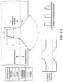
- FIGS. 1 A through 1 Care diagrams of a retaining wall block 100 in accordance with an example embodiment of the present disclosure.
- Retaining wall block 100can be formed from masonry, concrete or other suitable materials, using a wet cast process, a dry cast process or other suitable processes.
- retaining wall block 100includes a body 102 , a base 104 , a top face 106 , engagement cavity 110 , and textured front face 115 . Textured front face 115 can be formed by splitting retaining wall block 100 from a second retaining wall block 100 , as discussed in greater detail below.
- front face 115includes a false joint 120 .
- the false joint 120can extend the width of the body 102 along the front face 115 and a depth of the body 102 .
- the false joint 120can be located anywhere along the front face 115 of the body 102 and can be extended to different depths of the body 102 .
- the false joint 120can have an exterior false joint section having an apparent angle ⁇ and an interior false joint section having an apparent angle ⁇ .
- the false joint 120can have an interior false joint width W and an interior false joint depth D and a depth divided by width (D/W) of greater than a predetermined amount, such as 2 to 3, depending on the size of the body 102 , or other suitable amounts.
- the width Wcan be equal to or less than 3 mm or other suitable values.
- the false joint 120can have a depth of about a third of the depth of the body 102 , or other suitable depths.
- the apparent angle ⁇ of false joint 120can range from less than 10° to greater than 20°, and the apparent angle ⁇ of false joint 120 can range from less than 60° to greater than 80°.
- a transition region between the interior false joint section and the exterior false joint sectioncan have a thickness t, where t can be less than or equal to a predetermined value, such as 8 mm, or other suitable values.
- the body 102can include multiple false joints 120 . Alternate interior and exterior portions are shown as alternatives.
- retaining wall block 100can also include a bottom surface 125 having at least one engagement protrusion 130 .
- Engagement protrusion 130is configured to interface with engagement cavity 110 of an underlying retaining wall block 100 .
- the front engagement cavity 110is offset from the location of engagement protrusion 130 , so as to result in a staggered incline as successive rows of retaining wall blocks 100 are formed.
- the incline of successive rows of retaining wall blocks 100is generally vertical with no staggering.
- FIGS. 2 A through 2 Care diagrams of engaged retaining wall blocks 100 and 200 , in accordance with an example embodiment of the present disclosure.
- retaining wall blocks 100 and 200can have different sizes and can include top faces 106 and 206 , respectively, engagement cavities 110 and 210 , respectively, and textured front faces 115 and 215 , respectively.
- retaining wall blocks 100 and 200also include false joints 120 and 220 , as shown in FIGS. 2 A and 2 B .
- other suitable false jointscan also or alternatively be used.
- first retaining wall block 100is disposed onto a top surface 206 of a second retaining wall block 200 . As shown in FIG. 2 C , first retaining wall block 100 can positioned so that engagement protrusions 130 align with and fit into engagement cavity 210 of second retaining wall block 200 .
- the angle and configuration of engagement notches 110 and 210 and engagement members 130 and 230can be varied to allow the blocks 100 , 200 to be assembled with an offset. In one example embodiment of the present disclosure, the angle of engagement notches 110 and 210 can be between about 30 degrees and about 90 degrees. Likewise, the angle of engagement members 130 and 230 can be between about 30 degrees and about 90 degrees.
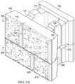
- FIG. 3is a diagram of a retaining wall block 300 with false joints 120 formed in the molded product, prior to splitting, in accordance with an example embodiment.
- Block 300includes a first block having a body 102 and base 104 casted with a second block having a body 102 and base 104 .
- the individual blocks 100can be formed by splitting block 300 at the centerline, through the diamond shaped aperture segmenting the false joints 120 .
- the false joints 120 described hereincan be cast within the mold at different suitable depths and at different suitable widths, and at varying suitable locations within body 102 corresponding to selected false joint locations.
- FIG. 4is a diagram of a mold 400 for providing a false joint, in accordance with an example embodiment of the present disclosure.
- Mold 400includes base 402 , index notches 404 , outer frame 406 and false joint 120 frame.
- false joint 120 framecreates a false joint feature, such as shown in FIG. 1 D or other suitable false joints.
- mold 400can be removed to allow the wet or dry mix to set and cure.
- False joint 120 framecan be coupled to mold 400 (not explicitly shown), or can be secured in another suitable manner to allow it to be withdrawn prior to setting.
Landscapes
- Engineering & Computer Science (AREA)
- Mechanical Engineering (AREA)
- Civil Engineering (AREA)
- Architecture (AREA)
- Structural Engineering (AREA)
- Ceramic Engineering (AREA)
- Chemical & Material Sciences (AREA)
- Manufacturing & Machinery (AREA)
- Life Sciences & Earth Sciences (AREA)
- General Life Sciences & Earth Sciences (AREA)
- Paleontology (AREA)
- Mining & Mineral Resources (AREA)
- General Engineering & Computer Science (AREA)
- Environmental & Geological Engineering (AREA)
- Wood Science & Technology (AREA)
- Physics & Mathematics (AREA)
- Electromagnetism (AREA)
- Retaining Walls (AREA)
Abstract
Description
Claims (20)
Priority Applications (1)
| Application Number | Priority Date | Filing Date | Title |
|---|---|---|---|
| US18/096,229US12053911B2 (en) | 2018-05-14 | 2023-01-12 | Manufactured retaining wall block with improved false joint |
Applications Claiming Priority (4)
| Application Number | Priority Date | Filing Date | Title |
|---|---|---|---|
| US15/978,891US10583588B2 (en) | 2013-06-21 | 2018-05-14 | Manufactured retaining wall block with improved false joint |
| US16/812,851US11034062B2 (en) | 2013-06-21 | 2020-03-09 | Manufactured retaining wall block with improved false joint |
| US17/346,785US11801622B2 (en) | 2013-06-21 | 2021-06-14 | Manufactured retaining wall block with improved false joint |
| US18/096,229US12053911B2 (en) | 2018-05-14 | 2023-01-12 | Manufactured retaining wall block with improved false joint |
Related Parent Applications (1)
| Application Number | Title | Priority Date | Filing Date |
|---|---|---|---|
| US17/346,785ContinuationUS11801622B2 (en) | 2013-06-21 | 2021-06-14 | Manufactured retaining wall block with improved false joint |
Publications (2)
| Publication Number | Publication Date |
|---|---|
| US20230241810A1 US20230241810A1 (en) | 2023-08-03 |
| US12053911B2true US12053911B2 (en) | 2024-08-06 |
Family
ID=87431411
Family Applications (1)
| Application Number | Title | Priority Date | Filing Date |
|---|---|---|---|
| US18/096,229ActiveUS12053911B2 (en) | 2018-05-14 | 2023-01-12 | Manufactured retaining wall block with improved false joint |
Country Status (1)
| Country | Link |
|---|---|
| US (1) | US12053911B2 (en) |
Families Citing this family (3)
| Publication number | Priority date | Publication date | Assignee | Title |
|---|---|---|---|---|
| USD1036705S1 (en)* | 2021-04-28 | 2024-07-23 | Keystone Retaining Wall Systems, Llc | Landscaping block |
| USD1041034S1 (en)* | 2021-04-28 | 2024-09-03 | Keystone Retaining Wall Systems, Llc | Landscaping block |
| USD1085468S1 (en)* | 2023-10-06 | 2025-07-22 | Westblock Systems, Inc. | Wall block |
Citations (19)
| Publication number | Priority date | Publication date | Assignee | Title |
|---|---|---|---|---|
| US20070193181A1 (en) | 2006-01-30 | 2007-08-23 | Klettenberg Charles N | Dry-cast concrete block |
| EP1867798A2 (en) | 2006-06-14 | 2007-12-19 | Transpavé Inc. | Concrete block system |
| US20070292216A1 (en) | 2006-06-14 | 2007-12-20 | Denis Hamel | Concrete block system |
| US20080145148A1 (en) | 2006-12-15 | 2008-06-19 | Denis Hamel | Dry-cast concrete block |
| US20080222986A1 (en) | 2007-03-14 | 2008-09-18 | Hamel Denis Louis | Exterior wall structure of a building |
| US7665250B2 (en) | 2003-05-02 | 2010-02-23 | Powell David W | System for construction of a compression structure with corner blocks, key blocks, and corner block supports |
| US7854573B2 (en) | 2005-05-11 | 2010-12-21 | New Technology Resources, Inc. | Landscaping products including continuous chamber mass confinement cells and methods of use thereof |
| US7866923B2 (en) | 2005-08-10 | 2011-01-11 | New Technology Resources, Inc. | Continuous chamber mass confinement cells and methods of use thereof |
| US8011152B2 (en) | 2007-11-13 | 2011-09-06 | Transpave Inc. | Block suitable for use in an arrangement of interlocking blocks |
| US20120151862A1 (en) | 2010-12-21 | 2012-06-21 | Les Materiaux De Construction Oldcastle Canada, Inc. | Concrete wall block |
| CA2544152C (en) | 2005-04-21 | 2013-06-11 | Les Materiaux De Construction Oldcastle Canada Inc./ Oldcastle Building Products Canada Inc. | Improvement in a molding apparatus for producing dry cast products having textured side surfaces |
| CA2550358C (en) | 2006-06-14 | 2014-05-27 | Transpave Inc. | Dry-cast concrete blocks and manufacturing process therefor |
| US9744697B2 (en) | 2013-06-21 | 2017-08-29 | Pavestone, LLC | Adjustable locator retaining wall block and mold apparatus |
| US20180104853A1 (en) | 2002-01-04 | 2018-04-19 | Anchor Wall Systems, Inc. | Method of making a concrete block |
| US20180187405A1 (en) | 2006-06-14 | 2018-07-05 | Oldcastle Building Products Canada, Inc. | Dry-cast concrete block |
| US10087597B2 (en) | 2010-12-21 | 2018-10-02 | Les Materiaux De Construction Oldcastle Canada, Inc. | Concrete wall block |
| US20200217036A1 (en) | 2017-07-24 | 2020-07-09 | Anchor Wall Systems, Inc. | Molded concrete block having visually enhanced contrasting surface sections; methods, and use |
| US10760242B2 (en) | 2015-02-25 | 2020-09-01 | Keystone Retaining Wall Systems Llc | Blocks, block systems and methods of making blocks |
| US11034062B2 (en) | 2013-06-21 | 2021-06-15 | Pavestone, LLC | Manufactured retaining wall block with improved false joint |
- 2023
- 2023-01-12USUS18/096,229patent/US12053911B2/enactiveActive
Patent Citations (21)
| Publication number | Priority date | Publication date | Assignee | Title |
|---|---|---|---|---|
| US20180104853A1 (en) | 2002-01-04 | 2018-04-19 | Anchor Wall Systems, Inc. | Method of making a concrete block |
| US7665250B2 (en) | 2003-05-02 | 2010-02-23 | Powell David W | System for construction of a compression structure with corner blocks, key blocks, and corner block supports |
| CA2544152C (en) | 2005-04-21 | 2013-06-11 | Les Materiaux De Construction Oldcastle Canada Inc./ Oldcastle Building Products Canada Inc. | Improvement in a molding apparatus for producing dry cast products having textured side surfaces |
| US7854573B2 (en) | 2005-05-11 | 2010-12-21 | New Technology Resources, Inc. | Landscaping products including continuous chamber mass confinement cells and methods of use thereof |
| US7866923B2 (en) | 2005-08-10 | 2011-01-11 | New Technology Resources, Inc. | Continuous chamber mass confinement cells and methods of use thereof |
| US20070193181A1 (en) | 2006-01-30 | 2007-08-23 | Klettenberg Charles N | Dry-cast concrete block |
| CA2550358C (en) | 2006-06-14 | 2014-05-27 | Transpave Inc. | Dry-cast concrete blocks and manufacturing process therefor |
| EP1867798A2 (en) | 2006-06-14 | 2007-12-19 | Transpavé Inc. | Concrete block system |
| US20070292216A1 (en) | 2006-06-14 | 2007-12-20 | Denis Hamel | Concrete block system |
| US7410328B2 (en) | 2006-06-14 | 2008-08-12 | Transpavé Inc. | Concrete block system |
| US20180187405A1 (en) | 2006-06-14 | 2018-07-05 | Oldcastle Building Products Canada, Inc. | Dry-cast concrete block |
| US20080145148A1 (en) | 2006-12-15 | 2008-06-19 | Denis Hamel | Dry-cast concrete block |
| US20080222986A1 (en) | 2007-03-14 | 2008-09-18 | Hamel Denis Louis | Exterior wall structure of a building |
| US8011152B2 (en) | 2007-11-13 | 2011-09-06 | Transpave Inc. | Block suitable for use in an arrangement of interlocking blocks |
| US20120151862A1 (en) | 2010-12-21 | 2012-06-21 | Les Materiaux De Construction Oldcastle Canada, Inc. | Concrete wall block |
| US10087597B2 (en) | 2010-12-21 | 2018-10-02 | Les Materiaux De Construction Oldcastle Canada, Inc. | Concrete wall block |
| US9744697B2 (en) | 2013-06-21 | 2017-08-29 | Pavestone, LLC | Adjustable locator retaining wall block and mold apparatus |
| US11034062B2 (en) | 2013-06-21 | 2021-06-15 | Pavestone, LLC | Manufactured retaining wall block with improved false joint |
| US11554521B2 (en) | 2013-06-21 | 2023-01-17 | Pavestone, LLC | Adjustable locator retaining wall block and mold apparatus |
| US10760242B2 (en) | 2015-02-25 | 2020-09-01 | Keystone Retaining Wall Systems Llc | Blocks, block systems and methods of making blocks |
| US20200217036A1 (en) | 2017-07-24 | 2020-07-09 | Anchor Wall Systems, Inc. | Molded concrete block having visually enhanced contrasting surface sections; methods, and use |
Also Published As
| Publication number | Publication date |
|---|---|
| US20230241810A1 (en) | 2023-08-03 |
Similar Documents
| Publication | Publication Date | Title |
|---|---|---|
| US11034062B2 (en) | Manufactured retaining wall block with improved false joint | |
| US12053911B2 (en) | Manufactured retaining wall block with improved false joint | |
| US20210138695A1 (en) | Adjustable locator retaining wall block and mold apparatus | |
| US12065826B2 (en) | Block for use in automated building construction | |
| US20230150174A1 (en) | Adjustable locator retaining wall block and mold apparatus | |
| US7207146B1 (en) | Multiple purpose wall block | |
| AU2006201621B2 (en) | Concrete block with beveled core opening edge | |
| US8973322B2 (en) | Masonry units and structures formed therefrom | |
| US20090184440A1 (en) | Molding equipment and method to manufacture stackable inter-engaging bricks, blocks, stones and the like with a smooth or embossed face | |
| US20060145050A1 (en) | Multi-block mold and system | |
| US20240140003A1 (en) | Manufactured retaining wall block with improved false joint | |
| US1725200A (en) | Wall tie | |
| US966226A (en) | Building-block. | |
| KR101721808B1 (en) | brick | |
| RU70909U1 (en) | CERAMIC PRODUCT FOR OBTAINING ANGULAR FACING TILES AND VOID FORMER FOR ITS MANUFACTURE | |
| US6038822A (en) | Octagonal shaped concrete block | |
| US875318A (en) | Flooring. | |
| US1602728A (en) | Building block | |
| US11512482B2 (en) | Device for connecting and separating masonry units | |
| US9903088B2 (en) | Blocks and block connectors, block systems and methods of making blocks | |
| FR2281467A1 (en) | Multiple cavity breeze block - has tapered vert channels distributing mortar along foam insulation cavities | |
| JPH0735630U (en) | Dry tile | |
| EP3196377A1 (en) | Multi cavity concrete construction element | |
| JPH05329817A (en) | Production of accessory tile | |
| JPH04182342A (en) | Production of tile for dry application |
Legal Events
| Date | Code | Title | Description |
|---|---|---|---|
| AS | Assignment | Owner name:PAVESTONE, LLC, GEORGIA Free format text:CHANGE OF ADDRESS OF ASSIGNEE;ASSIGNOR:PAVESTONE, LLC;REEL/FRAME:062380/0340 Effective date:20200915 Owner name:PAVESTONE, LLC, GEORGIA Free format text:ASSIGNMENT OF ASSIGNORS INTEREST;ASSIGNOR:KARAU, WILLIAM H.;REEL/FRAME:062360/0197 Effective date:20180511 | |
| FEPP | Fee payment procedure | Free format text:ENTITY STATUS SET TO UNDISCOUNTED (ORIGINAL EVENT CODE: BIG.); ENTITY STATUS OF PATENT OWNER: LARGE ENTITY | |
| STPP | Information on status: patent application and granting procedure in general | Free format text:DOCKETED NEW CASE - READY FOR EXAMINATION | |
| STPP | Information on status: patent application and granting procedure in general | Free format text:NON FINAL ACTION MAILED | |
| STPP | Information on status: patent application and granting procedure in general | Free format text:NOTICE OF ALLOWANCE MAILED -- APPLICATION RECEIVED IN OFFICE OF PUBLICATIONS | |
| STPP | Information on status: patent application and granting procedure in general | Free format text:PUBLICATIONS -- ISSUE FEE PAYMENT VERIFIED | |
| STCF | Information on status: patent grant | Free format text:PATENTED CASE | |
| AS | Assignment | Owner name:WELLS FARGO BANK, NATIONAL ASSOCIATION, COLORADO Free format text:SECURITY INTEREST;ASSIGNOR:PAVESTONE, LLC;REEL/FRAME:070168/0221 Effective date:20250210 Owner name:U.S. BANK TRUST COMPANY, NATIONAL ASSOCIATION, MINNESOTA Free format text:PATENT SECURITY AGREEMENT;ASSIGNORS:BEST BLOCK, LLC;CONTECH ENGINEERED SOLUTIONS LLC;CUSTOM BUILDING PRODUCTS, LLC;AND OTHERS;REEL/FRAME:070170/0919 Effective date:20250210 | |
| AS | Assignment | Owner name:WELLS FARGO BANK, NATIONAL ASSOCIATION, AS AGENT, GEORGIA Free format text:PATENT SECURITY AGREEMENT;ASSIGNORS:SUMMIT MATERIALS, INC.;CONTECH ENGINEERED SOLUTIONS LLC;KEYSTONE RETAINING WALL SYSTEMS LLC;AND OTHERS;REEL/FRAME:070203/0158 Effective date:20250210 | |
| AS | Assignment | Owner name:PAVESTONE, LLC, GEORGIA Free format text:ENTITY CONVERSION - DE TO GA;ASSIGNOR:PAVESTONE, LLC;REEL/FRAME:071931/0588 Effective date:20241217 |