US12053229B2 - Vessel sealing instrument with seal plates for directing the flow of energy - Google Patents
Vessel sealing instrument with seal plates for directing the flow of energyDownload PDFInfo
- Publication number
- US12053229B2 US12053229B2US16/917,566US202016917566AUS12053229B2US 12053229 B2US12053229 B2US 12053229B2US 202016917566 AUS202016917566 AUS 202016917566AUS 12053229 B2US12053229 B2US 12053229B2
- Authority
- US
- United States
- Prior art keywords
- sealing plate
- sealing
- jaw member
- impedance
- tissue
- Prior art date
- Legal status (The legal status is an assumption and is not a legal conclusion. Google has not performed a legal analysis and makes no representation as to the accuracy of the status listed.)
- Active, expires
Links
Images


Classifications
- A—HUMAN NECESSITIES
- A61—MEDICAL OR VETERINARY SCIENCE; HYGIENE
- A61B—DIAGNOSIS; SURGERY; IDENTIFICATION
- A61B18/00—Surgical instruments, devices or methods for transferring non-mechanical forms of energy to or from the body
- A61B18/04—Surgical instruments, devices or methods for transferring non-mechanical forms of energy to or from the body by heating
- A61B18/12—Surgical instruments, devices or methods for transferring non-mechanical forms of energy to or from the body by heating by passing a current through the tissue to be heated, e.g. high-frequency current
- A61B18/14—Probes or electrodes therefor
- A61B18/1442—Probes having pivoting end effectors, e.g. forceps
- A61B18/1445—Probes having pivoting end effectors, e.g. forceps at the distal end of a shaft, e.g. forceps or scissors at the end of a rigid rod
- A—HUMAN NECESSITIES
- A61—MEDICAL OR VETERINARY SCIENCE; HYGIENE
- A61B—DIAGNOSIS; SURGERY; IDENTIFICATION
- A61B18/00—Surgical instruments, devices or methods for transferring non-mechanical forms of energy to or from the body
- A61B2018/00053—Mechanical features of the instrument of device
- A61B2018/00059—Material properties
- A61B2018/00071—Electrical conductivity
- A61B2018/00083—Electrical conductivity low, i.e. electrically insulating
- A—HUMAN NECESSITIES
- A61—MEDICAL OR VETERINARY SCIENCE; HYGIENE
- A61B—DIAGNOSIS; SURGERY; IDENTIFICATION
- A61B18/00—Surgical instruments, devices or methods for transferring non-mechanical forms of energy to or from the body
- A61B2018/00053—Mechanical features of the instrument of device
- A61B2018/00107—Coatings on the energy applicator
- A61B2018/00148—Coatings on the energy applicator with metal
- A—HUMAN NECESSITIES
- A61—MEDICAL OR VETERINARY SCIENCE; HYGIENE
- A61B—DIAGNOSIS; SURGERY; IDENTIFICATION
- A61B18/00—Surgical instruments, devices or methods for transferring non-mechanical forms of energy to or from the body
- A61B2018/00315—Surgical instruments, devices or methods for transferring non-mechanical forms of energy to or from the body for treatment of particular body parts
- A61B2018/00345—Vascular system
- A61B2018/00404—Blood vessels other than those in or around the heart
- A61B2018/00428—Severing
- A—HUMAN NECESSITIES
- A61—MEDICAL OR VETERINARY SCIENCE; HYGIENE
- A61B—DIAGNOSIS; SURGERY; IDENTIFICATION
- A61B18/00—Surgical instruments, devices or methods for transferring non-mechanical forms of energy to or from the body
- A61B2018/00571—Surgical instruments, devices or methods for transferring non-mechanical forms of energy to or from the body for achieving a particular surgical effect
- A61B2018/0063—Sealing
- A—HUMAN NECESSITIES
- A61—MEDICAL OR VETERINARY SCIENCE; HYGIENE
- A61B—DIAGNOSIS; SURGERY; IDENTIFICATION
- A61B18/00—Surgical instruments, devices or methods for transferring non-mechanical forms of energy to or from the body
- A61B18/04—Surgical instruments, devices or methods for transferring non-mechanical forms of energy to or from the body by heating
- A61B18/12—Surgical instruments, devices or methods for transferring non-mechanical forms of energy to or from the body by heating by passing a current through the tissue to be heated, e.g. high-frequency current
- A61B18/1206—Generators therefor
- A61B2018/1246—Generators therefor characterised by the output polarity
- A61B2018/126—Generators therefor characterised by the output polarity bipolar
- A—HUMAN NECESSITIES
- A61—MEDICAL OR VETERINARY SCIENCE; HYGIENE
- A61B—DIAGNOSIS; SURGERY; IDENTIFICATION
- A61B18/00—Surgical instruments, devices or methods for transferring non-mechanical forms of energy to or from the body
- A61B18/04—Surgical instruments, devices or methods for transferring non-mechanical forms of energy to or from the body by heating
- A61B18/12—Surgical instruments, devices or methods for transferring non-mechanical forms of energy to or from the body by heating by passing a current through the tissue to be heated, e.g. high-frequency current
- A61B18/14—Probes or electrodes therefor
- A61B18/1442—Probes having pivoting end effectors, e.g. forceps
- A61B2018/1452—Probes having pivoting end effectors, e.g. forceps including means for cutting
- A61B2018/1455—Probes having pivoting end effectors, e.g. forceps including means for cutting having a moving blade for cutting tissue grasped by the jaws
Definitions
- the present technologyis generally related an apparatus for performing an electrosurgical procedure. More particularly, the present technology relates to a vessel sealing instrument that employs an end effector assembly including sealing plates that direct the flow of energy to enhance sealing and severing of tissue.
- Electrosurgical apparatusese.g., electrosurgical forceps
- Electrosurgical forcepsare well known in the medical arts and typically include a handle, a shaft, and an end effector assembly operatively coupled to a distal end of the shaft that is configured to manipulate tissue (e.g., grasp and seal tissue).
- Electrosurgical forcepsutilize both mechanical clamping action and electrical energy to effect homeostasis by heating the tissue and blood vessels to coagulate, cauterize, fuse, seal, cut, desiccate, and/or fulgurate tissue.
- Electrosurgical forcepsmay be open forceps for use when accessing open body cavities or open surgical access points, e.g., incisions, or endoscopic forceps for remotely accessing organs through smaller, puncture-like incisions.
- endoscopic surgeriespatients tend to benefit from less scarring, less pain, and reduced healing time.
- the endoscopic forcepsis inserted into the patient through one or more various types of cannulas or access ports (typically having an opening that ranges from about five millimeters to about fifteen millimeters) that has been made with a trocar.
- Open and endoscopic forcepsboth utilize an end effector assembly disposed at a distal end thereof for treating tissue between a pair of opposing jaw members.
- Each jaw memberincludes an electrically conductive surface or sealing plate used to treat or seal tissue grasped therebetween.
- This disclosuregenerally relates to directing the flow of energy (e.g., bipolar energy) in an end effector assembly.
- Sealing plates of the end effector assemblyare of variable thickness and/or incorporate conductive, semiconductive, or insulative materials on the sealing plates to direct the amount and flow of energy through the sealing plates and thus, through tissue thereby increasing seal reliability and/or biasing or decreasing thermal spread.
- the techniques of this disclosuremay be utilized to improve sealing of tissue in cases of non-parallel closure of the end effector assembly when the tissue being treated is not centered between jaw members of the end effector assembly.
- the disclosureprovides a jaw member including a sealing plate and an insulator supporting the sealing plate thereon.
- the sealing platehas a length, a width, and a height. The height varies from a minimal height to a maximum height along the width or the length of the sealing plate.
- the height of the sealing platemay vary across the width of the sealing plate and be consistent along the length of the sealing plate.
- the sealing platemay include a sealing surface and an outwardly facing surface tapering to an apex, and the maximum height of the sealing plate may extend from the sealing surface to the apex.
- the outwardly facing surfacemay include legs extending from outer edges of the sealing plate to the apex. The legs may be equal in length such that the apex is disposed in a central portion of the sealing plate, or the legs may have different lengths such that the apex is disposed in a side portion of the sealing plate.
- the height of the sealing platemay vary along the length of the sealing plate and be consistent across the width of the sealing plate.
- the sealing platemay include a sealing surface and an outwardly facing surface tapering to an apex, and the maximum height of the sealing plate may extend from the sealing surface to the apex.
- the outwardly facing surfacemay include legs extending from proximal and distal ends of the sealing plate to the apex.
- the apexmay be disposed in a tip portion of the sealing plate.
- the minimal height of the sealing platemay be defined in a heel portion of the sealing plate.
- the disclosureprovides a jaw member including a sealing plate and an insulator supporting the sealing plate thereon.
- the sealing plateincludes a sealing surface having at least two impedance zones.
- the at least two impedance zonesincludes a first zone having a first impedance value and a second zone having a second impedance value that is different from the first impedance value.
- the sealing surfacemay further include an interphase disposed between the first and second zones.
- the interphasemay have an impedance value that gradually transitions from the first zone to the second zone.
- Each of the at least two impedance zonesmay be homogeneous.
- the first and second zonesmay be positioned longitudinally adjacent to each other.
- the sealing platemay further include a third zone having a third impedance value that is different from the first and second impedance values.
- the first zonemay be disposed on a proximal portion of the sealing surface
- the second zonemay be disposed on an intermediate portion of the sealing surface
- the third zonemay be disposed on a distal portion of the sealing surface.
- the third impedance valuemay be less than the second impedance value which may be less than the first impedance value.
- the first and second zonesmay be concentric with each other.
- the first zonemay be disposed inside of the second zone, and the first impedance value may be less than the second impedance value.
- the at least two impedance zonesmay be coatings of conductive materials disposed on the sealing surface of the sealing plate.
- the disclosureprovides a jaw member including a support base, an insulator supported within the support base, and a sealing plate supported on the insulator.
- the sealing platehas a length, a width, and a height. The height varies from a minimal height to a maximum height along the width of the sealing plate.
- the sealing platemay include a sealing surface and an outwardly facing surface positioned adjacent to the insulator.
- the outwardly facing surfacemay have at least one apex, and the maximum height of the sealing plate may extend from the sealing surface to the at least one apex.
- the sealing platemay include two apexes.
- the outwardly facing surface of the sealing platemay include two sets of legs with each set of the two sets of legs extending to one of the two apexes.
- a first leg of each of the two sets of legsmay extend from an outer edge of the sealing plate to the respective apex, and a second leg of each of the two sets of legs may extend from a central portion of the sealing plate to the respective apex.
- the first and second legsmay have different lengths. At least one of the first or second legs may be non-linear.
- a tissue contacting surface of the jaw membermay define a length and width, and the width of the sealing plate may be less than the width of the jaw member.
- the tissue contacting surfacemay be nonplanar.
- the sealing platemay be offset in a height direction relative to the insulator.
- the disclosureprovides a jaw member including a support base, an insulator supported within the support base, and a sealing plate supported on the insulator.
- the sealing plateincludes a sealing surface having at least two impedance zones. The at least two impedance zones have different impedance values.
- the at least two impedance zonesmay be positioned longitudinally adjacent to each other.
- the at least two impedance zonesmay be concentric with each other.
- the at least two impedance zonesmay be formed from a material having a different thickness in each of the at least two impedance zones.
- the sealing platemay include a first conductive material disposed at a proximal end of the sealing plate, and a second conductive material positioned over at least a portion of the first material and extending distally therefrom across the sealing surface to a distal end of the sealing plate.
- the first conductive materialmay have a resistivity lower than that of the second conductive material.
- the sealing platemay include a first impedance region including the at least two impedance zones and a second impedance region including at least one impedance zone.
- the first impedance regionmay extend from a proximal end of the sealing plate towards a distal end of the sealing plate adjacent to a tip portion, and the second impedance region may be disposed at the tip portion of the sealing plate.
- the first impedance regionmay extend from a proximal end of the sealing plate to a central portion of the sealing plate, the second impedance region may be disposed about the central portion of the sealing plate, and a third impedance region may extend from the central portion to a distal end of the sealing plate.
- the first impedance regionmay be disposed within the second impedance region.
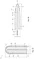
- FIG. 1is a perspective view of an endoscopic bipolar forceps in accordance with an embodiment of the disclosure
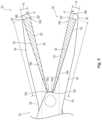
- FIG. 2is a perspective view of an open bipolar forceps in accordance with an embodiment of the disclosure
- FIG. 3 Ais a perspective view of jaw members in accordance with an embodiment of the disclosure.
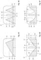
- FIG. 3 Bis a cross-sectional view of the jaw members of FIG. 3 A , taken along section line 3 B- 3 B of FIG. 3 A ;
- FIG. 4 Ais a cross-sectional view of jaw members in accordance with another embodiment of the disclosure.
- FIG. 4 Bis a cross-sectional view of jaw members in accordance with yet another embodiment of the disclosure.
- FIGS. 4 C- 4 Hare cross-sectional views of jaw members in accordance with embodiments of the disclosure.
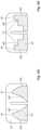
- FIG. 5is a side, cross-sectional view of jaw members in accordance with another embodiment of the disclosure.
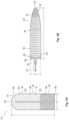
- FIG. 6 Ais a top view of a sealing plate of a jaw member in accordance with an embodiment of the disclosure.
- FIG. 6 Bis a top view of a sealing plate of a jaw member in accordance with another embodiment of the disclosure.
- FIG. 7 Ais a top view of a sealing plate of a jaw member in accordance with yet another embodiment of the disclosure.
- FIG. 7 Bis a top view of a sealing plate of a jaw member in accordance with another embodiment of the disclosure.
- FIGS. 8 A- 8 Care top views of sealing plates of jaw members in accordance with embodiments of the disclosure.
- proximalrefers to a portion (e.g., an end) of the apparatus which is closer to the user and the term “distal” refers to a portion of the apparatus which is farther away from the user.
- distalrefers to a portion of the apparatus which is farther away from the user.
- clinical professionale.g., doctor, surgeon, nurse, or the like
- an instrumentgenerally identified as endoscopic bipolar forceps 10 may be used during various surgical procedures and includes a housing 20 , a handle assembly 30 , a rotating assembly 40 , a trigger assembly 50 , and an end effector assembly 100 that mutually cooperate to grasp, seal, and divide tubular vessels and vascular tissues.
- the forceps 10includes a shaft 12 that has a distal end 14 dimensioned to mechanically engage the end effector assembly 100 and a proximal end 16 that mechanically engages the housing 20 .
- the proximal end 16 of the shaft 12mechanically engages the rotating assembly 40 to facilitate rotation of a jaw assembly 110 of the end effector assembly 100 .
- the handle assembly 30includes a fixed handle 32 and a movable handle 34 .
- the fixed handle 32is integrally associated with the housing 20 and the movable handle 34 is movable relative to the fixed handle 32 to actuate a pair of opposing jaw members 120 , 130 of the jaw assembly 110 .
- the movable handle 34imparts movement of the jaw members 120 , 130 about a pivot pin 15 from an open position wherein the jaw members 120 , 130 are disposed in spaced relation relative to one another for approximating tissue, to a clamping or closed position wherein the jaw members 120 , 130 cooperate to grasp tissue therebetween (e.g., for sealing and/or dividing purposes).
- the trigger assembly 50is selectively movable by a clinician to energize the jaw assembly 110 .
- the movable handle 34 and the trigger assembly 50are typically of unitary construction and are operatively connected to the housing 20 and the fixed handle 32 during the assembly process.
- the forceps 10also includes an electrical interface or plug 60 which connects the forceps 10 to a source of electrosurgical energy, e.g., an electrosurgical generator (not shown).
- An electrical cable 62extends from the plug 60 and is securely connected to the forceps 10 .
- the cable 62is internally divided within the housing 20 to transmit electrosurgical energy through various electrical feed paths to the jaw assembly 110 .
- the forceps 10may be designed such that it is fully or partially disposable depending upon a particular purpose or to achieve a particular result.
- the jaw assembly 110may be selectively and releasably engageable with the distal end 14 of the shaft 12 and/or the proximal end 16 of the shaft 12 may be selectively and releasably engageable with the housing 20 and the handle assembly 30 .
- the forceps 10would be considered “partially disposable” or “reposable”, e.g., a new or different jaw assembly 110 (or jaw assembly 110 and shaft 12 ) selectively replaces the old jaw assembly 110 , as needed.
- the forceps 11includes a pair of opposing shafts 22 a and 22 b having an end effector assembly 200 attached to distal ends 24 a and 24 b thereof, respectively.
- the end effector assembly 200is similar in design to the end effector assembly 100 and includes a jaw assembly 210 having a pair of opposing jaw members 220 , 230 that are pivotably connected about a pivot pin 15 a and that are movable relative to one another to grasp tissue.
- Each shaft 22 a , 22 bincludes a handle 30 a , 30 b , respectively, disposed at the proximal end 26 a , 26 b thereof.
- Each handle 30 a , 30 bdefines a finger hole 31 a , 31 b , respectively, therethrough for receiving a finger of a clinician.
- the finger holes 31 a , 31 bfacilitate movement of the shafts 22 a , 22 b relative to one another which, in turn, pivot the jaw members 220 , 230 from an open position wherein the jaw members 220 , 230 are disposed in spaced relation relative to one another, to a clamping or closed position wherein the jaw members 220 , 230 cooperate to grasp tissue therebetween.
- One of the shafts 22 a , 22 bincludes a proximal shaft connector or flange 23 which is designed to connect the forceps 11 to a source of electrosurgical energy, such as an electrosurgical generator (not shown).
- the flange 23mechanically secures an electrosurgical cable 62 a to the forceps 11 such that a clinician may selectively apply electrosurgical energy as needed.
- the cable 62 aincludes a plug 60 a , similar to plug 60 of FIG. 1 .
- a ratchet 70is included for selectively locking the jaw members 220 , 230 relative to one another at various positions during pivoting.
- FIGS. 3 A and 3 Bshow opposing jaw members 320 , 330 of a jaw assembly 310 .
- the jaw assembly 310is contemplated for use with the endoscopic forceps 10 of FIG. 1 or the open forceps 11 of FIG. 2 .
- an endoscopic instrument or an open instrumentmay be utilized with the end effector assembly described herein.
- Different electrical and/or mechanical connections and considerationsapply to each particular type of instrument, as should be understood by one skilled in the art, however, the novel aspects with respect to the end effector assembly and its operating characteristics remain generally consistent with respect to both the endoscopic and open designs.
- each of the jaw members 320 , 330generally includes: electrically conductive sealing plates or substrates 322 , 332 , respectively; insulators 324 , 334 , respectively; and insulative support bases or frames 326 , 336 , respectively.
- the support bases 326 , 336are dimensioned to support insulators 324 , 334 therein which, in turn, support the sealing plates 322 , 332 thereon.
- the sealing plates 322 , 332may be affixed atop the insulators 324 , 334 and the support bases 326 , 336 in any manner within the purview of those skilled in the art, such as snap-fit, over-molding, stamping, ultrasonic welding, etc. It should be understood that the insulators 324 , 334 are configured and dimensioned to have a geometry complementary to the sealing plates 322 , 332 to support the sealing plates 322 , 332 thereon, and to the support bases 326 , 336 in which the insulators 324 , 334 are disposed.
- the jaw members 320 , 330are generally symmetrical and include similar component features which cooperate to permit facile rotation about a pivot (see e.g., pivot pin 15 , 15 a of FIGS. 1 , 2 ) to effect the grasping of tissue.
- the jaw members 320 , 330may be straight or may be curved to facilitate manipulation of tissue and to provide better “line of sight” for accessing targeted tissues.
- Either or both of the sealing plates 322 , 332 and, in some cases, the insulators 324 , 334may include longitudinally-oriented knife slots (see e.g., knife slot 131 of FIG. 1 ) defined therethrough for reciprocation of a knife blade (not shown).
- sealing plates 322 , 332may have sealing surfaces 323 , 333 that are substantially planar, or the sealing surfaces 323 , 333 may have other configurations or features, such as stop members (not shown) to define a gap between the jaw members 320 , 330 during grasping, sealing, and/or cutting of tissue, and/or grooves, ridges, etc. (not shown) to enhance the gripping of tissue during the sealing process.
- each of the sealing plates 322 , 332has a longitudinally extending length “L” and a transversely extending width “W.”
- a vertical height or thickness of each of the sealing plates 322 , 332varies from a nominal or minimal height “H 1 ” to a maximum height “H 2 ” across the width “W” of the sealing plate 322 , 332 and is consistent or uniform along the length “L” thereof.
- the sealing plates 322 , 332include respective inwardly facing or sealing surfaces 323 , 333 and outwardly facing surfaces 325 , 335 that taper to apexes 340 , 350 disposed about central portions 322 a , 332 a of the sealing plates 322 , 332 such that the thickness of the sealing plates 322 , 332 is greatest about the central portions 322 a , 332 a of the sealing plates 322 , 332 .
- Each of the sealing plates 322 , 332includes a base 342 , 352 having the nominal height “H 1 ” throughout the entire length “L” and width “W” of the sealing plate 322 , 332 .
- the base 342 , 352extends from the sealing surface 323 , 333 outwardly towards the insulator 324 , 334 such that the height “H 1 ” of the base 342 , 352 of the sealing plate 322 , 332 is uniform along the length “L” and width “W” of the base 342 , 352 .
- An extension or projection 344 , 354extends from the base 342 , 352 and tapers towards the apex 340 , 350 such that the thickness of the extension 344 , 354 varies from the nominal height “H 1 ” to the maximum height “H 2 ” along the width “W” of the sealing plate 322 , 332 and is consistent along the length “L” of the sealing plate 322 , 332 .
- the maximum height “H 2 ” at the apex 340 , 350 of the sealing plate 322 , 332extends a majority of the height or thickness “T” of the jaw member 320 , 330 and in embodiments, the maximum height “H 2 ” of the sealing plate 322 , 332 is almost the full height “T” of the jaw member 320 , 330 (e.g., about 90% to about 98% of the height “T” of the jaw member 320 , 330 ).
- the extension 344 , 354includes legs 346 a , 356 a and 346 b , 356 b that taper linearly from outer edges 322 c , 332 c of the sealing plate 322 , 332 towards the central portion 322 a , 332 a of the sealing plate 322 , 332 .
- the legs 346 a , 356 a and 346 b , 356 bhave equal lengths such that the apex 340 , 350 is centered about the sealing plate 322 , 332 .
- the legs 346 a , 356 a and 346 b , 356 bmay be linear or non-linear (e.g., curved).
- Energy provided to the jaw assembly 310is concentrated in the central portions 322 a , 332 a of the jaw members 320 , 330 (e.g., the thickest part of the sealing plate 322 , 332 ) thereby reducing thermal spread outside of the jaw members 320 , 330 .
- FIG. 4 Ashows opposing jaw members 420 , 430 of a jaw assembly 410 .
- the jaw members 420 , 430include: electrically conductive sealing plates or substrates 422 , 432 ; insulators 424 , 434 ; and insulative support bases 426 , 436 .
- a vertical height or thickness of each of the sealing plates 422 , 432varies from a nominal or minimal height “H 1 ” to a maximum height “H 2 ” across the width “W” of the sealing plate 422 , 432 and is consistent or uniform along the length “L” ( FIG. 3 A ) thereof.
- the sealing plates 422 , 432include inwardly facing or sealing surfaces 423 , 433 and outwardly facing surfaces 425 , 435 that taper to apexes 440 , 450 disposed about side portions 422 b , 432 b of the sealing plates 422 , 432 such that the thickness of the sealing plate 422 , 432 is greatest about one of the side portions 422 b , 432 b of the sealing plates 422 , 432 .
- the outwardly facing surface 425 , 435includes legs 446 a , 456 a and 446 b , 456 b that extend respectively from outer edges 422 c , 432 c of the sealing plates 422 , 432 adjacent the sealing surface 423 , 433 and taper towards the apexes 440 , 450 such that the thickness of the sealing plate 422 , 432 varies from the minimal height “H 1 ” to the maximum height “H 2 ”.
- the maximum height “H 2 ” at the apex 440 , 450 of the sealing plate 422 , 432extends a majority of the height or thickness “T” of the jaw member 420 , 430 and in embodiments, the maximum height “H 2 ” of the sealing plate 422 , 432 is almost the full height “T” of the jaw member 420 , 430 .
- the legs 446 a , 456 a and 446 b , 456 bhave different lengths such that the apex 440 , 450 is off-center of the sealing plate 422 , 432 .
- the legs 446 a , 456 a and 446 b , 456 bmay be linear or non-linear (e.g., curved).
- Energy provided to the jaw assembly 410more easily flows to the side portion 422 b , 432 b of the jaw member 420 , 430 containing the apex 440 , 450 (e.g., the thickest part of the sealing plate 422 , 432 ) thus increasing thermal spread on the side portion 422 b , 432 b containing the apex 440 , 450 , with the other side portion 422 b , 432 b having minimal thermal spread.
- FIG. 4 Bshows opposing jaw members 420 ′, 430 ′ of a jaw assembly 410 ′.
- the jaw members 420 ′, 430 ′include: electrically conductive sealing plates or substrates 422 ′, 432 ′; insulators 424 ′, 434 ′; and insulative support bases 426 ′, 436 ′.
- Knife slots 421 ′, 431 ′extend through each of the jaw members 420 ′, 430 ′ about a central portion 422 a ′, 432 a ′ of the sealing plates 422 ′, 432 ′.
- a vertical height or thickness of each of the sealing plates 422 ′, 432 ′varies between a nominal or minimal height “H 1 ” and a maximum height “H 2 ” across the width “W” of the sealing plate 422 ′, 432 ′ and is consistent or uniform along the length “L” ( FIG. 3 A ) thereof.
- the sealing plates 422 ′, 432 ′include inwardly facing or sealing surfaces 423 ′, 433 ′ and outwardly facing surfaces 425 ′, 435 ′ that taper to apexes 440 ′, 450 ′ disposed about each of the side portions 422 b ′, 432 b ′ of the sealing plates 422 ′, 432 ′ such that the thickness of the sealing plate 422 ′, 432 ′ is greatest about both of the side portions 422 b ′, 432 b ′ of the sealing plates 422 ′, 432 ′.
- the outwardly facing surface 425 ′, 435 ′includes two sets 445 ′, 455 ′ of legs 446 a ′, 456 a ′ and 446 b ′, 456 b ′.
- the first leg 446 a ′, 456 a ′ of each set 445 ′, 455 ′extends respectively from an outer edge 422 c ′, 432 c ′ of the sealing plate 422 ′, 432 ′ adjacent the sealing surface 423 ′, 433 ′ to the respective apex 440 ′, 450 ′.
- the second leg 446 b ′, 456 b ′ of each set 445 ′, 455 ′extends respectively from the knife slot 421 ′, 431 ′, or in embodiments devoid of a knife slot 421 ′, 431 ′, from about the central portion 422 a ′, 432 a ′ of the sealing plate 422 ′, 432 ′ to the respective apex 440 ′, 450 ′.
- the first and second legs 446 a ′, 456 a ′ and 446 b ′, 456 b ′ of each set 445 ′, 455 ′tapers towards the respective apex 440 ′, 450 ′ such that the thickness of the sealing plate 422 ′, 432 ′ varies from the minimal height “H 1 ” to the maximum height “H 2 ”.
- the maximum height “H 2 ” at the apexes 440 ′, 450 ′ of the sealing plates 422 ′, 432 ′extends a majority of the height or thickness “T” of the jaw member 420 ′, 430 ′ and in embodiments, the maximum height “H 2 ” of the sealing plate 422 ′, 432 ′ is almost the full height “T” of the jaw member 420 ′, 430 ′.
- the first and second legs 446 a ′, 456 a ′ and 446 b ′, 456 b ′ of each set 445 ′, 455 ′have different lengths such that the apexes 440 ′, 450 ′ are off-center and disposed closer to the outer edges 422 c ′ 432 c ′ of the sealing plates 422 ′, 432 ′ than the central portions 422 a ′ 432 a ′ of the sealing plates 422 ′, 432 ′.
- first and second legs 446 a ′, 456 a ′ and 446 b ′, 456 b ′ of each set 445 ′, 455 ′may have the same length such that the apexes 440 ′, 450 ′ are centered in each of the side portions 422 b ′, 432 b ′ of the sealing plates 422 ′, 432 ′.
- the first and second legs 446 a ′, 456 a ′ and 446 b ′, 456 b ′may be linear or non-linear (e.g., curved).
- Energy provided to the jaw assembly 410 ′is transferred into the thickest part (e.g., the portions of the jaw members 420 ′, 430 ′ containing the apexes 440 ′, 450 ′) of the sealing plates 422 ′, 432 ′ (e.g., thermal energy is dissipated into the sealing plate 422 ′, 432 ′ cross-section and electrical energy rides the outer sealing plate surfaces) thereby minimizing thermal spread at the outer edges 422 c ′, 432 c ′ of the sealing plates 422 ′, 432 ′ and improving seal quality.
- the thickest parte.g., the portions of the jaw members 420 ′, 430 ′ containing the apexes 440 ′, 450 ′
- thermal energyis dissipated into the sealing plate 422 ′, 432 ′ cross-section and electrical energy rides the outer sealing plate surfaces
- the sealing plates 422 , 422 ′may have a width “W 1 ” extending through a portion (e.g., a majority) of the width “W” of the jaw members 420 , 420 ′.
- the outer edges 422 c , 422 c ′ of the sealing plates 422 , 422 ′may be spaced inwardly of the outer edges of the jaw members 420 , 420 ′ such that the insulators 424 , 424 ′ are disposed outwardly of the sealing plates 422 , 422 ′ around the outer periphery of the tissue contacting surface 412 , 412 ′ of the jaw member 420 , 420 ′ at a width “W 2 .” As seen in FIG.
- the sealing plate 422 ′may include inner edges 422 h ′ spaced outwardly of the knife slot 421 ′ such that the insulator 424 ′ is disposed between to the knife slot 421 ′ and the sealing plate 422 ′ at a width “W 3 .”
- the width “W 2 ,” “W 3 ”may be the same or different.
- FIGS. 4 E- 4 Hshow that the tissue contacting surface of the jaw members may be nonplanar.
- the sealing platemay extend outwardly beyond the insulator and the insulative support base of the jaw member.
- the sealing plate 422 ′′may extend downwardly towards the opposing jaw member (not explicitly shown) in stepped relation relative to the insulator 424 ′′ such that a height “H 3 ” of the jaw member 420 ′′ including the sealing plate 422 ′′ is more than a height “H 4 ” of the jaw member 420 ′′ that does not include the sealing plate 422 ′′.
- one or more legs of the sealing platesmay be contoured to achieve the desired geometry and thus, thermal effect.
- the first leg 446 a ′′ of each of the two sets 445 ′′ of legs 446 a ′′, 446 b ′′may extend linearly upwardly into the insulator 424 ′′ and the second leg 446 b ′′ may include a first segment 447 a ′′ extending linearly upwardly into the jaw member 420 ′′ adjacent to the knife slot 421 ′′ and a second segment 447 b ′′ angled towards the apex 440 ′′ of the sealing plate 422 ′′.
- FIG. 4 Ethe first leg 446 a ′′ of each of the two sets 445 ′′ of legs 446 a ′′, 446 b ′′ may extend linearly upwardly into the insulator 424 ′′ and the second leg 446 b ′′ may include a first segment 447 a ′′ extending linearly upwardly into the jaw member 420 ′′ adjacent to the knife slot 421 ′′ and
- the first leg 446 a ′′ of the sealing plate 422 ′′may extend linearly upwardly to a rounded apex 440 ′′ and the second leg 446 b ′′ may include a linear first segment 447 a ′′ and a contour second segment 447 b ′′.
- the contoured second segment 447 b ′′may be concave, convex, or have other non-linear configurations.
- the first leg 446 a ′′ of the sealing plate 422 ′′may be convex and the second leg 446 b ′′ may be concave from the apex 440 ′′ towards the sealing surface 423 ′′.
- FIG. 4 Gthe first leg 446 a ′′ of the sealing plate 422 ′′ may be convex and the second leg 446 b ′′ may be concave from the apex 440 ′′ towards the sealing surface 423 ′′.
- the first leg 446 a ′′ of the sealing plate 422 ′′may extend linearly upwardly and the second leg 446 b ′′ may include a plurality of stepped segments 447 ′′ leading from the sealing surface 423 ′′ to a substantially flat apex 440 ′′.
- Other geometriesare envisioned.
- FIG. 5illustrates opposing jaws members 520 , 530 of a jaw assembly 510 .
- the jaw members 520 , 530include: electrically conductive sealing plates or substrates 522 , 532 ; insulators 524 , 534 ; and insulative support bases 526 , 536 .
- a vertical height or thickness of each of the sealing plates 522 , 532varies from a minimal height “H 1 ” to a maximum height “H 2 ” across the length “L” of the sealing plate 522 , 532 and is consistent or uniform along the width “W” ( FIG. 3 B ) thereof.
- the sealing plates 522 , 532include inwardly facing or sealing surfaces 523 , 533 and outwardly facing surfaces 525 , 535 that taper to apexes 540 , 550 disposed about distal or tip portions 522 d , 532 d of the sealing plates 522 , 532 such that the thickness of the sealing plate 522 , 532 is greatest about the tip portions 522 d , 532 d of the sealing plates 522 , 532 .
- the outwardly facing surface 525 , 535includes legs 546 a , 556 a and 546 b , 556 b that extend respectively from proximal and distal ends 522 e , 532 e and 522 f , 532 f of the sealing plate 522 , 532 and taper towards the apexes 540 , 550 such that the thickness of the sealing plate 522 , 532 varies from a minimal height “H 1 ” at a proximal or heel portion 522 g , 532 g of the sealing plate 522 , 532 to a maximum height “H 2 ” at the tip portion 522 d , 532 d of the sealing plates 522 , 532 .
- the legs 546 a , 556 a and 546 b , 556 bhave different lengths such that the apex 540 , 550 is disposed in the tip portion 522 d , 532 d of the sealing plate 522 , 532 .
- the thickness of the sealing plate 522 , 532increases along a majority of the length “L” of the jaw member 520 , 530 such that energy is biased towards the tip portion 522 d . 532 d which improves tip sealing and overcomes non-parallel closure configurations.
- the geometry of the sealing plate and/or the geometry, type, and/or location of the insulator relative to the sealing platemay be tailored to reduce thermal spread.
- the geometry of the sealing platee.g., the position of the apex or apexes
- the geometry of the sealing platemay be optimized to control thermal mass location and thermal conductivity to minimize thermal spread by transferring heat into the sealing plate or away from the outer edges of the sealing plate.
- the type of insulator utilized in the jaw member, the insulator location relative to the sealing surface of the sealing plate, and/or the sealing plate and insulator geometry near the outer edges of the sealing platemay be tailored to control the current densities at the outer edges of the sealing plate, e.g., minimizing thermal spread at the outer edges of the sealing plate and thus, minimizing edge cutting.
- FIG. 6 Aa top view of a sealing plate 622 of a jaw member 620 is shown.
- the sealing plate 622includes a longitudinally extending length “L” and a transversely extending width “W”.
- the sealing plate 622may have a generally flat or planar configuration, or may have a non-planar geometry such as those described above.
- the sealing plate 622includes a plurality of impedance zones 660 defined along the length “L” thereof.
- the impedance zones 660are disposed adjacent each other along the entire length “L” of the sealing plate 622 from a proximal end 622 e to a distal end 622 f of the sealing plate 622 , with each of the impedance zones 660 extending the entire width “W” of the sealing plate 622 .
- the impedance zones 660are formed by coating the sealing plate 622 with the same or different conductive, semiconductive, and/or insulative materials (e.g., conductors, such as stainless steel, semiconductors, such as silicon dioxide, or insulators) of the same or different thicknesses to achieve the desired thermal effect in each of the impedance zones 660 .
- the impedance zones 660may be formed in any manner within the purview of those skilled in the art, such as sputter coating.
- the impedance zones 660include a first or proximal zone 660 a , a second or intermediate zone 660 b , and a third or distal zone 660 c .
- the first zone 660 ais a high impedance zone.
- the electrical impedance of the first zone 660 ais about or greater than 200 ohms (e.g., about 300 ohms) thereby having nearly zero tissue effect.
- the second zone 660 bis a medium impedance zone having an electrical impedance less than that of the first zone 660 a .
- the electrical impedance of the second zone 660 bis about 100 ohms to achieve some tissue sealing effect.
- the third zone 660 cis a low impedance zone having an electrical impedance less than the second zone 660 b .
- the electrical impedance of the third zone 660 cis about 0 ohms to about 20 ohms, and in some embodiment, about 10 ohms, to achieve a tissue sealing effect.
- Energy provided to the jaw member 620is biased towards the tip portion 622 d of the sealing plate 622 to improve tip sealing.
- Each impedance zone 660is homogenous in that the impedance value is consistent throughout the impedance zone 660 .
- the impedance zones 660are delineated by an interphase 662 between each adjacent impedance zone 660 .
- the interphase 662is a gradual transition or gradient transition from one impedance zone 660 to another.
- the first zone 660 amay have an impedance value of 200 ohms
- the second zone 660 bmay have an impedance value of about 100 ohms.
- the interphase 662 separating the first and second zones 660 a , 660 bmay include an impedance value that gradually transitions from the first zone 660 a to the second zone 660 b .
- the portion of the interphase 662 closer to the first zone 660 ahas a higher impedance value (closer to 200 ohms) while the portion of the interphase 662 closer to the second zone 660 b has a lower impedance value (closer to 100 ohms).
- the impedance zones 660may be separated by an interface.
- the interfaceis sharp transition at a common boundary between adjacent impedance zones 660 .
- other embodiments in accordance with the disclosuremay include one or more interphases, one or more interfaces, or combinations of interphases and interfaces between impedance zones.
- the impedance zones 660are shown as being substantially equal in area across the sealing surface 623 of the sealing plate 622 .
- the impedance zones 660may cover different amounts of area of the sealing surface 623 depending upon the desired thermal effect, as is within the purview of those skilled in the art. Further, while three impedance zones 660 are shown, it should be understood that the number of impedance zones 660 of the sealing plate 622 may vary (e.g., the sealing plate may include two impedance zones or may include a multitude of impedance zones forming a smooth or continuous gradient transition across the entire sealing plate).
- a sealing plate 622 ′ of a jaw member 620 ′includes a plurality of impedance zones 660 ′ extending along a length “L” of the sealing plate 622 ′ from a proximal end 622 e ′ to a distal end 622 f ′ thereof.
- the impedance zones 660 ′are disposed adjacent to each other and extend the entire width “W” of the sealing plate 622 ′.
- the impedance zones 660 ′form a gradient transition across the length “L” of the sealing plate 622 ′ that spans from an area of low resistance at the proximal end 622 e ′ of the sealing plate 622 ′ to an area of high resistance at the distal end 622 f ′ of the sealing plate 622 ′.
- the sealing plate 622 ′includes a first material 661 a ′, such as a conductive material (e.g., a metal) with low resistance characteristics, such as copper or aluminum, and a second material 661 b ′, such as a conductive material (e.g., a metal) with high resistance characteristics, such as stainless steel.
- the first material 661 a ′is positioned at a proximal portion 622 g ′ of the sealing plate 622 ′ over an insulator (not shown) and forms a wire connection “C” with an electrical jaw lead 602 ′ that supplies energy to the jaw member 620 ′.
- the second material 661 b ′is positioned over a portion of the first material 661 a ′ and extends distally therefrom across the sealing surface 623 ′ to the distal end 662 f ′ of the sealing plate 622 ′.
- the thickness of the second material 661 b ′varies to create the impedance zones 660 ′.
- the sealing surface 623 ′ of the sealing plate 622 ′is substantially planar, with the thickness of the second material 661 b ′ varying inwardly towards an insulator over which the sealing plate 662 ′ is positioned (see e.g., FIG. 3 B ).
- FIG. 7 Ashows a sealing surface 723 of a sealing plate 722 of a jaw member 720 .
- the sealing plate 722includes a plurality of impedance zones 760 extending radially outwardly from a knife slot 721 defined therein, or in embodiments devoid of a knife slot 721 , from about a central portion 722 a of the sealing plate 722 .
- the impedance zones 760are concentric with each other and extend the length “L” of the entire circumference of the sealing plate 722 , although it is contemplated that at least one of the impedance zones 760 may extend along a portion or arc of the circumference.
- the impedance zones 760are formed by coating the sealing plate 722 with the same or different conductive, semiconductive, and/or insulative materials (e.g., conductors, such as stainless steel, semiconductors, such as silicon dioxide, or insulators) of the same or different thicknesses to achieve the desired thermal effect in each of the impedance zones 760 .
- conductive, semiconductive, and/or insulative materialse.g., conductors, such as stainless steel, semiconductors, such as silicon dioxide, or insulators
- the impedance zones 760include a first or inner zone 760 a and a second or outer zone 760 b .
- the first and second zones 760 a , 760 bare generally ring-shaped in cross-sectional area and extend the length “L” of the sealing plate 722 .
- the first zone 760 ais at least partially or substantially inside the second zone 760 b
- the knife slot 721is inside the first zone 760 a.
- the first zone 760 ais a low impedance zone
- the second zone 760 bis a high impedance zone.
- the first zone 760 ahas an electrical impedance of about 0 ohms to about 10 ohms
- the second zone 760 bhas an electrical impedance of about 250 ohms.
- the first zone 760 ais immediately adjacent to and extends radially outwardly from the knife slot 721
- the second zone 760 bis adjacent to and extends radially outwardly from the first zone 760 a to outer edges 722 c of the sealing plate 722 .
- the first and second zones 760 a , 760 bare homogenous, as described above with regard to sealing plate 622 , and include an interphase 762 disposed between the first and second zones 760 a , 760 b .
- Energy provided to the jaw member 720is concentrated in the middle of the sealing plate 722 (about the first zone 760 a ), and the high impedance value of the second zone 760 b reduces or eliminates thermal spread to surrounding tissue.
- a sealing plate 722 ′ of a jaw member 720 ′includes a plurality of impedance zones 760 ′ defined concentrically therein.
- the impedance zones 760 ′extend the length “L” and the width “W” of the sealing plate 722 ′.
- the impedance zones 760 ′form a gradient transition outwardly from a central portion 722 a ′ of the sealing plate 722 ′ to the outer edges 722 c ′ that spans from an area of low resistance about the central portion 722 a ′ to an area of high resistance at the outer edges 722 c′.
- the sealing plate 722 ′includes a first material 761 a ′, such as a conductive material (e.g., a metal) with low resistance characteristics, such as copper or aluminum, and a second material 761 b ′, such as a conductive material (e.g., a metal) with high resistance characteristics, such as stainless steel.
- the first material 661 a ′forms a wire connection “C” with an electrical jaw lead 702 ′ that supplies energy to the jaw member 720 ′ at a proximal end 722 e ′ of the sealing plate 722 ′ and extends distally through the central portion 722 a ′ of the sealing plate 722 ′ adjacent to the distal end 722 f ′ of the sealing plate 722 ′.
- the second material 761 b ′is disposed over the first material 761 a ′ and extends along and across the sealing surface 723 ′.
- the thickness of the second material 761 b ′varies to create the impedance zones 760 ′ of the jaw member 720 ′.
- sealing platesmay include a plurality of impedance regions each having one or more impedance zones.
- a sealing plate 822 of a jaw member 820includes a plurality of impedance regions 870 extending along a length “L” of the sealing plate 822 from a proximal end 822 e to a distal end 822 f thereof.
- the impedance regions 870are disposed adjacent to each other and extend the entire width “W” of the sealing plate 822 .
- the impedance regions 870includes a first impedance region 870 a and a second impedance region 870 b.
- the first impedance region 870 aextends from the proximal end 822 e of the sealing plate 822 towards the distal end 822 f adjacent to and proximal of the tip portion 822 d .
- the first impedance region 870 aincludes a plurality of impedance zones 860 that forms a continuous gradient transition across the first impedance region 870 a from a proximal impedance zone 860 a that is a low impedance zone to a distal impedance zone 860 b that is a high impedance zone.
- the second impedance region 870 bis disposed at the tip portion 822 d and has a single impedance zone 860 c that may have an impedance value that is higher or lower than the distal impedance zone 860 b of the first impedance region 870 a depending upon the desired thermal effect. It should be understood that the plurality of impedance zones 860 in the first impedance region 870 a may span, proximally to distally, from an area of high impedance to an area of low impedance and/or the second impedance region 870 b may include more than one impedance zone 860 .
- a sealing plate 822 ′includes a plurality of impedance regions 870 ′ extending along a length “L” ( FIG. 8 A ) of the sealing plate 822 ′ from a proximal end 822 e ′ to a distal end 822 f ′ thereof.
- the impedance regions 870 ′are disposed adjacent to each other and extend the entire width “W” ( FIG. 8 A ) of the sealing plate 822 ′.
- the impedance regions 870 ′includes a first impedance region 870 a ′, a second impedance region 870 b ′, and a third impedance region 870 c′.
- the first impedance region 870 a ′extends from the proximal end 822 e ′ of the sealing plate 822 ′ to about a central portion 822 a ′ of the sealing plate 822 ′.
- the first impedance region 870 a ′includes a plurality of impedance zones 860 ′ that forms a continuous gradient transition across the first impedance region 870 a ′ from a proximal impedance zone 860 a ′ that is a low impedance zone to a distal impedance zone 860 b ′ that is a high impedance zone.
- the second impedance region 870 b ′is disposed about the central portion 822 a ′ of the sealing plate 822 ′ and has a single impedance zone 860 c ′ that may have an impedance value that is higher or lower than the distal impedance zone 860 b ′ of the first impedance region 870 a ′.
- the third impedance region 870 c ′extends from the central portion 822 a ′ of the sealing plate 822 ′ to the distal end 822 f .
- the third impedance region 870 c ′includes a plurality of impedance zones 860 ′ that forms a continuous gradient transition across the third impedance region 870 c ′ from a proximal impedance zone 860 d ′ that is a low impedance zone to a distal impedance zone 860 e ′ that is a high impedance zone. It should be understood that the combinations and/or number of impedance zones 860 ′ within each impedance region 870 ′ may vary (e.g., increase or decrease proximally to distally).
- a sealing plate 822 ′′includes a plurality of impedance regions 870 ′′ defined concentrically therein.
- the impedance regions 870 ′′includes a first impedance region 870 a ′′ and a second impedance region 870 b ′′.
- the first impedance region 870 a ′′extend laterally outwardly from the knife slot 821 ′′, or in embodiments devoid of a knife slot 820 ′′, about the center portion 822 a ′′ of the sealing plate 822 ′′.
- the second impedance region 870 b ′′extends around the first impedance region 870 a along the length “L” and the width “W” ( FIG. 8 A ) of the sealing plate 822 ′′.
- the first impedance region 870 a ′′includes a plurality of impedance zones 860 ′′ forming a gradient transition that increases from an area of low impedance adjacent to the knife slot 821 ′′ outwardly towards an area of high impedance in the direction of arrow “A.”
- the second impedance region 870 b ′′includes a plurality of impedance regions 860 ′′ that increase from an area of low impedance at the proximal end 822 e ′′ of the sealing plate 822 ′′ to an area of high impedance at the distal end 822 f ′ of the sealing plate 822 ′′ in the direction of arrow “B.” While the first impedance region 870 a ′′ is shown longitudinally offset relative to each other on opposed sides of the knife slot 821 ′′, it should be understood that the first impedance region 870 a ′′ may be symmetrical.
- the impedance zones 860 ′′ within each of the impedance regions 870 ′′may be separated by an interface or interphase and/or may increase or decrease proximally to distally and/or laterally.
- the values, range of values of the impedance zones, and/or the configuration of the impedance zones on the sealing surface of the sealing platedepend on the specific energy application and desired tissue effect.
- the impedance zonesmay be in pre-defined areas on the jaw member, such as along the tip portion or on one side of the sealing plate.
- the impedance zonesmay follow the jaw curvature or have a more complex contour.
- the impedance zonesmay be placed across from gap setting features.
Landscapes
- Health & Medical Sciences (AREA)
- Surgery (AREA)
- Engineering & Computer Science (AREA)
- Life Sciences & Earth Sciences (AREA)
- Biomedical Technology (AREA)
- Otolaryngology (AREA)
- Nuclear Medicine, Radiotherapy & Molecular Imaging (AREA)
- Plasma & Fusion (AREA)
- Physics & Mathematics (AREA)
- Heart & Thoracic Surgery (AREA)
- Medical Informatics (AREA)
- Molecular Biology (AREA)
- Animal Behavior & Ethology (AREA)
- General Health & Medical Sciences (AREA)
- Public Health (AREA)
- Veterinary Medicine (AREA)
- Surgical Instruments (AREA)
Abstract
Description
Claims (14)
Priority Applications (3)
| Application Number | Priority Date | Filing Date | Title |
|---|---|---|---|
| US16/917,566US12053229B2 (en) | 2020-06-30 | 2020-06-30 | Vessel sealing instrument with seal plates for directing the flow of energy |
| EP25173123.8AEP4570209A2 (en) | 2020-06-30 | 2021-06-30 | Vessel sealing instrument with seal plates for directing the flow of energy |
| EP21182941.1AEP3932355B1 (en) | 2020-06-30 | 2021-06-30 | Vessel sealing instrument with seal plates for directing the flow of energy |
Applications Claiming Priority (1)
| Application Number | Priority Date | Filing Date | Title |
|---|---|---|---|
| US16/917,566US12053229B2 (en) | 2020-06-30 | 2020-06-30 | Vessel sealing instrument with seal plates for directing the flow of energy |
Publications (2)
| Publication Number | Publication Date |
|---|---|
| US20210401484A1 US20210401484A1 (en) | 2021-12-30 |
| US12053229B2true US12053229B2 (en) | 2024-08-06 |
Family
ID=76730464
Family Applications (1)
| Application Number | Title | Priority Date | Filing Date |
|---|---|---|---|
| US16/917,566Active2041-08-01US12053229B2 (en) | 2020-06-30 | 2020-06-30 | Vessel sealing instrument with seal plates for directing the flow of energy |
Country Status (2)
| Country | Link |
|---|---|
| US (1) | US12053229B2 (en) |
| EP (2) | EP4570209A2 (en) |
Citations (119)
| Publication number | Priority date | Publication date | Assignee | Title |
|---|---|---|---|---|
| US1586645A (en)* | 1925-07-06 | 1926-06-01 | Bierman William | Method of and means for treating animal tissue to coagulate the same |
| USD249549S (en) | 1976-10-22 | 1978-09-19 | Aspen Laboratories, Inc. | Electrosurgical handle |
| USD263020S (en) | 1980-01-22 | 1982-02-16 | Rau Iii David M | Retractable knife |
| USD295893S (en) | 1985-09-25 | 1988-05-24 | Acme United Corporation | Disposable surgical clamp |
| USD295894S (en) | 1985-09-26 | 1988-05-24 | Acme United Corporation | Disposable surgical scissors |
| USD298353S (en) | 1986-05-06 | 1988-11-01 | Vitalmetrics, Inc. | Handle for surgical instrument |
| USD299413S (en) | 1985-07-17 | 1989-01-17 | The Stanley Works | Folding pocket saw handle |
| US5151102A (en) | 1989-05-31 | 1992-09-29 | Kyocera Corporation | Blood vessel coagulation/stanching device |
| USD343453S (en) | 1993-05-05 | 1994-01-18 | Laparomed Corporation | Handle for laparoscopic surgical instrument |
| US5324289A (en)* | 1991-06-07 | 1994-06-28 | Hemostatic Surgery Corporation | Hemostatic bi-polar electrosurgical cutting apparatus and methods of use |
| USD348930S (en) | 1991-10-11 | 1994-07-19 | Ethicon, Inc. | Endoscopic stapler |
| USD349341S (en) | 1992-10-28 | 1994-08-02 | Microsurge, Inc. | Endoscopic grasper |
| USD354564S (en) | 1993-06-25 | 1995-01-17 | Richard-Allan Medical Industries, Inc. | Surgical clip applier |
| US5403312A (en) | 1993-07-22 | 1995-04-04 | Ethicon, Inc. | Electrosurgical hemostatic device |
| USD358887S (en) | 1993-12-02 | 1995-05-30 | Cobot Medical Corporation | Combined cutting and coagulating forceps |
| US5626578A (en) | 1995-05-08 | 1997-05-06 | Tihon; Claude | RF valvulotome |
| US5658281A (en) | 1995-12-04 | 1997-08-19 | Valleylab Inc | Bipolar electrosurgical scissors and method of manufacture |
| USD384413S (en) | 1994-10-07 | 1997-09-30 | United States Surgical Corporation | Endoscopic suturing instrument |
| US5688270A (en) | 1993-07-22 | 1997-11-18 | Ethicon Endo-Surgery,Inc. | Electrosurgical hemostatic device with recessed and/or offset electrodes |
| US5766166A (en) | 1995-03-07 | 1998-06-16 | Enable Medical Corporation | Bipolar Electrosurgical scissors |
| USH1745H (en) | 1995-09-29 | 1998-08-04 | Paraschac; Joseph F. | Electrosurgical clamping device with insulation limited bipolar electrode |
| US5810811A (en) | 1993-07-22 | 1998-09-22 | Ethicon Endo-Surgery, Inc. | Electrosurgical hemostatic device |
| USD402028S (en) | 1997-10-10 | 1998-12-01 | Invasatec, Inc. | Hand controller for medical system |
| US5876401A (en) | 1993-07-22 | 1999-03-02 | Ethicon Endo Surgery, Inc. | Electrosurgical hemostatic device with adaptive electrodes |
| USD408018S (en) | 1996-03-12 | 1999-04-13 | Mcnaughton Patrick J | Switch guard |
| USD416089S (en) | 1996-04-08 | 1999-11-02 | Richard-Allan Medical Industries, Inc. | Endoscopic linear stapling and dividing surgical instrument |
| USD424694S (en) | 1998-10-23 | 2000-05-09 | Sherwood Services Ag | Forceps |
| USD425201S (en) | 1998-10-23 | 2000-05-16 | Sherwood Services Ag | Disposable electrode assembly |
| US6066137A (en) | 1997-10-03 | 2000-05-23 | Megadyne Medical Products, Inc. | Electric field concentrated electrosurgical electrode |
| US6086586A (en) | 1998-09-14 | 2000-07-11 | Enable Medical Corporation | Bipolar tissue grasping apparatus and tissue welding method |
| USH1904H (en) | 1997-05-14 | 2000-10-03 | Ethicon Endo-Surgery, Inc. | Electrosurgical hemostatic method and device |
| US6162220A (en) | 1998-05-01 | 2000-12-19 | Perfect Surgical Techniques, Inc. | Bipolar surgical instruments having focused electrical fields |
| USD449886S1 (en) | 1998-10-23 | 2001-10-30 | Sherwood Services Ag | Forceps with disposable electrode |
| US6334860B1 (en) | 1998-12-18 | 2002-01-01 | Karl Storz Gmbh & Co. Kg | Bipolar medical instrument |
| USD453923S1 (en) | 2000-11-16 | 2002-02-26 | Carling Technologies, Inc. | Electrical rocker switch guard |
| USD454951S1 (en) | 2001-02-27 | 2002-03-26 | Visionary Biomedical, Inc. | Steerable catheter |
| USD457959S1 (en) | 2001-04-06 | 2002-05-28 | Sherwood Services Ag | Vessel sealer |
| USD457958S1 (en) | 2001-04-06 | 2002-05-28 | Sherwood Services Ag | Vessel sealer and divider |
| USH2037H1 (en) | 1997-05-14 | 2002-07-02 | David C. Yates | Electrosurgical hemostatic device including an anvil |
| US20020099368A1 (en) | 2001-01-24 | 2002-07-25 | Schulze Dale R. | Surgical instrument with a bi-directional cutting element |
| US20020107517A1 (en) | 2001-01-26 | 2002-08-08 | Witt David A. | Electrosurgical instrument for coagulation and cutting |
| US20020111624A1 (en) | 2001-01-26 | 2002-08-15 | Witt David A. | Coagulating electrosurgical instrument with tissue dam |
| US6458128B1 (en) | 2001-01-24 | 2002-10-01 | Ethicon, Inc. | Electrosurgical instrument with a longitudinal element for conducting RF energy and moving a cutting element |
| USD465281S1 (en) | 1999-09-21 | 2002-11-05 | Karl Storz Gmbh & Co. Kg | Endoscopic medical instrument |
| USD466209S1 (en) | 2001-02-27 | 2002-11-26 | Visionary Biomedical, Inc. | Steerable catheter |
| US6656177B2 (en) | 2000-10-23 | 2003-12-02 | Csaba Truckai | Electrosurgical systems and techniques for sealing tissue |
| US20040082952A1 (en) | 2001-04-06 | 2004-04-29 | Dycus Sean T. | Vessel sealer and divider |
| US6770072B1 (en) | 2001-10-22 | 2004-08-03 | Surgrx, Inc. | Electrosurgical jaw structure for controlled energy delivery |
| USD493888S1 (en) | 2003-02-04 | 2004-08-03 | Sherwood Services Ag | Electrosurgical pencil with pistol grip |
| US6773409B2 (en) | 2001-09-19 | 2004-08-10 | Surgrx Llc | Surgical system for applying ultrasonic energy to tissue |
| USD496997S1 (en) | 2003-05-15 | 2004-10-05 | Sherwood Services Ag | Vessel sealer and divider |
| USD499181S1 (en) | 2003-05-15 | 2004-11-30 | Sherwood Services Ag | Handle for a vessel sealer and divider |
| USD502994S1 (en) | 2003-05-21 | 2005-03-15 | Blake, Iii Joseph W | Repeating multi-clip applier |
| US6926716B2 (en) | 2001-11-09 | 2005-08-09 | Surgrx Inc. | Electrosurgical instrument |
| USD509297S1 (en) | 2003-10-17 | 2005-09-06 | Tyco Healthcare Group, Lp | Surgical instrument |
| US6953461B2 (en) | 2002-05-16 | 2005-10-11 | Tissuelink Medical, Inc. | Fluid-assisted medical devices, systems and methods |
| US7025763B2 (en) | 2002-03-26 | 2006-04-11 | Olympus Corporation | Medical apparatus |
| USD525361S1 (en) | 2004-10-06 | 2006-07-18 | Sherwood Services Ag | Hemostat style elongated dissecting and dividing instrument |
| USD531311S1 (en) | 2004-10-06 | 2006-10-31 | Sherwood Services Ag | Pistol grip style elongated dissecting and dividing instrument |
| US7135020B2 (en) | 1997-11-12 | 2006-11-14 | Sherwood Services Ag | Electrosurgical instrument reducing flashover |
| US20060264930A1 (en)* | 2005-05-20 | 2006-11-23 | River Seiko Medical Limited Company | High frequency incision tool for endoscope |
| US20060271038A1 (en) | 2002-10-04 | 2006-11-30 | Sherwood Services Ag | Vessel sealing instrument with electrical cutting mechanism |
| USD533274S1 (en) | 2004-10-12 | 2006-12-05 | Allegiance Corporation | Handle for surgical suction-irrigation device |
| US7147637B2 (en) | 2003-12-09 | 2006-12-12 | Gyrus Group Plc | Surgical instrument |
| USD533942S1 (en) | 2004-06-30 | 2006-12-19 | Sherwood Services Ag | Open vessel sealer with mechanical cutter |
| USD535027S1 (en) | 2004-10-06 | 2007-01-09 | Sherwood Services Ag | Low profile vessel sealing and cutting mechanism |
| USD538932S1 (en) | 2005-06-30 | 2007-03-20 | Medical Action Industries Inc. | Surgical needle holder |
| USD541418S1 (en) | 2004-10-06 | 2007-04-24 | Sherwood Services Ag | Lung sealing device |
| USD541938S1 (en) | 2004-04-09 | 2007-05-01 | Sherwood Services Ag | Open vessel sealer with mechanical cutter |
| USD541611S1 (en) | 2006-01-26 | 2007-05-01 | Robert Bosch Gmbh | Cordless screwdriver |
| USD545432S1 (en) | 2003-08-08 | 2007-06-26 | Olympus Corporation | Distal portion of hemostatic forceps for endoscope |
| USD547154S1 (en) | 2006-09-08 | 2007-07-24 | Winsource Industries Limited | Rotary driving tool |
| US7278992B2 (en) | 2005-02-01 | 2007-10-09 | Ethicon Endo-Surgery, Inc. | Medical instrument having medical-treatment electrode |
| US7329257B2 (en) | 1999-01-25 | 2008-02-12 | Olympus Optical Co., Ltd. | Medical treatment instrument |
| USD564662S1 (en) | 2004-10-13 | 2008-03-18 | Sherwood Services Ag | Hourglass-shaped knife for electrosurgical forceps |
| USD567943S1 (en) | 2004-10-08 | 2008-04-29 | Sherwood Services Ag | Over-ratchet safety for a vessel sealing instrument |
| USD575401S1 (en) | 2007-06-12 | 2008-08-19 | Tyco Healthcare Group Lp | Vessel sealer |
| USD575395S1 (en) | 2007-02-15 | 2008-08-19 | Tyco Healthcare Group Lp | Hemostat style elongated dissecting and dividing instrument |
| US7419490B2 (en) | 2006-07-27 | 2008-09-02 | Applied Medical Resources Corporation | Bipolar electrosurgical scissors |
| USD582038S1 (en) | 2004-10-13 | 2008-12-02 | Medtronic, Inc. | Transurethral needle ablation device |
| US20090182322A1 (en) | 2008-01-11 | 2009-07-16 | Live Tissue Connect, Inc. | Bipolar modular forceps modular arms |
| US20090216229A1 (en) | 2008-02-22 | 2009-08-27 | Tyco Healthcare Group Lp | Monocoque Jaw Design |
| US7597693B2 (en) | 2003-06-13 | 2009-10-06 | Covidien Ag | Vessel sealer and divider for use with small trocars and cannulas |
| US7632269B2 (en) | 2004-01-16 | 2009-12-15 | Ethicon Endo-Surgery, Inc. | Electrosurgical instrument with replaceable cartridge |
| US20100016857A1 (en) | 2008-07-21 | 2010-01-21 | Mckenna Nicole | Variable Resistor Jaw |
| US20100057081A1 (en)* | 2008-08-28 | 2010-03-04 | Tyco Healthcare Group Lp | Tissue Fusion Jaw Angle Improvement |
| US7686804B2 (en) | 2005-01-14 | 2010-03-30 | Covidien Ag | Vessel sealer and divider with rotating sealer and cutter |
| USD617903S1 (en) | 2009-05-13 | 2010-06-15 | Tyco Healthcare Group Lp | End effector pointed tip |
| USD617901S1 (en) | 2009-05-13 | 2010-06-15 | Tyco Healthcare Group Lp | End effector chamfered tip |
| USD617900S1 (en) | 2009-05-13 | 2010-06-15 | Tyco Healthcare Group Lp | End effector tip with undercut bottom jaw |
| USD617902S1 (en) | 2009-05-13 | 2010-06-15 | Tyco Healthcare Group Lp | End effector tip with undercut top jaw |
| USD618798S1 (en) | 2009-05-13 | 2010-06-29 | Tyco Healthcare Group Lp | Vessel sealing jaw seal plate |
| US20100179543A1 (en) | 2002-10-04 | 2010-07-15 | Johnson Kristin D | Vessel Sealing Instrument With Electrical Cutting Mechanism |
| USD621503S1 (en) | 2009-04-28 | 2010-08-10 | Tyco Healthcare Group Ip | Pistol grip laparoscopic sealing and dissection device |
| US7799026B2 (en) | 2002-11-14 | 2010-09-21 | Covidien Ag | Compressible jaw configuration with bipolar RF output electrodes for soft tissue fusion |
| USD627462S1 (en) | 2009-09-09 | 2010-11-16 | Tyco Healthcare Group Lp | Knife channel of a jaw device |
| USD628290S1 (en) | 2009-11-30 | 2010-11-30 | Tyco Healthcare Group Lp | Surgical instrument handle |
| USD628289S1 (en) | 2009-11-30 | 2010-11-30 | Tyco Healthcare Group Lp | Surgical instrument handle |
| USD630324S1 (en) | 2009-08-05 | 2011-01-04 | Tyco Healthcare Group Lp | Dissecting surgical jaw |
| USD649249S1 (en) | 2007-02-15 | 2011-11-22 | Tyco Healthcare Group Lp | End effectors of an elongated dissecting and dividing instrument |
| USD649643S1 (en) | 2009-05-13 | 2011-11-29 | Tyco Healthcare Group Lp | End effector with a rounded tip |
| US20120059374A1 (en) | 2010-09-07 | 2012-03-08 | Tyco Healthcare Group Lp | Electrosurgical Instrument |
| USD661394S1 (en) | 2011-02-24 | 2012-06-05 | Tyco Healthcare Group Lp | Device jaw |
| USD670808S1 (en) | 2010-10-01 | 2012-11-13 | Tyco Healthcare Group Lp | Open vessel sealing forceps |
| US20120289957A1 (en)* | 2011-05-13 | 2012-11-15 | Bernd Emmerich | Electrosurgical instrument |
| US20130079764A1 (en) | 2009-08-20 | 2013-03-28 | Erbe Elektromedizin Gmbh | Electrosurgical forceps |
| USD680220S1 (en) | 2012-01-12 | 2013-04-16 | Coviden IP | Slider handle for laparoscopic device |
| US20130185922A1 (en) | 2012-01-23 | 2013-07-25 | Tyco Healthcare Group Lp | Electrosurgical Instrument And Method Of Manufacturing The Same |
| US20130255063A1 (en) | 2012-03-29 | 2013-10-03 | Tyco Healthcare Group Lp | Electrosurgical Forceps and Method of Manufacturing the Same |
| US8597297B2 (en) | 2006-08-29 | 2013-12-03 | Covidien Ag | Vessel sealing instrument with multiple electrode configurations |
| US8784417B2 (en) | 2008-08-28 | 2014-07-22 | Covidien Lp | Tissue fusion jaw angle improvement |
| US20140353869A1 (en) | 2013-05-31 | 2014-12-04 | Covidien Lp | End effector assemblies and methods of manufacturing end effector assemblies for treating and/or cutting tissue |
| US20150025528A1 (en)* | 2013-07-18 | 2015-01-22 | Covidien Lp | Surgical forceps for treating and cutting tissue |
| US20160038224A1 (en)* | 2014-08-11 | 2016-02-11 | Covidien Lp | Surgical instruments and methods for performing tonsillectomy and adenoidectomy procedures |
| US20160074095A1 (en) | 2014-09-15 | 2016-03-17 | Ethicon Endo-Surgery, Inc. | Methods and devices for creating thermal zones within an electrosurgical instrument |
| US20160175025A1 (en) | 2014-12-17 | 2016-06-23 | Ethicon Endo-Surgery, Inc. | Surgical Devices and Methods for Tissue Cutting and Sealing |
| US10278768B2 (en) | 2014-04-02 | 2019-05-07 | Covidien Lp | Electrosurgical devices including transverse electrode configurations |
| US20190142504A1 (en) | 2016-07-19 | 2019-05-16 | Olympus Corporation | Treatment tool |
| US20190209233A1 (en) | 2016-07-07 | 2019-07-11 | Intuitive Surgical Operations, Inc. | Electrode configurations for electrical flux delivery instruments, and related systems and methods |
Family Cites Families (3)
| Publication number | Priority date | Publication date | Assignee | Title |
|---|---|---|---|---|
| US7582087B2 (en) | 1998-10-23 | 2009-09-01 | Covidien Ag | Vessel sealing instrument |
| US7156846B2 (en) | 2003-06-13 | 2007-01-02 | Sherwood Services Ag | Vessel sealer and divider for use with small trocars and cannulas |
| US7909823B2 (en) | 2005-01-14 | 2011-03-22 | Covidien Ag | Open vessel sealing instrument |
- 2020
- 2020-06-30USUS16/917,566patent/US12053229B2/enactiveActive
- 2021
- 2021-06-30EPEP25173123.8Apatent/EP4570209A2/enactivePending
- 2021-06-30EPEP21182941.1Apatent/EP3932355B1/enactiveActive
Patent Citations (124)
| Publication number | Priority date | Publication date | Assignee | Title |
|---|---|---|---|---|
| US1586645A (en)* | 1925-07-06 | 1926-06-01 | Bierman William | Method of and means for treating animal tissue to coagulate the same |
| USD249549S (en) | 1976-10-22 | 1978-09-19 | Aspen Laboratories, Inc. | Electrosurgical handle |
| USD263020S (en) | 1980-01-22 | 1982-02-16 | Rau Iii David M | Retractable knife |
| USD299413S (en) | 1985-07-17 | 1989-01-17 | The Stanley Works | Folding pocket saw handle |
| USD295893S (en) | 1985-09-25 | 1988-05-24 | Acme United Corporation | Disposable surgical clamp |
| USD295894S (en) | 1985-09-26 | 1988-05-24 | Acme United Corporation | Disposable surgical scissors |
| USD298353S (en) | 1986-05-06 | 1988-11-01 | Vitalmetrics, Inc. | Handle for surgical instrument |
| US5151102A (en) | 1989-05-31 | 1992-09-29 | Kyocera Corporation | Blood vessel coagulation/stanching device |
| US5324289A (en)* | 1991-06-07 | 1994-06-28 | Hemostatic Surgery Corporation | Hemostatic bi-polar electrosurgical cutting apparatus and methods of use |
| USD348930S (en) | 1991-10-11 | 1994-07-19 | Ethicon, Inc. | Endoscopic stapler |
| USD349341S (en) | 1992-10-28 | 1994-08-02 | Microsurge, Inc. | Endoscopic grasper |
| USD343453S (en) | 1993-05-05 | 1994-01-18 | Laparomed Corporation | Handle for laparoscopic surgical instrument |
| USD354564S (en) | 1993-06-25 | 1995-01-17 | Richard-Allan Medical Industries, Inc. | Surgical clip applier |
| US5833690A (en) | 1993-07-22 | 1998-11-10 | Ethicon, Inc. | Electrosurgical device and method |
| US5688270A (en) | 1993-07-22 | 1997-11-18 | Ethicon Endo-Surgery,Inc. | Electrosurgical hemostatic device with recessed and/or offset electrodes |
| US5810811A (en) | 1993-07-22 | 1998-09-22 | Ethicon Endo-Surgery, Inc. | Electrosurgical hemostatic device |
| US5403312A (en) | 1993-07-22 | 1995-04-04 | Ethicon, Inc. | Electrosurgical hemostatic device |
| US5876401A (en) | 1993-07-22 | 1999-03-02 | Ethicon Endo Surgery, Inc. | Electrosurgical hemostatic device with adaptive electrodes |
| USD358887S (en) | 1993-12-02 | 1995-05-30 | Cobot Medical Corporation | Combined cutting and coagulating forceps |
| USD384413S (en) | 1994-10-07 | 1997-09-30 | United States Surgical Corporation | Endoscopic suturing instrument |
| US5766166A (en) | 1995-03-07 | 1998-06-16 | Enable Medical Corporation | Bipolar Electrosurgical scissors |
| US5626578A (en) | 1995-05-08 | 1997-05-06 | Tihon; Claude | RF valvulotome |
| USH1745H (en) | 1995-09-29 | 1998-08-04 | Paraschac; Joseph F. | Electrosurgical clamping device with insulation limited bipolar electrode |
| US5658281A (en) | 1995-12-04 | 1997-08-19 | Valleylab Inc | Bipolar electrosurgical scissors and method of manufacture |
| USD408018S (en) | 1996-03-12 | 1999-04-13 | Mcnaughton Patrick J | Switch guard |
| USD416089S (en) | 1996-04-08 | 1999-11-02 | Richard-Allan Medical Industries, Inc. | Endoscopic linear stapling and dividing surgical instrument |
| USH2037H1 (en) | 1997-05-14 | 2002-07-02 | David C. Yates | Electrosurgical hemostatic device including an anvil |
| USH1904H (en) | 1997-05-14 | 2000-10-03 | Ethicon Endo-Surgery, Inc. | Electrosurgical hemostatic method and device |
| US6066137A (en) | 1997-10-03 | 2000-05-23 | Megadyne Medical Products, Inc. | Electric field concentrated electrosurgical electrode |
| USD402028S (en) | 1997-10-10 | 1998-12-01 | Invasatec, Inc. | Hand controller for medical system |
| US7135020B2 (en) | 1997-11-12 | 2006-11-14 | Sherwood Services Ag | Electrosurgical instrument reducing flashover |
| US6162220A (en) | 1998-05-01 | 2000-12-19 | Perfect Surgical Techniques, Inc. | Bipolar surgical instruments having focused electrical fields |
| US6086586A (en) | 1998-09-14 | 2000-07-11 | Enable Medical Corporation | Bipolar tissue grasping apparatus and tissue welding method |
| USD425201S (en) | 1998-10-23 | 2000-05-16 | Sherwood Services Ag | Disposable electrode assembly |
| USD449886S1 (en) | 1998-10-23 | 2001-10-30 | Sherwood Services Ag | Forceps with disposable electrode |
| USD424694S (en) | 1998-10-23 | 2000-05-09 | Sherwood Services Ag | Forceps |
| US6334860B1 (en) | 1998-12-18 | 2002-01-01 | Karl Storz Gmbh & Co. Kg | Bipolar medical instrument |
| US7329257B2 (en) | 1999-01-25 | 2008-02-12 | Olympus Optical Co., Ltd. | Medical treatment instrument |
| USD465281S1 (en) | 1999-09-21 | 2002-11-05 | Karl Storz Gmbh & Co. Kg | Endoscopic medical instrument |
| US6656177B2 (en) | 2000-10-23 | 2003-12-02 | Csaba Truckai | Electrosurgical systems and techniques for sealing tissue |
| USD453923S1 (en) | 2000-11-16 | 2002-02-26 | Carling Technologies, Inc. | Electrical rocker switch guard |
| US20020099368A1 (en) | 2001-01-24 | 2002-07-25 | Schulze Dale R. | Surgical instrument with a bi-directional cutting element |
| US6458128B1 (en) | 2001-01-24 | 2002-10-01 | Ethicon, Inc. | Electrosurgical instrument with a longitudinal element for conducting RF energy and moving a cutting element |
| US20020107517A1 (en) | 2001-01-26 | 2002-08-08 | Witt David A. | Electrosurgical instrument for coagulation and cutting |
| US20020111624A1 (en) | 2001-01-26 | 2002-08-15 | Witt David A. | Coagulating electrosurgical instrument with tissue dam |
| USD454951S1 (en) | 2001-02-27 | 2002-03-26 | Visionary Biomedical, Inc. | Steerable catheter |
| USD466209S1 (en) | 2001-02-27 | 2002-11-26 | Visionary Biomedical, Inc. | Steerable catheter |
| US20040082952A1 (en) | 2001-04-06 | 2004-04-29 | Dycus Sean T. | Vessel sealer and divider |
| USD457959S1 (en) | 2001-04-06 | 2002-05-28 | Sherwood Services Ag | Vessel sealer |
| USD457958S1 (en) | 2001-04-06 | 2002-05-28 | Sherwood Services Ag | Vessel sealer and divider |
| US6773409B2 (en) | 2001-09-19 | 2004-08-10 | Surgrx Llc | Surgical system for applying ultrasonic energy to tissue |
| US6770072B1 (en) | 2001-10-22 | 2004-08-03 | Surgrx, Inc. | Electrosurgical jaw structure for controlled energy delivery |
| US6926716B2 (en) | 2001-11-09 | 2005-08-09 | Surgrx Inc. | Electrosurgical instrument |
| US7025763B2 (en) | 2002-03-26 | 2006-04-11 | Olympus Corporation | Medical apparatus |
| US6953461B2 (en) | 2002-05-16 | 2005-10-11 | Tissuelink Medical, Inc. | Fluid-assisted medical devices, systems and methods |
| US20100179543A1 (en) | 2002-10-04 | 2010-07-15 | Johnson Kristin D | Vessel Sealing Instrument With Electrical Cutting Mechanism |
| US20060271038A1 (en) | 2002-10-04 | 2006-11-30 | Sherwood Services Ag | Vessel sealing instrument with electrical cutting mechanism |
| US7799026B2 (en) | 2002-11-14 | 2010-09-21 | Covidien Ag | Compressible jaw configuration with bipolar RF output electrodes for soft tissue fusion |
| USD493888S1 (en) | 2003-02-04 | 2004-08-03 | Sherwood Services Ag | Electrosurgical pencil with pistol grip |
| USD499181S1 (en) | 2003-05-15 | 2004-11-30 | Sherwood Services Ag | Handle for a vessel sealer and divider |
| USD496997S1 (en) | 2003-05-15 | 2004-10-05 | Sherwood Services Ag | Vessel sealer and divider |
| USD502994S1 (en) | 2003-05-21 | 2005-03-15 | Blake, Iii Joseph W | Repeating multi-clip applier |
| US7597693B2 (en) | 2003-06-13 | 2009-10-06 | Covidien Ag | Vessel sealer and divider for use with small trocars and cannulas |
| USD545432S1 (en) | 2003-08-08 | 2007-06-26 | Olympus Corporation | Distal portion of hemostatic forceps for endoscope |
| USD509297S1 (en) | 2003-10-17 | 2005-09-06 | Tyco Healthcare Group, Lp | Surgical instrument |
| US7147637B2 (en) | 2003-12-09 | 2006-12-12 | Gyrus Group Plc | Surgical instrument |
| US7632269B2 (en) | 2004-01-16 | 2009-12-15 | Ethicon Endo-Surgery, Inc. | Electrosurgical instrument with replaceable cartridge |
| USD541938S1 (en) | 2004-04-09 | 2007-05-01 | Sherwood Services Ag | Open vessel sealer with mechanical cutter |
| USD533942S1 (en) | 2004-06-30 | 2006-12-19 | Sherwood Services Ag | Open vessel sealer with mechanical cutter |
| USD535027S1 (en) | 2004-10-06 | 2007-01-09 | Sherwood Services Ag | Low profile vessel sealing and cutting mechanism |
| USD541418S1 (en) | 2004-10-06 | 2007-04-24 | Sherwood Services Ag | Lung sealing device |
| USD531311S1 (en) | 2004-10-06 | 2006-10-31 | Sherwood Services Ag | Pistol grip style elongated dissecting and dividing instrument |
| USD525361S1 (en) | 2004-10-06 | 2006-07-18 | Sherwood Services Ag | Hemostat style elongated dissecting and dividing instrument |
| USD567943S1 (en) | 2004-10-08 | 2008-04-29 | Sherwood Services Ag | Over-ratchet safety for a vessel sealing instrument |
| USD533274S1 (en) | 2004-10-12 | 2006-12-05 | Allegiance Corporation | Handle for surgical suction-irrigation device |
| USD564662S1 (en) | 2004-10-13 | 2008-03-18 | Sherwood Services Ag | Hourglass-shaped knife for electrosurgical forceps |
| USD582038S1 (en) | 2004-10-13 | 2008-12-02 | Medtronic, Inc. | Transurethral needle ablation device |
| US20100145335A1 (en) | 2005-01-14 | 2010-06-10 | Johnson Kristin D | Vessel Sealer and Divider With Rotating Sealer and Cutter |
| US7686804B2 (en) | 2005-01-14 | 2010-03-30 | Covidien Ag | Vessel sealer and divider with rotating sealer and cutter |
| US7278992B2 (en) | 2005-02-01 | 2007-10-09 | Ethicon Endo-Surgery, Inc. | Medical instrument having medical-treatment electrode |
| US20060264930A1 (en)* | 2005-05-20 | 2006-11-23 | River Seiko Medical Limited Company | High frequency incision tool for endoscope |
| USD538932S1 (en) | 2005-06-30 | 2007-03-20 | Medical Action Industries Inc. | Surgical needle holder |
| USD541611S1 (en) | 2006-01-26 | 2007-05-01 | Robert Bosch Gmbh | Cordless screwdriver |
| US7419490B2 (en) | 2006-07-27 | 2008-09-02 | Applied Medical Resources Corporation | Bipolar electrosurgical scissors |
| US8597297B2 (en) | 2006-08-29 | 2013-12-03 | Covidien Ag | Vessel sealing instrument with multiple electrode configurations |
| USD547154S1 (en) | 2006-09-08 | 2007-07-24 | Winsource Industries Limited | Rotary driving tool |
| USD575395S1 (en) | 2007-02-15 | 2008-08-19 | Tyco Healthcare Group Lp | Hemostat style elongated dissecting and dividing instrument |
| USD649249S1 (en) | 2007-02-15 | 2011-11-22 | Tyco Healthcare Group Lp | End effectors of an elongated dissecting and dividing instrument |
| USD575401S1 (en) | 2007-06-12 | 2008-08-19 | Tyco Healthcare Group Lp | Vessel sealer |
| US20090182322A1 (en) | 2008-01-11 | 2009-07-16 | Live Tissue Connect, Inc. | Bipolar modular forceps modular arms |
| US20090216229A1 (en) | 2008-02-22 | 2009-08-27 | Tyco Healthcare Group Lp | Monocoque Jaw Design |
| US8388646B2 (en) | 2008-02-22 | 2013-03-05 | Covidien Lp | Monocoque jaw design |
| US8469956B2 (en) | 2008-07-21 | 2013-06-25 | Covidien Lp | Variable resistor jaw |
| US20100016857A1 (en) | 2008-07-21 | 2010-01-21 | Mckenna Nicole | Variable Resistor Jaw |
| US8784417B2 (en) | 2008-08-28 | 2014-07-22 | Covidien Lp | Tissue fusion jaw angle improvement |
| US20100057081A1 (en)* | 2008-08-28 | 2010-03-04 | Tyco Healthcare Group Lp | Tissue Fusion Jaw Angle Improvement |
| USD621503S1 (en) | 2009-04-28 | 2010-08-10 | Tyco Healthcare Group Ip | Pistol grip laparoscopic sealing and dissection device |
| USD617902S1 (en) | 2009-05-13 | 2010-06-15 | Tyco Healthcare Group Lp | End effector tip with undercut top jaw |
| USD618798S1 (en) | 2009-05-13 | 2010-06-29 | Tyco Healthcare Group Lp | Vessel sealing jaw seal plate |
| USD617901S1 (en) | 2009-05-13 | 2010-06-15 | Tyco Healthcare Group Lp | End effector chamfered tip |
| USD617903S1 (en) | 2009-05-13 | 2010-06-15 | Tyco Healthcare Group Lp | End effector pointed tip |
| USD617900S1 (en) | 2009-05-13 | 2010-06-15 | Tyco Healthcare Group Lp | End effector tip with undercut bottom jaw |
| USD649643S1 (en) | 2009-05-13 | 2011-11-29 | Tyco Healthcare Group Lp | End effector with a rounded tip |
| USD630324S1 (en) | 2009-08-05 | 2011-01-04 | Tyco Healthcare Group Lp | Dissecting surgical jaw |
| US20130079764A1 (en) | 2009-08-20 | 2013-03-28 | Erbe Elektromedizin Gmbh | Electrosurgical forceps |
| USD627462S1 (en) | 2009-09-09 | 2010-11-16 | Tyco Healthcare Group Lp | Knife channel of a jaw device |
| USD628289S1 (en) | 2009-11-30 | 2010-11-30 | Tyco Healthcare Group Lp | Surgical instrument handle |
| USD628290S1 (en) | 2009-11-30 | 2010-11-30 | Tyco Healthcare Group Lp | Surgical instrument handle |
| US8734445B2 (en) | 2010-09-07 | 2014-05-27 | Covidien Lp | Electrosurgical instrument with sealing and dissection modes and related methods of use |
| US20120059374A1 (en) | 2010-09-07 | 2012-03-08 | Tyco Healthcare Group Lp | Electrosurgical Instrument |
| USD670808S1 (en) | 2010-10-01 | 2012-11-13 | Tyco Healthcare Group Lp | Open vessel sealing forceps |
| USD661394S1 (en) | 2011-02-24 | 2012-06-05 | Tyco Healthcare Group Lp | Device jaw |
| US20120289957A1 (en)* | 2011-05-13 | 2012-11-15 | Bernd Emmerich | Electrosurgical instrument |
| USD680220S1 (en) | 2012-01-12 | 2013-04-16 | Coviden IP | Slider handle for laparoscopic device |
| US20130185922A1 (en) | 2012-01-23 | 2013-07-25 | Tyco Healthcare Group Lp | Electrosurgical Instrument And Method Of Manufacturing The Same |
| US20130255063A1 (en) | 2012-03-29 | 2013-10-03 | Tyco Healthcare Group Lp | Electrosurgical Forceps and Method of Manufacturing the Same |
| US20140353869A1 (en) | 2013-05-31 | 2014-12-04 | Covidien Lp | End effector assemblies and methods of manufacturing end effector assemblies for treating and/or cutting tissue |
| US20150025528A1 (en)* | 2013-07-18 | 2015-01-22 | Covidien Lp | Surgical forceps for treating and cutting tissue |
| US10278768B2 (en) | 2014-04-02 | 2019-05-07 | Covidien Lp | Electrosurgical devices including transverse electrode configurations |
| US20160038224A1 (en)* | 2014-08-11 | 2016-02-11 | Covidien Lp | Surgical instruments and methods for performing tonsillectomy and adenoidectomy procedures |
| US20160074095A1 (en) | 2014-09-15 | 2016-03-17 | Ethicon Endo-Surgery, Inc. | Methods and devices for creating thermal zones within an electrosurgical instrument |
| US20160175025A1 (en) | 2014-12-17 | 2016-06-23 | Ethicon Endo-Surgery, Inc. | Surgical Devices and Methods for Tissue Cutting and Sealing |
| US20190209233A1 (en) | 2016-07-07 | 2019-07-11 | Intuitive Surgical Operations, Inc. | Electrode configurations for electrical flux delivery instruments, and related systems and methods |
| US20190142504A1 (en) | 2016-07-19 | 2019-05-16 | Olympus Corporation | Treatment tool |
Non-Patent Citations (1)
| Title |
|---|
| Extended European Search Report for application No. 21182941 dated Nov. 18, 2021. |
Also Published As
| Publication number | Publication date |
|---|---|
| EP3932355B1 (en) | 2025-05-28 |
| EP3932355A1 (en) | 2022-01-05 |
| US20210401484A1 (en) | 2021-12-30 |
| EP4570209A2 (en) | 2025-06-18 |
Similar Documents
| Publication | Publication Date | Title |
|---|---|---|
| US7160298B2 (en) | Electrosurgical instrument which reduces effects to adjacent tissue structures | |
| EP1372505B1 (en) | Electrosurgical instrument reducing thermal spread | |
| US8211105B2 (en) | Electrosurgical instrument which reduces collateral damage to adjacent tissue | |
| US7435249B2 (en) | Electrosurgical instruments which reduces collateral damage to adjacent tissue | |
| US7510556B2 (en) | Vessel sealing instrument | |
| US7582087B2 (en) | Vessel sealing instrument | |
| US7513898B2 (en) | Vessel sealing instrument | |
| US20090292282A9 (en) | Movable handle for vessel sealer | |
| EP1862138A1 (en) | Electrosurgical instrument that directs energy delivery and protects adjacent tissue | |
| AU2001249932A1 (en) | Electrosurgical instrument which reduces collateral damage to adjacent tissue | |
| JPH09108234A (en) | Bipolar electric surgical apparatus | |
| WO2004098383A2 (en) | Electrosurgical instrument which reduces thermal damage to adjacent tissue | |
| US12053229B2 (en) | Vessel sealing instrument with seal plates for directing the flow of energy | |
| US12127781B2 (en) | Vessel sealing instrument with seal plates for directing the flow of energy | |
| CA2443246C (en) | Electrosurgical instrument reducing thermal spread | |
| AU2001249912A1 (en) | Electrosurgical instrument reducing thermal spread | |
| CA2697569C (en) | Electrosurgical instrument which reduces collateral damage to adjacent tissue |
Legal Events
| Date | Code | Title | Description |
|---|---|---|---|
| FEPP | Fee payment procedure | Free format text:ENTITY STATUS SET TO UNDISCOUNTED (ORIGINAL EVENT CODE: BIG.); ENTITY STATUS OF PATENT OWNER: LARGE ENTITY | |
| STPP | Information on status: patent application and granting procedure in general | Free format text:NON FINAL ACTION MAILED | |
| STPP | Information on status: patent application and granting procedure in general | Free format text:RESPONSE TO NON-FINAL OFFICE ACTION ENTERED AND FORWARDED TO EXAMINER | |
| STPP | Information on status: patent application and granting procedure in general | Free format text:NON FINAL ACTION MAILED | |
| STPP | Information on status: patent application and granting procedure in general | Free format text:ADVISORY ACTION MAILED | |
| STPP | Information on status: patent application and granting procedure in general | Free format text:DOCKETED NEW CASE - READY FOR EXAMINATION | |
| STPP | Information on status: patent application and granting procedure in general | Free format text:NON FINAL ACTION MAILED | |
| STPP | Information on status: patent application and granting procedure in general | Free format text:RESPONSE TO NON-FINAL OFFICE ACTION ENTERED AND FORWARDED TO EXAMINER | |
| STPP | Information on status: patent application and granting procedure in general | Free format text:FINAL REJECTION MAILED | |
| STPP | Information on status: patent application and granting procedure in general | Free format text:RESPONSE AFTER FINAL ACTION FORWARDED TO EXAMINER | |
| STPP | Information on status: patent application and granting procedure in general | Free format text:NOTICE OF ALLOWANCE MAILED -- APPLICATION RECEIVED IN OFFICE OF PUBLICATIONS | |
| ZAAA | Notice of allowance and fees due | Free format text:ORIGINAL CODE: NOA | |
| ZAAB | Notice of allowance mailed | Free format text:ORIGINAL CODE: MN/=. | |
| STPP | Information on status: patent application and granting procedure in general | Free format text:PUBLICATIONS -- ISSUE FEE PAYMENT VERIFIED | |
| STCF | Information on status: patent grant | Free format text:PATENTED CASE |