US12053203B2 - Multiple configuration surgical cutting device - Google Patents
Multiple configuration surgical cutting deviceDownload PDFInfo
- Publication number
- US12053203B2 US12053203B2US17/240,269US202117240269AUS12053203B2US 12053203 B2US12053203 B2US 12053203B2US 202117240269 AUS202117240269 AUS 202117240269AUS 12053203 B2US12053203 B2US 12053203B2
- Authority
- US
- United States
- Prior art keywords
- sheath assembly
- cutting tip
- tip
- sheath
- cutting
- Prior art date
- Legal status (The legal status is an assumption and is not a legal conclusion. Google has not performed a legal analysis and makes no representation as to the accuracy of the status listed.)
- Active, expires
Links
Images


Classifications
- A—HUMAN NECESSITIES
- A61—MEDICAL OR VETERINARY SCIENCE; HYGIENE
- A61N—ELECTROTHERAPY; MAGNETOTHERAPY; RADIATION THERAPY; ULTRASOUND THERAPY
- A61N1/00—Electrotherapy; Circuits therefor
- A61N1/02—Details
- A61N1/04—Electrodes
- A61N1/05—Electrodes for implantation or insertion into the body, e.g. heart electrode
- A61N1/056—Transvascular endocardial electrode systems
- A—HUMAN NECESSITIES
- A61—MEDICAL OR VETERINARY SCIENCE; HYGIENE
- A61B—DIAGNOSIS; SURGERY; IDENTIFICATION
- A61B17/00—Surgical instruments, devices or methods
- A61B17/32—Surgical cutting instruments
- A61B17/320016—Endoscopic cutting instruments, e.g. arthroscopes, resectoscopes
- A61B17/32002—Endoscopic cutting instruments, e.g. arthroscopes, resectoscopes with continuously rotating, oscillating or reciprocating cutting instruments
- A—HUMAN NECESSITIES
- A61—MEDICAL OR VETERINARY SCIENCE; HYGIENE
- A61B—DIAGNOSIS; SURGERY; IDENTIFICATION
- A61B17/00—Surgical instruments, devices or methods
- A61B17/32—Surgical cutting instruments
- A61B17/3205—Excision instruments
- A61B17/32053—Punch like cutting instruments, e.g. using a cylindrical or oval knife
- A—HUMAN NECESSITIES
- A61—MEDICAL OR VETERINARY SCIENCE; HYGIENE
- A61B—DIAGNOSIS; SURGERY; IDENTIFICATION
- A61B17/00—Surgical instruments, devices or methods
- A61B17/34—Trocars; Puncturing needles
- A61B17/3468—Trocars; Puncturing needles for implanting or removing devices, e.g. prostheses, implants, seeds, wires
- A—HUMAN NECESSITIES
- A61—MEDICAL OR VETERINARY SCIENCE; HYGIENE
- A61B—DIAGNOSIS; SURGERY; IDENTIFICATION
- A61B17/00—Surgical instruments, devices or methods
- A61B17/50—Instruments, other than pincettes or toothpicks, for removing foreign bodies from the human body
- A—HUMAN NECESSITIES
- A61—MEDICAL OR VETERINARY SCIENCE; HYGIENE
- A61L—METHODS OR APPARATUS FOR STERILISING MATERIALS OR OBJECTS IN GENERAL; DISINFECTION, STERILISATION OR DEODORISATION OF AIR; CHEMICAL ASPECTS OF BANDAGES, DRESSINGS, ABSORBENT PADS OR SURGICAL ARTICLES; MATERIALS FOR BANDAGES, DRESSINGS, ABSORBENT PADS OR SURGICAL ARTICLES
- A61L31/00—Materials for other surgical articles, e.g. stents, stent-grafts, shunts, surgical drapes, guide wires, materials for adhesion prevention, occluding devices, surgical gloves, tissue fixation devices
- A61L31/08—Materials for coatings
- A61L31/10—Macromolecular materials
- A—HUMAN NECESSITIES
- A61—MEDICAL OR VETERINARY SCIENCE; HYGIENE
- A61L—METHODS OR APPARATUS FOR STERILISING MATERIALS OR OBJECTS IN GENERAL; DISINFECTION, STERILISATION OR DEODORISATION OF AIR; CHEMICAL ASPECTS OF BANDAGES, DRESSINGS, ABSORBENT PADS OR SURGICAL ARTICLES; MATERIALS FOR BANDAGES, DRESSINGS, ABSORBENT PADS OR SURGICAL ARTICLES
- A61L31/00—Materials for other surgical articles, e.g. stents, stent-grafts, shunts, surgical drapes, guide wires, materials for adhesion prevention, occluding devices, surgical gloves, tissue fixation devices
- A61L31/14—Materials characterised by their function or physical properties, e.g. injectable or lubricating compositions, shape-memory materials, surface modified materials
- A61L31/146—Porous materials, e.g. foams or sponges
- A—HUMAN NECESSITIES
- A61—MEDICAL OR VETERINARY SCIENCE; HYGIENE
- A61N—ELECTROTHERAPY; MAGNETOTHERAPY; RADIATION THERAPY; ULTRASOUND THERAPY
- A61N1/00—Electrotherapy; Circuits therefor
- A61N1/18—Applying electric currents by contact electrodes
- A61N1/32—Applying electric currents by contact electrodes alternating or intermittent currents
- A61N1/36—Applying electric currents by contact electrodes alternating or intermittent currents for stimulation
- A61N1/372—Arrangements in connection with the implantation of stimulators
- A—HUMAN NECESSITIES
- A61—MEDICAL OR VETERINARY SCIENCE; HYGIENE
- A61B—DIAGNOSIS; SURGERY; IDENTIFICATION
- A61B17/00—Surgical instruments, devices or methods
- A61B2017/00017—Electrical control of surgical instruments
- A61B2017/00115—Electrical control of surgical instruments with audible or visual output
- A61B2017/00119—Electrical control of surgical instruments with audible or visual output alarm; indicating an abnormal situation
- A—HUMAN NECESSITIES
- A61—MEDICAL OR VETERINARY SCIENCE; HYGIENE
- A61B—DIAGNOSIS; SURGERY; IDENTIFICATION
- A61B17/00—Surgical instruments, devices or methods
- A61B2017/00367—Details of actuation of instruments, e.g. relations between pushing buttons, or the like, and activation of the tool, working tip, or the like
- A61B2017/00411—Details of actuation of instruments, e.g. relations between pushing buttons, or the like, and activation of the tool, working tip, or the like actuated by application of energy from an energy source outside the body
- A—HUMAN NECESSITIES
- A61—MEDICAL OR VETERINARY SCIENCE; HYGIENE
- A61B—DIAGNOSIS; SURGERY; IDENTIFICATION
- A61B17/00—Surgical instruments, devices or methods
- A61B2017/00681—Aspects not otherwise provided for
- A61B2017/00725—Calibration or performance testing
- A—HUMAN NECESSITIES
- A61—MEDICAL OR VETERINARY SCIENCE; HYGIENE
- A61B—DIAGNOSIS; SURGERY; IDENTIFICATION
- A61B17/00—Surgical instruments, devices or methods
- A61B2017/00681—Aspects not otherwise provided for
- A61B2017/00734—Aspects not otherwise provided for battery operated
- A—HUMAN NECESSITIES
- A61—MEDICAL OR VETERINARY SCIENCE; HYGIENE
- A61B—DIAGNOSIS; SURGERY; IDENTIFICATION
- A61B17/00—Surgical instruments, devices or methods
- A61B2017/00831—Material properties
- A61B2017/00862—Material properties elastic or resilient
- A—HUMAN NECESSITIES
- A61—MEDICAL OR VETERINARY SCIENCE; HYGIENE
- A61B—DIAGNOSIS; SURGERY; IDENTIFICATION
- A61B17/00—Surgical instruments, devices or methods
- A61B17/32—Surgical cutting instruments
- A61B17/320016—Endoscopic cutting instruments, e.g. arthroscopes, resectoscopes
- A61B17/32002—Endoscopic cutting instruments, e.g. arthroscopes, resectoscopes with continuously rotating, oscillating or reciprocating cutting instruments
- A61B2017/320024—Morcellators, e.g. having a hollow cutting tube with an annular cutter for morcellating and removing tissue
- A—HUMAN NECESSITIES
- A61—MEDICAL OR VETERINARY SCIENCE; HYGIENE
- A61B—DIAGNOSIS; SURGERY; IDENTIFICATION
- A61B90/00—Instruments, implements or accessories specially adapted for surgery or diagnosis and not covered by any of the groups A61B1/00 - A61B50/00, e.g. for luxation treatment or for protecting wound edges
- A61B90/08—Accessories or related features not otherwise provided for
- A61B2090/0801—Prevention of accidental cutting or pricking
- A61B2090/08021—Prevention of accidental cutting or pricking of the patient or his organs
- A—HUMAN NECESSITIES
- A61—MEDICAL OR VETERINARY SCIENCE; HYGIENE
- A61B—DIAGNOSIS; SURGERY; IDENTIFICATION
- A61B90/00—Instruments, implements or accessories specially adapted for surgery or diagnosis and not covered by any of the groups A61B1/00 - A61B50/00, e.g. for luxation treatment or for protecting wound edges
- A61B90/08—Accessories or related features not otherwise provided for
- A61B2090/0807—Indication means
- A61B2090/0811—Indication means for the position of a particular part of an instrument with respect to the rest of the instrument, e.g. position of the anvil of a stapling instrument
- A—HUMAN NECESSITIES
- A61—MEDICAL OR VETERINARY SCIENCE; HYGIENE
- A61N—ELECTROTHERAPY; MAGNETOTHERAPY; RADIATION THERAPY; ULTRASOUND THERAPY
- A61N1/00—Electrotherapy; Circuits therefor
- A61N1/02—Details
- A61N1/04—Electrodes
- A61N1/05—Electrodes for implantation or insertion into the body, e.g. heart electrode
- A61N1/056—Transvascular endocardial electrode systems
- A61N1/057—Anchoring means; Means for fixing the head inside the heart
- A61N2001/0578—Anchoring means; Means for fixing the head inside the heart having means for removal or extraction
Definitions
- the present disclosurerelates generally to devices, methods, and systems for separating tissue in a patient, and more specifically, to devices for separating tissue attached to implanted objects, such as leads, in a patient and removing such objects.
- Surgically implanted cardiac pacing systemssuch as pacemakers and defibrillators, play an important role in the treatment of heart disease.
- technologyhas improved dramatically, and these systems have saved or improved the quality of countless lives.
- Pacemakerstreat slow heart rhythms by increasing the heart rate or by coordinating the heart's contraction for some heart failure patients.
- Implantable cardioverter-defibrillatorsstop dangerous rapid heart rhythms by delivering an electric shock.
- Cardiac pacing systemstypically include a timing device and a lead, which are placed inside the body of a patient.
- One part of the systemis the pulse generator containing electric circuits and a battery, usually placed under the skin on the chest wall beneath the collarbone. To replace the battery, the pulse generator must be changed by a simple surgical procedure every 5 to 10 years.
- Another part of the systemincludes the wires, or leads, which run between the pulse generator and the heart. In a pacemaker, these leads allow the device to increase the heart rate by delivering small timed bursts of electric energy to make the heart beat faster.
- the leadIn a defibrillator, the lead has special coils to allow the device to deliver a high-energy shock and convert potentially dangerous rapid rhythms (ventricular tachycardia or fibrillation) back to a normal rhythm. Additionally, the leads may transmit information about the heart's electrical activity to the pacemaker.
- leadsFor both of these functions, leads must be in contact with heart tissue. Most leads pass through a vein under the collarbone that connects to the right side of the heart (right atrium and right ventricle). In some cases, a lead is inserted through a vein and guided into a heart chamber where it is attached with the heart. In other instances, a lead is attached to the outside of the heart. To remain attached to the heart muscle, most leads have a fixation mechanism, such as a small screw and/or hooks at the end.
- leadsusually last longer than device batteries, so leads are simply reconnected to each new pulse generator (battery) at the time of replacement.
- pulse generatorbattery
- leadsare designed to be implanted permanently in the body, occasionally these leads must be removed, or extracted. Leads may be removed from patients for numerous reasons, including but not limited to, infections, lead age, and lead malfunction.
- the body's natural healing processforms scar tissue over and along the lead, and possibly at its tip, thereby encasing at least a portion of the lead and fastening it even more securely in the patient's body.
- the lead and/or tissuemay become attached to the vasculature wall. Both results may, therefore, increase the difficulty of removing the leads from the patient's vasculature.
- a mechanical device to extract leadsincludes a flexible tube called a sheath that passes over the lead and/or the surrounding tissue.
- the sheathtypically may include a cutting blade, such that upon advancement, the cutting blade and sheath cooperate to separate the scar tissue from other scar tissue including the scar tissue surrounding the lead. In some cases, the cutting blade and sheath may also separate the tissue itself from the lead.
- the leadOnce the lead is separated from the surrounding tissue and/or the surrounding tissue is separated from the remaining scar tissue, the lead may be inserted into a hollow lumen of the sheath for removal and/or be removed from the patient's vasculature using some other mechanical devices, such as the mechanical traction device previously described in United States Patent Publication No. 2008/0154693 to Taylor, which is hereby incorporated herein by reference in its entirety for all that it teaches and for all purposes.
- Some lead extraction devicesinclude mechanical sheaths that have trigger mechanisms for extending the blade from the distal end of the sheath.
- An example of such devices and method used to extract leadsis described and illustrated in U.S. Pat. No. 5,651,781 to Grace, which is hereby incorporated herein by reference in its entirety for all that it teaches and for all purposes.
- Controlling the extension of the blade within a patient's vasculaturemay be critical, particularly when the sheath and blade negotiate tortuous paths that exist in certain vascular or physiological environments.
- using such mechanical devices for lead removalmay require more precise control, such as when the leads are located in, and/or attached to a structurally-weak portion of the vasculature.
- typical leads in a humanmay pass through the innominate vein, past the superior vena cava (“SVC”), and into the right atrium of the heart. Tissue growth occurring along the SVC and other locations along the innominate vein may increase the risk and difficulty in extracting the leads from such locations, particularly when the vein(s)' walls are thin. Tissue growth may also occur at other challenging locations within a patient's vasculature which requires the delicate and precise control of the devices used to extract leads from such locations.
- SVCsuperior vena cava
- a device for removing an implanted object from a body vessel in accordance with this disclosureincludes an intermediate sheath assembly including an intermediate sheath and an intermediate tip disposed at a distal end of the intermediate sheath assembly; an inner sheath assembly rotatably carried within the intermediate sheath assembly, the inner sheath assembly including an inner sheath and a cutting tip, the cutting tip including a cutting surface adapted to cut tissue coupled to the implanted object as the cutting tip rotates relative to the intermediate sheath assembly; a handle assembly including a housing, a trigger carried by the housing, and a cutting tip drive mechanism carried by the housing and coupled to the trigger and the inner sheath assembly, the trigger being actuatable to drive the cutting tip drive mechanism and thereby rotate the inner sheath and the cutting tip relative to the intermediate sheath assembly; an outer sheath assembly carried outside of the intermediate sheath assembly, the outer sheath assembly including an outer sheath and an outer shield disposed at a distal end of the outer sheath assembly, the outer shield
- the intermediate sheath assemblyincludes a longitudinal axis extending between the distal end of the intermediate sheath assembly and a proximal end of the intermediate sheath assembly, wherein the shield drive mechanism is actuated by rotating about the longitudinal axis.
- the shield drive mechanismis actuated to rotate the outer sheath assembly relative to the intermediate sheath assembly, and further including a cam and follower mechanism defined by the intermediate tip and the outer shield, the cam and follower mechanism translating the outer sheath assembly relative to the intermediate sheath assembly from the first position to the second position and vice versa when the outer sheath assembly rotates relative to the intermediate sheath assembly.
- cam and follower mechanismis a first cam and follower mechanism, and further including a second cam and follower mechanism defined by the intermediate tip and the cutting tip, the second cam and follower mechanism translating the cutting tip relative to the intermediate tip as the cutting tip rotates relative to the intermediate tip.
- the device of any of the preceding paragraphsfurther including a cam and follower mechanism defined by the intermediate tip and the cutting tip, the cam and follower mechanism translating the cutting tip relative to the intermediate tip as the cutting tip rotates relative to the intermediate tip.
- the intermediate sheath assemblyincludes a longitudinal axis extending between the distal end of the intermediate sheath assembly and a proximal end of the intermediate sheath assembly, and the cutting surface of the cutting tip is perpendicular relative to the longitudinal axis.
- the intermediate sheath assemblyincludes a longitudinal axis extending between the distal end of the intermediate sheath assembly and a proximal end of the intermediate sheath assembly, and the cutting surface of the cutting tip is disposed at an acute angle relative to the longitudinal axis.
- the cutting tip drive mechanismincludes a barrel cam coupled to the trigger and the inner sheath assembly, the trigger being actuatable to rotate the barrel cam and thereby rotate the inner sheath and the cutting tip relative to the intermediate sheath assembly.
- the barrel camincludes a cam slot that extends longitudinally and circumferentially on the barrel cam, and the cam slot couples the barrel cam to the trigger.
- a device for removing an implanted object from a body vessel in accordance with this disclosureincludes an intermediate sheath assembly including an intermediate sheath and an intermediate tip disposed at a distal end of the intermediate sheath assembly; an inner sheath assembly rotatably carried within the intermediate sheath assembly, the inner sheath assembly including an inner sheath and a cutting tip, the cutting tip including a cutting surface adapted to cut tissue coupled to the implanted object as the cutting tip rotates relative to the intermediate sheath assembly; a handle assembly including a housing, a trigger carried by the housing, and a cutting tip drive mechanism carried by the housing and coupled to the trigger and the inner sheath assembly, the trigger being actuatable to drive the cutting tip drive mechanism and thereby rotate the inner sheath and the cutting tip relative to the intermediate sheath assembly; an outer shield carried outside of the intermediate tip, the outer shield including a distal opening, the outer shield being translatable relative to the intermediate tip from a first position to a second position and vice versa, in the first position
- cam and follower mechanismis a first cam and follower mechanism, and further including a second cam and follower mechanism defined by the intermediate tip and the cutting tip, the second cam and follower mechanism translating the cutting tip relative to the intermediate tip as the cutting tip rotates relative to the intermediate tip.
- a device for removing an implanted object from a body vessel in accordance with this disclosureincludes an inner sheath assembly including an inner sheath and a cutting tip disposed at a distal end of the inner sheath assembly, the cutting tip including a cutting surface adapted to cut tissue coupled to the implanted object as the cutting tip rotates; a handle assembly including a housing, a trigger carried by the housing, and a cutting tip drive mechanism carried by the housing and coupled to the trigger and the inner sheath assembly, the trigger being actuatable to drive the cutting tip drive mechanism and thereby rotate the inner sheath and the cutting tip relative to the housing; an outer sheath assembly carried outside of the inner sheath assembly, the outer sheath assembly including an outer sheath and an outer shield disposed at a distal end of the outer sheath assembly, the outer shield including a distal opening, the outer sheath assembly being translatable relative to the inner sheath assembly from a first position to a second position and vice versa, in the first position the cutting surface of
- the inner sheath assemblyincludes a longitudinal axis extending between the distal end of the inner sheath assembly and a proximal end of the inner sheath assembly, wherein the shield drive mechanism is actuated by rotating about the longitudinal axis.
- a device for removing an implanted object from a body vessel in accordance with this disclosureincludes an outer sheath; an outer cam member coupled to the outer sheath; an intermediate sheath carried within the outer sheath; an intermediate cam member coupled to the intermediate sheath and carried within the outer cam member, the intermediate cam member comprising a first cam slot; a first pin received in the first cam slot and connecting the intermediate cam member to the outer cam member; an inner sheath carried within the intermediate sheath; an inner cam member coupled to the inner sheath and carried within the intermediate cam member, the inner cam member comprising a cutting surface and a second cam slot; a second pin received in the second cam slot and connecting the inner cam member to the intermediate cam member.
- each of the expressions “at least one of A, B and C”, “at least one of A, B, or C”, “one or more of A, B, and C”, “one or more of A, B, or C” and “A, B, and/or C”means A alone, B alone, C alone, A and B together, A and C together, B and C together, or A, B and C together.
- each one of A, B, and C in the above expressionsrefers to an element, such as X, Y, and Z, or class of elements, such as X 1 -X n , Y 1 -Y m , and Z 1 -Z o
- the phraseis intended to refer to a single element selected from X, Y, and Z, a combination of elements selected from the same class (for example, X 1 and X 2 ) as well as a combination of elements selected from two or more classes (for example, Y 1 and Z o ).
- a “lead”is a conductive structure, typically an electrically insulated coiled wire.
- the electrically conductive materialmay be any conductive material, with metals and intermetallic alloys common.
- the outer sheath of insulated materialis biocompatible and bio stable (for example, non-dissolving in the body) and generally includes organic materials such as polyurethane and polyimide.
- Lead typesinclude, by way of non-limiting example, epicardial and endocardial leads. Leads are commonly implanted into a body percutaneously or surgically.
- a “serration” or “serrated edge” or “serrated blade” or other variations, as used herein,shall mean the configuration of a cutting surface having a notched edge or saw-like teeth.
- the notched edgescreate a plurality of smaller points that contact (and therefore less contact area with) the material being cut in comparison to an un-notched blade. Additionally, the pressure applied by each serrated point of contact is relatively greater and the points of contact are at a sharper angle to the material being cut.
- One example of a serrated blademay include one notch adjacent to and abutting another notch such that there is very little, if any, blade between such notches, thereby creating points of contact. There are multiple variations and/or features of serrations.
- a serrated bladeor other variation, in the shape of a “crown,” shall mean a blade comprising a plurality of notches and adjacent un-notched areas such that the combination of notched and un-notched areas resembles a crown for a royal member (for example, king, queen, etc.), particularly when the blade is circular.
- a royal memberfor example, king, queen, etc.
- a further type of “crown”includes a “hook crown.”
- a serrated blade, or other variation, in the shape of a “hook crown,”shall mean a blade comprising a plurality of notches and adjacent un-notched areas, wherein the length of un-notched areas of the blade are longer than the notched areas of the blade.
- a “surgical implant”is a medical device manufactured to replace a missing biological structure, support, stimulate, or treat a damaged biological structure, or enhance, stimulate, or treat an existing biological structure.
- Medical implantsare man-made devices, in contrast to a transplant, which is a transplanted biomedical tissue.
- implantscontain electronics, including, without limitation, artificial pacemaker, defibrillator, electrodes, and cochlear implants.
- Some implantsare bioactive, including, without limitation, subcutaneous drug delivery devices in the form of implantable pills or drug-eluting stents.
- FIG. 1is a perspective view of a subject having a pacemaker lead located in the venous system and a terminating electrode anchored to the ventricular heart chamber, with an embodiment of a surgical device being shown inserted into the body and partly advanced over the lead;
- FIG. 2is an elevation view of the surgical device illustrated in FIG. 1 ;
- FIG. 3 Ais an internal view of a handle assembly of the surgical device illustrated in FIG. 1 ;
- FIG. 3 Bis a detail view of the handle assembly within line 3 B- 3 B of FIG. 3 A ;
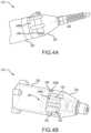
- FIG. 4 Ais a perspective view of a shield drive mechanism of the surgical device illustrated in FIG. 1 ;
- FIG. 4 Bis another perspective view of the shield drive mechanism of FIG. 4 A ;
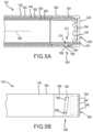
- FIG. 5 Ais a detail, longitudinal sectional view of a sheath assembly of the surgical device within line 5 - 5 of FIG. 3 A ;
- FIG. 5 Bis another detail view of the sheath assembly of the surgical device within line 5 - 5 of FIG. 3 A ; the surgical device is illustrated in a shielded configuration in which a cutting tip is disposed within an outer shield;
- FIG. 5 Cis another detail view of the sheath assembly of the surgical device within line 5 - 5 of FIG. 3 A ; the surgical device is illustrated in a first extended configuration in which the cutting tip partially protrudes from the outer shield;
- FIG. 5 Dis another detail view of the sheath assembly of the surgical device within line 5 - 5 of FIG. 3 A ; the surgical device is illustrated in a second extended configuration in which the cutting tip further protrudes from the outer shield;
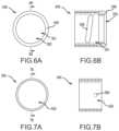
- FIG. 6 Ais an end view of the outer shield of the surgical device illustrated in FIG. 1 ;
- FIG. 6 Bis a longitudinal sectional view of the outer shield illustrated in FIG. 6 A taken along line 6 B- 6 B;
- FIG. 7 Ais an end view of an intermediate tip of the surgical device illustrated in FIG. 1 ;
- FIG. 7 Bis a longitudinal sectional view of the intermediate tip illustrated in FIG. 7 A taken along line 7 B- 7 B;
- FIG. 8 Ais a perspective view of an embodiment of a cutting tip of the surgical device of FIG. 1 ;
- FIG. 8 Bis a side view of the cutting tip illustrated in FIG. 8 A ;
- FIG. 8 Cis an end view of the cutting tip illustrated in FIG. 8 A ;
- FIG. 8 Dis a cross-sectional view of the cutting tip illustrated in FIG. 8 A taken along line 8 D- 8 D in FIG. 8 C ;
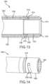
- FIG. 9 Ais a detail view of the surgical device of FIG. 1 including another embodiment of a cutting tip
- FIG. 9 Bis a longitudinal sectional view of the surgical device of FIG. 9 A ;
- FIG. 10is a partial longitudinal sectional view of the surgical device of FIG. 1 including another embodiment of a cutting tip;
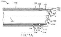
- FIG. 11 Ais a detail, longitudinal sectional view of a sheath assembly of an embodiment of a surgical device
- FIG. 11 Bis a detail view of the sheath assembly of FIG. 11 A ; the sheath assembly is illustrated in a shielded configuration in which a cutting tip is disposed within an outer shield, and an apex of the cutting tip is illustrated as being rotated out of angular alignment with an apex of the outer shield;
- FIG. 11 Cis a detail view of the outer shield, an intermediate tip, and the cutting tip of the sheath assembly of FIG. 11 A ; the components are illustrated in the shielded configuration in which the cutting tip is disposed within the outer shield, and the apex of the cutting tip is illustrated as being rotated out of angular alignment with the apex of the outer shield;
- FIG. 11 Dis another detail view of the sheath assembly of FIG. 11 A ; the sheath assembly is illustrated in an extended configuration in which the cutting tip partially protrudes from the outer shield, and the apex of the cutting tip is illustrated as being rotated out of angular alignment with the apex of the outer shield;
- FIG. 11 Eis a detail view of the outer shield, the intermediate tip, and the cutting tip of the sheath assembly of FIG. 11 A ; the components are illustrated in an extended configuration in which the cutting tip partially protrudes from the outer shield, and the apex of the cutting tip is illustrated as being rotated out of angular alignment with the apex of the outer shield;
- FIG. 12 Ais a perspective view of a shield drive mechanism associated with the sheath assembly of FIGS. 11 A- 11 E ;
- FIG. 12 Bis another perspective view of the shield drive mechanism of FIG. 12 A ;
- FIG. 13is a detail, longitudinal sectional view of a sheath assembly of an embodiment of a surgical device.
- Embodiments according to this disclosureprovide a surgical device that includes a sheath assembly, which can be deployed safely within a vascular system of a patient and separate implanted objects, such as leads, from a patient's vasculature system.
- FIGS. 1 and 2depict a surgical device 100 having a sheath assembly 102 that is adapted to be inserted within a subject 10 (for example, a human patient).
- the sheath assembly 102surrounds an implanted lead (not shown) running along the left innominate vein past the SVC and connected into, or about, the right ventricle of the heart.
- the user of the surgical device 100may actuate a handle assembly 104 , thereby rotating a cutting tip (not shown in FIG. 1 ) disposed at the distal end of the sheath assembly 102 to cut, separate, and/or dilate the tissue surrounding the lead within the patient's SVC.
- the cutting tipmay rotate to cut, separate, and/or dilate tissue in one or more shielded configurations of the device 100 in which the cutting tip is disposed within an outer sheath assembly 106 of the sheath assembly 102 .
- the shielded configuration(s) of the device 100may inhibit the cutting tip from contacting and potentially damaging the SVC of the subject.
- the cutting tipmay also rotate to cut, separate, and/or dilate tissue in one or more extended configurations of the device 100 in which the cutting tip at least partially protrudes from the outer sheath assembly 106 .
- the cutting tipmay cut tissue more efficiently in the extended configuration(s) compared to the shielded configuration(s).
- the surgical device 100is selectively reconfigurable to move the cutting tip from the shielded configuration(s) to the extended configuration(s) and vice versa.
- the process of rotating the cutting tipis repeated (in the shielded configuration(s) and/or the extended configuration(s)) until the implanted lead and/or surrounding tissue is completely or substantially cut, separated, and/or dilated from the tissue attached to the SVC.
- the implanted leadmay safely be removed from the patient's SVC.
- the handle assembly 104includes a housing 308 .
- the housing 308may be formed of various appropriate materials, such as polymers and the like.
- the housing 308includes two or more components that are coupled to one another, for example, via fasteners, adhesives, or the like.
- the housing 308includes two “halves”, or components that are generally mirror images of each other, that together define the housing 308 .
- one of the halves of the housing 308is omitted to illustrate components that are carried by the housing 308 .
- the housing 308movably carries a trigger 310 .
- the trigger 310is actuated by the user, or moved relative to the housing 308 , to cause the cutting tip to rotate.
- the trigger 310is actuated by translating the trigger 310 proximally and distally relative to the housing 308 .
- the trigger 310may be actuated by pivoting the trigger 310 relative to the housing 308 .
- the trigger 310may be actuated by translating and pivoting the trigger 310 relative to the housing 308 .
- the trigger 310may be formed as a depressible button.
- the trigger 310may be formed of various appropriate materials, such as polymers and the like.
- the trigger 310includes one opening into which the user can insert one or more fingers.
- the trigger 310may include two or more openings.
- the trigger 310may be a straight or non-linear member without any openings.
- the trigger 310may have a variety of sizes and shapes provided that the trigger 310 , either alone or in conjunction with the housing 308 , is ergonomically correct and comfortable for the user.
- the housing 308 of the handle assembly 104also movably carries a spring 312 .
- the spring 312is coupled to the trigger 310 to urge the trigger 310 toward a home position.
- the trigger 310is actuated when the user translates the trigger 310 proximally relative to the housing 308 and the spring 312 subsequently translates the trigger 310 distally relative to the housing 308 .
- the spring 312is a constant force spring.
- the housing 308 of the handle assembly 104further carries a cutting tip drive mechanism 314 that is coupled to the sheath assembly 102 .
- Actuation of the trigger 310drives the cutting tip drive mechanism 314 , and the cutting tip drive mechanism 314 in turn transmits rotational motion to the sheath assembly 102 and the cutting tip.
- the cutting tip drive mechanism 314includes a barrel cam 316 , such as any of the barrel cams or barrel cam assemblies described and/or illustrated in U.S. Provisional Patent Application Nos. 62/058,790, 62/113,865, and/or 61/947,377, which are hereby incorporated by reference in their entirety for all they teach and for all purposes.
- the barrel cam 316includes a cam slot that receives a pin carried by the trigger 310 .
- the cam slotextends longitudinally and circumferentially on the surface of the barrel cam 316 .
- the cutting tip drive mechanism 314may take various other forms.
- the cutting tip drive mechanism 314may be formed as a gear mechanism (not shown) or a threaded nut and shaft mechanism (not shown), such as any of the mechanisms described and/or illustrated in PCT Application No. PCT/US2014/026496, which is hereby incorporated by reference in its entirety for all it teaches and for all purposes.
- the cutting tip drive mechanism 314may include a prime mover (not shown), such as an electric motor, that receives power from a power supply (not shown), such as a battery carried by the housing 308 .
- the housing 308 of the handle assembly 104further carries a shield drive mechanism 318 .
- the shield drive mechanism 318may be actuated by the user of the surgical device 100 to reconfigure the device from a shielded configuration (that is, a configuration in which the cutting tip is disposed within the outer sheath assembly 106 ) to an extended configuration (that is, a configuration in which the cutting tip at least partially protrudes from the outer sheath assembly 106 ) and vice versa.
- the shield drive mechanism 318is carried near a distal end of the housing 308 of the handle assembly 104 .
- the shield drive mechanism 318may include a base 320 that fixedly couples to the housing 308 of the handle assembly 104 via, for example, fasteners (not shown) or the like.
- the base 320may be formed of various appropriate materials, such as polymers and the like.
- the base 320may rotatably couple to an actuatable component or “chuck” 322 via, for example, a bearing (not shown).
- the chuck 322may be formed of various appropriate materials, such as polymers and the like.
- one or more components of the sheath assembly 102may extend through a passageway 424 defined by the base 320 and the chuck 322 .
- the chuck 322may fixedly couple to a proximal end of the outer sheath assembly 106 via, for example, one or more fasteners, adhesives, or the like.
- the chuck 322may be rotated about a longitudinal axis 326 of the sheath assembly 102 to translate the outer sheath assembly 106 relative to the cutting tip and thereby reconfigure the device 100 from the shielded configuration to the extended configuration and vice versa.
- rotation of the chuck 322 about the longitudinal axis 326causes the device 100 to change configurations due to the presence of a shield cam and follower mechanism 528 defined at the distal end of the sheath assembly 102 .
- the cam and follower mechanism 528causes translation of the outer sheath assembly 106 relative to the cutting tip upon rotation of the chuck 322 .
- the chuck 322may be rotated in a first direction about the longitudinal axis (for example, a clockwise direction viewing the device 100 from the proximal end to the distal end) to reconfigure the device 100 to a second configuration (for example, the extended configuration).
- the chuck 322may be rotated in a second direction about the longitudinal axis (for example, a counter-clockwise direction viewing the device 100 from the proximal end to the distal end) to reconfigure the device 100 to the first configuration.
- the chuck 322rotates about 90 degrees relative to the base 320 to reconfigure the device 100 from the first configuration to the second configuration and vice versa.
- the chuck 322may rotate over various other angles relative to the base 320 to reconfigure the device 100 from the first configuration to the second configuration and vice versa.
- the shield drive mechanism 318includes a detent mechanism 430 (see FIG. 4 B ) that maintains the chuck 322 in its rotational orientation relative to the base 320 in the shielded configuration and/or the extended configuration of the device 100 (that is, a “shielded rotational orientation” and/or an “extended rotational orientation”.
- a holding force provided by the detent mechanism 430may be overcome to rotate the chuck 322 relative to the base 320 as described above.
- the detent mechanism 430may be formed by a component 432 of the base 320 that includes several flat outer surfaces and a spring-biased pin 433 that is carried by the chuck 322 and engages the flat surfaces of the component 432 .
- the detent mechanism 430may define one or more shielded configurations and one or more extended configurations for the surgical device 100 .
- the surgical device 100may be configurable to a shielded configuration (see, for example, FIG. 5 B ; that is, a configuration in which the cutting tip 534 is disposed within the outer sheath assembly 106 ; this configuration is also referred to as a “flush” configuration because the cutting surface 564 is flush with the distal surface 548 ), a first extended configuration (see, for example, FIG.
- FIG. 5 Cthat is, a configuration in which the cutting tip 534 partially protrudes from the outer sheath assembly 106 , for example, by 0.010 inches; this configuration is also referred to as a “partially extended” configuration), and a second extended configuration (see, for example, FIG. 5 D ; that is, a configuration in which the cutting tip 534 further protrudes from the outer sheath assembly 106 , for example, by 0.020 inches; this configuration is also referred to as a “fully extended” configuration).
- the chuck 322rotates about 45 degrees relative to the base 320 in a first direction (for example, a clockwise direction viewing the device 100 from the proximal end to the distal end) to reconfigure the device 100 from the first extended configuration to the second extended configuration and vice versa. In some embodiments, when the device 100 is in the first extended configuration, the chuck 322 rotates about 45 degrees relative to the base 320 in a second direction (for example, a counter-clockwise direction viewing the device 100 from the proximal end to the distal end) to reconfigure the device 100 from the first extended configuration to the shielded configuration and vice versa.
- a first directionfor example, a clockwise direction viewing the device 100 from the proximal end to the distal end
- a second directionfor example, a counter-clockwise direction viewing the device 100 from the proximal end to the distal end
- the chuck 322may rotate over various other angles relative to the base 320 to reconfigure the device 100 from the first extended configuration to the second extended configuration and vice versa, and to reconfigure the device 100 from the first extended configuration to the shielded configuration and vice versa.
- the chuck 322may include one or more indicators (for example, three indictors 436 A, 436 B, and 436 C) that align with an indicator 438 on the base 320 in the shielded and/or extended configurations of the device 100 .
- the first indicator 436 Amay longitudinally align with the base indicator 438 in the shielded configuration
- the second indicator 436 Bmay longitudinally align with the base indicator 438 in the first extended configuration (the partially extended configuration)
- the third indicator 436 Cmay longitudinally align with the base indicator 438 in the second extended configuration (the fully extended configuration).
- the indicators 436 A, 436 B, and 436 Cmay be different colors.
- the first indicator 436 Amay be green the second indicator 436 B may be yellow, and the third indictor 436 C may be red.
- the indicators 436 and 438may be formed as various types and different combinations of symbols and/or shapes, such as circles or the like.
- the sheath assembly 102may be generally flexible in order to accept, accommodate, and navigate the patient's vasculature system.
- the sheath assembly 102generally includes the outer sheath assembly 106 , an intermediate sheath assembly 540 carried within the outer sheath assembly 106 , and an inner sheath assembly 542 carried within the intermediate sheath assembly 540 .
- the outer sheath assembly 106includes an outer sheath 544 .
- the outer sheath 544may be formed of a polymer extrusion, braided reinforced polymer extrusion, coils, bi-coils, tri-coils, laser cut metal tubing and any combination of the above.
- the outer sheath 544includes a jacket, such as a flexible polymer jacket, that surrounds the above component(s).
- the outer sheath 544may be a unitary structure that includes multiple portions.
- the outer sheath 544has an outer diameter of about 0.203 inches and an inner diameter of about 0.189 inches.
- the outer sheath 544has an outer diameter of about 0.250 inches and an inner diameter of about 0.230 inches.
- a proximal end of the outer sheath 544may be fixedly coupled to the chuck 322 .
- the proximal end of the outer sheath 544may be rotatably fixed and translatably slidable relative to the chuck 322 .
- a distal end of the outer sheath 544couples to an outer shield or outer band 546 via, for example, a welded connection or the like.
- the outer shield 546is illustrated separately in FIGS. 6 A and 6 B .
- the outer shield 546is a generally annular-shaped component that be formed of various appropriate components, such as biocompatible metals or the like.
- the outer shield 546includes a distal surface 548 opposite the outer sheath 544 .
- the distal surface 548is a curved, polished, and/or generally smooth surface that facilitates dilating tissue of the subject.
- the distal surface 548defines a distal opening 550 that receives an implanted lead and, in some cases, a portion of the tissue surrounding the implanted lead.
- the cutting tip 534extends at least partially through the distal opening 550 in extended configurations of the surgical device 100 (see, for example, FIGS. 5 C and 5 D ).
- the distal opening 550is in communication with an outer shield passageway 551 that extends from the distal surface 548 to a proximal end of the outer shield 546 .
- the intermediate sheath assembly 540includes an intermediate sheath 552 that is carried within the outer sheath 544 .
- the intermediate sheath 552may be formed of a polymer extrusion, braided reinforced polymer extrusion, coils, bi-coils, tri-coils, laser cut metal tubing and any combination of the above.
- the intermediate sheath 552may be a unitary structure that includes multiple portions.
- the intermediate sheath 552has an outer diameter of about 0.180 inches and an inner diameter of about 0.166 inches.
- the intermediate sheath 552has an outer diameter of about 0.219 inches and an inner diameter of about 0.205 inches.
- a proximal end of the intermediate sheath 552may be fixedly coupled to the base 320 of the shield drive mechanism 318 .
- the intermediate sheath 552may extend through the passageway 424 of the base 320 and the proximal end of the intermediate sheath 552 may be fixedly coupled to the housing 308 of the handle assembly 104 .
- a distal end of the intermediate sheath 552couples to an intermediate tip 554 via, for example, a welded connection or the like.
- the intermediate tip 554is illustrated separately in FIGS. 7 A and 7 B .
- the intermediate tip 554may be formed of various appropriate components, such as biocompatible metals or the like.
- the intermediate tip 554is a generally annular shaped-component that is carried in the outer shield passageway 551 .
- the intermediate tip 554includes an intermediate tip passageway 555 that extends from a distal end to a proximal end of the intermediate tip 554 .
- the outer shield 546 and the intermediate tip 554together define a shield cam and follower mechanism 528 .
- the cam and follower mechanism 528causes translation of a least a portion of the outer sheath assembly 106 (for example, the distal portion) relative to the intermediate sheath assembly 540 and the cutting tip 534 upon actuation of the shield drive mechanism 318 and rotation of the outer sheath assembly 106 (for example, upon rotation of the chuck 322 ).
- the cam and follower mechanism 528includes a cam slot or channel 556 defined by the outer shield 546 and a follower or pin 558 carried by the intermediate tip 554 .
- the pin 558is press-fittingly received in a through hole 559 defined by the intermediate tip 554 .
- the cam slot 556may be defined by the intermediate tip 554 and the follower 558 may be carried by the outer shield 546 . In either case, the cam slot 556 slidably receives the follower 558 .
- the cam slot 556includes a profile that extends longitudinally and over at least a portion of the circumference of (that is, partially helically around) the outer shield 546 (or, alternatively, the intermediate tip 554 ).
- the follower 558slides in the cam slot 556 , and the profile of the cam slot 556 controls longitudinal translation of the outer shield 546 relative to the intermediate tip 554 and the cutting tip 534 .
- the profile of the cam slot 556controls translation of the outer shield 546 from one or more first positions in which the cutting tip 534 is disposed within the outer shield 546 (that is, one or more of the shielded configurations of the device 100 ; see, for example, FIG.
- the cam slot 556includes a linear profile.
- the cam slot 556may include a non-linear profile or a combination of individual and/or multiple linear and non-linear profiles.
- translation and rotation of the outer shield 546 relative to the intermediate sheath assembly 540causes a relatively small amount of longitudinal compression and extension of the outer sheath 544 between the chuck 322 and the outer shield 546 (for example, about 0.020 inches of longitudinal compression and extension).
- the proximal end of the outer sheath 544is fixedly coupled to the chuck 322 , and the proximal end of the outer sheath 544 does not translate as the outer shield 546 translates and rotates relative to the intermediate sheath assembly 540 .
- translation, and rotation of the outer shield 546 relative to the intermediate sheath assembly 540causes translation and/or rotation of the proximal end of the outer sheath 544 relative to the chuck 322 .
- the proximal end of the outer sheath 544is translatably and/or rotationally coupled to the chuck 322 .
- the inner sheath assembly 542includes an inner sheath 560 that is rotatably carried by the intermediate sheath 552 .
- the inner sheath 560may be formed of a polymer extrusion, braided reinforced polymer extrusion, coils, bi-coils, tri-coils, laser cut metal tubing and any combination of the above.
- the inner sheath 560may be a unitary structure that includes multiple portions. In addition to being flexible, the inner sheath 560 may also have a high degree of rotational stiffness in order to receive the torque transferred from the cutting tip drive mechanism 314 and transfer sufficient torque to the cutting tip 534 .
- the inner sheath 560has an outer diameter of about 0.156 inches and an inner diameter of about 0.136 inches. In some embodiments, the inner sheath 560 has an outer diameter of about 0.196 inches and an inner diameter of about 0.177 inches.
- a proximal end of the inner sheath 560may be rotatably fixed and translatably slidable relative to the cutting tip drive mechanism 314 via, for example, a key assembly 362 (see FIG. 3 A ), such as an assembly including any of the inner keys and outer keys described and/or illustrated in U.S. Provisional Patent Application No. 62/058,790.
- a distal end of the inner sheath 560couples to the cutting tip 534 via, for example, a welded connection or the like.
- the cutting tip 534is illustrated separately in FIGS. 8 A- 8 D .
- the cutting tip 534may be formed of various appropriate components, such as biocompatible metals or the like.
- the cutting tip 534is a generally annular shaped-component that is carried in the intermediate tip passageway 555 .
- a distal end of the cutting tip 534includes a cutting surface 564 that is adapted to cut tissue of the subject when the cutting tip 534 rotates relative to the intermediate tip 554 (for example, upon actuation of the cutting tip drive mechanism 314 and rotation of the inner sheath 560 relative to the intermediate sheath 552 ).
- the cutting surface 564is adapted to cut tissue of the subject in both the shielded configuration(s) and the extended configuration(s) of the surgical device 100 .
- the cutting surface 564may be formed as a “crown” serration (that is, a surface that includes a plurality of notches and adjacent un-notched areas).
- the sheath assembly 102may include a cutting tip 966 that has a cutting surface 968 formed as another type of serration.
- the cutting surface 968may be formed as a serration that includes a plurality of notches but lacks adjacent un-notched areas.
- the cutting surface of a cutting tipmay lack a serration. The remainder of this description only refers to the cutting tip 534 for brevity, although it is to be understood that any description of the cutting tip 534 also applies to the cutting tip 966 .
- any of the cutting tips described hereinmay include an inner surface 1070 .
- the inner surface 1070may be disposed radially inwardly and proximally relative to the cutting surface 564 .
- the inner surface 1070may be a curved, polished, and/or generally smooth surface that facilitates guiding cut tissue T and/or an implanted lead L into the sheath assembly 102 .
- the cutting tip 534simply rotates relative to the intermediate tip 554 and the outer shield 546 upon actuation of the cutting tip drive mechanism 314 (that is, the cutting tip 534 does not translate longitudinally relative to the intermediate tip 554 and the outer shield 546 upon actuation of the cutting tip drive mechanism 314 ).
- the cutting tip 534rotates and translates longitudinally relative to the intermediate tip 554 and the outer shield 546 upon actuation of the cutting tip drive mechanism 314 .
- the surgical device 100includes a cutting tip cam and follower mechanism 572 defined at the distal end of the sheath assembly 102 .
- the cam and follower mechanism 572causes translation of the cutting tip 534 relative to the intermediate tip 554 and the outer shield 546 upon actuation of the cutting tip drive mechanism 314 and rotation of the cutting tip 534 (for example, by proximally and distally translating the trigger 310 ).
- the cam and follower mechanism 572includes a cam slot or channel 574 defined by the cutting tip 534 and the follower or pin 558 carried by the intermediate tip 554 .
- the cam slot 574may be defined by the intermediate tip 554 and the follower 558 may be carried by the cutting tip 534 .
- the cutting tip cam and follower mechanism 572may include a different follower or pin (not shown) than the shield cam and follower mechanism 528 .
- the cam slot 574slidably receives the follower 558 .
- the cam slot 574includes a profile that extends longitudinally and over at least a portion of the circumference of the cutting tip 534 (or, alternatively, the intermediate tip 554 ).
- the profile of the cam slot 574may take a variety of forms, including any of those described and/or illustrated in U.S. Provisional Patent Application No. 62/058,790 or U.S. patent application Ser. No. 13/834,405.
- the cam slot 574may have a substantially linear profile, a substantially sinusoidal profile, or a combination of individual and/or multiple linear and non-linear profiles.
- the cam slot 574may have an open and continuous configuration, thereby allowing the cutting tip 534 to continuously rotate.
- the cam slot 574may have a closed and discontinuous configuration such that when the cutting tip 534 reaches a fully rotated orientation, the trigger 310 must be released or reversed so that the cutting tip 534 returns to an initial orientation before being re-actuated.
- the cam slot 574 in FIG. 8 Ais discontinuous because the cam slot 574 does not travel around the entire circumference of the exterior of the cutting tip 534 .
- the cam slot 574may be a partial lobe cam (which includes a cam slot surrounding less than 360 degrees of the circumference of the exterior surface of the cutting tip 534 ), a single lobe cam (which includes a cam slot surrounding 360 degrees of the circumference of the exterior surface of the cutting tip 534 ), a double lobe cam (which includes a cam slot surrounding 720 degrees of the circumference of the exterior surface of the cutting tip 534 ) and/or other multiple lobe cams.
- a partial lobe camwhich includes a cam slot surrounding less than 360 degrees of the circumference of the exterior surface of the cutting tip 534
- a single lobe camwhich includes a cam slot surrounding 360 degrees of the circumference of the exterior surface of the cutting tip 534
- a double lobe camwhich includes a cam slot surrounding 720 degrees of the circumference of the exterior surface of the cutting tip 534
- other multiple lobe camswhich includes a cam slot surrounding less than 360 degrees of the circumference of the exterior surface of the cutting tip 534
- the cutting surface 564 of the cutting tip 534is disposed within the outer shield 546 when the cutting tip drive mechanism 314 is not actuated.
- the cam slot 574includes a profile such that, in one or more shielded configurations of the device 100 , the cutting surface 564 remains disposed within the outer shield 546 during actuation of the cutting tip drive mechanism 314 .
- such a device 100reduces the risk of damaging the wall of the vessel because the cutting surface 564 remains shielded during actuation of the cutting tip drive mechanism 314 because the cutting surface 564 remains proximal of the most distal end of the outer shield 546 , even during rotation and extension of the cutting tip 534 within the outer shield 546 .
- the cam slot 574includes a profile such that, in one or more shielded configurations of the device 100 , the cutting surface 564 extends through the distal opening 550 of the outer shield 546 and is at least partially disposed outside of the outer shield 546 during a portion of actuation of the cutting tip drive mechanism 314 .
- the cutting surface 564 of the cutting tip 534is at least partially disposed outside of the outer shield 546 when the cutting tip drive mechanism 314 is not actuated.
- the cam slot 574includes a profile such that, in one or more extended configurations of the device 100 , the cutting surface 564 remains at least partially disposed outside of the outer shield 546 during actuation of the cutting tip drive mechanism 314 .
- the cam slot 574includes a profile such that, in one or more extended configurations of the device 100 , the cutting surface 564 retracts through the distal opening 550 of the outer shield 546 and is disposed within the outer shield 546 during a portion of actuation of the cutting tip drive mechanism 314 .
- the surgical device 100includes a cutting tip 534 that has a “flat” cutting surface 564 . That is, the cutting surface 564 is perpendicular relative to the longitudinal axis 326 of the sheath assembly 102 . In some embodiments, the distal surface 548 of the outer shield 546 is also perpendicular relative to the longitudinal axis 326 of the sheath assembly 102 .
- the surgical device 100includes a sheath assembly 1176 that has a “beveled”, “diagonal”, or “offset” distal end. That is, the sheath assembly 1176 includes a cutting tip 1178 that has a “beveled”, “diagonal”, or “offset” cutting surface 1180 and/or an outer shield 1182 that has a “beveled”, “diagonal”, or “offset” distal opening 1184 . That is, in some embodiments the cutting surface 1180 of the cutting tip 1178 is disposed at an acute angle ⁇ relative to the longitudinal axis 326 .
- the distal opening 1184 of the outer shield 1182is disposed at an acute angle ⁇ relative to the longitudinal axis 326 . In some embodiments, angle ⁇ and angle ⁇ are equal. In some embodiments, angle ⁇ and angle ⁇ are not equal.
- the cutting surface 1180may have various types of serrations, such as those described above, or it may lack serrations.
- the cutting tip 1178may rotate to cut, separate, and/or dilate tissue in one or more shielded configurations of the sheath assembly 1176 in which the cutting tip 1178 is disposed within the outer shield 1182 .
- the cutting tip 1178may also rotate to cut, separate, and/or dilate tissue in one or more extended configurations of the sheath assembly 1176 in which the cutting tip 1178 at least partially protrudes from the outer shield 1182 .
- the sheath assembly 1176is selectively reconfigurable to move the cutting tip 1178 from the shielded configuration(s) to the extended configuration(s) and vice versa.
- the deviceincludes a shield drive mechanism 1286 that may be actuated by the user to reconfigure the sheath assembly 1176 from a shielded configuration to an extended configuration and vice versa.
- the shield drive mechanism 1286is carried near a distal end of the handle assembly (not shown).
- the shield drive mechanism 1286may include a base 1288 that fixedly couples to the handle assembly.
- the base 1288may rotatably couple to an actuatable component or “chuck” 1290 .
- the chuck 1290couples to the outer shield 1182 via an outer sheath 1192 .
- rotation of the chuck 1290 about the longitudinal axis 326causes rotation of the outer shield 1185 relative to the cutting tip 1178 and an intermediate tip 1194 .
- the outer shield 1185rotates, the outer shield 1185 translates longitudinally relative to the cutting tip 1178 and the intermediate tip 1194 due to the presence of a shield cam and follower mechanism 1196 .
- the cam and follower mechanism 1196includes a cam slot or channel 1198 defined by the intermediate tip 1194 and a follower or pin 11100 carried by the outer shield 1182 .
- the cam slot 1198may be defined by the outer shield 1182 and the follower 11100 may be carried by the intermediate tip 1194 . In either case, the cam slot 1198 slidably receives the follower 11100 .
- the cam slot 1198includes a profile that extends longitudinally and over at least a portion of the circumference of (that is, partially helically around) the intermediate tip 1194 (or, alternatively, outer shield 1182 ).
- rotation of the outer shield 1182 relative to the intermediate tip 1194causes the outer shield 1182 to translate from one or more first positions in which the cutting tip 1178 is disposed within the outer shield 1182 (that is, one or more of the shielded configurations of the sheath assembly 1176 ; see, for example, FIGS. 11 B and 11 C ) to one or more second positions in which the cutting tip 1178 extends at least partially through the distal opening 1184 (that is, one or more of the extended configurations of the sheath assembly 1176 ; see, for example, FIGS. 11 D and 11 E ) and vice versa.
- the cam slot 1198includes a linear profile.
- the cam slot 1198may include a non-linear profile or a combination of individual and/or multiple linear and non-linear profiles.
- the cam slot 1198extends for 360 degrees about the circumference of the intermediate tip 1194 (or, alternatively, outer shield 1182 ) and the chuck 1290 rotates 360 degrees to reconfigure the sheath assembly 1176 from one of the shielded configurations to one of the extended configurations and vice versa. This facilitates angular alignment of an apex 11102 of the cutting surface 1180 with an apex 11104 of the outer shield 1182 in both the shielded configuration and the extended configuration.
- the cutting tip 1178simply rotates relative to the intermediate tip 1194 and the outer shield 1182 upon actuation of the cutting tip drive mechanism (not shown in FIGS. 11 A- 12 B ; that is, the cutting tip 1178 does not translate longitudinally relative to the intermediate tip 1194 and the outer shield 1182 upon actuation of the cutting tip drive mechanism).
- the cutting tip 1178rotates and translates longitudinally relative to the intermediate tip 1194 and the outer shield 1182 upon actuation of the cutting tip drive mechanism.
- the sheath assembly 1176includes a cutting tip cam and follower mechanism 11106 defined at the distal end of the sheath assembly 1176 .
- the cam and follower mechanism 11106causes translation of the cutting tip 1178 relative to the intermediate tip 1194 and the outer shield 1182 upon actuation of the cutting tip drive mechanism and rotation of the cutting tip 1178 .
- the cam and follower mechanism 11106includes a cam slot or channel 11108 defined by the cutting tip 1178 and the follower or pin 11110 carried by the intermediate tip 1194 .
- the cam slot 11108may be defined by the intermediate tip 1194 and the follower 11110 may be carried by the cutting tip 1178 . In either case, the cam slot 11108 slidably receives the follower 11110 .
- the cam slot 11108includes a profile that extends longitudinally and over at least a portion of the circumference of the cutting tip 1178 (or, alternatively, the intermediate tip 1194 ).
- the follower 11110slides in the cam slot 11108 , and the profile of the cam slot 11108 controls longitudinal translation of the cutting tip 1178 relative to the intermediate tip 1194 and the outer shield 1182 .
- the profile of the cam slot 11108may take a variety of forms, including any of those described above.
- the cutting surface 1180 of the cutting tip 1178is disposed within the outer shield 1182 when the cutting tip drive mechanism is not actuated.
- the cam slot 1198includes a profile such that, in one or more shielded configurations of the sheath assembly 1176 , the cutting surface 1180 remains disposed within the outer shield 1182 during actuation of the cutting tip drive mechanism.
- the apex 11102 of the cutting tip 1178may remain within the outer shield 1182 during a portion of actuation of the cutting tip drive mechanism.
- the cam slot 1198includes a profile such that, in one or more shielded configurations of the sheath assembly 1176 , the cutting surface 1180 extends through the distal opening 1184 of the outer shield 1182 and is at least partially disposed outside of the outer shield 1182 during a portion of actuation of the cutting tip drive mechanism.
- the apex 11102 of the cutting tip 1178may be disposed outside of the outer shield 1182 during a portion of actuation of the cutting tip drive mechanism.
- the cutting surface 1180 of the cutting tip 1178is at least partially disposed outside of the outer shield 1182 when the cutting tip drive mechanism is not actuated.
- the apex 11102 of the cutting tip 1178may extend 0.020 inches distally past the outer shield 1182 when the cutting tip drive mechanism is not actuated.
- the cam slot 1198includes a profile such that, in one or more extended configurations of the sheath assembly 1176 , the cutting surface 1180 remains at least partially disposed outside of the outer shield 1182 during actuation of the cutting tip drive mechanism.
- the apex 11102 of the cutting tip 1178may remain disposed outside of the outer shield 1182 during a portion of actuation of the cutting tip drive mechanism.
- the cam slot 1198includes a profile such that, in one or more extended configurations of the sheath assembly 1176 , the cutting surface 1180 retracts through the distal opening 1184 of the outer shield 1182 and is disposed within the outer shield 1182 during a portion of actuation of the cutting tip drive mechanism.
- the apex 11102 of the cutting tip 1178may retract into the outer shield 1182 during a portion of actuation of the cutting tip drive mechanism.
- the surgical device 100includes the sheath assembly 1300 .
- This figureillustrates a flexible stationary outer sheath 1302 , a flexible extendable intermediate sheath 1304 , and a flexible extendable inner sheath 1306 .
- Coupled to the outer sheath 1302is a rotatable outer cam member 1308 .
- Coupled to the intermediate sheath 1304is a rotatable intermediate cam member 1310 .
- Coupled to the inner sheath 1306is a rotatable inner cam member 1312 .
- the inner cam member 1312includes a cutting surface 1313 .
- the inner cam member 1312is connected to the intermediate cam member 1310 by a pin 1314 .
- the intermediate cam member 1310is connected to the outer cam member by a pin 1316 .
- the inner cam member 1312rotates and travels according to the profile of a cam slot 1318 in which the pin 1314 sits.
- the intermediate cam memberrotates and travels according to the profile of a cam slot 1320 in which the pin 1316 sits.
- the cutting tip 1402is disposed within the outer shield 1406 .
- the cutting tip 1402In the extended configurations, the cutting tip 1402 at least partially protrudes from the outer shield 1406 .
- the outer shield 1406may be moved from the shielded configuration to the extended configuration and vice versa by rotating the outer shield 1406 relative to the intermediate tip 1404 .
- the shield cam and follower mechanism 1408facilitates translation of the outer shield 1406 relative to the intermediate tip 1404 upon rotation of the outer shield 1406 relative to the intermediate tip 1404 .
- the sheath assembly 1400may include one or more indicators that are exposed or visible when the outer shield 1406 is in a shielded configuration and/or an extended configuration.
- the intermediate tip 1404may carry a colored band 1410 (for example, a green band) that is exposed in a shielded configuration.
- the usermay remove the distal end of the sheath assembly 1400 from the patient to move the outer shield 1406 from the shielded configuration to the extended configuration relative to the intermediate tip 1404 and vice versa.
Landscapes
- Health & Medical Sciences (AREA)
- Life Sciences & Earth Sciences (AREA)
- Surgery (AREA)
- Veterinary Medicine (AREA)
- Animal Behavior & Ethology (AREA)
- General Health & Medical Sciences (AREA)
- Public Health (AREA)
- Heart & Thoracic Surgery (AREA)
- Nuclear Medicine, Radiotherapy & Molecular Imaging (AREA)
- Biomedical Technology (AREA)
- Engineering & Computer Science (AREA)
- Molecular Biology (AREA)
- Medical Informatics (AREA)
- Vascular Medicine (AREA)
- Epidemiology (AREA)
- Orthopedic Medicine & Surgery (AREA)
- Radiology & Medical Imaging (AREA)
- Pathology (AREA)
- Dispersion Chemistry (AREA)
- Chemical & Material Sciences (AREA)
- Cardiology (AREA)
- Surgical Instruments (AREA)
Abstract
Description
Claims (10)
Priority Applications (1)
| Application Number | Priority Date | Filing Date | Title |
|---|---|---|---|
| US17/240,269US12053203B2 (en) | 2014-03-03 | 2021-04-26 | Multiple configuration surgical cutting device |
Applications Claiming Priority (9)
| Application Number | Priority Date | Filing Date | Title |
|---|---|---|---|
| US201461947377P | 2014-03-03 | 2014-03-03 | |
| PCT/US2014/026496WO2014151814A1 (en) | 2013-03-15 | 2014-03-13 | Surgical instrument for removing an implanted object |
| US201461987993P | 2014-05-02 | 2014-05-02 | |
| US201462048808P | 2014-09-11 | 2014-09-11 | |
| US201462058790P | 2014-10-02 | 2014-10-02 | |
| US201562113865P | 2015-02-09 | 2015-02-09 | |
| US14/635,742US10136913B2 (en) | 2013-03-15 | 2015-03-02 | Multiple configuration surgical cutting device |
| US16/125,770US11160579B2 (en) | 2013-03-15 | 2018-09-10 | Multiple configuration surgical cutting device |
| US17/240,269US12053203B2 (en) | 2014-03-03 | 2021-04-26 | Multiple configuration surgical cutting device |
Related Parent Applications (1)
| Application Number | Title | Priority Date | Filing Date |
|---|---|---|---|
| US16/125,770ContinuationUS11160579B2 (en) | 2013-03-15 | 2018-09-10 | Multiple configuration surgical cutting device |
Publications (2)
| Publication Number | Publication Date |
|---|---|
| US20210307776A1 US20210307776A1 (en) | 2021-10-07 |
| US12053203B2true US12053203B2 (en) | 2024-08-06 |
Family
ID=92075773
Family Applications (1)
| Application Number | Title | Priority Date | Filing Date |
|---|---|---|---|
| US17/240,269Active2035-01-29US12053203B2 (en) | 2014-03-03 | 2021-04-26 | Multiple configuration surgical cutting device |
Country Status (1)
| Country | Link |
|---|---|
| US (1) | US12053203B2 (en) |
Citations (458)
| Publication number | Priority date | Publication date | Assignee | Title |
|---|---|---|---|---|
| US1663761A (en) | 1927-02-07 | 1928-03-27 | George A Johnson | Surgical instrument |
| US2708437A (en) | 1952-03-31 | 1955-05-17 | Elizabeth Painter Hutchins | Surgical instrument |
| US3400708A (en) | 1965-11-24 | 1968-09-10 | Robert A. Scheidt | Cytologic endocrine evaluation device |
| US3614953A (en) | 1968-01-30 | 1971-10-26 | Nat Res Dev | Drills for clearing obstructions in arteries |
| US3703767A (en) | 1971-07-02 | 1972-11-28 | Micro Mega Sa | Dental instrument for root canal work |
| US3756242A (en) | 1972-01-04 | 1973-09-04 | Micro Motors Inc | Mechanical scarifier |
| US4051596A (en) | 1975-09-10 | 1977-10-04 | U.S. Philips Corporation | Wire cutter, particularly for cutting electrical connection wires |
| US4203444A (en) | 1977-11-07 | 1980-05-20 | Dyonics, Inc. | Surgical instrument suitable for closed surgery such as of the knee |
| US4246902A (en) | 1978-03-10 | 1981-01-27 | Miguel Martinez | Surgical cutting instrument |
| US4274414A (en) | 1979-02-21 | 1981-06-23 | Dyonics, Inc. | Surgical instrument |
| USD267145S (en) | 1979-09-28 | 1982-12-07 | Hogara Kaneko | Strap tightener and cutter |
| US4471777A (en) | 1983-03-30 | 1984-09-18 | Mccorkle Jr Charles E | Endocardial lead extraction apparatus and method |
| US4517977A (en) | 1981-07-24 | 1985-05-21 | Unisearch Limited | Co-axial tube surgical infusion/suction cutter tip |
| US4582056A (en) | 1983-03-30 | 1986-04-15 | Mccorkle Jr Charles E | Endocardial lead extraction apparatus and method |
| US4598710A (en) | 1984-01-20 | 1986-07-08 | Urban Engineering Company, Inc. | Surgical instrument and method of making same |
| US4601290A (en) | 1983-10-11 | 1986-07-22 | Cabot Medical Corporation | Surgical instrument for cutting body tissue from a body area having a restricted space |
| US4646738A (en) | 1985-12-05 | 1987-03-03 | Concept, Inc. | Rotary surgical tool |
| US4662869A (en) | 1984-11-19 | 1987-05-05 | Wright Kenneth W | Precision intraocular apparatus |
| US4674502A (en) | 1985-09-27 | 1987-06-23 | Coopervision, Inc. | Intraocular surgical instrument |
| US4729763A (en) | 1986-06-06 | 1988-03-08 | Henrie Rodney A | Catheter for removing occlusive material |
| US4754755A (en) | 1984-05-14 | 1988-07-05 | Husted Royce Hill | Catheter with a rotary blade |
| US4767403A (en) | 1987-02-09 | 1988-08-30 | The Boc Group, Inc. | Positive pulse device and system |
| US4785826A (en) | 1987-03-02 | 1988-11-22 | Ward John L | Biopsy instrument |
| USD309350S (en) | 1987-06-01 | 1990-07-17 | Pfizer Hospital Products Group, Inc. | Surgical sternotomy band tightening instrument |
| US4943289A (en) | 1989-05-03 | 1990-07-24 | Cook Pacemaker Corporation | Apparatus for removing an elongated structure implanted in biological tissue |
| US4950277A (en) | 1989-01-23 | 1990-08-21 | Interventional Technologies, Inc. | Atherectomy cutting device with eccentric wire and method |
| US4988347A (en) | 1988-11-09 | 1991-01-29 | Cook Pacemaker Corporation | Method and apparatus for separating a coiled structure from biological tissue |
| US5011482A (en) | 1989-01-17 | 1991-04-30 | Cook Pacemaker Corporation | Apparatus for removing an elongated structure implanted in biological tissue |
| US5013310A (en) | 1988-11-09 | 1991-05-07 | Cook Pacemaker Corporation | Method and apparatus for removing an implanted pacemaker lead |
| US5031634A (en) | 1990-01-19 | 1991-07-16 | Beth Israel Hospital Assoc., Inc. | Adjustable biopsy needle-guide device |
| WO1991017711A1 (en) | 1990-05-21 | 1991-11-28 | Cardiovascular Imaging Systems, Inc. | Intravascular catheter having combined imaging abrasion head |
| US5152744A (en) | 1990-02-07 | 1992-10-06 | Smith & Nephew Dyonics | Surgical instrument |
| US5201316A (en) | 1991-03-18 | 1993-04-13 | Cardiovascular Imaging Systems, Inc. | Guide wire receptacle for catheters having rigid housings |
| US5207683A (en) | 1988-11-09 | 1993-05-04 | Cook Pacemaker Corporation | Apparatus for removing an elongated structure implanted in biological tissue |
| US5217454A (en) | 1991-08-01 | 1993-06-08 | Angiolaz, Incorporated | Laser delivery catheter |
| US5261877A (en) | 1991-07-22 | 1993-11-16 | Dow Corning Wright | Method of performing a thrombectomy procedure |
| US5263928A (en) | 1991-06-14 | 1993-11-23 | Baxter International Inc. | Catheter and endoscope assembly and method of use |
| US5275609A (en)* | 1990-06-22 | 1994-01-04 | Vance Products Incorporated | Surgical cutting instrument |
| US5281220A (en) | 1992-01-13 | 1994-01-25 | Blake Joseph W Iii | Endoscopic instrument |
| US5290275A (en) | 1985-03-22 | 1994-03-01 | Massachusetts Institute Of Technology | Catheter for laser angiosurgery |
| US5290303A (en) | 1990-06-22 | 1994-03-01 | Vance Products Incorporated D/B/A Cook Urological Incorporated | Surgical cutting instrument |
| US5383199A (en) | 1992-07-02 | 1995-01-17 | Advanced Interventional Systems, Inc. | Apparatus and method for optically controlling the output energy of a pulsed laser source |
| US5395328A (en) | 1994-01-19 | 1995-03-07 | Daig Corporation | Steerable catheter tip having an X-shaped lumen |
| US5411513A (en) | 1994-02-24 | 1995-05-02 | Danek Medical, Inc. | Transmission mechanism for a surgical cutting instrument |
| US5423806A (en) | 1993-10-01 | 1995-06-13 | Medtronic, Inc. | Laser extractor for an implanted object |
| US5423330A (en) | 1993-03-10 | 1995-06-13 | The University Of Miami | Capsule suction punch instrument and method of use |
| US5456680A (en) | 1993-09-14 | 1995-10-10 | Spectranetics Corp | Fiber optic catheter with shortened guide wire lumen |
| WO1995033513A1 (en) | 1994-06-08 | 1995-12-14 | Cook Pacemaker Corporation | Locally flexible dilator sheath |
| US5484433A (en) | 1993-12-30 | 1996-01-16 | The Spectranetics Corporation | Tissue ablating device having a deflectable ablation area and method of using same |
| US5562694A (en) | 1994-10-11 | 1996-10-08 | Lasersurge, Inc. | Morcellator |
| US5569284A (en) | 1994-09-23 | 1996-10-29 | United States Surgical Corporation | Morcellator |
| US5575797A (en) | 1993-09-24 | 1996-11-19 | Siemens Elema Ab | Device for explanting a medical electrode device |
| US5595186A (en) | 1992-04-06 | 1997-01-21 | Alan I. Rubinstein | Bone marrow biopsy needle |
| US5620451A (en) | 1995-04-25 | 1997-04-15 | Intermedics, Inc. | Lead extraction system for transvenous defibrillation leads and for endocardial pacing leads |
| US5651781A (en)* | 1995-04-20 | 1997-07-29 | Grace-Wells Technology Partners No. 1, L.P. | Surgical cutting instrument |
| US5697936A (en) | 1988-11-10 | 1997-12-16 | Cook Pacemaker Corporation | Device for removing an elongated structure implanted in biological tissue |
| US5718237A (en) | 1993-11-15 | 1998-02-17 | Haaga; John R. | Biopsy needle |
| US5725523A (en) | 1996-03-29 | 1998-03-10 | Mueller; Richard L. | Lateral-and posterior-aspect method and apparatus for laser-assisted transmyocardial revascularization and other surgical applications |
| US5766164A (en) | 1996-07-03 | 1998-06-16 | Eclipse Surgical Technologies, Inc. | Contiguous, branched transmyocardial revascularization (TMR) channel, method and device |
| US5782823A (en) | 1996-04-05 | 1998-07-21 | Eclipse Surgical Technologies, Inc. | Laser device for transmyocardial revascularization procedures including means for enabling a formation of a pilot hole in the epicardium |
| US5792151A (en) | 1996-01-24 | 1998-08-11 | The Ohio State University | Method and apparatus for ligating a blood vessel, tissue or other bodily duct |
| US5807399A (en) | 1996-10-23 | 1998-09-15 | Medtronic, Inc. | Method for removal of chronically implanted leads and leads optimized for use therewith |
| US5814044A (en) | 1995-02-10 | 1998-09-29 | Enable Medical Corporation | Apparatus and method for morselating and removing tissue from a patient |
| US5823971A (en) | 1993-10-29 | 1998-10-20 | Boston Scientific Corporation | Multiple biopsy sampling coring device |
| US5824026A (en) | 1996-06-12 | 1998-10-20 | The Spectranetics Corporation | Catheter for delivery of electric energy and a process for manufacturing same |
| US5863294A (en) | 1996-01-26 | 1999-01-26 | Femrx, Inc. | Folded-end surgical tubular cutter and method for fabrication |
| WO1999007295A1 (en) | 1997-08-05 | 1999-02-18 | Femrx, Inc. | Disposable laparoscopic morcellator |
| US5873886A (en) | 1995-04-04 | 1999-02-23 | United States Surgical Corporation | Surgical cutting apparatus |
| US5879365A (en) | 1995-04-04 | 1999-03-09 | United States Surgical Corporation | Surgical cutting apparatus |
| US5893862A (en) | 1997-04-10 | 1999-04-13 | Pratt; Arthur William | Surgical apparatus |
| US5899915A (en) | 1996-12-02 | 1999-05-04 | Angiotrax, Inc. | Apparatus and method for intraoperatively performing surgery |
| US5910150A (en) | 1996-12-02 | 1999-06-08 | Angiotrax, Inc. | Apparatus for performing surgery |
| US5916210A (en) | 1990-01-26 | 1999-06-29 | Intraluminal Therapeutics, Inc. | Catheter for laser treatment of atherosclerotic plaque and other tissue abnormalities |
| WO1999049937A1 (en) | 1998-03-27 | 1999-10-07 | The General Hospital Corporation | Method and apparatus for the selective targeting of lipid-rich tissues |
| US5972012A (en) | 1997-10-17 | 1999-10-26 | Angiotrax, Inc. | Cutting apparatus having articulable tip |
| US5980545A (en) | 1996-05-13 | 1999-11-09 | United States Surgical Corporation | Coring device and method |
| US5980515A (en) | 1997-12-19 | 1999-11-09 | Irvine Biomedical, Inc. | Devices and methods for lead extraction |
| WO1999058066A1 (en) | 1998-05-12 | 1999-11-18 | Med-En Ltd. | Device and method for evacuating refuse from tissues of the body |
| US6010476A (en) | 1996-12-02 | 2000-01-04 | Angiotrax, Inc. | Apparatus for performing transmyocardial revascularization |
| US6019756A (en) | 1996-04-05 | 2000-02-01 | Eclipse Surgical Technologies, Inc. | Laser device for transmyocardial revascularization procedures |
| US6022336A (en) | 1996-05-20 | 2000-02-08 | Percusurge, Inc. | Catheter system for emboli containment |
| US6027497A (en) | 1996-03-29 | 2000-02-22 | Eclipse Surgical Technologies, Inc. | TMR energy delivery system |
| US6033402A (en) | 1998-09-28 | 2000-03-07 | Irvine Biomedical, Inc. | Ablation device for lead extraction and methods thereof |
| US6051008A (en) | 1996-12-02 | 2000-04-18 | Angiotrax, Inc. | Apparatus having stabilization members for percutaneously performing surgery and methods of use |
| US6063037A (en) | 1998-08-21 | 2000-05-16 | Manan Medical Products, Inc. | Bone marrow biopsy needle |
| US6080175A (en) | 1998-07-29 | 2000-06-27 | Corvascular, Inc. | Surgical cutting instrument and method of use |
| US6083237A (en) | 1998-10-23 | 2000-07-04 | Ethico Endo-Surgery, Inc. | Biopsy instrument with tissue penetrating spiral |
| US6099537A (en) | 1996-02-26 | 2000-08-08 | Olympus Optical Co., Ltd. | Medical treatment instrument |
| US6102926A (en) | 1996-12-02 | 2000-08-15 | Angiotrax, Inc. | Apparatus for percutaneously performing myocardial revascularization having means for sensing tissue parameters and methods of use |
| USD430781S (en) | 1999-11-01 | 2000-09-12 | Panduit Corp. | Cable tie application tool |
| US6117149A (en) | 1992-11-30 | 2000-09-12 | Optex Ophthalmologics, Inc. | Rotary device and method for removing ophthalmic lens |
| US6120520A (en) | 1997-05-27 | 2000-09-19 | Angiotrax, Inc. | Apparatus and methods for stimulating revascularization and/or tissue growth |
| US6126654A (en) | 1997-04-04 | 2000-10-03 | Eclipse Surgical Technologies, Inc. | Method of forming revascularization channels in myocardium using a steerable catheter |
| US6136005A (en) | 1988-11-09 | 2000-10-24 | Cook Pacemaker Corporation | Apparatus for removing a coiled structure implanted in biological tissue, having expandable means including a laterally deflectable member |
| US6139543A (en) | 1998-07-22 | 2000-10-31 | Endovasix, Inc. | Flow apparatus for the disruption of occlusions |
| US6152909A (en) | 1996-05-20 | 2000-11-28 | Percusurge, Inc. | Aspiration system and method |
| US6152918A (en) | 1996-04-05 | 2000-11-28 | Eclipse Surgical Technologies, Inc. | Laser device with auto-piercing tip for myocardial revascularization procedures |
| US6156049A (en) | 1997-04-11 | 2000-12-05 | Coherent Inc. | Method and apparatus for transurethral resection of the prostate |
| US6159225A (en) | 1995-10-13 | 2000-12-12 | Transvascular, Inc. | Device for interstitial transvascular intervention and revascularization |
| US6159203A (en) | 1985-07-31 | 2000-12-12 | Cardiofocus, Inc. | Infrared laser catheter system |
| US6162214A (en) | 1997-10-30 | 2000-12-19 | Eclipse Surgical Technologies, Inc. | Corning device for myocardial revascularization |
| US6165188A (en) | 1996-12-02 | 2000-12-26 | Angiotrax, Inc. | Apparatus for percutaneously performing myocardial revascularization having controlled cutting depth and methods of use |
| US6167315A (en) | 1999-04-05 | 2000-12-26 | Spectranetics Corporation | Lead locking device and method |
| US6174307B1 (en) | 1996-03-29 | 2001-01-16 | Eclipse Surgical Technologies, Inc. | Viewing surgical scope for minimally invasive procedures |
| US6190352B1 (en) | 1997-10-01 | 2001-02-20 | Boston Scientific Corporation | Guidewire compatible port and method for inserting same |
| US6190353B1 (en) | 1995-10-13 | 2001-02-20 | Transvascular, Inc. | Methods and apparatus for bypassing arterial obstructions and/or performing other transvascular procedures |
| US6203537B1 (en) | 1999-02-04 | 2001-03-20 | Sorin Adrian | Laser-driven acoustic ablation catheter |
| US6210400B1 (en) | 1998-07-22 | 2001-04-03 | Endovasix, Inc. | Flexible flow apparatus and method for the disruption of occlusions |
| US6228076B1 (en) | 1999-01-09 | 2001-05-08 | Intraluminal Therapeutics, Inc. | System and method for controlling tissue ablation |
| US6235044B1 (en) | 1999-08-04 | 2001-05-22 | Scimed Life Systems, Inc. | Percutaneous catheter and guidewire for filtering during ablation of mycardial or vascular tissue |
| US6241692B1 (en) | 1998-10-06 | 2001-06-05 | Irvine Biomedical, Inc. | Ultrasonic ablation device and methods for lead extraction |
| US6245011B1 (en) | 1997-11-04 | 2001-06-12 | Karl Storz Gmbh & Co. Kg | Endoscopic instrument with cutting tool |
| US6290668B1 (en) | 1998-04-30 | 2001-09-18 | Kenton W. Gregory | Light delivery catheter and methods for the use thereof |
| WO2001076680A1 (en) | 2000-04-05 | 2001-10-18 | Stx Medical, Inc. | Intralumenal material removal systems and methods |
| US20010031981A1 (en) | 2000-03-31 | 2001-10-18 | Evans Michael A. | Method and device for locating guidewire and treating chronic total occlusions |
| US20010039427A1 (en) | 1999-09-24 | 2001-11-08 | Dinger Fred B. | Suction rasp and handpiece adapter assembly and powered surgical handpiece assembly including a suction rasp |
| US6315774B1 (en) | 1996-03-29 | 2001-11-13 | Eclipse Surgical Technologies, Inc. | Minimally invasive apparatus for forming revascularization channels |
| US20010041899A1 (en) | 1998-03-27 | 2001-11-15 | James B. Hunt | Minimally-invasive medical retrieval device |
| US20010044568A1 (en) | 2000-01-31 | 2001-11-22 | Langberg Jonathan J. | Endoluminal ventricular retention |
| US20020002372A1 (en) | 2000-04-27 | 2002-01-03 | Medtronic, Inc. | Suction stabilized epicardial ablation devices |
| US20020007204A1 (en) | 2000-05-17 | 2002-01-17 | Cook Vascular Incorporated | Apparatus for removing an elongated structure implanted in biological tissue |
| US20020045811A1 (en) | 1985-03-22 | 2002-04-18 | Carter Kittrell | Laser ablation process and apparatus |
| US6379351B1 (en) | 1997-08-27 | 2002-04-30 | Arthrocare Corporation | Electrosurgical method for the removal of pacemaker leads |
| US6395002B1 (en) | 2000-01-18 | 2002-05-28 | Alan G. Ellman | Electrosurgical instrument for ear surgery |
| US20020065543A1 (en) | 2000-11-29 | 2002-05-30 | Pacesetter, Inc. | Double threaded stylet for extraction of leads with a threaded electrode |
| US20020068954A1 (en) | 1999-03-26 | 2002-06-06 | Cook Urological Inc. | Minimally-invasive medical retrieval device |
| US6402771B1 (en) | 1999-12-23 | 2002-06-11 | Guidant Endovascular Solutions | Snare |
| WO2002049690A2 (en) | 2000-12-20 | 2002-06-27 | Fox Hollow Technologies, Inc. | Debulking catheter |
| US20020087151A1 (en) | 2000-12-29 | 2002-07-04 | Afx, Inc. | Tissue ablation apparatus with a sliding ablation instrument and method |
| US20020087046A1 (en) | 1997-04-23 | 2002-07-04 | St. Jude Medical Cardiovascular Group, Inc. | Medical grafting methods and apparatus |
| US6419684B1 (en) | 2000-05-16 | 2002-07-16 | Linvatec Corporation | End-cutting shaver blade for axial resection |
| US6419674B1 (en) | 1996-11-27 | 2002-07-16 | Cook Vascular Incorporated | Radio frequency dilator sheath |
| US6423051B1 (en) | 1999-09-16 | 2002-07-23 | Aaron V. Kaplan | Methods and apparatus for pericardial access |
| US20020103477A1 (en) | 1999-02-19 | 2002-08-01 | Michael Grasso | Laser lithotripsy device with suction |
| US20020103532A1 (en) | 2001-01-30 | 2002-08-01 | Langberg Jonathan J. | Transluminal mitral annuloplasty |
| US20020103459A1 (en) | 2000-12-05 | 2002-08-01 | Sparks Kurt D. | Catheter system for vascular re-entry from a sub-intimal space |
| US6428556B1 (en) | 1999-08-25 | 2002-08-06 | Origin Medsystems, Inc. | Longitudinal dilator and method |
| US6428539B1 (en) | 2000-03-09 | 2002-08-06 | Origin Medsystems, Inc. | Apparatus and method for minimally invasive surgery using rotational cutting tool |
| US6432119B1 (en) | 1999-03-17 | 2002-08-13 | Angiotrax, Inc. | Apparatus and methods for performing percutaneous myocardial revascularization and stimulating angiogenesis using autologous materials |
| US6436054B1 (en) | 1998-11-25 | 2002-08-20 | United States Surgical Corporation | Biopsy system |
| US6436114B1 (en) | 1998-02-18 | 2002-08-20 | Storz Endoskop Gmbh | Apparatus for treating body tissue with ultrasound |
| US20020123785A1 (en) | 2001-03-02 | 2002-09-05 | Cardiac Pacemakers, Inc. | Cardiac lead permitting easy extraction |
| US6454758B1 (en) | 1996-12-19 | 2002-09-24 | Ep Technologies, Inc. | Loop structures for supporting multiple electrode elements |
| US6454741B1 (en) | 1997-03-06 | 2002-09-24 | Medtronic Percusurge, Inc. | Aspiration method |
| US6461349B1 (en) | 1997-10-24 | 2002-10-08 | Carl Zeiss Meditec Ag | Medical handpiece with a light guide which can be displaced in an axial direction |
| US20020151961A1 (en) | 2000-01-31 | 2002-10-17 | Lashinski Randall T. | Medical system and method for remodeling an extravascular tissue structure |
| US20020151918A1 (en) | 2001-04-17 | 2002-10-17 | Scimed Life Systems, Inc. | In-stent ablative tool |
| US20020165425A1 (en) | 2000-06-22 | 2002-11-07 | Yoon Gul Joong | Implantable left ventricular assist device with cylindrical cam |
| US6478777B1 (en) | 2000-05-25 | 2002-11-12 | Medtronic, Inc. | Introducer system for medical electrical lead |
| US6488636B2 (en) | 1997-09-19 | 2002-12-03 | United States Surgical Corporation | Biopsy apparatus |
| US20020183735A1 (en) | 2000-04-25 | 2002-12-05 | Edwards Stuart D. | Ablation of rectal and other internal body structures |
| US20020188278A1 (en) | 2001-06-07 | 2002-12-12 | Bruce Tockman | Method and apparatus for an adjustable shape guide catheter |
| US6512959B1 (en) | 2000-11-28 | 2003-01-28 | Pacesetter, Inc. | Double threaded stylet for extraction of leads with a threaded electrode |
| US20030036788A1 (en) | 2000-12-04 | 2003-02-20 | The Spectranetics Corporation | Lead locking device and method |
| US6527752B1 (en) | 1999-09-24 | 2003-03-04 | Cook Urological, Inc. | Embryo transfer catheter |
| US6540865B1 (en) | 1996-09-27 | 2003-04-01 | Avery Dennison Corporation | Prelaminate pressure-sensitive adhesive constructions |
| US20030073985A1 (en) | 1996-06-13 | 2003-04-17 | Mueller Richard L. | Intraoperative myocardial device and stimulation procedure |
| US20030078562A1 (en) | 2001-01-17 | 2003-04-24 | Transvascular, Inc. | Methods and apparatus for acute or chronic delivery of substances or apparatus to extravascular treatment sites |
| US6554779B2 (en) | 1998-02-20 | 2003-04-29 | United States Surgical Corporation | Biopsy instrument driver apparatus |
| US6565588B1 (en) | 2000-04-05 | 2003-05-20 | Pathway Medical Technologies, Inc. | Intralumenal material removal using an expandable cutting device |
| US6569082B1 (en) | 1999-08-10 | 2003-05-27 | Origin Medsystems, Inc. | Apparatus and methods for cardiac restraint |
| US20030105451A1 (en) | 2001-12-04 | 2003-06-05 | Cardiac Pacemakers, Inc. | Adjustable length catheter assembly |
| US6575997B1 (en) | 1999-12-23 | 2003-06-10 | Endovascular Technologies, Inc. | Embolic basket |
| US20030125709A1 (en) | 2001-12-28 | 2003-07-03 | Eidenschink Tracee E.J. | Hypotube with improved strain relief |
| US20030125619A1 (en) | 2001-12-31 | 2003-07-03 | Cardiac Pacemakers, Inc. | Telescoping guide catheter with peel-away outer sheath |
| US6595982B2 (en) | 1996-06-03 | 2003-07-22 | Terumo Kabushiki Kaisha | Tubular medical device |
| US6599296B1 (en) | 2001-07-27 | 2003-07-29 | Advanced Cardiovascular Systems, Inc. | Ratcheting handle for intraluminal catheter systems |
| US6610046B1 (en) | 1999-04-30 | 2003-08-26 | Usaminanotechnology Inc. | Catheter and guide wire |
| US6620160B2 (en) | 1996-09-26 | 2003-09-16 | Nanoptics, Inc. | Method and device for electro microsurgery in a physiological liquid environment |
| US6620180B1 (en) | 1998-09-09 | 2003-09-16 | Medtronic Xomed, Inc. | Powered laryngeal cutting blade |
| US20030187460A1 (en) | 1999-08-10 | 2003-10-02 | Chin Albert K. | Methods and apparatus for endoscopic cardiac surgery |
| US20030187461A1 (en) | 1999-08-10 | 2003-10-02 | Chin Albert K. | Releasable guide and method for endoscopic cardiac lead placement |
| US20030199916A1 (en) | 1997-11-14 | 2003-10-23 | Yee Carl E. | Multi-sheath delivery catheter |
| US20030208209A1 (en) | 2000-03-03 | 2003-11-06 | Gambale Richard A. | Endoscopic tissue apposition device with multiple suction ports |
| US6652480B1 (en) | 1997-03-06 | 2003-11-25 | Medtronic Ave., Inc. | Methods for reducing distal embolization |
| US6660021B1 (en) | 1999-12-23 | 2003-12-09 | Advanced Cardiovascular Systems, Inc. | Intravascular device and system |
| US20030229353A1 (en) | 2000-02-16 | 2003-12-11 | Cragg Andrew H. | Method and apparatus for providing posterior or anterior trans-sacral access to spinal vertebrae |
| US6663626B2 (en) | 1998-07-13 | 2003-12-16 | Novacept | Apparatuses and methods for interstitial tissue removal |
| US6669685B1 (en) | 1997-11-06 | 2003-12-30 | Biolase Technology, Inc. | Tissue remover and method |
| US20040006358A1 (en) | 2000-04-05 | 2004-01-08 | Pathway Medical Technologies, Inc. | Intralumenal material removal using a cutting device for differential cutting |
| US20040010248A1 (en) | 2002-07-10 | 2004-01-15 | Appling William M. | Endovascular treatment device having a fiber tip spacer |
| US20040015193A1 (en) | 2002-04-11 | 2004-01-22 | Transvascular, Inc. | Devices and methods for transluminal or transthoracic interstitial electrode placement |
| US20040019359A1 (en) | 2002-07-24 | 2004-01-29 | Worley Seth J. | Telescopic introducer with a compound curvature for inducing alignment and method of using the same |
| US20040049208A1 (en) | 2002-04-03 | 2004-03-11 | Thomas Fogarty, M.D. | Methods and systems for vein harvesting and fistula creation |
| US6706052B1 (en) | 1999-08-10 | 2004-03-16 | Origin Medsystems, Inc. | Longitudinal dilator and method |
| US20040054388A1 (en) | 2002-07-19 | 2004-03-18 | Osypka Thomas P. | Device and method for delivering cardiac leads |
| US20040059348A1 (en) | 2002-09-23 | 2004-03-25 | Geske Jeff B. | Non-sheath based medical device delivery system |
| US6712773B1 (en) | 2000-09-11 | 2004-03-30 | Tyco Healthcare Group Lp | Biopsy system |
| US20040064024A1 (en) | 2002-09-30 | 2004-04-01 | Sommer John L. | Cardiac vein lead and guide catheter |
| US20040102804A1 (en) | 1999-08-10 | 2004-05-27 | Chin Albert K. | Apparatus and methods for endoscopic surgical procedures |
| US20040111101A1 (en) | 1999-08-10 | 2004-06-10 | Chin Albert K. | Endoscopic subxiphoid surgical procedures |
| WO2004049956A2 (en) | 2002-11-27 | 2004-06-17 | The Anspach Effort | Powered kerrison-like rongeur system |
| US20040133220A1 (en) | 2000-01-31 | 2004-07-08 | Randall Lashinski | Adjustable transluminal annuloplasty system |
| US20040138562A1 (en) | 2002-01-17 | 2004-07-15 | Joshua Makower | Devices, systems and methods for acute or chronic delivery of substances or apparatus to extravascular treatment sites |
| US20040143284A1 (en) | 2003-01-17 | 2004-07-22 | Chin Albert K. | Subxiphoid procedures and apparatus for placement of cardiac defibrillator and pacer |
| US20040147911A1 (en) | 1999-08-25 | 2004-07-29 | Cardiofocus, Inc. | Surgical ablation instruments for forming an encircling lesion |
| US20040153096A1 (en) | 2003-02-05 | 2004-08-05 | Goode Louis B. | Device for removing an elongated structure implanted in biological tissue |
| US20040153098A1 (en) | 1999-08-10 | 2004-08-05 | Chin Albert K. | Apparatus and method for endoscopic cardiac mapping and lead placement |
| US20040172116A1 (en) | 2003-01-31 | 2004-09-02 | Medtronic, Inc. | Arrangement for implanting a miniaturized cardiac lead having a fixation helix |
| WO2004080507A2 (en) | 2003-03-10 | 2004-09-23 | Pathway Medical Technologies, Inc. | Interventional catheters assemblies and control systems |
| US6802838B2 (en) | 2002-04-22 | 2004-10-12 | Trimedyne, Inc. | Devices and methods for directed, interstitial ablation of tissue |
| US20040216748A1 (en) | 1999-08-10 | 2004-11-04 | Chin Albert K. | Apparatus and method for endoscopic encirclement of pulmonary veins for epicardial ablation |
| US20040230213A1 (en) | 2000-04-05 | 2004-11-18 | Pathway Medical Technologies, Inc. | Liquid seal assembly for a rotating torque tube |
| US20040230212A1 (en) | 2000-04-05 | 2004-11-18 | Pathway Medical Technologies, Inc. | Medical sealed tubular structures |
| US20040236397A1 (en) | 1999-04-05 | 2004-11-25 | The Spectranetics Corporation | Lead locking device and method |
| US20040243162A1 (en) | 2000-04-05 | 2004-12-02 | Pathway Medical Technologies, Inc. | Interventional catheter assemblies and control systems |
| US20040254534A1 (en) | 2003-06-11 | 2004-12-16 | Bjorkman Bradford A. | Sliding connection assembly to facilitate lead stabilization |
| US20040260322A1 (en) | 2003-06-20 | 2004-12-23 | Rudko Robert I. | Endovascular tissue removal device |
| US20040267276A1 (en) | 2003-06-30 | 2004-12-30 | Camino Thomas S. | Slide and kit for delivering implants |
| US20040267304A1 (en) | 2003-06-30 | 2004-12-30 | Zannis Anthony D. | Instrument for delivery of implant |
| US20050004644A1 (en) | 2003-05-06 | 2005-01-06 | Enpath Medical, Inc. | Rotatable lead introducer |
| US20050027337A1 (en) | 2003-07-28 | 2005-02-03 | Rudko Robert I. | Endovascular tissue removal device |
| US20050025798A1 (en) | 2003-07-29 | 2005-02-03 | Harry Moulis | Medical liquid delivery device |
| US20050038419A9 (en) | 1994-09-09 | 2005-02-17 | Cardiofocus, Inc. | Coaxial catheter instruments for ablation with radiant energy |
| US6860860B2 (en) | 2000-11-27 | 2005-03-01 | Tyco Healthcare Group, Lp | Tissue sampling and removal apparatus and method |
| US20050054948A1 (en) | 2003-07-29 | 2005-03-10 | Goldenberg Alec S. | Biopsy needles |
| US20050060030A1 (en) | 2000-01-31 | 2005-03-17 | Lashinski Randall T. | Remotely activated mitral annuloplasty system and methods |
| US6884240B1 (en) | 2001-12-07 | 2005-04-26 | Ronald Dykes | Protection system for surgical instruments |
| US20050096740A1 (en) | 2001-01-30 | 2005-05-05 | Edwards Lifesciences Ag | Transluminal mitral annuloplasty |
| US20050119615A1 (en) | 2000-04-06 | 2005-06-02 | Norborn Medical, Inc. | Guidewire for crossing occlusions or stenoses |
| US20050131399A1 (en) | 2002-04-22 | 2005-06-16 | Loeb Marvin P. | Devices and methods for directed, interstitial ablation of tissue |
| US20050149104A1 (en) | 2003-10-03 | 2005-07-07 | Leeflang Stephen A. | Expandable guide sheath and apparatus and methods for making them |
| US20050154378A1 (en) | 2003-09-18 | 2005-07-14 | Teague James A. | Medical retrieval devices and methods |
| US20050197623A1 (en) | 2004-02-17 | 2005-09-08 | Leeflang Stephen A. | Variable steerable catheters and methods for using them |
| US20050228452A1 (en) | 2004-02-11 | 2005-10-13 | Mourlas Nicholas J | Steerable catheters and methods for using them |
| US20050228402A1 (en) | 2002-01-24 | 2005-10-13 | Lawrence Hofmann | Methods and devices for percutaneous and surgical interventions |
| US6962585B2 (en) | 2002-11-22 | 2005-11-08 | Poleo Jr Louis A | Catherization system and method |
| US20050251116A1 (en) | 2004-05-05 | 2005-11-10 | Minnow Medical, Llc | Imaging and eccentric atherosclerotic material laser remodeling and/or ablation catheter |
| US20050259942A1 (en) | 2004-04-08 | 2005-11-24 | Burak Temelkuran | Photonic crystal fibers and medical systems including photonic crystal fibers |
| US20050267557A1 (en) | 1998-07-22 | 2005-12-01 | Cardiac Pacemakers, Inc. | Extendable and retractable lead having a snap-fit terminal connector |
| US20050273090A1 (en) | 2004-06-07 | 2005-12-08 | Tim Nieman | Methods and devices for directionally ablating tissue |
| US6979290B2 (en) | 2002-05-30 | 2005-12-27 | The Board Of Trustees Of The Leland Stanford Junior University | Apparatus and methods for coronary sinus access |
| US20050288604A1 (en) | 2002-09-26 | 2005-12-29 | Eigler Neal L | Implantable pressure transducer system optimized to correct environmental factors |
| US20060004346A1 (en) | 2004-06-17 | 2006-01-05 | Begg John D | Bend relief |
| WO2006007410A2 (en) | 2004-06-16 | 2006-01-19 | Medtronic, Inc. | Minimally invasive coring vein harvester |
| US6999809B2 (en) | 2002-07-16 | 2006-02-14 | Edwards Lifesciences Corporation | Central venous catheter having a soft tip and fiber optics |
| US20060052660A1 (en) | 1999-08-10 | 2006-03-09 | Chin Albert K | Apparatus and methods for cardiac restraint |
| US7014614B2 (en) | 2000-07-20 | 2006-03-21 | H.S. Hospital Service S.P.A. | Device for transcutaneous biopsy |
| US7033324B2 (en) | 2000-12-28 | 2006-04-25 | H.S. Hospital Service S.P.A. | Apparatus for transcutaneous biopsy of rigid tissues in particular osteomedullary tissue |
| US7063693B2 (en) | 2003-01-15 | 2006-06-20 | Medtronic, Inc. | Methods and tools for accessing an anatomic space |
| US7077856B2 (en) | 1999-06-02 | 2006-07-18 | Power Medical Interventions, Inc. | Electromechanical driver and remote surgical instrument attachment having computer assisted control capabilities |
| US20060167417A1 (en) | 2005-01-26 | 2006-07-27 | Thomas Medical Products, Inc. | Catheter sheath slitter and method of use |
| US20060173440A1 (en) | 2001-01-17 | 2006-08-03 | Medtronic Vascular, Inc. | Microcatheter Devices and Methods for Targeted Substance Delivery |
| US20060217755A1 (en) | 2004-10-04 | 2006-09-28 | Eversull Christian S | Expandable guide sheath with steerable backbone and methods for making and using them |
| US7114642B2 (en) | 1999-07-12 | 2006-10-03 | Power Medical Interventions, Inc. | Expanding parallel jaw device for use with an electromechanical driver device |
| US20060235431A1 (en) | 2005-04-15 | 2006-10-19 | Cook Vascular Incorporated | Lead extraction device |
| US20060247751A1 (en) | 2005-04-28 | 2006-11-02 | Seifert Kevin R | Guide catheters for accessing cardiac sites |
| US20060265042A1 (en) | 2005-05-20 | 2006-11-23 | Exploramed Nc2, Inc. | Devices, systems and methods for retracting, lifting, compressing, supporting or repositioning tissues or anatomical structures |
| US20060276871A1 (en) | 2005-05-20 | 2006-12-07 | Exploramed Nc2, Inc. | Devices, systems and methods for treating benign prostatic hyperplasia and other conditions |
| US7149587B2 (en) | 2002-09-26 | 2006-12-12 | Pacesetter, Inc. | Cardiovascular anchoring device and method of deploying same |
| US20060287574A1 (en) | 1999-08-25 | 2006-12-21 | Chin Albert K | Longitudinal dilator |
| US20070016130A1 (en) | 2005-05-06 | 2007-01-18 | Leeflang Stephen A | Complex Shaped Steerable Catheters and Methods for Making and Using Them |
| US20070049929A1 (en) | 2005-05-20 | 2007-03-01 | Catanese Joseph Iii | Apparatus and method for manipulating or retracting tissue and anatomical structure |
| US20070050003A1 (en) | 2005-08-30 | 2007-03-01 | Cardiac Pacemakers, Inc. | Device on lead to prevent perforation and/or fixate lead |
| US20070083217A1 (en) | 2002-05-30 | 2007-04-12 | Eversull Christian S | Apparatus and Methods for Placing Leads Using Direct Visualization |
| US20070123892A1 (en) | 2005-10-26 | 2007-05-31 | Joimax Gmbh | Facet joint reamer |
| US7226459B2 (en) | 2001-10-26 | 2007-06-05 | Smith & Nephew, Inc. | Reciprocating rotary arthroscopic surgical instrument |
| US20070142846A1 (en) | 2005-05-20 | 2007-06-21 | Neotract, Inc. | Integrated handle assembly for anchor delivery system |
| US7238180B2 (en) | 2003-10-30 | 2007-07-03 | Medicalcv Inc. | Guided ablation with end-fire fiber |
| US7238179B2 (en) | 2003-10-30 | 2007-07-03 | Medical Cv, Inc. | Apparatus and method for guided ablation treatment |
| US7252641B2 (en) | 2003-02-25 | 2007-08-07 | Ethicon Endo-Surgery, Inc. | Method of operating a biopsy device |
| US20070198020A1 (en) | 1998-04-06 | 2007-08-23 | Kyphon Inc. | Apparatus and method for creating cavities in interior body regions |
| US7276052B2 (en) | 2002-07-23 | 2007-10-02 | Nipro Corporation | Medical aspirator |
| US20070232981A1 (en) | 2005-11-10 | 2007-10-04 | Phase One Medical Llc | Catheter device |
| US20070276419A1 (en) | 2006-05-26 | 2007-11-29 | Fox Hollow Technologies, Inc. | Methods and devices for rotating an active element and an energy emitter on a catheter |
| US20080004647A1 (en) | 2006-06-30 | 2008-01-03 | Atheromed, Inc. | Atherectomy devices and methods |
| US20080004645A1 (en) | 2006-06-30 | 2008-01-03 | Atheromed, Inc. | Atherectomy devices and methods |
| US20080004646A1 (en) | 2006-06-30 | 2008-01-03 | Atheromed, Inc. | Atherectomy devices and methods |
| WO2008005888A2 (en) | 2006-06-30 | 2008-01-10 | Atheromed, Inc. | Atherectomy devices and methods |
| US20080015625A1 (en) | 2004-10-04 | 2008-01-17 | Acumen Medical, Inc. | Shapeable for steerable guide sheaths and methods for making and using them |
| US7328071B1 (en) | 2005-10-12 | 2008-02-05 | Pacesetter, Inc. | Lead placement device |
| US20080033458A1 (en) | 2005-05-20 | 2008-02-07 | Neotract, Inc. | Multi-actuating trigger anchor delivery system |
| US20080039884A1 (en)* | 2006-08-10 | 2008-02-14 | Nohilly Martin J | Morcellator with detachable handle |
| US20080039883A1 (en)* | 2006-08-10 | 2008-02-14 | Nohilly Martin J | Anti-coring device for a surgical morcellator |
| US20080039893A1 (en) | 2005-05-20 | 2008-02-14 | Neotract, Inc. | Multi-actuating trigger anchor delivery system |
| US20080045986A1 (en) | 2006-06-30 | 2008-02-21 | Atheromed, Inc. | Atherectomy devices and methods |
| US20080071341A1 (en) | 2005-04-15 | 2008-03-20 | Cook Vascular Incorporated | Tip for lead extraction device |
| US20080077085A1 (en) | 2006-09-27 | 2008-03-27 | Boston Scientific Scimed, Inc. | Catheter shaft designs |
| WO2008042987A2 (en) | 2006-10-04 | 2008-04-10 | Pathway Medical Technologies, Inc. | Interventional catheters |
| US20080097398A1 (en) | 2006-07-31 | 2008-04-24 | Vladimir Mitelberg | Interventional medical device component having an interrupted spiral section and method of making the same |
| US7369901B1 (en) | 2004-02-11 | 2008-05-06 | Pacesetter, Inc. | Myocardial lead and lead system |
| US20080125748A1 (en) | 2006-09-25 | 2008-05-29 | Medtronic Vascular, Inc. | High Torque, Low Profile Catheters and Methods for Transluminal Interventions |
| US20080147061A1 (en) | 2006-12-15 | 2008-06-19 | Cook Vascular Incorporated | Device for extracting an elongated structure implanted in biological tissue |
| US20080154293A1 (en)* | 2006-12-22 | 2008-06-26 | The Spectranetics Corporation | Retractable Separating Systems and Methods |
| US20080154296A1 (en)* | 2006-12-22 | 2008-06-26 | The Spectranetics Corporation | Tissue Separating Systems and Methods |
| US7396354B2 (en) | 2002-08-05 | 2008-07-08 | Rychnovsky Steven J | Light delivery catheter |
| US20080183163A1 (en) | 2007-01-30 | 2008-07-31 | Lampropoulos Fred P | Introducer sheath and hub assembly |
| US20080208105A1 (en) | 2006-12-12 | 2008-08-28 | Zelickson Brian D | Laser energy device for soft tissue removal |
| US20080221560A1 (en) | 2003-05-01 | 2008-09-11 | Keio University | Intravascular Diagnostic or Therapeutic Apparatus Using High-Intensity Pulsed Light |
| US20080234602A1 (en) | 2007-03-19 | 2008-09-25 | Oostman Clifford A | Biological unit removal tools with retention mechanism |
| US20080234716A1 (en) | 2005-10-12 | 2008-09-25 | Kiester Douglas P | Apparatus And Method For A High Speed Rotation-To-Rotation Oscillation Converter For Surgical Use |
| US20080249516A1 (en) | 2007-03-05 | 2008-10-09 | Amj Bv | Device for creating openings in pressurized vessels with deformable walls |
| US7449010B1 (en) | 2002-07-15 | 2008-11-11 | Motoya Hayase | Material removal catheter and method |
| US20080277445A1 (en) | 2007-05-07 | 2008-11-13 | Zergiebel Earl M | Single fire tacker instrument |
| US20080281308A1 (en) | 2007-05-07 | 2008-11-13 | Ceramoptec Industries, Inc. | Device and method for improved vascular laser treatment |
| US20080287888A1 (en) | 2005-11-10 | 2008-11-20 | Ravenscroft Adrian C | Catheter device |
| US20090012510A1 (en) | 2001-12-04 | 2009-01-08 | Endoscopic Technologies, Inc. | Cardiac ablation devices and methods |
| WO2009005779A1 (en) | 2007-06-29 | 2009-01-08 | Atheromed, Inc. | Atherectomy devices, systems, and methods |
| US20090018553A1 (en) | 2007-07-09 | 2009-01-15 | Neotract, Inc. | Multi-actuating trigger anchor delivery system |
| US7494484B2 (en) | 1999-12-10 | 2009-02-24 | Beck Robert C | Method of removing particulate debris with an interventional device |
| US20090054918A1 (en) | 2007-08-06 | 2009-02-26 | Henson Michael R | Thrombectomy System and Method |
| US20090071012A1 (en) | 2007-09-18 | 2009-03-19 | Ela Medical S.A.S., 98, Rue Maurice-Arnoux, F-9212 | Slitter tool for cutting a tubular sheath of a guide catheter |
| US20090076522A1 (en) | 2007-09-18 | 2009-03-19 | Ela Medical S.A.S. | Toolkit for implanting an intracorporeal lead such as for cardiac pacing or sensing |
| WO2009054968A1 (en) | 2007-10-22 | 2009-04-30 | Atheromed, Inc. | Atherectomy devices and methods |
| WO2009065082A1 (en) | 2007-11-14 | 2009-05-22 | Pathway Medical Technologies, Inc. | Methods and systems for biological sample collection and analysis |
| US7540865B2 (en) | 2003-03-27 | 2009-06-02 | Boston Scientific Scimed, Inc. | Medical device |
| US20090149847A1 (en) | 2007-10-05 | 2009-06-11 | Cardiodex Ltd. | Systems and methods for puncture closure |
| USD594983S1 (en) | 2007-10-05 | 2009-06-23 | Ethicon Endo-Surgery, Inc. | Handle assembly for surgical instrument |
| US20090221994A1 (en) | 2006-05-11 | 2009-09-03 | Wolfgang Neuberger | Device and Method for Improved Vascular Laser Treatment |
| US20090227999A1 (en) | 2007-05-11 | 2009-09-10 | Voyage Medical, Inc. | Visual electrode ablation systems |
| US20090234378A1 (en) | 2007-10-22 | 2009-09-17 | Atheromed, Inc. | Atherectomy devices and methods |
| US7591790B2 (en) | 2001-03-23 | 2009-09-22 | Stryker Puerto Rico Limited | Micro-invasive device |
| USD600792S1 (en) | 2009-02-12 | 2009-09-22 | Pathway Medical Technologies, Inc. | Tubing cassette |
| WO2009126309A2 (en) | 2008-04-10 | 2009-10-15 | Atheromed, Inc. | Atherectomy devices and methods |
| US20090270862A1 (en) | 2008-04-25 | 2009-10-29 | Greg Arcenio | Medical device with one-way rotary drive mechanism |
| US7611474B2 (en) | 2004-12-29 | 2009-11-03 | Ethicon Endo-Surgery, Inc. | Core sampling biopsy device with short coupled MRI-compatible driver |
| US7637904B2 (en) | 2003-12-19 | 2009-12-29 | Vance Products Incorporated | Catheter with snap on feature |
| US20100004606A1 (en) | 2008-07-02 | 2010-01-07 | William Cook Europe Aps | Deployment assembly and introducer |
| US7648466B2 (en) | 2000-10-13 | 2010-01-19 | Ethicon Endo-Surgery, Inc. | Manually rotatable piercer |
| US7651503B1 (en) | 2005-10-26 | 2010-01-26 | The Spectranetics Corporation | Endocardial lead cutting apparatus |
| US20100030262A1 (en) | 2005-05-20 | 2010-02-04 | Neotract, Inc. | Anchor delivery system with replaceable cartridge |
| US20100030161A1 (en) | 2008-07-30 | 2010-02-04 | Niall Duffy | Integrated slitter for medical instrument inserter |
| US20100030263A1 (en) | 2005-05-20 | 2010-02-04 | Neotracrt, Inc. | Slotted anchor device |
| US20100030154A1 (en) | 2008-07-30 | 2010-02-04 | Niall Duffy | Medical instrument inserter |
| USD610259S1 (en) | 2008-10-23 | 2010-02-16 | Vertos Medical, Inc. | Tissue modification device |
| US20100049225A1 (en) | 2007-10-22 | 2010-02-25 | Atheromed, Inc. | Atherectomy devices and methods |
| USD611146S1 (en) | 2008-10-23 | 2010-03-02 | Vertos Medical, Inc. | Tissue modification device |
| US20100063488A1 (en) | 2008-09-09 | 2010-03-11 | Fischer Jr Frank J | Wire guided thrombectomy device |
| US7695485B2 (en) | 2001-11-30 | 2010-04-13 | Power Medical Interventions, Llc | Surgical device |
| US20100125253A1 (en) | 2008-11-17 | 2010-05-20 | Avinger | Dual-tip Catheter System for Boring through Blocked Vascular Passages |
| US7722549B2 (en) | 2004-11-29 | 2010-05-25 | Granit Medical Innovations, Llc | Rotating fine needle for core tissue sampling |
| US20100137873A1 (en) | 2004-11-03 | 2010-06-03 | Grady Jr Mark P | Aiming Arm for Bone Plates |
| US7740626B2 (en) | 2003-11-21 | 2010-06-22 | Terumo Kabushiki Kaisha | Laser induced liquid jet generating apparatus |
| US7743960B2 (en) | 2002-06-14 | 2010-06-29 | Power Medical Interventions, Llc | Surgical device |
| USD619253S1 (en) | 2008-10-23 | 2010-07-06 | Vertos Medical, Inc. | Tissue modification device |
| USD619252S1 (en) | 2008-10-23 | 2010-07-06 | Vertos Medical, Inc. | Tissue modification device |
| US20100191165A1 (en) | 2009-01-29 | 2010-07-29 | Angiodynamics, Inc. | Multilumen Catheters and Method of Manufacturing |
| US20100198229A1 (en) | 2009-01-13 | 2010-08-05 | Leadex Cardiac Ltd. | Lead extraction methods and apparatus |
| USD621939S1 (en) | 2008-10-23 | 2010-08-17 | Vertos Medical, Inc. | Tissue modification device |
| US20100217277A1 (en) | 2009-02-25 | 2010-08-26 | Pacesetter, Inc. | Device and method for the implantation of active fixation medical leads |
| US20100217081A1 (en) | 2004-05-12 | 2010-08-26 | Linvatec Corporation | Endoscope and related system |
| US20100222737A1 (en) | 2007-04-24 | 2010-09-02 | Arizant Healthcare Inc. | High flow rate infusion unit and heat exchanger |
| US20100222787A1 (en) | 2009-03-02 | 2010-09-02 | Cook Vascular Incorporated | Tension control device |
| US7794411B2 (en) | 1994-03-24 | 2010-09-14 | Devicor Medical Products, Inc. | Methods and devices for automated biopsy and collection of soft tissue |
| US7798813B1 (en) | 2007-11-20 | 2010-09-21 | Harrel Stephen K | Rotary tissue removing instrument |
| US20100240951A1 (en) | 2005-05-20 | 2010-09-23 | Neotract, Inc. | Integrated Handle Assembly for Anchor Delivery System |
| US7803151B2 (en) | 2001-12-04 | 2010-09-28 | Power Medical Interventions, Llc | System and method for calibrating a surgical instrument |
| US7806835B2 (en) | 2007-11-20 | 2010-10-05 | Devicor Medical Products, Inc. | Biopsy device with sharps reduction feature |
| US20100256616A1 (en) | 2007-09-26 | 2010-10-07 | Retrovascular, Inc. | Recanalizing occluded vessels using radiofrequency energy |
| US7811281B1 (en) | 2000-01-04 | 2010-10-12 | Peter Rentrop | Excimer laser catheter |
| US20100280496A1 (en) | 2009-05-01 | 2010-11-04 | Shippert Ronald D | Tissue transfer cannula |
| US20100305594A1 (en) | 2004-05-13 | 2010-12-02 | Scottsdale Medical Devices, Inc. | Percutaneous vein harvester with shielded blade |
| US20100324472A1 (en) | 2007-11-14 | 2010-12-23 | Pathway Medical Technologies, Inc. | Delivery and administration of compositions using interventional catheters |
| US7858038B2 (en) | 2007-11-20 | 2010-12-28 | Devicor Medical Products, Inc. | Biopsy device with illuminated tissue holder |
| US20100331793A1 (en) | 2008-02-21 | 2010-12-30 | Amj B.V. | Laser catheter for bypass surgery and assembly comprising said catheter |
| WO2011003113A1 (en) | 2009-07-03 | 2011-01-06 | Tactus Technology | User interface enhancement system |
| USD631155S1 (en) | 2010-02-23 | 2011-01-18 | Cambridge Endoscopic Devices, Inc. | Medical instrument |
| US20110022057A1 (en) | 2006-02-03 | 2011-01-27 | Pacesetter, Inc. | Apparatus and methods for transferring an implanted elongate body to a remote site |
| US20110028959A1 (en) | 2009-07-30 | 2011-02-03 | Paul Chasan | Surgical Apparatus and Method for Performing Minimally Invasive Surgery |
| US20110040326A1 (en) | 2005-05-20 | 2011-02-17 | Neotract, Inc. | Coiled anchor device |
| US20110040238A1 (en) | 2009-08-12 | 2011-02-17 | Pathway Medical Technologies, Inc. | Interventional catheter assemblies incorporating guide wire brake and management systems |
| US20110040312A1 (en) | 2005-05-20 | 2011-02-17 | Neotract, Inc. | Deforming anchor device |
| US20110046648A1 (en) | 2005-05-20 | 2011-02-24 | Neotract, Inc. | Latching anchor device |
| US7896879B2 (en) | 2004-07-29 | 2011-03-01 | Vertos Medical, Inc. | Spinal ligament modification |
| US20110054493A1 (en) | 2005-05-20 | 2011-03-03 | Neotract, Inc. | Multi-Actuating Trigger Anchor Delivery System |
| US20110060349A1 (en) | 2005-05-20 | 2011-03-10 | Neotract, Inc. | Anchor delivery system |
| US7914464B2 (en) | 1999-12-17 | 2011-03-29 | Devicor Medical Products, Inc. | Surgical biopsy system with control unit for selecting an operational mode |
| US7918230B2 (en) | 2007-09-21 | 2011-04-05 | Tyco Healthcare Group Lp | Surgical device having a rotatable jaw portion |
| USD635671S1 (en) | 2008-10-23 | 2011-04-05 | Vertos Medical, Inc. | Tissue modification device |
| US20110106099A1 (en) | 2009-10-29 | 2011-05-05 | Medtronic, Inc. | Lead extraction device |
| US20110106004A1 (en) | 2009-08-12 | 2011-05-05 | Pathway Medical Technologies, Inc. | Systems and methods for operating interventional catheters using a common operating console and adaptive interface components |
| US20110105947A1 (en) | 2009-10-30 | 2011-05-05 | Wilson-Cook Medical Inc. | System and method for performing a full thickness tissue biopsy |
| US7938786B2 (en) | 2006-12-13 | 2011-05-10 | Devicor Medical Products, Inc. | Vacuum timing algorithm for biopsy device |
| US20110112548A1 (en) | 2009-11-06 | 2011-05-12 | Daniel Fifer | Methods and systems for removal of implantable intravascular devices |
| US20110112563A1 (en) | 2006-06-30 | 2011-05-12 | Atheromed, Inc. | Atherectomy devices and methods |
| US20110112564A1 (en) | 2008-05-21 | 2011-05-12 | Wolf Yehuda G | Device And Method For Crossing Occlusions |
| US7942830B2 (en) | 2006-05-09 | 2011-05-17 | Vertos Medical, Inc. | Ipsilateral approach to minimally invasive ligament decompression procedure |
| US20110118660A1 (en) | 2006-10-04 | 2011-05-19 | Pathway Medical Technologies, Inc. | Interventional catheters incorporating an active aspiration system |
| USD638935S1 (en) | 2010-06-25 | 2011-05-31 | Abbott Cardiovascular Systems Inc. | Medical device handle |
| US7951071B2 (en) | 1999-06-02 | 2011-05-31 | Tyco Healthcare Group Lp | Moisture-detecting shaft for use with an electro-mechanical surgical device |
| US20110144423A1 (en) | 2005-05-20 | 2011-06-16 | Neotract, Inc. | Median Lobe Retraction Apparatus and Method |
| US7963433B2 (en) | 2007-09-21 | 2011-06-21 | Tyco Healthcare Group Lp | Surgical device having multiple drivers |
| US20110152907A1 (en) | 2006-06-30 | 2011-06-23 | Atheromed, Inc. | Devices, systems, and methods for performing atherectomy including delivery of a bioactive material |
| US20110160748A1 (en) | 2005-05-20 | 2011-06-30 | Neotract, Inc. | Median Lobe Band Implant Apparatus and Method |
| US20110160747A1 (en) | 2005-05-20 | 2011-06-30 | Neotract, Inc. | Continuous Indentation Lateral Lobe Apparatus and Method |
| US20110166564A1 (en) | 2005-05-20 | 2011-07-07 | Neotract, Inc. | Median Lobe Destruction Apparatus and Method |
| WO2011084863A2 (en) | 2010-01-07 | 2011-07-14 | Cheetah Omni, Llc | Fiber lasers and mid-infrared light sources in methods and systems for selective biological tissue processing and spectroscopy |
| US7981049B2 (en) | 2006-12-13 | 2011-07-19 | Devicor Medical Products, Inc. | Engagement interface for biopsy system vacuum module |
| US20110178543A1 (en) | 2010-01-20 | 2011-07-21 | Pavilion Medical Innovations | Systems and methods for removal of intravascular leads |
| US7993359B1 (en) | 2005-07-27 | 2011-08-09 | The Spectrametics Corporation | Endocardial lead removing apparatus |
| US20110196298A1 (en) | 2008-10-31 | 2011-08-11 | Cathrx Ltd | Catheter Assembly |
| US20110196355A1 (en) | 2008-11-18 | 2011-08-11 | Precise Light Surgical, Inc. | Flash vaporization surgical systems |
| US20110208207A1 (en) | 2005-07-27 | 2011-08-25 | Bowe Wade A | Endocardial lead removing apparatus |
| US8007434B2 (en) | 2006-03-06 | 2011-08-30 | Boston Scientific Scimed, Inc. | Variable stiffness medical device shaft |
| US20110218528A1 (en) | 2010-03-05 | 2011-09-08 | Retro Vascular, Inc. | Anatomical structure access and penetration |
| US8016844B2 (en) | 1998-10-23 | 2011-09-13 | Devicor Medical Products, Inc. | Surgical device for the collection of soft tissue |
| US8016855B2 (en) | 2002-01-08 | 2011-09-13 | Tyco Healthcare Group Lp | Surgical device |
| US8025199B2 (en) | 2004-02-23 | 2011-09-27 | Tyco Healthcare Group Lp | Surgical cutting and stapling device |
| US20110238078A1 (en) | 2010-03-29 | 2011-09-29 | Cook Medical Technologies Llc | Device and method for positioning an implanted structure to facilitate removal |
| US20110238102A1 (en) | 2007-06-14 | 2011-09-29 | Pacesetter, Inc. | Transseptal delivery instrument |
| US20110270169A1 (en) | 2010-04-30 | 2011-11-03 | Medtronic, Inc. | Steerable Stylet with Guidewire Tip |
| US20110270170A1 (en) | 2010-04-30 | 2011-11-03 | Medtronic, Inc. | Steerable Medical Device Having Means For Imparting Multiple Curves in the Device |
| US8052616B2 (en) | 2007-11-20 | 2011-11-08 | Devicor Medical Products, Inc. | Biopsy device with fine pitch drive train |
| USD650074S1 (en) | 2010-10-01 | 2011-12-06 | Ethicon Endo-Surgery, Inc. | Surgical instrument |
| US20110300010A1 (en) | 2009-08-12 | 2011-12-08 | Pathway Medical Technologies, Inc. | Peristaltic pump assemblies, tubing cassettes, and systems incorporating such pump assemblies |
| WO2011162595A1 (en) | 2010-06-24 | 2011-12-29 | Vascular Connect B.V. | Laser catheter for bypass surgery |
| WO2012009697A1 (en) | 2010-07-16 | 2012-01-19 | Pathway Medical Technologies, Inc. | Peristaltic pump assemblies and systems incorporating such pump assemblies |
| US20120029278A1 (en) | 2009-11-09 | 2012-02-02 | Olympus Medical Systems Corp. | Implant placement device, coupling support, and endoscopic treatment tool |
| US20120035590A1 (en) | 2006-02-03 | 2012-02-09 | Pacesetter, Inc. | System and method for manipulating insertion pathways for accessing target sites |
| US8128636B2 (en) | 2006-02-13 | 2012-03-06 | Cook Medical Technologies Llc | Device and method for removing lumenless leads |
| US20120065659A1 (en) | 2009-02-09 | 2012-03-15 | To John T | Helical groove dilating device and related methods |
| WO2012040239A1 (en) | 2010-09-20 | 2012-03-29 | Spine View, Inc. | Cannulotome |
| US20120083826A1 (en) | 2009-04-03 | 2012-04-05 | The Board Of Trustees Of The Leland Stanford Junior University | Surgical device and methods |
| US20120095447A1 (en) | 2010-10-19 | 2012-04-19 | Occam Scientific, Llc | Apparatus for rotating medical devices, systems including the apparatus, and associated methods |
| US20120097174A1 (en) | 2009-07-07 | 2012-04-26 | The Trustees Of Columbia University In The City Of | Coronary Sinus Cannula With Left Ventricle Lead And Pressure Tent |
| US20120123411A1 (en) | 2010-11-12 | 2012-05-17 | Estech, Inc. (Endoscopic Technologies, Inc.) | Stabilized ablation systems and methods |
| US8187204B2 (en) | 2007-10-01 | 2012-05-29 | Suros Surgical Systems, Inc. | Surgical device and method for using same |
| US20120165827A1 (en) | 2010-12-13 | 2012-06-28 | Alexander Khairkhahan | Pacemaker Retrieval Systems and Methods |
| US20120165861A1 (en) | 1999-12-23 | 2012-06-28 | Abbott Laboratories | Snare |
| WO2012098335A1 (en) | 2011-01-20 | 2012-07-26 | A Raymond Et Cie | Device for introducing elements into a body |
| US20120191015A1 (en) | 2004-10-29 | 2012-07-26 | Depuy Products, Inc. | Coordinate instrument set |
| US20120215305A1 (en) | 2007-08-10 | 2012-08-23 | Micardia Corporation | Adjustable annuloplasty ring and activation system |
| US8251916B2 (en) | 2006-12-13 | 2012-08-28 | Devicor Medical Products, Inc. | Revolving tissue sample holder for biopsy device |
| WO2012114333A1 (en) | 2011-02-24 | 2012-08-30 | Ilan Ben Oren | Hybrid catheter for vascular intervention |
| US20120239008A1 (en) | 2010-10-19 | 2012-09-20 | Distal Access, Llc | Apparatus for rotating medical devices, systems including the apparatus, and associated methods |
| US20120253229A1 (en) | 2011-04-01 | 2012-10-04 | Cook Medical Technologies Llc | Tissue Sampling Device And Method |
| US20120265183A1 (en) | 2009-09-11 | 2012-10-18 | Amj Bv | Catheter system for bypass surgery and a method for preparing a catheter system for bypass surgery |
| US8303570B2 (en) | 2005-09-02 | 2012-11-06 | Boston Scientific Scimed, Inc. | Adjustable stiffness catheter |
| US8326437B2 (en) | 2009-03-04 | 2012-12-04 | W. L. Gore & Associates, Inc. | Atraumatic lead removal sheath |
| US20120323253A1 (en) | 2010-09-28 | 2012-12-20 | Ellis Garai | Device and method for positioning an electrode in tissue |
| US20120323252A1 (en) | 2011-06-16 | 2012-12-20 | Cook Medical Technologies Llc | Tip for lead extraction device |
| WO2012177117A1 (en) | 2011-06-21 | 2012-12-27 | Amj B.V. | Laser catheter for bypass surgery, as well as assembly comprising such a catheter |
| US20120330292A1 (en) | 2011-06-24 | 2012-12-27 | Arqos Surgical, Inc. | Tissue extraction devices and methods |
| US20130006228A1 (en) | 2000-07-25 | 2013-01-03 | Johnson Theododre C | Methods and apparatuses for tissue treatment |
| US20130006167A1 (en) | 2011-06-30 | 2013-01-03 | Alvarez Jeffery B | Reentry Catheter and Method Thereof |
| US8353899B1 (en) | 2007-03-18 | 2013-01-15 | Lockheed Martin Corporation | Multiple-mode device for high-power short-pulse laser ablation and CW cauterization of bodily tissues |
| US8364280B2 (en) | 2004-05-28 | 2013-01-29 | Boston Scientific Neuromodulation Corporation | Engagement tool for implantable medical devices |
| US8372098B2 (en) | 2006-02-08 | 2013-02-12 | Merit Medical Systems, Inc. | Fluid line removal device for removing a fluid line from a body and related methods |
| US20130066345A1 (en) | 2011-06-29 | 2013-03-14 | Matthew Wilkinson | System and method for dilating and adjusting flexibility in a guiding device |
| WO2013036588A1 (en) | 2011-09-07 | 2013-03-14 | Circulite, Inc. | Cannula tips, tissue attachment rings, and methods of delivering and using the same |
| USD679010S1 (en) | 2011-10-31 | 2013-03-26 | Olympus Medical Systems Corp. | Handle of surgical instrument |
| US8424535B2 (en) | 2008-11-06 | 2013-04-23 | Covidien Lp | Circular surgical stapler with mating anvil and shell assembly |
| US20130103047A1 (en) | 2011-10-24 | 2013-04-25 | Medtronic, Inc. | Delivery system assemblies and associated methods for implantable medical devices |
| US20130131548A1 (en) | 2010-07-30 | 2013-05-23 | Cook Medical Technologies Llc | Coaxial incisional full-core biopsy needle |
| USD687549S1 (en) | 2011-10-24 | 2013-08-06 | Ethicon Endo-Surgery, Inc. | Surgical instrument |
| US8622275B2 (en) | 2009-11-19 | 2014-01-07 | Ethicon Endo-Surgery, Inc. | Circular stapler introducer with rigid distal end portion |
| USD697618S1 (en) | 2010-06-04 | 2014-01-14 | Entrigue Surgical, Inc. | Insertion device |
| USD706928S1 (en) | 2013-03-05 | 2014-06-10 | Anchor Orthopedics Xt Inc. | Handle for suturing instrument |
| USD708742S1 (en) | 2012-06-12 | 2014-07-08 | Karl Storz Gmbh & Co. Kg | Handle for medical device |
| WO2014151814A1 (en) | 2013-03-15 | 2014-09-25 | The Spectranetics Corporation | Surgical instrument for removing an implanted object |
| US20150196297A1 (en) | 2007-06-18 | 2015-07-16 | Covidien Lp | Interlocking buttress material retention system |
| US20150305744A1 (en) | 2008-02-14 | 2015-10-29 | Ethicon Endo-Surgery, Inc. | Detachable motor powered surgical instrument |
| US9232945B2 (en) | 2010-09-09 | 2016-01-12 | Ethicon Endo-Surgery, Inc. | Surgical stapling head assembly with firing lockout for a surgical stapler |
| US20160361080A1 (en) | 2013-03-15 | 2016-12-15 | The Spectranetics Corporation | Medical device for removing an implanted object using laser cut hypotubes |
| US9603618B2 (en) | 2013-03-15 | 2017-03-28 | The Spectranetics Corporation | Medical device for removing an implanted object |
| US9622762B2 (en) | 2013-09-18 | 2017-04-18 | Xablecath Inc. | Catheter devices for crossing and treating an occlusion |
| USD786430S1 (en) | 2015-07-23 | 2017-05-09 | Baylis Medical Company Inc. | Medical device handle |
| US20170172622A1 (en) | 2013-03-15 | 2017-06-22 | The Spectranetics Corporation | Medical device for removing an implanted object |
- 2021
- 2021-04-26USUS17/240,269patent/US12053203B2/enactiveActive
Patent Citations (759)
| Publication number | Priority date | Publication date | Assignee | Title |
|---|---|---|---|---|
| US1663761A (en) | 1927-02-07 | 1928-03-27 | George A Johnson | Surgical instrument |
| US2708437A (en) | 1952-03-31 | 1955-05-17 | Elizabeth Painter Hutchins | Surgical instrument |
| US3400708A (en) | 1965-11-24 | 1968-09-10 | Robert A. Scheidt | Cytologic endocrine evaluation device |
| US3614953A (en) | 1968-01-30 | 1971-10-26 | Nat Res Dev | Drills for clearing obstructions in arteries |
| US3703767A (en) | 1971-07-02 | 1972-11-28 | Micro Mega Sa | Dental instrument for root canal work |
| US3756242A (en) | 1972-01-04 | 1973-09-04 | Micro Motors Inc | Mechanical scarifier |
| US4051596A (en) | 1975-09-10 | 1977-10-04 | U.S. Philips Corporation | Wire cutter, particularly for cutting electrical connection wires |
| US4203444A (en) | 1977-11-07 | 1980-05-20 | Dyonics, Inc. | Surgical instrument suitable for closed surgery such as of the knee |
| US4203444B1 (en) | 1977-11-07 | 1987-07-21 | ||
| US4246902A (en) | 1978-03-10 | 1981-01-27 | Miguel Martinez | Surgical cutting instrument |
| US4274414A (en) | 1979-02-21 | 1981-06-23 | Dyonics, Inc. | Surgical instrument |
| USD267145S (en) | 1979-09-28 | 1982-12-07 | Hogara Kaneko | Strap tightener and cutter |
| US4517977A (en) | 1981-07-24 | 1985-05-21 | Unisearch Limited | Co-axial tube surgical infusion/suction cutter tip |
| US4582056A (en) | 1983-03-30 | 1986-04-15 | Mccorkle Jr Charles E | Endocardial lead extraction apparatus and method |
| US4471777A (en) | 1983-03-30 | 1984-09-18 | Mccorkle Jr Charles E | Endocardial lead extraction apparatus and method |
| US4601290A (en) | 1983-10-11 | 1986-07-22 | Cabot Medical Corporation | Surgical instrument for cutting body tissue from a body area having a restricted space |
| US4598710A (en) | 1984-01-20 | 1986-07-08 | Urban Engineering Company, Inc. | Surgical instrument and method of making same |
| US4754755A (en) | 1984-05-14 | 1988-07-05 | Husted Royce Hill | Catheter with a rotary blade |
| US4662869A (en) | 1984-11-19 | 1987-05-05 | Wright Kenneth W | Precision intraocular apparatus |
| US20020045811A1 (en) | 1985-03-22 | 2002-04-18 | Carter Kittrell | Laser ablation process and apparatus |
| US5290275A (en) | 1985-03-22 | 1994-03-01 | Massachusetts Institute Of Technology | Catheter for laser angiosurgery |
| US6159203A (en) | 1985-07-31 | 2000-12-12 | Cardiofocus, Inc. | Infrared laser catheter system |
| US4674502A (en) | 1985-09-27 | 1987-06-23 | Coopervision, Inc. | Intraocular surgical instrument |
| US4646738A (en) | 1985-12-05 | 1987-03-03 | Concept, Inc. | Rotary surgical tool |
| US4729763A (en) | 1986-06-06 | 1988-03-08 | Henrie Rodney A | Catheter for removing occlusive material |
| US4767403A (en) | 1987-02-09 | 1988-08-30 | The Boc Group, Inc. | Positive pulse device and system |
| US4785826A (en) | 1987-03-02 | 1988-11-22 | Ward John L | Biopsy instrument |
| USD309350S (en) | 1987-06-01 | 1990-07-17 | Pfizer Hospital Products Group, Inc. | Surgical sternotomy band tightening instrument |
| US5207683A (en) | 1988-11-09 | 1993-05-04 | Cook Pacemaker Corporation | Apparatus for removing an elongated structure implanted in biological tissue |
| US4988347A (en) | 1988-11-09 | 1991-01-29 | Cook Pacemaker Corporation | Method and apparatus for separating a coiled structure from biological tissue |
| US5507751A (en) | 1988-11-09 | 1996-04-16 | Cook Pacemaker Corporation | Locally flexible dilator sheath |
| US5632749A (en) | 1988-11-09 | 1997-05-27 | Cook Pacemaker Corporation | Apparatus for removing an elongated structure implanted in biological tissue |
| US5013310A (en) | 1988-11-09 | 1991-05-07 | Cook Pacemaker Corporation | Method and apparatus for removing an implanted pacemaker lead |
| US6136005A (en) | 1988-11-09 | 2000-10-24 | Cook Pacemaker Corporation | Apparatus for removing a coiled structure implanted in biological tissue, having expandable means including a laterally deflectable member |
| US5697936A (en) | 1988-11-10 | 1997-12-16 | Cook Pacemaker Corporation | Device for removing an elongated structure implanted in biological tissue |
| US5011482A (en) | 1989-01-17 | 1991-04-30 | Cook Pacemaker Corporation | Apparatus for removing an elongated structure implanted in biological tissue |
| US4950277A (en) | 1989-01-23 | 1990-08-21 | Interventional Technologies, Inc. | Atherectomy cutting device with eccentric wire and method |
| US4943289A (en) | 1989-05-03 | 1990-07-24 | Cook Pacemaker Corporation | Apparatus for removing an elongated structure implanted in biological tissue |
| US5031634A (en) | 1990-01-19 | 1991-07-16 | Beth Israel Hospital Assoc., Inc. | Adjustable biopsy needle-guide device |
| US5916210A (en) | 1990-01-26 | 1999-06-29 | Intraluminal Therapeutics, Inc. | Catheter for laser treatment of atherosclerotic plaque and other tissue abnormalities |
| US5152744A (en) | 1990-02-07 | 1992-10-06 | Smith & Nephew Dyonics | Surgical instrument |
| JPH05506382A (en) | 1990-05-21 | 1993-09-22 | ボストン・サイエンティフィック・リミテッド | Intravascular catheter with combined contrast imaging and scraping head |
| WO1991017711A1 (en) | 1990-05-21 | 1991-11-28 | Cardiovascular Imaging Systems, Inc. | Intravascular catheter having combined imaging abrasion head |
| US5275609A (en)* | 1990-06-22 | 1994-01-04 | Vance Products Incorporated | Surgical cutting instrument |
| US5290303A (en) | 1990-06-22 | 1994-03-01 | Vance Products Incorporated D/B/A Cook Urological Incorporated | Surgical cutting instrument |
| US5201316A (en) | 1991-03-18 | 1993-04-13 | Cardiovascular Imaging Systems, Inc. | Guide wire receptacle for catheters having rigid housings |
| US5263928A (en) | 1991-06-14 | 1993-11-23 | Baxter International Inc. | Catheter and endoscope assembly and method of use |
| US5261877A (en) | 1991-07-22 | 1993-11-16 | Dow Corning Wright | Method of performing a thrombectomy procedure |
| US5217454A (en) | 1991-08-01 | 1993-06-08 | Angiolaz, Incorporated | Laser delivery catheter |
| US5281220A (en) | 1992-01-13 | 1994-01-25 | Blake Joseph W Iii | Endoscopic instrument |
| US5595186A (en) | 1992-04-06 | 1997-01-21 | Alan I. Rubinstein | Bone marrow biopsy needle |
| US5383199A (en) | 1992-07-02 | 1995-01-17 | Advanced Interventional Systems, Inc. | Apparatus and method for optically controlling the output energy of a pulsed laser source |
| US6117149A (en) | 1992-11-30 | 2000-09-12 | Optex Ophthalmologics, Inc. | Rotary device and method for removing ophthalmic lens |
| US5423330A (en) | 1993-03-10 | 1995-06-13 | The University Of Miami | Capsule suction punch instrument and method of use |
| US5456680A (en) | 1993-09-14 | 1995-10-10 | Spectranetics Corp | Fiber optic catheter with shortened guide wire lumen |
| US5575797A (en) | 1993-09-24 | 1996-11-19 | Siemens Elema Ab | Device for explanting a medical electrode device |
| US5423806A (en) | 1993-10-01 | 1995-06-13 | Medtronic, Inc. | Laser extractor for an implanted object |
| US5823971A (en) | 1993-10-29 | 1998-10-20 | Boston Scientific Corporation | Multiple biopsy sampling coring device |
| US5718237A (en) | 1993-11-15 | 1998-02-17 | Haaga; John R. | Biopsy needle |
| US5484433A (en) | 1993-12-30 | 1996-01-16 | The Spectranetics Corporation | Tissue ablating device having a deflectable ablation area and method of using same |
| US5395328A (en) | 1994-01-19 | 1995-03-07 | Daig Corporation | Steerable catheter tip having an X-shaped lumen |
| US5411513A (en) | 1994-02-24 | 1995-05-02 | Danek Medical, Inc. | Transmission mechanism for a surgical cutting instrument |
| US7794411B2 (en) | 1994-03-24 | 2010-09-14 | Devicor Medical Products, Inc. | Methods and devices for automated biopsy and collection of soft tissue |
| US7981050B2 (en) | 1994-03-24 | 2011-07-19 | Devicor Medical Products, Inc. | Methods and devices for automated biopsy and collection of soft tissue |
| US7918803B2 (en) | 1994-03-24 | 2011-04-05 | Devicor Medical Products, Inc. | Methods and devices for automated biopsy and collection of soft tissue |
| WO1995033513A1 (en) | 1994-06-08 | 1995-12-14 | Cook Pacemaker Corporation | Locally flexible dilator sheath |
| US20050038419A9 (en) | 1994-09-09 | 2005-02-17 | Cardiofocus, Inc. | Coaxial catheter instruments for ablation with radiant energy |
| US8241272B2 (en) | 1994-09-09 | 2012-08-14 | Cardiofocus, Inc. | Methods for ablation with radiant energy |
| US5569284A (en) | 1994-09-23 | 1996-10-29 | United States Surgical Corporation | Morcellator |
| US5562694A (en) | 1994-10-11 | 1996-10-08 | Lasersurge, Inc. | Morcellator |
| US5814044A (en) | 1995-02-10 | 1998-09-29 | Enable Medical Corporation | Apparatus and method for morselating and removing tissue from a patient |
| US6007512A (en) | 1995-02-10 | 1999-12-28 | Enable Medical Corporation | Apparatus and method for morselating and removing tissue from a patient |
| US5879365A (en) | 1995-04-04 | 1999-03-09 | United States Surgical Corporation | Surgical cutting apparatus |
| US5873886A (en) | 1995-04-04 | 1999-02-23 | United States Surgical Corporation | Surgical cutting apparatus |
| US5651781A (en)* | 1995-04-20 | 1997-07-29 | Grace-Wells Technology Partners No. 1, L.P. | Surgical cutting instrument |
| US5620451A (en) | 1995-04-25 | 1997-04-15 | Intermedics, Inc. | Lead extraction system for transvenous defibrillation leads and for endocardial pacing leads |
| US20050283143A1 (en) | 1995-08-31 | 2005-12-22 | Rizoiu Ioana M | Tissue remover and method |
| US6159225A (en) | 1995-10-13 | 2000-12-12 | Transvascular, Inc. | Device for interstitial transvascular intervention and revascularization |
| US6190353B1 (en) | 1995-10-13 | 2001-02-20 | Transvascular, Inc. | Methods and apparatus for bypassing arterial obstructions and/or performing other transvascular procedures |
| US5792151A (en) | 1996-01-24 | 1998-08-11 | The Ohio State University | Method and apparatus for ligating a blood vessel, tissue or other bodily duct |
| US5863294A (en) | 1996-01-26 | 1999-01-26 | Femrx, Inc. | Folded-end surgical tubular cutter and method for fabrication |
| US6099537A (en) | 1996-02-26 | 2000-08-08 | Olympus Optical Co., Ltd. | Medical treatment instrument |
| US6258083B1 (en) | 1996-03-29 | 2001-07-10 | Eclipse Surgical Technologies, Inc. | Viewing surgical scope for minimally invasive procedures |
| US5725523A (en) | 1996-03-29 | 1998-03-10 | Mueller; Richard L. | Lateral-and posterior-aspect method and apparatus for laser-assisted transmyocardial revascularization and other surgical applications |
| US6174307B1 (en) | 1996-03-29 | 2001-01-16 | Eclipse Surgical Technologies, Inc. | Viewing surgical scope for minimally invasive procedures |
| US6027497A (en) | 1996-03-29 | 2000-02-22 | Eclipse Surgical Technologies, Inc. | TMR energy delivery system |
| US20010025174A1 (en) | 1996-03-29 | 2001-09-27 | Daniel Steven A. | Viewing surgical scope for minimally invasive procedures |
| US6315774B1 (en) | 1996-03-29 | 2001-11-13 | Eclipse Surgical Technologies, Inc. | Minimally invasive apparatus for forming revascularization channels |
| US6036685A (en) | 1996-03-29 | 2000-03-14 | Eclipse Surgical Technologies. Inc. | Lateral- and posterior-aspect method for laser-assisted transmyocardial revascularization and other surgical applications |
| US6019756A (en) | 1996-04-05 | 2000-02-01 | Eclipse Surgical Technologies, Inc. | Laser device for transmyocardial revascularization procedures |
| US6152918A (en) | 1996-04-05 | 2000-11-28 | Eclipse Surgical Technologies, Inc. | Laser device with auto-piercing tip for myocardial revascularization procedures |
| US5782823A (en) | 1996-04-05 | 1998-07-21 | Eclipse Surgical Technologies, Inc. | Laser device for transmyocardial revascularization procedures including means for enabling a formation of a pilot hole in the epicardium |
| US5980545A (en) | 1996-05-13 | 1999-11-09 | United States Surgical Corporation | Coring device and method |
| US6022336A (en) | 1996-05-20 | 2000-02-08 | Percusurge, Inc. | Catheter system for emboli containment |
| US6398773B1 (en) | 1996-05-20 | 2002-06-04 | Medtronic Percusurge, Inc | Aspiration system and method |
| US6152909A (en) | 1996-05-20 | 2000-11-28 | Percusurge, Inc. | Aspiration system and method |
| US6595982B2 (en) | 1996-06-03 | 2003-07-22 | Terumo Kabushiki Kaisha | Tubular medical device |
| US5824026A (en) | 1996-06-12 | 1998-10-20 | The Spectranetics Corporation | Catheter for delivery of electric energy and a process for manufacturing same |
| US20030073985A1 (en) | 1996-06-13 | 2003-04-17 | Mueller Richard L. | Intraoperative myocardial device and stimulation procedure |
| US6620153B2 (en) | 1996-06-13 | 2003-09-16 | Richard L. Mueller | Intraoperative myocardial device and stimulation procedure |
| US5766164A (en) | 1996-07-03 | 1998-06-16 | Eclipse Surgical Technologies, Inc. | Contiguous, branched transmyocardial revascularization (TMR) channel, method and device |
| US6066131A (en) | 1996-07-03 | 2000-05-23 | Eclipse Surgical Technologies, Inc. | Contiguous, branched transmyocardial revascularization (TMR) channel, method and device |
| US6620160B2 (en) | 1996-09-26 | 2003-09-16 | Nanoptics, Inc. | Method and device for electro microsurgery in a physiological liquid environment |
| US6540865B1 (en) | 1996-09-27 | 2003-04-01 | Avery Dennison Corporation | Prelaminate pressure-sensitive adhesive constructions |
| US5807399A (en) | 1996-10-23 | 1998-09-15 | Medtronic, Inc. | Method for removal of chronically implanted leads and leads optimized for use therewith |
| US6419674B1 (en) | 1996-11-27 | 2002-07-16 | Cook Vascular Incorporated | Radio frequency dilator sheath |
| US5941893A (en) | 1996-12-02 | 1999-08-24 | Angiotrax, Inc. | Apparatus for transluminally performing surgery |
| USRE42959E1 (en) | 1996-12-02 | 2011-11-22 | Abbott Cardiovascular Systems Inc. | Apparatus and methods for stimulating revascularization and/or tissue growth |
| US5899915A (en) | 1996-12-02 | 1999-05-04 | Angiotrax, Inc. | Apparatus and method for intraoperatively performing surgery |
| USRE43300E1 (en) | 1996-12-02 | 2012-04-03 | Abbott Cardiovascular Systems Inc. | Apparatus having stabilization members for percutaneously performing surgery and methods of use |
| US6010476A (en) | 1996-12-02 | 2000-01-04 | Angiotrax, Inc. | Apparatus for performing transmyocardial revascularization |
| US6102926A (en) | 1996-12-02 | 2000-08-15 | Angiotrax, Inc. | Apparatus for percutaneously performing myocardial revascularization having means for sensing tissue parameters and methods of use |
| US6165188A (en) | 1996-12-02 | 2000-12-26 | Angiotrax, Inc. | Apparatus for percutaneously performing myocardial revascularization having controlled cutting depth and methods of use |
| US5910150A (en) | 1996-12-02 | 1999-06-08 | Angiotrax, Inc. | Apparatus for performing surgery |
| US6051008A (en) | 1996-12-02 | 2000-04-18 | Angiotrax, Inc. | Apparatus having stabilization members for percutaneously performing surgery and methods of use |
| US5951581A (en) | 1996-12-02 | 1999-09-14 | Angiotrax, Inc. | Cutting apparatus having disposable handpiece |
| US6251121B1 (en) | 1996-12-02 | 2001-06-26 | Angiotrax, Inc. | Apparatus and methods for intraoperatively performing surgery |
| US5931848A (en) | 1996-12-02 | 1999-08-03 | Angiotrax, Inc. | Methods for transluminally performing surgery |
| US6454758B1 (en) | 1996-12-19 | 2002-09-24 | Ep Technologies, Inc. | Loop structures for supporting multiple electrode elements |
| US7033344B2 (en) | 1997-03-06 | 2006-04-25 | Medtronic Vascular, Inc. | Methods for reducing distal embolization |
| US6805692B2 (en) | 1997-03-06 | 2004-10-19 | Medtronic Ave, Inc. | Aspiration method |
| US20030009146A1 (en) | 1997-03-06 | 2003-01-09 | Muni Ketan P. | Aspiration method |
| US6454741B1 (en) | 1997-03-06 | 2002-09-24 | Medtronic Percusurge, Inc. | Aspiration method |
| US6652480B1 (en) | 1997-03-06 | 2003-11-25 | Medtronic Ave., Inc. | Methods for reducing distal embolization |
| US6126654A (en) | 1997-04-04 | 2000-10-03 | Eclipse Surgical Technologies, Inc. | Method of forming revascularization channels in myocardium using a steerable catheter |
| US5893862A (en) | 1997-04-10 | 1999-04-13 | Pratt; Arthur William | Surgical apparatus |
| US6156049A (en) | 1997-04-11 | 2000-12-05 | Coherent Inc. | Method and apparatus for transurethral resection of the prostate |
| US20020087046A1 (en) | 1997-04-23 | 2002-07-04 | St. Jude Medical Cardiovascular Group, Inc. | Medical grafting methods and apparatus |
| US6120520A (en) | 1997-05-27 | 2000-09-19 | Angiotrax, Inc. | Apparatus and methods for stimulating revascularization and/or tissue growth |
| US6039748A (en)* | 1997-08-05 | 2000-03-21 | Femrx, Inc. | Disposable laparoscopic morcellator |
| WO1999007295A1 (en) | 1997-08-05 | 1999-02-18 | Femrx, Inc. | Disposable laparoscopic morcellator |
| US6379351B1 (en) | 1997-08-27 | 2002-04-30 | Arthrocare Corporation | Electrosurgical method for the removal of pacemaker leads |
| US6488636B2 (en) | 1997-09-19 | 2002-12-03 | United States Surgical Corporation | Biopsy apparatus |
| US6190352B1 (en) | 1997-10-01 | 2001-02-20 | Boston Scientific Corporation | Guidewire compatible port and method for inserting same |
| US20010016717A1 (en) | 1997-10-01 | 2001-08-23 | Boston Scientific Corporation | Guidewire compatible port and method for inserting same |
| US20090157045A1 (en) | 1997-10-01 | 2009-06-18 | Brett Haarala | Guidewire Compatible Port and Method for Inserting the Same |
| US7033335B2 (en) | 1997-10-01 | 2006-04-25 | Boston Scientific Corporation | Guidewire compatible port and method for inserting same |
| US6613013B2 (en) | 1997-10-01 | 2003-09-02 | Boston Scientific Corporation | Guidewire compatible port and method for inserting same |
| US7513892B1 (en) | 1997-10-01 | 2009-04-07 | Navilyst Medical, Inc. | Guidewire compatible port and method for inserting same |
| US20030229323A1 (en) | 1997-10-01 | 2003-12-11 | Boston Scientific Corporation | Guidewire compatible port and method for inserting same |
| US5972012A (en) | 1997-10-17 | 1999-10-26 | Angiotrax, Inc. | Cutting apparatus having articulable tip |
| US6461349B1 (en) | 1997-10-24 | 2002-10-08 | Carl Zeiss Meditec Ag | Medical handpiece with a light guide which can be displaced in an axial direction |
| US6162214A (en) | 1997-10-30 | 2000-12-19 | Eclipse Surgical Technologies, Inc. | Corning device for myocardial revascularization |
| US6245011B1 (en) | 1997-11-04 | 2001-06-12 | Karl Storz Gmbh & Co. Kg | Endoscopic instrument with cutting tool |
| US20040068256A1 (en) | 1997-11-06 | 2004-04-08 | Biolase Technology, Inc. | Tissue remover and method |
| US6669685B1 (en) | 1997-11-06 | 2003-12-30 | Biolase Technology, Inc. | Tissue remover and method |
| US7022133B2 (en) | 1997-11-14 | 2006-04-04 | Scimed Life Systems, Inc. | Multi-sheath delivery catheter |
| US20030199916A1 (en) | 1997-11-14 | 2003-10-23 | Yee Carl E. | Multi-sheath delivery catheter |
| US5980515A (en) | 1997-12-19 | 1999-11-09 | Irvine Biomedical, Inc. | Devices and methods for lead extraction |
| US6436114B1 (en) | 1998-02-18 | 2002-08-20 | Storz Endoskop Gmbh | Apparatus for treating body tissue with ultrasound |
| US6554779B2 (en) | 1998-02-20 | 2003-04-29 | United States Surgical Corporation | Biopsy instrument driver apparatus |
| US6500182B2 (en) | 1998-03-27 | 2002-12-31 | Cook Urological, Incorporated | Minimally-invasive medical retrieval device |
| US20010041899A1 (en) | 1998-03-27 | 2001-11-15 | James B. Hunt | Minimally-invasive medical retrieval device |
| US7060061B2 (en) | 1998-03-27 | 2006-06-13 | Palomar Medical Technologies, Inc. | Method and apparatus for the selective targeting of lipid-rich tissues |
| WO1999049937A1 (en) | 1998-03-27 | 1999-10-07 | The General Hospital Corporation | Method and apparatus for the selective targeting of lipid-rich tissues |
| US20070197861A1 (en) | 1998-04-06 | 2007-08-23 | Kyphon Inc. | Systems and methods for creating cavities in interior body regions |
| US20070198020A1 (en) | 1998-04-06 | 2007-08-23 | Kyphon Inc. | Apparatus and method for creating cavities in interior body regions |
| US6290668B1 (en) | 1998-04-30 | 2001-09-18 | Kenton W. Gregory | Light delivery catheter and methods for the use thereof |
| WO1999058066A1 (en) | 1998-05-12 | 1999-11-18 | Med-En Ltd. | Device and method for evacuating refuse from tissues of the body |
| US7192430B2 (en) | 1998-07-13 | 2007-03-20 | Cytyc Corporation | Apparatuses and methods for interstitial tissue removal |
| US20070293853A1 (en) | 1998-07-13 | 2007-12-20 | Cytyc Corporation | Apparatuses and Methods for Interstitial Tissue Removal |
| US6663626B2 (en) | 1998-07-13 | 2003-12-16 | Novacept | Apparatuses and methods for interstitial tissue removal |
| US20040054368A1 (en) | 1998-07-13 | 2004-03-18 | Novacept | Apparatuses and methods for interstitial tissue removal |
| US20050267557A1 (en) | 1998-07-22 | 2005-12-01 | Cardiac Pacemakers, Inc. | Extendable and retractable lead having a snap-fit terminal connector |
| US6210400B1 (en) | 1998-07-22 | 2001-04-03 | Endovasix, Inc. | Flexible flow apparatus and method for the disruption of occlusions |
| US6139543A (en) | 1998-07-22 | 2000-10-31 | Endovasix, Inc. | Flow apparatus for the disruption of occlusions |
| US6080175A (en) | 1998-07-29 | 2000-06-27 | Corvascular, Inc. | Surgical cutting instrument and method of use |
| US6063037A (en) | 1998-08-21 | 2000-05-16 | Manan Medical Products, Inc. | Bone marrow biopsy needle |
| US6620180B1 (en) | 1998-09-09 | 2003-09-16 | Medtronic Xomed, Inc. | Powered laryngeal cutting blade |
| US6033402A (en) | 1998-09-28 | 2000-03-07 | Irvine Biomedical, Inc. | Ablation device for lead extraction and methods thereof |
| US6241692B1 (en) | 1998-10-06 | 2001-06-05 | Irvine Biomedical, Inc. | Ultrasonic ablation device and methods for lead extraction |
| US8016844B2 (en) | 1998-10-23 | 2011-09-13 | Devicor Medical Products, Inc. | Surgical device for the collection of soft tissue |
| US6083237A (en) | 1998-10-23 | 2000-07-04 | Ethico Endo-Surgery, Inc. | Biopsy instrument with tissue penetrating spiral |
| US8206409B2 (en) | 1998-10-23 | 2012-06-26 | Devicor Medical Products, Inc. | Surgical device for the collection of soft tissue |
| US6436054B1 (en) | 1998-11-25 | 2002-08-20 | United States Surgical Corporation | Biopsy system |
| US6228076B1 (en) | 1999-01-09 | 2001-05-08 | Intraluminal Therapeutics, Inc. | System and method for controlling tissue ablation |
| US6203537B1 (en) | 1999-02-04 | 2001-03-20 | Sorin Adrian | Laser-driven acoustic ablation catheter |
| US20020103477A1 (en) | 1999-02-19 | 2002-08-01 | Michael Grasso | Laser lithotripsy device with suction |
| US7104983B2 (en) | 1999-02-19 | 2006-09-12 | Boston Scientific Scimed, Inc. | Laser lithotripsy device with suction |
| US20040243123A1 (en) | 1999-02-19 | 2004-12-02 | Scimed Life Systems, Inc. | Laser lithotripsy device with suction |
| US6432119B1 (en) | 1999-03-17 | 2002-08-13 | Angiotrax, Inc. | Apparatus and methods for performing percutaneous myocardial revascularization and stimulating angiogenesis using autologous materials |
| US20020068954A1 (en) | 1999-03-26 | 2002-06-06 | Cook Urological Inc. | Minimally-invasive medical retrieval device |
| US6893450B2 (en) | 1999-03-26 | 2005-05-17 | Cook Urological Incorporated | Minimally-invasive medical retrieval device |
| US20040236397A1 (en) | 1999-04-05 | 2004-11-25 | The Spectranetics Corporation | Lead locking device and method |
| US6324434B2 (en) | 1999-04-05 | 2001-11-27 | Spectranetics Corporation | Lead locking device and method |
| US6167315A (en) | 1999-04-05 | 2000-12-26 | Spectranetics Corporation | Lead locking device and method |
| US6610046B1 (en) | 1999-04-30 | 2003-08-26 | Usaminanotechnology Inc. | Catheter and guide wire |
| US7758613B2 (en) | 1999-06-02 | 2010-07-20 | Power Medical Interventions, Llc | Electromechanical driver and remote surgical instrument attachment having computer assisted control capabilities |
| US7951071B2 (en) | 1999-06-02 | 2011-05-31 | Tyco Healthcare Group Lp | Moisture-detecting shaft for use with an electro-mechanical surgical device |
| US8016858B2 (en) | 1999-06-02 | 2011-09-13 | Tyco Healthcare Group Ip | Electromechanical driver and remote surgical instrument attachment having computer assisted control capabilities |
| US7077856B2 (en) | 1999-06-02 | 2006-07-18 | Power Medical Interventions, Inc. | Electromechanical driver and remote surgical instrument attachment having computer assisted control capabilities |
| US7845538B2 (en) | 1999-07-12 | 2010-12-07 | Power Medical Interventions, Llc | Expanding parallel jaw device for use with an electromechanical driver device |
| US7114642B2 (en) | 1999-07-12 | 2006-10-03 | Power Medical Interventions, Inc. | Expanding parallel jaw device for use with an electromechanical driver device |
| US8186559B1 (en) | 1999-07-12 | 2012-05-29 | Tyco Healthcare Group Lp | Expanding parallel jaw device for use with an electromechanical driver device |
| US7537602B2 (en) | 1999-07-12 | 2009-05-26 | Power Medical Interventions, Inc. | Expanding parallel jaw device for use with an electromechanical driver device |
| US8056791B2 (en) | 1999-07-12 | 2011-11-15 | Tyco Healthcare Group Lp | Expanding parallel jaw device for use with an electromechanical driver device |
| US8118208B2 (en) | 1999-07-12 | 2012-02-21 | Tyco Healthcare Group Lp | Expanding parallel jaw device for use with an electromechanical driver device |
| US20040093016A1 (en) | 1999-08-04 | 2004-05-13 | Scimed Life Systems, Inc. | Percutaneous catheter and guidewire for filtering during ablation of myocardial or vascular tissue |
| US6673090B2 (en) | 1999-08-04 | 2004-01-06 | Scimed Life Systems, Inc. | Percutaneous catheter and guidewire for filtering during ablation of myocardial or vascular tissue |
| US7326226B2 (en) | 1999-08-04 | 2008-02-05 | Boston Scientific Scimed, Inc. | Percutaneous catheter and guidewire for filtering during ablation of myocardial or vascular tissue |
| US20080097426A1 (en) | 1999-08-04 | 2008-04-24 | Boston Scientific Scimed, Inc. | Percutaneous catheter and guidewire for filtering during ablation of myocardial or vascular tissue |
| US6235044B1 (en) | 1999-08-04 | 2001-05-22 | Scimed Life Systems, Inc. | Percutaneous catheter and guidewire for filtering during ablation of mycardial or vascular tissue |
| US20010005789A1 (en) | 1999-08-04 | 2001-06-28 | Embol-X, Inc. | Percutaneous catheter and guidewire for filtering during ablation of myocardial or vascular tissue |
| US20040111101A1 (en) | 1999-08-10 | 2004-06-10 | Chin Albert K. | Endoscopic subxiphoid surgical procedures |
| US20040216748A1 (en) | 1999-08-10 | 2004-11-04 | Chin Albert K. | Apparatus and method for endoscopic encirclement of pulmonary veins for epicardial ablation |
| US20060229490A1 (en) | 1999-08-10 | 2006-10-12 | Chin Albert K | Method for cardiac restaint |
| US20040102804A1 (en) | 1999-08-10 | 2004-05-27 | Chin Albert K. | Apparatus and methods for endoscopic surgical procedures |
| US7264587B2 (en) | 1999-08-10 | 2007-09-04 | Origin Medsystems, Inc. | Endoscopic subxiphoid surgical procedures |
| US7597698B2 (en) | 1999-08-10 | 2009-10-06 | Maquet Cardiovascular Llc | Apparatus and method for endoscopic encirclement of pulmonary veins for epicardial ablation |
| US20030187460A1 (en) | 1999-08-10 | 2003-10-02 | Chin Albert K. | Methods and apparatus for endoscopic cardiac surgery |
| US20030187461A1 (en) | 1999-08-10 | 2003-10-02 | Chin Albert K. | Releasable guide and method for endoscopic cardiac lead placement |
| US20060052660A1 (en) | 1999-08-10 | 2006-03-09 | Chin Albert K | Apparatus and methods for cardiac restraint |
| US6706052B1 (en) | 1999-08-10 | 2004-03-16 | Origin Medsystems, Inc. | Longitudinal dilator and method |
| US7214180B2 (en) | 1999-08-10 | 2007-05-08 | Origin Medsystems, Inc. | Method for cardiac restraint |
| US20080306333A1 (en) | 1999-08-10 | 2008-12-11 | Chin Albert K | Apparatus and Method for Endoscopic Surgical Procedures |
| US6569082B1 (en) | 1999-08-10 | 2003-05-27 | Origin Medsystems, Inc. | Apparatus and methods for cardiac restraint |
| US20040153098A1 (en) | 1999-08-10 | 2004-08-05 | Chin Albert K. | Apparatus and method for endoscopic cardiac mapping and lead placement |
| US20090131907A1 (en) | 1999-08-10 | 2009-05-21 | Maquet Cardiovascular Llc | Endoscopic Cardiac Surgery |
| US7526342B2 (en) | 1999-08-10 | 2009-04-28 | Maquet Cardiovascular Llc | Apparatus for endoscopic cardiac mapping and lead placement |
| US7398781B1 (en) | 1999-08-10 | 2008-07-15 | Maquet Cardiovascular, Llc | Method for subxiphoid endoscopic access |
| US6607547B1 (en) | 1999-08-25 | 2003-08-19 | Origin Medsystems, Inc. | Longitudinal dilator and method |
| US20040147913A1 (en) | 1999-08-25 | 2004-07-29 | Cardiofocus, Inc. | Surgical ablation instruments with irrigation features |
| US20040147912A1 (en) | 1999-08-25 | 2004-07-29 | Cardiofocus, Inc. | Surgical ablation system with sliding ablation device |
| US20040147911A1 (en) | 1999-08-25 | 2004-07-29 | Cardiofocus, Inc. | Surgical ablation instruments for forming an encircling lesion |
| US20060287574A1 (en) | 1999-08-25 | 2006-12-21 | Chin Albert K | Longitudinal dilator |
| US6428556B1 (en) | 1999-08-25 | 2002-08-06 | Origin Medsystems, Inc. | Longitudinal dilator and method |
| US6423051B1 (en) | 1999-09-16 | 2002-07-23 | Aaron V. Kaplan | Methods and apparatus for pericardial access |
| US20010039427A1 (en) | 1999-09-24 | 2001-11-08 | Dinger Fred B. | Suction rasp and handpiece adapter assembly and powered surgical handpiece assembly including a suction rasp |
| US6527752B1 (en) | 1999-09-24 | 2003-03-04 | Cook Urological, Inc. | Embryo transfer catheter |
| USD430781S (en) | 1999-11-01 | 2000-09-12 | Panduit Corp. | Cable tie application tool |
| US7494484B2 (en) | 1999-12-10 | 2009-02-24 | Beck Robert C | Method of removing particulate debris with an interventional device |
| US7914464B2 (en) | 1999-12-17 | 2011-03-29 | Devicor Medical Products, Inc. | Surgical biopsy system with control unit for selecting an operational mode |
| US6592607B1 (en) | 1999-12-23 | 2003-07-15 | Endovascular Technologies, Inc. | Snare |
| US20030199921A1 (en) | 1999-12-23 | 2003-10-23 | Olin Palmer | Snare |
| US20080275497A1 (en) | 1999-12-23 | 2008-11-06 | Endosvascular Technologies, Inc. | Snare |
| US6575997B1 (en) | 1999-12-23 | 2003-06-10 | Endovascular Technologies, Inc. | Embolic basket |
| US6402771B1 (en) | 1999-12-23 | 2002-06-11 | Guidant Endovascular Solutions | Snare |
| US20060100663A1 (en) | 1999-12-23 | 2006-05-11 | Olin Palmer | Embolic basket |
| US6913612B2 (en) | 1999-12-23 | 2005-07-05 | Endovascular Technologies, Inc. | Snare |
| US7780694B2 (en) | 1999-12-23 | 2010-08-24 | Advanced Cardiovascular Systems, Inc. | Intravascular device and system |
| US20050222607A1 (en) | 1999-12-23 | 2005-10-06 | Olin Palmer | Snare |
| US6660021B1 (en) | 1999-12-23 | 2003-12-09 | Advanced Cardiovascular Systems, Inc. | Intravascular device and system |
| US20040068288A1 (en) | 1999-12-23 | 2004-04-08 | Olin Palmer | Intravascular device and system |
| US20120165861A1 (en) | 1999-12-23 | 2012-06-28 | Abbott Laboratories | Snare |
| US7004956B2 (en) | 1999-12-23 | 2006-02-28 | Endovascular Technologies, Inc. | Embolic basket |
| US20030204202A1 (en) | 1999-12-23 | 2003-10-30 | Olin Palmer | Embolic basket |
| US8137377B2 (en) | 1999-12-23 | 2012-03-20 | Abbott Laboratories | Embolic basket |
| US8142442B2 (en) | 1999-12-23 | 2012-03-27 | Abbott Laboratories | Snare |
| US20080275498A1 (en) | 1999-12-23 | 2008-11-06 | Endosvascular Technologies, Inc. | Embolic basket |
| US20110004238A1 (en) | 1999-12-23 | 2011-01-06 | Abbott Laboratories | Intravascular device and system |
| US6641590B1 (en) | 1999-12-23 | 2003-11-04 | Endovascular Technologies, Inc. | Snare |
| US7811281B1 (en) | 2000-01-04 | 2010-10-12 | Peter Rentrop | Excimer laser catheter |
| US6395002B1 (en) | 2000-01-18 | 2002-05-28 | Alan G. Ellman | Electrosurgical instrument for ear surgery |
| US7935146B2 (en) | 2000-01-31 | 2011-05-03 | Edwards Lifesciences Ag | Percutaneous mitral annuloplasty with hemodynamic monitoring |
| US6709456B2 (en) | 2000-01-31 | 2004-03-23 | Ev3 Santa Rosa, Inc. | Percutaneous mitral annuloplasty with hemodynamic monitoring |
| US20110009957A1 (en) | 2000-01-31 | 2011-01-13 | Edwards Lifesciences Ag | Percutaneous mitral annulplasty with cardiac rhythm management |
| US20020016628A1 (en) | 2000-01-31 | 2002-02-07 | Langberg Jonathan J. | Percutaneous mitral annuloplasty with hemodynamic monitoring |
| US7507252B2 (en) | 2000-01-31 | 2009-03-24 | Edwards Lifesciences Ag | Adjustable transluminal annuloplasty system |
| US20040138744A1 (en) | 2000-01-31 | 2004-07-15 | Randall Lashinski | Transluminal mitral annuloplasty with active anchoring |
| US7695512B2 (en) | 2000-01-31 | 2010-04-13 | Edwards Lifesciences Ag | Remotely activated mitral annuloplasty system and methods |
| US20060116757A1 (en) | 2000-01-31 | 2006-06-01 | Randall Lashinski | Methods and apparatus for remodeling an extravascular tissue structure |
| US20040176840A1 (en) | 2000-01-31 | 2004-09-09 | Langberg Jonathan J. | Percutaneous mitral annuloplasty with hemodynamic monitoring |
| US20040133220A1 (en) | 2000-01-31 | 2004-07-08 | Randall Lashinski | Adjustable transluminal annuloplasty system |
| US6989028B2 (en) | 2000-01-31 | 2006-01-24 | Edwards Lifesciences Ag | Medical system and method for remodeling an extravascular tissue structure |
| US20020151961A1 (en) | 2000-01-31 | 2002-10-17 | Lashinski Randall T. | Medical system and method for remodeling an extravascular tissue structure |
| US6537314B2 (en) | 2000-01-31 | 2003-03-25 | Ev3 Santa Rosa, Inc. | Percutaneous mitral annuloplasty and cardiac reinforcement |
| US20040102841A1 (en) | 2000-01-31 | 2004-05-27 | Langberg Jonathan J. | Percutaneous mitral annuloplasty with cardiac rhythm management |
| US7296577B2 (en) | 2000-01-31 | 2007-11-20 | Edwards Lifescience Ag | Transluminal mitral annuloplasty with active anchoring |
| US20050060030A1 (en) | 2000-01-31 | 2005-03-17 | Lashinski Randall T. | Remotely activated mitral annuloplasty system and methods |
| US6402781B1 (en) | 2000-01-31 | 2002-06-11 | Mitralife | Percutaneous mitral annuloplasty and cardiac reinforcement |
| US7988726B2 (en) | 2000-01-31 | 2011-08-02 | Edward Lifesciences Llc | Percutaneous mitral annuloplasty with cardiac rhythm management |
| US7011682B2 (en) | 2000-01-31 | 2006-03-14 | Edwards Lifesciences Ag | Methods and apparatus for remodeling an extravascular tissue structure |
| US6706065B2 (en) | 2000-01-31 | 2004-03-16 | Ev3 Santa Rosa, Inc. | Endoluminal ventricular retention |
| US20010044568A1 (en) | 2000-01-31 | 2001-11-22 | Langberg Jonathan J. | Endoluminal ventricular retention |
| US20020103533A1 (en) | 2000-01-31 | 2002-08-01 | Langberg Jonathan J. | Percutaneous mitral annuloplasty and cardiac reinforcement |
| US20030229353A1 (en) | 2000-02-16 | 2003-12-11 | Cragg Andrew H. | Method and apparatus for providing posterior or anterior trans-sacral access to spinal vertebrae |
| US20080262516A1 (en) | 2000-03-03 | 2008-10-23 | C.R. Bard, Inc. | Endoscopic tissue apposition device with multiple suction ports |
| US20030208209A1 (en) | 2000-03-03 | 2003-11-06 | Gambale Richard A. | Endoscopic tissue apposition device with multiple suction ports |
| US8100920B2 (en) | 2000-03-03 | 2012-01-24 | C.R. Bard, Inc. | Endoscopic tissue apposition device with multiple suction ports |
| US7033357B2 (en) | 2000-03-09 | 2006-04-25 | Origin Medsystems, Inc. | Apparatus and method for minimally invasive surgery using rotational cutting tool |
| US6702813B1 (en) | 2000-03-09 | 2004-03-09 | Origin Medsystems, Inc. | Apparatus and method for minimally invasive surgery using rotational cutting tool |
| US6428539B1 (en) | 2000-03-09 | 2002-08-06 | Origin Medsystems, Inc. | Apparatus and method for minimally invasive surgery using rotational cutting tool |
| US20030055445A1 (en) | 2000-03-31 | 2003-03-20 | Bacchus Vascular, Inc. | Expansible shearing catheters for thrombus and occlusive material removal |
| US6652548B2 (en) | 2000-03-31 | 2003-11-25 | Bacchus Vascular Inc. | Expansible shearing catheters for thrombus removal |
| US20020010487A1 (en) | 2000-03-31 | 2002-01-24 | Evans Michael A. | Expansible shearing catheters for thrombus removal |
| US20030055444A1 (en) | 2000-03-31 | 2003-03-20 | Bacchus Vascular, Inc. | Expansible shearing catheters for thrombus and occlusive material removal |
| US20010031981A1 (en) | 2000-03-31 | 2001-10-18 | Evans Michael A. | Method and device for locating guidewire and treating chronic total occlusions |
| US20040243162A1 (en) | 2000-04-05 | 2004-12-02 | Pathway Medical Technologies, Inc. | Interventional catheter assemblies and control systems |
| US20040006358A1 (en) | 2000-04-05 | 2004-01-08 | Pathway Medical Technologies, Inc. | Intralumenal material removal using a cutting device for differential cutting |
| WO2001076680A1 (en) | 2000-04-05 | 2001-10-18 | Stx Medical, Inc. | Intralumenal material removal systems and methods |
| US20040230212A1 (en) | 2000-04-05 | 2004-11-18 | Pathway Medical Technologies, Inc. | Medical sealed tubular structures |
| US7344546B2 (en) | 2000-04-05 | 2008-03-18 | Pathway Medical Technologies | Intralumenal material removal using a cutting device for differential cutting |
| US20040230213A1 (en) | 2000-04-05 | 2004-11-18 | Pathway Medical Technologies, Inc. | Liquid seal assembly for a rotating torque tube |
| US6565588B1 (en) | 2000-04-05 | 2003-05-20 | Pathway Medical Technologies, Inc. | Intralumenal material removal using an expandable cutting device |
| US6818001B2 (en) | 2000-04-05 | 2004-11-16 | Pathway Medical Technologies, Inc. | Intralumenal material removal systems and methods |
| US20050119615A1 (en) | 2000-04-06 | 2005-06-02 | Norborn Medical, Inc. | Guidewire for crossing occlusions or stenoses |
| US20020183735A1 (en) | 2000-04-25 | 2002-12-05 | Edwards Stuart D. | Ablation of rectal and other internal body structures |
| US20030167056A1 (en) | 2000-04-27 | 2003-09-04 | Jahns Scott E. | Suction stabilized epicardial ablation devices |
| US20020002372A1 (en) | 2000-04-27 | 2002-01-03 | Medtronic, Inc. | Suction stabilized epicardial ablation devices |
| US6887238B2 (en) | 2000-04-27 | 2005-05-03 | Medtronic, Inc. | Suction stabilized epicardial ablation devices |
| US6558382B2 (en) | 2000-04-27 | 2003-05-06 | Medtronic, Inc. | Suction stabilized epicardial ablation devices |
| US6419684B1 (en) | 2000-05-16 | 2002-07-16 | Linvatec Corporation | End-cutting shaver blade for axial resection |
| US20020007204A1 (en) | 2000-05-17 | 2002-01-17 | Cook Vascular Incorporated | Apparatus for removing an elongated structure implanted in biological tissue |
| US20020010475A1 (en) | 2000-05-17 | 2002-01-24 | Cook Vascular Incorporated | Apparatus for removing an elongated structure implanted in biological tissue |
| US7359756B2 (en) | 2000-05-17 | 2008-04-15 | Cook Vascular Incorporated | Method of removing an elongated structure implanted in biological tissue |
| US6712826B2 (en) | 2000-05-17 | 2004-03-30 | Cook Vascular Incorporated | Apparatus for removing an elongated structure implanted in biological tissue |
| US6687548B2 (en) | 2000-05-17 | 2004-02-03 | Cook Vascular Incorporated | Apparatus for removing an elongated structure implanted in biological tissue |
| US20040116939A1 (en) | 2000-05-17 | 2004-06-17 | Cook Vascular Incorporated | Apparatus for removing an elongated structure implanted in biological tissue |
| US6478777B1 (en) | 2000-05-25 | 2002-11-12 | Medtronic, Inc. | Introducer system for medical electrical lead |
| US20020165425A1 (en) | 2000-06-22 | 2002-11-07 | Yoon Gul Joong | Implantable left ventricular assist device with cylindrical cam |
| US7014614B2 (en) | 2000-07-20 | 2006-03-21 | H.S. Hospital Service S.P.A. | Device for transcutaneous biopsy |
| US20130006228A1 (en) | 2000-07-25 | 2013-01-03 | Johnson Theododre C | Methods and apparatuses for tissue treatment |
| US8128577B2 (en) | 2000-09-11 | 2012-03-06 | Tyco Healthcare Group Lp | Biopsy system |
| US6712773B1 (en) | 2000-09-11 | 2004-03-30 | Tyco Healthcare Group Lp | Biopsy system |
| US7189207B2 (en) | 2000-09-11 | 2007-03-13 | Tyco Healthcare Group Lp | Biopsy system having a single use loading unit operable with a trocar driver, a knife driver and firing module |
| US7648466B2 (en) | 2000-10-13 | 2010-01-19 | Ethicon Endo-Surgery, Inc. | Manually rotatable piercer |
| US7513877B2 (en) | 2000-11-27 | 2009-04-07 | Tyco Healthcare Group Lp | Tissue sampling and removal apparatus and method |
| US6860860B2 (en) | 2000-11-27 | 2005-03-01 | Tyco Healthcare Group, Lp | Tissue sampling and removal apparatus and method |
| US6512959B1 (en) | 2000-11-28 | 2003-01-28 | Pacesetter, Inc. | Double threaded stylet for extraction of leads with a threaded electrode |
| US20020065543A1 (en) | 2000-11-29 | 2002-05-30 | Pacesetter, Inc. | Double threaded stylet for extraction of leads with a threaded electrode |
| US20030036788A1 (en) | 2000-12-04 | 2003-02-20 | The Spectranetics Corporation | Lead locking device and method |
| US6772014B2 (en) | 2000-12-04 | 2004-08-03 | The Spectranetics Corporation | Lead locking device and method |
| US20020103459A1 (en) | 2000-12-05 | 2002-08-01 | Sparks Kurt D. | Catheter system for vascular re-entry from a sub-intimal space |
| WO2002049690A2 (en) | 2000-12-20 | 2002-06-27 | Fox Hollow Technologies, Inc. | Debulking catheter |
| JP2004516073A (en) | 2000-12-20 | 2004-06-03 | フォックス ハロウ テクノロジーズ,インコーポレイティド | Reduced volume catheter |
| WO2002049690A9 (en) | 2000-12-20 | 2003-05-01 | Fox Hollow Technologies Inc | Debulking catheter |
| US7033324B2 (en) | 2000-12-28 | 2006-04-25 | H.S. Hospital Service S.P.A. | Apparatus for transcutaneous biopsy of rigid tissues in particular osteomedullary tissue |
| US20030050631A1 (en) | 2000-12-29 | 2003-03-13 | Afx, Inc. | Tissue ablation apparatus with a sliding ablation instrument and method |
| US20030069575A1 (en) | 2000-12-29 | 2003-04-10 | Afx, Inc. | Tissue ablation system with a sliding ablating device and method |
| US20030050630A1 (en) | 2000-12-29 | 2003-03-13 | Afx, Inc. | Tissue ablation apparatus with a sliding ablation instrument and method |
| US20020087151A1 (en) | 2000-12-29 | 2002-07-04 | Afx, Inc. | Tissue ablation apparatus with a sliding ablation instrument and method |
| US8090430B2 (en) | 2001-01-17 | 2012-01-03 | Medtronic Vascular, Inc. | Methods and apparatus for acute or chronic delivery or substances or apparatus to extravascular treatment sites |
| US20030078562A1 (en) | 2001-01-17 | 2003-04-24 | Transvascular, Inc. | Methods and apparatus for acute or chronic delivery of substances or apparatus to extravascular treatment sites |
| US20060173440A1 (en) | 2001-01-17 | 2006-08-03 | Medtronic Vascular, Inc. | Microcatheter Devices and Methods for Targeted Substance Delivery |
| US7606615B2 (en) | 2001-01-17 | 2009-10-20 | Medtronic Vascular, Inc. | Methods and apparatus for acute or chronic delivery of substances or apparatus to extravascular treatment sites |
| US6602241B2 (en) | 2001-01-17 | 2003-08-05 | Transvascular, Inc. | Methods and apparatus for acute or chronic delivery of substances or apparatus to extravascular treatment sites |
| US20050090748A1 (en) | 2001-01-17 | 2005-04-28 | Transvascular, Inc. | Methods and apparatus for acute or chronic delivery of substances or apparatus to extravascular treatment sites |
| US20020103532A1 (en) | 2001-01-30 | 2002-08-01 | Langberg Jonathan J. | Transluminal mitral annuloplasty |
| US7510576B2 (en) | 2001-01-30 | 2009-03-31 | Edwards Lifesciences Ag | Transluminal mitral annuloplasty |
| US6810882B2 (en) | 2001-01-30 | 2004-11-02 | Ev3 Santa Rosa, Inc. | Transluminal mitral annuloplasty |
| US20050096740A1 (en) | 2001-01-30 | 2005-05-05 | Edwards Lifesciences Ag | Transluminal mitral annuloplasty |
| US20020123785A1 (en) | 2001-03-02 | 2002-09-05 | Cardiac Pacemakers, Inc. | Cardiac lead permitting easy extraction |
| US7591790B2 (en) | 2001-03-23 | 2009-09-22 | Stryker Puerto Rico Limited | Micro-invasive device |
| US20020151918A1 (en) | 2001-04-17 | 2002-10-17 | Scimed Life Systems, Inc. | In-stent ablative tool |
| US20020188278A1 (en) | 2001-06-07 | 2002-12-12 | Bruce Tockman | Method and apparatus for an adjustable shape guide catheter |
| US7875018B2 (en) | 2001-06-07 | 2011-01-25 | Cardiac Pacemakers, Inc. | Method for manipulating an adjustable shape guide catheter |
| US6599296B1 (en) | 2001-07-27 | 2003-07-29 | Advanced Cardiovascular Systems, Inc. | Ratcheting handle for intraluminal catheter systems |
| US7226459B2 (en) | 2001-10-26 | 2007-06-05 | Smith & Nephew, Inc. | Reciprocating rotary arthroscopic surgical instrument |
| US7695485B2 (en) | 2001-11-30 | 2010-04-13 | Power Medical Interventions, Llc | Surgical device |
| US8021373B2 (en) | 2001-11-30 | 2011-09-20 | Tyco Healthcare Group Lp | Surgical device |
| US20030105451A1 (en) | 2001-12-04 | 2003-06-05 | Cardiac Pacemakers, Inc. | Adjustable length catheter assembly |
| US7803151B2 (en) | 2001-12-04 | 2010-09-28 | Power Medical Interventions, Llc | System and method for calibrating a surgical instrument |
| US20090012510A1 (en) | 2001-12-04 | 2009-01-08 | Endoscopic Technologies, Inc. | Cardiac ablation devices and methods |
| US6706018B2 (en) | 2001-12-04 | 2004-03-16 | Cardiac Pacemakers, Inc. | Adjustable length catheter assembly |
| US6884240B1 (en) | 2001-12-07 | 2005-04-26 | Ronald Dykes | Protection system for surgical instruments |
| US20030125709A1 (en) | 2001-12-28 | 2003-07-03 | Eidenschink Tracee E.J. | Hypotube with improved strain relief |
| US20070021812A1 (en) | 2001-12-31 | 2007-01-25 | Cardiac Pacemakers, Inc. | Telescoping guide catheter with peel-away outer sheath |
| US20100198194A1 (en) | 2001-12-31 | 2010-08-05 | Manning Frank E | Telescoping Guide Catheter with Peel-Away Outer Sheath |
| US20030125619A1 (en) | 2001-12-31 | 2003-07-03 | Cardiac Pacemakers, Inc. | Telescoping guide catheter with peel-away outer sheath |
| US6979319B2 (en) | 2001-12-31 | 2005-12-27 | Cardiac Pacemakers, Inc. | Telescoping guide catheter with peel-away outer sheath |
| US7117039B2 (en) | 2001-12-31 | 2006-10-03 | Cardiac Pacemakers, Inc. | Methods of using a telescoping guide catheter with peel-away outer sheath |
| US7697996B2 (en) | 2001-12-31 | 2010-04-13 | Cardiac Pacemakers, Inc. | Telescoping guide catheter with peel-away outer sheath |
| US8126570B2 (en) | 2001-12-31 | 2012-02-28 | Cardiac Pacemakers, Inc. | Telescoping guide catheter with peel-away outer sheath |
| US20050065561A1 (en) | 2001-12-31 | 2005-03-24 | Cardiac Pacemakers, Inc. | Methods of using a telescoping guide catheter with peel-away outer sheath |
| US8016855B2 (en) | 2002-01-08 | 2011-09-13 | Tyco Healthcare Group Lp | Surgical device |
| US20040138562A1 (en) | 2002-01-17 | 2004-07-15 | Joshua Makower | Devices, systems and methods for acute or chronic delivery of substances or apparatus to extravascular treatment sites |
| US20080058759A1 (en) | 2002-01-17 | 2008-03-06 | Medtronic Vascular, Inc. | Devices, Systems and Methods for Acute or Chronic Delivery of Substances or Apparatus to Extravascular Treatment Sites |
| US7357794B2 (en) | 2002-01-17 | 2008-04-15 | Medtronic Vascular, Inc. | Devices, systems and methods for acute or chronic delivery of substances or apparatus to extravascular treatment sites |
| US20080051756A1 (en) | 2002-01-17 | 2008-02-28 | Medtronic Vascular, Inc. | Devices, Systems and Methods for Acute or Chronic Delivery of Substances or Apparatus to Extravascular Treatment Sites |
| US20110245751A1 (en) | 2002-01-24 | 2011-10-06 | The John Hopkins University | Methods and devices for percutaneous and surgical interventions |
| US20050228402A1 (en) | 2002-01-24 | 2005-10-13 | Lawrence Hofmann | Methods and devices for percutaneous and surgical interventions |
| US20040049208A1 (en) | 2002-04-03 | 2004-03-11 | Thomas Fogarty, M.D. | Methods and systems for vein harvesting and fistula creation |
| US20040015193A1 (en) | 2002-04-11 | 2004-01-22 | Transvascular, Inc. | Devices and methods for transluminal or transthoracic interstitial electrode placement |
| US7191015B2 (en) | 2002-04-11 | 2007-03-13 | Medtronic Vascular, Inc. | Devices and methods for transluminal or transthoracic interstitial electrode placement |
| US8295947B2 (en) | 2002-04-11 | 2012-10-23 | Medtronic Vascular, Inc. | Devices and methods for transluminal or transthoracic interstitial electrode placement |
| US20070100410A1 (en) | 2002-04-11 | 2007-05-03 | Medtronic Vascular, Inc. | Devices and methods for transluminal or transthoracic interstitial electrode placement |
| US7306588B2 (en) | 2002-04-22 | 2007-12-11 | Trimedyne, Inc. | Devices and methods for directed, interstitial ablation of tissue |
| US6802838B2 (en) | 2002-04-22 | 2004-10-12 | Trimedyne, Inc. | Devices and methods for directed, interstitial ablation of tissue |
| US20050131399A1 (en) | 2002-04-22 | 2005-06-16 | Loeb Marvin P. | Devices and methods for directed, interstitial ablation of tissue |
| US6979290B2 (en) | 2002-05-30 | 2005-12-27 | The Board Of Trustees Of The Leland Stanford Junior University | Apparatus and methods for coronary sinus access |
| US20070083217A1 (en) | 2002-05-30 | 2007-04-12 | Eversull Christian S | Apparatus and Methods for Placing Leads Using Direct Visualization |
| US20060084839A1 (en) | 2002-05-30 | 2006-04-20 | Mourlas Nicholas J | Apparatus and methods for coronary sinus access |
| US20110034790A1 (en) | 2002-05-30 | 2011-02-10 | The Board Of Trustees Of The Leland Stanford Jr. University | Apparatus and methods for coronary sinus access |
| US20110301417A1 (en) | 2002-05-30 | 2011-12-08 | The Board Of Trustees Of The Leland Stanford Jr. University | Apparatus and methods for coronary sinus access |
| US20070015964A1 (en) | 2002-05-30 | 2007-01-18 | Eversull Christian S | Apparatus and Methods for Coronary Sinus Access |
| US8016748B2 (en) | 2002-05-30 | 2011-09-13 | The Board Of Trustees Of The Leland Stanford Jr. University | Apparatus and methods for coronary sinus access |
| US8056786B2 (en) | 2002-06-14 | 2011-11-15 | Tyco Healthcare Group Lp | Surgical device |
| US7743960B2 (en) | 2002-06-14 | 2010-06-29 | Power Medical Interventions, Llc | Surgical device |
| US20040010248A1 (en) | 2002-07-10 | 2004-01-15 | Appling William M. | Endovascular treatment device having a fiber tip spacer |
| US7273478B2 (en) | 2002-07-10 | 2007-09-25 | Angiodynamics, Inc. | Endovascular treatment device having a fiber tip spacer |
| US7449010B1 (en) | 2002-07-15 | 2008-11-11 | Motoya Hayase | Material removal catheter and method |
| US20090036871A1 (en) | 2002-07-15 | 2009-02-05 | Motoya Hayase | Material removal catheter and method |
| US20120209173A1 (en) | 2002-07-15 | 2012-08-16 | Motoya Hayase | Material removal catheter and method |
| US8133214B2 (en) | 2002-07-15 | 2012-03-13 | Motoya Hayase | Material removal catheter and method |
| US6999809B2 (en) | 2002-07-16 | 2006-02-14 | Edwards Lifesciences Corporation | Central venous catheter having a soft tip and fiber optics |
| US7151965B2 (en) | 2002-07-19 | 2006-12-19 | Oscor Inc. | Device and method for delivering cardiac leads |
| US20040054388A1 (en) | 2002-07-19 | 2004-03-18 | Osypka Thomas P. | Device and method for delivering cardiac leads |
| US7276052B2 (en) | 2002-07-23 | 2007-10-02 | Nipro Corporation | Medical aspirator |
| US20040019359A1 (en) | 2002-07-24 | 2004-01-29 | Worley Seth J. | Telescopic introducer with a compound curvature for inducing alignment and method of using the same |
| US7993351B2 (en) | 2002-07-24 | 2011-08-09 | Pressure Products Medical Supplies, Inc. | Telescopic introducer with a compound curvature for inducing alignment and method of using the same |
| US7396354B2 (en) | 2002-08-05 | 2008-07-08 | Rychnovsky Steven J | Light delivery catheter |
| US20040059348A1 (en) | 2002-09-23 | 2004-03-25 | Geske Jeff B. | Non-sheath based medical device delivery system |
| US7092765B2 (en) | 2002-09-23 | 2006-08-15 | Medtronic, Inc. | Non-sheath based medical device delivery system |
| US7149587B2 (en) | 2002-09-26 | 2006-12-12 | Pacesetter, Inc. | Cardiovascular anchoring device and method of deploying same |
| US20070106328A1 (en) | 2002-09-26 | 2007-05-10 | Wardle John L | Retrieval devices for anchored cardiovascular sensors |
| US8303511B2 (en) | 2002-09-26 | 2012-11-06 | Pacesetter, Inc. | Implantable pressure transducer system optimized for reduced thrombosis effect |
| US7509169B2 (en) | 2002-09-26 | 2009-03-24 | Pacesetter, Inc. | Implantable pressure transducer system optimized for anchoring and positioning |
| US7890186B2 (en) | 2002-09-26 | 2011-02-15 | Pacesetter, Inc. | Retrieval devices for anchored cardiovascular sensors |
| US20050288604A1 (en) | 2002-09-26 | 2005-12-29 | Eigler Neal L | Implantable pressure transducer system optimized to correct environmental factors |
| US20050288596A1 (en) | 2002-09-26 | 2005-12-29 | Eigler Neal L | Implantable pressure transducer system optimized for reduced thrombosis effect |
| US20040064024A1 (en) | 2002-09-30 | 2004-04-01 | Sommer John L. | Cardiac vein lead and guide catheter |
| US6871085B2 (en) | 2002-09-30 | 2005-03-22 | Medtronic, Inc. | Cardiac vein lead and guide catheter |
| US20060041250A1 (en) | 2002-11-22 | 2006-02-23 | Poleo Louis A | Catherization system and method |
| US6962585B2 (en) | 2002-11-22 | 2005-11-08 | Poleo Jr Louis A | Catherization system and method |
| WO2004049956A2 (en) | 2002-11-27 | 2004-06-17 | The Anspach Effort | Powered kerrison-like rongeur system |
| US7063693B2 (en) | 2003-01-15 | 2006-06-20 | Medtronic, Inc. | Methods and tools for accessing an anatomic space |
| US20060116746A1 (en) | 2003-01-17 | 2006-06-01 | Chin Albert K | Cardiac electrode attachment procedure |
| US20040143284A1 (en) | 2003-01-17 | 2004-07-22 | Chin Albert K. | Subxiphoid procedures and apparatus for placement of cardiac defibrillator and pacer |
| US7288096B2 (en) | 2003-01-17 | 2007-10-30 | Origin Medsystems, Inc. | Apparatus for placement of cardiac defibrillator and pacer |
| US20040172116A1 (en) | 2003-01-31 | 2004-09-02 | Medtronic, Inc. | Arrangement for implanting a miniaturized cardiac lead having a fixation helix |
| US20040153096A1 (en) | 2003-02-05 | 2004-08-05 | Goode Louis B. | Device for removing an elongated structure implanted in biological tissue |
| US7651504B2 (en) | 2003-02-05 | 2010-01-26 | Cook Vascular Incorporated | Device for removing an elongated structure implanted in biological tissue |
| US7252641B2 (en) | 2003-02-25 | 2007-08-07 | Ethicon Endo-Surgery, Inc. | Method of operating a biopsy device |
| WO2004080345A2 (en) | 2003-03-10 | 2004-09-23 | Pathway Medical Technologies Inc. | Interventional catheters having differential cutting surfaces |
| US20040236312A1 (en) | 2003-03-10 | 2004-11-25 | Pathway Medical Technologies, Inc. | Seal for a connector of a movable catheter system |
| US8323240B2 (en) | 2003-03-10 | 2012-12-04 | Medrad, Inc. | Interventional catheter assemblies and control systems |
| US7674272B2 (en) | 2003-03-10 | 2010-03-09 | Pathway Medical Technologies, Inc. | Bearing system to support a rotatable operating head in an intracorporeal device |
| US20040235611A1 (en) | 2003-03-10 | 2004-11-25 | Pathway Medical Technologies, Inc. | Tubular torque transmitting system for medical device |
| US7713231B2 (en) | 2003-03-10 | 2010-05-11 | Pathway Medical Technologies, Inc. | Interventional catheter assemblies and control systems |
| US7485127B2 (en) | 2003-03-10 | 2009-02-03 | Pathway Medical Technologies, Inc. | Tubular torque transmitting system for medical device |
| US20040181249A1 (en) | 2003-03-10 | 2004-09-16 | Pathway Medical Technologies, Inc. | Bearing system to support a rotatable operating head in an intracorporeal device |
| WO2004080507A2 (en) | 2003-03-10 | 2004-09-23 | Pathway Medical Technologies, Inc. | Interventional catheters assemblies and control systems |
| US20040220519A1 (en) | 2003-03-10 | 2004-11-04 | Pathway Medical Technologies, Inc. | Interventional catheter assemblies and control systems |
| US20080228208A1 (en) | 2003-03-10 | 2008-09-18 | Pathway Medical Technologies, Inc. | Intralumenal material removal using a cutting device for differential cutting |
| US20110112562A1 (en) | 2003-03-10 | 2011-05-12 | Pathway Medical Technologies, Inc. | Interventional catheter assemblies and control systems |
| US7540865B2 (en) | 2003-03-27 | 2009-06-02 | Boston Scientific Scimed, Inc. | Medical device |
| US20080221560A1 (en) | 2003-05-01 | 2008-09-11 | Keio University | Intravascular Diagnostic or Therapeutic Apparatus Using High-Intensity Pulsed Light |
| US20050004644A1 (en) | 2003-05-06 | 2005-01-06 | Enpath Medical, Inc. | Rotatable lead introducer |
| US7544197B2 (en) | 2003-05-06 | 2009-06-09 | Greatbatch Ltd. | Rotatable lead introducer |
| US7890192B1 (en) | 2003-05-06 | 2011-02-15 | Greatbatch Ltd. | Method for inserting a lead electrode into body tissue using a rotatable lead introducer |
| US7930040B1 (en) | 2003-05-06 | 2011-04-19 | Greatbatch Ltd. | Rotatable lead introducer |
| US20040254534A1 (en) | 2003-06-11 | 2004-12-16 | Bjorkman Bradford A. | Sliding connection assembly to facilitate lead stabilization |
| US20040260322A1 (en) | 2003-06-20 | 2004-12-23 | Rudko Robert I. | Endovascular tissue removal device |
| US20040267276A1 (en) | 2003-06-30 | 2004-12-30 | Camino Thomas S. | Slide and kit for delivering implants |
| US20040267304A1 (en) | 2003-06-30 | 2004-12-30 | Zannis Anthony D. | Instrument for delivery of implant |
| US7559941B2 (en) | 2003-06-30 | 2009-07-14 | Depuy Products, Inc. | Instrument for delivery of implant |
| US20050027337A1 (en) | 2003-07-28 | 2005-02-03 | Rudko Robert I. | Endovascular tissue removal device |
| US20070129710A1 (en) | 2003-07-28 | 2007-06-07 | Rudko Robert I | Endovascular tissue removal device |
| US20050054948A1 (en) | 2003-07-29 | 2005-03-10 | Goldenberg Alec S. | Biopsy needles |
| US7204824B2 (en) | 2003-07-29 | 2007-04-17 | Harry Moulis | Medical liquid delivery device |
| US20050025798A1 (en) | 2003-07-29 | 2005-02-03 | Harry Moulis | Medical liquid delivery device |
| US20050154378A1 (en) | 2003-09-18 | 2005-07-14 | Teague James A. | Medical retrieval devices and methods |
| US20100160952A1 (en) | 2003-10-03 | 2010-06-24 | Medtronic, Inc. | Expandable Guide Sheath and Apparatus and Methods for Making Them |
| US7713281B2 (en) | 2003-10-03 | 2010-05-11 | Medtronic, Inc. | Expandable guide sheath and apparatus and methods for making them |
| US20050149105A1 (en) | 2003-10-03 | 2005-07-07 | Leeflang Stephen A. | Expandable guide sheath and apparatus and methods for making them |
| US20050149104A1 (en) | 2003-10-03 | 2005-07-07 | Leeflang Stephen A. | Expandable guide sheath and apparatus and methods for making them |
| US8252015B2 (en) | 2003-10-03 | 2012-08-28 | Medtronic, Inc. | Expandable guide sheath and apparatus and methods for making them |
| US7238179B2 (en) | 2003-10-30 | 2007-07-03 | Medical Cv, Inc. | Apparatus and method for guided ablation treatment |
| US7238180B2 (en) | 2003-10-30 | 2007-07-03 | Medicalcv Inc. | Guided ablation with end-fire fiber |
| US7740626B2 (en) | 2003-11-21 | 2010-06-22 | Terumo Kabushiki Kaisha | Laser induced liquid jet generating apparatus |
| US7637904B2 (en) | 2003-12-19 | 2009-12-29 | Vance Products Incorporated | Catheter with snap on feature |
| US20050228452A1 (en) | 2004-02-11 | 2005-10-13 | Mourlas Nicholas J | Steerable catheters and methods for using them |
| US7369901B1 (en) | 2004-02-11 | 2008-05-06 | Pacesetter, Inc. | Myocardial lead and lead system |
| US20050197623A1 (en) | 2004-02-17 | 2005-09-08 | Leeflang Stephen A. | Variable steerable catheters and methods for using them |
| US8025199B2 (en) | 2004-02-23 | 2011-09-27 | Tyco Healthcare Group Lp | Surgical cutting and stapling device |
| US20050259942A1 (en) | 2004-04-08 | 2005-11-24 | Burak Temelkuran | Photonic crystal fibers and medical systems including photonic crystal fibers |
| US7991258B2 (en) | 2004-04-08 | 2011-08-02 | Omniguide, Inc. | Photonic crystal fibers and medical systems including photonic crystal fibers |
| US20090034927A1 (en) | 2004-04-08 | 2009-02-05 | Burak Temelkuran | Photonic crystal fibers and medical systems including photonic crystal fibers |
| US20050251116A1 (en) | 2004-05-05 | 2005-11-10 | Minnow Medical, Llc | Imaging and eccentric atherosclerotic material laser remodeling and/or ablation catheter |
| US20100217081A1 (en) | 2004-05-12 | 2010-08-26 | Linvatec Corporation | Endoscope and related system |
| US20100305594A1 (en) | 2004-05-13 | 2010-12-02 | Scottsdale Medical Devices, Inc. | Percutaneous vein harvester with shielded blade |
| US8364280B2 (en) | 2004-05-28 | 2013-01-29 | Boston Scientific Neuromodulation Corporation | Engagement tool for implantable medical devices |
| US20050288654A1 (en) | 2004-06-07 | 2005-12-29 | Tim Nieman | Methods and devices for delivering ablative energy |
| US20050273090A1 (en) | 2004-06-07 | 2005-12-08 | Tim Nieman | Methods and devices for directionally ablating tissue |
| WO2006007410A2 (en) | 2004-06-16 | 2006-01-19 | Medtronic, Inc. | Minimally invasive coring vein harvester |
| US20060004346A1 (en) | 2004-06-17 | 2006-01-05 | Begg John D | Bend relief |
| US7896879B2 (en) | 2004-07-29 | 2011-03-01 | Vertos Medical, Inc. | Spinal ligament modification |
| US7993350B2 (en) | 2004-10-04 | 2011-08-09 | Medtronic, Inc. | Shapeable or steerable guide sheaths and methods for making and using them |
| US7875049B2 (en) | 2004-10-04 | 2011-01-25 | Medtronic, Inc. | Expandable guide sheath with steerable backbone and methods for making and using them |
| US20110257592A1 (en) | 2004-10-04 | 2011-10-20 | Medtronic, Inc. | Shapeable or Steerable Guide Sheaths and Methods for Making and Using Them |
| US20060217755A1 (en) | 2004-10-04 | 2006-09-28 | Eversull Christian S | Expandable guide sheath with steerable backbone and methods for making and using them |
| US20080015625A1 (en) | 2004-10-04 | 2008-01-17 | Acumen Medical, Inc. | Shapeable for steerable guide sheaths and methods for making and using them |
| US20120191015A1 (en) | 2004-10-29 | 2012-07-26 | Depuy Products, Inc. | Coordinate instrument set |
| US20100137873A1 (en) | 2004-11-03 | 2010-06-03 | Grady Jr Mark P | Aiming Arm for Bone Plates |
| US7722549B2 (en) | 2004-11-29 | 2010-05-25 | Granit Medical Innovations, Llc | Rotating fine needle for core tissue sampling |
| US7611474B2 (en) | 2004-12-29 | 2009-11-03 | Ethicon Endo-Surgery, Inc. | Core sampling biopsy device with short coupled MRI-compatible driver |
| US20060167417A1 (en) | 2005-01-26 | 2006-07-27 | Thomas Medical Products, Inc. | Catheter sheath slitter and method of use |
| US7462167B2 (en) | 2005-01-26 | 2008-12-09 | Thomas Medical Products, Inc. | Catheter sheath slitter and method of use |
| US20060235431A1 (en) | 2005-04-15 | 2006-10-19 | Cook Vascular Incorporated | Lead extraction device |
| US20080071341A1 (en) | 2005-04-15 | 2008-03-20 | Cook Vascular Incorporated | Tip for lead extraction device |
| US20080071342A1 (en) | 2005-04-15 | 2008-03-20 | Cook Vascular Incorporated | Vessel entry device |
| US20060253179A1 (en) | 2005-04-15 | 2006-11-09 | Cook Vascular Incorporated | Tip for lead extraction device |
| US20060247751A1 (en) | 2005-04-28 | 2006-11-02 | Seifert Kevin R | Guide catheters for accessing cardiac sites |
| US7974710B2 (en) | 2005-04-28 | 2011-07-05 | Medtronic, Inc. | Guide catheters for accessing cardiac sites |
| US20070016130A1 (en) | 2005-05-06 | 2007-01-18 | Leeflang Stephen A | Complex Shaped Steerable Catheters and Methods for Making and Using Them |
| US20110160747A1 (en) | 2005-05-20 | 2011-06-30 | Neotract, Inc. | Continuous Indentation Lateral Lobe Apparatus and Method |
| US7780682B2 (en) | 2005-05-20 | 2010-08-24 | Neotract, Inc. | Apparatus and method for manipulating or retracting tissue and anatomical structure |
| US20110040326A1 (en) | 2005-05-20 | 2011-02-17 | Neotract, Inc. | Coiled anchor device |
| US20100030262A1 (en) | 2005-05-20 | 2010-02-04 | Neotract, Inc. | Anchor delivery system with replaceable cartridge |
| US20070142846A1 (en) | 2005-05-20 | 2007-06-21 | Neotract, Inc. | Integrated handle assembly for anchor delivery system |
| US20100030263A1 (en) | 2005-05-20 | 2010-02-04 | Neotracrt, Inc. | Slotted anchor device |
| US20080039889A1 (en) | 2005-05-20 | 2008-02-14 | Neotract, Inc. | Devices, systems and methods for treating benign prostatic hyperplasia and other conditions |
| US20080033232A1 (en) | 2005-05-20 | 2008-02-07 | Neotract, Inc. | Devices, systems and methods for retracting, lifting, compressing, supporting or repositioning tissues or anatomical structures |
| US8343187B2 (en) | 2005-05-20 | 2013-01-01 | Neotract, Inc. | Devices, systems and methods for treating benign prostatic hyperplasia and other conditions |
| US20110144423A1 (en) | 2005-05-20 | 2011-06-16 | Neotract, Inc. | Median Lobe Retraction Apparatus and Method |
| US20070276412A1 (en) | 2005-05-20 | 2007-11-29 | Neotract, Inc. | Integrated handle assembly for anchor delivery system |
| US8333776B2 (en) | 2005-05-20 | 2012-12-18 | Neotract, Inc. | Anchor delivery system |
| US20060276871A1 (en) | 2005-05-20 | 2006-12-07 | Exploramed Nc2, Inc. | Devices, systems and methods for treating benign prostatic hyperplasia and other conditions |
| US20060265042A1 (en) | 2005-05-20 | 2006-11-23 | Exploramed Nc2, Inc. | Devices, systems and methods for retracting, lifting, compressing, supporting or repositioning tissues or anatomical structures |
| US7645286B2 (en) | 2005-05-20 | 2010-01-12 | Neotract, Inc. | Devices, systems and methods for retracting, lifting, compressing, supporting or repositioning tissues or anatomical structures |
| US8043309B2 (en) | 2005-05-20 | 2011-10-25 | Neotract, Inc. | Devices, systems and methods for retracting, lifting, compressing, supporting or repositioning tissues or anatomical structures |
| US20080033458A1 (en) | 2005-05-20 | 2008-02-07 | Neotract, Inc. | Multi-actuating trigger anchor delivery system |
| US20080039894A1 (en) | 2005-05-20 | 2008-02-14 | Neotract, Inc. | Devices, systems and methods for retracting, lifting, compressing, supporting or repositioning tissues or anatomical structures |
| US20080033456A1 (en) | 2005-05-20 | 2008-02-07 | Neotract, Inc. | Integrated handle assembly for anchor delivery system |
| US20090018523A1 (en) | 2005-05-20 | 2009-01-15 | Neotract, Inc. | Devices, systems and methods for treating benign prostatic hyperplasia and other conditions |
| US20080039833A1 (en) | 2005-05-20 | 2008-02-14 | Neotract, Inc. | Apparatus and method for maniuplating or retracting tissue and anatomical structure |
| US8425535B2 (en) | 2005-05-20 | 2013-04-23 | Neotract, Inc. | Multi-actuating trigger anchor delivery system |
| US7914542B2 (en) | 2005-05-20 | 2011-03-29 | Neotract, Inc. | Devices, systems and methods for treating benign prostatic hyperplasia and other conditions |
| US8394110B2 (en) | 2005-05-20 | 2013-03-12 | Neotract, Inc. | Apparatus and method for manipulating or retracting tissue and anatomical structure |
| US20110152607A1 (en) | 2005-05-20 | 2011-06-23 | Neotract, Inc. | Apparatus and Method for Manipulating or Retracting Tissue and Anatomical Structure |
| US20080033488A1 (en) | 2005-05-20 | 2008-02-07 | Neotract, Inc. | Devices, systems and methods for retracting, lifting, compressing, supporting or repositioning tissues or anatomical structures |
| US7758594B2 (en) | 2005-05-20 | 2010-07-20 | Neotract, Inc. | Devices, systems and methods for treating benign prostatic hyperplasia and other conditions |
| US20070049929A1 (en) | 2005-05-20 | 2007-03-01 | Catanese Joseph Iii | Apparatus and method for manipulating or retracting tissue and anatomical structure |
| US20080039876A1 (en) | 2005-05-20 | 2008-02-14 | Neotract, Inc. | Apparatus and method for manipulating or retracting tissue and anatomical structure |
| US7766923B2 (en) | 2005-05-20 | 2010-08-03 | Neotract, Inc. | Integrated handle assembly for anchor delivery system |
| US20120245600A1 (en) | 2005-05-20 | 2012-09-27 | Neotract, Inc. | Anchor delivery system with replaceable cartridge |
| US8394113B2 (en) | 2005-05-20 | 2013-03-12 | Neotract, Inc. | Coiled anchor device |
| US20080021485A1 (en) | 2005-05-20 | 2008-01-24 | Neotract, Inc. | Apparatus and method for manipulating or retracting tissue and anatomical structure |
| US20080039893A1 (en) | 2005-05-20 | 2008-02-14 | Neotract, Inc. | Multi-actuating trigger anchor delivery system |
| US20080021484A1 (en) | 2005-05-20 | 2008-01-24 | Neotract, Inc. | Apparatus and method for manipulating or retracting tissue and anatomical structure |
| US7951158B2 (en) | 2005-05-20 | 2011-05-31 | Neotract, Inc. | Devices, systems and methods for retracting, lifting, compressing, supporting or repositioning tissues or anatomical structures |
| US20080039872A1 (en) | 2005-05-20 | 2008-02-14 | Neotract, Inc. | Apparatus and method for manipulating or retracting tissue and anatomical structure |
| US7909836B2 (en) | 2005-05-20 | 2011-03-22 | Neotract, Inc. | Multi-actuating trigger anchor delivery system |
| US8007503B2 (en) | 2005-05-20 | 2011-08-30 | Neotract, Inc. | Apparatus and method for manipulating or retracting tissue and anatomical structure |
| US20130096582A1 (en) | 2005-05-20 | 2013-04-18 | Neotract, Inc. | Anchor delivery system |
| US20080039874A1 (en) | 2005-05-20 | 2008-02-14 | Neotract, Inc. | Devices, systems and methods for retracting, lifting, compressing, supporting or repositioning tissues or anatomical structures |
| US20100240951A1 (en) | 2005-05-20 | 2010-09-23 | Neotract, Inc. | Integrated Handle Assembly for Anchor Delivery System |
| US20110040312A1 (en) | 2005-05-20 | 2011-02-17 | Neotract, Inc. | Deforming anchor device |
| US7905889B2 (en) | 2005-05-20 | 2011-03-15 | Neotract, Inc. | Integrated handle assembly for anchor delivery system |
| US8157815B2 (en) | 2005-05-20 | 2012-04-17 | Neotract, Inc. | Integrated handle assembly for anchor delivery system |
| US20080039875A1 (en) | 2005-05-20 | 2008-02-14 | Neotract, Inc. | Apparatus and method for manipulating or retracting tissue and anatomical structure |
| US7815655B2 (en) | 2005-05-20 | 2010-10-19 | Neotract, Inc. | Devices, systems and methods for retracting, lifting, compressing, supporting or repositioning tissues or anatomical structures |
| US20110190758A1 (en) | 2005-05-20 | 2011-08-04 | Neotract, Inc. | Devices, systems and methods for treating benign prostatic hyperplasia and other conditions |
| US20090060977A1 (en) | 2005-05-20 | 2009-03-05 | Neotract, Inc. | Devices, systems and methods for treating benign prostatic hyperplasia and other conditions |
| US20110060349A1 (en) | 2005-05-20 | 2011-03-10 | Neotract, Inc. | Anchor delivery system |
| US20110054493A1 (en) | 2005-05-20 | 2011-03-03 | Neotract, Inc. | Multi-Actuating Trigger Anchor Delivery System |
| US20110166564A1 (en) | 2005-05-20 | 2011-07-07 | Neotract, Inc. | Median Lobe Destruction Apparatus and Method |
| US8211118B2 (en) | 2005-05-20 | 2012-07-03 | Neotract, Inc. | Apparatus and method for manipulating or retracting tissue and anatomical structure |
| US20110144425A1 (en) | 2005-05-20 | 2011-06-16 | Neotract, Inc. | Apparatus and Method for Manipulating or Retracting Tissue and Anatomical Structure |
| US20090222025A1 (en) | 2005-05-20 | 2009-09-03 | Neotract, Inc. | Devices, systems and methods for retracting, lifting, compressing, supporting or repositioning tissues or anatomical structures |
| US7896891B2 (en) | 2005-05-20 | 2011-03-01 | Neotract, Inc. | Apparatus and method for manipulating or retracting tissue and anatomical structure |
| US20090204128A1 (en) | 2005-05-20 | 2009-08-13 | Neotract, Inc. | Devices, systems and methods for treating benign prostatic hyperplasia and other conditions |
| US8216254B2 (en) | 2005-05-20 | 2012-07-10 | Neotract, Inc. | Anchor delivery system with replaceable cartridge |
| US20110160748A1 (en) | 2005-05-20 | 2011-06-30 | Neotract, Inc. | Median Lobe Band Implant Apparatus and Method |
| US20090192439A1 (en) | 2005-05-20 | 2009-07-30 | Neotract, Inc. | Devices, systems and methods for treating benign prostatic hyperplasia and other conditions |
| US20110046648A1 (en) | 2005-05-20 | 2011-02-24 | Neotract, Inc. | Latching anchor device |
| US7993359B1 (en) | 2005-07-27 | 2011-08-09 | The Spectrametics Corporation | Endocardial lead removing apparatus |
| US20110208207A1 (en) | 2005-07-27 | 2011-08-25 | Bowe Wade A | Endocardial lead removing apparatus |
| US8097012B2 (en) | 2005-07-27 | 2012-01-17 | The Spectranetics Corporation | Endocardial lead removing apparatus |
| US20120095479A1 (en) | 2005-07-27 | 2012-04-19 | Bowe Wade A | Endocardial Lead Removing Apparatus |
| US8239039B2 (en) | 2005-08-30 | 2012-08-07 | Cardiac Pacemakers, Inc. | Device on lead to prevent perforation and/or fixate lead |
| US20070050003A1 (en) | 2005-08-30 | 2007-03-01 | Cardiac Pacemakers, Inc. | Device on lead to prevent perforation and/or fixate lead |
| US8303570B2 (en) | 2005-09-02 | 2012-11-06 | Boston Scientific Scimed, Inc. | Adjustable stiffness catheter |
| US7328071B1 (en) | 2005-10-12 | 2008-02-05 | Pacesetter, Inc. | Lead placement device |
| US20080234716A1 (en) | 2005-10-12 | 2008-09-25 | Kiester Douglas P | Apparatus And Method For A High Speed Rotation-To-Rotation Oscillation Converter For Surgical Use |
| US20070123892A1 (en) | 2005-10-26 | 2007-05-31 | Joimax Gmbh | Facet joint reamer |
| US7651503B1 (en) | 2005-10-26 | 2010-01-26 | The Spectranetics Corporation | Endocardial lead cutting apparatus |
| US20080287888A1 (en) | 2005-11-10 | 2008-11-20 | Ravenscroft Adrian C | Catheter device |
| US8052659B2 (en) | 2005-11-10 | 2011-11-08 | Phase One Medical Llc | Catheter device |
| US20070232981A1 (en) | 2005-11-10 | 2007-10-04 | Phase One Medical Llc | Catheter device |
| US20120053564A1 (en) | 2005-11-10 | 2012-03-01 | Ravenscroft Adrian C | Catheter device |
| US8007488B2 (en) | 2005-11-10 | 2011-08-30 | Phase One Medical Llc | Catheter device |
| US8235916B2 (en) | 2006-02-03 | 2012-08-07 | Pacesetter, Inc. | System and method for manipulating insertion pathways for accessing target sites |
| US20120041422A1 (en) | 2006-02-03 | 2012-02-16 | Pacesetter, Inc. | System and method for manipulating insertion pathways for accessing target sites |
| US20120035590A1 (en) | 2006-02-03 | 2012-02-09 | Pacesetter, Inc. | System and method for manipulating insertion pathways for accessing target sites |
| US20110022057A1 (en) | 2006-02-03 | 2011-01-27 | Pacesetter, Inc. | Apparatus and methods for transferring an implanted elongate body to a remote site |
| US8372098B2 (en) | 2006-02-08 | 2013-02-12 | Merit Medical Systems, Inc. | Fluid line removal device for removing a fluid line from a body and related methods |
| US8128636B2 (en) | 2006-02-13 | 2012-03-06 | Cook Medical Technologies Llc | Device and method for removing lumenless leads |
| US8007434B2 (en) | 2006-03-06 | 2011-08-30 | Boston Scientific Scimed, Inc. | Variable stiffness medical device shaft |
| US7942830B2 (en) | 2006-05-09 | 2011-05-17 | Vertos Medical, Inc. | Ipsilateral approach to minimally invasive ligament decompression procedure |
| US20090221994A1 (en) | 2006-05-11 | 2009-09-03 | Wolfgang Neuberger | Device and Method for Improved Vascular Laser Treatment |
| US20070276419A1 (en) | 2006-05-26 | 2007-11-29 | Fox Hollow Technologies, Inc. | Methods and devices for rotating an active element and an energy emitter on a catheter |
| US20080004644A1 (en) | 2006-06-30 | 2008-01-03 | Atheromed, Inc. | Atherectomy devices and methods |
| US20080004646A1 (en) | 2006-06-30 | 2008-01-03 | Atheromed, Inc. | Atherectomy devices and methods |
| US8007506B2 (en) | 2006-06-30 | 2011-08-30 | Atheromed, Inc. | Atherectomy devices and methods |
| US20110112563A1 (en) | 2006-06-30 | 2011-05-12 | Atheromed, Inc. | Atherectomy devices and methods |
| US20080004643A1 (en) | 2006-06-30 | 2008-01-03 | Atheromed, Inc. | Atherectomy devices and methods |
| WO2008005891A2 (en) | 2006-06-30 | 2008-01-10 | Atheromed, Inc. | Atherectomy devices and methods |
| US20080004647A1 (en) | 2006-06-30 | 2008-01-03 | Atheromed, Inc. | Atherectomy devices and methods |
| US20080004645A1 (en) | 2006-06-30 | 2008-01-03 | Atheromed, Inc. | Atherectomy devices and methods |
| US7981128B2 (en) | 2006-06-30 | 2011-07-19 | Atheromed, Inc. | Atherectomy devices and methods |
| US20110270289A1 (en) | 2006-06-30 | 2011-11-03 | Atheromed, Inc. | Atherectomy devices and methods |
| US20080045986A1 (en) | 2006-06-30 | 2008-02-21 | Atheromed, Inc. | Atherectomy devices and methods |
| US20110301626A1 (en) | 2006-06-30 | 2011-12-08 | Atheromed, Inc. | Atherectomy devices and methods |
| US20110040315A1 (en) | 2006-06-30 | 2011-02-17 | Atheromed, Inc. | Devices, systems, and methods for cutting and removing occlusive material from a body lumen |
| US8361094B2 (en) | 2006-06-30 | 2013-01-29 | Atheromed, Inc. | Atherectomy devices and methods |
| US20110152906A1 (en) | 2006-06-30 | 2011-06-23 | Atheromed, Inc. | Devices, systems, and methods for debulking restenosis of a blood vessel |
| US20110152907A1 (en) | 2006-06-30 | 2011-06-23 | Atheromed, Inc. | Devices, systems, and methods for performing atherectomy including delivery of a bioactive material |
| WO2008005888A2 (en) | 2006-06-30 | 2008-01-10 | Atheromed, Inc. | Atherectomy devices and methods |
| US20080097398A1 (en) | 2006-07-31 | 2008-04-24 | Vladimir Mitelberg | Interventional medical device component having an interrupted spiral section and method of making the same |
| US20080039883A1 (en)* | 2006-08-10 | 2008-02-14 | Nohilly Martin J | Anti-coring device for a surgical morcellator |
| US20080039884A1 (en)* | 2006-08-10 | 2008-02-14 | Nohilly Martin J | Morcellator with detachable handle |
| US20080125748A1 (en) | 2006-09-25 | 2008-05-29 | Medtronic Vascular, Inc. | High Torque, Low Profile Catheters and Methods for Transluminal Interventions |
| US20080077085A1 (en) | 2006-09-27 | 2008-03-27 | Boston Scientific Scimed, Inc. | Catheter shaft designs |
| US20110118660A1 (en) | 2006-10-04 | 2011-05-19 | Pathway Medical Technologies, Inc. | Interventional catheters incorporating an active aspiration system |
| WO2008042987A2 (en) | 2006-10-04 | 2008-04-10 | Pathway Medical Technologies, Inc. | Interventional catheters |
| US20110071440A1 (en) | 2006-10-04 | 2011-03-24 | Pathway Medical Technologies, Inc. | Interventional catheters incorporating aspiration and/or infusion systems |
| US20080103516A1 (en) | 2006-10-04 | 2008-05-01 | Pathway Medical Technologies, Inc. | Interventional catheters having cutter assemblies and differential cutting surfaces for use in such assemblies |
| US20080103446A1 (en) | 2006-10-04 | 2008-05-01 | Pathway Medical Technologies, Inc. | Interventional catheters incorporating aspiration and/or infusion systems |
| US20080103439A1 (en) | 2006-10-04 | 2008-05-01 | Pathway Medical Technologies, Inc. | Interventional catheters incorporating an active aspiration system |
| US7713235B2 (en) | 2006-10-04 | 2010-05-11 | Pathway Medical Technologies, Inc. | Interventional catheters incorporating an active aspiration system |
| US7842009B2 (en) | 2006-10-04 | 2010-11-30 | Pathway Medical Technologies, Inc. | Interventional catheters incorporating aspiration and/or infusion systems |
| US20080208105A1 (en) | 2006-12-12 | 2008-08-28 | Zelickson Brian D | Laser energy device for soft tissue removal |
| US7981049B2 (en) | 2006-12-13 | 2011-07-19 | Devicor Medical Products, Inc. | Engagement interface for biopsy system vacuum module |
| US7938786B2 (en) | 2006-12-13 | 2011-05-10 | Devicor Medical Products, Inc. | Vacuum timing algorithm for biopsy device |
| US8251916B2 (en) | 2006-12-13 | 2012-08-28 | Devicor Medical Products, Inc. | Revolving tissue sample holder for biopsy device |
| US20080147061A1 (en) | 2006-12-15 | 2008-06-19 | Cook Vascular Incorporated | Device for extracting an elongated structure implanted in biological tissue |
| US8192430B2 (en) | 2006-12-15 | 2012-06-05 | Cook Medical Technologies Llc | Device for extracting an elongated structure implanted in biological tissue |
| US20080154293A1 (en)* | 2006-12-22 | 2008-06-26 | The Spectranetics Corporation | Retractable Separating Systems and Methods |
| US8961551B2 (en) | 2006-12-22 | 2015-02-24 | The Spectranetics Corporation | Retractable separating systems and methods |
| US20160120562A1 (en) | 2006-12-22 | 2016-05-05 | The Spectranetics Corporation | Retractable separating systems and methods |
| US20080154296A1 (en)* | 2006-12-22 | 2008-06-26 | The Spectranetics Corporation | Tissue Separating Systems and Methods |
| US20080183163A1 (en) | 2007-01-30 | 2008-07-31 | Lampropoulos Fred P | Introducer sheath and hub assembly |
| US20080249516A1 (en) | 2007-03-05 | 2008-10-09 | Amj Bv | Device for creating openings in pressurized vessels with deformable walls |
| US8273078B2 (en) | 2007-03-05 | 2012-09-25 | Amj Bv | Device for creating openings in pressurized vessels with deformable walls |
| US8353899B1 (en) | 2007-03-18 | 2013-01-15 | Lockheed Martin Corporation | Multiple-mode device for high-power short-pulse laser ablation and CW cauterization of bodily tissues |
| US20080234602A1 (en) | 2007-03-19 | 2008-09-25 | Oostman Clifford A | Biological unit removal tools with retention mechanism |
| US20080234698A1 (en) | 2007-03-19 | 2008-09-25 | Oostman Clifford A | Harvesting tools for biological units |
| US20100222737A1 (en) | 2007-04-24 | 2010-09-02 | Arizant Healthcare Inc. | High flow rate infusion unit and heat exchanger |
| US20080281308A1 (en) | 2007-05-07 | 2008-11-13 | Ceramoptec Industries, Inc. | Device and method for improved vascular laser treatment |
| US20080277445A1 (en) | 2007-05-07 | 2008-11-13 | Zergiebel Earl M | Single fire tacker instrument |
| US20090227999A1 (en) | 2007-05-11 | 2009-09-10 | Voyage Medical, Inc. | Visual electrode ablation systems |
| US20110238102A1 (en) | 2007-06-14 | 2011-09-29 | Pacesetter, Inc. | Transseptal delivery instrument |
| US20150196297A1 (en) | 2007-06-18 | 2015-07-16 | Covidien Lp | Interlocking buttress material retention system |
| WO2009005779A1 (en) | 2007-06-29 | 2009-01-08 | Atheromed, Inc. | Atherectomy devices, systems, and methods |
| US20090018553A1 (en) | 2007-07-09 | 2009-01-15 | Neotract, Inc. | Multi-actuating trigger anchor delivery system |
| US8343167B2 (en) | 2007-08-06 | 2013-01-01 | Reverse Medical Corporation | Thrombectomy system and method |
| US20090054918A1 (en) | 2007-08-06 | 2009-02-26 | Henson Michael R | Thrombectomy System and Method |
| US20120215305A1 (en) | 2007-08-10 | 2012-08-23 | Micardia Corporation | Adjustable annuloplasty ring and activation system |
| US20090076522A1 (en) | 2007-09-18 | 2009-03-19 | Ela Medical S.A.S. | Toolkit for implanting an intracorporeal lead such as for cardiac pacing or sensing |
| US7963040B2 (en) | 2007-09-18 | 2011-06-21 | Ela Medical S.A.S. | Slitter tool for cutting a tubular sheath of a guide catheter |
| US8142446B2 (en) | 2007-09-18 | 2012-03-27 | Sorin Crm S.A.S. | Toolkit for implanting an intracorporeal lead such as for cardiac pacing or sensing |
| US20090071012A1 (en) | 2007-09-18 | 2009-03-19 | Ela Medical S.A.S., 98, Rue Maurice-Arnoux, F-9212 | Slitter tool for cutting a tubular sheath of a guide catheter |
| US7918230B2 (en) | 2007-09-21 | 2011-04-05 | Tyco Healthcare Group Lp | Surgical device having a rotatable jaw portion |
| US7992758B2 (en) | 2007-09-21 | 2011-08-09 | Tyco Healthcare Group Lp | Surgical device having a rotatable jaw portion |
| US8272554B2 (en) | 2007-09-21 | 2012-09-25 | Tyco Healthcare Group Lp | Surgical device having multiple drivers |
| US7963433B2 (en) | 2007-09-21 | 2011-06-21 | Tyco Healthcare Group Lp | Surgical device having multiple drivers |
| US20100256616A1 (en) | 2007-09-26 | 2010-10-07 | Retrovascular, Inc. | Recanalizing occluded vessels using radiofrequency energy |
| US8202229B2 (en) | 2007-10-01 | 2012-06-19 | Suros Surgical Systems, Inc. | Surgical device |
| US8187204B2 (en) | 2007-10-01 | 2012-05-29 | Suros Surgical Systems, Inc. | Surgical device and method for using same |
| US20090149847A1 (en) | 2007-10-05 | 2009-06-11 | Cardiodex Ltd. | Systems and methods for puncture closure |
| USD631965S1 (en) | 2007-10-05 | 2011-02-01 | Ethicon Endo-Surgery, Inc. | Handle assembly for surgical instrument |
| USD594983S1 (en) | 2007-10-05 | 2009-06-23 | Ethicon Endo-Surgery, Inc. | Handle assembly for surgical instrument |
| US20120083810A1 (en) | 2007-10-22 | 2012-04-05 | Atheromed, Inc. | Atherectomy devices and methods |
| US20090234378A1 (en) | 2007-10-22 | 2009-09-17 | Atheromed, Inc. | Atherectomy devices and methods |
| US8236016B2 (en) | 2007-10-22 | 2012-08-07 | Atheromed, Inc. | Atherectomy devices and methods |
| US20100049225A1 (en) | 2007-10-22 | 2010-02-25 | Atheromed, Inc. | Atherectomy devices and methods |
| US8337516B2 (en) | 2007-10-22 | 2012-12-25 | Atheromed, Inc. | Atherectomy devices and methods |
| US8070762B2 (en) | 2007-10-22 | 2011-12-06 | Atheromed Inc. | Atherectomy devices and methods |
| WO2009054968A1 (en) | 2007-10-22 | 2009-04-30 | Atheromed, Inc. | Atherectomy devices and methods |
| WO2009065082A1 (en) | 2007-11-14 | 2009-05-22 | Pathway Medical Technologies, Inc. | Methods and systems for biological sample collection and analysis |
| US20110151463A1 (en) | 2007-11-14 | 2011-06-23 | Pathway Medical Technologies, Inc. | Methods and systems for biological sample collection and analysis |
| US20100324472A1 (en) | 2007-11-14 | 2010-12-23 | Pathway Medical Technologies, Inc. | Delivery and administration of compositions using interventional catheters |
| US7798813B1 (en) | 2007-11-20 | 2010-09-21 | Harrel Stephen K | Rotary tissue removing instrument |
| US7806835B2 (en) | 2007-11-20 | 2010-10-05 | Devicor Medical Products, Inc. | Biopsy device with sharps reduction feature |
| US7858038B2 (en) | 2007-11-20 | 2010-12-28 | Devicor Medical Products, Inc. | Biopsy device with illuminated tissue holder |
| US8052616B2 (en) | 2007-11-20 | 2011-11-08 | Devicor Medical Products, Inc. | Biopsy device with fine pitch drive train |
| US20150305744A1 (en) | 2008-02-14 | 2015-10-29 | Ethicon Endo-Surgery, Inc. | Detachable motor powered surgical instrument |
| US20100331793A1 (en) | 2008-02-21 | 2010-12-30 | Amj B.V. | Laser catheter for bypass surgery and assembly comprising said catheter |
| WO2009126309A2 (en) | 2008-04-10 | 2009-10-15 | Atheromed, Inc. | Atherectomy devices and methods |
| US20090270862A1 (en) | 2008-04-25 | 2009-10-29 | Greg Arcenio | Medical device with one-way rotary drive mechanism |
| US20110112564A1 (en) | 2008-05-21 | 2011-05-12 | Wolf Yehuda G | Device And Method For Crossing Occlusions |
| US20100004606A1 (en) | 2008-07-02 | 2010-01-07 | William Cook Europe Aps | Deployment assembly and introducer |
| US20100030154A1 (en) | 2008-07-30 | 2010-02-04 | Niall Duffy | Medical instrument inserter |
| US8007469B2 (en) | 2008-07-30 | 2011-08-30 | Medtronic, Inc. | Medical instrument inserter |
| US8257312B2 (en) | 2008-07-30 | 2012-09-04 | Medtronic, Inc. | Integrated slitter for medical instrument inserter |
| US20100030161A1 (en) | 2008-07-30 | 2010-02-04 | Niall Duffy | Integrated slitter for medical instrument inserter |
| US20100063488A1 (en) | 2008-09-09 | 2010-03-11 | Fischer Jr Frank J | Wire guided thrombectomy device |
| USD619253S1 (en) | 2008-10-23 | 2010-07-06 | Vertos Medical, Inc. | Tissue modification device |
| USD621939S1 (en) | 2008-10-23 | 2010-08-17 | Vertos Medical, Inc. | Tissue modification device |
| USD610259S1 (en) | 2008-10-23 | 2010-02-16 | Vertos Medical, Inc. | Tissue modification device |
| USD635671S1 (en) | 2008-10-23 | 2011-04-05 | Vertos Medical, Inc. | Tissue modification device |
| USD619252S1 (en) | 2008-10-23 | 2010-07-06 | Vertos Medical, Inc. | Tissue modification device |
| USD611146S1 (en) | 2008-10-23 | 2010-03-02 | Vertos Medical, Inc. | Tissue modification device |
| US20110196298A1 (en) | 2008-10-31 | 2011-08-11 | Cathrx Ltd | Catheter Assembly |
| US8424535B2 (en) | 2008-11-06 | 2013-04-23 | Covidien Lp | Circular surgical stapler with mating anvil and shell assembly |
| US20100125253A1 (en) | 2008-11-17 | 2010-05-20 | Avinger | Dual-tip Catheter System for Boring through Blocked Vascular Passages |
| US20110196355A1 (en) | 2008-11-18 | 2011-08-11 | Precise Light Surgical, Inc. | Flash vaporization surgical systems |
| US20100198229A1 (en) | 2009-01-13 | 2010-08-05 | Leadex Cardiac Ltd. | Lead extraction methods and apparatus |
| US20100191165A1 (en) | 2009-01-29 | 2010-07-29 | Angiodynamics, Inc. | Multilumen Catheters and Method of Manufacturing |
| US20120136341A1 (en) | 2009-01-29 | 2012-05-31 | Appling William M | Multilumen Catheters and Method of Manufacturing |
| US20120065659A1 (en) | 2009-02-09 | 2012-03-15 | To John T | Helical groove dilating device and related methods |
| USD600792S1 (en) | 2009-02-12 | 2009-09-22 | Pathway Medical Technologies, Inc. | Tubing cassette |
| US20100217277A1 (en) | 2009-02-25 | 2010-08-26 | Pacesetter, Inc. | Device and method for the implantation of active fixation medical leads |
| US20100222787A1 (en) | 2009-03-02 | 2010-09-02 | Cook Vascular Incorporated | Tension control device |
| US8326437B2 (en) | 2009-03-04 | 2012-12-04 | W. L. Gore & Associates, Inc. | Atraumatic lead removal sheath |
| US20120083826A1 (en) | 2009-04-03 | 2012-04-05 | The Board Of Trustees Of The Leland Stanford Junior University | Surgical device and methods |
| US20100280496A1 (en) | 2009-05-01 | 2010-11-04 | Shippert Ronald D | Tissue transfer cannula |
| US8333740B2 (en) | 2009-05-01 | 2012-12-18 | Shippert Ronald D | Tissue transfer cannula |
| WO2011003113A1 (en) | 2009-07-03 | 2011-01-06 | Tactus Technology | User interface enhancement system |
| US20120097174A1 (en) | 2009-07-07 | 2012-04-26 | The Trustees Of Columbia University In The City Of | Coronary Sinus Cannula With Left Ventricle Lead And Pressure Tent |
| US20110028959A1 (en) | 2009-07-30 | 2011-02-03 | Paul Chasan | Surgical Apparatus and Method for Performing Minimally Invasive Surgery |
| US20110040238A1 (en) | 2009-08-12 | 2011-02-17 | Pathway Medical Technologies, Inc. | Interventional catheter assemblies incorporating guide wire brake and management systems |
| US20110106004A1 (en) | 2009-08-12 | 2011-05-05 | Pathway Medical Technologies, Inc. | Systems and methods for operating interventional catheters using a common operating console and adaptive interface components |
| US20110300010A1 (en) | 2009-08-12 | 2011-12-08 | Pathway Medical Technologies, Inc. | Peristaltic pump assemblies, tubing cassettes, and systems incorporating such pump assemblies |
| US20120265183A1 (en) | 2009-09-11 | 2012-10-18 | Amj Bv | Catheter system for bypass surgery and a method for preparing a catheter system for bypass surgery |
| US20110106099A1 (en) | 2009-10-29 | 2011-05-05 | Medtronic, Inc. | Lead extraction device |
| US20110105947A1 (en) | 2009-10-30 | 2011-05-05 | Wilson-Cook Medical Inc. | System and method for performing a full thickness tissue biopsy |
| US20110112548A1 (en) | 2009-11-06 | 2011-05-12 | Daniel Fifer | Methods and systems for removal of implantable intravascular devices |
| US20120029278A1 (en) | 2009-11-09 | 2012-02-02 | Olympus Medical Systems Corp. | Implant placement device, coupling support, and endoscopic treatment tool |
| US8622275B2 (en) | 2009-11-19 | 2014-01-07 | Ethicon Endo-Surgery, Inc. | Circular stapler introducer with rigid distal end portion |
| WO2011084863A2 (en) | 2010-01-07 | 2011-07-14 | Cheetah Omni, Llc | Fiber lasers and mid-infrared light sources in methods and systems for selective biological tissue processing and spectroscopy |
| US20110213398A1 (en) | 2010-01-20 | 2011-09-01 | Pavilion Medical Innovations | Systems and Methods for Removal of Intravascular Leads |
| US20110178543A1 (en) | 2010-01-20 | 2011-07-21 | Pavilion Medical Innovations | Systems and methods for removal of intravascular leads |
| USD631155S1 (en) | 2010-02-23 | 2011-01-18 | Cambridge Endoscopic Devices, Inc. | Medical instrument |
| US20110218528A1 (en) | 2010-03-05 | 2011-09-08 | Retro Vascular, Inc. | Anatomical structure access and penetration |
| US20110238078A1 (en) | 2010-03-29 | 2011-09-29 | Cook Medical Technologies Llc | Device and method for positioning an implanted structure to facilitate removal |
| US20130035676A1 (en) | 2010-04-22 | 2013-02-07 | Precise Light Surgical, Inc. | Flash vaporization surgical systems |
| WO2011133941A2 (en) | 2010-04-22 | 2011-10-27 | Precise Light Surgical, Inc. | Flash vaporization surgical systems |
| US20110270170A1 (en) | 2010-04-30 | 2011-11-03 | Medtronic, Inc. | Steerable Medical Device Having Means For Imparting Multiple Curves in the Device |
| US20110270169A1 (en) | 2010-04-30 | 2011-11-03 | Medtronic, Inc. | Steerable Stylet with Guidewire Tip |
| USD697618S1 (en) | 2010-06-04 | 2014-01-14 | Entrigue Surgical, Inc. | Insertion device |
| WO2011162595A1 (en) | 2010-06-24 | 2011-12-29 | Vascular Connect B.V. | Laser catheter for bypass surgery |
| USD638935S1 (en) | 2010-06-25 | 2011-05-31 | Abbott Cardiovascular Systems Inc. | Medical device handle |
| WO2012009697A4 (en) | 2010-07-16 | 2012-04-05 | Pathway Medical Technologies, Inc. | Peristaltic pump assemblies and systems incorporating such pump assemblies |
| WO2012009697A1 (en) | 2010-07-16 | 2012-01-19 | Pathway Medical Technologies, Inc. | Peristaltic pump assemblies and systems incorporating such pump assemblies |
| US20130131548A1 (en) | 2010-07-30 | 2013-05-23 | Cook Medical Technologies Llc | Coaxial incisional full-core biopsy needle |
| US9232945B2 (en) | 2010-09-09 | 2016-01-12 | Ethicon Endo-Surgery, Inc. | Surgical stapling head assembly with firing lockout for a surgical stapler |
| WO2012040239A1 (en) | 2010-09-20 | 2012-03-29 | Spine View, Inc. | Cannulotome |
| US20120323253A1 (en) | 2010-09-28 | 2012-12-20 | Ellis Garai | Device and method for positioning an electrode in tissue |
| USD650074S1 (en) | 2010-10-01 | 2011-12-06 | Ethicon Endo-Surgery, Inc. | Surgical instrument |
| US20120239008A1 (en) | 2010-10-19 | 2012-09-20 | Distal Access, Llc | Apparatus for rotating medical devices, systems including the apparatus, and associated methods |
| US20120095447A1 (en) | 2010-10-19 | 2012-04-19 | Occam Scientific, Llc | Apparatus for rotating medical devices, systems including the apparatus, and associated methods |
| US20120123411A1 (en) | 2010-11-12 | 2012-05-17 | Estech, Inc. (Endoscopic Technologies, Inc.) | Stabilized ablation systems and methods |
| US20120165827A1 (en) | 2010-12-13 | 2012-06-28 | Alexander Khairkhahan | Pacemaker Retrieval Systems and Methods |
| WO2012098335A1 (en) | 2011-01-20 | 2012-07-26 | A Raymond Et Cie | Device for introducing elements into a body |
| WO2012114333A1 (en) | 2011-02-24 | 2012-08-30 | Ilan Ben Oren | Hybrid catheter for vascular intervention |
| US20120253229A1 (en) | 2011-04-01 | 2012-10-04 | Cook Medical Technologies Llc | Tissue Sampling Device And Method |
| US20120323252A1 (en) | 2011-06-16 | 2012-12-20 | Cook Medical Technologies Llc | Tip for lead extraction device |
| WO2012177117A1 (en) | 2011-06-21 | 2012-12-27 | Amj B.V. | Laser catheter for bypass surgery, as well as assembly comprising such a catheter |
| US20120330292A1 (en) | 2011-06-24 | 2012-12-27 | Arqos Surgical, Inc. | Tissue extraction devices and methods |
| US20130066345A1 (en) | 2011-06-29 | 2013-03-14 | Matthew Wilkinson | System and method for dilating and adjusting flexibility in a guiding device |
| US20130006167A1 (en) | 2011-06-30 | 2013-01-03 | Alvarez Jeffery B | Reentry Catheter and Method Thereof |
| WO2013036588A1 (en) | 2011-09-07 | 2013-03-14 | Circulite, Inc. | Cannula tips, tissue attachment rings, and methods of delivering and using the same |
| USD687549S1 (en) | 2011-10-24 | 2013-08-06 | Ethicon Endo-Surgery, Inc. | Surgical instrument |
| US20130103047A1 (en) | 2011-10-24 | 2013-04-25 | Medtronic, Inc. | Delivery system assemblies and associated methods for implantable medical devices |
| USD679010S1 (en) | 2011-10-31 | 2013-03-26 | Olympus Medical Systems Corp. | Handle of surgical instrument |
| USD708742S1 (en) | 2012-06-12 | 2014-07-08 | Karl Storz Gmbh & Co. Kg | Handle for medical device |
| USD706928S1 (en) | 2013-03-05 | 2014-06-10 | Anchor Orthopedics Xt Inc. | Handle for suturing instrument |
| WO2014151814A1 (en) | 2013-03-15 | 2014-09-25 | The Spectranetics Corporation | Surgical instrument for removing an implanted object |
| US20160015963A1 (en) | 2013-03-15 | 2016-01-21 | The Spectranetics Corporation | Surgical instrument for removing an implanted object |
| US20150105796A1 (en) | 2013-03-15 | 2015-04-16 | The Spectranetics Corporation | Surgical instrument including an inwardly deflecting cutting tip for removing an implanted object |
| US20160361080A1 (en) | 2013-03-15 | 2016-12-15 | The Spectranetics Corporation | Medical device for removing an implanted object using laser cut hypotubes |
| US9603618B2 (en) | 2013-03-15 | 2017-03-28 | The Spectranetics Corporation | Medical device for removing an implanted object |
| US20170157392A1 (en) | 2013-03-15 | 2017-06-08 | The Spectranetics Corporation | Medical device for removing an implanted object |
| US20170172622A1 (en) | 2013-03-15 | 2017-06-22 | The Spectranetics Corporation | Medical device for removing an implanted object |
| US20170189064A1 (en) | 2013-03-15 | 2017-07-06 | The Spectranetics Corporation | Medical device for removing an implanted object |
| US9622762B2 (en) | 2013-09-18 | 2017-04-18 | Xablecath Inc. | Catheter devices for crossing and treating an occlusion |
| USD786430S1 (en) | 2015-07-23 | 2017-05-09 | Baylis Medical Company Inc. | Medical device handle |
Non-Patent Citations (56)
| Title |
|---|
| Decision to Grant for European Patent Application No. 07255018.9, dated Aug. 8, 2013, 2 pages. |
| Department of Health and Ageing in Australian Government, "Horizon Scanning Technology Prioritising: Laser Extraction Systems." 2010. 15 pages. |
| Design U.S. Appl. No. 29/519,239 entitled Medical Device Handle, filed Mar. 3, 2015. |
| Design U.S. Appl. No. 29/519,258 entitled Medical Device Handle, filed Mar. 3, 2015. |
| EP extended Search Report mailed Oct. 21, 2009; Application No. 07255019.7, 8 pages. |
| Extended European Search Report for European Application No. 07255018.9, dated Nov. 12, 2010. |
| Extended European Search Report issued in EP Application No. 14770860.6, mailed Jan. 10, 2017, 14 pages. |
| Final Action for U.S. Appl. No. 11/615,005, mailed Nov. 21, 2013, 20 pages. |
| Final Action for U.S. Appl. No. 11/615,005, mailed Nov. 9, 2009, 10 pages. |
| Intent to Grant for European Patent Application No. 07255018.9, dated Nov. 29, 2012, 7 pages. |
| International Preliminary Report on Patentability issued in PCT/US2015/016899, mailed Sep. 15, 2016, 7 pages. |
| International Search Report and Written Opinion for International Patent Application No. PCT/US2013/059434, dated Dec. 13, 2013, 14 pages. |
| International Search Report and Written Opinion issued in PCT/US2014/021167 mailed Jun. 26, 2014, 19 pages. |
| International Search Report and Written Opinion issued in PCT/US2014/026496 mailed Jul. 30, 2014, 16 pages. |
| International Search Report and Written Opinion issued in PCT/US2015/016899, mailed May 1, 2015. |
| International Search Report and Written Opinion issued in PCT/US2015/018305, mailed May 28, 2015, 14 pages. |
| International Search Report and Written Opinion issued in PCT/US2015/058227, mailed Feb. 3, 2016, 18 pages. |
| International Search Report and Written Opinion issued in PCT/US2016/049108, mailed Dec. 5, 2016, 9 pages. |
| Notice of Allowance for European Patent Application No. 07255018.9, dated Jul. 26, 2012, 47 pages. |
| Notice of Allowance for Japan Patent Application No. 2007-333273, mailed Jan. 16, 2014, 3 pages. |
| Official Action for European Patent Application No. 07255018.9, dated Jul. 19, 2011, 3 pages. |
| Official Action for U.S. Appl. No. 11/615,005, mailed Apr. 16, 2009, 13 pages. |
| Official Action for U.S. Appl. No. 11/615,005, mailed Feb. 11, 2011, 12 pages. |
| Official Action for U.S. Appl. No. 11/615,005, mailed Jul. 21, 2010, 10 pages. |
| Official Action for U.S. Appl. No. 11/615,005, mailed Mar. 14, 2013, 16 pages. |
| Official Action for U.S. Appl. No. 13/800,728, mailed Jan. 16, 2014, 14 pages. |
| Official Action with English translation for Japan Patent Application No. 2007-333173, mailed Apr. 30, 2013, 5 pages. |
| Official Action with English translation for Japan Patent Application No. 2007-333173, mailed Aug. 13, 2012, 7 pages. |
| Official Action with English translation for Japan Patent Application No. 2007-333273, mailed Jul. 30, 2012, 7 pages. |
| Official Action with English translation for Japan Patent Application No. 2007-333273, mailed Jun. 6, 2013, 10 pages. |
| PCT Application No. PCT/US2015/016899 entitled Medical Device for Removing an Implanted Object filed Feb. 20, 2015. |
| PCT Application No. PCT/US2015/018305 entitled Multiple Configuration Surgical Cutting Device filed Mar. 2, 2015. |
| Supplemental European Search Report issued in EP Application 14770355 mailed Sep. 15, 2016, 7 pages. |
| Supplemental Partial European Search Report issued in EP Application No. EP14770860 mailed Sep. 15, 2016, 7 pages. |
| U.S. Appl. No. 13/800,651 entitled System and Method of Ablative Cutting and Pulsed Vacuum Aspiration, filed Mar. 13, 2013. |
| U.S. Appl. No. 13/800,675 entitled Laser Catheter With Helical Internal Lumen, filed Mar. 13, 2013. |
| U.S. Appl. No. 13/800,700 entitled Device and Method of Ablative Cutting With Helical Tip, filed Mar. 13, 2013. |
| U.S. Appl. No. 13/800,728 entitled Laser Ablation Catheter, filed Mar. 13, 2013. |
| U.S. Appl. No. 13/828,231 entitled Tissue Slitting Methods and Systems, filed Mar. 14, 2013. |
| U.S. Appl. No. 13/828,310 entitled Tissue Slitting Methods and Systems, filed Mar. 14, 2013. |
| U.S. Appl. No. 13/828,383 entitled Tissue Slitting Methods and Systems, filed Mar. 14, 2013. |
| U.S. Appl. No. 13/828,441 entitled Tissue Slitting Methods and Systems, filed Mar. 14, 2013. |
| U.S. Appl. No. 13/828,536 entitled Expandable Lead Jacket, filed Mar. 14, 2013. |
| U.S. Appl. No. 13/828,638 entitled Lead Removal Sleeve, filed Mar. 14, 2013. |
| U.S. Appl. No. 13/834,405 entitled Retractable Blade for Lead Removal Device, filed Mar. 15, 2013. |
| U.S. Appl. No. 14/577,976 entitled Surgical Instrument Including an Inwardly Deflecting Cutting Tip for Removing an Implanted Object filed Dec. 19, 2014. |
| U.S. Appl. No. 14/589,688 entitled Retractable Separating Systems and Methods filed Jan. 5, 2015. |
| U.S. Appl. No. 14/627,851 entitled Medical Device for Removing an Implanted Object filed Feb. 20, 2015. |
| U.S. Appl. No. 14/627,950 entitled Medical Device for Removing an Implanted Object filed Feb. 20, 2015. |
| U.S. Appl. No. 14/725,781 entitled Surgical Instrument for Removing an Implanted Object, filed May 29, 2015. |
| U.S. Appl. No. 61/793,597 entitled Surgical Instrument for Removing an Implanted Object filed Mar. 15, 2013. |
| U.S. Appl. No. 61/987,993 entitled Dual Mode Mechanical Catheter Cutting System filed May 2, 2014. |
| U.S. Appl. No. 62/005,315 entitled Surgical Instrument for Removing an Implanted Object filed May 30, 2014. |
| U.S. Appl. No. 62/058,790 entitled Medical Device for Removing an Implanted Object filed Oct. 2, 2014. |
| U.S. Appl. No. 62/094,808 entitled Multiple Configuration Surgical Cutting Device filed Dec. 19, 2014. |
| U.S. Appl. No. 62/113,865 entitled Medical Device for Removing an Implanted Object filed Feb. 9, 2015. |
Also Published As
| Publication number | Publication date |
|---|---|
| US20210307776A1 (en) | 2021-10-07 |
Similar Documents
| Publication | Publication Date | Title |
|---|---|---|
| US11160579B2 (en) | Multiple configuration surgical cutting device | |
| US12303165B2 (en) | Medical device for removing an implanted object using laser cut hypotubes | |
| US20220015792A1 (en) | Medical device for removing an omplanted object using laser cut hypotubes | |
| US11925334B2 (en) | Surgical instrument for removing an implanted object | |
| US10219819B2 (en) | Retractable blade for lead removal device | |
| US9980743B2 (en) | Medical device for removing an implanted object using laser cut hypotubes | |
| US20210259737A1 (en) | Surgical cutting device with shield drive mechanism | |
| EP4309596A2 (en) | Calibrated power-driven surgical cutting device | |
| US12053203B2 (en) | Multiple configuration surgical cutting device |
Legal Events
| Date | Code | Title | Description |
|---|---|---|---|
| FEPP | Fee payment procedure | Free format text:ENTITY STATUS SET TO UNDISCOUNTED (ORIGINAL EVENT CODE: BIG.); ENTITY STATUS OF PATENT OWNER: LARGE ENTITY | |
| STPP | Information on status: patent application and granting procedure in general | Free format text:DOCKETED NEW CASE - READY FOR EXAMINATION | |
| STPP | Information on status: patent application and granting procedure in general | Free format text:NON FINAL ACTION MAILED | |
| STPP | Information on status: patent application and granting procedure in general | Free format text:RESPONSE TO NON-FINAL OFFICE ACTION ENTERED AND FORWARDED TO EXAMINER | |
| STPP | Information on status: patent application and granting procedure in general | Free format text:FINAL REJECTION MAILED | |
| STPP | Information on status: patent application and granting procedure in general | Free format text:RESPONSE AFTER FINAL ACTION FORWARDED TO EXAMINER | |
| STPP | Information on status: patent application and granting procedure in general | Free format text:NOTICE OF ALLOWANCE MAILED -- APPLICATION RECEIVED IN OFFICE OF PUBLICATIONS | |
| ZAAA | Notice of allowance and fees due | Free format text:ORIGINAL CODE: NOA | |
| ZAAB | Notice of allowance mailed | Free format text:ORIGINAL CODE: MN/=. | |
| STPP | Information on status: patent application and granting procedure in general | Free format text:AWAITING TC RESP., ISSUE FEE NOT PAID | |
| STPP | Information on status: patent application and granting procedure in general | Free format text:NOTICE OF ALLOWANCE MAILED -- APPLICATION RECEIVED IN OFFICE OF PUBLICATIONS | |
| STPP | Information on status: patent application and granting procedure in general | Free format text:PUBLICATIONS -- ISSUE FEE PAYMENT RECEIVED | |
| STPP | Information on status: patent application and granting procedure in general | Free format text:AWAITING TC RESP, ISSUE FEE PAYMENT VERIFIED | |
| STCF | Information on status: patent grant | Free format text:PATENTED CASE |