US12053035B2 - Upper body article of apparel - Google Patents
Upper body article of apparelDownload PDFInfo
- Publication number
- US12053035B2 US12053035B2US17/135,334US202017135334AUS12053035B2US 12053035 B2US12053035 B2US 12053035B2US 202017135334 AUS202017135334 AUS 202017135334AUS 12053035 B2US12053035 B2US 12053035B2
- Authority
- US
- United States
- Prior art keywords
- upper body
- apparel
- body article
- stimulus
- region
- Prior art date
- Legal status (The legal status is an assumption and is not a legal conclusion. Google has not performed a legal analysis and makes no representation as to the accuracy of the status listed.)
- Active, expires
Links
Images


Classifications
- A—HUMAN NECESSITIES
- A41—WEARING APPAREL
- A41D—OUTERWEAR; PROTECTIVE GARMENTS; ACCESSORIES
- A41D1/00—Garments
- A41D1/06—Trousers
- A41D1/08—Trousers specially adapted for sporting purposes
- A—HUMAN NECESSITIES
- A41—WEARING APPAREL
- A41D—OUTERWEAR; PROTECTIVE GARMENTS; ACCESSORIES
- A41D13/00—Professional, industrial or sporting protective garments, e.g. surgeons' gowns or garments protecting against blows or punches
- A41D13/0015—Sports garments other than provided for in groups A41D13/0007 - A41D13/088
- A—HUMAN NECESSITIES
- A41—WEARING APPAREL
- A41D—OUTERWEAR; PROTECTIVE GARMENTS; ACCESSORIES
- A41D31/00—Materials specially adapted for outerwear
- A41D31/04—Materials specially adapted for outerwear characterised by special function or use
- A41D31/18—Elastic
- A—HUMAN NECESSITIES
- A41—WEARING APPAREL
- A41B—SHIRTS; UNDERWEAR; BABY LINEN; HANDKERCHIEFS
- A41B11/00—Hosiery; Panti-hose
- A41B11/003—Hosiery with intermediate sections of different elasticity
Definitions
- the present inventionrelates to an upper body article of apparel.
- upper body article of apparelcovers every garment which is worn close to the body in the region of the upper body of the wearer including the arms, in particular shirts, bodysuits, undershirts and sleeves.
- an upper body article of apparelin particular a shirt, a bodysuit, an undershirt or an oversleeve which comprises at least one compression region in which, in the worn state, the upper body article of apparel exerts a compression effect on the body of the wearer of the upper body article of apparel, and at least one stimulus-inducing structure which, in the worn state, is arranged on an inside of the upper body article of apparel facing toward the body of the wearer of the upper body article of apparel.
- the present inventionis based on the concept of exerting a proprioceptive stimulating effect on the wearer of the upper body article of apparel by means of the stimulus-inducing structure, wherein the proprioceptive stimulating effect of the stimulus-inducing structure is amplified by the simultaneous compression effect of the upper body article of apparel on the upper body of the wearer.
- a neurophysiological initiation of the proprioceptors of the wearerthat is, the receptors which enable the perception and control of the current position of the body of the wearer in space, in particular the muscle spindles, the Golgi tendon organ and the joint receptors
- the proprioceptors of the wearerthat is, the receptors which enable the perception and control of the current position of the body of the wearer in space, in particular the muscle spindles, the Golgi tendon organ and the joint receptors
- An improvement in body stability and/or a reduction in imbalances in the musculoskeletal systembring about a balanced, symmetrical posture of the wearer, which results in lower loading, a delayed fatiguing tendency and a prolonged tendency in the wearer to feel a sense of wellbeing.
- the proprioceptive stimulation of the musculature of the wearer of the upper body article of apparelbrings about a reduced risk of injury through incorrect movements and overstretching, as well as optimisation and synchronisation of the bodily coordination of the wearer.
- the upper body article of apparel according to the inventionenables the positive effect of proprioceptive stimulation to be used, including particularly in the domain of mass sports, for preventative uses, for example, in the business field, and/or in the wellness or cosmetic fields.
- the upper body article of apparel according to the inventionis a garment worn close to the body which enables effective proprioceptive stimulation of the musculature of the wearer in a simple and easily usable manner.
- the upper body article of apparel according to the inventioncan be configured, in particular, as a shirt with or without arm regions.
- the proprioceptive stimulation desired according to the inventionis achieved, in particular, through a specific attachment of at least one stimulus-inducing structure having functional elements which exert a sensory stimulating effect on the musculature of the wearer, on the inside of the upper body article of apparel facing toward the body of the wearer.
- the stimulus-inducing structureis preferably arranged at a position of the upper body article of apparel which, in the worn state of the upper body article of apparel, is associated with a region of the body of the wearer which has the greatest possible proprioceptor density.
- Preferred regions of the arrangement of the stimulus-inducing structureare the courses of the myofascial chains which run helically upwardly, starting at the foot, via the leg region to the head.
- those regions of the upper body article of apparelwhich, in the worn state of the upper body article of apparel, make contact with the thoracic region, the spinous processes of the vertebral column and/or with the neck region of the wearer remain free from stimulus-inducing structures in order reliably to prevent potential faulty stimulation at these sites and a possible risk of irritation and nerve stimulation and to increase wearing comfort.
- the stimulus-inducing structureis arranged at least partially, preferably substantially entirely, in the at least one compression region of the upper body article of apparel.
- the stimulus-inducing structurein the worn state of the upper body article of apparel, is in direct contact with the skin of the wearer of the upper body article of apparel.
- At least one stimulus-inducing structureis separated from the skin of the wearer by a covering.
- At least one stimulus-inducing structureis covered by a textile construction.
- the compression region of the upper body article of apparelpreferably comprises an elastically yielding material.
- the compression region of the upper body article of apparelcomprises a knitted fabric.
- the compression region of the upper body article of apparelcomprises at least one elastic yarn, for example, elastane.
- the compression regioncan in principle have a compression strength which is substantially constant.
- the compression regionhas a gradual progression of the compression strength.
- the compression regionis arranged in a trunk region or an arm region of the upper body article of apparel, it is advantageous if the compression strength in the compression region decreases in the direction toward a chest region of the upper body article of apparel.
- the compression regionpreferably does not comprise the elbow region of the upper body article of apparel.
- the maximum compression strength in the compression regionis preferably at least approximately 7 mm Hg, particularly at least approximately 10 mm Hg.
- the maximum compression strength in the compression regionis preferably not more than approximately 32 mm Hg, particularly not more than approximately 25 mm Hg.
- At least one compression regioncomprises at least a part of a trunk region, at least a part of an upper arm region and/or at least a part of a forearm region of the upper body article of apparel.
- the relative compression strength in the chest regionis preferably from zero to approximately 30% of the maximum compression strength in the trunk region and in the shoulder region, is preferably from zero to approximately 60% of the maximum compression strength in the trunk region.
- the maximum compression strength in the trunk region of the upper body article of apparelis preferably not more than approximately 12 mm Hg.
- the maximum compression strength in the arm regionis preferably not more than approximately 32 mm Hg, particularly preferably not more than approximately 25 mm Hg.
- the compression strengthpreferably decreases gradually from the wrist region to the region of the shoulder joint.
- the upper body article of apparelpreferably has no compression.
- the compression strength in the shoulder region of the arm regionsis preferably substantially the same as the compression strength in the shoulder region of the trunk region.
- the maximum compression strength in the arm regionsis preferably not more than approximately 18 mm Hg, particularly preferably not more than approximately 15 mm Hg.
- the maximum compression strengthis preferably not more than approximately 32 mm Hg, particularly preferably not more than approximately 25 mm Hg.
- the compression strength of the sleevespreferably decreases gradually from the wrist to the shoulder joint. It can also be provided that the sleeves have no compression in the region of the elbow joint.
- the compression strengthis preferably at least approximately 10 mm Hg.
- the proprioceptive stimulating effect of the stimulus-inducing structureis preferably achieved in that the stimulus-inducing structure comprises at least one stimulus-inducing functional element.
- the stimulus-inducing structurehas a multiplicity of such functional elements.
- the different functional elements of the stimulus-inducing structurecan be isolated from one another or, particularly at end regions of the functional elements, adjoin one another.
- At least one functional element of a stimulus-inducing structureis configured as a raised portion.
- the functional elementscan be formed by attaching or working in materials or constructions to a base element, in particular a basic knit material of the upper body article of apparel, which result in a localised raised portion of the textile structure which is noticeable as a local pressure point when the upper body article of apparel is worn.
- the functional elementsare fixedly attached directly to a textile material of the upper body article of apparel.
- the stimulus-inducing structurecan be optimally positioned on the upper body article of apparel.
- thiscan involve both hard, compact materials made, for example, of wood, plastics of any type or metal, as well as soft, flexible, plastic materials, such as plastics based on silicone, polytetrafluoroethylene (PTFE) or polyurethane (PUR).
- PTFEpolytetrafluoroethylene
- PURpolyurethane
- At least one functional elementcontains an elastic polymer, a thermoplastic polymer (in particular a thermoplastic elastomer) and/or a thermosetting polymer.
- At least one functional elementcontains a silicone, a polyurethane, a plastisol (in particular a PVC-based plastisol), a polyurethane-based polymer, a polytetrafluorethylene-based polymer and/or a thermoplastic elastomer.
- At least one functional elementis formed by a textile construction, for example, plush, a spacer fabric, a spacer knitted fabric or by a punctiform two-layered knitted fabric.
- At least one functional elementcomprises a knitted region of the upper body article of apparel which, with regard to its knitted construction, differs from a knitted region of the upper body article of apparel adjoining the functional element.
- the knitted region of the functional elementis configured as a plush.
- the knitted region of the functional elementis configured as a tuck stitch fabric.
- the knitted region of the functional elementcontains a hot-melt adhesive thread.
- a hot-melt adhesive thread of this typecan comprise, for example, polyester and/or copolyamide, and can preferably be made substantially entirely of polyester and/or copolyamide.
- the hot-melt adhesive material from which such a hot-melt adhesive thread is madecan have, for example, a softening point of 50° C. or higher, in particular 80° C. or higher.
- the region of the upper body article of apparel in which the functional element has been createdcan be subjected to a heat treatment, by means of which the hot-melt adhesive material is heated to a temperature above its softening point.
- the treatment temperaturecan be 70° C. or higher, in particular 100° C. or higher.
- the heat treatmentcan be performed, for example, by tumbling, form fixing or the application of hot air.
- At least one functional elementpreferably a plurality of functional elements, have a drop-shaped or napped form.
- At least one functional element of a stimulus-inducing structureis configured locally delimited, in particular substantially punctiform.
- all the functional elements of at least one stimulus-inducing structureare configured locally delimited, in particular substantially punctiform.
- At least one functional elementhas a largest extent (along the base element of the upper body article of apparel) of not more than approximately 1.0 cm, preferably not more than approximately 0.7 cm, in particular not more than approximately 0.6 cm, particularly preferably not more than approximately 0.3 cm. It is particularly favourable if all the functional elements of a stimulus-inducing structure have such a greatest extent.
- At least one functional elementhas a largest extent (along the base element of the upper body article of apparel) of at least approximately 0.2 cm. It is particularly favourable if all the functional elements of a stimulus-inducing structure have such a greatest extent.
- a functional element of a stimulus-inducing structurecan have, for example, a substantially circular outer contour.
- Each functional elementin particular each locally delimited functional element, however, can in principle also have any other outer contour, for example, a polygonal outer contour, a triangular outer contour, a square outer contour, a rectangular outer contour or an angular outer contour.
- Locally delimited functional elementsdiffer from linear elements which have a large extent in one dimension and from large area elements which have a large extent in two dimensions.
- a stimulus-inducing structurewhich are particularly in the form of web elements, adjoin one another at their end regions and thus form a coherent stimulus-inducing structure
- a stimulus-inducing structurecan be configured, in particular, honeycomb-shaped.
- the height of at least one functional elementis at least approximately 0.1 cm, in particular at least approximately 0.2 cm.
- the height of at least one functional elementis not more than approximately 0.6 cm, preferably not more than approximately 0.4 cm, in particular not more than approximately 0.3 cm.
- the Shore A hardness of the material of at least one functional elementis at least approximately 20, preferably at least approximately 30.
- At least one functional elementis made of a material with a Shore A hardness of not more than approximately 90.
- the Shore A hardnesscan be determined according to DIN 53505 or DIN EN ISO 868.
- At least one functional elementis made of a material with a Shore D hardness of at least approximately 20.
- the Shore D hardnessis preferably not more than approximately 90.
- the Shore D hardnesscan be determined according to DIN 53505 or DIN ISO 7619-1.
- At least one functional elementis fixed to a base element of the upper body article of apparel.
- all the functional elementsare fixed to the base element of the upper body article of apparel.
- At least one functional elementis fixedly connected directly to a textile material of the garment.
- the stimulus-inducing structure formed by the functional elementscan be optimally positioned on the upper body article of apparel.
- the application of functional elements which are not based on a textile construction onto the base element of the upper body article of apparelcan be carried out, for example, by a printing method, for example, a stencil printing method or a silk screen method with subsequent thermal fixing of the functional elements to the base element of the upper body article of apparel.
- At least one stimulus-inducing structurecomprises at least one support element on which a plurality of functional elements are provided.
- the plurality of functional elementsare formed integrally with the support element.
- At least one support elementcan be non-releasably fastened to a base element of the upper body article of apparel.
- At least one support elementis releasably connected to a base element of the upper body article of apparel.
- a plurality of stimulus-inducing functional elementscan be connected in a separate process to a coherent unit and this unit can be fixed to the base element of the upper body article of apparel, for example, by adhesion, welding or sewing.
- the support elementcan be a pre-fabricated part which has a plurality of functional elements.
- the support elementcan be formed, for example, as an injection moulded part.
- a stimulus-inducing structurecan be formed by a support element of this type or by a plurality of such support elements.
- the outer contour of such a support elementcan correspond to the outer contour of an overall stimulus-inducing structure.
- the support elementcan be formed, for example, as a film or a textile construction.
- a support elementwhich preferably comprises the stimulus-inducing functional elements of an overall stimulus-inducing structure and is preferably based on a textile construction can be connected flexibly and/or releasably to the base element of the upper body article of apparel by means of known manufacturing techniques.
- the upper body article of apparelcan be provided with markings differentiated by colour relative to a base material of the upper body article of apparel, which serve as an orientation aid for the wearer of the upper body article of apparel when putting on the upper body article of apparel, in order to achieve an optimum positioning of the stimulus-inducing structures on the body of the wearer.
- the functional elementsare preferably arranged in regions of the upper body article of apparel which, in the worn state of the upper body article of apparel, lie on regions of the body of the wearer with the greatest possible receptor density.
- muscle and tendon structureswhich are relevant according to physiological and medical criteria for posture and movement coordination.
- a stimulus-inducing structureis preferably provided with an extent which results, in the worn state of the upper body article of apparel, in the greatest possible and optimum overlapping with the thoracolumbar fascia.
- the stimulus-inducing regionalso referred to hereinafter as the stimulus induction zone, is configured as a right-angled quadrilateral, preferably with an edge length of at least approximately 8 cm.
- strip-shaped stimulus induction zonesdirectly adjoin, each with a narrow side, the stimulus induction zone which at least partially overlaps the thoracolumbar fascia.
- the spacing of the stimulus induction zones extending parallel to the spinal column from one anotheris herein selected such that, in the worn state of the upper body article of apparel, overlapping with the vertebral spinous processes is prevented in order to prevent nerve irritation.
- the strip-shaped stimulus induction zonespreferably have a width of not more than approximately 6 cm, in particular not more than approximately 5 cm.
- the spacing between the strip-shaped stimulus induction zones extending to the left and right of the spinal column parallel thereto and substantially parallel to one anotheris preferably at least approximately 1 cm and not more than approximately 4 cm.
- At least one stimulus-inducing structureat least partially overlaps the thoracolumbar fascia of the wearer of the upper body article of apparel.
- a stimulus-inducing structuresubstantially completely overlaps the thoracolumbar fascia.
- At least one stimulus-inducing structureat least partially overlaps the erector spinae muscle group.
- an outer contour of at least one stimulus-inducing structuresubstantially corresponds to an outer contour of the erector spinae muscle group.
- At least one stimulus-inducing structure at least partially overlapping the erector spinae muscle groupextends in the worn state of the upper body article of apparel to approximately the height of thoracic vertebra T 10.
- the upper body article of apparelcomprises at least one arm region
- at least one stimulus-inducing structureat least partially overlaps the triceps brachii muscles.
- an outer contour of at least one stimulus-inducing structuresubstantially corresponds to an outer contour of the triceps brachii muscles.
- At least one stimulus-inducing structureat least partially overlaps the extensors of the forearm of the wearer.
- an outer contour of at least one stimulus-inducing structuresubstantially corresponds to an outer contour of the extensors of the forearm of the wearer.
- the thoracic regionIn order to enhance the wearing comfort and to prevent a possible risk of irritations and nerve stimulation, it is preferably provided that, in the worn state of the upper body article of apparel, the thoracic region, the spinous processes of the vertebral column and/or the neck region of the wearer of the upper body article of apparel are not in contact with a stimulus-inducing structure of the upper body article of apparel.
- the upper body article of apparelhas at least two stimulus-inducing structures which are separated from one another by a region without any stimulus-inducing structure.
- the stimulus induction zones in which the stimulus-inducing structures are arrangedcover not more than half, preferably not more than a third, in particular not more than a quarter of the inside surface of the upper body article of apparel facing the body of the wearer in the worn state of the upper body article of apparel.
- At least one stimulus-inducing structureis arranged outside border regions of the upper body article of apparel.
- At least one stimulus-inducing structureis arranged in a stimulus induction zone which is edged at least partially by a bordering strip.
- a bordering strip of this typecan stand out from the base element, in particular, by means of a colour contrasting with the colour of the base element of the upper body article of apparel.
- the upper body article of apparelis preferably provided with a marking which serves as a positioning aid for positioning at least one stimulus-inducing structure of the upper body article of apparel relative to the body of the wearer during putting on of the upper body article of apparel.
- a marking of this typecan be distinct particularly as regards colour from a base material of the upper body article of apparel.
- At least one stimulus-inducing structure of the upper body article of apparel according to the inventionis preferably configured substantially as a strip.
- such a strip-shaped stimulus-inducing structurehas a width (that is, an extent perpendicular to its longitudinal extent) of not more than approximately 4 cm, in particular not more than approximately 2 cm.
- the stimulus-inducing structureis preferably fixedly attached to a base element, in particular a ground fabric of the upper body article of apparel.
- the surface density of the functional elements within a stimulus-inducing structure of the upper body article of apparelis preferably at least approximately 1 per cm 2 , in particular at least approximately 4 per cm 2 , particularly preferably at least approximately 8 per cm 2 .
- the surface density of the functional elements within a stimulus-inducing structureis preferably not more than approximately 25 per cm 2 , in particular not more than approximately 16 per cm 2 , particularly preferably not more than approximately 12 per cm 2 .
- FIG. 1shows a schematic front view of an upper body article of apparel with compression regions and stimulus induction zones
- FIG. 2shows a schematic rear view of the upper body article of apparel of FIG. 1 ;
- FIG. 3shows a schematic representation of a circular functional element of a stimulus-inducing structure
- FIG. 4shows a schematic plan view of a triangular functional element of a stimulus-inducing structure
- FIG. 5shows a schematic plan view of a square functional element of a stimulus-inducing structure
- FIG. 6shows a schematic plan view of a rectangular functional element of a stimulus-inducing structure
- FIG. 7shows a schematic plan view of an angular functional element of a stimulus-inducing structure
- FIG. 8shows a schematic plan view of a portion of a stimulus-inducing structure in the form of a honeycomb
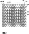
- FIG. 9shows a schematic stitch structure of a knitted surface with a knitted-in functional element in the form of plush
- FIG. 10shows a perspective view of sandwich plush sinkers of a knitting machine
- FIG. 11shows a schematic stitch structure of a knitted surface with two functional elements configured as tuck stitch fabric
- FIG. 12shows an enlarged representation of the region I of FIG. 11 ;
- FIG. 13shows a schematic plan view of a front side of a support element of a stimulus-inducing structure, the support element being provided with a plurality of stimulus-inducing functional elements;
- FIG. 14shows a schematic perspective view of the support element of FIG. 18 , viewed obliquely from above;
- FIG. 15shows a schematic plan view of a rear side of a support element facing away from the stimulus-inducing functional elements, the support element being provided with adhesive elements for releasable connection to a base element of an upper body article of apparel;
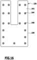
- FIG. 16shows a schematic plan view of a rear side of a support element facing away from the stimulus-inducing functional elements, the support element being provided with press fasteners for releasable connection to a base element of the upper body article of apparel;
- FIG. 17shows a schematic plan view of a pocket which contains a plurality of support elements, each of which comprises a plurality of stimulus-inducing functional elements, wherein part of a front side of the pocket facing the skin of the wearer in the worn state of the upper body article of apparel is broken away to show the support elements with the stimulus-inducing functional elements;
- FIG. 18shows a schematic perspective, partially sectional view of the pocket with the support elements of FIG. 17 .
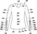
- FIGS. 1 and 2An upper body article of apparel shown in FIGS. 1 and 2 configured, by way of example, as a shirt 100 is shown in FIG. 1 from the front and in FIG. 2 from the rear and comprises a trunk region 214 , the front side 212 of which extends from two shoulder regions 216 and a collar 218 arranged therebetween downwardly via a chest region 220 and an abdominal region 222 to a lower border 224 (see FIG. 1 ).
- a rear side 226 of the trunk region 214extends from the shoulder regions 216 and the collar 218 downwardly over a back region 228 to the lower border 224 of the shirt 100 .
- An arm region 230 of the shirt 100is fixed to each of the shoulder regions 216 of the trunk region 214 .
- Each arm region 230comprises an upper arm region 232 , an elbow region 234 in the region of the elbow joint and a forearm region 235 .
- the shirt 100also has one or more compression regions 142 in which, in the worn state, the shirt 100 exerts a compression effect on the body of the wearer.
- This compression effectcan be achieved, in particular, through the working in of one or more elastic threads into the basic knit material of the shirt 100 .
- the elastic thread(s)can, in particular, comprise elastane.
- the shirt 100can have, at the front side 212 of the trunk region 214 , a first compression region 142 a which extends from the lower border 224 upwardly into the shoulder regions 216 and to the collar 218 of the shirt 100 .
- the shirt 100can have, at the rear side 226 of the trunk region 214 , a second compression region 142 b which extends from the lower border 224 via the back region 228 into the shoulder regions 216 and the collar 218 of the shirt 100 .
- the shirt 100can have a third compression region 142 c on each arm region 230 , extending from a lower border 270 of each arm region 230 upwardly as far as an upper edge 272 of the third compression region 142 c which preferably extends below the elbow region 234 of each arm region 230 .
- the shirt 100can have a fourth compression region 142 d on each arm region 230 , extending from a lower edge 274 of the fourth compression region 142 d upwardly as far as an upper edge 276 of each arm region 230 , at which the arm region 230 borders on the trunk region 214 of the shirt 100 .
- the lower edge 274 of the fourth compression region 142 dpreferably runs above each elbow region 234 .
- the lower edge 274 of the fourth compression region 142 d and the upper edge 272 of the third compression region 142 care separated from one another.
- the compression regions 142 c and 142 ddirectly adjoin one another and form a coherent compression region of the respective arm region 230 of the shirt 100 .
- the progression of the compression strength in the compression regions 142 a to 142 dcan be substantially constant.
- the gradient of the compression strengthis herein directed such that the compression strength both in the trunk region 214 and in the arm regions 230 always decreases in the direction toward the chest region 220 .
- the relative compression strength in the chest region 220is from zero to approximately 30% of the maximum compression strength in the first compression region 142 a and in the shoulder regions 216 is from zero to approximately 60% of the maximum compression strength in the first compression region 142 a.
- the maximum compression strength in the first compression region 142 ais preferably not more than approximately 12 mm Hg.
- the relative compression strength in the part of the back region 228 lying opposite the chest region 220is preferably from zero to approximately 30% of the maximum compression strength in the second compression region 142 b and in the shoulder regions 216 is preferably from zero to approximately 60% of the maximum compression strength in the second compression region 142 b.
- the maximum compression strength in the second compression region 142 bis preferably not more than approximately 12 mm Hg.
- the compression strengthpreferably decreases from the lower border 270 to the upper edge 272 .
- the compression strengthpreferably decreases from the lower edge 274 to the upper edge 276 .
- the arm regions 230preferably have no compression effect.
- the compression strengthis preferably substantially the same as in the shoulder regions 216 of the trunk region 214 .
- the arm regions 230 of the shirt 100are preferably fixedly attached to the trunk region 214 .
- the arm regions 230can have any desired length up to a full arm length.
- the trunk region 214 and the arm regions 230are made of an elastically yielding material.
- a base element 170 of the shirt 100can be made of an elastic base material, preferably a knitted fabric.
- the yarns and threads used for manufacturing the shirt 100can be of natural as well as of synthetic origin.
- the use of a combination of natural and synthetic fibrous materialsis also possible.
- Each stimulus-inducing structure 156comprises functional elements 158 which, in the worn state of the shirt 100 , bring about a sensory stimulus effect and a proprioceptive stimulation of the musculature of the wearer.
- This stimulationleads to increased muscle activity and improves the synchronisation of the wearer.
- the functional elements 158are preferably configured as raised portions which are arranged on the inside of the shirt 100 and act directly on the skin of the wearer.
- thermoplastic or thermosetting polymerswhich can optionally contain additives, are suitable as a material for the raised portions.
- Silicones and PVC-based plastisolshave proved to be particularly suitable.
- Functional elements 158 made of such materialscan be applied, for example, by a printing method, in particular by a stencil printing method or a silk screen printing method, onto the inside of the basic knit material 122 of the shirt 100 .
- the functional elements 158can be made particularly in the form of raised portions, but also with textile materials and/or textile constructions, which lead to the formation of a raised portion, for example by means of a plush configuration, projecting toward the skin of the wearer.
- the stimulationtakes place locally limited, in particular substantially in point form.
- the functional elements 158have a largest extent of not more than approximately 1.0 cm, preferably not more than approximately 0.6 cm, in particular not more than approximately 0.3 cm.
- the largest extent of the functional elements 158is at least approximately 0.2 cm.
- the height of the functional elements 158is at least approximately 0.1 cm, in particular at least approximately 0.2 cm.
- the height of the functional elements 158is not more than approximately 0.6 cm, in particular not more than approximately 0.4 cm.
- the functional elements 158are made of a material with a Shore A hardness of at least approximately 20.
- the Shore A hardnesscan be determined according to DIN 53505 or DIN EN ISO 868.
- the functional elements 158can be made of a material with a Shore D hardness of at least approximately 20 and/or not more than approximately 90.
- the Shore D hardnesscan be determined according to DIN 53505 or DIN ISO 7619-1.
- the stimulus-inducing structures 156are preferably arranged in stimulus induction zones 154 along the courses of the muscles and/or the tendons.
- Each stimulus-inducing structure 156comprises functional elements 158 which, in the worn state of the shirt 100 , bring about a sensory stimulus effect and a proprioceptive stimulation of the musculature of the wearer.
- the functional elements 158are preferably configured as raised portions arranged on the inside of the shirt 100 , so that they can act directly on the skin of the wearer.
- the shirt 100can have a stimulus induction zone 154 a , which substantially completely covers the thoracolumbar fascia of the wearer in the worn state of the upper body article of apparel.
- the stimulus induction zone 154 ais preferably configured as a rectangle with a width (extent parallel to the lower border 224 ) of approximately 10 cm to approximately 15 cm and a height (extent along the spinal column line 278 which, in the worn state of the shirt 100 , follows the course of the spinal column of the wearer) of approximately 8 cm to approximately 15 cm.
- the outer contour 280 of the stimulus induction zone 154 ais preferably substantially configured and oriented with mirror symmetry to the spinal column line 278 , which in the worn state of the shirt 100 corresponds to the position of the spinal column of the wearer.
- the spinal column line 278is configured as a marking strip or a marking line on the shirt 100 , which extends from the lower border 224 to the collar 218 and, when the shirt 100 is put on, can serve as a positioning aid for the wearer.
- Two further stimulus induction zones 154 b and 154 ccan be arranged to the left and right of the spinal column line 278 , parallel thereto, and preferably such that the stimulus induction zones 154 b and 154 c in the form of strips directly adjoin the stimulus induction zone 154 a at their lower edge, each with a narrow side, and extend upwardly to approximately the height of the vertebra T 10, in order thus to overlap the erector spinae muscle group as completely as possible.
- the spacing of the stimulus induction zones 154 b and 154 c from one another perpendicular to the spinal column line 278is preferably at least 1 cm and preferably not more than 4 cm. It is thereby achieved that, in the worn state of the shirt 100 , overlapping of the stimulus induction zones 154 b and 154 c with the processes of the spinal column is largely avoided to preclude nerve irritation.
- the width of the stimulus induction zones 154 b and 154 c themselves, that is their extent parallel to the lower border 224 ,is preferably from approximately 4 cm to approximately 6 cm.
- the extent of the stimulus induction zones 154 b and 154 c along the spinal column line 278is preferably from approximately 7 cm to approximately 17 cm.
- the shirt 100can have a stimulus induction zone 154 e in each of the arm regions 230 , extending from the lower border 270 of each arm region 230 via the forearm region 235 , the elbow region 234 and the upper arm region 232 as far as the upper edge 276 of the each arm region 230 .
- These stimulus induction zones 145 epreferably extend along the triceps brachii muscles and along the extensors of the forearm when the shirt 100 is worn.
- the outer contours 280 of the stimulus induction zones 154 esubstantially correspond to the outer contours of the triceps brachii muscles and/or the extensors of the forearm.
- the width of the stimulus induction zones 154that is, their extent in the peripheral direction of the shirt 100 is preferably dimensioned so that the individual anatomical differences of the different wearers are taken into account.
- the functional elements 158 of the stimulus induction zones 154are arranged on the inside of the shirt 100 , they do not have to be visible from the outside of the shirt 100 (as shown in FIGS. 1 and 2 ).
- the stimulus induction zones 154should be positioned, in the worn state, as precisely as possible on the respectively associated muscle and tendon structures.
- the stimulus-inducing structures 156 of the stimulus induction zones 154are mostly arranged, preferably by more than 90%, in one of the compression regions 142 of the shirt 100 .
- the local pressure loading of the skin of the weareris amplified by the functional elements 158 of the stimulus-inducing structures 156 by the large area compression effect of the compression regions 142 .
- a particularly effective proprioceptive stimulation of the musculature of the weareris brought about.
- the surface density of the functional elements 158 in the stimulus induction zones 154is preferably at least approximately 1 per cm 2 , in particular at least approximately 4 per cm 2 , particularly preferably at least approximately 8 per cm 2 .
- the surface density of the functional elements 158 in the stimulus induction zones 154is not more than approximately 25 per cm 2 , in particular not more than approximately 16 per cm 2 , particularly preferably not more than approximately 12 per cm 2 .
- the functional elements 158 of the stimulus-inducing structures 156are shown schematically as substantially circular.
- a single functional element 158 with a circular edgeis shown in FIG. 3 .
- the functional elements 158can, in principle, also have any desired other outer contours, for example, a triangular outer contour (see FIG. 4 ), a square outer contour (see FIG. 5 ), a rectangular outer contour (see FIG. 6 ) or an angled outer contour (see FIG. 7 ).
- a stimulus-inducing structure 156is not entirely isolated from one another, but rather adjoin one another at end points and thus form a coherent stimulus-inducing structure 156 , for example a stimulus-inducing structure 156 in the form of a honeycomb, as shown as a section in FIG. 8 .
- the functional elements 158do not cover the whole area of the respective stimulus induction zone 154 , but that surface sections 168 free from the functional elements 158 remain between the functional elements 158 and, in the worn state of the shirt 100 , do not exert any pressure on the skin of the wearer.
- the functional elements 158 of the stimulus-inducing structures 156can be formed, in particular, in that the relevant functional element 158 comprises a knitted region 174 which differs in its construction from an adjoining knitted region 176 of the basic knit material 172 .
- the knitted region 176 of the basic knit material 172 adjoining the functional element 158is knitted in a single jersey basic structure made of a ground thread 178 (shown in FIG. 9 without shading), which is plaited with a plaiting thread 180 (shown in FIG. 9 with shading).
- an additional plush thread 182is knitted into the basic knit material 172 with a plush structure.
- the knitted region 174 of the functional element 158is therefore selectively configured as a plush (sandwich or normal plush).
- This plushforms a structure raised above the basic knit material 172 .
- the plushcan be knitted with an ergonomic method (plated in shapes) or selectively knitted.
- the shape of the knitted region 174is, in principle, arbitrary; in particular, any of the outer contours shown in FIGS. 3 to 8 can be used for this.
- Each functional element 158 which comprises a knitted region 174 with a raised areais knitted separately from the other functional elements 158 by means of the plush thread 182 introduced additionally from a basic system of the knitting machine or from one or more knitting systems of the knitting machine, which forms stitches together with the basic knit material 172 .
- ground stitchesare created from the additional plush threads 182 with inwardly facing (that is, in the worn state of the upper body article of apparel, toward the skin of the wearer) plush loops 184 .
- the additional plush thread 182is introduced into an area which can be freely determined using a pattern and cut, for example, by means of a saw and a top blade of the knitting machine, so that individual functional elements 158 arranged separately from one another are produced.
- a knitting machinewhich has needles 186 and plush sinkers 188 can be used, as illustrated schematically in FIG. 10 .
- the plush sinkers 188 shown in FIG. 10are sandwich plush sinkers. Alternatively thereto, however, other knocking-over sinkers, in particular, normal plush sinkers can be used.
- Each of the plush sinkers 188has a foot 190 , a shaft 192 , a forward guide part 194 arranged between the shaft 192 and the foot 190 , a sinker beak 196 arranged above the shaft, a throat 198 arranged above the sinker beak 196 and a plush nib 199 arranged above the throat.
- the course of the plaiting thread 180 and of the plush thread 182 over the plush sinkers 188 and the needles 186is also shown in FIG. 10 .
- the ground thread 178runs directly under the plaiting thread 180 and in the representation in FIG. 10 is covered by the plaiting thread 180 .
- the plush thread 182is brought to the outside of the fabric.
- ground thread 178 and the plaiting thread 180 of the basic knit material 172can be used as the ground thread 178 and the plaiting thread 180 of the basic knit material 172 .
- a synthetic fibre materialmade, for example, of polypropylene in combination with a hot-melt adhesive material made, for example, of polyester.
- a polyproylene filament yarnfor example, a twisted dtex 84/F25/2 yarn, made of 2 threads of 25 filaments each
- a relatively low melting pointin the region of 165° C. to approximately 175° C. and a softening point in the region of 150° C. to 155° C.
- PES Grilon KE 60with a softening point in the range of 55° C. to 65° C. and a usage temperature of 80° C. to 110° C.
- the combination of these materials forming the plush thread 182can be made, for example, by intermingling or entwining.
- a twisting processis less favoured in order to obtain extensive neutrality in the twisting tendency.
- the thread construction forming the plush thread 182can be very readily used in the stitch forming process of the knitting process due to its retained softness.
- the hardness of the functional elements 158 made in this waycan be influenced, for example, by the selection of the treatment temperature during the heat treatment.
- a higher treatment temperatureleads, in principle, to a higher level of hardness of the functional elements 158 , since a larger proportion of the hot-melt adhesive material is melted and binds to the other materials in the knitted region 174 of the functional element 158 , so that the functional element 158 becomes stiffer.
- the heat treatmentcan be performed after knitting the knitted region 174 of the functional element 158 , for example, by tumbling, form fixing, or by applying hot air.
- FIG. 12is an enlarged section of the region I of the fabric, shown at top left in FIG. 11 .
- the basic knit material 172is formed from a ground thread 178 (shown without shading in FIGS. 11 and 12 ) and a plaiting thread 180 (shown with shading in FIGS. 11 and 12 ).
- a functional element 158 in the form of a region which is raised relative to the basic knit material 172is obtained in this embodiment in that a tuck stitch fabric is created which comprises a plurality of tuck stitch loops 200 over a plurality of, in the exemplary embodiment shown eight, stitch rows and with a repeat of a plurality of, in the exemplary embodiment shown, six, stitch wales in a single jersey knitted fabric.
- a hot-melt adhesive thread 204(shown dotted in FIGS. 11 and 12 ) can be worked in by plaiting as an additional plaiting thread 202 .
- a hot-melt adhesive thread 204 of this typecan comprise, for example, polyester or copolyamide.
- the hot-melt adhesive material PES Grilon KE 60 made of polyester (with a softening point of 55° C. to 65° C.) or the hot-melt adhesive material Grilon KE 85 Copolyamide made of copolyamide with a softening point of 80° C. to 90° C.can be used as the hot-melt adhesive thread 204 .
- ground thread 178 and the plaiting thread 180 for the basic knit material 172can be used as the ground thread 178 and the plaiting thread 180 for the basic knit material 172 .
- the elastic covering material CT 6416consisting of an elastane thread with a fineness of dtex 17 covered with a polyamide thread having a dtex of 16F10 is used as the ground thread 178 and a polyamide yarn with a dtex of 78/68/2 is used as the plaiting thread 180 .
- the ground thread 178 , the plaiting thread 180 and the hot-melt adhesive thread 204are floated to form the tuck stitch loops 200 during the formation of a plurality of, for example eight, stitch rows and are then cast off.
- FIG. 11two functional elements 158 made in this way are shown, offset to one another in a diagonal direction of the fabric.
- At least one stimulus-inducing structure 156can comprise at least one support element 236 (see FIG. 13 ) on which a plurality of functional elements 158 are provided.
- the support element 236 having the functional elements 158can be manufactured separately from the base element 170 of the upper body article of apparel and then releasably or non-releasably connected to the base element 170 of the upper body article of apparel.
- a support element 236it is provided that all the functional elements 158 of a stimulus induction zone 154 are arranged on the relevant support element 236 , so that for manufacturing the stimulus-inducing structure 156 of the respective stimulus induction zone 154 , only a single support element 158 is needed.
- an outer contour 238 of the support element 236preferably substantially matches the outer contour 280 of the associated stimulus induction zone 154 .
- the outer contour 238 thereofmatches the outer contour 280 of the combined stimulus induction zone 154 d on the rear side of the shirt 100 (see FIG. 2 ).
- a support element of this typecan be manufactured, for example, as an injection moulded part or as a film of a suitable plastics material.
- the support element 236can comprise a textile material, for example a knitted fabric.
- the support element 236is arranged on the base element 170 of the upper body article of apparel such that the stimulus-inducing functional elements 158 lie on a front side 240 of the support element 236 facing away from the base element 170 of the upper body article of apparel and, in the worn state of the upper body article of apparel, face toward the body of the wearer.
- the rear side 242 of the support element 236 shown in FIG. 15which, in the mounted state of the support element 236 , faces toward the base element 170 of the upper body article of apparel can be provided with fastening devices 244 .
- the fastening devices 244can be configured, for example, as adhesion elements 246 which cooperate with adhesion elements (not shown) on the base element 170 of the upper body article of apparel in order to fasten the support element 236 releasably on the base element 170 of the upper body article of apparel.
- the adhesion elements 246can form a constituent part of a touch-and-close fastener or a hook-and-loop fastener.
- the fastening devices 244are configured as locking elements 248 which are lockable to base element-side locking elements (not shown), in order to fasten the support element 236 releasably on the base element 170 of the upper body article of apparel.
- At least one support element-side locking element 248 and a base element-side locking element cooperating therewithtogether form a press fastener.
- the functional elements 158do not make direct contact with the skin of the wearer of the upper body article of apparel, but rather that, in the worn state of the upper body article of apparel, a covering 250 is arranged between the functional elements 158 and the body of the wearer.
- the covering 250can be formed, for example, from a textile material or a film, in particular a plastics film.
- An outer contour 252 of the covering 250preferably substantially matches the outer contour 280 of the relevant stimulus induction zone 154 .
- the covering 250can be connected, for example, by means of a seam 254 , to a rear wall 256 manufactured separately from the base element 170 , for example from a textile material or a film, in particular a plastics material and, together with the rear wall 256 , can thus form a pocket 258 in which the functional elements 158 of the stimulus-inducing structure 156 are accommodated.
- the pocket 258is assembled from the covering 250 and the rear wall 256 separately from the base element 170 before the pocket 258 as a whole is non-releasably or releasably fastened to the base element 170 of the upper body article of apparel.
- the pocket 258can be closed along its outer contour or can have an opening through which the functional elements 158 and, in particular, the support elements 236 supporting the functional elements 158 can be introduced into the pocket 258 .
- all the functional elements 158 of the stimulus-inducing structure 156are arranged on a single support element 236 .
- the stimulus-inducing structure 156has a plurality of support elements 236 , each of which carries a plurality of stimulus-inducing functional elements 158 .
- the support elements 236can be manufactured separately from the covering 250 and separately from the rear wall 256 and subsequently connected to the rear wall 256 and/or to the covering 250 , for example, by adhesion, welding and/or sewing.
- the rear side of the pocket 258 opposing the covering 250is not formed by means of a rear wall 256 configured separately from the base element 170 , but rather by means of a section 260 of the base element 170 .
- the support elements 236are connected to the section 260 of the base element 170 , for example, by means of adhesion, welding and/or sewing.
- a biasing element(not shown) which, in the worn state of the upper body article of apparel, biases the functional elements 158 toward the body of the wearer, in order thus to amplify the application pressure of the functional elements 158 onto the skin of the wearer through the covering 250 .
- a biasing element of this typecan comprise, for example, a foam material inlay.
- biasing elementcan be useful, in particular, if the body of the wearer of the upper body article of apparel is concavely shaped in the region in which the relevant stimulus induction zone 154 is arranged.
- a covering 250 between the functional elements 158 and the body of the wearer of the upper body article of apparelis particularly advantageous if the functional elements 158 are configured relatively hard, relatively high and/or relatively pointed.
Landscapes
- Engineering & Computer Science (AREA)
- Textile Engineering (AREA)
- Health & Medical Sciences (AREA)
- General Health & Medical Sciences (AREA)
- Physical Education & Sports Medicine (AREA)
- Professional, Industrial, Or Sporting Protective Garments (AREA)
- Socks And Pantyhose (AREA)
- Outer Garments And Coats (AREA)
- Orthopedics, Nursing, And Contraception (AREA)
- Carbon And Carbon Compounds (AREA)
- Crystals, And After-Treatments Of Crystals (AREA)
Abstract
Description
- single jersey—unplated;
- single jersey—plated (RL-p);
- single jersey—tuck (RL-F);
- single jersey—knop (RL-N);
- single jersey—terry (RL-P); and
- single jersey—floated (RL-h).
Claims (36)
Priority Applications (1)
| Application Number | Priority Date | Filing Date | Title |
|---|---|---|---|
| US17/135,334US12053035B2 (en) | 2012-09-12 | 2020-12-28 | Upper body article of apparel |
Applications Claiming Priority (5)
| Application Number | Priority Date | Filing Date | Title |
|---|---|---|---|
| DE102012216180 | 2012-09-12 | ||
| DE102012216180.5ADE102012216180A1 (en) | 2012-09-12 | 2012-09-12 | Leg garment |
| PCT/EP2013/068916WO2014041077A1 (en) | 2012-09-12 | 2013-09-12 | Upper body covering item |
| US14/641,215US10905174B2 (en) | 2012-09-12 | 2015-03-06 | Upper body article of apparel |
| US17/135,334US12053035B2 (en) | 2012-09-12 | 2020-12-28 | Upper body article of apparel |
Related Parent Applications (1)
| Application Number | Title | Priority Date | Filing Date |
|---|---|---|---|
| US14/641,215ContinuationUS10905174B2 (en) | 2012-09-12 | 2015-03-06 | Upper body article of apparel |
Publications (2)
| Publication Number | Publication Date |
|---|---|
| US20210112888A1 US20210112888A1 (en) | 2021-04-22 |
| US12053035B2true US12053035B2 (en) | 2024-08-06 |
Family
ID=49165747
Family Applications (4)
| Application Number | Title | Priority Date | Filing Date |
|---|---|---|---|
| US14/641,215Active2035-07-14US10905174B2 (en) | 2012-09-12 | 2015-03-06 | Upper body article of apparel |
| US14/641,195Active2035-09-05US10779586B2 (en) | 2012-09-12 | 2015-03-06 | Leg apparel |
| US16/935,053Active2034-05-03US11684093B2 (en) | 2012-09-12 | 2020-07-21 | Leg apparel |
| US17/135,334Active2036-01-29US12053035B2 (en) | 2012-09-12 | 2020-12-28 | Upper body article of apparel |
Family Applications Before (3)
| Application Number | Title | Priority Date | Filing Date |
|---|---|---|---|
| US14/641,215Active2035-07-14US10905174B2 (en) | 2012-09-12 | 2015-03-06 | Upper body article of apparel |
| US14/641,195Active2035-09-05US10779586B2 (en) | 2012-09-12 | 2015-03-06 | Leg apparel |
| US16/935,053Active2034-05-03US11684093B2 (en) | 2012-09-12 | 2020-07-21 | Leg apparel |
Country Status (15)
| Country | Link |
|---|---|
| US (4) | US10905174B2 (en) |
| EP (4) | EP2895020B2 (en) |
| CN (6) | CN108936862A (en) |
| DE (1) | DE102012216180A1 (en) |
| DK (2) | DK3248490T3 (en) |
| ES (2) | ES2733080T3 (en) |
| HK (1) | HK1206210A1 (en) |
| HR (2) | HRP20191155T1 (en) |
| HU (2) | HUE043936T2 (en) |
| PL (2) | PL3243396T3 (en) |
| PT (2) | PT3243396T (en) |
| RS (2) | RS58987B1 (en) |
| SI (2) | SI3243396T1 (en) |
| TR (2) | TR201905904T4 (en) |
| WO (2) | WO2014041075A1 (en) |
Families Citing this family (34)
| Publication number | Priority date | Publication date | Assignee | Title |
|---|---|---|---|---|
| DE102012216180A1 (en) | 2012-09-12 | 2014-03-13 | Falke Kgaa | Leg garment |
| DE102014103309A1 (en) | 2014-03-12 | 2015-09-17 | Falke Kgaa | Method of making a garment and garment |
| US20150264995A1 (en)* | 2014-03-24 | 2015-09-24 | Henry Lucius Hilderbrand, IV | Grip-Enhancing Sportswear and Methods of Manufacturing the Same |
| DE202014010687U1 (en)* | 2014-07-28 | 2016-05-18 | Hexonia Gmbh | Textile garment with a ballistic protective equipment |
| DE102014111939A1 (en)* | 2014-08-21 | 2016-02-25 | Ntt New Textile Technologies Gmbh | Method of making a garment |
| USD764750S1 (en)* | 2015-01-21 | 2016-08-30 | Nicholas Ballesteros | Set of shirt sleeves |
| DK3273816T3 (en) | 2015-03-27 | 2021-02-08 | Trere Innovation S R L | Garment with elastic inserts made using circular knitting machines |
| CA2986589C (en) | 2015-05-22 | 2022-11-22 | Nike Innovate C.V. | Training tight with preconfigured compression zones and integrated structure patterns |
| US20170035120A1 (en)* | 2015-08-03 | 2017-02-09 | Tbl Licensing Llc | Sock with selective yarn placement |
| DE102015119654A1 (en)* | 2015-11-13 | 2017-05-18 | Falke Kgaa | garment |
| DE102015119657A1 (en)* | 2015-11-13 | 2017-05-18 | Falke Kgaa | garment |
| CN106345113A (en)* | 2016-11-04 | 2017-01-25 | 浙江华尔纺织科技有限公司 | Leg coat |
| USD849390S1 (en)* | 2017-03-14 | 2019-05-28 | Sultan Abdul-Malik | Compression sock |
| EP3381422A1 (en)* | 2017-03-29 | 2018-10-03 | FXF GmbH | Foot and/or ankle bandage which interacts with near-surface nerves |
| US10743805B2 (en) | 2017-06-02 | 2020-08-18 | International Business Machines Corporation | Haptic interface for generating preflex stimulation |
| WO2019003145A1 (en)* | 2017-06-27 | 2019-01-03 | Peúgas Carlos Maia, Lda | Sock for preventing ankle injury |
| EP3687326A4 (en)* | 2017-09-26 | 2021-07-07 | Fortiac Corporation | Non-stretch garment having knit stretch panels |
| WO2019116405A1 (en)* | 2017-12-12 | 2019-06-20 | Pro Eight S R L | Dynamic ventilation system for socks |
| USD840669S1 (en)* | 2017-12-29 | 2019-02-19 | Jockey International, Inc. | Sock |
| GB2587129B (en)* | 2018-03-28 | 2023-04-05 | Emeline Kuhner Stout | Energizing garment |
| EP3575463B1 (en)* | 2018-06-01 | 2023-04-05 | medi GmbH & Co. KG | Clothing item for legs, in particular socks |
| CN113242698A (en)* | 2018-06-15 | 2021-08-10 | 彪马欧洲公司 | Sports garment for team sports |
| US11819064B2 (en)* | 2018-11-30 | 2023-11-21 | Nike, Inc. | Upper torso garment with varied tuck binder knit structure |
| DE102018132640A1 (en) | 2018-12-18 | 2020-06-18 | Ottobock Se & Co. Kgaa | Elastic sheet material, bandage made of it and process for its production |
| PT3733941T (en)* | 2019-05-03 | 2023-01-19 | Medi Gmbh & Co Kg | Compressive knitted item with clinging effect |
| FR3103103A1 (en)* | 2019-11-18 | 2021-05-21 | Thuasne | COMPRESSION AND / OR RESTRAINT GARMENT FOR THE TREATMENT OF LYMPHOEDEMA |
| DE202020102580U1 (en) | 2020-05-07 | 2021-08-11 | Julius Zorn Gmbh | Compression knitted fabrics and compression articles, in particular for tissue, nerve, muscle and fascia stimulation |
| DE102020112429A1 (en) | 2020-05-07 | 2021-11-11 | Julius Zorn Gmbh | Compression knitted fabrics and compression articles, in particular for tissue, nerve, muscle and fascia stimulation |
| IT202000010843A1 (en)* | 2020-05-13 | 2021-11-13 | Coffinardi & Delpanno Ind Srl | SOCKS WITH BIOMECHANICAL, CIRCULATORY AND NEUROLOGICAL FUNCTIONAL EFFECTIVENESS |
| IT202000032024A1 (en)* | 2020-12-23 | 2022-06-23 | Coffinardi & Delpanno Ind Srl | SOCK OR SIMILAR INCLUDING A SOCK STRUCTURE WITH BIOMECHANICAL EFFECTS PARTICULARLY SUITABLE FOR FOOTBALL, CYCLING AND SIMILAR SPORTS |
| USD928458S1 (en)* | 2021-02-03 | 2021-08-24 | Xiamen Wenmi Technology Co., Ltd. | Long sleeve shirt |
| JP7488598B2 (en) | 2022-09-28 | 2024-05-22 | 株式会社Aband | socks |
| WO2024168020A1 (en)* | 2023-02-07 | 2024-08-15 | Qolify Llc | Compression garments and methods of manufacture |
| CN118716715A (en)* | 2024-06-17 | 2024-10-01 | 苏州闰博尔纺织科技有限公司 | A fully-formed ski compression suit knitted with four needle beds and a knitting method thereof |
Citations (74)
| Publication number | Priority date | Publication date | Assignee | Title |
|---|---|---|---|---|
| AT193541B (en) | 1955-11-18 | 1957-11-25 | Elsa Hammerer Fa | Medical varicose vein stocking |
| DE1842303U (en) | 1961-05-19 | 1961-11-30 | Strumpf Fabriken A Marum Wwe G | OUTSOLE FOR STOCKINGS OR SOCKS. |
| US3013420A (en) | 1957-12-03 | 1961-12-19 | Cormier Hosiery Mills Inc | Elastic fabric for a stocking top |
| US3159990A (en) | 1961-10-18 | 1964-12-08 | Stretch Corp U | Elastic bobby sock top |
| US3216223A (en) | 1963-07-16 | 1965-11-09 | High Point Seamless Hosiery Mi | Stocking and method of making the same |
| FR2115802A5 (en) | 1970-11-25 | 1972-07-07 | Tornhajm Gilbert | Close-fitting garments - from knitted ribbed constructions |
| GB1444445A (en) | 1972-11-24 | 1976-07-28 | Johnson & Johnson | Non-slip waistband product and method for manufacturing the same |
| GB1552320A (en) | 1975-10-25 | 1979-09-12 | Haanen K T | Stocking type ankle protector for athletes |
| GB2029468A (en) | 1978-09-07 | 1980-03-19 | Kayser Roth Hosiery Inc | Tube sock with mock rib leg and method of knitting |
| US4216547A (en) | 1979-02-02 | 1980-08-12 | Picchione P Vincent | Injury protection device for athletes |
| US4333976A (en) | 1978-03-15 | 1982-06-08 | Toray Industries, Incorporated | Composite woven or knitted fabric |
| US4372998A (en) | 1980-08-26 | 1983-02-08 | Shimada Shoji Co., Ltd. | Heat adhesive tapes for finishing hems of trousers, skirts and like articles |
| EP0553616A1 (en) | 1992-01-29 | 1993-08-04 | Robert Bosch Gmbh | Windscreen wiper for a motor vehicle |
| US5263923A (en) | 1991-05-22 | 1993-11-23 | Wacoal Corp. | Wearing article for wearing in pressed relation to human body surface |
| US5329640A (en) | 1993-04-14 | 1994-07-19 | Hourigan James T | Cushioned sock |
| US5791164A (en) | 1996-06-17 | 1998-08-11 | Milliken Research Corporation | Outdoor sporting fabric |
| US5857947A (en) | 1997-07-14 | 1999-01-12 | Dicker; Timothy P. | Energy expenditure/training garment |
| EP0919145A2 (en) | 1997-10-14 | 1999-06-02 | Calzificio Pinelli S.r.l. | Girdle for tights |
| EP0964091A2 (en) | 1998-06-12 | 1999-12-15 | CSP International Industria Calze S.p.A. | Stocking, particularly of the pantyhose type, with shaping effect for slender and straight legs |
| US6138281A (en) | 1998-06-26 | 2000-10-31 | Vegas Spa | Sock with improved comfort |
| EP1074652A1 (en) | 1999-07-29 | 2001-02-07 | Breilly S.A. Société dite: | Knitted sock having a relaxing effect |
| DE19946019A1 (en) | 1999-09-25 | 2001-03-29 | Bauerfeind Orthopaedie Gmbh & | Compression hose of elastic textile base material for treatment of leg ailments, comprises a rhombic grid formed by helically oriented strips whose elasticity is greater than that of the base material |
| US6314584B1 (en) | 1997-11-03 | 2001-11-13 | Vdc Innovation S.A.R.L. | Massaging socks, knee-socks and tights |
| US6378138B1 (en) | 2001-04-19 | 2002-04-30 | Ridgley Aleta O'dell | Heavenly hosiery |
| US6446264B2 (en) | 1999-12-17 | 2002-09-10 | Speedo International Limited | Articles of clothing |
| EP1241286A1 (en) | 2001-03-05 | 2002-09-18 | Karin Co., Ltd | Underwear |
| US6673421B1 (en) | 1999-08-24 | 2004-01-06 | Beiersdorf Ag | Stocking having a seamlessly attached antislip coating in the edge region of the upper opening |
| US20040016041A1 (en) | 2002-05-23 | 2004-01-29 | Mizuno Corporation | Undershirt |
| US20040255358A1 (en) | 2003-04-15 | 2004-12-23 | Wacoal Corp. | Pants garment |
| US20050112582A1 (en) | 1989-02-09 | 2005-05-26 | Toshimitsu Matsui | Antibodies for the alpha platelet-derived growth factor receptor |
| US20050193461A1 (en) | 2004-02-10 | 2005-09-08 | Adidas International Marketing B.V. | Garment |
| US20060026740A1 (en) | 2004-08-09 | 2006-02-09 | Vargas Stacey L | Pilates sock with tactile posture feedback |
| US20060080754A1 (en) | 2004-10-14 | 2006-04-20 | Nike, Inc. | Article of apparel incorporating an embossed material |
| US20060169004A1 (en) | 2004-12-24 | 2006-08-03 | Nicolas Belluye | Tights presenting a localized compression effect for practicing a sport |
| US20060230488A1 (en) | 2005-04-15 | 2006-10-19 | Sheryl Rudolph | Equestrian riding breeches garment and method for its manufacture |
| US20060260024A1 (en) | 2005-05-18 | 2006-11-23 | Seung-Hee Lee | Sock having part for preventing slipping-down phenomenon of sock |
| US20070074328A1 (en) | 2005-09-30 | 2007-04-05 | Nike, Inc. | Article of apparel with zonal stretch resistance |
| WO2007046298A1 (en) | 2005-10-18 | 2007-04-26 | Wacoal Corp. | Garment |
| WO2007147980A2 (en) | 2006-06-22 | 2007-12-27 | Dbapparel Operations | Knitted foot and/or legwear, particular relaxing half hose |
| US20080083055A1 (en) | 2004-10-19 | 2008-04-10 | Onyone Co., Ltd | Sports Garment |
| US20080178359A1 (en) | 2007-01-29 | 2008-07-31 | Morning Pride Manufacturing, L.L.C. | Pad wearable over articulated joint |
| US7434423B1 (en) | 2004-04-30 | 2008-10-14 | Carolon Company | Impact protection and performance garment |
| US20080295230A1 (en) | 2007-05-31 | 2008-12-04 | Nike, Inc. | Articles of Apparel Providing Enhanced Body Position Feedback |
| US20080295216A1 (en) | 2007-05-31 | 2008-12-04 | Nike, Inc. | Articles of Apparel Providing Enhanced Body Position Feedback |
| US20090025115A1 (en) | 2004-09-23 | 2009-01-29 | Skins Compression Garments Pty Limited | Compression Garments And A Method Of Manufacture |
| US20090062704A1 (en) | 2007-05-23 | 2009-03-05 | Alignmed, Inc. | Posture improvement devices and methods for use |
| US7516498B2 (en) | 2004-12-21 | 2009-04-14 | Alignmed, Llc | Garment with enhanced knee support |
| US20090133181A1 (en)* | 2007-05-31 | 2009-05-28 | Nike, Inc. | Articles of apparel providing enhanced body position feedback |
| US20090275873A1 (en) | 2008-05-02 | 2009-11-05 | Julius Zorn Gmbh | Circular knit fabric for use in compression therapy |
| US20100004563A1 (en) | 2008-07-01 | 2010-01-07 | Circaid Medical Products | Graduated Compression Device for the Treatment of Circulatory Disorders |
| US20100010568A1 (en) | 2007-05-23 | 2010-01-14 | Dr. Brown Designs, Llc | Sensory motor stimulation garment and method |
| US20100050699A1 (en) | 2008-06-06 | 2010-03-04 | Nathaniel H. Kolmes | Lightweight, cut and/or abrasion resistant garments, and related protective wear |
| US20100050313A1 (en) | 2008-08-26 | 2010-03-04 | Shackelford Jr John P | Posture improving device |
| CN201459349U (en) | 2009-08-07 | 2010-05-12 | 东莞润达弹性织造有限公司 | Spandex knitted ribbon |
| US20100130903A1 (en) | 2008-11-25 | 2010-05-27 | Mmi-Ipco, Llc | Compression Garments |
| CN101766334A (en) | 2009-12-24 | 2010-07-07 | 平湖市金象纺织品有限公司 | Beach socks |
| AT11230U2 (en) | 2010-01-20 | 2010-07-15 | Ines Mueller | DRESS |
| US20100256717A1 (en)* | 2007-05-23 | 2010-10-07 | Brown Timothy W | Sensory Motor Stimulation Garment and Method |
| US20100299799A1 (en) | 2007-05-11 | 2010-12-02 | Decathlon | Clothing item with heterogeneous contention effect for practising a sport |
| US20110040222A1 (en) | 2008-04-21 | 2011-02-17 | Medi Gmbh & Co. Kg | Orthopedic auxiliary aid comprising an introduceable functional element |
| DE102009050031B3 (en) | 2009-10-21 | 2011-03-03 | Hermann Christiansen | Material for a product for compressing body parts, and a medical bandage and a garment made from this material |
| US20110083246A1 (en) | 2009-10-14 | 2011-04-14 | Ranil Kirthi Vitarana | Garment with Elastomeric Coating |
| US20110107502A1 (en) | 2009-11-12 | 2011-05-12 | Todd Dalhausser | Training and recovery clothing and related methods |
| CN201929003U (en) | 2011-03-21 | 2011-08-17 | 简秋雪 | Reinforced butt lifter tummy control bodysuit |
| CN102273741A (en) | 2010-06-14 | 2011-12-14 | 萨洛蒙股份有限公司 | Close-fitting sports garment |
| CN202085728U (en) | 2010-12-25 | 2011-12-28 | 陆思烨 | Health care underpants |
| CN202143449U (en) | 2011-06-23 | 2012-02-15 | 深圳市美百年服装有限公司 | Posture correction health-care underwear |
| JP2012052276A (en) | 2010-09-03 | 2012-03-15 | Rushian:Kk | Inner wear |
| US20120070608A1 (en)* | 2004-06-24 | 2012-03-22 | MMI-, a Delaware corporation | Engineered fabric articles |
| DE202012007243U1 (en) | 2012-07-27 | 2012-08-23 | Christian Mertens | clothing unit |
| WO2012114209A1 (en) | 2011-02-25 | 2012-08-30 | Amarcod Industria Abbigliamento S.R.L. | Garment for the neuro-musculo-skeletal assistance |
| WO2013053370A1 (en) | 2011-10-11 | 2013-04-18 | Puma SE | Article of clothing |
| US20150173430A1 (en) | 2012-09-12 | 2015-06-25 | Falke Kgaa | Upper body article of apparel |
| US10426657B2 (en)* | 2014-10-03 | 2019-10-01 | Rachel's Remedies, LLC | Thermal device for treating breastfeeding conditions |
Family Cites Families (15)
| Publication number | Priority date | Publication date | Assignee | Title |
|---|---|---|---|---|
| AT11230B (en) | 1901-06-26 | 1903-03-26 | Nikolaus Dobrzanski | Automatic, laterally detachable rail car coupling. |
| US4195497A (en)* | 1977-06-29 | 1980-04-01 | Allstate Hosiery Sales, Inc. | Aerated stocking |
| DE4216650A1 (en) | 1992-01-29 | 1993-08-05 | Rudolf Weyergans | COSMETIC COMPRESSION STOCKING |
| DE29800791U1 (en) | 1998-01-20 | 1999-05-20 | Franz Falke-Rohen Strumpffabriken Zweigniederlassung der Franz Falke-Rohen, 57392 Schmallenberg | Asymmetric lace sock |
| EP1675990A4 (en)* | 2003-10-23 | 2007-02-14 | Lee Sara Corp | Seamless knit garments |
| US7007517B2 (en)* | 2004-08-02 | 2006-03-07 | Menzies—Southern Hosiery Mills, Inc. | Knit sock |
| CN101564204B (en)* | 2005-04-01 | 2010-12-08 | 郡是株式会社 | Clothes capable of being freely cut |
| US20100090365A1 (en)* | 2006-11-23 | 2010-04-15 | Basf Se | Method for the production of fibers |
| JP5414998B2 (en)* | 2007-08-21 | 2014-02-12 | 日清紡ホールディングス株式会社 | Adhesive tape |
| JP5102611B2 (en)* | 2007-12-27 | 2012-12-19 | 岡本株式会社 | socks |
| JP2009167552A (en)* | 2008-01-15 | 2009-07-30 | Tokai Thermo Kk | Padding cloth fabric for clothes, and clothes |
| CN201219516Y (en)* | 2008-06-19 | 2009-04-15 | 赖志佳 | Binding band |
| US20100056973A1 (en)* | 2008-08-28 | 2010-03-04 | Farrow Medical Innovations, Inc. | Therapeutic Compression Garments |
| JP5394875B2 (en)* | 2009-09-30 | 2014-01-22 | 日清紡テキスタイル株式会社 | Woven knitting |
| CN102166047A (en)* | 2011-03-09 | 2011-08-31 | 山东如意科技集团有限公司 | Hot melting line process for flat lining of radiation-proof suit |
- 2012
- 2012-09-12DEDE102012216180.5Apatent/DE102012216180A1/enactivePending
- 2013
- 2013-09-12DKDK17175094.6Tpatent/DK3248490T3/enactive
- 2013-09-12HUHUE17175094Apatent/HUE043936T2/enunknown
- 2013-09-12ESES17175094Tpatent/ES2733080T3/enactiveActive
- 2013-09-12EPEP13762119.9Apatent/EP2895020B2/enactiveActive
- 2013-09-12RSRS20190797Apatent/RS58987B1/enunknown
- 2013-09-12CNCN201810755934.4Apatent/CN108936862A/enactivePending
- 2013-09-12ESES17175200Tpatent/ES2733121T3/enactiveActive
- 2013-09-12SISI201331466Tpatent/SI3243396T1/enunknown
- 2013-09-12PLPL17175200Tpatent/PL3243396T3/enunknown
- 2013-09-12CNCN201811018930.4Apatent/CN109222267B/ennot_activeExpired - Fee Related
- 2013-09-12EPEP17175200.9Apatent/EP3243396B1/enactiveActive
- 2013-09-12CNCN201380047479.8Apatent/CN104619203A/enactivePending
- 2013-09-12WOPCT/EP2013/068914patent/WO2014041075A1/enactiveApplication Filing
- 2013-09-12SISI201331465Tpatent/SI3248490T1/enunknown
- 2013-09-12EPEP17175094.6Apatent/EP3248490B1/enactiveActive
- 2013-09-12PLPL17175094Tpatent/PL3248490T3/enunknown
- 2013-09-12WOPCT/EP2013/068916patent/WO2014041077A1/enactiveApplication Filing
- 2013-09-12PTPT17175200Tpatent/PT3243396T/enunknown
- 2013-09-12HKHK15107097.0Apatent/HK1206210A1/enunknown
- 2013-09-12HUHUE17175200Apatent/HUE043931T2/enunknown
- 2013-09-12RSRS20190798Apatent/RS58970B1/enunknown
- 2013-09-12TRTR2019/05904Tpatent/TR201905904T4/enunknown
- 2013-09-12TRTR2019/05356Tpatent/TR201905356T4/enunknown
- 2013-09-12CNCN201810756316.1Apatent/CN108813750B/ennot_activeExpired - Fee Related
- 2013-09-12DKDK17175200.9Tpatent/DK3243396T3/enactive
- 2013-09-12PTPT17175094Tpatent/PT3248490T/enunknown
- 2013-09-12CNCN201380047524.XApatent/CN104619205B/enactiveActive
- 2013-09-12CNCN201811019637.XApatent/CN109567284A/enactivePending
- 2013-09-12EPEP13762120.7Apatent/EP2895021B2/enactiveActive
- 2015
- 2015-03-06USUS14/641,215patent/US10905174B2/enactiveActive
- 2015-03-06USUS14/641,195patent/US10779586B2/enactiveActive
- 2019
- 2019-06-26HRHRP20191155TTpatent/HRP20191155T1/enunknown
- 2019-06-26HRHRP20191156TTpatent/HRP20191156T1/enunknown
- 2020
- 2020-07-21USUS16/935,053patent/US11684093B2/enactiveActive
- 2020-12-28USUS17/135,334patent/US12053035B2/enactiveActive
Patent Citations (86)
| Publication number | Priority date | Publication date | Assignee | Title |
|---|---|---|---|---|
| AT193541B (en) | 1955-11-18 | 1957-11-25 | Elsa Hammerer Fa | Medical varicose vein stocking |
| US3013420A (en) | 1957-12-03 | 1961-12-19 | Cormier Hosiery Mills Inc | Elastic fabric for a stocking top |
| DE1842303U (en) | 1961-05-19 | 1961-11-30 | Strumpf Fabriken A Marum Wwe G | OUTSOLE FOR STOCKINGS OR SOCKS. |
| US3159990A (en) | 1961-10-18 | 1964-12-08 | Stretch Corp U | Elastic bobby sock top |
| US3216223A (en) | 1963-07-16 | 1965-11-09 | High Point Seamless Hosiery Mi | Stocking and method of making the same |
| FR2115802A5 (en) | 1970-11-25 | 1972-07-07 | Tornhajm Gilbert | Close-fitting garments - from knitted ribbed constructions |
| GB1444445A (en) | 1972-11-24 | 1976-07-28 | Johnson & Johnson | Non-slip waistband product and method for manufacturing the same |
| GB1552320A (en) | 1975-10-25 | 1979-09-12 | Haanen K T | Stocking type ankle protector for athletes |
| US4333976A (en) | 1978-03-15 | 1982-06-08 | Toray Industries, Incorporated | Composite woven or knitted fabric |
| GB2029468A (en) | 1978-09-07 | 1980-03-19 | Kayser Roth Hosiery Inc | Tube sock with mock rib leg and method of knitting |
| US4216547A (en) | 1979-02-02 | 1980-08-12 | Picchione P Vincent | Injury protection device for athletes |
| US4372998A (en) | 1980-08-26 | 1983-02-08 | Shimada Shoji Co., Ltd. | Heat adhesive tapes for finishing hems of trousers, skirts and like articles |
| US20050112582A1 (en) | 1989-02-09 | 2005-05-26 | Toshimitsu Matsui | Antibodies for the alpha platelet-derived growth factor receptor |
| US5263923A (en) | 1991-05-22 | 1993-11-23 | Wacoal Corp. | Wearing article for wearing in pressed relation to human body surface |
| EP0553616A1 (en) | 1992-01-29 | 1993-08-04 | Robert Bosch Gmbh | Windscreen wiper for a motor vehicle |
| US5329640A (en) | 1993-04-14 | 1994-07-19 | Hourigan James T | Cushioned sock |
| US5791164A (en) | 1996-06-17 | 1998-08-11 | Milliken Research Corporation | Outdoor sporting fabric |
| US5857947A (en) | 1997-07-14 | 1999-01-12 | Dicker; Timothy P. | Energy expenditure/training garment |
| EP0919145A2 (en) | 1997-10-14 | 1999-06-02 | Calzificio Pinelli S.r.l. | Girdle for tights |
| US6314584B1 (en) | 1997-11-03 | 2001-11-13 | Vdc Innovation S.A.R.L. | Massaging socks, knee-socks and tights |
| EP0964091A2 (en) | 1998-06-12 | 1999-12-15 | CSP International Industria Calze S.p.A. | Stocking, particularly of the pantyhose type, with shaping effect for slender and straight legs |
| US6138281A (en) | 1998-06-26 | 2000-10-31 | Vegas Spa | Sock with improved comfort |
| EP1074652A1 (en) | 1999-07-29 | 2001-02-07 | Breilly S.A. Société dite: | Knitted sock having a relaxing effect |
| US6673421B1 (en) | 1999-08-24 | 2004-01-06 | Beiersdorf Ag | Stocking having a seamlessly attached antislip coating in the edge region of the upper opening |
| US6311334B1 (en) | 1999-09-17 | 2001-11-06 | Bauerfeind Orthopadie Gmbh & Co. Kg | Compression hose for the treatment of leg conditions |
| DE19946019A1 (en) | 1999-09-25 | 2001-03-29 | Bauerfeind Orthopaedie Gmbh & | Compression hose of elastic textile base material for treatment of leg ailments, comprises a rhombic grid formed by helically oriented strips whose elasticity is greater than that of the base material |
| US6446264B2 (en) | 1999-12-17 | 2002-09-10 | Speedo International Limited | Articles of clothing |
| EP1241286A1 (en) | 2001-03-05 | 2002-09-18 | Karin Co., Ltd | Underwear |
| US6378138B1 (en) | 2001-04-19 | 2002-04-30 | Ridgley Aleta O'dell | Heavenly hosiery |
| US20040016041A1 (en) | 2002-05-23 | 2004-01-29 | Mizuno Corporation | Undershirt |
| US20040255358A1 (en) | 2003-04-15 | 2004-12-23 | Wacoal Corp. | Pants garment |
| US20050193461A1 (en) | 2004-02-10 | 2005-09-08 | Adidas International Marketing B.V. | Garment |
| US7434423B1 (en) | 2004-04-30 | 2008-10-14 | Carolon Company | Impact protection and performance garment |
| US20120070608A1 (en)* | 2004-06-24 | 2012-03-22 | MMI-, a Delaware corporation | Engineered fabric articles |
| US20060026740A1 (en) | 2004-08-09 | 2006-02-09 | Vargas Stacey L | Pilates sock with tactile posture feedback |
| US20090025115A1 (en) | 2004-09-23 | 2009-01-29 | Skins Compression Garments Pty Limited | Compression Garments And A Method Of Manufacture |
| US20060080754A1 (en) | 2004-10-14 | 2006-04-20 | Nike, Inc. | Article of apparel incorporating an embossed material |
| US20080083055A1 (en) | 2004-10-19 | 2008-04-10 | Onyone Co., Ltd | Sports Garment |
| US7516498B2 (en) | 2004-12-21 | 2009-04-14 | Alignmed, Llc | Garment with enhanced knee support |
| US20060169004A1 (en) | 2004-12-24 | 2006-08-03 | Nicolas Belluye | Tights presenting a localized compression effect for practicing a sport |
| US20060230488A1 (en) | 2005-04-15 | 2006-10-19 | Sheryl Rudolph | Equestrian riding breeches garment and method for its manufacture |
| US20060260024A1 (en) | 2005-05-18 | 2006-11-23 | Seung-Hee Lee | Sock having part for preventing slipping-down phenomenon of sock |
| US20070074328A1 (en) | 2005-09-30 | 2007-04-05 | Nike, Inc. | Article of apparel with zonal stretch resistance |
| WO2007046298A1 (en) | 2005-10-18 | 2007-04-26 | Wacoal Corp. | Garment |
| WO2007147980A2 (en) | 2006-06-22 | 2007-12-27 | Dbapparel Operations | Knitted foot and/or legwear, particular relaxing half hose |
| US20080178359A1 (en) | 2007-01-29 | 2008-07-31 | Morning Pride Manufacturing, L.L.C. | Pad wearable over articulated joint |
| US20100299799A1 (en) | 2007-05-11 | 2010-12-02 | Decathlon | Clothing item with heterogeneous contention effect for practising a sport |
| US20090062704A1 (en) | 2007-05-23 | 2009-03-05 | Alignmed, Inc. | Posture improvement devices and methods for use |
| US20100010568A1 (en) | 2007-05-23 | 2010-01-14 | Dr. Brown Designs, Llc | Sensory motor stimulation garment and method |
| US20100256717A1 (en)* | 2007-05-23 | 2010-10-07 | Brown Timothy W | Sensory Motor Stimulation Garment and Method |
| US20080295230A1 (en) | 2007-05-31 | 2008-12-04 | Nike, Inc. | Articles of Apparel Providing Enhanced Body Position Feedback |
| US20080295216A1 (en) | 2007-05-31 | 2008-12-04 | Nike, Inc. | Articles of Apparel Providing Enhanced Body Position Feedback |
| US20090133181A1 (en)* | 2007-05-31 | 2009-05-28 | Nike, Inc. | Articles of apparel providing enhanced body position feedback |
| US7934267B2 (en) | 2007-05-31 | 2011-05-03 | Nike, Inc. | Articles of apparel providing enhanced body position feedback |
| US7996924B2 (en) | 2007-05-31 | 2011-08-16 | Nike, Inc. | Articles of apparel providing enhanced body position feedback |
| CN101715306A (en) | 2007-05-31 | 2010-05-26 | 耐克国际有限公司 | Article of apparel providing enhanced body position feedback |
| US20110040222A1 (en) | 2008-04-21 | 2011-02-17 | Medi Gmbh & Co. Kg | Orthopedic auxiliary aid comprising an introduceable functional element |
| US20090275873A1 (en) | 2008-05-02 | 2009-11-05 | Julius Zorn Gmbh | Circular knit fabric for use in compression therapy |
| US20100050699A1 (en) | 2008-06-06 | 2010-03-04 | Nathaniel H. Kolmes | Lightweight, cut and/or abrasion resistant garments, and related protective wear |
| US20100004563A1 (en) | 2008-07-01 | 2010-01-07 | Circaid Medical Products | Graduated Compression Device for the Treatment of Circulatory Disorders |
| US20100050313A1 (en) | 2008-08-26 | 2010-03-04 | Shackelford Jr John P | Posture improving device |
| US20100130903A1 (en) | 2008-11-25 | 2010-05-27 | Mmi-Ipco, Llc | Compression Garments |
| CN102264252A (en) | 2008-11-25 | 2011-11-30 | 耐克国际有限公司 | Clothing items that provide enhanced body position feedback |
| CN201459349U (en) | 2009-08-07 | 2010-05-12 | 东莞润达弹性织造有限公司 | Spandex knitted ribbon |
| US20110083246A1 (en) | 2009-10-14 | 2011-04-14 | Ranil Kirthi Vitarana | Garment with Elastomeric Coating |
| DE102009050031B3 (en) | 2009-10-21 | 2011-03-03 | Hermann Christiansen | Material for a product for compressing body parts, and a medical bandage and a garment made from this material |
| US20110092872A1 (en) | 2009-10-21 | 2011-04-21 | Hermann Christiansen | Medical compression therapy material, bandage and clothing piece |
| US20110107502A1 (en) | 2009-11-12 | 2011-05-12 | Todd Dalhausser | Training and recovery clothing and related methods |
| CN101766334A (en) | 2009-12-24 | 2010-07-07 | 平湖市金象纺织品有限公司 | Beach socks |
| AT11230U2 (en) | 2010-01-20 | 2010-07-15 | Ines Mueller | DRESS |
| CN102273741A (en) | 2010-06-14 | 2011-12-14 | 萨洛蒙股份有限公司 | Close-fitting sports garment |
| US20110302686A1 (en) | 2010-06-14 | 2011-12-15 | Salomon S.A.S | Close-fitting sports garment |
| JP2012052276A (en) | 2010-09-03 | 2012-03-15 | Rushian:Kk | Inner wear |
| CN202085728U (en) | 2010-12-25 | 2011-12-28 | 陆思烨 | Health care underpants |
| WO2012114209A1 (en) | 2011-02-25 | 2012-08-30 | Amarcod Industria Abbigliamento S.R.L. | Garment for the neuro-musculo-skeletal assistance |
| CN201929003U (en) | 2011-03-21 | 2011-08-17 | 简秋雪 | Reinforced butt lifter tummy control bodysuit |
| CN202143449U (en) | 2011-06-23 | 2012-02-15 | 深圳市美百年服装有限公司 | Posture correction health-care underwear |
| US20140230124A1 (en) | 2011-10-11 | 2014-08-21 | Puma SE | Article of clothing |
| WO2013053370A1 (en) | 2011-10-11 | 2013-04-18 | Puma SE | Article of clothing |
| DE202012007243U1 (en) | 2012-07-27 | 2012-08-23 | Christian Mertens | clothing unit |
| US20150173430A1 (en) | 2012-09-12 | 2015-06-25 | Falke Kgaa | Upper body article of apparel |
| US20150173428A1 (en) | 2012-09-12 | 2015-06-25 | Falke Kgaa | Leg apparel |
| US10779586B2 (en)* | 2012-09-12 | 2020-09-22 | Falke Kgaa | Leg apparel |
| US10905174B2 (en)* | 2012-09-12 | 2021-02-02 | Falke Kgaa | Upper body article of apparel |
| US11684093B2 (en)* | 2012-09-12 | 2023-06-27 | Falke Kgaa | Leg apparel |
| US10426657B2 (en)* | 2014-10-03 | 2019-10-01 | Rachel's Remedies, LLC | Thermal device for treating breastfeeding conditions |
Non-Patent Citations (46)
| Title |
|---|
| "Knitting Handbook Second Volume (weft knitting warp knitting)," Oct. 31, 1982, Mainly Edited by Shanghai Knitting Industry Co., Ltd., pp. 9-11, 10 pages. English translation of pp. 9-11 included. |
| A variety of articles from professional journals published in the years Jan. through Mar. 1999 through 2001, reporting on the product "Compressana magic," 38 pages. |
| An excerpt from the price list 2001 of the company Compressana GmbH, wherein the pantyhose "Compressana magic" and the trunks "Compressana magic pants" are offered for sale, 3 pages. |
| An invoice issued by the Italian manufacturing company Calzificio Pinelli to the German sales company Compressana GmbH, related to the delivery of trunks and pantyhoses of the type "magic", dated Jun. 3, 1999, 1 page. |
| China Intellectual Property Administration, "Notification of the Second Office Action," issued in connection with Chinese Patent Application No. 201811018930.4, dated Jun. 23, 2020, 38 pages. English translation included. |
| China Intellectual Property Administration, "Notification of the Third Office Action," issued in connection with Chinese Patent Application No. 201810756316.1, dated Sep. 7, 2020, 24 pages. English translation included. |
| China National Intellectual Property Administration, "Decision of Rejection," issued in connection with Chinese Patent Application No. 201810755934.4, mailed on Dec. 2, 2020, 19 pages. English translation included. |
| China National Intellectual Property Administration, "Notification of First Office Action and Search Report," issued in connection with Chinese Patent Application No. 201810756316.1, dated Jul. 25, 2019, 18 pages. English version included. |
| Chinese Patent Office, "First Office Action," issued in connection with Chinese Patent Application No. 201811018930.4, dated Nov. 25, 2019, 26 pages. English version included. |
| Chinese Patent Office, "First Office Action," issued in connection with Chinese Patent Application No. 201811019637.X, dated Mar. 9, 2020, 18 pages. English version included. |
| Chinese Patent Office, English version of "Notification of the Third Office Action," issued in connection with CN Application No. 201380047524.X, dated Jun. 16, 2017 (23 pages). |
| English version of European Patent Office, "Notice of Opposition," issued in connection with European Patent No. 2895020, dated Apr. 17, 2018, 48 pages. |
| English version of European Patent Office, "Notice of Opposition," issued in connection with European Patent No. 2895021, dated Apr. 18, 2018, 45 pages. |
| European Patent Office, "Brief of the Opponent in the Opposition Proceedings Against the Corresponding European Patent No. 2 895 020," issued in connection with the European Patent Application No. 13762119.9, mailed Aug. 15, 2019, 29 pages. Rough machine translated English version included. |
| European Patent Office, "Brief of the Opponent in the Opposition Proceedings Against the Corresponding European Patent No. 2 895 021," issued in connection with the European Patent Application No. 13762120.7, mailed Aug. 15, 2019, 30 pages. Rough machine translated English version included. |
| European Patent Office, "European Search Report," issued in connection with International Patent Application No. 17175200.9, dated Sep. 5, 2017, 6 pages. |
| European Patent Office, "Short Communication Reporting Opponent Letter," issued in connection with European Patent Application No. 13762119.9, dated Aug. 7, 2019, 2 pages. Rough machine translated English version included. |
| European Patent Office, "Short Communication Reporting Opponent Letter," issued in connection with European Patent Application No. 13762120.7, dated Aug. 7, 2019, 2 pages. Rough machine translated English version included. |
| European Patent Office, English machine translation of "European Search Report", issued in connection with European Patent Application No. 17175094.6, dated Oct. 9, 2017, 6 pages. |
| G.G. Hohlbaum, "The medical compression stocking," Schattauer Verlag, 1987, Germany, 147 pages (Partial English translation included). |
| German Patent Office,"First Office Action," issued in connection with German Application No. 10 2012 216 180.5, dated Apr. 25, 2013, 5 pages. |
| Hairu, Rough English machine translation of "Knitting Technology," China Textile Press, pp. 71-75, Jun. 2004, 13 pages. |
| Information materials and advertising materials of the company Compressana GmbH concerning the pantyhose "Compressana magic" and the trunks "Compressana magic pants", which allegedly were distributed on the tradeshow "Expopharm 1999" in Leipzig, Germany, together with a letter to the management of the tradeshow dated Sep. 28, 1999, to which these information and advertising materials allegedly were attached, 13 pages. |
| International Searching Authority, "International Search Report," issued in connection with PCT Application No. PCT/EP2013/068916, dated Dec. 11, 2013, 6 pages. |
| International Searching Authority, "Written Opinion," issued in connection with PCT Application No. PCT/EP2013/068914, dated Dec. 11, 2013, 6 pages. |
| International Searching Authority, "Written Opinion," issued in connection with PCT Application No. PCT/EP2013/068916, dated Dec. 11, 2013, 6 pages. |
| International Searching Authority, English version of "International Search Report," issued in connection with PCT Application No. PCT/EP2013/068914, dated Dec. 11, 2013, 6 pages. |
| Kia, Zhengnong, "Comprehensive Dictionary Volume of Chemical Industry Light Industry Textile," 1Edition, Shanghai Lexicographic Publishing House, Aug. 31, 2009, 8 pages. English translation of p. 255 included. |
| Liu, Sen and Yang, Biling, Liu, "Introduction to Textile Dyeing," Beijing China Textile & Apparel Press, Mar. 31, 2017, 6 pages. English translation included. |
| Photographs of samples of a pantyhose "Compressana magic" and of sports trunks "Compressana magic pants" and the respective packaging, 2 pages. |
| State Intellectual Property Office of the People's Republic of China, English version of "Notification of Second Office Action," issued in connection with Chinese Application No. 201380047524.X, dated Sep. 26, 2016, 20 pages. |
| State of Intellctual Property Office of the People's Republic of China,English version of "Notification of First Office Action," issued in connection with Chinese Application No. 201380047524.X, dated Nov. 17, 2015, 23 pages. |
| State of Intellectual Property Office of the People's Republic of China, English version of "Notification of First Office Action," issued in connection with Chinese Application No. 201380047479.8, dated Nov. 27, 2015, 15 pages. |
| United States Patent and Trademark Office, "Corrected Notice of Allowability," issued in connection with U.S. Appl. No. 14/641,195, dated Aug. 13, 2020, 6 pages. |
| United States Patent and Trademark Office, "Corrected Notice of Allowability" issued in connection with U.S. Appl. No. 14/641,215, mailed on Nov. 17, 2020, 13 pages. |
| United States Patent and Trademark Office, "Final Office Action," issued in connection with U.S. Appl. No. 14/641,195, dated Feb. 28, 2018, 53 pages. |
| United States Patent and Trademark Office, "Final Office Action," issued in connection with U.S. Appl. No. 14/641,215, mailed on Apr. 9, 2020, 45 pages. |
| United States Patent and Trademark Office, "Final Office Action," issued in connection with U.S. Appl. No. 14/641,215, mailed on Jun. 27, 2018, 28 pages. |
| United States Patent and Trademark Office, "Non-Final Office Action," issued in connection with U.S. Appl. No. 14/641,215, mailed on Jan. 26, 2018, 54 pages. |
| United States Patent and Trademark Office, "Non-Final Office Action" issued in connection with U.S. Appl. No. 14/641,215, mailed on May 2, 2019, 22 pages. |
| United States Patent and Trademark Office, "Notice of Allowance and Fee(s)" issued in connection with U.S. Appl. No. 14/641,215, mailed on Oct. 7, 2020, Oct. 7, 2020, 27 pages. |
| United States Patent and Trademark Office, "Office Action," issued in connection with U.S. Appl. No. 14/641,195, dated Sep. 19, 2017, 38 pages. |
| United States Patent and Trademark Office, "Restriction," issued in connection with U.S. Appl. No. 14/641,195, dated May 17, 2017 (9 pages). |
| United States Patent and Trademark Office, "Restriction/Election Requirement," issued in connection with U.S. Appl. No. 14/641,215, mailed on Aug. 2, 2017, 8 pages. |
| Wang, Lu, "Sportswear Design Innovation," China Light Industry Press, Sep. 30, 2008, 4 pages. English translation included. |
| Wikipedia Contributors, "Musculus Erector Spinae and Musculus Triceps Brachii," The Free Encyclopedia, Aug. 8, 2019, 14 pages. Rough machine translated English version included. |
Also Published As
Similar Documents
| Publication | Publication Date | Title |
|---|---|---|
| US12053035B2 (en) | Upper body article of apparel | |
| US11559094B2 (en) | Training tight with preconfigured compression zones and integrated structure patterns | |
| CN110167374B (en) | Waistband construction, method of forming a waistband support sheet, and garment support sheet | |
| KR101808929B1 (en) | Method for limiting elasticity of selected regions in knitted fabrics | |
| TWI586288B (en) | Leg support belt | |
| JP2006028648A (en) | Garment | |
| HK1260750B (en) | Upper body covering item | |
| HK40000937A (en) | Upper body covering item | |
| HK1260750A1 (en) | Upper body covering item | |
| JP2001336001A (en) | Undergarment | |
| HK1206213B (en) | Upper body covering item | |
| HK1259599A1 (en) | Leg covering item | |
| HK1256919B (en) | Leg covering item |
Legal Events
| Date | Code | Title | Description |
|---|---|---|---|
| FEPP | Fee payment procedure | Free format text:ENTITY STATUS SET TO UNDISCOUNTED (ORIGINAL EVENT CODE: BIG.); ENTITY STATUS OF PATENT OWNER: LARGE ENTITY | |
| STPP | Information on status: patent application and granting procedure in general | Free format text:APPLICATION DISPATCHED FROM PREEXAM, NOT YET DOCKETED | |
| AS | Assignment | Owner name:FALKE KGAA, GERMANY Free format text:ASSIGNMENT OF ASSIGNORS INTEREST;ASSIGNORS:LANGER, ANGELA;BRINKMANN, CLAUDIUS;WUELLNER, GEORG;SIGNING DATES FROM 20150421 TO 20150427;REEL/FRAME:055066/0789 | |
| STPP | Information on status: patent application and granting procedure in general | Free format text:DOCKETED NEW CASE - READY FOR EXAMINATION | |
| STPP | Information on status: patent application and granting procedure in general | Free format text:NON FINAL ACTION MAILED | |
| STPP | Information on status: patent application and granting procedure in general | Free format text:NOTICE OF ALLOWANCE MAILED -- APPLICATION RECEIVED IN OFFICE OF PUBLICATIONS | |
| ZAAA | Notice of allowance and fees due | Free format text:ORIGINAL CODE: NOA | |
| STPP | Information on status: patent application and granting procedure in general | Free format text:AWAITING TC RESP., ISSUE FEE NOT PAID | |
| ZAAB | Notice of allowance mailed | Free format text:ORIGINAL CODE: MN/=. | |
| STPP | Information on status: patent application and granting procedure in general | Free format text:NOTICE OF ALLOWANCE MAILED -- APPLICATION RECEIVED IN OFFICE OF PUBLICATIONS | |
| ZAAA | Notice of allowance and fees due | Free format text:ORIGINAL CODE: NOA | |
| STPP | Information on status: patent application and granting procedure in general | Free format text:PUBLICATIONS -- ISSUE FEE PAYMENT RECEIVED | |
| STPP | Information on status: patent application and granting procedure in general | Free format text:PUBLICATIONS -- ISSUE FEE PAYMENT VERIFIED | |
| STCF | Information on status: patent grant | Free format text:PATENTED CASE |