US12051316B2 - Liquid jet cutting head sensor systems and methods - Google Patents
Liquid jet cutting head sensor systems and methodsDownload PDFInfo
- Publication number
- US12051316B2 US12051316B2US17/125,819US202017125819AUS12051316B2US 12051316 B2US12051316 B2US 12051316B2US 202017125819 AUS202017125819 AUS 202017125819AUS 12051316 B2US12051316 B2US 12051316B2
- Authority
- US
- United States
- Prior art keywords
- liquid jet
- cutting head
- sensor
- monitoring system
- accelerometer
- Prior art date
- Legal status (The legal status is an assumption and is not a legal conclusion. Google has not performed a legal analysis and makes no representation as to the accuracy of the status listed.)
- Active, expires
Links
Images


Classifications
- G—PHYSICS
- G08—SIGNALLING
- G08B—SIGNALLING OR CALLING SYSTEMS; ORDER TELEGRAPHS; ALARM SYSTEMS
- G08B21/00—Alarms responsive to a single specified undesired or abnormal condition and not otherwise provided for
- G08B21/18—Status alarms
- B—PERFORMING OPERATIONS; TRANSPORTING
- B26—HAND CUTTING TOOLS; CUTTING; SEVERING
- B26D—CUTTING; DETAILS COMMON TO MACHINES FOR PERFORATING, PUNCHING, CUTTING-OUT, STAMPING-OUT OR SEVERING
- B26D5/00—Arrangements for operating and controlling machines or devices for cutting, cutting-out, stamping-out, punching, perforating, or severing by means other than cutting
- B—PERFORMING OPERATIONS; TRANSPORTING
- B05—SPRAYING OR ATOMISING IN GENERAL; APPLYING FLUENT MATERIALS TO SURFACES, IN GENERAL
- B05B—SPRAYING APPARATUS; ATOMISING APPARATUS; NOZZLES
- B05B12/00—Arrangements for controlling delivery; Arrangements for controlling the spray area
- B05B12/004—Arrangements for controlling delivery; Arrangements for controlling the spray area comprising sensors for monitoring the delivery, e.g. by displaying the sensed value or generating an alarm
- B05B12/006—Pressure or flow rate sensors
- B—PERFORMING OPERATIONS; TRANSPORTING
- B05—SPRAYING OR ATOMISING IN GENERAL; APPLYING FLUENT MATERIALS TO SURFACES, IN GENERAL
- B05B—SPRAYING APPARATUS; ATOMISING APPARATUS; NOZZLES
- B05B15/00—Details of spraying plant or spraying apparatus not otherwise provided for; Accessories
- B05B15/14—Arrangements for preventing or controlling structural damage to spraying apparatus or its outlets, e.g. for breaking at desired places; Arrangements for handling or replacing damaged parts
- B—PERFORMING OPERATIONS; TRANSPORTING
- B05—SPRAYING OR ATOMISING IN GENERAL; APPLYING FLUENT MATERIALS TO SURFACES, IN GENERAL
- B05B—SPRAYING APPARATUS; ATOMISING APPARATUS; NOZZLES
- B05B7/00—Spraying apparatus for discharge of liquids or other fluent materials from two or more sources, e.g. of liquid and air, of powder and gas
- B05B7/14—Spraying apparatus for discharge of liquids or other fluent materials from two or more sources, e.g. of liquid and air, of powder and gas designed for spraying particulate materials
- B05B7/1481—Spray pistols or apparatus for discharging particulate material
- B05B7/149—Spray pistols or apparatus for discharging particulate material with separate inlets for a particulate material and a liquid to be sprayed
- B—PERFORMING OPERATIONS; TRANSPORTING
- B24—GRINDING; POLISHING
- B24C—ABRASIVE OR RELATED BLASTING WITH PARTICULATE MATERIAL
- B24C1/00—Methods for use of abrasive blasting for producing particular effects; Use of auxiliary equipment in connection with such methods
- B24C1/04—Methods for use of abrasive blasting for producing particular effects; Use of auxiliary equipment in connection with such methods for treating only selected parts of a surface, e.g. for carving stone or glass
- B24C1/045—Methods for use of abrasive blasting for producing particular effects; Use of auxiliary equipment in connection with such methods for treating only selected parts of a surface, e.g. for carving stone or glass for cutting
- B—PERFORMING OPERATIONS; TRANSPORTING
- B25—HAND TOOLS; PORTABLE POWER-DRIVEN TOOLS; MANIPULATORS
- B25J—MANIPULATORS; CHAMBERS PROVIDED WITH MANIPULATION DEVICES
- B25J11/00—Manipulators not otherwise provided for
- B25J11/005—Manipulators for mechanical processing tasks
- B25J11/0055—Cutting
- B—PERFORMING OPERATIONS; TRANSPORTING
- B25—HAND TOOLS; PORTABLE POWER-DRIVEN TOOLS; MANIPULATORS
- B25J—MANIPULATORS; CHAMBERS PROVIDED WITH MANIPULATION DEVICES
- B25J13/00—Controls for manipulators
- B25J13/08—Controls for manipulators by means of sensing devices, e.g. viewing or touching devices
- B25J13/088—Controls for manipulators by means of sensing devices, e.g. viewing or touching devices with position, velocity or acceleration sensors
- B—PERFORMING OPERATIONS; TRANSPORTING
- B25—HAND TOOLS; PORTABLE POWER-DRIVEN TOOLS; MANIPULATORS
- B25J—MANIPULATORS; CHAMBERS PROVIDED WITH MANIPULATION DEVICES
- B25J9/00—Programme-controlled manipulators
- B25J9/16—Programme controls
- B25J9/1674—Programme controls characterised by safety, monitoring, diagnostic
- B—PERFORMING OPERATIONS; TRANSPORTING
- B26—HAND CUTTING TOOLS; CUTTING; SEVERING
- B26D—CUTTING; DETAILS COMMON TO MACHINES FOR PERFORATING, PUNCHING, CUTTING-OUT, STAMPING-OUT OR SEVERING
- B26D7/00—Details of apparatus for cutting, cutting-out, stamping-out, punching, perforating, or severing by means other than cutting
- B26D7/22—Safety devices specially adapted for cutting machines
- B26D7/24—Safety devices specially adapted for cutting machines arranged to disable the operating means for the cutting member
- B—PERFORMING OPERATIONS; TRANSPORTING
- B26—HAND CUTTING TOOLS; CUTTING; SEVERING
- B26F—PERFORATING; PUNCHING; CUTTING-OUT; STAMPING-OUT; SEVERING BY MEANS OTHER THAN CUTTING
- B26F3/00—Severing by means other than cutting; Apparatus therefor
- B26F3/004—Severing by means other than cutting; Apparatus therefor by means of a fluid jet
- G—PHYSICS
- G08—SIGNALLING
- G08B—SIGNALLING OR CALLING SYSTEMS; ORDER TELEGRAPHS; ALARM SYSTEMS
- G08B7/00—Signalling systems according to more than one of groups G08B3/00 - G08B6/00; Personal calling systems according to more than one of groups G08B3/00 - G08B6/00
- G08B7/06—Signalling systems according to more than one of groups G08B3/00 - G08B6/00; Personal calling systems according to more than one of groups G08B3/00 - G08B6/00 using electric transmission, e.g. involving audible and visible signalling through the use of sound and light sources
- B—PERFORMING OPERATIONS; TRANSPORTING
- B26—HAND CUTTING TOOLS; CUTTING; SEVERING
- B26F—PERFORATING; PUNCHING; CUTTING-OUT; STAMPING-OUT; SEVERING BY MEANS OTHER THAN CUTTING
- B26F1/00—Perforating; Punching; Cutting-out; Stamping-out; Apparatus therefor
- B26F1/38—Cutting-out; Stamping-out
- B26F1/3806—Cutting-out; Stamping-out wherein relative movements of tool head and work during cutting have a component tangential to the work surface
- G—PHYSICS
- G05—CONTROLLING; REGULATING
- G05B—CONTROL OR REGULATING SYSTEMS IN GENERAL; FUNCTIONAL ELEMENTS OF SUCH SYSTEMS; MONITORING OR TESTING ARRANGEMENTS FOR SUCH SYSTEMS OR ELEMENTS
- G05B19/00—Programme-control systems
- G05B19/02—Programme-control systems electric
- G05B19/18—Numerical control [NC], i.e. automatically operating machines, in particular machine tools, e.g. in a manufacturing environment, so as to execute positioning, movement or co-ordinated operations by means of programme data in numerical form
- G05B19/406—Numerical control [NC], i.e. automatically operating machines, in particular machine tools, e.g. in a manufacturing environment, so as to execute positioning, movement or co-ordinated operations by means of programme data in numerical form characterised by monitoring or safety
- G—PHYSICS
- G05—CONTROLLING; REGULATING
- G05B—CONTROL OR REGULATING SYSTEMS IN GENERAL; FUNCTIONAL ELEMENTS OF SUCH SYSTEMS; MONITORING OR TESTING ARRANGEMENTS FOR SUCH SYSTEMS OR ELEMENTS
- G05B2219/00—Program-control systems
- G05B2219/30—Nc systems
- G05B2219/37—Measurements
- G05B2219/37337—Noise, acoustic emission, sound
- G—PHYSICS
- G05—CONTROLLING; REGULATING
- G05B—CONTROL OR REGULATING SYSTEMS IN GENERAL; FUNCTIONAL ELEMENTS OF SUCH SYSTEMS; MONITORING OR TESTING ARRANGEMENTS FOR SUCH SYSTEMS OR ELEMENTS
- G05B2219/00—Program-control systems
- G05B2219/30—Nc systems
- G05B2219/37—Measurements
- G05B2219/37388—Acceleration or deceleration, inertial measurement
- G—PHYSICS
- G05—CONTROLLING; REGULATING
- G05B—CONTROL OR REGULATING SYSTEMS IN GENERAL; FUNCTIONAL ELEMENTS OF SUCH SYSTEMS; MONITORING OR TESTING ARRANGEMENTS FOR SUCH SYSTEMS OR ELEMENTS
- G05B2219/00—Program-control systems
- G05B2219/30—Nc systems
- G05B2219/45—Nc applications
- G05B2219/45036—Waterjet cutting
Definitions
- the present disclosureis generally related to systems and methods for monitoring and diagnosing performance characteristics of a liquid jet cutting system.
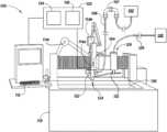
- FIG. 1is perspective and partially schematic view of a liquid jet cutting system, configured in accordance with embodiments of the present technology.
- FIG. 2is a schematic illustration of a liquid jet cutting system having one or more sensors, configured in accordance with embodiments of the present technology.
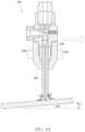
- FIG. 3is a cross-sectional view of a cutting head assembly having one or more sensors, configured in accordance with embodiments of the present technology.
- FIG. 4 Ais a cross-sectional view of the cutting head assembly of FIG. 3 impacting the portion of a workpiece.
- FIG. 4 Billustrates data associated with detected motion, planned motion, and noise associated with the cutting head assembly of FIG. 4 A .
- FIG. 5 Ais a cross-sectional view of the cutting and assembly of FIG. 3 scraping along a portion of a workpiece.
- FIG. 5 Billustrates data associated with detected motion, planned motion, and noise associated with the cutting head assembly of FIG. 5 A .
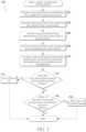
- FIG. 6is a flow diagram of a routine for monitoring operation of a liquid jet cutting system, in accordance with some embodiments of the present technology.
- FIG. 7is a flow diagram of another routine for monitoring operation of a liquid jet cutting system, in accordance with some embodiments of the present technology.
- the operational monitoring systemscan generally include one or more sensors configured to monitor characteristics (e.g., movement, sounds, temperature, etc.) of components of the liquid jet cutting system.
- Data generated by the sensorscan be collected by a computing device (e.g., a controller).
- the collected datacan be correlated with planned data (e.g., threshold data) associated with the cut plan of the liquid jet cutting system.
- planned datae.g., threshold data
- data collected by one sensoris correlated with data collected by another sensor.
- the computing devicecan use the correlations between the collected data and planned data, or correlations between collected data of two or more sensors, to automatically predict and detect wear, failure conditions, and/or other phenomena of interest from the components of the liquid jet cutting system.
- the computing deviceis configured to automatically generate alarm signals and/or shut down all or portions of the liquid jet system when certain failures or other phenomena (e.g., resonant frequencies, leaks, etc.) are detected or predicted. Automatic alarm generation and/or shut down can reduce the risk of damage to workpieces and/or to components of the liquid jet cutting system.
- certain failures or other phenomenae.g., resonant frequencies, leaks, etc.
- FIG. 1is a perspective and partially schematic view of a liquid jet cutting system 100 , configured in accordance with embodiments of the present technology.
- the system 100can include a fluid supply assembly 102 (shown schematically).
- the fluid supply assembly 102can include, for example, a fluid container, a pump, an intensifier, an accumulator, one or more valves, and/or one or more hydraulic units.
- the fluid supply assembly 102can be configured to provide pressurized fluid to the system 100 .
- the system 100uses various fluids including, e.g., water and/or gases.
- the system 100further includes a cutting head assembly 104 operably connected to the fluid supply assembly 102 and one or more conduits 106 extending between the fluid supply assembly 102 and the cutting head assembly 104 .
- the conduit 106includes one or more joints 107 (e.g., a swivel joint or another suitable joint having two or more degrees of freedom).
- the system 100can further include a base 110 (e.g., a table) and a user interface 112 .
- the user interface 112can be supported by the base 110 .
- the system 100can include one or more actuators configured to tilt, rotate, translate, and/or otherwise move the cutting head assembly 104 .
- the system 100can include a first actuator 114 a , a second actuator 114 b , and a third actuator 114 c (collectively, “the actuators 114 ”) configured to move the waterjet assembly 104 relative to the base 110 and other stationary components of the system 100 , and/or to move the base 110 relative to the cutting head assembly, (such as a stationary waterjet assembly) 104 .
- the second actuator 114 bcan be configured to move the cutting head assembly 104 along a processing path (e.g., cutting path) in two or three dimensions and to tilt the cutting head assembly 104 relative to the base 110 , or to tilt the base 110 relative to the cutting head assembly 104 , or to tilt both. In some embodiments, the second actuator 114 b tilts the cutting head assembly 104 in two or more dimensions.
- a processing pathe.g., cutting path
- the second actuator 114 btilts the cutting head assembly 104 in two or more dimensions.
- the cutting head assembly 104can be configured to direct a pressurized jet of fluid toward a workpiece (not shown) supported by the base 110 (e.g., held in a jig supported by the base 110 ) and to move relative to either the cutting head assembly 104 or the base 110 , or both, while directing the jet toward the workpiece.
- the system 100can also be configured to manipulate the workpiece in translatory and/or rotatory motion, manipulating the jet and/or the workpiece.
- the user interface 112can be configured to receive input from a user and to send data based on the input to a computing device 120 (e.g., a controller).
- the inputcan include, for example, one or more specifications (e.g., coordinates, geometry or dimensions) of the processing path and/or one or more specifications (e.g., material type or thickness) of the workpiece and operating parameters (e.g., for a waterjet tool, pressure, flow rate, abrasive material, etc.).
- the cutting head assembly 104can include a cutting head 122 and a nozzle outlet 124 .
- the cutting head 122can be configured to receive fluid from the fluid supply assembly 102 via the conduit 106 at a pressure suitable for liquid jet (e.g., waterjet) processing.
- the cutting head 122can include one or more components configured to condition fluid between the fluid supply assembly 102 and the nozzle outlet 124 .
- the system 100can further include a consumable delivery apparatus 126 configured to feed consumables, such as particulate abrasive, from a consumables storage container 128 to the cutting head assembly 104 .
- the system 100can include an abrasive conduit 129 configured to convey consumables from the storage container 128 to the consumable delivery apparatus.
- the consumable delivery apparatus 126is configured to move with the cutting head 104 relative to the base 110 , or vice versa.
- the consumable-delivery apparatus 126can be configured to be stationary while the cutting head assembly 104 moves relative to the base 110 .
- the system 100can include one or more cutting heads that can be controlled individually and can be applying same or different parameters (orifice size, mixing tube size, abrasive size, abrasive type, abrasive feed rate, etc.).
- the base 110can include a diffusing tray 130 .
- the diffusing tray 130can be configured to hold a pool of fluid positioned relative to the jig so as to diffuse the remaining energy of the jet from the cutting head assembly 104 after the jet passes through the workpiece.
- the computing device 120(shown schematically) can be operably connected to the user interface 112 and one or more of the actuators 114 (e.g., via one or more cables, wireless connections, etc.). In some embodiments, the computing device 120 is also operably connected to a consumable metering device 132 (shown schematically) of the consumable delivery apparatus 126 . In other embodiments, the consumable delivery apparatus 126 can be without the metering device 132 or the metering device 132 can be configured for use without being operably associated with the computing device 120 .
- the metered consumablescan be but are not limited to sand, abrasive garnet, or other appropriate abrasive materials or combinations of materials.
- the computing device 120can include a processor 134 and memory 136 and can be programmed with instructions (e.g., non-transitory instructions contained on a computer-readable medium) that, when executed, control operation of the liquid jet cutting system 100 .
- instructionse.g., non-transitory instructions contained on a computer-readable medium
- the systemcan be configured to contain one or more independent or connected motion control units.
- the systemcan be configured in various ways that allow perpendicular, rotational and/or angular cutting of workpieces of different shape.
- Embodiments of the systemcan include but are not limited to gantry, bridge, multi-axis kinematics (similar in function to OMAX Tilt-A-Jet or A-Jet tools and Hypertherm Echion and HyPrecision systems), 6-axis robot, rotary, and hexapod style machines.
- the systemis suited to cutting workpieces of a wide variety of thicknesses, including workpieces of negligible thicknesses.
- the system 100is adapted to cut workpieces of a variety of three-dimensional shapes.
- the jetcan cut at any angle relative to the workpiece.
- FIG. 2is a schematic illustration of the liquid jet cutting system 100 , configured in accordance with embodiments of the present technology.
- the system 100includes a fluid supply assembly 102 configured to provide pressurized fluid to the cutting head assembly 104 via one or more conduits 106 .
- the fluid supply assembly 102can include a fluid source 240 , such as, for example, a fluid tank, a utility water line, or some other source of fluid.
- the fluid supply assembly 102can further include one or more pressurization devices 242 in fluid communication with the fluid source 240 (e.g., via one or more fluid conduits 243 ), and configured to pressurize fluid from the fluid source 240 .
- the pressurization device(s) 242can include one or more pumps, intensifiers, accumulators, and/or other devices configured to pressurize fluid for use with the cutting head assembly 104 .
- the cutting head assembly 104can be configured to receive pressurized fluid (e.g., water) from the pressurization devices 242 .
- the cutting head assembly 104can also receive abrasive material from the consumable storage container 128 .
- the system 100includes one or more valves between the consumable storage container 128 and the cutting head assembly 104 to meter flow of consumable material to the cutting head assembly 104 .
- the cutting head assembly 104can be configured to emit a jet 244 toward a workpiece 250 to cut or otherwise remove material from the workpiece 250 .
- the workpiece 250can be secured to the base 110 (e.g., a table) using one or more jigs or other securement devices.
- One or more of the assemblies, components, and/or subcomponents of the fluid jet cutting system 100can include one or more sensors (collectively, “252”) configured to monitor characteristics of the fluid jet cutting system 100 . While FIG. 2 illustrates a single sensor corresponding to each illustrated component (e.g., a first sensor 252 a corresponding to the fluid source 240 , a second sensor 252 b corresponding to the pressurization device(s), a third sensor 252 c corresponding to the conduit 106 between the fluid supply assembly 102 and the cutting head assembly 104 , etc.), one or more of the components may include more than one sensor.
- the sensors 252can be, for example, accelerometers or other motion sensors, microphones or other audio sensors, thermistors or other temperature sensors, optical sensors, pressure sensors, electrostatic sensors, continuity sensors, micro-electromechanical systems (MEMS), glass-break sensors, and/or impact switches.
- accelerometers or other motion sensorscan be configured to monitor orientation, scalar movement, vibration, translation, rotation, and/or tilting of a component of the liquid jet cutting system 100 .
- the fluid jet cutting system 100includes multiple sensors 252 , each of which are operably connected to or otherwise configured to monitor separate components of the fluid jet cutting system 100 .
- one or more components of the fluid jet cutting system 100include more than one sensor configured to monitor characteristics of that single component.
- two or more of an accelerometer, temperature sensor, audio sensor, and/or other sensorcan be operably connected to and/or configured to monitor characteristics of the cutting head assembly 104 or subcomponents thereof.
- the sensors 252can be physically connected to, embedded at least partially within, or otherwise operably coupled with various components of the fluid jet cutting system 100 .
- one or more sensors 252 ccan be connected to the conduit 106 between the fluid supply assembly 102 and the cutting head assembly 104 .
- the one or more sensors 252 ccan be positioned inside of the conduit 106 , in a wall of the conduit 106 , and/or on an exterior of the conduit 106 .
- a sensor 252 ccan be positioned near, but not directly connected to, the conduit 106 to monitor a characteristic of the conduit 106 .
- an audio sensormay be best positioned near but not in contact with the conduit 106 in order to monitor sound generated by the conduit 106 during operation of the fluid jet cutting system 100 .
- Sensors 252can be similarly distributed with one or more of the other components, assemblies, and subsystems of the fluid jet cutting system 100 , as illustrated in FIG. 2 .
- one or more sensors 252 emay be associated with the cutting head assembly 104 .
- one or more sensors 252are integrated in electrical cable systems of the liquid cutting system 100 .
- one or more sensorscan be integrated into cable heads or other structures of the electrical cable system.
- the one or more sensors 252can be removable attached (e.g., via magnets, clips, clamps, etc.) or fixedly attached to the components of the fluid jet cutting system 100 .
- different types of sensorsare swappable with respect to the same component.
- a first type of sensor 252may be coupled to a component during a first operation, and then removed and replaced with a second type of sensor for a subsequent operation.
- two or more sensors 252can share a coupling or mounting structure.
- the sensors 252can be operably connected to the computing device 120 via wired or wireless connections and can be configured to generate sensor data in response to monitoring characteristics (e.g., performance characteristics) of one or more components of the fluid jet cutting system 100 .
- one of the sensors 252can be an accelerometer connected to a component of the liquid jet cutting system 100 .
- the accelerometercan detect movement (i.e., vibration, rotation, translation, tilting, etc.) of the component with which the accelerometer is associated. This movement data can be collected from the accelerometer by the computing device 120 and can be stored in the memory 136 of the computing device.
- a second sensor 252can be used to monitor a second characteristic of a component of the fluid jet cutting system 100 .
- the component monitored by the second sensor 252can be the same component monitored by the first sensor 252 , or another component of the fluid jet cutting system 100 .
- the second sensor 252can be either a same type of sensor as the first sensor 252 or a different sensor type.
- a microphone or other audio sensorcan be used in combination with an accelerometer. Audio data generated by the audio sensor can be collected by the computing device 120 and, in some embodiments, stored in the memory 136 thereof. As explained in more detail below, data generated by multiple sensors 252 can be correlated by the computing device 120 (e.g., using a processor 138 thereof) to diagnose the performance characteristic of the component being monitored.
- FIG. 3is a cross-sectional view of the cutting head assembly 104 , configured in accordance with embodiments of the present technology.
- the cutting head assembly 104can include a cutting head body 356 , a nozzle 358 connected to the cutting head body 356 , an abrasive inlet 360 , and a fluid inlet 362 .
- the nozzle 358can be positioned at least partially within the cutting head body 356 and can include the nozzle outlet 124 .
- the abrasive inlet 360can be configured to receive abrasive material from the consumables storage container 128 (e.g., via the abrasive conduit 129 ).
- the abrasive inlet 360is in a lateral side of the cutting head body 356 with respect to a longitudinal axis of the nozzle 358 .
- the fluid inlet 362can be configured to receive pressurized fluid from a fluid supply assembly 102 .
- the cutting head body 356 , abrasive inlet 360 , and/or fluid inlet 362include valves configured to control flow of fluid and/or abrasive material to the nozzle 358 .
- high-pressure fluid from the fluid inlet 362entrains abrasive material from the abrasive inlet 362 into a mixing chamber 364 within the cutting head body 356 .
- the resulting mixed abrasive and fluidis then passed through the nozzle 358 and emitted as a high-pressure jet from the nozzle outlet 124 .
- the cutting head assembly 104is configured to operate without abrasive material.
- One or more flow conditionerscan be positioned within the flow paths of the fluid, abrasive, and/or mixed fluid in abrasive within the cutting head body 356 .
- the cutting assembly 104can include an orifice 366 in the flow path between the fluid inlet 362 in the mixing chamber 364 .
- the orifice 366can be formed as part of the cutting head body 356 or in a separate component configured to couple with the cutting head body 356 .
- the orifice 366can be configured to accelerate (e.g., form a jet of) fluid upstream of the mixing chamber 364 .
- one or more sensorscan be positioned on or in the cutting head assembly 104 .
- the sensors 252 ecan be configured to monitor various performance characteristics of the cutting head assembly 104 and/or subcomponents thereof.
- a first sensor 252 e ′can be connected to the cutting head body 356 (e.g., via a magnetic, adhesive, or other mounting structure).
- the first sensor 252 e ′can be, for example, an accelerometer configured to monitor movement of the cutting head body 356 .
- a second sensor 252 e ′′may also be connected to the cutting head body 356 .
- the second sensor 252 e ′′can be, for example, a microphone or other audio sensor configured to monitor noise generated by the cutting head assembly 104 or some subcomponent thereof. Data from each of the sensors 252 e can be relayed to the computing device 120 as described above.
- additional sensorscan be associated with the cutting head assembly 104 .
- a third sensor 252 e ′′′can be connected to the nozzle 358 to monitor performance characteristics thereof.
- the third sensor 252 e ′′′could be an accelerometer, a microphone, a temperature sensor, or some other sensor configured to monitor a performance characteristic of the nozzle 358 .
- the third sensor 252 e ′′′is an impact sensor configured to detect contact between the nozzle 358 and a workpiece 150 .
- the actuators 114can bring the nozzle 358 into contact with the workpiece 150 (e.g., tapping the workpiece 150 with the nozzle 358 ). Determining the precise location of the nozzle 358 with respect to the workpiece 150 can reduce the likelihood of inadvertent impact between the nozzle 358 and the workpiece 150 during operation of liquid jet cutting system 100 .
- the cutting head assembly 104can include one or more sensors installed inside of, or at least partially inside of the cutting head body 356 or some other subcomponent of the cutting head assembly 104 .
- a fourth sensor 252 e ′′′′may be positioned within the cutting head body 356 at or near the orifice 366 to monitor performance characteristics of the orifice 366 .
- the fourth sensor 252 e ′′′′can be mounted on a circuit board within the cutting head body 356 . It will be understood that the cutting assembly 104 of the liquid jet cutting system 100 can include one or more, or none, of the above described sensors 252 e.
- FIGS. 4 A and 4 Billustrate a scenario in which sensors can be used to diagnose a failure in the liquid jet cutting system 100 .
- that part 470can tip up between slats on the base 110 (e.g., table), leaving a raised obstacle in the movement path of the nozzle 358 or other component of the cutting head assembly 104 .
- a portion of the workpiece 250can break, warp, or otherwise displace into the movement path of the nozzle 358 or other component of the cutting head assembly 104 .
- a tipped-up part 470 of the workpiece 250is angled up toward the cutting head assembly 104 and blocks movement of the nozzle 358 as the cutting head assembly 104 moves along a cut path.
- the nozzle 358can impact the tipped-up part 470 of the workpiece 250 .
- This impactcould have various negative effects on the liquid jet cutting system 100 .
- the nozzle 358 , cutting head body 356 , or some other portion of the liquid jet cutting assembly 100e.g., an actuator 114 ) could be damaged.
- FIG. 4 Billustrates example data that may be monitored and collected by the sensors 252 e of FIG. 4 A .
- the first sensor 252 e ′can be an accelerometer or other motion sensor. Movement data collected by the first sensor 252 e ′ can be plotted as acceleration over time, as reflected in the data set charted in the movement chart 472 .
- the computing device 120can be configured to correlate the movement data collected from the first sensor 252 e ′ with planned data associated with the dictated cut path associated with the specific project and/or with normal operation of the liquid jet cutting system 100 .
- sensors 252 ecan be used in supervised jobs to generate data associated with normal operation of the liquid jet cutting system 100 .
- Using the sensors 252 e during supervised operation of the liquid jet cutting system 100can generate baseline or planned data associated with performance characteristics of the liquid jet cutting system 100 .
- the chart 474 of FIG. 4 Billustrates a planned data set associated with movement of the cutting assembly 104 during normal operation.
- the first local maximum of the acceleration datacan be at a time T 1 associated with initiating a cut using the cutting head assembly 104 (e.g., starting the liquid jet).
- the second local maximum the acceleration data at a time T 2can be associated with shutting off the jet of the cutting assembly 104 .
- the computing device 120can define a planned maximum acceleration 476 (chart 472 ) associated with normal operation of the liquid jet cutting system 100 .
- the planned maximum acceleration 476can be equal to or approximately equal to (e.g., within +/ ⁇ 5%) of the local maximum associated with initiating a cut.
- a local maximum associated with impact between the nozzle 358 and the broken portion 470 of the workpiece 250is shown at time T 3 .
- the magnitude of the acceleration associated with impact between the nozzle 358 and the broken portion 470 of the workpiece 250is greater than the planned maximum acceleration 476 .
- the computing device 120can be configured to generate an alarm signal and/or shut off the cutting head assembly 104 upon detection of acceleration greater than the planned maximum acceleration 476 .
- the second sensor 252 e ′′can be a microphone or other audio sensor configured to monitor sound produced by the cutting head assembly 104 during operation of the liquid jet cutting system 100 .
- sound data generated by the microphone(chart 478 of FIG. 4 B ) can be received by the computing device 120 and correlated to the movement data collected by the first sensor 252 e ′ and/or to the planned data.
- the computing device 120can further verify the occurrence of a failure by correlating local maxima of the noise data with local maxima of the movement data. I.e., in the event that a high magnitude acceleration occurs at or near the same time that a loud sound occurs, this correlation between acceleration and sound can increase confidence that a failure (e.g. impact between two parts) has occurred.
- FIGS. 5 A- 5 Billustrate another scenario in which sensors can be used to diagnose a failure in the liquid jet cutting system 100 .
- the workpiece 250can be warped, tilted, or otherwise misaligned such that the vertical position of the workpiece 250 (e.g., as measured vertically in the frame of reference of FIG. 5 A and/or in a direction parallel to the longitudinal axis of the nozzle 358 ) is tilted upward and/or toward the cutting and assembly 104 .
- Such tilting or misalignmentmay be added relatively small angle A 1 .
- the angle A 1 between a top surface of the workpiece 250 and horizontalmay be as low as about 1°, about 5°, about 10°, and/or about 30° or less. Rather than a hard or jolting impact, contact between the nozzle 358 in such a tilted workpiece 250 can result in gradual scraping, increase friction, and/or resistance to movement of the cutting head assembly 104 along the cut path.
- the scraping between the nozzle 358 and the workpiece 250can be reflected in motion data generated by the first sensor 252 ′ (e.g., an accelerometer).
- the motion datamay reflect a gradual increase in acceleration corresponding to scraping of the nozzle 358 along the workpiece 250 .
- the magnitude of this increased accelerationmay not, in some situations, exceed the plan max acceleration 476 .
- the computing device 120can correlate a range 482 of increased acceleration (e.g., as compared to the planned motion data) associated with the scraping with the plan motion data.
- the computing device 120can be configured to generate an alarm signal and/or shut down the liquid jet cutting system 100 if sustained elevated acceleration is detected (e.g., elevated acceleration over an extended or predetermined period of time). For example, increased acceleration over a time range greater than 0.1 seconds, 0.3 seconds, one second, two seconds, five seconds, 10 seconds, and/or 30 seconds can be used by the computing device 120 to shut down the liquid jet cutting system 100 .
- sustained elevated acceleratione.g., elevated acceleration over an extended or predetermined period of time.
- increased acceleration over a time range greater than 0.1 seconds, 0.3 seconds, one second, two seconds, five seconds, 10 seconds, and/or 30 secondscan be used by the computing device 120 to shut down the liquid jet cutting system 100 .
- data from a second sensor 252 e ′′can be used in addition to or instead of the planned data.
- the second sensor 252 e ′′can be a microphone configured to monitor noise output from the cutting head assembly 104 .
- sound magnitude detected by the microphonecan resemble the sound values charted in chart 484 of FIG. 5 B .
- the sound valuesmay increase over a time range 486 .
- the computing device 120in this scenario, can correlate the time range 482 of increased acceleration detected by the accelerometer with the time range 486 of increased sound detected by the microphone. Concurrence of the ranges 482 , 486 with each other can increase the confidence that a failure is occurring and reduce the risk that the computing device 120 shuts down the liquid jet cutting system 100 in reaction to a false positive detection of failure.
- sensor data other than motioncan be used to establish planned data as described above with respect to the planned maximum acceleration.
- noise or temperaturecan be measured by one or more sensors during normal operation. This data can be used to established planned noise/temperature data, against which later-gathered data can be compared and correlated in a manner similar to or the same as that described above with respect to FIGS. 4 A- 5 B .
- sensor data obtained at the beginning of an operationcan be compared with data from the same sensor at the end of the operation to determine whether one or more components have experienced wear during the operation of the liquid jet cutting system 100 .
- accelerometer data of a first operational statee.g., powered on without cutting or movement of the cutting head assembly 104
- accelerometer data of that same operational state at the end of the cutting operationcan be compared to accelerometer data of that same operational state at the end of the cutting operation.
- Some such comparisonscan be made automatically by the computing device 120 . For example, if higher acceleration values are observed at the end of the cutting operation, the computing device 120 can be configured to alert the user of potential wear to one or more components of liquid jet cutting assembly 100 .
- the sensors 252 and computing device 120can be used to determine whether planned cuts are completed during operation of the liquid jet cutting system 100 .
- specific performance characteristics associated with the cutting head assembly 104 or subcomponent thereofindicate that the jet emitted from the nozzle 358 has pierced or otherwise cut through a workpiece 150 .
- Such performance indicatorscan include, for example, a momentary spike in acceleration data from an accelerometer and/or a change in volume and/or pitch of sound produced during operation of the cutting head assembly 104 .
- Accelerometers and/or microphonescan be used during normal operation to establish baseline performance indicators indicative of piercing or cutting through workpieces.
- the computing device 120can compare performance characteristics as measured by one or more sensors during a specific operation with planned or expected performance characteristics to determine whether desired piercing or through cutting is achieved. On the other hand, the computing device 120 can also determine whether an undesired piercing or through cut has occurred. In either situation, the computing device 120 can be configured to generate an alarm signal and/or shut off the jet if undesired piercing or lack of piercing occurs.
- anomalies detected by a microphone or other audio sensorcan be indicative of a clog of abrasive material a portion of the fluid jet cutting system 100 .
- abrasive materialmay clog in the mixing chamber 364 of the cutting and assembly 104 , in the abrasive conduit 129 , in the nozzle 358 , or elsewhere in the liquid jet cutting system 100 .
- Such clogscan result in increased vibration within the system 100 , acceleration of fluid through the system 100 , change in sound profile of the jet 244 , and/or in other phenomena that would change sounds generated by one or more components of the liquid jet cutting system 100 .
- the ON/OFF state of the consumable delivery system 126may be monitored using an accelerometer and/or a microphone.
- the computing device 120can be configured to alert the user of the liquid jet cutting system 100 if the expected sound and/or vibration characteristics associated with operation of the consumable delivery system 126 are absent from the data generated by the one or more sensors of the liquid jet cutting system 100 .
- orifice failurese.g. cracks or other damage to an orifice
- the computing device 120is configured to alert a user of the liquid jet cutting system 100 to the possibility of a clog or other failure upon detection, by an audio sensor, of anomalous sound from the liquid jet cutting system 100 or subcomponent thereof.
- the computing device 120can be configured to filter ambient noise, ambient vibration, and other environmental factors from the signals received from the one or more sensors. For example, adjacent machinery, seismic activity, altitude, humidity, and other environmental factors can affect the signals generated by the one or more sensors. These environmental factors may be filtered out of the signals by generating data using the one or more sensors while the fluid jet cutting system 100 shut off. Filtering out environmental factors can reduce the likelihood of false positive indications of failure or where in the fluid jet cutting system 100 . For example, filtering out environmental factors reduces the likelihood that elevated sound levels or vibration levels from the surrounding environment are mistaken for deterioration in the performance of the fluid jet cutting system 100 .
- the operational monitoring systemis configured to filter out baseline operational characteristics of the liquid jet cutting system 100 .
- one or more sensorscan be used to monitor performance characteristics of the liquid jet cutting system 100 in various states of operation.
- the states operationcan include power on without activating the cutting head assembly 104 , power on without moving components of the liquid jet cutting system 100 , movement of the cutting head assembly 104 and/or other components without activating the nozzle 358 of the cutting and assembly 104 , and/or other operation states. Collecting data at the various states of operation can reduce the likelihood that normal operating parameters are mistaken for failures or other anomalies.
- the computing device 120can be configured to monitor acceleration data from one or more accelerometers in the liquid jet cutting system 100 and determine whether the acceleration data indicates that one or more components are vibrating at a resonant frequency. Resonant frequency values for the one or more components may be stored in the memory 136 of the computing device 120 . The computing device can be configured to generate an alarm signal and/or shut down the liquid jet cutting system 100 if resonant frequencies are detected. Such alarms and/or shut-downs can reduce the likelihood of damage to components of the liquid jet cutting system 100 due to wear imposed by vibrations at resonant frequency of those components.
- the planned data associated with a specific cutting operationcan include orientation data of the cutting head assembly 104 , nozzle 358 , or the components of the liquid jet cutting system 100 .
- One or more accelerometers or other motion sensorsmay be used to monitor orientation of the cutting head assembly 104 during a cutting operation in the monitored orientation data produced by such sensors can be compared to the planned data. Differences in orientation between the monitored orientation data in the planned data can indicate deviation of the cutting assembly 104 from the planned cut path.
- the computing device 120can be configured to detect such deviations generate alarm signals and/or shut down the liquid jet cutting system 100 when and if such orientation deviations are detected.
- FIG. 6is a flow diagram of a routine 600 for monitoring performance of the liquid jet cutting system 100 described in detail above with reference to FIGS. 1 - 5 B , in accordance with an embodiment of the present technology. All or portions of the routine 600 can be performed by the computing device 120 in accordance with computer-readable instructions stored on, e.g., the memory 136 . Although the routine 600 is described below in reference to the liquid jet cutting system 100 described above with reference to FIGS. 1 - 5 B , it will be appreciated that the routine 600 and/or various portions thereof can be performed with other liquid jet cutting systems having configured in accordance with the present disclosure.
- the routine 600begins by powering on the liquid jet cutting system (e.g., the liquid jet cutting system 100 described above). The routine then proceeds to block 602 , wherein one or more sensors are used to monitor a first performance characteristic of a component of the liquid jet cutting system.
- a first performance characteristic of a component of the liquid jet cutting systemFor example, as described above, an accelerometer can be used to monitor movement of the cutting head assembly of the liquid jet cutting system.
- the first performance characteristiccan be something other than movement, such as temperature, noise, pressure, or another characteristic.
- more than one sensoris used to monitor the first performance characteristic of a component of the liquid jet cutting system.
- the routine 600can proceed to block 604 wherein data associated with the first performance characteristic is generated by one or more sensors.
- the datais displayed to a user.
- the datacan be displayed as a graph or chart similar to those described above with respect to FIGS. 4 B and 5 B .
- the data associated with the first performance characteristicis not displayed to the user.
- the datacan be sent to a computing device (e.g., the computing device 120 described above).
- the routine 600then proceeds to block 606 , wherein the computing device correlates the data generated by the one or more sensors with planned data gathered during previous operation of the liquid jet cutting system.
- the planned datacan be data gathered during analogous operations at known, normal (e.g., without fault) operating conditions and stored in a memory of the computing device.
- Correlating the first performance characteristic data with the planned datacan include confirming whether the monitored first performance characteristic data exceeds or otherwise deviates from the planned data.
- the computing devicecan determine whether magnitude of an acceleration monitored by an accelerometer exceeds a maximum planned acceleration associated with the present operation of the liquid jet cutting system.
- correlating first performance characteristic data with the planned datacan include determining whether monitored first performance characteristics exceeds expected planned data characteristics over a predetermined period of time.
- the computing devicecan determine whether the first performance characteristic exceeds a predetermined threshold value for that performance characteristic. For example, the computing device can determine whether acceleration levels, sound levels, temperature values, pressure values, and/or other performance characteristics are greater than correlating predetermined maximum values. If the measured values exceed the threshold values, the computing device can be configured to shut off the liquid jet, as indicated in block 610 .
- the computing devicecan determine whether the first performance characteristic deviates from the planned data for an extended or otherwise predetermined period of time, as indicated in decision block 612 . If the computing device determines that the first performance characteristic deviates from the planned data for an extended or otherwise predetermined period of time, the computing device can be configured to shut off the liquid jet, as indicated in block 614 .
- the routine 600can proceed to decision block 616 , wherein the computing device determines whether a second performance characteristic exceeds a threshold value.
- the second performance characteristiccan be different from the first performance characteristic.
- the first performance characteristicis the movement of a component of the liquid jet cutting system
- the second performance characteristiccould be sound levels, pressure levels, and/or temperature of that component.
- the second performance characteristicis of the same type as the first performance characteristic, but measured at a different location or with respect to a different component of the liquid jet cutting system.
- the computing devicedetermines that the second performance characteristic exceeds a threshold value, the computing device can be configured to shut off the liquid jet system, as indicated in block 618 .
- the computing devicebefore shutting off the liquid jet, is configured to generate an alarm.
- the alarmcan be an audible alarm, a visual alarm, or some other alarm used to alert a user of the liquid jet cutting system to the likelihood of a failure in the liquid jet cutting system.
- the usercan be given a predetermined amount of time in which to decide whether to shut off the liquid jet cutting system or allow operation to continue.
- FIG. 7is a flow diagram of a routine 700 for monitoring performance of the liquid jet cutting system 100 described in detail above with reference to FIGS. 1 - 5 B , in accordance with an embodiment of the present technology. All or portions of the routine 700 can be performed by the computing device 120 in accordance with computer-readable instructions stored on, e.g., the memory 136 . Although the routine 700 is described below in reference to the liquid jet cutting system 100 described above with reference to FIGS. 1 - 5 B , it will be appreciated that the routine 700 and/or various portions thereof can be performed with other liquid jet cutting systems having configured in accordance with the present disclosure.
- the routine 700begins by powering on the liquid jet cutting system (e.g., the liquid jet cutting system 100 described above). The routine 700 then proceeds to block 702 , wherein a first sensor is used to monitor a first performance characteristic of a component of the liquid jet cutting system.
- a first sensoris used to monitor a first performance characteristic of a component of the liquid jet cutting system.
- an accelerometercan be used to monitor movement of the cutting head assembly of the liquid jet cutting system.
- the first sensorcan generate data associated with the monitored first performance characteristic, as indicated in block 704 . This data can be sent to a computing device or another component of the liquid jet cutting system.
- the routine 700can proceed to block 706 , wherein a second sensor is used to monitor a second performance characteristic of a component of the liquid jet cutting system.
- the second sensoris of a different type from the first sensor.
- the second sensorcan be a microphone or other audio sensor, a thermistor other temperature sensor, a pressure sensor, or some other sensor used to monitor a second characteristic of the component.
- the second sensormonitors a second performance characteristic of a second component separate from the component monitored by the first sensor.
- the second sensorcan be a microphone configured to monitor sound generated by the cutting head assembly.
- the second sensorcan generate data associated with the monitored second performance characteristic. This data can be sent to the computing device or to another component of the liquid jet cutting system.
- Data from the first sensorcan be correlated to data from the second sensor to compare the data of the first performance characteristic to the data of the second performance characteristic, as indicated in block 710 . If data from both sensors indicates a failure (e.g., data from the two sensors indicates contemporaneous abnormal first and second performance characteristics), the computing device can be configured to shut off the liquid jet. If, on the other hand, only one of the two sensors indicates a failure, the computing device can be configured to alert the user to a possible failure without automatically shutting off the liquid jet.
- An operational monitoring systemfor use with a liquid jet cutting system, the operational monitoring system comprising: an accelerometer coupled to a cutting head of the liquid jet cutting system and configured to generate motion data associated with movement of the cutting head; and a computing device operably connected to the accelerometer and having a memory and a processor; wherein: the memory stores a planned data set including expected parameters associated with movement of the cutting head along a planned cut path; and the computing device configured to receive the motion data from the accelerometer and correlate the motion data to the planned data set.
- liquid jet cutting systemis a water jet cutting system.
- the operational monitoring system of claim 1wherein the accelerometer is positioned adjacent an abrasive feed line in the cutting head, and wherein the accelerometer is configured to generate motion data associated with flow of abrasive through the abrasive feed line.
- the operational monitoring system of claim 1wherein the accelerometer is mounted on a circuit board within the cutting head.
- the operational monitoring system of claim 5wherein the computing device is configured to generate an alarm signal when the orientation of the cutting head, as indicated by the accelerometer, is different from a planned orientation of the cutting head in the planned data set.
- the operational monitoring system of claim 1wherein the computing device is configured to generate an alarm signal when a magnitude of the motion data generated by the accelerometer exceeds a threshold value.
- the operational monitoring system of claim 1wherein the computing device is configured to filter the motion data generated by the accelerometer by at least one frequency value.
- the operational monitoring system of claim 9wherein the sensor includes a second accelerometer, an audio sensor, a temperature sensor, a pressure sensor, an electrostatic sensor, a continuity sensor, a micro-electromechanical system, and/or an impact switch.
- the operational monitoring system of claim 9wherein the sensor is a temperature sensor connected to the cutting head and configured to monitor a temperature of one or more portions of the cutting head.
- the operational monitoring system of claim 11wherein the temperature sensor is configured to monitor a temperature of a nozzle of the cutting head.
- the operational monitoring system of claim 9wherein the computing device is configured to generate an alarm signal if both the motion data and the sensor data indicate deviations from the planned data set greater than a threshold value.
- the operational monitoring system of claim 9wherein the computing device is configured to filter out portions of the motion data and/or of the sensor data associated with ambient conditions.
- the operational monitoring system of claim 9wherein the computing device is configured to filter out baseline vibration of the cutting head associated with powering the liquid jet cutting system.
- the operational monitoring system of claim 9wherein one or both of the accelerometer and the sensor are embedded in an electrical cable of the liquid jet cutting system.
- the operational monitoring system of claim 1wherein the accelerometer is connected to the cutting head using a magnet.
- the operational monitoring system of claim 1wherein the computing device is configured to generate an alarm signal when the motion data indicates one or more components are vibrating at their respective resonant frequencies.
- An operational monitoring systemfor use with a liquid jet cutting system, the operational monitoring system comprising: an accelerometer coupled to a component of the liquid jet cutting system and configured to generate motion data associated with movement of the component of the liquid jet cutting system; a sensor configured to generate sensor data corresponding to one or more characteristics of the liquid jet cutting system; and a computing device operably connected to the accelerometer and to the sensor, the computing device having a memory and a processor and being configured to: receive the motion data and the sensor data; and determine whether: the motion data indicates a first performance characteristic; and the sensor data indicates a second performance characteristic.
- the operational monitoring system of claim 21wherein the first performance characteristic indicates scraping of the cutting head along a surface of the workpiece.
- the operational monitoring system of claim 21wherein the first performance characteristic indicates impact of the cutting head with a tipped-up part of the workpiece.
- the operational monitoring system of claim 19wherein the computing device is configured to shut off the liquid jet cutting system if the motion data indicates the first performance characteristic and the sensor data indicates the second performance characteristic.
- the operational monitoring system of claim 26wherein the first direction is parallel to a longitudinal axis of a cutting head of the liquid jet cutting system.
- the operational monitoring system of claim 26wherein the first direction is perpendicular to a longitudinal axis of a cutting head of the liquid jet cutting system.
- the operational monitoring system of claim 19wherein the accelerometer is coupled to a cutting head of the liquid jet cutting system and the sensor is a second accelerometer coupled to an actuator of the liquid jet cutting system upstream of the cutting head.
- a method of monitoring operation of a liquid jet cutting systemcomprising: monitoring acceleration of a cutting head of the liquid jet cutting system using an accelerometer; generating motion data indicating acceleration of the cutting head; receiving the motion data from the accelerometer at a computing device having a memory and a processor; correlating, using the computing device, the motion data with planned data, wherein the planned data reflects normal operating motions and/or operating conditions associated with a planned cut; indicating a condition of the liquid jet cutting system based on one or more correlations between the motion data and the planned data.
- the method of claim 30,further comprising generating an alarm signal, via the computing device, if the condition of the liquid jet cutting system indicates wear on a component of the liquid jet cutting system beyond an acceptable wear value.
- the method of claim 30,further comprising generating an alarm signal, via the computing device, if the motion data indicates an acceleration of the cutting head greater than an acceptable acceleration value.
- liquid jet cutting systemis a water jet cutting system.
- the method of claim 30 wherein the accelerometeris configured to monitor abrasive flow through an abrasive feed line in the cutting head.
- the method of claim 37further comprising generating an alarm signal if the motion data indicates that one or more components are vibrating at resonant frequencies.
- a method of monitoring operation of a liquid jet cutting systemcomprising: monitoring acceleration of a component of the liquid jet cutting system using an accelerometer; generating motion data, using the accelerometer, indicating acceleration of the component; monitoring one or more characteristics of one or more components of the liquid jet cutting system using a sensor; generating characteristic data, using the sensor, indicating the one or characteristics of the one or more components of the liquid jet cutting system; receiving, at a computing device having a memory and a processor, the motion data from the accelerometer and the characteristic data from the sensor; correlating, using the computing device, the motion data with the characteristic data; determining a failure within the liquid jet cutting system via the correlation between the motion data and the characteristic data.
- the method of claim 40wherein the second accelerometer is positioned on a portion of a pump of the liquid jet cutting system and the method further includes monitoring vibration of one or more components of the pump.
- the senora second accelerometer, an audio sensor, a temperature sensor, an electrostatic sensor, a continuity sensor, a micro-electromechanical system, and/or an impact switch.
- the method of claim 39 wherein the one or more characteristicsinclude acceleration, noise, and/or temperature.
- embodiments of the operational monitoring systems described hereincan reduce the need for operator involvement and can provide faster and more reliable detection of faults, failures, or other adverse phenomena within a liquid jet cutting system.
- Such advantagescan be achieved, for example, by automating the detection of anomalous performance characteristics of one or more components of liquid jet cutting system.
- sensorscan be used to precisely and objectively monitor performance characteristics of components of the system and compare those performance characteristics to predetermined “normal” or “acceptable” (e.g., planned) characteristic values, and/or to other characteristics monitored by other sensors in the system.
Landscapes
- Engineering & Computer Science (AREA)
- Mechanical Engineering (AREA)
- Chemical & Material Sciences (AREA)
- Forests & Forestry (AREA)
- Life Sciences & Earth Sciences (AREA)
- Analytical Chemistry (AREA)
- Physics & Mathematics (AREA)
- General Physics & Mathematics (AREA)
- Robotics (AREA)
- Business, Economics & Management (AREA)
- Emergency Management (AREA)
- Fluid Mechanics (AREA)
- Human Computer Interaction (AREA)
- Perforating, Stamping-Out Or Severing By Means Other Than Cutting (AREA)
Abstract
Description
Claims (33)
Priority Applications (2)
| Application Number | Priority Date | Filing Date | Title |
|---|---|---|---|
| US17/125,819US12051316B2 (en) | 2019-12-18 | 2020-12-17 | Liquid jet cutting head sensor systems and methods |
| US18/746,045US20240339022A1 (en) | 2019-12-18 | 2024-06-18 | Liquid jet cutting head sensor systems and methods |
Applications Claiming Priority (2)
| Application Number | Priority Date | Filing Date | Title |
|---|---|---|---|
| US201962949951P | 2019-12-18 | 2019-12-18 | |
| US17/125,819US12051316B2 (en) | 2019-12-18 | 2020-12-17 | Liquid jet cutting head sensor systems and methods |
Related Child Applications (1)
| Application Number | Title | Priority Date | Filing Date |
|---|---|---|---|
| US18/746,045ContinuationUS20240339022A1 (en) | 2019-12-18 | 2024-06-18 | Liquid jet cutting head sensor systems and methods |
Publications (2)
| Publication Number | Publication Date |
|---|---|
| US20210192922A1 US20210192922A1 (en) | 2021-06-24 |
| US12051316B2true US12051316B2 (en) | 2024-07-30 |
Family
ID=74186910
Family Applications (2)
| Application Number | Title | Priority Date | Filing Date |
|---|---|---|---|
| US17/125,819Active2041-04-04US12051316B2 (en) | 2019-12-18 | 2020-12-17 | Liquid jet cutting head sensor systems and methods |
| US18/746,045PendingUS20240339022A1 (en) | 2019-12-18 | 2024-06-18 | Liquid jet cutting head sensor systems and methods |
Family Applications After (1)
| Application Number | Title | Priority Date | Filing Date |
|---|---|---|---|
| US18/746,045PendingUS20240339022A1 (en) | 2019-12-18 | 2024-06-18 | Liquid jet cutting head sensor systems and methods |
Country Status (2)
| Country | Link |
|---|---|
| US (2) | US12051316B2 (en) |
| WO (1) | WO2021127253A1 (en) |
Cited By (1)
| Publication number | Priority date | Publication date | Assignee | Title |
|---|---|---|---|---|
| US20240339022A1 (en)* | 2019-12-18 | 2024-10-10 | Hypertherm, Inc. | Liquid jet cutting head sensor systems and methods |
Families Citing this family (8)
| Publication number | Priority date | Publication date | Assignee | Title |
|---|---|---|---|---|
| US11577366B2 (en) | 2016-12-12 | 2023-02-14 | Omax Corporation | Recirculation of wet abrasive material in abrasive waterjet systems and related technology |
| US11554461B1 (en) | 2018-02-13 | 2023-01-17 | Omax Corporation | Articulating apparatus of a waterjet system and related technology |
| US12403621B2 (en) | 2019-12-20 | 2025-09-02 | Hypertherm, Inc. | Motorized systems and associated methods for controlling an adjustable dump orifice on a liquid jet cutting system |
| WO2021195106A1 (en) | 2020-03-24 | 2021-09-30 | Hypertherm, Inc. | High-pressure seal for a liquid jet cutting system |
| WO2021202390A1 (en) | 2020-03-30 | 2021-10-07 | Hypertherm, Inc. | Cylinder for a liquid jet pump with multi-functional interfacing longitudinal ends |
| CN114310677A (en)* | 2022-01-05 | 2022-04-12 | 江苏华臻航空科技有限公司 | Abrasive water jet flexible intelligent six-axis cutting platform 3D surface cutting process |
| CN115070867A (en)* | 2022-08-22 | 2022-09-20 | 江苏沛飞特包装材料有限公司 | Based on reverse coefficient formula RCPP membrane is with die-cut equipment of two side effects types |
| EP4615656A1 (en)* | 2022-11-09 | 2025-09-17 | Hypertherm, Inc. | Abrasive identifiers and associated systems and methods for determining information about abrasives in liquid jet cutting systems |
Citations (536)
| Publication number | Priority date | Publication date | Assignee | Title |
|---|---|---|---|---|
| US433022A (en) | 1890-07-29 | Electro-magnetic cut-out | ||
| US1544519A (en) | 1919-09-26 | 1925-06-30 | Willys Overland Co | Sand-blast equipment |
| US1554406A (en) | 1924-02-27 | 1925-09-22 | Kobe Inc | Cutting torch with oscillating tip |
| US1684431A (en) | 1926-09-25 | 1928-09-18 | Jr Joseph H Behee | Process of lettering on stone monuments and other hard substances |
| US1937408A (en) | 1929-08-03 | 1933-11-28 | Ingersoll Milling Machine Co | Machine tool |
| US2007180A (en) | 1934-05-07 | 1935-07-09 | Gray & Co G A | Device for moving a machine member or other part, by power means, an exact distance or to an exact position |
| US2009932A (en) | 1933-07-14 | 1935-07-30 | Klotzman Aaron | Atomizer |
| US2200002A (en) | 1937-01-16 | 1940-05-07 | Eastman Kodak Co | Paper making machine |
| US2308347A (en) | 1941-10-07 | 1943-01-12 | Arthur N Asselin | Flush tank valve |
| US2359352A (en) | 1939-10-31 | 1944-10-03 | Linde Air Prod Co | Welding |
| US2376287A (en) | 1944-03-28 | 1945-05-15 | Oceanic Ship Scaling Co Inc | Sandblasting nozzle |
| US2403751A (en) | 1945-03-20 | 1946-07-09 | Standard Oil Dev Co | Throttling valve |
| US2456041A (en) | 1942-11-05 | 1948-12-14 | Barker Edgar | Machine for machining arcuate surfaces |
| US2544414A (en) | 1946-11-22 | 1951-03-06 | Norton Co | High-pressure apparatus |
| US2558035A (en) | 1947-07-05 | 1951-06-26 | Percy W Bridgman | Method and apparatus for cold drawing |
| US2819835A (en) | 1954-11-26 | 1958-01-14 | Harwood Engineering Co | System for delivering a continuous and steady flow of a compressible fluid at high pressure |
| US2822789A (en) | 1956-06-15 | 1958-02-11 | Exxon Research Engineering Co | Injection of heavy fuel into diesel engines and valve means therefor |
| US2951369A (en) | 1958-09-24 | 1960-09-06 | Harwood Engineering Company | High pressure measuring gage |
| US2952071A (en) | 1957-12-30 | 1960-09-13 | Bendix Corp | Method of making an orifice |
| US2985050A (en) | 1958-10-13 | 1961-05-23 | North American Aviation Inc | Liquid cutting of hard materials |
| US3081990A (en) | 1961-03-10 | 1963-03-19 | Donald A Fagan | Gas cutting machine |
| US3086749A (en) | 1959-12-07 | 1963-04-23 | And Continental Illinois Bank | Needle valve for extreme pressure |
| US3088854A (en) | 1960-11-08 | 1963-05-07 | Air Reduction | Methods and apparatus for cutting |
| US3095900A (en) | 1961-04-03 | 1963-07-02 | Harwood Engineering Company | Poppet valve |
| US3106169A (en) | 1961-11-13 | 1963-10-08 | Union Carbide Corp | Intensifier high pressure valve and block assembly |
| US3137978A (en) | 1960-11-15 | 1964-06-23 | Incantalupo Paul | Sand blast stencil and method |
| US3148528A (en) | 1960-12-16 | 1964-09-15 | American Instr Co Inc | Pressure balance |
| US3174364A (en) | 1960-09-26 | 1965-03-23 | Monsanto Co | Process for the manufacture of spinnerets for melt spinning |
| US3270464A (en) | 1964-04-28 | 1966-09-06 | Pangborn Corp | Abrasive blasting apparatus |
| US3296855A (en) | 1964-09-11 | 1967-01-10 | Harwood Engineering Company | Pressure cylinder type measuring apparatus |
| US3323809A (en) | 1964-05-14 | 1967-06-06 | Richard A Brookfield | Tool holder |
| US3343794A (en) | 1965-07-12 | 1967-09-26 | Vyacheslavovich Bogdan | Jet nozzle for obtaining high pulse dynamic pressure heads |
| US3449742A (en) | 1965-05-04 | 1969-06-10 | Gen Motors Corp | Digitizer system |
| US3452412A (en) | 1965-12-28 | 1969-07-01 | Celanese Corp | Processing of fluid entangling non-woven fabrics |
| US3460013A (en) | 1967-05-11 | 1969-08-05 | Sperry Rand Corp | Self-adaptive control system |
| US3507740A (en) | 1966-03-10 | 1970-04-21 | G M P Stencil Cutting Machine | Inscription of hard surfaces |
| US3515860A (en) | 1967-11-06 | 1970-06-02 | Industrial Nucleonics Corp | Process controller with dynamic set-point adjustment responsive to the statistical variance of the controlled property |
| US3519998A (en) | 1967-09-29 | 1970-07-07 | Adaptronics Inc | Self-organizing control system for providing multiple-goal,multiple-actuator control |
| US3521853A (en) | 1966-12-12 | 1970-07-28 | Thomas S Gillis Jr | Throttle and shutoff valve |
| US3530273A (en) | 1969-01-24 | 1970-09-22 | Smith Corp A O | Automatic tracer for positioning control |
| US3543444A (en) | 1968-04-25 | 1970-12-01 | Sun Shipbuilding & Dry Dock Co | Abrasive blasting system |
| US3548172A (en) | 1964-08-24 | 1970-12-15 | Bendix Corp | Adaptive control system for numerically controlled machine tool |
| US3548170A (en) | 1964-11-09 | 1970-12-15 | Continental Oil Co | Process control by a digital computer |
| US3564971A (en) | 1968-05-31 | 1971-02-23 | Schiess Ag | Arrangement for keeping transverse beam of portal type milling machine in parallel displacement with itself |
| US3593459A (en) | 1969-06-06 | 1971-07-20 | Pennwalt Corp | Movable support for abrading apparatus |
| US3668498A (en) | 1971-04-20 | 1972-06-06 | Atlas Automation | Transfer apparatus with digital path control |
| US3705693A (en) | 1971-07-16 | 1972-12-12 | Norman Franz | Means for sealing fittings and nozzle assemblies at extremely high fluid pressures |
| US3708936A (en) | 1971-04-22 | 1973-01-09 | Avco Corp | Method of trimming crystalline photosensor arrays to close tolerances |
| US3725651A (en) | 1970-08-05 | 1973-04-03 | Bendix Corp | Numerical control system for a lathe |
| US3746256A (en) | 1971-04-19 | 1973-07-17 | Exotech | Apparatus for producing a pulse of liquid for machining operations |
| US3750961A (en) | 1971-07-16 | 1973-08-07 | N Franz | Very high velocity fluid jet nozzles and methods of making same |
| US3756106A (en) | 1971-03-01 | 1973-09-04 | Bendix Corp | Nozzle for producing fluid cutting jet |
| US3765661A (en) | 1971-09-09 | 1973-10-16 | Mitsui Shipbuilding Eng | Cutting torch device for gas cutting |
| US3769753A (en) | 1972-03-16 | 1973-11-06 | H Fleischer | Automatic car sand blaster |
| US3785707A (en) | 1970-10-30 | 1974-01-15 | Agency Ind Science Techn | Automatically controlled hydrostatic bearing |
| US3789741A (en) | 1971-07-26 | 1974-02-05 | Fmc Corp | Hydrostatic bearing for radial piston pump |
| US3851899A (en) | 1971-07-14 | 1974-12-03 | N Franz | Means for sealing fittings and nozzle assemblies at extremely high fluid pressures |
| US3870941A (en) | 1972-06-30 | 1975-03-11 | Fujikoshi Kk | Method and circuit for sampling position data |
| US3918331A (en) | 1973-06-06 | 1975-11-11 | Smt Machine Co Ab | Lathes |
| US3932961A (en) | 1973-11-21 | 1976-01-20 | Ing. C. Olivetti & C., S.P.A. | Grinding machine |
| US4006890A (en) | 1974-04-22 | 1976-02-08 | Shimon Abramovich Vainer | Gas-cutting torch arrangement |
| US3997111A (en) | 1975-07-21 | 1976-12-14 | Flow Research, Inc. | Liquid jet cutting apparatus and method |
| US3999384A (en) | 1975-10-14 | 1976-12-28 | Institute Of Gas Technology | Thrust generator |
| US4009860A (en) | 1974-05-18 | 1977-03-01 | Woma-Apparatebau Wolfgang Maasberg & Co. Gmbh | Shutoff valve for high-pressure spray guns |
| US4026322A (en) | 1976-02-11 | 1977-05-31 | Flow Industries, Inc. | Reciprocating pump check valve assembly |
| US4031369A (en) | 1975-08-12 | 1977-06-21 | The Bendix Corporation | Interpolation and control apparatus and method for a numerical control system |
| US4042178A (en) | 1975-01-25 | 1977-08-16 | Woma-Apparatebau Wolfgang Maasberg & Co. Gmbh | Shutoff valve construction particularly for high pressure |
| US4048918A (en) | 1975-08-13 | 1977-09-20 | Identicar Corporation Of America | Stenciling apparatus and identification system |
| US4050001A (en) | 1975-01-20 | 1977-09-20 | Oki Electric Industry Co., Ltd. | Edit circuit for a numerical control system |
| US4066944A (en) | 1976-05-06 | 1978-01-03 | The Superior Electric Company | Motion control system with incremental data commands |
| US4075789A (en) | 1976-07-19 | 1978-02-28 | Dremann George H | Abrasive blast system having a modulation function |
| US4078727A (en) | 1975-08-05 | 1978-03-14 | Woma-Apparatebau W. Maasberg & Co. Gmbh | Rotatable nozzle construction |
| US4081200A (en) | 1976-12-10 | 1978-03-28 | Flow Industries, Inc. | Method and apparatus to remove structural concrete |
| US4081892A (en) | 1976-11-01 | 1978-04-04 | Flow Industries, Inc. | Method of making composite structure |
| US4084083A (en) | 1975-11-05 | 1978-04-11 | Contraves Goerz Corporation | Multi-axis electronic motion generator |
| US4125969A (en) | 1977-01-25 | 1978-11-21 | A. Long & Company Limited | Wet abrasion blasting |
| US4162763A (en) | 1978-01-10 | 1979-07-31 | Camsco, Inc. | Water jet valve assembly |
| US4164183A (en) | 1975-11-06 | 1979-08-14 | Peck Gregory G A | Stenciling apparatus having improved casing structure |
| US4192343A (en) | 1977-11-08 | 1980-03-11 | Woma-Apparatebau Wolfgang Maasberg & Co., Gmbh | Full-flow relief valve |
| US4203022A (en) | 1977-10-31 | 1980-05-13 | Hypertherm, Incorporated | Method and apparatus for positioning a plasma arc cutting torch |
| US4205828A (en) | 1978-08-28 | 1980-06-03 | C-R-O, Inc. | Cutting of contour bevels |
| US4214192A (en) | 1976-12-27 | 1980-07-22 | Siemens Aktiengesellschaft | Path control apparatus for the computer directed control of a numerically controlled machine tool |
| US4216415A (en) | 1977-05-31 | 1980-08-05 | Nippon Electric Co., Ltd. | Position control system comprising a digital algebraic adder circuit |
| US4216911A (en) | 1978-02-04 | 1980-08-12 | Woma Apparatebau Wolfgang Maasberg & Co. Gmbh | High-pressure liquid-jet gun |
| US4216906A (en) | 1976-06-21 | 1980-08-12 | Flow Research, Inc. | Method of making high velocity liquid jet |
| US4237913A (en) | 1978-07-22 | 1980-12-09 | Woma Apparatbau Wolfgang Maasberg & Co. GmbH | High-pressure conduit-cleaning nozzle |
| US4246838A (en) | 1979-04-09 | 1981-01-27 | Velten & Pulver, Inc. | Multi-row dough slitting apparatus |
| US4253610A (en) | 1979-09-10 | 1981-03-03 | Larkin Joe M | Abrasive blast nozzle |
| US4256139A (en) | 1977-10-08 | 1981-03-17 | Woma-Apparatebau | Valve assembly for high-pressure piston pump |
| US4262757A (en) | 1978-08-04 | 1981-04-21 | Hydronautics, Incorporated | Cavitating liquid jet assisted drill bit and method for deep-hole drilling |
| US4272017A (en) | 1976-03-22 | 1981-06-09 | Franz Norman C | Method and nozzle assembly for fluid jet penetration of a work material |
| US4277229A (en) | 1977-11-21 | 1981-07-07 | Partek Corporation Of Houston | High pressure fluid delivery system |
| US4282763A (en) | 1979-05-15 | 1981-08-11 | C-R-O, Inc. | Compound oscillator |
| US4306627A (en) | 1977-09-22 | 1981-12-22 | Flow Industries, Inc. | Fluid jet drilling nozzle and method |
| US4306728A (en) | 1979-04-03 | 1981-12-22 | Woma-Apparatebau Wolfgang Maasberg & Co. Gmbh | Sliding surface packing |
| US4313570A (en) | 1979-11-20 | 1982-02-02 | Flow Industries, Inc. | High pressure cutting nozzle with on-off capability |
| US4326937A (en) | 1980-09-16 | 1982-04-27 | Par Systems Corp. | Grab mechanism |
| US4361748A (en) | 1981-01-30 | 1982-11-30 | Couch Jr Richard W | Cooling and height sensing system for a plasma arc cutting tool |
| US4371001A (en) | 1977-10-31 | 1983-02-01 | Flow Industries, Inc. | Check valve assembly |
| US4392534A (en) | 1980-08-23 | 1983-07-12 | Tsukamoto Seiki Co., Ltd. | Composite nozzle for earth boring and bore enlarging bits |
| US4392784A (en) | 1980-10-28 | 1983-07-12 | Pumpenfabrik Urach | Valve arrangement for venting conduits and pumping system including the same |
| US4401345A (en) | 1980-04-30 | 1983-08-30 | Flow Industries, Inc. | Hydraulic borehole mining system |
| US4404507A (en) | 1980-11-25 | 1983-09-13 | Commonwealth Of Australia | Forming contours |
| US4412792A (en) | 1981-01-21 | 1983-11-01 | The Oilgear Company | Intensifier pump with integrated check valve |
| US4415867A (en) | 1981-05-22 | 1983-11-15 | The United States Of America As Represented By The Secretary Of The Navy | Hybrid coupled microstrip amplifier |
| US4435902A (en) | 1980-12-16 | 1984-03-13 | Flow Industries, Inc. | Articulated boom water jet cutting apparatus |
| US4437525A (en) | 1981-07-06 | 1984-03-20 | Flow Industries, Inc. | Hand held water drilling apparatus |
| US4447178A (en) | 1981-03-10 | 1984-05-08 | Scharmann Gmbh & Co. | Horizontal drilling and milling machine with a headstock moving up and down in guides |
| US4456132A (en) | 1980-12-08 | 1984-06-26 | Par Systems Corp. | Control system for automatic material handling crane |
| US4456863A (en) | 1980-12-23 | 1984-06-26 | Cleveland Machine Controls, Inc. | Apparatus for automatic calibration of servo response |
| US4456440A (en) | 1981-03-25 | 1984-06-26 | Uhde Gmbh | Valve assembly for high-pressure pumps |
| US4478368A (en) | 1982-06-11 | 1984-10-23 | Fluidyne Corporation | High velocity particulate containing fluid jet apparatus and process |
| US4495845A (en) | 1981-07-01 | 1985-01-29 | Ppg Industries, Inc. | Pattern cutter |
| US4524544A (en) | 1982-03-05 | 1985-06-25 | Robert Habib | Machine for backing-off and/or grinding drifting spindles provided with teeth |
| US4534427A (en) | 1983-07-25 | 1985-08-13 | Wang Fun Den | Abrasive containing fluid jet drilling apparatus and process |
| US4540320A (en) | 1983-08-08 | 1985-09-10 | Flow Systems, Inc. | Self generating profile generator |
| US4540056A (en) | 1984-05-03 | 1985-09-10 | Inco Limited | Cutter assembly |
| US4545157A (en) | 1983-10-18 | 1985-10-08 | Mccartney Manufacturing Company | Center feeding water jet/abrasive cutting nozzle assembly |
| US4555758A (en) | 1982-03-08 | 1985-11-26 | Fanuc Ltd. | Method and apparatus for controlling the acceleration and deceleration of a movable element without abrupt changes in motion |
| US4555872A (en) | 1982-06-11 | 1985-12-03 | Fluidyne Corporation | High velocity particulate containing fluid jet process |
| US4557245A (en) | 1983-01-21 | 1985-12-10 | Hydrostress Ag | Concrete cutting or milling apparatus including a guide rail |
| EP0165690A2 (en) | 1984-06-19 | 1985-12-27 | Economics Laboratory, Inc. | Pneumatic powder dispensing method and apparatus |
| US4564995A (en) | 1982-02-26 | 1986-01-21 | O-M Limited | Composite machine tool |
| US4573886A (en) | 1979-10-06 | 1986-03-04 | Woma-Apparatebau Wolfgang Massberg & Co. Gmbh | Valve assembly for high pressure pump |
| US4574825A (en) | 1983-03-05 | 1986-03-11 | Uraca Pumpenfabrik Gmbh & Co. Kg | Tank cleaning apparatus |
| US4578748A (en) | 1981-10-26 | 1986-03-25 | Kabushiki Kaisha Komatsu Seisakusho | Positioning control system |
| US4594924A (en) | 1984-04-25 | 1986-06-17 | Vereinigte Edelstahlwerke Aktiengesellschaft | Liquid jet cutting apparatus |
| US4598380A (en) | 1984-08-13 | 1986-07-01 | Cincinnati Milacron Inc. | Method and apparatus for controlling manipulator and workpiece positioner |
| US4600985A (en) | 1982-06-01 | 1986-07-15 | Fanuc Ltd. | Numerical control method and apparatus therefor |
| US4606150A (en) | 1984-10-03 | 1986-08-19 | Maschinenfabrik Gehring Gesellschaft Mit Beschrankter Haftung & Co. Kommanditgesellschaft | Grinding machine |
| US4614128A (en) | 1981-12-18 | 1986-09-30 | Lars International S.A., Luxembourg | Linear drive device with two motors |
| US4626756A (en) | 1980-10-13 | 1986-12-02 | Fanuc Ltd | Numerical control system |
| US4634353A (en) | 1984-02-25 | 1987-01-06 | Woma-Apparatebau Wolfgand Maasberg & Co. GmbH | Valve head for high-pressure pumps |
| US4644460A (en) | 1983-03-28 | 1987-02-17 | Fanuc Ltd | Cutting direction input method in automatic programming |
| US4648215A (en) | 1982-10-22 | 1987-03-10 | Flow Industries, Inc. | Method and apparatus for forming a high velocity liquid abrasive jet |
| US4651601A (en) | 1984-05-24 | 1987-03-24 | Fanuc Ltd | Device for preventing a collision between a work holder and a tool in numerical control for a turret punch press |
| US4660773A (en) | 1983-11-08 | 1987-04-28 | Flow Industries, Inc. | Leakproof high pressure nozzle assembly |
| US4665944A (en) | 1981-08-10 | 1987-05-19 | Flow Industries, Inc. | On-off dump valve |
| US4666803A (en) | 1984-11-26 | 1987-05-19 | Kabushiki Kaisha Toshiba | Photoconductive member for exhibiting photoconductivity upon illumination by electromagnetic light in the visible to ultraviolet range |
| US4669783A (en) | 1985-12-27 | 1987-06-02 | Flow Industries, Inc. | Process and apparatus for fragmenting rock and like material using explosion-free high pressure shock waves |
| US4674239A (en) | 1986-05-29 | 1987-06-23 | Jodoin Pierre Paul | Portable abrasive blasting gun assembly |
| US4680519A (en) | 1985-09-23 | 1987-07-14 | General Electric Co. | Recursive methods for world-to-joint transformation for a robot manipulator |
| US4697769A (en) | 1984-04-23 | 1987-10-06 | Flow Industries, Inc. | Method and apparatus for controlling bound vortices in the vicinity of lifting surfaces |
| US4716350A (en) | 1986-12-08 | 1987-12-29 | Ford Motor Company | Method to avoid singularity in a robot mechanism |
| US4715538A (en) | 1984-04-03 | 1987-12-29 | Woma-Apparatebau Wolfgang Maasberg & Co., Gmbh | Swirl jet nozzle as a hydraulic work tool |
| US4728872A (en) | 1984-12-29 | 1988-03-01 | Fanuc Ltd | Robot path error correction system |
| US4738174A (en) | 1985-12-26 | 1988-04-19 | Flow Systems, Inc. | Alignment method and apparatus for fluid jet cutting system |
| US4741680A (en) | 1985-06-29 | 1988-05-03 | Paul Hammelmann | High-pressure plunger pump with coaxial pressure and suction valves |
| GB2198975A (en) | 1986-12-03 | 1988-06-29 | Mccoll K G & Co Ltd | Abrasive blasting |
| US4761595A (en) | 1987-05-01 | 1988-08-02 | General Motors Corporation | Motion control system having adaptive feedforward path tracking |
| US4768702A (en) | 1986-04-30 | 1988-09-06 | Hitachi, Ltd. | Die bonding apparatus |
| US4776769A (en) | 1986-03-07 | 1988-10-11 | Hydro-Ergon Corporation | System for removing material with a high velocity jet of working fluid |
| US4785027A (en) | 1987-01-29 | 1988-11-15 | Bp Chemicals Limited | Process for preparing polyurethane foams in the presence of a polyether acid |
| US4787049A (en) | 1986-05-21 | 1988-11-22 | Toyoda Koki Kabushiki Kaisha | Adaptive control apparatus for a machine tool |
| US4798094A (en) | 1988-01-11 | 1989-01-17 | The Unites States Of America As Represented By The Secretary Of The Army | Hydrostatic primary force standard |
| US4802312A (en) | 1981-07-09 | 1989-02-07 | Ernst Peiniger Gmbh Unternehmen Fur Bautenschutz | Wet sand blasting with pressurized water feed |
| US4810945A (en) | 1986-11-07 | 1989-03-07 | Toyoda Koki Kabushiki Kaisha | Numerical control feed device for machine tool |
| US4815241A (en) | 1986-11-24 | 1989-03-28 | Whitemetal Inc. | Wet jet blast nozzle |
| US4816284A (en) | 1987-12-08 | 1989-03-28 | Magee Ted N | Method for marking and decorating plastic panels |
| US4817342A (en) | 1987-07-15 | 1989-04-04 | Whitemetal Inc. | Water/abrasive propulsion chamber |
| US4817874A (en) | 1985-10-31 | 1989-04-04 | Flow Systems, Inc. | Nozzle attachment for abrasive fluid-jet cutting systems |
| US4818194A (en) | 1987-06-11 | 1989-04-04 | Saurwein Albert C | Check valve assembly for fluid pressure intensifying apparatus |
| US4821467A (en) | 1986-06-06 | 1989-04-18 | Whitemetal Inc. | Control system for liquid propelled abrasive cleaning |
| US4822218A (en) | 1986-03-31 | 1989-04-18 | Yoshikazu Satoh | Fluid delivery device for a machining center, and a machining center |
| US4823550A (en) | 1987-06-23 | 1989-04-25 | Templeton, Kenly & Co. | Rotary valve with jet pump aspirator |
| US4852800A (en) | 1985-06-17 | 1989-08-01 | Flow Systems, Inc. | Method and apparatus for stablizing flow to sharp edges orifices |
| US4879663A (en) | 1986-07-09 | 1989-11-07 | Siemens Aktiengesellschaft | Method for determining points in space guiding the movement of a robot arm |
| US4893753A (en) | 1987-07-06 | 1990-01-16 | Ingersoll-Rand Company | Pressure spike suppressing apparatus |
| US4899602A (en) | 1989-03-24 | 1990-02-13 | Graco Robotics, Inc. | Indicator for monitoring linear activator position |
| US4903213A (en) | 1986-12-01 | 1990-02-20 | Ag Fur Industrielle Elektronik Agie | Numerical control system for highly dynamic processes |
| US4907371A (en) | 1988-12-30 | 1990-03-13 | Mitsubishi Jukogyo Kabushiki Kaisha | Automatic polishing machine |
| US4912385A (en) | 1986-11-12 | 1990-03-27 | Fanuc Ltd. | Tapping control apparatus |
| US4920495A (en) | 1988-07-15 | 1990-04-24 | Gfm Holdings Ag | Sheet cutting machine |
| US4934111A (en) | 1989-02-09 | 1990-06-19 | Flow Research, Inc. | Apparatus for piercing brittle materials with high velocity abrasive-laden waterjets |
| US4951429A (en) | 1989-04-07 | 1990-08-28 | Flow Research, Inc. | Abrasivejet nozzle assembly for small hole drilling and thin kerf cutting |
| US4955164A (en) | 1989-06-15 | 1990-09-11 | Flow Research, Inc | Method and apparatus for drilling small diameter holes in fragile material with high velocity liquid jet |
| US4973026A (en) | 1988-08-01 | 1990-11-27 | Saurwein Albert C | High pressure water jet cutting nozzle on-off valve |
| US4987356A (en) | 1988-10-14 | 1991-01-22 | Hitachi Construction Machinery Co., Ltd. | Profiling control system for given curved surface |
| US4987668A (en) | 1989-01-25 | 1991-01-29 | Dixi S.A. | Machine-tool |
| US5018670A (en) | 1990-01-10 | 1991-05-28 | Possis Corporation | Cutting head for water jet cutting machine |
| US5037277A (en) | 1989-07-26 | 1991-08-06 | Flow International Corporation | Poppet valve for a high pressure fluid pump |
| US5037276A (en) | 1989-04-04 | 1991-08-06 | Flow International Corporation | High pressure pump valve assembly |
| FR2659264A1 (en) | 1990-03-06 | 1991-09-13 | Flandres Manufacture Broderies | Device for cutting cutout pieces from a sheet of flexible material |
| US5051555A (en) | 1990-02-26 | 1991-09-24 | Universal Instruments Corporation | Hot-bar suspension system |
| US5052089A (en) | 1988-05-25 | 1991-10-01 | Somab, S.A. | Multi-function machine tool which permits complex machining of long pieces |
| US5084791A (en) | 1988-05-10 | 1992-01-28 | Quantum Corporation | Head position control system for fixed drive including position encoder, temperature sensor and embedded fine servo information |
| US5098229A (en) | 1989-10-18 | 1992-03-24 | Mobil Solar Energy Corporation | Source material delivery system |
| US5107630A (en) | 1989-09-07 | 1992-04-28 | L.T.C. International B.V. | Abrasive blasting apparatus |
| US5117872A (en) | 1991-05-16 | 1992-06-02 | Fluidyne Corporation | High-pressure fluid control valve |
| US5126645A (en) | 1989-09-30 | 1992-06-30 | Kabushiki Kaisha Toshiba | Grinder robot |
| US5144211A (en) | 1989-01-31 | 1992-09-01 | Staubli International Ag | Multiaxis robot controller having workpoint torque control |
| US5154643A (en) | 1990-10-29 | 1992-10-13 | Gemcor Engineering Corporation | Method and apparatus for positioning tooling |
| US5162016A (en) | 1991-09-04 | 1992-11-10 | Texas Beef Group | Abrasive for a water jet cutting head |
| US5177421A (en) | 1989-11-16 | 1993-01-05 | Fanuc Ltd. | Method of correcting machine position change |
| US5176018A (en) | 1991-10-02 | 1993-01-05 | General Electric Company | Shot sensing shot peening system and method having a capacitance based densitometer |
| US5186157A (en) | 1991-01-28 | 1993-02-16 | Hydrostress Ag | Guide and support structure for surface cutting apparatus |
| US5186393A (en) | 1990-12-20 | 1993-02-16 | Fluidyne Corporation | On-off valves and pressure regulators for high-pressure fluids |
| US5199642A (en) | 1991-08-22 | 1993-04-06 | Rankin George J | High pressure water spray gun |
| US5201150A (en) | 1990-07-24 | 1993-04-13 | Fuji Seiki Machine Works, Limited | Wet abrasive blasting apparatus using pressurized slurry |
| US5209406A (en) | 1990-04-20 | 1993-05-11 | Ingersoll-Rand Company | Swivel valve for fluid jet cutting |
| US5212430A (en) | 1990-05-22 | 1993-05-18 | Siemens Aktiengesellschaft | Control system for a machine tool or a robot |
| US5214972A (en) | 1992-04-30 | 1993-06-01 | Alliedsignal Aerospace | Fault-tolerant linear electromechanical actuator |
| US5226799A (en) | 1992-06-30 | 1993-07-13 | Flow International Corporation | Ultrahigh pressure poppet valve with low wear |
| US5232155A (en) | 1991-05-17 | 1993-08-03 | Ingersoll-Rand Company | Integrity sensor for fluid jet nozzle |
| US5236459A (en) | 1989-09-06 | 1993-08-17 | Sulzer Brothers Limited | Bone implant and method of making same |
| US5239788A (en) | 1987-12-04 | 1993-08-31 | Whitemetal, Inc. | Abrasive feed system |
| US5249161A (en) | 1992-08-21 | 1993-09-28 | Schlumberger Technology Corporation | Methods and apparatus for preventing jamming of encoder of logging while drilling tool |
| US5253808A (en) | 1992-06-16 | 1993-10-19 | Butterworth Jetting Systems, Inc. | Power assisted dump valve |
| US5286006A (en) | 1992-06-29 | 1994-02-15 | Koike Sanso Kogyo Kabushiki Kaisha | Bevel cutting device |
| US5297777A (en) | 1990-12-20 | 1994-03-29 | Jetec Company | Instant on-off valve for high-pressure fluids |
| US5315222A (en) | 1992-07-03 | 1994-05-24 | Daihen Corporation | Control apparatus for industrial robot |
| US5320289A (en) | 1992-08-14 | 1994-06-14 | National Center For Manufacturing Sciences | Abrasive-waterjet nozzle for intelligent control |
| US5330167A (en) | 1993-03-24 | 1994-07-19 | Plumb Edwin W | Work holder with self-energizing friction lock |
| US5331264A (en) | 1993-04-15 | 1994-07-19 | Fanuc Robotics North America, Inc. | Method and device for generating an input command for a motion control system |
| US5335459A (en) | 1991-07-27 | 1994-08-09 | Dale Brian D | Nozzle for abrasive cleaning or cutting |
| US5351714A (en) | 1992-12-09 | 1994-10-04 | Paul Hammelmann Meschinenfabrik | Safety valve for high-pressure pumps, high-pressure water-jet machines and the like |
| WO1994025209A1 (en) | 1993-04-21 | 1994-11-10 | Mahle Gmbh | Variable mounting of a boring bar on the work spindle of a fineboring machine |
| US5372540A (en) | 1993-07-13 | 1994-12-13 | The Laitram Corporation | Robot cutting system |
| US5380159A (en) | 1992-08-17 | 1995-01-10 | Flow International Corporation | Pressure compensation device for high-pressure liquid pump |
| US5407379A (en) | 1994-04-18 | 1995-04-18 | Church & Dwight Co., Inc. | Differential pressure metering and dispensing system for abrasive media |
| US5413270A (en) | 1993-01-06 | 1995-05-09 | Societe Nationale D'etude Et De Construction De Moteurs D'aviation "Snecma" | Method for removing a portion of a coating by liquid jets |
| US5415033A (en) | 1990-08-30 | 1995-05-16 | Vista Research, Inc. | Simplified apparatus for detection of leaks in pressurized pipelines |
| US5441441A (en) | 1992-08-28 | 1995-08-15 | Cook; Jack R. | Method for removal of surface contaminants from concrete substrates |
| US5468066A (en) | 1994-10-14 | 1995-11-21 | Hammonds; Carl L. | Apparatus and method for injecting dry particulate material in a fluid flow line |
| US5469768A (en) | 1992-06-01 | 1995-11-28 | Schumacher; Charles E. | Machining head for a water jet cutting machine and aiming device intended to equip such head |
| US5472367A (en) | 1993-10-07 | 1995-12-05 | Omax Corporation | Machine tool apparatus and linear motion track therefor |
| US5475196A (en) | 1992-11-02 | 1995-12-12 | Lisec; Peter | Process and apparatus to cut laminated glass |
| US5481260A (en) | 1994-03-28 | 1996-01-02 | Nordson Corporation | Monitor for fluid dispensing system |
| DE4422691A1 (en) | 1994-06-29 | 1996-01-11 | Heinrich Georg Ridder | High pressure water jet cutter |
| US5484325A (en) | 1993-10-07 | 1996-01-16 | Church & Dwight Co., Inc. | Blast nozzle containing water atomizer for dust control |
| US5505653A (en) | 1992-10-17 | 1996-04-09 | Saechsische Werkzeug Und Sondermaschinen Gmbh | Abrasive/water jet cutting apparatus |
| US5508596A (en) | 1993-10-07 | 1996-04-16 | Omax Corporation | Motion control with precomputation |
| US5509849A (en) | 1994-04-18 | 1996-04-23 | Church & Dwight Co., Inc. | Blast nozzle for water injection and method of using same for blast cleaning solid surfaces |
| US5524821A (en) | 1990-12-20 | 1996-06-11 | Jetec Company | Method and apparatus for using a high-pressure fluid jet |
| US5557154A (en) | 1991-10-11 | 1996-09-17 | Exlar Corporation | Linear actuator with feedback position sensor device |
| US5564469A (en) | 1994-03-23 | 1996-10-15 | Flow International Corporation | Erosion resistant high pressure relief valve |
| US5616067A (en) | 1996-01-16 | 1997-04-01 | Ford Motor Company | CO2 nozzle and method for cleaning pressure-sensitive surfaces |
| US5636789A (en) | 1995-05-01 | 1997-06-10 | Nlb Corp | Fluid delivery system |
| US5643058A (en) | 1995-08-11 | 1997-07-01 | Flow International Corporation | Abrasive fluid jet system |
| US5649694A (en) | 1995-05-23 | 1997-07-22 | Buck; James R. | Multiple jaw vise with floating actuator |
| US5673030A (en) | 1996-09-05 | 1997-09-30 | Wheellock, Inc. | Zero inrush alarm circuit |
| US5679058A (en) | 1993-08-27 | 1997-10-21 | Extrude Hone Corporation | Abrasive jet cutting medium |
| US5682309A (en) | 1995-04-28 | 1997-10-28 | Exxon Chemical Patents Inc. | Feedback method for controlling non-linear processes |
| US5704824A (en) | 1993-10-12 | 1998-01-06 | Hashish; Mohamad | Method and apparatus for abrasive water jet millins |
| US5719480A (en) | 1992-10-27 | 1998-02-17 | Minister Of National Defence Of Her Majesty's Canadian Government | Parametric control device |
| US5722688A (en) | 1995-04-17 | 1998-03-03 | Panderra Enterprises Inc. | Unibeam trailer chassis |
| US5727773A (en) | 1996-11-08 | 1998-03-17 | International Flow Technology, Inc. | Adjustable fluid valve assembly |
| US5730358A (en) | 1995-12-22 | 1998-03-24 | Flow International Corporation | Tunable ultrahigh-pressure nozzle |
| US5730635A (en) | 1993-11-09 | 1998-03-24 | U.S. Philips Corporation | Method of providing a pattern of apertures and/or cavities in a plate of non-metallic material |
| US5740081A (en) | 1994-11-04 | 1998-04-14 | Fanuc Ltd. | Method of correcting a deviation of a tool position in a machine tool |
| US5759086A (en) | 1994-11-04 | 1998-06-02 | Trumpf Gmbh & Co. | Method and machine tool for cutting workpieces |
| US5778713A (en) | 1997-05-13 | 1998-07-14 | Waterjet Technology, Inc. | Method and apparatus for ultra high pressure water jet peening |
| US5782673A (en) | 1996-08-27 | 1998-07-21 | Warehime; Kevin S. | Fluid jet cutting and shaping system and method of using |
| US5800246A (en) | 1994-04-22 | 1998-09-01 | Rich Hill, Inc. | Abrasive blasting apparatus |
| US5799688A (en) | 1990-12-20 | 1998-09-01 | Jetec Company | Automatic flow control valve |
| US5806390A (en) | 1995-09-08 | 1998-09-15 | Gerber Garment Technology, Inc. | Method for cutting sheet material |
| US5831403A (en) | 1996-02-28 | 1998-11-03 | Nabco Limited | Controller for an automatic door system |
| US5848929A (en)* | 1997-03-24 | 1998-12-15 | H Technology | Centrifugal finisher with fixed outer vessel and rotatable inner vessel |
| US5848880A (en) | 1996-02-06 | 1998-12-15 | Paul Hammelmann Maschinenfabrik Gmbh | Axial valve arrangement for a high pressure plunger pump |
| US5854744A (en) | 1996-06-25 | 1998-12-29 | Ingersoll-Rand Company | Adaptive process control system |
| US5865576A (en) | 1995-12-18 | 1999-02-02 | Honda Giken Kogyo Kabushiki Kaisha | Relative positioning machine |
| US5876267A (en) | 1996-08-19 | 1999-03-02 | Fuji Manufacturing Co., Ltd. | Blasting method and apparatus |
| US5904297A (en) | 1997-08-22 | 1999-05-18 | Nlb Corporation | Two-handed shut-off valve |
| US5924853A (en) | 1997-04-11 | 1999-07-20 | Butterworth Jetting Systems, Inc. | High pressure pump |
| US5927329A (en) | 1997-05-30 | 1999-07-27 | Jetec Company | Apparatus for generating a high-speed pulsed fluid jet |
| US5970996A (en) | 1994-09-16 | 1999-10-26 | Picanol Nv | Throttling valve for compressed air or the like and its application to an airjet loom |
| US5975429A (en) | 1997-12-23 | 1999-11-02 | J. Edward Stachowiak | High pressure fluid apparatus for blast cleaning |
| US5986425A (en) | 1996-06-17 | 1999-11-16 | Fanuc Ltd. | Numerical controller |
| US6083001A (en) | 1998-10-13 | 2000-07-04 | Kreativ, Inc. | Apparatus and method for particle feeding by pressure regulation |
| US6099388A (en) | 1997-08-06 | 2000-08-08 | Fritsch; Joseph F | Method and apparatus for repairing a damaged compact disc |
| US6098677A (en) | 1999-09-10 | 2000-08-08 | Xerox Corporation | High speed air nozzle with mechanical valve for particulate systems |
| US6120351A (en) | 1998-08-31 | 2000-09-19 | Ingersoll-Rand Company | Automatic machinability measuring and machining methods and apparatus therefor |
| US6121744A (en) | 1998-03-13 | 2000-09-19 | Oriental Motor Co., Ltd. | Control apparatus for position control motor |
| US6126524A (en) | 1999-07-14 | 2000-10-03 | Shepherd; John D. | Apparatus for rapid repetitive motion of an ultra high pressure liquid stream |
| US6155245A (en) | 1999-04-26 | 2000-12-05 | Zanzuri; Clement | Fluid jet cutting system and method |
| US6168503B1 (en) | 1997-07-11 | 2001-01-02 | Waterjet Technology, Inc. | Method and apparatus for producing a high-velocity particle stream |
| US6201207B1 (en) | 2000-01-13 | 2001-03-13 | Koike Sanso Kogyo Co., Ltd. | Torch angle setting apparatus |
| US6222155B1 (en) | 2000-06-14 | 2001-04-24 | The Esab Group, Inc. | Cutting apparatus with thermal and nonthermal cutters, and associated methods |
| US6220529B1 (en) | 2000-02-10 | 2001-04-24 | Jet Edge Division Tc/American Monorail, Inc. | Dual pressure valve arrangement for waterjet cutting system |
| US6227087B1 (en) | 1995-06-07 | 2001-05-08 | The Pillsbury Company | Liquid jet cutter for cutting a rolled dough product |
| US6243625B1 (en) | 1996-04-12 | 2001-06-05 | N E D Corp. | Automated quarry operation with communication interface |
| US20010002562A1 (en) | 1995-06-07 | 2001-06-07 | Moutafis Timothy E. | Fluid jet cutting system |
| US6244927B1 (en) | 1998-08-31 | 2001-06-12 | Ingersoll-Rand Company | Multi-functional sensing methods and apparatus therefor |
| US6247422B1 (en) | 1998-09-04 | 2001-06-19 | J. P. Murray Co., Inc. | Planing watercraft hull and propulsion system |
| US6276993B1 (en) | 1997-09-16 | 2001-08-21 | Donald Stuart Miller | Fluid abrasive jets for machining |
| US20010015514A1 (en) | 2000-02-21 | 2001-08-23 | Atila Babai | Apparatus for the scanning of working levels |
| US6280302B1 (en) | 1999-03-24 | 2001-08-28 | Flow International Corporation | Method and apparatus for fluid jet formation |
| US6283833B1 (en) | 1997-07-11 | 2001-09-04 | Flow International Corporation | Method and apparatus for producing a high-velocity particle stream |
| US6283832B1 (en) | 2000-07-18 | 2001-09-04 | John D. Shepherd | Surface treatment method with rapid repetitive motion of an ultra high pressure liquid stream |
| US6299510B1 (en) | 1998-04-28 | 2001-10-09 | Flow International Corporation | Abrasive removal system for use with high-pressure fluid-jet cutting device |
| US20010030245A1 (en) | 2000-02-07 | 2001-10-18 | Lindsey Orville L. | Pressurized abrasive feed and metering system for waterjet cutting systems |
| US6328638B1 (en) | 1998-04-28 | 2001-12-11 | Flow International Corporation | Apparatus and methods for recovering abrasive from an abrasive-laden fluid |
| US6333487B1 (en) | 1999-11-05 | 2001-12-25 | Koike Sanso Kogyo Co., Ltd. | Torch-angle setting device |
| US20020011092A1 (en) | 1998-02-23 | 2002-01-31 | Ryuichi Hara | Method for calibrating force sensor mounted on robot, and robot |
| US6379214B1 (en) | 1999-08-25 | 2002-04-30 | Flow International Corporation | Apparatus and methods for z-axis control and collision detection and recovery for waterjet cutting systems |
| US20020056347A1 (en) | 2000-11-15 | 2002-05-16 | Signey Ferdinand S. | Method and system for cutting integrated circuit packages |
| US20020066345A1 (en) | 2000-12-06 | 2002-06-06 | Shepherd John D. | Waterjet edge cut taper controlling method |
| US6415820B1 (en) | 2000-04-03 | 2002-07-09 | Eaton Corporation | Variable assist power steering system and flow control valve therefor |
| US20020099835A1 (en) | 2001-01-22 | 2002-07-25 | Chi-Chung Chen | Dynamic controlling method for field authority and system thereof |
| US6425805B1 (en) | 1999-05-21 | 2002-07-30 | Kennametal Pc Inc. | Superhard material article of manufacture |
| US6425804B1 (en) | 2000-03-21 | 2002-07-30 | Hewlett-Packard Company | Pressurized delivery system for abrasive particulate material |
| US6430787B1 (en) | 2000-01-17 | 2002-08-13 | Eagle Automation, Inc. | Apparatus and method for carving and separating carpet |
| US6431465B1 (en) | 2000-04-18 | 2002-08-13 | Jetec Company | On-off valve and apparatus for performing work |
| WO2002085572A1 (en) | 2001-04-25 | 2002-10-31 | Dennis Chisum | Abrasivejet cutting head |
| US6494240B1 (en) | 1997-09-04 | 2002-12-17 | Denis Comact Inc. | Apparatus for controlled curved sawing or cutting of two-faced cants |
| US6511368B1 (en) | 1999-10-27 | 2003-01-28 | Strasbaugh | Spherical drive assembly for chemical mechanical planarization |
| WO2003011524A1 (en) | 2001-07-31 | 2003-02-13 | Flow International Corporation | Multiple segment high pressure fluidjet nozzle and method of making the nozzle |
| USD470566S1 (en) | 2002-04-01 | 2003-02-18 | Flow International Corporation | Orifice mount for high-pressure fluid jet system |
| US20030034122A1 (en) | 2001-08-10 | 2003-02-20 | Fuji Machine Mfg. Co., Ltd. | Unfired-ceramic-body procesing method |
| US6533640B1 (en) | 1999-12-14 | 2003-03-18 | General Electric Company | Ultra high pressure abrasive waterjet cutting apparatus |
| US6533643B1 (en) | 2002-01-22 | 2003-03-18 | North America Intellectual Property Corporation | Sandblasting mask devices of wood objects |
| US20030057295A1 (en) | 2001-07-20 | 2003-03-27 | Hammelmann Maschinenfabrik Gmbh | Reversing valve for a high pressure spray gun |
| US6540586B2 (en) | 1999-08-25 | 2003-04-01 | Flow International Corporation | Apparatus and methods for collision detection and recovery for waterjet cutting systems |
| US20030065424A1 (en) | 2001-08-27 | 2003-04-03 | Flow International Corporation | Method and system for automated software control of waterjet orientation parameters |
| US20030085295A1 (en) | 1999-12-17 | 2003-05-08 | Henk Dijkman | Method for using a liquid jet cutting device and a nozzle for a liquid jet cutting device |
| US20030106594A1 (en) | 2001-11-16 | 2003-06-12 | Saurwein Albert C. | Normally open three-way valve for ultra-high-pressure application |
| US20030106591A1 (en) | 2001-11-16 | 2003-06-12 | Saurwein Albert C. | Unloading valve for ultra-high-pressure applications |
| US20030107021A1 (en) | 2001-11-16 | 2003-06-12 | Saurwein Albert C. | Normally closed on-off valve for ultra-high-pressure applications |
| US6588724B2 (en) | 2001-08-15 | 2003-07-08 | Jetec Company | On-off valves for high pressure fluids |
| WO2003064118A1 (en) | 2002-01-31 | 2003-08-07 | Abb Research Ltd. | Robot machining tool position and orientation calibration |
| US20030148709A1 (en) | 2002-02-05 | 2003-08-07 | The Johns Hopkins University | Porous, lubricated nozzle for abrasive fluid suspension jet |
| DE10214251C1 (en) | 2002-03-30 | 2003-08-14 | Rag Ag | Nozzle for introducing water underground during mining and tunnel construction comprises hollow cylindrical nozzle body containing valve body having groove on its outer surface to introduce water jet from an inner chamber into pre-chamber |
| US6616372B2 (en) | 2000-07-21 | 2003-09-09 | John M. Seroka | Process for making products using waterjet technology and computer software |
| US6619570B1 (en) | 2000-06-14 | 2003-09-16 | Orbit Irrigation Products, Inc. | Telescoping watering wand |
| WO2003089999A1 (en) | 2002-04-22 | 2003-10-30 | Aliko Automation Oy | Cutting device with synchronized calibration units |
| US6684133B2 (en) | 2000-06-20 | 2004-01-27 | Hammelmann Maschinenfabrik Gmbh | Control arrangement for a high-pressure cleaning system |
| US6705921B1 (en) | 2002-09-09 | 2004-03-16 | John D. Shepherd | Method and apparatus for controlling cutting tool edge cut taper |
| US20040107810A1 (en) | 2001-08-27 | 2004-06-10 | Flow International Corporation | Apparatus for generating a high-pressure fluid jet |
| US20040108000A1 (en) | 2002-12-06 | 2004-06-10 | Flow International Corporation | Ultrahigh-pressure check valve |
| US6752685B2 (en) | 2001-04-11 | 2004-06-22 | Lai East Laser Applications, Inc. | Adaptive nozzle system for high-energy abrasive stream cutting |
| US6785010B2 (en) | 1999-12-13 | 2004-08-31 | Ebara Corporation | Substrate film thickness measurement method, substrate film thickness measurement apparatus and substrate processing apparatus |
| US6802541B2 (en) | 2002-01-02 | 2004-10-12 | Flow International Corporation | Components, systems and methods for forming a gasketless seal between like metal components in an ultrahigh pressure system |
| US6812665B2 (en) | 2002-04-19 | 2004-11-02 | Abb Ab | In-process relative robot workcell calibration |
| US6819974B1 (en) | 2000-03-29 | 2004-11-16 | The Boeing Company | Process for qualifying accuracy of a numerically controlled machining system |
| US6845295B2 (en) | 2002-03-07 | 2005-01-18 | Fanuc Robotics America, Inc. | Method of controlling a robot through a singularity |
| US20050017091A1 (en) | 2003-07-22 | 2005-01-27 | Omax Corporation | Abrasive water-jet cutting nozzle having a vented water-jet pathway |
| US20050048873A1 (en) | 2003-08-26 | 2005-03-03 | Alberts Daniel G. | CNC abrasive fluid-jet milling |
| US6870346B2 (en) | 2000-08-15 | 2005-03-22 | Acuid Corporation (Guernsey) Limited | Method and apparatus for controlling acceleration and velocity of a stepper motor |
| US6879415B2 (en) | 2000-02-03 | 2005-04-12 | Pentax Corporation | Film scanner |
| US20050098963A1 (en) | 2003-11-06 | 2005-05-12 | Omax Corporation | One-piece extrusion-resistant seal |
| US6905396B1 (en) | 2003-11-20 | 2005-06-14 | Huffman Corporation | Method of removing a coating from a substrate |
| US6922605B1 (en) | 2003-10-10 | 2005-07-26 | Omax Corporation | Automated fluid-jet tilt compensation for lag and taper |
| US20050172815A1 (en) | 2002-04-29 | 2005-08-11 | Marco Betting | Cyclonic fluid separator equipped with adjustable vortex finder position |
| US6932285B1 (en) | 2000-06-16 | 2005-08-23 | Omax Corporation | Orifice body with mixing chamber for abrasive water jet cutting |
| US6959908B2 (en) | 2003-06-03 | 2005-11-01 | Velan Inc. | Gate valve flexible wedge |
| US20050252352A1 (en) | 2004-05-13 | 2005-11-17 | Disco Corporation | Liquid jet machining apparatus |
| US7035708B1 (en) | 2003-10-10 | 2006-04-25 | Omax Corporation | Automated fluid-jet tilt compensation for lag and taper |
| US7033256B2 (en) | 2001-04-25 | 2006-04-25 | Donald Stuart Miller | Abrasive fluid jet machining apparatus |
| US7040959B1 (en) | 2004-01-20 | 2006-05-09 | Illumina, Inc. | Variable rate dispensing system for abrasive material and method thereof |
| US7074112B2 (en) | 2003-03-21 | 2006-07-11 | Omax Corporation | Apparatus that holds and tilts a tool |
| US7083124B2 (en) | 2001-07-11 | 2006-08-01 | Hammelmann Maschinenfabrik Gmbh | Spray gun |
| US7094135B2 (en) | 2004-08-10 | 2006-08-22 | International Waterjet Parts, Inc. | Abrasivejet cutting head with back-flow prevention valve |
| US20060223423A1 (en) | 2005-04-05 | 2006-10-05 | United Materials International, Llc | High pressure abrasive-liquid jet |
| US20060237672A1 (en) | 2005-04-22 | 2006-10-26 | Alejandro Moreno | Normally open high flow hydraulic pressure control actuator |
| US20060278613A1 (en) | 2003-09-26 | 2006-12-14 | Raul Hess | Method and device for removing material from a three-dimensional surface in a multi-layered manner by means of a laser, using a polygon network which is described by a mathematical function and represents the surface |
| US7162943B1 (en) | 2005-02-14 | 2007-01-16 | The United States Of America As Represented By The Secretary Of The Navy | Cavitating explosively augmented water-jet mine cutter system |
| US20070021039A1 (en) | 2005-07-20 | 2007-01-25 | Basil Haslett | Glass etching |
| US20070037496A1 (en) | 2005-08-04 | 2007-02-15 | Par Systems, Inc. | Compensation for a fluid cutting apparatus |
| US20070063066A1 (en) | 2003-11-03 | 2007-03-22 | Nortel Networks Limited | Ultrasonic waterjet apparatus |
| US7207868B2 (en) | 2005-09-22 | 2007-04-24 | Towa Corporation | Cutting apparatus |
| US7216003B2 (en) | 2000-04-06 | 2007-05-08 | Solid Terrain Modeling | Hi-accuracy three-dimensional topographic modeling apparatus |
| US20070131455A1 (en) | 2003-10-21 | 2007-06-14 | Jan Jette Blange | Nozzle unit and method for excavating a hole in an object |
| US20070155289A1 (en) | 2003-11-19 | 2007-07-05 | Miller Donald S | Abrasive entrainment |
| US20070203858A1 (en) | 2006-01-30 | 2007-08-30 | Omax Corporation | Method and apparatus for enabling use of design software with a price based on design complexity |
| US20070218808A1 (en) | 2006-03-17 | 2007-09-20 | Hitachi Plant Technologies, Ltd. | Sponge blasting apparatus and sponge blasting method |
| US20070267996A1 (en) | 2006-04-03 | 2007-11-22 | Seiko Epson Corporation | Method of controlling stepping motor, apparatus for controlling stepping motor, and printer |
| US20080033593A1 (en) | 1998-10-05 | 2008-02-07 | Mystix Limited | Lithophane-like article and method of manufacture |
| US7331842B2 (en) | 2004-08-19 | 2008-02-19 | Flow International Corporation | Contour follower for tool |
| US20080060493A1 (en) | 2006-09-11 | 2008-03-13 | Omax Corporation | Flash vaporizing water jet and piercing with flash vaporization |
| US20080103629A1 (en) | 2005-06-21 | 2008-05-01 | Abb Research Ltd | Diagnostic device for use in process control system |
| US20080110311A1 (en) | 2006-11-13 | 2008-05-15 | Simec S.P.A. | Multiple-tool machine for combined cutting of slabs of hard material |
| US7386262B2 (en) | 2005-01-25 | 2008-06-10 | Ricoh Company, Ltd. | Belt driving control apparatus and image forming apparatus which uses a moving average process and a revolution average process |
| US7383896B2 (en) | 2003-04-16 | 2008-06-10 | Particle Drilling Technologies, Inc. | Impact excavation system and method with particle separation |
| US20080169581A1 (en) | 2007-01-12 | 2008-07-17 | Denso Corporation | Method of manufacturing honeycomb structure molding die |
| US20080282855A1 (en) | 2007-05-16 | 2008-11-20 | Disco Corporation | Water jet cutting method |
| US7464630B2 (en) | 2001-08-27 | 2008-12-16 | Flow International Corporation | Apparatus for generating and manipulating a high-pressure fluid jet |
| US20090013839A1 (en) | 2007-06-14 | 2009-01-15 | Disco Corporation | Water jet processing method |
| US7489984B2 (en) | 2006-02-22 | 2009-02-10 | New World Stoneworks Llc | System for designing, previewing, and cutting natural stone veneer to deliver ready for installation |
| US20090064832A1 (en) | 2005-10-07 | 2009-03-12 | Eros Caretta | Cutting Unit With Modular Structure |
| US7503134B2 (en)* | 2000-11-27 | 2009-03-17 | Buckner Lynn A | Inclined slope vacuum excavation container |
| US20090071303A1 (en) | 2007-09-18 | 2009-03-19 | Flow International Corporation | Apparatus and process for formation of laterally directed fluid jets |
| WO2009050251A2 (en) | 2007-10-16 | 2009-04-23 | Hkpb Scientific Limited | Surface coating processes and uses of same |
| US7537019B2 (en) | 2005-06-03 | 2009-05-26 | Avure Technologies Incorporated | Systems and methods to slowly reduce the pressure in a pressure chamber over time |
| US7544112B1 (en) | 2006-12-13 | 2009-06-09 | Huffman Corporation | Method and apparatus for removing coatings from a substrate using multiple sequential steps |
| US20090200084A1 (en) | 2004-07-22 | 2009-08-13 | Particle Drilling Technologies, Inc. | Injection System and Method |
| US20090258582A1 (en) | 2005-11-03 | 2009-10-15 | Finecut Ab | Cutting Heads |
| US20090272409A1 (en) | 2008-05-01 | 2009-11-05 | Petit Thomas J | Vehicle wash systems and methods |
| US20090272245A1 (en) | 2008-05-02 | 2009-11-05 | Rolls-Royce Plc | Method of fluid jet machining |
| US20090288532A1 (en) | 2008-05-21 | 2009-11-26 | Flow International Corporation | Mixing tube for a waterjet system |
| US20090311944A1 (en) | 2008-06-17 | 2009-12-17 | Omax Corporation | Method and apparatus for etching plural depths with a fluid jet |
| US20090318064A1 (en) | 2008-06-23 | 2009-12-24 | Flow International Corporation | Vented cutting head body for abrasive jet system |
| US20090325468A1 (en) | 2008-06-30 | 2009-12-31 | Tahany Ibrahim El-Wardany | Abrasive waterjet machining and method to manufacture a curved rotor blade retention slot |
| US20100003894A1 (en) | 2008-07-02 | 2010-01-07 | Huffman Corporation | Method and apparatus for selectively removing portions of an abradable coating using a water jet |
| CN101630409A (en) | 2009-08-17 | 2010-01-20 | 北京航空航天大学 | Hand-eye vision calibration method for robot hole boring system |
| US20100066786A1 (en) | 2007-10-11 | 2010-03-18 | Albert Yafe | Method and system for printing on a printed circuit board |
| US20100124872A1 (en) | 2008-11-17 | 2010-05-20 | Flow International Corporation | Processes and apparatuses for enhanced cutting using blends of abrasive materials |
| WO2010060459A1 (en) | 2008-11-25 | 2010-06-03 | Abb Technology Ab | A method and an apparatus for calibration of an industrial robot system |
| US7748373B2 (en) | 2004-10-20 | 2010-07-06 | Dario Toncelli | Combined apparatus for machining of articles, in particular in form of slabs |
| US7757786B2 (en) | 2003-04-16 | 2010-07-20 | Pdti Holdings, Llc | Impact excavation system and method with injection system |
| US20100227305A1 (en) | 2009-03-09 | 2010-09-09 | Bakir Huzefa Yusuf | Knowledge assessment tool |
| EP2236893A2 (en) | 2009-03-30 | 2010-10-06 | Delta Fire Limited | An improved coupling joint for a nozzle |
| US20100267314A1 (en) | 2009-04-20 | 2010-10-21 | Mladen Cvjeticanin | Arrangement of devices and a method for empirically for determining efficiency index in abrasive waterjet cutting and application thereof in a device for simultaneous control of abrasive waterjet cutting |
| US20100269593A1 (en) | 2009-04-22 | 2010-10-28 | Roland Richard Moser | Process for producing a body provided with a slot as a test crack |
| US7832481B2 (en) | 2008-08-20 | 2010-11-16 | Martindale James G | Fluid perforating/cutting nozzle |
| US20100326271A1 (en) | 2009-06-25 | 2010-12-30 | Omax Corporation | Reciprocating pump and method for making a system with enhanced dynamic seal reliability |
| US20110027032A1 (en) | 2008-09-18 | 2011-02-03 | David Keller | Systems And Methods For Machining Materials |
| US20110060439A1 (en) | 2006-10-25 | 2011-03-10 | Proto Labs, Inc. | Automated Quoting Of CNC Machined Custom Molds And/Or Custom Parts |
| US7917017B2 (en) | 2006-11-14 | 2011-03-29 | Denso Corporation | Motor drive apparatus and method |
| WO2011042244A2 (en) | 2009-10-06 | 2011-04-14 | Sulzer Metco (Us) Inc. | Method and apparatus for preparation of cylinder bore surfaces for thermal spray coating with pulsed waterjet |
| CN201803832U (en) | 2010-09-26 | 2011-04-20 | 长沙理工大学 | Test device for detecting valve leakage by acoustic emission signal |
| US7938713B2 (en) | 2006-02-22 | 2011-05-10 | Bhdt Gmbh | Device for water-jet cutting or abrasive water-jet cutting units |
| US20110135505A1 (en) | 2008-06-04 | 2011-06-09 | Continental Automotive Gmbh | Pump Device For Feeding Fuel In A Fuel Tank |
| US8024068B2 (en) | 2006-08-04 | 2011-09-20 | Hurco Companies, Inc. | Machine tool control system |
| US20110269382A1 (en) | 2009-02-17 | 2011-11-03 | Michel Deleris | Very high-pressure liquid spraying gun for a very high-pressure liquid spraying machine, and method for manufacturing same |
| US20110287692A1 (en) | 2010-05-21 | 2011-11-24 | Flow International Corporation | Automated determination of jet orientation parameters in three-dimensional fluid jet cutting |
| US20120022839A1 (en) | 2010-07-23 | 2012-01-26 | Jan Valicek | Method for the design of a technology for the abrasive waterjet cutting of materials |
| US20120021676A1 (en) | 2010-06-21 | 2012-01-26 | Omax Corporation | Systems for abrasive jet piercing and associated methods |
| US8123591B2 (en) | 2008-03-28 | 2012-02-28 | Omax Corporation | Abrasive pump for an abrasive jet cutting machine |
| US20120065769A1 (en) | 2010-09-09 | 2012-03-15 | Michael Knaupp | System and method for tool testing and alignment |
| US20120085211A1 (en) | 2010-10-07 | 2012-04-12 | Liu Peter H-T | Piercing and/or cutting devices for abrasive waterjet systems and associated systems and methods |
| US20120091382A1 (en) | 2010-10-18 | 2012-04-19 | Yie Gene G | On-off valves for high pressure fluids |
| US20120196516A1 (en) | 2011-02-02 | 2012-08-02 | Funatsu Akihiro | Abrasive water jet processing machine |
| US20120199218A1 (en) | 2010-07-29 | 2012-08-09 | Gea Mechanical Equipment Italia S.P.A. | High pressure mechanical safety valve |
| US8240634B2 (en) | 2008-02-01 | 2012-08-14 | Hammelmann Maschinenfabrik Gmbh | High-pressure valve assembly |
| US20120217011A1 (en) | 2011-02-28 | 2012-08-30 | Dotson Thomas L | Apparatus and method for high pressure abrasive fluid injection |
| US20120238188A1 (en) | 2009-12-11 | 2012-09-20 | Donald Miller | waterjet assembly comprising a structural waterjet nozzle |
| US8277206B2 (en) | 2003-10-01 | 2012-10-02 | Flow International Corporatioin | Device and method for maintaining a static seal of a high pressure pump |
| US20120252326A1 (en) | 2011-04-01 | 2012-10-04 | Omax Corporation | Particle-delivery in abrasive-jet systems |
| US20120282845A1 (en) | 2011-05-04 | 2012-11-08 | Jong Kwang Whang | Substrate processing apparatus and method of operating the same |
| US20120309268A1 (en) | 2008-03-10 | 2012-12-06 | Regency Technologies Llc | Method and apparatus for jet-assisted drilling or cutting |
| US20130025422A1 (en) | 2011-07-29 | 2013-01-31 | Chillman Alex M | Waterjet cutting system with standoff distance control |
| EP2584419A2 (en) | 2011-10-21 | 2013-04-24 | MicroStep spol. s r.o. | CNC machine for cutting with plasma, oxygen and water jet used as a cutting tool with automatic setting up a precise position of a cutting tool in a cutting head by autocalibration and method thereof |
| US20130123982A1 (en) | 2011-11-11 | 2013-05-16 | Long-En Chiu | Calibration method for tool center point of a robot manipulator |
| US20130167697A1 (en) | 2010-09-13 | 2013-07-04 | Techni Waterjet Pty Ltd | Ultra high pressure pump |
| WO2013109473A1 (en) | 2012-01-19 | 2013-07-25 | Flow International Corporation | Relief valve assembly and components thereof |
| US8541710B2 (en) | 2005-01-27 | 2013-09-24 | Hypertherm, Inc. | Method and apparatus for automatic gas control for a plasma arc torch |
| US20130267152A1 (en) | 2012-04-10 | 2013-10-10 | Sugino Machine Limited | Abrasive water jet nozzle and abrasive water jet machine |
| US8573244B2 (en) | 2009-05-15 | 2013-11-05 | Taylor Innovations, L.L.C. | Non-simmer relief valve |
| US8593086B2 (en) | 2009-05-27 | 2013-11-26 | Omax Corporation | System and method including feed-forward control of a brushless synchronous motor |
| US20130345853A1 (en) | 2011-02-28 | 2013-12-26 | Solidcam Ltd. | Computerized tool path generation |
| US20140030963A1 (en) | 2011-04-13 | 2014-01-30 | Hiroyuki Kanazawa | Abrasive water-jet machining device |
| US20140046477A1 (en)* | 2012-08-10 | 2014-02-13 | Hypertherm, Inc. | Automatic on-cnc tool for motion analysis and optimization |
| US20140045409A1 (en) | 2012-08-13 | 2014-02-13 | Omax Corporation | Method and Apparatus for Monitoring Particle Laden Pneumatic Abrasive Flow in an Abrasive Fluid Jet Cutting System |
| US20140051334A1 (en) | 2012-08-16 | 2014-02-20 | Omax Corporation | Control valves for waterjet systems and related devices, systems and methods |
| US8676372B1 (en) | 2011-07-19 | 2014-03-18 | The Boeing Company | Tool path generation for machining operations |
| US20140087631A1 (en) | 2012-08-16 | 2014-03-27 | Omax Corporation | Control valves for waterjet systems and related devices, systems, and methods |
| US8768516B2 (en) | 2009-06-30 | 2014-07-01 | Intuitive Surgical Operations, Inc. | Control of medical robotic system manipulator about kinematic singularities |
| US20140203103A1 (en) | 2012-12-18 | 2014-07-24 | Psc Industrial Outsourcing, Inc. | Water blasting gun safety system |
| US20140252684A1 (en) | 2013-03-08 | 2014-09-11 | Stratasys, Inc. | Additive manufacturing method for printing three-dimensional parts with purge towers |
| US20140273768A1 (en) | 2013-03-15 | 2014-09-18 | Omax Corporation | Waterjet systems having sectional catcher tanks and related devices, systems and methods |
| US8920213B2 (en) | 2010-03-04 | 2014-12-30 | Omax Corporation | Abrasive jet systems, including abrasive jet systems utilizing fluid repelling materials, and associated methods |
| US20150030088A1 (en) | 2013-07-26 | 2015-01-29 | Vixs Systems Inc. | Clock recovery for media stream in bursty network channel |
| US20150053075A1 (en) | 2013-08-20 | 2015-02-26 | Vianney Rabhi | Reversible hydraulic pressure converter employing tubular valves |
| US9003955B1 (en) | 2014-01-24 | 2015-04-14 | Omax Corporation | Pump systems and associated methods for use with waterjet systems and other high pressure fluid systems |
| US9011204B2 (en) | 2013-07-30 | 2015-04-21 | Omax Corporation | Reducing small colloidal particle concentrations in feed and/or byproduct fluids in the context of waterjet processing |
| US20150107075A1 (en) | 2013-10-21 | 2015-04-23 | Esco Corporation | Wear assembly removal and installation |
| US20150134093A1 (en) | 2013-11-12 | 2015-05-14 | Embraer S.A. | Springback compensation in formed sheet metal parts |
| CN104625969A (en) | 2015-02-09 | 2015-05-20 | 合肥工业大学 | Ultrahigh pressure water jet-based compressor housing opening and disassembling equipment and control method of equipment |
| US9044873B2 (en) | 2010-03-22 | 2015-06-02 | Omax Corporation | Fluid-jet systems including multiple independently-controllable bridges and fluid-jet cutting heads, and associated methods |
| US9050704B1 (en) | 2013-03-15 | 2015-06-09 | Omax Corporation | Abrasive-delivery apparatuses for use with abrasive materials in abrasive-jet systems and related apparatuses, systems, and methods |
| US9067331B2 (en) | 2011-04-01 | 2015-06-30 | Omax Corporation | Waterjet cutting system fluid conduits and associated methods |
| US20150205293A1 (en)* | 2014-01-22 | 2015-07-23 | Omax Corporation | Generating optimized tool paths and machine commands for beam cutting tools |
| US9090808B1 (en) | 2013-03-15 | 2015-07-28 | Omax Corporation | Abrasive materials for use in abrasive-jet systems and associated materials, apparatuses, systems, and methods |
| US20150239059A1 (en)* | 2014-02-21 | 2015-08-27 | Lincoln Global, Inc. | Methods and system for enhanced plasma torch control |
| US20150251331A1 (en) | 2014-03-07 | 2015-09-10 | Hypertherm, Inc. | Liquid Pressurization Pump and Systems With Data Storage |
| US20150251267A1 (en) | 2014-03-05 | 2015-09-10 | Lincoln Global, Inc. | System and method for integrated controller |
| US9163617B2 (en) | 2010-09-10 | 2015-10-20 | Kmt Waterjet Systems Inc. | High pressure pump including hollow stud |
| WO2015164459A1 (en) | 2014-04-23 | 2015-10-29 | Abbott Medical Optics Inc. | Vitrectomy surgical apparatus employing multisensor pressure feedback |
| US9232959B2 (en) | 2007-01-02 | 2016-01-12 | Aquabeam, Llc | Multi fluid tissue resection methods and devices |
| US20160037550A1 (en) | 2014-06-09 | 2016-02-04 | Airvana Lp | Radio access networks |
| US20160059384A1 (en) | 2014-08-27 | 2016-03-03 | Flow International Corporation | End effector adjustment systems and methods |
| US20160184996A1 (en) | 2014-12-24 | 2016-06-30 | Seiko Epson Corporation | Robot, robot system, control apparatus, and control method |
| US20160223138A1 (en) | 2015-01-30 | 2016-08-04 | Fanuc Corporation | Servo controller for measuring lubrication characteristics of a machine by experimental modal analysis |
| TWI544982B (en) | 2014-01-23 | 2016-08-11 | 國立臺灣大學 | A multi-axis hybrid machine tool capable of maintaining operation at an optimum operating plane and a spherical joint |
| CN105945948A (en) | 2016-05-25 | 2016-09-21 | 南京工程学院 | TCP online quick calibration method and device applied to industrial robot |
| CN105945966A (en) | 2016-06-30 | 2016-09-21 | 中国人民武装警察部队工程大学 | Intelligent water jet cutter explosive-handling robot |
| US20160279800A1 (en) | 2015-03-27 | 2016-09-29 | Seiko Epson Corporation | Robot, robot control device, and robotic system |
| CN106019232A (en) | 2016-05-11 | 2016-10-12 | 北京地平线信息技术有限公司 | Sound source positioning system and method |
| US9492908B2 (en) | 2013-01-25 | 2016-11-15 | Omax Corporation | Particle delivery apparatuses including control junctions for use in abrasive-jet systems and related apparatuses, systems, and methods |
| CN106287240A (en) | 2016-09-05 | 2017-01-04 | 中国石油大学(华东) | A kind of pipeline leakage testing device based on acoustic emission and single-sensor localization method |
| US9573289B2 (en) | 2013-10-28 | 2017-02-21 | Flow International Corporation | Fluid jet cutting systems |
| CN106488358A (en) | 2015-09-09 | 2017-03-08 | 上海其高电子科技有限公司 | Optimize sound field imaging localization method and system |
| WO2017048788A1 (en) | 2015-09-14 | 2017-03-23 | Tolomatic, Inc. | Actuator diagnostics and prognostics |
| US9638357B1 (en) | 2015-06-24 | 2017-05-02 | Omax Corporation | Mechanical processing of high aspect ratio metallic tubing and related technology |
| US9649744B2 (en) | 2013-07-30 | 2017-05-16 | Omax Corporation | Reducing small colloidal particle concentrations in feed and/or byproduct fluids in the context of waterjet processing |
| US20170170435A1 (en)* | 2012-12-27 | 2017-06-15 | Kateeva, Inc. | Nozzle-Droplet Combination Techniques to Deposit Fluids in Substrate Locations within Precise Tolerances |
| US20170226842A1 (en) | 2014-08-01 | 2017-08-10 | Schlumberger Technology Corporation | Monitoring health of additive systems |
| US9793599B2 (en) | 2015-03-06 | 2017-10-17 | Apple Inc. | Portable electronic device with antenna |
| WO2017203279A1 (en) | 2016-05-26 | 2017-11-30 | Advanced Engineering Solutions Ltd | Apparatus for acoustic monitoring of pipeline connected components |
| US20180059638A1 (en) | 2016-09-01 | 2018-03-01 | Water Jet Sweden Ab | Fluid jet cutting system and method for controlling the motion of a fluid jet cutting head |
| US20180150049A1 (en) | 2016-11-29 | 2018-05-31 | Mikron Agie Charmilles Ag | Kinematic calibration |
| US20180161958A1 (en) | 2016-12-12 | 2018-06-14 | Omax Corporation | Recirculation of wet abrasive material in abrasive waterjet systems and related technology |
| WO2018133494A1 (en) | 2017-01-18 | 2018-07-26 | 中国石油大学(华东) | Method of locating leak based on speed difference |
| US20180222057A1 (en) | 2017-02-06 | 2018-08-09 | Seiko Epson Corporation | Control device, robot, and robot system |
| US20180257253A1 (en)* | 2014-03-07 | 2018-09-13 | Hypertherm, Inc. | Waterjet cutting head temperature sensor |
| US20180315158A1 (en) | 2017-04-28 | 2018-11-01 | Intel Corporation | Programmable coarse grained and sparse matrix compute hardware with advanced scheduling |
| CN108980638A (en) | 2018-07-24 | 2018-12-11 | 广州特种承压设备检测研究院 | Buried appendix leak point positioning method |
| CN109087720A (en) | 2018-09-12 | 2018-12-25 | 上海核工程研究设计院有限公司 | A kind of acousto-optic combination leakage monitoring system for nuclear power plant's main steam line |
| US20190015928A1 (en) | 2016-03-09 | 2019-01-17 | Trumpf Laser- Und Systemtechnik Gmbh | Axis calibration of beam processing machines |
| US10209107B2 (en) | 2013-12-05 | 2019-02-19 | Okuma Corporation | Geometric error identification method of multi-axis machine tool and multi-axis machine tool |
| US20190077017A1 (en) | 2017-09-11 | 2019-03-14 | Seiko Epson Corporation | Robot and offset correction device for force sensor |
| CN109469837A (en) | 2018-11-19 | 2019-03-15 | 江苏省特种设备安全监督检验研究院 | Multi-point leak location method of pressure pipeline based on VMD-PSE |
| CN109654384A (en) | 2019-01-29 | 2019-04-19 | 南京工业大学 | Pipeline leakage detection device and detection method based on PSO-VMD algorithm |
| WO2019086634A1 (en) | 2017-11-03 | 2019-05-09 | Fraunhofer-Gesellschaft zur Förderung der angewandten Forschung eingetragener Verein | Method for the adhesive bonding of electrical sheets and electrical sheet packs produced according to a corresponding method |
| JP2019119005A (en) | 2018-01-05 | 2019-07-22 | 株式会社Fdkエンジニアリング | Calibration method of component assembly device |
| US20190249805A1 (en)* | 2018-02-15 | 2019-08-15 | Omax Corporation | Ultrahigh pressure fitting with recessed sealing surface and related technology |
| US10430038B2 (en) | 2014-07-18 | 2019-10-01 | General Electric Company | Automated data overlay in industrial monitoring systems |
| US20190325779A1 (en) | 2018-04-19 | 2019-10-24 | Lincoln Global, Inc. | Gaming in welding training |
| US20190372449A1 (en) | 2017-02-12 | 2019-12-05 | Brilliant Light Power, Inc. | Magnetohydrodynamic electric power generator |
| US20200007254A1 (en) | 2018-06-27 | 2020-01-02 | Omax Corporation | Networked motion control |
| US10525569B2 (en)* | 2015-02-18 | 2020-01-07 | Ant Applied New Technologies Ag | Water-abrasive cutting system |
| US10541189B2 (en) | 2016-12-28 | 2020-01-21 | Denka Company Limited | Heat dissipation component for semiconductor element |
| US10573403B2 (en) | 2017-06-03 | 2020-02-25 | Gongin Precision Industries Co., Ltd. | Water jets cutting machine |
| US20200089190A1 (en) | 2018-09-19 | 2020-03-19 | Hypertherm, Inc. | Multi-sensor analysis and data point correlation for predictive monitoring and maintenance of a pressurized fluid cutting system |
| US20200106424A1 (en) | 2018-09-27 | 2020-04-02 | Apple Inc. | Semi dynamic flop and single stage pulse flop with shadow latch and transparency on both input data edges |
| WO2020064974A1 (en) | 2018-09-26 | 2020-04-02 | Université Du Luxembourg | Abrasive waterjet cutting system, nozzle for such a system and monitoring process for such an abrasive waterjet cutting system |
| US20200122295A1 (en) | 2016-05-05 | 2020-04-23 | Wazer Inc. | Waterjet systems and methods |
| WO2020087129A1 (en) | 2018-10-31 | 2020-05-07 | Endogene Limited | Self-advancing endoscopic probe and system comprising same |
| US10664357B1 (en) | 2016-12-20 | 2020-05-26 | EMC IP Holding Company LLC | Single agent backup for cloud networks |
| WO2020128090A1 (en) | 2018-12-21 | 2020-06-25 | Université Du Luxembourg | Machining system and monitoring method |
| US20200217044A1 (en)* | 2019-01-03 | 2020-07-09 | Hypertherm, Inc. | Fluid Jet Agricultural Devices, Systems and Methods |
| US10808688B1 (en) | 2017-07-03 | 2020-10-20 | Omax Corporation | High pressure pumps having a check valve keeper and associated systems and methods |
| US10859997B1 (en) | 2017-12-04 | 2020-12-08 | Omax Corporation | Numerically controlled machining |
| US20210039259A1 (en) | 2018-02-26 | 2021-02-11 | Renishaw Plc | Coordinate positioning machine |
| US20210046610A1 (en) | 2019-07-29 | 2021-02-18 | Omax Corporation | Measuring abrasive flow rates in a conduit |
| US20210187778A1 (en) | 2019-12-20 | 2021-06-24 | Omax Corporation | Motorized systems and associated methods for controlling an adjustable dump orifice on a liquid jet cutting system |
| US20210192922A1 (en) | 2019-12-18 | 2021-06-24 | Hypertherm, Inc. | Liquid jet cutting head sensor systems and methods |
| DE112019005484T5 (en) | 2018-11-01 | 2021-08-19 | TE Connectivity Services Gmbh | Automatic calibration for a camera-robot system with tool offsets |
| US20210255613A1 (en) | 2018-07-06 | 2021-08-19 | Panasonic Intellectual Property Management Co., Ltd. | Abnormality predicting system and abnormality predicting method |
| US20210291332A1 (en) | 2020-03-17 | 2021-09-23 | Hypertherm, Inc. | High pressure liquid-jet seal assembly carriage |
| US20210299903A1 (en) | 2020-03-24 | 2021-09-30 | Hypertherm, Inc. | High-pressure seal for a liquid jet cutting system |
| US20210301936A1 (en) | 2020-03-26 | 2021-09-30 | Hypertherm, Inc. | Freely clocking check valve |
| US20210299904A1 (en) | 2020-03-30 | 2021-09-30 | Hypertherm, Inc. | Cylinder for a liquid jet pump with multi-functional interfacing longitudinal ends |
| USD934920S1 (en) | 2020-04-29 | 2021-11-02 | Hypertherm, Inc. | Pump enclosure |
| US11224987B1 (en) | 2018-03-09 | 2022-01-18 | Omax Corporation | Abrasive-collecting container of a waterjet system and related technology |
| US20230120907A1 (en) | 2018-02-13 | 2023-04-20 | Omax Corporation | Articulating apparatus of a waterjet system and related technology |
Family Cites Families (2)
| Publication number | Priority date | Publication date | Assignee | Title |
|---|---|---|---|---|
| US7644523B2 (en)* | 2000-11-27 | 2010-01-12 | Lynn Allan Buckner | Mobile vacuum boring and excavation method |
| US11273602B2 (en)* | 2018-08-10 | 2022-03-15 | Peter Jan Wiktor | Coupled positioners |
- 2020
- 2020-12-17WOPCT/US2020/065722patent/WO2021127253A1/ennot_activeCeased
- 2020-12-17USUS17/125,819patent/US12051316B2/enactiveActive
- 2024
- 2024-06-18USUS18/746,045patent/US20240339022A1/enactivePending
Patent Citations (627)
| Publication number | Priority date | Publication date | Assignee | Title |
|---|---|---|---|---|
| US433022A (en) | 1890-07-29 | Electro-magnetic cut-out | ||
| US1544519A (en) | 1919-09-26 | 1925-06-30 | Willys Overland Co | Sand-blast equipment |
| US1554406A (en) | 1924-02-27 | 1925-09-22 | Kobe Inc | Cutting torch with oscillating tip |
| US1684431A (en) | 1926-09-25 | 1928-09-18 | Jr Joseph H Behee | Process of lettering on stone monuments and other hard substances |
| US1937408A (en) | 1929-08-03 | 1933-11-28 | Ingersoll Milling Machine Co | Machine tool |
| US2009932A (en) | 1933-07-14 | 1935-07-30 | Klotzman Aaron | Atomizer |
| US2007180A (en) | 1934-05-07 | 1935-07-09 | Gray & Co G A | Device for moving a machine member or other part, by power means, an exact distance or to an exact position |
| US2200002A (en) | 1937-01-16 | 1940-05-07 | Eastman Kodak Co | Paper making machine |
| US2359352A (en) | 1939-10-31 | 1944-10-03 | Linde Air Prod Co | Welding |
| US2308347A (en) | 1941-10-07 | 1943-01-12 | Arthur N Asselin | Flush tank valve |
| US2456041A (en) | 1942-11-05 | 1948-12-14 | Barker Edgar | Machine for machining arcuate surfaces |
| US2376287A (en) | 1944-03-28 | 1945-05-15 | Oceanic Ship Scaling Co Inc | Sandblasting nozzle |
| US2403751A (en) | 1945-03-20 | 1946-07-09 | Standard Oil Dev Co | Throttling valve |
| US2544414A (en) | 1946-11-22 | 1951-03-06 | Norton Co | High-pressure apparatus |
| US2558035A (en) | 1947-07-05 | 1951-06-26 | Percy W Bridgman | Method and apparatus for cold drawing |
| US2819835A (en) | 1954-11-26 | 1958-01-14 | Harwood Engineering Co | System for delivering a continuous and steady flow of a compressible fluid at high pressure |
| US2822789A (en) | 1956-06-15 | 1958-02-11 | Exxon Research Engineering Co | Injection of heavy fuel into diesel engines and valve means therefor |
| US2952071A (en) | 1957-12-30 | 1960-09-13 | Bendix Corp | Method of making an orifice |
| US2951369A (en) | 1958-09-24 | 1960-09-06 | Harwood Engineering Company | High pressure measuring gage |
| US2985050A (en) | 1958-10-13 | 1961-05-23 | North American Aviation Inc | Liquid cutting of hard materials |
| US3086749A (en) | 1959-12-07 | 1963-04-23 | And Continental Illinois Bank | Needle valve for extreme pressure |
| US3174364A (en) | 1960-09-26 | 1965-03-23 | Monsanto Co | Process for the manufacture of spinnerets for melt spinning |
| US3088854A (en) | 1960-11-08 | 1963-05-07 | Air Reduction | Methods and apparatus for cutting |
| US3137978A (en) | 1960-11-15 | 1964-06-23 | Incantalupo Paul | Sand blast stencil and method |
| US3148528A (en) | 1960-12-16 | 1964-09-15 | American Instr Co Inc | Pressure balance |
| US3081990A (en) | 1961-03-10 | 1963-03-19 | Donald A Fagan | Gas cutting machine |
| US3095900A (en) | 1961-04-03 | 1963-07-02 | Harwood Engineering Company | Poppet valve |
| US3106169A (en) | 1961-11-13 | 1963-10-08 | Union Carbide Corp | Intensifier high pressure valve and block assembly |
| US3270464A (en) | 1964-04-28 | 1966-09-06 | Pangborn Corp | Abrasive blasting apparatus |
| US3323809A (en) | 1964-05-14 | 1967-06-06 | Richard A Brookfield | Tool holder |
| US3548172A (en) | 1964-08-24 | 1970-12-15 | Bendix Corp | Adaptive control system for numerically controlled machine tool |
| US3296855A (en) | 1964-09-11 | 1967-01-10 | Harwood Engineering Company | Pressure cylinder type measuring apparatus |
| US3548170A (en) | 1964-11-09 | 1970-12-15 | Continental Oil Co | Process control by a digital computer |
| US3449742A (en) | 1965-05-04 | 1969-06-10 | Gen Motors Corp | Digitizer system |
| US3343794A (en) | 1965-07-12 | 1967-09-26 | Vyacheslavovich Bogdan | Jet nozzle for obtaining high pulse dynamic pressure heads |
| US3452412A (en) | 1965-12-28 | 1969-07-01 | Celanese Corp | Processing of fluid entangling non-woven fabrics |
| US3507740A (en) | 1966-03-10 | 1970-04-21 | G M P Stencil Cutting Machine | Inscription of hard surfaces |
| US3521853A (en) | 1966-12-12 | 1970-07-28 | Thomas S Gillis Jr | Throttle and shutoff valve |
| US3460013A (en) | 1967-05-11 | 1969-08-05 | Sperry Rand Corp | Self-adaptive control system |
| US3519998A (en) | 1967-09-29 | 1970-07-07 | Adaptronics Inc | Self-organizing control system for providing multiple-goal,multiple-actuator control |
| US3515860A (en) | 1967-11-06 | 1970-06-02 | Industrial Nucleonics Corp | Process controller with dynamic set-point adjustment responsive to the statistical variance of the controlled property |
| US3543444A (en) | 1968-04-25 | 1970-12-01 | Sun Shipbuilding & Dry Dock Co | Abrasive blasting system |
| US3564971A (en) | 1968-05-31 | 1971-02-23 | Schiess Ag | Arrangement for keeping transverse beam of portal type milling machine in parallel displacement with itself |
| US3530273A (en) | 1969-01-24 | 1970-09-22 | Smith Corp A O | Automatic tracer for positioning control |
| US3593459A (en) | 1969-06-06 | 1971-07-20 | Pennwalt Corp | Movable support for abrading apparatus |
| US3725651A (en) | 1970-08-05 | 1973-04-03 | Bendix Corp | Numerical control system for a lathe |
| US3785707A (en) | 1970-10-30 | 1974-01-15 | Agency Ind Science Techn | Automatically controlled hydrostatic bearing |
| US3756106A (en) | 1971-03-01 | 1973-09-04 | Bendix Corp | Nozzle for producing fluid cutting jet |
| US3746256A (en) | 1971-04-19 | 1973-07-17 | Exotech | Apparatus for producing a pulse of liquid for machining operations |
| US3668498A (en) | 1971-04-20 | 1972-06-06 | Atlas Automation | Transfer apparatus with digital path control |
| US3708936A (en) | 1971-04-22 | 1973-01-09 | Avco Corp | Method of trimming crystalline photosensor arrays to close tolerances |
| US3851899A (en) | 1971-07-14 | 1974-12-03 | N Franz | Means for sealing fittings and nozzle assemblies at extremely high fluid pressures |
| US3705693A (en) | 1971-07-16 | 1972-12-12 | Norman Franz | Means for sealing fittings and nozzle assemblies at extremely high fluid pressures |
| US3750961A (en) | 1971-07-16 | 1973-08-07 | N Franz | Very high velocity fluid jet nozzles and methods of making same |
| US3789741A (en) | 1971-07-26 | 1974-02-05 | Fmc Corp | Hydrostatic bearing for radial piston pump |
| US3765661A (en) | 1971-09-09 | 1973-10-16 | Mitsui Shipbuilding Eng | Cutting torch device for gas cutting |
| US3769753A (en) | 1972-03-16 | 1973-11-06 | H Fleischer | Automatic car sand blaster |
| US3870941A (en) | 1972-06-30 | 1975-03-11 | Fujikoshi Kk | Method and circuit for sampling position data |
| US3918331A (en) | 1973-06-06 | 1975-11-11 | Smt Machine Co Ab | Lathes |
| US3932961A (en) | 1973-11-21 | 1976-01-20 | Ing. C. Olivetti & C., S.P.A. | Grinding machine |
| US4006890A (en) | 1974-04-22 | 1976-02-08 | Shimon Abramovich Vainer | Gas-cutting torch arrangement |
| US4009860A (en) | 1974-05-18 | 1977-03-01 | Woma-Apparatebau Wolfgang Maasberg & Co. Gmbh | Shutoff valve for high-pressure spray guns |
| US4050001A (en) | 1975-01-20 | 1977-09-20 | Oki Electric Industry Co., Ltd. | Edit circuit for a numerical control system |
| US4042178A (en) | 1975-01-25 | 1977-08-16 | Woma-Apparatebau Wolfgang Maasberg & Co. Gmbh | Shutoff valve construction particularly for high pressure |
| US3997111A (en) | 1975-07-21 | 1976-12-14 | Flow Research, Inc. | Liquid jet cutting apparatus and method |
| US4078727A (en) | 1975-08-05 | 1978-03-14 | Woma-Apparatebau W. Maasberg & Co. Gmbh | Rotatable nozzle construction |
| US4031369A (en) | 1975-08-12 | 1977-06-21 | The Bendix Corporation | Interpolation and control apparatus and method for a numerical control system |
| US4048918A (en) | 1975-08-13 | 1977-09-20 | Identicar Corporation Of America | Stenciling apparatus and identification system |
| US3999384A (en) | 1975-10-14 | 1976-12-28 | Institute Of Gas Technology | Thrust generator |
| US4084083A (en) | 1975-11-05 | 1978-04-11 | Contraves Goerz Corporation | Multi-axis electronic motion generator |
| US4164183A (en) | 1975-11-06 | 1979-08-14 | Peck Gregory G A | Stenciling apparatus having improved casing structure |
| US4026322A (en) | 1976-02-11 | 1977-05-31 | Flow Industries, Inc. | Reciprocating pump check valve assembly |
| US4272017A (en) | 1976-03-22 | 1981-06-09 | Franz Norman C | Method and nozzle assembly for fluid jet penetration of a work material |
| US4066944A (en) | 1976-05-06 | 1978-01-03 | The Superior Electric Company | Motion control system with incremental data commands |
| US4216906A (en) | 1976-06-21 | 1980-08-12 | Flow Research, Inc. | Method of making high velocity liquid jet |
| US4075789A (en) | 1976-07-19 | 1978-02-28 | Dremann George H | Abrasive blast system having a modulation function |
| US4081892A (en) | 1976-11-01 | 1978-04-04 | Flow Industries, Inc. | Method of making composite structure |
| US4081200A (en) | 1976-12-10 | 1978-03-28 | Flow Industries, Inc. | Method and apparatus to remove structural concrete |
| US4214192A (en) | 1976-12-27 | 1980-07-22 | Siemens Aktiengesellschaft | Path control apparatus for the computer directed control of a numerically controlled machine tool |
| US4125969A (en) | 1977-01-25 | 1978-11-21 | A. Long & Company Limited | Wet abrasion blasting |
| US4216415A (en) | 1977-05-31 | 1980-08-05 | Nippon Electric Co., Ltd. | Position control system comprising a digital algebraic adder circuit |
| US4306627A (en) | 1977-09-22 | 1981-12-22 | Flow Industries, Inc. | Fluid jet drilling nozzle and method |
| US4256139A (en) | 1977-10-08 | 1981-03-17 | Woma-Apparatebau | Valve assembly for high-pressure piston pump |
| US4203022A (en) | 1977-10-31 | 1980-05-13 | Hypertherm, Incorporated | Method and apparatus for positioning a plasma arc cutting torch |
| US4371001A (en) | 1977-10-31 | 1983-02-01 | Flow Industries, Inc. | Check valve assembly |
| US4192343A (en) | 1977-11-08 | 1980-03-11 | Woma-Apparatebau Wolfgang Maasberg & Co., Gmbh | Full-flow relief valve |
| US4277229A (en) | 1977-11-21 | 1981-07-07 | Partek Corporation Of Houston | High pressure fluid delivery system |
| US4162763A (en) | 1978-01-10 | 1979-07-31 | Camsco, Inc. | Water jet valve assembly |
| US4216911A (en) | 1978-02-04 | 1980-08-12 | Woma Apparatebau Wolfgang Maasberg & Co. Gmbh | High-pressure liquid-jet gun |
| US4237913A (en) | 1978-07-22 | 1980-12-09 | Woma Apparatbau Wolfgang Maasberg & Co. GmbH | High-pressure conduit-cleaning nozzle |
| US4262757A (en) | 1978-08-04 | 1981-04-21 | Hydronautics, Incorporated | Cavitating liquid jet assisted drill bit and method for deep-hole drilling |
| US4205828A (en) | 1978-08-28 | 1980-06-03 | C-R-O, Inc. | Cutting of contour bevels |
| US4306728A (en) | 1979-04-03 | 1981-12-22 | Woma-Apparatebau Wolfgang Maasberg & Co. Gmbh | Sliding surface packing |
| US4246838A (en) | 1979-04-09 | 1981-01-27 | Velten & Pulver, Inc. | Multi-row dough slitting apparatus |
| US4282763A (en) | 1979-05-15 | 1981-08-11 | C-R-O, Inc. | Compound oscillator |
| US4253610A (en) | 1979-09-10 | 1981-03-03 | Larkin Joe M | Abrasive blast nozzle |
| US4573886A (en) | 1979-10-06 | 1986-03-04 | Woma-Apparatebau Wolfgang Massberg & Co. Gmbh | Valve assembly for high pressure pump |
| US4313570A (en) | 1979-11-20 | 1982-02-02 | Flow Industries, Inc. | High pressure cutting nozzle with on-off capability |
| US4401345A (en) | 1980-04-30 | 1983-08-30 | Flow Industries, Inc. | Hydraulic borehole mining system |
| US4392534A (en) | 1980-08-23 | 1983-07-12 | Tsukamoto Seiki Co., Ltd. | Composite nozzle for earth boring and bore enlarging bits |
| US4326937A (en) | 1980-09-16 | 1982-04-27 | Par Systems Corp. | Grab mechanism |
| US4626756A (en) | 1980-10-13 | 1986-12-02 | Fanuc Ltd | Numerical control system |
| US4392784A (en) | 1980-10-28 | 1983-07-12 | Pumpenfabrik Urach | Valve arrangement for venting conduits and pumping system including the same |
| US4404507A (en) | 1980-11-25 | 1983-09-13 | Commonwealth Of Australia | Forming contours |
| US4456132A (en) | 1980-12-08 | 1984-06-26 | Par Systems Corp. | Control system for automatic material handling crane |
| US4435902A (en) | 1980-12-16 | 1984-03-13 | Flow Industries, Inc. | Articulated boom water jet cutting apparatus |
| US4456863A (en) | 1980-12-23 | 1984-06-26 | Cleveland Machine Controls, Inc. | Apparatus for automatic calibration of servo response |
| US4412792A (en) | 1981-01-21 | 1983-11-01 | The Oilgear Company | Intensifier pump with integrated check valve |
| US4361748A (en) | 1981-01-30 | 1982-11-30 | Couch Jr Richard W | Cooling and height sensing system for a plasma arc cutting tool |
| US4447178A (en) | 1981-03-10 | 1984-05-08 | Scharmann Gmbh & Co. | Horizontal drilling and milling machine with a headstock moving up and down in guides |
| US4456440A (en) | 1981-03-25 | 1984-06-26 | Uhde Gmbh | Valve assembly for high-pressure pumps |
| US4415867A (en) | 1981-05-22 | 1983-11-15 | The United States Of America As Represented By The Secretary Of The Navy | Hybrid coupled microstrip amplifier |
| US4495845A (en) | 1981-07-01 | 1985-01-29 | Ppg Industries, Inc. | Pattern cutter |
| US4437525A (en) | 1981-07-06 | 1984-03-20 | Flow Industries, Inc. | Hand held water drilling apparatus |
| US4802312A (en) | 1981-07-09 | 1989-02-07 | Ernst Peiniger Gmbh Unternehmen Fur Bautenschutz | Wet sand blasting with pressurized water feed |
| US4665944A (en) | 1981-08-10 | 1987-05-19 | Flow Industries, Inc. | On-off dump valve |
| US4578748A (en) | 1981-10-26 | 1986-03-25 | Kabushiki Kaisha Komatsu Seisakusho | Positioning control system |
| US4614128A (en) | 1981-12-18 | 1986-09-30 | Lars International S.A., Luxembourg | Linear drive device with two motors |
| US4564995A (en) | 1982-02-26 | 1986-01-21 | O-M Limited | Composite machine tool |
| US4524544A (en) | 1982-03-05 | 1985-06-25 | Robert Habib | Machine for backing-off and/or grinding drifting spindles provided with teeth |
| US4555758A (en) | 1982-03-08 | 1985-11-26 | Fanuc Ltd. | Method and apparatus for controlling the acceleration and deceleration of a movable element without abrupt changes in motion |
| US4600985A (en) | 1982-06-01 | 1986-07-15 | Fanuc Ltd. | Numerical control method and apparatus therefor |
| US4555872A (en) | 1982-06-11 | 1985-12-03 | Fluidyne Corporation | High velocity particulate containing fluid jet process |
| US4478368A (en) | 1982-06-11 | 1984-10-23 | Fluidyne Corporation | High velocity particulate containing fluid jet apparatus and process |
| US4648215A (en) | 1982-10-22 | 1987-03-10 | Flow Industries, Inc. | Method and apparatus for forming a high velocity liquid abrasive jet |
| US4557245A (en) | 1983-01-21 | 1985-12-10 | Hydrostress Ag | Concrete cutting or milling apparatus including a guide rail |
| US4574825A (en) | 1983-03-05 | 1986-03-11 | Uraca Pumpenfabrik Gmbh & Co. Kg | Tank cleaning apparatus |
| US4644460A (en) | 1983-03-28 | 1987-02-17 | Fanuc Ltd | Cutting direction input method in automatic programming |
| US4534427A (en) | 1983-07-25 | 1985-08-13 | Wang Fun Den | Abrasive containing fluid jet drilling apparatus and process |
| US4540320A (en) | 1983-08-08 | 1985-09-10 | Flow Systems, Inc. | Self generating profile generator |
| US4545157A (en) | 1983-10-18 | 1985-10-08 | Mccartney Manufacturing Company | Center feeding water jet/abrasive cutting nozzle assembly |
| US4660773A (en) | 1983-11-08 | 1987-04-28 | Flow Industries, Inc. | Leakproof high pressure nozzle assembly |
| US4634353A (en) | 1984-02-25 | 1987-01-06 | Woma-Apparatebau Wolfgand Maasberg & Co. GmbH | Valve head for high-pressure pumps |
| US4715538A (en) | 1984-04-03 | 1987-12-29 | Woma-Apparatebau Wolfgang Maasberg & Co., Gmbh | Swirl jet nozzle as a hydraulic work tool |
| US4697769A (en) | 1984-04-23 | 1987-10-06 | Flow Industries, Inc. | Method and apparatus for controlling bound vortices in the vicinity of lifting surfaces |
| US4594924A (en) | 1984-04-25 | 1986-06-17 | Vereinigte Edelstahlwerke Aktiengesellschaft | Liquid jet cutting apparatus |
| US4540056A (en) | 1984-05-03 | 1985-09-10 | Inco Limited | Cutter assembly |
| US4651601A (en) | 1984-05-24 | 1987-03-24 | Fanuc Ltd | Device for preventing a collision between a work holder and a tool in numerical control for a turret punch press |
| EP0165690A2 (en) | 1984-06-19 | 1985-12-27 | Economics Laboratory, Inc. | Pneumatic powder dispensing method and apparatus |
| US4598380A (en) | 1984-08-13 | 1986-07-01 | Cincinnati Milacron Inc. | Method and apparatus for controlling manipulator and workpiece positioner |
| US4606150A (en) | 1984-10-03 | 1986-08-19 | Maschinenfabrik Gehring Gesellschaft Mit Beschrankter Haftung & Co. Kommanditgesellschaft | Grinding machine |
| US4666803A (en) | 1984-11-26 | 1987-05-19 | Kabushiki Kaisha Toshiba | Photoconductive member for exhibiting photoconductivity upon illumination by electromagnetic light in the visible to ultraviolet range |
| US4728872A (en) | 1984-12-29 | 1988-03-01 | Fanuc Ltd | Robot path error correction system |
| US4852800A (en) | 1985-06-17 | 1989-08-01 | Flow Systems, Inc. | Method and apparatus for stablizing flow to sharp edges orifices |
| US4741680A (en) | 1985-06-29 | 1988-05-03 | Paul Hammelmann | High-pressure plunger pump with coaxial pressure and suction valves |
| US4680519A (en) | 1985-09-23 | 1987-07-14 | General Electric Co. | Recursive methods for world-to-joint transformation for a robot manipulator |
| US4817874A (en) | 1985-10-31 | 1989-04-04 | Flow Systems, Inc. | Nozzle attachment for abrasive fluid-jet cutting systems |
| US4738174A (en) | 1985-12-26 | 1988-04-19 | Flow Systems, Inc. | Alignment method and apparatus for fluid jet cutting system |
| US4669783A (en) | 1985-12-27 | 1987-06-02 | Flow Industries, Inc. | Process and apparatus for fragmenting rock and like material using explosion-free high pressure shock waves |
| US4776769A (en) | 1986-03-07 | 1988-10-11 | Hydro-Ergon Corporation | System for removing material with a high velocity jet of working fluid |
| US4822218A (en) | 1986-03-31 | 1989-04-18 | Yoshikazu Satoh | Fluid delivery device for a machining center, and a machining center |
| US4768702A (en) | 1986-04-30 | 1988-09-06 | Hitachi, Ltd. | Die bonding apparatus |
| US4787049A (en) | 1986-05-21 | 1988-11-22 | Toyoda Koki Kabushiki Kaisha | Adaptive control apparatus for a machine tool |
| US4674239A (en) | 1986-05-29 | 1987-06-23 | Jodoin Pierre Paul | Portable abrasive blasting gun assembly |
| US4821467A (en) | 1986-06-06 | 1989-04-18 | Whitemetal Inc. | Control system for liquid propelled abrasive cleaning |
| US4879663A (en) | 1986-07-09 | 1989-11-07 | Siemens Aktiengesellschaft | Method for determining points in space guiding the movement of a robot arm |
| US4810945A (en) | 1986-11-07 | 1989-03-07 | Toyoda Koki Kabushiki Kaisha | Numerical control feed device for machine tool |
| US4912385A (en) | 1986-11-12 | 1990-03-27 | Fanuc Ltd. | Tapping control apparatus |
| US4815241A (en) | 1986-11-24 | 1989-03-28 | Whitemetal Inc. | Wet jet blast nozzle |
| US4903213A (en) | 1986-12-01 | 1990-02-20 | Ag Fur Industrielle Elektronik Agie | Numerical control system for highly dynamic processes |
| GB2198975A (en) | 1986-12-03 | 1988-06-29 | Mccoll K G & Co Ltd | Abrasive blasting |
| US4716350A (en) | 1986-12-08 | 1987-12-29 | Ford Motor Company | Method to avoid singularity in a robot mechanism |
| US4785027A (en) | 1987-01-29 | 1988-11-15 | Bp Chemicals Limited | Process for preparing polyurethane foams in the presence of a polyether acid |
| US4761595A (en) | 1987-05-01 | 1988-08-02 | General Motors Corporation | Motion control system having adaptive feedforward path tracking |
| US4818194A (en) | 1987-06-11 | 1989-04-04 | Saurwein Albert C | Check valve assembly for fluid pressure intensifying apparatus |
| US4823550A (en) | 1987-06-23 | 1989-04-25 | Templeton, Kenly & Co. | Rotary valve with jet pump aspirator |
| US4893753A (en) | 1987-07-06 | 1990-01-16 | Ingersoll-Rand Company | Pressure spike suppressing apparatus |
| US4817342A (en) | 1987-07-15 | 1989-04-04 | Whitemetal Inc. | Water/abrasive propulsion chamber |
| US5239788A (en) | 1987-12-04 | 1993-08-31 | Whitemetal, Inc. | Abrasive feed system |
| US4816284A (en) | 1987-12-08 | 1989-03-28 | Magee Ted N | Method for marking and decorating plastic panels |
| US4798094A (en) | 1988-01-11 | 1989-01-17 | The Unites States Of America As Represented By The Secretary Of The Army | Hydrostatic primary force standard |
| US5084791A (en) | 1988-05-10 | 1992-01-28 | Quantum Corporation | Head position control system for fixed drive including position encoder, temperature sensor and embedded fine servo information |
| US5052089A (en) | 1988-05-25 | 1991-10-01 | Somab, S.A. | Multi-function machine tool which permits complex machining of long pieces |
| US4920495A (en) | 1988-07-15 | 1990-04-24 | Gfm Holdings Ag | Sheet cutting machine |
| US4973026A (en) | 1988-08-01 | 1990-11-27 | Saurwein Albert C | High pressure water jet cutting nozzle on-off valve |
| US4987356A (en) | 1988-10-14 | 1991-01-22 | Hitachi Construction Machinery Co., Ltd. | Profiling control system for given curved surface |
| US4907371A (en) | 1988-12-30 | 1990-03-13 | Mitsubishi Jukogyo Kabushiki Kaisha | Automatic polishing machine |
| US4987668A (en) | 1989-01-25 | 1991-01-29 | Dixi S.A. | Machine-tool |
| US5144211A (en) | 1989-01-31 | 1992-09-01 | Staubli International Ag | Multiaxis robot controller having workpoint torque control |
| US4934111A (en) | 1989-02-09 | 1990-06-19 | Flow Research, Inc. | Apparatus for piercing brittle materials with high velocity abrasive-laden waterjets |
| US4899602A (en) | 1989-03-24 | 1990-02-13 | Graco Robotics, Inc. | Indicator for monitoring linear activator position |
| US5037276A (en) | 1989-04-04 | 1991-08-06 | Flow International Corporation | High pressure pump valve assembly |
| US4951429A (en) | 1989-04-07 | 1990-08-28 | Flow Research, Inc. | Abrasivejet nozzle assembly for small hole drilling and thin kerf cutting |
| US4955164A (en) | 1989-06-15 | 1990-09-11 | Flow Research, Inc | Method and apparatus for drilling small diameter holes in fragile material with high velocity liquid jet |
| US5037277A (en) | 1989-07-26 | 1991-08-06 | Flow International Corporation | Poppet valve for a high pressure fluid pump |
| US5236459A (en) | 1989-09-06 | 1993-08-17 | Sulzer Brothers Limited | Bone implant and method of making same |
| US5107630A (en) | 1989-09-07 | 1992-04-28 | L.T.C. International B.V. | Abrasive blasting apparatus |
| US5126645A (en) | 1989-09-30 | 1992-06-30 | Kabushiki Kaisha Toshiba | Grinder robot |
| US5098229A (en) | 1989-10-18 | 1992-03-24 | Mobil Solar Energy Corporation | Source material delivery system |
| US5177421A (en) | 1989-11-16 | 1993-01-05 | Fanuc Ltd. | Method of correcting machine position change |
| US5018670A (en) | 1990-01-10 | 1991-05-28 | Possis Corporation | Cutting head for water jet cutting machine |
| US5051555A (en) | 1990-02-26 | 1991-09-24 | Universal Instruments Corporation | Hot-bar suspension system |
| FR2659264A1 (en) | 1990-03-06 | 1991-09-13 | Flandres Manufacture Broderies | Device for cutting cutout pieces from a sheet of flexible material |
| US5209406A (en) | 1990-04-20 | 1993-05-11 | Ingersoll-Rand Company | Swivel valve for fluid jet cutting |
| US5212430A (en) | 1990-05-22 | 1993-05-18 | Siemens Aktiengesellschaft | Control system for a machine tool or a robot |
| US5201150A (en) | 1990-07-24 | 1993-04-13 | Fuji Seiki Machine Works, Limited | Wet abrasive blasting apparatus using pressurized slurry |
| US5415033A (en) | 1990-08-30 | 1995-05-16 | Vista Research, Inc. | Simplified apparatus for detection of leaks in pressurized pipelines |
| US5154643A (en) | 1990-10-29 | 1992-10-13 | Gemcor Engineering Corporation | Method and apparatus for positioning tooling |
| US5524821A (en) | 1990-12-20 | 1996-06-11 | Jetec Company | Method and apparatus for using a high-pressure fluid jet |
| US5297777A (en) | 1990-12-20 | 1994-03-29 | Jetec Company | Instant on-off valve for high-pressure fluids |
| US5186393A (en) | 1990-12-20 | 1993-02-16 | Fluidyne Corporation | On-off valves and pressure regulators for high-pressure fluids |
| US5799688A (en) | 1990-12-20 | 1998-09-01 | Jetec Company | Automatic flow control valve |
| US5186157A (en) | 1991-01-28 | 1993-02-16 | Hydrostress Ag | Guide and support structure for surface cutting apparatus |
| US5117872A (en) | 1991-05-16 | 1992-06-02 | Fluidyne Corporation | High-pressure fluid control valve |
| US5232155A (en) | 1991-05-17 | 1993-08-03 | Ingersoll-Rand Company | Integrity sensor for fluid jet nozzle |
| US5335459A (en) | 1991-07-27 | 1994-08-09 | Dale Brian D | Nozzle for abrasive cleaning or cutting |
| US5199642A (en) | 1991-08-22 | 1993-04-06 | Rankin George J | High pressure water spray gun |
| US5162016A (en) | 1991-09-04 | 1992-11-10 | Texas Beef Group | Abrasive for a water jet cutting head |
| US5176018A (en) | 1991-10-02 | 1993-01-05 | General Electric Company | Shot sensing shot peening system and method having a capacitance based densitometer |
| US5557154A (en) | 1991-10-11 | 1996-09-17 | Exlar Corporation | Linear actuator with feedback position sensor device |
| US5214972A (en) | 1992-04-30 | 1993-06-01 | Alliedsignal Aerospace | Fault-tolerant linear electromechanical actuator |
| US5469768A (en) | 1992-06-01 | 1995-11-28 | Schumacher; Charles E. | Machining head for a water jet cutting machine and aiming device intended to equip such head |
| US5253808A (en) | 1992-06-16 | 1993-10-19 | Butterworth Jetting Systems, Inc. | Power assisted dump valve |
| US5286006A (en) | 1992-06-29 | 1994-02-15 | Koike Sanso Kogyo Kabushiki Kaisha | Bevel cutting device |
| US5226799A (en) | 1992-06-30 | 1993-07-13 | Flow International Corporation | Ultrahigh pressure poppet valve with low wear |
| US5315222A (en) | 1992-07-03 | 1994-05-24 | Daihen Corporation | Control apparatus for industrial robot |
| US5320289A (en) | 1992-08-14 | 1994-06-14 | National Center For Manufacturing Sciences | Abrasive-waterjet nozzle for intelligent control |
| US5380159A (en) | 1992-08-17 | 1995-01-10 | Flow International Corporation | Pressure compensation device for high-pressure liquid pump |
| US5249161A (en) | 1992-08-21 | 1993-09-28 | Schlumberger Technology Corporation | Methods and apparatus for preventing jamming of encoder of logging while drilling tool |
| US5441441A (en) | 1992-08-28 | 1995-08-15 | Cook; Jack R. | Method for removal of surface contaminants from concrete substrates |
| US5505653A (en) | 1992-10-17 | 1996-04-09 | Saechsische Werkzeug Und Sondermaschinen Gmbh | Abrasive/water jet cutting apparatus |
| US5719480A (en) | 1992-10-27 | 1998-02-17 | Minister Of National Defence Of Her Majesty's Canadian Government | Parametric control device |
| US5475196A (en) | 1992-11-02 | 1995-12-12 | Lisec; Peter | Process and apparatus to cut laminated glass |
| US5351714A (en) | 1992-12-09 | 1994-10-04 | Paul Hammelmann Meschinenfabrik | Safety valve for high-pressure pumps, high-pressure water-jet machines and the like |
| US5413270A (en) | 1993-01-06 | 1995-05-09 | Societe Nationale D'etude Et De Construction De Moteurs D'aviation "Snecma" | Method for removing a portion of a coating by liquid jets |
| US5330167A (en) | 1993-03-24 | 1994-07-19 | Plumb Edwin W | Work holder with self-energizing friction lock |
| US5331264A (en) | 1993-04-15 | 1994-07-19 | Fanuc Robotics North America, Inc. | Method and device for generating an input command for a motion control system |
| WO1994025209A1 (en) | 1993-04-21 | 1994-11-10 | Mahle Gmbh | Variable mounting of a boring bar on the work spindle of a fineboring machine |
| US5372540A (en) | 1993-07-13 | 1994-12-13 | The Laitram Corporation | Robot cutting system |
| US5679058A (en) | 1993-08-27 | 1997-10-21 | Extrude Hone Corporation | Abrasive jet cutting medium |
| US5472367A (en) | 1993-10-07 | 1995-12-05 | Omax Corporation | Machine tool apparatus and linear motion track therefor |
| US5484325A (en) | 1993-10-07 | 1996-01-16 | Church & Dwight Co., Inc. | Blast nozzle containing water atomizer for dust control |
| US5892345A (en) | 1993-10-07 | 1999-04-06 | Omax Corporation | Motion control for quality in jet cutting |
| US5508596A (en) | 1993-10-07 | 1996-04-16 | Omax Corporation | Motion control with precomputation |
| US5704824A (en) | 1993-10-12 | 1998-01-06 | Hashish; Mohamad | Method and apparatus for abrasive water jet millins |
| US5800231A (en) | 1993-11-09 | 1998-09-01 | U.S. Philips Corporation | Method of providing a pattern of apertures and/or cavities in a plate of non-metallic material |
| US5730635A (en) | 1993-11-09 | 1998-03-24 | U.S. Philips Corporation | Method of providing a pattern of apertures and/or cavities in a plate of non-metallic material |
| US5564469A (en) | 1994-03-23 | 1996-10-15 | Flow International Corporation | Erosion resistant high pressure relief valve |
| US5481260A (en) | 1994-03-28 | 1996-01-02 | Nordson Corporation | Monitor for fluid dispensing system |
| US5509849A (en) | 1994-04-18 | 1996-04-23 | Church & Dwight Co., Inc. | Blast nozzle for water injection and method of using same for blast cleaning solid surfaces |
| US5407379A (en) | 1994-04-18 | 1995-04-18 | Church & Dwight Co., Inc. | Differential pressure metering and dispensing system for abrasive media |
| US5800246A (en) | 1994-04-22 | 1998-09-01 | Rich Hill, Inc. | Abrasive blasting apparatus |
| DE4422691A1 (en) | 1994-06-29 | 1996-01-11 | Heinrich Georg Ridder | High pressure water jet cutter |
| US5970996A (en) | 1994-09-16 | 1999-10-26 | Picanol Nv | Throttling valve for compressed air or the like and its application to an airjet loom |
| US5468066A (en) | 1994-10-14 | 1995-11-21 | Hammonds; Carl L. | Apparatus and method for injecting dry particulate material in a fluid flow line |
| US5740081A (en) | 1994-11-04 | 1998-04-14 | Fanuc Ltd. | Method of correcting a deviation of a tool position in a machine tool |
| US5759086A (en) | 1994-11-04 | 1998-06-02 | Trumpf Gmbh & Co. | Method and machine tool for cutting workpieces |
| US5722688A (en) | 1995-04-17 | 1998-03-03 | Panderra Enterprises Inc. | Unibeam trailer chassis |
| US5682309A (en) | 1995-04-28 | 1997-10-28 | Exxon Chemical Patents Inc. | Feedback method for controlling non-linear processes |
| US5636789A (en) | 1995-05-01 | 1997-06-10 | Nlb Corp | Fluid delivery system |
| US5649694A (en) | 1995-05-23 | 1997-07-22 | Buck; James R. | Multiple jaw vise with floating actuator |
| US6227087B1 (en) | 1995-06-07 | 2001-05-08 | The Pillsbury Company | Liquid jet cutter for cutting a rolled dough product |
| US20010002562A1 (en) | 1995-06-07 | 2001-06-07 | Moutafis Timothy E. | Fluid jet cutting system |
| US5643058A (en) | 1995-08-11 | 1997-07-01 | Flow International Corporation | Abrasive fluid jet system |
| US5806390A (en) | 1995-09-08 | 1998-09-15 | Gerber Garment Technology, Inc. | Method for cutting sheet material |
| US5865576A (en) | 1995-12-18 | 1999-02-02 | Honda Giken Kogyo Kabushiki Kaisha | Relative positioning machine |
| US5730358A (en) | 1995-12-22 | 1998-03-24 | Flow International Corporation | Tunable ultrahigh-pressure nozzle |
| US5616067A (en) | 1996-01-16 | 1997-04-01 | Ford Motor Company | CO2 nozzle and method for cleaning pressure-sensitive surfaces |
| US5848880A (en) | 1996-02-06 | 1998-12-15 | Paul Hammelmann Maschinenfabrik Gmbh | Axial valve arrangement for a high pressure plunger pump |
| US5831403A (en) | 1996-02-28 | 1998-11-03 | Nabco Limited | Controller for an automatic door system |
| US6243625B1 (en) | 1996-04-12 | 2001-06-05 | N E D Corp. | Automated quarry operation with communication interface |
| US5986425A (en) | 1996-06-17 | 1999-11-16 | Fanuc Ltd. | Numerical controller |
| US5854744A (en) | 1996-06-25 | 1998-12-29 | Ingersoll-Rand Company | Adaptive process control system |
| US5876267A (en) | 1996-08-19 | 1999-03-02 | Fuji Manufacturing Co., Ltd. | Blasting method and apparatus |
| US5782673A (en) | 1996-08-27 | 1998-07-21 | Warehime; Kevin S. | Fluid jet cutting and shaping system and method of using |
| US5908349A (en) | 1996-08-27 | 1999-06-01 | Warehime; Kevin S. | Fluid jet cutting and shaping system |
| US6077152A (en) | 1996-08-27 | 2000-06-20 | Warehime; Kevin S. | Fluid jet cutting and shaping system |
| US5673030A (en) | 1996-09-05 | 1997-09-30 | Wheellock, Inc. | Zero inrush alarm circuit |
| US5727773A (en) | 1996-11-08 | 1998-03-17 | International Flow Technology, Inc. | Adjustable fluid valve assembly |
| US5848929A (en)* | 1997-03-24 | 1998-12-15 | H Technology | Centrifugal finisher with fixed outer vessel and rotatable inner vessel |
| US5924853A (en) | 1997-04-11 | 1999-07-20 | Butterworth Jetting Systems, Inc. | High pressure pump |
| US5778713A (en) | 1997-05-13 | 1998-07-14 | Waterjet Technology, Inc. | Method and apparatus for ultra high pressure water jet peening |
| US5927329A (en) | 1997-05-30 | 1999-07-27 | Jetec Company | Apparatus for generating a high-speed pulsed fluid jet |
| US6168503B1 (en) | 1997-07-11 | 2001-01-02 | Waterjet Technology, Inc. | Method and apparatus for producing a high-velocity particle stream |
| US6283833B1 (en) | 1997-07-11 | 2001-09-04 | Flow International Corporation | Method and apparatus for producing a high-velocity particle stream |
| US6099388A (en) | 1997-08-06 | 2000-08-08 | Fritsch; Joseph F | Method and apparatus for repairing a damaged compact disc |
| US5904297A (en) | 1997-08-22 | 1999-05-18 | Nlb Corporation | Two-handed shut-off valve |
| US6494240B1 (en) | 1997-09-04 | 2002-12-17 | Denis Comact Inc. | Apparatus for controlled curved sawing or cutting of two-faced cants |
| US6276993B1 (en) | 1997-09-16 | 2001-08-21 | Donald Stuart Miller | Fluid abrasive jets for machining |
| US5975429A (en) | 1997-12-23 | 1999-11-02 | J. Edward Stachowiak | High pressure fluid apparatus for blast cleaning |
| US20020011092A1 (en) | 1998-02-23 | 2002-01-31 | Ryuichi Hara | Method for calibrating force sensor mounted on robot, and robot |
| US6121744A (en) | 1998-03-13 | 2000-09-19 | Oriental Motor Co., Ltd. | Control apparatus for position control motor |
| US6299510B1 (en) | 1998-04-28 | 2001-10-09 | Flow International Corporation | Abrasive removal system for use with high-pressure fluid-jet cutting device |
| US6328638B1 (en) | 1998-04-28 | 2001-12-11 | Flow International Corporation | Apparatus and methods for recovering abrasive from an abrasive-laden fluid |
| US6361416B1 (en) | 1998-04-28 | 2002-03-26 | Flow International Corporation | Apparatus and methods for recovering abrasive from an abrasive-laden fluid for use with abrasive jet cutting systems |
| US6120351A (en) | 1998-08-31 | 2000-09-19 | Ingersoll-Rand Company | Automatic machinability measuring and machining methods and apparatus therefor |
| US6244927B1 (en) | 1998-08-31 | 2001-06-12 | Ingersoll-Rand Company | Multi-functional sensing methods and apparatus therefor |
| US6247422B1 (en) | 1998-09-04 | 2001-06-19 | J. P. Murray Co., Inc. | Planing watercraft hull and propulsion system |
| US20080033593A1 (en) | 1998-10-05 | 2008-02-07 | Mystix Limited | Lithophane-like article and method of manufacture |
| US6083001A (en) | 1998-10-13 | 2000-07-04 | Kreativ, Inc. | Apparatus and method for particle feeding by pressure regulation |
| US6280302B1 (en) | 1999-03-24 | 2001-08-28 | Flow International Corporation | Method and apparatus for fluid jet formation |
| US6155245A (en) | 1999-04-26 | 2000-12-05 | Zanzuri; Clement | Fluid jet cutting system and method |
| US7357697B2 (en) | 1999-05-21 | 2008-04-15 | Kennametal Inc. | Superhard material article of manufacture |
| US6425805B1 (en) | 1999-05-21 | 2002-07-30 | Kennametal Pc Inc. | Superhard material article of manufacture |
| US6126524A (en) | 1999-07-14 | 2000-10-03 | Shepherd; John D. | Apparatus for rapid repetitive motion of an ultra high pressure liquid stream |
| US6540586B2 (en) | 1999-08-25 | 2003-04-01 | Flow International Corporation | Apparatus and methods for collision detection and recovery for waterjet cutting systems |
| US6852002B2 (en) | 1999-08-25 | 2005-02-08 | Flow International Corporation | Apparatus and methods for Z-axis control and collision detection and recovery for waterjet cutting systems |
| US6379214B1 (en) | 1999-08-25 | 2002-04-30 | Flow International Corporation | Apparatus and methods for z-axis control and collision detection and recovery for waterjet cutting systems |
| US6098677A (en) | 1999-09-10 | 2000-08-08 | Xerox Corporation | High speed air nozzle with mechanical valve for particulate systems |
| US6511368B1 (en) | 1999-10-27 | 2003-01-28 | Strasbaugh | Spherical drive assembly for chemical mechanical planarization |
| US6333487B1 (en) | 1999-11-05 | 2001-12-25 | Koike Sanso Kogyo Co., Ltd. | Torch-angle setting device |
| US6785010B2 (en) | 1999-12-13 | 2004-08-31 | Ebara Corporation | Substrate film thickness measurement method, substrate film thickness measurement apparatus and substrate processing apparatus |
| US6533640B1 (en) | 1999-12-14 | 2003-03-18 | General Electric Company | Ultra high pressure abrasive waterjet cutting apparatus |
| US20030085295A1 (en) | 1999-12-17 | 2003-05-08 | Henk Dijkman | Method for using a liquid jet cutting device and a nozzle for a liquid jet cutting device |
| EP1116543A2 (en) | 2000-01-13 | 2001-07-18 | Koike Sanso Kogyo Co., Ltd | Torch angle setting apparatus |
| US6201207B1 (en) | 2000-01-13 | 2001-03-13 | Koike Sanso Kogyo Co., Ltd. | Torch angle setting apparatus |
| US6430787B1 (en) | 2000-01-17 | 2002-08-13 | Eagle Automation, Inc. | Apparatus and method for carving and separating carpet |
| US6879415B2 (en) | 2000-02-03 | 2005-04-12 | Pentax Corporation | Film scanner |
| US6676039B2 (en) | 2000-02-07 | 2004-01-13 | Framatome Anp, Inc. | Pressurized abrasive feed and metering system for waterjet cutting systems |
| US20010030245A1 (en) | 2000-02-07 | 2001-10-18 | Lindsey Orville L. | Pressurized abrasive feed and metering system for waterjet cutting systems |
| US6220529B1 (en) | 2000-02-10 | 2001-04-24 | Jet Edge Division Tc/American Monorail, Inc. | Dual pressure valve arrangement for waterjet cutting system |
| US20010015514A1 (en) | 2000-02-21 | 2001-08-23 | Atila Babai | Apparatus for the scanning of working levels |
| US6425804B1 (en) | 2000-03-21 | 2002-07-30 | Hewlett-Packard Company | Pressurized delivery system for abrasive particulate material |
| US6819974B1 (en) | 2000-03-29 | 2004-11-16 | The Boeing Company | Process for qualifying accuracy of a numerically controlled machining system |
| US6415820B1 (en) | 2000-04-03 | 2002-07-09 | Eaton Corporation | Variable assist power steering system and flow control valve therefor |
| US7216003B2 (en) | 2000-04-06 | 2007-05-08 | Solid Terrain Modeling | Hi-accuracy three-dimensional topographic modeling apparatus |
| US6431465B1 (en) | 2000-04-18 | 2002-08-13 | Jetec Company | On-off valve and apparatus for performing work |
| US6619570B1 (en) | 2000-06-14 | 2003-09-16 | Orbit Irrigation Products, Inc. | Telescoping watering wand |
| US6222155B1 (en) | 2000-06-14 | 2001-04-24 | The Esab Group, Inc. | Cutting apparatus with thermal and nonthermal cutters, and associated methods |
| US6932285B1 (en) | 2000-06-16 | 2005-08-23 | Omax Corporation | Orifice body with mixing chamber for abrasive water jet cutting |
| US6684133B2 (en) | 2000-06-20 | 2004-01-27 | Hammelmann Maschinenfabrik Gmbh | Control arrangement for a high-pressure cleaning system |
| US6283832B1 (en) | 2000-07-18 | 2001-09-04 | John D. Shepherd | Surface treatment method with rapid repetitive motion of an ultra high pressure liquid stream |
| US6616372B2 (en) | 2000-07-21 | 2003-09-09 | John M. Seroka | Process for making products using waterjet technology and computer software |
| US6870346B2 (en) | 2000-08-15 | 2005-03-22 | Acuid Corporation (Guernsey) Limited | Method and apparatus for controlling acceleration and velocity of a stepper motor |
| US20020056347A1 (en) | 2000-11-15 | 2002-05-16 | Signey Ferdinand S. | Method and system for cutting integrated circuit packages |
| US7503134B2 (en)* | 2000-11-27 | 2009-03-17 | Buckner Lynn A | Inclined slope vacuum excavation container |
| US20020066345A1 (en) | 2000-12-06 | 2002-06-06 | Shepherd John D. | Waterjet edge cut taper controlling method |
| US20020099835A1 (en) | 2001-01-22 | 2002-07-25 | Chi-Chung Chen | Dynamic controlling method for field authority and system thereof |
| US6752685B2 (en) | 2001-04-11 | 2004-06-22 | Lai East Laser Applications, Inc. | Adaptive nozzle system for high-energy abrasive stream cutting |
| US7033256B2 (en) | 2001-04-25 | 2006-04-25 | Donald Stuart Miller | Abrasive fluid jet machining apparatus |
| WO2002085572A1 (en) | 2001-04-25 | 2002-10-31 | Dennis Chisum | Abrasivejet cutting head |
| US7083124B2 (en) | 2001-07-11 | 2006-08-01 | Hammelmann Maschinenfabrik Gmbh | Spray gun |
| US20030057295A1 (en) | 2001-07-20 | 2003-03-27 | Hammelmann Maschinenfabrik Gmbh | Reversing valve for a high pressure spray gun |
| WO2003011524A1 (en) | 2001-07-31 | 2003-02-13 | Flow International Corporation | Multiple segment high pressure fluidjet nozzle and method of making the nozzle |
| US20030034122A1 (en) | 2001-08-10 | 2003-02-20 | Fuji Machine Mfg. Co., Ltd. | Unfired-ceramic-body procesing method |
| US6588724B2 (en) | 2001-08-15 | 2003-07-08 | Jetec Company | On-off valves for high pressure fluids |
| US7703363B2 (en) | 2001-08-27 | 2010-04-27 | Flow International Corporation | Apparatus for generating and manipulating a high-pressure fluid jet |
| US6766216B2 (en) | 2001-08-27 | 2004-07-20 | Flow International Corporation | Method and system for automated software control of waterjet orientation parameters |
| US7464630B2 (en) | 2001-08-27 | 2008-12-16 | Flow International Corporation | Apparatus for generating and manipulating a high-pressure fluid jet |
| US20030065424A1 (en) | 2001-08-27 | 2003-04-03 | Flow International Corporation | Method and system for automated software control of waterjet orientation parameters |
| US20040107810A1 (en) | 2001-08-27 | 2004-06-10 | Flow International Corporation | Apparatus for generating a high-pressure fluid jet |
| US20030106594A1 (en) | 2001-11-16 | 2003-06-12 | Saurwein Albert C. | Normally open three-way valve for ultra-high-pressure application |
| US20030107021A1 (en) | 2001-11-16 | 2003-06-12 | Saurwein Albert C. | Normally closed on-off valve for ultra-high-pressure applications |
| US20030106591A1 (en) | 2001-11-16 | 2003-06-12 | Saurwein Albert C. | Unloading valve for ultra-high-pressure applications |
| US6802541B2 (en) | 2002-01-02 | 2004-10-12 | Flow International Corporation | Components, systems and methods for forming a gasketless seal between like metal components in an ultrahigh pressure system |
| US6533643B1 (en) | 2002-01-22 | 2003-03-18 | North America Intellectual Property Corporation | Sandblasting mask devices of wood objects |
| WO2003064118A1 (en) | 2002-01-31 | 2003-08-07 | Abb Research Ltd. | Robot machining tool position and orientation calibration |
| US20030148709A1 (en) | 2002-02-05 | 2003-08-07 | The Johns Hopkins University | Porous, lubricated nozzle for abrasive fluid suspension jet |
| US6845295B2 (en) | 2002-03-07 | 2005-01-18 | Fanuc Robotics America, Inc. | Method of controlling a robot through a singularity |
| DE10214251C1 (en) | 2002-03-30 | 2003-08-14 | Rag Ag | Nozzle for introducing water underground during mining and tunnel construction comprises hollow cylindrical nozzle body containing valve body having groove on its outer surface to introduce water jet from an inner chamber into pre-chamber |
| USD470566S1 (en) | 2002-04-01 | 2003-02-18 | Flow International Corporation | Orifice mount for high-pressure fluid jet system |
| US6812665B2 (en) | 2002-04-19 | 2004-11-02 | Abb Ab | In-process relative robot workcell calibration |
| WO2003089999A1 (en) | 2002-04-22 | 2003-10-30 | Aliko Automation Oy | Cutting device with synchronized calibration units |
| US20050172815A1 (en) | 2002-04-29 | 2005-08-11 | Marco Betting | Cyclonic fluid separator equipped with adjustable vortex finder position |
| US6705921B1 (en) | 2002-09-09 | 2004-03-16 | John D. Shepherd | Method and apparatus for controlling cutting tool edge cut taper |
| US20040108000A1 (en) | 2002-12-06 | 2004-06-10 | Flow International Corporation | Ultrahigh-pressure check valve |
| US7074112B2 (en) | 2003-03-21 | 2006-07-11 | Omax Corporation | Apparatus that holds and tilts a tool |
| US7383896B2 (en) | 2003-04-16 | 2008-06-10 | Particle Drilling Technologies, Inc. | Impact excavation system and method with particle separation |
| US7757786B2 (en) | 2003-04-16 | 2010-07-20 | Pdti Holdings, Llc | Impact excavation system and method with injection system |
| US6959908B2 (en) | 2003-06-03 | 2005-11-01 | Velan Inc. | Gate valve flexible wedge |
| US20050017091A1 (en) | 2003-07-22 | 2005-01-27 | Omax Corporation | Abrasive water-jet cutting nozzle having a vented water-jet pathway |
| US20090124169A1 (en) | 2003-08-26 | 2009-05-14 | Ormond, Llc | Cnc abrasive fluid-jet milling |
| US7419418B2 (en) | 2003-08-26 | 2008-09-02 | Ormond, Llc | CNC abrasive fluid-jet milling |
| US20050048873A1 (en) | 2003-08-26 | 2005-03-03 | Alberts Daniel G. | CNC abrasive fluid-jet milling |
| US20060278613A1 (en) | 2003-09-26 | 2006-12-14 | Raul Hess | Method and device for removing material from a three-dimensional surface in a multi-layered manner by means of a laser, using a polygon network which is described by a mathematical function and represents the surface |
| US8277206B2 (en) | 2003-10-01 | 2012-10-02 | Flow International Corporatioin | Device and method for maintaining a static seal of a high pressure pump |
| US7035708B1 (en) | 2003-10-10 | 2006-04-25 | Omax Corporation | Automated fluid-jet tilt compensation for lag and taper |
| US6922605B1 (en) | 2003-10-10 | 2005-07-26 | Omax Corporation | Automated fluid-jet tilt compensation for lag and taper |
| US20070131455A1 (en) | 2003-10-21 | 2007-06-14 | Jan Jette Blange | Nozzle unit and method for excavating a hole in an object |
| US7594614B2 (en) | 2003-11-03 | 2009-09-29 | Vln Advanced Technologies, Inc. | Ultrasonic waterjet apparatus |
| US20070063066A1 (en) | 2003-11-03 | 2007-03-22 | Nortel Networks Limited | Ultrasonic waterjet apparatus |
| US20050098963A1 (en) | 2003-11-06 | 2005-05-12 | Omax Corporation | One-piece extrusion-resistant seal |
| US20070155289A1 (en) | 2003-11-19 | 2007-07-05 | Miller Donald S | Abrasive entrainment |
| US7485027B2 (en) | 2003-11-19 | 2009-02-03 | Donald Stuart Miller | Abrasive entrainment |
| US6905396B1 (en) | 2003-11-20 | 2005-06-14 | Huffman Corporation | Method of removing a coating from a substrate |
| US7040959B1 (en) | 2004-01-20 | 2006-05-09 | Illumina, Inc. | Variable rate dispensing system for abrasive material and method thereof |
| US20050252352A1 (en) | 2004-05-13 | 2005-11-17 | Disco Corporation | Liquid jet machining apparatus |
| US20090200084A1 (en) | 2004-07-22 | 2009-08-13 | Particle Drilling Technologies, Inc. | Injection System and Method |
| US7094135B2 (en) | 2004-08-10 | 2006-08-22 | International Waterjet Parts, Inc. | Abrasivejet cutting head with back-flow prevention valve |
| US7331842B2 (en) | 2004-08-19 | 2008-02-19 | Flow International Corporation | Contour follower for tool |
| US7748373B2 (en) | 2004-10-20 | 2010-07-06 | Dario Toncelli | Combined apparatus for machining of articles, in particular in form of slabs |
| US7386262B2 (en) | 2005-01-25 | 2008-06-10 | Ricoh Company, Ltd. | Belt driving control apparatus and image forming apparatus which uses a moving average process and a revolution average process |
| US8541710B2 (en) | 2005-01-27 | 2013-09-24 | Hypertherm, Inc. | Method and apparatus for automatic gas control for a plasma arc torch |
| US7162943B1 (en) | 2005-02-14 | 2007-01-16 | The United States Of America As Represented By The Secretary Of The Navy | Cavitating explosively augmented water-jet mine cutter system |
| US20060223423A1 (en) | 2005-04-05 | 2006-10-05 | United Materials International, Llc | High pressure abrasive-liquid jet |
| US20060237672A1 (en) | 2005-04-22 | 2006-10-26 | Alejandro Moreno | Normally open high flow hydraulic pressure control actuator |
| US7537019B2 (en) | 2005-06-03 | 2009-05-26 | Avure Technologies Incorporated | Systems and methods to slowly reduce the pressure in a pressure chamber over time |
| US20080103629A1 (en) | 2005-06-21 | 2008-05-01 | Abb Research Ltd | Diagnostic device for use in process control system |
| US20070021039A1 (en) | 2005-07-20 | 2007-01-25 | Basil Haslett | Glass etching |
| US20070037496A1 (en) | 2005-08-04 | 2007-02-15 | Par Systems, Inc. | Compensation for a fluid cutting apparatus |
| US20110294401A1 (en) | 2005-08-04 | 2011-12-01 | Par Systems, Inc. | Method of compensation for a fluid cutting apparatus |
| US7207868B2 (en) | 2005-09-22 | 2007-04-24 | Towa Corporation | Cutting apparatus |
| US20090064832A1 (en) | 2005-10-07 | 2009-03-12 | Eros Caretta | Cutting Unit With Modular Structure |
| US20090258582A1 (en) | 2005-11-03 | 2009-10-15 | Finecut Ab | Cutting Heads |
| US8439726B2 (en) | 2005-11-03 | 2013-05-14 | Finecut Ab | Cutting heads |
| US20070203858A1 (en) | 2006-01-30 | 2007-08-30 | Omax Corporation | Method and apparatus for enabling use of design software with a price based on design complexity |
| US7938713B2 (en) | 2006-02-22 | 2011-05-10 | Bhdt Gmbh | Device for water-jet cutting or abrasive water-jet cutting units |
| US7489984B2 (en) | 2006-02-22 | 2009-02-10 | New World Stoneworks Llc | System for designing, previewing, and cutting natural stone veneer to deliver ready for installation |
| US20070218808A1 (en) | 2006-03-17 | 2007-09-20 | Hitachi Plant Technologies, Ltd. | Sponge blasting apparatus and sponge blasting method |
| US20070267996A1 (en) | 2006-04-03 | 2007-11-22 | Seiko Epson Corporation | Method of controlling stepping motor, apparatus for controlling stepping motor, and printer |
| US7560892B2 (en) | 2006-04-03 | 2009-07-14 | Seiko Epson Corporation | Method of controlling stepping motor, apparatus for controlling stepping motor, and printer |
| US8024068B2 (en) | 2006-08-04 | 2011-09-20 | Hurco Companies, Inc. | Machine tool control system |
| US20080060493A1 (en) | 2006-09-11 | 2008-03-13 | Omax Corporation | Flash vaporizing water jet and piercing with flash vaporization |
| US7815490B2 (en) | 2006-09-11 | 2010-10-19 | Omax Corporation | Flash vaporizing water jet and piercing with flash vaporization |
| US20110060439A1 (en) | 2006-10-25 | 2011-03-10 | Proto Labs, Inc. | Automated Quoting Of CNC Machined Custom Molds And/Or Custom Parts |
| US20080110311A1 (en) | 2006-11-13 | 2008-05-15 | Simec S.P.A. | Multiple-tool machine for combined cutting of slabs of hard material |
| US7917017B2 (en) | 2006-11-14 | 2011-03-29 | Denso Corporation | Motor drive apparatus and method |
| US7544112B1 (en) | 2006-12-13 | 2009-06-09 | Huffman Corporation | Method and apparatus for removing coatings from a substrate using multiple sequential steps |
| US7896726B1 (en) | 2006-12-13 | 2011-03-01 | Huffman Corporation | Method and apparatus for removing coatings from a substrate using multiple sequential steps |
| US9232959B2 (en) | 2007-01-02 | 2016-01-12 | Aquabeam, Llc | Multi fluid tissue resection methods and devices |
| US20080169581A1 (en) | 2007-01-12 | 2008-07-17 | Denso Corporation | Method of manufacturing honeycomb structure molding die |
| US20080282855A1 (en) | 2007-05-16 | 2008-11-20 | Disco Corporation | Water jet cutting method |
| US20090013839A1 (en) | 2007-06-14 | 2009-01-15 | Disco Corporation | Water jet processing method |
| US7585201B2 (en) | 2007-06-14 | 2009-09-08 | Disco Corporation | Water jet processing method |
| US20090071303A1 (en) | 2007-09-18 | 2009-03-19 | Flow International Corporation | Apparatus and process for formation of laterally directed fluid jets |
| US8534787B2 (en) | 2007-10-11 | 2013-09-17 | Camtek Ltd. | Method and system for printing on a printed circuit board |
| US20100066786A1 (en) | 2007-10-11 | 2010-03-18 | Albert Yafe | Method and system for printing on a printed circuit board |
| WO2009050251A2 (en) | 2007-10-16 | 2009-04-23 | Hkpb Scientific Limited | Surface coating processes and uses of same |
| US8240634B2 (en) | 2008-02-01 | 2012-08-14 | Hammelmann Maschinenfabrik Gmbh | High-pressure valve assembly |
| US20120309268A1 (en) | 2008-03-10 | 2012-12-06 | Regency Technologies Llc | Method and apparatus for jet-assisted drilling or cutting |
| US8123591B2 (en) | 2008-03-28 | 2012-02-28 | Omax Corporation | Abrasive pump for an abrasive jet cutting machine |
| US20090272409A1 (en) | 2008-05-01 | 2009-11-05 | Petit Thomas J | Vehicle wash systems and methods |
| US20090272245A1 (en) | 2008-05-02 | 2009-11-05 | Rolls-Royce Plc | Method of fluid jet machining |
| US8651920B2 (en) | 2008-05-21 | 2014-02-18 | Flow International Corporation | Mixing tube for a waterjet system |
| US20090288532A1 (en) | 2008-05-21 | 2009-11-26 | Flow International Corporation | Mixing tube for a waterjet system |
| US20110135505A1 (en) | 2008-06-04 | 2011-06-09 | Continental Automotive Gmbh | Pump Device For Feeding Fuel In A Fuel Tank |
| US8892236B2 (en) | 2008-06-17 | 2014-11-18 | Omax Corporation | Method and apparatus for etching plural depths with a fluid jet |
| US20090311944A1 (en) | 2008-06-17 | 2009-12-17 | Omax Corporation | Method and apparatus for etching plural depths with a fluid jet |
| US20090318064A1 (en) | 2008-06-23 | 2009-12-24 | Flow International Corporation | Vented cutting head body for abrasive jet system |
| US20090325468A1 (en) | 2008-06-30 | 2009-12-31 | Tahany Ibrahim El-Wardany | Abrasive waterjet machining and method to manufacture a curved rotor blade retention slot |
| US20100003894A1 (en) | 2008-07-02 | 2010-01-07 | Huffman Corporation | Method and apparatus for selectively removing portions of an abradable coating using a water jet |
| US7832481B2 (en) | 2008-08-20 | 2010-11-16 | Martindale James G | Fluid perforating/cutting nozzle |
| US20110027032A1 (en) | 2008-09-18 | 2011-02-03 | David Keller | Systems And Methods For Machining Materials |
| US20100124872A1 (en) | 2008-11-17 | 2010-05-20 | Flow International Corporation | Processes and apparatuses for enhanced cutting using blends of abrasive materials |
| US8308525B2 (en) | 2008-11-17 | 2012-11-13 | Flow Internationl Corporation | Processes and apparatuses for enhanced cutting using blends of abrasive materials |
| WO2010060459A1 (en) | 2008-11-25 | 2010-06-03 | Abb Technology Ab | A method and an apparatus for calibration of an industrial robot system |
| US20110269382A1 (en) | 2009-02-17 | 2011-11-03 | Michel Deleris | Very high-pressure liquid spraying gun for a very high-pressure liquid spraying machine, and method for manufacturing same |
| US20100227305A1 (en) | 2009-03-09 | 2010-09-09 | Bakir Huzefa Yusuf | Knowledge assessment tool |
| EP2236893A3 (en) | 2009-03-30 | 2011-01-26 | Delta Fire Limited | An improved coupling joint for a nozzle |
| EP2236893A2 (en) | 2009-03-30 | 2010-10-06 | Delta Fire Limited | An improved coupling joint for a nozzle |
| US20100267314A1 (en) | 2009-04-20 | 2010-10-21 | Mladen Cvjeticanin | Arrangement of devices and a method for empirically for determining efficiency index in abrasive waterjet cutting and application thereof in a device for simultaneous control of abrasive waterjet cutting |
| US20100269593A1 (en) | 2009-04-22 | 2010-10-28 | Roland Richard Moser | Process for producing a body provided with a slot as a test crack |
| US8573244B2 (en) | 2009-05-15 | 2013-11-05 | Taylor Innovations, L.L.C. | Non-simmer relief valve |
| US8593086B2 (en) | 2009-05-27 | 2013-11-26 | Omax Corporation | System and method including feed-forward control of a brushless synchronous motor |
| US9273682B2 (en) | 2009-06-25 | 2016-03-01 | Omax Corporation | Method for making a pump system with enhanced dynamic seal reliability |
| US20100326271A1 (en) | 2009-06-25 | 2010-12-30 | Omax Corporation | Reciprocating pump and method for making a system with enhanced dynamic seal reliability |
| US8768516B2 (en) | 2009-06-30 | 2014-07-01 | Intuitive Surgical Operations, Inc. | Control of medical robotic system manipulator about kinematic singularities |
| CN101630409A (en) | 2009-08-17 | 2010-01-20 | 北京航空航天大学 | Hand-eye vision calibration method for robot hole boring system |
| WO2011042244A2 (en) | 2009-10-06 | 2011-04-14 | Sulzer Metco (Us) Inc. | Method and apparatus for preparation of cylinder bore surfaces for thermal spray coating with pulsed waterjet |
| US20120238188A1 (en) | 2009-12-11 | 2012-09-20 | Donald Miller | waterjet assembly comprising a structural waterjet nozzle |
| US8920213B2 (en) | 2010-03-04 | 2014-12-30 | Omax Corporation | Abrasive jet systems, including abrasive jet systems utilizing fluid repelling materials, and associated methods |
| US9044873B2 (en) | 2010-03-22 | 2015-06-02 | Omax Corporation | Fluid-jet systems including multiple independently-controllable bridges and fluid-jet cutting heads, and associated methods |
| US8423172B2 (en) | 2010-05-21 | 2013-04-16 | Flow International Corporation | Automated determination of jet orientation parameters in three-dimensional fluid jet cutting |
| US20110287692A1 (en) | 2010-05-21 | 2011-11-24 | Flow International Corporation | Automated determination of jet orientation parameters in three-dimensional fluid jet cutting |
| US20120021676A1 (en) | 2010-06-21 | 2012-01-26 | Omax Corporation | Systems for abrasive jet piercing and associated methods |
| US9827649B2 (en) | 2010-06-21 | 2017-11-28 | Omax Corporation | Systems for abrasive jet piercing and associated methods |
| US9108297B2 (en) | 2010-06-21 | 2015-08-18 | Omax Corporation | Systems for abrasive jet piercing and associated methods |
| US20120022839A1 (en) | 2010-07-23 | 2012-01-26 | Jan Valicek | Method for the design of a technology for the abrasive waterjet cutting of materials |
| US20120199218A1 (en) | 2010-07-29 | 2012-08-09 | Gea Mechanical Equipment Italia S.P.A. | High pressure mechanical safety valve |
| US8401692B2 (en) | 2010-09-09 | 2013-03-19 | Flow International Corporation | System and method for tool testing and alignment |
| US20120065769A1 (en) | 2010-09-09 | 2012-03-15 | Michael Knaupp | System and method for tool testing and alignment |
| US9163617B2 (en) | 2010-09-10 | 2015-10-20 | Kmt Waterjet Systems Inc. | High pressure pump including hollow stud |
| US20130167697A1 (en) | 2010-09-13 | 2013-07-04 | Techni Waterjet Pty Ltd | Ultra high pressure pump |
| CN201803832U (en) | 2010-09-26 | 2011-04-20 | 长沙理工大学 | Test device for detecting valve leakage by acoustic emission signal |
| US20120085211A1 (en) | 2010-10-07 | 2012-04-12 | Liu Peter H-T | Piercing and/or cutting devices for abrasive waterjet systems and associated systems and methods |
| US8821213B2 (en) | 2010-10-07 | 2014-09-02 | Omax Corporation | Piercing and/or cutting devices for abrasive waterjet systems and associated systems and methods |
| US20120091382A1 (en) | 2010-10-18 | 2012-04-19 | Yie Gene G | On-off valves for high pressure fluids |
| JP2012157956A (en) | 2011-02-02 | 2012-08-23 | Sugino Machine Ltd | Abrasive water jet working machine |
| US20120196516A1 (en) | 2011-02-02 | 2012-08-02 | Funatsu Akihiro | Abrasive water jet processing machine |
| US8342912B2 (en) | 2011-02-02 | 2013-01-01 | Sugino Machine Limited | Abrasive water jet processing machine |
| US20130345853A1 (en) | 2011-02-28 | 2013-12-26 | Solidcam Ltd. | Computerized tool path generation |
| US20120217011A1 (en) | 2011-02-28 | 2012-08-30 | Dotson Thomas L | Apparatus and method for high pressure abrasive fluid injection |
| US20120252325A1 (en) | 2011-04-01 | 2012-10-04 | Omax Corporation | Systems and methods for fluidizing an abrasive material |
| US9283656B2 (en) | 2011-04-01 | 2016-03-15 | Omax Corporation | Systems and methods for fluidizing an abrasive material |
| US9067331B2 (en) | 2011-04-01 | 2015-06-30 | Omax Corporation | Waterjet cutting system fluid conduits and associated methods |
| US20120252326A1 (en) | 2011-04-01 | 2012-10-04 | Omax Corporation | Particle-delivery in abrasive-jet systems |
| US9138863B2 (en) | 2011-04-01 | 2015-09-22 | Omax Corporation | Particle-delivery in abrasive-jet systems |
| US20140030963A1 (en) | 2011-04-13 | 2014-01-30 | Hiroyuki Kanazawa | Abrasive water-jet machining device |
| US20120282845A1 (en) | 2011-05-04 | 2012-11-08 | Jong Kwang Whang | Substrate processing apparatus and method of operating the same |
| US8676372B1 (en) | 2011-07-19 | 2014-03-18 | The Boeing Company | Tool path generation for machining operations |
| US20130025422A1 (en) | 2011-07-29 | 2013-01-31 | Chillman Alex M | Waterjet cutting system with standoff distance control |
| EP2584419A2 (en) | 2011-10-21 | 2013-04-24 | MicroStep spol. s r.o. | CNC machine for cutting with plasma, oxygen and water jet used as a cutting tool with automatic setting up a precise position of a cutting tool in a cutting head by autocalibration and method thereof |
| US20130123982A1 (en) | 2011-11-11 | 2013-05-16 | Long-En Chiu | Calibration method for tool center point of a robot manipulator |
| US10054118B2 (en) | 2012-01-19 | 2018-08-21 | Flow International Corporation | Relief valve assembly and components thereof |
| WO2013109473A1 (en) | 2012-01-19 | 2013-07-25 | Flow International Corporation | Relief valve assembly and components thereof |
| US20130267152A1 (en) | 2012-04-10 | 2013-10-10 | Sugino Machine Limited | Abrasive water jet nozzle and abrasive water jet machine |
| US20140046477A1 (en)* | 2012-08-10 | 2014-02-13 | Hypertherm, Inc. | Automatic on-cnc tool for motion analysis and optimization |
| US20170165810A1 (en) | 2012-08-13 | 2017-06-15 | Omax Corporation | Method and apparatus for monitoring particle laden pneumatic abrasive flow in an abrasive fluid jet cutting system |
| US10675733B2 (en) | 2012-08-13 | 2020-06-09 | Omax Corporation | Method and apparatus for monitoring particle laden pneumatic abrasive flow in an abrasive fluid jet cutting system |
| US20140045409A1 (en) | 2012-08-13 | 2014-02-13 | Omax Corporation | Method and Apparatus for Monitoring Particle Laden Pneumatic Abrasive Flow in an Abrasive Fluid Jet Cutting System |
| US10780551B2 (en) | 2012-08-13 | 2020-09-22 | Omax Corporation | Method and apparatus for monitoring particle laden pneumatic abrasive flow in an abrasive fluid jet cutting system |
| US9586306B2 (en) | 2012-08-13 | 2017-03-07 | Omax Corporation | Method and apparatus for monitoring particle laden pneumatic abrasive flow in an abrasive fluid jet cutting system |
| US20170190021A1 (en) | 2012-08-13 | 2017-07-06 | Omax Corporation | Method and apparatus for monitoring particle laden pneumatic abrasive flow in an abrasive fluid jet cutting system |
| US20200406424A1 (en)* | 2012-08-13 | 2020-12-31 | Omax Corporation | Method and apparatus for monitoring particle laden pneumatic abrasive flow in an abrasive fluid jet cutting system |
| US10864613B2 (en) | 2012-08-16 | 2020-12-15 | Omax Corporation | Control valves for waterjet systems and related devices, systems, and methods |
| US9610674B2 (en) | 2012-08-16 | 2017-04-04 | Omax Corporation | Control valves for waterjet systems and related devices, systems, and methods |
| US8904912B2 (en) | 2012-08-16 | 2014-12-09 | Omax Corporation | Control valves for waterjet systems and related devices, systems, and methods |
| US10010999B2 (en) | 2012-08-16 | 2018-07-03 | Omax Corporation | Control valves for waterjet systems and related devices, systems, and methods |
| US20140087631A1 (en) | 2012-08-16 | 2014-03-27 | Omax Corporation | Control valves for waterjet systems and related devices, systems, and methods |
| US9095955B2 (en) | 2012-08-16 | 2015-08-04 | Omax Corporation | Control valves for waterjet systems and related devices, systems and methods |
| US20140051334A1 (en) | 2012-08-16 | 2014-02-20 | Omax Corporation | Control valves for waterjet systems and related devices, systems and methods |
| US20150360344A1 (en) | 2012-08-16 | 2015-12-17 | Omax Corporation | Control valves for waterjet systems and related devices, systems, and methods |
| US20170297168A1 (en) | 2012-08-16 | 2017-10-19 | Omax Corporation | Control valves for waterjet systems and related devices, systems, and methods |
| US20140203103A1 (en) | 2012-12-18 | 2014-07-24 | Psc Industrial Outsourcing, Inc. | Water blasting gun safety system |
| US20170170435A1 (en)* | 2012-12-27 | 2017-06-15 | Kateeva, Inc. | Nozzle-Droplet Combination Techniques to Deposit Fluids in Substrate Locations within Precise Tolerances |
| US9492908B2 (en) | 2013-01-25 | 2016-11-15 | Omax Corporation | Particle delivery apparatuses including control junctions for use in abrasive-jet systems and related apparatuses, systems, and methods |
| US20140252684A1 (en) | 2013-03-08 | 2014-09-11 | Stratasys, Inc. | Additive manufacturing method for printing three-dimensional parts with purge towers |
| US20140273768A1 (en) | 2013-03-15 | 2014-09-18 | Omax Corporation | Waterjet systems having sectional catcher tanks and related devices, systems and methods |
| US9090808B1 (en) | 2013-03-15 | 2015-07-28 | Omax Corporation | Abrasive materials for use in abrasive-jet systems and associated materials, apparatuses, systems, and methods |
| US9050704B1 (en) | 2013-03-15 | 2015-06-09 | Omax Corporation | Abrasive-delivery apparatuses for use with abrasive materials in abrasive-jet systems and related apparatuses, systems, and methods |
| US9636799B2 (en) | 2013-03-15 | 2017-05-02 | Omax Corporation | Abrasive-delivery apparatuses for use with abrasive materials in abrasive-jet systems and related apparatuses, systems, and methods |
| US20150030088A1 (en) | 2013-07-26 | 2015-01-29 | Vixs Systems Inc. | Clock recovery for media stream in bursty network channel |
| US9011204B2 (en) | 2013-07-30 | 2015-04-21 | Omax Corporation | Reducing small colloidal particle concentrations in feed and/or byproduct fluids in the context of waterjet processing |
| US9649744B2 (en) | 2013-07-30 | 2017-05-16 | Omax Corporation | Reducing small colloidal particle concentrations in feed and/or byproduct fluids in the context of waterjet processing |
| US20150053075A1 (en) | 2013-08-20 | 2015-02-26 | Vianney Rabhi | Reversible hydraulic pressure converter employing tubular valves |
| US20150107075A1 (en) | 2013-10-21 | 2015-04-23 | Esco Corporation | Wear assembly removal and installation |
| US9573289B2 (en) | 2013-10-28 | 2017-02-21 | Flow International Corporation | Fluid jet cutting systems |
| US20150134093A1 (en) | 2013-11-12 | 2015-05-14 | Embraer S.A. | Springback compensation in formed sheet metal parts |
| US10209107B2 (en) | 2013-12-05 | 2019-02-19 | Okuma Corporation | Geometric error identification method of multi-axis machine tool and multi-axis machine tool |
| US9720399B2 (en) | 2014-01-22 | 2017-08-01 | Omax Corporation | Generating optimized tool paths and machine commands for beam cutting tools |
| US20150205290A1 (en) | 2014-01-22 | 2015-07-23 | Omax Corporation | Generating optimized tool paths and machine commands for beam cutting tools |
| US20180107193A1 (en) | 2014-01-22 | 2018-04-19 | Omax Corporation | Generating optimized tool paths and machine commands for beam cutting tools |
| US10983503B2 (en) | 2014-01-22 | 2021-04-20 | Omax Corporation | Generating optimized tool paths and machine commands for beam cutting tools |
| US20150205295A1 (en) | 2014-01-22 | 2015-07-23 | Omax Corporation | Generating optimized tool paths and machine commands for beam cutting tools |
| US20210221534A1 (en) | 2014-01-22 | 2021-07-22 | Omax Corporation | Generating optimized tool paths and machine commands for beam cutting tools |
| US20180088558A1 (en) | 2014-01-22 | 2018-03-29 | Omax Corporation | Generating optimized tool paths and machine commands for beam cutting tools |
| US20150205289A1 (en) | 2014-01-22 | 2015-07-23 | Omax Corporation | Generating optimized tool paths and machine commands for beam cutting tools |
| US20180364679A1 (en) | 2014-01-22 | 2018-12-20 | Omax Corporation | Generating optimized tool paths and machine commands for beam cutting tools |
| US10048676B2 (en) | 2014-01-22 | 2018-08-14 | Omax Corporation | Generating optimized tool paths and machine commands for beam cutting tools |
| US20150205292A1 (en) | 2014-01-22 | 2015-07-23 | Omax Corporation | Generating optimized tool paths and machine commands for beam cutting tools |
| US20150205291A1 (en) | 2014-01-22 | 2015-07-23 | Omax Corporation | Generating optimized tool paths and machine commands for beam cutting tools |
| US10642252B2 (en) | 2014-01-22 | 2020-05-05 | Omax Corporation | Generating optimized tool paths and machine commands for beam cutting tools |
| US20190101894A1 (en) | 2014-01-22 | 2019-04-04 | Omax Corporation | Generating optimized tool paths and machine commands for beam cutting tools |
| US9658613B2 (en) | 2014-01-22 | 2017-05-23 | Omax Corporation | Generating optimized tool paths and machine commands for beam cutting tools |
| US20150205296A1 (en) | 2014-01-22 | 2015-07-23 | Omax Corporation | Generating optimized tool paths and machine commands for beam cutting tools |
| US20150205293A1 (en)* | 2014-01-22 | 2015-07-23 | Omax Corporation | Generating optimized tool paths and machine commands for beam cutting tools |
| US10606240B2 (en) | 2014-01-22 | 2020-03-31 | Omax Corporation | Generating optimized tool paths and machine commands for beam cutting tools |
| US10146209B2 (en) | 2014-01-22 | 2018-12-04 | Omax Corporation | Generating optimized tool paths and machine commands for beam cutting tools |
| US9727051B2 (en) | 2014-01-22 | 2017-08-08 | Omax Corporation | Generating optimized tool paths and machine commands for beam cutting tools |
| US9891617B2 (en) | 2014-01-22 | 2018-02-13 | Omax Corporation | Generating optimized tool paths and machine commands for beam cutting tools |
| US20170255184A1 (en) | 2014-01-22 | 2017-09-07 | Omax Corporation | Generating optimized tool paths and machine commands for beam cutting tools |
| US9772620B2 (en) | 2014-01-22 | 2017-09-26 | Omax Corporation | Generating optimized tool paths and machine commands for beam cutting tools |
| US20180164783A1 (en) | 2014-01-22 | 2018-06-14 | Omax Corporation | Generating optimized tool paths and machine commands for beam cutting tools |
| US10990080B2 (en) | 2014-01-22 | 2021-04-27 | Omax Corporation | Generating optimized tool paths and machine commands for beam cutting tools |
| US10564627B2 (en) | 2014-01-22 | 2020-02-18 | Omax Corporation | Generating optimized tool paths and machine commands for beam cutting tools |
| US20170322543A1 (en) | 2014-01-22 | 2017-11-09 | Omax Corporation | Generating optimized tool paths and machine commands for beam cutting tools |
| US9989954B2 (en) | 2014-01-22 | 2018-06-05 | Omax Corporation | Generating optimized tool paths and machine commands for beam cutting tools |
| US10656622B2 (en) | 2014-01-22 | 2020-05-19 | Omax Corporation | Generating optimized tool paths and machine commands for beam cutting tools |
| TWI544982B (en) | 2014-01-23 | 2016-08-11 | 國立臺灣大學 | A multi-axis hybrid machine tool capable of maintaining operation at an optimum operating plane and a spherical joint |
| US9810205B2 (en) | 2014-01-24 | 2017-11-07 | Omax Corporation | Pump systems and associated methods for use with waterjet systems and other high pressure fluid systems |
| US9003955B1 (en) | 2014-01-24 | 2015-04-14 | Omax Corporation | Pump systems and associated methods for use with waterjet systems and other high pressure fluid systems |
| US20150239059A1 (en)* | 2014-02-21 | 2015-08-27 | Lincoln Global, Inc. | Methods and system for enhanced plasma torch control |
| US20150251267A1 (en) | 2014-03-05 | 2015-09-10 | Lincoln Global, Inc. | System and method for integrated controller |
| US9993934B2 (en) | 2014-03-07 | 2018-06-12 | Hyperthem, Inc. | Liquid pressurization pump and systems with data storage |
| US20150251331A1 (en) | 2014-03-07 | 2015-09-10 | Hypertherm, Inc. | Liquid Pressurization Pump and Systems With Data Storage |
| US20180257253A1 (en)* | 2014-03-07 | 2018-09-13 | Hypertherm, Inc. | Waterjet cutting head temperature sensor |
| WO2015164459A1 (en) | 2014-04-23 | 2015-10-29 | Abbott Medical Optics Inc. | Vitrectomy surgical apparatus employing multisensor pressure feedback |
| US20160037550A1 (en) | 2014-06-09 | 2016-02-04 | Airvana Lp | Radio access networks |
| US10430038B2 (en) | 2014-07-18 | 2019-10-01 | General Electric Company | Automated data overlay in industrial monitoring systems |
| US20170226842A1 (en) | 2014-08-01 | 2017-08-10 | Schlumberger Technology Corporation | Monitoring health of additive systems |
| US9862073B2 (en) | 2014-08-27 | 2018-01-09 | Flow International Corporation | End effector adjustment systems and methods |
| US20160059384A1 (en) | 2014-08-27 | 2016-03-03 | Flow International Corporation | End effector adjustment systems and methods |
| US20160184996A1 (en) | 2014-12-24 | 2016-06-30 | Seiko Epson Corporation | Robot, robot system, control apparatus, and control method |
| US20160223138A1 (en) | 2015-01-30 | 2016-08-04 | Fanuc Corporation | Servo controller for measuring lubrication characteristics of a machine by experimental modal analysis |
| CN104625969A (en) | 2015-02-09 | 2015-05-20 | 合肥工业大学 | Ultrahigh pressure water jet-based compressor housing opening and disassembling equipment and control method of equipment |
| US10525569B2 (en)* | 2015-02-18 | 2020-01-07 | Ant Applied New Technologies Ag | Water-abrasive cutting system |
| US9793599B2 (en) | 2015-03-06 | 2017-10-17 | Apple Inc. | Portable electronic device with antenna |
| US20160279800A1 (en) | 2015-03-27 | 2016-09-29 | Seiko Epson Corporation | Robot, robot control device, and robotic system |
| US20180320802A1 (en) | 2015-06-24 | 2018-11-08 | Omax Corporation | Mechanical processing of high aspect ratio metallic tubing and related technology |
| US11125360B2 (en) | 2015-06-24 | 2021-09-21 | Omax Corporation | Mechanical processing of high aspect ratio metallic tubing and related technology |
| US9976675B1 (en) | 2015-06-24 | 2018-05-22 | Omax Corporation | Mechanical processing of high aspect ratio metallic tubing and related technology |
| US9638357B1 (en) | 2015-06-24 | 2017-05-02 | Omax Corporation | Mechanical processing of high aspect ratio metallic tubing and related technology |
| CN106488358A (en) | 2015-09-09 | 2017-03-08 | 上海其高电子科技有限公司 | Optimize sound field imaging localization method and system |
| WO2017048788A1 (en) | 2015-09-14 | 2017-03-23 | Tolomatic, Inc. | Actuator diagnostics and prognostics |
| US20190048988A1 (en) | 2015-09-14 | 2019-02-14 | Tolomatic, Inc. | Actuator diagnostics and prognostics |
| US20190015928A1 (en) | 2016-03-09 | 2019-01-17 | Trumpf Laser- Und Systemtechnik Gmbh | Axis calibration of beam processing machines |
| US20200122295A1 (en) | 2016-05-05 | 2020-04-23 | Wazer Inc. | Waterjet systems and methods |
| CN106019232A (en) | 2016-05-11 | 2016-10-12 | 北京地平线信息技术有限公司 | Sound source positioning system and method |
| CN105945948A (en) | 2016-05-25 | 2016-09-21 | 南京工程学院 | TCP online quick calibration method and device applied to industrial robot |
| WO2017203279A1 (en) | 2016-05-26 | 2017-11-30 | Advanced Engineering Solutions Ltd | Apparatus for acoustic monitoring of pipeline connected components |
| CN105945966A (en) | 2016-06-30 | 2016-09-21 | 中国人民武装警察部队工程大学 | Intelligent water jet cutter explosive-handling robot |
| US20180059638A1 (en) | 2016-09-01 | 2018-03-01 | Water Jet Sweden Ab | Fluid jet cutting system and method for controlling the motion of a fluid jet cutting head |
| CN106287240A (en) | 2016-09-05 | 2017-01-04 | 中国石油大学(华东) | A kind of pipeline leakage testing device based on acoustic emission and single-sensor localization method |
| CN106287240B (en) | 2016-09-05 | 2018-10-30 | 中国石油大学(华东) | A kind of pipeline leakage testing device and single-sensor localization method based on sound emission |
| US20180150049A1 (en) | 2016-11-29 | 2018-05-31 | Mikron Agie Charmilles Ag | Kinematic calibration |
| US20180161958A1 (en) | 2016-12-12 | 2018-06-14 | Omax Corporation | Recirculation of wet abrasive material in abrasive waterjet systems and related technology |
| US10664357B1 (en) | 2016-12-20 | 2020-05-26 | EMC IP Holding Company LLC | Single agent backup for cloud networks |
| US10541189B2 (en) | 2016-12-28 | 2020-01-21 | Denka Company Limited | Heat dissipation component for semiconductor element |
| WO2018133494A1 (en) | 2017-01-18 | 2018-07-26 | 中国石油大学(华东) | Method of locating leak based on speed difference |
| US20180222057A1 (en) | 2017-02-06 | 2018-08-09 | Seiko Epson Corporation | Control device, robot, and robot system |
| US20190372449A1 (en) | 2017-02-12 | 2019-12-05 | Brilliant Light Power, Inc. | Magnetohydrodynamic electric power generator |
| US20180315158A1 (en) | 2017-04-28 | 2018-11-01 | Intel Corporation | Programmable coarse grained and sparse matrix compute hardware with advanced scheduling |
| US10573403B2 (en) | 2017-06-03 | 2020-02-25 | Gongin Precision Industries Co., Ltd. | Water jets cutting machine |
| US10808688B1 (en) | 2017-07-03 | 2020-10-20 | Omax Corporation | High pressure pumps having a check valve keeper and associated systems and methods |
| US20190077017A1 (en) | 2017-09-11 | 2019-03-14 | Seiko Epson Corporation | Robot and offset correction device for force sensor |
| WO2019086634A1 (en) | 2017-11-03 | 2019-05-09 | Fraunhofer-Gesellschaft zur Förderung der angewandten Forschung eingetragener Verein | Method for the adhesive bonding of electrical sheets and electrical sheet packs produced according to a corresponding method |
| US11630433B1 (en) | 2017-12-04 | 2023-04-18 | Omax Corporation | Calibration for numerically controlled machining |
| US10859997B1 (en) | 2017-12-04 | 2020-12-08 | Omax Corporation | Numerically controlled machining |
| JP2019119005A (en) | 2018-01-05 | 2019-07-22 | 株式会社Fdkエンジニアリング | Calibration method of component assembly device |
| US20230120907A1 (en) | 2018-02-13 | 2023-04-20 | Omax Corporation | Articulating apparatus of a waterjet system and related technology |
| US20190249805A1 (en)* | 2018-02-15 | 2019-08-15 | Omax Corporation | Ultrahigh pressure fitting with recessed sealing surface and related technology |
| US10801651B2 (en) | 2018-02-15 | 2020-10-13 | Omax Corporation | Ultrahigh pressure fitting with recessed sealing surface and related technology |
| US20210039259A1 (en) | 2018-02-26 | 2021-02-11 | Renishaw Plc | Coordinate positioning machine |
| US11224987B1 (en) | 2018-03-09 | 2022-01-18 | Omax Corporation | Abrasive-collecting container of a waterjet system and related technology |
| US20190325779A1 (en) | 2018-04-19 | 2019-10-24 | Lincoln Global, Inc. | Gaming in welding training |
| US20200007254A1 (en) | 2018-06-27 | 2020-01-02 | Omax Corporation | Networked motion control |
| US20210255613A1 (en) | 2018-07-06 | 2021-08-19 | Panasonic Intellectual Property Management Co., Ltd. | Abnormality predicting system and abnormality predicting method |
| CN108980638A (en) | 2018-07-24 | 2018-12-11 | 广州特种承压设备检测研究院 | Buried appendix leak point positioning method |
| CN109087720A (en) | 2018-09-12 | 2018-12-25 | 上海核工程研究设计院有限公司 | A kind of acousto-optic combination leakage monitoring system for nuclear power plant's main steam line |
| US20220057774A1 (en) | 2018-09-19 | 2022-02-24 | Hypertherm, Inc. | Multi-sensor analysis and data point correlation for predictive monitoring and maintenance of a pressurized fluid cutting system |
| US20200089190A1 (en) | 2018-09-19 | 2020-03-19 | Hypertherm, Inc. | Multi-sensor analysis and data point correlation for predictive monitoring and maintenance of a pressurized fluid cutting system |
| WO2020064974A1 (en) | 2018-09-26 | 2020-04-02 | Université Du Luxembourg | Abrasive waterjet cutting system, nozzle for such a system and monitoring process for such an abrasive waterjet cutting system |
| US20200106424A1 (en) | 2018-09-27 | 2020-04-02 | Apple Inc. | Semi dynamic flop and single stage pulse flop with shadow latch and transparency on both input data edges |
| WO2020087129A1 (en) | 2018-10-31 | 2020-05-07 | Endogene Limited | Self-advancing endoscopic probe and system comprising same |
| DE112019005484T5 (en) | 2018-11-01 | 2021-08-19 | TE Connectivity Services Gmbh | Automatic calibration for a camera-robot system with tool offsets |
| CN109469837A (en) | 2018-11-19 | 2019-03-15 | 江苏省特种设备安全监督检验研究院 | Multi-point leak location method of pressure pipeline based on VMD-PSE |
| WO2020128090A1 (en) | 2018-12-21 | 2020-06-25 | Université Du Luxembourg | Machining system and monitoring method |
| US20200217044A1 (en)* | 2019-01-03 | 2020-07-09 | Hypertherm, Inc. | Fluid Jet Agricultural Devices, Systems and Methods |
| CN109654384A (en) | 2019-01-29 | 2019-04-19 | 南京工业大学 | Pipeline leakage detection device and detection method based on PSO-VMD algorithm |
| US20210046610A1 (en) | 2019-07-29 | 2021-02-18 | Omax Corporation | Measuring abrasive flow rates in a conduit |
| US20210192922A1 (en) | 2019-12-18 | 2021-06-24 | Hypertherm, Inc. | Liquid jet cutting head sensor systems and methods |
| US20210187778A1 (en) | 2019-12-20 | 2021-06-24 | Omax Corporation | Motorized systems and associated methods for controlling an adjustable dump orifice on a liquid jet cutting system |
| US20210291332A1 (en) | 2020-03-17 | 2021-09-23 | Hypertherm, Inc. | High pressure liquid-jet seal assembly carriage |
| US20210299903A1 (en) | 2020-03-24 | 2021-09-30 | Hypertherm, Inc. | High-pressure seal for a liquid jet cutting system |
| US20210301936A1 (en) | 2020-03-26 | 2021-09-30 | Hypertherm, Inc. | Freely clocking check valve |
| US20210299904A1 (en) | 2020-03-30 | 2021-09-30 | Hypertherm, Inc. | Cylinder for a liquid jet pump with multi-functional interfacing longitudinal ends |
| USD934920S1 (en) | 2020-04-29 | 2021-11-02 | Hypertherm, Inc. | Pump enclosure |
Non-Patent Citations (24)
| Title |
|---|
| "Better Cutting with Jetting," 14th International Conference, Jetting Technology, Brugge, Belgium: Sep. 21-23, 1998, @ BHR Group Limited, 6 pages. |
| "Memory waterjet milling," available from http://www.computescotland.com/memory-water-jet-milling-5236.php , Apr. 24, 2012, 4 pages. |
| Bullock, Thomas B., "Motion Control and Industrial Controllers," Motion Control, Sep./Oct. 1990. |
| Custom Fabricator PIW Corporation Couples ‘Tool Box’ of Innovation, High Tech Equipment and Craftsmanship with SWAT Team Approach, JetEdge, Waterjet Success Stories, Case Studies, 2010, 4 pages. |
| Epilog Laser 2009, Zing Laser 3D Engraving, http://www.epiloglaser.com/zing_3d_engraving.htm, downloaded on Oct. 5, 2010. |
| European Patent Office International Search Authority, International Search Report and Written Opinion dated Apr. 1, 2021 for PCT/US2020/065722 filed Dec. 17, 2020, Applicant: Hypertherm, Inc., 18 pages. |
| Genuine Flow Parts—87K High-Pressure Cylinder, Pump Type Compatability, 94k HyperJet, Flow Shape Technologies Group, copyright 2021 Flow International Corporation, https://flowparts.com/collections/high-pressure-components/products/cylinder-hp-cartridge-87k-2-0-intn [last accessed Feb. 26, 2021]. |
| Hashish, M., "Visualization of the Abrasive-Waterjet Cutting Process," from Experimental Mechanics Jun. 1988. |
| Hashish, M., "Waterjet Machine Tool of the Future," 9th American Waterjet Conference, Aug. 23-26, 1997, paper 58, 15 pages. |
| Henning, A., "Cutting-edge quality improvements through geometrical modelling," @ BHR Group 1998 Jetting Technology, pp. 321-328. |
| Hydraulics & Pneumatics, Serving Fluid Power and Motion Control Engineers Worldwide, @2010 Penton Media, Inc. & Hydraulics & Pneumatics magazine, 2 pages. |
| KERN Laser Systems, "3D Laser Engraving System," http://www.kernlasers.com/3d_laser_engraving.htm, downloaded on Oct. 5, 2010. |
| Kovacevic, R., "State of the Art of Research and Development in Abrasive Waterjet Machining," Transactions of the ASME, vol. 119, Nov. 1997, pp. 776-785. |
| Miller, D.S., "New Abrasive Waterjet Systems to Compete With Lasers," 2005 WJTA American Waterjet Conference, Aug. 21-23, 2005, Houston, Texas, 11 pages. |
| Olsen, J. et al., Advanced Error Correction Methodology Applied to Abrasive Waterjet Cutting, 2003, WJTA American WaterJet Conference, OMAX Corporation, Kent, Washington, USA, Aug. 2003, pp. 1-15. |
| OMAX Accessory Specifications A-Jet, Precision Abrasive Waterjet Accessories, Jan. 2010, 1 page. |
| Omron Industrial Automation, "Servomotors/Servo Drives," 2016, https://web.archive.org/web/20160801203451/https://www.ia.omron.com/support/guide/14/introduction.html, 4 pages. |
| Pilkey, Walter D., "Peterson's Stress Concentration Factors," Second Edition, John Wiley & Sons, Inc., copyright 1997, pp. 175-185, 204-207, 211-216, 256-257, 284, 287-301, 318-322, 326, 362, 370. |
| Savin, G.N., "Stress Concentration Around Holes," Pergamon Press, 1961, pp. 72-80, 104-112, 123-142, 205-225. |
| Stephens, Ralph et al., "Metal Fatigue in Engineering," Second Edition, John Wiley & Sons, Inc., copyright 2001, Chapter 7, pp. 186-193. |
| Stress Concentration-Wikipedia, http:Wikipedia.org/wiki/Stress_concentration, accessed Oct. 5, 2011, 3 pages. |
| Tech Briefs, "The Basics of Encoder Selection," Feb. 1, 2017, https://www.techbriefs.com/component/content/article/tb/supplements/md/features/articles/26431 , 8 pages. |
| Timoshenko, S.P. et al. "Theory of Elasticity," Third Edition, McGraw Hill Book Company, Copyright 1934, pp. 90-97, 181-194, 209-217. |
| Waterjet Cutting Head Parts 60k High Pressure HP Cylinder body for Jet Edge / Sunrise Water Jet Head Intensifier Pump, SR20004, Guangzhou perfect machinery tec co., ltd., AliExpress, copyright 2010-2020 AliExpress.com, https://www.aliexpress.com/item/33039960455.html [last accessed Feb. 26, 2021]. |
Cited By (1)
| Publication number | Priority date | Publication date | Assignee | Title |
|---|---|---|---|---|
| US20240339022A1 (en)* | 2019-12-18 | 2024-10-10 | Hypertherm, Inc. | Liquid jet cutting head sensor systems and methods |
Also Published As
| Publication number | Publication date |
|---|---|
| WO2021127253A1 (en) | 2021-06-24 |
| US20240339022A1 (en) | 2024-10-10 |
| US20210192922A1 (en) | 2021-06-24 |
Similar Documents
| Publication | Publication Date | Title |
|---|---|---|
| US12051316B2 (en) | Liquid jet cutting head sensor systems and methods | |
| US9884403B2 (en) | Machining arrangement for drilling at least one hole into a workpiece | |
| US20140170935A1 (en) | Method for machining a series of workpieces by means of at least one machining jet | |
| US20170074089A1 (en) | Sensing cavitation-related events in artificial lift systems | |
| CN101341008B (en) | Systems and methods for aligning and controlling the position of a robotic tool | |
| US6333488B1 (en) | Method for setting up and controlling confinement media flow in laser shock peening | |
| US6021682A (en) | Automatic machinability measuring and machining methods and apparatus therefor | |
| CN110434886B (en) | Vacuum treatment equipment | |
| US20170001255A1 (en) | Adaptive plasma cutting system and method | |
| US8638226B2 (en) | Method and device for determining a leak in a system component and/or for determining a state of a system component | |
| US20170036154A1 (en) | Monitoring of a pressurized gas-based cleaning process in a hose filter installation | |
| US9981337B2 (en) | Diagnostic system and method for testing integrity of stack during ultrasonic welding | |
| CN112975075B (en) | System for monitoring a welding process | |
| US10585415B2 (en) | Portable operation panel having vibrating function and vibration-detecting function | |
| JP2016135519A (en) | Processing equipment | |
| JP2018149567A (en) | Welding state determination system and welding state determination method | |
| JP6053716B2 (en) | Uncutting judgment method and cutting processing apparatus in cutting processing | |
| EP2795308B1 (en) | Ultrasonic inspection system with laser pointer | |
| CN112327750A (en) | Tool magazine testing method and system, storage medium and processor | |
| EP4384818A1 (en) | Performing consumable diagnostics via spectral analysis | |
| KR20150010137A (en) | Gas leakage sensing device for ship | |
| JPS6114083A (en) | Welding state monitoring method | |
| TW202146128A (en) | Ultrasonic cleaning device | |
| KR20140005779U (en) | Hull repair robot | |
| EP2599525A1 (en) | An automated fire - fighting complex integrating a television system |
Legal Events
| Date | Code | Title | Description |
|---|---|---|---|
| FEPP | Fee payment procedure | Free format text:ENTITY STATUS SET TO UNDISCOUNTED (ORIGINAL EVENT CODE: BIG.); ENTITY STATUS OF PATENT OWNER: LARGE ENTITY | |
| STPP | Information on status: patent application and granting procedure in general | Free format text:DOCKETED NEW CASE - READY FOR EXAMINATION | |
| AS | Assignment | Owner name:BANK OF AMERICA, N.A., NORTH CAROLINA Free format text:SECURITY INTEREST;ASSIGNOR:HYPERTHERM, INC.;REEL/FRAME:058510/0810 Effective date:20211230 | |
| AS | Assignment | Owner name:BANK OF AMERICA, N.A., NORTH CAROLINA Free format text:SECURITY INTEREST;ASSIGNOR:HYPERTHERM, INC.;REEL/FRAME:058982/0480 Effective date:20211230 Owner name:BANK OF AMERICA, N.A., NORTH CAROLINA Free format text:SECURITY INTEREST;ASSIGNOR:HYPERTHERM, INC.;REEL/FRAME:058982/0425 Effective date:20211230 Owner name:BANK OF AMERICA, N.A., NEW HAMPSHIRE Free format text:SECURITY INTEREST;ASSIGNOR:HYPERTHERM, INC.;REEL/FRAME:058573/0832 Effective date:20211230 | |
| STPP | Information on status: patent application and granting procedure in general | Free format text:NON FINAL ACTION COUNTED, NOT YET MAILED | |
| STPP | Information on status: patent application and granting procedure in general | Free format text:NON FINAL ACTION MAILED | |
| AS | Assignment | Owner name:BANK OF AMERICA, N.A., NORTH CAROLINA Free format text:CORRECTIVE ASSIGNMENT TO CORRECT THE COLLATERAL AGENT/ASSIGNEE'S ADDRESS PREVIOUSLY RECORDED AT REEL: 058573 FRAME: 0832. ASSIGNOR(S) HEREBY CONFIRMS THE SECURITY INTEREST;ASSIGNOR:HYPERTHERM, INC.;REEL/FRAME:058983/0459 Effective date:20211230 | |
| STPP | Information on status: patent application and granting procedure in general | Free format text:RESPONSE TO NON-FINAL OFFICE ACTION ENTERED AND FORWARDED TO EXAMINER | |
| STPP | Information on status: patent application and granting procedure in general | Free format text:FINAL REJECTION MAILED | |
| STPP | Information on status: patent application and granting procedure in general | Free format text:NON FINAL ACTION MAILED | |
| AS | Assignment | Owner name:HYPERTHERM, INC., NEW HAMPSHIRE Free format text:ASSIGNMENT OF ASSIGNORS INTEREST;ASSIGNORS:VANDERGON, CEDAR;SCHULTZ, WILLIAM;REEL/FRAME:062270/0594 Effective date:20220920 | |
| ZAAA | Notice of allowance and fees due | Free format text:ORIGINAL CODE: NOA | |
| ZAAB | Notice of allowance mailed | Free format text:ORIGINAL CODE: MN/=. | |
| STPP | Information on status: patent application and granting procedure in general | Free format text:NON FINAL ACTION MAILED | |
| STPP | Information on status: patent application and granting procedure in general | Free format text:RESPONSE TO NON-FINAL OFFICE ACTION ENTERED AND FORWARDED TO EXAMINER | |
| STPP | Information on status: patent application and granting procedure in general | Free format text:FINAL REJECTION MAILED | |
| STPP | Information on status: patent application and granting procedure in general | Free format text:DOCKETED NEW CASE - READY FOR EXAMINATION | |
| STPP | Information on status: patent application and granting procedure in general | Free format text:NOTICE OF ALLOWANCE MAILED -- APPLICATION RECEIVED IN OFFICE OF PUBLICATIONS | |
| ZAAA | Notice of allowance and fees due | Free format text:ORIGINAL CODE: NOA | |
| ZAAB | Notice of allowance mailed | Free format text:ORIGINAL CODE: MN/=. | |
| STPP | Information on status: patent application and granting procedure in general | Free format text:PUBLICATIONS -- ISSUE FEE PAYMENT VERIFIED | |
| STCF | Information on status: patent grant | Free format text:PATENTED CASE |