US12049293B2 - Linking member between a first and a second structural member of a fuselage of an aircraft allowing improved dissipation of stresses - Google Patents
Linking member between a first and a second structural member of a fuselage of an aircraft allowing improved dissipation of stressesDownload PDFInfo
- Publication number
- US12049293B2 US12049293B2US17/849,889US202217849889AUS12049293B2US 12049293 B2US12049293 B2US 12049293B2US 202217849889 AUS202217849889 AUS 202217849889AUS 12049293 B2US12049293 B2US 12049293B2
- Authority
- US
- United States
- Prior art keywords
- linking member
- web plate
- lattice structure
- fuselage
- linking
- Prior art date
- Legal status (The legal status is an assumption and is not a legal conclusion. Google has not performed a legal analysis and makes no representation as to the accuracy of the status listed.)
- Active, expires
Links
- 230000003068static effectEffects0.000claimsabstractdescription11
- RTAQQCXQSZGOHL-UHFFFAOYSA-NTitaniumChemical compound[Ti]RTAQQCXQSZGOHL-UHFFFAOYSA-N0.000claimsdescription3
- 229910052719titaniumInorganic materials0.000claimsdescription3
- 239000010936titaniumSubstances0.000claimsdescription3
- 238000004519manufacturing processMethods0.000claimsdescription2
- 239000000654additiveSubstances0.000claims1
- 230000000996additive effectEffects0.000claims1
- 238000010276constructionMethods0.000claims1
- 239000007787solidSubstances0.000abstractdescription41
- 2380000101463D printingMethods0.000description3
- 239000000463materialSubstances0.000description3
- 230000021715photosynthesis, light harvestingEffects0.000description3
- 230000006978adaptationEffects0.000description1
- 230000007547defectEffects0.000description1
- 238000000034methodMethods0.000description1
- 238000012986modificationMethods0.000description1
- 230000004048modificationEffects0.000description1
- 238000005457optimizationMethods0.000description1
- 238000000926separation methodMethods0.000description1
- 239000011343solid materialSubstances0.000description1
- 239000003351stiffenerSubstances0.000description1
- 238000006467substitution reactionMethods0.000description1
- 230000003746surface roughnessEffects0.000description1
- 238000004381surface treatmentMethods0.000description1
Images


Classifications
- B—PERFORMING OPERATIONS; TRANSPORTING
- B64—AIRCRAFT; AVIATION; COSMONAUTICS
- B64C—AEROPLANES; HELICOPTERS
- B64C1/00—Fuselages; Constructional features common to fuselages, wings, stabilising surfaces or the like
- B64C1/06—Frames; Stringers; Longerons ; Fuselage sections
- B64C1/061—Frames
- B64C1/062—Frames specially adapted to absorb crash loads
- B—PERFORMING OPERATIONS; TRANSPORTING
- B22—CASTING; POWDER METALLURGY
- B22F—WORKING METALLIC POWDER; MANUFACTURE OF ARTICLES FROM METALLIC POWDER; MAKING METALLIC POWDER; APPARATUS OR DEVICES SPECIALLY ADAPTED FOR METALLIC POWDER
- B22F3/00—Manufacture of workpieces or articles from metallic powder characterised by the manner of compacting or sintering; Apparatus specially adapted therefor ; Presses and furnaces
- B22F3/10—Sintering only
- B22F3/11—Making porous workpieces or articles
- B22F3/1103—Making porous workpieces or articles with particular physical characteristics
- B22F3/1115—Making porous workpieces or articles with particular physical characteristics comprising complex forms, e.g. honeycombs
- B—PERFORMING OPERATIONS; TRANSPORTING
- B33—ADDITIVE MANUFACTURING TECHNOLOGY
- B33Y—ADDITIVE MANUFACTURING, i.e. MANUFACTURING OF THREE-DIMENSIONAL [3-D] OBJECTS BY ADDITIVE DEPOSITION, ADDITIVE AGGLOMERATION OR ADDITIVE LAYERING, e.g. BY 3-D PRINTING, STEREOLITHOGRAPHY OR SELECTIVE LASER SINTERING
- B33Y80/00—Products made by additive manufacturing
- B—PERFORMING OPERATIONS; TRANSPORTING
- B64—AIRCRAFT; AVIATION; COSMONAUTICS
- B64C—AEROPLANES; HELICOPTERS
- B64C1/00—Fuselages; Constructional features common to fuselages, wings, stabilising surfaces or the like
- B64C1/06—Frames; Stringers; Longerons ; Fuselage sections
- B64C1/12—Construction or attachment of skin panels
- C—CHEMISTRY; METALLURGY
- C22—METALLURGY; FERROUS OR NON-FERROUS ALLOYS; TREATMENT OF ALLOYS OR NON-FERROUS METALS
- C22C—ALLOYS
- C22C1/00—Making non-ferrous alloys
- C22C1/04—Making non-ferrous alloys by powder metallurgy
- C22C1/045—Alloys based on refractory metals
- C22C1/0458—Alloys based on titanium, zirconium or hafnium
Definitions
- the disclosure hereinrelates to a linking member intended to connect the skin of a fuselage of an aircraft to a frame of the aircraft.
- This linking memberhelps to dissipate any stresses that occur during dynamic loading, such as any ground impacts of the aircraft.
- Aircraftcomprise a structure designed to protect all individuals on board the aircraft in accordance with conditions that are defined by international regulations.
- the aircraft structurecomprises a fuselage generally containing circumferentially extending frames, and an aerodynamic skin, to which these frames are fixed, as well as longitudinally extending stiffeners, which are arranged on an inner face of the skin.
- the aircraft structurealso comprises cross-members supporting a floor and cargo hold struts.
- the specific members used to dissipate energyare the frames, the cargo hold struts and the cross-members.
- the framesare fixed to the skin of the fuselage by linking members, called “clips” or “fittings”.
- linking membersdo not help to dissipate energy due to their low intrinsic contribution.
- An object of the disclosure hereinis to overcome this disadvantage. To this end, it relates to a linking member between a first structural member and a second structural member of a fuselage of an aircraft.
- the linking membercomprises a first part made of a solid structure and at least one second part made of a lattice structure, the first part made of the solid structure being configured to dissipate static stresses and to withstand fatigue up to a predetermined maximum stress and fatigue threshold.
- the use of the part made of a lattice structuretherefore allows a new source of energy dissipation to be acquired that ensures better overall performance capability and frees up the design constraints of the surrounding parts that typically help to dissipate energy.
- the part made of the solid structurecomprises at least one open portion, the open portion or portions being occupied by the second part or parts made of the lattice structure.
- the second part or parts made of the lattice structureat least partly cover the first part made of the solid structure.
- the linking membercomprises a web plate intended to be fixed to the first structural member of the fuselage and a base plate intended to be fixed to the second structural member of the fuselage, the base plate and the web plate being connected by a joint line.
- the web platecomprises a first zone in the form of a strip parallel to the joint line, the first zone comprising the open portion or portions spaced apart by at least one solid structure portion.
- the solid structure portion or portionshave a cross-section designed to dissipate the static stresses up to the predetermined maximum stress and fatigue threshold.
- the solid structure portion or portionshave a height perpendicular to the first zone, the height being designed so that the solid structure portion or portions are capable of dissipating the static stresses up to the predetermined maximum stress and fatigue threshold.
- the web platecomprises a second zone in the form of a strip parallel to the first zone in the form of a strip, the second zone comprising first fixing holes intended to accommodate fixing members provided for fixing the linking member to the first structural member of the fuselage.
- the first fixing holesare disposed in line with the solid structure portion or portions.
- the base platecomprises second fixing holes intended to accommodate fixing elements provided for fixing the linking member to the second structural member of the fuselage.
- the second fixing holesare disposed in line with the solid structure portion or portions.
- the lattice structurecompletely covers the first zone over at least one face of the web plate.
- the linking memberis manufactured from titanium.
- the linking memberis manufactured by three-dimensional printing.
- the disclosure hereinalso relates to an aircraft.
- the aircraftcomprises a fuselage comprising a first structural member, a second structural member and a linking member as specified above.
- FIG. 1is a perspective view of the linking member according to one embodiment.
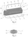
- FIG. 2is a perspective view of the linking member according to another embodiment.
- FIG. 3shows details of an example of a lattice structure.
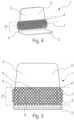
- FIG. 4shows a perspective view of the linking member according to another embodiment.
- FIG. 5shows a front view of the linking member according to the embodiment of FIG. 4 .
- FIG. 6shows a profile view of the linking member according to the embodiment of FIG. 4 .
- FIG. 7shows a profile view of an aircraft having a fuselage with frames fixed to the skin by at least one linking member.
- FIG. 8shows a schematic perspective and transparent view of a portion of the fuselage of the aircraft of FIG. 7 .
- the portion of the fuselagecomprises a frame fixed to the skin by a plurality of linking members.
- the disclosure hereinrelates to a linking member 1 between a structural member 13 and a structural member 14 of a fuselage F of an aircraft AC, such as a transport airplane ( FIG. 7 ).
- the linking member 1helps to fix the structural member 13 to the structural member 14 of the fuselage F of the aircraft AC.
- the structural member 13corresponds to a frame of the fuselage F and the structural member 14 corresponds to a skin of the fuselage F.
- FIG. 8shows a portion of the fuselage F comprising a frame fixed to a skin by linking members 1 . For the sake of clarity, only two linking members 1 are shown in FIG. 8 .
- FIG. 1In FIG. 1 , FIG. 2 and from FIG. 4 through FIG. 6 , various linking members 1 are shown in various perspectives.
- the linking member 1comprises a part 5 made of a solid structure and at least one part 6 made of a lattice structure 7 .
- the part 5 made of the solid structureis configured to dissipate static stresses and to withstand fatigue up to a predetermined maximum stress and fatigue threshold.
- the predetermined maximum stress and fatigue thresholdcan be defined as being a fatigue value below which the first part 5 made of the solid structure is capable of dissipating any static stresses that are normally exerted on the linking member 1 and of withstanding any fatigue that is normally experienced by the linking member 1 .
- the solid structurecorresponds to a solid material.
- the lattice structure 7corresponds to a type of non-solid, porous architectural material comprising a non-stochastic spatial repetition of an elementary pattern 12 .
- the spatial repetition of the elementary pattern 12is valid in all three dimensions of space.
- the lattice structure 7is very efficient in terms of energy dissipation per unit mass.
- FIG. 3shows a detailed example of a lattice structure 7 .
- the elementary pattern 12 of the lattice structure 7corresponds to an octahedron.
- the lattice structure 7 of FIG. 3is thus made of elementary patterns 12 in the shape of an octahedron spatially repeating in the three dimensions of space.
- the number and the shape of the geometry of the elementary patterns 12 of a lattice structure 7are defined so as to ensure maximum energy dissipation over the entire duration of the dynamic load.
- integrating a lattice structure 7 in a linking member 1involves compliance with the following features:
- the linking member 1is one-piece, i.e., made of a single part.
- the part 5 made of the solid structure and the part 6 made of the lattice structure 7thus form a one-piece assembly.
- the part 5 made of the solid structure and the part 6 made of the lattice structure 7are manufactured from the same material.
- the linking member 1is manufactured from titanium.
- the linking member 1is manufactured by three-dimensional printing.
- Three-dimensional printingcan generate surface finish defects that can limit the fatigue resistance of the linking member 1 . It therefore can be important for a configuration to be provided for the linking member 1 that allows either the zones of the linking member 1 that are subject to fatigue to be machined or a surface treatment to be used that allows a standard surface roughness to be achieved.
- the part 5 made of the solid structureadvantageously comprises at least one open portion 8 .
- the open portion or portions 8are occupied by the part or parts 6 made of the lattice structure 7 .
- the second part or parts 6 made of the lattice structure 7can also cover, at least partly, the first part 5 made of the solid structure.
- the linking member 1comprises a base plate 2 intended to be fixed to the structural member 14 of the fuselage F and a web plate 3 intended to be fixed to the structural member 13 .
- the structural member 13corresponds to a frame and the structural member 14 corresponds to a skin.
- the frame and the skinare shown highly schematically.
- the base plate 2 and the web plate 3are connected together by a joint line 4 .
- the base plate 2is substantially perpendicular to the web plate 3 .
- the joint line 4can correspond to a corner between the base plate 2 and the web plate 3 .
- the linking member 1can have a T or L shape.
- the open portion or portions 8are arranged through the web plate 3 of the linking member 1 .
- the part or parts 6 made of the lattice structure 7have a thickness E (perpendicular to the web plate 3 ) that is substantially equal to the thickness of the part 5 made of the solid structure of the linking member 1 . According to other embodiments, this thickness E can be greater than the thickness of the part 5 made of the solid structure of the linking member 1 .
- the web plate 3can comprise a zone Z 1 in the form of a strip parallel to the joint line 4 .
- the zone Z 1thus can comprise the open portion or portions 8 spaced apart by at least one solid structure portion 9 (or also called “monolithic zone”) of the part 5 made of the solid structure.
- the open portion or portions 8can be evenly spaced apart by the solid structure portion or portions 9 .
- the solid structure portion or portions 9are configured so that their fatigue performance capability is optimized. Thus, it is possible to machine or post-process this solid structure portion or these solid structure portions 9 in order to improve their fatigue resistance. It is also possible to reduce any geometric errors that could be formed when manufacturing the linking member 1 , in particular at the ends of the solid structure portion or portions 9 .
- the solid structure portion or portions 9can have a cross-section that is designed to dissipate the static stresses up to the predetermined maximum stress and fatigue threshold. Above the predetermined maximum stress and fatigue threshold, breakage or buckling are desired so as to engage the part 6 made of the lattice structure 7 .
- the cross-sectiondepends on the material from which the linking member 1 is manufactured and the predetermined maximum stress and fatigue threshold.
- the solid structure portion or portions 9have a height H perpendicular to the joint line 4 (see FIG. 1 ). This height H is advantageously designed so that the solid structure portion or portions 9 are capable of dissipating the static stresses up to the predetermined maximum stress and fatigue threshold.
- the number of physical links between the solid structure portions 9 and the part 6 made of the lattice structure 7is limited to a number of physical links allowing separation between, on the one hand, the dissipation of the static and fatigue resistance stresses by the solid structure portion 9 and, on the other hand, the dissipation by the part 6 made of the lattice structure 7 .
- the web plate 3comprises a zone Z 2 in the form of a strip parallel to the zone Z 1 in the form of a strip.
- the zone Z 2comprises fixing holes 10 intended to accommodate fixing members provided for fixing the linking member 1 to the structural member 13 of the fuselage F.
- the fixing holes 10are disposed in line with the solid structure portion or portions 9 .
- a fixing hole 10is disposed in line with each of the solid structure portions 9 .
- the height H of the solid structure portion or portions 9also can be limited by constraints associated with fixing the linking member 1 to the structural member 13 of the fuselage F and to the joint line 4 .
- the base plate 2can also comprise fixing holes 11 intended to accommodate fixing members provided for fixing the linking member 1 to the structural member 14 .
- the fixing holes 11are disposed in line with the solid structure portion or portions 9 .
- a fixing hole 11is disposed in line with each of the solid structure portions 9 .
- This arrangement of the fixing holes 10 and/or 11allows the transfer of a pressurization force to be optimized. It optionally allows a space to be left available for the passage of tools for fixing the linking member 1 .
- the lattice structure 7can completely cover the zone Z 1 on at least one face of the web plate 3 .
- the coverage by the lattice structure 7allows the dissipative performance capability of the linking member 1 to be improved by providing better stability for the linking member 1 and better transfer of stresses when the stress and fatigue threshold is exceeded.
- the thickness E of the part 6 made of the lattice structure 7can be greater than the thickness of the part 5 made of the solid structure, such that it is at least partly integrated between the structural member 13 , in particular the frame of the fuselage F, and the structural member 14 , in particular the skin of the fuselage F.
- This increase in thickness E compared to the embodiment of FIG. 1provides the linking member 1 with better stability, enabling increased dissipation efficiency in the event of significant deformations.
- the thickness Ecan be limited by the assembly constraints for fixing the linking member 1 to the frame 13 and to the skin 14 . This limitation allows a space to be left available for the passage of tools for fixing the linking member 1 .
Landscapes
- Engineering & Computer Science (AREA)
- Mechanical Engineering (AREA)
- Aviation & Aerospace Engineering (AREA)
- Chemical & Material Sciences (AREA)
- Manufacturing & Machinery (AREA)
- Materials Engineering (AREA)
- Metallurgy (AREA)
- Organic Chemistry (AREA)
- Aiming, Guidance, Guns With A Light Source, Armor, Camouflage, And Targets (AREA)
- Connection Of Plates (AREA)
Abstract
Description
- resistance to the static stresses and fatigue typically exerted by aeronautical structures;
- triggering the dissipation of the stresses on the basis of the maximum stress and fatigue threshold;
- optimization of the dissipation that ensures the reduction of the transfer of energy to the members surrounding the linking member1.
Claims (20)
Applications Claiming Priority (2)
| Application Number | Priority Date | Filing Date | Title |
|---|---|---|---|
| FR2106994AFR3124487A1 (en) | 2021-06-29 | 2021-06-29 | Connecting element between a first and a second structural element of the fuselage of an aircraft allowing improved dissipation of forces. |
| FR2106994 | 2021-06-29 |
Publications (2)
| Publication Number | Publication Date |
|---|---|
| US20220411038A1 US20220411038A1 (en) | 2022-12-29 |
| US12049293B2true US12049293B2 (en) | 2024-07-30 |
Family
ID=77519293
Family Applications (1)
| Application Number | Title | Priority Date | Filing Date |
|---|---|---|---|
| US17/849,889Active2042-11-16US12049293B2 (en) | 2021-06-29 | 2022-06-27 | Linking member between a first and a second structural member of a fuselage of an aircraft allowing improved dissipation of stresses |
Country Status (4)
| Country | Link |
|---|---|
| US (1) | US12049293B2 (en) |
| EP (1) | EP4112445B1 (en) |
| CN (1) | CN115535208A (en) |
| FR (1) | FR3124487A1 (en) |
Families Citing this family (1)
| Publication number | Priority date | Publication date | Assignee | Title |
|---|---|---|---|---|
| FR3124487A1 (en)* | 2021-06-29 | 2022-12-30 | Airbus Operations | Connecting element between a first and a second structural element of the fuselage of an aircraft allowing improved dissipation of forces. |
Citations (20)
| Publication number | Priority date | Publication date | Assignee | Title |
|---|---|---|---|---|
| US3591109A (en)* | 1966-06-29 | 1971-07-06 | Frank W Mclarty | Rotary wing aircraft |
| US20080023583A1 (en)* | 2006-01-27 | 2008-01-31 | Herve Payen | Composite anti-crash structure with lateral retention, for an aircraft |
| US20080093503A1 (en)* | 2004-11-15 | 2008-04-24 | Bruno Cacciaguerra | Structural frame for an aircraft fuselage |
| US7382959B1 (en)* | 2006-10-13 | 2008-06-03 | Hrl Laboratories, Llc | Optically oriented three-dimensional polymer microstructures |
| US7510052B2 (en)* | 2005-04-04 | 2009-03-31 | Hexcel Corporation | Acoustic septum cap honeycomb |
| US8066098B2 (en)* | 2005-04-04 | 2011-11-29 | Hexcel Corporation | Acoustic septum cap honeycomb |
| US8079443B2 (en)* | 2008-01-07 | 2011-12-20 | Pelzer Acoustic Products Gmbh | Aircraft trim panel with integrated adjustable acoustic properties |
| US9199714B2 (en)* | 2007-11-16 | 2015-12-01 | Airbus Operations S.A.S. | Interconnection device connecting an aircraft internal structure component to the fuselage of this aircraft |
| US9222229B1 (en)* | 2013-10-10 | 2015-12-29 | Hrl Laboratories, Llc | Tunable sandwich-structured acoustic barriers |
| US20160129984A1 (en)* | 2014-11-06 | 2016-05-12 | Airbus Operations Gmbh | Structural component and method for producing a structural component |
| US9978354B2 (en)* | 2016-04-15 | 2018-05-22 | Rohr, Inc. | Acoustic panel with vertical stiffeners |
| US20200239124A1 (en)* | 2018-02-23 | 2020-07-30 | Mitsubishi Heavy Industries, Ltd. | Rectification structure body and flying vehicle |
| US11047304B2 (en)* | 2018-08-08 | 2021-06-29 | General Electric Company | Acoustic cores with sound-attenuating protuberances |
| US20210391627A1 (en)* | 2020-06-16 | 2021-12-16 | Ernest Villanueva | Aircraft energy storage venting system |
| US11260582B2 (en)* | 2018-10-16 | 2022-03-01 | Divergent Technologies, Inc. | Methods and apparatus for manufacturing optimized panels and other composite structures |
| US20220220587A1 (en)* | 2020-12-21 | 2022-07-14 | Divergent Technologies, Inc. | Aluminum alloys and structures |
| US20220220589A1 (en)* | 2020-12-21 | 2022-07-14 | Divergent Technologies, Inc. | Aluminum alloys and structures |
| US11434819B2 (en)* | 2019-03-29 | 2022-09-06 | General Electric Company | Acoustic liners with enhanced acoustic absorption and reduced drag characteristics |
| US20220411038A1 (en)* | 2021-06-29 | 2022-12-29 | Airbus Operations (S.A.S.) | Linking member between a first and a second structural member of a fuselage of an aircraft allowing improved dissipation of stresses |
| US11591065B2 (en)* | 2017-10-11 | 2023-02-28 | Fokker Aerostructures Bv | Noise attenuation panel |
Family Cites Families (1)
| Publication number | Priority date | Publication date | Assignee | Title |
|---|---|---|---|---|
| DE102009020896B4 (en)* | 2009-05-08 | 2013-07-18 | Deutsches Zentrum für Luft- und Raumfahrt e.V. | missile |
- 2021
- 2021-06-29FRFR2106994Apatent/FR3124487A1/ennot_activeCeased
- 2022
- 2022-06-17EPEP22179653.5Apatent/EP4112445B1/enactiveActive
- 2022-06-27USUS17/849,889patent/US12049293B2/enactiveActive
- 2022-06-29CNCN202210750067.1Apatent/CN115535208A/enactivePending
Patent Citations (22)
| Publication number | Priority date | Publication date | Assignee | Title |
|---|---|---|---|---|
| US3591109A (en)* | 1966-06-29 | 1971-07-06 | Frank W Mclarty | Rotary wing aircraft |
| US20080093503A1 (en)* | 2004-11-15 | 2008-04-24 | Bruno Cacciaguerra | Structural frame for an aircraft fuselage |
| EP1812288B1 (en) | 2004-11-15 | 2008-08-06 | AIRBUS France | Structural frame for an aircraft fuselage |
| US7510052B2 (en)* | 2005-04-04 | 2009-03-31 | Hexcel Corporation | Acoustic septum cap honeycomb |
| US8066098B2 (en)* | 2005-04-04 | 2011-11-29 | Hexcel Corporation | Acoustic septum cap honeycomb |
| US20080023583A1 (en)* | 2006-01-27 | 2008-01-31 | Herve Payen | Composite anti-crash structure with lateral retention, for an aircraft |
| US7382959B1 (en)* | 2006-10-13 | 2008-06-03 | Hrl Laboratories, Llc | Optically oriented three-dimensional polymer microstructures |
| US9199714B2 (en)* | 2007-11-16 | 2015-12-01 | Airbus Operations S.A.S. | Interconnection device connecting an aircraft internal structure component to the fuselage of this aircraft |
| US8079443B2 (en)* | 2008-01-07 | 2011-12-20 | Pelzer Acoustic Products Gmbh | Aircraft trim panel with integrated adjustable acoustic properties |
| US9222229B1 (en)* | 2013-10-10 | 2015-12-29 | Hrl Laboratories, Llc | Tunable sandwich-structured acoustic barriers |
| US20160129984A1 (en)* | 2014-11-06 | 2016-05-12 | Airbus Operations Gmbh | Structural component and method for producing a structural component |
| US9988136B2 (en)* | 2014-11-06 | 2018-06-05 | Airbus Operations Gmbh | Structural component and method for producing a structural component |
| US9978354B2 (en)* | 2016-04-15 | 2018-05-22 | Rohr, Inc. | Acoustic panel with vertical stiffeners |
| US11591065B2 (en)* | 2017-10-11 | 2023-02-28 | Fokker Aerostructures Bv | Noise attenuation panel |
| US20200239124A1 (en)* | 2018-02-23 | 2020-07-30 | Mitsubishi Heavy Industries, Ltd. | Rectification structure body and flying vehicle |
| US11047304B2 (en)* | 2018-08-08 | 2021-06-29 | General Electric Company | Acoustic cores with sound-attenuating protuberances |
| US11260582B2 (en)* | 2018-10-16 | 2022-03-01 | Divergent Technologies, Inc. | Methods and apparatus for manufacturing optimized panels and other composite structures |
| US11434819B2 (en)* | 2019-03-29 | 2022-09-06 | General Electric Company | Acoustic liners with enhanced acoustic absorption and reduced drag characteristics |
| US20210391627A1 (en)* | 2020-06-16 | 2021-12-16 | Ernest Villanueva | Aircraft energy storage venting system |
| US20220220587A1 (en)* | 2020-12-21 | 2022-07-14 | Divergent Technologies, Inc. | Aluminum alloys and structures |
| US20220220589A1 (en)* | 2020-12-21 | 2022-07-14 | Divergent Technologies, Inc. | Aluminum alloys and structures |
| US20220411038A1 (en)* | 2021-06-29 | 2022-12-29 | Airbus Operations (S.A.S.) | Linking member between a first and a second structural member of a fuselage of an aircraft allowing improved dissipation of stresses |
Non-Patent Citations (2)
| Title |
|---|
| European Office Action for Application No. 22179653 dated Oct. 26, 2022. |
| French Search Report for Application No. 2106994 dated Mar. 3, 2022. |
Also Published As
| Publication number | Publication date |
|---|---|
| EP4112445A1 (en) | 2023-01-04 |
| FR3124487A1 (en) | 2022-12-30 |
| CN115535208A (en) | 2022-12-30 |
| EP4112445B1 (en) | 2024-10-09 |
| US20220411038A1 (en) | 2022-12-29 |
Similar Documents
| Publication | Publication Date | Title |
|---|---|---|
| EP1196325B1 (en) | Monolithic structure with redundant load paths | |
| RU2424945C2 (en) | Aircraft door frame | |
| EP1399362B1 (en) | Aircraft panel | |
| JP5308354B2 (en) | Aircraft with an aircraft fuselage section and one such section | |
| US12049293B2 (en) | Linking member between a first and a second structural member of a fuselage of an aircraft allowing improved dissipation of stresses | |
| US20060006284A1 (en) | Floor for aircraft | |
| JP6345505B2 (en) | Pressure panel | |
| US20170106990A1 (en) | Aircraft engine pylon | |
| CN111386225B (en) | Two-piece center frame assembly | |
| US8382034B2 (en) | System box for accommodating aircraft systems | |
| US9688381B2 (en) | Subfloor structure with an integral hull for a rotary wing aircraft | |
| US11377189B2 (en) | Aircraft fuselage structure having a grid-stiffened panel | |
| US8550401B2 (en) | Modular floor section for aircraft | |
| US20150225065A1 (en) | Stiffening Element, Method For Coupling The Same, And Shell Component For An Aircraft Or Spacecraft | |
| US8033502B2 (en) | Modular aircraft interior configuration and methods | |
| CA3055976A1 (en) | Floor fixing assembly | |
| US20170113777A1 (en) | Structural Arrangement, Aircraft Or Spacecraft, And Method For Producing A Structural Arrangement | |
| US7258303B2 (en) | Aircraft partition designed to separate a cargo part from a cockpit or from a passenger compartment | |
| US20180362142A1 (en) | Panel for an aircraft structure | |
| US20130313391A1 (en) | Securing plate and aircraft structure | |
| EP2813426B1 (en) | Shell structure of a fuselage at a door opening and method of forming the shell structure | |
| US10611455B2 (en) | Aircraft assembly comprising a self-stiffened panel assembled with a structural element by means of an alternation of terminal ribs and terminal tabs | |
| US10457375B2 (en) | Aircraft interior fitting component system and method for manufacturing an aircraft interior fitting component system | |
| CN105905272B (en) | Flat-folded rear pressure bulkhead | |
| US20230382511A1 (en) | Stiffener integration in an isogrid structure |
Legal Events
| Date | Code | Title | Description |
|---|---|---|---|
| FEPP | Fee payment procedure | Free format text:ENTITY STATUS SET TO UNDISCOUNTED (ORIGINAL EVENT CODE: BIG.); ENTITY STATUS OF PATENT OWNER: LARGE ENTITY | |
| STPP | Information on status: patent application and granting procedure in general | Free format text:DOCKETED NEW CASE - READY FOR EXAMINATION | |
| AS | Assignment | Owner name:AIRBUS OPERATIONS (S.A.S.), FRANCE Free format text:ASSIGNMENT OF ASSIGNORS INTEREST;ASSIGNORS:MOLINA HAMDAN, OMAR;LAVIGNE, VALERIE;DUBOST, JEROME;SIGNING DATES FROM 20220617 TO 20220620;REEL/FRAME:060830/0205 | |
| STPP | Information on status: patent application and granting procedure in general | Free format text:NON FINAL ACTION MAILED | |
| STPP | Information on status: patent application and granting procedure in general | Free format text:RESPONSE TO NON-FINAL OFFICE ACTION ENTERED AND FORWARDED TO EXAMINER | |
| STPP | Information on status: patent application and granting procedure in general | Free format text:NOTICE OF ALLOWANCE MAILED -- APPLICATION RECEIVED IN OFFICE OF PUBLICATIONS | |
| ZAAA | Notice of allowance and fees due | Free format text:ORIGINAL CODE: NOA | |
| ZAAB | Notice of allowance mailed | Free format text:ORIGINAL CODE: MN/=. | |
| STPP | Information on status: patent application and granting procedure in general | Free format text:PUBLICATIONS -- ISSUE FEE PAYMENT RECEIVED | |
| STPP | Information on status: patent application and granting procedure in general | Free format text:PUBLICATIONS -- ISSUE FEE PAYMENT VERIFIED | |
| STCF | Information on status: patent grant | Free format text:PATENTED CASE |