US12048791B2 - Peritoneal dialysis fluid preparation and/or treatment devices methods and systems - Google Patents
Peritoneal dialysis fluid preparation and/or treatment devices methods and systemsDownload PDFInfo
- Publication number
- US12048791B2 US12048791B2US16/621,824US201816621824AUS12048791B2US 12048791 B2US12048791 B2US 12048791B2US 201816621824 AUS201816621824 AUS 201816621824AUS 12048791 B2US12048791 B2US 12048791B2
- Authority
- US
- United States
- Prior art keywords
- concentrate
- fluid
- line
- peritoneal dialysis
- mixing container
- Prior art date
- Legal status (The legal status is an assumption and is not a legal conclusion. Google has not performed a legal analysis and makes no representation as to the accuracy of the status listed.)
- Active, expires
Links
- 238000011282treatmentMethods0.000titleclaimsabstractdescription149
- 238000000034methodMethods0.000titleabstractdescription62
- 238000002360preparation methodMethods0.000titledescription56
- 239000003330peritoneal dialysis fluidSubstances0.000titledescription21
- 238000000502dialysisMethods0.000claimsabstractdescription188
- 238000005086pumpingMethods0.000claimsabstractdescription146
- 239000012530fluidSubstances0.000claimsdescription599
- 238000002156mixingMethods0.000claimsdescription277
- 230000001954sterilising effectEffects0.000claimsdescription151
- 239000012141concentrateSubstances0.000abstractdescription546
- XLYOFNOQVPJJNP-UHFFFAOYSA-NwaterSubstancesOXLYOFNOQVPJJNP-UHFFFAOYSA-N0.000abstractdescription251
- 239000003814drugSubstances0.000abstractdescription48
- 230000007774longtermEffects0.000abstractdescription25
- 230000036512infertilityEffects0.000abstractdescription10
- 230000008901benefitEffects0.000abstractdescription8
- 239000000385dialysis solutionSubstances0.000description190
- 238000012360testing methodMethods0.000description49
- 239000002357osmotic agentSubstances0.000description40
- 239000012528membraneSubstances0.000description35
- 239000003792electrolyteSubstances0.000description32
- 210000004379membraneAnatomy0.000description31
- 229920001169thermoplasticPolymers0.000description31
- 239000004416thermosoftening plasticSubstances0.000description31
- 239000000463materialSubstances0.000description29
- 239000008213purified waterSubstances0.000description29
- 230000006870functionEffects0.000description20
- 238000011109contaminationMethods0.000description19
- 230000002354daily effectEffects0.000description19
- 238000005520cutting processMethods0.000description15
- 238000005259measurementMethods0.000description14
- 238000007789sealingMethods0.000description12
- 238000003466weldingMethods0.000description12
- 230000004888barrier functionEffects0.000description11
- 238000010790dilutionMethods0.000description11
- 239000012895dilutionSubstances0.000description11
- 230000007246mechanismEffects0.000description11
- 230000002572peristaltic effectEffects0.000description11
- 238000004891communicationMethods0.000description9
- 238000007865dilutingMethods0.000description9
- 230000001276controlling effectEffects0.000description8
- 230000008569processEffects0.000description8
- 238000001816coolingMethods0.000description6
- 238000004519manufacturing processMethods0.000description6
- 239000002699waste materialSubstances0.000description6
- 238000004590computer programMethods0.000description5
- 238000006073displacement reactionMethods0.000description5
- 238000003780insertionMethods0.000description5
- 230000037431insertionEffects0.000description5
- 230000003287optical effectEffects0.000description5
- 210000003200peritoneal cavityAnatomy0.000description5
- 229920000642polymerPolymers0.000description5
- WQZGKKKJIJFFOK-GASJEMHNSA-NGlucoseNatural productsOC[C@H]1OC(O)[C@H](O)[C@@H](O)[C@@H]1OWQZGKKKJIJFFOK-GASJEMHNSA-N0.000description4
- 239000008280bloodSubstances0.000description4
- 210000004369bloodAnatomy0.000description4
- 238000004140cleaningMethods0.000description4
- 239000000356contaminantSubstances0.000description4
- 238000001514detection methodMethods0.000description4
- 230000000694effectsEffects0.000description4
- 238000010438heat treatmentMethods0.000description4
- 238000004806packaging method and processMethods0.000description4
- 238000000746purificationMethods0.000description4
- 241000894007speciesSpecies0.000description4
- 238000006467substitution reactionMethods0.000description4
- 238000004026adhesive bondingMethods0.000description3
- 230000000295complement effectEffects0.000description3
- 238000012790confirmationMethods0.000description3
- 238000001125extrusionMethods0.000description3
- 239000008103glucoseSubstances0.000description3
- 239000000203mixtureSubstances0.000description3
- 238000012986modificationMethods0.000description3
- 230000004048modificationEffects0.000description3
- 238000012544monitoring processMethods0.000description3
- 239000002243precursorSubstances0.000description3
- 239000000047productSubstances0.000description3
- 238000012959renal replacement therapyMethods0.000description3
- 239000000243solutionSubstances0.000description3
- 238000003860storageMethods0.000description3
- 238000011144upstream manufacturingMethods0.000description3
- 241000894006BacteriaSpecies0.000description2
- OKTJSMMVPCPJKN-UHFFFAOYSA-NCarbonChemical compound[C]OKTJSMMVPCPJKN-UHFFFAOYSA-N0.000description2
- WQZGKKKJIJFFOK-VFUOTHLCSA-Nbeta-D-glucoseChemical compoundOC[C@H]1O[C@@H](O)[C@H](O)[C@@H](O)[C@@H]1OWQZGKKKJIJFFOK-VFUOTHLCSA-N0.000description2
- 238000005266castingMethods0.000description2
- 238000013461designMethods0.000description2
- 238000010586diagramMethods0.000description2
- 238000012061filter integrity testMethods0.000description2
- 238000001914filtrationMethods0.000description2
- 238000009434installationMethods0.000description2
- 230000010354integrationEffects0.000description2
- 150000002605large moleculesChemical class0.000description2
- 239000007788liquidSubstances0.000description2
- 229920002521macromoleculePolymers0.000description2
- 239000012982microporous membraneSubstances0.000description2
- 210000004303peritoneumAnatomy0.000description2
- 239000011148porous materialSubstances0.000description2
- 230000001105regulatory effectEffects0.000description2
- 230000004044responseEffects0.000description2
- 238000000926separation methodMethods0.000description2
- 238000012859sterile fillingMethods0.000description2
- 238000004659sterilization and disinfectionMethods0.000description2
- 239000003053toxinSubstances0.000description2
- 231100000765toxinToxicity0.000description2
- 108700012359toxinsProteins0.000description2
- 238000012546transferMethods0.000description2
- 230000000007visual effectEffects0.000description2
- 230000003442weekly effectEffects0.000description2
- 2380000101463D printingMethods0.000description1
- 235000014676Phragmites communisNutrition0.000description1
- XSQUKJJJFZCRTK-UHFFFAOYSA-NUreaChemical compoundNC(N)=OXSQUKJJJFZCRTK-UHFFFAOYSA-N0.000description1
- 210000001015abdomenAnatomy0.000description1
- 210000003815abdominal wallAnatomy0.000description1
- 238000010521absorption reactionMethods0.000description1
- 230000009471actionEffects0.000description1
- 239000012491analyteSubstances0.000description1
- 239000000823artificial membraneSubstances0.000description1
- 230000000903blocking effectEffects0.000description1
- 235000012206bottled waterNutrition0.000description1
- 238000004422calculation algorithmMethods0.000description1
- 238000004364calculation methodMethods0.000description1
- 239000004202carbamideSubstances0.000description1
- 239000003795chemical substances by applicationSubstances0.000description1
- 208000020832chronic kidney diseaseDiseases0.000description1
- 239000004020conductorSubstances0.000description1
- 239000000470constituentSubstances0.000description1
- 238000002788crimpingMethods0.000description1
- 238000002242deionisation methodMethods0.000description1
- 239000008121dextroseSubstances0.000description1
- 238000003113dilution methodMethods0.000description1
- 239000003651drinking waterSubstances0.000description1
- 208000028208end stage renal diseaseDiseases0.000description1
- 201000000523end stage renal failureDiseases0.000description1
- 238000005516engineering processMethods0.000description1
- 230000007613environmental effectEffects0.000description1
- 230000003203everyday effectEffects0.000description1
- 238000011049fillingMethods0.000description1
- 239000013020final formulationSubstances0.000description1
- 239000012634fragmentSubstances0.000description1
- 230000005484gravityEffects0.000description1
- 238000001631haemodialysisMethods0.000description1
- 230000036541healthEffects0.000description1
- 230000000322hemodialysisEffects0.000description1
- 230000006872improvementEffects0.000description1
- 238000011065in-situ storageMethods0.000description1
- 239000004615ingredientSubstances0.000description1
- 230000000977initiatory effectEffects0.000description1
- 150000002500ionsChemical class0.000description1
- 238000011068loading methodMethods0.000description1
- 238000004599local-density approximationMethods0.000description1
- 238000010801machine learningMethods0.000description1
- 238000012423maintenanceMethods0.000description1
- 239000003550markerSubstances0.000description1
- 230000000422nocturnal effectEffects0.000description1
- 230000003204osmotic effectEffects0.000description1
- 239000002245particleSubstances0.000description1
- 244000052769pathogenSpecies0.000description1
- 230000001717pathogenic effectEffects0.000description1
- 230000002093peripheral effectEffects0.000description1
- 206010034674peritonitisDiseases0.000description1
- 239000000546pharmaceutical excipientSubstances0.000description1
- 230000010287polarizationEffects0.000description1
- 238000003825pressingMethods0.000description1
- 230000001737promoting effectEffects0.000description1
- 230000005855radiationEffects0.000description1
- 239000000700radioactive tracerSubstances0.000description1
- 230000009467reductionEffects0.000description1
- 239000003507refrigerantSubstances0.000description1
- 230000000452restraining effectEffects0.000description1
- 238000001223reverse osmosisMethods0.000description1
- 230000002441reversible effectEffects0.000description1
- 150000003839saltsChemical class0.000description1
- 238000005070samplingMethods0.000description1
- 239000004065semiconductorSubstances0.000description1
- 230000007958sleepEffects0.000description1
- 239000002904solventSubstances0.000description1
- 239000000126substanceSubstances0.000description1
- 239000013589supplementSubstances0.000description1
- 238000012549trainingMethods0.000description1
- 230000007704transitionEffects0.000description1
- 238000000108ultra-filtrationMethods0.000description1
- 238000005406washingMethods0.000description1
- 230000036642wellbeingEffects0.000description1
- 238000009736wettingMethods0.000description1
Images


Classifications
- A—HUMAN NECESSITIES
- A61—MEDICAL OR VETERINARY SCIENCE; HYGIENE
- A61M—DEVICES FOR INTRODUCING MEDIA INTO, OR ONTO, THE BODY; DEVICES FOR TRANSDUCING BODY MEDIA OR FOR TAKING MEDIA FROM THE BODY; DEVICES FOR PRODUCING OR ENDING SLEEP OR STUPOR
- A61M1/00—Suction or pumping devices for medical purposes; Devices for carrying-off, for treatment of, or for carrying-over, body-liquids; Drainage systems
- A61M1/14—Dialysis systems; Artificial kidneys; Blood oxygenators ; Reciprocating systems for treatment of body fluids, e.g. single needle systems for hemofiltration or pheresis
- A61M1/16—Dialysis systems; Artificial kidneys; Blood oxygenators ; Reciprocating systems for treatment of body fluids, e.g. single needle systems for hemofiltration or pheresis with membranes
- A61M1/1654—Dialysates therefor
- A61M1/1656—Apparatus for preparing dialysates
- A—HUMAN NECESSITIES
- A61—MEDICAL OR VETERINARY SCIENCE; HYGIENE
- A61M—DEVICES FOR INTRODUCING MEDIA INTO, OR ONTO, THE BODY; DEVICES FOR TRANSDUCING BODY MEDIA OR FOR TAKING MEDIA FROM THE BODY; DEVICES FOR PRODUCING OR ENDING SLEEP OR STUPOR
- A61M1/00—Suction or pumping devices for medical purposes; Devices for carrying-off, for treatment of, or for carrying-over, body-liquids; Drainage systems
- A61M1/14—Dialysis systems; Artificial kidneys; Blood oxygenators ; Reciprocating systems for treatment of body fluids, e.g. single needle systems for hemofiltration or pheresis
- A61M1/15—Dialysis systems; Artificial kidneys; Blood oxygenators ; Reciprocating systems for treatment of body fluids, e.g. single needle systems for hemofiltration or pheresis with a cassette forming partially or totally the flow circuit for the treating fluid, e.g. the dialysate fluid circuit or the treating gas circuit
- A61M1/154—Dialysis systems; Artificial kidneys; Blood oxygenators ; Reciprocating systems for treatment of body fluids, e.g. single needle systems for hemofiltration or pheresis with a cassette forming partially or totally the flow circuit for the treating fluid, e.g. the dialysate fluid circuit or the treating gas circuit with sensing means or components thereof
- A—HUMAN NECESSITIES
- A61—MEDICAL OR VETERINARY SCIENCE; HYGIENE
- A61M—DEVICES FOR INTRODUCING MEDIA INTO, OR ONTO, THE BODY; DEVICES FOR TRANSDUCING BODY MEDIA OR FOR TAKING MEDIA FROM THE BODY; DEVICES FOR PRODUCING OR ENDING SLEEP OR STUPOR
- A61M1/00—Suction or pumping devices for medical purposes; Devices for carrying-off, for treatment of, or for carrying-over, body-liquids; Drainage systems
- A61M1/14—Dialysis systems; Artificial kidneys; Blood oxygenators ; Reciprocating systems for treatment of body fluids, e.g. single needle systems for hemofiltration or pheresis
- A61M1/15—Dialysis systems; Artificial kidneys; Blood oxygenators ; Reciprocating systems for treatment of body fluids, e.g. single needle systems for hemofiltration or pheresis with a cassette forming partially or totally the flow circuit for the treating fluid, e.g. the dialysate fluid circuit or the treating gas circuit
- A61M1/155—Dialysis systems; Artificial kidneys; Blood oxygenators ; Reciprocating systems for treatment of body fluids, e.g. single needle systems for hemofiltration or pheresis with a cassette forming partially or totally the flow circuit for the treating fluid, e.g. the dialysate fluid circuit or the treating gas circuit with treatment-fluid pumping means or components thereof
- A—HUMAN NECESSITIES
- A61—MEDICAL OR VETERINARY SCIENCE; HYGIENE
- A61M—DEVICES FOR INTRODUCING MEDIA INTO, OR ONTO, THE BODY; DEVICES FOR TRANSDUCING BODY MEDIA OR FOR TAKING MEDIA FROM THE BODY; DEVICES FOR PRODUCING OR ENDING SLEEP OR STUPOR
- A61M1/00—Suction or pumping devices for medical purposes; Devices for carrying-off, for treatment of, or for carrying-over, body-liquids; Drainage systems
- A61M1/14—Dialysis systems; Artificial kidneys; Blood oxygenators ; Reciprocating systems for treatment of body fluids, e.g. single needle systems for hemofiltration or pheresis
- A61M1/15—Dialysis systems; Artificial kidneys; Blood oxygenators ; Reciprocating systems for treatment of body fluids, e.g. single needle systems for hemofiltration or pheresis with a cassette forming partially or totally the flow circuit for the treating fluid, e.g. the dialysate fluid circuit or the treating gas circuit
- A61M1/156—Constructional details of the cassette, e.g. specific details on material or shape
- A61M1/1565—Details of valves
- A—HUMAN NECESSITIES
- A61—MEDICAL OR VETERINARY SCIENCE; HYGIENE
- A61M—DEVICES FOR INTRODUCING MEDIA INTO, OR ONTO, THE BODY; DEVICES FOR TRANSDUCING BODY MEDIA OR FOR TAKING MEDIA FROM THE BODY; DEVICES FOR PRODUCING OR ENDING SLEEP OR STUPOR
- A61M1/00—Suction or pumping devices for medical purposes; Devices for carrying-off, for treatment of, or for carrying-over, body-liquids; Drainage systems
- A61M1/14—Dialysis systems; Artificial kidneys; Blood oxygenators ; Reciprocating systems for treatment of body fluids, e.g. single needle systems for hemofiltration or pheresis
- A61M1/15—Dialysis systems; Artificial kidneys; Blood oxygenators ; Reciprocating systems for treatment of body fluids, e.g. single needle systems for hemofiltration or pheresis with a cassette forming partially or totally the flow circuit for the treating fluid, e.g. the dialysate fluid circuit or the treating gas circuit
- A61M1/159—Dialysis systems; Artificial kidneys; Blood oxygenators ; Reciprocating systems for treatment of body fluids, e.g. single needle systems for hemofiltration or pheresis with a cassette forming partially or totally the flow circuit for the treating fluid, e.g. the dialysate fluid circuit or the treating gas circuit specially adapted for peritoneal dialysis
- A—HUMAN NECESSITIES
- A61—MEDICAL OR VETERINARY SCIENCE; HYGIENE
- A61M—DEVICES FOR INTRODUCING MEDIA INTO, OR ONTO, THE BODY; DEVICES FOR TRANSDUCING BODY MEDIA OR FOR TAKING MEDIA FROM THE BODY; DEVICES FOR PRODUCING OR ENDING SLEEP OR STUPOR
- A61M1/00—Suction or pumping devices for medical purposes; Devices for carrying-off, for treatment of, or for carrying-over, body-liquids; Drainage systems
- A61M1/14—Dialysis systems; Artificial kidneys; Blood oxygenators ; Reciprocating systems for treatment of body fluids, e.g. single needle systems for hemofiltration or pheresis
- A61M1/16—Dialysis systems; Artificial kidneys; Blood oxygenators ; Reciprocating systems for treatment of body fluids, e.g. single needle systems for hemofiltration or pheresis with membranes
- A61M1/1654—Dialysates therefor
- A61M1/1656—Apparatus for preparing dialysates
- A61M1/1668—Details of containers
- A—HUMAN NECESSITIES
- A61—MEDICAL OR VETERINARY SCIENCE; HYGIENE
- A61M—DEVICES FOR INTRODUCING MEDIA INTO, OR ONTO, THE BODY; DEVICES FOR TRANSDUCING BODY MEDIA OR FOR TAKING MEDIA FROM THE BODY; DEVICES FOR PRODUCING OR ENDING SLEEP OR STUPOR
- A61M1/00—Suction or pumping devices for medical purposes; Devices for carrying-off, for treatment of, or for carrying-over, body-liquids; Drainage systems
- A61M1/14—Dialysis systems; Artificial kidneys; Blood oxygenators ; Reciprocating systems for treatment of body fluids, e.g. single needle systems for hemofiltration or pheresis
- A61M1/16—Dialysis systems; Artificial kidneys; Blood oxygenators ; Reciprocating systems for treatment of body fluids, e.g. single needle systems for hemofiltration or pheresis with membranes
- A61M1/1654—Dialysates therefor
- A61M1/1656—Apparatus for preparing dialysates
- A61M1/1672—Apparatus for preparing dialysates using membrane filters, e.g. for sterilising the dialysate
- A—HUMAN NECESSITIES
- A61—MEDICAL OR VETERINARY SCIENCE; HYGIENE
- A61M—DEVICES FOR INTRODUCING MEDIA INTO, OR ONTO, THE BODY; DEVICES FOR TRANSDUCING BODY MEDIA OR FOR TAKING MEDIA FROM THE BODY; DEVICES FOR PRODUCING OR ENDING SLEEP OR STUPOR
- A61M1/00—Suction or pumping devices for medical purposes; Devices for carrying-off, for treatment of, or for carrying-over, body-liquids; Drainage systems
- A61M1/14—Dialysis systems; Artificial kidneys; Blood oxygenators ; Reciprocating systems for treatment of body fluids, e.g. single needle systems for hemofiltration or pheresis
- A61M1/28—Peritoneal dialysis ; Other peritoneal treatment, e.g. oxygenation
- A61M1/281—Instillation other than by gravity
- A—HUMAN NECESSITIES
- A61—MEDICAL OR VETERINARY SCIENCE; HYGIENE
- A61M—DEVICES FOR INTRODUCING MEDIA INTO, OR ONTO, THE BODY; DEVICES FOR TRANSDUCING BODY MEDIA OR FOR TAKING MEDIA FROM THE BODY; DEVICES FOR PRODUCING OR ENDING SLEEP OR STUPOR
- A61M1/00—Suction or pumping devices for medical purposes; Devices for carrying-off, for treatment of, or for carrying-over, body-liquids; Drainage systems
- A61M1/14—Dialysis systems; Artificial kidneys; Blood oxygenators ; Reciprocating systems for treatment of body fluids, e.g. single needle systems for hemofiltration or pheresis
- A61M1/28—Peritoneal dialysis ; Other peritoneal treatment, e.g. oxygenation
- A61M1/287—Dialysates therefor
- A—HUMAN NECESSITIES
- A61—MEDICAL OR VETERINARY SCIENCE; HYGIENE
- A61M—DEVICES FOR INTRODUCING MEDIA INTO, OR ONTO, THE BODY; DEVICES FOR TRANSDUCING BODY MEDIA OR FOR TAKING MEDIA FROM THE BODY; DEVICES FOR PRODUCING OR ENDING SLEEP OR STUPOR
- A61M39/00—Tubes, tube connectors, tube couplings, valves, access sites or the like, specially adapted for medical use
- A61M39/22—Valves or arrangement of valves
- A—HUMAN NECESSITIES
- A61—MEDICAL OR VETERINARY SCIENCE; HYGIENE
- A61M—DEVICES FOR INTRODUCING MEDIA INTO, OR ONTO, THE BODY; DEVICES FOR TRANSDUCING BODY MEDIA OR FOR TAKING MEDIA FROM THE BODY; DEVICES FOR PRODUCING OR ENDING SLEEP OR STUPOR
- A61M2205/00—General characteristics of the apparatus
- A61M2205/12—General characteristics of the apparatus with interchangeable cassettes forming partially or totally the fluid circuit
- A61M2205/128—General characteristics of the apparatus with interchangeable cassettes forming partially or totally the fluid circuit with incorporated valves
- A—HUMAN NECESSITIES
- A61—MEDICAL OR VETERINARY SCIENCE; HYGIENE
- A61M—DEVICES FOR INTRODUCING MEDIA INTO, OR ONTO, THE BODY; DEVICES FOR TRANSDUCING BODY MEDIA OR FOR TAKING MEDIA FROM THE BODY; DEVICES FOR PRODUCING OR ENDING SLEEP OR STUPOR
- A61M2205/00—General characteristics of the apparatus
- A61M2205/33—Controlling, regulating or measuring
- A61M2205/3331—Pressure; Flow
- A—HUMAN NECESSITIES
- A61—MEDICAL OR VETERINARY SCIENCE; HYGIENE
- A61M—DEVICES FOR INTRODUCING MEDIA INTO, OR ONTO, THE BODY; DEVICES FOR TRANSDUCING BODY MEDIA OR FOR TAKING MEDIA FROM THE BODY; DEVICES FOR PRODUCING OR ENDING SLEEP OR STUPOR
- A61M2205/00—General characteristics of the apparatus
- A61M2205/50—General characteristics of the apparatus with microprocessors or computers
- A—HUMAN NECESSITIES
- A61—MEDICAL OR VETERINARY SCIENCE; HYGIENE
- A61M—DEVICES FOR INTRODUCING MEDIA INTO, OR ONTO, THE BODY; DEVICES FOR TRANSDUCING BODY MEDIA OR FOR TAKING MEDIA FROM THE BODY; DEVICES FOR PRODUCING OR ENDING SLEEP OR STUPOR
- A61M2205/00—General characteristics of the apparatus
- A61M2205/60—General characteristics of the apparatus with identification means
- A—HUMAN NECESSITIES
- A61—MEDICAL OR VETERINARY SCIENCE; HYGIENE
- A61M—DEVICES FOR INTRODUCING MEDIA INTO, OR ONTO, THE BODY; DEVICES FOR TRANSDUCING BODY MEDIA OR FOR TAKING MEDIA FROM THE BODY; DEVICES FOR PRODUCING OR ENDING SLEEP OR STUPOR
- A61M2205/00—General characteristics of the apparatus
- A61M2205/70—General characteristics of the apparatus with testing or calibration facilities
- A61M2205/705—Testing of filters for leaks
- A—HUMAN NECESSITIES
- A61—MEDICAL OR VETERINARY SCIENCE; HYGIENE
- A61M—DEVICES FOR INTRODUCING MEDIA INTO, OR ONTO, THE BODY; DEVICES FOR TRANSDUCING BODY MEDIA OR FOR TAKING MEDIA FROM THE BODY; DEVICES FOR PRODUCING OR ENDING SLEEP OR STUPOR
- A61M2205/00—General characteristics of the apparatus
- A61M2205/75—General characteristics of the apparatus with filters
- A61M2205/7509—General characteristics of the apparatus with filters for virus
- A—HUMAN NECESSITIES
- A61—MEDICAL OR VETERINARY SCIENCE; HYGIENE
- A61M—DEVICES FOR INTRODUCING MEDIA INTO, OR ONTO, THE BODY; DEVICES FOR TRANSDUCING BODY MEDIA OR FOR TAKING MEDIA FROM THE BODY; DEVICES FOR PRODUCING OR ENDING SLEEP OR STUPOR
- A61M2205/00—General characteristics of the apparatus
- A61M2205/75—General characteristics of the apparatus with filters
- A61M2205/7518—General characteristics of the apparatus with filters bacterial
- A—HUMAN NECESSITIES
- A61—MEDICAL OR VETERINARY SCIENCE; HYGIENE
- A61M—DEVICES FOR INTRODUCING MEDIA INTO, OR ONTO, THE BODY; DEVICES FOR TRANSDUCING BODY MEDIA OR FOR TAKING MEDIA FROM THE BODY; DEVICES FOR PRODUCING OR ENDING SLEEP OR STUPOR
- A61M39/00—Tubes, tube connectors, tube couplings, valves, access sites or the like, specially adapted for medical use
- A61M39/10—Tube connectors; Tube couplings
Definitions
- peritoneal dialysis solution admixer/cyclerrefers to a system that generates peritoneal dialysis solution by admixing and, optionally, also performs a peritoneal dialysis treatment.
- peritoneal dialysis solution admixer/cyclersgenerate peritoneal dialysis, but may not perform a peritoneal dialysis treatment.
- Peritoneal dialysisis a mature technology that has been in use for many years. It is one of two common forms of dialysis, the other being hemodialysis, which uses an artificial membrane to directly cleanse the blood of a renal patient. Peritoneal dialysis employs the natural membrane of the peritoneum to permit the removal of excess water and toxins from the blood.
- peritoneal dialysissterile peritoneal dialysis solution is infused into a patient's peritoneal cavity using a catheter that has been inserted through the abdominal wall.
- the solutionremains in the peritoneal cavity for a dwell period.
- Osmotic exchange with the patient's bloodoccurs across the peritoneal membrane, removing urea and other toxins and excess water from the blood. Ions that need to be regulated are also exchanged across the membrane.
- the removal of excess waterresults in a higher volume of fluid being removed from the patient than is infused. The net excess is called ultrafiltrate, and the process of removal is called ultrafiltration.
- the dialysis solutionis removed from the body cavity through the catheter.
- Peritoneal dialysisrequires the maintenance of strict sterility because of the high risk of peritoneal infection.
- peritoneal dialysiswhich is sometimes referred to as cycler-assisted peritoneal dialysis
- an automated cycleris used to infuse and drain dialysis solution.
- This form of peritoneal dialysis treatmentcan be done automatically at night while the patient sleeps.
- One of the safety mechanisms for such a peritoneal dialysis treatmentis the monitoring by the cycler of the quantity of ultrafiltrate. The cycler performs this monitoring function by measuring the amount of fluid infused and the amount removed to compute the net fluid removal.
- the peritoneal dialysis treatment sequenceusually begins with an initial drain cycle to empty the peritoneal cavity of spent dialysis solution, except on so-called “dry days” when the patient begins automated peritoneal dialysis treatment without their peritoneal cavity filled with dialysis solution.
- the cyclerthen performs a series of fill, dwell, and drain cycles, typically finishing with a fill cycle.
- the fill cyclepresents a risk of over-pressurizing the peritoneal cavity, which has a low tolerance for excess pressure.
- a dialysis solution containeris elevated to certain level above the patient's abdomen so that the fill pressure is determined by the height difference.
- Automated systemssometimes employ pumps that cannot generate a pressure beyond a certain level, but this system is not foolproof since a fluid column height can arise due to a patient-cycler level difference and cause an overpressure.
- a reverse height differencecan also introduce an error in the fluid balance calculation because of incomplete draining.
- Modern cyclersmay fill by regulating fill volume during each cycle.
- the volumemay be entered a controller based on a prescription.
- the prescriptionwhich also determines the composition of the dialysis solution, may be based upon the patient's size, weight, and other criteria. Due to errors, prescriptions may be incorrect or imperfectly implemented resulting in a detriment to patient well-being and health.
- Peritoneal dialysis admixing and/or treatment devices, methods, and systemsare disclosed.
- the systems, methods, and devicesprovide high-level guarantees of sterility and employs relatively inexpensive disposable components to provide pumping.
- Disclosed systems, methods, and devices and features thereofare adapted for point of use generation of medicament.
- admixing systems that employ independently-replaceable long term concentrateare disclosed.
- Featuresare directed to assurance of sterility and accurate admixing of water and concentrate to generate ready-to-use medicaments and other benefits.
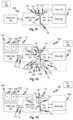
- FIGS. 1 A- 1 Dshow peritoneal dialysis solution admixer/cyclers according to respective embodiments of the disclosed subject matter.
- FIG. 1 Eshows a series testable filter arrangement that may be substituted for the filters employed in the embodiments of FIGS. 1 A- 1 D .
- FIGS. 1 F- 1 Hshow embodiments similar to those of FIGS. 1 A- 1 D and elaborating further details thereof.
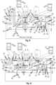
- FIG. 2 Ashows a disposable fluid circuit for use with peritoneal dialysis solution admixer/cyclers of certain embodiments disclosed herein.
- FIG. 2 Bshows an actuator portion of a peritoneal dialysis solution admixer/cycler, according to embodiments of the disclosed subject matter.
- FIG. 2 Cshows a connection platform between a pure water source and the peritoneal dialysis solution admixer/cycler, according to embodiments of the disclosed subject matter.
- FIG. 2 Dshows an eight-roller peristaltic pumping actuator that permits the use of a straight pumping tube segment in a generally planar cartridge, employed as a feature of embodiments disclosed herein.
- FIG. 2 Eshows a disposable fluid circuit for a peritoneal dialysis solution admixer/cycler according to embodiment of the disclosed subject matter in which concentrates are extracted from a disposable component that is separate from the cycler/preparation fluid circuit.
- FIGS. 2 F and 2 Gshow a concentrate disposable component for use with embodiments of the disclosed subject matter.
- FIG. 2 Hshows a disposable fluid circuit for a peritoneal dialysis solution admixer/cycler according to embodiments of the disclosed subject matter in which concentrates are extracted from a disposable component that is separate from the cycler/preparation fluid circuit through respective filtered lines.
- FIGS. 2 I, 2 J, and 2 Kshow respective embodiments of connection platforms between a pure water source and a separate concentrate source and the peritoneal dialysis solution admixer/cycler embodiments disclosed herein, according to embodiments of the disclosed subject matter.
- FIGS. 2 L and 2 Mshow details of variations of the embodiments described with reference to FIG. 2 K .
- FIG. 3shows a method of manufacturing a disposable circuit such as is disclosed in FIG. 2 A .
- FIG. 4 Ashows a peritoneal dialysis solution admixer/cycler according to embodiments of the disclosed subject matter.
- FIG. 4 Bshows the peritoneal dialysis solution admixer/cycler of FIG. 4 A in a first phase of fluid preparation in which osmotic agent concentrate is added to a mixing container, according to embodiments of the disclosed subject matter.
- FIG. 4 Cshows the peritoneal dialysis solution admixer/cycler of FIG. 4 A in a second phase of fluid preparation in which a dialysis solution precursor is obtained by diluting and mixing the contents of the mixing container, according to embodiments of the disclosed subject matter.
- FIG. 4 Dshows the peritoneal dialysis solution admixer/cycler of FIG. 4 A in a third phase of fluid preparation in which the peritoneal dialysis solution precursor properties are verified, according to embodiments of the disclosed subject matter.
- FIG. 4 Eshows the peritoneal dialysis solution admixer/cycler of FIG. 4 A in a fourth phase of fluid preparation in which dialysis solution precursor is further prepared by addition of electrolyte concentrate to the mixing container, according to embodiments of the disclosed subject matter.
- FIG. 4 Fshows the peritoneal dialysis solution admixer/cycler of FIG. 4 A in a fifth phase of fluid preparation in which end-use dialysis solution is prepared by adjustment of the dilution of the mixing container contents, according to embodiments of the disclosed subject matter.
- FIG. 4 Gshows the peritoneal dialysis solution admixer/cycler of FIG. 4 A in a sixth phase of fluid preparation in which dialysis solution in the mixing container is verified, according to embodiments of the disclosed subject matter.
- FIG. 4 H and FIG. 4 Kshow the peritoneal dialysis solution admixer/cycler of FIG. 4 A in various peritoneal dialysis treatment modes, according to embodiments of the disclosed subject matter.
- FIG. 4 Lshows a peritoneal dialysis solution admixer/cycler similar to that of FIG. 4 A in which a single mixing container line connects a valve network to the mixing container.
- FIGS. 5 A- 5 Dillustrate the structure and use of a multifunction connector according to embodiments of the disclosed subject matter.
- FIG. 5 Eshows features for a variation of a double connector 500 that protect against contamination.
- FIG. 6 Ashows mechanical aspects and a control and sensor system for the cut-and-seal devices with actuation, temperature, and force control features, according to embodiments of the disclosed subject matter.
- FIGS. 6 B through 6 Gshow various embodiments of cut-and-seal devices.
- FIGS. 7 A through 7 Dshow various jaw arrangements for cut-and-seal devices according to different embodiments of the disclosed subject matter.
- FIGS. 8 A and 8 Bshow details of chamber portions of fluid circuits according to embodiments of the disclosed subject matter.
- FIGS. 8 C through 8 Gshow various features to promote mixing of fluids in a mixing container according to embodiments of the disclosed subject matter.
- FIG. 9 Ashows a manifold according to embodiments of the disclosed subject matter.
- FIG. 9 Bshows a peritoneal dialysis fill/drain line according to embodiments of the disclosed subject matter.
- FIGS. 10 A and 10 Bshow the structure of a valve network portion of a fluid circuit according to embodiments of the disclosed subject matter.
- FIG. 11shows a fluid circuit for peritoneal dialysis according to embodiments of the disclosed subject matter.
- FIG. 12shows a block diagram of an example computer system according to embodiments of the disclosed subject matter.
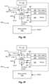
- FIGS. 1 A- 1 Dshow peritoneal dialysis solution admixer/cyclers according to respective embodiments of the disclosed subject matter.
- medical fluid preparation and peritoneal dialysis solution admixer/cycler 90 Aincludes a purified water source 104 that provides water suitable for peritoneal dialysis to a peritoneal dialysis solution admixer/cycler 103 which is connected to a disposable component 100 A.
- the purified water source 104also provides a connection to a drain (shown in FIG. 1 A only, but similar in FIGS. 1 B- 1 D ).
- the peritoneal dialysis solution admixer/cycler 103meters concentrate from one or more concentrate containers 101 (one container is shown but multiple containers may be present) and adds them to, and dilutes them with purified water in a mixing container 102 .
- the concentrate containers 101 and mixing container 102form parts of a single disposable which may also contain a switchable fluid circuit (not shown) that forms part of the disposable component 100 A.
- Mixed dialysis solution (or other medicament)is pumped by the peritoneal dialysis solution admixer/cycler 103 through a connected line to a peritoneal dialysis treatment device such as a dialyzer or to a patient 101 A, for example for peritoneal dialysis.
- a peritoneal dialysis treatment devicesuch as a dialyzer or to a patient 101 A, for example for peritoneal dialysis.
- the disposable component 100 Amay be configured with sufficient concentrate to perform multiple fill/drain cycles of a single peritoneal dialysis treatment.
- the disposable component 100 Amay have sufficient concentrate for multiple fill cycles of a daily automated peritoneal dialysis treatment (APD).
- APDdaily automated peritoneal dialysis treatment
- a medical preparation and peritoneal dialysis solution admixer/cycler 90 Bis similar to the medical fluid preparation and peritoneal dialysis solution admixer/cycler 90 A except that the disposable component 100 B that has a fluid circuit for proportioning and diluting as well as delivering the product medicament does not contain the concentrate.
- the disposable component 100 Bthat has a fluid circuit for proportioning and diluting as well as delivering the product medicament does not contain the concentrate.
- Thisallows the size of the disposable component 100 B, which is handled frequently, for example, daily, to be reduced in mass and easier for a patient and/or user to handle and store. It also can make the disposable component 100 B more economical by reducing waste and providing packaging and manufacturing economies.
- a separate disposable component 100 Eis provided which contains one or more concentrate containers 101 .
- the disposable component 100 Emay have a large capacity and may be changed on a schedule that is much less frequent than the frequency of the replacement of the disposable component 100 B.
- the disposable component 100 Bmay be replaced each time a daily peritoneal dialysis treatment is performed. It may be called a “daily disposable component.”
- the disposable component 100 Emay be replaced once every month so it may be called a “monthly disposable.”
- the disposable component 100 Bmay also have, as part of the fluid circuit included therein, a sterilizing filter 115 of a type that has an air-line 118 to permit the pressure testing of a membrane thereof.
- the latter type of filter testmay be performed automatically by a controller of the peritoneal dialysis solution admixer/cycler 103 on a schedule that is more frequent than the replacement schedule for the disposable component 100 E.
- the sterilizing filter 115may be integrated, and therefore, replaced with, the disposable component 100 B. This allows the sterilizing filter 115 to be sealed and sterilized with the disposable component 100 B and mixing container 102 as a single unit along with the switchable fluid circuit (not shown). Note details of a suitable configuration for a switchable fluid circuit may be found in International Patent Application Publication WO2013141896 to Burbank, et al.
- a function provided by the sterilizing filter 115is to provide safety given that a new sterile disposable component 100 B is attached to the concentrate 101 for each peritoneal dialysis treatment.
- a similar filtermay be employed in all the embodiments for the line indicated at 107 conveying the purified water to the peritoneal dialysis solution admixer/cycler 103 . Since a new connection is required each time the disposable component 100 B is replaced, there is a risk of contamination from the new connection.
- the sterilizing filter 115(and others) can be provided as a sterile barrier to protect the sterile interior of the disposable component 100 B, thereby ensuring that any contamination resulting from the newly-made connection does not enter the disposable component 100 B interior.
- the automatic testing of the filterprovides assurance that the sterilizing filter 115 integrity has provided the expected sterile fluid.
- the testabilityfunctions as a guarantee of the filter's sterilizing function.
- Testing of sterilizing filters using pressurized air testingcan be done in various ways, for example, a bubble point test can be performed.
- a pressure decay testcan be done where fluid is pumped across the membrane and the pressure drop measured and compared with a pressure drop representative of an intact filter or pressure is increased on one side, pumping stopped, and the rate of decay of pressure compared to a predefined curve representative of an intact filter.
- concentratescan include a large-molecule excipient whose presence can be detected using automatic chip-based analyte detection (e.g., attachment of fluid samples to selective fluorophore after flowing through the filter and optical detection after concentration).
- automatic chip-based analyte detectione.g., attachment of fluid samples to selective fluorophore after flowing through the filter and optical detection after concentration.
- a feature of the embodiments that use a filter to provide the guarantee, as mentioned,is that the filter forms part of a sterilized unit that is otherwise hermetically sealed or protected by one or more additional sterilizing filters.
- the entire sealed and sterilized circuitmay have sterilizing filters (1) at all openings to its interior or at least (2) at all openings to which fluid is admitted from the external environment.
- a medical preparation and peritoneal dialysis solution admixer/cycler 90 Cis similar to the medical fluid preparation and peritoneal dialysis solution admixer/cycler 90 B in that the disposable component 100 C that has a fluid circuit for proportioning and diluting as well as delivering the product medicament does not contain the concentrate.
- a separate disposable component 100 Fis provided which contains one or more concentrate containers 101 , in this example, a first concentrate container 105 A and a second concentrate container 105 B are shown. These may be in the form of canisters held by a single packaging wrapper 105 C or they may be replaced separately when they expire.
- the disposable component 100 Cmay have a large capacity and may be changed on a schedule that is much less frequent than the frequency of the replacement of the disposable component 100 B.
- the first concentrate container 105 A and/or second concentrate container 105 Bmay be sized to be replaced on a monthly basis.
- the disposable component 100 Cmay also have, as part of the fluid circuit included therein, two sterilizing filters (collectively indicated as the sterilizing filter 115 ), each of the type that has an air-line 118 to permit the pressure-testing of a membrane thereof.
- Each of the concentrates from first concentrate container 105 A and second concentrate container 105 Bmay thereby be sterilizing filtered and the filter tested for each separately.
- this configurationallows the sterilizing filters 115 to be sealed and sterilized with the disposable component 100 C and mixing container 102 as a single unit along with the switchable fluid circuit (not shown).
- a sterilizing filtermay be used in the water line as indicated at 107 .
- a medical preparation and peritoneal dialysis solution admixer/cycler 90 Dis similar to the medical fluid preparation and peritoneal dialysis solution admixer/cycler 90 C in that the disposable component 100 C that has a fluid circuit for proportioning and diluting as well as delivering the product medicament does not contain the concentrate.
- a separate disposable component 100 Gis provided which contains a first concentrate container 105 A and a second concentrate container 105 B.
- the number of concentratesmay be greater or fewer.
- the concentratesmay be held in the canisters which may have a single packaging wrapper 105 C or they may be replaced separately when they expire.
- the disposable component 100 Gmay have a large capacity such that it can be replaced on a schedule that is much less frequent than the frequency of the replacement of the disposable component 100 D.
- the first concentrate container 105 A and/or second concentrate container 105 Bmay be sized to be replaced on a monthly basis.
- the disposable component 100 Dmay also have, as part of the fluid circuit included therein, the sterilizing filter 115 , also of the type that has an air-line 118 to permit the pressure testing of a membrane thereof.
- the sterilizing filter 115also of the type that has an air-line 118 to permit the pressure testing of a membrane thereof.
- a connection platformallows the peritoneal dialysis solution admixer/cycler 103 to draw purified water, first concentrate container 105 A or second concentrate container 105 B selectively by closing a valve on all but one of these at a time by the connection platform 106 under control of the peritoneal dialysis solution admixer/cycler 103 .
- this configurationallows the sterilizing filter 115 to be sealed and sterilized with the disposable component 100 D and mixing container 102 as a single unit along with the switchable fluid circuit (not shown).
- the switching fluid circuit of the connection platform 106may be part of a disposable that is replaced with the first concentrate container 105 A and second concentrate container 105 B.
- the long-term concentrate containerse.g., monthly disposable
- the long-term concentrate containersmay be replaced on separate schedules so they need not be packaged as a single disposable. This may provide further economy when one concentrate is used at a lower rate by some patients than others, thus allowing the concentrate to be consumed fully before replacing.
- each concentrate containercan be used until exhaustion.
- exhaustionmay be defined to be a condition where insufficient concentrate remains in a single container to permit the preparation of a full batch of peritoneal dialysis fluid, a full batch, in embodiments being a quantity of concentrate component sufficient for a single fill cycle.
- Exhaustionmay be defined to be a condition where insufficient concentrate remains in a single container to permit the preparation of a full batch of peritoneal dialysis fluid, a number of full batches, in embodiments being a quantity of concentrate component sufficient for full peritoneal dialysis treatment. If two concentrates are mixed to form a batch, each component concentrate may be changed out when the prescription's required contribution of that concentrate to a single batch beyond the remaining volume in the particular container.
- the residual volume threshold associated with this insufficiencyis a fixed volume, so that its percentage of the total volume available from a full container is smaller for a large container than for a smaller container.
- the total wasteis much smaller than a disposable component containing concentrate for a single peritoneal dialysis treatment.
- a disposable component containing concentrate for a single peritoneal dialysis treatmentAn example of the latter is discussed below with reference to FIGS. 8 A and 8 B .
- the fixed residual thresholds of the multiple concentrate containersare independent of each other because each container can be replaced independently of the other.
- the contents of neither concentrate containercan be used further.
- the concentrate containersare sized to permit a single peritoneal dialysis treatment.
- a single peritoneal dialysis treatmentwould be considered a single day's worth of peritoneal dialysis treatment, for example, a series of nocturnal PD cycles ending with a fill. So, a single day's peritoneal dialysis treatment is equal to a sufficient quantity of fluid to perform multiple fill drain cycles.
- Embodiments in which the concentrate containers are sized for a single day's peritoneal dialysis treatmentdiffer from those described with reference to the embodiments of FIGS.
- the concentratescan be changed independently thereby achieving a potential savings of a first concentrate that is used at a rate such that a residual volume of the first concentrate can be used more fully as described above. More specifically, if the concentrate containers are sized such that batches of at least predefined prescriptions require more of a first concentrate component than of a second concentrate component and such that at least one batch, or at least one day's worth of batches can be completed while leaving sufficient residual concentrate of the second component to make at least one additional batch, or one additional day's worth of batches, after replacing the first concentrate component, then a savings of the second concentrate may be enjoyed.
- the total concentrate of the most heavily used container of a multiple-component concentrate systemis at least sufficient for:
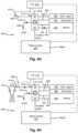
- FIGS. 1 F- 1 Hshow embodiments similar to those of FIGS. 1 A- 1 D and elaborating further details thereof.
- a fluid circuitis indicated at 112 .
- the fluid circuitengages with the peritoneal dialysis solution admixer/cycler 114 by means of valve actuators 123 and one or more pumping actuators 125 which engage the fluid circuit elements of the fluid circuit 112 without wetting the actuator components.
- valve actuators 123such as a linear-motor driven pinch clamp may close and open tubing for flow therethrough and peristaltic pump rollers may engage pumping tube segments.
- the configurationis not limited to such examples, and many are known in the art, any of which may be used in the present embodiment.
- the fluid circuit 112has water suitable for peritoneal dialysis and drain lines 126 , 127 .
- the only connections that need to be made for supplying fluid or draining fluidare connections indicated at 129 .
- the water suitable for peritoneal dialysis and drain lines 126 , 127may be formed as part of the fluid circuit 112 .
- the fluid circuit 112 , concentrate container(s) 101 , and mixing container 102may be pre-connected to form a complete disposable fluid circuit 100 A including concentrate.
- the separate disposable component 100 Fcontains concentrate containers 105 A and 105 B and connects to the peritoneal dialysis solution admixer/cycler 114 by connectors 121 , which may include a double connector as described in embodiments described herein or other types.
- the peritoneal dialysis solution admixer/cycler 114has pumping actuators 125 and valve actuators 123 that engage the fluid circuit 112 .
- the peritoneal dialysis solution admixer/cycler 114provides a pass-through connection for the concentrate while the sterilizing filters 115 on the concentrate lines 130 form part of the disposable component 100 C, which includes the fluid circuit 112 and mixing container 102 . That is, the peritoneal dialysis solution admixer/cycler 114 connects the concentrate lines 131 respectively to the concentrate lines 155 A and 155 B of the fluid circuit 112 .
- connectors for air-lines 130 A and 130 Bare provided to the peritoneal dialysis solution admixer/cycler 114 where an air pump (not shown) can generate a positive pressure and a pressure sensor can measure the positive pressure.
- a filter integrity testmay be done after flowing fluid into the fluid circuit.
- the disposable component 100 Cmay be connected by connecting water suitable for peritoneal dialysis and drain lines 126 , 127 , concentrate lines 155 A and 155 B and air-lines 130 A and 130 B, while the connectors 121 can remain in place through the entire long-term disposable cycle, that is, until the separate disposable component 100 F is expired. Since the latter is replaced much less frequently, the connectors 121 can remain in place for a relatively long period, and frequent changes can be limited to changing connectors 122 , 120 , and connectors for water suitable for peritoneal dialysis and drain lines 126 , 127 as well as the air-lines 130 A and 130 B.
- connection platform(not shown as a unit but may include the connectors and a support for the concentrate containers 105 A and 105 B) and a holder for the by the dialysis solution admixer/cycler 114 . See further connection platform embodiments for details.
- connection platformmay be provided.
- the connection platformmay have its own controller.
- the connection platform and peritoneal dialysis solution admixer/cyclerare collectively indicated at 119 .
- the connection platform portion of admixer/cycler and connection platform 119may be as described with reference to FIGS. 2 K through 2 M , for example.
- connection platform portion of admixer/cycler and connection platform 119selects one of the fluids at a given time by closing off the others and opening a fluid path to the selected one of water, concentrate A, and concentrate B. As indicated, here and in any embodiments, further or fewer concentrates may be used.
- a drain line 135is present.
- a communications interfacemay be provided to allow commands to be sent from the fluid circuit 112 to the peritoneal dialysis solution admixer/cycler and connection platform 119 .
- FIG. 2 Ashows a disposable fluid circuit 200 with fluid lines and components 200 A and a cartridge portion 205 containing a fluid flow director portion 200 B and a manifold portion 200 E.
- the disposable fluid circuit 200is used as a replaceable disposable component with a peritoneal dialysis solution admixer/cycler according to embodiments disclosed herein.
- the present disposable fluid circuit 200may be used with the peritoneal dialysis solution admixer/cycler 90 A, for example.
- Two concentrate containers 105 A and 105 B and a mixing container 102are connected as a pre-connected unit with other parts of the fluid circuit.
- the two concentrate containers 105 A and 105 B and mixing container 102may be provided as a welded double panel sheet with welded seams that define the respective chambers.
- the mixing container 102has two lines, an inflow line 165 and an outflow line 166 .
- a first concentrate container 105 A containerhas 167 , which may be pre-connected and a second concentrate container 105 B line 164 , which may be pre-connected.
- the present embodimentis for a peritoneal dialysis solution admixer/cycler and has a pre-connected fill-drain line 160 with a dialysis solution line 172 attached to an air-line 129 .
- the lattermay be formed as a single unit by co-extrusion.
- the air-line 129attaches to a pressure-sensing pod 162 located at a distal end of the pre-connected fill-drain line 160 .
- a connector 185 at the distal end of the pre-connected fill-drain line 160is sealed.
- Another double line 161has an air-line 129 and a fluid line 171 .
- the fluid line 171receives fluid from peritoneal dialysis solution admixer/cycler 114 and the air-line is used for testing the membrane of the filter.
- the two air-lines 129connect to respective ports 191 that automatically connect in the actuator portion 140 of any of the suitable peritoneal dialysis solution admixer/cycler embodiments.
- the actuator portion 140may be is described with reference to FIG. 2 B .
- Sample portsare provided at 168 at the ends of sample fluid lines 132 and 133 for extracting fluid from respective chambers 175 and 176 of a manifold 174 .
- the two chambers 175 and 176are separated by a barrier 134 and connected by a pumping tube segment 137 .
- Pressure pods 178are installed in each of the two chambers 175 and 176 to measure pressure on the suction and pressure sides of the pumping tube segment 137 .
- the dialysis solution line 172has two branches 136 and 139 .
- a waste line 128 and the fluid line 171connect via a double connector 181 .
- Lines 132 , 128 , 165 , and branch 136connect to chamber 175 .
- Lines 133 , 164 , 166 , 167 , 171 and branch 139connect to chamber 176 .
- the double connector 181supports lines 171 and 128 and provides a pair of connectors 186 and 187 to permit connection of lines 171 and 128 to fill and drain line ports on the peritoneal dialysis solution admixer/cycler 114 .
- the connectors 186 and 187are sealed by a cap 180 .
- a recess 527(See FIGS. 5 A, 5 B ) to engage a détente pin (not shown, but may be a spring-biased pin in the opening that receives the double connector 181 ) provides tactile confirmation of full engagement of the double connector 181 .
- the double connector 181has a window 183 that provides access to a cut and seal actuator (not shown in this drawing but indicated at 212 in FIGS. 2 I through 2 K ).
- the double connectorcan remain in place sealing the fill and drain line ports until it is removed immediately prior to connecting a fresh double connector 181 .
- Thisprovides a barrier to prevent contaminants from entering the fill and drain line ports, which in turn protects the sterile fluid path used by the peritoneal dialysis solution admixer/cycler or connection platform.
- the first concentrate container 105 A and concentrate container 105 Bare both sealed by a frangible seal 154 in each of the lines 164 and 167 .
- the sealis fractured automatically by an actuator after the manifold cartridge 205 is loaded into a receiver that engages it with the interface shown in FIG. 2 B .
- Holes 170are provided in a cartridge support 169 that holds the lines in predefined positions. Holes 170 provide access to pinch actuators that selectively close and open the lines 177 . Certain lines such as lines 177 engage with valve actuators so that they function as valve segments. Holes 179 provide access to actuators that fracture the frangible seals 154 .
- the cartridge support 169is bridged to the manifold 174 by a battery of tubes indicated collectively at 200 C. Even though the polymer of the tubes is flexible, their lengths, number, are such that the overall structure including the cartridge support 169 and the manifold 174 is sufficiently stiff may be readily inserted in a receiving slot.
- FIG. 2 Bshows an actuator portion 140 of a peritoneal dialysis solution admixer/cycler, according to embodiments of the disclosed subject matter.
- a receiving slot 158receives the cartridge portion 205 and aligns it with the various actuators and sensors now identified.
- the various actuators and sensorsinclude pinch clamp actuators 141 that selectively press against selected tubes to provide a valve function.
- the actuators and sensorsfurther include frangible seal actuators 142 that fracture frangible seals 154 in the concentrate lines that contain them.
- the frangible seal actuators 142may be activated simultaneously to open the lines between the pump and the concentrate containers once the pump (e.g., eight-roller peristaltic pump 143 ) is engaged with the pumping tube segment 137 .
- the actuators and sensorsfurther include an air sensor 150 , for example an optical air sensor, that wraps partly around the tube segment of branch 136 in the upper portion of the hole indicated at 124 .
- Ports 146 and 147connect a vacuum or pressure pump to the respective ports 191 .
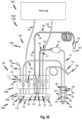
- FIG. 2 Cshows connection platform 219 that serves as an interface between a pure water source and the peritoneal dialysis solution admixer/cycler, according to embodiments of the disclosed subject matter.
- Connection platform 219is an embodiment that may provide for connection to water and drain lines 116 and 117 of embodiments of FIGS. 1 G and 1 H as well as connectors for the concentrate containers 105 A and 105 B for interfacing with the peritoneal dialysis solution admixer/cycler 114 .
- the connection platform 219permits the purified water source 104 to be connected to different devices, such as different peritoneal dialysis treatment devices. Shown here is a configuration adapted for peritoneal dialysis medicament preparation, and optionally peritoneal dialysis treatment also.
- Water from the purified water source 104is received in water line 245 via connection 244 and flows through ultrafilters 237 .
- Pressure of the water suitable for peritoneal dialysis supplyis monitored by a pressure sensor 218 .
- a valve 234selectively controls the flow of water suitable for peritoneal dialysis to a double connector 215 .
- the purified water sourceterminates at a purified water connector 224 of the double connector 215 .
- the double connector 215also has a drain terminal connector 225 which splits at a junction 220 into a path that flows to a pair of conductivity sensors 230 and then merges at junction 238 to proceed to a drain 236 and a path that flows directly to the drain 236 .
- the selected pathis controlled by valves 232 , 240 , and 242 which are controlled by a controller 210 .
- the double connector 181 previously describedis received in a slot 214 where connections are made to the purified water connector 224 and drain terminal connector 225 .
- a détente mechanism 216provides tactile and audible feedback to the operator when a home (fully connected) position of the double connector 181 is made by inserting into the receiving slot 214 .
- the receiving slot 214 Ahas a cutting and sealing actuator 212 driven by a controller 210 that cuts the tubes through the window of double connector 181 .
- a connector 239serves as an adapter to permit connection to various types of drains.
- connection platform 219is also provided with sensors including a moisture sensor 249 located to detect leaking fluid in the connection platform 219 , a tilt sensor 226 to indicate the proper orientation of the connection platform 219 , and a user interface 228 to interact with the controller 210 .
- the connection platform 219may be received in a receiving slot 231 and may be formed as a unitary replaceable component. If sterility or leakage problems arise, the connection platform 219 can be replaced easily.
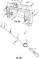
- FIG. 2 Dshows an eight-roller peristaltic pumping actuator 143 that permits the use of a straight pumping tube segment in a generally planar cartridge, employed as a feature of embodiments disclosed herein.
- the rollers 145are attached to a rotor that has recesses to permit clearance for the bulge of an adjacent pumping tube segment positioned between a race 148 and the rollers 145 .
- the rollers 145are unsprung, unlike other peristaltic pump rollers, and rotate on fixed bearings 1471 . Instead, the race 148 is sprung by springs 144 which urge the race against a pumping tube segment pinched by the rollers 145 .
- Either the rotor 149can be moved toward the race 148 to engage a pumping tube segment, or the race 148 can be moved toward the rotor 149 .
- a sufficient gap at 149 during loadingallows a cartridge, such as cartridge portion 205 with a pumping tube segment to be slid in with no interference.
- the race 148is constrained to tilt (in the plane of the drawing) and translate up and down in the plane of the drawing by pins 152 received in guides 153 .
- FIG. 2 Eshows a disposable fluid circuit for a peritoneal dialysis solution admixer/cycler according to an embodiment of the disclosed subject matter in which concentrates are extracted from a disposable component that is separate from the cycler/preparation fluid circuit.
- a disposable fluid circuit 300has fluid lines and components 300 A and a cartridge portion 305 containing a fluid flow director portion 300 B and a manifold portion 300 E.
- the disposable fluid circuit 300is for use with peritoneal dialysis solution admixer/cyclers of certain embodiments disclosed herein.
- the present disposableis an embodiment that may be used with the peritoneal dialysis solution admixer/cycler 90 B or 90 D, for example, where two concentrate containers 105 A and 105 B (not shown in this drawing but shown in FIGS.
- the mixing container 102may be provided as a welded double panel sheet with welded seams that define the chambers.
- the mixing container 102may have two lines, an inflow line 165 and an outflow line 166 . In alternative embodiments, the mixing container 102 may have only a single line for both inflow and outflow.
- the present embodimentis for a peritoneal dialysis solution admixer/cycler and has a pre-connected fill-drain line 160 with a dialysis solution line 172 attached to an air-line 129 .
- the lattermay be formed as a single unit by co-extrusion.
- the fill-drain linemay be separate and connectable with a separate connector.
- the air-line 129attaches to a pressure-sensing pod 162 located at a distal end of the pre-connected fill-drain line 160 .
- a connector 185 at the distal end of the pre-connected fill-drain line 160is sealed.
- Another double line 161has an air-line 129 and a fluid line 171 .
- the fluid line 171receives fluid from peritoneal dialysis solution admixer/cycler 114 and the air-line is used for testing the membrane of the filter.
- the two air-lines 129connect to respective ports 191 that automatically connect in an actuator portion 140 as described with reference to FIG. 2 B .
- Sample portsare provided at 168 at the ends of sample fluid lines 132 and 133 for extracting fluid from respective chambers 175 and 176 of a manifold 174 .
- the two chambers 175 and 176are separated by a barrier 134 and connected by a pumping tube segment 137 .
- Pressure pods 178are installed in each of the two chambers 175 and 176 to measure pressure on the suction and pressure sides of the pumping tube segment 137 .
- the dialysis solution line 172has two branches 136 and 139 .
- a waste line 128 and the fluid line 171connect via a double connector 181 .
- Lines 132 , 128 , 165 , and branch 136connect to chamber 175 .
- Lines 133 , 164 , 166 , 167 , 171 and branch 139connect to chamber 176 .
- the double connector 181supports lines 171 and 128 and provides a pair of connectors 186 and 187 to permit connection of lines 171 and 128 to fill and drain line ports on the peritoneal dialysis solution admixer/cycler 114 .
- the connectors 186 and 187are sealed by a cap 180 .
- a recess to engage a détente pinprovides tactile confirmation of full engagement of the double connector 181 .
- the double connector 181has a window 183 that provides access to a cut and seal actuator (not shown in this drawing).
- the double connectorcan remain in place sealing the fill and drain line ports on the peritoneal dialysis solution admixer/cycler 114 until it is removed immediately prior to connecting a fresh double connector 181 .
- Thisprovides a barrier to prevent contaminants from entering the connection platform 219 fluid path, which in turn protects the sterile fluid path used by the peritoneal dialysis solution admixer/cycler 114 .
- the connection platform 219selects the fluid to be delivered to the fluid line 171 .
- Holes 170are provided in cartridge support 169 that holds the lines in predefined positions. Holes 170 provide access to pinch actuators that selectively close and open the lines 177 .
- Holes 179provide access to actuators that fracture the frangible seals 154 .
- the cartridge support 169is bridged to the manifold 174 by a battery of tubes indicated collectively at 300 C. Even though the polymer of the tubes is flexible, however, the cartridge support 169 and the manifold 174 may be readily inserted in a receiving slot.
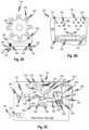
- FIGS. 2 F and 2 Gshow a concentrate disposable component for use with embodiments of the disclosed subject matter.
- a concentrate package 260for example a cardboard box, contains a pair of concentrate containers 262 and 264 .
- Each of the concentrate containers 262 and 264may be connected to a respective port 265 , 266 of a double connector 181 B, the double connector 181 B may be as the one described above or another, for example, a simple two-port connector 273 .
- Separate connectorsmay also be used to permit the containers to be replaced independently of each other.
- the double portmay be connected to a receiving device 287 as shown in FIG.
- the receiving device 287has fluid connectors 285 for connecting to corresponding connectors on the concentrate containers 262 and 264 such that once the containers are installed, fluid can be drawn through the ports 288 A and 288 B of the two-port connector 273 .
- the lattermay be connected to the to the to the connection platform 219 , for example as shown in FIG. 2 I .
- FIG. 2 Hshows a disposable fluid circuit for a peritoneal dialysis solution admixer/cycler according to embodiment of the disclosed subject matter in which concentrates are extracted from a disposable component that is separate from the cycler/preparation fluid circuit through respective filtered lines.
- a disposable fluid circuit 310has fluid lines and components 310 A and a cartridge portion 315 containing a fluid flow director portion 300 B and a manifold portion 300 E.
- the disposable fluid circuit 310is for use with peritoneal dialysis solution admixer/cyclers of certain embodiments disclosed herein.
- the present disposableis an embodiment that may be used with the peritoneal dialysis solution admixer/cycler 90 C where two concentrate containers 105 A and 105 B are provided as a separate disposable from one 100 C with a mixing container 102 , only.
- the mixing container 102may be provided as a welded double panel sheet with welded seams that define the chambers.
- the mixing container 102has two lines, an inflow line 165 and an outflow line 166 .
- the present embodimentis for a peritoneal dialysis solution admixer/cycler and has a pre-connected fill-drain line 160 with a dialysis solution line 172 attached to an air-line 129 . The latter may be formed as a single unit by co-extrusion.
- the air-line 129attaches to a pressure-sensing pod 162 located at a distal and of the pre-connected fill-drain line 160 .
- a connector 185 at the distal end of the pre-connected fill-drain line 160is sealed.
- Another double line 161has an air-line 129 and a fluid line 171 .
- the fluid line 171receives fluid from peritoneal dialysis solution admixer/cycler 114 and the air-line is used for testing the membrane of the filter.
- the two air-lines 129connect to respective ports 191 that automatically connect in an actuator portion such as 140 as described with reference to FIG. 2 B .
- Sample portsare provided at 168 at the ends of sample fluid lines 132 and 133 for extracting fluid from respective chambers 175 and 176 of a manifold 174 .
- the two chambers 175 and 176are separated by a barrier 134 and connected by a pumping tube segment 137 .
- Pressure pods 178are installed in each of the two chambers 175 and 176 to measure pressure on the suction and pressure sides of the pumping tube segment 137 .
- the dialysis solution line 172has two branches 136 and 139 .
- a waste line 128 and the fluid line 171connect via a double connector 181 .
- Lines 132 , 128 , 165 , and branch 136connect to chamber 175 .
- Lines 133 , 164 , 166 , 167 , 171 and branch 139connect to chamber 176 .
- the fluid line 171connects to a water source.
- the double connector 181supports lines 171 and 128 and provides a pair of connectors 186 and 187 to permit connection of lines 171 and 128 to fill and drain line ports on the peritoneal dialysis solution admixer/cycler 114 .
- the connectors 186 and 187are sealed by a cap 180 .
- a recess to engage a détente pinprovides tactile confirmation of full engagement of the double connector 181 .
- the double connector 181has a window 183 that provides access to a cut and seal actuator (not shown in this drawing).
- the double connectorcan remain in place sealing the fill and drain line ports on the peritoneal dialysis solution admixer/cycler 114 until it is removed immediately prior to connecting a fresh double connector 181 .
- Thisprovides a barrier to prevent contaminants from entering the connection platform fluid path, which in turn protects the sterile fluid path used by the peritoneal dialysis solution admixer/cycler 114 .
- the connection platform 219selects the fluid to be delivered to the fluid line 171 .
- Holes 170are provided in a cartridge support 169 (which may be vacuum-formed) that holds the lines in predefined positions. Holes 170 provide access to pinch actuators that selectively close and open the lines 177 .
- Holes 179provide access to actuators that fracture the frangible seals 154 .
- the cartridge support 169is bridged to the manifold 174 by a battery of tubes indicated collectively at 310 C. Even though the polymer of the tubes is flexible, however, the cartridge support 169 and the manifold 174 may be readily inserted in a receiving slot.
- Two concentratesare received through lines 164 and 167 , respectively. Each of the lines is filtered by a filter 115 as described with reference to FIG. 1 G .
- Respective holes 170are provided to control the flow of concentrate through each of the lines 164 and 167 .
- FIGS. 2 I and 2 Jshow examples of connection platforms 219 for connecting to a double connector 181 A to permit concentrate to be drawn through the lines 164 and 167 .
- actuators and sensors of the embodiments of FIGS. 2 I, 2 J, 2 K, 2 L, and 2 Mmay be controlled by a single controller, for example,
- FIGS. 2 I, 2 J, and 2 Kshow respective embodiments of connection platforms that interface between a pure water source and a separate concentrate source and the peritoneal dialysis solution admixer/cycler embodiments disclosed herein, according to embodiments of the disclosed subject matter.
- connection platform 219is an embodiment of the interface providing the water supply and drain connections ( 116 , 117 ) between the purified water source 104 and the peritoneal dialysis solution admixer/cycler 114 .
- the connection platform 219permits the purified water source 104 to be connected to different devices, such as different peritoneal dialysis treatment devices.
- Shown hereis a configuration adapted for peritoneal dialysis medicament preparation, and optionally peritoneal dialysis treatment also.
- the present configurationdiffers from that of FIG. 2 C in that the present arrangement includes a mechanism for connecting a circuit such as disposable fluid circuit 310 of FIG. 2 H which draws concentrate from a double connector 181 A which fits in slot 214 A to receive concentrate through ports 283 .
- the double connector 181 Apreviously described also has a détente mechanism 216 to provide feedback to the operator when a home (fully connected) position of the double connector 181 A is made by inserting into the receiving slot 214 A.
- the receiving slot 214 Ahas a cutting and sealing actuator 212 , driven by controller 210 , that cuts the tubes through the window of double connector 181 , 181 A.
- the ports 283may be supported on a replaceable double connector 273 as described in FIG. 2 F so that these ports are provided by a replaceable connector as part of a concentrate package 260 that includes concentrate containers 262 and 264 or fitted to the receiving device 287 described above with reference to FIG. 2 G .
- the ports 283may be part of the connection platform 219 .
- the tubes 290 and 292may be part of the connection platform 219 and provided with separate connectors for connecting the tubes 293 and 294 of the concentrate containers 262 and 264 ( FIG. 2 F ) or similarly to connect the receiving device 287 .
- water from the purified water source 104is received in water line 245 via connection 244 and flows through ultrafilters 237 .
- Pressure of the water suitable for peritoneal dialysis supplyis monitored by a pressure sensor 218 .
- a valve 234selectively controls the flow of water suitable for peritoneal dialysis to a double connector 215 .
- the purified water sourceterminates at a purified water connector 224 of the double connector 215 .
- the double connector 215also has a drain terminal connector 225 , which splits at a junction 220 into a path that flows to a pair of conductivity sensors 230 , and then merges at junction 238 to proceed to a drain 236 and a path that flows directly to the drain 236 .
- the selected path 247is controlled by valves 232 , 240 , and 242 which are controlled by a controller 210 .
- the double connector 181 previously describedis received in a slot 214 where connections are made to the purified water connector 224 and drain terminal connector 225 .
- a détente mechanism 216provides tactile and audible feedback to the operator when a home (fully connected) position of the double connector 181 is made by inserting into the receiving slot 214 .
- a connector 239serves as an adapter to permit connection to various types of drains.
- connection platform 219is also provided with sensors including a moisture sensor 249 located to detect leaking fluid in the connection platform 219 , a tilt sensor 226 to indicate the proper orientation of the connection platform 219 , and a user interface to interact with the controller 210 .
- the connection platform 219may be received in a receiving slot 231 and may be formed as a unitary replaceable component. If sterility or leakage problems arise, the connection platform 219 can be replaced easily.
- connection platform 219provides a receiving connector for the concentrate connector 181 B, which may be attached to the receiving device 287 of the concentrate containers as shown in FIGS. 2 F and 2 G .
- a pair of lines 280 and 281connect the double connectors 181 A and 181 B so that concentrate can be drawn by the peritoneal dialysis solution admixer/cycler 114 according to any of the various embodiments.
- the connection platform 219in this case functions as a pass-through.
- the connection with double 181 Bcan be made on a low frequency basis according to the size of the concentrate containers and the connection with double connector 181 A can be made on a per-peritoneal dialysis treatment (or other schedule) each time the mixing container 102 and associated fluid circuit (e.g. 310 ) is replaced.
- FIG. 2 Kshows another mechanism for connecting and controlling flow of concentrate to the peritoneal dialysis solution admixer/cycler 114 .
- connectors 289connect to a manifold 297 with controllable valves 279 which open and close under the control of a controller 213 to permit only a selected one of the water suitable for peritoneal dialysis from a water line 296 , the first concentrate from a first concentrate line 295 A, and the second concentrate from a second concentrate line 295 B. Each of these may be drawn through common fluid line 298 through connector 224 .
- the pumping actuator 125 peritoneal dialysis solution admixer/cycler 114is able to draw each of the fluids.
- the controller of the peritoneal dialysis solution admixer/cycler 114can be made to control the valves 279 by communicating with the controller 213 through a user interface 312 .
- controller 213 and user interface 312may be the same except as otherwise indicated across FIGS. 2 I, 2 J, and 2 K .
- a single controller of the peritoneal dialysis solution admixer/cycler 103( 410 , 109 ) or an independent controller common to both (indicated also by 109 ) may be employed for controlling the described functions of the peritoneal dialysis solution admixer/cycler 90 A through 90 D.
- FIGS. 2 L and 2 Mshow modifications of the connection platform of FIG. 2 K to provide for water and concentrate to be supplied through the common fluid line 298 .
- a pair of junctions 222are used, one to join the first concentrate line 295 A and the second concentrate line 295 B.
- the concentratesare pumped respectively, according to the selection of valves 250 A and 250 B which are controlled automatically by a controller of the peritoneal dialysis solution admixer/cycler 103 or through a separate controller 109 or through an interface by a dedicated controller 213 of the connection platform 219 (or variations as illustrated in FIGS. 2 L and 2 M ).
- the fluid circuit 100 B, 100 Dwhich has a testable type of filter as the filter 115 having an air side and a fluid side separated by a membrane
- the fluidmay advantageously be pumped by a pump 221 in a push configuration with respect to the filter 115 rather than relying solely on a suction force provided by the pumping actuator through pumping tube segment 137 .
- a particular concentrateis selected by valves 250 A and 250 B.
- a control valve 250 Cis also operated by the controller to control flow in the water line 296 .
- watermay be advantageously pumped by a push pump 246 if water is supplied through a filtration plant 223 .
- watermay be filtered through reverse osmosis, deionization, activated carbon, and other types of filters to generate water suitable for peritoneal dialysis from potable water.
- the pumps 221 , and 246may be controlled as indicated above with respect to the valves 250 A and 250 B to operate in tandem with the pumping actuators of the peritoneal dialysis solution admixer/cycler (e.g., 103 ).
- the connection platform of FIG. 2 Kfunctions to select one of multiple fluids among water and one or more concentrates thereby allowing all fluids to pass into the fluid circuit through a single inlet line (as in the fluid circuit of FIG. 2 E , for example).
- FIG. 2 Manother variant of the connection platform 219 of FIG. 2 K , may be employed advantageously where a push pump such as push pump 246 is not required to draw water, for example, if instead of using the cycler to prepare dialysis solution, a premixed dialysis solution is connected to one of the inlets instead with suitable programming of the controller to permit flow only from one of the premixed containers at a time.
- control valves 279select the fluid to be drawn at each time and the pump 221 draws the selected fluid pushing it through the filter.
- the pressure sensor 218may be used for feedback control of the push pump 246 .
- FIG. 3shows a method of manufacturing a disposable circuit such as disclosed in FIG. 2 A .
- the concentrate containersare filled at S 10 .
- the concentrate containersare then sealed with frangible elements that form a hermetic seal at S 12 . This isolates the contents of the concentrate containers from the outside environment and causes them to be protected from intrusion of contaminants.
- the concentrate containersare connected to a remainder of the fluid circuit, for example the disposable fluid circuit 200 .
- the remaining portions of the fluid circuitare sealed by ensuring that end caps are placed on any line terminations that are not interconnected within the circuit. For example, caps on connector 185 , sample ports 168 and connectors 186 and 187 .
- the entire circuit assembly with the concentratesmay be radiation sterilized.
- FIG. 4 Ashows a peritoneal dialysis solution admixer/cycler according to embodiments of the disclosed subject matter.
- the present FIGS. 4 A through 4 Kare abstractions of the various embodiments disclosed above for purposes of explaining the operational use thereof for preparing peritoneal dialysis solution and for treating a patient using the structures described above.
- a peritoneal dialysis solution admixer/cycler 400may correspond to any of the foregoing embodiments described for generating dialysis solution by mixing concentrates and water.
- note embodiments 90 A- 90 Dnote embodiments 90 A- 90 D.
- the peritoneal dialysis solution admixer/cycler 400generates custom peritoneal dialysis solution according to a prescription stored in a controller 410 (corresponding to controllers described above).
- the prescriptionmay be entered in the controller via a user interface 401 , via a remote terminal and/or server 403 , or by other means such as a smart card or bar code reader (not shown).
- the controllerapplies control signals to a fluid conveyer and circuit switch 416 and a water purifier 420 and receives signals from distal and proximal pressure sensors 413 and 414 , respectively, on a fill/drain line 450 which may be in accord with foregoing embodiments.
- the fluid circuit with pump and valve network 416is a fluid circuit element with one or more sensors, actuators, and/or pumps which is effective to convey fluid between selected lines 442 , 444 , 446 , 448 , 450 and 418 responsively to control signals from the controller 410 .
- Example embodimentsare described herein, but many details are known from the prior art for making such a device so they are not elaborated here.
- a multiple-container unit 441includes a pre-filled, pre-sterilized osmotic agent concentrate container 402 for osmotic agent concentrate and another electrolyte concentrate container 404 with electrolyte.
- the multiple-container unit 441also contains the mixing container 406 (which is empty) which is large enough to hold a sufficient volume of dialysis solution for the completion of at least one fill cycle of an automated peritoneal dialysis treatment.
- the containers 402 , 404 , and 406may be flexible bag-type containers that collapse when fluid is drawn from them and therefore, do not require any means to vent air into them when drained.
- Osmotic agent concentrate container 402 , electrolyte concentrate container 404 , and mixing container 406are all connected by respective lines 442 , 448 , 444 , and 446 to the fluid circuit with pump and valve network 416 .
- the fill/drain line (or multiple lines) 450 and a drain line 418 for spent fluid (and other fluids) with a conductivity sensor 428may also be connected to the fluid circuit with pump and valve network 416 .
- the fluid circuit with pump and valve network 416also has a fill purified water line 431 for receiving water.
- the water purifier 420may be a purifier or any source of sterile and pure water including a pre-sterilized container of water or multiple containers.
- water purifier 420may be configured as described in WO2007/118235 (PCT/US2007/066251) and US20150005699, which are hereby incorporated by reference in their entireties.
- the water purifier 420may include the flow circuit components of FIG. 22 A of WO2007/118235 including the water purification stages and conform generally to the mechanical packaging design shown in FIG. 24 of WO2007/118235.
- 416is an abstraction of the peritoneal dialysis solution admixer/cycler 114 as well as elements of a fluid circuit such as fluid circuit 112 and connection platform 219 .
- 402 and 404represent concentrate containers according to any of the disclosed embodiments including the concentrate containers 101 , 262 and 264 , 105 A and 105 B.
- the mixing container 406corresponds to any of the mixing container embodiments ( 102 ) described above.
- Other elementswill be evident from their description with the understanding that the figures represent abstractions thereof for purposes of describing the function. It should also be understood that the number and type of concentrates may differ from the present which is disclosed as an example, only.
- the examples of concentrates discussed hereinare glucose and electrolyte concentrates but they could be one or other multiples or other concentrates in other embodiments.
- the osmotic agent concentrate or glucose concentrateis presumed here to include an electrolyte concentrate marker to permit the concentration of osmotic agent to be inferred from a measurement of conductivity of diluted agent with a priori knowledge (stored in a memory used by the controller) of the ratio of osmotic agent concentrate to electrolyte concentrate in the osmotic agent concentrate. See US20150005699.
- the osmotic agentis not provided with electrolyte and the peritoneal dialysis solution admixer/cycler 400 relies on volumetric proportioning for the transfer of osmotic agent. Note also that the order of concentrate addition may be reversed, with electrolyte being added first.
- FIG. 4 Bshows a preliminary stage of fluid preparation prior to peritoneal dialysis treatment according to an embodiment of the disclosed subject matter.
- the controller 410reads a prescription and generates a command, responsive to a peritoneal dialysis treatment preparation initiation command, to flow osmotic agent concentrate from osmotic agent concentrate container 402 to the mixing container 406 .
- the commandis applied to the fluid circuit with pump and valve network 416 to connect the osmotic agent concentrate line 442 to the batch fill line 444 and also to convey the osmotic agent concentrate into the mixing container 406 . This may be done by one or more valve actuators and one or more pumps that form the fluid circuit with pump and valve network 416 .
- the fluid circuit with pump and valve network 416may be configured to meter the quantity of osmotic agent concentrate precisely according to a predicted amount of dilution by electrolyte concentrate and water to achieve the prescription.
- the meteringmay be performed by a positive displacement pump internal to the fluid circuit with pump and valve network 416 or other means such as a measurement of the weight of the osmotic agent concentrate container 402 or the mixing container or a volumetric flow measurement device.
- part of the water(less than the total used for dilution as discussed below with reference to FIG. 4 C ) is added to the mixing container first, before the osmotic agent concentrate and electrolyte concentrates (if needed) are pumped into the mixing container.
- a dilution stageis performed using the peritoneal dialysis solution admixer/cycler 400 .
- the controller 410in response to the prescription, generates a command, to flow purified water from the water purifier 420 to the mixing container 406 .
- the commandis applied to the fluid circuit with pump and valve network 416 to connect the purified water line 431 to the mixing container 406 to add a measured quantity of water to dilute the osmotic agent concentrate in the mixing container 406 .
- the controllermay control the fluid circuit with pump and valve network 416 to ensure the correct amount of water is conveyed.
- the water purifiermay incorporate a flow measurement device or metering pump or other suitable mechanism to convey the correct amount of water.
- the controller 410may be connected to the water purifier 420 to effectuate the dilution result.
- the fluid circuit with pump and valve network 416may also be configured to circulate diluted osmotic agent concentrate solution through lines 444 and 446 either simultaneously with the dilution or after the diluting water has been transferred to the mixing container according to alternative embodiments.
- the relative amounts of water, osmotic agent concentrate, and electrolyte concentratemay be defined based on the ratiometric proportioning properties of the pump. Since a single pump tube is used to convey all the liquids into the mixing container, most sources of offset from predicted pumping rate (based on shaft rotations, for example) to actual pumping rate affect all the fluids roughly equally.
- the diluted osmotic agent concentrate solution in the mixing container 406is tested to ensure that the correct concentration of osmotic agent is achieved.
- the osmotic agent concentrate 402has an amount of electrolyte concentrate to generate a conductivity signal using the conductivity sensor 428 when fluid from the mixing container 406 is conveyed by the fluid circuit with pump and valve network 416 to the drain line 418 past the conductivity sensor.
- the amount of electrolyte concentrate pre-mixed with the osmotic agent concentratemay be the lowest ratio of electrolyte concentrate to osmotic agent concentrate that a possible prescription may require.
- the fluid circuit with pump and valve network 416may perform the function using one or more valve actuators and one or more pumps that form the fluid circuit with pump and valve network 416 .
- the fluid circuit with pump and valve network 416may be configured to meter the quantity of water precisely or the function may be provided by the water purifier 420 .
- the controllermay add additional water or osmotic agent concentrate and test the conductivity again if the measured concentration of osmotic agent and/or electrolytes, if applicable, is incorrect.
- the osmotic agent concentrate container 402holds osmotic agent concentrate with no electrolyte concentrate and osmotic agent concentration is optionally measured directly by other means such as specific gravity (hydrometer), refractive index (refractometer), polarization, infrared absorption or other spectrographic technique.
- FIG. 4 Eshows an electrolyte concentrate addition stage of fluid preparation prior to peritoneal dialysis treatment according to an embodiment of the disclosed subject matter.
- the controller 410reads a prescription and generates a command to flow electrolyte concentrate from container 404 to the mixing container 406 .
- the commandis applied to the fluid circuit with pump and valve network 416 to connect the electrolyte concentrate line 448 to the batch fill line 444 and also to convey the electrolyte concentrate into the mixing container 406 . This may be done by one or more valve actuators and one or more pumps that form the fluid circuit with pump and valve network 416 .
- the fluid circuit with pump and valve network 416may be configured to meter the quantity of electrolyte concentrate precisely according to a predicted amount of dilution by osmotic agent concentrate and water that has been previously determined to be in the mixing container 406 , to achieve the prescription.
- the meteringmay be performed by a positive displacement pump internal to the fluid circuit with pump and valve network 416 or other means such as a measurement of the weight of the electrolyte concentrate container 404 or the mixing container 406 or a volumetric flow measurement device.
- the electrolyte concentratemay be mixed using the batch fill and drain lines 446 and 444 in a closed loop. If necessary, depending on how much dilution was performed during the osmotic agent concentrate dilution process, further dilution may be performed as described above.
- the final formulationmay be achieved by the process illustrated in FIG. 4 F .
- the final electrolyte concentration of the mixture in mixing container 406may be determined with a conductivity sensor 428 by flowing a sample therethrough.
- any embodiments of a peritoneal dialysis solution admixer/cycler disclosed hereinmay employ ratiometric proportioning as well, particularly where positive displacement pumping is employed.
- Ratiometric proportioningtakes advantage of the volumetric repeatability and predictability of certain pumps. For example, a particular pump can deliver a highly repeatable volume of fluid for a given number of pumping cycles (pump rotations for a peristaltic pump or cycles for a diaphragm pump, for example).
- dialysis solution componentswater, osmotic agent concentrate, and electrolyte concentrate, for example
- the volume ratios of the componentswill, after adjustment for potential flow path and/or viscosity differences as described below, be fully determined by the number of pump cycles used to convey each component.
- Rationmetric proportioningmay supplement or substitute for measurement of the fluid conductance or density or other measurements.
- a calibrationmay be performed and/or flow path (including fluid properties) compensation parameters may be employed.
- the flow path compensation parametersmay be respective to each particular fluid flow path and/or fluid type, or may be identical for all fluid paths and fluid types.
- one or more pump calibration and/or flow path compensation parametersmay be generated through a calibration procedure.
- flow path compensation factorswill be established and stored in non-volatile memory.
- one or more flow path calibration procedureswill be performed when the peritoneal dialysis solution admixer/cycler is used by a patient.
- the calibration proceduremay be performed after each new fluid set is installed, or before each batch preparation cycle, or even multiple times during the preparation of a single batch.
- a disposable fluid setmay be installed every day.
- the calibration proceduremay be done using water.
- the calibrationmay sequentially pump fluid through one or more of the stages provided in Table 1.
- a separate calibration coefficientmay be generated for each of the paths.
- the calibration coefficientmay be stored in a memory or non-volatile data store, for example, as a parameter representing the number of ml/per pump rotation (or diaphragm pump cycle), or as a proportionality ratio relative to a particular reference flow path.
- the actual fluid quantity transported during the calibration stepmay be measured by any suitable device (flow sensor) including volume or mass measurement devices or direct flow rate measurement with integration, for example, using laser Doppler velocimetry, thermal transit time, magnetohydrodynamics, propeller hydrometer, positive displacement flow measurement, differential pressure through a resistance such as a venturi, nozzle, orifice plate, or other flow obstruction, variable area or rotameter, pitot or impact tube, vortex shedding frequency counting, ultrasonic, or other device.
- a particularly advantageous device for flow calibrationis to measure the transit time of a fluid property perturbation between spaced fluid property sensors as described below with reference to FIG. 22 A .
- any of the disclosed embodimentsmay employ a flow sensor in which at least the portion of which that carries fluid is disposable so that the flow rate (or total displaced fluid quantity) can be input to a controller while allowing the use of a disposable fluid circuit.
- a flow sensorin which at least the portion of which that carries fluid is disposable so that the flow rate (or total displaced fluid quantity) can be input to a controller while allowing the use of a disposable fluid circuit.
- Examplesinclude an ultrasonic soft tube flowmeter made by Strain Measurement Devices SMD that non-invasively measure flow in soft tubing by means of slotted transducers in which a length of tubing can be inserted during fluid circuit installation.
- the PD cyclercan employ a moving transducer stage that engages an exposed tube length of the cartridge after passive insertion of the cartridge.
- the pumping systemmay also be sufficiently repeatable in a way that allows precise ratios to be established without calibration, depending on the predefined tolerances. If the manufacturing tolerances, including materials, are sufficiently controlled, a desired level of control over ratios may be achieved without in situ (point of care) calibration.
- a particularly sensitive component in terms of guaranteeing repeatabilityis the pumping tube segment of a peristaltic pump.
- the peristaltic pump tube segmentis made from a material whose mechanical and material tolerances are controlled within predefined limits. The lengths of the tubing circuit elements and mechanical parameters are also controlled within respective predefined limits.
- a calibrationmay then be done outside the peritoneal dialysis treatment context, e.g., in the laboratory, to calculate precise values to convert pump cycles to fluid quantity transferred for a single lot of replaceable fluid circuits.
- the calibrationmay be done for multiple lots.
- the calibrationmay also be done for each fluid circuit.
- the calibrationmay also be done by the peritoneal dialysis solution admixer/cycler for each fluid circuit.
- the calibrationmay also be done for each batch of peritoneal dialysis fluid prepared by the fluid circuit.
- the fluid circuit with pump and valve network 416may be configured to drain the patient 412 depending on the patient's prior status.
- Spent dialysis solution fluidmay be withdrawn by the fluid circuit with pump and valve network 416 and conveyed through the drain line 418 .
- the contents of the mixing container 406may be conveyed as illustrated in FIG. 4 K to the patient.
- the controller 410has configured the fluid circuit with pump and valve network 416 to flow fluid to a patient 412 .
- a single monolithic memberhas a shape with at least one window, where two windows are shown one of which is indicated as window 512 .
- the body 504has a ridge 507 that overhangs the frame 506 to permit the frame 506 overall to be grasped easily by a user for pushing or pulling to connect ports 514 , 516 to ports of a device (e.g., 219 ) to which lines 508 and 510 of a fluid circuit 530 are to be connected.
- a releasable port cover 502(see also cap 180 ) seals ports 525 and 526 to prevent contamination thereof.
- FIG. 5 Bshows the double connector 500 after cutting and sealing, the sealed ends of one end of cut tubes forming stubs indicated at 520 and 521 and the opposing ends at 522 , 523 .
- the ends 522 , 523remain attached to a fluid circuit 530 which is to be replaced.
- the stubs 520 , 521remain attached to a resulting stub connector 519 which can remain attached to a connected device after use so as to act as a cover and seal against environmental contamination of a connected device, such as connection platform 219 connectors 224 and 225 .
- the protected ports of the connected deviceare indicated at 525 and 526 .
- a connector 500(which may be a double connector) including a cut and seal operation in which a portion 540 of a connector (e.g., double connector 181 ) is left in place to act as a sterile barrier begins with the removal of a sterile barrier-type cap from the end of the connector S 32 .
- the sterile barriermay take the form of the double releasable port cover 502 .
- S 33sterile barrier formed by a previous connector (which was cut and sealed See FIGS. 6 A- 7 D and elsewhere in the present disclosure) is removed and a new replacement connector of the same form as the connector 500 attached S 34 .
- a cut and seal operationis initiated at S 36 resulting the separation of the fluid circuit (cut and sealed forming the stubs 520 , 521 and ends 522 , 523 ) and a new portion 640 of the new connector to be left in place to act as a sterile barrier.
- the cut and seal operationmay include cooling the cut ends of the tube to speed the operation so that a delay for sufficient passive cooling is not required.
- the lattermay also permit the cutting heads to act as mechanism for gripping the stubs 520 and 521 to prevent them being removed before cooling. See, for example, the embodiment of FIGS. 6 E and 6 F which have a broad flat interface for gripping the ends of the cut tube 666 .
- FIG. 5 Eshows features for a variation of a double connector 501 that protect against contamination.
- a male connector portion 562mates with a female connector portion 564 .
- Ports 526(male) pass through openings 547 of female ports 548 .
- a pin 545is provided on the male connector portion 562 that is received within a recess 546 .
- the female ports 548open in a wall 552 as does an access 549 of the recess 546 .
- Lines 544connect to the male connector portion 562 .
- the remainder of the double connector 501is as described with reference to connector 500 shown in FIGS. 5 C and 5 D .
- the pin 545may be sized to prevent the ports 526 from contacting a flat surface inadvertently and thereby prevent contact contamination.
- the pin 545may also be shaped asymmetrically to prevent incorrect orientation of the connectors.
- the double connector 501may be modified such that it has a greater or lesser number of tubes 508 , 510 and openings 547 .
- the number of pins 545 and recesses 546may differ from what is shown. For example two pins and recesses may be provided at the edges 571 with or without the illustrated pin and recess.
- the male and female connectorsmay be swapped or mixed on a given side of the male connector portion 562 and the female connector portion 564 .
- One or more pins 545may be provided on either side or mixed as may openings 547 .
- FIG. 6 Ashows mechanical aspects and a control and sensor system for the cut-and-seal devices with actuation, temperature, and force control features, according to embodiments of the disclosed subject matter.
- FIGS. 6 B through 6 Dshow a sealing and cutting operation provided by the embodiment of FIG. 6 A .
- a pair of jaws 11 and 18close on opposite sides of a tube 50 to cut and seal the tube 50 such that the tube 50 is divided into two parts with ends 54 A and 54 B sealed.
- the jaw 11receives heating or cooling through a conveyance 20 A or multiple conveyances 20 B which may be electrical conductors for resistive heating element 14 or a combination of heating and cooling heat transfer fluids such as molten salt and refrigerant.
- the source of heat/cool or current supplyis provided by a source 6 .
- Either jaw 11 or 18may be heated to achieve the described effect in alternative embodiments.
- a drive 2 under control of a controller 4moves at least one of the jaws 11 and 18 toward the other or together.
- Temperature sensors 16 and 12may be provided to regulate the temperature and provide feedback control for a cutting and sealing operation.
- the controller 4may receive the temperature signals and control the drive 2 .
- a force sensor 40may indicate to the controller the magnitude of force applied through the tube 50 for feedback control of a cutting operation or for error detection (out of bounds force).
- the cutting headscan have various shapes as shown in FIGS. 7 A- 7 D .
- FIG. 7 Aillustrates opposing jaw shapes with jaw 604 having a flattened tip 606 and jaw 602 having a flat surface 608 .
- FIG. 7 Aillustrates opposing jaw shapes with jaw 604 having a flattened tip 606 and jaw 602 having a flat surface 608 .
- FIG. 7 Aillustrates opposing jaw shapes with jaw 604 having a flattened tip 606
- FIG. 7 Billustrates opposing jaw shapes with jaw 614 having a sharp tip 616 and jaw 612 having a flat surface 618 .
- FIG. 7 Cillustrates opposing jaw shapes with jaw 624 having a rounded tip 626 and jaw 622 having a flat surface 628 .
- a sharp ridge 636is provided on jaw 634 and a recess 637 on jaw 635 .
- An alternative jaw 632 that may be used with the jaw 634has a flat surface 638 .
- FIGS. 6 E and 6 Fshow a cut and seal arrangement in which the cutting and sealing portions move partially independently.
- a cutting knife 662cuts a tube 666 when a jaw 658 pushes up against it.
- the jaw 658 or the jaw 654 (or both)may be heated to melt the tube 666 such that tube is cut and sealed in a single operation.
- a spring 664ensures that a predefined amount of force is maintained for heating the tube 666 during the closing of the jaws.
- FIG. 6 Gshows a configuration in which the jaws are rounded elements 670 and 672 which may cut and seal the tube 666 where either or both jaws may be heated. Cooling in the above embodiments may be provided to cool the jaws and the tubing cut ends for safety or speed of completion.
- the arrangements of FIGS. 6 A through 6 Fare details that may apply to the cutting and sealing actuator 212 .
- Concentrate containers 953 and 954 and mixing container 952are formed from a single pair of sheets by welding seals 962 , shown as a pair of lines all around the depicted structure.
- Concentrate fill tubes 964 , concentrate outlet tubes 956 and 957 , mixing container inlet 948 and outlet line 954 , as well as a mixing container sample tube 958are all welded as the seals 962 are closed by solvent bonding, thermal welding, polymer fill-bonding, ultrasonic welding, or other means.
- the entire structuremay then be folded as shown in FIG. 8 B to form a compact structure before or after a predefined quantity of concentrate is conveyed through the concentrate fill tubes 964 and the latter sealed.
- a nozzle 950may terminate the mixing container inlet 948 tube which extends into the chamber. This causes the extended part of the tube to whip around to inject incoming fluid around the mixing container 952 to agitate the contents and promote effective mixing of the contents.
- the mixing container sample tube 958may be terminated by a septum to permit the insertion of a hypodermic needle.
- the length of the extended partmay be at least 3 diameters into the container. The length may be five, 7.5, 10, or 15 diameters. The length may be between 3 diameters and 25 diameters. The length may be at least 5 diameters.
- the term diameterrefers to the tube outer diameter. Note that another alternative is for the inlet line to have a nozzle but no extended part, that is, the nozzle may be located at the wall of the mixing container and be aimed toward the center of the mixing container.
- FIGS. 8 C through 8 Fshow various features to promote mixing of fluids in a mixing container according to embodiments of the disclosed subject matter.
- a mixing container 952uses a single mixing container inlet and outlet line 949 that functions as a mixing container inlet and outlet line 949 .
- FIG. 8 Cshows a fluid outgoing from the mixing container 952 and
- FIG. 8 Dshows fluid incoming into the mixing container 952 .
- a two way header 924has a check valve 918 that allows outgoing fluid to be drawn through an opening 920 into the mixing container inlet and outlet line 949 but blocks flow out of the opening 920 .
- FIG. 8 Fshows an embodiment in which the container inlet and outlet line 949 attaches to a header tube 934 that is similar in structure to a peritoneal catheter in that it has openings distributed along a portion of its length such that ingoing flows are distributed.
- a header tube 934may be used as a single container inlet and outlet line as for 949 or, in combination with a dedicated outline line 954 , as an inlet line.
- a flexible membersuch as a reed or flap valve as indicated in FIG. 8 G , which creates greater resistance for flow in one direction than another, may be employed. So flow does not necessarily need to be halted altogether in a selected direction to achieve substantially the above effect.
- a single partthat may be formed, for example, by 3 D printing, assembled from parts, or molded directly has a flap 921 that bends in response to both suction and pressure resulting from pumping fluid from and to the mixing container 952 causing flow out of the mixing container to be drawn through the inlet covered by the flap 921 and to be projected by the nozzle 924 when fluid is pumped into the mixing container as described with reference to FIGS.
- the flap 921need not fully close or open but may, in embodiments, merely create a differential resistance to ingoing and outgoing flows ( 931 A and 931 B, respectively) such that fluid pumped into the mixing container is projected away from the location where it is drawn in, thereby facilitating the mixing process.
- FIG. 4 Lillustrates schematically a variation of the peritoneal dialysis solution admixer/cycler 400 of FIG. 4 A with the addition of an accumulator 447 connected by an accumulator line 449 to allow a pump such as a peristaltic pump according to any of the disclosed embodiments, to allow mixing with a single mixing container line 445 connecting the mixing container 406 .
- the controller 410pumps fluid from the mixing container 406 to the accumulator 447 back and forth multiple times to mix the contents of the mixing container 406 . This is in contrast to the disclosed embodiments in which two lines connect the mixing container 406 to the fluid circuit with pump and valve network 416 .
- a pump that has the ability to accumulate fluidsuch as a diaphragm pump, may allow fluid to be pumped into an out of the mixing container 406 without a separate accumulator 447 by pumping fluid into the mixing container 406 from the diaphragm pump internal volume.
- Reference numeral 451points to the arrows indicating spaced ingoing and outgoing flows to/from the mixing container that may be provided by the foregoing embodiments of devices for separating (at least partially) the ingoing and outgoing flows.
- a manifold 900which functions as manifold 174 , has two chambers 982 and 981 defined by the shape of a rigid housing 989 that is sealed by a welded or bonded film 986 .
- Rigid house 989may be formed by casting and an internal volume sealed by the bonded film.
- the filmhas regions 987 overlying the housing for pressure detection.
- Pressure transducers(not shown) contacts the regions 987 and detects a force applied by pressure within the chambers 982 and 981 at either end of a pumping tube segment 985 which connects the two chambers 982 and 981 .
- Respective ones of ports 983convey fluid to respective ones of the chambers 982 and 981 .
- Tubesmay be friction fitted or bonded to the ports 983 .
- the ports 988have air-lines attached to them and these are respectively fluidly coupled to air ports 990 which sealingly engage pressure transducers (See 146 and 147 of FIG. 2 B ).
- the rigid housing 989is replaced with a fully enclosed housing (not shown) with pod type pressure sensors embedded in them and there is no film required for sealing the structure closed.
- a dialysis solution line 172has a pre-connected fill-drain line 160 and an air-line 129 as well as a pressure-sensing pod 162 which has an internal diaphragm which is displaced responsively to pressure changes in the pre-connected fill-drain line 160 near the patient connector 995 . Movement of the internal diaphragm compresses or expands an air volume in the air-line 129 which is conveyed to a connector 996 .
- the patient connector 995connects to a peritoneal catheter.
- the proximal end 997 of the pre-connected fill-drain line 160is attached or bonded to a respective one of the ports 983 .
- a cartridge portion 910 of the fluid circuitsprovides the manifold and the pumping and pressure sensing portions previously described.
- the cartridge support 169may be made from a single panel 912 that is folded at a pair of creases indicated at 914 .
- the panelscontain recesses for all the tubes held between them precisely controlling their positions.
- a compartmentis defined by the shapes of the panels to hold the rigid housing 989 .
- FIG. 2 Ashows an alternative embodiment in which the manifold 174 is connected by a battery of tubes indicated collectively at 200 C so the double panel structure is not directly attached to the manifold 174 .
- FIG. 11shows the single vacuum formed panel 912 before it is closed about the pair of creases 914 .
- FIG. 11otherwise shows a complete fluid circuit 909 including how the features of 8 A through 10 B are assembled in a completed fluid circuit 909 .
- the disclosed subject matterincludes a peritoneal dialysis treatment method that includes connecting a fluid circuit to a peritoneal dialysis treatment, such as a peritoneal dialysis treatment, component, in which the fluid circuit includes a mixing container.
- the peritoneal dialysis treatmentsuch as a peritoneal dialysis treatment, component has actuators and at least one sensor that engage with the fluid circuit when the peritoneal dialysis treatment, such as a peritoneal dialysis treatment, component receives the fluid circuit such as by connecting the fluid circuit with mounting points, insertion in a slot, or some other alignment mechanism.
- the methodfurther includes connecting one or more containers of medicament concentrate to the peritoneal dialysis treatment, such as a peritoneal dialysis treatment, component. Each container may have sufficient medicament concentrate to supply multiple peritoneal dialysis treatments.
- the methodfurther includes flowing purified water and concentrate through the peritoneal dialysis treatment, such as a peritoneal dialysis treatment, component to the fluid circuit to mix a diluted medicament using the concentrate.
- the flowing operationmay include flowing water and concentrate through at least one sterilizing filter.
- a sterilizing filter, or sterilizing filteris one which sterilizes the fluid flowing through it by blocking the passage of large particles such as large molecules, bacteria, bacteria fragments, and other substances other than solutes which are used in the medicament.
- the methodfurther includes treating a patient using diluted medicament concentrate using the peritoneal dialysis treatment, such as a peritoneal dialysis treatment, component.
- the diluted medicament concentrateis the medicament that is used to treat the patient.
- the medicamentmay, in a principal embodiment, be peritoneal dialysis solution. It may be any type of medicament that can be formed at the point of use from concentrate by dilution.
- the methodfurther includes testing an integrity of the at least one sterilizing filter, replacing the fluid circuit and repeating the connecting a fluid circuit, flowing purified water and concentrate, treating a patient, and testing multiple times without repeating the connecting of one or more containers of medicament concentrate. In other words, the peritoneal dialysis treatment is repeated without replacing the source of concentrate.
- the first embodimentsinclude ones in which, the at least one filter is integrally attached to the fluid circuit. In variations thereof, the first embodiments include ones in which the flowing water and concentrate through at least one sterilizing filter includes flowing water and concentrate through separate filters.
- the disclosed subject matterincludes a fluid circuit for peritoneal dialysis and dialysis solution preparation.
- a disposable mixing container of polymeric materialhas a pre-connected fluid circuit, the mixing container and fluid circuit are sealed from an external environment.
- the fluid circuitincludes a fluid flow director that includes a valve network that has junctions and valve portions that mechanically interface with valve actuators to define selectable flow paths in the valve network.
- the valve networkfurther includes at least two concentrate lines terminated by respective concentrate line connectors, a water line terminated by a water line connector, and a pair of lines connected to the mixing container to permit simultaneous flow into, and flow out from, the mixing container.
- Each of the concentrate and water lineshas an in-line sterilizing filter with an air-line attached to a respective one of the in-line sterilizing filters, the air-line is connected to the respective one such that air forced through the air-line applies pressure to a membrane of the in-line sterilizing filter to permit an integrity test of the filter. If a lack of integrity is determined a corrective action may be taken by the controller.
- the valve networkis embodied in a cartridge with a pumping portion that has a rigid manifold, the manifold being hollow and defining at least some of the junctions and the air-lines connecting to ports fixedly attached to the manifold.
- the manifold chamberis rigid and defining two separate chambers connected by a pumping tube segment.
- the air-linesare each collinear with at least a portion of a respective one of the concentrate and water lines. This means they run continuously and parallel together because they are inter-attached along their lengths.
- the second embodimentsinclude ones in which the air-lines are each integral with at least a portion of a respective one of the concentrate and water lines.
- the manifold chamberhas pressure sensors integrated therein, one at each end of the pumping tube segment.
- the second embodimentsinclude ones in which the pumping tube segment is straight.
- the second embodimentsinclude ones in which the pressure sensor includes a pressure pod with a diaphragm that serves as a portion of a wall of a respective one of the two separate chambers.
- the respective concentrate line connectorsare connected by a frame that support portions of the concentrate lines.
- the framehas a window and the portions of the concentrate lines pass across the window.
- the valve networkhas a drain line.
- the drain and water linesconnected by a frame that support portions of the drain and water lines.
- the framehas a window and portions of the drain and water lines pass across the window.
- the valve portionsare supported by a planar element.
- the planar elementincludes a pair of sheets shaped to hold the valve portions in predefined positions.
- the planar elementincludes a pair of sheets shaped to hold the valve portions in predefined positions, at least one of the pair of sheets has holes in it to permit valve actuators to contact the valve portions.
- the valve portionsare tube segments.
- the cartridgeincludes parallel panels with the valve network sandwiched between them, the at least two frangible seals are held in the cartridge aligned with windows in at least one of the panels to permit an actuator to fracture them prior to use thereby allowing the concentrate to flow through the at least two concentrate lines.
- the disclosed subject matterincludes a peritoneal dialysis solution admixer/cycler.
- the embodimentsinclude at least two concentrate containers with concentrate supply connectors.
- the concentrate containershave sufficient concentrate to perform multiple peritoneal dialysis treatments, where each peritoneal dialysis treatment includes multiple fill/drain cycles.
- a daily disposable componentincludes a disposable mixing container of polymeric material with a pre-connected fluid circuit, the mixing container and fluid circuit are sealed from an external environment.
- the daily disposable componentmay be used on a different schedule rather than daily, for example, it may be used to perform peritoneal dialysis treatments once every couple of days or less or more frequently than daily. So, the term “daily disposable component” highlights a range of frequencies of use and embodiments.
- the fluid circuitincludes a fluid flow director that includes a valve network that has junctions and valve portions that mechanically interface with valve actuators to define selectable flow paths in the valve network.
- the valve networkfurther includes at least two concentrate lines terminated by respective concentrate line connectors, a water line terminated by a water line connector, and a pair of lines connected to the mixing container to permit simultaneous flow into, and flow out from, the mixing container.
- the concentrate line connectorsare connectable to the concentrate supply connectors.
- Each of the concentrate and water lineshas an in-line sterilizing filter with an air-line attached to a respective one of the in-line sterilizing filters, the air-line is connected to the respective one such that air forced through the air-line applies pressure to a membrane of the in-line sterilizing filter to permit an integrity test thereof.
- the valve networkis embodied in, held by, or supported by a cartridge that also has a pumping portion supported by a rigid manifold, the manifold being hollow and defining at least some of the junctions and the air-lines connecting to ports fixedly attached to the manifold.
- the manifold chamberis rigid and defines two separate chambers connected by a pumping tube segment.
- the third embodimentsinclude a connection platform that mechanically supports the concentrate line connectors and the concentrate supply connectors to facilitate their interconnection.
- Other examples of the third embodimentsinclude a connection platform that fluidly couples the concentrate line connectors and the concentrate supply connectors to facilitate their interconnection.
- the air-linesare each collinear with at least a portion of a respective one of the concentrate and water lines.
- the air-linesare each integral with at least a portion of a respective one of the concentrate and water lines.
- the manifold chamberhas pressure sensors integrated therein, one at each end of the pumping tube segment. In other examples of the third embodiments, the pumping tube segment is straight.
- the pressure sensorincludes a pressure pod with a diaphragm that serves as a portion of a wall of a respective one of the two separate chambers.
- the respective concentrate line connectorsare connected by a frame that supports portions of the concentrate lines.
- the framehas a window and the portions of the concentrate lines pass across the window.
- the valve networkhas a drain line.
- the drain and water linesare connected by a frame that supports portions of the drain and water lines.
- the framehas a window and portions of the drain and water lines pass across the window.
- the valve portionsare supported by a planar element.
- the planar elementincludes a pair of sheets shaped to hold the valve portions in predefined positions. In other examples of the third embodiments, the planar element includes a pair of sheets shaped to hold the valve portions in predefined positions, and at least one of the pair of sheets has holes in it to permit valve actuators to contact the valve portions. In other examples of the third embodiments, the valve portions are tube segments. In other examples of the third embodiments, the fluid circuit has a drain line with a drain connector and the connection platform includes a water supply connector and a drain connector to which the water line connector and the drain connector are respectively connectable.
- the fluid circuithas a drain line with a drain connector and the connection platform includes a water supply connector and a drain connector to which the water line connector and the drain connector are respectively connected.
- the at least two concentrate containersare contained in a single package.
- the single packageis housed by a single box.
- the single boxis of cardboard.
- the at least two concentrate containersare cylindrical containers.
- the disclosed subject matterincludes a fluid system for dialysis solution preparation.
- a disposable mixing containeris of polymeric material with a pre-connected fluid circuit. The mixing container and fluid circuit are sealed from an external environment.
- a concentrate container of polymeric materialis pre-connected to the fluid circuit. The concentrate container is sealed from an external environment.
- the fluid circuitincludes a valve network that has junctions and valve portions to define selectable flow paths in the valve network.
- the valve networkfurther includes a concentrate line connected to the concentrate container, a water line terminated by a water line connector, and one or a pair of lines connected to the mixing container to permit intermittent of simultaneous flow into, and flow out from, the mixing container.
- the water linehas an in-line sterilizing filter with an air-line attached thereto, the air-line is connected such that air forced through the air-line applies pressure to a membrane of the in-line sterilizing filter to permit an integrity test thereof.
- An actuator devicehas valve actuators, sensors, and a pumping actuator.
- the fluid circuithas sensor and pumping portions that engage, respectively, along with said valve portions, with the valve actuators, sensors, and a pumping actuator, respectively, of the actuator device.
- the fourth embodimentsare ones in which the valve network is in a cartridge with the pumping portion held by a rigid manifold thereof, the manifold is hollow and defining at least some of said junctions. According to variations thereof, the fourth embodiments are ones in which the air-line connects to a port fixedly attached to said manifold. According to variations thereof, the fourth embodiments are ones in which the manifold is rigid and has two separate chambers connected by the pumping portion. According to variations thereof, the fourth embodiments are ones in which the valve network is supported by a panel providing support for the cartridge, the manifold is connected to the panel. According to variations thereof, the fourth embodiments are ones in which the valve network is supported by a panel, the manifold is spaced apart from the panel.
- the fourth embodimentsare ones in which each of said two separate chambers has a pressure sensor integrated therein, one at each end of said pumping portion. According to variations thereof, the fourth embodiments are ones in which each pressure sensor includes a pressure pod with a diaphragm that serves as a portion of a wall of a respective one of the two separate chambers. According to variations thereof, the fourth embodiments are ones in which respective concentrate line connectors are connected by a frame that supports a portion of the concentrate line. According to variations thereof, the fourth embodiments are ones in which the frame has a window and the portion of the concentrate line passes across the window. According to variations thereof, the fourth embodiments are ones in which the valve network has a drain line.
- the fourth embodimentsare ones in which the valve network has a fill/drain line connectable to a peritoneal catheter. According to variations thereof, the fourth embodiments are ones in which the valve network has a fill/drain line connectable to a peritoneal catheter. According to variations thereof, the fourth embodiments are ones in which the fill/drain line is pre-connected to the valve network and sealed by a removable end cap.
- the fourth embodimentsare ones in which the drain and water lines are connected by a frame that supports portions of the drain and water lines. According to variations thereof, the fourth embodiments are ones in which the frame has a window and a portion of the concentrate line crosses the window. According to variations thereof, the fourth embodiments are ones in which the valve portions are supported by a planar element. According to variations thereof, the fourth embodiments are ones in which the planar element includes a pair of sheets shaped to hold the valve portions in predefined positions. According to variations thereof, the fourth embodiments are ones in which the planar element includes a pair of sheets shaped to hold the valve portions in predefined positions, at least one of the pair of sheets has holes in it to permit valve actuators to contact the valve portions.
- the fourth embodimentsare ones in which the valve portions are tube segments. According to variations thereof, the fourth embodiments are ones in which the valve portions are tube segments. According to variations thereof, the fourth embodiments are ones in which the concentrate line is sealed by a frangible seal. According to variations thereof, the fourth embodiments are ones in which the panel is one of two parallel panels with said valve network sandwiched between them, the valve portion held in alignment with a window in at least one of the two parallel panels to permit an actuator to access the valve portion. According to variations thereof, the fourth embodiments are ones in which the two parallel panels are portions of a single folded panel. According to variations thereof, the fourth embodiments are ones in which the valve network includes the concentrate line which is sealed by a frangible seal thereby separating the concentrate from a remainder of the fluid circuit until the frangible seal is fractured.
- the fourth embodimentsare ones that include a second sterilizing filter connected in series with said in-line sterilizing filter by a flow channel to prevent grow-through contamination between membranes thereof.
- the fourth embodimentsare ones in which the mixing container and concentrate container are defined by two bonded flexible panels along seams to define the mixing container and concentrate container.
- the fourth embodimentsare ones in which the seams are integral as formed by welding or adhesive bonding.
- the fourth embodimentsare ones in which the fluid circuit encloses a sterile internal volume.
- the fourth embodimentsare ones in which the actuator device includes a peritoneal dialysis cycler.
- the fourth embodimentsare ones in which the actuator device includes a peritoneal dialysis cycler. According to variations thereof, the fourth embodiments are ones in which the actuator device has a cut-and-seal device and a receiving slot that receives said frame and aligns the window with the cut-and-seal device. According to variations thereof, the fourth embodiments are ones in which the actuator device has a controller programmed to activate the cut-and-seal device to cut and seal said concentrate line thereby permitting the fluid circuit to be separated from the frame and a stub portion of the concentrate line. According to variations thereof, the fourth embodiments are ones in which the frame and a stub portion of the concentrate line collectively remain in place on the actuator device when separated from the fluid circuit. According to variations thereof, the fourth embodiments are ones in which the frame and stub portion act as a seal on connectors of the actuator device.
- the disclosed subject matterincludes a system for the preparation of sterile peritoneal dialysis fluid that includes a disposable fluid circuit with a pumping tube segment and multiple valve segments, and a peritoneal dialysis solution admixer/cycler dialysis treatment device with at least one pumping actuator positioned to engage the at least one pumping tube segment and multiple valve actuators positioned to engage the valve segments.
- a first of the multiple valve segmentsis connected to a fluid inlet.
- the disposable fluid circuithas a sterilizing filter connected between a fluid inlet connector and the first of the multiple valve segments.
- a first concentrate containerhas sufficient concentrate for the preparation of enough peritoneal dialysis solution to perform multiple peritoneal dialysis treatments, wherein each peritoneal dialysis treatment includes multiple fill/drain cycles.
- the disposable fluid circuithas an integrally-attached mixing container sized to hold sufficient peritoneal dialysis solution for at least a single fill/drain cycle.
- An interconnection modulehas a primary concentrate connector and a primary water connector, to which the first concentrate container is connected once every multiple peritoneal dialysis treatments, the interconnection module also has a common secondary connector to which the disposable fluid circuit fluid inlet connector is connected once every peritoneal dialysis treatment.
- the interconnection modulehas a valve network controlled by the programmable controller that selects water or concentrate to be drawn by the peritoneal dialysis solution admixer/cycler dialysis treatment device through the common secondary connector.
- the peritoneal dialysis solution admixer/cycler dialysis treatment devicehas a programmable controller programmed to control the pumping actuator to pump concentrate and water into the mixing container to make a batch of peritoneal dialysis fluid and subsequently to perform a fill/drain cycle, which includes draining spent peritoneal dialysis solution and pumping a fill of the peritoneal dialysis solution from the mixing container.
- the disposable fluid circuithas a second concentrate inlet with a sterilizing filter connected between the second concentrate inlet and a third of the multiple valve segments.
- Other examples of the fifth embodimentsinclude a second concentrate container that includes concentrate for the preparation of enough peritoneal dialysis solution to perform multiple peritoneal dialysis treatments, wherein each peritoneal dialysis treatment includes multiple fill/drain cycles, wherein the first and second concentrate inlets are connected to the first and second concentrate containers by a double connector that carries the first concentrate inlet connector and a second concentrate inlet connector of the disposable fluid circuit, the double connector making connections for the first concentrate inlet connector and the second concentrate inlet simultaneously to the first and second concentrate containers.
- controlleris programmed to calculate and store data representing a volume of water or concentrate remaining in a portion of the valve network after selecting water or concentrate to be drawn by the peritoneal dialysis solution admixer/cycler dialysis treatment device and to control the pump responsively to the data representing a volume of water or concentrate.
- the disclosed subject matterincludes a method of performing a peritoneal dialysis treatment.
- the methodincludes drawing a concentrate and water through a sterilizing filter in predefined quantities to make a sufficient quantity of peritoneal dialysis solution for a peritoneal dialysis treatment of multiple fill/drain cycles.
- the drawingincludes, using an interconnection module, connecting water and concentrate in succession to a common inlet of a disposable fluid circuit to which the sterilizing filter is integrally attached.
- the methodfurther includes testing the sterilizing filter by means of an air pressure test and using, or preventing use of, the quantity for a peritoneal dialysis fill and drain cycle depending on a result of the testing.
- sixth embodimentsinclude connecting a long-term concentrate container to the interconnection module once every multiple peritoneal dialysis treatments.
- Other examples of the sixth embodimentsinclude connecting a peritoneal dialysis treatment circuit that has the sterilizing filter integrally attached thereto, to the interconnection module once every single peritoneal dialysis treatment.
- Other examples of the sixth embodimentsinclude mixing the water and the concentrate.
- the drawing and the mixingare performed using a single common pump.
- the disclosed subject matterincludes a method of performing a peritoneal dialysis treatment.
- the methodincludes drawing a concentrate and water through respective sterilizing filters in predefined quantities to make a sufficient quantity of peritoneal dialysis solution for a single fill of a peritoneal dialysis treatment.
- the drawingincludes, using an interconnection module, flowing water and concentrate in succession to a mixing container by switching flow paths in a peritoneal dialysis cycler.
- the methodfurther includes testing the sterilizing filter by means of an air pressure test and using, or preventing use of, the quantity for a peritoneal dialysis fill and drain cycle depending on a result of the testing.
- Other examples of the seventh embodimentsinclude connecting a long-term concentrate container to the interconnection module once every multiple peritoneal dialysis treatments.
- Other examples of the seventh embodimentsinclude connecting a peritoneal dialysis treatment circuit that has the respective sterilizing filters integrally attached thereto, to the interconnection module once every single peritoneal dialysis treatment.
- Other examples of the seventh embodimentsinclude mixing the water and the concentrate. In other examples of the seventh embodiments, the drawing and the mixing are performed using a single common pump.
- the seventh embodimentsinclude the connecting a peritoneal dialysis treatment circuit and removing at least one sterile seal from water and concentrate connectors and connecting one or more new connectors of the peritoneal dialysis treatment circuit to water and concentrate connectors and wherein following the using the quantity, cutting one or more portions of the one or more new connectors to create at least one new sterile seal.
- the interconnection modulesupports a connector of the concentrate container, the connecting of a long-term concentrate connector which includes replacing the connector of the concentrate container, and the connecting a peritoneal dialysis treatment circuit includes connecting the peritoneal dialysis treatment circuit to the connector of the concentrate container.
- the connecting water and concentrate in succession using the interconnection moduleincludes washing a fixed volume of concentrate from a common outlet of the interconnection module and the disposable fluid circuit inlet, the method further comprising, using a controller used to make the sufficient quantity, calculating an amount of the fixed volume and controlling an amount of water pumped to form the sufficient quantity responsively to a result of the calculating.
- the disclosed subject matterincludes a method of making a fluid circuit that has a chamber prefilled with medicament concentrate.
- the methodincludes integrally connecting a fluid circuit with a chamber and connecting a sterilizing filter with the chamber.
- the methodis performed in such a way that the integrally connecting and connecting a sterilizing filter form an assembly with a sealed volume that is separated from the outside environment by walls thereof, a frangible plug in a concentrate outlet line stemming from the chamber, and a membrane of the sterilizing filter.
- the methodincludes sterilizing the assembly and sterile-filling the chamber with concentrate through the sterilizing filter.
- the methodfurther includes heat welding and cutting a line connecting the sterilizing filter and the chamber and finally subjecting the fluid circuit and chamber to gamma or e-beam sterilization to terminally sterilize the same.
- the sterilizing filteris not one integrated in the product—e.g. pre-connected to multiple daily disposable components.
- linesmay be sealed by crimping a permanent clip or other means.
- the disclosed subject matterincludes a fluid circuit for peritoneal dialysis and dialysis solution preparation.
- the circuitincludes a disposable mixing container of polymeric material with a pre-connected fluid circuit, the mixing container and fluid circuit being sealed from an external environment.
- a concentrate containeris of polymeric material and is pre-connected to the fluid circuit and sealed from an external environment.
- the fluid circuitincludes a fluid flow director that includes a valve network that has junctions and valve portions that mechanically interface with valve actuators to define selectable flow paths in the valve network.
- the valve networkfurther includes a concentrate line connected to the concentrate container, a water line terminated by a water line connector, and a pair of lines connected to the mixing container to permit simultaneous flow into, and flow out from, the mixing container.
- the water linehas an in-line sterilizing filter with an air-line attached thereto, the air-line is connected such that air forced through the air-line applies pressure to a membrane of the in-line sterilizing filter to permit an integrity test thereof.
- the valve networkis embodied in a cartridge with a pumping portion that has a rigid manifold, the manifold being hollow and defining at least some of the junctions, and the air-line connects to a port fixedly attached to the manifold.
- the manifoldis rigid and includes two separate chambers connected by a pumping tube segment.
- the air-lineis collinear with at least a portion of a respective one of the concentrate and water lines.
- the valve networkis supported by a panel, and the manifold is connected to the panel.
- the valve networkis supported by a panel, and the manifold is spaced apart from the panel.
- the air-lineis integral with at least a portion of a respective one of the concentrate and water lines.
- the manifold chamberhas pressure sensors integrated therein, one at each end of the pumping tube segment. In other examples of the ninth embodiments, the pumping tube segment is straight.
- pressure sensorincludes a pressure pod with a diaphragm that serves as a portion of a wall of a respective one of the two separate chambers.
- respective concentrate line connectorsare connected by a frame that supports a portion of the concentrate line.
- the framehas a window and a portion of the concentrate line passes across the window.
- the valve networkhas a drain line.
- the valve networkhas a fill/drain line connectable to a peritoneal catheter.
- the fill/drain lineis sealed by a removable end cap.
- the fill/drain linehas a second air-line collinear with the fill/drain line, connected at an end of the fill/drain line to a pressure pod connected to the fill/drain line to measure a pressure therewithin.
- the drain and water linesare connected by a frame that supports portions of the drain and water lines.
- the framehas a window and portions of the drain and water lines pass across the window.
- the valve portionsare supported by a planar element.
- the planar elementincludes a pair of sheets shaped to hold the valve portions in predefined positions.
- the planar elementincludes a pair of sheets shaped to hold the valve portions in predefined positions, at least one of the pair of sheets having holes to permit valve actuators to contact the valve portions.
- the valve portionsare tube segments.
- the concentrate lineis sealed by a frangible seal.
- the cartridgeincludes parallel panels with the valve network sandwiched between them, and the frangible seal is held in the cartridge aligned with windows in at least one of the panels to permit an actuator to fracture them prior to use thereby allowing the concentrate to flow through the concentrate line.
- the cartridgeincludes a single folded panel forming parallel panel portions with the valve network sandwiched between them, and the frangible seal is held in the cartridge aligned with windows in at least one of the panels to permit an actuator to fracture them prior to use thereby allowing the concentrate to flow through the concentrate line.
- the valve networkincludes the concentrate line which is sealed by a frangible seal thereby separating the concentrate from the rest of the fluid circuit until the frangible seal is fractured.
- the ninth embodimentsinclude a second sterilizing filter connected in series with the in-line sterilizing filter such that the second and in-line sterilizing filters are separated by a flow channel to prevent grow-through contamination between membranes thereof.
- the mixing container and concentrate containerare defined by two bonded flexible panels along seams to define the mixing container and concentrate container.
- the seamsare a result of thermal welding.
- the fluid circuitencloses a sterile internal volume.
- the disclosed subject matterincludes a fluid line connector with at least one thermoplastic tube supported in a frame such that the at least one thermoplastic tube is accessible from opposite sides of the frame.
- the framehas an overhanging ridge at one end and at least one connector that is fluidly coupled at an opposite end to the at least one thermoplastic tube.
- a capis fitted to the frame to cover the at least one connector.
- the at least one tubeextends through holes in the frame at an end thereof adjacent to the overhanging ridge.
- the framehas a recess shaped to engage a détente pin along an elongated side thereof.
- the framehas an oval-shaped recess
- the at least one connectoris located within the oval-shaped recess.
- the capfits in the oval-shaped recess to define a tortuous path between the at least one connector and an access of the oval-shaped recess.
- at least one connector and the at least one thermoplastic tubesare at least two.
- the disclosed subject matterincludes a connector system with a connector component that has at least one thermoplastic tube supported in a frame such that the at least one thermoplastic tube is accessible from opposite sides of the frame.
- the framehas an overhanging ridge at one end and at least one connector that is fluidly coupled at an opposite end to the at least one thermoplastic tube.
- a capis fitted to the frame to cover the at least one connector.
- the at least one tubeextends through holes in the frame at an end thereof adjacent to the overhanging ridge.
- a fluid supply device with at least one supply connector that mates with the at least one connectorhas a portion shaped to engage the frame to align the at least one thermoplastic tube with a tube cut-and-seal device.
- the cut-and-seal devicecuts the at least one thermoplastic tube and seals it at both cut ends
- the connector componentis configured to permit the at least one thermoplastic tube to be withdrawn from the one end leaving the frame and at least one connector in place on the at least one supply connector to cover and protect it from contamination until it is replaced by another connector component.
- the framehas a recess shaped to engage a détente pin along an elongated side thereof.
- the framehas an oval-shaped recess, and the at least one connector is located within the oval-shaped recess.
- the capfits in the oval-shaped recess to define a tortuous path between the at least one connector and an access of the oval-shaped recess.
- the at least one connector and the at least one thermoplastic tubesare at least two.
- the disclosed subject matterincludes a fluid system for peritoneal dialysis and dialysis solution preparation.
- a disposable mixing container of polymeric materialhas a pre-connected fluid circuit. The mixing container and fluid circuit are sealed from an external environment.
- a concentrate containeris of polymeric material pre-connected to the fluid circuit. The concentrate container is sealed from an external environment.
- the fluid circuitincludes a fluid flow director that includes a valve network that has junctions and valve portions that mechanically engage valve actuators to define selectable flow paths in the valve network.
- the valve networkfurther includes a concentrate line connected to the concentrate container, a water line terminated by a water line connector, and a pair of lines connected to the mixing container to permit simultaneous flow into, and flow out from, the mixing container.
- the water linehas an in-line sterilizing filter with an air-line attached thereto, the air-line is connected such that air forced through the air-line applies pressure to a membrane of the in-line sterilizing filter to permit an integrity test thereof.
- An actuator devicehas valve actuators, sensors, and a pumping actuator.
- the fluid circuithas sensor and pumping portions that engage, respectively, along with the valve portions, with effecters of the actuator device.
- the valve networkis in a cartridge with the pumping portion held by a rigid manifold thereof, the manifold is hollow, and defines at least some of the junctions.
- the air-lineconnects to a port fixedly attached to the manifold.
- the manifoldis rigid and has two separate chambers connected by the pumping portion.
- the valve networkis supported by a panel providing support for the cartridge, and the manifold is connected to the panel. In other examples of the twelfth embodiments, the valve network is supported by a panel, and the manifold is spaced apart from the panel.
- the manifold chamberhas pressure sensors integrated therein, one at each end of the pumping portion.
- the pressure sensorincludes a pressure pod with a diaphragm that serves as a portion of a wall of a respective one of the two separate chambers.
- the respective concentrate line connectorsare connected by a frame that supports a portion of the concentrate line.
- the framehas a window and a portion of the concentrate line passes across the window.
- the valve networkhas a drain line.
- the valve networkhas a fill/drain line connectable to a peritoneal catheter.
- the fill/drain lineis sealed by a removable end cap.
- the fill/drain linehas a second air-line collinear with the fill/drain line, connected at an end of the fill/drain line to a pressure pod connected to the fill/drain line to measure a pressure therewithin.
- the drain and water linesare connected by a frame that supports portions of the drain and water lines.
- the framehas a window and portions of the drain and water lines pass across the window.
- the valve portionsare supported by a planar element.
- the planar elementincludes a pair of sheets shaped to hold the valve portions in predefined positions.
- the planar elementincludes a pair of sheets shaped to hold the valve portions in predefined positions, and at least one of the pair of sheets has holes in it to permit valve actuators to contact the valve portions.
- the valve portionsare tube segments. In other examples of the twelfth embodiments, the valve portions are tube segments.
- the concentrate lineis sealed by a frangible seal.
- the cartridgeincludes parallel panels with the valve network sandwiched between them, and the frangible seal is held in the cartridge and aligned with windows in at least one of the panels to permit an actuator to fracture them prior to use, thereby allowing the concentrate to flow through the concentrate line.
- the cartridgeincludes a single folded panel forming parallel panel portions with the valve network sandwiched between them, and the frangible seal is held in the cartridge and aligned with windows in at least one of the panels to permit an actuator to fracture them prior to use, thereby allowing the concentrate to flow through the concentrate line.
- the valve networkincludes the concentrate line which is sealed by a frangible seal thereby separating the concentrate from the rest of the fluid circuit until the frangible seal is fractured.
- Other examples of the twelfth embodimentsinclude a second sterilizing filter connected in series with the in-line sterilizing filter such that the second and in-line sterilizing filters are separated by a flow channel to prevent grow-through contamination between membranes thereof.
- the mixing container and concentrate containerare defined by two bonded flexible panels along seams to define the mixing container and concentrate container.
- the seamsare a result of thermal welding.
- the fluid circuitencloses a sterile internal volume.
- the actuator deviceincludes a peritoneal dialysis cycler.
- the actuator devicehas a cut-and-seal device and a receiving slot that receives the frame and aligns the window with the cut-and-seal device.
- the actuator devicehas a controller programmed to activate the cut-and-seal device to cut and seal the concentrate line thereby permitting the fluid circuit to be separated from the frame and the concentrate line connector, as well as from a stub portion of the concentrate line, which collectively remain in place on the actuator device to act as a seal on connectors of the actuator device.
- the disclosed subject matterincludes a peritoneal dialysis treatment method.
- the methodincludes connecting a fluid circuit to a fluid admixer, the fluid circuit includes a mixing container.
- the admixerhas actuators and that engage with the fluid circuit when received thereby.
- the methodfurther includes connecting one or more containers of medicament concentrate to the fluid circuit, each container has sufficient medicament concentrate for multiple peritoneal dialysis treatments and using the admixer, flowing purified water and concentrate through the fluid circuit to the mixing container to prepare a medicament in the mixing container by admixing and diluting the medicament concentrate.
- the flowingincludes flowing water and concentrate through at least one sterilizing filter to ensure sterility of the water and concentrate.
- the methodfurther includes treating a patient using the prepared medicament in the mixing container. replacing the fluid circuit with a new fluid circuit and repeating the connecting a fluid circuit, flowing purified water and concentrate, treating a patient, without replacing said one or more containers of medicament concentrate.
- the at least one filteris integrally attached to the fluid circuit.
- the flowing water and concentrate through at least one sterilizing filterincludes flowing water and concentrate through separate filters.
- the disclosed subject matterincludes a fluid circuit for peritoneal dialysis and dialysis solution preparation.
- a disposable mixing container of polymeric materialhas a pre-connected fluid circuit. The mixing container and fluid circuit are sealed from an external environment.
- a concentrate container of polymeric materialis pre-connected to the fluid circuit. The concentrate container is sealed from an external environment.
- the fluid circuitincludes a fluid flow director that includes a valve network that has junctions and valve portions that mechanically engage valve actuators to define selectable flow paths in the valve network.
- the valve networkfurther includes a concentrate line connected to the concentrate container, a water line terminated by a water line connector, and a pair of lines connected to the mixing container to permit simultaneous flow into, and flow out from, the mixing container.
- a fluid linehas an in-line sterilizing filter.
- the valve networkis positioned and held in a cartridge that has a pumping portion supported by a rigid manifold.
- the manifoldis hollow and defines at least some of the junctions.
- the manifoldis rigid and defining two separate chambers connected by a pumping tube segment.
- the in-line sterilizing filterhas an air-line attached thereto; the air-line is connected such that air forced through the air-line applies pressure to a membrane of the in-line sterilizing filter to permit an integrity test thereof, said air-line also connecting to a port fixedly attached to the manifold.
- the air-lineis collinear with at least a portion of a respective one of the concentrate and water lines.
- the valve networkis supported by a panel and the manifold is connected to the panel.
- the valve networkis supported by a panel and the manifold is spaced apart from the panel.
- the air-lineis integral with at least a portion of a respective one of the concentrate and water lines.
- the manifold chamberhas pressure sensors integrated therein, one at each end of the pumping tube segment.
- the pumping tube segmentis straight.
- the pressure sensorincludes a pressure pod with a diaphragm that serves as a portion of a wall of a respective one of the two separate chambers.
- the respective concentrate line connectorsare connected by a frame that supports a portion of the concentrate line.
- the framehas a window and the portion of the concentrate line passes across the window.
- the valve networkhas a drain line.
- the valve networkhas a fill/drain line connectable to a peritoneal catheter.
- the fill/drain lineis sealed by a removable end cap.
- the fill/drain linehas a second air-line collinear with the fill/drain line, connected at an end of the fill/drain line to a pressure pod connected to the fill/drain line to measure a pressure therewithin.
- the drain and water linesare connected by a frame that supports portions of the drain and water lines. In other examples of the fourteenth embodiments, the frame has a window and portions of the drain and water lines pass across the window.
- the valve portionsare supported by a planar element.
- the planar elementincludes a pair of sheets shaped to hold the valve portions in predefined positions.
- the planar elementincludes a pair of sheets shaped to hold the valve portions in predefined positions, and at least one of the pair of sheets has holes in it to permit valve actuators to contact the valve portions.
- the valve portionsare tube segments.
- the concentrate linehas a valve portion exposed for access by a valve actuator.
- the cartridgeincludes parallel panels with the valve network sandwiched between them, and the valve portion held in the cartridge is aligned with a window in at least one of the panels to permit an actuator to access the valve portion.
- the cartridgeincludes a single folded panel forming parallel panel portions with the valve network sandwiched between them, and the valve portion held in the cartridge is aligned with a windows in at least one of the panels to permit an actuator to access the valve portion.
- Other examples of the fourteenth embodimentsinclude a second sterilizing filter connected in series with the in-line sterilizing filter such that the second and in-line sterilizing filters are separated by a flow channel to prevent grow-through contamination between membranes thereof.
- the mixing container and concentrate containerare defined by two bonded flexible panels along seams that define the mixing container and concentrate container.
- the seamsare a result of thermal welding.
- the fluid circuitencloses a sterile internal volume.
- the disclosed subject matterincludes a system for performing a peritoneal dialysis treatment.
- At least two concentrate containershave concentrate supply connectors.
- the concentrate containershave sufficient concentrate to perform multiple peritoneal dialysis treatments, where each peritoneal dialysis treatment includes multiple fill/drain cycles.
- a daily disposable componentincludes a disposable mixing container of polymeric material with a pre-connected fluid circuit.
- the mixing container and fluid circuitare sealed from an external environment.
- the fluid circuitincludes a fluid flow director that includes a valve network that has junctions and valve portions that mechanically engage valve actuators to define selectable flow paths in the valve network.
- the valve networkfurther includes a fluid inlet line and a pair of lines connected to the mixing container to permit simultaneous flow into, and flow out from, the mixing container.
- the fluid inlet linehas an in-line sterilizing filter with an air-line attached to the in-line sterilizing filter.
- the air-lineis connected such that air forced through the air-line applies pressure to a membrane of the in-line sterilizing filter to permit an integrity test thereof.
- the valve networkis positioned and held in a cartridge that has a pumping portion supported by a rigid manifold, a manifold that is hollow and defines at least some of the junctions, and air-lines connecting to ports fixedly attached to the manifold.
- the manifold chamberis rigid and defines two separate chambers connected by a pumping tube segment.
- connection platformthat mechanically supports the at least two concentrate containers and selectively couples them to the fluid inlet line.
- connection platformwith a water source and attachments for the at least two concentrate containers, the connection platform having a valve network that fluidly couples the concentrate containers and the water source to the fluid inlet line.
- an air-lineis collinear with at least a portion of the fluid inlet line. In other examples of the fifteenth embodiments, an air-line is attached along at least a portion of the fluid inlet line.
- the manifold chamberhas pressure sensors integrated therein, one at each end of the pumping tube segment. In other examples of the fifteenth embodiments, the pumping tube segment is straight.
- the pressure sensorincludes a pressure pod with a diaphragm that serves as a portion of a wall of a respective one of the two separate chambers.
- the respective concentrate line connectorsare connected by a frame that supports portions of the concentrate lines.
- the framehas a window and portions of the concentrate lines pass across the window.
- the valve networkhas a drain line.
- the drain and fluid linesare connected by a frame that supports portions of the drain and fluid lines.
- the framehas a window and portions of the drain and fluid lines pass across the window.
- the valve portionsare supported by a planar element.
- the planar elementincludes a pair of sheets shaped to hold the valve portions in predefined positions.
- the planar elementincludes a pair of sheets shaped to hold the valve portions in predefined positions, and at least one of the pair of sheets has holes in it to permit valve actuators to contact the valve portions.
- the valve portionsare tube segments.
- the fluid circuithas a drain line with a drain connector, the fluid line has a fluid line connector, and the connection platform includes a fluid supply connector and a drain receiving connector to which the fluid line connector and the drain connector are respectively connectable.
- the at least two concentrate containersare contained in a single package.
- the single packageis housed by a single box.
- the single boxis made from cardboard.
- the at least two concentrate containersare cylindrical containers.
- the disclosed subject matterincludes a system for the preparation of sterile peritoneal dialysis fluid. It includes a disposable fluid circuit with a pumping tube segment and multiple valve segments.
- the peritoneal dialysis solution admixer/cycler dialysis treatment deviceincludes at least one pumping actuator shaped to engage the at least one pumping tube segment, and has multiple valve actuators positioned to engage the valve segments.
- a first of the multiple valve segmentsis connected to a fluid inlet.
- the disposable fluid circuithas a sterilizing filter connected between the first of the multiple valve segments and the fluid inlet.
- the systemhas a water source such as a water purifier or containers of pure water.
- the systemhas a first concentrate container with sufficient concentrate for the preparation of enough peritoneal dialysis solution to perform multiple peritoneal dialysis treatments, each peritoneal dialysis treatment including multiple fill/drain cycles.
- a flow control moduleconnects the first concentrate container and the water source to the fluid inlet and controls flow such that a selected one of water and concentrate can be pumped through the fluid inlet while excluding an unselected one of concentrate and water.
- the disposable fluid circuithas an integrally-attached mixing container sized to hold sufficient peritoneal dialysis solution for at least a single fill/drain cycle.
- the peritoneal dialysis solution admixer/cycler dialysis treatment devicehas a programmable controller programmed to control the pumping actuator to pump concentrate and water into the mixing container to make a batch of peritoneal dialysis fluid and subsequently to perform a fill/drain cycle that includes draining spent peritoneal dialysis solution and pumping a fill of the peritoneal dialysis solution from the mixing container.
- sixteenth embodimentsmay include a second concentrate container that is connected by the flow control module to the fluid circuit.
- sixteenth embodimentsmay include a second concentrate container that has concentrate for the preparation of enough peritoneal dialysis solution to perform multiple peritoneal dialysis treatments, each such peritoneal dialysis treatment including multiple fill/drain cycles.
- the flow control modulehas a primary connector for the first concentrate container to be used every multiple peritoneal dialysis treatments and a secondary connector to which the fluid inlet is connected once every peritoneal dialysis treatment.
- the sterilizing filterhas an air port to allow a membrane of the sterilizing filter to be pressure tested, and the controller is programmed to test the sterilizing filter membrane by applying pressure to the air port and measuring the pressure after pumping water therethrough.
- the controllergenerates an alarm signal responsively to a result of a test of the sterilizing filter membrane if the test indicates a loss of integrity of the sterilizing filter membrane.
- the disclosed subject matterincludes a system for the preparation of sterile peritoneal dialysis fluid. It includes a disposable fluid circuit with a pumping tube segment and multiple valve segments.
- the peritoneal dialysis solution admixer/cycler dialysis treatment devicehas at least one pumping actuator positioned to engage the at least one pumping tube segment, and multiple valve actuators positioned to engage the valve segments.
- a first of the multiple valve segmentsis connected to a fluid inlet.
- the disposable fluid circuithas a sterilizing filter connected between a fluid inlet connector and the first of the multiple valve segments.
- a first concentrate containerhas sufficient concentrate for the preparation of enough peritoneal dialysis solution to perform multiple peritoneal dialysis treatments, each peritoneal dialysis treatment including multiple fill/drain cycles.
- the disposable fluid circuithas an integrally-attached mixing container sized to hold sufficient peritoneal dialysis solution for at least a single fill/drain cycle.
- An interconnection modulehas a primary concentrate connector and a primary water connector. The first concentrate container is replaced by connecting a new first concentrate connector to the primary concentrate connector once every multiple peritoneal dialysis treatments.
- the interconnection modulealso has a common secondary connector to which the disposable fluid circuit fluid inlet connector is connected once every peritoneal dialysis treatment.
- the interconnection modulehas a valve network controlled by the programmable controller that selects water or concentrate to be drawn by the peritoneal dialysis solution admixer/cycler dialysis treatment device through the common secondary connector.
- the peritoneal dialysis solution admixer/cycler dialysis treatment devicehas a programmable controller programmed to control the pumping actuator to pump concentrate and water into the mixing container to make a batch of peritoneal dialysis fluid and subsequently to perform a fill/drain cycle that includes draining spent peritoneal dialysis solution and pumping a fill of the peritoneal dialysis solution from the mixing container.
- the seventeenth embodimentsinclude a second concentrate container that is replaced by connecting a new second concentrate connector to the primary concentrate connector once every multiple peritoneal dialysis treatments, the interconnection module valve network controlled to select water, the first concentrate, or the second concentrate to be drawn by the peritoneal dialysis solution admixer/cycler dialysis treatment device through the common secondary connector.
- the second concentrate containerhas concentrate for the preparation of enough peritoneal dialysis solution to perform multiple peritoneal dialysis treatments, each peritoneal dialysis treatment including multiple fill/drain cycles, wherein first and second concentrate inlets are connected to the first and second concentrate containers by a double connector, the double connector making connections for the first concentrate inlet connector and the second concentrate inlet simultaneously to the first and second concentrate containers, the interconnection module selectively connecting the first and second concentrate inlets to the primary concentrate connector.
- the programmable controlleris programmed to calculate and store data representing a volume, and data representing a composition of fluid remaining in a portion of the valve network after flowing fluid by the peritoneal dialysis solution admixer/cycler dialysis treatment device, and to control the pump responsively to the data representing a volume of water or concentrate, whereby the proportions of solutes and water ultimately generated in the mixing container includes residual volumes remaining at times in the fluid circuit which are accounted for by the controller.
- the disclosed subject matterincludes a method of performing a peritoneal dialysis treatment.
- the methodincludes drawing a concentrate and water through a sterilizing filter in predefined quantities to make a sufficient quantity of peritoneal dialysis solution for at least a single fill of a peritoneal dialysis treatment.
- the drawingincludes, using an interconnection module, connecting water and concentrate at different times to a common inlet of a disposable fluid circuit to which the sterilizing filter is integrally attached.
- the methodincludes testing the sterilizing filter by means of an air pressure test and using, or preventing use of, the quantity of peritoneal dialysis solution for a peritoneal dialysis fill and drain cycle depending on a result of the testing.
- the methodmay include connecting a long-term concentrate container to the interconnection module once every multiple peritoneal dialysis treatments. In other eighteenth embodiments, the method may include connecting a peritoneal dialysis treatment circuit with the sterilizing filter integrally attached thereto to the interconnection module once every single peritoneal dialysis treatments. In other eighteenth embodiments, the method may include mixing the water and the concentrate. In other eighteenth embodiments, the drawing and the mixing are performed using a single common pump. In other eighteenth embodiments, the drawing is assisted by a separate pump connected to a source of concentrate.
- the disclosed subject matterincludes a method of making a fluid circuit that has a chamber prefilled with medicament concentrate.
- the methodincludes integrally connecting a fluid circuit with a chamber, and connecting a sterilizing filter with the chamber.
- the integrally connecting and connecting a sterilizing filtermay form an assembly with a sealed volume that is separated from the outside environment by walls thereof, a frangible plug in a concentrate outlet line stemming from the chamber, and a membrane of the sterilizing filter.
- the methodincludes sterilizing the assembly and sterile-filling the chamber with concentrate through the sterilizing filter, permanently cutting and sealing a line connecting the sterilizing filter and the chamber.
- the methodmay include subjecting the fluid circuit and chamber to gamma or e-beam sterilization.
- the disclosed subject matterincludes a fluid circuit for peritoneal dialysis and dialysis solution preparation.
- a disposable mixing container of polymeric materialhas a pre-connected fluid circuit. The mixing container and fluid circuit are sealed from an external environment.
- a concentrate container of polymeric materialis pre-connected to the fluid circuit. The concentrate container is sealed from an external environment.
- the fluid circuitincludes a fluid flow director that includes a valve network that has junctions and valve portions that mechanically engage valve actuators to define selectable flow paths in the valve network.
- the valve networkfurther includes a concentrate line connected to the concentrate container.
- a water lineis terminated by a water line connector.
- a pair of linesis connected to the mixing container to permit simultaneous flow into, and flow out from, the mixing container.
- the water linehas an in-line sterilizing filter with an air-line attached thereto.
- the air-lineis connected such that air forced through the air-line applies pressure to a membrane of the in-line sterilizing filter to permit an integrity test thereof.
- the valve networkis positioned and held in a cartridge that has a pumping portion supported by a rigid manifold which is hollow and defines at least some of the junctions, and an air-line connecting to a port fixedly attached to the manifold.
- the manifoldis rigid and defines two separate chambers connected by a pumping tube segment.
- the twentieth embodimentsinclude ones in which the air-line is collinear with at least a portion of a respective one of the concentrate and water lines. In variations thereof, the twentieth embodiments include ones in which the valve network is supported by a panel and the manifold is connected to the panel. In variations thereof, the twentieth embodiments include ones in which the valve network is supported by a panel and the manifold is spaced apart from the panel. In variations thereof, the twentieth embodiments include ones in which the air-line is integral with at least a portion of a respective one of the concentrate and water lines. In variations thereof, the twentieth embodiments include ones in which the manifold chamber has pressure sensors integrated therein, one at each end of the pumping tube segment.
- the twentieth embodimentsinclude ones in which the pumping tube segment is straight. In variations thereof, the twentieth embodiments include ones in which the pressure sensor includes a pressure pod with a diaphragm that serves as a portion of a wall of a respective one of the two separate chambers. In variations thereof, the twentieth embodiments include ones in which the respective concentrate line connectors are connected by a frame that supports a portion of the concentrate line. In variations thereof, the twentieth embodiments include ones in which the frame has a window and a portion of the concentrate line passes across the window. In variations thereof, the twentieth embodiments include ones in which the valve network has a drain line. In variations thereof, the twentieth embodiments include ones in which the valve network has a fill/drain line connectable to a peritoneal catheter.
- the twentieth embodimentsinclude ones in which the fill/drain line is sealed by a removable end cap. In variations thereof, the twentieth embodiments include ones in which the fill/drain line has a second air-line collinear with the fill/drain line, connected at an end of the fill/drain line to a pressure pod connected to the fill/drain line to measure a pressure therewithin.
- the twentieth embodimentsinclude ones in which the drain and water lines are connected by a frame that supports portions of the drain and water lines. In variations thereof, the twentieth embodiments include ones in which the frame has a window and portions of the drain and water lines pass across the window. In variations thereof, the twentieth embodiments include ones in which the valve portions are supported by a planar element. In variations thereof, the twentieth embodiments include ones in which the planar element includes a pair of sheets shaped to hold the valve portions in predefined positions. In variations thereof, the twentieth embodiments include ones in which the planar element includes a pair of sheets shaped to hold the valve portions in predefined positions, and at least one of the pair of sheets has holes in it to permit valve actuators to contact the valve portions.
- the twentieth embodimentsinclude ones in which the valve portions are tube segments. In variations thereof, the twentieth embodiments include ones in which the concentrate line is sealed by a frangible seal. In variations thereof, the twentieth embodiments include ones in which the cartridge includes parallel panels with the valve network sandwiched between them, and the frangible seal held in the cartridge is aligned with windows in at least one of the panels to permit an actuator to fracture them prior to use, thereby allowing the concentrate to flow through the concentrate line.
- the twentieth embodimentsinclude ones in which the cartridge includes a single folded panel forming parallel panel portions with the valve network sandwiched between them, and the frangible seal held in the cartridge is aligned with windows in at least one of the panels to permit an actuator to fracture them prior to use thereby allowing the concentrate to flow through the concentrate line.
- the twentieth embodimentsinclude ones in which the valve network includes the concentrate line which is sealed by a frangible seal thereby separating the concentrate from the rest of the fluid circuit until the frangible seal is fractured.
- the twentieth embodimentsinclude ones with a second sterilizing filter connected in series with the in-line sterilizing filter such that the second and in-line sterilizing filters are separated by a flow channel to prevent grow-through contamination between membranes thereof.
- the twentieth embodimentsinclude ones in which the mixing container and concentrate container are defined by two bonded flexible panels along seams that define the mixing container and concentrate container. In variations thereof, the twentieth embodiments include ones in which the seams are a result of thermal welding. In variations thereof, the twentieth embodiments include ones in which the fluid circuit encloses a sterile internal volume.
- the disclosed subject matterincludes a fluid line connector.
- At least one thermoplastic tubeis supported in a frame such that the at least one thermoplastic tube is accessible from opposite sides of the frame.
- the framehas an overhanging ridge at one end and at least one connector that is fluidly coupled at an opposite end to the at least one thermoplastic tube.
- a capis fitted to the frame to cover the at least one connector.
- the at least one tubeextends through holes in the frame at ends thereof adjacent the overhanging ridge.
- the twenty-first embodimentsinclude ones in which the frame has a recess shaped to engage a détente pin along an elongated side thereof. In variations thereof, the twenty-first embodiments include ones in which the frame has an oval-shaped recess, and the at least one connector is located within the oval-shaped recess. In variations thereof, the twenty-first embodiments include ones in which the cap fits in the oval-shaped recess to define a tortuous path between the at least one connector and an access of the oval-shaped recess. In variations thereof, the twenty-first embodiments include ones in which at least one connector and the at least one thermoplastic tubes are at least two.
- the disclosed subject matterincludes a connector system in which a connector component has at least one thermoplastic tube supported in a frame such that the at least one thermoplastic tube is accessible from opposite sides of the frame.
- the framehas an overhanging ridge at one end and at least one connector that is fluidly coupled at an opposite end to the at least one thermoplastic tube.
- a capis fitted to the frame to cover the at least one connector.
- the at least one tubeextends through holes in the frame at an end thereof adjacent the overhanging ridge.
- a fluid supply devicehas at least one supply connector that mates with the at least one connector.
- the fluid supply devicehas a portion shaped to engage the frame to align the at least one thermoplastic tube with a tube cut-and-seal device.
- the twenty-second embodimentsinclude ones in which the cut-and-seal device cuts the at least one thermoplastic tube thereby forming two cut ends and seals it at the two cut ends.
- the connector componentis configured to permit the at least one thermoplastic tube to be withdrawn from the one end leaving the frame and at least one connector in place on the at least one supply connector to cover and protect it from contamination until it is replaced by another connector component.
- the twenty-second embodimentsinclude ones in which the frame has a recess shaped to engage a détente pin along an elongated side thereof.
- the twenty-second embodimentsinclude ones in which the frame has an oval-shaped recess, and the at least one connector is located within the oval-shaped recess.
- the twenty-second embodimentsinclude ones in which the cap fits in the oval-shaped recess to define a tortuous path between the at least one connector and an access of the oval-shaped recess.
- the disclosed subject matterincludes a fluid preparation method implemented by an admixer under programmatic control of a controller.
- the controllerimplements the method.
- the admixerhas, connected thereto, a fluid circuit that includes a mixing container, one or more containers of medicament concentrate, and a source of purified water suitable for peritoneal dialysate. Each of the one or more containers has sufficient medicament concentrate for multiple treatments.
- the admixerhas actuators that engage with the fluid circuit to transport concentrate and water to the mixing container.
- the methodincludes flowing purified water and concentrate through the fluid circuit to the mixing container to prepare a medicament in the mixing container by admixing and diluting the medicament concentrate.
- the flowingincludes flowing water and concentrate through at least one sterilizing filter to ensure sterility of the water and concentrate.
- the twenty-third embodimentsinclude ones in which the at least one sterilizing filter is integrally attached to the fluid circuit. In variations thereof, the twenty-third embodiments include ones that include ensuring an integrity of at least one sterilizing filter by testing the at least one sterilizing filter or providing serially-connected redundant sterilizing filters. In variations thereof, the twenty-third embodiments include ones that include using the contents of the mixing container to treat a first patient and thereafter replacing the fluid circuit in preparation for treating the first or a second patient.
- the disclosed subject matterincludes a fluid preparation system.
- An admixing componentreceives water and concentrate from sources thereof and mixes them in a mixing container under control of a controller.
- a drain componentis connected to the mixing container through a fluid flow director controlled by the controller to selectively convey fluids from the mixing container to the drain through a fluid channel containing a fluid conductivity measurement sensor.
- a bypass linehas an automatic valve, controlled by the controller, that diverts fluids from fluid flow director directly to the drain without flowing through the fluid conductivity measurement sensor.
- the twenty-fourth embodimentsinclude ones in which the controller is a programmable controller programmed to divert fluids from a source other than the mixing container from the fluid flow director directly to the drain.
- the twenty-fourth embodimentsinclude ones in which the source other than the mixing container is a source of cleaning fluid or a source of water.
- the twenty-fourth embodimentsinclude ones in which the source other than the mixing container is a source of used dialysate.
- the twenty-fourth embodimentsinclude ones in which the source other than the mixing container is a source of cleaning fluid or a source of water.
- the disclosed subject matterincludes a system for generating a dialysis fluid.
- a fluid admixer with an admixer controller and valve and pumping actuatorsis controlled by an admixer controller.
- At least two concentrate containershave concentrate supply connectors.
- the concentrate containershave sufficient concentrate to perform multiple peritoneal dialysis treatments. Each treatment includes multiple fill/drain cycles.
- a daily disposable componentincludes a mixing container of polymeric material with a pre-connected fluid circuit. The mixing container and fluid circuit is sealed from an external environment.
- the mixing containerhas a capacity sufficient for a full automated peritoneal dialysis treatment of at least five fill/drain cycles each of at least 1000 ml.
- the fluid circuitincludes a valve network with junctions and valve portions and a pumping portion that mechanically interface with the valve and pumping actuators to define selectable flow paths in the valve network.
- the valve networkfurther includes a fluid inlet line.
- the valve networkis fluidly connected for flow into and out of the mixing container.
- the fluid inlet linehas at least one in-line sterilizing filter.
- the twenty-fifth embodimentsinclude ones in which the valve network is positioned and held in a cartridge that has a pumping portion supported by a rigid manifold, the rigid manifold is hollow and defining at least some of the junctions.
- the twenty-fifth embodimentsinclude ones in which the at least one in-line sterilizing filter includes a testable filter with an air-line, the air-line connecting to a port fixedly attached to the rigid manifold and configured to engage with an air supply port of the fluid admixer upon insertion of the manifold in a slot of the fluid admixer.
- the twenty-fifth embodimentsinclude ones in which the rigid manifold defines two separate chambers, the pumping portion includes a pumping tube segment, the pumping tube segment connecting the two separate chambers.
- the twenty-fifth embodimentsinclude ones that include a connection platform that mechanically supports the at least two concentrate containers and selectively couples them to the fluid inlet line.
- the twenty-fifth embodimentsinclude ones that include a connection platform with a water source and attachments for the at least two concentrate containers, the connection platform has a valve network that fluidly couples the concentrate containers and the water source to the fluid inlet line.
- the twenty-fifth embodimentsinclude ones in which the at least one sterilizing filter includes two redundant sterilizing filters in series or an air-line attached to the in-line sterilizing filter, the air-line is connected such that air forced through the air-line applies pressure to a membrane of the in-line sterilizing filter to permit an integrity test thereof the air-lines are each collinear with at least a portion of the fluid inlet line.
- the twenty-fifth embodimentsinclude ones in which the air-line is attached along at least a portion of the fluid inlet line.
- the twenty-fifth embodimentsinclude ones in which each manifold chamber has pressure sensors integrated therein, one at each end of the pumping tube segment.
- the twenty-fifth embodimentsinclude ones in which the pumping tube segment is straight. In variations thereof, the twenty-fifth embodiments include ones in which the pressure sensors include pressure pods, each with a diaphragm that serves as a portion of a wall of a respective one of the two separate chambers. In variations thereof, the twenty-fifth embodiments include ones that include a connection platform, wherein respective concentrate supply connectors are connected to a valve network of the connection platform, the connection platform has a water source connected to the fluid inlet by the connection platform valve network. In variations thereof, the twenty-fifth embodiments include ones in which the valve network has a drain line with at least one conductivity sensor.
- the twenty-fifth embodimentsinclude ones that include a connection platform and wherein respective concentrate supply connectors are connected to a valve network of the connection platform, the connection platform has a water source connected to the fluid inlet by the connection platform valve network, the water source has a pump and the connection platform valve network has a pump connected by outlets of the at least two concentrate containers.
- the disclosed subject matterincludes a fluid preparation system with an admixer under programmatic control of an admixing controller.
- the admixerhas connectable to a disposable fluid circuit that includes a mixing container.
- the fluid circuitis connected by a fluid interface to one or more containers of medicament concentrate, and a pure water source, the pure water source includes a container or treatment plant suitable for providing purified water suitable for peritoneal dialysate.
- Each of the one or more containers of medicament concentratehas sufficient medicament concentrate for multiple peritoneal dialysis treatments.
- the admixeris connected to the fluid interface to receive medicament concentrate and water from the pure water source therethrough.
- the admixerhas actuators that engage with the fluid circuit, when connected thereto, to transport concentrate and water to the mixing container.
- the admixing controlleris programmed to flow water and concentrate through the fluid circuit to the mixing container to prepare a medicament in the mixing container by admixing and diluting the medicament concentrate.
- the twenty-sixth embodimentsinclude ones with at least one sterilizing filter positioned in the disposable fluid circuit to filter water and concentrate from the one or more containers of concentrate, wherein the at least one sterilizing filter is integrally attached to the fluid circuit.
- the twenty-sixth embodimentsinclude ones in which the fluid interface has a drain component connectable to the fluid circuit by a drain port.
- the twenty-sixth embodimentsinclude ones in which the drain component has a conductivity sensor and two selectable channels including a bypass channel that connects the drain port directly to a drain outlet and a conductivity sensor channel connects the drain port to the drain outlet through the conductivity sensor, a selected one of the two selectable channels connecting the drain port and drain outlet being selectable by means of a control valve.
- the twenty-sixth embodimentsinclude ones in which the admixing controller selects the selected one of the two selectable channels responsively to a type of fluid or a fluid source.
- the twenty-sixth embodimentsinclude ones in which the admixing controller selects the conductivity sensor channel, at times, when the fluid source is the mixing container.
- the twenty-sixth embodimentsinclude ones in which the admixing controller selects the bypass channel, at times, when the fluid source is a source of cleaning fluid. In variations thereof, the twenty-sixth embodiments include ones in which the admixing controller selects the bypass channel, at times, when the fluid source is the pure water source. In variations thereof, the twenty-sixth embodiments include ones in which the admixing controller selects the bypass channel, at times, when the fluid source is a source of used dialysate.
- the twenty-sixth embodimentsinclude ones in which the fluid interface has a fluid supply network with valves for each of the one or more containers of medicament concentrate, the fluid supply network selectively connecting a selected one of the one or more containers of medicament concentrate to a common concentrate line of the fluid supply network responsively to the admixing controller.
- the twenty-sixth embodimentsinclude ones in which the fluid supply network includes a single pump in the common concentrate line.
- the twenty-sixth embodimentsinclude ones in which the common concentrate line is connectable to a common fluid inlet of the fluid circuit.
- the twenty-sixth embodimentsinclude ones in which the common fluid inlet of the fluid circuit has a sterilizing filter.
- the twenty-sixth embodimentsinclude ones in which the at least one sterilizing filter includes two sterilizing filters in series or a testable filter with a port for an application of pressurized air.
- the twenty-sixth embodimentsinclude ones in which the fluid interface has a fluid supply network with valves for each of the one or more containers of medicament concentrate and a valve for the pure water source, the fluid supply network selectively connecting a selected one of the one or more containers of medicament concentrate or the pure water source a common fluid line of the fluid supply network responsively to the admixing controller.
- the twenty-sixth embodimentsinclude ones in which the fluid supply network includes a single pump in the common fluid line.
- the twenty-sixth embodimentsinclude ones in which the common fluid line is connectable to a common fluid inlet of the fluid circuit. In variations thereof, the twenty-sixth embodiments include ones in which the common fluid inlet of the fluid circuit has a sterilizing filter. In variations thereof, the twenty-sixth embodiments include ones that include at least one in-line sterilizing filter positioned in the disposable fluid circuit to filter water and concentrate from the one or more containers of concentrate, wherein the at least one sterilizing filter is integrally attached to the fluid circuit and wherein the sterilizing filter includes two sterilizing filters in series or a testable filter with a port for an application of pressurized air.
- the twenty-sixth embodimentsinclude ones in which the fluid interface has a fluid supply network with valves for each of the one or more containers of medicament concentrate and a valve for the pure water source, the fluid supply network selectively connecting a selected one of the one or more containers of medicament concentrate or the pure water source a common fluid line of the fluid supply network responsively to the admixing controller, wherein the pure water source includes a treatment plant with a pump.
- the twenty-sixth embodimentsinclude ones in which the fluid supply network includes a single pump in the common fluid line.
- the twenty-sixth embodimentsinclude ones in which the common fluid line is connectable to a common fluid inlet of the fluid circuit.
- the twenty-sixth embodimentsinclude ones in which the common fluid inlet of the fluid circuit has a sterilizing filter.
- the twenty-sixth embodimentsinclude ones in which the sterilizing filter includes two sterilizing filters in series or a testable filter with a port for an application of pressurized air.
- the twenty-sixth embodimentsinclude ones in which the fluid interface has a fluid supply network with channels for each of the one or more containers of medicament concentrate and a channel for the pure water source, each of the channels connecting to the fluid circuit connected to the admixing controller, the admixing controller selecting, at a time, one of the channels for transport of a selected concentrate or water to the mixing container by actuation of the actuators.
- the twenty-sixth embodimentsinclude ones in which each of the channels has a sterilizing filter. In variations thereof, the twenty-sixth embodiments include ones in which the sterilizing filter includes two sterilizing filters in series or a testable filter with a port for application of pressurized air.
- the disclosed subject matterincludes a fluid circuit for dialysis solution preparation.
- a disposable mixing container of polymeric materialhas a pre-connected fluid circuit, the mixing container and fluid circuit is sealed from an external environment.
- a concentrate container of polymeric materialis pre-connected to the fluid circuit and fluidly coupled therewith except for has a frangible seal between the concentrate container and a rest of the fluid circuit.
- the concentrate container and fluid circuitare sealed from an external environment.
- the fluid circuitincludes a valve network that has junctions and valve portions that mechanically interface with valve actuators to define selectable flow paths in the valve network.
- the valve networkfurther includes a concentrate line connected to the concentrate container, a water line terminated by a water line connector, and at least one line connected to the mixing container to permit simultaneous flow into, and flow out from, the mixing container.
- a water inlet line in the valve networkfluidly coupled to the mixing container, the water inlet line having an in-line sterilizing filter.
- the sterile filteris positioned in the water line.
- the water linemay be the only line by which fluid may enter the mixing container via the fluid network from the outside world. This is not guaranteed by the form of the fluid circuit but this is enabled by it in providing the sterilizing filter on the water connection.
- connectionsuch as the patient line, drain, and sample lines may be provided but these only permit flow out of the fluid circuit, except for the flow of spent peritoneal dialysis fluid which is generally safe from contamination as long as the patient is healthy and sterile practice is properly followed in performing a treatment.
- An example of the twenty-seventh embodimentis the fluid circuit 200 . It can be verified that the only other fluids required for adding to the mixing container to make a batch of dialysis fluid are the concentrates and those are already sterile-sealed in the fluid circuit. Thus, by providing a sterile filter 115 on the water line, no risk of touch contamination is present except for the patient line, when the admixer/cycler uses the fluid circuit.
- the twenty-seventh embodimentsinclude ones in which the at least one line includes a pair of lines. In variations thereof, the twenty-seventh embodiments include ones in which the valve network is positioned and held in a cartridge that has a pumping portion. In variations thereof, the twenty-seventh embodiments include ones in which the valve network is positioned and held in a cartridge that has a pumping portion supported by a rigid manifold. In variations thereof, the twenty-seventh embodiments include ones in which the manifold has two chambers interconnected by the pumping portion. In variations thereof, the twenty-seventh embodiments include ones in which the manifold two chambers are rigidly connected.
- the twenty-seventh embodimentsinclude ones in which the pumping portion includes a pumping tube segment.
- the twenty-seventh embodimentsinclude ones in which the valve network includes a manifold and the in-line sterilizing filter has an air-line attached thereto, the air-line is connected such that air forced through the air-line applies pressure to a membrane of the in-line sterilizing filter to permit an integrity test thereof, the air-line connecting to a port fixedly attached to the manifold.
- the twenty-seventh embodimentsinclude ones in which the mixing container and concentrate container are defined by two bonded flexible panels along seams to define the mixing container and concentrate container.
- the twenty-seventh embodimentsinclude ones in which the seams are integral as formed by welding or adhesive bonding.
- the twenty-seventh embodimentsinclude ones in which the fluid circuit encloses a sterile internal volume.
- the disclosed subject matterincludes a system for dialysis solution preparation.
- An admixerhas valve and pumping actuators and an admixing controller.
- a disposable mixing container of polymeric materialhas a pre-connected fluid circuit. The mixing container and fluid circuit are sealed from an external environment.
- a concentrate container of polymeric materialis pre-connected to the fluid circuit and fluidly coupled therewith except for has a frangible seal between the concentrate container and a rest of the fluid circuit.
- the concentrate container and fluid circuitare sealed from an external environment (using connector seal caps as necessary).
- the fluid circuitincludes a valve network that has pumping and valve portions that mechanically interface with the valve and pumping actuators to transport fluid along selected channels in the valve network.
- the valve networkfurther includes a concentrate line connected to the concentrate container, a water line terminated by a water line connector, and at least one line connected to the mixing container to permit simultaneous flow into, and flow out from, the mixing container.
- a water inlet line in the valve networkfluidly coupled to the mixing container, the water inlet line having an in-line sterilizing filter.
- the twenty-eighth embodimentsinclude ones in which the admixer has a seal breaker that engages with the frangible seal, the admixing controller breaking the frangible seal before transporting concentrate through the fluid circuit.
- the twenty-eighth embodimentsinclude ones in which the at least one line includes a pair of lines.
- the twenty-eighth embodimentsinclude ones in which the valve network is positioned and held in a cartridge that has a pumping portion.
- the twenty-eighth embodimentsinclude ones in which valve network is positioned and held in a cartridge that has a pumping portion supported by a rigid manifold.
- the twenty-eighth embodimentsinclude ones in which the manifold has two chambers interconnected by the pumping portion. In variations thereof, the twenty-eighth embodiments include ones in which the manifold two chambers are rigidly connected. In variations thereof, the twenty-eighth embodiments include ones in which the pumping portion includes a pumping tube segment. In variations thereof, the twenty-eighth embodiments include ones in which the in-line sterilizing filter has an air-line attached thereto, the air-line is connected such that air forced through the air-line applies pressure to a membrane of the in-line sterilizing filter to permit an integrity test thereof, the air-line connecting to a port fixedly attached to the manifold.
- the twenty-eighth embodimentsinclude ones in which the mixing container and concentrate container are defined by two bonded flexible panels along seams to define the mixing container and concentrate container. In variations thereof, the twenty-eighth embodiments include ones in which the seams are integral as formed by welding or adhesive bonding. In variations thereof, the twenty-eighth embodiments include ones in which the system encloses a sterile internal volume.
- the disclosed subject matterincludes a system for dialysis solution preparation.
- An admixerhas valve actuators, a pumping actuator, and an admixing controller.
- a disposable mixing container of polymeric materialis pre-connected by a mixing container line to a fluid circuit.
- the mixing container and fluid circuitare sealed from an external environment and the fluid circuit has a valve network.
- One or more concentrate containers and a source of purified waterare connected to the valve network.
- the valve networkdefines selectable flow paths to convey water and concentrate into the mixing container and permit flow of contents of the mixing container out of the mixing container.
- the valve networkhas pumping and valve portions that mechanically interface with the valve and pumping actuators to transport fluid along selected channels in the valve network to mix water and concentrate in the mixing container.
- the mixing container lineis connected to a header tube with multiple openings to distribute flow over an extended length thereof to the mixing container.
- the admixing controllercontrols the pumping actuator pump to mix fluid in the mixing container by pumping fluid into and out of the mixing container.
- the twenty-ninth embodimentsinclude ones in which a header tube receives flow from the mixing container at multiple locations along the header tube. In variations thereof, the twenty-ninth embodiments include ones in which the header tube has a plurality of openings distributed along a major length thereof. In variations thereof, the twenty-ninth embodiments include ones in which the mixing container line is used for incoming flow only and outgoing flow is conveyed from the mixing container through a further line connected to the valve network. In variations thereof, the twenty-ninth embodiments include ones in which the fluid circuit has an accumulator and the pumping actuator pumps fluid back and forth between the mixing container and the accumulator to mix the contents of the mixing container.
- the disclosed subject matterincludes a fluid circuit for dialysis solution preparation.
- a disposable mixing container of polymeric materialis pre-connected by a mixing container line to a fluid circuit.
- the mixing container and fluid circuitare sealed from an external environment.
- the fluid circuithas a valve network.
- At least one fluid linehas an inlet connection for receiving concentrate and purified water into the valve network.
- the valve networkdefining selectable flow paths to convey water and concentrate into the mixing container and permit flow of contents of the mixing container out of the mixing container.
- the valve networkhas pumping and valve portions that can mechanically interface with valve and pumping actuators to define the selectable flow paths in the valve network and permit pumping therethrough to mix water and concentrate in the mixing container.
- the mixing container lineis connected to a header tube with multiple openings to distribute flow over an extended length thereof to the mixing container.
- the thirtieth embodimentsinclude ones in which the mixing container header tube receives flow from the mixing container at multiple locations along the header tube. In variations thereof, the thirtieth embodiments include ones in which the fluid circuit includes an accumulator fluidly connected to the mixing container with the pumping portion between the mixing container and accumulator to permit the pumping of fluid therebetween to perform mixing.
- the thirtieth embodimentsinclude ones in which the header tube has a plurality of openings distributed along a major length thereof. In variations thereof, the thirtieth embodiments include ones in which the mixing container line is used for incoming flow only and outgoing flow is conveyed from the mixing container through a further line connected to the valve network.
- the disclosed subject matterincludes a connector system with a connector component that has at least one thermoplastic tube supported in a frame such that the at least one thermoplastic tube is accessible from opposite sides of the frame.
- the framehas a first at least one male and/or female connector that is fluidly coupled at an end of the at least one thermoplastic tube.
- a complementary connectorhas a second at least one male and/or female connector that fits the first at least one male or female connector.
- a pin on one of the complementary connector or the frameis adjacent a respective one of the first and second male and/or female connector. There is a slot on the other of the complementary connector or the frame that is sized and positioned to receive the pin.
- the thirty-first embodimentsinclude ones in which a cap that is fitted to the frame to cover the at least one connector. In variations thereof, the thirty-first embodiments include ones in which the at least one thermoplastic tube extends through one or more holes in the frame at an end thereof. In variations thereof, the thirty-first embodiments include ones in which the frame has an overhanging ridge adjacent the first at least one male and/or female connector. In variations thereof, the thirty-first embodiments include ones that include a fluid supply device with at least one supply connector that mates with the at least one connector, the fluid supply device has a portion shaped to engage the frame to align the at least one thermoplastic tube with a tube cut-and-seal device.
- the thirty-first embodimentsinclude ones in which the cut-and-seal device cuts the at least one thermoplastic tube thereby forming two cut ends and seals it at the two cut ends, the connector component is configured to permit the at least one thermoplastic tube to be withdrawn from the one end leaving the frame and at least one connector in place on the at least one supply connector to cover and protect it from contamination until it is replaced by another connector component.
- the thirty-first embodimentsinclude ones in which the frame has a recess shaped to engage a détente pin along an elongated side thereof.
- the thirty-first embodimentsinclude ones in which the frame has an oval-shaped recess, the at least one connector is located within the oval-shaped recess.
- the thirty-first embodimentsinclude ones in which the cap fits in the oval-shaped recess to define a tortuous path between the at least one connector and an access of the oval-shaped recess. In variations thereof, the thirty-first embodiments include ones in which at least one connector and the at least one thermoplastic tube are at least two. In variations thereof, the thirty-first embodiments include ones in which the frame has a recess shaped to engage a détente pin along an elongated side thereof. In variations thereof, the thirty-first embodiments include ones in which the frame has an oval-shaped recess, the at least one connector is located within the oval-shaped recess.
- the thirty-first embodimentsinclude ones in which the cap fits in the oval-shaped recess to define a tortuous path between the at least one connector and an access of the oval-shaped recess. In variations thereof, the thirty-first embodiments include ones in which the at least one connector and the at least one thermoplastic tube are at least two.
- the disclosed subject materincludes a system for preparing dialysis treatment fluid.
- An integrally interconnected fluid circuitincludes a mixing container with a pre-connected fluid circuit.
- the mixing container and fluid circuitare sealed from an external environment.
- the fluid circuitincludes a valve network that has junctions and valve portions that mechanically interface with valve actuators to define selectable flow paths in the valve network.
- the valve networkfurther includes a pumping portion and a fluid inlet line with a connector for connection to a fluid source.
- the fluid inlet lineis fluidly connected to the mixing container by the pumping portion.
- the valve networkis fluidly connects the mixing container to the fluid inlet.
- the fluid inlet linehas at least one in-line sterilizing filter includes one of a pair of spaced sterilizing filters and a testable filter with an air-line.
- the thirty-second embodimentsinclude ones in which the mixing container is principally of polymeric sheet material. In variations thereof, the thirty-second embodiments include ones in which the valve portions include tube segments that are flexible to permit closure by clamps. In variations thereof, the thirty-second embodiments include ones that include a manifold connected to the valve network and defining at least some of the junctions, the manifold has integrated pressure sensors. In variations thereof, the thirty-second embodiments include ones in which the manifold supports the pumping portion between the pressure sensors. In variations thereof, the thirty-second embodiments include ones in which the pumping portion is a straight tube supported at opposite ends thereof by the manifold. In variations thereof, the thirty-second embodiments include ones in which the manifold has connectors for the air-line.
- the thirty-second embodimentsinclude ones in which the sterile filter is a testable sterile filter with an air pressure line, the air pressure line is connected to an air pump. In variations thereof, the thirty-second embodiments include ones in which the mixing container has two mixing container lines. In variations thereof, the thirty-second embodiments include ones in which the mixing container has single mixing container line. In variations thereof, the thirty-second embodiments include ones in which the valve network is connected to an accumulator that is connected by the pumping portion to the mixing container. In variations thereof, the thirty-second embodiments include ones in which the fluid inlet is connected to at least two concentrate containers, the concentrate containers have a capacity sufficient to store enough concentrate to perform multiple peritoneal dialysis treatments, where each treatment includes multiple fill/drain cycles.
- the thirty-second embodimentsinclude ones in which the fluid inlet is connected to a water source. In variations thereof, the thirty-second embodiments include ones in which a first of the at least two concentrate containers contains an osmotic agent and the second of the concentrate containers containing electrolytes. In variations thereof, the thirty-second embodiments include ones that include a peritoneal dialysis admixer/cycler with a controller connected to control valve actuators arranged to engage the valve portions and a pumping actuator arranged to receive the pumping portion when the fluid circuit is attached thereto.
- the thirty-second embodimentsinclude ones in which the controller is of a programmable type that stores a program to automatically perform a pressure test of the sterile filter filling the mixing container with a fluid.
- the thirty-second embodimentsinclude ones that include a peritoneal dialysis admixer/cycler with a controller connected to control valve actuators arranged to engage the valve portions and a pumping actuator arranged to receive the pumping portion when the fluid circuit is attached thereto, wherein the controller is of a programmable type that stores a program to automatically detect the replacement of the fluid circuit and responsively thereto, to determine whether a remaining quantity of the at least two concentrates is sufficient to mix sufficient peritoneal dialysis fluid for a treatment.
- the thirty-second embodimentsinclude ones that include a peritoneal dialysis admixer/cycler with a controller that controls a pumping actuator in engagement with the pumping portion, the controller controlling the pumping actuator to mix fluid in the mixing container by continuously circulating fluid with the pump through the valve network and the mixing container through the mixing container lines.
- the thirty-second embodimentsinclude ones that include a peritoneal dialysis admixer/cycler with a controller that controls a pumping actuator in engagement with the pumping portion, the controller controlling the pumping actuator to mix fluid in the mixing container by intermittently exchanging fluid with the pump or an accumulator connected to the valve network.
- the thirty-second embodimentsinclude ones in which fluid circuit has a double connector carrying the fluid inlet line and a drain line, the drain line is connected to the valve network, the double connector has a frame that exposes the fluid inlet and drain lines on opposing sides thereof.
- the thirty-second embodimentsinclude ones in which the manifold has at least one manifold chamber connected to a sample port, the at least one sample port is controlled by one of the valve actuators responsively to the controller.
- the thirty-second embodimentsinclude ones that include a manifold connected to the valve network and defining at least some of the junctions, wherein the fluid circuit has a sample line, a patient fill line, a patient drain line, and drain line connected to the manifold.
- the thirty-second embodimentsinclude ones in which the two mixing container lines, the sample line, the fluid inlet line, the patient fill line, the patient drain line, stem from the manifold.
- the thirty-second embodimentsinclude ones in which the two mixing container lines, the sample line, the fluid inlet line, the patient fill line, the patient drain line are parallel and adjacent to the manifold and pass along a planar support. In variations thereof, the thirty-second embodiments include ones in which the planar support has windows to permit access to pinch valve actuators. In variations thereof, the thirty-second embodiments include ones in which the planar support, manifold and parallel lines form a generally planar cartridge that can be inserted in a slot. In variations thereof, the thirty-second embodiments include ones in which the controller performs a peritoneal dialysis treatment using the mixing container. In variations thereof, the thirty-second embodiments include ones in which the controller detects an attachment of a new fluid circuit.
- the thirty-second embodimentsinclude ones that include a peritoneal dialysis admixer/cycler with a controller that controls a pumping actuator and valve actuators in a receiver into which the insertion of the cartridge, when inserted therein, aligns the pumping actuator, pinch valve actuators, an air sensor, air pump connectors, and pressure transducers with respective portions of the cartridge.
- the thirty-second embodimentsinclude ones in which the patient fill line and patient drain line join via a junction. In variations thereof, the thirty-second embodiments include ones in which the peritoneal dialysis admixer/cycler includes a cycler. In variations thereof, the thirty-second embodiments include ones in which the fluid source includes a connection platform with concentrates and a water source. In variations thereof, the thirty-second embodiments include ones in which the water source includes a purification plant with a pump upstream of the fluid inlet. In variations thereof, the thirty-second embodiments include ones in which the connection platform has a valve array to define flow paths selectively indicated by the controller to connect a selected one of the concentrates or water to the fluid inlet line.
- the thirty-second embodimentsinclude ones in which the connection platform has a controller that receives commands from the peritoneal dialysis admixer/cycler.
- the thirty-second embodimentsinclude ones in which the connection platform valve array includes a concentrate valve for each of multiple concentrates and a water valve for the water source.
- the thirty-second embodimentsinclude ones in which the water source includes a water purification plant with a pump and the water valve is located at an outlet of the water purification, an outlet of the water valve leading to a junction connects a common concentrate line with a pump to a fluid outlet that connects to the fluid inlet, the common concentrate line is connected to the concentrate containers.
- the thirty-second embodimentsinclude ones in which the peritoneal dialysis admixer/cycler mixes concentrate and water by commanding the connection platform to set the valve array to select each fluid for transport to the mixing container.
- the thirty-second embodimentsinclude ones in which the peritoneal dialysis admixer/cycler uses contents of the mixing container to perform an automated peritoneal dialysis treatment.
- the thirty-second embodimentsinclude ones that include a flow diverter connected to the mixing container line and configured to cause ingoing fluid to enter mixing container at a different location or to be projected to a different location by a nozzle than where outgoing flow exits the mixing container.
- the thirty-second embodimentsinclude ones that include a header tube in the mixing container that is configured to distribute ingoing fluid from multiple openings in the mixing container.
- the thirty-second embodimentsinclude ones in which the valve network is positioned and held in a cartridge, the pumping portion is supported by a rigid manifold, the manifold is hollow and defining at least some of the junctions. In variations thereof, the thirty-second embodiments include ones in which the manifold has two separate chambers connected by a pumping tube segment. In variations thereof, the thirty-second embodiments include ones in which the manifold has two separate chambers connected for flow communication. In variations thereof, the thirty-second embodiments include ones in which the at least one in-line sterilizing filter includes two redundant sterilizing filters in series.
- the thirty-second embodimentsinclude ones in which the in-line sterilizing filter is testable by means of air pressure applied to an air-line attached thereto, the air-line is attached along at least a portion of the fluid inlet line.
- the thirty-second embodimentsinclude ones in which the fluid circuit contains no fluids.
- the thirty-second embodimentsinclude ones in which the concentrate containers have sufficient concentrate to form at least 35, 40, 50, 65, 80, or 100 liters of ready-to-use dialysate.
- the thirty-second embodimentsinclude ones in which the mixing container has a capacity of no more than 15, 20, 25, or 30 liters.
- any of the pumpsmay be, or include, any of a variety of types including peristaltic pumps, diaphragm pumps, screw pumps, gear pumps, centrifugal pumps, turbine pumps, syringe pumps, or piston pumps.
- peristaltic pumpsdiaphragm pumps, screw pumps, gear pumps, centrifugal pumps, turbine pumps, syringe pumps, or piston pumps.
- the containers of concentratemay be replaced with online sources of concentrate such as admixing plants in a large-scale installation that mixes component ingredients to form concentrates and provides them from a fixed connector.
- other sources of fluidsmay be connected to the fluid flow director embodiments described herein. For example, cleaning fluids, reference testing fluids for calibrating the conductivity sensor or sensors, sample fluids, and fluids for testing membranes such as air.
- such other fluidsmay flow through various parts of the fluid circuit including the drain as described with reference to other fluids.
- flow directoris a fluid circuit and associated actuators effective for selectively creating flow paths and moving fluids through the flow paths in order to connect fluid channels or vessels including those connected to sources and consumers, repositories, or other receiving elements.
- a “fluid circuit”is may be any line or branching element and may contain vessels, chambers, sensor portions, actuator portions, or any other type of fluid confining and controlling element.
- any embodiment which recites or shows tubes as portions of a fluid circuit, fluid channel, or other equivalentmay have instead other types of fluid channel elements such as channels defined in a casting with a bonded film layer to close the channels, panels with welded patterns to form fluid channels, non-round ducts, or other types of elements.
- the disclosed tubesmay be replaced with such alternative elements to form additional embodiments.
- Any embodiment which identifies peritoneal dialysis fluidmay be modified to form additional embodiments by replacing the components identified with that particular fluid with corresponding fluids to form other medicaments.
- any component or element identified herein as “disposable”may be sterile. Sterility may be readily provided and assured at a time of use, by providing components as disposable elements as is known in the relevant field of medical devices.
- pre-connectedor “pre-connected” may refer to the integral combination of elements or to their connection in such a manner as to form a sterile boundary or permit the provision of a sterile boundary around their interior.
- the pre-connected or pre-connected elementsmay protect against the touch contamination that would be required if the corresponding connection were made in the field, for example.
- elementsare integral they may provide the same benefit.
- pre-connectedor “pre-connected” have the same meaning as used herein.
- electrolyte concentratemay include various ionic species as well as non-ionic species as required.
- osmotic agent concentratemay include any osmotic agent such as glucose or dextrose and may include other species including ionic species that may be characterized by the term “electrolytes.”
- peripheral dialysis fluidmay be modified to form additional embodiments by substitution of the term “dialysate” and making appropriate substitutions for the constituents.
- Any embodiments limited to multiple concentrates, including two,may be changed to employ a single concentrate that is diluted to form a ready-to-use medicament.
- valves or pumps recited hereinmay be substituted for any of a variety of types of flow directing and fluid conveying devices.
- a variety of pump and valve typesare known and may be substituted for those described herein. Variations based on substitutions of these elements may be made to form additional embodiments.
- in-linemeans that an element is in a flow path.
- a flow channel with an in-line sterilizing filteris such that fluid flowing in the flow channel is filtered by the in-line filter.
- a portis any transition for a fluid conveyance such as a channel, tube, integral connection, or connector. Any recitation of “port” may be replaced with the term “connector” to form variations of the disclosed embodiments.
- a windowis any opening in a curved or flat element.
- a drainis any outlet to an external element and may include a storage vessel.
- Any sterilizing filtermay be embodied as a channel blocked by a microporous membrane.
- a microporous membranemay have pores whose maximum size is no greater than a minimum pathogen size.
- Known threshold pore sizesare, for example, 0.2 microns.
- Integral or integrally attachedrefers to elements that are formed of a single piece or bonded together so as to create a single unit. Elements identified as integral may be changed to identify them as “connected” or “attached” to define additional embodiments.
- a “source”is any container or plant capable of supplying a recited fluid.
- a sinkis any destination for a fluid such as a container, a consuming device, or a drain.
- a “line”is tube or other type of fluid channel.
- linesmay be tubes such as polymer tubing commonly used for medical disposable devices.
- a “recess”is any concavity.
- a recesshas two ends, an “access” which is the open end, and a “blind end,” which is the closed end.
- Any détente mechanism identified hereinmay be substituted with any type of frictional or interference-based mechanism for locking or restraining one element relative to another to form additional embodiments.
- modules, processes, systems, and sections described abovecan be implemented in hardware, hardware programmed by software, software instruction stored on a non-transitory computer readable medium, or a combination of the above.
- a method for preparing a peritoneal dialysis treatment fluid and/or treating a patientcan be implemented, for example, using a processor configured to execute a sequence of programmed instructions stored on a non-transitory computer readable medium.
- the processorcan include, but not be limited to, a personal computer or workstation or other such computing system that includes a processor, microprocessor, microcontroller device, or is comprised of control logic including integrated circuits such as, for example, an Application Specific Integrated Circuit (ASIC).
- ASICApplication Specific Integrated Circuit
- the instructionscan be compiled from source code instructions provided in accordance with a programming language such as Java, C++, C #.net or the like.
- the instructionscan also comprise code and data objects provided in accordance with, for example, the Visual BasicTM language, LabVIEW, or another structured or object-oriented programming language.
- the sequence of programmed instructions and data associated therewithcan be stored in a non-transitory computer-readable medium such as a computer memory or storage device which may be any suitable memory apparatus, such as, but not limited to read-only memory (ROM), programmable read-only memory (PROM), electrically erasable programmable read-only memory (EEPROM), random-access memory (RAM), flash memory, disk drive and the like.
- ROMread-only memory
- PROMprogrammable read-only memory
- EEPROMelectrically erasable programmable read-only memory
- RAMrandom-access memory
- flash memorydisk drive and the like.
- modules, processes, systems, and sectionscan be implemented as a single processor or as a distributed processor. Further, it should be appreciated that the steps mentioned above may be performed on a single or distributed processor (single and/or multi-core). Also, the processes, modules, and sub-modules described in the various figures of and for embodiments above may be distributed across multiple computers or systems or may be co-located in a single processor or system. Exemplary structural embodiment alternatives suitable for implementing the modules, sections, systems, means, or processes described herein are provided below.
- the modules, processors or systems described abovecan be implemented as a programmed general purpose computer, an electronic device programmed with microcode, a hard-wired analog logic circuit, software stored on a computer-readable medium or signal, an optical computing device, a networked system of electronic and/or optical devices, a special purpose computing device, an integrated circuit device, a semiconductor chip, and a software module or object stored on a computer-readable medium or signal, for example.
- Embodiments of the method and systemmay be implemented on a general-purpose computer, a special-purpose computer, a programmed microprocessor or microcontroller and peripheral integrated circuit element, an ASIC or other integrated circuit, a digital signal processor, a hardwired electronic or logic circuit such as a discrete element circuit, a programmed logic circuit such as a programmable logic device (PLD), programmable logic array (PLA), field-programmable gate array (FPGA), programmable array logic (PAL) device, or the like.
- PLDprogrammable logic device
- PLAprogrammable logic array
- FPGAfield-programmable gate array
- PALprogrammable array logic
- any process capable of implementing the functions or steps described hereincan be used to implement embodiments of the method, system, or a computer program product (software program stored on a non-transitory computer readable medium).
- embodiments of the disclosed method, system, and computer program productmay be readily implemented, fully or partially, in software using, for example, object or object-oriented software development environments that provide portable source code that can be used on a variety of computer platforms.
- embodiments of the disclosed method, system, and computer program productcan be implemented partially or fully in hardware using, for example, standard logic circuits or a very-large-scale integration (VLSI) design.
- VLSIvery-large-scale integration
- Other hardware or softwarecan be used to implement embodiments depending on the speed and/or efficiency requirements of the systems, the particular function, and/or particular software or hardware system, microprocessor, or microcomputer being utilized.
- Embodiments of the method, system, and computer program productcan be implemented in hardware and/or software using any known or later developed systems or structures, devices and/or software by those of ordinary skill in the applicable art from the function description provided herein and with a general basic knowledge of control system, fluid handling systems, peritoneal dialysis treatment, such as a peritoneal dialysis treatment, and/or computer programming arts.
- embodiments of the disclosed method, system, and computer program productcan be implemented in software executed on a programmed general-purpose computer, a special-purpose computer, a microprocessor, or the like.
- FIG. 12shows a block diagram of an example computer system according to embodiments of the disclosed subject matter.
- the controllermay take the form of the embodiment of FIG. 12 .
- all or parts of system 1000may be included in a peritoneal dialysis treatment, such as a peritoneal dialysis treatment, device/system such as a renal replacement therapy system.
- all or parts of system 1000may provide the functionality of a controller of the peritoneal dialysis treatment, such as a peritoneal dialysis treatment, device/systems.
- all or parts of system 1000may be implemented as a distributed system, for example, as a cloud-based system.
- System 1000includes a computer 1002 such as a personal computer or workstation or other such computing system that includes a processor 1006 .
- a computer 1002such as a personal computer or workstation or other such computing system that includes a processor 1006 .
- processor 1006may implement more than one processor and/or one or more microprocessors, microcontroller devices, or control logic including integrated circuits such as ASIC.
- Computer 1002further includes a bus 1004 that provides communication functionality among various modules of computer 1002 .
- bus 1004may allow for communicating information/data between processor 1006 and a memory 1008 of computer 1002 so that processor 1006 may retrieve stored data from memory 1008 and/or execute instructions stored on memory 1008 .
- such instructionsmay be compiled from source code/objects provided in accordance with a programming language such as Java, C++, C #, .net, Visual BasicTM language, LabVIEW, or another structured or object-oriented programming language.
- the instructionsinclude software modules that, when executed by processor 1006 , provide renal replacement therapy functionality according to any of the embodiments disclosed herein.
- Memory 1008may include any volatile or non-volatile computer-readable memory that can be read by computer 1002 .
- memory 1008may include a non-transitory computer-readable medium such as ROM, PROM, EEPROM, RAM, flash memory, disk drive, etc.
- Memory 1008may be a removable or non-removable medium.
- Bus 1004may further allow for communication between computer 1002 and a display 1018 , a keyboard 1020 , a mouse 1022 , and a speaker 1024 , each providing respective functionality in accordance with various embodiments disclosed herein, for example, for configuring a peritoneal dialysis treatment for a patient and monitoring a patient during a peritoneal dialysis treatment.
- Computer 1002may also implement a communication interface 1010 to communicate with a network 1012 to provide any functionality disclosed herein, for example, for alerting a healthcare professional and/or receiving instructions from a healthcare professional, reporting patient/device conditions in a distributed system for training a machine learning algorithm, logging data to a remote repository, etc.
- Communication interface 1010may be any such interface known in the art to provide wireless and/or wired communication, such as a network card or a modem.
- Bus 1004may further allow for communication with a sensor 1014 and/or an actuator 1016 , each providing respective functionality in accordance with various embodiments disclosed herein, for example, for measuring signals indicative of a patient/device condition and for controlling the operation of the device accordingly.
- sensor 1014may provide a signal indicative of a viscosity of a fluid in a fluid circuit in a renal replacement therapy device
- actuator 1016may operate a pump that controls the flow of the fluid responsively to the signals of sensor 1014 .
- the componentsmay be integrally-attached, meaning the components may be permanently bonded or otherwise locked together as delivered for use except for removable caps on inlets and outlets.
- only a single capmay be required to connect one or more concentrate inlets and a single cap may be required to connect a peritoneal dialysis catheter to the integrally-attached fill/drain line. This helps to ensure that a fluid circuit as delivered will not be contaminated by making multiple connections.
- the pressure testingmay be performed by applying pressurized air to one side of the filter membrane, fixing the pressurized volume, for example by halting a positive displacement pump, and sampling the pressure over time to acquire a pressure decay curve.
- a bubble point testmay be employed.
- any other known type of filter integrity testmay be employed in addition or as an alternative.
- controllersmay be formed by multiple controllers or consolidated in a single device, such as an embedded system.
- the controllersmay also include driver circuits and final-controllers, A/D circuits, and other elements to provide the recited functions according to methods and systems known in the art.
- peritoneal dialysis treatmentrefers to an automated peritoneal dialysis APD that includes multiple fill and drain cycles.
- APDis performed at night over an 7-12 hour period.
- APDis performed during the day.
- a peritoneal dialysis treatmentmay include the generation and fill of a last fill that is different from the prescription of the multiple fill/drain cycles over the majority of the APD.
- the fill volumes for APDcan be adjusted as can the dwell time (time between fill and drain) and the number of fill/drain cycles.
- fill volumesmay be 500 ml., 1000 ml., 1500 ml., 2000 ml., 2500 ml., 3000 ml.
- the long term (or weekly) concentrate containerscontain sufficient concentrate to make multiple mixing containers-full of ready-to-use peritoneal dialysis fluid. That is, the long term concentrate containers have sufficient concentrate for multiple APD treatments.
- the long term concentrate containersare exchanged every several days, for example, weekly.
- the short term fluid circuit with a pre-connected mixing containeris used for a single treatment and after its mixing container contents are exhausted and a treatment is finished, it is removed. At the beginning of a next treatment, the fluid circuit with a new mixing container is connected to the peritoneal dialysis admixer/cycler. Since APD treatments are frequently done on a daily basis, the short term fluid circuit with the pre-connected mixing container may be referred conveniently as a daily fluid circuit.
- the daily fluid circuitis used for a single peritoneal dialysis treatment and has a mixing container whose capacity is sufficient for a single APD but not more than one treatment.
- an additional fillmay be generated by a daily disposable component for use in continuous ambulatory peritoneal dialysis (CAPD) after an APD treatment, for example.
- CPDcontinuous ambulatory peritoneal dialysis
- the peritoneal dialysis solution admixer/cycler controllermay be programmed to receive indications of several events as it sequences its operations. For example, a signal may be generated either automatically or by user input that one or both of the long term concentrate container is replaced. Such a signal may be generated automatically by an electrical switch (not shown) connected to a latch 286 ( FIG. 2 G ) that indicates release or connection of a container.
- Containersmay have optical bar codes, near field communication (NFC), radio frequency identification, smart chip or other indicators to identify them uniquely.
- the peritoneal dialysis solution admixer/cycler controllermay store a history of the container (locally in a non-volatile data store or on a server) in order to determine how much capacity it has left.
- the peritoneal dialysis solution admixer/cycler controllermay further determine if the identified concentrate is expired.
- the peritoneal dialysis solution admixer/cycler controllermay output a message or alarm output on a user interface to indicate when one of these conditions is determined.
- the peritoneal dialysis solution admixer/cycler controllermay determine whether the long term concentrate containers have capacity sufficient to make a batch of ready-to-use peritoneal dialysis fluid.
- the peritoneal dialysis solution admixer/cycler controllermay output an indication that one or both long term concentrate containers need(s) to be changed responsively to the determination. This check may be done each time the admixing operation is initiated. The determination may be initiated when the daily fluid circuit is partially or fully connected to the peritoneal dialysis solution admixer/cycler.
- the determinationmay be initiated when an operator enters a command to being guided set up by prompting, by user input, the peritoneal dialysis solution admixer/cycler controller to begin outputting a set up script stored by the peritoneal dialysis solution admixer/cycler controller.
- the volume of the long term concentrate containersmay be at least sufficient to form 35 liters of ready-to-use peritoneal dialysis solution. In any of the embodiments, the volume of the long term concentrate containers may be at least sufficient to form 40 liters of ready-to-use peritoneal dialysis solution. In any of the embodiments, the volume of the long term concentrate containers may be at least sufficient to form 50 liters of ready-to-use peritoneal dialysis solution. In any of the embodiments, the volume of the long term concentrate containers may be at least sufficient to form 65 liters of ready-to-use peritoneal dialysis solution.
- the volume of the long term concentrate containersmay be at least sufficient to form 80 liters of ready-to-use peritoneal dialysis solution. In any of the embodiments, the volume of the long term concentrate containers may be at least sufficient to form 100 liters of ready-to-use peritoneal dialysis solution.
- the volume of the long term concentrate containersmay be at least sufficient to form ready-to-use peritoneal dialysis fluid for 50 fill volumes. In any of the embodiments, the volume of the long term concentrate containers may be at least sufficient to form ready-to-use peritoneal dialysis fluid for 100 fill volumes. In any of the embodiments, the volume of the long term concentrate containers may be at least sufficient to form ready-to-use peritoneal dialysis fluid for 125 fill volumes. In any of the embodiments, the volume of the long term concentrate containers may be at least sufficient to form ready-to-use peritoneal dialysis fluid for 150 fill volumes.
- a testable sterilizing filteris used to filter concentrates and water flowing into a fluid circuit that is replaced daily.
- the sterilizing filteris integrally connected to the fluid circuit.
- the sterilizing filteris of a type to which air is applied to perform an integrity test, identified herein as a testable sterilizing filter.
- fluidcannot be drawn through them by a pump because a negative pressure in the fluid channel will draw air into the fluid via a connected air-line.
- pumpsmay be arranged to ensure that a positive pressure is maintained on the liquid channel through the testable filter by providing a pump arranged upstream thereof to push fluid.
- a water pumpis provided in the water source to push water through filtration stages that purify the water and on the concentrate side of a fluid inlet with the testable filter, upstream of the testable filter, a pump may be provided to draw concentrate and push it through the sterilizing filter.
- a pumpmay be provided to draw concentrate and push it through the sterilizing filter.
- itmay be possible to draw a low viscosity fluid through a testable filter.
- the viscous concentratesare pushed through the testable filter. Note that as the term is used herein, the term “in-line” does not exclude testable filters with an air port for pressure testing.
- the fluid circuitmay contain no fluids.
- the fluid circuitmay contain no fluids, including concentrate, unless explicitly recited that a fluid is contained, for example a concentrate.
- any of the containers recited in the specification or claimsmay be made of polymeric sheet material, expanded thermoplastic, or other materials.
- Polymeric sheet materialsuch as used for medical fluid bags may be welded or adhesively bonded to define internal volumes.
- Containers of sheet materialmay be collapsed to occupy minimal space when empty.
- Many of the embodiments in which a fluid circuit is recitedmay be formed of tubing which is welded or adhesively bonded to the containers of sheet material. The various details of forming such containers and fluid circuits are well known in the art.
Landscapes
- Health & Medical Sciences (AREA)
- Heart & Thoracic Surgery (AREA)
- Urology & Nephrology (AREA)
- Emergency Medicine (AREA)
- Public Health (AREA)
- Engineering & Computer Science (AREA)
- Anesthesiology (AREA)
- Biomedical Technology (AREA)
- Hematology (AREA)
- Life Sciences & Earth Sciences (AREA)
- Animal Behavior & Ethology (AREA)
- General Health & Medical Sciences (AREA)
- Veterinary Medicine (AREA)
- Vascular Medicine (AREA)
- Pulmonology (AREA)
- External Artificial Organs (AREA)
Abstract
Description
- 1. Multiple batches, a batch being sufficient for a single peritoneal cycle (fill volume of a peritoneum of a predefined class of patient (e.g., child, adult, adult of a certain size, etc.);
- 2. Same as 1, but where the multiple batches are sufficient for a single peritoneal dialysis treatment of multiple fill-drain cycles;
- 3. Same as 2, but the most heavily used concentrate container is sufficient for making enough dialysis solution for multiple peritoneal dialysis treatments;
- 4. Same as 2, but the most heavily used concentrate container is sufficient for making enough dialysis solution for multiple days' worth of peritoneal dialysis treatments if a single day's worth is not identical to a single peritoneal dialysis treatment's worth;
- 5. A full week's worth of peritoneal dialysis treatments; or
- 6. A full month's worth of peritoneal dialysis treatments or some other interval on the order of a month or multiple months.
| TABLE 1 |
| Example stages for sequentially pumping fluid during calibration |
| From | To | |
| Water source | Drain | |
| Mixing container | Drain | |
| Osmotic agent concentrate container | Drain | |
| Electrolyte concentrate container | Drain | |
| Patient access | Drain | |
| Osmotic agent concentrate container | Mixing container | |
| Electrolyte concentrate container | Mixing container | |
| Water source | Mixing container | |
Claims (2)
Priority Applications (1)
| Application Number | Priority Date | Filing Date | Title |
|---|---|---|---|
| US16/621,824US12048791B2 (en) | 2017-06-24 | 2018-06-24 | Peritoneal dialysis fluid preparation and/or treatment devices methods and systems |
Applications Claiming Priority (3)
| Application Number | Priority Date | Filing Date | Title |
|---|---|---|---|
| US201762524492P | 2017-06-24 | 2017-06-24 | |
| PCT/US2018/039188WO2018237375A1 (en) | 2017-06-24 | 2018-06-24 | METHODS AND SYSTEMS FOR PREPARING AND / OR PROCESSING PERITONEAL DIALYSIS FLUID |
| US16/621,824US12048791B2 (en) | 2017-06-24 | 2018-06-24 | Peritoneal dialysis fluid preparation and/or treatment devices methods and systems |
Related Parent Applications (1)
| Application Number | Title | Priority Date | Filing Date |
|---|---|---|---|
| PCT/US2018/039188A-371-Of-InternationalWO2018237375A1 (en) | 2017-06-24 | 2018-06-24 | METHODS AND SYSTEMS FOR PREPARING AND / OR PROCESSING PERITONEAL DIALYSIS FLUID |
Related Child Applications (1)
| Application Number | Title | Priority Date | Filing Date |
|---|---|---|---|
| US18/773,788ContinuationUS20240366849A1 (en) | 2017-06-24 | 2024-07-16 | Peritoneal Dialysis Fluid Preparation and/or Treatment Devices Methods and Systems |
Publications (2)
| Publication Number | Publication Date |
|---|---|
| US20210308349A1 US20210308349A1 (en) | 2021-10-07 |
| US12048791B2true US12048791B2 (en) | 2024-07-30 |
Family
ID=64735822
Family Applications (2)
| Application Number | Title | Priority Date | Filing Date |
|---|---|---|---|
| US16/621,824Active2040-04-17US12048791B2 (en) | 2017-06-24 | 2018-06-24 | Peritoneal dialysis fluid preparation and/or treatment devices methods and systems |
| US18/773,788PendingUS20240366849A1 (en) | 2017-06-24 | 2024-07-16 | Peritoneal Dialysis Fluid Preparation and/or Treatment Devices Methods and Systems |
Family Applications After (1)
| Application Number | Title | Priority Date | Filing Date |
|---|---|---|---|
| US18/773,788PendingUS20240366849A1 (en) | 2017-06-24 | 2024-07-16 | Peritoneal Dialysis Fluid Preparation and/or Treatment Devices Methods and Systems |
Country Status (3)
| Country | Link |
|---|---|
| US (2) | US12048791B2 (en) |
| EP (1) | EP3641850B1 (en) |
| WO (1) | WO2018237375A1 (en) |
Families Citing this family (7)
| Publication number | Priority date | Publication date | Assignee | Title |
|---|---|---|---|---|
| US10518014B2 (en)* | 2015-10-30 | 2019-12-31 | Nxstage Medical, Inc. | Treatment fluid devices methods and systems |
| AU2020277416B2 (en) | 2019-05-23 | 2025-06-26 | Nxstage Medical, Inc. | Medicament preparation devices, methods, and systems |
| DE102019126086A1 (en)* | 2019-09-27 | 2021-04-01 | Fresenius Medical Care AG & Co. KGaA | Method and system for non-electrical communication in water treatment plants or medical devices |
| AU2020378257A1 (en)* | 2019-11-05 | 2022-06-16 | Diality Inc. | Disposable cartridge and pump track mechanism |
| CA3159401A1 (en)* | 2019-11-20 | 2021-05-27 | Nxstage Medical, Inc. | Methods, devices, and systems for providing peritoneal dialysis fluid from powdered concentrate |
| IT202000030332A1 (en) | 2020-12-10 | 2022-06-10 | Baxter Int | MANIFOLD ASSEMBLY FOR A PERITONEAL DIALYSIS SYSTEM AND PERITONEAL DIALYSIS SYSTEM INCLUDING SUCH MANIFOLD ASSEMBLY |
| IT202000030326A1 (en) | 2020-12-10 | 2022-06-10 | Baxter Int | MANIFOLD ASSEMBLY FOR A PERITONEAL DIALYSIS SYSTEM AND PERITONEAL DIALYSIS SYSTEM INCLUDING SUCH MANIFOLD ASSEMBLY |
Citations (783)
| Publication number | Priority date | Publication date | Assignee | Title |
|---|---|---|---|---|
| US2369070A (en) | 1943-12-14 | 1945-02-06 | Bell Telephone Labor Inc | Signal for electric bridge measurements |
| US2575447A (en) | 1947-10-04 | 1951-11-20 | Rca Corp | Fail-safe feature for balanced bridge indicators |
| US2874351A (en) | 1956-09-14 | 1959-02-17 | Western Electric Co | Impedance measuring system |
| US3490591A (en) | 1967-03-21 | 1970-01-20 | Lucas Industries Ltd | Dialysate concentration control in artificial kidney machines |
| US3526834A (en) | 1968-04-04 | 1970-09-01 | Bell Telephone Labor Inc | Impedance loss meter measuring voltage differences independently of signal source error by comparing test and reference voltages derived from a common source |
| US3753493A (en) | 1971-04-23 | 1973-08-21 | E Mellor | Artificial kidney cleaning apparatus |
| US3786810A (en) | 1971-03-22 | 1974-01-22 | Levoy Inc S | Placement apparatus for positioning an elongated element in a body lument |
| US3847809A (en) | 1972-07-03 | 1974-11-12 | David Kopf Syst | Proportioning system |
| US3861388A (en) | 1973-07-30 | 1975-01-21 | Robert Lee Vaughn | Apparatus for administering supplemental medication with parenteral solutions |
| US3871913A (en) | 1972-03-14 | 1975-03-18 | Dialysis Systems Limited | Cleaning of dialyser compartments and blood lines of artificial kidney machine |
| US3992301A (en) | 1973-11-19 | 1976-11-16 | Raypak, Inc. | Automatic flushing system for membrane separation machines such as reverse osmosis machines |
| US3994293A (en) | 1974-05-07 | 1976-11-30 | Crinospital S.P.A. | Injector assembly for use in transfusions and perfusions |
| US4138639A (en) | 1977-07-14 | 1979-02-06 | Hutchins Thomas B | Fluid conductivity measurement |
| US4158034A (en) | 1976-10-14 | 1979-06-12 | Gambro Ab | Sterilization method and apparatus for dialysis system |
| US4161264A (en) | 1977-06-17 | 1979-07-17 | Johnson Bryan E | Fluid metering and mixing device having inlet and outlet valves |
| GB2021418A (en) | 1978-05-18 | 1979-12-05 | Baxter Travenol Lab | Medical set for a diffusion device |
| DE2838414A1 (en) | 1978-09-02 | 1980-03-06 | Fresenius Chem Pharm Ind | DEVICE FOR ULTRAFILTRATION CONTROL IN HAEMODIALYSIS |
| US4197848A (en) | 1978-01-06 | 1980-04-15 | Baxter Travenol Laboratories, Inc. | Closed urinary irrigation site |
| US4209391A (en) | 1978-11-06 | 1980-06-24 | Cordis Dow Corp. | Apparatus and method for automatically controlling hemodialysis at a pre-selected ultrafiltration rate |
| EP0049673A1 (en)* | 1980-10-06 | 1982-04-14 | Hospal Industrie | Artificial kidney with a disposable dialysis-liquid circuit |
| US4338190A (en) | 1976-02-13 | 1982-07-06 | A. T. Ramot Plastics Ltd. | Peritoneal artificial kidney |
| US4361485A (en) | 1979-07-03 | 1982-11-30 | Wafilin B.V. | Method of and apparatus for washing and cleaning membrane filtration units |
| WO1983002060A1 (en) | 1981-12-10 | 1983-06-23 | Baxter Travenol Lab | Ultraviolet sterilizable connector having spike with projecting vanes |
| US4396382A (en) | 1981-12-07 | 1983-08-02 | Travenol European Research And Development Centre | Multiple chamber system for peritoneal dialysis |
| US4399030A (en) | 1981-04-28 | 1983-08-16 | Cobe Laboratories, Inc. | Rinsing, cleaning and disinfecting dialysate preparation and supply apparatus |
| US4412834A (en) | 1981-06-05 | 1983-11-01 | Baxter Travenol Laboratories | Antimicrobial ultraviolet irradiation of connector for continuous ambulatory peritoneal dialysis |
| US4420752A (en) | 1978-03-20 | 1983-12-13 | Murray W. Davis | Real-time parameter sensor-transmitter |
| WO1984000137A1 (en) | 1982-06-24 | 1984-01-19 | Baxter Travenol Lab | Fluid communication device |
| WO1984000340A1 (en) | 1982-07-09 | 1984-02-02 | Baxter Travenol Lab | A sterile fluid transfer system and an associated multiple access fluid transfer device |
| EP0100682A1 (en) | 1982-08-03 | 1984-02-15 | Peritronic Medical Industries Plc | Fluid flow control process and apparatus |
| US4432759A (en) | 1982-04-26 | 1984-02-21 | Abbott Laboratories | Connecting device for medical liquid containers |
| US4432765A (en) | 1982-07-14 | 1984-02-21 | Oscarsson Rolf A | Attachment device for medical fluids bag |
| US4435171A (en) | 1979-06-04 | 1984-03-06 | Goldberg Edward M | Apparatus to be worn and method for removing fluid from a living subject |
| US4439179A (en) | 1982-02-16 | 1984-03-27 | Baxter Travenol Laboratories, Inc. | Dual tubing clamp |
| US4439188A (en) | 1980-09-15 | 1984-03-27 | Baxter Travenol Laboratories, Inc. | Tube connector |
| US4440207A (en) | 1982-05-14 | 1984-04-03 | Baxter Travenol Laboratories, Inc. | Antibacterial protective cap for connectors |
| EP0104460A2 (en) | 1982-08-31 | 1984-04-04 | CD Medical Inc. | Hemodialysis apparatus |
| US4447230A (en) | 1981-08-05 | 1984-05-08 | Quest Medical, Inc. | Intravenous administration set assembly |
| EP0112104A2 (en) | 1982-12-10 | 1984-06-27 | Japan Medical Supply Co., Ltd. | Apparatus for peritoneal dialysis |
| JPS59166156A (en) | 1983-03-01 | 1984-09-19 | ザルトリウス・ゲゼルシヤフト・ミツト・ベシユレンクテル・ハフツング | Apparatus for preparing medical injection solution |
| US4479760A (en) | 1982-12-28 | 1984-10-30 | Baxter Travenol Laboratories, Inc. | Actuator apparatus for a prepackaged fluid processing module having pump and valve elements operable in response to applied pressures |
| US4489535A (en) | 1980-10-02 | 1984-12-25 | Veltman Preston Leonard | Materials and method for preparing dialysis solutions containing bicarbonate ions |
| US4493705A (en) | 1982-08-10 | 1985-01-15 | Bentley Laboratories, Inc. | Blood reservoir |
| US4526572A (en) | 1982-06-30 | 1985-07-02 | The Boots Company Plc | Medical connector |
| JPS60155952A (en) | 1984-01-25 | 1985-08-16 | Denki Kagaku Keiki Co Ltd | Concentration measurement method |
| US4553552A (en) | 1984-02-21 | 1985-11-19 | Valdespino Joseph M | Hemodialysis meter |
| US4559043A (en) | 1984-10-29 | 1985-12-17 | Drs Infusion Systems, Inc. | Assembly with septum fitting for connecting adaptor and fluid tube |
| JPS618057A (en) | 1984-06-18 | 1986-01-14 | チラナ‐ビズクムニ ウスタフ ツドラボトニツケ テクニキ コンサートバ ウセロバ オルガニツアセ | Blood dialytic apparatus |
| US4585436A (en) | 1983-11-03 | 1986-04-29 | Baxter Travenol Laboratories, Inc. | Peritoneal dialysis apparatus |
| US4605895A (en) | 1984-03-09 | 1986-08-12 | Park Alan J C | Domestic electrical tester |
| US4612170A (en) | 1983-06-13 | 1986-09-16 | Luther Ronald B | Blood oxygenator with dual sparger and reuseable heat exchanger |
| US4618343A (en) | 1983-09-15 | 1986-10-21 | Fresenius Ag | Apparatus for peritoneal dialysis |
| US4636204A (en) | 1982-04-13 | 1987-01-13 | Gambro Lundia Ab | Coupling for the connection of flexible tubes and the like |
| US4654026A (en) | 1984-12-26 | 1987-03-31 | Underwood Mara Z | Intravascular tube assembly |
| US4655742A (en) | 1983-07-13 | 1987-04-07 | Rhone-Poulenc S.A. | Process/apparatus for the withdrawal/return of body fluids |
| US4657529A (en) | 1984-06-29 | 1987-04-14 | Hemascience Laboratories, Inc. | Blood extraction and reinfusion flow control system and method |
| US4663006A (en) | 1983-09-08 | 1987-05-05 | The Montefiore Hospital Association Of Western Pennsylvania | Cyclic controlled electrolysis |
| US4673506A (en) | 1983-05-28 | 1987-06-16 | Akzo Nv | Cleaning treatment for blood compartments of dialyzators |
| FR2594340A1 (en) | 1986-02-14 | 1987-08-21 | Pf Medicament | Improved dialysis device |
| US4695385A (en) | 1985-04-29 | 1987-09-22 | Colorado Medical, Inc. | Dialyzer reuse system |
| US4702829A (en) | 1984-12-07 | 1987-10-27 | Fresenius Ag | Hemodiafiltration apparatus |
| EP0256640A2 (en) | 1986-06-20 | 1988-02-24 | Bieffe Medital S.A. | Connecting device for peritoneal dialysis |
| EP0265352A1 (en) | 1986-10-20 | 1988-04-27 | Hospal Industrie | Method and device for pumping two liquids in equal quantities for artificial kidneys |
| US4747822A (en) | 1984-07-09 | 1988-05-31 | Peabody Alan M | Continuous flow peritoneal dialysis system and method |
| US4747950A (en) | 1983-12-16 | 1988-05-31 | Cd Medical, Inc. | Method and apparatus for controlled ultrafiltration during hemodialysis |
| EP0090093B1 (en) | 1982-03-26 | 1988-06-08 | Kawasumi Laboratories Inc. | A humors processing device |
| US4752292A (en) | 1983-01-24 | 1988-06-21 | Icu Medical, Inc. | Medical connector |
| US4797191A (en) | 1984-05-08 | 1989-01-10 | Fresenius Ag | Measuring device for determination of the activity or of the concentration of ions in solutions |
| US4825168A (en) | 1986-05-30 | 1989-04-25 | Cobe Laboratories, Inc. | Remote conductivity sensor using square wave excitation |
| US4823833A (en) | 1982-06-24 | 1989-04-25 | Baxter Healthcare Corporation | Fluid communication device |
| US4846950A (en) | 1983-09-08 | 1989-07-11 | Montefiore Hospital Assn Of Western Pa | Cyclic controlled electrolysis apparatus |
| US4867739A (en) | 1982-03-26 | 1989-09-19 | Kawasumi Laboratories Inc. | Sterilizing method |
| US4871353A (en) | 1987-06-24 | 1989-10-03 | John Thomsen | Method and apparatus for injecting fluids into IV line |
| US4876515A (en) | 1987-05-08 | 1989-10-24 | The Boeing Company | Self-checking ohmmeter that checks for contact resistance of its probes |
| EP0367252A2 (en) | 1988-11-04 | 1990-05-09 | Fresenius AG | Method and apparatus for ultrafiltration during hemodialysis |
| US4954782A (en) | 1987-05-08 | 1990-09-04 | The Boeing Company | Self-checking ohmmeter that checks for contact resistance of its probes |
| US4966585A (en) | 1988-05-31 | 1990-10-30 | Gangemi Ronald J | Infusion apparatus |
| US4976685A (en) | 1988-06-15 | 1990-12-11 | Block Jr Frank E | Method of blood-gas interface control in surgical gas traps |
| US4981469A (en) | 1988-04-18 | 1991-01-01 | Dij Catheter Corp. | Septum adapter assembly and external needle adapter fitting |
| US5004535A (en) | 1989-04-17 | 1991-04-02 | Aquatec Water Systems Incorporated | Water purification system |
| JPH03150035A (en) | 1989-11-06 | 1991-06-26 | Hitachi Ltd | Field winding for dynamo-electric machine |
| EP0442310A1 (en) | 1990-02-15 | 1991-08-21 | GAMBRO DIALYSATOREN GMBH & CO. KG | A nipple intended to cooperate with multiple coupling components |
| US5061365A (en) | 1991-01-22 | 1991-10-29 | Utterberg David S | Medical fluid flow set |
| US5062774A (en) | 1989-12-01 | 1991-11-05 | Abbott Laboratories | Solution pumping system including disposable pump cassette |
| US5071413A (en) | 1990-06-13 | 1991-12-10 | Utterberg David S | Universal connector |
| US5078699A (en) | 1989-09-22 | 1992-01-07 | Habley Medical Technology Corporation | Compact, easy to assemble, safety IV system |
| US5087245A (en) | 1989-03-13 | 1992-02-11 | Ivac Corporation | System and method for detecting abnormalities in intravascular infusion |
| WO1992003202A2 (en) | 1990-08-20 | 1992-03-05 | Abbott Laboratories | Medical drug formulation and delivery system |
| US5139483A (en) | 1990-05-07 | 1992-08-18 | Ryan Medical, Inc. | Medical intravenous administration line connector |
| US5139675A (en) | 1990-08-08 | 1992-08-18 | Arnold Edward R | Filtration cleaning system |
| US5141493A (en) | 1990-01-26 | 1992-08-25 | Sarcos Group | Peritoneal dialysis system |
| US5203771A (en) | 1989-06-26 | 1993-04-20 | University Of Florida | Arterial/venous fluid transfer system |
| US5209800A (en)* | 1990-08-20 | 1993-05-11 | Denco, Inc. | Total containment welding of plastic tubes |
| JPH05502614A (en) | 1990-09-28 | 1993-05-13 | バクスター、インターナショナル、インコーポレイテッド | Method and apparatus for preparing solutions from concentrated liquids |
| US5225783A (en) | 1991-02-18 | 1993-07-06 | Mitsubishi Denki Kabushiki Kaisha | Dielectric constant detection apparatus for fuel |
| US5224932A (en) | 1988-09-27 | 1993-07-06 | Venivee, Inc. | System for intravenous administration of a plurality of medicaments and/or nutrients |
| US5242392A (en) | 1992-02-13 | 1993-09-07 | Vaughn Dale T | Intravenous piggyback flush apparatus |
| US5256371A (en) | 1989-12-13 | 1993-10-26 | Medical Support Gmbh | Method and arrangement for disinfecting a dialysis fluid circuit |
| US5268144A (en) | 1989-11-04 | 1993-12-07 | Fresenius Ag | Method for sterilizing a medical unit |
| DE4308586C1 (en) | 1993-03-18 | 1994-05-11 | Fresenius Ag | Haemodialysis appts. with balance chamber - involves inner volume of balance chamber being at most two thirds of that of dialysis fluid chamber |
| US5326476A (en) | 1991-04-19 | 1994-07-05 | Althin Medical, Inc. | Method and apparatus for kidney dialysis using machine with programmable memory |
| US5330425A (en) | 1992-04-30 | 1994-07-19 | Utterberg David S | Blow molded venous drip chamber for hemodialysis |
| US5336173A (en) | 1990-11-30 | 1994-08-09 | Fresenius Usa, Inc. | Peritoneal dialysis tubing set and method of operation |
| EP0611227A1 (en) | 1993-02-12 | 1994-08-17 | Hospal Industrie | Integrated blood treatment fluid module |
| US5344568A (en) | 1991-10-11 | 1994-09-06 | Children's Hospital Medical Center | Hemofiltration system and method |
| US5346472A (en) | 1993-06-02 | 1994-09-13 | Baxter International Inc. | Apparatus and method for preventing hypotension in a dialysis patient |
| WO1994020154A1 (en) | 1993-03-03 | 1994-09-15 | Deka Products Limited Partnership | Peritoneal dialysis systems and methods employing a liquid distribution and pump cassette with self-contained air isolation and removal |
| US5360395A (en) | 1993-12-20 | 1994-11-01 | Utterberg David S | Pump conduit segment having connected, parallel branch line |
| US5442969A (en) | 1992-10-13 | 1995-08-22 | Baxter International Inc. | Fluid sampling module |
| US5485083A (en) | 1993-10-28 | 1996-01-16 | Smiths Industries | Transformer coupled in-line metallic debris sensor |
| US5484397A (en) | 1991-08-21 | 1996-01-16 | Twardowski; Zbylut J. | Artificial kidney for frequent (daily) hemodialysis |
| US5486286A (en) | 1991-04-19 | 1996-01-23 | Althin Medical, Inc. | Apparatus for performing a self-test of kidney dialysis membrane |
| US5490925A (en) | 1992-03-13 | 1996-02-13 | Medical Support Gmbh | Assembly for the on-line flushing and filling of an extracorporeal blood circulation system of dialysis machines |
| EP0711569A1 (en) | 1994-11-12 | 1996-05-15 | Fresenius AG | Means and method for determining the level of removed ureminatoxins during a dialysis treatment |
| WO1996025214A1 (en) | 1995-02-13 | 1996-08-22 | Aksys, Ltd. | Modular home dialysis system |
| US5567320A (en) | 1993-12-17 | 1996-10-22 | Hospal Ag | Method for the determination of a significant parameter of the progess of an extracorporeal treatment of blood |
| US5570026A (en) | 1992-09-30 | 1996-10-29 | Cobe Laboratories, Inc. | Altered fluid conductivity monitor |
| US5589070A (en) | 1993-07-16 | 1996-12-31 | Cobe Laboratories, Inc. | Method and apparatus for cleaning a dialysate circuit downstream of a dialyzer |
| WO1997007837A1 (en) | 1995-08-30 | 1997-03-06 | Baxter International Inc. | System and method for providing sterile fluids for admixed solutions in automated peritoneal dialysis |
| EP0763367A1 (en) | 1995-09-16 | 1997-03-19 | Fresenius AG | Method for testing at least one filter mounted in a dialyse circuit |
| DE19546027C1 (en) | 1995-12-09 | 1997-04-03 | Fresenius Ag | Appts. removing toxic substances from blood by dialysis or related techniques |
| US5631552A (en) | 1992-09-30 | 1997-05-20 | Cobe Laboratories, Inc. | Hemodynamic monitor for detecting air bubbles |
| EP0778033A2 (en) | 1995-12-09 | 1997-06-11 | Fresenius AG | Blood treatment device with balanced flow |
| US5650071A (en) | 1995-06-07 | 1997-07-22 | Cobe Laboratories, Inc. | Technique for priming and recirculating fluid through a dialysis machine to prepare the machine for use |
| EP0813880A1 (en) | 1996-06-18 | 1997-12-29 | Hospal Industrie | Method for desinfecting a dialysis machine |
| WO1998032480A1 (en) | 1997-01-29 | 1998-07-30 | Baxter International Inc. | Double lumen tubing design for catheter |
| US5800383A (en) | 1996-07-17 | 1998-09-01 | Aquarius Medical Corporation | Fluid management system for arthroscopic surgery |
| US5836933A (en) | 1996-06-19 | 1998-11-17 | Baxter International, Inc. | Parenteral fluid delivery bag with integral line set |
| US5865764A (en) | 1996-12-30 | 1999-02-02 | Armoor Opthalmics, Inc. | Device and method for noninvasive measurement of internal pressure within body cavities |
| WO1999006082A1 (en) | 1997-07-28 | 1999-02-11 | 1274515 Ontario Inc. | Method and apparatus for performing peritoneal dialysis |
| US5900136A (en) | 1995-03-29 | 1999-05-04 | Toa Electronics Ltd. | Method of measuring concentration of nonelectrolyte in electrolyte solution, method of preparing mixed solution containing electrolytes and nonelectrolytes and apparatus for preparing the solution |
| US5932110A (en) | 1995-02-13 | 1999-08-03 | Aksys, Ltd. | Dialysate conductivity adjustment in a batch dialysate preparation system |
| US5938634A (en) | 1995-09-08 | 1999-08-17 | Baxter International Inc. | Peritoneal dialysis system with variable pressure drive |
| US5945449A (en) | 1996-11-01 | 1999-08-31 | Dialysis Solutions Inc. | Sterile bicarbonate concentrate |
| US6036680A (en) | 1997-01-27 | 2000-03-14 | Baxter International Inc. | Self-priming solution lines and a method and system for using same |
| DE29918801U1 (en) | 1999-07-06 | 2000-03-23 | HAAS Medizintechnik GmbH, 97076 Würzburg | Dialysis concentrate and device for processing this dialysis concentrate |
| GB2312055B (en) | 1996-04-10 | 2000-07-12 | Baxter Int | Infusion pump |
| US6110384A (en) | 1997-12-09 | 2000-08-29 | Gambro, Ab | Method of determining a parameter indicative of the progress of an extracorporeal blood treatment |
| WO2000057833A1 (en) | 1999-03-25 | 2000-10-05 | Gambro Lundia Ab | Method and supply bag for providing a medical solution |
| WO2000057935A1 (en) | 1999-03-30 | 2000-10-05 | Gambro Lundia Ab | Method, apparatus and components of dialysis system |
| US6129699A (en) | 1997-10-31 | 2000-10-10 | Sorenson Development, Inc. | Portable persistaltic pump for peritoneal dialysis |
| US6139754A (en) | 1991-11-15 | 2000-10-31 | Baxter International Inc. | Hemodialysis conductivity servo-proportioning system and method |
| US6156797A (en) | 1998-07-07 | 2000-12-05 | Terumo Kabushiki Kaisha | Peritoneal dialysis solution |
| US6168578B1 (en) | 1999-02-18 | 2001-01-02 | Melvin Diamond | Portable kidney dialysis system |
| US6196991B1 (en) | 1996-05-03 | 2001-03-06 | Baxter International Inc. | Dual-filled twin bag, a package and a method for forming a package for administering a solution |
| WO2001019413A1 (en) | 1999-09-16 | 2001-03-22 | Gambro Lundia Ab | Method and apparatus for producing a sterile fluid |
| US6228047B1 (en) | 1997-07-28 | 2001-05-08 | 1274515 Ontario Inc. | Method and apparatus for performing peritoneal dialysis |
| WO2001032237A1 (en) | 1999-11-02 | 2001-05-10 | Hospal Ag | Method and device for preparing a medical fluid |
| US6241943B1 (en) | 1996-02-20 | 2001-06-05 | Gambro Ab | Use of a solution comprising glucose for peritoneal dialysis having reduced formation of age products |
| US20010005487A1 (en) | 1999-12-24 | 2001-06-28 | Masato Kamibayashi | Apparatus for artificial kidney, quality evaluating device for dialyzing fluid and dialyzing means using the same, and fluid circuit |
| US6254567B1 (en) | 1999-02-26 | 2001-07-03 | Nxstage Medical, Inc. | Flow-through peritoneal dialysis systems and methods with on-line dialysis solution regeneration |
| US6270673B1 (en) | 1999-09-03 | 2001-08-07 | Baxter International Inc. | Door latching assembly for holding a fluid pressure actuated cassette during use |
| WO2001058509A1 (en) | 2000-02-10 | 2001-08-16 | Baxter International Inc. | Method and apparatus for monitoring and controlling peritoneal dialysis therapy |
| US6327895B1 (en) | 1997-07-09 | 2001-12-11 | Gambro Lundia Ab | Method and arrangement for integrity-testing of a tube-set for use in a cycler for peritoneal dialysis |
| US20020045851A1 (en) | 2000-10-04 | 2002-04-18 | Minoru Suzuki | Peritoneal dialysis apparatus |
| WO2002032476A2 (en) | 2000-10-19 | 2002-04-25 | Nephros, Inc. | Method and apparatus for generating a sterile infusion fluid |
| US6391404B1 (en) | 1995-06-07 | 2002-05-21 | Baxter International Inc. | Coextruded multilayer film materials and containers made therefrom |
| US20020072718A1 (en) | 1999-11-03 | 2002-06-13 | Brugger James M. | Set for blood processing |
| US6409699B1 (en) | 1996-10-22 | 2002-06-25 | Renal Solutions, Inc. | Continuous flow-through peritoneal dialysis (CFPD) method with control of intraperitoneal pressure |
| US20020087126A1 (en) | 2000-12-28 | 2002-07-04 | Eric Quah | Clamp device, method and system for exchanging a solution |
| US6423029B1 (en) | 1999-04-29 | 2002-07-23 | Medtronic, Inc. | System and method for detecting abnormal medicament pump fluid pressure |
| WO2002066099A2 (en) | 2001-02-16 | 2002-08-29 | Piedmont Renal Clinics, P.A. | Automated peritoneal dialysis system and process with in-line sterilization of dialysate |
| US20020123715A1 (en) | 2000-09-22 | 2002-09-05 | Sorenson James Levoy | Apparatus and method for peritoneal dialysis |
| US6460592B1 (en) | 1999-04-27 | 2002-10-08 | Tervino Kabushiki Kaisha | Tube connecting apparatus |
| US6463979B1 (en) | 1999-04-27 | 2002-10-15 | Terumo Kabushiki Kaisha | Tube connecting apparatus |
| US6471855B1 (en) | 2000-11-22 | 2002-10-29 | Baxter International Inc. | Cassette with integral separation device |
| US6488647B1 (en) | 1999-06-29 | 2002-12-03 | Hiromu Miura | Automated solution injection-discharge system and automated peritoneal dialysis system (APDS) |
| US6489785B2 (en) | 2000-12-05 | 2002-12-03 | Agilent Technologies, Inc. | Comparative contactless conductivity detector |
| US6491658B1 (en) | 1999-06-29 | 2002-12-10 | Jms Co., Ltd. | Automated solution injection-discharge system and automated peritoneal dialysis system |
| JP2002355305A (en) | 2001-05-31 | 2002-12-10 | Jms Co Ltd | Apparatus and method for remote collection of medical data |
| US6492336B1 (en) | 1997-07-04 | 2002-12-10 | Allied Therapeutics Limited | Peritoneal dialysis fluid |
| US6503062B1 (en) | 2000-07-10 | 2003-01-07 | Deka Products Limited Partnership | Method for regulating fluid pump pressure |
| JP2003024435A (en) | 2001-07-19 | 2003-01-28 | Jms Co Ltd | Circuit with sterilization filter for automatic peritoneal dialyzer |
| US6537976B1 (en) | 1997-08-07 | 2003-03-25 | Ajay Gupta | Dialysis solutions containing water soluble vitamins and nutrients |
| US20030065284A1 (en) | 1999-09-03 | 2003-04-03 | Briggs Dennis A. | Uninterrupted flow pump apparatus and method |
| EP1314442A1 (en) | 2001-11-26 | 2003-05-28 | Infomed S.A. | Intra- and extracorporeal purification device |
| US6585682B1 (en) | 1998-11-20 | 2003-07-01 | Gambro Ab | Method and apparatus for preventing protein loss with peritoneal dialysis |
| US6591126B2 (en) | 2000-08-04 | 2003-07-08 | Roche Diagnostics Corporation | Microdialysis system |
| JP2003205031A (en) | 2002-01-15 | 2003-07-22 | Terumo Corp | Peritoneal dialysis support system |
| US20030143352A1 (en) | 2002-01-31 | 2003-07-31 | Tahua Yang | Laser weldable flexible medical tubings, films and assemblies thereof |
| US6605214B1 (en) | 1999-03-03 | 2003-08-12 | Prismedical Corporation | Devices for preparing hemodialysis solutions |
| US20030153865A1 (en) | 2002-02-11 | 2003-08-14 | Brian Connell | Dialysis connector and cap having an integral disinfectant |
| US6610206B1 (en) | 1998-10-20 | 2003-08-26 | Advanced Renal Technologies | Buffered compositions for dialysis |
| US6626862B1 (en) | 2000-04-04 | 2003-09-30 | Acist Medical Systems, Inc. | Fluid management and component detection system |
| US6645191B1 (en) | 1999-11-18 | 2003-11-11 | Fresenius Medical Care Deutschland Gmbh | Multi-chamber container with a concentrated glucose compartment and a concentrated hydrochloric acid compartment |
| US6648906B2 (en) | 2000-04-06 | 2003-11-18 | Innercool Therapies, Inc. | Method and apparatus for regulating patient temperature by irrigating the bladder with a fluid |
| US20030218623A1 (en) | 2002-05-24 | 2003-11-27 | Andrea Krensky | Graphical user interface for automated dialysis system |
| US20030217976A1 (en) | 2002-05-24 | 2003-11-27 | Bowman Joseph H. | Vented medical fluid tip protector |
| EP0971674B1 (en) | 1998-01-22 | 2003-12-17 | Baxter International Inc. | Multi-use solution container having flaps |
| US6666842B1 (en) | 1998-10-07 | 2003-12-23 | Asahi Sakai | Device and method for perfusing peritoneal dialyzing fluid |
| WO2004006992A1 (en) | 2002-07-17 | 2004-01-22 | Nipro Corporation | Peritoneal dialyzer and method of peritoneal dialysis |
| WO2004009156A2 (en) | 2002-07-19 | 2004-01-29 | Baxter International Inc. | Systems and methods for peritoneal dialysis |
| US20040019312A1 (en) | 2002-07-19 | 2004-01-29 | Childers Robert W. | Systems and methods for performing peritoneal dialysis |
| US6689275B1 (en) | 1996-12-31 | 2004-02-10 | Ajay Gupta | Method and pharmaceutical composition for replacing iron losses in dialysis patients |
| US20040031756A1 (en) | 2002-07-19 | 2004-02-19 | Terumo Kabushiki Kaisha | Peritoneal dialysis apparatus and control method thereof |
| US20040040620A1 (en) | 2002-08-28 | 2004-03-04 | Helge Brauer | Device for carrying fluids for a medical treatment device |
| US20040078024A1 (en) | 2002-10-22 | 2004-04-22 | Francesco Peluso | Formed, filled, sealed solution container, port and method for establishing flow between the container and an administration set |
| US6738052B1 (en) | 1997-09-26 | 2004-05-18 | Fresenius Medical Care Deutschland Gmbh | Device and method of operating technical medical apparatus |
| US20040099521A1 (en) | 2002-11-13 | 2004-05-27 | Deka Products Limited Partnership | Liquid ring pumps with hermetically sealed motor rotors |
| US20040108223A1 (en) | 2002-12-09 | 2004-06-10 | Rasmus Jansson | Simplified signal processing method for voltammetry |
| US20040111294A1 (en) | 2002-12-09 | 2004-06-10 | Mcnally Larry | System and a method for providing integrated access management for peritoneal dialysis and hemodialysis |
| US6749580B2 (en) | 2001-10-05 | 2004-06-15 | Medical Components, Inc. | Catheter |
| US6769231B2 (en) | 2001-07-19 | 2004-08-03 | Baxter International, Inc. | Apparatus, method and flexible bag for use in manufacturing |
| US6803363B2 (en) | 2002-05-31 | 2004-10-12 | Nd Partners, Llc | Peritoneal dialysis solution with taurolidine |
| US20040215129A1 (en) | 1999-09-16 | 2004-10-28 | Gambro Ab | Method and cycler for the administration of a peritoneal dialysis fluid |
| US20040215336A1 (en) | 2003-04-25 | 2004-10-28 | Kishore Udipi | Plasticized stent coatings |
| US6814869B2 (en) | 2001-07-25 | 2004-11-09 | Fresenius Medical Care Deutschland Gmbh | Method and an apparatus as well as a connector and a concentrate container unit for the preparation of solutions |
| US20040221643A1 (en) | 2000-03-03 | 2004-11-11 | Rudolf Ehwald | Method for affinity viscosimetry and viscosimetric sensor |
| US20040254513A1 (en) | 2002-04-10 | 2004-12-16 | Sherwin Shang | Conductive polymer materials and applications thereof including monitoring and providing effective therapy |
| US20050006296A1 (en) | 2003-05-28 | 2005-01-13 | Sullivan Thomas A. | Sorbent reactor for extracorporeal blood treatment systems, peritoneal dialysis systems, and other body fluid treatment systems |
| US20050020507A1 (en) | 2003-07-25 | 2005-01-27 | Paul Zieske | Dialysis solutions with reduced levels of glucose degradation products |
| WO2005009511A2 (en) | 2003-07-31 | 2005-02-03 | Debiotech S.A. | A system for performing peritoneal dialysis |
| US6861033B2 (en) | 2001-01-05 | 2005-03-01 | Gambro, Inc. | Purified water supply system for high demand devices and applications |
| US6877713B1 (en) | 1999-07-20 | 2005-04-12 | Deka Products Limited Partnership | Tube occluder and method for occluding collapsible tubes |
| US20050082226A1 (en) | 2002-02-08 | 2005-04-21 | Bernard Bene | Method and apparatus for determining access flow |
| US20050089994A1 (en) | 2002-01-28 | 2005-04-28 | Frederic Neftel | Peritoneal dialysis system |
| US6887214B1 (en) | 2000-09-12 | 2005-05-03 | Chf Solutions, Inc. | Blood pump having a disposable blood passage cartridge with integrated pressure sensors |
| US20050095154A1 (en) | 2003-10-30 | 2005-05-05 | Deka Products Limited Partnership | Bezel assembly for pneumatic control |
| US6889713B2 (en) | 2001-03-16 | 2005-05-10 | John A. Navis | Peritoneal dialysis catheter |
| US20050126998A1 (en) | 2003-10-28 | 2005-06-16 | Childers Robert W. | Priming, integrity and head height methods and apparatuses for medical fluid systems |
| US20050131141A1 (en) | 2003-02-28 | 2005-06-16 | Poss Mitchell J. | Macromolecular ketoaldehydes |
| US6911014B2 (en) | 2001-10-05 | 2005-06-28 | Medical Components, Inc. | Continuous flow peritoneal dialysis catheter |
| US6912917B2 (en) | 1992-09-30 | 2005-07-05 | Gambro, Inc. | Differential fluid parameter determination |
| US20050202395A1 (en) | 2004-03-15 | 2005-09-15 | Edrich Richard A. | Methods for uniformly treating biological samples with electromagnetic radiation |
| US20050209563A1 (en) | 2004-03-19 | 2005-09-22 | Peter Hopping | Cassette-based dialysis medical fluid therapy systems, apparatuses and methods |
| US20050211373A1 (en) | 2004-03-29 | 2005-09-29 | Baxter International, Inc. | Method for sterile connection of tubing |
| US20050224372A1 (en) | 2002-03-12 | 2005-10-13 | Giuseppe Sasso | Multiple compartment bag assembly for dialysis fluid |
| US20050244909A1 (en) | 2002-07-10 | 2005-11-03 | Jms Co., Ltd. | Method for examination about peritoneal function |
| US20050283132A1 (en) | 2002-10-22 | 2005-12-22 | Stanus J B P | Access port with safety tab and fluid container employing same |
| US6981977B2 (en) | 2001-10-26 | 2006-01-03 | Atrium Medical Corporation | Body fluid cartridge exchange platform device |
| US20060005886A1 (en) | 2002-09-06 | 2006-01-12 | Andrea Parrino | Multiway wave |
| US6986752B2 (en) | 2001-01-09 | 2006-01-17 | Rex Medical, Lp | Peritoneal dialysis catheter and insertion method |
| US20060015015A1 (en) | 2002-07-15 | 2006-01-19 | Atsushi Kawamoto | Medical data warning notifying system and method |
| EP0958832B1 (en) | 1998-05-21 | 2006-01-25 | Nipro Corporation | Albumin containing peritoneal dialysis fluid |
| US6995563B2 (en) | 2004-02-17 | 2006-02-07 | Invensys Systems, Inc. | Nonmetallic process connection |
| US7057400B2 (en) | 2004-05-17 | 2006-06-06 | Millipore Corporation | Fluid conductivity measuring cell |
| EP1066068B1 (en) | 1998-04-02 | 2006-07-12 | Debiotech S.A. | Device for peritoneal dialysis |
| JP2006181386A (en) | 2006-03-06 | 2006-07-13 | Jms Co Ltd | Automatic peritoneal dialysis apparatus |
| US20060161107A1 (en) | 2002-11-12 | 2006-07-20 | Mantle Ross E | Device for the extravascular recirculation of liquid in body cavities |
| US20060172954A1 (en) | 2005-01-28 | 2006-08-03 | Jensen Lynn E | Systems and methods for dextrose containing peritoneal dialysis (PD) solutions with neutral pH and reduced glucose degradation product |
| JP2006218037A (en) | 2005-02-09 | 2006-08-24 | Jms Co Ltd | Peritoneal perfusion device and driving program therefor |
| US20060189923A1 (en) | 2003-07-31 | 2006-08-24 | Frederic Neftel | System for performing fluid administration |
| US20060195064A1 (en) | 2005-02-28 | 2006-08-31 | Fresenius Medical Care Holdings, Inc. | Portable apparatus for peritoneal dialysis therapy |
| US7119305B2 (en) | 2002-11-01 | 2006-10-10 | Terumo Kabushiki Kaisha | Tube connecting apparatus |
| US7138088B2 (en) | 2002-04-10 | 2006-11-21 | Baxter International Inc. | Access disconnection system and methods |
| US20070007208A1 (en) | 2003-01-07 | 2007-01-11 | Nxstage Medical, Inc. | Batch filtration system for preparation of sterile fluid for renal |
| US7175606B2 (en) | 2002-05-24 | 2007-02-13 | Baxter International Inc. | Disposable medical fluid unit having rigid frame |
| EP1351726B1 (en) | 2001-01-08 | 2007-02-21 | Gambro Lundia AB | Coupling device and medical line set including same |
| US20070043317A1 (en) | 2003-10-02 | 2007-02-22 | Terumo Kabushiki Kaisha | Method of producing blood processing circuits and filter unit |
| US20070048161A1 (en) | 2005-08-26 | 2007-03-01 | Ahmad-Maher Moubayed | Rotary axial peristaltic pumps and related methods |
| US20070088314A1 (en) | 2002-10-17 | 2007-04-19 | Paul-Andre Gollier | Peelable seal |
| US7214228B2 (en) | 2003-01-14 | 2007-05-08 | Crabtree John H | Tunnel port apparatus |
| US20070106197A1 (en) | 2002-01-17 | 2007-05-10 | Baxter International Inc. | Method of structuring a machine to heat dialysis fluid using radiant energy |
| US20070106247A1 (en) | 2005-10-21 | 2007-05-10 | Ceeben Systems, Inc. | Method and apparatus for peritoneal hypothermia and/or resuscitation |
| US20070112297A1 (en) | 2005-02-28 | 2007-05-17 | Plahey Kulwinder S | Cassette system for peritoneal dialysis machine |
| EP1110564B1 (en) | 1999-12-23 | 2007-05-30 | Fresenius Medical Care Deutschland GmbH | Apparatus for the peritoneal dialysis |
| WO2007061368A1 (en) | 2005-11-28 | 2007-05-31 | As Ldiamon | System for a patient treatment workstation |
| US7235589B2 (en) | 2004-09-21 | 2007-06-26 | Bio Numerik Pharmaceuticals, Inc. | Method of treating patients undergoing kidney dialysis |
| US20070149913A1 (en) | 2002-05-24 | 2007-06-28 | Don Busby | Automated dialysis pumping system |
| US7243893B2 (en) | 2003-12-18 | 2007-07-17 | Baxter International Inc. | Dialysis solution bag stand |
| US7250619B2 (en) | 2001-05-14 | 2007-07-31 | Prismedical Corporation | Powered sterile solution device |
| US20070179422A1 (en) | 2005-11-09 | 2007-08-02 | Schnell William J | Diaphragm pressure pod for medical fluids |
| EP1236685B1 (en) | 2001-03-02 | 2007-08-08 | Manfred Völker | Ultrapure water supply system and method for heat disinfecting the ultrapure water supply system of dialyzers |
| WO2007091217A1 (en) | 2006-02-08 | 2007-08-16 | Debiotech S.A. | Peritoneal dialysis system |
| US20070194792A1 (en) | 2005-05-02 | 2007-08-23 | Quackenbush John K | Non-metallic flow-through electrodeless conductivity sensor with leak and temperature detection |
| US20070213665A1 (en) | 2006-03-08 | 2007-09-13 | Conor Curtin | Wearable kidney |
| WO2007118235A2 (en) | 2006-04-07 | 2007-10-18 | Nxstage Medical Inc. | Filtration system for preparation of fluids for medical applications. |
| US20070253463A1 (en) | 2006-04-14 | 2007-11-01 | Deka Products Limited Partnership | Thermal and conductivity sensing systems, devices and methods |
| US20070276328A1 (en) | 2006-05-26 | 2007-11-29 | Baxter International Inc. | Automated dialysis system driven by gravity and vacuum |
| US20070287966A1 (en) | 2006-06-09 | 2007-12-13 | Baxter International Inc. | Fail safe dual chamber peritoneal dialysis/infusion system |
| WO2007144427A2 (en) | 2006-06-15 | 2007-12-21 | As Ldiamon | Container, system and method for providing a solution |
| WO2007148443A1 (en) | 2006-06-22 | 2007-12-27 | Nikkiso Company Limited | System for dialysis treatment and disinfection method thereof |
| US20080015492A1 (en) | 2004-06-07 | 2008-01-17 | Wolfgang Biesel | Cap , Particularly A Disinfection Cap, Detection Device For Peritoneal Dialysis, Bag Set For Peritoneal Dialysis, And The Use Thereof |
| US7320676B2 (en) | 2003-10-02 | 2008-01-22 | Medtronic, Inc. | Pressure sensing in implantable medical devices |
| US20080023135A1 (en) | 2006-07-31 | 2008-01-31 | Ivansons Ivars V | Device for welding plastic tubes |
| US20080058712A1 (en) | 2006-08-31 | 2008-03-06 | Plahey Kulwinder S | Peritoneal dialysis machine with dual voltage heater circuit and method of operation |
| US20080065006A1 (en) | 2002-04-10 | 2008-03-13 | Baxter International, Inc. | Enhanced signal detection for access disconnection systems |
| US20080097283A1 (en) | 2006-08-31 | 2008-04-24 | Plahey Kulwinder S | Data communication system for peritoneal dialysis machine |
| JP2008119509A (en) | 2008-02-07 | 2008-05-29 | Baxter Internatl Inc | Solution set for preparation of peritoneal dialysis fluid |
| US20080125693A1 (en) | 2006-08-31 | 2008-05-29 | Gavin David A | Peritoneal dialysis systems and related methods |
| EP1938849A2 (en) | 2006-12-29 | 2008-07-02 | Fresenius Medical Care Holdings, Inc. | Peritoneal dialysis therapy validation |
| WO2008086619A1 (en) | 2007-01-19 | 2008-07-24 | Newsol Technologies Inc. | System and method for peritoneal dialysis |
| US20080183127A1 (en) | 2006-07-27 | 2008-07-31 | Fresenius Medical Care Holdings, Inc. | Apparatus and methods for early stage peritonitis detection including self-cleaning effluent chamber |
| US20080183126A1 (en) | 2006-07-27 | 2008-07-31 | Fresenius Medical Care Holdings, Inc. | Apparatus and methods for early stage peritonitis detection and for in vivo testing of bodily fluid |
| US20080200866A1 (en) | 2007-02-15 | 2008-08-21 | Baxter International Inc. | Dialysis system having inductive heating |
| US20080200868A1 (en) | 2007-02-15 | 2008-08-21 | One Baxter Parkway | Dialysis system having video display with ambient light adjustment |
| US20080200867A1 (en) | 2007-02-15 | 2008-08-21 | Baxter International Inc. | Dialysis system having display with electromagnetic compliance ("emc") seal |
| US20080200869A1 (en) | 2007-02-15 | 2008-08-21 | Baxter International Inc. | Dialysis system with efficient battery back-up |
| US20080200865A1 (en) | 2007-02-15 | 2008-08-21 | Baxter International Inc. | Dialysis system having optical flowrate detection |
| US20080208195A1 (en) | 2002-12-20 | 2008-08-28 | Medtronic, Inc. | Surgical Instrument With Telescoping Attachment |
| EP1191960B1 (en) | 1999-07-06 | 2008-09-03 | Sterisafe GmbH | Container with components of an acidic concentrate for a dialysis fluid and method of preparing an acidic dialysis concentrate |
| WO2008106440A1 (en) | 2007-02-27 | 2008-09-04 | Deka Products Limited Partnership | Pumping cassette |
| US20080216898A1 (en) | 2007-02-27 | 2008-09-11 | Deka Products Limited Partnership | Cassette System Integrated Apparatus |
| US20080230450A1 (en)* | 2005-01-07 | 2008-09-25 | Burbank Jeffrey H | Filtration System for Preparation of Fluids for Medical Applications |
| US20080240929A1 (en) | 2007-03-30 | 2008-10-02 | Deka Products Limited Partnership | Pumping Cassette |
| US20080243211A1 (en) | 2007-04-02 | 2008-10-02 | Baxter International Inc. | User selectable masking sounds for medical instruments |
| US20080253427A1 (en) | 2007-02-27 | 2008-10-16 | Deka Products Limited Partnership | Sensor Apparatus Systems, Devices and Methods |
| US7441108B2 (en) | 2002-11-19 | 2008-10-21 | Ken Scott Fisher | Portable memory drive with portable applications and cross-computer system management application |
| US20080275382A1 (en) | 2004-02-03 | 2008-11-06 | Wolfgang Biesel | Device and Method for Loading a Patient Connector for Peritoneal Dialysis with a Closure Plug |
| DE102007020573A1 (en) | 2007-05-02 | 2008-11-06 | Fresenius Medical Care Deutschland Gmbh | Hose roller pump |
| CN201150709Y (en) | 2008-01-28 | 2008-11-19 | 北京奥星医药耗材有限公司 | Tube connector with breaking plug and peritoneal dialysis system with the tube connector |
| WO2008154435A2 (en) | 2007-06-07 | 2008-12-18 | Deka Products Limited Partnership | Water vapor distillation apparatus, method and system |
| WO2009005900A1 (en) | 2007-07-05 | 2009-01-08 | Baxter International Inc. | Medical fluid pumping system having real time volume determination |
| US20090012460A1 (en) | 2007-07-05 | 2009-01-08 | Baxter International Inc. | Dialysis cassette having multiple outlet valve |
| US20090012447A1 (en) | 2007-07-05 | 2009-01-08 | Baxter International Inc. | Temperature compensation for pneumatic pumping system |
| US20090012451A1 (en) | 2007-07-05 | 2009-01-08 | Baxter International Inc. | Peritoneal dialysis patient connection system |
| US20090012458A1 (en) | 2007-07-05 | 2009-01-08 | Baxter International Inc. | Dialysis system having dual patient line connection and prime |
| US20090008306A1 (en) | 2007-07-05 | 2009-01-08 | Baxter International Inc. | Extracorporeal dialysis ready peritoneal dialysis machine |
| US20090007642A1 (en) | 2007-07-05 | 2009-01-08 | Baxter International Inc. | Dialysis fluid measurement method and apparatus using conductive contacts |
| US20090012453A1 (en) | 2007-07-05 | 2009-01-08 | Baxter International Inc. | Mobile dialysis system having supply container detection |
| US20090012455A1 (en) | 2007-07-05 | 2009-01-08 | Baxter International Inc. | Dialysis system having supply container autoconnection |
| US20090012464A1 (en) | 2007-07-02 | 2009-01-08 | Baecke Martin | Hose system for an injector, squeeze valve and pressure measuring interface |
| US20090012452A1 (en) | 2007-07-05 | 2009-01-08 | Baxter International Inc. | Dialysis fluid measurement systems using conductive contacts |
| US20090009290A1 (en) | 2007-07-05 | 2009-01-08 | Baxter International Inc. | Radio frequency auto-identification system |
| US20090024096A1 (en) | 2007-07-20 | 2009-01-22 | Baxter International Inc. | Immobilization of dyes and antimicrobial agents on a medical device |
| EP1218039B1 (en) | 1999-09-22 | 2009-02-18 | Advanced Renal Technologies | Use of high citrate dialysate |
| US20090082758A1 (en) | 2006-02-15 | 2009-03-26 | Reinshaw Plc | Implantable Fluid Distribution Device and Method of Fluid Delivery |
| US20090098215A1 (en) | 2007-10-11 | 2009-04-16 | Baxter International Inc. | Dialysis solutions containing pyrophosphates |
| US20090095679A1 (en) | 2007-02-27 | 2009-04-16 | Deka Products Limited Partnership | Hemodialysis systems and methods |
| US20090101549A1 (en) | 2007-02-27 | 2009-04-23 | Deka Products Limited Partnership | Modular assembly for a portable hemodialysis system |
| US20090112151A1 (en) | 2007-10-30 | 2009-04-30 | Baxter International Inc. | Dialysis system having integrated pneumatic manifold |
| JP3150035U (en) | 2008-10-31 | 2009-04-30 | 有道 丹野 | Peritoneal dialysis catheter |
| DE102007053752A1 (en) | 2007-11-12 | 2009-05-20 | Fresenius Medical Care Deutschland Gmbh | A method for determining at least one index concerning the glucose metabolism of a patient and device therefor |
| US20090143723A1 (en) | 2007-11-29 | 2009-06-04 | Baxter International Inc. | Flow control device for peritoneal dialysis |
| US7544301B2 (en) | 2004-08-19 | 2009-06-09 | Hhd Llc | Citrate-based dialysate chemical formulations |
| US20090149810A1 (en) | 2007-12-06 | 2009-06-11 | Lawrence Scott Ring | Implantable Infusion Devices Including Apparatus For Confirming Fluid Flow And Systems, Apparatus And Methods Associated With Same |
| JP2009131573A (en) | 2007-11-28 | 2009-06-18 | Daiki Iwami | Constitution of and method for using artificial kidney for completely embedding in body |
| JP2009139091A (en) | 2007-12-03 | 2009-06-25 | Kurita Water Ind Ltd | Liquid flow measurement method and liquid flow measurement system |
| JP2009142436A (en) | 2007-12-13 | 2009-07-02 | Tsutomu Sanaka | Aqueous solution for dialysis |
| US20090169872A1 (en) | 2007-12-27 | 2009-07-02 | Baxter International Inc. | Radiation curable coatings |
| US20090177149A1 (en) | 2002-05-24 | 2009-07-09 | Baxter International Inc. | Method of purging air from a medical fluid machine |
| US20090173682A1 (en)* | 2007-11-29 | 2009-07-09 | Thomas Patrick Robinson | System and Method for Conducting Hemodialysis and Hemofiltration |
| US7559483B2 (en) | 2001-05-21 | 2009-07-14 | Scott Laboratories, Inc. | Smart supplies, components and capital equipment |
| US7559913B1 (en) | 2000-02-28 | 2009-07-14 | Gambro Lundia Ab | Method and device for PD cyclers |
| WO2009094186A2 (en) | 2008-01-23 | 2009-07-30 | Deka Products Limited Partnership | Disposable components for fluid line autoconnect systems and methods |
| US20090198170A1 (en) | 2008-02-01 | 2009-08-06 | Baxter International Inc. | Multi-pass dialysis |
| US20090206023A1 (en) | 2008-02-14 | 2009-08-20 | Baxter International Inc. | Dialysis system including supplemental power source |
| US20090213521A1 (en) | 2008-02-22 | 2009-08-27 | Baxter International Inc. | Dialysis machine having multiple line voltage heater |
| US20090212178A1 (en) | 2008-02-27 | 2009-08-27 | Baxter International Inc. | Dialysate bag seal breakage sensor incorporated in dialysate bag management |
| US20090222119A1 (en) | 2008-02-29 | 2009-09-03 | Fresenius Medical Care Holdings, Inc. | Multimedia system for dialysis machine |
| US20090232908A1 (en) | 2006-10-18 | 2009-09-17 | Fangqiang Zhou | Stable aqueous solution containing sodium pyruvate, and the preparation and use thereof |
| WO2009127683A1 (en) | 2008-04-17 | 2009-10-22 | Gambro Lundia Ab | Method and devices for monitoring flow circuits |
| WO2009134881A1 (en) | 2008-05-02 | 2009-11-05 | Baxter International Inc. | Optimizing therapy outcomes for peritoneal dialysis |
| US20090275883A1 (en) | 2008-05-02 | 2009-11-05 | Baxter International Inc. | Smart patient transfer set for peritoneal dialysis |
| US20090277276A1 (en) | 2006-01-26 | 2009-11-12 | Hans-Gerd Evering | Pressure measurement unit for determining fluid pressure within medical disposables |
| US20090299272A1 (en) | 2008-05-28 | 2009-12-03 | Baxter International Inc. | Dialysis system having automated effluent sampling and peritoneal equilibration test |
| US20090294339A1 (en) | 2008-06-03 | 2009-12-03 | Baxter International Inc. | Customizable personal dialysis device having ease of use and therapy enhancement features |
| US20090299273A1 (en) | 2008-06-02 | 2009-12-03 | Baxter International Inc. | Remote exchange peritoneal dialysis |
| JP2009279110A (en) | 2008-05-21 | 2009-12-03 | Jms Co Ltd | Hemodialysis system |
| US20090295591A1 (en) | 2008-06-02 | 2009-12-03 | Baxter International Inc. | Verifying speaker operation during alarm generation |
| JP2009279532A (en) | 2008-05-23 | 2009-12-03 | Daiso Co Ltd | Method and apparatus for water treatment with chlorine dioxide |
| US7641753B2 (en) | 2003-10-17 | 2010-01-05 | Fresenius Medical Care Deutschland Gmbh | PVC-free multilayer tube with more dependable peelability for medical purposes, and process for its production |
| US20100005416A1 (en) | 2008-07-04 | 2010-01-07 | Frank Hedmann | Apparatus for Peritoneal Dialysis |
| US20100004590A1 (en) | 2008-07-04 | 2010-01-07 | Frank Hedmann | Apparatus for Peritoneal Dialysis |
| US20100004588A1 (en) | 2008-07-01 | 2010-01-07 | Baxter International Inc. | Nanoclay sorbents for dialysis |
| US20100004589A1 (en) | 2008-07-04 | 2010-01-07 | Frank Hedmann | Apparatus for Peritoneal Dialysis |
| US20100010423A1 (en) | 2008-07-09 | 2010-01-14 | Baxter International Inc. | Dialysis system having filtering method for determining therapy prescriptions |
| US20100010427A1 (en) | 2008-07-09 | 2010-01-14 | Baxter International Inc. | Dialysis system having trending and alert generation |
| US20100010425A1 (en) | 2008-07-09 | 2010-01-14 | Baxter International Inc. | Peritoneal equilibration test and dialysis system using same |
| US20100010424A1 (en) | 2008-07-09 | 2010-01-14 | Baxter International Inc. | Dialysis system having regimen generation methodology |
| US20100010428A1 (en) | 2008-07-09 | 2010-01-14 | Baxter International Inc. | Dialysis system and machine having therapy prescription recall |
| US20100010426A1 (en) | 2008-07-09 | 2010-01-14 | Baxter International Inc. | Dialysis system having inventory management including online dextrose mixing |
| US20100016802A1 (en) | 2006-05-12 | 2010-01-21 | Gambro Lundia Ab | Medical-use bandage |
| JP2010502405A (en) | 2006-09-11 | 2010-01-28 | バクスター・インターナショナル・インコーポレイテッド | Medical fluid system having a disposable unit of flexible sheet |
| WO2010009867A1 (en) | 2008-07-22 | 2010-01-28 | Fresenius Medical Care Deutschland Gmbh | Method for operating a pressure measuring unit, apparatus having at least one pressure measuring unit, device having such an apparatus, and use of a measuring chamber |
| US20100019686A1 (en) | 2008-02-13 | 2010-01-28 | Gutierrez Jr Enrique | Devices and methods for generating beam patterns with controllable intensity, color, or information content |
| US20100028208A1 (en) | 2006-11-09 | 2010-02-04 | G-Sense Ltd. | System and Method for Pseudo-Continuous Measurement of Metabolite Concentrations in a Mammalian Body |
| US20100028170A1 (en) | 2006-09-04 | 2010-02-04 | Debiotech Sa | Device for Delivering a Liquid, the Device Comprising a Pump and a Valve |
| US20100038322A1 (en) | 2008-08-18 | 2010-02-18 | Fresenius Medical Care Deutschland Gmbh | Dialysis cassettes and related systems and methods |
| JP2010042312A (en) | 2009-11-26 | 2010-02-25 | Baxter Internatl Inc | Solution set for preparation of peritoneal dialysis fluid |
| WO2010020380A1 (en) | 2008-08-21 | 2010-02-25 | Fresenius Medical Care Deutschland Gmbh | Method and apparatus for monitoring a peristaltic hose pump for conducting a fluid in a tubing |
| US20100049158A1 (en) | 2007-01-22 | 2010-02-25 | Baxter International Inc. | Embedded access dual chamber bag |
| US7670491B2 (en) | 1998-10-20 | 2010-03-02 | Advanced Renal Technologies | Buffered compositions for dialysis |
| WO2010024963A1 (en) | 2008-08-28 | 2010-03-04 | Baxter International Inc. | In-line sensors for dialysis applications |
| DE102008045422A1 (en) | 2008-09-02 | 2010-03-04 | Fresenius Medical Care Deutschland Gmbh | Device for filling a filter and method for this purpose |
| US20100063445A1 (en) | 2008-09-09 | 2010-03-11 | Baxter International Inc. | Device to Indicate Priming of an Infusion Line |
| WO2010031424A1 (en) | 2008-09-22 | 2010-03-25 | Fraunhofer-Gesellschaft zur Förderung der angewandten Forschung e.V. | Device for determining at least one flow parameter |
| US7686279B2 (en) | 2006-05-12 | 2010-03-30 | Caridianbct, Inc. | Non-reopenable clamp for tubing sets |
| US20100078387A1 (en) | 2008-09-30 | 2010-04-01 | Fresenius Medical Care Holdings, Inc. | Acid Zirconium Phosphate and Alkaline Hydrous Zirconium Oxide Materials For Sorbent Dialysis |
| US20100084326A1 (en) | 2007-03-09 | 2010-04-08 | Asahi Kasei Kuraray Medical Co., Ltd. | Forming method of bodily fluid purification cassette |
| US20100096329A1 (en) | 2008-10-16 | 2010-04-22 | Fresenius Medical Care Holdings, Inc. | Method of Removing Protein-Bound Deleterious Substances During Extracorporeal Renal Replacement Treatment |
| US20100100034A1 (en) | 2007-04-18 | 2010-04-22 | Joachim Wich-Heiter | Method for preparing a treatment machine and treatment machine |
| JP2010088759A (en) | 2008-10-10 | 2010-04-22 | Daicel Chem Ind Ltd | Method for processing wastewater including dialyzate wastewater generated by dialysis treatment |
| US20100100027A1 (en) | 2006-12-21 | 2010-04-22 | Nederlandse Organisatie Voor Toegepastnatuurweten- Schappelijk Onderzoek Tno | Device for the removal of toxic substances from blood |
| US20100114012A1 (en) | 2008-11-03 | 2010-05-06 | Sandford Harold F | Portable Peritoneal Dialysis System |
| JP2010099631A (en) | 2008-10-27 | 2010-05-06 | Daicel Chem Ind Ltd | Apparatus for treating artificial dialysis wastewater |
| US20100130919A1 (en) | 2008-11-21 | 2010-05-27 | Baxter International Inc. | Systems and methods for removing air from the patient's peritoneal cavity |
| WO2010059959A2 (en) | 2008-11-21 | 2010-05-27 | Baxter International Inc. | Dialysis machine having auto-connection system with roller occluder |
| US20100130918A1 (en) | 2008-11-21 | 2010-05-27 | Baxter International Inc. | Systems and methods for removing air from supply containers and associated fill tubing |
| US20100137782A1 (en) | 2003-10-13 | 2010-06-03 | Olof Jansson | Device for carrying a peritoneal dialysis treatment |
| US20100133153A1 (en) | 2002-06-04 | 2010-06-03 | Josef Beden | Medical Fluid Cassettes and Related Systems |
| JP2010131495A (en) | 2008-12-03 | 2010-06-17 | Osumo:Kk | Production method of medical purified water |
| US20100169513A1 (en) | 2008-12-31 | 2010-07-01 | Fresenius Medical Care Holdings, Inc. | Identifying A Self-Powered Device Connected To A Medical Device |
| US20100168652A1 (en) | 2008-12-31 | 2010-07-01 | Fresenius Medical Care Holdings, Inc. | Methods and apparatus for delivering peritoneal dialysis (pd) solution with a peristaltic pump |
| US7758552B2 (en) | 1999-10-05 | 2010-07-20 | Fresenius Kabi Deutschland Gmbh | Tube clamp, and tube clamp set for use with an infusion pump |
| US20100185132A1 (en) | 2002-04-10 | 2010-07-22 | Baxter International Inc. | Access disconnection systems and methods using conductive contacts |
| US7763013B2 (en) | 2005-01-14 | 2010-07-27 | Baxa Corporation | Swabable fluid connectors and fluid connector pairs |
| US20100187476A1 (en) | 2007-08-15 | 2010-07-29 | Yasumi Yugari | Peritoneal dialysate |
| US20100191181A1 (en) | 2009-01-29 | 2010-07-29 | Baxter International Inc. | Drain and fill logic for automated peritoneal dialysis |
| US20100191180A1 (en) | 2009-01-29 | 2010-07-29 | Baxter International Inc. | Method for optimizing tidal therapies employing ultrafiltrate trending |
| US20100192686A1 (en) | 2007-02-27 | 2010-08-05 | Deka Products Limited Partnership | Blood treatment systems and methods |
| US20100197817A1 (en) | 2007-07-20 | 2010-08-05 | Baxter International Inc. | Antimicrobial housing and cover for a medical device |
| JP2010175285A (en) | 2009-01-27 | 2010-08-12 | Terumo Corp | Method for detecting degree of peritoneopathy |
| US20100204765A1 (en) | 2009-02-06 | 2010-08-12 | Hall Gregory W | Method and Apparatus for Inducing Therapeutic Hypothermia |
| US20100217179A1 (en) | 2009-02-20 | 2010-08-26 | Baxter International Inc. | Bulk delivery peritoneal dialysis system and method |
| US20100217178A1 (en) | 2009-02-20 | 2010-08-26 | Baxter International Inc. | Prediction of peritoneal dialysis therapy outcomes using dialysates mixed at different glucose concentrations |
| US20100217180A1 (en) | 2009-02-20 | 2010-08-26 | Baxter International Inc. | Simulation of patient drain phase in peritoneal dialysis |
| US20100224492A1 (en) | 2009-03-06 | 2010-09-09 | Baxter International Inc. | Hemodialysis and peritoneal dialysis systems having electrodeionization capabilities |
| US20100229978A1 (en) | 2009-03-11 | 2010-09-16 | Baxter International Inc. | Infusion pump actuators, system and method for controlling medical fluid flowrate |
| US20100241062A1 (en) | 2009-03-20 | 2010-09-23 | Fresenius Medical Care Holdings, Inc. | Medical fluid pump systems and related components and methods |
| US7803628B2 (en) | 2003-05-09 | 2010-09-28 | Mhm Harzbecher Medizintechnik Gmbh | Device for measuring pressure |
| JP2010214132A (en) | 2010-06-04 | 2010-09-30 | Awajitec:Kk | Arm holder |
| US20100252490A1 (en) | 2008-09-12 | 2010-10-07 | Fulkerson Barry N | Modular Reservoir Assembly for a Hemodialysis and Hemofiltration System |
| US20100252702A1 (en) | 2009-04-06 | 2010-10-07 | Baxter International Inc. | Rapid attach and release clamps |
| US20100258690A1 (en) | 2009-04-08 | 2010-10-14 | Baxter International Inc. | Slide and lock clamps |
| JP2010238013A (en) | 2009-03-31 | 2010-10-21 | Terumo Corp | Remote diagnosing device, remote diagnosing method, and remote diagnosing system |
| WO2010121751A2 (en) | 2009-04-23 | 2010-10-28 | Fresenius Medical Care Deutschland Gmbh | Connecting device and method for connecting at least two fluid-conducting medical systems, as well as medical-technical device |
| CN101901000A (en) | 2010-07-22 | 2010-12-01 | 西安建筑科技大学 | Ultrafiltration automatic control system and control method based on membrane structure parameter model |
| US7847564B2 (en) | 2006-08-04 | 2010-12-07 | Tecnologie Dinamiche S.A.S. Di Rossi Vincenzo & C. | Conductivity probe and dialysis machine comprising the probe |
| US20100312174A1 (en) | 2009-06-06 | 2010-12-09 | Hoffman Josef C A | Peritoneal Dialysis System |
| US20100308243A1 (en) | 2009-06-05 | 2010-12-09 | Baxter International Inc. | Solenoid pinch valve apparatus and method for medical fluid applications having reduced noise production |
| WO2010143693A1 (en) | 2009-06-12 | 2010-12-16 | 株式会社ジェイ・エム・エス | Medical device for forming liquid communication path |
| JP2010279423A (en) | 2009-06-02 | 2010-12-16 | Mitsubishi Rayon Cleansui Co Ltd | Dialysis system |
| US20100314314A1 (en) | 2009-06-11 | 2010-12-16 | Baxter International Inc. | Dialysis treatment devices for removing urea |
| US7857805B2 (en) | 2006-10-02 | 2010-12-28 | B. Braun Medical Inc. | Ratcheting luer lock connector |
| US20100326916A1 (en) | 2009-06-24 | 2010-12-30 | State of Oregon acting by and through the State Board of Higher Education on behalf of Oregon | Dialysis system |
| US20100331768A1 (en) | 2008-02-29 | 2010-12-30 | Hedmann Frank L | Method for checking and/or monitoring the tightness of a plurality of pneumatically or hydraulically actuated actuators, and machine, especially medical treatment machine |
| US20110004152A1 (en) | 1997-07-30 | 2011-01-06 | Medasorb, Inc. | Biocompatible devices, systems, and methods for reducing levels of proinflammatory of antiinflammatory stimulators or mediators in the blood |
| US20110000902A1 (en) | 2008-02-29 | 2011-01-06 | Hedmann Frank L | Method and device for heating solutions, preferably dialysis solutions |
| US20110010101A1 (en) | 2009-07-07 | 2011-01-13 | Baxter International Inc. | Simplified peritoneal equilibration test for peritoneal dialysis |
| CN201710718U (en) | 2010-06-25 | 2011-01-19 | 董大泉 | Simple and convenient automatic peritoneal dialysis equipment |
| US20110015610A1 (en) | 2009-07-15 | 2011-01-20 | Fresenius Medical Care Holdings, Inc. | Medical fluid cassettes and related systems and methods |
| US20110017665A1 (en) | 2007-11-16 | 2011-01-27 | Fresenius Medical Care Holdings, Inc. | Dialysis Systems and Methods |
| US20110034866A1 (en) | 2009-08-04 | 2011-02-10 | Honeywell International Inc. | Broadband infrared heating of medical fluids |
| WO2011017215A1 (en) | 2009-08-04 | 2011-02-10 | Fresenius Medical Care Holdings, Inc. | Dialysis systems, components, and methods |
| US20110040242A1 (en) | 2009-08-11 | 2011-02-17 | Joseph Michael Fallon | Portable peritoneal dialysis carts and related systems |
| US20110038755A1 (en) | 2009-08-12 | 2011-02-17 | Baxter International Inc. | Containers comprising peelable seals |
| US7892423B2 (en) | 2008-02-14 | 2011-02-22 | Baxter International Inc. | Dialysis system including multi-heater power coordination |
| US20110046533A1 (en) | 2008-04-01 | 2011-02-24 | David Stefani | Apparatus and a method for monitoring a vascular access |
| DE102009037917A1 (en) | 2009-08-19 | 2011-02-24 | Fresenius Medical Care Deutschland Gmbh | Tube set for a blood treatment device and blood treatment device with a tube set |
| US20110054397A1 (en) | 2006-03-31 | 2011-03-03 | Menot Sebastien | Medical liquid injection device |
| US7905855B2 (en) | 2007-07-05 | 2011-03-15 | Baxter International Inc. | Dialysis system having non-invasive temperature sensing |
| US20110064608A1 (en) | 2009-09-15 | 2011-03-17 | Baxter International Inc. | Dialysis connector and cap compatible with gas sterilization |
| JP2011056395A (en) | 2009-09-09 | 2011-03-24 | Kometto:Kk | Water treatment method for producing purified water |
| JP2011067535A (en) | 2009-09-28 | 2011-04-07 | Terumo Corp | Operation guide display device, operation guide display system, and medical equipment |
| US20110092895A1 (en) | 2007-10-01 | 2011-04-21 | Baxter International Inc. | Dialysis systems having spiraling fluid air separation chambers |
| US20110093294A1 (en) | 2009-10-16 | 2011-04-21 | Baxter International Inc. | Peritoneal dialysis optimized using a patient hand-held scanning device |
| CN201806987U (en) | 2010-09-29 | 2011-04-27 | 四川大学华西医院 | Graduated cylinder peritoneal dialysis unit |
| US20110105981A1 (en) | 2009-11-03 | 2011-05-05 | Gambro Lundia Ab | Dialysis device |
| US20110105979A1 (en) | 2009-11-05 | 2011-05-05 | Fresenius Medical Care Holdings, Inc. | Patient treatment and monitoring systems and methods |
| WO2011052348A1 (en) | 2009-10-29 | 2011-05-05 | ニプロ株式会社 | Method for monitoring dialysate concentration and device therefor |
| US20110114559A1 (en) | 2008-01-03 | 2011-05-19 | Fresenius Medical Care Deutschland Gmbh | Hollow fibre membrane |
| WO2011065222A1 (en) | 2009-11-25 | 2011-06-03 | 栗田工業株式会社 | Device and method for treating nitrogen compound-containing acidic solutions |
| US7955295B2 (en) | 2007-07-05 | 2011-06-07 | Baxter International Inc. | Fluid delivery system with autoconnect features |
| US20110137237A1 (en) | 2007-10-01 | 2011-06-09 | Baxter International Inc. | Dialysis systems and methods having vibration-aided air removal |
| US20110132838A1 (en) | 2009-12-05 | 2011-06-09 | Curtis James R | Dialysis system with ultrafiltration control |
| US20110144557A1 (en) | 2007-10-01 | 2011-06-16 | Baxter International Inc. | Dialysis systems and methods including cassette with fluid heating and air removal |
| US20110138936A1 (en) | 2009-12-10 | 2011-06-16 | Nephros, Inc. | Means for testing filter integrity in a liquid purification system |
| US20110141116A1 (en) | 2009-12-16 | 2011-06-16 | Baxter International Inc. | Methods and apparatus for displaying flow rate graphs and alarms on a dialysis system |
| JP2011120713A (en) | 2009-12-10 | 2011-06-23 | Jms Co Ltd | Connection structure |
| US20110158823A1 (en) | 2009-12-31 | 2011-06-30 | Baxter International Inc. | Shuttle pump with controlled geometry |
| US20110160649A1 (en) | 2009-12-24 | 2011-06-30 | Li Pan | Automated peritoneal dialysis cycler and methods of use |
| US20110166507A1 (en) | 2007-07-05 | 2011-07-07 | Baxter International Inc. | Dialysis systems and methods having disposable cassette and interface therefore |
| JP2011131209A (en) | 2009-11-25 | 2011-07-07 | Kurita Water Ind Ltd | Method and apparatus for treating acidic solution |
| US20110171713A1 (en) | 2008-06-23 | 2011-07-14 | Christian Gert Bluchel | Sorbent for a dialysis device |
| US20110184339A1 (en) | 2010-01-27 | 2011-07-28 | Ta-Lun Tan | Intelligent automatic peritoneal dialysis |
| EP2350897A2 (en) | 2008-08-27 | 2011-08-03 | Deka Products Limited Partnership | Control architecture and methods for blood treatment systems |
| US20110190691A1 (en) | 2010-01-29 | 2011-08-04 | Baxter International Inc. | Apparatus for monitoring and controlling peritoneal dialysis |
| US20110186517A1 (en) | 2009-12-23 | 2011-08-04 | Frank Hedmann | Dialysis machine, in particular peritoneal dialysis machine |
| US20110189048A1 (en) | 2009-12-05 | 2011-08-04 | Curtis James R | Modular dialysis system |
| WO2011091998A1 (en) | 2010-01-26 | 2011-08-04 | Fresenius Medical Care Deutschland Gmbh | Medical device |
| US20110192796A1 (en) | 2009-12-05 | 2011-08-11 | Dalibor Jan Smejtek | Ultra-pasteurization for dialysis machines |
| US20110198350A1 (en) | 2008-10-10 | 2011-08-18 | Fresenius Kabi Deutschland Gmbh | Device for opening a line |
| DE102010009816A1 (en) | 2010-03-02 | 2011-09-08 | Manfred Völker | Fluid system for supplying a device with highly pure liquid |
| TWM411244U (en) | 2011-04-20 | 2011-09-11 | Ta-Lun Tan | Peritoneal dialysis device |
| WO2011113615A1 (en) | 2010-03-19 | 2011-09-22 | Fresenius Medical Care Deutschland Gmbh | Device for peritoneal dialysis |
| JP2011188996A (en) | 2010-03-15 | 2011-09-29 | Terumo Corp | Automatic peritoneal dialyzer and cassette used for the same |
| JP2011189190A (en) | 2011-06-20 | 2011-09-29 | Jms Co Ltd | Contact-type heater |
| US8034017B2 (en) | 2005-12-29 | 2011-10-11 | Flexdialysis Aps | Method and apparatus for home dialysis |
| US20110249916A1 (en) | 2008-11-20 | 2011-10-13 | Fresenius Medical Care Deutschland Gmbh | Disposable bag comprising a multilayer film |
| US20110257124A1 (en) | 2010-03-19 | 2011-10-20 | Fresenius Medical Care Deutschland Gmbh | Esterified Polysaccharide Osmotics |
| JP2011207867A (en) | 2010-03-08 | 2011-10-20 | Kyoto Univ | Pharmaceutical composition for prevention of peritoneal adhesion |
| US20110262555A1 (en) | 2010-04-23 | 2011-10-27 | Baxter Healthcare S.A. | Methods and compositions for reducing or preventing vascular calcification during peritoneal dialysis therapy |
| WO2011132165A1 (en) | 2010-04-22 | 2011-10-27 | Debiotech S.A. | Peritoneal dialysis prescription system and method |
| US20110266221A1 (en) | 2003-10-15 | 2011-11-03 | Baxter Healthcare S.A. | Flow balancing system and method, especially for citrate |
| JP2011217965A (en) | 2010-04-09 | 2011-11-04 | Nipro Corp | Contamination prevention method in piping for dialysis |
| US20110284377A1 (en) | 2010-05-24 | 2011-11-24 | Baxter Healthcare S.A. | Systems and methods for removing hydrogen peroxide from water purification systems |
| US20110286167A1 (en) | 2010-05-21 | 2011-11-24 | Novomatic Ag | Cooling air cleaner of an electronic device |
| CN102258942A (en) | 2010-05-26 | 2011-11-30 | 覃正元 | Three-stage reverse osmosis |
| JP2011241174A (en) | 2010-05-18 | 2011-12-01 | Jms Co Ltd | Solution composition containing amyloid formation inhibitor |
| US20110300231A1 (en) | 2010-06-07 | 2011-12-08 | State University and Home Dialysis Plus, Ltd. | Fluid purification system |
| US20110309019A1 (en) | 2009-02-11 | 2011-12-22 | B. Braun Avitum Ag | Apparatus for the extracorporeal treatment of blood |
| US8088094B2 (en) | 2003-05-14 | 2012-01-03 | Jms Co., Ltd. | Planning method and apparatus for peritoneal dialysis and hemodialysis hybrid remedy |
| EP2402047A1 (en) | 2007-06-14 | 2012-01-04 | RenApta B.V. | Device for detoxification and use of such a device |
| US20120001762A1 (en) | 2007-08-06 | 2012-01-05 | Smith & Nephew Plc | Determining flow rate |
| US8096969B2 (en) | 2006-01-30 | 2012-01-17 | The Regents Of The University Of California | Peritoneal dialysis methods and apparatus |
| CN202116617U (en) | 2011-06-21 | 2012-01-18 | 蔡成俊 | Heat processing furnace |
| JP2012011260A (en) | 2002-05-24 | 2012-01-19 | Baxter Internatl Inc | Automated dialysis system |
| US20120022440A1 (en) | 2007-07-05 | 2012-01-26 | Baxter Healthcare S.A. | Dialysis system having disposable cassette |
| US8105487B2 (en) | 2007-09-25 | 2012-01-31 | Fresenius Medical Care Holdings, Inc. | Manifolds for use in conducting dialysis |
| US20120029325A1 (en) | 2003-01-23 | 2012-02-02 | Debiotech S.A. | Device for determining the characteristics of peritoneal membrane |
| US20120029937A1 (en) | 2009-03-24 | 2012-02-02 | Debiotech S.A. | Dialysis device |
| US20120031826A1 (en) | 2007-10-24 | 2012-02-09 | Baxter Healthcare S.A. | Hemodialysis system having clamping mechanism for peristaltic pumping |
| DE102010033241A1 (en) | 2010-08-03 | 2012-02-09 | Fresenius Medical Care Deutschland Gmbh | Device with a hose roller pump and method for this purpose |
| CN102363054A (en) | 2011-10-27 | 2012-02-29 | 尹良红 | Liquid bag type online liquid dispensing peritoneal dialysis machine |
| US20120058328A1 (en) | 2009-05-26 | 2012-03-08 | Arnaud Tourvieille | Controlling the porosity in an anisotropic coating |
| US20120071815A1 (en) | 2010-09-17 | 2012-03-22 | Baxter Healthcare S.A. | Drain and fill logic for automated peritoneal dialysis |
| US20120074060A1 (en) | 2009-06-07 | 2012-03-29 | Y.M. Nufiltration Ltd. | Device and method for water filtration using recycled medical filters |
| US20120078168A1 (en) | 2009-06-05 | 2012-03-29 | Alain Veneroni | Device for collecting samples |
| US8147696B1 (en) | 2006-09-19 | 2012-04-03 | Pandya Ken V | High-efficiency water-softening process |
| US20120082576A1 (en) | 2010-10-01 | 2012-04-05 | Kent Beck | Pressure monitoring system for infusion pumps |
| JP2012071287A (en) | 2010-09-29 | 2012-04-12 | Kuraray Co Ltd | Method and apparatus for manufacturing soft water and charge-mosaic membrane |
| JP2012075573A (en) | 2010-09-30 | 2012-04-19 | Terumo Corp | Automatic peritoneal dialyzer |
| JP2012075575A (en) | 2010-09-30 | 2012-04-19 | Terumo Corp | Automatic peritoneal dialysis device |
| US20120095392A1 (en) | 2010-10-14 | 2012-04-19 | Fresenius Medical Care Holdings, Inc. | Systems and methods for delivery of peritoneal dialysis (pd) solutions with integrated inter-chamber diffuser |
| JP2012075574A (en) | 2010-09-30 | 2012-04-19 | Terumo Corp | Automatic peritoneal dialysis machine |
| JP2012075572A (en) | 2010-09-30 | 2012-04-19 | Terumo Corp | Automatic peritoneal dialysis machine |
| WO2012049261A1 (en) | 2010-10-13 | 2012-04-19 | Fresenius Kabi Deutschland Gmbh | Pump module, base pump module and pump system |
| EP2446910A1 (en) | 2010-10-27 | 2012-05-02 | Fresenius Kabi Deutschland GmbH | Pump and method for conveying a fluid and cavity for a pump |
| US20120105850A1 (en) | 2007-07-05 | 2012-05-03 | Baxter Healthcare S.A. | Cassette-based method and apparatus for measuring the presence and concentration of pharmaceutical substances in a medical fluid |
| US20120116294A1 (en) | 2010-05-10 | 2012-05-10 | Boenig William | Systems and methods for increasing sterilization during peritoneal dialysis |
| US8178040B2 (en) | 1999-11-09 | 2012-05-15 | Fresenius Medical Care Deutschland Gmbh | Software update for a medical fluid management device |
| EP1465687B2 (en) | 2002-01-15 | 2012-05-23 | Sterisafe GmbH | Cartridge for preparation of an acetate dialysis concentrate from a highly densified concentrate and method of processing the cartridge |
| DE102010053903A1 (en) | 2010-12-09 | 2012-06-14 | Fresenius Medical Care Deutschland Gmbh | pump rotor |
| US20120145615A1 (en) | 2007-10-22 | 2012-06-14 | Baxter Healthcare S.A. | Dialysis systems and methods including moving dialyzer |
| WO2012087798A2 (en) | 2010-12-20 | 2012-06-28 | Fresenius Medical Care Holdings, Inc. | Medical fluid cassettes and related systems and methods |
| US8222229B2 (en) | 2002-11-21 | 2012-07-17 | Kowa Co., Ltd. | Peritoneal dialysis method |
| US20120185619A1 (en) | 2008-12-31 | 2012-07-19 | Roland Levin | Identifying when a self-powered device is electrically connected to a medical device |
| WO2012095829A2 (en) | 2011-01-16 | 2012-07-19 | Q-Core Medical Ltd. | Methods, apparatus and systems for medical device communication, control and localization |
| US20120185267A1 (en) | 2010-01-22 | 2012-07-19 | Deka Products Limited Partnership | System, Method, and Apparatus for Electronic Patient Care |
| CN202355628U (en) | 2011-10-27 | 2012-08-01 | 尹良红 | Infusion bag type online liquid dispensing peritoneal dialysis machine |
| US20120199205A1 (en) | 2011-02-03 | 2012-08-09 | Fresenius Medical Care Deutschland Gmbh | System for preparing a medical fluid and method for preparing a medical fluid |
| CN202379834U (en) | 2011-09-30 | 2012-08-15 | 潍坊中洋水处理工程有限公司 | EDI (electrodeionization) haemodialysis water equipment |
| US20120205306A1 (en) | 2009-08-28 | 2012-08-16 | The Trustees Of Columbia University In The City Of New York | Multi-layered blood component exchange devices, systems, and methods |
| US8246826B2 (en) | 2007-02-27 | 2012-08-21 | Deka Products Limited Partnership | Hemodialysis systems and methods |
| US20120212434A1 (en) | 2011-02-18 | 2012-08-23 | Holger Bluemler | Technical medical device having a touchscreen and method |
| US20120211422A1 (en) | 2011-02-23 | 2012-08-23 | corporation Fresenius Medical Care Deutschland GmbH | Apparatus and method for supporting an operator in operating a medical device as well as single-use items for a medical device |
| US20120212455A1 (en) | 2011-02-18 | 2012-08-23 | Peter Kloeffel | Technical medical device having a multifunction display |
| US20120226237A1 (en) | 2011-03-02 | 2012-09-06 | Dale Medical Products, Inc. | Percutaneous catheter anchoring device |
| US20120232469A1 (en) | 2011-03-09 | 2012-09-13 | Fresenius Medical Care Holdings, Inc. | Medical fluid delivery sets and related systems and methods |
| US20120238525A1 (en) | 2011-03-18 | 2012-09-20 | Baxter Healthcare S.A. | Peritoneal dialysis solutions comprising glucose polymers |
| EP2503150A1 (en) | 2011-03-21 | 2012-09-26 | SMC-Swiss Medical Care S.A. | Device for detecting and measuring the rotation of a peristaltic cassette |
| WO2012129501A2 (en) | 2011-03-23 | 2012-09-27 | Nxstage Medical, Inc. | Peritoneal dialysis systems, devices, and methods |
| US20120241367A1 (en) | 2007-07-05 | 2012-09-27 | Baxter Healthcare S.A. | Dialysis system having autoconnection |
| CN202478260U (en) | 2012-02-28 | 2012-10-10 | 智红晓 | Peritoneal dialysis device for controlling using amount and flow velocity of peritoneal dialysis solution |
| EP2510958A1 (en) | 2011-04-11 | 2012-10-17 | Fresenius Medical Care Deutschland GmbH | Method and apparatus for monitoring a treatment of a patient, preferably for monitoring hemodialysis, hemodiafiltration and/or peritoneal dialysis |
| US20120265145A1 (en) | 2009-12-23 | 2012-10-18 | De-Biotech S.A. | Soluble microneedle |
| US20120271226A1 (en) | 2011-04-21 | 2012-10-25 | Fresenius Medical Care Holdings, Inc. | Medical fluid pumping systems and related devices and methods |
| US8298167B2 (en) | 2008-11-03 | 2012-10-30 | B. Braun Avitum Ag | Modular hemofiltration apparatus with interactive operator instructions and control system |
| KR20120118906A (en) | 2011-04-20 | 2012-10-30 | 조경란 | The apparatus preventing contamination of tube connector for peritoneal dialysis system |
| CN202505852U (en) | 2011-12-27 | 2012-10-31 | 旭化成医疗株式会社 | Dialysate adjusting device and dialysis device with same |
| US20120273354A1 (en) | 2011-04-29 | 2012-11-01 | Medtronic, Inc. | Multimodal dialysis system |
| JP2012210382A (en) | 2011-03-31 | 2012-11-01 | Terumo Corp | Peritoneal dialysis apparatus controlling system and peritoneal dialysis apparatus controlling method |
| WO2012148781A1 (en) | 2011-04-29 | 2012-11-01 | Medtronic, Inc. | Multimodal dialysis system |
| US8308128B2 (en) | 2007-05-21 | 2012-11-13 | Halkey-Roberts Corporation | Leaf clamp for tubing |
| JP2012223248A (en) | 2011-04-15 | 2012-11-15 | Terumo Corp | Peritoneal dialyzer control system |
| CN202542986U (en) | 2012-04-01 | 2012-11-21 | 潍坊中洋水处理工程有限公司 | Residual chlorine removing duplex security device for water equipment for hematodialysis |
| JP2012228285A (en) | 2011-04-23 | 2012-11-22 | Sunceramics Corp | Dialysing fluid enhanced in concentration of oxygen |
| DE102011103325A1 (en) | 2011-06-03 | 2012-12-06 | Fresenius Medical Care Deutschland Gmbh | Method for setting a continuous dialysate volume flow in a dialysis machine and dialysis machine |
| US20120310150A1 (en) | 2009-12-16 | 2012-12-06 | Matthias Brandl | Multi-Chamber Bag |
| WO2012172818A1 (en) | 2011-06-16 | 2012-12-20 | テルモ株式会社 | Color display circuit for liquid crystal display |
| US20120318740A1 (en) | 2009-12-17 | 2012-12-20 | Gambro Lundia Ab | Apparatus for extracorporeal blood treatment and method of operation |
| WO2012176135A1 (en) | 2011-06-24 | 2012-12-27 | Emd Millipore Corporation | System and method for water purification with automatic purge |
| WO2013000569A1 (en) | 2011-06-29 | 2013-01-03 | Fresenius Medical Care Deutschland Gmbh | Dialysis machine |
| US8348904B2 (en) | 2007-03-21 | 2013-01-08 | Novo Nordisk A/S | Medical delivery system having container recognition and container for use with the medical delivery system |
| JP2013006128A (en) | 2011-06-22 | 2013-01-10 | Astom:Kk | Electric dialysis system |
| US20130020237A1 (en) | 2007-02-27 | 2013-01-24 | Deka Products Limited Partnership | Blood treatment systems and methods |
| WO2013012744A2 (en) | 2011-07-15 | 2013-01-24 | Deka Products Limited Partnership | Water vapor distillation apparatus, method and system |
| US20130030356A1 (en) | 2011-07-29 | 2013-01-31 | Baxter Healthcare S.A. | Sodium management for dialysis systems |
| US20130030404A1 (en) | 2011-07-29 | 2013-01-31 | Fresenius Medical Care Deutschland Gmbh | Contact protection apparatus for a medical fluid-conducting cassette and cassette |
| US8367731B2 (en) | 2005-05-30 | 2013-02-05 | Fresenius Medical Care Deutschland Gmbh | Peritoneal dialysis fluid |
| WO2013019179A1 (en) | 2011-07-29 | 2013-02-07 | Baxter International Inc. | Sodium management for dialysis systems |
| WO2013019994A2 (en) | 2011-08-02 | 2013-02-07 | Medtronic, Inc. | Hemodialysis system having a flow path with a controlled compliant volume |
| US20130037142A1 (en) | 2011-08-08 | 2013-02-14 | Fresenius Medical Care Holdings, Inc. | Dialysis system having peristaltic pump arrangement |
| US20130037465A1 (en) | 2005-05-06 | 2013-02-14 | Keith James Heyes | Fluid processing apparatus |
| US20130056419A1 (en) | 2011-08-30 | 2013-03-07 | James R. Curtis | Dialysate mixing and dialyzer control for dialysis system |
| US8393690B2 (en) | 2007-02-27 | 2013-03-12 | Deka Products Limited Partnership | Enclosure for a portable hemodialysis system |
| JP2013048895A (en) | 2011-07-29 | 2013-03-14 | Nikkiso Co Ltd | Dialysis agent and method for producing dialysis agent |
| JP2013048894A (en) | 2011-07-29 | 2013-03-14 | Nikkiso Co Ltd | Dialysis agent and method for producing dialysis agent |
| WO2013040420A2 (en) | 2011-09-15 | 2013-03-21 | Deka Products Limited Partnership | Systems, apparatus, and methods for a water purification system |
| US20130072895A1 (en)* | 2010-04-13 | 2013-03-21 | Fresenius Medical Care Deutschland Gmbh | Multilayer film, use of a multilayer film and process for producing a multilayer film |
| CN202822485U (en) | 2012-10-29 | 2013-03-27 | 陈鼎然 | Quick release connector for air pipe |
| CN102989047A (en) | 2012-12-25 | 2013-03-27 | 董大泉 | Household peritoneal dialysis liquid manufacture equipment |
| US20130075309A1 (en) | 2011-09-26 | 2013-03-28 | Nelson Environmental Technologies, Inc. | Self-Test of a Dual-Probe Chlorine Sensor for a Hemodialysis System |
| US20130085437A1 (en) | 2011-09-29 | 2013-04-04 | Tyco Healthcare Group Lp | Catheter with articulable septum extension |
| US20130085451A1 (en) | 2011-09-29 | 2013-04-04 | Tyco Healthcare Group Lp | Plasma-treated dialysis catheter cuff |
| US8414686B2 (en) | 2008-01-18 | 2013-04-09 | Fresenius Medical Care Holdings, Inc. | Carbon dioxide gas removal from a fluid circuit of a dialysis device |
| WO2013051927A1 (en) | 2011-10-04 | 2013-04-11 | Chin Guan Low | Peritoneal dialysis machine |
| WO2013057109A1 (en) | 2011-10-21 | 2013-04-25 | Fresenius Vial Sas | Peristaltic pump for pumping a liquid and method for operating a peristaltic pump |
| US8431086B2 (en) | 2006-07-20 | 2013-04-30 | Baxter International Inc. | Medical fluid access device with antiseptic indicator |
| US20130106609A1 (en) | 2011-11-01 | 2013-05-02 | Fresenius Medical Care Holdings, Inc. | Dialysis Machine Support Assemblies and Related Systems and Methods |
| US8444593B2 (en) | 2003-05-14 | 2013-05-21 | Jms Co., Ltd. | Method for testing peritoneum function and a peritoneal dialysis planning apparatus |
| US20130131583A1 (en) | 2009-01-30 | 2013-05-23 | Baxter Healthcare S.A. | Transfer sets for therapy optimization |
| US8460544B2 (en) | 2009-08-22 | 2013-06-11 | Manfred Völker | Supply device for dialysis apparatuses |
| US20130153048A1 (en) | 2010-08-18 | 2013-06-20 | Fresenius Kabi Deutschland Gmbh | Method and device for the sterile connection of pipes |
| US20130165848A1 (en) | 2010-09-03 | 2013-06-27 | Fresenius Medical Care Deutschland Gmbh | Apparatus that can be electrically operated via a mains voltage connection |
| US20130167052A1 (en) | 2011-12-22 | 2013-06-27 | Michael Niesslein | Drug Delivery Devices and Related Systems and Methods |
| US8474784B2 (en) | 2006-04-05 | 2013-07-02 | Noble House Group Pty. Ltd. | Non-reopening locking pinch clamp for tubing |
| US20130172806A1 (en) | 2011-12-20 | 2013-07-04 | Fresenius Medical Care Deutschland Gmbh | Method and device for preparing medical treatment devices |
| US20130177455A1 (en) | 2011-12-21 | 2013-07-11 | DEKA Productions Limited Partnership | System, Method, and Apparatus for Infusing Fluid |
| US20130190681A1 (en) | 2010-06-23 | 2013-07-25 | Gambro Lundia Ab | Preparation of medical solutions from powdery material |
| US20130186759A1 (en) | 2009-03-06 | 2013-07-25 | Baxter Healthcare S.A. | Hemodialysis and peritoneal dialysis systems having electrodialysis and electrodeionization capabilities |
| US20130193041A1 (en) | 2008-02-14 | 2013-08-01 | Baxter Healthcare S.A. | Control of a water device via a dialysis machine user interface |
| US20130195792A1 (en) | 2010-04-01 | 2013-08-01 | Cytosorbents Corporation | Method of treating inflammation |
| WO2013110919A1 (en) | 2012-01-26 | 2013-08-01 | Quanta Fluid Solutions Ltd | Dialysis machine |
| US20130204173A1 (en) | 2003-12-16 | 2013-08-08 | Baxter Healthcare S.A. | Renal therapy blood cleansing system with isolation feature |
| WO2013114063A1 (en) | 2012-02-02 | 2013-08-08 | Quanta Fluid Solutions Ltd. | Dialysis machine |
| US20130211322A1 (en) | 2012-02-15 | 2013-08-15 | Thomas Werner Degen | Systems and methods for treating chronic liver failure based on peritoneal dialysis |
| US20130205873A1 (en) | 2010-08-11 | 2013-08-15 | Gambro Lundia Ab | Device and process for testing hollow fibre membrane filters |
| WO2013121162A1 (en) | 2012-02-14 | 2013-08-22 | Quanta Fluid Solutions Ltd | Dialysis machine |
| US8516902B2 (en) | 2007-09-06 | 2013-08-27 | Deka Products Limited Partnership | Product dispensing system |
| DE102012004673A1 (en) | 2012-03-12 | 2013-09-12 | Fresenius Medical Care Deutschland Gmbh | Hose adapter for influencing the pressure within a hose section during a medical treatment |
| WO2013135388A1 (en) | 2012-03-16 | 2013-09-19 | Fresenius Medical Care Deutschland Gmbh | Medical device comprising a socket unit for connecting a device for providing medical liquids |
| WO2013135386A1 (en) | 2012-03-16 | 2013-09-19 | Fresenius Medical Care Deutschland Gmbh | Medical device comprising a socket unit for connecting a device for providing medical liquids and device for providing medical liquids, comprising a plug unit for connection to a medical device |
| US20130248449A1 (en) | 2007-10-01 | 2013-09-26 | Baxter Healthcare S.A. | Fluid and air handling in blood and dialysis circuits |
| WO2013141896A1 (en) | 2012-03-23 | 2013-09-26 | Nxstage Medical, Inc. | Peritoneal dialysis systems, devices, and methods |
| JP2013202231A (en) | 2012-03-29 | 2013-10-07 | Terumo Corp | Peritoneal dialyzer |
| US20130263650A1 (en) | 2012-04-05 | 2013-10-10 | Fresenius Medical Care Deutschland Gmbh | Method and apparatus for determining the composition of medical liquids with regard to their fraction of electrolytes and non-electrolytes |
| US8560510B2 (en) | 2009-04-24 | 2013-10-15 | Fresenius Medical Care Deutschland Gmbh | Computer system and method for creating at least one machine-readable file for a medical treatment apparatus |
| DE102012007412A1 (en) | 2012-04-16 | 2013-10-17 | Fresenius Medical Care Deutschland Gmbh | Methods and apparatus for modulating the working point of fluid pumps in medical treatment devices |
| US20130272902A1 (en) | 2010-12-23 | 2013-10-17 | Debiotech S.A. | Electronic control method and system for a piezo-electric pump |
| EP2656785A1 (en) | 2012-04-26 | 2013-10-30 | Fresenius Medical Care Deutschland GmbH | Electrodes for a bio-impedance measuring device, and devices used during dialysis |
| WO2013163949A1 (en) | 2012-05-03 | 2013-11-07 | 重庆智延科技发展有限公司 | Tube abutting operational bin for peritoneal dialysis |
| US8587516B2 (en) | 2009-04-24 | 2013-11-19 | Baxter International Inc. | User interface powered via an inductive coupling |
| US20130310726A1 (en) | 2012-05-15 | 2013-11-21 | Baxter Healthcare S.A. | Home Medical Device Systems and Methods for Therapy Prescription and Tracking, Servicing and Inventory |
| US20130313191A1 (en) | 2009-05-14 | 2013-11-28 | Omni Water Solutions, Inc. | Water treatment systems and methods |
| US8600772B2 (en) | 2009-05-28 | 2013-12-03 | 3M Innovative Properties Company | Systems and methods for interfacing with healthcare organization coding system |
| WO2013185080A1 (en) | 2012-06-08 | 2013-12-12 | Fresenius Medical Care Holdings, Inc. | System and method of monitoring and control of ultrafiltration volume during peritoneal dialysis using segmental bioimpedance |
| US20130331774A1 (en) | 2012-06-08 | 2013-12-12 | Fresenius Medical Care Holdings, Inc. | Medical fluid cassettes and related systems and methods |
| US20130330208A1 (en) | 2012-06-11 | 2013-12-12 | Fresenius Medical Care Holdings, Inc. | Medical fluid cassettes and related systems and methods |
| US20130338102A1 (en) | 2004-02-27 | 2013-12-19 | Baxter Healthcare S.A. | Methods and compositions for detection of microbial contaminants in peritoneal dialysis solutions |
| US8613739B2 (en) | 2011-12-16 | 2013-12-24 | Baxter International Inc. | Medical tubing connection assembly |
| WO2013191344A1 (en) | 2012-06-22 | 2013-12-27 | 영남대학교 산학협력단 | Connection cap for peritoneal dialysis cannula |
| WO2014009111A1 (en) | 2012-07-13 | 2014-01-16 | Gambro Lundia Ab | Filtering of pressure signals for suppression of periodic pulses |
| US20140018272A1 (en) | 2011-03-23 | 2014-01-16 | Dow Global Technologies Llc | Polyalkylene Glycol Based Heat Transfer Fluids and Monofluid Engine Oils |
| US20140021115A1 (en) | 2011-04-04 | 2014-01-23 | Pure H20 A/S | Mobile Water Purification System |
| EP2689790A1 (en) | 2012-07-26 | 2014-01-29 | Manfred Völker | RO device and method for disinfecting lines in an RO device |
| JP2014014645A (en) | 2012-06-15 | 2014-01-30 | Nippon Torimu:Kk | Artificial dialysis water manufacturing installation for personal dialysis |
| US8641685B2 (en) | 2009-04-06 | 2014-02-04 | Carefusion 303, Inc. | Closed male luer device for use with needleless access devices |
| US20140046248A1 (en) | 2011-06-09 | 2014-02-13 | Sis-Ter S.P.A. | Heat exchange device |
| US20140046150A1 (en) | 2012-06-15 | 2014-02-13 | Fresenius Medical Care Deutschland Gmbh | Method and device for monitoring an extracorporeal blood treatment of a patient |
| US20140052044A1 (en) | 2011-04-01 | 2014-02-20 | Martin Joseph Crnkovich | Apparatus and method for venting gas from a liquid |
| US8671996B2 (en) | 2007-02-26 | 2014-03-18 | Fresenius Medical Care Deutschland Gmbh | Method and device for filling and/or emptying a dialysis machine |
| US8678224B2 (en) | 2009-04-08 | 2014-03-25 | Fresenius Medical Care Deutschland Gmbh | Insert for receptacle containing solid products to be dissolved |
| WO2014053858A1 (en) | 2012-10-04 | 2014-04-10 | Quanta Fluid Solutions Ltd | Peristaltic pump rotor |
| US8698741B1 (en) | 2009-01-16 | 2014-04-15 | Fresenius Medical Care Holdings, Inc. | Methods and apparatus for medical device cursor control and touchpad-based navigation |
| US8708992B2 (en) | 2009-11-02 | 2014-04-29 | Hosokawa Yoko Co., Ltd. | Plastic film having oxygen absorbing function and infusion bag |
| US20140129250A1 (en) | 2012-11-08 | 2014-05-08 | Fresenius Medical Care Deutschland Gmbh | Device and method for monitoring the treatment of a patient |
| US8728056B2 (en) | 2007-11-07 | 2014-05-20 | Psi Medical Catheter Care, Llc | Apparatus and method for sterile docking of male medical line connectors |
| US20140148409A1 (en) | 2005-04-20 | 2014-05-29 | Hayashibara Co. Ltd | Fluid for peritoneal dialysis |
| WO2014081367A1 (en) | 2012-11-23 | 2014-05-30 | Triomed Ab | Method of adsorption of ions from a dialysis fluid |
| US8741131B2 (en) | 2008-07-23 | 2014-06-03 | Baxter International Inc. | Method for powering portable dialysis machine |
| US8740864B2 (en) | 2005-11-17 | 2014-06-03 | Becton, Dickinson And Company | Patient fluid line access valve antimicrobial cap/cleaner |
| US8747370B2 (en) | 1998-09-17 | 2014-06-10 | Carefusion 303, Inc. | Multi-valve injection/aspiration manifold with needleless access connection |
| US8758626B2 (en) | 2009-12-07 | 2014-06-24 | Fresenius Medical Care Holdings, Inc. | Water purification cartridge using zirconium ion-exchange sorbents |
| WO2014106010A1 (en) | 2012-12-31 | 2014-07-03 | Gambro Renal Products, Inc. | Pressure-based leak detection in extracorporeal blood treatment apparatus |
| US8774885B2 (en) | 1996-09-04 | 2014-07-08 | Geelux Holdings, Ltd. | Device for generating a detectable signal based upon concentration of at least one substance |
| US20140216994A1 (en) | 2011-06-02 | 2014-08-07 | Woodyoung Meditech Co., Ltd. | Apparatus relating to hemodialysis, hemodiafiltration, hemofiltration or peritoneal dialysis having function for rise temperature |
| US20140217030A1 (en) | 2013-02-01 | 2014-08-07 | Medtronic, Inc. | Sodium and buffer source cartridges for use in a modular controlled compliant flow path |
| US20140217029A1 (en) | 2013-02-01 | 2014-08-07 | Medtronic, Inc. | Fluid circuit for delivery of renal replacement therapies |
| US8801652B2 (en) | 2006-07-27 | 2014-08-12 | Fresenius Medical Care Holding, Inc. | Early stage peritonitis detection apparatus and methods |
| US8801677B2 (en) | 2011-09-14 | 2014-08-12 | Brandon Wallin | Medical clamp for flexible tubing |
| WO2014124186A2 (en) | 2013-02-07 | 2014-08-14 | Rocomp Global, Llc | Electromagnetic radiation targeting devices, assemblies, systems and methods |
| US8808595B2 (en) | 2009-04-07 | 2014-08-19 | Cryovac, Inc. | Multilayer film for medical solution pouches having reduced proficiency for forming bubbles |
| US8813769B2 (en) | 2009-04-23 | 2014-08-26 | Fresenius Medical Care Deutschland Gmbh | Method and device for dissolving a solid concentrate |
| US8838395B2 (en) | 2010-09-09 | 2014-09-16 | S.E.A. Medical Systems, Inc. | Systems and methods for intravenous drug management using immittance spectroscopy |
| US8834718B2 (en) | 2010-07-09 | 2014-09-16 | Wd Manor Mechanical Contractors, Inc. | Dialysis service box |
| US20140263063A1 (en)* | 2013-03-15 | 2014-09-18 | Fresenius Medical Care Holdings, Inc. | Medical fluid sensors and related systems |
| US20140288947A1 (en) | 2002-01-29 | 2014-09-25 | Baxter International Inc. | System and method for communicating with a dialysis machine through a network |
| WO2014155120A1 (en) | 2013-03-28 | 2014-10-02 | Quanta Fluid Solutions | Re-use of a hemodialysis cartridge |
| JP2014184410A (en) | 2013-03-25 | 2014-10-02 | Miura Co Ltd | Water treatment apparatus |
| JP2014184411A (en) | 2013-03-25 | 2014-10-02 | Miura Co Ltd | Water treatment apparatus |
| JP2014184384A (en) | 2013-03-22 | 2014-10-02 | Miura Co Ltd | Water treatment apparatus |
| US20140291218A1 (en) | 2011-10-21 | 2014-10-02 | Temasek Polytechnic | Sensing system for detecting a substance in a dialysate |
| JP2014184380A (en) | 2013-03-22 | 2014-10-02 | Miura Co Ltd | Water treatment apparatus |
| DE102013103223A1 (en) | 2013-03-28 | 2014-10-02 | B. Braun Melsungen Ag | Peristaltic pump with crushing force changing device and method for changing a squeezing pressure in an infusion tube of a peristaltic pump |
| WO2014162489A1 (en) | 2013-04-01 | 2014-10-09 | テルモ株式会社 | Automated peritoneal dialysis machine |
| US20140316332A1 (en) | 2011-06-24 | 2014-10-23 | Richard Wai Cheong Lo | Multi-container systems and uses thereof |
| US8869612B2 (en) | 2011-03-08 | 2014-10-28 | Baxter International Inc. | Non-invasive radio frequency liquid level and volume detection system using phase shift |
| US8876753B2 (en) | 2006-01-30 | 2014-11-04 | The Regents Of The University Of California | Peritoneal dialysis methods and apparatus |
| US8924458B2 (en) | 2008-06-11 | 2014-12-30 | Fresenius Medical Care Holdings, Inc. | User interface processing device |
| US20150005699A1 (en)* | 2012-03-23 | 2015-01-01 | Nxstage Medical, Inc. | Peritoneal dialysis systems, devices, and methods |
| US8926551B2 (en) | 2009-07-07 | 2015-01-06 | Baxter Healthcare Inc. | Peritoneal dialysis therapy with large dialysis solution volumes |
| US8930213B2 (en) | 2003-01-31 | 2015-01-06 | I.M.D. Soft Ltd. | Medical information event manager |
| DE102013013414B3 (en) | 2013-08-09 | 2015-01-29 | Fresenius Medical Care Deutschland Gmbh | cassette module |
| DE102013013415A1 (en) | 2013-08-09 | 2015-02-12 | Fresenius Medical Care Deutschland Gmbh | cassette module |
| US20150051536A1 (en) | 2012-03-21 | 2015-02-19 | Yair Mendels | Extensionless reversible connection catheter apparatus |
| US8961466B2 (en) | 2011-12-28 | 2015-02-24 | Palyon Medical (Bvi) Limited | Programmable implantable pump design |
| US8980070B2 (en) | 2008-12-08 | 2015-03-17 | Astom Corporation | Bipolar membrane and method of manufacturing the same |
| US8992454B2 (en) | 2004-06-09 | 2015-03-31 | Bard Access Systems, Inc. | Splitable tip catheter with bioresorbable adhesive |
| US8992777B2 (en) | 2011-11-18 | 2015-03-31 | Fresenius Medical Care Holdings, Inc. | Systems and methods for providing notifications in dialysis systems |
| DE102013016204A1 (en) | 2013-09-28 | 2015-04-02 | Fresenius Medical Care Deutschland Gmbh | Sensor technology for the detection of phases and / or phase transitions in peritoneal dialysis treatments |
| WO2015050752A1 (en) | 2013-10-01 | 2015-04-09 | Baxter International Inc. | Pump system with removable cartridge |
| US9014775B2 (en) | 2008-03-10 | 2015-04-21 | S.E.A. Medical Systems, Inc. | Multi-parametric fluid determination systems using complex admittance |
| DE102013018444A1 (en) | 2013-11-05 | 2015-05-07 | Novalung Gmbh | Device with a fluid pump, at least two abdominal wall access and fluid pump and abdominal wall connecting hoses |
| US20150129055A1 (en) | 2013-11-11 | 2015-05-14 | Fresenius Medical Care Holdings, Inc. | Smart Actuator For Valve |
| US20150159643A1 (en) | 2013-12-10 | 2015-06-11 | Terumo Cardiovascular Systems Corporation | Magnetically-retained shielding cap for peristaltic pump |
| US9060727B2 (en) | 2002-11-06 | 2015-06-23 | Abbott Diabetes Care Inc. | Automatic biological analyte testing meter with integrated lancing device and methods of use |
| US9069886B2 (en) | 2010-09-29 | 2015-06-30 | Terumo Kabushiki Kaisha | Home medical apparatus |
| US20150197431A1 (en) | 2014-01-10 | 2015-07-16 | Asahi Kasei Chemicals Corporation | Hollow fiber membrane module and filtering method |
| DE102014201714A1 (en) | 2014-01-31 | 2015-08-06 | Schaeffler Technologies AG & Co. KG | Electric peristaltic pump with roller bearing elements |
| US9108031B2 (en) | 2008-09-25 | 2015-08-18 | Fresenius Kabi Deutschland Gmbh | Connector having a membrane, for connecting a syringe to a container or tubing |
| US9112245B2 (en) | 2012-04-03 | 2015-08-18 | Quanta Computer Inc. | Rechargeable battery module, battery-powered electronic device, and battery-charging method |
| US20150233367A1 (en) | 2014-02-18 | 2015-08-20 | Shinano Kenshi Co., Ltd. | Pump device for artificial dialysis |
| US20150231571A1 (en) | 2011-05-27 | 2015-08-20 | Manfred Volker | Reverse osmosis system |
| US9132220B2 (en) | 2011-04-14 | 2015-09-15 | Fresenius Medical Care Deutschland Gmbh | Multichamber container for preparing medicinal solutions |
| US9138523B2 (en) | 2004-08-18 | 2015-09-22 | Sequana Medical Ag | Dialysis implant and methods of use |
| US20150276742A1 (en) | 2011-09-01 | 2015-10-01 | Fresenius Medical Care Holdings, Inc. | Kit For Sampling And Detection Of Endotoxin In Aqueous Solution |
| DE102014004476A1 (en) | 2014-03-28 | 2015-10-01 | Fresenius Medical Care Deutschland Gmbh | Peristaltic pump, pumping device and portable blood treatment device |
| US20150273471A1 (en)* | 2012-08-28 | 2015-10-01 | Fenwal, Inc. | Spring-Open Sheeting For Fluid Processing Cassette |
| US9153002B2 (en) | 2011-08-12 | 2015-10-06 | Alaster Jones | Bar code reader for a medical device |
| US9152918B1 (en) | 2012-01-10 | 2015-10-06 | Cerner Innovation, Inc. | Resource forecasting using Bayesian model reduction |
| US9162044B2 (en) | 2007-09-04 | 2015-10-20 | Fresenius Vial Sas | Clamp for a flexible tube, pump equipped with means for opening such a clamp, and perfusion set equipped with such a clamp |
| US9165112B2 (en) | 2012-02-03 | 2015-10-20 | Fresenius Medical Care Holdings, Inc. | Systems and methods for displaying objects at a medical treatment apparatus display screen |
| CN204723486U (en) | 2015-06-10 | 2015-10-28 | 青岛大学附属医院 | The external storage fixing band of peritoneal dialysis catheter |
| CN105013031A (en) | 2015-07-03 | 2015-11-04 | 广州市红十字会医院 | Fully automatic carbonate peritoneal dialysis device and dialysis method |
| US9180238B2 (en) | 2008-06-11 | 2015-11-10 | Baxter International Inc. | Distributed processing system and method for dialysis machines |
| US20150335808A1 (en) | 2012-10-22 | 2015-11-26 | Baxter International Inc. | Total chlorine water detection system and method for medical fluid treatments |
| WO2015177606A1 (en) | 2014-05-22 | 2015-11-26 | Debiotech S.A. | Home hemodialysis systems |
| US9199070B2 (en) | 2011-12-21 | 2015-12-01 | Fenwal, Inc. | Fluid flow conduits and apparatus and methods for making and joining fluid conduits |
| US9198830B2 (en) | 2012-04-23 | 2015-12-01 | Fresenius Medical Care Deutschland Gmbh | Bag with a flexurally rigid plastic part welded into it |
| CN204824277U (en) | 2015-06-29 | 2015-12-02 | 北京大学深圳医院 | Blood passes through water reverse osmosis degassing unit |
| WO2015188154A1 (en) | 2014-06-05 | 2015-12-10 | Deka Products Limited Partnership | System for calculating a change in fluid volume in a pumping chamber |
| US9217702B2 (en) | 2002-08-06 | 2015-12-22 | The Regents Of The University Of California | Biomarker normalization |
| US9242035B2 (en) | 2012-01-19 | 2016-01-26 | Baxter International Inc. | Method and composition for removing uremic toxins in dialysis processes |
| US20160051949A1 (en) | 2013-04-25 | 2016-02-25 | Gambro Lundia Ab | System and method for preparation of a medical fluid |
| DE102014013152A1 (en) | 2014-09-04 | 2016-03-10 | Fresenius Medical Care Deutschland Gmbh | A method for determining a system compressibility value of a medical diaphragm pump drive |
| US9284960B2 (en) | 2011-06-23 | 2016-03-15 | Debiotech S.A. | Vented reservoir for medical pump |
| WO2016049542A2 (en)* | 2014-09-25 | 2016-03-31 | Nxstage Medical, Inc. | Medicament preparation and treatment devices, methods, and systems |
| US9310232B2 (en) | 2008-02-25 | 2016-04-12 | Fresenius Medical Care Deutschland Gmbh | Method for calibrating a sensor within an enclosure; sensor, disposable, and treatment device including a like sensor |
| US9308309B2 (en) | 2008-02-29 | 2016-04-12 | Fresenuis Medical Care Deutschland GmbH | Method for actuating valves for controlling a flow path and machines, especially medical treatment machines |
| WO2016059634A2 (en) | 2014-10-14 | 2016-04-21 | Cologuard Ltd. | Apparatus for delivering a device to a hollow organ |
| US9320680B2 (en) | 2006-12-07 | 2016-04-26 | Gambro Lundia Ab | Multicompartment container |
| US9345871B2 (en) | 2011-06-01 | 2016-05-24 | Industrie Borla S.P.A. | Injection site for tubular medical connectors |
| WO2016080883A1 (en) | 2014-11-21 | 2016-05-26 | Triomed Ab | Apparatus for performing peritoneal ultrafiltration |
| US20160153444A1 (en) | 2008-10-22 | 2016-06-02 | Debiotech S.A. | Mems fluid pump with integrated pressure sensor for dysfunction detection |
| WO2016088072A1 (en) | 2014-12-04 | 2016-06-09 | Debiotech S.A. | User interface for dialysis treatment |
| WO2016091366A1 (en) | 2014-12-08 | 2016-06-16 | Fresenius Medical Care Deutschland Gmbh | Dialysis machine for monitoring the time changes of the hematocrit and/or hemoglobin value |
| WO2016095026A1 (en) | 2014-12-17 | 2016-06-23 | Newsol Technologies Inc. | System and method for peritoneal dialysis |
| US9381290B2 (en) | 2009-05-20 | 2016-07-05 | Baxter International Inc. | System and method for pairing a dialysis machine with peripheral devices |
| US20160193399A1 (en) | 2009-06-15 | 2016-07-07 | Quanta Fluid Solutions Ltd. | Dialysis Machine Calibration |
| US9393356B2 (en) | 2001-11-13 | 2016-07-19 | Baxter International Inc. | Method and composition for removing uremic toxins in dialysis processes |
| US20160206804A1 (en) | 2013-09-09 | 2016-07-21 | Gambro Lundia Ab | Separation of interference pulses from physiological pulses in a pressure signal |
| US9408958B2 (en) | 2010-12-17 | 2016-08-09 | Fresenius Medical Care Holdings, Inc. | User interfaces for dialysis devices |
| US9433768B2 (en) | 2011-03-25 | 2016-09-06 | Becton, Dickinson And Company | Drug delivery connectors |
| US9440019B2 (en) | 2010-06-24 | 2016-09-13 | Fresenius Medical Care Deutschland Gmbh | Sorbent for endotoxins |
| US20160271312A1 (en) | 2015-03-18 | 2016-09-22 | Justin A. LANCE | Catheter connection system for ultraviolet light disinfection |
| US9474841B2 (en) | 2011-08-01 | 2016-10-25 | Manfred Volker | Combination of a single-station reverse osmosis device with a hemodialysis device |
| US20160319954A1 (en) | 2009-01-12 | 2016-11-03 | Fresenius Medical Care Holdings, Inc. | Valve System |
| US9495511B2 (en) | 2011-03-01 | 2016-11-15 | Covidien Lp | Remote monitoring systems and methods for medical devices |
| US20160346451A1 (en) | 2015-05-28 | 2016-12-01 | Fresenius Medical Care Holdings, Inc. | Alert on a Dialysis Machine |
| US9514131B1 (en) | 2010-05-30 | 2016-12-06 | Crisi Medical Systems, Inc. | Medication container encoding, verification, and identification |
| WO2016193930A1 (en) | 2015-06-03 | 2016-12-08 | Debiotech S.A. | Peritoneal dialysis treatment system and method of operation |
| US9519969B1 (en) | 2011-07-12 | 2016-12-13 | Cerner Innovation, Inc. | System for determining whether an individual suffers a fall requiring assistance |
| US20160362234A1 (en) | 2011-12-21 | 2016-12-15 | Deka Products Limited Partnership | System, Method, and Apparatus for Monitoring, Regulating, or Controlling Fluid Flow |
| WO2016206949A1 (en) | 2015-06-25 | 2016-12-29 | Gambro Lundia Ab | Device and method for generating a filtered pressure signal |
| JP2017000802A (en) | 2016-08-26 | 2017-01-05 | 日機装株式会社 | Ironing type pump |
| US9539387B2 (en) | 2010-12-10 | 2017-01-10 | Fresenius Medical Care Deutschalnd Gmbh | Insert and vial for the infusion of liquids |
| JP2017006538A (en) | 2015-06-25 | 2017-01-12 | 日機装株式会社 | Blood purification device |
| US9555232B2 (en) | 2011-11-23 | 2017-01-31 | Carefusion 303, Inc. | Positive bolus clamp |
| JP6080937B1 (en) | 2015-12-08 | 2017-02-15 | 日機装株式会社 | Fluid sterilizer |
| DE102015010418A1 (en) | 2015-08-11 | 2017-02-16 | Fresenius Medical Care Deutschland Gmbh | peritoneal dialysis |
| US9616163B2 (en) | 2012-01-04 | 2017-04-11 | Fresenius Medical Care Holdings, Inc. | Method and system of enhancing removal of toxic anions and organic solutes in sorbent dialysis |
| US20170112992A1 (en) | 2013-01-10 | 2017-04-27 | Fresenius Medical Care Holdings, Inc. | Peritoneal dialysis systems and related devices and methods |
| US9651511B2 (en) | 2006-12-06 | 2017-05-16 | Abb Limited | Conductivity sensor |
| US9669145B2 (en) | 2007-09-10 | 2017-06-06 | Fresenius Medical Care Deutschland Gmbh | Device and method for treating a medical fluid and medical cassette |
| US20170157310A1 (en) | 2011-11-04 | 2017-06-08 | Deka Products Limited Partnership | Medical treatment system and methods using a plurality of fluid lines |
| US20170157311A1 (en) | 2015-12-04 | 2017-06-08 | Fresenius Medical Care Holdings, Inc. | Medical Fluid Pumping Systems and Related Methods |
| US9687646B2 (en) | 2007-07-05 | 2017-06-27 | Baxter International Inc. | Peritoneal dialysis connection system and method for using ultraviolet light emitting diodes |
| US9700711B2 (en) | 2012-05-24 | 2017-07-11 | Deka Products Limited Partnership | Flexible tubing occlusion assembly |
| US9724505B2 (en) | 2011-07-28 | 2017-08-08 | Applied Medical Technology, Inc. | Coupling for medical fluids |
| US9724270B2 (en) | 2011-08-04 | 2017-08-08 | B. Braun Melsungen Ag | Needle free connector with a collapsible resilient membrane fitting and corresponding method |
| US9724298B2 (en) | 2012-03-08 | 2017-08-08 | Gambro Lundia Ab | Method to form a dialysis composition comprising citrate, calcium and magnesium |
| US20170281846A1 (en) | 2016-04-04 | 2017-10-05 | Medtronic, Inc. | Peritoneal dialysate fluid generation system with integrated cycler |
| US20170319768A1 (en) | 2016-05-06 | 2017-11-09 | Gambro Lundia Ab | Systems and methods for peritoneal dialysis having point of use dialysis fluid preparation using water accumulator and disposable set |
| US20170333609A1 (en) | 2016-05-20 | 2017-11-23 | Terumo Bct, Inc. | Pump |
| US20180021501A1 (en) | 2016-04-04 | 2018-01-25 | Medtronic, Inc. | Peritoneal dialysate preparation and sensor system |
| US20180043079A1 (en) | 2016-08-10 | 2018-02-15 | Medtronic, Inc. | Peritoneal dialysis intracycle osmotic agent adjustment |
| JP2018027256A (en) | 2016-08-19 | 2018-02-22 | 日本ウォーターシステム株式会社 | Water treatment equipment |
| WO2018041760A1 (en) | 2016-09-02 | 2018-03-08 | Gambro Lundia Ab | Apparatus for providing automated peritoneal dialysis |
| JP2018050751A (en) | 2016-09-27 | 2018-04-05 | ニプロ株式会社 | Blood purification system, control method and control device thereof, clean water supply device, and device for treatment |
| US20180093031A1 (en) | 2016-10-04 | 2018-04-05 | Fresenius Medical Care Holdings, Inc. | Medical Fluid Temperature Control |
| WO2018115028A1 (en) | 2016-12-21 | 2018-06-28 | Fresenius Medical Care Deutschland Gmbh | Diaphragm pump device and diaphragm pump having a diaphragm pump device and an actuation device |
- 2018
- 2018-06-24EPEP18821268.2Apatent/EP3641850B1/enactiveActive
- 2018-06-24WOPCT/US2018/039188patent/WO2018237375A1/ennot_activeCeased
- 2018-06-24USUS16/621,824patent/US12048791B2/enactiveActive
- 2024
- 2024-07-16USUS18/773,788patent/US20240366849A1/enactivePending
Patent Citations (1061)
| Publication number | Priority date | Publication date | Assignee | Title |
|---|---|---|---|---|
| US2369070A (en) | 1943-12-14 | 1945-02-06 | Bell Telephone Labor Inc | Signal for electric bridge measurements |
| US2575447A (en) | 1947-10-04 | 1951-11-20 | Rca Corp | Fail-safe feature for balanced bridge indicators |
| US2874351A (en) | 1956-09-14 | 1959-02-17 | Western Electric Co | Impedance measuring system |
| US3490591A (en) | 1967-03-21 | 1970-01-20 | Lucas Industries Ltd | Dialysate concentration control in artificial kidney machines |
| US3526834A (en) | 1968-04-04 | 1970-09-01 | Bell Telephone Labor Inc | Impedance loss meter measuring voltage differences independently of signal source error by comparing test and reference voltages derived from a common source |
| US3786810A (en) | 1971-03-22 | 1974-01-22 | Levoy Inc S | Placement apparatus for positioning an elongated element in a body lument |
| US3753493A (en) | 1971-04-23 | 1973-08-21 | E Mellor | Artificial kidney cleaning apparatus |
| US3871913A (en) | 1972-03-14 | 1975-03-18 | Dialysis Systems Limited | Cleaning of dialyser compartments and blood lines of artificial kidney machine |
| US3847809A (en) | 1972-07-03 | 1974-11-12 | David Kopf Syst | Proportioning system |
| US3861388A (en) | 1973-07-30 | 1975-01-21 | Robert Lee Vaughn | Apparatus for administering supplemental medication with parenteral solutions |
| US3992301A (en) | 1973-11-19 | 1976-11-16 | Raypak, Inc. | Automatic flushing system for membrane separation machines such as reverse osmosis machines |
| US3994293A (en) | 1974-05-07 | 1976-11-30 | Crinospital S.P.A. | Injector assembly for use in transfusions and perfusions |
| US4338190A (en) | 1976-02-13 | 1982-07-06 | A. T. Ramot Plastics Ltd. | Peritoneal artificial kidney |
| US4158034A (en) | 1976-10-14 | 1979-06-12 | Gambro Ab | Sterilization method and apparatus for dialysis system |
| US4161264A (en) | 1977-06-17 | 1979-07-17 | Johnson Bryan E | Fluid metering and mixing device having inlet and outlet valves |
| US4138639A (en) | 1977-07-14 | 1979-02-06 | Hutchins Thomas B | Fluid conductivity measurement |
| US4197848A (en) | 1978-01-06 | 1980-04-15 | Baxter Travenol Laboratories, Inc. | Closed urinary irrigation site |
| US4420752A (en) | 1978-03-20 | 1983-12-13 | Murray W. Davis | Real-time parameter sensor-transmitter |
| GB2021418A (en) | 1978-05-18 | 1979-12-05 | Baxter Travenol Lab | Medical set for a diffusion device |
| DE2838414A1 (en) | 1978-09-02 | 1980-03-06 | Fresenius Chem Pharm Ind | DEVICE FOR ULTRAFILTRATION CONTROL IN HAEMODIALYSIS |
| US4209391A (en) | 1978-11-06 | 1980-06-24 | Cordis Dow Corp. | Apparatus and method for automatically controlling hemodialysis at a pre-selected ultrafiltration rate |
| US4435171A (en) | 1979-06-04 | 1984-03-06 | Goldberg Edward M | Apparatus to be worn and method for removing fluid from a living subject |
| US4361485A (en) | 1979-07-03 | 1982-11-30 | Wafilin B.V. | Method of and apparatus for washing and cleaning membrane filtration units |
| US4439188A (en) | 1980-09-15 | 1984-03-27 | Baxter Travenol Laboratories, Inc. | Tube connector |
| US4489535A (en) | 1980-10-02 | 1984-12-25 | Veltman Preston Leonard | Materials and method for preparing dialysis solutions containing bicarbonate ions |
| EP0049673A1 (en)* | 1980-10-06 | 1982-04-14 | Hospal Industrie | Artificial kidney with a disposable dialysis-liquid circuit |
| US4617115A (en) | 1980-10-06 | 1986-10-14 | Hospal Industrie | Artificial kidney with disposable dialysis liquid circuit |
| US4399030A (en) | 1981-04-28 | 1983-08-16 | Cobe Laboratories, Inc. | Rinsing, cleaning and disinfecting dialysate preparation and supply apparatus |
| US4412834A (en) | 1981-06-05 | 1983-11-01 | Baxter Travenol Laboratories | Antimicrobial ultraviolet irradiation of connector for continuous ambulatory peritoneal dialysis |
| US4447230A (en) | 1981-08-05 | 1984-05-08 | Quest Medical, Inc. | Intravenous administration set assembly |
| US4396382A (en) | 1981-12-07 | 1983-08-02 | Travenol European Research And Development Centre | Multiple chamber system for peritoneal dialysis |
| WO1983002060A1 (en) | 1981-12-10 | 1983-06-23 | Baxter Travenol Lab | Ultraviolet sterilizable connector having spike with projecting vanes |
| US4439179A (en) | 1982-02-16 | 1984-03-27 | Baxter Travenol Laboratories, Inc. | Dual tubing clamp |
| US4867739A (en) | 1982-03-26 | 1989-09-19 | Kawasumi Laboratories Inc. | Sterilizing method |
| EP0090093B1 (en) | 1982-03-26 | 1988-06-08 | Kawasumi Laboratories Inc. | A humors processing device |
| US4636204A (en) | 1982-04-13 | 1987-01-13 | Gambro Lundia Ab | Coupling for the connection of flexible tubes and the like |
| US4432759A (en) | 1982-04-26 | 1984-02-21 | Abbott Laboratories | Connecting device for medical liquid containers |
| US4440207A (en) | 1982-05-14 | 1984-04-03 | Baxter Travenol Laboratories, Inc. | Antibacterial protective cap for connectors |
| US4823833A (en) | 1982-06-24 | 1989-04-25 | Baxter Healthcare Corporation | Fluid communication device |
| WO1984000137A1 (en) | 1982-06-24 | 1984-01-19 | Baxter Travenol Lab | Fluid communication device |
| US4526572A (en) | 1982-06-30 | 1985-07-02 | The Boots Company Plc | Medical connector |
| WO1984000340A1 (en) | 1982-07-09 | 1984-02-02 | Baxter Travenol Lab | A sterile fluid transfer system and an associated multiple access fluid transfer device |
| US4432765A (en) | 1982-07-14 | 1984-02-21 | Oscarsson Rolf A | Attachment device for medical fluids bag |
| EP0100682A1 (en) | 1982-08-03 | 1984-02-15 | Peritronic Medical Industries Plc | Fluid flow control process and apparatus |
| US4670007A (en) | 1982-08-03 | 1987-06-02 | Peritronic Medical Industries Plc | Fluid flow control process and apparatus |
| US4493705A (en) | 1982-08-10 | 1985-01-15 | Bentley Laboratories, Inc. | Blood reservoir |
| EP0104460A2 (en) | 1982-08-31 | 1984-04-04 | CD Medical Inc. | Hemodialysis apparatus |
| EP0112104A2 (en) | 1982-12-10 | 1984-06-27 | Japan Medical Supply Co., Ltd. | Apparatus for peritoneal dialysis |
| US4479760A (en) | 1982-12-28 | 1984-10-30 | Baxter Travenol Laboratories, Inc. | Actuator apparatus for a prepackaged fluid processing module having pump and valve elements operable in response to applied pressures |
| US4752292A (en) | 1983-01-24 | 1988-06-21 | Icu Medical, Inc. | Medical connector |
| JPS59166156A (en) | 1983-03-01 | 1984-09-19 | ザルトリウス・ゲゼルシヤフト・ミツト・ベシユレンクテル・ハフツング | Apparatus for preparing medical injection solution |
| US4673506A (en) | 1983-05-28 | 1987-06-16 | Akzo Nv | Cleaning treatment for blood compartments of dialyzators |
| US4612170A (en) | 1983-06-13 | 1986-09-16 | Luther Ronald B | Blood oxygenator with dual sparger and reuseable heat exchanger |
| US4655742A (en) | 1983-07-13 | 1987-04-07 | Rhone-Poulenc S.A. | Process/apparatus for the withdrawal/return of body fluids |
| US4663006A (en) | 1983-09-08 | 1987-05-05 | The Montefiore Hospital Association Of Western Pennsylvania | Cyclic controlled electrolysis |
| US4846950A (en) | 1983-09-08 | 1989-07-11 | Montefiore Hospital Assn Of Western Pa | Cyclic controlled electrolysis apparatus |
| US4618343A (en) | 1983-09-15 | 1986-10-21 | Fresenius Ag | Apparatus for peritoneal dialysis |
| US4585436A (en) | 1983-11-03 | 1986-04-29 | Baxter Travenol Laboratories, Inc. | Peritoneal dialysis apparatus |
| US4747950A (en) | 1983-12-16 | 1988-05-31 | Cd Medical, Inc. | Method and apparatus for controlled ultrafiltration during hemodialysis |
| JPS60155952A (en) | 1984-01-25 | 1985-08-16 | Denki Kagaku Keiki Co Ltd | Concentration measurement method |
| US4553552A (en) | 1984-02-21 | 1985-11-19 | Valdespino Joseph M | Hemodialysis meter |
| US4605895A (en) | 1984-03-09 | 1986-08-12 | Park Alan J C | Domestic electrical tester |
| US4797191A (en) | 1984-05-08 | 1989-01-10 | Fresenius Ag | Measuring device for determination of the activity or of the concentration of ions in solutions |
| JPS618057A (en) | 1984-06-18 | 1986-01-14 | チラナ‐ビズクムニ ウスタフ ツドラボトニツケ テクニキ コンサートバ ウセロバ オルガニツアセ | Blood dialytic apparatus |
| US4657529A (en) | 1984-06-29 | 1987-04-14 | Hemascience Laboratories, Inc. | Blood extraction and reinfusion flow control system and method |
| US4747822A (en) | 1984-07-09 | 1988-05-31 | Peabody Alan M | Continuous flow peritoneal dialysis system and method |
| US4559043A (en) | 1984-10-29 | 1985-12-17 | Drs Infusion Systems, Inc. | Assembly with septum fitting for connecting adaptor and fluid tube |
| US4702829A (en) | 1984-12-07 | 1987-10-27 | Fresenius Ag | Hemodiafiltration apparatus |
| US4654026A (en) | 1984-12-26 | 1987-03-31 | Underwood Mara Z | Intravascular tube assembly |
| US4695385A (en) | 1985-04-29 | 1987-09-22 | Colorado Medical, Inc. | Dialyzer reuse system |
| FR2594340A1 (en) | 1986-02-14 | 1987-08-21 | Pf Medicament | Improved dialysis device |
| US4825168A (en) | 1986-05-30 | 1989-04-25 | Cobe Laboratories, Inc. | Remote conductivity sensor using square wave excitation |
| EP0256640A2 (en) | 1986-06-20 | 1988-02-24 | Bieffe Medital S.A. | Connecting device for peritoneal dialysis |
| US4857199A (en) | 1986-10-20 | 1989-08-15 | Hospal Industrie | Method and system for pumping two liquids in equal quantities in an artificial kidney |
| EP0265352A1 (en) | 1986-10-20 | 1988-04-27 | Hospal Industrie | Method and device for pumping two liquids in equal quantities for artificial kidneys |
| US4876515A (en) | 1987-05-08 | 1989-10-24 | The Boeing Company | Self-checking ohmmeter that checks for contact resistance of its probes |
| US4954782A (en) | 1987-05-08 | 1990-09-04 | The Boeing Company | Self-checking ohmmeter that checks for contact resistance of its probes |
| US4871353A (en) | 1987-06-24 | 1989-10-03 | John Thomsen | Method and apparatus for injecting fluids into IV line |
| US4981469A (en) | 1988-04-18 | 1991-01-01 | Dij Catheter Corp. | Septum adapter assembly and external needle adapter fitting |
| US4966585A (en) | 1988-05-31 | 1990-10-30 | Gangemi Ronald J | Infusion apparatus |
| US4976685A (en) | 1988-06-15 | 1990-12-11 | Block Jr Frank E | Method of blood-gas interface control in surgical gas traps |
| US5224932A (en) | 1988-09-27 | 1993-07-06 | Venivee, Inc. | System for intravenous administration of a plurality of medicaments and/or nutrients |
| EP0367252A2 (en) | 1988-11-04 | 1990-05-09 | Fresenius AG | Method and apparatus for ultrafiltration during hemodialysis |
| US4997570A (en) | 1988-11-04 | 1991-03-05 | Fresenius Ag | Method and device for ultrafiltration during hemodialysis |
| US5087245A (en) | 1989-03-13 | 1992-02-11 | Ivac Corporation | System and method for detecting abnormalities in intravascular infusion |
| US5004535A (en) | 1989-04-17 | 1991-04-02 | Aquatec Water Systems Incorporated | Water purification system |
| US5203771A (en) | 1989-06-26 | 1993-04-20 | University Of Florida | Arterial/venous fluid transfer system |
| US5078699A (en) | 1989-09-22 | 1992-01-07 | Habley Medical Technology Corporation | Compact, easy to assemble, safety IV system |
| US5268144A (en) | 1989-11-04 | 1993-12-07 | Fresenius Ag | Method for sterilizing a medical unit |
| JPH03150035A (en) | 1989-11-06 | 1991-06-26 | Hitachi Ltd | Field winding for dynamo-electric machine |
| US5062774A (en) | 1989-12-01 | 1991-11-05 | Abbott Laboratories | Solution pumping system including disposable pump cassette |
| US5256371A (en) | 1989-12-13 | 1993-10-26 | Medical Support Gmbh | Method and arrangement for disinfecting a dialysis fluid circuit |
| US5141493A (en) | 1990-01-26 | 1992-08-25 | Sarcos Group | Peritoneal dialysis system |
| EP0442310A1 (en) | 1990-02-15 | 1991-08-21 | GAMBRO DIALYSATOREN GMBH & CO. KG | A nipple intended to cooperate with multiple coupling components |
| US5139483A (en) | 1990-05-07 | 1992-08-18 | Ryan Medical, Inc. | Medical intravenous administration line connector |
| US5071413A (en) | 1990-06-13 | 1991-12-10 | Utterberg David S | Universal connector |
| US5139675A (en) | 1990-08-08 | 1992-08-18 | Arnold Edward R | Filtration cleaning system |
| US5209800A (en)* | 1990-08-20 | 1993-05-11 | Denco, Inc. | Total containment welding of plastic tubes |
| WO1992003202A2 (en) | 1990-08-20 | 1992-03-05 | Abbott Laboratories | Medical drug formulation and delivery system |
| US5344392A (en) | 1990-09-28 | 1994-09-06 | Baxter International Inc. | Method and apparatus for preparation of solutions from concentrates |
| JPH05502614A (en) | 1990-09-28 | 1993-05-13 | バクスター、インターナショナル、インコーポレイテッド | Method and apparatus for preparing solutions from concentrated liquids |
| US5336173A (en) | 1990-11-30 | 1994-08-09 | Fresenius Usa, Inc. | Peritoneal dialysis tubing set and method of operation |
| US5061365A (en) | 1991-01-22 | 1991-10-29 | Utterberg David S | Medical fluid flow set |
| US5225783A (en) | 1991-02-18 | 1993-07-06 | Mitsubishi Denki Kabushiki Kaisha | Dielectric constant detection apparatus for fuel |
| US5486286A (en) | 1991-04-19 | 1996-01-23 | Althin Medical, Inc. | Apparatus for performing a self-test of kidney dialysis membrane |
| US5326476A (en) | 1991-04-19 | 1994-07-05 | Althin Medical, Inc. | Method and apparatus for kidney dialysis using machine with programmable memory |
| US5484397A (en) | 1991-08-21 | 1996-01-16 | Twardowski; Zbylut J. | Artificial kidney for frequent (daily) hemodialysis |
| US5344568B1 (en) | 1991-10-11 | 1999-09-07 | Childrens Hosp Medical Center | Hemofiltration system and method |
| US5344568A (en) | 1991-10-11 | 1994-09-06 | Children's Hospital Medical Center | Hemofiltration system and method |
| US6139754A (en) | 1991-11-15 | 2000-10-31 | Baxter International Inc. | Hemodialysis conductivity servo-proportioning system and method |
| US5242392A (en) | 1992-02-13 | 1993-09-07 | Vaughn Dale T | Intravenous piggyback flush apparatus |
| US5490925A (en) | 1992-03-13 | 1996-02-13 | Medical Support Gmbh | Assembly for the on-line flushing and filling of an extracorporeal blood circulation system of dialysis machines |
| US5330425A (en) | 1992-04-30 | 1994-07-19 | Utterberg David S | Blow molded venous drip chamber for hemodialysis |
| US6912917B2 (en) | 1992-09-30 | 2005-07-05 | Gambro, Inc. | Differential fluid parameter determination |
| US5631552A (en) | 1992-09-30 | 1997-05-20 | Cobe Laboratories, Inc. | Hemodynamic monitor for detecting air bubbles |
| US5570026A (en) | 1992-09-30 | 1996-10-29 | Cobe Laboratories, Inc. | Altered fluid conductivity monitor |
| US5442969A (en) | 1992-10-13 | 1995-08-22 | Baxter International Inc. | Fluid sampling module |
| EP0611227A1 (en) | 1993-02-12 | 1994-08-17 | Hospal Industrie | Integrated blood treatment fluid module |
| WO1994020154A1 (en) | 1993-03-03 | 1994-09-15 | Deka Products Limited Partnership | Peritoneal dialysis systems and methods employing a liquid distribution and pump cassette with self-contained air isolation and removal |
| US5628908A (en) | 1993-03-03 | 1997-05-13 | Deka Products Limited Partnership | Peritoneal dialysis systems and methods employing a liquid distribution and pump cassette with self-contained air isolation and removal |
| US5522998A (en) | 1993-03-18 | 1996-06-04 | Fresenius Ag | Hemodialysis apparatus having a single balance chamber and method of dialyzing blood therewith |
| DE4308586C1 (en) | 1993-03-18 | 1994-05-11 | Fresenius Ag | Haemodialysis appts. with balance chamber - involves inner volume of balance chamber being at most two thirds of that of dialysis fluid chamber |
| US5346472A (en) | 1993-06-02 | 1994-09-13 | Baxter International Inc. | Apparatus and method for preventing hypotension in a dialysis patient |
| US5589070A (en) | 1993-07-16 | 1996-12-31 | Cobe Laboratories, Inc. | Method and apparatus for cleaning a dialysate circuit downstream of a dialyzer |
| US5603902A (en) | 1993-07-16 | 1997-02-18 | Cobe Laboratories, Inc. | Method and apparatus for cleaning a dialysate circuit downstream of a dialyzer |
| US5485083A (en) | 1993-10-28 | 1996-01-16 | Smiths Industries | Transformer coupled in-line metallic debris sensor |
| US5567320A (en) | 1993-12-17 | 1996-10-22 | Hospal Ag | Method for the determination of a significant parameter of the progess of an extracorporeal treatment of blood |
| US5360395A (en) | 1993-12-20 | 1994-11-01 | Utterberg David S | Pump conduit segment having connected, parallel branch line |
| US5725773A (en) | 1994-11-12 | 1998-03-10 | Fresenius Ag | Method and apparatus for determining the quantity of oremic toxins removed by a hemodialysis treatment |
| EP0711569A1 (en) | 1994-11-12 | 1996-05-15 | Fresenius AG | Means and method for determining the level of removed ureminatoxins during a dialysis treatment |
| US5932110A (en) | 1995-02-13 | 1999-08-03 | Aksys, Ltd. | Dialysate conductivity adjustment in a batch dialysate preparation system |
| US5651893A (en) | 1995-02-13 | 1997-07-29 | Aksys, Ltd. | Disinfection of dialysis machine |
| US5674390A (en) | 1995-02-13 | 1997-10-07 | Aksys, Ltd. | Dialysis machine with leakage detection |
| US5591344A (en) | 1995-02-13 | 1997-01-07 | Aksys, Ltd. | Hot water disinfection of dialysis machines, including the extracorporeal circuit thereof |
| WO1996025214A1 (en) | 1995-02-13 | 1996-08-22 | Aksys, Ltd. | Modular home dialysis system |
| US5900136A (en) | 1995-03-29 | 1999-05-04 | Toa Electronics Ltd. | Method of measuring concentration of nonelectrolyte in electrolyte solution, method of preparing mixed solution containing electrolytes and nonelectrolytes and apparatus for preparing the solution |
| US5650071A (en) | 1995-06-07 | 1997-07-22 | Cobe Laboratories, Inc. | Technique for priming and recirculating fluid through a dialysis machine to prepare the machine for use |
| US6391404B1 (en) | 1995-06-07 | 2002-05-21 | Baxter International Inc. | Coextruded multilayer film materials and containers made therefrom |
| WO1997007837A1 (en) | 1995-08-30 | 1997-03-06 | Baxter International Inc. | System and method for providing sterile fluids for admixed solutions in automated peritoneal dialysis |
| US5925011A (en) | 1995-08-30 | 1999-07-20 | Baxter International Inc. | System and method for providing sterile fluids for admixed solutions in automated peritoneal dialysis |
| US5938634A (en) | 1995-09-08 | 1999-08-17 | Baxter International Inc. | Peritoneal dialysis system with variable pressure drive |
| EP0763367A1 (en) | 1995-09-16 | 1997-03-19 | Fresenius AG | Method for testing at least one filter mounted in a dialyse circuit |
| EP0778033A2 (en) | 1995-12-09 | 1997-06-11 | Fresenius AG | Blood treatment device with balanced flow |
| DE19546027C1 (en) | 1995-12-09 | 1997-04-03 | Fresenius Ag | Appts. removing toxic substances from blood by dialysis or related techniques |
| EP0914093B1 (en) | 1996-02-20 | 2004-02-25 | Gambro Lundia AB | Use of a solution comprising glucose for peritoneal dialysis having reduced formation of age products |
| US6241943B1 (en) | 1996-02-20 | 2001-06-05 | Gambro Ab | Use of a solution comprising glucose for peritoneal dialysis having reduced formation of age products |
| GB2312055B (en) | 1996-04-10 | 2000-07-12 | Baxter Int | Infusion pump |
| US6196991B1 (en) | 1996-05-03 | 2001-03-06 | Baxter International Inc. | Dual-filled twin bag, a package and a method for forming a package for administering a solution |
| EP0813880A1 (en) | 1996-06-18 | 1997-12-29 | Hospal Industrie | Method for desinfecting a dialysis machine |
| US5895578A (en) | 1996-06-18 | 1999-04-20 | Hospal Industrie | Method of disinfection for a dialysis machine |
| US5836933A (en) | 1996-06-19 | 1998-11-17 | Baxter International, Inc. | Parenteral fluid delivery bag with integral line set |
| US5800383A (en) | 1996-07-17 | 1998-09-01 | Aquarius Medical Corporation | Fluid management system for arthroscopic surgery |
| US8774885B2 (en) | 1996-09-04 | 2014-07-08 | Geelux Holdings, Ltd. | Device for generating a detectable signal based upon concentration of at least one substance |
| US6409699B1 (en) | 1996-10-22 | 2002-06-25 | Renal Solutions, Inc. | Continuous flow-through peritoneal dialysis (CFPD) method with control of intraperitoneal pressure |
| US5945449A (en) | 1996-11-01 | 1999-08-31 | Dialysis Solutions Inc. | Sterile bicarbonate concentrate |
| EP0846470B1 (en) | 1996-12-09 | 2003-09-24 | Aksys, Ltd. | Batch dialysate conductivity adjustment in a batch dialysate preparation system |
| DE69725104T2 (en) | 1996-12-09 | 2004-07-01 | Aksys, Ltd., Libertyville | Adjustment of dialysate conductivity in a batch dialysate production process |
| US6136201A (en) | 1996-12-09 | 2000-10-24 | Aksys, Ltd. | Method of preparation of batch of physiologic solution |
| US6280634B1 (en) | 1996-12-09 | 2001-08-28 | Aksys Ltd. | Method of determining system volume of a dialysis machine |
| US5865764A (en) | 1996-12-30 | 1999-02-02 | Armoor Opthalmics, Inc. | Device and method for noninvasive measurement of internal pressure within body cavities |
| US6689275B1 (en) | 1996-12-31 | 2004-02-10 | Ajay Gupta | Method and pharmaceutical composition for replacing iron losses in dialysis patients |
| US6036680A (en) | 1997-01-27 | 2000-03-14 | Baxter International Inc. | Self-priming solution lines and a method and system for using same |
| WO1998032480A1 (en) | 1997-01-29 | 1998-07-30 | Baxter International Inc. | Double lumen tubing design for catheter |
| US6492336B1 (en) | 1997-07-04 | 2002-12-10 | Allied Therapeutics Limited | Peritoneal dialysis fluid |
| EP0994739B1 (en) | 1997-07-09 | 2005-09-28 | Gambro Lundia AB | Method and arrangement for integrity-testing of a tube-set for use in a cycler for peritoneal dialysis |
| US6327895B1 (en) | 1997-07-09 | 2001-12-11 | Gambro Lundia Ab | Method and arrangement for integrity-testing of a tube-set for use in a cycler for peritoneal dialysis |
| WO1999006082A1 (en) | 1997-07-28 | 1999-02-11 | 1274515 Ontario Inc. | Method and apparatus for performing peritoneal dialysis |
| JP2001511400A (en) | 1997-07-28 | 2001-08-14 | 1274515 オンタリオ インコーポレイテッド | Method and apparatus for performing peritoneal dialysis |
| US6228047B1 (en) | 1997-07-28 | 2001-05-08 | 1274515 Ontario Inc. | Method and apparatus for performing peritoneal dialysis |
| US20110004152A1 (en) | 1997-07-30 | 2011-01-06 | Medasorb, Inc. | Biocompatible devices, systems, and methods for reducing levels of proinflammatory of antiinflammatory stimulators or mediators in the blood |
| US6537976B1 (en) | 1997-08-07 | 2003-03-25 | Ajay Gupta | Dialysis solutions containing water soluble vitamins and nutrients |
| US6738052B1 (en) | 1997-09-26 | 2004-05-18 | Fresenius Medical Care Deutschland Gmbh | Device and method of operating technical medical apparatus |
| US6129699A (en) | 1997-10-31 | 2000-10-10 | Sorenson Development, Inc. | Portable persistaltic pump for peritoneal dialysis |
| US6110384A (en) | 1997-12-09 | 2000-08-29 | Gambro, Ab | Method of determining a parameter indicative of the progress of an extracorporeal blood treatment |
| EP0971674B1 (en) | 1998-01-22 | 2003-12-17 | Baxter International Inc. | Multi-use solution container having flaps |
| EP1066068B1 (en) | 1998-04-02 | 2006-07-12 | Debiotech S.A. | Device for peritoneal dialysis |
| EP0958832B1 (en) | 1998-05-21 | 2006-01-25 | Nipro Corporation | Albumin containing peritoneal dialysis fluid |
| EP0970699B1 (en) | 1998-07-07 | 2005-09-07 | Terumo Kabushiki Kaisha | Peritoneal dialysis solution |
| US6156797A (en) | 1998-07-07 | 2000-12-05 | Terumo Kabushiki Kaisha | Peritoneal dialysis solution |
| US8747370B2 (en) | 1998-09-17 | 2014-06-10 | Carefusion 303, Inc. | Multi-valve injection/aspiration manifold with needleless access connection |
| US6666842B1 (en) | 1998-10-07 | 2003-12-23 | Asahi Sakai | Device and method for perfusing peritoneal dialyzing fluid |
| US20040087890A1 (en) | 1998-10-07 | 2004-05-06 | Asahi Sakai | Device and method for perfusing peritoneal dialyzing fluid |
| US7670491B2 (en) | 1998-10-20 | 2010-03-02 | Advanced Renal Technologies | Buffered compositions for dialysis |
| US6610206B1 (en) | 1998-10-20 | 2003-08-26 | Advanced Renal Technologies | Buffered compositions for dialysis |
| US9216247B2 (en) | 1998-10-20 | 2015-12-22 | Advanced Renal Technologies | Buffered compositions for dialysis |
| US6585682B1 (en) | 1998-11-20 | 2003-07-01 | Gambro Ab | Method and apparatus for preventing protein loss with peritoneal dialysis |
| US6168578B1 (en) | 1999-02-18 | 2001-01-02 | Melvin Diamond | Portable kidney dialysis system |
| US6254567B1 (en) | 1999-02-26 | 2001-07-03 | Nxstage Medical, Inc. | Flow-through peritoneal dialysis systems and methods with on-line dialysis solution regeneration |
| US6605214B1 (en) | 1999-03-03 | 2003-08-12 | Prismedical Corporation | Devices for preparing hemodialysis solutions |
| US20050167363A1 (en) | 1999-03-03 | 2005-08-04 | Taylor Michael A. | Methods and devices for preparing hemodialysis solutions |
| WO2000057833A1 (en) | 1999-03-25 | 2000-10-05 | Gambro Lundia Ab | Method and supply bag for providing a medical solution |
| EP1187642A1 (en) | 1999-03-30 | 2002-03-20 | Gambro Lundia AB | Method, apparatus and components of dialysis system |
| JP2002539896A (en) | 1999-03-30 | 2002-11-26 | ガンブロ ルンデイア アクチーボラグ | Method, apparatus and components of dialysis system |
| WO2000057935A1 (en) | 1999-03-30 | 2000-10-05 | Gambro Lundia Ab | Method, apparatus and components of dialysis system |
| US6463979B1 (en) | 1999-04-27 | 2002-10-15 | Terumo Kabushiki Kaisha | Tube connecting apparatus |
| US6460592B1 (en) | 1999-04-27 | 2002-10-08 | Tervino Kabushiki Kaisha | Tube connecting apparatus |
| EP1438981A2 (en) | 1999-04-27 | 2004-07-21 | Terumo Kabushiki Kaisha | Tube connecting apparatus |
| EP1438982A2 (en) | 1999-04-27 | 2004-07-21 | Terumo Kabushiki Kaisha | Tube connecting apparatus |
| EP1867359A2 (en) | 1999-04-27 | 2007-12-19 | Terumo Kabushiki Kaisha | Tube connecting apparatus |
| US6705372B2 (en) | 1999-04-27 | 2004-03-16 | Terumo Kabushiki Kaisha | Tube connecting apparatus |
| EP1048316B1 (en) | 1999-04-27 | 2003-10-01 | Terumo Kabushiki Kaisha | Tube connecting apparatus |
| EP1346749A2 (en) | 1999-04-27 | 2003-09-24 | Terumo Kabushiki Kaisha | Tube connecting apparatus |
| US6423029B1 (en) | 1999-04-29 | 2002-07-23 | Medtronic, Inc. | System and method for detecting abnormal medicament pump fluid pressure |
| US6491658B1 (en) | 1999-06-29 | 2002-12-10 | Jms Co., Ltd. | Automated solution injection-discharge system and automated peritoneal dialysis system |
| US6488647B1 (en) | 1999-06-29 | 2002-12-03 | Hiromu Miura | Automated solution injection-discharge system and automated peritoneal dialysis system (APDS) |
| DE29918801U1 (en) | 1999-07-06 | 2000-03-23 | HAAS Medizintechnik GmbH, 97076 Würzburg | Dialysis concentrate and device for processing this dialysis concentrate |
| EP1191960B1 (en) | 1999-07-06 | 2008-09-03 | Sterisafe GmbH | Container with components of an acidic concentrate for a dialysis fluid and method of preparing an acidic dialysis concentrate |
| US20100296953A1 (en) | 1999-07-20 | 2010-11-25 | Deka Products Limited Partnership | Pump chamber configured to contain a residual fluid volume for inhibiting the pumping of a gas |
| US8556225B2 (en) | 1999-07-20 | 2013-10-15 | Deka Products Limited Partnership | Pump chamber configured to contain a residual fluid volume for inhibiting the pumping of a gas |
| US7559524B2 (en) | 1999-07-20 | 2009-07-14 | Deka Products Limited Partnership | Tube occluder for occluding collapsible tubes |
| US20150359956A1 (en) | 1999-07-20 | 2015-12-17 | Deka Products Limited Partnership | Fluid pumping apparatus for use with a removable fluid pumping cartridge |
| US6877713B1 (en) | 1999-07-20 | 2005-04-12 | Deka Products Limited Partnership | Tube occluder and method for occluding collapsible tubes |
| US9593679B2 (en) | 1999-07-20 | 2017-03-14 | Deka Products Limited Partnership | Fluid pumping apparatus for use with a removable fluid pumping cartridge |
| US6270673B1 (en) | 1999-09-03 | 2001-08-07 | Baxter International Inc. | Door latching assembly for holding a fluid pressure actuated cassette during use |
| US20030065284A1 (en) | 1999-09-03 | 2003-04-03 | Briggs Dennis A. | Uninterrupted flow pump apparatus and method |
| US20040215129A1 (en) | 1999-09-16 | 2004-10-28 | Gambro Ab | Method and cycler for the administration of a peritoneal dialysis fluid |
| JP2003509126A (en) | 1999-09-16 | 2003-03-11 | ガンブロ ルンデイア アクチーボラグ | Method and apparatus for producing sterile liquid |
| WO2001019413A1 (en) | 1999-09-16 | 2001-03-22 | Gambro Lundia Ab | Method and apparatus for producing a sterile fluid |
| EP1218039B1 (en) | 1999-09-22 | 2009-02-18 | Advanced Renal Technologies | Use of high citrate dialysate |
| US7862530B2 (en) | 1999-09-22 | 2011-01-04 | Advanced Renal Technologies | High citrate dialysate and uses thereof |
| US7758552B2 (en) | 1999-10-05 | 2010-07-20 | Fresenius Kabi Deutschland Gmbh | Tube clamp, and tube clamp set for use with an infusion pump |
| WO2001032237A1 (en) | 1999-11-02 | 2001-05-10 | Hospal Ag | Method and device for preparing a medical fluid |
| US7067061B2 (en) | 1999-11-02 | 2006-06-27 | Gambro Hospal (Schweiz) Ag | Method and a device for preparing a medical liquid |
| US20020072718A1 (en) | 1999-11-03 | 2002-06-13 | Brugger James M. | Set for blood processing |
| US8178040B2 (en) | 1999-11-09 | 2012-05-15 | Fresenius Medical Care Deutschland Gmbh | Software update for a medical fluid management device |
| US6645191B1 (en) | 1999-11-18 | 2003-11-11 | Fresenius Medical Care Deutschland Gmbh | Multi-chamber container with a concentrated glucose compartment and a concentrated hydrochloric acid compartment |
| EP1110564B1 (en) | 1999-12-23 | 2007-05-30 | Fresenius Medical Care Deutschland GmbH | Apparatus for the peritoneal dialysis |
| US20010005487A1 (en) | 1999-12-24 | 2001-06-28 | Masato Kamibayashi | Apparatus for artificial kidney, quality evaluating device for dialyzing fluid and dialyzing means using the same, and fluid circuit |
| US20020120227A1 (en) | 2000-02-10 | 2002-08-29 | Childers Robert Warren | Method and apparatus for monitoring and controlling peritoneal dialysis therapy |
| WO2001058509A1 (en) | 2000-02-10 | 2001-08-16 | Baxter International Inc. | Method and apparatus for monitoring and controlling peritoneal dialysis therapy |
| US7559913B1 (en) | 2000-02-28 | 2009-07-14 | Gambro Lundia Ab | Method and device for PD cyclers |
| US20040221643A1 (en) | 2000-03-03 | 2004-11-11 | Rudolf Ehwald | Method for affinity viscosimetry and viscosimetric sensor |
| US6626862B1 (en) | 2000-04-04 | 2003-09-30 | Acist Medical Systems, Inc. | Fluid management and component detection system |
| US6648906B2 (en) | 2000-04-06 | 2003-11-18 | Innercool Therapies, Inc. | Method and apparatus for regulating patient temperature by irrigating the bladder with a fluid |
| US20140249683A1 (en) | 2000-07-10 | 2014-09-04 | Deka Products Limited Partnership | Method and device for regulating fluid pump pressures |
| US20030086794A1 (en) | 2000-07-10 | 2003-05-08 | Larry Gray | System for regulating fluid pump pressures |
| EP2289577A1 (en) | 2000-07-10 | 2011-03-02 | DEKA Products Limited Partnership | Apparatus and method for regulating fluid pump pressures |
| US8989906B2 (en) | 2000-07-10 | 2015-03-24 | Deka Products Limited Partnership | Method and device for regulating fluid pump pressures |
| US6503062B1 (en) | 2000-07-10 | 2003-01-07 | Deka Products Limited Partnership | Method for regulating fluid pump pressure |
| US20110085923A1 (en) | 2000-07-10 | 2011-04-14 | Deka Products Limited Partnership | Method and Device for Regulating Fluid Pump Pressures |
| US20080031746A9 (en) | 2000-07-10 | 2008-02-07 | Deka Products Limited Partnership | Method and device for regulating fluid pump pressures |
| US6808369B2 (en) | 2000-07-10 | 2004-10-26 | Deka Products Limited Partnership | System for regulating fluid pump pressures |
| US7421316B2 (en) | 2000-07-10 | 2008-09-02 | Deka Products Limited Partnership | Method and device for regulating fluid pump pressures |
| EP1357958B1 (en) | 2000-07-10 | 2010-08-11 | Deka Products Limited Partnership | Apparatus and method for regulating fluid pump pressures |
| US20080273996A1 (en) | 2000-07-10 | 2008-11-06 | Deka Products Limited Partnership | Method and Device for Regulating Fluid Pump Pressures |
| US8731726B2 (en) | 2000-07-10 | 2014-05-20 | Deka Products Limited Partnership | Method and device for regulating fluid pump pressures |
| US6591126B2 (en) | 2000-08-04 | 2003-07-08 | Roche Diagnostics Corporation | Microdialysis system |
| US6887214B1 (en) | 2000-09-12 | 2005-05-03 | Chf Solutions, Inc. | Blood pump having a disposable blood passage cartridge with integrated pressure sensors |
| US20020123715A1 (en) | 2000-09-22 | 2002-09-05 | Sorenson James Levoy | Apparatus and method for peritoneal dialysis |
| US20020045851A1 (en) | 2000-10-04 | 2002-04-18 | Minoru Suzuki | Peritoneal dialysis apparatus |
| EP1195171B1 (en) | 2000-10-04 | 2012-08-15 | Terumo Kabushiki Kaisha | Peritoneal dialysis apparatus |
| US6595948B2 (en) | 2000-10-04 | 2003-07-22 | Terumo Kabushiki Kaisha | Peritoneal dialysis apparatus |
| WO2002032476A2 (en) | 2000-10-19 | 2002-04-25 | Nephros, Inc. | Method and apparatus for generating a sterile infusion fluid |
| JP2004518462A (en) | 2000-10-19 | 2004-06-24 | ネフロス・インコーポレーテッド | Method and apparatus for producing a sterile infusion |
| US6471855B1 (en) | 2000-11-22 | 2002-10-29 | Baxter International Inc. | Cassette with integral separation device |
| US6489785B2 (en) | 2000-12-05 | 2002-12-03 | Agilent Technologies, Inc. | Comparative contactless conductivity detector |
| US20020087126A1 (en) | 2000-12-28 | 2002-07-04 | Eric Quah | Clamp device, method and system for exchanging a solution |
| US6861033B2 (en) | 2001-01-05 | 2005-03-01 | Gambro, Inc. | Purified water supply system for high demand devices and applications |
| EP1351726B1 (en) | 2001-01-08 | 2007-02-21 | Gambro Lundia AB | Coupling device and medical line set including same |
| US6986752B2 (en) | 2001-01-09 | 2006-01-17 | Rex Medical, Lp | Peritoneal dialysis catheter and insertion method |
| US20020162778A1 (en) | 2001-02-16 | 2002-11-07 | Peabody Alan M. | Automated peritoneal dialysis system and process with in-line sterilization of dialysate |
| US6758975B2 (en) | 2001-02-16 | 2004-07-06 | Piedmont Renal Clinic, Pa | Automated peritoneal dialysis system and process with in-line sterilization of dialysate |
| WO2002066099A2 (en) | 2001-02-16 | 2002-08-29 | Piedmont Renal Clinics, P.A. | Automated peritoneal dialysis system and process with in-line sterilization of dialysate |
| EP1236685B1 (en) | 2001-03-02 | 2007-08-08 | Manfred Völker | Ultrapure water supply system and method for heat disinfecting the ultrapure water supply system of dialyzers |
| US6889713B2 (en) | 2001-03-16 | 2005-05-10 | John A. Navis | Peritoneal dialysis catheter |
| US7013928B2 (en) | 2001-03-16 | 2006-03-21 | John Navis | Peritoneal dialysis catheter |
| US7250619B2 (en) | 2001-05-14 | 2007-07-31 | Prismedical Corporation | Powered sterile solution device |
| US7559483B2 (en) | 2001-05-21 | 2009-07-14 | Scott Laboratories, Inc. | Smart supplies, components and capital equipment |
| JP2002355305A (en) | 2001-05-31 | 2002-12-10 | Jms Co Ltd | Apparatus and method for remote collection of medical data |
| US6769231B2 (en) | 2001-07-19 | 2004-08-03 | Baxter International, Inc. | Apparatus, method and flexible bag for use in manufacturing |
| JP2003024435A (en) | 2001-07-19 | 2003-01-28 | Jms Co Ltd | Circuit with sterilization filter for automatic peritoneal dialyzer |
| US6814869B2 (en) | 2001-07-25 | 2004-11-09 | Fresenius Medical Care Deutschland Gmbh | Method and an apparatus as well as a connector and a concentrate container unit for the preparation of solutions |
| US6911014B2 (en) | 2001-10-05 | 2005-06-28 | Medical Components, Inc. | Continuous flow peritoneal dialysis catheter |
| EP1432462B1 (en) | 2001-10-05 | 2011-05-18 | Medical Components, Inc. | Catheter |
| US6749580B2 (en) | 2001-10-05 | 2004-06-15 | Medical Components, Inc. | Catheter |
| US6981977B2 (en) | 2001-10-26 | 2006-01-03 | Atrium Medical Corporation | Body fluid cartridge exchange platform device |
| US9393356B2 (en) | 2001-11-13 | 2016-07-19 | Baxter International Inc. | Method and composition for removing uremic toxins in dialysis processes |
| EP1314442A1 (en) | 2001-11-26 | 2003-05-28 | Infomed S.A. | Intra- and extracorporeal purification device |
| JP2003205031A (en) | 2002-01-15 | 2003-07-22 | Terumo Corp | Peritoneal dialysis support system |
| EP1465687B2 (en) | 2002-01-15 | 2012-05-23 | Sterisafe GmbH | Cartridge for preparation of an acetate dialysis concentrate from a highly densified concentrate and method of processing the cartridge |
| US20070106197A1 (en) | 2002-01-17 | 2007-05-10 | Baxter International Inc. | Method of structuring a machine to heat dialysis fluid using radiant energy |
| US20050089994A1 (en) | 2002-01-28 | 2005-04-28 | Frederic Neftel | Peritoneal dialysis system |
| US20140288947A1 (en) | 2002-01-29 | 2014-09-25 | Baxter International Inc. | System and method for communicating with a dialysis machine through a network |
| US20030143352A1 (en) | 2002-01-31 | 2003-07-31 | Tahua Yang | Laser weldable flexible medical tubings, films and assemblies thereof |
| US20090054873A1 (en) | 2002-01-31 | 2009-02-26 | Baxter International Inc. | Apparatus and method for connecting and disconnecting flexible tubing |
| US7459054B2 (en) | 2002-01-31 | 2008-12-02 | Baxter International Inc. | Apparatus and method for connecting and disconnecting flexible tubing |
| US20050082226A1 (en) | 2002-02-08 | 2005-04-21 | Bernard Bene | Method and apparatus for determining access flow |
| US20030153865A1 (en) | 2002-02-11 | 2003-08-14 | Brian Connell | Dialysis connector and cap having an integral disinfectant |
| US20050224372A1 (en) | 2002-03-12 | 2005-10-13 | Giuseppe Sasso | Multiple compartment bag assembly for dialysis fluid |
| US20110264042A1 (en) | 2002-04-10 | 2011-10-27 | Baxter Healthcare S.A. | Conductive polymer materials and applications thereof including monitoring and providing effective therapy |
| US20040254513A1 (en) | 2002-04-10 | 2004-12-16 | Sherwin Shang | Conductive polymer materials and applications thereof including monitoring and providing effective therapy |
| US20120215151A1 (en) | 2002-04-10 | 2012-08-23 | Baxter Healthcare S.A. | Access disconnection systems using conductive contacts |
| US20100185132A1 (en) | 2002-04-10 | 2010-07-22 | Baxter International Inc. | Access disconnection systems and methods using conductive contacts |
| US20080065006A1 (en) | 2002-04-10 | 2008-03-13 | Baxter International, Inc. | Enhanced signal detection for access disconnection systems |
| US7138088B2 (en) | 2002-04-10 | 2006-11-21 | Baxter International Inc. | Access disconnection system and methods |
| US20100087777A1 (en) | 2002-05-24 | 2010-04-08 | Baxter International Inc. | Peritoneal dialysis machine with variable voltage input control scheme |
| US20130158469A1 (en) | 2002-05-24 | 2013-06-20 | Baxter Healthcare S.A. | Dialysis machine with electrical insulation for variable voltage input |
| US20150088053A1 (en) | 2002-05-24 | 2015-03-26 | Baxter International Inc. | Systems with disposable pumping unit |
| US7410475B2 (en) | 2002-05-24 | 2008-08-12 | Baxter International Inc. | Graphical user interface for automated dialysis system |
| US20130131581A1 (en) | 2002-05-24 | 2013-05-23 | Baxter Healthcare S.A. | Method of operating a dipsosable pumping unit |
| US20130150781A1 (en) | 2002-05-24 | 2013-06-13 | Baxter International Inc. | Automated dialysis system using piston and negative pressure |
| US7083719B2 (en) | 2002-05-24 | 2006-08-01 | Baxter International Inc. | Medical system including vented tip protector |
| US20120071816A1 (en) | 2002-05-24 | 2012-03-22 | Baxter International Inc. | Automated dialysis system including touch screen controlled mechanically and pneumatically actuated pumping |
| US20110040244A1 (en) | 2002-05-24 | 2011-02-17 | Baxter International Inc. | Automated dialysis system including a piston and stepper motor |
| US20120035533A1 (en) | 2002-05-24 | 2012-02-09 | Baxter Healthcare S.A. | Peritoneal dialysis machine touch screen user interface |
| US7175606B2 (en) | 2002-05-24 | 2007-02-13 | Baxter International Inc. | Disposable medical fluid unit having rigid frame |
| US20110040243A1 (en) | 2002-05-24 | 2011-02-17 | Baxter International Inc. | Automated dialysis system including a piston and vacuum source |
| JP2012011260A (en) | 2002-05-24 | 2012-01-19 | Baxter Internatl Inc | Automated dialysis system |
| US8529496B2 (en) | 2002-05-24 | 2013-09-10 | Baxter International Inc. | Peritoneal dialysis machine touch screen user interface |
| US20130324915A1 (en) | 2002-05-24 | 2013-12-05 | Baxter Healthcare S.A. | Stepper motor driven peritoneal dialysis machine |
| US20070213654A1 (en) | 2002-05-24 | 2007-09-13 | Baxter International Inc. | Method of making a peritoneal dialysis therapy machine |
| US8298170B2 (en) | 2002-05-24 | 2012-10-30 | Baxter International Inc. | Method of making a peritoneal dialysis therapy machine |
| US20070213651A1 (en) | 2002-05-24 | 2007-09-13 | Don Busby | Automated dialysis pumping system using stepper motor |
| US7033539B2 (en) | 2002-05-24 | 2006-04-25 | Baxter International Inc. | Graphical user interface for automated dialysis system |
| US20030218623A1 (en) | 2002-05-24 | 2003-11-27 | Andrea Krensky | Graphical user interface for automated dialysis system |
| US6929751B2 (en) | 2002-05-24 | 2005-08-16 | Baxter International Inc. | Vented medical fluid tip protector methods |
| US20110144569A1 (en) | 2002-05-24 | 2011-06-16 | Baxter International Inc. | Peritoneal dialysis machine touch screen user interface |
| US20070149913A1 (en) | 2002-05-24 | 2007-06-28 | Don Busby | Automated dialysis pumping system |
| US20030217976A1 (en) | 2002-05-24 | 2003-11-27 | Bowman Joseph H. | Vented medical fluid tip protector |
| US20140188040A1 (en) | 2002-05-24 | 2014-07-03 | Baxter International Inc. | Automated dialysis system using piston and negative pressure |
| US20130331775A1 (en) | 2002-05-24 | 2013-12-12 | Baxter Healthcare S.A | Peritoneal dialysis systems and methods having graphical user interface |
| US20090177149A1 (en) | 2002-05-24 | 2009-07-09 | Baxter International Inc. | Method of purging air from a medical fluid machine |
| US20050173344A1 (en) | 2002-05-24 | 2005-08-11 | Bowman Joseph H.Jr. | Medical system including vented tip protector |
| US6803363B2 (en) | 2002-05-31 | 2004-10-12 | Nd Partners, Llc | Peritoneal dialysis solution with taurolidine |
| EP1509231B1 (en) | 2002-05-31 | 2012-02-22 | ND Partners, LLC | System for peritoneal dialysis comprising a reservoir of dialysis solution and a cartridge containing taurolidine powder |
| US20100133153A1 (en) | 2002-06-04 | 2010-06-03 | Josef Beden | Medical Fluid Cassettes and Related Systems |
| US20050244909A1 (en) | 2002-07-10 | 2005-11-03 | Jms Co., Ltd. | Method for examination about peritoneal function |
| US20060015015A1 (en) | 2002-07-15 | 2006-01-19 | Atsushi Kawamoto | Medical data warning notifying system and method |
| WO2004006992A1 (en) | 2002-07-17 | 2004-01-22 | Nipro Corporation | Peritoneal dialyzer and method of peritoneal dialysis |
| EP1382359B1 (en) | 2002-07-19 | 2007-02-07 | Terumo Kabushiki Kaisha | Peritoneal dialysis apparatus and storage medium storing a program for controlling said apparatus |
| WO2004009156A2 (en) | 2002-07-19 | 2004-01-29 | Baxter International Inc. | Systems and methods for peritoneal dialysis |
| US20040019312A1 (en) | 2002-07-19 | 2004-01-29 | Childers Robert W. | Systems and methods for performing peritoneal dialysis |
| US20040031756A1 (en) | 2002-07-19 | 2004-02-19 | Terumo Kabushiki Kaisha | Peritoneal dialysis apparatus and control method thereof |
| US8815095B2 (en) | 2002-07-19 | 2014-08-26 | Baxter International Inc. | Peritoneal dialysis systems and methods that regenerate dialysate |
| JP2005533574A (en) | 2002-07-19 | 2005-11-10 | バクスター インターナショナル インコーポレイテッド | System and method for peritoneal dialysis |
| US7867214B2 (en) | 2002-07-19 | 2011-01-11 | Baxter International Inc. | Systems and methods for performing peritoneal dialysis |
| EP1582227B1 (en) | 2002-07-19 | 2008-11-19 | Terumo Kabushiki Kaisha | Peritoneal dialysis apparatus |
| US9217702B2 (en) | 2002-08-06 | 2015-12-22 | The Regents Of The University Of California | Biomarker normalization |
| US20040040620A1 (en) | 2002-08-28 | 2004-03-04 | Helge Brauer | Device for carrying fluids for a medical treatment device |
| US20060005886A1 (en) | 2002-09-06 | 2006-01-12 | Andrea Parrino | Multiway wave |
| US20070088314A1 (en) | 2002-10-17 | 2007-04-19 | Paul-Andre Gollier | Peelable seal |
| US20040078024A1 (en) | 2002-10-22 | 2004-04-22 | Francesco Peluso | Formed, filled, sealed solution container, port and method for establishing flow between the container and an administration set |
| US20050283132A1 (en) | 2002-10-22 | 2005-12-22 | Stanus J B P | Access port with safety tab and fluid container employing same |
| US7119305B2 (en) | 2002-11-01 | 2006-10-10 | Terumo Kabushiki Kaisha | Tube connecting apparatus |
| US9060727B2 (en) | 2002-11-06 | 2015-06-23 | Abbott Diabetes Care Inc. | Automatic biological analyte testing meter with integrated lancing device and methods of use |
| US20060161107A1 (en) | 2002-11-12 | 2006-07-20 | Mantle Ross E | Device for the extravascular recirculation of liquid in body cavities |
| US7842002B2 (en) | 2002-11-12 | 2010-11-30 | Mantle Ross E | Device for the extravascular recirculation of liquid in body cavities |
| US20040099521A1 (en) | 2002-11-13 | 2004-05-27 | Deka Products Limited Partnership | Liquid ring pumps with hermetically sealed motor rotors |
| WO2004043566A2 (en) | 2002-11-13 | 2004-05-27 | Deka Products Limited Partnership | Distillation with vapour pressurization |
| US7441108B2 (en) | 2002-11-19 | 2008-10-21 | Ken Scott Fisher | Portable memory drive with portable applications and cross-computer system management application |
| US8222229B2 (en) | 2002-11-21 | 2012-07-17 | Kowa Co., Ltd. | Peritoneal dialysis method |
| US20110131058A1 (en) | 2002-12-09 | 2011-06-02 | Baxter International Inc. | Therapy management system and method for peritoneal dialysis |
| US20040111294A1 (en) | 2002-12-09 | 2004-06-10 | Mcnally Larry | System and a method for providing integrated access management for peritoneal dialysis and hemodialysis |
| US20040108223A1 (en) | 2002-12-09 | 2004-06-10 | Rasmus Jansson | Simplified signal processing method for voltammetry |
| US20080208195A1 (en) | 2002-12-20 | 2008-08-28 | Medtronic, Inc. | Surgical Instrument With Telescoping Attachment |
| US20070007208A1 (en) | 2003-01-07 | 2007-01-11 | Nxstage Medical, Inc. | Batch filtration system for preparation of sterile fluid for renal |
| US7214228B2 (en) | 2003-01-14 | 2007-05-08 | Crabtree John H | Tunnel port apparatus |
| US20120029325A1 (en) | 2003-01-23 | 2012-02-02 | Debiotech S.A. | Device for determining the characteristics of peritoneal membrane |
| US8930213B2 (en) | 2003-01-31 | 2015-01-06 | I.M.D. Soft Ltd. | Medical information event manager |
| US20050131141A1 (en) | 2003-02-28 | 2005-06-16 | Poss Mitchell J. | Macromolecular ketoaldehydes |
| US20090218290A1 (en) | 2003-02-28 | 2009-09-03 | Baxter International Inc. | Macromolecular ketoaldehydes |
| US20090223899A1 (en) | 2003-02-28 | 2009-09-10 | Baxter International Inc. | Macromolecular ketoaldehydes |
| US20040215336A1 (en) | 2003-04-25 | 2004-10-28 | Kishore Udipi | Plasticized stent coatings |
| US7803628B2 (en) | 2003-05-09 | 2010-09-28 | Mhm Harzbecher Medizintechnik Gmbh | Device for measuring pressure |
| US8449496B2 (en) | 2003-05-14 | 2013-05-28 | Jms Co., Ltd. | Method for testing peritoneum function and a peritoneal dialysis planning apparatus |
| US8088094B2 (en) | 2003-05-14 | 2012-01-03 | Jms Co., Ltd. | Planning method and apparatus for peritoneal dialysis and hemodialysis hybrid remedy |
| US8444593B2 (en) | 2003-05-14 | 2013-05-21 | Jms Co., Ltd. | Method for testing peritoneum function and a peritoneal dialysis planning apparatus |
| US20050006296A1 (en) | 2003-05-28 | 2005-01-13 | Sullivan Thomas A. | Sorbent reactor for extracorporeal blood treatment systems, peritoneal dialysis systems, and other body fluid treatment systems |
| EP1641473B1 (en) | 2003-06-24 | 2010-04-14 | Advanced Renal Technologies | Buffered compositions for dialysis |
| US7053059B2 (en) | 2003-07-25 | 2006-05-30 | Baxter International Inc. | Dialysis solutions with reduced levels of glucose degradation products |
| US20050020507A1 (en) | 2003-07-25 | 2005-01-27 | Paul Zieske | Dialysis solutions with reduced levels of glucose degradation products |
| EP1648536A2 (en) | 2003-07-31 | 2006-04-26 | Debiotech S.A. | A system for performing peritoneal dialysis |
| US20140207055A1 (en) | 2003-07-31 | 2014-07-24 | Debiotech S.A. | System for performing peritoneal dialysis |
| US20060189923A1 (en) | 2003-07-31 | 2006-08-24 | Frederic Neftel | System for performing fluid administration |
| WO2005009511A2 (en) | 2003-07-31 | 2005-02-03 | Debiotech S.A. | A system for performing peritoneal dialysis |
| US7320676B2 (en) | 2003-10-02 | 2008-01-22 | Medtronic, Inc. | Pressure sensing in implantable medical devices |
| US20070043317A1 (en) | 2003-10-02 | 2007-02-22 | Terumo Kabushiki Kaisha | Method of producing blood processing circuits and filter unit |
| US20100137782A1 (en) | 2003-10-13 | 2010-06-03 | Olof Jansson | Device for carrying a peritoneal dialysis treatment |
| US8500676B2 (en) | 2003-10-13 | 2013-08-06 | Fresenius Medical Care Deutschland Gmbh | Device for carrying out a peritoneal dialysis treatment |
| US20120132574A1 (en) | 2003-10-15 | 2012-05-31 | Baxter Healthcare S.A. | Flow balancing and synchronization system |
| US20110266221A1 (en) | 2003-10-15 | 2011-11-03 | Baxter Healthcare S.A. | Flow balancing system and method, especially for citrate |
| US7641753B2 (en) | 2003-10-17 | 2010-01-05 | Fresenius Medical Care Deutschland Gmbh | PVC-free multilayer tube with more dependable peelability for medical purposes, and process for its production |
| US20050126998A1 (en) | 2003-10-28 | 2005-06-16 | Childers Robert W. | Priming, integrity and head height methods and apparatuses for medical fluid systems |
| US20080112258A1 (en) | 2003-10-30 | 2008-05-15 | Deka Products Limited Partnership | Two-Stage Mixing System, Apparatus, and Method |
| US7354190B2 (en) | 2003-10-30 | 2008-04-08 | Deka Products Limited Partnership | Two-stage mixing system, apparatus, and method |
| US20080138223A1 (en) | 2003-10-30 | 2008-06-12 | Deka Products Limited Partnership | System and Method for Pumping Fluid Using A Pump Cassette |
| US20120030933A1 (en) | 2003-10-30 | 2012-02-09 | Deka Products Limited Partnership | System and method for pumping fluid using a pump cassette |
| EP1677900A2 (en) | 2003-10-30 | 2006-07-12 | Deka Products Limited Partnership | System, device, and method for mixing liquids |
| US20140010691A1 (en) | 2003-10-30 | 2014-01-09 | Deka Products Limited Partnership | System and Method for Pumping Fluid Using a Pump Cassette |
| CA2791816A1 (en) | 2003-10-30 | 2005-05-12 | Deka Products Limited Partnership | Two-stage mixing system, apparatus, and method |
| US20050094483A1 (en) | 2003-10-30 | 2005-05-05 | Deka Products Limited Partnership | Two-stage mixing system, apparatus, and method |
| US20090185920A1 (en) | 2003-10-30 | 2009-07-23 | Deka Products Limited Partnership | System and Method for Pumping Fluid Using a Pump Cassette |
| US20160245277A1 (en) | 2003-10-30 | 2016-08-25 | DEKA Products Limited Pertnership | System and method for pumping fluid using a pump cassette |
| US20050095154A1 (en) | 2003-10-30 | 2005-05-05 | Deka Products Limited Partnership | Bezel assembly for pneumatic control |
| CA2832661A1 (en) | 2003-10-30 | 2005-05-12 | Jason A. Demers | Two-stage mixing system, apparatus, and method |
| US20050094485A1 (en) | 2003-10-30 | 2005-05-05 | Deka Products Limited Partnership | System, device, and method for mixing liquids |
| US7993050B2 (en) | 2003-10-30 | 2011-08-09 | Deka Products Limited Partnership | Two-stage mixing system, apparatus, and method |
| WO2005042139A1 (en) | 2003-10-30 | 2005-05-12 | Deka Products Limited Partnership | Two-stage mixing system, apparatus, and method |
| CA2544144A1 (en) | 2003-10-30 | 2005-05-12 | Deka Products Limited Partnership | Two-stage mixing system, apparatus, and method |
| US20130204173A1 (en) | 2003-12-16 | 2013-08-08 | Baxter Healthcare S.A. | Renal therapy blood cleansing system with isolation feature |
| US7243893B2 (en) | 2003-12-18 | 2007-07-17 | Baxter International Inc. | Dialysis solution bag stand |
| US20080275382A1 (en) | 2004-02-03 | 2008-11-06 | Wolfgang Biesel | Device and Method for Loading a Patient Connector for Peritoneal Dialysis with a Closure Plug |
| US6995563B2 (en) | 2004-02-17 | 2006-02-07 | Invensys Systems, Inc. | Nonmetallic process connection |
| US20130338102A1 (en) | 2004-02-27 | 2013-12-19 | Baxter Healthcare S.A. | Methods and compositions for detection of microbial contaminants in peritoneal dialysis solutions |
| US20050202395A1 (en) | 2004-03-15 | 2005-09-15 | Edrich Richard A. | Methods for uniformly treating biological samples with electromagnetic radiation |
| WO2005089832A2 (en) | 2004-03-19 | 2005-09-29 | Baxter International Inc. | Cassette-based dialysis medical fluid therapy systems, apparatuses and methods |
| US20050209563A1 (en) | 2004-03-19 | 2005-09-22 | Peter Hopping | Cassette-based dialysis medical fluid therapy systems, apparatuses and methods |
| US20050211373A1 (en) | 2004-03-29 | 2005-09-29 | Baxter International, Inc. | Method for sterile connection of tubing |
| EP1735028B1 (en) | 2004-04-14 | 2013-07-10 | Medical Components, Inc. | Continuous flow peritoneal dialysis catheter |
| US7057400B2 (en) | 2004-05-17 | 2006-06-06 | Millipore Corporation | Fluid conductivity measuring cell |
| US20080015492A1 (en) | 2004-06-07 | 2008-01-17 | Wolfgang Biesel | Cap , Particularly A Disinfection Cap, Detection Device For Peritoneal Dialysis, Bag Set For Peritoneal Dialysis, And The Use Thereof |
| US8992454B2 (en) | 2004-06-09 | 2015-03-31 | Bard Access Systems, Inc. | Splitable tip catheter with bioresorbable adhesive |
| US9138523B2 (en) | 2004-08-18 | 2015-09-22 | Sequana Medical Ag | Dialysis implant and methods of use |
| US9254356B2 (en) | 2004-08-19 | 2016-02-09 | Baxter International Inc. | Dialysis system for preparing a citrate dialysate from a base concentrate and an acid concentrate |
| US8828232B2 (en) | 2004-08-19 | 2014-09-09 | Baxter International Inc. | Citrate-based dialysate chemical formulations |
| US7883725B2 (en) | 2004-08-19 | 2011-02-08 | Hhd Llc | Citrate-based dialysate chemical formulations |
| US8202547B2 (en) | 2004-08-19 | 2012-06-19 | Baxter International Inc. | Citrate-based dialysate chemical formulations |
| US7544301B2 (en) | 2004-08-19 | 2009-06-09 | Hhd Llc | Citrate-based dialysate chemical formulations |
| US20130248448A1 (en) | 2004-08-19 | 2013-09-26 | Baxter Healthcare S.A. | Citrate-Based Dialysate Chemical Formulations |
| US8414768B2 (en) | 2004-08-19 | 2013-04-09 | Baxter International Inc. | Citrate-based dialysate chemical formulations |
| US7235589B2 (en) | 2004-09-21 | 2007-06-26 | Bio Numerik Pharmaceuticals, Inc. | Method of treating patients undergoing kidney dialysis |
| US20080230450A1 (en)* | 2005-01-07 | 2008-09-25 | Burbank Jeffrey H | Filtration System for Preparation of Fluids for Medical Applications |
| US7763013B2 (en) | 2005-01-14 | 2010-07-27 | Baxa Corporation | Swabable fluid connectors and fluid connector pairs |
| US20120259275A1 (en) | 2005-01-28 | 2012-10-11 | Fresenius Medical Care Holdings, Inc. | Systems and methods for delivery of peritoneal dialysis (pd) solutions |
| US20080027374A1 (en) | 2005-01-28 | 2008-01-31 | Fresenius Medical Care Holdings, Inc. | Systems and methods for delivery of peritoneal dialysis (pd) solutions |
| US20060172954A1 (en) | 2005-01-28 | 2006-08-03 | Jensen Lynn E | Systems and methods for dextrose containing peritoneal dialysis (PD) solutions with neutral pH and reduced glucose degradation product |
| US20090078592A1 (en) | 2005-01-28 | 2009-03-26 | Fresenius Medical Care North America | Systems and methods for delivery of peritoneal dialysis (pd) solutions |
| US20090264854A1 (en) | 2005-01-28 | 2009-10-22 | Fresenius Medical Care Holdings, Inc. | Systems and Methods for Delivery of Peritoneal Dialysis (PD) Solutions |
| US7837666B2 (en) | 2005-01-28 | 2010-11-23 | Fresenius Medical Care North America | Systems and methods for delivery of peritoneal dialysis (PD) solutions |
| JP2006218037A (en) | 2005-02-09 | 2006-08-24 | Jms Co Ltd | Peritoneal perfusion device and driving program therefor |
| US20060195064A1 (en) | 2005-02-28 | 2006-08-31 | Fresenius Medical Care Holdings, Inc. | Portable apparatus for peritoneal dialysis therapy |
| US20100222735A1 (en) | 2005-02-28 | 2010-09-02 | Fresenius Medical Care Holdings, Inc. | Portable apparatus for peritoneal dialysis therapy |
| US20110196289A1 (en) | 2005-02-28 | 2011-08-11 | Fresenius Medical Care Holdings, Inc. | Cassette system for peritoneal dialysis machine |
| US20070112297A1 (en) | 2005-02-28 | 2007-05-17 | Plahey Kulwinder S | Cassette system for peritoneal dialysis machine |
| US7935074B2 (en) | 2005-02-28 | 2011-05-03 | Fresenius Medical Care Holdings, Inc. | Cassette system for peritoneal dialysis machine |
| US20140148409A1 (en) | 2005-04-20 | 2014-05-29 | Hayashibara Co. Ltd | Fluid for peritoneal dialysis |
| EP1878430B1 (en) | 2005-04-20 | 2016-04-13 | Hayashibara Co., Ltd. | Peritoneal dialysis fluid |
| US9066968B2 (en) | 2005-04-20 | 2015-06-30 | Hayashibara Co. Ltd | Fluid for peritoneal dialysis |
| US20070194792A1 (en) | 2005-05-02 | 2007-08-23 | Quackenbush John K | Non-metallic flow-through electrodeless conductivity sensor with leak and temperature detection |
| US20130037465A1 (en) | 2005-05-06 | 2013-02-14 | Keith James Heyes | Fluid processing apparatus |
| US8367731B2 (en) | 2005-05-30 | 2013-02-05 | Fresenius Medical Care Deutschland Gmbh | Peritoneal dialysis fluid |
| US20080101969A1 (en) | 2005-08-26 | 2008-05-01 | Ahmad-Maher Moubayed | Rotary axial peristaltic pumps and related methods |
| US20090196776A1 (en) | 2005-08-26 | 2009-08-06 | Baxter International Inc. | Rotary axial peristaltic pumps and related methods |
| US20070048161A1 (en) | 2005-08-26 | 2007-03-01 | Ahmad-Maher Moubayed | Rotary axial peristaltic pumps and related methods |
| US8297954B2 (en) | 2005-08-26 | 2012-10-30 | Baxter International Inc. | Rotary axial peristaltic pumps and related methods |
| US20070106247A1 (en) | 2005-10-21 | 2007-05-10 | Ceeben Systems, Inc. | Method and apparatus for peritoneal hypothermia and/or resuscitation |
| US20140135878A1 (en) | 2005-10-21 | 2014-05-15 | Daniel R. BURNETT | Method and Apparatus for Peritoneal Hypothermia and/or Resuscitation |
| US20070179422A1 (en) | 2005-11-09 | 2007-08-02 | Schnell William J | Diaphragm pressure pod for medical fluids |
| US8740864B2 (en) | 2005-11-17 | 2014-06-03 | Becton, Dickinson And Company | Patient fluid line access valve antimicrobial cap/cleaner |
| WO2007061368A1 (en) | 2005-11-28 | 2007-05-31 | As Ldiamon | System for a patient treatment workstation |
| US8034017B2 (en) | 2005-12-29 | 2011-10-11 | Flexdialysis Aps | Method and apparatus for home dialysis |
| US20090277276A1 (en) | 2006-01-26 | 2009-11-12 | Hans-Gerd Evering | Pressure measurement unit for determining fluid pressure within medical disposables |
| US8096969B2 (en) | 2006-01-30 | 2012-01-17 | The Regents Of The University Of California | Peritoneal dialysis methods and apparatus |
| US8876753B2 (en) | 2006-01-30 | 2014-11-04 | The Regents Of The University Of California | Peritoneal dialysis methods and apparatus |
| WO2007091217A1 (en) | 2006-02-08 | 2007-08-16 | Debiotech S.A. | Peritoneal dialysis system |
| US9471754B2 (en) | 2006-02-08 | 2016-10-18 | Debiotech S.A. | Peritoneal dialysis system |
| US20090082758A1 (en) | 2006-02-15 | 2009-03-26 | Reinshaw Plc | Implantable Fluid Distribution Device and Method of Fluid Delivery |
| JP2006181386A (en) | 2006-03-06 | 2006-07-13 | Jms Co Ltd | Automatic peritoneal dialysis apparatus |
| WO2007103411A2 (en) | 2006-03-08 | 2007-09-13 | Fresenius Medical Care Holdings, Inc. | Wearable kidney |
| US20070213665A1 (en) | 2006-03-08 | 2007-09-13 | Conor Curtin | Wearable kidney |
| US20110054397A1 (en) | 2006-03-31 | 2011-03-03 | Menot Sebastien | Medical liquid injection device |
| US8474784B2 (en) | 2006-04-05 | 2013-07-02 | Noble House Group Pty. Ltd. | Non-reopening locking pinch clamp for tubing |
| JP2009533092A (en) | 2006-04-07 | 2009-09-17 | ネクステージ メディカル インコーポレイテッド | Filtration system to create medical fluid |
| WO2007118235A2 (en) | 2006-04-07 | 2007-10-18 | Nxstage Medical Inc. | Filtration system for preparation of fluids for medical applications. |
| US20090182263A1 (en) | 2006-04-07 | 2009-07-16 | Burbank Jeffrey H | Filtration system for preparation of fluids for medical applications |
| US20070253463A1 (en) | 2006-04-14 | 2007-11-01 | Deka Products Limited Partnership | Thermal and conductivity sensing systems, devices and methods |
| US20100016802A1 (en) | 2006-05-12 | 2010-01-21 | Gambro Lundia Ab | Medical-use bandage |
| US7686279B2 (en) | 2006-05-12 | 2010-03-30 | Caridianbct, Inc. | Non-reopenable clamp for tubing sets |
| US20070276328A1 (en) | 2006-05-26 | 2007-11-29 | Baxter International Inc. | Automated dialysis system driven by gravity and vacuum |
| US20120283629A1 (en) | 2006-05-26 | 2012-11-08 | Baxter Healthcare S.A. | Peritoneal dialysis system having heater pan and weight sensor |
| US20140074018A1 (en) | 2006-05-26 | 2014-03-13 | Baxter Healthcare S.A. | Method of performing peritoneal dialysis using pneumatic valves |
| US20070287966A1 (en) | 2006-06-09 | 2007-12-13 | Baxter International Inc. | Fail safe dual chamber peritoneal dialysis/infusion system |
| WO2007144427A2 (en) | 2006-06-15 | 2007-12-21 | As Ldiamon | Container, system and method for providing a solution |
| JP2009539522A (en) | 2006-06-15 | 2009-11-19 | エーエス ルダイアモン | Container, system and method for providing a solution |
| US20100069817A1 (en)* | 2006-06-15 | 2010-03-18 | Thore Falkvall | Container, system and method for providing a solution |
| WO2007148443A1 (en) | 2006-06-22 | 2007-12-27 | Nikkiso Company Limited | System for dialysis treatment and disinfection method thereof |
| US8431086B2 (en) | 2006-07-20 | 2013-04-30 | Baxter International Inc. | Medical fluid access device with antiseptic indicator |
| US20080183127A1 (en) | 2006-07-27 | 2008-07-31 | Fresenius Medical Care Holdings, Inc. | Apparatus and methods for early stage peritonitis detection including self-cleaning effluent chamber |
| US20080183126A1 (en) | 2006-07-27 | 2008-07-31 | Fresenius Medical Care Holdings, Inc. | Apparatus and methods for early stage peritonitis detection and for in vivo testing of bodily fluid |
| US8801652B2 (en) | 2006-07-27 | 2014-08-12 | Fresenius Medical Care Holding, Inc. | Early stage peritonitis detection apparatus and methods |
| US20080023135A1 (en) | 2006-07-31 | 2008-01-31 | Ivansons Ivars V | Device for welding plastic tubes |
| US7847564B2 (en) | 2006-08-04 | 2010-12-07 | Tecnologie Dinamiche S.A.S. Di Rossi Vincenzo & C. | Conductivity probe and dialysis machine comprising the probe |
| US20080058712A1 (en) | 2006-08-31 | 2008-03-06 | Plahey Kulwinder S | Peritoneal dialysis machine with dual voltage heater circuit and method of operation |
| US8926550B2 (en) | 2006-08-31 | 2015-01-06 | Fresenius Medical Care Holdings, Inc. | Data communication system for peritoneal dialysis machine |
| US20080097283A1 (en) | 2006-08-31 | 2008-04-24 | Plahey Kulwinder S | Data communication system for peritoneal dialysis machine |
| US20080125693A1 (en) | 2006-08-31 | 2008-05-29 | Gavin David A | Peritoneal dialysis systems and related methods |
| US20100028170A1 (en) | 2006-09-04 | 2010-02-04 | Debiotech Sa | Device for Delivering a Liquid, the Device Comprising a Pump and a Valve |
| JP2010502405A (en) | 2006-09-11 | 2010-01-28 | バクスター・インターナショナル・インコーポレイテッド | Medical fluid system having a disposable unit of flexible sheet |
| US8147696B1 (en) | 2006-09-19 | 2012-04-03 | Pandya Ken V | High-efficiency water-softening process |
| US7857805B2 (en) | 2006-10-02 | 2010-12-28 | B. Braun Medical Inc. | Ratcheting luer lock connector |
| US20090232908A1 (en) | 2006-10-18 | 2009-09-17 | Fangqiang Zhou | Stable aqueous solution containing sodium pyruvate, and the preparation and use thereof |
| US20100028208A1 (en) | 2006-11-09 | 2010-02-04 | G-Sense Ltd. | System and Method for Pseudo-Continuous Measurement of Metabolite Concentrations in a Mammalian Body |
| US9651511B2 (en) | 2006-12-06 | 2017-05-16 | Abb Limited | Conductivity sensor |
| US9320680B2 (en) | 2006-12-07 | 2016-04-26 | Gambro Lundia Ab | Multicompartment container |
| US20100100027A1 (en) | 2006-12-21 | 2010-04-22 | Nederlandse Organisatie Voor Toegepastnatuurweten- Schappelijk Onderzoek Tno | Device for the removal of toxic substances from blood |
| US20080161751A1 (en) | 2006-12-29 | 2008-07-03 | Plahey Kulwinder S | Peritoneal dialysis therapy validation |
| EP1938849A2 (en) | 2006-12-29 | 2008-07-02 | Fresenius Medical Care Holdings, Inc. | Peritoneal dialysis therapy validation |
| EP2517742A2 (en) | 2006-12-29 | 2012-10-31 | Fresenius Medical Care Holdings, Inc. | Peritoneal dialysis therapy validation |
| WO2008086619A1 (en) | 2007-01-19 | 2008-07-24 | Newsol Technologies Inc. | System and method for peritoneal dialysis |
| US20100049158A1 (en) | 2007-01-22 | 2010-02-25 | Baxter International Inc. | Embedded access dual chamber bag |
| EP2114487B1 (en) | 2007-02-15 | 2016-04-20 | Baxter International Inc. | Dialysis system having video display with ambient light adjustment |
| US20150014249A1 (en) | 2007-02-15 | 2015-01-15 | Baxter International Inc. | Method of controlling medical fluid therapy machine brightness |
| US20080200868A1 (en) | 2007-02-15 | 2008-08-21 | One Baxter Parkway | Dialysis system having video display with ambient light adjustment |
| US20080200866A1 (en) | 2007-02-15 | 2008-08-21 | Baxter International Inc. | Dialysis system having inductive heating |
| US8870812B2 (en) | 2007-02-15 | 2014-10-28 | Baxter International Inc. | Dialysis system having video display with ambient light adjustment |
| US20080200867A1 (en) | 2007-02-15 | 2008-08-21 | Baxter International Inc. | Dialysis system having display with electromagnetic compliance ("emc") seal |
| US20080200869A1 (en) | 2007-02-15 | 2008-08-21 | Baxter International Inc. | Dialysis system with efficient battery back-up |
| US20080200865A1 (en) | 2007-02-15 | 2008-08-21 | Baxter International Inc. | Dialysis system having optical flowrate detection |
| EP2131891B1 (en) | 2007-02-26 | 2016-04-13 | Fresenius Medical Care Deutschland GmbH | Method and device for filling and/or emptying a dialysis machine |
| US8671996B2 (en) | 2007-02-26 | 2014-03-18 | Fresenius Medical Care Deutschland Gmbh | Method and device for filling and/or emptying a dialysis machine |
| US8491184B2 (en) | 2007-02-27 | 2013-07-23 | Deka Products Limited Partnership | Sensor apparatus systems, devices and methods |
| US20100192686A1 (en) | 2007-02-27 | 2010-08-05 | Deka Products Limited Partnership | Blood treatment systems and methods |
| US20080253911A1 (en) | 2007-02-27 | 2008-10-16 | Deka Products Limited Partnership | Pumping Cassette |
| US20080253427A1 (en) | 2007-02-27 | 2008-10-16 | Deka Products Limited Partnership | Sensor Apparatus Systems, Devices and Methods |
| US20150204807A1 (en) | 2007-02-27 | 2015-07-23 | Deka Products Limited Partnership | Sensor apparatus systems, devices and methods |
| US20150196698A1 (en) | 2007-02-27 | 2015-07-16 | Deka Products Limited Partnership | Cassette system integrated apparatus |
| US20130020237A1 (en) | 2007-02-27 | 2013-01-24 | Deka Products Limited Partnership | Blood treatment systems and methods |
| US20080216898A1 (en) | 2007-02-27 | 2008-09-11 | Deka Products Limited Partnership | Cassette System Integrated Apparatus |
| US20090095679A1 (en) | 2007-02-27 | 2009-04-16 | Deka Products Limited Partnership | Hemodialysis systems and methods |
| US8246826B2 (en) | 2007-02-27 | 2012-08-21 | Deka Products Limited Partnership | Hemodialysis systems and methods |
| US20090101549A1 (en) | 2007-02-27 | 2009-04-23 | Deka Products Limited Partnership | Modular assembly for a portable hemodialysis system |
| US8393690B2 (en) | 2007-02-27 | 2013-03-12 | Deka Products Limited Partnership | Enclosure for a portable hemodialysis system |
| WO2008106440A1 (en) | 2007-02-27 | 2008-09-04 | Deka Products Limited Partnership | Pumping cassette |
| US20100084326A1 (en) | 2007-03-09 | 2010-04-08 | Asahi Kasei Kuraray Medical Co., Ltd. | Forming method of bodily fluid purification cassette |
| US8348904B2 (en) | 2007-03-21 | 2013-01-08 | Novo Nordisk A/S | Medical delivery system having container recognition and container for use with the medical delivery system |
| US20080240929A1 (en) | 2007-03-30 | 2008-10-02 | Deka Products Limited Partnership | Pumping Cassette |
| US20080243211A1 (en) | 2007-04-02 | 2008-10-02 | Baxter International Inc. | User selectable masking sounds for medical instruments |
| US20100100034A1 (en) | 2007-04-18 | 2010-04-22 | Joachim Wich-Heiter | Method for preparing a treatment machine and treatment machine |
| DE102007020573A1 (en) | 2007-05-02 | 2008-11-06 | Fresenius Medical Care Deutschland Gmbh | Hose roller pump |
| US20100129247A1 (en) | 2007-05-02 | 2010-05-27 | Martin Lauer | Peristaltic hose pump |
| US8308128B2 (en) | 2007-05-21 | 2012-11-13 | Halkey-Roberts Corporation | Leaf clamp for tubing |
| WO2008154435A2 (en) | 2007-06-07 | 2008-12-18 | Deka Products Limited Partnership | Water vapor distillation apparatus, method and system |
| EP2402047A1 (en) | 2007-06-14 | 2012-01-04 | RenApta B.V. | Device for detoxification and use of such a device |
| US20090012464A1 (en) | 2007-07-02 | 2009-01-08 | Baecke Martin | Hose system for an injector, squeeze valve and pressure measuring interface |
| US20090009290A1 (en) | 2007-07-05 | 2009-01-08 | Baxter International Inc. | Radio frequency auto-identification system |
| US20120271273A1 (en) | 2007-07-05 | 2012-10-25 | Baxter Healthcare S.A. | Medical fluid autoconnection and autoidentification method |
| US8083709B2 (en) | 2007-07-05 | 2011-12-27 | Baxter International Inc. | Dialysis method having supply container autoconnection |
| US20110166507A1 (en) | 2007-07-05 | 2011-07-07 | Baxter International Inc. | Dialysis systems and methods having disposable cassette and interface therefore |
| US20160106904A1 (en) | 2007-07-05 | 2016-04-21 | Baxter International Inc. | Hybrid blood and peritoneal dialysis treatment systems and methods |
| US8764702B2 (en) | 2007-07-05 | 2014-07-01 | Baxter International Inc. | Dialysis system having dual patient line connection and prime |
| US8361009B2 (en) | 2007-07-05 | 2013-01-29 | Baxter International Inc. | Medical fluid machine with supply autoconnection |
| US20180078692A1 (en) | 2007-07-05 | 2018-03-22 | Baxter International Inc. | System for peritoneal dialysis and extracorporeal blood treatments |
| US20090007642A1 (en) | 2007-07-05 | 2009-01-08 | Baxter International Inc. | Dialysis fluid measurement method and apparatus using conductive contacts |
| US9687646B2 (en) | 2007-07-05 | 2017-06-27 | Baxter International Inc. | Peritoneal dialysis connection system and method for using ultraviolet light emitting diodes |
| US20120105850A1 (en) | 2007-07-05 | 2012-05-03 | Baxter Healthcare S.A. | Cassette-based method and apparatus for measuring the presence and concentration of pharmaceutical substances in a medical fluid |
| US20130079706A1 (en) | 2007-07-05 | 2013-03-28 | Baxter Healthcare S.A. | Dialysis system having disposable cassette |
| US20140360594A1 (en) | 2007-07-05 | 2014-12-11 | Baxter International Inc. | Medical fluid machine with supply autoconnection |
| US20090012455A1 (en) | 2007-07-05 | 2009-01-08 | Baxter International Inc. | Dialysis system having supply container autoconnection |
| US20130334138A1 (en) | 2007-07-05 | 2013-12-19 | Baxter Healthcare S.A. | Dual, single needle blood treatment system and method |
| US7901376B2 (en) | 2007-07-05 | 2011-03-08 | Baxter International Inc. | Dialysis cassette having multiple outlet valve |
| US7905855B2 (en) | 2007-07-05 | 2011-03-15 | Baxter International Inc. | Dialysis system having non-invasive temperature sensing |
| US20130345621A1 (en) | 2007-07-05 | 2013-12-26 | Baxter Healthcare S.A. | Hybrid blood and peritoneal dialysis treatment systems and methods |
| US8945042B2 (en) | 2007-07-05 | 2015-02-03 | Baxter International Inc. | Medical fluid machine with supply autoconnection |
| JP2010532217A (en) | 2007-07-05 | 2010-10-07 | バクスター・インターナショナル・インコーポレイテッド | Dialysis fluid measurement system using conductive contact |
| US20090008306A1 (en) | 2007-07-05 | 2009-01-08 | Baxter International Inc. | Extracorporeal dialysis ready peritoneal dialysis machine |
| US20120241367A1 (en) | 2007-07-05 | 2012-09-27 | Baxter Healthcare S.A. | Dialysis system having autoconnection |
| US20110230822A1 (en) | 2007-07-05 | 2011-09-22 | Baxter International Inc. | Medical fluid machine with supply autoconnection |
| US20090012453A1 (en) | 2007-07-05 | 2009-01-08 | Baxter International Inc. | Mobile dialysis system having supply container detection |
| US20120022440A1 (en) | 2007-07-05 | 2012-01-26 | Baxter Healthcare S.A. | Dialysis system having disposable cassette |
| US20120089085A1 (en) | 2007-07-05 | 2012-04-12 | Baxter Healthcare S.A. | Dialysis methods and systems having autoconnection and autoidentification |
| US20140027380A1 (en) | 2007-07-05 | 2014-01-30 | Baxter Healthcare S.A. | Dialysis system having autoidentification mechanism |
| US20130138037A1 (en) | 2007-07-05 | 2013-05-30 | Baxter Healthcare S.A. | Medical fluid machine with supply autoconnection |
| US20110218486A1 (en) | 2007-07-05 | 2011-09-08 | Baxter International Inc. | Temperature compensation for pneumatic pumping system |
| US20090012458A1 (en) | 2007-07-05 | 2009-01-08 | Baxter International Inc. | Dialysis system having dual patient line connection and prime |
| WO2009005900A1 (en) | 2007-07-05 | 2009-01-08 | Baxter International Inc. | Medical fluid pumping system having real time volume determination |
| US20090012460A1 (en) | 2007-07-05 | 2009-01-08 | Baxter International Inc. | Dialysis cassette having multiple outlet valve |
| EP2173433B1 (en) | 2007-07-05 | 2016-05-04 | Baxter International Inc. | System for auto-connecting fluid bag tubings to a disposable pump cassette |
| US20090012447A1 (en) | 2007-07-05 | 2009-01-08 | Baxter International Inc. | Temperature compensation for pneumatic pumping system |
| US20090012451A1 (en) | 2007-07-05 | 2009-01-08 | Baxter International Inc. | Peritoneal dialysis patient connection system |
| US7955295B2 (en) | 2007-07-05 | 2011-06-07 | Baxter International Inc. | Fluid delivery system with autoconnect features |
| US8287724B2 (en) | 2007-07-05 | 2012-10-16 | Baxter International Inc. | Dialysis fluid measurement systems using conductive contacts |
| US20120067805A1 (en) | 2007-07-05 | 2012-03-22 | Baxter Healthcare S.A. | Dialysis system method having supply container autoconnection |
| US20090012452A1 (en) | 2007-07-05 | 2009-01-08 | Baxter International Inc. | Dialysis fluid measurement systems using conductive contacts |
| US20090024096A1 (en) | 2007-07-20 | 2009-01-22 | Baxter International Inc. | Immobilization of dyes and antimicrobial agents on a medical device |
| US20100197817A1 (en) | 2007-07-20 | 2010-08-05 | Baxter International Inc. | Antimicrobial housing and cover for a medical device |
| US20120001762A1 (en) | 2007-08-06 | 2012-01-05 | Smith & Nephew Plc | Determining flow rate |
| US20100187476A1 (en) | 2007-08-15 | 2010-07-29 | Yasumi Yugari | Peritoneal dialysate |
| US9162044B2 (en) | 2007-09-04 | 2015-10-20 | Fresenius Vial Sas | Clamp for a flexible tube, pump equipped with means for opening such a clamp, and perfusion set equipped with such a clamp |
| US8516902B2 (en) | 2007-09-06 | 2013-08-27 | Deka Products Limited Partnership | Product dispensing system |
| US9669145B2 (en) | 2007-09-10 | 2017-06-06 | Fresenius Medical Care Deutschland Gmbh | Device and method for treating a medical fluid and medical cassette |
| US8105487B2 (en) | 2007-09-25 | 2012-01-31 | Fresenius Medical Care Holdings, Inc. | Manifolds for use in conducting dialysis |
| US20120065581A1 (en) | 2007-10-01 | 2012-03-15 | Baxter Healthcare S.A. | Dialysis systems and methods including cassette with air removal |
| US20110092895A1 (en) | 2007-10-01 | 2011-04-21 | Baxter International Inc. | Dialysis systems having spiraling fluid air separation chambers |
| US20110144557A1 (en) | 2007-10-01 | 2011-06-16 | Baxter International Inc. | Dialysis systems and methods including cassette with fluid heating and air removal |
| US20110137236A1 (en) | 2007-10-01 | 2011-06-09 | Baxter International Inc. | Fluid delivery systems and methods having floating baffle aided air removal |
| US20110137237A1 (en) | 2007-10-01 | 2011-06-09 | Baxter International Inc. | Dialysis systems and methods having vibration-aided air removal |
| US20130248449A1 (en) | 2007-10-01 | 2013-09-26 | Baxter Healthcare S.A. | Fluid and air handling in blood and dialysis circuits |
| US20090098215A1 (en) | 2007-10-11 | 2009-04-16 | Baxter International Inc. | Dialysis solutions containing pyrophosphates |
| US20120145615A1 (en) | 2007-10-22 | 2012-06-14 | Baxter Healthcare S.A. | Dialysis systems and methods including moving dialyzer |
| US20120031826A1 (en) | 2007-10-24 | 2012-02-09 | Baxter Healthcare S.A. | Hemodialysis system having clamping mechanism for peristaltic pumping |
| US8834719B2 (en) | 2007-10-24 | 2014-09-16 | Baxter International Inc. | Personal hemodialysis system |
| US20110163033A1 (en) | 2007-10-30 | 2011-07-07 | Baxter International Inc. | Noise-reducing dialysis systems and methods of reducing noise in dialysis systems |
| US8961444B2 (en) | 2007-10-30 | 2015-02-24 | Baxter International Inc. | Pressure manifold system for dialysis |
| US20130277306A1 (en) | 2007-10-30 | 2013-10-24 | Baxter Healthcare S.A. | Noise-reducing dialysis systems and methods of reducing noise in dialysis systems |
| US20090112151A1 (en) | 2007-10-30 | 2009-04-30 | Baxter International Inc. | Dialysis system having integrated pneumatic manifold |
| US7905853B2 (en) | 2007-10-30 | 2011-03-15 | Baxter International Inc. | Dialysis system having integrated pneumatic manifold |
| US8728056B2 (en) | 2007-11-07 | 2014-05-20 | Psi Medical Catheter Care, Llc | Apparatus and method for sterile docking of male medical line connectors |
| DE102007053752A1 (en) | 2007-11-12 | 2009-05-20 | Fresenius Medical Care Deutschland Gmbh | A method for determining at least one index concerning the glucose metabolism of a patient and device therefor |
| US20110017665A1 (en) | 2007-11-16 | 2011-01-27 | Fresenius Medical Care Holdings, Inc. | Dialysis Systems and Methods |
| JP2009131573A (en) | 2007-11-28 | 2009-06-18 | Daiki Iwami | Constitution of and method for using artificial kidney for completely embedding in body |
| US20090173682A1 (en)* | 2007-11-29 | 2009-07-09 | Thomas Patrick Robinson | System and Method for Conducting Hemodialysis and Hemofiltration |
| US20090143723A1 (en) | 2007-11-29 | 2009-06-04 | Baxter International Inc. | Flow control device for peritoneal dialysis |
| JP2009139091A (en) | 2007-12-03 | 2009-06-25 | Kurita Water Ind Ltd | Liquid flow measurement method and liquid flow measurement system |
| US20090149810A1 (en) | 2007-12-06 | 2009-06-11 | Lawrence Scott Ring | Implantable Infusion Devices Including Apparatus For Confirming Fluid Flow And Systems, Apparatus And Methods Associated With Same |
| JP2009142436A (en) | 2007-12-13 | 2009-07-02 | Tsutomu Sanaka | Aqueous solution for dialysis |
| US20090169872A1 (en) | 2007-12-27 | 2009-07-02 | Baxter International Inc. | Radiation curable coatings |
| US20110114559A1 (en) | 2008-01-03 | 2011-05-19 | Fresenius Medical Care Deutschland Gmbh | Hollow fibre membrane |
| US8414686B2 (en) | 2008-01-18 | 2013-04-09 | Fresenius Medical Care Holdings, Inc. | Carbon dioxide gas removal from a fluid circuit of a dialysis device |
| US20110092893A1 (en) | 2008-01-23 | 2011-04-21 | Deka Research & Development | Medical treatment system and methods using a plurality of fluid lines |
| US9022969B2 (en) | 2008-01-23 | 2015-05-05 | Deka Products Limited Partnership | Fluid line autoconnect apparatus and methods for medical treatment system |
| US20110098635A1 (en) | 2008-01-23 | 2011-04-28 | Deka Research & Development | Fluid flow occluder and methods of use for medical treatment systems |
| US8840581B2 (en) | 2008-01-23 | 2014-09-23 | Deka Products Limited Partnership | Disposable components for fluid line autoconnect systems and methods |
| WO2009094186A2 (en) | 2008-01-23 | 2009-07-30 | Deka Products Limited Partnership | Disposable components for fluid line autoconnect systems and methods |
| WO2009094182A2 (en) | 2008-01-23 | 2009-07-30 | Deka Products Limited Partnership | Pump cassette and methods for use in medical treatment system using a plurality of fluid lines |
| WO2009094183A1 (en) | 2008-01-23 | 2009-07-30 | Deka Products Limited Partnership | Fluid line autoconnect apparatus and methods for medical treatment system |
| US9358332B2 (en) | 2008-01-23 | 2016-06-07 | Deka Products Limited Partnership | Pump cassette and methods for use in medical treatment system using a plurality of fluid lines |
| CN201150709Y (en) | 2008-01-28 | 2008-11-19 | 北京奥星医药耗材有限公司 | Tube connector with breaking plug and peritoneal dialysis system with the tube connector |
| US20090198170A1 (en) | 2008-02-01 | 2009-08-06 | Baxter International Inc. | Multi-pass dialysis |
| JP2008119509A (en) | 2008-02-07 | 2008-05-29 | Baxter Internatl Inc | Solution set for preparation of peritoneal dialysis fluid |
| US20100019686A1 (en) | 2008-02-13 | 2010-01-28 | Gutierrez Jr Enrique | Devices and methods for generating beam patterns with controllable intensity, color, or information content |
| US20090206023A1 (en) | 2008-02-14 | 2009-08-20 | Baxter International Inc. | Dialysis system including supplemental power source |
| US10973968B2 (en) | 2008-02-14 | 2021-04-13 | Baxter International Inc. | Control of a water device via a dialysis machine user interface |
| US7892423B2 (en) | 2008-02-14 | 2011-02-22 | Baxter International Inc. | Dialysis system including multi-heater power coordination |
| US20130193041A1 (en) | 2008-02-14 | 2013-08-01 | Baxter Healthcare S.A. | Control of a water device via a dialysis machine user interface |
| US20090213521A1 (en) | 2008-02-22 | 2009-08-27 | Baxter International Inc. | Dialysis machine having multiple line voltage heater |
| US20110288480A1 (en) | 2008-02-22 | 2011-11-24 | Baxter Healthcare S.A. | Dialysis machine having multi-input voltage capable heater |
| US20120179133A1 (en) | 2008-02-22 | 2012-07-12 | Baxter Healthcare S.A. | Dialysis machine having multi-input voltage capable heater |
| US9310232B2 (en) | 2008-02-25 | 2016-04-12 | Fresenius Medical Care Deutschland Gmbh | Method for calibrating a sensor within an enclosure; sensor, disposable, and treatment device including a like sensor |
| US20090212178A1 (en) | 2008-02-27 | 2009-08-27 | Baxter International Inc. | Dialysate bag seal breakage sensor incorporated in dialysate bag management |
| US9308309B2 (en) | 2008-02-29 | 2016-04-12 | Fresenuis Medical Care Deutschland GmbH | Method for actuating valves for controlling a flow path and machines, especially medical treatment machines |
| US20110000902A1 (en) | 2008-02-29 | 2011-01-06 | Hedmann Frank L | Method and device for heating solutions, preferably dialysis solutions |
| US20100331768A1 (en) | 2008-02-29 | 2010-12-30 | Hedmann Frank L | Method for checking and/or monitoring the tightness of a plurality of pneumatically or hydraulically actuated actuators, and machine, especially medical treatment machine |
| US20090222119A1 (en) | 2008-02-29 | 2009-09-03 | Fresenius Medical Care Holdings, Inc. | Multimedia system for dialysis machine |
| US9014775B2 (en) | 2008-03-10 | 2015-04-21 | S.E.A. Medical Systems, Inc. | Multi-parametric fluid determination systems using complex admittance |
| US20110046533A1 (en) | 2008-04-01 | 2011-02-24 | David Stefani | Apparatus and a method for monitoring a vascular access |
| WO2009127683A1 (en) | 2008-04-17 | 2009-10-22 | Gambro Lundia Ab | Method and devices for monitoring flow circuits |
| US8882700B2 (en) | 2008-05-02 | 2014-11-11 | Baxter International Inc. | Smart patient transfer set for peritoneal dialysis |
| WO2009134881A1 (en) | 2008-05-02 | 2009-11-05 | Baxter International Inc. | Optimizing therapy outcomes for peritoneal dialysis |
| US20090275883A1 (en) | 2008-05-02 | 2009-11-05 | Baxter International Inc. | Smart patient transfer set for peritoneal dialysis |
| US20090275881A1 (en) | 2008-05-02 | 2009-11-05 | Baxter International Inc. | Optimizing therapy outcomes for peritoneal dialysis |
| JP2009279110A (en) | 2008-05-21 | 2009-12-03 | Jms Co Ltd | Hemodialysis system |
| JP2009279532A (en) | 2008-05-23 | 2009-12-03 | Daiso Co Ltd | Method and apparatus for water treatment with chlorine dioxide |
| US20090299272A1 (en) | 2008-05-28 | 2009-12-03 | Baxter International Inc. | Dialysis system having automated effluent sampling and peritoneal equilibration test |
| US20090299273A1 (en) | 2008-06-02 | 2009-12-03 | Baxter International Inc. | Remote exchange peritoneal dialysis |
| US20090295591A1 (en) | 2008-06-02 | 2009-12-03 | Baxter International Inc. | Verifying speaker operation during alarm generation |
| US20090294339A1 (en) | 2008-06-03 | 2009-12-03 | Baxter International Inc. | Customizable personal dialysis device having ease of use and therapy enhancement features |
| US7988849B2 (en) | 2008-06-03 | 2011-08-02 | Baxter International Inc. | Customizable personal dialysis device having ease of use and therapy enhancement features |
| US20130037461A1 (en) | 2008-06-03 | 2013-02-14 | Baxter Healthcare S.A. | Customizable personal dialysis device having ease of use and therapy enhancement features |
| US20110275984A1 (en) | 2008-06-03 | 2011-11-10 | Baxter Healthcare S.A. | Customizable personal dialysis device having ease of use and therapy enhancement features |
| US9180238B2 (en) | 2008-06-11 | 2015-11-10 | Baxter International Inc. | Distributed processing system and method for dialysis machines |
| US8924458B2 (en) | 2008-06-11 | 2014-12-30 | Fresenius Medical Care Holdings, Inc. | User interface processing device |
| US20110171713A1 (en) | 2008-06-23 | 2011-07-14 | Christian Gert Bluchel | Sorbent for a dialysis device |
| US9067017B2 (en) | 2008-06-23 | 2015-06-30 | Temasek Polytechnic | Flow system of a dialysis device and a portable dialysis device |
| US20110184340A1 (en) | 2008-06-23 | 2011-07-28 | Kim Cheng Tan | Flow system of a dialysis device and a portable dialysis device |
| US20100004588A1 (en) | 2008-07-01 | 2010-01-07 | Baxter International Inc. | Nanoclay sorbents for dialysis |
| WO2010002830A2 (en) | 2008-07-01 | 2010-01-07 | Baxter International Inc. | Nanoclay sorbents for dialysis device |
| US20100005416A1 (en) | 2008-07-04 | 2010-01-07 | Frank Hedmann | Apparatus for Peritoneal Dialysis |
| US20100004589A1 (en) | 2008-07-04 | 2010-01-07 | Frank Hedmann | Apparatus for Peritoneal Dialysis |
| US20100004590A1 (en) | 2008-07-04 | 2010-01-07 | Frank Hedmann | Apparatus for Peritoneal Dialysis |
| US20100010425A1 (en) | 2008-07-09 | 2010-01-14 | Baxter International Inc. | Peritoneal equilibration test and dialysis system using same |
| US20100010427A1 (en) | 2008-07-09 | 2010-01-14 | Baxter International Inc. | Dialysis system having trending and alert generation |
| US20100010423A1 (en) | 2008-07-09 | 2010-01-14 | Baxter International Inc. | Dialysis system having filtering method for determining therapy prescriptions |
| US20160239637A1 (en) | 2008-07-09 | 2016-08-18 | Baxter International Inc. | System and method for performing renal therapy at a home or dwelling of a patient |
| US20100010424A1 (en) | 2008-07-09 | 2010-01-14 | Baxter International Inc. | Dialysis system having regimen generation methodology |
| US20100010428A1 (en) | 2008-07-09 | 2010-01-14 | Baxter International Inc. | Dialysis system and machine having therapy prescription recall |
| US20100010426A1 (en) | 2008-07-09 | 2010-01-14 | Baxter International Inc. | Dialysis system having inventory management including online dextrose mixing |
| US20130346102A1 (en) | 2008-07-09 | 2013-12-26 | Baxter Healthcare S.A. | Dialysis treatment prescription system and method |
| US20130346099A1 (en) | 2008-07-09 | 2013-12-26 | Baxter Healthcare S.A. | Networked dialysis system |
| US20130310735A1 (en) | 2008-07-09 | 2013-11-21 | Baxter Healthcare S.A. | System and method for selection of stored dialysis therapy prescriptions |
| US8375797B2 (en) | 2008-07-22 | 2013-02-19 | Fresenius Medical Care Deutschland Gmbh | Method for operating a pressure measuring unit, apparatus having at least one pressure measuring unit, device having such an apparatus, and use of a measuring chamber |
| WO2010009867A1 (en) | 2008-07-22 | 2010-01-28 | Fresenius Medical Care Deutschland Gmbh | Method for operating a pressure measuring unit, apparatus having at least one pressure measuring unit, device having such an apparatus, and use of a measuring chamber |
| US8741131B2 (en) | 2008-07-23 | 2014-06-03 | Baxter International Inc. | Method for powering portable dialysis machine |
| US8540886B2 (en) | 2008-08-18 | 2013-09-24 | Fresenius Medical Care Deutschland Gmbh | Dialysis cassettes and related systems and methods |
| US20130310736A1 (en) | 2008-08-18 | 2013-11-21 | Fresenius Medical Care Deutschland Gmbh | Dialysis cassettes and related systems and methods |
| US20100038322A1 (en) | 2008-08-18 | 2010-02-18 | Fresenius Medical Care Deutschland Gmbh | Dialysis cassettes and related systems and methods |
| WO2010020380A1 (en) | 2008-08-21 | 2010-02-25 | Fresenius Medical Care Deutschland Gmbh | Method and apparatus for monitoring a peristaltic hose pump for conducting a fluid in a tubing |
| EP2350897A2 (en) | 2008-08-27 | 2011-08-03 | Deka Products Limited Partnership | Control architecture and methods for blood treatment systems |
| US20100051552A1 (en) | 2008-08-28 | 2010-03-04 | Baxter International Inc. | In-line sensors for dialysis applications |
| WO2010024963A1 (en) | 2008-08-28 | 2010-03-04 | Baxter International Inc. | In-line sensors for dialysis applications |
| DE102008045422A1 (en) | 2008-09-02 | 2010-03-04 | Fresenius Medical Care Deutschland Gmbh | Device for filling a filter and method for this purpose |
| US8875748B2 (en) | 2008-09-02 | 2014-11-04 | Fresenius Medical Care Deutschland Gmbh | Device for filling a filter, and method therefor |
| US20100063445A1 (en) | 2008-09-09 | 2010-03-11 | Baxter International Inc. | Device to Indicate Priming of an Infusion Line |
| US8398590B2 (en) | 2008-09-09 | 2013-03-19 | Baxter International Inc. | Device to indicate priming of an infusion line |
| US20100252490A1 (en) | 2008-09-12 | 2010-10-07 | Fulkerson Barry N | Modular Reservoir Assembly for a Hemodialysis and Hemofiltration System |
| WO2010031424A1 (en) | 2008-09-22 | 2010-03-25 | Fraunhofer-Gesellschaft zur Förderung der angewandten Forschung e.V. | Device for determining at least one flow parameter |
| US20110224603A1 (en) | 2008-09-22 | 2011-09-15 | Martin Richter | Device and method for determining at least one flow parameter |
| US9108031B2 (en) | 2008-09-25 | 2015-08-18 | Fresenius Kabi Deutschland Gmbh | Connector having a membrane, for connecting a syringe to a container or tubing |
| US20130180905A1 (en) | 2008-09-30 | 2013-07-18 | Fresenius Medical Care Holdings, Inc. | Acid Zirconium Phosphate and Alkaline Hydrous Zirconium Oxide Materials For Sorbent Dialysis |
| US20100078387A1 (en) | 2008-09-30 | 2010-04-01 | Fresenius Medical Care Holdings, Inc. | Acid Zirconium Phosphate and Alkaline Hydrous Zirconium Oxide Materials For Sorbent Dialysis |
| JP2010088759A (en) | 2008-10-10 | 2010-04-22 | Daicel Chem Ind Ltd | Method for processing wastewater including dialyzate wastewater generated by dialysis treatment |
| US20110198350A1 (en) | 2008-10-10 | 2011-08-18 | Fresenius Kabi Deutschland Gmbh | Device for opening a line |
| US20100096329A1 (en) | 2008-10-16 | 2010-04-22 | Fresenius Medical Care Holdings, Inc. | Method of Removing Protein-Bound Deleterious Substances During Extracorporeal Renal Replacement Treatment |
| US20160153444A1 (en) | 2008-10-22 | 2016-06-02 | Debiotech S.A. | Mems fluid pump with integrated pressure sensor for dysfunction detection |
| JP2010099631A (en) | 2008-10-27 | 2010-05-06 | Daicel Chem Ind Ltd | Apparatus for treating artificial dialysis wastewater |
| JP3150035U (en) | 2008-10-31 | 2009-04-30 | 有道 丹野 | Peritoneal dialysis catheter |
| US20100114012A1 (en) | 2008-11-03 | 2010-05-06 | Sandford Harold F | Portable Peritoneal Dialysis System |
| US8777892B2 (en) | 2008-11-03 | 2014-07-15 | Fresenius Medical Care Holdings, Inc. | Portable peritoneal dialysis system |
| US8298167B2 (en) | 2008-11-03 | 2012-10-30 | B. Braun Avitum Ag | Modular hemofiltration apparatus with interactive operator instructions and control system |
| US20110249916A1 (en) | 2008-11-20 | 2011-10-13 | Fresenius Medical Care Deutschland Gmbh | Disposable bag comprising a multilayer film |
| US20100130919A1 (en) | 2008-11-21 | 2010-05-27 | Baxter International Inc. | Systems and methods for removing air from the patient's peritoneal cavity |
| WO2010059959A2 (en) | 2008-11-21 | 2010-05-27 | Baxter International Inc. | Dialysis machine having auto-connection system with roller occluder |
| US9044544B2 (en) | 2008-11-21 | 2015-06-02 | Baxter International Inc. | Dialysis machine having auto-connection system with roller occluder |
| US20100130918A1 (en) | 2008-11-21 | 2010-05-27 | Baxter International Inc. | Systems and methods for removing air from supply containers and associated fill tubing |
| JP2010131495A (en) | 2008-12-03 | 2010-06-17 | Osumo:Kk | Production method of medical purified water |
| US8980070B2 (en) | 2008-12-08 | 2015-03-17 | Astom Corporation | Bipolar membrane and method of manufacturing the same |
| US20120185619A1 (en) | 2008-12-31 | 2012-07-19 | Roland Levin | Identifying when a self-powered device is electrically connected to a medical device |
| US20100168652A1 (en) | 2008-12-31 | 2010-07-01 | Fresenius Medical Care Holdings, Inc. | Methods and apparatus for delivering peritoneal dialysis (pd) solution with a peristaltic pump |
| US20100169513A1 (en) | 2008-12-31 | 2010-07-01 | Fresenius Medical Care Holdings, Inc. | Identifying A Self-Powered Device Connected To A Medical Device |
| US20160319954A1 (en) | 2009-01-12 | 2016-11-03 | Fresenius Medical Care Holdings, Inc. | Valve System |
| US8698741B1 (en) | 2009-01-16 | 2014-04-15 | Fresenius Medical Care Holdings, Inc. | Methods and apparatus for medical device cursor control and touchpad-based navigation |
| JP2010175285A (en) | 2009-01-27 | 2010-08-12 | Terumo Corp | Method for detecting degree of peritoneopathy |
| US20100191181A1 (en) | 2009-01-29 | 2010-07-29 | Baxter International Inc. | Drain and fill logic for automated peritoneal dialysis |
| US20120215159A1 (en) | 2009-01-29 | 2012-08-23 | Baxter Healthcare S.A. | Drain and fill logic for automated peritoneal dialysis |
| US20100191180A1 (en) | 2009-01-29 | 2010-07-29 | Baxter International Inc. | Method for optimizing tidal therapies employing ultrafiltrate trending |
| US20120150102A1 (en) | 2009-01-29 | 2012-06-14 | Baxter Healthcare S.A. | Method for optimizing tidal therapies employing ultrafiltrate trending |
| US20130131583A1 (en) | 2009-01-30 | 2013-05-23 | Baxter Healthcare S.A. | Transfer sets for therapy optimization |
| US20140031631A1 (en) | 2009-02-06 | 2014-01-30 | Gregory W. HALL | Method and Apparatus for Inducing Therapeutic Hypothermia |
| US20100204765A1 (en) | 2009-02-06 | 2010-08-12 | Hall Gregory W | Method and Apparatus for Inducing Therapeutic Hypothermia |
| US20110309019A1 (en) | 2009-02-11 | 2011-12-22 | B. Braun Avitum Ag | Apparatus for the extracorporeal treatment of blood |
| US20100217180A1 (en) | 2009-02-20 | 2010-08-26 | Baxter International Inc. | Simulation of patient drain phase in peritoneal dialysis |
| US20100217179A1 (en) | 2009-02-20 | 2010-08-26 | Baxter International Inc. | Bulk delivery peritoneal dialysis system and method |
| US20130317795A1 (en) | 2009-02-20 | 2013-11-28 | Baxter International Inc | Simulation of patient drain phase in peritoneal dialysis |
| US20100217178A1 (en) | 2009-02-20 | 2010-08-26 | Baxter International Inc. | Prediction of peritoneal dialysis therapy outcomes using dialysates mixed at different glucose concentrations |
| US20150209500A1 (en) | 2009-03-06 | 2015-07-30 | Baxter International Inc. | Hemodialysis and peritoneal dialysis systems having electrodialysis and electrodeionization capabilities |
| US8858792B2 (en) | 2009-03-06 | 2014-10-14 | Baxter International Inc. | Hemodialysis and peritoneal dialysis systems having electrodeionization capabilities |
| US20130186759A1 (en) | 2009-03-06 | 2013-07-25 | Baxter Healthcare S.A. | Hemodialysis and peritoneal dialysis systems having electrodialysis and electrodeionization capabilities |
| US20100224492A1 (en) | 2009-03-06 | 2010-09-09 | Baxter International Inc. | Hemodialysis and peritoneal dialysis systems having electrodeionization capabilities |
| US9440016B2 (en) | 2009-03-06 | 2016-09-13 | Baxter International Inc. | Hemodialysis and peritoneal dialysis systems having electrodialysis and electrodeionization capabilities |
| US20100229978A1 (en) | 2009-03-11 | 2010-09-16 | Baxter International Inc. | Infusion pump actuators, system and method for controlling medical fluid flowrate |
| US20100241062A1 (en) | 2009-03-20 | 2010-09-23 | Fresenius Medical Care Holdings, Inc. | Medical fluid pump systems and related components and methods |
| US20120209169A1 (en) | 2009-03-20 | 2012-08-16 | Fresenius Medical Care Holdings, Inc. | Medical fluid pump systems and related components and methods |
| US20120029937A1 (en) | 2009-03-24 | 2012-02-02 | Debiotech S.A. | Dialysis device |
| JP2010238013A (en) | 2009-03-31 | 2010-10-21 | Terumo Corp | Remote diagnosing device, remote diagnosing method, and remote diagnosing system |
| US20100252702A1 (en) | 2009-04-06 | 2010-10-07 | Baxter International Inc. | Rapid attach and release clamps |
| US8641685B2 (en) | 2009-04-06 | 2014-02-04 | Carefusion 303, Inc. | Closed male luer device for use with needleless access devices |
| US8808595B2 (en) | 2009-04-07 | 2014-08-19 | Cryovac, Inc. | Multilayer film for medical solution pouches having reduced proficiency for forming bubbles |
| US8678224B2 (en) | 2009-04-08 | 2014-03-25 | Fresenius Medical Care Deutschland Gmbh | Insert for receptacle containing solid products to be dissolved |
| US20100258690A1 (en) | 2009-04-08 | 2010-10-14 | Baxter International Inc. | Slide and lock clamps |
| WO2010121751A2 (en) | 2009-04-23 | 2010-10-28 | Fresenius Medical Care Deutschland Gmbh | Connecting device and method for connecting at least two fluid-conducting medical systems, as well as medical-technical device |
| US8813769B2 (en) | 2009-04-23 | 2014-08-26 | Fresenius Medical Care Deutschland Gmbh | Method and device for dissolving a solid concentrate |
| US9319110B2 (en) | 2009-04-24 | 2016-04-19 | Baxter International Inc. | User interface powered via an inductive coupling |
| US8587516B2 (en) | 2009-04-24 | 2013-11-19 | Baxter International Inc. | User interface powered via an inductive coupling |
| US8560510B2 (en) | 2009-04-24 | 2013-10-15 | Fresenius Medical Care Deutschland Gmbh | Computer system and method for creating at least one machine-readable file for a medical treatment apparatus |
| US20130313191A1 (en) | 2009-05-14 | 2013-11-28 | Omni Water Solutions, Inc. | Water treatment systems and methods |
| US9381290B2 (en) | 2009-05-20 | 2016-07-05 | Baxter International Inc. | System and method for pairing a dialysis machine with peripheral devices |
| US20120058328A1 (en) | 2009-05-26 | 2012-03-08 | Arnaud Tourvieille | Controlling the porosity in an anisotropic coating |
| US8600772B2 (en) | 2009-05-28 | 2013-12-03 | 3M Innovative Properties Company | Systems and methods for interfacing with healthcare organization coding system |
| JP2010279423A (en) | 2009-06-02 | 2010-12-16 | Mitsubishi Rayon Cleansui Co Ltd | Dialysis system |
| US20100308243A1 (en) | 2009-06-05 | 2010-12-09 | Baxter International Inc. | Solenoid pinch valve apparatus and method for medical fluid applications having reduced noise production |
| US20160367794A1 (en) | 2009-06-05 | 2016-12-22 | Baxter International Inc. | Solenoid pinch valve apparatus and method for medical fluid applications having reduced noise production |
| US20120078168A1 (en) | 2009-06-05 | 2012-03-29 | Alain Veneroni | Device for collecting samples |
| US20100312174A1 (en) | 2009-06-06 | 2010-12-09 | Hoffman Josef C A | Peritoneal Dialysis System |
| US20120074060A1 (en) | 2009-06-07 | 2012-03-29 | Y.M. Nufiltration Ltd. | Device and method for water filtration using recycled medical filters |
| US20100314314A1 (en) | 2009-06-11 | 2010-12-16 | Baxter International Inc. | Dialysis treatment devices for removing urea |
| WO2010143693A1 (en) | 2009-06-12 | 2010-12-16 | 株式会社ジェイ・エム・エス | Medical device for forming liquid communication path |
| US20160193399A1 (en) | 2009-06-15 | 2016-07-07 | Quanta Fluid Solutions Ltd. | Dialysis Machine Calibration |
| US20100326916A1 (en) | 2009-06-24 | 2010-12-30 | State of Oregon acting by and through the State Board of Higher Education on behalf of Oregon | Dialysis system |
| US8926551B2 (en) | 2009-07-07 | 2015-01-06 | Baxter Healthcare Inc. | Peritoneal dialysis therapy with large dialysis solution volumes |
| US20110010101A1 (en) | 2009-07-07 | 2011-01-13 | Baxter International Inc. | Simplified peritoneal equilibration test for peritoneal dialysis |
| US20110015610A1 (en) | 2009-07-15 | 2011-01-20 | Fresenius Medical Care Holdings, Inc. | Medical fluid cassettes and related systems and methods |
| WO2011017215A1 (en) | 2009-08-04 | 2011-02-10 | Fresenius Medical Care Holdings, Inc. | Dialysis systems, components, and methods |
| US20110034866A1 (en) | 2009-08-04 | 2011-02-10 | Honeywell International Inc. | Broadband infrared heating of medical fluids |
| US20120248017A1 (en) | 2009-08-04 | 2012-10-04 | Fresenius Medical Care Holdings, Inc. | Dialysis systems, components, and methods |
| US20110040242A1 (en) | 2009-08-11 | 2011-02-17 | Joseph Michael Fallon | Portable peritoneal dialysis carts and related systems |
| US20110038755A1 (en) | 2009-08-12 | 2011-02-17 | Baxter International Inc. | Containers comprising peelable seals |
| DE102009037917A1 (en) | 2009-08-19 | 2011-02-24 | Fresenius Medical Care Deutschland Gmbh | Tube set for a blood treatment device and blood treatment device with a tube set |
| US8460544B2 (en) | 2009-08-22 | 2013-06-11 | Manfred Völker | Supply device for dialysis apparatuses |
| US20120205306A1 (en) | 2009-08-28 | 2012-08-16 | The Trustees Of Columbia University In The City Of New York | Multi-layered blood component exchange devices, systems, and methods |
| JP2011056395A (en) | 2009-09-09 | 2011-03-24 | Kometto:Kk | Water treatment method for producing purified water |
| US20110064608A1 (en) | 2009-09-15 | 2011-03-17 | Baxter International Inc. | Dialysis connector and cap compatible with gas sterilization |
| JP2011067535A (en) | 2009-09-28 | 2011-04-07 | Terumo Corp | Operation guide display device, operation guide display system, and medical equipment |
| US20110093294A1 (en) | 2009-10-16 | 2011-04-21 | Baxter International Inc. | Peritoneal dialysis optimized using a patient hand-held scanning device |
| WO2011052348A1 (en) | 2009-10-29 | 2011-05-05 | ニプロ株式会社 | Method for monitoring dialysate concentration and device therefor |
| US8708992B2 (en) | 2009-11-02 | 2014-04-29 | Hosokawa Yoko Co., Ltd. | Plastic film having oxygen absorbing function and infusion bag |
| US20110105981A1 (en) | 2009-11-03 | 2011-05-05 | Gambro Lundia Ab | Dialysis device |
| US20110105979A1 (en) | 2009-11-05 | 2011-05-05 | Fresenius Medical Care Holdings, Inc. | Patient treatment and monitoring systems and methods |
| WO2011065222A1 (en) | 2009-11-25 | 2011-06-03 | 栗田工業株式会社 | Device and method for treating nitrogen compound-containing acidic solutions |
| JP2011131209A (en) | 2009-11-25 | 2011-07-07 | Kurita Water Ind Ltd | Method and apparatus for treating acidic solution |
| JP2010042312A (en) | 2009-11-26 | 2010-02-25 | Baxter Internatl Inc | Solution set for preparation of peritoneal dialysis fluid |
| US8685251B2 (en) | 2009-12-05 | 2014-04-01 | Home Dialysis Plus, Ltd. | Ultra-pasteurization for dialysis machines |
| US20110132838A1 (en) | 2009-12-05 | 2011-06-09 | Curtis James R | Dialysis system with ultrafiltration control |
| US20110192796A1 (en) | 2009-12-05 | 2011-08-11 | Dalibor Jan Smejtek | Ultra-pasteurization for dialysis machines |
| US20110189048A1 (en) | 2009-12-05 | 2011-08-04 | Curtis James R | Modular dialysis system |
| US8758626B2 (en) | 2009-12-07 | 2014-06-24 | Fresenius Medical Care Holdings, Inc. | Water purification cartridge using zirconium ion-exchange sorbents |
| JP2011120713A (en) | 2009-12-10 | 2011-06-23 | Jms Co Ltd | Connection structure |
| US20110138936A1 (en) | 2009-12-10 | 2011-06-16 | Nephros, Inc. | Means for testing filter integrity in a liquid purification system |
| US20110141116A1 (en) | 2009-12-16 | 2011-06-16 | Baxter International Inc. | Methods and apparatus for displaying flow rate graphs and alarms on a dialysis system |
| US20120310150A1 (en) | 2009-12-16 | 2012-12-06 | Matthias Brandl | Multi-Chamber Bag |
| US20120318740A1 (en) | 2009-12-17 | 2012-12-20 | Gambro Lundia Ab | Apparatus for extracorporeal blood treatment and method of operation |
| US20110186517A1 (en) | 2009-12-23 | 2011-08-04 | Frank Hedmann | Dialysis machine, in particular peritoneal dialysis machine |
| US20120265145A1 (en) | 2009-12-23 | 2012-10-18 | De-Biotech S.A. | Soluble microneedle |
| US8597229B2 (en) | 2009-12-24 | 2013-12-03 | Vr Medical Technology, Llc | Automated peritoneal dialysis cycler and methods of use |
| US20110160649A1 (en) | 2009-12-24 | 2011-06-30 | Li Pan | Automated peritoneal dialysis cycler and methods of use |
| US20110158823A1 (en) | 2009-12-31 | 2011-06-30 | Baxter International Inc. | Shuttle pump with controlled geometry |
| US8382447B2 (en) | 2009-12-31 | 2013-02-26 | Baxter International, Inc. | Shuttle pump with controlled geometry |
| US20120185267A1 (en) | 2010-01-22 | 2012-07-19 | Deka Products Limited Partnership | System, Method, and Apparatus for Electronic Patient Care |
| WO2011091998A1 (en) | 2010-01-26 | 2011-08-04 | Fresenius Medical Care Deutschland Gmbh | Medical device |
| US20110184339A1 (en) | 2010-01-27 | 2011-07-28 | Ta-Lun Tan | Intelligent automatic peritoneal dialysis |
| US20110190691A1 (en) | 2010-01-29 | 2011-08-04 | Baxter International Inc. | Apparatus for monitoring and controlling peritoneal dialysis |
| US20130079705A1 (en) | 2010-01-29 | 2013-03-28 | Baxter Healthcare S.A. | Method for monitoring and controlling peritoneal dialysis |
| DE102010009816A1 (en) | 2010-03-02 | 2011-09-08 | Manfred Völker | Fluid system for supplying a device with highly pure liquid |
| US8789558B2 (en) | 2010-03-02 | 2014-07-29 | Manfred Volker | Fluid system for supplying a device with highly pure liquid |
| JP2011207867A (en) | 2010-03-08 | 2011-10-20 | Kyoto Univ | Pharmaceutical composition for prevention of peritoneal adhesion |
| JP2011188996A (en) | 2010-03-15 | 2011-09-29 | Terumo Corp | Automatic peritoneal dialyzer and cassette used for the same |
| US20110257124A1 (en) | 2010-03-19 | 2011-10-20 | Fresenius Medical Care Deutschland Gmbh | Esterified Polysaccharide Osmotics |
| WO2011113615A1 (en) | 2010-03-19 | 2011-09-22 | Fresenius Medical Care Deutschland Gmbh | Device for peritoneal dialysis |
| US20130195792A1 (en) | 2010-04-01 | 2013-08-01 | Cytosorbents Corporation | Method of treating inflammation |
| JP2011217965A (en) | 2010-04-09 | 2011-11-04 | Nipro Corp | Contamination prevention method in piping for dialysis |
| US20130072895A1 (en)* | 2010-04-13 | 2013-03-21 | Fresenius Medical Care Deutschland Gmbh | Multilayer film, use of a multilayer film and process for producing a multilayer film |
| WO2011132165A1 (en) | 2010-04-22 | 2011-10-27 | Debiotech S.A. | Peritoneal dialysis prescription system and method |
| US20150093450A1 (en) | 2010-04-23 | 2015-04-02 | Baxter Healthcare S.A. | Methods and compositions for reducing or preventing vascular calcification during peritoneal dialysis therapy |
| US20110262555A1 (en) | 2010-04-23 | 2011-10-27 | Baxter Healthcare S.A. | Methods and compositions for reducing or preventing vascular calcification during peritoneal dialysis therapy |
| US20120116294A1 (en) | 2010-05-10 | 2012-05-10 | Boenig William | Systems and methods for increasing sterilization during peritoneal dialysis |
| JP2011241174A (en) | 2010-05-18 | 2011-12-01 | Jms Co Ltd | Solution composition containing amyloid formation inhibitor |
| US20110286167A1 (en) | 2010-05-21 | 2011-11-24 | Novomatic Ag | Cooling air cleaner of an electronic device |
| US20110284377A1 (en) | 2010-05-24 | 2011-11-24 | Baxter Healthcare S.A. | Systems and methods for removing hydrogen peroxide from water purification systems |
| CN102258942A (en) | 2010-05-26 | 2011-11-30 | 覃正元 | Three-stage reverse osmosis |
| US9514131B1 (en) | 2010-05-30 | 2016-12-06 | Crisi Medical Systems, Inc. | Medication container encoding, verification, and identification |
| JP2010214132A (en) | 2010-06-04 | 2010-09-30 | Awajitec:Kk | Arm holder |
| US8501009B2 (en) | 2010-06-07 | 2013-08-06 | State Of Oregon Acting By And Through The State Board Of Higher Education On Behalf Of Oregon State University | Fluid purification system |
| US20110300231A1 (en) | 2010-06-07 | 2011-12-08 | State University and Home Dialysis Plus, Ltd. | Fluid purification system |
| US20140299545A1 (en) | 2010-06-07 | 2014-10-09 | State of Oregon acting by and through the State Board of Higher Education on behalf of Oregon | Dialysis system |
| US20130190681A1 (en) | 2010-06-23 | 2013-07-25 | Gambro Lundia Ab | Preparation of medical solutions from powdery material |
| US9440019B2 (en) | 2010-06-24 | 2016-09-13 | Fresenius Medical Care Deutschland Gmbh | Sorbent for endotoxins |
| CN201710718U (en) | 2010-06-25 | 2011-01-19 | 董大泉 | Simple and convenient automatic peritoneal dialysis equipment |
| US8834718B2 (en) | 2010-07-09 | 2014-09-16 | Wd Manor Mechanical Contractors, Inc. | Dialysis service box |
| CN101901000A (en) | 2010-07-22 | 2010-12-01 | 西安建筑科技大学 | Ultrafiltration automatic control system and control method based on membrane structure parameter model |
| DE102010033241A1 (en) | 2010-08-03 | 2012-02-09 | Fresenius Medical Care Deutschland Gmbh | Device with a hose roller pump and method for this purpose |
| US20130205873A1 (en) | 2010-08-11 | 2013-08-15 | Gambro Lundia Ab | Device and process for testing hollow fibre membrane filters |
| US20130153048A1 (en) | 2010-08-18 | 2013-06-20 | Fresenius Kabi Deutschland Gmbh | Method and device for the sterile connection of pipes |
| US20130165848A1 (en) | 2010-09-03 | 2013-06-27 | Fresenius Medical Care Deutschland Gmbh | Apparatus that can be electrically operated via a mains voltage connection |
| US8838395B2 (en) | 2010-09-09 | 2014-09-16 | S.E.A. Medical Systems, Inc. | Systems and methods for intravenous drug management using immittance spectroscopy |
| US20120071815A1 (en) | 2010-09-17 | 2012-03-22 | Baxter Healthcare S.A. | Drain and fill logic for automated peritoneal dialysis |
| US9069886B2 (en) | 2010-09-29 | 2015-06-30 | Terumo Kabushiki Kaisha | Home medical apparatus |
| CN201806987U (en) | 2010-09-29 | 2011-04-27 | 四川大学华西医院 | Graduated cylinder peritoneal dialysis unit |
| JP2012071287A (en) | 2010-09-29 | 2012-04-12 | Kuraray Co Ltd | Method and apparatus for manufacturing soft water and charge-mosaic membrane |
| JP2012075573A (en) | 2010-09-30 | 2012-04-19 | Terumo Corp | Automatic peritoneal dialyzer |
| JP2012075572A (en) | 2010-09-30 | 2012-04-19 | Terumo Corp | Automatic peritoneal dialysis machine |
| JP2012075574A (en) | 2010-09-30 | 2012-04-19 | Terumo Corp | Automatic peritoneal dialysis machine |
| JP2012075575A (en) | 2010-09-30 | 2012-04-19 | Terumo Corp | Automatic peritoneal dialysis device |
| US20120082576A1 (en) | 2010-10-01 | 2012-04-05 | Kent Beck | Pressure monitoring system for infusion pumps |
| US9004886B2 (en) | 2010-10-01 | 2015-04-14 | Zevex, Inc. | Pressure monitoring system for infusion pumps |
| US9470220B2 (en) | 2010-10-13 | 2016-10-18 | Fresenius Kabu Deutschland Gmbh | Pump module, pump base module and pump system |
| WO2012049261A1 (en) | 2010-10-13 | 2012-04-19 | Fresenius Kabi Deutschland Gmbh | Pump module, base pump module and pump system |
| US20170043079A1 (en) | 2010-10-14 | 2017-02-16 | Fresenius Medical Care Holdings, Inc. | Systems and methods for delivery of peritoneal dialysis (pd) solutions with integrated inter-chamber diffuser |
| US20120095392A1 (en) | 2010-10-14 | 2012-04-19 | Fresenius Medical Care Holdings, Inc. | Systems and methods for delivery of peritoneal dialysis (pd) solutions with integrated inter-chamber diffuser |
| EP2446910A1 (en) | 2010-10-27 | 2012-05-02 | Fresenius Kabi Deutschland GmbH | Pump and method for conveying a fluid and cavity for a pump |
| DE102010053903A1 (en) | 2010-12-09 | 2012-06-14 | Fresenius Medical Care Deutschland Gmbh | pump rotor |
| US9427518B2 (en) | 2010-12-09 | 2016-08-30 | Fresenius Medical Care Deutschland Gmbh | Pump rotor |
| US9539387B2 (en) | 2010-12-10 | 2017-01-10 | Fresenius Medical Care Deutschalnd Gmbh | Insert and vial for the infusion of liquids |
| US9408958B2 (en) | 2010-12-17 | 2016-08-09 | Fresenius Medical Care Holdings, Inc. | User interfaces for dialysis devices |
| US20160310653A1 (en) | 2010-12-17 | 2016-10-27 | Fresenius Medical Care Holdings, Inc. | User interfaces for dialysis devices |
| WO2012087798A2 (en) | 2010-12-20 | 2012-06-28 | Fresenius Medical Care Holdings, Inc. | Medical fluid cassettes and related systems and methods |
| US9694125B2 (en) | 2010-12-20 | 2017-07-04 | Fresenius Medical Care Holdings, Inc. | Medical fluid cassettes and related systems and methods |
| US20130272902A1 (en) | 2010-12-23 | 2013-10-17 | Debiotech S.A. | Electronic control method and system for a piezo-electric pump |
| WO2012095829A2 (en) | 2011-01-16 | 2012-07-19 | Q-Core Medical Ltd. | Methods, apparatus and systems for medical device communication, control and localization |
| US20120199205A1 (en) | 2011-02-03 | 2012-08-09 | Fresenius Medical Care Deutschland Gmbh | System for preparing a medical fluid and method for preparing a medical fluid |
| US20120212434A1 (en) | 2011-02-18 | 2012-08-23 | Holger Bluemler | Technical medical device having a touchscreen and method |
| US20120212455A1 (en) | 2011-02-18 | 2012-08-23 | Peter Kloeffel | Technical medical device having a multifunction display |
| US20120211422A1 (en) | 2011-02-23 | 2012-08-23 | corporation Fresenius Medical Care Deutschland GmbH | Apparatus and method for supporting an operator in operating a medical device as well as single-use items for a medical device |
| US9495511B2 (en) | 2011-03-01 | 2016-11-15 | Covidien Lp | Remote monitoring systems and methods for medical devices |
| US20120226237A1 (en) | 2011-03-02 | 2012-09-06 | Dale Medical Products, Inc. | Percutaneous catheter anchoring device |
| US8869612B2 (en) | 2011-03-08 | 2014-10-28 | Baxter International Inc. | Non-invasive radio frequency liquid level and volume detection system using phase shift |
| US20120232469A1 (en) | 2011-03-09 | 2012-09-13 | Fresenius Medical Care Holdings, Inc. | Medical fluid delivery sets and related systems and methods |
| US20120230844A1 (en) | 2011-03-09 | 2012-09-13 | Fresenius Medical Care Holdings, Inc. | Medical fluid delivery sets and related systems and methods |
| US20120238525A1 (en) | 2011-03-18 | 2012-09-20 | Baxter Healthcare S.A. | Peritoneal dialysis solutions comprising glucose polymers |
| EP2503150A1 (en) | 2011-03-21 | 2012-09-26 | SMC-Swiss Medical Care S.A. | Device for detecting and measuring the rotation of a peristaltic cassette |
| JP2014519345A (en) | 2011-03-23 | 2014-08-14 | ネクステージ メディカル インコーポレイテッド | Peritoneal dialysis system, device and method |
| US20170232175A1 (en) | 2011-03-23 | 2017-08-17 | Nxstage Medical, Inc. | Peritoneal Dialysis Systems, Devices, and Methods |
| EP2688602A2 (en) | 2011-03-23 | 2014-01-29 | NxStage Medical, Inc. | Peritoneal dialysis systems, devices, and methods |
| WO2012129501A2 (en) | 2011-03-23 | 2012-09-27 | Nxstage Medical, Inc. | Peritoneal dialysis systems, devices, and methods |
| US20140018272A1 (en) | 2011-03-23 | 2014-01-16 | Dow Global Technologies Llc | Polyalkylene Glycol Based Heat Transfer Fluids and Monofluid Engine Oils |
| US20140018727A1 (en) | 2011-03-23 | 2014-01-16 | Nxstage Medical, Inc. | Peritoneal dialysis systems, devices, and methods |
| US9433768B2 (en) | 2011-03-25 | 2016-09-06 | Becton, Dickinson And Company | Drug delivery connectors |
| JP2012210382A (en) | 2011-03-31 | 2012-11-01 | Terumo Corp | Peritoneal dialysis apparatus controlling system and peritoneal dialysis apparatus controlling method |
| US20140052044A1 (en) | 2011-04-01 | 2014-02-20 | Martin Joseph Crnkovich | Apparatus and method for venting gas from a liquid |
| US20140021115A1 (en) | 2011-04-04 | 2014-01-23 | Pure H20 A/S | Mobile Water Purification System |
| EP2510958A1 (en) | 2011-04-11 | 2012-10-17 | Fresenius Medical Care Deutschland GmbH | Method and apparatus for monitoring a treatment of a patient, preferably for monitoring hemodialysis, hemodiafiltration and/or peritoneal dialysis |
| US20140098359A1 (en) | 2011-04-11 | 2014-04-10 | Fresenius Medical Care Deutschland Gmbh | Method and apparatus for monitoring a treatment of a patient, preferably for monitoring hemodialysis, hemodiafiltration, and/or peritoneal dialysis |
| US9132220B2 (en) | 2011-04-14 | 2015-09-15 | Fresenius Medical Care Deutschland Gmbh | Multichamber container for preparing medicinal solutions |
| JP2012223248A (en) | 2011-04-15 | 2012-11-15 | Terumo Corp | Peritoneal dialyzer control system |
| TWM411244U (en) | 2011-04-20 | 2011-09-11 | Ta-Lun Tan | Peritoneal dialysis device |
| KR20120118906A (en) | 2011-04-20 | 2012-10-30 | 조경란 | The apparatus preventing contamination of tube connector for peritoneal dialysis system |
| US20120271226A1 (en) | 2011-04-21 | 2012-10-25 | Fresenius Medical Care Holdings, Inc. | Medical fluid pumping systems and related devices and methods |
| JP2012228285A (en) | 2011-04-23 | 2012-11-22 | Sunceramics Corp | Dialysing fluid enhanced in concentration of oxygen |
| US20120273354A1 (en) | 2011-04-29 | 2012-11-01 | Medtronic, Inc. | Multimodal dialysis system |
| WO2012148781A1 (en) | 2011-04-29 | 2012-11-01 | Medtronic, Inc. | Multimodal dialysis system |
| US20150231571A1 (en) | 2011-05-27 | 2015-08-20 | Manfred Volker | Reverse osmosis system |
| US9345871B2 (en) | 2011-06-01 | 2016-05-24 | Industrie Borla S.P.A. | Injection site for tubular medical connectors |
| US20140216994A1 (en) | 2011-06-02 | 2014-08-07 | Woodyoung Meditech Co., Ltd. | Apparatus relating to hemodialysis, hemodiafiltration, hemofiltration or peritoneal dialysis having function for rise temperature |
| WO2012163537A1 (en) | 2011-06-03 | 2012-12-06 | Fresenius Medical Care Deutschland Gmbh | Method for setting a continuous dialysate volume flow rate in a dialysis machine, and dialysis machine |
| DE102011103325A1 (en) | 2011-06-03 | 2012-12-06 | Fresenius Medical Care Deutschland Gmbh | Method for setting a continuous dialysate volume flow in a dialysis machine and dialysis machine |
| US9694126B2 (en) | 2011-06-03 | 2017-07-04 | Fresenius Medical Care Deutschland Gmbh | Method for adjusting a continuous dialysate volume flow in a dialysis machine and dialysis machine |
| US20140046248A1 (en) | 2011-06-09 | 2014-02-13 | Sis-Ter S.P.A. | Heat exchange device |
| WO2012172818A1 (en) | 2011-06-16 | 2012-12-20 | テルモ株式会社 | Color display circuit for liquid crystal display |
| JP2011189190A (en) | 2011-06-20 | 2011-09-29 | Jms Co Ltd | Contact-type heater |
| CN202116617U (en) | 2011-06-21 | 2012-01-18 | 蔡成俊 | Heat processing furnace |
| JP2013006128A (en) | 2011-06-22 | 2013-01-10 | Astom:Kk | Electric dialysis system |
| US9284960B2 (en) | 2011-06-23 | 2016-03-15 | Debiotech S.A. | Vented reservoir for medical pump |
| WO2012176135A1 (en) | 2011-06-24 | 2012-12-27 | Emd Millipore Corporation | System and method for water purification with automatic purge |
| US20140316332A1 (en) | 2011-06-24 | 2014-10-23 | Richard Wai Cheong Lo | Multi-container systems and uses thereof |
| US20130006171A1 (en) | 2011-06-29 | 2013-01-03 | Fresenius Medical Care Deutschland Gmbh | Dialysis machine |
| WO2013000569A1 (en) | 2011-06-29 | 2013-01-03 | Fresenius Medical Care Deutschland Gmbh | Dialysis machine |
| US9519969B1 (en) | 2011-07-12 | 2016-12-13 | Cerner Innovation, Inc. | System for determining whether an individual suffers a fall requiring assistance |
| US9610518B2 (en) | 2011-07-15 | 2017-04-04 | Deka Products Limited Partnership | Water vapor distillation apparatus, method and system |
| WO2013012744A2 (en) | 2011-07-15 | 2013-01-24 | Deka Products Limited Partnership | Water vapor distillation apparatus, method and system |
| US9724505B2 (en) | 2011-07-28 | 2017-08-08 | Applied Medical Technology, Inc. | Coupling for medical fluids |
| WO2013019179A1 (en) | 2011-07-29 | 2013-02-07 | Baxter International Inc. | Sodium management for dialysis systems |
| JP2013048894A (en) | 2011-07-29 | 2013-03-14 | Nikkiso Co Ltd | Dialysis agent and method for producing dialysis agent |
| JP2013048895A (en) | 2011-07-29 | 2013-03-14 | Nikkiso Co Ltd | Dialysis agent and method for producing dialysis agent |
| US20130030356A1 (en) | 2011-07-29 | 2013-01-31 | Baxter Healthcare S.A. | Sodium management for dialysis systems |
| US20130030404A1 (en) | 2011-07-29 | 2013-01-31 | Fresenius Medical Care Deutschland Gmbh | Contact protection apparatus for a medical fluid-conducting cassette and cassette |
| US9474841B2 (en) | 2011-08-01 | 2016-10-25 | Manfred Volker | Combination of a single-station reverse osmosis device with a hemodialysis device |
| WO2013019994A2 (en) | 2011-08-02 | 2013-02-07 | Medtronic, Inc. | Hemodialysis system having a flow path with a controlled compliant volume |
| US9724270B2 (en) | 2011-08-04 | 2017-08-08 | B. Braun Melsungen Ag | Needle free connector with a collapsible resilient membrane fitting and corresponding method |
| US20130037142A1 (en) | 2011-08-08 | 2013-02-14 | Fresenius Medical Care Holdings, Inc. | Dialysis system having peristaltic pump arrangement |
| US9153002B2 (en) | 2011-08-12 | 2015-10-06 | Alaster Jones | Bar code reader for a medical device |
| US20130056419A1 (en) | 2011-08-30 | 2013-03-07 | James R. Curtis | Dialysate mixing and dialyzer control for dialysis system |
| US20150276742A1 (en) | 2011-09-01 | 2015-10-01 | Fresenius Medical Care Holdings, Inc. | Kit For Sampling And Detection Of Endotoxin In Aqueous Solution |
| US8801677B2 (en) | 2011-09-14 | 2014-08-12 | Brandon Wallin | Medical clamp for flexible tubing |
| US20130126430A1 (en) | 2011-09-15 | 2013-05-23 | Deka Products Limited Partnership | Systems, Apparatus, and Methods for a Water Purification System |
| WO2013040420A2 (en) | 2011-09-15 | 2013-03-21 | Deka Products Limited Partnership | Systems, apparatus, and methods for a water purification system |
| US20130075309A1 (en) | 2011-09-26 | 2013-03-28 | Nelson Environmental Technologies, Inc. | Self-Test of a Dual-Probe Chlorine Sensor for a Hemodialysis System |
| EP2712648B1 (en) | 2011-09-29 | 2015-03-25 | Covidien LP | Catheter with articulable septum extension |
| US20130085437A1 (en) | 2011-09-29 | 2013-04-04 | Tyco Healthcare Group Lp | Catheter with articulable septum extension |
| US20130085451A1 (en) | 2011-09-29 | 2013-04-04 | Tyco Healthcare Group Lp | Plasma-treated dialysis catheter cuff |
| CN202379834U (en) | 2011-09-30 | 2012-08-15 | 潍坊中洋水处理工程有限公司 | EDI (electrodeionization) haemodialysis water equipment |
| WO2013051927A1 (en) | 2011-10-04 | 2013-04-11 | Chin Guan Low | Peritoneal dialysis machine |
| US20140291218A1 (en) | 2011-10-21 | 2014-10-02 | Temasek Polytechnic | Sensing system for detecting a substance in a dialysate |
| WO2013057109A1 (en) | 2011-10-21 | 2013-04-25 | Fresenius Vial Sas | Peristaltic pump for pumping a liquid and method for operating a peristaltic pump |
| CN202355628U (en) | 2011-10-27 | 2012-08-01 | 尹良红 | Infusion bag type online liquid dispensing peritoneal dialysis machine |
| CN102363054A (en) | 2011-10-27 | 2012-02-29 | 尹良红 | Liquid bag type online liquid dispensing peritoneal dialysis machine |
| US20160030654A1 (en) | 2011-11-01 | 2016-02-04 | Fresenius Medical Care Holdings, Inc. | Dialysis Machine Support Assemblies and Related Systems and Methods |
| US20130106609A1 (en) | 2011-11-01 | 2013-05-02 | Fresenius Medical Care Holdings, Inc. | Dialysis Machine Support Assemblies and Related Systems and Methods |
| US20170157310A1 (en) | 2011-11-04 | 2017-06-08 | Deka Products Limited Partnership | Medical treatment system and methods using a plurality of fluid lines |
| US8992777B2 (en) | 2011-11-18 | 2015-03-31 | Fresenius Medical Care Holdings, Inc. | Systems and methods for providing notifications in dialysis systems |
| US9555232B2 (en) | 2011-11-23 | 2017-01-31 | Carefusion 303, Inc. | Positive bolus clamp |
| US8613739B2 (en) | 2011-12-16 | 2013-12-24 | Baxter International Inc. | Medical tubing connection assembly |
| US20130172806A1 (en) | 2011-12-20 | 2013-07-04 | Fresenius Medical Care Deutschland Gmbh | Method and device for preparing medical treatment devices |
| US20180128259A1 (en) | 2011-12-21 | 2018-05-10 | Deka Products Limited Partnership | Peristaltic pump |
| US20180106246A1 (en) | 2011-12-21 | 2018-04-19 | Deka Products Limited Partnership | Peristaltic pump |
| US9677555B2 (en) | 2011-12-21 | 2017-06-13 | Deka Products Limited Partnership | System, method, and apparatus for infusing fluid |
| US20160097382A1 (en) | 2011-12-21 | 2016-04-07 | Deka Products Limited Partnership | System, Method, and Apparatus for Infusing Fluid |
| US20130177455A1 (en) | 2011-12-21 | 2013-07-11 | DEKA Productions Limited Partnership | System, Method, and Apparatus for Infusing Fluid |
| US20160362234A1 (en) | 2011-12-21 | 2016-12-15 | Deka Products Limited Partnership | System, Method, and Apparatus for Monitoring, Regulating, or Controlling Fluid Flow |
| US9199070B2 (en) | 2011-12-21 | 2015-12-01 | Fenwal, Inc. | Fluid flow conduits and apparatus and methods for making and joining fluid conduits |
| US20180066648A1 (en) | 2011-12-21 | 2018-03-08 | Deka Products Limited Partnership | Peristaltic Pump |
| US20130167052A1 (en) | 2011-12-22 | 2013-06-27 | Michael Niesslein | Drug Delivery Devices and Related Systems and Methods |
| CN202505852U (en) | 2011-12-27 | 2012-10-31 | 旭化成医疗株式会社 | Dialysate adjusting device and dialysis device with same |
| US8961466B2 (en) | 2011-12-28 | 2015-02-24 | Palyon Medical (Bvi) Limited | Programmable implantable pump design |
| US9616163B2 (en) | 2012-01-04 | 2017-04-11 | Fresenius Medical Care Holdings, Inc. | Method and system of enhancing removal of toxic anions and organic solutes in sorbent dialysis |
| US9152918B1 (en) | 2012-01-10 | 2015-10-06 | Cerner Innovation, Inc. | Resource forecasting using Bayesian model reduction |
| US9242035B2 (en) | 2012-01-19 | 2016-01-26 | Baxter International Inc. | Method and composition for removing uremic toxins in dialysis processes |
| WO2013110919A1 (en) | 2012-01-26 | 2013-08-01 | Quanta Fluid Solutions Ltd | Dialysis machine |
| WO2013114063A1 (en) | 2012-02-02 | 2013-08-08 | Quanta Fluid Solutions Ltd. | Dialysis machine |
| US9165112B2 (en) | 2012-02-03 | 2015-10-20 | Fresenius Medical Care Holdings, Inc. | Systems and methods for displaying objects at a medical treatment apparatus display screen |
| WO2013121162A1 (en) | 2012-02-14 | 2013-08-22 | Quanta Fluid Solutions Ltd | Dialysis machine |
| US20130211322A1 (en) | 2012-02-15 | 2013-08-15 | Thomas Werner Degen | Systems and methods for treating chronic liver failure based on peritoneal dialysis |
| CN202478260U (en) | 2012-02-28 | 2012-10-10 | 智红晓 | Peritoneal dialysis device for controlling using amount and flow velocity of peritoneal dialysis solution |
| US9724298B2 (en) | 2012-03-08 | 2017-08-08 | Gambro Lundia Ab | Method to form a dialysis composition comprising citrate, calcium and magnesium |
| DE102012004673A1 (en) | 2012-03-12 | 2013-09-12 | Fresenius Medical Care Deutschland Gmbh | Hose adapter for influencing the pressure within a hose section during a medical treatment |
| US9629993B2 (en) | 2012-03-12 | 2017-04-25 | Fresenius Medical Care Deutschland Gmbh | Tubing adapter for influencing the pressure inside a tubing section during a medical treatment |
| US20130245530A1 (en) | 2012-03-16 | 2013-09-19 | Fresenius Medical Care Deutschland Gmbh | Medical apparatus having a socket unit for connection of a device for supplying medical fluids, and device for supplying medical fluids having a plug unit for connection to a medical apparatus |
| WO2013135386A1 (en) | 2012-03-16 | 2013-09-19 | Fresenius Medical Care Deutschland Gmbh | Medical device comprising a socket unit for connecting a device for providing medical liquids and device for providing medical liquids, comprising a plug unit for connection to a medical device |
| US20130245531A1 (en) | 2012-03-16 | 2013-09-19 | Fresenius Medical Care Deutschland Gmbh | Medical apparatus with a socket unit for the connection of a device for supplying medical fluids |
| WO2013135388A1 (en) | 2012-03-16 | 2013-09-19 | Fresenius Medical Care Deutschland Gmbh | Medical device comprising a socket unit for connecting a device for providing medical liquids |
| US20150051536A1 (en) | 2012-03-21 | 2015-02-19 | Yair Mendels | Extensionless reversible connection catheter apparatus |
| EP3222305A1 (en) | 2012-03-23 | 2017-09-27 | NxStage Medical, Inc. | Peritoneal dialysis systems and devices |
| US20150005699A1 (en)* | 2012-03-23 | 2015-01-01 | Nxstage Medical, Inc. | Peritoneal dialysis systems, devices, and methods |
| WO2013141896A1 (en) | 2012-03-23 | 2013-09-26 | Nxstage Medical, Inc. | Peritoneal dialysis systems, devices, and methods |
| JP2015517834A (en) | 2012-03-23 | 2015-06-25 | ネクステージ メディカル インコーポレイテッド | Peritoneal dialysis system, device and method |
| JP2013202231A (en) | 2012-03-29 | 2013-10-07 | Terumo Corp | Peritoneal dialyzer |
| CN202542986U (en) | 2012-04-01 | 2012-11-21 | 潍坊中洋水处理工程有限公司 | Residual chlorine removing duplex security device for water equipment for hematodialysis |
| US9112245B2 (en) | 2012-04-03 | 2015-08-18 | Quanta Computer Inc. | Rechargeable battery module, battery-powered electronic device, and battery-charging method |
| US9274073B2 (en) | 2012-04-05 | 2016-03-01 | Fresenius Medical Care Deutschland Gmbh | Method and apparatus for determining the composition of medical liquids with regard to their fraction of electrolytes and non-electrolytes |
| US20130263650A1 (en) | 2012-04-05 | 2013-10-10 | Fresenius Medical Care Deutschland Gmbh | Method and apparatus for determining the composition of medical liquids with regard to their fraction of electrolytes and non-electrolytes |
| DE102012007412A1 (en) | 2012-04-16 | 2013-10-17 | Fresenius Medical Care Deutschland Gmbh | Methods and apparatus for modulating the working point of fluid pumps in medical treatment devices |
| US9198830B2 (en) | 2012-04-23 | 2015-12-01 | Fresenius Medical Care Deutschland Gmbh | Bag with a flexurally rigid plastic part welded into it |
| EP2656785A1 (en) | 2012-04-26 | 2013-10-30 | Fresenius Medical Care Deutschland GmbH | Electrodes for a bio-impedance measuring device, and devices used during dialysis |
| WO2013159935A1 (en) | 2012-04-26 | 2013-10-31 | Fresenius Medical Care Deutschland Gmbh | Electrodes for a blo-impedance measuring device, and devices used during dialysis |
| WO2013163949A1 (en) | 2012-05-03 | 2013-11-07 | 重庆智延科技发展有限公司 | Tube abutting operational bin for peritoneal dialysis |
| US20130310726A1 (en) | 2012-05-15 | 2013-11-21 | Baxter Healthcare S.A. | Home Medical Device Systems and Methods for Therapy Prescription and Tracking, Servicing and Inventory |
| US9700711B2 (en) | 2012-05-24 | 2017-07-11 | Deka Products Limited Partnership | Flexible tubing occlusion assembly |
| WO2013185080A1 (en) | 2012-06-08 | 2013-12-12 | Fresenius Medical Care Holdings, Inc. | System and method of monitoring and control of ultrafiltration volume during peritoneal dialysis using segmental bioimpedance |
| US20130331774A1 (en) | 2012-06-08 | 2013-12-12 | Fresenius Medical Care Holdings, Inc. | Medical fluid cassettes and related systems and methods |
| US20150133854A1 (en) | 2012-06-08 | 2015-05-14 | Fresenius Medical Care Holdings, Inc. | System and method of monitoring and control of ultrafiltration volume during peritoneal dialysis using segmental bioimpedance |
| US9500188B2 (en) | 2012-06-11 | 2016-11-22 | Fresenius Medical Care Holdings, Inc. | Medical fluid cassettes and related systems and methods |
| US20130330208A1 (en) | 2012-06-11 | 2013-12-12 | Fresenius Medical Care Holdings, Inc. | Medical fluid cassettes and related systems and methods |
| JP2014014645A (en) | 2012-06-15 | 2014-01-30 | Nippon Torimu:Kk | Artificial dialysis water manufacturing installation for personal dialysis |
| US20140046150A1 (en) | 2012-06-15 | 2014-02-13 | Fresenius Medical Care Deutschland Gmbh | Method and device for monitoring an extracorporeal blood treatment of a patient |
| WO2013191344A1 (en) | 2012-06-22 | 2013-12-27 | 영남대학교 산학협력단 | Connection cap for peritoneal dialysis cannula |
| WO2014009111A1 (en) | 2012-07-13 | 2014-01-16 | Gambro Lundia Ab | Filtering of pressure signals for suppression of periodic pulses |
| EP2689790A1 (en) | 2012-07-26 | 2014-01-29 | Manfred Völker | RO device and method for disinfecting lines in an RO device |
| US9254358B2 (en) | 2012-07-26 | 2016-02-09 | Manfred Volker | RO system and method for disinfecting lines of the RO system |
| US20150273471A1 (en)* | 2012-08-28 | 2015-10-01 | Fenwal, Inc. | Spring-Open Sheeting For Fluid Processing Cassette |
| WO2014053858A1 (en) | 2012-10-04 | 2014-04-10 | Quanta Fluid Solutions Ltd | Peristaltic pump rotor |
| US20150335808A1 (en) | 2012-10-22 | 2015-11-26 | Baxter International Inc. | Total chlorine water detection system and method for medical fluid treatments |
| CN202822485U (en) | 2012-10-29 | 2013-03-27 | 陈鼎然 | Quick release connector for air pipe |
| US20140129250A1 (en) | 2012-11-08 | 2014-05-08 | Fresenius Medical Care Deutschland Gmbh | Device and method for monitoring the treatment of a patient |
| WO2014081367A1 (en) | 2012-11-23 | 2014-05-30 | Triomed Ab | Method of adsorption of ions from a dialysis fluid |
| CN102989047A (en) | 2012-12-25 | 2013-03-27 | 董大泉 | Household peritoneal dialysis liquid manufacture equipment |
| WO2014106010A1 (en) | 2012-12-31 | 2014-07-03 | Gambro Renal Products, Inc. | Pressure-based leak detection in extracorporeal blood treatment apparatus |
| US20170112992A1 (en) | 2013-01-10 | 2017-04-27 | Fresenius Medical Care Holdings, Inc. | Peritoneal dialysis systems and related devices and methods |
| US20140217029A1 (en) | 2013-02-01 | 2014-08-07 | Medtronic, Inc. | Fluid circuit for delivery of renal replacement therapies |
| US20140217030A1 (en) | 2013-02-01 | 2014-08-07 | Medtronic, Inc. | Sodium and buffer source cartridges for use in a modular controlled compliant flow path |
| WO2014124186A2 (en) | 2013-02-07 | 2014-08-14 | Rocomp Global, Llc | Electromagnetic radiation targeting devices, assemblies, systems and methods |
| US20140263063A1 (en)* | 2013-03-15 | 2014-09-18 | Fresenius Medical Care Holdings, Inc. | Medical fluid sensors and related systems |
| JP2014184380A (en) | 2013-03-22 | 2014-10-02 | Miura Co Ltd | Water treatment apparatus |
| JP2014184384A (en) | 2013-03-22 | 2014-10-02 | Miura Co Ltd | Water treatment apparatus |
| JP2014184410A (en) | 2013-03-25 | 2014-10-02 | Miura Co Ltd | Water treatment apparatus |
| JP2014184411A (en) | 2013-03-25 | 2014-10-02 | Miura Co Ltd | Water treatment apparatus |
| WO2014155120A1 (en) | 2013-03-28 | 2014-10-02 | Quanta Fluid Solutions | Re-use of a hemodialysis cartridge |
| DE102013103223A1 (en) | 2013-03-28 | 2014-10-02 | B. Braun Melsungen Ag | Peristaltic pump with crushing force changing device and method for changing a squeezing pressure in an infusion tube of a peristaltic pump |
| WO2014162489A1 (en) | 2013-04-01 | 2014-10-09 | テルモ株式会社 | Automated peritoneal dialysis machine |
| US20160051949A1 (en) | 2013-04-25 | 2016-02-25 | Gambro Lundia Ab | System and method for preparation of a medical fluid |
| DE102013013415A1 (en) | 2013-08-09 | 2015-02-12 | Fresenius Medical Care Deutschland Gmbh | cassette module |
| DE102013013414B3 (en) | 2013-08-09 | 2015-01-29 | Fresenius Medical Care Deutschland Gmbh | cassette module |
| US20160206804A1 (en) | 2013-09-09 | 2016-07-21 | Gambro Lundia Ab | Separation of interference pulses from physiological pulses in a pressure signal |
| DE102013016204A1 (en) | 2013-09-28 | 2015-04-02 | Fresenius Medical Care Deutschland Gmbh | Sensor technology for the detection of phases and / or phase transitions in peritoneal dialysis treatments |
| WO2015050752A1 (en) | 2013-10-01 | 2015-04-09 | Baxter International Inc. | Pump system with removable cartridge |
| DE102013018444A1 (en) | 2013-11-05 | 2015-05-07 | Novalung Gmbh | Device with a fluid pump, at least two abdominal wall access and fluid pump and abdominal wall connecting hoses |
| US20150129055A1 (en) | 2013-11-11 | 2015-05-14 | Fresenius Medical Care Holdings, Inc. | Smart Actuator For Valve |
| US20150159643A1 (en) | 2013-12-10 | 2015-06-11 | Terumo Cardiovascular Systems Corporation | Magnetically-retained shielding cap for peristaltic pump |
| US20150197431A1 (en) | 2014-01-10 | 2015-07-16 | Asahi Kasei Chemicals Corporation | Hollow fiber membrane module and filtering method |
| DE102014201714A1 (en) | 2014-01-31 | 2015-08-06 | Schaeffler Technologies AG & Co. KG | Electric peristaltic pump with roller bearing elements |
| US20150233367A1 (en) | 2014-02-18 | 2015-08-20 | Shinano Kenshi Co., Ltd. | Pump device for artificial dialysis |
| DE102014004476A1 (en) | 2014-03-28 | 2015-10-01 | Fresenius Medical Care Deutschland Gmbh | Peristaltic pump, pumping device and portable blood treatment device |
| WO2015177606A1 (en) | 2014-05-22 | 2015-11-26 | Debiotech S.A. | Home hemodialysis systems |
| WO2015188154A1 (en) | 2014-06-05 | 2015-12-10 | Deka Products Limited Partnership | System for calculating a change in fluid volume in a pumping chamber |
| DE102014013152A1 (en) | 2014-09-04 | 2016-03-10 | Fresenius Medical Care Deutschland Gmbh | A method for determining a system compressibility value of a medical diaphragm pump drive |
| WO2016049542A2 (en)* | 2014-09-25 | 2016-03-31 | Nxstage Medical, Inc. | Medicament preparation and treatment devices, methods, and systems |
| WO2016059634A2 (en) | 2014-10-14 | 2016-04-21 | Cologuard Ltd. | Apparatus for delivering a device to a hollow organ |
| WO2016080883A1 (en) | 2014-11-21 | 2016-05-26 | Triomed Ab | Apparatus for performing peritoneal ultrafiltration |
| WO2016088072A1 (en) | 2014-12-04 | 2016-06-09 | Debiotech S.A. | User interface for dialysis treatment |
| WO2016091366A1 (en) | 2014-12-08 | 2016-06-16 | Fresenius Medical Care Deutschland Gmbh | Dialysis machine for monitoring the time changes of the hematocrit and/or hemoglobin value |
| WO2016095026A1 (en) | 2014-12-17 | 2016-06-23 | Newsol Technologies Inc. | System and method for peritoneal dialysis |
| US20160271312A1 (en) | 2015-03-18 | 2016-09-22 | Justin A. LANCE | Catheter connection system for ultraviolet light disinfection |
| US20160346451A1 (en) | 2015-05-28 | 2016-12-01 | Fresenius Medical Care Holdings, Inc. | Alert on a Dialysis Machine |
| WO2016193930A1 (en) | 2015-06-03 | 2016-12-08 | Debiotech S.A. | Peritoneal dialysis treatment system and method of operation |
| CN204723486U (en) | 2015-06-10 | 2015-10-28 | 青岛大学附属医院 | The external storage fixing band of peritoneal dialysis catheter |
| JP2017006538A (en) | 2015-06-25 | 2017-01-12 | 日機装株式会社 | Blood purification device |
| WO2016206949A1 (en) | 2015-06-25 | 2016-12-29 | Gambro Lundia Ab | Device and method for generating a filtered pressure signal |
| CN204824277U (en) | 2015-06-29 | 2015-12-02 | 北京大学深圳医院 | Blood passes through water reverse osmosis degassing unit |
| CN105013031A (en) | 2015-07-03 | 2015-11-04 | 广州市红十字会医院 | Fully automatic carbonate peritoneal dialysis device and dialysis method |
| DE102015010418A1 (en) | 2015-08-11 | 2017-02-16 | Fresenius Medical Care Deutschland Gmbh | peritoneal dialysis |
| US20170157311A1 (en) | 2015-12-04 | 2017-06-08 | Fresenius Medical Care Holdings, Inc. | Medical Fluid Pumping Systems and Related Methods |
| JP6080937B1 (en) | 2015-12-08 | 2017-02-15 | 日機装株式会社 | Fluid sterilizer |
| US20180021501A1 (en) | 2016-04-04 | 2018-01-25 | Medtronic, Inc. | Peritoneal dialysate preparation and sensor system |
| US20170281846A1 (en) | 2016-04-04 | 2017-10-05 | Medtronic, Inc. | Peritoneal dialysate fluid generation system with integrated cycler |
| US20170319769A1 (en) | 2016-05-06 | 2017-11-09 | Gambro Lundia Ab | Systems and methods for peritoneal dialysis having point of use dialysis fluid preparation including testing thereof |
| US20170319768A1 (en) | 2016-05-06 | 2017-11-09 | Gambro Lundia Ab | Systems and methods for peritoneal dialysis having point of use dialysis fluid preparation using water accumulator and disposable set |
| US20170319770A1 (en) | 2016-05-06 | 2017-11-09 | Gambro Lundia Ab | Systems and methods for peritoneal dialysis having point of use dialysis fluid preparation including mixing and heating therefore |
| WO2017193065A1 (en) | 2016-05-06 | 2017-11-09 | Gambro Lundia Ab | Systems and methods for peritoneal dialysis having point of use dialysis fluid preparation including testing thereof |
| US20170333609A1 (en) | 2016-05-20 | 2017-11-23 | Terumo Bct, Inc. | Pump |
| US20180043079A1 (en) | 2016-08-10 | 2018-02-15 | Medtronic, Inc. | Peritoneal dialysis intracycle osmotic agent adjustment |
| JP2018027256A (en) | 2016-08-19 | 2018-02-22 | 日本ウォーターシステム株式会社 | Water treatment equipment |
| JP2017000802A (en) | 2016-08-26 | 2017-01-05 | 日機装株式会社 | Ironing type pump |
| WO2018041760A1 (en) | 2016-09-02 | 2018-03-08 | Gambro Lundia Ab | Apparatus for providing automated peritoneal dialysis |
| JP2018050751A (en) | 2016-09-27 | 2018-04-05 | ニプロ株式会社 | Blood purification system, control method and control device thereof, clean water supply device, and device for treatment |
| US20180093031A1 (en) | 2016-10-04 | 2018-04-05 | Fresenius Medical Care Holdings, Inc. | Medical Fluid Temperature Control |
| WO2018115028A1 (en) | 2016-12-21 | 2018-06-28 | Fresenius Medical Care Deutschland Gmbh | Diaphragm pump device and diaphragm pump having a diaphragm pump device and an actuation device |
Non-Patent Citations (63)
| Title |
|---|
| Agar, "An Obituary For Baxter's Vivia Home HD Machine," Home Dialysis Central, 2016, pp. 1-11, Home Dialysis Central, Madison, Wisconsin. |
| Agar, "Technology: What's Coming," Nocturnal Haemodialysis Program, Barwon Health, 2012, pp. 1-8, www.nocturnaldialysis.org/technology_whats_coming.html. |
| Communication under Rule 71(3) EPC dated Apr. 23, 2020, issued in EP 19 166 992.8. |
| English language abstract for Swedish application publication No. SE 198300739 A, published Aug. 13, 1983. |
| Examination Report for United Kingdom Patent Application No. 1316544.4 dated Nov. 1, 2017. |
| Extended European Search Report dated Apr. 2, 2019 for European Patent Application No. 18215332.0. |
| Extended European Search Report dated Feb. 17, 2021 for European Patent Application No. 18821268.2. |
| Extended European Search Report dated Oct. 18, 2021, issued in European Application No. 19760761.7. |
| Extended European Search Report dated Oct. 22, 2019 for European Patent Application No. 19167042.1. |
| Extended European Search Report for European Application No. 17170146 dated Jul. 25, 2017. |
| Extended European Search Report for European Application No. 17170151.9 dated Aug. 22, 2017. |
| Extended European Search Report for European Patent Application No. 12760085.6 dated Sep. 25, 2015. |
| Extended European Search Report for European Patent Application No. 12871735.2 dated Oct. 15, 2015. |
| Extended European Search Report for European Patent Application No. 19166992.8 dated Aug. 2, 2019. |
| Extended European Search Report issued in EP Application 19173274.2 and dated Jul. 29, 2019. |
| Fassbinder, "Experience with the Genius hemodialysis system," Kidney Blood Press Res., 2003, vol. 26(2), pp. 96-99 (Abstract only), Karger, Basel, Switzerland. |
| Heroux, "Aksys—Dialysis Technologists," Dialysis Technologists, 2005, pp. 1-5, https://www.tapatalk.com/groups/dialysistechnologists39151/aksys-t607.html. |
| International Preliminary Report on Patentability dated Sep. 10, 2020, issued in International Application No. PCT/US2019/019967. |
| International Search Report and Written Opinion dated Oct. 24, 2018 issued in International Patent Application No. PCT/US2018/039188. |
| International Search Report and Written Opinion dated Sep. 6, 2019 and issued in International Application No. PCT/US2019/019967. |
| International Search Report and Written Opinion for International Application No. PCT/US2012/30350 dated Sep. 13, 2012. |
| International Search Report and Written Opinion for International Application No. PCT/US2012/56781 dated Apr. 4, 2013. |
| Kjellstrand et al., "The Aksys personal hemodialysis system," Seminars in Dialysis, 2004, vol. 17(2), Abstract only, Wiley, Hoboken, New Jersey. |
| Notice of Reasons for Refusal dated Nov. 15, 2018 for Japanese Patent Application No. 2018-071806. |
| Office Action (Communication Pursuant to Article 94(3) EPC) dated Aug. 11, 2022 for European Patent Application No. 19167042.1. |
| Office Action (Communication Pursuant to Article 94(3) EPC) dated Jun. 24, 2020 for European Patent Application No. 19173274.2. |
| Office Action (Communication Pursuant to Article 94(3) EPC) dated May 10, 2021, issued in European Application No. 18215332.0. |
| Office Action (Examination Report No. 1) dated Jun. 1, 2021 for Australian Patent Application No. 2019228526. |
| Office Action (Examination Report No. 1) dated Jun. 1, 2021 for Australian Patent Application No. 2020244565. |
| Office Action (Examination Report No. 1) dated Jun. 1, 2021 for Australian Patent Application No. 2020244566. |
| Office Action (Examination Report No. 1) dated Jun. 1, 2021 for Australian Patent Application No. 2020244567. |
| Office Action (Notice of Reasons for Refusal) dated Mar. 1, 2022 for Japanese Patent Application No. 2020-200127. |
| Office Action (Notice of Reasons for Refusal) dated Mar. 22, 2022 for Japanese Patent Application No. 2020-545472. |
| Office Action (Notification of Examination) issued in German Application No. 112012001381.6 dated Mar. 30, 2022. |
| Office Action (Pre-Appeal Examination Report) dated Feb. 9, 2021 for Japanese Patent Application No. 2019-063926. |
| Office Action dated Aug. 4, 2020, issued in Japanese Application No. 2019-063926. |
| Office Action dated Mar. 24, 2020 issued in JP Patent App. No. 2019-063926. |
| Office Action for Chinese Patent Application No. 201280015466.8 dated Apr. 20, 2015 (with translation). |
| Office Action for Japanese Patent Application No. 2014-501276 dated Aug. 9, 2022 (includes English translation). |
| Office Action for Japanese Patent Application No. 2014-501276 dated Mar. 1, 2016 (with translation). |
| Office Action for Japanese Patent Application No. 2015-503186 dated Jun. 6, 2017 (with translation). |
| Office Action for Japanese Patent Application No. 2015-503186 dated Oct. 3, 2017 (with machine translation). |
| Office Action for Japanese Patent Application No. 2020-200127, dated Apr. 11, 2023. |
| Office Action for Japanese Patent Application No. 2023-063941 issued on Feb. 27, 2024 (includes English language translation). |
| Office Action for U.S. Appl. No. 14/006,763 dated Dec. 15, 2016. |
| Office Action for U.S. Appl. No. 14/006,763 dated Jul. 12, 2017. |
| Office Action for U.S. Appl. No. 14/006,763 dated May 16, 2016. |
| Office Action for U.S. Appl. No. 14/348,533 dated Feb. 22, 2017. |
| Office Action for U.S. Appl. No. 15/400,978 dated Sep. 21, 2017. |
| Office Action in Japanese Patent Application No. 2015-503186 dated Aug. 2, 2016 (with translation). |
| Partial European Search Report issued in application 19167042.1 and dated Jul. 15, 2019. |
| Partial Supplementary European Search Report for European Patent Application No. 12760085.6 dated Jun. 1, 2015. |
| Schlaeper et al., "The Fresenius Medical Care Home Hemodialysis System," Seminars in Dialysis, 2004, vol. 17 (2), pp. 159-161, Wiley, Hoboken, New Jersey. |
| Unknown, "4008 H—Hemodialysis Machine Operating Instructions," Fresenius Medical Care AG, Software Version 4.3, May 1, 2005, pp. 1-365. |
| Unknown, "4008 S—Hemodialysis Machine Operating Instructions," Fresenius Medical Care, Software Version 4.5, Oct. 1, 2011, pp. 1-368. |
| Unknown, "4400HX Hot Water Disinfection Water Treatment Solutions for Hemodialysis," Mar Car Purification—A Cantel Medical Company, 2006, 4 pages. |
| Unknown, "Aquaboss EcoRO Dia 70—Portable water treatment for hemodialysis," Lauer Membran Wassertechnik, 2008, Rev. 4.53, Software version 4.00_12, pp. 1-144. |
| Unknown, "AquaUNO Single Station Reverse Osmosis Unit—Operation Instructions," Fresenius Medical Care, Jul. 1, 2006, Software Version: V2.05, pp. 1-116. |
| Unknown, "Baxter nixes Vivia home hemodialysis machine," Nephrology News & Issues, 2016, p. 1, Healio, https://www.healio.com/news/nephrology/20180227/baxter-nixes-vivia-home-hemodialysis-machine. |
| Unknown, "Conversion/Retrofit Kit—No. M37525—Connection of an AguaUNO or AquaC UNO H to a 4008" Fresenius Medical Care, 2012, pp. 1-8. |
| Unknown, "User and service manual—Single place reverse osmosis system—RO 4008," DWA GmbH & Co. KG, Oct. 1, 2008, pp. 1-39. |
| Unknown, "User Interface Design—PHD Personal Hemodialysis System for Aksys," Brochure, Stream Product Development, Inc., 2020, North Chelmsford, Massachusetts. |
| Unknown, "Xcorporeal, Inc Announces The XCR-6 Dialysis Platform For Self-Directed Kidney Hemodialysis," Med Device Online, 2008, pp. 1-2, Business Wire, San Francisco, California, https://www.meddeviceonline.com/doc/xcorporeal-inc-announces-the-xcr-6-dialysis-0001. |
Also Published As
| Publication number | Publication date |
|---|---|
| EP3641850A4 (en) | 2021-03-17 |
| US20240366849A1 (en) | 2024-11-07 |
| WO2018237375A1 (en) | 2018-12-27 |
| US20210308349A1 (en) | 2021-10-07 |
| EP3641850A1 (en) | 2020-04-29 |
| EP3641850B1 (en) | 2024-10-09 |
Similar Documents
| Publication | Publication Date | Title |
|---|---|---|
| US12409259B2 (en) | Fluid preparation and treatment devices methods and systems | |
| US20240366849A1 (en) | Peritoneal Dialysis Fluid Preparation and/or Treatment Devices Methods and Systems | |
| US11433169B2 (en) | Dialysis systems, devices, and methods | |
| EP4308193A1 (en) | Medicament preparation devices, methods, and systems | |
| AU2022237524A1 (en) | Medicament preparation devices, methods, and systems |
Legal Events
| Date | Code | Title | Description |
|---|---|---|---|
| FEPP | Fee payment procedure | Free format text:ENTITY STATUS SET TO UNDISCOUNTED (ORIGINAL EVENT CODE: BIG.); ENTITY STATUS OF PATENT OWNER: LARGE ENTITY | |
| AS | Assignment | Owner name:NXSTAGE MEDICAL, INC., MASSACHUSETTS Free format text:ASSIGNMENT OF ASSIGNORS INTEREST;ASSIGNORS:WYETH, MARK T.;YANTZ, GREGORY;JOHNSON, JAMES IAN;AND OTHERS;SIGNING DATES FROM 20180626 TO 20180713;REEL/FRAME:051477/0592 | |
| STPP | Information on status: patent application and granting procedure in general | Free format text:DOCKETED NEW CASE - READY FOR EXAMINATION | |
| STPP | Information on status: patent application and granting procedure in general | Free format text:NON FINAL ACTION MAILED | |
| STPP | Information on status: patent application and granting procedure in general | Free format text:RESPONSE TO NON-FINAL OFFICE ACTION ENTERED AND FORWARDED TO EXAMINER | |
| STPP | Information on status: patent application and granting procedure in general | Free format text:FINAL REJECTION MAILED | |
| STPP | Information on status: patent application and granting procedure in general | Free format text:RESPONSE AFTER FINAL ACTION FORWARDED TO EXAMINER | |
| STPP | Information on status: patent application and granting procedure in general | Free format text:NOTICE OF ALLOWANCE MAILED -- APPLICATION RECEIVED IN OFFICE OF PUBLICATIONS | |
| ZAAA | Notice of allowance and fees due | Free format text:ORIGINAL CODE: NOA | |
| ZAAB | Notice of allowance mailed | Free format text:ORIGINAL CODE: MN/=. | |
| STPP | Information on status: patent application and granting procedure in general | Free format text:AWAITING TC RESP., ISSUE FEE NOT PAID | |
| STPP | Information on status: patent application and granting procedure in general | Free format text:NOTICE OF ALLOWANCE MAILED -- APPLICATION RECEIVED IN OFFICE OF PUBLICATIONS | |
| ZAAA | Notice of allowance and fees due | Free format text:ORIGINAL CODE: NOA | |
| STPP | Information on status: patent application and granting procedure in general | Free format text:DOCKETED NEW CASE - READY FOR EXAMINATION | |
| STPP | Information on status: patent application and granting procedure in general | Free format text:NOTICE OF ALLOWANCE MAILED -- APPLICATION RECEIVED IN OFFICE OF PUBLICATIONS | |
| ZAAA | Notice of allowance and fees due | Free format text:ORIGINAL CODE: NOA | |
| ZAAB | Notice of allowance mailed | Free format text:ORIGINAL CODE: MN/=. | |
| STPP | Information on status: patent application and granting procedure in general | Free format text:PUBLICATIONS -- ISSUE FEE PAYMENT RECEIVED | |
| STPP | Information on status: patent application and granting procedure in general | Free format text:PUBLICATIONS -- ISSUE FEE PAYMENT VERIFIED | |
| STCF | Information on status: patent grant | Free format text:PATENTED CASE |