US12048647B2 - Piezoelectric dispenser with replaceable ampoule - Google Patents
Piezoelectric dispenser with replaceable ampouleDownload PDFInfo
- Publication number
- US12048647B2 US12048647B2US17/147,196US202117147196AUS12048647B2US 12048647 B2US12048647 B2US 12048647B2US 202117147196 AUS202117147196 AUS 202117147196AUS 12048647 B2US12048647 B2US 12048647B2
- Authority
- US
- United States
- Prior art keywords
- ampoule
- fluid
- actuator
- aperture
- neck portion
- Prior art date
- Legal status (The legal status is an assumption and is not a legal conclusion. Google has not performed a legal analysis and makes no representation as to the accuracy of the status listed.)
- Active, expires
Links
Images


Classifications
- A—HUMAN NECESSITIES
- A61—MEDICAL OR VETERINARY SCIENCE; HYGIENE
- A61F—FILTERS IMPLANTABLE INTO BLOOD VESSELS; PROSTHESES; DEVICES PROVIDING PATENCY TO, OR PREVENTING COLLAPSING OF, TUBULAR STRUCTURES OF THE BODY, e.g. STENTS; ORTHOPAEDIC, NURSING OR CONTRACEPTIVE DEVICES; FOMENTATION; TREATMENT OR PROTECTION OF EYES OR EARS; BANDAGES, DRESSINGS OR ABSORBENT PADS; FIRST-AID KITS
- A61F9/00—Methods or devices for treatment of the eyes; Devices for putting in contact-lenses; Devices to correct squinting; Apparatus to guide the blind; Protective devices for the eyes, carried on the body or in the hand
- A61F9/0008—Introducing ophthalmic products into the ocular cavity or retaining products therein
- A61F9/0026—Ophthalmic product dispenser attachments to facilitate positioning near the eye
- A—HUMAN NECESSITIES
- A61—MEDICAL OR VETERINARY SCIENCE; HYGIENE
- A61J—CONTAINERS SPECIALLY ADAPTED FOR MEDICAL OR PHARMACEUTICAL PURPOSES; DEVICES OR METHODS SPECIALLY ADAPTED FOR BRINGING PHARMACEUTICAL PRODUCTS INTO PARTICULAR PHYSICAL OR ADMINISTERING FORMS; DEVICES FOR ADMINISTERING FOOD OR MEDICINES ORALLY; BABY COMFORTERS; DEVICES FOR RECEIVING SPITTLE
- A61J1/00—Containers specially adapted for medical or pharmaceutical purposes
- A61J1/05—Containers specially adapted for medical or pharmaceutical purposes for collecting, storing or administering blood, plasma or medical fluids ; Infusion or perfusion containers
- B—PERFORMING OPERATIONS; TRANSPORTING
- B05—SPRAYING OR ATOMISING IN GENERAL; APPLYING FLUENT MATERIALS TO SURFACES, IN GENERAL
- B05B—SPRAYING APPARATUS; ATOMISING APPARATUS; NOZZLES
- B05B1/00—Nozzles, spray heads or other outlets, with or without auxiliary devices such as valves, heating means
- B05B1/02—Nozzles, spray heads or other outlets, with or without auxiliary devices such as valves, heating means designed to produce a jet, spray, or other discharge of particular shape or nature, e.g. in single drops, or having an outlet of particular shape
- B05B1/08—Nozzles, spray heads or other outlets, with or without auxiliary devices such as valves, heating means designed to produce a jet, spray, or other discharge of particular shape or nature, e.g. in single drops, or having an outlet of particular shape of pulsating nature, e.g. delivering liquid in successive separate quantities
- B05B1/083—Nozzles, spray heads or other outlets, with or without auxiliary devices such as valves, heating means designed to produce a jet, spray, or other discharge of particular shape or nature, e.g. in single drops, or having an outlet of particular shape of pulsating nature, e.g. delivering liquid in successive separate quantities the pulsating mechanism comprising movable parts
- B05B1/086—Nozzles, spray heads or other outlets, with or without auxiliary devices such as valves, heating means designed to produce a jet, spray, or other discharge of particular shape or nature, e.g. in single drops, or having an outlet of particular shape of pulsating nature, e.g. delivering liquid in successive separate quantities the pulsating mechanism comprising movable parts with a resiliently deformable element, e.g. sleeve
- B—PERFORMING OPERATIONS; TRANSPORTING
- B05—SPRAYING OR ATOMISING IN GENERAL; APPLYING FLUENT MATERIALS TO SURFACES, IN GENERAL
- B05B—SPRAYING APPARATUS; ATOMISING APPARATUS; NOZZLES
- B05B9/00—Spraying apparatus for discharge of liquids or other fluent material, without essentially mixing with gas or vapour
- B05B9/03—Spraying apparatus for discharge of liquids or other fluent material, without essentially mixing with gas or vapour characterised by means for supplying liquid or other fluent material
- B05B9/04—Spraying apparatus for discharge of liquids or other fluent material, without essentially mixing with gas or vapour characterised by means for supplying liquid or other fluent material with pressurised or compressible container; with pump
- B05B9/08—Apparatus to be carried on or by a person, e.g. of knapsack type
- B05B9/0805—Apparatus to be carried on or by a person, e.g. of knapsack type comprising a pressurised or compressible container for liquid or other fluent material
- B05B9/0838—Apparatus to be carried on or by a person, e.g. of knapsack type comprising a pressurised or compressible container for liquid or other fluent material supply being effected by follower in container, e.g. membrane or floating piston, or by deformation of container
- B—PERFORMING OPERATIONS; TRANSPORTING
- B65—CONVEYING; PACKING; STORING; HANDLING THIN OR FILAMENTARY MATERIAL
- B65D—CONTAINERS FOR STORAGE OR TRANSPORT OF ARTICLES OR MATERIALS, e.g. BAGS, BARRELS, BOTTLES, BOXES, CANS, CARTONS, CRATES, DRUMS, JARS, TANKS, HOPPERS, FORWARDING CONTAINERS; ACCESSORIES, CLOSURES, OR FITTINGS THEREFOR; PACKAGING ELEMENTS; PACKAGES
- B65D1/00—Rigid or semi-rigid containers having bodies formed in one piece, e.g. by casting metallic material, by moulding plastics, by blowing vitreous material, by throwing ceramic material, by moulding pulped fibrous material or by deep-drawing operations performed on sheet material
- B65D1/02—Bottles or similar containers with necks or like restricted apertures, designed for pouring contents
- B65D1/08—Bottles or similar containers with necks or like restricted apertures, designed for pouring contents adapted to discharge drops
- B—PERFORMING OPERATIONS; TRANSPORTING
- B65—CONVEYING; PACKING; STORING; HANDLING THIN OR FILAMENTARY MATERIAL
- B65D—CONTAINERS FOR STORAGE OR TRANSPORT OF ARTICLES OR MATERIALS, e.g. BAGS, BARRELS, BOTTLES, BOXES, CANS, CARTONS, CRATES, DRUMS, JARS, TANKS, HOPPERS, FORWARDING CONTAINERS; ACCESSORIES, CLOSURES, OR FITTINGS THEREFOR; PACKAGING ELEMENTS; PACKAGES
- B65D1/00—Rigid or semi-rigid containers having bodies formed in one piece, e.g. by casting metallic material, by moulding plastics, by blowing vitreous material, by throwing ceramic material, by moulding pulped fibrous material or by deep-drawing operations performed on sheet material
- B65D1/09—Ampoules
- B65D1/095—Ampoules made of flexible material
Definitions
- the present inventionrelates to devices for ejecting a fluid stream, specifically but not exclusively, for topical ophthalmic applications.
- a typical medical eye dropperdispenses single drops that are about 40-50 ⁇ L in volume.
- the human eyecan typically retain only 7 ⁇ L of fluid on the corneal surface, larger deposited volumes result in overflow and loss of most of the medication from the eye surface.
- a large volume of a single dropsuch as 30 or 50 ⁇ L, causes a blinking reflex, which removes the majority of the fluid from the ocular surface, and also causes discomfort and reflex tearing. These factors together can make self-administration of eye drops unpleasant, which can lead to poor compliance.
- droplet generating devicesare described in further detail in U.S. Pat. Nos.
- 5,630,793 and 8,684,980(each of which is incorporated herein by reference in its entirety) for drug delivery to the eye.
- These devicesgenerally comprise a piezoelectric actuated droplet generator for delivering small droplets to the eye and further incorporate a piezoelectric fluid ejector to dispense droplets to the surface of the eye.
- ejector mechanismsare integrally coupled to a fluid reservoir which may be periodically refilled by the user. Refilling, however, carries the risk of bacterial contamination and may result in ocular infection.
- drug filling or refilling of fluid reservoirsparticularly for ophthalmic use, must be processed in a tightly controlled aseptic environment which is generally not available to the typical user.
- the devices and methods described herein for ejecting therapeutic fluids to the cornea or to the conjunctival tissue of the eyeadvantageously utilize a disposable sterile drug ampoule which may include a dispensing nozzle and where the ampoule can be readily attached to and detached from a piezoelectric transducer thereby eliminating the need for refilling. This mitigates the possibility of bacterial contamination and provides a cost effective approach by reusing the piezoelectric actuator for further operation.
- the devices and methods describedfurther provide for delivery of a liquid stream and a mechanism to align the stream to the eye prior to actuation to ensure convenient and precise dosing.
- delivery of a single streamsurprisingly causes less discomfort to the eye and is therefore more convenient compared to delivery of a mist or a random distribution of small droplets which have the same total volume.
- streamscan be precisely oriented to target a specific location on the cornea or the conjunctival tissue of the eye. This characteristic is largely attributed to the aerodynamic behavior of a stream.
- delivery of a mistinvolves turbulence which causes divergence of the droplets from the target while a stream propagates through the air and reaches the target area more precisely.
- Fluid ejection devicesfor emitting a fluid to a body region of a subject, e.g., for treatment of ophthalmic diseases, by topical administration are described where a disposable drug or fluid package such as an ampoule may be separate or separable from a piezoelectric actuator.
- the piezoelectric actuatoris configured to oscillate the ampoule thereby generating acoustic pressure in the fluid therein which in turn produces cycles of acoustic pressure in the fluid and ejection of droplets or a stream of fluid from one or more apertures defined along the ampoule.
- the ampoule drug packagingcan be easily attached to or detached from the piezoelectric actuator assembly and the empty drug or fluid packages are disposable, thereby eliminating the need for filling the drug by the user and the risk of bacterial contamination.
- only the ampouleis disposable, while in another embodiment, the entire assembly including the piezoelectric actuator and the ampoule are disposable.
- the piezoelectric fluid ejection deviceis configured to dispense the contents of a fluid-filled ampoule directly and eliminates the need to transfer the contents of the ampoule to a secondary dispensing device and the need to sterilize the dispensing device prior to fluid filling. This particularly useful for delivery of ophthalmic solutions to the surface of the eye.
- the devicegenerally comprises a piezoelectric clamping actuator and separable disposable fluid-filled ampoule which in one variation comprises a thin-walled thermoplastic package which includes a first or proximal section (e.g., a conduit portion) and a second or distal section (e.g., a bulb portion). One or more apertures may be positioned on the wall of the first section of the ampoule.
- the piezoelectric clamping actuatormay be configured to clamp about the first section while leaving the one or more apertures uncovered to allow for the fluid to be emitted.
- the clamping actuatormay be configured to clamp at least partially around the circumference of the first section adjacent to the one or more apertures while and simultaneously applying cycles of oscillations in the clamping direction.
- the oscillationstypically in ultrasonic frequency, produce cycles of acoustic pressure in the fluid contained within the ampoule which forces the ejection of fluid droplets or a stream of fluid from the one or more apertures.
- the fluid-filled ampoulemay be held in a first orientation, e.g., vertically relative to the ground, while fluid droplets or a stream is ejected in a second orientation, e.g., horizontally.
- a first orientatione.g., vertically relative to the ground
- fluid droplets or a streamis ejected in a second orientation, e.g., horizontally.
- the fluidis continuously fed from the second reservoir section to the first conduit section of the ampoule while fluid droplets or the stream may be ejected horizontally from the one or more apertures.
- This orientationis particularly useful for delivery to the surface of the eye.
- the fluidmay be ejected directly from the ampoule without having to transfer the fluid content to a container in a step that normally requires sterilization of the container.
- the ampoulecan be easily coupled or decoupled from the piezoelectric clamp actuator so that empty drug or fluid packages may be readily disposed to eliminate the need for filling the drug by the user and the risk of bacterial contamination.
- the fluid packagemay be coupled to the clamp by, e.g., a friction or interference fit, and may generally require an insertion force that is less than, e.g., 5 Newton, or less than, e.g., 10 Newton. The amount of insertion force may accordingly be adjusted.
- the drug or fluid packageis configured to dispense micro-droplets by one or more oscillations exerted by the piezoelectric actuator clamp onto the external surface or the conduit portion of the ampoule drug package.
- the ampoulecan be decoupled from the piezoelectric actuator allowing disposal of used packages while the piezoelectric clamping transducer may be subsequently reused with another ampoule to provide a cost effective approach, e.g., for topical drug delivery to the eye.
- the ampoule(or at least portions of the ampoule) may be manufactured, e.g., by a blow-fill-seal process, in which the ampoule may be filled and sealed while it is retained in a mold cavity. Such processes are described for example in U.S. Pat. Pub.
- the ampoule itselfmay be fabricated of, e.g., a thermoplastic polymer such as terephthalate, polyethylene or polypropylene, either high density or low density, etc.
- the piezoelectric clamping actuatormay be configured as a relatively small module which can be used in a handheld device or, e.g., as an attachment to an eyewear article such as spectacles or sunglasses.
- the fluid ejection devicemay comprise a piezoelectric clamp configured to oscillate at ultrasonic frequency and further includes an ampoule containing a fluid to be dispensed. Ultrasonic oscillations which are generated by the clamp actuator may be transmitted to the conduit portion of the ampoule and produces cycles of acoustic pressure in the fluid thus forcing the ejection of droplets from one or more apertures in the ampoule.
- the piezoelectric transducerincludes a clamp having two jaws which are structurally connected to a bending actuator which may generally be comprised of a laminate having two active piezoceramic plates oriented in opposite polarity.
- a bending actuatoris generally known as a bimorph actuator which oscillates in a bending mode causing the clamp to cyclically open and close against the conduit of the ampoule.
- the bending actuatormay comprise a laminate of two active piezoceramic plates and one passive plate positioned between the two piezoceramic plates.
- the passive layermay comprise, e.g., a printed circuit board (PCB) made of FR-4 material.
- the PCBmay include a controller having electronic circuitry for driving and controlling the piezoceramic clamp.
- the piezoceramic platesmay be attached to the PCB by a solder reflow process where the electrical connections to the piezoceramic plates may be made via, e.g., one or more copper pads on the PCB.
- the controller having the electronic circuitrymay be in electrical communication with the bending actuator and may generally comprise circuitry that is configured to generate and transmit one or more electric pulses or waveforms to the piezoelectric actuator.
- the circuitrymay be comprised of a half-bridge driver which may include a half-bridge driver chip and two MOSFET transistors.
- the half-bridge driverreceives an input signal and transmits a switching output which drives a pair of MOSFET transistors sequentially “on” and “off”. In this way, it translates the low voltage input signal to a high power electrical pulse that is capable of driving the piezoelectric actuator.
- the circuitmay further include an inductor which boosts the input voltage to the piezoelectric actuator.
- the inductance of the inductor and the capacitance of the piezoelectric actuatormay be tuned to operate in electrical resonance at the selected frequency.
- the input signal which is transmitted to the half-bridge driver chipmay be generated by a microprocessor or by a signal generator IC (integrated circuit).
- the transistors and the microprocessormay be fabricated on a single integrated circuit.
- Such an ICmay be attached and encapsulated directly to a PCB utilizing a chip-on-board (COB) packaging process.
- COBchip-on-board
- the input voltage of the circuitis preferably below, e.g., 5 volts, and more preferably below, e.g., 3 volts, and even more preferably below, e.g., 1.5 volts.
- the source of energymay be provided by a power supply such as capacitors, batteries, etc. which may be optionally rechargeable.
- the fluid streamemits from the one or more apertures as individual droplets.
- the electrical outputbecomes sinusoidal and the fluid emits either as a collimated and continuous stream without individual droplets, or as a collimated, discontinuous stream of individual droplets.
- the droplet volume emitted from the devicemay range generally between, e.g., 100 to 1000 pL, and the size of the aperture may range typically between, e.g., 10 to 100 micron in the case of a discontinuous stream of droplets.
- the stream diametermay range to be similar to the range of diameters of the apertures of between, e.g., 0.070-0.130 mm, and the total volume will be determined by the duration.
- various fluids, compositions, and/or therapeuticsmay be used with the devices and methods described herein for containment within the ampoule and emission through the one or more apertures.
- U.S. Pat. Pub. 2012/0070467(the entirety of which is hereby incorporated by reference herein and for any purpose) describes examples of various ophthalmic compositions and therapeutics which may be used with the devices and methods described herein.
- the dispensing devicemay include an optical mechanism to align or target the dispensing aperture to the ocular surface or to the area of the conjunctiva prior to actuation. Such alignment assures that the entire dose reaches the surface of the eye. It may include a tubular member with proximal and distal openings where the distal opening may be positioned near a visible light source such as red LED or the like while the proximal opening of the tube is brought into proximity near the eye of the user. The tubular member may be parallel to the droplet projection direction but may be placed by a predetermined offset.
- the usermay align the eye to be treated with the proximal opening of the tube and then manipulate the orientation of the device until the light at the distal end of the tube becomes visible. In this way the device is brought to an alignment with the optical axis of the eye to be treated or the center of the pupil.
- the dispensing nozzlemay be positioned at a predetermined small offset relative to the optical axis of the tube.
- alignment or targeting method described hereinmay be used for aligning the nozzle to the eye in any topical delivery system or eye dropper including a squeeze bottle.
- the optical tubemay have a length of, e.g., 20, 30, or 40 mm while its internal diameter ranges between, e.g., 1 to 5 mm.
- the internal surfaces of the tubemay be coated with optically-black non-reflective coating.
- a typical volume of, e.g., between 1 and 10 ⁇ L,may be delivered to the eye during the time of fixation of the eye on the target, typically under 1 second, and preferably within 250 msec in one variation or within 400-600 msecs in another variation.
- the dispensing deviceincludes one or more apertures but typically less than, e.g., 20 apertures, and preferably less than, e.g., 10 apertures, and most preferably a single aperture.
- the aperturesare positioned in a predetermined offset relative to the optical axis of the alignment tube. This offset determines where the fluid stream is deposited relative to the optical axis of the eye or relative to the center of the pupil or to the center of the iris.
- the offsetmay be, e.g., 2-20 mm, from the center of the pupil in the vertical or horizontal directions, or in both vertical and horizontal directions.
- each of the aperturesmay be configured to preserve the uniqueness of an individual stream rather than forming a mist.
- Factors such as aperture size and spacing between the aperturesmay be adjusted accordingly to maintain the formation of the individual streams of fluid and to minimize or inhibit the merging or conflation of the individual fluid streams. For instance, apertures having a relatively larger size, e.g., 80-100 microns, may allow for both relatively shorter pulse durations to deliver an equivalent volume of fluid.
- apertures having such a sizemay also allow for the use of fluids having a relatively higher viscosity such as artificial tears which are generally comprised of methylcellulose or carboxy-methylcellulose, hyaluronic acid derivatives or other hydrogels which would otherwise block or clog smaller sized apertures in the range of, e.g., 10-12 microns.
- fluids having a relatively higher viscositysuch as artificial tears which are generally comprised of methylcellulose or carboxy-methylcellulose, hyaluronic acid derivatives or other hydrogels which would otherwise block or clog smaller sized apertures in the range of, e.g., 10-12 microns.
- the fluid or fluids which may be used with the dispensing devicemay vary to include any number of agents depending upon, e.g., the treatment, the region of the body where the fluid is applied, etc.
- various fluids or agents which can be usedmay include (but are not limited to), e.g., anti-infectives (including but not limited to antibiotics, antivirals, etc.); anti-inflammatories (including but not limited to steroids and non-steroidal anti-inflammatory drugs (NSAIDS), etc.); anti-allergy (including but not limited to anti-histamines and mast cell stabilizers, etc.); anti-fungals; vasoconstrictors; mydriatic (pupil dilating) agents; miotic agents (pupil constricting agents); biologics (e.g.
- the apparatusmay generally comprise an ampoule containing a liquid to be dispensed and having a first portion and a second portion, wherein the first portion defines one or more apertures, and a piezoelectric assembly which is configured to secure the first portion and impart a primary oscillation to the first portion along a first direction such that a secondary oscillation is induced in the first portion along a second direction which is perpendicular to the first direction.
- the primary oscillation and secondary oscillationmay be co-planar with one another, and the one or more apertures may be aligned along the second direction such that the secondary oscillation dispenses a stream of the liquid through the one or more apertures.
- the fluid dispensing apparatusmay generally comprise a fluid reservoir having a proximal section and a distal section, wherein a side surface of the proximal section defines one or more apertures.
- the apparatusmay also include a clamp member which defines a receiving channel sized to retain the proximal section of the fluid reservoir and a piezoelectric actuator in vibrational communication with the clamp member, wherein actuation of the piezoelectric actuator deforms the clamp member to impart a primary oscillation to the proximal section along a first direction such that a secondary oscillation is induced in the proximal section along a second direction which is perpendicular to the first direction.
- the primary oscillation and secondary oscillationmay be co-planar with one another, and the one or more apertures may be aligned along the second direction such that the secondary oscillation induced within the proximal section is sufficient to eject a fluid through the one or more apertures.
- the methodmay generally comprise providing a piezoelectric assembly configured for removable engagement with a fluid reservoir, imparting a primary oscillation along a first direction to a proximal section of the fluid reservoir such that a secondary oscillation is induced in the proximal section along a second direction which is perpendicular to the first direction, wherein the primary oscillation and second oscillation are co-planar with one another, and ejecting a fluid from one or more apertures defined along a side surface of the proximal section, wherein the one or more apertures are aligned along the second direction.
- the fluid ejection devicemay generally comprise at least one piezoelectric actuator configured to vibrate at a selected frequency, an ampoule configured to dispense a fluid through an aperture, and a vibrational transmission component defining a longitudinal axis and having an elongate section and a mounting section.
- the elongate sectionmay define a lumen as it transitions from the mounting section, and the at least one piezoelectric actuator may be attached to the mounting section and the ampoule is removably attachable to the elongate section such that the aperture is aligned with the longitudinal axis when assembled.
- the methodmay generally comprise securing an ampoule to a vibrational transmission component defining a longitudinal axis and having an elongate section and a mounting section such that an aperture defined by the ampoule is aligned with the longitudinal axis, actuating at least one piezoelectric actuator secured to the mounting section such that vibrations are transmitted from the mounting section, through the elongate section, and to the ampoule, and emitting a fluid from the ampoule and through the aperture.
- the ampoulemay generally comprise an ampoule body having a cylindrical portion and a tapered portion which narrows into an opening defining an aperture which is in fluid communication with a volume defined by the ampoule body, and an insert having an outer surface which follows an inner surface of the ampoule body in a corresponding manner such that an annular capillary passage which is in fluid communication with the aperture is formed between the outer surface and inner surface.
- FIG. 1 Aillustrates a perspective exploded view of a piezoelectric clamping actuator and an ampoule.
- FIG. 1 Billustrates a perspective view of the piezoelectric clamping actuator and ampoule secured by the actuator.
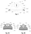
- FIG. 2illustrates a section end view of a piezoelectric clamping actuator.
- FIG. 3 Aillustrates a section end view of a piezoelectric actuator in a bending mode while expending the clamp jaws as a result of harmonic analysis.
- FIG. 3 Billustrates a section end view of the piezoelectric actuator in a bending mode while contracting the clamp jaws as a result of harmonic analysis.
- FIG. 4 Aillustrates a prospective view of an ampoule formed via a blow-fill-seal molding process.
- FIG. 4 Billustrates a front view of the ampoule formed by the blow-fill-seal molding process.
- FIGS. 4 C and 4 Dillustrate cross-sectional and side views, respectively, of the ampoule showing an insert that was included in the mold.
- FIG. 4 Eillustrates a detail front view of another variation of an ampoule aperture formed in part from a separate tubular member.
- FIG. 5 Aillustrates a perspective view of an ampoule secured within a piezoelectric clamping actuator which also includes a controller assembly having a drive circuit.
- FIGS. 5 B and 5 Cillustrate front and side views of the assembly having the ampoule and piezoelectric clamping actuator.
- FIG. 5 Dillustrates a detail side view of the interface between the piezoelectric clamping actuator and the printed circuit board.
- FIG. 5 Eillustrates a side view of the dispensing device aligned with an eye for treatment.
- FIGS. 6 A and 6 Billustrate perspective views of an alternative embodiment of an actuator having a partially tubular component.
- FIGS. 7 A and 7 Billustrate reversed detail perspective views of the elongate section and mounting section of the actuator.
- FIGS. 8 A and 8 Billustrate side and perspective assembly views of the actuator.
- FIGS. 9 A and 9 Billustrate alternate perspective views of an embodiment of a dispensing device utilizing the piezoelectric actuator assembly.
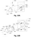
- FIGS. 10 A and 10 Billustrate perspective and exploded assembly views of an alternative embodiment of a bimorph piezoelectric actuator and an ampoule holder component.
- FIGS. 10 C and 10 Dillustrate exploded assembly and perspective views of a piezoelectric actuator with a single piezo-ceramic plate.
- FIGS. 11 A and 11 Billustrate perspective views of the piezoelectric actuator, ampoule, and cup and an alternative ampoule holder component.
- FIGS. 12 A and 12 Billustrate exploded assembly and cross-sectional views of the ampoule.
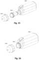
- FIGS. 13 and 14illustrate exploded assembly and perspective views of a dispensing assembly and housing.
- FIGS. 15 and 16illustrate exploded assembly and perspective views of the housing, dispensing assembly, and ampoule.
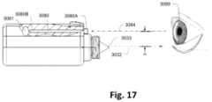
- FIG. 17illustrates a side view of the dispensing device aligned with an eye for treatment.
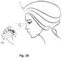
- FIG. 18illustrates a perspective view of the dispensing device in use by a subject.
- dropletsare dispensed in high frequency but in a single drop format or in a continuous stream depending on the electric signal input as described earlier.
- dropletsWhen droplets are produced they generally have ultra-small volumes ranging from about a few hundred pico-liters to about one nano-liters. Generally, droplets of such volume or a continuous (or discontinuous) collimated single stream do not cause blinking reflex.
- the devices and methodsare described for ejecting droplets or a stream of fluid into or upon the surface of an eye for ophthalmic treatment, the devices and methods may be utilized for any number of non-ophthalmic applications as well, e.g., otologic (e.g. ear drum); endoscopic (e.g., gastrointestinal tract); gynecologic (e.g.
- cervical, uterine, reproductive care(fallopian tube)); laparoscopic (e.g., body cavity, abdominal); laryngoscopic (e.g., throat, vocal cords); bronchoscopic (e.g., bronchi or other lung tissue); urologic (e.g., bladder, prostate); oral (e.g., tonsils, dental, pharynx); neurosurgical (e.g., through skull drilled holes); dermatologic (e.g. local topical chemotherapy or chemical cautery).
- laparoscopice.g., body cavity, abdominal
- laryngoscopice.g., throat, vocal cords
- bronchoscopice.g., bronchi or other lung tissue
- urologice.g., bladder, prostate
- orale.g., tonsils, dental, pharynx
- neurosurgicale.g., through skull drilled holes
- dermatologice.g. local topical chemotherapy or chemical cautery.
- the assemblymay reside along a rigid or flexible/articulating shaft, with the piezoelectric actuator and the ampoule positioned distally so that it enters the body cavity, and power source positioned proximally and remain outside the body cavity, while the electrical current courses through the rigid or flexible shaft or flexible arm of the instrument to activate the piezoelectric actuator.
- the ampouleresides next to the distal aspect of the light source and camera lens (e.g., adjacent to where the light arises out of the shaft and the camera lens is located).
- the assemblyhas no light source or camera and these elements are provided on a separate instrument.
- the ampoule and piezoelectric actuatormay remain on the proximal size of the shaft, such that the fluid being dispenses from the aperture courses through the length of the shaft and exits the distal end or tip of the shaft.
- the length of the rigid or flexible/articulating armwould differ in length and caliber/diameter depending on the application (e.g., relatively longer for laparoscopic, endoscopic, and gastroenterologic applications; relatively shorter for otologic applications; and intermediate for others).
- the dispensing devicesmay advantageously utilize a disposable, removable, or separable drug or fluid package while desirably retaining the piezoelectric actuator or transducer for subsequent further uses, thereby providing an economical and cost effective approach with reuse of the piezoelectric actuator or transducer for further operation.
- the assemblymay utilize a reusable actuator and/or housing with an ampoule which is separate or separable and implemented as a disposable or reusable ampoule.
- the actuator and/or housingmay be integrated with the ampoule in which case the entire assembly may be fully disposable or reusable.
- Various components of the assemblymay be optionally reusable or disposable and implementation of such components is not intended to be limiting.
- FIG. 1 A and FIG. 1 Billustrate an exploded perspective view and an assembly perspective view of one variation of the dispensing device assembly ( 1000 ).
- Device assembly ( 1000 )may generally comprise a piezoelectric actuator assembly ( 1010 ) and a separable disposable fluid-filled ampoule ( 1020 ).
- the ampoule ( 1020 )may comprise a thin-walled thermoplastic package which includes a second portion ( 1022 ) generally comprising a bulb or reservoir section and a first portion ( 1021 ) generally comprising a neck or an elongated section extending from the second portion ( 1022 ).
- the first portion ( 1021 )may have a cylindrical shape with a circular or oval cross-sectional shape. Other cross-sectional shapes are also possible, e.g., triangular, square, pentagon, hexagon, octagonal, etc.
- One or more apertures ( 1023 )are positioned on the wall of the first portion ( 1021 ).
- the piezoelectric actuator assembly ( 1010 )may generally comprise a piezoelectric clamping actuator ( 1014 ) which is configured to clamp or engage at least partially around the circumference of the first portion ( 1021 ) and adjacent to the one or more apertures ( 1023 ).
- the clamping actuatormay have at least two opposed jaw members ( 1016 A) and ( 1016 B) which are designed to support and engage the first portion ( 1021 ) in a receiving channel ( 1011 ) defined between the jaw members ( 1016 A), ( 1016 B) via a secure engagement such as an interference fit, as shown in FIG. 1 B .
- the assembly ( 1010 )may also apply cycles of oscillations in the clamping direction against the wall of the ampoule as illustrated by the arrows ( 1014 A) and ( 1014 B). Oscillation of the ampoule first portion ( 1021 ) may cyclically deform the cross-section of the first portion ( 1021 ) so that the portion oscillates between, e.g., a circular shape and an elliptical shape to produce cycles of acoustic pressure in the fluid retained within the first portion ( 1021 ).
- primary oscillationsmay be imparted by the jaw members ( 1016 A), ( 1016 B) to the first portion ( 1021 ) along a first direction ( 1030 ) such that a secondary oscillation is induced in the first portion ( 1021 ) along a second direction ( 1032 ) which is perpendicular to the first direction ( 1030 ).
- the primary and secondary oscillationsmay thus force the ejection of fluid ( 1024 ) retained within the first portion ( 1021 ) from the one or more apertures ( 1023 ) such that the emitted fluid ( 1024 ) may be ejected in a stream of individual droplets or as a continuous stream of fluid depending, e.g., upon the frequency of the oscillations.
- the emitted fluid ( 1024 )may be ejected from the one or more apertures ( 1023 ) in a direction that is normal to a longitudinal axis of the assembly ( 1000 ) such that an initial angle of the fluid ( 1024 ) relative to the first portion ( 1021 ) is perpendicular relative to one another.
- the fluid ( 1024 )may be emitted at some predetermined angle relative to the first portion ( 1021 ).
- multiple fluid streamsmay be emitted from different apertures simultaneously or sequentially which may each be at uniform angles or at angles different from one another, e.g., for emitting fluid streams at different regions of the eye when the assembly ( 1000 ) is maintained in a stationary position relative to the subject's eye.
- the oscillation amplitude of the jaw members ( 1016 A), ( 1016 B)may be less than, e.g., 2 microns.
- the fluid retained within the second portion ( 1022 )may provide for a continuous flow of the fluid into the first portion ( 1021 ) during use, where the fluid may then be emitted from the first portion ( 1021 ) in a continuous or discontinuous fluid stream.
- the first portion ( 1021 ) of the ampoule ( 1020 )may be inserted into the piezoelectric receiving channel ( 1011 ) by a relatively light force, typically less than 10 Newton in some variations and less than 5 Newton in other variations.
- FIG. 2a cross-sectional end view of the piezoelectric actuator assembly ( 1010 ) and the first portion ( 1021 ) retained between the jaw members ( 1016 A), ( 1016 B) within the receiving channel ( 1011 ) is illustrated.
- the actuator assembly ( 1010 )may have a base plate ( 1015 ) from which the jaw members ( 16 A), ( 16 B) extend into apposition relative to one another.
- a first piezoceramic plate ( 1012 )may be bonded to a second piezoceramic plate ( 1013 ) which may in turn be bonded to the base plate ( 1015 ).
- a passive layer ( 1017 )may be optionally positioned between the two piezoceramic plates ( 1012 ) and ( 1013 ). Moreover, these two plates ( 1012 ), ( 1013 ) may be bonded to one another in a face-to-face manner such that each plate is oriented in an opposite polling direction. The size and configuration of the plates ( 1012 ), ( 1013 ) may be matched to one another as well as to the size and configuration of the base plate ( 1015 ) as well.
- Such a piezo laminateis also known as Bimorph Bender in that each piezoceramic plate ( 1012 ), ( 1013 ) expands and contracts in a direction opposite relative to each other.
- the variation shownillustrates how the first plate ( 1012 ) may be configured to expand planarly, as indicated by arrows ( 1012 P), simultaneously when the second plate ( 1013 ) is configured to contract planarly, as indicated by arrows ( 1013 P) so that the piezoceramic laminate oscillates resulting in a bending mode.
- the base plate ( 1015 )may be attached to the piezoceramic laminate by a structural adhesive such as high strength epoxy or the like.
- the bending of the piezo laminatecauses the clamp member ( 1014 ) to bend which in turn causing the clamping jaws ( 1016 A), ( 1016 B) to cyclically apply a clamping force onto the first portion ( 1021 ) of the ampoule so that the fluid retained within is subsequently ejected from the aperture by the resulting secondary oscillations ( 1032 ).
- FIGS. 3 A and 3 Bshow the results of a harmonic analysis generated by finite element analysis to illustrate the frequency response of the clamping jaws ( 1016 A), ( 1016 B) and the first portion ( 1021 ) of the ampoule.
- the figuresshow that at an oscillation frequency of at least 22,000 Hz, the clamping jaws ( 1016 A), ( 1016 B) are actuated by the piezoceramic plates ( 1012 ), ( 1013 ) to oscillate in the direction shown ( 1030 ) to alternately squeeze down upon the first portion ( 1021 ) of the ampoule to force the circular cross-section into an oval or elliptical shape.
- the operating frequency of the clamping jawsmay be near or at its resonance frequency.
- the deflection of the ampoulehas been scaled up by a factor of 4000.
- Analytical and actual measurementhas shown that the amplitude of the first portion ( 1021 ) of the ampoule in the vicinity of the one or more apertures ( 1023 ) is only, e.g., about 1 micron.
- Actual measurement performed by laser vibrometerModel Polytec Gmbh, Polytec Platz D-76337 Waldbronn).
- the first portion ( 1021 ) and second portion ( 1022 )may be constructed as separate components which are attached to one another or they may be constructed as a single, integrated structure. They may be made from one and the same material, or two different materials with differing material properties. For instance, the first portion ( 1021 ) may be made from a relatively more rigid material while the second portion made from a relatively more flexible material.
- the first ( 1021 ) and second ( 1022 ) portionsmay engage with each other in a variety of ways. For instance, a luer-lock mechanism maybe used to connect the first ( 1021 ) and second ( 1022 ) portions. In another example, a piercing mechanism or a screw-in mechanism may be used.
- fluid from the second portion ( 1022 )may be released into the first portion ( 1021 ).
- FIG. 4 Ashows an ampoule ( 1020 ) which may be manufactured via a Blow-Fill-Seal molding process which includes a nozzle member that is inserted to the mold. Since the blow molding process has limited accuracy, small features such as the dispensing aperture may be difficult to produce by blow molding. Thus an insert member ( 1041 ) which includes the aperture may be separately manufactured using injection molding or laser drill techniques. The insert ( 1041 ) may be then placed inside the blow mold cavity and may be captured by the blow molded part during the blow mold process.
- FIGS. 4 A and 4 Billustrate perspective and front views of the ampoule ( 1040 ) in its final shape following the blow molding process.
- FIG. 4 Dillustrates a side view of the final shape of the blow molded ampoule ( 1040 ).
- FIG. 4 Cillustrates a cross sectional side view of the ampoule showing the blow molded of the resulting ampoule and the insert member ( 1041 ) which was placed within the mold and captured by the blow molded ampoule.
- the insert ( 1041 )may also include other features such as a valve or a vent.
- the blow molded ampoulemay be generally made of, e.g., low density polyethylene (LDPE), high density polyethylene (HDPE), etc. while the insert member ( 1041 ) may be made of, e.g., Delrin® (E. I. du Pont de Nemours and Company) acetal homopolymer resin, polypropylene, etc.
- LDPElow density polyethylene
- HDPEhigh density poly
- the formation of such small diameter aperturesmay be relatively difficult because of behavior of thermoplastics when processed such as when laser machined.
- One variationmay include the formation of a structure having the apertures separated from the ampoule fabrication so that the apertures may be formed with higher accuracy and precision.
- Such a structuremay include the use of polyimide films which are stable over a wide range of temperatures such as Kapton® (E. I. du Pont de Nemours and Company).
- suitable polyimide materialsmay include, e.g., compositions of Kapton® and PTFE, synthetic polymers such as Nylon (E. I. du Pont de Nemours and Company), etc.
- the first portion ( 1021 )may include a thin-wall tubular member ( 1042 ) made from the polyimide such as Kapton® provided with one or more apertures ( 1023 ) where the tubular member ( 1042 ) may be fabricated separate from the ampoule and then secured, e.g., press-fit, over an external diameter of the first portion ( 1021 ) which defines a relatively larger opening. This opening may be covered by the tubular member ( 1042 ) to allow for fluid contact with the internal surface of the tubular member ( 1042 ) for fluid ejection through the aperture ( 1023 ).
- a thin-wall tubular member ( 1042 )made from the polyimide such as Kapton® provided with one or more apertures ( 1023 ) where the tubular member ( 1042 ) may be fabricated separate from the ampoule and then secured, e.g., press-fit, over an external diameter of the first portion ( 1021 ) which defines a relatively larger opening. This opening may be covered by the tubular member ( 1042
- the one or more aperturesmay be laser micro-machined and/or drilled.
- the tubular member ( 1042 )may have an inside diameter of, e.g., 6 mm, and a wall thickness of, e.g., 0.1 mm, and one or more apertures ( 1023 ) with an exit opening of, e.g., 0.070-0.130 mm.
- the one or more apertures ( 1023 )may be optionally tapered to provide for an efficient fluid ejection.
- each of the aperturesmay be configured to preserve the uniqueness of an individual stream rather than forming a mist.
- Factors such as aperture size and spacing between the aperturesmay be adjusted accordingly to maintain the formation of the individual streams of fluid and to minimize or inhibit the merging or conflation of the individual fluid streams.
- apertures each having a relatively larger sizee.g., 80-100 microns, may allow for both relatively shorter pulse durations to deliver an equivalent volume of fluid.
- apertures having such a sizemay also allow for the use of fluids having a relatively higher viscosity such as artificial tears which are generally comprised of methylcellulose or carboxy-methylcellulose, hyaluronic acid derivatives or other hydrogels which would otherwise block or clog smaller sized apertures in the range of, e.g., 10-12 microns.
- fluids having a relatively higher viscositysuch as artificial tears which are generally comprised of methylcellulose or carboxy-methylcellulose, hyaluronic acid derivatives or other hydrogels which would otherwise block or clog smaller sized apertures in the range of, e.g., 10-12 microns.
- the fluid or fluids which may be used with the dispensing devicemay vary to include any number of agents depending upon, e.g., the treatment, the region of the body where the fluid is applied, etc.
- various fluids or agents which can be usedmay include (but are not limited to), e.g., anti-infectives (including but not limited to antibiotics, antivirals, etc.); anti-inflammatories (including but not limited to steroids and non-steroidal anti-inflammatory drugs (NSAIDS), etc.); anti-allergy (including but not limited to anti-histamines and mast cell stabilizers, etc.); anti-fungals; vasoconstrictors; mydriatic (pupil dilating) agents; miotic agents (pupil constricting agents); biologics (e.g.
- FIG. 5 Aillustrates a perspective assembly view of an alternative clamping transducer assembly ( 1200 ) in which the actuator assembly ( 1010 ) may be mounted directly on a printed circuit board (PCB) ( 1005 ) which includes a circuit section ( 1005 C) at a first end and a piezo mounting section ( 1005 P) at a second end where the actuator assembly ( 1010 ) may be mounted.
- PCBprinted circuit board
- a piezoelectric driver circuitry ( 1051 ) mounted on the PCB ( 1005 ) in the circuit section ( 1005 C)may comprise, e.g., a programmable processor, which is in electrical communication with the actuator assembly ( 1010 ) to control the actuation and ejection of the fluid contained within the ampoule ( 1020 ).
- the piezoelectric clamp ( 1014 )may include the first piezoceramic plate ( 1012 ) bonded to the second piezoceramic plate ( 1013 ) where the first piezoceramic plate ( 1012 ) may be mounted on to the PCB ( 1005 ) along the piezo mounting section ( 1005 P) and the clamp ( 1014 ) may be structurally bonded to the face of the second piezoelectric plate ( 1013 ).
- Both piezoceramic plates ( 1012 ) and ( 1013 )may be aligned relative to each other and the combination of the piezoceramic plates ( 1012 ) and ( 1013 ) and the PCB ( 1005 ) may form a laminate which known as bimorph bender and which oscillates in a bending mode thereby causing oscillator clamping action on clamp ( 1014 ) electrically configure to oscillate in a bending mode, as described herein, so that the droplets or stream of fluid ( 1024 ) are ejected from the one or more apertures ( 1023 ).
- the first piezoceramic plate ( 1012 )may be mounted on a first or back side of the PCB ( 1005 ) and the second piezoceramic plate ( 1013 ) may be mounted on a second or front side of the PCB ( 1005 ) so that the PCB ( 1005 ) is sandwiched between the respective plates ( 1012 ), ( 1013 ).
- the clamp ( 1014 )may be mounted upon the second piezoceramic plate ( 1013 ), as previously described, and the plates ( 1012 ), ( 1013 ) may remain aligned relative to one another.
- the piezoceramic plates ( 1012 ), ( 1013 )may be soldered to the PCB ( 1005 ) during the solder reflow process in which all the electronic components ( 1051 ) are assembled.
- the PCB ( 1005 )functions as a passive layer and collectively forms the bimorph bender, as shown in the side and detailed side views of FIGS. 5 C and 5 D .
- Either mounting configurationwhere the plates ( 1012 ), ( 1013 ) are mounted to one another directly and then to the PCB ( 1005 ) or where the PCB ( 1005 ) is sandwiched between the plates ( 1012 ), ( 1013 ), may be utilized with any of the ampoule ( 1020 ), PCB ( 1005 ), controller, and/or housing variations described herein.
- the piezo mounting section ( 1005 P) of the PCB ( 1005 )may be at least partially isolated from the circuit section ( 1005 C) by one or more cutouts.
- cutouts ( 1052 ), ( 1054 ), ( 1053 ), ( 1055 )may extend transversely inward from the outer edge of the PCB ( 1005 ) and define channels or notches positioned, e.g., proximally and distally, of the piezo mounting section ( 1005 P).
- the cutouts ( 1052 ), ( 1054 ), ( 1053 ), ( 1055 )may at least partially isolate, prevent, or limit the transmission of vibrations from the piezo mounting section ( 1005 P) to the rest of the PCB ( 1005 ) and the circuit section ( 1005 C).
- other vibration dampening mechanismsmay be used to vibrationally isolate the piezo mounting section ( 1005 P).
- the electronicsmay be hermetically sealed and/or isolated from the mechanical portions of the devices not only to isolate vibrations from the electronics but also to protect the electronics from fluids, debris, etc.
- the fluid ejection devicemay include an optical alignment mechanism which helps to align or target the one or more apertures to the ocular surface or to the area of the lower conjunctiva prior to actuation to ensure that the entire dose reaches the surface of the eye.
- FIG. 5 Eillustrates a side view of the actuator assembly with an exemplary alignment mechanism ( 1064 ) positioned relative to the eye ( 1060 ) of a patient.
- the alignment mechanism ( 1064 )may include any of the variations described herein or any number of other optical alignment devices which may be used with the actuator assembly.
- the housingis not illustrated for clarity purposes only.
- the usermay align the eye ( 1060 ) to be treated with the alignment mechanism ( 1064 ) so that the device is brought to an alignment with the optical axis ( 1062 ) of the eye ( 1060 ) to be treated or the center of the pupil.
- Proper alignment with the optical axis ( 1062 )may accordingly position the one or more apertures ( 1023 ) at a predetermined small offset (D) relative to the optical axis ( 1062 ) as shown, e.g., 4 to 12 mm, depending on the preset offset (D).
- a stream of fluide.g., a continuous stream or discontinuous stream of droplets
- a stream of fluidwill reach the targeted surface of the eye ( 1060 ) or the conjunctival tissue and deposit fluid at the above mentioned offset (D) from the pupil.
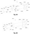
- a transducer assemblyconfigured to oscillate a disposable drug ampoule ( 2015 ) to dispense a fluid from the ampoule is illustrated in the exploded perspective view of FIG. 6 A .
- the assemblymay be used to dispense a fluid to, e.g., the corneal surface of the eye or other region of the patient body.
- This embodimentmay comprise a vibrational transmission component having an elongate section ( 2001 ) formed as, e.g., a partially tubular component, extending distally from a transducer mounting section ( 2002 ) generally configured into, e.g., a rectangular section.
- the two sections ( 2001 ) and ( 2002 )may blend into each other via a junction ( 2003 ) which may form a tapered or stepped transition between the two.
- the junction ( 2003 )may project radially from the mounting section ( 2002 ) to transition and form the elongate section ( 2001 ), as mentioned above, which further extends longitudinally and symmetrically about the longitudinal axis ( 2005 ) to terminate at a flattened interface surface ( 2012 ) which is formed perpendicularly relative to the axis ( 2005 ).
- the entire assembly ( 2001 ), ( 2002 ), ( 2003 )may be formed of a thermoplastic material preferably with modulus of elasticity that is greater than, e.g., 3 GPa, such as acrylic, Acrylonitrile butadiene styrene (ABS), polyaryletherketone (Peek), etc.
- the assemblymay be optionally formed (e.g., machined, cast, etc.) of a metal as well.
- the transducer mounting section ( 2002 )may be formed with flattened mounting surfaces ( 2004 A) and ( 2004 B) which are aligned symmetrically and in parallel relative to one another and relative to a longitudinal axis ( 2005 ) of the transducer assembly ( 2000 ).
- the piezoelectric plates ( 2006 A) and ( 2006 B)may be similarly or identically sized with one another and are mounted on opposite sides from one another.
- the mounting section ( 2002 )may further include one or more mounting projections ( 2007 ) which extend from one or both sides of the section ( 2002 ) to facilitate securement of the assembly ( 2000 ) when in use.
- the mounting arrangement of the piezoelectric plates ( 2006 A) and ( 2006 B)is advantageous since the transducer assembly ( 2000 ) can be made of a thermoplastic material which can optionally provide for a relatively low-cost disposable product.
- Conventional longitudinal transducerssuch as those described in U.S. Pat. Nos. 4,655,393; 4,352,459; and U.S. Pat. Pub. 2010/44460 are typically made of a metal such as aluminum or stainless steel. Each of these references is incorporated herein by reference in its entirety and for any purpose herein. These transducers often have a clamping feature which clamps the piezoelectric plates to the end face of the transducer shaft.
- the piezoelectric plates ( 2006 A) and ( 2006 B)may be simply adhered to their respective mounting surfaces ( 2004 A) and ( 2004 B) via an adhesive rather than using a clamping force provided that any discontinuities in the interface between the plates ( 2006 A) and ( 2006 B) and the surfaces ( 2004 A) and ( 2004 B) are minimized.
- the advantage of using a plastic transducer assemblymay be a significant reduction in manufacturing costs since the plastic can be molded to any desirable shape very inexpensively and entirely removes the need for clamping of the plates ( 2006 A), ( 2006 B).
- the elongate section ( 2001 )may extend and form a tubular member which defines a uniform wall thickness, as shown.
- the section ( 2001 )may be partially hollow and define a lumen ( 2014 ) as it transitions from the mounting section ( 2002 ) and junction ( 2003 ).
- the elongate section ( 2001 ) shownmay be formed as a tubular section, other cross-sectional shapes may be used as well, e.g., elliptical, octagonal, hexagonal, pentagonal, rectangular, etc. and the length of the section ( 2001 ) may range anywhere from, e.g., 1 to 10 cm.
- this cross-sectional shapemay be optimal for transferring vibrations from the piezoelectric plates ( 2006 A) and ( 2006 B) and through the length of the section ( 2001 ).
- An ampoule mounting element ( 2008 )may be configured to be mounted upon a distal end of the elongate section ( 2001 ) such that a first proximal side ( 2011 ) of the element ( 2008 ) contacts against and/or over the interface surface ( 2012 ) and a second distal side ( 2010 ) of the element ( 2008 ) is presented for interfacing against the ampoule ( 2015 ).
- the element ( 2008 )may further define an ampoule engagement feature ( 2009 ) for coupling with the ampoule ( 2015 ).
- the element ( 2008 )may be formed into a cup-shaped member that is connected via the proximal side ( 2011 ) to the end of the elongate member ( 2001 ).
- An inner diameter of the cup-shaped configurationmay engage securely over the distal end of the elongate section ( 2001 ), e.g., via an interference fit or any other securement mechanism.
- the ampoule engagement feature ( 2009 )in this embodiment, may be formed as a threaded opening which is aligned with the longitudinal axis ( 2005 ).
- a proximal end of the ampoule ( 2015 )may be formed as an engagement rod ( 2017 ) which extends proximally from the body ( 2016 ) of the ampoule ( 2015 ).
- the rod ( 2017 )may be threaded allowing for an optionally threaded engagement with the ampoule engagement feature ( 2009 ) of the ampoule mounting element ( 2008 ). This may allow for the secure threaded engagement of the ampoule ( 2015 ) to the mounting element ( 2008 ) and the ready removal and replacement of the ampule ( 2015 ) from the assembly ( 2000 ), e.g., for replacement when the ampoule ( 2015 ) is emptied after use.
- Other embodiments of the ampoulemay utilize other attachment features rather than a rod ( 2017 ), e.g., frictional fitting, magnetic coupling, etc.
- the ampoule ( 2015 )may further include a distal tapered section ( 2018 ) which narrows from the body ( 2016 ) to a distal end defining an opening ( 2019 ) through which fluid or agent contained within the ampoule ( 2015 ) may be dispensed during use of the assembly ( 2000 ).
- the reservoir volume of the ampoule ( 2015 )may also vary anywhere from, e.g., 0.2 ml to 5 ml or more preferably 0.5 ml to 1.5 ml, although other volumes may be sized accordingly.
- FIG. 6 Bshows a perspective view of the assembly ( 2000 ) which is partially assembled.
- the mounting element ( 2008 )is shown attached to the distal end of the elongate section ( 2001 ) and ready to receive the engagement rod ( 2017 ).
- the ampoule ( 2015 )is illustrated with a flattened distal portion ( 2020 ) through which the dispensing aperture ( 2019 ) is defined.
- FIGS. 7 A and 7 Bshow reversed detail perspective views of the elongate section ( 2001 ) and mounting section ( 2002 ).
- the FIG. 7 Ashows a transparent view of the assembly for clarity purposes.
- the elongate section ( 2001 )may have the lumen ( 2014 ) defined at least partially through the interior of the section ( 2001 ) such that an inner wall ( 2030 ) is defined within and narrows or tapers along a conical region ( 2031 ) through a proximal portion of the elongate section ( 2001 ) to a second lumen ( 2032 ) which is smaller in diameter than the lumen ( 2014 ).
- This second lumen ( 2032 )may extend through the mounting section ( 2002 ) and terminate at an opening ( 2033 ) defined at a proximal end of the section ( 2002 ).
- This lumenmay provide a channel into the lumen ( 2014 ) to provide for the drainage of any fluids which may have leaked and also prevents a pressure differential from building within the lumen ( 2014 ) when the assembly is vibrating.
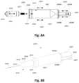
- FIG. 8 Awhich illustrates a side view of the assembly
- the two piezoelectric plates ( 2006 A), ( 2006 B)may be seen symmetrically aligned and in parallel relative to one another. Because the plates ( 2006 A), ( 2006 B) are configured to have the same polarity orientation and electrical connection, the two plates ( 2006 A), ( 2006 B) will expand and contract simultaneously in the same direction and without a phase shift between the plates ( 2006 A), ( 2006 B), as indicated by the vibrational direction ( 2040 ).
- the stresspropagates back and forth through the cylindrical walls of the elongate section ( 2001 ) according to acoustic wave propagation principles and the elongate section ( 2001 ) vibrates at a relatively high amplitude extending and contracting along its longitudinal axis ( 2005 ) as indicated by the vibrational direction ( 2041 ).
- the elongate section ( 2001 ), mounting section ( 2002 ), and junction ( 2003 )may be fabricated from a single material such that they form an integral piece, the oscillations may propagate through the device relatively unimpeded.
- the face of element ( 2008 )may be forced to resonate substantially at the same resonant frequency of the elongate section ( 2001 ).
- the face of the element ( 2008 )may vibrate in a bending mode such that the amplitude near the circumference of its annular opening ( 2009 ) is the highest over the element ( 2008 ) as indicated by the vibrational direction ( 2042 ) and phantom lines ( 2044 ) which indicate the displacement movement of the element ( 2008 ) relative to the elongate section ( 2001 ).
- the ampoulemay be attached at the opening ( 2009 ) via rod ( 2017 ) such that the oscillation ( 2042 ) at its highest amplitude is transmitted to the body ( 2016 ) of the ampoule resulting in the corresponding oscillation ( 2043 ) of the ampoule body ( 2016 ). Consequently, the fluid contained within the ampoule ( 2015 ) may be ejected out of the ampoule body ( 2016 ) and through the aperture ( 2019 ) into a stream ( 2045 ) of fluid, as shown in the perspective view of FIG. 8 B , for treating the eye of the patient or other region of the patient's body.
- the stream ( 2045 )may be ejected as a stream of individual droplets which are collinearly aligned when dispensed. If the pulse generator generates a frequency above a threshold frequency, the stream ( 2045 ) may be configured such that the individual droplets are coalesced into a single continuous stream of fluid.
- FIGS. 9 A and 9 Billustrate alternate perspective views of an embodiment of a dispensing device ( 2050 ) utilizing the piezoelectric actuator assembly ( 2000 ).
- the assemblymay be encased within the device housing with the annular opening ( 2009 ) exposed at a distal end of the device ( 2050 ).
- the ampoule rod ( 2017 )may be inserted or otherwise attached to the device ( 2050 ) via the annular opening ( 2009 ), as described above. Once the ampoule has been suitably attached and seated, the ampoule dispensing aperture ( 2019 ) is brought into alignment with the bore ( 2053 ) of light source ( 2052 ) by an offset distance.
- the dispensing aperture ( 2019 )is offset by the predetermined distance below the optical axis of the eye, e.g., 2-20 mm.
- the device ( 2050 )is actuated, e.g., by manipulating one or more controls ( 2051 )
- the dispensed stream of fluidmay be ejected to reach the area of the eye below the optical axis for treatment.
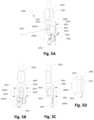
- FIGS. 10 A and 10 Billustrate perspective and exploded perspective views of a piezoelectric transducer ( 3000 ) which functions similarly to the embodiments described above.
- Transducer ( 3000 )comprises a bimorph actuator ( 3010 ) which includes an ampoule holder ( 3020 ) which may retain and hold an ampoule ( 3030 ) containing a fluid to be dispensed.
- Ultrasonic oscillations which are generated by the bimorph actuator ( 3010 ), as described herein,may propagate to the ampoule holder ( 3020 ) and to the ampoule therein which in turn produce cycles of acoustic pressure in the fluid and ejection of droplets ( 3032 ) from an aperture ( 3033 ) at the tip of the ampoule.
- the bimorph actuator ( 3010 )may comprise a laminate of one passive plate ( 3011 ) and two active piezo-ceramic plates ( 3012 ), ( 3013 ) configured such that the passive plate ( 3011 ) is laid in between the two piezo-ceramic plates ( 3012 ), ( 3013 ), one piezo-ceramic plate on each opposite side of the passive plate.
- the faces of the passive plates ( 3011 A) and ( 3011 B)may be attached or bonded to a face of one piezo-ceramic plate ( 3012 ) and to a face of one piezo-ceramic plate ( 3013 ), respectively, while the passive plate itself is extended as a cantilever plate from the ampoule holder ( 3020 ) via a junction interface ( 3025 ). Oscillation of piezo-ceramic plates ( 3012 ), ( 3013 ) are transmitted to the passive plate ( 3011 ) and to the ampoule holder via a connection therebetween, as will be explained further below.
- both piezo-ceramic plates ( 3012 ), ( 3013 )may have the same piezo poling orientation as indicated by the arrows ( 3012 P), ( 3013 P) relative to their attachment to the passive plate and the same electrical connection with respect to the piezo poling such that when the two piezo-ceramic plates receives alternating voltage signal, accordingly, bimorph actuator ( 3010 ) expands and contracts along its lateral dimension and producing oscillation amplitude in the lateral directions as indicated by arrows ( 3011 L). Lateral oscillations are transmitted to the ampoule holder ( 3020 ) via the attachment between the structural plate and the ampoule holder ( 3020 ).
- This embodimentsimilar to the piezo-ceramic plate configuration described above, illustrates the use of two symmetrically attached plates; however, in other embodiments, fewer than two or greater than two plates may be utilized. Additionally, it is within the scope of this description that other variations of the plates may be used having different configurations, as desired.
- the frequency of the alternating electrical signalis substantially equal to the resonance frequency of the dispensing device at its lateral or longitudinal mode.
- the length of the bimorph actuator ( 3010 )may be, e.g., 15 mm, and its width may be, e.g., 10 mm.
- the passive platemay be an integral part to the ampoule holder wherein the overall length of the piezoelectric actuator ( 3010 ) may be, e.g., 35 mm, and the diameter of the ampoule holder may be, e.g., 8-12 mm.
- the resonance frequency of the piezoelectric actuatormay be, e.g., 22.5 kHz.
- the passive plate ( 3011 )may extend for the ampoule holder perpendicularly as a cantilever plate or optionally the passive plate may extend at an angle relative to the longitudinal axis ( 3026 ) of the ampoule holder.
- ampoule ( 3030 )that can be readily attached to or detached from ampoule holder ( 3020 ) as will explain further below.
- ampoule ( 3030 )may have a cylindrical shape ( 3031 ) which transitions to a conical shape ( 3032 ) so that it tapers from the body of the ampoule ( 3030 ) to a relatively smaller opening ( 3033 ) defining the exit opening of dispensing aperture.
- Ampoule ( 3030 )may further include a flange ( 3034 ) at the end of the cylindrical body that is used to engage with the ampoule holder ( 3020 ) to receive ultrasonic oscillation from the ampoule holder ( 3020 ) when flange ( 3034 ) is held against the face ( 3021 ) of ampoule holder ( 3020 ).
- This flange ( 3034 )may be integrated with the body of the ampoule ( 3030 ) to ensure that no interface between the two is formed although in other variations, the flange ( 3034 ) may be formed as a separate component and securely attached to the ampoule ( 3030 ) body.
- the ampoule ( 3030 )may further include a circular array of protrusions or bumps ( 3035 ) arranged around the circumference of the ampoule ( 3030 ) at a small distance from the face of flange ( 3034 ), typically from, e.g., 1 to 4 mm.
- the protrusions ( 3035 )may be used as anchoring points to securely retain the ampoule ( 3030 ) inside the ampoule holder ( 3020 ).
- These protrusions or bumpsmay also be shaped in any number of different configurations as well as arranged in any number of patterns so long as the protrusions ( 3035 ) securely retain the ampoule ( 3030 ) within the ampoule holder ( 3020 ).
- Ampoule holder ( 3020 )includes an end-face ( 3021 ) and an internal bore ( 3022 ) having a diameter that is slightly larger than the diameter of the ampoule.
- the internal boremay have a hump or restricting feature ( 3023 ) around its internal diameter that may be shaped, e.g., like a rounded circumferential protuberance.
- FIG. 10 Ashows an illustration of the ampoule ( 3030 ) as it is retained within the ampoule holder ( 3020 ).
- the inserting force of the ampoule ( 3030 ) into the ampoule holderis below, e.g., 5 N.
- FIGS. 10 C and 10 Dillustrate an alternative piezoelectric transducer that uses an actuator with a single piezo plate and two passive plates.
- actuator ( 3010 )may comprise a laminate of a single piezo-ceramic plate ( 3010 ) and two passive plates ( 3011 ), ( 3012 ) configured such that the piezo-ceramic plate ( 3010 ) is laid in-between the two passive plates ( 3011 ), ( 3012 ), one passive plate on each side of the piezo-ceramic plate.
- the faces of the passive plates ( 3011 ), ( 3012 ) in contact with the opposite sides of the piezo-ceramic plate ( 3010 )may be attached or bonded to faces of the piezo-ceramic plate ( 3010 ) while the two passive plates ( 3011 ), ( 3012 ) are structurally connected to the ampoule holder ( 3020 ). Oscillations of the piezo-ceramic plate ( 3010 ) are transmitted to the passive plates ( 3011 ), ( 3012 ) and to the ampoule holder ( 3020 ) via a connection therebetween.
- the frequency of the alternating electrical signalis substantially equal to the resonance frequency of the dispensing device at its lateral or longitudinal mode.
- the piezo-ceramic plate ( 3010 )may be mounted along the longitudinal axis of the ampoule holder ( 3020 ) so that the two passive plates ( 3011 ), ( 3012 ) are symmetrically aligned relative to the longitudinal axis.
- actuator ( 3010 )may include one or two piezo-ceramic plates and one or two passive plates.
- the passive platesmay be made of thermoplastic elastomers, e.g., acrylic or PEEK. Elastomers have a relatively low modulus of elasticity, approximately 3 GPa, relative to the elasticity of the piezo-ceramic material having a modulus of elasticity of approximately 60 GPa. This subsequently enables the use of relatively thinner piezo-electric plates to generate cycles of structural deformation. Thinner piezo-ceramic plates require proportionally lower input voltages which substantially eliminates the need to include a voltage boosting circuitry such as DC-DC converter.
- the lateral or longitudinal transducer and ampoule holdermay be made from a thermoplastic by, e.g., injection molding processes, with thermoplastics having a modulus of elasticity that is lower than, e.g., 4 GPa, and more preferably between, e.g., 3 GPa to 4 GPa, while the thickness of the piezo-ceramic plate may be less than, e.g., 1 mm, and preferably less than, e.g., 0.5 mm.
- ampoule ( 3030 )may include a cup or cap ( 3040 ) that seals off the opening of aperture ( 3033 ) during storage and periods on non-use.
- the cup or cap ( 3040 )may be configured to be engaged with an external thread ( 3036 ) or other feature or it may be retained via the ampoule holder ( 3020 ).
- the ampoule ( 3030 )may dispense fluid in any orientation thereby allowing the user (P) to conveniently position his/her head, e.g., inclined downwardly towards the ground, while the dispensing device ( 3050 ) is inclined at an angle such as being inclined upwardly at an angle ( 0 ), as illustrated in FIG. 18 , relative to horizontal.
- the liquid that is stored in the ampoulemay move away from the aperture due to gravity; however, in the present embodiment, the ampoule ( 3020 ) may include a capillary feature that draws fluid directly to the aperture regardless of the ampoule ( 3020 ) orientation and fluid level within.
- FIG. 11 Bshows a perspective view of another variation of the ampoule holder ( 3020 ) which may define grooves or channels along the sides of the holder ( 3020 ) to accommodate expansion of the holder ( 3020 ), as indicated by the arrows.
- the opposing sides of the holder ( 3020 )may extend radially due to the presence of the grooves or channels to accommodate the securement or release of the ampoule ( 3030 ).
- FIGS. 12 A and 12 Billustrate exploded assembly and cross-sectional side views of ampoule assembly ( 4000 ).
- ampoule assembly ( 4000 )comprises a hollow cylindrical body ( 3030 ) that transitions to a conical shape ( 3032 ) which tapers from the cylindrical body to a narrow opening ( 3033 ) which defines the exit of the dispensing aperture ( 3037 ).
- the ampoulefurther includes an insert ( 3030 i ) that may be placed inside the ampoule ( 3030 ) and forms a gap between its external surfaces ( 3031 i ) and the internal surfaces ( 3038 ) of ampoule ( 3030 ).
- the insert ( 3030 i )may have a shape which corresponds with the internal shape or volume defined by the ampoule ( 3030 ) but which is slightly smaller so that a body of the insert ( 3030 i ) may be similarly cylindrical and which tapers into a conical configuration.
- FIG. 12 Billustrates a cross-sectional view of the ampoule ( 3030 ) when insert ( 3030 i ) is placed inside the ampoule ( 3030 ). It can be seen that a gap ( 3033 i ), e.g., typically of 0.3 to 1 mm, is formed between the two surfaces such that the insert ( 3030 i ) outer surfaces follow the inner surfaces of the ampoule ( 3030 ) in a corresponding manner. In this way, a consistent or uniform gap may be formed between the outer surfaces of the insert ( 3030 i ) and the inner surfaces of the ampoule ( 3030 ) even between the conical portions of both, as illustrated.
- Insert ( 3030 i )may include one or more openings ( 3034 i ) around its circumference which allows fluid to flow from the center of the ampoule ( 3030 ) through the openings ( 3034 i ) to the annular capillary gap ( 3033 i ) and to the aperture ( 3037 ).
- the internal surfaces of the annular capillary gap ( 3033 i )may be treated with a hydrophilic coating such as HYDROPHILIC COATING FORMULA B (Coating 2Go, Carlisle, MA).
- the capillary actionensures that the movement of fluid to the aperture is independent of the orientation that the ampoule ( 3030 ) is held by the user and is further independent of the fluid level contained within the ampoule ( 3030 ), i.e., dispensing of the fluid from the ampoule ( 3030 ) is independent of gravity.
- Conventional fluid reservoirstypically require some active pumping mechanism to draw a fluid for dispensing particularly when the fluid level drops relative to the aperture such as when a user holds the fluid reservoir at an extreme angle or when the fluid runs low.
- the capillary action created between the ampoule ( 3030 ) and insert ( 3033 i )ensures that the fluid is drawn to the aperture ( 3037 ).
- the ampoule ( 3030 ) and insert ( 3030 i )can be made of a thermo-plastic polymer such as polypropylene or polyethylene and preferably hydrophilic polymer or a polymer which has its surfaces modified to have hydrophilic properties.
- Insert ( 3030 i )can be made from hydrophilic porous polypropylene (Porex Corporation, Fairburn, GA).
- the ampoulemay be further provided with a venting hole ( 3038 ) which allows for equalization of the pressure as fluid is dispensed from the ampoule.
- the ampoule ( 3030 )may be provided with a cup or cap ( 3040 ) which closes the opening of the aperture ( 3033 ) when the device is not in use.
- the cup or cap ( 3040 )may be attached to the ampoule body by, e.g., thread engagement ( 3036 ) ( 3041 ) or other engagement mechanism, and seal the tapered end ( 3032 ) of the ampoule against tapered hole ( 3042 ) in the cup or cap ( 3040 ).
- venting hole ( 3038 )When the cup or cap ( 3040 ) is fully engaged with ampoule ( 3030 ), the aperture ( 3033 ) and venting hole ( 3038 ) are both sealed.
- the diameter of venting hole ( 3038 )may range from, e.g., 0.1 to 0.6 mm, which is sufficiently small to prevent outflow or spillage of fluid from the ampoule.
- the angular dimension (Ang) of conical section ( 3036 )may range from, e.g., 30 to 60 degrees, while the wall thickness (Thk) of the ampoule may range from, e.g., 0.3 to 1 mm.
- the diameter (D) of the ampouleis generally between, e.g., 4 to 10 mm, while its length (L) may vary based on the desired liquid volume to be stored in the ampoule, liquid volume is generally between, e.g., 0.5 to 3 mL.
- the ampoule assembly ( 3000 )may further include an end cup ( 3030 c ) which seals the ampoule following aseptic drug filling.
- FIG. 13illustrates an exploded view of fluid ejection device ( 5000 ) which includes an ultrasonic transducer ( 3020 ) and a housing ( 3050 ).
- Housing ( 3050 )provides an enclosure for the ultrasonic transducer and its electronic circuitry, batteries and further for an optical aiming device ( 3052 ).
- the ultrasonic transducer ( 3020 )may be provided with extensions or protrusions ( 3027 ) which capture the ultrasonic dispenser inside the housing ( 3050 ).
- the housing ( 3050 )may be configured into any number of shapes or sizes suitable for holding, manipulation, or carrying by a subject.
- the housing ( 3050 )may be generally configured resemble the form factor of a conventional squeeze-bottle eye-dropper to make the device rather intuitive for use by a subject.
- the housing ( 3050 )may further include an activation switch ( 3051 ) and an aiming feature ( 3052 ).
- FIG. 14illustrates the assembly ( 6000 ) with the housing ( 3050 ) assembled with the ampoule holder ( 3020 ) inserted within and FIG. 15 further illustrates the housing ( 3050 ) with the ampoule holder ( 3020 ) as well as ampoule ( 3030 ) in an exploded view showing with the addition of the cup or cap ( 3040 ) separately.
- FIG. 16illustrates a perspective view of the fluid ejection device showing the housing ( 3050 ) when ampoule ( 3030 ) is fully inserted into the ampoule holder ( 3020 ).
- the fluid ejection devicemay include an optical apparatus to align or target the dispensing aperture to the ocular surface or to the area of the lower conjunctiva prior to actuation, as further described herein. Such alignment assures that the entire dose reaches the surface of the eye.
- the dispensing deviceis shown in a partial cross-sectional view with the alignment fixture.
- the alignment featurecomprises a tubular member ( 3080 ) and a light source ( 3081 ).
- the tube ( 3080 )has a proximal opening ( 3080 A) and a distal opening ( 3080 B) while the distal opening is positioned near light source ( 3081 ) such as an LED ( 3081 ), e.g., red LED, or the like and the proximal opening of the tube ( 3080 A) is brought into proximity near the eye ( 3089 ) of the user.
- the tubular member ( 3080 )is parallel to the droplet projection direction of the droplets ( 3032 ) but may be placed in a predetermined offset (D).
- the usermay align the eye to be treated with the proximal opening ( 3080 A) of the tube and then manipulate the orientation of the device until the LED light ( 3081 ) at the distal end of the tube becomes visible. In this way the device is brought to an alignment with the optical axis of the eye to be treated or the center of the pupil.
- the dispensing nozzle ( 3033 )may be positioned at a predetermined small offset (D) relative to the optical axis of the tube ( 3084 ), e.g., 4 to 12 mm, depending on the preset offset (D).
- Dsmall offset
- a stream of fluide.g., a continuous stream or discontinuous stream of droplets
- the optical tube ( 3080 )may have a length of, e.g., 20, 30, or 40 mm, while its internal diameter ranges between, e.g., 1 to 5 mm.
- the internal surfaces of the tubemay be optionally coated with optically-black non-reflective coating.
Landscapes
- Health & Medical Sciences (AREA)
- Engineering & Computer Science (AREA)
- Life Sciences & Earth Sciences (AREA)
- Veterinary Medicine (AREA)
- Public Health (AREA)
- General Health & Medical Sciences (AREA)
- Animal Behavior & Ethology (AREA)
- Biomedical Technology (AREA)
- Vascular Medicine (AREA)
- Heart & Thoracic Surgery (AREA)
- Ophthalmology & Optometry (AREA)
- Mechanical Engineering (AREA)
- Ceramic Engineering (AREA)
- Hematology (AREA)
- Pharmacology & Pharmacy (AREA)
- Medical Preparation Storing Or Oral Administration Devices (AREA)
- General Electrical Machinery Utilizing Piezoelectricity, Electrostriction Or Magnetostriction (AREA)
- Infusion, Injection, And Reservoir Apparatuses (AREA)
- Coating Apparatus (AREA)
- Containers And Packaging Bodies Having A Special Means To Remove Contents (AREA)
Abstract
Description
Claims (17)
Priority Applications (1)
| Application Number | Priority Date | Filing Date | Title |
|---|---|---|---|
| US17/147,196US12048647B2 (en) | 2017-01-20 | 2021-01-12 | Piezoelectric dispenser with replaceable ampoule |
Applications Claiming Priority (7)
| Application Number | Priority Date | Filing Date | Title |
|---|---|---|---|
| US201762448791P | 2017-01-20 | 2017-01-20 | |
| US201762492624P | 2017-05-01 | 2017-05-01 | |
| US201762520270P | 2017-06-15 | 2017-06-15 | |
| US201762523071P | 2017-06-21 | 2017-06-21 | |
| US201762534083P | 2017-07-18 | 2017-07-18 | |
| US15/874,377US10888454B2 (en) | 2017-01-20 | 2018-01-18 | Piezoelectric fluid dispenser |
| US17/147,196US12048647B2 (en) | 2017-01-20 | 2021-01-12 | Piezoelectric dispenser with replaceable ampoule |
Related Parent Applications (1)
| Application Number | Title | Priority Date | Filing Date |
|---|---|---|---|
| US15/874,377ContinuationUS10888454B2 (en) | 2017-01-20 | 2018-01-18 | Piezoelectric fluid dispenser |
Publications (2)
| Publication Number | Publication Date |
|---|---|
| US20210128350A1 US20210128350A1 (en) | 2021-05-06 |
| US12048647B2true US12048647B2 (en) | 2024-07-30 |
Family
ID=62905378
Family Applications (2)
| Application Number | Title | Priority Date | Filing Date |
|---|---|---|---|
| US15/874,377Active2038-02-28US10888454B2 (en) | 2017-01-20 | 2018-01-18 | Piezoelectric fluid dispenser |
| US17/147,196Active2039-09-09US12048647B2 (en) | 2017-01-20 | 2021-01-12 | Piezoelectric dispenser with replaceable ampoule |
Family Applications Before (1)
| Application Number | Title | Priority Date | Filing Date |
|---|---|---|---|
| US15/874,377Active2038-02-28US10888454B2 (en) | 2017-01-20 | 2018-01-18 | Piezoelectric fluid dispenser |
Country Status (8)
| Country | Link |
|---|---|
| US (2) | US10888454B2 (en) |
| EP (1) | EP3570986B1 (en) |
| JP (2) | JP2020508715A (en) |
| KR (2) | KR102412086B1 (en) |
| CN (1) | CN109906120A (en) |
| AU (1) | AU2018209932A1 (en) |
| CA (1) | CA3039106A1 (en) |
| WO (1) | WO2018136618A2 (en) |
Families Citing this family (29)
| Publication number | Priority date | Publication date | Assignee | Title |
|---|---|---|---|---|
| CA2973471A1 (en) | 2015-01-12 | 2016-07-21 | Kedalion Therapeutics, Inc. | Micro-droplet delivery device and methods |
| KR20170135862A (en) | 2015-04-10 | 2017-12-08 | 켄달리온 테라퓨틱스 인코포레이티드 | Piezoelectric dispenser with replaceable ampoules |
| KR102487355B1 (en) | 2016-04-25 | 2023-01-11 | 코스카 패밀리 리미티드 | medical delivery system |
| KR102412086B1 (en) | 2017-01-20 | 2022-06-22 | 켄달리온 테라퓨틱스 인코포레이티드 | piezoelectric fluid dispenser |
| CA3066408A1 (en) | 2017-06-10 | 2018-12-13 | Eyenovia, Inc. | Methods and devices for handling a fluid and delivering the fluid to the eye |
| CN111615409A (en) | 2017-11-17 | 2020-09-01 | 科斯卡家族有限公司 | Systems and methods for fluid delivery manifolds |
| CA3083219A1 (en) | 2017-12-08 | 2019-06-13 | Reynaldo Quintana | Fluid delivery alignment system |
| JP6939657B2 (en)* | 2018-03-12 | 2021-09-22 | 三菱電機株式会社 | Injection device and injection method |
| US12350194B1 (en) | 2018-04-12 | 2025-07-08 | Bausch + Lomb Ireland Limited | Topical ocular delivery of fluids with controlled mass dosing and wireless communication |
| US20190314196A1 (en) | 2018-04-12 | 2019-10-17 | Kedalion Therapeutics, Inc. | Topical Ocular Delivery Methods and Devices for Use in the Same |
| CN112334099A (en) | 2018-07-03 | 2021-02-05 | 科达莱昂治疗公司 | Topical ocular delivery devices and methods of using the same |
| US11679028B2 (en) | 2019-03-06 | 2023-06-20 | Novartis Ag | Multi-dose ocular fluid delivery system |
| US12097145B2 (en) | 2019-03-06 | 2024-09-24 | Bausch + Lomb Ireland Limited | Vented multi-dose ocular fluid delivery system |
| CN113543752B (en)* | 2019-03-06 | 2024-10-15 | 博士伦爱尔兰有限公司 | Multidose ocular fluid delivery system |
| US11510809B2 (en) | 2019-05-14 | 2022-11-29 | Twenty Twenty Therapeutics Llc | Non-gravitational fluid delivery device for ophthalmic applications |
| KR102738254B1 (en)* | 2019-05-14 | 2024-12-04 | 베릴리 라이프 사이언시즈 엘엘시 | Non-gravity fluid transport device for ocular applications |
| AU2020308104B2 (en)* | 2019-06-27 | 2025-06-19 | Pneuma Respiratory, Inc. | Delivery of small droplets to the respiratory system via electronic breath actuated droplet delivery device |
| CA3164288A1 (en) | 2019-12-11 | 2021-06-17 | Eyenovia, Inc. | Systems and devices for delivering fluids to the eye and methods of use |
| US12290472B2 (en) | 2020-04-17 | 2025-05-06 | Bausch + Lomb Ireland Limited | Hydrodynamically actuated preservative free dispensing system |
| US11938057B2 (en)* | 2020-04-17 | 2024-03-26 | Bausch + Lomb Ireland Limited | Hydrodynamically actuated preservative free dispensing system |
| US11925577B2 (en)* | 2020-04-17 | 2024-03-12 | Bausch + Lomb Ireland Limted | Hydrodynamically actuated preservative free dispensing system |
| EP4120973A4 (en)* | 2020-04-17 | 2024-04-17 | Bausch + Lomb Ireland Limited | Hydrodynamically actuated preservative free dispensing system having a collapsible liquid reservoir |
| USD1052082S1 (en) | 2020-06-01 | 2024-11-19 | Koska Family Limited | Sealed fluid container |
| US11771591B2 (en) | 2020-08-17 | 2023-10-03 | Lumio Health Inc. | Liquid medication dispensing apparatus |
| USD992110S1 (en) | 2021-08-10 | 2023-07-11 | Koska Family Limited | Sealed fluid container |
| CN120187469A (en)* | 2022-05-02 | 2025-06-20 | 博士伦爱尔兰有限公司 | Ventilated Multi-Dose Ocular Fluid Delivery System |
| US20240415697A1 (en)* | 2023-06-17 | 2024-12-19 | Topnote, Inc. | Device and system for liquid delivery to a surface of an eye |
| WO2025049906A1 (en)* | 2023-08-31 | 2025-03-06 | Nanodropper, Inc. | Cartridge based spray applicator for ophthalmic medicine |
| WO2025088119A1 (en)* | 2023-10-25 | 2025-05-01 | EyeNeb GmbH | Modular application device |
Citations (246)
| Publication number | Priority date | Publication date | Assignee | Title |
|---|---|---|---|---|
| US3640274A (en) | 1966-11-04 | 1972-02-08 | Colgate Palmolive Co | Eye-spraying device having mirror |
| US3779245A (en) | 1972-06-13 | 1973-12-18 | R Windsor | Device for applying materials to the area of the eye |
| US3812854A (en) | 1972-10-20 | 1974-05-28 | A Michaels | Ultrasonic nebulizer |
| US3861386A (en) | 1966-01-12 | 1975-01-21 | Misto & Gen Equipment Co | Ultrasonic nebulizer |
| US3934585A (en) | 1970-08-13 | 1976-01-27 | Maurice David M | Method and apparatus for application of eye drops |
| US3970250A (en) | 1974-09-25 | 1976-07-20 | Siemens Aktiengesellschaft | Ultrasonic liquid atomizer |
| US3976072A (en) | 1975-09-03 | 1976-08-24 | The United States Of America As Represented By The Secretary Of The Department Of Health, Education And Welfare | Blink-operated extracorporeal tear duct |
| US4159803A (en) | 1977-03-31 | 1979-07-03 | MistO2 Gen Equipment Company | Chamber for ultrasonic aerosol generation |
| US4300546A (en) | 1978-11-15 | 1981-11-17 | Carl Heyer Gmbh Inhalationstechnik | Hand-held atomizer especially for dispensing inhalation-administered medicaments |
| US4334531A (en) | 1979-06-19 | 1982-06-15 | Bosch-Siemens Hausgerate Gmbh | Inhalator |
| US4338576A (en) | 1978-07-26 | 1982-07-06 | Tdk Electronics Co., Ltd. | Ultrasonic atomizer unit utilizing shielded and grounded elements |
| US4344744A (en) | 1979-01-24 | 1982-08-17 | Pfeiffer Zerstaubervertriebsgesellschaft mbH & Co. KG | Spray pump |
| US4352459A (en) | 1979-11-13 | 1982-10-05 | Sono-Tek Corporation | Ultrasonic liquid atomizer having an axially-extending liquid feed passage |
| US4465234A (en) | 1980-10-06 | 1984-08-14 | Matsushita Electric Industrial Co., Ltd. | Liquid atomizer including vibrator |
| US4632311A (en) | 1982-12-20 | 1986-12-30 | Matsushita Electric Industrial Co., Ltd. | Atomizing apparatus employing a capacitive piezoelectric transducer |
| US4655393A (en) | 1983-01-05 | 1987-04-07 | Sonotek Corporation | High volume ultrasonic liquid atomizer |
| US4793339A (en) | 1984-08-29 | 1988-12-27 | Omron Tateisi Electronics Co. | Ultrasonic atomizer and storage bottle and nozzle therefor |
| US4850534A (en) | 1987-05-30 | 1989-07-25 | Tdk Corporation | Ultrasonic wave nebulizer |
| US4882150A (en) | 1988-06-03 | 1989-11-21 | Kaufman Herbert E | Drug delivery system |
| US4952581A (en) | 1987-04-03 | 1990-08-28 | The Trustees Of Columbia University In The City Of New York | Use of a prostaglandin in combination with an adrenergic blocking agent for reduction of intraocular pressure |
| US4961345A (en) | 1986-12-08 | 1990-10-09 | Fuji Electric Co., Ltd. | Vibration type transducer |
| US4976259A (en) | 1986-12-22 | 1990-12-11 | Mountain Medical Equipment, Inc. | Ultrasonic nebulizer |
| US4981625A (en) | 1988-03-14 | 1991-01-01 | California Institute Of Technology | Monodisperse, polymeric microspheres produced by irradiation of slowly thawing frozen drops |
| US5025957A (en) | 1988-10-07 | 1991-06-25 | Ryder International Corp. | Liquid dispenser nozzle assembly |
| US5171306A (en) | 1991-03-13 | 1992-12-15 | Vo Van T | Eyedrop delivery system |
| US5232363A (en) | 1991-06-11 | 1993-08-03 | Eran Meller | Scaler with improved vibration characteristics |
| WO1994020875A2 (en) | 1993-03-03 | 1994-09-15 | Street Graham S B | Method and apparatus for image alignment |
| EP0622035A1 (en) | 1993-04-30 | 1994-11-02 | Henlopen Manufacturing Co., Inc. | Applicator system for fluid cosmetic material |
| US5368582A (en) | 1992-08-10 | 1994-11-29 | The Schepens Eye Research Institute | Method and apparatus for introducing fluid material into an eye |
| US5370317A (en) | 1991-06-28 | 1994-12-06 | Glaxo Group Limited | Atomizing device for producing a spray from a liquid under pressure |
| WO1996000050A1 (en) | 1994-06-23 | 1996-01-04 | R.P. Scherer Corporation | Ocular treatment device |
| US5487378A (en) | 1990-12-17 | 1996-01-30 | Minnesota Mining And Manufacturing Company | Inhaler |
| US5549249A (en) | 1991-12-13 | 1996-08-27 | Contico International, Inc. | Fluid spinner and nozzle head assembly with controlled fluid flood path |
| JPH08251948A (en) | 1995-03-15 | 1996-09-27 | Olympus Optical Co Ltd | Sliding member |
| US5624057A (en) | 1993-12-22 | 1997-04-29 | Merck & Co., Inc. | Ophthalmic package and delivery device |
| US5627611A (en) | 1995-12-29 | 1997-05-06 | Scheiner; Stanley A. | Artificial tears |
| US5630793A (en) | 1994-03-25 | 1997-05-20 | Zeneca Limited | Aqueous ophthalmic sprays |
| US5657926A (en) | 1995-04-13 | 1997-08-19 | Toda; Kohji | Ultrasonic atomizing device |
| US5692651A (en) | 1996-06-06 | 1997-12-02 | Owens-Illinois Closure Inc. | Self-sealing dispensing closure |
| US5811443A (en) | 1992-10-13 | 1998-09-22 | Alcon Laboratories, Inc. | Combinations of prostaglandins and clonidine derivatives for the treatment of glaucoma |
| US5828394A (en) | 1995-09-20 | 1998-10-27 | The Board Of Trustees Of The Leland Stanford Junior University | Fluid drop ejector and method |
| JP3055480U (en) | 1998-07-01 | 1999-01-12 | 孟 ▲じゃ−▼ 康 | Light-weight eye drop injector |
| US5938117A (en) | 1991-04-24 | 1999-08-17 | Aerogen, Inc. | Methods and apparatus for dispensing liquids as an atomized spray |
| US5960224A (en) | 1996-12-26 | 1999-09-28 | Fuji Photo Film Co., Ltd. | Image forming apparatus and fluid injecting apparatus |
| US5958342A (en) | 1996-05-17 | 1999-09-28 | Incyte Pharmaceuticals, Inc. | Jet droplet device |
| WO2000005482A1 (en) | 1998-07-23 | 2000-02-03 | Petroleum Engineering Services Limited | Tool string shock absorber |
| US6024717A (en) | 1996-10-24 | 2000-02-15 | Vibrx, Inc. | Apparatus and method for sonically enhanced drug delivery |
| US6062212A (en) | 1992-11-04 | 2000-05-16 | Bespak Plc | Dispensing apparatus |
| US6065623A (en) | 1998-02-13 | 2000-05-23 | Crown Cork & Seal Technologies Corporation | Closure with lenticular lens insert |
| US6095376A (en) | 1996-03-29 | 2000-08-01 | Sofab | Antibacterial device for spraying a liquid |
| US6196218B1 (en) | 1999-02-24 | 2001-03-06 | Ponwell Enterprises Ltd | Piezo inhaler |
| US6232129B1 (en) | 1999-02-03 | 2001-05-15 | Peter Wiktor | Piezoelectric pipetting device |
| WO2001046134A1 (en) | 1999-12-22 | 2001-06-28 | Alcon Universal Ltd. | 6-KETO PROSTAGLANDIN F1α AND ANALOGS FOR TREATING DRY EYE |
| US6273092B1 (en) | 2000-09-22 | 2001-08-14 | Gerard M. Nolan | Methods for treating various eye disorders |
| US6302101B1 (en) | 1999-12-14 | 2001-10-16 | Daniel Py | System and method for application of medicament into the nasal passage |
| US20010035184A1 (en) | 1999-12-17 | 2001-11-01 | Carlos Schuler | Systems and methods for treating packaged powders |
| US20010036424A1 (en) | 2000-02-18 | 2001-11-01 | Olympus Optical Co., Ltd. | Liquid pipetting apparatus and micro array manufacturing apparatus |
| US20010036449A1 (en) | 1999-04-13 | 2001-11-01 | Garst Michael E. | Ocular treatment using cyclosporin-A derivatives |
| US20020078947A1 (en) | 2000-06-28 | 2002-06-27 | Mircrodose Technologies, Inc. | Packaging and delivery of pharmaceuticals and drugs |
| US20020124843A1 (en) | 2001-02-01 | 2002-09-12 | Skiba Jeffry B. | Eye medication delivery system |
| WO2002072169A2 (en) | 2001-03-09 | 2002-09-19 | Antares Pharma, Inc. | Ocular drug delivery nebulizer |
| US6467476B1 (en) | 1995-04-05 | 2002-10-22 | Aerogen, Inc. | Liquid dispensing apparatus and methods |
| US20020158196A1 (en) | 2001-03-29 | 2002-10-31 | Berggren William Travis | Piezoelectric charged droplet source |
| US20020161344A1 (en) | 2001-02-08 | 2002-10-31 | Christian Peclat | Liquid delivery device and method of use thereof |
| US20020185125A1 (en) | 1995-04-05 | 2002-12-12 | Aerogen, Inc. | Methods and apparatus for aerosolizing a substance |
| US20020190079A1 (en) | 2001-06-15 | 2002-12-19 | Taisei Kako Co., Ltd | Dispensing container |
| US20030052573A1 (en) | 2001-06-12 | 2003-03-20 | Physik-Instrumente (Pi) Gmbh & Co. Kg | Piezoelectric adjusting element |
| US20030065294A1 (en) | 2001-09-28 | 2003-04-03 | Pickup Ray L. | Cutaneous administration system |
| US6543442B2 (en) | 1998-11-16 | 2003-04-08 | Aradigm Corporation | Aerosol-forming porous membrane with certain pore structure |
| USRE38077E1 (en) | 1996-08-08 | 2003-04-15 | Ben Z. Cohen | Microdispensing ophthalmic pump |
| US20030071071A1 (en) | 2001-07-19 | 2003-04-17 | Valois S.A. | Fluid product dispenser |
| US20030140921A1 (en) | 2000-05-05 | 2003-07-31 | Aerogen, Inc. | Methods and systems for operating an aerosol generator |
| US6629646B1 (en) | 1991-04-24 | 2003-10-07 | Aerogen, Inc. | Droplet ejector with oscillating tapered aperture |
| US20040039355A1 (en) | 2002-08-26 | 2004-02-26 | Gonzalez Jose M. | Fluid dispensing devices and methods |
| US20040050861A1 (en) | 2000-10-24 | 2004-03-18 | Thomas Lisec | Pipette system and pipette array |
| US6730066B1 (en) | 1999-08-03 | 2004-05-04 | Pharmacia Ab | Liquid delivery container |
| US20040138630A1 (en) | 2002-10-23 | 2004-07-15 | Al-Abdulla Nael A. | Aqueous ophthalmic spray and method for delivery of artificial tears to the ocular surface |
| US20040163645A1 (en) | 2001-01-12 | 2004-08-26 | Connelly Robert I. | Medicament inhalation delivery devices and methods for using the same |
| US20040173642A1 (en) | 2003-03-06 | 2004-09-09 | Clifford Julia A. | Device for dispensing fluid medicine |
| US20040204674A1 (en) | 2003-04-10 | 2004-10-14 | Anderson Daryl E. | Dispensing method and device for delivering material to an eye |
| US20040256487A1 (en) | 2003-05-20 | 2004-12-23 | Collins James F. | Ophthalmic drug delivery system |
| US20040263567A1 (en) | 2003-04-15 | 2004-12-30 | Microflow Engineering Sa | Low-cost liquid droplet spray device and nozzle body |
| EP1493410A2 (en) | 2003-07-03 | 2005-01-05 | Hewlett-Packard Development Company, L.P. | Ophthalmic apparatus for administering agents to the eye |
| US20050006417A1 (en) | 2003-04-30 | 2005-01-13 | David Nicol | Method and system for precise dispensation of a liquid |
| US6869275B2 (en) | 2002-02-14 | 2005-03-22 | Philip Morris Usa Inc. | Piezoelectrically driven fluids pump and piezoelectric fluid valve |
| US20050107832A1 (en) | 2001-04-06 | 2005-05-19 | Mattioli Engineering Ltd. | Method and apparatus for skin absorption enhancement and transdermal drug delivery |
| US20050172962A1 (en) | 2004-02-06 | 2005-08-11 | Microdose Technologies, Inc. | Blister pack for use with an inhalation device |
| US20050207917A1 (en) | 2004-02-05 | 2005-09-22 | Joachim Koerner | Microdosing device |
| US20050240162A1 (en) | 2004-04-21 | 2005-10-27 | Wen-Pin Chen | Eye treatment device |
| US20050261641A1 (en) | 2002-09-26 | 2005-11-24 | Warchol Mark P | Method for ophthalmic administration of medicament |
| US20060069358A1 (en) | 2004-09-29 | 2006-03-30 | Gerondale Scott J | Controlled drop dispensing units |
| US20060065677A1 (en) | 2004-09-27 | 2006-03-30 | Daniel Py | Laterally-actuated dispenser with one-way valve for storing and dispensing metered amounts of substances |
| US7066398B2 (en) | 1999-09-09 | 2006-06-27 | Aerogen, Inc. | Aperture plate and methods for its construction and use |
| US20060147313A1 (en) | 2003-08-14 | 2006-07-06 | Roland Zengerle And Hermann Sandmaier | Microdosing apparatus and method for dosed dispensing of liquids |
| US7105357B1 (en) | 1998-05-27 | 2006-09-12 | Max-Planck-Gesellschaft Zur Forderung Der Wissenschaften E. V. | Method and device for processing extremely small substance quantities |
| US20060210604A1 (en) | 2004-10-04 | 2006-09-21 | Eric Dadey | Ocular delivery of polymeric delivery formulations |
| US20070051362A1 (en) | 2004-04-23 | 2007-03-08 | Sullivan Timothy R | Multiple unit dose drug delivery system |
| US20070088268A1 (en) | 2004-11-22 | 2007-04-19 | Edwards Eric S | Devices systems and methods for medicament delivery |
| US20070088267A1 (en) | 2004-05-30 | 2007-04-19 | Avraham Shekalim | Drug delivery device and method |
| US20070102455A1 (en) | 2005-10-26 | 2007-05-10 | Roland Stark | Dispenser for a liquid |
| US20070119969A1 (en) | 2003-05-20 | 2007-05-31 | Optimyst Systems Inc. | Ophthalmic fluid reservoir assembly for use with an ophthalmic fluid delivery device |
| US20070195151A1 (en) | 2006-02-23 | 2007-08-23 | Anderson Frank E | Hand-held ink jet pen |
| JP2007531577A (en) | 2004-04-02 | 2007-11-08 | アメリカ合衆国 | Aerosol delivery systems and methods |
| US20070268340A1 (en) | 2006-05-17 | 2007-11-22 | Bruno Dacquay | Ophthalmic Injection System and Method Using Piezoelectric Array |
| US20070295332A1 (en) | 2004-05-13 | 2007-12-27 | Novartis Ag | Inhaler Device |
| US7314938B2 (en) | 2003-11-05 | 2008-01-01 | Sunesis Pharmaceuticals, Inc. | Modulators of cellular adhesion |
| US20080039807A1 (en) | 2006-08-08 | 2008-02-14 | Jerrold Scott Pine | Ophthalmic Drug Dispensing Tip |
| US20080202514A1 (en) | 2007-02-28 | 2008-08-28 | Microdose Technologies, Inc. | Inhaler |
| US20080214940A1 (en) | 2007-03-02 | 2008-09-04 | Benaron David A | Medical imaging lens system, and method with high-efficiency light collection and collinear illumination |
| US20080233053A1 (en) | 2005-02-07 | 2008-09-25 | Pharmalight Inc. | Method and Device for Ophthalmic Administration of Active Pharmaceutical Ingredients |
| US20080247264A1 (en) | 2005-09-09 | 2008-10-09 | Siemens Aktiengesellschaft | Apparatus and Method For Moving a Liquid by Means of a Piezoelectric Transducer |
| US20080257911A1 (en) | 2007-04-17 | 2008-10-23 | Choi Hee Jin | Airless dispensing pump container with an airtight push down type nozzle head |
| US20090060793A1 (en) | 2005-06-03 | 2009-03-05 | Scienion Ag | Microdispenser and associated operating method |
| US20090134235A1 (en) | 2005-05-25 | 2009-05-28 | Aerogen, Inc. | Vibration Systems and Methods |
| US20090182291A1 (en) | 2006-05-11 | 2009-07-16 | Eran Eilat | Eye medicament dispenser |
| US20090192443A1 (en) | 2008-10-06 | 2009-07-30 | Collins Jr James F | Ophthalmic fluid delivery device and method of operation |
| US7571722B2 (en) | 2004-02-24 | 2009-08-11 | Boehringer Ingelheim International Gmbh | Nebulizer |
| US20090212127A1 (en) | 2007-12-14 | 2009-08-27 | Weidlinger Associates, Inc. | Fuel injector with single crystal piezoelectric actuator stack |
| US20090212133A1 (en) | 2008-01-25 | 2009-08-27 | Collins Jr James F | Ophthalmic fluid delivery device and method of operation |
| US20100001090A1 (en) | 2008-07-03 | 2010-01-07 | Arthur Hampton Neergaard | Liquid Particle Emitting Device |
| US20100005903A1 (en) | 2007-09-06 | 2010-01-14 | Deka Products Limited Partnership | Product Dispensing System |
| US20100013352A1 (en) | 2008-07-15 | 2010-01-21 | Baruch Pletner | Unimorph/bimorph piezoelectric package |
| US20100044460A1 (en) | 2006-11-14 | 2010-02-25 | Jean-Denis Sauzade | Ultrasound liquid atomizer |
| US20100072301A1 (en) | 2008-09-19 | 2010-03-25 | Miro Cater | Discharge device |
| US20100076388A1 (en) | 2008-09-19 | 2010-03-25 | Miro Cater | Discharge device for pharmaceutical media |
| US20100072302A1 (en) | 2008-09-19 | 2010-03-25 | Miro Cater | Discharge device |
| US20100147899A1 (en) | 2007-05-17 | 2010-06-17 | Federigo Federighi | Multidose dispenser for sterile liquid preparations |
| WO2010078428A1 (en) | 2008-12-30 | 2010-07-08 | Optimyst Systems, Inc. | Ophthalmic fluid delivery system |
| US20100186738A1 (en) | 2007-07-26 | 2010-07-29 | Canon Kabushiki Kaisha | Liquid cartridge |
| US20100236545A1 (en) | 2006-06-07 | 2010-09-23 | Joachim Kern | Dosage inhaler |
| US20100295420A1 (en) | 2006-08-29 | 2010-11-25 | Peter Wierach | Piezoceramic surface actuator and method for the production thereof |
| US20100326431A1 (en) | 2007-11-07 | 2010-12-30 | Health & Life Co., Ltd. | Aerosolization Device |
| US7874467B2 (en) | 2005-11-03 | 2011-01-25 | Reseal International Limited Partnership | Metered drop push button dispenser system |
| US20110074247A1 (en) | 2009-09-28 | 2011-03-31 | Stichting Imec Nederland | Systems and Methods for Resonance Frequency Tuning of Micromachined Structures |
| US20110102735A1 (en) | 2009-10-15 | 2011-05-05 | Amitava Gupta | Fluid Filled Lens Reservoir System and Manufacturing Method of the Reservoir System |
| US20110106025A1 (en) | 2009-10-29 | 2011-05-05 | Hall Gary S | Ophthalmic fluid pump |
| US20110146670A1 (en) | 2008-05-09 | 2011-06-23 | Pari Pharma Gmbh | Nebuliser for ventilation machines and a ventilation machine comprising such a nebuliser |
| US8048047B2 (en) | 2006-06-23 | 2011-11-01 | Novartis Ag | Surgical cassette with improved air filtering |
| US8056766B2 (en) | 2006-02-23 | 2011-11-15 | Rexam Pharma | Assembly for containing and dispensing a liquid |
| US20110284579A1 (en) | 2010-04-06 | 2011-11-24 | Reseal International Limited Partnership | Delivery system for dispensing metered volumes of pure or sterile flowable substances |
| US20110293452A1 (en) | 2010-05-25 | 2011-12-01 | Samsung Electro-Mechanics Co., Ltd. | Micro-ejector and method for manufacturing the same |
| US20110305425A1 (en) | 2010-04-16 | 2011-12-15 | Grzegorz Fabrykowski | Distribution device |
| WO2012009706A1 (en) | 2010-07-15 | 2012-01-19 | Corinthian Ophthalmic, Inc. | Drop generating device |
| US20120017898A1 (en) | 2010-07-23 | 2012-01-26 | Tanner Medico A/S | Method of administering a substance to the throat |
| US20120062840A1 (en) | 2010-07-15 | 2012-03-15 | Corinthian Ophthalmic, Inc. | Method and System for Performing Remote Treatment and Monitoring |
| US20120070467A1 (en) | 2010-07-15 | 2012-03-22 | Corinthian Ophthalmic, Inc. | Ophthalmic Drug Delivery |
| US8144399B2 (en) | 2005-05-18 | 2012-03-27 | Visual Physics, Llc | Image presentation and micro-optic security system |
| US8168655B2 (en) | 2005-05-17 | 2012-05-01 | Sarcode Bioscience Inc. | Compositions and methods for treatment of eye disorders |
| US20120179122A1 (en) | 2009-07-22 | 2012-07-12 | Advanced Ophthalmic Pharma Ltd | Device for applying an ophthalmic medicament mist |
| US20120197219A1 (en) | 2011-02-01 | 2012-08-02 | Scanlon Christopher M | Ergonomic Hand-Operable Fluid-Dispensing Device |
| US20120304929A1 (en) | 2011-01-21 | 2012-12-06 | Biodot, Inc. | Piezoelectric dispenser with a longitudinal transducer and replaceable capillary tube |
| US20130002095A1 (en)* | 2010-03-11 | 2013-01-03 | Johnson Matthey Catalysts (Germany) Gmbh | Bending transducer |
| US20130017283A1 (en) | 2011-07-15 | 2013-01-17 | Michael Zemel | Compositions and methods for modulating metabolic pathways |
| US20130025038A1 (en) | 2010-04-09 | 2013-01-31 | Henkel Ag & Co. Kgaa | Dispensing device having a piezoelectric element |
| US8367701B2 (en) | 2008-04-15 | 2013-02-05 | Sarcode Bioscience Inc. | Crystalline pharmaceutical and methods of preparation and use thereof |
| US20130053042A1 (en) | 2010-05-06 | 2013-02-28 | Ntt Docomo, Inc. | Mobile station and method for mobile communication system |
| US20130079733A1 (en) | 2009-11-18 | 2013-03-28 | Reckitt Benckiser Llc | Surface Treatment Device and Method |
| KR101258025B1 (en) | 2011-11-21 | 2013-04-25 | 동아대학교 산학협력단 | Apparatus for injecting eye drops automatically |
| US8435544B2 (en) | 2007-10-08 | 2013-05-07 | Lux Biosciences, Inc. | Ophthalmic compositions comprising calcineurin inhibitors or mTOR inhibitors |
| US20130118619A1 (en) | 2010-06-02 | 2013-05-16 | Technische Universität Berlin | Valve device for controlling a flow of a fluid through a fluid channel, arrangement and multi-way valve device |
| WO2013076682A1 (en) | 2011-11-24 | 2013-05-30 | Luso Pharma Sagl | Multidose dispenser nozzle |
| US20130140225A1 (en) | 2010-07-30 | 2013-06-06 | Thierry Decock | Nozzle And Container For Dispensing A Liquid |
| US20130150812A1 (en) | 2011-12-12 | 2013-06-13 | Corinthian Ophthalmic, Inc. | High modulus polymeric ejector mechanism, ejector device, and methods of use |
| US20130152796A1 (en) | 2011-12-19 | 2013-06-20 | Chrysler Group Llc | Fluid aeration-reduction system |
| US20130153677A1 (en) | 2010-09-07 | 2013-06-20 | University Of Limerick | Liquid droplet dispenser |
| US20130164436A1 (en) | 2011-12-27 | 2013-06-27 | Ricoh Company | Thin film manufacturing apparatus, thin film manufacturing method, liquid droplet ejecting head, and inkjet recording apparatus |
| US20130206857A1 (en)* | 2011-01-21 | 2013-08-15 | Biodot, Inc. | Piezoelectric dispenser with a longitudinal transducer and replaceable capillary tube |
| US8544462B2 (en) | 2001-03-15 | 2013-10-01 | The United States Of America As Represented By The Secretary Of The Department Of Health And Human Services, Centers For Disease Control And Prevention | Systems and methods for aerosol delivery of agents |
| WO2013155201A2 (en) | 2012-04-10 | 2013-10-17 | Corinthian Ophthalmic, Inc. | Spray ejector mechanisms and devices providing charge isolation and controllable droplet charge, and low dosage volume opthalmic administration |
| WO2013158967A2 (en) | 2012-04-20 | 2013-10-24 | Corinthian Ophthalmic, Inc. | Spray ejector device and methods of use |
| US20130345672A1 (en) | 2012-06-26 | 2013-12-26 | Becton, Dickinson And Company | Blow Fill Seal Luer Syringe |
| US8629111B2 (en) | 2003-09-15 | 2014-01-14 | Allergan, Inc. | Methods of providing therapeutic effects using cyclosporin components |
| US20140088524A1 (en)* | 2010-03-11 | 2014-03-27 | Alvin J. Marx | Bandolier Cartridge Sterile Eyedrop Delivery System with Eyelid Retracting Legs and Eyedrop Delivery Confirmation |
| US20140113946A1 (en) | 2011-09-20 | 2014-04-24 | Allergan, Inc. | Compositions and methods for treating presbyopia, mild hyperopia, and irregular astigmatism |
| US8722728B2 (en) | 2008-10-09 | 2014-05-13 | Ramscor, Inc. | Composition and method for treating dry eye syndrome |
| US20140157956A1 (en) | 2011-07-19 | 2014-06-12 | Koninklijke Philips N.V. | Domestic appliance comprising an actuator |
| US20140187969A1 (en) | 2010-07-15 | 2014-07-03 | Corinthian Ophthalmic, Inc. | Drop generating device |
| US20140214024A1 (en) | 2011-09-30 | 2014-07-31 | Carl Zeiss Meditec Ag | Ophthalmic surgical control apparatus |
| US20140224267A1 (en) | 2013-02-12 | 2014-08-14 | Sis Resources, Ltd. | Inductive Charging for an Electronic Cigarette |
| US20140242022A1 (en) | 2011-10-06 | 2014-08-28 | Allergan, Inc. | Compositions for the treatement of dry eye |
| US20140257172A1 (en) | 2013-03-07 | 2014-09-11 | Alcon Research, Ltd. | Active acoustic streaming in hand piece for occlusion surge mitigation |
| US20140274910A1 (en) | 2008-04-04 | 2014-09-18 | Mimetogen Pharmaceuticals, Inc. | Beta-turn peptidomimetic cyclic compounds for treating dry eye |
| US20140276054A1 (en) | 2013-03-15 | 2014-09-18 | Volcano Corporation | Piezoelectric-Actuated Fluid-Delivery Devices and Associated Systems and Methods |
| US20140285121A1 (en) | 2011-11-08 | 2014-09-25 | Fairchild Semiconductor Corporation | Modulation scheme for driving a piezo element |
| US8863998B2 (en) | 2009-09-11 | 2014-10-21 | Rexam Healthcare La Verpilliere | Liquid dispensing device |
| US20140323931A1 (en) | 2005-06-02 | 2014-10-30 | Ads & B Investment Fund L.P. | Vibrating device for treating nasal congestion and sinusitis symptoms and method thereof |
| US20140336596A1 (en) | 2011-11-21 | 2014-11-13 | Matthias Wochele | Dispenser for dispensing pharmaceutical liquids |
| CN104146816A (en) | 2014-09-02 | 2014-11-19 | 镇江万新光学眼镜有限公司 | Eye atomization dosing device |
| US8927574B2 (en) | 2009-10-21 | 2015-01-06 | Sarcode Bioscience Inc. | Crystalline pharmaceutical and methods of preparation and use thereof |
| US8927921B1 (en) | 2012-10-02 | 2015-01-06 | Sun Nuclear Corporation | Systems and methods for composite dose quality assurance with three dimensional arrays |
| US20150018781A1 (en) | 2013-04-10 | 2015-01-15 | California Institute Of Technology | Systems, devices, and methods for topical drug delivery to the eye |
| US20150036219A1 (en) | 2013-08-02 | 2015-02-05 | Forward Optics Co., Ltd. | Lens array module |
| US20150035180A1 (en) | 2013-08-02 | 2015-02-05 | Forward Optics Co., Ltd. | Method for fabricating an arrayed optical element |
| US20150040891A1 (en) | 2005-06-02 | 2015-02-12 | Respinova Ltd. | Pulsating inhaler and a method of treating upper respiratory disorders |
| US20150086397A1 (en) | 2013-09-25 | 2015-03-26 | Hsiao-Kang Ma | Micropump with separate chamber |
| US20150097050A1 (en) | 2013-10-03 | 2015-04-09 | Sonaer Inc. | Ultrasonic Cosmetic Applicator |
| US20150139973A1 (en) | 2012-05-15 | 2015-05-21 | F. Holzer Gmbh | Ophthalmological vehicle system for drugs, ophthalmological kit and also use of an ophthalmological composition |
| US9039666B2 (en) | 2009-10-21 | 2015-05-26 | Johnson & Johnson Vision Care, Inc. | Method and apparatus for liquid dispensing |
| US20150144128A1 (en) | 2012-04-26 | 2015-05-28 | Koninklijke Philips N.V. | Nebulizer and a method of manufacturing a nebulizer |
| US9085553B2 (en) | 2012-07-25 | 2015-07-21 | SARcode Bioscience, Inc. | LFA-1 inhibitor and methods of preparation and polymorph thereof |
| US20150209178A1 (en) | 2012-09-07 | 2015-07-30 | Glaxo Group Limited | Liquid droplet dispenser |
| US20150209174A1 (en) | 2014-01-10 | 2015-07-30 | Geelux Holding, Ltd. | Devices configured to monitor biological parameters, and to provide treatment, at an abreu brain thermal tunnel |
| US20150238689A1 (en) | 2012-09-27 | 2015-08-27 | Terumo Kabushiki Kaisha | Infusion pump |
| US20150256730A1 (en) | 2014-03-05 | 2015-09-10 | Forward Optics Co., Ltd. | Image-capturing device configured for a handheld electronic device |
| US20150276994A1 (en) | 2014-03-28 | 2015-10-01 | Forward Optics Co., Ltd. | Method of making a lens array plate with an aperture mask layer |
| US20150308421A1 (en) | 2014-04-29 | 2015-10-29 | Heraeus Medical Gmbh | Compressed gas motor for operation of a lavage system |
| CN204813955U (en) | 2015-07-22 | 2015-12-02 | 吉林大学 | Infrasonic sound experimental system of adjustable pressure cavity volume |
| US20150352297A1 (en) | 2014-06-09 | 2015-12-10 | Dance Biopharm Inc. | Liquid drug cartridges and associated dispenser |
| CN105351426A (en) | 2015-12-14 | 2016-02-24 | 陈鸽 | Vibration reducer and switching device |
| US20160120833A1 (en) | 2014-10-31 | 2016-05-05 | Sundragon Biomedical Electronics Co., Ltd. | Composition and method for treating and relieving myopia |
| US20160129467A1 (en) | 2012-01-19 | 2016-05-12 | AdvanJet | Control method and apparatus for dispensing high-quality drops of high-viscosity materials |
| US20160199225A1 (en) | 2015-01-12 | 2016-07-14 | Yehuda Ivri | Micro-droplet delivery device and methods |
| US20160199230A1 (en) | 2013-08-26 | 2016-07-14 | Lightside Md, Llc | Adhesive support devices and methods of making and using them |
| US20160213866A1 (en) | 2015-01-23 | 2016-07-28 | William Tan | Ultrasonic vaporizing element |
| US20160296367A1 (en) | 2015-04-10 | 2016-10-13 | Yehuda Ivri | Piezoelectric dispenser with replaceable ampoule |
| US20160354559A1 (en) | 2015-06-03 | 2016-12-08 | Novopyxis, Inc. | Fluid delivery devices and methods |
| US20170028626A1 (en) | 2015-07-29 | 2017-02-02 | Ecole Polytechnique Federale De Lausanne (Epfl) | Compact Drop-on-Demand Apparatus Using Light Actuation Through Optical Fibers |
| US9597230B2 (en) | 2002-04-08 | 2017-03-21 | Glaukos Corporation | Devices and methods for glaucoma treatment |
| US20170138357A1 (en) | 2014-07-16 | 2017-05-18 | Murata Manufacturing Co., Ltd. | Fluid control device |
| US20170156927A1 (en) | 2015-12-08 | 2017-06-08 | Fraunhofer-Gesellschaft Zur Foerderung Der Angewandten Forschung E.V. | Unknow |
| US9676525B2 (en) | 2013-12-17 | 2017-06-13 | Aptar Radolfzell Gmbh | Protective cap for a dispenser, and discharge device for discharging pharmaceutical and/or cosmetical liquids |
| US20170187969A1 (en) | 2015-12-28 | 2017-06-29 | Renesas Electronics Corporation | Imaging device |
| US20170182510A1 (en) | 2012-05-15 | 2017-06-29 | Eyenovia, Inc. | Ejector devices, methods, drivers, and circuits therefor |
| US9801757B2 (en) | 2011-08-31 | 2017-10-31 | Johnson & Johnson Vision Care, Inc. | Liquid dispensing reservoir |
| US9808825B2 (en) | 2011-08-26 | 2017-11-07 | Nordson Corporation | Modular jetting devices |
| US20180108275A1 (en) | 2016-10-17 | 2018-04-19 | Sanmina Corporation | System and method for a blood flow simulator |
| US20180207030A1 (en) | 2017-01-20 | 2018-07-26 | Kadalion Therapeutics, Inc. | Piezoelectric fluid dispenser |
| US20180229247A1 (en) | 2015-08-14 | 2018-08-16 | Leafgreen Limited | Pulsed spray nozzle arrangements |
| US20180236466A1 (en) | 2015-04-30 | 2018-08-23 | Leafgreen Limited | Spray nozzle arrangements |
| US20180297053A1 (en)* | 2015-10-16 | 2018-10-18 | The Technology Partnership Plc | Linear droplet generating device |
| WO2018227190A1 (en) | 2017-06-10 | 2018-12-13 | Eyenovia, Inc. | Methods and devices for handling a fluid and delivering the fluid to the eye |
| US10174017B2 (en) | 2009-05-01 | 2019-01-08 | Aerie Pharmaceuticals, Inc. | Dual mechanism inhibitors for the treatment of disease |
| US20190099071A1 (en) | 2016-03-24 | 2019-04-04 | Brien Holden Vision Institute | Devices and Method for Generating A Stimulus to Evaluate Ocular Sensitivity |
| US10314740B2 (en) | 2011-09-19 | 2019-06-11 | Daniel L. Kraft | Eye drop dispenser |
| WO2019113483A1 (en) | 2017-12-08 | 2019-06-13 | Kedalion Therapeutics, Inc. | Fluid delivery alignment system |
| US20190314197A1 (en) | 2018-04-12 | 2019-10-17 | Kedalion Therapeutics, Inc. | Topical Ocular Delivery Methods and Devices for Use in the Same |
| WO2020010116A1 (en) | 2018-07-03 | 2020-01-09 | Kedalion Therapeutics, Inc. | Topical ocular delivery devices and methods for using the same |
| US20200022416A1 (en) | 2018-07-23 | 2020-01-23 | Wellness Insight Technologies, Inc. | System for analyzing and controlling consumable media dosing information |
| US20200281768A1 (en) | 2019-03-06 | 2020-09-10 | Kedalion Therapeutics, Inc. | Multi-dose ocular fluid delivery system |
| US20200330267A1 (en) | 2017-10-19 | 2020-10-22 | Shenzhen Qiming Pharmaceutical Technology Co.,Ltd. | Fluid supply unit, and micro-droplet ejection driving device and generating device |
| US20210137732A1 (en) | 2019-03-06 | 2021-05-13 | Kedalion Therapeutics, Inc. | Vented Multi-dose Ocular Fluid Delivery System |
| US20210322209A1 (en) | 2020-04-17 | 2021-10-21 | Kedalion Therapeutics, Inc. | Hydrodynamically Actuated Preservative Free Dispensing System |
| US20210322210A1 (en) | 2020-04-17 | 2021-10-21 | Kedalion Therapeutics, Inc. | Hydrodynamically Actuated Preservative Free Dispensing System having a Collapsible Liquid Reservoir |
| US20220039998A1 (en) | 2020-04-17 | 2022-02-10 | Kedalion Therapeutics, Inc. | Hydrodynamically Actuated Preservative Free Dispensing System |
| US20220125631A1 (en) | 2019-03-04 | 2022-04-28 | Eyenovia, Inc. | Methods and devices for delivering pilocarpine to the eye as a micro-dose stream of droplets |
| US20220192874A1 (en) | 2020-04-17 | 2022-06-23 | Kedaliion Therapeutics, Inc. | Hydrodynamically Actuated Preservative Free Dispensing System |
Family Cites Families (1)
| Publication number | Priority date | Publication date | Assignee | Title |
|---|---|---|---|---|
| DE102012208470A1 (en)* | 2012-05-21 | 2013-11-21 | Robert Bosch Gmbh | Device and method for disconnecting and / or bridging connections for a battery cell |
- 2018
- 2018-01-18KRKR1020197016112Apatent/KR102412086B1/enactiveActive
- 2018-01-18KRKR1020227020487Apatent/KR102550534B1/enactiveActive
- 2018-01-18USUS15/874,377patent/US10888454B2/enactiveActive
- 2018-01-18JPJP2019536575Apatent/JP2020508715A/enactivePending
- 2018-01-18CNCN201880004097.XApatent/CN109906120A/enactivePending
- 2018-01-18EPEP18741786.0Apatent/EP3570986B1/enactiveActive
- 2018-01-18AUAU2018209932Apatent/AU2018209932A1/ennot_activeAbandoned
- 2018-01-18CACA3039106Apatent/CA3039106A1/enactivePending
- 2018-01-18WOPCT/US2018/014211patent/WO2018136618A2/ennot_activeCeased
- 2021
- 2021-01-12USUS17/147,196patent/US12048647B2/enactiveActive
- 2023
- 2023-10-12JPJP2023176782Apatent/JP2023182770A/enactivePending
Patent Citations (326)
| Publication number | Priority date | Publication date | Assignee | Title |
|---|---|---|---|---|
| US3861386A (en) | 1966-01-12 | 1975-01-21 | Misto & Gen Equipment Co | Ultrasonic nebulizer |
| US3640274A (en) | 1966-11-04 | 1972-02-08 | Colgate Palmolive Co | Eye-spraying device having mirror |
| US3934585A (en) | 1970-08-13 | 1976-01-27 | Maurice David M | Method and apparatus for application of eye drops |
| US3779245A (en) | 1972-06-13 | 1973-12-18 | R Windsor | Device for applying materials to the area of the eye |
| US3812854A (en) | 1972-10-20 | 1974-05-28 | A Michaels | Ultrasonic nebulizer |
| US3970250A (en) | 1974-09-25 | 1976-07-20 | Siemens Aktiengesellschaft | Ultrasonic liquid atomizer |
| US3976072A (en) | 1975-09-03 | 1976-08-24 | The United States Of America As Represented By The Secretary Of The Department Of Health, Education And Welfare | Blink-operated extracorporeal tear duct |
| US4159803A (en) | 1977-03-31 | 1979-07-03 | MistO2 Gen Equipment Company | Chamber for ultrasonic aerosol generation |
| US4338576A (en) | 1978-07-26 | 1982-07-06 | Tdk Electronics Co., Ltd. | Ultrasonic atomizer unit utilizing shielded and grounded elements |
| US4300546A (en) | 1978-11-15 | 1981-11-17 | Carl Heyer Gmbh Inhalationstechnik | Hand-held atomizer especially for dispensing inhalation-administered medicaments |
| US4344744A (en) | 1979-01-24 | 1982-08-17 | Pfeiffer Zerstaubervertriebsgesellschaft mbH & Co. KG | Spray pump |
| US4334531A (en) | 1979-06-19 | 1982-06-15 | Bosch-Siemens Hausgerate Gmbh | Inhalator |
| US4352459A (en) | 1979-11-13 | 1982-10-05 | Sono-Tek Corporation | Ultrasonic liquid atomizer having an axially-extending liquid feed passage |
| US4465234A (en) | 1980-10-06 | 1984-08-14 | Matsushita Electric Industrial Co., Ltd. | Liquid atomizer including vibrator |
| US4632311A (en) | 1982-12-20 | 1986-12-30 | Matsushita Electric Industrial Co., Ltd. | Atomizing apparatus employing a capacitive piezoelectric transducer |
| US4655393A (en) | 1983-01-05 | 1987-04-07 | Sonotek Corporation | High volume ultrasonic liquid atomizer |
| US4793339A (en) | 1984-08-29 | 1988-12-27 | Omron Tateisi Electronics Co. | Ultrasonic atomizer and storage bottle and nozzle therefor |
| US4961345A (en) | 1986-12-08 | 1990-10-09 | Fuji Electric Co., Ltd. | Vibration type transducer |
| US4976259A (en) | 1986-12-22 | 1990-12-11 | Mountain Medical Equipment, Inc. | Ultrasonic nebulizer |
| US4952581A (en) | 1987-04-03 | 1990-08-28 | The Trustees Of Columbia University In The City Of New York | Use of a prostaglandin in combination with an adrenergic blocking agent for reduction of intraocular pressure |
| US4850534A (en) | 1987-05-30 | 1989-07-25 | Tdk Corporation | Ultrasonic wave nebulizer |
| US4981625A (en) | 1988-03-14 | 1991-01-01 | California Institute Of Technology | Monodisperse, polymeric microspheres produced by irradiation of slowly thawing frozen drops |
| US4882150A (en) | 1988-06-03 | 1989-11-21 | Kaufman Herbert E | Drug delivery system |
| US5025957A (en) | 1988-10-07 | 1991-06-25 | Ryder International Corp. | Liquid dispenser nozzle assembly |
| US5487378A (en) | 1990-12-17 | 1996-01-30 | Minnesota Mining And Manufacturing Company | Inhaler |
| US5171306A (en) | 1991-03-13 | 1992-12-15 | Vo Van T | Eyedrop delivery system |
| US5938117A (en) | 1991-04-24 | 1999-08-17 | Aerogen, Inc. | Methods and apparatus for dispensing liquids as an atomized spray |
| US6629646B1 (en) | 1991-04-24 | 2003-10-07 | Aerogen, Inc. | Droplet ejector with oscillating tapered aperture |
| US5232363A (en) | 1991-06-11 | 1993-08-03 | Eran Meller | Scaler with improved vibration characteristics |
| US5370317A (en) | 1991-06-28 | 1994-12-06 | Glaxo Group Limited | Atomizing device for producing a spray from a liquid under pressure |
| US5549249A (en) | 1991-12-13 | 1996-08-27 | Contico International, Inc. | Fluid spinner and nozzle head assembly with controlled fluid flood path |
| US5368582A (en) | 1992-08-10 | 1994-11-29 | The Schepens Eye Research Institute | Method and apparatus for introducing fluid material into an eye |
| US5811443A (en) | 1992-10-13 | 1998-09-22 | Alcon Laboratories, Inc. | Combinations of prostaglandins and clonidine derivatives for the treatment of glaucoma |
| US6062212A (en) | 1992-11-04 | 2000-05-16 | Bespak Plc | Dispensing apparatus |
| WO1994020875A3 (en) | 1993-03-03 | 1995-01-12 | Street Graham S B | Method and apparatus for image alignment |
| WO1994020875A2 (en) | 1993-03-03 | 1994-09-15 | Street Graham S B | Method and apparatus for image alignment |
| EP0622035A1 (en) | 1993-04-30 | 1994-11-02 | Henlopen Manufacturing Co., Inc. | Applicator system for fluid cosmetic material |
| EP0622035B1 (en) | 1993-04-30 | 1999-03-03 | Henlopen Manufacturing Co., Inc. | Applicator system for fluid cosmetic material |
| US5624057A (en) | 1993-12-22 | 1997-04-29 | Merck & Co., Inc. | Ophthalmic package and delivery device |
| US5630793A (en) | 1994-03-25 | 1997-05-20 | Zeneca Limited | Aqueous ophthalmic sprays |
| WO1996000050A1 (en) | 1994-06-23 | 1996-01-04 | R.P. Scherer Corporation | Ocular treatment device |
| JPH08251948A (en) | 1995-03-15 | 1996-09-27 | Olympus Optical Co Ltd | Sliding member |
| US20020185125A1 (en) | 1995-04-05 | 2002-12-12 | Aerogen, Inc. | Methods and apparatus for aerosolizing a substance |
| US6467476B1 (en) | 1995-04-05 | 2002-10-22 | Aerogen, Inc. | Liquid dispensing apparatus and methods |
| US5657926A (en) | 1995-04-13 | 1997-08-19 | Toda; Kohji | Ultrasonic atomizing device |
| US5828394A (en) | 1995-09-20 | 1998-10-27 | The Board Of Trustees Of The Leland Stanford Junior University | Fluid drop ejector and method |
| US5627611A (en) | 1995-12-29 | 1997-05-06 | Scheiner; Stanley A. | Artificial tears |
| US6095376A (en) | 1996-03-29 | 2000-08-01 | Sofab | Antibacterial device for spraying a liquid |
| US5958342A (en) | 1996-05-17 | 1999-09-28 | Incyte Pharmaceuticals, Inc. | Jet droplet device |
| US5692651A (en) | 1996-06-06 | 1997-12-02 | Owens-Illinois Closure Inc. | Self-sealing dispensing closure |
| USRE38077E1 (en) | 1996-08-08 | 2003-04-15 | Ben Z. Cohen | Microdispensing ophthalmic pump |
| US6024717A (en) | 1996-10-24 | 2000-02-15 | Vibrx, Inc. | Apparatus and method for sonically enhanced drug delivery |
| US5960224A (en) | 1996-12-26 | 1999-09-28 | Fuji Photo Film Co., Ltd. | Image forming apparatus and fluid injecting apparatus |
| US6065623A (en) | 1998-02-13 | 2000-05-23 | Crown Cork & Seal Technologies Corporation | Closure with lenticular lens insert |
| US7105357B1 (en) | 1998-05-27 | 2006-09-12 | Max-Planck-Gesellschaft Zur Forderung Der Wissenschaften E. V. | Method and device for processing extremely small substance quantities |
| JP3055480U (en) | 1998-07-01 | 1999-01-12 | 孟 ▲じゃ−▼ 康 | Light-weight eye drop injector |
| WO2000005482A1 (en) | 1998-07-23 | 2000-02-03 | Petroleum Engineering Services Limited | Tool string shock absorber |
| US6543442B2 (en) | 1998-11-16 | 2003-04-08 | Aradigm Corporation | Aerosol-forming porous membrane with certain pore structure |
| US6232129B1 (en) | 1999-02-03 | 2001-05-15 | Peter Wiktor | Piezoelectric pipetting device |
| US6196218B1 (en) | 1999-02-24 | 2001-03-06 | Ponwell Enterprises Ltd | Piezo inhaler |
| US20010036449A1 (en) | 1999-04-13 | 2001-11-01 | Garst Michael E. | Ocular treatment using cyclosporin-A derivatives |
| US6730066B1 (en) | 1999-08-03 | 2004-05-04 | Pharmacia Ab | Liquid delivery container |
| US7066398B2 (en) | 1999-09-09 | 2006-06-27 | Aerogen, Inc. | Aperture plate and methods for its construction and use |
| US8398001B2 (en) | 1999-09-09 | 2013-03-19 | Novartis Ag | Aperture plate and methods for its construction and use |
| US6302101B1 (en) | 1999-12-14 | 2001-10-16 | Daniel Py | System and method for application of medicament into the nasal passage |
| US20010035184A1 (en) | 1999-12-17 | 2001-11-01 | Carlos Schuler | Systems and methods for treating packaged powders |
| WO2001046134A1 (en) | 1999-12-22 | 2001-06-28 | Alcon Universal Ltd. | 6-KETO PROSTAGLANDIN F1α AND ANALOGS FOR TREATING DRY EYE |
| US20010036424A1 (en) | 2000-02-18 | 2001-11-01 | Olympus Optical Co., Ltd. | Liquid pipetting apparatus and micro array manufacturing apparatus |
| US20030140921A1 (en) | 2000-05-05 | 2003-07-31 | Aerogen, Inc. | Methods and systems for operating an aerosol generator |
| US20020078947A1 (en) | 2000-06-28 | 2002-06-27 | Mircrodose Technologies, Inc. | Packaging and delivery of pharmaceuticals and drugs |
| US6273092B1 (en) | 2000-09-22 | 2001-08-14 | Gerard M. Nolan | Methods for treating various eye disorders |
| US20040050861A1 (en) | 2000-10-24 | 2004-03-18 | Thomas Lisec | Pipette system and pipette array |
| US20040163645A1 (en) | 2001-01-12 | 2004-08-26 | Connelly Robert I. | Medicament inhalation delivery devices and methods for using the same |
| US20020124843A1 (en) | 2001-02-01 | 2002-09-12 | Skiba Jeffry B. | Eye medication delivery system |
| US20040215157A1 (en) | 2001-02-08 | 2004-10-28 | Christian Peclat | Liquid delivery device and method of use thereof |
| US20020161344A1 (en) | 2001-02-08 | 2002-10-31 | Christian Peclat | Liquid delivery device and method of use thereof |
| US6758837B2 (en) | 2001-02-08 | 2004-07-06 | Pharmacia Ab | Liquid delivery device and method of use thereof |
| WO2002072169A2 (en) | 2001-03-09 | 2002-09-19 | Antares Pharma, Inc. | Ocular drug delivery nebulizer |
| US8544462B2 (en) | 2001-03-15 | 2013-10-01 | The United States Of America As Represented By The Secretary Of The Department Of Health And Human Services, Centers For Disease Control And Prevention | Systems and methods for aerosol delivery of agents |
| US20020158196A1 (en) | 2001-03-29 | 2002-10-31 | Berggren William Travis | Piezoelectric charged droplet source |
| US20050107832A1 (en) | 2001-04-06 | 2005-05-19 | Mattioli Engineering Ltd. | Method and apparatus for skin absorption enhancement and transdermal drug delivery |
| US20030052573A1 (en) | 2001-06-12 | 2003-03-20 | Physik-Instrumente (Pi) Gmbh & Co. Kg | Piezoelectric adjusting element |
| US20020190079A1 (en) | 2001-06-15 | 2002-12-19 | Taisei Kako Co., Ltd | Dispensing container |
| US20030071071A1 (en) | 2001-07-19 | 2003-04-17 | Valois S.A. | Fluid product dispenser |
| US20030065294A1 (en) | 2001-09-28 | 2003-04-03 | Pickup Ray L. | Cutaneous administration system |
| US6869275B2 (en) | 2002-02-14 | 2005-03-22 | Philip Morris Usa Inc. | Piezoelectrically driven fluids pump and piezoelectric fluid valve |
| US9597230B2 (en) | 2002-04-08 | 2017-03-21 | Glaukos Corporation | Devices and methods for glaucoma treatment |
| US20040039355A1 (en) | 2002-08-26 | 2004-02-26 | Gonzalez Jose M. | Fluid dispensing devices and methods |
| US20050261641A1 (en) | 2002-09-26 | 2005-11-24 | Warchol Mark P | Method for ophthalmic administration of medicament |
| US20040138630A1 (en) | 2002-10-23 | 2004-07-15 | Al-Abdulla Nael A. | Aqueous ophthalmic spray and method for delivery of artificial tears to the ocular surface |
| US8133210B2 (en) | 2002-10-23 | 2012-03-13 | Al-Abdulla Nael A | Aqueous ophthalmic spray and method for delivery of artificial tears to the ocular surface |
| US20040173642A1 (en) | 2003-03-06 | 2004-09-09 | Clifford Julia A. | Device for dispensing fluid medicine |
| US7201732B2 (en) | 2003-04-10 | 2007-04-10 | Hewlett-Packard Development Company, L.P. | Dispensing method and device for delivering material to an eye |
| US20040204674A1 (en) | 2003-04-10 | 2004-10-14 | Anderson Daryl E. | Dispensing method and device for delivering material to an eye |
| US20040263567A1 (en) | 2003-04-15 | 2004-12-30 | Microflow Engineering Sa | Low-cost liquid droplet spray device and nozzle body |
| US20050006417A1 (en) | 2003-04-30 | 2005-01-13 | David Nicol | Method and system for precise dispensation of a liquid |
| US7883031B2 (en) | 2003-05-20 | 2011-02-08 | James F. Collins, Jr. | Ophthalmic drug delivery system |
| US20100222752A1 (en) | 2003-05-20 | 2010-09-02 | Collins Jr James F | Ophthalmic fluid delivery system |
| US8936021B2 (en) | 2003-05-20 | 2015-01-20 | Optimyst Systems, Inc. | Ophthalmic fluid delivery system |
| US20090114742A1 (en) | 2003-05-20 | 2009-05-07 | Collins Jr James F | Ophthalmic fluid delivery system |
| US8545463B2 (en) | 2003-05-20 | 2013-10-01 | Optimyst Systems Inc. | Ophthalmic fluid reservoir assembly for use with an ophthalmic fluid delivery device |
| US8012136B2 (en) | 2003-05-20 | 2011-09-06 | Optimyst Systems, Inc. | Ophthalmic fluid delivery device and method of operation |
| US20040256487A1 (en) | 2003-05-20 | 2004-12-23 | Collins James F. | Ophthalmic drug delivery system |
| US20070119969A1 (en) | 2003-05-20 | 2007-05-31 | Optimyst Systems Inc. | Ophthalmic fluid reservoir assembly for use with an ophthalmic fluid delivery device |
| US8128606B2 (en) | 2003-07-03 | 2012-03-06 | Hewlett-Packard Development Company, L.P. | Ophthalmic apparatus and method for administering agents to the eye |
| EP1493410A2 (en) | 2003-07-03 | 2005-01-05 | Hewlett-Packard Development Company, L.P. | Ophthalmic apparatus for administering agents to the eye |
| US20050001981A1 (en) | 2003-07-03 | 2005-01-06 | Anderson Daryl E. | Ophthalmic apparatus and method for administering agents to the eye |
| US20060147313A1 (en) | 2003-08-14 | 2006-07-06 | Roland Zengerle And Hermann Sandmaier | Microdosing apparatus and method for dosed dispensing of liquids |
| US8648048B2 (en) | 2003-09-15 | 2014-02-11 | Allergan, Inc. | Methods of providing therapeutic effects using cyclosporin components |
| US8685930B2 (en) | 2003-09-15 | 2014-04-01 | Allergan, Inc. | Methods of providing therapeutic effects using cyclosporin components |
| US8629111B2 (en) | 2003-09-15 | 2014-01-14 | Allergan, Inc. | Methods of providing therapeutic effects using cyclosporin components |
| US8633162B2 (en) | 2003-09-15 | 2014-01-21 | Allergan, Inc. | Methods of providing therapeutic effects using cyclosporin components |
| US9248191B2 (en) | 2003-09-15 | 2016-02-02 | Allergan, Inc. | Methods of providing therapeutic effects using cyclosporin components |
| US8642556B2 (en) | 2003-09-15 | 2014-02-04 | Allergan, Inc. | Methods of providing therapeutic effects using cyclosporin components |
| US9216174B2 (en) | 2003-11-05 | 2015-12-22 | Sarcode Bioscience Inc. | Modulators of cellular adhesion |
| US10124000B2 (en) | 2003-11-05 | 2018-11-13 | Sarcode Bioscience Inc. | Modulators of cellular adhesion |
| US7790743B2 (en) | 2003-11-05 | 2010-09-07 | Sarcode Corporation | Modulators of cellular adhesion |
| US7928122B2 (en) | 2003-11-05 | 2011-04-19 | Sarcode Corporation | Modulators of cellular adhesion |
| US7314938B2 (en) | 2003-11-05 | 2008-01-01 | Sunesis Pharmaceuticals, Inc. | Modulators of cellular adhesion |
| US7745460B2 (en) | 2003-11-05 | 2010-06-29 | Sarcode Corporation | Modulators of cellular adhesion |
| US20050207917A1 (en) | 2004-02-05 | 2005-09-22 | Joachim Koerner | Microdosing device |
| US20050172962A1 (en) | 2004-02-06 | 2005-08-11 | Microdose Technologies, Inc. | Blister pack for use with an inhalation device |
| US7571722B2 (en) | 2004-02-24 | 2009-08-11 | Boehringer Ingelheim International Gmbh | Nebulizer |
| JP2007531577A (en) | 2004-04-02 | 2007-11-08 | アメリカ合衆国 | Aerosol delivery systems and methods |
| US20090223513A1 (en) | 2004-04-02 | 2009-09-10 | Mark J Papania | Aerosol delivery systems and methods |
| US20050240162A1 (en) | 2004-04-21 | 2005-10-27 | Wen-Pin Chen | Eye treatment device |
| US20070051362A1 (en) | 2004-04-23 | 2007-03-08 | Sullivan Timothy R | Multiple unit dose drug delivery system |
| US20070295332A1 (en) | 2004-05-13 | 2007-12-27 | Novartis Ag | Inhaler Device |
| US20070088267A1 (en) | 2004-05-30 | 2007-04-19 | Avraham Shekalim | Drug delivery device and method |
| US20060065677A1 (en) | 2004-09-27 | 2006-03-30 | Daniel Py | Laterally-actuated dispenser with one-way valve for storing and dispensing metered amounts of substances |
| US20060069358A1 (en) | 2004-09-29 | 2006-03-30 | Gerondale Scott J | Controlled drop dispensing units |
| US20060210604A1 (en) | 2004-10-04 | 2006-09-21 | Eric Dadey | Ocular delivery of polymeric delivery formulations |
| US20070088268A1 (en) | 2004-11-22 | 2007-04-19 | Edwards Eric S | Devices systems and methods for medicament delivery |
| US20140171490A1 (en) | 2005-02-07 | 2014-06-19 | Pharmalingt Inc. | Method and Device for Ophthalmic Administration of Active Pharmaceutical Ingredients |
| US20080233053A1 (en) | 2005-02-07 | 2008-09-25 | Pharmalight Inc. | Method and Device for Ophthalmic Administration of Active Pharmaceutical Ingredients |
| US8592450B2 (en) | 2005-05-17 | 2013-11-26 | Sarcode Bioscience Inc. | Compositions and methods for treatment of eye disorders |
| US8168655B2 (en) | 2005-05-17 | 2012-05-01 | Sarcode Bioscience Inc. | Compositions and methods for treatment of eye disorders |
| US8144399B2 (en) | 2005-05-18 | 2012-03-27 | Visual Physics, Llc | Image presentation and micro-optic security system |
| US20090134235A1 (en) | 2005-05-25 | 2009-05-28 | Aerogen, Inc. | Vibration Systems and Methods |
| US20140323931A1 (en) | 2005-06-02 | 2014-10-30 | Ads & B Investment Fund L.P. | Vibrating device for treating nasal congestion and sinusitis symptoms and method thereof |
| US20150040891A1 (en) | 2005-06-02 | 2015-02-12 | Respinova Ltd. | Pulsating inhaler and a method of treating upper respiratory disorders |
| US8273307B2 (en) | 2005-06-03 | 2012-09-25 | Scienion Ag | Microdispenser and associated operating method |
| US20090060793A1 (en) | 2005-06-03 | 2009-03-05 | Scienion Ag | Microdispenser and associated operating method |
| US20080247264A1 (en) | 2005-09-09 | 2008-10-09 | Siemens Aktiengesellschaft | Apparatus and Method For Moving a Liquid by Means of a Piezoelectric Transducer |
| US20070102455A1 (en) | 2005-10-26 | 2007-05-10 | Roland Stark | Dispenser for a liquid |
| US7874467B2 (en) | 2005-11-03 | 2011-01-25 | Reseal International Limited Partnership | Metered drop push button dispenser system |
| US20070195151A1 (en) | 2006-02-23 | 2007-08-23 | Anderson Frank E | Hand-held ink jet pen |
| US8056766B2 (en) | 2006-02-23 | 2011-11-15 | Rexam Pharma | Assembly for containing and dispensing a liquid |
| US20090182291A1 (en) | 2006-05-11 | 2009-07-16 | Eran Eilat | Eye medicament dispenser |
| US20070268340A1 (en) | 2006-05-17 | 2007-11-22 | Bruno Dacquay | Ophthalmic Injection System and Method Using Piezoelectric Array |
| US20100236545A1 (en) | 2006-06-07 | 2010-09-23 | Joachim Kern | Dosage inhaler |
| US8048047B2 (en) | 2006-06-23 | 2011-11-01 | Novartis Ag | Surgical cassette with improved air filtering |
| US20080039807A1 (en) | 2006-08-08 | 2008-02-14 | Jerrold Scott Pine | Ophthalmic Drug Dispensing Tip |
| US20100295420A1 (en) | 2006-08-29 | 2010-11-25 | Peter Wierach | Piezoceramic surface actuator and method for the production thereof |
| US20100044460A1 (en) | 2006-11-14 | 2010-02-25 | Jean-Denis Sauzade | Ultrasound liquid atomizer |
| US20080202514A1 (en) | 2007-02-28 | 2008-08-28 | Microdose Technologies, Inc. | Inhaler |
| US20080214940A1 (en) | 2007-03-02 | 2008-09-04 | Benaron David A | Medical imaging lens system, and method with high-efficiency light collection and collinear illumination |
| US20080257911A1 (en) | 2007-04-17 | 2008-10-23 | Choi Hee Jin | Airless dispensing pump container with an airtight push down type nozzle head |
| US20100147899A1 (en) | 2007-05-17 | 2010-06-17 | Federigo Federighi | Multidose dispenser for sterile liquid preparations |
| US20100186738A1 (en) | 2007-07-26 | 2010-07-29 | Canon Kabushiki Kaisha | Liquid cartridge |
| US20100005903A1 (en) | 2007-09-06 | 2010-01-14 | Deka Products Limited Partnership | Product Dispensing System |
| US8435544B2 (en) | 2007-10-08 | 2013-05-07 | Lux Biosciences, Inc. | Ophthalmic compositions comprising calcineurin inhibitors or mTOR inhibitors |
| US20100326431A1 (en) | 2007-11-07 | 2010-12-30 | Health & Life Co., Ltd. | Aerosolization Device |
| US20090212127A1 (en) | 2007-12-14 | 2009-08-27 | Weidlinger Associates, Inc. | Fuel injector with single crystal piezoelectric actuator stack |
| US20090212133A1 (en) | 2008-01-25 | 2009-08-27 | Collins Jr James F | Ophthalmic fluid delivery device and method of operation |
| US20140274910A1 (en) | 2008-04-04 | 2014-09-18 | Mimetogen Pharmaceuticals, Inc. | Beta-turn peptidomimetic cyclic compounds for treating dry eye |
| US8367701B2 (en) | 2008-04-15 | 2013-02-05 | Sarcode Bioscience Inc. | Crystalline pharmaceutical and methods of preparation and use thereof |
| US9447077B2 (en) | 2008-04-15 | 2016-09-20 | Sarcode Bioscience Inc. | Crystalline pharmaceutical and methods of preparation and use thereof |
| US20110146670A1 (en) | 2008-05-09 | 2011-06-23 | Pari Pharma Gmbh | Nebuliser for ventilation machines and a ventilation machine comprising such a nebuliser |
| US20100001090A1 (en) | 2008-07-03 | 2010-01-07 | Arthur Hampton Neergaard | Liquid Particle Emitting Device |
| US20100013352A1 (en) | 2008-07-15 | 2010-01-21 | Baruch Pletner | Unimorph/bimorph piezoelectric package |
| US20100076388A1 (en) | 2008-09-19 | 2010-03-25 | Miro Cater | Discharge device for pharmaceutical media |
| US20100072302A1 (en) | 2008-09-19 | 2010-03-25 | Miro Cater | Discharge device |
| US20100072301A1 (en) | 2008-09-19 | 2010-03-25 | Miro Cater | Discharge device |
| US20090192443A1 (en) | 2008-10-06 | 2009-07-30 | Collins Jr James F | Ophthalmic fluid delivery device and method of operation |
| US8722728B2 (en) | 2008-10-09 | 2014-05-13 | Ramscor, Inc. | Composition and method for treating dry eye syndrome |
| WO2010078428A1 (en) | 2008-12-30 | 2010-07-08 | Optimyst Systems, Inc. | Ophthalmic fluid delivery system |
| US10174017B2 (en) | 2009-05-01 | 2019-01-08 | Aerie Pharmaceuticals, Inc. | Dual mechanism inhibitors for the treatment of disease |
| US20120179122A1 (en) | 2009-07-22 | 2012-07-12 | Advanced Ophthalmic Pharma Ltd | Device for applying an ophthalmic medicament mist |
| US8863998B2 (en) | 2009-09-11 | 2014-10-21 | Rexam Healthcare La Verpilliere | Liquid dispensing device |
| US20110074247A1 (en) | 2009-09-28 | 2011-03-31 | Stichting Imec Nederland | Systems and Methods for Resonance Frequency Tuning of Micromachined Structures |
| US20110102735A1 (en) | 2009-10-15 | 2011-05-05 | Amitava Gupta | Fluid Filled Lens Reservoir System and Manufacturing Method of the Reservoir System |
| US9890141B2 (en) | 2009-10-21 | 2018-02-13 | Sarcode Bioscience Inc. | Crystalline pharmaceutical and methods of preparation and use thereof |
| US9039666B2 (en) | 2009-10-21 | 2015-05-26 | Johnson & Johnson Vision Care, Inc. | Method and apparatus for liquid dispensing |
| US8927574B2 (en) | 2009-10-21 | 2015-01-06 | Sarcode Bioscience Inc. | Crystalline pharmaceutical and methods of preparation and use thereof |
| US9353088B2 (en) | 2009-10-21 | 2016-05-31 | Sarcode Bioscience Inc. | Crystalline pharmaceutical and methods of preparation and use thereof |
| US20110106025A1 (en) | 2009-10-29 | 2011-05-05 | Hall Gary S | Ophthalmic fluid pump |
| US20130079733A1 (en) | 2009-11-18 | 2013-03-28 | Reckitt Benckiser Llc | Surface Treatment Device and Method |
| US20140088524A1 (en)* | 2010-03-11 | 2014-03-27 | Alvin J. Marx | Bandolier Cartridge Sterile Eyedrop Delivery System with Eyelid Retracting Legs and Eyedrop Delivery Confirmation |
| US20130002095A1 (en)* | 2010-03-11 | 2013-01-03 | Johnson Matthey Catalysts (Germany) Gmbh | Bending transducer |
| US9867933B2 (en) | 2010-04-06 | 2018-01-16 | Reseal International Limited Partnership | Delivery system for dispensing metered volumes of pure or sterile flowable substances |
| US20110284579A1 (en) | 2010-04-06 | 2011-11-24 | Reseal International Limited Partnership | Delivery system for dispensing metered volumes of pure or sterile flowable substances |
| US20160263314A1 (en) | 2010-04-06 | 2016-09-15 | Reseal International Limited Partnership | Delivery system for dispensing metered volumes of pure or sterile flowable substances |
| US20130025038A1 (en) | 2010-04-09 | 2013-01-31 | Henkel Ag & Co. Kgaa | Dispensing device having a piezoelectric element |
| US20110305425A1 (en) | 2010-04-16 | 2011-12-15 | Grzegorz Fabrykowski | Distribution device |
| US20130053042A1 (en) | 2010-05-06 | 2013-02-28 | Ntt Docomo, Inc. | Mobile station and method for mobile communication system |
| US20110293452A1 (en) | 2010-05-25 | 2011-12-01 | Samsung Electro-Mechanics Co., Ltd. | Micro-ejector and method for manufacturing the same |
| US20130118619A1 (en) | 2010-06-02 | 2013-05-16 | Technische Universität Berlin | Valve device for controlling a flow of a fluid through a fluid channel, arrangement and multi-way valve device |
| US10154923B2 (en) | 2010-07-15 | 2018-12-18 | Eyenovia, Inc. | Drop generating device |
| US20120062840A1 (en) | 2010-07-15 | 2012-03-15 | Corinthian Ophthalmic, Inc. | Method and System for Performing Remote Treatment and Monitoring |
| US20120143152A1 (en) | 2010-07-15 | 2012-06-07 | Corinthian Ophthalmic, Inc. | Drop generating device |
| JP2013535250A (en) | 2010-07-15 | 2013-09-12 | コリンシアン オフサルミック,インコーポレイティド | Drop generation device |
| CN103118642A (en) | 2010-07-15 | 2013-05-22 | 科林斯眼科股份有限公司 | Drop generating device |
| US9087145B2 (en) | 2010-07-15 | 2015-07-21 | Eyenovia, Inc. | Ophthalmic drug delivery |
| US8684980B2 (en)* | 2010-07-15 | 2014-04-01 | Corinthian Ophthalmic, Inc. | Drop generating device |
| US20170151088A1 (en) | 2010-07-15 | 2017-06-01 | Eyenovia, Inc. | Method and system for performing remote treatment and monitoring |
| US20120070467A1 (en) | 2010-07-15 | 2012-03-22 | Corinthian Ophthalmic, Inc. | Ophthalmic Drug Delivery |
| US20190053945A1 (en) | 2010-07-15 | 2019-02-21 | Eyenovia, Inc. | Drop generating device |
| US8733935B2 (en) | 2010-07-15 | 2014-05-27 | Corinthian Ophthalmic, Inc. | Method and system for performing remote treatment and monitoring |
| US10073949B2 (en) | 2010-07-15 | 2018-09-11 | Eyenovia, Inc. | Ophthalmic drug delivery |
| US20190074086A1 (en) | 2010-07-15 | 2019-03-07 | Eyenovia, Inc. | Ophthalmic drug delivery |
| US20140187969A1 (en) | 2010-07-15 | 2014-07-03 | Corinthian Ophthalmic, Inc. | Drop generating device |
| KR20130054352A (en) | 2010-07-15 | 2013-05-24 | 코린시언 아프샐믹 인코포레이티드 | Drip generating device |
| US20150328151A1 (en) | 2010-07-15 | 2015-11-19 | Eyenovia, Inc. | Ophthalmic drug delivery |
| WO2012009706A1 (en) | 2010-07-15 | 2012-01-19 | Corinthian Ophthalmic, Inc. | Drop generating device |
| US20140249491A1 (en) | 2010-07-15 | 2014-09-04 | Corinthian Ophthalmic, Inc. | Method and System for Performing Remote Treatment and Monitoring |
| US20170344714A1 (en) | 2010-07-15 | 2017-11-30 | Eyenovia, Inc. | Ophthalmic drug delivery |
| US20120017898A1 (en) | 2010-07-23 | 2012-01-26 | Tanner Medico A/S | Method of administering a substance to the throat |
| US20130140225A1 (en) | 2010-07-30 | 2013-06-06 | Thierry Decock | Nozzle And Container For Dispensing A Liquid |
| US9238532B2 (en) | 2010-07-30 | 2016-01-19 | Nemera La Verpillière S.A.S. | Nozzle and container for dispensing a liquid |
| US20160107180A1 (en) | 2010-07-30 | 2016-04-21 | Nemera La Verpillière S.A.S. | Nozzle And Container For Dispensing A Liquid |
| US10105720B2 (en) | 2010-07-30 | 2018-10-23 | Nemera La Verpillière S.A.S. | Nozzle and container for dispensing a liquid |
| US20130153677A1 (en) | 2010-09-07 | 2013-06-20 | University Of Limerick | Liquid droplet dispenser |
| US9068566B2 (en) | 2011-01-21 | 2015-06-30 | Biodot, Inc. | Piezoelectric dispenser with a longitudinal transducer and replaceable capillary tube |
| US20130206857A1 (en)* | 2011-01-21 | 2013-08-15 | Biodot, Inc. | Piezoelectric dispenser with a longitudinal transducer and replaceable capillary tube |
| US20120304929A1 (en) | 2011-01-21 | 2012-12-06 | Biodot, Inc. | Piezoelectric dispenser with a longitudinal transducer and replaceable capillary tube |
| US20120197219A1 (en) | 2011-02-01 | 2012-08-02 | Scanlon Christopher M | Ergonomic Hand-Operable Fluid-Dispensing Device |
| US9186690B2 (en) | 2011-02-01 | 2015-11-17 | Bausch & Lomb Incorporated | Ergonomic hand-operable fluid-dispensing device |
| US20130017283A1 (en) | 2011-07-15 | 2013-01-17 | Michael Zemel | Compositions and methods for modulating metabolic pathways |
| US20140157956A1 (en) | 2011-07-19 | 2014-06-12 | Koninklijke Philips N.V. | Domestic appliance comprising an actuator |
| US9808825B2 (en) | 2011-08-26 | 2017-11-07 | Nordson Corporation | Modular jetting devices |
| US9801757B2 (en) | 2011-08-31 | 2017-10-31 | Johnson & Johnson Vision Care, Inc. | Liquid dispensing reservoir |
| US10314740B2 (en) | 2011-09-19 | 2019-06-11 | Daniel L. Kraft | Eye drop dispenser |
| US20140113946A1 (en) | 2011-09-20 | 2014-04-24 | Allergan, Inc. | Compositions and methods for treating presbyopia, mild hyperopia, and irregular astigmatism |
| US20140214024A1 (en) | 2011-09-30 | 2014-07-31 | Carl Zeiss Meditec Ag | Ophthalmic surgical control apparatus |
| US20140242022A1 (en) | 2011-10-06 | 2014-08-28 | Allergan, Inc. | Compositions for the treatement of dry eye |
| US20140285121A1 (en) | 2011-11-08 | 2014-09-25 | Fairchild Semiconductor Corporation | Modulation scheme for driving a piezo element |
| KR101258025B1 (en) | 2011-11-21 | 2013-04-25 | 동아대학교 산학협력단 | Apparatus for injecting eye drops automatically |
| US20140336596A1 (en) | 2011-11-21 | 2014-11-13 | Matthias Wochele | Dispenser for dispensing pharmaceutical liquids |
| WO2013076682A1 (en) | 2011-11-24 | 2013-05-30 | Luso Pharma Sagl | Multidose dispenser nozzle |
| WO2013090459A1 (en) | 2011-12-12 | 2013-06-20 | Corinthian Ophthalmic, Inc. | Ejector mechanism, ejector device, and methods of use |
| WO2013090468A1 (en) | 2011-12-12 | 2013-06-20 | Corinthian Ophthalmic, Inc. | High modulus polymeric ejector mechanism, ejector device, and methods of use |
| US20180085251A1 (en) | 2011-12-12 | 2018-03-29 | Eyenovia, Inc. | Ejector mechanism, ejector device, and methods of use |
| US20180116871A1 (en) | 2011-12-12 | 2018-05-03 | Eyenovia, Inc. | High modulus polymeric ejector mechanism, ejector device, and methods of use |
| CN104582647A (en) | 2011-12-12 | 2015-04-29 | 艾诺维亚股份有限公司 | Ejector mechanism, ejector device, and methods of use |
| US20130172830A1 (en) | 2011-12-12 | 2013-07-04 | Corinthian Ophthalmic, Inc. | Ejector mechanism, ejector device, and methods of use |
| US20130150812A1 (en) | 2011-12-12 | 2013-06-13 | Corinthian Ophthalmic, Inc. | High modulus polymeric ejector mechanism, ejector device, and methods of use |
| US20130152796A1 (en) | 2011-12-19 | 2013-06-20 | Chrysler Group Llc | Fluid aeration-reduction system |
| US20130164436A1 (en) | 2011-12-27 | 2013-06-27 | Ricoh Company | Thin film manufacturing apparatus, thin film manufacturing method, liquid droplet ejecting head, and inkjet recording apparatus |
| US20160129467A1 (en) | 2012-01-19 | 2016-05-12 | AdvanJet | Control method and apparatus for dispensing high-quality drops of high-viscosity materials |
| WO2013155201A2 (en) | 2012-04-10 | 2013-10-17 | Corinthian Ophthalmic, Inc. | Spray ejector mechanisms and devices providing charge isolation and controllable droplet charge, and low dosage volume opthalmic administration |
| US20140336618A1 (en) | 2012-04-10 | 2014-11-13 | Corinthian Ophthalmic, Inc. | Spray ejector mechanisms and devices providing charge isolation and controllable droplet charge, and low dosage volume ophthalmic administration |
| WO2013158967A2 (en) | 2012-04-20 | 2013-10-24 | Corinthian Ophthalmic, Inc. | Spray ejector device and methods of use |
| US20130299607A1 (en) | 2012-04-20 | 2013-11-14 | Corinthiam Ophthalmic, Inc. | Spray ejector device and methods of use |
| US20170136484A1 (en) | 2012-04-20 | 2017-05-18 | Eyenovia, Inc. | Spray ejector device and methods of use |
| US20150144128A1 (en) | 2012-04-26 | 2015-05-28 | Koninklijke Philips N.V. | Nebulizer and a method of manufacturing a nebulizer |
| US20150139973A1 (en) | 2012-05-15 | 2015-05-21 | F. Holzer Gmbh | Ophthalmological vehicle system for drugs, ophthalmological kit and also use of an ophthalmological composition |
| US20170182510A1 (en) | 2012-05-15 | 2017-06-29 | Eyenovia, Inc. | Ejector devices, methods, drivers, and circuits therefor |
| US20130345672A1 (en) | 2012-06-26 | 2013-12-26 | Becton, Dickinson And Company | Blow Fill Seal Luer Syringe |
| US9085553B2 (en) | 2012-07-25 | 2015-07-21 | SARcode Bioscience, Inc. | LFA-1 inhibitor and methods of preparation and polymorph thereof |
| US20150209178A1 (en) | 2012-09-07 | 2015-07-30 | Glaxo Group Limited | Liquid droplet dispenser |
| US20150238689A1 (en) | 2012-09-27 | 2015-08-27 | Terumo Kabushiki Kaisha | Infusion pump |
| US8927921B1 (en) | 2012-10-02 | 2015-01-06 | Sun Nuclear Corporation | Systems and methods for composite dose quality assurance with three dimensional arrays |
| US20140224267A1 (en) | 2013-02-12 | 2014-08-14 | Sis Resources, Ltd. | Inductive Charging for an Electronic Cigarette |
| US20140257172A1 (en) | 2013-03-07 | 2014-09-11 | Alcon Research, Ltd. | Active acoustic streaming in hand piece for occlusion surge mitigation |
| US20140276054A1 (en) | 2013-03-15 | 2014-09-18 | Volcano Corporation | Piezoelectric-Actuated Fluid-Delivery Devices and Associated Systems and Methods |
| US20150018781A1 (en) | 2013-04-10 | 2015-01-15 | California Institute Of Technology | Systems, devices, and methods for topical drug delivery to the eye |
| US20150036219A1 (en) | 2013-08-02 | 2015-02-05 | Forward Optics Co., Ltd. | Lens array module |
| US20150035180A1 (en) | 2013-08-02 | 2015-02-05 | Forward Optics Co., Ltd. | Method for fabricating an arrayed optical element |
| US20160199230A1 (en) | 2013-08-26 | 2016-07-14 | Lightside Md, Llc | Adhesive support devices and methods of making and using them |
| US20150086397A1 (en) | 2013-09-25 | 2015-03-26 | Hsiao-Kang Ma | Micropump with separate chamber |
| US20150097050A1 (en) | 2013-10-03 | 2015-04-09 | Sonaer Inc. | Ultrasonic Cosmetic Applicator |
| US9676525B2 (en) | 2013-12-17 | 2017-06-13 | Aptar Radolfzell Gmbh | Protective cap for a dispenser, and discharge device for discharging pharmaceutical and/or cosmetical liquids |
| US20150209174A1 (en) | 2014-01-10 | 2015-07-30 | Geelux Holding, Ltd. | Devices configured to monitor biological parameters, and to provide treatment, at an abreu brain thermal tunnel |
| US20150256730A1 (en) | 2014-03-05 | 2015-09-10 | Forward Optics Co., Ltd. | Image-capturing device configured for a handheld electronic device |
| US20150276994A1 (en) | 2014-03-28 | 2015-10-01 | Forward Optics Co., Ltd. | Method of making a lens array plate with an aperture mask layer |
| US20150308421A1 (en) | 2014-04-29 | 2015-10-29 | Heraeus Medical Gmbh | Compressed gas motor for operation of a lavage system |
| US20150352297A1 (en) | 2014-06-09 | 2015-12-10 | Dance Biopharm Inc. | Liquid drug cartridges and associated dispenser |
| US20170138357A1 (en) | 2014-07-16 | 2017-05-18 | Murata Manufacturing Co., Ltd. | Fluid control device |
| CN104146816A (en) | 2014-09-02 | 2014-11-19 | 镇江万新光学眼镜有限公司 | Eye atomization dosing device |
| US20160120833A1 (en) | 2014-10-31 | 2016-05-05 | Sundragon Biomedical Electronics Co., Ltd. | Composition and method for treating and relieving myopia |
| WO2016115050A1 (en) | 2015-01-12 | 2016-07-21 | Lagunita Llc | Micro-droplet delivery device and methods |
| US20200246182A1 (en) | 2015-01-12 | 2020-08-06 | Kedalion Therapeutics, Inc. | Micro-droplet delivery device and methods |
| US10624781B2 (en) | 2015-01-12 | 2020-04-21 | Kedalion Therapeutics, Inc. | Micro-droplet delivery device and methods |
| US20160199225A1 (en) | 2015-01-12 | 2016-07-14 | Yehuda Ivri | Micro-droplet delivery device and methods |
| US20160213866A1 (en) | 2015-01-23 | 2016-07-28 | William Tan | Ultrasonic vaporizing element |
| US20160296367A1 (en) | 2015-04-10 | 2016-10-13 | Yehuda Ivri | Piezoelectric dispenser with replaceable ampoule |
| US20200197220A1 (en) | 2015-04-10 | 2020-06-25 | Kedalion Therapeutics, Inc. | Ophthalmic Dispenser With Replaceable Ampoule |
| CN107530509A (en) | 2015-04-10 | 2018-01-02 | 科达莱昂治疗公司 | Piezo dispenser with replaceable ampoule |
| WO2016164830A1 (en) | 2015-04-10 | 2016-10-13 | Lagunita Llc | Piezoelectric dispenser with replaceable ampoule |
| US20180236466A1 (en) | 2015-04-30 | 2018-08-23 | Leafgreen Limited | Spray nozzle arrangements |
| US20160354559A1 (en) | 2015-06-03 | 2016-12-08 | Novopyxis, Inc. | Fluid delivery devices and methods |
| US9700686B2 (en) | 2015-06-03 | 2017-07-11 | Novopyxis, Inc. | Fluid delivery devices and methods |
| US20170274159A1 (en) | 2015-06-03 | 2017-09-28 | Novopyxis, Inc. | Fluid delivery devices and methods |
| CN204813955U (en) | 2015-07-22 | 2015-12-02 | 吉林大学 | Infrasonic sound experimental system of adjustable pressure cavity volume |
| US20170028626A1 (en) | 2015-07-29 | 2017-02-02 | Ecole Polytechnique Federale De Lausanne (Epfl) | Compact Drop-on-Demand Apparatus Using Light Actuation Through Optical Fibers |
| US20180229247A1 (en) | 2015-08-14 | 2018-08-16 | Leafgreen Limited | Pulsed spray nozzle arrangements |
| US20180297053A1 (en)* | 2015-10-16 | 2018-10-18 | The Technology Partnership Plc | Linear droplet generating device |
| US20170156927A1 (en) | 2015-12-08 | 2017-06-08 | Fraunhofer-Gesellschaft Zur Foerderung Der Angewandten Forschung E.V. | Unknow |
| CN105351426A (en) | 2015-12-14 | 2016-02-24 | 陈鸽 | Vibration reducer and switching device |
| US20170187969A1 (en) | 2015-12-28 | 2017-06-29 | Renesas Electronics Corporation | Imaging device |
| US20190099071A1 (en) | 2016-03-24 | 2019-04-04 | Brien Holden Vision Institute | Devices and Method for Generating A Stimulus to Evaluate Ocular Sensitivity |
| US20180108275A1 (en) | 2016-10-17 | 2018-04-19 | Sanmina Corporation | System and method for a blood flow simulator |
| WO2018136618A2 (en) | 2017-01-20 | 2018-07-26 | Kedalion Therapeutics, Inc. | Piezoelectric fluid dispenser |
| US20180207030A1 (en) | 2017-01-20 | 2018-07-26 | Kadalion Therapeutics, Inc. | Piezoelectric fluid dispenser |
| WO2018227190A1 (en) | 2017-06-10 | 2018-12-13 | Eyenovia, Inc. | Methods and devices for handling a fluid and delivering the fluid to the eye |
| US20200197218A1 (en) | 2017-06-10 | 2020-06-25 | Eyenovia, Inc. | Methods and devices for handling a fluid and delivering the fluid to the eye |
| US20200330267A1 (en) | 2017-10-19 | 2020-10-22 | Shenzhen Qiming Pharmaceutical Technology Co.,Ltd. | Fluid supply unit, and micro-droplet ejection driving device and generating device |
| US20200315842A1 (en) | 2017-12-08 | 2020-10-08 | Reynaldo Quintana | Fluid Delivery Alignment System |
| US11278448B2 (en) | 2017-12-08 | 2022-03-22 | Kedalion Therapeutics, Inc. | Fluid delivery alignment system |
| US20220160542A1 (en) | 2017-12-08 | 2022-05-26 | Kedalion Therapeutics, Inc. | Fluid delivery alignment system |
| WO2019113483A1 (en) | 2017-12-08 | 2019-06-13 | Kedalion Therapeutics, Inc. | Fluid delivery alignment system |
| US20190314196A1 (en) | 2018-04-12 | 2019-10-17 | Kedalion Therapeutics, Inc. | Topical Ocular Delivery Methods and Devices for Use in the Same |
| US20190314195A1 (en) | 2018-04-12 | 2019-10-17 | Kedalion Therapeutics, Inc. | Topical Ocular Delivery Methods and Devices for Use in the Same |
| US20190314198A1 (en) | 2018-04-12 | 2019-10-17 | Kedalion Therapeutics, Inc. | Topical Ocular Delivery Methods and Devices for Use in the Same |
| US20190314197A1 (en) | 2018-04-12 | 2019-10-17 | Kedalion Therapeutics, Inc. | Topical Ocular Delivery Methods and Devices for Use in the Same |
| WO2020010116A1 (en) | 2018-07-03 | 2020-01-09 | Kedalion Therapeutics, Inc. | Topical ocular delivery devices and methods for using the same |
| US20210220169A1 (en) | 2018-07-03 | 2021-07-22 | Kedalion Therapeutics, Inc. | Topical ocular delivery devices and methods for using the same |
| US20200022416A1 (en) | 2018-07-23 | 2020-01-23 | Wellness Insight Technologies, Inc. | System for analyzing and controlling consumable media dosing information |
| US20220125631A1 (en) | 2019-03-04 | 2022-04-28 | Eyenovia, Inc. | Methods and devices for delivering pilocarpine to the eye as a micro-dose stream of droplets |
| US20210137732A1 (en) | 2019-03-06 | 2021-05-13 | Kedalion Therapeutics, Inc. | Vented Multi-dose Ocular Fluid Delivery System |
| US20200281768A1 (en) | 2019-03-06 | 2020-09-10 | Kedalion Therapeutics, Inc. | Multi-dose ocular fluid delivery system |
| US20220039998A1 (en) | 2020-04-17 | 2022-02-10 | Kedalion Therapeutics, Inc. | Hydrodynamically Actuated Preservative Free Dispensing System |
| US20210322210A1 (en) | 2020-04-17 | 2021-10-21 | Kedalion Therapeutics, Inc. | Hydrodynamically Actuated Preservative Free Dispensing System having a Collapsible Liquid Reservoir |
| US20210322209A1 (en) | 2020-04-17 | 2021-10-21 | Kedalion Therapeutics, Inc. | Hydrodynamically Actuated Preservative Free Dispensing System |
| US20220192874A1 (en) | 2020-04-17 | 2022-06-23 | Kedaliion Therapeutics, Inc. | Hydrodynamically Actuated Preservative Free Dispensing System |
Non-Patent Citations (27)
| Title |
|---|
| Abidi et al., "Lifilegrast: A Novel Drug for Treatment of Dry Eye Disease", Journal of Pharmacology and Pharmacotherapy, 2016, vol. 7, pp. 194-198. |
| Ali et al., "Glaucoma and Dry Eye", Ophthalmology, 2009, vol. 116, p. 1232. |
| Birkhoff et al., "New Devices for Dispensing Ophthalmic Treatments May be the Key to Managing the Life Cycles of Established Products", 2010, Drug Delivery Technology, vol. 10, pp. 16-21. |
| Brenton, "CRUK/10/30: TRICON8—Sample collection of ovarian cancer tissues and blood for translational research from patients participating in the CR-UK/MRC ICON8 trial", 2015, online abstract. |
| Choi et al., "Generation of Controllable Monodispersed Sprays Using Impulse Jet and Charging Techniques", Review of Scientific Instruments, 1990, vol. 61, pp. 1689-1693. |
| Denion et al., "A 5-Minute Interval between Two Dilating Eye Drops Increases Their Effect", Jul. 19, 2017, Optometry and Vision Science, vol. 94, pp. 838-844. |
| Electronic Tutorials, "Linear Solenoid Actuator", 2016 [online]; [Retrieved on Oct. 17, 2022], Retrieved from the Internet [URL: https://www.electronics-tutorials.ws/io/io_6.html]. |
| Elert, Glenn, "Spherical mirrors", The Physics Hypertextbook, 2021 [online]; [Retrieved on Oct. 17, 2022], Retrieved from the Internet [URL: https://physics.info/mirrors/]. |
| Gannon, Megan, "The Best Length for Eyelashes, According to Science", Feb. 24, 2015 [online]; [Retrieved on Oct. 17, 2022], Retrieved from the Internet [URL: https://www.livescience.com/49934-optimal-length-for-eyelashes-discovered.html]. |
| Ianchulev et al., "Pharmacodynamic profile of mydriatic agents delivered by ocular piezo-ejection microdosing compared with conventional eyedropper", 2016, Ther. Deliv., vol. 7, pp. 751-760. |
| International Search Report and Written Opinion dated Jul. 23, 2018 in corresponding International Patent Application No. PCT/US2018/014211 (23 pages). |
| Jow et al., "Design and Optimization of Printed Spiral Coils for Efficient Transcutaneous Inductive Power Transmission", IEEE Transactions on Biomedical Circuits and Systems, 2007, vol. 1, pp. 193-202. |
| Kent, Christopher, "Getting Meds onto the Eye, 21st Century Style", Mar. 15, 2013 [online]; [Retrieved on Aug. 27, 2019], Retrieved from the Internet <URL: https://www.reviewofophthalmology.com/article/getting-meds-onto-the-eye-21st-century-style>. |
| Kompella et al., "ISOPT Clinical Hot Topic Panel Discussion on Ocular Drug Delivery", 2019, J. Ocul. Pharmacol. Ther., vol. 35, pp. 457-465. |
| Lallemand et al., "Cyclosporine A Delivery to the Eye: A Comprehensive Review of Academic and Industrial Efforts", European Journal of Pharmaceutics and Biopharmaceutics, 2017, vol. 117, pp. 14-28. |
| Lindblad et al., "Production of Uniform-Sized Liquid Droplets", Journal of Scientific Instruments, 1965, vol. 42, pp. 635-638. |
| Lux et al., "A Comparative Bioavailability Study of Three Conventional Eye Drops Versus a Single Lyophilisate", Br. J. Ophthalmol., 2003, vol. 87, pp. 436-440. |
| Macmillan Online Dictionary, "Stream," n.d. [online]; [Retrieved on Dec. 13, 2018]; Retrieved from the Internet <URL: https://macmillandictionary.com/dictionary/american/stream_ 1#stream_9>. |
| Marx et al., "Opthalmic Squeeze Dispenser: Eliminating the Need for Additives in Multidose Preservative-Free Eyecare Formulations", 2017, Drug Development Delivery, vol. 17, pp. 40-44. |
| Merriam-Webster, "Clamp," 2019 [online]; [Retrieved on Oct. 25, 2022], Retrieved from the Internet <URL: https://www.merriam-webster.com/dictionary/clamp>. |
| Merriam-Webster, "Collimate," 2020 [online]; [Retrieved on Oct. 17, 2022], Retrieved from the Internet [URL: https://www.merriam-webster.com/dictionary/collimated]. |
| Merriam-Webster, "Stream," n.d. [online]; [Retrieved on Dec. 13, 2018], Retrieved from the Internet [URL: https://www.merriam-webster.com/dictionary/stream]. |
| Murube et al., "Classification of Artificial Tears, I: Composition and Properties", Advanced Experimental Medical Biology, 1998, vol. 438, pp. 693-704. |
| Murube et al., Classification of Artificial Tears, II: Additives and Commercial Formulas, Advanced Experimental Medical Biology, 1998, vol. 438, pp. 705-715. |
| Oxford Online Dictionary, "Stream," n.d. [online]; [Retrieved on Dec. 13, 2018]; Retrieved from the Internet <URL: https://en.oxforddictionaries.com/definition/us/stream>. |
| Pronin et al., "Teaching an Old Drug New Tricks: Agonism, Antagonism, and Biased Signaling of Pilocarpine through M3 Muscarinic Acetylcholine Receptor", 2017, Mol. Pharmacol., vol. 92, pp. 601-612. |
| Vocabulary.com, "Stream," n.d. [online]; [Retrieved on Dec. 13, 2018]; Retrieved from the Internet <URL: https://www.dictionary.com/stream>. |
Also Published As
| Publication number | Publication date |
|---|---|
| US20210128350A1 (en) | 2021-05-06 |
| AU2018209932A1 (en) | 2019-04-11 |
| KR102550534B1 (en) | 2023-07-03 |
| WO2018136618A2 (en) | 2018-07-26 |
| JP2023182770A (en) | 2023-12-26 |
| JP2020508715A (en) | 2020-03-26 |
| CN109906120A (en) | 2019-06-18 |
| WO2018136618A3 (en) | 2018-08-23 |
| KR20230107693A (en) | 2023-07-17 |
| KR20190108100A (en) | 2019-09-23 |
| KR20220088953A (en) | 2022-06-28 |
| EP3570986A4 (en) | 2020-11-18 |
| CA3039106A1 (en) | 2018-07-26 |
| US10888454B2 (en) | 2021-01-12 |
| EP3570986B1 (en) | 2025-03-19 |
| EP3570986A2 (en) | 2019-11-27 |
| US20180207030A1 (en) | 2018-07-26 |
| KR102412086B1 (en) | 2022-06-22 |
Similar Documents
| Publication | Publication Date | Title |
|---|---|---|
| US12048647B2 (en) | Piezoelectric dispenser with replaceable ampoule | |
| US20200197220A1 (en) | Ophthalmic Dispenser With Replaceable Ampoule | |
| US11819453B2 (en) | Micro-droplet delivery device and methods | |
| JP7436363B2 (en) | fluid delivery alignment system | |
| US20100222752A1 (en) | Ophthalmic fluid delivery system | |
| US12290472B2 (en) | Hydrodynamically actuated preservative free dispensing system | |
| KR102866401B1 (en) | Piezoelectric fluid dispenser | |
| CN104582647B (en) | Injection mechanism, injection device and method of use |
Legal Events
| Date | Code | Title | Description |
|---|---|---|---|
| FEPP | Fee payment procedure | Free format text:ENTITY STATUS SET TO UNDISCOUNTED (ORIGINAL EVENT CODE: BIG.); ENTITY STATUS OF PATENT OWNER: LARGE ENTITY | |
| FEPP | Fee payment procedure | Free format text:ENTITY STATUS SET TO SMALL (ORIGINAL EVENT CODE: SMAL); ENTITY STATUS OF PATENT OWNER: LARGE ENTITY | |
| STPP | Information on status: patent application and granting procedure in general | Free format text:APPLICATION DISPATCHED FROM PREEXAM, NOT YET DOCKETED | |
| AS | Assignment | Owner name:KEDALION THERAPEUTICS, INC., CALIFORNIA Free format text:ASSIGNMENT OF ASSIGNORS INTEREST;ASSIGNORS:IVRI, YEHUDA;BLUMENKRANZ, MARK S.;PALANKER, DANIEL V.;REEL/FRAME:055089/0962 Effective date:20210112 | |
| STPP | Information on status: patent application and granting procedure in general | Free format text:DOCKETED NEW CASE - READY FOR EXAMINATION | |
| AS | Assignment | Owner name:NOVARTIS AG, SWITZERLAND Free format text:ASSIGNMENT OF ASSIGNORS INTEREST;ASSIGNOR:KEDALION THERAPEUTICS, INC.;REEL/FRAME:062116/0917 Effective date:20221115 | |
| FEPP | Fee payment procedure | Free format text:ENTITY STATUS SET TO UNDISCOUNTED (ORIGINAL EVENT CODE: BIG.); ENTITY STATUS OF PATENT OWNER: LARGE ENTITY | |
| STPP | Information on status: patent application and granting procedure in general | Free format text:NON FINAL ACTION MAILED | |
| AS | Assignment | Owner name:NOVARTIS AG, SWITZERLAND Free format text:CORRECTIVE ASSIGNMENT TO CORRECT THE ASSIGNMENT AGREEMENT PREVIOUSLY RECORDED ON REEL 062116 FRAME 0917. ASSIGNOR(S) HEREBY CONFIRMS THE ASSIGNMENT;ASSIGNOR:KEDALION THERAPEUTICS, INC.;REEL/FRAME:064237/0507 Effective date:20221115 | |
| STPP | Information on status: patent application and granting procedure in general | Free format text:RESPONSE TO NON-FINAL OFFICE ACTION ENTERED AND FORWARDED TO EXAMINER | |
| AS | Assignment | Owner name:BAUSCH + LOMB IRELAND LIMITED, IRELAND Free format text:ASSIGNMENT OF ASSIGNORS INTEREST;ASSIGNOR:NOVARTIS AG;REEL/FRAME:065531/0583 Effective date:20230929 | |
| STPP | Information on status: patent application and granting procedure in general | Free format text:FINAL REJECTION MAILED | |
| STPP | Information on status: patent application and granting procedure in general | Free format text:ADVISORY ACTION MAILED | |
| AS | Assignment | Owner name:CITIBANK, N.A., AS COLLATERAL AGENT, NEW YORK Free format text:INTELLECTUAL PROPERTY SECURITY AGREEMENT;ASSIGNOR:BAUSCH + LOMB IRELAND LIMITED;REEL/FRAME:066694/0131 Effective date:20240227 | |
| AS | Assignment | Owner name:CITIBANK, N.A., AS NOTES COLLATERAL AGENT, NEW YORK Free format text:INTELLECTUAL PROPERTY SECURITY AGREEMENT;ASSIGNOR:BAUSCH + LOMB IRELAND LIMITED;REEL/FRAME:066707/0684 Effective date:20240228 | |
| STPP | Information on status: patent application and granting procedure in general | Free format text:NOTICE OF ALLOWANCE MAILED -- APPLICATION RECEIVED IN OFFICE OF PUBLICATIONS | |
| ZAAA | Notice of allowance and fees due | Free format text:ORIGINAL CODE: NOA | |
| STPP | Information on status: patent application and granting procedure in general | Free format text:AWAITING TC RESP., ISSUE FEE NOT PAID | |
| ZAAB | Notice of allowance mailed | Free format text:ORIGINAL CODE: MN/=. | |
| STPP | Information on status: patent application and granting procedure in general | Free format text:NOTICE OF ALLOWANCE MAILED -- APPLICATION RECEIVED IN OFFICE OF PUBLICATIONS | |
| ZAAA | Notice of allowance and fees due | Free format text:ORIGINAL CODE: NOA | |
| STPP | Information on status: patent application and granting procedure in general | Free format text:PUBLICATIONS -- ISSUE FEE PAYMENT VERIFIED | |
| STCF | Information on status: patent grant | Free format text:PATENTED CASE | |
| AS | Assignment | Owner name:CITIBANK, N.A., AS NOTES COLLATERAL AGENT, NEW YORK Free format text:PATENT SECURITY AGREEMENT;ASSIGNORS:BAUSCH & LOMB INCORPORATED;ALDEN OPTICAL LABORATORIES, INC.;BAUSCH + LOMB IRELAND LIMITED;REEL/FRAME:071773/0871 Effective date:20250626 |