US12048633B2 - Porous composite biomaterials and related methods - Google Patents
Porous composite biomaterials and related methodsDownload PDFInfo
- Publication number
- US12048633B2 US12048633B2US17/519,336US202117519336AUS12048633B2US 12048633 B2US12048633 B2US 12048633B2US 202117519336 AUS202117519336 AUS 202117519336AUS 12048633 B2US12048633 B2US 12048633B2
- Authority
- US
- United States
- Prior art keywords
- pores
- reinforced composite
- porous
- polymer matrix
- particles
- Prior art date
- Legal status (The legal status is an assumption and is not a legal conclusion. Google has not performed a legal analysis and makes no representation as to the accuracy of the status listed.)
- Active, expires
Links
Images


Classifications
- A—HUMAN NECESSITIES
- A61—MEDICAL OR VETERINARY SCIENCE; HYGIENE
- A61F—FILTERS IMPLANTABLE INTO BLOOD VESSELS; PROSTHESES; DEVICES PROVIDING PATENCY TO, OR PREVENTING COLLAPSING OF, TUBULAR STRUCTURES OF THE BODY, e.g. STENTS; ORTHOPAEDIC, NURSING OR CONTRACEPTIVE DEVICES; FOMENTATION; TREATMENT OR PROTECTION OF EYES OR EARS; BANDAGES, DRESSINGS OR ABSORBENT PADS; FIRST-AID KITS
- A61F2/00—Filters implantable into blood vessels; Prostheses, i.e. artificial substitutes or replacements for parts of the body; Appliances for connecting them with the body; Devices providing patency to, or preventing collapsing of, tubular structures of the body, e.g. stents
- A61F2/02—Prostheses implantable into the body
- A61F2/30—Joints
- A61F2/44—Joints for the spine, e.g. vertebrae, spinal discs
- A61F2/4455—Joints for the spine, e.g. vertebrae, spinal discs for the fusion of spinal bodies, e.g. intervertebral fusion of adjacent spinal bodies, e.g. fusion cages
- A—HUMAN NECESSITIES
- A61—MEDICAL OR VETERINARY SCIENCE; HYGIENE
- A61F—FILTERS IMPLANTABLE INTO BLOOD VESSELS; PROSTHESES; DEVICES PROVIDING PATENCY TO, OR PREVENTING COLLAPSING OF, TUBULAR STRUCTURES OF THE BODY, e.g. STENTS; ORTHOPAEDIC, NURSING OR CONTRACEPTIVE DEVICES; FOMENTATION; TREATMENT OR PROTECTION OF EYES OR EARS; BANDAGES, DRESSINGS OR ABSORBENT PADS; FIRST-AID KITS
- A61F2/00—Filters implantable into blood vessels; Prostheses, i.e. artificial substitutes or replacements for parts of the body; Appliances for connecting them with the body; Devices providing patency to, or preventing collapsing of, tubular structures of the body, e.g. stents
- A61F2/02—Prostheses implantable into the body
- A61F2/28—Bones
- A—HUMAN NECESSITIES
- A61—MEDICAL OR VETERINARY SCIENCE; HYGIENE
- A61F—FILTERS IMPLANTABLE INTO BLOOD VESSELS; PROSTHESES; DEVICES PROVIDING PATENCY TO, OR PREVENTING COLLAPSING OF, TUBULAR STRUCTURES OF THE BODY, e.g. STENTS; ORTHOPAEDIC, NURSING OR CONTRACEPTIVE DEVICES; FOMENTATION; TREATMENT OR PROTECTION OF EYES OR EARS; BANDAGES, DRESSINGS OR ABSORBENT PADS; FIRST-AID KITS
- A61F2/00—Filters implantable into blood vessels; Prostheses, i.e. artificial substitutes or replacements for parts of the body; Appliances for connecting them with the body; Devices providing patency to, or preventing collapsing of, tubular structures of the body, e.g. stents
- A61F2/02—Prostheses implantable into the body
- A61F2/30—Joints
- A61F2/44—Joints for the spine, e.g. vertebrae, spinal discs
- A61F2/4455—Joints for the spine, e.g. vertebrae, spinal discs for the fusion of spinal bodies, e.g. intervertebral fusion of adjacent spinal bodies, e.g. fusion cages
- A61F2/4465—Joints for the spine, e.g. vertebrae, spinal discs for the fusion of spinal bodies, e.g. intervertebral fusion of adjacent spinal bodies, e.g. fusion cages having a circular or kidney shaped cross-section substantially perpendicular to the axis of the spine
- A—HUMAN NECESSITIES
- A61—MEDICAL OR VETERINARY SCIENCE; HYGIENE
- A61L—METHODS OR APPARATUS FOR STERILISING MATERIALS OR OBJECTS IN GENERAL; DISINFECTION, STERILISATION OR DEODORISATION OF AIR; CHEMICAL ASPECTS OF BANDAGES, DRESSINGS, ABSORBENT PADS OR SURGICAL ARTICLES; MATERIALS FOR BANDAGES, DRESSINGS, ABSORBENT PADS OR SURGICAL ARTICLES
- A61L27/00—Materials for grafts or prostheses or for coating grafts or prostheses
- A61L27/02—Inorganic materials
- A61L27/12—Phosphorus-containing materials, e.g. apatite
- A—HUMAN NECESSITIES
- A61—MEDICAL OR VETERINARY SCIENCE; HYGIENE
- A61L—METHODS OR APPARATUS FOR STERILISING MATERIALS OR OBJECTS IN GENERAL; DISINFECTION, STERILISATION OR DEODORISATION OF AIR; CHEMICAL ASPECTS OF BANDAGES, DRESSINGS, ABSORBENT PADS OR SURGICAL ARTICLES; MATERIALS FOR BANDAGES, DRESSINGS, ABSORBENT PADS OR SURGICAL ARTICLES
- A61L27/00—Materials for grafts or prostheses or for coating grafts or prostheses
- A61L27/14—Macromolecular materials
- A61L27/18—Macromolecular materials obtained otherwise than by reactions only involving carbon-to-carbon unsaturated bonds
- A—HUMAN NECESSITIES
- A61—MEDICAL OR VETERINARY SCIENCE; HYGIENE
- A61L—METHODS OR APPARATUS FOR STERILISING MATERIALS OR OBJECTS IN GENERAL; DISINFECTION, STERILISATION OR DEODORISATION OF AIR; CHEMICAL ASPECTS OF BANDAGES, DRESSINGS, ABSORBENT PADS OR SURGICAL ARTICLES; MATERIALS FOR BANDAGES, DRESSINGS, ABSORBENT PADS OR SURGICAL ARTICLES
- A61L27/00—Materials for grafts or prostheses or for coating grafts or prostheses
- A61L27/14—Macromolecular materials
- A61L27/26—Mixtures of macromolecular compounds
- A—HUMAN NECESSITIES
- A61—MEDICAL OR VETERINARY SCIENCE; HYGIENE
- A61L—METHODS OR APPARATUS FOR STERILISING MATERIALS OR OBJECTS IN GENERAL; DISINFECTION, STERILISATION OR DEODORISATION OF AIR; CHEMICAL ASPECTS OF BANDAGES, DRESSINGS, ABSORBENT PADS OR SURGICAL ARTICLES; MATERIALS FOR BANDAGES, DRESSINGS, ABSORBENT PADS OR SURGICAL ARTICLES
- A61L27/00—Materials for grafts or prostheses or for coating grafts or prostheses
- A61L27/40—Composite materials, i.e. containing one material dispersed in a matrix of the same or different material
- A61L27/44—Composite materials, i.e. containing one material dispersed in a matrix of the same or different material having a macromolecular matrix
- A61L27/46—Composite materials, i.e. containing one material dispersed in a matrix of the same or different material having a macromolecular matrix with phosphorus-containing inorganic fillers
- A—HUMAN NECESSITIES
- A61—MEDICAL OR VETERINARY SCIENCE; HYGIENE
- A61L—METHODS OR APPARATUS FOR STERILISING MATERIALS OR OBJECTS IN GENERAL; DISINFECTION, STERILISATION OR DEODORISATION OF AIR; CHEMICAL ASPECTS OF BANDAGES, DRESSINGS, ABSORBENT PADS OR SURGICAL ARTICLES; MATERIALS FOR BANDAGES, DRESSINGS, ABSORBENT PADS OR SURGICAL ARTICLES
- A61L27/00—Materials for grafts or prostheses or for coating grafts or prostheses
- A61L27/50—Materials characterised by their function or physical properties, e.g. injectable or lubricating compositions, shape-memory materials, surface modified materials
- A61L27/54—Biologically active materials, e.g. therapeutic substances
- A—HUMAN NECESSITIES
- A61—MEDICAL OR VETERINARY SCIENCE; HYGIENE
- A61L—METHODS OR APPARATUS FOR STERILISING MATERIALS OR OBJECTS IN GENERAL; DISINFECTION, STERILISATION OR DEODORISATION OF AIR; CHEMICAL ASPECTS OF BANDAGES, DRESSINGS, ABSORBENT PADS OR SURGICAL ARTICLES; MATERIALS FOR BANDAGES, DRESSINGS, ABSORBENT PADS OR SURGICAL ARTICLES
- A61L27/00—Materials for grafts or prostheses or for coating grafts or prostheses
- A61L27/50—Materials characterised by their function or physical properties, e.g. injectable or lubricating compositions, shape-memory materials, surface modified materials
- A61L27/56—Porous materials, e.g. foams or sponges
- B—PERFORMING OPERATIONS; TRANSPORTING
- B29—WORKING OF PLASTICS; WORKING OF SUBSTANCES IN A PLASTIC STATE IN GENERAL
- B29C—SHAPING OR JOINING OF PLASTICS; SHAPING OF MATERIAL IN A PLASTIC STATE, NOT OTHERWISE PROVIDED FOR; AFTER-TREATMENT OF THE SHAPED PRODUCTS, e.g. REPAIRING
- B29C67/00—Shaping techniques not covered by groups B29C39/00 - B29C65/00, B29C70/00 or B29C73/00
- B29C67/20—Shaping techniques not covered by groups B29C39/00 - B29C65/00, B29C70/00 or B29C73/00 for porous or cellular articles, e.g. of foam plastics, coarse-pored
- B29C67/202—Shaping techniques not covered by groups B29C39/00 - B29C65/00, B29C70/00 or B29C73/00 for porous or cellular articles, e.g. of foam plastics, coarse-pored comprising elimination of a solid or a liquid ingredient
- C—CHEMISTRY; METALLURGY
- C08—ORGANIC MACROMOLECULAR COMPOUNDS; THEIR PREPARATION OR CHEMICAL WORKING-UP; COMPOSITIONS BASED THEREON
- C08J—WORKING-UP; GENERAL PROCESSES OF COMPOUNDING; AFTER-TREATMENT NOT COVERED BY SUBCLASSES C08B, C08C, C08F, C08G or C08H
- C08J9/00—Working-up of macromolecular substances to porous or cellular articles or materials; After-treatment thereof
- C08J9/0066—Use of inorganic compounding ingredients
- C—CHEMISTRY; METALLURGY
- C08—ORGANIC MACROMOLECULAR COMPOUNDS; THEIR PREPARATION OR CHEMICAL WORKING-UP; COMPOSITIONS BASED THEREON
- C08J—WORKING-UP; GENERAL PROCESSES OF COMPOUNDING; AFTER-TREATMENT NOT COVERED BY SUBCLASSES C08B, C08C, C08F, C08G or C08H
- C08J9/00—Working-up of macromolecular substances to porous or cellular articles or materials; After-treatment thereof
- C08J9/28—Working-up of macromolecular substances to porous or cellular articles or materials; After-treatment thereof by elimination of a liquid phase from a macromolecular composition or article, e.g. drying of coagulum
- C—CHEMISTRY; METALLURGY
- C08—ORGANIC MACROMOLECULAR COMPOUNDS; THEIR PREPARATION OR CHEMICAL WORKING-UP; COMPOSITIONS BASED THEREON
- C08J—WORKING-UP; GENERAL PROCESSES OF COMPOUNDING; AFTER-TREATMENT NOT COVERED BY SUBCLASSES C08B, C08C, C08F, C08G or C08H
- C08J9/00—Working-up of macromolecular substances to porous or cellular articles or materials; After-treatment thereof
- C08J9/36—After-treatment
- A—HUMAN NECESSITIES
- A61—MEDICAL OR VETERINARY SCIENCE; HYGIENE
- A61F—FILTERS IMPLANTABLE INTO BLOOD VESSELS; PROSTHESES; DEVICES PROVIDING PATENCY TO, OR PREVENTING COLLAPSING OF, TUBULAR STRUCTURES OF THE BODY, e.g. STENTS; ORTHOPAEDIC, NURSING OR CONTRACEPTIVE DEVICES; FOMENTATION; TREATMENT OR PROTECTION OF EYES OR EARS; BANDAGES, DRESSINGS OR ABSORBENT PADS; FIRST-AID KITS
- A61F2/00—Filters implantable into blood vessels; Prostheses, i.e. artificial substitutes or replacements for parts of the body; Appliances for connecting them with the body; Devices providing patency to, or preventing collapsing of, tubular structures of the body, e.g. stents
- A61F2/02—Prostheses implantable into the body
- A61F2/30—Joints
- A61F2/3094—Designing or manufacturing processes
- A61F2/30965—Reinforcing the prosthesis by embedding particles or fibres during moulding or dipping
- A—HUMAN NECESSITIES
- A61—MEDICAL OR VETERINARY SCIENCE; HYGIENE
- A61F—FILTERS IMPLANTABLE INTO BLOOD VESSELS; PROSTHESES; DEVICES PROVIDING PATENCY TO, OR PREVENTING COLLAPSING OF, TUBULAR STRUCTURES OF THE BODY, e.g. STENTS; ORTHOPAEDIC, NURSING OR CONTRACEPTIVE DEVICES; FOMENTATION; TREATMENT OR PROTECTION OF EYES OR EARS; BANDAGES, DRESSINGS OR ABSORBENT PADS; FIRST-AID KITS
- A61F2/00—Filters implantable into blood vessels; Prostheses, i.e. artificial substitutes or replacements for parts of the body; Appliances for connecting them with the body; Devices providing patency to, or preventing collapsing of, tubular structures of the body, e.g. stents
- A61F2/02—Prostheses implantable into the body
- A61F2/28—Bones
- A61F2002/2817—Bone stimulation by chemical reactions or by osteogenic or biological products for enhancing ossification, e.g. by bone morphogenetic or morphogenic proteins [BMP] or by transforming growth factors [TGF]
- A—HUMAN NECESSITIES
- A61—MEDICAL OR VETERINARY SCIENCE; HYGIENE
- A61F—FILTERS IMPLANTABLE INTO BLOOD VESSELS; PROSTHESES; DEVICES PROVIDING PATENCY TO, OR PREVENTING COLLAPSING OF, TUBULAR STRUCTURES OF THE BODY, e.g. STENTS; ORTHOPAEDIC, NURSING OR CONTRACEPTIVE DEVICES; FOMENTATION; TREATMENT OR PROTECTION OF EYES OR EARS; BANDAGES, DRESSINGS OR ABSORBENT PADS; FIRST-AID KITS
- A61F2/00—Filters implantable into blood vessels; Prostheses, i.e. artificial substitutes or replacements for parts of the body; Appliances for connecting them with the body; Devices providing patency to, or preventing collapsing of, tubular structures of the body, e.g. stents
- A61F2/02—Prostheses implantable into the body
- A61F2/28—Bones
- A61F2002/2835—Bone graft implants for filling a bony defect or an endoprosthesis cavity, e.g. by synthetic material or biological material
- A—HUMAN NECESSITIES
- A61—MEDICAL OR VETERINARY SCIENCE; HYGIENE
- A61F—FILTERS IMPLANTABLE INTO BLOOD VESSELS; PROSTHESES; DEVICES PROVIDING PATENCY TO, OR PREVENTING COLLAPSING OF, TUBULAR STRUCTURES OF THE BODY, e.g. STENTS; ORTHOPAEDIC, NURSING OR CONTRACEPTIVE DEVICES; FOMENTATION; TREATMENT OR PROTECTION OF EYES OR EARS; BANDAGES, DRESSINGS OR ABSORBENT PADS; FIRST-AID KITS
- A61F2/00—Filters implantable into blood vessels; Prostheses, i.e. artificial substitutes or replacements for parts of the body; Appliances for connecting them with the body; Devices providing patency to, or preventing collapsing of, tubular structures of the body, e.g. stents
- A61F2/02—Prostheses implantable into the body
- A61F2/30—Joints
- A61F2002/30001—Additional features of subject-matter classified in A61F2/28, A61F2/30 and subgroups thereof
- A61F2002/30003—Material related properties of the prosthesis or of a coating on the prosthesis
- A61F2002/30004—Material related properties of the prosthesis or of a coating on the prosthesis the prosthesis being made from materials having different values of a given property at different locations within the same prosthesis
- A61F2002/30006—Material related properties of the prosthesis or of a coating on the prosthesis the prosthesis being made from materials having different values of a given property at different locations within the same prosthesis differing in density or specific weight
- A—HUMAN NECESSITIES
- A61—MEDICAL OR VETERINARY SCIENCE; HYGIENE
- A61F—FILTERS IMPLANTABLE INTO BLOOD VESSELS; PROSTHESES; DEVICES PROVIDING PATENCY TO, OR PREVENTING COLLAPSING OF, TUBULAR STRUCTURES OF THE BODY, e.g. STENTS; ORTHOPAEDIC, NURSING OR CONTRACEPTIVE DEVICES; FOMENTATION; TREATMENT OR PROTECTION OF EYES OR EARS; BANDAGES, DRESSINGS OR ABSORBENT PADS; FIRST-AID KITS
- A61F2/00—Filters implantable into blood vessels; Prostheses, i.e. artificial substitutes or replacements for parts of the body; Appliances for connecting them with the body; Devices providing patency to, or preventing collapsing of, tubular structures of the body, e.g. stents
- A61F2/02—Prostheses implantable into the body
- A61F2/30—Joints
- A61F2002/30001—Additional features of subject-matter classified in A61F2/28, A61F2/30 and subgroups thereof
- A61F2002/30003—Material related properties of the prosthesis or of a coating on the prosthesis
- A61F2002/30004—Material related properties of the prosthesis or of a coating on the prosthesis the prosthesis being made from materials having different values of a given property at different locations within the same prosthesis
- A61F2002/30011—Material related properties of the prosthesis or of a coating on the prosthesis the prosthesis being made from materials having different values of a given property at different locations within the same prosthesis differing in porosity
- A—HUMAN NECESSITIES
- A61—MEDICAL OR VETERINARY SCIENCE; HYGIENE
- A61F—FILTERS IMPLANTABLE INTO BLOOD VESSELS; PROSTHESES; DEVICES PROVIDING PATENCY TO, OR PREVENTING COLLAPSING OF, TUBULAR STRUCTURES OF THE BODY, e.g. STENTS; ORTHOPAEDIC, NURSING OR CONTRACEPTIVE DEVICES; FOMENTATION; TREATMENT OR PROTECTION OF EYES OR EARS; BANDAGES, DRESSINGS OR ABSORBENT PADS; FIRST-AID KITS
- A61F2/00—Filters implantable into blood vessels; Prostheses, i.e. artificial substitutes or replacements for parts of the body; Appliances for connecting them with the body; Devices providing patency to, or preventing collapsing of, tubular structures of the body, e.g. stents
- A61F2/02—Prostheses implantable into the body
- A61F2/30—Joints
- A61F2002/30001—Additional features of subject-matter classified in A61F2/28, A61F2/30 and subgroups thereof
- A61F2002/30003—Material related properties of the prosthesis or of a coating on the prosthesis
- A61F2002/30004—Material related properties of the prosthesis or of a coating on the prosthesis the prosthesis being made from materials having different values of a given property at different locations within the same prosthesis
- A61F2002/30032—Material related properties of the prosthesis or of a coating on the prosthesis the prosthesis being made from materials having different values of a given property at different locations within the same prosthesis differing in absorbability or resorbability, i.e. in absorption or resorption time
- A—HUMAN NECESSITIES
- A61—MEDICAL OR VETERINARY SCIENCE; HYGIENE
- A61F—FILTERS IMPLANTABLE INTO BLOOD VESSELS; PROSTHESES; DEVICES PROVIDING PATENCY TO, OR PREVENTING COLLAPSING OF, TUBULAR STRUCTURES OF THE BODY, e.g. STENTS; ORTHOPAEDIC, NURSING OR CONTRACEPTIVE DEVICES; FOMENTATION; TREATMENT OR PROTECTION OF EYES OR EARS; BANDAGES, DRESSINGS OR ABSORBENT PADS; FIRST-AID KITS
- A61F2/00—Filters implantable into blood vessels; Prostheses, i.e. artificial substitutes or replacements for parts of the body; Appliances for connecting them with the body; Devices providing patency to, or preventing collapsing of, tubular structures of the body, e.g. stents
- A61F2/02—Prostheses implantable into the body
- A61F2/30—Joints
- A61F2002/30001—Additional features of subject-matter classified in A61F2/28, A61F2/30 and subgroups thereof
- A61F2002/30003—Material related properties of the prosthesis or of a coating on the prosthesis
- A61F2002/3006—Properties of materials and coating materials
- A61F2002/30062—(bio)absorbable, biodegradable, bioerodable, (bio)resorbable, resorptive
- A—HUMAN NECESSITIES
- A61—MEDICAL OR VETERINARY SCIENCE; HYGIENE
- A61F—FILTERS IMPLANTABLE INTO BLOOD VESSELS; PROSTHESES; DEVICES PROVIDING PATENCY TO, OR PREVENTING COLLAPSING OF, TUBULAR STRUCTURES OF THE BODY, e.g. STENTS; ORTHOPAEDIC, NURSING OR CONTRACEPTIVE DEVICES; FOMENTATION; TREATMENT OR PROTECTION OF EYES OR EARS; BANDAGES, DRESSINGS OR ABSORBENT PADS; FIRST-AID KITS
- A61F2/00—Filters implantable into blood vessels; Prostheses, i.e. artificial substitutes or replacements for parts of the body; Appliances for connecting them with the body; Devices providing patency to, or preventing collapsing of, tubular structures of the body, e.g. stents
- A61F2/02—Prostheses implantable into the body
- A61F2/30—Joints
- A61F2002/30001—Additional features of subject-matter classified in A61F2/28, A61F2/30 and subgroups thereof
- A61F2002/30003—Material related properties of the prosthesis or of a coating on the prosthesis
- A61F2002/3006—Properties of materials and coating materials
- A61F2002/30065—Properties of materials and coating materials thermoplastic, i.e. softening or fusing when heated, and hardening and becoming rigid again when cooled
- A—HUMAN NECESSITIES
- A61—MEDICAL OR VETERINARY SCIENCE; HYGIENE
- A61F—FILTERS IMPLANTABLE INTO BLOOD VESSELS; PROSTHESES; DEVICES PROVIDING PATENCY TO, OR PREVENTING COLLAPSING OF, TUBULAR STRUCTURES OF THE BODY, e.g. STENTS; ORTHOPAEDIC, NURSING OR CONTRACEPTIVE DEVICES; FOMENTATION; TREATMENT OR PROTECTION OF EYES OR EARS; BANDAGES, DRESSINGS OR ABSORBENT PADS; FIRST-AID KITS
- A61F2/00—Filters implantable into blood vessels; Prostheses, i.e. artificial substitutes or replacements for parts of the body; Appliances for connecting them with the body; Devices providing patency to, or preventing collapsing of, tubular structures of the body, e.g. stents
- A61F2/02—Prostheses implantable into the body
- A61F2/30—Joints
- A61F2002/30001—Additional features of subject-matter classified in A61F2/28, A61F2/30 and subgroups thereof
- A61F2002/30108—Shapes
- A61F2002/30199—Three-dimensional shapes
- A61F2002/30224—Three-dimensional shapes cylindrical
- A61F2002/30225—Flat cylinders, i.e. discs
- A—HUMAN NECESSITIES
- A61—MEDICAL OR VETERINARY SCIENCE; HYGIENE
- A61F—FILTERS IMPLANTABLE INTO BLOOD VESSELS; PROSTHESES; DEVICES PROVIDING PATENCY TO, OR PREVENTING COLLAPSING OF, TUBULAR STRUCTURES OF THE BODY, e.g. STENTS; ORTHOPAEDIC, NURSING OR CONTRACEPTIVE DEVICES; FOMENTATION; TREATMENT OR PROTECTION OF EYES OR EARS; BANDAGES, DRESSINGS OR ABSORBENT PADS; FIRST-AID KITS
- A61F2/00—Filters implantable into blood vessels; Prostheses, i.e. artificial substitutes or replacements for parts of the body; Appliances for connecting them with the body; Devices providing patency to, or preventing collapsing of, tubular structures of the body, e.g. stents
- A61F2/02—Prostheses implantable into the body
- A61F2/30—Joints
- A61F2002/30001—Additional features of subject-matter classified in A61F2/28, A61F2/30 and subgroups thereof
- A61F2002/30108—Shapes
- A61F2002/30199—Three-dimensional shapes
- A61F2002/30224—Three-dimensional shapes cylindrical
- A61F2002/30235—Three-dimensional shapes cylindrical tubular, e.g. sleeves
- A—HUMAN NECESSITIES
- A61—MEDICAL OR VETERINARY SCIENCE; HYGIENE
- A61F—FILTERS IMPLANTABLE INTO BLOOD VESSELS; PROSTHESES; DEVICES PROVIDING PATENCY TO, OR PREVENTING COLLAPSING OF, TUBULAR STRUCTURES OF THE BODY, e.g. STENTS; ORTHOPAEDIC, NURSING OR CONTRACEPTIVE DEVICES; FOMENTATION; TREATMENT OR PROTECTION OF EYES OR EARS; BANDAGES, DRESSINGS OR ABSORBENT PADS; FIRST-AID KITS
- A61F2/00—Filters implantable into blood vessels; Prostheses, i.e. artificial substitutes or replacements for parts of the body; Appliances for connecting them with the body; Devices providing patency to, or preventing collapsing of, tubular structures of the body, e.g. stents
- A61F2/02—Prostheses implantable into the body
- A61F2/30—Joints
- A61F2002/30001—Additional features of subject-matter classified in A61F2/28, A61F2/30 and subgroups thereof
- A61F2002/30621—Features concerning the anatomical functioning or articulation of the prosthetic joint
- A61F2002/30622—Implant for fusing a joint or bone material
- A—HUMAN NECESSITIES
- A61—MEDICAL OR VETERINARY SCIENCE; HYGIENE
- A61F—FILTERS IMPLANTABLE INTO BLOOD VESSELS; PROSTHESES; DEVICES PROVIDING PATENCY TO, OR PREVENTING COLLAPSING OF, TUBULAR STRUCTURES OF THE BODY, e.g. STENTS; ORTHOPAEDIC, NURSING OR CONTRACEPTIVE DEVICES; FOMENTATION; TREATMENT OR PROTECTION OF EYES OR EARS; BANDAGES, DRESSINGS OR ABSORBENT PADS; FIRST-AID KITS
- A61F2/00—Filters implantable into blood vessels; Prostheses, i.e. artificial substitutes or replacements for parts of the body; Appliances for connecting them with the body; Devices providing patency to, or preventing collapsing of, tubular structures of the body, e.g. stents
- A61F2/02—Prostheses implantable into the body
- A61F2/30—Joints
- A61F2/30767—Special external or bone-contacting surface, e.g. coating for improving bone ingrowth
- A61F2/30771—Special external or bone-contacting surface, e.g. coating for improving bone ingrowth applied in original prostheses, e.g. holes or grooves
- A61F2002/30904—Special external or bone-contacting surface, e.g. coating for improving bone ingrowth applied in original prostheses, e.g. holes or grooves serrated profile, i.e. saw-toothed
- A—HUMAN NECESSITIES
- A61—MEDICAL OR VETERINARY SCIENCE; HYGIENE
- A61F—FILTERS IMPLANTABLE INTO BLOOD VESSELS; PROSTHESES; DEVICES PROVIDING PATENCY TO, OR PREVENTING COLLAPSING OF, TUBULAR STRUCTURES OF THE BODY, e.g. STENTS; ORTHOPAEDIC, NURSING OR CONTRACEPTIVE DEVICES; FOMENTATION; TREATMENT OR PROTECTION OF EYES OR EARS; BANDAGES, DRESSINGS OR ABSORBENT PADS; FIRST-AID KITS
- A61F2/00—Filters implantable into blood vessels; Prostheses, i.e. artificial substitutes or replacements for parts of the body; Appliances for connecting them with the body; Devices providing patency to, or preventing collapsing of, tubular structures of the body, e.g. stents
- A61F2/02—Prostheses implantable into the body
- A61F2/30—Joints
- A61F2/30767—Special external or bone-contacting surface, e.g. coating for improving bone ingrowth
- A61F2002/3092—Special external or bone-contacting surface, e.g. coating for improving bone ingrowth having an open-celled or open-pored structure
- A—HUMAN NECESSITIES
- A61—MEDICAL OR VETERINARY SCIENCE; HYGIENE
- A61F—FILTERS IMPLANTABLE INTO BLOOD VESSELS; PROSTHESES; DEVICES PROVIDING PATENCY TO, OR PREVENTING COLLAPSING OF, TUBULAR STRUCTURES OF THE BODY, e.g. STENTS; ORTHOPAEDIC, NURSING OR CONTRACEPTIVE DEVICES; FOMENTATION; TREATMENT OR PROTECTION OF EYES OR EARS; BANDAGES, DRESSINGS OR ABSORBENT PADS; FIRST-AID KITS
- A61F2/00—Filters implantable into blood vessels; Prostheses, i.e. artificial substitutes or replacements for parts of the body; Appliances for connecting them with the body; Devices providing patency to, or preventing collapsing of, tubular structures of the body, e.g. stents
- A61F2/02—Prostheses implantable into the body
- A61F2/30—Joints
- A61F2/3094—Designing or manufacturing processes
- A61F2/30942—Designing or manufacturing processes for designing or making customized prostheses, e.g. using templates, CT or NMR scans, finite-element analysis or CAD-CAM techniques
- A61F2002/30957—Designing or manufacturing processes for designing or making customized prostheses, e.g. using templates, CT or NMR scans, finite-element analysis or CAD-CAM techniques using a positive or a negative model, e.g. moulds
- A—HUMAN NECESSITIES
- A61—MEDICAL OR VETERINARY SCIENCE; HYGIENE
- A61F—FILTERS IMPLANTABLE INTO BLOOD VESSELS; PROSTHESES; DEVICES PROVIDING PATENCY TO, OR PREVENTING COLLAPSING OF, TUBULAR STRUCTURES OF THE BODY, e.g. STENTS; ORTHOPAEDIC, NURSING OR CONTRACEPTIVE DEVICES; FOMENTATION; TREATMENT OR PROTECTION OF EYES OR EARS; BANDAGES, DRESSINGS OR ABSORBENT PADS; FIRST-AID KITS
- A61F2210/00—Particular material properties of prostheses classified in groups A61F2/00 - A61F2/26 or A61F2/82 or A61F9/00 or A61F11/00 or subgroups thereof
- A61F2210/0004—Particular material properties of prostheses classified in groups A61F2/00 - A61F2/26 or A61F2/82 or A61F9/00 or A61F11/00 or subgroups thereof bioabsorbable
- A—HUMAN NECESSITIES
- A61—MEDICAL OR VETERINARY SCIENCE; HYGIENE
- A61F—FILTERS IMPLANTABLE INTO BLOOD VESSELS; PROSTHESES; DEVICES PROVIDING PATENCY TO, OR PREVENTING COLLAPSING OF, TUBULAR STRUCTURES OF THE BODY, e.g. STENTS; ORTHOPAEDIC, NURSING OR CONTRACEPTIVE DEVICES; FOMENTATION; TREATMENT OR PROTECTION OF EYES OR EARS; BANDAGES, DRESSINGS OR ABSORBENT PADS; FIRST-AID KITS
- A61F2210/00—Particular material properties of prostheses classified in groups A61F2/00 - A61F2/26 or A61F2/82 or A61F9/00 or A61F11/00 or subgroups thereof
- A61F2210/0071—Particular material properties of prostheses classified in groups A61F2/00 - A61F2/26 or A61F2/82 or A61F9/00 or A61F11/00 or subgroups thereof thermoplastic
- A—HUMAN NECESSITIES
- A61—MEDICAL OR VETERINARY SCIENCE; HYGIENE
- A61F—FILTERS IMPLANTABLE INTO BLOOD VESSELS; PROSTHESES; DEVICES PROVIDING PATENCY TO, OR PREVENTING COLLAPSING OF, TUBULAR STRUCTURES OF THE BODY, e.g. STENTS; ORTHOPAEDIC, NURSING OR CONTRACEPTIVE DEVICES; FOMENTATION; TREATMENT OR PROTECTION OF EYES OR EARS; BANDAGES, DRESSINGS OR ABSORBENT PADS; FIRST-AID KITS
- A61F2230/00—Geometry of prostheses classified in groups A61F2/00 - A61F2/26 or A61F2/82 or A61F9/00 or A61F11/00 or subgroups thereof
- A61F2230/0063—Three-dimensional shapes
- A61F2230/0069—Three-dimensional shapes cylindrical
- A—HUMAN NECESSITIES
- A61—MEDICAL OR VETERINARY SCIENCE; HYGIENE
- A61F—FILTERS IMPLANTABLE INTO BLOOD VESSELS; PROSTHESES; DEVICES PROVIDING PATENCY TO, OR PREVENTING COLLAPSING OF, TUBULAR STRUCTURES OF THE BODY, e.g. STENTS; ORTHOPAEDIC, NURSING OR CONTRACEPTIVE DEVICES; FOMENTATION; TREATMENT OR PROTECTION OF EYES OR EARS; BANDAGES, DRESSINGS OR ABSORBENT PADS; FIRST-AID KITS
- A61F2250/00—Special features of prostheses classified in groups A61F2/00 - A61F2/26 or A61F2/82 or A61F9/00 or A61F11/00 or subgroups thereof
- A61F2250/0014—Special features of prostheses classified in groups A61F2/00 - A61F2/26 or A61F2/82 or A61F9/00 or A61F11/00 or subgroups thereof having different values of a given property or geometrical feature, e.g. mechanical property or material property, at different locations within the same prosthesis
- A61F2250/0015—Special features of prostheses classified in groups A61F2/00 - A61F2/26 or A61F2/82 or A61F9/00 or A61F11/00 or subgroups thereof having different values of a given property or geometrical feature, e.g. mechanical property or material property, at different locations within the same prosthesis differing in density or specific weight
- A—HUMAN NECESSITIES
- A61—MEDICAL OR VETERINARY SCIENCE; HYGIENE
- A61F—FILTERS IMPLANTABLE INTO BLOOD VESSELS; PROSTHESES; DEVICES PROVIDING PATENCY TO, OR PREVENTING COLLAPSING OF, TUBULAR STRUCTURES OF THE BODY, e.g. STENTS; ORTHOPAEDIC, NURSING OR CONTRACEPTIVE DEVICES; FOMENTATION; TREATMENT OR PROTECTION OF EYES OR EARS; BANDAGES, DRESSINGS OR ABSORBENT PADS; FIRST-AID KITS
- A61F2250/00—Special features of prostheses classified in groups A61F2/00 - A61F2/26 or A61F2/82 or A61F9/00 or A61F11/00 or subgroups thereof
- A61F2250/0014—Special features of prostheses classified in groups A61F2/00 - A61F2/26 or A61F2/82 or A61F9/00 or A61F11/00 or subgroups thereof having different values of a given property or geometrical feature, e.g. mechanical property or material property, at different locations within the same prosthesis
- A61F2250/0018—Special features of prostheses classified in groups A61F2/00 - A61F2/26 or A61F2/82 or A61F9/00 or A61F11/00 or subgroups thereof having different values of a given property or geometrical feature, e.g. mechanical property or material property, at different locations within the same prosthesis differing in elasticity, stiffness or compressibility
- A—HUMAN NECESSITIES
- A61—MEDICAL OR VETERINARY SCIENCE; HYGIENE
- A61F—FILTERS IMPLANTABLE INTO BLOOD VESSELS; PROSTHESES; DEVICES PROVIDING PATENCY TO, OR PREVENTING COLLAPSING OF, TUBULAR STRUCTURES OF THE BODY, e.g. STENTS; ORTHOPAEDIC, NURSING OR CONTRACEPTIVE DEVICES; FOMENTATION; TREATMENT OR PROTECTION OF EYES OR EARS; BANDAGES, DRESSINGS OR ABSORBENT PADS; FIRST-AID KITS
- A61F2250/00—Special features of prostheses classified in groups A61F2/00 - A61F2/26 or A61F2/82 or A61F9/00 or A61F11/00 or subgroups thereof
- A61F2250/0014—Special features of prostheses classified in groups A61F2/00 - A61F2/26 or A61F2/82 or A61F9/00 or A61F11/00 or subgroups thereof having different values of a given property or geometrical feature, e.g. mechanical property or material property, at different locations within the same prosthesis
- A61F2250/0023—Special features of prostheses classified in groups A61F2/00 - A61F2/26 or A61F2/82 or A61F9/00 or A61F11/00 or subgroups thereof having different values of a given property or geometrical feature, e.g. mechanical property or material property, at different locations within the same prosthesis differing in porosity
- A—HUMAN NECESSITIES
- A61—MEDICAL OR VETERINARY SCIENCE; HYGIENE
- A61F—FILTERS IMPLANTABLE INTO BLOOD VESSELS; PROSTHESES; DEVICES PROVIDING PATENCY TO, OR PREVENTING COLLAPSING OF, TUBULAR STRUCTURES OF THE BODY, e.g. STENTS; ORTHOPAEDIC, NURSING OR CONTRACEPTIVE DEVICES; FOMENTATION; TREATMENT OR PROTECTION OF EYES OR EARS; BANDAGES, DRESSINGS OR ABSORBENT PADS; FIRST-AID KITS
- A61F2250/00—Special features of prostheses classified in groups A61F2/00 - A61F2/26 or A61F2/82 or A61F9/00 or A61F11/00 or subgroups thereof
- A61F2250/0014—Special features of prostheses classified in groups A61F2/00 - A61F2/26 or A61F2/82 or A61F9/00 or A61F11/00 or subgroups thereof having different values of a given property or geometrical feature, e.g. mechanical property or material property, at different locations within the same prosthesis
- A61F2250/003—Special features of prostheses classified in groups A61F2/00 - A61F2/26 or A61F2/82 or A61F9/00 or A61F11/00 or subgroups thereof having different values of a given property or geometrical feature, e.g. mechanical property or material property, at different locations within the same prosthesis differing in adsorbability or resorbability, i.e. in adsorption or resorption time
- A61F2250/0031—Special features of prostheses classified in groups A61F2/00 - A61F2/26 or A61F2/82 or A61F9/00 or A61F11/00 or subgroups thereof having different values of a given property or geometrical feature, e.g. mechanical property or material property, at different locations within the same prosthesis differing in adsorbability or resorbability, i.e. in adsorption or resorption time made from both resorbable and non-resorbable prosthetic parts, e.g. adjacent parts
Definitions
- the present disclosurerelates generally to composite biomaterials and more particularly to porous composite biomaterials and related methods.
- Natural bone graftssuch as autogenous bone grafts (autografts) are commonly used in procedures for repairing or replacing bone defects because they provide good structural support and osteoinductivity. Natural bone grafts involve removing or harvesting tissue from another part of a host's body (e.g., typically from the iliac crest, hip, ribs, etc.) and implanting the harvested tissue in the defect site. Not only do these grafts require an added surgical procedure needed to harvest the bone tissue, these grafts have limitations, including for example, transplant site morbidity.
- One alternative to autograftsis allografts, which involve removing and transplanting tissue from another human (e.g., from bone banks that harvest bone tissue from cadavers) to the defect site.
- DBMDemineralized bone matrix
- Synthetic bone substitute materialshave been researched in the treatment of diseased bone (e.g., osteoporosis), injured bone (e.g., fractures), or other bone defects in lieu of natural bone grafts. Synthetic bone substitutes are viable alternatives to the more traditional methods described above. However, synthetic substitute materials used to repair diseased bones and joints should function or perform biologically and mechanically (i.e., as the structural support role of the bone itself) by, for example, mimicking the density and overall physical structure of natural bone to provide a framework for ingrowth of new tissue.
- One type or application of a synthetic bone substituteis a scaffold, which provides support for bone-producing cells.
- Scaffoldsmay be biodegradable, which degrade in vivo, or they may be non-biodegradable to provide permanent implant fixation (e.g., spinal fusion cages).
- scaffoldsare typically biocompatible, and some may be bioactive, bioresorbable, osteoconductive, and/or osteoinductive. The shapability, deliverability, cost, and ability to match the mechanical properties of the surrounding host tissue are other factors that vary among different types of scaffolds and other bone substitutes.
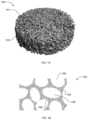
- FIG. 1 Ais a perspective view of an example porous composite material described herein.
- FIG. 1 Bis a cross-sectional view of a portion of the example porous composite material of FIG. 1 A .
- FIG. 2 A- 2 Care scanning electron micrographs of a portion of the example porous composite material shown in increasing magnification.
- FIG. 3is graphical representation of the elastic modulus of example apatite reinforced polymer composites versus the reinforcement volume fraction.
- FIG. 4shows scanning electron micrograph of a portion of the surface of an example composite material reinforced with calcium phosphate whiskers embedded within and exposed on the surface, and schematically showing the orientation of the whiskers relative to the loading direction of the material or scaffold strut.
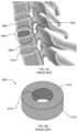
- FIG. 5 Ais a schematic illustration of a known spinal fusion cage inserted between spinal vertebrae.
- FIG. 5 Billustrates the example known spinal fusion cage of FIG. 5 A .
- FIG. 6illustrates another example scaffold described herein.
- FIG. 7illustrates yet another example scaffold described herein.
- FIG. 8is a flow diagram illustrating an example process of creating an example composite material apparatus described herein.
- the example methods, apparatus, and materials described hereinprovide a biocompatible, bioactive synthetic porous composite for use as synthetic bone substitute materials.
- the synthetic compositemay provide a synthetic porous scaffold for use an orthopedic implant and/or be injectable via percutaneous or surgical injection to cure in vivo. Because the example composite material is used to form a scaffold or matrix that is used in an implantable device, the descriptions of one or more of these structures may also describe one or more of the other structures.
- the synthetic porous compositesare tailored to mimic biological and mechanical properties of bone tissue for implant fixation, synthetic bone graft substitutes, tissue engineering scaffolds, interbody spinal fusion, or other orthopedic applications.
- An example porous composite material described hereinreduces subsidence and/or bone resorption resulting from mechanical mismatch problems between a synthetic scaffold of an implant device and the peri-implant tissue. Additionally, porosity and/or the pore sizes of the example synthetic composite are tailorable to specific applications to effectively promote the vascularization and growth of bone in the pores and/or void spaces of the example scaffolds, thereby improving bonding between the scaffolds and peri-implant tissue.
- the example composite material or scaffoldsare synthesized or made through a process that enables reinforcement particles to be integrally formed with or embedded within polymer matrices.
- the polymer matrices embedded with the reinforcement materialprovide improved material properties (e.g., stiffness, fatigue strength, and toughness).
- the reinforcement particlesare also exposed on a surface of the matrices, which promotes bioactivity and/or bioresorption.
- the processprovides flexibility to tailor the level of reinforcement particles and porosity for a desired application.
- a porogen materialmay be used to vary the porosity, while the pore size is tailored by, for example, sieving the porogen to a desired size.
- the mechanical properties (e.g., stiffness, strength, toughness, etc.) of the example scaffold of the implant devicemay be tailored to match those of the adjacent peri-implant bone tissue to reduce mechanical mismatch problems. Reducing mechanical mismatch provides a decreased risk of subsidence, stress shielding, bone resorption, and/or subsequent failure of adjacent peri-implant bone tissue. Additionally, the example scaffold of the implant device may include a significantly high porosity to promote bone ingrowth, while exhibiting significantly higher effective mechanical properties such as, for example, the mechanical properties of trabecular bone.
- the example composite materialincludes a continuous porous biocompatible matrix having a thermoplastic polymer matrix reinforced with anisometric calcium phosphate particles.
- a composite materialincludes a polyetheretherketone (PEEK) or a polyetherketoneketone (PEKK) matrix reinforced with various volume fractions of hydroxyapatite (HA) whiskers (e.g., 20 or 40 volume percent), wherein the matrix is approximately between 70% and 90% porous.
- PEEKpolyetheretherketone
- PEKKpolyetherketoneketone
- HAhydroxyapatite
- the porous matrixincludes a biocompatible, microporous polymer cage reinforced with anisometric calcium phosphate particles and bone morphogenic protein (BMP) such as, for example, rhBMP-2, which can be dispersed or accommodated by the void spaces and/or pores of the example porous scaffold and/or exposed on the surface of the example porous scaffold. Additionally, the BMP binds to the calcium phosphate further localizing the BMP to the surface of the scaffold or matrix.
- BMPbone morphogenic protein
- the example composite materials described hereinmay be used for applications such as, for example, synthetic bone graft substitutes, bone ingrowth surfaces applied to existing implants, tissue engineering scaffolds, interbody spinal fusion cages, etc.
- carrier materialse.g., collagen, hydrogels, etc.
- growth factorssuch as BMP
- a femurincludes a cortical bone that has a relative porosity on the order of about 5-15%, and a trabecular bone that has a porosity on the order of about 75-95%. Due to the highly significant porosity differences, the trabecular bone exhibits significantly lower effective mechanical properties compared to the cortical bone. Therefore, depending on the application, synthetic composite materials for use as scaffolds and/or spinal fusion cages or other implant devices should possess the mechanical properties exhibited by the cortical bone or the trabecular bone, but must also have effective porosity to promote bone growth.
- the example scaffold of the implant device described hereinmay be tailored to substantially match or mimic the mechanical properties (e.g., stiffness, strength, toughness, etc.) of the adjacent and/or substituted bone tissue.
- the mechanical propertiese.g., stiffness, strength, toughness, etc.
- Several factorsmay be varied during the synthesis of the composite material and scaffold of the implant device to tailor the mechanical properties including the calcium phosphate reinforcement volume fraction, aspect ratio, size and orientation; the polymer; and the size, volume fraction, shape and directionality of the void space and/or porosity. Tailoring the mechanical properties of the scaffold reduces the likelihood of mechanical mismatch leading to a decreased risk of subsidence, stress shielding, bone resorption and/or subsequent failure of adjacent vertebrae.
- FIG. 1 Aillustrates the example synthetic porous composite material 100 described herein.
- FIG. 1 Bis a cross-sectional view of a portion of the example porous composite material 100 of FIG. 1 A .
- the example synthetic composite material 100provides a synthetic porous scaffold 101 for use or in as an orthopedic implant.
- the example synthetic porous composite material 100includes a porous thermoplastic polymer (e.g., a PEEK polymer) matrix 102 having anisometric calcium phosphate reinforcement particles 104 integrally formed or embedded with the matrix 102 and/or exposed on a surface of the matrix.
- a porous thermoplastic polymere.g., a PEEK polymer
- the porous polymer matrix 102includes a substantially continuous porosity and a plurality of pores 106 to enable bone ingrowth into the porous matrix 102 .
- the matrix 102is substantially continuously interconnected via a plurality of struts 108 .
- At least one of the plurality of struts 108may be a load-bearing strut.
- FIGS. 2 A- 2 Care scanning electron micrographs showing increasing magnification of a portion of an example scaffold 200 with struts 202 .
- the example scaffold 200is a PEEK scaffold reinforced with 40% by volume HA whiskers 204 .
- FIG. 2 Aillustrates the architecture or matrix 206 of the scaffold 200 and FIG. 2 B illustrates an enlarged portion of the struts 202 .
- the HA whiskers 204are integrally formed and/or embedded within the matrix 206 of the scaffold 200 for reinforcement.
- the HA whiskers 204are also exposed on a surface 208 of the matrix of the scaffold 200 for bioactivity and/or bioresorption, as noted above.
- the HA whiskers 204are aligned in a sheet texture and are exposed on the surface 208 of the struts 202 .
- thermoplastic polymer of the example scaffolds described hereinmay be a biodegradable polymer for synthetic bone graft substitute applications, or nonbiodegradable for implant fixation applications.
- the thermoplastic polymerincludes a continuous matrix of a composite material and is biocompatible and/or bioresorbable as described above.
- the polymermay be a radiolucent polymer, bioresorbable (i.e., a material capable of being resorbed by a patient under normal physiological conditions) and/or non-bioresorbable, as desired.
- the thermoplastic polymer matrixmay include a polymer suitable for injection via percutaneous or surgical injection so that the composite material 100 cures in vivo.
- Suitable non-resorbable polymersinclude, without limitation, polyaryletherketone (PAEK), polyetheretherketone (PEEK), polyetherketonekteone (PEKK), polyetherketone (PEK), polyethylene, high density polyethylene (HDPE), ultra-high molecular weight polyethylene (UHMWPE), low density polyethylene (LDPE), polyethylene oxide (PEO), polyurethane, polypropylene, polypropylene oxide (PPO), polysulfone, polypropylene, copolymers thereof, and blends thereof.
- PAEKpolyaryletherketone
- PEEKpolyetheretherketone
- PEKKpolyetherketonekteone
- PEKpolyetherketone
- PEKpolyethylene, high density polyethylene (HDPE), ultra-high molecular weight polyethylene (UHMWPE), low density polyethylene (LDPE), polyethylene oxide (PEO), polyurethane, polypropylene, polypropylene oxide (PPO), polysulfone, polypropylene, copolymers thereof
- Suitable bioresorbable polymersinclude, without limitation, poly(DL-lactide) (PDLA), poly(L-lactide) (PLLA), poly(glycolide) (PGA), poly( ⁇ -caprolactone) (PCL), poly(dioxanone) (PDO), poly(glyconate), poly(hydroxybutyrate) (PHB), poly(hydroxyvalerate (PHV), poly(orthoesters), poly(carboxylates), poly(propylene fumarate), poly(phosphates), poly(carbonates), poly(anhydrides), poly(iminocarbonates), poly(phosphazenes), copolymers thereof, and blends thereof.
- PDLApoly(DL-lactide)
- PLLApoly(L-lactide)
- PGApoly(glycolide)
- PCLpoly( ⁇ -caprolactone)
- PDOpoly(dioxanone)
- PDOpoly(glyconate), poly(hydroxybutyrate) (PH
- Suitable polymers that are injectable via percutaneous or surgical injection that cure in vivoinclude, without limitation, polymethylmethacrylate (PMMA), and other polyacrylics from monomers such as bisphenol a hydroxypropylmethacrylate (bis-GMA) and/or tri(ethylene glycol) dimethacrylate (TEG-DMA).
- PMMApolymethylmethacrylate
- bis-GMAbisphenol a hydroxypropylmethacrylate
- TEG-DMAtri(ethylene glycol) dimethacrylate
- synthetic substitute composite materials made of polymerssatisfy the functional criteria of an implantable device because they are, for example, formable and inexpensive, polymers alone lack biological efficacy to promote bone growth and/or may lack requisite mechanical properties to support load levels.
- the polymersare reinforced with calcium phosphates.
- the aspect ratio, size, volume fraction and degree of preferred orientation of the calcium phosphate particles 104may be tailored for the desired material properties and implant performance. For example, consider the information presented in FIG. 3 , which is a graphical illustration of the elastic modulus of HA whisker and powder reinforced polymer composite materials versus the volume fraction percentage of the apatite calcium phosphates that is mixed with the polymer matrix.
- the shaded areas of FIG. 3show approximate regions for the given mechanical property of the human cortical bone tissue.
- the elastic modulus of the composite materialsincreases with increasing HA content.
- increasing the level of HA reinforcement in polymer compositesincreases cellular activity during osteointegration.
- the calcium phosphate reinforcement particles 104may be in the form of single crystals or dense polycrystals but are at least in some portion anisometric.
- “Anisometric”refers to any particle morphology (shape) that is not equiaxed (e.g., spherical), such as whiskers, plates, fibers, etc.
- Anisometric particlesare usually characterized by an aspect ratio.
- HA single crystalsare characterized by the ratio of dimensions in the c- and a-axes of the hexagonal crystal structure.
- the anisometric particles in the present disclosurehave an aspect ratio greater than 1.
- the mean aspect ratio of the reinforcement particlesis from about 1 to about 100.
- the reinforcement particlescan be provided in an amount of from about 1% by volume of the composite biomaterial to about 60% by volume, and for example, from about 20% by volume of the composite to about 50% by volume.
- the calcium phosphate reinforcements particles 104may be oriented in bulk or near the surface of the polymer matrix 102 to provide directional properties, if desired. For example, if the reinforcement particles 104 are predominately aligned within the matrix 102 the morphological alignment of the particles 104 provides anisotropy for the overall composite 100 , which can be tailored to be similar to the anisotropic mechanical properties of bone tissues.
- FIG. 4shows a micrograph of anisometric calcium phosphate reinforcement 400 on the surface of a dense composite polymer matrix 402 . Also shown in FIG. 4 is a schematic illustration of a portion of matrix 402 and illustratively showing the orientation of the reinforcement particles 400 relative to the loading direction of the material and/or a scaffold strut, which is, for example, at an angle ⁇ .
- the reinforcement particles 104may have a maximum dimension from about 20 nm to about 2 mm, and for example, between 20 nm to about 100 ⁇ m. While both nano- and micro-scale calcium phosphate particles improve the mechanical properties of the example synthetic composite material 100 described herein, nano-scale calcium phosphate particles are particularly effective for enhancing bioresorbability and cell attachment, and micro-scale particles are particularly effective for obtaining a uniform dispersion within the matrix 102 .
- Suitable calcium phosphatesmay include, without limitation, calcium HA, HA whiskers, HA, carbonated calcium HA, beta-tricalcium phosphate (beta-TCP), alpha-tricalcium phosphate (alpha-TCP), amorphous calcium phosphate (ACP), octacalcium phosphate (OCP), tetracalcium phosphate, biphasic calcium phosphate (BCP), anhydrous dicalcium phosphate (DCPA), dicalcium phosphate dihydrate (DCPD), anhydrous monocalcium phosphate (MCPA), monocalcium phosphate monohydrate (MCPM), and combinations thereof.
- DCPAdicalcium phosphate
- DCPDdicalcium phosphate dihydrate
- MCPAmonocalcium phosphate monohydrate
- MCPMmonocalcium phosphate monohydrate
- a synthetic composite material 100not only bears physiological levels of load, but also promotes oseteointegration—the direct structural and functional connection between the living bone and the surface of the load-bearing implant.
- the bioactive calcium phosphate particles 104e.g., HA whiskers
- exposed on the surface of the example porous matrix 102promote a stable bone-implant interface. Osteointegration also requires the vascularization and growth of bone into an implant via interconnected and/or continuous porosity.
- the size, volume fraction, shape, and directionality of the void spaces and/or pores 106may be tailored to optimize osteoconduction and implant mechanical properties.
- the pores 106may be any size or shape, while maintaining a continuous network to promote a fusion through the formation of new bone tissue in the void spaces and/or pores 106 .
- the pores 106may be present throughout the matrix 102 as illustrated in FIG. 1 A .
- the pores 106may be functionally graded in any material or implant direction, for example, radially, as shown in FIGS. 6 and 7 , from a highly porous region to a relatively dense region or may include a void space.
- the change in porosity from one region to anothermay be very distinct, for example as shown in FIGS.
- the graded changemay be uniform or variant.
- the central voidmay be any shape or size, and may receive (e.g., be filled) a material, a structure, or the composite material 100 (i.e., the composite material graded from the porous outer surface to a dense center), thereby forming a porous outer perimeter and a dense central region. Examples are further described in connection with FIGS. 6 and 7 below.
- the porosity and/or pore sizes 106may be selectively formed by the inclusion of, for example, a porogen material during synthesis of the composite material 100 .
- Pores spacesmay range from about 100 ⁇ m to about 500 ⁇ m, and, for example, from about 250 ⁇ m to about 500 ⁇ m.
- the example composite biomaterial 100may additionally contain some fraction of microporosity within scaffold struts that is less than about 10 ⁇ m in size.
- the total amount of porosity within porous regionsmay range from about 1% to about 90% by volume, and, for example, between about 70% and 90% by volume.
- the porositymay also be tailored via other processes such as, for example, microsphere sintering, fiber weaving, solvent casting, electrospinning, freeze drying (lyophilization), thermally induced phase separation, gas foaming, and rapid prototyping processes such as, for example, solid freeform fabrication, robotic deposition (aka, robocasting), selective laser sintering, fused deposition modeling, three-dimensional printing, laminated object manufacturing, stereolithography, etc., or any other suitable process(es) or combination(s) thereof.
- processessuch as, for example, microsphere sintering, fiber weaving, solvent casting, electrospinning, freeze drying (lyophilization), thermally induced phase separation, gas foaming, and rapid prototyping processes such as, for example, solid freeform fabrication, robotic deposition (aka, robocasting), selective laser sintering, fused deposition modeling, three-dimensional printing, laminated object manufacturing, stereolithography, etc., or any other suitable process(es) or combination(s) thereof.
- the example composite material 100may optionally include additives, if desired.
- the composite material 100may include one or more surface-active agents to enhance interfacial bonding between the reinforcement particles 104 and the polymer matrix 102 .
- the void spaces and/or pores 106may accommodate and deliver one or more growth factors such as, for example, BMP, to enhance osteoinductivity and/or bone regeneration.
- the void spaces and/or pores 106may also accommodate and deliver one or more transcription factors, matrix metalloproteinases, peptides, proteins, bone cells, progenitor cells, blood plasma, bone marrow aspirate, or combinations thereof, to improve or speed bone regeneration, or resorption and replacement of the biomaterial.
- the void spaces and/or pores 106may further accommodate a carrier material that may be incorporated into the void spaces and/or pores 106 .
- the carrier materialmay include, for example, a collagen sponge, membrane, or a hydrogel material to deliver the growth factor material such as, for example, the BMP.
- FIG. 5 Ais an illustration showing a known interbody spinal fusion cage 500 .
- the example spinal fusion cage 500is implanted in the inter-vertebral space 502 between two adjacent vertebrae 506 and 508 .
- a disc 510due to degeneration, herniation, etc., is typically removed and replaced by the spinal fusion cage 500 .
- the spinal fusion cage 500is used to support or restore vertebral height, and, thus, stabilize or retain adjacent vertebrae 506 and 508 in a desired position. Additionally, the spinal fusion cage 500 is to promote fusion between the vertebrae 506 and 508 .
- FIG. 5 Bis an enlarged illustration of the known spinal fusion cage 500 of FIG. 5 A .
- a typical spinal fusion cage 500includes a body 510 having a dense outer region 512 and a void 514 at its center.
- the dense outer surface 512may be made of PEEK, titanium, or other material that can be used to support the vertebrae 506 and 508 .
- the spinal fusion cage 500 made of a PEEK, titanium, etc.cannot attach to the bone.
- the center void 514is typically provided with a packing material (not shown) such as, a natural bone graft, a collagen sponge that retains bone growth factors, or the spinal fusion cage 500 is coated with the bone growth factors or other agents that promote osteoinduction.
- the example porous scaffold 101 having the composite material 100 described herein, and with respect to FIG. 1 Acan be implemented with the spinal fusion cage 500 of FIGS. 5 A and 5 B to replace the packing materials, such as natural bone graft.
- the porous scaffold 101promotes bone ingrowth and the pores 106 may accommodate or deliver for example, a BMP, to further improve rate of growth (fusion rate).
- the calcium phosphatee.g., HA whisker
- FIG. 6illustrates another example scaffold or matrix 600 implemented with the example composite material 100 described herein.
- the example scaffold 600may be implemented as an interbody spinal fusion cage.
- the scaffold 600includes a body 602 having a porous polymer matrix 604 integrally formed or embedded with anisometric calcium phosphate particles 606 .
- the matrix 604 of the example scaffold 600includes a radiolucent polymer (e.g., PEEK) integrally formed or embedded with anisometric calcium phosphate reinforcements 606 such as, for example, HA whiskers.
- the radiolucent polymerprovides improved radiographic analysis of fusion following implantation.
- the example scaffold 600may also include a BMP such as, for example, rhBMP-2.
- the example scaffold 600is a biocompatible, microporous polymer scaffold or matrix supplemented with anisometric calcium phosphate reinforcements and BMP.
- the example scaffold 600may formed so that the pores are functionally graded in any material or implant direction such as, for example, radially, as shown in FIG. 6 , from a highly porous center or central region 608 to relatively dense outer region or surface 610 .
- the change in porosity from one region to anothermay be distinct or gradual from the central region 608 to the outer region 610 . Further, the graded change may be uniform or variant.
- the dense outer region 610provides structural integrity along with the advantages of the composite material 100 described herein.
- the porous structure 604has pore sizes that range between about 100 ⁇ m and about 500 ⁇ m, and preferably, between about 250 ⁇ m and about 500 ⁇ m, and a porosity that ranges between about 1% to about 90%.
- the spinal fusion cage material 600may include microporosity having pore sizes less than about 10 ⁇ m.
- FIG. 7illustrates another example scaffold 700 .
- the porous scaffold 700includes a porous matrix 702 having the composite material 100 described herein.
- the porous scaffold 700includes a center or central void 704 that may be any shape or size. Additionally, or alternatively, the central void 704 may receive a material 706 , a stem, or any other substance or structure, illustratively depicted by dashed lines.
- the central void 704may receive a stem 706 (e.g., an implant) such as, for example, a titanium stem, a dense composite stem (e.g., a PEEK composite stem), or any other suitable material or structure.
- a stem 706e.g., an implant
- a dense composite steme.g., a PEEK composite stem
- the scaffold 700is formed so that the pores are functionally graded in any material or implant direction, for example, radially as shown in FIG. 7 , from a high porous outer region or surface 702 to a relatively dense center or central region 708 .
- the change in porosity from one region to anothermay be distinct or gradual from the central region 708 to the highly porous outer region 702 .
- the graded changemay be uniform or variant.
- the example scaffold 700forms a porous perimeter having a dense core, where the material is continuous from the porous perimeter to the dense core.
- the dense central region 708provides structural integrity along with the advantages of the composite material 100 described herein.
- the porous matrix 702 and the dense central region 708may have pore sizes that range between about 100 ⁇ m and about 500 ⁇ m, and preferably, between about 250 ⁇ m and about 500 ⁇ m, and a porosity that ranges between about 1% to about 90%.
- the spinal fusion cage 700may include a microporosity having pore sizes less than about 10 ⁇ m.
- the composite material 100 and/or the scaffolds 101 , 600 , 700may also include a roughened surface such as, for example, serrated teeth, that come into direct contact with the adjacent peri-implant tissue to prevent movement relative to the peri-implant tissue after implantation.
- the scaffolds 101 , 600 , 700may include holes, notches, pins, radiographic markers, or other features that may be gripped or otherwise used for positioning of the scaffolds 101 , 600 , 700 by minimally invasive surgical tools and procedures.
- the example composite material 100 and/or the scaffolds 101 , 600 , 700may be manufactured by methods common to reinforced thermoplastic and thermosetting polymers, including but not limited to injection molding, reaction injection molding, compression molding, transfer molding, extrusion, blow molding, pultrusion, casting/potting, solvent casting, microsphere sintering, fiber weaving, solvent casting, electrospinning, freeze drying (lyophilization), thermally induced phase separation, gas foaming, and rapid prototyping processes such as solid freeform fabrication, robotic deposition (aka, robocasting), selective laser sintering, fused deposition modeling, three-dimensional printing, laminated object manufacturing, stereolithography, etc., or any other suitable process(es) or combination(s) thereof.
- methods common to reinforced thermoplastic and thermosetting polymersincluding but not limited to injection molding, reaction injection molding, compression molding, transfer molding, extrusion, blow molding, pultrusion, casting/potting, solvent casting, microsphere sintering, fiber weaving, solvent casting, electrospinning, freeze drying (lyophilization), thermally
- FIG. 8is a flowchart of an example method 800 that may be used to synthesize the example composite material 100 and/or scaffolds 101 , 600 , 700 described herein. While an example manner of synthesizing the example composite material 100 and/or scaffolds 101 , 600 , 700 has been illustrated in FIG. 8 , one or more of the steps and/or processes illustrated in FIG. 8 may be combined, divided, re-arranged, omitted, eliminated and/or implemented in any other way. Further still, the example method of FIG. 8 may include one or more processes and/or steps in addition to, or instead of, those illustrated in FIG. 8 , and/or may include more than one of any or all of the illustrated processes and/or steps. Further, although the example method is described with reference to the flow chart illustrated in FIG. 8 , persons of ordinary skill in the art will readily appreciate that many other methods of synthesizing the example composite material 100 and/or scaffolds 101 , 600 , 700 may alternatively be used.
- the composite material 100 and/or the scaffolds 101 , 600 , 700are processed using a powder processing approach in conjunction with compression molding and particle leaching techniques and is particularly suited for achieving a high concentration (e.g., >40 vol %) of well-dispersed (and aligned, if desired) anisometric calcium phosphate reinforcements (e.g., HA whiskers) in a thermoplastic matrix (e.g., PEEK) with minimal degradation of the calcium phosphate size/shape during processing.
- a high concentratione.g., >40 vol %
- anisometric calcium phosphate reinforcementse.g., HA whiskers
- a thermoplastic matrixe.g., PEEK
- the calcium phosphate reinforcement volume fraction, aspect ratio, size and orientation; the polymer; and the size, volume fraction, shape and directionality of the void space and/or porositymay be tailored to vary the mechanical properties of the composite material 100 and/or scaffolds 101 , 600 , 700 .
- a polymer such as, for example, PEEK, and anisometric calcium phosphate particles, such as HA whiskers,are provide in powder form (block 802 ).
- the PEEK polymer powdermay have, for example, a mean particle size of about 26 ⁇ m.
- the HA whiskersmay be synthesized (block 801 ) using, for example, the chelate decomposition method.
- the PEEK powder and the synthesized HA whiskersare co-dispersed in a fluid (block 804 ) such as, for example ethanol, and mixed (block 804 ) using, for example, ultrasonication under constant stirring—forming a viscous suspension.
- a fluidsuch as, for example ethanol
- the porosity of the mixtureis selectively varied and/or tailored (block 806 ).
- the porositymay be formed and tailored by the addition of a suitable porogen material such as, for example, NaCl, wax, polysaccharides (sugars), cellulose, etc.
- the extent of the porositycan be controlled by varying the amount of porogen used (block 805 ), while the pore size could be tailored by sieving the porogen (block 807 ) to a desired size prior to mixing the porogen with the polymer mixture.
- the porosity and/or the pore size of the polymer matrixmay be selectively varied using any other suitable methods and/or process(es) such as, for example, microsphere sintering, fiber weaving, solvent casting, electrospinning, freeze drying (lyophilization), thermally induced phase separation, gas foaming, or rapid prototyping processes such as, for example, solid freeform fabrication, robotic deposition (aka, robocasting), selective laser sintering, fused deposition modeling, three-dimensional printing, laminated object manufacturing, stereolithography, etc., or any other suitable process(es) or combination(s) thereof.
- suitable methods and/or process(es)such as, for example, microsphere sintering, fiber weaving, solvent casting, electrospinning, freeze drying (lyophilization), thermally induced phase separation, gas foaming, or rapid prototyping processes such as, for example, solid freeform fabrication, robotic deposition (aka, robocasting), selective laser sintering, fused deposition modeling, three-dimensional printing, laminated object manufacturing
- the viscous suspensionis wet-consolidated (block 808 ) by, for example, vacuum filtration and drying to remove any residual fluid (i.e., ethanol).
- the composite mixtureis densified (block 810 ) by, for example, uniaxial compression, to form a composite preform.
- the preformis compression molded (block 812 ) and/or sintered at elevated temperatures (e.g., approximately 20° C. to 400° C.) sufficient to fuse the polymer particles with minimal damage to the calcium phosphate reinforcements.
- elevated temperaturese.g., approximately 20° C. to 400° C.
- the process or composite materialmay be heated to a desired processing temperature and the implant may be shaped or formed (block 814 ). Densifying and molding the composite material includes aligning the calcium phosphate reinforcement particles (e.g., HA whiskers) morphologically and/or crystallographically within the scaffold struts.
- the scaffoldmay have any shape and/or size (e.g., any polygonal shape) and can be formed by methods common to reinforced thermoplastic and thermosetting polymers, including but not limited to injection molding, reaction injection molding, compression molding, transfer molding, extrusion, blow molding, pultrusion, casting/potting, solvent casting, and rapid prototyping processes such as, for example, solid freeform fabrication, robotic deposition (aka, robocasting), selective laser sintering, fused deposition modeling, three-dimensional printing, laminated object manufacturing, stereolithography, etc., or any other suitable process(es).
- the composite material 100 and/or the scaffolds 101 , 600 , 700are formed by the mold walls and/or machining after molding.
- the composite materialundergoes a leaching process (block 816 ) to remove, for example, the porogen used during synthesis of the composite material.
- the leachingmay occur, for example, via a dissolution method, heating method, and/or any other suitable methods and/or process(es). More specifically, dissolution may include immersing the scaffold in a fluid, such as, for example, deionized water.
- viscous flow of the polymer/reinforcement mixture during moldingcan be designed to tailor the preferred orientation of the anisometric reinforcements in the implant.
- surface-active agentsmay be added during the mixing process and/or to the surface of the composite material to enhance interfacial bonding between reinforcement particles and the matrix.
- HA whiskerswere synthesized using the chelate decomposition method. The as-synthesized HA whiskers were measured by optical microscopy to have a mean length of 21.6 ⁇ m, width of ⁇ m and aspect ratio of 7.6.
- composite scaffolds with 75, 82.5 and 90% porositywere processed with 0-40 vol % HA whisker reinforcement.
- Appropriate amounts of polymer powder and HA whiskerswere co-dispersed in ethanol via a sonic dismembrator and mechanical stirring at 1200 rpm.
- the appropriate amount of the NaCli.e., porogen
- the total scaffold volumeconsisted of the material volume plus the pore volume.
- the reinforcement levelwas calculated based the desired material volume, while the porosity level was calculated based on the total scaffold volume.
- the viscous suspensionwas wet-consolidated using vacuum filtration.
- the powder mixturewas dried overnight in a forced convection oven at 90° C. and densified at 125 MPa in a cylindrical pellet die using a hydraulic platen press.
- the die and densified powder mixturewas heated in a vacuum oven to the desired processing temperature and transferred to a hydraulic platen press for compression molding. Scaffolds with 82.5 and 90% porosity were molded at 350° C., while scaffolds with 75% porosity were molded at 350, 365 and 375° C.
- a pressure of 250 MPawas applied to the die as the polymer solidified.
- the sintered composite pelletwas ejected from the die and placed approximately 300 mL deionized water for at least 72 h to dissolve the NaCl crystals. The deionized water was changed daily.
- the as-molded composite scaffoldshad a diameter of 1 cm and were machined to a height of 1 cm.
- the table belowprovides mechanical properties of the example PEKK scaffold reinforced with HA whiskers that was processed using a compression molding/particle leaching method such as, for example, the method 800 of FIG. 8 as implemented in the description above.
- the mechanical properties of HA whisker reinforced PEKKwere evaluated in uniaxial compression.
- Tensile properties of the HA whisker reinforced PEKK scaffoldswere evaluated prior to scaffold fabrication.
- Scaffolds with 0 vol % HA whisker reinforcement and 75% and 90% porosityexhibited yield strengths of 1.25 MPa and 0.15 MPa, respectively.
- Scaffolds with 40 vol % HA whisker reinforcement and 75%, 82% and 90% porosityexhibited yield strengths of 0.52 MPa, 0.13 M P a and 0.04 MPa, respectively.
- the HA contentalso affected the modulus and failure strain of the scaffolds.
- a scaffold having 75% porosity and 20 vol % reinforcement HA whiskerexhibited modulus of 106.3 MPa, compared to a modulus of 69.5 MPa for scaffolds with 0 vol % HA whisker reinforcement.
- the example methods and apparatus described hereinoffer synthetic porous composite material that may be used for synthetic bone substitutes for implant fixation, fraction fixation, synthetic bone graft substitutes, interbody spinal fusion, tissue engineering scaffolds, or other applications.
- Many aspects of the of the porous composite materialmay be tailored to provide specific mechanical, biological, and surgical functions, such as, the polymer composition and molecular orientation, porosity and pore size of the porous matrix, or the HA reinforcement content, morphology, preferred orientation, and size.
Landscapes
- Health & Medical Sciences (AREA)
- Chemical & Material Sciences (AREA)
- Engineering & Computer Science (AREA)
- Medicinal Chemistry (AREA)
- Life Sciences & Earth Sciences (AREA)
- Oral & Maxillofacial Surgery (AREA)
- Transplantation (AREA)
- Veterinary Medicine (AREA)
- Animal Behavior & Ethology (AREA)
- General Health & Medical Sciences (AREA)
- Public Health (AREA)
- Biomedical Technology (AREA)
- Materials Engineering (AREA)
- Dermatology (AREA)
- Epidemiology (AREA)
- Orthopedic Medicine & Surgery (AREA)
- Chemical Kinetics & Catalysis (AREA)
- Neurology (AREA)
- Polymers & Plastics (AREA)
- Organic Chemistry (AREA)
- Vascular Medicine (AREA)
- Cardiology (AREA)
- Inorganic Chemistry (AREA)
- Heart & Thoracic Surgery (AREA)
- Dispersion Chemistry (AREA)
- Composite Materials (AREA)
- Molecular Biology (AREA)
- Mechanical Engineering (AREA)
- Prostheses (AREA)
- Materials For Medical Uses (AREA)
Abstract
Description
| TABLE 1 | |||||
| HA | Molding | Elastic | |||
| Porosity | Content | Temperature | Modulus | Yield | |
| (%) | (Vol %) | (° C.) | (MPa) | CYS (MPa) | Strain (%) |
| 75 | 0 | 350 | 69.5 (12.2) | 1.25 (0.16) | 5.7(0.4) |
| 75 | 0 | 365 | 100.7 (10.7) | 2.04 (0.26) | 4.4(1.2) |
| 75 | 0 | 375 | 95.6 (10.5) | 2.55 (0.34) | 4.4(1.1) |
| 75 | 20 | 350 | 106.3 (15.0) | 1.28 (0.13) | 3.7(1.1) |
| 75 | 20 | 365 | 115.4 (13.4) | 1.77 (0.30) | 2.9(0.6) |
| 75 | 20 | 375 | 141.1 (39.2) | 2.28 (0.35) | 2.9(0.7) |
| 75 | 40 | 350 | 54.0 (18.3) | 0.52 (0.17) | 2.2(0.3) |
| 75 | 40 | 365 | 84.3 (41.5) | 1.15 (0.38) | 2.7(0.5) |
| 75 | 40 | 375 | 120.2 (29.8) | 1.65 (0.34) | 2.3(1.9) |
| 82 | 40 | 350 | 15.7 (6.7) | 0.13 (0.03) | 2.6(1.9) |
| 90 | 0 | 350 | 0.75 (0.18) | 0.15 (0.04) | 30(0.0) |
| 90 | 40 | 350 | 0.23 (0.13) | 0.04 (0.01) | 30(0.0) |
Claims (12)
Priority Applications (2)
| Application Number | Priority Date | Filing Date | Title |
|---|---|---|---|
| US17/519,336US12048633B2 (en) | 2007-02-28 | 2021-11-04 | Porous composite biomaterials and related methods |
| US18/750,616US20240341972A1 (en) | 2007-02-28 | 2024-06-21 | Porous composite biomaterials and related methods |
Applications Claiming Priority (6)
| Application Number | Priority Date | Filing Date | Title |
|---|---|---|---|
| US90409807P | 2007-02-28 | 2007-02-28 | |
| US93925607P | 2007-05-21 | 2007-05-21 | |
| US12/039,666US20080206297A1 (en) | 2007-02-28 | 2008-02-28 | Porous composite biomaterials and related methods |
| US14/078,614US10945854B2 (en) | 2007-02-28 | 2013-11-13 | Porous composite biomaterials and related methods |
| US17/180,935US20210177620A1 (en) | 2007-02-28 | 2021-02-22 | Porous composite biomaterials and related methods |
| US17/519,336US12048633B2 (en) | 2007-02-28 | 2021-11-04 | Porous composite biomaterials and related methods |
Related Parent Applications (1)
| Application Number | Title | Priority Date | Filing Date |
|---|---|---|---|
| US17/180,935ContinuationUS20210177620A1 (en) | 2007-02-28 | 2021-02-22 | Porous composite biomaterials and related methods |
Related Child Applications (1)
| Application Number | Title | Priority Date | Filing Date |
|---|---|---|---|
| US18/750,616ContinuationUS20240341972A1 (en) | 2007-02-28 | 2024-06-21 | Porous composite biomaterials and related methods |
Publications (2)
| Publication Number | Publication Date |
|---|---|
| US20220062004A1 US20220062004A1 (en) | 2022-03-03 |
| US12048633B2true US12048633B2 (en) | 2024-07-30 |
Family
ID=39716166
Family Applications (5)
| Application Number | Title | Priority Date | Filing Date |
|---|---|---|---|
| US12/039,666AbandonedUS20080206297A1 (en) | 2007-02-28 | 2008-02-28 | Porous composite biomaterials and related methods |
| US14/078,614Active2028-06-06US10945854B2 (en) | 2007-02-28 | 2013-11-13 | Porous composite biomaterials and related methods |
| US17/180,935AbandonedUS20210177620A1 (en) | 2007-02-28 | 2021-02-22 | Porous composite biomaterials and related methods |
| US17/519,336Active2028-07-24US12048633B2 (en) | 2007-02-28 | 2021-11-04 | Porous composite biomaterials and related methods |
| US18/750,616PendingUS20240341972A1 (en) | 2007-02-28 | 2024-06-21 | Porous composite biomaterials and related methods |
Family Applications Before (3)
| Application Number | Title | Priority Date | Filing Date |
|---|---|---|---|
| US12/039,666AbandonedUS20080206297A1 (en) | 2007-02-28 | 2008-02-28 | Porous composite biomaterials and related methods |
| US14/078,614Active2028-06-06US10945854B2 (en) | 2007-02-28 | 2013-11-13 | Porous composite biomaterials and related methods |
| US17/180,935AbandonedUS20210177620A1 (en) | 2007-02-28 | 2021-02-22 | Porous composite biomaterials and related methods |
Family Applications After (1)
| Application Number | Title | Priority Date | Filing Date |
|---|---|---|---|
| US18/750,616PendingUS20240341972A1 (en) | 2007-02-28 | 2024-06-21 | Porous composite biomaterials and related methods |
Country Status (2)
| Country | Link |
|---|---|
| US (5) | US20080206297A1 (en) |
| WO (1) | WO2008106625A2 (en) |
Families Citing this family (137)
| Publication number | Priority date | Publication date | Assignee | Title |
|---|---|---|---|---|
| US6558426B1 (en) | 2000-11-28 | 2003-05-06 | Medidea, Llc | Multiple-cam, posterior-stabilized knee prosthesis |
| GB0329654D0 (en) | 2003-12-23 | 2004-01-28 | Smith & Nephew | Tunable segmented polyacetal |
| EP1988855A2 (en) | 2006-02-27 | 2008-11-12 | Synthes GmbH | Intervertebral implant with fixation geometry |
| US20110282392A1 (en)* | 2006-10-30 | 2011-11-17 | Tissue Regeneration Systems, Inc. | Degradable cage for bone fusion |
| US8722783B2 (en) | 2006-11-30 | 2014-05-13 | Smith & Nephew, Inc. | Fiber reinforced composite material |
| WO2008106625A2 (en) | 2007-02-28 | 2008-09-04 | University Of Notre Dame Du Lac | Porous composite biomaterials and related methods |
| US11179243B2 (en) | 2007-02-28 | 2021-11-23 | Happe Spine Llc | Implantable devices |
| EP2142353A1 (en) | 2007-04-18 | 2010-01-13 | Smith & Nephew PLC | Expansion moulding of shape memory polymers |
| US9000066B2 (en) | 2007-04-19 | 2015-04-07 | Smith & Nephew, Inc. | Multi-modal shape memory polymers |
| EP2150288B1 (en) | 2007-04-19 | 2011-04-13 | Smith & Nephew, Inc. | Graft fixation |
| US8715359B2 (en) | 2009-10-30 | 2014-05-06 | Depuy (Ireland) | Prosthesis for cemented fixation and method for making the prosthesis |
| US20110035017A1 (en)* | 2007-09-25 | 2011-02-10 | Depuy Products, Inc. | Prosthesis with cut-off pegs and surgical method |
| US8128703B2 (en) | 2007-09-28 | 2012-03-06 | Depuy Products, Inc. | Fixed-bearing knee prosthesis having interchangeable components |
| US8632600B2 (en) | 2007-09-25 | 2014-01-21 | Depuy (Ireland) | Prosthesis with modular extensions |
| US9204967B2 (en) | 2007-09-28 | 2015-12-08 | Depuy (Ireland) | Fixed-bearing knee prosthesis having interchangeable components |
| EP2238192B1 (en)* | 2008-02-01 | 2017-03-01 | Synthes GmbH | Porous biocompatible polymer material and methods |
| US8192498B2 (en) | 2008-06-30 | 2012-06-05 | Depuy Products, Inc. | Posterior cructiate-retaining orthopaedic knee prosthesis having controlled condylar curvature |
| US8236061B2 (en) | 2008-06-30 | 2012-08-07 | Depuy Products, Inc. | Orthopaedic knee prosthesis having controlled condylar curvature |
| US9119723B2 (en) | 2008-06-30 | 2015-09-01 | Depuy (Ireland) | Posterior stabilized orthopaedic prosthesis assembly |
| US8206451B2 (en) | 2008-06-30 | 2012-06-26 | Depuy Products, Inc. | Posterior stabilized orthopaedic prosthesis |
| US8828086B2 (en) | 2008-06-30 | 2014-09-09 | Depuy (Ireland) | Orthopaedic femoral component having controlled condylar curvature |
| US9168145B2 (en) | 2008-06-30 | 2015-10-27 | Depuy (Ireland) | Posterior stabilized orthopaedic knee prosthesis having controlled condylar curvature |
| US8187335B2 (en) | 2008-06-30 | 2012-05-29 | Depuy Products, Inc. | Posterior stabilized orthopaedic knee prosthesis having controlled condylar curvature |
| EP2349107B1 (en) | 2008-08-14 | 2016-12-21 | Oxford Performance Materials, Inc. | Customized implants for bone replacement |
| CN102256570B (en) | 2008-11-07 | 2015-09-02 | 斯恩蒂斯有限公司 | Spacer and connecting plate assembly between vertebral bodies |
| BRPI1008524A2 (en) | 2009-02-06 | 2015-08-25 | David Cheung | "biocompatible resorbable biphasic collagen membrane and its production method" |
| US20100256758A1 (en)* | 2009-04-02 | 2010-10-07 | Synvasive Technology, Inc. | Monolithic orthopedic implant with an articular finished surface |
| US8609127B2 (en)* | 2009-04-03 | 2013-12-17 | Warsaw Orthopedic, Inc. | Medical implant with bioactive material and method of making the medical implant |
| US9492587B2 (en)* | 2009-04-13 | 2016-11-15 | Abbott Cardiovascular Systems Inc. | Stent made from an ultra high molecular weight bioabsorbable polymer with high fatigue and fracture resistance |
| US20100262244A1 (en)* | 2009-04-14 | 2010-10-14 | Warsaw Orthopedic, Inc. | Metal Coated Implant |
| US9399086B2 (en)* | 2009-07-24 | 2016-07-26 | Warsaw Orthopedic, Inc | Implantable medical devices |
| US9039784B2 (en)* | 2009-07-28 | 2015-05-26 | Southwest Research Institute | Micro-structure particles for load bearing bone growth |
| EP2319462B1 (en) | 2009-10-30 | 2013-04-03 | DePuy Products, Inc. | Prosthesis with composite component |
| US9011547B2 (en) | 2010-01-21 | 2015-04-21 | Depuy (Ireland) | Knee prosthesis system |
| KR101196062B1 (en) | 2010-05-03 | 2012-11-01 | 순천향대학교 산학협력단 | Method for preparing porous biphasic calciumphosphate granules |
| EP2621869A4 (en)* | 2010-10-01 | 2014-10-08 | Skeletal Kinetics Llc | Porogen containing calcium phosphate cement compositions |
| US9339387B2 (en) | 2010-10-13 | 2016-05-17 | Cibor, Inc. | Synthetic bone grafts constructed from carbon foam materials |
| EP2637609B1 (en) | 2010-11-11 | 2016-02-24 | Zimmer, Inc. | Orthopedic implant with porous polymer bone contacting surface |
| WO2012088238A2 (en) | 2010-12-21 | 2012-06-28 | Synthes Usa, Llc | Intervertebral implants, systems, and methods of use |
| US9119728B2 (en) | 2011-01-17 | 2015-09-01 | Cibor, Inc. | Reinforced carbon fiber/carbon foam intervertebral spine fusion device |
| GB201100815D0 (en)* | 2011-01-18 | 2011-03-02 | Invibio Ltd | Polymeric materials |
| GB2488111A (en)* | 2011-02-14 | 2012-08-22 | Invibio Ltd | Components incorporating bioactive material |
| DE102011004305A1 (en)* | 2011-02-17 | 2012-08-23 | Evonik Degussa Gmbh | Process for the production of bars |
| EP2786770B1 (en)* | 2011-08-30 | 2017-04-19 | Kyoto University | Porous scaffold material, and method for producing same |
| WO2013052361A1 (en)* | 2011-10-03 | 2013-04-11 | The Cleveland Clinic Foundation | Synthetic bone model and method for providing same |
| DE102011119939A1 (en)* | 2011-12-01 | 2013-06-06 | Technische Universität Hamburg-Harburg | Method of making a composite, the composite and the use of the composite to make certain products |
| US11304811B2 (en) | 2012-01-17 | 2022-04-19 | KYOCERA Medical Technologies, Inc. | Surgical implant devices incorporating porous surfaces and associated method of manufacture |
| AU2013267381B2 (en)* | 2012-05-30 | 2016-03-31 | New York University | Tissue repair devices and scaffolds |
| US10207027B2 (en) | 2012-06-11 | 2019-02-19 | Globus Medical, Inc. | Bioactive bone graft substitutes |
| CN102727937B (en)* | 2012-06-28 | 2014-03-26 | 哈尔滨工程大学 | Biodegradable zinc (or zinc alloy) and porous biphase calcium phosphate composite material and preparation method thereof |
| US8843229B2 (en)* | 2012-07-20 | 2014-09-23 | Biomet Manufacturing, Llc | Metallic structures having porous regions from imaged bone at pre-defined anatomic locations |
| CA3100510A1 (en) | 2012-08-21 | 2014-02-27 | Vertera, Inc. | Systems and methods for making porous films, fibers, spheres, and other articles |
| US9949837B2 (en) | 2013-03-07 | 2018-04-24 | Howmedica Osteonics Corp. | Partially porous bone implant keel |
| CA2905111A1 (en)* | 2013-03-14 | 2014-09-25 | Skeletal Kinetics, Llc | Calcium phosphate cement compositions that set into high strength porous structures |
| JP6419181B2 (en)* | 2013-07-24 | 2018-11-07 | レノビス サージカル テクノロジーズ,インコーポレイテッド | Surgical implant device incorporating a porous surface |
| EP3024419B1 (en)* | 2013-07-24 | 2022-05-11 | Kyocera Medical Technologies, Inc. | Surgical implant devices incorporating porous surfaces |
| US9550012B2 (en) | 2013-08-05 | 2017-01-24 | University Of Notre Dame Du Lac | Tissue scaffolds having bone growth factors |
| US9295565B2 (en) | 2013-10-18 | 2016-03-29 | Spine Wave, Inc. | Method of expanding an intradiscal space and providing an osteoconductive path during expansion |
| US9504550B2 (en) | 2014-06-26 | 2016-11-29 | Vertera, Inc. | Porous devices and processes for producing same |
| US9498922B2 (en) | 2014-06-26 | 2016-11-22 | Vertera, Inc. | Apparatus and process for producing porous devices |
| BR112017007645B1 (en)* | 2014-10-14 | 2023-05-02 | Samuel Lynch | COMPOSITIONS TO TREAT WOUNDS |
| US9867718B2 (en) | 2014-10-22 | 2018-01-16 | DePuy Synthes Products, Inc. | Intervertebral implants, systems, and methods of use |
| US10279081B2 (en) | 2014-10-24 | 2019-05-07 | Allosource | Composite grafts, systems, and methods |
| US20160167306A1 (en)* | 2014-12-11 | 2016-06-16 | Massachusetts Institute Of Technology | Systems and methods of hierarchical material design for additive fabrication |
| US9821339B2 (en)* | 2014-12-19 | 2017-11-21 | Palo Alto Research Center Incorporated | System and method for digital fabrication of graded, hierarchical material structures |
| US9486960B2 (en) | 2014-12-19 | 2016-11-08 | Palo Alto Research Center Incorporated | System for digital fabrication of graded, hierarchical material structures |
| WO2016105286A1 (en)* | 2014-12-25 | 2016-06-30 | Hasirci Vasif Nejat | A new prosthesis material developed for use in the treatment of cervical and lumbar disc hernia |
| EP3240584A1 (en)* | 2014-12-29 | 2017-11-08 | Hasirci, Vasif Nejat | Craniofacial implants |
| CN104623728B (en)* | 2015-01-12 | 2016-05-11 | 四川大学 | Anisotropy bone replacement composites of a kind of injection mo(u)lding and preparation method thereof |
| WO2016130878A1 (en)* | 2015-02-13 | 2016-08-18 | Eit Emerging Implant Technologies Gmbh | Spinal implants with engineered cellular structure and internal imaging markers |
| USD815281S1 (en) | 2015-06-23 | 2018-04-10 | Vertera, Inc. | Cervical interbody fusion device |
| FR3039988A1 (en)* | 2015-08-11 | 2017-02-17 | Abdelmadjid Djemai | EXPANDED SPRING INTERSOMATIC CAGE, DOUBLE-STRUCKED DOUBLE STRUCK HINGE AND METHOD FOR MANUFACTURING THE SAME |
| US10485897B2 (en)* | 2015-10-12 | 2019-11-26 | Erik Erbe | Osteogenic and angiogenic implant material |
| CN105233335B (en)* | 2015-11-06 | 2018-07-13 | 四川大学 | Biologically active porous poly(aryl ether ketone) material of one kind and the preparation method and application thereof |
| US10596660B2 (en) | 2015-12-15 | 2020-03-24 | Howmedica Osteonics Corp. | Porous structures produced by additive layer manufacturing |
| AU2016369593B2 (en) | 2015-12-16 | 2021-04-01 | Nuvasive, Inc. | Porous spinal fusion implant |
| CN106913406A (en)* | 2015-12-25 | 2017-07-04 | 苏州微创脊柱创伤医疗科技有限公司 | A kind of spinal fusion device and preparation method thereof |
| CN105559950B (en)* | 2016-02-03 | 2018-02-02 | 北京纳通科技集团有限公司 | Fusion device |
| EP3429648A1 (en)* | 2016-03-18 | 2019-01-23 | AlloSource | Composite medical grafts and methods of use and manufacture |
| WO2017161121A1 (en)* | 2016-03-18 | 2017-09-21 | Allosource | Composite medical grafts and methods of use and manufacture |
| DE102016107223B4 (en) | 2016-04-19 | 2018-05-24 | Karl Leibinger Medizintechnik Gmbh & Co. Kg | Hybrid implant made of a composite material |
| WO2017201371A1 (en)* | 2016-05-19 | 2017-11-23 | University Of Pittsburgh-Of The Commonwealth System Of Higher Education | Biomimetic plywood motifs for bone tissue engineering |
| US11638645B2 (en) | 2016-05-19 | 2023-05-02 | University of Pittsburgh—of the Commonwealth System of Higher Education | Biomimetic plywood motifs for bone tissue engineering |
| WO2017210695A1 (en)* | 2016-06-03 | 2017-12-07 | Additive Orthopaedics, LLC | Bone fixation devices |
| US10660764B2 (en)* | 2016-06-14 | 2020-05-26 | The Trustees Of The Stevens Institute Of Technology | Load sustaining bone scaffolds for spinal fusion utilizing hyperbolic struts and translational strength gradients |
| FI127762B (en)* | 2016-09-19 | 2019-02-15 | Tty Saeaetioe | Method for producing porous composite material |
| US11033394B2 (en) | 2016-10-25 | 2021-06-15 | Institute for Musculoskeletal Science and Education, Ltd. | Implant with multi-layer bone interfacing lattice |
| CN106344221A (en)* | 2016-10-26 | 2017-01-25 | 四川大学 | Bonelike porous biomechanical bionic designed spinal fusion device and preparation method and use thereof |
| CN106435544A (en)* | 2016-11-09 | 2017-02-22 | 北京科技大学 | Method for preparing nano-hydroxyapatite gradient coating on titanium alloy matrix |
| US10960601B2 (en)* | 2017-03-02 | 2021-03-30 | Bond High Performance 3D Technology B.V. | Three-dimensional modeling system and method |
| US11685113B2 (en)* | 2017-03-06 | 2023-06-27 | Katholieke Universiteit Leuven | 3D printing of porous liquid handling device |
| GB2560369B (en) | 2017-03-10 | 2020-04-01 | Vestlandets Innovasjonsselskap As | Tissue engineering scaffolds |
| WO2018165571A1 (en)* | 2017-03-10 | 2018-09-13 | Life Spine, Inc. (A Delaware Corporation) | 3-d printed orthopedic implants |
| US20180296343A1 (en)* | 2017-04-18 | 2018-10-18 | Warsaw Orthopedic, Inc. | 3-d printing of porous implants |
| US10064726B1 (en) | 2017-04-18 | 2018-09-04 | Warsaw Orthopedic, Inc. | 3D printing of mesh implants for bone delivery |
| US11660196B2 (en) | 2017-04-21 | 2023-05-30 | Warsaw Orthopedic, Inc. | 3-D printing of bone grafts |
| US20180339082A1 (en)* | 2017-05-23 | 2018-11-29 | Bioalpha Corporation | Polyether ether ketone surface-modified with hydroxyapatite |
| CN107320220B (en)* | 2017-06-14 | 2019-12-24 | 西安交通大学 | A preparation method of a porous implant based on ceramic additive manufacturing |
| US11628517B2 (en) | 2017-06-15 | 2023-04-18 | Howmedica Osteonics Corp. | Porous structures produced by additive layer manufacturing |
| EP3479798B1 (en) | 2017-11-03 | 2023-06-21 | Howmedica Osteonics Corp. | Flexible construct for femoral reconstruction |
| US10713238B2 (en)* | 2017-11-14 | 2020-07-14 | Snowflake Inc. | Database metadata in immutable storage |
| CN108309517B (en)* | 2018-01-25 | 2019-08-30 | 中国人民解放军新疆军区总医院 | A kind of absorbable cervical fusion cage and preparation method thereof |
| CN111770739B (en) | 2018-02-18 | 2024-10-25 | G&G生物技术有限公司 | Implant with enhanced shell adhesion |
| USD870888S1 (en) | 2018-03-02 | 2019-12-24 | Restor3D, Inc. | Accordion airway stent |
| USD870889S1 (en) | 2018-03-02 | 2019-12-24 | Restor3D, Inc. | Cutout airway stent |
| USD871577S1 (en) | 2018-03-02 | 2019-12-31 | Restor3D, Inc. | Studded airway stent |
| US10183442B1 (en) | 2018-03-02 | 2019-01-22 | Additive Device, Inc. | Medical devices and methods for producing the same |
| USD870890S1 (en) | 2018-03-02 | 2019-12-24 | Restor3D, Inc. | Spiral airway stent |
| SG11202009612YA (en)* | 2018-03-26 | 2020-10-29 | Univ California | Medical implants and other articles of manufacture based on trabecular bone lattices |
| US10947419B2 (en) | 2018-07-23 | 2021-03-16 | Palo Alto Research Center Incorporated | Method for joining dissimilar materials |
| WO2020060809A1 (en)* | 2018-09-17 | 2020-03-26 | Rejuvablast LLC | Combination grafts for tissue repair or regeneration applications |
| WO2020061176A1 (en)* | 2018-09-18 | 2020-03-26 | Happe Spine Llc | Implantable devices |
| EP3937858B1 (en) | 2019-03-12 | 2025-03-05 | Happe Spine LLC | Implantable medical device with thermoplastic composite body and method for forming thermoplastic composite body |
| US10889053B1 (en) | 2019-03-25 | 2021-01-12 | Restor3D, Inc. | Custom surgical devices and method for manufacturing the same |
| USD920515S1 (en) | 2020-01-08 | 2021-05-25 | Restor3D, Inc. | Spinal implant |
| US10772732B1 (en) | 2020-01-08 | 2020-09-15 | Restor3D, Inc. | Sheet based triply periodic minimal surface implants for promoting osseointegration and methods for producing same |
| USD920517S1 (en) | 2020-01-08 | 2021-05-25 | Restor3D, Inc. | Osteotomy wedge |
| USD920516S1 (en) | 2020-01-08 | 2021-05-25 | Restor3D, Inc. | Osteotomy wedge |
| CN112060574B (en)* | 2020-07-21 | 2022-03-29 | 陈勃生 | Additive manufacturing method of three-dimensional implant made of biological composite material |
| US11426904B2 (en)* | 2020-09-11 | 2022-08-30 | Happe Spine Llc | Implantable medical device with varied composition and porosity, and method for forming same |
| EP3984715B1 (en)* | 2020-10-13 | 2023-11-15 | Technische Universität München | Fiber-reinforced soluble core and method for its manufacture |
| EP3984501B1 (en)* | 2020-10-14 | 2025-03-05 | Warsaw Orthopedic, Inc. | Additive-manufactured non-woven fibrous implants, systems, and related manufacturing methods |
| US20220203589A1 (en)* | 2020-12-24 | 2022-06-30 | Next Chapter Manufacturing Corporation | Vented Mold Pin |
| WO2022197859A1 (en)* | 2021-03-16 | 2022-09-22 | Orthomod Llc | Bioceramic-containing thermoplastic extrusion and method of surgical implant manufacture |
| CN113103576B (en)* | 2021-04-07 | 2022-01-28 | 吉林大学 | 3D printing method for ordered gradient porous material |
| US20230037593A1 (en)* | 2021-07-26 | 2023-02-09 | Leap Polymers Llc | Poroelastic biomaterial for orthopedic devices |
| CN113842499B (en)* | 2021-09-17 | 2022-07-01 | 中国科学院宁波材料技术与工程研究所 | Ultrahigh molecular weight polyethylene composite material and preparation method and application thereof |
| WO2023137124A2 (en)* | 2022-01-12 | 2023-07-20 | Orthofundamentals, Llc | Medical implants for generating fusion between two bones |
| CN115120781A (en)* | 2022-07-11 | 2022-09-30 | 运怡(北京)医疗器械有限公司 | Medical composite high polymer material and preparation method thereof |
| US11850144B1 (en) | 2022-09-28 | 2023-12-26 | Restor3D, Inc. | Ligament docking implants and processes for making and using same |
| US11806028B1 (en) | 2022-10-04 | 2023-11-07 | Restor3D, Inc. | Surgical guides and processes for producing and using the same |
| EP4353168A1 (en)* | 2022-10-12 | 2024-04-17 | Kumovis GmbH | 3d printed semi-finished part for medical implant manufacturing and medical implant thereof |
| WO2024081626A2 (en)* | 2022-10-12 | 2024-04-18 | Leap Polymers Inc. | Poroelastic biomaterial with active agent for orthopedic devices |
| USD1053353S1 (en) | 2023-03-24 | 2024-12-03 | Restor3D, Inc. | Orthopedic screw |
| USD1051384S1 (en) | 2023-03-24 | 2024-11-12 | Restor3D, Inc. | Bone fixation pin |
| USD1052732S1 (en) | 2023-05-25 | 2024-11-26 | Restor3D, Inc. | Subtalar wedge |
| US11960266B1 (en) | 2023-08-23 | 2024-04-16 | Restor3D, Inc. | Patient-specific medical devices and additive manufacturing processes for producing the same |
Citations (42)
| Publication number | Priority date | Publication date | Assignee | Title |
|---|---|---|---|---|
| US6149688A (en) | 1995-06-07 | 2000-11-21 | Surgical Dynamics, Inc. | Artificial bone graft implant |
| WO2001054746A2 (en) | 2000-01-31 | 2001-08-02 | Advanced Research And Technology Institute, Inc. | Composite biomaterial including anisometric calcium phosphate reinforcement particles |
| US20020115742A1 (en)* | 2001-02-22 | 2002-08-22 | Trieu Hai H. | Bioactive nanocomposites and methods for their use |
| US6887408B2 (en)* | 2003-05-05 | 2005-05-03 | Porogen Llc | Porous poly(aryl ether ketone) membranes, processes for their preparation and use thereof |
| US20050100578A1 (en) | 2003-11-06 | 2005-05-12 | Schmid Steven R. | Bone and tissue scaffolding and method for producing same |
| US20050112397A1 (en) | 2003-07-24 | 2005-05-26 | Rolfe Jonathan L. | Assembled non-random foams |
| US20050251267A1 (en) | 2004-05-04 | 2005-11-10 | John Winterbottom | Cell permeable structural implant |
| US20070041952A1 (en) | 2005-04-18 | 2007-02-22 | Duke University | Three-dimensional fiber scaffolds for tissue engineering |
| US20080161927A1 (en) | 2006-10-18 | 2008-07-03 | Warsaw Orthopedic, Inc. | Intervertebral Implant with Porous Portions |
| US20080206297A1 (en) | 2007-02-28 | 2008-08-28 | Roeder Ryan K | Porous composite biomaterials and related methods |
| US20090164023A1 (en) | 2006-03-01 | 2009-06-25 | Invibio Limited | Assembly comprising composite materials for bearing surfaces and uses thereof in reconstructive or artificial joints |
| US20090317766A1 (en) | 2006-09-01 | 2009-12-24 | Frank Heidenau | Structured coatings for implants and process for the preparation thereof |
| US20100016985A1 (en) | 2008-07-18 | 2010-01-21 | North Carolina State University | Processing of biocompatible coating on polymeric implants |
| US20100129416A1 (en) | 2006-09-25 | 2010-05-27 | Orthovita, Inc | Bioactive load-bearing composites |
| US20100145393A1 (en) | 2008-12-05 | 2010-06-10 | Medicinelodge, Inc. | Medical and dental porous implants |
| US20100168798A1 (en) | 2008-12-30 | 2010-07-01 | Clineff Theodore D | Bioactive composites of polymer and glass and method for making same |
| US20100211183A1 (en) | 2005-08-26 | 2010-08-19 | Charles Chi | Chemical Mechanical Vapor Deposition Device for Production of Bone Substitute Material |
| US20100298937A1 (en) | 2009-05-22 | 2010-11-25 | Soft Tissue Regeneration, Inc. | Mechanically competent scaffold for ligament and tendon regeneration |
| US20100317039A1 (en) | 2009-05-29 | 2010-12-16 | Natalie Salk | Molding with embedded coupling particles for biomolecules |
| US20110012280A1 (en) | 2009-07-14 | 2011-01-20 | Doctors Research Group, Inc. | Method for fabricating a multi-density polymeric interbody spacer |
| US20110022181A1 (en) | 2008-01-28 | 2011-01-27 | Ngk Spark Plug Co., Ltd. | Article with foamed surface, implant and method of producing the same |
| US20110022180A1 (en) | 2009-07-24 | 2011-01-27 | Warsaw Orthopedic, Inc. | Implantable medical devices |
| US7879093B2 (en) | 2007-03-26 | 2011-02-01 | University Of Connecticut | Electrospun apatite/polymer nano-composite scaffolds |
| US20110035018A1 (en) | 2007-09-25 | 2011-02-10 | Depuy Products, Inc. | Prosthesis with composite component |
| US20110045087A1 (en) | 2008-02-01 | 2011-02-24 | Synthes Gmbh | Porous biocompatible polymer material and methods |
| US20110054625A1 (en) | 2009-09-01 | 2011-03-03 | Howmedica Osteonics Corp. | Prosthesis Having A Soft Tissue Attachment Element |
| US20110151259A1 (en) | 2008-07-17 | 2011-06-23 | Invibio Limited | Polymeric materials |
| US7972628B2 (en) | 2003-10-01 | 2011-07-05 | University Of Washington | Porous biomaterials |
| US20110189466A1 (en) | 2008-10-03 | 2011-08-04 | Smith & Nephew Orthopaedics Ag | Plasma spray process and products formed thereby |
| US20110230590A1 (en) | 2008-10-17 | 2011-09-22 | Invibio Limited | Polymeric materials |
| US20120101185A1 (en) | 2009-04-21 | 2012-04-26 | Invibio Limited | Polymeric materials comprising barium sulphate |
| US20120185047A1 (en) | 2011-01-17 | 2012-07-19 | Cibor, Inc. | Reinforced carbon fiber/carbon foam intervertebral spine fusion device |
| US20120323339A1 (en) | 2009-12-23 | 2012-12-20 | Beatriz Olalde Graells | Porous peek article as an implant |
| US8383024B2 (en) | 2005-11-04 | 2013-02-26 | Ppd Meditech | Porous material and method for fabricating same |
| US20130066320A1 (en) | 2010-03-26 | 2013-03-14 | Invibio Limited | Medical Device |
| WO2013076493A1 (en) | 2011-11-25 | 2013-05-30 | Invibio Limited | Prosthodontic device |
| US8609127B2 (en) | 2009-04-03 | 2013-12-17 | Warsaw Orthopedic, Inc. | Medical implant with bioactive material and method of making the medical implant |
| US20140035201A1 (en) | 2011-02-14 | 2014-02-06 | Invibio Limited | Components incorporating bioactive material |
| US20140107299A1 (en) | 2011-03-22 | 2014-04-17 | Invibio Limited | Medical device comprising machined parts and injection molded parts |
| WO2014068285A1 (en) | 2012-11-01 | 2014-05-08 | Invibio Limited | Orthopaedic polymer-on-polymer bearings |
| US20140200466A1 (en) | 2011-06-24 | 2014-07-17 | Invibio Limited | Polymeric materials |
| US20140228497A1 (en) | 2013-02-08 | 2014-08-14 | Invibio Limited | Polymeric Materials |
Family Cites Families (35)
| Publication number | Priority date | Publication date | Assignee | Title |
|---|---|---|---|---|
| US5514378A (en)* | 1993-02-01 | 1996-05-07 | Massachusetts Institute Of Technology | Biocompatible polymer membranes and methods of preparation of three dimensional membrane structures |
| US6689608B1 (en)* | 1993-02-01 | 2004-02-10 | Massachusetts Institute Of Technology | Porous biodegradable polymeric materials for cell transplantation |
| US5522895A (en)* | 1993-07-23 | 1996-06-04 | Rice University | Biodegradable bone templates |
| US5626861A (en)* | 1994-04-01 | 1997-05-06 | Massachusetts Institute Of Technology | Polymeric-hydroxyapatite bone composite |
| ATE242646T1 (en)* | 1995-09-14 | 2003-06-15 | Takiron Co | OSTEOSYNTHETIC MATERIAL, COMPOSITE FOR IMPLANTS AND METHOD FOR THE PRODUCTION THEREOF |
| US5866155A (en)* | 1996-11-20 | 1999-02-02 | Allegheny Health, Education And Research Foundation | Methods for using microsphere polymers in bone replacement matrices and composition produced thereby |
| US6472210B1 (en)* | 1997-11-14 | 2002-10-29 | Bonetec Corporation | Polymer scaffold having microporous polymer struts defining interconnected macropores |
| US7022522B2 (en)* | 1998-11-13 | 2006-04-04 | Limin Guan | Macroporous polymer scaffold containing calcium phosphate particles |
| US6333029B1 (en)* | 1999-06-30 | 2001-12-25 | Ethicon, Inc. | Porous tissue scaffoldings for the repair of regeneration of tissue |
| US6355699B1 (en)* | 1999-06-30 | 2002-03-12 | Ethicon, Inc. | Process for manufacturing biomedical foams |
| US6306424B1 (en)* | 1999-06-30 | 2001-10-23 | Ethicon, Inc. | Foam composite for the repair or regeneration of tissue |
| WO2001028469A2 (en)* | 1999-10-21 | 2001-04-26 | Sdgi Holdings, Inc. | Devices and techniques for a posterior lateral disc space approach |
| US6673285B2 (en)* | 2000-05-12 | 2004-01-06 | The Regents Of The University Of Michigan | Reverse fabrication of porous materials |
| US6423252B1 (en)* | 2000-06-23 | 2002-07-23 | Ethicon, Inc. | Methods of making micropatterned foams |
| CA2415061C (en)* | 2000-07-03 | 2010-11-02 | Osteotech, Inc. | Osteogenic implants derived from bone |
| US6595998B2 (en)* | 2001-03-08 | 2003-07-22 | Spinewave, Inc. | Tissue distraction device |
| US20050177238A1 (en)* | 2001-05-01 | 2005-08-11 | Khandkar Ashok C. | Radiolucent bone graft |
| US6987136B2 (en)* | 2001-07-13 | 2006-01-17 | Vita Special Purpose Corporation | Bioactive spinal implant material and method of manufacture thereof |
| DE60208569T2 (en)* | 2001-09-27 | 2006-08-10 | Zimmer Spine, Inc., Minneapolis | MODULAR INTERMEDIATE SPINNING DEVICE AND METHOD OF MANUFACTURING THEREOF |
| US6712850B2 (en)* | 2001-11-30 | 2004-03-30 | Ethicon, Inc. | Porous tissue scaffolds for the repair and regeneration of dermal tissue |
| EP1344538A1 (en)* | 2002-03-14 | 2003-09-17 | Degradable Solutions AG | Porous biodegradable implant material and method for its fabrication |
| US6758862B2 (en)* | 2002-03-21 | 2004-07-06 | Sdgi Holdings, Inc. | Vertebral body and disc space replacement devices |
| US6991653B2 (en)* | 2002-03-21 | 2006-01-31 | Sdgi Holdings, Inc. | Vertebral body and disc space replacement devices |
| US20040002770A1 (en)* | 2002-06-28 | 2004-01-01 | King Richard S. | Polymer-bioceramic composite for orthopaedic applications and method of manufacture thereof |
| US7049348B2 (en)* | 2002-07-06 | 2006-05-23 | Kensey Nash Corporation | Resorbable structure for treating and healing of tissue defects |
| US20040193270A1 (en)* | 2003-03-31 | 2004-09-30 | Depuyacromed, Inc. | Implantable bone graft |
| US7837732B2 (en)* | 2003-11-20 | 2010-11-23 | Warsaw Orthopedic, Inc. | Intervertebral body fusion cage with keels and implantation methods |
| US20050149192A1 (en)* | 2003-11-20 | 2005-07-07 | St. Francis Medical Technologies, Inc. | Intervertebral body fusion cage with keels and implantation method |
| US7666230B2 (en)* | 2003-12-08 | 2010-02-23 | Depuy Products, Inc. | Implant device for cartilage regeneration in load bearing articulation regions |
| US7137997B2 (en)* | 2003-12-29 | 2006-11-21 | Globus Medical, Inc. | Spinal fusion implant |
| US7189263B2 (en)* | 2004-02-03 | 2007-03-13 | Vita Special Purpose Corporation | Biocompatible bone graft material |
| US7905920B2 (en)* | 2004-08-19 | 2011-03-15 | Foster-Miller, Inc. | Support system for intervertebral fusion |
| US7176273B2 (en)* | 2004-11-03 | 2007-02-13 | Porogen Llc | Functionalized porous poly(aryl ether ketone) materials and their use |
| US7780732B2 (en)* | 2005-03-16 | 2010-08-24 | Dennis Lee Abernathie | Spinal fusion cage and method of use |
| US8057548B2 (en)* | 2005-03-16 | 2011-11-15 | Dennis Lee Abernathie | Spinal fusion cage, method of design, and method of use |
- 2008
- 2008-02-28WOPCT/US2008/055391patent/WO2008106625A2/enactiveApplication Filing
- 2008-02-28USUS12/039,666patent/US20080206297A1/ennot_activeAbandoned
- 2013
- 2013-11-13USUS14/078,614patent/US10945854B2/enactiveActive
- 2021
- 2021-02-22USUS17/180,935patent/US20210177620A1/ennot_activeAbandoned
- 2021-11-04USUS17/519,336patent/US12048633B2/enactiveActive
- 2024
- 2024-06-21USUS18/750,616patent/US20240341972A1/enactivePending
Patent Citations (53)
| Publication number | Priority date | Publication date | Assignee | Title |
|---|---|---|---|---|
| US6149688A (en) | 1995-06-07 | 2000-11-21 | Surgical Dynamics, Inc. | Artificial bone graft implant |
| WO2001054746A2 (en) | 2000-01-31 | 2001-08-02 | Advanced Research And Technology Institute, Inc. | Composite biomaterial including anisometric calcium phosphate reinforcement particles |
| US20030031698A1 (en) | 2000-01-31 | 2003-02-13 | Roeder Ryan K. | Composite biomaterial including anisometric calcium phosphate reinforcement particles and related methods |
| US7758882B2 (en) | 2000-01-31 | 2010-07-20 | Indiana University Research And Technology Corporation | Composite biomaterial including anisometric calcium phosphate reinforcement particles and related methods |
| US20020115742A1 (en)* | 2001-02-22 | 2002-08-22 | Trieu Hai H. | Bioactive nanocomposites and methods for their use |
| US6887408B2 (en)* | 2003-05-05 | 2005-05-03 | Porogen Llc | Porous poly(aryl ether ketone) membranes, processes for their preparation and use thereof |
| US20050112397A1 (en) | 2003-07-24 | 2005-05-26 | Rolfe Jonathan L. | Assembled non-random foams |
| US7972628B2 (en) | 2003-10-01 | 2011-07-05 | University Of Washington | Porous biomaterials |
| US8318193B2 (en) | 2003-10-01 | 2012-11-27 | University Of Washington | Crosslinked porous biomaterials |
| WO2005047467A2 (en) | 2003-11-06 | 2005-05-26 | University Of Notre Dame | Bone and tissue scaffolding and method for producing same |
| US20050100578A1 (en) | 2003-11-06 | 2005-05-12 | Schmid Steven R. | Bone and tissue scaffolding and method for producing same |
| US20050251267A1 (en) | 2004-05-04 | 2005-11-10 | John Winterbottom | Cell permeable structural implant |
| US20070041952A1 (en) | 2005-04-18 | 2007-02-22 | Duke University | Three-dimensional fiber scaffolds for tissue engineering |
| US20100211183A1 (en) | 2005-08-26 | 2010-08-19 | Charles Chi | Chemical Mechanical Vapor Deposition Device for Production of Bone Substitute Material |
| US8383024B2 (en) | 2005-11-04 | 2013-02-26 | Ppd Meditech | Porous material and method for fabricating same |
| US20130171443A1 (en) | 2005-11-04 | 2013-07-04 | Ppd Meditech | Porous material and method for fabricating same |
| US20090164023A1 (en) | 2006-03-01 | 2009-06-25 | Invibio Limited | Assembly comprising composite materials for bearing surfaces and uses thereof in reconstructive or artificial joints |
| US20090317766A1 (en) | 2006-09-01 | 2009-12-24 | Frank Heidenau | Structured coatings for implants and process for the preparation thereof |
| US20100129416A1 (en) | 2006-09-25 | 2010-05-27 | Orthovita, Inc | Bioactive load-bearing composites |
| US20080161927A1 (en) | 2006-10-18 | 2008-07-03 | Warsaw Orthopedic, Inc. | Intervertebral Implant with Porous Portions |
| WO2008106625A3 (en) | 2007-02-28 | 2009-12-30 | University Of Notre Dame Du Lac | Porous composite biomaterials and related methods |
| WO2008106625A2 (en) | 2007-02-28 | 2008-09-04 | University Of Notre Dame Du Lac | Porous composite biomaterials and related methods |
| US20080206297A1 (en) | 2007-02-28 | 2008-08-28 | Roeder Ryan K | Porous composite biomaterials and related methods |
| US7879093B2 (en) | 2007-03-26 | 2011-02-01 | University Of Connecticut | Electrospun apatite/polymer nano-composite scaffolds |
| US20110035018A1 (en) | 2007-09-25 | 2011-02-10 | Depuy Products, Inc. | Prosthesis with composite component |
| US20110022181A1 (en) | 2008-01-28 | 2011-01-27 | Ngk Spark Plug Co., Ltd. | Article with foamed surface, implant and method of producing the same |
| US20110045087A1 (en) | 2008-02-01 | 2011-02-24 | Synthes Gmbh | Porous biocompatible polymer material and methods |
| US8530560B2 (en) | 2008-02-01 | 2013-09-10 | DePuy Synthes Products, LLC | Porous biocompatible polymer material and methods |
| US20110151259A1 (en) | 2008-07-17 | 2011-06-23 | Invibio Limited | Polymeric materials |
| US20100016985A1 (en) | 2008-07-18 | 2010-01-21 | North Carolina State University | Processing of biocompatible coating on polymeric implants |
| US20110189466A1 (en) | 2008-10-03 | 2011-08-04 | Smith & Nephew Orthopaedics Ag | Plasma spray process and products formed thereby |
| US8729150B2 (en) | 2008-10-17 | 2014-05-20 | Invibio Limited | Polymeric materials |
| US20110230590A1 (en) | 2008-10-17 | 2011-09-22 | Invibio Limited | Polymeric materials |
| US20100145393A1 (en) | 2008-12-05 | 2010-06-10 | Medicinelodge, Inc. | Medical and dental porous implants |
| US20100168798A1 (en) | 2008-12-30 | 2010-07-01 | Clineff Theodore D | Bioactive composites of polymer and glass and method for making same |
| US8609127B2 (en) | 2009-04-03 | 2013-12-17 | Warsaw Orthopedic, Inc. | Medical implant with bioactive material and method of making the medical implant |
| US20120101185A1 (en) | 2009-04-21 | 2012-04-26 | Invibio Limited | Polymeric materials comprising barium sulphate |
| US20100298937A1 (en) | 2009-05-22 | 2010-11-25 | Soft Tissue Regeneration, Inc. | Mechanically competent scaffold for ligament and tendon regeneration |
| US20100317039A1 (en) | 2009-05-29 | 2010-12-16 | Natalie Salk | Molding with embedded coupling particles for biomolecules |
| US20110012280A1 (en) | 2009-07-14 | 2011-01-20 | Doctors Research Group, Inc. | Method for fabricating a multi-density polymeric interbody spacer |
| US20110022180A1 (en) | 2009-07-24 | 2011-01-27 | Warsaw Orthopedic, Inc. | Implantable medical devices |
| US20110054625A1 (en) | 2009-09-01 | 2011-03-03 | Howmedica Osteonics Corp. | Prosthesis Having A Soft Tissue Attachment Element |
| US20120323339A1 (en) | 2009-12-23 | 2012-12-20 | Beatriz Olalde Graells | Porous peek article as an implant |
| US20130066320A1 (en) | 2010-03-26 | 2013-03-14 | Invibio Limited | Medical Device |
| US20120185047A1 (en) | 2011-01-17 | 2012-07-19 | Cibor, Inc. | Reinforced carbon fiber/carbon foam intervertebral spine fusion device |
| US20140035201A1 (en) | 2011-02-14 | 2014-02-06 | Invibio Limited | Components incorporating bioactive material |
| US20140107299A1 (en) | 2011-03-22 | 2014-04-17 | Invibio Limited | Medical device comprising machined parts and injection molded parts |
| US20140200466A1 (en) | 2011-06-24 | 2014-07-17 | Invibio Limited | Polymeric materials |
| WO2013076493A1 (en) | 2011-11-25 | 2013-05-30 | Invibio Limited | Prosthodontic device |
| US20140343707A1 (en) | 2011-11-25 | 2014-11-20 | Invibio Limited | Prosthodontic device |
| WO2014068285A1 (en) | 2012-11-01 | 2014-05-08 | Invibio Limited | Orthopaedic polymer-on-polymer bearings |
| US20140228497A1 (en) | 2013-02-08 | 2014-08-14 | Invibio Limited | Polymeric Materials |
| US8829096B2 (en) | 2013-02-08 | 2014-09-09 | Invibio Limited | Polymeric materials |
Non-Patent Citations (32)
| Title |
|---|
| Chawla, Krishan K., Composite Materials, Science and Engineering, Second Edition, 1998, 1987 Springer Science + Business Media, Inc., United States. |
| D.W. Grant, "Reduced Burst Release of Bioactive rhBMP-2 from a Three-Phase Composite Scaffold," M.S. Thesis, University of Toronto, 2010. |
| Dalby, M.J., et al., Surface topography and HA filler volume effect on primary human osteoblasts in vitro., Bonfield W. J Mater Sci Mater Med. Dec. 2000;11(12):805-10. |
| Duan, B. et al., "Three-dimensional nanocomposite scaffolds fabricated via selective laser sintering for bone tissue engineering." Acta Biomaterialia 6 (2010) 4495-4505, Elsevier Ltd. |
| Evans, N.T., et al., "High-strength, surface-porous polyether-ether-ketone for load-bearing orthopedic implants." Acta Biomaterialia 13 (2015) 159-167, Elsevier Ltd. |
| Evans, N.T., et al., "Impact of surface porosity and topography on the mechanical behavior of high strength biomedical polymers." Journal of the Mechanical Behavior of Biomedical Materials 59 (2016) 459-473, 2016 Elsevier Ltd. |
| G. Converse et al., Hydroxyapatite whisker-reinforced polyetherketoneketone bone ingrowth scaffolds, Acta Biomaterialia 6(2010) 856-863; Elsevier B.V. |
| G. Converse et al., Mechanical properties of hydroxyapatite whisker reinforced polyetherketoneketone composite scaffolds, Journal of Mechanical Behavior of Biomedical Materials 2 (2009) 627-635, Elsevier B.V. |
| Ishaug, et al; Bone formation by three-dimensional stromal osteoblast culture in biodegradable polymer scaffolds; Journal of Biomedical Materials Research, vol. 36, 17-28 (1997). |
| J. Deuerling et al., Micromechanical Model for the Orthotropic Elastic Constants of Polyetheretherketone Composites Considering the Orientation Distribution of the Hydroxyapatite Whisker Reinforcements; Journal of Engineering Materials and Technology, Jan. 2012, vol. 134, pp. 010906-1-8. |
| Karageorgiou, V. and D. Kaplan, Biomaterials 26: 5474-5491 (2005). (Year: 2005).* |
| Kausch, H., et al., Advanced Thermoplastic Composites: Characterization and Processing; Oxford University Press, USA, 1993, p. 341. |
| Kurtz, S., et al., PEEK biomaterials in trauma, orthopedic, and spinal implants; Elsevier, Science Direct, Biomaterials 28 (2007) 4845-4869. |
| Lickorish, D., et al., A three-phase, fully resorbable, polyester/calcium phosphate scaffold for bone tissue engineering: Evolution of scaffold design; Elsevier, Science Direct, Biomaterials 28 (2007) 1495-1502, Canada. |
| M. Meagher et al., Surface Adsorption of rhBMP-2 to Hydroxyapatite Reinforced PEEK Scaffolds, Abstract; Department of Aerospace and Mechanical Engineering, Bioengineering Graduate Program, University of Notre Dame. |
| Merriam-Webster, retrieved from the Internet on Oct. 24, 2022 at https://www.merriam-webster.com/-dictionary/trapped. (Year: 2022).* |
| P. Moreno, Femtosecond laster ablation of carbon reinforced polymers, Applied Surface Science 252 (2006) 4110-4119; Elsevier B.V. |
| PCT Notification of Transmittal of the International Search Report and the Written Opinion of the International Searching Authority, or the Declaration for Application No. PCT/US2020/022468 dated Jun. 30, 2020. |
| Post, M.J. "Design and Manufacture of Polymer Osseointegrative Scaffolds,"Graduate Program in Aerospace and Mechanical Engineering, Notre Dame, IN, 2007. |
| R. Roeder et al., Bioactive Polyaryletherketone Composites, PEEK Biomaterials Handbook, 2012, Chapter 11, pp. 163-179; Elsevier B.V. |
| R. Roeder et al., Hydroxyapatite-Reinforced Polymer Biocomposites for Synthetic Bone Substitutes, Mar. 2008, JOM, pp. 38-45. |
| R. Roeder et al., Porous and Bioactive PEEK Implants for Interbody Spinal Fusion, Advanced Materials & Processes, Oct. 2009. |
| R.J. Kane, G.L. Converse and R.K. Roeder, "Effects of the reinforcement morphology on the fatigue properties of hydroxyapatite reinforced polymers," J. Mech. Behav. Biomed. Mater., 1 [3] 261-268 (2008). |
| Rotel, M., et al., Preadhesion Laser Surface Treatment of Carbon Fiber Reinforced PEEK Composite; A. Buchman & H. Dodiuk; Dec. 1995. |
| Schmid, S.R., et al., "A Manufacturing Framework for Biomimetic Porous Metals," Department of Aerospace and Mechanical Engineering, University of Notre Dame, IN. Transactions of NAMRI/SME, pp. 183-188, vol. 37, 2009. |
| Siddiq, A.R., et al., "Porous poly-ether ether ketone (PEEK) manufactured by a novel powder route using near-spherical salt bead porogens: Characterisation and mechanical properties." Materials Science and Engineering C 47 (2015) 180-188, 2014 Elsevier B.V. |
| T. Conrad et al., Effects of the mold temperature on the mechanical properties and crystallinity of hydroxyapatite whisker-reinforced polyetheretherketone scaffolds; Journal of Biomedical Materials Reserach B: Applied Biomaterials, May 2013, vol. 101B, issue 4, pp. 576-583; Wiley Periodicals, Inc. |
| Tan, K.H., et al., "Fabrication and characterization of three-dimensional poly(ether-ether-ketone)/-hydroxyapatite biocomposite scaffolds using laser sintering." 2004, pp. 183-194, Proc. IMechE. vol. 219 Part H: J. Engineering in Medicine, 2004. |
| Tan, K.H., et al., "Selective Laser sintering of biocompatible polymers for applications in tissue engineering." Bio-Medical Materials and Engineering 15 (2005) pp. 113-124. 2005-IOS Press. |
| Thomson, et al; Hydroxyapatite bber reinforced poly(a-hydroxy ester) foams for bone regeneration; Biomaterials 19 (1998) 1935Ð1943. |
| Thomson, R., et al., Biomaterials 19: 1935-1943 (1998). (Year: 1998).* |
| Von Wilmowsky, C., et al., "Effects of bioactive glass and β-TCP containing three-dimensional laser sintered polyetheretherketone composites on osteoblasts in vitro." Wiley Periodicals, Inc. J. Biomed Mater Res 87A: 896-902, 2008. |
Also Published As
| Publication number | Publication date |
|---|---|
| US10945854B2 (en) | 2021-03-16 |
| US20210177620A1 (en) | 2021-06-17 |
| US20210015977A9 (en) | 2021-01-21 |
| US20140236299A1 (en) | 2014-08-21 |
| US20240341972A1 (en) | 2024-10-17 |
| US20080206297A1 (en) | 2008-08-28 |
| WO2008106625A3 (en) | 2009-12-30 |
| US20220062004A1 (en) | 2022-03-03 |
| WO2008106625A2 (en) | 2008-09-04 |
Similar Documents
| Publication | Publication Date | Title |
|---|---|---|
| US12048633B2 (en) | Porous composite biomaterials and related methods | |
| US11179243B2 (en) | Implantable devices | |
| US11911535B2 (en) | Implantable medical device with thermoplastic composite body and method for forming thermoplastic composite body | |
| US8715286B2 (en) | Porous and nonporous materials for tissue grafting and repair | |
| US20020143403A1 (en) | Compositions and methods for biomedical applications | |
| CN1280508A (en) | bone substitute | |
| WO2020061176A1 (en) | Implantable devices | |
| US20230089343A1 (en) | Implantable medical device with varied composition and porosity, and method for forming same | |
| US20150265745A1 (en) | Porous and Nonporous Materials for Tissue Grafting and Repair | |
| US10105207B2 (en) | Porous and nonporous materials for tissue grafting and repair | |
| Dunkley | The Development and Characterization of a Primarily Mineral Calcium Phosphate-Poly (ε-caprolactone) Biocomposite |
Legal Events
| Date | Code | Title | Description |
|---|---|---|---|
| FEPP | Fee payment procedure | Free format text:ENTITY STATUS SET TO UNDISCOUNTED (ORIGINAL EVENT CODE: BIG.); ENTITY STATUS OF PATENT OWNER: SMALL ENTITY | |
| FEPP | Fee payment procedure | Free format text:ENTITY STATUS SET TO SMALL (ORIGINAL EVENT CODE: SMAL); ENTITY STATUS OF PATENT OWNER: SMALL ENTITY | |
| STPP | Information on status: patent application and granting procedure in general | Free format text:SPECIAL NEW | |
| STPP | Information on status: patent application and granting procedure in general | Free format text:NON FINAL ACTION MAILED | |
| STPP | Information on status: patent application and granting procedure in general | Free format text:RESPONSE TO NON-FINAL OFFICE ACTION ENTERED AND FORWARDED TO EXAMINER | |
| STPP | Information on status: patent application and granting procedure in general | Free format text:NON FINAL ACTION MAILED | |
| STCV | Information on status: appeal procedure | Free format text:EXAMINER'S ANSWER TO APPEAL BRIEF MAILED | |
| STCV | Information on status: appeal procedure | Free format text:ON APPEAL -- AWAITING DECISION BY THE BOARD OF APPEALS | |
| FEPP | Fee payment procedure | Free format text:PETITION RELATED TO MAINTENANCE FEES GRANTED (ORIGINAL EVENT CODE: PTGR); ENTITY STATUS OF PATENT OWNER: SMALL ENTITY | |
| STCV | Information on status: appeal procedure | Free format text:BOARD OF APPEALS DECISION RENDERED | |
| STPP | Information on status: patent application and granting procedure in general | Free format text:NOTICE OF ALLOWANCE MAILED -- APPLICATION RECEIVED IN OFFICE OF PUBLICATIONS | |
| ZAAA | Notice of allowance and fees due | Free format text:ORIGINAL CODE: NOA | |
| ZAAB | Notice of allowance mailed | Free format text:ORIGINAL CODE: MN/=. | |
| AS | Assignment | Owner name:SMITH, STEPHEN M., INDIANA Free format text:ASSIGNMENT OF ASSIGNORS INTEREST;ASSIGNOR:UNIVERSITY OF NOTRE DAME DU LAC;REEL/FRAME:067798/0852 Effective date:20131113 Owner name:CONVERSE, GABRIEL L., INDIANA Free format text:ASSIGNMENT OF ASSIGNORS INTEREST;ASSIGNOR:UNIVERSITY OF NOTRE DAME DU LAC;REEL/FRAME:067798/0852 Effective date:20131113 Owner name:ROEDER, RYAN K., INDIANA Free format text:ASSIGNMENT OF ASSIGNORS INTEREST;ASSIGNOR:UNIVERSITY OF NOTRE DAME DU LAC;REEL/FRAME:067798/0852 Effective date:20131113 Owner name:SPINESMITH LLC, INDIANA Free format text:ASSIGNMENT OF ASSIGNORS INTEREST;ASSIGNORS:ROEDER, RYAN K.;CONVERSE, GABRIEL L.;SMITH, STEPHEN M.;SIGNING DATES FROM 20151116 TO 20180518;REEL/FRAME:067799/0056 Owner name:UNIVERSITY OF NOTRE DAME DU LAC, INDIANA Free format text:ASSIGNMENT OF ASSIGNORS INTEREST;ASSIGNORS:ROEDER, RYAN K.;CONVERSE, GABRIEL L.;SMITH, STEPHEN M.;SIGNING DATES FROM 20080505 TO 20080508;REEL/FRAME:067798/0737 Owner name:HAPPE SPINE, LLC, MICHIGAN Free format text:ASSIGNMENT OF ASSIGNORS INTEREST;ASSIGNOR:SPINESMITH LLC;REEL/FRAME:067799/0281 Effective date:20180411 | |
| STPP | Information on status: patent application and granting procedure in general | Free format text:PUBLICATIONS -- ISSUE FEE PAYMENT RECEIVED | |
| STPP | Information on status: patent application and granting procedure in general | Free format text:PUBLICATIONS -- ISSUE FEE PAYMENT VERIFIED | |
| STCF | Information on status: patent grant | Free format text:PATENTED CASE |