US12048613B2 - Incontinence detection system - Google Patents
Incontinence detection systemDownload PDFInfo
- Publication number
- US12048613B2 US12048613B2US17/195,023US202117195023AUS12048613B2US 12048613 B2US12048613 B2US 12048613B2US 202117195023 AUS202117195023 AUS 202117195023AUS 12048613 B2US12048613 B2US 12048613B2
- Authority
- US
- United States
- Prior art keywords
- incontinence
- tag
- wireless tag
- detection
- uwb
- Prior art date
- Legal status (The legal status is an assumption and is not a legal conclusion. Google has not performed a legal analysis and makes no representation as to the accuracy of the status listed.)
- Active, expires
Links
- 206010021639IncontinenceDiseases0.000titleclaimsdescription298
- 238000001514detection methodMethods0.000titleclaimsdescription208
- 230000006854communicationEffects0.000claimsdescription59
- 238000004891communicationMethods0.000claimsdescription59
- 230000008859changeEffects0.000claimsdescription26
- 239000000758substrateSubstances0.000claimsdescription25
- 230000002093peripheral effectEffects0.000claimsdescription10
- 230000005540biological transmissionEffects0.000claimsdescription8
- 230000004044responseEffects0.000abstractdescription9
- 239000012530fluidSubstances0.000description25
- 238000000034methodMethods0.000description16
- 230000008569processEffects0.000description8
- 238000010348incorporationMethods0.000description5
- 230000005055memory storageEffects0.000description5
- 210000004243sweatAnatomy0.000description5
- 238000012546transferMethods0.000description5
- 210000000689upper legAnatomy0.000description4
- 238000004364calculation methodMethods0.000description3
- 230000006870functionEffects0.000description3
- 238000012544monitoring processMethods0.000description3
- 230000035900sweatingEffects0.000description3
- 230000007175bidirectional communicationEffects0.000description2
- 230000000875corresponding effectEffects0.000description2
- 238000005516engineering processMethods0.000description2
- 230000000737periodic effectEffects0.000description2
- 208000034347Faecal incontinenceDiseases0.000description1
- WHXSMMKQMYFTQS-UHFFFAOYSA-NLithiumChemical compound[Li]WHXSMMKQMYFTQS-UHFFFAOYSA-N0.000description1
- FAPWRFPIFSIZLT-UHFFFAOYSA-MSodium chlorideChemical compound[Na+].[Cl-]FAPWRFPIFSIZLT-UHFFFAOYSA-M0.000description1
- 230000002745absorbentEffects0.000description1
- 239000002250absorbentSubstances0.000description1
- 230000001154acute effectEffects0.000description1
- 230000004888barrier functionEffects0.000description1
- 239000008280bloodSubstances0.000description1
- 210000004369bloodAnatomy0.000description1
- 230000002596correlated effectEffects0.000description1
- 230000007423decreaseEffects0.000description1
- 230000008021depositionEffects0.000description1
- 230000004069differentiationEffects0.000description1
- 230000000694effectsEffects0.000description1
- 230000005611electricityEffects0.000description1
- 210000003722extracellular fluidAnatomy0.000description1
- 210000003608feceAnatomy0.000description1
- 239000000835fiberSubstances0.000description1
- 230000036541healthEffects0.000description1
- 238000003384imaging methodMethods0.000description1
- 230000001939inductive effectEffects0.000description1
- 150000002500ionsChemical class0.000description1
- 229910052744lithiumInorganic materials0.000description1
- 238000004519manufacturing processMethods0.000description1
- 238000005259measurementMethods0.000description1
- 238000012986modificationMethods0.000description1
- 230000004048modificationEffects0.000description1
- 238000012545processingMethods0.000description1
- 239000011780sodium chlorideSubstances0.000description1
- 230000001131transforming effectEffects0.000description1
- 238000002604ultrasonographyMethods0.000description1
- 230000002485urinary effectEffects0.000description1
- 210000002700urineAnatomy0.000description1
Images


Classifications
- A—HUMAN NECESSITIES
- A61—MEDICAL OR VETERINARY SCIENCE; HYGIENE
- A61F—FILTERS IMPLANTABLE INTO BLOOD VESSELS; PROSTHESES; DEVICES PROVIDING PATENCY TO, OR PREVENTING COLLAPSING OF, TUBULAR STRUCTURES OF THE BODY, e.g. STENTS; ORTHOPAEDIC, NURSING OR CONTRACEPTIVE DEVICES; FOMENTATION; TREATMENT OR PROTECTION OF EYES OR EARS; BANDAGES, DRESSINGS OR ABSORBENT PADS; FIRST-AID KITS
- A61F13/00—Bandages or dressings; Absorbent pads
- A61F13/15—Absorbent pads, e.g. sanitary towels, swabs or tampons for external or internal application to the body; Supporting or fastening means therefor; Tampon applicators
- A61F13/42—Absorbent pads, e.g. sanitary towels, swabs or tampons for external or internal application to the body; Supporting or fastening means therefor; Tampon applicators with wetness indicator or alarm
- A—HUMAN NECESSITIES
- A61—MEDICAL OR VETERINARY SCIENCE; HYGIENE
- A61F—FILTERS IMPLANTABLE INTO BLOOD VESSELS; PROSTHESES; DEVICES PROVIDING PATENCY TO, OR PREVENTING COLLAPSING OF, TUBULAR STRUCTURES OF THE BODY, e.g. STENTS; ORTHOPAEDIC, NURSING OR CONTRACEPTIVE DEVICES; FOMENTATION; TREATMENT OR PROTECTION OF EYES OR EARS; BANDAGES, DRESSINGS OR ABSORBENT PADS; FIRST-AID KITS
- A61F13/00—Bandages or dressings; Absorbent pads
- A61F13/15—Absorbent pads, e.g. sanitary towels, swabs or tampons for external or internal application to the body; Supporting or fastening means therefor; Tampon applicators
- A61F2013/15008—Absorbent pads, e.g. sanitary towels, swabs or tampons for external or internal application to the body; Supporting or fastening means therefor; Tampon applicators characterized by the use
- A61F2013/15121—Absorbent pads, e.g. sanitary towels, swabs or tampons for external or internal application to the body; Supporting or fastening means therefor; Tampon applicators characterized by the use for mild incontinence
- A—HUMAN NECESSITIES
- A61—MEDICAL OR VETERINARY SCIENCE; HYGIENE
- A61F—FILTERS IMPLANTABLE INTO BLOOD VESSELS; PROSTHESES; DEVICES PROVIDING PATENCY TO, OR PREVENTING COLLAPSING OF, TUBULAR STRUCTURES OF THE BODY, e.g. STENTS; ORTHOPAEDIC, NURSING OR CONTRACEPTIVE DEVICES; FOMENTATION; TREATMENT OR PROTECTION OF EYES OR EARS; BANDAGES, DRESSINGS OR ABSORBENT PADS; FIRST-AID KITS
- A61F13/00—Bandages or dressings; Absorbent pads
- A61F13/15—Absorbent pads, e.g. sanitary towels, swabs or tampons for external or internal application to the body; Supporting or fastening means therefor; Tampon applicators
- A61F13/42—Absorbent pads, e.g. sanitary towels, swabs or tampons for external or internal application to the body; Supporting or fastening means therefor; Tampon applicators with wetness indicator or alarm
- A61F2013/424—Absorbent pads, e.g. sanitary towels, swabs or tampons for external or internal application to the body; Supporting or fastening means therefor; Tampon applicators with wetness indicator or alarm having an electronic device
- A—HUMAN NECESSITIES
- A61—MEDICAL OR VETERINARY SCIENCE; HYGIENE
- A61F—FILTERS IMPLANTABLE INTO BLOOD VESSELS; PROSTHESES; DEVICES PROVIDING PATENCY TO, OR PREVENTING COLLAPSING OF, TUBULAR STRUCTURES OF THE BODY, e.g. STENTS; ORTHOPAEDIC, NURSING OR CONTRACEPTIVE DEVICES; FOMENTATION; TREATMENT OR PROTECTION OF EYES OR EARS; BANDAGES, DRESSINGS OR ABSORBENT PADS; FIRST-AID KITS
- A61F13/00—Bandages or dressings; Absorbent pads
- A61F13/15—Absorbent pads, e.g. sanitary towels, swabs or tampons for external or internal application to the body; Supporting or fastening means therefor; Tampon applicators
- A61F13/84—Accessories, not otherwise provided for, for absorbent pads
- A61F2013/8476—Accessories, not otherwise provided for, for absorbent pads with various devices or method
- A61F2013/8479—Accessories, not otherwise provided for, for absorbent pads with various devices or method including electric or magnetic devices
- A61F2013/8482—Accessories, not otherwise provided for, for absorbent pads with various devices or method including electric or magnetic devices including numeric control, e.g. using computer
- G—PHYSICS
- G08—SIGNALLING
- G08B—SIGNALLING OR CALLING SYSTEMS; ORDER TELEGRAPHS; ALARM SYSTEMS
- G08B7/00—Signalling systems according to more than one of groups G08B3/00 - G08B6/00; Personal calling systems according to more than one of groups G08B3/00 - G08B6/00
- G08B7/06—Signalling systems according to more than one of groups G08B3/00 - G08B6/00; Personal calling systems according to more than one of groups G08B3/00 - G08B6/00 using electric transmission, e.g. involving audible and visible signalling through the use of sound and light sources
- H—ELECTRICITY
- H04—ELECTRIC COMMUNICATION TECHNIQUE
- H04W—WIRELESS COMMUNICATION NETWORKS
- H04W84/00—Network topologies
- H04W84/02—Hierarchically pre-organised networks, e.g. paging networks, cellular networks, WLAN [Wireless Local Area Network] or WLL [Wireless Local Loop]
- H04W84/10—Small scale networks; Flat hierarchical networks
- H04W84/12—WLAN [Wireless Local Area Networks]
Definitions
- the present disclosurerelates to patient support apparatuses having alerting capabilities. More specifically, the present disclosure relates to patient support apparatuses that include sensors for monitoring an incontinence state of a patient and structures for alerting caregivers when moisture is detected.
- Patients in healthcare facilitiesmay become incontinent and may need the wetness to be removed from the bed to prevent undesirable side effects.
- moistureis detected by an incontinence detection system but a location of the patient may not immediately be known.
- other persons in the vicinity of the patient and the hospital bedmay become upset if they notice an alert that the patient has become incontinent yet no caregivers are available to immediately assist them.
- Locating systemsare used in various facilities to determine the whereabouts of people and equipment. Such locating systems are used widely in healthcare facilities, for example, to determine the locations of caregivers and medical equipment. A variety of wireless technologies such as infrared (IR), radio frequency (RF), ultrasound, and so forth have been used for communication between locating tags and receivers or transceivers. In recent times, ultra-wideband (UWB) locating systems have been developed and are able to determine the locations of locating tags much more accurately than the predecessor systems.
- IRinfrared
- RFradio frequency
- UWBultra-wideband
- UWB locating systemsare known in general, the industry has not yet fully realized the potential for more sophisticated algorithms in connection with such locating systems. Accordingly, a need persists for improvements in high-accuracy locating systems, such as UWB locating systems, particularly those used in healthcare facilities.
- a system for detecting and locating an incontinence eventincludes a patient support apparatus configured to support a patient thereon.
- the systemmay further include an incontinence detection pad including a condition-responsive sensor configured to provide incontinence signals indicative of incontinence data.
- the systemmay further include an ultra-wideband communications system coupled communicatively with the incontinence detection pad and configured to provide a transmission of data signals including: (i) incontinence signals indicative of the incontinence data sensed by the condition responsive sensor and (ii) location signals indicative of location data of the incontinence detention pad and the patient support apparatus.
- the ultra-wideband communication systemincludes an ultra-wideband tag coupled with the condition responsive sensor.
- the ultra-wideband communication systemmay further include an ultra-wideband reader coupled communicatively with the ultra-wideband tag.
- the ultra-wideband communication systemmay further include a controller including a microprocessor and a memory storage device storing instructions that when executed by the microprocessor cause the controller to output a command signal to notify a caregiver of the incontinence data and the location data of the incontinence detention pad and the patient support apparatus.
- condition responsive sensorincludes a detection grid configured to sense the presence of moisture and an radio-frequency identification tag configured to provide an input signal to the ultra-wideband tag.
- the ultra-wideband tagis configured to provide signals to the ultra-wideband reader based on the input signal and the controller is configured to determine a location and an incontinence state of the incontinence detection pad based on the signals provided by the ultra-wideband tag.
- the ultra-wideband reader and the ultra-wideband tagprovide a low-power, high-accuracy location system and the controller is configured to determine the location of the incontinence detection pad based on the signals provided by the ultra-wideband tag with an accuracy within about a foot of the ultra-wideband tag.
- the radio frequency identification tagincludes a distinct flap coupled to the patient support apparatus and the distinct flap hangs down below a surface of the patient support apparatus.
- the radio frequency identification tagis included in the incontinence detection pad and the incontinence detection pad has an outer dimension that is greater than a corresponding outer dimension of the patient support apparatus so that the ultra-wideband tag hangs below a surface of the patient support apparatus unobstructed from the patient supported by the patient support apparatus.
- the condition-responsive sensorincludes a detection grid with a plurality of traces extending through a substrate and an ohmic sensor configured to measure a resistance between at least two of the plurality of traces and the ultra-wideband reader is coupled with the ohmic sensor.
- the ohmic sensoris configured to provide incontinence signals to the ultra-wideband reader indicative of the resistance between the at least two traces and the controller is configured to determine if moisture is present on the incontinence detention pad based on the signals provided by the ohmic sensor through the ultra-wideband reader.
- the ohmic sensorincludes a microprocessor and a memory device storing instructions that, when executed, cause the ohmic sensor to change from a sleep mode, in which the ohmic sensor provides no signals to the ultra-wideband reader, and an active mode, in which the ohmic sensor is awake and provides the incontinence signals to the ultra-wideband reader.
- the memory devicestores instructions that, when executed, cause the ohmic sensor to change from the sleep mode to the active mode about twice every minute.
- the ultra-wideband tagincludes a battery and the ultra-wideband tag is configured to provide battery signals indicative of a charge state of the battery and the controller is configured to determine a useful life of the battery simultaneously with the incontinence signals and the location signals and output a command signal to cause a notification when the charge state of the battery reaches a predetermined threshold.
- the batteryis configured to be recharged when the controller determines that the charge state of the battery has reached the predetermined threshold.
- the batteryis recharged wirelessly when the controller determines that the charge state of the battery has reached the predetermined threshold.
- the ultra-wideband communication systemis configured to relay the incontinence data and the location data to a network for incorporation into a patient's electronic medical record.
- a methodincludes providing an incontinence detection pad.
- the methodmay further include sensing for an incontinence event on the patient support apparatus.
- the methodmay further include outputting a first signal indicative of incontinence data.
- the methodmay further include outputting a second signal indicative of location data of the patient support apparatus.
- the first signal and the second signalare output simultaneously over an ultra-wideband communication system.
- the ultra-wideband communication systemincludes an ultra-wideband tag, an ultra-wideband reader coupled communicatively with the incontinence detection pad, and a controller and the method further comprises receiving the first and second signals with the ultra-wideband reader, determining if an incontinence event has occurred with the controller and, if the incontinence event has occurred, outputting a command signal from the controller to notify a caregiver of the location data of the incontinence detention pad and the patient support apparatus.
- condition responsive sensorincludes a detection grid configured to sense the presence of moisture and an radio-frequency identification tag configured to provide an input signal to the ultra-wideband tag.
- the ultra-wideband tagis configured to provide intermediate pulses of signals that are received by the ultra-wideband reader and the controller is configured to determine a location and an incontinence state of the incontinence detection pad based on the signals provided by the ultra-wideband tag.
- the ultra-wideband reader and the ultra-wideband tagprovide a low-power, high-accuracy location system and the controller is configured to determine the location of the incontinence detection pad based on the signals provided by the ultra-wideband tag with an accuracy within about a foot of the ultra-wideband tag.
- the step of sensing for the incontinence eventincludes sensing for the incontinence event with a condition-responsive sensor that includes a detection grid with a plurality of traces extending through a substrate and an ohmic sensor configured to measure a resistance between at least two of the plurality of traces.
- the ohmic sensoris configured to provide incontinence signals indicative of the resistance between the at least two traces and the method further comprises determining if moisture is present on the incontinence detention pad based on the signals provided by the ohmic sensor.
- the ohmic sensorincludes a microprocessor and a memory device storing instructions that, when executed, cause the ohmic sensor to change from a sleep mode, in which the ohmic sensor provides no signals to the ultra-wideband reader, and an active mode, in which the ohmic sensor is awake and provides the incontinence signals to the ultra-wideband reader.
- the memory devicestores instructions that, when executed, cause the ohmic sensor to change from the sleep mode to the active mode about twice every minute.
- the ultra-wideband tagfurther includes a battery and the ultra-wideband tag is configured to provide battery signals indicative of a charge state of the battery and the controller is configured to determine a useful life of the battery simultaneously with the first signal and the second signal and output a command signal to cause a notification when the charge state of the battery reaches a predetermined threshold.
- the batteryis configured to be recharged when the controller determines that the charge state of the battery has reached the predetermined threshold.
- the batteryis recharged wirelessly when the controller determines that the charge state of the battery has reached the predetermined threshold.
- the step of outputting the command signalincludes relaying the incontinence data and the location data to a network for incorporation in a patient's electronic medical record.
- the methodfurther comprises a step of outputting a third signal indicative of patient data through the ultra-wideband communication system simultaneously with the first signal and the second signal.
- a system for detecting and locating an incontinence eventincludes a patient support apparatus configured to support a patient thereon.
- the systemmay further include an incontinence detection pad including a condition-responsive sensor configured to provide signals indicative of incontinence data.
- the systemmay further include a diagnostic patch configured to provide signals indicative of patient data.
- the systemmay further include an ultra-wideband communications system coupled communicatively with the incontinence detection pad and the diagnostic patch and configured to simultaneously provide signals indicative of the incontinence data sensed by the condition responsive sensor, the patient data sensed by the diagnostic patch, and location data of the incontinence detention pad and the patient support apparatus.
- the ultra-wideband communication systemincludes an ultra-wideband tag, an ultra-wideband reader coupled communicatively with the incontinence detection pad, and a controller including a microprocessor and a memory storage device storing instructions that when executed by the microprocessor cause the controller to output a command signal to notify a caregiver of the incontinence data, the location data of the incontinence detention pad and the patient support apparatus, and the patient data.
- condition responsive sensorincludes a detection grid configured to sense the presence of moisture and an radio-frequency identification tag configured to provide an input signal to the ultra-wideband tag.
- the ultra-wideband tagis configured to provide intermediate pulses of signals that are received by the ultra-wideband reader and the controller is configured to determine a location of the incontinence detection pad based on the signals provided by the ultra-wideband tag.
- the ultra-wideband reader and the ultra-wideband tagprovide a low-power, high-accuracy location system and the controller is configured to determine the location of the incontinence detection pad based on the signals provided by the ultra-wideband tag with an accuracy within about a foot of the ultra-wideband tag.
- the radio frequency identification tagincludes a distinct flap coupled to the patient support apparatus and the distinct flap hangs down below a plane of the patient support apparatus.
- the radio frequency identification tagis included in the incontinence detection pad and the incontinence detection pad has an outer dimension that is greater than a corresponding outer dimension of the patient support apparatus so that the ultra-wideband tag hangs below a plane of the patient support apparatus unobstructed from the patient supported by the patient support apparatus.
- condition-responsive sensorincludes a detection grid with a plurality of traces extending through a substrate and an ohmic sensor configured to measure a resistance between at least two of the plurality of traces and the ultra-wideband reader is coupled with the ohmic sensor.
- the ohmic sensoris configured to provide incontinence signals to the ultra-wideband reader indicative of the resistance between the at least two traces and the controller is configured to determine if moisture is present on the incontinence detention pad based on the signals provided by the ohmic sensor through the ultra-wideband reader.
- the ohmic sensorincludes a microprocessor and a memory device storing instructions that, when executed, cause the ohmic sensor to change from a sleep mode, in which the ohmic sensor provides no signals to the ultra-wideband reader, and an active mode, in which the ohmic sensor is awake and provides the incontinence signals to the ultra-wideband reader.
- the memory devicestores instructions that, when executed, cause the ohmic sensor to change from the sleep mode to the active mode about twice every minute.
- the ultra-wideband tagincludes a battery and the ultra-wideband tag is configured to provide battery signals indicative of a charge state of the battery and the controller is configured to determine a useful life of the battery simultaneously with the incontinence signals and the location signals and output a command signal to cause a notification when the charge state of the battery reaches a predetermined threshold.
- the batteryis configured to be recharged when the controller determines that the charge state of the battery has reached the predetermined threshold.
- the batteryis recharged wirelessly when the controller determines that the charge state of the battery has reached the predetermined threshold.
- the ultra-wideband communication systemis configured to relay the incontinence data and the location data to a network for incorporation into a patient's electronic medical record.
- an incontinence detection and location systemincludes an ultra-wideband communications system configured to be communicatively coupled with an incontinence detection pad having a condition-responsive sensor and simultaneously provide signals indicative of the incontinence data sensed by the condition responsive sensor and location data of the incontinence detention pad.
- the ultra-wideband communication systemincludes an ultra-wideband tag, an ultra-wideband reader coupled communicatively with the incontinence detection pad, and a controller including a microprocessor and a memory storage device storing instructions that when executed by the microprocessor cause the controller to output a command signal to notify a caregiver of location data of the incontinence detention pad and a status of the incontinence detection pad.
- condition responsive sensorincludes a detection grid configured to sense the presence of moisture and an radio-frequency identification tag configured to provide an input signal to the ultra-wideband tag.
- the ultra-wideband tagis configured to provide intermediate pulses of signals indicative of the input signal that are received by the ultra-wideband reader and the controller is configured to determine a location and incontinence state of the incontinence detection pad based on the signals provided by the ultra-wideband tag.
- the ultra-wideband reader and the ultra-wideband tagprovide a low-power, high-accuracy location system and the controller is configured to determine the location of the incontinence detection pad based on the signals provided by the ultra-wideband tag with an accuracy within about a foot of the ultra-wideband tag.
- condition-responsive sensorincludes a detection grid with a plurality of traces extending through a substrate and an ohmic sensor configured to measure a resistance between at least two of the plurality of traces and the ultra-wideband reader is coupled with the ohmic sensor.
- the ohmic sensoris configured to provide incontinence signals to the ultra-wideband reader indicative of the resistance between the at least two traces and the controller is configured to determine if moisture is present on the incontinence detention pad based on the signals provided by the ohmic sensor through the ultra-wideband reader.
- the ohmic sensorincludes a microprocessor and a memory device storing instructions that, when executed, cause the ohmic sensor to change from a sleep mode, in which the ohmic sensor provides no signals to the ultra-wideband reader, and an active mode, in which the ohmic sensor is awake and provides the incontinence signals to the ultra-wideband reader.
- the memory devicestores instructions that, when executed, cause the ohmic sensor to change from the sleep mode to the active mode about twice every minute.
- the ultra-wideband tagincludes a battery and the ultra-wideband tag is configured to provide battery signals indicative of a charge state of the battery and the controller is configured to determine a useful life of the battery simultaneously with the incontinence signals and the location signals and output a command signal to cause a notification when the charge state of the battery reaches a predetermined threshold.
- the batteryis configured to be recharged when the controller determines that the charge state of the battery has reached the predetermined threshold.
- the batteryis recharged wirelessly when the controller determines that the charge state of the battery has reached the predetermined threshold.
- the ultra-wideband communication systemis configured to relay the incontinence data and the location data to a network for incorporation into a patient's electronic medical record.
- a system for detecting an incontinence eventincludes a patient support apparatus configured to support a patient thereon.
- the systemfurther includes an incontinence detection pad including a substrate and an incontinence detection grid coupled to the substrate and a communications system.
- the communications systemincludes a wireless tag coupled removably to the incontinence detection pad and configured to sense one or more electrical characteristics of the detection grid.
- the communications systemmay further include a wireless module coupled to the patient support apparatus and having an antenna to receive signals from the wireless tag including the one or more electrical characteristics sensed by the wireless tag, and circuitry coupled to the patient support apparatus configured to provide a transmission of data signals to a nurse call station including incontinence signals indicative of the occurrence of an incontinence event based on the one or more electrical characteristics.
- the circuitryincludes a microprocessor and memory storing instructions that, when executed by the microprocessor, determines whether the incontinence event has occurred from the one or more electrical characteristics sensed by the wireless tag.
- the circuitryfurther includes a relay that is coupled to the nurse call station by a wired connection including a first connector coupled to the patient support apparatus and a second connector coupled to a wall located in a room where the patient support apparatus is located.
- the circuitryfurther includes a Wifi module coupled to the patient support apparatus and a wireless access point spaced apart from the patient support apparatus, and wherein the Wifi module is configured to wirelessly relay the data signals to the wireless access point and the wireless access point is communicatively coupled to the nurse call station.
- the wireless tagis configured to sense a first resistance of the one or more electrical characteristics of the detection grid at a first point in time and is configured to sense a second resistance of the one or more electrical characteristics of the detection grid at a second point in time, and wherein the circuitry is configured to compare the first resistance to the second resistance and provide incontinence signals indicating that the incontinence event has occurred only when a rate of change of the resistance of the detection grid exceeds a predetermined rate of change.
- the wireless tagincludes a microprocessor and memory storing instructions that, when executed by the microprocessor, determines whether the incontinence event has occurred from the one or more electrical characteristics sensed by the wireless tag.
- the wireless tagis configured to determine a first resistance of the one or more electrical characteristics of the detection grid at a first point in time and is configured to determine a second resistance of the one or more electrical characteristics of the detection grid at a second point in time, and wherein the wireless tag is configured to compare the first resistance to the second resistance and provide incontinence signals indicating that the incontinence event has occurred only when a rate of change of the resistance of the detection grid exceeds a predetermined rate of change.
- the wireless tagincludes a housing having an upper shell, a lower shell, and an attachment lever coupled to at least one of the upper shell and the lower shell, and wherein the attachment lever is moveable between an opened position in which the attachment lever is at least partially spaced from the lower shell, and a closed position, in which the attachment lever provides a compressive force on the incontinence detection pad.
- the attachment leverincludes a flexible flange such that the attachment lever is configured to deform relative to the lower shell from the closed position to the opened position and is normally biased toward the closed position.
- the attachment leverincludes a flange, an attachment rib coupled to the flexible flange and arranged to extend toward the lower shell, and an attachment magnet coupled to the attachment rib.
- the wireless tagincludes a pair of index tabs and the incontinence detection pad is formed to include a pair of index openings that each receive one of the index tabs to position the wireless tag in contact with a plurality of conductive traces included in the detection grid.
- the wireless tagfurther includes a plurality of conductive contacts that are aligned with the attachment magnet and that are spaced apart laterally from one another, each conductive contact of the plurality of conductive contacts being arranged to engage a respective conductive contact of the plurality of conductive traces.
- the wireless tagincludes an indicator light configured to display a first color and a second color different than the first color, the first color being displayed prior to the incontinence event, the second color being displayed after the incontinence event.
- the wireless tagincludes an indicator light configured to display a first color and a second color different than the first color, he first color being displayed when the wireless tag has a power level above a predetermined amount, the second color being displayed when the wireless tag has a power level below the predetermined amount to indicate that a power source of the wireless tag should be recharged or replaced.
- the incontinence detection padincludes a distinct flap and the wireless tag is coupled to the distinct flap.
- the wireless tagis a clip-on tag and includes a housing, a power source located within an interior space defined by the housing, and circuitry located within the interior space defined by the housing, and wherein the housing is leak-tight so that the wireless tag is waterproof.
- the incontinence detection gridincludes a plurality of conductive traces, the plurality of conductive traces including a peripheral loop and a pair of interior detection branches.
- the peripheral detection loopsurrounds the interior detection branches and includes an inner trace and an outer trace spaced apart from the inner trace.
- each interior detection branchincludes an arm and a plurality of fingers extending from the arm and each of the plurality of fingers extends toward the opposite arm that the plurality of fingers are connected to.
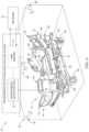
- FIG. 1is a perspective view of a patient support apparatus and an incontinence detection and notification system according to the present disclosure
- FIG. 2is a diagrammatic view of the incontinence detection and location system of FIG. 1 including an incontinence detection pad and an ultra-wideband communication system;
- FIG. 3is a diagrammatic view of another incontinence detection and location system similar to the system shown in FIG. 2 ;
- FIG. 4is a diagrammatic view of the patient support apparatus of FIG. 1 with a patient diagnostic patch
- FIG. 5is a diagrammatic flow chart of a process of analyzing data transmitted through the ultra-wideband communication system
- FIG. 6is a perspective view of the patient support apparatus and another incontinence detection and notification system according to the present disclosure
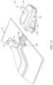
- FIG. 7is a perspective view of a clip-on wireless tag in a closed position in accordance with the present disclosure.
- FIG. 8is a perspective view of the wireless tag in an opened position
- FIG. 9is an exploded assembly view of the wireless tag
- FIG. 10is another perspective view of the wireless tag
- FIG. 11is a perspective view similar to FIG. 10 with a portion of the wireless tag removed to show a plurality of conductive contacts;
- FIG. 12is a perspective view showing the wireless tag being positioned to attach to an incontinence detection pad
- FIG. 13is a perspective view showing the wireless tag positioned over the top of the incontinence detection pad
- FIG. 14is a perspective view showing the wireless tag in contact with a plurality of traces included in the incontinence detection pad
- FIG. 15is a perspective view showing the wireless tag applying a compressive force on the incontinence detection pad
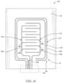
- FIG. 16is a top plane view of the incontinence detection pad
- FIG. 17is a diagrammatic view of another embodiment of an incontinence detection system.
- FIG. 18is a diagrammatic view of another embodiment of an incontinence detection system.
- a patient support apparatus 12is illustratively embodied as a hospital bed.
- the patient support apparatusmay include a stretcher, cot, operating table, support table, patient recliner, chair, wheelchair, or other structures used to support a patient.
- the patient support apparatus 12 in the illustrative embodimentis located in a healthcare facility. In other embodiments, the patient support apparatus may be located in a remote location such as the patient's home or another acute care environment outside of a healthcare facility.
- the patient support apparatus 12includes a frame 14 , a mattress 16 supported on the frame 14 .
- An example of a suitable frame 14 and mattress 16is shown and described in U.S. Patent Pub. No. 2018/0184984 which is expressly incorporated by reference herein for the purpose of describing a suitable patient support apparatus with a frame and mattress along with associated functions and capabilities of the frame and mattress.
- An incontinence detection and location system 10is coupled to the patient support apparatus 12 and is configured to determine an incontinence state of a patient supported on the patient support apparatus.
- the term “incontinence” as used hereinis intended to cover all biofluids such as blood, urine, fecal matter, interstitial fluid, saline, or any other fluid having a large concentration of ions that easily conduct electricity.
- the incontinence detection and location system 10includes an incontinence detection pad 18 and an ultra-wideband (UWB) communication system 20 as shown in FIG. 1 .
- the incontinence detection pad 18is coupled with the mattress 16 in the illustrative embodiment. In other embodiments, the incontinence detection pad 16 may be coupled to the frame 14 or may be coupled to one or more intervening structures between the mattress 16 and the incontinence detection pad 16 .
- the UWB communication system 20is communicatively coupled to the incontinence detection pad 18 and is configured to transfer data between the incontinence detection pad 18 and/or the patient support apparatus 12 and a network 22 .
- the incontinence detection pad 18is positioned on the hospital bed 10 , as suggested in FIG. 1 , for surveillance for unwanted incontinence fluids or other biofluids that may be produced by a patient.
- the incontinence detection pad 18may be removed and replaced without replacing the entire mattress 16 if the patient experiences an incontinence event.
- An example of a suitable incontinence detection pad with a condition-responsive sensoris shown and described in U.S. Patent Pub. Nos. 2017/0065464, U.S. Patent Pub. No. 2018/0021184, and U.S. Patent Pub. No. 2019/0060137, each of which is expressly incorporated by reference herein for the purpose of describing a suitable incontinence detection pad with one or more sensors for determining the incontinence status of the incontinence detection pad 18 .
- the incontinence detection pad 18includes a condition-responsive sensor 24 and a substrate 25 as shown diagrammatically in FIG. 2 .
- the condition responsive sensor 24is configured to provide incontinence signals in the presence of incontinence fluids to indicate that an incontinence event has occurred on the incontinence detection pad 18 .
- the substrate 25may include one or more absorbent layers to retain the incontinence fluid and one or more moisture-barrier layers to block the incontinence fluid from reaching the mattress 16 .
- the condition-responsive sensor 18is integrated into the substrate 25 of the incontinence detection pad 18 between one or more of the layers forming the substrate.
- the condition-responsive sensor 24overlays the substrate 25 and is permeable to incontinence fluids.
- the substrate 25absorbs and retains fluids therein while the condition-responsive sensor 24 senses the fluids on and/or in the incontinence detection pad 18 .
- the patient support apparatus 12is positioned in a room with a plurality of walls.
- the UWB communication system 20includes one or more ultra-wideband readers 26 coupled to the walls of the room at various locations and an ultra-wideband tag 28 coupled to the patient support apparatus 12 in communication with the condition-responsive sensor 24 .
- the UWB tag 28is configured to provide signals to readers 26 in proximity to the UWB tag 28 in response to the conditions sensed on the incontinence detection pad 18 by the condition-responsive sensor 24 .
- the condition-responsive sensor 24may include a detection grid 40 and an RFID tag 42 coupled to the detection grid 40 .
- the detection grid 40has a plurality of electrically conductive traces printed on or fitted in the substrate 25 of the incontinence detection pad 18 .
- the plurality of tracesallow for an estimation of a volume of fluid on the incontinence detection pad 18 .
- the RFID tag 42is illustratively a passive RFID tag with an antenna and integrated circuitry.
- the RFID tag 42is periodically excited by the UWB reader 26 or the UWB tag 28 and transmits an input signal associated with a sensed value across the detection grid 40 .
- the sensed valuechanges depending on whether moisture is present or absent from the incontinence detection pad 18 and, hence, changes the input signal that is provided by the RFID tag 42 .
- the incontinence fluidis absorbed into the substrate 25 of the incontinence detection pad 18 and interconnects two or more of the electrically conductive traces of the detection grid 40 .
- the signal provided by the RFID tag 42 to the UWB tag 28indicates the presence of moisture and the UWB tag 28 outputs an incontinence signal to the one or more UWB readers 26 which is processed and relayed through the UWB communication system 20 to network 22 .
- the UWB tag 28itself may be coupled to the detection grid 40 and the RFID tag 42 may be removed as shown in FIGS. 6 and 9 .
- the system 10is able to detect an incontinence fluid, determine that an incontinence event has occurred, and report the incontinence event through the UWB communication system 20 to hospital caregivers, a nurse call system, or an EMR (electronic medical record) system to allow patients to be quickly removed from the soiled environment.
- the sensor 24communicates wirelessly with the UWB communication system 20 .
- a wired connectionis provided between the sensor and the UWB communication system 20 .
- the RFID tag 42is a distinct flap that extends away from the incontinence detection pad 18 and hangs below a surface 44 of the mattress 16 .
- the RFID tag 42is contiguous with an outer perimeter of the incontinence detection pad 18 .
- the RFID tag 42is kept out from under a patient that may lay on top of the incontinence detection pad 18 and disrupt signals to and from the RFID tag 42 .
- the UWB tag 28is illustratively coupled to a foot end 74 of the patient support apparatus 12 adjacent to the RFID tag 42 . This arrangement increases signal strength between the UWB tag 28 and the RFID tag 42 .
- condition-responsive sensor 224may be used in place of condition-responsive sensor 24 shown in FIG. 2 .
- the condition-responsive sensor 224is similar to condition-responsive sensor 24 except condition-responsive sensor 224 includes an ohmic sensor 242 instead of RFID tag 42 .
- the ohmic sensor 242is coupled directly to the UWB tag 28 and a detection grid 240 with a reusable electronics package.
- the detection grid 240includes a plurality of electrically conducive traces and the ohmic sensor 242 is configured to measure a resistance between each of the traces and provide a signal to the UWB tag 28 indicative of a resistive value. As moisture is introduced onto the incontinence detection pad 18 the resistive value changes.
- the signals transmitted by the UWB tag 28 to the UWB reader 26also change in response to the moisture which indicates that an incontinence event has occurred.
- the UWB tags 28 and readers 26also cooperate to provide a locating system, sometimes referred to as a real time locating system (RTLS) in the art, that tracks the location of the incontinence detection pad 18 throughout the healthcare facility.
- RTLSreal time locating system
- the locating systemis embodied as a high-accuracy locating system such as an ultra-wideband locating system, but this need not be the case in other embodiments of high-accuracy locating systems such as those using radio detection and ranging (RADAR) equipment or cameras and/or other imaging equipment.
- RADARradio detection and ranging
- the UWB communication system 20includes the one or more UWB readers 26 , the UWB tag 28 , and a controller 30 as shown in FIG. 2 .
- the controller 30may also be referred to as a central hub computer or server for the UWB communication system 20 .
- the controller 30is communicatively coupled to each of the readers 26 and includes a microprocessor 32 and a memory storage device 34 coupled to the microprocessor 32 .
- the memory storage device 34is programmed with instructions that, when executed, allow the controller 30 to control operations of the incontinence detection and location system 10 .
- the UWB readers 26receive location signals (or pings) from UWB tag 28 .
- the location signals from the UWB tag 28include a tag identification (ID) which is unique to each UWB tag 28 and allows the controller to determine which UWB tag 28 is providing the signals.
- each of the UWB reader's 26include a reader ID that correlates to particular locations in the healthcare facility.
- the controller 30determines the locations of UWB tag 28 within the healthcare facility by correlating the tag ID's with the reader ID's and, ultimately, with the location correlated with the reader ID's.
- the portion of system 10 that operates as a high-accuracy locating system using UWB technologyis able to determine the location of each UWB tag 28 within about one foot (30.48 cm) or less of the tag's actual location.
- the locating systemis able to determine the location of each UWB tag 28 that is in communication with at least three of UWB readers 26 within about three feet (91.44 cm) or less of the tag's actual location and such embodiments are still considered to be high-accuracy locating systems according to the present disclosure.
- the UWB tag 28is configured as a UWB transceiver, and the UWB readers 26 are configured as UWB transceivers.
- the UWB readers 26are stationary and the UWB tag 28 are mobile, but their circuitry otherwise may be substantially the same.
- UWB tag 28 and UWB readers 26each include a housing 48 , 50 that contains associated circuitry 52 , 54 .
- the circuitry 52 , 54 of UWB tag 28 and UWB readers 26includes, for example, a processor such as a microprocessor or microcontroller or the like, memory for storing software, and communications circuitry including at least one transmitter, receiver, and antenna.
- UWB readers 26each include mounting hardware (not shown), such as brackets or plates or the like, in some embodiments, to permit the UWB readers 26 to be mounted at fixed locations in the patient rooms and other locations of the healthcare facility with fasteners such as screws or the like.
- the UWB tag 28also includes suitable mounting hardware to permit the UWB tag 28 to be mounted to the patient support apparatus 12 .
- the UWB tag 28may further include a power source 56 such as a battery as shown in FIGS. 2 and 3 .
- the UWB tag 28is also configured to provide battery-life signals which are relayed to the controller 30 for monitoring.
- the controller 30monitors the battery-life signals and is configured to output a command signal when a battery life of the power source 56 reaches a predetermined threshold. This notifies a caregiver or a technician that the power source 56 should be replaced to avoid any disruptions in the UWB communication system 20 .
- the batterymay be recharged when the controller determines that the battery life has reached the predetermined threshold.
- the batterymay be recharged wirelessly such as by inductive charging, radio charging, resonance charging, or any other suitable recharging method.
- the UWB communication system 20 in the present disclosuremay be referred to as an ultra-low power system.
- the power source 56may have a battery life of at least a year, although, the battery life may change with the frequency of pings the UWB tag 28 and/or the system 10 has been designed to provide.
- the UWB tag 28may receive power from a direct connection with the patient support apparatus 12 or another location in the room such as a wall outlet or a power bank servicing other devices in the room.
- the UWB reader 26is directly connected to the controller 30 as shown in FIG. 2 .
- the UWB readers 26may be wirelessly connected to the controller 30 and capable of receiving and relaying data between the UWB tag 28 and the controller 30 .
- the UWB reader 26Upon receipt of the signals from the UWB tag 28 , the UWB reader 26 relays the signals to the controller 30 .
- the controller 30then processes the signals and provides outputs depending on the status of the incontinence detection pad 18 or other patient data signals transmitted through the UWB communication system 20 .
- the signals provided by the UWB tag 28include both incontinence data signals and location data signals associated with the incontinence detection pad 18 .
- the UWB tag 28is configured to provide means for transmitting a transmission including both the incontinence data signals and the location data signals to the UWB reader 26 simultaneously once an incontinence event occurs.
- the UWB communication system 20is also communicatively coupled to network 22 which may include various servers or computers of the healthcare facility, such as a nurse call server, an EMR server, or an admission/discharge/transfer (ADT) computer, just to name a few.
- Network 22also includes the infrastructure (e.g., wireless access points, Ethernet jacks such as RJ-45 connectors, wires, routers, gateways, etc.) provided in a healthcare facility used to communicate between various computer devices and servers (e.g., personal computers, servers, laptop computers, patient care equipment, etc.) that are coupled to the infrastructure.
- the various subsystems described hereininclude components that may communicate with each other using portions of network 22 .
- UWB readers 26communicate with controller 30 via portions of network 22 .
- the outputs provided by the controller 30may cause one or more alerts or notifications to be displayed so that a caregiver is notified that the patient has experienced an incontinence event and where the patient is located. The care giver may then timely respond to the alert or notification to address the situation.
- Such notificationmay be displayed on various devices, such as, an interface on the patient support apparatus, a monitor in the patient's room, a monitor at a nurse call station, a mobile device, or any other suitable device.
- an audible notificationmay be provided.
- various linesinterconnect the components associated with the UWB communication system 20 and the incontinence detection pad 18 .
- solid linesrepresent bidirectional communication over wired data links (including electrical wires or fiber optic data links) while dashed lines represent bidirectional communication over a wireless data link, at the discretion of the designer of the system.
- the UWB readers 26communicate wirelessly with the UWB tag 28 using radio frequency (RF). It is known that RF signals are able to pass through walls, ceilings, floors, and other objects such as people and equipment. Thus, according to this disclosure, it is not required that each patient room has a UWB reader 26 located therein in those embodiments of the locating system using RF communication.
- controller 30is programmed to use signals from only a subset of the plurality of UWB readers 26 to determine the location of any given locating UWB tag 28 .
- the subsetmay be determined based on signal strength of signals between the particular locating UWB tag 28 and the plurality of UWB readers 26 .
- the subsetmay include at least three UWB readers 26 from the plurality of UWB readers 26 having highest signal strength values as compared to others of the plurality of UWB readers 26 .
- the UWB tag 28may also provide means for transmitting any patient data signals or patient support apparatus signals to the UWB reader 26 .
- a patient diagnostic patch 60is provided and may be coupled to a patient to measure various vital signs of the patient.
- the patient diagnostic patch 60may also be coupled to the UWB tag 28 by a wired or wireless connection so that signals indicative of the vital signs of the patient are transmitted through the UWB communication system 20 along with the incontinence data signals and the location data signals (collectively, data signals).
- Such an arrangementminimizes an amount of connections from the patient and/or patient support apparatus by using only one presence through the UWB communication system 20 .
- This arrangementcan also save network traffic and may allow the UWB communication system 20 to be larger in terms of the number of nodes (i.e. patients, patient support apparatuses, rooms, buildings, etc.) and area it can cover throughout the healthcare facility. It should be appreciated that any number of devices or sensors may be coupled, wired or wirelessly, to the UWB tag 28 for transmission of their associated data signals through the UWB communication system 20 .
- the controller 30is configured to process the signals and output one or more command signals in response to the signals from the UWB tag 28 according to a process 100 .
- the processbegins at step 102 where the UWB tag 28 is kept in a deep-sleep mode to conserve power.
- the UWB tag 28is configured to wake-up at step 104 to communicate with the UWB reader 26 and/or the RFID tag 42 .
- the UWB tag 28receives periodic signals from transmitter circuitry of one or more of the UWB readers 26 and, in response, is awoken to provide the data signals to at least one of the UWB readers 26 .
- Such an arrangementpreserves battery life of UWB tag 28 because in some embodiments transmissions of tag ID's are only made by the UWB tag 28 when in communicative proximity of one or more UWB readers 26 and after receiving a request signal from at least one of the UWB readers 26 .
- UWB tag 28includes associated circuitry with preprogrammed instructions to wake up periodically on its own and transmit the data signals.
- the UWB tag 28may be woken up twice every minute, however any suitable interval may be used at the discretion of the system designer.
- short range wireless beacons or infrared transmittersare mounted at fixed locations throughout the healthcare facility and send a signal with a location ID to the UWB tag 28 when it is in the vicinity of the short range beacons and, in response to receipt of the signal, the UWB tag 28 is awoken and transmits the data signals to the UWB readers 26 .
- one or more UWB readers 26relay the signals to the controller 30 along with the received tag ID of the UWB tag 28 , a respective reader(s) ID and, if applicable, the location ID.
- the UWB tag 28receives an input signal from the condition-responsive sensor 24 , 224 at step 106 .
- the input signalin the illustrative embodiment is indicative of a resistive value between the plurality of traces included in the detection grid 40 . In other embodiments, other electrical values may be measured such as voltage or amperes.
- the input signalchanges depending on the presence or lack of an incontinence fluid on the incontinence detection pad 18 .
- the UWB tag 28may also be configured to receive other input signals from other devices or sensors (i.e. patient diagnostic patch 60 ) coupled to the patient support apparatus or the patient as previously described.
- the UWB tag 28receives all of the input signals and outputs a data signal to the UWB reader containing all of the information received from the input signals in the previous step 106 .
- the UWB reader 26relays the data signal to the controller 30 where the information in the data signal is analyzed. All of the data analyzed by the controller 30 may be output to the network 22 for incorporation in the patient's electronic medical record (EMR) at step 110 .
- EMRelectronic medical record
- the controller 30is configured to determine if the value associated with the incontinence data is outside of a threshold value at step 112 . This would indicate that an incontinence event has occurred. If the value associate with the incontinence data is not outside of the threshold (i.e.
- the UWB tag 28is instructed to return to sleep mode at step 102 .
- the UWB tag 28automatically returns to sleep mode after transmitting the data signal to the UWB reader 26 without any further input from the controller 30 .
- the controller 30is configured to determine the location of the incontinence detection pad 18 from the data signal at step 114 .
- the incontinence eventis also uploaded into the patient's EMR through the network 22 .
- Various data associated with the incontinence eventmay also be uploaded into the patient's EMR such as an estimation of the volume of incontinence fluid as determined by the controller 30 based on the information in the data signal.
- the controller 30is then configured to output a notification through the network 22 to indicate to a caregiver that the patient has experienced an incontinence event and to indicate the location of the incontinence detection pad 18 at step 116 .
- patient support apparatus 12has a bed frame 14 which includes a base frame 62 with casters 64 and an upper frame or patient support platform 66 .
- the patient support apparatus 12further includes a headboard 68 at a head end 70 , a footboard 72 at a foot end 74 , and side rails 76 , 78 coupled to the patient support platform 66 .
- a surface or mattress 16is supported on the patient support platform 66 and, in some embodiments, includes a plurality of inflatable support bladders as is well known in the art.
- Mattress 14has an upper surface 44 on which a patient lies. Additionally, the patient support platform 66 includes a number of mattress support sections that support the mattress 14 .
- the mattress support sectionsinclude a head section 80 , a seat section 82 , a thigh section 84 , and a foot section 86 .
- the head section 80 , the thigh section 84 , and the foot section 86are movable relative to the seat section 82 which, in some embodiments, is affixed to upper frame members of the patient support platform 66 .
- the head section 80may be pivotally raised and lowered relative to the seat section 82
- the thigh section 84may be pivotally raised and lowered relative to the seat section 82
- the foot section 86may be pivotally raised and lowered relative to the thigh section 84 and the seat section 82 .
- the UWB tag 28is shown being attached directly to the incontinence detection pad 18 and the RFID tag 42 has been removed.
- the UWB tag 28is coupled to the detection grid 40 of the incontinence detection pad 18 and is configured to communicate wirelessly with UWB readers 26 .
- the UWB tag 28is configured to output a transmission to the UWB readers 26 that includes one or both of incontinence data and location data.
- the data received by the UWB readers 26is then relayed to a UWB server 21 included in the UWB communication system 20 .
- the datamay then be routed to a network 22 , such as a nurse call system and/or a patient's EMR.
- each of the UWB readers 26is coupled to the UWB server 21 by a wired connection, however wireless communication of data from the UWB readers 26 to the UWB server 21 is also possible.
- Each UWB reader 26is coupled to the UWB server 21 by a RS-422 connector, however any suitable connector may be used such as a USB-A, USB-C, VGA, Ethernet, HDMI, etc.
- the UWB server 21is connected to the network 22 by a wired connection, however wireless communication of data from the UWB server 21 to the network 22 is also possible.
- the UWB server 21is coupled to the network 22 by a Ethernet connector, however any suitable connector may be used such as a USB-A, USB-C, VGA, HDMI, etc.
- the UWB tag 28is configured to determine an electrical voltage, resistance, capacitance and/or current (i.e. an electrical characteristic) through the detection grid 40 and emit a signal associated with the electrical voltage, resistance, capacitance and/or current.
- the UWB tag 28may provide a pulsed electrical current through the detection grid 40 at periodic intervals to sense when an incontinence event has occurred. The pulsed intervals may occur once every thirty seconds, however, any suitable time interval may be used.
- the UWB tag 28may also output a status signal to the UWB readers 26 in predetermined intervals to notify the system 20 that the incontinence pad 18 is still attached and dry, that the UWB tag 28 is still monitoring for incontinence events, and/or a battery charge level of the UWB tag 28 , for example.
- the intervals used for the status signalsmay be larger than the intervals used to sense for the incontinence event to increase a battery life of the UWB tag 28 .
- an exemplary UWB tag 28is shown as being a clip-on UWB tag 28 that may be attached removably to the incontinence detection pad 18 .
- the UWB tag 28 shown in FIGS. 7 - 11includes housing 48 , circuitry 52 , and power source 56 .
- the housing 48includes an upper shell 140 , a lower shell 142 , and an attachment lever 144 .
- the upper shell 140 and the lower shell 142define an interior space 146 that houses the circuitry 52 and the power source 56 as shown in FIG. 9 .
- the upper shell 140 and the lower shell 142provide a fluid-tight housing 48 for the circuitry 52 and the power source 56 so that the UWB tag 28 can be cleaned and reused.
- the attachment lever 144is coupled to at least one of the upper shell 140 and the lower shell 142 as shown in FIGS. 7 - 9 .
- the attachment lever 144is elastically deformable relative to the upper and lower shells 140 , 142 between an opened position, as shown in FIG. 8 , and a closed position, as shown in FIG. 7 . Flexing the attachment lever 144 increases a space 148 between the lower shell 142 and the attachment lever 144 so that the UWB tag 28 can be positioned on the incontinence detection pad 18 .
- the attachment lever 144is formed such that it returns to a closed position after being deformed.
- the attachment lever 144may be attached to the upper shell 140 or the lower shell 142 with a hinged connection such that the attachment lever 144 pivots about an axis relative to the upper and lower shells 140 , 142 .
- the attachment lever 144includes a flexible flange 150 , an attachment rib 152 , and an attachment magnet 154 as shown in FIG. 9 .
- the flexible flange 150is coupled to one of the upper shell 140 and lower shell 142 to locate the attachment lever 144 relative to the upper shell 140 and the lower shell 142 .
- the attachment rib 152protrudes away from the flexible flange 150 into the space 148 to increase grip on the incontinence detection pad 18 .
- the attachment magnet 154is coupled to a surface of the attachment rib 152 and is exposed to the space 148 .
- the attachment magnet 154is configured to interact with other portions of the UWB tag 28 to pull the attachment lever 144 toward the lower shell 142 and apply a compressive force on the incontinence detection pad 18 .
- the circuitry 52includes a circuit board 156 including a microprocessor, memory and one or more transceivers, a plurality of contacts 158 , and a plurality of spring clips 160 that correspond with the plurality of contacts 158 as shown in FIG. 9 .
- the plurality of contacts 156are positioned within respective openings 162 formed in the lower shell 142 .
- a lower end 164 of each contact 158is exposed to space 148 between the attachment lever 144 and the lower shell 142 .
- An upper end of each contact 158engages a respective spring clip 160 .
- the plurality of spring clips 160are mounted on the circuit board 156 to transfer electric signals from the contacts 158 to the circuit board 156 .
- the circuitry 52processes information received from the traces included in the detection grid 40 and determines if an incontinence event has occurred. In other embodiments, the circuitry 52 relays the information sensed on the detection grid 40 to the UWB readers 26 and controller 30 for processing to determine if an incontinence event has occurred.
- Each of the contacts 158corresponds with an individual electrical trace 41 included in the detection grid 40 of the incontinence detection pad 18 as shown in FIGS. 9 and 12 .
- Each of the contacts 158is also aligned with the attachment magnet 154 to provide areas for the attachment magnet 154 to attract and apply the compressive force on the incontinence detection pad 18 to help maintain engagement of the contacts 158 and the traces 41 .
- the lower shell 142 of the housing 48includes a body 165 and a pair of index tabs 166 that extend away from the body 165 toward the attachment lever 144 as shown in FIGS. 10 and 11 .
- the plurality of contacts 158are positioned between the index tabs 166 .
- the index tabs 166correspond with a pair of index apertures 168 formed in the incontinence detection pad 18 as shown in FIGS. 12 - 15 .
- a userdeforms the attachment lever 144 to the opened position as shown in FIG. 12 .
- the incontinence detection pad 18may then be position in the space 148 formed between the attachment lever 144 and the lower shell 142 as shown in FIG.
- the index tabs 166may then be aligned with and inserted into the index apertures 168 to position the contacts 158 in engagement with each trace 41 as shown in FIG. 14 .
- the attachment lever 144may then be released to return to the closed position so that the UWB tag 28 is attached to the incontinence detection pad 18 as shown in FIG. 15 .
- the UWB tag 28may further include an indicator light 170 to indicate a status of the UWB tag 28 or of conditions sensed on the incontinence detection pad 18 as shown in FIG. 15 .
- the indicator light 170is coupled to the upper shell 140 .
- the indicator light 170displays a first color (i.e. green) when the UWB tag 28 determines that the incontinence detection pad 18 is dry or that an incontinence event has not occurred.
- the indicator light 170may display a second color (i.e. orange) when the UWB tag 28 determines that the incontinence detection pad 18 is wet and an incontinence event has occurred.
- the indicator light 170displays the first color when the power source 56 has a charge level above a predetermined amount.
- the indicator light 170may display the second color when the charge level of the power source 56 is below the predetermined amount to indicate that the power source 56 should be replaced.
- the incontinence detection pad 18is shown with one or more layers of the substrate 25 removed to show the arrangement of traces 41 forming detection grid 40 .
- the traces 41 of the detection grid 40includes a peripheral detection loop 172 and a pair of interior detection branches 174 , 176 .
- the peripheral detection loop 172surrounds the interior detection branches 174 , 176 and includes an inner trace 178 and an outer trace 180 spaced apart from one another.
- Each interior detection branch 174 , 176includes an arm 182 , 184 and a plurality of fingers 186 , 188 extending from the arm 182 , 184 .
- Each of the plurality of fingers 186 , 188extends toward the opposite arm 182 , 184 that the fingers 186 , 188 are connected to. Each finger 186 , 188 is neighbored by fingers 186 , 188 of the opposite interior detection branch 174 , 176 . In the illustrative embodiment shown in FIG. 16 , an overall resistive value of the detection grid 40 decreases as more traces 41 are interconnected by fluid.
- the traces 41also include a trace link 190 that interconnects one of the interior detection branches (i.e. 176 ) and inner trace 178 of the peripheral detection loop 172 .
- the detection grid 40 of the incontinence detection pad 18may allow the UWB tag 28 and/or the controller 30 to determine if an incontinence event has occurred by analyzing a sensed rate of change of resistance of the detection grid 40 .
- the UWB tag 28is configured to determine a first resistance of the detection grid at a first point in time and is configured to determine a second resistance of the detection grid at a second point in time.
- the circuitry of the UWB tag 28may then compare the first resistance to the second resistance and provide incontinence signals indicating that the incontinence event has occurred only when a rate of change of the resistance of the detection grid 40 exceeds a predetermined rate of change.
- the UWB tag 28may continuously sense the resistance or periodically awake and sense the resistance.
- the UWB tag 28may only sense the resistance and report the resistance at each point in time to an external controller where the resistance values are compared to determine the rate of change of resistance.
- external controllersinclude controller 30 or the circuitry of another device, like patient support apparatus 12 .
- the peripheral loop 172 and each interior detection branch 174 , 176provide a plurality of detection zones on the incontinence detection pad 18 . These zones may allow the incontinence detection pad 18 to distinguish between non-incontinence fluids (i.e. sweat) and incontinence fluids based on the sensed rate of change of the resistance. For example, if only the inner trace 178 and the outer trace 180 of the peripheral loop 172 are interconnected by a fluid, the UWB tag 28 or controller 30 may determine that an incontinence event has not occurred because only a small amount of fluid is on the incontinence detection pad 18 and/or near an outer edge of the pad 18 .
- non-incontinence fluidsi.e. sweat
- the UWB tag 28 or controller 30may determine that an incontinence event has not occurred because only a small amount of fluid is on the incontinence detection pad 18 and/or near an outer edge of the pad 18 .
- the UWB tag 28 or controller 30may determine that an incontinence event has occurred due to the sudden presence of a large amount of fluid in a generally central area of the detection grid 40 . If the fingers 186 , 188 and the peripheral loop 172 are interconnected by fluid, the UWB tag 28 or the controller 30 may determine that an excessive incontinence event has occurred and that the fluid may have reached the patient's bed sheets, which should now be changed. A separate and different alert may be sent to the nurse call station for each of these examples and for other examples which the detection grid 40 may allow to be sensed.
- any suitable wireless meansmay be used to communicate data signals such as Bluetooth, Bluetooth LE, Zigbee, WIFI, or a custom wireless protocol, for example.
- Such systemsmay not include UWB readers 26 , UWB tag 28 , or controller 30 . Instead, such systems may include a wireless tag that is configured to communicate with a device that has its own connection to the network 22 or a nurse call system, such as patient support apparatus 12 . Two illustrative examples of a system with this configuration are described below with reference to FIGS. 17 and 18 .
- an incontinence detection system 300includes an incontinence detection pad 318 and a communication system 320 .
- the incontinence detection pad 318is configured to rest on the mattress 16 shown in FIGS. 1 and 4 in the illustrative embodiment.
- the communication system 320is communicatively coupled to the incontinence detection pad 318 and is configured to transfer data between the incontinence detection pad 318 and a patient support apparatus 312 which is then relayed to a network 322 , such as a nurse call system.
- the incontinence detection pad 318includes a substrate 325 that absorbs incontinence fluid and a detection grid 340 coupled to the substrate 325 .
- the substrate 325is substantially similar to substrates 25 , 225 described above.
- the detection grid 340is substantially similar to detection grids 40 , 240 described above.
- the communication system 320includes a Bluetooth module 326 coupled to the patient-support apparatus 312 and in wireless communication with a wireless tag 328 coupled to the incontinence detection pad 318 .
- the tag 328communicates wirelessly with circuitry 330 included in the patient-support apparatus 312 as shown in FIG. 17 .
- the Bluetooth module 326is coupled to the circuitry 330 and includes an antenna 327 to receive and relay signals from the tag 328 to the circuitry 330 .
- the Bluetooth module 326 and the wireless tag 328communicate using Bluetooth signals, it should be appreciated that any type of signal may be used.
- the wireless tag 328may be a clip-on tag such as UWB tag 28 described above.
- the wireless tag 328is coupled to the detection grid 340 and is configured to output signals in response to conditions (i.e. the presence of moisture) present on the incontinence detection pad 318 .
- the signals output from the wireless tag 328are received by the antenna 327 of the Bluetooth module 326 .
- the circuitry 330includes a microprocessor 332 and memory 334 and is configured to process the signals to determine if an incontinence event has occurred.
- the circuitry 330also includes a relay or switch 336 that closes if the signals indicate that an incontinence event has occurred. With the relay 336 closed, an incontinence event signal is provided to a nurse call system 322 .
- the incontinence event signalis transferred through a wired connection including a first connector 352 coupled to the patient support apparatus 12 and a second connector 354 coupled to a wall 355 . From the second connector 354 the incontinence event signal is transferred to the nurse call system 322 .
- the circuitry 330 of the patient support apparatus 312may also include location data that is transmitted with the incontinence event signal.
- incontinence detection system 300is configured to detect an incontinence event and determine the location of the incontinence event.
- the wireless tag 328includes its own microprocessor 329 and memory 331 and determines whether an incontinence event has occurred on its own. Once an incontinence event is determined to have occurred, a signal indicating the event is communicated to the Bluetooth module 326 and routed to the nurse call system 322 as described above.
- an incontinence detection system 400includes an incontinence detection pad 418 and a communication system 420 .
- the incontinence detection pad 418is configured to rest on the mattress 16 shown in FIGS. 1 and 4 in the illustrative embodiment.
- the communication system 420is communicatively coupled to the incontinence detection pad 418 and is configured to transfer data between the incontinence detection pad 418 and a patient support apparatus 412 which is then relayed to a network 422 or a nurse call system 423 .
- the incontinence detection pad 418includes a substrate 425 that absorbs incontinence fluid and a detection grid 440 coupled to the substrate 425 .
- the substrate 425is substantially similar to substrates 25 , 225 described above.
- the detection grid 440is substantially similar to detection grids 40 , 240 described above.
- the communication system 420includes a Bluetooth module 426 coupled to the patient-support apparatus 412 and in wireless communication with a wireless tag 428 coupled to the incontinence detection pad 418 .
- the tag 428communicates wirelessly with circuitry 430 included in the patient-support apparatus 412 as shown in FIG. 18 .
- the Bluetooth module 426is coupled to the circuitry 430 and includes an antenna 427 to receive and relay signals from the tag 428 to the circuitry 330 .
- the Bluetooth module 426 and the wireless tag 428communicate using Bluetooth signals, it should be appreciated that any type of signal may be used.
- the wireless tag 428may be a clip-on tag such as UWB tag 28 described above.
- the wireless tag 428is coupled to the detection grid 440 and is configured to output signals in response to conditions (i.e. the presence of moisture) present on the incontinence detection pad 418 .
- the signals output from the wireless tag 428are received by the antenna 427 of the Bluetooth module 426 .
- the circuitry 330includes a microprocessor 432 and memory 434 and is configured to process the signals to determine if an incontinence event has occurred.
- the circuitry 430also includes a WIFI module 436 that outputs an incontinence event signal wirelessly to a wireless access point (WAP) 452 which is then routed to a nurse call system 423 through network 422 .
- the circuitry 430 of the patient support apparatus 412may also include location data that is transmitted with the incontinence event signal.
- incontinence detection system 400is configured to detect an incontinence event and determine the location of the incontinence event.
- the wireless tag 428includes its own microprocessor 429 and memory 431 and determines whether an incontinence event has occurred on its own. Once an incontinence event is determined to have occurred, a signal indicating the event is communicated to the Bluetooth module 426 and routed to the nurse call system 432 as described above.
- the system 10 , 200 , 300 , 400 disclosed hereinmay lower the cost of the disposable pad 18 , 218 , 318 , 418 by eliminating the RFID tag 42 .
- another means of communicating the status of the incontinence padmay be provided.
- the wired incontinence detector or tag 28 , 328 , 428may be battery powered by a primary lithium battery which may or may not be replaceable or rechargeable.
- patient sweatingmay be distinguished from an incontinence event.
- excessive patient sweatingcan sometimes look very similar to an incontinence event (i.e. if there is a fixed threshold for determining an incontinence event and discerning a wet or dry pad).
- One way to distinguish between patient sweating and an incontinence eventis to look at the time rate of change of sensed resistance in detection grid 40 to determine whether there is a sudden application of a conductive, incontinence biofluid or whether the deposition of the biofluid is sweat which may have a lower time rate of change compared to the incontinence biofluid.
- Sweatis also conductive and in sufficient quantity, may be difficult to distinguish if only looking at a single snapshot in time of the sensed resistance of the incontinence grid.
- a low power communications channelavailable between the remote sensing device and the nursecall connected medical device (i.e. a hospital bed 12 , 312 , 412 ).
- the nursecall connected medical devicei.e. a hospital bed 12 , 312 , 412 .
- the wall-powered devicei.e. a hospital bed
- a wired nurse call relay closure or circuit closureupon detection of an incontinence event which is conveyed across the low power wireless link. If it is desired to transmit the raw resistance data from the sensor instead of actually conveying over the wireless connection the incontinence event, determination of an incontinence event can be determined by the electronics on the hospital bed 12 , 312 , 412 which can then assert a wired nurse call signal to a nurse call station 22 , 322 , 422 to indicate that an incontinence event has occurred.
- the calculation and determination of an incontinence eventcan be accomplished on the incontinence sensor and communicated over the wireless link without any intervention of the remote medical device (bed, typically) for the assertion of the nurse call output to flag the incontinence event.
- the incontinence eventis determined based on measurement of the time rate of change of the sensed pad resistance.
- Low power wireless linkfor conveying either incontinence event occurrence or incontinence grid resistance data to another medical device, typically a hospital bed; Remote calculation (at hospital bed or other medical device or network) of incontinence detection threshold based on sensed resistance data conveyed across the wireless RF link; Local calculation (sensing) (on a battery powered device 28 , 328 , 428 ) of incontinence event; Low power wireless sensor 28 , 328 , 428 coupled with wired nurse call or other event responsive system to alert caregivers of a high priority health event such as (but not limited to) an incontinence event.
- the present disclosuremay simultaneously achieve three goals: Provide a bed-agnostic incontinence solution which does not require expensive capital equipment installs on the hospital bed, enable the use of much less expensive incontinence pads which can essentially be printed and assembled without the RFID tag, and also reduce the manufacturing cost of the pads by removing the need for the barrier layer intended to block sweat by transforming the incontinence indication from a binary function to more of a continuous, time varying response that can be read and transmitted to indicate not just the presence of an incontinence event, but also the volume of fluid expelled by the patient.
- a low-power locating transponder 28 , 328 , 428is used.
- the transponder 28 , 328 , 428may be an Ultra Wide Band (UWB) transceiver capable of resolving its own location to within 10 cm and enabling precise correlation to a bed in a room and a patient within a multi-patient ward.
- UWBUltra Wide Band
- a low-power analog resistance sensing circuitwhich measures the resistance between one or more conductive incontinence grids 40 , 172 , 174 , 176 on the back sheet of the incontinence pad 18 , 318 , 418 is used.
- This circuitmay be utilized to measure the relative resistance between the electrodes of the detection grid 40 as a function of time to allow the differentiation of sweat vs. urinary or certain types of fecal incontinence.
- the detection grid 40 geometrycan also help indicate either the volume or physical location of the incontinence event. For instance, one of the many incontinence detection zones present on the pad could be the periphery of the pad, indicating that the event has crossed the boundary of the pad and the patient's bedsheets may need to be changed.
Landscapes
- Health & Medical Sciences (AREA)
- Epidemiology (AREA)
- Engineering & Computer Science (AREA)
- Biomedical Technology (AREA)
- Heart & Thoracic Surgery (AREA)
- Vascular Medicine (AREA)
- Life Sciences & Earth Sciences (AREA)
- Animal Behavior & Ethology (AREA)
- General Health & Medical Sciences (AREA)
- Public Health (AREA)
- Veterinary Medicine (AREA)
- Orthopedics, Nursing, And Contraception (AREA)
- Absorbent Articles And Supports Therefor (AREA)
Abstract
Description
Claims (17)
Priority Applications (2)
| Application Number | Priority Date | Filing Date | Title |
|---|---|---|---|
| US17/195,023US12048613B2 (en) | 2019-09-30 | 2021-03-08 | Incontinence detection system |
| EP21164916.5AEP4056156B1 (en) | 2021-03-08 | 2021-03-25 | Incontinence detection system |
Applications Claiming Priority (3)
| Application Number | Priority Date | Filing Date | Title |
|---|---|---|---|
| US201962908001P | 2019-09-30 | 2019-09-30 | |
| US17/027,881US11712186B2 (en) | 2019-09-30 | 2020-09-22 | Incontinence detection with real time location information |
| US17/195,023US12048613B2 (en) | 2019-09-30 | 2021-03-08 | Incontinence detection system |
Related Parent Applications (1)
| Application Number | Title | Priority Date | Filing Date |
|---|---|---|---|
| US17/027,881Continuation-In-PartUS11712186B2 (en) | 2019-09-30 | 2020-09-22 | Incontinence detection with real time location information |
Publications (2)
| Publication Number | Publication Date |
|---|---|
| US20210205151A1 US20210205151A1 (en) | 2021-07-08 |
| US12048613B2true US12048613B2 (en) | 2024-07-30 |
Family
ID=76654153
Family Applications (1)
| Application Number | Title | Priority Date | Filing Date |
|---|---|---|---|
| US17/195,023Active2042-10-12US12048613B2 (en) | 2019-09-30 | 2021-03-08 | Incontinence detection system |
Country Status (1)
| Country | Link |
|---|---|
| US (1) | US12048613B2 (en) |
Families Citing this family (1)
| Publication number | Priority date | Publication date | Assignee | Title |
|---|---|---|---|---|
| US11903746B2 (en)* | 2020-06-25 | 2024-02-20 | Hill-Rom Services, Inc. | Incontinence prediction systems and methods |
Citations (175)
| Publication number | Priority date | Publication date | Assignee | Title |
|---|---|---|---|---|
| GB145859A (en) | 1919-03-31 | 1920-06-30 | William Charles Vinten | Improvements in kinematographic cameras |
| US1772232A (en) | 1927-12-06 | 1930-08-05 | Jesse S Van Guilder | Alarm |
| US2127538A (en) | 1936-09-26 | 1938-08-23 | Harry W Seiger | Signaling device |
| US2644050A (en) | 1951-12-27 | 1953-06-30 | Seiger Harry Wright | Enuresis bed pad |
| US2668202A (en) | 1952-08-02 | 1954-02-02 | Benjamin D Kaplan | Moisture responsive signaling device |
| US2726294A (en) | 1951-01-30 | 1955-12-06 | Health Guardian Corp | Devices for giving an alarm upon bed wetting |
| US2907841A (en) | 1958-06-10 | 1959-10-06 | Kenneth E Campbell | Signal device |
| US3199095A (en) | 1960-10-05 | 1965-08-03 | Ashida Hiroo | Absorbed-moisture alarm utilizing electrolytic action by special galvanic couple |
| US3971371A (en) | 1975-05-27 | 1976-07-27 | Stanley Bloom | Urine-sensing pad |
| US4069817A (en) | 1976-08-25 | 1978-01-24 | Fenole Joseph E | Body waste detecting device |
| US4106001A (en) | 1977-05-12 | 1978-08-08 | Kurt Mahoney | Moisture detector |
| US4163449A (en) | 1977-09-30 | 1979-08-07 | Regal Robert A | Enuresis treatment device |
| US4191950A (en) | 1978-02-09 | 1980-03-04 | Levin Anne F | Anti-bed-wetting device |
| US4212295A (en) | 1978-05-12 | 1980-07-15 | Nite Train-R Enterprises, Inc. | Moisture responsive pad for treatment of enuresis |
| US4228426A (en) | 1978-09-29 | 1980-10-14 | Roberts William A | Hospital bed monitor |
| US4347503A (en) | 1981-02-17 | 1982-08-31 | Health Guardian Company | Bedwetting detection device |
| GB2145859A (en) | 1983-08-30 | 1985-04-03 | Kek How Ng | Lift urine/wetting alarm system |
| US4539559A (en) | 1982-03-29 | 1985-09-03 | Hugh Kelly | Portable, disposable warning device for detecting urine-wet undergarments |
| US4747166A (en) | 1987-05-15 | 1988-05-31 | Kuntz David H | Fluid aspiration system for the management of urinary incontinence |
| EP0335279A1 (en) | 1988-03-29 | 1989-10-04 | Willy Drückler | Cushioned body for a bed for a person suffering from incontinence |
| WO1989010110A1 (en) | 1988-04-22 | 1989-11-02 | Erkki Vetri | Bedding, in particular for persons unable to move |
| US4965554A (en) | 1987-07-21 | 1990-10-23 | Darling John E | Moisture presence alarm system |
| US5081422A (en) | 1990-09-07 | 1992-01-14 | Ishiang Shih | Methods for roof, wall or floor leak detection |
| US5086294A (en) | 1988-05-10 | 1992-02-04 | Omron Tateisi Electronics Co. | Indicator circuit for protecting light emitting diode |
| DE4137631A1 (en) | 1990-11-22 | 1992-05-27 | Sieglinda Fuchs | Mattress joggler for sleeper who snores - uses air pump to tilt up mattress beneath sleeper and has sound sensor to initiate operation |
| US5137033A (en) | 1991-07-15 | 1992-08-11 | Norton John L | Patient monitoring device |
| US5144284A (en) | 1991-05-22 | 1992-09-01 | Hammett Rawlings H | Patient-monitoring bed covering device |
| US5291181A (en) | 1992-03-30 | 1994-03-01 | Deponte Dominic A | Wet bed alarm and temperature monitoring system |
| WO1994020002A1 (en) | 1993-03-09 | 1994-09-15 | Inter Care A/S | A sheet, and an assembly comprising a sheet and a mat conveyor |
| US5438721A (en) | 1991-11-13 | 1995-08-08 | Ssi Medical Services, Inc. | Apparatus and method for managing waste from patient care, maintenance and treatment |
| US5459452A (en) | 1992-03-30 | 1995-10-17 | Deponte; Dominic A. | Wet bed and patient wander alarm system with snap-on and magnet transmitter assembly |
| US5491609A (en) | 1994-02-28 | 1996-02-13 | Telepad | Portable electronic platform system |
| US5537095A (en) | 1993-10-29 | 1996-07-16 | Hill-Rom Company, Inc. | Incontinence detection device |
| US5675854A (en) | 1996-12-27 | 1997-10-14 | Zibelin; Henry S. | Mattress apparatus |
| US5760694A (en) | 1996-05-07 | 1998-06-02 | Knox Security Engineering Corporation | Moisture detecting devices such as for diapers and diapers having such devices |
| US5790035A (en) | 1995-08-02 | 1998-08-04 | Ho; Geng Kaung | Reusable temperature and wetness alarm device for the diaper |
| US5824883A (en) | 1996-07-16 | 1998-10-20 | Samsung Display Devices Co., Ltd. | Battery leakage sensing system |
| US5910080A (en) | 1996-08-19 | 1999-06-08 | Selton; Daniel E. | Therapeutic bedding pad |
| US5947943A (en) | 1998-02-02 | 1999-09-07 | Lee; Frances Meiling | Diaper visual indicator |
| US5949332A (en) | 1998-04-21 | 1999-09-07 | Jae-hoon Kim | Fire alarm radio transmitter and receiver set |
| US6028241A (en) | 1998-06-24 | 2000-02-22 | Armstead; Kenneth W. | Patient underpad |
| US6047419A (en) | 1999-04-01 | 2000-04-11 | Ferguson; Patricia A. | Maternal positioning support system |
| WO2000044091A2 (en) | 1999-01-20 | 2000-07-27 | Rf Code, Inc. | Antenna system for radio frequency identification |
| US6104311A (en) | 1996-08-26 | 2000-08-15 | Addison Technologies | Information storage and identification tag |
| WO2001025817A2 (en) | 1999-10-02 | 2001-04-12 | Rf Code, Inc. | System for determining item orientation and identification |
| US6292102B1 (en) | 1999-07-22 | 2001-09-18 | Bed-Check Corporation | Apparatus for detecting enuresis in a patient |
| WO2001085085A2 (en) | 2000-05-05 | 2001-11-15 | Hill-Rom Services, Inc. | Remote control for a hospital bed |
| US20020002633A1 (en) | 2000-06-23 | 2002-01-03 | Colling John K. | Event notification system |
| US6341393B1 (en) | 1995-09-13 | 2002-01-29 | Ergodyne Corporation | Patient transfer and repositioning system |
| US6351215B2 (en) | 1998-06-02 | 2002-02-26 | Rf Code, Inc. | Monitoring antenna system |
| US6384728B1 (en) | 2000-03-17 | 2002-05-07 | Toys For Special Children, Inc. | Personal care monitoring system |
| US20020145526A1 (en) | 2001-03-30 | 2002-10-10 | Augmentech, Inc. | Patient positioning monitoring apparatus and method of use thereof |
| WO2002103645A2 (en) | 2001-06-14 | 2002-12-27 | Rf Code, Inc. | Wireless identification system and protocol |
| US6544200B1 (en) | 2001-08-31 | 2003-04-08 | Bed-Check Corporation | Electronic patient monitor with automatically configured alarm parameters |
| US6552661B1 (en) | 2000-08-25 | 2003-04-22 | Rf Code, Inc. | Zone based radio frequency identification |
| US6583722B2 (en) | 2000-12-12 | 2003-06-24 | Kimberly-Clark Worldwide, Inc. | Wetness signaling device |
| US6603403B2 (en) | 2000-12-12 | 2003-08-05 | Kimberly-Clark Worldwide, Inc. | Remote, wetness signaling system |
| US6832507B1 (en) | 1998-09-11 | 2004-12-21 | Telesensing Holding B.V. | System for detecting the presence of moisture |
| US20050003763A1 (en) | 2003-07-03 | 2005-01-06 | Rotani, Inc. | Methods and apparatus for high throughput multiple radio wireless cells and networks |
| US20050060246A1 (en) | 2003-07-11 | 2005-03-17 | Roc Lastinger | System, method, and computer program product for monitoring inventory |
| US20050099294A1 (en) | 2003-08-05 | 2005-05-12 | Bogner James T. | System for managing conditions |
| GB2408204A (en) | 2003-11-21 | 2005-05-25 | Ucl Biomedica Plc | Mattress protection |
| US6933849B2 (en) | 2002-07-09 | 2005-08-23 | Fred Sawyer | Method and apparatus for tracking objects and people |
| US6948205B2 (en) | 2001-01-05 | 2005-09-27 | Beter Bed Holding N.V. | Mattress, provided with spring elements, such as coil springs |
| US20050242946A1 (en) | 2002-10-18 | 2005-11-03 | Hubbard James E Jr | Patient activity monitor |
| US20050277441A1 (en) | 2004-06-15 | 2005-12-15 | Rotani, Inc. | Method and apparatus for creating shpaed antenna radiation patterns |
| US7017213B2 (en) | 2004-04-19 | 2006-03-28 | Joseph Chisari | Stomach sleeper |
| US7071830B2 (en) | 2001-07-06 | 2006-07-04 | Bioett Ab | Moisture sensor |
| US20060164320A1 (en) | 2005-01-21 | 2006-07-27 | Rotani, Inc. | Method and apparatus for an antenna module |
| US20060208886A1 (en) | 2005-03-01 | 2006-09-21 | Static Control Components, Inc. | Systems and methods for providing packages with RFID tags |
| US7120952B1 (en) | 2004-01-20 | 2006-10-17 | Beverly Bass | Incontinence protective device |
| WO2006108540A1 (en) | 2005-04-12 | 2006-10-19 | Dankmar Olbertz | Bedding device for a person, and bed comprising a bedding device |
| US20060270351A1 (en) | 2004-06-15 | 2006-11-30 | Rotani, Inc. | Method and apparatus for increasing data throughput |
| US20060279427A1 (en) | 2005-03-29 | 2006-12-14 | Stryker Canadian Management, Inc. | Location detection system for a patient handling device |
| US7181206B2 (en) | 2001-10-11 | 2007-02-20 | Lyndale Trading Company Ltd. | Broadband communication platform and methods of network operation |
| WO2007069968A1 (en) | 2005-12-16 | 2007-06-21 | Sca Hygiene Products Ab | Method and system for associating a reading of a machine readable sensor positioned in an absorbent article with the identity of a user |
| US20070159332A1 (en)* | 2006-01-07 | 2007-07-12 | Arthur Koblasz | Using RFID to prevent or detect falls, wandering, bed egress and medication errors |
| US7250547B1 (en) | 2000-11-07 | 2007-07-31 | Rf Technologies, Inc. | Wetness monitoring system |
| US7253729B2 (en) | 2002-07-09 | 2007-08-07 | Rf Code, Inc. | Wireless vending communication systems |
| US20070202809A1 (en) | 2006-02-28 | 2007-08-30 | Rotani, Inc. | Methods and apparatus for overlapping MIMO antenna physical sectors |
| US20070270774A1 (en) | 2004-11-03 | 2007-11-22 | Frederick Bergman | Incontinence management system and diaper |
| US7348930B2 (en) | 2005-01-21 | 2008-03-25 | Rotani, Inc. | Method and apparatus for a radio transceiver |
| US7355090B2 (en) | 2005-08-31 | 2008-04-08 | Kimberly-Clark Worldwide, Inc. | Method of detecting the presence of insults in an absorbent article |
| US20080116990A1 (en) | 2006-11-18 | 2008-05-22 | Rfmicron, Inc. | Method and apparatus for varying an impedance |
| US20080204245A1 (en) | 2007-02-28 | 2008-08-28 | Blair William A | Method, apparatus and article for detection of transponder tagged objects, for example during surgery |
| US20080262376A1 (en) | 2007-04-17 | 2008-10-23 | Proactive Health Devices, Inc. | Wireless sensor system for monitoring skin condition using the body as communication conduit |
| US20080263776A1 (en) | 2007-04-30 | 2008-10-30 | Span-America Medical Systems, Inc. | Low air loss moisture control mattress overlay |
| WO2008130298A1 (en) | 2007-04-20 | 2008-10-30 | Sca Hygiene Products Ab | Method and system for associating an absorbent article with a user. |
| EP2014267A1 (en) | 2007-06-15 | 2009-01-14 | Intensia NV | Universal wet garment detector |
| EP2019659A1 (en) | 2006-05-02 | 2009-02-04 | Fred Bergman Healthcare Pty Ltd | Moisture monitoring system |
| US7489252B2 (en) | 2006-04-26 | 2009-02-10 | Kimberly-Clark Worldwide, Inc. | Wetness monitoring systems with status notification system |
| US7498478B2 (en) | 2005-08-31 | 2009-03-03 | Kimberly-Clark Worldwide, Inc. | Method of detecting the presence of an insult in an absorbent article |
| DE102007050074A1 (en) | 2007-10-19 | 2009-04-30 | Rainer Mittl | Incontinence pad for use by e.g. paralyzed patient, has leg and buttock protection elements attached at feculence layer for covering body-areas or parts of anogenital region and lower body-areas or parts in partial or complete manner |
| US20090160648A1 (en) | 2007-12-24 | 2009-06-25 | Rfmicron, Inc. | Method and apparatus for bulk calibrating RFID tags |
| US7595756B2 (en) | 2005-11-01 | 2009-09-29 | Rotani, Inc. | Methods and apparatus for improving wireless communication by antenna polarization position |
| US7595734B2 (en) | 2006-04-26 | 2009-09-29 | Kimberly-Clark Worldwide, Inc. | Wetness monitoring systems with power management |
| US7599699B2 (en) | 2005-11-01 | 2009-10-06 | Rotani, Inc. | Method and apparatus for client control of wireless communications |
| US7598862B2 (en) | 2006-12-16 | 2009-10-06 | Roc2Loc, Inc. | Methods and apparatus for security device coupling |
| US20090292265A1 (en) | 2006-02-01 | 2009-11-26 | Commonwealth Scientific And Industrial Research Organization | Moisture monitor system for diapers and alike |
| US20090315728A1 (en) | 2008-06-20 | 2009-12-24 | Ales Iii Thomas Michael | Method of reducing sensor corrosion in absorbent articles |
| US20090326417A1 (en) | 2008-06-30 | 2009-12-31 | Ales Iii Thomas M | Multifunctional Monitoring Device for Absorbent Articles |
| US7649125B2 (en) | 2005-08-31 | 2010-01-19 | Kimberly-Clark Worldwide, Inc. | Method of detecting the presence of an insult in an absorbent article and device for detecting the same |
| US7663483B2 (en) | 2006-12-16 | 2010-02-16 | Roc2Loc, Inc. | Methods and apparatus for security device portal sensing |
| US7667600B2 (en) | 2006-12-16 | 2010-02-23 | Roc2Loc, Inc. | Methods and apparatus for security device removal detection |
| US20100060452A1 (en)* | 2008-09-05 | 2010-03-11 | DearlerMesh, Inc. | Using a mesh of radio frequency identification tags for tracking entities at a site |
| WO2010043368A1 (en) | 2008-10-13 | 2010-04-22 | Gavin Armstrong | Moisture sensor assembly |
| US7812731B2 (en) | 2006-12-22 | 2010-10-12 | Vigilan, Incorporated | Sensors and systems for detecting environmental conditions or changes |
| US7834234B2 (en) | 2005-04-07 | 2010-11-16 | The Procter & Gamble Company | Absorbent article having a wetness event counter |
| US7834235B2 (en) | 2006-08-31 | 2010-11-16 | Kimberly-Clark Worldwide, Inc. | System for interactively training a child and a caregiver to assist the child to overcome bedwetting |
| US7849544B2 (en) | 2007-06-18 | 2010-12-14 | Hill-Rom Industries Sa | Support device of the mattress type comprising a heterogeneous inflatable structure |
| US20110025458A1 (en) | 2009-08-01 | 2011-02-03 | Rfmicron, Inc. | Method and apparatus for authenticating rfid tags |
| US20110092890A1 (en) | 2009-10-20 | 2011-04-21 | Stryker Corporation | Microclimate management system |
| US20110115635A1 (en) | 2009-05-06 | 2011-05-19 | Dusko Petrovski | Control schemes and features for climate-controlled beds |
| WO2011107580A1 (en) | 2010-03-04 | 2011-09-09 | Heinrich Essers Gmbh & Co. Kg | Pad, in particular for use in the nursing care and hospital fields |
| US20110283459A1 (en) | 2009-02-05 | 2011-11-24 | Heinz-Willy Essers | Mattress, in particular for use in the care and hospital sector |
| US20110295619A1 (en) | 2010-05-25 | 2011-12-01 | Fred Bergman Healthcare Pty Ltd | System for managing patient assessment |
| US20110291810A1 (en) | 2006-11-18 | 2011-12-01 | Rfmicron, Inc. | Method and Apparatus for Detecting RF Field Strength |
| US20110300808A1 (en) | 2006-11-18 | 2011-12-08 | Rfmicron, Inc. | Method and Apparatus for Detecting RF Field Strength |
| US20110302720A1 (en) | 2010-06-12 | 2011-12-15 | American Home Health Care, Inc. | Patient weighing and bed exit monitoring |
| US20110309937A1 (en) | 2006-12-22 | 2011-12-22 | Vigilan, Incorporated | Sensors and systems for detecting environmental conditions or changes |
| US8104126B2 (en) | 2007-10-18 | 2012-01-31 | Hill-Rom Industries Sa | Method of inflating, in alternating manner, a support device having inflatable cells, and a device for implementing the method |
| US8106782B2 (en) | 2002-11-21 | 2012-01-31 | Secumanagement B.V. | Method and device for fall prevention and detection |
| US8111165B2 (en) | 2002-10-02 | 2012-02-07 | Orthocare Innovations Llc | Active on-patient sensor, method and system |
| US8121856B2 (en) | 2005-06-28 | 2012-02-21 | Hill-Rom Services, Inc. | Remote access to healthcare device diagnostic information |
| US20120092027A1 (en) | 2010-10-18 | 2012-04-19 | Avery Dennison Corporation | RFID Wetness Sensing Device |
| EP2444039A1 (en) | 2010-08-26 | 2012-04-25 | Medline Industries, Inc. | Disposable Absorbent Lift Device |
| EP2452183A1 (en) | 2009-07-09 | 2012-05-16 | Salusion IP B.V. | A moisture detecting module and a receiving unit |
| US20120119915A1 (en) | 2006-10-30 | 2012-05-17 | International Business Machines Corporation | Self-powered rfid tag activated by a fluid |
| US8181290B2 (en) | 2008-07-18 | 2012-05-22 | Amerigon Incorporated | Climate controlled bed assembly |
| US20120130330A1 (en) | 2010-11-19 | 2012-05-24 | Wilson Richard R | Stacked moisture sensing device |
| US8191187B2 (en) | 2009-08-31 | 2012-06-05 | Amerigon Incorporated | Environmentally-conditioned topper member for beds |
| CN102568259A (en) | 2010-12-31 | 2012-07-11 | 东莞市中科教育电子有限公司 | A story machine with an infant urine wet alarm function |
| US20120217311A1 (en) | 2006-11-18 | 2012-08-30 | Rfmicron, Inc. | Roll-To-Roll Production of RFID Tags |
| EP2496197A1 (en) | 2009-11-06 | 2012-09-12 | Fred Bergman Healthcare Pty Ltd | Improvements in incontinence monitoring and assessment |
| WO2012136157A1 (en) | 2011-07-29 | 2012-10-11 | 卓越进科技(深圳)有限公司 | Wireless bedwetting alarm and disposable diaper product |
| CN202711437U (en) | 2012-06-18 | 2013-01-30 | 卓越进科技(深圳)有限公司 | Wireless enuresis alarm and paper diaper product corresponding to same |
| CN102985853A (en) | 2010-06-04 | 2013-03-20 | 帝创有限公司 | Defecation/urination detection system and method |
| US20130079590A1 (en) | 2011-03-21 | 2013-03-28 | Bradley P. Bengtson | Multipurpose surgical spongepads, devices, systems, and methods |
| US8428605B2 (en) | 2001-10-11 | 2013-04-23 | Innovative Wireless Sweden Ab | Adaptive broadband platforms and methods of operation |
| EP2582341A1 (en) | 2010-06-16 | 2013-04-24 | Fred Bergman Healthcare Pty Ltd | Apparatus and method for analysing events from sensor data by optimization |
| US20130109929A1 (en) | 2011-10-28 | 2013-05-02 | Mindray Ds Usa, Inc. | Systems and methods for patient monitors to automatically identify patients |
| US20130123726A1 (en) | 2011-11-16 | 2013-05-16 | Industrial Technology Research Institute | Radio frequency identification tag and diaper, absorber and sensing system using the same |
| US8482305B2 (en) | 2010-08-11 | 2013-07-09 | Apple Inc. | Mechanisms for detecting exposure to water in an electronic device |
| US20130189946A1 (en) | 2012-01-19 | 2013-07-25 | Numerex Corp. | Security System Alarming and Processing Based on User Location Information |
| US20130233924A1 (en)* | 2012-03-06 | 2013-09-12 | Christopher J. Burns | Smartcard and Computer Quick Connect and Release System |
| US20140070950A1 (en) | 2012-09-12 | 2014-03-13 | Ultraclenz, Llc | Sanitization Compliance Monitoring System |
| EP2729107A1 (en) | 2011-07-06 | 2014-05-14 | Fred Bergman Healthcare Pty Ltd | Improvements relating to event detection algorithms |
| US20140148772A1 (en) | 2012-11-28 | 2014-05-29 | Kang Na Hsiung Enterprise Co., Ltd. | Absorbent pad, absorbent article, and method for manufacturing an absorbent pad |
| EP2739254A1 (en) | 2011-08-01 | 2014-06-11 | Fred Bergman Healthcare Pty Ltd | A capacitive wetness sensor and method for manufacturing the same |
| US20140200538A1 (en) | 2011-07-20 | 2014-07-17 | Etect, Inc. | Wetness sensors, wetness monitoring system, and related methods |
| US20140236629A1 (en) | 2013-02-19 | 2014-08-21 | Hill-Rom Services, Inc. | Direct patient association |
| US20140247125A1 (en) | 2011-08-16 | 2014-09-04 | Lili Loni Barsky | Liability Intervention Logistical Innovation System and Method |
| US20140266735A1 (en) | 2013-03-14 | 2014-09-18 | Nicolas A. Riggio | Wireless diaper alarm system |
| WO2014165041A2 (en) | 2013-03-13 | 2014-10-09 | Hill-Rom Services, Inc. | Methods and apparatuses for the detection of incontinence or other moisture, methods of fluid analysis, and multifunctional sensor systems |
| US8878557B2 (en) | 2009-05-01 | 2014-11-04 | Linak A/S | Electrode arrangement for monitoring a bed |
| US8878676B2 (en) | 2006-05-16 | 2014-11-04 | Gt Angel, Llc | Healthcare workstations and RFID devices for detecting medication errors |
| US20140358099A1 (en) | 2013-05-30 | 2014-12-04 | Children's Healthcare Of Atlanta | RF Backscatter Sensor for Measuring Moisture and Other Biological Data |
| US8914923B2 (en) | 2012-01-04 | 2014-12-23 | Dean Preston Smith | Assemblies for managing incontinence |
| US8933292B2 (en) | 2011-10-28 | 2015-01-13 | Kimberly-Clark Worldwide, Inc. | Absorbent article with sensor array for body exudate detection |
| US20150080819A1 (en) | 2013-09-14 | 2015-03-19 | SingLi Technology Inc. | Diaper structure capable of wirelessly detecting a soaking wet condition thereof and diaper detection system of the same |
| US20150080834A1 (en) | 2005-08-26 | 2015-03-19 | Medline Industries, Inc. | Absorbent article |
| US20150076221A1 (en) | 2009-05-22 | 2015-03-19 | Berntsen International, Inc. | System, method and monument for land surveying |
| US20150087935A1 (en) | 2013-09-23 | 2015-03-26 | Alice McKinstry Davis | Real-time blood detection system |
| US20150164438A1 (en) | 2008-05-12 | 2015-06-18 | Earlysense Ltd. | Monitoring, predicting and treating clinical episodes |
| WO2015137999A1 (en) | 2014-03-12 | 2015-09-17 | Hill-Rom Services, Inc. | Method and apparatus for the detection of moisture and multifunctional sensor system |
| US20150286852A1 (en)* | 2014-04-06 | 2015-10-08 | Trackblue, Llc | Wireless Medication Compliance Sensing Device, System, and Related Methods |
| US20160089059A1 (en)* | 2014-09-30 | 2016-03-31 | Darma Inc. | Systems and methods for posture and vital sign monitoring |
| US20160157755A1 (en) | 2005-11-07 | 2016-06-09 | Stryker Corporation | Patient handling device including local status indication, one-touch fowler angle adjustment, and power-on alarm configuration |
| US20170098044A1 (en) | 2015-10-06 | 2017-04-06 | Convergence Systems Limited | Medical pad and a wetness reporting system with such a medical pad |
| US20170309115A1 (en) | 2006-10-06 | 2017-10-26 | Cfph, Llc | Apparatus for pari-mutuel racing game with finish order betting |
| US20180021184A1 (en)* | 2015-11-16 | 2018-01-25 | Hill-Rom Services, Inc. | Incontinence detection apparatus |
| US10115291B2 (en) | 2016-04-26 | 2018-10-30 | Hill-Rom Services, Inc. | Location-based incontinence detection |
| WO2019036155A1 (en) | 2017-08-17 | 2019-02-21 | Welch Allyn, Inc. | Patient monitoring system |
| US20210275773A1 (en)* | 2016-07-29 | 2021-09-09 | Thomas Jefferson University | Circadian-friendly and distance-responsive lighting system |
| US11712186B2 (en)* | 2019-09-30 | 2023-08-01 | Hill-Rom Services, Inc. | Incontinence detection with real time location information |
- 2021
- 2021-03-08USUS17/195,023patent/US12048613B2/enactiveActive
Patent Citations (281)
| Publication number | Priority date | Publication date | Assignee | Title |
|---|---|---|---|---|
| GB145859A (en) | 1919-03-31 | 1920-06-30 | William Charles Vinten | Improvements in kinematographic cameras |
| US1772232A (en) | 1927-12-06 | 1930-08-05 | Jesse S Van Guilder | Alarm |
| US2127538A (en) | 1936-09-26 | 1938-08-23 | Harry W Seiger | Signaling device |
| US2726294A (en) | 1951-01-30 | 1955-12-06 | Health Guardian Corp | Devices for giving an alarm upon bed wetting |
| US2644050A (en) | 1951-12-27 | 1953-06-30 | Seiger Harry Wright | Enuresis bed pad |
| US2668202A (en) | 1952-08-02 | 1954-02-02 | Benjamin D Kaplan | Moisture responsive signaling device |
| US2907841A (en) | 1958-06-10 | 1959-10-06 | Kenneth E Campbell | Signal device |
| US3199095A (en) | 1960-10-05 | 1965-08-03 | Ashida Hiroo | Absorbed-moisture alarm utilizing electrolytic action by special galvanic couple |
| US3971371A (en) | 1975-05-27 | 1976-07-27 | Stanley Bloom | Urine-sensing pad |
| US4069817A (en) | 1976-08-25 | 1978-01-24 | Fenole Joseph E | Body waste detecting device |
| US4106001A (en) | 1977-05-12 | 1978-08-08 | Kurt Mahoney | Moisture detector |
| US4163449A (en) | 1977-09-30 | 1979-08-07 | Regal Robert A | Enuresis treatment device |
| US4191950A (en) | 1978-02-09 | 1980-03-04 | Levin Anne F | Anti-bed-wetting device |
| US4212295A (en) | 1978-05-12 | 1980-07-15 | Nite Train-R Enterprises, Inc. | Moisture responsive pad for treatment of enuresis |
| US4228426A (en) | 1978-09-29 | 1980-10-14 | Roberts William A | Hospital bed monitor |
| US4347503A (en) | 1981-02-17 | 1982-08-31 | Health Guardian Company | Bedwetting detection device |
| US4539559A (en) | 1982-03-29 | 1985-09-03 | Hugh Kelly | Portable, disposable warning device for detecting urine-wet undergarments |
| GB2145859A (en) | 1983-08-30 | 1985-04-03 | Kek How Ng | Lift urine/wetting alarm system |
| US4747166A (en) | 1987-05-15 | 1988-05-31 | Kuntz David H | Fluid aspiration system for the management of urinary incontinence |
| US4965554A (en) | 1987-07-21 | 1990-10-23 | Darling John E | Moisture presence alarm system |
| EP0335279A1 (en) | 1988-03-29 | 1989-10-04 | Willy Drückler | Cushioned body for a bed for a person suffering from incontinence |
| WO1989010110A1 (en) | 1988-04-22 | 1989-11-02 | Erkki Vetri | Bedding, in particular for persons unable to move |
| US5086294A (en) | 1988-05-10 | 1992-02-04 | Omron Tateisi Electronics Co. | Indicator circuit for protecting light emitting diode |
| US5081422A (en) | 1990-09-07 | 1992-01-14 | Ishiang Shih | Methods for roof, wall or floor leak detection |
| DE4137631A1 (en) | 1990-11-22 | 1992-05-27 | Sieglinda Fuchs | Mattress joggler for sleeper who snores - uses air pump to tilt up mattress beneath sleeper and has sound sensor to initiate operation |
| US5144284A (en) | 1991-05-22 | 1992-09-01 | Hammett Rawlings H | Patient-monitoring bed covering device |
| US5137033A (en) | 1991-07-15 | 1992-08-11 | Norton John L | Patient monitoring device |
| US5438721A (en) | 1991-11-13 | 1995-08-08 | Ssi Medical Services, Inc. | Apparatus and method for managing waste from patient care, maintenance and treatment |
| US5291181A (en) | 1992-03-30 | 1994-03-01 | Deponte Dominic A | Wet bed alarm and temperature monitoring system |
| US5459452A (en) | 1992-03-30 | 1995-10-17 | Deponte; Dominic A. | Wet bed and patient wander alarm system with snap-on and magnet transmitter assembly |
| WO1994020002A1 (en) | 1993-03-09 | 1994-09-15 | Inter Care A/S | A sheet, and an assembly comprising a sheet and a mat conveyor |
| US5537095A (en) | 1993-10-29 | 1996-07-16 | Hill-Rom Company, Inc. | Incontinence detection device |
| US5491609A (en) | 1994-02-28 | 1996-02-13 | Telepad | Portable electronic platform system |
| US5790035A (en) | 1995-08-02 | 1998-08-04 | Ho; Geng Kaung | Reusable temperature and wetness alarm device for the diaper |
| US6341393B1 (en) | 1995-09-13 | 2002-01-29 | Ergodyne Corporation | Patient transfer and repositioning system |
| US5760694A (en) | 1996-05-07 | 1998-06-02 | Knox Security Engineering Corporation | Moisture detecting devices such as for diapers and diapers having such devices |
| US5824883A (en) | 1996-07-16 | 1998-10-20 | Samsung Display Devices Co., Ltd. | Battery leakage sensing system |
| US5910080A (en) | 1996-08-19 | 1999-06-08 | Selton; Daniel E. | Therapeutic bedding pad |
| US6104311A (en) | 1996-08-26 | 2000-08-15 | Addison Technologies | Information storage and identification tag |
| US6621410B1 (en) | 1996-08-26 | 2003-09-16 | Rf Code, Inc. | System for item and orientation identification |
| US5675854A (en) | 1996-12-27 | 1997-10-14 | Zibelin; Henry S. | Mattress apparatus |
| US5947943A (en) | 1998-02-02 | 1999-09-07 | Lee; Frances Meiling | Diaper visual indicator |
| US5949332A (en) | 1998-04-21 | 1999-09-07 | Jae-hoon Kim | Fire alarm radio transmitter and receiver set |
| US7633378B2 (en) | 1998-06-02 | 2009-12-15 | Rf Code, Inc. | Object identification system with adaptive transceivers and methods of operation |
| US20020011932A1 (en) | 1998-06-02 | 2002-01-31 | Rf Code, Inc. | Object identification system with adaptive transceivers and methods of operation |
| US6831562B2 (en) | 1998-06-02 | 2004-12-14 | Rf Code, Inc. | Object identification system with adaptive transceivers and methods of operation |
| US6982646B2 (en) | 1998-06-02 | 2006-01-03 | Rf Code, Inc. | Object identification system with adaptive transceivers and methods of operation |
| US20050052282A1 (en) | 1998-06-02 | 2005-03-10 | Rodgers James L. | Radio frequency identification device |
| US6362737B1 (en) | 1998-06-02 | 2002-03-26 | Rf Code, Inc. | Object Identification system with adaptive transceivers and methods of operation |
| US20020033757A1 (en) | 1998-06-02 | 2002-03-21 | Rf Code, Inc. | Object identification system with adaptive transceivers and methods of operation |
| US6351215B2 (en) | 1998-06-02 | 2002-02-26 | Rf Code, Inc. | Monitoring antenna system |
| US6340932B1 (en) | 1998-06-02 | 2002-01-22 | Rf Code, Inc. | Carrier with antenna for radio frequency identification |
| US6028241A (en) | 1998-06-24 | 2000-02-22 | Armstead; Kenneth W. | Patient underpad |
| US6832507B1 (en) | 1998-09-11 | 2004-12-21 | Telesensing Holding B.V. | System for detecting the presence of moisture |
| WO2000044091A2 (en) | 1999-01-20 | 2000-07-27 | Rf Code, Inc. | Antenna system for radio frequency identification |
| DE69917491T2 (en) | 1999-01-20 | 2005-05-12 | RF Code, Inc., El Paso | DEVICE FOR IDENTIFICATION WITH RADIO FREQUENCIES |
| EP1153317A2 (en) | 1999-01-20 | 2001-11-14 | RF Code, Inc. | Method of interrogating a radio frequency identification device |
| EP1149305A2 (en) | 1999-01-20 | 2001-10-31 | RF Code, Inc. | Radio frequency identification device |
| DE69915370T2 (en) | 1999-01-20 | 2005-03-17 | RF Code, Inc., El Paso | ANTENNA SYSTEM FOR IDENTIFICATION WITH RADIO FREQUENCIES |
| CA2361145A1 (en) | 1999-01-20 | 2000-07-27 | Rf Code, Inc. | Object identification system with adaptive transceivers and method of operation |
| EP1147603A2 (en) | 1999-01-20 | 2001-10-24 | RF Code, Inc. | Antenna system for radio frequency identification |
| CA2494896A1 (en) | 1999-01-20 | 2000-07-27 | Rf Code, Inc. | Monitoring antenna system |
| EP1286179A2 (en) | 1999-01-20 | 2003-02-26 | RF Code, Inc. | Method of interrogating a radio frequency identification device |
| DE69906388T2 (en) | 1999-01-20 | 2004-02-12 | RF Code, Inc., El Paso | METHOD FOR INQUIRING A DEVICE FOR IDENTIFICATION WITH RADIO FREQUENCIES |
| US6047419A (en) | 1999-04-01 | 2000-04-11 | Ferguson; Patricia A. | Maternal positioning support system |
| US6292102B1 (en) | 1999-07-22 | 2001-09-18 | Bed-Check Corporation | Apparatus for detecting enuresis in a patient |
| EP1218771A2 (en) | 1999-10-02 | 2002-07-03 | RF Code, Inc. | System for determining item orientation and identification |
| DE60016946T2 (en) | 1999-10-02 | 2006-06-08 | RF Code, Inc., Mesa | DEVICE FOR ORIENTATION AND IDENTIFICATION OF OBJECTS |
| WO2001025817A2 (en) | 1999-10-02 | 2001-04-12 | Rf Code, Inc. | System for determining item orientation and identification |
| US6384728B1 (en) | 2000-03-17 | 2002-05-07 | Toys For Special Children, Inc. | Personal care monitoring system |
| US8487774B2 (en) | 2000-05-05 | 2013-07-16 | Hill-Rom Services, Inc. | System for monitoring caregivers and equipment |
| US8766804B2 (en) | 2000-05-05 | 2014-07-01 | Hill-Rom Services, Inc. | System for monitoring caregivers and equipment |
| WO2001085085A2 (en) | 2000-05-05 | 2001-11-15 | Hill-Rom Services, Inc. | Remote control for a hospital bed |
| US20020002633A1 (en) | 2000-06-23 | 2002-01-03 | Colling John K. | Event notification system |
| US6552661B1 (en) | 2000-08-25 | 2003-04-22 | Rf Code, Inc. | Zone based radio frequency identification |
| US7250547B1 (en) | 2000-11-07 | 2007-07-31 | Rf Technologies, Inc. | Wetness monitoring system |
| US6603403B2 (en) | 2000-12-12 | 2003-08-05 | Kimberly-Clark Worldwide, Inc. | Remote, wetness signaling system |
| US6583722B2 (en) | 2000-12-12 | 2003-06-24 | Kimberly-Clark Worldwide, Inc. | Wetness signaling device |
| US6948205B2 (en) | 2001-01-05 | 2005-09-27 | Beter Bed Holding N.V. | Mattress, provided with spring elements, such as coil springs |
| US6774800B2 (en) | 2001-03-30 | 2004-08-10 | Augmentech, Inc. | Patient incontinence monitoring apparatus and method of use thereof |
| US20020145526A1 (en) | 2001-03-30 | 2002-10-10 | Augmentech, Inc. | Patient positioning monitoring apparatus and method of use thereof |
| WO2002103645A2 (en) | 2001-06-14 | 2002-12-27 | Rf Code, Inc. | Wireless identification system and protocol |
| US20030030568A1 (en) | 2001-06-14 | 2003-02-13 | Roc Lastinger | Wireless identification systems and protocols |
| EP1410353A2 (en) | 2001-06-14 | 2004-04-21 | RF Code, Inc. | Wireless identification system and protocol |
| US7030731B2 (en) | 2001-06-14 | 2006-04-18 | Rf Code, Inc. | Wireless identification systems and protocols |
| US7071830B2 (en) | 2001-07-06 | 2006-07-04 | Bioett Ab | Moisture sensor |
| US6544200B1 (en) | 2001-08-31 | 2003-04-08 | Bed-Check Corporation | Electronic patient monitor with automatically configured alarm parameters |
| US8073386B2 (en) | 2001-10-11 | 2011-12-06 | Innovative Wireless Sweden Ab | Broadband communication platform and methods of network operation |
| US7181206B2 (en) | 2001-10-11 | 2007-02-20 | Lyndale Trading Company Ltd. | Broadband communication platform and methods of network operation |
| US8428605B2 (en) | 2001-10-11 | 2013-04-23 | Innovative Wireless Sweden Ab | Adaptive broadband platforms and methods of operation |
| US7834765B2 (en) | 2002-07-09 | 2010-11-16 | Automated Tracking Solutions, Llc | Method and apparatus for tracking objects and people |
| US8866615B2 (en) | 2002-07-09 | 2014-10-21 | Automated Tracking Solutions, Llc | Method and apparatus for tracking objects and people |
| US7253729B2 (en) | 2002-07-09 | 2007-08-07 | Rf Code, Inc. | Wireless vending communication systems |
| US7551089B2 (en) | 2002-07-09 | 2009-06-23 | Automated Tracking Solutions, Llc | Method and apparatus for tracking objects and people |
| US7834766B2 (en) | 2002-07-09 | 2010-11-16 | Automated Tracking Solutions, Llc | Method and apparatus for tracking objects and people |
| US8896449B2 (en) | 2002-07-09 | 2014-11-25 | Automated Tracking Solutions, Llc | Method and apparatus for tracking objects and people |
| US8279069B2 (en) | 2002-07-09 | 2012-10-02 | Automated Tracking Solutions, Llc | Method and apparatus for tracking objects and people |
| US8742929B2 (en) | 2002-07-09 | 2014-06-03 | Automated Tracking Solutions, Llc | Method and apparatus for tracking objects and people |
| US6933849B2 (en) | 2002-07-09 | 2005-08-23 | Fred Sawyer | Method and apparatus for tracking objects and people |
| US8842013B2 (en) | 2002-07-09 | 2014-09-23 | Automated Tracking Solutions, Llc | Method and apparatus for tracking objects and people |
| US8111165B2 (en) | 2002-10-02 | 2012-02-07 | Orthocare Innovations Llc | Active on-patient sensor, method and system |
| US20120119912A1 (en) | 2002-10-02 | 2012-05-17 | Orthocare Innovations Llc | Active on-patient sensor, method and system |
| US20050242946A1 (en) | 2002-10-18 | 2005-11-03 | Hubbard James E Jr | Patient activity monitor |
| US8106782B2 (en) | 2002-11-21 | 2012-01-31 | Secumanagement B.V. | Method and device for fall prevention and detection |
| US20050003763A1 (en) | 2003-07-03 | 2005-01-06 | Rotani, Inc. | Methods and apparatus for high throughput multiple radio wireless cells and networks |
| US7305246B2 (en) | 2003-07-03 | 2007-12-04 | Rotani, Inc. | Method and apparatus for high throughput multiple radio sectorized wireless cell |
| US20050250453A1 (en) | 2003-07-03 | 2005-11-10 | Rotani, Inc. | Method and apparatus for high throughput multiple radio sectorized wireless cell |
| US20050282553A1 (en) | 2003-07-03 | 2005-12-22 | Rotani, Inc. | Method and apparatus for high throughput multiple radio sectorized wireless cell |
| US7274944B2 (en) | 2003-07-03 | 2007-09-25 | Rotani, Inc. | Method and apparatus for high throughput multiple radio sectorized wireless cell |
| US20050282545A1 (en) | 2003-07-03 | 2005-12-22 | Rotani, Inc. | Method and apparatus for high throughput multiple radio sectorized wireless cell |
| US7302278B2 (en) | 2003-07-03 | 2007-11-27 | Rotani, Inc. | Method and apparatus for high throughput multiple radio sectorized wireless cell |
| US7359675B2 (en) | 2003-07-03 | 2008-04-15 | Rotani, Inc. | Methods and apparatus for high throughput multiple radio wireless cells and networks |
| US7308270B2 (en) | 2003-07-03 | 2007-12-11 | Rotani, Inc. | Method and apparatus for high throughput multiple radio sectorized wireless cell |
| US20050003865A1 (en) | 2003-07-03 | 2005-01-06 | Roc Lastinger | Method and apparatus for high throughput multiple radio sectorized wireless cell |
| US7873319B2 (en) | 2003-07-03 | 2011-01-18 | Rotani, Inc. | Methods and apparatus for channel assignment |
| US7424298B2 (en) | 2003-07-03 | 2008-09-09 | Rotani, Inc. | Methods and apparatus for channel assignment |
| US20050060246A1 (en) | 2003-07-11 | 2005-03-17 | Roc Lastinger | System, method, and computer program product for monitoring inventory |
| US20050099294A1 (en) | 2003-08-05 | 2005-05-12 | Bogner James T. | System for managing conditions |
| EP1684615A1 (en) | 2003-11-21 | 2006-08-02 | UCL Biomedica PLC | Mattress protection |
| GB2408204A (en) | 2003-11-21 | 2005-05-25 | Ucl Biomedica Plc | Mattress protection |
| US7120952B1 (en) | 2004-01-20 | 2006-10-17 | Beverly Bass | Incontinence protective device |
| US7017213B2 (en) | 2004-04-19 | 2006-03-28 | Joseph Chisari | Stomach sleeper |
| US7349701B2 (en) | 2004-06-15 | 2008-03-25 | Rotani, Inc. | Method and apparatus for creating shape antenna radiation patterns |
| US7400860B2 (en) | 2004-06-15 | 2008-07-15 | Rotani, Inc. | Method and apparatus for increasing data throughput |
| US7822386B2 (en) | 2004-06-15 | 2010-10-26 | Rotani, Inc. | Method and apparatus for increasing data throughput |
| US20060270351A1 (en) | 2004-06-15 | 2006-11-30 | Rotani, Inc. | Method and apparatus for increasing data throughput |
| US20050277441A1 (en) | 2004-06-15 | 2005-12-15 | Rotani, Inc. | Method and apparatus for creating shpaed antenna radiation patterns |
| US7616959B2 (en) | 2004-07-19 | 2009-11-10 | Rotani, Inc. | Method and apparatus for shaped antenna radiation patterns |
| US7977529B2 (en) | 2004-11-03 | 2011-07-12 | Fred Bergman Healthcare Pty Ltd. | Incontinence management system and diaper |
| US20110263952A1 (en) | 2004-11-03 | 2011-10-27 | Fred Bergman Healthcare Pty Ltd | Incontinence management system and diaper |
| US20070270774A1 (en) | 2004-11-03 | 2007-11-22 | Frederick Bergman | Incontinence management system and diaper |
| US9107776B2 (en) | 2004-11-03 | 2015-08-18 | Fred Bergman Healthcare Pty. Ltd. | Incontinence management system and diaper |
| US20060164320A1 (en) | 2005-01-21 | 2006-07-27 | Rotani, Inc. | Method and apparatus for an antenna module |
| US7348930B2 (en) | 2005-01-21 | 2008-03-25 | Rotani, Inc. | Method and apparatus for a radio transceiver |
| US7489282B2 (en) | 2005-01-21 | 2009-02-10 | Rotani, Inc. | Method and apparatus for an antenna module |
| US20060208886A1 (en) | 2005-03-01 | 2006-09-21 | Static Control Components, Inc. | Systems and methods for providing packages with RFID tags |
| US8461982B2 (en) | 2005-03-29 | 2013-06-11 | Stryker Corporation | Communication system for patient handling devices |
| US8674826B2 (en) | 2005-03-29 | 2014-03-18 | Stryker Corporation | Location detection system for a device |
| US8102254B2 (en) | 2005-03-29 | 2012-01-24 | Stryker Canadian Management, Inc. | Location detection system for a patient handling device |
| US20060279427A1 (en) | 2005-03-29 | 2006-12-14 | Stryker Canadian Management, Inc. | Location detection system for a patient handling device |
| US8319633B2 (en) | 2005-03-29 | 2012-11-27 | David Terrance Becker | Location detection system for a patient handling device |
| US7598853B2 (en) | 2005-03-29 | 2009-10-06 | Stryker Canadian Management, Inc. | Location detection system for a patient handling device |
| US7838720B2 (en) | 2005-04-07 | 2010-11-23 | The Procter & Gamble Company | Absorbent article having a wetness event counter |
| US7834234B2 (en) | 2005-04-07 | 2010-11-16 | The Procter & Gamble Company | Absorbent article having a wetness event counter |
| WO2006108540A1 (en) | 2005-04-12 | 2006-10-19 | Dankmar Olbertz | Bedding device for a person, and bed comprising a bedding device |
| EP1868553A1 (en) | 2005-04-12 | 2007-12-26 | Dankmar Olbertz | Bedding device for a person, and bed comprising a bedding device |
| EP1897278A1 (en) | 2005-06-21 | 2008-03-12 | Rotani Inc. | Method and apparatus for increasing data throughput |
| US8121856B2 (en) | 2005-06-28 | 2012-02-21 | Hill-Rom Services, Inc. | Remote access to healthcare device diagnostic information |
| US20150080834A1 (en) | 2005-08-26 | 2015-03-19 | Medline Industries, Inc. | Absorbent article |
| US7355090B2 (en) | 2005-08-31 | 2008-04-08 | Kimberly-Clark Worldwide, Inc. | Method of detecting the presence of insults in an absorbent article |
| US7649125B2 (en) | 2005-08-31 | 2010-01-19 | Kimberly-Clark Worldwide, Inc. | Method of detecting the presence of an insult in an absorbent article and device for detecting the same |
| US7498478B2 (en) | 2005-08-31 | 2009-03-03 | Kimberly-Clark Worldwide, Inc. | Method of detecting the presence of an insult in an absorbent article |
| US7599699B2 (en) | 2005-11-01 | 2009-10-06 | Rotani, Inc. | Method and apparatus for client control of wireless communications |
| US7595756B2 (en) | 2005-11-01 | 2009-09-29 | Rotani, Inc. | Methods and apparatus for improving wireless communication by antenna polarization position |
| US20160157755A1 (en) | 2005-11-07 | 2016-06-09 | Stryker Corporation | Patient handling device including local status indication, one-touch fowler angle adjustment, and power-on alarm configuration |
| WO2007069968A1 (en) | 2005-12-16 | 2007-06-21 | Sca Hygiene Products Ab | Method and system for associating a reading of a machine readable sensor positioned in an absorbent article with the identity of a user |
| EP1959900A1 (en) | 2005-12-16 | 2008-08-27 | SCA Hygiene Products AB | Method and system for associating a reading of a machine readable sensor positioned in an absorbent article with the identity of a user |
| US20070159332A1 (en)* | 2006-01-07 | 2007-07-12 | Arthur Koblasz | Using RFID to prevent or detect falls, wandering, bed egress and medication errors |
| US20090292265A1 (en) | 2006-02-01 | 2009-11-26 | Commonwealth Scientific And Industrial Research Organization | Moisture monitor system for diapers and alike |
| US8395014B2 (en) | 2006-02-01 | 2013-03-12 | Commonwealth Scientific And Industrial Research Organisation | Moisture monitor system for diapers and alike |
| US8855089B2 (en) | 2006-02-28 | 2014-10-07 | Helvetia Ip Ag | Methods and apparatus for overlapping MIMO physical sectors |
| US8270383B2 (en) | 2006-02-28 | 2012-09-18 | Rotani, Inc. | Methods and apparatus for overlapping MIMO physical sectors |
| EP1994650A2 (en) | 2006-02-28 | 2008-11-26 | Rotani Inc. | Methods and apparatus for overlapping mimo antenna physical sectors |
| US8428039B2 (en) | 2006-02-28 | 2013-04-23 | Rotani, Inc. | Methods and apparatus for overlapping MIMO physical sectors |
| US8345651B2 (en) | 2006-02-28 | 2013-01-01 | Rotani, Inc. | Methods and apparatus for overlapping MIMO antenna physical sectors |
| US8325695B2 (en) | 2006-02-28 | 2012-12-04 | Rotani, Inc. | Methods and apparatus for overlapping MIMO physical sectors |
| US8111678B2 (en) | 2006-02-28 | 2012-02-07 | Rotani, Inc. | Methods and apparatus for overlapping MIMO antenna physical sectors |
| US20070202809A1 (en) | 2006-02-28 | 2007-08-30 | Rotani, Inc. | Methods and apparatus for overlapping MIMO antenna physical sectors |
| US8009646B2 (en) | 2006-02-28 | 2011-08-30 | Rotani, Inc. | Methods and apparatus for overlapping MIMO antenna physical sectors |
| US7595734B2 (en) | 2006-04-26 | 2009-09-29 | Kimberly-Clark Worldwide, Inc. | Wetness monitoring systems with power management |
| US7489252B2 (en) | 2006-04-26 | 2009-02-10 | Kimberly-Clark Worldwide, Inc. | Wetness monitoring systems with status notification system |
| EP2019659A1 (en) | 2006-05-02 | 2009-02-04 | Fred Bergman Healthcare Pty Ltd | Moisture monitoring system |
| US8878676B2 (en) | 2006-05-16 | 2014-11-04 | Gt Angel, Llc | Healthcare workstations and RFID devices for detecting medication errors |
| US7834235B2 (en) | 2006-08-31 | 2010-11-16 | Kimberly-Clark Worldwide, Inc. | System for interactively training a child and a caregiver to assist the child to overcome bedwetting |
| US20170309115A1 (en) | 2006-10-06 | 2017-10-26 | Cfph, Llc | Apparatus for pari-mutuel racing game with finish order betting |
| US8248249B2 (en) | 2006-10-30 | 2012-08-21 | International Business Machines Corporation | Self-powered RFID tag activated by a fluid |
| US8237572B2 (en) | 2006-10-30 | 2012-08-07 | International Business Machines Corporation | Self-powered RFID tag activated by a fluid and method for using such RFID tags |
| US20120119915A1 (en) | 2006-10-30 | 2012-05-17 | International Business Machines Corporation | Self-powered rfid tag activated by a fluid |
| US20110291810A1 (en) | 2006-11-18 | 2011-12-01 | Rfmicron, Inc. | Method and Apparatus for Detecting RF Field Strength |
| US20090289743A1 (en) | 2006-11-18 | 2009-11-26 | Rfmicron, Inc. | Method and apparatus for varying an impedance |
| US8749319B2 (en) | 2006-11-18 | 2014-06-10 | Rfmicron, Inc. | Method and apparatus for detecting RF field strength |
| US8081043B2 (en) | 2006-11-18 | 2011-12-20 | Rfmicron, Inc. | Method and apparatus for varying an impedance |
| US20140120836A1 (en) | 2006-11-18 | 2014-05-01 | Rfmicron, Inc. | Method and Apparatus for Detecting RF Field Strength |
| US20120217311A1 (en) | 2006-11-18 | 2012-08-30 | Rfmicron, Inc. | Roll-To-Roll Production of RFID Tags |
| US20110300808A1 (en) | 2006-11-18 | 2011-12-08 | Rfmicron, Inc. | Method and Apparatus for Detecting RF Field Strength |
| US20080116990A1 (en) | 2006-11-18 | 2008-05-22 | Rfmicron, Inc. | Method and apparatus for varying an impedance |
| US9048819B2 (en) | 2006-11-18 | 2015-06-02 | RF Micron, Inc. | Method and apparatus for detecting RF field strength |
| US7586385B2 (en) | 2006-11-18 | 2009-09-08 | Rfmicron, Inc. | Method and apparatus for varying an impedance |
| US7663483B2 (en) | 2006-12-16 | 2010-02-16 | Roc2Loc, Inc. | Methods and apparatus for security device portal sensing |
| US7598862B2 (en) | 2006-12-16 | 2009-10-06 | Roc2Loc, Inc. | Methods and apparatus for security device coupling |
| US7667600B2 (en) | 2006-12-16 | 2010-02-23 | Roc2Loc, Inc. | Methods and apparatus for security device removal detection |
| US20110309937A1 (en) | 2006-12-22 | 2011-12-22 | Vigilan, Incorporated | Sensors and systems for detecting environmental conditions or changes |
| US8502684B2 (en) | 2006-12-22 | 2013-08-06 | Geoffrey J. Bunza | Sensors and systems for detecting environmental conditions or changes |
| US7812731B2 (en) | 2006-12-22 | 2010-10-12 | Vigilan, Incorporated | Sensors and systems for detecting environmental conditions or changes |
| US20080204245A1 (en) | 2007-02-28 | 2008-08-28 | Blair William A | Method, apparatus and article for detection of transponder tagged objects, for example during surgery |
| US20080262376A1 (en) | 2007-04-17 | 2008-10-23 | Proactive Health Devices, Inc. | Wireless sensor system for monitoring skin condition using the body as communication conduit |
| US20100072271A1 (en) | 2007-04-20 | 2010-03-25 | Robert Thorstensson | System and method for associating an absorbent article with a user |
| EP2156222A1 (en) | 2007-04-20 | 2010-02-24 | Sca Hygiene Products AB | Method and system for associating an absorbent article with a user |
| WO2008130298A1 (en) | 2007-04-20 | 2008-10-30 | Sca Hygiene Products Ab | Method and system for associating an absorbent article with a user. |
| US8196809B2 (en) | 2007-04-20 | 2012-06-12 | Sca Hygiene Products Ab | System and method for associating an absorbent article with a user |
| US20100043143A1 (en) | 2007-04-30 | 2010-02-25 | Span-America Medical Systems, Inc. | Low air loss moisture control mattress overlay |
| US20080263776A1 (en) | 2007-04-30 | 2008-10-30 | Span-America Medical Systems, Inc. | Low air loss moisture control mattress overlay |
| EP2014267A1 (en) | 2007-06-15 | 2009-01-14 | Intensia NV | Universal wet garment detector |
| US7849544B2 (en) | 2007-06-18 | 2010-12-14 | Hill-Rom Industries Sa | Support device of the mattress type comprising a heterogeneous inflatable structure |
| US8104126B2 (en) | 2007-10-18 | 2012-01-31 | Hill-Rom Industries Sa | Method of inflating, in alternating manner, a support device having inflatable cells, and a device for implementing the method |
| DE102007050074A1 (en) | 2007-10-19 | 2009-04-30 | Rainer Mittl | Incontinence pad for use by e.g. paralyzed patient, has leg and buttock protection elements attached at feculence layer for covering body-areas or parts of anogenital region and lower body-areas or parts in partial or complete manner |
| US20090160648A1 (en) | 2007-12-24 | 2009-06-25 | Rfmicron, Inc. | Method and apparatus for bulk calibrating RFID tags |
| US20150164438A1 (en) | 2008-05-12 | 2015-06-18 | Earlysense Ltd. | Monitoring, predicting and treating clinical episodes |
| US20090315728A1 (en) | 2008-06-20 | 2009-12-24 | Ales Iii Thomas Michael | Method of reducing sensor corrosion in absorbent articles |
| EP2313044A2 (en) | 2008-06-30 | 2011-04-27 | Kimberly-Clark Worldwide, Inc. | Multifunctional monitoring device for absorbent articles |
| US8628506B2 (en) | 2008-06-30 | 2014-01-14 | Kimberly-Clark Worldwide, Inc. | Multifunctional monitoring device for absorbent articles |
| US20090326417A1 (en) | 2008-06-30 | 2009-12-31 | Ales Iii Thomas M | Multifunctional Monitoring Device for Absorbent Articles |
| WO2010001271A2 (en) | 2008-06-30 | 2010-01-07 | Kimberly-Clark Worldwide, Inc. | Multifunctional monitoring device for absorbent articles |
| US8181290B2 (en) | 2008-07-18 | 2012-05-22 | Amerigon Incorporated | Climate controlled bed assembly |
| US20100060452A1 (en)* | 2008-09-05 | 2010-03-11 | DearlerMesh, Inc. | Using a mesh of radio frequency identification tags for tracking entities at a site |
| US8471706B2 (en)* | 2008-09-05 | 2013-06-25 | John Schuster | Using a mesh of radio frequency identification tags for tracking entities at a site |
| WO2010043368A1 (en) | 2008-10-13 | 2010-04-22 | Gavin Armstrong | Moisture sensor assembly |
| US20110283459A1 (en) | 2009-02-05 | 2011-11-24 | Heinz-Willy Essers | Mattress, in particular for use in the care and hospital sector |
| US8878557B2 (en) | 2009-05-01 | 2014-11-04 | Linak A/S | Electrode arrangement for monitoring a bed |
| US20110115635A1 (en) | 2009-05-06 | 2011-05-19 | Dusko Petrovski | Control schemes and features for climate-controlled beds |
| US20150076221A1 (en) | 2009-05-22 | 2015-03-19 | Berntsen International, Inc. | System, method and monument for land surveying |
| EP2452183A1 (en) | 2009-07-09 | 2012-05-16 | Salusion IP B.V. | A moisture detecting module and a receiving unit |
| US20120165772A1 (en) | 2009-07-09 | 2012-06-28 | Benno Groosman | Moisture detecting module and a receiving unit |
| US8962909B2 (en) | 2009-07-09 | 2015-02-24 | Salusion Ip B.V. | Moisture detecting module and a receiving unit |
| US20110025458A1 (en) | 2009-08-01 | 2011-02-03 | Rfmicron, Inc. | Method and apparatus for authenticating rfid tags |
| US20110025473A1 (en) | 2009-08-01 | 2011-02-03 | Rfmicron, Inc. | Method and apparatus for linking an rfid tag to an object |
| US8332975B2 (en) | 2009-08-31 | 2012-12-18 | Gentherm Incorporated | Climate-controlled topper member for medical beds |
| US8191187B2 (en) | 2009-08-31 | 2012-06-05 | Amerigon Incorporated | Environmentally-conditioned topper member for beds |
| US20110092890A1 (en) | 2009-10-20 | 2011-04-21 | Stryker Corporation | Microclimate management system |
| US20120268278A1 (en) | 2009-11-06 | 2012-10-25 | Fred Bergman Healthcare Pty Ltd | incontinence monitoring and assessment |
| EP2496197A1 (en) | 2009-11-06 | 2012-09-12 | Fred Bergman Healthcare Pty Ltd | Improvements in incontinence monitoring and assessment |
| EP2542200A1 (en) | 2010-03-04 | 2013-01-09 | Heinrich Essers GmbH & Co. KG | Pad, in particular for use in the nursing care and hospital fields |
| WO2011107580A1 (en) | 2010-03-04 | 2011-09-09 | Heinrich Essers Gmbh & Co. Kg | Pad, in particular for use in the nursing care and hospital fields |
| US20110295619A1 (en) | 2010-05-25 | 2011-12-01 | Fred Bergman Healthcare Pty Ltd | System for managing patient assessment |
| EP2579069A2 (en) | 2010-06-04 | 2013-04-10 | DTron Co., Ltd. | Defecation/urination detection system and method |
| CN102985853A (en) | 2010-06-04 | 2013-03-20 | 帝创有限公司 | Defecation/urination detection system and method |
| US20110302720A1 (en) | 2010-06-12 | 2011-12-15 | American Home Health Care, Inc. | Patient weighing and bed exit monitoring |
| EP2582341A1 (en) | 2010-06-16 | 2013-04-24 | Fred Bergman Healthcare Pty Ltd | Apparatus and method for analysing events from sensor data by optimization |
| US20130254141A1 (en) | 2010-06-16 | 2013-09-26 | Fred Bergman Healthcare Pty Ltd | Apparatus and method for analysing events from sensor data by optimisation |
| US8482305B2 (en) | 2010-08-11 | 2013-07-09 | Apple Inc. | Mechanisms for detecting exposure to water in an electronic device |
| EP2444039A1 (en) | 2010-08-26 | 2012-04-25 | Medline Industries, Inc. | Disposable Absorbent Lift Device |
| US20120092027A1 (en) | 2010-10-18 | 2012-04-19 | Avery Dennison Corporation | RFID Wetness Sensing Device |
| US20120130330A1 (en) | 2010-11-19 | 2012-05-24 | Wilson Richard R | Stacked moisture sensing device |
| CN102568259A (en) | 2010-12-31 | 2012-07-11 | 东莞市中科教育电子有限公司 | A story machine with an infant urine wet alarm function |
| US20130079590A1 (en) | 2011-03-21 | 2013-03-28 | Bradley P. Bengtson | Multipurpose surgical spongepads, devices, systems, and methods |
| EP2729107A1 (en) | 2011-07-06 | 2014-05-14 | Fred Bergman Healthcare Pty Ltd | Improvements relating to event detection algorithms |
| US20140244644A1 (en) | 2011-07-06 | 2014-08-28 | Fred Bergman Healthcare Pty Ltd | Event detection algorithms |
| US20140200538A1 (en) | 2011-07-20 | 2014-07-17 | Etect, Inc. | Wetness sensors, wetness monitoring system, and related methods |
| WO2012136157A1 (en) | 2011-07-29 | 2012-10-11 | 卓越进科技(深圳)有限公司 | Wireless bedwetting alarm and disposable diaper product |
| EP2738748A1 (en) | 2011-07-29 | 2014-06-04 | Advance Technology Limited | Wireless bedwetting alarm and disposable diaper product |
| US20140152442A1 (en) | 2011-07-29 | 2014-06-05 | Advance Technology Limited | Wireless bedwetting alarm and disposable diaper product |
| US20140296808A1 (en) | 2011-08-01 | 2014-10-02 | Fred Bergman Heaalthcare PTY LTD | Capacitive wetness sensor and method for manufacturing the same |
| EP2739254A1 (en) | 2011-08-01 | 2014-06-11 | Fred Bergman Healthcare Pty Ltd | A capacitive wetness sensor and method for manufacturing the same |
| US20140247125A1 (en) | 2011-08-16 | 2014-09-04 | Lili Loni Barsky | Liability Intervention Logistical Innovation System and Method |
| US8933292B2 (en) | 2011-10-28 | 2015-01-13 | Kimberly-Clark Worldwide, Inc. | Absorbent article with sensor array for body exudate detection |
| US20130109929A1 (en) | 2011-10-28 | 2013-05-02 | Mindray Ds Usa, Inc. | Systems and methods for patient monitors to automatically identify patients |
| US20130123726A1 (en) | 2011-11-16 | 2013-05-16 | Industrial Technology Research Institute | Radio frequency identification tag and diaper, absorber and sensing system using the same |
| US8914923B2 (en) | 2012-01-04 | 2014-12-23 | Dean Preston Smith | Assemblies for managing incontinence |
| US20130189946A1 (en) | 2012-01-19 | 2013-07-25 | Numerex Corp. | Security System Alarming and Processing Based on User Location Information |
| US9135478B2 (en)* | 2012-03-06 | 2015-09-15 | Iall-Tech Llc | Smartcard and computer quick connect and release system |
| US20130233924A1 (en)* | 2012-03-06 | 2013-09-12 | Christopher J. Burns | Smartcard and Computer Quick Connect and Release System |
| CN202711437U (en) | 2012-06-18 | 2013-01-30 | 卓越进科技(深圳)有限公司 | Wireless enuresis alarm and paper diaper product corresponding to same |
| US20140070950A1 (en) | 2012-09-12 | 2014-03-13 | Ultraclenz, Llc | Sanitization Compliance Monitoring System |
| US20140148772A1 (en) | 2012-11-28 | 2014-05-29 | Kang Na Hsiung Enterprise Co., Ltd. | Absorbent pad, absorbent article, and method for manufacturing an absorbent pad |
| US20140236629A1 (en) | 2013-02-19 | 2014-08-21 | Hill-Rom Services, Inc. | Direct patient association |
| WO2014165041A2 (en) | 2013-03-13 | 2014-10-09 | Hill-Rom Services, Inc. | Methods and apparatuses for the detection of incontinence or other moisture, methods of fluid analysis, and multifunctional sensor systems |
| US20170065464A1 (en) | 2013-03-13 | 2017-03-09 | Hill-Rom Services, Inc. | Methods and apparatus for the detection of moisture and multifunctional sensor systems |
| US20140266735A1 (en) | 2013-03-14 | 2014-09-18 | Nicolas A. Riggio | Wireless diaper alarm system |
| US20140358099A1 (en) | 2013-05-30 | 2014-12-04 | Children's Healthcare Of Atlanta | RF Backscatter Sensor for Measuring Moisture and Other Biological Data |
| US20150080819A1 (en) | 2013-09-14 | 2015-03-19 | SingLi Technology Inc. | Diaper structure capable of wirelessly detecting a soaking wet condition thereof and diaper detection system of the same |
| US20150087935A1 (en) | 2013-09-23 | 2015-03-26 | Alice McKinstry Davis | Real-time blood detection system |
| WO2015137999A1 (en) | 2014-03-12 | 2015-09-17 | Hill-Rom Services, Inc. | Method and apparatus for the detection of moisture and multifunctional sensor system |
| US20150286852A1 (en)* | 2014-04-06 | 2015-10-08 | Trackblue, Llc | Wireless Medication Compliance Sensing Device, System, and Related Methods |
| US9904885B2 (en)* | 2014-04-06 | 2018-02-27 | Vypin, LLC | Wireless medication compliance sensing device, system, and related methods |
| US20160089059A1 (en)* | 2014-09-30 | 2016-03-31 | Darma Inc. | Systems and methods for posture and vital sign monitoring |
| US20170098044A1 (en) | 2015-10-06 | 2017-04-06 | Convergence Systems Limited | Medical pad and a wetness reporting system with such a medical pad |
| US20180021184A1 (en)* | 2015-11-16 | 2018-01-25 | Hill-Rom Services, Inc. | Incontinence detection apparatus |
| US10115291B2 (en) | 2016-04-26 | 2018-10-30 | Hill-Rom Services, Inc. | Location-based incontinence detection |
| US20210275773A1 (en)* | 2016-07-29 | 2021-09-09 | Thomas Jefferson University | Circadian-friendly and distance-responsive lighting system |
| WO2019036155A1 (en) | 2017-08-17 | 2019-02-21 | Welch Allyn, Inc. | Patient monitoring system |
| US11712186B2 (en)* | 2019-09-30 | 2023-08-01 | Hill-Rom Services, Inc. | Incontinence detection with real time location information |
Non-Patent Citations (1)
| Title |
|---|
| Communication pursuant to Article 94(3) EPC issued by the European Patent Office in European Patent Application No. 20198656.9; dated Jul. 26, 2023; 8 pages. |
Also Published As
| Publication number | Publication date |
|---|---|
| US20210205151A1 (en) | 2021-07-08 |
Similar Documents
| Publication | Publication Date | Title |
|---|---|---|
| EP3797679B1 (en) | Incontinence detection with real time location information | |
| US10163322B2 (en) | Wireless communication between patient beds and equipment for checking compatibility | |
| US8471715B2 (en) | Disposable diaper with wireless alarm system | |
| US10543137B2 (en) | Patient support apparatus with remote communications | |
| US6287253B1 (en) | Pressure ulcer condition sensing and monitoring | |
| US10115291B2 (en) | Location-based incontinence detection | |
| US6544200B1 (en) | Electronic patient monitor with automatically configured alarm parameters | |
| US20050156744A1 (en) | Diaper wetness annunciator system | |
| US20140020175A1 (en) | Monitoring systems devices and methods for patient lifts | |
| US11626000B2 (en) | Patient care system | |
| WO2006105269A1 (en) | Location detection system for a patient handling device | |
| WO2015172246A1 (en) | Multifunctional monitoring system comprising sensors attached to an absorbent article | |
| KR101027994B1 (en) | Apparatus and method for notifying emergency situation | |
| JP2019520964A (en) | Diaper sensor device and diaper monitoring system | |
| US12048613B2 (en) | Incontinence detection system | |
| EP4056156B1 (en) | Incontinence detection system | |
| JP2881583B1 (en) | Wireless care assistance device | |
| CN111759273A (en) | Behavior tracking method and device | |
| JP4765087B2 (en) | Rolling management system | |
| Gaddam et al. | Development of a bed sensor for an integrated digital home monitoring system | |
| EP3672546A1 (en) | Incontinence care system and method therefor | |
| US20060030182A1 (en) | Patient presence monitoring system and method |
Legal Events
| Date | Code | Title | Description |
|---|---|---|---|
| FEPP | Fee payment procedure | Free format text:ENTITY STATUS SET TO UNDISCOUNTED (ORIGINAL EVENT CODE: BIG.); ENTITY STATUS OF PATENT OWNER: LARGE ENTITY | |
| AS | Assignment | Owner name:HILL-ROM SERVICES, INC., INDIANA Free format text:ASSIGNMENT OF ASSIGNORS INTEREST;ASSIGNORS:MONSON, GAVIN M.;WILLIAMS, JASON M.;SEIM, DOUGLAS A.;SIGNING DATES FROM 20210330 TO 20210331;REEL/FRAME:055793/0632 | |
| STPP | Information on status: patent application and granting procedure in general | Free format text:APPLICATION DISPATCHED FROM PREEXAM, NOT YET DOCKETED | |
| STPP | Information on status: patent application and granting procedure in general | Free format text:DOCKETED NEW CASE - READY FOR EXAMINATION | |
| AS | Assignment | Owner name:HILL-ROM HOLDINGS, INC., ILLINOIS Free format text:RELEASE OF SECURITY INTEREST AT REEL/FRAME 050260/0644;ASSIGNOR:JPMORGAN CHASE BANK, N.A.;REEL/FRAME:058517/0001 Effective date:20211213 Owner name:BARDY DIAGNOSTICS, INC., ILLINOIS Free format text:RELEASE OF SECURITY INTEREST AT REEL/FRAME 050260/0644;ASSIGNOR:JPMORGAN CHASE BANK, N.A.;REEL/FRAME:058517/0001 Effective date:20211213 Owner name:VOALTE, INC., FLORIDA Free format text:RELEASE OF SECURITY INTEREST AT REEL/FRAME 050260/0644;ASSIGNOR:JPMORGAN CHASE BANK, N.A.;REEL/FRAME:058517/0001 Effective date:20211213 Owner name:HILL-ROM, INC., ILLINOIS Free format text:RELEASE OF SECURITY INTEREST AT REEL/FRAME 050260/0644;ASSIGNOR:JPMORGAN CHASE BANK, N.A.;REEL/FRAME:058517/0001 Effective date:20211213 Owner name:WELCH ALLYN, INC., NEW YORK Free format text:RELEASE OF SECURITY INTEREST AT REEL/FRAME 050260/0644;ASSIGNOR:JPMORGAN CHASE BANK, N.A.;REEL/FRAME:058517/0001 Effective date:20211213 Owner name:ALLEN MEDICAL SYSTEMS, INC., ILLINOIS Free format text:RELEASE OF SECURITY INTEREST AT REEL/FRAME 050260/0644;ASSIGNOR:JPMORGAN CHASE BANK, N.A.;REEL/FRAME:058517/0001 Effective date:20211213 Owner name:HILL-ROM SERVICES, INC., ILLINOIS Free format text:RELEASE OF SECURITY INTEREST AT REEL/FRAME 050260/0644;ASSIGNOR:JPMORGAN CHASE BANK, N.A.;REEL/FRAME:058517/0001 Effective date:20211213 Owner name:BREATHE TECHNOLOGIES, INC., CALIFORNIA Free format text:RELEASE OF SECURITY INTEREST AT REEL/FRAME 050260/0644;ASSIGNOR:JPMORGAN CHASE BANK, N.A.;REEL/FRAME:058517/0001 Effective date:20211213 | |
| STPP | Information on status: patent application and granting procedure in general | Free format text:NON FINAL ACTION MAILED | |
| STPP | Information on status: patent application and granting procedure in general | Free format text:RESPONSE TO NON-FINAL OFFICE ACTION ENTERED AND FORWARDED TO EXAMINER | |
| STPP | Information on status: patent application and granting procedure in general | Free format text:NOTICE OF ALLOWANCE MAILED -- APPLICATION RECEIVED IN OFFICE OF PUBLICATIONS | |
| ZAAA | Notice of allowance and fees due | Free format text:ORIGINAL CODE: NOA | |
| ZAAB | Notice of allowance mailed | Free format text:ORIGINAL CODE: MN/=. | |
| STPP | Information on status: patent application and granting procedure in general | Free format text:PUBLICATIONS -- ISSUE FEE PAYMENT RECEIVED | |
| STCF | Information on status: patent grant | Free format text:PATENTED CASE |