US12048587B2 - Ultrasound imaging with sparse array probes - Google Patents
Ultrasound imaging with sparse array probesDownload PDFInfo
- Publication number
- US12048587B2 US12048587B2US17/114,354US202017114354AUS12048587B2US 12048587 B2US12048587 B2US 12048587B2US 202017114354 AUS202017114354 AUS 202017114354AUS 12048587 B2US12048587 B2US 12048587B2
- Authority
- US
- United States
- Prior art keywords
- elements
- receive
- micro
- ultrasound
- transducer
- Prior art date
- Legal status (The legal status is an assumption and is not a legal conclusion. Google has not performed a legal analysis and makes no representation as to the accuracy of the status listed.)
- Active, expires
Links
- 239000000523sampleSubstances0.000titleclaimsabstractdescription164
- 238000012285ultrasound imagingMethods0.000titleclaimsabstractdescription55
- 238000002604ultrasonographyMethods0.000claimsabstractdescription131
- 238000003384imaging methodMethods0.000claimsabstractdescription99
- 238000003491arrayMethods0.000claimsabstractdescription54
- 238000002592echocardiographyMethods0.000claimsdescription118
- 238000000034methodMethods0.000abstractdescription103
- 239000000463materialSubstances0.000abstractdescription43
- 230000009286beneficial effectEffects0.000abstractdescription4
- 239000004020conductorSubstances0.000description49
- 239000000758substrateSubstances0.000description30
- 230000008569processEffects0.000description28
- 230000000875corresponding effectEffects0.000description22
- 238000004519manufacturing processMethods0.000description20
- 230000001427coherent effectEffects0.000description17
- 230000015654memoryEffects0.000description17
- 238000012545processingMethods0.000description15
- 230000005540biological transmissionEffects0.000description14
- 238000010586diagramMethods0.000description13
- 230000008901benefitEffects0.000description11
- 210000001519tissueAnatomy0.000description11
- 230000007704transitionEffects0.000description10
- 230000001788irregularEffects0.000description9
- 230000004044responseEffects0.000description9
- 230000006870functionEffects0.000description7
- 238000005070samplingMethods0.000description7
- 238000004364calculation methodMethods0.000description6
- 229910052451lead zirconate titanateInorganic materials0.000description6
- 230000002463transducing effectEffects0.000description6
- 238000004891communicationMethods0.000description5
- 230000000694effectsEffects0.000description5
- 230000005684electric fieldEffects0.000description5
- 238000004458analytical methodMethods0.000description4
- 239000002131composite materialSubstances0.000description4
- 238000010276constructionMethods0.000description4
- 238000001914filtrationMethods0.000description4
- 238000005459micromachiningMethods0.000description4
- 238000012935AveragingMethods0.000description3
- 239000000654additiveSubstances0.000description3
- 230000000996additive effectEffects0.000description3
- 229910010293ceramic materialInorganic materials0.000description3
- 238000006243chemical reactionMethods0.000description3
- 238000005304joiningMethods0.000description3
- 230000007787long-term memoryEffects0.000description3
- 239000004065semiconductorSubstances0.000description3
- 238000003860storageMethods0.000description3
- XEEYBQQBJWHFJM-UHFFFAOYSA-NIronChemical compound[Fe]XEEYBQQBJWHFJM-UHFFFAOYSA-N0.000description2
- 230000003321amplificationEffects0.000description2
- 210000003484anatomyAnatomy0.000description2
- 230000015572biosynthetic processEffects0.000description2
- 239000013078crystalSubstances0.000description2
- 238000013480data collectionMethods0.000description2
- 238000002059diagnostic imagingMethods0.000description2
- 238000005516engineering processMethods0.000description2
- 238000005530etchingMethods0.000description2
- 238000009499grossingMethods0.000description2
- 238000010859live-cell imagingMethods0.000description2
- 230000007774longtermEffects0.000description2
- 238000003754machiningMethods0.000description2
- 229910052751metalInorganic materials0.000description2
- 239000002184metalSubstances0.000description2
- 230000003278mimic effectEffects0.000description2
- 238000012986modificationMethods0.000description2
- 230000004048modificationEffects0.000description2
- 238000000465mouldingMethods0.000description2
- 238000003199nucleic acid amplification methodMethods0.000description2
- 210000000056organAnatomy0.000description2
- 230000001902propagating effectEffects0.000description2
- 238000011160researchMethods0.000description2
- 238000000926separation methodMethods0.000description2
- 230000006403short-term memoryEffects0.000description2
- 239000000243solutionSubstances0.000description2
- 239000000126substanceSubstances0.000description2
- 238000012360testing methodMethods0.000description2
- 238000007736thin film deposition techniqueMethods0.000description2
- WKBPZYKAUNRMKP-UHFFFAOYSA-N1-[2-(2,4-dichlorophenyl)pentyl]1,2,4-triazoleChemical compoundC=1C=C(Cl)C=C(Cl)C=1C(CCC)CN1C=NC=N1WKBPZYKAUNRMKP-UHFFFAOYSA-N0.000description1
- 2380000101463D printingMethods0.000description1
- 241001465754MetazoaSpecies0.000description1
- 229910000831SteelInorganic materials0.000description1
- RTAQQCXQSZGOHL-UHFFFAOYSA-NTitaniumChemical compound[Ti]RTAQQCXQSZGOHL-UHFFFAOYSA-N0.000description1
- 239000000956alloySubstances0.000description1
- 229910045601alloyInorganic materials0.000description1
- 229910052782aluminiumInorganic materials0.000description1
- XAGFODPZIPBFFR-UHFFFAOYSA-NaluminiumChemical compound[Al]XAGFODPZIPBFFR-UHFFFAOYSA-N0.000description1
- 210000003423ankleAnatomy0.000description1
- 238000000149argon plasma sinteringMethods0.000description1
- 210000001367arteryAnatomy0.000description1
- 229910002113barium titanateInorganic materials0.000description1
- JRPBQTZRNDNNOP-UHFFFAOYSA-Nbarium titanateChemical compound[Ba+2].[Ba+2].[O-][Ti]([O-])([O-])[O-]JRPBQTZRNDNNOP-UHFFFAOYSA-N0.000description1
- 238000001574biopsyMethods0.000description1
- 210000000988bone and boneAnatomy0.000description1
- 210000000481breastAnatomy0.000description1
- 230000008859changeEffects0.000description1
- 238000003486chemical etchingMethods0.000description1
- 238000005229chemical vapour depositionMethods0.000description1
- 210000000038chestAnatomy0.000description1
- 230000001276controlling effectEffects0.000description1
- 230000002596correlated effectEffects0.000description1
- 238000013481data captureMethods0.000description1
- 230000001934delayEffects0.000description1
- 230000003111delayed effectEffects0.000description1
- 238000013461designMethods0.000description1
- 230000001066destructive effectEffects0.000description1
- 238000002405diagnostic procedureMethods0.000description1
- 238000004512die castingMethods0.000description1
- 238000012377drug deliveryMethods0.000description1
- 210000001513elbowAnatomy0.000description1
- 239000011263electroactive materialSubstances0.000description1
- 238000011156evaluationMethods0.000description1
- 230000001747exhibiting effectEffects0.000description1
- 239000007775ferroic materialSubstances0.000description1
- 238000000227grindingMethods0.000description1
- 238000010438heat treatmentMethods0.000description1
- 230000001771impaired effectEffects0.000description1
- 238000010348incorporationMethods0.000description1
- 238000001746injection mouldingMethods0.000description1
- 238000003780insertionMethods0.000description1
- 230000037431insertionEffects0.000description1
- 238000013152interventional procedureMethods0.000description1
- 238000001990intravenous administrationMethods0.000description1
- 229910052742ironInorganic materials0.000description1
- 210000003734kidneyAnatomy0.000description1
- 210000003127kneeAnatomy0.000description1
- HFGPZNIAWCZYJU-UHFFFAOYSA-Nlead zirconate titanateChemical compound[O-2].[O-2].[O-2].[O-2].[O-2].[Ti+4].[Zr+4].[Pb+2]HFGPZNIAWCZYJU-UHFFFAOYSA-N0.000description1
- 238000001459lithographyMethods0.000description1
- 210000004185liverAnatomy0.000description1
- 230000005055memory storageEffects0.000description1
- 150000002739metalsChemical class0.000description1
- 210000003205muscleAnatomy0.000description1
- 238000009659non-destructive testingMethods0.000description1
- 238000005457optimizationMethods0.000description1
- 230000010355oscillationEffects0.000description1
- 230000035515penetrationEffects0.000description1
- 230000010363phase shiftEffects0.000description1
- 238000007747platingMethods0.000description1
- 238000005498polishingMethods0.000description1
- 239000002861polymer materialSubstances0.000description1
- 229920002981polyvinylidene fluoridePolymers0.000description1
- 238000013442quality metricsMethods0.000description1
- 239000010453quartzSubstances0.000description1
- 230000005855radiationEffects0.000description1
- 230000009467reductionEffects0.000description1
- 238000007493shaping processMethods0.000description1
- VYPSYNLAJGMNEJ-UHFFFAOYSA-Nsilicon dioxideInorganic materialsO=[Si]=OVYPSYNLAJGMNEJ-UHFFFAOYSA-N0.000description1
- 210000003625skullAnatomy0.000description1
- 239000007787solidSubstances0.000description1
- 239000010959steelSubstances0.000description1
- 238000001356surgical procedureMethods0.000description1
- 229920002994synthetic fiberPolymers0.000description1
- 230000002123temporal effectEffects0.000description1
- 239000010936titaniumSubstances0.000description1
- 229910052719titaniumInorganic materials0.000description1
- 239000011031topazSubstances0.000description1
- 229910052853topazInorganic materials0.000description1
- 239000011032tourmalineSubstances0.000description1
- 229910052613tourmalineInorganic materials0.000description1
- 229940070527tourmalineDrugs0.000description1
- XLYOFNOQVPJJNP-UHFFFAOYSA-NwaterSubstancesOXLYOFNOQVPJJNP-UHFFFAOYSA-N0.000description1
- 238000001039wet etchingMethods0.000description1
- 210000000707wristAnatomy0.000description1
Images


Classifications
- A—HUMAN NECESSITIES
- A61—MEDICAL OR VETERINARY SCIENCE; HYGIENE
- A61B—DIAGNOSIS; SURGERY; IDENTIFICATION
- A61B8/00—Diagnosis using ultrasonic, sonic or infrasonic waves
- A61B8/13—Tomography
- A61B8/14—Echo-tomography
- A—HUMAN NECESSITIES
- A61—MEDICAL OR VETERINARY SCIENCE; HYGIENE
- A61B—DIAGNOSIS; SURGERY; IDENTIFICATION
- A61B8/00—Diagnosis using ultrasonic, sonic or infrasonic waves
- A61B8/44—Constructional features of the ultrasonic, sonic or infrasonic diagnostic device
- A61B8/4483—Constructional features of the ultrasonic, sonic or infrasonic diagnostic device characterised by features of the ultrasound transducer
- A61B8/4488—Constructional features of the ultrasonic, sonic or infrasonic diagnostic device characterised by features of the ultrasound transducer the transducer being a phased array
- A—HUMAN NECESSITIES
- A61—MEDICAL OR VETERINARY SCIENCE; HYGIENE
- A61B—DIAGNOSIS; SURGERY; IDENTIFICATION
- A61B8/00—Diagnosis using ultrasonic, sonic or infrasonic waves
- A61B8/44—Constructional features of the ultrasonic, sonic or infrasonic diagnostic device
- A61B8/4483—Constructional features of the ultrasonic, sonic or infrasonic diagnostic device characterised by features of the ultrasound transducer
- A61B8/4494—Constructional features of the ultrasonic, sonic or infrasonic diagnostic device characterised by features of the ultrasound transducer characterised by the arrangement of the transducer elements
- B—PERFORMING OPERATIONS; TRANSPORTING
- B06—GENERATING OR TRANSMITTING MECHANICAL VIBRATIONS IN GENERAL
- B06B—METHODS OR APPARATUS FOR GENERATING OR TRANSMITTING MECHANICAL VIBRATIONS OF INFRASONIC, SONIC, OR ULTRASONIC FREQUENCY, e.g. FOR PERFORMING MECHANICAL WORK IN GENERAL
- B06B1/00—Methods or apparatus for generating mechanical vibrations of infrasonic, sonic, or ultrasonic frequency
- B06B1/02—Methods or apparatus for generating mechanical vibrations of infrasonic, sonic, or ultrasonic frequency making use of electrical energy
- B06B1/06—Methods or apparatus for generating mechanical vibrations of infrasonic, sonic, or ultrasonic frequency making use of electrical energy operating with piezoelectric effect or with electrostriction
- B06B1/0607—Methods or apparatus for generating mechanical vibrations of infrasonic, sonic, or ultrasonic frequency making use of electrical energy operating with piezoelectric effect or with electrostriction using multiple elements
- B06B1/0622—Methods or apparatus for generating mechanical vibrations of infrasonic, sonic, or ultrasonic frequency making use of electrical energy operating with piezoelectric effect or with electrostriction using multiple elements on one surface
- G—PHYSICS
- G01—MEASURING; TESTING
- G01S—RADIO DIRECTION-FINDING; RADIO NAVIGATION; DETERMINING DISTANCE OR VELOCITY BY USE OF RADIO WAVES; LOCATING OR PRESENCE-DETECTING BY USE OF THE REFLECTION OR RERADIATION OF RADIO WAVES; ANALOGOUS ARRANGEMENTS USING OTHER WAVES
- G01S15/00—Systems using the reflection or reradiation of acoustic waves, e.g. sonar systems
- G01S15/88—Sonar systems specially adapted for specific applications
- G01S15/89—Sonar systems specially adapted for specific applications for mapping or imaging
- G01S15/8906—Short-range imaging systems; Acoustic microscope systems using pulse-echo techniques
- G01S15/8909—Short-range imaging systems; Acoustic microscope systems using pulse-echo techniques using a static transducer configuration
- G01S15/8915—Short-range imaging systems; Acoustic microscope systems using pulse-echo techniques using a static transducer configuration using a transducer array
- G01S15/8925—Short-range imaging systems; Acoustic microscope systems using pulse-echo techniques using a static transducer configuration using a transducer array the array being a two-dimensional transducer configuration, i.e. matrix or orthogonal linear arrays
- G—PHYSICS
- G01—MEASURING; TESTING
- G01S—RADIO DIRECTION-FINDING; RADIO NAVIGATION; DETERMINING DISTANCE OR VELOCITY BY USE OF RADIO WAVES; LOCATING OR PRESENCE-DETECTING BY USE OF THE REFLECTION OR RERADIATION OF RADIO WAVES; ANALOGOUS ARRANGEMENTS USING OTHER WAVES
- G01S15/00—Systems using the reflection or reradiation of acoustic waves, e.g. sonar systems
- G01S15/88—Sonar systems specially adapted for specific applications
- G01S15/89—Sonar systems specially adapted for specific applications for mapping or imaging
- G01S15/8906—Short-range imaging systems; Acoustic microscope systems using pulse-echo techniques
- G01S15/8909—Short-range imaging systems; Acoustic microscope systems using pulse-echo techniques using a static transducer configuration
- G01S15/8915—Short-range imaging systems; Acoustic microscope systems using pulse-echo techniques using a static transducer configuration using a transducer array
- G01S15/8927—Short-range imaging systems; Acoustic microscope systems using pulse-echo techniques using a static transducer configuration using a transducer array using simultaneously or sequentially two or more subarrays or subapertures
- G—PHYSICS
- G01—MEASURING; TESTING
- G01S—RADIO DIRECTION-FINDING; RADIO NAVIGATION; DETERMINING DISTANCE OR VELOCITY BY USE OF RADIO WAVES; LOCATING OR PRESENCE-DETECTING BY USE OF THE REFLECTION OR RERADIATION OF RADIO WAVES; ANALOGOUS ARRANGEMENTS USING OTHER WAVES
- G01S7/00—Details of systems according to groups G01S13/00, G01S15/00, G01S17/00
- G01S7/52—Details of systems according to groups G01S13/00, G01S15/00, G01S17/00 of systems according to group G01S15/00
- G01S7/52017—Details of systems according to groups G01S13/00, G01S15/00, G01S17/00 of systems according to group G01S15/00 particularly adapted to short-range imaging
- G01S7/52079—Constructional features
- A—HUMAN NECESSITIES
- A61—MEDICAL OR VETERINARY SCIENCE; HYGIENE
- A61B—DIAGNOSIS; SURGERY; IDENTIFICATION
- A61B8/00—Diagnosis using ultrasonic, sonic or infrasonic waves
- A61B8/48—Diagnostic techniques
- A61B8/483—Diagnostic techniques involving the acquisition of a 3D volume of data
Definitions
- This applicationrelates generally to the field of ultrasound imaging, and more particularly to ping-based ultrasound imaging using sparse arrays of ultrasound transducer elements.
- a focused beam of ultrasound energyis transmitted into body tissues to be examined and echoes returned along the same line are detected and plotted to form a portion of an image along the scanline.
- a complete imagemay be formed by repeating the process and combining image portions along a series of scanlines within a scan plane. Any information in between successive scanlines must be estimated by interpolation.
- the various embodiments of systems and methods hereinprovide the ability to perform high resolution three-dimensional ultrasound imaging at frame rates sufficient to capture details of moving objects.
- Traditional scanline-based ultrasound imaging methodsare limited to relatively slow frame rates due to the need to transmit and receive many scanlines to obtain a single two-dimensional plane. Extending such techniques to obtain imaging data from a complete 3D volume results in even slower frame rates due to the need to image many 2D slices.
- the shape that would be exploredwould be a truncated pyramid instead of a shape with comparable thickness in the proximal and distal regions.
- the tissuemay be sampled with beams that are 2 mm (or less) apart on the distal face of the cube. To cover the distal surface one would need at least 50 ⁇ 50 directed beams or 2500 directed pulses. With a maximum pulse rate of approximately 2500 pulses/sec (which may be constrained by the speed of sound in tissue, the expected signal attenuation, and the background noise level), all of the required data may be collected in about one second. This collection time may be adequate for non-moving tissue such as bone, liver, etc., but is not fast enough to capture motion in arteries, or organs such as kidneys and especially the heart, or in moving joints or muscles.
- ping-based imaginga single ping, propagating substantially uniformly in three dimensions, can insonify the entire volume, and dynamic beamforming (focusing) can identify the sources of the echo returns.
- a minimum of three pingsmay be needed to obtain data for a 3D volume, while a minimum of two pings may be needed to obtain data for a 2D slice.
- ten to fifty (or more) pingsmay be used to achieve a desired image quality.
- the use of 25 pings at a rate of 2500 pings per secondmay require only 0.01 seconds to acquire all the data for the entire 10 cm cube of tissue.
- data collectionmay be 100 times faster than with the scanline-based method.
- both 2D and 3D frame ratesmay be increased substantially so as to allow for imaging of 3D volumes in real-time.
- multiple aperture imaging techniquese.g., transmitting and receiving ultrasound signals through multiple, spatially or physically separated acoustic windows
- the resolution of such real-time 3D imagesmay be dramatically improved relative to single-aperture techniques.
- Ping-based multiple aperture ultrasound imagingcan provide very powerful real-time three-dimensional imaging capabilities as described above.
- the benefits of ping-based multiple aperture ultrasound imagingmay be achieved by using transducer probes with overall dimensions much larger than traditional ultrasound probes.
- ping-based multiple aperture ultrasound imagingmay be beneficially used with probes having an active imaging surface in excess of 100 cm 2 .
- ultrasound elements in a probeare spaced as close together as possible, typically significantly less than (and generally no more than) half a wavelength of the ultrasound frequency being used.
- sparse arrays of transducer elementsmay be beneficial in providing an ultrasound probe with a wide total aperture while containing a manageable number of transducer elements.
- the following disclosureprovides various embodiments of ultrasound probe configurations, methods of making such probes, and methods of using such probes to perform high-frame-rate, high-resolution, real-time 2D, 3D and 4D ultrasound imaging.
- An ultrasound transducer probecomprising an array of ultrasound transducing micro-elements, where each micro-element has a diameter less than 500 microns, a first group of micro-elements electrically connected to a first signal conductor, a second group of micro-elements electrically connected to a second signal conductor, the second signal conductor being electrically separate from the first signal conductor, and a third group of micro-elements positioned between the first group and the second group, the third group of micro-elements being permanently disconnected from any signal conductors.
- each micro-elementhas a diameter between 25 microns and 200 microns.
- some of the micro-elements of the first groupare differently sized than other micro-elements of the first group, wherein the size of a micro-element corresponds its fundamental operating frequency.
- the micro-elements of the first groupare connected to a first ground conductor and the micro-elements of the second group are connected to a second ground conductor not electrically connected to the first ground conductor.
- the first group of micro-elementsincludes more micro-elements than the second group.
- the first group of micro-elementscollectively forms a dedicated transmit element and the second group of micro-elements collectively forms a dedicated receive element.
- the probecomprises a fourth group of micro-elements electrically connected to the first signal conductor by a switch that, when closed causes the fourth group to form a combined element with first group.
- the micro-elements of the fourth groupcollectively surround the micro-elements of the first group.
- the fourth group of micro-elementsis adjacent to the first group of micro-elements.
- the fourth group of micro-elementsis contiguous with the first group of micro-elements.
- the combined elementhas a different shape than the first group alone. In other embodiments, the combined element has a shape that is the same as a shape of the first group but a different size.
- An ultrasound imaging systemcomprising a transducer probe having a first array segment and a second array segment separated from the first array segment by a gap of open space, the first and second array segments secured to at least one structural housing member rigidly holding the first and second arrays in fixed positions relative to one another, and an imaging control system containing instructions to: transmit an unfocused ultrasound ping from a transmit aperture approximating a point-source into an object to be imaged, receiving echoes of the ping from reflectors directly below gap with receive transducer elements on both the first array segment and the second array segment, producing a volumetric image of the region below the gap by combining echo data from echoes received by receive elements on both array segments.
- each array segmentcomprises an array of micro-elements as in any of the previous embodiments.
- An ultrasound imaging probecomprising a sparse array of ultrasound transducer elements in which less than 50% of potential element positions are occupied by active transducer elements, the sparse array having a first plurality of elements designated as transmit elements and a second plurality of elements designated as receive elements, and wherein no more than N of the receive elements are equidistant to any one transmit element, wherein N is an integer between 1 and 100.
- Nis 1, 2, 3, 4, or 5.
- spacing between adjacent elementsare pseudo-random distances. In other embodiments, spacing between adjacent elements are non-repeating distances based on a non-repeating number sequence.
- the transmit elements and the receive elementsare made of bulk piezoelectric material.
- each transmit element and each receive elementis made up of a plurality of micro-elements.
- At least one transmit element or at least one receive elementis made up of two sub-groups of micro-elements.
- At least one transmit element or at least one receive elementcomprises a first plurality micro-elements operating at a first frequency and a second plurality of microelements operating at a second frequency different than the first frequency.
- At least two of the designated transmit elementsare configured to transmit different frequencies of ultrasound than a remainder of the transmit elements.
- spacing between adjacent elementsis irregular.
- Another ultrasound imaging probecomprising a sparse array of ultrasound transducer elements in which adjacent transducer elements are spaced by a distance of greater than half a maximum wavelength at which any element of the array is configured to operate, the sparse array having a first plurality of elements designated as transmit elements and a second plurality of elements designated as receive elements.
- spacing between adjacent elementsare pseudo-random distances. In other embodiments, spacing between adjacent elements are non-repeating distances based on a non-repeating number sequence.
- the transmit elements and the receive elementsare made of bulk piezoelectric material.
- each transmit element and each receive elementis made up of a plurality of micro-elements.
- At least one transmit element or at least one receive elementis made up of two sub-groups of micro-elements. In another embodiment, at least one transmit element or at least one receive element comprises a first plurality micro-elements operating at a first frequency and a second plurality of microelements operating at a second frequency different than the first frequency.
- At least two of the designated transmit elementsare configured to transmit different frequencies of ultrasound than a remainder of the transmit elements.
- spacing between adjacent elementsis irregular.
- An ultrasound imaging methodcomprising transmitting a first ultrasound ping from a transmit aperture approximating a point source at a first time, receiving echoes of the first ultrasound ping with a first transducer element between the first time and a second time, the first transducer element coupled to a first receive channel by a first signal conductor, closing a switch at the second time to connect a second transducer element to the first signal conductor, the second transducer element surrounding the first transducer element, receiving echoes of the first ultrasound ping with the first transducer element and the second transducer element between the second time and a third time, and producing an image from the echoes received between the first time and the third time and displaying the image.
- first transducer elementhas a circular shape
- second transducer elementhas a ring shape concentric with the first transducer element
- the first transducer elementcomprises a first group of micro-elements electrically connected to the first signal conductor.
- the second transducer elementcomprises a second group of micro-elements electrically connectable to the first signal conductor via the switch.
- echoes received between the first time and the second timeare near-field echoes.
- the imageis a volumetric image. In another embodiment, the image is a two-dimensional image.
- An ultrasound imaging methodcomprising transmitting a first ultrasound ping from a transmit aperture approximating a point source at a first time, receiving and storing echoes of the first ultrasound ping with a first transducer element, the first transducer element coupled to a first receive channel by a first signal conductor, receiving and storing echoes of the first ultrasound ping with a second transducer element that surrounds the first transducer element, the second transducer element coupled to a second receive channel by a second signal conductor, retrieving first echoes received by the first element between a first time and a third time, retrieving second echoes received by the second element between a second time and the third time, the second time occurring between the first time and the third time, combining the first echoes received between the second time and the third time with the second echoes, and producing an image from the combined echoes and displaying the image.
- the first transducer elementhas a circular shape
- the second transducer elementhas a ring shape concentric with the first transducer element
- the first transducer elementcomprises a first group of micro-elements electrically connected to the first signal conductor.
- the second transducer elementcomprises a second group of micro-elements electrically connectable to the first signal conductor via the switch.
- echoes received between the first time and the second timeare near-field echoes.
- the imageis a volumetric image. In another embodiment, image is a two-dimensional image.
- An ultrasound imaging methodcomprising transmitting a first ultrasound ping from a transmit aperture approximating a point source at a first time, receiving echoes of the first ultrasound ping with a first transducer element between the first time and a second time, the first transducer element coupled to a first receive channel by a first signal conductor, opening a switch between the first transducer element and the first signal conductor and simultaneously closing a switch between a second transducer element and the signal conductor, the second transducer element being larger than the first transducer element, receiving echoes of the first ultrasound ping with the second transducer element between the second time and a third time, and producing an image from the echoes received by both the first transducer element and the second transducer element between the first time and the third time and displaying the image.
- opening a switch between the first transducer element and the first signal conductor and simultaneously closing a switch between the second transducer element and the signal conductorcomprises operating a single switch.
- the imageis a volumetric image. In another embodiment, the image is a two-dimensional image.
- An ultrasound imaging methodcomprising transmitting a first ultrasound ping from a transmit aperture approximating a point source at a first time, receiving and storing echoes of the first ultrasound ping with a first transducer element, the first transducer element coupled to a first receive channel by a first signal conductor, receiving and storing echoes of the first ultrasound ping with a second transducer element that is larger than the first transducer element, the second transducer element coupled to a second receive channel by a second signal conductor, retrieving first echoes received by the first transducer element between a first time and a second time, retrieving second echoes received by the second transducer element between the second time and a third time, the second time occurring between the first time and the third time, producing an image from the first echoes and the second echoes, and displaying the image.
- the imageis a volumetric image. In another embodiment, the image is a two-dimensional image.
- An ultrasound imaging methodcomprising transmitting an unfocused ultrasound ping from a transmitter approximating a point source into an object to be imaged, receiving echoes of the ping at a first receive element and a second receive element, where a line between the first receive element and the second receive element defines an axis, retrieving position data defining a position of the first receive element and the second receive element relative to a common coordinate system, identifying a first echo sample corresponding to a first reflector received at the first element, and identifying a second echo sample corresponding to the same first reflector received at the second element, determining a first time-of-arrival at which the first sample echo was received at the first receive element, determining second time-of-arrival at which the second sample echo was received at the second receive element, comparing the first time-of-arrival and the second time-of-arrival to determine which of the echo samples corresponding to the first reflector was received first, determining that the first element is closest to the first reflector based on the comparison of times-of
- the methodfurther comprises assigning a greater weight to the second echo sample than a third echo sample received by a third element that is further from the first element than from the second element along the axis, and producing the image of the reflector from the weighted first echo sample, the weighted second echo sample, and the weighted third echo sample.
- the first time-of-arrivalis based on explicit timing information in stored echo data.
- the first time-of-arrivalis based on implicit timing information in stored echo data.
- An ultrasound imaging systemcomprising an array of ultrasound transducer elements, a first transducer element in the array having a long axis and a short axis, wherein the first transducer element produces a first phase signature in response to ultrasound signals received from a first region of an imaged object and a second phase signature in response to ultrasound signals received from a second region of the imaged object, an imaging system configured to transmit ultrasound signals into the object from at least one transmit aperture approximating a point-source and to receive signals produced by the first transducer element in response to echoes of signals transmitted from the at least one transmit aperture, wherein the imaging system is further configured to determine whether a given reflector is located in the first region or the second region based on a phase signature produced by the first transducer element in response to an echo of the reflector received by the first transducer element, and wherein the imaging system is further configured to apply weights to echoes of the reflector received by other receive elements in the array based on the determination of the reflector being located in the first region
- the first region and the second regionare quadrants
- the first transducer elementfurther produces a third phase signature in response to ultrasound signals received from a third quadrant of the imaged object, and a fourth phase signature in response to ultrasound signals received from a fourth quadrant of the imaged object
- the first and second quandrantscorrespond to regions of the object adjacent opposite ends of the short axis
- the third and fourth quadrantscorrespond to regions of the object adjacent opposite ends of the long axis.
- FIG. 1is a schematic diagram illustrating a sparse array of ultrasound transducer elements made up of micro-elements.
- FIG. 2is a schematic diagram illustrating a sparse array of ultrasound transducer elements made up of micro-elements with no micro-elements between identified elements.
- FIG. 3is a schematic diagram illustrating rectangular a sparse array arrangement of ultrasound transducer elements represented as squares.
- FIG. 4is a schematic diagram illustrating a rectangular sparse array arrangement of ultrasound transducer elements.
- FIG. 5is a schematic diagram illustrating an elliptical sparse array arrangement of ultrasound transducer elements.
- FIG. 6is a schematic diagram illustrating a circular sparse array arrangement of ultrasound transducer elements.
- FIG. 7is a schematic diagram illustrating a concave or convex three-dimensional surface sparse array arrangement of ultrasound transducer elements.
- FIG. 8is a plan view illustration of a sparse array of regularly-spaced transmit and receive transducer elements.
- FIG. 9is a schematic diagram illustrating an example multi-frequency transmit transducer element made up of a plurality of micro-elements of different sizes.
- FIG. 10 Ais a schematic illustration of an embodiment of an electric circuit that may be used to connect a group of concentric receive elements to separate receive channels of a receive subsystem.
- FIG. 10 Bis a schematic illustration of an embodiment of an electric circuit that may be used to connect a group of concentric receive elements to a receive channel of a receive subsystem.
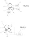
- FIG. 11 Ais a schematic illustration of an embodiment of an electric circuit that may be used to connect a group of circular receive elements of different sizes to separate receive channels of a receive subsystem.
- FIG. 11 Bis a schematic illustration of an embodiment of an electric circuit that may be used to connect a group of circular receive elements of different sizes to a single receive channel of a receive subsystem.
- FIG. 12is a schematic diagram illustrating a plurality of receive transducer elements in a grid pattern, showing axes for determining estimated reflector locations.
- FIG. 13is a schematic diagram illustrating an asymmetrical receive transducer element with a long axis and a short axis.
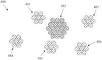
- FIG. 14is a schematic diagram illustrating a constellation configuration of ultrasound transmit elements surrounded by receive elements grouped into overlapping receive apertures based, at least in part, on proximity to transmit elements.
- FIG. 15is a schematic illustration of a circular ultrasound imaging probe having a central opening.
- FIG. 16 Ais a schematic illustration showing a top plan view of an ultrasound imaging probe having two probe segments separated by a gap and joined to a bridge handle.
- FIG. 16 Bis a schematic illustration showing a bottom plan view of an ultrasound imaging probe having two probe segments separated by a gap and joined to a bridge handle.
- FIG. 17is a schematic block diagram illustrating example components in an embodiment of a multiple aperture imaging system.
- the present disclosureprovides systems and methods for improving the quality of real-time two-dimensional and three-dimensional ultrasound imaging through the use of sparse arrays of various construction, including arrays in which each “element” is made up of a plurality of micro-elements arranged to be operated in concert with one another.
- the various embodimentsare described herein with reference to ultrasound imaging of various anatomic structures, it will be understood that many of the methods and devices shown and described herein may also be used in other applications, such as imaging and evaluating non-anatomic structures and objects.
- the various embodiments hereinmay be applied to non-destructive testing applications such as evaluating the quality, integrity, dimensions, or other characteristics of various structures such as welds, pressure vessels, pipes, structural members, beams, etc.
- the systems and methodsmay also be used for imaging and/or testing a range of materials including human or animal tissues, solid metals such as iron, steel, aluminum, or titanium, various alloys or composite materials, etc.
- an ultrasound transducermay carry their ordinary meanings as understood by those skilled in the art of ultrasound imaging technologies, and may refer without limitation to any single component capable of converting an electrical signal into an ultrasonic signal and/or vice versa.
- an ultrasound transducermay comprise a piezoelectric device.
- ultrasound transducersmay comprise capacitive micro-machined ultrasound transducers (CMUT), other micro-machined transducers made of electroactive materials such as piezoelectric materials, ferroic materials, ferroelectric materials, pyroelectric materials, electrostrictive materials, or any other transducing material or device capable of converting ultrasound waves to and from electrical signals.
- CMUTcapacitive micro-machined ultrasound transducers
- Transducersare often configured in arrays of multiple individual transducer elements.
- the terms “transducer array” or “array”generally refers to a collection of transducer elements attached to a common support structure.
- An arraymay typically (though not necessarily) comprise a plurality of transducer elements mounted to a common backing plate or substrate.
- Such arraysmay have one dimension (1D), two dimensions (2D), 1.X dimensions (1.XD) or three dimensions (3D) as those terms are used elsewhere herein and/or as they are commonly understood in the art.
- Other dimensioned arraysas understood by those skilled in the art may also be used.
- Annular arrayssuch as concentric circular arrays and elliptical arrays may also be used.
- transducer arraysmay include irregularly-spaced transducer elements, sparsely positioned transducer elements (also referred to as sparse arrays), randomly spaced transducer elements, or any other geometric or random arrangement of transducer elements. Elements of an array need not be contiguous and may be separated by non-transducing material or empty space.
- An element of a transducer arraymay be the smallest discretely functional component of an array.
- each elementmay be a single piezoelectric crystal or a single machined section of a piezoelectric crystal.
- a group of micro-elementsmay be electrically coupled so as to operate collectively as a single functional element. In such a case, a group of collectively-operating micro-elements may be referred to as a single “element.”
- the terms “transmit element” and “receive element”may carry their ordinary meanings as understood by those skilled in the art of ultrasound imaging technologies.
- the term “transmit element”may refer without limitation to an ultrasound transducer element which at least momentarily performs a transmit function in which an electrical signal is converted into an ultrasound signal.
- the term “receive element”may refer without limitation to an ultrasound transducer element which at least momentarily performs a receive function in which an ultrasound signal impinging on the element is converted into an electrical signal.
- the term “transmit element”may refer to a single element or to a plurality of elements operated together to form the desired waveform transmission.
- a plurality of transducer elementsmay be activated simultaneously or with delays selected to produce a circular or spherical waveform in the region of interest.
- Such a plurality of transducers, when operated together to form such a waveformmay have a collective acoustic center which is the apparent point-source origin of the transmitted waveform.
- one or more transmit elementsmay approximate a point-source transmitter if an unfocused spherical waveform produced by the one or more transmit elements appears to have originated from a point source.
- Transmitted ultrasound signalsmay be focused in a particular direction, or may be unfocused, transmitting in all directions or a wide range of directions. Transmission of ultrasound into a medium may also be referred to herein as “insonifying.” An object or structure which reflects ultrasound waves may be referred to as a “reflector” or a “scatterer.”
- a “position” or “location” of a transducer elementrefer to an acoustic center position exhibited by the element.
- an acoustic center position of an elementmay be precisely coincident with a mechanical or geometric center of the element, group of elements, or group of micro-elements.
- an acoustic center position of an elementmay be different than a mechanical or geometric center of the element due to various factors such as manufacturing irregularities, damage, irregular element geometries, or other factors.
- Acoustic center positions of elementsmay be determined using various calibration techniques such as those described in US Patent Publication 2014/0043933, titled “Calibration of Multiple Aperture Ultrasound Probes” (now U.S. Pat. No. 9,572,549), U.S. Pat. No. 9,282,945, titled “Calibration of Ultrasound Probes,” or other methods.
- aperturemay refer to a single transducer element or a group of transducer elements that are collectively managed as a common group by imaging control electronics.
- an aperturemay be a grouping of elements which may be physically separate and distinct from elements of an adjacent aperture.
- adjacent aperturesneed not necessarily be physically separate or distinct.
- a single aperturemay include elements of two or more physically separate or distinct transducer arrays or elements spaced from one another by any distance or different distances. In some cases, two or more elements need not be adjacent to one another to be included in a common aperture with one another.
- distinct groups of transducer elementsmay be constructed from a left array, plus the left half of a physically distinct center array, while a “right aperture” may be constructed from a right array, plus the right half of a physically distinct center array.
- the terms “receive aperture,” “insonifying aperture,” and/or “transmit aperture”are used herein to mean an individual element, a group of elements within an array, or even entire arrays, that perform the desired transmit or receive function as a group.
- such transmit and receive aperturesmay be created as physically separate components with dedicated functionality.
- any number of transmit and/or receive aperturesmay be dynamically defined electronically as needed.
- a multiple aperture ultrasound imaging systemmay use a combination of dedicated-function and dynamic-function apertures.
- elementsmay be assigned to different apertures during two or more ping cycles (as defined below).
- ping cyclerefers to a cycle that begins with the transmission of a ping from a transmit aperture approximating a point source and ends when all available (or all desired) echoes of that transmitted ping have been received by receive transducer elements.
- ping cyclesmay be distinct and separated by some time period. In other cases, ping cycles may overlap one another in time. That is, an N+1th ping cycle may begin (with transmission of a ping) before an Nth ping cycle is completed (i.e., before all echoes of the Nth ping are received).
- a single “image” or “image frame”may be produced from the echoes of one or more transmitted pings. Therefore, an “imaging cycle” or “image cycle” may refer to a cycle that begins with the transmission of a first ping that will contribute to an image and may end with the reception of echoes of a final ping contributing to the same image. In various embodiments, a single imaging cycle may include one, two, three, four, five, or more ping cycles.
- total aperturerefers to the overall size of all imaging apertures in a probe.
- total aperturemay refer to one or more dimensions defined by a maximum distance between the furthest-most transducer elements of any combination of transmit and/or receive elements used for a particular imaging cycle.
- the total aperturemay be made up of any number of sub-apertures designated as send or receive apertures for a particular cycle.
- the total aperture, sub-aperture, transmit aperture, and receive aperturemay all have the same dimensions.
- the dimensions of the total aperturemay include the sum of the dimensions of all send and receive apertures plus any space between apertures.
- two aperturesmay be located adjacent to one another on a continuous array. In other embodiments, two apertures may overlap one another on a continuous array, such that at least one element functions as part of two separate apertures.
- the location, function, number of elements and physical size of an aperturemay be defined dynamically in any manner needed for a particular application.
- Elements and arrays described hereinmay also be multi-function. That is, the designation of transducer elements or arrays as transmitters in one instance does not preclude their immediate re-designation as receivers in the next instance.
- embodiments of control systems hereininclude the capabilities for making such designations electronically based on user inputs, pre-set scan or resolution criteria, or other automatically determined criteria.
- the “image-able field” of the imaging systemmay be any area or volume of an imaged object or substance that may practically be imaged by the imaging system.
- image-able fieldmay be synonymous with the term “insonified region.”
- region of interestmay refer to a two-dimensional or three-dimensional region within the image-able field.
- the extents of an image-able field relative to a probemay be imposed by physical limits (e.g., based on signal-to-noise ratios or attenuation rates) or may be chosen logical limits (e.g., based on a desired region of interest).
- the term “pixel”refers to a region of two-dimensional space within an image-able field of the imaging system.
- the term “pixel”is not intended to be limited to a pixel of a display device, and may represent a region of a real-world-scale object that is either larger or smaller than a display pixel.
- a “pixel”may represent a region of the image-able field of any real-world size, and in some cases may represent a region smaller than any resolvable object of the imaging system. Pixels may be, but need not necessarily be square or rectangular, and may have any shape allowing for contiguous two-dimensional representation of the image-able field.
- data representing a pixelmay not be displayed, but may still be processed as a unit and referred to as a “pixel.”
- voxelrefers to a region of three-dimensional space within an image-able field of the imaging system.
- the term “voxel”is not intended to be limited to any particular portion of a two-dimensional or three-dimensional display device, and may represent a region of a real-world-scale object that is either larger or smaller than a display voxel.
- a “voxel”may represent a three-dimensional region of the image-able field of any real-world size, and in some cases may represent a region smaller than any resolvable object of the imaging system.
- Voxelsmay be, but need not necessarily be three-dimensional square or rectangular prisms. Voxels may have any shape allowing for contiguous three-dimensional representation of the image-able field. In some cases, data representing a voxel may not be displayed, but may still be processed as a unit and referred to as a “voxel.”
- pixel locationand “voxel location” (or “position”) refer to a location within the image-able field that is identifiable by a coordinate system, which may be a Cartesian coordinate system or any other coordinate system. Unless otherwise specified, references to a location of a pixel or voxel may generally refer to a center-point (e.g., center-of-mass, circular center, etc.) of the pixel or voxel.
- a pixelmay be described as “intersecting” a voxel.
- a two-dimensional pixelmay be defined as intersecting a three-dimensional voxel using any desired convention. For example, for square pixels and cubic voxels, a pixel intersecting a voxel may be a square face of the voxel or any other square or rectangle passing through the voxel. If a coordinate system used for pixels is different than a coordinate system used for voxels, then one pixel may intersect multiple voxels.
- the term “echo”refers to an ultrasound wavefront or an analog or digital representation of an ultrasound wavefront that arrives at a receive transducer element. Because imaging methods described herein allow for an extremely wide range of probe configurations, some ultrasound signals arriving at a receive transducer element may originate at a transmit transducer element on an opposite side of an imaged object. Such wavefronts are also intended to be included within the definition of an “echo” even if such wavefronts may also be described as “transmitted” or “deflected.”
- the terms “reflector” and “scatterer”refer to a physical portion of a physical object being imaged. When struck by a wavefront, reflectors and scatterers will tend to re-radiate a wavefront in a direction generally dictated by physics. The terms are not intended to limit the relative geometry or positions of transmitters, scatterers, and reflectors.
- the verb terms “reflect” and “scatter”refer to the effect of a scatterer on a propagating ultrasound wavefront.
- a wavefront that is only slightly deflected (e.g., forming a combined transmit element/scatterer/receive element angle approaching 180°) by a scatterermay still be described as having been “reflected” by that scatterer (or “reflector”).
- samplerefers to a digital data element in a physical volatile or non-volatile storage medium.
- samplesdescribed herein generally refer to data elements representing a discrete portion of a received ultrasound waveform.
- a time-varying electrical signal produced by a transducer element vibrating in response to a received ultrasound wavefrontmay be quantified and digitally sampled at a sample rate in order to produce a series of digital values representing the received time-varying electrical signal. Those values may be referred to as “samples.”
- a “sample”may include an interpolated value in between two digitally stored sample values.
- the position of each sample(e.g., as measured by a location in memory device, or a position in a sequence of values) may be directly related to an arrival time of the wavefront segment responsible for each sample value.
- beamformrefers to the process of determining a value for pixels or voxels based on a sample value (directly stored or interpolated), the known acoustic center position of a transmit element responsible for the sample value, and the known acoustic center position of a receive element responsible for the sample value. Beamforming is described in further detail elsewhere herein.
- imagerefers to a human-visible graphical representation of a physical object or a series of non-transitory digital values stored on a physical storage medium that may be interpreted by software and/or an image processor to produce such a graphical representation.
- imagedoes not necessarily imply any particular degree of quality or human-readability.
- An “image”may refer to a two-dimensional representation (e.g., a cross-section, in some cases) or a three-dimensional volumetric representation of an object. Therefore, a “volumetric image” may include a visible representation of a three-dimensional point cloud or digital data representing the three-dimensional point cloud.
- image and imagingin verb form refer to a process that results in an image.
- point-source transmission ultrasound imagingprovides several advantages over traditional scanline-based imaging.
- Point-source transmissiondiffers in its spatial characteristics from a “phased array transmission” which focuses energy in a particular direction from the transducer element array along a directed scanline.
- a point-source pulse(also referred to herein as a “ping”) may be transmitted so as to generate either a two-dimensional circular wavefront or a three-dimensional spherical wavefront, thereby insonifying as wide an area as possible in the two-dimensional or three-dimensional region of interest. Echoes from scatterers in the region of interest may return to all of the elements of receive apertures (or all of those elements not blocked by obstacles preventing transmission of the echoes). Those received echo signals may be filtered, amplified, digitized and stored in short term or long term memory (depending on the needs or capabilities of a particular system).
- Imagesmay then be reconstructed from received echoes by determining positions of reflectors responsible for received echo samples.
- the position of each reflector responsible for a digital echo samplemay be calculated based on the arrival time of the received echo sample (which may be inferred based on a sample position and a known sampling rate) relative to the known time at which the ping was transmitted, the acoustic position of the transmit element(s) responsible for the echo sample, and the acoustic position of the receive element responsible for the echo sample.
- This process of determining positions of reflectorsis generally referred to herein as beamforming.
- Beamformingmay be performed by a software-based, firmware-based, or hardware-based dynamic beamforming technique, in which a beamformer's focus may be continuously changed to focus at a particular pixel position corresponding to a reflector position.
- a beamformermay be used to plot the position of echoes received from point-source pings.
- such a dynamic beamformermay plot the locus of each echo signal based on a round-trip travel time of the signal from the transmitter to an individual receive transducer element.
- the locus of possible positions of the target reflector responsible for the echo samplewill be an ellipse mathematically defined by two foci.
- a first focus of the ellipsewill be at the position of the transmit transducer element and the second focus will be at the position of the receive transducer element.
- echoes of the same target reflectorwill also be received by other receive transducer elements.
- the slightly different positions of each receive transducer elementmeans that each receive element will define a slightly different ellipse for the target reflector.
- Accumulating the results by summing the ellipses for multiple receive elements at slightly different positionswill indicate an intersection of the ellipses for a reflector. As echo samples from more receive elements are combined with the first, the intersecting ellipses will converge towards a point at which the target reflector is located. Similarly, echoes of pings transmitted from different transmit element positions may also be combined to further refine reflector points.
- the target reflector positionmay be correlated with a pixel location representing the reflector.
- the combined sample valuesmay be used to determine a display intensity for a display pixel at the pixel location.
- the echo amplitudes received by any number of transmit positions and receive elementsmay thereby be combined to form each pixel. In other embodiments the computation can be organized differently to arrive at substantially the same result.
- Various algorithmsmay be used for combining echo signals received by separate receive elements. For example, some embodiments may process echo-signals individually, plotting each echo signal at all possible locations along its ellipse, then proceeding to the next echo signal. Alternatively, each pixel location may be processed individually, identifying and processing all echo samples potentially contributing to that pixel location before proceeding to the next pixel location.
- Image qualitymay be further improved by combining images formed by the beamformer from one or more subsequent transmitted pings, transmitted from the same or a different point-source (or multiple different point-sources). Still further improvements to image quality may be obtained by combining images formed by more than one receive aperture.
- the decision as to whether to use coherent or incoherent summationmay be influenced by the lateral extent/size of the receive aperture(s) and/or the transmit aperture(s). In some embodiments, it may be convenient to confine the size of an aperture to conform to the assumption that the average speed of sound is substantially the same for every path from a scatterer to each element of the transmit or receive aperture. For narrow receive apertures this simplifying assumption is easily met. However, as the width of the receive aperture increases, an inflection point may be reached (referred to herein as the “maximum coherent aperture width” or “maximum coherence width”), beyond which paths traveled by echoes of a common reflector will necessarily pass though different types of tissue having intrinsically different speeds of sound when returning to the elements furthest apart from one another. When this difference results in receive wavefront phase shifts approaching or exceeding 180 degrees, additional receive elements extended beyond the maximum coherence width will actually degrade the image rather than improve it.
- a maximum coherent aperture size considerationsmay also apply to the size of transmit apertures, which may include a plurality of transducer elements.
- transmit apertureswhich may include a plurality of transducer elements.
- a maximum coherent aperture sizein two dimensions.
- a maximum coherent aperturemay be defined as a group of transducer elements in a square, circle, polygon or other two-dimensional shape with a maximum distance between any two elements such that phase cancellation will be avoided when echo data received at the elements of the aperture are coherently combined.
- the full probe widthmay be physically or logically divided into multiple transmit and/or receive apertures, each of which may be limited to an effective width less than or equal to the maximum coherent aperture width, and thus small enough to avoid phase cancellation of received signals.
- the maximum coherence widthcan be different for different patients (or different test objects), for different probe positions on the same patient, and for other variables such as ultrasound frequency.
- a compromise widthmay be determined for a given probe and/or imaging system.
- a multiple aperture ultrasound imaging control systemmay be configured with a dynamic algorithm to subdivide the available elements into groups that are small enough to avoid significant image-degrading phase cancellation.
- a particular coherent aperture sizemay be determined automatically by a control system, or manually through user input via a user control such as a dial or slider.
- coherent (phase sensitive) summationmay be used to combine echo data received by transducer elements located on a common receive aperture resulting from one or more pings.
- incoherent summationmay be used to combine echo data or image data received by separate receive apertures if such receive apertures are sized and positioned so as to form a combined total aperture that is greater than a maximum coherence width for a given imaging target.
- Two-dimensional ping-based beamformingmay implicitly assume that the wavefronts emitted from the point-source are physically circular in the region of interest.
- the wavefrontmay also have some penetration in the dimension orthogonal to the scanning plane (i.e., some energy may essentially “leak” into the dimension perpendicular to the desired two-dimensional image plane, which may have the effect of reducing the effective imaging depth).
- the “circular” wavefrontmay actually be limited to a semicircle or a fraction of a circle less than 180 degrees ahead of the front face of the transducer according to the unique off-axis properties of the transducing material used.
- a three-dimensional “spherical” wavefrontmay have an actual shape of a hemisphere or less than a hemisphere within the medium to be imaged.
- point-source ultrasound imagingalso referred to herein as “ping-based” imaging
- ping-based imagingpredominantly describes two-dimensional imaging in which ultrasound signals are focused into a narrow field approximating a plane in a region of an image. Such two-dimensional focusing may be accomplished with lensing or other techniques.
- Ping-based imagingcan also be extended to real-time three-dimensional imaging without adding significant complexity.
- Three-dimensional ping-based imagingcan be performed using an ultrasound probe with transducer elements spaced from one another in two dimensions.
- the resulting semi-spherical wavefronttravels into the insonified region containing a region of interest (ROI) where some of the ultrasound energy may be reflected (or deflected) by scatterers in the ROI.
- ROIregion of interest
- Some of the echoes from the scatterersmay travel towards receive transducer elements of the probe, where the echoes may be detected, amplified, digitized, and stored in a short-term or long-term memory device.
- Each digitized sample valuemay represent a scatterer from the ROI.
- the magnitude of each received sample, along with its time of arrival and the exact positions of the transmit and receive transducers used,may be analyzed to define a locus of points identifying potential positions of the scatterer.
- a locusis an ellipsoid having as its foci the positions of the transmitter point source and receive transducer element.
- Each unique combination of transmit and receive transducer elementsmay define a separate view of the same reflector.
- an image in a 3D array of voxelsmay be assembled in computer memory by beginning with an evaluation of a selected digital sample.
- the selected digitized sample valuemay be written into every voxel indicated by the corresponding ellipsoid described above. Proceeding to do the same with every other collected sample value, and then combining all resulting ellipsoids may produce a more refined image.
- Real scattererswould be indicated by the intersection of many ellipsoids whereas parts of the ellipsoids not reinforced by other ellipsoids would have low levels of signal and may be treated as noise (i.e., eliminated or reduced by filters, gain adjustments, or other image processing steps).
- the order of computationmay be changed by beginning with a selected voxel in a final 3D image volume to be produced. For example, for a selected voxel, the closest stored sample or interpolated sample may be identified for each transmitter/receiver pair. All samples corresponding to the selected voxel may then be evaluated and summed (or averaged) to produce a final representation of the voxel. Closeness of a sample to a selected voxel may be determined by calculating the vector distance from the three-dimensional position of a transmitter (i.e., the transmitter used to produce the sample) to the selected voxel position plus the vector distance from the selected voxel position to the position of a receiver used to produce the sample.
- a transmitteri.e., the transmitter used to produce the sample
- Such a linear distancemay be related to the time-divided sample values by dividing the total path length by speed of sound through the imaged object.
- the samples corresponding to a calculated timemay be associated with the selected voxel.
- data corresponding to a common voxelmay be combined according to a chosen combining algorithm.
- a framemay be made up of any number of combined image layers. Frames may be displayed sequentially at a desired frame-rate on a display to form a moving image or video.
- the above-described beamforming processesmay beneficially also be used for evaluating pixel values in a 2D cross-sectional slice through a 3D volume using raw echo data. In various embodiments, such 2D slices may be taken at any arbitrary angle or along any curved path through the 3D volume.
- the same techniquesmay also be used to zoom in (i.e., increase the size of features) using raw echo data rather than enlarging processed pixels or voxels.
- Images obtained from different unique combinations of one ping and one receive element and/or combinations of one ping and one receive aperturemay be referred to herein as “sub-image layers.” Multiple sub-image layers may be combined coherently to improve overall image quality (e.g., by combining multiple ellipses or ellipsoids as described above). Additional image layer combining may be performed to further improve the quality of a final image.
- image layer combiningthe term “image” may refer to a single two-dimensional pixel, a single voxel of a three-dimensional volume or a collection of any number of pixels or voxels.
- Image layer combiningmay be described in terms of four image layer levels. These include base-level image layers, first-level image layers, second-level image layers and third-level image layers.
- base-level image layerrefers to an image obtained by beamforming echoes received at a single receive element from a single transmitted ping.
- the beamforming processdefines an ellipse corresponding to each echo sample. Therefore, a base-level image may include a series of such ellipses representing all of the echoes of a single ping received by a single receive element. Such an image may not be particularly useful for diagnostic imaging purposes, but may be used for other purposes.
- a first-level image layermay be formed from echoes received at a single receive aperture resulting from a single ping from a single transmit aperture (where a “transmit aperture” can be a composite point-source transmit element, a single-element transmitter, or a group of transmit elements). For a unique combination of a single ping and a single receive aperture, the echoes received by all the receive elements in the receive aperture may be summed coherently to obtain a first-level image layer.
- first-level imagesmay be formed by combining the echoes of two or more pings received at elements of a common receive aperture.
- Second-level image layersmay be further processed to improve alignment or other image characteristics.
- Third-level imagesmay be obtained by combining second-level image layers formed with data from multiple receive apertures.
- third-level imagesmay be displayed as sequential time-domain frames to form a moving image.
- pixels or voxels of a first-level image layermay also be formed by summing in-phase and quadrature echo data, that is by summing each echo with an echo 1 ⁇ 4 wavelength delayed for each receive-aperture element.
- echo datamay be sampled and stored as an in-phase data set and as a separate quadrature data set.
- a quadrature sample corresponding to an in-phase samplemay be identified by selecting a sample at an appropriate number of samples prior to the in-phase sample. If the desired quadrature sample does not correspond to an existing whole sample, a quadrature sample may be obtained by interpolation.
- in-phase and quadrature data for a single imagemay provide the advantage of increasing the resolution of the echo data without introducing blurring effects.
- samples at values other than 1 ⁇ 4 wavelengthmay be combined with in-phase samples in order to improve various imaging characteristics.
- Combination, summation or averaging of various image layersmay be accomplished either by coherent addition, incoherent addition, or a combination of the two.
- Coherent additionincorporating both phase and magnitude information during image layer summation
- incoherent additionsumming magnitudes only and omitting phase information
- Speckle noiseis reduced through incoherent summing because each image layer will tend to develop its own independent speckle pattern, and summing the patterns incoherently has the effect of averaging out these speckle patterns.
- the patternsare added coherently, they reinforce each other and only one strong speckle pattern results.
- echoes received by elements of a single receive apertureare typically combined coherently.
- the number of receive apertures and/or the size of each receive aperturemay be changed in order to maximize some desired combination of image quality metrics such as lateral resolution, speed-of-sound variation tolerance, speckle noise reduction, etc.
- image quality metricssuch as lateral resolution, speed-of-sound variation tolerance, speckle noise reduction, etc.
- alternative element-to-aperture grouping arrangementsmay be selectable by a user. In other embodiments, such arrangements may be automatically selected or developed by an imaging system.
- Variations in the speed of soundmay be tolerated by incoherent addition as follows: Summing two pixels coherently with a speed-of-sound variation resulting in only half a wavelength's delay (e.g., approximately 0.25 mm for 3 MHz ultrasound) results in destructive phase cancellation, which causes significant image data loss; if the pixels are added incoherently, the same or even greater delay causes only an insignificant spatial distortion in the image layer and no loss of image data.
- the incoherent addition of such image layersmay result in some smoothing of the final image (in some embodiments, such smoothing may be added intentionally to make the image more readable).
- coherent additioncan lead to maximum lateral resolution of a multiple aperture system if the geometry of the probe elements is known to a desired degree of precision and the assumption of a constant speed of sound across all paths is valid.
- incoherent additionleads to the best averaging out of speckle noise and tolerance of minor variations in speed of sound through the imaged medium.
- coherent additioncan be used to combine image layers resulting from apertures for which phase cancellation is not likely to be a problem, and incoherent addition can then be used where phase cancellation would be more likely to present a problem, such as when combining images formed from echoes received at different receive apertures separated by a distance exceeding some threshold.
- all first-level imagesmay be formed by using coherent addition of all sub-image layers obtained from elements of a common receive aperture, assuming the receive aperture has a width less than the maximum coherent aperture width.
- second and third level image layersmany combinations of coherent and incoherent summation are possible.
- second-level image layersmay be formed by coherently summing contributing first-level image layers
- third-level image layersmay be formed by incoherent summing of the contributing second-level image layers.
- Time-domain framesmay be formed by any level of image layer depending on the desired trade-off between processing time and image quality. Higher-level images will tend to be of higher quality, but may also require more processing time. Thus, if it is desired to provide real-time imaging, the level of image layer combination processing may be limited in order to display images without significant “lag” being visible to the operator. The details of such a trade-off may depend on the particular processing hardware in use as well as other factors.
- a form of 2D imagingmay be performed using a probe and imaging system configured for 3D imaging by simply beamforming and displaying only a 2D slice of data from the received three-dimensional echo data.
- a probe and imaging systemconfigured for 3D imaging by simply beamforming and displaying only a 2D slice of data from the received three-dimensional echo data.
- such techniquesmay be used in order to reduce a beamform calculation and simplify display for real-time imaging using an imaging device with limited processing capability, while still retaining the full 3D echo data.
- a two-dimensional planemay be selected (automatically or by a user) from the voxels making up a three-dimensional volumetric representation of the imaged region, voxels intersecting the selected plane may be identified.
- An image windowmay be defined by automatically or manually selecting a portion of the selected plane, and a two-dimensional image of the selected image window may then be formed by beamforming only those echo samples corresponding to the voxels intersecting the selected plane and lying within the selected image window.
- the selected two-dimensional image windowmay then be displayed in real-time while three-dimensional data of the entire insonified volume is simultaneously collected.
- two separate image windows in the same or different image planesmay be defined and imaged simultaneously from the same set of real-time three-dimensional echo data.
- the collected full 3D echo datamay be beamformed and reviewed at a later time using a device with greater processing power.
- the 2D slice to be beamformed and displayedmay be automatically selected by an imaging device.
- the 2D slice to be beamformed and displayedmay be selected or adjusted by an operator of the device.
- raw un-beamformed echo data resulting from a ping transmitted from point-source transmit transducers and received by one or more arrays of receive transducer elementsmay be captured and stored in a raw data memory device for subsequent retrieval and analysis.
- captured echo datamay be digitally transmitted over a network for remote processing, beamforming, and/or viewing.
- additional datamay also be stored and/or transmitted over a network and retrieved for subsequent and/or remote image generation and analysis.
- additional datamay include calibration data describing the positions of the transmitting and receiving transducer elements, and transmit data describing the identity (or position) of transmitting transducers associated with specific echo data.
- a clinicianmay use the data to reconstruct imaging sessions in a variety of ways while making adjustments that may not have been made during a live imaging session. For example, images of a series of 2D slices through a 3D volume may be generated and shown in succession in order to simulate a 2D transducer passing across a surface of the region of interest. Examples of these and other methods are described in Applicant's US Publication 2014/0058266 (now U.S. Pat. No. 9,986,969), titled “Ultrasound Imaging System Memory Architecture” and PCT Patent Application Publication WO2016/028787, titled “Network-Based Ultrasound Imaging System.”
- a probeconfigured for imaging an entire patient's body or a substantial portion of a patient's body may comprise an array of designated point-source transmitters and designated receive elements sized and arranged to cover a substantial portion of the desired region of a patient's body.
- a probemay be sized to cover substantially half of a patient's chest or more. Such a probe may have a maximum dimension of about 8 cm to about 10 cm.
- a much smaller probecapable of insonifying a conically-shaped volume of, for example, + or ⁇ 30 degrees, can be placed on a patient's body such that an organ of interest may be included in the cone.
- Such a probemay be placed in more than one place to cover a larger volume of interest.
- a point-source transmittermay be approximated using a single small transducer element of a transducer array.
- a single elementmay be able to produce a ping with sufficient energy in the imaging plane to achieve imaging at a reasonable depth.
- an “apparent point-source transmitter” transducermay be configured to produce a waveform that both approximates an actual point-source and has sufficient energy to produce high quality images at the desired depth.
- apparent point-source transmittersmay be configured such that ultrasound power output may be limited only by safety considerations within the imaged medium.
- point-sourcerefers to a point in two-dimensional (2D) space or three-dimensional (3D) space that represents a center point of a transmitted 2D or 3D ultrasound waveform, respectively.
- a pointis ideally an infinitely small point corresponding to a produced wavefront with a consistent semi-spherical shape.
- such a pointmay lie on the surface of the transducer element.
- the terms “semi-spherical pulse” and “semi-spherical wavefront”may refer to any ultrasound wavefront with a spherical-section shape, including wavefronts with approximately spherical-section shapes greater than or less-than a n ideal semi-sphere.
- the terms “semi-circular pulse” and “semi-circular wavefront”may refer to any ultrasound wavefront which appears in an imaging plane to have a circular-section shape, including wavefronts with approximately circular-section shapes greater than or less-than an ideal semi-circle.
- multiple (e.g., two, three, four or more) small transducer elements from a common transmit/receive arraymay be excited simultaneously to produce a ping with more energy than may be produced by a single element.
- a designated point source transmittermay comprise a large transducer shaped and configured to produce a relatively high-power waveform that “appears” to have originated from a point-source even if the location of the apparent point source does not correspond to a physical structure responsible for producing the wavefront—in other words, an apparent point-source.
- the location of the apparent point-sourcemay be used as the origin of the transmitted ping wavefront.
- an approximate location of an apparent point sourcemay be estimated based on a physical geometry or other characteristic of a designated point source transmitter.
- particularly suitable shapes for designated point source transmittersmay include individual elements in the shape of concave and convex spherical caps sized to deliver sufficient ultrasound power to perform real-time three-dimensional ping-based imaging.
- Convex spherical capsmay generally be referred to herein as “dome-shaped,” while concave spherical caps may be referred to as “bowl-shaped.”
- Some examples of imaging probes incorporating examples of such spherical cap transducer elementsare shown and described in U.S. Publication No. US 2015/0080727 (now U.S. Pat. No. 9,883,848).
- a designated point source transmittermay include a single structure or one or more element sub-structures arranged in a planar, convex, or concave shape.
- each designated transmitter element or receive transducer elementsmay be constructed from a single contiguous piece of a piezoelectric material. Such elements may be referred to herein as “bulk” elements or as being made from “bulk piezoelectric” materials.
- transmitter and/or receiver elementsmay be composed of a plurality of sub-element structures, such as cut piezoelectric materials, micro-element structures (as described further below), or other structures that may be operated collectively to form a complete element.
- transmitter elements or receiver elementsmay be in the form of a thin shell of a piezoelectric material in a planar shape or in the shape of a truncated spherical cap.
- Such elementsmay be made of any material exhibiting piezoelectric properties. Many naturally occurring and synthetic materials are known to exhibit piezoelectric properties that may be of a character suitable for use in ultrasound imaging applications.
- ultrasound ping signalsmay be transmitted at frequencies commonly used in diagnostic medical ultrasound, e.g., in the range of about 1 MHz to about 20 MHz or more. Thus, apparent point-source transducers with fundamental frequencies within this range may be suitable for use in ping-based multiple aperture imaging.
- Naturally-occurring piezoelectric materialsinclude quartz, topaz and tourmaline, while man-made piezoelectric ceramic materials include lead zirconate titanate (PZT), barium titanate, lead metaniobate, & polyvinylidene difluoride (PVF 2 —not naturally piezoelectric, but may be made so by heating in the presence of a strong electrical field).
- PZTlead zirconate titanate
- PVF 2polyvinylidene difluoride
- Some man-made piezoelectric ceramic materialsmay be combined with non-piezoelectric polymer materials to create piezo-composites.
- the thickness of a designated transmitter elementmay be directly related to the fundamental frequency of the transducer.
- the thickness of a transducer shellmay be equal to about half a wavelength of its corresponding fundamental frequency.
- the shell thicknessmay be differently related to a transducer element's fundamental frequency. Manufacturing processes may also vary depending on the piezoelectric material used and other factors.
- natural or man-made piezoelectric materialmay be machined using traditional techniques in order to form the desired shape directly from a block of material. Such machining may be performed using mechanical cutters, water jets or any other available machining technique.
- a block or sheet of piezoelectric materialmay be machined into a plurality of elements attached to a flexible substrate which may then be formed into the desired shape.
- a plurality of concentric ring cuts 42 and radial cuts 44may be made in a sheet of piezoelectric material, which may then be formed over a backing material with the desired shape (e.g., a spherical-cap).
- the individual sub-element sections that make up the elementmay be electrically connected so as to transmit simultaneously without phasing.
- a desired shapemay be molded (e.g., by injection molding, die casting, or other molding process) from a piezo-composite material. Examples of molding processes that may be adapted to forming spherical-cap elements are described in U.S. Pat. Nos. 5,340,510 and 5,625,149.
- Ultrasound transducersmay also be produced in desired shapes using additive manufacturing techniques (commonly known as 3D printing techniques).
- additive manufacturing techniquescommonly known as 3D printing techniques.
- US Patent Publication 2013/0076207 and US Patent Publication 2013/0088122describe systems and methods for forming transducers in the shape of cylindrical posts. Similar techniques may also be adapted to form transducers with spherical-cap or other shapes. Additionally, other manufacturing techniques such as laser sintering, stereo lithography, chemical vapor deposition or any other suitable techniques may be used to produce transducers in the shapes and sizes described herein.
- Capacitive Micromachined Ultrasound Transducer (CMUT) formation techniquesmay also be used to form transducers of desired shapes onto a pre-shaped substrate.
- CMUTCapacitive Micromachined Ultrasound Transducer
- WO 2012/112540shows and describes some examples of structures and techniques that may be adapted to forming spherical-cap shaped transducers.
- a transducer elementmay be made by forming an array of CMUT transducers on a substrate pre-formed into a desired shape (e.g., a concave or convex spherical cap as described above).
- the CMUT elementsmay be electrically connected so as to transmit simultaneously without phasing.
- transducer elementsmay be made up of a plurality of micro-elements which may be made using lithographic techniques, thin-film deposition techniques, etching techniques, additive manufacturing techniques, surface micromachining, bulk micromachining, and/or other methods.
- U.S. Pat. No. 6,222,304 to Bernstein(which is incorporated herein by reference) describes processes for making micro-shell transducer elements which include a substrate, an electro-active medium mounted on the substrate and including an arched section spaced from the substrate defining a chamber between the substrate and arched section, and a pair of electrodes mounted on the medium for either applying an electric field across the medium for flexing the arched section or sensing the electric field generated by a flexure of the medium.
- the flexible “arched section”may be replaced by a flexible planar section or a flexible concave section that may be flexed upon application of an appropriate electrical signal.
- each elementin order to build transducer elements into a probe, the “front” surface of each element (e.g., the inside surface of a concave element, the outside surface of a convex element or the outward-facing surface of a planar element) may be plated with an electrically conductive layer (such as a metal) so as to allow electrical connection to the element.
- an electrically conductive layersuch as a metal
- the entire inner surface and the entire outer surface of each elementmay be plated, thereby allowing the entire piezoelectric shell to be activated by applying an electrical signal across the two plated surfaces.
- less than an entire shellmay be activated by plating less than an entire inner and/or outer surface of the shell. In this way, a similar range of element sizes may be made functional from a single physical structure.
- transmitter and receiver elementsmay be made in a range of shapes, such as having a top surface that is planar, convex, concave, or combination of shapes.
- Transmitter and/or receiver elementsmay also have various plan-view shapes such as circular, rectangular, pentagonal, hexagonal, heptagonal, octagonal, other polygonal, or others.
- Elementscan be electrically and logically connected to a controller so as to be dedicated transmitters, dedicated receivers, or switchable between transmit and receive functions.
- Elementscan be arranged into various arrays, such as regular arrays, irregular arrays, sparse arrays, or arrays that may be controlled so as to be operated as regular, irregular, or sparse arrays.
- Ultrasound probes made up of ultrasound transmitters and receiversmay be made by various techniques suitable for producing arrays of micro-elements.
- the term “micro-element”refers to very small transducer elements with sizes (e.g., diameters) on the order of less than about 1,000 microns, in some cases about 10 microns to about 500 microns, in some cases between about 50 microns to about 200 microns, in some cases between about 50 and about 150 microns, in some cases between about 10 microns and about 25 microns, in some cases between about 25 microns to about 50 microns, and in some cases between about 50 microns and about 100 microns.
- a micro-elementmay be defined as any element that has a diameter equal to less than half a wavelength of the ultrasound frequency in the imaged material at which the micro-element will be used.
- micro-elementsmay be too small to be mechanically machined from traditional bulk piezoelectric materials, and may therefore be made using lithographic techniques, thin-film deposition techniques, etching techniques, additive manufacturing techniques, surface micromachining, bulk micromachining, and/or other methods.
- lithographic techniquesthin-film deposition techniques
- etching techniquesetching techniques
- additive manufacturing techniquessurface micromachining, bulk micromachining, and/or other methods.
- micro-shell transducer elementswhich include a substrate, an electro-active medium mounted on the substrate and including an arched section spaced from the substrate defining a chamber between the substrate and arched section, and a pair of electrodes mounted on the medium for either applying an electric field across the medium for flexing the arched section (i.e., in order to transmit an ultrasound signal) or sensing the electric field generated by a flexure of the medium (i.e., in order to receive an ultrasound signal impinging on the micro-element).
- Other techniquesmay also be used to produce micro-elements of different types.
- the flexible “arched section”may be replaced by a flexible planar section or a flexible concave section that may be flexed upon application of an appropriate electrical signal and/or may be sensitive to received impulses.
- a pattern of micro-elementsmay be formed on a semiconductor substrate using one or more of the above techniques, a back-surface (i.e., opposite the surface on which micro-elements lie) of the substrate may be thinned to make the substrate flexible to a desired degree, and the substrate may then be conformed to a new shape and secured to a supporting material.
- thinning and re-shapingmay be performed over an entire substrate surface or in localized regions.
- CMPchemical mechanical polishing
- ADPatmospheric downstream plasma
- DCEdry chemical etching
- one or more sections of an array of micro-elementsmay be conformed so as to form entire arrays or array sections in desired shapes.
- arraysmay be shaped so as to conform to a portion of a human anatomy, such as a breast, a joint (e.g., a knee, elbow, wrist, ankle, etc.), a skull, or other anatomical structure.
- arraysmay be shaped so as to conform to mechanical, structural, or industrial parts.
- array sectionsmay be shaped to form three-dimensional element groups arranged to exhibit desired transmit patterns. For example, such techniques may be used to form transducer element groups configured to transmit apparent point-source waveforms.
- an array of micro-elementsmay be conformed so as to form dome-shaped sections or dish-shaped sections, such as the spherical section elements described herein.
- convex or concave dome-shaped transmit elements optimized for near-field imagingmay be formed from a plurality of micro-elements on a thinned section of substrate and conformed to a desired dome shape.
- a dome-shapemay be optimized for near-field imaging based on transmit angles of micro-elements that will make up the dome.
- Each micro-elementmay have a transmit angle relative to a centerline of a transmitted wavefront.
- the transmit angle of a micro-elementdefines the angle at which the energy of a transmitted wavefront drops below some threshold value.
- a convex dome shape optimized for near-field imagingmay be defined by a spherical section with a cut elevation selected such that wavefronts transmitted from micro-elements at a low region of the dome (i.e., a region of the spherical section adjacent an attachment point with the surrounding micro-element array) will not tend to impinge directly on adjacent micro-elements.
- the micro-elements of such a dome-shaped groupmay be electrically connected such that they may be operated as a single element.
- the spherical center point of such an elementmay be used as the acoustic center point for the purpose of beamforming calculations for pings transmitted from such a spherical-section shaped transmitter element.
- a concave dish shape optimized for far-field imagingmay be defined by a spherical section with a cut elevation selected such that wavefronts transmitted from micro-elements within the dish will not tend to impinge directly on other micro-elements within the dish-shaped element.
- the micro-elements of such a dish-shaped groupmay be electrically connected such that they may be operated together to collectively form a single transmitter and/or receiver element.
- the spherical center point of such an element groupmay be used as the acoustic center point for the purpose of beamforming calculations for pings transmitted from such a spherical-section shaped transmitter element or receiver element.
- an overall shape of a substrate supporting an array of micro-elementsmay be conformed into a desired shape.
- a substrate supporting an array of micro-elementsmay be formed into complex overall shapes.
- an array of micro-elementsmay include one or more surfaces with inflected sections, such as to conform to an anatomical or other structure.
- micro-elementsmay be grouped to form shaped transducer elements such as those described elsewhere herein. Groups of micro-elements may be treated collectively as a single element in the various processes described herein, and may be referred to herein as “element groups” or “micro-element groups.” For example, as shown in FIG. 1 and FIG. 2 , a plurality of adjacent micro-elements may be logically and electrically treated as a single unit so as to form transducer elements of a desired size and shape, and in a desired location. In some embodiments, spherical cap or dome-shaped elements may be formed from a plurality of micro-elements.
- transducer elementsfrom a group of such micro-elements is that the position of each micro-element may be known very precisely based on the precision of manufacturing techniques used to produce the micro-elements. Therefore, the position of each micro-element-group may also be known very precisely.
- a group of micro-elements forming a single transducer element groupmay collectively share a single electrical ground conductor and a single electrical signal conductor.
- each of the ground conductor and the signal conductor for each transducer element groupmay form a differential pair independent of signal and ground conductors for other elements of the array.
- micro-elements in a group of micro-elements forming an element groupmay share a single ground conductor that is not shared with ground conductors of micro-elements belonging to other element groups between the probe and a connector joining the probe to control electronics.
- micro-elements of an element groupmay share a single signal conductor that is not shared with signal conductors of micro-elements of other element groups between the probe and a connector joining the probe to control electronics.
- some micro-elementse.g., a sub-set of micro-elements forming an element group
- micro-element groupsmay share a common ground conductor and/or a common signal conductor.
- micro-element groups that form elements that are collectively part of a single aperturemay share a common ground conductor and/or a common signal conductor.
- one or more signal and/or ground conductorsmay be shared in a multiplexed arrangement, such as time-division-multiplexed communications, or other multiplexing method.
- Ping-based multiple aperture ultrasound imagingcan provide very powerful real-time three-dimensional imaging capabilities as described above.
- the benefits of ping-based multiple aperture ultrasound imagingmay be achieved by using transducer probes with overall dimensions much larger than traditional ultrasound probes.
- ping-based multiple aperture ultrasound imagingmay be beneficially used with probes having an active imaging surface in excess of 100 cm 2 .
- ultrasound elements in a probeare spaced as close together as possible, typically significantly less than (and generally no more than) half a wavelength of the ultrasound frequency being used.
- sparse arrays of transducer elementsmay be beneficial in providing an ultrasound probe with a wide total aperture while containing a manageable number of transducer elements.
- a “sparse array”is generally defined as an array in which the majority of array positions have a zero or null value. In some cases, a similar definition may be applied to an array of ultrasound transducer elements.
- a sparse arraymay be defined as an array of potential element positions in which a majority of the element positions contain no active elements.
- the inactive element positionsmay contain no transducers, or may contain transducers that are not active at a specified time, if ever.
- inactive element positionsmay comprise transducer elements that are temporarily or permanently electrically disconnected from imaging control electronics.
- inactive element positionsmay comprise empty spaces (or spaces filled with non-transducing material) of sizes equivalent to a transducer element.
- an ultrasound transducer array in which less than a majority of element positions contain no active elementsmay also be considered “sparse” if average spacing between adjacent elements exceeds a threshold distance.
- an ultrasound transducer arraymay be considered “sparse” if all (or nearly all) adjacent elements of the array are spaced from one another by a distance of at least half a wavelength of the ultrasound transmitted and/or received by the elements.
- an ultrasound transducer arraymay be considered “sparse” if at least a majority of elements of the array are spaced from adjacent elements by a distance of at least a threshold distance. If an array is configured to operate at more than one ultrasound frequency, then a threshold distance may be half of the maximum wavelength at which any part of the array is configured to operate.
- ultrasound probescomprising a sparse array of ultrasound transmitters and receivers may be made using one or more of the various micro-element or sub-element configurations described herein.
- a sparse arraymay be formed from a continuous array of micro-elements by electrically assigning micro-elements to element-groups where the element groups are located in a sparse arrangement. Examples of such embodiments are described below with reference to FIG. 1 .
- micro-elements that are not assigned to an element-groupmay simply be electrically inactive.
- a sparse-array transducer probemay comprise a plurality of groups of micro-elements formed in desired locations on a substrate without necessarily forming additional micro-elements between micro-element groups.
- FIG. 2illustrates an example of such a sparse array 480 made up of separated micro-element groups 481 - 486 .
- ultrasound probescomprising a sparse array of ultrasound transmitters and receivers may be made by forming individual transducer elements from bulk piezoelectric material, mechanically picking up and placing each element in a precise location on a substrate, securing each element to the substrate, and making electrical connections to each element.
- Bulk piezoelectric elementsmay be made in any shape or size as described herein.
- a sparse array probemay be effectively used by 3D multiple aperture imaging techniques as described herein, and in some cases may be preferred to a continuous array densely populated with transducer elements, particularly when spacing between receivers and transmitters avoid certain patterns.
- using a probe having a sparse two-dimensional or three-dimensional array of regularly-spaced transducer elements with the ping-based multiple aperture imaging beamforming techniques described hereinmay result in the production of self-reinforcing artifacts that may undesirably degrade image quality.
- Such artifactsmay be the result of phase cancellation causing certain returning echo signals to cancel one another out before reaching some receive elements thereby producing distortions in the form of extremely dark and/or extremely bright bands in the resulting image.
- such artifactsmay be avoided or mitigated by positioning transducer elements at inconsistent distances from one another in a sparse array.
- phase cancellation artifactsmay be avoided or mitigated by positioning transmit and receive elements such that no two transducer elements are an equal distance from any single third element.
- a small amount of element position equivalencemay be acceptable.
- a probemay be constructed such that no more than “N” receive elements are located an equal distance from a single transmitter, where “N” is an integer value between 1 and 1,000 or more, more commonly between about 1 and 100, and in some specific examples N may be 1, 2, 3, 4, 5, 10, 100 or more and wherein all of the receiver elements receive the same frequency of ultrasound signal.
- transmit elementsmay be regularly-spaced relative to one another while spacing receive elements at irregular distances relative to the transmit elements.
- both transmit elements and receive elementsmay be irregularly positioned in a sparse array.
- a two-dimensional sparse array of transducer elements positioned to mitigate phase cancellation artifactsmay include elements spaced from one another at “random” distances.
- FIG. 3 and FIG. 4illustrate examples of two-dimensional sparse array element positions in which a distance between any two adjacent elements is not exactly equal to any other distance between two adjacent elements. In the example of FIG. 3 and FIG. 4 , the distances between adjacent elements are effectively random in the sense that there is no mathematical pattern relating the distances.
- FIG. 3illustrates a two-dimensional array 401 made up of elements 410 unevenly spaced from one another in two dimensions according to a pseudo-random pattern.
- the array 401 illustrated in FIG. 3may have an overall length dimension 413 and/or an overall width dimension 414 of about 3 cm to about 10 cm or more.
- Each element 410 of the array 401may have a square shape, a circular shape, a polygonal shape, or any other regular or irregular shape.
- FIG. 4illustrates a sparse array 402 embodiment in which designated transmit elements are shown as circular elements 411 while designated receive elements are shown as square elements 412 . In other embodiments, all elements may be circular, square, or otherwise-shaped elements even if some are designated transmitters and others are designated receivers.
- sparse arrays 401 , 402 of ultrasound elements with uneven spacingmay be arranged in other shapes, such as a generally oval shaped array 403 as shown in FIG. 5 , or a generally circular shaped array 404 as shown in FIG. 6 .
- Sparse arrays of ultrasound elements with uneven spacingmay also be arranged in a generally planar configuration, or a generally concave or convex configuration 405 as shown in FIG. 7 .
- the arrangement of transducer elements shown in FIG. 7may be made convex by a supporting substrate layer positioned on the concave side of the pattern of elements. Similarly, supporting the elements with a substrate on the convex side of the pattern will provide a concave array.
- sparse arraysmay be arranged for use in intra-venous ultrasound probes or other specialized probes.
- spacing distances between elementsmay be non-repeating random or pseudo-random distances obtained with use of a random or pseudo-random number generation algorithm.
- spacing distances between elementsmay be irregular values which may be based on non-repeating values from an integer sequence such as the Fibonacci sequence or any other non-repeating numeric sequence.
- an algorithmmay be applied to values from a numeric sequence in order to maintain element spacing distances within a desired range. For example, in some embodiments distances between adjacent elements may be constrained to a range such as 1 mm to 10 mm (or 1 mm to 20 mm or more).
- the spacing between transducer elementsneed only be un-equal by an amount at least as great as a manufacturing tolerance of a manufacturing method used to construct the array. For example, if an array manufacturing process is capable of positioning elements on a substrate within a distance of +/1 100 microns of an intended position, then it may be desirable to design the two spacing distances so as to be different by at least 100 microns. In other embodiments, the spacing between transducer elements need only be un-equal by an amount based on a frequency of ultrasound used.
- FIG. 8illustrates an example array 302 of dedicated transmit elements 310 and receive elements 312 .
- the transmit elements 310 and/or the receive elements 312may be replaced with any other transmit or receive elements described elsewhere herein.
- FIG. 15 and FIG. 16 Balso illustrate elements with examples of regularly spaced elements which may contain elements of any construction such as those described herein.
- phase cancellation artifactsmay be avoided or mitigated by constructing and/or operating a sparse array probe such that only a small number of regularly-spaced elements operate at the same ultrasound frequency as one another.
- some embodiments of sparse array probesmay be constructed and/or operated such that no more than “N” receive elements operating at the same ultrasound frequency (or combination of frequencies) are equidistant to any one transmit element.
- Nmay be an integer between 1 and 100, in some specific examples, N may be 1, 2, 3, 4, 5 or more.
- a probemay contain any number of receive elements equidistant to one or more transmit elements as long as no more than N of the receivers are operated at the same ultrasound frequency (or combination of frequencies).
- the ultrasound frequency (or combination of frequencies) at which any given transmit or receive element may be operatedmay be based on structural characteristics of the element (e.g., material, thickness, diameter, or other dimensions) and/or variable operational characteristics such as an electric voltage or signal shape applied to the element. Which and to what degree such factors may change an element's operating frequency may depend on the element material and/or the process by which it is manufactured. For example, while many transducers may have a fundamental frequency, many can also be driven (i.e., operated in transmit or receive) at frequencies other than their fundamental frequency. The range of frequencies at which any particular transducer element may be driven may depend on many factors such as the material, construction, available power, etc.
- an operating frequency of a micro-elementmay be determined by a diameter of a flexible section of material, such as the “arched section” described by Bernstein referenced above or a similarly-configured flexible planar or concave section.
- micro-element groupsmay be made up entirely of micro-elements configured to operate at the same frequency, or may be made up of micro-elements configured to operate at different frequencies.
- an outer micro-element groupe.g., 464 in FIG. 1
- FIG. 9illustrates an example of a group of micro-elements of different sizes arranged to form a multi-frequency transmit element.
- the fundamental transmit frequency of a micro-elementmay be a function of the size of a flexible surface member. Therefore, a multi-frequency transmit element group may be formed by providing micro-elements of varying sizes arranged so as to be controllable as a common element group.
- the group 500 of micro-elements in FIG. 9includes micro-elements of three different sizes. In other embodiments, micro-elements of two, four, five, six, or more different sizes may be grouped into a transmitter or receiver group. Other patterns or numbers of micro-elements of each size may also be used, depending on the waveform characteristics desired.
- the variously-sized micro-elements of FIG. 9may be electrically connected so as to be activated simultaneously as a group, such as by providing a single electrical signal conductor and a single electrical ground conductor common to all of the micro-elements of a transmit group such as that shown in FIG. 9 .
- a micro-element arraymay comprise a plurality of transmit element groups containing micro-elements of various sizes.
- different transmit elementsmay be provided with different mixes of micro-element sizes in order to produce pings with different multi-frequency combinations. In this way, each transmit group may have a unique frequency signature. If different transmitters in a probe have different mixes of micro-element sizes to produce a different frequency signature, then pings transmitted from one transmitter may be distinguished from pings transmitted by a second transmitter, even if pings from the two transmitters are transmitted at the same time or during overlapping ping cycles.
- a probewhen a probe is configured to include at least two transmitters configured to transmit multi-frequency waveforms and receive elements of the probe are sensitive to all of the transmitted frequencies, then echoes received by each receive element of the probe may be mapped to the transmitter that produced the echo based only on the frequency signature of the received echoes. This may be tremendously beneficial in increasing ping rates and/or frame rates well beyond the limits imposed by single-frequency imaging.
- a size of transducer elementsmay be varied instead of or in addition to varying spacing between elements.
- a sparse ultrasound arraymay be entirely made up of transducer elements of various (and/or variable) sizes as shown for example in FIG. 1 , FIG. 10 A , FIG. 10 B , FIG. 11 A , FIG. 11 B .
- micro-element groupsmay be switched between a first configuration in which a first element group includes a first group of micro-elements and a second configuration in which the first element group includes a second group of micro-elements in addition to (or subtracted from) the first group of micro-elements.
- switching between a first configuration and a second configurationmay be performed in between ping cycles. That is, a first ping may be transmitted and echoes of the first ping may be received by the micro-elements of the first configuration of the element group. Then, a second ping may be transmitted, and echoes of the second ping may be received by the second configuration in which the first element group includes a second group of micro-elements in addition to the first group of micro-elements.
- a transmit element groupmay be configured to be switchable between a first configuration and a second configuration that is larger, smaller, or differently shaped than the first configuration.
- element groupsmay be switched between a first configuration and a second configuration within a single ping cycle.
- a first pingmay be transmitted, a first plurality of echoes of the first ping may be received by the micro-elements of the first configuration of the element group, and the switch may then be closed so that a second plurality of echoes of the first ping may be received by the micro-elements of the second configuration of the element group in addition to or instead of the micro-elements of the first configuration.
- the first plurality of echoesmay be relatively near-field echoes that are produced by reflectors closer than a threshold distance to the receiver micro-elements
- the second plurality of echoesmay be mid-field or far-field echoes that are produced by reflectors further than a threshold distance from the receiver micro-elements.
- the thresholdmay be a time value, such that the first plurality of echoes may be received with the first configuration of micro-elements until a switch-time at which a switch may activate the second configuration of micro-elements to allow the second plurality of echoes to be received after the switch-time until the end of the ping cycle.
- individual micro-elements or groups of micro-elementsmay be electrically switchable so as to be selectively included in or excluded from a micro-element group forming an element or an aperture.
- Transmit element groups or receive element groupsmay be configured to be switchable between a first configuration and a second configuration, where the second configuration is larger, smaller, or differently shaped than the first configuration.
- FIG. 1illustrates an example section of a continuous array 450 of micro-elements 460 .
- Some of the micro-elements 460are indicated as having been assigned to an element-group 462 , 464 , 466 , 468 , 470 , and 472 .
- FIG. 1further illustrates an outer group of micro-elements 464 identified by stippling surrounding a central group 466 of micro-elements.
- a larger element group 468may be used as a transmit element
- the smaller element groups 462 , 464 , 470 , and 472may be used as receive elements.
- the outer group 464may be switchable as a group so as to selectively form a larger element in combination with the central group 466 .
- Similar element groupsmay be formed with any number of adjacent micro-element groups in any desired configuration.
- Such a variably-sized elementmay be used as a transmit element, as a receive element, or as both.
- groups 472 and 474which provide for switchable configurations with different shapes and sizes.
- One or more switchesmay be provided to allow the group 474 to be included with the group 472 so that both groups 472 and 474 may operate together as a single element (e.g., as a receive element or as a transmit element).
- the elongated element formed by the combination of sub-groups 472 and 474may be beneficially used in combination with the process for estimating a position of a reflector using an elongated receive element.
- ping-based receive beamforming calculationsmay be performed using the position of the circular center of the center micro-element (e.g., 744 ) of a micro-element group as the acoustic center position of the transducer element group.
- the position of the micro-element groupmay be defined at a center-of-mass point or a geometric center point of the group of micro-elements.
- various calibration processesmay be used to measure, determine, and/or to refine an acoustic center position for each transducer element group.
- FIGS. 10 A and 10 Billustrate examples of radially symmetrical groups 342 of switchable concentric sub-elements 344 , 346 , 348 which may be operated in concert with one another.
- the group 342may include a central circular receive element 344 surrounded by one or more concentric-ring receive elements 346 , 348 providing the ability to obtain the benefits of elements of various sizes in a small physical footprint while maintaining a consistent acoustic center position.
- a center element 344may be surrounded by two, three or more rings, depending on the needs of a particular application.
- the space (or “kerf”) between the center circular element 344 and the inner ring 346 and the space/kerf between rings 344 , 348may be as small as possible so as to provide as much of a seamless transition between adjacent ring elements as possible.
- the inner circular element 344may have a diameter of about 1 mm
- the inner ring 346may have a width of about 0.5 mm
- the outer ring 348may have a width of about 0.5 mm.
- center element 344 and inner ring element 346may be combined to mimic a circular element with a diameter of about 2 mm
- the center element 344 , inner ring element 346 , and outer ring element 348may be combined to mimic a circular element with a diameter of about 3 mm.
- each element 344 , 346 , 348may be individually connected to a separate receive channel 331 , 332 , 333 of a receive subsystem so as to allow echoes received with each concentric element to be stored separately.
- a complete imagemay be formed from received echoes after echoes have been received with all receive elements of all sizes. This may allow for a “digital switching” process in which echo data received with the sub-elements may be selectively combined to improve a final image.
- Stored echoesmay be retrieved from the memory device and combined so as to obtain an optimal image based on the timing of received echoes and/or the location of the transmitted ping.
- echo data received with the center element 344alone may be used for beamforming near-field reflectors.
- Echo data received with the center element 344may be coherently combined with echo data received with the inner ring element 346 for beamforming mid-field reflectors.
- echo data received with the center element 344may be coherently combined with echo data received with the inner ring element 346 and the outer ring element 348 for beamforming far-field reflectors.
- the transitions between “near-field,” “mid-field,” and “far-field”may be defined based on optimal characteristics of the intended imaging application, the particular sizes of the elements to be used, transmitted ultrasound frequencies, and other factors.
- One advantage of the digital switching methods described hereinis that the transition between “near-field,” “mid-field,” and “far-field” may be changed and redefined after echo data has been received and stored. This may allow for iterative adjustment of such transitions for optimization of image quality or other desired characteristics.
- each group of three ring sections 342may be electrically connected to a common receive channel of a receive subsystem so as to allow for electrical switching between “small,” “medium,” and “large” receive elements.
- the three ring sections 344 , 346 , 348are arranged in a concentric pattern, the location of the circular center of each of the sections 344 , 346 , 348 will be the same, thereby simplifying beamforming operations.
- a center circular element 344 and one or more concentric ring sections 346 , 348may be electrically connected to a common receive channel 330 via switches 352 , 354 .
- the switches 352 , 354may be any remotely operable electrical switch, and may include any suitable electromechanical, MEMS, semiconductor or other components.
- the sub-elements 344 , 346 , and 348may be electrically connected in parallel when the switches 352 , 354 are closed.
- each sub-element 344 , 346 , 348may have an independent ground conductor.
- the sub-elements 344 , 346 , 348may share a common ground conductor.
- both switches 352 , 354may be open during and immediately following transmission of a ping at time t 0 . Then, at time t 1 , the inner-ring switch 352 may be closed, thereby electrically combining the signal generated by the inner circular element 344 with the signal generated by the inner-ring transducer element 346 .
- the outer-ring switch 354may also be closed, leaving the inner-ring switch 352 also closed, thereby electrically combining the signal generated by the inner circular element 344 with the signal generated by the inner-ring transducer element 346 and the outer-ring transducer element 348 .
- the resulting echo data string produced by the ping transmitted at t 0will then contain near-field echoes received by the inner circle element 344 alone, mid-field echoes received by the combined inner circular element 344 and the inner ring element 346 , and far-field echoes received by all three 344 , 346 , 348 elements combined.
- receive elements of various sizesmay be made using any suitable manufacturing process or processes.
- continuous circular disc-shaped elements and ring-shaped elementsmay be made of a bulk PZT material, other piezoelectric materials, or from arrays of micro-elements or other sub-elements using any of the various manufacturing techniques identified herein.
- the transducer elements 344 , 346 , 348may also have shapes other than circular, such as polygonal or amorphous shapes. Each of the elements 344 , 346 , 348 may also be made up of multiple micro-elements.
- a center element and one or more concentric ring elementsmay be formed from a single continuous piece of PZT (or other piezoelectric material) that is plated with an electrically conductive material to form a center element 344 and one or more distinctly-operable rings 346 , 348 .
- the ring elementsmay be defined by rings of plated electrically conductive material in the shape of the desired ring(s) with regions of un-plated material in between adjacent ring elements or between an inner ring and a center element.
- ring-shaped plated regionsmay be formed on both a top and a bottom surface of the piezoelectric material.
- ring-shaped sectionsmay be plated on a top surface, and a bottom surface may be continuously plated.
- a bias voltagemay be applied to an inner ring 346 and/or an outer ring 348 while receiving echoes with a center element in order to dampen unwanted oscillation of the outer region of PZT.
- a switchable group of sub-elementssuch as that illustrated in FIG. 10 B may be used as a transmit element of variable size.
- differently-shaped waveforms or waveforms of different power levelsmay be produced by transmitting from the center element 344 alone than by transmitting simultaneously from both the center element 344 and the inner ring element 346 , which will in turn be different than a waveform transmitted from all three sub-elements 344 , 346 , 348 .
- the center element 344may also be switchably connected to a receive system or a transmit system.
- the arrangement illustrated in FIG. 10 Amay be combined with the arrangement in FIG. 10 B . That is, each sub-element may be switchable between one of three states: connected to its own receive (or transmit) channel, connected in electrical parallel with one another, or disconnected (i.e., at open circuit relative to the other sub-elements).
- elements of different sizesmay be grouped in different constellations allowing for a different mode of operation.
- FIG. 11 Aillustrates elements of multiple sizes arranged in a group 322 .
- elements of varying sizesmay be grouped together, each group 322 including a small element 324 , a medium element 326 , and a large element 328 positioned close together.
- a sparse arraymay comprise groups of elements of different sizes in which the elements in each group may be spaced from one another by a distance of less than half a wavelength of the ultrasound transmitted and/or received by the elements.
- groups 322 of elementsmay be sparsely positioned relative to other groups, while the elements of each group may be non-sparsely spaced from one another.
- the small element 324may have a diameter of about 1 mm
- the medium element 326may have a diameter of about 2 mm
- the large element 328may have a diameter of about 3 mm (any other sizes may also be desired, depending on the needs of a particular application).
- an element constellation 322may include receive elements of only two sizes or elements of four or more sizes. The individual and relative element sizes used and the relative positions of elements may also be varied depending on the needs of a particular application.
- each element of a constellation group 322may comprise concentric elements as described above with reference to FIGS. 10 A and/or 10 B .
- each element 324 , 326 , 328 of the constellation of FIG. 11 A and the constellation of FIG. 11 Bmay be a micro-element (e.g., a micro-dome as described above or another micro-element structure) or a group of micro-elements.
- an imaging systemmay be configured to switch between using information from elements of various size such that small elements 324 may be used primarily for forming images from echoes received from near-field reflectors, medium-sized elements 326 may be used primarily for forming images from echoes received from mid-field reflectors, and large elements 328 may be used primarily for forming images from echoes received from far-field reflectors.
- this switchingmay be accomplished digitally by forming a complete image from received echoes after echoes have been received with all receive elements of all sizes.
- each of the receive elements 324 , 326 , 328 of the constellation of FIG. 11 Amay be individually electrically connected to a separate channel 331 , 332 , 333 of a receive subsystem.
- echoes received by the elements of varying sizesmay be digitized and stored in a memory device separately. Stored echoes may then be retrieved from the memory device and combined so as to obtain an optimal image based on the timing of received echoes and/or the location of the transmitted ping.
- one or more threshold depthsmay be established in order to determine which regions of a volume (or 2D image) should be formed with echoes received by small elements, which regions should be formed with echoes received by medium-sized elements, which regions should be formed with echoes received by large elements, and which regions should be formed by combining echoes from small and medium elements or by combining echoes from medium and large elements.
- Such informationcan be stored in an imaging controller and used during live imaging or during reconstruction of an image from stored echo data.
- receive element constellationsmay be grouped into receive apertures, each receive aperture having an overall size selected such that echoes received by multiple elements of a common receive aperture may be combined coherently without phase cancellation. Information obtained from two or more receive apertures may then be combined incoherently.
- a receive group 322 including a large element 328 , a medium element 326 , and a small element 324may be electrically connected to a single receive channel 330 of a receive subsystem via switches S 1 , S 2 , S 3 .
- Each of the large 328 , medium 326 , and small 324 elementsmay be switched “on” (closed-circuit) during times when that element is expected to return usable (or beneficially-contributing) information.
- the elementmay be switched “off” (open-circuit) in favor of switching on an element of a different size.
- a single group of three differently-sized receive elementsmay be switched as follows: only the small element 324 is switched on (e.g., S 1 is closed, S 2 and S 3 are open) from time t 0 to t 1 , only the medium element 326 is switched on (S 2 is closed, S 2 and S 3 are open) from time t 1 to t 2 , and only the large element 328 is switched on (S 3 is closed, S 2 and S 2 are open) from time t 2 until the next ping is transmitted (or until such time as all receivable echoes
- an image formation subsystemmay use a physical location of each individual element 324 , 326 , 328 to identify echo samples corresponding to a particular pixel or voxel location within an imaged region.
- the position of the circular center of each receive elementmay be individually stored and associated with the corresponding receive channel for use during beamforming operations. Even in the electrical switching case, because the time at which switching occurs is known, the samples corresponding to the small, medium, and large elements can be determined based on times associated with the data samples, and the appropriate element circular center position information may be used for beamforming echoes received by the elements of different sizes.
- transducer elements of different sizes in a patternsuch as that shown in FIG. 1 , FIG. 11 A , FIG. 11 B , FIG. 10 A , or FIG. 10 B or any other pattern, may be used as transmit elements.
- planar, concave, or convex elements of any circular, polygonal, or other shapemay be provided in two, three, or more different sizes for use as dedicated transmit elements.
- switches used for switching individual micro-elements or groups of micro-elementsmay include microelectromechanical systems (MEMS) switches of any suitable type.
- MEMS switchesmay be formed on an opposite side of same substrate as the micro-elements.
- MEMS or other switchesmay be controllable by transmit subsystems, receive subsystems, or both, as appropriate for a given application.
- low noise amplifiersmay also be provided on the back-side of a substrate supporting an array of micro-elements.
- one LNAmay be provided for each receive element (or group of micro-elements controlled collectively).
- one LNAmay be provided for each receive aperture or group of receive elements.
- LNAsmay also be controlled by one or more elements of an imaging control system, such as a transmit subsystem or a receive subsystem.
- beamforming calculationsproduce a locus of possible locations for a reflector based on a known position of a transmitter element and a receiver element, and the loci obtained from multiple elements are combined to converge towards an actual location for a given reflector. Therefore, any additional information about the likely position of reflectors may be used to further enhance image quality.
- a known pattern of receiver elementsmay be used to determine an approximate direction from which echoes return to the receiver elements.
- FIG. 12shows a pattern 600 of six receive elements 602 , each made up of a plurality of micro-elements.
- the elements 602are shown arranged in a regular grid pattern for clarity of illustration, but may be irregularly spaced and may be asymmetrically aligned relative to one another.
- Various axesmay be drawn through any two or more transducer elements arranged in the pattern.
- FIG. 12illustrates a vertical axis 610 , a horizontal axis 606 , and two diagonal axes 604 , 608 .
- Several other axescould also be drawn, any of which could be used with the same methods.
- the beamforming processwill determine the locus of possible location points for the reflector based on the position of the transmitter and the positions of each of the receive elements 602 .
- the systemmay also compare the absolute time-of-arrival of the echoes of the given reflector at elements along one or more of the axes ( 604 , 606 , 608 , 610 ).
- the upper-right element along the diagonal axis 604receives an echo of the given reflector at an earlier time than the same echoes arrive at the center element (a time measured in nanoseconds), then it may be reasonable to conclude that the reflector is located in a portion of the region of interest closer to the upper-right quadrant of the array section.
- This location estimate informationmay be supported or confirmed by comparing the arrival time of the given reflector echoes at the upper-right element with the arrival time of the same given reflector echoes at the lower left element. Additional elements along the same axis may also be used to further confirm an estimate of an origin of the reflector. Comparing arrival times of the same given reflector along other axes may provide further information about the approximate location of the reflector.
- a process of axis-based direction estimationmay include: transmitting an unfocused ultrasound ping from a transmitter approximating a point source into an object to be imaged. Echoes of the transmitted ping may then be received at a first receive element and a second receive element, where a line between the first receive element and the second receive element defines an axis.
- the first receive element and the second receive elementmay be located at known positions relative to a common coordinate system (e.g., based on position data retrieved from a data store).
- the processmay proceed by identifying a first echo sample corresponding to a first reflector received at the first element, and identifying a second echo sample corresponding to the same first reflector received at the second element.
- a first time-of-arrivalmay be determined for the time at which the first sample echo was received at the first receive element.
- the first time-of-arrivalmay be based on explicit or implicit timing information in the stored echo data.
- Explicit timing informationmay include specific clock times recorded along with each received echo sample.
- Implicit timing informationmay include a known sample rate and a sample position (or interpolated sample position) of a particular sample relative to some baseline (e.g., a start-of-ping time).
- a second time-of-arrivalmay be determined for the time at which the second sample echo was received at the second receive element. The first and second times-of-arrival may then be compared to determine which of the elements first received the echo sample corresponding to the first reflector. The element that received the first reflector's echo sample first is closest to the reflector along the axis. This information may then be used for other elements along the same axis.
- echoes of the given reflector received by elements that are further away from the estimated reflector positionmay be weighted lower than echoes of the same reflector received by elements closer to the estimated position of the reflector. It the first reflector is closer to the first receiver element along the axis, then the echoes of the first reflector received by the first element may be weighted higher than the echoes of the first reflector received by the second element when the echoes are combined to form an image.
- the same informationmay also be used to weight echoes of the same first reflector received by other elements along the same axis. That is, echo contributions from receive elements determined to be closer to the reflector along the axis may be given more weight (i.e., a larger weighting factor) than echo contributions from receive elements further away from the reflector along the axis.
- one or more asymmetrically-shaped receive elementsmay be used to estimate an approximate location of a reflector in order to improve image quality.
- FIG. 13illustrates receive transducer element 650 with a generally elliptical shape having a long axis 654 and a short axis 652 . Echoes with strong directional components along one or both axes of such an asymmetrical element will produce recognizable phase patterns due to the asymmetry. The different phase patterns may be due to phase differences of echoes arriving predominantly along each axis.
- an echo returning to the element 650 with a strong component along the long axis 656arrives at the top point 656 at a first time, then arrives at the center point 658 at a second time after the first time, and finally arrives at the bottom point 660 at a third time after the second time.
- the echoes of a single reflector arriving to the upper point 656will be slightly out of phase with the echoes of the same reflector arriving at the middle 658 and lower points 660 .
- echoes arriving at different times at different points along the short axis 652may also exhibit a unique phase pattern.
- the phase pattern along each axiscan be calibrated by transmitting pings from known transmit positions relative to the asymmetrical receive element and measuring the phase response. Then the approximate direction of each arriving echo can be estimated based on the phase pattern response of the asymmetrical receiver(s).
- the calibration set of various phase patterns corresponding to various origin pointsmay be stored, and used during imaging to estimate the approximate location of reflectors by comparing echo phase patterns with the calibration set phase patterns.
- a wide range of asymmetrical receive element shapesmay be used to estimate approximate reflector locations.
- any shape with at least one generally long axis and one generally shorter axismay be used.
- Such shapesmay include elongated irregular polygons such as rectangles or rectangles with rounded corners, oblong shapes, oval shapes, or generally elongated amorphous shapes.
- each receive aperturemay include only one, two, three, four, five, or more asymmetrical receivers.
- an entire array of receive elementsmay be asymmetrical.
- Asymmetrical elementsneed not all be aligned with long axes in the same direction as one another, and in some embodiments it may be desirable to provide asymmetrical elements with long axes perpendicular to one another.
- asymmetrical transducer elementsmay be formed of any transducing material and using any manufacturing process, including those described elsewhere herein.
- asymmetrical elementsmay be formed from a group of micro-elements in a micro-element array.
- shaped receive elementsare described relative to arrays made up of micro-elements, the same techniques and principles may also be applied using elements of different constructions made by various other manufacturing processes. For example, the techniques may also be applied using machined bulk PZT elements.
- FIG. 14illustrates an array 700 of micro-elements 710 in which micro-elements are grouped into transmit element groups and receive element groups.
- each transmit element group 702(indicated by “X” hatched micro-elements) may be surrounded by a plurality of receive element groups 704 (indicated by “/” hatched micro-elements).
- receive elements 704may be grouped into receive apertures 706 based on their proximity to a transmit element 702 .
- Receive apertures 706are indicated by the lines drawn around groups of receive elements 704 . As shown, some elements may participate in two or more different receive apertures 704 .
- each receive elementmay be connected to a separate channel in a receive subsystem such that echoes received by each receive element may be independently stored. Therefore, receive elements may be assigned to apertures after echo data has been collected. In some cases, receive elements may be assigned to apertures based on the known positions of receive elements relative to known positions of transmit elements.
- point source transmittersmay take any suitable form, such as a single bulk piezoelectric element, a segmented piezoelectric element, a coordinated group of bulk piezoelectric elements, or a dedicated transmitter group of micro-elements which may be operated to transmit spherical waveform pings from an apparent point source at a geometric center of the transmitter group.
- Micro-elements making up a transmitter groupmay be arranged in a planar arrangement relative to one another. Alternately, micro-elements making up a transmitter group of micro-elements may be arranged on a locally concave or convex substrate so as to form an apparent-point-source transducer element.
- transmitter micro-element groups and/or receiver micro-element groupsmay be made in any other planar, convex, concave, concave and convex, or amorphous shape.
- micro-element groupsmay be formed in approximately square shapes, approximately circular shapes, approximately polygonal shapes, approximately concentric ring shapes, etc.
- Overall dimensions of transmitter micro-element groups and receiver micro-element groupsmay be sized as described elsewhere in this disclosure.
- transmitter micro-element groupsmay be the same size as receiver micro-element groups, e.g., with dimensions of between about 150 microns and about 0.5 mm or more.
- the use of a sparse array configurationmay allow for other uses of regions in between transducer elements.
- various treatment structuresmay be provided in spaces between transducer elements.
- Such treatment structuresmay include high frequency ultrasound (HIFU) transmitters for delivering targeted ablative US treatment, radiation or drug delivery elements, lasers or radio frequency (RF) delivery elements, or any other structures for treating or diagnosing a patient that may be positioned in spaces between transducer elements contributing to a unified image.
- HIFUhigh frequency ultrasound
- RFradio frequency
- vacuum portsmay be provided between transducer elements for causing a tissue or other medium to be drawn into contact with a surface of the imaging probe.
- Vacuum portsmay comprise holes and/or channels in the substrate, support structures, matching layers, lensing layers, etc.
- sparse array probesmay be configured with openings or gaps through which instruments or tools may be inserted.
- probesmay be configured with gaps sized and configured to receive instruments or tools such as scalpels, scrapers, biopsy tools, robotic arms, needles, surgical tools, or other implements.
- FIG. 15illustrates an ultrasound probe made up of a circular array 800 of transducer elements 802 with a gap 810 in the center.
- the circular array 800may be made up of array segments 812 , 814 , 816 , 818 .
- FIG. 15shows a probe array made up of four pie-slice segments each in the shape of a quarter-circular segment.
- the segmentsmay be rigidly fixed in a housing, bracket, or other structural support configured to hold the segments in a consistent position relative to one another.
- the central gap 810may be sized to allow insertion of various tools or instruments as discussed above.
- the region immediately under the probe gap 810may be imaged by transmitting spherical ping signals that insonify the region under the gap, and receiving echoes with receive elements 802 near the gap 810 .
- transducer elements closer to the central gap 810may be spaced more closely to one another so as to provide more receive elements adjacent to the gap, thereby increasing the number of receivers that may receive echoes from reflectors lying under the gap 810 .
- Transmit transducer elementswill tend to produce spherical waveforms that propagate in all directions extending from the point-source transmitter element into the imaged object. At some angle from normal, the strength of the transmitted energy will typically tend to drop off dramatically, thereby defining a threshold angle. Rotating a single angle about the point-source defines a “signal cone.” Reflectors within the signal cone will tend to provide sufficiently high signal-to-noise reflections that they may be reliably imaged, while reflectors outside of the signal cone may tend to return echoes with too little energy to provide valuable contributions to the final image.
- the signal cone for any particular transmit transducer elementmay be determined empirically by experimentation. Receive elements may have a similar signal cone of positively-contributing reflectors.
- the angle of a transducer element's signal conemay be related to the size of the element with smaller elements generally having a wider signal cone than larger elements.
- larger elementsmay produce more energy (or may be sensitive to weaker received signals) than smaller elements.
- transmitter elements and receiver elementsmay be positioned relative to the gap 810 so as to allow effective imaging of the volume below the gap 810 .
- transmitter elements and receiver elements with wide signal conesalso referred to as “look angles”
- transmitter elements and receiver elements of various or variable sizesmay be used based on the energy requirements and signal cone shapes.
- FIG. 16 A and FIG. 16 Billustrate another example of an ultrasound probe 850 with a physical gap 852 separating array segments 854 , 856 .
- the probe 850 of FIG. 16 A and FIG. 16 Bis generally configured to provide real-time volumetric imaging of a region below both array segments including the region below the gap 852 between the segments.
- the gap 852may be used for performing various surgical, diagnostic, or interventional procedures.
- the probe 850 of FIG. 16 A and FIG. 16 Bmay include a bridge handle 860 rigidly joining the two array segments 854 , 856 and containing conduits for electrical connections.
- the bridge handlemay take any shape and structure as needed in order to rigidly hold the array segments in consistent positions relative to one another.
- transmitter elements and receiver elementsmay be positioned relative to the gap 852 so as to allow effective imaging of the volume below the gap 852 .
- transmitter and receiver elements 862 of various or variable sizesmay be used based on the energy requirements and signal cone shapes.
- the block diagram of FIG. 17illustrates components of an ultrasound imaging system 200 that may be used in combination with various embodiments of systems and methods as described herein.
- the system 200 of FIG. 17may include several subsystems: a transmit control subsystem 204 , a probe subsystem 202 , a receive subsystem 210 , an image generation subsystem 230 , and a video subsystem 240 .
- the system 200may also include one or more memory devices for containing various data for use during one or more ultrasound imaging steps.
- Such memory devicesmay include a raw echo data memory 220 , a weighting factor memory 235 , a calibration data memory 238 , an image buffer 236 and/or a video memory 246 .
- all dataincluding software and/or firmware code for executing any other process
- separate memory devicesmay be used for one or more data types.
- the transmission of ultrasound signals from elements of the probe 202may be controlled by a transmit control subsystem 204 .
- the transmit control subsystem 204may include any combination of analog and digital components for controlling transducer elements of the probe 202 to transmit un-focused ultrasound pings at desired frequencies and intervals from selected transmit apertures according to a desired imaging algorithm.
- a transmit control system 204may be configured to transmit ultrasound pings at a range of ultrasound frequencies.
- the transmit control subsystemmay also be configured to control the probe in a phased array mode, transmitting focused (i.e., transmit beamformed) ultrasound scanline beams.
- a transmit control sub-system 204may include a transmit signal definition module 206 and a transmit element control module 208 .
- the transmit signal definition module 206may include suitable combinations of hardware, firmware and/or software configured to define desired characteristics of a signal to be transmitted by an ultrasound probe.
- the transmit signal definition module 206may establish (e.g., based on user inputs or on predetermined factors) characteristics of an ultrasound signal to be transmitted such as a pulse start time, pulse length (duration), ultrasound frequency, pulse power, pulse shape, pulse direction (if any), pulse amplitude, transmit aperture location, or any other characteristics.
- the transmit element control module 208may then take information about the desired transmit pulse and determine the corresponding electrical signals to be sent to the appropriate transducer elements in order to produce this signal.
- the signal definition module 206 and the transmit element control module 208may comprise separate electronic components, or may include portions of one or more common components.
- the probe elementsmay generate time-varying electrical signals corresponding to the received ultrasound vibrations. Signals representing the received echoes may be output from the probe 202 and sent to a receive subsystem 210 .
- the receive subsystemmay include multiple channels, each of which may include an analog front-end device (“AFE”) 212 and an analog-to-digital conversion device (ADC) 214 .
- AFEanalog front-end device
- ADCanalog-to-digital conversion device
- each channel of the receive subsystem 210may also include digital filters and data conditioners (not shown) after the ADC 214 .
- analog filters prior to the ADC 214may also be provided.
- the output of each ADC 214may be directed into a raw data memory device 220 .
- an independent channel of the receive subsystem 210may be provided for each receive transducer element of the probe 202 . In other embodiments, two or more transducer elements may share a common receive channel.
- an analog front-end device 212may perform certain filtering processes before passing the signal to an analog-to-digital conversion device 214 (ADC).
- ADCanalog-to-digital conversion device 214
- the ADC 214may be configured to convert received analog signals into a series of digital data points at some predetermined sampling rate.
- some embodiments of the ultrasound imaging system of FIG. 17may then store digital data representing the timing, phase, magnitude and/or the frequency of ultrasound echo signals received by each individual receive element in a raw data memory device 220 before performing any further receive beamforming, filtering, image layer combining or other image processing.
- the datamay be retrieved from the raw data memory 220 by an image generation subsystem 230 .
- the image generation subsystem 230may include a beamforming block 232 and an image layer combining (“ILC”) block 234 .
- a beamformer 232may be in communication with a calibration memory 238 that contains probe calibration data.
- Probe calibration datamay include information about the precise position, operational quality, and/or other information about individual probe transducer elements.
- the calibration memory 238may be physically located within the probe, within the imaging system, or in location external to both the probe and the imaging system.
- image datamay then be stored in an image buffer memory 236 which may store beamformed and (in some embodiments) layer-combined image frames.
- a video processor 242 within a video subsystem 240may then retrieve image frames from the image buffer, and may process the images into a video stream that may be displayed on a video display 244 and/or stored in a video memory 246 as a digital video clip, e.g., as referred to in the art as a “cine loop”.
- the AFE 212may be configured to perform various amplification and filtering processes to a received analog signal before passing the analog signal to an analog-to-digital conversion device.
- an AFE 212may include amplifiers such as a low noise amplifier (LNA), a variable gain amplifier (VGA), a bandpass or lowpass/anti-aliasing filter, and/or other amplification or filtering devices.
- LNAlow noise amplifier
- VGAvariable gain amplifier
- an AFE device 212may be configured to begin passing an analog signal to an ADC 214 upon receiving a trigger signal.
- an AFE devicecan be “free running”, continuously passing an analog signal to an ADC.
- each analog-to-digital converter 214may generally include any device configured to sample a received analog signal at some consistent, predetermined sampling rate.
- an analog-to-digital convertermay be configured to record digital samples of a time-varying analog signal at 25 MHz, which is 25 million samples per second or one sample every 40 nanoseconds.
- data sampled by an ADCmay simply include a list of data points, each of which may correspond to a signal value at a particular instant.
- an ADC 214may be configured to begin digitally sampling an analog signal upon receiving a trigger signal.
- an ADC devicecan be “free running”, continuously sampling a received analog signal.
- the raw data memory device 220may include any suitable volatile or non-volatile digital memory storage device.
- the raw data memory 220may also comprise communication electronics for transmitting raw digital ultrasound data to an external device over a wired or wireless network. In such cases, the transmitted raw echo data may be stored on the external device in any desired format.
- the raw data memory 220may include a combination of volatile memory, non-volatile memory and communication electronics.
- the raw data memory device 220may comprise a temporary (volatile or non-volatile) memory section, and a long-term non-volatile memory section.
- the temporary memorymay act as a buffer between the ADC 214 and the beamformer 232 in cases where the beamformer 232 may be unable to operate fast enough to accommodate data at the full rate from the ADC 214 .
- a long-term non-volatile memory devicemay be configured to receive data from a temporary memory device or directly from the ADC 214 . Such a long-term memory device may be configured to store a quantity of raw echo data for subsequent processing, analysis or transmission to an external device.
- the beamforming block 232 and the image layer combining block 234may each include any digital signal processing and/or computing components configured to perform the specified processes (e.g., as described below).
- the beamforming 232 and image layer combining 234may be performed by software running on a single GPU, on multiple GPUs, on one or more CPUs, on combinations of CPUs & GPUs, on single or multiple accelerator cards or modules, on a distributed processing system, or a clustered processing system.
- these or other processesmay be performed by firmware running on an FPGA (Field Programmable Gate Array) architecture or one or more dedicated ASIC (Application-Specific Integrated Circuit) devices.
- FPGAField Programmable Gate Array
- ASICApplication-Specific Integrated Circuit
- the video processor 242may include any video processing hardware, firmware and software components that may be configured to assemble image frames into a video stream for display and/or storage.
- a plurality of elementsmay share one or more conductors in a multiplexed arrangement, such as time-division-multiplexed communications, or other multiplexing methods.
- Multiplexing signalsmay allow for a cable size to be reduced without sacrificing the benefits of individual channels for each element.
- each transmit element and each receive elementmay be determined by precision manufacturing, by calibration, or some combination of both.
- Such element location informationmay be stored and made available to an image-formation and/or beamforming system.
Landscapes
- Engineering & Computer Science (AREA)
- Health & Medical Sciences (AREA)
- Physics & Mathematics (AREA)
- Life Sciences & Earth Sciences (AREA)
- Radar, Positioning & Navigation (AREA)
- Remote Sensing (AREA)
- Acoustics & Sound (AREA)
- Molecular Biology (AREA)
- Heart & Thoracic Surgery (AREA)
- Veterinary Medicine (AREA)
- Public Health (AREA)
- Biophysics (AREA)
- Nuclear Medicine, Radiotherapy & Molecular Imaging (AREA)
- Pathology (AREA)
- Radiology & Medical Imaging (AREA)
- Biomedical Technology (AREA)
- General Health & Medical Sciences (AREA)
- Medical Informatics (AREA)
- Animal Behavior & Ethology (AREA)
- Surgery (AREA)
- Computer Networks & Wireless Communication (AREA)
- General Physics & Mathematics (AREA)
- Gynecology & Obstetrics (AREA)
- Mechanical Engineering (AREA)
- Ultra Sonic Daignosis Equipment (AREA)
Abstract
Description
Claims (2)
Priority Applications (2)
| Application Number | Priority Date | Filing Date | Title |
|---|---|---|---|
| US17/114,354US12048587B2 (en) | 2016-01-27 | 2020-12-07 | Ultrasound imaging with sparse array probes |
| US18/763,696US20250176938A1 (en) | 2016-01-27 | 2024-07-03 | Ultrasound imaging with sparse array probes |
Applications Claiming Priority (4)
| Application Number | Priority Date | Filing Date | Title |
|---|---|---|---|
| US201662287694P | 2016-01-27 | 2016-01-27 | |
| US201662310482P | 2016-03-18 | 2016-03-18 | |
| US15/418,534US10856846B2 (en) | 2016-01-27 | 2017-01-27 | Ultrasound imaging with sparse array probes |
| US17/114,354US12048587B2 (en) | 2016-01-27 | 2020-12-07 | Ultrasound imaging with sparse array probes |
Related Parent Applications (1)
| Application Number | Title | Priority Date | Filing Date |
|---|---|---|---|
| US15/418,534DivisionUS10856846B2 (en) | 2016-01-27 | 2017-01-27 | Ultrasound imaging with sparse array probes |
Related Child Applications (1)
| Application Number | Title | Priority Date | Filing Date |
|---|---|---|---|
| US18/763,696ContinuationUS20250176938A1 (en) | 2016-01-27 | 2024-07-03 | Ultrasound imaging with sparse array probes |
Publications (2)
| Publication Number | Publication Date |
|---|---|
| US20210085292A1 US20210085292A1 (en) | 2021-03-25 |
| US12048587B2true US12048587B2 (en) | 2024-07-30 |
Family
ID=59359803
Family Applications (3)
| Application Number | Title | Priority Date | Filing Date |
|---|---|---|---|
| US15/418,534Active2038-08-18US10856846B2 (en) | 2016-01-27 | 2017-01-27 | Ultrasound imaging with sparse array probes |
| US17/114,354Active2038-09-13US12048587B2 (en) | 2016-01-27 | 2020-12-07 | Ultrasound imaging with sparse array probes |
| US18/763,696PendingUS20250176938A1 (en) | 2016-01-27 | 2024-07-03 | Ultrasound imaging with sparse array probes |
Family Applications Before (1)
| Application Number | Title | Priority Date | Filing Date |
|---|---|---|---|
| US15/418,534Active2038-08-18US10856846B2 (en) | 2016-01-27 | 2017-01-27 | Ultrasound imaging with sparse array probes |
Family Applications After (1)
| Application Number | Title | Priority Date | Filing Date |
|---|---|---|---|
| US18/763,696PendingUS20250176938A1 (en) | 2016-01-27 | 2024-07-03 | Ultrasound imaging with sparse array probes |
Country Status (4)
| Country | Link |
|---|---|
| US (3) | US10856846B2 (en) |
| EP (1) | EP3408037A4 (en) |
| CN (2) | CN108778530B (en) |
| WO (1) | WO2017132517A1 (en) |
Families Citing this family (55)
| Publication number | Priority date | Publication date | Assignee | Title |
|---|---|---|---|---|
| US10226234B2 (en) | 2011-12-01 | 2019-03-12 | Maui Imaging, Inc. | Motion detection using ping-based and multiple aperture doppler ultrasound |
| JP6274724B2 (en) | 2010-02-18 | 2018-02-07 | マウイ イマギング,インコーポレーテッド | Point source transmission and sound velocity correction using multi-aperture ultrasound imaging |
| KR101906838B1 (en) | 2010-10-13 | 2018-10-11 | 마우이 이미징, 인코포레이티드 | Concave ultrasound transducers and 3d arrays |
| JP6438769B2 (en) | 2012-02-21 | 2018-12-19 | マウイ イマギング,インコーポレーテッド | Determination of material hardness using multiple aperture ultrasound. |
| WO2013148673A1 (en) | 2012-03-26 | 2013-10-03 | Maui Imaging, Inc. | Systems and methods for improving ultrasound image quality by applying weighting factors |
| JP6270843B2 (en) | 2012-08-10 | 2018-01-31 | マウイ イマギング,インコーポレーテッド | Calibration of multiple aperture ultrasonic probes |
| US20140064513A1 (en) | 2012-09-06 | 2014-03-06 | MUSIC Group IP Ltd. | System and method for remotely controlling audio equipment |
| US9883848B2 (en) | 2013-09-13 | 2018-02-06 | Maui Imaging, Inc. | Ultrasound imaging using apparent point-source transmit transducer |
| CN106794007B (en) | 2014-08-18 | 2021-03-09 | 毛伊图像公司 | Network-based ultrasound imaging system |
| US10591869B2 (en) | 2015-03-24 | 2020-03-17 | Light Field Lab, Inc. | Tileable, coplanar, flat-panel 3-D display with tactile and audio interfaces |
| KR102681141B1 (en) | 2015-03-30 | 2024-07-02 | 마우이 이미징, 인코포레이티드 | Ultrasonic imaging systems and methods for detecting object motion |
| JP6597026B2 (en)* | 2015-07-30 | 2019-10-30 | セイコーエプソン株式会社 | Ultrasonic device and ultrasonic module |
| JP2017046811A (en)* | 2015-08-31 | 2017-03-09 | セイコーエプソン株式会社 | Ultrasonic device, ultrasonic module, and ultrasonic measuring apparatus |
| CN108778530B (en) | 2016-01-27 | 2021-07-27 | 毛伊图像公司 | Ultrasound imaging with sparse array detectors |
| JP6632431B2 (en)* | 2016-03-08 | 2020-01-22 | キヤノン株式会社 | Ultrasonic transducer unit and information acquisition device including the same |
| KR20230131497A (en) | 2016-07-15 | 2023-09-13 | 라이트 필드 랩 인코포레이티드 | Energy Propagation and Transverse Anderson Localization with Two-Dimensional, Light Field and Holographic Relays |
| US11039814B2 (en) | 2016-12-04 | 2021-06-22 | Exo Imaging, Inc. | Imaging devices having piezoelectric transducers |
| DE112018003501T5 (en)* | 2017-07-09 | 2020-04-23 | The Board Of Trustees Of The Leland Stanford Junior University | ULTRASOUND IMAGING WITH SPECTRAL COMPOUNDING FOR SPECKLE REDUCTION |
| CN112105975A (en)* | 2018-01-14 | 2020-12-18 | 光场实验室公司 | System and method for lateral energy localization using ordered structures in energy repeaters |
| US10966683B2 (en) | 2018-03-22 | 2021-04-06 | Exo Imaging Inc. | Integrated ultrasonic transducers |
| US10656007B2 (en)* | 2018-04-11 | 2020-05-19 | Exo Imaging Inc. | Asymmetrical ultrasound transducer array |
| US10648852B2 (en) | 2018-04-11 | 2020-05-12 | Exo Imaging Inc. | Imaging devices having piezoelectric transceivers |
| CN112470214A (en) | 2018-05-21 | 2021-03-09 | 艾科索成像公司 | Ultrasonic transducer with Q value abrupt change |
| WO2019232427A1 (en)* | 2018-05-31 | 2019-12-05 | Matt Mcgrath Design & Co., Llc | Integrated medical imaging apparatus including multi-dimensional user interface |
| US11813110B2 (en)* | 2018-06-05 | 2023-11-14 | Vanderbilt University | Advanced ultrasound imaging techniques for kidney stone detection and characterization |
| CN112533673B (en)* | 2018-06-06 | 2024-03-29 | 医视特有限公司 | Improved reflection autofocus |
| JP7515182B2 (en) | 2018-08-01 | 2024-07-12 | エコー イメージング,インク. | Systems and methods for integration of ultrasonic transducers with hybrid terminations - Patents.com |
| US12082975B2 (en)* | 2018-10-19 | 2024-09-10 | Duke University | Methods, systems and computer program products for ultrasound imaging using coherence contribution |
| CN109350112B (en)* | 2018-11-13 | 2020-06-12 | 飞依诺科技(苏州)有限公司 | Ultrasonic image imaging method and device and medical equipment |
| KR102141654B1 (en)* | 2018-11-28 | 2020-08-05 | 재단법인 대구경북첨단의료산업진흥재단 | Transmitting and receiving dual mode focused ultrasonic transducer, and micro-bubble cavitation image visualization method using the same |
| US11395641B2 (en)* | 2018-12-21 | 2022-07-26 | Industrial Technology Research Institute | Ultrasonic imaging device and imaging method thereof |
| CN109737992B (en)* | 2019-01-09 | 2020-11-06 | 苏州星航综测科技有限公司 | Sensor structure with periodic band gap structure |
| WO2020204978A1 (en)* | 2019-04-04 | 2020-10-08 | VeriPhase, Inc. | Method for monetization of the data processing of ultrasonic scan data files |
| US11251523B2 (en) | 2019-04-09 | 2022-02-15 | St Technologies Llc | Active array systems utilizing a thinned array |
| CN110479569B (en)* | 2019-08-27 | 2021-03-12 | 哈尔滨工业大学 | Adjustable columnar uniform near-field ultrasonic transducer |
| TW202519098A (en) | 2019-09-12 | 2025-05-01 | 美商艾克索影像股份有限公司 | Increased mut coupling efficiency and bandwidth via edge groove, virtual pivots, and free boundaries |
| CN110743769B (en)* | 2019-09-29 | 2021-06-08 | 杭州电子科技大学 | Multiband MEMS ultrasonic transducer array based on triangular grid layout |
| CN110749343A (en)* | 2019-09-29 | 2020-02-04 | 杭州电子科技大学 | Multiband MEMS Ultrasonic Transducer Array Based on Hexagonal Grid Layout |
| US12266236B2 (en)* | 2020-07-08 | 2025-04-01 | Robert L. Warren, JR. | System for detection of money laundering |
| CN112845002B (en)* | 2020-12-31 | 2022-01-14 | 武汉大学 | MEMS broadband ultrasonic transducer array |
| US12353531B2 (en)* | 2021-01-22 | 2025-07-08 | Orchid Sound Technologies, Llc | System with ultrasound sensor |
| US11951512B2 (en) | 2021-03-31 | 2024-04-09 | Exo Imaging, Inc. | Imaging devices having piezoelectric transceivers with harmonic characteristics |
| US11819881B2 (en) | 2021-03-31 | 2023-11-21 | Exo Imaging, Inc. | Imaging devices having piezoelectric transceivers with harmonic characteristics |
| GB2608420A (en)* | 2021-06-30 | 2023-01-04 | Dolphitech As | Ultrasound scanning system comprising multiple 2D arrays |
| CN113647991A (en)* | 2021-07-16 | 2021-11-16 | 深圳市赛禾医疗技术有限公司 | Ultrasonic device and ultrasonic imaging catheter |
| US12099150B2 (en)* | 2021-10-26 | 2024-09-24 | Exo Imaging, Inc. | Multi-transducer chip ultrasound device |
| EP4472519A1 (en)* | 2022-02-04 | 2024-12-11 | Maui Imaging, Inc. | Multiple aperture ultrasound imaging systems and methods |
| CN114813968B (en)* | 2022-04-21 | 2025-03-07 | 京东方科技集团股份有限公司 | Ultrasonic probe, ultrasonic imaging device and ultrasonic detection imaging method |
| CN114631847B (en)* | 2022-05-20 | 2022-09-09 | 之江实验室 | A time-division multiplexing method for suppressing crosstalk of medical ultrasonic transducer arrays |
| JP2024053908A (en)* | 2022-10-04 | 2024-04-16 | キヤノンメディカルシステムズ株式会社 | Ultrasound diagnostic device and program |
| WO2024073835A1 (en)* | 2022-10-07 | 2024-04-11 | Daxsonics Ultrasound Inc. | Ultrasound imaging and therapy using bias apertures and element clusters driven in quadrature |
| US20240268789A1 (en)* | 2023-02-13 | 2024-08-15 | SoundCath, Inc. | Integrated steerable sheath ultrasonic imaging system and method |
| CN118845087B (en)* | 2024-02-01 | 2024-12-13 | 青蓝集创医疗设备(成都)有限公司 | Ultrasonic endoscope and ultrasonic imaging system and imaging method thereof |
| GB2638288A (en)* | 2024-02-19 | 2025-08-20 | Calyo Ltd | An ultrasound sensor apparatus and an operating method thereof |
| CN120467456B (en)* | 2025-07-15 | 2025-09-19 | 江西善流慧联科技有限公司 | Traffic monitoring method and system based on video image analysis and processing |
Citations (710)
| Publication number | Priority date | Publication date | Assignee | Title |
|---|---|---|---|---|
| US3174286A (en) | 1963-06-27 | 1965-03-23 | Gen Motors Corp | Master cylinder |
| JPS4911189A (en) | 1972-05-29 | 1974-01-31 | ||
| US3895381A (en) | 1973-02-21 | 1975-07-15 | Winston E Kock | Synthetic aperture imaging systems |
| US3974692A (en) | 1973-08-16 | 1976-08-17 | Siemens Aktiengesellschaft | Apparatus for the measurement of the velocity of media flowing in conduits |
| US4055988A (en) | 1976-12-09 | 1977-11-01 | J. B. Engineering And Sales Company, Inc. | Alignment control apparatus for a turntable used in an ultrasonic testing system |
| US4072922A (en) | 1975-11-13 | 1978-02-07 | Seiscom Delta Inc. | Method for seismic exploration for enhanced results in simulated cylindrical or plane waves |
| US4097835A (en) | 1976-09-20 | 1978-06-27 | Sri International | Dual transducer arrangement for ultrasonic imaging system |
| US4105018A (en) | 1976-02-02 | 1978-08-08 | University Of Utah | Acoustic examination, material characterization and imaging of the internal structure of a body by measurement of the time-of-flight of acoustic energy therethrough |
| JPS5444375A (en) | 1977-09-14 | 1979-04-07 | Oki Electric Ind Co Ltd | Ultrasonic wave reflection system |
| US4180792A (en) | 1978-03-09 | 1979-12-25 | General Electric Company | Transmit-receive transducer array and ultrasonic imaging system |
| US4205394A (en) | 1978-11-03 | 1980-05-27 | The United States Of America As Represented By The Secretary Of The Navy | Sealed cavity hydrophone array calibration |
| JPS55103839A (en) | 1979-02-03 | 1980-08-08 | Fujitsu Ltd | Ultrasonic diagnosis apparatus |
| US4229798A (en) | 1978-01-30 | 1980-10-21 | Alistair Francis McDermott | Liquid storage tank contents gauge |
| US4259733A (en) | 1979-05-14 | 1981-03-31 | Seiscom Delta, Inc. | Multi-dimensional seismic imaging |
| US4265126A (en) | 1979-06-15 | 1981-05-05 | General Electric Company | Measurement of true blood velocity by an ultrasound system |
| US4271842A (en) | 1978-03-03 | 1981-06-09 | Smith Kline Instruments, Inc. | Apparatus and method for providing multiple ultrasonic sector image displays |
| JPS5731848A (en) | 1980-08-01 | 1982-02-20 | Fujitsu Ltd | Ultrasonic diagnostic device |
| US4325257A (en) | 1980-02-20 | 1982-04-20 | Kino Gordon S | Real-time digital, synthetic-focus, acoustic imaging system |
| US4328569A (en) | 1979-11-14 | 1982-05-04 | The United States Of America As Represented By The Secretary Of The Navy | Array shading for a broadband constant directivity transducer |
| US4327738A (en) | 1979-10-19 | 1982-05-04 | Green Philip S | Endoscopic method & apparatus including ultrasonic B-scan imaging |
| US4333474A (en) | 1978-02-06 | 1982-06-08 | New York Institute Of Technology | Ultrasonic imaging system |
| US4339952A (en) | 1979-04-26 | 1982-07-20 | Ontario Cancer Institute | Cylindrical transducer ultrasonic scanner |
| JPS58223059A (en) | 1982-06-21 | 1983-12-24 | Toshiba Corp | Ultrasonic flaw detector |
| US4452084A (en) | 1982-10-25 | 1984-06-05 | Sri International | Inherent delay line ultrasonic transducer and systems |
| JPS59101143A (en) | 1982-12-02 | 1984-06-11 | 富士通株式会社 | Ultrasonic measurement or processing device |
| JPS59174151A (en) | 1983-03-25 | 1984-10-02 | 横河メディカルシステム株式会社 | Ultrasonic image apparatus |
| JPS6013109U (en) | 1983-07-07 | 1985-01-29 | アロカ株式会社 | Ultrasound diagnostic equipment |
| US4501279A (en) | 1981-09-18 | 1985-02-26 | Tokyo Shibaura Denki Kabushiki Kaisha | Ultrasonic blood flow sensing apparatus |
| US4511998A (en) | 1980-01-21 | 1985-04-16 | Hitachi, Ltd. | Multielement acoustic transducer as well as a method of manufacturing the same and an acoustic imaging instrument |
| JPS6068836A (en) | 1983-09-24 | 1985-04-19 | 株式会社島津製作所 | Ultrasonic diagnostic apparatus |
| US4539847A (en) | 1984-01-03 | 1985-09-10 | Texaco Inc. | Acoustic method and apparatus for measuring thickness of a coating layer on a substrate |
| US4566459A (en) | 1983-02-14 | 1986-01-28 | Hitachi, Ltd. | Ultrasonic diagnosis system |
| US4567768A (en) | 1984-01-18 | 1986-02-04 | Kabushiki Kaisha Toshiba | Ultrasonic image output apparatus |
| US4604697A (en) | 1983-08-05 | 1986-08-05 | Interspec, Inc. | Body imaging using vectorial addition of acoustic reflection to achieve effect of scanning beam continuously focused in range |
| US4662222A (en) | 1984-12-21 | 1987-05-05 | Johnson Steven A | Apparatus and method for acoustic imaging using inverse scattering techniques |
| US4669482A (en) | 1985-10-28 | 1987-06-02 | Board Of Regents, The University Of Texas System | Pulse echo method and apparatus for sound velocity estimation in vivo |
| US4682497A (en) | 1985-03-04 | 1987-07-28 | Kabushiki Kaisha Toshiba | Ultrasonic imaging apparatus |
| US4694434A (en) | 1984-06-12 | 1987-09-15 | Von Ramm Olaf T | Three-dimensional imaging system |
| US4781199A (en) | 1985-01-07 | 1988-11-01 | Kabushiki Kaisha Toshiba | System and method for measuring sound velocity of internal tissue in an object being investigated |
| US4817434A (en) | 1985-11-19 | 1989-04-04 | Forrest Anderson | Device for imaging three dimensions using simultaneous multiple beam formation |
| US4831601A (en) | 1986-10-31 | 1989-05-16 | Siemens Aktiengesellschaft | Apparatus for transmitting and receiving ultrasonic signals |
| JPH01164354A (en) | 1987-12-21 | 1989-06-28 | Hitachi Ltd | Ultrasonic probe |
| US4893284A (en) | 1988-05-27 | 1990-01-09 | General Electric Company | Calibration of phased array ultrasound probe |
| US4893628A (en) | 1988-04-04 | 1990-01-16 | Bjorn Angelsen | Dual element ultrasonic transducer probe for combined imaging of tissue structures and blood flow in real time |
| JPH02501431A (en) | 1986-11-28 | 1990-05-17 | ジェネラル エレクトリック セージェーエール エス.アー. | Ultrasonic device probe with piezoelectric element arranged in a concave state |
| JPH0315455A (en) | 1989-06-13 | 1991-01-23 | Toshiba Corp | Ultrasonic diagnostic device |
| US4990462A (en) | 1989-04-12 | 1991-02-05 | Advanced Micro Devices, Inc. | Method for coplanar integration of semiconductor ic devices |
| JPH03126443A (en) | 1989-10-11 | 1991-05-29 | Matsushita Electric Ind Co Ltd | Ultrasonic probe |
| US5027658A (en) | 1986-05-02 | 1991-07-02 | Anderson Forrest L | Three dimensional imaging method and device using ellipsoidal backprojection with arbitrarily shaped pulses |
| US5050588A (en) | 1990-02-08 | 1991-09-24 | Richard Grey | High energy ultrasonic lens assembly with mounting facets |
| US5060205A (en) | 1990-05-29 | 1991-10-22 | Deere & Company | Ultrasonic distance measuring system |
| US5062295A (en) | 1990-12-24 | 1991-11-05 | Sparktech | Dual tube sonic level gage |
| JPH0417842A (en) | 1990-05-11 | 1992-01-22 | Kiyoshi Nakayama | Ultrasonic diagnostic apparatus |
| JPH0467856A (en) | 1990-07-09 | 1992-03-03 | Yokogawa Medical Syst Ltd | Ultrasonic imager by bistatic transmission/reception |
| US5141738A (en) | 1983-04-15 | 1992-08-25 | Schering Aktiengesellschaft | Ultrasonic contrast medium comprising gas bubbles and solid lipophilic surfactant-containing microparticles and use thereof |
| WO1992018054A1 (en) | 1991-04-22 | 1992-10-29 | Interspec, Inc. | Ultrasonic probe assembly |
| US5161536A (en) | 1991-03-22 | 1992-11-10 | Catheter Technology | Ultrasonic position indicating apparatus and methods |
| JPH0542138A (en) | 1991-08-14 | 1993-02-23 | Toshiba Corp | Ultrasonic diagnostic device and its calibrating method |
| US5197475A (en) | 1988-08-10 | 1993-03-30 | The Board Of Regents, The University Of Texas System | Method and apparatus for analyzing material properties using ultrasound |
| JPH05146437A (en) | 1991-11-29 | 1993-06-15 | Fujitsu Ltd | Ultrasonic opening surface synthesizing device |
| US5226019A (en) | 1992-01-10 | 1993-07-06 | Amoco Corporation | Method of geophysical exploration |
| US5230339A (en) | 1991-06-13 | 1993-07-27 | Array Tech, Inc. | Performance evaluation of ultrasonic examination equipment |
| US5269309A (en) | 1991-12-11 | 1993-12-14 | Fort J Robert | Synthetic aperture ultrasound imaging system |
| US5278757A (en) | 1991-11-15 | 1994-01-11 | The Trustees Of The University Of Pennsylvania | Synthetic aperture ultrasonic imaging system using a minimum or reduced redundancy phased array |
| US5293871A (en) | 1993-05-05 | 1994-03-15 | Cornell Research Foundation Inc. | System for ultrasonically determining corneal layer thicknesses and shape |
| US5301674A (en) | 1992-03-27 | 1994-04-12 | Diasonics, Inc. | Method and apparatus for focusing transmission and reception of ultrasonic beams |
| US5305756A (en) | 1993-04-05 | 1994-04-26 | Advanced Technology Laboratories, Inc. | Volumetric ultrasonic imaging with diverging elevational ultrasound beams |
| JPH06125908A (en) | 1992-10-19 | 1994-05-10 | Toshiba Corp | Ultrasonic diagnostic equipment |
| US5339282A (en) | 1992-10-02 | 1994-08-16 | University Of Utah Research Foundation | Resolution enhancement for ultrasonic reflection mode imaging |
| US5340510A (en) | 1993-04-05 | 1994-08-23 | Materials Systems Incorporated | Method for making piezoelectric ceramic/polymer composite transducers |
| US5345426A (en) | 1993-05-12 | 1994-09-06 | Hewlett-Packard Company | Delay interpolator for digital phased array ultrasound beamformers |
| JPH06254092A (en) | 1993-03-05 | 1994-09-13 | Hitachi Ltd | Ultrasonic signal processor |
| US5349960A (en) | 1991-10-01 | 1994-09-27 | Olympus Optical Co., Ltd. | Ultrasonic diagnosis apparatus |
| US5355888A (en) | 1992-11-12 | 1994-10-18 | Massachusetts Institute Of Technology | High resolution phased array echo imager |
| US5381794A (en) | 1993-01-21 | 1995-01-17 | Aloka Co., Ltd. | Ultrasonic probe apparatus |
| US5398216A (en) | 1993-08-30 | 1995-03-14 | General Electric Company | Method for detecting two-dimensional flow for ultrasound color flow imaging |
| US5409010A (en) | 1992-05-19 | 1995-04-25 | Board Of Regents Of The University Of Washington | Vector doppler medical devices for blood velocity studies |
| JPH07204201A (en) | 1994-01-25 | 1995-08-08 | Aloka Co Ltd | Ultrasonographic diagnostic device |
| JPH07204202A (en) | 1994-01-26 | 1995-08-08 | Toshiba Corp | Ultrasonic therapy equipment |
| US5442462A (en) | 1992-06-10 | 1995-08-15 | D.V.P. Technologies Ltd. | Apparatus and method for smoothing images |
| US5454372A (en) | 1994-06-17 | 1995-10-03 | Siemens Medical Systems, Inc. | Angle independent doppler in ultrasound imaging |
| US5477858A (en) | 1986-07-30 | 1995-12-26 | Siemens Medical Systems, Inc. | Ultrasound blood flow/tissue imaging system |
| US5503152A (en) | 1994-09-28 | 1996-04-02 | Tetrad Corporation | Ultrasonic transducer assembly and method for three-dimensional imaging |
| US5515856A (en) | 1994-08-30 | 1996-05-14 | Vingmed Sound A/S | Method for generating anatomical M-mode displays |
| US5515853A (en) | 1995-03-28 | 1996-05-14 | Sonometrics Corporation | Three-dimensional digital ultrasound tracking system |
| US5522393A (en) | 1994-05-24 | 1996-06-04 | Duke University | Multi-dimensional real-time ultrasonic blood flow imaging apparatus and method |
| JPH08154930A (en) | 1994-12-08 | 1996-06-18 | Hitachi Medical Corp | Ultrasonic apparatus |
| US5526815A (en) | 1993-01-29 | 1996-06-18 | Siemens Aktiengesellschat | Therapy apparatus for locating and treating a zone located in the body of a life form with acoustic waves |
| US5544659A (en) | 1994-12-29 | 1996-08-13 | Siemens Medical Systems, Inc. | Ultrasonic doppler imager having a reduced hardware adaptive tissue rejection filter arrangement |
| US5558092A (en) | 1995-06-06 | 1996-09-24 | Imarx Pharmaceutical Corp. | Methods and apparatus for performing diagnostic and therapeutic ultrasound simultaneously |
| JPH08252253A (en) | 1995-03-17 | 1996-10-01 | Hitachi Medical Corp | Ultrasonic diagnostic system |
| US5564423A (en) | 1994-01-14 | 1996-10-15 | Igea S.R.L. | Ultrasonic measurement system for the determination of bone density and structure |
| US5570691A (en) | 1994-08-05 | 1996-11-05 | Acuson Corporation | Method and apparatus for real-time, concurrent adaptive focusing in an ultrasound beamformer imaging system |
| US5581517A (en) | 1994-08-05 | 1996-12-03 | Acuson Corporation | Method and apparatus for focus control of transmit and receive beamformer systems |
| JPH09103429A (en) | 1995-10-13 | 1997-04-22 | Hitachi Medical Corp | Ultrasonic diagnostic device |
| US5625149A (en) | 1994-07-27 | 1997-04-29 | Hewlett-Packard Company | Ultrasonic transductor |
| US5628320A (en) | 1996-03-29 | 1997-05-13 | Siemens Medical Systems, Inc. | Ultrasound image reconstruction using back-propagation |
| JPH09201361A (en) | 1995-11-21 | 1997-08-05 | Toshiba Corp | Ultrasound diagnostic equipment |
| US5666953A (en) | 1993-01-10 | 1997-09-16 | Wilk; Peter J. | System and associated method for providing information for use in forming medical diagnosis |
| US5673697A (en) | 1996-04-24 | 1997-10-07 | Raytheon Company | High-resolution three, dimensional ultrasound imaging device |
| US5675550A (en) | 1995-06-08 | 1997-10-07 | Ekhaus; Ira B. | Reduced wavenumber synthetic aperture |
| WO1998000719A2 (en) | 1996-07-02 | 1998-01-08 | B-K Medical A/S | Apparatus and method for determining movements and velocities of moving objects |
| US5720291A (en) | 1996-03-22 | 1998-02-24 | Advanced Technology Laboratories, Inc. | Three dimensional medical ultrasonic diagnostic image of tissue texture and vasculature |
| US5720708A (en) | 1997-01-02 | 1998-02-24 | Mayo Foundation For Medical Education And Research | High frame rate imaging with limited diffraction beams |
| US5744898A (en) | 1992-05-14 | 1998-04-28 | Duke University | Ultrasound transducer array with transmitter/receiver integrated circuitry |
| US5769079A (en) | 1996-10-22 | 1998-06-23 | Acuson Corporation | Method and apparatus for determining quantitative measures of flow parameters |
| US5784334A (en) | 1996-03-13 | 1998-07-21 | Atlantic Richfield Company | Method and system for detecting hydrocarbon reservoirs using amplitude versus offset analysis of seismic signals |
| US5795297A (en) | 1996-09-12 | 1998-08-18 | Atlantis Diagnostics International, L.L.C. | Ultrasonic diagnostic imaging system with personal computer architecture |
| JPH10216128A (en) | 1997-02-05 | 1998-08-18 | Olympus Optical Co Ltd | Ultrasonic diagnosing apparatus |
| US5798459A (en) | 1995-05-12 | 1998-08-25 | Japan As Represented By President Of Hokkaido University | Subject identification method, apparatus and system |
| US5797845A (en) | 1996-11-04 | 1998-08-25 | Barabash; Leonid S. | Ultrasound apparatus for three dimensional image reconstruction |
| US5817023A (en) | 1997-05-12 | 1998-10-06 | General Electrical Company | Ultrasound imaging system with dynamic window function generator |
| US5820561A (en) | 1996-07-30 | 1998-10-13 | Vingmed Sound A/S | Analysis and measurement of temporal tissue velocity information |
| US5838564A (en) | 1994-12-12 | 1998-11-17 | Amoco Corporation | Apparatus for seismic signal processing and exploration |
| US5850622A (en) | 1996-11-08 | 1998-12-15 | Amoco Corporation | Time-frequency processing and analysis of seismic data using very short-time fourier transforms |
| US5862100A (en) | 1996-05-28 | 1999-01-19 | Atlantic Richfield Company | Method and system for detecting hydrocarbon reservoirs using statistical normalization of amplitude-versus-offset indicators based upon seismic signals |
| US5870691A (en) | 1996-12-06 | 1999-02-09 | Amoco Corporation | Spectral decomposition for seismic interpretation |
| US5871446A (en) | 1992-01-10 | 1999-02-16 | Wilk; Peter J. | Ultrasonic medical system and associated method |
| US5876342A (en) | 1997-06-30 | 1999-03-02 | Siemens Medical Systems, Inc. | System and method for 3-D ultrasound imaging and motion estimation |
| US5891038A (en) | 1996-12-30 | 1999-04-06 | General Electric Company | Method, apparatus and applications for combining transmit wave functions to obtain synthetic waveform in ultrasonic imaging system |
| JPH1189833A (en) | 1997-09-16 | 1999-04-06 | Aloka Co Ltd | Ultrasonic bone measuring instrument |
| US5892732A (en) | 1996-04-12 | 1999-04-06 | Amoco Corporation | Method and apparatus for seismic signal processing and exploration |
| US5916169A (en) | 1995-06-07 | 1999-06-29 | Acuson Corporation | Phased array transducer design and method for manufacture thereof |
| US5919139A (en) | 1997-12-19 | 1999-07-06 | Diasonics Ultrasound | Vibrational doppler ultrasonic imaging |
| US5920285A (en) | 1996-06-06 | 1999-07-06 | University Of Bristol | Post-reception focusing in remote detection systems |
| US5930730A (en) | 1994-12-12 | 1999-07-27 | Amoco Corporation | Method and apparatus for seismic signal processing and exploration |
| US5940778A (en) | 1997-07-31 | 1999-08-17 | Bp Amoco Corporation | Method of seismic attribute generation and seismic exploration |
| US5938612A (en) | 1997-05-05 | 1999-08-17 | Creare Inc. | Multilayer ultrasonic transducer array including very thin layer of transducer elements |
| JPH11239578A (en) | 1997-12-17 | 1999-09-07 | Nippon Koden Corp | 3D position calibrator and calibration method |
| US5951479A (en) | 1998-09-29 | 1999-09-14 | General Electric Company | Method and apparatus for synthetic transmit aperture imaging |
| US5964707A (en) | 1993-11-29 | 1999-10-12 | Life Imaging Systems Inc. | Three-dimensional imaging system |
| US5969661A (en) | 1996-06-06 | 1999-10-19 | University Of Bristol | Apparatus for and method of detecting a reflector within a medium |
| US5999836A (en) | 1995-06-06 | 1999-12-07 | Nelson; Robert S. | Enhanced high resolution breast imaging device and method utilizing non-ionizing radiation of narrow spectral bandwidth |
| US6007499A (en) | 1997-10-31 | 1999-12-28 | University Of Washington | Method and apparatus for medical procedures using high-intensity focused ultrasound |
| US6013032A (en) | 1998-03-13 | 2000-01-11 | Hewlett-Packard Company | Beamforming methods and apparatus for three-dimensional ultrasound imaging using two-dimensional transducer array |
| US6014473A (en) | 1996-02-29 | 2000-01-11 | Acuson Corporation | Multiple ultrasound image registration system, method and transducer |
| US6049509A (en) | 1995-04-27 | 2000-04-11 | Geco A.S. | Method of processing seismic data to obtain the travel time curve |
| US6048315A (en) | 1998-09-28 | 2000-04-11 | General Electric Company | Method and apparatus for ultrasonic synthetic transmit aperture imaging using orthogonal complementary codes |
| US6050943A (en) | 1997-10-14 | 2000-04-18 | Guided Therapy Systems, Inc. | Imaging, therapy, and temperature monitoring ultrasonic system |
| US6056693A (en) | 1999-08-16 | 2000-05-02 | General Electric Company | Ultrasound imaging with synthetic transmit focusing |
| US6058074A (en) | 1998-07-31 | 2000-05-02 | Atlantic Richfield Company | Method and system for detecting hydrocarbon reservoirs using amplitude-versus-offset analysis with improved measurement of background statistics |
| US6077224A (en) | 1998-03-23 | 2000-06-20 | Lang; Philipp | Methods and device for improving broadband ultrasonic attenuation and speed of sound measurements using anatomical landmarks |
| US6092026A (en) | 1998-01-22 | 2000-07-18 | Bp Amoco Corporation | Seismic signal processing and exploration |
| US6122538A (en) | 1997-01-16 | 2000-09-19 | Acuson Corporation | Motion--Monitoring method and system for medical devices |
| US6123670A (en) | 1998-12-15 | 2000-09-26 | General Electric Company | Ultrasound imaging with optimal image quality in region of interest |
| US6129672A (en) | 1991-11-08 | 2000-10-10 | Mayo Foundation For Medical Education And Research | Volumetric image ultrasound transducer underfluid catheter system |
| US6138075A (en) | 1998-08-05 | 2000-10-24 | Landmark Graphics Corporation | Methods and apparatus for analyzing seismic data |
| US6135960A (en) | 1998-08-31 | 2000-10-24 | Holmberg; Linda Jean | High-resolution, three-dimensional whole body ultrasound imaging system |
| US6148095A (en) | 1997-09-08 | 2000-11-14 | University Of Iowa Research Foundation | Apparatus and method for determining three-dimensional representations of tortuous vessels |
| US6162175A (en) | 1997-09-29 | 2000-12-19 | Acuson Corporation | Multi-array pencil-sized untrasound transducer and method of imaging and manufacture |
| US6166384A (en) | 1998-11-06 | 2000-12-26 | General Electric Company | Method and apparatus for minimizing blurring and generating a high resolution image in a radiation imaging system |
| US6166853A (en) | 1997-01-09 | 2000-12-26 | The University Of Connecticut | Method and apparatus for three-dimensional deconvolution of optical microscope images |
| US6190318B1 (en) | 1996-11-26 | 2001-02-20 | Novadent Ltd. | Device and method for the ultrasonic detection of smooth surface lesions on tooth crown surfaces |
| US6193665B1 (en) | 1998-12-31 | 2001-02-27 | General Electric Company | Doppler angle unfolding in ultrasound color flow and Doppler |
| US6196739B1 (en) | 1997-07-15 | 2001-03-06 | Silverbrook Research Pty Ltd | Paper guide system in a print on demand digital camera system |
| US6200266B1 (en) | 1998-03-31 | 2001-03-13 | Case Western Reserve University | Method and apparatus for ultrasound imaging using acoustic impedance reconstruction |
| US6210335B1 (en) | 1999-12-08 | 2001-04-03 | General Electric Company | Acoustic flash to increase penetration |
| US6213958B1 (en) | 1996-08-29 | 2001-04-10 | Alan A. Winder | Method and apparatus for the acoustic emission monitoring detection, localization, and classification of metabolic bone disease |
| US6222304B1 (en) | 1999-07-28 | 2001-04-24 | The Charles Stark Draper Laboratory | Micro-shell transducer |
| US6221019B1 (en) | 1995-10-04 | 2001-04-24 | Sunlight Ultrasound Technologies Limited | Ultrasonic device for determining bone characteristics |
| US6224556B1 (en)* | 1998-11-25 | 2001-05-01 | Acuson Corporation | Diagnostic medical ultrasound system and method for using a sparse array |
| US6231511B1 (en) | 1997-11-10 | 2001-05-15 | Medison Co., Ltd. | Ultrasonic signal focusing method and apparatus for ultrasonic imaging system |
| US6238342B1 (en) | 1998-05-26 | 2001-05-29 | Riverside Research Institute | Ultrasonic tissue-type classification and imaging methods and apparatus |
| JP2001507794A (en) | 1996-12-24 | 2001-06-12 | テラテク・コーポレーシヨン | Ultrasonic scan conversion method with spatial dithering |
| US6246901B1 (en) | 1999-05-05 | 2001-06-12 | David A. Benaron | Detecting, localizing, and targeting internal sites in vivo using optical contrast agents |
| US6251073B1 (en) | 1999-08-20 | 2001-06-26 | Novasonics, Inc. | Miniaturized ultrasound apparatus and method |
| US6264609B1 (en) | 1999-09-15 | 2001-07-24 | Wake Forest University | Ultrasound apparatus and method for tissue characterization |
| US6266551B1 (en) | 1996-02-15 | 2001-07-24 | Biosense, Inc. | Catheter calibration and usage monitoring system |
| US6278949B1 (en) | 1998-11-25 | 2001-08-21 | M. Aftab Alam | Method for multi-attribute identification of structure and stratigraphy in a volume of seismic data |
| US6279399B1 (en) | 1998-08-03 | 2001-08-28 | Vingmed Sound A/S | Multi-dimensional transducer array apparatus |
| WO2001064109A1 (en) | 2000-02-28 | 2001-09-07 | Wilk Ultrasound Of Canada, Inc. | Ultrasonic medical device and associated method |
| JP2001245884A (en) | 1999-12-27 | 2001-09-11 | Ge Yokogawa Medical Systems Ltd | Ultrasonic imaging apparatus |
| US6289230B1 (en) | 1998-07-07 | 2001-09-11 | Lightouch Medical, Inc. | Tissue modulation process for quantitative noninvasive in vivo spectroscopic analysis of tissues |
| US6299580B1 (en) | 1996-11-19 | 2001-10-09 | Hitachi Medical Corporation | Ultrasonic probe and ultrasonic diagnostic apparatus using the same |
| US6304684B1 (en) | 2000-02-15 | 2001-10-16 | Cyberecord, Inc. | Information processing system and method of using same |
| US6309356B1 (en) | 2000-03-06 | 2001-10-30 | Acuson Corporation | Method and apparatus for forming medical ultrasound images |
| US6324453B1 (en) | 1998-12-31 | 2001-11-27 | Automotive Technologies International, Inc. | Methods for determining the identification and position of and monitoring objects in a vehicle |
| US6345539B1 (en) | 1996-10-19 | 2002-02-12 | Cranfield University | Relating to flow measurement |
| WO2002017296A1 (en) | 2000-08-24 | 2002-02-28 | Koninklijke Philips Electronics N.V. | Ultrasonic diagnostic imaging system transducer array with multiline patches |
| US6361500B1 (en) | 2000-02-07 | 2002-03-26 | Scimed Life Systems, Inc. | Three transducer catheter |
| US6363033B1 (en) | 1994-08-05 | 2002-03-26 | Acuson Corporation | Method and apparatus for transmit beamformer system |
| US20020035864A1 (en) | 1997-12-31 | 2002-03-28 | Yoav Paltieli | Calibration method and apparatus for calibrating position sensors on scanning transducers |
| US6370480B1 (en) | 1999-05-21 | 2002-04-09 | General Electric Company | Quantitative analysis system and method for certifying ultrasound medical imaging equipment |
| US6374185B1 (en) | 2000-02-18 | 2002-04-16 | Rdsp I, L.P. | Method for generating an estimate of lithological characteristics of a region of the earth's subsurface |
| US6373984B1 (en) | 1999-03-16 | 2002-04-16 | Indigo Medical Incorporated | System and method for detecting patterns or objects in a digital image |
| US6394955B1 (en) | 1999-02-01 | 2002-05-28 | Siemens Aktiengesellschaft | Device attachable to a therapeutic head for adjustably holding an ultrasound transducer, and therapeutic head in combination with such a device |
| US20020073781A1 (en) | 2000-03-31 | 2002-06-20 | Shinichi Hashimoto | Ultrasonic probe, method of manufacturing the same and ultrasonic diagnosis apparatus |
| US20020087071A1 (en) | 2000-09-15 | 2002-07-04 | Institut Fur Diagnostikforschung Gmbh | Process for graphic visualization and diagnosis of thrombi by means of nuclear spin tomography with use of particulate contrast media |
| US6423002B1 (en) | 1999-06-24 | 2002-07-23 | Acuson Corporation | Intra-operative diagnostic ultrasound multiple-array transducer probe and optional surgical tool |
| JP2002209894A (en) | 2001-01-19 | 2002-07-30 | Fuji Photo Film Co Ltd | Ultrasonic probe |
| US6431175B1 (en) | 1997-12-30 | 2002-08-13 | Remon Medical Technologies Ltd. | System and method for directing and monitoring radiation |
| US20020111568A1 (en) | 2001-02-12 | 2002-08-15 | Shmuel Bukshpan | Method for phased array ultrasonic transmission |
| US6436046B1 (en) | 1997-12-18 | 2002-08-20 | Acuson Corporation | Diagnostic ultrasound imaging method and system with improved frame rate |
| JP2002253549A (en) | 2001-03-02 | 2002-09-10 | Fuji Photo Film Co Ltd | Ultrasonic image pickup device and method, and probe |
| JP2002253548A (en) | 2001-03-02 | 2002-09-10 | Fuji Photo Film Co Ltd | Ultrasonic examination device |
| US6450965B2 (en) | 1998-01-26 | 2002-09-17 | Scimed Life Systems, Inc. | Imaging catheter assembly with distal end inductive coupler and embedded transmission line |
| US6449821B1 (en) | 1997-09-23 | 2002-09-17 | Koninklijke Philips Electronics, N.V. | Method of constructing segmented connections for multiple elevation transducers |
| US20020138003A1 (en) | 2001-02-12 | 2002-09-26 | Shmuel Bukshpan | Method for ultrasonic coronary thrombolysis |
| US6464637B1 (en) | 2000-06-23 | 2002-10-15 | Koninklijke Philips Electronics N.V. | Automatic flow angle correction by ultrasonic vector |
| US6468216B1 (en) | 2000-08-24 | 2002-10-22 | Kininklijke Philips Electronics N.V. | Ultrasonic diagnostic imaging of the coronary arteries |
| WO2002084594A2 (en) | 2001-04-18 | 2002-10-24 | Voxar Limited | Correction of boundary artefacts in image data processing |
| US20020161299A1 (en) | 2001-04-30 | 2002-10-31 | Prater David M. | Real-time arbitrary mmode for ultrasonic imaging system |
| US6475150B2 (en) | 2000-12-01 | 2002-11-05 | The Regents Of The University Of California | System and method for ultrasonic tomography |
| US6480790B1 (en) | 1999-10-29 | 2002-11-12 | Exxonmobil Upstream Research Company | Process for constructing three-dimensional geologic models having adjustable geologic interfaces |
| US6487502B1 (en) | 2000-12-01 | 2002-11-26 | Rdsp I, L.P. | System for estimating the locations of shaley subsurface formations |
| US6490477B1 (en) | 1998-05-05 | 2002-12-03 | Koninklijke Philips Electronics N.V. | Imaging modality for image guided surgery |
| US6499536B1 (en) | 1997-12-22 | 2002-12-31 | Eureka Oil Asa | Method to increase the oil production from an oil reservoir |
| US6503204B1 (en) | 2000-03-31 | 2003-01-07 | Acuson Corporation | Two-dimensional ultrasonic transducer array having transducer elements in a non-rectangular or hexagonal grid for medical diagnostic ultrasonic imaging and ultrasound imaging system using same |
| US20030007598A1 (en) | 2000-11-24 | 2003-01-09 | U-Systems, Inc. | Breast cancer screening with adjunctive ultrasound mammography |
| US20030013962A1 (en) | 2001-06-12 | 2003-01-16 | Steinar Bjaerum | Ultrasound display of selected movement parameter values |
| US6508768B1 (en) | 2000-11-22 | 2003-01-21 | University Of Kansas Medical Center | Ultrasonic elasticity imaging |
| US6508770B1 (en) | 2001-03-08 | 2003-01-21 | Acuson Corporation | Aperture compounding for medical imaging |
| US6514205B1 (en) | 1999-02-09 | 2003-02-04 | Medison Co., Ltd. | Medical digital ultrasonic imaging apparatus capable of storing and reusing radio-frequency (RF) ultrasound pulse echoes |
| US20030028111A1 (en) | 1998-09-18 | 2003-02-06 | The University Of Washington | Noise-free real time ultrasonic imaging of a treatment site undergoing high intensity focused ultrasound therapy |
| US6517484B1 (en) | 2000-02-28 | 2003-02-11 | Wilk Patent Development Corporation | Ultrasonic imaging system and associated method |
| US6526163B1 (en) | 1998-11-23 | 2003-02-25 | G.E. Diasonics Ltd. | Ultrasound system with parallel processing architecture |
| US20030040669A1 (en) | 2001-01-09 | 2003-02-27 | Michael Grass | Method of imaging the blood flow in a vascular tree |
| US6543272B1 (en) | 2000-04-21 | 2003-04-08 | Insightec-Txsonics Ltd. | Systems and methods for testing and calibrating a focused ultrasound transducer array |
| US6547732B2 (en) | 1998-10-01 | 2003-04-15 | Koninklijke Philips Electronics N.V. | Adaptive image processing for spatial compounding |
| US6551246B1 (en) | 2000-03-06 | 2003-04-22 | Acuson Corporation | Method and apparatus for forming medical ultrasound images |
| US6565510B1 (en) | 2000-03-22 | 2003-05-20 | General Electric Company | Method and apparatus for servicing remote ultrasound beamformer from central service facility |
| US6582367B1 (en) | 2000-09-15 | 2003-06-24 | Koninklijke Philips Electronics N.V. | 2D ultrasonic transducer array for two dimensional and three dimensional imaging |
| US6585647B1 (en) | 1998-07-21 | 2003-07-01 | Alan A. Winder | Method and means for synthetic structural imaging and volume estimation of biological tissue organs |
| US6597171B2 (en) | 2000-07-21 | 2003-07-22 | Schlumberger Technology Corporation | Nuclear magnetic resonance methods for extracting information about a fluid in a rock |
| US6604421B1 (en) | 1998-10-23 | 2003-08-12 | Gang Li | Method, transducer wheel and flaw detection system for ultrasonic detecting railroad rails |
| JP2003235839A (en) | 2002-02-18 | 2003-08-26 | Matsushita Electric Ind Co Ltd | Ultrasound diagnostic equipment |
| US20030163271A1 (en) | 2002-02-25 | 2003-08-28 | Erik Chell | Method and apparatus for reconstruction calibration of detector position and source motion based on a multi-pin phantom |
| US6614560B1 (en) | 1997-07-15 | 2003-09-02 | Silverbrook Research Pty Ltd | Integrated camera circuit including image sensor, image processing, and printer drive circuits |
| US6620101B2 (en) | 2001-07-26 | 2003-09-16 | Dentosonic Ltd. | Bone measurement device |
| EP1346689A2 (en) | 2002-02-25 | 2003-09-24 | GE Medical Systems Global Technology Company LLC | Method and apparatus for controlling electron beam motion based on calibration information |
| US20030181806A1 (en) | 2002-03-25 | 2003-09-25 | Insightec-Txsonics Ltd. | Positioning systems and methods for guided ultrasound therapy systems |
| US6629929B1 (en) | 2002-11-08 | 2003-10-07 | Koninklijke Philips Electronics N.V. | Method and apparatus for automatically setting the transmit aperture and apodization of an ultrasound transducer array |
| JP2003290224A (en) | 2000-03-17 | 2003-10-14 | Toshiba Corp | Medical image diagnostic apparatus, its maintenance management method, and its maintenance management system |
| US6645147B1 (en) | 1998-11-25 | 2003-11-11 | Acuson Corporation | Diagnostic medical ultrasound image and system for contrast agent imaging |
| US6652461B1 (en) | 1999-04-15 | 2003-11-25 | F.R.A.Y Project Ltd. | Ultrasound device for three-dimensional imaging of internal structure of a body part |
| US20030220554A1 (en) | 2002-05-23 | 2003-11-27 | Volumetrics Medical Imaging, Inc. | Two-dimensional ultrasonic array with asymmetric apertures |
| US20030228053A1 (en) | 2002-05-03 | 2003-12-11 | Creatv Microtech, Inc. | Apparatus and method for three-dimensional image reconstruction |
| US6668654B2 (en) | 2001-08-15 | 2003-12-30 | Lockheed Martin Corporation | Method and apparatus for generating specific frequency response for ultrasound testing |
| US6672165B2 (en) | 2000-08-29 | 2004-01-06 | Barbara Ann Karmanos Cancer Center | Real-time three dimensional acoustoelectronic imaging and characterization of objects |
| US6681185B1 (en) | 2002-07-26 | 2004-01-20 | Eseis | Method of seismic signal processing |
| US20040015079A1 (en) | 1999-06-22 | 2004-01-22 | Teratech Corporation | Ultrasound probe with integrated electronics |
| US6690816B2 (en) | 2000-04-07 | 2004-02-10 | The University Of North Carolina At Chapel Hill | Systems and methods for tubular object processing |
| US6692450B1 (en) | 2000-01-19 | 2004-02-17 | Medtronic Xomed, Inc. | Focused ultrasound ablation devices having selectively actuatable ultrasound emitting elements and methods of using the same |
| US6695778B2 (en) | 2002-07-03 | 2004-02-24 | Aitech, Inc. | Methods and systems for construction of ultrasound images |
| US6702745B1 (en) | 1999-01-21 | 2004-03-09 | David Smythe | 3D/4D ultrasound imaging system |
| US6704692B1 (en) | 1999-10-25 | 2004-03-09 | The Boeing Company | Method and system for tracking multiple objects |
| US20040054283A1 (en) | 2002-08-28 | 2004-03-18 | Scott Corey | Apparatus for hematocrit determination and method for its use |
| US20040068184A1 (en) | 2002-10-07 | 2004-04-08 | Trahey Gregg E. | Methods, systems, and computer program products for imaging using virtual extended shear wave sources |
| US6719693B2 (en) | 2002-03-29 | 2004-04-13 | Becs Technology, Inc. | Apparatus and system for real-time synthetic focus ultrasonic imaging |
| US6728567B2 (en) | 1998-03-20 | 2004-04-27 | Barbara Ann Karmanos Cancer Institute | Method and apparatus for high-resolution detection and characterization of medical pathologies |
| US20040100163A1 (en) | 2002-11-22 | 2004-05-27 | Baumgartner Charles E. | Method for making electrical connection to ultrasonic transducer through acoustic backing material |
| US20040111028A1 (en) | 2002-08-12 | 2004-06-10 | Yasuhiko Abe | Ultrasound diagnosis apparatus and ultrasound image display method and apparatus |
| JP2004167092A (en) | 2002-11-21 | 2004-06-17 | Aloka Co Ltd | Ultrasonic diagnostic apparatus |
| US6752762B1 (en) | 1999-01-21 | 2004-06-22 | Acuson Corporation | Method and apparatus for ultrasound contrast imaging |
| US20040122322A1 (en) | 2002-12-18 | 2004-06-24 | Barbara Ann Karmanos Cancer Institute | Electret acoustic transducer array for computerized ultrasound risk evaluation system |
| US20040122313A1 (en) | 2002-12-18 | 2004-06-24 | Barbara Ann Karmanos Cancer Institute | Methods and systems for using reference images in acoustic image processing |
| US6755787B2 (en) | 1998-06-02 | 2004-06-29 | Acuson Corporation | Medical diagnostic ultrasound system and method for versatile processing |
| US20040127793A1 (en) | 1998-03-09 | 2004-07-01 | Mendlein John D. | Methods and devices for improving ultrasonic measurements using multiple angle interrogation |
| US20040138565A1 (en) | 2002-11-28 | 2004-07-15 | Andrea Trucco | Method and apparatus for ultrasonic imaging using acoustic beamforming |
| US20040144176A1 (en) | 2003-01-16 | 2004-07-29 | Sadato Yoden | Ultrasonic diagnostic apparatus and ultrasonic diagnostic method |
| US6780152B2 (en) | 2002-06-26 | 2004-08-24 | Acuson Corporation | Method and apparatus for ultrasound imaging of the heart |
| FR2851662A1 (en) | 2003-02-24 | 2004-08-27 | Socomate Internat | Medium e.g. linear probe, discontinuity detecting method for e.g. portable medical apparatus, involves applying coherence criteria to selected maxima for regrouping maxima to same discontinuity, where maxima has value higher than threshold |
| US6790182B2 (en) | 2000-09-05 | 2004-09-14 | Koninklijke Philips Electronics N.V. | Ultrasound system and ultrasound diagnostic apparatus for imaging scatterers in a medium |
| CN1535243A (en) | 2001-07-31 | 2004-10-06 | �ʼҷ����ֵ�������˾ | Micro-machined ultrasonic transducer (MUT) array |
| US20040215075A1 (en) | 2003-04-22 | 2004-10-28 | Zagzebski James A. | Ultrasonic elastography with angular compounding |
| US20040236223A1 (en) | 2003-05-22 | 2004-11-25 | Siemens Medical Solutions Usa, Inc.. | Transducer arrays with an integrated sensor and methods of use |
| US20040236217A1 (en) | 2003-05-22 | 2004-11-25 | Cerwin Stephen Anthony | Electromagnetic-acoustic Imaging |
| JP2004340809A (en) | 2003-05-16 | 2004-12-02 | Mitsubishi Heavy Ind Ltd | Phased array probe and ultrasonic test equipment using it |
| JP2004337457A (en) | 2003-05-16 | 2004-12-02 | Olympus Corp | Ultrasonic image processor |
| JP2004351214A (en) | 2003-05-29 | 2004-12-16 | Biosense Webster Inc | Ultrasonic catheter calibration system |
| US20040258127A1 (en) | 2003-06-23 | 2004-12-23 | Siemens Medical Solutions Usa, Inc. | Ultrasound transducer fault measurement method and system |
| US6835178B1 (en) | 1999-06-23 | 2004-12-28 | Hologic, Inc. | Ultrasonic bone testing with copolymer transducers |
| US20040267132A1 (en) | 2003-06-30 | 2004-12-30 | Ethicon, Inc. | Ultrasonic radial focused transducer for pulmonary vein ablation |
| US6837853B2 (en) | 2002-06-27 | 2005-01-04 | Acuson Corporation | System and method for using an ultrasound transducer with an integrated transducer information system |
| US20050004449A1 (en) | 2003-05-20 | 2005-01-06 | Matthias Mitschke | Method for marker-less navigation in preoperative 3D images using an intraoperatively acquired 3D C-arm image |
| US6843770B2 (en) | 2002-06-26 | 2005-01-18 | Acuson Corporation | Compound tuning method and system |
| US6847737B1 (en) | 1998-03-13 | 2005-01-25 | University Of Houston System | Methods for performing DAF data filtering and padding |
| WO2005009245A1 (en) | 2003-07-15 | 2005-02-03 | Board Of Regents The University Of Texas System | Rapid and accurate detection of bone quality using ultrasound critical angle reflectometry |
| US6854332B2 (en) | 2001-01-26 | 2005-02-15 | Guided Ultrasonics (Rail) Ltd. | Inspection of non axi-symmetric elongate bodies |
| JP2005046192A (en) | 2003-07-29 | 2005-02-24 | Toshiba Medical System Co Ltd | Medical information system, medical database system, ultrasonic diagnostic apparatus, and medical data supply method |
| JP2005046193A (en) | 2003-07-29 | 2005-02-24 | Toshiba Corp | Ultrasonic diagnostic apparatus and ultrasonic image data generation method |
| US6865140B2 (en)* | 2003-03-06 | 2005-03-08 | General Electric Company | Mosaic arrays using micromachined ultrasound transducers |
| US20050053305A1 (en) | 2003-09-10 | 2005-03-10 | Yadong Li | Systems and methods for implementing a speckle reduction filter |
| US20050054910A1 (en) | 2003-07-14 | 2005-03-10 | Sunnybrook And Women's College Health Sciences Centre | Optical image-based position tracking for magnetic resonance imaging applications |
| US20050061536A1 (en) | 2003-09-19 | 2005-03-24 | Siemens Medical Solutions Usa, Inc. | Reduced crosstalk ultrasound cable |
| US20050090743A1 (en) | 2003-10-14 | 2005-04-28 | Olympus Corporation | Ultrasonic diagnostic apparatus |
| US20050090745A1 (en) | 2003-10-28 | 2005-04-28 | Steen Erik N. | Methods and systems for medical imaging |
| US20050111846A1 (en) | 2003-11-21 | 2005-05-26 | Franz Steinbacher | Method and apparatus for transmitting multiple beams |
| US20050113694A1 (en) | 2003-11-21 | 2005-05-26 | Haugen Geir U. | Ultrasound probe distributed beamformer |
| US20050113689A1 (en) | 2003-11-21 | 2005-05-26 | Arthur Gritzky | Method and apparatus for performing multi-mode imaging |
| US20050124883A1 (en) | 2003-11-20 | 2005-06-09 | Hunt Thomas J. | Adaptive parallel artifact mitigation |
| US20050131300A1 (en) | 2003-12-15 | 2005-06-16 | Siemens Medical Solutions Usa, Inc. | Automatic optimization for ultrasound medical imaging |
| JP2005152187A (en) | 2003-11-25 | 2005-06-16 | Mitsubishi Electric Corp | 3D ultrasonic phantom |
| CN1636150A (en) | 2001-06-27 | 2005-07-06 | 皇家菲利浦电子有限公司 | Ultrasound transducer |
| US20050147297A1 (en) | 2002-03-04 | 2005-07-07 | Mclaughlin Robert A. | Unsupervised data segmentation |
| US20050148874A1 (en) | 2003-12-19 | 2005-07-07 | Brock-Fisher George A. | Ultrasonic imaging aberration correction with microbeamforming |
| US20050165312A1 (en) | 2004-01-26 | 2005-07-28 | Knowles Heather B. | Acoustic window for ultrasound probes |
| JP2005523792A (en) | 2002-04-30 | 2005-08-11 | コーニンクレッカ フィリップス エレクトロニクス エヌ ヴィ | Synthetic focused ultrasound diagnostic imaging system for aging tissue and flow |
| US6932767B2 (en) | 2003-03-20 | 2005-08-23 | Siemens Medical Solutions Usa, Inc. | Diagnostic medical ultrasound system having a pipes and filters architecture |
| JP2005526539A (en) | 2002-01-07 | 2005-09-08 | ジーイー・メディカル・システムズ・イスラエル・リミテッド | System and method for mapping irregularities in hard tissue |
| US20050203404A1 (en) | 2004-02-26 | 2005-09-15 | Siemens Medical Solutions Usa, Inc. | Steered continuous wave doppler methods and systems for two-dimensional ultrasound transducer arrays |
| US20050215883A1 (en) | 2004-02-06 | 2005-09-29 | Hundley William G | Non-invasive imaging for determination of global tissue characteristics |
| US20050240125A1 (en) | 2004-04-16 | 2005-10-27 | Makin Inder Raj S | Medical system having multiple ultrasound transducers or an ultrasound transducer and an RF electrode |
| US20050252295A1 (en) | 2002-09-02 | 2005-11-17 | Centre National De La Recherche Scientifique- Cnrs | Imaging method and device employing sherar waves |
| US20050281447A1 (en) | 2004-03-02 | 2005-12-22 | Romain Moreau-Gobard | System and method for detecting the aortic valve using a model-based segmentation technique |
| US20050288588A1 (en) | 2004-06-25 | 2005-12-29 | Peter Weber | Real-time 3D ultrasonic imaging apparatus and method |
| US20060036170A1 (en) | 2004-07-20 | 2006-02-16 | Martin Lachaine | Calibrating imaging devices |
| JP2006051356A (en) | 2004-08-09 | 2006-02-23 | General Electric Co <Ge> | Distance-dependent weighting for generating spatial composite images |
| JP2006061203A (en) | 2004-08-24 | 2006-03-09 | Aloka Co Ltd | Ultrasonic diagnosing apparatus |
| US20060058664A1 (en) | 2004-09-16 | 2006-03-16 | Guided Therapy Systems, Inc. | System and method for variable depth ultrasound treatment |
| US20060062447A1 (en) | 2004-09-09 | 2006-03-23 | Daniel Rinck | Method for simple geometric visualization of tubular anatomical structures |
| US20060074315A1 (en) | 2004-10-04 | 2006-04-06 | Jianming Liang | Medical diagnostic ultrasound characterization of cardiac motion |
| US20060074320A1 (en) | 2004-08-27 | 2006-04-06 | Yoo Yang M | Home ultrasound system |
| US20060074313A1 (en) | 2004-10-06 | 2006-04-06 | Guided Therapy Systems, L.L.C. | Method and system for treating cellulite |
| US20060079778A1 (en) | 2004-10-07 | 2006-04-13 | Zonare Medical Systems, Inc. | Ultrasound imaging system parameter optimization via fuzzy logic |
| US20060079782A1 (en) | 2004-08-31 | 2006-04-13 | University Of Washington | Ultrasonic technique for assessing wall vibrations in stenosed blood vessels |
| US20060079759A1 (en) | 2004-10-13 | 2006-04-13 | Regis Vaillant | Method and apparatus for registering 3D models of anatomical regions of a heart and a tracking system with projection images of an interventional fluoroscopic system |
| US7033320B2 (en) | 2003-08-05 | 2006-04-25 | Siemens Medical Solutions Usa, Inc. | Extended volume ultrasound data acquisition |
| US20060094962A1 (en) | 2004-10-29 | 2006-05-04 | Clark David W | Aperture shading estimation techniques for reducing ultrasound multi-line image distortion |
| JP2006122657A (en) | 2004-09-29 | 2006-05-18 | Aloka Co Ltd | Ultrasonic diagnostic apparatus and probe |
| US20060111634A1 (en) | 2004-10-30 | 2006-05-25 | Sonowise, Inc. | User interface for medical imaging including improved pan-zoom control |
| JP2006130313A (en) | 1994-09-17 | 2006-05-25 | Toshiba Corp | Ultrasonic therapy device |
| US20060122506A1 (en) | 2004-09-20 | 2006-06-08 | Davies Timothy J | Sub-Nyquist sampling of acoustic signals in ultrasound imaging |
| US20060173327A1 (en) | 2005-01-05 | 2006-08-03 | Medison Co., Ltd. | Ultrasound diagnostic system and method of forming arbitrary M-mode images |
| US7087023B2 (en) | 2003-02-14 | 2006-08-08 | Sensant Corporation | Microfabricated ultrasonic transducers with bias polarity beam profile control and method of operating the same |
| JP2006204923A (en) | 2005-01-27 | 2006-08-10 | Siemens Medical Solutions Usa Inc | Coherence factor adaptive ultrasound imaging |
| US7104956B1 (en) | 1996-11-08 | 2006-09-12 | Research Corporation Technologies, Inc. | Finite amplitude distortion-based inhomogeneous pulse echo ultrasonic imaging |
| WO2006113445A1 (en) | 2005-04-14 | 2006-10-26 | Verasonics, Inc. | Ultrasound imaging system with pixel oriented processing |
| WO2006114735A1 (en) | 2005-04-25 | 2006-11-02 | Koninklijke Philips Electronics, N.V. | Method and apparatus for continuous imaging by ultrasound transducer system |
| US20060256231A1 (en) | 2005-05-13 | 2006-11-16 | Casio Computer Co., Ltd. | Image pick-up apparatus having function of detecting shake direction |
| US20060262961A1 (en) | 2000-06-14 | 2006-11-23 | Troy Holsing Et Al. | System and method for image based sensor calibration |
| US20060270934A1 (en) | 2003-03-27 | 2006-11-30 | Bernard Savord | Guidance of invasive medical devices with combined three dimensional ultrasonic imaging system |
| US20070016044A1 (en) | 2003-01-14 | 2007-01-18 | University Of Virginia Patent Foundation | Ultrasonic transducer drive |
| US20070016022A1 (en) | 2003-01-14 | 2007-01-18 | University Of Virginia Patent Foundation | Ultrasound imaging beam-former apparatus and method |
| WO2007013814A2 (en) | 2005-07-26 | 2007-02-01 | Angelsen Bjoern A J | Dual frequency band ultrasound transducer arrays |
| US20070036414A1 (en) | 2005-08-15 | 2007-02-15 | Siemens Corporate Research Inc | Method for database guided simultaneous multi slice object detection in three dimensional volumetric data |
| US20070043290A1 (en) | 2005-08-03 | 2007-02-22 | Goepp Julius G | Method and apparatus for the detection of a bone fracture |
| US20070055155A1 (en) | 2005-08-17 | 2007-03-08 | Neil Owen | Method and system to synchronize acoustic therapy with ultrasound imaging |
| US20070073781A1 (en) | 2005-09-27 | 2007-03-29 | Adkins Janet E | Method and apparatus to capture and transmit dense diagnostic data of a file system |
| US20070078345A1 (en) | 2005-09-30 | 2007-04-05 | Siemens Medical Solutions Usa, Inc. | Flexible ultrasound transducer array |
| US20070083109A1 (en) | 2005-09-28 | 2007-04-12 | Ustuner Kutay F | Adaptive line synthesis for ultrasound |
| US20070088213A1 (en) | 2003-11-20 | 2007-04-19 | Koninklijke Philips Electronics N.V. | Ultrasonic diagnostic imaging with automatic adjustment of beamforming parameters |
| KR100715132B1 (en) | 1998-11-20 | 2007-05-10 | 코닌클리케 필립스 일렉트로닉스 엔.브이. | Ultrasound Diagnostic Images with Wireless Scanhead Transmission System |
| US7217243B2 (en) | 2003-06-25 | 2007-05-15 | Aloka Co., Ltd. | Ultrasound diagnosis apparatus |
| US7221867B2 (en) | 1997-07-15 | 2007-05-22 | Silverbrook Research Pty Ltd | Device for image capture and processing |
| US7231072B2 (en) | 2002-02-27 | 2007-06-12 | Konica Corporation | Image processing method and image converting apparatus |
| US20070138157A1 (en) | 2005-12-20 | 2007-06-21 | Metal Improvement Company Llc | Laser Shock Processing With Momentum Trap |
| US20070161898A1 (en) | 2006-01-10 | 2007-07-12 | Siemens Medical Solutions Usa, Inc. | Raw data reprocessing in ultrasound diagnostic imaging |
| US20070161904A1 (en) | 2006-11-10 | 2007-07-12 | Penrith Corporation | Transducer array imaging system |
| US20070167752A1 (en) | 2005-12-07 | 2007-07-19 | Siemens Medical Solutions Usa, Inc. | Ultrasound imaging transducer array for synthetic aperture |
| US20070167824A1 (en) | 2005-11-30 | 2007-07-19 | Warren Lee | Method of manufacture of catheter tips, including mechanically scanning ultrasound probe catheter tip, and apparatus made by the method |
| US7269299B2 (en) | 2003-10-10 | 2007-09-11 | Orbimage Si Opco, Inc. | Image warp |
| US20070232914A1 (en) | 2005-12-07 | 2007-10-04 | Siemens Corporate Research, Inc. | System and Method For Adaptive Spatial Compounding For Ultrasound Imaging |
| US20070238985A1 (en) | 2006-02-16 | 2007-10-11 | Catholic Healthcare West (D/B/A St. Joseph's Hospital And Medical Center) | System utilizing radio frequency signals for tracking and improving navigation of slender instruments during insertion in the body |
| US7283652B2 (en) | 2002-11-27 | 2007-10-16 | General Electric Company | Method and system for measuring disease relevant tissue changes |
| US20070242567A1 (en) | 2005-12-07 | 2007-10-18 | Daft Christopher M | Multi-dimensional CMUT array with integrated beamformation |
| US7285094B2 (en) | 2002-01-30 | 2007-10-23 | Nohara Timothy J | 3D ultrasonic imaging apparatus and method |
| US7293462B2 (en) | 2005-01-04 | 2007-11-13 | General Electric Company | Isolation of short-circuited sensor cells for high-reliability operation of sensor array |
| JP2007325937A (en) | 1995-06-29 | 2007-12-20 | Teratech Corp | Portable ultrasound imaging system |
| US7313053B2 (en) | 2003-03-06 | 2007-12-25 | General Electric Company | Method and apparatus for controlling scanning of mosaic sensor array |
| US20080009739A1 (en) | 2006-06-23 | 2008-01-10 | Chiang Alice M | Ultrasound 3D imaging system |
| CN101103927A (en) | 2006-07-12 | 2008-01-16 | 株式会社东芝 | Two-dimensional array ultrasonic probe |
| CN101116622A (en) | 2006-08-02 | 2008-02-06 | 深圳迈瑞生物医疗电子股份有限公司 | Beam unitized real-time computing technique for receiving apodized parameters and the device thereof |
| US20080044572A1 (en) | 2006-08-15 | 2008-02-21 | Loeffler Stephen D | Right-sized vacuum precursor (rsvp) distillation system |
| US7366704B2 (en) | 2001-06-28 | 2008-04-29 | Waters Investments, Limited | System and method for deconvoluting the effect of topography on scanning probe microscopy measurements |
| JP2008513763A (en) | 2004-09-20 | 2008-05-01 | インナー ビジョン メディカル テクノロジーズ インコーポレイテッド | System and method for improving imaging performance |
| US20080114248A1 (en) | 2006-11-10 | 2008-05-15 | Penrith Corporation | Transducer array imaging system |
| US20080114247A1 (en) | 2006-11-10 | 2008-05-15 | Penrith Corporation | Transducer array imaging system |
| US20080114251A1 (en) | 2006-11-10 | 2008-05-15 | Penrith Corporation | Transducer array imaging system |
| US20080114253A1 (en) | 2006-11-10 | 2008-05-15 | Penrith Corporation | Transducer array imaging system |
| US20080114249A1 (en) | 2006-11-10 | 2008-05-15 | Penrith Corporation | Transducer array imaging system |
| US20080114246A1 (en) | 2006-11-10 | 2008-05-15 | Penrith Corporation | Transducer array imaging system |
| US20080112265A1 (en) | 2006-11-10 | 2008-05-15 | Penrith Corporation | Transducer array imaging system |
| US20080114255A1 (en) | 2006-11-10 | 2008-05-15 | Penrith Corporation | Transducer array imaging system |
| JP2008515557A (en) | 2004-10-06 | 2008-05-15 | ガイデッド セラピー システムズ, エル.エル.シー. | Method and system for controlled heat treatment of human surface tissue |
| US20080110263A1 (en) | 2006-11-10 | 2008-05-15 | Penrith Corporation | Transducer array imaging system |
| US20080110261A1 (en) | 2006-11-10 | 2008-05-15 | Penrith Corporation | Transducer array imaging system |
| US20080114241A1 (en) | 2006-11-10 | 2008-05-15 | Penrith Corporation | Transducer array imaging system |
| US20080114245A1 (en) | 2006-11-10 | 2008-05-15 | Randall Kevin S | Transducer array imaging system |
| KR20080044737A (en) | 2006-11-16 | 2008-05-21 | 주식회사 메디슨 | Ultrasound Image Processing Method |
| US20080125659A1 (en) | 2006-11-28 | 2008-05-29 | Siemens Medical Solutions Usa, Inc. | Helical acoustic array for medical ultrasound |
| JP2008122209A (en) | 2006-11-10 | 2008-05-29 | Mitsubishi Heavy Ind Ltd | Ultrasonic flaw inspection device and method |
| CN101190134A (en) | 2006-11-28 | 2008-06-04 | 深圳迈瑞生物医疗电子股份有限公司 | Method and device for transmitting and receiving multiple wave beams in ultrasound wave diagnosis system |
| US20080132790A1 (en) | 2005-05-12 | 2008-06-05 | Compumedics Medical Innovations Pty. Ltd. | Ultrasound Diagnosis and Treatment Apparatus |
| JP2008132342A (en) | 2008-01-15 | 2008-06-12 | Aloka Co Ltd | Ultrasonic diagnostic apparatus |
| JP2008522642A (en) | 2004-10-06 | 2008-07-03 | ガイデッド セラピー システムズ, エル.エル.シー. | Method and system for beauty enhancement |
| EP1944070A1 (en) | 2007-01-12 | 2008-07-16 | Esaote S.p.A. | Bidimensional ultrasonic array for volumetric imaging |
| US7402136B2 (en) | 2003-01-15 | 2008-07-22 | University Of Virginia Patent Foundation | Efficient ultrasound system for two-dimensional C-scan imaging and related method thereof |
| EP1949856A1 (en) | 2005-11-11 | 2008-07-30 | Hitachi Medical Corporation | Ultrasonic probe and ultrasonographic device |
| US20080181479A1 (en) | 2002-06-07 | 2008-07-31 | Fuxing Yang | System and method for cardiac imaging |
| US20080183075A1 (en) | 2007-01-31 | 2008-07-31 | Assaf Govari | Ultrasound catheter calibration with enhanced accuracy |
| US20080188750A1 (en) | 2007-02-05 | 2008-08-07 | Penrith Corporation | Automated movement detection with audio and visual information |
| US7410469B1 (en) | 1999-05-21 | 2008-08-12 | Exogen, Inc. | Apparatus and method for ultrasonically and electromagnetically treating tissue |
| US20080194957A1 (en) | 2007-02-14 | 2008-08-14 | Ralph Thomas Hoctor | Method and Apparatus for Generating an Ultrasound Image of Moving Objects Using Deformable Models |
| US20080194959A1 (en) | 2004-06-04 | 2008-08-14 | Shih-Ping Wang | Breast Ultrasound Scanning Promoting Patient Comfort and Improved Imaging Near Chest Wall |
| US20080194958A1 (en) | 2005-08-11 | 2008-08-14 | Medison, Co., Ltd | Method of Compounding and Ultrasound Image |
| US7415880B2 (en) | 2002-07-17 | 2008-08-26 | Agfa Ntd Gmbh | Method for determining the sound velocity in a basic material, particularly for measuring the thickness of a wall |
| US20080208061A1 (en) | 2007-02-23 | 2008-08-28 | General Electric Company | Methods and systems for spatial compounding in a handheld ultrasound device |
| US20080242996A1 (en) | 2007-03-30 | 2008-10-02 | General Electric Company | Method and apparatus for measuring flow in multi-dimensional ultrasound |
| US20080249408A1 (en) | 2007-02-09 | 2008-10-09 | Palmeri Mark L | Methods, Systems and Computer Program Products for Ultrasound Shear Wave Velocity Estimation and Shear Modulus Reconstruction |
| US20080255452A1 (en) | 2004-09-29 | 2008-10-16 | Koninklijke Philips Electronics, N.V. | Methods and Apparatus For Performing Enhanced Ultrasound Diagnostic Breast Imaging |
| US20080262357A1 (en) | 2007-04-19 | 2008-10-23 | General Electric Company | Transmit/receive circuitry for ultrasound systems |
| US7443765B2 (en) | 2003-03-06 | 2008-10-28 | General Electric Company | Reconfigurable linear sensor arrays for reduced channel count |
| US20080269613A1 (en) | 2004-04-26 | 2008-10-30 | Summers Douglas G | Versatile Breast Ultrasound Scanning |
| US20080269604A1 (en) | 2004-04-15 | 2008-10-30 | John Hopkins University | Ultrasound Calibration and Real-Time Quality Assurance Based on Closed Form Formulation |
| JP2008259541A (en) | 2007-04-10 | 2008-10-30 | Hitachi Medical Corp | Ultrasonic probe and ultrasonic diagnostic apparatus |
| US7444875B1 (en) | 2005-02-18 | 2008-11-04 | University Of Rochester | Real time visualization of shear wave propagation in soft materials with sonoelastography |
| US7447535B2 (en) | 2003-08-04 | 2008-11-04 | Koninklijke Philips Electronics N.V. | Mapping the coronary arteries on a sphere |
| US20080275344A1 (en) | 2007-05-04 | 2008-11-06 | Barbara Ann Karmanos Cancer Institute | Method and Apparatus for Categorizing Breast Density and Assessing Cancer Risk Utilizing Acoustic Parameters |
| WO2008137030A1 (en) | 2007-05-01 | 2008-11-13 | The Regents Of The University Of California | A flexible conformal ultrasonic imaging transducer and system |
| US20080285819A1 (en) | 2006-08-30 | 2008-11-20 | The Trustees Of Columbia University In The City Of New York | Systems and method for composite elastography and wave imaging |
| US20080287787A1 (en) | 2006-02-02 | 2008-11-20 | Frank Sauer | Line-based calibration of ultrasound transducer integrated with a pose sensor |
| JP2008279274A (en) | 2000-11-28 | 2008-11-20 | Physiosonics Inc | Non-invasive physiological evaluation system and method |
| US20080294045A1 (en) | 2003-11-21 | 2008-11-27 | Becky Ellington | Three Dimensional Ultrasonic Imaging Using Mechanical Probes with Beam Scanning Reversal |
| US20080294050A1 (en) | 2004-07-08 | 2008-11-27 | Ryuichi Shinomura | Ultrasonic Imaging Apparatus |
| US20080294052A1 (en) | 2007-05-21 | 2008-11-27 | Siemens Medical Solutions Usa, Inc. | Biplane ultrasound imaging and corresponding transducer |
| US20080306386A1 (en) | 2007-06-05 | 2008-12-11 | Tatsuro Baba | Ultrasonic diagnostic apparatus and method of measuring velocity with ultrasonic waves |
| US20080306382A1 (en) | 2007-06-05 | 2008-12-11 | Siemens Medical Solutions Usa, Inc. | Adaptive clinical marker preservation in spatial compound ultrasound imaging |
| US7466848B2 (en) | 2002-12-13 | 2008-12-16 | Rutgers, The State University Of New Jersey | Method and apparatus for automatically detecting breast lesions and tumors in images |
| US7469096B2 (en) | 1997-07-15 | 2008-12-23 | Silverbrook Research Pty Ltd | Platen unit for a disposable camera having a printer |
| US20080319317A1 (en) | 2006-03-31 | 2008-12-25 | Naohisa Kamiyama | Ultrasonic diagnostic apparatus and method of controlling the same |
| US20080319318A1 (en)* | 2007-05-15 | 2008-12-25 | Johnson Steven A | Breast scanning system |
| JP2008307087A (en) | 2007-06-12 | 2008-12-25 | Toshiba Corp | Ultrasonic diagnostic equipment |
| US20090005679A1 (en) | 2007-06-30 | 2009-01-01 | Ep Medsystems, Inc. | Ultrasound Image Processing To Render Three-Dimensional Images From Two-Dimensional Images |
| US7474778B2 (en) | 2002-03-12 | 2009-01-06 | Hitachi Medical Corporation | Ultrasonograph |
| US20090012393A1 (en) | 2007-03-23 | 2009-01-08 | Medison Co. Ltd. | Ultrasound system and method for forming ultrasound images |
| US20090010459A1 (en) | 2006-11-28 | 2009-01-08 | Garbini Lex J | Multi-twisted acoustic array for medical ultrasound |
| US20090015665A1 (en) | 2007-07-13 | 2009-01-15 | Willsie Todd D | Medical diagnostic ultrasound video timing control |
| US20090018445A1 (en) | 2007-06-20 | 2009-01-15 | Perception Raisonnement Action En Medecine | Ultrasonic bone motion tracking system |
| US20090016163A1 (en) | 2006-03-01 | 2009-01-15 | Koninklijke Philips Electronics, N.V. | Linear array ultrasound transducer with microbeamformer |
| US20090024039A1 (en) | 2006-05-02 | 2009-01-22 | U-Systems, Inc. | Handheld volumetric ultrasound scanning device |
| US20090036780A1 (en) | 2007-08-03 | 2009-02-05 | Innoscion, Llc | Wired and Wireless Remotely Controlled Ultrasonic Transducer and Imaging Apparatus |
| US20090043206A1 (en) | 2007-08-06 | 2009-02-12 | Farhad Towfiq | System and method for three-dimensional ultrasound imaging |
| US7491171B2 (en) | 2004-10-06 | 2009-02-17 | Guided Therapy Systems, L.L.C. | Method and system for treating acne and sebaceous glands |
| US20090048519A1 (en) | 2007-08-16 | 2009-02-19 | The University Of Virginia Patent Foundation | Hybrid Dual Layer Diagnostic Ultrasound Transducer Array |
| US7497830B2 (en) | 2003-11-21 | 2009-03-03 | Koninklijke Philips Electronics N.V. | Three dimensional ultrasonic imaging using mechanical probes with beam scanning reversal |
| US20090069692A1 (en) | 2006-05-12 | 2009-03-12 | Koninklijke Philips Electronics, N.V. | Ultrasonic Synthetic Transmit Focusing With a Multiline Beamformer |
| US20090069686A1 (en) | 2007-09-11 | 2009-03-12 | Siemens Medical Solutions Usa, Inc. | Piezoelectric and CMUT layered ultrasound transducer array |
| US20090069681A1 (en) | 2007-09-12 | 2009-03-12 | Sonosite, Inc. | System and method for spatial compounding using phased arrays |
| US20090079299A1 (en) | 2007-09-26 | 2009-03-26 | Bradley Charles E | Aperture synthesis using cMUTs |
| US7510529B2 (en) | 2002-09-18 | 2009-03-31 | Zonare Medical Systems, Inc. | Ultrasound reconstruction unit |
| US7514851B2 (en) | 2005-07-13 | 2009-04-07 | Siemens Medical Solutions Usa, Inc. | Curved capacitive membrane ultrasound transducer array |
| US20090099483A1 (en) | 2007-10-11 | 2009-04-16 | Andrey Rybyanets | Apparatus and method for ultrasound treatment |
| EP2058796A2 (en) | 2007-11-07 | 2009-05-13 | Aloka Co., Ltd. | Ultrasound receive beamformer |
| WO2009060182A1 (en) | 2007-11-05 | 2009-05-14 | Micrima Limited | Methods and apparatus for measuring the contents of a search volume |
| US20090131797A1 (en) | 2007-11-14 | 2009-05-21 | Mok Kun Jeong | Ultrasound Diagnostic Device Having Transducers Facing Each Other |
| US20090143680A1 (en) | 2007-11-29 | 2009-06-04 | Shenzhen Mindray Bio-Medical Electronics Co., Ltd. | Method and apparatus for scan conversion and interpolation of ultrasonic linear array steering imaging |
| US20090148012A1 (en) | 2007-12-05 | 2009-06-11 | Andres Claudio Altmann | Anatomical modeling from a 3-d image and a surface mapping |
| US20090150094A1 (en) | 2007-11-14 | 2009-06-11 | Fbs, Inc. | Guided waves for nondestructive testing of pipes |
| US7549962B2 (en) | 1998-11-19 | 2009-06-23 | Siemens Medical Solutions Usa, Inc. | Diagnostic medical ultrasound systems and transducers utilizing micro-mechanical components |
| US20090182237A1 (en)* | 2005-07-26 | 2009-07-16 | Angelsen Bjorn A J | Dual Frequency Band Ultrasound Transducer Arrays |
| US20090182233A1 (en) | 2008-01-10 | 2009-07-16 | Robert Gideon Wodnicki | Ultrasound System With Integrated Control Switches |
| US20090198134A1 (en) | 2008-01-31 | 2009-08-06 | Shinichi Hashimoto | Ultrasonic diagnostic apparatus, diagnostic imaging apparatus, and program |
| US7574026B2 (en) | 2003-02-12 | 2009-08-11 | Koninklijke Philips Electronics N.V. | Method for the 3d modeling of a tubular structure |
| US20090203997A1 (en) | 2008-02-07 | 2009-08-13 | Kutay Ustuner | Ultrasound displacement imaging with spatial compounding |
| US20090208080A1 (en) | 2005-07-18 | 2009-08-20 | Vicente Grau | Method and computer program for spatial compounding of images |
| EP2101191A2 (en) | 2008-03-13 | 2009-09-16 | SuperSonic Imagine | Method and apparatus for ultrasound synthetic imaging |
| CN100545650C (en) | 2004-04-26 | 2009-09-30 | 株式会社东芝 | Three-dimensional ultrasonic examination apparatus |
| KR20090103408A (en) | 2008-03-28 | 2009-10-01 | 연세대학교 산학협력단 | Elastic measurement system of biological tissue using ultrasonic wave |
| US20090259128A1 (en) | 2008-04-14 | 2009-10-15 | Stribling Mark L | Moveable ultrasound elements for use in medical diagnostic equipment |
| JP2009240667A (en) | 2008-03-31 | 2009-10-22 | Fujifilm Corp | Ultrasonic imaging apparatus and ultrasonic imaging method |
| US20090264760A1 (en) | 2008-04-21 | 2009-10-22 | Siemens Medical Solutions Usa, Inc. | Compounding in medical diagnostic ultrasound for infant or adaptive imaging |
| US7625343B2 (en) | 2005-07-01 | 2009-12-01 | Scimed Life Systems, Inc. | Concave phased array imaging catheter |
| US20090306510A1 (en) | 2005-06-17 | 2009-12-10 | Kunio Hashiba | Ultrasound Imaging Apparatus |
| CN101609150A (en) | 2009-07-07 | 2009-12-23 | 哈尔滨工程大学 | A Fast Beamforming Method for Improving Matrix Resolution and Gain |
| US7637869B2 (en) | 2003-06-30 | 2009-12-29 | Koninklijke Philips Electronics N.V. | Two-dimensional transducer arrays for improved field of view |
| US20090326379A1 (en) | 2008-06-26 | 2009-12-31 | Ronald Elvin Daigle | High frame rate quantitative doppler flow imaging using unfocused transmit beams |
| US20100010354A1 (en) | 2008-07-09 | 2010-01-14 | Olaf Skerl | Implantable ultrasonic measurement arrangement |
| JP2010005375A (en) | 2008-05-27 | 2010-01-14 | Canon Inc | Ultrasonic diagnostic apparatus |
| US20100016725A1 (en) | 2006-12-20 | 2010-01-21 | Koninklijke Philips Electronics N.V. | Multi-beam transmit isolation |
| US20100036258A1 (en) | 2008-05-30 | 2010-02-11 | Dietz Dennis R | Real time ultrasound catheter probe |
| US7668583B2 (en) | 2002-06-10 | 2010-02-23 | Rayonex Schwingungstechnik Gmbh | Method and apparatus for control and location of an instrument or appliance |
| US7674228B2 (en) | 2004-03-01 | 2010-03-09 | Sunnybrook And Women's College Health Sciences Centre | System and method for ECG-triggered retrospective color flow ultrasound imaging |
| US20100063397A1 (en) | 2008-09-09 | 2010-03-11 | Paul Wagner | Multi-dimensional transducer array and beamforming for ultrasound imaging |
| US20100063399A1 (en) | 2008-08-18 | 2010-03-11 | Walker William F | Front end circuitry for imaging systems and methods of use |
| US20100069756A1 (en) | 2008-09-17 | 2010-03-18 | Kabushiki Kaisha Toshiba | Ultrasonic diagnostic apparatus and computer program product |
| US20100069751A1 (en) | 2008-09-18 | 2010-03-18 | General Electric Company | Systems and methods for detecting regions of altered stiffness |
| US7682311B2 (en) | 2005-09-22 | 2010-03-23 | Siemens Medical Solutions Usa, Inc. | Phase unwrapped velocity display for ultrasound medical imaging |
| US20100085383A1 (en) | 2008-10-06 | 2010-04-08 | Microsoft Corporation | Rendering annotations for images |
| US7699776B2 (en) | 2002-03-08 | 2010-04-20 | University Of Virginia Patent Foundation | Intuitive ultrasonic imaging system and related method thereof |
| US20100106431A1 (en) | 2008-10-29 | 2010-04-29 | Hitachi, Ltd. | Apparatus and method for ultrasonic testing |
| US20100109481A1 (en) | 2008-10-30 | 2010-05-06 | Avago Technologies, Ltd. | Multi-aperture acoustic horn |
| US20100121193A1 (en) | 2007-04-24 | 2010-05-13 | Panasonic Corporation | Ultrasonsographic device |
| US20100121196A1 (en) | 1996-06-28 | 2010-05-13 | Sonosite, Inc. | Ultrasonic Signal Processor for a Hand Held Ultrasonic Diagnostic Instrument |
| KR20100051108A (en) | 2007-08-23 | 2010-05-14 | 베라소닉스, 인코포레이티드 | Adaptive ultrasound image reconstruction based on sensing of local media motion |
| US7722541B2 (en) | 2004-12-10 | 2010-05-25 | Siemens Medical Solutions Usa, Inc. | Multiple receive beams for rapid acquisition |
| US20100130855A1 (en) | 2008-11-24 | 2010-05-27 | Sonosite, Inc. | Systems and methods for active optimized spatio-temporal sampling |
| US20100145195A1 (en) | 2008-12-08 | 2010-06-10 | Dong Gyu Hyun | Hand-Held Ultrasound System |
| JP2010124842A (en) | 2008-11-25 | 2010-06-10 | Toshiba Corp | Ultrasonic diagnostic apparatus |
| EP2198785A1 (en) | 2004-06-04 | 2010-06-23 | U-Systems, Inc. | Processing and displaying breast ultrasound information |
| US7744532B2 (en) | 2004-03-31 | 2010-06-29 | Siemens Medical Solutions Usa, Inc. | Coherence factor adaptive ultrasound imaging methods and systems |
| US20100168566A1 (en) | 2006-03-29 | 2010-07-01 | Super Sonic Imagine | Method and a device for imaging a visco-elastic medium |
| US20100168578A1 (en) | 2007-06-12 | 2010-07-01 | University Of Virginia Patent Foundation | System and Method for Combined ECG-Echo for Cardiac Diagnosis |
| US7750311B2 (en) | 2005-02-25 | 2010-07-06 | Intramedical Imaging, Llc | Positron emission detectors and configurations |
| US20100174194A1 (en) | 2008-09-15 | 2010-07-08 | Teratech Corporation | Ultrasound 3d imaging system |
| US20100174198A1 (en) | 2009-01-07 | 2010-07-08 | Bam Labs, Inc. | Apparatus for monitoring vital signs having fluid bladder beneath padding |
| US7764984B2 (en) | 2003-07-10 | 2010-07-27 | Koninklijke Philips Electronics N.V. | Apparatus and method for navigating an instrument through an anatomical structure |
| CN101785684A (en) | 2010-01-27 | 2010-07-28 | 天津大学 | Ultrasonic endoscopic synthetic aperture imaging system and synthetic method of larger aperture |
| US20100191110A1 (en) | 2008-12-01 | 2010-07-29 | Insana Michael F | Techniques to evaluate mechanical properties of a biologic material |
| JP2010526626A (en) | 2007-05-16 | 2010-08-05 | スーパー ソニック イマジン | Method and apparatus for measuring the average value of viscoelasticity of a region of interest |
| US20100217125A1 (en) | 2007-06-04 | 2010-08-26 | Masahiko Kadokura | Ultrasonic diagnosis device and ultrasonic probe for use in ultrasonic diagnosis device |
| US20100217124A1 (en) | 2006-06-27 | 2010-08-26 | Koninklijke Philips Electronics, N.V. | Ultrasound imaging system and method using multiline acquisition with high frame rate |
| WO2010095094A1 (en) | 2009-02-20 | 2010-08-26 | Koninklijke Philips Electronics N.V. | Ultrasonic imaging with a variable refractive lens |
| US7785260B2 (en) | 2001-12-12 | 2010-08-31 | Hitachi Medical Corporation | Ultrasonograph |
| US7787680B2 (en) | 2006-03-10 | 2010-08-31 | Medison Co., Ltd. | System and method for processing an image |
| US20100228126A1 (en) | 2009-03-06 | 2010-09-09 | Mirabilis Medica Inc. | Ultrasound treatment and imaging applicator |
| US20100240994A1 (en) | 2009-03-23 | 2010-09-23 | The Hong Kong Polytechnic University | Method and apparatus for ultrasound imaging and elasticity measurement |
| US20100249596A1 (en) | 2009-03-24 | 2010-09-30 | Texas Instruments Incorporated | Receive beamformer for ultrasound having delay value sorting |
| US20100249570A1 (en) | 2007-12-12 | 2010-09-30 | Carson Jeffrey J L | Three-dimensional photoacoustic imager and methods for calibrating an imager |
| US7806828B2 (en) | 2002-02-05 | 2010-10-05 | Inceptio Medical Technologies, Lc | Multiplanar ultrasonic vascular sensor assembly and apparatus for movably affixing a sensor assembly to a body |
| CN101852773A (en) | 2009-03-30 | 2010-10-06 | 株式会社东芝 | Ultrasonic imaging apparatus |
| US20100256488A1 (en) | 2007-09-27 | 2010-10-07 | University Of Southern California | High frequency ultrasonic convex array transducers and tissue imaging |
| US20100262013A1 (en) | 2009-04-14 | 2010-10-14 | Smith David M | Universal Multiple Aperture Medical Ultrasound Probe |
| US20100266176A1 (en) | 2009-04-16 | 2010-10-21 | Fujifilm Corporation | Diagnosis assisting apparatus, diagnosis assisting method, and storage medium having a diagnosis assisting program recorded therein |
| US7819810B2 (en) | 2002-02-05 | 2010-10-26 | Inceptio Medical Technologies, Lc | Multiplanar ultrasonic vascular sensor assembly, system and methods employing same, apparatus for movably affixing a sensor assembly to a body and associated methods |
| US7822250B2 (en) | 2005-08-29 | 2010-10-26 | Shenzhen Mindray Bio-Medical Electronics Co., Ltd. | Method and apparatus for ultrasonic imaging in mmode |
| US7824337B2 (en) | 2005-12-27 | 2010-11-02 | Kabushiki Kaisha Toshiba | Ultrasonic image processing apparatus and control program for ultrasonic image processing apparatus |
| US20100286525A1 (en) | 2009-05-08 | 2010-11-11 | Kabushiki Kaisha Toshiba | Ultrasound diagnosis apparatus |
| US20100286527A1 (en) | 2009-05-08 | 2010-11-11 | Penrith Corporation | Ultrasound system with multi-head wireless probe |
| US7833163B2 (en) | 2003-12-10 | 2010-11-16 | Siemens Medical Solutions Usa, Inc. | Steering angle varied pattern for ultrasound imaging with a two-dimensional array |
| EP1757955B1 (en) | 2005-08-24 | 2010-11-17 | Medison Co., Ltd. | Apparatus and method for processing an ultrasound image |
| US7837624B1 (en) | 1998-11-20 | 2010-11-23 | Siemens Medical Solutions Usa, Inc. | Medical diagnostic ultrasound imaging methods for extended field of view |
| US20100298712A1 (en) | 2009-05-20 | 2010-11-25 | Laurent Pelissier | Ultrasound systems incorporating spatial position sensors and associated methods |
| WO2010137453A1 (en) | 2009-05-27 | 2010-12-02 | Canon Kabushiki Kaisha | Ultrasoungimaging measurement apparatus using adaptive data reduction |
| US7846097B2 (en) | 2003-02-20 | 2010-12-07 | Siemens Medical Solutions Usa, Inc. | Measuring transducer movement methods and systems for multi-dimensional ultrasound imaging |
| WO2010139519A1 (en) | 2009-06-04 | 2010-12-09 | Super Sonic Imagine | Method and apparatus for measuring heart contractility |
| US20100310143A1 (en) | 2009-06-05 | 2010-12-09 | Rao Bimba S | Filter Bank for Ultrasound Image Enhancement |
| US7850613B2 (en) | 2003-05-30 | 2010-12-14 | Orison Corporation | Apparatus and method for three dimensional ultrasound breast imaging |
| CN101912278A (en) | 2010-08-12 | 2010-12-15 | 陈庆武 | Ultrasound dynamic elastic imaging probe and method |
| US20100317971A1 (en) | 2009-05-04 | 2010-12-16 | Siemens Medical Solutions Usa, Inc. | Feedback in medical ultrasound imaging for high intensity focused ultrasound |
| US20100324418A1 (en) | 2009-06-23 | 2010-12-23 | Essa El-Aklouk | Ultrasound transducer |
| US20100329521A1 (en) | 2009-06-26 | 2010-12-30 | Beymer David James | Systems and methods for cardiac view recognition and disease recognition |
| US7862508B2 (en) | 2004-09-20 | 2011-01-04 | Innervision Medical Technologies Inc. | Systems and methods for ultrasound imaging |
| WO2011004661A1 (en) | 2009-07-07 | 2011-01-13 | 株式会社 日立メディコ | Ultrasonic diagnosis apparatus and ultrasonic measurement method |
| US20110005322A1 (en) | 2009-07-08 | 2011-01-13 | Ustuner Kutay F | Pulse Period Jitter for Artifact Detection or Reduction in Ultrasound Imaging |
| US7876945B2 (en) | 2003-11-12 | 2011-01-25 | Valtion Teknillinen Tutkimuskeskus | Method for processing slice images |
| US20110021923A1 (en) | 2009-07-22 | 2011-01-27 | Siemens Medical Solutions Usa, Inc. | Redistribution Layer in an Ultrasound Diagnostic Imaging Transducer |
| US7880154B2 (en) | 2005-07-25 | 2011-02-01 | Karl Otto | Methods and apparatus for the planning and delivery of radiation treatments |
| CN101965232A (en) | 2008-01-09 | 2011-02-02 | 海浪科技有限公司 | Multiple frequency band acoustic transducer arrays |
| US20110033098A1 (en) | 2009-08-07 | 2011-02-10 | Medinol Ltd. | Method and system for stabilizing a series of intravascular ultrasound images and extracting vessel lumen from the images |
| US7887486B2 (en) | 2003-07-25 | 2011-02-15 | Siemens Medical Solutions Usa, Inc. | Adaptive grating lobe suppression in ultrasound imaging |
| US20110044133A1 (en) | 2008-06-23 | 2011-02-24 | Canon Kabushiki Kaisha | Ultrasound apparatus |
| US7901358B2 (en) | 2005-11-02 | 2011-03-08 | Visualsonics Inc. | High frequency array ultrasound system |
| US20110066030A1 (en) | 2009-09-11 | 2011-03-17 | Mr Holdings (Hk) Ltd. | Systems and methods for shear wave field formation |
| US7914451B2 (en) | 2005-09-15 | 2011-03-29 | Innervision Medical Technologies Inc. | Determining attributes using ultrasound |
| US7919906B2 (en) | 2005-01-18 | 2011-04-05 | Esaote, S.P.A. | Ultrasound probe, particularly for diagnostic imaging |
| US7926350B2 (en) | 2005-10-28 | 2011-04-19 | Fraunhofer-Gesellschaft zur Förderung der angewandten Forschung e.V. | Method for the non-destructive inspection of a test body using ultrasound |
| US7927280B2 (en) | 2005-08-05 | 2011-04-19 | Koninklijke Philips Electronics N.V. | Curved 2-D array ultrasound transducer and method for volumetric imaging |
| US20110098565A1 (en) | 2007-08-27 | 2011-04-28 | Hiroshi Masuzawa | Ultrasound imaging device |
| EP2319417A1 (en) | 2008-08-29 | 2011-05-11 | Hitachi Medical Corporation | Ultrasonic diagnosing device |
| WO2011057252A1 (en) | 2009-11-09 | 2011-05-12 | Sonosite, Inc. | Systems and methods for beam enhancement |
| US20110112400A1 (en) | 2009-11-06 | 2011-05-12 | Ardian, Inc. | High intensity focused ultrasound catheter apparatuses, systems, and methods for renal neuromodulation |
| US20110112404A1 (en) | 2006-10-24 | 2011-05-12 | Alla Gourevitch | 3-d quantitative-imaging ultrasonic method for bone inspections and device for its implementation |
| EP2325672A1 (en) | 2009-11-19 | 2011-05-25 | Medison Co., Ltd. | Spatial compound imaging in an ultrasound system |
| US20110125017A1 (en) | 2004-09-20 | 2011-05-26 | Innervision Medical Technologies Inc. | Systems and Methods for Ultrasound Imaging |
| WO2011064688A1 (en) | 2009-11-25 | 2011-06-03 | Koninklijke Philips Electronics N.V. | Ultrasonic shear wave imaging with focused scanline beamforming |
| CN102112047A (en) | 2008-07-31 | 2011-06-29 | 医疗技术情报公司 | Method and system for centralizing construction of images |
| US7972271B2 (en) | 2003-10-28 | 2011-07-05 | The Board Of Trustees Of The Leland Stanford Junior University | Apparatus and method for phased subarray imaging |
| EP1462819B1 (en) | 2003-03-24 | 2011-07-20 | FUJIFILM Corporation | Ultrasonic imaging apparatus with multiple transmit beams and reduced sidelobes |
| US20110178441A1 (en) | 2008-07-14 | 2011-07-21 | Tyler William James P | Methods and devices for modulating cellular activity using ultrasound |
| US7984637B2 (en) | 2007-07-06 | 2011-07-26 | General Electric Company | System and method for field calibration of flow meters |
| US7984651B2 (en) | 2006-11-10 | 2011-07-26 | Penrith Corporation | Transducer array imaging system |
| WO2011094585A1 (en) | 2010-01-29 | 2011-08-04 | University Of Virginia | Ultrasound for locating anatomy or probe guidance |
| US20110196237A1 (en) | 2010-02-05 | 2011-08-11 | Ultrasonix Medical Corporation | Ultrasound pulse-wave doppler measurement of blood flow velocity and/or turbulence |
| EP2356941A1 (en) | 2008-11-10 | 2011-08-17 | Kyoto University | Ultrasonographic system and ultrasonographic device |
| WO2011100697A1 (en) | 2010-02-12 | 2011-08-18 | Delphinus Medical Technologies, Inc. | Method of characterizing tissue of a patient |
| US8002705B1 (en) | 2005-07-22 | 2011-08-23 | Zonaire Medical Systems, Inc. | Continuous transmit focusing method and apparatus for ultrasound imaging system |
| US8007439B2 (en) | 2006-10-25 | 2011-08-30 | Maui Imaging, Inc. | Method and apparatus to produce ultrasonic images using multiple apertures |
| US20110213244A1 (en) | 2008-11-24 | 2011-09-01 | Bracco Research Sa | Real-Time Perfusion Imaging and Quantification |
| WO2011123529A1 (en) | 2010-04-02 | 2011-10-06 | Duke University | Methods, systems and apparatuses for van-cittert zernike imaging |
| EP1979739B1 (en) | 2006-01-27 | 2011-10-12 | Fraunhofer-Gesellschaft zur Förderung der angewandten Forschung e.V. | Method for the non-destructive examination of a test body having at least one acoustically anisotropic material area |
| EP2385391A2 (en) | 2010-05-04 | 2011-11-09 | Sony Corporation | Active imaging device and method for speckle noise reduction |
| US8057393B2 (en) | 2006-11-28 | 2011-11-15 | Shenzhen Mindray Bio-Medical Electronics Co., Ltd. | Method and device for transmission of a wide-beam in an ultrasonic diagnostic system |
| US8057392B2 (en) | 2004-10-05 | 2011-11-15 | University Of Virgina Patent Foundation | Efficient architecture for 3D and planar ultrasonic imaging—synthetic axial acquisition and method thereof |
| CN102258388A (en) | 2010-05-25 | 2011-11-30 | 通用电气公司 | Ultrasound Probes and Ultrasound Imaging Systems |
| US20110301470A1 (en) | 2010-06-04 | 2011-12-08 | Takeshi Sato | Ultrasonic diagnostic apparatus |
| US20110306886A1 (en) | 2010-06-10 | 2011-12-15 | Siemens Medical Solutions Usa, Inc. | Volume Mechanical Transducer for Medical Diagnostic Ultrasound |
| US8079956B2 (en) | 2003-08-06 | 2011-12-20 | Hitachi Medical Corporation | Ultrasonographic device and ultrasonographic method |
| US8079263B2 (en) | 2006-11-10 | 2011-12-20 | Penrith Corporation | Transducer array imaging system |
| CN102283679A (en) | 2011-08-04 | 2011-12-21 | 中国科学院深圳先进技术研究院 | Ultrasonic imaging system for elasticity measurement and method for measuring elasticity of biological tissue |
| US20110319764A1 (en) | 2010-06-23 | 2011-12-29 | Toshiba Medical Systems Corporation | Ultrasonic diagnosis apparatus |
| US8088067B2 (en) | 2002-12-23 | 2012-01-03 | Insightec Ltd. | Tissue aberration corrections in ultrasound therapy |
| US8088071B2 (en) | 2002-03-29 | 2012-01-03 | Sonosite, Inc. | Modular apparatus for diagnostic ultrasound |
| US20120004545A1 (en) | 2010-06-30 | 2012-01-05 | Morris Ziv-Ari | Method and system for ultrasound data processing |
| US8105239B2 (en) | 2006-02-06 | 2012-01-31 | Maui Imaging, Inc. | Method and apparatus to visualize the coronary arteries using ultrasound |
| US20120035482A1 (en) | 2010-08-05 | 2012-02-09 | Samsung Electro-Mechanics Co., Ltd. | Method for estimating acoustic velocity of ultrasonic image and ultrasonic diagnosis apparatus using the same |
| US20120036934A1 (en) | 2004-12-11 | 2012-02-16 | Kroening Michael | Method using ultrasound for the non-destructive examination of a test body |
| EP2294400B1 (en) | 2008-05-28 | 2012-02-29 | GE Sensing & Inspection Technologies GmbH | Device and method for the non-destructive testing of objects using ultrasound and the use of matrix phased array probes |
| WO2012028896A1 (en) | 2010-08-31 | 2012-03-08 | B-K Medical Aps | 3d view of 2d ultrasound images |
| US8135190B2 (en) | 2007-10-25 | 2012-03-13 | Medison Co., Ltd. | Method of removing an effect of side lobes in forming an ultrasound synthetic image |
| WO2012033093A1 (en) | 2010-09-10 | 2012-03-15 | 富士フイルム株式会社 | Ultrasound diagnostic equipment |
| US20120071710A1 (en) | 1999-03-01 | 2012-03-22 | Gazdzinski Robert F | Endoscopic smart probe and method |
| US20120085173A1 (en) | 2010-09-02 | 2012-04-12 | Alliant Techsystems Inc. | Non-intrusive sensor for in-situ measurement of recession rate of ablative and eroding materials |
| US8157737B2 (en) | 2006-12-15 | 2012-04-17 | Shenzhen Mindray Bio-Medical Electronics Co., Ltd. | Method and apparatus for real time spatial compound imaging |
| WO2012049612A2 (en) | 2010-10-14 | 2012-04-19 | Koninklijke Philips Electronics N.V. | High intensity focused ultrasound system, computer-implemented method, and computer program product |
| WO2012049124A2 (en) | 2010-10-11 | 2012-04-19 | B-K Medical Aps | Methods and systems for producing compounded ultrasound images |
| US20120101378A1 (en) | 2010-10-20 | 2012-04-26 | Samsung Medison Co., Ltd. | Providing an ultrasound spatial compound image based on a phased array probe in an ultrasound system |
| US20120114210A1 (en) | 2010-11-10 | 2012-05-10 | Medison Co., Ltd. | Enhancing quality of ultrasound image in ultrasound system |
| EP2453256A2 (en) | 2010-11-10 | 2012-05-16 | Samsung Medison Co., Ltd. | Enhancing the quality of an ultrasound spatial compound image based on beam profiles in an ultrasound system |
| US20120121150A1 (en) | 2010-11-16 | 2012-05-17 | Hitachi Aloka Medical, Ltd. | Ultrasonic image processing apparatus |
| US8182427B2 (en) | 2007-11-22 | 2012-05-22 | Ge Medical Systems Global Technology Company, Llc | Ultrasonic imaging apparatus and ultrasonic imaging method |
| EP1840594B1 (en) | 2006-03-28 | 2012-06-06 | FUJIFILM Corporation | Ultrasonic diagnostic apparatus and data analysis and measurement apparatus |
| US20120140595A1 (en) | 2010-12-07 | 2012-06-07 | Shinichi Amemiya | Ultrasound probe and ultrasound diagnostic apparatus |
| US20120141002A1 (en) | 2010-10-07 | 2012-06-07 | Penrith Corporation | Ultrasound Image Performance Determination |
| US20120137778A1 (en) | 2008-05-30 | 2012-06-07 | Hitachi, Ltd. | Ultrasonic inspection equipment and ultrasonic inspection method |
| WO2012078639A1 (en) | 2010-12-06 | 2012-06-14 | Salzman Aram T | Flexible ultrasound transducer device |
| US8202219B2 (en) | 2004-02-23 | 2012-06-19 | Cyberlogic, Inc. | Ultrasonic bone assessment apparatus and method |
| US20120165670A1 (en) | 2009-09-03 | 2012-06-28 | Koninklijke Philips Electronics N.V. | Contralateral array based correction of transcranial ultrasound aberration |
| WO2012091280A1 (en) | 2010-12-27 | 2012-07-05 | 서강대학교산학협력단 | Method for generating synthetic image and ultrasonic imaging apparatus using same |
| US20120179044A1 (en) | 2009-09-30 | 2012-07-12 | Alice Chiang | Ultrasound 3d imaging system |
| CN102599930A (en) | 2010-12-10 | 2012-07-25 | 通用电气公司 | Ultrasound imaging system and method for ultrasound imaging a three dimensional volume |
| US20120209150A1 (en) | 2011-02-10 | 2012-08-16 | Siemens Medical Solutions Usa, Inc. | Sub-Aperture Control in High Intensity Focused Ultrasound |
| WO2012112540A2 (en) | 2011-02-15 | 2012-08-23 | Fujifilm Dimatix, Inc. | Piezoelectric transducers using micro-dome arrays |
| US20120226201A1 (en) | 2009-11-09 | 2012-09-06 | Koninklijke Philips Electronics N.V. | Curved ultrasonic hifu transducer with pre-formed spherical matching layer |
| US8265175B2 (en) | 2007-06-05 | 2012-09-11 | Constellation Designs, Inc. | Methods and apparatuses for signaling with geometric constellations |
| US20120235998A1 (en) | 2011-03-18 | 2012-09-20 | Siemens Corporation | Three-Dimensional Reconstruction for Irregular Ultrasound Sampling Grids |
| US20120243763A1 (en) | 2009-12-03 | 2012-09-27 | Han Wen | Signal-to-noise enhancement in imaging applications using a time-series of images |
| US8279705B2 (en) | 2010-10-20 | 2012-10-02 | Kabushiki Kaisha Toshiba | Ultrasonic diagnostic apparatus and ultrasonic transmission/reception method |
| WO2012131340A2 (en) | 2011-03-25 | 2012-10-04 | Norwegian University Of Science And Technology (Ntnu) | Methods and apparatus for multibeam doppler ultrasound display |
| US20120253194A1 (en) | 2011-03-30 | 2012-10-04 | Tadashi Tamura | Methods and apparatus for ultrasound imaging |
| US20120265075A1 (en) | 2011-04-18 | 2012-10-18 | Amid S.R.L. | Method of transforming a doppler velocity dataset into a velocity vector field |
| US20120277585A1 (en) | 2011-04-29 | 2012-11-01 | Medtronic Navigation, Inc. | Method and Apparatus for Calibrating and Re-aligning an Ultrasound Image Plane to a Navigation Tracker |
| WO2012160541A2 (en) | 2011-05-25 | 2012-11-29 | Orcasonix Ltd. | Ultrasound imaging system and method |
| EP1850743B1 (en) | 2005-02-09 | 2012-12-05 | Micrima Limited | Methods and apparatus for measuring the internal structure of an object |
| US8343054B1 (en) | 2010-09-30 | 2013-01-01 | Hitachi Aloka Medical, Ltd. | Methods and apparatus for ultrasound imaging |
| US20130030296A1 (en) | 2010-11-11 | 2013-01-31 | Olympus Medical Systems Corp. | Ultrasonic observation apparatus, operation method of the same, and computer readable recording medium |
| US20130046168A1 (en) | 2011-08-17 | 2013-02-21 | Lei Sui | Method and system of characterization of carotid plaque |
| US20130070062A1 (en) | 2009-09-16 | 2013-03-21 | Monash University | Partical image velocimetry suitable for x-ray projection imaging |
| DE102011114333A1 (en) | 2011-09-24 | 2013-03-28 | Ziehm Imaging Gmbh | Method for registering C-arm X-ray device suitable for three-dimensional reconstruction of X-ray volume, involves producing X-ray projection of X-ray marks with C-arm X-ray unit |
| US20130079639A1 (en) | 2011-09-28 | 2013-03-28 | General Electric Company | System and method for ultrasound imaging |
| US20130076207A1 (en) | 2011-09-22 | 2013-03-28 | Matthew Harvey Krohn | Transducer structure for a transducer probe and methods of fabricating same |
| US8412307B2 (en) | 1997-08-01 | 2013-04-02 | Boston Scientific Scimed, Inc. | System and method for marking an anatomical structure in three-dimensional coordinate system |
| US20130083628A1 (en) | 2011-09-30 | 2013-04-04 | Ge Inspection Technologies Ltd | Imaging system and method |
| US8414564B2 (en) | 2010-02-18 | 2013-04-09 | Alcon Lensx, Inc. | Optical coherence tomographic system for ophthalmic surgery |
| US20130088122A1 (en) | 2011-10-06 | 2013-04-11 | General Electric Company | Direct writing of functionalized acoustic backing |
| US8419642B2 (en) | 2007-03-21 | 2013-04-16 | Echosens | Device for measuring the viscoelastic properties of biological tissues and method using said device |
| WO2013059358A2 (en) | 2011-10-17 | 2013-04-25 | Butterfly Network, Inc. | Transmissive imaging and related apparatus and methods |
| US20130131516A1 (en) | 2008-09-25 | 2013-05-23 | Fujifilm Corporation | Ultrasound diagnostic apparatus and ultrasound diagnostic method |
| US20130128702A1 (en)* | 2011-05-12 | 2013-05-23 | Georgia Tech Research Corporation | Compact, energy-efficient ultrasound imaging probes using cmut arrays with integrated electronics |
| US20130144165A1 (en) | 2010-06-09 | 2013-06-06 | Emad S. Ebbini | Dual mode ultrasound transducer (dmut) system and method for controlling delivery of ultrasound therapy |
| KR20130060875A (en) | 2011-11-30 | 2013-06-10 | 삼성전기주식회사 | Sensor and method for detecting fingerprint |
| JP2013118984A (en) | 2011-12-08 | 2013-06-17 | Toshiba Corp | Ultrasonic diagnosis apparatus, image processing apparatus and image processing program |
| JP2013121493A (en) | 2011-11-09 | 2013-06-20 | Toshiba Corp | Ultrasonic diagnostic system and data processing program for the same |
| US8473239B2 (en) | 2009-04-14 | 2013-06-25 | Maui Imaging, Inc. | Multiple aperture ultrasound array alignment fixture |
| US8478382B2 (en) | 2008-02-11 | 2013-07-02 | C. R. Bard, Inc. | Systems and methods for positioning a catheter |
| US8483804B2 (en) | 2007-07-10 | 2013-07-09 | General Electric Company | Method and apparatus for reconstructing images of moving structures based on motion cycle temporal data |
| WO2013109965A1 (en) | 2012-01-19 | 2013-07-25 | Brigham And Women's Hospital, Inc. | Data reconstruction for improved ultrasound imaging |
| WO2013116807A1 (en) | 2012-02-03 | 2013-08-08 | Los Alamos National Security, Llc | Systems and methods for synthetic aperture ultrasound tomography |
| US20130204136A1 (en) | 2012-02-03 | 2013-08-08 | Delphinus Medical Technologies, Inc. | System and method for imaging a volume of tissue |
| US20130204137A1 (en) | 2012-02-03 | 2013-08-08 | Delphinus Medical Technologies, Inc. | Method and System for Denoising Acoustic Travel Times and Imaging a Volume of Tissue |
| KR20130089645A (en) | 2010-07-16 | 2013-08-12 | 타이외테르베이슬라이토스 | A method, an apparatus and an arrangement for visualizing information |
| WO2013126559A1 (en) | 2012-02-21 | 2013-08-29 | Maui Imaging, Inc. | Determining material stiffness using multiple aperture ultrasound |
| WO2013128301A2 (en) | 2012-02-29 | 2013-09-06 | Crystalview Medical Imaging Limited | Clutter suppression in ultrasonic imaging systems |
| US8532951B2 (en) | 2009-12-22 | 2013-09-10 | Delphinus Medical Technologies, Inc. | Method for calibrating a transducer array |
| EP1594404B1 (en) | 2003-01-23 | 2013-09-11 | 3G Ultrasound, Inc. | Ultrasonic imaging device and system |
| US20130237799A1 (en) | 2012-03-09 | 2013-09-12 | Canon Kabushiki Kaisha | Object information acquiring apparatus and calibration device |
| US8539838B2 (en) | 2008-06-05 | 2013-09-24 | Koninklijke Philips N.V. | Extended field of view ultrasonic imaging with a two dimensional array probe |
| EP2026280B1 (en) | 2007-07-23 | 2013-10-23 | Esaote S.p.A. | Method and corresponding apparatus for quantitative measurements on sequences of images, particularly ultrasonic images |
| US8582848B2 (en) | 2010-07-30 | 2013-11-12 | Siemens Medical Solutions Usa, Inc. | System and method for detection of acoustic shadows and automatic assessment of image usability in 3D ultrasound images |
| US20130310688A1 (en) | 2011-01-13 | 2013-11-21 | Ultrasonic Medical Mapping, Llc | Non-imaging low frequency ultrasonic testing and diagnostic evaluation system |
| US20130317331A1 (en) | 2012-05-03 | 2013-11-28 | Vioptix, Inc. | Monte Carlo and Iterative Methods for Determination of Tissue Oxygen Saturation |
| US8602993B2 (en) | 2008-08-08 | 2013-12-10 | Maui Imaging, Inc. | Imaging with multiple aperture medical ultrasound and synchronization of add-on systems |
| US20130345566A1 (en) | 2012-05-09 | 2013-12-26 | The Regents Of The University Of Michigan | Linear magnetic drive transducer for ultrasound imaging |
| US8634615B2 (en) | 2008-10-08 | 2014-01-21 | Tomtec Imaging Systems Gmbh | Method of filtering an image dataset |
| US20140056099A1 (en) | 2012-08-24 | 2014-02-27 | Volcano Corporation | System and Method for Focusing Ultrasound Image Data |
| KR20140034114A (en) | 2010-10-13 | 2014-03-19 | 마우이 이미징, 인코포레이티드 | Concave ultrasound transducers and 3d arrays |
| US20140086014A1 (en) | 2011-05-25 | 2014-03-27 | Hitachi Aloka Medical, Ltd. | Ultrasound image processing apparatus and program |
| CN103792288A (en) | 2014-01-28 | 2014-05-14 | 河海大学 | Sparse array ultrasound phased array detection method of concrete dam disease |
| JP2014087448A (en) | 2012-10-30 | 2014-05-15 | Seiko Epson Corp | Ultrasonic measurement apparatus, program and control method for ultrasonic measurement apparatus |
| US20140147013A1 (en) | 2010-10-11 | 2014-05-29 | The Regents Of The University Of Colorado, A Body Corporate | Direct echo particle image velocimetry flow vector mapping on ultrasound dicom images |
| KR20140069664A (en) | 2012-11-29 | 2014-06-10 | 삼성전자주식회사 | Ultrasonic Probe apparatus and Method for controlling Ultrasonic Probe apparatus thereof |
| KR20140098843A (en) | 2011-12-01 | 2014-08-08 | 마우이 이미징, 인코포레이티드 | Motion detection using ping-based and multiple aperture doppler ultrasound |
| US20140243673A1 (en) | 2011-09-22 | 2014-08-28 | Koninklijke Philips N.V. | Excitation schemes for low-cost transducer arrays |
| CN104080407A (en) | 2011-12-29 | 2014-10-01 | 毛伊图像公司 | M-mode ultrasound imaging of arbitrary paths |
| CN104620128A (en) | 2012-08-10 | 2015-05-13 | 毛伊图像公司 | Calibration of Multi-aperture Ultrasonic Probes |
| US9036887B2 (en) | 2009-09-16 | 2015-05-19 | Monash University | Particle image velocimetry suitable for X-ray projection imaging |
| US20150172878A1 (en) | 2013-12-12 | 2015-06-18 | Aliphcom | Acoustic environments and awareness user interfaces for media devices |
| US20150224346A1 (en) | 2012-09-14 | 2015-08-13 | Isis Innovation Limited | Passive ultrasound imaging with sparse transducer arrays |
| US9146313B2 (en) | 2006-09-14 | 2015-09-29 | Maui Imaging, Inc. | Point source transmission and speed-of-sound correction using multi-aperature ultrasound imaging |
| US9152761B2 (en) | 2014-01-10 | 2015-10-06 | Heartflow, Inc. | Systems and methods for identifying medical image acquisition parameters |
| US9176078B2 (en) | 2012-09-28 | 2015-11-03 | Siemens Aktiengesellschaft | X-ray detector system for a computed tomography scanner and computed tomography device |
| JP2015532607A (en) | 2012-08-21 | 2015-11-12 | マウイ イマギング,インコーポレーテッド | Memory architecture of ultrasound imaging system |
| US9217660B2 (en) | 2013-01-30 | 2015-12-22 | A.P.M. Automation Solutions Ltd. | Surface mapping by virtual array processing via separate transmissions |
| US9247874B2 (en) | 2013-02-01 | 2016-02-02 | Carl Zeiss Meditec, Inc. | Systems and methods for sub-aperture based aberration measurement and correction in interferometric imaging |
| US9268777B2 (en) | 2012-06-25 | 2016-02-23 | International Business Machines Corporation | Methods and apparatus for data collection |
| US9271661B2 (en) | 2012-01-30 | 2016-03-01 | Beth Israel Deaconess Medical Center, Inc | Method for free-breathing magnetic resonance imaging using iterative image-based respiratory motion correction |
| US9277861B2 (en) | 2011-12-14 | 2016-03-08 | Universität Bern | Automatic image optimization system, particularly for stereomicroscopes |
| US9282945B2 (en) | 2009-04-14 | 2016-03-15 | Maui Imaging, Inc. | Calibration of ultrasound probes |
| US9339239B2 (en) | 2013-09-10 | 2016-05-17 | Ohio State Innovation Foundation | Methods and devices for optimization of magnetic resonance imaging protocols |
| US9392986B2 (en) | 2011-02-14 | 2016-07-19 | University Of Rochester | Method and apparatus for cone beam breast CT image-based computer-aided detection and diagnosis |
| US20160223632A1 (en) | 2015-02-02 | 2016-08-04 | Samsung Electronics Co., Ltd. | Magnetic resonance imaging apparatus and magnetic resonance spectroscopic method using the same |
| US20160228090A1 (en) | 2015-02-09 | 2016-08-11 | The Johns Hopkins University | Photoacoustic tracking and registration in interventional ultrasound |
| US9510806B2 (en) | 2013-03-13 | 2016-12-06 | Maui Imaging, Inc. | Alignment of ultrasound transducer arrays and multiple aperture probe assembly |
| US9526485B2 (en) | 2013-10-07 | 2016-12-27 | National Taiwan University Hospital | Device of automatic mechanical wound opener for head and neck surgery |
| US9576354B2 (en) | 2011-10-10 | 2017-02-21 | Monash University | Heart imaging method |
| US9606206B2 (en) | 2008-06-25 | 2017-03-28 | Koninklijke Philips Electronics N.V. | Radiation therapy system with real time magnetic resonance monitoring |
| US20170119352A1 (en) | 2015-10-30 | 2017-05-04 | Carestream Health, Inc. | Ultrasound display method |
| US9659152B2 (en) | 2013-04-12 | 2017-05-23 | Stryker European Holdings I, Llc | Computer-implemented technique for defining a bone cut |
| US9668714B2 (en) | 2010-04-14 | 2017-06-06 | Maui Imaging, Inc. | Systems and methods for improving ultrasound image quality by applying weighting factors |
| US9706972B1 (en) | 2016-09-28 | 2017-07-18 | General Electric Company | Systems and methods for reconstruction of emission activity image |
| US9788813B2 (en) | 2010-10-13 | 2017-10-17 | Maui Imaging, Inc. | Multiple aperture probe internal apparatus and cable assemblies |
| US20170363725A1 (en) | 2014-12-19 | 2017-12-21 | University Of Rochester | Ultrasound system for high-speed and high resolution imaging applications |
| US9883848B2 (en) | 2013-09-13 | 2018-02-06 | Maui Imaging, Inc. | Ultrasound imaging using apparent point-source transmit transducer |
| US9901407B2 (en) | 2013-08-23 | 2018-02-27 | Stryker European Holdings I, Llc | Computer-implemented technique for determining a coordinate transformation for surgical navigation |
| US10380399B2 (en) | 2015-03-30 | 2019-08-13 | Maui Imaging, Inc. | Ultrasound imaging systems and methods for detecting object motion |
| US20190251724A1 (en) | 2016-09-22 | 2019-08-15 | Tomtec Imaging Systems Gmbh | Method and apparatus for correcting dynamic models obtained by tracking methods |
| US10401493B2 (en) | 2014-08-18 | 2019-09-03 | Maui Imaging, Inc. | Network-based ultrasound imaging system |
| US10856846B2 (en) | 2016-01-27 | 2020-12-08 | Maui Imaging, Inc. | Ultrasound imaging with sparse array probes |
| US20230277158A1 (en) | 2012-09-06 | 2023-09-07 | Maui Imaging, Inc. | Ultrasound imaging system memory architecture |
| US20230380805A1 (en) | 2020-10-21 | 2023-11-30 | Maui Imaging, Inc. | Systems and methods for tissue characterization using multiple aperture ultrasound |
Family Cites Families (2)
| Publication number | Priority date | Publication date | Assignee | Title |
|---|---|---|---|---|
| ES2259330T3 (en) | 2000-07-21 | 2006-10-01 | Compagnie Gervais Danone | PROCEDURE FOR THE DETECTION OF MICROORGANISMS. |
| EP2747664A1 (en)* | 2011-08-26 | 2014-07-02 | University Of Dundee | Ultrasound probe |
- 2017
- 2017-01-27CNCN201780016439.5Apatent/CN108778530B/enactiveActive
- 2017-01-27USUS15/418,534patent/US10856846B2/enactiveActive
- 2017-01-27WOPCT/US2017/015350patent/WO2017132517A1/ennot_activeCeased
- 2017-01-27EPEP17744976.6Apatent/EP3408037A4/enactivePending
- 2017-01-27CNCN202110910419.0Apatent/CN113729764A/enactivePending
- 2020
- 2020-12-07USUS17/114,354patent/US12048587B2/enactiveActive
- 2024
- 2024-07-03USUS18/763,696patent/US20250176938A1/enactivePending
Patent Citations (801)
| Publication number | Priority date | Publication date | Assignee | Title |
|---|---|---|---|---|
| US3174286A (en) | 1963-06-27 | 1965-03-23 | Gen Motors Corp | Master cylinder |
| JPS4911189A (en) | 1972-05-29 | 1974-01-31 | ||
| US3895381A (en) | 1973-02-21 | 1975-07-15 | Winston E Kock | Synthetic aperture imaging systems |
| US3974692A (en) | 1973-08-16 | 1976-08-17 | Siemens Aktiengesellschaft | Apparatus for the measurement of the velocity of media flowing in conduits |
| US4072922A (en) | 1975-11-13 | 1978-02-07 | Seiscom Delta Inc. | Method for seismic exploration for enhanced results in simulated cylindrical or plane waves |
| US4105018A (en) | 1976-02-02 | 1978-08-08 | University Of Utah | Acoustic examination, material characterization and imaging of the internal structure of a body by measurement of the time-of-flight of acoustic energy therethrough |
| US4097835A (en) | 1976-09-20 | 1978-06-27 | Sri International | Dual transducer arrangement for ultrasonic imaging system |
| US4055988A (en) | 1976-12-09 | 1977-11-01 | J. B. Engineering And Sales Company, Inc. | Alignment control apparatus for a turntable used in an ultrasonic testing system |
| JPS5444375A (en) | 1977-09-14 | 1979-04-07 | Oki Electric Ind Co Ltd | Ultrasonic wave reflection system |
| US4229798A (en) | 1978-01-30 | 1980-10-21 | Alistair Francis McDermott | Liquid storage tank contents gauge |
| US4333474A (en) | 1978-02-06 | 1982-06-08 | New York Institute Of Technology | Ultrasonic imaging system |
| US4271842A (en) | 1978-03-03 | 1981-06-09 | Smith Kline Instruments, Inc. | Apparatus and method for providing multiple ultrasonic sector image displays |
| US4180792A (en) | 1978-03-09 | 1979-12-25 | General Electric Company | Transmit-receive transducer array and ultrasonic imaging system |
| US4205394A (en) | 1978-11-03 | 1980-05-27 | The United States Of America As Represented By The Secretary Of The Navy | Sealed cavity hydrophone array calibration |
| JPS55103839A (en) | 1979-02-03 | 1980-08-08 | Fujitsu Ltd | Ultrasonic diagnosis apparatus |
| US4339952A (en) | 1979-04-26 | 1982-07-20 | Ontario Cancer Institute | Cylindrical transducer ultrasonic scanner |
| US4259733A (en) | 1979-05-14 | 1981-03-31 | Seiscom Delta, Inc. | Multi-dimensional seismic imaging |
| US4265126A (en) | 1979-06-15 | 1981-05-05 | General Electric Company | Measurement of true blood velocity by an ultrasound system |
| US4327738A (en) | 1979-10-19 | 1982-05-04 | Green Philip S | Endoscopic method & apparatus including ultrasonic B-scan imaging |
| US4328569A (en) | 1979-11-14 | 1982-05-04 | The United States Of America As Represented By The Secretary Of The Navy | Array shading for a broadband constant directivity transducer |
| US4511998A (en) | 1980-01-21 | 1985-04-16 | Hitachi, Ltd. | Multielement acoustic transducer as well as a method of manufacturing the same and an acoustic imaging instrument |
| US4325257A (en) | 1980-02-20 | 1982-04-20 | Kino Gordon S | Real-time digital, synthetic-focus, acoustic imaging system |
| JPS5731848A (en) | 1980-08-01 | 1982-02-20 | Fujitsu Ltd | Ultrasonic diagnostic device |
| US4501279A (en) | 1981-09-18 | 1985-02-26 | Tokyo Shibaura Denki Kabushiki Kaisha | Ultrasonic blood flow sensing apparatus |
| JPS58223059A (en) | 1982-06-21 | 1983-12-24 | Toshiba Corp | Ultrasonic flaw detector |
| US4452084A (en) | 1982-10-25 | 1984-06-05 | Sri International | Inherent delay line ultrasonic transducer and systems |
| JPS59101143A (en) | 1982-12-02 | 1984-06-11 | 富士通株式会社 | Ultrasonic measurement or processing device |
| US4566459A (en) | 1983-02-14 | 1986-01-28 | Hitachi, Ltd. | Ultrasonic diagnosis system |
| JPS59174151A (en) | 1983-03-25 | 1984-10-02 | 横河メディカルシステム株式会社 | Ultrasonic image apparatus |
| US5141738A (en) | 1983-04-15 | 1992-08-25 | Schering Aktiengesellschaft | Ultrasonic contrast medium comprising gas bubbles and solid lipophilic surfactant-containing microparticles and use thereof |
| JPS6013109U (en) | 1983-07-07 | 1985-01-29 | アロカ株式会社 | Ultrasound diagnostic equipment |
| US4604697A (en) | 1983-08-05 | 1986-08-05 | Interspec, Inc. | Body imaging using vectorial addition of acoustic reflection to achieve effect of scanning beam continuously focused in range |
| JPS6068836A (en) | 1983-09-24 | 1985-04-19 | 株式会社島津製作所 | Ultrasonic diagnostic apparatus |
| US4539847A (en) | 1984-01-03 | 1985-09-10 | Texaco Inc. | Acoustic method and apparatus for measuring thickness of a coating layer on a substrate |
| US4567768A (en) | 1984-01-18 | 1986-02-04 | Kabushiki Kaisha Toshiba | Ultrasonic image output apparatus |
| US4694434A (en) | 1984-06-12 | 1987-09-15 | Von Ramm Olaf T | Three-dimensional imaging system |
| US4662222A (en) | 1984-12-21 | 1987-05-05 | Johnson Steven A | Apparatus and method for acoustic imaging using inverse scattering techniques |
| US4781199A (en) | 1985-01-07 | 1988-11-01 | Kabushiki Kaisha Toshiba | System and method for measuring sound velocity of internal tissue in an object being investigated |
| US4682497A (en) | 1985-03-04 | 1987-07-28 | Kabushiki Kaisha Toshiba | Ultrasonic imaging apparatus |
| US4669482A (en) | 1985-10-28 | 1987-06-02 | Board Of Regents, The University Of Texas System | Pulse echo method and apparatus for sound velocity estimation in vivo |
| US4817434A (en) | 1985-11-19 | 1989-04-04 | Forrest Anderson | Device for imaging three dimensions using simultaneous multiple beam formation |
| US5027658A (en) | 1986-05-02 | 1991-07-02 | Anderson Forrest L | Three dimensional imaging method and device using ellipsoidal backprojection with arbitrarily shaped pulses |
| US5477858A (en) | 1986-07-30 | 1995-12-26 | Siemens Medical Systems, Inc. | Ultrasound blood flow/tissue imaging system |
| US4831601A (en) | 1986-10-31 | 1989-05-16 | Siemens Aktiengesellschaft | Apparatus for transmitting and receiving ultrasonic signals |
| JPH02501431A (en) | 1986-11-28 | 1990-05-17 | ジェネラル エレクトリック セージェーエール エス.アー. | Ultrasonic device probe with piezoelectric element arranged in a concave state |
| JPH01164354A (en) | 1987-12-21 | 1989-06-28 | Hitachi Ltd | Ultrasonic probe |
| US4893628A (en) | 1988-04-04 | 1990-01-16 | Bjorn Angelsen | Dual element ultrasonic transducer probe for combined imaging of tissue structures and blood flow in real time |
| US4893284A (en) | 1988-05-27 | 1990-01-09 | General Electric Company | Calibration of phased array ultrasound probe |
| US5197475A (en) | 1988-08-10 | 1993-03-30 | The Board Of Regents, The University Of Texas System | Method and apparatus for analyzing material properties using ultrasound |
| US4990462A (en) | 1989-04-12 | 1991-02-05 | Advanced Micro Devices, Inc. | Method for coplanar integration of semiconductor ic devices |
| JPH0315455A (en) | 1989-06-13 | 1991-01-23 | Toshiba Corp | Ultrasonic diagnostic device |
| JP2777197B2 (en) | 1989-06-13 | 1998-07-16 | 株式会社東芝 | Ultrasound diagnostic equipment |
| JPH03126443A (en) | 1989-10-11 | 1991-05-29 | Matsushita Electric Ind Co Ltd | Ultrasonic probe |
| US5050588A (en) | 1990-02-08 | 1991-09-24 | Richard Grey | High energy ultrasonic lens assembly with mounting facets |
| JPH0417842A (en) | 1990-05-11 | 1992-01-22 | Kiyoshi Nakayama | Ultrasonic diagnostic apparatus |
| US5060205A (en) | 1990-05-29 | 1991-10-22 | Deere & Company | Ultrasonic distance measuring system |
| JPH0467856A (en) | 1990-07-09 | 1992-03-03 | Yokogawa Medical Syst Ltd | Ultrasonic imager by bistatic transmission/reception |
| US5062295A (en) | 1990-12-24 | 1991-11-05 | Sparktech | Dual tube sonic level gage |
| US5161536A (en) | 1991-03-22 | 1992-11-10 | Catheter Technology | Ultrasonic position indicating apparatus and methods |
| WO1992018054A1 (en) | 1991-04-22 | 1992-10-29 | Interspec, Inc. | Ultrasonic probe assembly |
| US5230339A (en) | 1991-06-13 | 1993-07-27 | Array Tech, Inc. | Performance evaluation of ultrasonic examination equipment |
| JPH0542138A (en) | 1991-08-14 | 1993-02-23 | Toshiba Corp | Ultrasonic diagnostic device and its calibrating method |
| US5349960A (en) | 1991-10-01 | 1994-09-27 | Olympus Optical Co., Ltd. | Ultrasonic diagnosis apparatus |
| US6129672A (en) | 1991-11-08 | 2000-10-10 | Mayo Foundation For Medical Education And Research | Volumetric image ultrasound transducer underfluid catheter system |
| US5278757A (en) | 1991-11-15 | 1994-01-11 | The Trustees Of The University Of Pennsylvania | Synthetic aperture ultrasonic imaging system using a minimum or reduced redundancy phased array |
| JPH05146437A (en) | 1991-11-29 | 1993-06-15 | Fujitsu Ltd | Ultrasonic opening surface synthesizing device |
| US5299576A (en) | 1991-11-29 | 1994-04-05 | Fujitsu Limited | Ultrasonic synthetic aperture diagnostic apparatus |
| US5269309A (en) | 1991-12-11 | 1993-12-14 | Fort J Robert | Synthetic aperture ultrasound imaging system |
| US7497828B1 (en) | 1992-01-10 | 2009-03-03 | Wilk Ultrasound Of Canada, Inc. | Ultrasonic medical device and associated method |
| US5226019A (en) | 1992-01-10 | 1993-07-06 | Amoco Corporation | Method of geophysical exploration |
| US5871446A (en) | 1992-01-10 | 1999-02-16 | Wilk; Peter J. | Ultrasonic medical system and associated method |
| US5301674A (en) | 1992-03-27 | 1994-04-12 | Diasonics, Inc. | Method and apparatus for focusing transmission and reception of ultrasonic beams |
| US5744898A (en) | 1992-05-14 | 1998-04-28 | Duke University | Ultrasound transducer array with transmitter/receiver integrated circuitry |
| US5409010A (en) | 1992-05-19 | 1995-04-25 | Board Of Regents Of The University Of Washington | Vector doppler medical devices for blood velocity studies |
| US5442462A (en) | 1992-06-10 | 1995-08-15 | D.V.P. Technologies Ltd. | Apparatus and method for smoothing images |
| US5339282A (en) | 1992-10-02 | 1994-08-16 | University Of Utah Research Foundation | Resolution enhancement for ultrasonic reflection mode imaging |
| JPH06125908A (en) | 1992-10-19 | 1994-05-10 | Toshiba Corp | Ultrasonic diagnostic equipment |
| US5355888A (en) | 1992-11-12 | 1994-10-18 | Massachusetts Institute Of Technology | High resolution phased array echo imager |
| US5666953A (en) | 1993-01-10 | 1997-09-16 | Wilk; Peter J. | System and associated method for providing information for use in forming medical diagnosis |
| US5381794A (en) | 1993-01-21 | 1995-01-17 | Aloka Co., Ltd. | Ultrasonic probe apparatus |
| US5526815A (en) | 1993-01-29 | 1996-06-18 | Siemens Aktiengesellschat | Therapy apparatus for locating and treating a zone located in the body of a life form with acoustic waves |
| JPH06254092A (en) | 1993-03-05 | 1994-09-13 | Hitachi Ltd | Ultrasonic signal processor |
| US5305756A (en) | 1993-04-05 | 1994-04-26 | Advanced Technology Laboratories, Inc. | Volumetric ultrasonic imaging with diverging elevational ultrasound beams |
| US5340510A (en) | 1993-04-05 | 1994-08-23 | Materials Systems Incorporated | Method for making piezoelectric ceramic/polymer composite transducers |
| US5293871A (en) | 1993-05-05 | 1994-03-15 | Cornell Research Foundation Inc. | System for ultrasonically determining corneal layer thicknesses and shape |
| US5345426A (en) | 1993-05-12 | 1994-09-06 | Hewlett-Packard Company | Delay interpolator for digital phased array ultrasound beamformers |
| JPH0751266A (en) | 1993-05-12 | 1995-02-28 | Hewlett Packard Co <Hp> | Delay interpolation circuit for digital phased array type ultrasonic beam forming device |
| US5398216A (en) | 1993-08-30 | 1995-03-14 | General Electric Company | Method for detecting two-dimensional flow for ultrasound color flow imaging |
| US5964707A (en) | 1993-11-29 | 1999-10-12 | Life Imaging Systems Inc. | Three-dimensional imaging system |
| US5564423A (en) | 1994-01-14 | 1996-10-15 | Igea S.R.L. | Ultrasonic measurement system for the determination of bone density and structure |
| JPH07204201A (en) | 1994-01-25 | 1995-08-08 | Aloka Co Ltd | Ultrasonographic diagnostic device |
| US5568812A (en) | 1994-01-25 | 1996-10-29 | Aloka Co., Ltd. | Diagnostic ultrasound apparatus |
| JPH07204202A (en) | 1994-01-26 | 1995-08-08 | Toshiba Corp | Ultrasonic therapy equipment |
| US5522393A (en) | 1994-05-24 | 1996-06-04 | Duke University | Multi-dimensional real-time ultrasonic blood flow imaging apparatus and method |
| US5454372A (en) | 1994-06-17 | 1995-10-03 | Siemens Medical Systems, Inc. | Angle independent doppler in ultrasound imaging |
| US5625149A (en) | 1994-07-27 | 1997-04-29 | Hewlett-Packard Company | Ultrasonic transductor |
| US5570691A (en) | 1994-08-05 | 1996-11-05 | Acuson Corporation | Method and apparatus for real-time, concurrent adaptive focusing in an ultrasound beamformer imaging system |
| US5581517A (en) | 1994-08-05 | 1996-12-03 | Acuson Corporation | Method and apparatus for focus control of transmit and receive beamformer systems |
| US6363033B1 (en) | 1994-08-05 | 2002-03-26 | Acuson Corporation | Method and apparatus for transmit beamformer system |
| US5515856A (en) | 1994-08-30 | 1996-05-14 | Vingmed Sound A/S | Method for generating anatomical M-mode displays |
| JP2006130313A (en) | 1994-09-17 | 2006-05-25 | Toshiba Corp | Ultrasonic therapy device |
| US5503152A (en) | 1994-09-28 | 1996-04-02 | Tetrad Corporation | Ultrasonic transducer assembly and method for three-dimensional imaging |
| JPH08154930A (en) | 1994-12-08 | 1996-06-18 | Hitachi Medical Corp | Ultrasonic apparatus |
| US5838564A (en) | 1994-12-12 | 1998-11-17 | Amoco Corporation | Apparatus for seismic signal processing and exploration |
| US5930730A (en) | 1994-12-12 | 1999-07-27 | Amoco Corporation | Method and apparatus for seismic signal processing and exploration |
| US5544659A (en) | 1994-12-29 | 1996-08-13 | Siemens Medical Systems, Inc. | Ultrasonic doppler imager having a reduced hardware adaptive tissue rejection filter arrangement |
| JPH08252253A (en) | 1995-03-17 | 1996-10-01 | Hitachi Medical Corp | Ultrasonic diagnostic system |
| US5515853A (en) | 1995-03-28 | 1996-05-14 | Sonometrics Corporation | Three-dimensional digital ultrasound tracking system |
| US6049509A (en) | 1995-04-27 | 2000-04-11 | Geco A.S. | Method of processing seismic data to obtain the travel time curve |
| US5798459A (en) | 1995-05-12 | 1998-08-25 | Japan As Represented By President Of Hokkaido University | Subject identification method, apparatus and system |
| US5999836A (en) | 1995-06-06 | 1999-12-07 | Nelson; Robert S. | Enhanced high resolution breast imaging device and method utilizing non-ionizing radiation of narrow spectral bandwidth |
| US5558092A (en) | 1995-06-06 | 1996-09-24 | Imarx Pharmaceutical Corp. | Methods and apparatus for performing diagnostic and therapeutic ultrasound simultaneously |
| US5916169A (en) | 1995-06-07 | 1999-06-29 | Acuson Corporation | Phased array transducer design and method for manufacture thereof |
| US5675550A (en) | 1995-06-08 | 1997-10-07 | Ekhaus; Ira B. | Reduced wavenumber synthetic aperture |
| JP2007325937A (en) | 1995-06-29 | 2007-12-20 | Teratech Corp | Portable ultrasound imaging system |
| US6221019B1 (en) | 1995-10-04 | 2001-04-24 | Sunlight Ultrasound Technologies Limited | Ultrasonic device for determining bone characteristics |
| JPH09103429A (en) | 1995-10-13 | 1997-04-22 | Hitachi Medical Corp | Ultrasonic diagnostic device |
| US5785654A (en) | 1995-11-21 | 1998-07-28 | Kabushiki Kaisha Toshiba | Ultrasound diagnostic apparatus |
| JPH09201361A (en) | 1995-11-21 | 1997-08-05 | Toshiba Corp | Ultrasound diagnostic equipment |
| US6266551B1 (en) | 1996-02-15 | 2001-07-24 | Biosense, Inc. | Catheter calibration and usage monitoring system |
| US6014473A (en) | 1996-02-29 | 2000-01-11 | Acuson Corporation | Multiple ultrasound image registration system, method and transducer |
| US5784334A (en) | 1996-03-13 | 1998-07-21 | Atlantic Richfield Company | Method and system for detecting hydrocarbon reservoirs using amplitude versus offset analysis of seismic signals |
| US5720291A (en) | 1996-03-22 | 1998-02-24 | Advanced Technology Laboratories, Inc. | Three dimensional medical ultrasonic diagnostic image of tissue texture and vasculature |
| US5628320A (en) | 1996-03-29 | 1997-05-13 | Siemens Medical Systems, Inc. | Ultrasound image reconstruction using back-propagation |
| US5892732A (en) | 1996-04-12 | 1999-04-06 | Amoco Corporation | Method and apparatus for seismic signal processing and exploration |
| US5673697A (en) | 1996-04-24 | 1997-10-07 | Raytheon Company | High-resolution three, dimensional ultrasound imaging device |
| US5862100A (en) | 1996-05-28 | 1999-01-19 | Atlantic Richfield Company | Method and system for detecting hydrocarbon reservoirs using statistical normalization of amplitude-versus-offset indicators based upon seismic signals |
| US5969661A (en) | 1996-06-06 | 1999-10-19 | University Of Bristol | Apparatus for and method of detecting a reflector within a medium |
| US5920285A (en) | 1996-06-06 | 1999-07-06 | University Of Bristol | Post-reception focusing in remote detection systems |
| US20100121196A1 (en) | 1996-06-28 | 2010-05-13 | Sonosite, Inc. | Ultrasonic Signal Processor for a Hand Held Ultrasonic Diagnostic Instrument |
| WO1998000719A2 (en) | 1996-07-02 | 1998-01-08 | B-K Medical A/S | Apparatus and method for determining movements and velocities of moving objects |
| US5820561A (en) | 1996-07-30 | 1998-10-13 | Vingmed Sound A/S | Analysis and measurement of temporal tissue velocity information |
| US6213958B1 (en) | 1996-08-29 | 2001-04-10 | Alan A. Winder | Method and apparatus for the acoustic emission monitoring detection, localization, and classification of metabolic bone disease |
| US5795297A (en) | 1996-09-12 | 1998-08-18 | Atlantis Diagnostics International, L.L.C. | Ultrasonic diagnostic imaging system with personal computer architecture |
| US6345539B1 (en) | 1996-10-19 | 2002-02-12 | Cranfield University | Relating to flow measurement |
| US5769079A (en) | 1996-10-22 | 1998-06-23 | Acuson Corporation | Method and apparatus for determining quantitative measures of flow parameters |
| US5797845A (en) | 1996-11-04 | 1998-08-25 | Barabash; Leonid S. | Ultrasound apparatus for three dimensional image reconstruction |
| US7104956B1 (en) | 1996-11-08 | 2006-09-12 | Research Corporation Technologies, Inc. | Finite amplitude distortion-based inhomogeneous pulse echo ultrasonic imaging |
| US5850622A (en) | 1996-11-08 | 1998-12-15 | Amoco Corporation | Time-frequency processing and analysis of seismic data using very short-time fourier transforms |
| US6299580B1 (en) | 1996-11-19 | 2001-10-09 | Hitachi Medical Corporation | Ultrasonic probe and ultrasonic diagnostic apparatus using the same |
| US6190318B1 (en) | 1996-11-26 | 2001-02-20 | Novadent Ltd. | Device and method for the ultrasonic detection of smooth surface lesions on tooth crown surfaces |
| US5870691A (en) | 1996-12-06 | 1999-02-09 | Amoco Corporation | Spectral decomposition for seismic interpretation |
| JP2001507794A (en) | 1996-12-24 | 2001-06-12 | テラテク・コーポレーシヨン | Ultrasonic scan conversion method with spatial dithering |
| US5891038A (en) | 1996-12-30 | 1999-04-06 | General Electric Company | Method, apparatus and applications for combining transmit wave functions to obtain synthetic waveform in ultrasonic imaging system |
| US5720708A (en) | 1997-01-02 | 1998-02-24 | Mayo Foundation For Medical Education And Research | High frame rate imaging with limited diffraction beams |
| US6166853A (en) | 1997-01-09 | 2000-12-26 | The University Of Connecticut | Method and apparatus for three-dimensional deconvolution of optical microscope images |
| US6122538A (en) | 1997-01-16 | 2000-09-19 | Acuson Corporation | Motion--Monitoring method and system for medical devices |
| JPH10216128A (en) | 1997-02-05 | 1998-08-18 | Olympus Optical Co Ltd | Ultrasonic diagnosing apparatus |
| US5938612A (en) | 1997-05-05 | 1999-08-17 | Creare Inc. | Multilayer ultrasonic transducer array including very thin layer of transducer elements |
| US5817023A (en) | 1997-05-12 | 1998-10-06 | General Electrical Company | Ultrasound imaging system with dynamic window function generator |
| US5876342A (en) | 1997-06-30 | 1999-03-02 | Siemens Medical Systems, Inc. | System and method for 3-D ultrasound imaging and motion estimation |
| US7221867B2 (en) | 1997-07-15 | 2007-05-22 | Silverbrook Research Pty Ltd | Device for image capture and processing |
| US6614560B1 (en) | 1997-07-15 | 2003-09-02 | Silverbrook Research Pty Ltd | Integrated camera circuit including image sensor, image processing, and printer drive circuits |
| US7469096B2 (en) | 1997-07-15 | 2008-12-23 | Silverbrook Research Pty Ltd | Platen unit for a disposable camera having a printer |
| US6196739B1 (en) | 1997-07-15 | 2001-03-06 | Silverbrook Research Pty Ltd | Paper guide system in a print on demand digital camera system |
| US5940778A (en) | 1997-07-31 | 1999-08-17 | Bp Amoco Corporation | Method of seismic attribute generation and seismic exploration |
| US8412307B2 (en) | 1997-08-01 | 2013-04-02 | Boston Scientific Scimed, Inc. | System and method for marking an anatomical structure in three-dimensional coordinate system |
| US6148095A (en) | 1997-09-08 | 2000-11-14 | University Of Iowa Research Foundation | Apparatus and method for determining three-dimensional representations of tortuous vessels |
| JPH1189833A (en) | 1997-09-16 | 1999-04-06 | Aloka Co Ltd | Ultrasonic bone measuring instrument |
| US6449821B1 (en) | 1997-09-23 | 2002-09-17 | Koninklijke Philips Electronics, N.V. | Method of constructing segmented connections for multiple elevation transducers |
| US6162175A (en) | 1997-09-29 | 2000-12-19 | Acuson Corporation | Multi-array pencil-sized untrasound transducer and method of imaging and manufacture |
| US6050943A (en) | 1997-10-14 | 2000-04-18 | Guided Therapy Systems, Inc. | Imaging, therapy, and temperature monitoring ultrasonic system |
| US6007499A (en) | 1997-10-31 | 1999-12-28 | University Of Washington | Method and apparatus for medical procedures using high-intensity focused ultrasound |
| US6231511B1 (en) | 1997-11-10 | 2001-05-15 | Medison Co., Ltd. | Ultrasonic signal focusing method and apparatus for ultrasonic imaging system |
| JPH11239578A (en) | 1997-12-17 | 1999-09-07 | Nippon Koden Corp | 3D position calibrator and calibration method |
| US6436046B1 (en) | 1997-12-18 | 2002-08-20 | Acuson Corporation | Diagnostic ultrasound imaging method and system with improved frame rate |
| US5919139A (en) | 1997-12-19 | 1999-07-06 | Diasonics Ultrasound | Vibrational doppler ultrasonic imaging |
| US6499536B1 (en) | 1997-12-22 | 2002-12-31 | Eureka Oil Asa | Method to increase the oil production from an oil reservoir |
| US6431175B1 (en) | 1997-12-30 | 2002-08-13 | Remon Medical Technologies Ltd. | System and method for directing and monitoring radiation |
| US20020035864A1 (en) | 1997-12-31 | 2002-03-28 | Yoav Paltieli | Calibration method and apparatus for calibrating position sensors on scanning transducers |
| US6092026A (en) | 1998-01-22 | 2000-07-18 | Bp Amoco Corporation | Seismic signal processing and exploration |
| US6450965B2 (en) | 1998-01-26 | 2002-09-17 | Scimed Life Systems, Inc. | Imaging catheter assembly with distal end inductive coupler and embedded transmission line |
| US20040127793A1 (en) | 1998-03-09 | 2004-07-01 | Mendlein John D. | Methods and devices for improving ultrasonic measurements using multiple angle interrogation |
| US6013032A (en) | 1998-03-13 | 2000-01-11 | Hewlett-Packard Company | Beamforming methods and apparatus for three-dimensional ultrasound imaging using two-dimensional transducer array |
| US6847737B1 (en) | 1998-03-13 | 2005-01-25 | University Of Houston System | Methods for performing DAF data filtering and padding |
| US6728567B2 (en) | 1998-03-20 | 2004-04-27 | Barbara Ann Karmanos Cancer Institute | Method and apparatus for high-resolution detection and characterization of medical pathologies |
| US6077224A (en) | 1998-03-23 | 2000-06-20 | Lang; Philipp | Methods and device for improving broadband ultrasonic attenuation and speed of sound measurements using anatomical landmarks |
| US6200266B1 (en) | 1998-03-31 | 2001-03-13 | Case Western Reserve University | Method and apparatus for ultrasound imaging using acoustic impedance reconstruction |
| US6490477B1 (en) | 1998-05-05 | 2002-12-03 | Koninklijke Philips Electronics N.V. | Imaging modality for image guided surgery |
| US6238342B1 (en) | 1998-05-26 | 2001-05-29 | Riverside Research Institute | Ultrasonic tissue-type classification and imaging methods and apparatus |
| US6755787B2 (en) | 1998-06-02 | 2004-06-29 | Acuson Corporation | Medical diagnostic ultrasound system and method for versatile processing |
| US6289230B1 (en) | 1998-07-07 | 2001-09-11 | Lightouch Medical, Inc. | Tissue modulation process for quantitative noninvasive in vivo spectroscopic analysis of tissues |
| US6585647B1 (en) | 1998-07-21 | 2003-07-01 | Alan A. Winder | Method and means for synthetic structural imaging and volume estimation of biological tissue organs |
| US6058074A (en) | 1998-07-31 | 2000-05-02 | Atlantic Richfield Company | Method and system for detecting hydrocarbon reservoirs using amplitude-versus-offset analysis with improved measurement of background statistics |
| US6279399B1 (en) | 1998-08-03 | 2001-08-28 | Vingmed Sound A/S | Multi-dimensional transducer array apparatus |
| US6138075A (en) | 1998-08-05 | 2000-10-24 | Landmark Graphics Corporation | Methods and apparatus for analyzing seismic data |
| US6135960A (en) | 1998-08-31 | 2000-10-24 | Holmberg; Linda Jean | High-resolution, three-dimensional whole body ultrasound imaging system |
| US20030028111A1 (en) | 1998-09-18 | 2003-02-06 | The University Of Washington | Noise-free real time ultrasonic imaging of a treatment site undergoing high intensity focused ultrasound therapy |
| US6048315A (en) | 1998-09-28 | 2000-04-11 | General Electric Company | Method and apparatus for ultrasonic synthetic transmit aperture imaging using orthogonal complementary codes |
| US5951479A (en) | 1998-09-29 | 1999-09-14 | General Electric Company | Method and apparatus for synthetic transmit aperture imaging |
| US6547732B2 (en) | 1998-10-01 | 2003-04-15 | Koninklijke Philips Electronics N.V. | Adaptive image processing for spatial compounding |
| US6604421B1 (en) | 1998-10-23 | 2003-08-12 | Gang Li | Method, transducer wheel and flaw detection system for ultrasonic detecting railroad rails |
| US6166384A (en) | 1998-11-06 | 2000-12-26 | General Electric Company | Method and apparatus for minimizing blurring and generating a high resolution image in a radiation imaging system |
| US7549962B2 (en) | 1998-11-19 | 2009-06-23 | Siemens Medical Solutions Usa, Inc. | Diagnostic medical ultrasound systems and transducers utilizing micro-mechanical components |
| US7837624B1 (en) | 1998-11-20 | 2010-11-23 | Siemens Medical Solutions Usa, Inc. | Medical diagnostic ultrasound imaging methods for extended field of view |
| KR100715132B1 (en) | 1998-11-20 | 2007-05-10 | 코닌클리케 필립스 일렉트로닉스 엔.브이. | Ultrasound Diagnostic Images with Wireless Scanhead Transmission System |
| US6526163B1 (en) | 1998-11-23 | 2003-02-25 | G.E. Diasonics Ltd. | Ultrasound system with parallel processing architecture |
| US6278949B1 (en) | 1998-11-25 | 2001-08-21 | M. Aftab Alam | Method for multi-attribute identification of structure and stratigraphy in a volume of seismic data |
| US6224556B1 (en)* | 1998-11-25 | 2001-05-01 | Acuson Corporation | Diagnostic medical ultrasound system and method for using a sparse array |
| US6645147B1 (en) | 1998-11-25 | 2003-11-11 | Acuson Corporation | Diagnostic medical ultrasound image and system for contrast agent imaging |
| US6123670A (en) | 1998-12-15 | 2000-09-26 | General Electric Company | Ultrasound imaging with optimal image quality in region of interest |
| US6193665B1 (en) | 1998-12-31 | 2001-02-27 | General Electric Company | Doppler angle unfolding in ultrasound color flow and Doppler |
| US6324453B1 (en) | 1998-12-31 | 2001-11-27 | Automotive Technologies International, Inc. | Methods for determining the identification and position of and monitoring objects in a vehicle |
| US6752762B1 (en) | 1999-01-21 | 2004-06-22 | Acuson Corporation | Method and apparatus for ultrasound contrast imaging |
| US6702745B1 (en) | 1999-01-21 | 2004-03-09 | David Smythe | 3D/4D ultrasound imaging system |
| US6394955B1 (en) | 1999-02-01 | 2002-05-28 | Siemens Aktiengesellschaft | Device attachable to a therapeutic head for adjustably holding an ultrasound transducer, and therapeutic head in combination with such a device |
| US6514205B1 (en) | 1999-02-09 | 2003-02-04 | Medison Co., Ltd. | Medical digital ultrasonic imaging apparatus capable of storing and reusing radio-frequency (RF) ultrasound pulse echoes |
| US20120071710A1 (en) | 1999-03-01 | 2012-03-22 | Gazdzinski Robert F | Endoscopic smart probe and method |
| US6373984B1 (en) | 1999-03-16 | 2002-04-16 | Indigo Medical Incorporated | System and method for detecting patterns or objects in a digital image |
| US6652461B1 (en) | 1999-04-15 | 2003-11-25 | F.R.A.Y Project Ltd. | Ultrasound device for three-dimensional imaging of internal structure of a body part |
| US6246901B1 (en) | 1999-05-05 | 2001-06-12 | David A. Benaron | Detecting, localizing, and targeting internal sites in vivo using optical contrast agents |
| US6370480B1 (en) | 1999-05-21 | 2002-04-09 | General Electric Company | Quantitative analysis system and method for certifying ultrasound medical imaging equipment |
| US7410469B1 (en) | 1999-05-21 | 2008-08-12 | Exogen, Inc. | Apparatus and method for ultrasonically and electromagnetically treating tissue |
| US20040015079A1 (en) | 1999-06-22 | 2004-01-22 | Teratech Corporation | Ultrasound probe with integrated electronics |
| US6835178B1 (en) | 1999-06-23 | 2004-12-28 | Hologic, Inc. | Ultrasonic bone testing with copolymer transducers |
| US6423002B1 (en) | 1999-06-24 | 2002-07-23 | Acuson Corporation | Intra-operative diagnostic ultrasound multiple-array transducer probe and optional surgical tool |
| US6222304B1 (en) | 1999-07-28 | 2001-04-24 | The Charles Stark Draper Laboratory | Micro-shell transducer |
| US6056693A (en) | 1999-08-16 | 2000-05-02 | General Electric Company | Ultrasound imaging with synthetic transmit focusing |
| US6251073B1 (en) | 1999-08-20 | 2001-06-26 | Novasonics, Inc. | Miniaturized ultrasound apparatus and method |
| US6264609B1 (en) | 1999-09-15 | 2001-07-24 | Wake Forest University | Ultrasound apparatus and method for tissue characterization |
| US6704692B1 (en) | 1999-10-25 | 2004-03-09 | The Boeing Company | Method and system for tracking multiple objects |
| US6480790B1 (en) | 1999-10-29 | 2002-11-12 | Exxonmobil Upstream Research Company | Process for constructing three-dimensional geologic models having adjustable geologic interfaces |
| US6210335B1 (en) | 1999-12-08 | 2001-04-03 | General Electric Company | Acoustic flash to increase penetration |
| JP2001245884A (en) | 1999-12-27 | 2001-09-11 | Ge Yokogawa Medical Systems Ltd | Ultrasonic imaging apparatus |
| US6692450B1 (en) | 2000-01-19 | 2004-02-17 | Medtronic Xomed, Inc. | Focused ultrasound ablation devices having selectively actuatable ultrasound emitting elements and methods of using the same |
| US6361500B1 (en) | 2000-02-07 | 2002-03-26 | Scimed Life Systems, Inc. | Three transducer catheter |
| US6304684B1 (en) | 2000-02-15 | 2001-10-16 | Cyberecord, Inc. | Information processing system and method of using same |
| US6374185B1 (en) | 2000-02-18 | 2002-04-16 | Rdsp I, L.P. | Method for generating an estimate of lithological characteristics of a region of the earth's subsurface |
| WO2001064109A1 (en) | 2000-02-28 | 2001-09-07 | Wilk Ultrasound Of Canada, Inc. | Ultrasonic medical device and associated method |
| US6517484B1 (en) | 2000-02-28 | 2003-02-11 | Wilk Patent Development Corporation | Ultrasonic imaging system and associated method |
| US6309356B1 (en) | 2000-03-06 | 2001-10-30 | Acuson Corporation | Method and apparatus for forming medical ultrasound images |
| US6551246B1 (en) | 2000-03-06 | 2003-04-22 | Acuson Corporation | Method and apparatus for forming medical ultrasound images |
| JP2003290224A (en) | 2000-03-17 | 2003-10-14 | Toshiba Corp | Medical image diagnostic apparatus, its maintenance management method, and its maintenance management system |
| US6565510B1 (en) | 2000-03-22 | 2003-05-20 | General Electric Company | Method and apparatus for servicing remote ultrasound beamformer from central service facility |
| US20020073781A1 (en) | 2000-03-31 | 2002-06-20 | Shinichi Hashimoto | Ultrasonic probe, method of manufacturing the same and ultrasonic diagnosis apparatus |
| US6503204B1 (en) | 2000-03-31 | 2003-01-07 | Acuson Corporation | Two-dimensional ultrasonic transducer array having transducer elements in a non-rectangular or hexagonal grid for medical diagnostic ultrasonic imaging and ultrasound imaging system using same |
| US6690816B2 (en) | 2000-04-07 | 2004-02-10 | The University Of North Carolina At Chapel Hill | Systems and methods for tubular object processing |
| US6543272B1 (en) | 2000-04-21 | 2003-04-08 | Insightec-Txsonics Ltd. | Systems and methods for testing and calibrating a focused ultrasound transducer array |
| US20060262961A1 (en) | 2000-06-14 | 2006-11-23 | Troy Holsing Et Al. | System and method for image based sensor calibration |
| US6464637B1 (en) | 2000-06-23 | 2002-10-15 | Koninklijke Philips Electronics N.V. | Automatic flow angle correction by ultrasonic vector |
| US6597171B2 (en) | 2000-07-21 | 2003-07-22 | Schlumberger Technology Corporation | Nuclear magnetic resonance methods for extracting information about a fluid in a rock |
| US6471650B2 (en) | 2000-08-24 | 2002-10-29 | Koninklijke Philips Electronics N.V. | Three dimensional ultrasonic diagnostic imaging with high density hexagonal acquisition |
| WO2002017296A1 (en) | 2000-08-24 | 2002-02-28 | Koninklijke Philips Electronics N.V. | Ultrasonic diagnostic imaging system transducer array with multiline patches |
| US6468216B1 (en) | 2000-08-24 | 2002-10-22 | Kininklijke Philips Electronics N.V. | Ultrasonic diagnostic imaging of the coronary arteries |
| US6672165B2 (en) | 2000-08-29 | 2004-01-06 | Barbara Ann Karmanos Cancer Center | Real-time three dimensional acoustoelectronic imaging and characterization of objects |
| US6790182B2 (en) | 2000-09-05 | 2004-09-14 | Koninklijke Philips Electronics N.V. | Ultrasound system and ultrasound diagnostic apparatus for imaging scatterers in a medium |
| US20020087071A1 (en) | 2000-09-15 | 2002-07-04 | Institut Fur Diagnostikforschung Gmbh | Process for graphic visualization and diagnosis of thrombi by means of nuclear spin tomography with use of particulate contrast media |
| US6582367B1 (en) | 2000-09-15 | 2003-06-24 | Koninklijke Philips Electronics N.V. | 2D ultrasonic transducer array for two dimensional and three dimensional imaging |
| US6508768B1 (en) | 2000-11-22 | 2003-01-21 | University Of Kansas Medical Center | Ultrasonic elasticity imaging |
| US20030007598A1 (en) | 2000-11-24 | 2003-01-09 | U-Systems, Inc. | Breast cancer screening with adjunctive ultrasound mammography |
| JP2008279274A (en) | 2000-11-28 | 2008-11-20 | Physiosonics Inc | Non-invasive physiological evaluation system and method |
| US6475150B2 (en) | 2000-12-01 | 2002-11-05 | The Regents Of The University Of California | System and method for ultrasonic tomography |
| US6487502B1 (en) | 2000-12-01 | 2002-11-26 | Rdsp I, L.P. | System for estimating the locations of shaley subsurface formations |
| US20030040669A1 (en) | 2001-01-09 | 2003-02-27 | Michael Grass | Method of imaging the blood flow in a vascular tree |
| JP2002209894A (en) | 2001-01-19 | 2002-07-30 | Fuji Photo Film Co Ltd | Ultrasonic probe |
| US6854332B2 (en) | 2001-01-26 | 2005-02-15 | Guided Ultrasonics (Rail) Ltd. | Inspection of non axi-symmetric elongate bodies |
| US20020138003A1 (en) | 2001-02-12 | 2002-09-26 | Shmuel Bukshpan | Method for ultrasonic coronary thrombolysis |
| US20020111568A1 (en) | 2001-02-12 | 2002-08-15 | Shmuel Bukshpan | Method for phased array ultrasonic transmission |
| JP2002253549A (en) | 2001-03-02 | 2002-09-10 | Fuji Photo Film Co Ltd | Ultrasonic image pickup device and method, and probe |
| JP2002253548A (en) | 2001-03-02 | 2002-09-10 | Fuji Photo Film Co Ltd | Ultrasonic examination device |
| US6508770B1 (en) | 2001-03-08 | 2003-01-21 | Acuson Corporation | Aperture compounding for medical imaging |
| WO2002084594A2 (en) | 2001-04-18 | 2002-10-24 | Voxar Limited | Correction of boundary artefacts in image data processing |
| US20020161299A1 (en) | 2001-04-30 | 2002-10-31 | Prater David M. | Real-time arbitrary mmode for ultrasonic imaging system |
| US20030013962A1 (en) | 2001-06-12 | 2003-01-16 | Steinar Bjaerum | Ultrasound display of selected movement parameter values |
| CN1636150A (en) | 2001-06-27 | 2005-07-06 | 皇家菲利浦电子有限公司 | Ultrasound transducer |
| US7366704B2 (en) | 2001-06-28 | 2008-04-29 | Waters Investments, Limited | System and method for deconvoluting the effect of topography on scanning probe microscopy measurements |
| US6620101B2 (en) | 2001-07-26 | 2003-09-16 | Dentosonic Ltd. | Bone measurement device |
| CN1535243A (en) | 2001-07-31 | 2004-10-06 | �ʼҷ����ֵ�������˾ | Micro-machined ultrasonic transducer (MUT) array |
| US6668654B2 (en) | 2001-08-15 | 2003-12-30 | Lockheed Martin Corporation | Method and apparatus for generating specific frequency response for ultrasound testing |
| US7785260B2 (en) | 2001-12-12 | 2010-08-31 | Hitachi Medical Corporation | Ultrasonograph |
| JP2005526539A (en) | 2002-01-07 | 2005-09-08 | ジーイー・メディカル・システムズ・イスラエル・リミテッド | System and method for mapping irregularities in hard tissue |
| US7285094B2 (en) | 2002-01-30 | 2007-10-23 | Nohara Timothy J | 3D ultrasonic imaging apparatus and method |
| US7819810B2 (en) | 2002-02-05 | 2010-10-26 | Inceptio Medical Technologies, Lc | Multiplanar ultrasonic vascular sensor assembly, system and methods employing same, apparatus for movably affixing a sensor assembly to a body and associated methods |
| US7806828B2 (en) | 2002-02-05 | 2010-10-05 | Inceptio Medical Technologies, Lc | Multiplanar ultrasonic vascular sensor assembly and apparatus for movably affixing a sensor assembly to a body |
| JP2003235839A (en) | 2002-02-18 | 2003-08-26 | Matsushita Electric Ind Co Ltd | Ultrasound diagnostic equipment |
| US20030163271A1 (en) | 2002-02-25 | 2003-08-28 | Erik Chell | Method and apparatus for reconstruction calibration of detector position and source motion based on a multi-pin phantom |
| EP1346689A2 (en) | 2002-02-25 | 2003-09-24 | GE Medical Systems Global Technology Company LLC | Method and apparatus for controlling electron beam motion based on calibration information |
| US7231072B2 (en) | 2002-02-27 | 2007-06-12 | Konica Corporation | Image processing method and image converting apparatus |
| US20050147297A1 (en) | 2002-03-04 | 2005-07-07 | Mclaughlin Robert A. | Unsupervised data segmentation |
| US7699776B2 (en) | 2002-03-08 | 2010-04-20 | University Of Virginia Patent Foundation | Intuitive ultrasonic imaging system and related method thereof |
| US7474778B2 (en) | 2002-03-12 | 2009-01-06 | Hitachi Medical Corporation | Ultrasonograph |
| US20030181806A1 (en) | 2002-03-25 | 2003-09-25 | Insightec-Txsonics Ltd. | Positioning systems and methods for guided ultrasound therapy systems |
| US6719693B2 (en) | 2002-03-29 | 2004-04-13 | Becs Technology, Inc. | Apparatus and system for real-time synthetic focus ultrasonic imaging |
| US8088071B2 (en) | 2002-03-29 | 2012-01-03 | Sonosite, Inc. | Modular apparatus for diagnostic ultrasound |
| US7448998B2 (en) | 2002-04-30 | 2008-11-11 | Koninklijke Philips Electronics, N.V. | Synthetically focused ultrasonic diagnostic imaging system for tissue and flow imaging |
| JP2005523792A (en) | 2002-04-30 | 2005-08-11 | コーニンクレッカ フィリップス エレクトロニクス エヌ ヴィ | Synthetic focused ultrasound diagnostic imaging system for aging tissue and flow |
| US20030228053A1 (en) | 2002-05-03 | 2003-12-11 | Creatv Microtech, Inc. | Apparatus and method for three-dimensional image reconstruction |
| US20030220554A1 (en) | 2002-05-23 | 2003-11-27 | Volumetrics Medical Imaging, Inc. | Two-dimensional ultrasonic array with asymmetric apertures |
| US20080181479A1 (en) | 2002-06-07 | 2008-07-31 | Fuxing Yang | System and method for cardiac imaging |
| US7668583B2 (en) | 2002-06-10 | 2010-02-23 | Rayonex Schwingungstechnik Gmbh | Method and apparatus for control and location of an instrument or appliance |
| US6780152B2 (en) | 2002-06-26 | 2004-08-24 | Acuson Corporation | Method and apparatus for ultrasound imaging of the heart |
| US6843770B2 (en) | 2002-06-26 | 2005-01-18 | Acuson Corporation | Compound tuning method and system |
| US6837853B2 (en) | 2002-06-27 | 2005-01-04 | Acuson Corporation | System and method for using an ultrasound transducer with an integrated transducer information system |
| US6695778B2 (en) | 2002-07-03 | 2004-02-24 | Aitech, Inc. | Methods and systems for construction of ultrasound images |
| US7415880B2 (en) | 2002-07-17 | 2008-08-26 | Agfa Ntd Gmbh | Method for determining the sound velocity in a basic material, particularly for measuring the thickness of a wall |
| US6681185B1 (en) | 2002-07-26 | 2004-01-20 | Eseis | Method of seismic signal processing |
| US20040111028A1 (en) | 2002-08-12 | 2004-06-10 | Yasuhiko Abe | Ultrasound diagnosis apparatus and ultrasound image display method and apparatus |
| US20040054283A1 (en) | 2002-08-28 | 2004-03-18 | Scott Corey | Apparatus for hematocrit determination and method for its use |
| US20050252295A1 (en) | 2002-09-02 | 2005-11-17 | Centre National De La Recherche Scientifique- Cnrs | Imaging method and device employing sherar waves |
| US7510529B2 (en) | 2002-09-18 | 2009-03-31 | Zonare Medical Systems, Inc. | Ultrasound reconstruction unit |
| US20040068184A1 (en) | 2002-10-07 | 2004-04-08 | Trahey Gregg E. | Methods, systems, and computer program products for imaging using virtual extended shear wave sources |
| US6629929B1 (en) | 2002-11-08 | 2003-10-07 | Koninklijke Philips Electronics N.V. | Method and apparatus for automatically setting the transmit aperture and apodization of an ultrasound transducer array |
| JP2004167092A (en) | 2002-11-21 | 2004-06-17 | Aloka Co Ltd | Ultrasonic diagnostic apparatus |
| US20040100163A1 (en) | 2002-11-22 | 2004-05-27 | Baumgartner Charles E. | Method for making electrical connection to ultrasonic transducer through acoustic backing material |
| US7283652B2 (en) | 2002-11-27 | 2007-10-16 | General Electric Company | Method and system for measuring disease relevant tissue changes |
| US20040138565A1 (en) | 2002-11-28 | 2004-07-15 | Andrea Trucco | Method and apparatus for ultrasonic imaging using acoustic beamforming |
| US7466848B2 (en) | 2002-12-13 | 2008-12-16 | Rutgers, The State University Of New Jersey | Method and apparatus for automatically detecting breast lesions and tumors in images |
| US20040122313A1 (en) | 2002-12-18 | 2004-06-24 | Barbara Ann Karmanos Cancer Institute | Methods and systems for using reference images in acoustic image processing |
| US20040122322A1 (en) | 2002-12-18 | 2004-06-24 | Barbara Ann Karmanos Cancer Institute | Electret acoustic transducer array for computerized ultrasound risk evaluation system |
| US8088067B2 (en) | 2002-12-23 | 2012-01-03 | Insightec Ltd. | Tissue aberration corrections in ultrasound therapy |
| US20070016022A1 (en) | 2003-01-14 | 2007-01-18 | University Of Virginia Patent Foundation | Ultrasound imaging beam-former apparatus and method |
| US20070016044A1 (en) | 2003-01-14 | 2007-01-18 | University Of Virginia Patent Foundation | Ultrasonic transducer drive |
| US7402136B2 (en) | 2003-01-15 | 2008-07-22 | University Of Virginia Patent Foundation | Efficient ultrasound system for two-dimensional C-scan imaging and related method thereof |
| JP2004215987A (en) | 2003-01-16 | 2004-08-05 | Matsushita Electric Ind Co Ltd | Ultrasonic diagnostic apparatus and ultrasonic diagnostic method |
| US20040144176A1 (en) | 2003-01-16 | 2004-07-29 | Sadato Yoden | Ultrasonic diagnostic apparatus and ultrasonic diagnostic method |
| EP1594404B1 (en) | 2003-01-23 | 2013-09-11 | 3G Ultrasound, Inc. | Ultrasonic imaging device and system |
| US7574026B2 (en) | 2003-02-12 | 2009-08-11 | Koninklijke Philips Electronics N.V. | Method for the 3d modeling of a tubular structure |
| US7087023B2 (en) | 2003-02-14 | 2006-08-08 | Sensant Corporation | Microfabricated ultrasonic transducers with bias polarity beam profile control and method of operating the same |
| US7846097B2 (en) | 2003-02-20 | 2010-12-07 | Siemens Medical Solutions Usa, Inc. | Measuring transducer movement methods and systems for multi-dimensional ultrasound imaging |
| FR2851662A1 (en) | 2003-02-24 | 2004-08-27 | Socomate Internat | Medium e.g. linear probe, discontinuity detecting method for e.g. portable medical apparatus, involves applying coherence criteria to selected maxima for regrouping maxima to same discontinuity, where maxima has value higher than threshold |
| US7313053B2 (en) | 2003-03-06 | 2007-12-25 | General Electric Company | Method and apparatus for controlling scanning of mosaic sensor array |
| US6865140B2 (en)* | 2003-03-06 | 2005-03-08 | General Electric Company | Mosaic arrays using micromachined ultrasound transducers |
| US7443765B2 (en) | 2003-03-06 | 2008-10-28 | General Electric Company | Reconfigurable linear sensor arrays for reduced channel count |
| US6932767B2 (en) | 2003-03-20 | 2005-08-23 | Siemens Medical Solutions Usa, Inc. | Diagnostic medical ultrasound system having a pipes and filters architecture |
| EP1462819B1 (en) | 2003-03-24 | 2011-07-20 | FUJIFILM Corporation | Ultrasonic imaging apparatus with multiple transmit beams and reduced sidelobes |
| US20060270934A1 (en) | 2003-03-27 | 2006-11-30 | Bernard Savord | Guidance of invasive medical devices with combined three dimensional ultrasonic imaging system |
| US20040215075A1 (en) | 2003-04-22 | 2004-10-28 | Zagzebski James A. | Ultrasonic elastography with angular compounding |
| JP2004340809A (en) | 2003-05-16 | 2004-12-02 | Mitsubishi Heavy Ind Ltd | Phased array probe and ultrasonic test equipment using it |
| JP2004337457A (en) | 2003-05-16 | 2004-12-02 | Olympus Corp | Ultrasonic image processor |
| US20050004449A1 (en) | 2003-05-20 | 2005-01-06 | Matthias Mitschke | Method for marker-less navigation in preoperative 3D images using an intraoperatively acquired 3D C-arm image |
| US20040236217A1 (en) | 2003-05-22 | 2004-11-25 | Cerwin Stephen Anthony | Electromagnetic-acoustic Imaging |
| US20040236223A1 (en) | 2003-05-22 | 2004-11-25 | Siemens Medical Solutions Usa, Inc.. | Transducer arrays with an integrated sensor and methods of use |
| JP2004351214A (en) | 2003-05-29 | 2004-12-16 | Biosense Webster Inc | Ultrasonic catheter calibration system |
| US7850613B2 (en) | 2003-05-30 | 2010-12-14 | Orison Corporation | Apparatus and method for three dimensional ultrasound breast imaging |
| US20040258127A1 (en) | 2003-06-23 | 2004-12-23 | Siemens Medical Solutions Usa, Inc. | Ultrasound transducer fault measurement method and system |
| US7481577B2 (en) | 2003-06-23 | 2009-01-27 | Siemens Medical Solutions Usa, Inc. | Ultrasound transducer fault measurement method and system |
| US7217243B2 (en) | 2003-06-25 | 2007-05-15 | Aloka Co., Ltd. | Ultrasound diagnosis apparatus |
| US7637869B2 (en) | 2003-06-30 | 2009-12-29 | Koninklijke Philips Electronics N.V. | Two-dimensional transducer arrays for improved field of view |
| US20040267132A1 (en) | 2003-06-30 | 2004-12-30 | Ethicon, Inc. | Ultrasonic radial focused transducer for pulmonary vein ablation |
| US7764984B2 (en) | 2003-07-10 | 2010-07-27 | Koninklijke Philips Electronics N.V. | Apparatus and method for navigating an instrument through an anatomical structure |
| US20050054910A1 (en) | 2003-07-14 | 2005-03-10 | Sunnybrook And Women's College Health Sciences Centre | Optical image-based position tracking for magnetic resonance imaging applications |
| WO2005009245A1 (en) | 2003-07-15 | 2005-02-03 | Board Of Regents The University Of Texas System | Rapid and accurate detection of bone quality using ultrasound critical angle reflectometry |
| US7887486B2 (en) | 2003-07-25 | 2011-02-15 | Siemens Medical Solutions Usa, Inc. | Adaptive grating lobe suppression in ultrasound imaging |
| JP2005046192A (en) | 2003-07-29 | 2005-02-24 | Toshiba Medical System Co Ltd | Medical information system, medical database system, ultrasonic diagnostic apparatus, and medical data supply method |
| JP2005046193A (en) | 2003-07-29 | 2005-02-24 | Toshiba Corp | Ultrasonic diagnostic apparatus and ultrasonic image data generation method |
| US7447535B2 (en) | 2003-08-04 | 2008-11-04 | Koninklijke Philips Electronics N.V. | Mapping the coronary arteries on a sphere |
| US7033320B2 (en) | 2003-08-05 | 2006-04-25 | Siemens Medical Solutions Usa, Inc. | Extended volume ultrasound data acquisition |
| US8079956B2 (en) | 2003-08-06 | 2011-12-20 | Hitachi Medical Corporation | Ultrasonographic device and ultrasonographic method |
| US20050053305A1 (en) | 2003-09-10 | 2005-03-10 | Yadong Li | Systems and methods for implementing a speckle reduction filter |
| US20050061536A1 (en) | 2003-09-19 | 2005-03-24 | Siemens Medical Solutions Usa, Inc. | Reduced crosstalk ultrasound cable |
| US7269299B2 (en) | 2003-10-10 | 2007-09-11 | Orbimage Si Opco, Inc. | Image warp |
| US20050090743A1 (en) | 2003-10-14 | 2005-04-28 | Olympus Corporation | Ultrasonic diagnostic apparatus |
| US7972271B2 (en) | 2003-10-28 | 2011-07-05 | The Board Of Trustees Of The Leland Stanford Junior University | Apparatus and method for phased subarray imaging |
| US20050090745A1 (en) | 2003-10-28 | 2005-04-28 | Steen Erik N. | Methods and systems for medical imaging |
| US7876945B2 (en) | 2003-11-12 | 2011-01-25 | Valtion Teknillinen Tutkimuskeskus | Method for processing slice images |
| US20070088213A1 (en) | 2003-11-20 | 2007-04-19 | Koninklijke Philips Electronics N.V. | Ultrasonic diagnostic imaging with automatic adjustment of beamforming parameters |
| US20050124883A1 (en) | 2003-11-20 | 2005-06-09 | Hunt Thomas J. | Adaptive parallel artifact mitigation |
| US20080294045A1 (en) | 2003-11-21 | 2008-11-27 | Becky Ellington | Three Dimensional Ultrasonic Imaging Using Mechanical Probes with Beam Scanning Reversal |
| US20050111846A1 (en) | 2003-11-21 | 2005-05-26 | Franz Steinbacher | Method and apparatus for transmitting multiple beams |
| US20050113694A1 (en) | 2003-11-21 | 2005-05-26 | Haugen Geir U. | Ultrasound probe distributed beamformer |
| US7497830B2 (en) | 2003-11-21 | 2009-03-03 | Koninklijke Philips Electronics N.V. | Three dimensional ultrasonic imaging using mechanical probes with beam scanning reversal |
| US20050113689A1 (en) | 2003-11-21 | 2005-05-26 | Arthur Gritzky | Method and apparatus for performing multi-mode imaging |
| JP2005152187A (en) | 2003-11-25 | 2005-06-16 | Mitsubishi Electric Corp | 3D ultrasonic phantom |
| US7833163B2 (en) | 2003-12-10 | 2010-11-16 | Siemens Medical Solutions Usa, Inc. | Steering angle varied pattern for ultrasound imaging with a two-dimensional array |
| US20050131300A1 (en) | 2003-12-15 | 2005-06-16 | Siemens Medical Solutions Usa, Inc. | Automatic optimization for ultrasound medical imaging |
| US20050148874A1 (en) | 2003-12-19 | 2005-07-07 | Brock-Fisher George A. | Ultrasonic imaging aberration correction with microbeamforming |
| US20050165312A1 (en) | 2004-01-26 | 2005-07-28 | Knowles Heather B. | Acoustic window for ultrasound probes |
| US20050215883A1 (en) | 2004-02-06 | 2005-09-29 | Hundley William G | Non-invasive imaging for determination of global tissue characteristics |
| US8202219B2 (en) | 2004-02-23 | 2012-06-19 | Cyberlogic, Inc. | Ultrasonic bone assessment apparatus and method |
| US20050203404A1 (en) | 2004-02-26 | 2005-09-15 | Siemens Medical Solutions Usa, Inc. | Steered continuous wave doppler methods and systems for two-dimensional ultrasound transducer arrays |
| US7674228B2 (en) | 2004-03-01 | 2010-03-09 | Sunnybrook And Women's College Health Sciences Centre | System and method for ECG-triggered retrospective color flow ultrasound imaging |
| US20050281447A1 (en) | 2004-03-02 | 2005-12-22 | Romain Moreau-Gobard | System and method for detecting the aortic valve using a model-based segmentation technique |
| US7744532B2 (en) | 2004-03-31 | 2010-06-29 | Siemens Medical Solutions Usa, Inc. | Coherence factor adaptive ultrasound imaging methods and systems |
| US20080269604A1 (en) | 2004-04-15 | 2008-10-30 | John Hopkins University | Ultrasound Calibration and Real-Time Quality Assurance Based on Closed Form Formulation |
| US20050240125A1 (en) | 2004-04-16 | 2005-10-27 | Makin Inder Raj S | Medical system having multiple ultrasound transducers or an ultrasound transducer and an RF electrode |
| CN100545650C (en) | 2004-04-26 | 2009-09-30 | 株式会社东芝 | Three-dimensional ultrasonic examination apparatus |
| US20080269613A1 (en) | 2004-04-26 | 2008-10-30 | Summers Douglas G | Versatile Breast Ultrasound Scanning |
| EP2198785A1 (en) | 2004-06-04 | 2010-06-23 | U-Systems, Inc. | Processing and displaying breast ultrasound information |
| US20080194959A1 (en) | 2004-06-04 | 2008-08-14 | Shih-Ping Wang | Breast Ultrasound Scanning Promoting Patient Comfort and Improved Imaging Near Chest Wall |
| US20050288588A1 (en) | 2004-06-25 | 2005-12-29 | Peter Weber | Real-time 3D ultrasonic imaging apparatus and method |
| US20080294050A1 (en) | 2004-07-08 | 2008-11-27 | Ryuichi Shinomura | Ultrasonic Imaging Apparatus |
| US20060036170A1 (en) | 2004-07-20 | 2006-02-16 | Martin Lachaine | Calibrating imaging devices |
| JP2006051356A (en) | 2004-08-09 | 2006-02-23 | General Electric Co <Ge> | Distance-dependent weighting for generating spatial composite images |
| JP2006061203A (en) | 2004-08-24 | 2006-03-09 | Aloka Co Ltd | Ultrasonic diagnosing apparatus |
| US20060074320A1 (en) | 2004-08-27 | 2006-04-06 | Yoo Yang M | Home ultrasound system |
| US20060079782A1 (en) | 2004-08-31 | 2006-04-13 | University Of Washington | Ultrasonic technique for assessing wall vibrations in stenosed blood vessels |
| US20060062447A1 (en) | 2004-09-09 | 2006-03-23 | Daniel Rinck | Method for simple geometric visualization of tubular anatomical structures |
| US20060058664A1 (en) | 2004-09-16 | 2006-03-16 | Guided Therapy Systems, Inc. | System and method for variable depth ultrasound treatment |
| US7862508B2 (en) | 2004-09-20 | 2011-01-04 | Innervision Medical Technologies Inc. | Systems and methods for ultrasound imaging |
| US20110125017A1 (en) | 2004-09-20 | 2011-05-26 | Innervision Medical Technologies Inc. | Systems and Methods for Ultrasound Imaging |
| JP2008513763A (en) | 2004-09-20 | 2008-05-01 | インナー ビジョン メディカル テクノロジーズ インコーポレイテッド | System and method for improving imaging performance |
| US20060122506A1 (en) | 2004-09-20 | 2006-06-08 | Davies Timothy J | Sub-Nyquist sampling of acoustic signals in ultrasound imaging |
| JP2006122657A (en) | 2004-09-29 | 2006-05-18 | Aloka Co Ltd | Ultrasonic diagnostic apparatus and probe |
| US20080255452A1 (en) | 2004-09-29 | 2008-10-16 | Koninklijke Philips Electronics, N.V. | Methods and Apparatus For Performing Enhanced Ultrasound Diagnostic Breast Imaging |
| US20060074315A1 (en) | 2004-10-04 | 2006-04-06 | Jianming Liang | Medical diagnostic ultrasound characterization of cardiac motion |
| US8057392B2 (en) | 2004-10-05 | 2011-11-15 | University Of Virgina Patent Foundation | Efficient architecture for 3D and planar ultrasonic imaging—synthetic axial acquisition and method thereof |
| JP2008522642A (en) | 2004-10-06 | 2008-07-03 | ガイデッド セラピー システムズ, エル.エル.シー. | Method and system for beauty enhancement |
| US7491171B2 (en) | 2004-10-06 | 2009-02-17 | Guided Therapy Systems, L.L.C. | Method and system for treating acne and sebaceous glands |
| US20060074313A1 (en) | 2004-10-06 | 2006-04-06 | Guided Therapy Systems, L.L.C. | Method and system for treating cellulite |
| JP2008515557A (en) | 2004-10-06 | 2008-05-15 | ガイデッド セラピー システムズ, エル.エル.シー. | Method and system for controlled heat treatment of human surface tissue |
| US20060079778A1 (en) | 2004-10-07 | 2006-04-13 | Zonare Medical Systems, Inc. | Ultrasound imaging system parameter optimization via fuzzy logic |
| US20060079759A1 (en) | 2004-10-13 | 2006-04-13 | Regis Vaillant | Method and apparatus for registering 3D models of anatomical regions of a heart and a tracking system with projection images of an interventional fluoroscopic system |
| US20060094962A1 (en) | 2004-10-29 | 2006-05-04 | Clark David W | Aperture shading estimation techniques for reducing ultrasound multi-line image distortion |
| US20060111634A1 (en) | 2004-10-30 | 2006-05-25 | Sonowise, Inc. | User interface for medical imaging including improved pan-zoom control |
| CN1781460A (en) | 2004-10-30 | 2006-06-07 | 声慧公司 | User interface for medical imaging including improved pan-zoom control |
| US7722541B2 (en) | 2004-12-10 | 2010-05-25 | Siemens Medical Solutions Usa, Inc. | Multiple receive beams for rapid acquisition |
| US20120036934A1 (en) | 2004-12-11 | 2012-02-16 | Kroening Michael | Method using ultrasound for the non-destructive examination of a test body |
| US7293462B2 (en) | 2005-01-04 | 2007-11-13 | General Electric Company | Isolation of short-circuited sensor cells for high-reliability operation of sensor array |
| US20060173327A1 (en) | 2005-01-05 | 2006-08-03 | Medison Co., Ltd. | Ultrasound diagnostic system and method of forming arbitrary M-mode images |
| US7919906B2 (en) | 2005-01-18 | 2011-04-05 | Esaote, S.P.A. | Ultrasound probe, particularly for diagnostic imaging |
| JP2006204923A (en) | 2005-01-27 | 2006-08-10 | Siemens Medical Solutions Usa Inc | Coherence factor adaptive ultrasound imaging |
| EP1850743B1 (en) | 2005-02-09 | 2012-12-05 | Micrima Limited | Methods and apparatus for measuring the internal structure of an object |
| US7444875B1 (en) | 2005-02-18 | 2008-11-04 | University Of Rochester | Real time visualization of shear wave propagation in soft materials with sonoelastography |
| US7750311B2 (en) | 2005-02-25 | 2010-07-06 | Intramedical Imaging, Llc | Positron emission detectors and configurations |
| WO2006113445A1 (en) | 2005-04-14 | 2006-10-26 | Verasonics, Inc. | Ultrasound imaging system with pixel oriented processing |
| US20090112095A1 (en) | 2005-04-14 | 2009-04-30 | Verasonics, Inc. | Ultrasound imaging system with pixel oriented processing |
| WO2006114735A1 (en) | 2005-04-25 | 2006-11-02 | Koninklijke Philips Electronics, N.V. | Method and apparatus for continuous imaging by ultrasound transducer system |
| US20080132790A1 (en) | 2005-05-12 | 2008-06-05 | Compumedics Medical Innovations Pty. Ltd. | Ultrasound Diagnosis and Treatment Apparatus |
| US20060256231A1 (en) | 2005-05-13 | 2006-11-16 | Casio Computer Co., Ltd. | Image pick-up apparatus having function of detecting shake direction |
| US20090306510A1 (en) | 2005-06-17 | 2009-12-10 | Kunio Hashiba | Ultrasound Imaging Apparatus |
| US7625343B2 (en) | 2005-07-01 | 2009-12-01 | Scimed Life Systems, Inc. | Concave phased array imaging catheter |
| US7514851B2 (en) | 2005-07-13 | 2009-04-07 | Siemens Medical Solutions Usa, Inc. | Curved capacitive membrane ultrasound transducer array |
| US20090208080A1 (en) | 2005-07-18 | 2009-08-20 | Vicente Grau | Method and computer program for spatial compounding of images |
| US8672846B2 (en) | 2005-07-22 | 2014-03-18 | Zonare Medical Systems, Inc. | Continuous transmit focusing method and apparatus for ultrasound imaging system |
| US8002705B1 (en) | 2005-07-22 | 2011-08-23 | Zonaire Medical Systems, Inc. | Continuous transmit focusing method and apparatus for ultrasound imaging system |
| US7880154B2 (en) | 2005-07-25 | 2011-02-01 | Karl Otto | Methods and apparatus for the planning and delivery of radiation treatments |
| US20090182237A1 (en)* | 2005-07-26 | 2009-07-16 | Angelsen Bjorn A J | Dual Frequency Band Ultrasound Transducer Arrays |
| WO2007013814A2 (en) | 2005-07-26 | 2007-02-01 | Angelsen Bjoern A J | Dual frequency band ultrasound transducer arrays |
| US20070043290A1 (en) | 2005-08-03 | 2007-02-22 | Goepp Julius G | Method and apparatus for the detection of a bone fracture |
| US7927280B2 (en) | 2005-08-05 | 2011-04-19 | Koninklijke Philips Electronics N.V. | Curved 2-D array ultrasound transducer and method for volumetric imaging |
| US20080194958A1 (en) | 2005-08-11 | 2008-08-14 | Medison, Co., Ltd | Method of Compounding and Ultrasound Image |
| US20070036414A1 (en) | 2005-08-15 | 2007-02-15 | Siemens Corporate Research Inc | Method for database guided simultaneous multi slice object detection in three dimensional volumetric data |
| US20070055155A1 (en) | 2005-08-17 | 2007-03-08 | Neil Owen | Method and system to synchronize acoustic therapy with ultrasound imaging |
| EP1757955B1 (en) | 2005-08-24 | 2010-11-17 | Medison Co., Ltd. | Apparatus and method for processing an ultrasound image |
| US7822250B2 (en) | 2005-08-29 | 2010-10-26 | Shenzhen Mindray Bio-Medical Electronics Co., Ltd. | Method and apparatus for ultrasonic imaging in mmode |
| US7914451B2 (en) | 2005-09-15 | 2011-03-29 | Innervision Medical Technologies Inc. | Determining attributes using ultrasound |
| US7682311B2 (en) | 2005-09-22 | 2010-03-23 | Siemens Medical Solutions Usa, Inc. | Phase unwrapped velocity display for ultrasound medical imaging |
| US20070073781A1 (en) | 2005-09-27 | 2007-03-29 | Adkins Janet E | Method and apparatus to capture and transmit dense diagnostic data of a file system |
| US20070083109A1 (en) | 2005-09-28 | 2007-04-12 | Ustuner Kutay F | Adaptive line synthesis for ultrasound |
| US20070078345A1 (en) | 2005-09-30 | 2007-04-05 | Siemens Medical Solutions Usa, Inc. | Flexible ultrasound transducer array |
| US7926350B2 (en) | 2005-10-28 | 2011-04-19 | Fraunhofer-Gesellschaft zur Förderung der angewandten Forschung e.V. | Method for the non-destructive inspection of a test body using ultrasound |
| US7901358B2 (en) | 2005-11-02 | 2011-03-08 | Visualsonics Inc. | High frequency array ultrasound system |
| EP1949856A1 (en) | 2005-11-11 | 2008-07-30 | Hitachi Medical Corporation | Ultrasonic probe and ultrasonographic device |
| US20070167824A1 (en) | 2005-11-30 | 2007-07-19 | Warren Lee | Method of manufacture of catheter tips, including mechanically scanning ultrasound probe catheter tip, and apparatus made by the method |
| US20070232914A1 (en) | 2005-12-07 | 2007-10-04 | Siemens Corporate Research, Inc. | System and Method For Adaptive Spatial Compounding For Ultrasound Imaging |
| US20070242567A1 (en) | 2005-12-07 | 2007-10-18 | Daft Christopher M | Multi-dimensional CMUT array with integrated beamformation |
| US20070167752A1 (en) | 2005-12-07 | 2007-07-19 | Siemens Medical Solutions Usa, Inc. | Ultrasound imaging transducer array for synthetic aperture |
| US20070138157A1 (en) | 2005-12-20 | 2007-06-21 | Metal Improvement Company Llc | Laser Shock Processing With Momentum Trap |
| US7824337B2 (en) | 2005-12-27 | 2010-11-02 | Kabushiki Kaisha Toshiba | Ultrasonic image processing apparatus and control program for ultrasonic image processing apparatus |
| US20070161898A1 (en) | 2006-01-10 | 2007-07-12 | Siemens Medical Solutions Usa, Inc. | Raw data reprocessing in ultrasound diagnostic imaging |
| EP1979739B1 (en) | 2006-01-27 | 2011-10-12 | Fraunhofer-Gesellschaft zur Förderung der angewandten Forschung e.V. | Method for the non-destructive examination of a test body having at least one acoustically anisotropic material area |
| US20080287787A1 (en) | 2006-02-02 | 2008-11-20 | Frank Sauer | Line-based calibration of ultrasound transducer integrated with a pose sensor |
| US9582876B2 (en) | 2006-02-06 | 2017-02-28 | Maui Imaging, Inc. | Method and apparatus to visualize the coronary arteries using ultrasound |
| US9192355B2 (en) | 2006-02-06 | 2015-11-24 | Maui Imaging, Inc. | Multiple aperture ultrasound array alignment fixture |
| US8105239B2 (en) | 2006-02-06 | 2012-01-31 | Maui Imaging, Inc. | Method and apparatus to visualize the coronary arteries using ultrasound |
| US20070238985A1 (en) | 2006-02-16 | 2007-10-11 | Catholic Healthcare West (D/B/A St. Joseph's Hospital And Medical Center) | System utilizing radio frequency signals for tracking and improving navigation of slender instruments during insertion in the body |
| US20090016163A1 (en) | 2006-03-01 | 2009-01-15 | Koninklijke Philips Electronics, N.V. | Linear array ultrasound transducer with microbeamformer |
| US7787680B2 (en) | 2006-03-10 | 2010-08-31 | Medison Co., Ltd. | System and method for processing an image |
| EP1840594B1 (en) | 2006-03-28 | 2012-06-06 | FUJIFILM Corporation | Ultrasonic diagnostic apparatus and data analysis and measurement apparatus |
| US20100168566A1 (en) | 2006-03-29 | 2010-07-01 | Super Sonic Imagine | Method and a device for imaging a visco-elastic medium |
| US20080319317A1 (en) | 2006-03-31 | 2008-12-25 | Naohisa Kamiyama | Ultrasonic diagnostic apparatus and method of controlling the same |
| WO2007127147A2 (en) | 2006-04-26 | 2007-11-08 | Siemens Medical Solutions Usa, Inc. | Multi-dimensional cmut array with integrated beamformation |
| KR20090009258A (en) | 2006-04-26 | 2009-01-22 | 지멘스 메디컬 솔루션즈 유에스에이, 인크. | Multidimensional CMVT Array with Integrated Beamforming |
| US20090024039A1 (en) | 2006-05-02 | 2009-01-22 | U-Systems, Inc. | Handheld volumetric ultrasound scanning device |
| US20090069692A1 (en) | 2006-05-12 | 2009-03-12 | Koninklijke Philips Electronics, N.V. | Ultrasonic Synthetic Transmit Focusing With a Multiline Beamformer |
| CN101453955A (en) | 2006-05-12 | 2009-06-10 | 皇家飞利浦电子股份有限公司 | Incoherent retrospective dynamic transmit focusing |
| US20080009739A1 (en) | 2006-06-23 | 2008-01-10 | Chiang Alice M | Ultrasound 3D imaging system |
| US20100217124A1 (en) | 2006-06-27 | 2010-08-26 | Koninklijke Philips Electronics, N.V. | Ultrasound imaging system and method using multiline acquisition with high frame rate |
| CN101103927A (en) | 2006-07-12 | 2008-01-16 | 株式会社东芝 | Two-dimensional array ultrasonic probe |
| CN101116622A (en) | 2006-08-02 | 2008-02-06 | 深圳迈瑞生物医疗电子股份有限公司 | Beam unitized real-time computing technique for receiving apodized parameters and the device thereof |
| US20080044572A1 (en) | 2006-08-15 | 2008-02-21 | Loeffler Stephen D | Right-sized vacuum precursor (rsvp) distillation system |
| US20080285819A1 (en) | 2006-08-30 | 2008-11-20 | The Trustees Of Columbia University In The City Of New York | Systems and method for composite elastography and wave imaging |
| US9986975B2 (en) | 2006-09-14 | 2018-06-05 | Maui Imaging, Inc. | Point source transmission and speed-of-sound correction using multi-aperture ultrasound imaging |
| US9526475B2 (en) | 2006-09-14 | 2016-12-27 | Maui Imaging, Inc. | Point source transmission and speed-of-sound correction using multi-aperture ultrasound imaging |
| US9146313B2 (en) | 2006-09-14 | 2015-09-29 | Maui Imaging, Inc. | Point source transmission and speed-of-sound correction using multi-aperature ultrasound imaging |
| US20150045668A1 (en) | 2006-09-14 | 2015-02-12 | David M. Smith | Universal multiple aperture medical ultrasound probe |
| US20110112404A1 (en) | 2006-10-24 | 2011-05-12 | Alla Gourevitch | 3-d quantitative-imaging ultrasonic method for bone inspections and device for its implementation |
| US20210378633A1 (en) | 2006-10-25 | 2021-12-09 | Maui Imaging, Inc. | Method and apparatus to produce ultrasonic images using multiple apertures |
| US8684936B2 (en) | 2006-10-25 | 2014-04-01 | Maui Imaging, Inc. | Method and apparatus to produce ultrasonic images using multiple apertures |
| US9420994B2 (en) | 2006-10-25 | 2016-08-23 | Maui Imaging, Inc. | Method and apparatus to produce ultrasonic images using multiple apertures |
| US8007439B2 (en) | 2006-10-25 | 2011-08-30 | Maui Imaging, Inc. | Method and apparatus to produce ultrasonic images using multiple apertures |
| US8277383B2 (en) | 2006-10-25 | 2012-10-02 | Maui Imaging, Inc. | Method and apparatus to produce ultrasonic images using multiple apertures |
| US9072495B2 (en) | 2006-10-25 | 2015-07-07 | Maui Imaging, Inc. | Method and apparatus to produce ultrasonic images using multiple apertures |
| US11096662B2 (en) | 2006-10-25 | 2021-08-24 | Maui Imaging, Inc. | Method and apparatus to produce ultrasonic images using multiple apertures |
| US10130333B2 (en) | 2006-10-25 | 2018-11-20 | Maui Imaging, Inc. | Method and apparatus to produce ultrasonic images using multiple apertures |
| US20080110263A1 (en) | 2006-11-10 | 2008-05-15 | Penrith Corporation | Transducer array imaging system |
| US20070161904A1 (en) | 2006-11-10 | 2007-07-12 | Penrith Corporation | Transducer array imaging system |
| US20080110261A1 (en) | 2006-11-10 | 2008-05-15 | Penrith Corporation | Transducer array imaging system |
| US8079263B2 (en) | 2006-11-10 | 2011-12-20 | Penrith Corporation | Transducer array imaging system |
| US7984651B2 (en) | 2006-11-10 | 2011-07-26 | Penrith Corporation | Transducer array imaging system |
| US20080114248A1 (en) | 2006-11-10 | 2008-05-15 | Penrith Corporation | Transducer array imaging system |
| US20080114247A1 (en) | 2006-11-10 | 2008-05-15 | Penrith Corporation | Transducer array imaging system |
| JP2008122209A (en) | 2006-11-10 | 2008-05-29 | Mitsubishi Heavy Ind Ltd | Ultrasonic flaw inspection device and method |
| US20080114255A1 (en) | 2006-11-10 | 2008-05-15 | Penrith Corporation | Transducer array imaging system |
| US20080114241A1 (en) | 2006-11-10 | 2008-05-15 | Penrith Corporation | Transducer array imaging system |
| US20080112265A1 (en) | 2006-11-10 | 2008-05-15 | Penrith Corporation | Transducer array imaging system |
| US20080114251A1 (en) | 2006-11-10 | 2008-05-15 | Penrith Corporation | Transducer array imaging system |
| US20080114250A1 (en) | 2006-11-10 | 2008-05-15 | Penrith Corporation | Transducer array imaging system |
| US20080114245A1 (en) | 2006-11-10 | 2008-05-15 | Randall Kevin S | Transducer array imaging system |
| US20080114253A1 (en) | 2006-11-10 | 2008-05-15 | Penrith Corporation | Transducer array imaging system |
| US20080114246A1 (en) | 2006-11-10 | 2008-05-15 | Penrith Corporation | Transducer array imaging system |
| US20080114249A1 (en) | 2006-11-10 | 2008-05-15 | Penrith Corporation | Transducer array imaging system |
| US20080114252A1 (en) | 2006-11-10 | 2008-05-15 | Penrith Corporation | Transducer array imaging system |
| KR20080044737A (en) | 2006-11-16 | 2008-05-21 | 주식회사 메디슨 | Ultrasound Image Processing Method |
| US8057393B2 (en) | 2006-11-28 | 2011-11-15 | Shenzhen Mindray Bio-Medical Electronics Co., Ltd. | Method and device for transmission of a wide-beam in an ultrasonic diagnostic system |
| US20090010459A1 (en) | 2006-11-28 | 2009-01-08 | Garbini Lex J | Multi-twisted acoustic array for medical ultrasound |
| US8088068B2 (en) | 2006-11-28 | 2012-01-03 | Shenzhen Mindray Bio-Medical Electronics Co., Ltd. | Multiple ultrasound beams transmitting and receiving method and apparatus |
| US20080125659A1 (en) | 2006-11-28 | 2008-05-29 | Siemens Medical Solutions Usa, Inc. | Helical acoustic array for medical ultrasound |
| CN101190134A (en) | 2006-11-28 | 2008-06-04 | 深圳迈瑞生物医疗电子股份有限公司 | Method and device for transmitting and receiving multiple wave beams in ultrasound wave diagnosis system |
| US8157737B2 (en) | 2006-12-15 | 2012-04-17 | Shenzhen Mindray Bio-Medical Electronics Co., Ltd. | Method and apparatus for real time spatial compound imaging |
| US20100016725A1 (en) | 2006-12-20 | 2010-01-21 | Koninklijke Philips Electronics N.V. | Multi-beam transmit isolation |
| EP1944070A1 (en) | 2007-01-12 | 2008-07-16 | Esaote S.p.A. | Bidimensional ultrasonic array for volumetric imaging |
| US20080183075A1 (en) | 2007-01-31 | 2008-07-31 | Assaf Govari | Ultrasound catheter calibration with enhanced accuracy |
| WO2008097479A1 (en) | 2007-02-05 | 2008-08-14 | Penrith Corporation | Automated movement detection with audio and visual information |
| US20080188747A1 (en) | 2007-02-05 | 2008-08-07 | Penrith Corporation | Automated movement detection with audio and visual information |
| US20080188750A1 (en) | 2007-02-05 | 2008-08-07 | Penrith Corporation | Automated movement detection with audio and visual information |
| US20080249408A1 (en) | 2007-02-09 | 2008-10-09 | Palmeri Mark L | Methods, Systems and Computer Program Products for Ultrasound Shear Wave Velocity Estimation and Shear Modulus Reconstruction |
| US20080194957A1 (en) | 2007-02-14 | 2008-08-14 | Ralph Thomas Hoctor | Method and Apparatus for Generating an Ultrasound Image of Moving Objects Using Deformable Models |
| US20080208061A1 (en) | 2007-02-23 | 2008-08-28 | General Electric Company | Methods and systems for spatial compounding in a handheld ultrasound device |
| US8419642B2 (en) | 2007-03-21 | 2013-04-16 | Echosens | Device for measuring the viscoelastic properties of biological tissues and method using said device |
| US20090012393A1 (en) | 2007-03-23 | 2009-01-08 | Medison Co. Ltd. | Ultrasound system and method for forming ultrasound images |
| US20080242996A1 (en) | 2007-03-30 | 2008-10-02 | General Electric Company | Method and apparatus for measuring flow in multi-dimensional ultrasound |
| JP2008259541A (en) | 2007-04-10 | 2008-10-30 | Hitachi Medical Corp | Ultrasonic probe and ultrasonic diagnostic apparatus |
| US20080262357A1 (en) | 2007-04-19 | 2008-10-23 | General Electric Company | Transmit/receive circuitry for ultrasound systems |
| US20100121193A1 (en) | 2007-04-24 | 2010-05-13 | Panasonic Corporation | Ultrasonsographic device |
| WO2008137030A1 (en) | 2007-05-01 | 2008-11-13 | The Regents Of The University Of California | A flexible conformal ultrasonic imaging transducer and system |
| US20080275344A1 (en) | 2007-05-04 | 2008-11-06 | Barbara Ann Karmanos Cancer Institute | Method and Apparatus for Categorizing Breast Density and Assessing Cancer Risk Utilizing Acoustic Parameters |
| US20080319318A1 (en)* | 2007-05-15 | 2008-12-25 | Johnson Steven A | Breast scanning system |
| JP2010526626A (en) | 2007-05-16 | 2010-08-05 | スーパー ソニック イマジン | Method and apparatus for measuring the average value of viscoelasticity of a region of interest |
| US20080294052A1 (en) | 2007-05-21 | 2008-11-27 | Siemens Medical Solutions Usa, Inc. | Biplane ultrasound imaging and corresponding transducer |
| US20100217125A1 (en) | 2007-06-04 | 2010-08-26 | Masahiko Kadokura | Ultrasonic diagnosis device and ultrasonic probe for use in ultrasonic diagnosis device |
| US20080306386A1 (en) | 2007-06-05 | 2008-12-11 | Tatsuro Baba | Ultrasonic diagnostic apparatus and method of measuring velocity with ultrasonic waves |
| US20080306382A1 (en) | 2007-06-05 | 2008-12-11 | Siemens Medical Solutions Usa, Inc. | Adaptive clinical marker preservation in spatial compound ultrasound imaging |
| US8265175B2 (en) | 2007-06-05 | 2012-09-11 | Constellation Designs, Inc. | Methods and apparatuses for signaling with geometric constellations |
| US20100168578A1 (en) | 2007-06-12 | 2010-07-01 | University Of Virginia Patent Foundation | System and Method for Combined ECG-Echo for Cardiac Diagnosis |
| JP2008307087A (en) | 2007-06-12 | 2008-12-25 | Toshiba Corp | Ultrasonic diagnostic equipment |
| US20090018445A1 (en) | 2007-06-20 | 2009-01-15 | Perception Raisonnement Action En Medecine | Ultrasonic bone motion tracking system |
| US20090005679A1 (en) | 2007-06-30 | 2009-01-01 | Ep Medsystems, Inc. | Ultrasound Image Processing To Render Three-Dimensional Images From Two-Dimensional Images |
| US7984637B2 (en) | 2007-07-06 | 2011-07-26 | General Electric Company | System and method for field calibration of flow meters |
| US8483804B2 (en) | 2007-07-10 | 2013-07-09 | General Electric Company | Method and apparatus for reconstructing images of moving structures based on motion cycle temporal data |
| US20090015665A1 (en) | 2007-07-13 | 2009-01-15 | Willsie Todd D | Medical diagnostic ultrasound video timing control |
| EP2026280B1 (en) | 2007-07-23 | 2013-10-23 | Esaote S.p.A. | Method and corresponding apparatus for quantitative measurements on sequences of images, particularly ultrasonic images |
| US20090036780A1 (en) | 2007-08-03 | 2009-02-05 | Innoscion, Llc | Wired and Wireless Remotely Controlled Ultrasonic Transducer and Imaging Apparatus |
| US20090043206A1 (en) | 2007-08-06 | 2009-02-12 | Farhad Towfiq | System and method for three-dimensional ultrasound imaging |
| US20090048519A1 (en) | 2007-08-16 | 2009-02-19 | The University Of Virginia Patent Foundation | Hybrid Dual Layer Diagnostic Ultrasound Transducer Array |
| KR20100051108A (en) | 2007-08-23 | 2010-05-14 | 베라소닉스, 인코포레이티드 | Adaptive ultrasound image reconstruction based on sensing of local media motion |
| US20110098565A1 (en) | 2007-08-27 | 2011-04-28 | Hiroshi Masuzawa | Ultrasound imaging device |
| US20090069686A1 (en) | 2007-09-11 | 2009-03-12 | Siemens Medical Solutions Usa, Inc. | Piezoelectric and CMUT layered ultrasound transducer array |
| US20090069681A1 (en) | 2007-09-12 | 2009-03-12 | Sonosite, Inc. | System and method for spatial compounding using phased arrays |
| EP2187813A1 (en) | 2007-09-12 | 2010-05-26 | SonoSite, Inc. | System and method for spatial compounding using phased arrays |
| US20090079299A1 (en) | 2007-09-26 | 2009-03-26 | Bradley Charles E | Aperture synthesis using cMUTs |
| US20100256488A1 (en) | 2007-09-27 | 2010-10-07 | University Of Southern California | High frequency ultrasonic convex array transducers and tissue imaging |
| US9339256B2 (en) | 2007-10-01 | 2016-05-17 | Maui Imaging, Inc. | Determining material stiffness using multiple aperture ultrasound |
| US10675000B2 (en) | 2007-10-01 | 2020-06-09 | Maui Imaging, Inc. | Determining material stiffness using multiple aperture ultrasound |
| US20090099483A1 (en) | 2007-10-11 | 2009-04-16 | Andrey Rybyanets | Apparatus and method for ultrasound treatment |
| US8135190B2 (en) | 2007-10-25 | 2012-03-13 | Medison Co., Ltd. | Method of removing an effect of side lobes in forming an ultrasound synthetic image |
| WO2009060182A1 (en) | 2007-11-05 | 2009-05-14 | Micrima Limited | Methods and apparatus for measuring the contents of a search volume |
| EP2058796A2 (en) | 2007-11-07 | 2009-05-13 | Aloka Co., Ltd. | Ultrasound receive beamformer |
| US20090131797A1 (en) | 2007-11-14 | 2009-05-21 | Mok Kun Jeong | Ultrasound Diagnostic Device Having Transducers Facing Each Other |
| US20090150094A1 (en) | 2007-11-14 | 2009-06-11 | Fbs, Inc. | Guided waves for nondestructive testing of pipes |
| US8182427B2 (en) | 2007-11-22 | 2012-05-22 | Ge Medical Systems Global Technology Company, Llc | Ultrasonic imaging apparatus and ultrasonic imaging method |
| US20090143680A1 (en) | 2007-11-29 | 2009-06-04 | Shenzhen Mindray Bio-Medical Electronics Co., Ltd. | Method and apparatus for scan conversion and interpolation of ultrasonic linear array steering imaging |
| US20090148012A1 (en) | 2007-12-05 | 2009-06-11 | Andres Claudio Altmann | Anatomical modeling from a 3-d image and a surface mapping |
| US20100249570A1 (en) | 2007-12-12 | 2010-09-30 | Carson Jeffrey J L | Three-dimensional photoacoustic imager and methods for calibrating an imager |
| CN101965232A (en) | 2008-01-09 | 2011-02-02 | 海浪科技有限公司 | Multiple frequency band acoustic transducer arrays |
| US20090182233A1 (en) | 2008-01-10 | 2009-07-16 | Robert Gideon Wodnicki | Ultrasound System With Integrated Control Switches |
| JP2008132342A (en) | 2008-01-15 | 2008-06-12 | Aloka Co Ltd | Ultrasonic diagnostic apparatus |
| US20090198134A1 (en) | 2008-01-31 | 2009-08-06 | Shinichi Hashimoto | Ultrasonic diagnostic apparatus, diagnostic imaging apparatus, and program |
| JP2009178448A (en) | 2008-01-31 | 2009-08-13 | Toshiba Corp | Ultrasonic diagnostic apparatus, diagnostic imaging apparatus, and program |
| US20090203997A1 (en) | 2008-02-07 | 2009-08-13 | Kutay Ustuner | Ultrasound displacement imaging with spatial compounding |
| US8478382B2 (en) | 2008-02-11 | 2013-07-02 | C. R. Bard, Inc. | Systems and methods for positioning a catheter |
| EP2101191A2 (en) | 2008-03-13 | 2009-09-16 | SuperSonic Imagine | Method and apparatus for ultrasound synthetic imaging |
| KR20090103408A (en) | 2008-03-28 | 2009-10-01 | 연세대학교 산학협력단 | Elastic measurement system of biological tissue using ultrasonic wave |
| JP2009240667A (en) | 2008-03-31 | 2009-10-22 | Fujifilm Corp | Ultrasonic imaging apparatus and ultrasonic imaging method |
| US20090259128A1 (en) | 2008-04-14 | 2009-10-15 | Stribling Mark L | Moveable ultrasound elements for use in medical diagnostic equipment |
| US20090264760A1 (en) | 2008-04-21 | 2009-10-22 | Siemens Medical Solutions Usa, Inc. | Compounding in medical diagnostic ultrasound for infant or adaptive imaging |
| JP2010005375A (en) | 2008-05-27 | 2010-01-14 | Canon Inc | Ultrasonic diagnostic apparatus |
| EP2294400B1 (en) | 2008-05-28 | 2012-02-29 | GE Sensing & Inspection Technologies GmbH | Device and method for the non-destructive testing of objects using ultrasound and the use of matrix phased array probes |
| US20100036258A1 (en) | 2008-05-30 | 2010-02-11 | Dietz Dennis R | Real time ultrasound catheter probe |
| US20120137778A1 (en) | 2008-05-30 | 2012-06-07 | Hitachi, Ltd. | Ultrasonic inspection equipment and ultrasonic inspection method |
| US8539838B2 (en) | 2008-06-05 | 2013-09-24 | Koninklijke Philips N.V. | Extended field of view ultrasonic imaging with a two dimensional array probe |
| US20110044133A1 (en) | 2008-06-23 | 2011-02-24 | Canon Kabushiki Kaisha | Ultrasound apparatus |
| US9606206B2 (en) | 2008-06-25 | 2017-03-28 | Koninklijke Philips Electronics N.V. | Radiation therapy system with real time magnetic resonance monitoring |
| CN102123668A (en) | 2008-06-26 | 2011-07-13 | 维拉声学公司 | High frame rate quantitative doppler flow imaging using unfocused transmit beams |
| US20090326379A1 (en) | 2008-06-26 | 2009-12-31 | Ronald Elvin Daigle | High frame rate quantitative doppler flow imaging using unfocused transmit beams |
| US20100010354A1 (en) | 2008-07-09 | 2010-01-14 | Olaf Skerl | Implantable ultrasonic measurement arrangement |
| US20110178441A1 (en) | 2008-07-14 | 2011-07-21 | Tyler William James P | Methods and devices for modulating cellular activity using ultrasound |
| CN102112047A (en) | 2008-07-31 | 2011-06-29 | 医疗技术情报公司 | Method and system for centralizing construction of images |
| JP2011529362A (en) | 2008-07-31 | 2011-12-08 | インテリジェンス イン メディカル テクノロジーズ | Method and system for centralizing image composition |
| US20140073921A1 (en) | 2008-08-08 | 2014-03-13 | Donald F. Specht | Imaging with Multiple Aperture Medical Ultrasound and Synchronization of Add-On Systems |
| US8602993B2 (en) | 2008-08-08 | 2013-12-10 | Maui Imaging, Inc. | Imaging with multiple aperture medical ultrasound and synchronization of add-on systems |
| US20100063399A1 (en) | 2008-08-18 | 2010-03-11 | Walker William F | Front end circuitry for imaging systems and methods of use |
| EP2319417A1 (en) | 2008-08-29 | 2011-05-11 | Hitachi Medical Corporation | Ultrasonic diagnosing device |
| US20100063397A1 (en) | 2008-09-09 | 2010-03-11 | Paul Wagner | Multi-dimensional transducer array and beamforming for ultrasound imaging |
| US20130261463A1 (en) | 2008-09-15 | 2013-10-03 | Teratech Corp. | Ultrasound 3d imaging system |
| US20100174194A1 (en) | 2008-09-15 | 2010-07-08 | Teratech Corporation | Ultrasound 3d imaging system |
| US20100069756A1 (en) | 2008-09-17 | 2010-03-18 | Kabushiki Kaisha Toshiba | Ultrasonic diagnostic apparatus and computer program product |
| US20100069751A1 (en) | 2008-09-18 | 2010-03-18 | General Electric Company | Systems and methods for detecting regions of altered stiffness |
| US20130131516A1 (en) | 2008-09-25 | 2013-05-23 | Fujifilm Corporation | Ultrasound diagnostic apparatus and ultrasound diagnostic method |
| US20100085383A1 (en) | 2008-10-06 | 2010-04-08 | Microsoft Corporation | Rendering annotations for images |
| US8634615B2 (en) | 2008-10-08 | 2014-01-21 | Tomtec Imaging Systems Gmbh | Method of filtering an image dataset |
| EP2182352A2 (en) | 2008-10-29 | 2010-05-05 | Hitachi Ltd. | Apparatus and method for ultrasonic testing |
| US20100106431A1 (en) | 2008-10-29 | 2010-04-29 | Hitachi, Ltd. | Apparatus and method for ultrasonic testing |
| US20100109481A1 (en) | 2008-10-30 | 2010-05-06 | Avago Technologies, Ltd. | Multi-aperture acoustic horn |
| US20110270088A1 (en) | 2008-11-10 | 2011-11-03 | Kyoto University | Ultrasonographic diagnostic system and ultrasonic diagnostic device |
| EP2356941A1 (en) | 2008-11-10 | 2011-08-17 | Kyoto University | Ultrasonographic system and ultrasonographic device |
| US20110213244A1 (en) | 2008-11-24 | 2011-09-01 | Bracco Research Sa | Real-Time Perfusion Imaging and Quantification |
| US20100130855A1 (en) | 2008-11-24 | 2010-05-27 | Sonosite, Inc. | Systems and methods for active optimized spatio-temporal sampling |
| JP2010124842A (en) | 2008-11-25 | 2010-06-10 | Toshiba Corp | Ultrasonic diagnostic apparatus |
| US20100191110A1 (en) | 2008-12-01 | 2010-07-29 | Insana Michael F | Techniques to evaluate mechanical properties of a biologic material |
| US20100145195A1 (en) | 2008-12-08 | 2010-06-10 | Dong Gyu Hyun | Hand-Held Ultrasound System |
| US20100174198A1 (en) | 2009-01-07 | 2010-07-08 | Bam Labs, Inc. | Apparatus for monitoring vital signs having fluid bladder beneath padding |
| WO2010095094A1 (en) | 2009-02-20 | 2010-08-26 | Koninklijke Philips Electronics N.V. | Ultrasonic imaging with a variable refractive lens |
| US20100228126A1 (en) | 2009-03-06 | 2010-09-09 | Mirabilis Medica Inc. | Ultrasound treatment and imaging applicator |
| CN101843501A (en) | 2009-03-23 | 2010-09-29 | 香港理工大学 | Method and instrument for ultrasonic imaging and elasticity measurement |
| US20100240994A1 (en) | 2009-03-23 | 2010-09-23 | The Hong Kong Polytechnic University | Method and apparatus for ultrasound imaging and elasticity measurement |
| US20100249596A1 (en) | 2009-03-24 | 2010-09-30 | Texas Instruments Incorporated | Receive beamformer for ultrasound having delay value sorting |
| JP2010227503A (en) | 2009-03-30 | 2010-10-14 | Toshiba Corp | Ultrasonic imaging device |
| CN101852773A (en) | 2009-03-30 | 2010-10-06 | 株式会社东芝 | Ultrasonic imaging apparatus |
| US11051791B2 (en) | 2009-04-14 | 2021-07-06 | Maui Imaging, Inc. | Calibration of ultrasound probes |
| US8473239B2 (en) | 2009-04-14 | 2013-06-25 | Maui Imaging, Inc. | Multiple aperture ultrasound array alignment fixture |
| US20100262013A1 (en) | 2009-04-14 | 2010-10-14 | Smith David M | Universal Multiple Aperture Medical Ultrasound Probe |
| US10206662B2 (en) | 2009-04-14 | 2019-02-19 | Maui Imaging, Inc. | Calibration of ultrasound probes |
| US9282945B2 (en) | 2009-04-14 | 2016-03-15 | Maui Imaging, Inc. | Calibration of ultrasound probes |
| US20100266176A1 (en) | 2009-04-16 | 2010-10-21 | Fujifilm Corporation | Diagnosis assisting apparatus, diagnosis assisting method, and storage medium having a diagnosis assisting program recorded therein |
| US20100317971A1 (en) | 2009-05-04 | 2010-12-16 | Siemens Medical Solutions Usa, Inc. | Feedback in medical ultrasound imaging for high intensity focused ultrasound |
| US20100286525A1 (en) | 2009-05-08 | 2010-11-11 | Kabushiki Kaisha Toshiba | Ultrasound diagnosis apparatus |
| US20100286527A1 (en) | 2009-05-08 | 2010-11-11 | Penrith Corporation | Ultrasound system with multi-head wireless probe |
| US20100298712A1 (en) | 2009-05-20 | 2010-11-25 | Laurent Pelissier | Ultrasound systems incorporating spatial position sensors and associated methods |
| WO2010137453A1 (en) | 2009-05-27 | 2010-12-02 | Canon Kabushiki Kaisha | Ultrasoungimaging measurement apparatus using adaptive data reduction |
| WO2010139519A1 (en) | 2009-06-04 | 2010-12-09 | Super Sonic Imagine | Method and apparatus for measuring heart contractility |
| US20100310143A1 (en) | 2009-06-05 | 2010-12-09 | Rao Bimba S | Filter Bank for Ultrasound Image Enhancement |
| US20100324423A1 (en) | 2009-06-23 | 2010-12-23 | Essa El-Aklouk | Ultrasound transducer device and method of operation |
| US20100324418A1 (en) | 2009-06-23 | 2010-12-23 | Essa El-Aklouk | Ultrasound transducer |
| US20100329521A1 (en) | 2009-06-26 | 2010-12-30 | Beymer David James | Systems and methods for cardiac view recognition and disease recognition |
| CN101609150A (en) | 2009-07-07 | 2009-12-23 | 哈尔滨工程大学 | A Fast Beamforming Method for Improving Matrix Resolution and Gain |
| WO2011004661A1 (en) | 2009-07-07 | 2011-01-13 | 株式会社 日立メディコ | Ultrasonic diagnosis apparatus and ultrasonic measurement method |
| US20110005322A1 (en) | 2009-07-08 | 2011-01-13 | Ustuner Kutay F | Pulse Period Jitter for Artifact Detection or Reduction in Ultrasound Imaging |
| US20110021920A1 (en) | 2009-07-22 | 2011-01-27 | Siemens Medical Solutions Usa, Inc | Switch for Aperture Control in Medical Diagnostic Ultrasound Imaging |
| US20110021923A1 (en) | 2009-07-22 | 2011-01-27 | Siemens Medical Solutions Usa, Inc. | Redistribution Layer in an Ultrasound Diagnostic Imaging Transducer |
| US20110016977A1 (en) | 2009-07-22 | 2011-01-27 | Siemens Medical Solutions Usa, Inc. | Scan Patterns for Electronically Positioned Apertures on an Array |
| US20110033098A1 (en) | 2009-08-07 | 2011-02-10 | Medinol Ltd. | Method and system for stabilizing a series of intravascular ultrasound images and extracting vessel lumen from the images |
| US20120165670A1 (en) | 2009-09-03 | 2012-06-28 | Koninklijke Philips Electronics N.V. | Contralateral array based correction of transcranial ultrasound aberration |
| US20110066030A1 (en) | 2009-09-11 | 2011-03-17 | Mr Holdings (Hk) Ltd. | Systems and methods for shear wave field formation |
| CN102018533A (en) | 2009-09-11 | 2011-04-20 | 迈瑞控股(香港)有限公司 | Method for transverse wave tissue imaging and ultrasonic imaging system thereof |
| US20130070062A1 (en) | 2009-09-16 | 2013-03-21 | Monash University | Partical image velocimetry suitable for x-ray projection imaging |
| US9036887B2 (en) | 2009-09-16 | 2015-05-19 | Monash University | Particle image velocimetry suitable for X-ray projection imaging |
| US20120179044A1 (en) | 2009-09-30 | 2012-07-12 | Alice Chiang | Ultrasound 3d imaging system |
| US20110112400A1 (en) | 2009-11-06 | 2011-05-12 | Ardian, Inc. | High intensity focused ultrasound catheter apparatuses, systems, and methods for renal neuromodulation |
| US20120226201A1 (en) | 2009-11-09 | 2012-09-06 | Koninklijke Philips Electronics N.V. | Curved ultrasonic hifu transducer with pre-formed spherical matching layer |
| WO2011057252A1 (en) | 2009-11-09 | 2011-05-12 | Sonosite, Inc. | Systems and methods for beam enhancement |
| EP2325672A1 (en) | 2009-11-19 | 2011-05-25 | Medison Co., Ltd. | Spatial compound imaging in an ultrasound system |
| WO2011064688A1 (en) | 2009-11-25 | 2011-06-03 | Koninklijke Philips Electronics N.V. | Ultrasonic shear wave imaging with focused scanline beamforming |
| US20120243763A1 (en) | 2009-12-03 | 2012-09-27 | Han Wen | Signal-to-noise enhancement in imaging applications using a time-series of images |
| US8532951B2 (en) | 2009-12-22 | 2013-09-10 | Delphinus Medical Technologies, Inc. | Method for calibrating a transducer array |
| CN101785684A (en) | 2010-01-27 | 2010-07-28 | 天津大学 | Ultrasonic endoscopic synthetic aperture imaging system and synthetic method of larger aperture |
| WO2011094585A1 (en) | 2010-01-29 | 2011-08-04 | University Of Virginia | Ultrasound for locating anatomy or probe guidance |
| US20110196237A1 (en) | 2010-02-05 | 2011-08-11 | Ultrasonix Medical Corporation | Ultrasound pulse-wave doppler measurement of blood flow velocity and/or turbulence |
| WO2011100697A1 (en) | 2010-02-12 | 2011-08-18 | Delphinus Medical Technologies, Inc. | Method of characterizing tissue of a patient |
| US11464492B2 (en) | 2010-02-18 | 2022-10-11 | Maui Imaging, Inc. | Point source transmission and speed-of-sound correction using multi-aperture ultrasound imaging |
| US8414564B2 (en) | 2010-02-18 | 2013-04-09 | Alcon Lensx, Inc. | Optical coherence tomographic system for ophthalmic surgery |
| US10342518B2 (en) | 2010-02-18 | 2019-07-09 | Maui Imaging, Inc. | Point source transmission and speed-of-sound correction using multi-aperture ultrasound imaging |
| WO2011123529A1 (en) | 2010-04-02 | 2011-10-06 | Duke University | Methods, systems and apparatuses for van-cittert zernike imaging |
| US9220478B2 (en) | 2010-04-14 | 2015-12-29 | Maui Imaging, Inc. | Concave ultrasound transducers and 3D arrays |
| US9668714B2 (en) | 2010-04-14 | 2017-06-06 | Maui Imaging, Inc. | Systems and methods for improving ultrasound image quality by applying weighting factors |
| US10835208B2 (en) | 2010-04-14 | 2020-11-17 | Maui Imaging, Inc. | Concave ultrasound transducers and 3D arrays |
| US9247926B2 (en) | 2010-04-14 | 2016-02-02 | Maui Imaging, Inc. | Concave ultrasound transducers and 3D arrays |
| US11172911B2 (en) | 2010-04-14 | 2021-11-16 | Maui Imaging, Inc. | Systems and methods for improving ultrasound image quality by applying weighting factors |
| EP2385391A2 (en) | 2010-05-04 | 2011-11-09 | Sony Corporation | Active imaging device and method for speckle noise reduction |
| CN102258388A (en) | 2010-05-25 | 2011-11-30 | 通用电气公司 | Ultrasound Probes and Ultrasound Imaging Systems |
| US20110301470A1 (en) | 2010-06-04 | 2011-12-08 | Takeshi Sato | Ultrasonic diagnostic apparatus |
| US20130144165A1 (en) | 2010-06-09 | 2013-06-06 | Emad S. Ebbini | Dual mode ultrasound transducer (dmut) system and method for controlling delivery of ultrasound therapy |
| US20110306886A1 (en) | 2010-06-10 | 2011-12-15 | Siemens Medical Solutions Usa, Inc. | Volume Mechanical Transducer for Medical Diagnostic Ultrasound |
| US20110319764A1 (en) | 2010-06-23 | 2011-12-29 | Toshiba Medical Systems Corporation | Ultrasonic diagnosis apparatus |
| US20120004545A1 (en) | 2010-06-30 | 2012-01-05 | Morris Ziv-Ari | Method and system for ultrasound data processing |
| KR20130089645A (en) | 2010-07-16 | 2013-08-12 | 타이외테르베이슬라이토스 | A method, an apparatus and an arrangement for visualizing information |
| US8582848B2 (en) | 2010-07-30 | 2013-11-12 | Siemens Medical Solutions Usa, Inc. | System and method for detection of acoustic shadows and automatic assessment of image usability in 3D ultrasound images |
| US20120035482A1 (en) | 2010-08-05 | 2012-02-09 | Samsung Electro-Mechanics Co., Ltd. | Method for estimating acoustic velocity of ultrasonic image and ultrasonic diagnosis apparatus using the same |
| CN101912278A (en) | 2010-08-12 | 2010-12-15 | 陈庆武 | Ultrasound dynamic elastic imaging probe and method |
| WO2012028896A1 (en) | 2010-08-31 | 2012-03-08 | B-K Medical Aps | 3d view of 2d ultrasound images |
| US20120085173A1 (en) | 2010-09-02 | 2012-04-12 | Alliant Techsystems Inc. | Non-intrusive sensor for in-situ measurement of recession rate of ablative and eroding materials |
| US8627724B2 (en) | 2010-09-02 | 2014-01-14 | Alliant Techsystems Inc. | Non-intrusive sensor for in-situ measurement of recession rate of ablative and eroding materials |
| WO2012033093A1 (en) | 2010-09-10 | 2012-03-15 | 富士フイルム株式会社 | Ultrasound diagnostic equipment |
| US8343054B1 (en) | 2010-09-30 | 2013-01-01 | Hitachi Aloka Medical, Ltd. | Methods and apparatus for ultrasound imaging |
| US20120141002A1 (en) | 2010-10-07 | 2012-06-07 | Penrith Corporation | Ultrasound Image Performance Determination |
| US20140147013A1 (en) | 2010-10-11 | 2014-05-29 | The Regents Of The University Of Colorado, A Body Corporate | Direct echo particle image velocimetry flow vector mapping on ultrasound dicom images |
| WO2012049124A2 (en) | 2010-10-11 | 2012-04-19 | B-K Medical Aps | Methods and systems for producing compounded ultrasound images |
| US20130258805A1 (en) | 2010-10-11 | 2013-10-03 | B-K Medical Aps | Methods and systems for producing compounded ultrasound images |
| US10925577B2 (en) | 2010-10-13 | 2021-02-23 | Maui Imaging, Inc. | Multiple aperture probe internal apparatus and cable assemblies |
| US9788813B2 (en) | 2010-10-13 | 2017-10-17 | Maui Imaging, Inc. | Multiple aperture probe internal apparatus and cable assemblies |
| US20210068787A1 (en) | 2010-10-13 | 2021-03-11 | Maui Imaging, Inc. | Concave ultrasound transducers and 3d arrays |
| KR20140034114A (en) | 2010-10-13 | 2014-03-19 | 마우이 이미징, 인코포레이티드 | Concave ultrasound transducers and 3d arrays |
| WO2012049612A2 (en) | 2010-10-14 | 2012-04-19 | Koninklijke Philips Electronics N.V. | High intensity focused ultrasound system, computer-implemented method, and computer program product |
| US8279705B2 (en) | 2010-10-20 | 2012-10-02 | Kabushiki Kaisha Toshiba | Ultrasonic diagnostic apparatus and ultrasonic transmission/reception method |
| US20120101378A1 (en) | 2010-10-20 | 2012-04-26 | Samsung Medison Co., Ltd. | Providing an ultrasound spatial compound image based on a phased array probe in an ultrasound system |
| US20120114210A1 (en) | 2010-11-10 | 2012-05-10 | Medison Co., Ltd. | Enhancing quality of ultrasound image in ultrasound system |
| EP2453256A2 (en) | 2010-11-10 | 2012-05-16 | Samsung Medison Co., Ltd. | Enhancing the quality of an ultrasound spatial compound image based on beam profiles in an ultrasound system |
| US20130030296A1 (en) | 2010-11-11 | 2013-01-31 | Olympus Medical Systems Corp. | Ultrasonic observation apparatus, operation method of the same, and computer readable recording medium |
| US20120121150A1 (en) | 2010-11-16 | 2012-05-17 | Hitachi Aloka Medical, Ltd. | Ultrasonic image processing apparatus |
| WO2012078639A1 (en) | 2010-12-06 | 2012-06-14 | Salzman Aram T | Flexible ultrasound transducer device |
| US20120140595A1 (en) | 2010-12-07 | 2012-06-07 | Shinichi Amemiya | Ultrasound probe and ultrasound diagnostic apparatus |
| CN102599930A (en) | 2010-12-10 | 2012-07-25 | 通用电气公司 | Ultrasound imaging system and method for ultrasound imaging a three dimensional volume |
| WO2012091280A1 (en) | 2010-12-27 | 2012-07-05 | 서강대학교산학협력단 | Method for generating synthetic image and ultrasonic imaging apparatus using same |
| US20130310688A1 (en) | 2011-01-13 | 2013-11-21 | Ultrasonic Medical Mapping, Llc | Non-imaging low frequency ultrasonic testing and diagnostic evaluation system |
| US20120209150A1 (en) | 2011-02-10 | 2012-08-16 | Siemens Medical Solutions Usa, Inc. | Sub-Aperture Control in High Intensity Focused Ultrasound |
| US9392986B2 (en) | 2011-02-14 | 2016-07-19 | University Of Rochester | Method and apparatus for cone beam breast CT image-based computer-aided detection and diagnosis |
| WO2012112540A2 (en) | 2011-02-15 | 2012-08-23 | Fujifilm Dimatix, Inc. | Piezoelectric transducers using micro-dome arrays |
| US20120235998A1 (en) | 2011-03-18 | 2012-09-20 | Siemens Corporation | Three-Dimensional Reconstruction for Irregular Ultrasound Sampling Grids |
| WO2012131340A2 (en) | 2011-03-25 | 2012-10-04 | Norwegian University Of Science And Technology (Ntnu) | Methods and apparatus for multibeam doppler ultrasound display |
| US20120253194A1 (en) | 2011-03-30 | 2012-10-04 | Tadashi Tamura | Methods and apparatus for ultrasound imaging |
| EP2514368A1 (en) | 2011-04-18 | 2012-10-24 | TomTec Imaging Systems GmbH | Method for transforming a Doppler velocity dataset into a velocity vector field |
| US20120265075A1 (en) | 2011-04-18 | 2012-10-18 | Amid S.R.L. | Method of transforming a doppler velocity dataset into a velocity vector field |
| US20120277585A1 (en) | 2011-04-29 | 2012-11-01 | Medtronic Navigation, Inc. | Method and Apparatus for Calibrating and Re-aligning an Ultrasound Image Plane to a Navigation Tracker |
| US20130128702A1 (en)* | 2011-05-12 | 2013-05-23 | Georgia Tech Research Corporation | Compact, energy-efficient ultrasound imaging probes using cmut arrays with integrated electronics |
| US20140086014A1 (en) | 2011-05-25 | 2014-03-27 | Hitachi Aloka Medical, Ltd. | Ultrasound image processing apparatus and program |
| WO2012160541A2 (en) | 2011-05-25 | 2012-11-29 | Orcasonix Ltd. | Ultrasound imaging system and method |
| CN102283679A (en) | 2011-08-04 | 2011-12-21 | 中国科学院深圳先进技术研究院 | Ultrasonic imaging system for elasticity measurement and method for measuring elasticity of biological tissue |
| US20130046168A1 (en) | 2011-08-17 | 2013-02-21 | Lei Sui | Method and system of characterization of carotid plaque |
| US20140243673A1 (en) | 2011-09-22 | 2014-08-28 | Koninklijke Philips N.V. | Excitation schemes for low-cost transducer arrays |
| US20130076207A1 (en) | 2011-09-22 | 2013-03-28 | Matthew Harvey Krohn | Transducer structure for a transducer probe and methods of fabricating same |
| DE102011114333A1 (en) | 2011-09-24 | 2013-03-28 | Ziehm Imaging Gmbh | Method for registering C-arm X-ray device suitable for three-dimensional reconstruction of X-ray volume, involves producing X-ray projection of X-ray marks with C-arm X-ray unit |
| US20130079639A1 (en) | 2011-09-28 | 2013-03-28 | General Electric Company | System and method for ultrasound imaging |
| US20130083628A1 (en) | 2011-09-30 | 2013-04-04 | Ge Inspection Technologies Ltd | Imaging system and method |
| US20130088122A1 (en) | 2011-10-06 | 2013-04-11 | General Electric Company | Direct writing of functionalized acoustic backing |
| US9576354B2 (en) | 2011-10-10 | 2017-02-21 | Monash University | Heart imaging method |
| US20130116561A1 (en) | 2011-10-17 | 2013-05-09 | Butterfly Network, Inc. | Transmissive imaging and related apparatus and methods |
| WO2013059358A2 (en) | 2011-10-17 | 2013-04-25 | Butterfly Network, Inc. | Transmissive imaging and related apparatus and methods |
| JP2013121493A (en) | 2011-11-09 | 2013-06-20 | Toshiba Corp | Ultrasonic diagnostic system and data processing program for the same |
| KR20130060875A (en) | 2011-11-30 | 2013-06-10 | 삼성전기주식회사 | Sensor and method for detecting fingerprint |
| US10226234B2 (en) | 2011-12-01 | 2019-03-12 | Maui Imaging, Inc. | Motion detection using ping-based and multiple aperture doppler ultrasound |
| US20190200961A1 (en) | 2011-12-01 | 2019-07-04 | Maui Imaging, Inc. | Motion detection using ping-based and multiple aperture doppler ultrasound |
| JP2015500062A (en) | 2011-12-01 | 2015-01-05 | マウイ イマギング,インコーポレーテッド | Motion detection using ping base and multi-aperture Doppler ultrasound |
| CN104105449A (en) | 2011-12-01 | 2014-10-15 | 毛伊图像公司 | Motion detection using ping-based and multiple aperture Doppler ultrasound |
| KR20140098843A (en) | 2011-12-01 | 2014-08-08 | 마우이 이미징, 인코포레이티드 | Motion detection using ping-based and multiple aperture doppler ultrasound |
| JP2013118984A (en) | 2011-12-08 | 2013-06-17 | Toshiba Corp | Ultrasonic diagnosis apparatus, image processing apparatus and image processing program |
| US9277861B2 (en) | 2011-12-14 | 2016-03-08 | Universität Bern | Automatic image optimization system, particularly for stereomicroscopes |
| CN104080407A (en) | 2011-12-29 | 2014-10-01 | 毛伊图像公司 | M-mode ultrasound imaging of arbitrary paths |
| US9265484B2 (en) | 2011-12-29 | 2016-02-23 | Maui Imaging, Inc. | M-mode ultrasound imaging of arbitrary paths |
| US10617384B2 (en) | 2011-12-29 | 2020-04-14 | Maui Imaging, Inc. | M-mode ultrasound imaging of arbitrary paths |
| WO2013109965A1 (en) | 2012-01-19 | 2013-07-25 | Brigham And Women's Hospital, Inc. | Data reconstruction for improved ultrasound imaging |
| US9271661B2 (en) | 2012-01-30 | 2016-03-01 | Beth Israel Deaconess Medical Center, Inc | Method for free-breathing magnetic resonance imaging using iterative image-based respiratory motion correction |
| WO2013116854A1 (en) | 2012-02-03 | 2013-08-08 | Los Alamos National Security, Llc | Ultrasound waveform tomography with spatial and edge regularization |
| WO2013116807A1 (en) | 2012-02-03 | 2013-08-08 | Los Alamos National Security, Llc | Systems and methods for synthetic aperture ultrasound tomography |
| WO2013116851A1 (en) | 2012-02-03 | 2013-08-08 | Los Alamos National Security, Llc | Ultrasound waveform tomography with wave-energy-based preconditioning |
| US20130204136A1 (en) | 2012-02-03 | 2013-08-08 | Delphinus Medical Technologies, Inc. | System and method for imaging a volume of tissue |
| WO2013116809A1 (en) | 2012-02-03 | 2013-08-08 | Los Alamos National Security, Llc | Ultrasound waveform tomography with tv regularization |
| US20130204137A1 (en) | 2012-02-03 | 2013-08-08 | Delphinus Medical Technologies, Inc. | Method and System for Denoising Acoustic Travel Times and Imaging a Volume of Tissue |
| WO2013116866A1 (en) | 2012-02-03 | 2013-08-08 | Los Alamos National Security, Llc | Systems and methods for increasing efficiency of ultrasound waveform tomography |
| US20200297320A1 (en) | 2012-02-21 | 2020-09-24 | Maui Imaging, Inc. | Determining material stiffness using multiple aperture ultrasound |
| WO2013126559A1 (en) | 2012-02-21 | 2013-08-29 | Maui Imaging, Inc. | Determining material stiffness using multiple aperture ultrasound |
| WO2013128301A2 (en) | 2012-02-29 | 2013-09-06 | Crystalview Medical Imaging Limited | Clutter suppression in ultrasonic imaging systems |
| US20130237799A1 (en) | 2012-03-09 | 2013-09-12 | Canon Kabushiki Kaisha | Object information acquiring apparatus and calibration device |
| US20220071601A1 (en) | 2012-03-26 | 2022-03-10 | Maui Imaging, Inc. | Systems and methods for improving ultrasound image quality by applying weighting factors |
| US20130317331A1 (en) | 2012-05-03 | 2013-11-28 | Vioptix, Inc. | Monte Carlo and Iterative Methods for Determination of Tissue Oxygen Saturation |
| US20130345566A1 (en) | 2012-05-09 | 2013-12-26 | The Regents Of The University Of Michigan | Linear magnetic drive transducer for ultrasound imaging |
| US9268777B2 (en) | 2012-06-25 | 2016-02-23 | International Business Machines Corporation | Methods and apparatus for data collection |
| US9572549B2 (en) | 2012-08-10 | 2017-02-21 | Maui Imaging, Inc. | Calibration of multiple aperture ultrasound probes |
| CN104620128A (en) | 2012-08-10 | 2015-05-13 | 毛伊图像公司 | Calibration of Multi-aperture Ultrasonic Probes |
| US11253233B2 (en) | 2012-08-10 | 2022-02-22 | Maui Imaging, Inc. | Calibration of multiple aperture ultrasound probes |
| US20220167949A1 (en) | 2012-08-10 | 2022-06-02 | Maui Imaging, Inc. | Calibration of multiple aperture ultrasound probes |
| US10064605B2 (en) | 2012-08-10 | 2018-09-04 | Maui Imaging, Inc. | Calibration of multiple aperture ultrasound probes |
| JP2015532607A (en) | 2012-08-21 | 2015-11-12 | マウイ イマギング,インコーポレーテッド | Memory architecture of ultrasound imaging system |
| US20140056099A1 (en) | 2012-08-24 | 2014-02-27 | Volcano Corporation | System and Method for Focusing Ultrasound Image Data |
| US20230277158A1 (en) | 2012-09-06 | 2023-09-07 | Maui Imaging, Inc. | Ultrasound imaging system memory architecture |
| US9986969B2 (en) | 2012-09-06 | 2018-06-05 | Maui Imaging, Inc. | Ultrasound imaging system memory architecture |
| US20200323513A1 (en) | 2012-09-06 | 2020-10-15 | Maui Imaging, Inc. | Ultrasound imaging system memory architecture |
| US10695027B2 (en) | 2012-09-06 | 2020-06-30 | Maui Imaging, Inc. | Ultrasound imaging system memory architecture |
| US20150224346A1 (en) | 2012-09-14 | 2015-08-13 | Isis Innovation Limited | Passive ultrasound imaging with sparse transducer arrays |
| US9176078B2 (en) | 2012-09-28 | 2015-11-03 | Siemens Aktiengesellschaft | X-ray detector system for a computed tomography scanner and computed tomography device |
| JP2014087448A (en) | 2012-10-30 | 2014-05-15 | Seiko Epson Corp | Ultrasonic measurement apparatus, program and control method for ultrasonic measurement apparatus |
| KR20140069664A (en) | 2012-11-29 | 2014-06-10 | 삼성전자주식회사 | Ultrasonic Probe apparatus and Method for controlling Ultrasonic Probe apparatus thereof |
| US9217660B2 (en) | 2013-01-30 | 2015-12-22 | A.P.M. Automation Solutions Ltd. | Surface mapping by virtual array processing via separate transmissions |
| US9247874B2 (en) | 2013-02-01 | 2016-02-02 | Carl Zeiss Meditec, Inc. | Systems and methods for sub-aperture based aberration measurement and correction in interferometric imaging |
| US9775511B2 (en) | 2013-02-01 | 2017-10-03 | Carl Zeiss Meditec, Inc. | Systems and methods for sub-aperture based aberration measurement and correction in interferometric imaging |
| US9510806B2 (en) | 2013-03-13 | 2016-12-06 | Maui Imaging, Inc. | Alignment of ultrasound transducer arrays and multiple aperture probe assembly |
| US10267913B2 (en) | 2013-03-13 | 2019-04-23 | Maui Imaging, Inc. | Alignment of ultrasound transducer arrays and multiple aperture probe assembly |
| US9659152B2 (en) | 2013-04-12 | 2017-05-23 | Stryker European Holdings I, Llc | Computer-implemented technique for defining a bone cut |
| US9901407B2 (en) | 2013-08-23 | 2018-02-27 | Stryker European Holdings I, Llc | Computer-implemented technique for determining a coordinate transformation for surgical navigation |
| US9339239B2 (en) | 2013-09-10 | 2016-05-17 | Ohio State Innovation Foundation | Methods and devices for optimization of magnetic resonance imaging protocols |
| US20200275910A1 (en) | 2013-09-13 | 2020-09-03 | Maui Imaging, Inc. | Ultrasound imaging using apparent point-source transmit transducer |
| US10653392B2 (en) | 2013-09-13 | 2020-05-19 | Maui Imaging, Inc. | Ultrasound imaging using apparent point-source transmit transducer |
| US20180153511A1 (en) | 2013-09-13 | 2018-06-07 | Donald F. Specht | Ultrasound imaging using apparent point-source transmt transducer |
| US9883848B2 (en) | 2013-09-13 | 2018-02-06 | Maui Imaging, Inc. | Ultrasound imaging using apparent point-source transmit transducer |
| US9526485B2 (en) | 2013-10-07 | 2016-12-27 | National Taiwan University Hospital | Device of automatic mechanical wound opener for head and neck surgery |
| US20150172878A1 (en) | 2013-12-12 | 2015-06-18 | Aliphcom | Acoustic environments and awareness user interfaces for media devices |
| US9152761B2 (en) | 2014-01-10 | 2015-10-06 | Heartflow, Inc. | Systems and methods for identifying medical image acquisition parameters |
| CN103792288A (en) | 2014-01-28 | 2014-05-14 | 河海大学 | Sparse array ultrasound phased array detection method of concrete dam disease |
| US20210278531A1 (en) | 2014-08-18 | 2021-09-09 | Maui Imaging, Inc. | Network-based ultrasound imaging system |
| US10401493B2 (en) | 2014-08-18 | 2019-09-03 | Maui Imaging, Inc. | Network-based ultrasound imaging system |
| US11016191B2 (en) | 2014-08-18 | 2021-05-25 | Maui Imaging, Inc. | Network-based ultrasound imaging system |
| US20170363725A1 (en) | 2014-12-19 | 2017-12-21 | University Of Rochester | Ultrasound system for high-speed and high resolution imaging applications |
| US20160223632A1 (en) | 2015-02-02 | 2016-08-04 | Samsung Electronics Co., Ltd. | Magnetic resonance imaging apparatus and magnetic resonance spectroscopic method using the same |
| US20160228090A1 (en) | 2015-02-09 | 2016-08-11 | The Johns Hopkins University | Photoacoustic tracking and registration in interventional ultrasound |
| US11068689B2 (en) | 2015-03-30 | 2021-07-20 | Maui Imaging, Inc. | Ultrasound imaging systems and methods for detecting object motion |
| US20210350101A1 (en) | 2015-03-30 | 2021-11-11 | Maui Imaging, Inc. | Ultrasound imaging systems and methods for detecting object motion |
| US10380399B2 (en) | 2015-03-30 | 2019-08-13 | Maui Imaging, Inc. | Ultrasound imaging systems and methods for detecting object motion |
| US20170119352A1 (en) | 2015-10-30 | 2017-05-04 | Carestream Health, Inc. | Ultrasound display method |
| US10856846B2 (en) | 2016-01-27 | 2020-12-08 | Maui Imaging, Inc. | Ultrasound imaging with sparse array probes |
| US20190251724A1 (en) | 2016-09-22 | 2019-08-15 | Tomtec Imaging Systems Gmbh | Method and apparatus for correcting dynamic models obtained by tracking methods |
| US9706972B1 (en) | 2016-09-28 | 2017-07-18 | General Electric Company | Systems and methods for reconstruction of emission activity image |
| US20230380805A1 (en) | 2020-10-21 | 2023-11-30 | Maui Imaging, Inc. | Systems and methods for tissue characterization using multiple aperture ultrasound |
Non-Patent Citations (66)
| Title |
|---|
| Abeysekera et al.; Alignment and calibration of dual ultrasound transducers using a wedge phantom; Ultrasound in Medicine and Biology; 37(2); pp. 271-279; Feb. 2011. |
| Arigovindan et al.; Full motion and flow field recovery from echo doppler data; IEEE Transactions on Medical Imaging; 26(1); pp. 31-45; Jan. 2007. |
| Atmeh et al.; U.S. Appl. No. 18/251,421 entitled "Systems and methods for improving ultrasound image quality," filed May 2, 2023. |
| Bajikar et al.; U.S. Appl. No. 18/165,276 entitled "Multiple aperture ultrasound imaging systems and methods," filed Feb. 6, 2023. |
| Call et al.; U.S. Appl. No. 18/330,699 entitled "Network-based ultrasound imaging system," filed Jun. 7, 2023. |
| Call et al.; U.S. Appl. No. 18/344,479 entitled "Ultrasound imaging systems and methods for detecting object motion," filed Jun. 29, 2023. |
| Capineri et al.; A doppler system for dynamic vector velocity maps; Ultrasound in Medicine & Biology; 28(2); pp. 237-248; Feb. 28, 2002. |
| Carson et al.; Measurement of photoacoustic transducer position by robotic source placement and nonlinear parameter estimation; Biomedical Optics (BIOS): International Society for Optics and Photonics (9th Conf. on Biomedical Thermoacoustics, Optoacoustics, and Acousto-optics; vol. 6856; 9 pages; Feb. 28, 2008. |
| Chen et al.; Maximum-likelihood source localization and unknown sensor location estimation for wideband signals in the near-field; IEEE Transactions On Signal Processing; 50(8); pp. 1843-1854; Aug. 2002. |
| Chen et al.; Source localization and tracking of a wideband source using a randomly distributed beamforming sensor array; International Journal of High Performance Computing Applications; 16(3); pp. 259-272; Fall 2002. |
| Cristianini et al.; An Introduction to Support Vector Machines; Cambridge University Press; pp. 93-111; Mar. 2000. |
| Du et al.; User parameter free approaches to multistatic adaptive ultrasound imaging; 5th IEEE International Symposium; pp. 1287-1290, May 2008. |
| Dunmire et al.; A brief history of vector doppler; Medical Imaging 2001; International Society for Optics and Photonics; pp. 200-214; May 30, 2001. |
| Dunmire et al.; Cross-beam vector Doppler ultrasound for angle-independent velocity measurements; Ultrasound in medicine & biology; 26(8); pp. 1213-1235; Oct. 2000. |
| Feigenbaum, Harvey, M.D.; Echocardiography; Lippincott Williams & Wilkins; Philadelphia; 5th Ed.; pp. 482, 484; Feb. 1994. |
| Fernandez et al.; High resolution ultrasound beamforming using synthetic and adaptive imaging techniques; Proceedings IEEE International Symposium on Biomedical Imaging; Washington, D.C.; pp. 433-436; Jul. 7-10, 2002. |
| Gazor et al.; Wideband multi-source beamforming with array location calibration and direction finding; Conference on Acoustics, Speech and Signal Processing ICASSP-95; Detroit, MI; vol. 3 IEEE; pp. 1904-1907; May 9-12, 1995. |
| Gran et al.; Directional velocity estimation using a spatio-temporal encoding technique based on frequency division for synthetic transmit aperture ultrasound; IEEE transactions on ultrasonics, ferroelectrics, and frequency control; 53(7); pp. 1289-1299; Aug. 2006. |
| Haykin, Simon; Neural Networks: A Comprehensive Foundation (2nd Ed.); Prentice Hall; pp. 156-187; Jul. 16, 1998. |
| Heikkila et al.; A four-step camera calibration procedure with implicit image correction; Proceedings IEEE Computer Scociety Conference on Computer Vision and Pattern Recognition, San Juan; pp. 1106-1112; Jun. 17-19, 1997. |
| Hendee et al.; Medical Imaging Physics; Wiley-Liss, Inc. 4th Edition; Chap. 19-22; pp. 303-353; (year of pub. sufficiently earlier than effective US filing date and any foreign priority date) © 2002. |
| Hsu et al.; Real-time freehand 3D ultrasound calibration; CUED/F-INFENG/TR 565; Department of Engineering, University of Cambridge, United Kingdom; 14 pages; Sep. 2006. |
| Jeffs; Beamforming: a brief introduction; Brigham Young University; 14 pages; retrieved from the internet (http://ens.ewi.tudelft.nl/Education/courses/et4235/Beamforming.pdf); Oct. 2004. |
| Jensen et al.; Synthetic aperture ultrasound imaging; Ultrasonics; vol. 44; pp. e5-e15; Dec. 22, 2006. |
| Khamene et al.; A novel phantom-less spatial and temporal ultrasound calibration method; Medical Image Computing and Computer-Assisted Intervention—MICCAI (Proceedings 8th Int. Conf.); Springer Berlin Heidelberg; Palm Springs, CA; pp. 65-72; Oct. 26-29, 2005. |
| Kramb et al,.; Considerations for using phased array ultrasonics in a fully automated inspection system. Review of Quantitative Nondestructive Evaluation, 2004 Edition, ed. D. O. Thompson and D. E. Chimenti, American Inst. of Physics, pp. 817-825, Mar. 2004. |
| Ledesma-Carbayo et al.; Spatio-temporal nonrigid registration for ultrasound cardiac motion estimation; IEEE Trans. On Medical Imaging; vol. 24; No. 9; Sep. 2005. |
| Leotta et al.; Quantitative three-dimensional echocardiography by rapid imaging . . . ; J American Society of Echocardiography; vol. 10; No. 8; ppl 830-839; Oct. 1997. |
| Li et al.; An efficient speckle tracking algorithm for ultrasonic imaging; 24; pp. 215-228; Oct. 1, 2002. |
| Lockwood et al.; Real-time 3-D ultrasound imaging using sparse synthetic aperture beamforming; IEEE transactions on ultrasonics, ferroelectrics, and frequency control; 45(4); pp. 980-988, Jul. 1998. |
| Morrison et al.; A probabilistic neural network based image segmentation network for magnetic resonance images; Proc. Conf. Neural Networks; Baltimore, MD; vol. 3; pp. 60-65; Jun. 1992. |
| Nadkarni et al.; Cardiac motion synchronization for 3D cardiac ultrasound imaging; Ph.D. Dissertation, University of Western Ontario; Jun. 2002. |
| Opretzka et al.; A high-frequency ultrasound imaging system combining limited-angle spatial compounding and model-based synthetic aperture focusing; IEEE Transactions on Ultrasonics, Ferroelectrics And Frequency Control, IEEE, US; 58(7); pp. 1355-1365; Jul. 2, 2011. |
| Pinghua; Optimization of Key Parameters of Phased array Ultrasonic Testing; Dalian University of Technology; Masters Dissertation; No. 7; retrieved from the internet (http://www.cnki.net); 69 pages; Jul. 15, 2012. |
| Press et al.; Cubic spline interpolation; §3.3 in "Numerical Recipes in FORTRAN: The Art of Scientific Computing", 2nd Ed.; Cambridge, England; Cambridge University Press; pp. 107-110; Sep. 1992. |
| Saad et al.; Computer vision approach for ultrasound doppler angle estimation; Journal of Digital Imaging; 22(6); pp. 681-688; Dec. 1, 2009. |
| Sakas et al.; Preprocessing and volume rendering of 3D ultrasonic data; IEEE Computer Graphics and Applications; pp. 47-54, Jul. 1995. |
| Sapia et al.; Deconvolution of ultrasonic waveforms using an adaptive wiener filter; Review of Progress in Quantitative Nondestructive Evaluation; vol. 13A; Plenum Press; pp. 855-862; Jan. 1994. |
| Sapia et al.; Ultrasound image deconvolution using adaptive inverse filtering; 12 IEEE Symposium on Computer-Based Medical Systems, CBMS, pp. 248-253; Jun. 1999. |
| Sapia, Mark Angelo; Multi-dimensional deconvolution of optical microscope and ultrasound imaging using adaptive least-mean-square (LMS) inverse filtering; Ph.D. Dissertation; University of Connecticut; Jan. 2000. |
| Scabia et al.; A real-time two-dimensional pulsed-wave Doppler system; Ultrasound in medicine & biology; 26(1); pp. 121-131; Jan. 1, 2000. |
| Slavine et al.; Construction, calibration and evaluation of a tissue phantom with reproducible optical properties for investigations in light emission tomography; Engineering in Medicine and Biology Workshop; Dallas, TX; IEEE pp. 122-125; Nov. 11-12, 2007. |
| Smith et al.; High-speed ultrasound volumetric imaging system. 1. Transducer design and beam steering; IEEE Trans. Ultrason., Ferroelect., Freq. Contr.; vol. 38; pp. 100-108; Mar. 1991. |
| Smith et al.; U.S. Appl. No. 18/344,278 entitled "Concave ultrasound transducers and 3d arrays," filed Jun. 29, 2023. |
| Spechit et al.; U.S. Appl. No. 17/936,420 entitled "Point source transmission and speed-of-sound correction using multi-aperture ultrasound imaging," filed Sep. 23, 2022. |
| Specht et al.; Deconvolution techniques for digital longitudinal tomography; SPIE; vol. 454; presented at Application of Optical Instrumentation in Medicine XII; pp. 319-325; Jun. 1984. |
| Specht et al.; Experience with adaptive PNN and adaptive GRNN; Proc. IEEE International Joint Conf. on Neural Networks; vol. 2; pp. 1203-1208; Orlando, FL; Jun. 1994. |
| Specht, D.F.; A general regression neural network; IEEE Trans. On Neural Networks; vol. 2.; No. 6; Nov. 1991. |
| Specht, D.F.; Blind deconvolution of motion blur using LMS inverse filtering; Lockheed Independent Research (unpublished); Jun. 23, 1975. |
| Specht, D.F.; Enhancements to probabilistic neural networks; Proc. IEEE International Joint Conf. on Neural Networks; Baltimore, MD; Jun. 1992. |
| Specht, D.F.; GRNN with double clustering; Proc. IEEE International Joint Conf. Neural Networks; Vancouver, Canada; Jul. 16-21, 2006. |
| Specht, D.F.; Probabilistic neural networks; Pergamon Press; Neural Networks; vol. 3; pp. 109-118; Feb. 1990. |
| Stern; The basic concepts of diagnostic ultrasound. Yale-New Haven Teachers Institute; Apr. 2005. |
| UCLA Academic Technology; SPSS learning module: How can I analyze a subset of my data; 6 pages; retrieved from the internet (http://www.ats.ucla.edu/stat/spss/modules/subset_analyze.htm) Nov. 26, 2001. |
| Urban et al; Implementation of vibro-acoustography on a clinical ultrasound system; IEEE Transactions on Ultrasonics, Ferroelectrics, and Frequency Control; 58(6); pp. 1169-1181 (Author Manuscript, 25 pgs.); Jun. 2011. |
| Urban et al; Implementation of vibro-acoustography on a clinical ultrasound system; IEEE Ultrasonics Symposium (IUS); pp. 326-329; Oct. 14, 2010. |
| Von Ramm et al.; High-speed ultrasound volumetric imaging—System. 2. Parallel processing and image display; IEEE Trans. Ultrason., Ferroelect., Freq. Contr.; vol. 38; pp. 109-115; Mar. 1991. |
| Wang et al.; Photoacoustic tomography of biological tissues with high cross-section resolution: reconstruction and experiment; Medical Physics; 29(12); pp. 2799-2805; Dec. 2002. |
| Wells, P.N.T.; Biomedical ultrasonics; Academic Press; London, New York, San Francisco; pp. 124-125; Mar. 1977. |
| Widrow et al.; Adaptive signal processing; Prentice-Hall; Englewood Cliffs, NJ; pp. 99-116; Mar. 1985. |
| Wikipedia; Curve fitting; 5 pages; retrieved from the internet (http:en.wikipedia.org/wiki/Curve_fitting) Dec. 19, 2010. |
| Wikipedia; Point cloud; 2 pages; retrieved Nov. 24, 2014 from the internet (https://en.wikipedia.org/w/index.php?title=Point_cloud&oldid=472583138). |
| Wikipedia; Speed of sound; 17 pages; retrieved from the internet (http:en.wikipedia.org/wiki/Speed_of_sound) Feb. 15, 2011. |
| Yang et al.; Time-of-arrival calibration for improving the microwave breast cancer imaging; 2011 IEEE Topical Conf. on Biomedical Wireless Technologies, Networks, and sensing Systems (BioWireleSS); Phoenix, AZ; pp. 67-70; Jan. 16-19, 2011. |
| Zhang et al.; A high-frequency high frame rate duplex ultrasound linear array imaging system for small animal imaging; IEEE transactions on ultrasound, ferroelectrics, and frequency control; 57(7); pp. 1548-1567; Jul. 2010. |
| Zhang et al.; Synthetic-aperture based photoacoustic re-beamforming (SPARE) approach using beamformed ultrasound data; Biomedical optics express; 7(8); pp. 3056-3068; Aug. 1, 2016. |
Also Published As
| Publication number | Publication date |
|---|---|
| CN113729764A (en) | 2021-12-03 |
| CN108778530B (en) | 2021-07-27 |
| US10856846B2 (en) | 2020-12-08 |
| CN108778530A (en) | 2018-11-09 |
| US20170209121A1 (en) | 2017-07-27 |
| EP3408037A1 (en) | 2018-12-05 |
| EP3408037A4 (en) | 2019-10-23 |
| US20250176938A1 (en) | 2025-06-05 |
| US20210085292A1 (en) | 2021-03-25 |
| WO2017132517A1 (en) | 2017-08-03 |
Similar Documents
| Publication | Publication Date | Title |
|---|---|---|
| US12048587B2 (en) | Ultrasound imaging with sparse array probes | |
| US12426855B2 (en) | Ultrasound imaging using apparent point-source transmit transducer | |
| CA3135281C (en) | Ultrasonic imaging device with programmable anatomy and flow imaging | |
| EP3277187B1 (en) | Ultrasound imaging methods for detecting object motion | |
| CN108158609B (en) | Ultrasound Probes and Ultrasound Imaging Systems | |
| US8394027B2 (en) | Multi-plane/multi-slice processing for 2-D flow imaging in medical diagnostic ultrasound | |
| CN117100317B (en) | Large-aperture ultra-fast ultrasonic imaging system and method | |
| HK40082645A (en) | Ultrasound imaging using apparent point-source transmit transducer | |
| HK1226928A1 (en) | Ultrasound imaging using apparent point-source transmit transducer | |
| HK1226928B (en) | Ultrasound imaging using apparent point-source transmit transducer |
Legal Events
| Date | Code | Title | Description |
|---|---|---|---|
| FEPP | Fee payment procedure | Free format text:ENTITY STATUS SET TO UNDISCOUNTED (ORIGINAL EVENT CODE: BIG.); ENTITY STATUS OF PATENT OWNER: SMALL ENTITY | |
| FEPP | Fee payment procedure | Free format text:ENTITY STATUS SET TO SMALL (ORIGINAL EVENT CODE: SMAL); ENTITY STATUS OF PATENT OWNER: SMALL ENTITY | |
| STPP | Information on status: patent application and granting procedure in general | Free format text:APPLICATION DISPATCHED FROM PREEXAM, NOT YET DOCKETED | |
| STPP | Information on status: patent application and granting procedure in general | Free format text:DOCKETED NEW CASE - READY FOR EXAMINATION | |
| STPP | Information on status: patent application and granting procedure in general | Free format text:NON FINAL ACTION MAILED | |
| AS | Assignment | Owner name:MAUI IMAGING, INC., CALIFORNIA Free format text:ASSIGNMENT OF ASSIGNORS INTEREST;ASSIGNORS:DAVIS, HENRY A.;SPECHT, DONALD F.;CALL, JOSEF R.;AND OTHERS;SIGNING DATES FROM 20170512 TO 20170815;REEL/FRAME:065944/0333 | |
| STPP | Information on status: patent application and granting procedure in general | Free format text:RESPONSE TO NON-FINAL OFFICE ACTION ENTERED AND FORWARDED TO EXAMINER | |
| STPP | Information on status: patent application and granting procedure in general | Free format text:NOTICE OF ALLOWANCE MAILED -- APPLICATION RECEIVED IN OFFICE OF PUBLICATIONS | |
| ZAAA | Notice of allowance and fees due | Free format text:ORIGINAL CODE: NOA | |
| ZAAB | Notice of allowance mailed | Free format text:ORIGINAL CODE: MN/=. | |
| STPP | Information on status: patent application and granting procedure in general | Free format text:AWAITING TC RESP., ISSUE FEE NOT PAID | |
| STPP | Information on status: patent application and granting procedure in general | Free format text:AWAITING TC RESP., ISSUE FEE NOT PAID | |
| STPP | Information on status: patent application and granting procedure in general | Free format text:NOTICE OF ALLOWANCE MAILED -- APPLICATION RECEIVED IN OFFICE OF PUBLICATIONS | |
| ZAAA | Notice of allowance and fees due | Free format text:ORIGINAL CODE: NOA | |
| STPP | Information on status: patent application and granting procedure in general | Free format text:PUBLICATIONS -- ISSUE FEE PAYMENT VERIFIED | |
| STCF | Information on status: patent grant | Free format text:PATENTED CASE |