US12048473B2 - Deployment mechanism for surgical instruments - Google Patents
Deployment mechanism for surgical instrumentsDownload PDFInfo
- Publication number
- US12048473B2 US12048473B2US16/697,320US201916697320AUS12048473B2US 12048473 B2US12048473 B2US 12048473B2US 201916697320 AUS201916697320 AUS 201916697320AUS 12048473 B2US12048473 B2US 12048473B2
- Authority
- US
- United States
- Prior art keywords
- sleeve
- rotatable shaft
- assembly
- elongate member
- proximal
- Prior art date
- Legal status (The legal status is an assumption and is not a legal conclusion. Google has not performed a legal analysis and makes no representation as to the accuracy of the status listed.)
- Active, expires
Links
- 230000007246mechanismEffects0.000titleabstractdescription40
- 239000012636effectorSubstances0.000claimsabstractdescription40
- 230000004913activationEffects0.000description11
- 230000000694effectsEffects0.000description9
- 230000007935neutral effectEffects0.000description8
- 230000000712assemblyEffects0.000description3
- 238000000429assemblyMethods0.000description3
- 238000005381potential energyMethods0.000description3
- 230000009286beneficial effectEffects0.000description2
- 238000012986modificationMethods0.000description2
- 230000004048modificationEffects0.000description2
- 238000001356surgical procedureMethods0.000description2
- 230000009471actionEffects0.000description1
- 230000002146bilateral effectEffects0.000description1
- 210000004204blood vesselAnatomy0.000description1
- 230000008878couplingEffects0.000description1
- 238000010168coupling processMethods0.000description1
- 238000005859coupling reactionMethods0.000description1
- 230000000994depressogenic effectEffects0.000description1
- 238000002224dissectionMethods0.000description1
- 238000012976endoscopic surgical procedureMethods0.000description1
- 238000010438heat treatmentMethods0.000description1
- 230000023597hemostasisEffects0.000description1
- 230000002401inhibitory effectEffects0.000description1
- 239000000463materialSubstances0.000description1
- 238000000034methodMethods0.000description1
- 230000000717retained effectEffects0.000description1
- 238000007789sealingMethods0.000description1
- 230000002792vascularEffects0.000description1
Images


Classifications
- A—HUMAN NECESSITIES
- A61—MEDICAL OR VETERINARY SCIENCE; HYGIENE
- A61B—DIAGNOSIS; SURGERY; IDENTIFICATION
- A61B18/00—Surgical instruments, devices or methods for transferring non-mechanical forms of energy to or from the body
- A61B18/04—Surgical instruments, devices or methods for transferring non-mechanical forms of energy to or from the body by heating
- A61B18/12—Surgical instruments, devices or methods for transferring non-mechanical forms of energy to or from the body by heating by passing a current through the tissue to be heated, e.g. high-frequency current
- A61B18/14—Probes or electrodes therefor
- A61B18/1442—Probes having pivoting end effectors, e.g. forceps
- A61B18/1445—Probes having pivoting end effectors, e.g. forceps at the distal end of a shaft, e.g. forceps or scissors at the end of a rigid rod
- A—HUMAN NECESSITIES
- A61—MEDICAL OR VETERINARY SCIENCE; HYGIENE
- A61B—DIAGNOSIS; SURGERY; IDENTIFICATION
- A61B17/00—Surgical instruments, devices or methods
- A61B2017/00367—Details of actuation of instruments, e.g. relations between pushing buttons, or the like, and activation of the tool, working tip, or the like
- A61B2017/00389—Button or wheel for performing multiple functions, e.g. rotation of shaft and end effector
- A61B2017/00393—Button or wheel for performing multiple functions, e.g. rotation of shaft and end effector with means for switching between functions
- A—HUMAN NECESSITIES
- A61—MEDICAL OR VETERINARY SCIENCE; HYGIENE
- A61B—DIAGNOSIS; SURGERY; IDENTIFICATION
- A61B17/00—Surgical instruments, devices or methods
- A61B2017/00367—Details of actuation of instruments, e.g. relations between pushing buttons, or the like, and activation of the tool, working tip, or the like
- A61B2017/00407—Ratchet means
- A—HUMAN NECESSITIES
- A61—MEDICAL OR VETERINARY SCIENCE; HYGIENE
- A61B—DIAGNOSIS; SURGERY; IDENTIFICATION
- A61B17/00—Surgical instruments, devices or methods
- A61B17/28—Surgical forceps
- A61B17/29—Forceps for use in minimally invasive surgery
- A61B17/2909—Handles
- A61B2017/2912—Handles transmission of forces to actuating rod or piston
- A61B2017/2923—Toothed members, e.g. rack and pinion
- A—HUMAN NECESSITIES
- A61—MEDICAL OR VETERINARY SCIENCE; HYGIENE
- A61B—DIAGNOSIS; SURGERY; IDENTIFICATION
- A61B18/00—Surgical instruments, devices or methods for transferring non-mechanical forms of energy to or from the body
- A61B2018/00053—Mechanical features of the instrument of device
- A61B2018/00184—Moving parts
- A61B2018/00202—Moving parts rotating
- A61B2018/00208—Moving parts rotating actively driven, e.g. by a motor
- A—HUMAN NECESSITIES
- A61—MEDICAL OR VETERINARY SCIENCE; HYGIENE
- A61B—DIAGNOSIS; SURGERY; IDENTIFICATION
- A61B18/00—Surgical instruments, devices or methods for transferring non-mechanical forms of energy to or from the body
- A61B2018/00315—Surgical instruments, devices or methods for transferring non-mechanical forms of energy to or from the body for treatment of particular body parts
- A61B2018/00345—Vascular system
- A61B2018/00404—Blood vessels other than those in or around the heart
- A61B2018/00428—Severing
- A—HUMAN NECESSITIES
- A61—MEDICAL OR VETERINARY SCIENCE; HYGIENE
- A61B—DIAGNOSIS; SURGERY; IDENTIFICATION
- A61B18/00—Surgical instruments, devices or methods for transferring non-mechanical forms of energy to or from the body
- A61B2018/00571—Surgical instruments, devices or methods for transferring non-mechanical forms of energy to or from the body for achieving a particular surgical effect
- A61B2018/00607—Coagulation and cutting with the same instrument
- A—HUMAN NECESSITIES
- A61—MEDICAL OR VETERINARY SCIENCE; HYGIENE
- A61B—DIAGNOSIS; SURGERY; IDENTIFICATION
- A61B18/00—Surgical instruments, devices or methods for transferring non-mechanical forms of energy to or from the body
- A61B2018/00571—Surgical instruments, devices or methods for transferring non-mechanical forms of energy to or from the body for achieving a particular surgical effect
- A61B2018/0063—Sealing
- A—HUMAN NECESSITIES
- A61—MEDICAL OR VETERINARY SCIENCE; HYGIENE
- A61B—DIAGNOSIS; SURGERY; IDENTIFICATION
- A61B18/00—Surgical instruments, devices or methods for transferring non-mechanical forms of energy to or from the body
- A61B18/04—Surgical instruments, devices or methods for transferring non-mechanical forms of energy to or from the body by heating
- A61B18/12—Surgical instruments, devices or methods for transferring non-mechanical forms of energy to or from the body by heating by passing a current through the tissue to be heated, e.g. high-frequency current
- A61B18/14—Probes or electrodes therefor
- A61B2018/1405—Electrodes having a specific shape
- A61B2018/1422—Hook
- A—HUMAN NECESSITIES
- A61—MEDICAL OR VETERINARY SCIENCE; HYGIENE
- A61B—DIAGNOSIS; SURGERY; IDENTIFICATION
- A61B18/00—Surgical instruments, devices or methods for transferring non-mechanical forms of energy to or from the body
- A61B18/04—Surgical instruments, devices or methods for transferring non-mechanical forms of energy to or from the body by heating
- A61B18/12—Surgical instruments, devices or methods for transferring non-mechanical forms of energy to or from the body by heating by passing a current through the tissue to be heated, e.g. high-frequency current
- A61B18/14—Probes or electrodes therefor
- A61B18/1442—Probes having pivoting end effectors, e.g. forceps
- A61B2018/1452—Probes having pivoting end effectors, e.g. forceps including means for cutting
- A61B2018/1455—Probes having pivoting end effectors, e.g. forceps including means for cutting having a moving blade for cutting tissue grasped by the jaws
- A—HUMAN NECESSITIES
- A61—MEDICAL OR VETERINARY SCIENCE; HYGIENE
- A61B—DIAGNOSIS; SURGERY; IDENTIFICATION
- A61B18/00—Surgical instruments, devices or methods for transferring non-mechanical forms of energy to or from the body
- A61B18/04—Surgical instruments, devices or methods for transferring non-mechanical forms of energy to or from the body by heating
- A61B18/12—Surgical instruments, devices or methods for transferring non-mechanical forms of energy to or from the body by heating by passing a current through the tissue to be heated, e.g. high-frequency current
- A61B18/14—Probes or electrodes therefor
- A61B2018/1475—Electrodes retractable in or deployable from a housing
Definitions
- the present disclosurerelates to surgical instruments and, more particularly, to a deployment mechanism for deploying or actuating one or more components of a surgical instrument.
- Bipolar electrosurgical instrumentstypically include two generally opposing electrodes charged to different electric potentials to selectively apply energy to tissue.
- a bipolar electrosurgical forcepsutilizes both mechanical clamping action and electrical energy to effect hemostasis by heating tissue and blood vessels to coagulate and/or cauterize tissue.
- Certain surgical proceduresrequire more than simply cauterizing tissue and rely on the unique combination of clamping pressure, precise electrosurgical energy control and gap distance (i.e., distance between opposing jaw members when closed about tissue) to “seal” tissue, vessels and certain vascular bundles.
- gap distancei.e., distance between opposing jaw members when closed about tissue
- Monopolar surgical instrumentsinclude an active electrode, and are used in conjunction with a remote return electrode, e.g., a return pad, to apply energy to tissue.
- Monopolar instrumentshave the ability to rapidly move through tissue and dissect through narrow tissue planes.
- bipolar and monopolar instrumentatione.g., procedures where it is necessary to dissect through one or more layers of tissue in order to reach underlying tissue(s) to be sealed.
- distalrefers to the portion that is being described that is further from a user
- proximalrefers to the portion that is being described that is closer to a user
- a surgical instrumentincluding an energizable member, an end effector assembly, and a deployment mechanism.
- the energizable memberincludes a distal tip disposed at a distal end thereof and a proximal hub engaged to a proximal end thereof.
- the proximal hubis movable between a proximal position and a distal position for moving the energizable member between a storage position and a deployed position relative to the end effector assembly.
- the deployment mechanismis configured to move the proximal hub between the proximal position and the distal position and includes a rotatable shaft, a cord, a biasing member, and a gear assembly.
- the cordincludes a proximal end engaged to the rotatable shaft and a distal end engaged to the proximal hub.
- the biasing memberis positioned to bias the proximal hub towards the distal position.
- the gear assemblyis operably coupled to the rotatable shaft and configured to move the proximal hub from the distal position to the proximal position against the bias of the biasing member by rotating the rotatable shaft relative to the cord to at least partially wind-up the cord about the rotatable shaft.
- At least one leveris operably coupled to the gear assembly.
- the at least one leveris rotatable from an actuated position to an un-actuated position to operate the gear assembly to move the proximal hub from the distal position to the proximal position.
- a latching mechanismis provided for releasably latching the one or more levers in the un-actuated position to thereby maintain the proximal hub in the proximal position against the bias of the biasing member.
- the deployment mechanismis configured such that rotation of one of the one or more levers from the un-actuated position further away from the actuated position disengages the latching mechanism allowing the proximal hub to move to the distal position under the bias of the biasing member.
- the deployment mechanismis configured such that movement of the proximal hub to the distal position under the bias of the biasing member pulls the cord distally to rotate the rotatable shaft relative to the cord to at least partially unwind the cord about the rotatable shaft.
- the deployment mechanismis configured such that rotation of the rotatable shaft relative to the cord to at least partially unwind the cord rotates the one or more levers from the un-actuated position to the actuated position.
- the gear assemblyincludes one or more first gear components and one or more second gear components disposed in meshed engagement with the respective first gear components.
- the first gear component(s)is coupled to the one or more levers and the second gear component(s) is coupled to the rotatable shaft.
- the deployment mechanismis configured such that rotation of the first gear component(s) in a first direction effects rotation of the second gear component(s) in a second, opposite direction.
- the biasing memberis disposed within a cartridge and the proximal hub is slidably disposed about the cartridge.
- an insulative memberis engaged to the proximal hub at a proximal end of the insulative member. Movement of the proximal hub between the proximal position and the distal position moves the insulative member between a storage position and a deployed position relative to the end effector assembly.
- Another surgical instrumentincludes a housing, a shaft extending distally from the housing, an end effector assembly disposed at a distal end of the shaft, a monopolar assembly, and a deployment mechanism.
- the end effector assemblyis adapted to connect to a source of energy for treating tissue with bipolar energy.
- the monopolar assemblyincludes a proximal hub disposed within the housing and an energizable member engaged to the proximal hub and extending distally therefrom.
- the energizable memberincludes a distal tip adapted to connect to a source of energy for treating tissue with monopolar energy.
- the proximal hubis movable relative to the housing between a proximal position and a distal position for moving the energizable member between a storage position, wherein the distal tip is positioned adjacent the end effector assembly, and a deployed position, wherein the distal tip extends distally from the end effector assembly.
- the deployment mechanismis configured to move the proximal hub between the proximal position and the distal position.
- the deployment mechanismincludes a biasing member positioned to bias the proximal hub towards the distal position, a rotatable shaft disposed within the housing, a cord disposed within the housing, and one or more levers rotatably disposed on the housing.
- the cordincludes a proximal end engaged to the rotatable shaft and a distal end engaged to the proximal hub.
- the one or more leversare operably coupled to the rotatable shaft and are rotatable between an actuated position and an un-actuated position. Rotation of one or more of the one or more levers from the actuated position to the un-actuated position rotates the rotatable shaft relative to the cord to at least partially wind-up the cord about the rotatable shaft, thereby pulling the proximal hub from the proximal position to the distal position against the bias of the biasing member.
- the surgical instrumentfurther includes a gear assembly disposed within the housing.
- the gear assemblyis operably couples between the one or more levers and the rotatable shaft. More specifically, the gear assembly includes one or more first gear components coupled to the one or more levers and one or more second gear components coupled to the rotatable shaft. The first gear component(s) and the second gear component(s) are disposed in meshed engagement with one another.
- the deployment mechanismis configured such that rotation of the first gear component(s) in a first direction effects rotation of the second gear component(s) in a second, opposite direction.
- the surgical instrumentfurther includes a latching mechanism configured to releasably latch the one or more levers in the un-actuated position thereby maintaining the proximal hub in the proximal position against the bias of the biasing member.
- the latching mechanismincludes one or more latching tabs coupled to the deployment mechanism and one or more tracks defined on an interior surface of the housing.
- the latching tab(s)is configured to move along the track(s) to releasably latch the one or more levers in the un-actuated position.
- the deployment mechanismis configured such that movement of the proximal hub to the distal position under the bias of the biasing member pulls the cord distally to rotate the rotatable shaft relative to the cord to at least partially unwind the cord about the rotatable shaft.
- the deployment mechanismis configured such that rotation of the rotatable shaft relative to the cord to at least partially unwind the cord rotates the one or more levers from the un-actuated position to the actuated position.
- the biasing memberis disposed within a cartridge mounted within the housing and the proximal hub is slidably disposed about the cartridge.
- the monopolar assemblyfurther includes an insulative member engaged to the proximal hub at a proximal end of the insulative member. Movement of the proximal hub between the proximal position and the distal position moves the insulative member between a storage position, wherein the insulative member is positioned proximally of the end effector assembly, and a deployed position, wherein the insulative member is disposed about the end effector assembly.
- the end effector assemblyincludes first and second jaw members. At least one of the jaw members is movable relative to the other for grasping tissue therebetween. At least one of the jaw members is adapted to connect to a source of energy for treating tissue grasped therebetween.
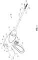
- FIG. 1is a front, perspective view of an endoscopic surgical forceps having a housing and a shaft that extends therefrom for supporting an end effector assembly, in accordance with the present disclosure
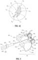
- FIG. 2is an enlarged, front, perspective view of an end effector assembly of the forceps of FIG. 1 , wherein jaw members of the end effector assembly are disposed in spaced-apart relation and wherein a monopolar assembly is disposed in a storage condition;
- FIG. 3is an enlarged, side, perspective view of the end effector assembly of FIG. 2 (shown in phantom), wherein the jaw members are disposed in approximated relation and wherein the monopolar assembly is disposed in a deployed condition;
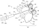
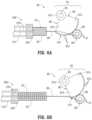
- FIG. 4 Ais a side, cut-a-way view of the housing of the forceps of FIG. 1 showing a deployment mechanism configured to selectively deploy the monopolar assembly from the storage condition;
- FIG. 4 Bis a side, cut-a-way view of the housing of the forceps of FIG. 1 with a proximal portion of the deployment mechanism removed;
- FIG. 4 Cis an enlarged view of the area of detail indicated as “ 4 C” in FIG. 4 B ;
- FIG. 5is an enlarged, front, perspective view of the deployment mechanism of FIG. 4 A ;
- FIG. 6 Ais an enlarged, side view of the deployment mechanism and a proximal end of the monopolar assembly, wherein the deployment mechanism is disposed in an un-actuated position corresponding to the storage condition of the monopolar assembly;
- FIG. 6 Bis a side view of the deployment mechanism and the proximal end of the monopolar assembly, wherein the deployment mechanism is disposed in an actuated position corresponding to the condition of the monopolar assembly.
- a forceps provided in accordance with the present disclosureis shown generally identified by reference numeral 10 .
- Forceps 10is configured to operate in both a bipolar mode, e.g., for grasping, treating, and/or dissecting tissue, and a monopolar mode, e.g., for treating and/or dissecting tissue.
- a bipolar modee.g., for grasping, treating, and/or dissecting tissue
- a monopolar modee.g., for treating and/or dissecting tissue.
- forceps 10includes a housing 20 , a handle assembly 30 , a trigger assembly 60 , a rotating assembly 70 , a deployment mechanism 80 , an end effector assembly 100 , and a monopolar assembly 200 .
- Forceps 10further includes a shaft 12 having a distal end 14 configured to mechanically engage end effector assembly 100 and a proximal end 16 that mechanically engages housing 20 .
- Forceps 10also includes an electrosurgical cable 2 that connects forceps 10 to a generator (not shown) or other suitable energy source, although forceps 10 may alternatively be configured as a battery powered instrument.
- Cable 2includes wires (not shown) extending therethrough that have sufficient length to extend through shaft 12 in order to provide electrical energy to at least one electrically-conductive surface 112 , 122 ( FIG. 2 ) of jaw members 110 , 120 , respectively, of end effector assembly 100 , e.g., upon activation of activation switch 4 in a bipolar mode.
- One or more of the wires of cable 2extends through housing 20 in order to provide electrical energy to monopolar assembly 200 , e.g., upon activation of activation switch 4 in a monopolar mode.
- Rotating assembly 70is rotatable in either direction to rotate end effector assembly 100 and monopolar assembly 200 relative to housing 20 .
- Housing 20houses the internal working components of forceps 10 . A detailed description of such internal working components, e.g., the drive assembly (not shown), rotating assembly 70 , and trigger assembly 60 can be found in U.S. Pat. No. 7,766,910, the entire contents of which are incorporated herein by reference.
- Handle assembly 30includes a movable handle 40 and a fixed handle 50 .
- Fixed handle 50is integrally associated with housing 20 and movable handle 40 is movable relative to fixed handle 50 .
- Movable handle 40is movable relative to fixed handle 50 between an initial position, wherein movable handle 40 is spaced from fixed handle 50 , and a compressed position, wherein movable handle 40 is compressed towards fixed handle 50 .
- a biasing member(not shown) may be provided to bias movable handle 40 towards the initial position.
- Movable handle 40is ultimately connected to a drive assembly (not shown) that, together, mechanically cooperate to impart movement of jaw members 110 , 120 between the spaced-apart position, corresponding to the initial position of movable handle 40 , and the approximated position, corresponding to the compressed position of movable handle 40 .
- a drive assemblyfor this purpose may be provided.
- Trigger assembly 60includes trigger 62 that is operably coupled to a knife assembly (not shown). Trigger 62 is selectively actuatable to advance a knife (not shown) of the knife assembly from a retracted position, wherein the knife is disposed proximally of jaw members 110 , 120 , to an extended position, wherein the knife extends at least partially between jaw members 110 , 120 to cut tissue grasped between jaw members 110 , 120 .
- electrical or electromechanical cutting featuresmay be provided.
- end effector assembly 100is attached at distal end 14 of shaft 12 and includes opposing jaw members 110 , 120 pivotably coupled to one another.
- Each of the jaw members 110 and 120includes a jaw body 111 , 121 supporting the respective electrically-conductive surface 112 , 122 , and a respective proximally-extending jaw flange 114 , 124 .
- Flanges 114 , 124are pivotably coupled to one another to permit movement of jaw members 110 , 120 relative to one another between a spaced-apart position ( FIG. 2 ) and an approximated position ( FIG. 3 ) for grasping tissue between surfaces 112 , 122 .
- One or both of surfaces 112 , 122are adapted to connect to the energy source, e.g., via the wires of cable 2 ( FIG. 1 ), and are configured to conduct energy through tissue grasped therebetween to treat, e.g., seal, tissue. More specifically, in some embodiments, end effector assembly 100 defines a bipolar configuration wherein surface 112 is charged to a first electrical potential and surface 122 is charged to a second, different electrical potential such that an electrical potential gradient is created for conducting energy between surfaces 112 , 122 and through tissue grasped therebetween for treating e.g., sealing, tissue.
- Activation switch 4FIG.
- End effector assembly 100is designed as a unilateral assembly, i.e., where jaw member 120 is fixed relative to shaft 12 and jaw member 110 is movable relative to shaft 12 and fixed jaw member 120 .
- end effector assembly 100may alternatively be configured as a bilateral assembly, i.e., where both jaw member 110 and jaw member 120 are movable relative to one another and to shaft 12 .
- a knife channel 125may be defined within one or both of jaw members 110 , 120 to permit reciprocation of the knife therethrough, e.g., upon actuation of a trigger 62 of trigger assembly 60 , to cut tissue grasped between jaw members 110 , 120 .
- electrical cutting mechanismsmay be provided for electrically or electromechanically cutting tissue grasped between jaw members 110 , 120 .
- monopolar assembly 200generally includes an insulative sleeve 210 , an energizable rod member 220 , and a proximal bushing 230 ( FIG. 4 A ).
- Insulative sleeve 210is slidably disposed about shaft 12 and is selectively movable about and relative to shaft 12 and end effector assembly 100 between a storage position ( FIG. 2 ), wherein insulative sleeve 210 is disposed proximal to end effector assembly 100 , and a deployed position ( FIG. 3 ), wherein insulative sleeve 210 is substantially disposed about end effector 100 so as to electrically insulate surfaces 112 , 122 of jaw members 110 , 120 , respectively, during monopolar activation.
- Energizable rod member 220extends through sleeve 210 and distally therefrom, ultimately defining an electrically-conductive distal tip 224 .
- Energizable rod member 220 and, more specifically, distal tip 224 thereof,functions as the active electrode of monopolar assembly 200 .
- the one or more wires(not shown) extending from cable 2 through housing 20 (see FIG. 1 ), are coupled to energizable rod member 220 to provide energy to energizable rod member 220 , e.g., upon actuation of activation switch 4 ( FIG. 1 ), for treating tissue in a monopolar mode of operation.
- Energizable rod member 220is movable between a storage position ( FIG.
- Distal tip 224 of rod member 220is positioned adjacent proximal flange 124 of jaw member 120 , and a deployed position ( FIG. 3 ), wherein distal tip 224 of rod member 220 extends distally from the distal ends of jaw members 110 , 120 .
- Distal tip 224may be hook-shaped (as shown), or may define any other suitable configuration, e.g., linear, circular, angled, etc.
- distal tip 224is disposed within an insulated groove 126 defined within proximal flange 124 of jaw member 120 , although other configurations are also contemplated. Insulated groove 126 electrically-insulates distal tip 224 of rod member 220 from electrically-conductive surfaces 112 , 122 of jaw members 110 , 120 , respectively, and from surrounding tissue when disposed in the storage position. Alternatively, distal tip 224 may only be insulated from surface 112 . In such configurations, distal tip 224 of rod member 220 is capable of being energized to the same polarity as surface 122 .
- distal tip 224extends distally from end effector assembly 100 and insulative sleeve 210 , which substantially surrounds end effector assembly 100 .
- energymay be applied to distal tip 224 of rod member 220 to treat tissue, e.g., via activation of activation switch 4 ( FIG. 1 ), in the monopolar mode of operation.
- proximal bushing 230is engaged to both the proximal end of sleeve 210 and the proximal end of energizable rod member 220 , thereby coupling sleeve 210 and energizable rod member 220 to one another.
- sleeve 210 and energizable rod member 220move between their respective storage positions ( FIGS. 2 and 6 A ), e.g., the storage condition of monopolar assembly 200 , and their deployed positions ( FIGS. 3 and 6 B ), e.g., the deployed condition of monopolar assembly 200 , upon selective translation of proximal bushing 230 .
- proximal bushing 230is operably coupled to deployment mechanism 80 ( FIG. 4 A ) for selectively translating proximal bushing 230 and, thus, for selectively transitioning monopolar assembly 200 between the storage condition ( FIGS. 2 and 6 A ) and the deployed condition ( FIGS. 3 and 6 B ).
- insulative sleeve 210is not provided and, thus, only enerigzable rod member 220 is utilized.
- the configuration and use of monopolar assembly 200 and deployment mechanism 80 ( FIG. 4 A )are substantially similar as detailed herein, with the exception of insulative sleeve 210 being omitted.
- insulative sleeve 210may be independently deployed, e.g., via a separate mechanism (not shown).
- deployment mechanism 80is operably coupled to monopolar assembly 200 for selectively transitioning monopolar assembly 200 between the storage condition ( FIGS. 2 and 6 A ) and the deployed condition ( FIGS. 3 and 6 B ).
- Deployment mechanism 80generally includes a pair of levers 82 ( FIG. 1 ; only one lever 82 is shown), a gear assembly 84 , a cartridge 92 , a biasing member 94 , and a cord 96 .
- Gear assembly 84includes a bar 85 that extends transversely through housing 20 and outwardly from each side of housing 20 .
- Bar 85is rotatably coupled to housing 20 .
- Levers 82are engaged to the portions of bar 85 that extend from housing 20 on either side thereof, thus enabling selective actuation of deployment mechanism 80 from either side of housing 20 .
- Each lever 82may further include a finger tab 83 ( FIG. 1 ) provided at an opposite end of the lever 82 as compared to bar 85 so as to facilitate rotation of lever 82 and, thus, corresponding rotation of bar 85 relative to housing 20 .
- Levers 82as shown in FIG. 1 , are rotatable relative to housing 20 along the path indicated by arrows “A,” between an un-actuated position (as shown in FIG. 1 ) corresponding to the storage condition of monopolar assembly 200 ( FIGS. 2 and 6 A ), and an actuated position corresponding to the deployed condition of monopolar assembly 200 ( FIGS. 3 and 6 B ).
- gear assembly 84further includes a pair of first gear components, e.g., gear plates 86 , disposed within housing 20 and coupled to bar 85 towards the respective ends thereof.
- Each gear plate 86includes a base 87 a that is engaged about bar 85 and a gear body 87 b extending proximally from its respective base 87 a .
- Each gear body 87 bdefines an arcuate engagement surface 87 c having a plurality of gear teeth 87 d formed thereon.
- Each gear body 87 bfurther includes a resiliently flexible latching tab 87 e , extending laterally outwardly therefrom towards a respective inner surface of housing 20 .
- the latching tab 87 e of each gear body 87 bis operably associated with a corresponding track 22 defined on an inner surface of housing 20 (only one of tracks 22 is shown in FIGS. 4 B- 4 C ). More specifically, latching tabs 87 e and tracks 22 cooperate to releasably latch levers 82 ( FIG. 1 ) in the un-actuated position (as shown in FIG. 1 ) corresponding to the storage condition of monopolar assembly 200 ( FIGS. 2 and 6 A ).
- latching tabs 87 e and tracks 22are detailed below with respect to the use and operation of forceps 10 ( FIG. 1 ).
- Other suitable latching mechanismsare also contemplated.
- a latching mechanism(not shown) may also be provided for releasably latching monopolar assembly 200 in the deployed condition ( FIGS. 3 and 6 B ).
- gear assembly 84further includes a shaft 88 transversely disposed and rotatably mounted within housing 20 (see FIG. 4 A ).
- Shaft 88includes a pair of second gear components, e.g., first and second annular gears 89 , engaged about shaft 88 towards the respective ends thereof.
- Each annular gear 89defines a plurality of circumferentially-disposed gear teeth 91 and is positioned such that gear teeth 91 are disposed in meshed engagement with the respective gear teeth 87 d of the corresponding gear plate 86 .
- rotation of either or both of levers 82 relative to housing 20 (see FIG. 1 ) in a first directioneffects rotation of shaft 88 in an opposite direction. That is, clockwise rotation of either of levers 82 relative to housing 20 see ( FIG. 1 ) effects counter-clockwise rotation of shaft 88 relative to housing 20 (see FIG. 1 ), and vice versa.
- cord 96is engaged to shaft 88 at the proximal end of cord 96 and extends distally from shaft 88 , through cartridge 92 , ultimately engaging proximal bushing 230 of monopolar assembly 200 at the distal end of cord 96 .
- Cord 96may be made from any suitable material and/or mechanisms that form a flexible linkage, e.g., rope, wire, chain, etc.
- the flexible linkage between gear assembly 84 and proximal bushing 230 formed by cord 96is advantageous in that it allows gear assembly 84 and proximal bushing 230 to be spaced-apart from one another, offset relative to one another, and/or have other components disposed therebetween without requiring complex linkage(s) joining gear assembly 84 and proximal bushing 230 .
- various pulley componentsmay be utilized to route cord 96 over/under and around various different components, thus providing additional flexibility with respect to positioning of the various components disposed within housing 20 .
- Cartridge 92is mounted within housing 20 and houses biasing member 94 , e.g., a coil spring, that is interdisposed between the proximal end of cartridge 92 and proximal bushing 230 .
- Proximal bushing 230is slidably disposed about cartridge 92 and is biased distally relative to cartridge 92 via biasing member 94 . This distal biasing of proximal bushing 230 biases monopolar assembly 200 towards the deployed condition ( FIGS. 3 and 6 B ). Further, as a result of the distal biasing of proximal bushing 230 , cord 96 is likewise biased distally such that shaft 88 is rotationally biased in a clockwise direction (as viewed in FIG.
- biasing member 94e.g., a coil spring
- forceps 10in both the bipolar mode, e.g., for grasping, treating, and/or cutting tissue, and the monopolar mode, e.g., for electrical/electromechanical tissue treatment (or to perforate or score tissue without the use of energy), is described.
- monopolar assembly 200is maintained in the storage condition ( FIGS. 2 and 6 A ). That is, referring to FIGS. 1 - 2 , 4 C and 6 A , for use in the bipolar mode of operation, levers 82 remain disposed in the un-actuated position (as shown in FIG. 1 ) with latching tabs 87 e engaged within saddles 26 of stop members 24 of tracks 22 at position P 1 ( FIG. 4 C ). In this position, latching tabs 87 e are maintained in a flexed condition, e.g., flexed from their neutral positions, under the urging of stop members 24 , the importance of which will be detailed below.
- end effector assembly 100may be maneuvered into position such that tissue to be grasped, treated, e.g., sealed, and/or cut, is disposed between jaw members 110 , 120 .
- movable handle 40is depressed, or pulled proximally relative to fixed handle 50 such that jaw member 110 is pivoted relative to jaw member 120 from the spaced-apart position to the approximated position to grasp tissue therebetween.
- energymay be supplied, e.g., via activation of switch 4 , to electrically-conductive surface 112 of jaw member 110 and/or electrically-conductive surface 122 of jaw member 120 and conducted through tissue to treat tissue, e.g., to effect a tissue seal or otherwise treat tissue in the bipolar mode of operation.
- the knife(not shown) may be deployed from within shaft 12 to between jaw members 110 , 120 , e.g., via actuation of trigger 62 of trigger assembly 60 , to cut tissue grasped between jaw members 110 , 120 .
- jaw members 110 , 120may be returned to the spaced-apart position to release the treated and/or divided tissue.
- monopolar assembly 200is unlatched and deployed to the deployed condition ( FIGS. 3 and 6 B ).
- either or both levers 82are rotated away from, e.g., in an opposite direction from, the actuated position sufficiently so as to move latching tabs 87 e to position P 2 .
- latching tabs 87 eare spaced-apart from stop members 24 such that latching tabs 87 e are permitted to resiliently return to their neutral, e.g., unflexed, positions, wherein latching tabs 87 e are offset from stop members 24 .
- the return of latching tabs 87 e to their neutral positions upon movement of latching tabs 87 e from position P 1 to position P 2inhibits re-engagement of latching tabs 87 e within saddles 26 once position P 2 has been achieved.
- lever(s) 82may be released.
- proximal bushing 230Upon release of lever(s) 82 , the potential energy stored in biasing member 94 is converted into potential energy to urge proximal bushing 230 distally to thereby push insulative sleeve 210 and energizable rod member 220 distally from their respective storage positions to their respective deployed positions ( FIGS. 3 and 6 B ).
- proximal bushing 230As proximal bushing 230 is translated distally, cord 96 is likewise pulled distally. This distal pulling of cord 96 unwinds cord 96 from about shaft 88 and urges shaft 88 to rotate in the clockwise direction (as viewed in FIG. 4 A ) to the position shown in FIG. 6 B .
- insulative sleeve 210surrounds jaw members 110 , 120 and energizable rod member 220 extends distally from end effector assembly 100 and insulative sleeve 210 .
- activation switch 4may be actuated to supply energy to energizable rod member 220 to treat, e.g., dissect, tissue.
- forceps 10may be moved relative to tissue, e.g., longitudinally, transversely, and/or radially, to facilitate electromechanical treatment of tissue.
- monopolar assembly 200may be returned to the storage condition ( FIGS. 2 and 6 A ). More specifically, with reference to FIGS. 1 and 4 C- 6 B , in order to return monopolar assembly 200 to the storage condition, either or both of levers 82 ( FIG. 1 ) are rotated back towards the un-actuated position against the bias of biasing member 94 . This rotation of levers 82 ( FIG. 1 ) effects rotation of shaft 88 in a clockwise direction (as viewed in FIG.
- latching tabs 87 eare moved along tracks 22 from position P 4 through position P 5 , wherein latching tabs 87 e contact stop members 24 and are flexed from their neutral positions by stop members 24 .
- latching tabs 87 eare positioned beyond stop members 24 at position P 6 , wherein latching tabs 87 e are permitted to resiliently return to their neutral positions.
- This configurationenables latching tabs 87 e to move into engagement within saddles 26 of stop members 24 , e.g., returning to position P 1 , upon release of levers 82 ( FIG. 1 ).
- monopolar assembly 200is one again latched in the storage condition, as shown in FIGS. 2 and 6 A .
Landscapes
- Health & Medical Sciences (AREA)
- Surgery (AREA)
- Engineering & Computer Science (AREA)
- Life Sciences & Earth Sciences (AREA)
- Biomedical Technology (AREA)
- Otolaryngology (AREA)
- Nuclear Medicine, Radiotherapy & Molecular Imaging (AREA)
- Plasma & Fusion (AREA)
- Physics & Mathematics (AREA)
- Heart & Thoracic Surgery (AREA)
- Medical Informatics (AREA)
- Molecular Biology (AREA)
- Animal Behavior & Ethology (AREA)
- General Health & Medical Sciences (AREA)
- Public Health (AREA)
- Veterinary Medicine (AREA)
- Surgical Instruments (AREA)
Abstract
Description
Claims (8)
Priority Applications (2)
| Application Number | Priority Date | Filing Date | Title |
|---|---|---|---|
| US16/697,320US12048473B2 (en) | 2014-11-17 | 2019-11-27 | Deployment mechanism for surgical instruments |
| US18/761,568US20240350191A1 (en) | 2014-11-17 | 2024-07-02 | Deployment mechanism for surgical instruments |
Applications Claiming Priority (3)
| Application Number | Priority Date | Filing Date | Title |
|---|---|---|---|
| US14/543,121US9687294B2 (en) | 2014-11-17 | 2014-11-17 | Deployment mechanism for surgical instruments |
| US15/633,105US10507055B2 (en) | 2014-11-17 | 2017-06-26 | Deployment mechanism for surgical instruments |
| US16/697,320US12048473B2 (en) | 2014-11-17 | 2019-11-27 | Deployment mechanism for surgical instruments |
Related Parent Applications (1)
| Application Number | Title | Priority Date | Filing Date |
|---|---|---|---|
| US15/633,105ContinuationUS10507055B2 (en) | 2014-11-17 | 2017-06-26 | Deployment mechanism for surgical instruments |
Related Child Applications (1)
| Application Number | Title | Priority Date | Filing Date |
|---|---|---|---|
| US18/761,568ContinuationUS20240350191A1 (en) | 2014-11-17 | 2024-07-02 | Deployment mechanism for surgical instruments |
Publications (2)
| Publication Number | Publication Date |
|---|---|
| US20200093538A1 US20200093538A1 (en) | 2020-03-26 |
| US12048473B2true US12048473B2 (en) | 2024-07-30 |
Family
ID=54360173
Family Applications (4)
| Application Number | Title | Priority Date | Filing Date |
|---|---|---|---|
| US14/543,121Active2035-08-14US9687294B2 (en) | 2014-11-17 | 2014-11-17 | Deployment mechanism for surgical instruments |
| US15/633,105Active2035-11-07US10507055B2 (en) | 2014-11-17 | 2017-06-26 | Deployment mechanism for surgical instruments |
| US16/697,320Active2035-10-24US12048473B2 (en) | 2014-11-17 | 2019-11-27 | Deployment mechanism for surgical instruments |
| US18/761,568PendingUS20240350191A1 (en) | 2014-11-17 | 2024-07-02 | Deployment mechanism for surgical instruments |
Family Applications Before (2)
| Application Number | Title | Priority Date | Filing Date |
|---|---|---|---|
| US14/543,121Active2035-08-14US9687294B2 (en) | 2014-11-17 | 2014-11-17 | Deployment mechanism for surgical instruments |
| US15/633,105Active2035-11-07US10507055B2 (en) | 2014-11-17 | 2017-06-26 | Deployment mechanism for surgical instruments |
Family Applications After (1)
| Application Number | Title | Priority Date | Filing Date |
|---|---|---|---|
| US18/761,568PendingUS20240350191A1 (en) | 2014-11-17 | 2024-07-02 | Deployment mechanism for surgical instruments |
Country Status (2)
| Country | Link |
|---|---|
| US (4) | US9687294B2 (en) |
| EP (1) | EP3020352B1 (en) |
Families Citing this family (5)
| Publication number | Priority date | Publication date | Assignee | Title |
|---|---|---|---|---|
| US10743874B2 (en)* | 2017-12-15 | 2020-08-18 | Ethicon Llc | Sealed adapters for use with electromechanical surgical instruments |
| USD904611S1 (en) | 2018-10-10 | 2020-12-08 | Bolder Surgical, Llc | Jaw design for a surgical instrument |
| USD934423S1 (en) | 2020-09-11 | 2021-10-26 | Bolder Surgical, Llc | End effector for a surgical device |
| USD1046129S1 (en) | 2021-04-14 | 2024-10-08 | Bolder Surgical, Llc | End effector for a surgical instrument |
| WO2023123498A1 (en)* | 2021-12-31 | 2023-07-06 | 杭州光典医疗器械有限公司 | Insertion surgical forceps |
Citations (66)
| Publication number | Priority date | Publication date | Assignee | Title |
|---|---|---|---|---|
| US1908201A (en)* | 1931-03-09 | 1933-05-09 | Morton G Welch | Bipolar tonsil forceps |
| US5312391A (en) | 1992-07-29 | 1994-05-17 | Wilk Peter J | Laparoscopic instrument assembly |
| US5318589A (en) | 1992-04-15 | 1994-06-07 | Microsurge, Inc. | Surgical instrument for endoscopic surgery |
| US5324254A (en) | 1990-05-25 | 1994-06-28 | Phillips Edward H | Tool for laparoscopic surgery |
| US5401274A (en) | 1992-04-20 | 1995-03-28 | Olympus Optical Co., Ltd. | High-frequency treating instrument |
| US5445638A (en) | 1993-03-08 | 1995-08-29 | Everest Medical Corporation | Bipolar coagulation and cutting forceps |
| US5458598A (en) | 1993-12-02 | 1995-10-17 | Cabot Technology Corporation | Cutting and coagulating forceps |
| US5556397A (en) | 1994-10-26 | 1996-09-17 | Laser Centers Of America | Coaxial electrosurgical instrument |
| US5611813A (en)* | 1992-04-15 | 1997-03-18 | Microsurge, Inc. | Surgical instrument |
| US5665100A (en)* | 1989-12-05 | 1997-09-09 | Yoon; Inbae | Multifunctional instrument with interchangeable operating units for performing endoscopic procedures |
| US5735873A (en) | 1996-12-19 | 1998-04-07 | Maclean; David S. | Surgical tool handle |
| US5792164A (en) | 1994-12-19 | 1998-08-11 | Lakatos; Nick | Surgical instrument |
| US5893863A (en) | 1989-12-05 | 1999-04-13 | Yoon; Inbae | Surgical instrument with jaws and movable internal hook member for use thereof |
| US5919202A (en) | 1989-12-05 | 1999-07-06 | Yoon; Inbae | Surgical instrument with jaws and movable internal needle and method for use thereof |
| US5984939A (en)* | 1989-12-05 | 1999-11-16 | Yoon; Inbae | Multifunctional grasping instrument with cutting member and operating channel for use in endoscopic and non-endoscopic procedures |
| US6113596A (en) | 1996-12-30 | 2000-09-05 | Enable Medical Corporation | Combination monopolar-bipolar electrosurgical instrument system, instrument and cable |
| US6156009A (en) | 1996-12-05 | 2000-12-05 | Comedicus Incorporated | Apparatus for accessing the pericardial space |
| US6190386B1 (en) | 1999-03-09 | 2001-02-20 | Everest Medical Corporation | Electrosurgical forceps with needle electrodes |
| US6270497B1 (en) | 1998-08-27 | 2001-08-07 | Olympus Optical Co., Ltd. | High-frequency treatment apparatus having control mechanism for incising tissue after completion of coagulation by high-frequency treatment tool |
| US6299625B1 (en) | 1998-08-12 | 2001-10-09 | Karl Storz Gmbh & Co. Kg | Handle for a medical instrument |
| US20020049442A1 (en) | 1999-07-27 | 2002-04-25 | Roberts Troy W. | Biopsy sampler |
| US6387094B1 (en) | 1998-10-30 | 2002-05-14 | Karl Storz Gmbh & Co. Kg | Medical instrument for dissecting tissue |
| US6551313B1 (en) | 2001-05-02 | 2003-04-22 | John M. Levin | Electrosurgical instrument with separate cutting and coagulating members |
| US6679882B1 (en) | 1998-06-22 | 2004-01-20 | Lina Medical Aps | Electrosurgical device for coagulating and for making incisions, a method of severing blood vessels and a method of coagulating and for making incisions in or severing tissue |
| US6808525B2 (en) | 2001-08-27 | 2004-10-26 | Gyrus Medical, Inc. | Bipolar electrosurgical hook probe for cutting and coagulating tissue |
| US20040236326A1 (en) | 2001-01-24 | 2004-11-25 | Schulze Dale R. | Electrosurgical instrument with closing tube for conducting RF energy and moving jaws |
| US20050187547A1 (en) | 2004-02-25 | 2005-08-25 | Yoshihiko Sugi | High frequency treatment device having a pair of jaws with electrodes |
| US6942662B2 (en) | 2001-12-27 | 2005-09-13 | Gyrus Group Plc | Surgical Instrument |
| US7033356B2 (en) | 2002-07-02 | 2006-04-25 | Gyrus Medical, Inc. | Bipolar electrosurgical instrument for cutting desiccating and sealing tissue |
| US7063699B2 (en) | 2001-01-24 | 2006-06-20 | Ethicon, Inc. | Electrosurgical instrument with minimally invasive jaws |
| US7128254B2 (en) | 2004-09-07 | 2006-10-31 | Ethicon Endo-Surgery, Inc. | Surgical stapling instrument incorporating a multistroke firing mechanism having a rotary slip-clutch transmission |
| US20060271042A1 (en)* | 2005-05-26 | 2006-11-30 | Gyrus Medical, Inc. | Cutting and coagulating electrosurgical forceps having cam controlled jaw closure |
| US20070043352A1 (en) | 2005-08-19 | 2007-02-22 | Garrison David M | Single action tissue sealer |
| US20070135813A1 (en)* | 2005-10-28 | 2007-06-14 | Hironori Yamamoto | Treatment tool for endoscope |
| US7232440B2 (en) | 2003-11-17 | 2007-06-19 | Sherwood Services Ag | Bipolar forceps having monopolar extension |
| US20070225754A1 (en) | 2006-03-21 | 2007-09-27 | Ethicon Endo-Surgery, Inc. | Medical instrument having an engagement mechanism |
| US20080077154A1 (en) | 2006-09-21 | 2008-03-27 | Edwards Scott G | System and method of bone compression and fixation |
| US7367976B2 (en) | 2003-11-17 | 2008-05-06 | Sherwood Services Ag | Bipolar forceps having monopolar extension |
| US7402162B2 (en) | 2004-03-24 | 2008-07-22 | Hoya Corporation | High frequency treatment instrument for endoscope |
| US20080215050A1 (en) | 2007-03-02 | 2008-09-04 | Ethicon Endo-Surgery, Inc. | Tissue engaging hemostasis device |
| US7510562B2 (en) | 2003-07-08 | 2009-03-31 | Terumo Corporation | Vein dissector, cauterizing and ligating apparatus for endoscopic harvesting of blood vessels |
| US20090125027A1 (en) | 2006-04-11 | 2009-05-14 | Klaus Fischer | Multifunction device for endoscopic surgery |
| US20090125026A1 (en) | 2007-11-13 | 2009-05-14 | Boston Scientific Scimed, Inc. | Apparatus system and method for coagulating and cutting tissue |
| US20090131974A1 (en) | 2004-12-29 | 2009-05-21 | Surgitech Norway As | Instrument, particularly for use in laparoscopic surgery |
| US7588570B2 (en) | 2003-06-09 | 2009-09-15 | Tohru Tani | Medical treatment instrument and medical treatment apparatus including the same |
| US20090254084A1 (en) | 2008-04-08 | 2009-10-08 | Naito Kimihiko | High-frequency treatment apparatus |
| US7658311B2 (en) | 2007-06-22 | 2010-02-09 | Ethicon Endo-Surgery, Inc. | Surgical stapling instrument with a geared return mechanism |
| US20100076430A1 (en)* | 2008-09-24 | 2010-03-25 | Tyco Healthcare Group Lp | Electrosurgical Instrument Having a Thumb Lever and Related System and Method of Use |
| US7758577B2 (en) | 2006-12-05 | 2010-07-20 | Ethicon Endo-Surgery, Inc. | Monopolar resection device and method of use |
| US20100185196A1 (en) | 2009-01-21 | 2010-07-22 | Satomi Sakao | Medical treatment apparatus, treatment instrument and treatment method for living tissue using energy |
| US20100185197A1 (en) | 2009-01-21 | 2010-07-22 | Satomi Sakao | Medical treatment apparatus, treatment instrument and treatment method for living tissue using energy |
| US7766910B2 (en) | 2006-01-24 | 2010-08-03 | Tyco Healthcare Group Lp | Vessel sealer and divider for large tissue structures |
| US7815636B2 (en) | 2005-11-29 | 2010-10-19 | Ethicon Endo-Surgery, Inc. | Auto-safety shut-off for energy based devices |
| US7819872B2 (en) | 2005-09-30 | 2010-10-26 | Covidien Ag | Flexible endoscopic catheter with ligasure |
| US20100292690A1 (en) | 2009-03-02 | 2010-11-18 | Bovie Medical Corporation | Surgical apparatus for tissue sealing and cutting |
| US20110087218A1 (en) | 2009-10-09 | 2011-04-14 | Ethicon Endo-Surgery, Inc. | Surgical instrument comprising first and second drive systems actuatable by a common trigger mechanism |
| US20110098703A1 (en)* | 2008-07-08 | 2011-04-28 | Keita Suzuki | High-frequency treatment instrument |
| US20110130757A1 (en) | 2008-06-30 | 2011-06-02 | Celon Ag Medical Instruments | Electrosurgical instrument |
| US20110264093A1 (en) | 2010-04-22 | 2011-10-27 | Ethicon Endo-Surgery, Inc. | Electrosurgical instrument comprising closing and firing systems |
| US20110290854A1 (en)* | 2007-06-04 | 2011-12-01 | Ethicon Endo-Surgery, Inc. | Robotically-controlled shaft based rotary drive systems for surgical instruments |
| US20120330351A1 (en) | 2009-09-30 | 2012-12-27 | Aegis Medical Innovations Inc. | Tissue capture and occlusion systems and methods |
| US8353437B2 (en) | 2007-06-22 | 2013-01-15 | Ethicon Endo-Surgery, Inc. | Surgical stapling instrument with a geared return mechanism |
| US20130197516A1 (en) | 2012-01-31 | 2013-08-01 | Boston Scientific Scimed, Inc. | Multi-functional medical device and related methods of use |
| EP2679176A1 (en) | 2012-06-29 | 2014-01-01 | Covidien LP | Surgical forceps |
| US20140135763A1 (en) | 2012-11-15 | 2014-05-15 | Covidien Lp | Deployment mechanisms for surgical instruments |
| US20140276797A1 (en) | 2013-03-15 | 2014-09-18 | GYRUS ACMI, INC., d/b/a Olympus Surgical Technologies America | Combination electrosurgical device |
Family Cites Families (1)
| Publication number | Priority date | Publication date | Assignee | Title |
|---|---|---|---|---|
| US8728076B2 (en)* | 2007-12-18 | 2014-05-20 | Bovie Medical Corporation | Surgical apparatus with removable tool cartridge |
- 2014
- 2014-11-17USUS14/543,121patent/US9687294B2/enactiveActive
- 2015
- 2015-10-23EPEP15191287.0Apatent/EP3020352B1/enactiveActive
- 2017
- 2017-06-26USUS15/633,105patent/US10507055B2/enactiveActive
- 2019
- 2019-11-27USUS16/697,320patent/US12048473B2/enactiveActive
- 2024
- 2024-07-02USUS18/761,568patent/US20240350191A1/enactivePending
Patent Citations (70)
| Publication number | Priority date | Publication date | Assignee | Title |
|---|---|---|---|---|
| US1908201A (en)* | 1931-03-09 | 1933-05-09 | Morton G Welch | Bipolar tonsil forceps |
| US5984939A (en)* | 1989-12-05 | 1999-11-16 | Yoon; Inbae | Multifunctional grasping instrument with cutting member and operating channel for use in endoscopic and non-endoscopic procedures |
| US5919202A (en) | 1989-12-05 | 1999-07-06 | Yoon; Inbae | Surgical instrument with jaws and movable internal needle and method for use thereof |
| US5893863A (en) | 1989-12-05 | 1999-04-13 | Yoon; Inbae | Surgical instrument with jaws and movable internal hook member for use thereof |
| US5665100A (en)* | 1989-12-05 | 1997-09-09 | Yoon; Inbae | Multifunctional instrument with interchangeable operating units for performing endoscopic procedures |
| US5324254A (en) | 1990-05-25 | 1994-06-28 | Phillips Edward H | Tool for laparoscopic surgery |
| US5611813A (en)* | 1992-04-15 | 1997-03-18 | Microsurge, Inc. | Surgical instrument |
| US5318589A (en) | 1992-04-15 | 1994-06-07 | Microsurge, Inc. | Surgical instrument for endoscopic surgery |
| US5401274A (en) | 1992-04-20 | 1995-03-28 | Olympus Optical Co., Ltd. | High-frequency treating instrument |
| US5312391A (en) | 1992-07-29 | 1994-05-17 | Wilk Peter J | Laparoscopic instrument assembly |
| US5445638B1 (en) | 1993-03-08 | 1998-05-05 | Everest Medical Corp | Bipolar coagulation and cutting forceps |
| US5445638A (en) | 1993-03-08 | 1995-08-29 | Everest Medical Corporation | Bipolar coagulation and cutting forceps |
| US5458598A (en) | 1993-12-02 | 1995-10-17 | Cabot Technology Corporation | Cutting and coagulating forceps |
| US5556397A (en) | 1994-10-26 | 1996-09-17 | Laser Centers Of America | Coaxial electrosurgical instrument |
| US5792164A (en) | 1994-12-19 | 1998-08-11 | Lakatos; Nick | Surgical instrument |
| US6156009A (en) | 1996-12-05 | 2000-12-05 | Comedicus Incorporated | Apparatus for accessing the pericardial space |
| US5735873A (en) | 1996-12-19 | 1998-04-07 | Maclean; David S. | Surgical tool handle |
| US6113596A (en) | 1996-12-30 | 2000-09-05 | Enable Medical Corporation | Combination monopolar-bipolar electrosurgical instrument system, instrument and cable |
| US6679882B1 (en) | 1998-06-22 | 2004-01-20 | Lina Medical Aps | Electrosurgical device for coagulating and for making incisions, a method of severing blood vessels and a method of coagulating and for making incisions in or severing tissue |
| US6299625B1 (en) | 1998-08-12 | 2001-10-09 | Karl Storz Gmbh & Co. Kg | Handle for a medical instrument |
| US6270497B1 (en) | 1998-08-27 | 2001-08-07 | Olympus Optical Co., Ltd. | High-frequency treatment apparatus having control mechanism for incising tissue after completion of coagulation by high-frequency treatment tool |
| US6387094B1 (en) | 1998-10-30 | 2002-05-14 | Karl Storz Gmbh & Co. Kg | Medical instrument for dissecting tissue |
| US6190386B1 (en) | 1999-03-09 | 2001-02-20 | Everest Medical Corporation | Electrosurgical forceps with needle electrodes |
| US20020049442A1 (en) | 1999-07-27 | 2002-04-25 | Roberts Troy W. | Biopsy sampler |
| US7063699B2 (en) | 2001-01-24 | 2006-06-20 | Ethicon, Inc. | Electrosurgical instrument with minimally invasive jaws |
| US20040236326A1 (en) | 2001-01-24 | 2004-11-25 | Schulze Dale R. | Electrosurgical instrument with closing tube for conducting RF energy and moving jaws |
| US6551313B1 (en) | 2001-05-02 | 2003-04-22 | John M. Levin | Electrosurgical instrument with separate cutting and coagulating members |
| US6808525B2 (en) | 2001-08-27 | 2004-10-26 | Gyrus Medical, Inc. | Bipolar electrosurgical hook probe for cutting and coagulating tissue |
| US6942662B2 (en) | 2001-12-27 | 2005-09-13 | Gyrus Group Plc | Surgical Instrument |
| US7033356B2 (en) | 2002-07-02 | 2006-04-25 | Gyrus Medical, Inc. | Bipolar electrosurgical instrument for cutting desiccating and sealing tissue |
| US7588570B2 (en) | 2003-06-09 | 2009-09-15 | Tohru Tani | Medical treatment instrument and medical treatment apparatus including the same |
| US7510562B2 (en) | 2003-07-08 | 2009-03-31 | Terumo Corporation | Vein dissector, cauterizing and ligating apparatus for endoscopic harvesting of blood vessels |
| US8257352B2 (en) | 2003-11-17 | 2012-09-04 | Covidien Ag | Bipolar forceps having monopolar extension |
| US7232440B2 (en) | 2003-11-17 | 2007-06-19 | Sherwood Services Ag | Bipolar forceps having monopolar extension |
| US20110004209A1 (en)* | 2003-11-17 | 2011-01-06 | Kate Lawes | Bipolar Forceps having Monopolar Extension |
| US7367976B2 (en) | 2003-11-17 | 2008-05-06 | Sherwood Services Ag | Bipolar forceps having monopolar extension |
| US7445621B2 (en) | 2003-11-17 | 2008-11-04 | Covidien Ag | Bipolar forceps having monopolar extension |
| US20050187547A1 (en) | 2004-02-25 | 2005-08-25 | Yoshihiko Sugi | High frequency treatment device having a pair of jaws with electrodes |
| US7402162B2 (en) | 2004-03-24 | 2008-07-22 | Hoya Corporation | High frequency treatment instrument for endoscope |
| US7128254B2 (en) | 2004-09-07 | 2006-10-31 | Ethicon Endo-Surgery, Inc. | Surgical stapling instrument incorporating a multistroke firing mechanism having a rotary slip-clutch transmission |
| US20090131974A1 (en) | 2004-12-29 | 2009-05-21 | Surgitech Norway As | Instrument, particularly for use in laparoscopic surgery |
| US20060271042A1 (en)* | 2005-05-26 | 2006-11-30 | Gyrus Medical, Inc. | Cutting and coagulating electrosurgical forceps having cam controlled jaw closure |
| US20070043352A1 (en) | 2005-08-19 | 2007-02-22 | Garrison David M | Single action tissue sealer |
| US7819872B2 (en) | 2005-09-30 | 2010-10-26 | Covidien Ag | Flexible endoscopic catheter with ligasure |
| US20070135813A1 (en)* | 2005-10-28 | 2007-06-14 | Hironori Yamamoto | Treatment tool for endoscope |
| US7815636B2 (en) | 2005-11-29 | 2010-10-19 | Ethicon Endo-Surgery, Inc. | Auto-safety shut-off for energy based devices |
| US7766910B2 (en) | 2006-01-24 | 2010-08-03 | Tyco Healthcare Group Lp | Vessel sealer and divider for large tissue structures |
| US20070225754A1 (en) | 2006-03-21 | 2007-09-27 | Ethicon Endo-Surgery, Inc. | Medical instrument having an engagement mechanism |
| US20090125027A1 (en) | 2006-04-11 | 2009-05-14 | Klaus Fischer | Multifunction device for endoscopic surgery |
| US20080077154A1 (en) | 2006-09-21 | 2008-03-27 | Edwards Scott G | System and method of bone compression and fixation |
| US7758577B2 (en) | 2006-12-05 | 2010-07-20 | Ethicon Endo-Surgery, Inc. | Monopolar resection device and method of use |
| US20080215050A1 (en) | 2007-03-02 | 2008-09-04 | Ethicon Endo-Surgery, Inc. | Tissue engaging hemostasis device |
| US20110290854A1 (en)* | 2007-06-04 | 2011-12-01 | Ethicon Endo-Surgery, Inc. | Robotically-controlled shaft based rotary drive systems for surgical instruments |
| US8353437B2 (en) | 2007-06-22 | 2013-01-15 | Ethicon Endo-Surgery, Inc. | Surgical stapling instrument with a geared return mechanism |
| US7658311B2 (en) | 2007-06-22 | 2010-02-09 | Ethicon Endo-Surgery, Inc. | Surgical stapling instrument with a geared return mechanism |
| US20090125026A1 (en) | 2007-11-13 | 2009-05-14 | Boston Scientific Scimed, Inc. | Apparatus system and method for coagulating and cutting tissue |
| US20090254084A1 (en) | 2008-04-08 | 2009-10-08 | Naito Kimihiko | High-frequency treatment apparatus |
| US20110130757A1 (en) | 2008-06-30 | 2011-06-02 | Celon Ag Medical Instruments | Electrosurgical instrument |
| US20110098703A1 (en)* | 2008-07-08 | 2011-04-28 | Keita Suzuki | High-frequency treatment instrument |
| US20100076430A1 (en)* | 2008-09-24 | 2010-03-25 | Tyco Healthcare Group Lp | Electrosurgical Instrument Having a Thumb Lever and Related System and Method of Use |
| US20100185197A1 (en) | 2009-01-21 | 2010-07-22 | Satomi Sakao | Medical treatment apparatus, treatment instrument and treatment method for living tissue using energy |
| US20100185196A1 (en) | 2009-01-21 | 2010-07-22 | Satomi Sakao | Medical treatment apparatus, treatment instrument and treatment method for living tissue using energy |
| US20100292690A1 (en) | 2009-03-02 | 2010-11-18 | Bovie Medical Corporation | Surgical apparatus for tissue sealing and cutting |
| US20120330351A1 (en) | 2009-09-30 | 2012-12-27 | Aegis Medical Innovations Inc. | Tissue capture and occlusion systems and methods |
| US20110087218A1 (en) | 2009-10-09 | 2011-04-14 | Ethicon Endo-Surgery, Inc. | Surgical instrument comprising first and second drive systems actuatable by a common trigger mechanism |
| US20110264093A1 (en) | 2010-04-22 | 2011-10-27 | Ethicon Endo-Surgery, Inc. | Electrosurgical instrument comprising closing and firing systems |
| US20130197516A1 (en) | 2012-01-31 | 2013-08-01 | Boston Scientific Scimed, Inc. | Multi-functional medical device and related methods of use |
| EP2679176A1 (en) | 2012-06-29 | 2014-01-01 | Covidien LP | Surgical forceps |
| US20140135763A1 (en) | 2012-11-15 | 2014-05-15 | Covidien Lp | Deployment mechanisms for surgical instruments |
| US20140276797A1 (en) | 2013-03-15 | 2014-09-18 | GYRUS ACMI, INC., d/b/a Olympus Surgical Technologies America | Combination electrosurgical device |
Non-Patent Citations (1)
| Title |
|---|
| Extended European Search Report issued in corresponding European Patent Application No. 15191287.0 on Apr. 12, 2016. |
Also Published As
| Publication number | Publication date |
|---|---|
| US20160135870A1 (en) | 2016-05-19 |
| US10507055B2 (en) | 2019-12-17 |
| US20200093538A1 (en) | 2020-03-26 |
| EP3020352A1 (en) | 2016-05-18 |
| EP3020352B1 (en) | 2018-12-12 |
| US9687294B2 (en) | 2017-06-27 |
| US20240350191A1 (en) | 2024-10-24 |
| US20170290625A1 (en) | 2017-10-12 |
Similar Documents
| Publication | Publication Date | Title |
|---|---|---|
| US12048473B2 (en) | Deployment mechanism for surgical instruments | |
| US11864822B2 (en) | Deployment mechanisms for surgical instruments | |
| US9918784B2 (en) | Surgical forceps | |
| US11298180B2 (en) | Gear assembly for surgical instruments | |
| JP5687309B2 (en) | Surgical forceps | |
| US11045250B2 (en) | Multi-function surgical instruments | |
| US9987076B2 (en) | Multi-function surgical instruments | |
| US10631920B2 (en) | Deployment mechanism for surgical instruments | |
| US9814516B2 (en) | Deployment mechanisms for multi-function surgical instruments |
Legal Events
| Date | Code | Title | Description |
|---|---|---|---|
| AS | Assignment | Owner name:COVIDIEN ENGINEERING SERVICES PRIVATE LIMITED, INDIA Free format text:ASSIGNMENT OF ASSIGNORS INTEREST;ASSIGNOR:JADHAV, AMARSINH D.;REEL/FRAME:051127/0895 Effective date:20141030 Owner name:COVIDIEN LP, MASSACHUSETTS Free format text:ASSIGNMENT OF ASSIGNORS INTEREST;ASSIGNOR:COVIDIEN AG;REEL/FRAME:051128/0342 Effective date:20150408 Owner name:COVIDIEN AG, SWITZERLAND Free format text:ASSIGNMENT OF ASSIGNORS INTEREST;ASSIGNOR:COVIDIEN PRIVATE LIMITED;REEL/FRAME:051128/0101 Effective date:20150324 Owner name:COVIDIEN PRIVATE LIMITED, SINGAPORE Free format text:ASSIGNMENT OF ASSIGNORS INTEREST;ASSIGNOR:COVIDIEN ENGINEERING SERVICES PRIVATE LIMITED;REEL/FRAME:051128/0025 Effective date:20150317 | |
| FEPP | Fee payment procedure | Free format text:ENTITY STATUS SET TO UNDISCOUNTED (ORIGINAL EVENT CODE: BIG.); ENTITY STATUS OF PATENT OWNER: LARGE ENTITY | |
| STPP | Information on status: patent application and granting procedure in general | Free format text:DOCKETED NEW CASE - READY FOR EXAMINATION | |
| STPP | Information on status: patent application and granting procedure in general | Free format text:NON FINAL ACTION MAILED | |
| STPP | Information on status: patent application and granting procedure in general | Free format text:RESPONSE TO NON-FINAL OFFICE ACTION ENTERED AND FORWARDED TO EXAMINER | |
| STPP | Information on status: patent application and granting procedure in general | Free format text:FINAL REJECTION MAILED | |
| STPP | Information on status: patent application and granting procedure in general | Free format text:ADVISORY ACTION MAILED | |
| STPP | Information on status: patent application and granting procedure in general | Free format text:DOCKETED NEW CASE - READY FOR EXAMINATION | |
| STPP | Information on status: patent application and granting procedure in general | Free format text:NON FINAL ACTION MAILED | |
| STPP | Information on status: patent application and granting procedure in general | Free format text:RESPONSE TO NON-FINAL OFFICE ACTION ENTERED AND FORWARDED TO EXAMINER | |
| STPP | Information on status: patent application and granting procedure in general | Free format text:NOTICE OF ALLOWANCE MAILED -- APPLICATION RECEIVED IN OFFICE OF PUBLICATIONS | |
| ZAAA | Notice of allowance and fees due | Free format text:ORIGINAL CODE: NOA | |
| ZAAB | Notice of allowance mailed | Free format text:ORIGINAL CODE: MN/=. | |
| STPP | Information on status: patent application and granting procedure in general | Free format text:PUBLICATIONS -- ISSUE FEE PAYMENT RECEIVED | |
| STPP | Information on status: patent application and granting procedure in general | Free format text:PUBLICATIONS -- ISSUE FEE PAYMENT VERIFIED | |
| STCF | Information on status: patent grant | Free format text:PATENTED CASE |