US12044301B2 - Track system with a support member - Google Patents
Track system with a support memberDownload PDFInfo
- Publication number
- US12044301B2 US12044301B2US17/179,159US202117179159AUS12044301B2US 12044301 B2US12044301 B2US 12044301B2US 202117179159 AUS202117179159 AUS 202117179159AUS 12044301 B2US12044301 B2US 12044301B2
- Authority
- US
- United States
- Prior art keywords
- anchor
- toothed
- track
- cam
- assembly
- Prior art date
- Legal status (The legal status is an assumption and is not a legal conclusion. Google has not performed a legal analysis and makes no representation as to the accuracy of the status listed.)
- Active, expires
Links
Images


Classifications
- B—PERFORMING OPERATIONS; TRANSPORTING
- B60—VEHICLES IN GENERAL
- B60N—SEATS SPECIALLY ADAPTED FOR VEHICLES; VEHICLE PASSENGER ACCOMMODATION NOT OTHERWISE PROVIDED FOR
- B60N2/00—Seats specially adapted for vehicles; Arrangement or mounting of seats in vehicles
- B60N2/02—Seats specially adapted for vehicles; Arrangement or mounting of seats in vehicles the seat or part thereof being movable, e.g. adjustable
- B60N2/04—Seats specially adapted for vehicles; Arrangement or mounting of seats in vehicles the seat or part thereof being movable, e.g. adjustable the whole seat being movable
- B60N2/06—Seats specially adapted for vehicles; Arrangement or mounting of seats in vehicles the seat or part thereof being movable, e.g. adjustable the whole seat being movable slidable
- B60N2/07—Slide construction
- B60N2/0702—Slide construction characterised by its cross-section
- B60N2/072—Complex cross-section, e.g. obtained by extrusion
- F—MECHANICAL ENGINEERING; LIGHTING; HEATING; WEAPONS; BLASTING
- F16—ENGINEERING ELEMENTS AND UNITS; GENERAL MEASURES FOR PRODUCING AND MAINTAINING EFFECTIVE FUNCTIONING OF MACHINES OR INSTALLATIONS; THERMAL INSULATION IN GENERAL
- F16H—GEARING
- F16H55/00—Elements with teeth or friction surfaces for conveying motion; Worms, pulleys or sheaves for gearing mechanisms
- F16H55/02—Toothed members; Worms
- F16H55/26—Racks
- B—PERFORMING OPERATIONS; TRANSPORTING
- B60—VEHICLES IN GENERAL
- B60N—SEATS SPECIALLY ADAPTED FOR VEHICLES; VEHICLE PASSENGER ACCOMMODATION NOT OTHERWISE PROVIDED FOR
- B60N2/00—Seats specially adapted for vehicles; Arrangement or mounting of seats in vehicles
- B60N2/005—Arrangement or mounting of seats in vehicles, e.g. dismountable auxiliary seats
- B60N2/015—Attaching seats directly to vehicle chassis
- B—PERFORMING OPERATIONS; TRANSPORTING
- B60—VEHICLES IN GENERAL
- B60N—SEATS SPECIALLY ADAPTED FOR VEHICLES; VEHICLE PASSENGER ACCOMMODATION NOT OTHERWISE PROVIDED FOR
- B60N2/00—Seats specially adapted for vehicles; Arrangement or mounting of seats in vehicles
- B60N2/02—Seats specially adapted for vehicles; Arrangement or mounting of seats in vehicles the seat or part thereof being movable, e.g. adjustable
- B60N2/0224—Non-manual adjustments, e.g. with electrical operation
- B60N2/0244—Non-manual adjustments, e.g. with electrical operation with logic circuits
- B60N2/0264—Non-manual adjustments, e.g. with electrical operation with logic circuits characterised by the type of electrical connection, e.g. wiring, plugs or USB
- B—PERFORMING OPERATIONS; TRANSPORTING
- B60—VEHICLES IN GENERAL
- B60N—SEATS SPECIALLY ADAPTED FOR VEHICLES; VEHICLE PASSENGER ACCOMMODATION NOT OTHERWISE PROVIDED FOR
- B60N2/00—Seats specially adapted for vehicles; Arrangement or mounting of seats in vehicles
- B60N2/02—Seats specially adapted for vehicles; Arrangement or mounting of seats in vehicles the seat or part thereof being movable, e.g. adjustable
- B60N2/04—Seats specially adapted for vehicles; Arrangement or mounting of seats in vehicles the seat or part thereof being movable, e.g. adjustable the whole seat being movable
- B60N2/06—Seats specially adapted for vehicles; Arrangement or mounting of seats in vehicles the seat or part thereof being movable, e.g. adjustable the whole seat being movable slidable
- B60N2/07—Slide construction
- B60N2/0722—Constructive details
- B—PERFORMING OPERATIONS; TRANSPORTING
- B60—VEHICLES IN GENERAL
- B60N—SEATS SPECIALLY ADAPTED FOR VEHICLES; VEHICLE PASSENGER ACCOMMODATION NOT OTHERWISE PROVIDED FOR
- B60N2/00—Seats specially adapted for vehicles; Arrangement or mounting of seats in vehicles
- B60N2/02—Seats specially adapted for vehicles; Arrangement or mounting of seats in vehicles the seat or part thereof being movable, e.g. adjustable
- B60N2/04—Seats specially adapted for vehicles; Arrangement or mounting of seats in vehicles the seat or part thereof being movable, e.g. adjustable the whole seat being movable
- B60N2/06—Seats specially adapted for vehicles; Arrangement or mounting of seats in vehicles the seat or part thereof being movable, e.g. adjustable the whole seat being movable slidable
- B60N2/08—Seats specially adapted for vehicles; Arrangement or mounting of seats in vehicles the seat or part thereof being movable, e.g. adjustable the whole seat being movable slidable characterised by the locking device
- B—PERFORMING OPERATIONS; TRANSPORTING
- B61—RAILWAYS
- B61B—RAILWAY SYSTEMS; EQUIPMENT THEREFOR NOT OTHERWISE PROVIDED FOR
- B61B13/00—Other railway systems
- B61B13/02—Rack railways
- B—PERFORMING OPERATIONS; TRANSPORTING
- B61—RAILWAYS
- B61C—LOCOMOTIVES; MOTOR RAILCARS
- B61C11/00—Locomotives or motor railcars characterised by the type of means applying the tractive effort; Arrangement or disposition of running gear other than normal driving wheel
- B61C11/04—Locomotives or motor railcars characterised by the type of means applying the tractive effort; Arrangement or disposition of running gear other than normal driving wheel tractive effort applied to racks
- B—PERFORMING OPERATIONS; TRANSPORTING
- B61—RAILWAYS
- B61F—RAIL VEHICLE SUSPENSIONS, e.g. UNDERFRAMES, BOGIES OR ARRANGEMENTS OF WHEEL AXLES; RAIL VEHICLES FOR USE ON TRACKS OF DIFFERENT WIDTH; PREVENTING DERAILING OF RAIL VEHICLES; WHEEL GUARDS, OBSTRUCTION REMOVERS OR THE LIKE FOR RAIL VEHICLES
- B61F9/00—Rail vehicles characterised by means for preventing derailing, e.g. by use of guide wheels
- B—PERFORMING OPERATIONS; TRANSPORTING
- B62—LAND VEHICLES FOR TRAVELLING OTHERWISE THAN ON RAILS
- B62D—MOTOR VEHICLES; TRAILERS
- B62D63/00—Motor vehicles or trailers not otherwise provided for
- B62D63/02—Motor vehicles
- B62D63/04—Component parts or accessories
- E—FIXED CONSTRUCTIONS
- E01—CONSTRUCTION OF ROADS, RAILWAYS, OR BRIDGES
- E01B—PERMANENT WAY; PERMANENT-WAY TOOLS; MACHINES FOR MAKING RAILWAYS OF ALL KINDS
- E01B25/00—Tracks for special kinds of railways
- E01B25/02—Tracks for rack railways
- E01B25/04—Rack rails; Supports or connections for rack rails
- F—MECHANICAL ENGINEERING; LIGHTING; HEATING; WEAPONS; BLASTING
- F16—ENGINEERING ELEMENTS AND UNITS; GENERAL MEASURES FOR PRODUCING AND MAINTAINING EFFECTIVE FUNCTIONING OF MACHINES OR INSTALLATIONS; THERMAL INSULATION IN GENERAL
- F16H—GEARING
- F16H1/00—Toothed gearings for conveying rotary motion
- F16H1/02—Toothed gearings for conveying rotary motion without gears having orbital motion
- F16H1/04—Toothed gearings for conveying rotary motion without gears having orbital motion involving only two intermeshing members
- F—MECHANICAL ENGINEERING; LIGHTING; HEATING; WEAPONS; BLASTING
- F16—ENGINEERING ELEMENTS AND UNITS; GENERAL MEASURES FOR PRODUCING AND MAINTAINING EFFECTIVE FUNCTIONING OF MACHINES OR INSTALLATIONS; THERMAL INSULATION IN GENERAL
- F16H—GEARING
- F16H19/00—Gearings comprising essentially only toothed gears or friction members and not capable of conveying indefinitely-continuing rotary motion
- F16H19/02—Gearings comprising essentially only toothed gears or friction members and not capable of conveying indefinitely-continuing rotary motion for interconverting rotary or oscillating motion and reciprocating motion
- F16H19/04—Gearings comprising essentially only toothed gears or friction members and not capable of conveying indefinitely-continuing rotary motion for interconverting rotary or oscillating motion and reciprocating motion comprising a rack
- F—MECHANICAL ENGINEERING; LIGHTING; HEATING; WEAPONS; BLASTING
- F16—ENGINEERING ELEMENTS AND UNITS; GENERAL MEASURES FOR PRODUCING AND MAINTAINING EFFECTIVE FUNCTIONING OF MACHINES OR INSTALLATIONS; THERMAL INSULATION IN GENERAL
- F16H—GEARING
- F16H55/00—Elements with teeth or friction surfaces for conveying motion; Worms, pulleys or sheaves for gearing mechanisms
- F16H55/02—Toothed members; Worms
- F16H55/17—Toothed wheels
- F—MECHANICAL ENGINEERING; LIGHTING; HEATING; WEAPONS; BLASTING
- F16—ENGINEERING ELEMENTS AND UNITS; GENERAL MEASURES FOR PRODUCING AND MAINTAINING EFFECTIVE FUNCTIONING OF MACHINES OR INSTALLATIONS; THERMAL INSULATION IN GENERAL
- F16H—GEARING
- F16H57/00—General details of gearing
- F16H57/12—Arrangements for adjusting or for taking-up backlash not provided for elsewhere
- H—ELECTRICITY
- H01—ELECTRIC ELEMENTS
- H01R—ELECTRICALLY-CONDUCTIVE CONNECTIONS; STRUCTURAL ASSOCIATIONS OF A PLURALITY OF MUTUALLY-INSULATED ELECTRICAL CONNECTING ELEMENTS; COUPLING DEVICES; CURRENT COLLECTORS
- H01R13/00—Details of coupling devices of the kinds covered by groups H01R12/70 or H01R24/00 - H01R33/00
- H01R13/02—Contact members
- H01R13/15—Pins, blades or sockets having separate spring member for producing or increasing contact pressure
- H01R13/187—Pins, blades or sockets having separate spring member for producing or increasing contact pressure with spring member in the socket
- H—ELECTRICITY
- H01—ELECTRIC ELEMENTS
- H01R—ELECTRICALLY-CONDUCTIVE CONNECTIONS; STRUCTURAL ASSOCIATIONS OF A PLURALITY OF MUTUALLY-INSULATED ELECTRICAL CONNECTING ELEMENTS; COUPLING DEVICES; CURRENT COLLECTORS
- H01R13/00—Details of coupling devices of the kinds covered by groups H01R12/70 or H01R24/00 - H01R33/00
- H01R13/02—Contact members
- H01R13/193—Means for increasing contact pressure at the end of engagement of coupling part, e.g. zero insertion force or no friction
- H—ELECTRICITY
- H01—ELECTRIC ELEMENTS
- H01R—ELECTRICALLY-CONDUCTIVE CONNECTIONS; STRUCTURAL ASSOCIATIONS OF A PLURALITY OF MUTUALLY-INSULATED ELECTRICAL CONNECTING ELEMENTS; COUPLING DEVICES; CURRENT COLLECTORS
- H01R13/00—Details of coupling devices of the kinds covered by groups H01R12/70 or H01R24/00 - H01R33/00
- H01R13/62—Means for facilitating engagement or disengagement of coupling parts or for holding them in engagement
- H01R13/629—Additional means for facilitating engagement or disengagement of coupling parts, e.g. aligning or guiding means, levers, gas pressure electrical locking indicators, manufacturing tolerances
- H01R13/62905—Additional means for facilitating engagement or disengagement of coupling parts, e.g. aligning or guiding means, levers, gas pressure electrical locking indicators, manufacturing tolerances comprising a camming member
- H01R13/62911—U-shaped sliding element
- H—ELECTRICITY
- H01—ELECTRIC ELEMENTS
- H01R—ELECTRICALLY-CONDUCTIVE CONNECTIONS; STRUCTURAL ASSOCIATIONS OF A PLURALITY OF MUTUALLY-INSULATED ELECTRICAL CONNECTING ELEMENTS; COUPLING DEVICES; CURRENT COLLECTORS
- H01R25/00—Coupling parts adapted for simultaneous co-operation with two or more identical counterparts, e.g. for distributing energy to two or more circuits
- H01R25/14—Rails or bus-bars constructed so that the counterparts can be connected thereto at any point along their length
- H01R25/142—Their counterparts
- H—ELECTRICITY
- H01—ELECTRIC ELEMENTS
- H01R—ELECTRICALLY-CONDUCTIVE CONNECTIONS; STRUCTURAL ASSOCIATIONS OF A PLURALITY OF MUTUALLY-INSULATED ELECTRICAL CONNECTING ELEMENTS; COUPLING DEVICES; CURRENT COLLECTORS
- H01R33/00—Coupling devices specially adapted for supporting apparatus and having one part acting as a holder providing support and electrical connection via a counterpart which is structurally associated with the apparatus, e.g. lamp holders; Separate parts thereof
- H01R33/02—Single-pole devices, e.g. holder for supporting one end of a tubular incandescent or neon lamp
- H—ELECTRICITY
- H01—ELECTRIC ELEMENTS
- H01R—ELECTRICALLY-CONDUCTIVE CONNECTIONS; STRUCTURAL ASSOCIATIONS OF A PLURALITY OF MUTUALLY-INSULATED ELECTRICAL CONNECTING ELEMENTS; COUPLING DEVICES; CURRENT COLLECTORS
- H01R33/00—Coupling devices specially adapted for supporting apparatus and having one part acting as a holder providing support and electrical connection via a counterpart which is structurally associated with the apparatus, e.g. lamp holders; Separate parts thereof
- H01R33/92—Holders formed as intermediate parts for distributing energy in parallel through two or more counterparts at least one of which is attached to apparatus to be held
- H—ELECTRICITY
- H01—ELECTRIC ELEMENTS
- H01R—ELECTRICALLY-CONDUCTIVE CONNECTIONS; STRUCTURAL ASSOCIATIONS OF A PLURALITY OF MUTUALLY-INSULATED ELECTRICAL CONNECTING ELEMENTS; COUPLING DEVICES; CURRENT COLLECTORS
- H01R33/00—Coupling devices specially adapted for supporting apparatus and having one part acting as a holder providing support and electrical connection via a counterpart which is structurally associated with the apparatus, e.g. lamp holders; Separate parts thereof
- H01R33/94—Holders formed as intermediate parts for linking a counter-part to a coupling part
- B—PERFORMING OPERATIONS; TRANSPORTING
- B60—VEHICLES IN GENERAL
- B60N—SEATS SPECIALLY ADAPTED FOR VEHICLES; VEHICLE PASSENGER ACCOMMODATION NOT OTHERWISE PROVIDED FOR
- B60N2/00—Seats specially adapted for vehicles; Arrangement or mounting of seats in vehicles
- B60N2/02—Seats specially adapted for vehicles; Arrangement or mounting of seats in vehicles the seat or part thereof being movable, e.g. adjustable
- B60N2/04—Seats specially adapted for vehicles; Arrangement or mounting of seats in vehicles the seat or part thereof being movable, e.g. adjustable the whole seat being movable
- B60N2/06—Seats specially adapted for vehicles; Arrangement or mounting of seats in vehicles the seat or part thereof being movable, e.g. adjustable the whole seat being movable slidable
- B60N2/07—Slide construction
- B60N2/0702—Slide construction characterised by its cross-section
- B60N2/0715—C or U-shaped
- F—MECHANICAL ENGINEERING; LIGHTING; HEATING; WEAPONS; BLASTING
- F16—ENGINEERING ELEMENTS AND UNITS; GENERAL MEASURES FOR PRODUCING AND MAINTAINING EFFECTIVE FUNCTIONING OF MACHINES OR INSTALLATIONS; THERMAL INSULATION IN GENERAL
- F16H—GEARING
- F16H19/00—Gearings comprising essentially only toothed gears or friction members and not capable of conveying indefinitely-continuing rotary motion
- F16H19/001—Gearings comprising essentially only toothed gears or friction members and not capable of conveying indefinitely-continuing rotary motion for conveying reciprocating or limited rotary motion
- F16H2019/008—Facilitating the engagement or stopping of gear sections
- H—ELECTRICITY
- H01—ELECTRIC ELEMENTS
- H01R—ELECTRICALLY-CONDUCTIVE CONNECTIONS; STRUCTURAL ASSOCIATIONS OF A PLURALITY OF MUTUALLY-INSULATED ELECTRICAL CONNECTING ELEMENTS; COUPLING DEVICES; CURRENT COLLECTORS
- H01R2201/00—Connectors or connections adapted for particular applications
- H01R2201/26—Connectors or connections adapted for particular applications for vehicles
- H—ELECTRICITY
- H01—ELECTRIC ELEMENTS
- H01R—ELECTRICALLY-CONDUCTIVE CONNECTIONS; STRUCTURAL ASSOCIATIONS OF A PLURALITY OF MUTUALLY-INSULATED ELECTRICAL CONNECTING ELEMENTS; COUPLING DEVICES; CURRENT COLLECTORS
- H01R39/00—Rotary current collectors, distributors or interrupters
- H01R39/64—Devices for uninterrupted current collection
Definitions
- the present disclosuregenerally relates to a track/rail system and/or support members configured for connection with, movement along/relative to, and removal from tracks/rails, including support members and tracks/rails that may, for example, be utilized in connection with vehicle seats.
- Some track systemsmay have support members that may not provide sufficient functionality, may be complex to operate and/or assemble, and/or may not operate efficiently. For example, some support members may not effectively and/or efficiently engage a track of a track assembly.
- an anchor for a support member of a track systemmay include an anchor body, a toothed anchor portion, and/or an anchor member.
- the anchor bodymay be connectable to said support member.
- the toothed anchor portionmay include a plurality of anchor teeth configured to engage a plurality of track teeth of a toothed portion of a track assembly.
- the anchor membermay be configured to facilitate engagement of the plurality of anchor teeth and said plurality of track teeth.
- the anchor body, the toothed anchor portion, and/or the anchor membermay be connected to one another to collectively form a hook portion configured to engage said toothed portion of said track assembly.
- a track systemmay include a track assembly and a support assembly.
- the track assemblymay include a toothed portion.
- the support assemblymay include a support member removably and adjustably connected to the track assembly.
- the toothed portionmay include a plurality of track teeth.
- the support membermay include an anchor configured to connect the support assembly to the track assembly.
- the anchormay include a plurality of anchor teeth configured to engage the plurality of track teeth.
- the anchormay be adjustable to an engaged position in which the anchor and the toothed portion are engaged with one another.
- the anchormay be adjustable to a disengaged position in which the anchor and the toothed portion are not engaged with one another.
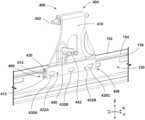
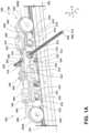
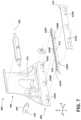
- FIGS. 1 A and 1 Bare perspective views generally illustrating an embodiment of a track system according to teachings of the present disclosure.
- FIG. 2is an end view generally illustrating an embodiment of a track assembly according to teachings of the present disclosure.
- FIG. 3is a cross-sectional view generally illustrating an embodiment of an inner track according to teachings of the present disclosure.
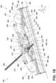
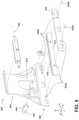
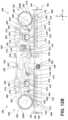
- FIG. 4is a cross-sectional side view generally illustrating an embodiment of a support member according to teachings of the present disclosure.
- FIGS. 5 A and 5 Bare perspective views generally illustrating an embodiment of an anchor according to teachings of the present disclosure.
- FIGS. 6 and 7are exploded perspective views generally illustrating an embodiment of an anchor according to teachings of the present disclosure.
- FIG. 8is a perspective view generally illustrating an embodiment of an anchor and a slider according to teachings of the present disclosure.
- FIGS. 9 A, 9 B, and 9 Care views generally illustrating an embodiment of an anchor according to teachings of the present disclosure.
- FIG. 10is a perspective view generally illustrating an embodiment of an anchor and an inner track according to teachings of the present disclosure.
- FIGS. 11 A and 11 Bare end views generally illustrating an embodiment of a track system with an anchor in an engaged position and a disengaged position, respectively, according to teachings of the present disclosure.
- FIGS. 12 A and 12 Bare cross-sectional views generally illustrating an embodiment of a track system with an anchor in a disengaged position and an engaged position, respectively, according to teachings of the present disclosure.
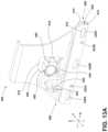
- FIG. 13 Ais a perspective view generally illustrating an embodiment of an anchor cam and an anchor, with the anchor cam in a first position corresponding to an engaged position of the anchor, according to teachings of the present disclosure.
- FIG. 13 Bis a perspective view generally illustrating an embodiment of an anchor cam and an anchor, with the anchor cam in a second position corresponding to a disengaged position of the anchor, according to teachings of the present disclosure.
- FIG. 14 Ais a perspective view generally illustrating an embodiment of an anchor cam and an anchor, with the anchor cam in a first position corresponding to an engaged position of the anchor, according to teachings of the present disclosure.
- FIG. 14 Bis a perspective view generally illustrating an embodiment of an anchor cam and an anchor, with the anchor cam in a second position corresponding to a disengaged position of the anchor, according to teachings of the present disclosure.
- a track system 100may include a support assembly 102 and/or one or more track/rail assemblies 104 .
- a support assembly 102 and/or a track assembly 104may include and/or be connected to an electrical system (e.g., of a vehicle 108 ), which may include a controller and/or a power source.
- a track assembly 104may be connected to and/or disposed in a mounting surface 106 (e.g., a floor of a vehicle 108 ) and may facilitate selective connection of one or more support assemblies 102 to the mounting surface 106 .
- a track assembly 104may facilitate adjustment of one or more support assemblies 102 , such as relative to the mounting surface 106 and/or within a vehicle 108 .
- a track system 100may include several track assemblies 104 that may be configured to engage a corresponding portion of a support assembly 102 .
- track assemblies 104may be connected to a portion of the mounting surface 106 (e.g., a floor, wall, ceiling, etc.), may extend parallel to one another, and/or may be offset from each other in a lateral/transverse direction (e.g., a Y-direction) such that the track assemblies 104 may be generally/substantially aligned with respective outer sides of a support assembly 102 .
- a portion of the mounting surface 106e.g., a floor, wall, ceiling, etc.
- a lateral/transverse directione.g., a Y-direction
- a track assembly 104may include an outer track 120 and/or an inner track 150 .
- An outer track 120 and/or an inner track 150may be an elongated member extending generally in an X-direction (e.g., a longitudinal direction).
- An outer track 120 and/or an inner track 150may facilitate movement and/or adjustment of a support assembly 102 and/or a support member 200 along a track assembly 104 .
- a support member 200may roll along a top surface of an outer track 120 via one or more rolling members 220 , and/or a support member 200 may selectively engage the outer track 120 and/or the inner track 150 to selectively restrict/control relative movement between a support assembly 102 and a track assembly 104 .
- An outer track 120 and/or an inner track 150may include one or more of a variety of materials.
- the outer track 120may include a first material (e.g., aluminum) that may be relatively light
- the inner track 150may include a second material (e.g., steel) that may be relatively strong compared to the first material.
- an outer track 120may have a track base portion 122 and two track wall portions (e.g., a first track wall portion 124 and a second track wall portion 126 ) protruding from the track base portion 122 to form a generally U shaped cross-section in a Y-Z plane (e.g., in a plane perpendicular to an X-direction).
- the U-shaped cross sectionmay define a track receptacle 130 configured to receive and/or at least temporarily retain a portion of a support assembly 102 .
- a first track lip/wing 132 and a second track lip/wing 134may project inwardly toward one another from the first track wall portion 124 and the second track wall portion 126 , respectively.
- a track opening 128may be defined between the two track lips 132 , 134 .
- a portion of a support assembly 102may be inserted into the track opening 128 and selectively retained within the track receptacle 130 .
- An outer track 120may include a first rolling portion 136 and/or a second rolling portion 138 , which may be configured to engage one or more rolling members 220 of a support member 200 .
- a first rolling portion 136may be disposed on and/or adjacent to a first track lip 132 (e.g., at or about a top surface of the outer track 120 ).
- a second rolling portion 138may be disposed on and/or adjacent to a second track lip 134 .
- a first rolling portion 136 and/or the second rolling portion 138may be configured as a ridge, for example, protruding from a track assembly 104 in a Z-direction and/or may extend substantially in an X-direction along some or all of a length of the outer track 120 .
- an inner track 150may be disposed partially and/or completely within a track receptacle 130 .
- An inner track 150may be disposed on and/or connected (e.g., fixed) to a track base portion 122 and/or one or more track wall portions 124 , 126 of an outer track 120 .
- An inner track 150may, for example, include a generally L-shaped cross section.
- An inner track 150may include a hook portion 152 , which may be disposed adjacent to and/or extend adjacent to a first track wall portion 124 and/or a first track lip 132 .
- a track assembly 104may include one or more toothed portions 154 (e.g., gear racks) configured to engage an adjuster pinion 250 of an adjuster assembly 230 .
- a toothed portion 154may each include one or more track teeth 156 .
- a toothed portion 154may generally extend in an X-direction, such as along some or all of a length of the inner track 150 .
- One or more (e.g., all) of the track teeth 156may be disposed one after another and/or aligned with one another in an X-direction.
- Track teeth 156may extend and/or protrude from the toothed portion 154 generally in a Z-direction (e.g., downward in the Z-direction toward the mounting surface 106 ).
- a toothed portion 154may be disposed within a track receptacle 130 and/or may be disposed on an underside of a track assembly 104 .
- a toothed portion 154may be connected to and/or formed as a portion of an outer track 120 and/or an inner track 150 .
- a toothed portion 154may be connected to and/or integrally formed with an inner track 150 , such as at or about a distal end of a hook portion 152 .
- a toothed portion 154 and/or track teeth 156may be disposed adjacent to and/or substantially aligned/overlapping (e.g., in a Z-direction) with an edge of a first track lip 132 that at least partially defines a track opening 128 .
- a track assembly 104may include one or more electrical conductors 160 (e.g., bus bars) configured to selectively contact and/or engage (e.g., electrically connect with) one or more contacts of a support assembly 102 .
- a conductor 160may be an elongated member extending in the X-direction and/or may have a generally U-shaped cross section that opens in a Y-direction (e.g., a transverse direction).
- a conductor 160may be operatively connected to a controller and/or a power source.
- a conductor 160may be connected to a first track wall portion 124 and/or a second track wall portion 126 of an outer track 120 , and/or another portion of a track assembly 104 .
- a conductor 160may be connected to a track assembly 104 via an insulator 170 , which may be configured to electrically insulate/isolate a conductor 160 from other portions of a track assembly 104 .
- An insulator 170may be an elongated body, which may extend in an X-direction, and/or may be configured to receive and/or retain one or more conductors 160 .
- a support assembly 102may include a support member 200 .
- a support assembly 102 and/or a support member 200may be adjusted and/or moved along a track assembly 104 (e.g., in an X-direction) manually and/or via an adjuster assembly 230 .
- a support member 200may be configured for connection with and removal (e.g., in a vertical/Z-direction) from a track assembly 104 , such as in a plurality of locations along the track assembly 104 .
- a support member 200may, for example and without limitation, include, be connected to, and/or support a seat, such as a vehicle seat, and/or one or more other components (e.g., consoles, cargo, cargo racks, etc.).
- the support assembly 102 , the support member 200 , and/or one or more components connected theretomay include one or more electrical components (e.g., controllers, power sources, seat heaters, airbags, air bladders, fans, etc.).
- a support member 200may be configured as a base, a leg, and/or a support structure, for example.
- a support member 200may include one or more electrical connectors 210 that may be configured for selective connection with a track assembly 104 .
- An electrical connector 210may be configured to selectively electrically connect with a track assembly 104 , such as with a conductor 160 (e.g., a bus bar) of the track assembly 104 .
- a conductor 160e.g., a bus bar
- one or more contacts of the electrical connector 210may rotate into and out of contact with one or more conductors 160 .
- Electrical connection between an electrical connector 210 and a conductor 160may permit electrical power and/or one or more signals (e.g., control signals, sensor data signals, etc.) to be provided to and/or received from the support member 200 (e.g., an electrical component).
- signalse.g., control signals, sensor data signals, etc.
- a support member 200may include one or more rolling members 220 .
- a rolling member 220may be configured to engage and/or roll along a first rolling portion 136 and/or a second rolling portion 138 of a track assembly 104 .
- a support member 200may be configured to move along a track assembly 104 , at least in part, via one or more rolling members 220 (e.g., rolling members 220 A, 220 B).
- a rolling member 220may be configured to support at least a portion of the support assembly 102 .
- a rolling member 220may rotate as the support assembly 102 moves along the track assembly 104 .
- a rolling member 220may be rotatably connected to a body of the support member 200 .
- a first rolling member 220 Amay be rotatably connected at or about a first end of a support member 200
- a second rolling member 220 Bmay be rotatably connected at or about a second end of the support member 200 .
- One or more rolling members 220e.g., first and second rolling members 220 A, 220 B
- first and second rolling members 220 A, 220 Bmay be connected to the same lateral side of a support member 200 .
- a first and second rolling member 220 A, 220 Bmay both engage and/or roll along the same rolling portion (e.g., a first rolling portion 136 , a second rolling portion 138 , etc.).
- rolling members 220may be rotatably connected on opposite sides of an adjuster assembly 230 relative to a Y-direction, such that a rolling member 220 may roll along a first rolling portion 136 another rolling member 220 may roll along a second rolling portion 138 .
- a support member 200may include an adjuster assembly 230 configured to facilitate adjustment of the position (e.g., in an X-direction) of a support member 200 relative to a track assembly 104 .
- an electric motor 232 of the adjuster assembly 230may rotate an adjuster pinion 250 , which may engage the toothed portion 154 to adjust the position of the support member 200 relative to the track assembly 104 , such as in an X-direction.
- An electric motor 232may be disposed within the adjuster assembly 230 and/or may be operatively connected to an adjuster pinion 250 such that the adjuster pinion 250 is rotatable via the electric motor 232 . Additionally and/or alternatively, an electrical motor 232 may be disposed within a support assembly 102 and/or may be operatively connected to one or more support members 200 .
- a support assembly 102may include (i) two or more support members 200 disposed opposite one another (e.g., relative generally to a Y-direction) and/or (ii) an electrical motor 232 disposed between the two support members 200 and connected to an adjuster assembly 230 of one or both of the two support members 200 , such as via a respective flex shaft, which may be curved and/or bent in some examples.
- a transmissionmay connect a motor 232 to an adjuster assembly 230 .
- an adjuster assembly 230may be adjustably connected to a body of the support member 200 such that the adjuster assembly 230 may move and/or float relative to the body of the support member 200 , such as in a Z-direction. Additionally and/or alternatively, an adjuster assembly 230 may be rotatable relative to the support member 200 and/or the track assembly 104 , such as about an adjuster axis 240 . An adjuster assembly 230 may be operatively connected to an electrical component of a support member 200 , such as via one or more wires. For example and without limitation, an electrical component may provide power to and/or control operation of the electric motor 232 of the adjuster assembly 230 .
- an adjuster assembly 230may include one or more portions (e.g., a tab 236 ) configured to contact and/or engage a slider 270 of a support member 200 .
- a tab 236may be configured as a protrusion extending, such as generally in a Z-direction (e.g., downward in the Z-direction toward the mounting surface 106 ).
- a tab 236may be configured as a surface, edge, slot, recess, body, and/or any other structure configured to engage a slider 270 .
- an adjuster assembly 230may include one or more portions (e.g., a flange 242 ) configured to contact and/or engage an actuation body 330 .
- An adjuster assembly 230may be adjustable, such as in a generally Z-direction, via a flange 242 .
- a flange 242may extend generally in a Y-direction and/or may be disposed on the same or an opposite side of the adjuster assembly 230 relative to an adjuster pinion 250 .
- a flange 242may be configured as a surface, edge, slot, recess, body, and/or any other structure configured to engage an actuation body 330 .
- a support member 200may include an adjuster pinion 250 .
- An adjuster pinion 250may be configured to engage a toothed portion 154 of a track assembly 104 .
- An adjuster pinion 250may be rotatable about an adjuster pinion axis 252 , which may extend generally in a Y-direction (e.g., perpendicular to a longitudinal direction of the track assembly 104 ).
- An adjuster pinion 250may include one or more adjuster pinion teeth 254 configured to engage one or more track teeth 156 of a toothed portion 154 .
- Adjuster pinion teeth 254may extend radially outward from the adjuster pinion 250 relative to the adjuster pinion axis 252 .
- An adjuster pinion 250may be connected to an electric motor 232 directly and/or indirectly (e.g., via a flex shaft).
- An electric motor 232may be operatively connected to an adjuster pinion 250 such that the adjuster pinion 250 is rotatable via the electric motor 232 .
- an adjuster pinion 250(and the adjuster assembly 230 , at least in some configurations) may be adjustable to engage and/or disengage a toothed portion 154 of a track assembly 104 (e.g., the adjuster pinion teeth 254 are or are not engaged with the track teeth 156 ).
- An adjuster pinion 250 and/or the adjuster assembly 230may, for example, be adjusted generally downward in a Z-direction to disengage a track assembly 104 and/or may be adjusted generally upward in a Z-direction to engage a track assembly 104 .
- An adjuster pinion 250 and/or an adjuster assembly 230may, when disengaged from the toothed portion 154 for example, be adjusted (e.g., moved, slid, rotated) generally laterally in a Y-direction into and/or out of Z-direction alignment with a toothed portion 154 of a track assembly 104 .
- a support member 200may include a slider 270 , which may be adjustable, movable, slidable, etc. in a direction generally parallel to an X-direction, for example.
- a slider 270may be disposed between a top and bottom of an adjuster assembly 230 .
- a slider 270may be configured to engage and/or facilitate adjustment of the adjuster assembly 230 and/or an anchor 400 , 400 ′. Additionally and/or alternatively, a slider 270 may be configured to engage and/or facilitate adjustment (e.g., rotation) of an electrical connector 210 to engage one or more contacts with a corresponding conductor 160 .
- a slider 270 of the support assembly 102 and a toothed portion 154 of the track assembly 104may be disposed on opposite sides of a track opening 128 relative to a Y-direction (e.g., a slider 270 may be disposed proximate/adjacent to a second track lip 134 and a toothed portion 154 may be disposed proximate/adjacent to a first track lip 132 ).
- a slider 270may include a slider body 272 , which may be configured as an elongated member and/or may extend generally in an X-direction.
- a slider 270may include a slider protrusion 274 , which may extend generally in a Z-direction.
- a slider protrusion 274may be disposed on and/or connected to the slider body 272 .
- a slider 270 and/or a slider protrusion 274may include a guide surface 282 configured to engage, contact, and/or abut an adjuster assembly 230 (e.g., a tab 236 ).
- a guide surface 282may extend generally in an X-direction and/or may face generally in a Y-direction.
- a guide surface 282may include a first end 284 , an intermediate section 286 , and/or a second end 288 .
- a tab 236may be disposed adjacent to and/or in contact with a first end 284 of the guide surface 282 and/or may extend obliquely relative to a slider protrusion 274 .
- An adjuster assembly 230may, for example, be biased generally in a Y-direction (e.g., about an adjuster axis 240 ) such that a tab 236 is biased into contact with a slider protrusion 274 and/or a guide surface 282 .
- a tab 236may be disposed between a first end 284 and an intermediate section 286 of the guide surface 282 and/or may extend generally parallel to a slider protrusion 274 .
- a tab 236may be disposed adjacent to and/or in contact with an intermediate section 286 of the guide surface 282 and/or may extend generally parallel to a slider protrusion 274 .
- a slider 270may include one or more slider channels (e.g., a first slider channel 298 , a second slider channel 298 ′) configured to engage and/or adjust one or more anchors 400 , 400 ′.
- a slider channel 298may be defined by one or more slider walls (e.g., a first slider wall 300 and second slider wall 302 ), which may be disposed on and/or connected to the slider body 272 .
- Slider walls 300 , 302may extend along a slider body 272 generally in an X-direction and/or may extend parallel to one another.
- a slider channel 298may be configured to receive an anchor tab 442 of a corresponding anchor 400 .
- an anchor tab 442may be insertable into a slider channel 298 (e.g., downward generally in a Z-direction), may engage, contact, and/or abut one or more slider walls 300 , 302 , and/or may be adjustable (e.g., slidable) along one or more slider walls 300 , 302 within a slider channel 298 .
- a slider channel 298may include a first section 298 A, a second section 298 B, and/or a third section 298 C.
- a second section 298 Bmay be disposed between the first and third sections 298 A, 298 C.
- a first section 298 A and a third section 298 Cmay be disposed offset from one another (e.g., generally in a Y-direction) such that a second section 298 B extends obliquely to an X-direction and/or a Y-direction, which may facilitate adjustment (e.g., generally in a Y-direction) of an anchor 400 into and/or out of Z-direction alignment with a toothed portion 154 of a track assembly 104 .
- a slider wall 300 , 302may extend from a slider body 272 generally in a Z-direction.
- a portion of a slider wall 300 , 302may extend farther from a slider body 272 generally in a Z-direction than another portion of a slider wall 300 , 302 (e.g., a portion of slider wall 300 , 302 defining a second section 298 B), which may facilitate adjustment (e.g., generally in a Z-direction) of an anchor 400 into and/or out of engagement with a toothed portion 154 of a track assembly 104 .
- a slider 270may include a slider recess 304 that may be configured to receive at least a portion of an anchor tab 442 , which may facilitate adjustment of an anchor 400 into and/or out of engagement with a track assembly 104 .
- a slider recess 304may be disposed adjacent to and/or proximal a slider channel 298 (e.g., a third section 298 C).
- a slider 270may include a second slider channel 298 ′, a second channel first section 298 A′, a second channel second section 298 B′, a second channel third section 298 C′, a first slider wall 300 ′, a second slider wall 302 ′, and/or a slider recess 304 ′ configured to engage a second anchor 400 ′, some or all of which may be configured in the same or similar manner as corresponding features of the first slider channel 298 .
- a first and second slider channels 298 , 298 ′may be configured differently from one another.
- a slider 270may include one or more toothed slider portions 276 (e.g., gear racks) that may be configured to engage a slider pinion 280 of a support member 200 , which may include one or more slider pinion teeth 294 .
- a toothed slider portion 276may include one or more slider teeth 278 .
- a toothed slider portion 276may generally extend in an X-direction.
- One or more (e.g., all) of the slider teeth 278may be disposed one after another and/or aligned with one another in an X-direction.
- Slider teeth 278may extend and/or protrude from a slider 270 and/or a toothed slider portion 276 generally in a Z-direction (e.g., upward in the Z-direction away the mounting surface 106 ).
- a support member 200may include a slider pinion 280 configured to engage a toothed slider portion 276 .
- a slider pinion 280may include one or more slider pinion teeth 294 configured to engage one or more slider teeth 278 .
- a slider pinion 280may be rotatable about a slider pinion axis 290 , that may extend generally in a Y-direction and/or that may be substantially coaxial with an engagement cam axis 314 .
- a slider pinion 280may be disposed on, connected to, and/or engaged with an engagement body 310 and/or an actuation shaft 292 .
- a slider pinion 280may be rotatable via rotating an actuation shaft 292 , rotating an engagement body 310 , and/or adjusting a slider 270 (e.g., generally in an X-direction). Additionally and/or alternatively, a slider pinion 280 may be configured to move independently of an actuation shaft 292 and/or an engagement body 310 (e.g., a slider pinion 280 may rotate without causing an actuation shaft 292 and/or an engagement body 310 to rotate, and/or the actuation shaft 292 may rotate without rotating the slider pinion 280 ). Rotating a slider pinion 280 may, at least in some situations, rotate an engagement body 310 , such as with the slider pinion 280 and relative to the actuation shaft 292 .
- a slider 270may be actuated/moved in one or more of a variety of ways.
- a slider 270may be actuated via adjusting (e.g., rotating) a lever 212 of a support member 200 , which may be engaged with and/or connected to the slider 270 .
- a slider 270may, for example, be actuated via an actuation shaft 292 and/or a slider pinion 280 connected thereto that may be engaged with a toothed slider portion 276 of the slider 270 .
- a usermay move a slider 270 directly and/or via a handle/lever/linkage.
- a support member 200may include an engagement body 310 that may be configured to facilitate adjustment of one or more anchors 400 , 400 ′ into and/or out of engagement with a toothed portion 154 of a track assembly 104 .
- An engagement body 310may be rotatable about an axis extending generally in a Y-direction (e.g., an engagement cam axis 314 ).
- An engagement body 310may be operatively connected to one or more engagement member 350 , 350 ′ such that rotating the engagement body 310 adjusts the engagement members 350 , 350 ′ generally in an X-direction.
- An engagement body 310may be disposed on, connected to, and/or engaged with an actuation shaft 292 , an engagement cam 312 , and/or a slider pinion 280 .
- An engagement body 310may be rotatable via rotating an engagement cam 312 (e.g., via rotating an actuation shaft 292 ) and/or rotating a slider pinion 280 (e.g., via adjusting a slider 270 with a lever 212 ). Additionally and/or alternatively, an engagement body 310 may be configured to, at least in some situations, rotate independently of an actuation shaft 292 , an engagement cam 312 , and/or a slider pinion 280 .
- rotation of the slider pinion 280may cause rotation of the engagement body 310 relative to the actuation shaft 292 and/or the engagement cam 312 , which may move the anchors 400 , 400 ′ without moving the adjuster assembly 230 (e.g., to maintain the adjuster assembly 230 in a disengaged position).
- a support member 200may include an engagement cam 312 which may be configured to facilitate adjustment of the adjuster assembly 230 and/or an adjuster pinion 250 into and/or out of engagement with a track assembly 104 .
- An engagement cam 312may be rotatable about an engagement cam axis 314 , which may extend generally in a Y-direction.
- an engagement cam 312may be adjustable (e.g., rotatable) to a first position (see, e.g., FIG. 12 B ) and/or to a second position (see, e.g., FIG. 12 A ).
- An engagement cam 312may include an engagement cam hub 316 and/or an engagement cam protrusion 318 .
- An engagement cam protrusion 318may extend radially from an engagement cam hub 316 relative to an engagement cam axis 314 .
- An engagement cam 312may be disposed on, connected to, and/or engaged with an actuation shaft 292 such that, for example, an engagement cam 312 is rotatable via rotating the actuation shaft 292 .
- An engagement cam 312may be connected to and/or engaged with an engagement body 310 .
- an engagement body 310 , an engagement cam 312 , and/or a slider pinion 280may be rotatably connected to a support member 200 (and/or a second support member 200 disposed opposite the first support member 200 ).
- an engagement body 310 , an engagement cam 312 , and/or a slider pinion 280may be connected to an actuation shaft 292 of a support member 200 , which may be configured to rotate the engagement cam 312 , the engagement body 310 , and/or the slider pinion 280 about the engagement cam axis 314 .
- an actuation shaft 292may be configured to simultaneously engage and/or rotate a slider pinion 280 and/or an engagement cam 312 .
- An actuation shaft 292may be actuated manually and/or via a powered actuator (e.g., an electric motor), for example.
- a support member 200may include an actuation body 330 .
- An actuation body 330may have and/or be rotatable about an actuation body axis 332 , which may extend generally in a Y-direction.
- An actuation body 330may include a first actuation portion 334 configured to engage, contact, and/or abut an adjuster assembly 230 , such as a flange 242 for example.
- An actuation body 330may include a second actuation portion 336 configured to engage, contact, and/or abut an engagement cam 312 (e.g., an engagement cam protrusion 318 ).
- An actuation body 330may include a third actuation portion 338 , which may engage and/or be connected to a biasing member 344 (e.g., a spring).
- a biasing member 344may, additionally and/or alternatively, be connected to a body of a support member 200 , such as at an end opposite the actuation body 330 .
- a biasing member 344may bias an actuation body 330 about an actuation body axis 332 , which may bias a second actuation portion 336 into contact with an engagement cam 312 .
- a support member 200may include one or more engagement members 350 configured to engage a corresponding anchor cam 470 .
- An engagement member 350may be an elongated member, which may extend generally in an X-direction.
- An engagement member 350may include an engagement member toothed portion 352 (e.g., a gear rack), which may be configured to engage anchor cam teeth 478 of an anchor cam 470 .
- An engagement member toothed portion 352may extend generally in an X-direction and/or may include one or more engagement member teeth 354 , which may be disposed one after another and/or aligned with one another in an X-direction.
- Engagement member teeth 354may extend and/or protrude from an engagement member 350 and/or an engagement member toothed portion 352 generally in a Z-direction (e.g., downward in the Z-direction toward the mounting surface 106 ).
- An engagement member 350may be operatively and/or adjustably connected to an engagement body 310 , such as on an opposite side of the engagement body 310 from the engagement cam 312 for example.
- an engagement member 350may adjustably engage a slot or recess of the engagement body 310 , which may be sloped toward an engagement cam axis 314 , such that rotation of the engagement body 310 adjusts, moves, etc. the engagement member 350 toward and/or away from the engagement cam axis 314 .
- An engagement member 350may be operatively and/or adjustably connected to an anchor cam 470 .
- an engagement member 350may be adjusted, moved, slid, etc. generally in an X-direction via an engagement body 310 , which may cause an engagement member toothed portion 352 to engage and/or rotate an anchor cam 470 .
- a support member 200may include a first engagement member 350 configured to engage a first anchor cam 470 of a first anchor 400 and a second engagement member 350 ′ configured to engage a second anchor cam 470 ′ of a second anchor 400 ′.
- a second engagement member 350 ′may include an engagement member toothed portion 352 ′ and/or engagement member teeth 354 ′, some or all of which may be configured in the same or similar manner as corresponding features of a first engagement member 350 .
- a cross-sectional view through the engagement members 350 , 350 ′ of a support member 200(e.g., in a plane perpendicular to a Y-direction) is generally depicted in FIG. 4 to provide a clear view of the engagement between the engagement members 350 , 350 ′ and the anchor cams 470 , 470 ′.
- a support member 200may include one or more anchors 400 configured to engage and/or connect, secure, fix, etc. a support member 200 to a track assembly 104 .
- An anchor 400may be adjustable generally in a Z-direction, may be adjustable generally in a Y-direction, and/or may be rotatable about an anchor axis 402 , which may extend generally in an X-direction.
- An anchor axis 402may be disposed at or about a first/top end 404 of an anchor 400 , which may be disposed opposite a second/bottom end 406 of an anchor 400 .
- An anchor 400may include an anchor body 410 , a toothed anchor portion 412 (e.g., a gear rack), and/or an anchor member 414 .
- a toothed anchor portion 412 and/or an anchor member 414may be connected to a second end 406 of an anchor 400 .
- An anchor member 414may be connected to a toothed anchor portion 412 such that, for example, the toothed anchor portion 412 is disposed between an anchor body 410 and an anchor member 414 .
- An anchor body 410 , a toothed anchor portion 412 , and/or an anchor member 414may collectively form a hook portion 408 of an anchor 400 .
- an anchor 400may be biased into engagement with the slider channel 298 (e.g., generally downward in a Z-direction) such that when the slider 270 is moved and the anchor protrusion 440 and/or the anchor tab 442 is aligned with the second section 298 B, the anchor 400 may move down into to a disengaged position.
- an anchor 400is adjustable via an engagement body 310 (see, e.g., FIGS.
- an anchor 400may be biased generally upward in a Z-direction (e.g., toward an engaged position), toward a toothed portion 154 generally in a Y-direction, and/or about an anchor axis 402 , such as via an anchor biasing member 456 .
- An anchor biasing member 456e.g., a spring
- a support member 200e.g., a body of the support member 200
- a portion of an anchor 400e.g., a portion of an anchor 400 .
- a hook portion 408 of an anchor 400 formed by an anchor body 410 , a toothed anchor portion 412 , and/or an anchor member 414may provide better space efficiency than anchors 400 that are formed from a single piece (e.g., with a portion bent into a U-shaped configuration). For example, bending a piece of metal into a U-shape may result in rounded portions and/or minimum radiuses that may increase a width in a Y-direction of the hook portion 408 and/or impair connection/formation of anchor teeth 416 .
- a hook portion 408 with a greater widthmay need to rotate farther to engage and/or disengage a track assembly 104 , which may utilize more space and/or a longer actuation distance, either or both of which may increase an overall size and/or weight of the track system 100 .
- an anchor 400may include an anchor adjustment portion 444 that may be configured to engage an anchor cam projection 480 , which may facilitate adjustment of an anchor 400 generally in a Z-direction (see, e.g., FIGS. 13 A and 13 B ).
- An anchor 400may include an anchor opening 446 which may be configured to, at least partially, receive an anchor cam base 482 (see, e.g., FIGS. 13 A and 13 B ).
- An anchor 400may include a tilt protrusion 448 that may be configured to engage an anchor cam protrusion 476 , such as to restrict and/or prevent movement/adjustment of an anchor 400 generally in a Z-direction and/or to cause an anchor 400 to tilt/rotate about an axis that may extend generally in a Y-direction (see, e.g., FIGS. 14 A and 14 B).
- An anchor adjustment portion 444 and/or a tilt protrusion 448may extend from an anchor 400 (e.g., an anchor body 410 ) generally perpendicular to the anchor 400 and/or may be disposed adjacent/proximate an anchor opening 446 .
- an anchor adjustment portion 444 and/or a tilt protrusion 448may be configured as a surface, edge, body, and/or any other structure configured to engage an anchor cam projection 480 and/or an anchor cam protrusion 476 .
- a toothed anchor portion 412may be configured to engage a toothed portion 154 of a track assembly 104 .
- a toothed anchor portion 412may be an elongated (e.g., planar) member and/or may include one or more anchor teeth 416 .
- a toothed anchor portion 412may extend generally in an X-direction.
- One or more (e.g., all) of the anchor teeth 416may be disposed one after another and/or aligned with one another in an X-direction.
- Anchor teeth 416may extend and/or protrude from an anchor 400 and/or a toothed anchor portion 412 generally in a Z-direction (e.g., upward in the Z-direction away the mounting surface 106 ).
- a toothed anchor portion 412may be configured as a separate, individual component from an anchor body 410 and/or an anchor member 414 (see, e.g., FIGS. 5 A- 8 ). Additionally and/or alternatively, a toothed anchor portion 412 may be integrally formed with and/or project from an anchor body 410 and/or an anchor member 414 .
- a toothed anchor portion 412may be stamped into an anchor body 410 and/or an anchor member 414 and, thus, configured as a stamped-in portion 418 of an anchor body 410 and/or an anchor 400 .
- an anchor member 414may be configured to facilitate and/or maintain alignment (e.g., generally in a Y-direction) and/or engagement of a toothed anchor portion 412 and a toothed portion 154 of a track assembly 104 .
- An anchor member 414may be an elongated (e.g., planar) member that extends generally in an X-direction.
- an anchor member 414may extend beyond and/or farther than a toothed anchor portion 412 generally upward in a Z-direction such that a gap 420 (e.g., a space) is defined between the anchor member 414 and an anchor body 410 (e.g., generally in a Y-direction).
- the gap 420may, additionally and/or alternatively, be defined and/or disposed above a toothed anchor portion 412 relative to a Z-direction.
- the gap 420may be configured to at least partially receive a toothed portion 154 of a track assembly 104 and/or guide a toothed portion 154 of a track assembly 104 , such as generally in a Z-direction, into engagement with a toothed anchor portion 412 .
- an anchor 400may include one or more anchor recesses 422 A, 422 B.
- An anchor recess 422 A, 422 Bmay be disposed in at least one of an anchor body 410 , a toothed anchor portion 412 , and/or an anchor member 414 .
- an anchor recess 422 A, 422 Bmay extend into and/or through an anchor body 410 , a toothed anchor portion 412 , and/or an anchor member 414 (e.g., generally in a Y-direction).
- One or more anchor connectors 424 A, 424 Bmay be disposed in and/or engage a corresponding anchor recess 422 A, 422 B to connect an anchor body 410 , a toothed anchor portion 412 , and/or an anchor member 414 to one another.
- an anchor 400may include one or more anchor receptacles 430 A, 430 B, 430 C, 432 A, 432 B and/or one or more anchor projections 434 A, 434 B, 434 C, 436 A, 436 B.
- a first anchor projection 434 A, 434 B, 434 Cmay be configured to engage a corresponding first anchor receptacle 430 A, 430 B, 430 C and/or a second anchor projection 436 A, 436 B may be configured to engage a corresponding second anchor receptacle 432 A, 432 B.
- a first anchor receptacle 430 A, 430 B, 430 Cmay be disposed in an anchor body 410 .
- a second anchor receptacle 432 A, 432 Bmay be disposed in an anchor member 414 .
- a first anchor projection 434 A, 434 B, 434 C and/or a second anchor projection 436 A, 436 Bmay be disposed on and/or connected to a toothed anchor portion 412 (e.g., on opposite sides relative to one another) and/or may be configured differently than one another, to facilitate proper assembly of an anchor 400 for example. Additionally and/or alternatively, one or more anchor projections 434 A, 434 B, 434 C, 436 A, 436 B may be disposed on an anchor body 410 and/or an anchor member 414 .
- An anchor projection 434 A, 434 B, 434 C, 436 A, 436 B disposed on an anchor body 410may, for example, be configured to engage a corresponding anchor receptacle 430 A, 430 B, 430 C, 432 A, 432 B disposed in a toothed anchor portion 412 and/or an anchor member 414 .
- An anchor projection 434 A, 434 B, 434 C, 436 A, 436 B disposed on an anchor member 414may, for example, be configured to engage a corresponding anchor receptacle 430 A, 430 B, 430 C, 432 A, 432 B disposed in a toothed anchor portion 412 and/or an anchor body 410 .
- One or more anchor projections 434 A, 434 B, 434 C, 436 A, 436 Bmay be configured as a separate, individual component or may be formed integrally with an anchor 400 (e.g., a toothed anchor portion 412 ).
- an anchor 400may include an anchor protrusion 440 that may be configured to engage a slider 270 .
- An anchor protrusion 440may extend from an anchor 400 (e.g., an anchor body 410 ) generally in a Y-direction.
- An anchor protrusion 440may include an anchor tab 442 , which may be configured to engage a corresponding slider channel 298 .
- An anchor tab 442may disposed on and/or connected to an anchor protrusion 440 , such as at or about an end of the anchor protrusion 440 opposite the anchor body 410 .
- An anchor tab 442may extend, such as from an anchor protrusion 440 , generally in a Z-direction (e.g., downward in the Z-direction toward the mounting surface 106 ).
- an anchor 400may include a ramp portion 450 configured to engage a corresponding anchor cam 470 .
- a ramp portion 450may project from an anchor 400 (e.g., an anchor body 410 ) generally in a Y-direction.
- a ramp portion 450may extend along an anchor 400 , such as from a first ramp end 452 to a second ramp end 454 , in a curved manner.
- a first ramp end 452may be disposed above a second ramp end 454 relative to a Z-direction, and/or a second ramp end 454 may project farther from an anchor 400 generally in a Y-direction than a first ramp end 452 , such that the ramp portion 450 is sloped generally downward in a Z-direction and away from the anchor 400 generally in a Y-direction.
- a support member 200may include a first anchor 400 and a second anchor 400 ′.
- a second anchor 400 ′may include a second anchor axis 402 ′, a first end 404 ′, a second end 406 ′, a hook portion 408 ′, an anchor body 410 ′, a toothed anchor portion 412 ′, an anchor member 414 ′, anchor teeth 416 ′, a gap 420 ′, anchor recesses 422 A′, 422 B′, anchor connectors 424 A′, 424 B′, an anchor protrusion 440 ′, an anchor tab 442 ′, an anchor adjustment portion, an anchor opening, a tilt protrusion, an anchor biasing member, a ramp portion 450 ′, a first ramp end 452 ′, and/or a second ramp end 454 ′, some or all of which may be configured in the same or similar manner as corresponding features of a first anchor 400 .
- an anchor 400 , 400 ′may be adjustable to an engaged position (see, e.g., FIGS. 4 , 10 , 11 A, 12 B, 13 A, 14 A ) in which an anchor 400 , 400 ′ (e.g., a toothed anchor portion 412 , 412 ′) is engaged with a toothed portion 154 of a track assembly 104 (e.g., the anchor teeth 416 , 416 ′ are engaged with the track teeth 156 ) and/or a disengaged position (see, e.g., FIGS.
- an anchor 400 , 400 ′e.g., a toothed anchor portion 412 , 412 ′
- a toothed portion 154 of a track assembly 104e.g., the anchor teeth 416 , 416 ′ are engaged with the track teeth 156
- a disengaged positionsee, e.g., FIGS.
- an anchor 400 , 400 ′e.g., a toothed anchor portion 412 , 412 ′
- a toothed portion 154 of a track assembly 104e.g., the anchor teeth 416 , 416 ′ are not engaged with the track teeth 156 .
- a disengaged positionmay include, for example, an unaligned position in which an anchor 400 , 400 ′ is disengaged from and not aligned with the toothed portion 154 (e.g., relative to a Z-direction) and/or an aligned position in which an anchor 400 , 400 ′ is disengaged from and aligned with the toothed portion 154 (e.g., relative to a Z-direction).
- an anchor 400 , 400 ′When in an unaligned position, an anchor 400 , 400 ′ may be disposed and/or extend obliquely or perpendicularly to a Z-direction.
- an anchor 400 , 400 ′When in an aligned position and/or in an engaged position, an anchor 400 , 400 ′ may be disposed generally parallel to a Z-direction.
- An anchor 400 , 400 ′may, for example, be adjusted generally downward in a Z-direction toward the disengaged position and/or may be adjusted generally upward in a Z-direction toward the engaged position.
- An anchor 400 , 400 ′may, when disengaged from the toothed portion 154 for example, be adjusted (e.g., moved, slid, rotated) generally laterally in a Y-direction toward an aligned position and/or toward an unaligned position.
- an anchor 400 , 400 ′such as when in an unaligned position (see, e.g., FIG. 11 B ), may be insertable into and/or removable from a track assembly 104 , such as via being inserted into and/or removed from a track receptacle 130 through a track opening 128 .
- an anchor 400 , 400 ′When in an aligned position, an anchor 400 , 400 ′ may (i) restrict and/or prevent removal of the support member 200 from a track assembly 104 (e.g., in a Z-direction) and/or (ii) facilitate adjustment of a support member 200 along a track assembly 104 (e.g., via an adjuster pinion 250 , via manual movement of a support assembly 102 by a user, etc.).
- an anchor 400 , 400 ′When an anchor 400 , 400 ′ is in an engaged position (see, e.g., FIG.
- an anchor 400 , 400 ′may connect, secure, and/or fix a support assembly 102 and/or a support member 200 to a track assembly 104 such that X-direction Y-direction, and/or Z-direction movement of the support member 200 relative to the track assembly 104 is restricted and/or substantially prevented.
- an adjuster assembly 230may be engaged with a track assembly 104 when an anchor 400 , 400 ′ is in a disengaged position (see, e.g., FIG. 12 A ) such that the support member 200 is connected/secured to the track assembly 104 and/or is adjustable along the track assembly 104 such as via operation of an electric motor 232 , which may cause rotation of the adjuster pinion 250 about an adjuster pinion axis 252 , which may cause the adjuster pinion teeth 254 to engage the toothed portion 154 of the track assembly 104 , which may cause movement of the support member 200 along the track assembly 104 .
- an adjuster assembly 230may be disengaged from and/or out of Z-direction alignment with a track assembly 104 when an anchor 400 , 400 ′ is in an unaligned position such that the support member 200 is removable from and/or insertable into a track assembly 104 in a plurality of locations along the track assembly 104 .
- An adjuster assembly 230may be disengaged from a track assembly 104 when an anchor 400 , 400 ′ is in an engaged position (see, e.g., FIG.
- an adjuster assembly 230e.g., an adjuster pinion 250
- damageat least to some degree
- an application of abnormal stresse.g., stress exceeding that which occurs during normal use and/or operation
- an adjuster assembly 230 and/or an adjuster pinion 250may default to an aligned position and/or an anchor 400 , 400 ′ may default to an engaged position.
- a support member 200may include an anchor cam 470 , which may be configured to engage and/or facilitate adjustment of a corresponding anchor 400 .
- An anchor cam 470may be rotatably connected to a support member 200 .
- An anchor cam 470may be rotatable about an anchor cam axis 472 , which may extend generally in a Y-direction.
- An anchor cam 470may include an anchor cam hub 474 and/or an anchor cam protrusion 476 .
- An anchor cam protrusion 476may extend radially from an anchor cam hub 474 relative to an anchor cam axis 472 .
- An anchor cam protrusion 476may be configured to contact, abut, and/or engage a ramp portion 450 of a corresponding anchor 400 .
- An anchor cam 470may include an anchor cam projection 480 , which may be connected to and/or extend radially from an anchor cam base 482 .
- An anchor cam projection 480may be configured to contact, abut, and/or engage an anchor adjustment portion 444 of a corresponding anchor 400 .
- An anchor cam base 482extend at least partially through an anchor opening 446 of an anchor 400 (e.g., generally in a Y-direction).
- An anchor cam protrusion 476 and an anchor cam projection 480may be disposed at and/or connected to opposite ends of an anchor cam base 482 such that, for example, the anchor cam protrusion 476 and the anchor cam projection 480 may be disposed on opposite sides of an anchor 400 .
- An anchor cam 470may include on or more anchor cam teeth 478 , which may extend radially relative to an anchor cam axis 472 , via which an anchor cam 470 may engage an engagement member toothed portion 352 of a corresponding engagement member 350 .
- an anchor cam 470may be connected to an engagement member toothed portion 352 of an engagement member 350 , which may be configured to rotate the anchor cam 470 about an anchor cam axis 472 .
- an anchor cam 470may be configured such that, when disengaging an anchor 400 from a track assembly 104 , an anchor cam projection 480 may adjust an anchor 400 generally downward in a Z-direction to disengage the anchor 400 from a toothed portion 154 of the track assembly 104 (e.g., via engaging an anchor adjustment portion 444 ) prior to an anchor cam protrusion 476 adjusting the anchor 400 away from the toothed portion 154 generally in a Y-direction (e.g., via engaging a ramp portion 450 ).
- an anchor cam 470may be configured such that, when engaging an anchor 400 with a track assembly 104 , an anchor cam protrusion 476 may adjust and/or allow adjustment of the anchor 400 toward a toothed portion 154 of the track assembly 104 generally in a Y-direction (e.g., via disengaging a ramp portion 450 and/or an anchor biasing member 456 applying a biasing force) prior to an anchor cam projection 480 adjusting and/or allowing adjustment of an anchor 400 generally upward in a Z-direction to engage the anchor 400 with the toothed portion 154 (e.g., via disengaging an anchor adjustment portion 444 and/or an anchor biasing member 456 applying a biasing force).
- a support member 200may include a first anchor cam 470 configured to engage a first anchor 400 and a second anchor cam 470 ′ configured to engage a second anchor 400 ′.
- a second anchor cam 470 ′may include a second anchor cam axis 472 ′, an anchor cam hub 474 ′, an anchor cam protrusion 476 ′, anchor cam teeth 478 ′, an anchor cam projection, and/or an anchor cam base, some or all of which may be configured in the same or similar manner as corresponding features of a first anchor cam 470 .
- an adjuster assembly 230 and/or an adjuster pinion 250may be disengaged from a track assembly 104 , and/or a support member 200 may be secured (e.g., fixed) to a track assembly 104 and adjustment and/or removal of a support member 200 from the track assembly 104 may be restricted and/or prevented via an anchor 400 , 400 ′.
- a second actuation portion 336may biased into contact with an engagement cam protrusion 318 (e.g., generally downward in a Z-direction), a first actuation portion 334 may (or may not) contact an adjuster assembly 230 (e.g., a flange 242 ), an anchor cam 470 , 470 ′ may be oriented such that (i) an anchor cam projection 480 does not engage/contact (or contacts to a lesser extent than in the second engagement cam position) an anchor adjustment portion 444 (see, e.g., FIG.
- an adjuster assembly 230 and/or an adjuster pinion 250may be disengaged from a track assembly 104 (e.g., a toothed portion 154 ), and/or an anchor 400 , 400 ′ may be engaged with a toothed portion 154 of a track assembly 104 (e.g., disposed in an engaged position).
- an adjuster assembly 230 and/or an adjuster pinion 250may be engaged with a track assembly 104 , and/or removal of a support member 200 from a track assembly 104 may be restricted and/or prevented via the adjuster assembly 230 (e.g., depending on the position of the adjuster assembly 230 ), and/or a support member 200 may be adjustable relative to the track assembly 104 , such as by actuating a motor 232 of the adjuster assembly 230 and/or rotating the adjuster pinion 250 .
- a second actuation portion 336may be disposed adjacent to and spaced apart from an engagement cam hub 316 , a first actuation portion 334 may engage, contact, and/or press against an adjuster assembly 230 (e.g., a flange 242 ) such as generally in a Z-direction, an anchor cam 470 , 470 ′ may be oriented such that (i) an anchor cam projection 480 engages and/or contacts an anchor adjustment portion 444 (see, e.g., FIG.
- an anchor cam protrusion 476 , 476 ′engages and/or contacts a ramp portion 450 , 450 ′ and/or disengages a tilt protrusion 448 (see, e.g., FIG. 14 B ), an anchor 400 , 400 ′ may be disengaged from a toothed portion 154 of a track assembly 104 (e.g., disposed in a disengaged position), and/or an adjuster assembly 230 and/or an adjuster pinion 250 may be engaged with a toothed portion 154 of a track assembly 104 . Additionally and/or alternatively, a second actuation portion 336 may contact and/or be biased against an engagement cam hub 316 when an engagement cam 312 is in a second engagement cam position.
- engaging and/or connecting a support assembly 102 on a track assembly 104may include inserting (e.g., moving sliding, rotating, etc.) an adjuster pinion 250 , an adjuster assembly 230 , and/or one or more anchors 400 , 400 ′ into a track receptacle 130 and adjusting an adjuster pinion 250 , an adjuster assembly 230 , and/or one or more anchors 400 , 400 ′, generally in a Y-direction into Z-direction alignment with a toothed portion 154 of a track assembly 104 , which may include rotating the adjuster assembly 230 (e.g., about an adjuster axis 240 ) and/or an anchor 400 , 400 ′ (e.g., about an anchor axis 402 , 402 ′), such as by rotating an anchor cam 470 , 470 ′ and/or by adjusting, sliding, moving, etc.
- rotating the adjuster assembly 230e.g., about an adjuster axis 240
- Engaging and/or connecting a support assembly 102 on a track assembly 104may include adjusting an adjuster pinion 250 , an adjuster assembly 230 , and/or one or more anchors 400 , 400 ′ into engagement with a toothed portion 154 of a track assembly 104 , such as by adjusting (e.g., moving sliding, rotating, etc.) an adjuster pinion 250 , an adjuster assembly 230 , and/or an anchor 400 , 400 ′ generally upward in a Z-direction, which may include adjusting (e.g., rotating) an actuation body 330 , adjusting (e.g., rotating) an engagement cam 312 , and/or adjusting (e.g., sliding) a slider 270 .
- Disengaging and/or disconnecting a support assembly 102 and a track assembly 104may include adjusting (e.g., moving sliding, rotating, etc.) an adjuster pinion 250 , an adjuster assembly 230 , and/or an anchor 400 , 400 ′, in an opposite direction for example, which may involve the above described process being conducted in reverse.
- adjustinge.g., moving sliding, rotating, etc.
- an adjuster assembly 230 , an adjuster pinion 250 , and/or an anchor 400 , 400 ′may be adjusted to an engaged position, an aligned position, and/or an unaligned position via actuating an actuation shaft 292 .
- Actuating an actuation shaft 292may include rotating an actuation shaft 292 (e.g., about an engagement cam axis 314 ), which may cause a slider pinion 280 to rotate, which may cause the slider pinion 280 to engage a toothed slider portion 276 (e.g., via slider pinion teeth 294 and slider teeth 278 ), which may slide, shift, move, etc.
- the slider 270(e.g., generally in an X-direction) relative to an adjuster assembly 230 and/or an anchor 400 , 400 ′, which may (i) adjust an adjuster assembly 230 and/or an adjuster pinion 250 from an unaligned position to an aligned position (e.g., via engaging a tab 236 ) and/or (ii) adjust an anchor 400 , 400 ′ from an unaligned position to an aligned position and/or to an engaged position (e.g., via engaging an anchor tab 442 , 442 ′).
- Continued rotation of the actuation shaft 292may (i) adjust an adjuster assembly 230 and/or an adjuster pinion 250 from an aligned position to an engaged position (e.g., via rotating an engagement cam 312 from a first engagement cam position to a second engagement cam position) and/or (ii) further adjust the slider 270 (e.g., generally in an X-direction), which may adjust an anchor 400 , 400 ′ from an engaged position to a disengaged position (e.g., via engaging an anchor tab 442 , 442 ′ with a slider recess 304 , 304 ′).
- an adjuster assembly 230 and/or an adjuster pinion 250from an aligned position to an engaged position (e.g., via rotating an engagement cam 312 from a first engagement cam position to a second engagement cam position) and/or (ii) further adjust the slider 270 (e.g., generally in an X-direction), which may adjust an anchor 400 , 400 ′ from an engaged position to
- An actuation shaft 292may be rotated in an opposite direction, for example, to engage (and/or subsequently disengage) an anchor 400 , 400 ′ from a track assembly 104 and/or to disengage an adjuster assembly 230 and/or an adjuster pinion 250 from a track assembly 104 , which may involve the above described process being conducted in reverse.
- an adjuster assembly 230 and/or an adjuster pinon 250may be (i) adjusted to an aligned position and/or an unaligned position via actuating a lever 212 , and/or (ii) adjusted to an engaged position and/or an aligned position via rotating an actuation shaft 292 .
- an anchor 400 , 400 ′may be adjusted to an engaged position, an aligned position, and/or an unaligned position via actuating a lever 212 and/or rotating an actuation shaft 292 .
- Rotation of an actuation shaft 292may, in some circumstances, be restricted and/or prevented when the adjuster assembly 230 and/or adjuster pinion 250 is in an unaligned position (e.g., is not in an aligned position or an engaged position). Additionally and/or alternatively, actuation of a lever 212 may, in some circumstances, be restricted and/or prevented when an adjuster assembly 230 and/or adjuster pinion 250 is engaged with a toothed portion 154 (e.g., is not in an aligned position or an unaligned position).
- actuatinge.g., adjusting, rotating, etc.
- a lever 212 of a support member 200may cause the lever 212 to contact and/or press against a slider 270 , which may cause the slider 270 to slide, shift, move, etc.
- an adjuster assembly 230 and/or an anchor 400 , 400 ′which may cause a toothed slider portion 276 of the slider 270 to engage a slider pinion 280 (e.g., via slider pinion teeth 294 and slider teeth 278 ), which may cause the slider pinion 280 to rotate about an axis (e.g., an engagement cam axis 314 ), which (i) may not cause an actuation shaft 292 to rotate such that an engagement cam 312 is not adjusted and does not adjust the adjuster assembly 230 , and/or (ii) may cause an engagement body 310 to rotate, which may adjust an anchor 400 , 400 ′ to an engaged position, an aligned position, and/or an unaligned position.
- a toothed slider portion 276 of the slider 270to engage a slider pinion 280 (e.g., via slider pinion teeth 294 and slider teeth 278 ), which may cause the slider pinion 280 to rotate about an axis (e.g., an engagement cam axi
- Adjusting a slider 270 via actuating a lever 212may, additionally and/or alternatively, cause the slider 270 to (i) engage a tab 236 of an adjuster assembly 230 , which may adjust an adjuster assembly 230 and/or an adjuster pinion 250 to an aligned position and/or an unaligned position, and/or (ii) engage an anchor tab 442 , 442 ′, which may adjust and/or facilitate adjustment of an anchor 400 , 400 ′ to an engaged position, an aligned position, and/or an unaligned position.
- a channel 298 , 298 ′ of a slider 270may engage an anchor tab 442 , 442 ′ to adjust and/or guide an anchor 400 , 400 ′ from an unaligned position to an aligned position and/or from an aligned position to an engaged position, which may supplement an anchor biasing member 456 that may (e.g., simultaneously) adjust/bias the anchor 400 , 400 ′ (e.g., via providing a biasing force that biases the anchor 400 , 400 ′ toward the engaged position).
- an anchor biasing member 456may (e.g., simultaneously) adjust/bias the anchor 400 , 400 ′ (e.g., via providing a biasing force that biases the anchor 400 , 400 ′ toward the engaged position).
- rotating an actuation shaft 292may rotate an engagement cam 312 , which may adjust an adjuster assembly 230 and/or an adjuster pinion 250 to an engaged position and/or an aligned position. Additionally and/or alternatively, rotating an actuation shaft 292 may rotate an engagement body 310 (e.g., via rotating the engagement cam 312 ), which (i) may not cause a slider pinion 280 to rotate such that movement of a slider 270 is not caused by rotation of the actuation shaft 292 , and/or (ii) may adjust an engagement member 350 , 350 ′ and/or an anchor cam 470 , 470 ′ to adjust an anchor 400 , 400 ′ to an engaged position, an aligned position, and/or an unaligned position.
- one or more anchors 400 , 400 ′may be disengaged from a track assembly 104 and/or an adjuster assembly 230 may be engaged with the track assembly 104 (or vice versa) by a single action (e.g., rotating an actuation shaft 292 ), which may facilitate adjustment of a support assembly 102 relative to a track assembly 104 .
- the anchors 400 , 400 ′, an adjuster assembly 230 , and/or an adjuster pinion 250may be disposed in or proximate to unaligned positions, such as to facilitate insertion/connection.
- a lever 212may be actuated to adjust a slider 270 , which may (i) adjust an adjuster assembly 230 and/or an adjuster pinion 250 from an unaligned position to an aligned position (e.g., via engaging a tab 236 ) and/or (ii) adjust an anchor 400 , 400 ′ from an unaligned position and/or an aligned position to an engaged position (e.g., via an anchor biasing member 456 , engaging an anchor tab 442 , 442 ′, and/or rotating a slider pinion 280 to rotate an engagement body 310 without rotating the actuation shaft 292 ).
- a slider 270may (i) adjust an adjuster assembly 230 and/or an adjuster pinion 250 from an unaligned position to an aligned position (e.g., via engaging a tab 236 ) and/or (ii) adjust an anchor 400 , 400 ′ from an unaligned position and/or an aligned position to an engaged position (e.
- an actuation shaft 292may be rotated, which may (i) adjust an adjuster assembly 230 and/or an adjuster pinion 250 from an aligned position to an engaged position (e.g. via rotating an engagement cam 312 ) and/or (ii) adjust an anchor 400 , 400 ′ from an engaged position to an aligned position and/or unaligned position (e.g., via rotating the engagement cam 312 to rotate an engagement body 310 without rotating the slider pinion 280 ), which may unlock the support assembly 102 from the track assembly 104 to facilitate movement of the support assembly 104 via the adjuster assembly 230 along the track assembly 104 .
- An actuation shaft 292may be rotated in an opposite direction or a lever 212 may be actuated in an opposite direction, for example, to engage an anchor 400 , 400 ′ with a track assembly 104 and/or to disengage an adjuster assembly 230 and/or an adjuster pinion 250 from a track assembly 104 , which may involve one or more portions of the above described process being conducted in reverse.
- adjusting an adjuster pinion 250 and/or an adjuster assembly 230 into and/or out of Z-direction alignment with a toothed portion 154 of a track assembly 104may include rotating the adjuster pinion 250 and/or the adjuster assembly 230 about an adjuster axis 240 , such as by adjusting, sliding, moving, etc. the adjuster assembly 230 and/or a slider 270 .
- a slider 270 and/or an adjuster assembly 230may be adjusted, moved, slid, etc.
- Adjusting a slider 270 and/or an adjuster assembly 230 to adjust an adjuster pinion 250 into Z-direction alignment with a toothed portion 154 of a track assembly 104may include actuating a lever 212 and/or rotating an actuation shaft 292 , which may cause the slider 270 to slide, shift, move, etc.
- adjuster assembly 230e.g., generally in an X-direction
- a tab 236may slide along a guide surface 282 toward an intermediate section 286 (e.g., from a first end 284 ), which may cause the adjuster assembly 230 to rotate about an adjuster axis 240 , which may adjust the adjuster pinion 250 generally in a Y-direction toward the toothed portion 154 of the track assembly 104 (e.g., away from the slider 270 ).
- the slider 270 and/or the adjuster assembly 230may be adjusted/moved, in an opposite direction for example, to adjust the adjuster assembly 230 and/or an adjuster pinion 250 out of Z-direction alignment with a toothed portion 154 of a track assembly 104 , which may involve the above described process being conducted in reverse.
- adjusting an adjuster pinion 250 and/or an adjuster assembly 230 into and/or out of engagement with a toothed portion 154 of a track assembly 104may include adjusting an adjuster assembly 230 generally in a Z-direction, such as by rotating an actuation body 330 and/or an engagement cam 312 .
- adjusting an engagement cam 312 to engage an adjuster assembly 230 and/or an adjuster pinion 250 with a toothed portion 154 of a track assembly 104e.g., adjusting the adjuster assembly 230 from the position of FIG. 12 B toward the position of FIGS.
- an engagement cam 312may be rotated about an engagement cam axis 314 , such as via rotating an actuation shaft 292 , which may cause a second actuation portion 336 engaging an engagement cam protrusion 318 to adjust, move, slide, off of the engagement cam protrusion 318 (e.g., to a position in which the second actuation portion 336 is disposed spaced slightly apart from and/or in contact with an engagement cam hub 316 ), which may cause the actuation body 330 to rotate about an actuation body axis 332 (e.g., clockwise in the view of FIG.
- a first actuation portion 334may move and/or adjust generally upward in a Z-direction such that it adjusts, presses, pushes, etc.
- a flange 242 of an adjuster assembly 230generally upward in a Z-direction, which may cause the adjuster assembly 230 and/or an adjuster pinion 250 to move generally upward in a Z-direction to engage a toothed portion 154 of a track assembly 104 .
- An actuation shaft 292 , an engagement cam 312 , and/or an actuation body 330may be adjusted, moved, rotated, etc., in an opposite direction for example, to disengage the adjuster assembly 230 and/or an adjuster pinion 250 from a toothed portion 154 of a track assembly 104 (e.g., to adjust the adjuster assembly 230 from the position of FIG. 12 A toward the position of FIG. 12 B ), which may involve the above described process being conducted in reverse.
- engaging and/or disengaging an anchor 400 , 400 ′ with a toothed portion 154 of a track assembly 104may include adjusting, sliding, moving, etc. an anchor 400 , 400 ′ and/or a slider 270 .
- a slider 270may be adjusted, moved, slid, etc.
- an anchor tab 442 , 442 ′may engage a slider channel 298 , 298 ′ and/or slide along one or more slider walls 300 , 302 , 300 ′, 302 ′, which may cause an anchor 400 , 400 ′ to adjust (e.g., rotate, slide, raise, lower, etc.) toward an aligned position, an unaligned position, an engaged position, and/or a disengaged position, which may connect (e.g., temporarily fix) and/or disconnect a support member 200 and a track assembly 104 .
- adjustment of an anchor tab 442 , 442 ′ within a channel 298 , 298 ′may supplement and/or may be supplemented by an anchor biasing member 456 , which may adjust/bias an anchor 400 , 400 ′ toward an engaged position.
- adjusting, moving, and/or sliding a slider 270 and/or an anchor 400 , 400 ′ to engage an anchor 400 , 400 ′ with a toothed portion 154 of a track assembly 104may include adjusting/moving an anchor tab 442 , 442 ′ within a first section 298 A, 298 A′ of a slider channel 298 , 298 ′ (e.g., toward a second section 298 B, 298 B′).
- further adjustment of the slider 270 (e.g., generally in an X-direction) and/or an anchor 400 , 400 ′may cause the anchor tab 442 , 442 ′ to adjust/move within a second section 298 B, 298 B′ of a slider channel 298 , 298 ′ (e.g., toward a third section 298 C, 298 C′), which may cause an anchor 400 , 400 ′ to adjust generally downward in a Z-direction away from the toothed portion 154 of the track assembly 104 , at least to some degree, which may facilitate rotation of the hooked portion 408 under the toothed portion 154 .
- Adjusting/moving an anchor tab 442 , 442 ′ within a second section 298 B, 298 B′ of a slider channel 298 , 298 ′may, additionally and/or alternatively, cause an anchor 400 , 400 ′ to rotate about an anchor axis 402 , 402 ′, which may adjust a toothed anchor portion 412 , 412 ′ generally in a Y-direction toward the toothed portion 154 of the track assembly 104 (e.g., away from the slider 270 ), which may cause the toothed anchor portion 412 , 412 ′ to be disposed in Z-direction alignment with the toothed portion 154 .
- further adjustment of the slider 270 and/or an anchor 400 , 400 ′may cause an anchor tab 442 , 442 ′ to adjust/move within a third section 298 C, 298 C′ of a slider channel 298 , 298 ′ (e.g., toward a slider recess 304 , 304 ′), which may cause an anchor 400 , 400 ′ to adjust generally upward in a Z-direction toward the toothed portion 154 of the track assembly 104 , which may cause the toothed anchor portion 412 , 412 ′ to engage the toothed portion 154 of a track assembly 104 , which may connect (e.g., temporarily fix) a support member 200 and a track assembly 104 to one another.
- further adjustment of the slider 270 generally in an X-directionmay cause an anchor tab 442 , 442 ′ to engage a slider recess 304 , 304 ′, which may cause an anchor 400 , 400 ′ to disengage a toothed portion 154 of a track assembly 104 , which may facilitate adjustment of a support assembly 102 and/or a support member 200 along the track assembly 104 .
- the slider 270 and/or an anchor 400 , 400 ′may be adjusted/moved, in an opposite direction for example, to disengage an anchor 400 , 400 ′ and/or a toothed anchor portion 412 , 412 ′ from a toothed portion 154 of a track assembly 104 (e.g., to adjust an anchor 400 , 400 ′ away from the position of FIGS. 8 and 11 A ), which may involve the above described process being conducted in reverse.
- engaging and/or disengaging an anchor 400 , 400 ′ from a toothed portion 154 of a track assembly 104may, additionally and/or alternatively, include adjusting (e.g., rotating) an engagement body 310 about an axis extending generally in a Y-direction (e.g., an engagement cam axis 314 ).
- Rotating an engagement body 310such as via rotating an actuation shaft 292 and/or adjusting a slider 270 , may adjust, move, slide, etc.
- an engagement member 350 , 350 ′generally in an X-direction, which may cause an anchor cam 470 , 470 ′ to adjust (e.g., rotate about an anchor cam axis 472 , 472 ′), which may cause an anchor 400 , 400 ′ to engage and/or disengage a toothed portion 154 of a track assembly 104 , which may connect (e.g., temporarily fix) and/or disconnect the support member 200 and the track assembly 104 .
- rotation of an engagement body 310 about an engagement cam axis 314 and/or about another axis extending generally in a Y-direction, such as via rotating an actuation shaft 292 and/or actuating a lever 212 ,may adjust, move, slide, etc.
- an engagement member 350 , 350 ′generally in an X-direction toward the engagement body 310 (e.g., via adjusting an engagement member 350 , 350 ′ within a slot or groove of the engagement body 310 ), which may cause an engagement member toothed portion 352 , 352 ′ to engage, contact, etc.
- anchor cam teeth 478 , 478 ′which may cause an anchor cam 470 , 470 ′ to rotate about an anchor cam axis 472 , 472 ′, which may cause an anchor cam protrusion 476 , 476 ′ to slide along a ramp portion 450 , 450 ′ generally upward in a Z-direction toward a first ramp end 452 , 452 ′ such as from a second ramp end 454 , 454 ′ (e.g., from the position of FIG. 14 B toward the position of FIG.
- an anchor 400 , 400 ′may adjust and/or allow adjustment of an anchor 400 , 400 ′ generally in a Y-direction (e.g., via rotating about an anchor axis 402 , 402 ′, such as with a biasing force provided by an anchor biasing member 456 ), which may cause a toothed anchor portion 412 to move into Z-direction alignment with a toothed portion 154 of a track assembly 104 .
- rotating an anchor cam 470 , 470 ′ about an anchor cam axis 472 , 472 ′may, additionally, alternatively, and/or simultaneously, adjust an anchor cam projection 480 (e.g., from the position of FIG. 13 B toward the position of FIG.
- an anchor 400 , 400 ′generally upward in a Z-direction (e.g., via rotating about an anchor axis 402 , 402 ′, such as with a biasing force provided by an anchor biasing member 456 and/or an anchor cam protrusion 476 , 476 ′ engaging a tilt protrusion 448 ), which may cause a toothed anchor portion 412 to engage a toothed portion 154 of a track assembly 104 .
- sliding an anchor cam protrusion 476 , 476 ′ along a ramp portion 450 , 450 ′ generally upward in a Z-direction toward a first ramp end 452 , 452 ′may cause/allow the anchor cam protrusion 476 , 476 ′ to engage and/or contact the tilt protrusion 448 of the anchor 400 , 400 ′, which may adjust (or facilitate adjustment of) the anchor 400 , 400 ′ generally upward in a Z-direction, restrict and/or prevent an anchor 400 , 400 ′ from disengaging the toothed portion 154 of the track assembly 104 , and/or tilt/rotate the anchor 400 , 400 ′ about an axis extending generally in a Y-direction.
- An engagement body 310may be adjusted, moved, rotated, etc., in an opposite direction, for example, to disengage an anchor 400 , 400 ′ from a toothed portion 154 of a track assembly 104 (e.g., to adjust an anchor 400 , 400 ′ from the position of FIGS. 12 B, 13 A, 14 A toward the position of FIGS. 1 A, 1 B, 12 A, 13 B, 14 B ), which may involve the above described process being conducted in reverse.
- an anchor 400 and an adjuster pinion 250may be configured to selectively engage the toothed portion 154 .
- a track system 100may, in some circumstances, be configured such that the anchor 400 and the adjuster pinion 250 are not engaged with the toothed portion 154 , and may, in some circumstances, both be disengaged from the toothed portion 154 , such as to facilitate vertical removal of a support assembly 102 from a track assembly 104 in a plurality of locations along the track assembly 104 .
- a track system 100While embodiments of a track system 100 are generally described in connection with a support assembly 102 connected with a track assembly 104 , multiple support assemblies 102 , which may include one or a plurality of support members 200 , which may be connected to the same track assembly 104 , which may include one or a plurality of pairs of tracks 120 , 150 (e.g., for a plurality of seats in a vehicle 108 ).
- references to a single elementare not necessarily so limited and may include one or more of such element.
- Any directional referencese.g., plus, minus, upper, lower, upward, downward, left, right, leftward, rightward, top, bottom, above, below, vertical, horizontal, clockwise, and counterclockwise
- Any directional referencesare only used for identification purposes to aid the reader's understanding of the present disclosure, and do not create limitations, particularly as to the position, orientation, or use of examples/embodiments.
- joinder referencesare to be construed broadly and may include intermediate members between a connection of elements, relative movement between elements, direct connections, indirect connections, fixed connections, movable connections, operative connections, indirect contact, and/or direct contact. As such, joinder references do not necessarily imply that two elements are directly connected/coupled and in fixed relation to each other. Connections of electrical components, if any, may include mechanical connections, electrical connections, wired connections, and/or wireless connections, among others. The use of “e.g.” in the specification is to be construed broadly and is used to provide non-limiting examples of embodiments of the disclosure, and the disclosure is not limited to such examples.
Landscapes
- Engineering & Computer Science (AREA)
- Mechanical Engineering (AREA)
- General Engineering & Computer Science (AREA)
- Transportation (AREA)
- Aviation & Aerospace Engineering (AREA)
- Architecture (AREA)
- Civil Engineering (AREA)
- Structural Engineering (AREA)
- Chemical & Material Sciences (AREA)
- Combustion & Propulsion (AREA)
- Transmission Devices (AREA)
- Seats For Vehicles (AREA)
- Details Of Connecting Devices For Male And Female Coupling (AREA)
- Legs For Furniture In General (AREA)
Abstract
Description
Claims (20)
Priority Applications (3)
| Application Number | Priority Date | Filing Date | Title |
|---|---|---|---|
| US17/179,159US12044301B2 (en) | 2020-02-21 | 2021-02-18 | Track system with a support member |
| DE102021104010.8ADE102021104010B4 (en) | 2020-02-21 | 2021-02-19 | Rail system with a support element and anchor for a support element of a rail system |
| CN202110199980.2ACN113291210B (en) | 2020-02-21 | 2021-02-22 | Rail system with support members |
Applications Claiming Priority (2)
| Application Number | Priority Date | Filing Date | Title |
|---|---|---|---|
| US202062979812P | 2020-02-21 | 2020-02-21 | |
| US17/179,159US12044301B2 (en) | 2020-02-21 | 2021-02-18 | Track system with a support member |
Publications (2)
| Publication Number | Publication Date |
|---|---|
| US20210261022A1 US20210261022A1 (en) | 2021-08-26 |
| US12044301B2true US12044301B2 (en) | 2024-07-23 |
Family
ID=77365342
Family Applications (6)
| Application Number | Title | Priority Date | Filing Date |
|---|---|---|---|
| US17/179,176Active2043-06-10US12055205B2 (en) | 2020-02-21 | 2021-02-18 | Track system with a support member |
| US17/179,170Active2042-02-20US11835119B2 (en) | 2020-02-21 | 2021-02-18 | Track system with a support member |
| US17/179,147Active2041-12-11US11906028B2 (en) | 2020-02-21 | 2021-02-18 | Track system with a support member |
| US17/179,166Active2043-11-04US12181033B2 (en) | 2020-02-21 | 2021-02-18 | Track system with a support member |
| US17/179,144ActiveUS11506272B2 (en) | 2018-05-04 | 2021-02-18 | Track system with a support member |
| US17/179,159Active2042-10-24US12044301B2 (en) | 2020-02-21 | 2021-02-18 | Track system with a support member |
Family Applications Before (5)
| Application Number | Title | Priority Date | Filing Date |
|---|---|---|---|
| US17/179,176Active2043-06-10US12055205B2 (en) | 2020-02-21 | 2021-02-18 | Track system with a support member |
| US17/179,170Active2042-02-20US11835119B2 (en) | 2020-02-21 | 2021-02-18 | Track system with a support member |
| US17/179,147Active2041-12-11US11906028B2 (en) | 2020-02-21 | 2021-02-18 | Track system with a support member |
| US17/179,166Active2043-11-04US12181033B2 (en) | 2020-02-21 | 2021-02-18 | Track system with a support member |
| US17/179,144ActiveUS11506272B2 (en) | 2018-05-04 | 2021-02-18 | Track system with a support member |
Country Status (2)
| Country | Link |
|---|---|
| US (6) | US12055205B2 (en) |
| CN (2) | CN113370853B (en) |
Families Citing this family (12)
| Publication number | Priority date | Publication date | Assignee | Title |
|---|---|---|---|---|
| WO2020252199A1 (en)* | 2019-06-12 | 2020-12-17 | Overcast Innovations Llc | Utility connection systems, splines, and associated methods |
| US11548419B2 (en)* | 2019-06-18 | 2023-01-10 | Lear Corporation | Seat assembly |
| US12055205B2 (en)* | 2020-02-21 | 2024-08-06 | Lear Corporation | Track system with a support member |
| DE102021104018B4 (en) | 2020-02-21 | 2023-11-09 | Lear Corporation | Rail system with a support element, method for operating a rail system |
| US11332043B2 (en)* | 2020-02-25 | 2022-05-17 | Ford Global Technologies, Llc | Connector assembly for a vehicle seat |
| US11505141B2 (en)* | 2020-10-23 | 2022-11-22 | Lear Corporation | Electrical system with track assembly and support assembly |
| US12269399B2 (en)* | 2021-10-11 | 2025-04-08 | Ford Global Technologies, Llc | Baseplate electrical contacts |
| CN114197257B (en)* | 2021-11-24 | 2024-08-02 | 重庆交通大学 | Variable tooth pitch rack for Strub rack railway bridge expansion joint |
| US12337972B2 (en) | 2022-07-25 | 2025-06-24 | Ami Industries, Inc. | Tracking system for an aircraft seat |
| US12187438B2 (en) | 2022-07-25 | 2025-01-07 | Ami Industries, Inc. | Track locking system for an aircraft seat |
| US12428162B2 (en) | 2022-07-25 | 2025-09-30 | Ami Industries, Inc. | Motion control system for an aircraft seat |
| US20250192500A1 (en)* | 2023-12-07 | 2025-06-12 | Lear Corporation | Track assembly |
Citations (337)
| Publication number | Priority date | Publication date | Assignee | Title |
|---|---|---|---|---|
| US1962789A (en) | 1931-12-10 | 1934-06-12 | Ternstedt Mfg Co | Seat adjuster |
| US2126143A (en) | 1937-11-03 | 1938-08-09 | American Forging & Socket Co | Adjustable supporting means |
| US2263554A (en) | 1940-01-30 | 1941-11-25 | Leon S Brach | Protective means for an automotive vehicle antenna |
| US2480622A (en) | 1945-12-04 | 1949-08-30 | Gen Electric | Electric switch |
| US2678082A (en) | 1952-12-09 | 1954-05-11 | Walker Nathan | Automobile seat shock absorbing system |
| US3096066A (en) | 1960-11-30 | 1963-07-02 | Granet Charles | Vehicle-seat suspension |
| US3181102A (en) | 1964-06-08 | 1965-04-27 | Gen Electric | Electrical busway apparatus |
| US3213403A (en) | 1961-03-24 | 1965-10-19 | Ite Circuit Breaker Ltd | Plug-in bus duct |
| US3268848A (en) | 1961-09-05 | 1966-08-23 | Gen Electric | Bus bar type electric power distribution system with formed insulating sheet housing |
| DE2004504A1 (en) | 1970-01-31 | 1971-08-26 | Recaro Gmbh & Co, 7000 Stuttgart | Locking device |
| US3603918A (en) | 1968-12-06 | 1971-09-07 | Oskar Woertz Inh H & O | Electric power distribution system |
| US3933403A (en) | 1973-04-26 | 1976-01-20 | Erich Rubesamen | Adaptor for feeding current to electrical contact rails |
| US3940182A (en) | 1973-08-31 | 1976-02-24 | Nissan Motor Co., Ltd. | Seat position control mechanism having a position memory element |
| US4020769A (en) | 1975-04-17 | 1977-05-03 | Donald James Keir | Cargo tie-down gripping anchor assembly |
| US4154422A (en) | 1976-12-29 | 1979-05-15 | Keiper Automobiltechnik Gmbh & Co Kg | Adjustable and automatically locking motor-vehicle seat mounting assembly |
| US4198025A (en) | 1977-11-29 | 1980-04-15 | Uop Inc. | Vehicle seats |
| US4238099A (en) | 1977-03-24 | 1980-12-09 | Hunwicks Alec A | Vehicle seat slides |
| US4243248A (en) | 1977-10-11 | 1981-01-06 | Daimler-Benz Aktiengesellschaft | Air bag system for the protection of the passengers of motor vehicles in case of accidents |
| US4281871A (en) | 1979-04-09 | 1981-08-04 | Ford Motor Company | Motor vehicle seat mounted with longitudinal sliding mobility |
| US4282631A (en) | 1978-04-03 | 1981-08-11 | Yoshida Kogyo K.K. | Tiltable roller assembly |
| EP0074754A2 (en) | 1981-09-07 | 1983-03-23 | Rotaflex p.l.c. | Elektrical supply connector for continuous outlet track |
| EP0090235A2 (en) | 1982-03-31 | 1983-10-05 | Kronenberg GmbH & Co. KG | Sliding seat guide, especially for motor vehicle seats |
| US4511187A (en) | 1983-11-25 | 1985-04-16 | General Motors Corporation | Bearing assembly for seat slide |
| US4575295A (en) | 1984-01-11 | 1986-03-11 | Gte Products Corporation | Fastener for channeled structural members |
| US4618808A (en) | 1985-01-30 | 1986-10-21 | International Business Machines Corporation | Electromagnetic actuator system using stepper motor with closed loop position sensing, electronic commutation and dynamic position and anomaly correction |
| US4707030A (en) | 1985-06-18 | 1987-11-17 | Magna International Inc. | Seat assembly |
| US4711589A (en) | 1986-03-31 | 1987-12-08 | General Motors Corporation | Manual seat adjuster with cam lock |
| US4763360A (en) | 1986-09-17 | 1988-08-09 | The Boeing Company | Passenger entertainment system having direct coupled seat receivers |
| US4776809A (en) | 1986-04-11 | 1988-10-11 | Light Source Electrical Equipment Limited | Low voltage distribution system with two-conductor track |
| US4804229A (en) | 1987-06-11 | 1989-02-14 | Tachi-S Co., Ltd. | Seat slide device |
| US4830531A (en) | 1985-10-04 | 1989-05-16 | Unistrut International Corp. | Unitary connection assembly for metal channels and method for assembly |
| US4853555A (en) | 1988-04-21 | 1989-08-01 | The Boeing Company | Electrical power transfer system for aircraft passenger entertainment system |
| US4941636A (en) | 1988-09-16 | 1990-07-17 | Ikeda Bussan Company Ltd. | Locking slide apparatus for mounting a seat |
| US4961559A (en) | 1989-12-18 | 1990-10-09 | Chrysler Corporation | Latching bar arrangement for seat adjuster |
| US4969621A (en) | 1988-05-04 | 1990-11-13 | Keiper Recaro Gmbh & Co. | Apparatus for adjusting seats in motor vehicles |
| US4987316A (en) | 1989-10-03 | 1991-01-22 | Automotive Systems Laboratory, Inc. | Passenger restraint firing circuit |
| US5106144A (en) | 1990-02-09 | 1992-04-21 | Ikeda Bussan Co., Ltd. | Seat slide device with rail-disconnection inhibiting mechanism |
| US5137331A (en) | 1990-11-30 | 1992-08-11 | Magna International Inc. | Seat track assembly with mechanical memory |
| US5167393A (en) | 1990-09-20 | 1992-12-01 | Ohi Seisakusho Co., Ltd. | Automotive seat slide device |
| US5192045A (en) | 1990-01-21 | 1993-03-09 | Aisin Seiki Kabushiki Kaisha | Seat slide adjuster for vehicles |
| US5222814A (en) | 1992-09-30 | 1993-06-29 | Rockwell International Corporation | Vehicle seat track assembly |
| US5302065A (en) | 1992-04-16 | 1994-04-12 | Deutsche Aerospace Airbus Gmbh | Locking device for securing a component to a rail, especially in an aircraft |
| US5322982A (en) | 1992-05-05 | 1994-06-21 | Square D Company | Fusible switch |
| US5332290A (en) | 1992-08-31 | 1994-07-26 | General Motors Corporation | Seat belt load transfer mechanism for bench seat |
| US5348373A (en) | 1992-03-27 | 1994-09-20 | Hoover Universal, Inc. | Elecromechanical release mechanism for a seat assembly |
| US5362241A (en) | 1991-12-26 | 1994-11-08 | Yamaichi Electronics Co., Ltd. | Contactor for electric part |
| US5446442A (en) | 1992-03-31 | 1995-08-29 | Siemens Aktiengesellschaft | Circuit arrangement for triggering a vehicle passenger protection system |
| US5466892A (en) | 1993-02-03 | 1995-11-14 | Zycon Corporation | Circuit boards including capacitive coupling for signal transmission and methods of use and manufacture |
| US5489173A (en) | 1992-12-19 | 1996-02-06 | Hilti Aktiengesellschaft | Device for attachment to a fastening rail |
| US5524504A (en) | 1991-11-21 | 1996-06-11 | Elcat S.P.A. | Device for longitudinally adjusting motor vehicle seats |
| DE19509344A1 (en) | 1995-03-15 | 1996-09-19 | Keiper Recaro Gmbh Co | Vehicle seat |
| US5582381A (en) | 1994-05-31 | 1996-12-10 | Alusuisse Technology & Management Ltd. | Means for guiding rails longitudinally free of play |
| US5599086A (en) | 1995-06-06 | 1997-02-04 | Ford Motor Company | Vehicle track lighting system |
| US5618192A (en) | 1991-08-05 | 1997-04-08 | Mass International Pty. Ltd. | Flexible conductive track |
| EP0783990A1 (en) | 1996-01-12 | 1997-07-16 | Dunlop Cox Limited | Connecting system |
| DE19602250A1 (en) | 1996-01-23 | 1997-07-24 | Teves Gmbh Alfred | Device for manual longitudinal adjustment of a vehicle seat |
| US5655816A (en) | 1994-09-24 | 1997-08-12 | American Seating Company | Seat assembly for mass transit vehicle |
| US5676341A (en) | 1995-03-20 | 1997-10-14 | Delta Kogyo Co., Ltd. | Vehicle seat slide mechanism |
| US5696409A (en) | 1996-09-04 | 1997-12-09 | Trw Vehicle Safety Systems Inc. | Apparatus for supplying power to the seat of a vehicle |
| US5701037A (en) | 1994-11-15 | 1997-12-23 | Siemens Aktiengesellschaft | Arrangement for inductive signal transmission between the chip layers of a vertically integrated circuit |
| CN1182686A (en) | 1996-11-14 | 1998-05-27 | 贝特朗-富尔设备公司 | Instantly lockable slideway |
| US5785387A (en) | 1996-09-23 | 1998-07-28 | Excel Industries, Inc. | Vehicle seat assembly with position-fixing means |
| US5796177A (en) | 1997-05-19 | 1998-08-18 | Delco Electronics Corporation | Firing circuit for multiple vehicle passenger restraint initiators |
| US5800015A (en) | 1996-10-16 | 1998-09-01 | Tachi-S Co., Ltd. | Long slide rail device for vehicle seat |
| FR2762814A1 (en) | 1997-04-30 | 1998-11-06 | Renault | SYSTEM FOR ADJUSTING THE LONGITUDINAL POSITION AND FIXING A MOTOR VEHICLE SEAT |
| US5893545A (en) | 1997-10-23 | 1999-04-13 | Excel Industries, Inc. | Seat track assembly with enhanced vertical dislocation resistance |
| US5899532A (en) | 1997-10-06 | 1999-05-04 | Excel Industries, Inc. | Easy entry seat track assembly with single point memory |
| US5918847A (en) | 1995-09-16 | 1999-07-06 | Bertrand Faure Equipements S.A. | Slide lockable position for automobile vehicle seats |
| US5921606A (en) | 1997-09-12 | 1999-07-13 | Berstrand Faure Equipments S.A. | Slide for a removable automobile vehicle seat |
| US5964442A (en) | 1997-03-03 | 1999-10-12 | Lear Corporation | Vehicle seat adjuster with self compensating cross wire length |
| US5964815A (en) | 1997-10-21 | 1999-10-12 | Trw Inc. | Occupant restraint system having serially connected devices, a method for providing the restraint system and a method for using the restraint system |
| US6008547A (en) | 1995-12-05 | 1999-12-28 | Robert Bosch Gmbh | Arrangement for contactless transmission of signals between vehicle parts movable linearly with respect to one another |
| US6036157A (en) | 1997-01-28 | 2000-03-14 | Bertrand Faure Equipments S.A. | Adjustment slide for automobile vehicle seats and adjustment system including two such slides |
| US6081044A (en) | 1996-03-08 | 2000-06-27 | Siemens Aktiengesellschaft | Method for tripping a restraint device in a vehicle |
| US6142718A (en) | 2000-01-26 | 2000-11-07 | Lear Automotive Dearborn, Inc. | Cargo tie-down loop |
| US6150774A (en) | 1997-08-26 | 2000-11-21 | Color Kinetics, Incorporated | Multicolored LED lighting method and apparatus |
| US6166451A (en) | 1999-01-14 | 2000-12-26 | Motorola, Inc. | Distributed airbag firing system and interface circuit therefor |
| JP2001500307A (en) | 1996-09-10 | 2001-01-09 | ユニヴァーサル パウァー トラック ピーテーワイ.リミテッド | Electric track and adapter assembly |
| US6216995B1 (en) | 1998-10-22 | 2001-04-17 | Johnson Contools Technology Company | Solenoid activated manual adjuster |
| US6227595B1 (en) | 1997-12-12 | 2001-05-08 | Bertgrand Faure Equipements Sa | Seat with adjustable interval between feet |
| US6260813B1 (en) | 2000-01-10 | 2001-07-17 | November Whiskey, Inc. | Aircraft seat track anchor fitting |
| US6290516B1 (en) | 1997-02-27 | 2001-09-18 | Usm U. Scharer Sohne Ag | Conductor bar |
| US6296498B1 (en) | 2000-01-25 | 2001-10-02 | Universal Electric Corporation | Busbar connector for plug-in busways |
| US6299230B1 (en) | 1997-07-10 | 2001-10-09 | Heinrich Oettl | Device for securing quick-release, displaceable and quick-locking motor vehicle equipment |
| US6318802B1 (en) | 1997-11-11 | 2001-11-20 | Scania Cv Aktiebolag | Device for adjustment of a vehicle seat, and a base frame for a vehicle seat |
| WO2001087665A1 (en) | 2000-05-18 | 2001-11-22 | Rieter Automotive (International) Ag | Profile rail for an installation element |
| US6325645B1 (en) | 1996-02-29 | 2001-12-04 | Johannes Leopold Boudewijn Schuite | Lighting rail for lighting objects to be exposed to view |
| EP1176047A1 (en) | 2000-07-27 | 2002-01-30 | Grupo Antolin-Ingenieria, S.A. | Device for guiding and anchoring removable vehicle seats |
| US6357814B1 (en) | 1997-12-22 | 2002-03-19 | Bertrand Faure Equipements Sa | Vehicle seat assembly comprising a removable seat assembled on guide rails |
| US6364272B1 (en) | 1998-02-05 | 2002-04-02 | Keiper Gmbh & Co. | Stop element for limiting the regulating distance of a longitudinal adjustment device for seats, especially motor vehicle seats |
| US20020056798A1 (en) | 2000-11-16 | 2002-05-16 | Moriyuki Eguchi | Seat slide apparatus |
| US6400259B1 (en) | 1997-08-04 | 2002-06-04 | Autoliv Development Ab | Safety arrangement for use in a motor vehicle |
| US6405988B1 (en) | 1999-11-26 | 2002-06-18 | Johnson Controls Technology Company | Anchor assembly |
| US6422596B1 (en) | 1998-03-28 | 2002-07-23 | Temic Telefunken Microelectronic Gmbh | Occupant protection system having a central unit, sensors and a plurality of control modules which are connected by means of a bus system |
| JP3314591B2 (en) | 1995-08-31 | 2002-08-12 | 株式会社豊田自動織機 | Automotive power supply |
| US6439531B1 (en) | 1999-09-22 | 2002-08-27 | Magna Seating Systems, Inc. | Easy entry seat track assembly |
| US6480144B1 (en) | 2002-01-30 | 2002-11-12 | Ford Global Technologies, Inc. | Wireless communication between countermeasure devices |
| WO2003002256A2 (en) | 2001-06-29 | 2003-01-09 | Almec Alectronic Assembly Services Limited | Motorised seat control with switch mode power supply |
| DE10143721A1 (en) | 2001-08-31 | 2003-03-27 | Brose Fahrzeugteile | Automotive seat |
| US6566765B1 (en) | 1998-03-28 | 2003-05-20 | Robert Bosch Gmbh | Method for operating a restraint system connected to a bus line during faulty power supply |
| US6565119B2 (en) | 2001-07-11 | 2003-05-20 | Trw Inc. | Vehicle occupant safety apparatus with restraint communication bus and transformer connections |
| JP2003227703A (en) | 2001-11-28 | 2003-08-15 | Aisin Seiki Co Ltd | Seat position detection device |
| US6693368B2 (en) | 2000-06-10 | 2004-02-17 | Bayerische Motoren Werke Aktiengesellschaft | Power supply system for a motor vehicle having a low-voltage onboard power supply and having a higher-voltage onboard power supply |
| US6710470B2 (en) | 2000-09-21 | 2004-03-23 | Robert Bosch Gmbh | Device for the wireless transmission of a tripping signal for a restraint system |
| JP2004103346A (en) | 2002-09-09 | 2004-04-02 | Ssec Kk | Ground terminal connecting device for wiring duct |
| US6719350B2 (en) | 2002-03-15 | 2004-04-13 | Grupo Antolin-Ingenieria, S.A. | Compensator for a lack of parallelism in a removable vehicle seat |
| US6736458B2 (en) | 2002-02-08 | 2004-05-18 | Grupo Antolin-Ingenieria, S.A. | Device for the vertical and automatic wedging of a vehicle seat |
| US6772056B2 (en) | 2001-01-24 | 2004-08-03 | Robert Bosch Gmbh | Data bus for constraint means in a vehicle |
| US6805375B2 (en) | 2000-09-21 | 2004-10-19 | Robert Bosch Gmbh | Device for wireless transmission of a trigger signal |
| US6851708B2 (en) | 2001-01-24 | 2005-02-08 | Robert Bosch Gmbh | Device for transferring data and/or energy to restraining means in a vehicle |
| US20050046367A1 (en) | 2003-08-29 | 2005-03-03 | Johnson Controls Technology Company | Circuit for providing power to multiple electrical devices |
| US6869057B2 (en) | 2002-12-20 | 2005-03-22 | Fuji Kiko Co., Ltd. | Seat slide device |
| US6882162B2 (en) | 2001-05-30 | 2005-04-19 | Robert Bosch Gmbh | System for the wireless transmission of information and/or energy between a removable vehicle seat and the vehicle body |
| US20050089367A1 (en) | 2002-08-21 | 2005-04-28 | Sempliner Arthur T. | Slide lock system for dovetail and other tracks |
| JP2005119518A (en) | 2003-10-17 | 2005-05-12 | East Japan Railway Co | AC electric railway power supply equipment |
| US20050150705A1 (en) | 2002-01-03 | 2005-07-14 | Philippe Vincent | Safety arrangement |
| WO2005068247A2 (en) | 2003-12-26 | 2005-07-28 | Renault S.A.S. | Fixture for mounting a seat on a car floor by means of retractable guiding blocks |
| US20050215098A1 (en) | 2004-03-29 | 2005-09-29 | Hidenori Muramatsu | Card connector |
| US20050211835A1 (en) | 2004-03-27 | 2005-09-29 | Henley James T | Continuous power bus for seat power |
| US20050230543A1 (en) | 2004-03-27 | 2005-10-20 | Laib Trevor M | Power strip for seats |
| US20050236899A1 (en) | 2002-05-18 | 2005-10-27 | Harald Kazmierczak | Device for data and/or energy transmission between a seat and a chassis |
| US6960993B2 (en) | 2002-04-30 | 2005-11-01 | Robert Bosch Gmbh | Device for transmitting signals and/or energy to a vehicle seat rail system |
| US20050258676A1 (en) | 2004-03-27 | 2005-11-24 | Mitchell Bradley J | Passenger cabin seat power bus |
| DE202005013714U1 (en) | 2005-05-10 | 2005-12-22 | Allsafe Jungfalk Gmbh & Co. Kg | Device for temporary connecting or anchoring of seat unit to floor of vehicle has flank of connecting frame for movable object is located on each mounting rail and has two fixed support elements axially spaced apart |
| DE102005007430A1 (en) | 2005-02-18 | 2006-03-30 | Daimlerchrysler Ag | Device is for releasable fixture and longitudinal positioning of seat in vehicle and involves rail, holding contour, bar contour and roll-off contour |
| US7042342B2 (en) | 2004-06-09 | 2006-05-09 | Lear Corporation | Remote keyless entry transmitter fob with RF analyzer |
| US20060131470A1 (en) | 2004-12-20 | 2006-06-22 | Aisin Seiki Kabushiki Kaisha | Seat slide apparatus for a vehicle |
| US7083437B2 (en) | 2004-08-25 | 2006-08-01 | The Boeing Company | Aircraft seat electrical quick disconnect |
| US7086874B2 (en) | 2004-03-27 | 2006-08-08 | The Boeing Company | Seat track cover and method with embedded conduits for seat-to-seat electrical connectivity |
| US20060208549A1 (en) | 2003-01-03 | 2006-09-21 | Johnson Controls Technology Company | Automotive seat with control system |
| US7113541B1 (en) | 1997-08-26 | 2006-09-26 | Color Kinetics Incorporated | Method for software driven generation of multiple simultaneous high speed pulse width modulated signals |
| US20060220411A1 (en) | 2003-08-01 | 2006-10-05 | Pathak Shriram S | Vehicle seat assembly and floor rail for lateral seat shuttling |
| DE102006022032A1 (en) | 2005-05-10 | 2006-12-28 | Allsafe Jungfalk Gmbh & Co. Kg | Temporary connection device for movable object has cradled flank of connecting cradle for moving object on each holding rail, with two fixed carrier elements |
| US7159899B2 (en) | 2002-12-17 | 2007-01-09 | Robert Bosch Gmbh | Device for actuating restraint means in a motor vehicle |
| US7170192B2 (en) | 2002-12-07 | 2007-01-30 | Robert Bosch Gmbh | Data transmission between a chassis and a seat movably arranged on the chassis |
| US7207541B2 (en) | 2001-11-28 | 2007-04-24 | C. Rob. Hammerstein Gmbh & Co. Kg | Locking device with several locking pins |
| JP2007112174A (en) | 2005-10-18 | 2007-05-10 | Yazaki Corp | Connection structure of removable seat |
| US7271501B2 (en) | 2002-12-17 | 2007-09-18 | Robert Bosch Gmbh | Data transmission between a chassis and a seat movably arranged on the chassis |
| US7288009B2 (en) | 2004-09-08 | 2007-10-30 | Delphi Technologies, Inc. | Apparatus and method for interconnecting a child seat and monitoring system |
| US7293831B2 (en) | 2006-04-04 | 2007-11-13 | Dura Global Technologies, Inc. | Integrated under-seat interior lighting for a motor vehicle seat |
| US7300091B2 (en) | 2004-02-24 | 2007-11-27 | Aisin Seiki Kabushiki Kaisha | Seat sliding device for vehicle |
| US20080021602A1 (en) | 2006-05-24 | 2008-01-24 | Ise Corporation | Electrically Powered Rail Propulsion Vehicle and Method |
| US7322605B2 (en) | 2004-07-09 | 2008-01-29 | Intier Automotive Inc. | Seat track assembly for a motor vehicle having an integrated position sensor |
| US7348687B2 (en) | 2003-09-26 | 2008-03-25 | Infineon Technologies Ag | Driving circuit for an ignition element of a passenger protection system |
| US20080084085A1 (en) | 2006-10-04 | 2008-04-10 | Aisin Seiki Kabushiki Kaisha | Seat position adjusting apparatus for vehicle |
| US20080090432A1 (en) | 2006-10-17 | 2008-04-17 | Patterson Brian T | Electrified ceiling framework underside connectors |
| US7363194B2 (en) | 2001-03-02 | 2008-04-22 | Robert Bosch Gmbh | Control and evaluation system for a compound sensor |
| US7388466B2 (en) | 2004-11-30 | 2008-06-17 | Lear Corporation | Integrated passive entry and remote keyless entry system |
| JP2008158578A (en) | 2006-12-20 | 2008-07-10 | Tokai Rika Co Ltd | Getting-off safety device and method for vehicle |
| US7416042B2 (en) | 2002-07-06 | 2008-08-26 | Robert Bosch Gmbh | Method for triggering a two-stage belt tensioner |
| US7434883B2 (en) | 2004-01-20 | 2008-10-14 | Faurecia Autositze Gmbh & Co. Kg | Vehicle seat |
| US7454170B2 (en) | 2003-08-08 | 2008-11-18 | Koninklijke Philips Electronics N.V. | Unidirectional power and bi-directional data transfer over a single inductive coupling |
| US7455535B2 (en) | 2002-09-04 | 2008-11-25 | Herman Miller, Inc. | Rail system |
| US20090014584A1 (en) | 2005-05-19 | 2009-01-15 | Telezygology Inc | Tracks, Power, and Data Blocks and Releasable Fastening System |
| JP4222262B2 (en) | 2004-06-17 | 2009-02-12 | トヨタ自動車株式会社 | Power supply system, vehicle equipped with the same, and control method of power supply system |
| US7505754B2 (en) | 2002-12-19 | 2009-03-17 | Robert Bosch Gmbh | Deployment of vehicle safety restraint via wireless trigger signal |
| US20090129105A1 (en) | 2007-11-20 | 2009-05-21 | Mazda Motor Corporation | Illumination device of vehicle |
| US7556233B2 (en) | 2003-04-24 | 2009-07-07 | Sears Manufacturing Co. | Dual track seat adjustment apparatus |
| US7560827B2 (en) | 2006-10-31 | 2009-07-14 | Lear Corporation | Removable seat sensing system |
| CN201272262Y (en) | 2008-07-08 | 2009-07-15 | 上海李尔汽车系统有限公司 | Manual long sliding rail mechanism of vehicle seat |
| JP2009200023A (en) | 2008-01-21 | 2009-09-03 | Toshiba Lighting & Technology Corp | Electric conduction device |
| JP2009202813A (en) | 2008-02-29 | 2009-09-10 | Gifu Auto Body Industry Co Ltd | Seat track device |
| US20090251920A1 (en) | 2008-04-02 | 2009-10-08 | Toyoda Gosei Co., Ltd. | Scuff plate |
| US20090302665A1 (en) | 2006-01-30 | 2009-12-10 | Mark Brian Dowty | Anti-rattle track fastener |
| US7633301B2 (en) | 2004-12-23 | 2009-12-15 | Touchsensor Technologies, Llc | Track position sensor and method |
| US20090319212A1 (en) | 1999-08-26 | 2009-12-24 | Tk Holdings, Inc. | Magnetic crash sensor |
| US7661637B2 (en) | 2005-10-14 | 2010-02-16 | Recaro Aircraft Seating Gmbh & Co. Kg | Seat attachment application |
| US7665939B1 (en) | 2006-08-10 | 2010-02-23 | Sure—Lok, Inc. | Retractor anchor with top release |
| KR20100044775A (en) | 2008-04-18 | 2010-04-30 | 존슨 컨트롤스 테크놀러지 컴퍼니 | Latch mechanism |
| US20100117275A1 (en) | 2007-03-23 | 2010-05-13 | Komatsu Ltd. | Damping device |
| US7739820B2 (en) | 2007-05-31 | 2010-06-22 | Gary Liebling Frank | Book shelf display device |
| US7744386B1 (en) | 2009-11-02 | 2010-06-29 | Lighting Services Inc. | High amperage busway system |
| DE102009059126A1 (en) | 2009-12-19 | 2010-07-29 | Daimler Ag | Length adjusting device for seat system of motor vehicle, has drive unit movable between rest position and engaging position by pivoting actuator around drive axis, where drive unit engages with engaging element of rail in engaging position |
| US20110001343A1 (en)* | 2009-07-06 | 2011-01-06 | Terrie Ellison | Vehicle seat assembly |
| US20110024595A1 (en) | 2008-04-03 | 2011-02-03 | Shiroki Corporation | Seat track |
| DE102010017038A1 (en) | 2009-06-12 | 2011-02-10 | Allsafe Jungfalk Gmbh & Co. Kg | Device for fixing an object |
| FR2951329A1 (en) | 2009-10-14 | 2011-04-15 | Airbus Operations Sas | Rail for fixing seats or monuments e.g. toilets in electrical cabin of aircraft, has first wall comprised of opening to access housing, and electrical conductor placed at interior of raceway and formed between two vertical walls |
| US7980525B2 (en) | 2007-06-14 | 2011-07-19 | Brose Fahrzeugteile Gmbh & Co. | Locking device for a rail adjustment system |
| US7980798B1 (en) | 2007-06-18 | 2011-07-19 | Adac Plastics, Inc. | Tie-down assembly |
| US8010255B2 (en) | 2003-05-09 | 2011-08-30 | Autoliv Development Ab | Movable or removable seat for a motor vehicle |
| DE102011002656A1 (en) | 2010-01-13 | 2011-09-01 | Lear Corporation | Vehicle seat entry aid with position memory |
| US20110225773A1 (en) | 2010-01-20 | 2011-09-22 | C. N. Unwin Limited | Anchorage systems and devices |
| US20120032059A1 (en)* | 2010-08-04 | 2012-02-09 | Faurcia Sieges d'Automobile | Slide Rail for an Automotive Vehicle Seat with Lateral Locking Without Clearance |
| US8146991B2 (en) | 2006-03-27 | 2012-04-03 | Johnson Controls Technology Company | Transmission device for seat adjuster |
| US20120112032A1 (en) | 2010-11-08 | 2012-05-10 | Robert M Kohen | Roller mount for seat |
| US8278840B2 (en) | 2009-03-12 | 2012-10-02 | Infineon Technologies Austria Ag | Sigma delta current source and LED driver |
| US8282326B2 (en) | 2008-05-02 | 2012-10-09 | Goodrich Corporation | Cargo restraint tie down |
| EP2298609B1 (en) | 2009-09-21 | 2012-12-19 | Grupo Antolin-Ingenieria, S.A. | Movable and adjustable fixing systeme and electrification of a vehicle seat |
| US20130020459A1 (en) | 2011-07-19 | 2013-01-24 | Aisin Seiki Kabushiki Kaisha | Seat slide apparatus |
| US20130035994A1 (en) | 2011-08-02 | 2013-02-07 | Neha Pattan | System and method for sharing content on third-party mobile applications |
| DE102011056278A1 (en) | 2011-08-10 | 2013-02-14 | Hyundai Motor Company | Wireless airbag device |
| US8376675B2 (en) | 2009-06-16 | 2013-02-19 | Goodrich, Corporation | Moveable tiedown |
| US8463501B2 (en) | 2007-03-15 | 2013-06-11 | Robert Bosch Gmbh | Device for controlling passenger protection devices |
| US20130153735A1 (en) | 2011-12-16 | 2013-06-20 | Lear Corporation | Positively Engaged Locking Mechanism For A Vehicle Seat |
| FR2986751A1 (en) | 2012-02-10 | 2013-08-16 | Antolin Grupo Ing Sa | MECHANISM FOR ANCHORING A REMOVABLE SEAT |
| CN203190203U (en) | 2013-03-11 | 2013-09-11 | 岱德光电有限公司 | Two-in-one track light device with light bar |
| US8536928B1 (en) | 2012-05-25 | 2013-09-17 | Fairchild Semiconductor Corporation | Constant VGS charge pump for load switch applications |
| US8549766B2 (en)* | 2011-03-23 | 2013-10-08 | Kamoseiko Kabushiki Kaisha | Rack extension jig device |
| CN103380024A (en) | 2011-02-28 | 2013-10-30 | 李尔公司 | Vehicle seat memory track assembly with external release |
| JP2013230721A (en) | 2012-04-27 | 2013-11-14 | Shiroki Corp | Vehicle slide rail device |
| US20130341479A1 (en) | 2012-06-21 | 2013-12-26 | Aisin Seiki Kabushiki Kaisha | Seat slide apparatus for vehicle |
| US8648613B2 (en) | 2007-08-06 | 2014-02-11 | Robert Bosch Gmbh | Control device and method for triggering person protecting device |
| US8702170B2 (en) | 2009-05-13 | 2014-04-22 | Johnson Controls Gmbh | Vehicle seat |
| US20140110554A1 (en) | 2011-06-07 | 2014-04-24 | Toyota Shatai Kabushiki Kaisha | Seat sliding device |
| DE202014102336U1 (en) | 2014-05-19 | 2014-06-06 | Frank Rusche | Power supply device for electrical consumers in motor vehicles |
| US8757720B2 (en) | 2009-11-26 | 2014-06-24 | Magna Seating Inc. | Seat track easy-entry actuation mechanism |
| US8757578B2 (en) | 2010-03-26 | 2014-06-24 | Fuji Jukogyo Kabushiki Kaisha | Slide device for vehicle seat |
| US20140224954A1 (en) | 2011-04-21 | 2014-08-14 | Austem Co., Ltd. | Seat track |
| CN203799201U (en) | 2014-03-12 | 2014-08-27 | 易家居联网科技有限公司 | Power supply control device |
| US20140263920A1 (en) | 2011-10-17 | 2014-09-18 | Fisher & Company, Incorporated | Seat-track assembly |
| US20140265479A1 (en) | 2013-03-15 | 2014-09-18 | Commercial Vehicle Group, Inc. | Seat adjustment system |
| CN104071039A (en) | 2013-03-27 | 2014-10-01 | 李尔公司 | Seat track end cap and advancing stopping seat position sensor |
| US8857778B2 (en) | 2010-10-28 | 2014-10-14 | Nhk Spring Co., Ltd. | Slide structure of seat for vehicle |
| US8936526B2 (en) | 2012-06-19 | 2015-01-20 | Faurecia Sieges D'automobile | Adjustment mechanism for vehicle seat, vehicle seat comprising such a mechanism |
| US20150048206A1 (en) | 2012-03-30 | 2015-02-19 | Sogeclair S.A. | Unitary panel for the floor of a vehicle, floor, and vehicle including such a unitary panel |
| US20150052819A1 (en) | 2012-04-01 | 2015-02-26 | Filobe Co., Ltd. | Moving window installation structure of sliding window system having aluminum alloy sash structure |
| US8967719B2 (en) | 2010-05-17 | 2015-03-03 | Magna Seating Inc. | Easy entry seat system with single position memory and hold open feature |
| DE102013109653A1 (en) | 2013-09-04 | 2015-03-05 | Harting Electric Gmbh & Co. Kg | connector housing |
| US20150069807A1 (en) | 2012-04-20 | 2015-03-12 | Andreas Kappel | Device for electrically driving a longitudinal adjustment mechanism for a vehicle seat |
| US20150083882A1 (en) | 2013-09-20 | 2015-03-26 | Lear Corporation | Easy entry adjustable end stop |
| CN104487282A (en) | 2012-07-23 | 2015-04-01 | 约翰逊控制技术公司 | Vehicle seat slide device |
| USRE45456E1 (en) | 2002-12-18 | 2015-04-07 | Power & Data Corporation Pty Ltd. | Elongated electrical conductor that is adapted for electrically connecting with an electrical contact |
| US9010712B2 (en) | 2009-10-08 | 2015-04-21 | Magna Seating Inc. | Sliding easy entry release mechanism with rest in full rear position |
| US9010713B2 (en)* | 2010-07-16 | 2015-04-21 | Km&I. Co., Ltd. | Seat track locking system for vehicle |
| US9018869B2 (en) | 2009-08-21 | 2015-04-28 | Aisin Seiki Kabushiki Kaisha | Motor control device and seat control device for vehicle |
| CN104648190A (en) | 2015-02-26 | 2015-05-27 | 上海延锋江森座椅有限公司 | Mechanism for increasing locking strength and stripping strength of sliding rail |
| US9045061B2 (en) | 2010-12-22 | 2015-06-02 | Brose Fahrzeugteile Gmbh & Co. Kommanditgesellschaft, Coburg | Vehicle seat having a height adjustment device |
| US20150191106A1 (en) | 2012-08-14 | 2015-07-09 | Delta Tooling Co., Ltd. | Seat slide device |
| US20150236462A1 (en) | 2014-02-14 | 2015-08-20 | Universal Electric Corporation | Tool-less busway take-off device for electrical busway and method of installing |
| US9162590B2 (en) | 2012-07-17 | 2015-10-20 | Aisin Seiki Kabushiki Kaisha | Seat slide apparatus for vehicle |
| US9174604B2 (en) | 2011-09-02 | 2015-11-03 | Robert Bosch Gmbh | Activation system for actuators of a vehicle seat device |
| DE102015212100A1 (en) | 2014-06-30 | 2015-12-31 | Lear Corporation | Linkage-actuated locking / unlocking of slide rails with easy entry / flat laying position |
| US9242580B2 (en) | 2012-03-30 | 2016-01-26 | Lear Corporation | Vehicle seat memory track assembly with memory adjustment compensation |
| US20160039314A1 (en) | 2011-10-17 | 2016-02-11 | Fisher & Company, Incorporated | Seat-track assembly |
| US9318922B2 (en) | 2008-09-27 | 2016-04-19 | Witricity Corporation | Mechanically removable wireless power vehicle seat assembly |
| US9346428B2 (en) | 2011-11-22 | 2016-05-24 | Autoliv Asp, Inc. | System and method for determining when to deploy a vehicle safety system |
| US20160154170A1 (en) | 2014-06-12 | 2016-06-02 | Nthdegree Technologies Worldwide Inc. | Ultra-thin display using thin flexible led light sheet |
| US20160236613A1 (en) | 2013-09-19 | 2016-08-18 | Kunststoff-Technik Scherer & Trier Gmbh & Co Kg | Covering device, system, body component, body component system, and vehicle |
| US9422058B2 (en) | 2010-05-14 | 2016-08-23 | Crane Co. | Modular seat actuation control system and communication method |
| US9561770B2 (en) | 2011-08-31 | 2017-02-07 | Robert Bosch Gmbh | Device and method for the voltage supply of an occupant protection system |
| US20170080825A1 (en) | 2015-09-22 | 2017-03-23 | Faurecia Automotive Seating, Llc | Position-sensing system for vehicle seat |
| US20170080826A1 (en) | 2015-09-22 | 2017-03-23 | Faurecia Automotive Seating, Llc | Seat-position sensing |
| US9608392B1 (en) | 2014-05-29 | 2017-03-28 | Luiz Fernando Destro | Arrangement for energized rail for movable sockets |
| US9610862B2 (en) | 2014-10-14 | 2017-04-04 | Faurecia Automotive Seating, Llc | Seat position sensing and adjustment |
| EP3150426A1 (en) | 2015-10-02 | 2017-04-05 | Tillmann Profil GmbH | Rail for a seat of a motor vehicle, and seat rail system for a motor vehicle |
| DE102016113409A1 (en) | 2015-10-02 | 2017-04-06 | Tillmann Profil Gmbh | Rail for a seat of a motor vehicle and seat rail system for a motor vehicle |
| DE102015221077A1 (en) | 2015-10-28 | 2017-05-04 | Adient Luxembourg Holding S.à.r.l. | LENGTHER FOR A VEHICLE SEAT, VEHICLE SEAT |
| US9663232B1 (en) | 2016-04-15 | 2017-05-30 | Ami Industries, Inc. | Aircraft seat assembly having a quick change preloading track lock assembly |
| US9673583B2 (en) | 2015-08-28 | 2017-06-06 | Solarcity Corporation | Photovoltaic mounting rail connector with drop-down connection to first photovoltaic module and slide-in connection to second photovoltaic module |
| US20170166093A1 (en) | 2015-12-15 | 2017-06-15 | Lear Corporation | Track assembly |
| US20170166091A1 (en) | 2015-12-15 | 2017-06-15 | Lear Corporation | Track assembly |
| US9701217B2 (en) | 2010-08-23 | 2017-07-11 | Johnson Controls Gmbh | Longitudinal adjusting device for a vehicle seat, comprising a separable upper and lower rail |
| CN106965712A (en) | 2016-01-14 | 2017-07-21 | 信昌机械厂股份有限公司 | Automobile seat slide rail |
| CN106994917A (en) | 2017-04-26 | 2017-08-01 | 长春富维安道拓汽车饰件系统有限公司 | A kind of mechanism for preventing the failure of automotive seat locking and upper and lower slide rail from peeling off |
| US9731628B1 (en) | 2016-01-25 | 2017-08-15 | Ford Global Technologies, Llc | Autonomous vehicle restraint selection |
| US9758061B2 (en) | 2013-04-30 | 2017-09-12 | Johnson Controls Components Gmbh & Co. Kg | Longitudinally adjustable vehicle seat |
| US20170261343A1 (en) | 2016-03-11 | 2017-09-14 | Polyresearch Ag | Sensor system for detecting the adjustment position of a vehicle seat |
| US20170291507A1 (en) | 2016-04-11 | 2017-10-12 | Toyota Boshoku Kabushiki Kaisha | Vehicle seat |
| US9789834B2 (en) | 2012-09-17 | 2017-10-17 | Robert Bosch Gmbh | Method and control unit for triggering at least one passenger protection means |
| US9796304B2 (en) | 2013-11-21 | 2017-10-24 | Ford Global Technologies, Llc | Vehicle floor lighting system having a pivotable base with light-producing assembly coupled to base |
| US9821681B2 (en) | 2016-01-25 | 2017-11-21 | Ford Global Technologies, Llc | Vehicle seat position sensing |
| US9840220B2 (en) | 2015-04-27 | 2017-12-12 | L & B Manufacturing, Inc. | Wireless airbag control system |
| DE102017210396A1 (en) | 2016-06-23 | 2017-12-28 | Magna Seating (Germany) Gmbh | Mechanical seat position detection |
| US20180017189A1 (en) | 2016-07-13 | 2018-01-18 | Paul Brett Wegner | Strut clip |
| CN107614316A (en) | 2015-03-31 | 2018-01-19 | 安道拓卢森堡控股有限公司 | Seat for vehicle railroad |
| US9879458B2 (en) | 2014-01-27 | 2018-01-30 | Stefano Gabriel | Easily displaceable sliding door |
| US20180039917A1 (en) | 2016-08-03 | 2018-02-08 | Ford Global Technologies, Llc | Vehicle ride sharing system and method using smart modules |
| CN107706680A (en) | 2017-09-20 | 2018-02-16 | 张鲁 | Rail mounted power outlet |
| US20180058122A1 (en) | 2016-08-31 | 2018-03-01 | Mammoth Industries Pty Ltd | Sliding panel wheel assembly |
| US20180072188A1 (en) | 2015-07-27 | 2018-03-15 | Toyota Jidosha Kabushiki Kaisha | Vehicle seat control system |
| CN107804196A (en) | 2016-09-08 | 2018-03-16 | 费舍尔和同伴有限公司 | Power seat length adjustment device assembly and its manufacture method |
| US20180086230A1 (en) | 2016-09-27 | 2018-03-29 | Toyota Boshoku Kabushiki Kaisha | Seat sliding device for vehicle |
| US20180086232A1 (en) | 2016-09-27 | 2018-03-29 | Toyota Boshoku Kabushiki Kaisha | Vehicle seat sliding device |
| US9937866B2 (en)* | 2014-09-04 | 2018-04-10 | Hyundai Mobis Co., Ltd. | Structure of damper for glove box |
| US20180105072A1 (en) | 2014-01-10 | 2018-04-19 | Zodiac Actuation Systems | Actuator and cabin seat comprising such an actuator |
| US9950682B1 (en) | 2017-02-22 | 2018-04-24 | Autoliv Asp, Inc. | Control system for removable seat with integrated occupant restraint |
| US20180126875A1 (en) | 2016-11-10 | 2018-05-10 | Toyota Boshoku Kabushiki Kaisha | Seat sliding device |
| US20180148011A1 (en) | 2016-11-29 | 2018-05-31 | Polycontact Ag | Method and device for detection of the displacement position of a motor vehicle seat |
| US20180154799A1 (en) | 2016-12-02 | 2018-06-07 | Toyota Motor Engineering & Manufacturing North America, Inc. | Vehicle seat adjustment systems |
| US20180183623A1 (en) | 2016-12-23 | 2018-06-28 | Robert Bosch Gmbh | Method for Operating a Sensor Device, Sensor Device |
| US10059232B2 (en) | 2014-03-26 | 2018-08-28 | Faurecia Automotive Seating, Llc | Vehicle seat |
| US20180244175A1 (en) | 2017-02-27 | 2018-08-30 | Nissan North America, Inc. | Autonomous vehicle seat positioning system |
| US20180275648A1 (en) | 2017-03-21 | 2018-09-27 | Sony Corporation | System and method for automatic passenger sharing among vehicles |
| CN109070771A (en) | 2016-04-28 | 2018-12-21 | 安道拓卢森堡控股有限公司 | Longitudinal adjuster and vehicle seat |
| US10160351B2 (en) | 2015-08-28 | 2018-12-25 | Aisin Seiki Kabushiki Kaisha | Seat sliding apparatus for vehicle |
| US20190001846A1 (en) | 2017-07-03 | 2019-01-03 | Ford Global Technologies, Llc | Motor vehicle having a multi-function mounting apparatus |
| EP3456579A1 (en) | 2017-09-15 | 2019-03-20 | FAURECIA Sièges d'Automobile | Guide for vehicle seat and vehicle seat comprising such a guide |
| CN208640054U (en) | 2017-10-13 | 2019-03-26 | 安吉县龙威家具有限责任公司 | Seat slide limiting device |
| US20190126786A1 (en) | 2017-11-02 | 2019-05-02 | Ford Global Technologies, Llc | Translatable seating assembly |
| CN109878384A (en) | 2017-12-01 | 2019-06-14 | 丰田纺织株式会社 | Carriage |
| JP2019098789A (en) | 2017-11-28 | 2019-06-24 | シロキ工業株式会社 | Seat slide device |
| US10352412B2 (en)* | 2017-03-20 | 2019-07-16 | King Slide Works Co., Ltd. | Gear arrangement |
| US20190337413A1 (en) | 2018-05-02 | 2019-11-07 | Faurecia Autositze Gmbh | Linear actuator for a motor vehicle seat |
| US20190337417A1 (en) | 2018-05-04 | 2019-11-07 | Lear Corporation | Track assembly |
| US20190337471A1 (en) | 2018-05-05 | 2019-11-07 | Magna Seating (Germany) Gmbh | Contacting system for electrically connecting a vehicle electrical system of a motor vehicle to a removable vehicle seat or a seat system |
| US20190337421A1 (en) | 2018-05-04 | 2019-11-07 | Lear Corporation | Support assembly |
| US20190337419A1 (en) | 2018-05-04 | 2019-11-07 | Lear Corporation | Track assembly |
| US20190337420A1 (en) | 2018-05-04 | 2019-11-07 | Lear Corporation | Track assembly |
| US20190337418A1 (en) | 2018-05-04 | 2019-11-07 | Lear Corporation | Track assembly |
| DE102019206304A1 (en) | 2018-05-04 | 2019-11-07 | Lear Corporation | RAIL ARRANGEMENT |
| CN209599576U (en) | 2018-12-06 | 2019-11-08 | 天津中亚慧通科技有限公司 | One kind having the function of chamfering polishing touch screen trimming device |
| US10479227B2 (en) | 2017-07-10 | 2019-11-19 | GM Global Technology Operations LLC | Systems and methods for controlling automotive seat adjustments using electromagnetic rail technology |
| US10493243B1 (en) | 2018-04-23 | 2019-12-03 | Antonio Braham | Respiratory airway and intravenous extension system (RAIVES) |
| US20190379187A1 (en) | 2018-06-08 | 2019-12-12 | Panduit Corp. | Cable Cleat Assembly |
| US20190389336A1 (en) | 2018-06-25 | 2019-12-26 | Faurecia Automotive Seating, Llc | Adjustment mechanism for a vehicle |
| US10527138B2 (en)* | 2016-10-24 | 2020-01-07 | Lock Antriebstechnik Gmbh | Gear device for fitting to a drive shaft |
| US20200010001A1 (en) | 2018-07-03 | 2020-01-09 | Toyota Motor Engineering & Manufacturing North America, Inc. | Adjustable firmness seat suspension and seat incorporating the same |
| US20200009995A1 (en)* | 2018-07-04 | 2020-01-09 | Magna Seating (Germany) Gmbh | Blocking and contact system for the electrical connection of an on-board power supply of a motor vehicle to a removable vehicle seat or a seat system |
| US10547135B2 (en) | 2016-03-18 | 2020-01-28 | Yokowo Co., Ltd. | Spring connector |
| US10549659B2 (en) | 2017-07-21 | 2020-02-04 | Toyota Motor Engineering & Manufacturing North America, Inc. | Seating arrangements in a vehicle |
| US20200047641A1 (en) | 2018-08-08 | 2020-02-13 | Uatc, Llc | Automated Vehicle Seats |
| JP2020023292A (en) | 2018-08-08 | 2020-02-13 | デルタ工業株式会社 | Slide device |
| US10562411B2 (en)* | 2017-05-19 | 2020-02-18 | Toyota Boshoku Kabushiki Kaisha | Sliding device |
| US20200055423A1 (en) | 2018-08-17 | 2020-02-20 | Ford Global Technologies, Llc | Movable vehicle module system |
| US20200079244A1 (en) | 2018-09-07 | 2020-03-12 | Lazzerini Societa? A Responsabilita? Limitata | Mobile frame for seats and relative sliding seats system |
| US20200180517A1 (en) | 2018-12-10 | 2020-06-11 | Lear Corporation | Track assembly |
| US20200180516A1 (en)* | 2018-12-10 | 2020-06-11 | Lear Corporation | Track assembly |
| US20200189504A1 (en) | 2018-12-17 | 2020-06-18 | Lear Corporation | Electrical assembly |
| US20200194936A1 (en) | 2018-12-18 | 2020-06-18 | Lear Corporation | Track assembly |
| US20200189511A1 (en) | 2018-12-17 | 2020-06-18 | Lear Corporation | Electrical assembly |
| US20200194948A1 (en) | 2018-12-17 | 2020-06-18 | Lear Corporation | Support assembly with a support member and a track assembly |
| US20200207241A1 (en) | 2018-05-04 | 2020-07-02 | Lear Corporation | Track system having a rolling member |
| US20200247275A1 (en) | 2019-02-05 | 2020-08-06 | Lear Corporation | Electrical assembly |
| US20200262367A1 (en) | 2019-02-20 | 2020-08-20 | Lear Corporation | Electrical assembly |
| US20200269754A1 (en) | 2019-02-25 | 2020-08-27 | Lear Corporation | Track assembly |
| US20200282871A1 (en) | 2019-03-08 | 2020-09-10 | Lear Corporation | Track assembly |
| US20200282880A1 (en) | 2019-03-06 | 2020-09-10 | Lear Corporation | Electrical assembly |
| US10907705B2 (en)* | 2015-04-13 | 2021-02-02 | Lock Antriebstechnik Gmbh | Transmission device for installation on a driveshaft |
| US20210105012A1 (en) | 2019-10-04 | 2021-04-08 | Lear Corporation | Electrical system |
| US20210105011A1 (en) | 2019-10-04 | 2021-04-08 | Lear Corporation | Electrical system |
| US20210101562A1 (en) | 2019-10-04 | 2021-04-08 | Lear Corporation | Removable component system |
| US20210107419A1 (en) | 2019-10-09 | 2021-04-15 | Lear Corporation | Electrical assembly |
| US20210129778A1 (en) | 2019-11-04 | 2021-05-06 | Lear Corporation | Electrical assembly |
| DE102020128572A1 (en) | 2019-10-31 | 2021-05-06 | Faurecia Sièges d'Automobile | Running rail for a vehicle seat and vehicle seat with such a running rail |
| US20210138933A1 (en)* | 2019-11-11 | 2021-05-13 | Magna Seating Inc. | Long rail assembly with retention latch |
| DE102019135631A1 (en) | 2019-12-20 | 2021-06-24 | Hochschule Für Technik Und Wirtschaft Berlin | System for providing extra-low voltage direct current and electronic data and processes |
| US11180054B2 (en)* | 2019-01-25 | 2021-11-23 | Toyota Boshoku Kabushiki Kaisha | Sliding device |
Family Cites Families (9)
| Publication number | Priority date | Publication date | Assignee | Title |
|---|---|---|---|---|
| PL1972488T3 (en)* | 2007-03-23 | 2011-05-31 | Aisin Seiki | Vehicle seat slide device |
| JP5549116B2 (en)* | 2009-05-21 | 2014-07-16 | トヨタ紡織株式会社 | Sliding device for vehicle seat |
| EP2832582A4 (en)* | 2012-03-27 | 2015-12-09 | Ts Tech Co Ltd | Slide rule mechanism |
| WO2016044841A1 (en)* | 2014-09-19 | 2016-03-24 | Magna Seating Inc. | Quick adjust power adjuster |
| CN206287587U (en) | 2016-12-13 | 2017-06-30 | 苏州市达瑞胶粘制品有限公司 | Paper glue product with the silica gel protected film of sandwich-type |
| IT201800006569A1 (en) | 2018-06-21 | 2019-12-21 | Sliding device for a vehicle seat having an improved locking system | |
| US10857910B2 (en)* | 2018-12-17 | 2020-12-08 | Lear Corporation | Vehicle seating system |
| US12055205B2 (en)* | 2020-02-21 | 2024-08-06 | Lear Corporation | Track system with a support member |
| DE102021104010B4 (en)* | 2020-02-21 | 2024-01-11 | Lear Corporation | Rail system with a support element and anchor for a support element of a rail system |
- 2021
- 2021-02-18USUS17/179,176patent/US12055205B2/enactiveActive
- 2021-02-18USUS17/179,170patent/US11835119B2/enactiveActive
- 2021-02-18USUS17/179,147patent/US11906028B2/enactiveActive
- 2021-02-18USUS17/179,166patent/US12181033B2/enactiveActive
- 2021-02-18USUS17/179,144patent/US11506272B2/enactiveActive
- 2021-02-18USUS17/179,159patent/US12044301B2/enactiveActive
- 2021-02-22CNCN202110199985.5Apatent/CN113370853B/enactiveActive
- 2021-02-22CNCN202110199094.XApatent/CN113370852B/enactiveActive
Patent Citations (378)
| Publication number | Priority date | Publication date | Assignee | Title |
|---|---|---|---|---|
| US1962789A (en) | 1931-12-10 | 1934-06-12 | Ternstedt Mfg Co | Seat adjuster |
| US2126143A (en) | 1937-11-03 | 1938-08-09 | American Forging & Socket Co | Adjustable supporting means |
| US2263554A (en) | 1940-01-30 | 1941-11-25 | Leon S Brach | Protective means for an automotive vehicle antenna |
| US2480622A (en) | 1945-12-04 | 1949-08-30 | Gen Electric | Electric switch |
| US2678082A (en) | 1952-12-09 | 1954-05-11 | Walker Nathan | Automobile seat shock absorbing system |
| US3096066A (en) | 1960-11-30 | 1963-07-02 | Granet Charles | Vehicle-seat suspension |
| US3213403A (en) | 1961-03-24 | 1965-10-19 | Ite Circuit Breaker Ltd | Plug-in bus duct |
| US3268848A (en) | 1961-09-05 | 1966-08-23 | Gen Electric | Bus bar type electric power distribution system with formed insulating sheet housing |
| US3181102A (en) | 1964-06-08 | 1965-04-27 | Gen Electric | Electrical busway apparatus |
| US3603918A (en) | 1968-12-06 | 1971-09-07 | Oskar Woertz Inh H & O | Electric power distribution system |
| DE2004504A1 (en) | 1970-01-31 | 1971-08-26 | Recaro Gmbh & Co, 7000 Stuttgart | Locking device |
| CH523159A (en) | 1970-01-31 | 1972-05-31 | Fritz Keiper Kg | Locking device for longitudinally adjustable vehicle seat |
| US3933403A (en) | 1973-04-26 | 1976-01-20 | Erich Rubesamen | Adaptor for feeding current to electrical contact rails |
| US3940182A (en) | 1973-08-31 | 1976-02-24 | Nissan Motor Co., Ltd. | Seat position control mechanism having a position memory element |
| US4020769A (en) | 1975-04-17 | 1977-05-03 | Donald James Keir | Cargo tie-down gripping anchor assembly |
| US4154422A (en) | 1976-12-29 | 1979-05-15 | Keiper Automobiltechnik Gmbh & Co Kg | Adjustable and automatically locking motor-vehicle seat mounting assembly |
| US4238099A (en) | 1977-03-24 | 1980-12-09 | Hunwicks Alec A | Vehicle seat slides |
| US4243248A (en) | 1977-10-11 | 1981-01-06 | Daimler-Benz Aktiengesellschaft | Air bag system for the protection of the passengers of motor vehicles in case of accidents |
| US4198025A (en) | 1977-11-29 | 1980-04-15 | Uop Inc. | Vehicle seats |
| US4282631A (en) | 1978-04-03 | 1981-08-11 | Yoshida Kogyo K.K. | Tiltable roller assembly |
| US4281871A (en) | 1979-04-09 | 1981-08-04 | Ford Motor Company | Motor vehicle seat mounted with longitudinal sliding mobility |
| EP0074754A2 (en) | 1981-09-07 | 1983-03-23 | Rotaflex p.l.c. | Elektrical supply connector for continuous outlet track |
| EP0090235A2 (en) | 1982-03-31 | 1983-10-05 | Kronenberg GmbH & Co. KG | Sliding seat guide, especially for motor vehicle seats |
| US4511187A (en) | 1983-11-25 | 1985-04-16 | General Motors Corporation | Bearing assembly for seat slide |
| US4575295A (en) | 1984-01-11 | 1986-03-11 | Gte Products Corporation | Fastener for channeled structural members |
| US4618808A (en) | 1985-01-30 | 1986-10-21 | International Business Machines Corporation | Electromagnetic actuator system using stepper motor with closed loop position sensing, electronic commutation and dynamic position and anomaly correction |
| US4707030A (en) | 1985-06-18 | 1987-11-17 | Magna International Inc. | Seat assembly |
| US4830531A (en) | 1985-10-04 | 1989-05-16 | Unistrut International Corp. | Unitary connection assembly for metal channels and method for assembly |
| US4711589A (en) | 1986-03-31 | 1987-12-08 | General Motors Corporation | Manual seat adjuster with cam lock |
| US4776809A (en) | 1986-04-11 | 1988-10-11 | Light Source Electrical Equipment Limited | Low voltage distribution system with two-conductor track |
| US4763360A (en) | 1986-09-17 | 1988-08-09 | The Boeing Company | Passenger entertainment system having direct coupled seat receivers |
| US4804229A (en) | 1987-06-11 | 1989-02-14 | Tachi-S Co., Ltd. | Seat slide device |
| US4853555A (en) | 1988-04-21 | 1989-08-01 | The Boeing Company | Electrical power transfer system for aircraft passenger entertainment system |
| US4969621A (en) | 1988-05-04 | 1990-11-13 | Keiper Recaro Gmbh & Co. | Apparatus for adjusting seats in motor vehicles |
| US4941636A (en) | 1988-09-16 | 1990-07-17 | Ikeda Bussan Company Ltd. | Locking slide apparatus for mounting a seat |
| US4987316A (en) | 1989-10-03 | 1991-01-22 | Automotive Systems Laboratory, Inc. | Passenger restraint firing circuit |
| US4961559A (en) | 1989-12-18 | 1990-10-09 | Chrysler Corporation | Latching bar arrangement for seat adjuster |
| US5192045A (en) | 1990-01-21 | 1993-03-09 | Aisin Seiki Kabushiki Kaisha | Seat slide adjuster for vehicles |
| US5106144A (en) | 1990-02-09 | 1992-04-21 | Ikeda Bussan Co., Ltd. | Seat slide device with rail-disconnection inhibiting mechanism |
| US5167393A (en) | 1990-09-20 | 1992-12-01 | Ohi Seisakusho Co., Ltd. | Automotive seat slide device |
| US5137331A (en) | 1990-11-30 | 1992-08-11 | Magna International Inc. | Seat track assembly with mechanical memory |
| US5618192A (en) | 1991-08-05 | 1997-04-08 | Mass International Pty. Ltd. | Flexible conductive track |
| US5524504A (en) | 1991-11-21 | 1996-06-11 | Elcat S.P.A. | Device for longitudinally adjusting motor vehicle seats |
| US5362241A (en) | 1991-12-26 | 1994-11-08 | Yamaichi Electronics Co., Ltd. | Contactor for electric part |
| US5348373A (en) | 1992-03-27 | 1994-09-20 | Hoover Universal, Inc. | Elecromechanical release mechanism for a seat assembly |
| US5446442A (en) | 1992-03-31 | 1995-08-29 | Siemens Aktiengesellschaft | Circuit arrangement for triggering a vehicle passenger protection system |
| US5302065A (en) | 1992-04-16 | 1994-04-12 | Deutsche Aerospace Airbus Gmbh | Locking device for securing a component to a rail, especially in an aircraft |
| US5322982A (en) | 1992-05-05 | 1994-06-21 | Square D Company | Fusible switch |
| US5332290A (en) | 1992-08-31 | 1994-07-26 | General Motors Corporation | Seat belt load transfer mechanism for bench seat |
| US5222814A (en) | 1992-09-30 | 1993-06-29 | Rockwell International Corporation | Vehicle seat track assembly |
| US5489173A (en) | 1992-12-19 | 1996-02-06 | Hilti Aktiengesellschaft | Device for attachment to a fastening rail |
| US5466892A (en) | 1993-02-03 | 1995-11-14 | Zycon Corporation | Circuit boards including capacitive coupling for signal transmission and methods of use and manufacture |
| US5582381A (en) | 1994-05-31 | 1996-12-10 | Alusuisse Technology & Management Ltd. | Means for guiding rails longitudinally free of play |
| US5655816A (en) | 1994-09-24 | 1997-08-12 | American Seating Company | Seat assembly for mass transit vehicle |
| US5701037A (en) | 1994-11-15 | 1997-12-23 | Siemens Aktiengesellschaft | Arrangement for inductive signal transmission between the chip layers of a vertically integrated circuit |
| DE19509344A1 (en) | 1995-03-15 | 1996-09-19 | Keiper Recaro Gmbh Co | Vehicle seat |
| US5676341A (en) | 1995-03-20 | 1997-10-14 | Delta Kogyo Co., Ltd. | Vehicle seat slide mechanism |
| US5599086A (en) | 1995-06-06 | 1997-02-04 | Ford Motor Company | Vehicle track lighting system |
| JP3314591B2 (en) | 1995-08-31 | 2002-08-12 | 株式会社豊田自動織機 | Automotive power supply |
| US5918847A (en) | 1995-09-16 | 1999-07-06 | Bertrand Faure Equipements S.A. | Slide lockable position for automobile vehicle seats |
| US6008547A (en) | 1995-12-05 | 1999-12-28 | Robert Bosch Gmbh | Arrangement for contactless transmission of signals between vehicle parts movable linearly with respect to one another |
| EP0783990A1 (en) | 1996-01-12 | 1997-07-16 | Dunlop Cox Limited | Connecting system |
| DE19602250A1 (en) | 1996-01-23 | 1997-07-24 | Teves Gmbh Alfred | Device for manual longitudinal adjustment of a vehicle seat |
| US6325645B1 (en) | 1996-02-29 | 2001-12-04 | Johannes Leopold Boudewijn Schuite | Lighting rail for lighting objects to be exposed to view |
| US6081044A (en) | 1996-03-08 | 2000-06-27 | Siemens Aktiengesellschaft | Method for tripping a restraint device in a vehicle |
| US5696409A (en) | 1996-09-04 | 1997-12-09 | Trw Vehicle Safety Systems Inc. | Apparatus for supplying power to the seat of a vehicle |
| JP2001500307A (en) | 1996-09-10 | 2001-01-09 | ユニヴァーサル パウァー トラック ピーテーワイ.リミテッド | Electric track and adapter assembly |
| US5785387A (en) | 1996-09-23 | 1998-07-28 | Excel Industries, Inc. | Vehicle seat assembly with position-fixing means |
| US5800015A (en) | 1996-10-16 | 1998-09-01 | Tachi-S Co., Ltd. | Long slide rail device for vehicle seat |
| CN1182686A (en) | 1996-11-14 | 1998-05-27 | 贝特朗-富尔设备公司 | Instantly lockable slideway |
| US5931436A (en) | 1996-11-14 | 1999-08-03 | Bertrand Faure Equipments S.A. | Instantly lockable slideway |
| US6036157A (en) | 1997-01-28 | 2000-03-14 | Bertrand Faure Equipments S.A. | Adjustment slide for automobile vehicle seats and adjustment system including two such slides |
| US6290516B1 (en) | 1997-02-27 | 2001-09-18 | Usm U. Scharer Sohne Ag | Conductor bar |
| US5964442A (en) | 1997-03-03 | 1999-10-12 | Lear Corporation | Vehicle seat adjuster with self compensating cross wire length |
| FR2762814A1 (en) | 1997-04-30 | 1998-11-06 | Renault | SYSTEM FOR ADJUSTING THE LONGITUDINAL POSITION AND FIXING A MOTOR VEHICLE SEAT |
| US5796177A (en) | 1997-05-19 | 1998-08-18 | Delco Electronics Corporation | Firing circuit for multiple vehicle passenger restraint initiators |
| US6299230B1 (en) | 1997-07-10 | 2001-10-09 | Heinrich Oettl | Device for securing quick-release, displaceable and quick-locking motor vehicle equipment |
| US6400259B1 (en) | 1997-08-04 | 2002-06-04 | Autoliv Development Ab | Safety arrangement for use in a motor vehicle |
| US6150774A (en) | 1997-08-26 | 2000-11-21 | Color Kinetics, Incorporated | Multicolored LED lighting method and apparatus |
| US7113541B1 (en) | 1997-08-26 | 2006-09-26 | Color Kinetics Incorporated | Method for software driven generation of multiple simultaneous high speed pulse width modulated signals |
| US5921606A (en) | 1997-09-12 | 1999-07-13 | Berstrand Faure Equipments S.A. | Slide for a removable automobile vehicle seat |
| US5899532A (en) | 1997-10-06 | 1999-05-04 | Excel Industries, Inc. | Easy entry seat track assembly with single point memory |
| US5964815A (en) | 1997-10-21 | 1999-10-12 | Trw Inc. | Occupant restraint system having serially connected devices, a method for providing the restraint system and a method for using the restraint system |
| US5893545A (en) | 1997-10-23 | 1999-04-13 | Excel Industries, Inc. | Seat track assembly with enhanced vertical dislocation resistance |
| US6318802B1 (en) | 1997-11-11 | 2001-11-20 | Scania Cv Aktiebolag | Device for adjustment of a vehicle seat, and a base frame for a vehicle seat |
| US6227595B1 (en) | 1997-12-12 | 2001-05-08 | Bertgrand Faure Equipements Sa | Seat with adjustable interval between feet |
| US6357814B1 (en) | 1997-12-22 | 2002-03-19 | Bertrand Faure Equipements Sa | Vehicle seat assembly comprising a removable seat assembled on guide rails |
| US6364272B1 (en) | 1998-02-05 | 2002-04-02 | Keiper Gmbh & Co. | Stop element for limiting the regulating distance of a longitudinal adjustment device for seats, especially motor vehicle seats |
| US6422596B1 (en) | 1998-03-28 | 2002-07-23 | Temic Telefunken Microelectronic Gmbh | Occupant protection system having a central unit, sensors and a plurality of control modules which are connected by means of a bus system |
| US6566765B1 (en) | 1998-03-28 | 2003-05-20 | Robert Bosch Gmbh | Method for operating a restraint system connected to a bus line during faulty power supply |
| US6216995B1 (en) | 1998-10-22 | 2001-04-17 | Johnson Contools Technology Company | Solenoid activated manual adjuster |
| US6166451A (en) | 1999-01-14 | 2000-12-26 | Motorola, Inc. | Distributed airbag firing system and interface circuit therefor |
| US20090319212A1 (en) | 1999-08-26 | 2009-12-24 | Tk Holdings, Inc. | Magnetic crash sensor |
| US6439531B1 (en) | 1999-09-22 | 2002-08-27 | Magna Seating Systems, Inc. | Easy entry seat track assembly |
| US6405988B1 (en) | 1999-11-26 | 2002-06-18 | Johnson Controls Technology Company | Anchor assembly |
| US6260813B1 (en) | 2000-01-10 | 2001-07-17 | November Whiskey, Inc. | Aircraft seat track anchor fitting |
| US6296498B1 (en) | 2000-01-25 | 2001-10-02 | Universal Electric Corporation | Busbar connector for plug-in busways |
| US6142718A (en) | 2000-01-26 | 2000-11-07 | Lear Automotive Dearborn, Inc. | Cargo tie-down loop |
| WO2001087665A1 (en) | 2000-05-18 | 2001-11-22 | Rieter Automotive (International) Ag | Profile rail for an installation element |
| US6693368B2 (en) | 2000-06-10 | 2004-02-17 | Bayerische Motoren Werke Aktiengesellschaft | Power supply system for a motor vehicle having a low-voltage onboard power supply and having a higher-voltage onboard power supply |
| EP1176047A1 (en) | 2000-07-27 | 2002-01-30 | Grupo Antolin-Ingenieria, S.A. | Device for guiding and anchoring removable vehicle seats |
| DE60100054T2 (en) | 2000-07-27 | 2003-07-17 | Grupo Antolin-Ingenieria S.A., Burgos | Device for guiding and anchoring removable vehicle seats |
| US6805375B2 (en) | 2000-09-21 | 2004-10-19 | Robert Bosch Gmbh | Device for wireless transmission of a trigger signal |
| US6710470B2 (en) | 2000-09-21 | 2004-03-23 | Robert Bosch Gmbh | Device for the wireless transmission of a tripping signal for a restraint system |
| US6588722B2 (en) | 2000-11-16 | 2003-07-08 | Johnson Controls Automotive Systems Corporation | Seat slide apparatus |
| US20020056798A1 (en) | 2000-11-16 | 2002-05-16 | Moriyuki Eguchi | Seat slide apparatus |
| US6772056B2 (en) | 2001-01-24 | 2004-08-03 | Robert Bosch Gmbh | Data bus for constraint means in a vehicle |
| US6851708B2 (en) | 2001-01-24 | 2005-02-08 | Robert Bosch Gmbh | Device for transferring data and/or energy to restraining means in a vehicle |
| US7363194B2 (en) | 2001-03-02 | 2008-04-22 | Robert Bosch Gmbh | Control and evaluation system for a compound sensor |
| US6882162B2 (en) | 2001-05-30 | 2005-04-19 | Robert Bosch Gmbh | System for the wireless transmission of information and/or energy between a removable vehicle seat and the vehicle body |
| WO2003002256A2 (en) | 2001-06-29 | 2003-01-09 | Almec Alectronic Assembly Services Limited | Motorised seat control with switch mode power supply |
| US6565119B2 (en) | 2001-07-11 | 2003-05-20 | Trw Inc. | Vehicle occupant safety apparatus with restraint communication bus and transformer connections |
| US7156463B2 (en) | 2001-08-31 | 2007-01-02 | Brose Fahrzeugteile Gmbh & Co Kg, Coburg | Motor vehicle seat |
| DE10143721A1 (en) | 2001-08-31 | 2003-03-27 | Brose Fahrzeugteile | Automotive seat |
| US7207541B2 (en) | 2001-11-28 | 2007-04-24 | C. Rob. Hammerstein Gmbh & Co. Kg | Locking device with several locking pins |
| JP2003227703A (en) | 2001-11-28 | 2003-08-15 | Aisin Seiki Co Ltd | Seat position detection device |
| US20050150705A1 (en) | 2002-01-03 | 2005-07-14 | Philippe Vincent | Safety arrangement |
| US6480144B1 (en) | 2002-01-30 | 2002-11-12 | Ford Global Technologies, Inc. | Wireless communication between countermeasure devices |
| US6736458B2 (en) | 2002-02-08 | 2004-05-18 | Grupo Antolin-Ingenieria, S.A. | Device for the vertical and automatic wedging of a vehicle seat |
| US6719350B2 (en) | 2002-03-15 | 2004-04-13 | Grupo Antolin-Ingenieria, S.A. | Compensator for a lack of parallelism in a removable vehicle seat |
| US6960993B2 (en) | 2002-04-30 | 2005-11-01 | Robert Bosch Gmbh | Device for transmitting signals and/or energy to a vehicle seat rail system |
| US20050236899A1 (en) | 2002-05-18 | 2005-10-27 | Harald Kazmierczak | Device for data and/or energy transmission between a seat and a chassis |
| US7416042B2 (en) | 2002-07-06 | 2008-08-26 | Robert Bosch Gmbh | Method for triggering a two-stage belt tensioner |
| US20050089367A1 (en) | 2002-08-21 | 2005-04-28 | Sempliner Arthur T. | Slide lock system for dovetail and other tracks |
| US7455535B2 (en) | 2002-09-04 | 2008-11-25 | Herman Miller, Inc. | Rail system |
| JP2004103346A (en) | 2002-09-09 | 2004-04-02 | Ssec Kk | Ground terminal connecting device for wiring duct |
| US7170192B2 (en) | 2002-12-07 | 2007-01-30 | Robert Bosch Gmbh | Data transmission between a chassis and a seat movably arranged on the chassis |
| US7271501B2 (en) | 2002-12-17 | 2007-09-18 | Robert Bosch Gmbh | Data transmission between a chassis and a seat movably arranged on the chassis |
| US7159899B2 (en) | 2002-12-17 | 2007-01-09 | Robert Bosch Gmbh | Device for actuating restraint means in a motor vehicle |
| USRE45456E1 (en) | 2002-12-18 | 2015-04-07 | Power & Data Corporation Pty Ltd. | Elongated electrical conductor that is adapted for electrically connecting with an electrical contact |
| US7505754B2 (en) | 2002-12-19 | 2009-03-17 | Robert Bosch Gmbh | Deployment of vehicle safety restraint via wireless trigger signal |
| US6869057B2 (en) | 2002-12-20 | 2005-03-22 | Fuji Kiko Co., Ltd. | Seat slide device |
| US20060208549A1 (en) | 2003-01-03 | 2006-09-21 | Johnson Controls Technology Company | Automotive seat with control system |
| US7556233B2 (en) | 2003-04-24 | 2009-07-07 | Sears Manufacturing Co. | Dual track seat adjustment apparatus |
| US8010255B2 (en) | 2003-05-09 | 2011-08-30 | Autoliv Development Ab | Movable or removable seat for a motor vehicle |
| US20060220411A1 (en) | 2003-08-01 | 2006-10-05 | Pathak Shriram S | Vehicle seat assembly and floor rail for lateral seat shuttling |
| US7454170B2 (en) | 2003-08-08 | 2008-11-18 | Koninklijke Philips Electronics N.V. | Unidirectional power and bi-directional data transfer over a single inductive coupling |
| US20050046367A1 (en) | 2003-08-29 | 2005-03-03 | Johnson Controls Technology Company | Circuit for providing power to multiple electrical devices |
| US7348687B2 (en) | 2003-09-26 | 2008-03-25 | Infineon Technologies Ag | Driving circuit for an ignition element of a passenger protection system |
| JP2005119518A (en) | 2003-10-17 | 2005-05-12 | East Japan Railway Co | AC electric railway power supply equipment |
| WO2005068247A2 (en) | 2003-12-26 | 2005-07-28 | Renault S.A.S. | Fixture for mounting a seat on a car floor by means of retractable guiding blocks |
| US7434883B2 (en) | 2004-01-20 | 2008-10-14 | Faurecia Autositze Gmbh & Co. Kg | Vehicle seat |
| US7300091B2 (en) | 2004-02-24 | 2007-11-27 | Aisin Seiki Kabushiki Kaisha | Seat sliding device for vehicle |
| US7389960B2 (en) | 2004-03-27 | 2008-06-24 | The Boeing Company | Passenger cabin seat power bus |
| US20050230543A1 (en) | 2004-03-27 | 2005-10-20 | Laib Trevor M | Power strip for seats |
| US20050258676A1 (en) | 2004-03-27 | 2005-11-24 | Mitchell Bradley J | Passenger cabin seat power bus |
| US7086874B2 (en) | 2004-03-27 | 2006-08-08 | The Boeing Company | Seat track cover and method with embedded conduits for seat-to-seat electrical connectivity |
| US7188805B2 (en) | 2004-03-27 | 2007-03-13 | The Boeing Company | Continuous power bus for seat power |
| US7503522B2 (en) | 2004-03-27 | 2009-03-17 | The Boeing Company | Continuous power bus for seat power |
| US20050211835A1 (en) | 2004-03-27 | 2005-09-29 | Henley James T | Continuous power bus for seat power |
| US7370831B2 (en) | 2004-03-27 | 2008-05-13 | The Boeing Company | Power strip for seats |
| US20050215098A1 (en) | 2004-03-29 | 2005-09-29 | Hidenori Muramatsu | Card connector |
| US7042342B2 (en) | 2004-06-09 | 2006-05-09 | Lear Corporation | Remote keyless entry transmitter fob with RF analyzer |
| JP4222262B2 (en) | 2004-06-17 | 2009-02-12 | トヨタ自動車株式会社 | Power supply system, vehicle equipped with the same, and control method of power supply system |
| US7322605B2 (en) | 2004-07-09 | 2008-01-29 | Intier Automotive Inc. | Seat track assembly for a motor vehicle having an integrated position sensor |
| US7083437B2 (en) | 2004-08-25 | 2006-08-01 | The Boeing Company | Aircraft seat electrical quick disconnect |
| US7288009B2 (en) | 2004-09-08 | 2007-10-30 | Delphi Technologies, Inc. | Apparatus and method for interconnecting a child seat and monitoring system |
| US7388466B2 (en) | 2004-11-30 | 2008-06-17 | Lear Corporation | Integrated passive entry and remote keyless entry system |
| US20060131470A1 (en) | 2004-12-20 | 2006-06-22 | Aisin Seiki Kabushiki Kaisha | Seat slide apparatus for a vehicle |
| US7633301B2 (en) | 2004-12-23 | 2009-12-15 | Touchsensor Technologies, Llc | Track position sensor and method |
| DE102005007430A1 (en) | 2005-02-18 | 2006-03-30 | Daimlerchrysler Ag | Device is for releasable fixture and longitudinal positioning of seat in vehicle and involves rail, holding contour, bar contour and roll-off contour |
| DE202005013714U1 (en) | 2005-05-10 | 2005-12-22 | Allsafe Jungfalk Gmbh & Co. Kg | Device for temporary connecting or anchoring of seat unit to floor of vehicle has flank of connecting frame for movable object is located on each mounting rail and has two fixed support elements axially spaced apart |
| DE102006022032A1 (en) | 2005-05-10 | 2006-12-28 | Allsafe Jungfalk Gmbh & Co. Kg | Temporary connection device for movable object has cradled flank of connecting cradle for moving object on each holding rail, with two fixed carrier elements |
| US20090014584A1 (en) | 2005-05-19 | 2009-01-15 | Telezygology Inc | Tracks, Power, and Data Blocks and Releasable Fastening System |
| US7661637B2 (en) | 2005-10-14 | 2010-02-16 | Recaro Aircraft Seating Gmbh & Co. Kg | Seat attachment application |
| JP2007112174A (en) | 2005-10-18 | 2007-05-10 | Yazaki Corp | Connection structure of removable seat |
| US20090302665A1 (en) | 2006-01-30 | 2009-12-10 | Mark Brian Dowty | Anti-rattle track fastener |
| US8146991B2 (en) | 2006-03-27 | 2012-04-03 | Johnson Controls Technology Company | Transmission device for seat adjuster |
| US7293831B2 (en) | 2006-04-04 | 2007-11-13 | Dura Global Technologies, Inc. | Integrated under-seat interior lighting for a motor vehicle seat |
| US20080021602A1 (en) | 2006-05-24 | 2008-01-24 | Ise Corporation | Electrically Powered Rail Propulsion Vehicle and Method |
| US7665939B1 (en) | 2006-08-10 | 2010-02-23 | Sure—Lok, Inc. | Retractor anchor with top release |
| US20080084085A1 (en) | 2006-10-04 | 2008-04-10 | Aisin Seiki Kabushiki Kaisha | Seat position adjusting apparatus for vehicle |
| US7523913B2 (en) | 2006-10-04 | 2009-04-28 | Aisin Seiki Kabuishiki Kaisha | Seat position adjusting apparatus for vehicle |
| US20080090432A1 (en) | 2006-10-17 | 2008-04-17 | Patterson Brian T | Electrified ceiling framework underside connectors |
| US7560827B2 (en) | 2006-10-31 | 2009-07-14 | Lear Corporation | Removable seat sensing system |
| JP2008158578A (en) | 2006-12-20 | 2008-07-10 | Tokai Rika Co Ltd | Getting-off safety device and method for vehicle |
| US8463501B2 (en) | 2007-03-15 | 2013-06-11 | Robert Bosch Gmbh | Device for controlling passenger protection devices |
| US20100117275A1 (en) | 2007-03-23 | 2010-05-13 | Komatsu Ltd. | Damping device |
| US7739820B2 (en) | 2007-05-31 | 2010-06-22 | Gary Liebling Frank | Book shelf display device |
| US7980525B2 (en) | 2007-06-14 | 2011-07-19 | Brose Fahrzeugteile Gmbh & Co. | Locking device for a rail adjustment system |
| US7980798B1 (en) | 2007-06-18 | 2011-07-19 | Adac Plastics, Inc. | Tie-down assembly |
| US8648613B2 (en) | 2007-08-06 | 2014-02-11 | Robert Bosch Gmbh | Control device and method for triggering person protecting device |
| US20090129105A1 (en) | 2007-11-20 | 2009-05-21 | Mazda Motor Corporation | Illumination device of vehicle |
| JP2009200023A (en) | 2008-01-21 | 2009-09-03 | Toshiba Lighting & Technology Corp | Electric conduction device |
| JP2009202813A (en) | 2008-02-29 | 2009-09-10 | Gifu Auto Body Industry Co Ltd | Seat track device |
| US20090251920A1 (en) | 2008-04-02 | 2009-10-08 | Toyoda Gosei Co., Ltd. | Scuff plate |
| US20110024595A1 (en) | 2008-04-03 | 2011-02-03 | Shiroki Corporation | Seat track |
| KR20100044775A (en) | 2008-04-18 | 2010-04-30 | 존슨 컨트롤스 테크놀러지 컴퍼니 | Latch mechanism |
| US20120001049A1 (en) | 2008-04-18 | 2012-01-05 | Johnson Controls Technology Company | Latch mechanism |
| US8282326B2 (en) | 2008-05-02 | 2012-10-09 | Goodrich Corporation | Cargo restraint tie down |
| CN201272262Y (en) | 2008-07-08 | 2009-07-15 | 上海李尔汽车系统有限公司 | Manual long sliding rail mechanism of vehicle seat |
| US9318922B2 (en) | 2008-09-27 | 2016-04-19 | Witricity Corporation | Mechanically removable wireless power vehicle seat assembly |
| US8278840B2 (en) | 2009-03-12 | 2012-10-02 | Infineon Technologies Austria Ag | Sigma delta current source and LED driver |
| US8702170B2 (en) | 2009-05-13 | 2014-04-22 | Johnson Controls Gmbh | Vehicle seat |
| DE102010017038A1 (en) | 2009-06-12 | 2011-02-10 | Allsafe Jungfalk Gmbh & Co. Kg | Device for fixing an object |
| US8376675B2 (en) | 2009-06-16 | 2013-02-19 | Goodrich, Corporation | Moveable tiedown |
| US20110001343A1 (en)* | 2009-07-06 | 2011-01-06 | Terrie Ellison | Vehicle seat assembly |
| US9018869B2 (en) | 2009-08-21 | 2015-04-28 | Aisin Seiki Kabushiki Kaisha | Motor control device and seat control device for vehicle |
| EP2298609B1 (en) | 2009-09-21 | 2012-12-19 | Grupo Antolin-Ingenieria, S.A. | Movable and adjustable fixing systeme and electrification of a vehicle seat |
| US9010712B2 (en) | 2009-10-08 | 2015-04-21 | Magna Seating Inc. | Sliding easy entry release mechanism with rest in full rear position |
| FR2951329A1 (en) | 2009-10-14 | 2011-04-15 | Airbus Operations Sas | Rail for fixing seats or monuments e.g. toilets in electrical cabin of aircraft, has first wall comprised of opening to access housing, and electrical conductor placed at interior of raceway and formed between two vertical walls |
| US7744386B1 (en) | 2009-11-02 | 2010-06-29 | Lighting Services Inc. | High amperage busway system |
| US8757720B2 (en) | 2009-11-26 | 2014-06-24 | Magna Seating Inc. | Seat track easy-entry actuation mechanism |
| DE102009059126A1 (en) | 2009-12-19 | 2010-07-29 | Daimler Ag | Length adjusting device for seat system of motor vehicle, has drive unit movable between rest position and engaging position by pivoting actuator around drive axis, where drive unit engages with engaging element of rail in engaging position |
| US8408631B2 (en) | 2010-01-13 | 2013-04-02 | Lear Corporation | Vehicle seat easy entry assembly with position memory |
| DE102011002656A1 (en) | 2010-01-13 | 2011-09-01 | Lear Corporation | Vehicle seat entry aid with position memory |
| US20110225773A1 (en) | 2010-01-20 | 2011-09-22 | C. N. Unwin Limited | Anchorage systems and devices |
| US8757578B2 (en) | 2010-03-26 | 2014-06-24 | Fuji Jukogyo Kabushiki Kaisha | Slide device for vehicle seat |
| US9422058B2 (en) | 2010-05-14 | 2016-08-23 | Crane Co. | Modular seat actuation control system and communication method |
| US8967719B2 (en) | 2010-05-17 | 2015-03-03 | Magna Seating Inc. | Easy entry seat system with single position memory and hold open feature |
| US9010713B2 (en)* | 2010-07-16 | 2015-04-21 | Km&I. Co., Ltd. | Seat track locking system for vehicle |
| US20120032059A1 (en)* | 2010-08-04 | 2012-02-09 | Faurcia Sieges d'Automobile | Slide Rail for an Automotive Vehicle Seat with Lateral Locking Without Clearance |
| US9701217B2 (en) | 2010-08-23 | 2017-07-11 | Johnson Controls Gmbh | Longitudinal adjusting device for a vehicle seat, comprising a separable upper and lower rail |
| US8857778B2 (en) | 2010-10-28 | 2014-10-14 | Nhk Spring Co., Ltd. | Slide structure of seat for vehicle |
| US20120112032A1 (en) | 2010-11-08 | 2012-05-10 | Robert M Kohen | Roller mount for seat |
| US9045061B2 (en) | 2010-12-22 | 2015-06-02 | Brose Fahrzeugteile Gmbh & Co. Kommanditgesellschaft, Coburg | Vehicle seat having a height adjustment device |
| US20130334390A1 (en) | 2011-02-28 | 2013-12-19 | Lear Corporation | Vehicle seat memory track assembly with external release |
| CN103380024A (en) | 2011-02-28 | 2013-10-30 | 李尔公司 | Vehicle seat memory track assembly with external release |
| US8800949B2 (en) | 2011-02-28 | 2014-08-12 | Lear Corporation | Vehicle seat memory track assembly with external release |
| US8549766B2 (en)* | 2011-03-23 | 2013-10-08 | Kamoseiko Kabushiki Kaisha | Rack extension jig device |
| US20140224954A1 (en) | 2011-04-21 | 2014-08-14 | Austem Co., Ltd. | Seat track |
| US20140110554A1 (en) | 2011-06-07 | 2014-04-24 | Toyota Shatai Kabushiki Kaisha | Seat sliding device |
| US20130020459A1 (en) | 2011-07-19 | 2013-01-24 | Aisin Seiki Kabushiki Kaisha | Seat slide apparatus |
| US20130035994A1 (en) | 2011-08-02 | 2013-02-07 | Neha Pattan | System and method for sharing content on third-party mobile applications |
| DE102011056278A1 (en) | 2011-08-10 | 2013-02-14 | Hyundai Motor Company | Wireless airbag device |
| US9561770B2 (en) | 2011-08-31 | 2017-02-07 | Robert Bosch Gmbh | Device and method for the voltage supply of an occupant protection system |
| US9174604B2 (en) | 2011-09-02 | 2015-11-03 | Robert Bosch Gmbh | Activation system for actuators of a vehicle seat device |
| US20140263920A1 (en) | 2011-10-17 | 2014-09-18 | Fisher & Company, Incorporated | Seat-track assembly |
| US20160039314A1 (en) | 2011-10-17 | 2016-02-11 | Fisher & Company, Incorporated | Seat-track assembly |
| US9346428B2 (en) | 2011-11-22 | 2016-05-24 | Autoliv Asp, Inc. | System and method for determining when to deploy a vehicle safety system |
| US20130153735A1 (en) | 2011-12-16 | 2013-06-20 | Lear Corporation | Positively Engaged Locking Mechanism For A Vehicle Seat |
| FR2986751A1 (en) | 2012-02-10 | 2013-08-16 | Antolin Grupo Ing Sa | MECHANISM FOR ANCHORING A REMOVABLE SEAT |
| US9242580B2 (en) | 2012-03-30 | 2016-01-26 | Lear Corporation | Vehicle seat memory track assembly with memory adjustment compensation |
| US20150048206A1 (en) | 2012-03-30 | 2015-02-19 | Sogeclair S.A. | Unitary panel for the floor of a vehicle, floor, and vehicle including such a unitary panel |
| US20150052819A1 (en) | 2012-04-01 | 2015-02-26 | Filobe Co., Ltd. | Moving window installation structure of sliding window system having aluminum alloy sash structure |
| US20150069807A1 (en) | 2012-04-20 | 2015-03-12 | Andreas Kappel | Device for electrically driving a longitudinal adjustment mechanism for a vehicle seat |
| JP2013230721A (en) | 2012-04-27 | 2013-11-14 | Shiroki Corp | Vehicle slide rail device |
| US8536928B1 (en) | 2012-05-25 | 2013-09-17 | Fairchild Semiconductor Corporation | Constant VGS charge pump for load switch applications |
| US8936526B2 (en) | 2012-06-19 | 2015-01-20 | Faurecia Sieges D'automobile | Adjustment mechanism for vehicle seat, vehicle seat comprising such a mechanism |
| US20130341479A1 (en) | 2012-06-21 | 2013-12-26 | Aisin Seiki Kabushiki Kaisha | Seat slide apparatus for vehicle |
| US9162590B2 (en) | 2012-07-17 | 2015-10-20 | Aisin Seiki Kabushiki Kaisha | Seat slide apparatus for vehicle |
| US9399412B2 (en) | 2012-07-23 | 2016-07-26 | Johnson Controls Technology Company | Vehicle seat slide device |
| US20150298580A1 (en) | 2012-07-23 | 2015-10-22 | Johnson Controls Technology Company | Vehicle seat slide device |
| CN104487282A (en) | 2012-07-23 | 2015-04-01 | 约翰逊控制技术公司 | Vehicle seat slide device |
| US20150191106A1 (en) | 2012-08-14 | 2015-07-09 | Delta Tooling Co., Ltd. | Seat slide device |
| US9789834B2 (en) | 2012-09-17 | 2017-10-17 | Robert Bosch Gmbh | Method and control unit for triggering at least one passenger protection means |
| CN203190203U (en) | 2013-03-11 | 2013-09-11 | 岱德光电有限公司 | Two-in-one track light device with light bar |
| US20140265479A1 (en) | 2013-03-15 | 2014-09-18 | Commercial Vehicle Group, Inc. | Seat adjustment system |
| US20140291473A1 (en) | 2013-03-27 | 2014-10-02 | Lear Corporation | Seat track end cap and travel stop seat position sensor |
| CN104071039A (en) | 2013-03-27 | 2014-10-01 | 李尔公司 | Seat track end cap and advancing stopping seat position sensor |
| US9758061B2 (en) | 2013-04-30 | 2017-09-12 | Johnson Controls Components Gmbh & Co. Kg | Longitudinally adjustable vehicle seat |
| DE102013109653A1 (en) | 2013-09-04 | 2015-03-05 | Harting Electric Gmbh & Co. Kg | connector housing |
| US20160181708A1 (en) | 2013-09-04 | 2016-06-23 | Harting Electric Gmbh & Co. Kg | Plug connector housing |
| US20160236613A1 (en) | 2013-09-19 | 2016-08-18 | Kunststoff-Technik Scherer & Trier Gmbh & Co Kg | Covering device, system, body component, body component system, and vehicle |
| US9340125B2 (en) | 2013-09-20 | 2016-05-17 | Lear Corporation | Easy entry adjustable end stop |
| US20150083882A1 (en) | 2013-09-20 | 2015-03-26 | Lear Corporation | Easy entry adjustable end stop |
| US9796304B2 (en) | 2013-11-21 | 2017-10-24 | Ford Global Technologies, Llc | Vehicle floor lighting system having a pivotable base with light-producing assembly coupled to base |
| US10654378B2 (en) | 2014-01-10 | 2020-05-19 | Zodiac Actuation Systems | Actuator and cabin seat comprising such an actuator |
| US20180105072A1 (en) | 2014-01-10 | 2018-04-19 | Zodiac Actuation Systems | Actuator and cabin seat comprising such an actuator |
| US9879458B2 (en) | 2014-01-27 | 2018-01-30 | Stefano Gabriel | Easily displaceable sliding door |
| US20150236462A1 (en) | 2014-02-14 | 2015-08-20 | Universal Electric Corporation | Tool-less busway take-off device for electrical busway and method of installing |
| CN203799201U (en) | 2014-03-12 | 2014-08-27 | 易家居联网科技有限公司 | Power supply control device |
| US10059232B2 (en) | 2014-03-26 | 2018-08-28 | Faurecia Automotive Seating, Llc | Vehicle seat |
| DE202014102336U1 (en) | 2014-05-19 | 2014-06-06 | Frank Rusche | Power supply device for electrical consumers in motor vehicles |
| US9608392B1 (en) | 2014-05-29 | 2017-03-28 | Luiz Fernando Destro | Arrangement for energized rail for movable sockets |
| US20160154170A1 (en) | 2014-06-12 | 2016-06-02 | Nthdegree Technologies Worldwide Inc. | Ultra-thin display using thin flexible led light sheet |
| DE102015212100A1 (en) | 2014-06-30 | 2015-12-31 | Lear Corporation | Linkage-actuated locking / unlocking of slide rails with easy entry / flat laying position |
| US9937866B2 (en)* | 2014-09-04 | 2018-04-10 | Hyundai Mobis Co., Ltd. | Structure of damper for glove box |
| US9610862B2 (en) | 2014-10-14 | 2017-04-04 | Faurecia Automotive Seating, Llc | Seat position sensing and adjustment |
| CN104648190A (en) | 2015-02-26 | 2015-05-27 | 上海延锋江森座椅有限公司 | Mechanism for increasing locking strength and stripping strength of sliding rail |
| CN107614316A (en) | 2015-03-31 | 2018-01-19 | 安道拓卢森堡控股有限公司 | Seat for vehicle railroad |
| US10907705B2 (en)* | 2015-04-13 | 2021-02-02 | Lock Antriebstechnik Gmbh | Transmission device for installation on a driveshaft |
| US9840220B2 (en) | 2015-04-27 | 2017-12-12 | L & B Manufacturing, Inc. | Wireless airbag control system |
| US20180072188A1 (en) | 2015-07-27 | 2018-03-15 | Toyota Jidosha Kabushiki Kaisha | Vehicle seat control system |
| US10160351B2 (en) | 2015-08-28 | 2018-12-25 | Aisin Seiki Kabushiki Kaisha | Seat sliding apparatus for vehicle |
| US9673583B2 (en) | 2015-08-28 | 2017-06-06 | Solarcity Corporation | Photovoltaic mounting rail connector with drop-down connection to first photovoltaic module and slide-in connection to second photovoltaic module |
| US20170080825A1 (en) | 2015-09-22 | 2017-03-23 | Faurecia Automotive Seating, Llc | Position-sensing system for vehicle seat |
| US20170080826A1 (en) | 2015-09-22 | 2017-03-23 | Faurecia Automotive Seating, Llc | Seat-position sensing |
| DE102016113409A1 (en) | 2015-10-02 | 2017-04-06 | Tillmann Profil Gmbh | Rail for a seat of a motor vehicle and seat rail system for a motor vehicle |
| EP3150426A1 (en) | 2015-10-02 | 2017-04-05 | Tillmann Profil GmbH | Rail for a seat of a motor vehicle, and seat rail system for a motor vehicle |
| DE102015221077A1 (en) | 2015-10-28 | 2017-05-04 | Adient Luxembourg Holding S.à.r.l. | LENGTHER FOR A VEHICLE SEAT, VEHICLE SEAT |
| US20170166093A1 (en) | 2015-12-15 | 2017-06-15 | Lear Corporation | Track assembly |
| US20170166091A1 (en) | 2015-12-15 | 2017-06-15 | Lear Corporation | Track assembly |
| US9919624B2 (en) | 2015-12-15 | 2018-03-20 | Lear Corporation | Track assembly |
| CN206287857U (en) | 2015-12-15 | 2017-06-30 | 李尔公司 | Rail assembly |
| CN106965712A (en) | 2016-01-14 | 2017-07-21 | 信昌机械厂股份有限公司 | Automobile seat slide rail |
| US9731628B1 (en) | 2016-01-25 | 2017-08-15 | Ford Global Technologies, Llc | Autonomous vehicle restraint selection |
| US9815425B2 (en) | 2016-01-25 | 2017-11-14 | Ford Global Technologies, Llc | Autonomous vehicle restraint deployment |
| US9821681B2 (en) | 2016-01-25 | 2017-11-21 | Ford Global Technologies, Llc | Vehicle seat position sensing |
| US20170261343A1 (en) | 2016-03-11 | 2017-09-14 | Polyresearch Ag | Sensor system for detecting the adjustment position of a vehicle seat |
| US10547135B2 (en) | 2016-03-18 | 2020-01-28 | Yokowo Co., Ltd. | Spring connector |
| US20170291507A1 (en) | 2016-04-11 | 2017-10-12 | Toyota Boshoku Kabushiki Kaisha | Vehicle seat |
| US9663232B1 (en) | 2016-04-15 | 2017-05-30 | Ami Industries, Inc. | Aircraft seat assembly having a quick change preloading track lock assembly |
| CN109070771A (en) | 2016-04-28 | 2018-12-21 | 安道拓卢森堡控股有限公司 | Longitudinal adjuster and vehicle seat |
| DE102017210396A1 (en) | 2016-06-23 | 2017-12-28 | Magna Seating (Germany) Gmbh | Mechanical seat position detection |
| US20180017189A1 (en) | 2016-07-13 | 2018-01-18 | Paul Brett Wegner | Strut clip |
| US20180039917A1 (en) | 2016-08-03 | 2018-02-08 | Ford Global Technologies, Llc | Vehicle ride sharing system and method using smart modules |
| US20180058122A1 (en) | 2016-08-31 | 2018-03-01 | Mammoth Industries Pty Ltd | Sliding panel wheel assembly |
| CN107804196A (en) | 2016-09-08 | 2018-03-16 | 费舍尔和同伴有限公司 | Power seat length adjustment device assembly and its manufacture method |
| US10486554B2 (en) | 2016-09-08 | 2019-11-26 | Fisher & Company, Inc. | Power seat length adjuster assembly and method of manufacture |
| CN107867204A (en) | 2016-09-27 | 2018-04-03 | 丰田纺织株式会社 | Seat for vehicle carriage |
| CN107867205A (en) | 2016-09-27 | 2018-04-03 | 丰田纺织株式会社 | Seat for vehicle carriage |
| US20180086232A1 (en) | 2016-09-27 | 2018-03-29 | Toyota Boshoku Kabushiki Kaisha | Vehicle seat sliding device |
| US20180086230A1 (en) | 2016-09-27 | 2018-03-29 | Toyota Boshoku Kabushiki Kaisha | Seat sliding device for vehicle |
| US10059229B2 (en) | 2016-09-27 | 2018-08-28 | Toyota Boshoku Kabushiki Kaisha | Seat sliding device for vehicle |
| US10220731B2 (en) | 2016-09-27 | 2019-03-05 | Toyota Boshoku Kabushiki Kaisha | Vehicle seat sliding device |
| US10527138B2 (en)* | 2016-10-24 | 2020-01-07 | Lock Antriebstechnik Gmbh | Gear device for fitting to a drive shaft |
| US20180126875A1 (en) | 2016-11-10 | 2018-05-10 | Toyota Boshoku Kabushiki Kaisha | Seat sliding device |
| US20180148011A1 (en) | 2016-11-29 | 2018-05-31 | Polycontact Ag | Method and device for detection of the displacement position of a motor vehicle seat |
| US20180154799A1 (en) | 2016-12-02 | 2018-06-07 | Toyota Motor Engineering & Manufacturing North America, Inc. | Vehicle seat adjustment systems |
| US20180183623A1 (en) | 2016-12-23 | 2018-06-28 | Robert Bosch Gmbh | Method for Operating a Sensor Device, Sensor Device |
| US9950682B1 (en) | 2017-02-22 | 2018-04-24 | Autoliv Asp, Inc. | Control system for removable seat with integrated occupant restraint |
| US20180244175A1 (en) | 2017-02-27 | 2018-08-30 | Nissan North America, Inc. | Autonomous vehicle seat positioning system |
| US10352412B2 (en)* | 2017-03-20 | 2019-07-16 | King Slide Works Co., Ltd. | Gear arrangement |
| US20180275648A1 (en) | 2017-03-21 | 2018-09-27 | Sony Corporation | System and method for automatic passenger sharing among vehicles |
| CN106994917A (en) | 2017-04-26 | 2017-08-01 | 长春富维安道拓汽车饰件系统有限公司 | A kind of mechanism for preventing the failure of automotive seat locking and upper and lower slide rail from peeling off |
| US10562411B2 (en)* | 2017-05-19 | 2020-02-18 | Toyota Boshoku Kabushiki Kaisha | Sliding device |
| US20190001846A1 (en) | 2017-07-03 | 2019-01-03 | Ford Global Technologies, Llc | Motor vehicle having a multi-function mounting apparatus |
| US10479227B2 (en) | 2017-07-10 | 2019-11-19 | GM Global Technology Operations LLC | Systems and methods for controlling automotive seat adjustments using electromagnetic rail technology |
| US10549659B2 (en) | 2017-07-21 | 2020-02-04 | Toyota Motor Engineering & Manufacturing North America, Inc. | Seating arrangements in a vehicle |
| US20190084453A1 (en) | 2017-09-15 | 2019-03-21 | Faurecia Sièges d'Automobile | Rail for vehicle seat and vehicle seat comprising such a rail |
| EP3456579A1 (en) | 2017-09-15 | 2019-03-20 | FAURECIA Sièges d'Automobile | Guide for vehicle seat and vehicle seat comprising such a guide |
| CN107706680A (en) | 2017-09-20 | 2018-02-16 | 张鲁 | Rail mounted power outlet |
| CN208640054U (en) | 2017-10-13 | 2019-03-26 | 安吉县龙威家具有限责任公司 | Seat slide limiting device |
| US20190126786A1 (en) | 2017-11-02 | 2019-05-02 | Ford Global Technologies, Llc | Translatable seating assembly |
| JP2019098789A (en) | 2017-11-28 | 2019-06-24 | シロキ工業株式会社 | Seat slide device |
| US10583752B2 (en) | 2017-12-01 | 2020-03-10 | Toyota Boshoku Kabushiki Kaisha | Seat sliding device |
| CN109878384A (en) | 2017-12-01 | 2019-06-14 | 丰田纺织株式会社 | Carriage |
| US10493243B1 (en) | 2018-04-23 | 2019-12-03 | Antonio Braham | Respiratory airway and intravenous extension system (RAIVES) |
| US20190337413A1 (en) | 2018-05-02 | 2019-11-07 | Faurecia Autositze Gmbh | Linear actuator for a motor vehicle seat |
| US20190337419A1 (en) | 2018-05-04 | 2019-11-07 | Lear Corporation | Track assembly |
| US20190337420A1 (en) | 2018-05-04 | 2019-11-07 | Lear Corporation | Track assembly |
| US10926667B2 (en)* | 2018-05-04 | 2021-02-23 | Lear Corporation | Track assembly |
| CN110435494A (en) | 2018-05-04 | 2019-11-12 | 李尔公司 | Rail assembly |
| CN110435487A (en) | 2018-05-04 | 2019-11-12 | 李尔公司 | Rail assembly |
| CN110435493A (en) | 2018-05-04 | 2019-11-12 | 李尔公司 | Rail assembly |
| US20190337417A1 (en) | 2018-05-04 | 2019-11-07 | Lear Corporation | Track assembly |
| US20190337422A1 (en)* | 2018-05-04 | 2019-11-07 | Lear Corporation | Support assembly with cam assembly |
| DE102019206411A1 (en) | 2018-05-04 | 2019-11-07 | Lear Corporation | rail arrangement |
| US20190337414A1 (en) | 2018-05-04 | 2019-11-07 | Lear Corporation | Track assembly |
| DE102019206304A1 (en) | 2018-05-04 | 2019-11-07 | Lear Corporation | RAIL ARRANGEMENT |
| US20190337415A1 (en) | 2018-05-04 | 2019-11-07 | Lear Corporation | Track assembly |
| US20200207241A1 (en) | 2018-05-04 | 2020-07-02 | Lear Corporation | Track system having a rolling member |
| US20190337418A1 (en) | 2018-05-04 | 2019-11-07 | Lear Corporation | Track assembly |
| US20190337421A1 (en) | 2018-05-04 | 2019-11-07 | Lear Corporation | Support assembly |
| US20190337416A1 (en) | 2018-05-04 | 2019-11-07 | Lear Corporation | Track assembly |
| US20190337471A1 (en) | 2018-05-05 | 2019-11-07 | Magna Seating (Germany) Gmbh | Contacting system for electrically connecting a vehicle electrical system of a motor vehicle to a removable vehicle seat or a seat system |
| US20190379187A1 (en) | 2018-06-08 | 2019-12-12 | Panduit Corp. | Cable Cleat Assembly |
| US20190389336A1 (en) | 2018-06-25 | 2019-12-26 | Faurecia Automotive Seating, Llc | Adjustment mechanism for a vehicle |
| US20200010001A1 (en) | 2018-07-03 | 2020-01-09 | Toyota Motor Engineering & Manufacturing North America, Inc. | Adjustable firmness seat suspension and seat incorporating the same |
| US20200009995A1 (en)* | 2018-07-04 | 2020-01-09 | Magna Seating (Germany) Gmbh | Blocking and contact system for the electrical connection of an on-board power supply of a motor vehicle to a removable vehicle seat or a seat system |
| US20200047641A1 (en) | 2018-08-08 | 2020-02-13 | Uatc, Llc | Automated Vehicle Seats |
| JP2020023292A (en) | 2018-08-08 | 2020-02-13 | デルタ工業株式会社 | Slide device |
| US20200055423A1 (en) | 2018-08-17 | 2020-02-20 | Ford Global Technologies, Llc | Movable vehicle module system |
| US20200079244A1 (en) | 2018-09-07 | 2020-03-12 | Lazzerini Societa? A Responsabilita? Limitata | Mobile frame for seats and relative sliding seats system |
| CN209599576U (en) | 2018-12-06 | 2019-11-08 | 天津中亚慧通科技有限公司 | One kind having the function of chamfering polishing touch screen trimming device |
| US20200180516A1 (en)* | 2018-12-10 | 2020-06-11 | Lear Corporation | Track assembly |
| US20200180517A1 (en) | 2018-12-10 | 2020-06-11 | Lear Corporation | Track assembly |
| US11440482B2 (en)* | 2018-12-10 | 2022-09-13 | Lear Corporation | Track assembly |
| US20200189511A1 (en) | 2018-12-17 | 2020-06-18 | Lear Corporation | Electrical assembly |
| US20200194948A1 (en) | 2018-12-17 | 2020-06-18 | Lear Corporation | Support assembly with a support member and a track assembly |
| US20200189504A1 (en) | 2018-12-17 | 2020-06-18 | Lear Corporation | Electrical assembly |
| US20200194936A1 (en) | 2018-12-18 | 2020-06-18 | Lear Corporation | Track assembly |
| US11180054B2 (en)* | 2019-01-25 | 2021-11-23 | Toyota Boshoku Kabushiki Kaisha | Sliding device |
| US20200247275A1 (en) | 2019-02-05 | 2020-08-06 | Lear Corporation | Electrical assembly |
| US20200262367A1 (en) | 2019-02-20 | 2020-08-20 | Lear Corporation | Electrical assembly |
| US20200269754A1 (en) | 2019-02-25 | 2020-08-27 | Lear Corporation | Track assembly |
| US20200282880A1 (en) | 2019-03-06 | 2020-09-10 | Lear Corporation | Electrical assembly |
| US20200282871A1 (en) | 2019-03-08 | 2020-09-10 | Lear Corporation | Track assembly |
| US20210105012A1 (en) | 2019-10-04 | 2021-04-08 | Lear Corporation | Electrical system |
| US20210105011A1 (en) | 2019-10-04 | 2021-04-08 | Lear Corporation | Electrical system |
| US20210101562A1 (en) | 2019-10-04 | 2021-04-08 | Lear Corporation | Removable component system |
| US20210107419A1 (en) | 2019-10-09 | 2021-04-15 | Lear Corporation | Electrical assembly |
| DE102020128572A1 (en) | 2019-10-31 | 2021-05-06 | Faurecia Sièges d'Automobile | Running rail for a vehicle seat and vehicle seat with such a running rail |
| US20210129710A1 (en) | 2019-10-31 | 2021-05-06 | Faurecia Sièges d'Automobile | Slide rail for vehicle seat and vehicle seat comprising such a slide rail |
| US20210129778A1 (en) | 2019-11-04 | 2021-05-06 | Lear Corporation | Electrical assembly |
| US20210138933A1 (en)* | 2019-11-11 | 2021-05-13 | Magna Seating Inc. | Long rail assembly with retention latch |
| DE102019135631A1 (en) | 2019-12-20 | 2021-06-24 | Hochschule Für Technik Und Wirtschaft Berlin | System for providing extra-low voltage direct current and electronic data and processes |
Non-Patent Citations (10)
| Title |
|---|
| Chinese Office Action dated Nov. 22, 2022 for Chinese Patent Application No. 202110199980.2. |
| Co-pending U.S. Appl. No. 16/711,661, filed Dec. 12, 2019. |
| Co-pending U.S. Appl. No. 17/078,706, filed Oct. 23, 2020. |
| Co-pending U.S. Appl. No. 17/116,959, filed Dec. 9, 2020. |
| Co-pending U.S. Appl. No. 17/179,144, filed Feb. 18, 2021. |
| Co-pending U.S. Appl. No. 17/179,147, filed Feb. 18, 2021. |
| Co-pending U.S. Appl. No. 17/179,166, filed Feb. 18, 2021. |
| Co-pending U.S. Appl. No. 17/179,170, filed Feb. 18, 2021. |
| Co-pending U.S. Appl. No. 17/179,176, filed Feb. 18, 2021. |
| German Office Action dated Oct. 26, 2021 related to corresponding German Patent Application No. 10 2021 104 010.8. |
Also Published As
| Publication number | Publication date |
|---|---|
| US20210262560A1 (en) | 2021-08-26 |
| CN113370853B (en) | 2024-05-28 |
| US20210261170A1 (en) | 2021-08-26 |
| US11835119B2 (en) | 2023-12-05 |
| US20210261169A1 (en) | 2021-08-26 |
| US12055205B2 (en) | 2024-08-06 |
| US11506272B2 (en) | 2022-11-22 |
| US20210261022A1 (en) | 2021-08-26 |
| CN113370852A (en) | 2021-09-10 |
| US12181033B2 (en) | 2024-12-31 |
| US20210265776A1 (en) | 2021-08-26 |
| CN113370852B (en) | 2023-04-11 |
| US11906028B2 (en) | 2024-02-20 |
| CN113370853A (en) | 2021-09-10 |
| US20210262173A1 (en) | 2021-08-26 |
Similar Documents
| Publication | Publication Date | Title |
|---|---|---|
| US12044301B2 (en) | Track system with a support member | |
| US10855037B2 (en) | Support assembly with a support member and a track assembly | |
| US7226139B2 (en) | Device for adjusting the height of a drawer | |
| US9010860B2 (en) | Vehicle seat device | |
| EP2163172B1 (en) | Drive for adjusting parts of seating and reclining furniture | |
| CN113291210B (en) | Rail system with support members | |
| US12253156B2 (en) | Track system with a support member | |
| US12233756B2 (en) | Track system with a support member | |
| CN113291209B (en) | Rail system with support member | |
| WO2022207602A1 (en) | Device for establishing an interlock connection | |
| CN111888019B (en) | Self-ligating brackets with full archwire coverage | |
| US20190070979A1 (en) | Seat device | |
| CN113291208A (en) | Rail system with support member | |
| US11332086B2 (en) | Track assembly with electrical connection system | |
| CN107427132B (en) | Electric furniture drive | |
| PT2075167E (en) | Motor-operated steering lock device | |
| CN113300178B (en) | Rail system with support members | |
| WO2000072418A1 (en) | Insertion tool | |
| DE102021104017A1 (en) | Rail system with a support element |
Legal Events
| Date | Code | Title | Description |
|---|---|---|---|
| AS | Assignment | Owner name:LEAR CORPORATION, MICHIGAN Free format text:ASSIGNMENT OF ASSIGNORS INTEREST;ASSIGNOR:MOULIN, ANTOINE;REEL/FRAME:055325/0018 Effective date:20210218 | |
| FEPP | Fee payment procedure | Free format text:ENTITY STATUS SET TO UNDISCOUNTED (ORIGINAL EVENT CODE: BIG.); ENTITY STATUS OF PATENT OWNER: LARGE ENTITY | |
| STPP | Information on status: patent application and granting procedure in general | Free format text:DOCKETED NEW CASE - READY FOR EXAMINATION | |
| STPP | Information on status: patent application and granting procedure in general | Free format text:NON FINAL ACTION MAILED | |
| STPP | Information on status: patent application and granting procedure in general | Free format text:RESPONSE TO NON-FINAL OFFICE ACTION ENTERED AND FORWARDED TO EXAMINER | |
| STPP | Information on status: patent application and granting procedure in general | Free format text:NON FINAL ACTION MAILED | |
| AS | Assignment | Owner name:GRUPO ANTOLIN INGENIERIE SIEGES SAS, FRANCE Free format text:NUNC PRO TUNC ASSIGNMENT;ASSIGNOR:HAMTACHE, NORDINE;REEL/FRAME:066707/0778 Effective date:20110526 | |
| AS | Assignment | Owner name:GRUPO ANTOLIN INGENIERIE SIEGES SAS, FRANCE Free format text:CORRECTIVE ASSIGNMENT TO CORRECT THE THE NATURE OF CONVEYANCE FROM NUNC PRO TUNC TO ASSIGNMENT PREVIOUSLY RECORDED AT REEL: 66707 FRAME: 778. ASSIGNOR(S) HEREBY CONFIRMS THE ASSIGNMENT;ASSIGNOR:HAMTACHE, NORDINE;REEL/FRAME:066796/0667 Effective date:20110526 | |
| AS | Assignment | Owner name:LEAR CORPORATION INGENIERIE S.A.S., FRANCE Free format text:CHANGE OF NAME;ASSIGNOR:GRUPO ANTOLIN INGENIERIE SIEGES SAS;REEL/FRAME:066822/0879 Effective date:20170428 | |
| AS | Assignment | Owner name:LEAR CORPORATION, MICHIGAN Free format text:ASSIGNMENT OF ASSIGNORS INTEREST;ASSIGNOR:LEAR CORPORATION INGENIERIE S.A.S.;REEL/FRAME:066944/0957 Effective date:20240221 | |
| STPP | Information on status: patent application and granting procedure in general | Free format text:RESPONSE TO NON-FINAL OFFICE ACTION ENTERED AND FORWARDED TO EXAMINER | |
| STPP | Information on status: patent application and granting procedure in general | Free format text:NOTICE OF ALLOWANCE MAILED -- APPLICATION RECEIVED IN OFFICE OF PUBLICATIONS | |
| STPP | Information on status: patent application and granting procedure in general | Free format text:PUBLICATIONS -- ISSUE FEE PAYMENT VERIFIED | |
| STCF | Information on status: patent grant | Free format text:PATENTED CASE |