US12044259B2 - Piping assembly and refrigeration system - Google Patents
Piping assembly and refrigeration systemDownload PDFInfo
- Publication number
- US12044259B2 US12044259B2US17/381,798US202117381798AUS12044259B2US 12044259 B2US12044259 B2US 12044259B2US 202117381798 AUS202117381798 AUS 202117381798AUS 12044259 B2US12044259 B2US 12044259B2
- Authority
- US
- United States
- Prior art keywords
- axis
- outlet
- inlet
- deflector plate
- straightening
- Prior art date
- Legal status (The legal status is an assumption and is not a legal conclusion. Google has not performed a legal analysis and makes no representation as to the accuracy of the status listed.)
- Active, expires
Links
Images


Classifications
- F—MECHANICAL ENGINEERING; LIGHTING; HEATING; WEAPONS; BLASTING
- F25—REFRIGERATION OR COOLING; COMBINED HEATING AND REFRIGERATION SYSTEMS; HEAT PUMP SYSTEMS; MANUFACTURE OR STORAGE OF ICE; LIQUEFACTION SOLIDIFICATION OF GASES
- F25B—REFRIGERATION MACHINES, PLANTS OR SYSTEMS; COMBINED HEATING AND REFRIGERATION SYSTEMS; HEAT PUMP SYSTEMS
- F25B43/00—Arrangements for separating or purifying gases or liquids; Arrangements for vaporising the residuum of liquid refrigerant, e.g. by heat
- F—MECHANICAL ENGINEERING; LIGHTING; HEATING; WEAPONS; BLASTING
- F04—POSITIVE - DISPLACEMENT MACHINES FOR LIQUIDS; PUMPS FOR LIQUIDS OR ELASTIC FLUIDS
- F04D—NON-POSITIVE-DISPLACEMENT PUMPS
- F04D29/00—Details, component parts, or accessories
- F04D29/40—Casings; Connections of working fluid
- F04D29/42—Casings; Connections of working fluid for radial or helico-centrifugal pumps
- F04D29/44—Fluid-guiding means, e.g. diffusers
- F04D29/441—Fluid-guiding means, e.g. diffusers especially adapted for elastic fluid pumps
- F—MECHANICAL ENGINEERING; LIGHTING; HEATING; WEAPONS; BLASTING
- F25—REFRIGERATION OR COOLING; COMBINED HEATING AND REFRIGERATION SYSTEMS; HEAT PUMP SYSTEMS; MANUFACTURE OR STORAGE OF ICE; LIQUEFACTION SOLIDIFICATION OF GASES
- F25B—REFRIGERATION MACHINES, PLANTS OR SYSTEMS; COMBINED HEATING AND REFRIGERATION SYSTEMS; HEAT PUMP SYSTEMS
- F25B41/00—Fluid-circulation arrangements
- F25B41/40—Fluid line arrangements
- F—MECHANICAL ENGINEERING; LIGHTING; HEATING; WEAPONS; BLASTING
- F04—POSITIVE - DISPLACEMENT MACHINES FOR LIQUIDS; PUMPS FOR LIQUIDS OR ELASTIC FLUIDS
- F04D—NON-POSITIVE-DISPLACEMENT PUMPS
- F04D29/00—Details, component parts, or accessories
- F04D29/40—Casings; Connections of working fluid
- F04D29/52—Casings; Connections of working fluid for axial pumps
- F04D29/54—Fluid-guiding means, e.g. diffusers
- F04D29/541—Specially adapted for elastic fluid pumps
- F04D29/545—Ducts
- F04D29/547—Ducts having a special shape in order to influence fluid flow
- F—MECHANICAL ENGINEERING; LIGHTING; HEATING; WEAPONS; BLASTING
- F15—FLUID-PRESSURE ACTUATORS; HYDRAULICS OR PNEUMATICS IN GENERAL
- F15D—FLUID DYNAMICS, i.e. METHODS OR MEANS FOR INFLUENCING THE FLOW OF GASES OR LIQUIDS
- F15D1/00—Influencing flow of fluids
- F15D1/02—Influencing flow of fluids in pipes or conduits
- F15D1/04—Arrangements of guide vanes in pipe elbows or duct bends; Construction of pipe conduit elements for elbows with respect to flow, e.g. for reducing losses of flow
Definitions
- the present applicationrelates to the field of refrigeration system structure. More specifically, the present application directs to a piping assembly that aims to provide improved fluid transfer. The present application also directs to a refrigeration system including the above piping assembly.
- a refrigeration circuitis usually provided with piping for transferring working fluid.
- the working fluid output from an evaporatorwill be supplied to a compressor, and the compressor may be a centrifugal compressor.
- the working fluid output from the evaporatorusually has significant vortices and may include liquid components entrained in gaseous components. These vortices and liquid components will adversely affect the overall performance of the refrigeration circuit.
- a piping assemblywhich includes: an inlet portion extending along an inlet axis; an outlet portion extending along an outlet axis, wherein a predetermined angle is formed between the inlet axis and the outlet axis; a transition portion being attached between the inlet portion and the outlet portion and defining a transition axis; a cavity, which extends from the inlet portion to the outlet portion through the transition portion; and a first straightening portion including a plurality of deflector plates attached to an inner wall of the cavity, wherein the first straightening portion includes at least a first deflector plate and a second deflector plate connected at an angle, and the first deflector plate and the second deflector plate are configured to extend in parallel with a part of the outlet axis and a part of the transition axis.
- first deflector plate and the second deflector plateare arranged to be perpendicular to each other, and rear edges of the first deflector plate and the second deflector plate that are closer to the outlet portion are arranged to be perpendicular to the outlet axis and/or the transition axis.
- a second straightening portionis further included, the second straightening portion is arranged upstream and/or downstream of the first straightening portion, and includes a plurality of third deflector plates attached to the inner wall of the cavity.
- the second straightening portion and the first straightening portionare configured to be spaced apart from each other.
- both ends of each of the third deflector platesare respectively attached to the inner wall of the cavity.
- the third deflector platesare configured to be parallel with each other and extend in parallel with a part of the transition axis.
- each of the third deflector plates that is closer to the outlet portionis arranged to be perpendicular to the transition axis and/or the outlet axis.
- the first straightening portionis made of a porous material
- the second straightening portionis made of a porous material
- the predetermined angleis configured to be between 45 degrees and 135 degrees.
- a refrigeration systemwhich includes: a refrigeration circuit including an evaporator and a compressor; and the piping assembly as described above, wherein the inlet portion is attached to an outlet end of the evaporator, and the outlet portion is attached to an inlet end of the compressor.
- the piping assemblyis arranged such that the inlet axis is oriented substantially vertical and the outlet axis is oriented substantially horizontal.
- the piping assembly and the refrigeration system of the present applicationhave the advantages of being simple and reliable, being easy to implement, and being convenient to use.
- the uniformity of the working fluid of the refrigeration systemis significantly improved, and the content of liquid components is reduced.
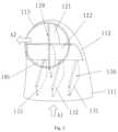
- FIG. 1is a partial cross-sectional perspective view of a piping assembly according to an embodiment of the present application.
- FIG. 2is a schematic perspective view of a piping assembly according to another embodiment of the present application.
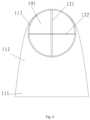
- FIG. 3is a view of the embodiment shown in FIG. 2 seen in a direction from the inlet portion.
- FIG. 4is a view of the embodiment shown in FIG. 2 seen in a direction from the outlet portion.
- FIG. 5is a cross-sectional view of the embodiment shown in FIG. 2 .
- orientational termssuch as top, bottom, upward, and downward mentioned herein are defined with respect to the directions in various drawings. These directions are relative concepts, and therefore will vary with the position and state thereof. Accordingly, these or other orientational terms should not be interpreted as restrictive.
- FIG. 1is a partial cross-sectional perspective view of a piping assembly according to an embodiment of the present application.
- the piping assembly 100includes an inlet portion 111 , a transition portion 112 , and an outlet portion 113 extending in sequence.
- the inlet portion 111may be configured to extend along an inlet axis
- the transition portion 112may be configured to extend along a transition axis
- the outlet portion 113may be configured to extend along an outlet axis.
- the inlet axismay be substantially parallel with an arrow A 1
- the outlet axismay be substantially parallel with the arrow A 2
- both ends of the transition axisare tangent to the outlet axis and the inlet axis respectively, so as to provide smooth transition between the inlet axis and the outlet axis.
- the inlet axis and the outlet axismay be respectively positioned in predetermined directions so as to form a predetermined angle therebetween.
- the predetermined angleis between 45 degrees and 135 degrees. In the illustrated embodiment, the predetermined angle may be approximately 90 degrees.
- the inlet portion 111 , the transition portion 112 and the outlet portion 113may jointly surround a cavity 101 .
- the edges of the cavity 101may be defined by the inner walls of the inlet portion 111 , the transition portion 112 and the outlet portion 113 and provide fluid communication from the inlet portion 111 to the outlet portion 113 .
- the inner wall of the cavity 101refers to the inner wall of one or more of the inlet portion 111 , the transition portion 112 and the outlet portion 113 .
- the wall thicknesses of the inlet portion 111 , the transition portion 112 and the outlet portion 113may be substantially the same, or gradually varying wall thicknesses may be provided according to actual needs.
- the inlet portion 111 , the transition portion 112 and the outlet portion 113may be configured in one piece, or may be manufactured separately and then assembled together.
- the inlet portion 111 , the transition portion 112 and the outlet portion 113may be configured to have a substantially circular, elliptical or other curvilinear cross section, and the size of the cross section may vary along the inlet axis, the transition axis, and the outlet axis.
- the circular cross section of the inlet portion 111has a first diameter
- the circular cross section of the outlet portion 113has a second diameter
- the first diameteris larger than the second diameter.
- the circular cross section of the transition portion 112may gradually change from the first diameter to the second diameter.
- the piping assembly 100further includes a first straightening portion 120 .
- the first straightening portion 120includes a plurality of deflector plates attached to the inner wall of the cavity 101 .
- the first straightening portion 120includes a first deflector plate 121 and a second deflector plate 122 connected perpendicular to each other.
- the first straightening portion 120may further include one or more deflector plates parallel with the first deflector plate 121 , and one or more deflector plates parallel with the second deflector plate 122 .
- the first deflector plate 121 and the second deflector plate 122extend in parallel with a part of the outlet axis and a part of the transition axis.
- first deflector plate 121 and the second deflector plate 122extend in parallel with a part of the transition axis. In the illustrated embodiment, for the sake of clarity, only the parts of the first deflector plate 121 and the second deflector plate 122 that are parallel with a part of the transition axis are shown. Those skilled in the art can easily understand that the first deflector plate 121 and the second deflector plate 122 may also have other shapes and positions that are not shown.
- the first deflector plate 121 and the second deflector plate 122may be arranged to form a predetermined angle relative to each other.
- the first deflector plate 121 and the second deflector plate 122may be configured to be perpendicular to each other, or may be angled relative to each other.
- the first deflector plate 121 and the second deflector plate 122may be arranged along the diameter of the circular cross section of the piping assembly 100 as shown in the figure, and pass through the center of the circle of the circular cross section.
- the first deflector plate 121 and the second deflector plate 122may also be arranged to deviate from the center of the circle, or have other asymmetrical patterns of arrangement.
- the first deflector plate 121 and the second deflector plate 122include a front edge closer to the inlet portion 111 and a rear edge closer to the outlet portion 113 .
- the front edges of the first deflector plate 121 and the second deflector plate 122may be located in a certain cross section within the transition portion 112
- the rear edges of the first deflector plate 121 and the second deflector plate 122may be located in a certain cross section within the outlet portion 113 .
- the rear edges of the first deflector plate 121 and the second deflector plate 122are arranged perpendicular to the outlet axis, and are located in the same cross section of the outlet portion 113 , as shown schematically below with reference to FIG. 5 .
- the rear edges of the first deflector plate 121 and the second deflector plate 122may also be arranged perpendicular to the transition axis, and are located in the same cross section of the transition portion 112 .
- the front edges of the first deflector plate 121 and the second deflector plate 122may be arranged perpendicular to the transition axis, or may form a certain angle with the transition axis, and the front edges of the first deflector plate 121 and the second deflector plate 122 may be arranged in the same cross section of the transition portion 112 .
- the front edges and rear edges referred to hereinare defined relative to a flow direction of working fluid.
- the front edgeis an end of the deflector plate that is located at an upstream position of a flow path of the working fluid
- the rear edgeis an end of the deflector plate that is located at a downstream position of the flow path of the working fluid. Therefore, the front edge of each deflector plate is closer to the inlet portion, and the rear edge of each deflector plate is closer to the outlet portion.
- the working fluidenters the piping assembly 100 from the inlet portion 111 substantially in a direction indicated by the arrow A 1 .
- the working fluidmay contain vortices in random directions and liquid components entrained therein.
- the first deflector plate 121 and the second deflector plate 122will at least partially destroy the vortices in the working fluid, so that the working fluid at least partially tends to change into fluid having parallel flow paths along the transition axis or the outlet axis, so that the fluid leaving the outlet portion 113 travels along the parallel flow paths.
- the liquid components in the working fluidcan be at least partially captured by the first straightening portion 120 , so that the liquid components are blocked or adsorbed at the first straightening portion 120 and are at least partially prevented from exiting through the outlet portion 113 .
- the inlet axisis substantially arranged in the vertical direction, and at least a part of the first straightening portion 120 faces the inlet portion 111 in the vertical direction. Therefore, the blocked or adsorbed liquid components may drip under the action of gravity and leave the piping assembly 100 from the inlet portion 111 .
- the vertical direction referred to hereinrefers to a direction in which gravity acts
- a horizontal direction referred to hereinrefers to a direction in which a horizontal plane is located.
- the horizontal direction and the vertical directionare perpendicular to each other.
- the first straightening portion 120may be made of a porous material to improve the ability of capturing the liquid components.
- the first straightening portion 120may also be made of a common material that does not contain pores. Porous materials include but are not limited to foaming alloys and so on.
- the first deflector plate 121 and the second deflector plate 122may have substantially uniform thickness, and may also be configured to have different thicknesses or varying thicknesses.
- FIGS. 2 to 5show another embodiment of the piping assembly of the present application.
- FIG. 2schematically shows components that cannot be directly observed from the outside of the piping assembly 100 with dashed lines.
- a second straightening portion 130is added on the basis of the embodiment in FIG. 1 .
- the second straightening portion 130includes a plurality of third deflector plates 131 , 132 and 133 provided upstream of the first straightening portion 120 . Both ends of the third deflector plates 131 , 132 and 133 may be attached to the inner wall of the cavity 101 .
- the third deflector platesmay also be attached to a component located upstream of the inlet portion 111 , and extend into the inlet portion 111 or extend into the transition portion 112 through the inlet portion 111 .
- Each of the third deflector plates 131 , 132 and 133may be configured to be parallel with each other, and may be configured to be equally or non-equally spaced apart.
- the second straightening portion 130 in the illustrated embodimentincludes three third deflector plates. According to actual needs, more or fewer third deflector plates may be provided at the second straightening portion 130 .
- the second straightening portion 130is located upstream of the first straightening portion 120 .
- the second straightening portionmay also be arranged downstream of the first straightening portion, or second straightening portions may be arranged at both upstream and downstream of the first straightening portion respectively.
- Each of the third deflector plates 131 , 132 and 133may extend in parallel with a part of the transition axis.
- the third deflector plates 131 , 132 and 133may each have a front edge closer to the inlet portion 111 and a rear edge closer to the outlet portion 113 .
- the rear edge of each of the third deflector platesmay be arranged perpendicular to the transition axis, and may be located in the same cross section of the transition portion.
- the front edge of each of the third deflector platesmay also be arranged perpendicular to the transition axis, and may be located in the same cross section of the transition portion.
- each of the third deflector platesmay also be arranged to form a certain angle with the transition axis.
- the rear edges of the third deflector platesmay also be arranged perpendicular to the outlet axis and may be located in the same cross section of the outlet portion.
- each of the third deflector platesmay be configured to be substantially parallel with the first deflector plate 121 , or may be configured to be substantially parallel with the front edge of one of the first deflector plate and the second deflector plate, so as to initially provide the desired fluid guiding function.
- the third deflector plate 132substantially shields the first deflector plate 121 , and at least a part of the first straightening portion 120 is visible at the inlet portion 111 .
- FIG. 4when seen from the outlet portion 113 , the rear edges of the first deflector plate 121 and the second deflector plate 122 that are arranged perpendicular to each other are visible, and the second straightening portion 130 is invisible.
- each of the third deflector platesmay have substantially the same wall thickness, or may have different wall thicknesses or varying wall thicknesses according to actual needs.
- the working fluidinflows from the inlet portion 111 and is initially straightened by the second straightening portion 130 .
- the arrangement of the third deflector platesis advantageous for initially destroying the vortices, so as to provide parallel flow paths of the working fluid.
- the second straightening portion 130may also at least partially capture the liquid components in the working fluid, and enables the liquid components to drip from the second straightening portion 130 under the action of gravity and leave the piping assembly 100 through the inlet portion 111 .
- the second straightening portion 130may also be made of a porous material to improve the ability of capturing the liquid components.
- the second straightening portion 130may also be made of a common material that does not contain pores. Porous materials include but are not limited to foaming alloys and so on.
- the second straightening portion 130may be made of the same material as the first straightening portion 120 , or may be made of a different material from the first straightening portion 120 .
- first straightening portion 120 and the second straightening portion 130may be manufactured separately and then attached within the piping assembly 100 .
- the attachment methodmay be bonding, bolting, welding and other connecting means.
- the first straightening portion 120 and/or the second straightening portion 130may also be configured to be integral with the inlet portion 111 , the transition portion 112 and the outlet portion 113 , and they may be manufactured integrally.
- the present applicationalso provides a refrigeration system.
- the refrigeration systemmay include an evaporator and a compressor connected in series in a refrigeration circuit.
- the piping assembly described abovemay be attached between the evaporator and the compressor.
- the inlet portion 111 of the piping assembly 100may be attached to an outlet end of the evaporator not shown, and the outlet portion 113 of the piping assembly 100 may be attached to an inlet end of the compressor not shown.
- the refrigeration circuitmay be appropriately oriented such that the piping assembly 100 is arranged in such a way that the inlet axis is substantially oriented in the vertical direction, and/or the outlet axis is substantially oriented in the horizontal direction.
- the refrigeration circuitmay further include components such as a condenser, a directional valve, and so on.
- the working fluid output from the evaporatormay have undesired vortices and liquid components, and the flow paths of the working fluid are random and interlaced with each other.
- the working fluidenters the piping assembly 100 through the inlet portion 111 and is straightened by the first straightening portion 120 or by both the first straightening portion 120 and the second straightening portion 130 .
- the vortices in the working fluidare at least partially eliminated, and the working fluid leaving the piping assembly 100 from the outlet portion 113 tends to have flow paths that are substantially parallel with each other.
- the liquid components entrained in the working fluidmay also be at least partially captured by the first straightening portion 120 and the second straightening portion 130 , and the working fluid leaving the outlet portion 130 tends to have fewer liquid components.
- piping assembly of the present applicationis not limited to the usage disclosed above, but may be installed at any suitable position in the refrigeration circuit, while still capable of providing improved parallelism, uniformity and liquid entrainment degree of the working fluid.
- the parallelism of the working fluid in the refrigeration circuitcan be effectively improved, and undesired liquid components can be reduced, thereby effectively improving the overall efficiency of the refrigeration circuit.
- the refrigeration system adopting the piping assembly of the present applicationcan achieve a performance improvement of 1%-3%.
Landscapes
- Engineering & Computer Science (AREA)
- Mechanical Engineering (AREA)
- General Engineering & Computer Science (AREA)
- Physics & Mathematics (AREA)
- Thermal Sciences (AREA)
- Fluid Mechanics (AREA)
- Chemical & Material Sciences (AREA)
- Analytical Chemistry (AREA)
- Power Engineering (AREA)
- Pipe Accessories (AREA)
- Heat-Exchange Devices With Radiators And Conduit Assemblies (AREA)
Abstract
Description
Claims (11)
Applications Claiming Priority (2)
| Application Number | Priority Date | Filing Date | Title |
|---|---|---|---|
| CN202010758307.3ACN114061182A (en) | 2020-07-31 | 2020-07-31 | Pipeline assembly and refrigerating system |
| CN202010758307.3 | 2020-07-31 |
Publications (2)
| Publication Number | Publication Date |
|---|---|
| US20220034338A1 US20220034338A1 (en) | 2022-02-03 |
| US12044259B2true US12044259B2 (en) | 2024-07-23 |
Family
ID=76859502
Family Applications (1)
| Application Number | Title | Priority Date | Filing Date |
|---|---|---|---|
| US17/381,798Active2042-09-25US12044259B2 (en) | 2020-07-31 | 2021-07-21 | Piping assembly and refrigeration system |
Country Status (3)
| Country | Link |
|---|---|
| US (1) | US12044259B2 (en) |
| EP (1) | EP3945217A1 (en) |
| CN (1) | CN114061182A (en) |
Cited By (1)
| Publication number | Priority date | Publication date | Assignee | Title |
|---|---|---|---|---|
| US20250230890A1 (en)* | 2024-01-12 | 2025-07-17 | Chevron U.S.A. Inc. | Additive manufactured return bend for fire tube or furnace tube |
Families Citing this family (2)
| Publication number | Priority date | Publication date | Assignee | Title |
|---|---|---|---|---|
| CN116848327A (en)* | 2021-02-17 | 2023-10-03 | 松下知识产权经营株式会社 | Suction pipe of centrifugal compressor, centrifugal compressor with suction pipe and refrigerating device |
| CN115419616A (en)* | 2022-09-05 | 2022-12-02 | 江森自控空调冷冻设备(无锡)有限公司 | Air suction pipe of centrifugal compressor |
Citations (36)
| Publication number | Priority date | Publication date | Assignee | Title |
|---|---|---|---|---|
| US1827727A (en)* | 1927-04-05 | 1931-10-20 | Foster Wheeler Corp | Conduit system |
| US2723680A (en)* | 1950-07-01 | 1955-11-15 | Neyrpic Ets | Conduit elements |
| US3597166A (en) | 1968-12-18 | 1971-08-03 | Exxon Research Engineering Co | Ammonia burner flow distributor |
| US4362223A (en) | 1979-05-18 | 1982-12-07 | Irmhild Meier | Sound absorbing device |
| US4471821A (en)* | 1980-07-24 | 1984-09-18 | Basf Aktiengesellschaft | Apparatus for distributing a gas, coming from a pipe, over the cross-section of a vessel |
| US4802342A (en) | 1988-04-18 | 1989-02-07 | Thermo King Corporation | Protective grille and air flow straightener for transport refrigeration apparatus |
| US4919170A (en)* | 1987-08-08 | 1990-04-24 | Veba Kraftwerke Ruhr Aktiengesellschaft | Flow duct for the flue gas of a flue gas-cleaning plant |
| US5687768A (en)* | 1996-01-18 | 1997-11-18 | The Babcock & Wilcox Company | Corner foils for hydraulic measurement |
| JP2939396B2 (en) | 1992-08-07 | 1999-08-25 | 新キャタピラー三菱株式会社 | Air suction rectifier in air suction type cooling device |
| CN1261427A (en) | 1997-06-30 | 2000-07-26 | 株式会社杰克赛尔 | Refrigerating apparatus for vehicles |
| US6116284A (en)* | 1999-08-06 | 2000-09-12 | Case Corporation | Guide structure for pneumatic applicator |
| JP2001147012A (en) | 1999-11-19 | 2001-05-29 | Hitachi Zosen Corp | Rectifier for gas processing vessel |
| CN1143995C (en) | 1998-05-14 | 2004-03-31 | 松下电器产业株式会社 | Muffler and air conditioner |
| US20040065375A1 (en) | 2002-10-07 | 2004-04-08 | Snider John Michael | Constant acceleration and constant hydraulic diameter eliminate pressure loss in internal and external flow |
| CN1161581C (en) | 1998-06-08 | 2004-08-11 | 普莱克斯技术有限公司 | Method and apparatus for retention of refrigerant fluid in refrigeration enclosure |
| JP2005061778A (en) | 2003-08-19 | 2005-03-10 | Calsonic Kansei Corp | Evaporator |
| US20050247361A1 (en)* | 2004-05-06 | 2005-11-10 | Sogefi Filtration Do Brasil Ltda. | Airflow converger |
| US7142424B2 (en) | 2004-04-29 | 2006-11-28 | Hewlett-Packard Development Company, L.P. | Heat exchanger including flow straightening fins |
| JP4062011B2 (en) | 2002-08-09 | 2008-03-19 | ダイキン工業株式会社 | Two-phase refrigerant flow rectifier and refrigeration system |
| US7362571B2 (en) | 2004-09-16 | 2008-04-22 | Cray Inc. | Inlet flow conditioners for computer cabinet air conditioning systems |
| CN100501277C (en) | 2005-03-25 | 2009-06-17 | 大金工业株式会社 | freezer |
| US20090218000A1 (en)* | 2006-01-10 | 2009-09-03 | Endress + Hauser Flowtec Ag | Apparatus for Redirecting a Medium Flowing in a Pipeline |
| CN101846461A (en) | 2009-03-24 | 2010-09-29 | 成智空调技术株式会社 | Modular cooling tower |
| CN101946091A (en) | 2008-02-20 | 2011-01-12 | 特灵国际有限公司 | Centrifugal compressor units part and method |
| CN102200141A (en) | 2011-06-02 | 2011-09-28 | 温州市天成密封件制造有限公司 | Energy-saving guide vane device for pump |
| US20120152394A1 (en)* | 2008-12-23 | 2012-06-21 | David Yoskowitz | Turning vane for air duct |
| US8251406B2 (en)* | 2010-04-04 | 2012-08-28 | Kawano Giken Co., Ltd. | Discharge elbow provided with guide vanes |
| US8322157B2 (en) | 2009-08-26 | 2012-12-04 | Deere & Company | De-aerating flow straightener for cooling system |
| CN105074354A (en) | 2013-02-20 | 2015-11-18 | 开利公司 | Inlet guide vane mechanism |
| US20180023589A1 (en) | 2015-02-03 | 2018-01-25 | Mitsubishi Heavy Industries, Ltd. | Centrifugal compressor |
| JP2018013097A (en) | 2016-07-21 | 2018-01-25 | サンデン・オートモーティブコンポーネント株式会社 | Compressor |
| US20180274831A1 (en) | 2017-03-24 | 2018-09-27 | Johnson Controls Technology Company | Converging suction line for compressor |
| WO2019060754A2 (en) | 2017-09-25 | 2019-03-28 | Johnson Controls Technology Company | Two piece split scroll for centrifugal compressor |
| CN109883085A (en) | 2019-01-20 | 2019-06-14 | 何家密 | Energy consumption reducing method for refrigerating and heating of evaporator and condenser |
| US20190390687A1 (en) | 2017-03-27 | 2019-12-26 | Mitsubishi Heavy Industries Thermal Systems, Ltd. | Compressor suction pipe, compression unit, and chiller |
| US20200378414A1 (en)* | 2019-05-31 | 2020-12-03 | Kalsi Engineering, Inc. | Flow conditioning assembly |
- 2020
- 2020-07-31CNCN202010758307.3Apatent/CN114061182A/enactivePending
- 2021
- 2021-07-09EPEP21184772.8Apatent/EP3945217A1/enactivePending
- 2021-07-21USUS17/381,798patent/US12044259B2/enactiveActive
Patent Citations (40)
| Publication number | Priority date | Publication date | Assignee | Title |
|---|---|---|---|---|
| US1827727A (en)* | 1927-04-05 | 1931-10-20 | Foster Wheeler Corp | Conduit system |
| US2723680A (en)* | 1950-07-01 | 1955-11-15 | Neyrpic Ets | Conduit elements |
| US3597166A (en) | 1968-12-18 | 1971-08-03 | Exxon Research Engineering Co | Ammonia burner flow distributor |
| US4362223A (en) | 1979-05-18 | 1982-12-07 | Irmhild Meier | Sound absorbing device |
| US4471821A (en)* | 1980-07-24 | 1984-09-18 | Basf Aktiengesellschaft | Apparatus for distributing a gas, coming from a pipe, over the cross-section of a vessel |
| US4919170A (en)* | 1987-08-08 | 1990-04-24 | Veba Kraftwerke Ruhr Aktiengesellschaft | Flow duct for the flue gas of a flue gas-cleaning plant |
| US4802342A (en) | 1988-04-18 | 1989-02-07 | Thermo King Corporation | Protective grille and air flow straightener for transport refrigeration apparatus |
| JP2939396B2 (en) | 1992-08-07 | 1999-08-25 | 新キャタピラー三菱株式会社 | Air suction rectifier in air suction type cooling device |
| US5687768A (en)* | 1996-01-18 | 1997-11-18 | The Babcock & Wilcox Company | Corner foils for hydraulic measurement |
| US6279334B1 (en) | 1997-06-30 | 2001-08-28 | Zexel Cold Systems Company | Refrigerating apparatus for vehicles |
| CN1261427A (en) | 1997-06-30 | 2000-07-26 | 株式会社杰克赛尔 | Refrigerating apparatus for vehicles |
| CN1143995C (en) | 1998-05-14 | 2004-03-31 | 松下电器产业株式会社 | Muffler and air conditioner |
| CN1161581C (en) | 1998-06-08 | 2004-08-11 | 普莱克斯技术有限公司 | Method and apparatus for retention of refrigerant fluid in refrigeration enclosure |
| US6116284A (en)* | 1999-08-06 | 2000-09-12 | Case Corporation | Guide structure for pneumatic applicator |
| JP2001147012A (en) | 1999-11-19 | 2001-05-29 | Hitachi Zosen Corp | Rectifier for gas processing vessel |
| JP4062011B2 (en) | 2002-08-09 | 2008-03-19 | ダイキン工業株式会社 | Two-phase refrigerant flow rectifier and refrigeration system |
| US20040065375A1 (en) | 2002-10-07 | 2004-04-08 | Snider John Michael | Constant acceleration and constant hydraulic diameter eliminate pressure loss in internal and external flow |
| JP2005061778A (en) | 2003-08-19 | 2005-03-10 | Calsonic Kansei Corp | Evaporator |
| US7142424B2 (en) | 2004-04-29 | 2006-11-28 | Hewlett-Packard Development Company, L.P. | Heat exchanger including flow straightening fins |
| US20050247361A1 (en)* | 2004-05-06 | 2005-11-10 | Sogefi Filtration Do Brasil Ltda. | Airflow converger |
| US7362571B2 (en) | 2004-09-16 | 2008-04-22 | Cray Inc. | Inlet flow conditioners for computer cabinet air conditioning systems |
| CN100501277C (en) | 2005-03-25 | 2009-06-17 | 大金工业株式会社 | freezer |
| US20090218000A1 (en)* | 2006-01-10 | 2009-09-03 | Endress + Hauser Flowtec Ag | Apparatus for Redirecting a Medium Flowing in a Pipeline |
| CN101946091B (en) | 2008-02-20 | 2015-01-14 | 特灵国际有限公司 | Centrifugal compressor assembly and method |
| CN101946091A (en) | 2008-02-20 | 2011-01-12 | 特灵国际有限公司 | Centrifugal compressor units part and method |
| US20120152394A1 (en)* | 2008-12-23 | 2012-06-21 | David Yoskowitz | Turning vane for air duct |
| CN101846461A (en) | 2009-03-24 | 2010-09-29 | 成智空调技术株式会社 | Modular cooling tower |
| CN101846461B (en) | 2009-03-24 | 2012-10-17 | 成智空调技术株式会社 | Modular cooling tower |
| US8322157B2 (en) | 2009-08-26 | 2012-12-04 | Deere & Company | De-aerating flow straightener for cooling system |
| US8251406B2 (en)* | 2010-04-04 | 2012-08-28 | Kawano Giken Co., Ltd. | Discharge elbow provided with guide vanes |
| CN102200141A (en) | 2011-06-02 | 2011-09-28 | 温州市天成密封件制造有限公司 | Energy-saving guide vane device for pump |
| CN105074354A (en) | 2013-02-20 | 2015-11-18 | 开利公司 | Inlet guide vane mechanism |
| CN105074354B (en) | 2013-02-20 | 2017-12-12 | 开利公司 | Inlet guide vane mechanism |
| US20180023589A1 (en) | 2015-02-03 | 2018-01-25 | Mitsubishi Heavy Industries, Ltd. | Centrifugal compressor |
| JP2018013097A (en) | 2016-07-21 | 2018-01-25 | サンデン・オートモーティブコンポーネント株式会社 | Compressor |
| US20180274831A1 (en) | 2017-03-24 | 2018-09-27 | Johnson Controls Technology Company | Converging suction line for compressor |
| US20190390687A1 (en) | 2017-03-27 | 2019-12-26 | Mitsubishi Heavy Industries Thermal Systems, Ltd. | Compressor suction pipe, compression unit, and chiller |
| WO2019060754A2 (en) | 2017-09-25 | 2019-03-28 | Johnson Controls Technology Company | Two piece split scroll for centrifugal compressor |
| CN109883085A (en) | 2019-01-20 | 2019-06-14 | 何家密 | Energy consumption reducing method for refrigerating and heating of evaporator and condenser |
| US20200378414A1 (en)* | 2019-05-31 | 2020-12-03 | Kalsi Engineering, Inc. | Flow conditioning assembly |
Non-Patent Citations (2)
| Title |
|---|
| European Search Report for Application No. 21184772.8; Issued Dec. 12, 2021; 8 Pages. |
| European Search Report for Application No. 21184772.8; Issued Nov. 12, 2023; 5 Pages. |
Cited By (1)
| Publication number | Priority date | Publication date | Assignee | Title |
|---|---|---|---|---|
| US20250230890A1 (en)* | 2024-01-12 | 2025-07-17 | Chevron U.S.A. Inc. | Additive manufactured return bend for fire tube or furnace tube |
Also Published As
| Publication number | Publication date |
|---|---|
| US20220034338A1 (en) | 2022-02-03 |
| CN114061182A (en) | 2022-02-18 |
| EP3945217A1 (en) | 2022-02-02 |
Similar Documents
| Publication | Publication Date | Title |
|---|---|---|
| US12044259B2 (en) | Piping assembly and refrigeration system | |
| US20110226005A1 (en) | Distributor, and evaporator and refrigerating machine with the same | |
| US9033029B2 (en) | Heat exchanger | |
| EP2863161A1 (en) | Heat exchanger and heat exchange method | |
| JP4613645B2 (en) | Heat exchanger | |
| US10072900B2 (en) | Heat exchanger distributor with intersecting streams | |
| JP6138264B2 (en) | Laminated header, heat exchanger, and air conditioner | |
| KR102170312B1 (en) | A heat exchanger | |
| KR20250065370A (en) | Gas suction pipe of centrifugal compressor | |
| EP2910875B1 (en) | Oil separator | |
| US10976084B2 (en) | Evaporator in a refrigerant circuit a | |
| US10760835B2 (en) | Evaporator in a refrigerant circuit E | |
| US12140349B2 (en) | Liquid blocking device and evaporator thereof | |
| EP3569954A1 (en) | Expansion valve and refrigeration cycle device provided with same | |
| CN105526750B (en) | A kind of dispenser | |
| CN116164454A (en) | Gas-liquid separator and refrigerating system | |
| US10895410B2 (en) | Evaporator in a refrigerant circuit B | |
| CN206847142U (en) | A kind of knockout filter screen bracket and knockout | |
| US20250314436A1 (en) | Air conditioner having refrigerant distributor | |
| CN221944554U (en) | Gas-liquid separation structure for gas-liquid separator | |
| WO2019078084A1 (en) | Evaporator and refrigeration system | |
| CN215635022U (en) | Electronic expansion valve and air conditioner | |
| US12235024B2 (en) | Deflector for condenser, condenser having it and chiller system | |
| CN215172507U (en) | Check valve and lampblack absorber | |
| US10760834B2 (en) | Evaporator in a refrigerant circuit D |
Legal Events
| Date | Code | Title | Description |
|---|---|---|---|
| FEPP | Fee payment procedure | Free format text:ENTITY STATUS SET TO UNDISCOUNTED (ORIGINAL EVENT CODE: BIG.); ENTITY STATUS OF PATENT OWNER: LARGE ENTITY | |
| AS | Assignment | Owner name:CARRIER CORPORATION, FLORIDA Free format text:ASSIGNMENT OF ASSIGNORS INTEREST;ASSIGNOR:CARRIER AIR CONDITIONING AND REFRIGERATION R&D MANAGEMENT (SHANGHAI) CO., LTD.;REEL/FRAME:056941/0780 Effective date:20210122 Owner name:CARRIER AIR CONDITIONING AND REFRIGERATION R&D MANAGEMENT (SHANGHAI) CO., LTD., CHINA Free format text:ASSIGNMENT OF ASSIGNORS INTEREST;ASSIGNORS:YU, LEI;FENG, FUJIN;SHAO, YUCHANG;AND OTHERS;SIGNING DATES FROM 20200820 TO 20201010;REEL/FRAME:056941/0776 | |
| STPP | Information on status: patent application and granting procedure in general | Free format text:DOCKETED NEW CASE - READY FOR EXAMINATION | |
| STPP | Information on status: patent application and granting procedure in general | Free format text:NON FINAL ACTION MAILED | |
| STPP | Information on status: patent application and granting procedure in general | Free format text:RESPONSE TO NON-FINAL OFFICE ACTION ENTERED AND FORWARDED TO EXAMINER | |
| STPP | Information on status: patent application and granting procedure in general | Free format text:NOTICE OF ALLOWANCE MAILED -- APPLICATION RECEIVED IN OFFICE OF PUBLICATIONS | |
| STPP | Information on status: patent application and granting procedure in general | Free format text:PUBLICATIONS -- ISSUE FEE PAYMENT RECEIVED | |
| STPP | Information on status: patent application and granting procedure in general | Free format text:PUBLICATIONS -- ISSUE FEE PAYMENT VERIFIED | |
| STCF | Information on status: patent grant | Free format text:PATENTED CASE |